Embed Size (px)
Citation preview

ELECTRIC METERING COMMERCIAL & INDUSTRIAL CM0001M
ELECTRIC METERING
COMMERCIAL & INDUSTRIAL
1.0 INDEX
1.0 INDEX
2.0 SCOPE
3.0 GENERAL REQUIREMENTS
4.0 METER LOCATIONS
5.0 UNDERGROUND TERMINATIONS
6.0 METERING TRANSFORMER ENCLOSURES
7.0 SINGLE CUSTOMER METER INSTALLATIONS
8.0 MULTIPLE METER INSTALLATIONS, 2-6 METERS, 7+ METERS
9.0 COMMERCIAL/ INDUSTRIAL, 100 & 200 AMP SERVICE PEDESTALS
2.0 SCOPE
This standard provides detailed information for installation of electrical metering (0-600 volts) in
Commercial and Industrial (C/I) applications.
3.0 GENERAL REQUIREMENTS
3.1 Type of Service
Electric service to C/I customers depends upon the load, applicable rate schedule, and area
voltages.
3.2 NVE Consultation
It is important the customer consult NVE prior to the purchase of equipment for fault duty
requirement of equipment. All C/I metering installations above 200 Amps must be approved in
writing by NVE, prior to installation by submitting two (2) sets of drawings to: NVE Electric
Metering Dept. (R90EM), P.O. BOX 10100, Reno, NV. 89520-0024.
3.3 General Codes
All meter sockets and enclosures shall be Underwriter's Laboratory listed. All installations and
equipment shall comply with the latest requirements of the Electric Utility Service Equipment
Requirements Committee (EUSERC), as adopted by NVE.
3.4 Disconnects or Breakers
All installations shall have an accessible disconnect or main breaker per the NEC and local fire
codes.
VOLUME 17 – ENGINERING & CONSTRUCTION STANDARD
CM0001M ELECTRIC METERING COMMERCIAL &
INDUSTRIAL Drawn: Eng: Appr: Date: Revision: 9
JL MB DA 8/18 Page 1 of 26
ELECTRIC METERING COMMERCIAL & INDUSTRIAL CM0001M
4.0 METER LOCATIONS
4.1 Basic Location Requirements
See NVE Standard, GM0001M, Electric Metering-General, for details.
4.2 Typical Location
Meter locations are preferred on an exterior 'ground-level' floor wall or other permanent
structure nearest NVE's distribution facilities. See GM0001M, Section 6.0 for options and details.
4.3 Multiple meter Installations
Multiple occupancy buildings will have the meters grouped at one location. One NVE
underground service will generally be run to a building.
4.4 Service Disconnect Locations
Meters may be located at a point other than adjacent to the service disconnecting means. In
accordance with applicable codes, the disconnect should be located outside the building being
served.
4.5 Metering Transformers
Transformer rated meters and associated metering transformers are installed adjacent to each other.
NVE may approve installations with a maximum separation of 50 circuit feet to assure
accessibility or prevent inaccurate meter measurements. When separation of the meter and
metering transformers is allowed, the customer shall provide clearances and working space for
both the meter and metering transformer assembly. The customer shall supply and install conduit
for the meter Wiring and the metering transformers. The conduit, minimum diameter of 1-1/2",
shall be limited to two 900 bends. Conduits, junction boxes or similar fittings are not allowed.
VOLUME 17 – ENGINERING & CONSTRUCTION STANDARD
CM0001M ELECTRIC METERING COMMERCIAL &
INDUSTRIAL Drawn: Eng: Appr: Date: Revision: 9
JL MB DA 8/18 Page 2 of 26
ELECTRIC METERING COMMERCIAL & INDUSTRIAL CM0001M
5.0 UNDERGROUND TERMINATIONS
5.1 Service Termination Facilities
Service termination facilities shall be specifically designed to receive NVE's underground service
lateral conductors as a single cable entry. Enclosures designed for a combination of overhead and
underground entry are acceptable as long as they meet NVE requirement for underground feed.
5.2 Cable Termination Lugs
Line cable termination lugs (crimp to flat) will be provided by NVE. Panels 400A and under may
utilize 'set-screw' type terminations. One NEMA 2 hole spade will be provided for each 400
amps of panel capacity Socket enclosures designed for service up to 200 amps shall have separate
service termination lugs independently mounted from the socket jaw support. Service termination
space in enclosures with ratings over 200 amps with multiple meter sockets shall accommodate
compression type lugs. All bussing or cable conductors beyond the terminating lugs shall be
provided by the customer. Bus stubs or bussing in the service terminating space used for
terminating the utility service shall have mounting bolts/spades in accordance with NEMA
standards. The service cable termination lugs shall be compatible with the size and type of service
being installed. The termination lugs for the neutral and each of the phase conductors shall be
rigidly and permanently affixed in the service termination space and all properly grouped at one
location. If the neutral is insulated from the enclosure, a bonding screw or jumper shall be
provided. Terminating lugs shall be mounted with a minimum of 1-1/2" clear work space between
two adjacent uninsulated line lugs of different voltage, any in-between uninsulated line lugs and
grounded metal. For equipment above 400 amps, the horizontal spacing may be reduced if
insulated barriers are used or if a 1-1/2" radial separation is maintained.
5.3 Service Terminations Enclosures
Wire-ways in the service termination space designed for terminating the utility service lateral shall
be clearly identified for such use. Termination shall be made in the service termination enclosure
or in a specifically designed space of a removable and sealable access plate.
5.4 Cable Layout
The layout or design of the service termination enclosure must allow adequate space for service
cable bending. Knockouts in the cable wire-ways should be positioned to minimize service cable
bending. Minimum bend radius of secondary service cables = 8 X "outside diameter" and primary
cables = 12X "outside diameter".
5.5 Sealing
The termination enclosure, socket enclosure, and test bypass block section shall be
sealable and isolated from other enclosure sections which are accessible to the
customer.
VOLUME 17 – ENGINERING & CONSTRUCTION STANDARD
CM0001M ELECTRIC METERING COMMERCIAL &
INDUSTRIAL Drawn: Eng: Appr: Date: Revision: 9
JL MB DA 8/18 Page 3 of 26
ELECTRIC METERING COMMERCIAL & INDUSTRIAL CM0001M
5.6 Labeling
The manufacturer's rating label shall show (a) whether the socket enclosure is designed for
overhead service entry, underground service entry, or both, (b) termination lugs are designed for
both copper and aluminum conductors, and (c) the wire size range of the lugs.
5.7 Clearance
The minimum distance between the point of entry of the underground service conductors into the
socket enclosure and the bottom of the hot bus terminating lugs shall be 8" for sockets up to 125
amps, and 11" for sockets rated 126 to 200 amps.
6.0 METERING TRANSFORMER ENCLOSURES
6.1 Definition
A metering transformer installation consists of current transformers and potential transformers
mounted in a metal cabinet with a watt-hour meter and its accompanying manual "test-bypass"
facilities. Automatic and lever style by-pass facilities are not approved. A separate mounting
device may be provided for the meter.
6.2 Customer Responsibility
The customer shall furnish and install a metal cabinet for enclosure of the metering transformers.
The enclosures short circuit duty rating will match or exceed the given fault duty.
6.3 Enclosure Covers
All covers must have a hinged door. All covers shall have a caution sign with the label "DO NOT
BREAK SEALS - NO FUSES INSIDE".
6.4 Locations
Metering transformer cabinets may be mounted either indoors or outdoors provided outdoor
installations are rain tight. Cabinets may be mounted vertically provided that the cables shall enter
and leave the cabinet in such a manner that NVE can conveniently install and connect the current
transformers.
7.0 SINGLE CUSTOMER METER INSTALLATIONS
7.1 Single Customer, 0 - 200 Amp, Overhead and Underground
The customer shall furnish, install and maintain an approved meter socket with a NVE approved
"manual test-bypass" facilities (only exception is a 100 amp panel that is exclusively for night time
lighting load) to permit NVE to bypass and de-energize the meter socket for all commercial three
phase and single phase services.
VOLUME 17 – ENGINERING & CONSTRUCTION STANDARD
CM0001M ELECTRIC METERING COMMERCIAL &
INDUSTRIAL Drawn: Eng: Appr: Date: Revision: 9
JL MB DA 8/18 Page 4 of 26
ELECTRIC METERING COMMERCIAL & INDUSTRIAL CM0001M
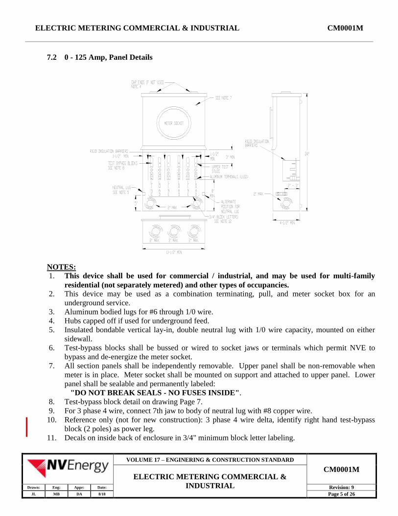
7.2 0 - 125 Amp, Panel Details
NOTES:
1. This device shall be used for commercial / industrial, and may be used for multi-family
residential (not separately metered) and other types of occupancies.
2. This device may be used as a combination terminating, pull, and meter socket box for an
underground service.
3. Aluminum bodied lugs for #6 through 1/0 wire.
4. Hubs capped off if used for underground feed.
5. Insulated bondable vertical lay-in, double neutral lug with 1/0 wire capacity, mounted on either
sidewall.
6. Test-bypass blocks shall be bussed or wired to socket jaws or terminals which permit NVE to
bypass and de-energize the meter socket.
7. All section panels shall be independently removable. Upper panel shall be non-removable when
meter is in place. Meter socket shall be mounted on support and attached to upper panel. Lower
panel shall be sealable and permanently labeled:
"DO NOT BREAK SEALS - NO FUSES INSIDE".
8. Test-bypass block detail on drawing Page 7.
9. For 3 phase 4 wire, connect 7th jaw to body of neutral lug with #8 copper wire.
10. Reference only (not for new construction): 3 phase 4 wire delta, identify right hand test-bypass
block (2 poles) as power leg.
11. Decals on inside back of enclosure in 3/4" minimum block letter labeling.
VOLUME 17 – ENGINERING & CONSTRUCTION STANDARD
CM0001M ELECTRIC METERING COMMERCIAL &
INDUSTRIAL Drawn: Eng: Appr: Date: Revision: 9
JL MB DA 8/18 Page 5 of 26
ELECTRIC METERING COMMERCIAL & INDUSTRIAL CM0001M
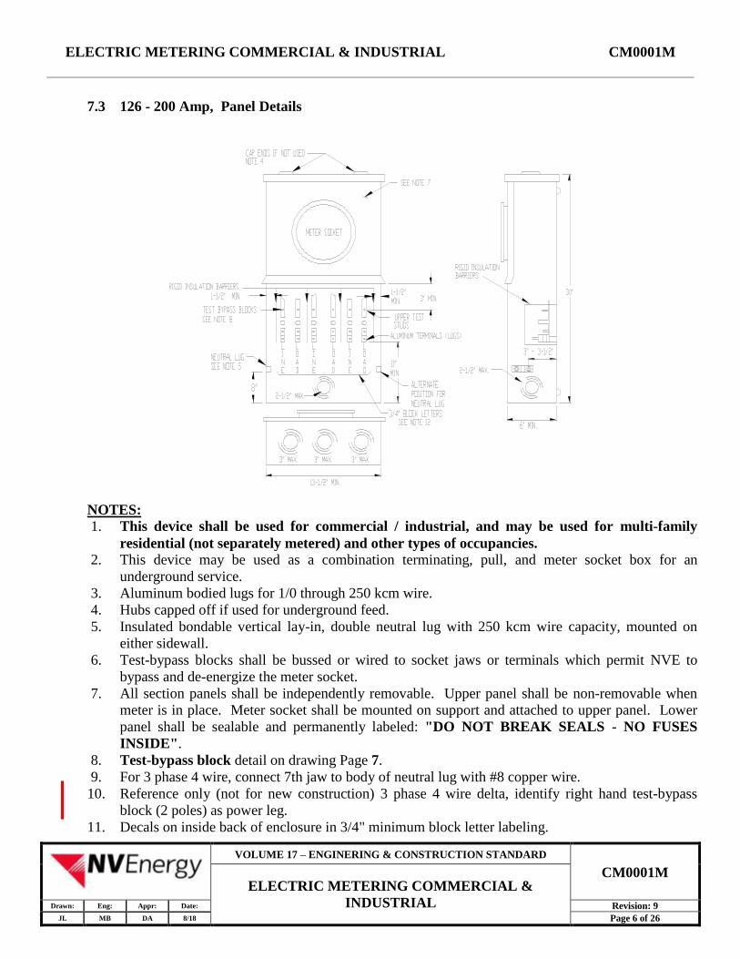
7.3 126 - 200 Amp, Panel Details
NOTES:
1. This device shall be used for commercial / industrial, and may be used for multi-family
residential (not separately metered) and other types of occupancies.
2. This device may be used as a combination terminating, pull, and meter socket box for an
underground service.
3. Aluminum bodied lugs for 1/0 through 250 kcm wire.
4. Hubs capped off if used for underground feed.
5. Insulated bondable vertical lay-in, double neutral lug with 250 kcm wire capacity, mounted on
either sidewall.
6. Test-bypass blocks shall be bussed or wired to socket jaws or terminals which permit NVE to
bypass and de-energize the meter socket.
7. All section panels shall be independently removable. Upper panel shall be non-removable when
meter is in place. Meter socket shall be mounted on support and attached to upper panel. Lower
panel shall be sealable and permanently labeled: "DO NOT BREAK SEALS - NO FUSES
INSIDE".
8. Test-bypass block detail on drawing Page 7.
9. For 3 phase 4 wire, connect 7th jaw to body of neutral lug with #8 copper wire.
10. Reference only (not for new construction) 3 phase 4 wire delta, identify right hand test-bypass
block (2 poles) as power leg.
11. Decals on inside back of enclosure in 3/4" minimum block letter labeling.
VOLUME 17 – ENGINERING & CONSTRUCTION STANDARD
CM0001M ELECTRIC METERING COMMERCIAL &
INDUSTRIAL Drawn: Eng: Appr: Date: Revision: 9
JL MB DA 8/18 Page 6 of 26
ELECTRIC METERING COMMERCIAL & INDUSTRIAL CM0001M
TEST BYPASS BLOCK DETAIL
NOTES:
1. Strike distance between upper and lower bus sections shall not be less than 1/4" when circuit-
closing nut is backed off.
2. Circuit-closing nut shall be a hex nut 5/8" across flats with plated copper washer attached and have
threads counter-bored at bottom to facilitate reinstallation. Bolt head shall be secured in place to
prevent turning and back out.
3. The circuit-closing nut and bolt assembly shall maintain the applied contact pressure between the
plated copper washer and the bus members of the test-bypass block.
4. Insulating washer shall be made from dimensionally stable, non-tracking material and shall
provide a minimum 1/8" creep distance between the bolt and the bus sections. Bus sections shall
be plated.
5. Wire stops shall extend to center of terminal opening or beyond.
6. Rigid insulating barriers shall project at least 1/4" beyond any energized parts when the maximum
wire size is installed.
7. Lugs shall be aluminum, and sized for the panel Amp rating. The opening shall extend through the
terminal body and, if wire hole is round, shall be chamfered as necessary to facilitate installation of
the largest size wire.
VOLUME 17 – ENGINERING & CONSTRUCTION STANDARD
CM0001M ELECTRIC METERING COMMERCIAL &
INDUSTRIAL Drawn: Eng: Appr: Date: Revision: 9
JL MB DA 8/18 Page 7 of 26
ELECTRIC METERING COMMERCIAL & INDUSTRIAL CM0001M
8. The terminal screw may be of the Allen type (3/16" across flats for 100 amp, 5/16" across flats for
200 amp). If stud "A" is a part of the terminal screw, the terminal screw shall be 5/8" hex across
flats.
9. Stud "A" shall be located in the clear area between the terminating lug and the circuit-closing nut,
and may be positioned on the terminal body, on the terminal screw, on the bus member, or
incorporated as part of the wire stop.
10. All designs must receive approval of the EUSERC Standards Committees prior to production.
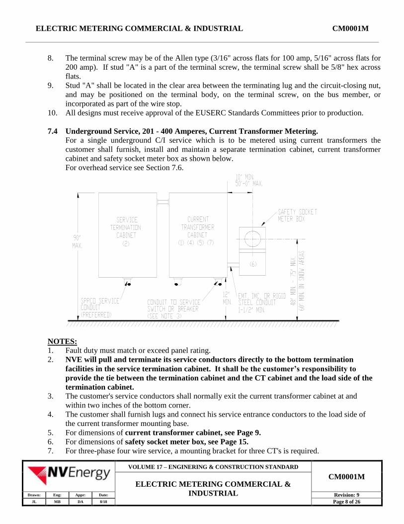
7.4 Underground Service, 201 - 400 Amperes, Current Transformer Metering.
For a single underground C/I service which is to be metered using current transformers the
customer shall furnish, install and maintain a separate termination cabinet, current transformer
cabinet and safety socket meter box as shown below.
For overhead service see Section 7.6.
NOTES:
1. Fault duty must match or exceed panel rating.
2. NVE will pull and terminate its service conductors directly to the bottom termination
facilities in the service termination cabinet. It shall be the customer’s responsibility to
provide the tie between the termination cabinet and the CT cabinet and the load side of the
termination cabinet.
3. The customer's service conductors shall normally exit the current transformer cabinet at and
within two inches of the bottom corner.
4. The customer shall furnish lugs and connect his service entrance conductors to the load side of
the current transformer mounting base.
5. For dimensions of current transformer cabinet, see Page 9.
6. For dimensions of safety socket meter box, see Page 15.
7. For three-phase four wire service, a mounting bracket for three CT's is required.
VOLUME 17 – ENGINERING & CONSTRUCTION STANDARD
CM0001M ELECTRIC METERING COMMERCIAL &
INDUSTRIAL Drawn: Eng: Appr: Date: Revision: 9
JL MB DA 8/18 Page 8 of 26
ELECTRIC METERING COMMERCIAL & INDUSTRIAL CM0001M
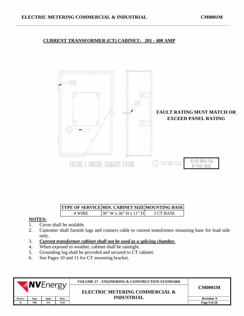
CURRENT TRANSFORMER (CT) CABINET: 201 - 400 AMP
FAULT RATING MUST MATCH OR
EXCEED PANEL RATING
TYPE OF SERVICE MIN. CABINET SIZE MOUNTING BASE
4 WIRE 30” W x 36” H x 11” D 3 CT BASE
NOTES:
1. Cover shall be sealable.
2. Customer shall furnish lugs and connect cable to current transformer mounting base for load side
only.
3. Current transformer cabinet shall not be used as a splicing chamber.
4. When exposed to weather, cabinet shall be raintight.
5. Grounding lug shall be provided and secured to CT cabinet.
6. See Pages 10 and 11 for CT mounting bracket.
VOLUME 17 – ENGINERING & CONSTRUCTION STANDARD
CM0001M ELECTRIC METERING COMMERCIAL &
INDUSTRIAL Drawn: Eng: Appr: Date: Revision: 9
JL MB DA 8/18 Page 9 of 26

ELECTRIC METERING COMMERCIAL & INDUSTRIAL CM0001M
CURRENT TRANSFORMER BRACKET (2 CT'S) 201 - 400 AMP
NOTES:
1. Fault duty rating must match or exceed panel rating.
2. For application see drawing Page 8.
3. Details shown on end view for left leg and bus assembly apply to all four leg assemblies.
4. 1/2" - 13 UNC x 2", 8 typical, hex nuts, lock washer and flat washer.
VOLUME 17 – ENGINERING & CONSTRUCTION STANDARD
CM0001M ELECTRIC METERING COMMERCIAL &
INDUSTRIAL Drawn: Eng: Appr: Date: Revision: 9
JL MB DA 8/18 Page 10 of 26
ELECTRIC METERING COMMERCIAL & INDUSTRIAL CM0001M
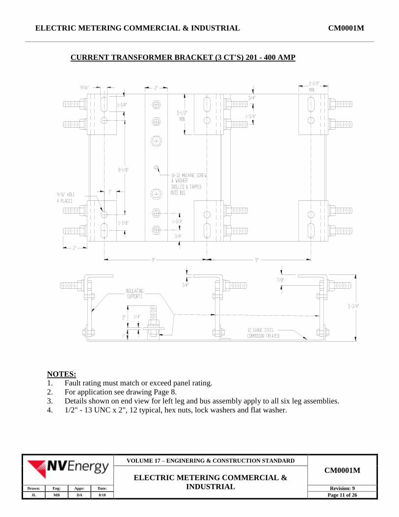
CURRENT TRANSFORMER BRACKET (3 CT'S) 201 - 400 AMP
NOTES:
1. Fault rating must match or exceed panel rating.
2. For application see drawing Page 8.
3. Details shown on end view for left leg and bus assembly apply to all six leg assemblies.
4. 1/2" - 13 UNC x 2", 12 typical, hex nuts, lock washers and flat washer.
VOLUME 17 – ENGINERING & CONSTRUCTION STANDARD
CM0001M ELECTRIC METERING COMMERCIAL &
INDUSTRIAL Drawn: Eng: Appr: Date: Revision: 9
JL MB DA 8/18 Page 11 of 26
ELECTRIC METERING COMMERCIAL & INDUSTRIAL CM0001M
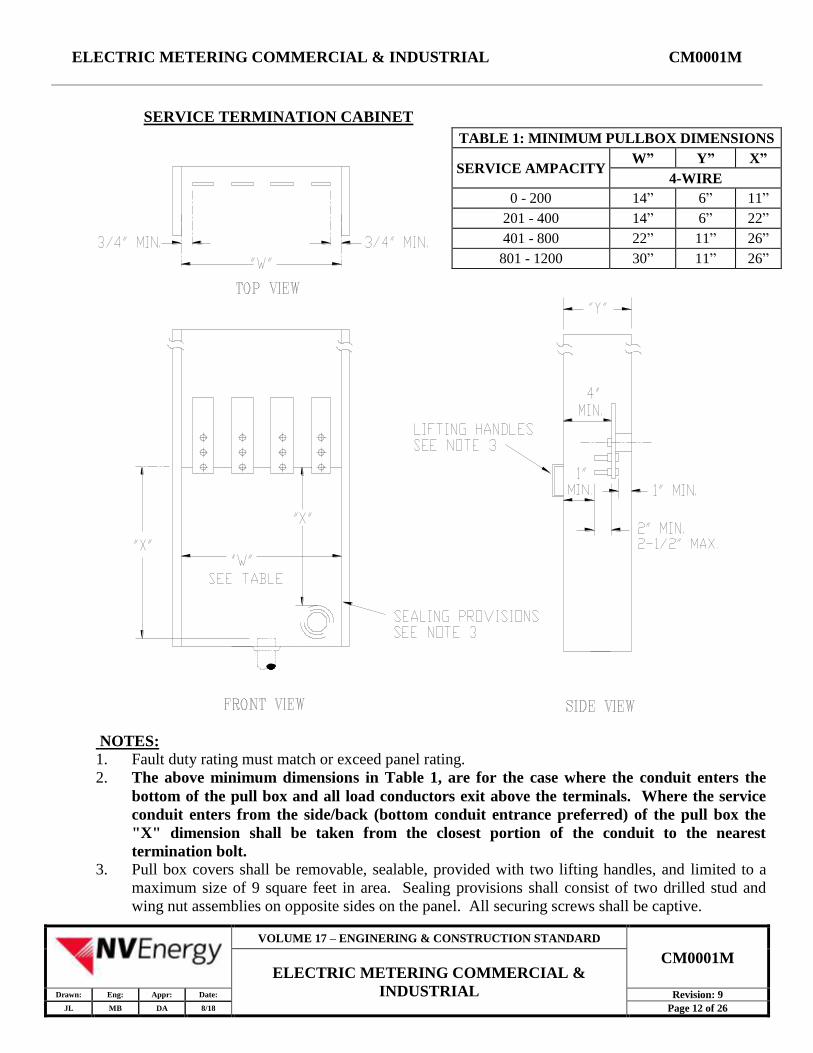
SERVICE TERMINATION CABINET
TABLE 1: MINIMUM PULLBOX DIMENSIONS
SERVICE AMPACITY W” Y” X”
4-WIRE
0 - 200 14” 6” 11” 201 - 400 14” 6” 22” 401 - 800 22” 11” 26”
801 - 1200 30” 11” 26”
NOTES:
1. Fault duty rating must match or exceed panel rating.
2. The above minimum dimensions in Table 1, are for the case where the conduit enters the
bottom of the pull box and all load conductors exit above the terminals. Where the service
conduit enters from the side/back (bottom conduit entrance preferred) of the pull box the
"X" dimension shall be taken from the closest portion of the conduit to the nearest
termination bolt.
3. Pull box covers shall be removable, sealable, provided with two lifting handles, and limited to a
maximum size of 9 square feet in area. Sealing provisions shall consist of two drilled stud and
wing nut assemblies on opposite sides on the panel. All securing screws shall be captive.
VOLUME 17 – ENGINERING & CONSTRUCTION STANDARD
CM0001M ELECTRIC METERING COMMERCIAL &
INDUSTRIAL Drawn: Eng: Appr: Date: Revision: 9
JL MB DA 8/18 Page 12 of 26

ELECTRIC METERING COMMERCIAL & INDUSTRIAL CM0001M
7.5 Underground service, 401-800 Amperes, Current Transformer Metering.
For a single underground commercial or industrial service which is to be metered using current
transformers, the customer will furnish, install and maintain a service termination cabinet, current
transformer cabinet and safety socket meter box as shown below. For overhead service see Section
7.6.
For compactness of equipment and aesthetics, it may be desirable to consider the installation of a
switchboard service section.
NOTES:
1. Fault duty rating must match or exceed the panel rating.
2. NVE will pull and terminate its service conductors directly to the bottom of the termination
facilities in the service termination cabinet. It shall be the customer’s responsibility to
provide the tie between the termination cabinet and the CT cabinet and the load side of the
termination cabinet.
3. The customer's service entrance conductors shall normally enter the service termination cabinet
at or within two inches of the bottom and leave the cabinet at or within two inches of the
opposite end.
4. The customer shall furnish lugs and connect his service entrance conductors to the load side of
the service termination cabinet.
5. For dimensions of current transformer cabinet, see Page 9. For dimensions of the service
termination cabinet, see Page 12.
6. For dimensions of safety socket box, see Page 15.
7. For three phase four wire service, bussing for three CT's is required.
VOLUME 17 – ENGINERING & CONSTRUCTION STANDARD
CM0001M ELECTRIC METERING COMMERCIAL &
INDUSTRIAL Drawn: Eng: Appr: Date: Revision: 9
JL MB DA 8/18 Page 13 of 26
ELECTRIC METERING COMMERCIAL & INDUSTRIAL CM0001M
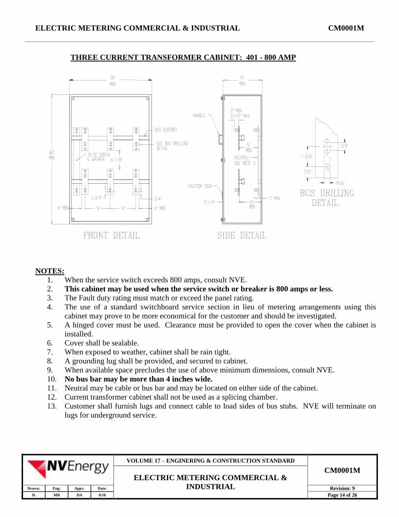
THREE CURRENT TRANSFORMER CABINET: 401 - 800 AMP
NOTES:
1. When the service switch exceeds 800 amps, consult NVE.
2. This cabinet may be used when the service switch or breaker is 800 amps or less.
3. The Fault duty rating must match or exceed the panel rating.
4. The use of a standard switchboard service section in lieu of metering arrangements using this
cabinet may prove to be more economical for the customer and should be investigated.
5. A hinged cover must be used. Clearance must be provided to open the cover when the cabinet is
installed.
6. Cover shall be sealable.
7. When exposed to weather, cabinet shall be rain tight.
8. A grounding lug shall be provided, and secured to cabinet.
9. When available space precludes the use of above minimum dimensions, consult NVE.
10. No bus bar may be more than 4 inches wide.
11. Neutral may be cable or bus bar and may be located on either side of the cabinet.
12. Current transformer cabinet shall not be used as a splicing chamber.
13. Customer shall furnish lugs and connect cable to load sides of bus stubs. NVE will terminate on
lugs for underground service.
VOLUME 17 – ENGINERING & CONSTRUCTION STANDARD
CM0001M ELECTRIC METERING COMMERCIAL &
INDUSTRIAL Drawn: Eng: Appr: Date: Revision: 9
JL MB DA 8/18 Page 14 of 26

ELECTRIC METERING COMMERCIAL & INDUSTRIAL CM0001M
SAFETY SOCKET METER BOX
NOTES:
1. All section covers shall be independently removable. Upper cover shall be non-removable when
meter is in place. Lower cover shall be sealable and permanently labeled: "DO NOT BREAK
SEALS - NO FUSES INSIDE"
VOLUME 17 – ENGINERING & CONSTRUCTION STANDARD
CM0001M ELECTRIC METERING COMMERCIAL &
INDUSTRIAL Drawn: Eng: Appr: Date: Revision: 9
JL MB DA 8/18 Page 15 of 26
ELECTRIC METERING COMMERCIAL & INDUSTRIAL CM0001M
7.6 Overhead service, 201 - 600 Amp, Current Transformer Metering.
For single overhead commercial or industrial service which is to be metered using current
transformers, the customer shall furnish, install, own and maintain a separate current transformer
cabinet and safety socket meter box and required service entrance conductors, conduit, and
weather head to the point of attachment of NVE's overhead service.
NOTES:
1. Fault duty rating must match or exceed panel rating.
2. The customer's service entrance conductors shall enter the current transformer cabinet at the
top and leave the cabinet at or within two inches of the bottom.
3. The customer shall furnish riser conduit, weather head, lugs and connect his service entrance
conductors to the line and load sides of the current transformer mounting base.
4. The customer's neutral conductor shall be continuous without splice through the current
transformer cabinet.
5. For dimension of the current transformer cabinet, see Page 9.
6. For dimension of safety socket box, see Page 15.
7. For three phase four wire service a mounting bracket for three CT's is required.
VOLUME 17 – ENGINERING & CONSTRUCTION STANDARD
CM0001M ELECTRIC METERING COMMERCIAL &
INDUSTRIAL Drawn: Eng: Appr: Date: Revision: 9
JL MB DA 8/18 Page 16 of 26
ELECTRIC METERING COMMERCIAL & INDUSTRIAL CM0001M
7.7 Underground service, 201 Amps and above, Current Transformer Metering in Switchboard
Service Sections.
For a single underground C/I service which is terminated in a multi-section manufactured
freestanding, self-supporting switchboard, the customer will furnish, install and maintain a
switchboard service section with accompanying provisions for the underground service
termination. See Section 7.8 for overhead switchboard service.
A switchboard service section is designed and manufactured specifically for terminating the
service entrance conductors and housing the metering transformers, meters and associated test
equipment, and may include the customer's service switch or breaker.
Typical arrangements of switchboard service sections with provision for a pull box for
underground service conductor termination are illustrated below. For switchboard details, see
SB0001M.
TABLE 2 - MINIMUM PULL SECTION DIMENSIONS 4-WIRE
SWITCHBOARD
RATING
(AMPERES)
MINIMUM ACCESS
OPENING DIMENSION
“W”
TERMINATION
HEIGHT “X”
400 - 800 24”
42” MIN. - 72” MAX. 801 - 1200 30”
1201 - 2000 35”
2001 - 3000 42” 60” MIN. - 72” MAX.
3001 - 4000 44” 60” MIN. - 72” MAX.
VOLUME 17 – ENGINERING & CONSTRUCTION STANDARD
CM0001M ELECTRIC METERING COMMERCIAL &
INDUSTRIAL Drawn: Eng: Appr: Date: Revision: 9
JL MB DA 8/18 Page 17 of 26
ELECTRIC METERING COMMERCIAL & INDUSTRIAL CM0001M
7.8 Overhead service, 201 Amps and above, Current Transformer Metering in Switchboard
Service Sections.
For a single overhead C/I service which is terminated in a multi-section manufactured
freestanding, self-supporting switchboard, the customer will furnish, install and maintain a
switchboard service section with accompanying provisions for the above grade (overhead) service
termination. See Section 7.7 for underground switchboard service.
A switchboard service section is designed and manufactured specifically for terminating the
service entrance conductors and housing the metering transformers, meters and associated test
equipment, and may include the customer's service switch or breaker.
Typical arrangements of switchboard service sections with provisions for overhead service
conductor terminations are illustrated. For switchboard details, see SB0001M. See SB0001M,
Section 10, Table 2 for dimensions.
VOLUME 17 – ENGINERING & CONSTRUCTION STANDARD
CM0001M ELECTRIC METERING COMMERCIAL &
INDUSTRIAL Drawn: Eng: Appr: Date: Revision: 9
JL MB DA 8/18 Page 18 of 26
ELECTRIC METERING COMMERCIAL & INDUSTRIAL CM0001M
8.0 MULTIPLE METER INSTALLATIONS: 2-6 METERS; 7+ METERS
8.1 Group meter installations are required for multi-customer buildings where each occupant has an
individual meter. Each individual meter shall be considered as single customer. Submittal of "shop
drawings" is required for all commercial multi-metered installations.
8.2 The maximum number of disconnects is six: (NEC #230-71), each disconnect (no fuses) shall
simultaneously open all poles: NEC #230-74.
8.3 Meter Identification and service disconnect shall clearly identify the location served.
Identification is a unit or street number and will be marked by a stamped/engraved metal /plastic
identification plate.
8.4 Customer Service Entrance Conductors shall extend from NV Energy's service termination
point to the line side of each meter socket jaw. NVE is not responsible for the wiring in the customer
owned raceway/gutter.
8.5 Ampacity Rating of the installation is given by: 2-6 Meters; Ampacity of service termination
facility. 7 + Meters; Main service disconnect rating. Fault duty rating must be obtained from NVE.
8.6 Center line spacing between meter sockets shall be a minimum:
7-1/2" Horizontal 8-1/2" Vertical
8.7 NVE will provide blank covers for empty sockets.
VOLUME 17 – ENGINERING & CONSTRUCTION STANDARD
CM0001M ELECTRIC METERING COMMERCIAL &
INDUSTRIAL Drawn: Eng: Appr: Date: Revision: 9
JL MB DA 8/18 Page 19 of 26

ELECTRIC METERING COMMERCIAL & INDUSTRIAL CM0001M
8.8 OVERHEAD SERVICE, GROUPED METER INSTALLATION, WITHOUT A MAIN
SWITCH (6 METERS MAX.)
8.9 UNDERGROUND SERVICE, GROUPED METER INSTALLATION, WITHOUT A MAIN
SWITCH (6 METERS MAX).
VOLUME 17 – ENGINERING & CONSTRUCTION STANDARD
CM0001M ELECTRIC METERING COMMERCIAL &
INDUSTRIAL Drawn: Eng: Appr: Date: Revision: 9
JL MB DA 8/18 Page 20 of 26
ELECTRIC METERING COMMERCIAL & INDUSTRIAL CM0001M
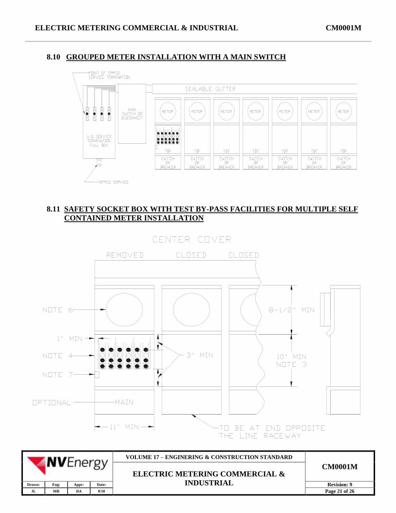
8.10 GROUPED METER INSTALLATION WITH A MAIN SWITCH
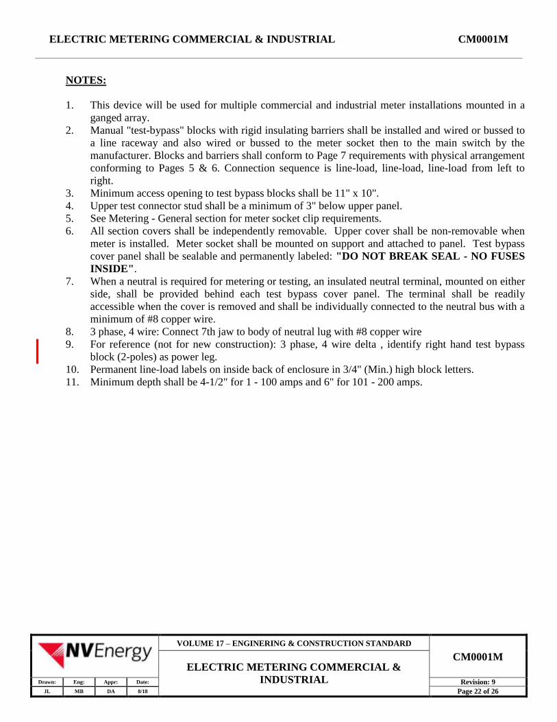
8.11 SAFETY SOCKET BOX WITH TEST BY-PASS FACILITIES FOR MULTIPLE SELF
CONTAINED METER INSTALLATION
VOLUME 17 – ENGINERING & CONSTRUCTION STANDARD
CM0001M ELECTRIC METERING COMMERCIAL &
INDUSTRIAL Drawn: Eng: Appr: Date: Revision: 9
JL MB DA 8/18 Page 21 of 26
ELECTRIC METERING COMMERCIAL & INDUSTRIAL CM0001M
NOTES:
1. This device will be used for multiple commercial and industrial meter installations mounted in a
ganged array.
2. Manual "test-bypass" blocks with rigid insulating barriers shall be installed and wired or bussed to
a line raceway and also wired or bussed to the meter socket then to the main switch by the
manufacturer. Blocks and barriers shall conform to Page 7 requirements with physical arrangement
conforming to Pages 5 & 6. Connection sequence is line-load, line-load, line-load from left to
right.
3. Minimum access opening to test bypass blocks shall be 11" x 10".
4. Upper test connector stud shall be a minimum of 3" below upper panel.
5. See Metering - General section for meter socket clip requirements.
6. All section covers shall be independently removable. Upper cover shall be non-removable when
meter is installed. Meter socket shall be mounted on support and attached to panel. Test bypass
cover panel shall be sealable and permanently labeled: "DO NOT BREAK SEAL - NO FUSES
INSIDE".
7. When a neutral is required for metering or testing, an insulated neutral terminal, mounted on either
side, shall be provided behind each test bypass cover panel. The terminal shall be readily
accessible when the cover is removed and shall be individually connected to the neutral bus with a
minimum of #8 copper wire.
8. 3 phase, 4 wire: Connect 7th jaw to body of neutral lug with #8 copper wire
9. For reference (not for new construction): 3 phase, 4 wire delta , identify right hand test bypass
block (2-poles) as power leg.
10. Permanent line-load labels on inside back of enclosure in 3/4" (Min.) high block letters.
11. Minimum depth shall be 4-1/2" for 1 - 100 amps and 6" for 101 - 200 amps.
VOLUME 17 – ENGINERING & CONSTRUCTION STANDARD
CM0001M ELECTRIC METERING COMMERCIAL &
INDUSTRIAL Drawn: Eng: Appr: Date: Revision: 9
JL MB DA 8/18 Page 22 of 26
ELECTRIC METERING COMMERCIAL & INDUSTRIAL CM0001M
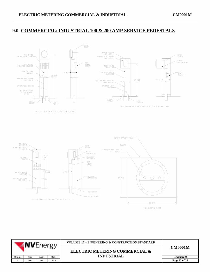
9.0 COMMERCIAL/ INDUSTRIAL 100 & 200 AMP SERVICE PEDESTALS
VOLUME 17 – ENGINERING & CONSTRUCTION STANDARD
CM0001M ELECTRIC METERING COMMERCIAL &
INDUSTRIAL Drawn: Eng: Appr: Date: Revision: 9
JL MB DA 8/18 Page 23 of 26
ELECTRIC METERING COMMERCIAL & INDUSTRIAL CM0001M
NOTES:
1. Meter sockets shall be securely attached to the meter socket support by more than one bolt.
2. Meter socket configuration requirements are listed in Electric Metering, General - Standard
GM0001M.
3. Wireways shall have minimum dimensions of 5-1/2" wide opening, 18" high and 2-3/4" deep and
shall be accessible from the front, side or rear through a removable, sealable, full-length cover.
The bottom of all wireways shall have provisions for accepting a minimum 2" conduit. A suitable
alternate construction for wireway is a conduit which permits pull and termination of the service
conductors directly into the "test-bypass" facilities.
4. Service conductors are to be terminated on the test bypass facilities in all cases.
5. If the meter is enclosed, the enclosing cover (top and front) shall be removable for test and
inspection of the meters by NVE. The metering cover shall have a demand reset cover which shall
be hinged, lockable and constructed of steel with minimum dimensions of 4-1/2" wide be 6" high.
6. The meter socket shall be provided with a full socket rim for securing the meter in place.
7. When a meter socket panel is not used, a rigid nonconductive or grounded metallic guard shall be
mounted behind and attached to the meter socket rim to prevent accidental contact with energized
parts.
8. Insulated cable or bus conductor shall be installed between the "test-bypass" facilities and the
meter socket.
9. Internal equipment shall be secured in place without screws or nuts on the outer surface of the
enclosure that may be loosened from the outside.
10. Pedestals shall be bolted securely to the pad.
11. Pedestals shall have openings at their base to permit 2- 3" conduits.
VOLUME 17 – ENGINERING & CONSTRUCTION STANDARD
CM0001M ELECTRIC METERING COMMERCIAL &
INDUSTRIAL Drawn: Eng: Appr: Date: Revision: 9
JL MB DA 8/18 Page 24 of 26
ELECTRIC METERING COMMERCIAL & INDUSTRIAL CM0001M
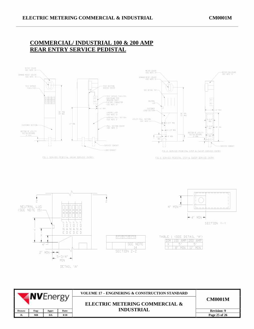
COMMERCIAL/ INDUSTRIAL 100 & 200 AMP
REAR ENTRY SERVICE PEDISTAL
VOLUME 17 – ENGINERING & CONSTRUCTION STANDARD
CM0001M ELECTRIC METERING COMMERCIAL &
INDUSTRIAL Drawn: Eng: Appr: Date: Revision: 9
JL MB DA 8/18 Page 25 of 26

ELECTRIC METERING COMMERCIAL & INDUSTRIAL CM0001M
NOTES:
1. Meter sockets shall be securely attached to the meter socket support by more than one bolt.
2. Meter socket configuration requirements are listed in Electric Metering, General- Standard
GM0001M.
3. Wireways shall have minimum dimensions of 5-1/2" wide opening, (9" if containing termination
facilities) 18" high and 2-3/4" deep and shall be accessible from the front, side or rear through a
removable sealable full-length cover. The bottom of all wireways shall have provisions for
accepting a minimum 2" conduit.
4. Service conductors are to be terminated on the test bypass facilities (or landing lugs when
provided).
5. If landing lugs are provided, insulated cable or bus shall be installed between the landing lugs and
the test bypass facilities (see fig 1).
6. If meter is enclosed, the enclosing cover (top and front) shall be removable for test and inspection
of the meters by NVE. The metering cover shall have a demand reset cover which shall be hinged,
lockable and constructed of steel with minimum dimensions of 4-1/2" wide by 6" high.
7. The meter socket shall be provided with a full socket rim for securing the meter in place.
8. When a meter socket panel is not used, a rigid nonconductive or rounded metallic guard shall be
mounted behind and attached to the meter socket rim to prevent accidental contact with energized
parts.
9. Insulated cable or buss conductors shall be installed between the "test-bypass" facilities and the
meter socket.
10. Internal equipment shall be secured in place without screws or nuts on the outer surface of the
enclosure that may be loosened from the outside.
11. Pedestals shall be bolted securely to the pad.
12. Pedestals shall have openings at their base to permit (2) - 3" conduits.
13. Maximum radial distance from the edge of the pull section that is closest to the furthest line
terminal shall not be greater than 2-1/2". See detail ZZ.
14. Refer to Page 25 and table 1 for figure 2 "test-bypass" facilities enclosure clearances.
VOLUME 17 – ENGINERING & CONSTRUCTION STANDARD
CM0001M ELECTRIC METERING COMMERCIAL &
INDUSTRIAL Drawn: Eng: Appr: Date: Revision: 9
JL MB DA 8/18 Page 26 of 26