Embed Size (px)
Citation preview

For the Latest InformationOn the Internet: www.sti.com
OmrOn Scientific technOlOgieS, inc.USA Tel. 1/888/510-4357 canada Tel. 1/866/986-6766
g
g102
Conforms to EN292, EN60204-1, EN954-1, EN1088, EN60947-5-3, EN947-5-3, EN50081, EN50082, EN61000-6-2, ISO 13849-1UL and C-UL listed, TUV certified
r
C US
most Diverse and flexible line of coded magnetic Safety interlock Switches and controllers• Combine door switch monitoring and E-stop monitoring by using
the CM-S41 controller• Monitor is single switch to CAT4 with the CM-S30 controller• Monitor multiple switches to CAT3 using CM-S4 or CM-S30
controllers• Monitoring multiple switches on individual channels can be
achieved by using the CM-S21 or CM-S41 controllers. Easily expand your system by using the CM-SE expansion module.
• All CM switches are rated IP67• Stainless steel switches are available for harsh environments
Safety interlock Switches
cm Series CM
Description
The CM series of controllers and coded magnetic switches offers the most flexibility and widest range of options available. The CM series is comprised of two basic technologies.
controller technologies2-Wire Single channel controllers
The CM-S41 and CM-S21 controllers monitor the 2-wire magnetically coded switches. The CM-S41 and CM-S21 control-lers use a patented technology which allows them to monitor the 2-wire or single channel switches up to Category 3. The ability to monitor just a single channel enables the CM-S41 and CM-S21 to easily monitor multiple switches and provide individual status of each channel. Both of these controllers are compatible with the CM-SE expansion module.
Dual channel controllersThe CM-S4 and CM-S30 controllers are designed to monitor
conventional read-style, magnetically-coded switches with 1 N/O + 1 N/C contacts. The CM-S4 controller can monitor up to four switches to category 3. The CM-S4 controller offers status indica-tion for each individual switch. The CM-S30 controller can monitor one switch to category 4, or two switches to category 3. The CM-S30 control unit is capable of monitoring up to 30 conventional read style switches in series, but does not conform to category 3 when used with more than two switches.
Switch categoriesThe CM series of switches are all magnetically coded.
The CM series of switches fall into three main categories:1. 2-wire Coded Magnetic2. Conventional Read Style 1 N/C + 1 N/O contacts3. Universal Read Style 2 N/C + 1 N/O contacts
The 2-wire Coded Magnetic Switches are only compatible with the CM-S21, CM-S41 and CM-SE control units and expansion module. The Conventional Read Style Switches are compatible with the CM-S4 and CM-S30 controllers. The Universal Read Style Switches are unique in design, all three contacts are rated for safety. This means that Universal Read Style switches can be used with the CM-S4 or CM-S30 Controllers, or conventional safety monitoring relays such as the G9SA, SR103 or G9SX-AD, -BC. This allows the Universal Read Style Switches to be run in series with E-stop switches or other mechanical door switches. Typically a category 2 rating would be applied to a system that incorporates multiple switches wired in series to a standard safety monitoring relay. A risk assessment should always be performed by properly trained and authorized personnel.

For the Latest InformationOn the Internet: www.sti.com
OmrOn Scientific technOlOgieS, inc.USA Tel. 1/888/510-4357 canada Tel. 1/866/986-6766
g
g103
Switch Specifications
electricalcm-S1, cm-S2, cm-S3 cm-S5, cm-S6
cm-S221, cm-S521, cm-S621 cm-S11 cm-S31
cm-S321, cm-S421
Safety Contacts: 1 N/C + 1 N/O 1 N/C + 1 N/O 2 N/C + 1 N/O Current Sensing Circuit
Current Sensing Circuit
2 N/C + 1 N/O
N/C Operating Distance: CM-S1 —On = 3 mm; Off = 8 mmCM-S2 and CM-S3 —On = 6 mm; Off = 13 mm
On = 7 mm; Off = 10 mm
On = 7 mm; Off = 10 mm
On = 5-7 mm; Off = 8-12 m
On = 5-7 mm; Off = 8-12 mm
On = 7 mm; Off = 10 mm
Minimum Gap: 1 mm 1 mm 1 mm 1 mm 1 mm 1 mmMax Switched Current/Voltage:
500 mA / 24 V 300 mA / 24 V 300 mA / 24 V 300 mA / 24 V
mechanicalMounting: 2 x M4
screws supplied2 x M4 screws supplied
2 x M4 screws supplied
2 x M4 screws supplied
2 x M4 screws supplied
3 x M4 screws supplied
Case Material: Glass filled PPS ABS ABS ABS 316 stainless steel
316 stainless steel
Max Wire Size: Pre-wired cable to 5 m
Pre-wired cable to 10 m
Pre-wired cable to 10 m
Pre-wired cable to 10 m
Pre-wired cable to 10 m
Pre-wired cable to 5 m, 6-pin micro AC connector
Weight: 230 g (8.1 oz.) 207 g (8.1 oz.) 230 g (8.1 oz.) 207 g (7.3 oz.) 265 g (9.3 oz.) 545 g (19.2 oz.)Color: Red Red Red Red Stainless StainlessMechanical Life: 106 106 106 106 106 106
environmentalProtection: IP67 (NEMA 6) IP67 (NEMA 6) IP67 (NEMA 6) IP67 (NEMA 6) IP67 (NEMA 6) IP67 (NEMA 6)Operating Temperature: -10 to 55°C
(14 to 131°F)-10 to 55°C (14 to 131°F)
-10 to 55°C (14 to 131°F)
-10 to 55°C (14 to 131°F)
-10 to 55°C (14 to 131°F)
Connector Models: -10 to 55°C (14 to 131°F)Integrated Cables: -10 to 95°C(14 to 203°F)
Humidity: 95% RH at 55°C (131°F)complianceStandards: EN292, EN60204-1, EN954-1, EN1088, EN60947-5-3, EN947-5-3, EN50081, EN50082, EN61000-6-2Approvals/Listings: CE marked for all applicable directives, UL and C-UL.
TUV certified: CM-S1, CM-S2, CM-S3, CM-S11 and CM-S31.Specifications are subject to change without notice.Note: The safety contacts of the Omron STI switches are described as normally closed (N/C) i.e., with the guard closed, actuator in place, and the machine able to be started.
cm Series Safety interlock Switches
For the Latest InformationOn the Internet: www.sti.com
OmrOn Scientific technOlOgieS, inc.USA Tel. 1/888/510-4357 canada Tel. 1/866/986-6766
g
g104
cm Series Safety interlock Switches
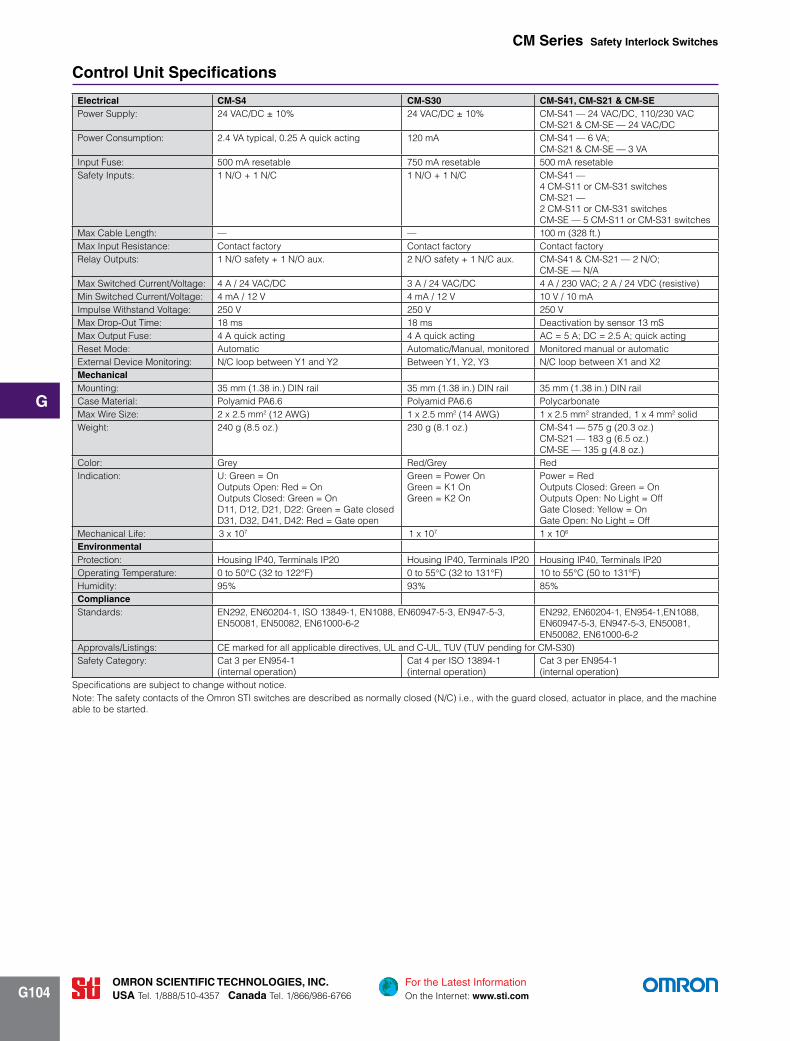
control Unit Specifications
electrical cm-S4 cm-S30 cm-S41, cm-S21 & cm-SePower Supply: 24 VAC/DC ± 10% 24 VAC/DC ± 10% CM-S41 — 24 VAC/DC, 110/230 VAC
CM-S21 & CM-SE — 24 VAC/DCPower Consumption: 2.4 VA typical, 0.25 A quick acting 120 mA CM-S41 — 6 VA;
CM-S21 & CM-SE — 3 VAInput Fuse: 500 mA resetable 750 mA resetable 500 mA resetableSafety Inputs: 1 N/O + 1 N/C 1 N/O + 1 N/C CM-S41 —
4 CM-S11 or CM-S31 switchesCM-S21 — 2 CM-S11 or CM-S31 switchesCM-SE — 5 CM-S11 or CM-S31 switches
Max Cable Length: — — 100 m (328 ft.)Max Input Resistance: Contact factory Contact factory Contact factoryRelay Outputs: 1 N/O safety + 1 N/O aux. 2 N/O safety + 1 N/C aux. CM-S41 & CM-S21 — 2 N/O;
CM-SE — N/AMax Switched Current/Voltage: 4 A / 24 VAC/DC 3 A / 24 VAC/DC 4 A / 230 VAC; 2 A / 24 VDC (resistive)Min Switched Current/Voltage: 4 mA / 12 V 4 mA / 12 V 10 V / 10 mAImpulse Withstand Voltage: 250 V 250 V 250 VMax Drop-Out Time: 18 ms 18 ms Deactivation by sensor 13 mSMax Output Fuse: 4 A quick acting 4 A quick acting AC = 5 A; DC = 2.5 A; quick actingReset Mode: Automatic Automatic/Manual, monitored Monitored manual or automaticExternal Device Monitoring: N/C loop between Y1 and Y2 Between Y1, Y2, Y3 N/C loop between X1 and X2mechanicalMounting: 35 mm (1.38 in.) DIN rail 35 mm (1.38 in.) DIN rail 35 mm (1.38 in.) DIN railCase Material: Polyamid PA6.6 Polyamid PA6.6 PolycarbonateMax Wire Size: 2 x 2.5 mm2 (12 AWG) 1 x 2.5 mm2 (14 AWG) 1 x 2.5 mm2 stranded, 1 x 4 mm2 solidWeight: 240 g (8.5 oz.) 230 g (8.1 oz.) CM-S41 — 575 g (20.3 oz.)
CM-S21 — 183 g (6.5 oz.)CM-SE — 135 g (4.8 oz.)
Color: Grey Red/Grey RedIndication: U: Green = On
Outputs Open: Red = OnOutputs Closed: Green = OnD11, D12, D21, D22: Green = Gate closedD31, D32, D41, D42: Red = Gate open
Green = Power On Green = K1 On Green = K2 On
Power = RedOutputs Closed: Green = OnOutputs Open: No Light = OffGate Closed: Yellow = OnGate Open: No Light = Off
Mechanical Life: 3 x 10⁷ 1 x 10⁷ 1 x 10⁶
environmentalProtection: Housing IP40, Terminals IP20 Housing IP40, Terminals IP20 Housing IP40, Terminals IP20Operating Temperature: 0 to 50°C (32 to 122°F) 0 to 55°C (32 to 131°F) 10 to 55°C (50 to 131°F)Humidity: 95% 93% 85%complianceStandards: EN292, EN60204-1, ISO 13849-1, EN1088, EN60947-5-3, EN947-5-3,
EN50081, EN50082, EN61000-6-2EN292, EN60204-1, EN954-1,EN1088, EN60947-5-3, EN947-5-3, EN50081, EN50082, EN61000-6-2
Approvals/Listings: CE marked for all applicable directives, UL and C-UL, TUV (TUV pending for CM-S30)Safety Category: Cat 3 per EN954-1
(internal operation)Cat 4 per ISO 13894-1 (internal operation)
Cat 3 per EN954-1 (internal operation)
Specifications are subject to change without notice.Note: The safety contacts of the Omron STI switches are described as normally closed (N/C) i.e., with the guard closed, actuator in place, and the machine able to be started.

For the Latest InformationOn the Internet: www.sti.com
OmrOn Scientific technOlOgieS, inc.USA Tel. 1/888/510-4357 canada Tel. 1/866/986-6766
g
g105
cm Series Safety interlock Switches
2-Wire Single channel controllers
cm-S41 control UnitThe CM-S41 is a combined Safety Switch and E-Stop control
unit. Along with the ability to monitor up to four, 2-wire CM Series safety switches, it can also monitor the normally closed contacts of emergency stop buttons or mechanical safety switches in dual channel control circuits.
The CM-S41 has 2 normally open safety contact outputs and 1 normally closed auxiliary output, an external reset/proving circuit and LED indication for “Power”, “Run” and the status of each activated gate switch.
cm-S21 control UnitThe CM-S21 control unit is a 24 VAC/DC system that can moni-
tor up to 2 CM Series safety switches.The CM-S21 has 2 normally open safety contact outputs and 1
normally closed auxiliary output, an external reset/proving circuit and LED indication for “Power”, “Run” and the status of each activated gate switch.
cm-Se extender moduleThe CM-SE expansion module is a 24 VAC/DC unit that can be
added to either the CM-S41 or CM-S21 to monitor an additional 5 CM Series safety swtiches. Connection to the main control unit is by a simple 2-wire bus connection. The status of each guard switch is shown by the YELLOW LED’s. Additional CMS-E modules can be added to monitor larger systems.
Applications
cm-S21 Application Diagram
cm-S41 Application Diagram cm-Se Application Diagram
RUN
POWER
GATE 4GATE 3
4
3
2
1
GATE 4
GATE 3
GATE 2
DE-SELECT
A1 S13 S23 X1 BL DR BL DR 31 13 23
A2 S14 S24 X2 BL DR BL DR 32 14 24
GATE 2GATE 1
GS3 GS4
GS1GS2
K1 K2
MECHANICALSAFETY
SWITCHESor
EMERGENCYSTOP
K1
K2
MANUALRE-SET
L (+ve)
N (-ve)
K1
K2
F1
F2
A1 BLDRGATE 1
GS1
24 V+ve
0 V -ve
BLDR BLDRGATE 2 GATE 3
GS2 GS3
A2 BLDRGATE 4
GS4
BLDR BLDRGATE 5 BUS
GS5
IND 1
IND 2
IND 3
IND 4
IND 5
2-WIRE BUS CONNECTION
POWER
BL DRA2
A1
ISIS-4 or ISIS-2CONTROL UNIT
Connect the ISIS-EBus connection to
Extender Module Control Unit
CM-S41 / CM-S21 Control Units: Connect the CM-SE Bus connection to an active gate input.
GATE 2
A1 X1 BL DR 31 13 23
A2 X2 BL DR 32 14 24
GATE 1
GS2
GS1
K1 K2
K1
K2
24V(+ve)
0V(-ve)
K1
K2
F1
F2
POWER
IND 1
IND 2
RUN
MANUALRE-SET

For the Latest InformationOn the Internet: www.sti.com
OmrOn Scientific technOlOgieS, inc.USA Tel. 1/888/510-4357 canada Tel. 1/866/986-6766
g
g106
Dual channel controllers
cm-S4 control UnitThe CM-S4 controller is capable of monitoring up to four,
magnetically coded switches with 1 N/O + 1 N/C contacts up to category 3 according to EN954-1. The CM-S4 has a dedicated dual channel input for each switch and has LED status indicators for each channel. The CM-S4 has 1 N/O safety contact and 1 N/C Aux contact. External Device Monitoring (EDM) is available using Y1,Y2 inputs.
cm-S30 control UnitThe CM-S30 controller is capable of monitoring one magneti-
cally coded switch with 1 N/O + 1 N/C contacts up to category 4, or two switches to category 3 according to ISO 13489-1. The CM-S30 control unit is capable of monitoring up to 30 convention-al read style switches in series, but does not conform to category 4 when used with more than two switches. The CM-S30 controller has 2 N/O safety contacts and 1 N/C Auxillary contact. External Device Monitoring (EDM) is available using Y1,Y2 inputs.
Applications (continued)
cm Series Safety interlock Switches
cm-S4 Application Diagram cm-S30 Application Diagram (cat 3)
cm-S30 Application Diagram (cat 4)
WH
K1
K1
K1 K2
UB
K1 K1 F2
K2
START/FEEDBACK LOOP
MONITORED AUTORESTART
K3
CHANNEL 1
CHANNEL 21
BRN
YE
GN
24VAC/DC
N (0 Volt)
A1 A2 HL1
H73 H74 Y1 Y2 Y3 14 24 32
HL2 H22 13 23 31
WH
BRN
YE
GN
GN
GNGN
CM-S30
WH
A1 A2 HL1
K1
K1
K1 K2
UB
K1 K1 F2
K2
H73 H74 Y1 Y2 Y3 14 24 32
MONITORED AUTORESTART
K3
CHANNEL 1
HL2 H22 13 23 31
BRN
YE
GN
READ
HEA
D 1
N (0 Volt)
24VAC/DC
START/FEEDBACK LOOPCHANNEL 21
GN
GNGN
CMS-S30
K1
K1
K2
K2
UB
D12
D12
D11 K1
control logic
READ HEAD 1
CHANNEL 1
CHANNEL 3 CHANNEL 4 FEEEDBACK LOOP
YE
A1 A2 1 2 3 4
GN WH BN
GN
RD
RD
RD
GN
CHANNEL 2
D21
OUT
GN ID
GN
D31GN
D41GN
D12
READ HEAD 2
READ HEAD 3 READ HEAD 4
MON
ITOR
ED A
UTO
REST
ART
YE
5 6 7 8
9 10 11 12 15 16 17 18 14 24Y1 Y2
13
GN WH BN
BN WH YE GN BN WH YE GN
24VAC/DC
N (0 Volt)
K2
K3
K4
23
D42
RDCM-S4

For the Latest InformationOn the Internet: www.sti.com
OmrOn Scientific technOlOgieS, inc.USA Tel. 1/888/510-4357 canada Tel. 1/866/986-6766
g
g107
cm Series Safety interlock Switches
Dimensions (mm/in.)
2-Wire coded magnetic Switches
cm-S11
cm-S31
CM-S11 Switch
SIDE
Ø4.20.16
Ø8.10.32
30.11
140.55
6.40.25
281.1
522.04
220.86
CM-S31 Switch
SIDE
Ø4.20.16
Ø8.10.32
30.11
13.50.53
6.40.25
281.1
532.08
220.86

For the Latest InformationOn the Internet: www.sti.com
OmrOn Scientific technOlOgieS, inc.USA Tel. 1/888/510-4357 canada Tel. 1/866/986-6766
g
g108
cm Series Safety interlock Switches
conventional read Style Switches
Dimensions (continued) (mm/in.)
cm-S1
cm-S2
cm-S3
1.50.06
200.79
361.42
80.310.34
0.013
421.65
CM-S3 Switch
Ø5.80.23
ca.
SW15 30.12
Center Offset m at s =
Son
SW40M30 x
2.50.1
2.50.1
Active Area Actuator
120.47 9.5
0.374
24.50.97 6
0.24
Ø5.50.22
130.51
2.50.1
67.52.66
87.53.44 6
0.24
CM-S2 Switch
NOTE: Actuator is samedimension as switch.
Ø5.80.23
ca.
0.340.013
421.65
2.50.1
2.50.1
30.12
Center Offset m at s =Active AreaActuator
Son
78 ± 13.07 ± 0.04
8.50.334
4.5in
130.51
26.21.03
19.20.755
50.2
Ø5.80.23
2.50.1
2.50.1
30.12
0.340.013
421.65
361.42
220.87
70.28
CM-S1 Switch
Son
Center Offset m at s =
Active Area
Actuator
NOTE: Actuator is samedimension as switch.
ca.

For the Latest InformationOn the Internet: www.sti.com
OmrOn Scientific technOlOgieS, inc.USA Tel. 1/888/510-4357 canada Tel. 1/866/986-6766
g
g109
conventional read Style Switches (continued)
Dimensions (continued) (mm/in.)
cm-S5
cm-S6
cm Series Safety interlock Switches
52.02.0522.00.87
28.01.10
4.20.17 dia.
8.10.32 dia.
14.00.55
3.00.12
6.40.25
CM-S5 and CM-S521
SIDE VIEW
4.90.19
5.00.20
5.00.20
7.20.28
4.90.19
82.53.25
82.53.25
73.02.87
68.02.68
19.00.75
19.00.75
19.00.75
19.00.75
7.20.28
CM-S6 and CM-S621
SWITCH ACTUATOR
For the Latest InformationOn the Internet: www.sti.com
OmrOn Scientific technOlOgieS, inc.USA Tel. 1/888/510-4357 canada Tel. 1/866/986-6766
g
g110
cm Series Safety interlock Switches
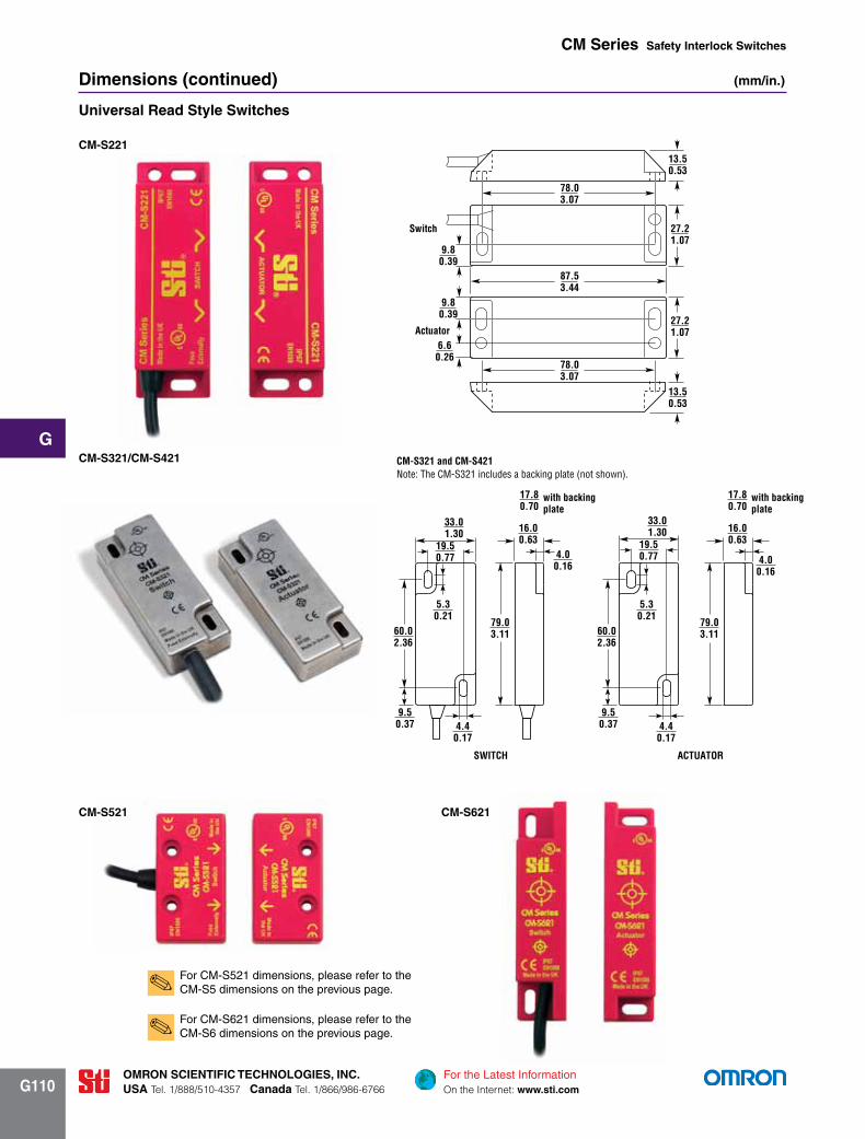
Universal read Style Switches
Dimensions (continued) (mm/in.)
cm-S221
For CM-S521 dimensions, please refer to the CM-S5 dimensions on the previous page.✎
CM-S221 Switch
78.03.07
87.53.44
78.03.07
13.50.53
27.21.07
9.80.39
9.80.39
6.60.26
Switch
Actuator
13.50.53
27.21.07
cm-S321/cm-S421
60.02.36
79.03.11
33.01.30 16.0
0.6319.50.77
5.30.21
9.50.37 4.4
0.17
4.00.16
79.03.11
4.40.17
5.30.21
60.02.36
9.50.37
33.01.30
19.50.77
16.00.63
17.80.70
4.00.16
CM-S321 and CM-S421Note: The CM-S321 includes a backing plate (not shown).
SWITCH ACTUATOR
with backingplate
17.80.70
with backingplate
cm-S521 cm-S621
For CM-S621 dimensions, please refer to the CM-S6 dimensions on the previous page.✎

For the Latest InformationOn the Internet: www.sti.com
OmrOn Scientific technOlOgieS, inc.USA Tel. 1/888/510-4357 canada Tel. 1/866/986-6766
g
g111
cm Series Safety interlock Switches
Dimensions (continued) (mm/in.)
control Units
cm-S4
cm-S41
cm-S21 & cm-Se
1054.13
351.38
114.74.515
752.95
752.95
451.77
CM-S4
CM-S41
CM-S21/SE
For DIN rail
752.95
742.91
742.91
843.3
1194.68
1194.68
22.50.88
22.50.88
843.3
1054.13
351.38
114.74.515
752.95
752.95
451.77
CM-S4
CM-S41
CM-S21/SE
For DIN rail
752.95
742.91
742.91
843.3
1194.68
1194.68
22.50.88
22.50.88
843.3
1054.13
351.38
114.74.515
752.95
752.95
451.77
CM-S4
CM-S41
CM-S21/SE
For DIN rail
752.95
742.91
742.91
843.3
1194.68
1194.68
22.50.88
22.50.88
843.3
For the Latest InformationOn the Internet: www.sti.com
OmrOn Scientific technOlOgieS, inc.USA Tel. 1/888/510-4357 canada Tel. 1/866/986-6766
g
g112
cm Series Safety interlock Switches
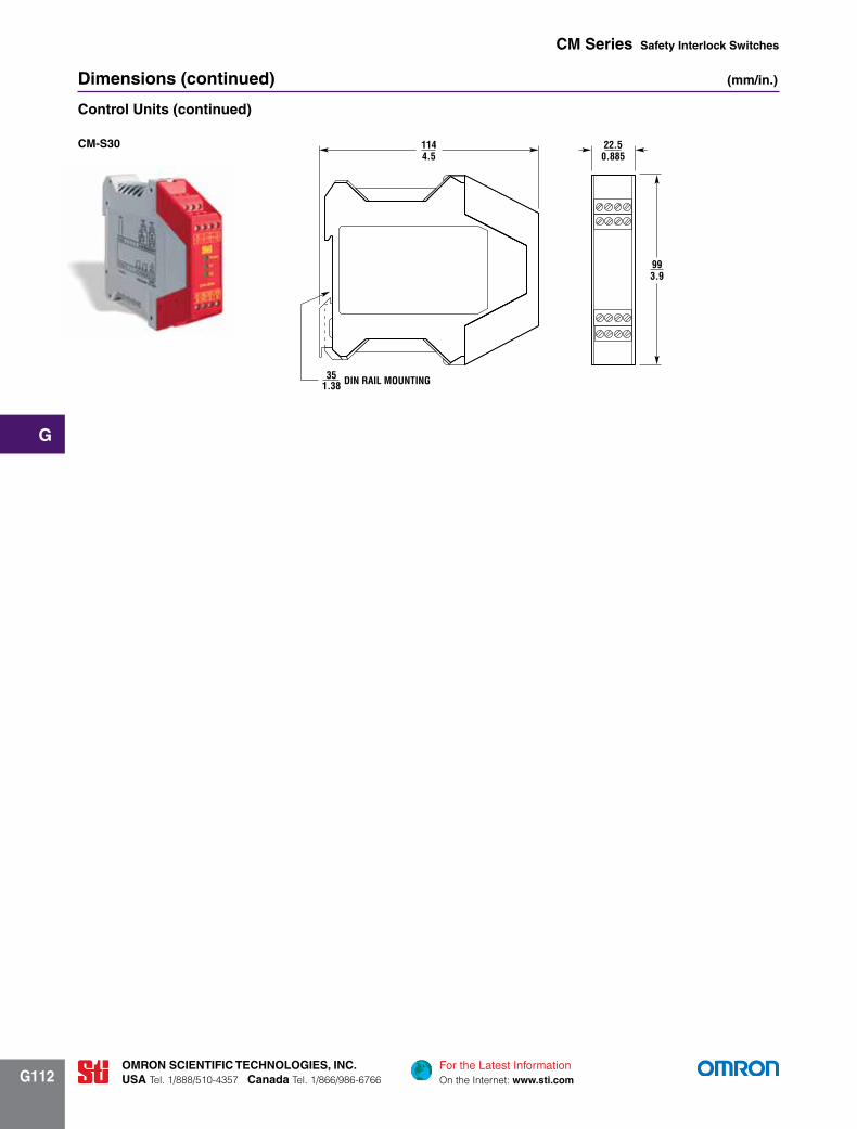
Dimensions (continued) (mm/in.)
control Units (continued) CM-S30
DIN RAIL MOUNTING351.38
993.9
1144.5
22.50.885
cm-S30
For the Latest InformationOn the Internet: www.sti.com
OmrOn Scientific technOlOgieS, inc.USA Tel. 1/888/510-4357 canada Tel. 1/866/986-6766
g
g113
cm Series Safety interlock Switches
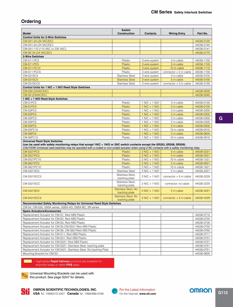
Universal Mounting Brackets can be used with this product. See page G247 for details.✎
modelSwitch
construction contacts Wiring entry Part no.control Units for 2-Wire SwitchesCM-S21-24 (24 VAC/DC) 44536-0120CM-S41-24 (24 VAC/DC) 44536-0140CM-S41-110 (110 VAC or 230 VAC) 44536-0141CM-SE-24 (24 VAC/DC) 44536-01702-Wire SwitchesCM-S11-PC3 Plastic 2-wire system 3 m cable 44536-1100CM-S11-PC5 Plastic 2-wire system 5 m cable 44536-1105CM-S11-PC10 Plastic 2-wire system 10 m cable 44536-1110CM-S11-PCC5 Plastic 2-wire system connector + 5 m cable 44536-1159CM-S31SC3 Stainless Steel 2-wire system 3 m cable 44536-3100CM-S31SC5 Stainless Steel 2-wire system 5 m cable 44536-3105CM-S31SCC5 Stainless Steel 2-wire system connector + 5 m cable 44536-3159control Units for 1 n/c + 1 n/O reed Style SwitchesCM-S30 (24VAC/DC) 44536-0030CM-S4 (24VAC/DC) 44536-00401 n/c + 1 n/O reed Style SwitchesCM-S1PC3 Plastic 1 N/C + 1 N/O 3 m cable 44536-0100CM-S1PC5 Plastic 1 N/C + 1 N/O 5 m cable 44536-0105CM-S2PC3 Plastic 1 N/C + 1 N/O 3 m cable 44536-0200CM-S2PC5 Plastic 1 N/C + 1 N/O 5 m cable 44536-0205CM-S3PC3 Plastic 1 N/C + 1 N/O 3 m cable 44536-0300CM-S3PC5 Plastic 1 N/C + 1 N/O 5 m cable 44536-0305CM-S5PC5 Plastic 1 N/C + 1 N/O 5 m cable 44536-0505CM-S5PC10 Plastic 1 N/C + 1 N/O 10 m cable 44536-0510CM-S6PC5 Plastic 1 N/C + 1 N/O 5 m cable 44536-0605CM-S6PC10 Plastic 1 N/C + 1 N/O 10 m cable 44536-0610Universal reed Style Switches (can be used with safety monitoring relays that accept 1n/c + 1n/O or 2nc switch contacts except the Sr203, Sr208, Sr209) CAUTION! Universal reed switches may be operated with a coded or non-coded actuator when using 2 NC contacts with a safety monitoring relay.CM-S221PC5 Plastic 2 N/C + 1 N/O 5 m cable 44536-0221CM-S521PC5 Plastic 2 N/C + 1 N/O 5 m cable 44536-0521CM-S521PC10 Plastic 2 N/C + 1 N/O 10 m cable 44536-1521CM-S621PC5 Plastic 2 N/C + 1 N/O 5 m cable 44536-0621CM-S621PC10 Plastic 2 N/C + 1 N/O 10 m cable 44536-1621CM-S321SC5 Stainless Steel 2 N/C + 1 N/O 5 m cable 44536-3221
CM-S321SCC5Stainless Steel, backing plate
2 N/C + 1 N/O connector + 5 m cable 44536-3229
CM-S321SCC Stainless Steel, backing plate
2 N/C + 1 N/O connector, no cable 44536-3220
CM-S421SC5Stainless Steel, No
backing plate2 N/C + 1 N/O 5 m cable 44536-4221
CM-S421SCC5Stainless Steel, No
backing plate2 N/C + 1 N/O connector + 5 m cable 44536-4229
recommended Safety monitoring relays for Universal reed Style Switches CM-S4, CM-S30, G9SA series, G9SX-AD, G9SX-BC, SR seriesSpare Actuators/AccessoriesReplacement Actuator for CM-S1, Red ABS Plastic 44536-0710Replacement Actuator for CM-S2, Red ABS Plastic 44536-0720Replacement Actuator for CM-S3, Red ABS Plastic 44536-0730Replacement Actuator for CM-S5,CM-S521 Red ABS Plastic 44536-0750Replacement Actuator for CM-S6, CM-S621Red ABS Plastic 44536-0760Replacement Actuator for CM-S11, Red ABS Plastic 44536-0711Replacement Actuator for CM-S31, Red ABS Plastic 44536-0731Replacement Actuator for CM-S221, Red ABS Plastic 44536-0721Replacement Actuator for CM-S321, Stainless Steel, backing plate 44536-0741Replacement Actuator for CM-S421, Stainless Steel, No backing Plate 44536-0751Mounting Bracket for CM-S3 44536-0800
Ordering
= Highlighted rapid Delivery products are available for shipment today or within fiVe days.