Embed Size (px)
Citation preview

Surgical Technique
Clover Staple™

Contents
ProductThe BioPro Clover Staple is a permanent implant that removes minimal cross-sectional fusion area, allows easy radiographical monitoring and may permit early mobilization.
Contact informationWebsite:www.bioproimplants.com
Email:[email protected]@bioproimplants.com
Phone: (810) 982-7777
Fax: (810) 982-7794
Address: 2929 Lapeer Rd, Port Huron, MI 48060
Table of contentsIndications & Contraindications 1Implant Specifications 2-3Instrument Specifications 4-5Surgical Technique 6-12Implant Ordering 13Replacement Instrument Ordering 14-15
1
Indications & Contraindications
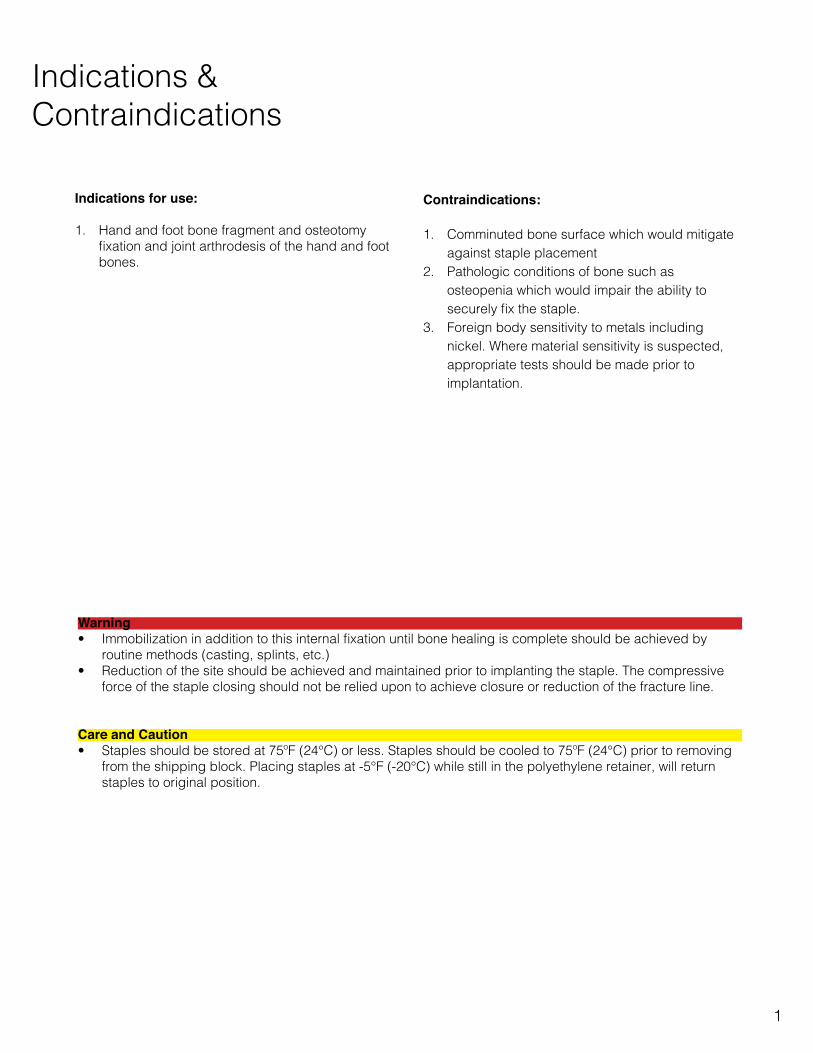
Indications for use:
1. Hand and foot bone fragment and osteotomy fixation and joint arthrodesis of the hand and foot bones.
Contraindications:
1. Comminuted bone surface which would mitigate against staple placement
2. Pathologic conditions of bone such as osteopenia which would impair the ability to securely fix the staple.
3. Foreign body sensitivity to metals including nickel. Where material sensitivity is suspected, appropriate tests should be made prior to implantation.
Warning• Immobilization in addition to this internal fixation until bone healing is complete should be achieved by
routine methods (casting, splints, etc.)• Reduction of the site should be achieved and maintained prior to implanting the staple. The compressive
force of the staple closing should not be relied upon to achieve closure or reduction of the fracture line.
Care and Caution• Staples should be stored at 75ºF (24°C) or less. Staples should be cooled to 75ºF (24°C) prior to removing
from the shipping block. Placing staples at -5°F (-20°C) while still in the polyethylene retainer, will return staples to original position.

2
Implant Specifications
The Clover Staple is manufactured from Nitinol, a memory alloy. Nitinol is approximately 50% nickel (Ni) and 50% titanium (Ti) and was developed by the Naval Ordinance Lab (NOL). The alloy’s unique properties allow the staple full activation at body temperature.
The clover shaped design utilizes strategically placed bends that pull the legs of the staple towards the center of the device upon activation. This will create a constant compressive force on the fusion site.
The Clover Staple is only 1mm thick, allowing minimal bone removal to recess the staple below the dorsal surface.
A
B
A
B
3-LEG STAPLE 4-LEG STAPLEMaterial NitinolTop Dimension (mm) A x B
10 x 814 x 1218 x 16
10 x 814 x 1218 x 16
Leg Length (mm) (available for every top dimension)
10, 12.5, 15 10, 12.5, 15

Implant Specifications
3
Open designThe Clover Staple’s open center design allows for easy monitoring of the fusion site via x-ray after implantation.
Barbed legsThe Clover Staple features teeth on the legs to prevent staple back-out.
Activation temperatureWhen exposed to patient body temperature, the staple will activate, creating 4-6 lbs of constant compressive force.

4
InstrumentSpecifications
Color coded instruments allow for easy identification between staple sizes.
Staple pushers Burr guidesStaple positioners
Also included in both instrument kits (ref 19678/19543) are (1) AO quick connect burr cutter, (3) drill guides, (1) impactor han-dle, (2) impactor tips and (1) depth gauge.
Burr cutter Drill guide
Impactor handle & tips Depth gauge

InstrumentSpecifications
5
Instrument kitsTwo instrument kits are available (ref 19678/19543), one for 3-leg staples and one for 4-leg staples. Each kit contains all the necessary instruments for implantation.
Drill bitsDrill bits are not contained in the instrument kits, but are sterile packed and sent along with the sterile Clover Staple inventory. (ref 18960)
3-Leg Instrument Kit (ref 19678)
4-Leg Instrument Kit (ref 19543)

6
SurgicalTechnique
The following technique describes the use of the Four-Leg Clover Staple for a 4-Corner fusion. This technique can be applied for use of the Clover Staple for other intercarpal fusions including the Three-Leg Clover Staple for use on STT fusions.
Step One:Make a dorsal incision between the 3rd and 4th compartments. Expose the radial and mid carpal joint and perform scaphoidectomy, osteophytosectomy and arthrolysis (Fig 1).
Correct the malalignment of the first row (front and sagittal) of the carpus onto the second row.
Cartilage is removed between all bones to be fused. For optimal fusion, use a small osteotome for the cartilage and a 1 or 2mm burr to decorticate the bone.
Fig 1
Important Note The removed bone should be denuded of cartilage and morselized to use later as bone graft.
Important NoteNo fusion will work without adequate preparation of the joint surfaces. All cartilage must be removed and subchondral bone must be fenestrated or decorticated.
Important NoteAdequate cancellous surface is important for fusion, while retaining the normal contours facilitates accurate positioning of the carpals. Thorough irrigation should remove all cartilagenous debris.

7
Fig 3
Step Two:Reduce and pin the carpals with K-wires (Fig 2). Mini-C-arm can be used to assure the lunate and capitate are collinear on the lateral view. Typically 0.045” K-wires provide adequate stability.
Suggested wire placement: Triquetro-Lunate, Triquetro-Hamo-Capitate.
Step Three: Use the burr guide or staple pusher to assess which size staple will obtain the best purchase in bone (Fig 3).
Fig 2

8
Fig 5
Step Four:Position the appropriate size burr guide (Fig 4), ensuring it sits flush against the dorsal surface (Fig 5).
Caution It is important to mount the burr guide as proximal as possible on the lunate to ensure proper leg placement in the lunate (Fig 6a). Due to the typical crescent shape of the lunate, mounting the guide too distal may result in a poor purchase of the lunate (Fig 6b).
Fig 4
Fig 6a Fig 6b

9
Step Five:Secure the burr guide in place with 0.045 (1.1mm) K-wires. A minimum of three K-wires is recommended for adequate stability (Fig 7).
Important NoteSlightly bend the wires outward to allow easier access to the center of the burr guide.
Step Six:Utilizing the burr cutter in a low speed AO connection rotary hand piece, plane around the inside of the burr guide to create a recess for the Clover Staple, most importantly on the lunate. This will prevent impingement of the staple during dorsiflexion of the wrist (Fig 8).
CautionThe burr cutter can be an aggressive instrument. It is advised to burr each corner of the burr guide prior to planing around the guide.
Important NoteEnsure the planer bit is inserted straight so the collar rides along the planer guide. Insertion of the bit at an angle can leave bone ridges that will interfere with staple seating.
Fig 7
Fig 8
10
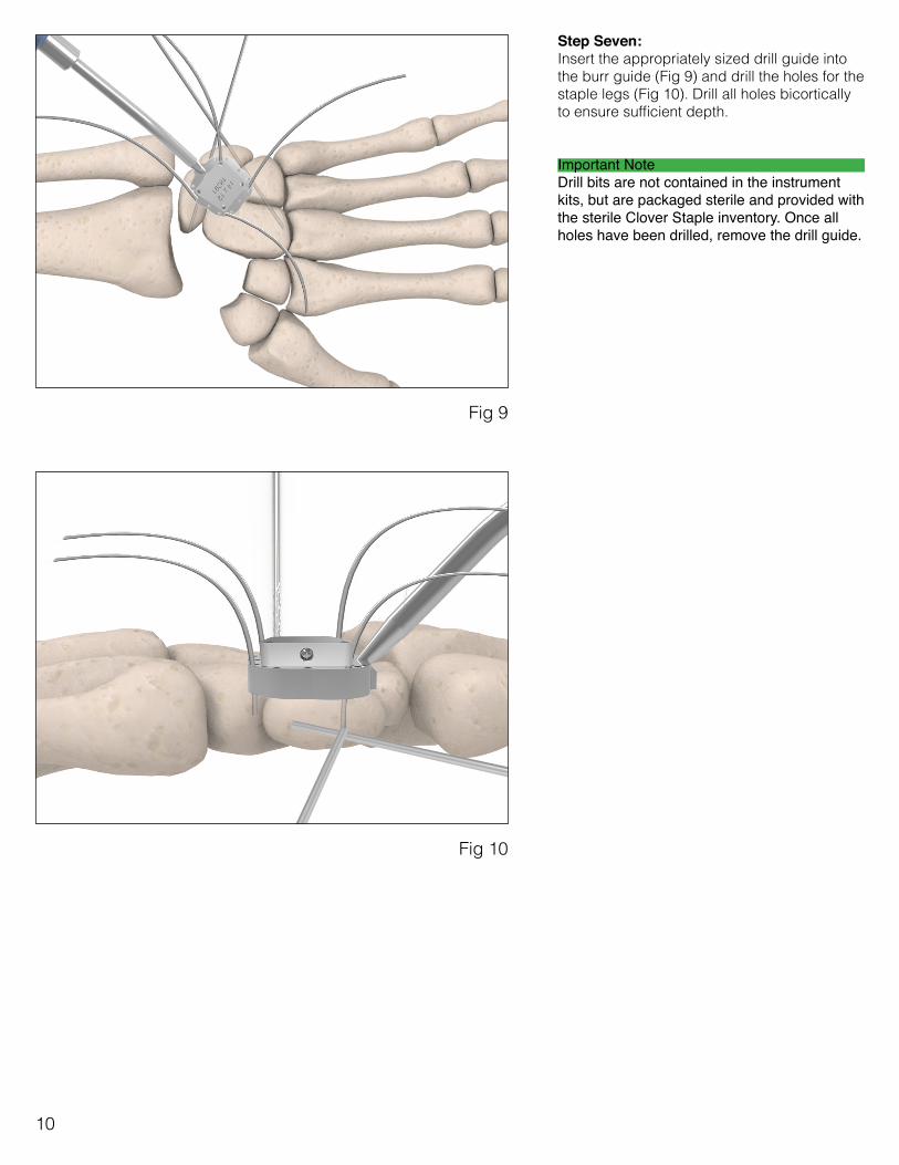
Step Seven:Insert the appropriately sized drill guide into the burr guide (Fig 9) and drill the holes for the staple legs (Fig 10). Drill all holes bicortically to ensure sufficient depth.
Important NoteDrill bits are not contained in the instrument kits, but are packaged sterile and provided with the sterile Clover Staple inventory. Once all holes have been drilled, remove the drill guide.
Fig 9
Fig 10

11
Step Eight:Before removing the burr guide, it is important to mark the drill holes. This can be accomplished in one of the following methods:
1. With a surgical marking pen 2. With an electro-cautery device
Once the drill holes have been appropriately marked, remove the K-wires used to mount the burr guide. Measure the depth of each leg hole with the depth gauge and select the longest leg length staple that will not sit bi-cortical. (Fig 11).
Important Note Ensure that the staple legs do not sit bi-cortical. This allows the legs to compress into the cancellous bone, ensuring the staple remains recessed within the carpals.
Step Nine:Irrigate again and then place bone graft in all interstices. Use the appropriately sized staple pusher to push the Clover Staple approximately 5mm out of its protective shipping block (Fig 12).
Slide the appropriately sized staple positioner between the staple and the shipping block (Fig 13).
Important Note Always use the supplied Staple Positioners to handle the Clover Staple. Heat from hands can prematurely activate the staple.
Fig 11
Fig 12 Fig 13

12
Once the Clover Staple has been removed from the shipping block with the staple positioner, insert it into the drill holes as far as possible and remove the Staple Positioner.
Step Ten:Impact the staple flush with the planed surface (Fig 14). Activate the staple with a small amount of 98° F (37°) or warm saline and remove the provisional wires. Confirm that no debris is in the radiocarpal joint. Gently assess motion; mini-C-arm can be beneficial to provide images of the maximum stable motion provided by the implant.
Important NoteIt is advised to take a lateral x-ray at this point. The Clover Staple often appears to sit proud in a lateral view. An immediate post-op x-ray will help avoid confusion in the future.
Step Eleven: Close the joint capsule in layers using your suture of choice. The extensor tendons should have remained within their compartment unless the Extensor Pollicis Longus is intentionally left out from the chosen approach. The skin is sutured closed.
Fig 14
Fig 10

ITEM # DESCRIPTION SIZE LEG LENGTH18259 FOUR-LEG CLOVER STAPLE 10MM X 8MM 10MM 18260 FOUR-LEG CLOVER STAPLE 10MM X 8MM 12.5MM 18261 FOUR-LEG CLOVER STAPLE 10MM X 8MM 15MM 18062 FOUR-LEG CLOVER STAPLE 14MM X 12MM 10MM 18063 FOUR-LEG CLOVER STAPLE 14MM X 12MM 12.5MM 18064 FOUR-LEG CLOVER STAPLE 14MM X 12MM 15MM 18065 FOUR-LEG CLOVER STAPLE 18MM X 16MM 10MM 18066 FOUR-LEG CLOVER STAPLE 18MM X 16MM 12.5MM 18067 FOUR-LEG CLOVER STAPLE 18MM X 16MM 15MM
18262 THREE-LEG CLOVER STAPLE 10MM X 8MM 10MM 18263 THREE-LEG CLOVER STAPLE 10MM X 8MM 12.5MM 18264 THREE-LEG CLOVER STAPLE 10MM X 8MM 15MM 18068 THREE-LEG CLOVER STAPLE 14MM X 12MM 10MM 18069 THREE-LEG CLOVER STAPLE 14MM X 12MM 12.5MM 18070 THREE-LEG CLOVER STAPLE 14MM X 12MM 15MM 18071 THREE-LEG CLOVER STAPLE 18MM X 16MM 10MM 18072 THREE-LEG CLOVER STAPLE 18MM X 16MM 12.5MM 18073 THREE-LEG CLOVER STAPLE 18MM X 16MM 15MM
ITEM # DESCRIPTION ø LENGTH18960 CLOVER STAPLE DRILL BIT 1.5MM 18MM
Implant Ordering
13

ITEM # DESCRIPTION19678 CLOVER STAPLE 3-LEG COMPLETE KIT15259 IMPACTOR HANDLE18284 IMPACTOR TIP SM18285 IMPACTOR TIP LG18311 PUSHER 3 LEG 10X818312 PUSHER 3 LEG 14X1218313 PUSHER 3 LEG 18X1619512 STAPLE POSITIONER 10X819513 STAPLE POSITIONER 14X1219514 STAPLE POSITIONER 18X1618302 DRILL GUIDE 3 LEG 10X818303 DRILL GUIDE 3 LEG 14X1218304 DRILL GUIDE 3 LEG 18X1618308 BURR GUIDE 3 LEG 10X818310 BURR GUIDE 3 LEG 14X1218309 BURR GUIDE 3 LEG 18X1618315 BURR CUTTER18378 DEPTH GAUGE19480 WRIST STAPLE INSTRUMENT TRAY
3-Leg Replacement Instrument Ordering
14

4-Leg Replacement Instrument Ordering
ITEM # DESCRIPTION19543 CLOVER STAPLE 4-LEG COMPLETE KIT15259 IMPACTOR HANDLE18284 IMPACTOR TIP SM18285 IMPACTOR TIP LG18299 PUSHER 4 LEG 10X818300 PUSHER 4 LEG 14X1218301 PUSHER 4 LEG 18X1619512 STAPLE POSITIONER 10X819513 STAPLE POSITIONER 14X1219514 STAPLE POSITIONER 18X1618290 DRILL GUIDE 4 LEG 10X818291 DRILL GUIDE 4 LEG 14X1218292 DRILL GUIDE 4 LEG 18X1618296 BURR GUIDE 4 LEG 10X818297 BURR GUIDE 4 LEG 14X1218298 BURR GUIDE 4 LEG 18X1618315 BURR CUTTER18378 DEPTH GAUGE19480 WRIST STAPLE INSTRUMENT TRAY
15

Notes