Embed Size (px)
Citation preview

CLOUDSIM BASED SIMULATOR FOR
DISTRIBUTED VIDEO TRANSCODING
Habtegebreil Kassaye Haile
Internship ReportSupervisor: Dr. Sébastien Lafond
Advisors: Tewodros Deneke , Fareed JokhioEmbedded Systems Laboratory
Department of Information TechnologiesÅbo Akademi University
January 2014
ABSTRACT
This report provides details of a new implementation of the simulator used for the paper[1]. The original simulator was implemented on SimPy discrete event simulation tool.Driven by some shortcomings in the SimPy tool and the underlying python programinglanguage, a new simulator on a framework better suited for modeling and simulationof cloud services was required. The aim of this project is to provide that improvedsimulator. The algorithm implemented provides way to allocate and deallocate virtualmachines dynamically on a collection of transcoding servers.
Keywords: CloudSim, Video Transcoding, Distributed Transcoding, Dynamic Provi-sioning
i
CONTENTS
Abstract i
Contents ii
List of Figures iii
Glossary iv
1 Introduction 1
2 The Simulated System 3
3 CloudSim 63.1 CloudSim Architecture . . . . . . . . . . . . . . . . . . . . . . . . . 63.2 CloudSim Core . . . . . . . . . . . . . . . . . . . . . . . . . . . . . 8
4 Components of the Simulator 104.1 TranscodingMain . . . . . . . . . . . . . . . . . . . . . . . . . . . . 104.2 TranscodingBroker . . . . . . . . . . . . . . . . . . . . . . . . . . . 154.3 TranscodingProvisioner . . . . . . . . . . . . . . . . . . . . . . . . . 174.4 Segment . . . . . . . . . . . . . . . . . . . . . . . . . . . . . . . . . 204.5 Stream . . . . . . . . . . . . . . . . . . . . . . . . . . . . . . . . . . 204.6 TranscodingVm . . . . . . . . . . . . . . . . . . . . . . . . . . . . . 20
5 Outputs and Performance of the simulation framework 215.1 Transcoding rates, Play rates and Number of VMs . . . . . . . . . . . 215.2 Simulation Time performances . . . . . . . . . . . . . . . . . . . . . 24
6 Future work and conclusions 266.1 Conclusions . . . . . . . . . . . . . . . . . . . . . . . . . . . . . . . 266.2 Future work . . . . . . . . . . . . . . . . . . . . . . . . . . . . . . . 26
Bibliography 27
ii
LIST OF FIGURES
2.1 Simulated system architecture . . . . . . . . . . . . . . . . . . . . . 4
3.1 CloudSim layered architecture . . . . . . . . . . . . . . . . . . . . . 73.2 CloudSim Core . . . . . . . . . . . . . . . . . . . . . . . . . . . . . 8
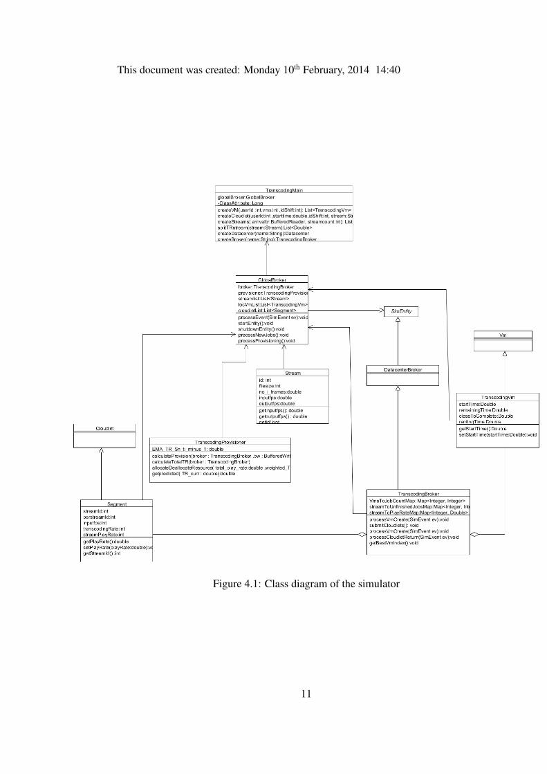
4.1 Class diagram of the simulator . . . . . . . . . . . . . . . . . . . . . 11
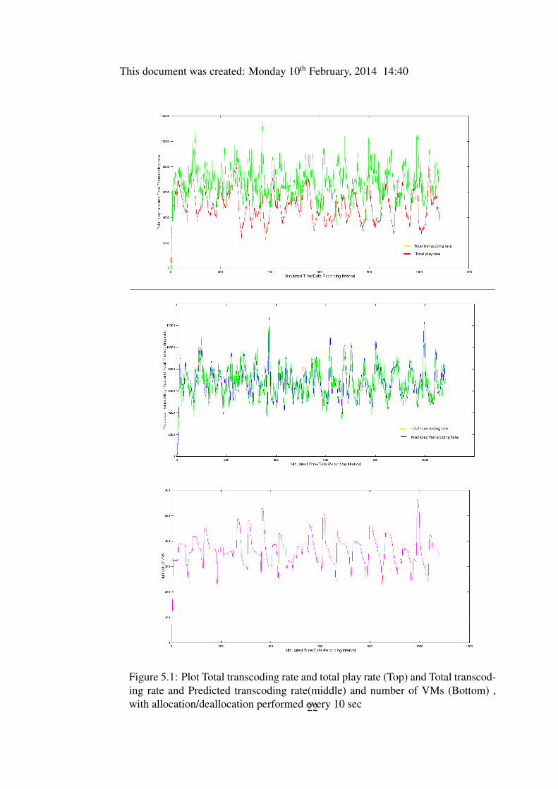
5.1 Plot Total transcoding rate and total play rate (Top) and Total transcod-ing rate and Predicted transcoding rate(middle) and number of VMs(Bottom) , with allocation/deallocation performed every 10 sec . . . . 22
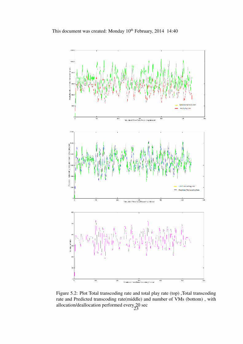
5.2 Plot Total transcoding rate and total play rate (top) ,Total transcodingrate and Predicted transcoding rate(middle) and number of VMs (bot-tom) , with allocation/deallocation performed every 20 sec . . . . . . 23
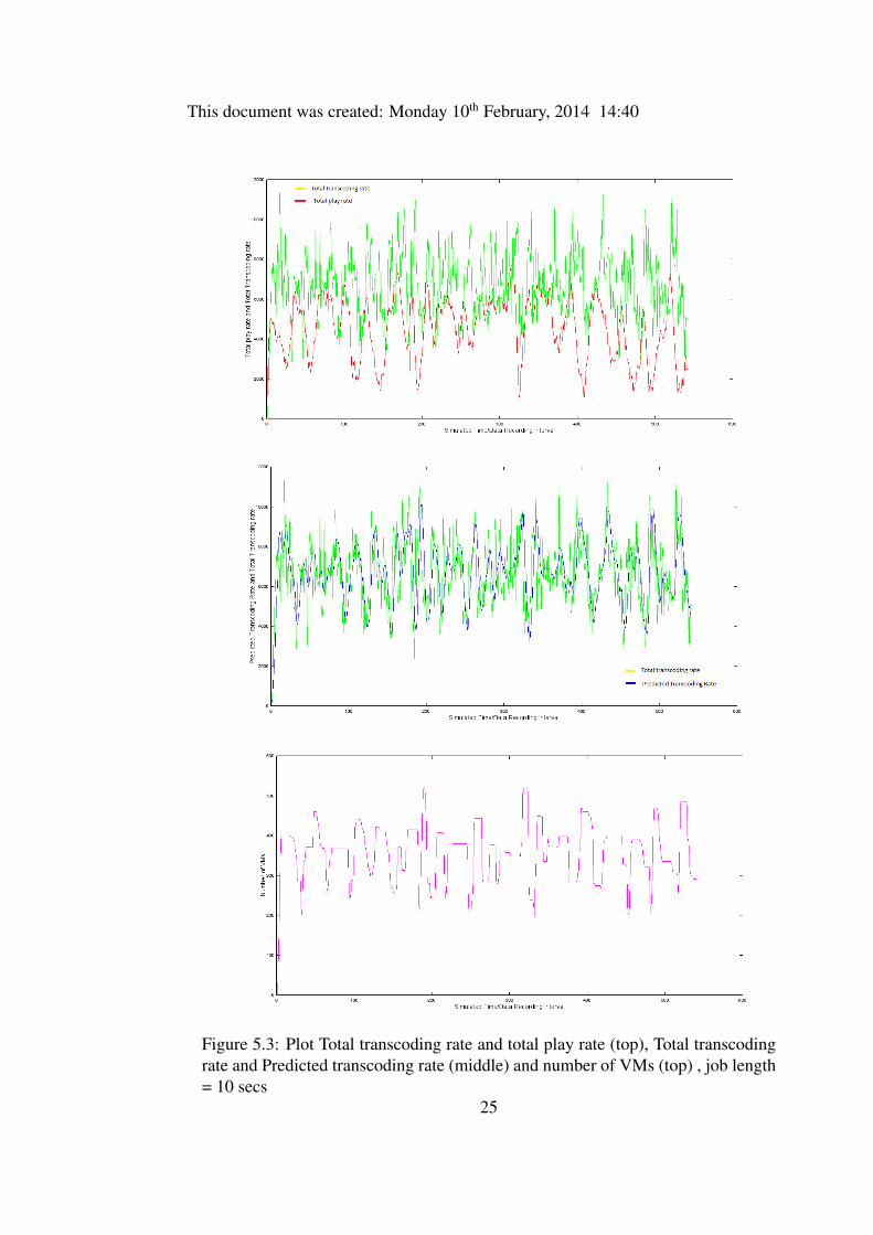
5.3 Plot Total transcoding rate and total play rate (top), Total transcodingrate and Predicted transcoding rate (middle) and number of VMs (top), job length = 10 secs . . . . . . . . . . . . . . . . . . . . . . . . . . 25
iii
GLOSSARY
DES Discrete-event simulation
Vm Virtual Machine. a service running on the servers and hosting the transcodingrequests.
MIPsMillions of Instructions per second. A measure in cloudsim used to processingpower.
RAMRandom Access Memory.
BW BandWidth.
iv
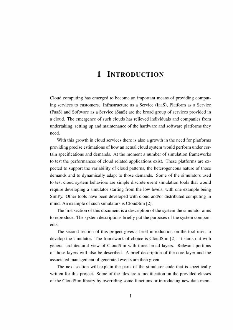
1 INTRODUCTION
Cloud computing has emerged to become an important means of providing comput-ing services to customers. Infrastructure as a Service (IaaS), Platform as a Service(PaaS) and Software as a Service (SaaS) are the broad group of services provided ina cloud. The emergence of such clouds has relieved individuals and companies fromundertaking, setting up and maintenance of the hardware and software platforms theyneed.
With this growth in cloud services there is also a growth in the need for platformsproviding precise estimations of how an actual cloud system would perform under cer-tain specifications and demands. At the moment a number of simulation frameworksto test the performances of cloud related applications exist. These platforms are ex-pected to support the variability of cloud patterns, the heterogeneous nature of thosedemands and to dynamically adapt to those demands. Some of the simulators usedto test cloud system behaviors are simple discrete event simulation tools that wouldrequire developing a simulator starting from the low levels, with one example beingSimPy. Other tools have been developed with cloud and/or distributed computing inmind. An example of such simulators is CloudSim [2].
The first section of this document is a description of the system the simulator aimsto reproduce. The system descriptions briefly put the purposes of the system compon-ents.
The second section of this project gives a brief introduction on the tool used todevelop the simulator. The framework of choice is CloudSim [2]. It starts out withgeneral architectural view of CloudSim with three broad layers. Relevant portionsof those layers will also be described. A brief description of the core layer and theassociated management of generated events are then given.
The next section will explain the parts of the simulator code that is specificallywritten for this project. Some of the files are a modification on the provided classesof the CloudSim library by overriding some functions or introducing new data mem-
1
This document was created: Monday 10th February, 2014 14:40
bers. There are also new classes and methods that provide some of the functional-ities required to realize a prediction based dynamic resource allocation of distributedtranscoding servers. The source code components will be discussed in decreasing orderof content, starting from the main class where the simulation begins.
The fourth section presents the results of tests obtained from running the simulatorwith different parameters. The first part of this section presents plots showing thedynamics of transcoding rate, play rate and number of VMs for the duration of thesimulated time. The second part of this section presents tabulated data of the recordedsimulation time for different simulation times and for different mean job sizes duringstream segmentation.
2
2 THE SIMULATED SYSTEM
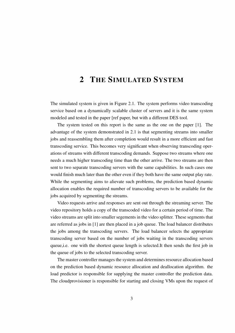
The simulated system is given in Figure 2.1. The system performs video transcodingservice based on a dynamically scalable cluster of servers and it is the same systemmodeled and tested in the paper [ref paper, but with a different DES tool.
The system tested on this report is the same as the one on the paper [1]. Theadvantage of the system demonstrated in 2.1 is that segmenting streams into smallerjobs and reassembling them after completion would result in a more efficient and fasttranscoding service. This becomes very significant when observing transcoding oper-ations of streams with different transcoding demands. Suppose two streams where oneneeds a much higher transcoding time than the other arrive. The two streams are thensent to two separate transcoding servers with the same capabilities. In such cases onewould finish much later than the other even if they both have the same output play rate.While the segmenting aims to alievate such problems, the prediction based dynamicallocation enables the required number of transcoding servers to be available for thejobs acquired by segmenting the streams.
Video requests arrive and responses are sent out through the streaming server. Thevideo repository holds a copy of the transcoded video for a certain period of time. Thevideo streams are split into smaller segements in the video splitter. These segments thatare referred as jobs in [1] are then placed in a job queue. The load balancer distributesthe jobs among the transcoding servers. The load balancer selects the appropriatetranscoding server based on the number of jobs waiting in the transcoding serversqueue,i.e. one with the shortest queue length is selected.It then sends the first job inthe queue of jobs to the selected transcoding server.
The master controller manages the system and determines resource allocation basedon the prediction based dynamic resource allocation and deallocation algorithm. theload predictor is responsible for supplying the master controller the prediction data.The cloudprovisioner is responsible for starting and closing VMs upon the request of
3
This document was created: Monday 10th February, 2014 14:40
Figure 2.1: Simulated system architecture
4
This document was created: Monday 10th February, 2014 14:40
the master controller. The video merger produces a video stream output from the joboutputs belonging to that stream.
5
3 CLOUDSIM
A number of frameworks were considered to be used as a tool to develop the simu-lator. As the streams will be arriving at certain moments in time to be processed bythe simulator, the frameworks that were considered were all discrete event simulationframeworks. In addition to stream arrivals a number of stream and stream segmentparameters will also trigger certain actions to be taken.
The framework of choice here is CloudSim. CloudSim is a discrete event simulatorwith features and functionalities that enable easy modeling and simulation of cloudinfrastructures and services. In particular, CloudSim offers approaches to define andcreate cloud entities in ways that are easier to visualize and understand. In this sectionsome of the important componenets of CloudSim useful to understand the simulatorare discussed. It is important to note that not all the components in CloudSim arepresented, but only those directly related to the simuator. For detailed understandingof the Cloudsim framework refer to [2] and the frameworks API.
3.1 CloudSim Architecture
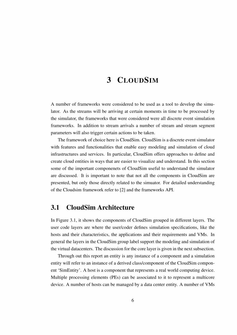
In Figure 3.1, it shows the components of CloudSim grouped in different layers. Theuser code layers are where the user/coder defines simulation specifications, like thehosts and their characteristics, the applications and their requirements and VMs. Ingeneral the layers in the CloudSim group label support the modeling and simulation ofthe virtual datacenters. The discussion for the core layer is given in the next subsection.
Through out this report an entity is any instance of a component and a simulationentity will refer to an instance of a derived class/component of the CloudSim compon-ent ‘SimEntity’. A host is a component that represents a real world computing device.Multiple processing elements (PEs) can be associated to it to represent a multicoredevice. A number of hosts can be managed by a data center entity. A number of VMs
6
This document was created: Monday 10th February, 2014 14:40
Figure 3.1: CloudSim layered architecture
can be associated with a single host. How multiple VMs operate on a host is governedby the VM allocation/provisioning policy component. Custom methods can be appliedto this component to allow implementation of new policies. By default, a simple firstcome first serve VM allocation policy is provided.
In CloudSim applicactions are modeled by extending the Cloudlet class. This classmodels a basic application services and can be deployed on instances of VM class. Aservice allocation policy will take care of assigninng VMs to the defined applicationservices. A host allocation policy is used to determine the distribution of VMs amongmultiple cores of a host instance.The host allocation policies provided in cloudsim arespace shared, where a CPU is exclusively mapped to a VM, and time shared, where acore is dynamically shared among multiple VMs with on demand assigment of coresto VMs .
The DataCenter class models the hardware hosting the cloud service providers in-frastructure. It can hold a diverse set of host machines on which the VMs will be run. Itcontains instance of a provisioning component that implements policies for resourcesto hosts and VMs.
7
This document was created: Monday 10th February, 2014 14:40
Figure 3.2: CloudSim Core
3.2 CloudSim Core
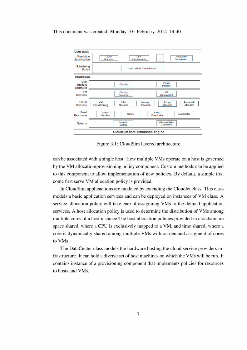
CloudSim originally relied on GridSim that in turn relies on SimJava library for eventhandling and communication between entities. However due to scalability issues, anew discrete event management framework was developed [2]. Figure 3.2 shows theclass diagram for the core of the simulation framework [2].
The CloudSim class is the main class controlling the event queues and executionof these events. Events are represented as instances of the class SimEvent. Some ofthe information stored in event instances are time of occurance, time of delivery tothe destination simulation entity, finish time, source and destination id, tag of eventand data for destination entity. Generated events are ordered based on their time para-meters and then added to the future queue. When the scheduled time of events arrivethe events are removed from the future events queue and moved to the deferred eventsqueue. All Simulation entities, which are instances of classes derived from the class Si-mEntity, will then run their event handling procedures. These procedures will performthe appropriate action based on the events found in the defereed queue.
The class SimEntity is an abstract class. Instances of derived classes of SimEntityare able to pass messages between each other and issue and handle events. Classes thatextend this function must implement three functions: startEntity(), shutdownEntity()and processEvent() . The startEntity() and shutdownEntity() are procedures that runwhen a simulation entity is initialized and destroyed . The processEvent() is the pro-cedure that handles events in a simulation entity.
CloudSimTags contains list of tags for events. The tags are used to identify the kindof action to be taken. It is also possible to use other tag definitions in events if there isa need for a new custom event and a new action corresponding to that event. Another
8
This document was created: Monday 10th February, 2014 14:40
important entity is CloudInformationService (CIS), which is responsible for registra-tion of resources. The CloudSimShutDown is the last entity that runs and indicates thesimulation has come to its end.
In a nutshell, upon start of simulation, datacenter entities are created and registeredin the CIS. Then brokers will request about the available resources from the CIS. Aftergetting the resource characteristics the brokers will then create VMs and associateapplication/jobs/cloudlets to the VMs.
9
4 COMPONENTS OF THE SIMULATOR
As described before, the simulator is built upon the CloudSim framework and usesvarious predefined classes from the framework. In addition some already providedclasses of the simulator were redefined and adjusted to suit the need of the simulator.New classes containing required functions have also been defined and integrated. Thefollowing are a list of java classes that have been either redefined or written from thescratch.Figure 4.1 shows the component classes of the simulator and the relationshipbetween the classes.
4.1 TranscodingMain
This is the place for the highest layer controls and where the simulation will be started.Creation, initialization and coordination between the different entities involved in thesimulation is done here. The above is accomplished through functions in the classesand also methods of external classes. The TranscodingMain class contains the mainfunction and also a static class derived from CloudSim SimEntity to handle some highlevel events. The functions of the main class are discusses one by one below;
createVM(. . . ) – this function is responsible to instantiate VMs the simulation andreturning a list of the instantiated VMs. In order to create a standard CloudSim VM anumber of parameters need to be specified. Those parameters specify characteristicslike image size of the VM, how much RAM the VM should have, execution speed ofthe VM in MIPS and scheduling method for the cloudlets/tasks to be executed on theVM. In addition to these typical members of the VM, a new member specifying therenting time of the VM is included. The createVm(. . . ) function takes three arguments.The first argument specifies the Id of the entity that will be managing the VMs. In thiscase the VMs are managed by a simulation entity called ’Broker’, which is responsiblefor allocating jobs to VMs and destroying the VMs when they are no longer needed,
10
This document was created: Monday 10th February, 2014 14:40
Figure 4.1: Class diagram of the simulator
11
This document was created: Monday 10th February, 2014 14:40
among other things. The second argument specifies the number of VMs to be createdand the third argument is the starting point for assigning Id numbers for the newlycreated VMs. All the VMs created in the simulation are identical.
createCloudlet(. . . ) – The jobs to be executed on the VMs are instantiated in thisfunction. As arguments it takes the Id of ’Broker’ entity, the creation time for theJobs/cloudlets, the starting point for assigning Ids, the stream to which the created jobsbelong to and an array containing the size of jobs in terms of execution time of eachjob to be created. The function returns a list containing job instances (referred alsoas cloudlets). To create the basic Cloudlet instance through the provided CloudSimlibraries one needs to specify the job length in terms of millions of instructions, size inmemory of the input and output of the job, utilization models for the CPU, RAM andBW(bandwidth) and the execution speed of VMs in terms of MIPs . In the simulator,simple utilization models where the cloudlet uses full capacity of the resource are used.The job length is acquired from the function argument that contains a list of job length.Subsequently, the input and output file sizes, which are expressed in terms of numberof video frames, are calculated from the job length and stream characteristics in theway given below;
fileSize =length ∗ stream.filesizestream.transcodingtime
(4.1)
outputSize =fileSize ∗ stream.outputfps
stream.inputfps(4.2)
The filesize represents the input file size. It is obtained by multiplying the totalinput size of the stream by the ratio of the job length (job transcoding time) with thetotal transcoding time of the stream. The output filesize is determined by multiplyingthe play duration of the portion of the stream belonging to the particular job with theoutput frame rate of the stream. Since the play duration is the same for the streambefore and after transcoding, it is obtained by dividing the input number of frames bythe input frame rate.
In addition to the above values associated with the default definition of cloudlets,values specifying the stream to which the job belongs to, the input and output framerate of the stream and the starting time (although not used in the simulation) of thecloudlets are also specified.
createStreams(. . . ) – This function handles the creation of streams based on data
12
This document was created: Monday 10th February, 2014 14:40
acquired from files specifying the number of streams to create and characteristics ofthose streams. As an argument this function takes a buffer reader object, associatedwith a file used to determine the number of streams to create, and the total streamcount until that instant. The function returns a list of stream objects. Once the functionextracted the number of streams to be created from the associated file, it will then go onto randomly select streams. After a stream is selected from the file containing the listof video streams and their associated characteristics, some characteristics are extractedand used to create a stream object. Those selected characteristics are transcoding timeof the stream, number of I frames in the stream, input frame rate of the stream, outputframe rate and file size in terms of number of video frames. The transcoding time ofthe stream is expressed in terms of MI by multiplying the duration in time by the MIPsvalue of all the VMs, which is universally 1000 in this case.
splitStream(. . . ) – Once the streams are created the splitter function takes the re-sponsibility of dividing the stream to jobs based on a Gaussian distribution with a givenmean transcoding time and standard deviation. The choice of the mean transcodingtime for the jobs is important in determining how many jobs will be created. Thisfunction is called for each stream that require splitting and it returns a list that containsthe job sizes for the stream. The list of job sizes will be later used in the createCloud-let(. . . ) function.
createDatacenter(. . . ) – Creates the DataCenter class instance that represents a reallife data center. The datacenter object will contain a list of host object. Characteristicssuch as PEs(processing elements) with specific MIPs and VM scheduling policy forPEs, Id, RAM size and RAM provisioning policy, storage capacity and Bandwidthcapacity and Bandwidth provisioning policy are specified during instantiation. Allprovisioning and provisioning policies used are rudimentary ones where the resourcein question is fully/exclusively used by entity being serviced and freed once the entitycompletes its need. The MIPs and RAM values of the host are set in such a way thata host can only support one VM at a time. A very high number of hosts are created sothat hosts will always be available to support any number of VMs that might exist inthe simulation.
When creating the datacenter object a datacentercharacterstics object, which spe-cifies the various costs associated with the datacenter and other characteristics likename, operating system and time zone, is specified. In addition an allocation policyfor the host list in the datacenter is also specified. The allocation policy for the host list
13
This document was created: Monday 10th February, 2014 14:40
is a simple one that chooses the host with the lowest number of PEs in use. Since thereis only one PE created per host, declaration of this allocation policy is just a formalityto concur with the predefined syntax.
printCloudletList() – this function is used to print out the list of completed job-s/cloudlets after the simulation is completed. This is taken from the example codesgiven for CloudSim with some minor modifications introduced to display informationregarding new data added in the simulator. However this function will only be usedfor short term simulations where the amount of jobs is limited. This is because thefunction makes use of a list that accumulates completed cloudlets, but this list willbe consuming memory for longer simulations and will not be allowed to accumulateobjects for such simulations.
Main() - the main function does the task of initializing the simulator with the ap-propriate flags and parameters and create all required the simulation entities. One ofthe simulation entities created is an object identified by the object globalBroker cre-ated from the class GlobalBroker. An instance of DataCenter class is also created here.Then the simulation is started and at the end of the simulation the end time is recordedto determine how long the simulation took to complete.
The highest level component handling high level events in the simulation andperforming some coordination between other event processing entities is the Glob-alBroker. It is an extension of the SimEntity class. As described before this meansthat GlobalBroker has to reimplement the three functions: startEntity(), processEvent(SimEvent) and shutdownEntity().
The startEntity() is called when the simulation is started, therefore any initializationor initial scheduling of events will be placed in this function. In this particular casethe startEntity() serves a simple purpose of opening the stream arrival rate file andscheduling the initial tasks of creating jobs and VMs. The shutdownEntity() closes allthe file readers that has been opened in the simulation.
The function that is responsible for calling out the appropriate procedures when anevent is to be processed by the GlobalBroker is processEvent (SimEvent). When anevent is scheduled a tag used to identify the event is associated with it. Based on thetag associated with the arriving event the function calls the corresponding procedures.There are two events handled by the GlobalBroker class. Those are events that callfor creation of new jobs and calculating the amount of VM provisioning (allocation ofdeallocation). When the creation of jobs event arrives then the function processNew-
14
This document was created: Monday 10th February, 2014 14:40
Jobs() is called, and when VM provisioning event arrives the function processProvis-sioning() is called.
The processNewJobs() function is responsible for calling the functions that createstreams, split the stream and create the actual cloudlets/jobs. If the function is beingcalled for the first time it will initialize all the required variables, cloudlets and VMs.It will also set an initial number of VMs and submit them to the next layer for creationon the datacenter and create a file reader stream associated with the file containing thearrival times. The function will then proceed by calling the function for the creation ofstreams. Then for each stream it will create an array of job sizes by calling the stream-Split() function and create the jobs for the stream based on the job size array acquired.After that it will update the job/cloudlet count and submit the list of cloudlet to thenext layer broker to schedule their execution. At the end the function will schedulethe next job creation time by calling the scheduling function with the appropriate tag.—activity diagram
The processProvisioning() function is called when an event for adjusting the num-ber of VMs occurs. The number of additional VMs to be created is obtained by callingthe method of the instance of TranscodingProvisioner class. If more VMs need tobe created, the method will return the number of VMs to be created. But if insteadthe number of VMs need to be reduced the function will return zero. The detailedprocessing and implementation of the TranscodingProvisioner class is discussed in aseparate subsection. If more VMs need to be created then the appropriate number ofVMs will be created and submitted to the next layer, an object of the class Transcod-ingBroker. The class TranscodingBroker is also described in a separate section below.Finally multiple methods to access the data members of the class are also provided.
4.2 TranscodingBroker
This class is an extension of the TranscodingBroker class provided in the CloudSimlibrary examples. The basic TranscodingBroker is an extension of the SimEntity class.The TranscodingBroker is responsible for negotiating resources on the cloud providers(DataCenters) to the needs of the demanding users (applications running by VMs).Some of the roles of this class are management of cloudlets and VMs, keeping trackof important information used when determining provisioning and distribution of jobsamong the existing VMs.
15
This document was created: Monday 10th February, 2014 14:40
Just like any other class extended from class SimEntity, this class also re-implementsthe function processEvent(SimEvent). In this function all the events that are to behandled by this class are forwarded to the appropriate function. In the following para-graphs some of the important functions that have been modified from the basic versionand other new functions are discussed.
The first important function in this class is the submitCloudlets() function. Thisfunction is not called in direct response to an event from the processEvent(SimEvent)function but instead from inside other event handling procedures. The function servesthe purpose of allocating the appropriate VM to a cloudlet. The appropriate VM isselected by making use of a function that returns the index of the VM with the lowestnumber of cloudlets scheduled to be executed on it, i.e. the VM with the smallestqueue is selected.
Once the VM for a cloudlet is selected then the transcoding time is calculatedfrom the length of the cloudlet specified in terms of MIPs and the speed of the VM,which is also in MIPs. Right now this process is more of a formality since the cloudletlength was obtained by multiplying the time value obtained from a file with a uni-versal VM MIPs value, as described in the createCloudlet() function description. Thedelay between a jobs/segments play time and transcoding time is determined and thesegment is held from submission to the Vm until this delay expires.This is meant to re-duce accumulation of transcoded jobs at the output buffer resulting from streams withhigher transcoding rates but smaller play rate. All the necessary tracking variablesand data members are updated to reflect the current state of the simulator. These statedata members are responsible for keeping track of the total number of cloudlets in thesystem, the cloudlet count per VM and the cloudlet count per stream.
The processVmCreate(SimEvent ev) function is responsible for handling a responseevent from the Datacenter informing the Broker that a VM has been successfully cre-ated in the system. The function will map the VM, whose successful creation is con-firmed, to the datacenter where the VM is created in. Then the job count of the VM isinitialized and the VM is added to a list containing the currently running VMs. Once allthe required VMs are created, unassigned cloudlets will be submitted to be assigned toa VM. This function also contains scripts that manage the case when all the requestedVMs cannot be created in the available data centers.
When a job is completed the generated event is handled in in this class by theprocessCloudletReturn (SimEvent ev) function. In general the purpose of this class
16
This document was created: Monday 10th February, 2014 14:40
is to make all the necessary state changes and updates reflecting that a job is on itsway out of the transcoding VM. The principal updates are removing the cloudlet fromthe list of submitted cloudlets, decreasing the job count in the associated VM to jobcount map and decreasing the job count from the associated stream to job count map.If the cloudlet happens to be the last job of the stream it belongs to, the stream will beremoved from the system. If the job is the last job to be processed on the associatedVM, then the VM will be scheduled for deletion at the end of the renting time and allthe parts that are keeping track of the state of the VM will be removed. If there are nomore cloudlets left in the system then the simulation is ended.
In addition to above functions the class included many functions inherited fromthe parent class and a simple function that returns the index of best suited VM. Thefunctions discussed above are those that have been overridden from the basic imple-mentation for the purpose of this simulator.
4.3 TranscodingProvisioner
The other major class in the system is the MyProvisioner class containing the functionsto calculate the number of VMs to allocate or deallocate. The allocation and dealloca-tion is supposed to closely follow the transcoding and play rate demand. The functionsof this class will be discussed in this section in the order in which they will be called.
The calculateTotalTR(MyDatacenterBroker broker) function is responsible for cal-culating the current transcoding rate of the system. A cloudlet can be in one of differ-ent states in the system. In CloudSim constant field values are defined to differentiatethese states. The cloudlet states that are already defined in the CloudSim library arecanceled, created, failed, failed resource unavailable, in execution, paused, queued,ready, resumed and success. Each cloudlet will also have a status variable. During thecourse of a lifetime of a cloudlet the status will go through some of the above definedstates. When computing the current transcoding rate of the system these cloudlets, whoare currently being executed in a VM, i.e. status is in execution, are considered. Thetranscoding rate of all those executing cloudlets is added up to give the total transcod-ing rate of the system. This value is then returned by the function.
The calculated total transcoding rate is then used as an argument for the functiongetPredicted(double TR_curr) that calculates a prediction of the transcoding rate. Thealgorithm is a direct reimplementation of the procedure used in [1], which is in turn
17
This document was created: Monday 10th February, 2014 14:40
based on [3]. The method employs a twostep approach. The first step consists of aload tracker, that implements exponential moving average (EMA) over a previouslygathered set of n values. Simply put the EMA computed for the latest transcoding ratemeasurement is the weighted sum of the current measurement and EMA obtained fromprevious measurement.
EMA(ti) = α ∗ si + (1− α) ∗ EMA(ti−1) (4.3)
Where α = n + 1 ,ti and ti−1 are current and previous time instants and initialEMA is average of the first n measures. A set of q values obtained from load trackerat q past instants of time is then used by the second stage (load predictor). The loadpredictor outputs a future value after a prediction window h. In this approach the linearpredictor output is calculated using the expression given below;
l = γ0 + γ1t (4.4)
Where γ0 and γ1 are can be estimated at run time based on the LT values and arecalled regression coefficients.
The next function in this class is the allocateDeallocateResource(. . . ) function.This function is responsible to determine if additional VMs need to be created or someneed to be removed. Then it will determine the number of new VMs to add or the num-ber of VMs to remove. More VMs will be added if a weighted transcoding rate, whichis calculated from the total calculated transcoding rate and the predicted transcodingrate, is less than the play rate threshold for allocation. The play rate threshold forallocation used here is the actual total play rate in the system. The total play rate iscalculated in the same way as the total transcoding rate, adding up play rate of all cur-rently executing cloudlets. If the above condition holds and new VMs are to be addedthe equation below is used to determine the number of VMs to add.
number of vms to add =total_play_rate_allocate− weighted_TR
total_transcoding_ratevmList.size()
(4.5)
If the weighted transcoding rate is greater than the play rate threshold for dealloc-ation then this implies there are more VMs than needed. The dealloacation procedureis a little more complicated than the allocation one. Instead of simply determining the
18

This document was created: Monday 10th February, 2014 14:40
number of VMs to remove, the procedure also identifies the best suited VMs to beremoved and marks them for deletion so they can be removed when their renting timeexpires. The first step the procedure does is identify the VMs in the ’deletion range’ oftheir lifetime. The deletion range is a time interval within a renting lifetime of a VM,that allows a VM just created and a VM almost about to be expired not to be deleted.The idea behind overlooking almost expiring VMs from deletion is the assumption thatrenewal process will have already started for a VM very close to expiry. After the VMseligible for deletion have been identified then we determine how many of these VMsneed to be deleted. The number of VMs to be deleted is calculated using the expressiongiven below;
number of vms to remove =weighted_TR− total_play_rate_deallocate
total_transcoding_ratevmList.size()
(4.6)
The above steps are followed by a procedure that sorts the VMs eligible for deletionon increasing order of remaining renting time. This is accomplished by a quicksortalgorithm implemented by the function quicksort(. . . ). The quicksort(. . . ) functionreturns an array with the index of VMs in the VM list arranged in the order described.Once the VMs are arranged then the ones to be removed will be selected and a Booleanvalue indicating they are going to be deleted is set. This Boolean value is checked inthe submitCloudlets() function of broker object of TranscodingBroker class to see ifmore cloudlets could be added to a VM. If this value is true (indicates the VM is closeto removal) then no new cloudlets are sent to the VM.
The allocation and deallocation function returns a number value that contains thenumber of VMs to create. If more VMs are to be created it will return the number ofVMs to create else it returns zero.
The final function of the MyProvisioner class is the calculateProvision(. . . ) func-tion called from the GlobalBroker in the main file. This function starts up the provi-sioning process since all the discussed functions are subsequently called from withinthis function. It starts out by determining the total play rate, and then the total transcod-ing rate and the predicted transcoding rate are obtained by calling the correspondingfunctions. Then the function to determine the number of VMs to allocate and dealloc-ate is called. The values for play rate, transcoding rate, predicted transcoding rate andthe number of running VMs are then all recorded on an output file. Finally the function
19
This document was created: Monday 10th February, 2014 14:40
returns the appropriate value indicating the number of VMs to provision.
4.4 Segment
This is a simple extension of the Cloudlet class given in the CloudSim library. Cloudletclass represents an application service and in the context of [1] , this class is equivaletto jobs to be executed on VMs. A job is a segment of a stream requiring a certaintranscoding service. In addition to the parent class members this class has additionalmembers to contain important characteristics of the job. Some of those importantcharacteristics are input frame per second (inputfps), the transcoding rate of the streamor job and output frame per second (streamPlayRate). There are also members thathold the identification number of the cloudlet globally and within a stream. Functionsto get access to the above data members are also defined.
4.5 Stream
This represents a video stream in the real world. The class holds important charac-teristics of the stream. Some of those characteristics are the total number of framesin the stream, the transcoding time of the stream, input and output frame per secondof the stream, number of I frames in the stream and value used to identify the stream.Functions to get access to some of the above data members are also defined.
4.6 TranscodingVm
This is an extension of the VM class defined in the CloudSim library. It represents avirtual machine with a defined capacity. The additional data members included in theextension are the time values to hold the start time, renting time and remaining timeand a Boolean value to indicate if a VM is set for completion (removal).Functions toget access to the above data members are also defined.
20
5 OUTPUTS AND PERFORMANCE OF THESIMULATION FRAMEWORK
A number of simulations with different parameters were run and the following are plotsfrom the data of the simulations. In each of the plots above the actual time in seconds ofsimulated time is the time unit given between two consecutive measures/recordings oftranscoding data multiplied by the value in the horizontal axis. The 3 hour simulationsare based on a sequence of Poisson random numbers, which represent the numberof stream arrivals, but the 6 hours and above are simply a replication of the 3 hoursarrivals.
5.1 Transcoding rates, Play rates and Number of VMs
Various plots are given below for different simulation scenarios, the parameters of thesimulations of each plot is given. For all the simulations Lower and upper remainingtime threshold parameters are 0.2 and 0.02 respectively and the LT and LP parametersn, q and k are 5, 10 and 30 respectively and the simulated time is 3 hours with Vmrenting time = 600 secs. For each simulation the video streams for the simulation arepicked randomly, i.e. no two simulations are simulating exactly the same video streamsequence.
Figure 5.1 is obtained from a simulation with a simulated time of 3 hours and andwith job length of 20 secs.
Figure 5.2 is obtained from a simulation with Simulated time of 3 hours, with a joblength of 20 seconds.
Although the last two simulations on Figure 5.1 and Figure 5.2 are not run onexactly the same data set the expectation would be that the simulation with frequentallocation/deallocation updates would tend to be less smooth and more ragged in the
21
This document was created: Monday 10th February, 2014 14:40
Figure 5.1: Plot Total transcoding rate and total play rate (Top) and Total transcod-ing rate and Predicted transcoding rate(middle) and number of VMs (Bottom) ,with allocation/deallocation performed every 10 sec22
This document was created: Monday 10th February, 2014 14:40
Figure 5.2: Plot Total transcoding rate and total play rate (top) ,Total transcodingrate and Predicted transcoding rate(middle) and number of VMs (bottom) , withallocation/deallocation performed every 20 sec
23
This document was created: Monday 10th February, 2014 14:40
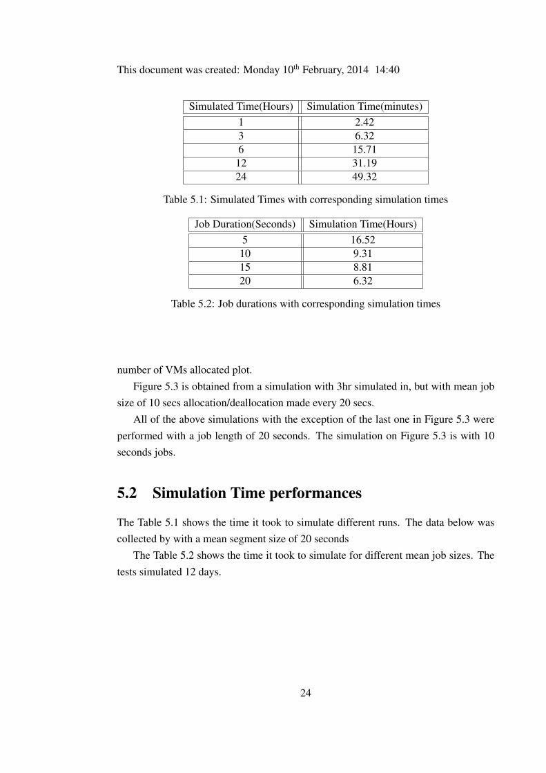
Simulated Time(Hours) Simulation Time(minutes)1 2.423 6.326 15.71
12 31.1924 49.32
Table 5.1: Simulated Times with corresponding simulation times
Job Duration(Seconds) Simulation Time(Hours)5 16.52
10 9.3115 8.8120 6.32
Table 5.2: Job durations with corresponding simulation times
number of VMs allocated plot.Figure 5.3 is obtained from a simulation with 3hr simulated in, but with mean job
size of 10 secs allocation/deallocation made every 20 secs.All of the above simulations with the exception of the last one in Figure 5.3 were
performed with a job length of 20 seconds. The simulation on Figure 5.3 is with 10seconds jobs.
5.2 Simulation Time performances
The Table 5.1 shows the time it took to simulate different runs. The data below wascollected by with a mean segment size of 20 seconds
The Table 5.2 shows the time it took to simulate for different mean job sizes. Thetests simulated 12 days.
24
This document was created: Monday 10th February, 2014 14:40
Figure 5.3: Plot Total transcoding rate and total play rate (top), Total transcodingrate and Predicted transcoding rate (middle) and number of VMs (top) , job length= 10 secs
25
6 FUTURE WORK AND CONCLUSIONS
6.1 Conclusions
In this work a new simulator for prediction based dynamic resource allocation distrib-uted transcoding is built and tested for certain simulated times and job sizes. The needfor a new simulator arose from the deficiencies in the previous simulator that was basedon SimPy discrete event simulation tool. The framework chosen for the new simulatorwas CloudSim, which is a discrete event simulator that is specifically developed withcloud applications in mind. From the results of the tests it can be observed that theamount of resources required for transcoding (VMs) is changing in time following thechange in the play rate/transcoding demand. With regards to performance the observa-tions reveal that linear relationship exists between the time simulated by the system andthe simulation time of the program. However, similar relationship was not observedwhen witnessing the simulation time for different job sizes.
6.2 Future work
A number of extensions can be done by using this simulator as a starting point. Sofar the work described in this report has been mainly based on the pre-existing firstversion python simulator. The next versions of the prediction based distributed videotranscoding simulator, like the one with access control, can be extended on this simu-lator. The Vm selection method used in the simulator is shortest queue, that is a Vmwith the shortest number of jobs is selected to process the next job requiring service.Different mechanisms of Vm selection can be tested either by replacing the shortestqueue approach or integrating the shortest queue method with other mechanisms. Oneexample is the duration of jobs in the queues of the Vms. This consideration could beuseful in cases of jobs with significantly varying durations.
26
BIBLIOGRAPHY
[1] F. Jokhio, A. Ashraf, S. Lafond, I. Porres, and J. Lilius. Prediction-based dynamicresource allocation for video transcoding in cloud computing. February.
[2] R. N. Calheiros, R. Ranjan, A. Beloglazov, C. A. F. De Rose, and R Buyya. Cloud-sim: a toolkit for modeling and simulation of cloud computing environments andevaluation of resource provisioning algo rithms. February 2010.
[3] M. Andreolini and S. Casolari. Load prediction models in webbased systems.February 2006.
27


![Modelling and Simulation of Fog and Edge …CloudSim is one the wildly adopted simulators to model Cloud computing envi-ronments [10] [11]. Extending the abstraction of basic CloudSim](https://img.pdfslide.us/doc/110x75/5e41e65c97a1e27648278150/modelling-and-simulation-of-fog-and-edge-cloudsim-is-one-the-wildly-adopted-simulators.jpg)