Embed Size (px)
Citation preview

Computer Communications 35 (2012) 1809–1818
Contents lists available at SciVerse ScienceDirect
Computer Communications
journal homepage: www.elsevier .com/locate /comcom
Cloud-based image processing system with priority-based datadistribution mechanism
Tin-Yu Wu a, Chi-Yuan Chen b, Ling-Shang Kuo c, Wei-Tsong Lee c, Han-Chieh Chao a,b,d,⇑a Institute of Computer Science & Information Engineering, National Ilan University, Taiwan, ROCb Department of Electrical Engineering, National Dong Hwa University, Taiwan, ROCc Department of Electrical Engineering, Tamkang University, Taiwan, ROCd Department of Electronic Engineering, National Ilan University, Taiwan, ROC
a r t i c l e i n f o
Article history:Available online 20 July 2012
Keywords:3D imageCloud systemMulticast streamingImage processing
0140-3664/$ - see front matter � 2012 Elsevier B.V. Ahttp://dx.doi.org/10.1016/j.comcom.2012.06.015
⇑ Corresponding author at: Institute of CompuEngineering, National Ilan University, Taiwan, ROC. T
E-mail address: [email protected] (H.-C. Chao).
a b s t r a c t
Most users process short tasks using MapReduce. In other words, most tasks handled by the Map andReduce functions require low response time. Currently, quite few users use MapReduce for 2D to 3Dimage processing, which is highly complicated and requires long execution time. However, in our opin-ion, MapReduce is exactly suitable for processing applications of high complexity and high computation.This paper implements MapReduce on an integrated 2D to 3D multi-user system, in which Map is respon-sible for image processing procedures of high complexity and high computation, and Reduce is respon-sible for integrating the intermediate data processed by Map for the final output. Different from shorttasks, when several users compete simultaneously to acquire data from MapReduce for 2D to 3D appli-cations, data that waits to be processed by Map will be delayed by the current user and Reduce has towait until the completion of all Map tasks to generate the final result. Therefore, a novel schedulingscheme, Dynamic Switch of Reduce Function (DSRF) Algorithm, is proposed in this paper for MapReduceto switch dynamically to the next task according to the achieved percentage of tasks and reduce the idletime of Reduce. By using Hadoop to implement our MapReduce platform, we compare the performance oftraditional Hadoop with our proposed scheme. The experimental results reveal that our proposed sched-uling scheme efficiently enhances MapReduce performance in running 2D to 3D applications.
� 2012 Elsevier B.V. All rights reserved.
1. Introduction
Cloud computing is composed of servers that provide high stor-age capacity, high flexibility and high-computing performance [1–5]. Because a cloud computing system has several computing serv-ers, users are able to execute procedures that require largeamounts of computing resources, process a great deal of data onthe cloud, and complete the tasks by low-cost and low-power de-vices. To process the procedures requested by users with cloudcomputing, users can simultaneously enhance the performance ofthe procedures. By using cloud computing for knowledge discoveryand data integration [6,7], Google thus proposed the MapReduceprogramming model.
As a distributed parallel computing architecture presented byGoogle, MapReduce automatically executes parallel computingand partitions the data input by the developer. To simply writeMap and Reduce functions, the developer can execute a full set
ll rights reserved.
ter Science & Informationel.: +886 39357400x251.
of computing procedures. MapReduce mainly include three func-tions: Master, Map function and Reduce function. The Master peri-odically obtains the status of the servers that run Map and Reducefunctions. The Master next divides the input data equally based onthe number of the Map function and distributes the sub-tasks tothe designated servers. The Map function converts the data desig-nated by the Master to the intermediate data while the Reducefunction merges the intermediate data processed by the Map func-tion together and creates the final result.
Derived from an implementation of Google’s MapReduce [8],Hadoop consists of two chief components: Hadoop MapReduceand Hadoop Distributed File System (HDFS). Hadoop MapReduceis a distributed computing platform that includes JobNode, whichis responsible for allocating the developer’s tasks to the TaskNodeand is thus called the Master, and TaskNode, which is responsiblefor executing the tasks designated by the JobNode, including theMap and Reduce functions written by the developer. HDFS mainlycomprises NameNode and DataNode. The DataNodes are responsi-ble for storing the results completed by the Map and Reduce func-tions while the NameNode is responsible for establishing the indexstored in the DataNodes and recording the positions of the dataneeded for the Map and Reduce functions to execute tasks.
1810 T.-Y. Wu et al. / Computer Communications 35 (2012) 1809–1818
At present, most applications built on Hadoop are low-complex-ity and high-density computing, like WordCount, Sort and so on[9–11]. While running such applications, the Map function canget the processed result within a very small amount of time andthe Reduce function mainly spends time waiting for the data pro-cessed by the Map function and integrating the data. However,using MapReduce to implement high-complexity and high-density2D to 3D image processing process [12,13] may cost lots of time forthe Map function to analyze images and to convert the images tointermediate data for the Reduce function to generate 3D images.This paper implements MapReduce on an integrated 2D to 3D mul-ti-user system, in which the Map function is responsible forprocessing 2D effects, like gray scale [14], sobel [15], Gaussianblur and corner detection [16], and converting the images tointermediate data, while the Reduce function is responsible forintegrating the intermediate data generated by the Map function,using 3D model construction algorithm [17] to construct themodel of the object, and presenting 3D images according to userrequirements.
Traditionally, the Map function converts the images to interme-diate data so that the Reduce function can combine the images to-gether for the final output. However, if the computing speed of theMap function is too slow, the data will not be completed and theReduce function has to wait until the data is completed for furthercombination. In such a manner, when the computing speed of theMap function cannot cope with the Reduce function, the tasks ofthe Reduce function will be greatly delayed, which moreover in-creases the operation time.
In this paper, because large amounts of users simultaneouslyuses MapReduce for 2D to 3D image processing, we present a solu-tion to the above-mentioned problem to enhance the performanceof MapReduce in executing 2D to 3D image processing: DynamicSwitch of Reduce Function (DSRF) algorithm, a scheduling schemeon the Reduce function for users who compete simultaneously toacquire Reduce resources to finish the tasks efficiently. With a pri-ority mechanism, DSRF algorithm allows the Reduce function toswitch to different tasks according to the achieved percentage ofthe tasks. In other words, when a combination task is not finishedand the Reduce function is waiting for the Map function to gener-ate intermediate data, the Reduce function can switch to anothertask to combine the image data first. For example, when the dataneeded for the first task is not completed yet but the image dataof the second combination task is ready, the Reduce function pro-cesses the second task first. After finishing the second combinationtask, supposing the image data of the first and the third tasks isboth ready, the Reduce function processes the first task accordingto the priority values. With our proposed scheme, the time spentwaiting for data can efficiently utilized by the Reduce functionand the delayed tasks also can be decreased to enhance the perfor-mance of MapReduce in 2D to 3D image processing.
The rest of the paper is organized as follows. Section 2 intro-duces the background and Section 3 presents our proposed systemarchitecture and DSRF algorithm. Section 4 includes the implemen-tation and performance analysis awhile Section concludes thispaper.
Fig. 1. MapReduce framework.
2. Background
2.1. MapReduce
Proposed by Google, MapReduce is a distributed parallel com-puting architecture designed for processing large amounts ofintensive data and its storage system is Google File System (GFS).For users to process large amounts of data while searching for databy the Google search engine, Google MapReduce provides a simple
programming interface for the developer to develop search engineand processing searching procedures. MapReduce is composed ofthree major components: Master, Map function and Reduce func-tion. The Master is responsible for managing the back-end Mapand Reduce functions and offering data and procedures to them.The Map function converts the data to intermediate data so thatthe Reduce function can combine the intermediate data togetherto obtain the final output.
Whenever the data is received and processed by the Map andReduce functions, there will be a record that includes a key and avalue. The key generated by the input processed by the Map func-tion refers to the correlation between the data while the value onthe other hand means the processed message. When a task is di-vided into several small tasks and handled by the Map function,their correlations are not marked especially. But, one or several re-cords are generated, including the key and the value, after the Mapfunction finishes processing the designated data. According to thekey produced by the Map function, the Reduce function collects thedata with the same key together and generates a value to form anew set of key/value.
As shown in Fig. 1, the input file is cut into M chunks before theMapReduce operation and the file size of each chunk ranges be-tween 16 MB to 64 MB. The file chunks are copied to the file sys-tem and one of the chunks is especially designated to the Masterto find the suitable idle server as the computing server. Next, afterthe Master determines the servers responsible for the Map and Re-duce functions, M Map functions and R Reduce functions are des-ignated to the servers. According to the key/value of the inputdata, servers responsible for the Map function deliver the pro-cessed data to the developer’s Map function and store the Map re-sult in the file system. The intermediate data output by the Mapfunction is cut into R pieces and their locations are returned tothe Master. Once receiving the locations of the data processed bythe Map function from the Master, servers responsible for the Re-duce function read the data remotely, sort the keys and group thevalues with the same key. The Reduce function calculates thenumber of the single key and forwards the data to the developer’sReduce function to generate the final output. After the data iscompletely processed, the Master notifies users to access theresult.
Because of the high-speed network and a storage system thatcan store a large volume of data, MapReduce allows most searchengines to operate. The hardware of MapReduce belongs to anopen-source operating system and is controlled and maintainedby managers to reduce not only the cost of purchasing and main-taining equipments but also the cost of developing MapReduce.Different from centralized RAID-based SAN and NAS storage
T.-Y. Wu et al. / Computer Communications 35 (2012) 1809–1818 1811
systems, the GFS of MapReduce belongs to RAIN (Redundant Arraysof Independent Nodes) architecture [18]. Every MapReduce nodehas its local storage space, each of which is combined with one an-other by the network to form a virtual storage system. Thus, thestorage space of the file system can be easily expanded by addingthe nodes. During the process of adding nodes, MapReduce contin-ues to work and the task will not be terminated. Owing to its highscalability, the Map and Reduce functions can be executed on thou-sands of and even more nodes. However, the nodes’ hardware isnot exactly the same and thus some nodes cannot present stableperformance and might be out of order at any time. By using sim-ple mechanisms to replicate data and perform the backup, GFS andMapReduce can maintain the operation. To repair the damagednodes, the manager removes the damaged ones and repair thehardware. New nodes can join in the computing cluster any timeand the Master takes charge of controlling the operation and per-forming the backup.
2.2. Hadoop
Because Google proposed the concept of MapReduce withoutpresenting the MapRedcue platform, Apache Software Foundationtherefore developed Hadoop, a software framework to implementthe MapReduce programming model. Written in the Java language,Hadoop allows users to process and compute large amounts ofdata. In addition, similar to Google’s GFS, Hadoop provides a file-system called HDFS (Hadoop Distributed File System).
2.2.1. Hadoop MapReduceIn Hadoop MapReduce, the Map and Reduce functions are inter-
linked and coexist. In Fig. 2, when a program processes the data,like Google’s MapReduce, the Master divides the data and distrib-utes the small tasks to the servers responsible for the Map functionwritten by the developer. After the data is processed completely,the Map function stores the data into one or more key/value pairsfor the Reduce function to identify and process, namely the inter-mediate data. Next, the Master transmits the storage locations ofthe intermediate data to the Reduce function to find out the data
Fig. 2. Hadoop MapReduce framework.
to be integrated, create one or more new key/value pairs, and re-port back to the Master the completion of the task. Finally, theMaster notifies users to access the result from the file system.The Master spontaneously designates different nodes to takecharge of the Map and Reduce functions: JobNode and TaskNode,respectively.
As the manager in Hadoop MapReduce, the JobNode is respon-sible for allocating the tasks to the computing servers. As men-tioned previously, the Master designates the tasks according toserver status and the task designation is exactly the responsibilityof the JobNode. When the JobNode is informed of the MapReducefunction to be execute, the JobNode allocates the tasks based onthe operation status reported regularly by the servers.
As the executor in Hadoop MapReduce, the TaskNode is respon-sible for executing the tasks designated by the JobNode. During thetask execution process, the TaskNode continues to report its oper-ation status. Supposing the TaskNode is damaged, the JobNode re-ceives the message and find another idle server to run the taskoriginally executed by the TaskNode.
2.2.2. HDFSHDFS, Hadoop Distributed File System, is designed to integrate
distributed storage resources into a file storage system with highfault-tolerance, high performance and mass storage volume. In Ha-doop, massive amounts of data and files generated during the com-putation are stored in this file system. Although HDFS can onlyprocess files using HDFS shell, Hadoop series systems, like MapRe-duce, can integrate with HDFS and use HDFS for data storage andbackup. Like MapReduce, HDFS chiefly comprises NameNode andDataNode, each of which is defined below.
The NameNode, the file manager in HFDS, is responsible formanaging and storing the attributes and permission of the filesin the system. Because the NameNode does not store files, it noti-fies MapReduce of the storage locations and permission of the fileswhen MapReduce demands the files.
In HDFS, the DataNodes are responsible for storing files. After afile is split into many blocks, each block is copied to a DataNodeand the duplicate of the blocks are also stored by other DataNodesto ensure the completeness of the data in the system when any ofthe DataNodes is broken. Moreover, the DataNodes inform theNameNode of the files’ storage locations so that the NameNodecan offer correct information to MapReduce.
2.3. Image processing procedures
Fig. 3 displays the flowchart of model reconstruction. To processtwo images, we first use Harris corner detector [16] to calculate theinterest points, complete the matching by sum of absolute differ-ence (SAD), and label the matched interest points. Next, we findout the thresholds of data, which is processed by Sobel marginali-zation and Gaussian Blur. Because of the intense edge informationof the data after edge binarization, the relationship among theinterest points can be figured out.
2.3.1. Harris corner detectorCommon corner detection methods include Harris, Susan,
Zheng and Harr. Among these methods, Harris corner detector isutilized most often because of its higher accuracy compared withother existing corner detection methods. Based on the points ofinterest proposed by Moravec in 1977 [2], Harris corner detectorwas proposed with the attempt to modify the problem of Moravecalgorithm that the corner might be located at the edge. Beforeintroducing Harris algorithm, we first introduce Moravec cornerdetection algorithm briefly.
A square mask with point P as the center is established. Suppos-ing V, the gray variation of the mask, is higher than the defined

Fig. 3. Flowchart of model reconstruction.
Fig. 4. Moravec corner detection.
1812 T.-Y. Wu et al. / Computer Communications 35 (2012) 1809–1818
threshold, point P is defined as the corner (Fig. 4(a)). Moravec algo-rithm can be expressed by mathematical function as
Eðx;yÞ ¼X
u;vwðu;vÞjIðxþu;yþvÞ � Iðu;vÞj2; ð1Þ
where w refers to the image window, which means to retrieve onlythe data inside of the mask during the search. Data outside of themask does not influence the computing result. Iðu;vÞ symbolizesthe gray level of location ðu;vÞ. However, this method often leadsto misjudgments because of higher gray variation occurred at theedge of the object (Fig. 4(b)), or caused by noises (Fig. 4(c)). More-over, it is very difficult to establish the threshold in a complicatedenvironment.
To solve the problems of Moravec: the difficulty in establishingthe thresholds, the misjudgment in determining the object’s edges,and the inability to recognize the corners after rotating the object,Chris Harris and Mike Stephens proposed Harris corner detectionalgorithm in 1988.
2.3.2. Sum of absolute difference (SAD)To subtract pixels of two image blocks, SAD can measure the
similarity between image blocks. The lower SAD value means thehigher similarity of the two blocks. SAD can be expressed by themathematical function as
SAD ¼X
xA2XA;B
jAðxAÞ � BðxAÞj; ð2Þ
where A and B stand for the two images to be judged, and XðA;BÞmeans that there are N pixels of A and B in the overlap area. Thus,we use SAD to judge the relationship of interest points detectedby Harris corner detection method, and label the correspondingpoints for computers to judge the corresponding locations of inter-est points after rotating an object. With the relationship of the cor-ners, we can use interpolation to judge the location of the cornerwhile being photographed to simulate the object rotation.
2.3.3. Model reconstructionWith the simulated corner location only, it is impossible to
judge the shape of an object in human vision. Therefore, the nextstep is to reconstruct the edge relations between corners.
By binarizing the image processed by Sobel marginalization andGaussian Blur, we can get the intense edge information with lownoises to determine whether the two points have edge relations.To define the average brightness of two points as B, the distanceas L, a random point between two points as P, we can get the math-ematical function as
B ¼XL
n¼1
Pðn�dx;n�dyÞ; ð3Þ
where
dx ¼ � x1 � x2
L; ð4Þ
and
dy ¼ � y1 � y2
L: ð5Þ
When B is higher than the defined threshold, it can be determinedthat the two points have edge relations.
3. DSRF (Dynamic Switch of Reduce Function) algorithm
3.1. MapReduce runtime system with 2D to 3D application
First, a Master is established in the server cluster to acquire theoperation status of all servers and the Map and Reduce functionswritten by the developer for 2D to 3D application are offered tothe Master. To connect all servers via the network, the Masteraccesses the resources of all servers’ HDFS and the current opera-tion status of Map and Reduce, and allocates the Map and Reducefunctions to designated servers. In other words, the Master mastersthe resources and status (idle or working) of all servers. Because

T.-Y. Wu et al. / Computer Communications 35 (2012) 1809–1818 1813
the Master’s NameNode owns the storage locations of the datastored in HDFS, the Master is responsible for notifying the comput-ing servers of the locations of the data needed to execute Map andReduce functions. By communicating with the Master, the devel-oper can know the operation status of all servers and the data inthe servers, choose the maximum limit of designated servers,and easily allocate the Map and Reduce function to the servers.
2D to 3D application is divided and handled separately by theMap function and Reduce function. In Fig. 5, the Map function givesservice to object cameras and provides the intermediate data forthe Reduce function. The Map process includes grayscale, sobel,Gaussian blur and corner detection. Through the four image pro-cessing procedures, we can get the positions of the corners andthe brightness of the original images from two cameras. In this pa-per, four image processing algorithms are moreover written intothe Map function for the Master to allocate. Next, the Reduce func-tion accesses the Map function to get the image data to be pro-cessed and creates the final output by SAD matching and 3Dgraphing. The Reduce function includes SAD matching, labelingand model reconstruction. The Reduce function combines the dataof two images, like the positions of the corner and motion vector,etc., and simulates the graphs of all angular vector by model recon-struction. Finally, through wireless network, the output is sentback to the terminal devices of MapReduce for parameter adjust-ments, and users are able to access the needed angles of visionby HDFS and display the images by terminal devices.
Fig. 6. DSRF algorithm.
3.2. DSRF algorithmAs shown in Fig. 6 and Algorithm 1, we use Hadoop to establishthe computing environment, which includes MapReduce andHDFS. The mechanism of MapReduce is that the developer adaptsthe 2D to 3D application to a framework of Map and Reduce func-tions and puts the framework in the Master server. Thus, beforeexecuting MapReduce, the developer can allocate the functions to
Fig. 5. MapReduce runtime system
the TaskNodes through the JobNode in the Master without spend-ing additional time allocating Map and Reduce functions. The im-age data obtained by the monitors are stored in key/value pairsand replicated to the DataNodes of Hadoop HDFS. After the Data-Nodes store the images, the locations of the images will be sent
with 2D to 3D application.

1814 T.-Y. Wu et al. / Computer Communications 35 (2012) 1809–1818
to the NameNode in the Master. Since the back-end servers period-ically send their busy status to the Master, the Master receives thecommands, searches for idle servers, and designates the Map andReduce functions to servers by the JobNode. The Master moreoverfinds out the locations of the data needed to execute functions bythe NameNode and informs the servers responsible for Map andReduce functions to access. After the Map function receives the im-age data and finishes processing, the output framework will be theintermediate data in key/value pairs for the Reduce function to rec-ognize. The intermediate data output by the Map function is storedin HDFS and its location is recorded by the Master. Thus, when theReduce function gets ready to execute a combination task, theMaster informs the servers responsible for the Reduce function ofthe location of the intermediate data. Once the data is completed,the Reduce starts the combination task and stores the result in key/value pairs in HDFS when the task is accomplished.
Algorithm 1: DSRF
1. Initialize image process;2. Write Map-Reduce structure;3. Set server to handle Map or Reduce;4. Write image into HDFS of Hadoop;5. Repeat image process until image data processed;6. Set Map-Reduce and data into Map layer cutting by
managers;7. When Map complete it’s task;8. Sent Map output data to Reduce;9. If Reduce task cannot get all data from Maps10. Set priority value to the task and put it into Reduce
wait queue;11. Detect the priority of task which have all data are in
the Reduce process queue;12. Operate the higher priority task which have all data;13. Otherwise14. Reduce sent the Reduce output data to clients.
Because the Map and Reduce functions spend longer time pro-cessing images, the Reduce function may need extra time waitingfor the data to be written into HDFS. Supposing the Reduce func-tion is ready to begin a combination task but cannot attain the fullintermediate data of the Map function from HDFS, the Reducefunction has to wait until all intermediate data needed has beenwritten into HDFS to begin the task, which wastes much more timein processing a combination task. For this reason, our DSRF (Dy-namic Switch of Reduce Function) algorithm proposes to processthe rest intermediate data first while the Reduce function is wait-ing for the intermediate data. Our DSRF algorithm adds a schedul-ing mechanism to the Reduce function and prioritizes thecombination tasks to be executed. When the intermediate dataneeded for the first combination task is not fully written into HDFS,the Reduce function switches to the second combination task withcomplete intermediate data. After finishing the second combina-tion task, if the intermediate data of the first task is ready, the Re-duce function returns to the first task, writes the task result toHDFS and completes the task.
3.3. DSRF algorithm working principle
The Master notifies the servers responsible for the Map functionof the locations of the images needed for the Map function. TheMap function next accesses the locations, obtains the images tobe processed, and processes four procedures: grayscale, sobel,Gaussian blur and corner detection. After the corner detection iscompleted, the Map function converts the image data to the inter-
mediate data for the Reduce function to execute and informs theMaster that the task has been completed. According to the Master’snotification, the Reduce function reads the intermediate data forthe combination tasks. DSRF algorithm in the Reduce function des-ignates different priority values to different combination tasksbased on their arrival time. The earlier combinations tasks havehigher priority values and vice versa. Supposing the data neededfor the earlier tasks is not ready yet, DSRF algorithm first switchesto other combination tasks with full image data. After the Reducefunction finishes the current combination task, DSRF algorithmasks the Reduce function to process the combination task withhigher priority value and full image data. Finally, the image datacompleted is written to HDFS and offered to users.
For example, as displayed in Fig. 7, the Reduce function is readyto process the first combination task but split1-5 of the first task isnot stored in HDFS yet, which means that the Reduce function doesnot have the full data for the first combination task. At the sametime, the data for the second combination task is ready. In such amanner, the Reduce function chooses to execute the second com-bination task while waiting for split1-5. After the second combina-tion task is finished and the data for the third and the firstcombination tasks is both ready, the Reduce function chooses toprocess the first task according to priority values. By such a sched-uling mechanism, our proposed method allows the Reduce func-tion to utilize the time waiting for data, to first process thecombination tasks with full data chunks, and to return to the ear-lier tasks based on priority values. The following implementationwill prove that our proposed DSRF algorithm and scheduling mech-anism can enhance the system performance.
4. Implementation
4.1. Implementation environment
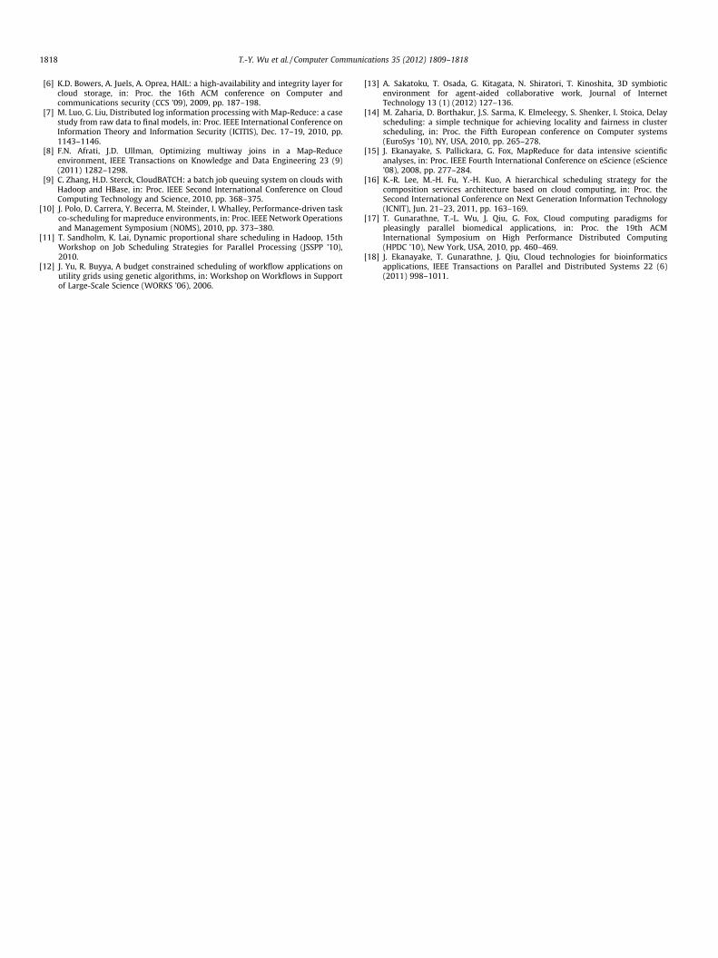
This section implements our DSRF algorithm in Hadoop MapRe-duce and Fig. 8 presents the implementation environment. This pa-per uses the Ubuntu 10.04 as the OS to run Hadoop and adoptsHadoop 0.20.2. Because Hadoop MapReduce is written in the Javalanguage, we use Eclipse IDE to write the Map and Reduce func-tions. There are totally four servers in the implementation: twofor the Map function and the other two for the Reduce function.The four servers are connected by the cable lines with a rate ofone gigabit per second. Next, we aim to analyze the influence ofuser number and the number of Map and Reduce functions tothe total time and compare the results with traditional Hadoop.
Left view and right view in Fig. 9 are the images that the Mapfunction will process and convert to a 3D model by image process-ing procedures. In other words, with the image data of left viewand right view, like corners and angles, we can simulate all anglesfrom left view to right view and display the 3D images on terminaldevices. The lower models in Fig. 9 are simulated by MapReduce.Thus, through the touch pads of terminal devices, users can viewthe simulated 3D images at different angles.
4.2. Performance analysis and evaluation
This section makes a comparison of MapReduce with DSRF algo-rithm and traditional Hadoop in processing 2D to 3D application.Fig. 10 shows the influence of user number to the total computingtime in our proposed DSRF algorithm and traditional Hadoop. Thehorizontal axis means the increasing user number while the verti-cal axis means the total time for the MapReduce operation. The fig-ure reveals that before the user number reaches 70, DSRFalgorithm obviously accelerates the MapReduce operation effi-ciently and outperforms traditional Hadoop because our proposed
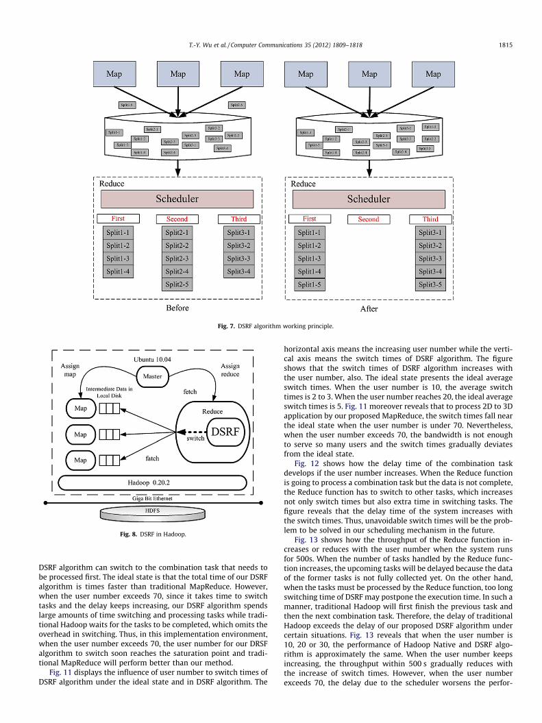
Fig. 7. DSRF algorithm working principle.
Fig. 8. DSRF in Hadoop.
T.-Y. Wu et al. / Computer Communications 35 (2012) 1809–1818 1815
DSRF algorithm can switch to the combination task that needs tobe processed first. The ideal state is that the total time of our DSRFalgorithm is times faster than traditional MapReduce. However,when the user number exceeds 70, since it takes time to switchtasks and the delay keeps increasing, our DSRF algorithm spendslarge amounts of time switching and processing tasks while tradi-tional Hadoop waits for the tasks to be completed, which omits theoverhead in switching. Thus, in this implementation environment,when the user number exceeds 70, the user number for our DRSFalgorithm to switch soon reaches the saturation point and tradi-tional MapReduce will perform better than our method.
Fig. 11 displays the influence of user number to switch times ofDSRF algorithm under the ideal state and in DSRF algorithm. The
horizontal axis means the increasing user number while the verti-cal axis means the switch times of DSRF algorithm. The figureshows that the switch times of DSRF algorithm increases withthe user number, also. The ideal state presents the ideal averageswitch times. When the user number is 10, the average switchtimes is 2 to 3. When the user number reaches 20, the ideal averageswitch times is 5. Fig. 11 moreover reveals that to process 2D to 3Dapplication by our proposed MapReduce, the switch times fall nearthe ideal state when the user number is under 70. Nevertheless,when the user number exceeds 70, the bandwidth is not enoughto serve so many users and the switch times gradually deviatesfrom the ideal state.
Fig. 12 shows how the delay time of the combination taskdevelops if the user number increases. When the Reduce functionis going to process a combination task but the data is not complete,the Reduce function has to switch to other tasks, which increasesnot only switch times but also extra time in switching tasks. Thefigure reveals that the delay time of the system increases withthe switch times. Thus, unavoidable switch times will be the prob-lem to be solved in our scheduling mechanism in the future.
Fig. 13 shows how the throughput of the Reduce function in-creases or reduces with the user number when the system runsfor 500s. When the number of tasks handled by the Reduce func-tion increases, the upcoming tasks will be delayed because the dataof the former tasks is not fully collected yet. On the other hand,when the tasks must be processed by the Reduce function, too longswitching time of DSRF may postpone the execution time. In such amanner, traditional Hadoop will first finish the previous task andthen the next combination task. Therefore, the delay of traditionalHadoop exceeds the delay of our proposed DSRF algorithm undercertain situations. Fig. 13 reveals that when the user number is10, 20 or 30, the performance of Hadoop Native and DSRF algo-rithm is approximately the same. When the user number keepsincreasing, the throughput within 500 s gradually reduces withthe increase of switch times. However, when the user numberexceeds 70, the delay due to the scheduler worsens the perfor-

Fig. 9. Input images and simulated images.
10 20 30 40 50 60 70 80 900
200
400
600
800
1000
1200
1400
1600
1800
User Number
Tota
l Tim
e (s
ec)
DSRF AlgorithmTraditional
Fig. 10. The influence of user number to the total time.
10 20 30 40 50 60 70 80 900
5
10
15
20
25
30
User Number
Switc
h Ti
mes
DSRF AlgorithmIdeal State
Fig. 11. The influence of user number to switch times of DSRF algorithm.
10 20 30 40 50 60 70 80 900
10
20
30
40
50
60
User Number
Del
ay T
ime
(sec
) & S
witc
h Ti
mes
Delay Time of DSRFSwitch Times of DSRF
Fig. 12. The influcence of user number to delay time and switch times of acombination task.
1816 T.-Y. Wu et al. / Computer Communications 35 (2012) 1809–1818
mance of DRSF algorithm and the throughput of DSRF algorithmgradually gets lower than Hadoop native.
Fig. 14 displays the average waiting time of each user when theuser number increases. The waiting time means the time from theuser requests the image to the user receives the image. In the fig-ure, when the user number exceeds 60, our proposed DSRF algo-rithm uses most of the waiting time in switching tasks.Nevertheless, the figure further shows that when the user numberis under 70, the waiting time of our DSRF algorithm is obviouslyless than traditional Hadoop MapReduce.
Fig. 15 compares the maximal queue number of traditional Ha-doop MapReduce and our proposed DSRF algorithm when the usernumber is 40. The figure shows that with less user number, thequeue number of Hadoop Native and DSRF algorithm is very close.Thus, we can know that Hadoop Native and DSRF algorithm resultto similar system stability but DSRF in fact performs better.
Fig. 16 compares the maximal queue number when the usernumber is 80. Our proposed DSRF algorithm is able to maintainthe queue number within a stable range. However, with the

10 20 30 40 50 60 70 80 900
5
10
15
20
25
30
User Number
Thro
ughp
ut (M
B)
DSRF AlgorithmHadoop Native
Fig. 13. The influence of user number to the throughput.
10 20 30 40 50 60 70 80 9010
15
20
25
User Number
Wai
ting
Tim
e (s
ec)
DSRF AlgorithmHadoop Native
Fig. 14. The influence of user number to the average waiting time.
5 10 15 20 25 30
5
10
15
20
25
30
35
Times
Que
ue N
umbe
r
DSRF AlgorithmHadoop Native
Fig. 15. Relation between user number and the maximal queue number (usernumber = 40).
5 10 15 20 25 30
5
10
15
20
25
30
35
Times
Que
ue N
umbe
r
DSRF AlgorithmHadoop Native
Fig. 16. Relation between user number and the maximal queue number (usernumber = 80).
T.-Y. Wu et al. / Computer Communications 35 (2012) 1809–1818 1817
increase of user number, Hadoop Native results to severe vibrationof the maximal queue number. Therefore, it reveals that traditionalHadoop Native is not as stable as DSRF algorithm.
5. Conclusion
MapReduce is presented to process vast amounts of data and toreturn the result to users within the minimum time. Most usersuse MapReduce to handle applications of higher speed and lowercomputing complexity. In this paper, we implement MapReduceon an integrated 2D to 3D multi-user system, in which the Mapfunction is responsible for image processing procedures with highcomplexity and high computation and the Reduce function isresponsible for combining the intermediate data processed bythe Map function and creating the final output. Applications ofhigh complexity and high computation will prolong the executionof the Map function and delay the following tasks. Thus, this paperpresents a DSRF (Dynamic Switch of Reduce Function) algorithm toswitch to different tasks dynamically according to the achievedpercentage of tasks. When the waiting time increases with the usernumber, our DSRF algorithm allows the Reduce function to utilizethe waiting time in computing other tasks. In this way, not only thewaiting time and the computing time can be reduced, but alsousers can get the image results quickly and the MapReduce systemcan reach higher performance. Our future target is to include morequality schemes, like QoE and QoS, so that better quality can beguaranteed in the cloud infrastructure to enhance cloud-basedtransmissions.
References
[1] Q. He, Z. Li, X. Zhang, Study on cloud storage system based on distributedstorage systems, in: Proc. International Conference on Computational andInformation Sciences (ICCIS), Dec. 17–19, 2010, pp. 1332–1335.
[2] J. Jiang, Y. Wu, X. Huang, G. Yang, W. Zheng, Online video playing onsmartphones: a context-aware approach based on cloud computing, Journal ofInternet Technology 11 (6) (2010) 821–828.
[3] C.-H. Chiu, H.-T. Lin, S.-M. Yuan, CloudEdge: a content delivery system forstorage service in cloud environment, International Journal of Ad Hoc andUbiquitous Computing 6 (4) (2010) 252–262.
[4] Y. Xu, J. Yan, A cloud-based design of smart car information services, Journal ofInternet Technology 13 (2) (2012) 317–326.
[5] Y.-X. Lai, C.-F. Lai, C.-C. Hu, H.-C. Chao, Y.-M. Huang, A personalized mobileIPTV system with seamless video reconstruction algorithm in cloud networks,International Journal of Communication Systems 24 (10) (2011) 1375–1387.
1818 T.-Y. Wu et al. / Computer Communications 35 (2012) 1809–1818
[6] K.D. Bowers, A. Juels, A. Oprea, HAIL: a high-availability and integrity layer forcloud storage, in: Proc. the 16th ACM conference on Computer andcommunications security (CCS ’09), 2009, pp. 187–198.
[7] M. Luo, G. Liu, Distributed log information processing with Map-Reduce: a casestudy from raw data to final models, in: Proc. IEEE International Conference onInformation Theory and Information Security (ICITIS), Dec. 17–19, 2010, pp.1143–1146.
[8] F.N. Afrati, J.D. Ullman, Optimizing multiway joins in a Map-Reduceenvironment, IEEE Transactions on Knowledge and Data Engineering 23 (9)(2011) 1282–1298.
[9] C. Zhang, H.D. Sterck, CloudBATCH: a batch job queuing system on clouds withHadoop and HBase, in: Proc. IEEE Second International Conference on CloudComputing Technology and Science, 2010, pp. 368–375.
[10] J. Polo, D. Carrera, Y. Becerra, M. Steinder, I. Whalley, Performance-driven taskco-scheduling for mapreduce environments, in: Proc. IEEE Network Operationsand Management Symposium (NOMS), 2010, pp. 373–380.
[11] T. Sandholm, K. Lai, Dynamic proportional share scheduling in Hadoop, 15thWorkshop on Job Scheduling Strategies for Parallel Processing (JSSPP ’10),2010.
[12] J. Yu, R. Buyya, A budget constrained scheduling of workflow applications onutility grids using genetic algorithms, in: Workshop on Workflows in Supportof Large-Scale Science (WORKS ’06), 2006.
[13] A. Sakatoku, T. Osada, G. Kitagata, N. Shiratori, T. Kinoshita, 3D symbioticenvironment for agent-aided collaborative work, Journal of InternetTechnology 13 (1) (2012) 127–136.
[14] M. Zaharia, D. Borthakur, J.S. Sarma, K. Elmeleegy, S. Shenker, I. Stoica, Delayscheduling: a simple technique for achieving locality and fairness in clusterscheduling, in: Proc. the Fifth European conference on Computer systems(EuroSys ’10), NY, USA, 2010, pp. 265–278.
[15] J. Ekanayake, S. Pallickara, G. Fox, MapReduce for data intensive scientificanalyses, in: Proc. IEEE Fourth International Conference on eScience (eScience’08), 2008, pp. 277–284.
[16] K.-R. Lee, M.-H. Fu, Y.-H. Kuo, A hierarchical scheduling strategy for thecomposition services architecture based on cloud computing, in: Proc. theSecond International Conference on Next Generation Information Technology(ICNIT), Jun. 21–23, 2011, pp. 163–169.
[17] T. Gunarathne, T.-L. Wu, J. Qiu, G. Fox, Cloud computing paradigms forpleasingly parallel biomedical applications, in: Proc. the 19th ACMInternational Symposium on High Performance Distributed Computing(HPDC ’10), New York, USA, 2010, pp. 460–469.
[18] J. Ekanayake, T. Gunarathne, J. Qiu, Cloud technologies for bioinformaticsapplications, IEEE Transactions on Parallel and Distributed Systems 22 (6)(2011) 998–1011.