Embed Size (px)
Citation preview
Caltrans Division of Research, Innovation and System Information
Preliminar y Investigation
Closing Additional Traffic Lanes Adjacent to Work Areas: A Survey of State Practices and Related Resources
Requested by Celso Izquierdo, Division of Construction
November 6, 2015
The Caltrans Division of Research, Innovation and System Information (DRISI) receives and evaluates numerous research problem statements for funding every year. DRISI conducts Preliminary Investigations on these problem statements to better scope and prioritize the proposed research in light of existing credible work on the topics nationally and internationally. Online and print sources for Preliminary Investigations include the National Cooperative Highway Research Program (NCHRP) and other Transportation Research Board (TRB) programs, the American Association of State Highway and Transportation Officials (AASHTO), the research and practices of other transportation agencies, and related academic and industry research. The views and conclusions in cited works, while generally peer reviewed or published by authoritative sources, may not be accepted without qualification by all experts in the field. The contents of this document reflect the views of the authors, who are responsible for the facts and accuracy of the data presented herein. The contents do not necessarily reflect the official views or policies of the California Department of Transportation, the State of California, or the Federal Highway Administration. This document does not constitute a standard, specification, or regulation. No part of this publication should be construed as an endorsement for a commercial product, manufacturer, contractor, or consultant. Any trade names or photos of commercial products appearing in this publication are for clarity only.
Table of Contents
Executive Summary ................................................................................................................. 2 Background ............................................................................................................................... 2
Summary of Findings ................................................................................................................ 2
Gaps in Findings ....................................................................................................................... 5
Next Steps................................................................................................................................. 5
Detailed Findings ..................................................................................................................... 6 Survey of State Practices ......................................................................................................... 6
Related Resources ................................................................................................................. 15
Appendices ............................................................................................................................. 28
Executive Summary
Background Caltrans is considering a modification to its work zone lane closure requirements that would provide for closure of an adjacent traffic lane (a “buffer lane”) where two or more lanes in the same direction are adjacent to the area where work is being performed, including shoulders, under the following conditions:
• Work is off the traveled way but within 6 feet of the edge of the traveled way, and the approach speed is greater than 45 mph.
Work is off the traveled way but within 3 feet of the edge of the traveled way, and the approach speed is less than 45 mph.
•
Closure of the adjacent traffic lane would not be required in the following situations:
1.
2.
3.
When crews are working behind a barrier.
For paving, grinding or grooving operations.
For installing, maintaining or removing traffic control devices, except Type K temporary railing.
In connection with this proposed modification, Caltrans is interested in learning about guidelines or decision tools that address the use of buffer lanes and appropriate alternatives to lane closure, including the use of positive protection devices.
To assist with this effort, CTC & Associates reviewed published and in-progress research and other relevant documents to identify publications that address the use of buffer lanes and positive protection devices, and the cost and safety implications of the use of buffer lanes and alternatives to this practice. To supplement the literature review, CTC conducted an email survey of representatives of state departments of transportation (DOTs) to gather information relevant to these topics.
Summary of Findings
Survey of State Practices A brief email survey was distributed to members of the AASHTO Subcommittee on Traffic Engineering to gather information about state practices for the use of buffer lanes, alternative practices when buffer lanes are not available, and guidance for the use of positive protection devices. Eighteen state DOTs responded to the survey.
Most respondents reported that their agencies do not have detailed guidelines for the use of buffer lanes. Even fewer respondents reported on efforts to compare the cost-effectiveness and safety implications of the use of buffer lanes with other alternatives. The area of inquiry that generated the most information from this brief survey was the use of positive protection devices.
Guidelines for Providing a Lateral Buffer Space
Six of the 18 states—Delaware, Kansas, Minnesota, Oklahoma, Virginia and Washington—have some type of guidance (published or in draft form) for the provision of a lateral buffer space in
Produced by CTC & Associates LLC 2
work areas. None of the respondents provided guidance as specific as the provisions under consideration by Caltrans.
Kansas, Minnesota and Oklahoma DOTs address the use of buffer space in edge drop-off guidelines or standards. The Kansas DOT guidance is in the draft stage. The respondent reported no internal consensus on the draft provisions, and does not expect the guidance to be published in the near future.
Delaware, Minnesota and Virginia DOTs address lateral buffer spaces in their respective state versions of the Manual on Uniform Traffic Control Devices (MUTCD). The Minnesota DOT respondent noted that, in practice, buffer lanes are rarely used due to lane closure restrictions aimed at maintaining traffic flow and minimizing backups and the resulting end-of-queue crashes. While Washington State DOT does not have a separate guideline, the agency’s design manual and work zone guidelines for maintenance require a minimum 2-foot lateral shy distance and recommend considering more.
Practices Used When a Buffer Lane Is Unavailable
There was little consensus among respondents with regard to practices used when there are not enough adjacent lanes available to provide a buffer lane. The most frequently cited practice—the use of some type of positive protection device—was reported by seven respondents (Kansas, Massachusetts, Minnesota, Nevada, New Mexico, North Carolina and Virginia). The next most frequently cited practices were police enforcement and reduced speed, reported by just four and five respondents, respectively.
Assessing the Cost-Effectiveness and Safety of Buffer Lanes
Of the four respondents who answered the survey question about the cost-effectiveness and safety of buffer lanes as compared to other alternatives, none reported the use of a specific tool or methodology to make such an assessment. Delaware and Washington State DOT make such considerations at the project level, and Minnesota and North Carolina DOTs highlighted the conflicting demands that affect the decision of whether to provide a buffer lane.
For Minnesota DOT, lane closure restrictions in the Minneapolis–St. Paul metro area make it impossible to take extra lanes during the daytime. Closing adjacent lanes may be possible during nighttime hours, but as the respondent noted, “the shifting of maintenance work from daytime to nights has other cost and safety implications.” For North Carolina DOT too, the use of a buffer lane is more likely during nighttime operations and during nonpeak hours only.
Guidelines for the Use of Positive Protection Devices
Twelve of the 18 state DOTs responding to the survey reported guidelines or established practices for the use of positive protection devices.
Related Resources Buffer Space
National Guidance
The national MUTCD includes a table that offers guidance in determining the length of a longitudinal buffer space. MUTCD guidance for the determination of a lateral buffer space is more limited, with figures that show the use of a lateral buffer space to separate the traffic space
Produced by CTC & Associates LLC 3
from the work space, or from areas of excavation and pavement-edge drop-offs, and these recommendations:
•
•
The width of a lateral buffer space should be determined by engineering judgment.
A lateral buffer space also may be used between two travel lanes, especially those carrying opposing flows.
A 2014 Federal Highway Administration (FHWA) guide on the use of buffer spaces provides a more general discussion of the use of lateral buffer spaces—not specifically buffer lanes—with and without the use of positive protection.
State Guidance
Researchers noted in a September 2014 Oregon DOT report that “[w]hen a buffer lane is provided, there is greater distance between the workers and passing traffic, yet this study reveals that the vehicle speed is greater. On the other hand, the speeds are slower yet the vehicles closer to the workers without the buffer lane. The results of this study are not sufficient to provide a clear recommendation for practice. A more detailed study of the risk associated with the buffer lane present compared to not having the buffer lane would be of interest.”
Positive Protection Devices
National Guidance
The most recent national guidance, from FHWA, provides a detailed discussion of the types of positive protection devices and a decision tool that can be used to select among the various devices available. Other relevant national publications include an AASHTO guide for testing temporary highway safety features (a class that includes positive protection devices) and FHWA’s final rule with regard to temporary traffic control devices.
State Guidance
A 2013 Kansas DOT report provides a comprehensive compilation of state practices, summarizing 25 state DOT responses to a survey about the use of positive protection devices. Positive protection guidance from six state DOTs—Colorado, Idaho, Michigan, New Hampshire, Texas and Vermont—is cited in this section of the Preliminary Investigation.
Barrier Systems
Several conference papers and research reports have examined a specific class of positive protection devices—mobile or portable barrier systems. Researchers have considered the impact of these systems on vehicle speeds; appropriate applications for these devices; and benefits and costs.
Truck-Mounted Attenuators
The truck-mounted attenuator (TMA) is another class of positive protection device. TMAs are defined by FHWA as “energy-absorbing devices attached to the rear of a shadow vehicle (a truck or trailer used to protect workers or work equipment from errant vehicles) that are designed to lessen impact severity for occupants of the impacting vehicle, and to some extent, occupants of the shadow vehicle.” A 2013 Texas DOT report contrasted the truck-mounted unit with a mobile unit. Other publications have assessed the costs and benefits of TMA use and examined how TMAs used in work zones affect crash rates.
Produced by CTC & Associates LLC 4
Alternatives to Lane Closure
A 2014 paper examined the impacts of shoulder use—a practice also identified by survey respondents as an alternative to lane closure. A 2015 Ohio DOT report evaluated alternative temporary traffic control practices on rural one- and two-lane highways.
Assessment Tools
We identified several citations that review tools for assessing the cost-effectiveness of lane closure in general. Although these tools do not specifically compare the cost and safety implications of a buffer lane with other alternatives, they may inform Caltrans’ investigation of a tool appropriate for examining the effects of buffer lanes.
Gaps in Findings The survey responses did not offer much guidance on the provision of buffer lanes. A few states’ guidance mirrors direction in the national MUTCD or expands slightly upon it. A review of the literature offered no further direction on the provision of buffer lanes. This indicates the need for further research, a conclusion also reached by researchers preparing a September 2014 Oregon DOT report on establishing speed reductions in work zones. Also lacking in the survey responses and results of the literature review are tools and practices to compare the cost- effectiveness and safety of the use of buffer lanes with other alternatives.
Next Steps Moving forward, Caltrans could consider:
• Consulting with Kansas DOT about the discussions in process at that agency with regard to buffer lanes.
Contacting researchers associated with a September 2014 Oregon DOT report to determine if further research is planned on the effects of buffer lanes.
Investigating the tools now used to assess the costs and benefits of lane closure, with an eye toward identifying potential areas of relevance to an examination of buffer lanes.
Examining in detail the guidelines for the use of positive protection devices to identify areas of interest for Caltrans’ use of such devices.
Following up with agencies with research in progress on positive protection devices. Topics include TMA crashes (Virginia); an electronic safety perimeter system (Kansas); and a safety assessment tool (Iowa).
Checking in with the Wisconsin Traffic Operations and Safety Laboratory about an ongoing effort to produce a decision guide for the use of positive protection. The Kansas DOT survey respondent commented on this research and noted that publication is expected in early 2016.
•
•
•
•
•
Produced by CTC & Associates LLC 5
Detailed Findings
Survey of State Practices We distributed a brief email survey to members of the AASHTO Subcommittee on Traffic Engineering to gather information about state practices for the use of buffer lanes, alternatives to lane closure and guidance for the use of positive protection devices. The survey consisted of the following questions:
1. Do you have guidelines you can share for determining when to provide a lateral buffer space when performing reconstruction or maintenance work on different types of roadways (rural, urban and freeway)?
What practices do you employ when there are not enough adjacent lanes available to provide a buffer space (for example, on two- or three-lane facilities)?
Have you examined the cost-effectiveness and safety implications of providing a buffer space and alternatives to closing adjacent traffic lanes?
Do you have guidelines you can share with regard to the use of positive protection devices when adjacent traffic lanes are not closed?
2.
3.
4.
We received responses from 18 state DOTs:
• • • • • •
• • • • • •
• • • • • •
Alaska. Delaware. Illinois. Kansas. Kentucky. Maine.
Massachusetts. Minnesota. Nebraska. Nevada. New Mexico. New York.
North Carolina. Oklahoma. South Dakota. Virginia. Washington. Wisconsin.
See Appendix A to this Preliminary Investigation for the full text of all survey responses.
The survey gathered information in four topic areas related to the use of buffer lanes, alternatives to lane closure and the use of positive protection devices:
•
•
•
•
Guidelines for providing a lateral buffer space.
Practices used when a buffer lane is unavailable.
Comparing the cost-effectiveness and safety of buffer lanes and alternatives.
Guidelines for the use of positive protection devices.
Key findings from the survey follow.
Guidelines for Providing a Lateral Buffer Space Six of the 18 respondents—Delaware, Kansas, Minnesota, Oklahoma, Virginia and Washington—have some type of guidance (published or in draft form) for the provision of a lateral buffer space in work areas.
Produced by CTC & Associates LLC 6
• Three agencies—Kansas, Minnesota and Oklahoma DOTs—address the use of buffer space in edge drop-off guidelines or standards.
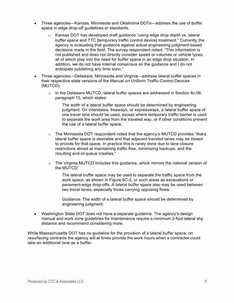
o Kansas DOT has developed draft guidance “using edge drop depth vs. lateral buffer space and TTC [temporary traffic control device] treatment.” Currently, the agency is evaluating that guidance against actual engineering judgment-based decisions made in the field. The survey respondent noted: “This information is not published and does not directly consider speed or volumes or vehicle types, all of which play into the need for buffer space in an edge drop situation. In addition, we do not have internal consensus on the guidance and I do not anticipate publishing any time soon.”
Three agencies—Delaware, Minnesota and Virginia—address lateral buffer spaces in their respective state versions of the Manual on Uniform Traffic Control Devices (MUTCD).
•
In the Delaware MUTCD, lateral buffer spaces are addressed in Section 6c.06, paragraph 15, which states:
The width of a lateral buffer space should be determined by engineering judgment. On interstates, freeways, or expressways, a lateral buffer space of one travel lane should be used, except where temporary traffic barrier is used to separate the work area from the traveled way, or if other conditions prevent the use of a lateral buffer space.
o
The Minnesota DOT respondent noted that the agency’s MUTCD provides “that a lateral buffer space is desirable and that adjacent traveled lanes may be closed to provide for that space. In practice this is rarely done due to lane closure restrictions aimed at maintaining traffic flow, minimizing backups, and the resulting end-of-queue crashes.”
o
The Virginia MUTCD includes this guidance, which mirrors the national version of the MUTCD:
The lateral buffer space may be used to separate the traffic space from the work space, as shown in Figure 6C-2, or such areas as excavations or pavement-edge drop-offs. A lateral buffer space also may be used between two travel lanes, especially those carrying opposing flows.
o
Guidance: The width of a lateral buffer space should be determined by engineering judgment.
• Washington State DOT does not have a separate guideline. The agency’s design manual and work zone guidelines for maintenance require a minimum 2-foot lateral shy distance and recommend considering more.
While Massachusetts DOT has no guideline for the provision of a lateral buffer space, on resurfacing contracts the agency will at times provide the work hours when a contractor could take an additional lane as a buffer.
Produced by CTC & Associates LLC 7
Respondents’ Alternative Practices When a Buffer Lane Is Unavailable
Category Practice Agency Comment Policies, regulations, standards
Night work Alaska None
Police enforcement
Alaska, Kansas, New Mexico, New York
None
Reduced speed
Alaska, Kansas, New Mexico, New York, Washington
New Mexico. Used for two- and three-lane facilities.
Informing the traveling public
Dynamic message sign
Alaska, Kansas, New Mexico
New Mexico. Used for two- and three-lane facilities.
Enhanced public information efforts
Kansas, New Mexico
New Mexico. Used for three- lane facilities.
Portable traffic signal New Mexico Used for two-lane facilities.
Traffic spotters New York None
Managing lanes
Lane or road closures
Alaska, Kansas, North Carolina
Kansas. Close the road.
North Carolina. Use of positive protection measures is associated with lane closure.
Median crossover operations
Washington
None
Narrow lanes Kansas None Shift onto shoulders
North Dakota, Washington
None
Tapers Alaska None
Temporary pavement Kansas None
Temporary widening North Dakota None
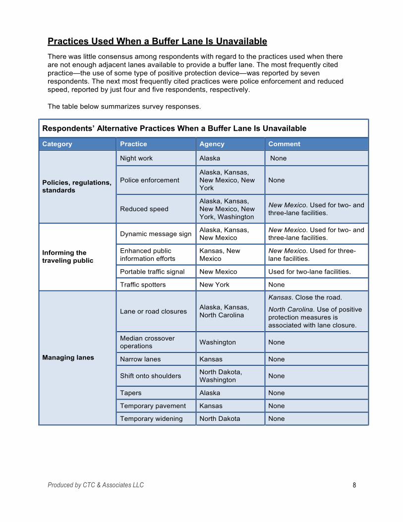
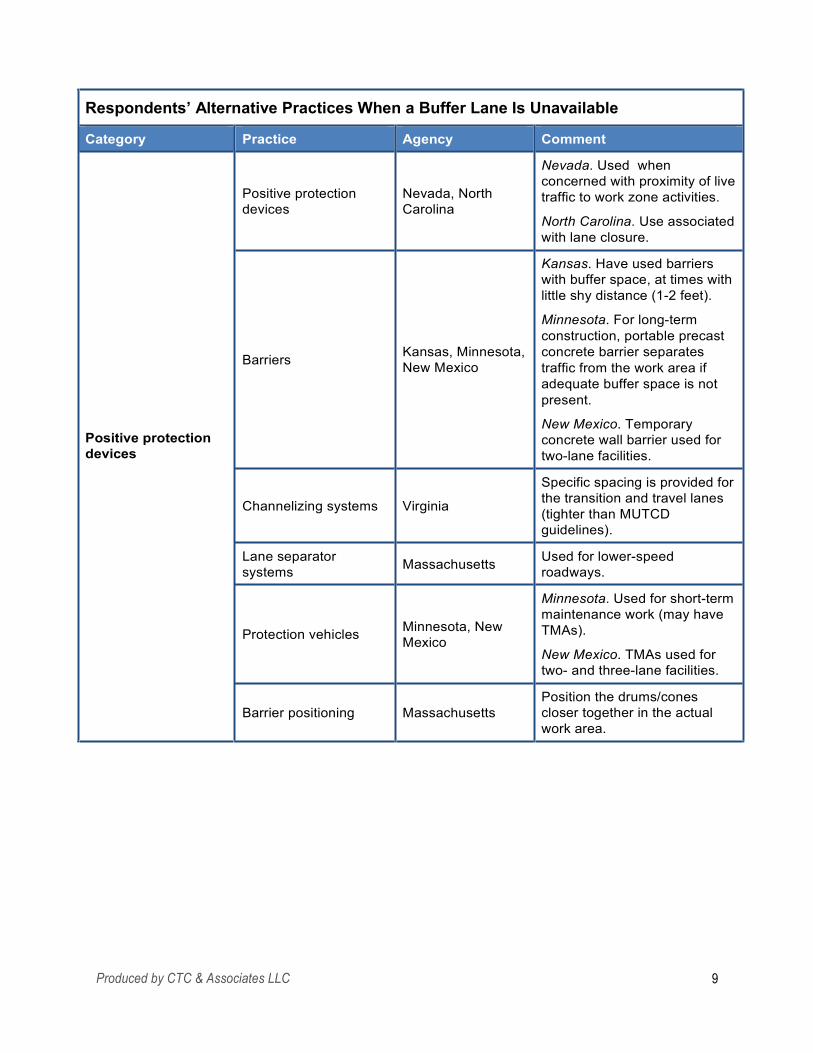
Practices Used When a Buffer Lane Is Unavailable There was little consensus among respondents with regard to the practices used when there are not enough adjacent lanes available to provide a buffer lane. The most frequently cited practice—the use of some type of positive protection device—was reported by seven respondents. The next most frequently cited practices were police enforcement and reduced speed, reported by just four and five respondents, respectively.
The table below summarizes survey responses.
Produced by CTC & Associates LLC 8
Respondents’ Alternative Practices When a Buffer Lane Is Unavailable
Category Practice Agency Comment
Positive protection devices
Positive protection devices
Nevada, North Carolina
Nevada. Used when concerned with proximity of live traffic to work zone activities.
North Carolina. Use associated with lane closure.
Barriers
Kansas, Minnesota, New Mexico
Kansas. Have used barriers with buffer space, at times with little shy distance (1-2 feet).
Minnesota. For long-term construction, portable precast concrete barrier separates traffic from the work area if adequate buffer space is not present.
New Mexico. Temporary concrete wall barrier used for two-lane facilities.
Channelizing systems
Virginia
Specific spacing is provided for the transition and travel lanes (tighter than MUTCD guidelines).
Lane separator systems
Massachusetts
Used for lower-speed roadways.
Protection vehicles
Minnesota, New Mexico
Minnesota. Used for short-term maintenance work (may have TMAs).
New Mexico. TMAs used for two- and three-lane facilities.
Barrier positioning
Massachusetts
Position the drums/cones closer together in the actual work area.
Produced by CTC & Associates LLC 9
Assessing the Cost-Effectiveness and Safety of Buffer Lanes None of the four respondents who reported considering the cost-effectiveness and safety of buffer lanes as compared to other alternatives use a specific tool or methodology to make such an assessment. Their experience is summarized below.
• Two states consider such issues at the project level:
o In Delaware, these issues may be considered on a project-by-project basis. o Washington State DOT has not evaluated these issues at the agency level, but
such an examination should be part of developing the transportation management plan required for each project.
Two other states highlighted the conflicting demands that affect the decision to provide a buffer lane:
o The Minnesota DOT respondent noted that “due to the Metro area’s lane closure restrictions, it is just not possible to take extra lanes during the daytime. Night maintenance work may close adjacent lanes, but the shifting of maintenance work from daytime to nights has other cost and safety implications.”
o For North Carolina DOT, cost and safety issues are considered along with maintaining the mobility of the facility when deciding whether to provide a buffer lane. For multilane facilities, additional lanes have been closed, providing greater lateral buffer space, but generally this practice has been reserved for nighttime operations during nonpeak hours only.
•
Guidelines for the Use of Positive Protection Devices We asked respondents about their use of positive protection devices when an adjacent lane is not available for use as a buffer lane. Twelve of the 18 state DOTs responding to the survey reported guidelines or established practices for the use of positive protection devices. Below is a summary of survey responses with links to agency publications, if provided.
Note: Guidance for the use of positive protection devices for states not responding to the survey appears in the Related Resources section of this Preliminary Investigation; see page 16.
Delaware Delaware DOT’s guidelines address the use of temporary traffic barriers. An excerpt from the guidelines:
Temporary traffic barrier shall be considered when the work area remains unchanged (i.e., excludes moving operations) and the duration of work is expected to be 2 weeks or more and either of the following two criteria are satisfied:
• Work is to be performed on a facility with an existing posted speed limit of 45 mph or greater.
Produced by CTC & Associates LLC 10
• The operation occurs within a travel lane or shoulder or is within 10 feet of the edge of a travel lane.
Related Resource:
Use of Temporary Traffic Barrier in Work Zones, Design Guidance Memorandum 1-21, Delaware DOT, December 2008. http://www.deldot.gov/information/pubs_forms/manuals/dgm/pdf/1- 21_use_temp_traffic_barrier_wz.pdf From the guidance:
As part of the development of a Traffic Control Plan (TCP), the need for and usefulness of temporary traffic barrier protection should be evaluated throughout the project development process. In general, temporary traffic control barriers should only be installed if it is determined that the barrier offers the least hazard potential. During concept development and design, exposure control measures should be considered to avoid or minimize worker exposure to motorized traffic and road user exposure to work zone activities, while also providing adequate consideration to the potential impacts on mobility.
Illinois Illinois DOT’s guidelines treat mobile and stationary operations differently, and provide specific guidance for locations with no means of escape from motorized traffic, and for long-duration stationary locations with high speed and workers near a traffic lane.
Related Resource:
Work Zone Safety and Mobility: Positive Protection of Workers, Drop-Offs and Temporary Concrete Barrier (TCB), Safety Engineering Policy Memorandum 4-15, Illinois DOT, March 2015. http://www.idot.illinois.gov/Assets/uploads/files/Doing-Business/Manuals-Guides-&- Handbooks/Highways/Safety-Engineering/HST%2055080%20BSE%20Policy%204- 15%20WZ%20Safety%20Positive%20Protection.pdf From the memorandum:
Positive protective devices must be considered in work zone situations that place workers at increased risk from motorized traffic, and where positive protective devices offer the highest potential for increased safety for workers and road users. For local roads with Average Daily Traffic (ADT) of less than or equal to 400, barricades may be used in lieu of positive protection based on engineering judgment.
Kansas While not providing a link to documented guidelines, the survey respondent indicated that Kansas DOT’s standard drawings show the type of barrier and installation requirements for a given length of need and quantity. The agency also has standards and specifications for various crash cushion types. The respondent also noted:
Engineering judgment is used to decide when to use positive protection and where to place it, considering expected speeds and volumes, available pavement width, location and severity of hazard, and other situational and environmental expectations.
Produced by CTC & Associates LLC 11
Minnesota The use of positive protection devices is optional on most of the agency’s temporary traffic control layouts. However, the respondent indicated:
Maintenance has over the last few years upgraded TMAs [truck-mounted attenuators] to TL-3 [Test Level 3 impact protection as specified by NCHRP Report 350] and deployed them to almost every Truck Station. Many maintenance crews would not think of leaving the shop without TMA-equipped protection vehicles.
Nevada At Nevada DOT, the need for positive protection devices is based on an engineering study. The study may be used to develop positive protection guidelines for the agency or to determine measures to be applied on an individual project.
Related Resource:
Positive Protection Devices, Section 2.5.2, Work Zone Safety & Mobility Implementation Guide, Nevada DOT, revised March 2012. https://nevadadot.com/uploadedFiles/NDOT/About_NDOT/NDOT_Divisions/Planning/Work %20Zone%20Safety%20and%20Mobility%20Implementation%20Guide%20March%202012 .pdf See page 13 of the guide (page 15 of the PDF) for Nevada DOT’s guidance for the use of positive protection devices.
New Mexico A 2009 Internal Design Directive addresses exposure control measures and provides an “Exposure Control Measure Matrix” for design and construction personnel to use during decision-making process.
Related Resource:
Temporary Traffic Control Devices Rule, Subpart K, Infrastructure Design Directive IDD- 2009-05, New Mexico DOT, July 2009. http://www.dot.state.nm.us/content/dam/nmdot/Plans_Specs_Estimates/Design_Directives/2 009/IDD-2009-05.pdf See page 18 of the directive (page 28 of the PDF) for Figure 4, Checklist 2, Exposure Control Measures Matrix.
New York New York State DOT uses 40-foot spacing between cones adjacent to exposed workers and barrier vehicles with truck- or trailer-mounted impact attenuators on high-speed closures. The respondent noted that the agency has seen the mobile barrier but has not used it.
North Carolina The respondent highlighted two documents—roadway standard drawings that identify the use of buffer space and TMAs in temporary lane closures, and the agency’s Transportation Management Plans Design Manual. The latter includes a chapter on positive protection devices.
Produced by CTC & Associates LLC 12
This chapter describes the types of barriers used, selection criteria, and usage and installation guidelines.
Related Resources:
Division 11, Work Zone Traffic Control, 2012 Roadway Standard Drawings, North Carolina DOT, 2012. https://connect.ncdot.gov/resources/Specifications/2012%20Roadway%20Standard%20Dra wings/Division%2011%20-%20Work%20Zone%20Traffic%20Control.pdf Descriptions of buffer space are included in these drawings for temporary lane closures, including the use of TMAs.
Positive Protection (Temporary Barriers), Chapter 5, Transportation Management Plans Design Manual, Part 2, North Carolina DOT, June 2015. See Appendix B. This chapter provides a description of barrier types, performance attributes, selection criteria and usage, and installation guidelines to address the agency’s use of positive protection devices.
North Dakota North Dakota DOT provides positive protection when there is no escape route for workers (bridge work) or if there is a drop-off. Positive barriers are not required if the drop-off is a short- term condition (seven calendar days or less) and is located 16 feet or more from the traffic- carrying lane.
Related Resource:
Work Zone Traffic Control, Section III-19, Design Manual, North Dakota DOT, January 2006. https://www.dot.nd.gov/manuals/design/designmanual/chapter3/DM-3-19_tag.pdf See page 16 of this section for a description of the agency’s use of positive protection.
Oklahoma The respondent identified the following as guidelines: “bricks and sticks” and edge drop-off.
Virginia Virginia DOT’s version of the MUTCD provides guidelines for the use of barrier/channelizing devices in work zones.
Related Resource:
Guidelines for the Use of Barrier/Channelizing Devices in Work Zones, Appendix A, Virginia Work Area Protection Manual, Virginia DOT, August 2011. See Appendix C of this Preliminary Investigation.
Produced by CTC & Associates LLC 13
Washington Washington State DOT’s Design Manual identifies the conditions under which positive protection devices are required unless an engineering study determines otherwise. These conditions include separating opposing high-speed traffic normally separated by a median or existing median barrier; for drop-off protection during widening or excavations; when temporary slopes change clear zone requirements; and other circumstances.
Related Resource:
Work Zone Safety and Mobility, Chapter 1010, WSDOT Design Manual, Washington State DOT, July 2014. http://www.wsdot.wa.gov/publications/manuals/fulltext/M22-01/1010.pdf Section 1010.10, Positive Protection Devices, begins on page 27 of this chapter of WSDOT’s Design Manual. From the manual:
Positive protective devices are required for the following conditions unless an engineering study determines otherwise:
• To separate opposing high-speed traffic normally separated by a median or existing median barrier.
Where existing traffic barriers or bridge railings are to be removed.
For drop-off protection during widening or excavations (see Standard Specification 1-07.23(1)).
When temporary slopes change clear zone requirements.
For bridge falsework protection.
When equipment or materials must remain in the work zone clear zone.
When newly constructed features in the clear zone will not have permanent protection until later in the project.
Where temporary signs or light standards are not crashworthy.
To separate workers from motorized traffic when work zone offers no means of escape for the worker, such as tunnels, bridges, and retaining walls, or for long- duration worker exposure within one lane-width of high-speed high-volume traffic.
•
•
•
•
•
•
•
•
Produced by CTC & Associates LLC 14
Related Resources The citations in this section are organized into four categories:
•
•
•
•
Buffer Space.
Positive Protection Devices.
Alternatives to Lane Closure.
Assessment Tools.
Buffer Space
National Guidance Manual on Uniform Traffic Control Devices, FHWA, 2009 Edition (including Revision 1 and Revision 2), May 2012. http://mutcd.fhwa.dot.gov/pdfs/2009r1r2/mutcd2009r1r2edition.pdf See page 554 of the MUTCD (page 594 of the PDF) for Section 6C.06, Activity Area. This section addresses the use of a buffer space, defined as a “lateral and/or longitudinal area that separates road user flow from the work space or an unsafe area, and might provide some recovery space for an errant vehicle.” While a table is provided to offer guidance in determining the length of a longitudinal buffer space, guidance in this section with regard to the determination of a lateral buffer space is limited to this:
The width of a lateral buffer space should be determined by engineering judgment.
Figures are provided that show the use of a lateral buffer space to separate the traffic space from the work space, or from areas such as excavations or pavement-edge drop-offs. The manual also indicates this: “A lateral buffer space also may be used between two travel lanes, especially those carrying opposing flows.”
Guidance: Use of Work Zone Clear Zones, Buffer Spaces and Positive Protection Deflection Distances, Work Zone Safety Consortium, FHWA, May 2014. https://www.workzonesafety.org/files/documents/training/courses_programs/rsa_program/RSP_ Guidance_Documents_Download/RSP_Clear_Zones_Guidance.pdf This document addresses the role of separation distances and positive protection device deflection distances in the safety of motorists and workers. The guidance examines separation distances for clear zones and buffer spaces, as well as the size of clear zones and buffer spaces with and without positive protection.
State Guidance Safe and Effective Speed Reductions for Freeway Work Zones, Phase 2, Oregon DOT, September 2014. http://www.oregon.gov/ODOT/TD/TP_RES/docs/Reports/2014/SPR769_HighSpeed_Final.pdf In this study, researchers investigated the impact of selected traffic control devices on vehicle speeds within highway paving project work zones. While not central to the research problem, researchers did note the effect of a buffer lane on vehicle speed. From page 69 of the report (page 88 of the PDF):
Produced by CTC & Associates LLC 15
It should be noted that on Day 3, the contractor paved the roadway shoulder. In this case, the full slow lane (B-lane) was also closed, moving the passing traffic farther away from the actual work taking place. As a result, it is expected that the vehicle speeds would be greater than if the work was directly adjacent the travel lane. That is, when a closed, “buffer” lane is provided, vehicle speeds tend to increase. This may be a reason for the high mean speed for Day 3 compared to both Days 1 and 2. This result is important as it brings up a question of speed and proximity. With the buffer lane present, the vehicles are farther away from the workers, however the traffic travels at a higher rate of speed. Without the buffer lane, the vehicles are closer to the workers, but travel at a slower rate of speed. A more detailed analysis of the associated risk is warranted to determine the preferred method.
From page 101 of the report (page 120 of the PDF):
The presence of a buffer lane when paving the shoulder is another area of recommended research. When a buffer lane is provided, there is greater distance between the workers and passing traffic, yet this study reveals that the vehicle speed is greater. On the other hand, the speeds are slower yet the vehicles closer to the workers without the buffer lane. The results of this study are not sufficient to provide a clear recommendation for practice. A more detailed study of the risk associated with the buffer lane present compared to not having the buffer lane would be of interest.
Positive Protection Devices
National Guidance Roadside Design Guide, AASHTO, 4th Edition, 2011. https://bookstore.transportation.org/imageview.aspx?id=1296&DB=3 This link provides access to the table of contents and Chapter 1 of the most recent edition of this publication. See Chapter 9, Traffic Barriers, Traffic Control Devices, and Other Safety Features for Work Zones.
Related Resource:
“Roadside Design Guide, 4th Edition 2011,” presentation by Keith A. Cota, New Hampshire DOT, 2012 AASHTO Subcommittee on Design Meeting. http://www.dot.ga.gov/PartnerSmart/DesignManuals/PolicyAnnouncements/RDG- Cota%20presentation.pdf This presentation highlights changes to the new edition of the guide, including these updates to Chapter 9, Traffic Barriers, Traffic Control Devices, and Other Safety Features for Work Zones:
•
•
Application for clear zone concept in work zones.
New Section 9.2.1.1 on test level requirement for portable concrete barriers and replacement of damaged systems.
Crashworthy truck-mounted attenuators and trailer-mounted attenuators.
New reference to pavement edge drop-offs.
•
•
Produced by CTC & Associates LLC 16
Manual for Assessing Safety Hardware, AASHTO, 2009. Brochure at http://safety.fhwa.dot.gov/roadway_dept/policy_guide/road_hardware/ctrmeasures/mash/mash. pdf This manual includes guidance on testing temporary highway safety features (a class that includes positive protection devices). An excerpt from the brochure describing the manual:
The AASHTO Manual for Assessing Safety Hardware (MASH) is the new state of the practice for the crash testing of safety hardware devices for use on the National Highway System (NHS). It updates and replaces NCHRP Report 350.
MASH presents uniform guidelines for crash testing permanent and temporary highway safety features and recommends evaluation criteria to assess test results. This manual is recommended for highway design engineers, bridge engineers, safety engineers, researchers, hardware developers, crash test laboratories, and others concerned with safety features used in the highway environment.
MASH does not supersede any guidelines for the design of roadside safety hardware, which are contained in the AASHTO Roadside Design Guide.
Questions and Answers: Temporary Traffic Control Devices Final Rule, 23 CFR 630 Subpart K, FHWA, updated February 29, 2008. http://www.ops.fhwa.dot.gov/wz/resources/temptraf_qa.htm The following excerpt from the website addresses the rule’s impact on state DOT use of positive protection devices, highlighting the rule’s requirement to consider the use of positive protection devices and how such use will be determined (based on an engineering study).
Q. What are the key components of the new Rule?
A: Key components of the new Rule include the following:
Policy – Policy and related processes, procedures, and guidance established under the WZ Safety & Mobility Rule for the systematic consideration and management of WZ impacts shall include consideration and management of road user and worker safety by addressing:
•
•
•
•
Use of positive protection devices to prevent intrusions;
Exposure control measures to avoid or minimize exposure;
Other traffic control measures to minimize crashes; and
Safe entry/exit of work vehicles onto/from the travel lanes.
Positive Protection Devices – use shall be based on an engineering study.
• An engineering study may be used to develop positive protection guidelines for the agency, or to determine the measures to be applied on an individual project;
Use of positive protection shall be considered in work zone situations that place workers at increased risk from motorized traffic and where positive protection devices offer the highest potential for increased safety for workers and road users.
•
Produced by CTC & Associates LLC 17
Work Zone Positive Protection Toolbox, American Traffic Safety Services Association and FHWA, undated. http://www.atssa.com/galleries/default- file/WZ%20Positive%20Protection%20Toolbox%20LL%20-%20FINAL.pdf Updates to the federal Work Zone Safety and Mobility Rule require transportation agencies to develop policies, procedures or guidance for the management of work zone safety that “shall address the use of Positive Protection Devices to prevent the intrusion of motorized traffic into the work space and other potentially hazardous areas in the work zone.” While required to consider the use of positive protection, agencies do have flexibility in determining when and how to use it. This publication highlights five positive protection devices—portable concrete barriers, movable concrete barriers, ballast-filled barriers, shadow vehicles, and vehicle arrestor systems—and provides guidance for their use.
Related Resource:
Guidelines on the Use of Positive Protection in Temporary Traffic Control Zones, FHWA, 2010. https://www.workzonesafety.org/files/documents/training/fhwa_wz_grant/atssa_positive_prot ection_guidelines.pdf This companion document to the toolbox cited above supplements the descriptions of guidance for use of various positive protection devices with information on how to determine when positive protection may be warranted. Decision-support tools for selecting among the various positive protection devices appear on pages 9 and 10 of the document. Agencies are cautioned that “[s]ince the barrier may be a hazard itself, first check to make sure that the hazard you are protecting is more dangerous than traffic exposure to the barrier.” The publication identifies the following as hazards that could be mitigated by the use of positive protection devices: worker exposure to traffic; a slope steeper than 6:1; and drop-off conditions greater than 3 inches.
State Guidance
Note: Additional guidance on the use of positive protection devices for states responding to this project’s survey appears in the Survey of State Practices section of this Preliminary Investigation; see page 10.
Colorado Guidelines for the Use of Positive Protection in Work Zones, Colorado DOT, January 2010. https://www.codot.gov/library/traffic/lane-close-work-zone-safety/work-zone-safety-mobility- program/CO_Guidelines_Positive_Protection_122809.pdf From page 4 of the guidelines (page 5 of the PDF):
Positive protection in work zones is warranted whenever an engineering study clearly indicates any of the following:
•
•
Positive protection will reduce the severity of potential crashes.
Consequences of striking a fixed object or running off the road are likely to be more serious than striking the positive protection.
Produced by CTC & Associates LLC 18
• Consequences of striking a worker or pedestrian are likely to be more serious than striking the positive protection.
Idaho Work Zone Positive Protection Guidelines for Idaho, Gerald L. Ullman and Vichika Iragavarapu, Idaho Transportation Department, December 2014. https://itd.idaho.gov/highways/research/archived/reports/RP228WorkZoneFinal01122015.pdf These guidelines include a state-of-the-practice review of guidance from five state DOTs— Colorado, Michigan, Minnesota, North Carolina and Virginia. Also included is a detailed discussion of the use of portable concrete barrier in work zones, the development of work zone positive protection guidelines that “address conditions where positive protection device (i.e. devices that contain and/or redirect vehicles and meet the federal crashworthiness evaluation criteria) application can be recommended on the basis of reduced work zone crash costs. For sites where such conditions do not exist, guidelines are provided regarding intrusion and crash reduction countermeasures (e.g., closer channelizing device spacing and supplemental speed management devices) that could be employed.”
Kansas Proposed Positive Protection Guidance for Kansas: Synthesis of Work Zone Positive Protection Devices and State of Practice, Steven D. Schrock, Eric J. Fitzsimmons, Ming- Heng Wang and Young Bai, Kansas DOT, February 2013. http://www.ksdot.org/PDF_Files/KU-10-3_Final.pdf In addition to examining a range of positive protection devices, including longitudinal barriers, mobile barriers, vehicle arresting systems and end protection systems, researchers conducted a national survey of state DOTs to gather current guidance on the use of positive protection devices. Together, this information informed researchers’ development of the preliminary work zone positive protection guidance for Kansas DOT included in this report.
Items of particular interest in the report include:
• A synthesis of the state-of-the-practice review includes these observations about the 25 survey respondents (see page 37 of the report; page 48 of the PDF):
Generally it was found that all state highway agencies had some form of basic guidelines in place and easy to access documents for common positive protection devices (e.g. portable concrete barrier, truck / trailer-mounted attenuator, longitudinal barrier end-treatments). It was found that some state highway agencies have gone as far as recommended certain types of proprietary devices for positive protection and their associated guidelines that can be used under unique or certain conditions. Finally, it was observed by the research team that many state highway agencies have successfully worked together in information sharing on best practices for work zone positive protection and are reflected in their guidance with similar language, references, and noted device limitations.
• Appendix A: Positive Protection Survey of State Highway Agencies begins on page 47 of the report (page 58 of the PDF). Key guidance from the 25 survey respondents is presented in a tabular format. This guidance includes documents from the following additional states that did not respond to the survey conducted for Caltrans’ Preliminary Investigation:
Produced by CTC & Associates LLC 19
• • • • • •
• • • • • •
• • • • • •
Alabama. Arizona. Colorado. Florida. Georgia. Hawaii.
Iowa. Michigan. Mississippi. Montana. New Hampshire. New Jersey.
Ohio. Tennessee. Texas. Vermont. West Virginia. Wyoming.
Seven states—Illinois, Nevada, North Carolina, South Dakota, Virginia, Washington and Wisconsin—participated in both the 2013 Kansas survey and the survey for Caltrans’ current Preliminary Investigation. In some cases, information provided by respondents to the current survey differs from the responses appearing in the 2013 Kansas report.
Appendix B: Proposed Positive Protection Guidance for Kansas begins on page 62 of the report (page 73 of the PDF). The proposed guidelines include a Positive Protection Flowchart for Temporary Work Zones, a table reflecting the uses and requirements for a range of positive protection devices, and a table that defines the agency’s exposure control measures.
•
Related Resource:
“Work Zone Positive Protection Policy Guidance: Synthesis of Devices and State of Practice,” Steven D. Schrock, Eric J. Fitzsimmons, Tomás Lindheimer, Ming-Heng Wang and Yong Bai, TRB 93rd Annual Meeting Compendium of Papers, Paper #14-5574, 2014. http://docs.trb.org/prp/14-5574.pdf This conference paper provides an excellent summary of the Kansas DOT report cited above.
Michigan Chapter 17, Subpart K, Work Zone Safety and Mobility Manual, Michigan DOT, 2010. http://www.michigan.gov/documents/mdot/MDOT_WorkZoneSafetyAndMobilityManual_233891 _7.pdf See page 92 of the PDF for the chapter that addresses Michigan DOT’s use of positive protection devices, which include but are not limited to vehicle-mounted attenuators and temporary barrier wall.
New Hampshire Positive Protection Guidance for Work Zones, New Hampshire DOT, February 2010. https://www.nh.gov/dot/org/projectdevelopment/highwaydesign/documents/FINAL_positive_prot ection_workzone_guidance_02221.pdf This report provides guidance in selecting a protection strategy and also addresses edge drop- offs, including the recommended spacing for channelizing devices.
Texas Work Zone Positive Protection Guidelines, Gerald L. Ullman, Vichika Iragavarapu and Dazhi Sun, Texas DOT, May 2011. http://tti.tamu.edu/documents/0-6163-1.pdf Researchers analyzed the costs and benefits of the use of portable concrete barrier technologies and developed guidelines for use of this type of positive protection in work zones.
Produced by CTC & Associates LLC 20
Researchers also developed guidelines for the use of portable steel barrier, mobile barrier and TMAs. Also included in the report are general guidance and information regarding the use of exposure control measures and other traffic control measures to reduce the risk of work space intrusion.
Vermont Temporary Traffic Control Devices, Appendix A, Work Zone Safety & Mobility Guidance Document, Vermont Agency of Transportation, May 2011. http://vtransengineering.vermont.gov/sites/aot_program_development/files/documents/publicatio ns/WorkZoneSafetyMobility%20Appendix%20A%20- %20Temp.%20Traffic%20Control%20Devices%209-12.pdf This document provides design guidelines for positive protection devices, exposure control measures, the use of uniformed traffic officers, work vehicles and equipment, and site-specific traffic control plan guidance. Included are these guidelines for the installation of positive barrier on page 4 of the appendix:
• Positive barrier should be installed tangentially with a desired minimum 2 ft offset from the traveled lane to the face of the barrier at its widest point. The lateral offset should not be less than 1 ft. On higher speed facilities, the lateral offsets should be maximized to the extent possible.
If there is no tolerance for deflection within the work area, consider anchoring barrier to roadway surface or bridge deck.
Tapers for positive barrier are based on operating or 85th percentile speed of the facility as seen in the chart on Standard T-22 (E- 106).
Unprotected ends of the barrier on US and State Routes should be tapered at least 10 ft. outside the edge of the traveled lane. If the positive barrier cannot be tapered outside the minimum clear zone of 10 ft, then an appropriate crash attenuator shall be provided to protect the end of the barrier. Truck mounted attenuators should not protect the ends of barrier but may be used to close off or protect the work area if adequate roll distance is available.
Unprotected ends of the barrier on interstates and other limited access multi-lane facilities should be tapered to the clear zone as defined in the latest edition of the AASHTO Roadside Design Guide. If the positive barrier cannot be tapered outside the minimum clear zone, then an appropriate crash attenuator shall be provided to protect the end of the barrier.
Consider and plan for how construction materials will be delivered to the job site. Positive barrier may need to be opened temporarily.
Access to businesses and residences must be delineated and proper treatment of the blunt ends of the barrier.
•
•
•
•
•
•
Produced by CTC & Associates LLC 21
Barrier Systems “Comparison of Vehicle Speeds Adjacent to Maintenance Work Zones With and Without a Mobile Barrier,” John Anthony Gambatese and Nicholas Tymvios, TRB 93rd Annual Meeting Compendium of Papers, Paper #14-4616, 2014. Citation at http://trid.trb.org/view/2014/C/1289487 Excerpt from the abstract:
A recent advancement in work zone safety is a mobile barrier system that consists of a motorized tractor/trailer combination and provides complete isolation of the work area. This paper presents research conducted to investigate the impacts of a mobile barrier on vehicles traveling adjacent to the mobile barrier and maintenance work zones. The study findings show that vehicle speeds are higher with the mobile barrier present than without the mobile barrier, indicating greater mobility as a result of faster travel times through the work zone. The presence of a mobile barrier resulted in lower speed reduction from the beginning to the end of the work zone. This positive impact on vehicle movement through the work zone complements the increased worker safety provided by the mobile barrier.
“Influence of Mobile Work Zone Barriers in Maintenance Work Zones on Driver Behavior: A Driving Simulator Study,” Joshua Swake, David S. Hurwitz, Justin Neill and John Anthony Gambatese, TRB 93rd Annual Meeting Compendium of Papers, Paper #14-2225, 2014. Citation at http://trid.trb.org/view/2014/C/1288205 Excerpt from the abstract:
Many research efforts have focused on developing standards to ensure the safety of drivers and workers in work zones, however comparatively little research has been conducted to better understand the influence of mobile work zone barriers (MWB), a relatively new type of positive barrier designed to protect workers in the activity area of a work zone, on driver behavior. The Oregon State University (OSU) Driving Simulator was used to evaluate the influence of an MWB on driver behavior in single left lane and right lane drop maintenance work zones on 4-lane, 2-way divided highways. Thirty six drivers traversed 144 work zones. Measures of vehicle trajectory, lateral position and glance patterns were recorded and examined. No statistical differences were observed in the glance patterns of drivers between work zones with and without the MWB, suggestive statistical differences were identified between average speeds in the taper and activity area of right lane closure work zones with speeds slightly slower in the presence of the MWB, and an eight inch shift to the right was observed in the lateral position of vehicles in the activity area of left lane drop work zones in the presence of the MWB. Results suggest that no critical hazards are introduced to drivers from the application of MWBs in maintenance work zones.
Evaluation of a Mobile Work Zone Barrier System, John A. Gambatese and Nicholas Tymvios, Oregon DOT, August 2013. http://www.oregon.gov/ODOT/TD/TP_RES/docs/Reports/2013/SPR746_MobileBarriers.pdf After evaluating a mobile barrier in a variety of work zone environments, researchers concluded that the barrier “is most applicable to and recommended for use on operations that are short- term, especially those that have a duration of one work shift or less where the work zone closure and worker protection is placed and then removed with each work shift.” Other methods such as a concrete or movable barrier are recommended for closures of a longer period.
Produced by CTC & Associates LLC 22

“Benefit-Cost Analysis of Portable Concrete Barrier Use in Work Zones to Protect Against Intrusion Crashes,” Vichika Iragavarapu and Gerald L. Ullman, TRB 91st Annual Meeting Compendium of Papers DVD, Paper #12-1840, 2012. Citation at http://trid.trb.org/view/2012/C/1129487 Excerpt from the abstract:
The objective of this study was to evaluate the benefits and costs associated with the use of portable concrete barriers (PCBs) in work zones to protect workers and equipment against intrusion crashes….The analysis found that for high speed multilane freeway facilities where work is occurring immediately adjacent to travel lanes, intrusion crash costs savings alone can justify PCB protection once the roadway ADT approaches 40,000 vpd over a year-long work zone, so long as there are constant hazards in the work space being protected by barrier.
Evaluation of Movable Barrier in Construction Work Zones, Ken Berg, Doug Anderson and David Eixenberger, Utah DOT, March 2010. http://utah.ptfs.com/awweb/awarchive?type=file&item=44665 Researchers noted that the use of a mobile barrier for traffic control during a reconstruction project contributed to the contractor completing the project ahead of schedule, saving millions of dollars in user costs. Use of a movable barrier should be considered on high-volume, urban projects “to increase the work area and safety of the project.”
Truck-Mounted Attenuators Research in Progress: “Investigation of Truck-Mounted Attenuator Crashes in Work Zones in Virginia,” Virginia Center for Transportation Innovation and Research, expected completion date: December 2015. http://trid.trb.org/view/2014/P/1364373 From the project description:
Truck-mounted attenuators (TMAs) are deployed on shadow vehicles in highway work zones to reduce the impacts of other vehicles that may strike the shadow vehicle - either by smoothly decelerating the errant vehicle to a stop when hit head on or by redirecting the errant vehicle. This study will investigate crashes involving TMAs in work zones in Virginia. Objectives include: (1) Review three- to five-year trends for crashes involving TMAs, including a measure of traffic exposure, such as how often work zones use TMAs; and (2) Identify causal factors of crashes in work zones where TMAs are involved. By determining causal factors behind such crashes, this project can provide improved guidance to the Virginia Department of Transportation (VDOT). Recommendations from this study are expected to result in changes to work-zone operations through revisions to the "Virginia Work Area Protection Manual" and/or other documents and practices used by VDOT's Traffic Engineering Division.
“Analysis of Expected Crash Reduction Benefits and Costs of Truck-Mounted Attenuator Use in Work Zones,” Gerald L. Ullman and Vichika Iragavarapu, Transportation Research Record 2458, pages 74-77, 2014. Citation at http://trid.trb.org/view/2014/C/1289177 From the abstract:
A truck-mounted attenuator (TMA) is a device that attaches to the back of a work truck to help protect work crews and the traveling public from the severe consequences of rear-end crashes between motorists and slow-moving or stopped work vehicles. Although TMAs have
Produced by CTC & Associates LLC 23
been used by most highway agencies and contractors for many years, there are few data on the actual in-field performance of TMAs and on reductions in crash costs attributable to their use by agencies and contractors. Such data would be useful in establishing criteria on when and where TMAs must be used. An analysis of potential rear-end crashes of motorists with work vehicles in mobile and short-duration operations found that TMAs were highly effective in reducing the severity of rear-end crashes and the costs of crashes. Each crash involving a TMA resulted in a savings of $196,855 in crash costs relative to the costs that would have been incurred had no TMA been present. On the basis of current TMA prices, agencies can recoup the cost of the TMA in terms of reduced rear-end crash costs in less than a year of daytime work shifts on facilities serving 20,000 vehicles per day or more and of nighttime work shifts on facilities serving 50,000 vehicles per day or more.
Worker Safety During Operations With Mobile Attenuators, LuAnn Theiss and Roger P. Bligh, Texas DOT, May 2013. http://d2dtl5nnlpfr0r.cloudfront.net/tti.tamu.edu/documents/0-6707-1.pdf From the abstract:
While most transportation agencies are very familiar with truck-mounted attenuators, trailer- mounted attenuators are increasing in popularity. There is a concern for the level of protection that attenuators provide for workers when they are mounted on trailers compared to trucks. This research evaluated and compared the level of protection provided to workers by truck-mounted and trailer-mounted attenuators. No crash testing was conducted; instead, the researchers used existing crash test report data for the comparison. The researchers found that the use of heavier support vehicles for these mobile attenuators provided better protection for workers and recommend that TxDOT maintains the current policy of requiring 20,000 lb support vehicles, regardless of attenuator type. In addition, the researchers found that the concern of trailer-mounted attenuators swinging around may not be justified, given that post-impact trajectories of the impacting vehicles are similar to those reported during truck-mounted attenuator impact testing.
Additional Resources Research in Progress: “Evaluation of an Electronic Safety Perimeter System for Kansas Temporary Work Zones,” Mid-America Transportation Center. Expected completion date not available. Project description at http://matc.unl.edu/research/research_projects.php?researchID=480 From the project description:
Currently, limited research exists that evaluates work zone warning systems in comparison to traditional means of protecting work crews. Many work zones do not require positive protection, often times leaving workers very close to traffic. Errant vehicles pose a serious concern, with drivers being more distracted or unable to control their vehicles. One manufacturer has taken action to reduce worker/vehicle crashes by developing an electronic safety perimeter system. This system aims to address errant vehicles penetrating work zones, and has had recent success in the United Kingdom using today’s technology. What makes the Intellicone System unique is that it is an integrated system that alerts work crews of an errant vehicle if one or more plastic channelizing devices or cones adjacent to, before, or in the taper area of the work zone are knocked over. By having multiple strike points for an errant vehicle to be detected, it is expected that this system would be highly effective in the United States for increasing safety in multiple areas of the temporary work zone. The proposed research project is to work with the manufacturer and distributor to retrofit the
Produced by CTC & Associates LLC 24
system to common U.S. safety devices found in Kansas work zones, and to evaluate the effectiveness of the system.
“Functional Requirements for Highly Portable Positive Protection Technologies in Work Zones,” Gerald L. Ullman, Melisa Dayle Finley and Dean C. Alberson, TRB 86th Annual Meeting Compendium of Papers CD-ROM, Paper #07-1690, 2007. Citation at http://trid.trb.org/view/2007/C/801818 Excerpt from the abstract:
This paper describes a set of functional requirements developed for highly-portable positive protection technologies that protect highway workers. These requirements were based on an assessment of a large number of construction and maintenance work activities that are highly mobile and thus would potentially benefit from such a system. Specific roadway design features believed to have the most significant impact upon the functional requirements of a highly-portable positive protection system were also considered. While it is desirable to have a protective device that covers a wide possibility of work zone conditions, this preliminary study shows there are some practical limits to activities that can be accommodated by a single type of highly-portable positive protection device. As defined, a protection system meeting the stated requirements could accommodate about two-thirds of the construction and maintenance activities considered. Perhaps a highly-portable positive protection system could be used during some of the remaining activities if work crews were to adopt slightly different procedures for those activities.
Alternatives to Lane Closure “Impact of Shoulder Use and Capacity Reduction Factors on Highway Work Zone Optimization,” Bo Du and Steven I-Jy Chien, TRB 93rd Annual Meeting Compendium of Papers, Paper #14-1241, 2014. Citation at http://trid.trb.org/view/2014/C/1287718 From the abstract:
Highway maintenance, often requiring lane closure, is very expensive in terms of the costs associated with transportation agencies (i.e., work zone setups) and road users (i.e., delay). Longer work zones tend to increase the user delay but will be efficient because of fewer repeated setups. To increase road capacity and mitigate congestion impact for a short-term work zone, temporary shoulder use may be applied. This study develops an analytical model to optimize work zone length on a multi-lane highway considering time-varying traffic volume and road capacity affected by light condition, heavy vehicle percentage, and lane width. The results can be used to evaluate the work zone impact (i.e., delay and cost) and assisting engineers/planners to prepare and develop a cost-effective highway maintenance plan. A case study for a highway work zone in New Jersey is conducted, in which the optimized solution was found. A guideline of using road shoulder under various circumstances is developed.
Evaluation of Alternative Methods of Temporary Traffic Control on Rural One-lane, Two- way Highways, Melisa D. Finley, Praprut Songchitruksa and Jacqueline Jenkins, Ohio DOT, April 2015. http://cdm16007.contentdm.oclc.org/cdm/ref/collection/p267401ccp2/id/12485 This examination of alternative methods to control traffic approaching the one-lane section of a rural, two-lane highway during temporary traffic control for maintenance operations resulted in the following recommendations:
Produced by CTC & Associates LLC 25
• Red/yellow lens automated flagger assistance devices (AFADs) are most suitable for short-term stationary operations that last a few hours up to one day. AFADs are also appropriate for use on narrow roadways with limited to no shoulders.
Portable traffic signals are an option when work duration increases, and are best suited for higher-volume roadways with shoulders and relatively flat side slopes.
•
Assessment Tools Research in Progress: “Safety Assessment Tool for Construction Zone Work Phasing Plans,” Smart Work Zone Deployment Initiative, Iowa DOT, expected completion date: December 2015. Citation at http://trid.trb.org/view.aspx?id=1312736 Excerpt from the abstract:
Project Objectives: The objective of this project is to develop a structured safety assessment tool to help decision makers to evaluate the safety impacts of different construction work zone phasing plans and lane closure scenarios. The research approach will include the collection and analysis of crash data from Midwestern states for different construction phasing alternatives. The project deliverables will include a spreadsheet tool to help decision makers evaluate the safety risks of different construction phasing alternatives and lane closure scenarios. Attainment of the project objective will help to fill gaps in existing knowledge and provide transportation practitioners with a valuable tool to assist them in the evaluation of the safety impacts of construction work zones for different alternatives…. The Smart Work Zone Deployment Initiative (SWZDI) is a Federal Highway Administration (FHWA), pooled fund study created to promote and coordinate research efforts related to safety and mobility in work zones among several cooperating states; Iowa, Kansas, Missouri, Nebraska, and Wisconsin.
“Estimating Operational Impacts of Freeway Work Zones on Extended Facilities,” Bastian J. Schroeder and Nagui M. Rouphail, Transportation Research Record 2169, pages 70-80, 2010. Citation at http://trrjournalonline.trb.org/doi/abs/10.3141/2169-08?journalCode=trr Excerpt from the abstract:
This paper presents an approach to estimating the operational impacts of freeway work zones. The focus is on significant work zones on freeway corridors as defined by FHWA. The methodology is based on deterministic freeway capacity concepts described in the “Highway Capacity Manual” and allows the analyst to test impacts of a range of work zone configurations in an extended time–space domain. The focus on extended facilities refers to the analysis of multiple segments of various types, including basic freeway, ramp, and weaving segments. The cost-effective and time-efficient analysis approach can model effects of work zones such as lane closures, lower speed limits, capacity reduction, and the implicit effects of traffic diversion, peak reduction, and other intelligent transportation system strategies. Performance measures include total delay, queuing impacts, average running speed, and the potential to estimate user cost. The methodology focuses on a corridor- based analysis of work zones on freeways. It is not appropriate for network analysis, for long corridors, for signalized arterials, or for cases in which congestion on the arterial network significantly affects freeway operations.
Produced by CTC & Associates LLC 26
An Integrated Work-Zone Computer System for Capacity Estimation, Cost/Benefit Analysis, and Design of Control, Gang-Len Chang and Nan Zou, Maryland State Highway Administration, December 2009. Citation at http://trid.trb.org/view/2009/M/914479 Excerpt from the abstract:
This project produced an integrated computer system that enables engineers at the Maryland State Highway Administration to analyze the impact of a work-zone operational plan and to estimate the resulting cost/benefit. The proposed system consists of an intelligent user-interface, an analytical computing module, a microscopic simulation model, and an output analysis module. Depending on the nature of a proposed work-zone plan, one can either perform the preliminary estimate with the embedded analytical module or conduct an in-depth cost-benefit analysis with its simulation model.
“A Hybrid Methodology for Freeway Work-Zone Optimization With Time Constraints,” Ning Yang, Paul Schonfeld and Min Wook Kang, Public Works Management & Policy, Vol. 13, Issue 3, pages 253-264, January 2009. Citation at http://dx.doi.org/10.1177/1087724X08322843 From the abstract:
This paper uses optimization techniques to determine work-zone plans that minimize total costs. The methodology seeks to determine the best construction periods, the best length for a particular work zone, lane closure options, the amount of traffic (if any) that should be diverted to other routes and the proper work rate and corresponding work cost. The costs considered in the methodology include agency costs, road-user delay costs and accident costs. A heuristic optimization algorithm, named two-stage modified simulated annealing (2SA), is developed to search for an optimized solution with a hybrid objective function evaluation approach (H2SA). After the decision variables are preoptimized analytically in the first stage, refined optimization is performed based on microscopic simulation models in the second stage. The results of a numerical experiment demonstrate that the H2SA can yield satisfactory solutions, which are close to the best optimization solutions based on simulation (S2SA) and obtained with much less computation time. The H2SA appears to be appropriate for both simple and complex networks. Directions for future research are discussed.
Produced by CTC & Associates LLC 27
Appendix A: Survey Results The full text of each survey response is provided below. For reference, we have included an abbreviated version of each question before the response; for the full question text, please see page 6 of this Preliminary Investigation.
Alaska Contact: Jeff C. Jeffers, Statewide Traffic & Safety, Alaska DOT and Public Facilities, 907-465-8962, [email protected].
1.
2.
Guidelines for providing lateral buffer space? No.
Practices when not enough adjacent lanes for buffer space: Reduced speed if necessary, night work as appropriate, lane closures with advance signing, DMS [dynamic message signs], tapers, enforcement, traffic price adjustment (penalty for late reopening), etc.
Examined cost-effectiveness and safety of buffer spaces and alternatives? No.
Guidelines for use of positive protection devices? No.
3.
4.
Delaware Contact: Mark Luszcz, Chief Traffic Engineer, Delaware DOT, 302-659-4062, [email protected].
1. Guidelines for providing lateral buffer space? Yes. The DE MUTCD has the following in Section 6C.06, para. 15: The width of a lateral buffer space should be determined by engineering judgment. On interstates, freeways, or expressways, a lateral buffer space of one travel lane should be used, except where temporary traffic barrier is used to separate the work area from the traveled way, or if other conditions prevent the use of a lateral buffer space. The full DE MUTCD is available for reference online at http://www.deldot.gov/information/pubs_forms/manuals/de_mutcd/index.shtml.
Practices when not enough adjacent lanes for buffer space: The guidelines are flexible enough to accommodate this situation.
Examined cost-effectiveness and safety of buffer spaces and alternatives? On a project-by-project basis, this may be considered.
Guidelines for use of positive protection devices? Also available online: http://www.deldot.gov/information/pubs_forms/manuals/dgm/pdf/1- 21_use_temp_traffic_barrier_wz.pdf.
2.
3.
4.
Illinois Contact: Paul L. Lorton, Safety Programs Unit Chief, Bureau of Safety Engineering, Illinois DOT, 217-785-0720, [email protected].
1. Guidelines for providing lateral buffer space? IDOT does not specifically differentiate based on types of roadways. Normal posted speed limit of a roadway dictates such guidance.
Practices when not enough adjacent lanes for buffer space: [No response.]
Examined cost-effectiveness and safety of buffer spaces and alternatives? IDOT has not performed a cost-effectiveness analysis for alternatives to closing adjacent traffic lanes.
Guidelines for use of positive protection devices? From Policy 4-15; see http://www.idot.illinois.gov/Assets/uploads/files/Doing-Business/Manuals-Guides-&- Handbooks/Highways/Safety-Engineering/HST%2055080%20BSE%20Policy%204- 15%20WZ%20Safety%20Positive%20Protection.pdf:
Positive Protective Devices. Positive protection devices means the devices that contain and/or redirect errant vehicles and meet the crashworthiness evaluation criteria contained in NCHRP Report 350 or MASH. This can include approved Temporary Longitudinal Traffic Barriers (TLTB) or truck/trailer mounted attenuators (TMA).
2.
3.
4.
Use of Positive Protective Devices Positive protective devices must be considered in work zone situations that place workers at increased risk from motorized traffic, and where positive protective devices offer the highest potential for increased safety for workers and road users. For local roads with Average Daily Traffic (ADT) of less than or equal to 400, barricades may be used in lieu of positive protection based on engineering judgment. The following describes conditions where work is conducted under traffic and positive protection is required:
Mobile Operations
• Multilane highways A mobile operation may be accomplished using a stationary standard lane closure as shown in the Highway Standards, the Work Site Protection Manual for IDOT Employees, or superseding publications, where the lane is closed using signing, arrow boards and channelizing devices. Establishing the lane closure shall employ TMAs as shown on the Highway Standards or other applicable references.
If such a stationary standard lane closure is not used, then positive protective devices such as TMAs shall be used to close the lane in advance of the workers. The use of additional signing would be dependent upon the normal posted speed limit, duration, and the length of the work and shall be in accordance with the Manual on Uniform Traffic Control Devices (MUTCD).
• 2L2W [Two-lane/two-way] highways Mobile operations on two lane highways will require the use of a positive protective device such as a TMA in advance of the work. TMAs are acceptable
Produced by CTC & Associates LLC 2
for limited daily work hours consistent with the Work Site Protection Manual for IDOT Employees, or superseding publications.
Stationary Operations
The conditions below will require positive protective devices.
Locations with no means of escape from motorized traffic:
• Multilane highways will require positive protection. When this condition lasts for more than 24 hours, or requires multiple days/nights setups exceeding a cumulative 24 hours to complete, it will require the use of TLTBs.
• 2L2W highways will require positive protection. When this condition lasts for more than four days per stage it will require the use of TLTBs.
Long duration, stationary locations, with high speed and workers near a traffic lane:
• TLTBs will be required for stationary operations where the normal posted speed limit is 45 mph or greater, the duration of the stationary operation is two weeks or more, and workers are present within one lane width of the open traffic lane. EXCEPT when the project is outside of an urbanized area and the annual average daily traffic load is less than 100 vehicles per hour. (AADT/24 is less than 100) Positive protective devices must be used in accordance with the Highway Standards, MUTCD, manufacturers’ requirements and NCHRP 350 or MASH, and technical guidance in this policy. Their use provides greater protection for workers than normal channelizing devices; however, workers should be aware of the limitations of positive protective devices.
For emergency situations and traffic incidents, apply the guidance in the Work Site Protection Manual for IDOT Employees or superseding publication. When developing the TMP, designers should take emergency situations into consideration. Gaps in the TCB to allow for emergency responder access should be considered and TCB ends shielded as appropriate.
Kansas Contact: Kristina R. Ericksen, Temporary Traffic Control Engineer, Kansas DOT, 785-296-0355, [email protected].
1. Guidelines for providing lateral buffer space? We have developed some draft guidance using edge drop depth vs. lateral buffer space and TTC [temporary traffic control] device treatment that we are currently evaluating that guidance against actual engineering judgment-based decisions made in the field. This information is not published and does not directly consider speed or volumes or vehicle types, all of which play into the need for buffer space in an edge drop situation. In addition, we do not have internal consensus on the guidance and I do not anticipate publishing any time soon.
Practices when not enough adjacent lanes for buffer space: In Kansas, we often do not have room for buffer space, less because of volumes, and more because there is not enough pavement width to provide one lane in each direction. In these situations, we make the best use of available pavement, narrow lanes, build temporary pavement, close the road, or a combination. In the situations where traffic volumes would indicate the need for
2.
Produced by CTC & Associates LLC 3
additional lanes, but engineering judgment indicates the need for buffer space, we have often provided the lanes and used barrier, and at times have used barrier with little shy distance (1-2 feet). Speed drops, increased enforcement, driver information systems indicating delay, and enhanced PI [public information] efforts have been used to mitigate lessened capacity by encouraging diversion, though we are not yet sure to what levels diversion is achieved.
Examined cost-effectiveness and safety of buffer spaces and alternatives? No. It is generally accepted that the availability of some sort of recovery area is a benefit to safety and crash rates, but we don’t have an idea of how much of a benefit is provided in work zones.
Guidelines for use of positive protection devices? We have standard drawings that show the type of barrier and installation requirements for a given length of need and quantity and we have standards and specs for various crash cushion types. Engineering judgment is used to decide when to use positive protection and where to place it, considering expected speeds and volumes, available pavement width, location and severity of hazard, other situational and environmental expectations, etc.
3.
4.
Additional Feedback: FHWA in conjunction with ARTBA published “Guidance: Use of Work Zone Clear Zones, Buffer Spaces, and Positive Protection Deflection Distances” (May 2014) and it can be found at www.workzonesafety.org. In addition, FHWA in conjunction with the University of Wisconsin is sponsoring “Positive Protection Decision Guide of Work Zones” (not yet published), which should be available in early 2016. For more information on that project, you can contact Bill Bremer at the UW TOPS Lab: [email protected].
Kentucky Contact: Jeff Wolfe, Director, Division of Traffic Operations, Kentucky Transportation Cabinet, 502-782-5546, [email protected].
1.
2.
3.
4.
Guidelines for providing lateral buffer space? No.
Practices when not enough adjacent lanes for buffer space: N/A.
Examined cost-effectiveness and safety of buffer spaces and alternatives? No.
Guidelines for use of positive protection devices? No.
Maine Contact: Stephen Landry, State Traffic Engineer, Maine DOT, 207-624-3632, [email protected].
The respondent provided the following in response to the survey questions:
The state of Maine has not done anything with buffer lanes.
Produced by CTC & Associates LLC 4
Massachusetts Contact: Douglas R. Small, Acting Traffic Design Manager, Highway Division, Massachusetts DOT, 857-368-9623, [email protected].
1. Guidelines for providing lateral buffer space? There are no set guidelines; however, on resurfacing contracts, we will at times provide the work hours when a contractor could take an additional lane as a buffer.
Practices when not enough adjacent lanes for buffer space: Some contractors will position the drums/cones closer together as one passes the actual work area. Lane separator systems could be considered based on the type of work being performed but this is normally for lower-speed roadways.
Examined cost-effectiveness and safety of buffer spaces and alternatives? No, however it would be reasonable to believe that providing a lane offset from actual work (equipment and laborers) would provide some recovery time for wayward motorists to recover as well as the laborers to get out of the way.
Guidelines for use of positive protection devices? No, again we have no set guidelines for this; however, as in #2 some contractors will position delineation devices closer together alongside the work area.
2.
3.
4.
Minnesota Contact: Ted Ulven, Work Zone Standards Specialist, Office of Traffic, Safety, and Technology Minnesota DOT, 651-234-7058, [email protected].
1. Guidelines for providing lateral buffer space? It is stated in our Minnesota MUTCD that a lateral buffer space is desirable and that adjacent traveled lanes may be closed to provide for that space. In practice this is rarely done due to lane closure restrictions aimed at maintaining traffic flow, minimizing backups, and the resulting end-of-queue crashes. We do have explicit guidance for lateral buffer space in some situations in our drop-off guidelines. They may be found here: http://www.dot.state.mn.us/trafficeng/publ/fieldmanual/longdropoffs.pdf.
Practices when not enough adjacent lanes for buffer space: When long-term construction work occurs, often portable precast concrete barrier is used to separate traffic from the work area if an adequate buffer space is not present. For short-term maintenance type work, protection vehicles, many with TMAs [truck-mounted attenuators], are utilized for worker protection.
Examined cost-effectiveness and safety of buffer spaces and alternatives? Due to the Metro area’s lane closure restrictions, it is just not possible to take extra lanes during the daytime. Night maintenance work may close adjacent lanes, but the shifting of maintenance work from daytime to nights has other cost and safety implications.
Guidelines for use of positive protection devices? On most of our Temporary Traffic Control layouts, the use of positive protection devices such as TMAs and buffer space is optional. Maintenance has over the last few years upgraded TMAs to TL-3 [Test Level 3 impact protection as specified by NCHRP 350] and deployed them to almost every Truck Station. Many maintenance crews would not think of leaving the shop without TMA- equipped protection vehicles.
2.
3.
4.
Produced by CTC & Associates LLC 5
Nebraska Contact: Daniel J. Waddle, Traffic Engineer, Nebraska Department of Roads, 402-479-4594, [email protected].
The respondent provided the following in response to the survey questions:
Sorry, the Nebraska Department of Roads does not have any policy or guidelines for closure of a buffer lane. Our answer would be NO or NA for all four question[s]. If we were to consider an additional buffer lane closure, it would be on a case-by-case basis.
Nevada Contact: Ish Garza, Assistant Chief Traffic Operations Engineer, NDOT Traffic Operations, Nevada DOT, 775-888-7087, [email protected].
1. Guidelines for providing lateral buffer space? Nevada Department of Transportation does not have any guidelines related to lateral buffer spaces in work zones.
Practices when not enough adjacent lanes for buffer space: We use positive protection at locations where we are concerned with the proximity of live traffic to work zone activities
Examined cost-effectiveness and safety of buffer spaces and alternatives? No.
Guidelines for use of positive protection devices? When adjacent traffic lanes are not closed? Attached is our positive protection policy from the Nevada Safety and Mobility Implementation Guidelines.
2.
3.
4.
Related Document: 2.5.2, Positive Protection Devices, Work Zone Safety & Mobility Implementation Guide, Nevada DOT, revised March 2012. https://nevadadot.com/uploadedFiles/NDOT/About_NDOT/NDOT_Divisions/Planning/Work%20Z one%20Safety%20and%20Mobility%20Implementation%20Guide%20March%202012.pdf See page 13 of the guide (page 15 of the PDF) for Nevada DOT’s guidance for the use of positive protection devices.
New Mexico Contact: Christina Bahl, Engineering Coordinator, New Mexico DOT, 505-470-6502, [email protected].
1. Guidelines for providing lateral buffer space? Lateral buffer space is considered as part of the safety evaluation of the work zone, but NMDOT does not have a policy.
Practices when not enough adjacent lanes for buffer space: On two-lane facilities we use a portable traffic signal, temporary concrete wall barrier and or TMA, speed reduction/enforcement strategies, and enhanced advance warning including the use of PCMS [portable changeable message signs] with project-specific information. For three- lane facilities shifting traffic away from the work zone is desirable, TMA use, speed reduction along with enforcement and enhanced public info.
Examined cost-effectiveness and safety of buffer spaces and alternatives? No.
Guidelines for use of positive protection devices? Yes, Internal Design Directive 2009- 05 addresses exposure control measures and provides an “Exposure Control Measure Matrix” for design and construction personnel to use during decision-making process.
2.
3.
4.
Produced by CTC & Associates LLC 6
Related Document: Temporary Traffic Control Devices Rule-Subpart K, Infrastructure Design Directive IDD-2009- 05, New Mexico DOT, July 2009. http://www.dot.state.nm.us/content/dam/nmdot/Plans_Specs_Estimates/Design_Directives/2009/I DD-2009-05.pdf See page 18 of the directive (page 28 of the PDF) for Figure 4, Checklist 2, Exposure Control Measures Matrix. This document uses the term exposure control measures in place of positive protection strategies to “reflect the fact that strategies were not aimed solely at preventing vehicles from entering the work space, but to reduce worker exposure through a variety of strategies.”
New York Contact: Chuck Riedel, Safety Program Management & Coordination Bureau, Office of Traffic Safety & Mobility, New York State DOT, 518-457-2185, [email protected].
1. Guidelines for providing lateral buffer space? NYSDOT does not have a formal or official process for determining whether to use an adjacent lane as a lateral buffer space. We encourage closing an adjacent lane if there is adequate remaining capacity, but in the vast majority of cases, the adjacent lane is needed to serve traffic. We would be more likely to close the adjacent lane during night construction when traffic volumes are lower. Note that while the MUTCD does have recommended distances for longitudinal buffer space, it does not for lateral buffer space. I think a “one size fits all” policy on this would be impractical in a diverse state such as NY or CA.
Practices when not enough adjacent lanes for buffer space: We have used spotters to slow traffic and warn coworkers when the work is extremely close to live traffic. In some cases we might use a reduced speed limit and request heightened police enforcement.
Examined cost-effectiveness and safety of buffer spaces and alternatives? No.
Guidelines for use of positive protection devices? We use 40-foot spacing between cones adjacent to exposed workers and barrier vehicles with truck- or trailer-mounted impact attenuators on high-speed closures. We have seen the mobile barrier but have not used it.
2.
3.
4.
North Carolina Contact: Roger M. Garrett, Work Zone Traffic Control, NCDOT Mobility & Safety, Traffic Management Unit, North Carolina DOT, 919-662-4383, [email protected].
1. Guidelines for providing lateral buffer space? We have not developed guidelines specific to lateral buffer spaces to date. We would be very interested in your findings
Practices when not enough adjacent lanes for buffer space: We use established lane closure standards/procedures. This does entail guidelines on the use of positive protection measures. (See the link to our Standard Drawings within answer 4 and the attached document.)
Examined cost-effectiveness and safety of buffer spaces and alternatives? We are aware of the cost-effectiveness and safety implications of providing additional lateral buffer space; however, maintaining the mobility of the facility also plays a role in the decision to provide same. Additional lane(s) have been closed providing greater lateral buffer space
2.
3.
Produced by CTC & Associates LLC 7
when multilane facilities avail themselves, but generally this practice has been reserved for nighttime operations during non-peak hours only.
Guidelines for use of positive protection devices? Please see our Roadway Standards Drawings: https://connect.ncdot.gov/resources/Specifications/Pages/2012-Roadway- Drawings.aspx (see Division 11 therein). Also attached is the chapter pertaining to the topic from our Transportation Management Plans Design Manual currently being developed.
4.
Related Document: Positive Protection (Temporary Barriers), Chapter 5, Transportation Management Plans Design Manual, Part 2, North Carolina DOT, June 2015. See Appendix B. This chapter provides a description of barrier types, performance attributes, selection criteria, and usage and installation guidelines address the agency’s use of positive protection devices.
North Dakota Contact: Douglas A. Schumaker, Traffic Safety Engineer, North Dakota DOT, 701-328-1210, [email protected].
1. Guidelines for providing lateral buffer space? North Dakota Department of Transportation (NDDOT) does not have many roads with multiple lanes that would provide an extra lane for lateral buffer space. We have about 10 miles of six-lane section (three lanes in each direction) in the Fargo area. We have not used lateral buffer space as a practice and therefore do not have guidelines.
Practices when not enough adjacent lanes for buffer space: Sometimes we try to utilize existing shoulders or we use temporary widening to maintain traffic.
Examined cost-effectiveness and safety of buffer spaces and alternatives? No.
Guidelines for use of positive protection devices? NDDOT will provide positive protection when there is no escape route for workers (bridge work) or if there is a drop-off. Below is a clip from our Design Manual with varying depth of drop-off.
2.
3.
4.
EDGE DROP-OFFS – ADJACENT TO TRAFFIC CARRYING LANE:
1. For drop-offs of 1-1/2 inches or less, appropriate traffic control signs should be provided as shown in Figure III-19.02 at the end of this section.
2. For drop-offs greater than 1-1/2 inches up to 4 inches:
A. The edge should be tapered and compacted at a slope of 4:1 and appropriate traffic control signs should be provided; or
B. If the taper is not provided, traffic should not be permitted to cross the drop-off, and that portion of the roadway should be closed to traffic with appropriate traffic control signs and devices.
3. For drop-offs greater than 4 inches up to 12 inches:
A. The edge should be tapered and compacted at a slope of 4:1. Traffic should not be allowed to cross the drop-off, and that portion of the roadway should be
Produced by CTC & Associates LLC 8
closed to traffic with appropriate traffic control signs and devices; Vertical Panels shall be placed at the top of the slope or Stackable Vertical Panels placed at the edge of the driving lane; or
B. If a taper is not provided, the traffic should not be allowed to cross the drop-off, and that portion of the roadway should be closed to traffic with appropriate traffic control signs, devices, and a positive barrier, such as a portable precast concrete barrier; or
C. If a taper is not provided, the traffic or auxiliary lane adjacent to the drop-off should be closed to traffic with the appropriate traffic control signs and devices.
Note: Tapers or positive barriers are not required if: 1) The drop-off is within an urban area and the speed limit is 30 mph or less; Stackable Vertical Panels placed at the edge of the driving lane; or
2) The drop-off is short term (7 calendar days or less) and less than 50 feet in length and the speed limit is higher than 30 mph. Vertical Panels shall be placed at the top of the slope or Stackable Vertical Panels placed at the edge of the driving lane.
4. For drop-offs greater than 12 inches:
The traffic or auxiliary lane adjacent to the drop-off should be closed to traffic with the appropriate traffic control signs and devices, and a positive barrier, such as a portable precast concrete barrier.
Positive barriers are not required if the drop-off is a short term condition (7 calendar days or less) and is located 16 feet or more from the traffic carrying lane.
Oklahoma Contact: Tarek Maarouf, Engineering Manager, Traffic Engineering Division, Oklahoma DOT, 405-522-2584, [email protected].
1. Guidelines for providing lateral buffer space? No guidelines but we use edge drop-off standards.
Practices when not enough adjacent lanes for buffer space: Edge drop-off standards.
Examined cost-effectiveness and safety of buffer spaces and alternatives? N/A.
Guidelines for use of positive protection devices? Bricks & sticks, edge drop-off.
2.
3.
4.
South Dakota Contact: Christina Bennett, Operations Traffic Engineer, Division of Operations, South Dakota DOT, 605-773-4759, [email protected].
1.
2.
Guidelines for providing lateral buffer space? No.
Practices when not enough adjacent lanes for buffer space: I am not exactly sure what
Produced by CTC & Associates LLC 9
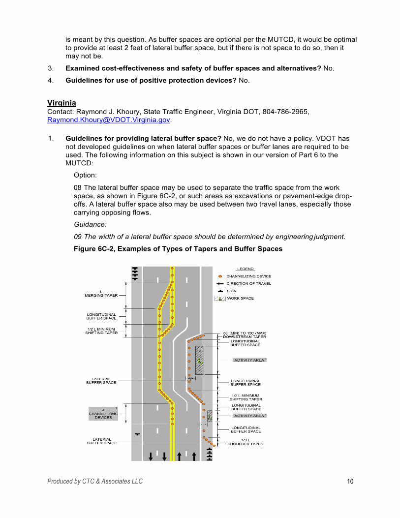
is meant by this question. As buffer spaces are optional per the MUTCD, it would be optimal to provide at least 2 feet of lateral buffer space, but if there is not space to do so, then it may not be.
Examined cost-effectiveness and safety of buffer spaces and alternatives? No.
Guidelines for use of positive protection devices? No.
3.
4.
Virginia Contact: Raymond J. Khoury, State Traffic Engineer, Virginia DOT, 804-786-2965, [email protected].
1. Guidelines for providing lateral buffer space? No, we do not have a policy. VDOT has not developed guidelines on when lateral buffer spaces or buffer lanes are required to be used. The following information on this subject is shown in our version of Part 6 to the MUTCD:
Option:
08 The lateral buffer space may be used to separate the traffic space from the work space, as shown in Figure 6C-2, or such areas as excavations or pavement-edge drop- offs. A lateral buffer space also may be used between two travel lanes, especially those carrying opposing flows.
Guidance:
09 The width of a lateral buffer space should be determined by engineering judgment.
Figure 6C-2, Examples of Types of Tapers and Buffer Spaces
Produced by CTC & Associates LLC 10
2. Practices when not enough adjacent lanes for buffer space: Our spacing for channelizing devices is tighter than the MUTCD guidelines. We place devices at the following spacing: Transition Spacing: posted speed limit up to 35 mph = 20' spacing, posted speed limit >35 = 40' spacing; Travel way Spacing : posted speed limit up to 35 mph = 40' spacing; posted speed limit >35 = 80' spacing.
Examined cost-effectiveness and safety of buffer spaces and alternatives? No, due to the fact that limited allowable work hours for lane closures would be even more limited if two lanes would be required in performing work in only one travel lane.
Guidelines for use of positive protection devices? We have attached Appendix A of the 2011 Virginia Work Area Protection Manual, our version of Part 6 to the MUTCD, which covers guidelines for the use of barrier/channelizing devices in work zones.
3.
4.
Related Document: Guidelines for the Use of Barrier/Channelizing Devices in Work Zones, Appendix A, Virginia Work Area Protection Manual, Virginia DOT, August 2011. See Appendix C. This part of Virginia’s version of the MUTCD addresses the use of positive protection devices.
Washington Contact: Steve Haapala, WSDOT Work Zone Training Specialist, Washington State DOT, 360-705-7241, [email protected].
1. Guidelines for providing lateral buffer space? WSDOT does not have a separate guideline for this issue. Our design manual and work zone guidelines for maintenance require a minimum 2-foot lateral shy distance and recommend considering more… Long duration worker exposure within a lane width of high speed high volume traffic requires positive protection.
Practices when not enough adjacent lanes for buffer space: Shifting onto shoulders, median crossover operations, work operation regulatory speed limit reductions.
Examined cost-effectiveness and safety of buffer spaces and alternatives? Not as an agency, but this should be part of developing a projects transportation management plan (TMP) required for our projects.
Guidelines for use of positive protection devices? See our Design Manual section 1010.10.
2.
3.
4.
Related Documents: Chapter 1010, Work Zone Safety and Mobility, WSDOT Design Manual, Washington State DOT, July 2014. http://www.wsdot.wa.gov/publications/manuals/fulltext/M22-01/1010.pdf See page 27 of this chapter of WSDOT’s Design Manual. From the manual:
Positive protective devices are required for the following conditions unless an engineering study determines otherwise:
• To separate opposing high-speed traffic normally separated by a median or existing median barrier. Where existing traffic barriers or bridge railings are to be removed. For drop-off protection during widening or excavations (see Standard Specification 1- 07.23(1)).
•
•
Produced by CTC & Associates LLC 11
•
•
•
•
When temporary slopes change clear zone requirements. For bridge falsework protection. When equipment or materials must remain in the work zone clear zone. When newly constructed features in the clear zone will not have permanent protection until later in the project. Where temporary signs or light standards are not crashworthy. To separate workers from motorized traffic when work zone offers no means of escape for the worker, such as tunnels, bridges, and retaining walls, or for long- duration worker exposure within one lane-width of high-speed high-volume traffic.
•
•
WSDOT Work Zone Traffic Control Guidelines for Maintenance Operations, Washington State DOT, December 2014. http://www.wsdot.wa.gov/publications/manuals/fulltext/M54-44/workzone.pdf See page 23 of the PDF for the agency’s guidelines on buffer space and shy distances. From the guidelines:
Buffer space is a lateral and/or longitudinal area that separates road user flow from the work space or an unsafe area, and might provide some recovery space for an errant vehicle.
• Lateral buffer space provides space between the driver and the active work space, traffic control device, or to a potential hazard such as an abrupt lane edge or drop-off. A minimum of 2-foot lateral buffer space is recommended.
Shy distance is the distance from the edge of the traveled way beyond which a roadside object will not be perceived as an immediate hazard by the typical driver to the extent that the driver will change the vehicle’s placement or speed.
Longitudinal buffer is the space between the end of the taper and the buffer vehicle. Refer to Appendix 3 for additional information.
•
•
Devices used to separate the driver from the work space should not encroach into adjacent lanes. If encroachment is necessary, it is recommend to close the adjacent lane to maintain the lateral buffer space.
In the case of short-term lane closure operations, the adjacent lane may need to be closed or traffic may need to be temporarily shifted onto a shoulder to maintain a lateral buffer space.
Wisconsin Contact: William McNary, Traffic Engineering Section Chief, Wisconsin DOT, 608-266-1260, [email protected].
1.
2.
3.
Guidelines for providing lateral buffer space? We do not.
Practices when not enough adjacent lanes for buffer space: [No response.]
Examined cost-effectiveness and safety of buffer spaces and alternatives? [No response.]
Guidelines for use of positive protection devices? We are reviewing our policy as well and are interested in what other states are doing.
4.
Produced by CTC & Associates LLC 12
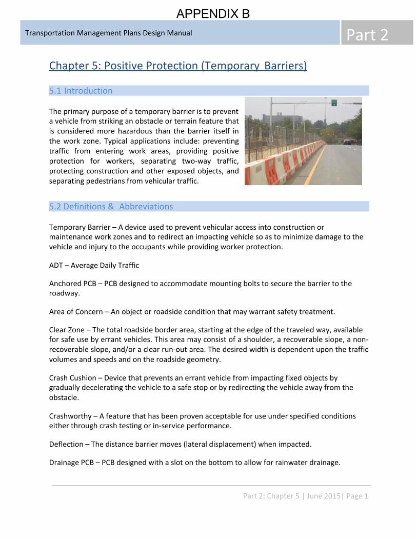
Part 2 Transportation Management Plans Design Manual
APPENDIX B
Chapter 5: Positive Protection (Temporary Barriers)
5.1 Introduction
The primary purpose of a temporary barrier is to prevent a vehicle from striking an obstacle or terrain feature that is considered more hazardous than the barrier itself in the work zone. Typical applications include: preventing traffic from entering work areas, providing positive protection for workers, separating two-way traffic, protecting construction and other exposed objects, and separating pedestrians from vehicular traffic.
5.2 Definitions & Abbreviations
Temporary Barrier – A device used to prevent vehicular access into construction or maintenance work zones and to redirect an impacting vehicle so as to minimize damage to the vehicle and injury to the occupants while providing worker protection.
ADT – Average Daily Traffic
Anchored PCB – PCB designed to accommodate mounting bolts to secure the barrier to the roadway.
Area of Concern – An object or roadside condition that may warrant safety treatment.
Clear Zone – The total roadside border area, starting at the edge of the traveled way, available for safe use by errant vehicles. This area may consist of a shoulder, a recoverable slope, a non- recoverable slope, and/or a clear run-out area. The desired width is dependent upon the traffic volumes and speeds and on the roadside geometry.
Crash Cushion – Device that prevents an errant vehicle from impacting fixed objects by gradually decelerating the vehicle to a safe stop or by redirecting the vehicle away from the obstacle.
Crashworthy – A feature that has been proven acceptable for use under specified conditions either through crash testing or in-service performance.
Deflection – The distance barrier moves (lateral displacement) when impacted.
Drainage PCB – PCB designed with a slot on the bottom to allow for rainwater drainage.
Part 2: Chapter 5 | June 2015| Page 1
Part 2 Transportation Management Plans Design Manual
Flare Rate – Rate of diversion of barrier from traveled way, e.g., 12:1.
Impact Angle – The angle at which the vehicle strikes the barrier.
Impact Severity – The force at which the vehicle impacts the barrier.
Length of Need – Total length of a longitudinal barrier needed to shield an Area of Concern.
Longitudinal Barrier – Traffic barrier oriented parallel or nearly parallel to the roadway. Beam guardrail, cable barrier, bridge rail, and concrete barrier are longitudinal barriers.
MSE Wall – A mechanically stabilized earth wall constructed by various methods to hold back a fill section.
NCHRP Report 350 – National Cooperative Highway Research Program (NCHRP) Report 350, “Recommended Procedures for the Safety Performance Evaluation of Highway Features”. FHWA policy requires that devices used on the National Highway System must be successfully tested in accordance with the guidelines contained in the report.
NCHRP 350 Test Level 2 and Test Level 3 – NCHRP Report 350 test level 2 (TL-2) and test level (TL-3) require successful tests of a 1,800 lb. car impacting a barrier at an angle of 20 degrees and a 4,400 lb. pickup truck impacting a barrier at an angle of 25 degrees at speeds of 45 mph and 60 mph, respectively.
NCHRP 350 Test Level 4 – NCHRP Report 350 test level 4 (TL-4) requires a successful test of a 17,650 lb. truck impacting a barrier at an angle of 15 degrees at a speed of 50 mph.
Non-Recoverable Slope - is a slope which is considered traversable but on which an errant vehicle will continue to the bottom. Embankment slopes between 1V:3H and 1V:4H may be considered traversable but non-recoverable if they are smooth and free of fixed objects.
Recoverable Slope - is a slope on which a motorist may, to a greater or lesser extent, retain or regain control of a vehicle by slowing or stopping. Slopes flatter than 1V:4H are generally considered recoverable.
Offset – Term used when defining either the lateral distance barrier will be placed from the traveled way or the lateral distance barrier will be placed from the Area of Concern it is protecting.
PCB – Portable Concrete Barrier
QMB – Quickchange Moveable Barrier (Zipper System)
Part 2: Chapter 5 | June 2015| Page 2
Part 2 Transportation Management Plans Design Manual
Roadside Design Guide – A document developed by AASHTO that presents a combination of current information and operating practices related to roadside safety.
Runout Length – The theoretical distance required for a vehicle that has left the roadway to come to a stop.
Shy Distance – The distance from the edge of the traveled way beyond which a roadside object will not be perceived as an obstacle by the typical driver to the extent the driver will change the vehicle’s placement or speed.
TMA – Truck Mounted Attenuator
Transition – A section of barrier between two different types of barrier or, more commonly, where a roadside barrier is connected to a bridge railing or to a rigid object such as a bridge pier.
Transverable Slope is a slope from which a motorist will be unlikely to steer back to the roadway but may be able to slow and stop safely. Slopes between 1V:3H and 1V:4H generally fall into this category.
Traveled Way – The portion of the roadway for the movement of vehicles, exclusive of shoulders.
5.3 Guidelines
INTRODUCTION Positive protection is defined by Federal Highway Administration (FHWA) as “devices that contain and/or redirect vehicles and meet the crashworthiness evaluation criteria contained in NCHRP Report 350.” By this definition, positive protection devices should then also prevent intrusion into the work area.
These guidelines address the use of positive protection devices in work zones to supplement the Work Zone Safety and Mobility Policy and comply with the Federal Highway Administration Final Rule Subpart K to CFR Part 630. These guidelines are not intended to be a rigid standard or policy; rather, they are guidance to be used in conjunction with engineering judgment. These guidelines are not a stand-alone document on work zone application of positive protection and must be used in conjunction with other traffic control standards and resources.
EXPOSURE CONTROL MEASURES Prior to including positive protection in a transportation management plan, careful consideration must be given to alternatives which would avoid or minimize exposure for
Part 2: Chapter 5 | June 2015| Page 3
Part 2 Transportation Management Plans Design Manual
workers and road users. Alternatives that are often considered include detouring traffic, minimizing exposure time, or maximizing the separation between traffic and workers. A more inclusive list of potential exposure control measures include: • • • • • • •
Removal of the hazard from the clear zone Full road closure/ramp closure with traffic detoured Road closure with diversion (i.e. onsite detour, median crossover, temporary pavement) Performing work during off-peak periods when traffic volumes are lower Accelerated construction techniques Directional detours or alternate route detours Rolling road blocks
WARRANT A warrant for using positive protection in a work zone is based on the premise that positive protection will reduce the severity of potential crashes. Positive protection in work zones is considered warranted whenever an engineering study indicates any of the following: • Consequences of striking a fixed object or running off the road are believed to be more
serious than striking the positive protection Consequences of striking a worker or pedestrian are believed to be more serious than striking the positive protection
•
TYPICAL APPLICATION The following provides a list of areas where positive protection has been used in the past. However, this list is intended to provide guidance and should not be used in place of performing an engineering study. • Objects that are within the clear zone such as:
- - - - - - -
Temporary shoring locations Bridge piers Overhead sign supports including foundations Staged pipe or culvert construction Stored construction material or equipment Pavement edge drop offs Non-transversable slope or steep/rough embankments within the clear zone
• • •
Staged bridge construction Worker’s or pedestrian safety is at risk due to the proximity of work to travel lanes Separation of opposing traffic
ENGINEERING STUDY AND ANALYSIS An Engineering Study is a process which will integrate data, analysis, judgment, and creativity to determine the best strategy for a given scenario. An Engineering Study does not take the place of good engineering judgment, but should be used in conjunction with engineering judgment to guide the decision making process. It is most important to understand that one individual
Part 2: Chapter 5 | June 2015| Page 4
Part 2 Transportation Management Plans Design Manual
factor cannot independently determine if positive protection is needed. Considering all the factors will provide the fundamental information for the designer to analyze if an individual operation warrants the need for positive protection.
The Engineering Study performed to determine the need for positive protection shall take into consideration clear zone distances, roadway geometry, anticipated construction year traffic volumes, traffic speeds, roadside geometry, workers safety, pedestrian safety, etc. following describes in more detail how these areas of concern are considered.
The
1. PRIMARY FACTORS TO CONSIDER
A. Clear Zone Distances The 2011 Roadside Design Guide (RDG) defines the principles of clear zone. Objects outside the clear zone will generally not require positive protection. A designer must determine if a fixed object or worker will be within this lateral distance from the travel way. Clear zones can be determined using Table 3-1 from the RDG.
Chapter 9 of the RDG provides information specifically for work zones. Table 9-1 provides example work zone clear zones. This table can be considered, using good engineering judgment, when evaluating the need for positive protection.
The lateral distance from the travel way to a drop off or embankment could affect the need for positive protection. The height of a fill section is related to the slope a vehicle would have to travel toward the obstacle. Figure 5-1(b) of the RDG helps to determine if positive protection is needed for a given fill height.
B. Roadside Geometry The depth and slope of the drop off or an embankment (roadside geometry) is an important factor to consider and will affect the decision to use positive protection.
• Pavement Edge Drop off “Safety in Construction Zones Where Pavement Edges and Drop-Offs Exist”, shown in the appendix as Figure 16, provides guidance on a correlation between the depth of a drop off, the distance the drop off is from the travel lane, and the roadside slope.
The Center for Transportation Research and Education (CTRE) in Iowa summarized the other state’s drop-off criteria shown in the appendix from “Traffic Control Strategies in Work Zones with Edge Drop-Offs”
• Embankment Figure 5-2(b) of the Roadside Design Guide, shown in the appendix indicates the relationship between the roadside slope, the height of an embankment and the traffic volume.
Part 2: Chapter 5 | June 2015| Page 5
Part 2 Transportation Management Plans Design Manual
C. Anticipated Traffic Volumes For best analysis, the construction year traffic volumes would provide a more realistic “anticipated” traffic volume than the current or the design year volumes. When analyzing the traffic volumes, the traffic mix should be considered. This includes the percent of truck traffic as well as motorists unfamiliar with area including seasonal tourists or for special events.
With higher traffic volumes, night work is often used as an exposure control measure. Night work may present unique challenges that must be taken into account such as, increased speeds, glare from portable lighting, driver’s impaired visibility, and possible increase of inattentive drivers. Nightly installation and removal of positive protection devices will increase time and traffic exposure and may offset any advantage associated with the use of positive protection, except in cases where it can be installed and left in place for extended periods. These items need to be considered prior to requiring night work.
Higher volumes increase the risk to road users and roadway workers. Therefore, positive protection will more likely be used in locations with higher volumes.
D. Traffic speeds For best analysis, the prevailing speed provides a more realistic speed than the speed limit or design speed for the roadway. If a speed study is available, use the 85th percentile speed. The higher the speed the more likely positive protection will be needed.
E. Roadway Geometry The geometry of the roadway may affect the site distance for motorists, especially at entrance ramps. If the construction operation is on the outside curve of a road, the clear zone distance may be affected. Table 3-2 of the RDG provides adjustment factor for the clear zone. This data considers ADT, speed, and the roadway geometry. The tighter the curve, the more clear zone distance needed.
F. Duration Duration is the length of time the hazard potentially requiring positive protection will be present. A designer must consider the exposure time associated with completing the operation versus the risk of installing the positive protection. In addition, the percent increase in duration must be considered when the installation of the barrier is included in the operation. If the duration to install the positive protection is longer than the construction operation itself, then positive protection may not be justified.
“Safety in Construction Zones Where Pavement Edges and Drop-Offs Exist” provides a figure to determine when temporary barrier may be justified to shield a drop-off as it relates to the ADT and duration/ exposure time of the drop off condition. This is shown in the appendix as Figure 16.
Part 2: Chapter 5 | June 2015| Page 6
Part 2 Transportation Management Plans Design Manual
2. SPECIAL FACTORS TO CONSIDER
A. Worker’s Safety Where worker’s exposure to traffic cannot be adequately managed through the application of an exposure control measure, positive protection should be considered. Consider positive protection in situations that place workers at increased risk from motorized traffic. Consideration must be given to an increase in worker’s exposure during the installation and anchorage of positive protection.
B. Pedestrian Safety Positive protection should be considered if there is a high potential for vehicle intrusion into pedestrian paths.
C. Separating Opposing Traffic Positive separation should be considered in situations where multilane divided facilities are temporarily shifted to a 2 lane 2 way traffic pattern for periods lasting longer than three days. Conditions that may influence the decision to use positive protection would be high speed facilities, narrowed lanes, and high traffic volumes.
3. SECONDARY FACTORS TO CONSIDER While the primary factors to consider are the driving force in the decision to use positive protection, secondary factors should not be dismissed especially in situations where a clear decision is not evident. The following are a list of secondary factors that may influence the decision to use positive protection:
• Crash History. Crash history of the area prior to construction Lessons learned from the crash history of previous work zone projects may be helpful in determining the need for positive protection. The Traffic Safety Unit is a good resource to help identify any potential areas of concern. Impacts on Project Cost and Duration. Positive protection will have an impact on the overall project duration and cost. Impacts on available lane widths. Restricted lane widths due to the use of positive protection may affect mobility for road users and the contractor. Consideration must be given to wide loads and equipment requirements to complete the work. Roadway Classification. The roadway classification is indicative of the characteristics of the road. Characteristics that may have an effect on the decision to use positive protection may include, speed, access, rural vs. urban, etc. Work Area Restrictions. Access to and from the work area for the delivery of materials and equipment should be considered. In addition, consideration should be given to the area needed for storage of equipment and materials and the area needed for equipment operation.
•
•
•
•
Part 2: Chapter 5 | June 2015| Page 7
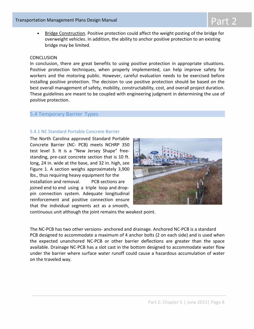
Part 2 Transportation Management Plans Design Manual
• Bridge Construction. Positive protection could affect the weight posting of the bridge for overweight vehicles. In addition, the ability to anchor positive protection to an existing bridge may be limited.
CONCLUSION In conclusion, there are great benefits to using positive protection in appropriate situations. Positive protection techniques, when properly implemented, can help improve safety for workers and the motoring public. However, careful evaluation needs to be exercised before installing positive protection. The decision to use positive protection should be based on the best overall management of safety, mobility, constructability, cost, and overall project duration. These guidelines are meant to be coupled with engineering judgment in determining the use of positive protection.
5.4 Temporary Barrier Types
5.4.1 NC Standard Portable Concrete Barrier The North Carolina approved Standard Portable Concrete Barrier (NC- PCB) meets NCHRP 350 test level 3. It is a “New Jersey Shape” free- standing, pre-cast concrete section that is 10 ft. long, 24 in. wide at the base, and 32 in. high, see Figure 1. A section weighs approximately 3,900 lbs., thus requiring heavy equipment for the installation and removal. PCB sections are joined end to end using a triple loop and drop- pin connection system. Adequate longitudinal reinforcement and positive connection ensure that the individual segments act as a smooth, continuous unit although the joint remains the weakest point.
The NC-PCB has two other versions- anchored and drainage. Anchored NC-PCB is a standard PCB designed to accommodate a maximum of 4 anchor bolts (2 on each side) and is used when the expected unanchored NC-PCB or other barrier deflections are greater than the space available. Drainage NC-PCB has a slot cast in the bottom designed to accommodate water flow under the barrier where surface water runoff could cause a hazardous accumulation of water on the traveled way.
Part 2: Chapter 5 | June 2015| Page 8
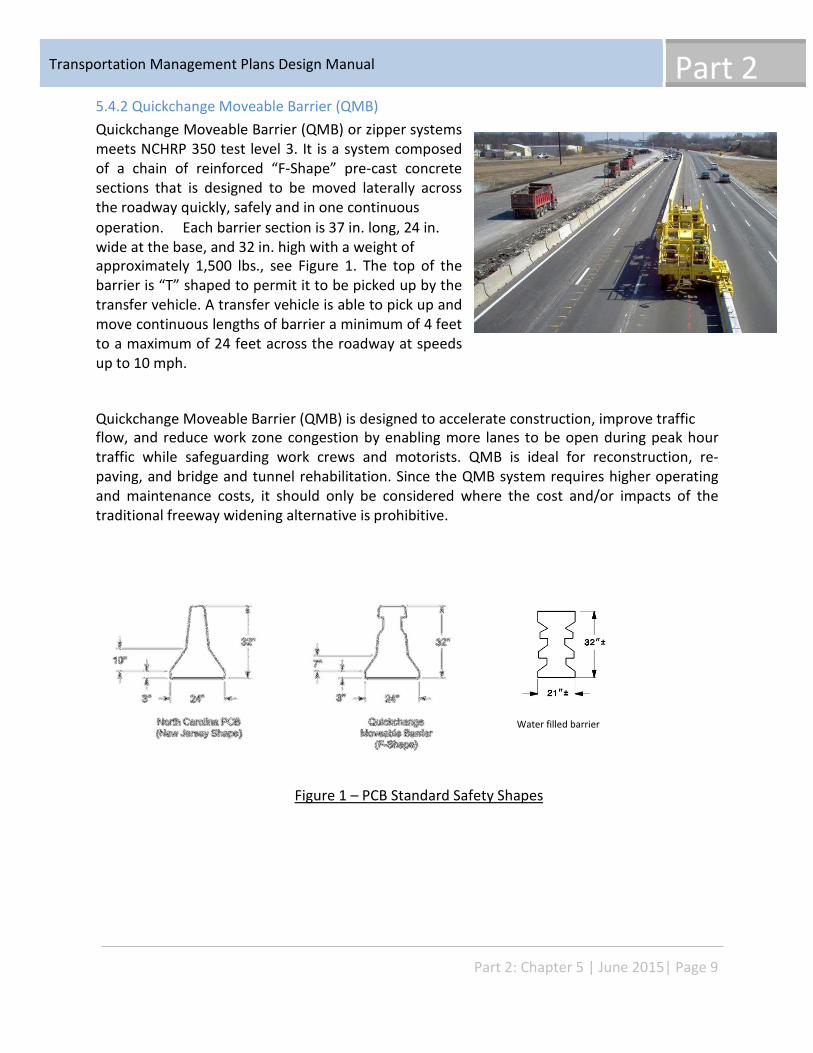
Part 2 Transportation Management Plans Design Manual
5.4.2 Quickchange Moveable Barrier (QMB) Quickchange Moveable Barrier (QMB) or zipper systems meets NCHRP 350 test level 3. It is a system composed of a chain of reinforced “F-Shape” pre-cast concrete sections that is designed to be moved laterally across the roadway quickly, safely and in one continuous operation. Each barrier section is 37 in. long, 24 in. wide at the base, and 32 in. high with a weight of approximately 1,500 lbs., see Figure 1. The top of the barrier is “T” shaped to permit it to be picked up by the transfer vehicle. A transfer vehicle is able to pick up and move continuous lengths of barrier a minimum of 4 feet to a maximum of 24 feet across the roadway at speeds up to 10 mph.
Quickchange Moveable Barrier (QMB) is designed to accelerate construction, improve traffic flow, and reduce work zone congestion by enabling more lanes to be open during peak hour traffic while safeguarding work crews and motorists. QMB is ideal for reconstruction, re- paving, and bridge and tunnel rehabilitation. Since the QMB system requires higher operating and maintenance costs, it should only be considered where the cost and/or impacts of the traditional freeway widening alternative is prohibitive.
Water filled barrier
Figure 1 – PCB Standard Safety Shapes
Part 2: Chapter 5 | June 2015| Page 9
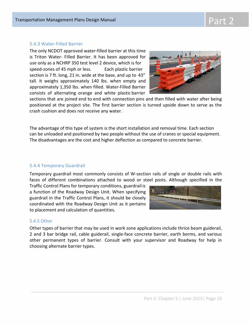
Part 2 Transportation Management Plans Design Manual
5.4.3 Water-Filled Barrier The only NCDOT approved water-filled barrier at this time is Triton Water- Filled Barrier. It has been approved for use only as a NCHRP 350 test level 2 device, which is for speed-zones of 45 mph or less. Each plastic barrier section is 7 ft. long, 21 in. wide at the base, and up to 43” tall. It weighs approximately 140 lbs. when empty and approximately 1,350 lbs. when filled. Water-Filled Barrier consists of alternating orange and white plastic barrier sections that are joined end to end with connection pins and then filled with water after being positioned at the project site. The first barrier section is turned upside down to serve as the crash cushion and does not receive any water.
The advantage of this type of system is the short installation and removal time. Each section can be unloaded and positioned by two people without the use of cranes or special equipment. The disadvantages are the cost and higher deflection as compared to concrete barrier.
5.4.4 Temporary Guardrail
Temporary guardrail most commonly consists of W-section rails of single or double rails with faces of different combinations attached to wood or steel posts. Although specified in the Traffic Control Plans for temporary conditions, guardrail is a function of the Roadway Design Unit. When specifying guardrail in the Traffic Control Plans, it should be closely coordinated with the Roadway Design Unit as it pertains to placement and calculation of quantities.
5.4.5 Other Other types of barrier that may be used in work zone applications include thrice beam guiderail, 2 and 3 bar bridge rail, cable guiderail, single-face concrete barrier, earth berms, and various other permanent types of barrier. Consult with your supervisor and Roadway for help in choosing alternate barrier types.
Part 2: Chapter 5 | June 2015| Page 10
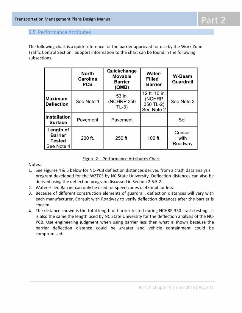
Part 2 Transportation Management Plans Design Manual
North
Carolina PCB
Quickchange Movable Barrier (QMB)
Water- Filled Barrier
W-Beam Guardrail
Maximum Deflection
See Note 1
53 in. (NCHRP 350
TL-3)
12 ft. 10 in. (NCHRP 350 TL-2)
See Note 2
See Note 3
Installation Surface Pavement
Pavement
Soil
Length of Barrier Tested
See Note 4
200 ft.
250 ft.
100 ft.
Consult with
Roadway
5.5 Performance Attributes
The following chart is a quick reference for the barrier approved for use by the Work Zone Traffic Control Section. subsections.
Support information to the chart can be found in the following
Figure 2 – Performance Attributes Chart Notes: 1. See Figures 4 & 5 below for NC-PCB deflection distances derived from a crash data analysis
program developed for the WZTCS by NC State University. Deflection distances can also be derived using the deflection program discussed in Section 2.5.5.2. Water-Filled Barrier can only be used for speed zones of 45 mph or less. Because of different construction elements of guardrail, deflection distances will vary with each manufacturer. Consult with Roadway to verify deflection distances after the barrier is chosen. The distance shown is the total length of barrier tested during NCHRP 350 crash testing. It is also the same the length used by NC State University for the deflection analysis of the NC- PCB. Use engineering judgment when using barrier less than what is shown because the barrier deflection distance could be greater and vehicle containment could be compromised.
2. 3.
4.
Part 2: Chapter 5 | June 2015| Page 11
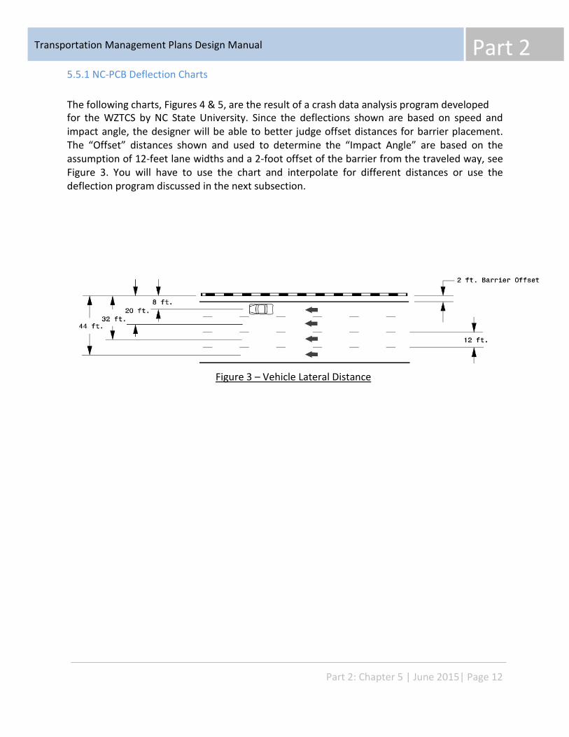
Part 2 Transportation Management Plans Design Manual
5.5.1 NC-PCB Deflection Charts
The following charts, Figures 4 & 5, are the result of a crash data analysis program developed for the WZTCS by NC State University. Since the deflections shown are based on speed and impact angle, the designer will be able to better judge offset distances for barrier placement. The “Offset” distances shown and used to determine the “Impact Angle” are based on the assumption of 12-feet lane widths and a 2-foot offset of the barrier from the traveled way, see Figure 3. You will have to use the chart and interpolate for different distances or use the deflection program discussed in the next subsection.
Figure 3 – Vehicle Lateral Distance
Part 2: Chapter 5 | June 2015| Page 12
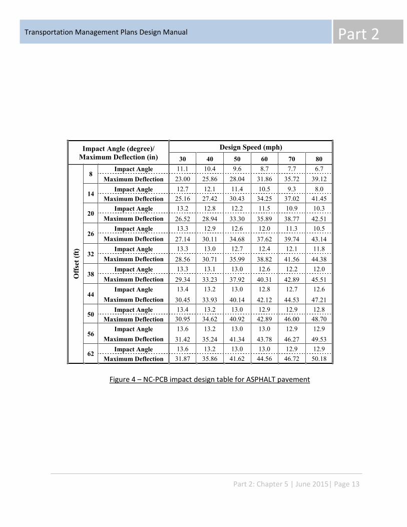
Part 2 Transportation Management Plans Design Manual
Impact Angle (degree)/ Maximum Deflection (in)
Design Speed (mph) 30 40 50 60 70 80
Offs
et (f
t)
8 Impact Angle
Maximum Deflection 11.1 23.00
10.4 25.86
9.6 28.04
8.7 31.86
7.7 35.72
6.7 39.12
14 Impact Angle
Maximum Deflection 12.7 25.16
12.1 27.42
11.4 30.43
10.5 34.25
9.3 37.02
8.0 41.45
20
Impact Angle Maximum Deflection
13.2 26.52
12.8 28.94
12.2 33.30
11.5 35.89
10.9 38.77
10.3 42.51
26
Impact Angle Maximum Deflection
13.3 27.14
12.9 30.11
12.6 34.68
12.0 37.62
11.3 39.74
10.5 43.14
32
Impact Angle Maximum Deflection
13.3 28.56
13.0 30.71
12.7 35.99
12.4 38.82
12.1 41.56
11.8 44.38
38
Impact Angle Maximum Deflection
13.3 29.34
13.1 33.23
13.0 37.92
12.6 40.31
12.2 42.89
12.0 45.51
44
Impact Angle Maximum Deflection
13.4 30.45
13.2 33.93
13.0 40.14
12.8 42.12
12.7 44.53
12.6 47.21
50 Impact Angle
Maximum Deflection 13.4 30.95
13.2 34.62
13.0 40.92
12.9 42.89
12.9 46.00
12.8 48.70
56
Impact Angle Maximum Deflection
13.6 31.42
13.2 35.24
13.0 41.34
13.0 43.78
12.9 46.27
12.9 49.53
62 Impact Angle
Maximum Deflection 13.6 31.87
13.2 35.86
13.0 41.62
13.0 44.56
12.9 46.72
12.9 50.18
Figure 4 – NC-PCB impact design table for ASPHALT pavement
Part 2: Chapter 5 | June 2015| Page 13
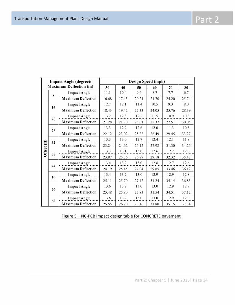
Part 2 Transportation Management Plans Design Manual
Impact Angle (degree)/ Maximum Deflection (in)
Design Speed (mph) 30 40 50 60 70 80
Offs
et (f
t)
8 Impact Angle
Maximum Deflection 11.1 16.68
10.4 17.45
9.6 20.21
8.7 21.70
7.7 24.20
6.7 25.74
14
Impact Angle Maximum Deflection
12.7 18.43
12.1 19.42
11.4 22.33
10.5 24.05
9.3 25.76
8.0 28.39
20
Impact Angle Maximum Deflection
13.2 21.28
12.8 21.70
12.2 23.61
11.5 25.37
10.9 27.51
10.3 30.05
26
Impact Angle Maximum Deflection
13.3 22.12
12.9 23.02
12.6 25.22
12.0 26.49
11.3 29.45
10.5 33.27
32
Impact Angle Maximum Deflection
13.3 23.24
13.0 24.62
12.7 26.12
12.4 27.98
12.1 31.30
11.8 34.26
38
Impact Angle Maximum Deflection
13.3 23.87
13.1 25.36
13.0 26.89
12.6 29.18
12.2 32.32
12.0 35.47
44
Impact Angle Maximum Deflection
13.4 24.19
13.2 25.45
13.0 27.04
12.8 29.85
12.7 33.46
12.6 36.12
50
Impact Angle Maximum Deflection
13.4 25.11
13.2 25.70
13.0 27.42
12.9 31.24
12.9 34.14
12.8 36.85
56
Impact Angle Maximum Deflection
13.6 25.48
13.2 25.80
13.0 27.83
13.0 31.54
12.9 34.51
12.9 37.12
62
Impact Angle Maximum Deflection
13.6 25.55
13.2 26.20
13.0 28.16
13.0 31.80
12.9 35.15
12.9 37.34
Figure 5 – NC-PCB impact design table for CONCRETE pavement
Part 2: Chapter 5 | June 2015| Page 14
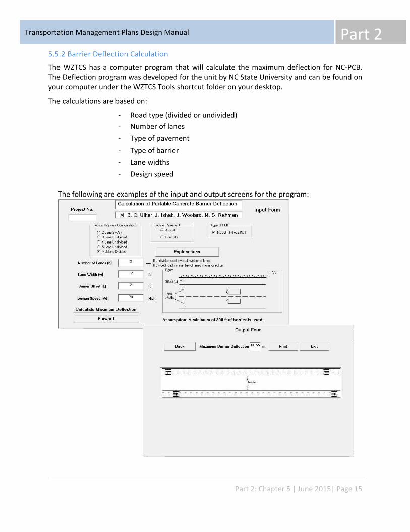
Part 2 Transportation Management Plans Design Manual
5.5.2 Barrier Deflection Calculation
The WZTCS has a computer program that will calculate the maximum deflection for NC-PCB. The Deflection program was developed for the unit by NC State University and can be found on your computer under the WZTCS Tools shortcut folder on your desktop.
The calculations are based on:
- - - - - -
Road type (divided or undivided) Number of lanes Type of pavement Type of barrier Lane widths Design speed
The following are examples of the input and output screens for the program:
Part 2: Chapter 5 | June 2015| Page 15
Transportation Management Plans Design Manual Part 2
5.6 Temporary Barrier Usage
5.6.1 Warrants for Temporary Barrier Usage
The Roadside Design Guide was introduced to promote the safety of the motorist that may inadvertently run off the roadway. With that purpose, the Roadside Design Guide established the concept of the Clear Zone (The total roadside border area, starting at the edge of the traveled way that is available for safe use by errant vehicles). While the principles governing the placement of barrier to protect the motorist from striking objects in the clear zone are generally the same, the work zone and permanent roadside environments are very different. Materials, equipment and workers are inherent of the work zone “clear zone” which is not the same as the objects found in the permanent roadside “clear zone”. Therefore, experience and judgment must be used to identify hazardous features. The following is a small list of hazards that may warrant the use of barrier in the work zone:
- - - - - -
Construction equipment and materials Existing permanent guardrail/concrete barrier Exposed ends of temporary barrier Bridge piers Bridge rail or parapet ends Culvert installations
In addition to shielding hazards, barrier may necessary for the following: - - - -
Protect the workers. Separate two-way traffic. Shield and/or guide pedestrians around the work site.
5.6.2 Guidelines for Barrier Usage
In addition to the examples listed above, the following is a list of guidelines to help determine the need for temporary barrier.
5.6.2.1 Drop-offs Drop-Offs greater than 3 inches need special attention when located within or near the traveled way. See Chapter 2.2 Drop-Offs in the WZTCS Design Manual for guidelines in the use of temporary barrier.
5.6.2.2 Roadside Slopes If a roadside is not flat, a vehicle leaving the roadway will encounter an embankment slope (negative grade), a cut slope (positive grade), or a channel (change in slope from negative to positive). Each of these features has an effect on a vehicle’s lateral encroachment and
Part 2: Chapter 5 | June 2015| Page 16
Part 2 Transportation Management Plans Design Manual
trajectory. Embankment or fill slopes are categorized as recoverable, non-recoverable, or critical:
- Recoverable Slopes are 4H:1V or flatter where a vehicle may be stopped or slowed enough to return to the roadway safely. Non-Recoverable Slopes between 3H:1V and 4H:1V are traversal, but from which most motorists will be unable to stop or return to the roadway safely. Critical Slopes steeper than 3H:1V may cause vehicle overturn.
-
-
Slopes steeper than 3H:1V should be protected by some type of barrier. See Chapter 2.2 Drop-Offs in the WZTCS Design Manual for guidelines in the use of temporary barrier to protect slopes.
5.6.2.3 Shoring and MSE Walls Shoring or a MSE wall located in the Clear Zone may require temporary barrier to protect the motorist. See the Temporary Shoring Special Provision SP11R02 and WZTC Standard Drawing “Portable Concrete Barrier at Temporary Shoring Locations” for guidelines.
5.6.3 Assessing the use of Temporary Barrier
Even though a hazard has been identified, engineering judgment needs to be used to determine if temporary barrier should be utilized. It must be remembered that the installation of temporary barrier also represents a hazard to the motorist and it is a safety issue for the worker who must install and remove the barrier. The following are a few factors to consider when assessing the need for positive protection:
- - - - - - -
Duration of the construction activity Traffic volumes (ADT) Work zone design speed Highway functional class Length of hazard Proximity between traffic and construction workers and/or equipment Adverse geometrics which may increase the likelihood of run-off-the-road vehicles
Consult with your supervisor for alternatives to barrier that can be used, e.g., drums for delineation, portable changeable message signs to alert the motorist and a TMA to shield the hazard. Other solutions may be a temporary detour or lane closure.
Part 2: Chapter 5 | June 2015| Page 17
Transportation Management Plans Design Manual Part 2
5.7 Selection Criteria
Once it has been decided to use temporary barrier, engineering judgment is needed in the selection and placement of temporary barrier in the work zone. The following summarizes some factors that should be considered before making the final selection:
– – –
–
The barrier chosen must be structurally able to contain and redirect the vehicle
Expected deflection of the barrier should not exceed available deflection distance
Slope and surface may limit some barrier types
The barrier chosen may have to be capable of transitioning to other barrier types and bridge railings
Other considerations are the duration of construction activity, work zone speed, ADT and barrier cost
–
5.7.1 Surface
The type of surface the barrier will be installed on is an important design element in choosing the correct temporary barrier type.
5.7.1.1 Paved
PCB (including anchored and drainage), QMB (Zipper System) and water filled barrier must be installed on paved surfaces. If necessary, temporary pavement may be placed on an unpaved area next to the travel lane for barrier installation. A paved surface is also required when the barrier is flared away from the traveled way.
5.7.1.2 Unpaved
If placing temporary pavement is not an option, consider using temporary guardrail or guiderail. Coordinate the selection and placement of guardrail/guiderail with Roadway Design Unit.
5.7.1.3 Bridge Decks
PCB is predominantly used on bridge decks. Coordinate with Structure Design on whether the structure rating is sufficient to accommodate the weight of the barrier or if the barrier can be anchored to the bridge deck. If the existing structure is aged to the point where concrete
Part 2: Chapter 5 | June 2015| Page 18
Part 2 Transportation Management Plans Design Manual
barrier cannot be supported; then guardrail can be considered and should be coordinated with Structure Design and Roadway Design.
5.7.1.4 Slopes
The Roadside Design Guide does not recommend placing barrier on slopes steeper than 10H:1V. Per the Roadside Design Guide, “When barrier is placed on slopes steeper than 10H:1V, studies have shown that for certain encroachment angles and speeds an errant vehicle may go over many standard roadside barriers or impact them too low.” Since PCB, QMB and water-filled barrier must be placed on a paved surface, slope will probably not be an issue. For Water-Filled Barrier it is recommended not to exceed slopes steeper than 20H:1V. When slopes are steeper than 10H:1V, consult with roadway for a guardrail or guiderail that may be suitable.
5.7.2 Performance
After the Area of Concern that needs to be protected has been identified, a barrier should be chosen that has a level of performance that can properly protect the area. The first concern will be to insure that the deflection of the barrier chosen will not encroach into Area of Concern when impacted. After reviewing the speed zone and lane width for worst case impact severity, refer to the charts in Section 2.5.5 Performance Attributes to find the deflection distance of the NC-PCB. (In the past, the designer could only use the deflection distances reported from the NCHRP 350 test data and use that distance as a worst case for deflection. The charts now give the designer the deflection distance that better matches the work zone). The designer can also use the deflection program. If the designer is using Water-Filled barrier, guardrail or another NCDOT approved barrier, the designer should use the deflection distance reported from the NCHRP 350 test data for that barrier as the worst case deflection.
Another consideration in the performance of the barrier is the type of traffic and work zone location. The PCB approved and most W-Beam guardrail meets NCHRP 350 TL-3 which has been crash tested for cars and light trucks. If your work zone is located in an urban area with a 35 mph speed zone, then Water-Filled barrier may be a better choice.
Part 2: Chapter 5 | June 2015| Page 19
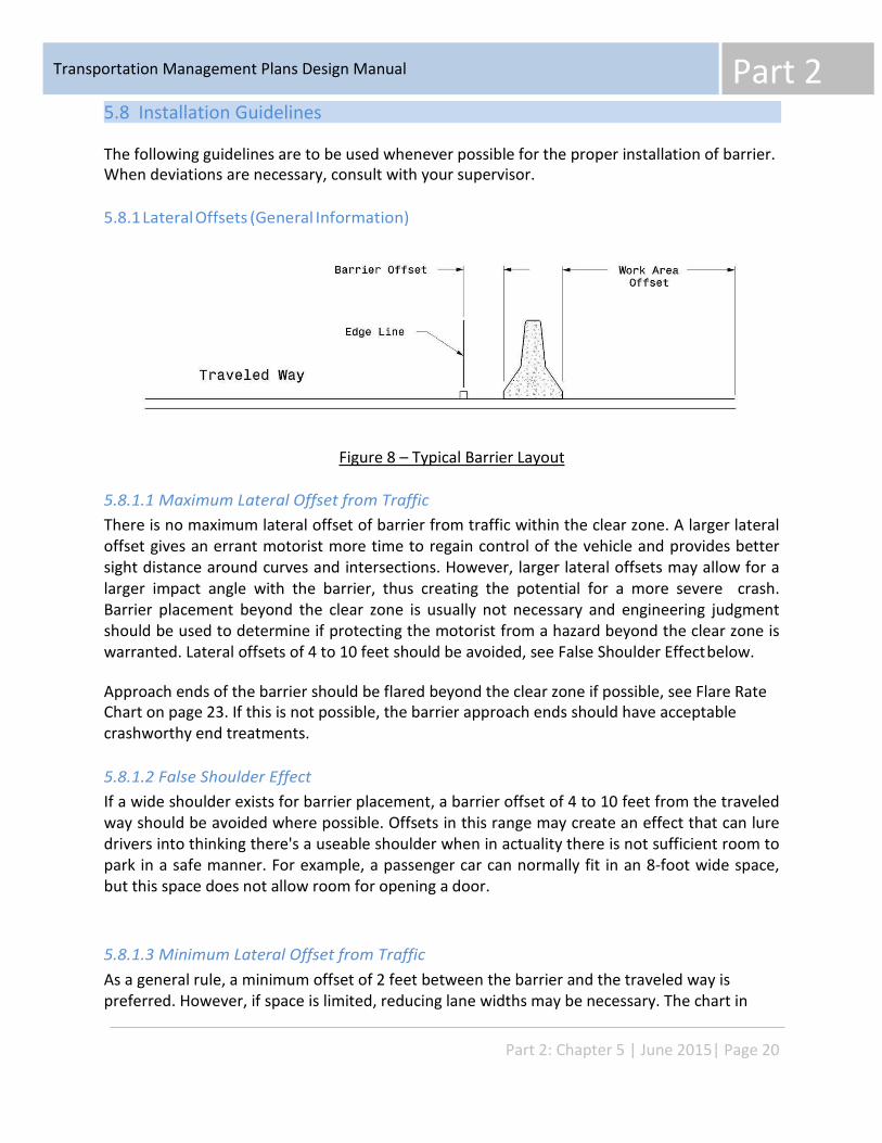
Transportation Management Plans Design Manual Part 2
5.8 Installation Guidelines
The following guidelines are to be used whenever possible for the proper installation of barrier. When deviations are necessary, consult with your supervisor.
5.8.1 Lateral Offsets (General Information)
Figure 8 – Typical Barrier Layout
5.8.1.1 Maximum Lateral Offset from Traffic There is no maximum lateral offset of barrier from traffic within the clear zone. A larger lateral offset gives an errant motorist more time to regain control of the vehicle and provides better sight distance around curves and intersections. However, larger lateral offsets may allow for a larger impact angle with the barrier, thus creating the potential for a more severe crash. Barrier placement beyond the clear zone is usually not necessary and engineering judgment should be used to determine if protecting the motorist from a hazard beyond the clear zone is warranted. Lateral offsets of 4 to 10 feet should be avoided, see False Shoulder Effect below.
Approach ends of the barrier should be flared beyond the clear zone if possible, see Flare Rate Chart on page 23. If this is not possible, the barrier approach ends should have acceptable crashworthy end treatments.
5.8.1.2 False Shoulder Effect If a wide shoulder exists for barrier placement, a barrier offset of 4 to 10 feet from the traveled way should be avoided where possible. Offsets in this range may create an effect that can lure drivers into thinking there's a useable shoulder when in actuality there is not sufficient room to park in a safe manner. For example, a passenger car can normally fit in an 8-foot wide space, but this space does not allow room for opening a door.
5.8.1.3 Minimum Lateral Offset from Traffic As a general rule, a minimum offset of 2 feet between the barrier and the traveled way is preferred. However, if space is limited, reducing lane widths may be necessary. The chart in
Part 2: Chapter 5 | June 2015| Page 20
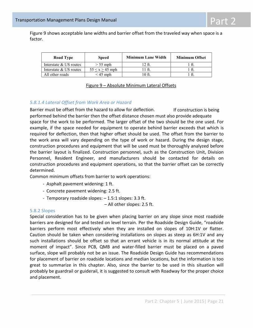
Part 2 Transportation Management Plans Design Manual
Road Type Speed Minimum Lane Width Minimum Offset
Interstate & US routes > 55 mph 12 ft. 1 ft. Interstate & US routes 55 < x > 45 mph 11 ft. 1 ft. All other roads < 45 mph 10 ft. 1 ft.
Figure 9 shows acceptable lane widths and barrier offset from the traveled way when space is a factor.
Figure 9 – Absolute Minimum Lateral Offsets
5.8.1.4 Lateral Offset from Work Area or Hazard Barrier must be offset from the hazard to allow for deflection. If construction is being performed behind the barrier then the offset distance chosen must also provide adequate space for the work to be performed. The larger offset of the two should be the one used. For example, if the space needed for equipment to operate behind barrier exceeds that which is required for deflection, then that higher offset should be used. The offset from the barrier to the work area will vary depending on the type of work or hazard. During the design stage, construction procedures and equipment that will be used must be thoroughly analyzed before the barrier layout is finalized. Construction personnel, such as the Construction Unit, Division Personnel, Resident Engineer, and manufacturers should be contacted for details on construction procedures and equipment operations, so that the barrier offset can be correctly determined. Common minimum offsets from barrier to work operations:
- - -
Asphalt pavement widening: 1 ft. Concrete pavement widening: 2.5 ft. Temporary roadside slopes: – 1.5:1 slopes: 3.3 ft.
– All other slopes: 2.5 ft. 5.8.2 Slopes Special consideration has to be given when placing barrier on any slope since most roadside barriers are designed for and tested on level terrain. Per the Roadside Design Guide, “roadside barriers perform most effectively when they are installed on slopes of 10H:1V or flatter. Caution should be taken when considering installations on slopes as steep as 6H:1V and any such installations should be offset so that an errant vehicle is in its normal attitude at the moment of impact”. Since PCB, QMB and water-filled barrier must be placed on a paved surface, slope will probably not be an issue. The Roadside Design Guide has recommendations for placement of barrier on roadside locations and median locations, but the information is too great to summarize in this chapter. Also, since the barrier to be used in this situation will probably be guardrail or guiderail, it is suggested to consult with Roadway for the proper choice and placement.
Part 2: Chapter 5 | June 2015| Page 21
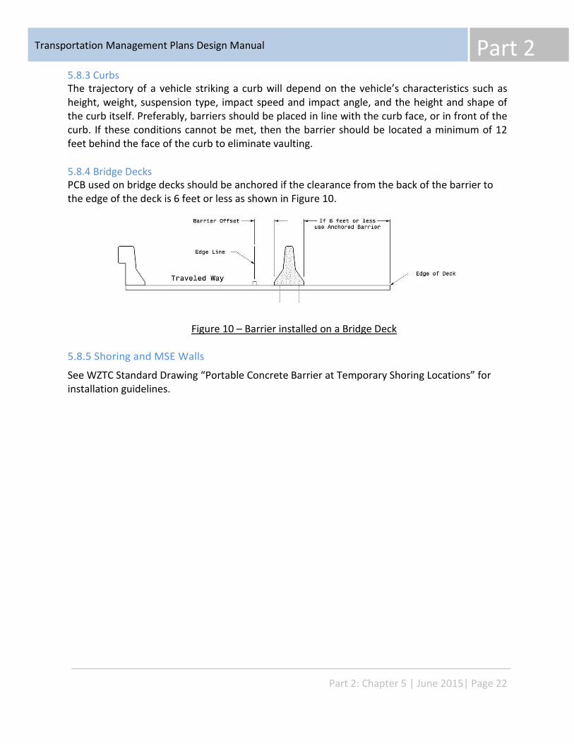
Part 2 Transportation Management Plans Design Manual
5.8.3 Curbs The trajectory of a vehicle striking a curb will depend on the vehicle’s characteristics such as height, weight, suspension type, impact speed and impact angle, and the height and shape of the curb itself. Preferably, barriers should be placed in line with the curb face, or in front of the curb. If these conditions cannot be met, then the barrier should be located a minimum of 12 feet behind the face of the curb to eliminate vaulting.
5.8.4 Bridge Decks PCB used on bridge decks should be anchored if the clearance from the back of the barrier to the edge of the deck is 6 feet or less as shown in Figure 10.
Figure 10 – Barrier installed on a Bridge Deck
5.8.5 Shoring and MSE Walls
See WZTC Standard Drawing “Portable Concrete Barrier at Temporary Shoring Locations” for installation guidelines.
Part 2: Chapter 5 | June 2015| Page 22
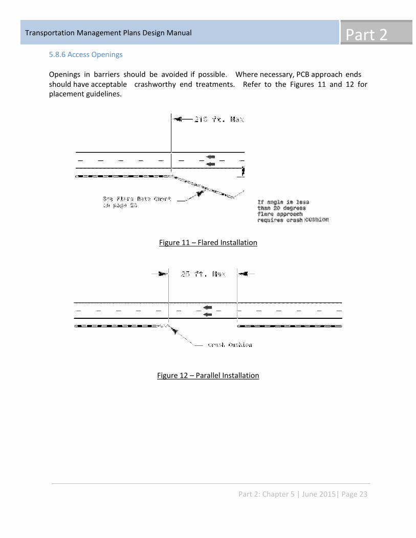
Part 2 Transportation Management Plans Design Manual
5.8.6 Access Openings
Openings in barriers should be avoided if possible. Where necessary, PCB approach ends should have acceptable placement guidelines.
crashworthy end treatments. Refer to the Figures 11 and 12 for
Figure 11 – Flared Installation
Figure 12 – Parallel Installation
Part 2: Chapter 5 | June 2015| Page 23
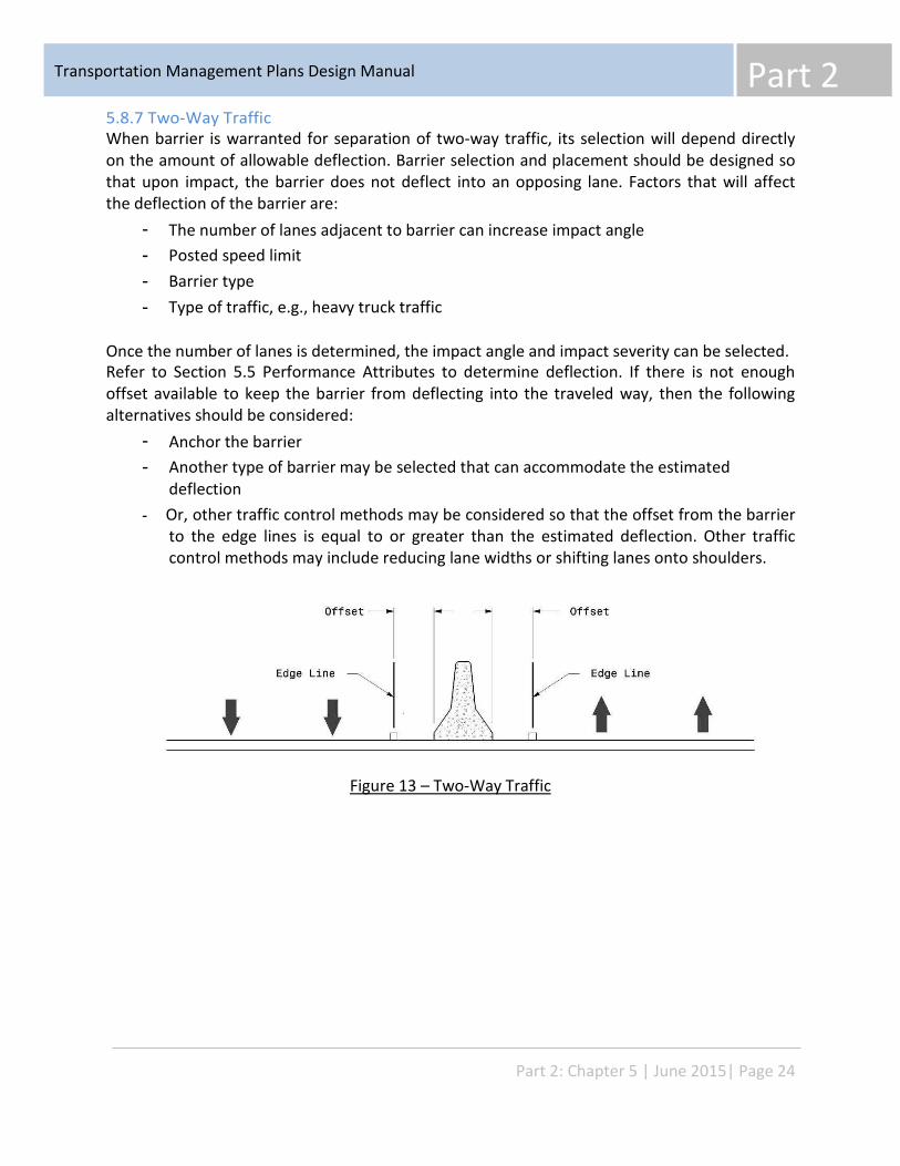
Part 2 Transportation Management Plans Design Manual
5.8.7 Two-Way Traffic When barrier is warranted for separation of two-way traffic, its selection will depend directly on the amount of allowable deflection. Barrier selection and placement should be designed so that upon impact, the barrier does not deflect into an opposing lane. Factors that will affect the deflection of the barrier are:
- - - -
The number of lanes adjacent to barrier can increase impact angle Posted speed limit Barrier type Type of traffic, e.g., heavy truck traffic
Once the number of lanes is determined, the impact angle and impact severity can be selected. Refer to Section 5.5 Performance Attributes to determine deflection. If there is not enough offset available to keep the barrier from deflecting into the traveled way, then the following alternatives should be considered:
- -
Anchor the barrier Another type of barrier may be selected that can accommodate the estimated deflection Or, other traffic control methods may be considered so that the offset from the barrier to the edge lines is equal to or greater than the estimated deflection. Other traffic control methods may include reducing lane widths or shifting lanes onto shoulders.
-
Figure 13 – Two-Way Traffic
Part 2: Chapter 5 | June 2015| Page 24
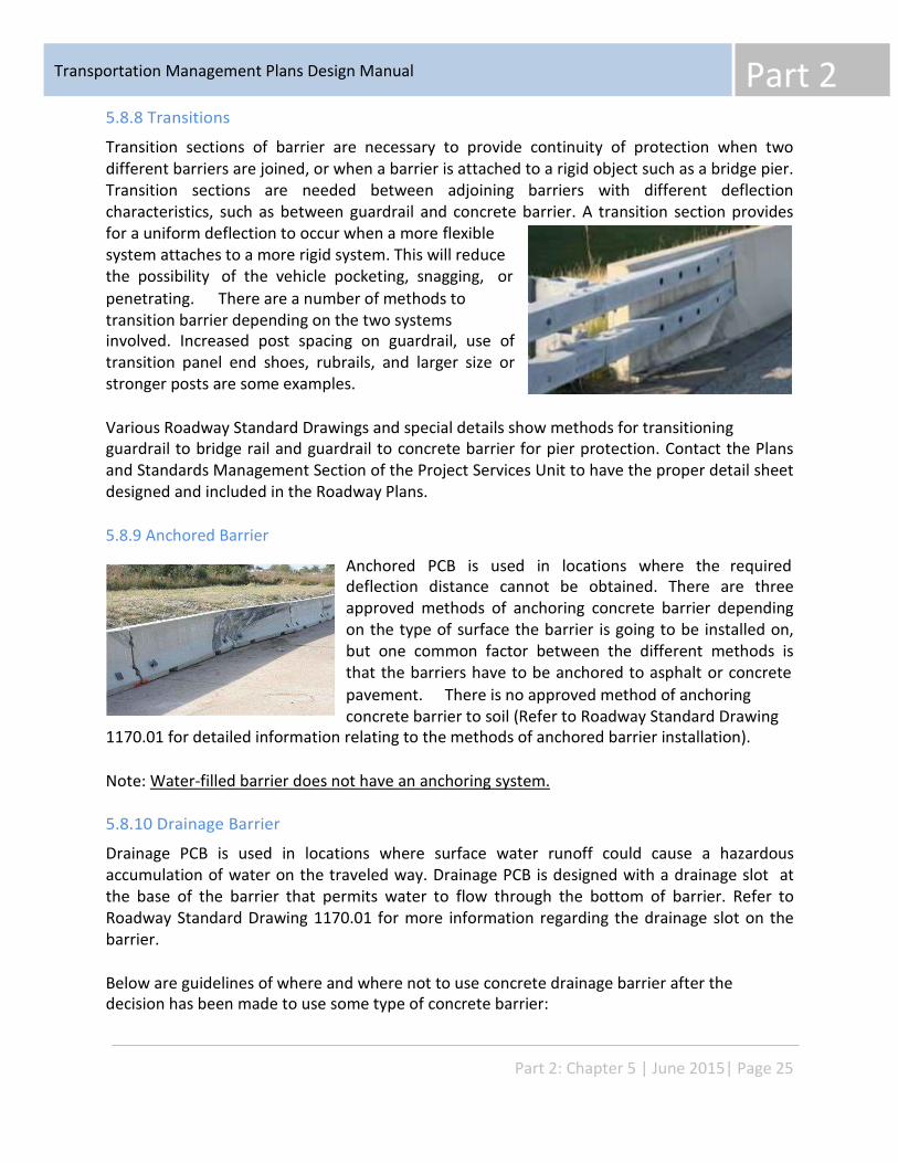
Part 2 Transportation Management Plans Design Manual
5.8.8 Transitions
Transition sections of barrier are necessary to provide continuity of protection when two different barriers are joined, or when a barrier is attached to a rigid object such as a bridge pier. Transition sections are needed between adjoining barriers with different deflection characteristics, such as between guardrail and concrete barrier. A transition section provides for a uniform deflection to occur when a more flexible system attaches to a more rigid system. This will reduce the possibility of the vehicle pocketing, snagging, or penetrating. There are a number of methods to transition barrier depending on the two systems involved. Increased post spacing on guardrail, use of transition panel end shoes, rubrails, and larger size or stronger posts are some examples.
Various Roadway Standard Drawings and special details show methods for transitioning guardrail to bridge rail and guardrail to concrete barrier for pier protection. Contact the Plans and Standards Management Section of the Project Services Unit to have the proper detail sheet designed and included in the Roadway Plans.
5.8.9 Anchored Barrier
Anchored PCB is used in locations where the required deflection distance cannot be obtained. There are three approved methods of anchoring concrete barrier depending on the type of surface the barrier is going to be installed on, but one common factor between the different methods is that the barriers have to be anchored to asphalt or concrete pavement. There is no approved method of anchoring concrete barrier to soil (Refer to Roadway Standard Drawing
1170.01 for detailed information relating to the methods of anchored barrier installation).
Note: Water-filled barrier does not have an anchoring system.
5.8.10 Drainage Barrier
Drainage PCB is used in locations where surface water runoff could cause a hazardous accumulation of water on the traveled way. Drainage PCB is designed with a drainage slot at the base of the barrier that permits water to flow through the bottom of barrier. Refer to Roadway Standard Drawing 1170.01 for more information regarding the drainage slot on the barrier.
Below are guidelines of where and where not to use concrete drainage barrier after the decision has been made to use some type of concrete barrier:
Part 2: Chapter 5 | June 2015| Page 25
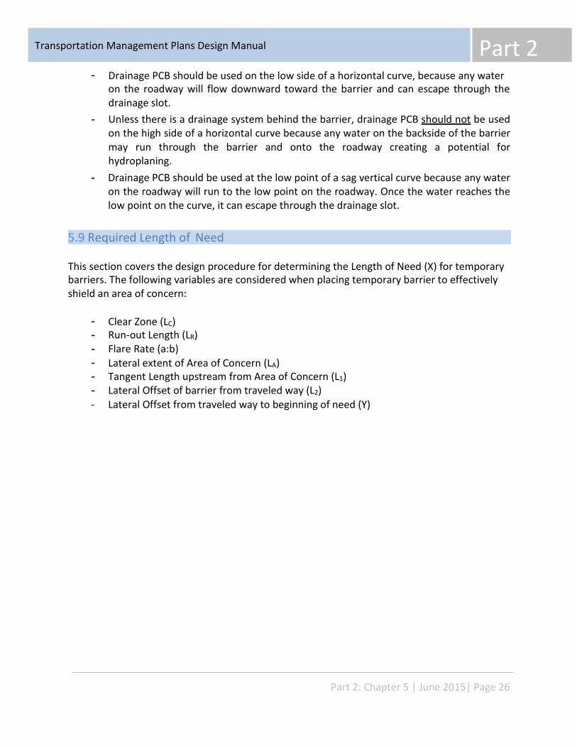
Part 2 Transportation Management Plans Design Manual
- Drainage PCB should be used on the low side of a horizontal curve, because any water on the roadway will flow downward toward the barrier and can escape through the drainage slot. Unless there is a drainage system behind the barrier, drainage PCB should not be used on the high side of a horizontal curve because any water on the backside of the barrier may run through the barrier and onto the roadway creating a potential for hydroplaning. Drainage PCB should be used at the low point of a sag vertical curve because any water on the roadway will run to the low point on the roadway. Once the water reaches the low point on the curve, it can escape through the drainage slot.
-
-
5.9 Required Length of Need
This section covers the design procedure for determining the Length of Need (X) for temporary barriers. The following variables are considered when placing temporary barrier to effectively shield an area of concern:
- - - - - - -
Clear Zone (LC) Run-out Length (LR) Flare Rate (a:b) Lateral extent of Area of Concern (LA) Tangent Length upstream from Area of Concern (L1) Lateral Offset of barrier from traveled way (L2) Lateral Offset from traveled way to beginning of need (Y)
Part 2: Chapter 5 | June 2015| Page 26
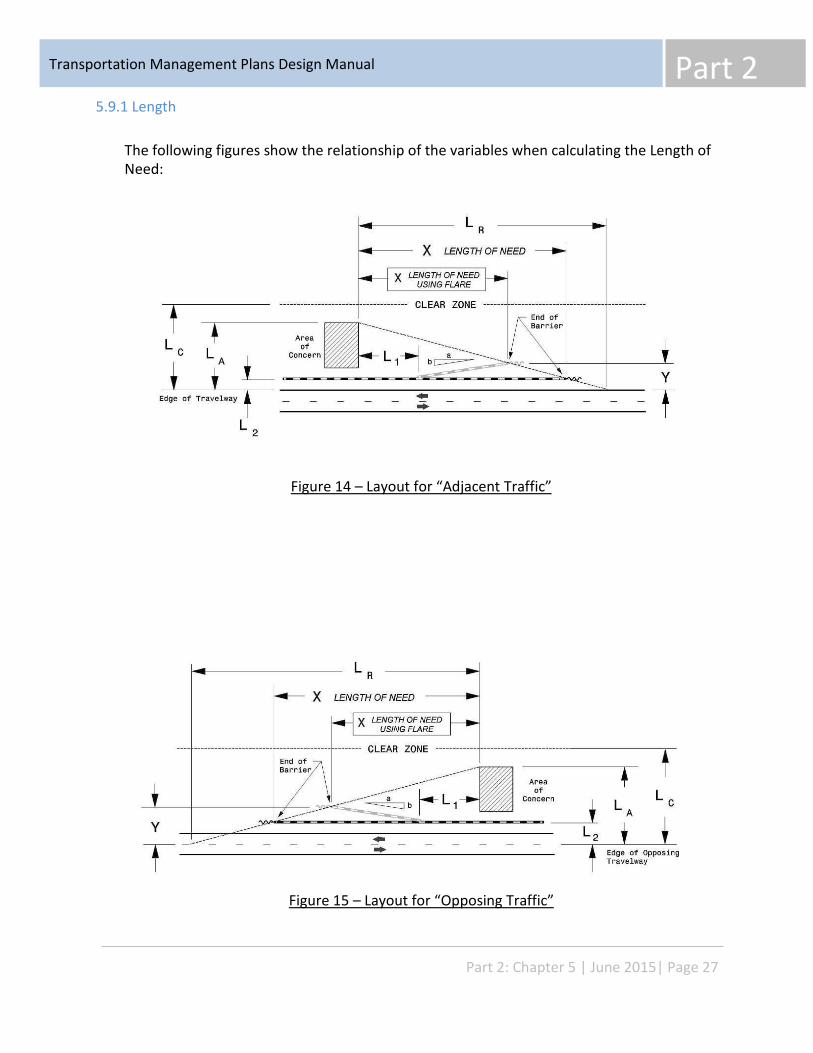
Part 2 Transportation Management Plans Design Manual
5.9.1 Length
The following figures show the relationship of the variables when calculating the Length of Need:
Figure 14 – Layout for “Adjacent Traffic”
Figure 15 – Layout for “Opposing Traffic”
Part 2: Chapter 5 | June 2015| Page 27
Part 2 Transportation Management Plans Design Manual
5.9.1.1 Length of Need (X)
The Length of Need (X) is the total length of longitudinal barrier needed to shield an area of concern. The Length of Need can be calculated by inputting the variables into the following formulas:
LA – L2 (LA – L2) + (b/a) (L1) Without Flare X = With Flare X =
LA / LR b/a + (LA / LR)
5.9.1.2 Clear Zone (LC)
The Clear Zone (LC) is the total roadside border area, starting at the edge of the +verable slope, a non-recoverable slope, and/or a clear run-out area. Barrier ends that are within the clear zone will need a crashworthy end treatment. In addition, there are three ranges of Clear Zone width, LC, that deserve special attention for an approach barrier for “Opposing Traffic”:
- If the barrier is located beyond the “Opposing Traffic” Clear Zone (LC), no additional barrier is required. However, a crashworthy end treatment should be considered based on ADT, distance beyond the clear zone and roadway geometrics. If the barrier is located within the “Opposing Traffic” Clear Zone (LC), but the area of concern is beyond it, no additional barrier is required, but a crashworthy end treatment should be used. If the area of concern extends well beyond the “Opposing Traffic” Clear Zone (LC), the designer may choose to shield only that portion which lies within the clear zone by setting LA equal to LC
-
-
The Roadside Design Guide discusses in Chapter 9 how the work zone “clear zone” differs from the before-construction “clear zone” and it states - “Engineering judgment must be used in applying the “clear zone” to work zones”. Because the manual does not publish clear guidance for work zone “clear zone” ranges, it is suggested to use the following chart from the Roadside Design Guide which shows the appropriate “clear zone” ranges used for permanent construction:
Part 2: Chapter 5 | June 2015| Page 28
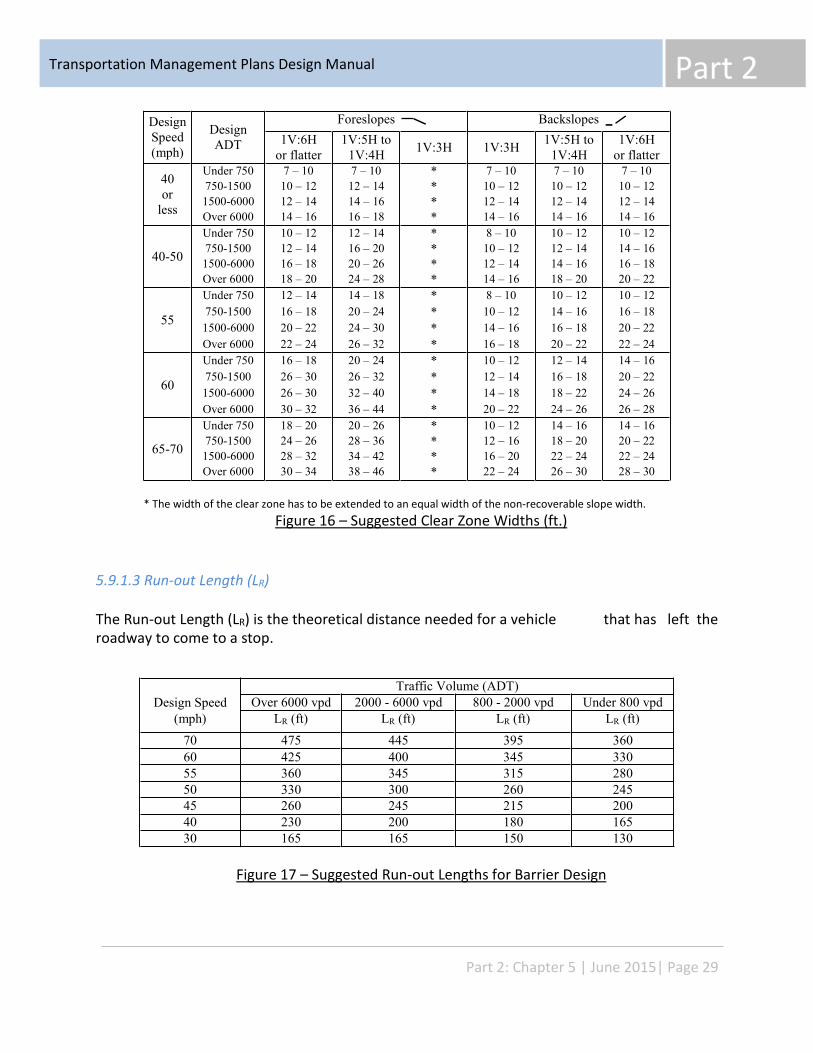
Part 2 Transportation Management Plans Design Manual
Design Speed (mph)
Design ADT
Foreslopes Backslopes 1V:6H
or flatter 1V:5H to
1V:4H 1V:3H 1V:3H 1V:5H to 1V:4H
1V:6H or flatter
40 or
less
Under 750 750-1500 1500-6000 Over 6000
7 – 10 10 – 12 12 – 14 14 – 16
7 – 10 12 – 14 14 – 16 16 – 18
* * * *
7 – 10 10 – 12 12 – 14 14 – 16
7 – 10 10 – 12 12 – 14 14 – 16
7 – 10 10 – 12 12 – 14 14 – 16
40-50
Under 750 750-1500 1500-6000 Over 6000
10 – 12 12 – 14 16 – 18 18 – 20
12 – 14 16 – 20 20 – 26 24 – 28
* * * *
8 – 10 10 – 12 12 – 14 14 – 16
10 – 12 12 – 14 14 – 16 18 – 20
10 – 12 14 – 16 16 – 18 20 – 22
55
Under 750 750-1500 1500-6000 Over 6000
12 – 14 16 – 18 20 – 22 22 – 24
14 – 18 20 – 24 24 – 30 26 – 32
* * * *
8 – 10 10 – 12 14 – 16 16 – 18
10 – 12 14 – 16 16 – 18 20 – 22
10 – 12 16 – 18 20 – 22 22 – 24
60
Under 750 750-1500 1500-6000 Over 6000
16 – 18 26 – 30 26 – 30 30 – 32
20 – 24 26 – 32 32 – 40 36 – 44
* * * *
10 – 12 12 – 14 14 – 18 20 – 22
12 – 14 16 – 18 18 – 22 24 – 26
14 – 16 20 – 22 24 – 26 26 – 28
65-70
Under 750 750-1500 1500-6000 Over 6000
18 – 20 24 – 26 28 – 32 30 – 34
20 – 26 28 – 36 34 – 42 38 – 46
* * * *
10 – 12 12 – 16 16 – 20 22 – 24
14 – 16 18 – 20 22 – 24 26 – 30
14 – 16 20 – 22 22 – 24 28 – 30
Design Speed
(mph)
Traffic Volume (ADT) Over 6000 vpd 2000 - 6000 vpd 800 - 2000 vpd Under 800 vpd
LR (ft) LR (ft) LR (ft) LR (ft) 70 475 445 395 360 60 425 400 345 330 55 360 345 315 280 50 330 300 260 245 45 260 245 215 200 40 230 200 180 165 30 165 165 150 130
* The width of the clear zone has to be extended to an equal width of the non-recoverable slope width. Figure 16 – Suggested Clear Zone Widths (ft.)
5.9.1.3 Run-out Length (LR)
The Run-out Length (LR) is the theoretical distance needed for a vehicle roadway to come to a stop.
that has left the
Figure 17 – Suggested Run-out Lengths for Barrier Design
Part 2: Chapter 5 | June 2015| Page 29
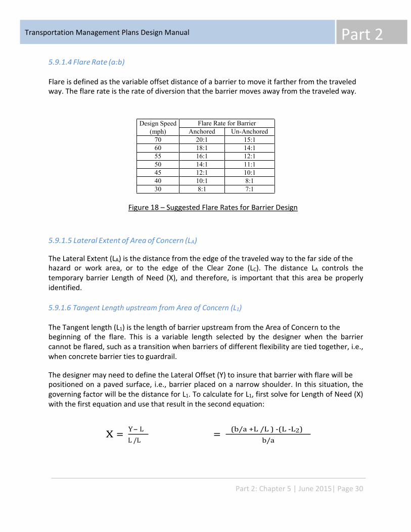
Part 2 Transportation Management Plans Design Manual
Design Speed (mph)
Flare Rate for Barrier Anchored Un-Anchored
70 20:1 15:1 60 18:1 14:1 55 16:1 12:1 50 14:1 11:1 45 12:1 10:1 40 10:1 8:1 30 8:1 7:1
5.9.1.4 Flare Rate (a:b)
Flare is defined as the variable offset distance of a barrier to move it farther from the traveled way. The flare rate is the rate of diversion that the barrier moves away from the traveled way.
Figure 18 – Suggested Flare Rates for Barrier Design
5.9.1.5 Lateral Extent of Area of Concern (LA)
The Lateral Extent (LA) is the distance from the edge of the traveled way to the far side of the hazard or work area, or to the edge of the Clear Zone (LC). The distance LA controls the temporary barrier Length of Need (X), and therefore, is important that this area be properly identified.
5.9.1.6 Tangent Length upstream from Area of Concern (L1)
The Tangent length (L1) is the length of barrier upstream from the Area of Concern to the beginning of the flare. This is a variable length selected by the designer when the barrier cannot be flared, such as a transition when barriers of different flexibility are tied together, i.e., when concrete barrier ties to guardrail.
The designer may need to define the Lateral Offset (Y) to insure that barrier with flare will be positioned on a paved surface, i.e., barrier placed on a narrow shoulder. In this situation, the governing factor will be the distance for L1. To calculate for L1, first solve for Length of Need (X) with the first equation and use that result in the second equation:
Y- L (b/a +L /L ) -(L -L2) X = = L /L b/a
Part 2: Chapter 5 | June 2015| Page 30
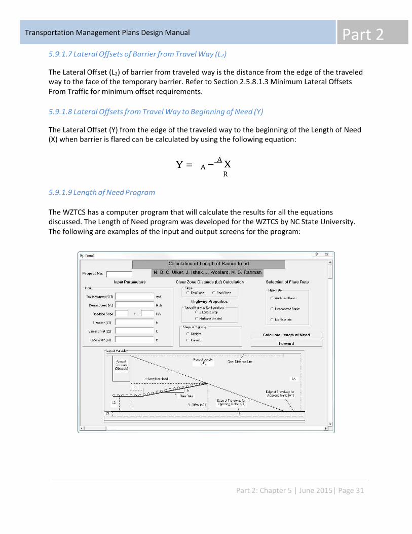
Part 2 Transportation Management Plans Design Manual
5.9.1.7 Lateral Offsets of Barrier from Travel Way (L2)
The Lateral Offset (L2) of barrier from traveled way is the distance from the edge of the traveled way to the face of the temporary barrier. Refer to Section 2.5.8.1.3 Minimum Lateral Offsets From Traffic for minimum offset requirements.
5.9.1.8 Lateral Offsets from Travel Way to Beginning of Need (Y)
The Lateral Offset (Y) from the edge of the traveled way to the beginning of the Length of Need (X) when barrier is flared can be calculated by using the following equation:
A − A X
R Y =
5.9.1.9 Length of Need Program
The WZTCS has a computer program that will calculate the results for all the equations discussed. The Length of Need program was developed for the WZTCS by NC State University. The following are examples of the input and output screens for the program:
Part 2: Chapter 5 | June 2015| Page 31
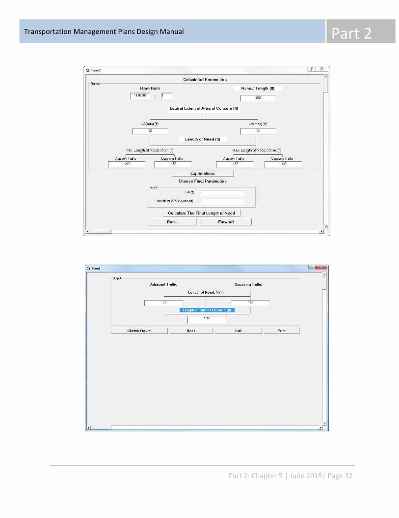
Part 2 Transportation Management Plans Design Manual
Part 2: Chapter 5 | June 2015| Page 32
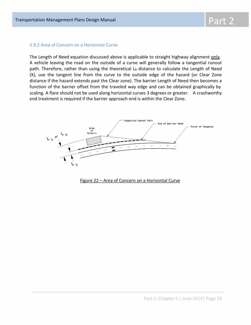
Part 2 Transportation Management Plans Design Manual
5.9.2 Area of Concern on a Horizontal Curve
The Length of Need equation discussed above is applicable to straight highway alignment only. A vehicle leaving the road on the outside of a curve will generally follow a tangential runout path. Therefore, rather than using the theoretical LR distance to calculate the Length of Need (X), use the tangent line from the curve to the outside edge of the hazard (or Clear Zone distance if the hazard extends past the Clear zone). The barrier Length of Need then becomes a function of the barrier offset from the traveled way edge and can be obtained graphically by scaling. A flare should not be used along horizontal curves 3 degrees or greater. end treatment is required if the barrier approach end is within the Clear Zone.
A crashworthy
Figure 22 – Area of Concern on a Horizontal Curve
Part 2: Chapter 5 | June 2015| Page 33
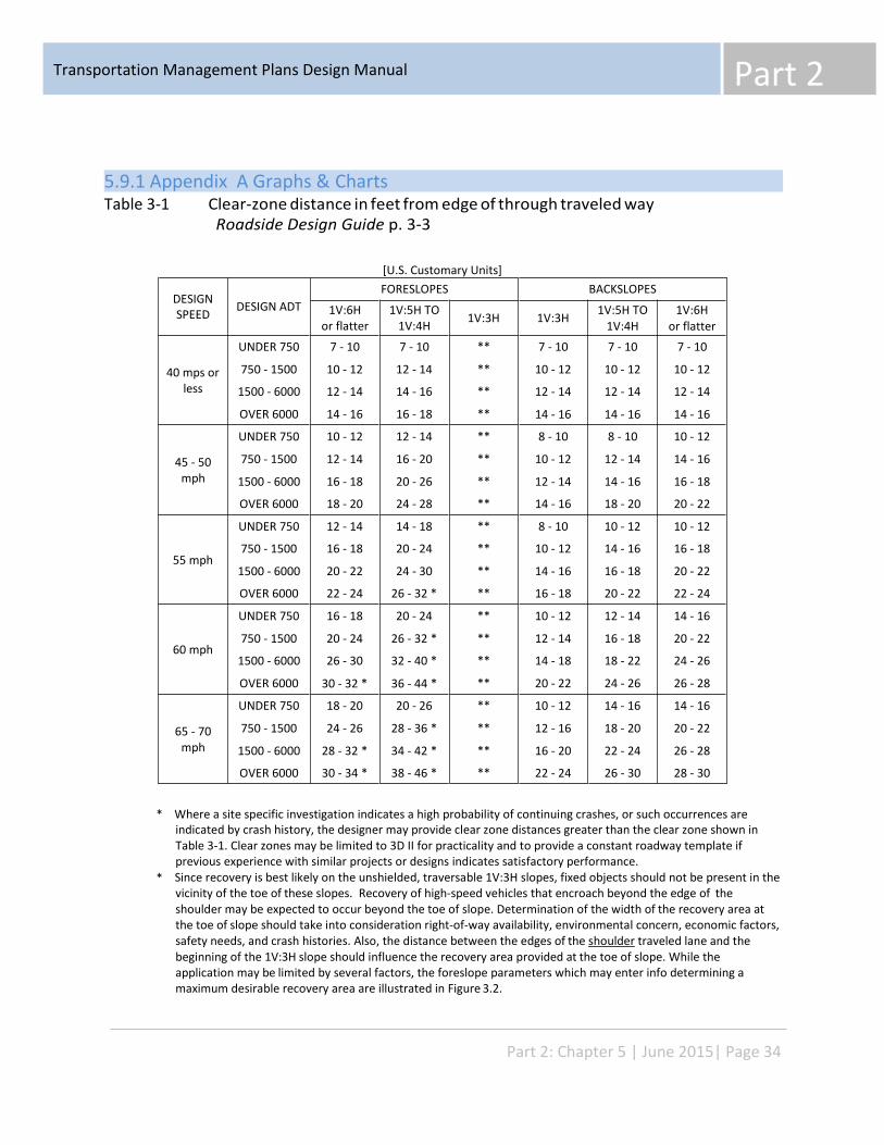
Part 2 Transportation Management Plans Design Manual
DESIGN SPEED
DESIGN ADT
FORESLOPES BACKSLOPES
1V:6H or flatter
1V:5H TO 1V:4H 1V:3H 1V:3H 1V:5H TO
1V:4H 1V:6H
or flatter
40 mps or less
UNDER 750
750 - 1500
1500 - 6000
OVER 6000
7 - 10
10 - 12
12 - 14
14 - 16
7 - 10
12 - 14
14 - 16
16 - 18
**
**
**
**
7 - 10
10 - 12
12 - 14
14 - 16
7 - 10
10 - 12
12 - 14
14 - 16
7 - 10
10 - 12
12 - 14
14 - 16
45 - 50 mph
UNDER 750
750 - 1500
1500 - 6000
OVER 6000
10 - 12
12 - 14
16 - 18
18 - 20
12 - 14
16 - 20
20 - 26
24 - 28
**
**
**
**
8 - 10
10 - 12
12 - 14
14 - 16
8 - 10
12 - 14
14 - 16
18 - 20
10 - 12
14 - 16
16 - 18
20 - 22
55 mph
UNDER 750
750 - 1500
1500 - 6000
OVER 6000
12 - 14
16 - 18
20 - 22
22 - 24
14 - 18
20 - 24
24 - 30
26 - 32 *
**
**
**
**
8 - 10
10 - 12
14 - 16
16 - 18
10 - 12
14 - 16
16 - 18
20 - 22
10 - 12
16 - 18
20 - 22
22 - 24
60 mph
UNDER 750
750 - 1500
1500 - 6000
OVER 6000
16 - 18
20 - 24
26 - 30
30 - 32 *
20 - 24
26 - 32 *
32 - 40 *
36 - 44 *
**
**
**
**
10 - 12
12 - 14
14 - 18
20 - 22
12 - 14
16 - 18
18 - 22
24 - 26
14 - 16
20 - 22
24 - 26
26 - 28
65 - 70 mph
UNDER 750
750 - 1500
1500 - 6000
OVER 6000
18 - 20
24 - 26
28 - 32 *
30 - 34 *
20 - 26
28 - 36 *
34 - 42 *
38 - 46 *
**
**
**
**
10 - 12
12 - 16
16 - 20
22 - 24
14 - 16
18 - 20
22 - 24
26 - 30
14 - 16
20 - 22
26 - 28
28 - 30
5.9.1 Appendix A Graphs & Charts Table 3-1 Clear-zone distance in feet from edge of through traveled way
Roadside Design Guide p. 3-3
[U.S. Customary Units]
* Where a site specific investigation indicates a high probability of continuing crashes, or such occurrences are indicated by crash history, the designer may provide clear zone distances greater than the clear zone shown in Table 3-1. Clear zones may be limited to 3D II for practicality and to provide a constant roadway template if previous experience with similar projects or designs indicates satisfactory performance. Since recovery is best likely on the unshielded, traversable 1V:3H slopes, fixed objects should not be present in the vicinity of the toe of these slopes. Recovery of high-speed vehicles that encroach beyond the edge of the shoulder may be expected to occur beyond the toe of slope. Determination of the width of the recovery area at the toe of slope should take into consideration right-of-way availability, environmental concern, economic factors, safety needs, and crash histories. Also, the distance between the edges of the shoulder traveled lane and the beginning of the 1V:3H slope should influence the recovery area provided at the toe of slope. While the application may be limited by several factors, the foreslope parameters which may enter info determining a maximum desirable recovery area are illustrated in Figure 3.2.
*
Part 2: Chapter 5 | June 2015| Page 34
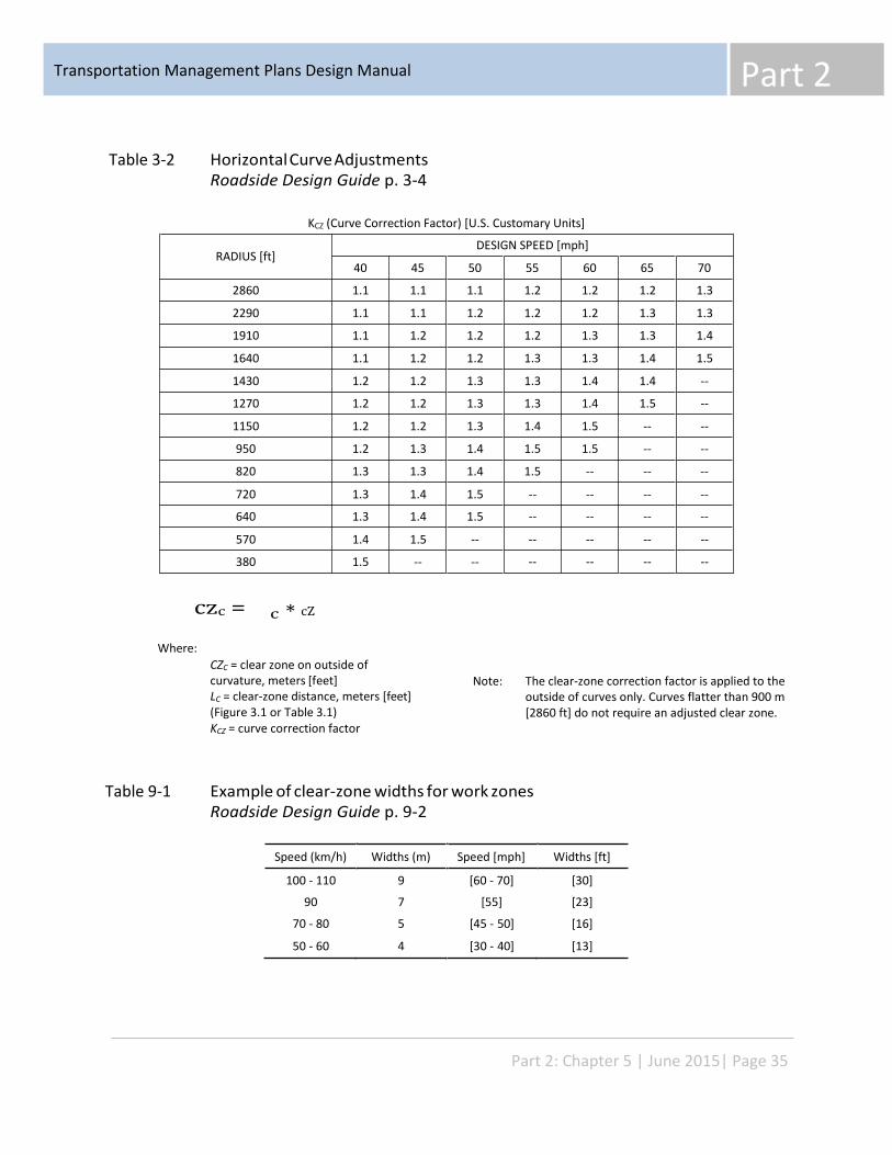
Part 2 Transportation Management Plans Design Manual
RADIUS [ft]
DESIGN SPEED [mph]
40 45 50 55 60 65 70
2860 1.1 1.1 1.1 1.2 1.2 1.2 1.3
2290 1.1 1.1 1.2 1.2 1.2 1.3 1.3
1910 1.1 1.2 1.2 1.2 1.3 1.3 1.4
1640 1.1 1.2 1.2 1.3 1.3 1.4 1.5
1430 1.2 1.2 1.3 1.3 1.4 1.4 --
1270 1.2 1.2 1.3 1.3 1.4 1.5 --
1150 1.2 1.2 1.3 1.4 1.5 -- --
950 1.2 1.3 1.4 1.5 1.5 -- --
820 1.3 1.3 1.4 1.5 -- -- --
720 1.3 1.4 1.5 -- -- -- --
640 1.3 1.4 1.5 -- -- -- --
570 1.4 1.5 -- -- -- -- --
380 1.5 -- -- -- -- -- --
Table 3-2 Horizontal Curve Adjustments Roadside Design Guide p. 3-4
KCZ (Curve Correction Factor) [U.S. Customary Units]
czc =
Where:
∗ cZ c
CZC = clear zone on outside of curvature, meters [feet] LC = clear-zone distance, meters [feet] (Figure 3.1 or Table 3.1) KCZ = curve correction factor
Note: The clear-zone correction factor is applied to the outside of curves only. Curves flatter than 900 m [2860 ft] do not require an adjusted clear zone.
Table 9-1 Example of clear-zone widths for work zones Roadside Design Guide p. 9-2
Speed (km/h) Widths (m) Speed [mph] Widths [ft]
100 - 110
90
70 - 80
50 - 60
9
7
5
4
[60 - 70]
[55]
[45 - 50]
[30 - 40]
[30]
[23]
[16]
[13]
Part 2: Chapter 5 | June 2015| Page 35
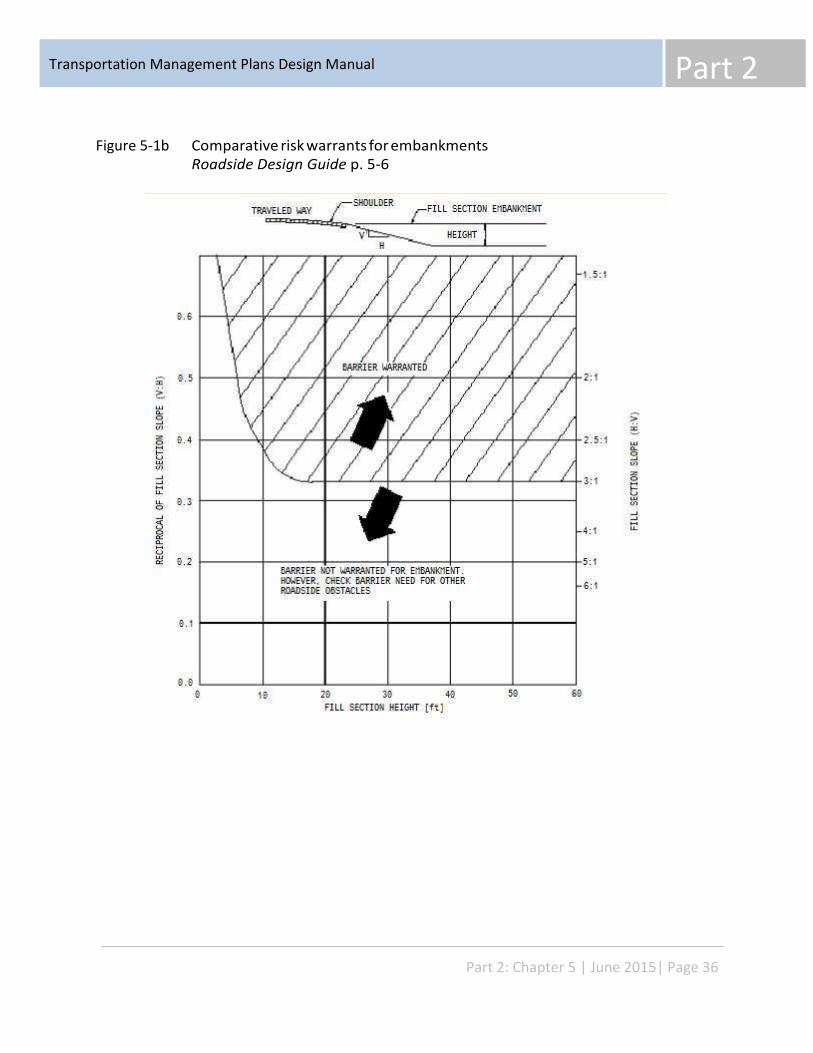
Part 2 Transportation Management Plans Design Manual
Figure 5-1b Comparative risk warrants for embankments Roadside Design Guide p. 5-6
Part 2: Chapter 5 | June 2015| Page 36
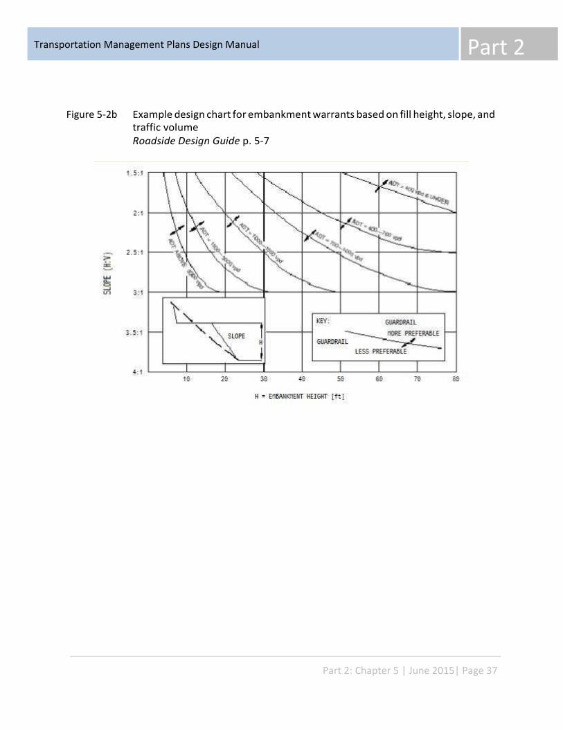
Part 2 Transportation Management Plans Design Manual
Figure 5-2b Example design chart for embankment warrants based on fill height, slope, and traffic volume Roadside Design Guide p. 5-7
Part 2: Chapter 5 | June 2015| Page 37
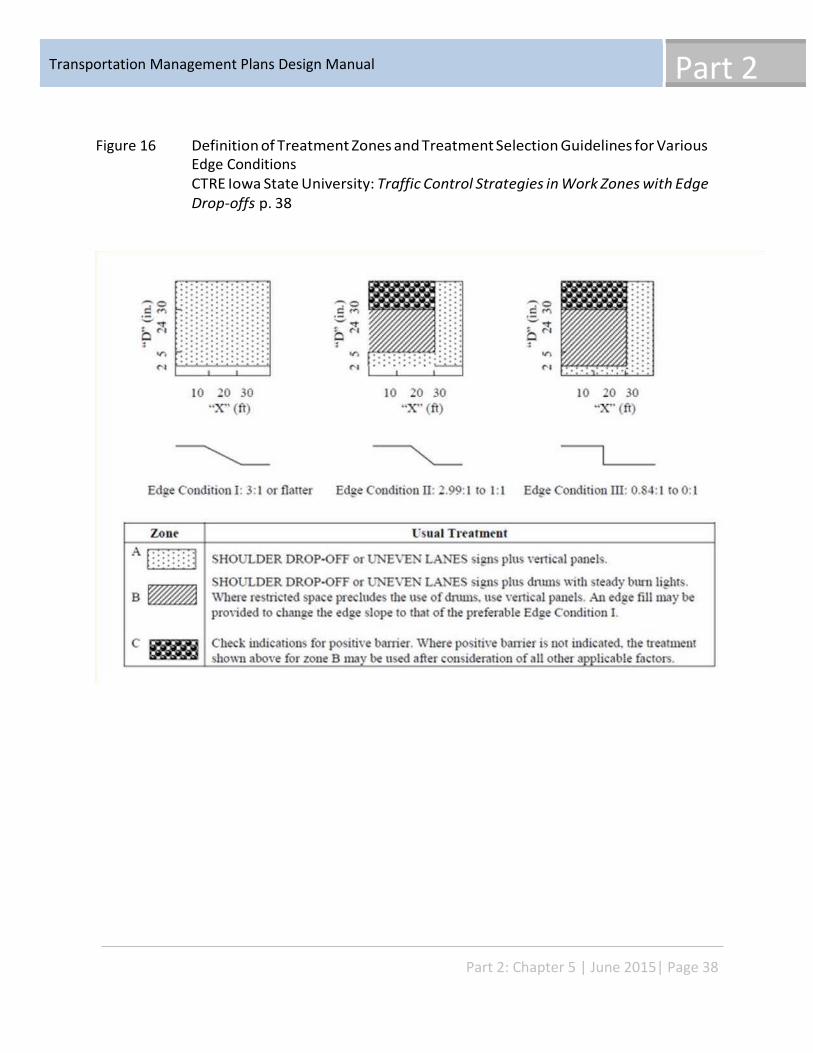
Part 2 Transportation Management Plans Design Manual
Figure 16 Definition of Treatment Zones and Treatment Selection Guidelines for Various Edge Conditions CTRE Iowa State University: Traffic Control Strategies in Work Zones with Edge Drop-offs p. 38
Part 2: Chapter 5 | June 2015| Page 38
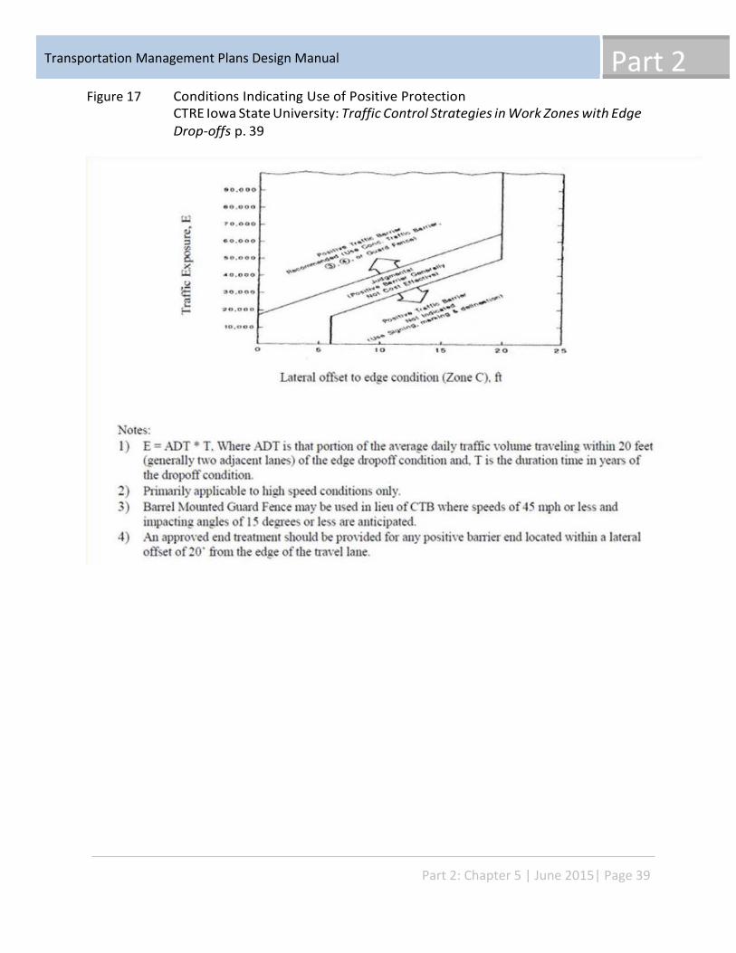
Part 2 Transportation Management Plans Design Manual
Figure 17 Conditions Indicating Use of Positive Protection CTRE Iowa State University: Traffic Control Strategies in Work Zones with Edge Drop-offs p. 39
Part 2: Chapter 5 | June 2015| Page 39
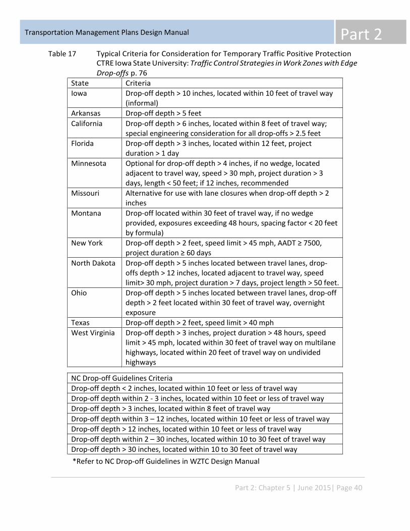
Part 2 Transportation Management Plans Design Manual
State Criteria Iowa
Drop-off depth > 10 inches, located within 10 feet of travel way (informal)
Arkansas Drop-off depth > 5 feet California
Drop-off depth > 6 inches, located within 8 feet of travel way; special engineering consideration for all drop-offs > 2.5 feet
Florida
Drop-off depth > 3 inches, located within 12 feet, project duration > 1 day
Minnesota
Optional for drop-off depth > 4 inches, if no wedge, located adjacent to travel way, speed > 30 mph, project duration > 3 days, length < 50 feet; if 12 inches, recommended
Missouri
Alternative for use with lane closures when drop-off depth > 2 inches
Montana
Drop-off located within 30 feet of travel way, if no wedge provided, exposures exceeding 48 hours, spacing factor < 20 feet by formula)
New York
Drop-off depth > 2 feet, speed limit > 45 mph, AADT ≥ 7500, project duration ≥ 60 days
North Dakota
Drop-off depth > 5 inches located between travel lanes, drop- offs depth > 12 inches, located adjacent to travel way, speed limit> 30 mph, project duration > 7 days, project length > 50 feet.
Ohio
Drop-off depth > 5 inches located between travel lanes, drop-off depth > 2 feet located within 30 feet of travel way, overnight exposure
Texas Drop-off depth > 2 feet, speed limit > 40 mph West Virginia
Drop-off depth > 3 inches, project duration > 48 hours, speed limit > 45 mph, located within 30 feet of travel way on multilane highways, located within 20 feet of travel way on undivided highways
NC Drop-off Guidelines Criteria Drop-off depth < 2 inches, located within 10 feet or less of travel way Drop-off depth within 2 - 3 inches, located within 10 feet or less of travel way Drop-off depth > 3 inches, located within 8 feet of travel way Drop-off depth within 3 – 12 inches, located within 10 feet or less of travel way Drop-off depth > 12 inches, located within 10 feet or less of travel way Drop-off depth within 2 – 30 inches, located within 10 to 30 feet of travel way Drop-off depth > 30 inches, located within 10 to 30 feet of travel way
Table 17 Typical Criteria for Consideration for Temporary Traffic Positive Protection CTRE Iowa State University: Traffic Control Strategies in Work Zones with Edge Drop-offs p. 76
*Refer to NC Drop-off Guidelines in WZTC Design Manual
Part 2: Chapter 5 | June 2015| Page 40
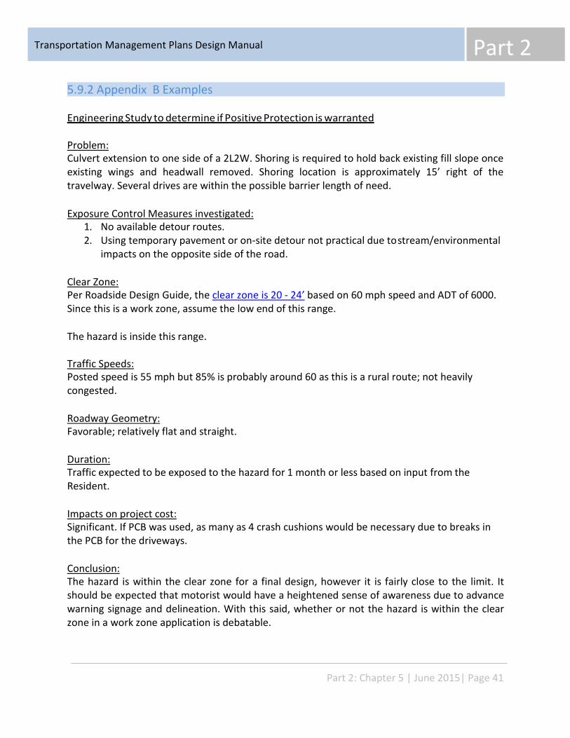
Part 2 Transportation Management Plans Design Manual
5.9.2 Appendix B Examples
Engineering Study to determine if Positive Protection is warranted
Problem: Culvert extension to one side of a 2L2W. Shoring is required to hold back existing fill slope once existing wings and headwall removed. Shoring location is approximately 15’ right of the travelway. Several drives are within the possible barrier length of need.
Exposure Control Measures investigated: 1. No available detour routes. 2. Using temporary pavement or on-site detour not practical due to stream/environmental
impacts on the opposite side of the road.
Clear Zone: Per Roadside Design Guide, the clear zone is 20 - 24’ based on 60 mph speed and ADT of 6000. Since this is a work zone, assume the low end of this range.
The hazard is inside this range.
Traffic Speeds: Posted speed is 55 mph but 85% is probably around 60 as this is a rural route; not heavily congested.
Roadway Geometry: Favorable; relatively flat and straight.
Duration: Traffic expected to be exposed to the hazard for 1 month or less based on input from the Resident.
Impacts on project cost: Significant. If PCB was used, as many as 4 crash cushions would be necessary due to breaks in the PCB for the driveways.
Conclusion: The hazard is within the clear zone for a final design, however it is fairly close to the limit. It should be expected that motorist would have a heightened sense of awareness due to advance warning signage and delineation. With this said, whether or not the hazard is within the clear zone in a work zone application is debatable.
Part 2: Chapter 5 | June 2015| Page 41
Part 2 Transportation Management Plans Design Manual
It could be argued that the severity of crash would be worse striking PCB here and then redirected into the path of oncoming traffic.
Multiple crash cushions due to the drives significantly raises costs and the breaks in the PCB over a short length would lessen the effectiveness of PCB.
Based on this, in combination with the relatively short duration, the recommendation was not to use PCB at this site. However, we did recommend increasing the level of delineation at the site by using water-filled barrier, not as positive protection, but as a superior delineator to drums or cones. This would also add a minor degree of positive protection that is much more forgiving than PCB.
Part 2: Chapter 5 | June 2015| Page 42
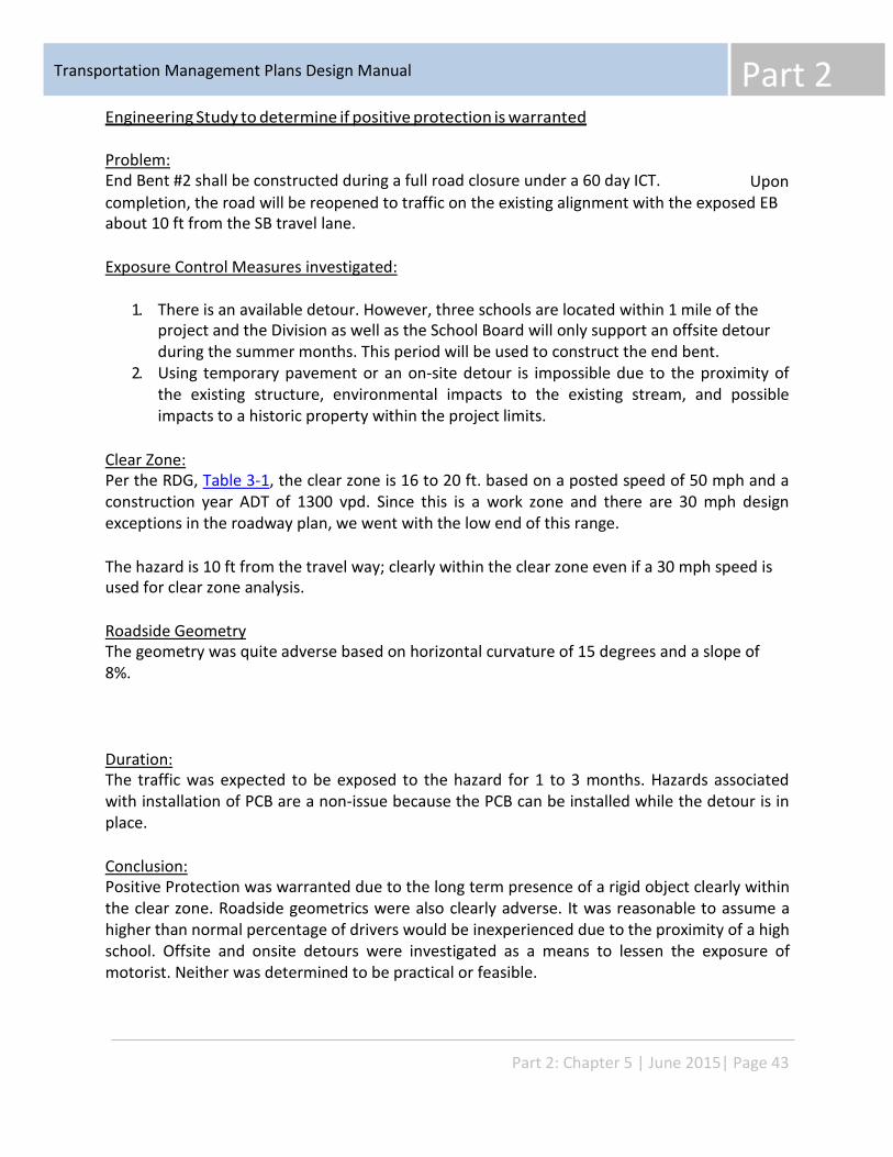
Part 2 Transportation Management Plans Design Manual
Engineering Study to determine if positive protection is warranted
Problem: End Bent #2 shall be constructed during a full road closure under a 60 day ICT. Upon completion, the road will be reopened to traffic on the existing alignment with the exposed EB about 10 ft from the SB travel lane.
Exposure Control Measures investigated:
1. There is an available detour. However, three schools are located within 1 mile of the project and the Division as well as the School Board will only support an offsite detour during the summer months. This period will be used to construct the end bent.
2. Using temporary pavement or an on-site detour is impossible due to the proximity of the existing structure, environmental impacts to the existing stream, and possible impacts to a historic property within the project limits.
Clear Zone: Per the RDG, Table 3-1, the clear zone is 16 to 20 ft. based on a posted speed of 50 mph and a construction year ADT of 1300 vpd. Since this is a work zone and there are 30 mph design exceptions in the roadway plan, we went with the low end of this range.
The hazard is 10 ft from the travel way; clearly within the clear zone even if a 30 mph speed is used for clear zone analysis.
Roadside Geometry The geometry was quite adverse based on horizontal curvature of 15 degrees and a slope of 8%.
Duration: The traffic was expected to be exposed to the hazard for 1 to 3 months. Hazards associated with installation of PCB are a non-issue because the PCB can be installed while the detour is in place.
Conclusion: Positive Protection was warranted due to the long term presence of a rigid object clearly within the clear zone. Roadside geometrics were also clearly adverse. It was reasonable to assume a higher than normal percentage of drivers would be inexperienced due to the proximity of a high school. Offsite and onsite detours were investigated as a means to lessen the exposure of motorist. Neither was determined to be practical or feasible.
Part 2: Chapter 5 | June 2015| Page 43
Part 2 Transportation Management Plans Design Manual
5.10 Design Resources
“Manual on Uniform Traffic Control Devices, 2009 Edition”, Federal Highway Administration, Washington, DC, November 2009
“Roadside Design Guide”, American Association of State Highway and Transportation Officials, Washington, DC, 2002
“NCHRP Report 350, Recommended Procedures for the Safety Performance Evaluation of Highway Features,” Transportation Research Board, Washington, DC, 1993.
NCHRP Report 350 Test 3-11 of the North Carolina Department of Transportation, Design Portable Concrete Barrier for FHWA Approval Test #2, Test No.:020104
Precast Concrete Barrier Crash Testing, Final Report SPR 330, December 2001, Oregon Department of Transportation.
Energy Absorption Systems, Inc., One East Wacker Drive, Chicago, IL, 60601.
Barrier Systems Inc., 180 River Road Rio Vista, CA. 94571
American Association of State Highway and Transportation Officials (2011). Roadside Design Guide.
Ivey, Don L., King K. Mak, Harold D. Cooner, and Mark A. Marek. “Safety in Construction Zones Where Pavement Edges and Drop-Offs Exist.” Transportation Research Record 1163, 1988, pp. 43-62.
Center for Transportation Research and Education, Department of Civil and Construction Engineering, Iowa State University, “Traffic Control Strategies in Work Zones with Edge Drop- Offs”, August 2002 p. 76.
Federal Highway Administration (2009). Manual on Uniform Traffic Control Devices (MUTCD). U.S. Department of Transportation, Washington, D.C.
Bryden, James and Mace, Douglas (2002). Guidelines for Design and Operation of Nighttime Traffic Control for Highway Maintenance and Construction, National Cooperative Highway Research Program Report NCHRP-476, Transportation Research Board of the National Academies, Washington, D.C.
Part 2: Chapter 5 | June 2015| Page 44
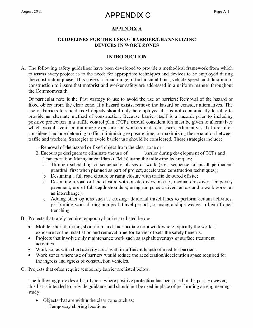
August 2011 Page A-1 APPENDIX C
APPENDIX A
GUIDELINES FOR THE USE OF BARRIER/CHANNELIZING DEVICES IN WORK ZONES
INTRODUCTION
A. The following safety guidelines have been developed to provide a methodical framework from which to assess every project as to the needs for appropriate techniques and devices to be employed during the construction phase. This covers a broad range of traffic conditions, vehicle speed, and duration of construction to insure that motorist and worker safety are addressed in a uniform manner throughout the Commonwealth. Of particular note is the first strategy to use to avoid the use of barriers: Removal of the hazard or fixed object from the clear zone. If a hazard exists, remove the hazard or consider alternatives. The use of barriers to shield fixed objects should only be employed if it is not economically feasible to provide an alternate method of construction. Because barrier itself is a hazard; prior to including positive protection in a traffic control plan (TCP), careful consideration must be given to alternatives which would avoid or minimize exposure for workers and road users. Alternatives that are often considered include detouring traffic, minimizing exposure time, or maximizing the separation between traffic and workers. Strategies to avoid barrier use should be considered. These strategies include:
1. Removal of the hazard or fixed object from the clear zone or; 2. Encourage designers to eliminate the use of barrier during development of TCPs and
Transportation Management Plans (TMPs) using the following techniques; a. Through scheduling or sequencing phases of work (e.g., sequence to install permanent
guardrail first when planned as part of project, accelerated construction techniques); b. Designing a full road closure or ramp closure with traffic detoured offsite; c. Designing a road or lane closure with onsite diversion (i.e., median crossover, temporary
pavement, use of full depth shoulders; using ramps as a diversion around a work zones at an interchange);
d. Adding other options such as closing additional travel lanes to perform certain activities, performing work during non-peak travel periods; or using a slope wedge in lieu of open trenching.
B. Projects that rarely require temporary barrier are listed below:
• Mobile, short duration, short term, and intermediate term work where typically the worker exposure for the installation and removal time for barrier offsets the safety benefits. Projects that involve only maintenance work such as asphalt overlays or surface treatment activities. Work zones with short activity areas with insufficient length of need for barriers. Work zones where use of barriers would reduce the acceleration/deceleration space required for the ingress and egress of construction vehicles.
• • •
C. Projects that often require temporary barrier are listed below.
The following provides a list of areas where positive protection has been used in the past. However, this list is intended to provide guidance and should not be used in place of performing an engineering study.
• Objects that are within the clear zone such as: - Temporary shoring locations
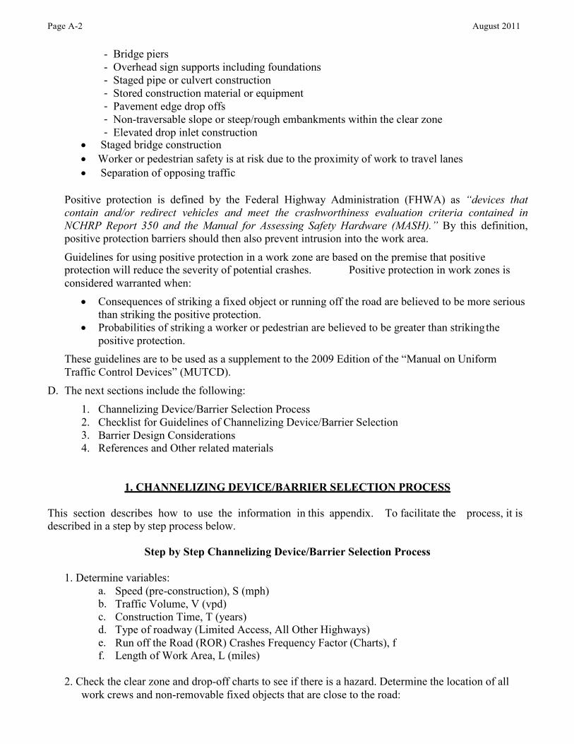
Page A-2 August 2011
- - - - - - -
Bridge piers Overhead sign supports including foundations Staged pipe or culvert construction Stored construction material or equipment Pavement edge drop offs Non-traversable slope or steep/rough embankments within the clear zone Elevated drop inlet construction
• • •
Staged bridge construction Worker or pedestrian safety is at risk due to the proximity of work to travel lanes Separation of opposing traffic
Positive protection is defined by the Federal Highway Administration (FHWA) as “devices that contain and/or redirect vehicles and meet the crashworthiness evaluation criteria contained in NCHRP Report 350 and the Manual for Assessing Safety Hardware (MASH).” By this definition, positive protection barriers should then also prevent intrusion into the work area. Guidelines for using positive protection in a work zone are based on the premise that positive protection will reduce the severity of potential crashes. considered warranted when:
Positive protection in work zones is
• Consequences of striking a fixed object or running off the road are believed to be more serious than striking the positive protection.
• Probabilities of striking a worker or pedestrian are believed to be greater than striking the positive protection.
These guidelines are to be used as a supplement to the 2009 Edition of the “Manual on Uniform Traffic Control Devices” (MUTCD). The next sections include the following: D.
1. 2. 3. 4.
Channelizing Device/Barrier Selection Process Checklist for Guidelines of Channelizing Device/Barrier Selection Barrier Design Considerations References and Other related materials
1. CHANNELIZING DEVICE/BARRIER SELECTION PROCESS
This section describes how to use the information in this appendix. To facilitate the described in a step by step process below.
process, it is
Step by Step Channelizing Device/Barrier Selection Process
1. Determine variables: a. b. c. d. e. f.
Speed (pre-construction), S (mph) Traffic Volume, V (vpd) Construction Time, T (years) Type of roadway (Limited Access, All Other Highways) Run off the Road (ROR) Crashes Frequency Factor (Charts), f Length of Work Area, L (miles)
2. Check the clear zone and drop-off charts to see if there is a hazard. Determine the location of all work crews and non-removable fixed objects that are close to the road:
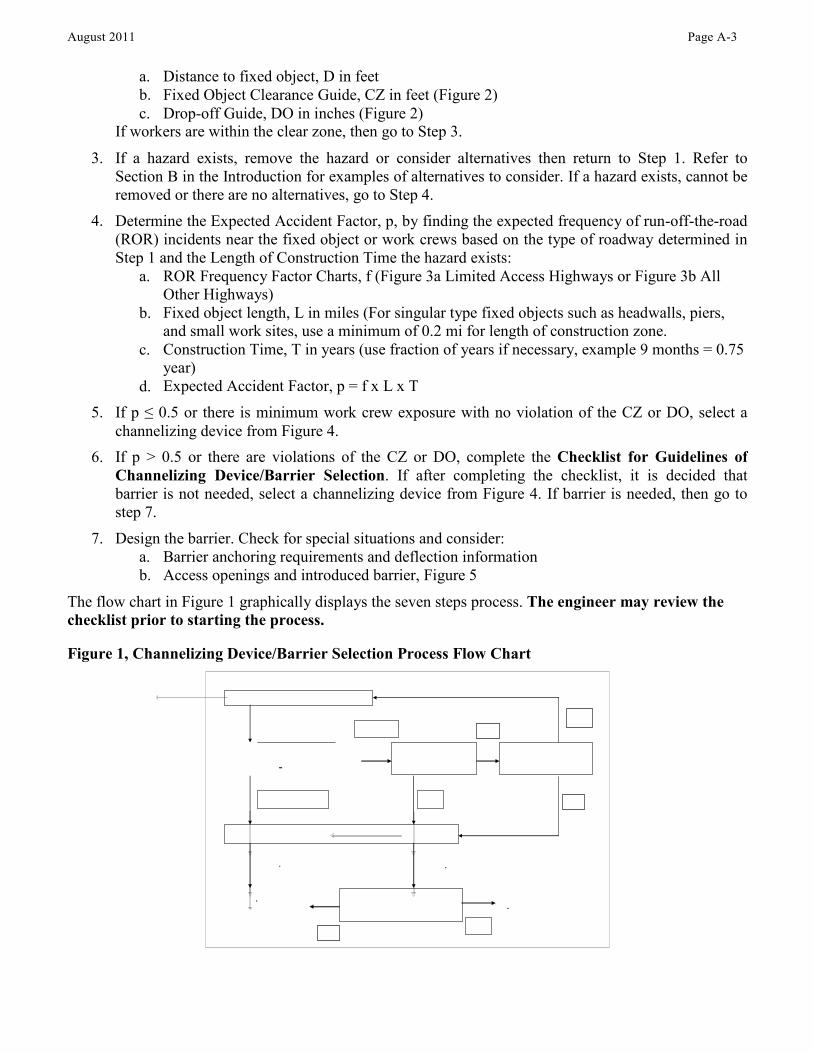
August 2011 Page A-3
a. b. c.
Distance to fixed object, D in feet Fixed Object Clearance Guide, CZ in feet (Figure 2) Drop-off Guide, DO in inches (Figure 2)
If workers are within the clear zone, then go to Step 3.
3. If a hazard exists, remove the hazard or consider alternatives then return to Step 1. Refer to Section B in the Introduction for examples of alternatives to consider. If a hazard exists, cannot be removed or there are no alternatives, go to Step 4. Determine the Expected Accident Factor, p, by finding the expected frequency of run-off-the-road (ROR) incidents near the fixed object or work crews based on the type of roadway determined in Step 1 and the Length of Construction Time the hazard exists:
4.
a. ROR Frequency Factor Charts, f (Figure 3a Limited Access Highways or Figure 3b All Other Highways) Fixed object length, L in miles (For singular type fixed objects such as headwalls, piers, and small work sites, use a minimum of 0.2 mi for length of construction zone. Construction Time, T in years (use fraction of years if necessary, example 9 months = 0.75 year) Expected Accident Factor, p = f x L x T
b.
c.
d. 5. If p ≤ 0.5 or there is minimum work crew exposure with no violation of the CZ or DO, select a
channelizing device from Figure 4. If p > 0.5 or there are violations of the CZ or DO, complete the Checklist for Guidelines of Channelizing Device/Barrier Selection. If after completing the checklist, it is decided that barrier is not needed, select a channelizing device from Figure 4. If barrier is needed, then go to step 7. Design the barrier. Check for special situations and consider:
a. Barrier anchoring requirements and deflection information b. Access openings and introduced barrier, Figure 5
6.
7.
The flow chart in Figure 1 graphically displays the seven steps process. The engineer may review the checklist prior to starting the process.
Figure 1, Channelizing Device/Barrier Selection Process Flow Chart
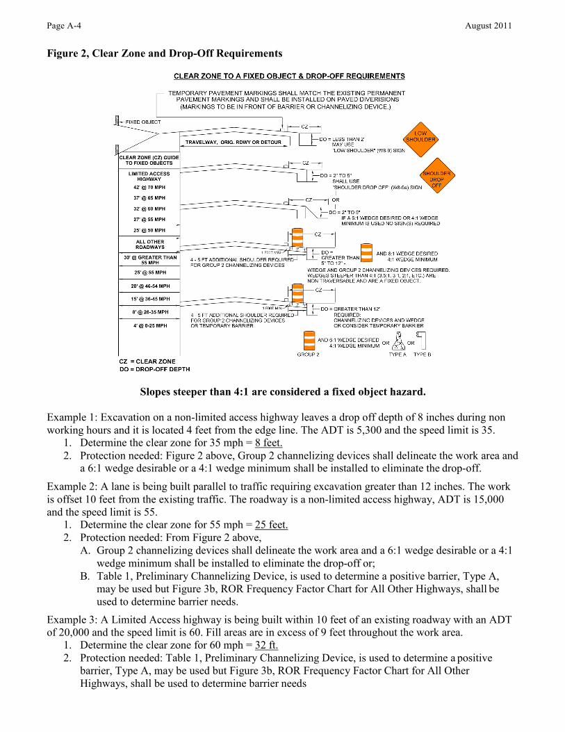
Page A-4 August 2011
Figure 2, Clear Zone and Drop-Off Requirements
Slopes steeper than 4:1 are considered a fixed object hazard.
Example 1: Excavation on a non-limited access highway leaves a drop off depth of 8 inches during non working hours and it is located 4 feet from the edge line. The ADT is 5,300 and the speed limit is 35.
1. Determine the clear zone for 35 mph = 8 feet. 2. Protection needed: Figure 2 above, Group 2 channelizing devices shall delineate the work area and
a 6:1 wedge desirable or a 4:1 wedge minimum shall be installed to eliminate the drop-off. Example 2: A lane is being built parallel to traffic requiring excavation greater than 12 inches. The work is offset 10 feet from the existing traffic. The roadway is a non-limited access highway, ADT is 15,000 and the speed limit is 55.
1. Determine the clear zone for 55 mph = 25 feet. 2. Protection needed: From Figure 2 above,
A. Group 2 channelizing devices shall delineate the work area and a 6:1 wedge desirable or a 4:1 wedge minimum shall be installed to eliminate the drop-off or;
B. Table 1, Preliminary Channelizing Device, is used to determine a positive barrier, Type A, may be used but Figure 3b, ROR Frequency Factor Chart for All Other Highways, shall be used to determine barrier needs.
Example 3: A Limited Access highway is being built within 10 feet of an existing roadway with an ADT of 20,000 and the speed limit is 60. Fill areas are in excess of 9 feet throughout the work area.
1. Determine the clear zone for 60 mph = 32 ft. 2. Protection needed: Table 1, Preliminary Channelizing Device, is used to determine a positive
barrier, Type A, may be used but Figure 3b, ROR Frequency Factor Chart for All Other Highways, shall be used to determine barrier needs
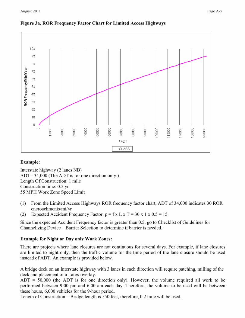
August 2011 Page A-5
Figure 3a, ROR Frequency Factor Chart for Limited Access Highways
Example: Interstate highway (2 lanes NB) ADT= 34,000 (The ADT is for one direction only.) Length Of Construction: 1 mile Construction time: 0.5 yr 55 MPH Work Zone Speed Limit
(1) From the Limited Access Highways ROR frequency factor chart, ADT of 34,000 indicates 30 ROR encroachments/mi/yr Expected Accident Frequency Factor, p = f x L x T = 30 x 1 x 0.5 = 15 (2)
Since the expected Accident Frequency factor is greater than 0.5, go to Checklist of Guidelines for Channelizing Device – Barrier Selection to determine if barrier is needed.
Example for Night or Day only Work Zones: There are projects where lane closures are not continuous for several days. For example, if lane closures are limited to night only, then the traffic volume for the time period of the lane closure should be used instead of ADT. An example is provided below.
A bridge deck on an Interstate highway with 3 lanes in each direction will require patching, milling of the deck and placement of a Latex overlay. ADT = 50,000 (the ADT is for one direction only). However, the volume required all work to be performed between 9:00 pm and 6:00 am each day. Therefore, the volume to be used will be between these hours, 6,000 vehicles for the 9-hour period. Length of Construction = Bridge length is 550 feet, therefore, 0.2 mile will be used.
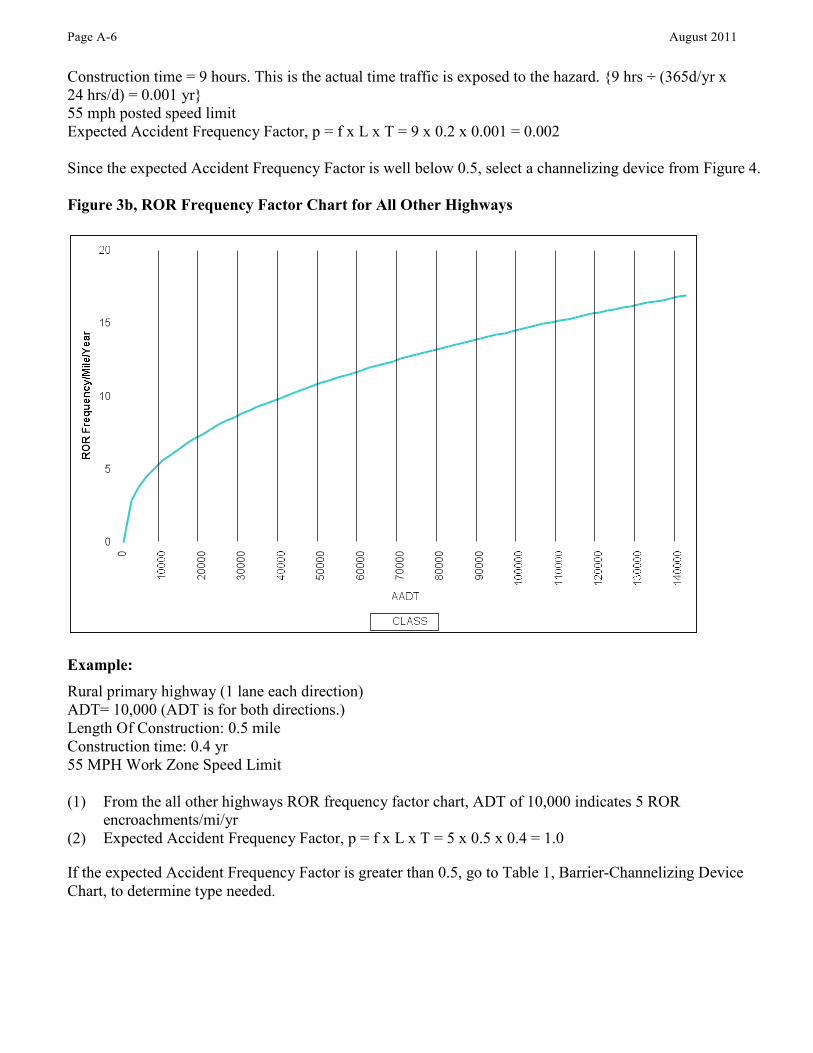
Page A-6 August 2011
Construction time = 9 hours. This is the actual time traffic is exposed to the hazard. {9 hrs ÷ (365d/yr x 24 hrs/d) = 0.001 yr} 55 mph posted speed limit Expected Accident Frequency Factor, p = f x L x T = 9 x 0.2 x 0.001 = 0.002
Since the expected Accident Frequency Factor is well below 0.5, select a channelizing device from Figure 4.
Figure 3b, ROR Frequency Factor Chart for All Other Highways
Example: Rural primary highway (1 lane each direction) ADT= 10,000 (ADT is for both directions.) Length Of Construction: 0.5 mile Construction time: 0.4 yr 55 MPH Work Zone Speed Limit
(1) From the all other highways ROR frequency factor chart, ADT of 10,000 indicates 5 ROR encroachments/mi/yr Expected Accident Frequency Factor, p = f x L x T = 5 x 0.5 x 0.4 = 1.0 (2)
If the expected Accident Frequency Factor is greater than 0.5, go to Table 1, Barrier-Channelizing Device Chart, to determine type needed.
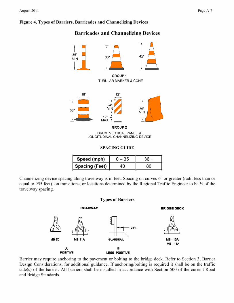
Speed (mph) 0 – 35 36 + Spacing (Feet) 40 80
August 2011 Page A-7
Figure 4, Types of Barriers, Barricades and Channelizing Devices
Barricades and Channelizing Devices
SPACING GUIDE
Channelizing device spacing along travelway is in feet. Spacing on curves 6° or greater (radii less than or equal to 955 feet), on transitions, or locations determined by the Regional Traffic Engineer to be ½ of the travelway spacing.
Types of Barriers
Barrier may require anchoring to the pavement or bolting to the bridge deck. Refer to Section 3, Barrier Design Considerations, for additional guidance. If anchoring/bolting is required it shall be on the traffic side(s) of the barrier. All barriers shall be installed in accordance with Section 500 of the current Road and Bridge Standards.
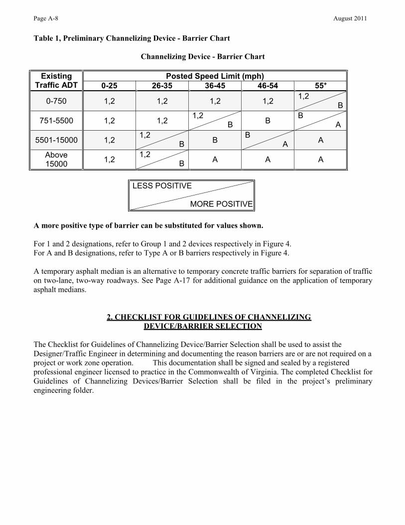
LESS POSITIVE
MORE POSITIVE
Existing Traffic ADT
Posted Speed Limit (mph) 0-25 26-35 36-45 46-54 55+
0-750 1,2 1,2 1,2 1,2 1,2 B
751-5500 1,2 1,2 1,2 B B B
A
5501-15000 1,2 1,2 B B B
A A
Above 15000 1,2 1,2
B A A A
Page A-8 August 2011
Table 1, Preliminary Channelizing Device - Barrier Chart
Channelizing Device - Barrier Chart
A more positive type of barrier can be substituted for values shown.
For 1 and 2 designations, refer to Group 1 and 2 devices respectively in Figure 4. For A and B designations, refer to Type A or B barriers respectively in Figure 4.
A temporary asphalt median is an alternative to temporary concrete traffic barriers for separation of traffic on two-lane, two-way roadways. See Page A-17 for additional guidance on the application of temporary asphalt medians.
2. CHECKLIST FOR GUIDELINES OF CHANNELIZING DEVICE/BARRIER SELECTION
The Checklist for Guidelines of Channelizing Device/Barrier Selection shall be used to assist the Designer/Traffic Engineer in determining and documenting the reason barriers are or are not required on a project or work zone operation. This documentation shall be signed and sealed by a registered professional engineer licensed to practice in the Commonwealth of Virginia. The completed Checklist for Guidelines of Channelizing Devices/Barrier Selection shall be filed in the project’s preliminary engineering folder.
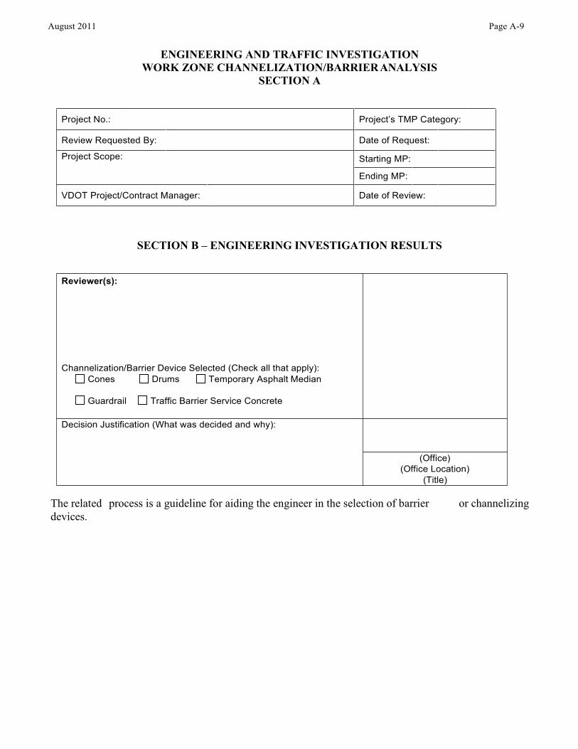
Project No.: Project’s TMP Category:
Review Requested By: Date of Request:
Project Scope:
Starting MP:
Ending MP:
VDOT Project/Contract Manager: Date of Review:
Reviewer(s): Channelization/Barrier Device Selected (Check all that apply):
Cones Drums Temporary Asphalt Median
Guardrail Traffic Barrier Service Concrete
Decision Justification (What was decided and why):
(Office) (Office Location)
(Title)
August 2011 Page A-9
ENGINEERING AND TRAFFIC INVESTIGATION WORK ZONE CHANNELIZATION/BARRIER ANALYSIS
SECTION A
SECTION B – ENGINEERING INVESTIGATION RESULTS
The related devices.
process is a guideline for aiding the engineer in the selection of barrier or channelizing
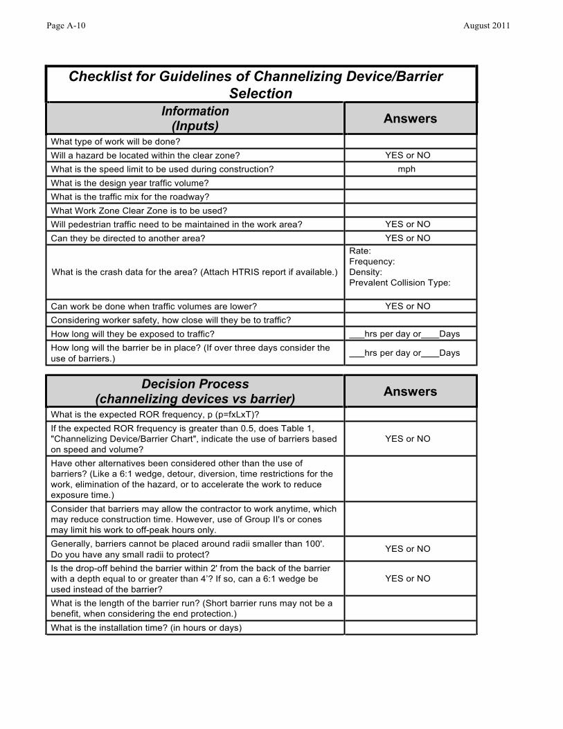
Checklist for Guidelines of Channelizing Device/Barrier Selection
Information (Inputs) Answers
What type of work will be done?
Will a hazard be located within the clear zone? YES or NO What is the speed limit to be used during construction? mph What is the design year traffic volume?
What is the traffic mix for the roadway?
What Work Zone Clear Zone is to be used?
Will pedestrian traffic need to be maintained in the work area? YES or NO Can they be directed to another area? YES or NO
What is the crash data for the area? (Attach HTRIS report if available.)
Rate: Frequency: Density: Prevalent Collision Type:
Can work be done when traffic volumes are lower? YES or NO Considering worker safety, how close will they be to traffic?
How long will they be exposed to traffic? hrs per day or Days How long will the barrier be in place? (If over three days consider the use of barriers.) hrs per day or Days
Decision Process (channelizing devices vs barrier) Answers
What is the expected ROR frequency, p (p=fxLxT)?
If the expected ROR frequency is greater than 0.5, does Table 1, "Channelizing Device/Barrier Chart", indicate the use of barriers based on speed and volume?
YES or NO
Have other alternatives been considered other than the use of barriers? (Like a 6:1 wedge, detour, diversion, time restrictions for the work, elimination of the hazard, or to accelerate the work to reduce exposure time.)
Consider that barriers may allow the contractor to work anytime, which may reduce construction time. However, use of Group II's or cones may limit his work to off-peak hours only.
Generally, barriers cannot be placed around radii smaller than 100'. Do you have any small radii to protect? YES or NO
Is the drop-off behind the barrier within 2' from the back of the barrier with a depth equal to or greater than 4’? If so, can a 6:1 wedge be used instead of the barrier?
YES or NO
What is the length of the barrier run? (Short barrier runs may not be a benefit, when considering the end protection.)
What is the installation time? (in hours or days)
Page A-10 August 2011
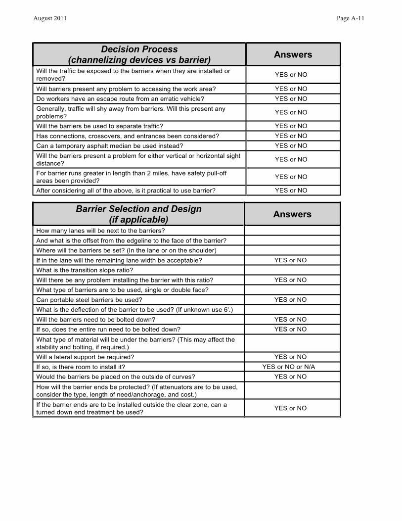
Decision Process (channelizing devices vs barrier) Answers
Will the traffic be exposed to the barriers when they are installed or removed? YES or NO
Will barriers present any problem to accessing the work area? YES or NO Do workers have an escape route from an erratic vehicle? YES or NO Generally, traffic will shy away from barriers. Will this present any problems? YES or NO
Will the barriers be used to separate traffic? YES or NO Has connections, crossovers, and entrances been considered? YES or NO Can a temporary asphalt median be used instead? YES or NO Will the barriers present a problem for either vertical or horizontal sight distance? YES or NO
For barrier runs greater in length than 2 miles, have safety pull-off areas been provided? YES or NO
After considering all of the above, is it practical to use barrier? YES or NO
Barrier Selection and Design (if applicable) Answers
How many lanes will be next to the barriers?
And what is the offset from the edgeline to the face of the barrier?
Where will the barriers be set? (In the lane or on the shoulder)
If in the lane will the remaining lane width be acceptable? YES or NO What is the transition slope ratio?
Will there be any problem installing the barrier with this ratio? YES or NO What type of barriers are to be used, single or double face?
Can portable steel barriers be used? YES or NO What is the deflection of the barrier to be used? (If unknown use 6'.)
Will the barriers need to be bolted down? YES or NO If so, does the entire run need to be bolted down? YES or NO What type of material will be under the barriers? (This may affect the stability and bolting, if required.)
Will a lateral support be required? YES or NO If so, is there room to install it? YES or NO or N/A Would the barriers be placed on the outside of curves? YES or NO How will the barrier ends be protected? (If attenuators are to be used, consider the type, length of need/anchorage, and cost.)
If the barrier ends are to be installed outside the clear zone, can a turned down end treatment be used? YES or NO
August 2011 Page A-11
Page A-12 August 2011
3. BARRIER DESIGN CONSIDERATIONS
Once it has been determined that a barrier is recommended, the next step is to determine the type of barrier and the barrier design.
The following three factors should be considered in the barrier design: a. Barrier anchoring requirements and deflection information b. Access openings, Figure 5 c. Use of a temporary asphalt median/temporary raised island to separate opposing traffic.
A. Barrier Anchoring Requirements and Deflection Information
Temporary Barrier Service Concrete Anchoring Requirements
Traffic Barrier Service Concrete (TBSC) is designed to prevent an errant vehicle from entering a work zone. NCHRP 350 and the “Manual for Assessing Safety Hardware” (MASH) testing have provided lateral deflection distances for various barrier designs. The distances these barriers deflect may pose a hazard to workers and motorists in the work area if materials, equipment and workers are adjacent to and within the deflection area of the barrier. Additionally, TBSC placed on bridge structures are subject to movement caused by the vibration of vehicles, principally large trucks, when they traverse the structure. If TBSC is warranted based on the criteria for determining the application of barrier per the 2011 Virginia Work Area Protection Manual, the following guidelines should be used to determine if anchoring the TBSC is appropriate:
• • • • •
If the barrier is placed within 2 ft of a trench/drop-off with a depth equal to or greater than 4 ft. On bridge decks. TBSC used as a bridge parapet. Equipment/materials are parked/stored within the TBSC deflection area. Site conditions that are deemed hazardous to workers.
An exception to the above guidelines for bridges may be permitted, with the approval of the Regional Traffic Engineer, provided the following conditions are met:
• • • • • •
No through openings in the bridge deck. TBSC is not used as a parapet. One open lane for traffic with a stop/yield condition or temporary traffic signal controlling traffic. Maximum lane width of 10 feet. Maximum posted speed of 25 mph. Maximum vehicle weight restriction of 22,000 pounds.
As noted above, if equipment/materials are parked/stored or if workers’ are completing work tasks within the TBSC deflection area the TBSC shall be anchored. Designers and engineers should use the VDOT pin and loop positive connection Precast Concrete Median Barrier (MB-INS) 6 ft dynamic deflection as the design criteria in determining anchoring TBSC during the development of the temporary traffic control plans. For field applications the TBSC Deflection Table should be used to determine anchoring requirements.
Designers and engineers should refer to the Road and Bridge Standards for additional guidance on the application of anchoring TBSC as well as specific details on anchoring various types of TBSC. Designers and engineers should contact the Standards/Special Design section for additional guidance on the application of all longitudinal barriers.
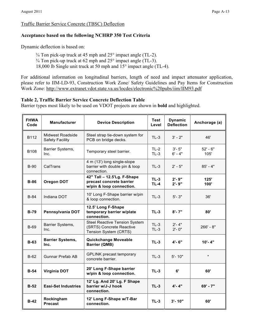
FHWA Code
Manufacturer
Device Description
Test Level
Dynamic Deflection
Anchorage (a)
B112
Midwest Roadside Safety Facility
Steel strap tie-down system for PCB on bridge decks.
TL-3
3' - 2"
46'
B108
Barrier Systems, Inc.
Temporary steel barrier.
TL-2 TL-3
3'- 5" 6' - 4"
52' - 6" 105'
B-90
CalTrans
4 m (13') long single-slope barrier with double pin & loop connection.
TL-3
2' - 5"
85' - 4"
B-86
Oregon DOT
42" Tall – 12.5'Lg. F-Shape precast concrete barrier w/pin & loop connection.
TL-3 TL-4
2'- 9" 2'- 9"
125' 100'
B-84
Indiana DOT
10' Long F-Shape barrier w/pin & loop connection.
TL-3
5'- 3"
36'
B-79
Pennsylvania DOT
12.5' Long F-Shape temporary barrier w/plate connection.
TL-3
8'- 7"
80'
B-69
Barrier Systems, Inc.
Steel Reactive Tension System (SRTS) Concrete Reactive Tension System (CRTS)
TL-3 TL-3
2'- 4" 2'- 0"
266' - 8"
B-63
Barrier Systems, Inc.
Quickchange Moveable Barrier (QMB)
TL-3
4'- 6"
10'- 4"
B-62
Gunnar Prefab AB
GPLINK precast temporary concrete barrier.
TL-3
5'- 10"
*
B-54
Virginia DOT
20' Long F-Shape barrier w/pin & loop connection.
TL-3
6'
60'
B-52
Easi-Set Industries
12' Lg. And 20' Lg. F Shape barrier w/J-J hook connection.
TL-3
4'- 4"
69' - 7"
B-42
Rockingham Precast
12' Long F-Shape w/T-Bar connection.
TL-3
3'- 10"
60'
August 2011 Page A-13
Traffic Barrier Service Concrete (TBSC) Deflection
Acceptance based on the following NCHRP 350 Test Criteria
Dynamic deflection is based on: ¾ Ton pick-up truck at 45 mph and 25° impact angle (TL-2). ¾ Ton pick-up truck at 62 mph and 25° impact angle (TL-3). 18,000 lb Single unit truck at 50 mph and 15° impact angle (TL-4).
For additional information on longitudinal barriers, length of need and impact attenuator application, please refer to IIM-LD-93, Construction Work Zone/ Safety Guidelines and Pay Items for Construction Work Zone: http://www.extranet.vdot.state.va.us/locdes/electronic%20pubs/iim/IIM93.pdf
Table 2, Traffic Barrier Service Concrete Deflection Table Barrier types most likely to be used on VDOT projects are shown in bold and highlighted.
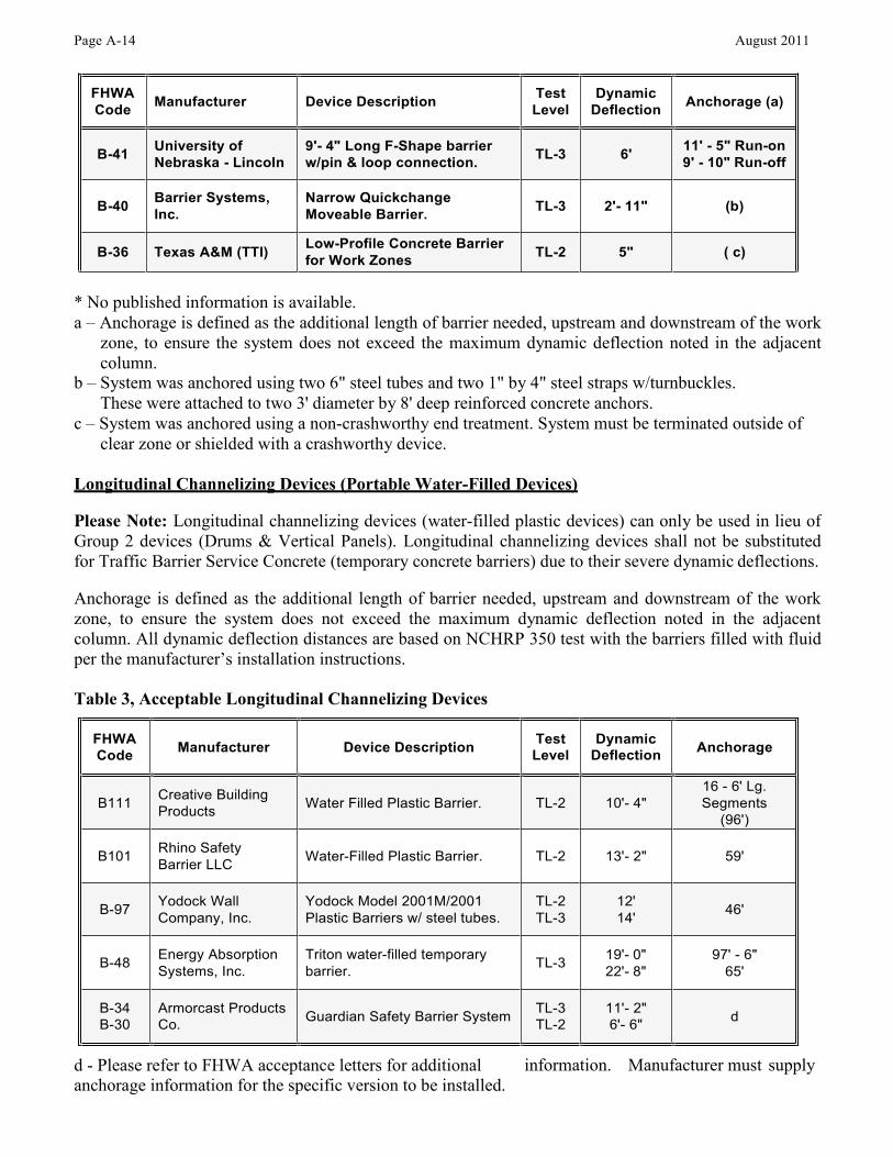
FHWA Code
Manufacturer
Device Description
Test Level
Dynamic Deflection
Anchorage (a)
B-41
University of Nebraska - Lincoln
9'- 4" Long F-Shape barrier w/pin & loop connection.
TL-3
6'
11' - 5" Run-on 9' - 10" Run-off
B-40
Barrier Systems, Inc.
Narrow Quickchange Moveable Barrier.
TL-3
2'- 11"
(b)
B-36 Texas A&M (TTI) Low-Profile Concrete Barrier for Work Zones TL-2 5" ( c)
Page A-14 August 2011
* No published information is available. a – Anchorage is defined as the additional length of barrier needed, upstream and downstream of the work
zone, to ensure the system does not exceed the maximum dynamic deflection noted in the adjacent column.
b – System was anchored using two 6" steel tubes and two 1" by 4" steel straps w/turnbuckles. These were attached to two 3' diameter by 8' deep reinforced concrete anchors.
c – System was anchored using a non-crashworthy end treatment. System must be terminated outside of clear zone or shielded with a crashworthy device.
Longitudinal Channelizing Devices (Portable Water-Filled Devices)
Please Note: Longitudinal channelizing devices (water-filled plastic devices) can only be used in lieu of Group 2 devices (Drums & Vertical Panels). Longitudinal channelizing devices shall not be substituted for Traffic Barrier Service Concrete (temporary concrete barriers) due to their severe dynamic deflections.
Anchorage is defined as the additional length of barrier needed, upstream and downstream of the work zone, to ensure the system does not exceed the maximum dynamic deflection noted in the adjacent column. All dynamic deflection distances are based on NCHRP 350 test with the barriers filled with fluid per the manufacturer’s installation instructions.
Table 3, Acceptable Longitudinal Channelizing Devices
d - Please refer to FHWA acceptance letters for additional anchorage information for the specific version to be installed.
information. Manufacturer must supply
FHWA Code
Manufacturer
Device Description
Test Level
Dynamic Deflection Anchorage
B111
Creative Building Products
Water
Filled Plastic Barrier.
TL-2
10'-
4"
16 - 6' Lg. Segments
(96')
B101
Rhino Safety Barrier LLC
Water-Filled
Plastic Barrier.
TL-2
13'-
2"
59'
B-97
Yodock Wall Company, Inc.
Yodock Model 2001M/2001 Plastic Barriers w/ steel tubes.
TL-2 TL-3
12' 14' 46'
B-48
Energy Absorption Systems, Inc.
Triton water-filled temporary barrier.
TL-3
19'- 22'-
0" 8"
97' - 6" 65'
B-34 B-30
Armorcast Co.
Products Guardian Safety
Barrier System TL-3 TL-2
11'- 2" 6'- 6" d
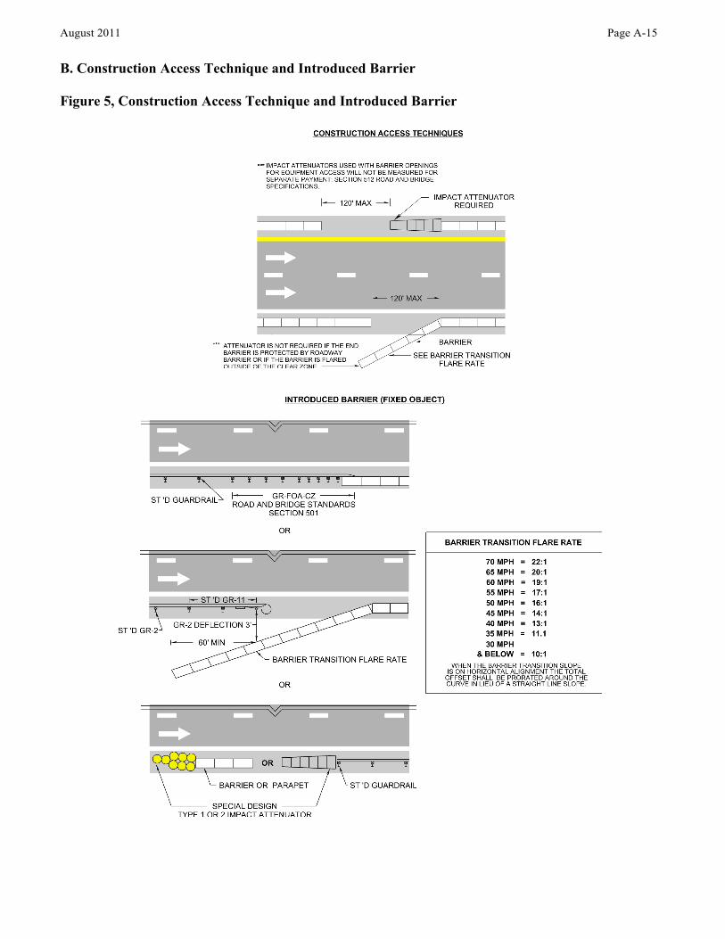
August 2011 Page A-15
B. Construction Access Technique and Introduced Barrier
Figure 5, Construction Access Technique and Introduced Barrier
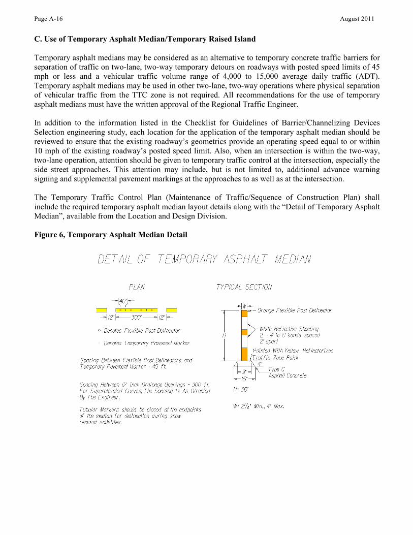
Page A-16 August 2011
C. Use of Temporary Asphalt Median/Temporary Raised Island
Temporary asphalt medians may be considered as an alternative to temporary concrete traffic barriers for separation of traffic on two-lane, two-way temporary detours on roadways with posted speed limits of 45 mph or less and a vehicular traffic volume range of 4,000 to 15,000 average daily traffic (ADT). Temporary asphalt medians may be used in other two-lane, two-way operations where physical separation of vehicular traffic from the TTC zone is not required. All recommendations for the use of temporary asphalt medians must have the written approval of the Regional Traffic Engineer.
In addition to the information listed in the Checklist for Guidelines of Barrier/Channelizing Devices Selection engineering study, each location for the application of the temporary asphalt median should be reviewed to ensure that the existing roadway’s geometrics provide an operating speed equal to or within 10 mph of the existing roadway’s posted speed limit. Also, when an intersection is within the two-way, two-lane operation, attention should be given to temporary traffic control at the intersection, especially the side street approaches. This attention may include, but is not limited to, additional advance warning signing and supplemental pavement markings at the approaches to as well as at the intersection.
The Temporary Traffic Control Plan (Maintenance of Traffic/Sequence of Construction Plan) shall include the required temporary asphalt median layout details along with the “Detail of Temporary Asphalt Median”, available from the Location and Design Division.
Figure 6, Temporary Asphalt Median Detail
August 2011 Page A-17
4. REFERENCES AND OTHER RELATED MATERIALS
VDOT Memorandums:
IIM-LD-93, Construction Work Zone/ Safety Guidelines and Pay Items for Construction Work Zone http://www.extranet.vdot.state.va.us/locdes/electronic%20pubs/iim/IIM93.pdf
IIM-LD-184, Concrete Median Barrier/Traffic Barrier Service http://www.extranet.vdot.state.va.us/locdes/electronic%20pubs/iim/IIM184.pdf
IIM-LD-222/TE-358, Roadway Safety Features/NCHRP 350 Test Requirements http://www.extranet.vdot.state.va.us/locdes/electronic%20pubs/iim/IIM222.pdf
IIM-LD-241/TE-351, Work Zone Safety and Mobility/Transportation Management Plan Requirements http://www.extranet.vdot.state.va.us/locdes/electronic%20pubs/iim/IIM241.pdf
TE-342, Work Zone/Lane Encroachment and Center Lane Closure Policy for Work Zones on Limited Access Highways
http://www.virginiadot.org/business/resources/traffic_engineering/memos2/TE- 342_Lane_Encroachment_and_Center_Lane_Closure_Policy_for_Work_Zone_on_Limited_Acce ss_Highways.pdf
TE-350, Work Zone Safety/Work Zone Speed Analysis http://www.virginiadot.org/business/resources/traffic_engineering/memos2/TE- 350_1_Work_Zone_Speed_Analysis.pdf
TE-352, Work Zone Safety/Slow Roll Temporary Traffic Control (Slow Roll TTC) http://www.virginiadot.org/business/resources/traffic_engineering/memos2/TE- 352_Slow_Roll_Temp_Traffic_Control.pdf
VDOT Manuals:
Virginia Road and Bridge Specifications http://www.virginiadot.org/business/const/spec-default.asp
Virginia Road and Bridge Standards http://www.virginiadot.org/business/locdes/2008_standards_complete_sections.asp
Virginia Road Design Manual (Index) http://www.extranet.vdot.state.va.us/locdes/Electronic%20Pubs/2005%20RDM/index.pdf
National Manuals and Web Sites:
2009 Manual on Uniform Traffic Control Devices http://mutcd.fhwa.dot.gov/kno_2009.htm
FHWA Safety (Work Zones) http://safety.fhwa.dot.gov/wz
The National Work Zone Safety Information Clearinghouse http://www.workzonesafety.org

Page A-18 August 2011
Intentionally Left Blank