Embed Size (px)
Citation preview
Clinician's Guide
Table of ContentsChapter 1: Introduction ........................................................................................................ 1
Device Description .......................................................................................................................................1
Chapter 2: Safety Information .............................................................................................. 3
Intended Use ...............................................................................................................................................3
Contraindications .........................................................................................................................................3
Precautions ..................................................................................................................................................3
Warnings .....................................................................................................................................................4
Chapter 3: Patient Harness Fitting Instructions ................................................................... 5
Selecting a Harness Size ............................................................................................................................5
Donning a Patient Harness ..........................................................................................................................5
Chapter 4: Starting the Vector Elite System and Software ................................................... 7
Turning the System On and Off ....................................................................................................................7
Launching the Vector Gait and Safety Software ...........................................................................................8
Main Menu Screen .......................................................................................................................................8
Logout Button .............................................................................................................................................10
Exit Button ..................................................................................................................................................10
Chapter 5: Patient Training Menu ...................................................................................... 11
Creating a New Patient Account ................................................................................................................ 11
Opening an Existing Patient Account .........................................................................................................12
Introduction to the Training Session Screen ...............................................................................................13
Manual Controls ...................................................................................................................................13
Training Controls ..................................................................................................................................14
Trolley Tracking ............................................................................................................................15
Dynamic Body Weight Support (DBWS) .......................................................................................16
Dynamic Unloading .......................................................................................................................16
Fall Prevention...............................................................................................................................16
Session Status Section ........................................................................................................................17
Emergency Stop and Emergency Lower Buttons ................................................................................17
Preparing for a Training Session ................................................................................................................17
Attaching a Patient Harness to the Spreader Bar .......................................................................................18
Starting a Training Session .........................................................................................................................19
Fall Limit Detection .....................................................................................................................................20
Stopping a Training Session .......................................................................................................................21
Session Summary Screen ..........................................................................................................................22
Vector Elite Time Out Feature ....................................................................................................................23
Chapter 6: Manual Control, Summaries, and Reference Library Menus ............................. 25
Manual Control Menu .................................................................................................................................25
Summaries Menu .......................................................................................................................................26
Reference Library Menu .............................................................................................................................29
Chapter 7: Vector Elite Remote Control ............................................................................ 31
Starting the Vector Elite Remote Control ....................................................................................................31
Vector Elite Remote Control Software Screens ..........................................................................................32
Controlling Device Status ...........................................................................................................................35
Using the Remote Control for a Patient Training Session ......................................................................... 36
Using the Remote Control to Operate System without Patient Data ........................................................ 38
Chapter 8: Multi-Trolley Sync Feature ................................................................................ 39
Sync Menu ..................................................................................................................................................39
Chapter 9: Vector Elite Software Administrator Menu ........................................................ 41
Accessing the Administrator Menu .............................................................................................................41
Admin Menu ...............................................................................................................................................43
Patient Database Menu .......................................................................................................................43
Add Users Menu ..................................................................................................................................45
Backup and Restore Database Menu ..................................................................................................46
Chapter 10: Troubleshooting .............................................................................................. 49
Chapter 11: Service and Maintenance ................................................................................ 53
Chapter 12: Technical Specifications ................................................................................. 55
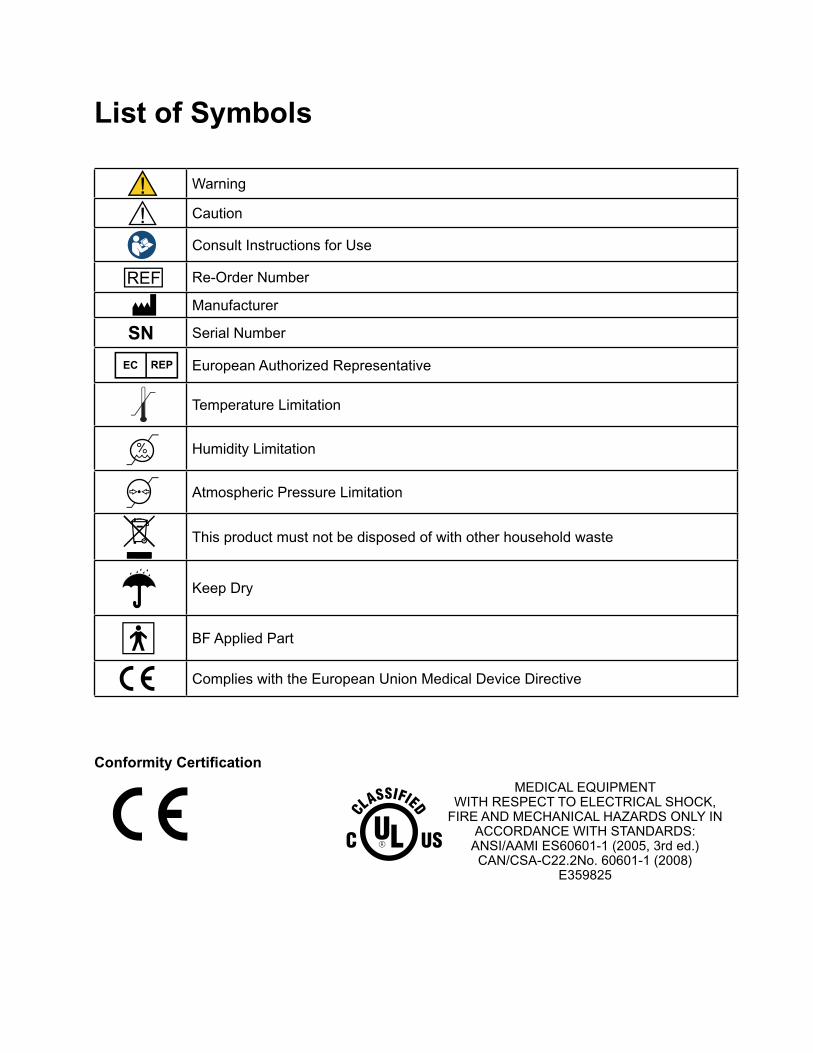
List of Symbols
Warning
Caution
Consult Instructions for Use
Re-Order Number
Manufacturer
SN Serial Number
European Authorized Representative
Temperature Limitation
Humidity Limitation
Atmospheric Pressure Limitation
This product must not be disposed of with other household waste
Keep Dry
BF Applied Part
Complies with the European Union Medical Device Directive
Conformity Certification
MEDICAL EQUIPMENT WITH RESPECT TO ELECTRICAL SHOCK,
FIRE AND MECHANICAL HAZARDS ONLY IN ACCORDANCE WITH STANDARDS:
ANSI/AAMI ES60601-1 (2005, 3rd ed.) CAN/CSA-C22.2No. 60601-1 (2008)
E359825

VII Clinician's Guide
1Chapter
1Chapter 1 - Introduction
Introduction Introduction of Vector Gait and Safety System™
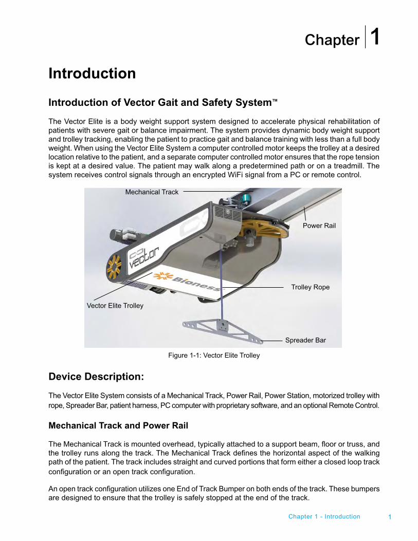
The Vector Elite is a body weight support system designed to accelerate physical rehabilitation of patients with severe gait or balance impairment. The system provides dynamic body weight support and trolley tracking, enabling the patient to practice gait and balance training with less than a full body weight. When using the Vector Elite System a computer controlled motor keeps the trolley at a desired location relative to the patient, and a separate computer controlled motor ensures that the rope tension is kept at a desired value. The patient may walk along a predetermined path or on a treadmill. The system receives control signals through an encrypted WiFi signal from a PC or remote control.
Figure 1-1: Vector Elite Trolley
Device Description:
The Vector Elite System consists of a Mechanical Track, Power Rail, Power Station, motorized trolley with rope, Spreader Bar, patient harness, PC computer with proprietary software, and an optional Remote Control.
Mechanical Track and Power Rail
The Mechanical Track is mounted overhead, typically attached to a support beam, floor or truss, and the trolley runs along the track. The Mechanical Track defines the horizontal aspect of the walking path of the patient. The track includes straight and curved portions that form either a closed loop track configuration or an open track configuration.
An open track configuration utilizes one End of Track Bumper on both ends of the track. These bumpers are designed to ensure that the trolley is safely stopped at the end of the track.
Mechanical Track
Trolley Rope
Spreader Bar
Vector Elite Trolley
Power Rail
Clinician's Guide2
The Power Rail is also mounted overhead, and runs parallel to the mechanical track. The Power Rail delivers electricity to the Vector Elite Trolley.
Power Station
The Power Station is mounted to a wall and plugs into an outlet. It converts electrical power from the building to a predetermined power level, which is supplied to the trolley through the Power Rail. The Power Station also contains an electrical isolation transformer, as a safety feature of the system.
Vector Elite Trolley
The Vector Elite Trolley consists of two motors and a rope that attaches to the Spreader Bar. When using the Vector Elite System a computer controlled motor keeps the trolley at a desired location relative to the patient, and a separate computer controlled motor ensures that the rope tension is kept at a desired value. The trolley moves along the entire length of the track.
Spreader Bar
The Spreader Bar is a device that enables the attachment of a patient harness to the trolley rope. The Spreader Bar attaches to a patient harness at two points. On each side of the Spreader Bar there are three holes built to accommodate patients of different widths.
Patient Harness
The patient harness secures a patient during a therapy session. The patient harness comes in a variety of different sizes and attaches to the Spreader Bar.
PC
The touch screen PC contains the software that controls the Vector Elite System and manages the secure patient database. The Vector Gait and Safety System Software is password protected and communicates with the trolley through an encrypted WiFi signal.
Remote Control
The Remote Control is an optional accessory that may be used to control the System once a training session has begun. This accessory is not necessary to operate the Vector Elite System. The Remote Control uses an Android Operating System with a Vector Gait and Safety System Application and communicates with the trolley through an encrypted WiFi signal.
Be sure to review this guide, including all safety information, before using the Vector Elite System. If you have questions contact Bioness at (800) 211-9136, Option 3 (in the United States) or your local distributor (outside of the United States). You can also visit the Bioness website at: www.bioness.com.
Caution: Do not use the Vector Elite System until you have been properly trained by a Bioness representative.
Chapter
3
Safety Information Intended Use
The Vector Elite System is a body weight support system designed to accelerate physical rehabilitation of patients with severe gait and/or balance impairment. The system unloads a programmed amount of the patient’s weight thus enabling the patient to practice walking with less than a full body weight.
Contraindications
Prior to use all patients need to be deemed medically stable and appropriate by a Vector Gait and Safety System trained healthcare professional. Patients with the following diagnoses, symptoms or findings should not use the Vector Elite System:
• Weight more than 400 lbs (181.4 kg)
• Unstable fractures
• Halo neck supports
• Uncontrolled hypertension
• Uncontrolled diabetes
• Severe osteoporosis
Precautions
• Pulling down on the Spreader Bar and then letting go could cause injury; use with caution.
• For correct usage, ensure that the patient harness connection to the Spreader Bar is not too narrow or too wide.
• Use care when assisting patients into/out of a harness as they can get tangled and fall.
• Follow instructions carefully to prevent pulling or jerking of the patient in the equipment.
• Carefully measure and fit a harness to the patient. Incorrect sizing may cause discomfort and/or injury to the patient.
• Use care when attaching a patient harness to the Spreader Bar. If not attached correctly, there is a risk of the patient falling.
• When using a multi-trolley configured system on the same track, leave a safe distance between patients to prevent collision injury or injury from a patient fall.
• In a multi-trolley configured system, while using the manual controls, avoid driving the Vector Elite Trolley into the other trolley on the same track.
• Before starting a training session, with a multi-trolley configured system, make sure the correct Computer and Remote Control are being used with the correct Vector Elite Trolley. The incorrect Computer or Remote Control will not operate the Trolley. The Remote Control and Computer are configured to only operate the Trolley with which they are paired.
Chapter 2 - Warnings and Cautions
2
4 Clinician's Guide
• Ensure that the handheld is operating and communicating with the appropriate computer before starting a training session.
Warnings
• Incorrect patient data entry or incorrect patient retrieval may cause the patient to fall and/or serious injury.
• Do not place a patient that weighs more than 400 lbs (181.4kg) in the Vector Gait and Safety System.
• Do not exceed recommended weight limits or otherwise misuse the equipment as the equipment can dislocate and fall causing serious injury.
• Do not lift the patient too high or have the patient ascend/descend high stairs where they might be injured from the trolley.
• Do not touch the motorized Elite trolley during a training session. The trolley contains moving parts that could cause injury if touched.
• In an emergency such as an electrical outage, stop exercise immediately to avoid injury and turn off the power switch located on the power station.
• Do not attempt to service or repair the Vector Elite System or electrocution may occur.
• Do not modify the Vector Elite System equipment; doing so would void the warranty.
• Do not use the Vector Elite System if maintenance is required; serious injury may occur.
• In the event of power failure, carefully remove patient from the harness and step away from the equipment.
• Do not use equipment if the Elite trolley has become wet (e.g. with sprinklers) as there is a risk of electrocution. Servicing is required before the equipment may be used.
• To avoid risk of electric shock, this equipment must only be connected to a supply mains with protective earth.
• The Vector Elite System is not intended for patient transport. Using the system as a transport could cause serious patient injury.
• Do not manually move the trolley along the track by pulling on the trolley rope, as this could damage the Vector Elite System.
• The Vector Gait and Safety System may only be operated by a trained health care professional.
• The use of accessories not specified by the manufacturer may result in risk of injury and/or increased emissions, or decreased immunity of the equipment, affecting its performance.
• There is a possibility of electromagnetic interference with other devices. When there is suspicion of possible EMC interference to Vector Gait and Safety System, it is recommended to shut down the electrical devices nearby, one-by-one, to locate the possible interference source.
• Due to potential confusion about which computer is being used with which patient, one clinician should not operate multiple computers at the same time.
Chapter
5
Patient Harness Fitting Instructions The Vector Elite System is used with a patient harness. The sizing chart and fitting instructions in this chapter are for the Maine Anti-Gravity Systems patient harness.
Selecting a Harness Size
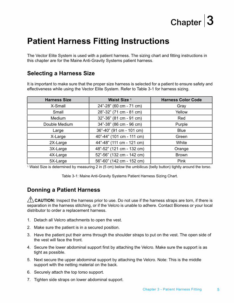
It is important to make sure that the proper size harness is selected for a patient to ensure safety and effectiveness while using the Vector Elite System. Refer to Table 3-1 for harness sizing.
Harness Size Waist Size 1 Harness Color Code
X-Small 24”-28” (60 cm - 71 cm) Gray
Small 28”-32” (71 cm - 81 cm) Yellow
Medium 32”-36” (81 cm - 91 cm) Red
Double Medium 34”-38” (86 cm - 96 cm) Purple
Large 36”-40” (91 cm - 101 cm) Blue
X-Large 40”-44” (101 cm - 111 cm) Green
2X-Large 44”-48” (111 cm - 121 cm) White
3X-Large 48”-52” (121 cm - 132 cm) Orange
4X-Large 52”-56” (132 cm - 142 cm) Brown
5X-Large 56”-60” (142 cm - 152 cm) Pink1 Waist Size is determined by measuring 2 in (5 cm) below the umbilicus (belly button) tightly around the torso.
Table 3-1: Maine Anti-Gravity Systems Patient Harness Sizing Chart.
Donning a Patient Harness
CAUTION: Inspect the harness prior to use. Do not use if the harness straps are torn, if there is separation in the harness stitching, or if the Velcro is unable to adhere. Contact Bioness or your local distributor to order a replacement harness.
1. Detach all Velcro attachments to open the vest.
2. Make sure the patient is in a secured position.
3. Have the patient put their arms through the shoulder straps to put on the vest. The open side of the vest will face the front.
4. Secure the lower abdominal support first by attaching the Velcro. Make sure the support is as tight as possible.
5. Next secure the upper abdominal support by attaching the Velcro. Note: This is the middle support with the netting material on the back.
6. Securely attach the top torso support.
7. Tighten side straps on lower abdominal support.
Chapter 3 - Patient Harness Fitting
3
6 Clinician's Guide
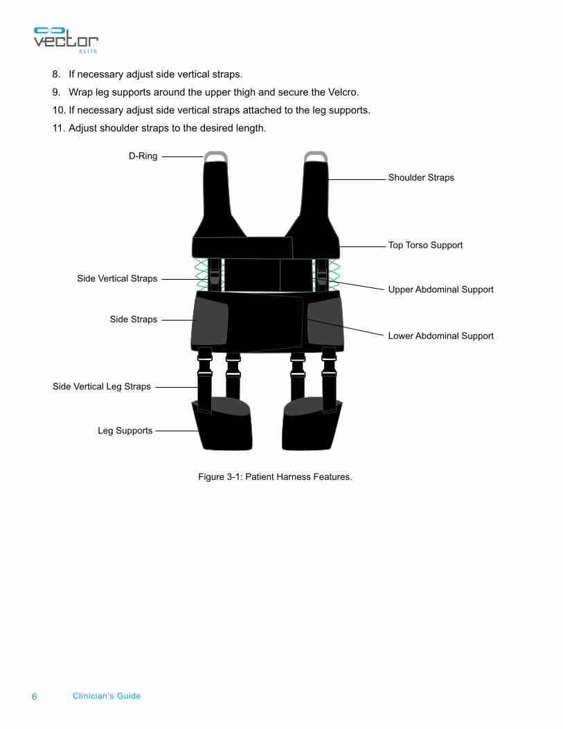
8. If necessary adjust side vertical straps.
9. Wrap leg supports around the upper thigh and secure the Velcro.
10. If necessary adjust side vertical straps attached to the leg supports.
11. Adjust shoulder straps to the desired length.
Figure 3-1: Patient Harness Features.
Shoulder Straps
Lower Abdominal Support
Upper Abdominal Support
Top Torso Support
Side Straps
Side Vertical Straps
Side Vertical Leg Straps
Leg Supports
D-Ring
Chapter
7
Starting the Vector Elite System and SoftwareTurning the System On and Off
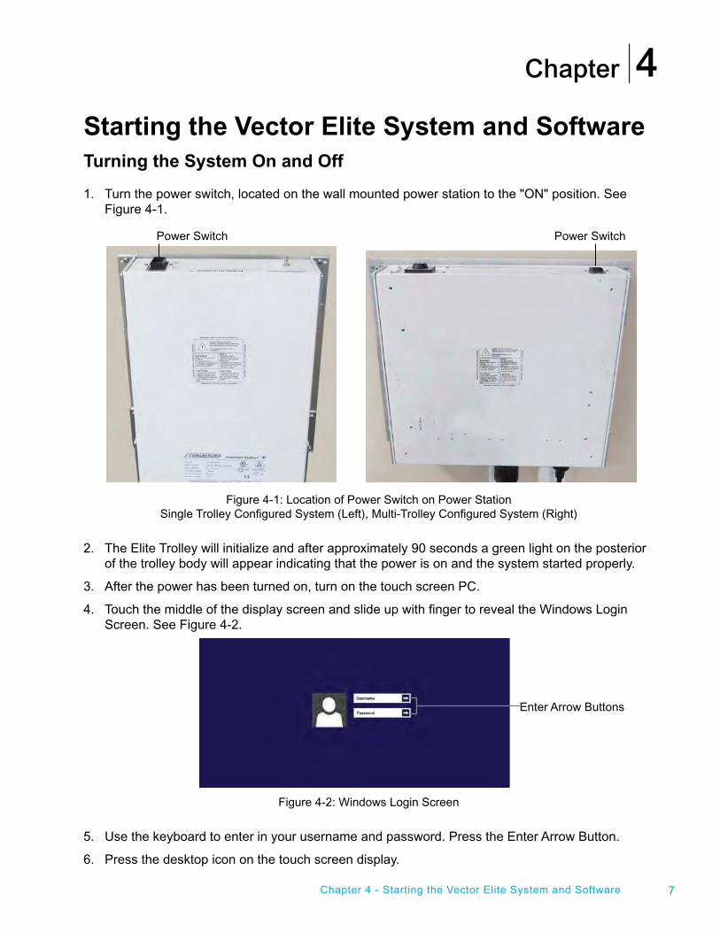
1. Turn the power switch, located on the wall mounted power station to the "ON" position. See Figure 4-1.
Figure 4-1: Location of Power Switch on Power Station Single Trolley Configured System (Left), Multi-Trolley Configured System (Right)
2. The Elite Trolley will initialize and after approximately 90 seconds a green light on the posterior of the trolley body will appear indicating that the power is on and the system started properly.
3. After the power has been turned on, turn on the touch screen PC.
4. Touch the middle of the display screen and slide up with finger to reveal the Windows Login Screen. See Figure 4-2.
Figure 4-2: Windows Login Screen
5. Use the keyboard to enter in your username and password. Press the Enter Arrow Button.
6. Press the desktop icon on the touch screen display.
4
Chapter 4 - Starting the Vector Elite System and Software
Enter Arrow Buttons
Power SwitchPower Switch

8 Clinician's Guide
Launching the Vector Gait and Safety Software
1. To launch the Vector Elite Software click on the Vector Gait and Safety System Icon located on the desktop.
2. The Vector Login Screen will open. Use the keyboard to enter in your username and password. Click on the Green Arrow Button to login. See Figure 4-3.
Note: Login username will be set up when the administrator creates new user accounts.
Figure 4-3: Login Screen
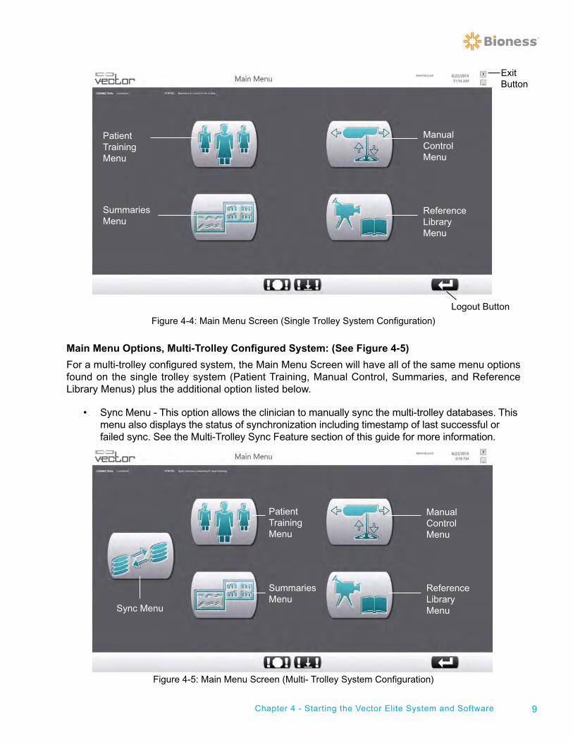
3. The Main Menu Screen will open. See Figure 4-4.
Main Menu Screen
The Vector Elite Main Menu Screen has four menu options with a single trolley configured system and five menu options with a multi-trolley configured system. The menu options appear as Icon Buttons on the Main Menu Screen. See Figures 4-4 and 4-5.
Main Menu Options, Single Trolley Configured System: (See Figure 4-4)
• Patient Training Menu - This option allows the clinician to access the patient database, create a new patient account, and start a training session.
• Manual Control Menu - This option allows the clinician to control the Vector Elite Trolley manually without needing to select a patient account.
• Summaries Menu - This option allows the clinician to view a patient’s training history data.
• Reference Library Menu - This option allows the clinician to access training videos, and the Vector Elite Clinician’s Guide.
9Chapter 4 - Starting the Vector Elite System and Software
Figure 4-4: Main Menu Screen (Single Trolley System Configuration)
Main Menu Options, Multi-Trolley Configured System: (See Figure 4-5)
For a multi-trolley configured system, the Main Menu Screen will have all of the same menu options found on the single trolley system (Patient Training, Manual Control, Summaries, and Reference Library Menus) plus the additional option listed below.
• Sync Menu - This option allows the clinician to manually sync the multi-trolley databases. This menu also displays the status of synchronization including timestamp of last successful or failed sync. See the Multi-Trolley Sync Feature section of this guide for more information.
Figure 4-5: Main Menu Screen (Multi- Trolley System Configuration)
Patient TrainingMenu
SummariesMenu
Manual ControlMenu
Reference LibraryMenu
Logout Button
Exit Button
Patient TrainingMenu
SummariesMenu
Manual ControlMenu
Reference LibraryMenuSync Menu
10 Clinician's Guide
Logout Button
The Logout Button appears in the lower right corner of the display screen in the Vector Elite Software. See Figure 4-4. Pressing the Logout Button will bring the user back to the Login Screen. It is recommended to press the Logout Button after a therapy session has been completed with a patient.
Note: When the Vector Elite is not in use, it is recommended to exit from the Vector Elite Software application.
Exit Button
To exit the Vector Elite Software application press the Exit Button (button with the letter "X"), located in the upper right corner of the display screen. See Figure 4-4. The display screen will return to the operating system's desktop.
Chapter
11
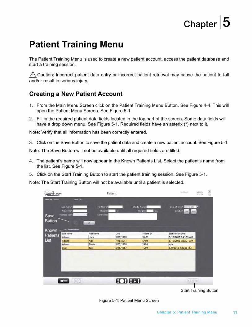
Patient Training Menu The Patient Training Menu is used to create a new patient account, access the patient database and start a training session.
Caution: Incorrect patient data entry or incorrect patient retrieval may cause the patient to fall and/or result in serious injury.
Creating a New Patient Account
1. From the Main Menu Screen click on the Patient Training Menu Button. See Figure 4-4. This will open the Patient Menu Screen. See Figure 5-1.
2. Fill in the required patient data fields located in the top part of the screen. Some data fields will have a drop down menu. See Figure 5-1. Required fields have an asterix (*) next to it.
Note: Verify that all information has been correctly entered.
3. Click on the Save Button to save the patient data and create a new patient account. See Figure 5-1.
Note: The Save Button will not be available until all required fields are filled.
4. The patient's name will now appear in the Known Patients List. Select the patient's name from the list. See Figure 5-1.
5. Click on the Start Training Button to start the patient training session. See Figure 5-1.
Note: The Start Training Button will not be available until a patient is selected.
Figure 5-1: Patient Menu Screen
Chapter 5: Patient Training Menu
5
SaveButton
Start Training Button
Known Patients List
12 Clinician's Guide
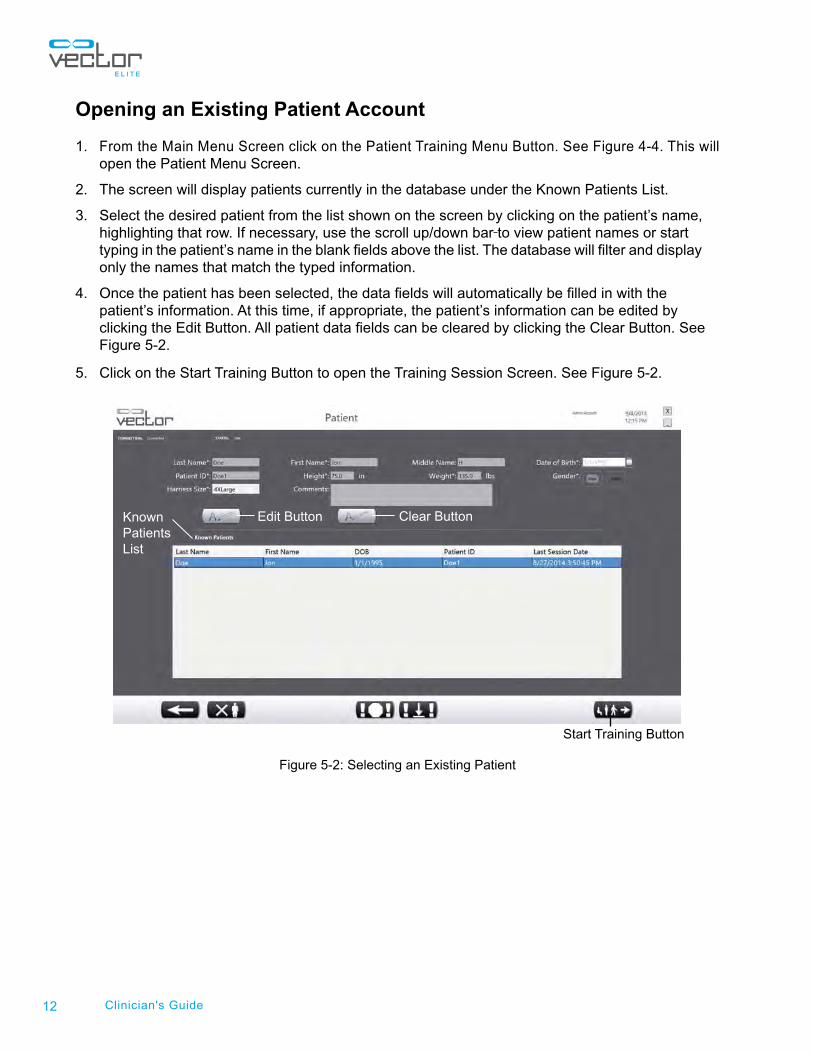
Opening an Existing Patient Account
1. From the Main Menu Screen click on the Patient Training Menu Button. See Figure 4-4. This will open the Patient Menu Screen.
2. The screen will display patients currently in the database under the Known Patients List.
3. Select the desired patient from the list shown on the screen by clicking on the patient’s name, highlighting that row. If necessary, use the scroll up/down bar to view patient names or start typing in the patient’s name in the blank fields above the list. The database will filter and display only the names that match the typed information.
4. Once the patient has been selected, the data fields will automatically be filled in with the patient’s information. At this time, if appropriate, the patient’s information can be edited by clicking the Edit Button. All patient data fields can be cleared by clicking the Clear Button. See Figure 5-2.
5. Click on the Start Training Button to open the Training Session Screen. See Figure 5-2.
Figure 5-2: Selecting an Existing Patient
Edit Button Clear Button
Start Training Button
Known Patients List
13Chapter 5: Patient Training Menu
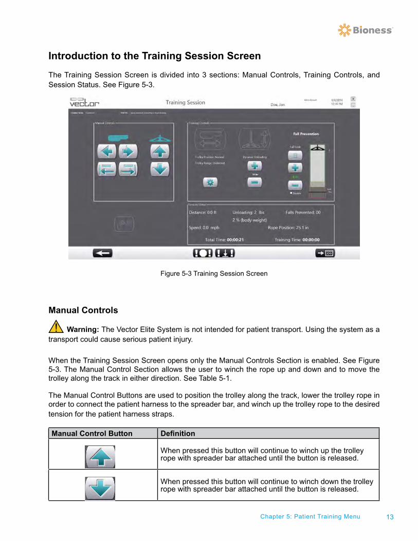
Introduction to the Training Session Screen
The Training Session Screen is divided into 3 sections: Manual Controls, Training Controls, and Session Status. See Figure 5-3.
Figure 5-3 Training Session Screen
Manual Controls
Warning: The Vector Elite System is not intended for patient transport. Using the system as a transport could cause serious patient injury.
When the Training Session Screen opens only the Manual Controls Section is enabled. See Figure 5-3. The Manual Control Section allows the user to winch the rope up and down and to move the trolley along the track in either direction. See Table 5-1.
The Manual Control Buttons are used to position the trolley along the track, lower the trolley rope in order to connect the patient harness to the spreader bar, and winch up the trolley rope to the desired tension for the patient harness straps.
Manual Control Button Definition
When pressed this button will continue to winch up the trolley rope with spreader bar attached until the button is released.
When pressed this button will continue to winch down the trolley rope with spreader bar attached until the button is released.
14 Clinician's Guide
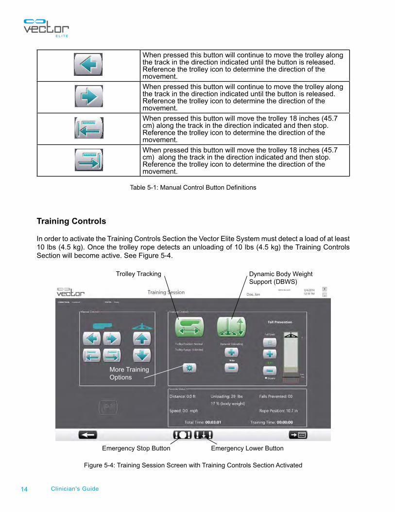
When pressed this button will continue to move the trolley along the track in the direction indicated until the button is released. Reference the trolley icon to determine the direction of the movement.
When pressed this button will continue to move the trolley along the track in the direction indicated until the button is released. Reference the trolley icon to determine the direction of the movement.
When pressed this button will move the trolley 18 inches (45.7 cm) along the track in the direction indicated and then stop. Reference the trolley icon to determine the direction of the movement.
When pressed this button will move the trolley 18 inches (45.7 cm) along the track in the direction indicated and then stop. Reference the trolley icon to determine the direction of the movement.
Table 5-1: Manual Control Button Definitions
Training Controls
In order to activate the Training Controls Section the Vector Elite System must detect a load of at least 10 lbs (4.5 kg). Once the trolley rope detects an unloading of 10 lbs (4.5 kg) the Training Controls Section will become active. See Figure 5-4.
Figure 5-4: Training Session Screen with Training Controls Section Activated
Trolley Tracking Dynamic Body Weight Support (DBWS)
More Training Options
Emergency Lower ButtonEmergency Stop Button
15Chapter 5: Patient Training Menu
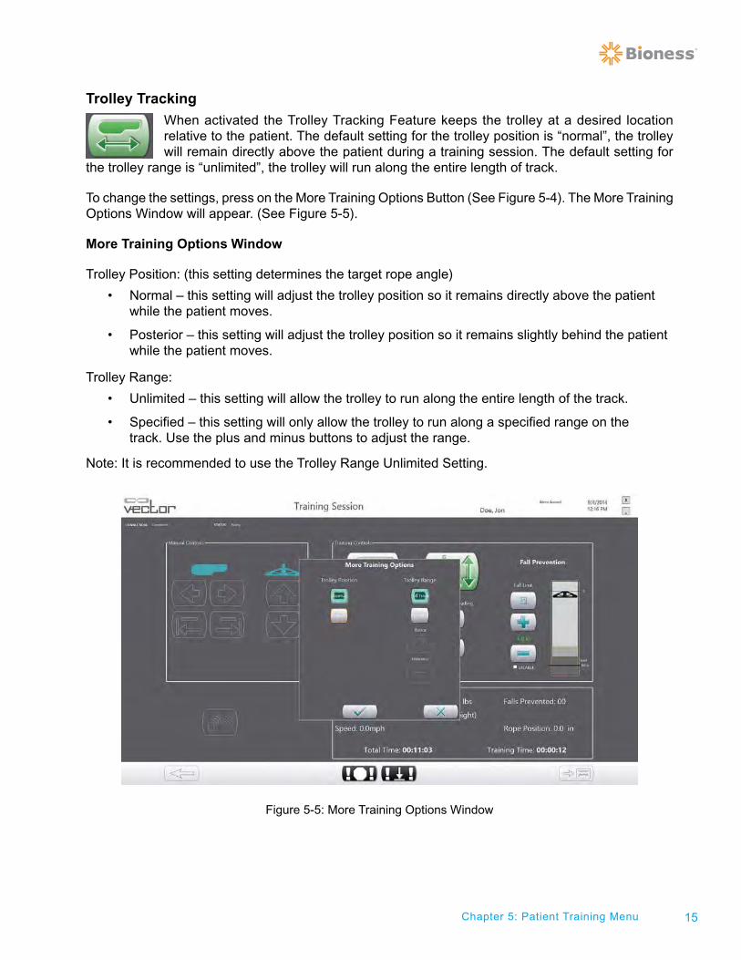
Trolley Tracking
When activated the Trolley Tracking Feature keeps the trolley at a desired location relative to the patient. The default setting for the trolley position is “normal”, the trolley will remain directly above the patient during a training session. The default setting for
the trolley range is “unlimited”, the trolley will run along the entire length of track.
To change the settings, press on the More Training Options Button (See Figure 5-4). The More Training Options Window will appear. (See Figure 5-5).
More Training Options Window
Trolley Position: (this setting determines the target rope angle)
• Normal – this setting will adjust the trolley position so it remains directly above the patient while the patient moves.
• Posterior – this setting will adjust the trolley position so it remains slightly behind the patient while the patient moves.
Trolley Range:
• Unlimited – this setting will allow the trolley to run along the entire length of the track.
• Specified – this setting will only allow the trolley to run along a specified range on the track. Use the plus and minus buttons to adjust the range.
Note: It is recommended to use the Trolley Range Unlimited Setting.
Figure 5-5: More Training Options Window
16 Clinician's Guide
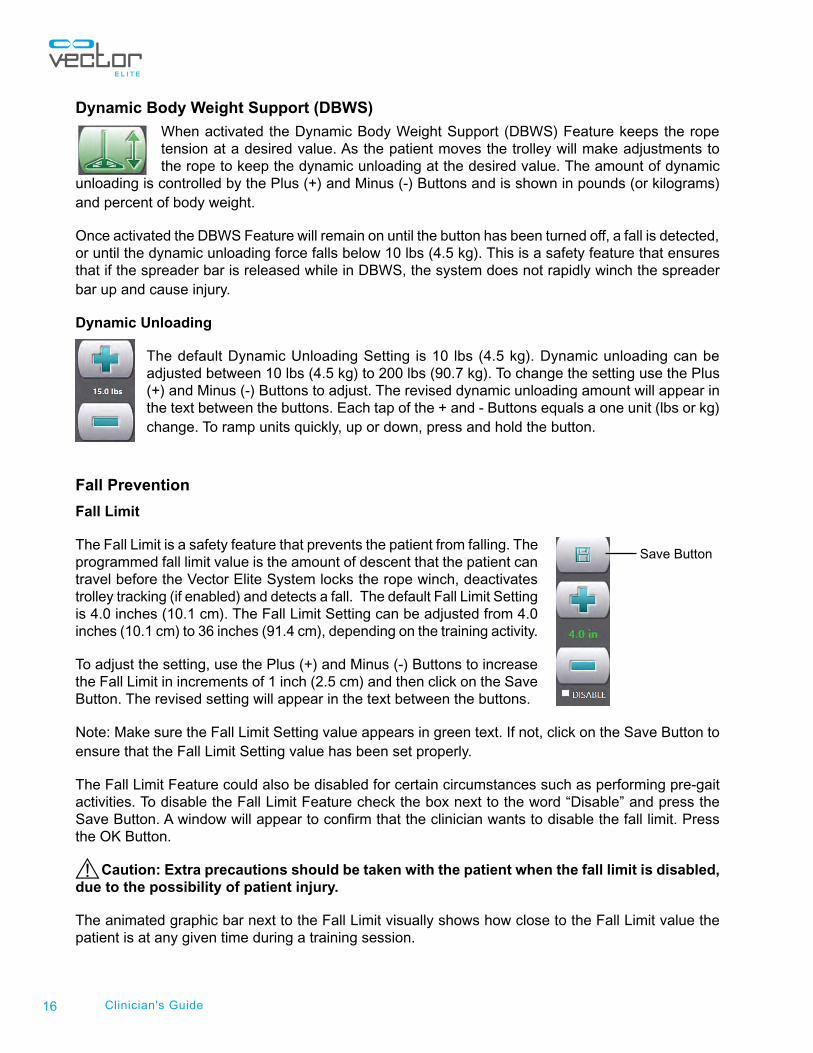
Dynamic Body Weight Support (DBWS)
When activated the Dynamic Body Weight Support (DBWS) Feature keeps the rope tension at a desired value. As the patient moves the trolley will make adjustments to the rope to keep the dynamic unloading at the desired value. The amount of dynamic
unloading is controlled by the Plus (+) and Minus (-) Buttons and is shown in pounds (or kilograms) and percent of body weight.
Once activated the DBWS Feature will remain on until the button has been turned off, a fall is detected, or until the dynamic unloading force falls below 10 lbs (4.5 kg). This is a safety feature that ensures that if the spreader bar is released while in DBWS, the system does not rapidly winch the spreader bar up and cause injury.
Dynamic Unloading
The default Dynamic Unloading Setting is 10 lbs (4.5 kg). Dynamic unloading can be adjusted between 10 lbs (4.5 kg) to 200 lbs (90.7 kg). To change the setting use the Plus (+) and Minus (-) Buttons to adjust. The revised dynamic unloading amount will appear in the text between the buttons. Each tap of the + and - Buttons equals a one unit (lbs or kg) change. To ramp units quickly, up or down, press and hold the button.
Fall Prevention Fall Limit
The Fall Limit is a safety feature that prevents the patient from falling. The programmed fall limit value is the amount of descent that the patient can travel before the Vector Elite System locks the rope winch, deactivates trolley tracking (if enabled) and detects a fall. The default Fall Limit Setting is 4.0 inches (10.1 cm). The Fall Limit Setting can be adjusted from 4.0 inches (10.1 cm) to 36 inches (91.4 cm), depending on the training activity.
To adjust the setting, use the Plus (+) and Minus (-) Buttons to increase the Fall Limit in increments of 1 inch (2.5 cm) and then click on the Save Button. The revised setting will appear in the text between the buttons.
Note: Make sure the Fall Limit Setting value appears in green text. If not, click on the Save Button to ensure that the Fall Limit Setting value has been set properly.
The Fall Limit Feature could also be disabled for certain circumstances such as performing pre-gait activities. To disable the Fall Limit Feature check the box next to the word “Disable” and press the Save Button. A window will appear to confirm that the clinician wants to disable the fall limit. Press the OK Button.
Caution: Extra precautions should be taken with the patient when the fall limit is disabled, due to the possibility of patient injury.
The animated graphic bar next to the Fall Limit visually shows how close to the Fall Limit value the patient is at any given time during a training session.
Save Button
17Chapter 5: Patient Training Menu
Session Status Section
The Session Status Section displays real-time information during a training session. See Figure 5-4. It displays the amount of weight unloaded, total session time, training time, walking speed, rope position, number of falls prevented, and total distance walked during the training session.
Emergency Stop and Emergency Lower Buttons
At the bottom of the Training Session Screen are the Emergency Stop and Emergency Lower Buttons. See Figure 5-4. At any given time these buttons can be used for emergency situations.
Emergency Stop Button
When the Emergency Stop Button is pressed the trolley stops moving and is in a locked position. The system is in Static Unload Mode, the position of the rope will be maintained
regardless of patient movement.
Emergency Lower Button
If a patient becomes medically unstable the Emergency Lower Button can be pressed. Once pressed the system will continue to winch down the rope, with controlled velocity,
until the patient has reached the ground or until the dynamic unload force goes below the default value.
Preparing for a Training Session
For open track configurations it is recommended to place markings on the floor to designate the end of the track, when the track does not terminate in a wall or other obstruction. Instruct the patient to stop prior to the marking in order to prevent the trolley from hitting the End of Track Bumpers. If a patient does hit the end of track bumper, instruct the patient to turn around and continue their training in the reverse direction on the track.
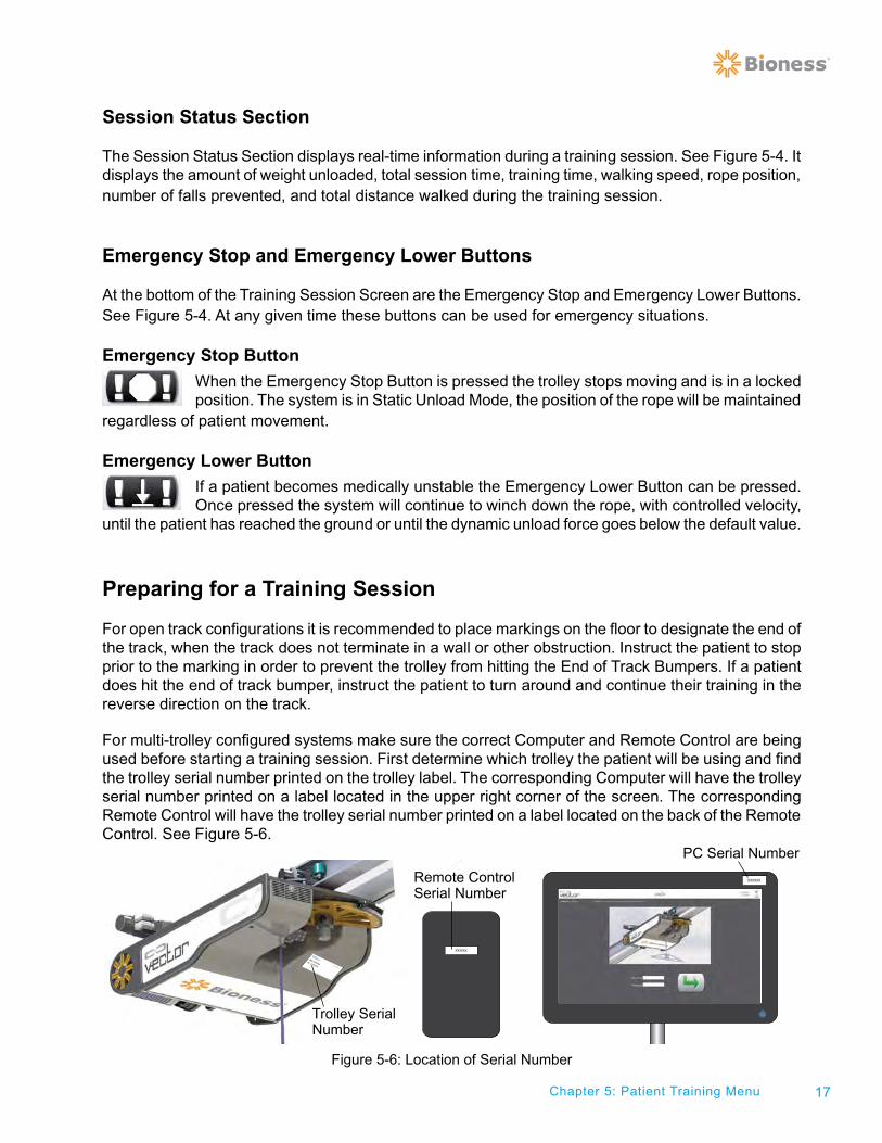
For multi-trolley configured systems make sure the correct Computer and Remote Control are being used before starting a training session. First determine which trolley the patient will be using and find the trolley serial number printed on the trolley label. The corresponding Computer will have the trolley serial number printed on a label located in the upper right corner of the screen. The corresponding Remote Control will have the trolley serial number printed on a label located on the back of the Remote Control. See Figure 5-6.
Figure 5-6: Location of Serial Number
XXXXXX
XXXXXX
Trolley Serial Number
Remote Control Serial Number
PC Serial Number
18 Clinician's Guide
Attaching a Patient Harness to the Spreader Bar
After a patient harness has been securely placed and adjusted on the patient, the harness will need to be attached to the Spreader Bar. For patient harness fitting instructions refer to Chapter 3.
1. Make sure the patient is in a secured position.
2. Use the Manual Control Winch Down Button to lower the rope with Spreader Bar attached.
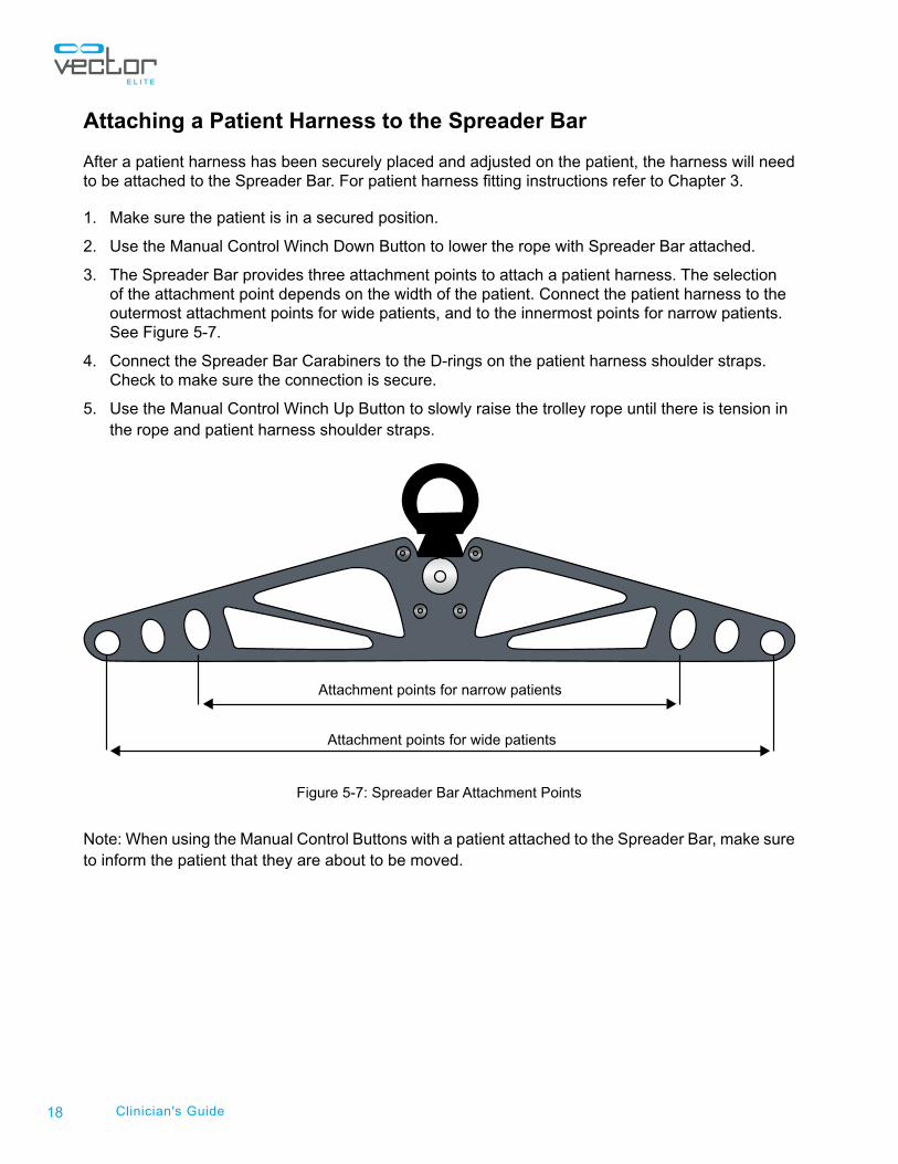
3. The Spreader Bar provides three attachment points to attach a patient harness. The selection of the attachment point depends on the width of the patient. Connect the patient harness to the outermost attachment points for wide patients, and to the innermost points for narrow patients. See Figure 5-7.
4. Connect the Spreader Bar Carabiners to the D-rings on the patient harness shoulder straps. Check to make sure the connection is secure.
5. Use the Manual Control Winch Up Button to slowly raise the trolley rope until there is tension in the rope and patient harness shoulder straps.
Figure 5-7: Spreader Bar Attachment Points
Note: When using the Manual Control Buttons with a patient attached to the Spreader Bar, make sure to inform the patient that they are about to be moved.
Attachment points for narrow patients
Attachment points for wide patients
19
Starting a Training Session
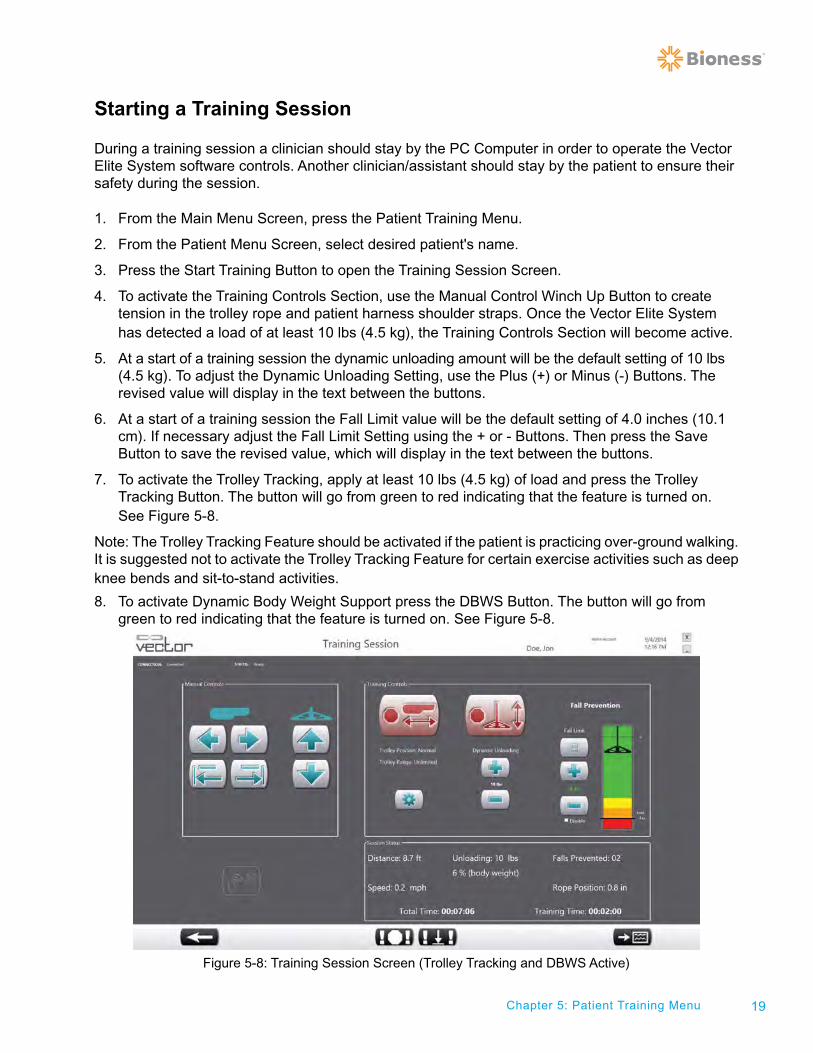
During a training session a clinician should stay by the PC Computer in order to operate the Vector Elite System software controls. Another clinician/assistant should stay by the patient to ensure their safety during the session.
1. From the Main Menu Screen, press the Patient Training Menu.
2. From the Patient Menu Screen, select desired patient's name.
3. Press the Start Training Button to open the Training Session Screen.
4. To activate the Training Controls Section, use the Manual Control Winch Up Button to create tension in the trolley rope and patient harness shoulder straps. Once the Vector Elite System has detected a load of at least 10 lbs (4.5 kg), the Training Controls Section will become active.
5. At a start of a training session the dynamic unloading amount will be the default setting of 10 lbs (4.5 kg). To adjust the Dynamic Unloading Setting, use the Plus (+) or Minus (-) Buttons. The revised value will display in the text between the buttons.
6. At a start of a training session the Fall Limit value will be the default setting of 4.0 inches (10.1 cm). If necessary adjust the Fall Limit Setting using the + or - Buttons. Then press the Save Button to save the revised value, which will display in the text between the buttons.
7. To activate the Trolley Tracking, apply at least 10 lbs (4.5 kg) of load and press the Trolley Tracking Button. The button will go from green to red indicating that the feature is turned on. See Figure 5-8.
Note: The Trolley Tracking Feature should be activated if the patient is practicing over-ground walking. It is suggested not to activate the Trolley Tracking Feature for certain exercise activities such as deep knee bends and sit-to-stand activities.
8. To activate Dynamic Body Weight Support press the DBWS Button. The button will go from green to red indicating that the feature is turned on. See Figure 5-8.
Figure 5-8: Training Session Screen (Trolley Tracking and DBWS Active)
Chapter 5: Patient Training Menu
20 Clinician's Guide
Note: If the DBWS Feature is not activated (the button is green) then the system is in a Static Unload mode. The position of the rope will be maintained regardless of patient movement.
Note: The Trolley Tracking Feature and DBWS Feature can be enabled one at a time or both together.
Adjusting the Dynamic Unloading Value During a Training Session
The dynamic unloading value can be adjusted while the DBWS Feature is active.
1. To adjust the Dynamic Unloading Setting value, use the Plus (+) or Minus (-) Buttons and the revised value will display in the text between the buttons. The adjustment will be instantaneous and can occur while the patient is actively training.
Adjusting the Fall Limit Value During a Training Session
The Fall Limit can be adjusted while DBWS Feature and/or Trolley Tracking Feature is active.
1. To adjust the Fall Limit Setting value, use the Plus (+) or Minus (-) Buttons and the revised value will appear in red text between the buttons.
2. Press the Save Button to save the revised value and the text between the buttons will turn green.
Note: The Save Button must be pressed in order for the revised Fall Limit Setting value to be activated.
Once the Save Button has been pressed then the zero point of the Fall Limit will readjust. The zero point represents the location of the rope when the DBWS Feature is activated. If the text between the + and - Buttons is in red it means that the revised value has not been saved and the zero-point is still reading from the last saved Fall Limit Setting.
Note: It is suggested that at the start of each exercise that the Fall Limit Save Button is pressed to ensure that the zero-point of the Fall Limit Setting value has been readjusted.
Fall Limit Detection
During a training session the Vector Elite System will detect and prevent a fall when the fall distance from the zero point is greater than the set Fall Limit Setting value. When the system detects and prevents a fall the trolley is locked and placed into Static Unload mode.
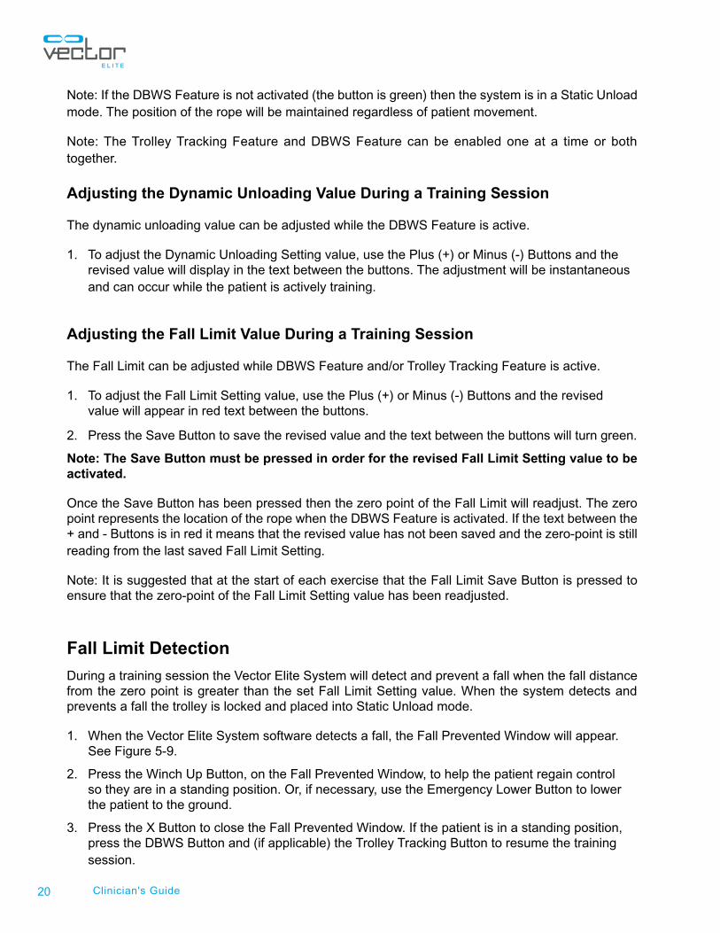
1. When the Vector Elite System software detects a fall, the Fall Prevented Window will appear. See Figure 5-9.
2. Press the Winch Up Button, on the Fall Prevented Window, to help the patient regain control so they are in a standing position. Or, if necessary, use the Emergency Lower Button to lower the patient to the ground.
3. Press the X Button to close the Fall Prevented Window. If the patient is in a standing position, press the DBWS Button and (if applicable) the Trolley Tracking Button to resume the training session.
21Chapter 5: Patient Training Menu
Figure 5-9: Fall Prevented Window
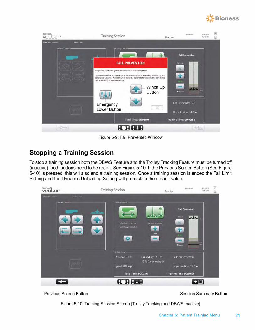
Stopping a Training Session
To stop a training session both the DBWS Feature and the Trolley Tracking Feature must be turned off (inactive), both buttons need to be green. See Figure 5-10. If the Previous Screen Button (See Figure 5-10) is pressed, this will also end a training session. Once a training session is ended the Fall Limit Setting and the Dynamic Unloading Setting will go back to the default value.
Figure 5-10: Training Session Screen (Trolley Tracking and DBWS Inactive)
Winch Up Button
Emergency Lower Button
Previous Screen Button Session Summary Button
22 Clinician's Guide
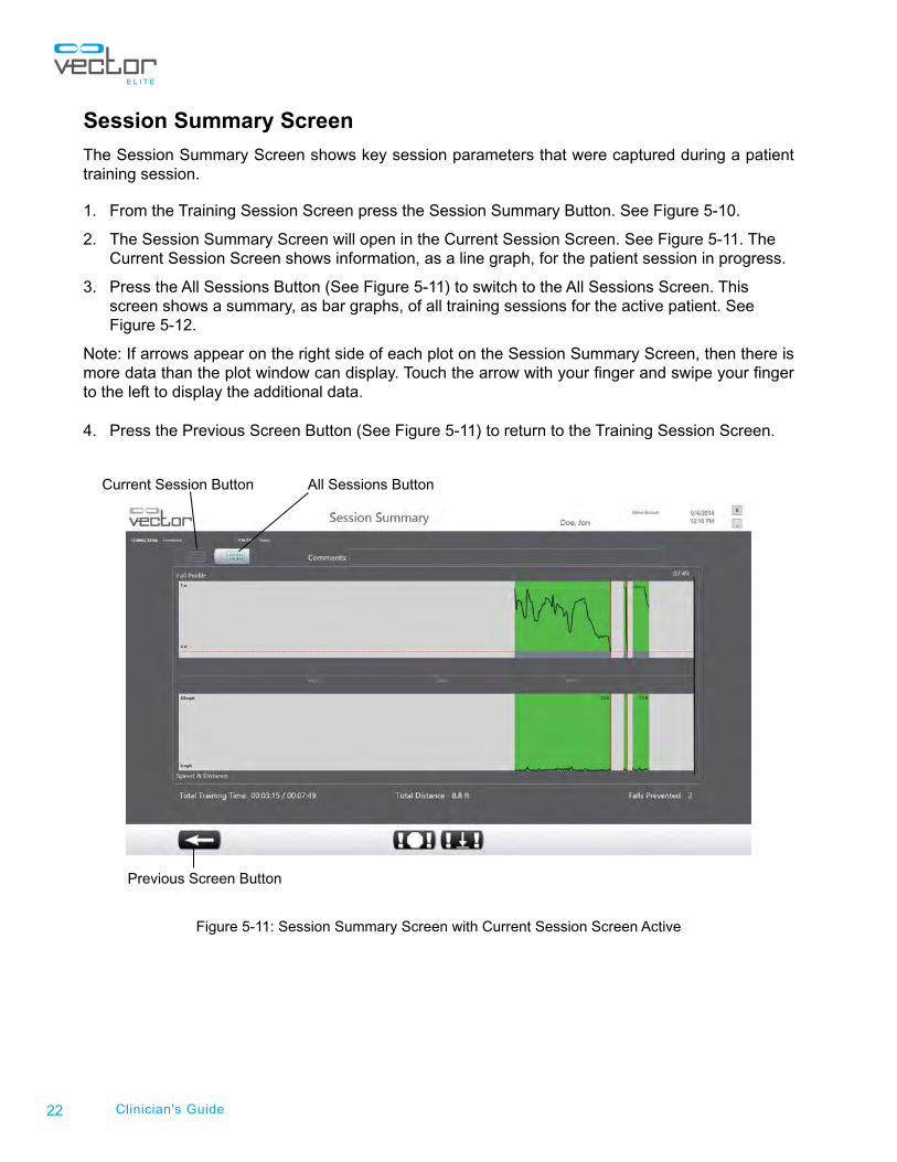
Session Summary Screen
The Session Summary Screen shows key session parameters that were captured during a patient training session.
1. From the Training Session Screen press the Session Summary Button. See Figure 5-10.
2. The Session Summary Screen will open in the Current Session Screen. See Figure 5-11. The Current Session Screen shows information, as a line graph, for the patient session in progress.
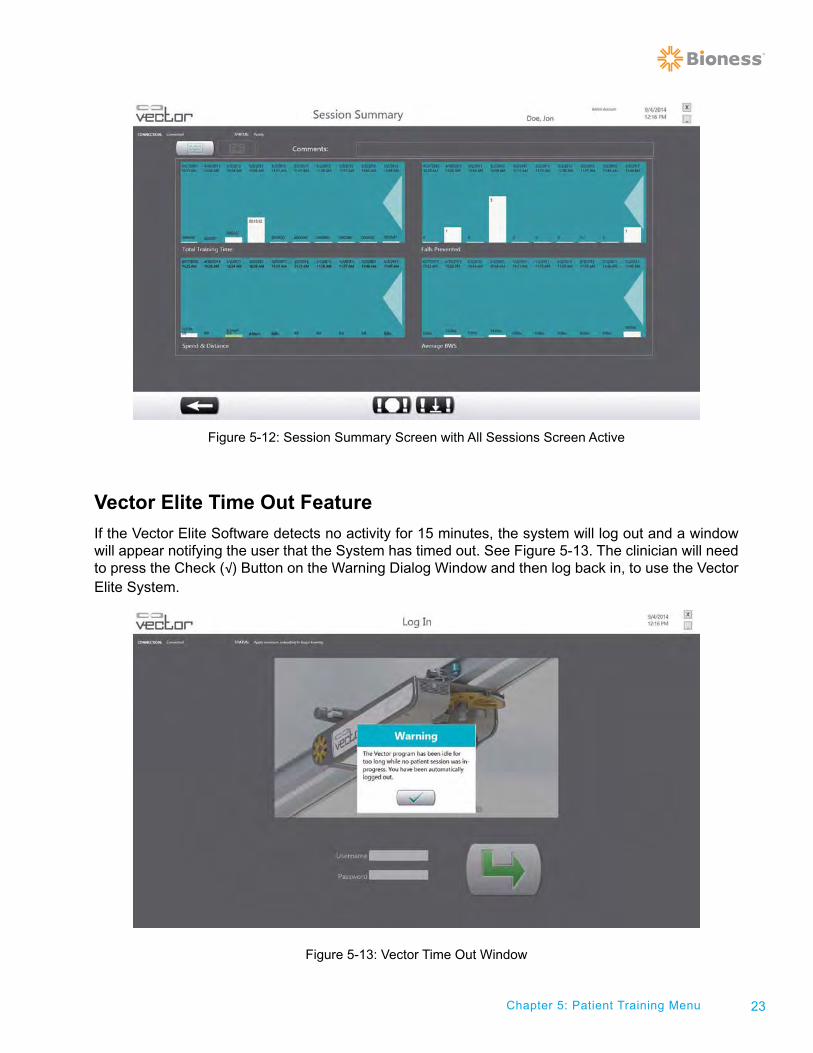
3. Press the All Sessions Button (See Figure 5-11) to switch to the All Sessions Screen. This screen shows a summary, as bar graphs, of all training sessions for the active patient. See Figure 5-12.
Note: If arrows appear on the right side of each plot on the Session Summary Screen, then there is more data than the plot window can display. Touch the arrow with your finger and swipe your finger to the left to display the additional data.
4. Press the Previous Screen Button (See Figure 5-11) to return to the Training Session Screen.
Figure 5-11: Session Summary Screen with Current Session Screen Active
All Sessions ButtonCurrent Session Button
Previous Screen Button
23Chapter 5: Patient Training Menu
Figure 5-12: Session Summary Screen with All Sessions Screen Active
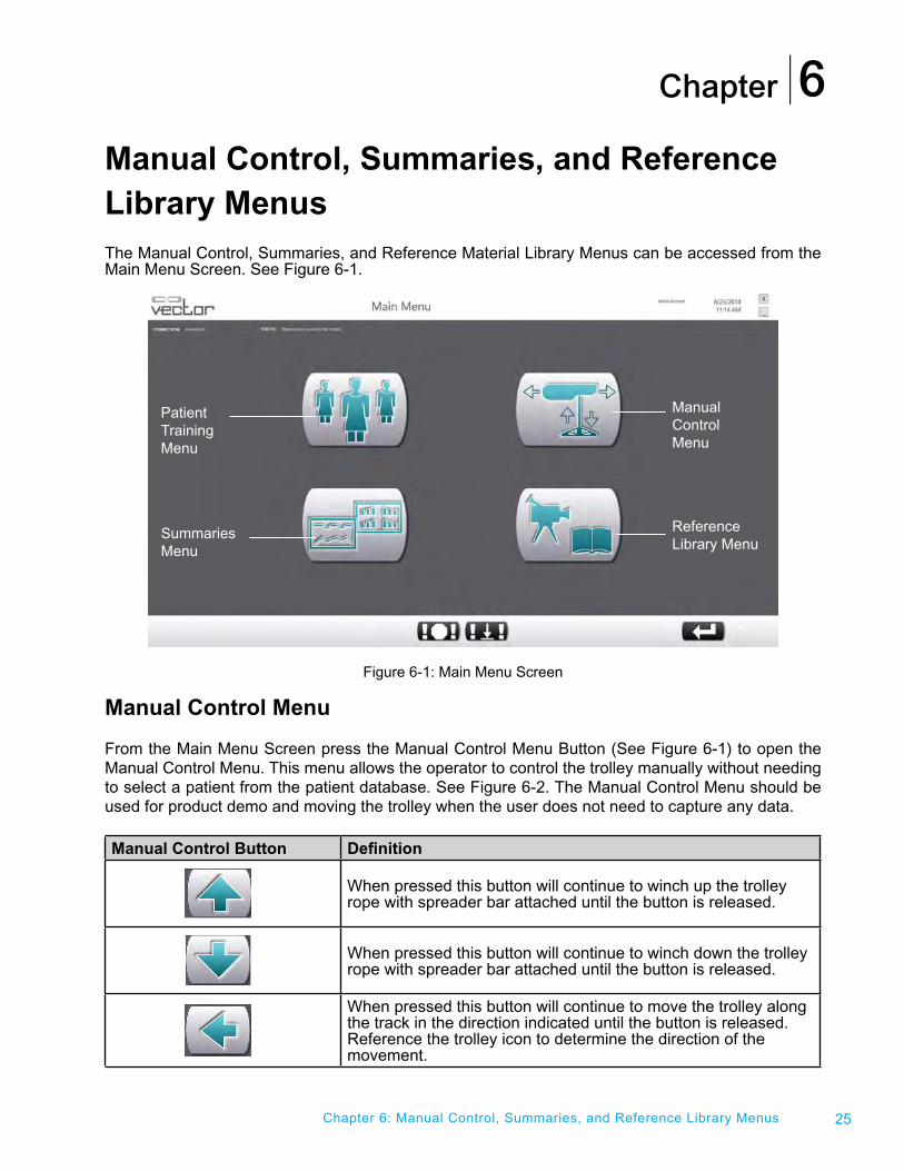
Vector Elite Time Out Feature
If the Vector Elite Software detects no activity for 15 minutes, the system will log out and a window will appear notifying the user that the System has timed out. See Figure 5-13. The clinician will need to press the Check (√) Button on the Warning Dialog Window and then log back in, to use the Vector Elite System.
Figure 5-13: Vector Time Out Window

24 Clinician's Guide
Chapter
25
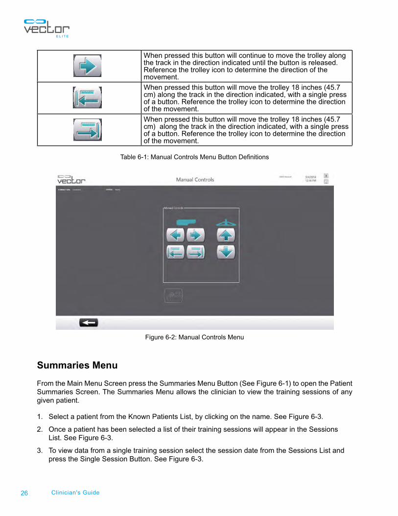
Manual Control, Summaries, and Reference Library Menus The Manual Control, Summaries, and Reference Material Library Menus can be accessed from the Main Menu Screen. See Figure 6-1.
Figure 6-1: Main Menu Screen
Manual Control Menu
From the Main Menu Screen press the Manual Control Menu Button (See Figure 6-1) to open the Manual Control Menu. This menu allows the operator to control the trolley manually without needing to select a patient from the patient database. See Figure 6-2. The Manual Control Menu should be used for product demo and moving the trolley when the user does not need to capture any data.
Manual Control Button Definition
When pressed this button will continue to winch up the trolley rope with spreader bar attached until the button is released.
When pressed this button will continue to winch down the trolley rope with spreader bar attached until the button is released.
When pressed this button will continue to move the trolley along the track in the direction indicated until the button is released. Reference the trolley icon to determine the direction of the movement.
Chapter 6: Manual Control, Summaries, and Reference Library Menus
6
Patient TrainingMenu
SummariesMenu
Manual ControlMenu
Reference Library Menu
26 Clinician's Guide
When pressed this button will continue to move the trolley along the track in the direction indicated until the button is released. Reference the trolley icon to determine the direction of the movement.
When pressed this button will move the trolley 18 inches (45.7 cm) along the track in the direction indicated, with a single press of a button. Reference the trolley icon to determine the direction of the movement.
When pressed this button will move the trolley 18 inches (45.7 cm) along the track in the direction indicated, with a single press of a button. Reference the trolley icon to determine the direction of the movement.
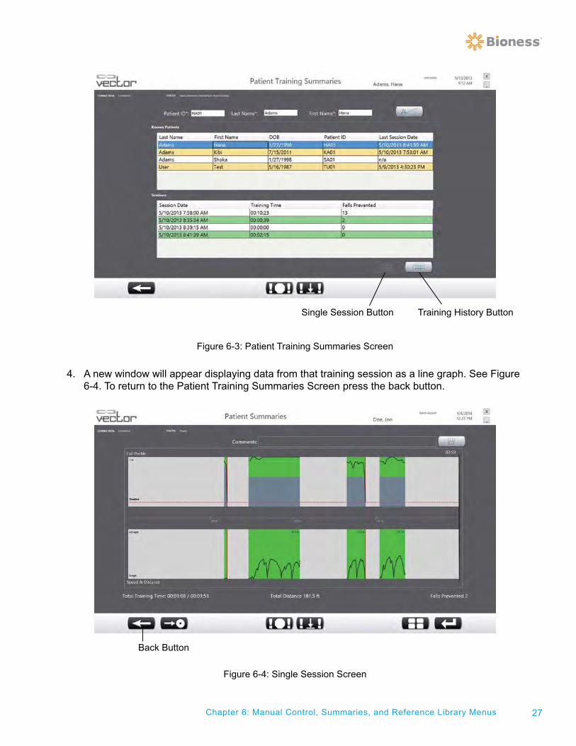
Table 6-1: Manual Controls Menu Button Definitions
Figure 6-2: Manual Controls Menu
Summaries Menu
From the Main Menu Screen press the Summaries Menu Button (See Figure 6-1) to open the Patient Summaries Screen. The Summaries Menu allows the clinician to view the training sessions of any given patient.
1. Select a patient from the Known Patients List, by clicking on the name. See Figure 6-3.
2. Once a patient has been selected a list of their training sessions will appear in the Sessions List. See Figure 6-3.
3. To view data from a single training session select the session date from the Sessions List and press the Single Session Button. See Figure 6-3.
27Chapter 6: Manual Control, Summaries, and Reference Library Menus
Figure 6-3: Patient Training Summaries Screen
4. A new window will appear displaying data from that training session as a line graph. See Figure 6-4. To return to the Patient Training Summaries Screen press the back button.
Figure 6-4: Single Session Screen
Training History ButtonSingle Session Button
Back Button
28 Clinician's Guide
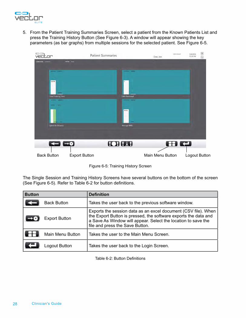
5. From the Patient Training Summaries Screen, select a patient from the Known Patients List and press the Training History Button (See Figure 6-3). A window will appear showing the key parameters (as bar graphs) from multiple sessions for the selected patient. See Figure 6-5.
Figure 6-5: Training History Screen
The Single Session and Training History Screens have several buttons on the bottom of the screen (See Figure 6-5). Refer to Table 6-2 for button definitions.
Button Definition
Back Button Takes the user back to the previous software window.
Export Button
Exports the session data as an excel document (CSV file). When the Export Button is pressed, the software exports the data and a Save As Window will appear. Select the location to save the file and press the Save Button.
Main Menu Button Takes the user to the Main Menu Screen.
Logout Button Takes the user back to the Login Screen.
Table 6-2: Button Definitions
Back Button Export Button Main Menu Button Logout Button
29Chapter 6: Manual Control, Summaries, and Reference Library Menus
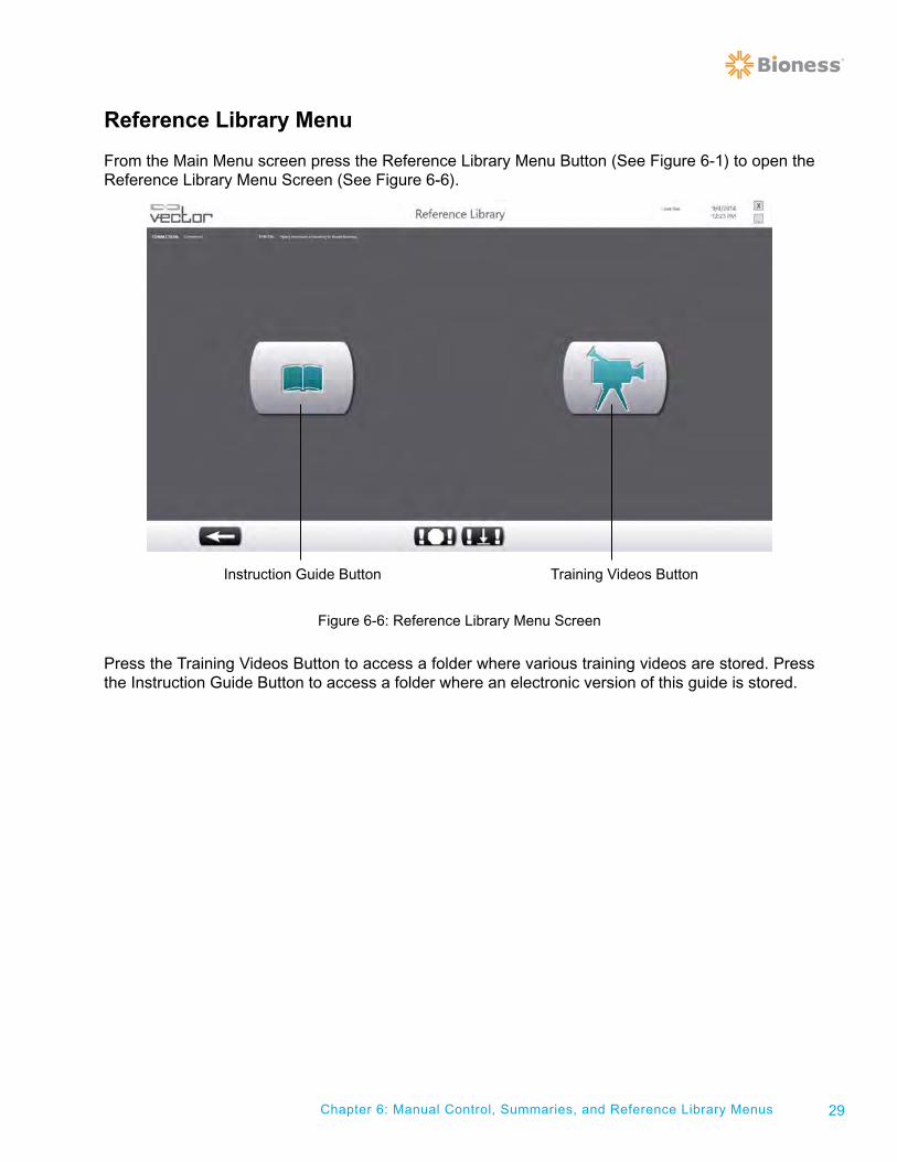
Reference Library Menu
From the Main Menu screen press the Reference Library Menu Button (See Figure 6-1) to open the Reference Library Menu Screen (See Figure 6-6).
Figure 6-6: Reference Library Menu Screen
Press the Training Videos Button to access a folder where various training videos are stored. Press the Instruction Guide Button to access a folder where an electronic version of this guide is stored.
Training Videos ButtonInstruction Guide Button

30 Clinician's Guide
Chapter
31Chapter 7 - Vector Elite Remote Control
Vector Elite Remote Control The Remote Control has a large subset of the Vector Elite PC capabilities. The Remote Control is a Samsung Galaxy S3 (or equivalent) with the Vector Elite Software Application. The Remote Control is an accessory device and is not required to operate the Vector Elite System, but does provide convenience for the clinician. During a training session the Remote Control allows the clinician to operate the Vector Elite System, while being able to be next to the patient.
Note: The Remote Control has not been evaluated by UL and therefore is not covered under the UL
Classification of the Vector Elite System.
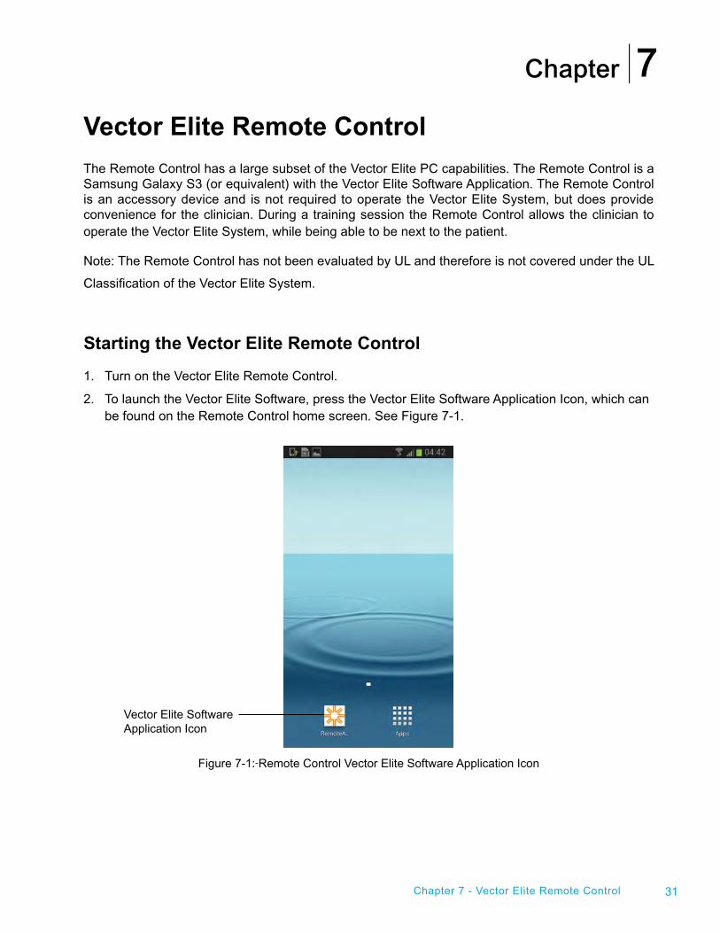
Starting the Vector Elite Remote Control
1. Turn on the Vector Elite Remote Control.
2. To launch the Vector Elite Software, press the Vector Elite Software Application Icon, which can be found on the Remote Control home screen. See Figure 7-1.
Figure 7-1: Remote Control Vector Elite Software Application Icon
7
Vector Elite Software Application Icon
32 Clinician's Guide
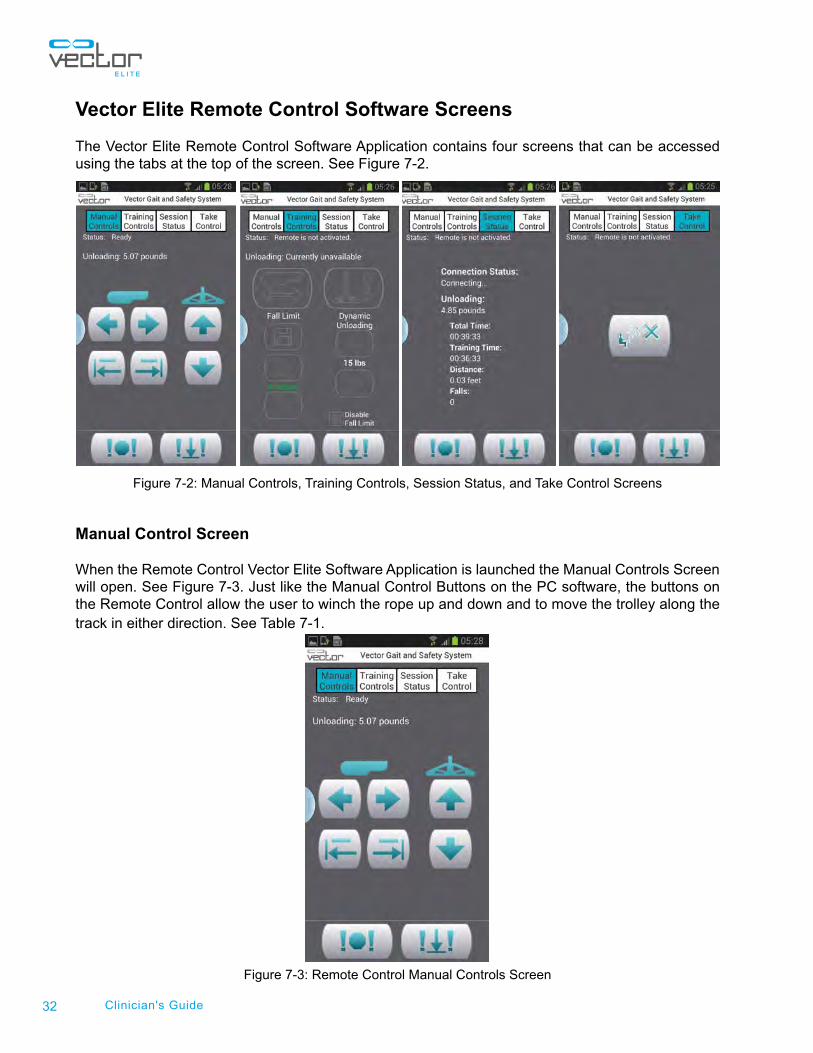
Vector Elite Remote Control Software Screens
The Vector Elite Remote Control Software Application contains four screens that can be accessed using the tabs at the top of the screen. See Figure 7-2.
Figure 7-2: Manual Controls, Training Controls, Session Status, and Take Control Screens
Manual Control Screen
When the Remote Control Vector Elite Software Application is launched the Manual Controls Screen will open. See Figure 7-3. Just like the Manual Control Buttons on the PC software, the buttons on the Remote Control allow the user to winch the rope up and down and to move the trolley along the track in either direction. See Table 7-1.
Figure 7-3: Remote Control Manual Controls Screen
33Chapter 7 - Vector Elite Remote Control
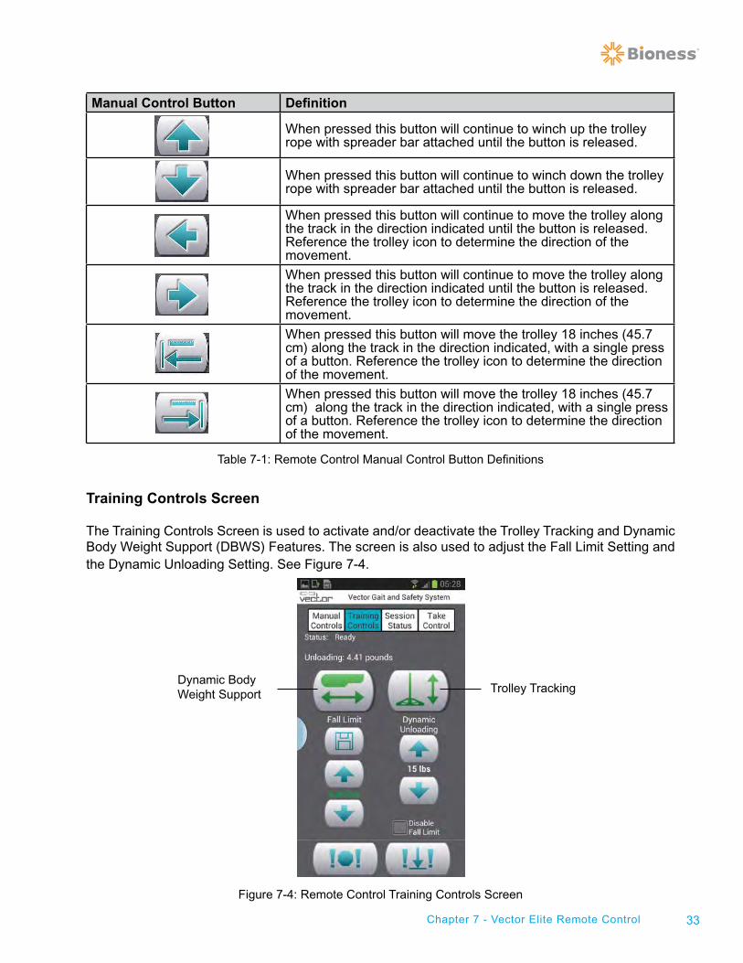
Manual Control Button Definition
When pressed this button will continue to winch up the trolley rope with spreader bar attached until the button is released.
When pressed this button will continue to winch down the trolley rope with spreader bar attached until the button is released.
When pressed this button will continue to move the trolley along the track in the direction indicated until the button is released. Reference the trolley icon to determine the direction of the movement.
When pressed this button will continue to move the trolley along the track in the direction indicated until the button is released. Reference the trolley icon to determine the direction of the movement.
When pressed this button will move the trolley 18 inches (45.7 cm) along the track in the direction indicated, with a single press of a button. Reference the trolley icon to determine the direction of the movement.
When pressed this button will move the trolley 18 inches (45.7 cm) along the track in the direction indicated, with a single press of a button. Reference the trolley icon to determine the direction of the movement.
Table 7-1: Remote Control Manual Control Button Definitions
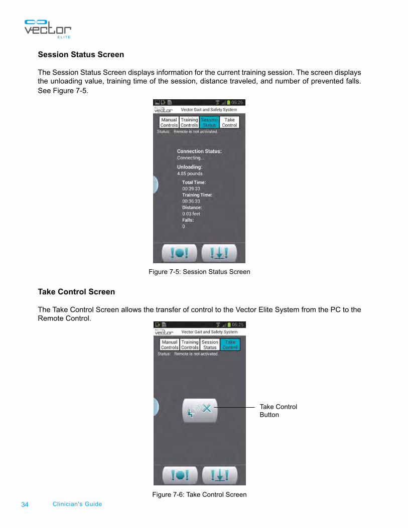
Training Controls Screen
The Training Controls Screen is used to activate and/or deactivate the Trolley Tracking and Dynamic Body Weight Support (DBWS) Features. The screen is also used to adjust the Fall Limit Setting and the Dynamic Unloading Setting. See Figure 7-4.
Figure 7-4: Remote Control Training Controls Screen
Trolley TrackingDynamic Body Weight Support
34 Clinician's Guide
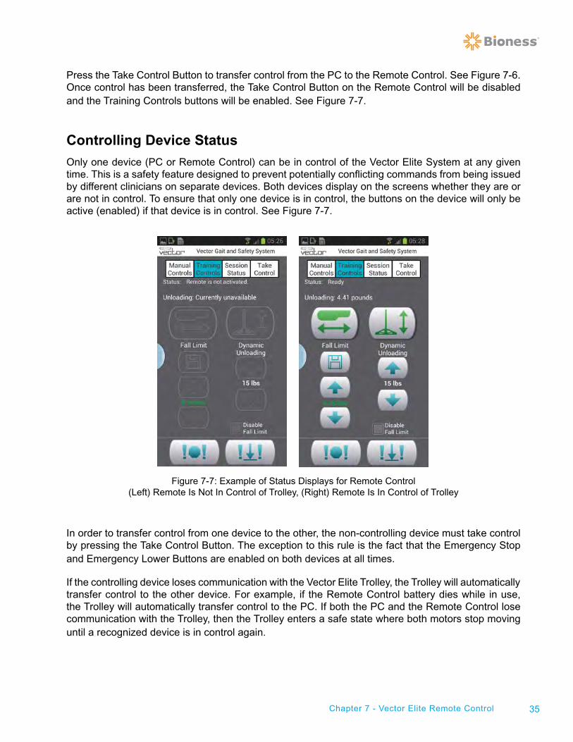
Session Status Screen
The Session Status Screen displays information for the current training session. The screen displays the unloading value, training time of the session, distance traveled, and number of prevented falls. See Figure 7-5.
Figure 7-5: Session Status Screen
Take Control Screen
The Take Control Screen allows the transfer of control to the Vector Elite System from the PC to the Remote Control.
Figure 7-6: Take Control Screen
Take ControlButton
35Chapter 7 - Vector Elite Remote Control
Press the Take Control Button to transfer control from the PC to the Remote Control. See Figure 7-6. Once control has been transferred, the Take Control Button on the Remote Control will be disabled and the Training Controls buttons will be enabled. See Figure 7-7.
Controlling Device Status
Only one device (PC or Remote Control) can be in control of the Vector Elite System at any given time. This is a safety feature designed to prevent potentially conflicting commands from being issued by different clinicians on separate devices. Both devices display on the screens whether they are or are not in control. To ensure that only one device is in control, the buttons on the device will only be active (enabled) if that device is in control. See Figure 7-7.
Figure 7-7: Example of Status Displays for Remote Control (Left) Remote Is Not In Control of Trolley, (Right) Remote Is In Control of Trolley
In order to transfer control from one device to the other, the non-controlling device must take control by pressing the Take Control Button. The exception to this rule is the fact that the Emergency Stop and Emergency Lower Buttons are enabled on both devices at all times.
If the controlling device loses communication with the Vector Elite Trolley, the Trolley will automatically transfer control to the other device. For example, if the Remote Control battery dies while in use, the Trolley will automatically transfer control to the PC. If both the PC and the Remote Control lose communication with the Trolley, then the Trolley enters a safe state where both motors stop moving until a recognized device is in control again.
36 Clinician's Guide
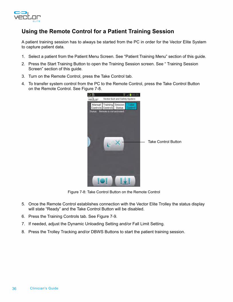
Using the Remote Control for a Patient Training Session
A patient training session has to always be started from the PC in order for the Vector Elite System to capture patient data.
1. Select a patient from the Patient Menu Screen. See “Patient Training Menu” section of this guide.
2. Press the Start Training Button to open the Training Session screen. See “ Training Session Screen” section of this guide.
3. Turn on the Remote Control, press the Take Control tab.
4. To transfer system control from the PC to the Remote Control, press the Take Control Button on the Remote Control. See Figure 7-8.
Figure 7-8: Take Control Button on the Remote Control
5. Once the Remote Control establishes connection with the Vector Elite Trolley the status display will state “Ready” and the Take Control Button will be disabled.
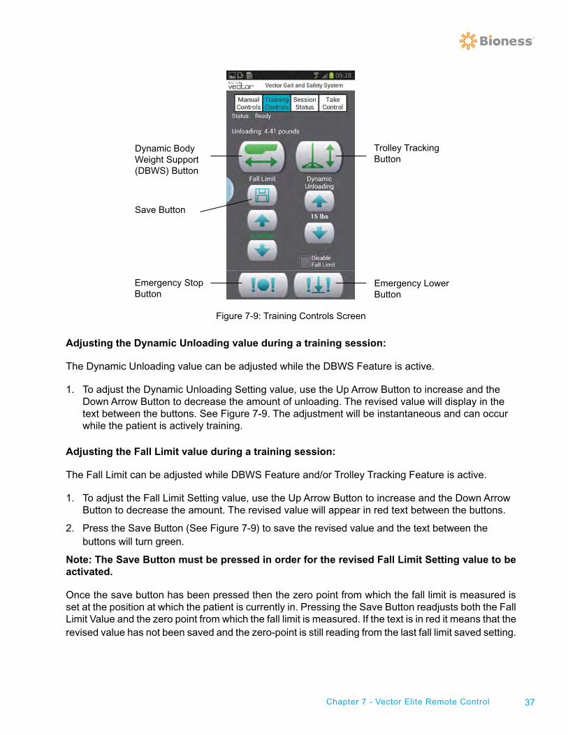
6. Press the Training Controls tab. See Figure 7-9.
7. If needed, adjust the Dynamic Unloading Setting and/or Fall Limit Setting.
8. Press the Trolley Tracking and/or DBWS Buttons to start the patient training session.
Take Control Button
37Chapter 7 - Vector Elite Remote Control
Figure 7-9: Training Controls Screen
Adjusting the Dynamic Unloading value during a training session:
The Dynamic Unloading value can be adjusted while the DBWS Feature is active.
1. To adjust the Dynamic Unloading Setting value, use the Up Arrow Button to increase and the Down Arrow Button to decrease the amount of unloading. The revised value will display in the text between the buttons. See Figure 7-9. The adjustment will be instantaneous and can occur while the patient is actively training.
Adjusting the Fall Limit value during a training session:
The Fall Limit can be adjusted while DBWS Feature and/or Trolley Tracking Feature is active.
1. To adjust the Fall Limit Setting value, use the Up Arrow Button to increase and the Down Arrow Button to decrease the amount. The revised value will appear in red text between the buttons.
2. Press the Save Button (See Figure 7-9) to save the revised value and the text between the buttons will turn green.
Note: The Save Button must be pressed in order for the revised Fall Limit Setting value to be activated.
Once the save button has been pressed then the zero point from which the fall limit is measured is set at the position at which the patient is currently in. Pressing the Save Button readjusts both the Fall Limit Value and the zero point from which the fall limit is measured. If the text is in red it means that the revised value has not been saved and the zero-point is still reading from the last fall limit saved setting.
Trolley TrackingButton
Dynamic Body Weight Support (DBWS) Button
Emergency StopButton
Emergency LowerButton
Save Button
38 Clinician's Guide
Disabling the Fall Limit
The fall limit can also be disabled from the Remote Control.
1. Check the “Disable Fall Limit” Box.
2. Press the Save Button.
3. A window will appear to confirm that the clinician wants to disable the Fall Limit. Press the OK Button.
Caution: Extra precautions should be taken with the patient when the Fall Limit is disabled, due
to the possibility of patient injury.
Emergency Stop and Emergency Lower
At any time the Emergency Stop Button or the Emergency Lower Button can be pressed from the Remote Control. See Figure 7-9. When the Emergency Stop Button is pressed the trolley stops moving and is in a locked position. The system is in a Static Unload mode. When the Emergency Lower Button is pressed the system will continue to winch down the rope until the patient has reached the ground or until the dynamic unload force goes below the minimum unload value.
Using the Remote Control to Operate System without Patient Data
When turning on the Vector Elite System if the Remote Control establishes a connection with the trolley before the PC does then any training data will not be saved. A patient account must be selected in order for training data to be saved to a session summary.
For certain circumstances the user will want to control the Vector Elite System without capturing training data.
1. Turn on the Vector Elite Trolley and then turn on the Remote Control to establish a connection.
2. If the Trolley Tracking and/or DBWS Buttons are pressed, without the PC establishing connection to the trolley, then a warning box stating that “Data is not being saved” will appear. Press the OK Button to proceed with using the Remote Control.
Charging the Remote Control
The Remote Control should be charged daily. Use the supplied AC adaptor and/or the micro USB cable for charging.
Chapter
39Chapter 8 - Multi-Trolley Sync Feature
Multi-Trolley Sync Feature Multi-Trolley configured Vector Elite Systems consist of more than one trolley on the same track and multiple computers. Each computer runs the Vector Elite Software Application, which includes the patient database, and is paired to a specific trolley. The computers are linked to each other through a Wi-Fi router.
The Vector Elite Software Sync Feature is an application that syncs the patient databases from multiple computers. This means that the clinician can access a patient file from any of the computers. This also enables any patient to be trained and have data stored to their patient files using any of the available Vector Elite Trolleys. The databases will automatically sync at least once a day. In order for the computers to automatically sync the clinician must transition to either the Main Menu Screen or to the Vector Login Screen. It is recommended that at the end of the day, on each computer, to transition to the Vector Login Screen for several minutes prior to exiting the Vector Elite Software.
Sync Menu
The clinician can also manually sync the patient databases with the Sync Menu found on the Main Menu Screen.
To Manually Sync the Patient Databases:
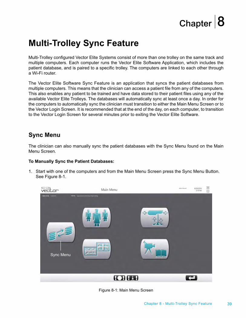
1. Start with one of the computers and from the Main Menu Screen press the Sync Menu Button. See Figure 8-1.
Figure 8-1: Main Menu Screen
8
Sync Menu
40 Clinician's Guide
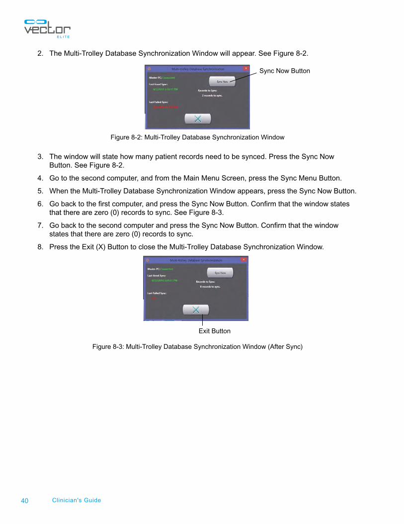
2. The Multi-Trolley Database Synchronization Window will appear. See Figure 8-2.
Figure 8-2: Multi-Trolley Database Synchronization Window
3. The window will state how many patient records need to be synced. Press the Sync Now Button. See Figure 8-2.
4. Go to the second computer, and from the Main Menu Screen, press the Sync Menu Button.
5. When the Multi-Trolley Database Synchronization Window appears, press the Sync Now Button.
6. Go back to the first computer, and press the Sync Now Button. Confirm that the window states that there are zero (0) records to sync. See Figure 8-3.
7. Go back to the second computer and press the Sync Now Button. Confirm that the window states that there are zero (0) records to sync.
8. Press the Exit (X) Button to close the Multi-Trolley Database Synchronization Window.
Figure 8-3: Multi-Trolley Database Synchronization Window (After Sync)
Exit Button
Sync Now Button
Chapter
41Chapter 9 - Vector Elite Software Administrator Menu
Vector Elite Software Administrator Menu The administrator has a higher level of privileges within the Vector Elite software. Administrator privileges include:
• Managing the Patient Database
• Managing User Accounts (create and close accounts)
• Data Backup and Restore
• Troubleshooting
• System Settings
Accessing the Administrator Menu
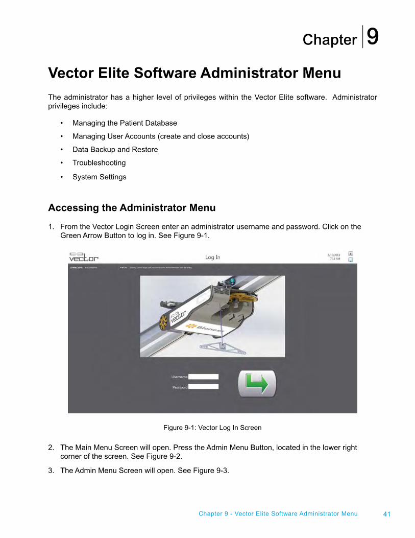
1. From the Vector Login Screen enter an administrator username and password. Click on the Green Arrow Button to log in. See Figure 9-1.
Figure 9-1: Vector Log In Screen
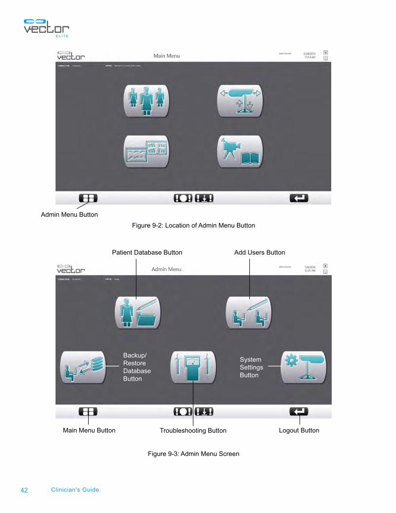
2. The Main Menu Screen will open. Press the Admin Menu Button, located in the lower right corner of the screen. See Figure 9-2.
3. The Admin Menu Screen will open. See Figure 9-3.
9
42 Clinician's Guide
Figure 9-2: Location of Admin Menu Button
Figure 9-3: Admin Menu Screen
Admin Menu Button
Patient Database Button
System SettingsButton
Troubleshooting Button
Add Users Button
Logout ButtonMain Menu Button
Backup/Restore Database Button
43Chapter 9 - Vector Elite Software Administrator Menu
Admin Menu
The Vector Elite Admin Menu Screen has five menu options, that appear as Icon Buttons on the Admin Menu Screen. See Figure 9-3.
Admin Menu Options:
• Patient Database Menu
• Add Users Menu
• Backup/Restore Database Menu
• System Settings Menu
Patient Database Menu
The Patient Database Menu is used to manage patient records.
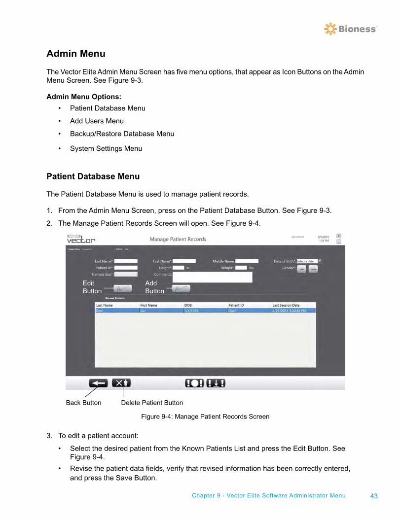
1. From the Admin Menu Screen, press on the Patient Database Button. See Figure 9-3.
2. The Manage Patient Records Screen will open. See Figure 9-4.
Figure 9-4: Manage Patient Records Screen
3. To edit a patient account:
• Select the desired patient from the Known Patients List and press the Edit Button. See Figure 9-4.
• Revise the patient data fields, verify that revised information has been correctly entered, and press the Save Button.
Edit Button
Delete Patient ButtonBack Button
Add Button
44 Clinician's Guide
4. To create a new patient account:
• Press the Add Button (See Figure 9-4).
• Fill in the required patient data fields. Required fields have an asterix (*) next to it. Verify that all information has been correctly entered.
• Press the Save Button.
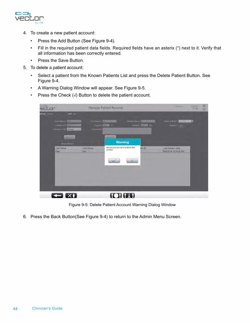
5. To delete a patient account:
• Select a patient from the Known Patients List and press the Delete Patient Button. See Figure 9-4.
• A Warning Dialog Window will appear. See Figure 9-5.
• Press the Check (√) Button to delete the patient account.
Figure 9-5: Delete Patient Account Warning Dialog Window
6. Press the Back Button(See Figure 9-4) to return to the Admin Menu Screen.
45Chapter 9 - Vector Elite Software Administrator Menu
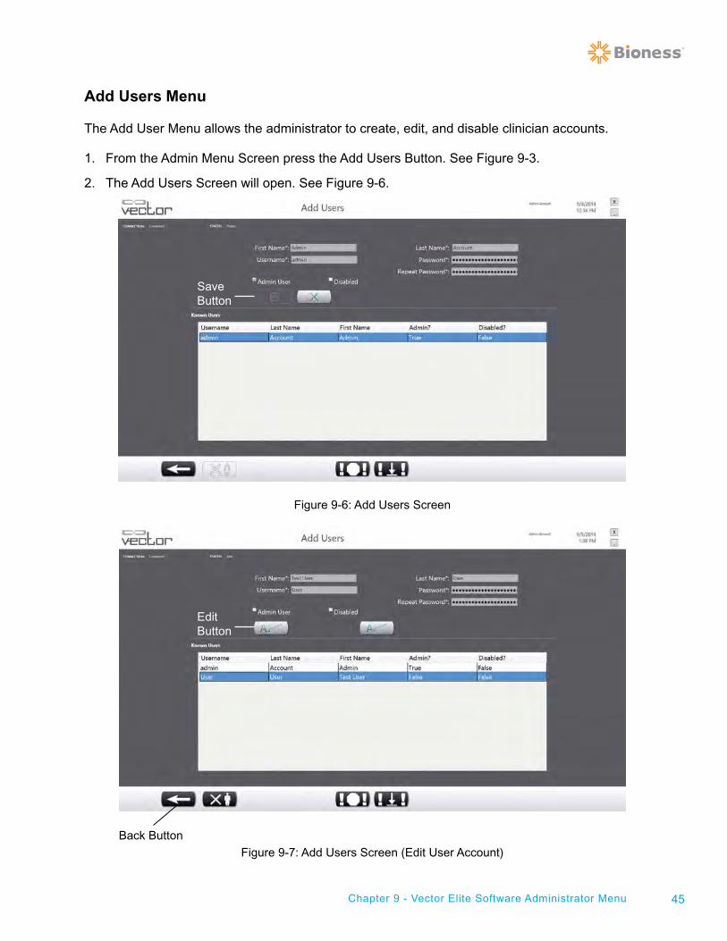
Add Users Menu
The Add User Menu allows the administrator to create, edit, and disable clinician accounts.
1. From the Admin Menu Screen press the Add Users Button. See Figure 9-3.
2. The Add Users Screen will open. See Figure 9-6.
Figure 9-6: Add Users Screen
Figure 9-7: Add Users Screen (Edit User Account)
Edit Button
Back Button
SaveButton
46 Clinician's Guide
3. To create a new user account:
• Enter data in all fields with an asteric (*). This is when the username and passwords are set for each user account.
• Press the Save Button. See Figure 9-6.
4. To edit a user account:
• Select the clinician's name from the Known Users List.
• Press the Edit Button. See Figure 9-7.
• Make revisions to the data fields.
• Press the Save Button.
5. To disable a user account:
• Select the clinician's name from the Known Users List.
• Press the Edit Button. See Figure 9-7
• Check the box next to “Disabled”.
• Press the Save button.
6. Press the Back Button(See Figure 9-7) to return to the Admin Menu Screen.
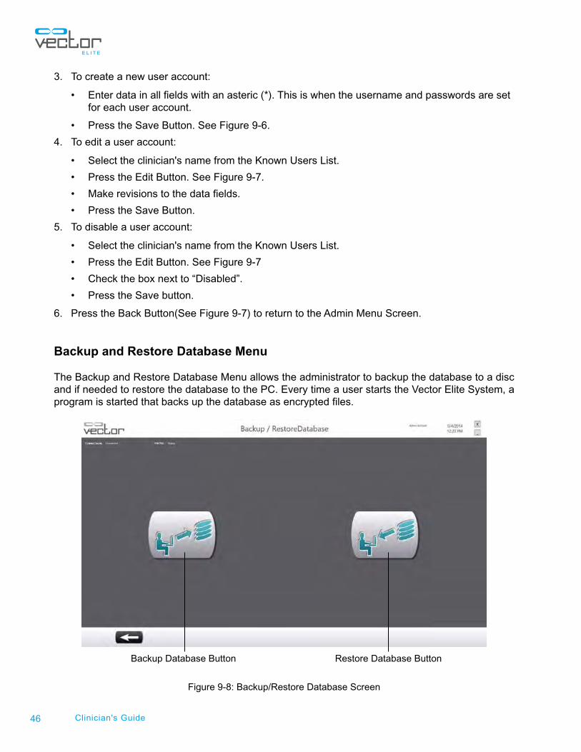
Backup and Restore Database Menu
The Backup and Restore Database Menu allows the administrator to backup the database to a disc and if needed to restore the database to the PC. Every time a user starts the Vector Elite System, a program is started that backs up the database as encrypted files.
Figure 9-8: Backup/Restore Database Screen
Backup Database Button Restore Database Button
47Chapter 9 - Vector Elite Software Administrator Menu
To Backup the System to a Disc:
1. From the Admin Menu Screen press the Backup/Restore Database Button. See Figure 9-3.
2. The Backup/Restore Menu Screen will open. See Figure 9-8.
3. Press the Backup Database Button to backup the system database onto a disc or external hard drive. See Figure 9-8.
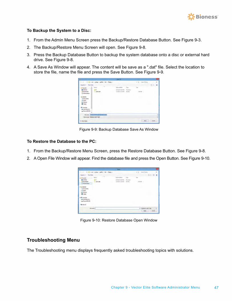
4. A Save As Window will appear. The content will be save as a ".dat" file. Select the location to store the file, name the file and press the Save Button. See Figure 9-9.
Figure 9-9: Backup Database Save As Window
To Restore the Database to the PC:
1. From the Backup/Restore Menu Screen, press the Restore Database Button. See Figure 9-8.
2. A Open File Window will appear. Find the database file and press the Open Button. See Figure 9-10.
Figure 9-10: Restore Database Open Window
Troubleshooting Menu
The Troubleshooting menu displays frequently asked troubleshooting topics with solutions.
48 Clinician's Guide
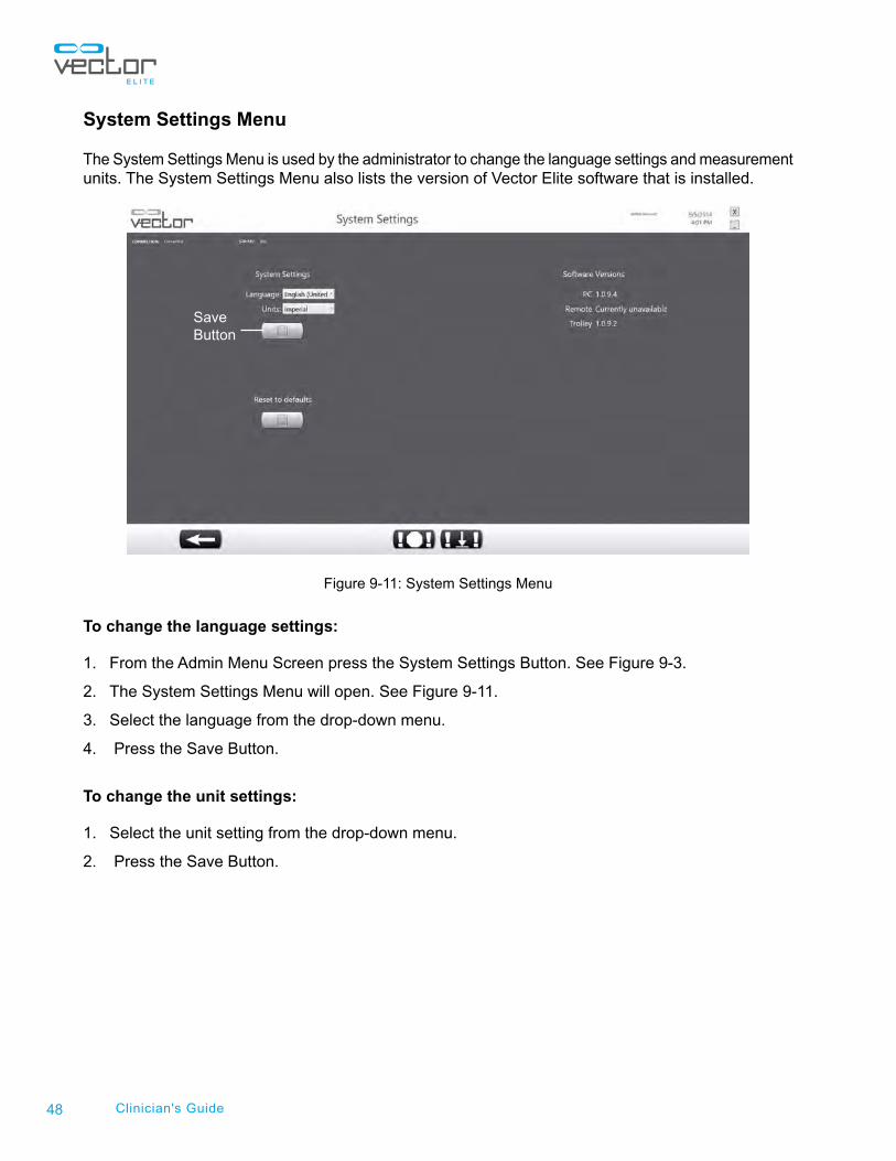
System Settings Menu
The System Settings Menu is used by the administrator to change the language settings and measurement units. The System Settings Menu also lists the version of Vector Elite software that is installed.
Figure 9-11: System Settings Menu
To change the language settings:
1. From the Admin Menu Screen press the System Settings Button. See Figure 9-3.
2. The System Settings Menu will open. See Figure 9-11.
3. Select the language from the drop-down menu.
4. Press the Save Button.
To change the unit settings:
1. Select the unit setting from the drop-down menu.
2. Press the Save Button.
SaveButton
Chapter
49
Troubleshooting Troubleshooting Wi-Fi Connection Issues
Before attempting to troubleshoot a Wi-Fi connection issue, make sure the Vector Elite Trolley is powered on. Wi-Fi connection will not be available until the trolley has fully initialized. Refer to the "Starting the Vector Elite System and Software" chapter in this guide for more information. Additionally make sure that the PC and Remote Control are within range of the Vector Elite Trolley. The PC and Remote Control need to be within 20 feet (6 meters) of the Vector Elite Trolley for proper Wi-Fi connection.
Troubleshooting PC Wi-Fi Connection Issues
For Single Trolley Configured Systems:
1. Press on the wireless network icon located on the PC status bar.
2. From the list of wireless networks, select the "VectorXXXX" WiFi network. The "XXXX" will be the serial number of the Vector Elite Trolley.
3. Recheck the Connect Automatically box and then press on the Connect button. The PC will then connect to the Vector Wi-Fi network.
Note: If the VectorXXXX Wi-Fi network does not appear on the wireless network list, then check to make sure the wireless adapter is properly connected to the PC. Look at the back of the wireless adapter in the USB slot, it should be slowly flashing. If it is not flashing reconnect it to the PC and repeat steps 2-3.
For Multi-Trolley Configured Systems:
1. Press on the wireless network icon located on the PC status bar.
2. From the list of wireless networks, under the "Wi-Fi" list, select the "VectorRouter_MT2G" network.
3. Recheck the Connect Automatically box and then press on the Connect button.
4. From the list of wireless networks, under the "Vector" list, select the "VectorXXXX-PC" network. The "XXXX" will be the serial number of the Vector Elite Trolley.
5. Recheck the Connect Automatically box and then press on the Connect button.
Note: If the "VectorRouter_MT2G" Wi-Fi network does not appear on the wireless network list, then check to make sure the separate Wi-Fi Router is plugged into a power strip and turned on.
Troubleshooting Remote Control Wi-Fi Connection Issues
1. From the Remote Control home screen pull down the icon bar to the middle of the screen to display the common settings.
2. Press on the Wi-Fi icon (hold down for several seconds).
3. From the list of wireless networks, select the "VectorXXXX" Wi-Fi network.
Chapter 10 - Troublehooting
10
50 Clinician's Guide
Elite Trolley Light Indicators
The Vector Elite Trolley has a indicator light located on the posterior of the trolley body. Refer to Table 10-1 for indicator light descriptions.
Light Description Meaning Solution
Green Light Power is on and the Vector Elite system started properly
N/A
Red Light The Vector Elite Trolley has detected a safety relay and goes into safe mode.
The Vector Elite System requires power cycling to reboot: • Turn the power off• Turn the power back on• Restart the Vector Elite Software Application
Table 10-1: Vector Elite Trolley Indicator Lights
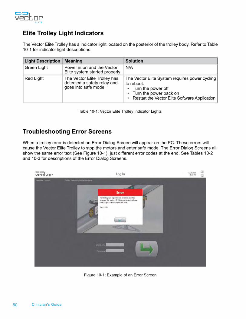
Troubleshooting Error Screens
When a trolley error is detected an Error Dialog Screen will appear on the PC. These errors will cause the Vector Elite Trolley to stop the motors and enter safe mode. The Error Dialog Screens all show the same error text (See Figure 10-1), just different error codes at the end. See Tables 10-2 and 10-3 for descriptions of the Error Dialog Screens.
Figure 10-1: Example of an Error Screen
51
Error Screen Description of Error Solution
#50A non-specific error has occurred on the trolley
• Close the error dialog screen• Retry the action
If the error dialog screen occurs again then the Vector Elite System requires power cycling to reboot:• Turn the power off• Turn the power back on• Restart the Vector Elite software application
If the error dialog screen occurs again after rebooting then stop using the system and call Bioness at (800) 211-9136, option 3 (in the United States) or your local distributor (outside of the United States) for a service appointment.
#55A non-specific error has occurred on the trolley
#81Trolley firmware has had an error
#87 Watchdog has had an error
#92 WiFi interlock has had an error
#90Internal networking on the trolley has had an error
#98 Trolley servo has had an error
#99 Winch servo has had an error
#88Winch motor controller has had an error
#89Trolley motor controller has had an error
Table 10-2: Error Screen Descriptions
Error Screen Description of Error Solution
#56A non-specific error has occurred on the trolley
The Vector Elite System requires power cycling to reboot: • Turn the power off• Turn the power back on• Restart the Vector Elite software application
#93 Contactor has had an error
#94 Hardware interlock for the winch has tripped
Table 10-3: Additional Error Screen Descriptions
Chapter 10 - Troublehooting

52 Clinician's Guide
Chapter
53Chapter 11 - Service and Maintenance
Service and Maintenance Routine maintenance is critical for the safety and effectiveness of this device.
Check the following items before each use of the Vector Elite System:
• Inspect the Trolley Rope. If the Rope is worn, frayed or damaged call Bioness at (800) 211- 9136, Option 3 (in the United States) or your local distributor (outside of the United States) for a service appointment to replace the Trolley Rope.
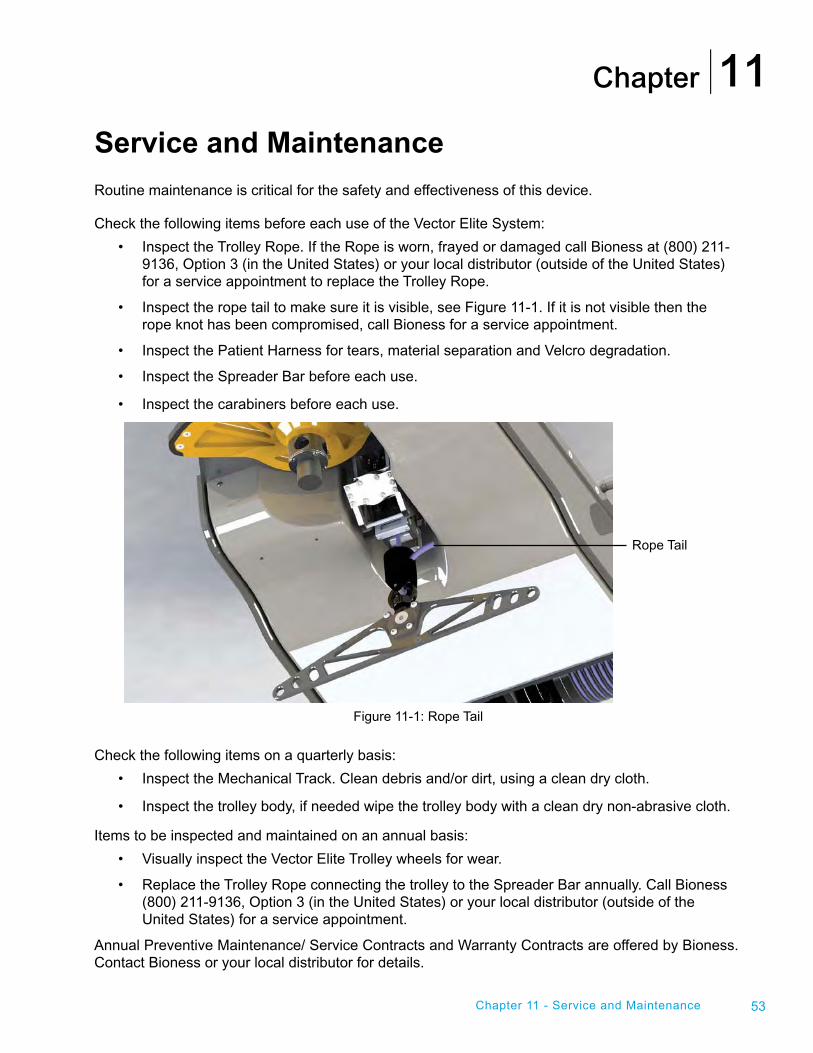
• Inspect the rope tail to make sure it is visible, see Figure 11-1. If it is not visible then the rope knot has been compromised, call Bioness for a service appointment.
• Inspect the Patient Harness for tears, material separation and Velcro degradation.
• Inspect the Spreader Bar before each use.
• Inspect the carabiners before each use.
Figure 11-1: Rope Tail
Check the following items on a quarterly basis:
• Inspect the Mechanical Track. Clean debris and/or dirt, using a clean dry cloth.
• Inspect the trolley body, if needed wipe the trolley body with a clean dry non-abrasive cloth.
Items to be inspected and maintained on an annual basis:
• Visually inspect the Vector Elite Trolley wheels for wear.
• Replace the Trolley Rope connecting the trolley to the Spreader Bar annually. Call Bioness (800) 211-9136, Option 3 (in the United States) or your local distributor (outside of the United States) for a service appointment.
Annual Preventive Maintenance/ Service Contracts and Warranty Contracts are offered by Bioness. Contact Bioness or your local distributor for details.
11
Rope Tail
54 Clinician's Guide
Cleaning the Patient Harness
Cleaning Instructions:
1. Hand wash the Patient Harness in cold water.
2. Hang dry (do not place harness in the dryer).
3. Do not iron the Patient Harness.
4. Machine washing may occasionally be performed. Place the entire Patient Harness in a mesh washing net and wash in warm water. The water temperature should not exceed 90°F (32°C). Use a mild or moderate disinfecting detergent.
PC Disk Storage Space Maintenance
The disk space on the PC should be checked once a month. It is recommended that there is at least 50 GB of free space available.
To check the PC for Disk Storage Space:
1. Bring up the Windows 8 File Explorer (formally known as Windows Explorer in Windows 7 and XP) by simultaneously pressing the Windows key and E key.
2. Click on the Computer icon on the left panel. On the right panel, it will show the disk usage. Verify that there is at least 50 GB available.
To Clear Disk Storage Space on the PC:
If there is less than 50 GB of free disk space available on the PC, data in the backup folder will need to be deleted in order to clear disk storage space. The backup folder contains backed up copies of the working data. It is recommended to remove the files that are older than several months old from the backup folder.
1. Connect an external drive to the PC.
2. Browse to the following location - C:Desktop/vector/AppData/Local/Bioness/Vector/Backups folder.
3. Open the Backups folder and sort the folder based on date by clicking on the ”Date modified” column heading.
4. Select the files to be backed up.
5. Right click on the selected files and select “Cut” menu item.
6. Browse to the destination external drive folder, and Right Click and select “Paste” menu item.
7. Repeat steps 4-6 for other folders that may have grown, such as .csv exports from the Vector Software Application.

Chapter
55Chapter 12 - Technical Specifications
Technical Specifications
Vector Elite System Technical Specifications
Trolley Dimensions 36 inches (91.4 cm) long, 25 inches (63.5 cm)wide, and 11 inches (27.9 cm) tall
Trolley Material Cover is ABS V0 plastic, base is Aluminum grade 60601-T6
Trolley Patient Weight Limit 400 lbs (181.4 kg)
Trolley Rope Material 8mm diameter HMPE (High Modulus Polyethylene)
Spreader Bar Material Anodized Aluminum
Environmental conditions for operation Temperature Range :15C to 35CAtmospheric Pressure Range: up to 80kPaRelative Humidity range: 20% to 60%.
Environmental conditions for transport and storage
Temperature Range :-25C to 70CAtmospheric Pressure Range: up to 67kPaRelative Humidity range: 5% to 95%
Electrical Requirements for Single Trolley Configured System
110/120VAC, 20A, 50/60Hz or 220/240VAC, 10A
50/60Hz dedicated circuit
Outlet must be capable of delivering 1.8kW
Electrical Requirements for Multi-Trolley Configured System
210/240VAC, 20A
50/60Hz dedicated circuit
Outlet must be capable of delivering 3.0kW The system consists of mechanical and electronic components. Inadequate handling of those components may cause health hazards. Disposal of the system must comply with local regulations.
12

Manufacturer:Bioness Inc.25103 Rye Canyon LoopValencia, CA 91355 USATelephone: 800.211.9136 or 661.362.4850Email: [email protected]: www.bioness.com
European Authorized Representative:NESS Europe B.V. Stationsweg 413331 LR Zwijndrecht, The NetherlandsTelephone: +31.78.625.6088 Email: [email protected]: www.bioness.com
612-00624-001 Rev. C09/2014
Vector Gait and Safety SystemTM, Bioness, the Bioness Logo®, and LiveOn® are registered trademarks of Bioness Inc. in the United States or other countries | www.bioness.com
©2014 Bioness Inc.All Rights Reserved
No part of this publication may be reproduced, transmitted, transcribed, stored in a retrieval system, or translated into any language or any computer language, in any form or by any third party, without the prior written permission of Bioness Inc. DisclaimerBioness Inc and its affiliates shall not be liable for any injury or damage suffered by any person, either directly or indirectly, as a result of the unauthorized use or repair of Bioness Inc products. Bioness Inc and its affiliates do not accept any responsibility for any damage caused to its products, either directly or indirectly, as a result of use and/or repair by unauthorized personnel.
![Florida Star. (Titusville, Florida) 1902-05-02 [p 4].ufdcimages.uflib.ufl.edu/UF/00/07/59/01/00624/00232.pdf · 2009-05-13 · introduction attended company Grapefruit FLORIDA-TAX](https://img.pdfslide.us/doc/110x75/5f26c377b1eae71d3a2114c5/florida-star-titusville-florida-1902-05-02-p-4-2009-05-13-introduction.jpg)


![HP Image Zone Print Job [30/05/2011 11:57 a.m. 50.763]€¦ · 2=con aportes recibidos 001-00334 001-00352 30680 0002-0167 001-00332 001-00353 005/00624 005/00624 001-00987 001-00352](https://img.pdfslide.us/doc/110x75/6060b542aad1f344a16ebf41/hp-image-zone-print-job-30052011-1157-am-50763-2con-aportes-recibidos-001-00334.jpg)