Embed Size (px)
Citation preview
Climate change, fuel burn targets and
the options and limitations facing the
designer
J E Green
Aircraft Research Association
UTIAS Workshop on Aviation and Climate Change
Toronto 27-28 May 2010
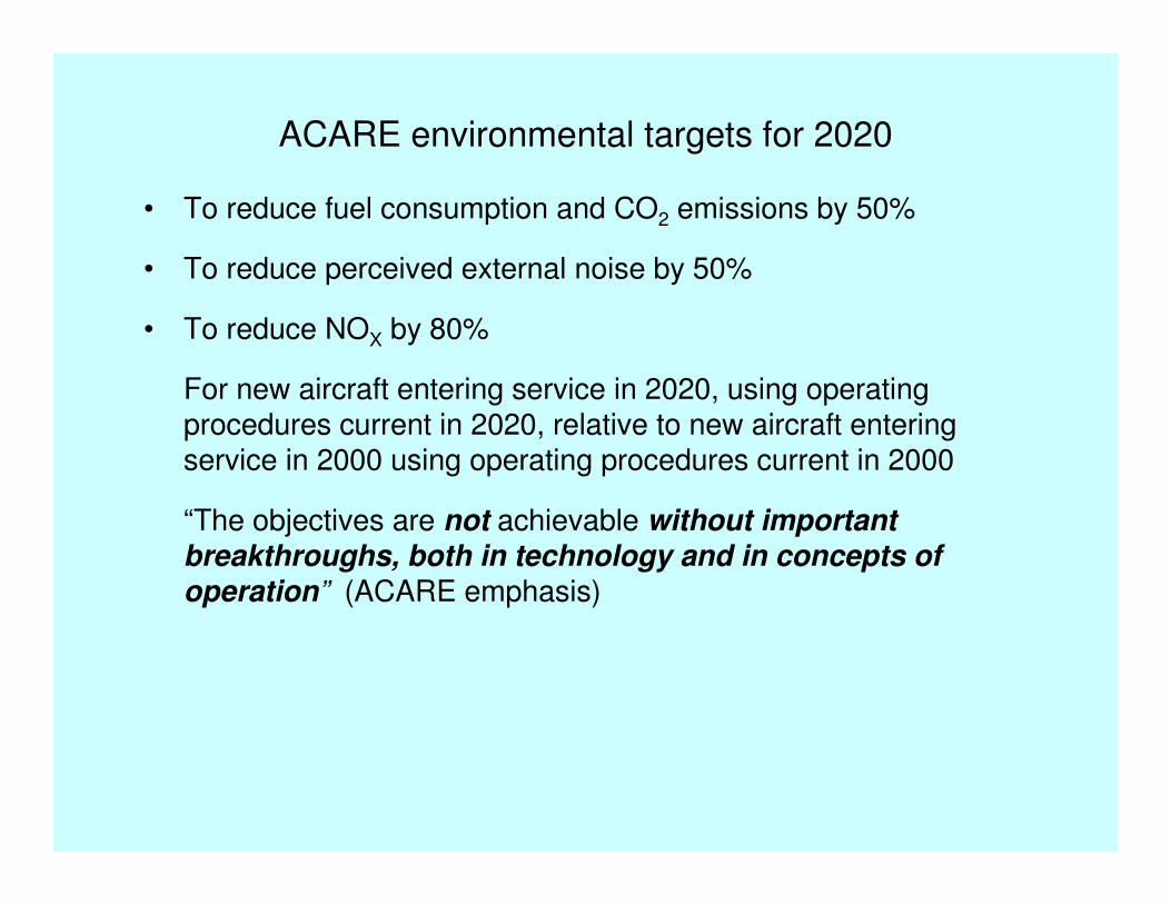
ACARE environmental targets for 2020
• To reduce fuel consumption and CO2 emissions by 50%
• To reduce perceived external noise by 50%
• To reduce NOX by 80%
For new aircraft entering service in 2020, using operating procedures current in 2020, relative to new aircraft entering service in 2000 using operating procedures current in 2000
“The objectives are not achievable without important
breakthroughs, both in technology and in concepts of
operation” (ACARE emphasis)
Climate priorities – NOX, contrail/cirrus, CO2
• Impact of NOx at altitude can be reduced substantially by advances in combustor technology
• Impact of contrails and contrail-induced cirrus can be reduced substantially by operational measures to reduce flight through ice-saturated regions
• Because of its longevity and the difficulty of reducing its emission, CO2 is the main environmental challenge to aviation
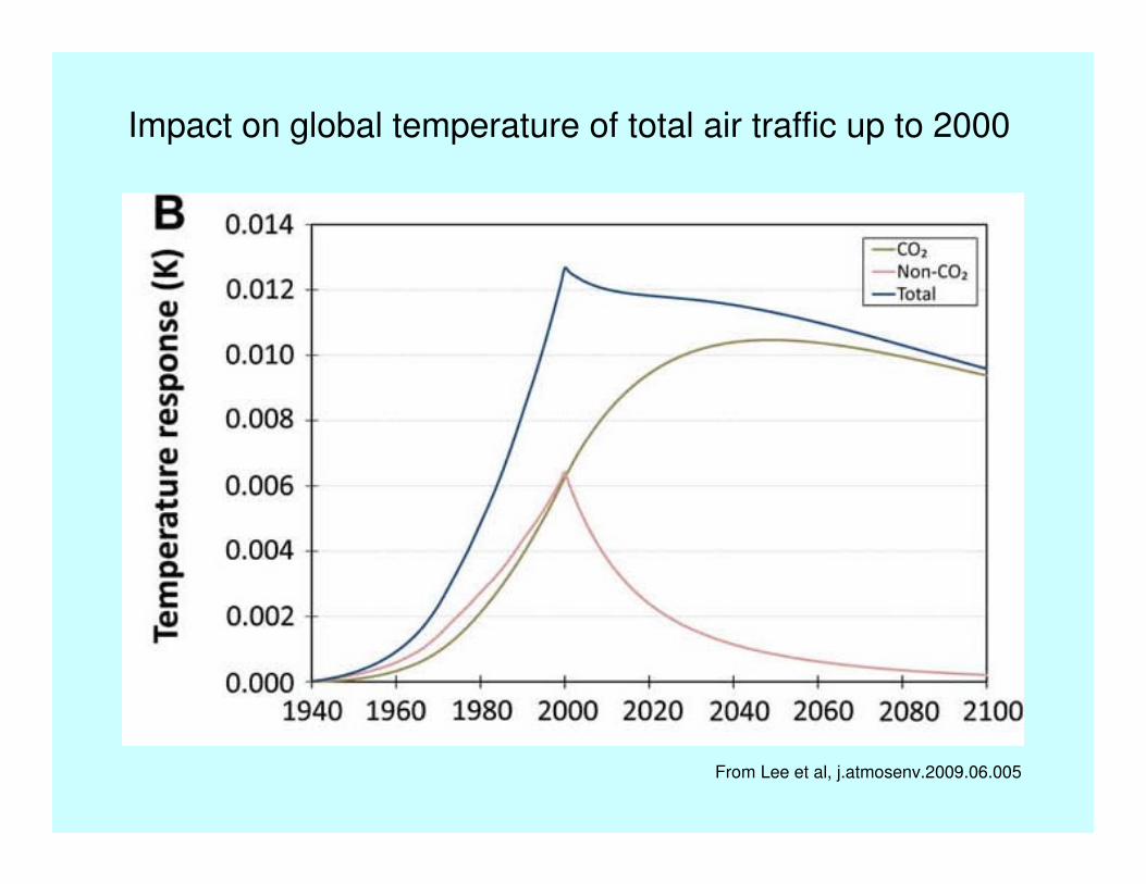
Impact on global temperature of total air traffic up to 2000
From Lee et al, j.atmosenv.2009.06.005

Distribution by stage length of world fuel burn in 2000 (Aero 2K)
0.00
2.00
4.00
6.00
8.00
10.00
12.00
14.00
16.00
0-50
050
0-10
0010
00-1
500
1500
-200
020
00-2
500
2500
-300
030
00-3
500
3500
-400
040
00-4
500
4500
-500
050
00-5
500
5500
-600
060
00-6
500
6500
-700
070
00-7
500
7500
-800
080
00-8
500
8500
-900
090
00-9
500
9500
-100
00
1000
0-10
500
1050
0-11
000
1100
0-11
500
1150
0-12
000
1200
0-12
500
1250
0-13
000
1300
0-13
500
1350
0-14
000
1400
0-14
500
1450
0-15
000
1500
0-15
500
1550
0-16
000
Range (km)
% t
ota
l w
orl
d f
uel bu
rn
Options for reducing CO2 emissions
• Operational measures – SESAR and NextGen
• Reduce ratio of empty weight to payload
• Increase propulsive efficiency
• Increase L/D in cruise
• Biokerosine

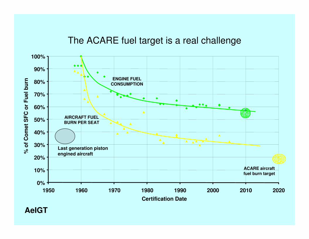
The ACARE fuel target is a real challenge
0%
10%
20%
30%
40%
50%
60%
70%
80%
90%
100%
1950 1960 1970 1980 1990 2000 2010 2020
Certification Date
% o
f C
om
et
SF
C o
r F
uel b
urn
ENGINE FUEL
CONSUMPTION
ACARE aircraft fuel burn target
AIRCRAFT FUEL
BURN PER SEAT
AeIGT
The ACARE fuel target is a real challenge
0%
10%
20%
30%
40%
50%
60%
70%
80%
90%
100%
1950 1960 1970 1980 1990 2000 2010 2020
Certification Date
% o
f C
om
et
SF
C o
r F
uel b
urn
ENGINE FUEL
CONSUMPTION
ACARE aircraft fuel burn target
AIRCRAFT FUEL
BURN PER SEAT
AeIGT
Last generation piston engined aircraft
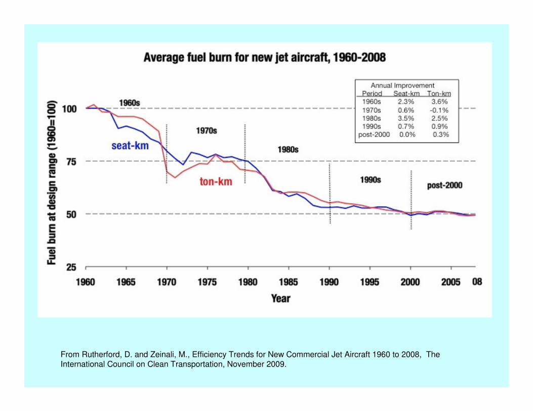
From Rutherford, D. and Zeinali, M., Efficiency Trends for New Commercial Jet Aircraft 1960 to 2008, The
International Council on Clean Transportation, November 2009.
Fuel burn limits – there is no escape from:
• The Breguet Range Equation
• The Second Law of Thermodynamics
• The stoichiometric limit
• Lanchester-Prandtl formula for induced drag
• Laminar boundary layer stability equations
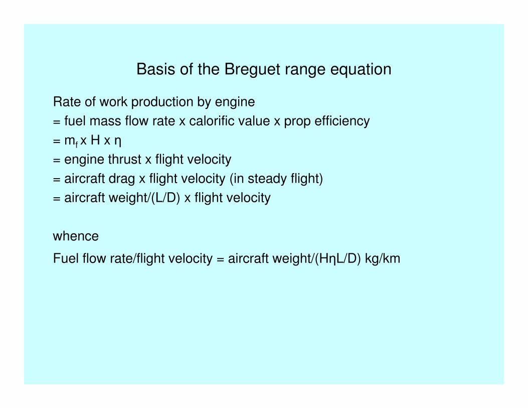
Basis of the Breguet range equation
Rate of work production by engine
= fuel mass flow rate x calorific value x prop efficiency
= mf x H x η
= engine thrust x flight velocity
= aircraft drag x flight velocity (in steady flight)
= aircraft weight/(L/D) x flight velocity
whence
Fuel flow rate/flight velocity = aircraft weight/(HηL/D) kg/km
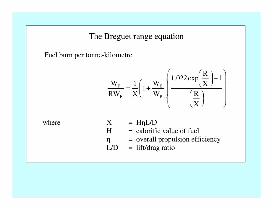
The Breguet range equation
Fuel burn per tonne-kilometre
−
+=
X
R
1X
Rexp022.1
W
W1
X
1
RW
W
P
E
P
F
where X = HηL/D
H = calorific value of fuel
η = overall propulsion efficiency
L/D = lift/drag ratio

0.8
0.9
1
1.1
1.2
1.3
1.4
1.5
1.6
0 2000 4000 6000 8000 10000 12000 14000 16000
Design range km
GBD corr
Poll 3
Poll 2
Poll 1
Weight ratio = (1+We/Wp)/zero range(1+We/Wp)
Effect of design range on weight ratio
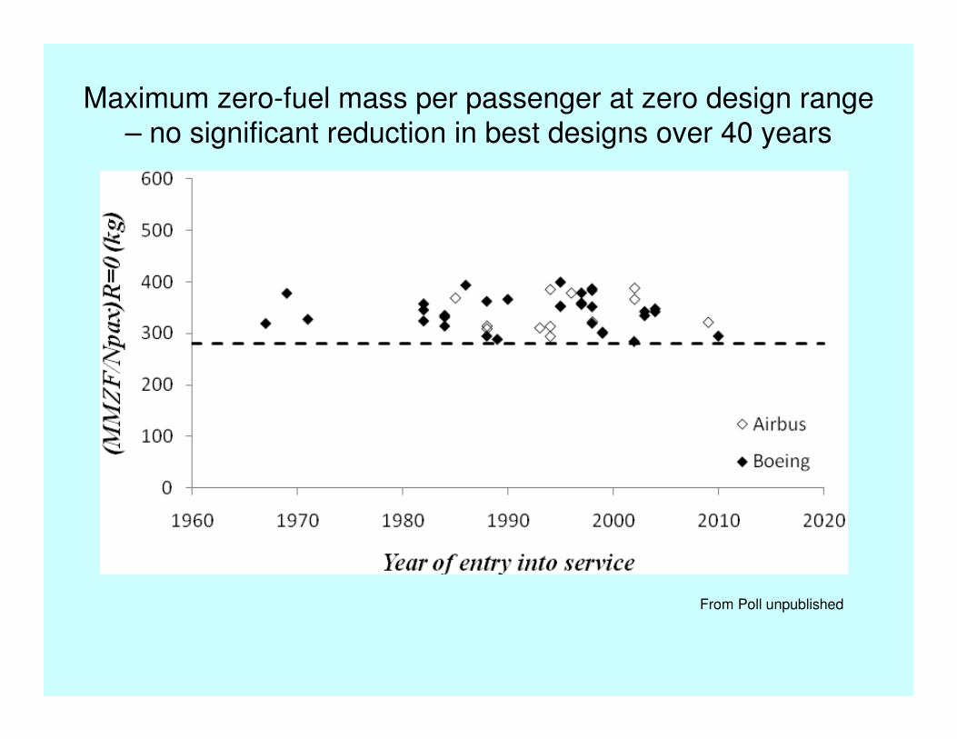
Maximum zero-fuel mass per passenger at zero design range – no significant reduction in best designs over 40 years
From Poll unpublished

The Breguet range equation
Fuel burn per tonne-kilometre
−
+=
X
R
1X
Rexp022.1
W
W1
X
1
RW
W
P
E
P
F
where X = HηL/D
H = calorific value of fuel
η = overall propulsion efficiency
L/D = lift/drag ratio
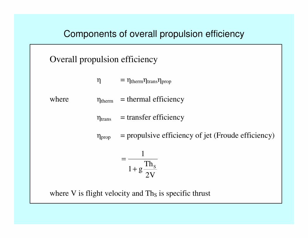
Components of overall propulsion efficiency
Overall propulsion efficiency
η = ηthermηtransηprop
where ηtherm = thermal efficiency
ηtrans = transfer efficiency
ηprop = propulsive efficiency of jet (Froude efficiency)
V2
Thg1
1
S+
=
where V is flight velocity and ThS is specific thrust
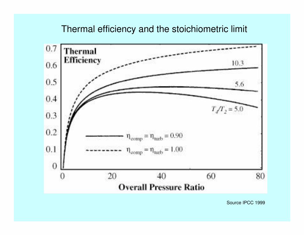
Thermal efficiencyThermal efficiency
Thermal efficiency and the stoichiometric limit
Source IPCC 1999
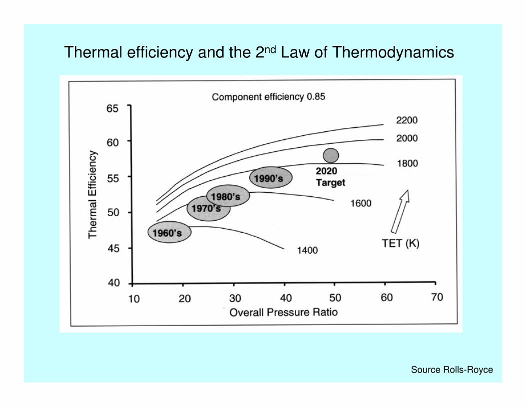
Thermal efficiency and the 2nd Law of Thermodynamics
Source Rolls-Royce
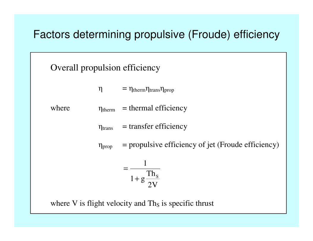
Factors determining propulsive (Froude) efficiency
Overall propulsion efficiency
η = ηthermηtransηprop
where ηtherm = thermal efficiency
ηtrans = transfer efficiency
ηprop = propulsive efficiency of jet (Froude efficiency)
V2
Thg1
1
S+
=
where V is flight velocity and ThS is specific thrust
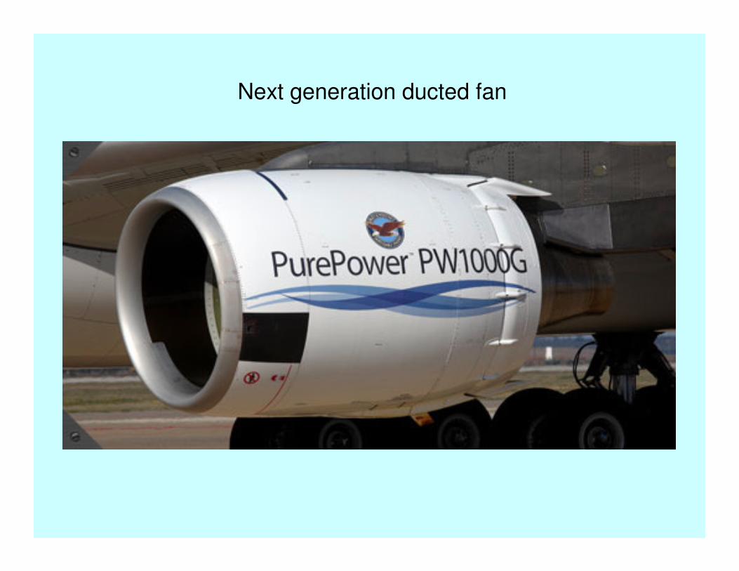
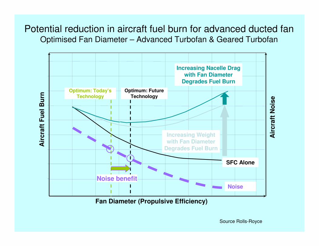
Next generation ducted fan
Air
cra
ft F
uel
Bu
rn
Fan Diameter (Propulsive Efficiency)
Air
cra
ft N
ois
e
SFC Alone
Increasing Nacelle Drag with Fan Diameter
Degrades Fuel Burn
Increasing Weight with Fan Diameter
Degrades Fuel Burn
Noise
Optimum: Today’s Technology
Optimum: Future Technology
Noise benefit
Potential reduction in aircraft fuel burn for advanced ducted fan Optimised Fan Diameter – Advanced Turbofan & Geared Turbofan
Source Rolls-Royce
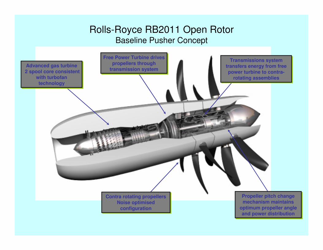
Advanced gas turbine2 spool core consistent
with turbofan technology
Advanced gas turbine2 spool core consistent
with turbofan technology
Transmissions system transfers energy from free power turbine to contra-
rotating assemblies
Transmissions system transfers energy from free power turbine to contra-
rotating assemblies
Contra rotating propellersNoise optimised
configuration
Contra rotating propellersNoise optimised
configuration
Propeller pitch change mechanism maintains
optimum propeller angle and power distribution
Propeller pitch change mechanism maintains
optimum propeller angle and power distribution
Free Power Turbine drives propellers through
transmission system
Free Power Turbine drives propellers through
transmission system
Rolls-Royce RB2011 Open RotorBaseline Pusher Concept
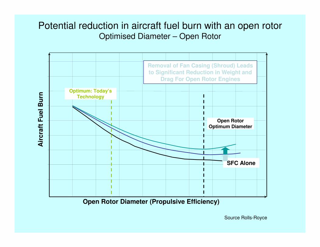
Air
cra
ft F
uel
Bu
rn
Open Rotor Diameter (Propulsive Efficiency)
SFC Alone
Optimum: Today’s Technology
Open Rotor Optimum Diameter
Removal of Fan Casing (Shroud) Leads to Significant Reduction in Weight and
Drag For Open Rotor Engines
Potential reduction in aircraft fuel burn with an open rotorOptimised Diameter – Open Rotor
Source Rolls-Royce
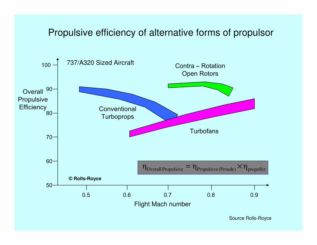
50
60
70
80
90
100
Overall PropulsiveEfficiency
0.5 0.6 0.7 0.8 0.9
Conventional Turboprops
Contra – Rotation Open Rotors
Turbofans
737/A320 Sized Aircraft
propeller(Froude) PropulsivePropulsive Overall ηηη ×=
Flight Mach number
© Rolls-Royce
Propulsive efficiency of alternative forms of propulsor
Source Rolls-Royce

The Breguet range equation
Fuel burn per tonne-kilometre
−
+=
X
R
1X
Rexp022.1
W
W1
X
1
RW
W
P
E
P
F
where X = HηL/D
H = calorific value of fuel
η = overall propulsion efficiency
L/D = lift/drag ratio
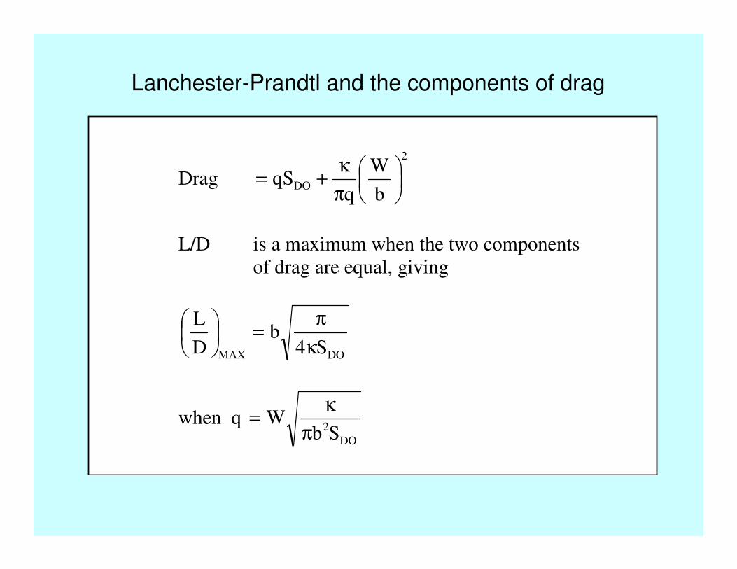
Lanchester-Prandtl and the components of drag
Drag
2
DOb
W
qqS
π
κ+=
L/D is a maximum when the two components
of drag are equal, giving
DOMAX S4b
D
L
κ
π=
when q DO
2SbW
π
κ=
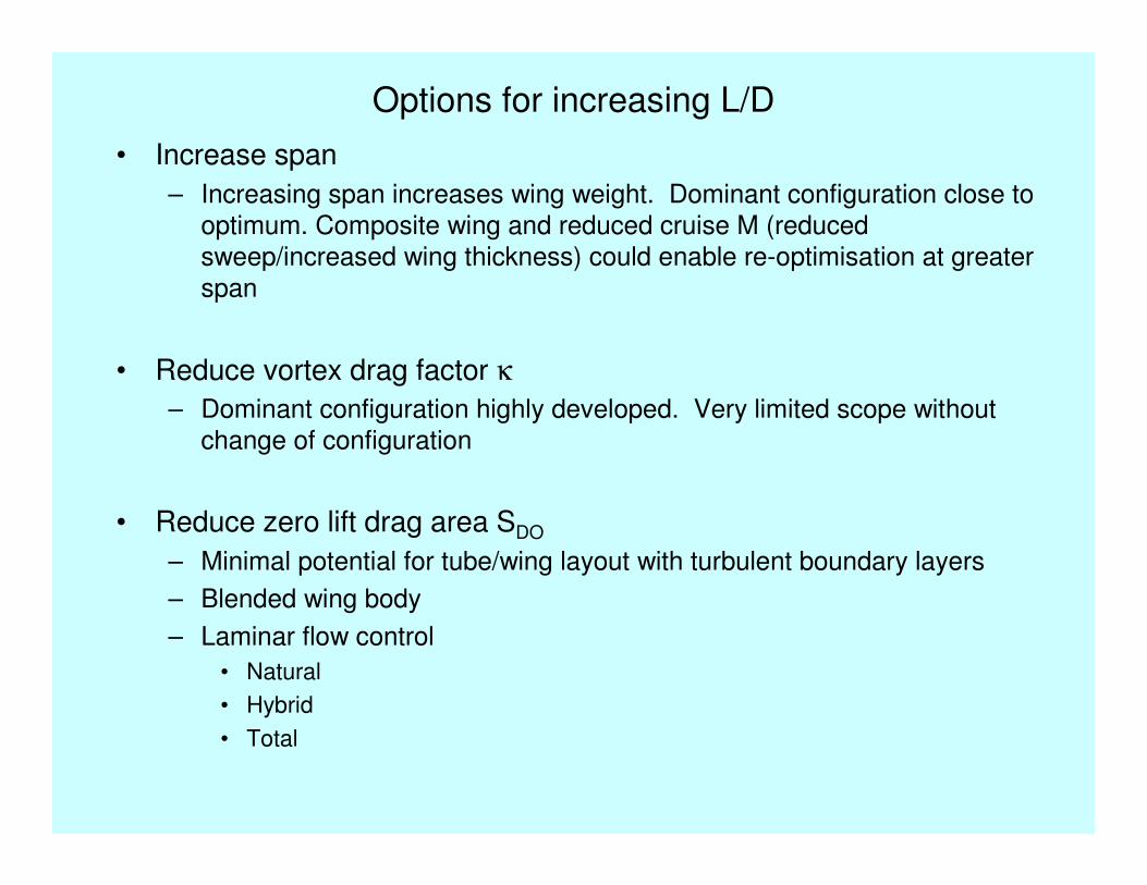
Options for increasing L/D
• Increase span
– Increasing span increases wing weight. Dominant configuration close to
optimum. Composite wing and reduced cruise M (reduced
sweep/increased wing thickness) could enable re-optimisation at greater
span
• Reduce vortex drag factor κ
– Dominant configuration highly developed. Very limited scope without
change of configuration
• Reduce zero lift drag area SDO
– Minimal potential for tube/wing layout with turbulent boundary layers
– Blended wing body
– Laminar flow control
• Natural
• Hybrid
• Total
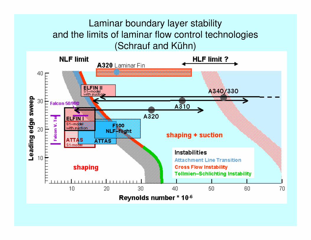
Laminar boundary layer stability
and the limits of laminar flow control technologies(Schrauf and Kühn)
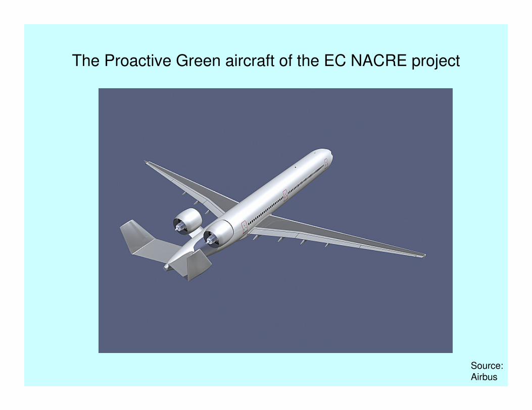
The Proactive Green aircraft of the EC NACRE project
Source:Airbus
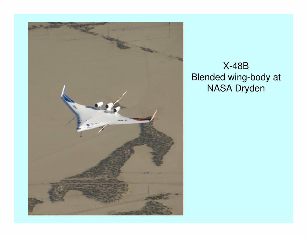
X-48B
Blended wing-body at NASA Dryden
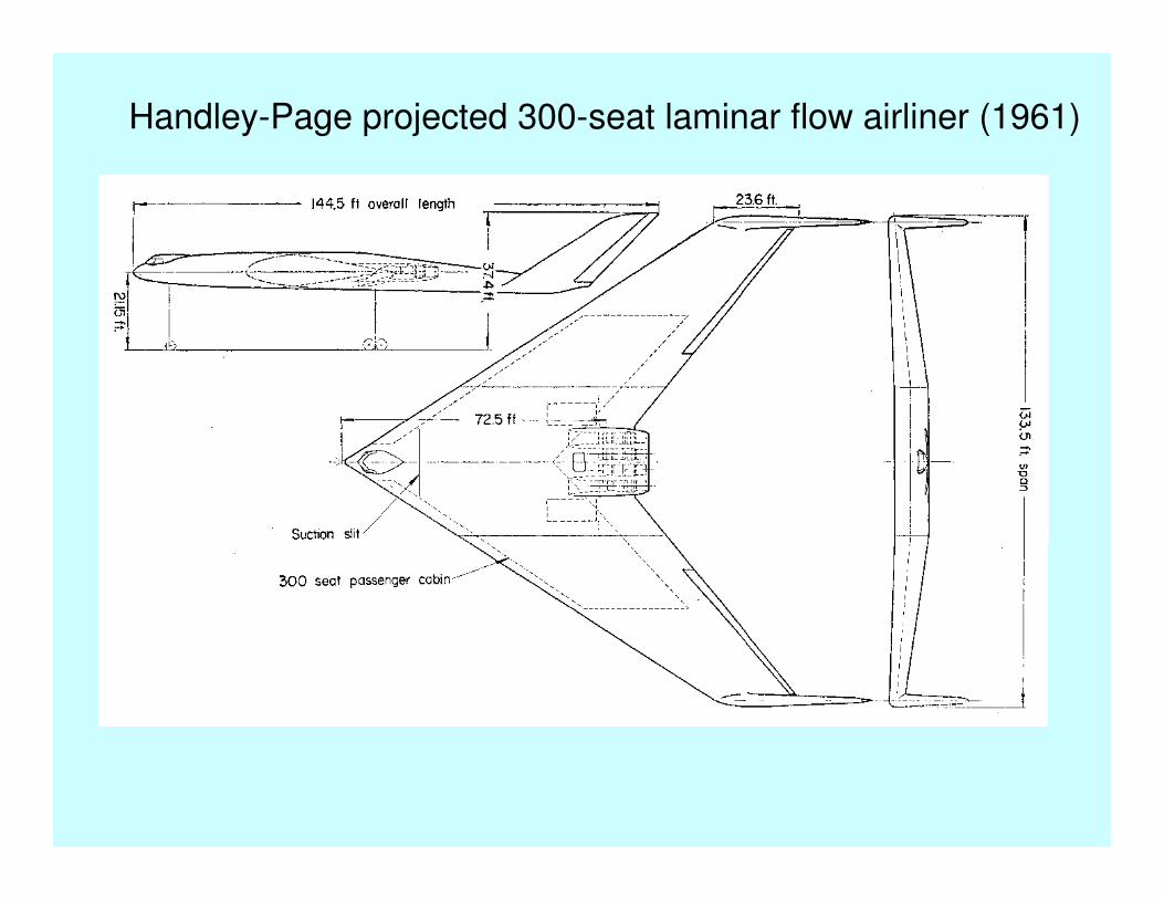
Handley-Page projected 300-seat laminar flow airliner (1961)
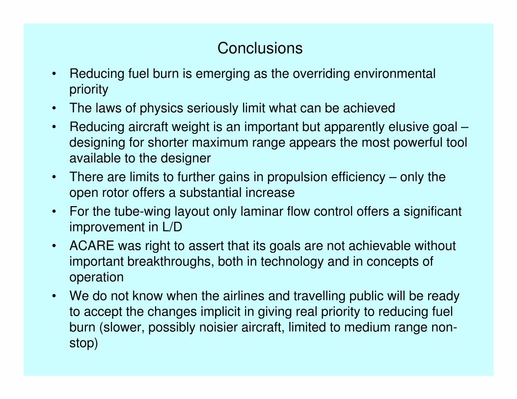
Conclusions
• Reducing fuel burn is emerging as the overriding environmental priority
• The laws of physics seriously limit what can be achieved
• Reducing aircraft weight is an important but apparently elusive goal –designing for shorter maximum range appears the most powerful tool available to the designer
• There are limits to further gains in propulsion efficiency – only the open rotor offers a substantial increase
• For the tube-wing layout only laminar flow control offers a significant improvement in L/D
• ACARE was right to assert that its goals are not achievable without important breakthroughs, both in technology and in concepts of operation
• We do not know when the airlines and travelling public will be ready to accept the changes implicit in giving real priority to reducing fuel burn (slower, possibly noisier aircraft, limited to medium range non-stop)

When will biokerosine come riding over the horizon to our rescue?