Embed Size (px)
Citation preview
Cleaning and Cleanliness Measurement of Additive Manufactured Parts
Mark A. Mitchell Randy E. RaleyMaterials & Processes/EM50 Jacobs ESSSA/EM50NASA Marshall Space Flight Center NASA Marshall Space Flight Center
Kevin EdwardsJacobs ESSSA/EM50NASA Marshall Space Flight Center
National Space & Missile Materials SymposiumJune 20-24, 2016Westminster, CO
https://ntrs.nasa.gov/search.jsp?R=20160008863 2020-04-09T11:19:40+00:00Z
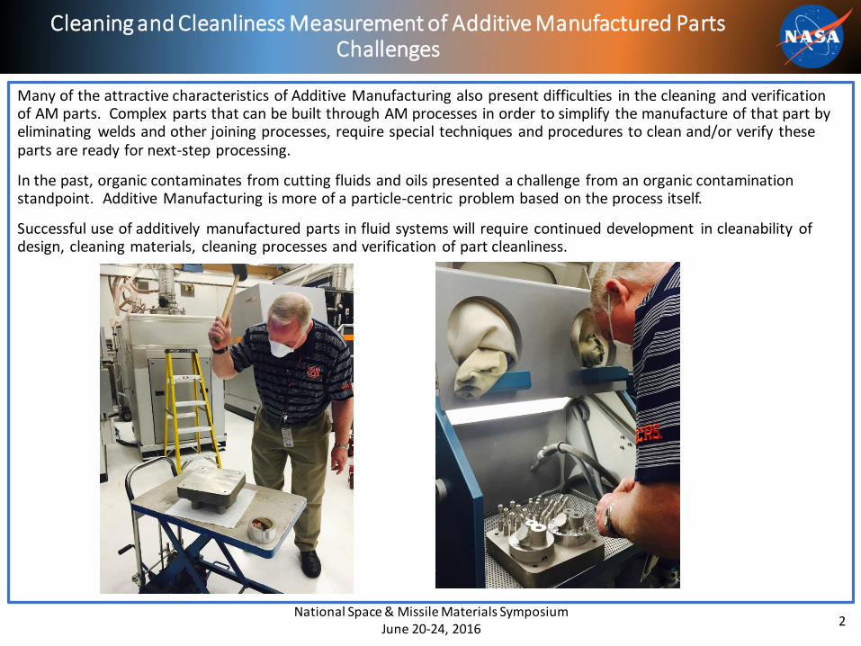
Many of the attractive characteristics of Additive Manufacturing also present difficulties in the cleaning and verification of AM parts. Complex parts that can be built through AM processes in order to simplify the manufacture of that part by eliminating welds and other joining processes, require special techniques and procedures to clean and/or verify these parts are ready for next-step processing.
In the past, organic contaminates from cutting fluids and oils presented a challenge from an organic contamination standpoint. Additive Manufacturing is more of a particle-centric problem based on the process itself.
Successful use of additively manufactured parts in fluid systems will require continued development in cleanability of design, cleaning materials, cleaning processes and verification of part cleanliness.
Cleaning and Cleanliness Measurement of Additive Manufactured PartsChallenges
National Space & Missile Materials SymposiumJune 20-24, 2016
2
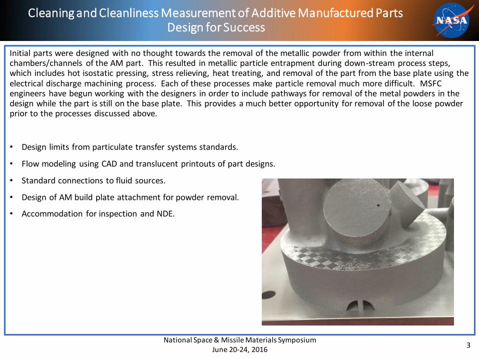
Initial parts were designed with no thought towards the removal of the metallic powder from within the internal chambers/channels of the AM part. This resulted in metallic particle entrapment during down-stream process steps, which includes hot isostatic pressing, stress relieving, heat treating, and removal of the part from the base plate using the electrical discharge machining process. Each of these processes make particle removal much more difficult. MSFC engineers have begun working with the designers in order to include pathways for removal of the metal powders in the design while the part is still on the base plate. This provides a much better opportunity for removal of the loose powder prior to the processes discussed above.
• Design limits from particulate transfer systems standards.
• Flow modeling using CAD and translucent printouts of part designs.
• Standard connections to fluid sources.
• Design of AM build plate attachment for powder removal.
• Accommodation for inspection and NDE.
Cleaning and Cleanliness Measurement of Additive Manufactured Parts Design for Success
National Space & Missile Materials Symposium June 20-24, 2016
3
1. Abrasive SlurrySlurry flow does not wear evenly on the interior of parts. It is possible to wear through an elbow or entrance before the sidewalls are acceptable in passages. Operator dependent on results and high risk of part damage. The smaller the passage the more likely that dimensional tolerances will be exceeded at some point. We recommend this method for parts with large or identical passages when it is covered by the contractor manufacturing the part and they assume the risk for the outcome.
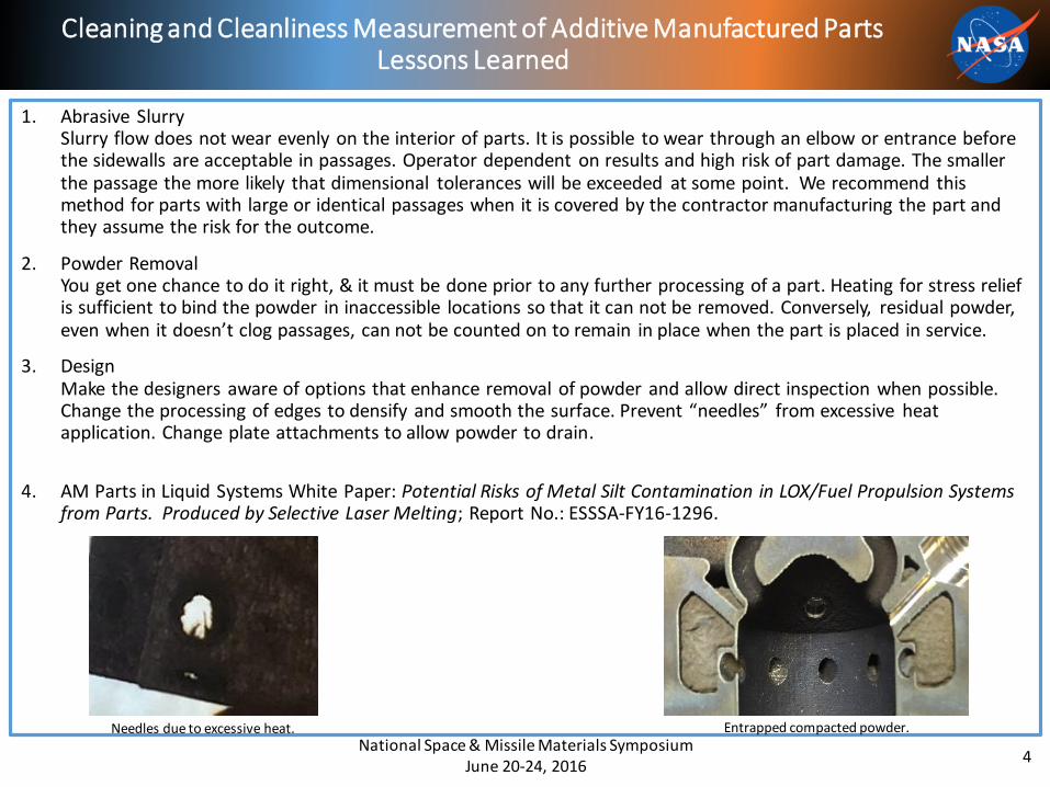
2. Powder Removal You get one chance to do it right, & it must be done prior to any further processing of a part. Heating for stress relief is sufficient to bind the powder in inaccessible locations so that it can not be removed. Conversely, residual powder, even when it doesn’t clog passages, can not be counted on to remain in place when the part is placed in service.
3. Design Make the designers aware of options that enhance removal of powder and allow direct inspection when possible. Change the processing of edges to densify and smooth the surface. Prevent “needles” from excessive heat application. Change plate attachments to allow powder to drain.
4. AM Parts in Liquid Systems White Paper: Potential Risks of Metal Silt Contamination in LOX/Fuel Propulsion Systems from Parts. Produced by Selective Laser Melting; Report No.: ESSSA-FY16-1296.
Cleaning and Cleanliness Measurement of Additive Manufactured Parts Lessons Learned
National Space & Missile Materials Symposium June 20-24, 2016
4
Needles due to excessive heat. Entrapped compacted powder.
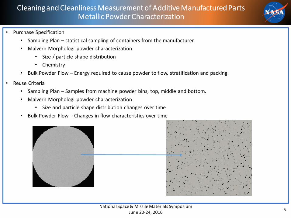
• Purchase Specification
• Sampling Plan – statistical sampling of containers from the manufacturer.
• Malvern Morphologi powder characterization
• Size / particle shape distribution
• Chemistry
• Bulk Powder Flow – Energy required to cause powder to flow, stratification and packing.
• Reuse Criteria
• Sampling Plan – Samples from machine powder bins, top, middle and bottom.
• Malvern Morphologi powder characterization
• Size and particle shape distribution changes over time
• Bulk Powder Flow – Changes in flow characteristics over time
Cleaning and Cleanliness Measurement of Additive Manufactured Parts Metallic Powder Characterization
National Space & Missile Materials Symposium June 20-24, 2016
5
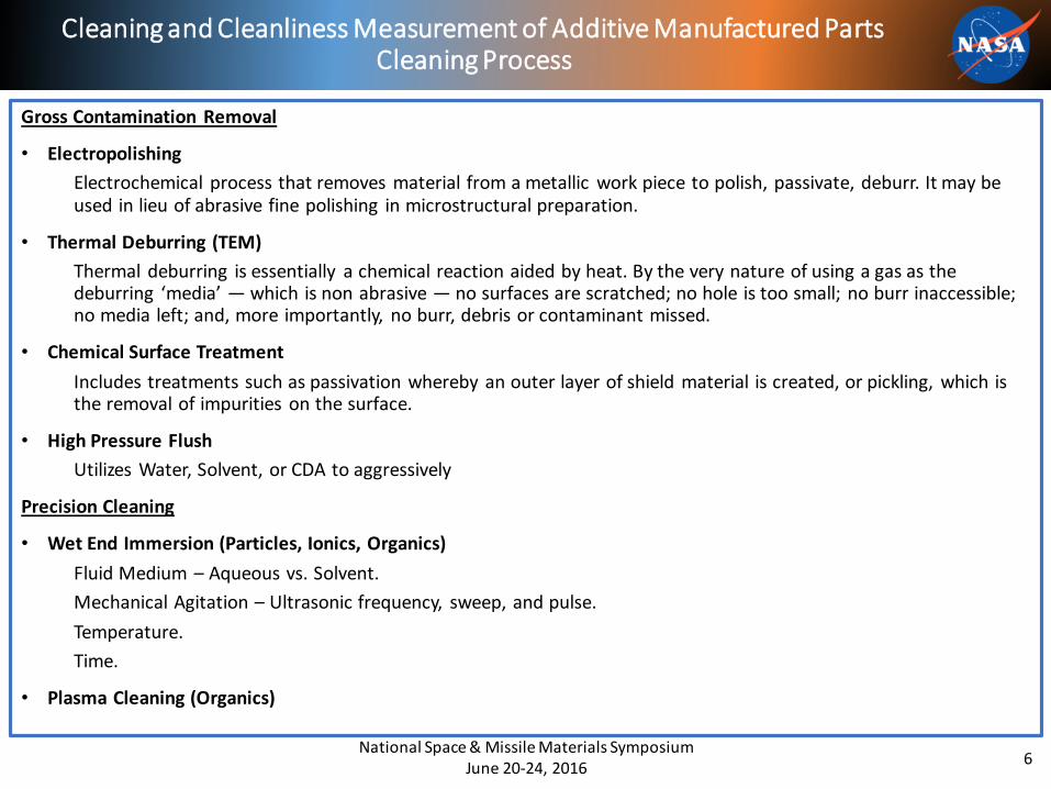
Gross Contamination Removal
• Electropolishing
Electrochemical process that removes material from a metallic work piece to polish, passivate, deburr. It may be used in lieu of abrasive fine polishing in microstructural preparation.
• Thermal Deburring (TEM)
Thermal deburring is essentially a chemical reaction aided by heat. By the very nature of using a gas as the deburring ‘media’ — which is non abrasive — no surfaces are scratched; no hole is too small; no burr inaccessible; no media left; and, more importantly, no burr, debris or contaminant missed.
• Chemical Surface Treatment
Includes treatments such as passivation whereby an outer layer of shield material is created, or pickling, which is the removal of impurities on the surface.
• High Pressure Flush
Utilizes Water, Solvent, or CDA to aggressively
Precision Cleaning
• Wet End Immersion (Particles, Ionics, Organics)
Fluid Medium – Aqueous vs. Solvent.
Mechanical Agitation – Ultrasonic frequency, sweep, and pulse.
Temperature.
Time.
• Plasma Cleaning (Organics)
Cleaning and Cleanliness Measurement of Additive Manufactured Parts Cleaning Process
National Space & Missile Materials Symposium June 20-24, 2016
6
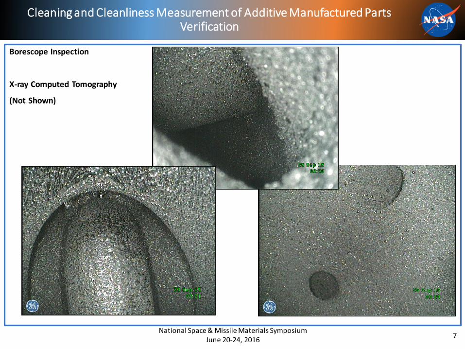
Borescope Inspection
X-ray Computed Tomography
(Not Shown)
Cleaning and Cleanliness Measurement of Additive Manufactured Parts Verification
National Space & Missile Materials Symposium June 20-24, 2016
7
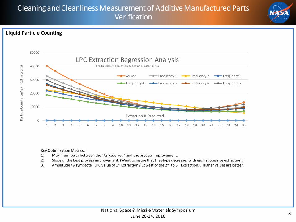
Liquid Particle Counting
Cleaning and Cleanliness Measurement of Additive Manufactured Parts Verification
National Space & Missile Materials Symposium June 20-24, 2016
8
0
10000
20000
30000
40000
50000
1 2 3 4 5 6 7 8 9 10 11 12 13 14 15 16 17 18 19 20 21 22 23 24 25
Par
ticl
e C
ou
nt
/ cm
^2 (
> 0.
3 m
icro
ns)
Extraction #, Predicted
LPC Extraction Regression AnalysisPredicted Extrapolation based on 5 Data Points
As Rec Frequency 1 Frequency 2 Frequency 3
Frequency 4 Frequency 5 Frequency 6 Frequency 7
Key Optimization Metrics:1) Maximum Delta between the “As Received” and the process improvement.2) Slope of the best process improvement. (Want to insure that the slope decreases with each successive extraction.)3) Amplitude / Asymptote: LPC Value of 1st Extraction / Lowest of the 2nd to 5th Extractions. Higher values are better.
If you are interested in collaborating please contact:
Mark A. Mitchell
NASA/MSFC/EM50
MSFC, AL 35812
256-544-5860
Cleaning and Cleanliness Measurement of Additive Manufactured Parts Forward Work
National Space & Missile Materials Symposium June 20-24, 2016
9
Thank You for Your Interest