Embed Size (px)
Citation preview
CAT.ES50-17 A
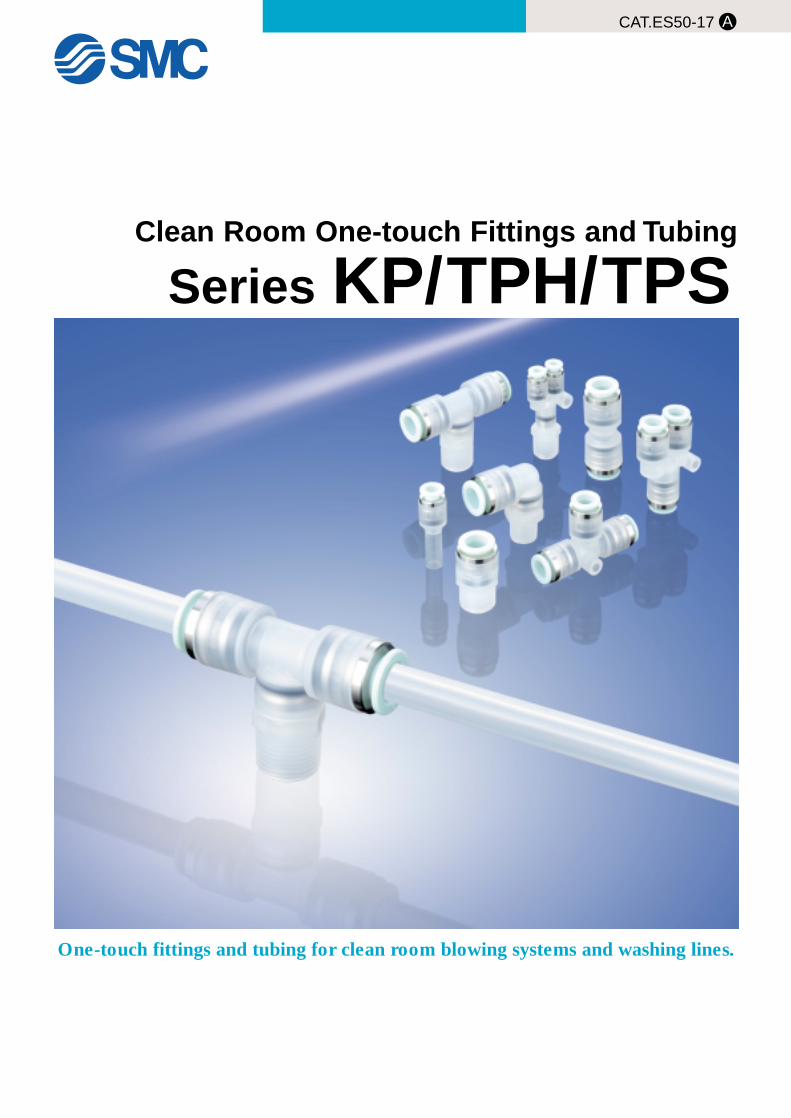
Clean Room One-touch Fittings and Tubing
Series KP/TPH/TPS
One-touch fittings and tubing for clean room blowing systems and washing lines.
Features 1
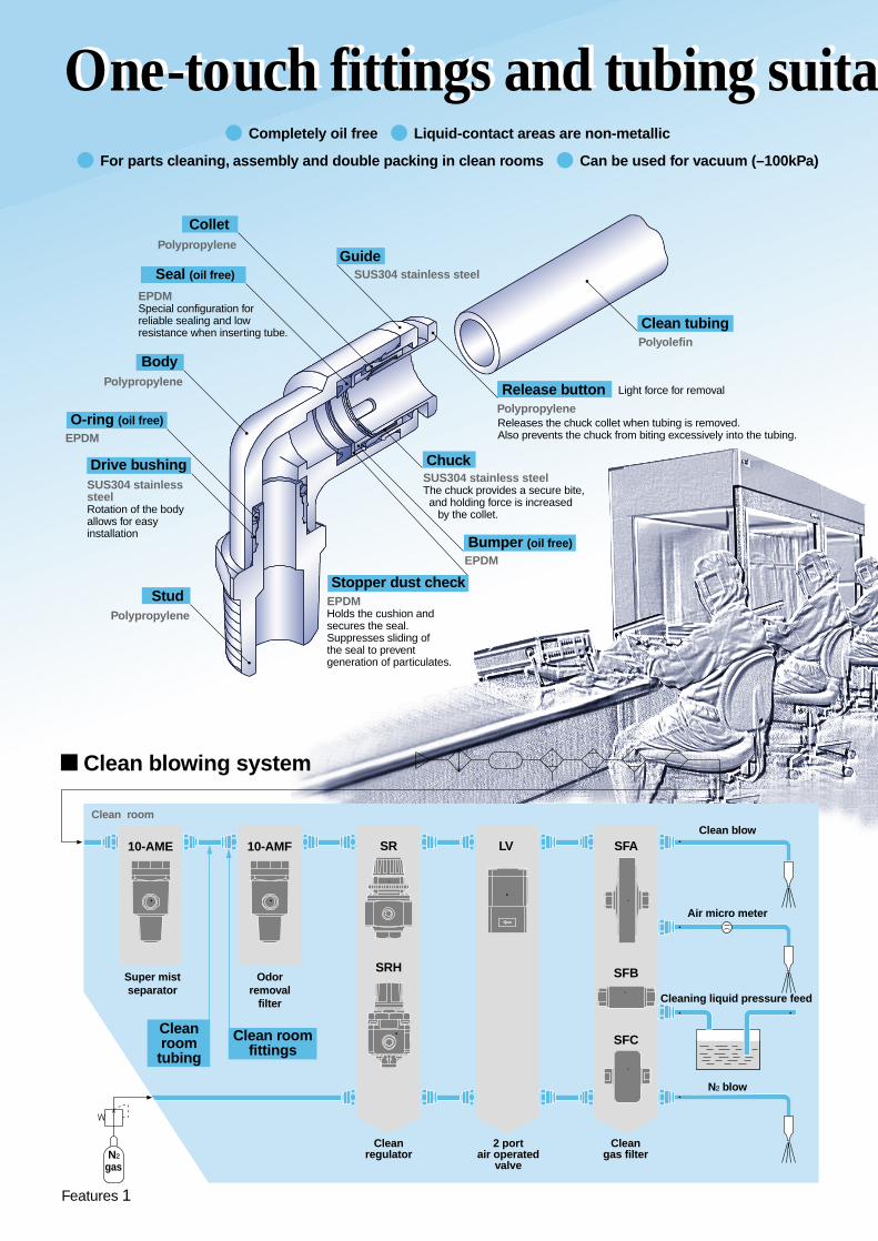
� Completely oil free � Liquid-contact areas are non-metallic
� For parts cleaning, assembly and double packing in clean rooms � Can be used for vacuum (–100kPa)
N₂
Super mistseparator
Odorremoval
filter
SR LV SFA
SFB
SFC
SRH
Cleanregulator
2 portair operated
valve
Cleangas filter
Cleaning liquid pressure feed
Clean blow
N₂ blow
Air micro meter
� Clean blowing system
Clean roomfittings
Cleanroomtubing
Clean room
gas
10-AMF10-AME
Polyolefin
SUS304 stainless steelThe chuck provides a secure bite, and holding force is increased by the collet.
EPDMHolds the cushion and secures the seal.Suppresses sliding of the seal to prevent generation of particulates.
SUS304 stainless steel
Polypropylene
EPDMSpecial configuration for reliable sealing and low resistance when inserting tube.
Releases the chuck collet when tubing is removed.Also prevents the chuck from biting excessively into the tubing.
Release button
Stopper dust check
Guide
Collet
Polypropylene
Body
Polypropylene
Stud
Seal (oil free)
EPDM
O-ring (oil free)
EPDMBumper (oil free)
Drive bushing Chuck
Clean tubing
Polypropylene
Light force for removal
One-touch fittings and tubing suitaOne-touch fittings and tubing suita
SUS304 stainless steelRotation of the body allows for easy installation
Features 2
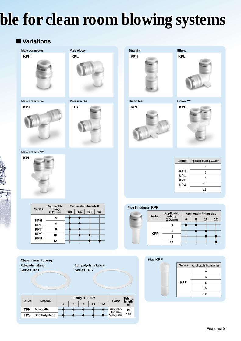
� Variations
SeriesConnection threads R
KPHKPLKPTKPYKPU
4
6
8
10
12
�
�
�
�
�
�
� �
� �
Applicabletubing
O.D. mm 1/8 1/4 3/8 1/2
Male connector
KPH
Male elbow
KPL
Male branch tee
KPT
Male branch "Y"
KPU
Male run tee
KPY
Straight
KPH
Elbow
KPL
Union tee
KPT
Union "Y"
KPU
Plug-in reducer KPR
Plug KPPClean room tubingPolyolefin tubing
Series TPHSoft polyolefin tubing
Series TPS
SeriesApplicable fitting size
KPR
4
6
8
10
� �
� �
� �
�
Applicabletubing
O.D. mm 6 8 10 12
Series
KPHKPLKPTKPU
4
6
8
10
12
Applicable tubing O.D. mm
Series Material ColorTubinglength
m
Tubing O.D. mm
TPH
TPS
Polyolefin
Soft Polyolefin
White, BlackRed, Blue
Yellow, Green
20100
�
�
�
�
�
�
�
�
4 6 8 10
�
�
12
Series
KPP
4
6
8
10
12
Applicable fitting size
able for clean room blowing systemsble for clean room blowing systems
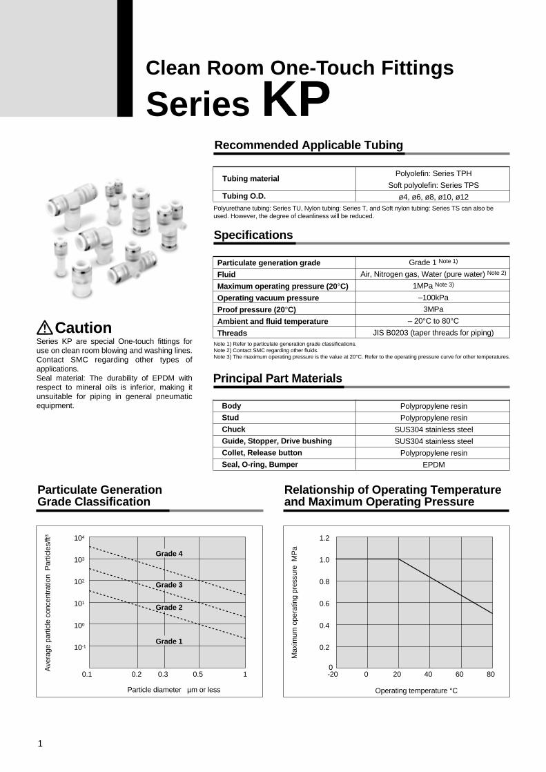
Recommended Applicable Tubing
Tubing material
Tubing O.D.
Polyolefin: Series TPH
Soft polyolefin: Series TPS
ø4, ø6, ø8, ø10, ø12
Grade 1 Note 1)
Air, Nitrogen gas, Water (pure water) Note 2)
1MPa Note 3)
–100kPa
3MPa
– 20°C to 80°CJIS B0203 (taper threads for piping)
Polypropylene resin
Polypropylene resin
SUS304 stainless steel
SUS304 stainless steel
Polypropylene resin
EPDM
Specifications
Particulate generation grade
Fluid
Maximum operating pressure (20°C)
Operating vacuum pressure
Proof pressure (20°C)
Ambient and fluid temperature
Threads
Principal Part Materials
Particulate Generation Grade Classification
Relationship of Operating Temperature and Maximum Operating Pressure
Body
Stud
Chuck
Guide, Stopper, Drive bushing
Collet, Release button
Seal, O-ring, Bumper
Note 1) Refer to particulate generation grade classifications.Note 2) Contact SMC regarding other fluids. Note 3) The maximum operating pressure is the value at 20°C. Refer to the operating pressure curve for other temperatures.
-20 0
Operating temperature °C
Max
imum
ope
ratin
g pr
essu
re M
Pa
20 40 60 80
0.2
0.4
0.6
0.8
1.0
1.2
00.1 0.2
Particle diameter µm or less
Ave
rage
par
ticle
con
cent
ratio
n P
artic
les/
ft3
0.3 0.5 1
10-1
100
101
102
103
104
Grade 4
Grade 3
Grade 2
Grade 1
CautionSeries KP are special One-touch fittings for use on clean room blowing and washing lines. Contact SMC regarding other types of applications.Seal material: The durability of EPDM with respect to mineral oils is inferior, making it unsuitable for piping in general pneumatic equipment.
Polyurethane tubing: Series TU, Nylon tubing: Series T, and Soft nylon tubing: Series TS can also be used. However, the degree of cleanliness will be reduced.
1
Clean Room One-Touch Fittings
Series KP
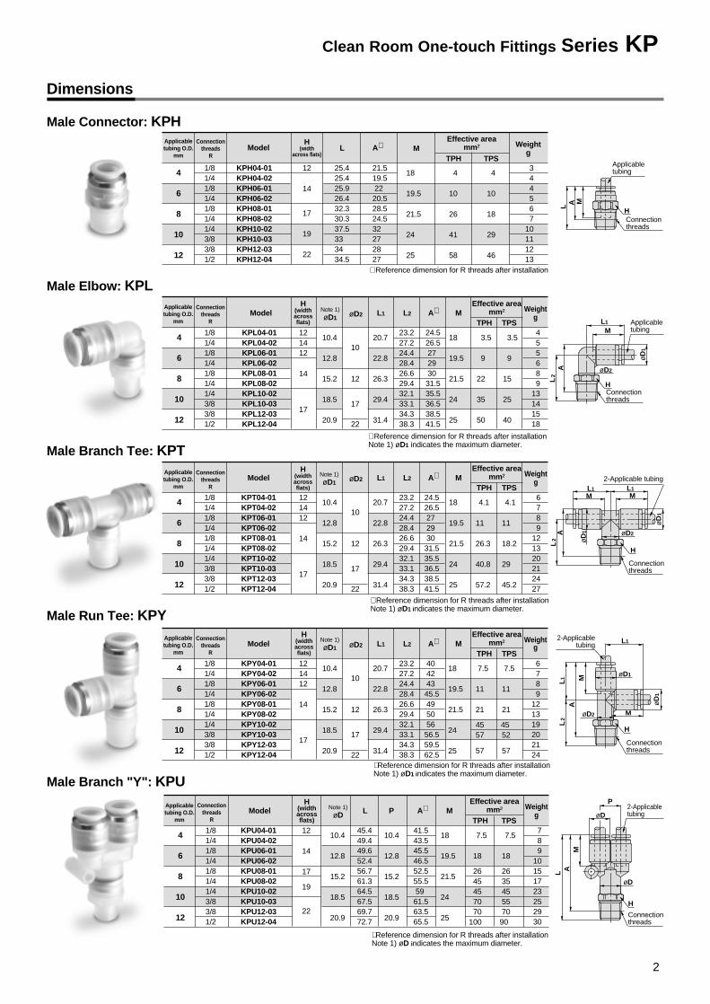
Dimensions
Male Connector: KPH
Male Elbow: KPL
Applicabletubing O.D.
mm
H(width
across flats)
Connectionthreads
R
Weightg
Effective areamm²Model L M
TPH TPSA∗
4
6
8
10
12
18
19.5
21.5
24
25
4
10
26
41
58
4
10
18
29
46
12
14
17
19
22
1/81/41/81/41/81/41/43/83/81/2
25.425.425.926.432.330.337.533 34 34.5
21.519.522 20.528.524.532 27 28 27
344567
10111213
KPH04-01KPH04-02KPH06-01KPH06-02KPH08-01KPH08-02KPH10-02KPH10-03KPH12-03KPH12-04
Weightg
Effective areamm²Note 1)
øD1Model L1
TPH TPSA∗
4
6
8
10
12
10.4
12.8
15.2
18.5
20.9
20.7
22.8
26.3
29.4
31.4
M
18
19.5
21.5
24
25
øD2
10
12
17
22
3.5
9
22
35
50
3.5
9
15
25
40
121412
14
17
1/81/41/81/41/81/41/43/83/81/2
24.526.527 29 30 31.535.536.538.541.5
455689
13141518
L2
23.227.224.428.426.629.432.133.134.338.3
KPL04-01KPL04-02KPL06-01KPL06-02KPL08-01KPL08-02KPL10-02KPL10-03KPL12-03KPL12-04
H(widthacrossflats)
Weightg
Effective areamm²Note 1)
øD1Model L1
TPH TPSA∗
4
6
8
10
12
10.4
12.8
15.2
18.5
20.9
20.7
22.8
26.3
29.4
31.4
M
18
19.5
21.5
24
25
øD2
10
12
17
22
4.1
11
26.3
40.8
57.2
4.1
11
18.2
29
45.2
121412
14
17
1/81/41/81/41/81/41/43/83/81/2
24.526.527 29 30 31.535.536.538.541.5
6789
121320212427
L2
23.227.224.428.426.629.432.133.134.338.3
KPT04-01KPT04-02KPT06-01KPT06-02KPT08-01KPT08-02KPT10-02KPT10-03KPT12-03KPT12-04
∗ Reference dimension for R threads after installation
∗ Reference dimension for R threads after installationNote 1) øD1 indicates the maximum diameter.
Weightg
Effective areamm²Note 1)
øDModel LTPH TPS
A∗
4
6
8
10
12
10.4
12.8
15.2
18.5
20.9
10.4
12.8
15.2
18.5
20.9
45.449.449.652.456.761.364.567.569.772.7
M
18
19.5
21.5
24
25
7.5
18
2645457070
100
7.5
18
263545557090
12
14
17
19
22
1/81/41/81/41/81/41/43/83/81/2
41.543.545.546.552.555.559 61.563.565.5
789
10151723252930
P
KPU04-01KPU04-02KPU06-01KPU06-02KPU08-01KPU08-02KPU10-02KPU10-03KPU12-03KPU12-04
∗ Reference dimension for R threads after installationNote 1) øD indicates the maximum diameter.
∗ Reference dimension for R threads after installationNote 1) øD1 indicates the maximum diameter.
Weightg
Effective areamm²
Note 1)øD1
Model L1
TPH TPSA∗
4
6
8
10
12
10.4
12.8
15.2
18.5
20.9
20.7
22.8
26.3
29.4
31.4
M
18
19.5
21.5
24
25
øD2
10
12
17
22
7.5
11
21
45 57
57
7.5
11
21
45 52
57
121412
14
17
1/81/41/81/41/81/41/43/83/81/2
40 42 43 45.549 50 56 56.559.562.5
6789
121319202124
L2
23.227.224.428.426.629.432.133.134.338.3
KPY04-01KPY04-02KPY06-01KPY06-02KPY08-01KPY08-02KPY10-02KPY10-03KPY12-03KPY12-04
∗ Reference dimension for R threads after installationNote 1) øD1 indicates the maximum diameter.
Male Branch Tee: KPT
Male Run Tee: KPY
Male Branch "Y": KPU
Applicabletubing
H
L A M
Connectionthreads
Applicabletubing
H
L2
A øD2
øD
1
L1
MA
L1
L2
AL
2
øD
1
øD2
øD
1
ML1
L1
H
L1
2-Applicable tubing
2-Applicabletubing
2-Applicabletubing
M
H
Connectionthreads
øD
1
L AM
øD1
øD
øD
P
øD2 M
Connectionthreads
H
Connectionthreads
M
Connectionthreads
Applicabletubing O.D.
mm
Connectionthreads
R
H(widthacrossflats)
Applicabletubing O.D.
mm
Connectionthreads
R
Applicabletubing O.D.
mm
Connectionthreads
R
H(widthacrossflats)
H(widthacrossflats)
Applicabletubing O.D.
mm
Connectionthreads
R
2
Clean Room One-touch Fittings Series KP
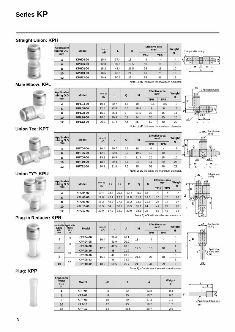
Straight Union: KPH
Male Elbow: KPL
Union Tee: KPT
Union "Y": KPU
Plug-in Reducer: KPR
Plug: KPP
2-Applicable tubing
2-Applicable tubing
3-Applicabletubing
3-Applicabletubing
Applicabletubing
Applicablefitting sizeød
Applicable fitting size
ød
M
M
M M
ML
L
L L
LQ
LQ
MM
M
MM
A
LL
2
L1
øD
øD
øD
øD
øD
øD
øD
ød
ød
øD
LA
ø4.
2ø8
Q
P
ø4.2ø8
ø4.2
ø8
øD
øD
øD
Applicabletubing O.D.
mm
Weightg
Effective areamm²Note 1)
øDModel L
TPH TPS
4
6
8
10
12
37.4
39.6
44.4
48.6
50.6
18
19.5
21.5
24
25
4
10
26
41
58
4
10
18
29
46
4
6
10
15
18
10.4
12.8
15.2
18.5
20.9
M
KPH04-00
KPH06-00
KPH08-00
KPH10-00
KPH12-00
Note 1) øD indicates the maximum diameter.
Weightg
Effective areamm²Note 1)
øDModel L
TPH TPS
4
6
8
10
12
20.7
22.8
26.3
29.4
31.4
4.5
5.3
6
6.8
7.5
18
19.5
21.5
24
25
3.5
9
22
35
50
3.5
9
15
25
40
3
7
11
16
20
10.4
12.8
15.2
18.5
20.9
MQ
KPL04-00
KPL06-00
KPL08-00
KPL10-00
KPL12-00
Note 1) øD indicates the maximum diameter.
Weightg
Effective areamm²Note 1)
øDModel L
TPH TPS
4
6
8
10
12
20.7
22.8
26.3
29.4
31.4
4.5
5.3
6
6.8
7.5
18
19.5
21.5
24
25
4
10
26
41
58
4
10
18
29
46
7
9
16
25
29
10.4
12.8
15.2
18.5
20.9
MQ
KPT04-00
KPT06-00
KPT08-00
KPT10-00
KPT12-00
Note 1) øD indicates the maximum diameter.
Applicablefittingsizeød
Weightg
Effective areamm²Note 1)
øDModel LTPH TPS
4
6
8
10
10.4
12.8
15.2
18.5
18
19.5
21.5
24
4
10
26
41
4
10
18
29
6
8
10
12
39.4
41.9
42.5
45
47
48
50.5
20.1
20.2
20.8
21.2
23.2
23.2
25.7
3
4
4
5
5
6
9
MA
KPR04-06
KPR04-08
KPR06-08
KPR06-10
KPR08-10
KPR08-12
KPR10-12
Note 1) øD indicates the maximum diameter.
Applicablefittingsizeød
WeightgøDModel L
4
6
8
10
12
32
35
39
43
45.5
6
8
10
12
14
13.8
15.7
17.3
19.2
20.7
0.4
0.7
1.1
1.7
2.5
A
KPP-04
KPP-06
KPP-08
KPP-10
KPP-12
Weightg
Effective areamm²Note 1)
øDModel L1
TPH TPS
4
6
8
10
12
38.8
42.1
48.7
54
57.2
L2
20.6
22.8
27.5
30.7
32.9
10.4
12.8
15.2
18.5
20.9
9.7
11.7
13.7
16.1
18.1
4
10
26
41
58
4
10
18
29
46
7
10
17
26
32
10.4
12.8
15.2
18.5
20.9
Q
18
19.5
21.5
24
25
MP
KPU04-00
KPU06-00
KPU08-00
KPU10-00
KPU12-00
Note 1) øD indicates the maximum size.
Applicabletubing O.D.
mm
Applicabletubing O.D.
mm
Applicabletubing O.D.
mm
ApplicabletubingO.D.mm
Series KP
3
Series
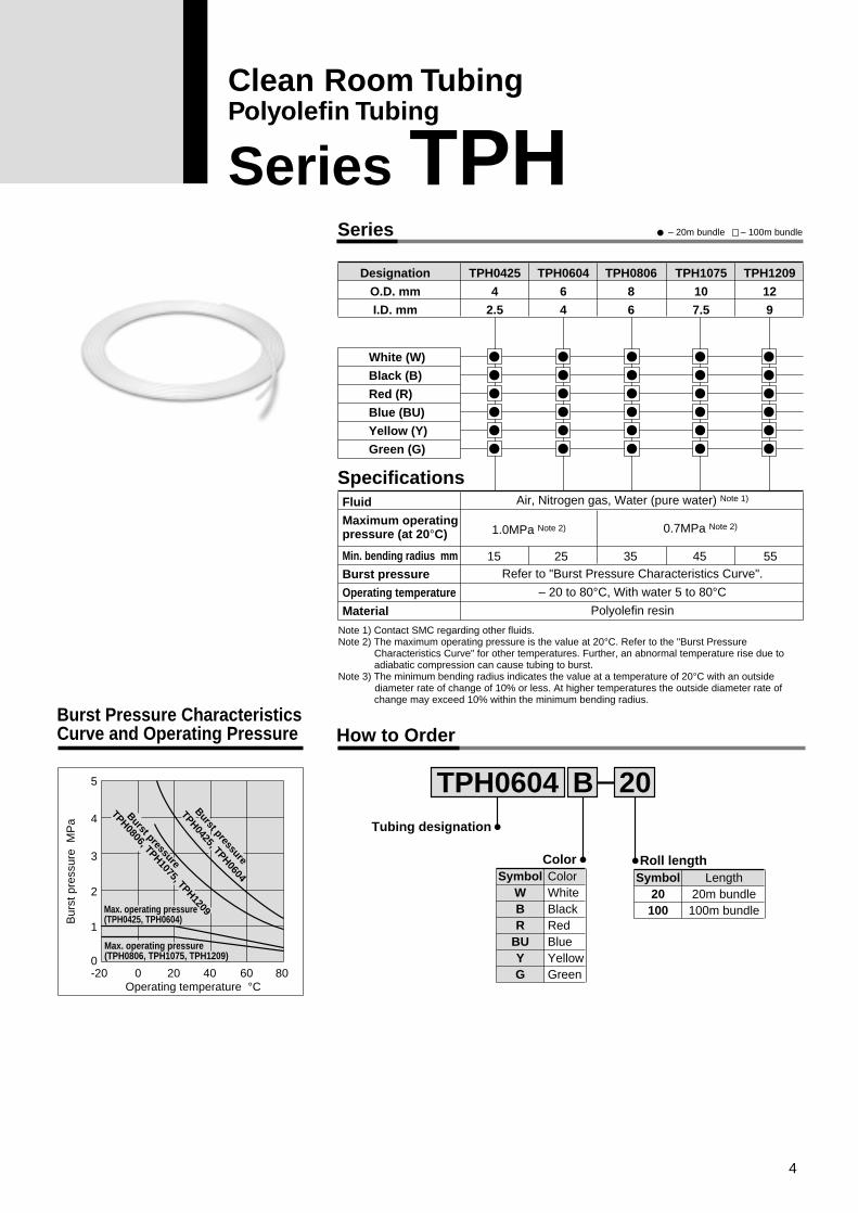
Specifications
Designation
O.D. mm
I.D. mm
White (W)
Black (B)
Red (R)
Blue (BU)
Yellow (Y)
Green (G)
Fluid
Maximum operatingpressure (at 20°C)
Min. bending radius mm
Burst pressure
Operating temperature
Material
TPH0425
4
2.5
TPH0604
6
4
TPH0806
8
6
TPH1075
10
7.5
TPH1209
12
9
Air, Nitrogen gas, Water (pure water) Note 1)
Refer to "Burst Pressure Characteristics Curve".
– 20 to 80°C, With water 5 to 80°CPolyolefin resin
1.0MPa Note 2) 0.7MPa Note 2)
15
ColorWhiteBlackRedBlueYellowGreen
SymbolWBR
BUYG
25 35 45 55
How to OrderBurst Pressure CharacteristicsCurve and Operating Pressure
Operating temperature °C
Max. operating pressure (TPH0425, TPH0604)
TPH0806, TPH1075, TPH1209
Burst pressureTPH0425, TPH0604
Burst pressure
Max. operating pressure(TPH0806, TPH1075, TPH1209)
Bur
st p
ress
ure
MP
a
-20 00
1
2
3
4
5
20 40 60 80
TPH0604Tubing designation
Color Roll length
B 20
Length20m bundle
100m bundle
Symbol20
100
– 20m bundle – 100m bundle
Note 1) Contact SMC regarding other fluids. Note 2) The maximum operating pressure is the value at 20°C. Refer to the "Burst Pressure
Characteristics Curve" for other temperatures. Further, an abnormal temperature rise due to adiabatic compression can cause tubing to burst.
Note 3) The minimum bending radius indicates the value at a temperature of 20°C with an outside diameter rate of change of 10% or less. At higher temperatures the outside diameter rate of
change may exceed 10% within the minimum bending radius.
4
Clean Room TubingPolyolefin Tubing
Series TPH
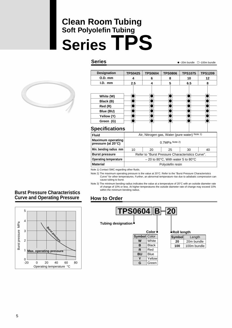
Series
Specifications
Designation
O.D. mm
I.D. mm
White (W)
Black (B)
Red (R)
Blue (BU)
Yellow (Y)
Green (G)
TPS0425
4
2.5
TPS0604
6
4
TPS0806
8
5
TPS1075
10
6.5
TPS1209
12
8
ColorWhiteBlackRedBlueYellowGreen
SymbolWBR
BUYG
How to OrderBurst Pressure Characteristics Curve and Operating Pressure
Operating temperature °C
Bur
st p
ress
ure
MP
a
-20 00
1
2
3
4
5
20 40 60 80
TPS0604Tubing designation
Color Roll length
B 20
Length20m bundle
100m bundle
Symbol20
100
–20m bundle –100m bundle
Max. operating pressure
Burst pressure
Fluid
Maximum operatingpressure (at 20°C)
Min. bending radius mm
Burst pressure
Operating temperature
Material
Air, Nitrogen gas, Water (pure water) Note 1)
0.7MPa Note 2)
Refer to "Burst Pressure Characteristics Curve".
– 20 to 80°C, With water 5 to 80°CPolyolefin resin
10 20 25 30 40
Note 1) Contact SMC regarding other fluids.
Note 2) The maximum operating pressure is the value at 20°C. Refer to the "Burst Pressure Characteristics Curve" for other temperatures. Further, an abnormal temperature rise due to adiabatic compression can cause tubing to burst.
Note 3) The minimum bending radius indicates the value at a temperature of 20°C with an outside diameter rate of change of 10% or less. At higher temperatures the outside diameter rate of change may exceed 10% within the minimum bending radius.
5
Clean Room TubingSoft Polyolefin Tubing
Series TPS
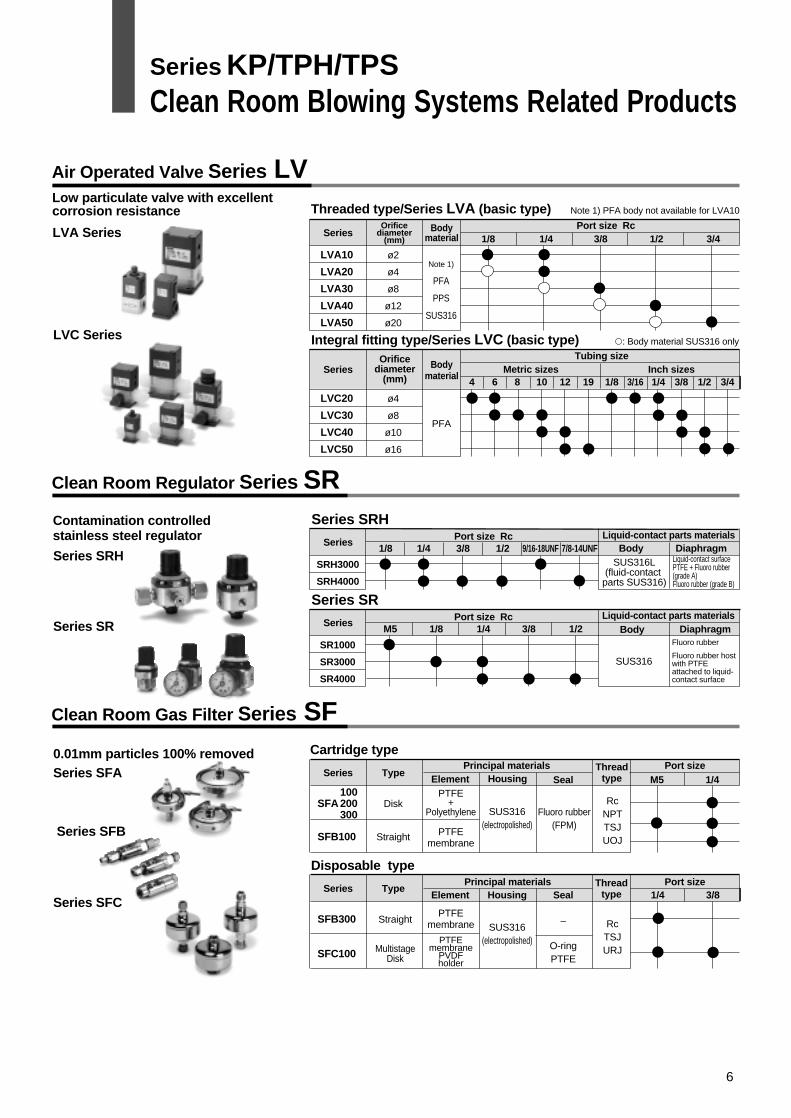
Air Operated Valve Series LV
Clean Room Regulator Series SR
Clean Room Gas Filter Series SF
Series Bodymaterial
Port size Rc1/8 1/4 3/8 1/2 3/4
Orificediameter
(mm)
LVA10
LVA20
LVA30
LVA40
LVA50
ø2
ø4
ø8
ø12
ø20
Note 1)
PFA
PPS
SUS316
�: Body material SUS316 only
Threaded type/Series LVA (basic type)
LVA Series
Series Bodymaterial
Tubing sizeMetric sizes Inch sizes
4 6 8 10 12 19 1/8 3/16 1/4 3/8 1/2 3/4
LVC20
LVC30
LVC40
LVC50
ø4
ø8
ø10
ø16
PFA
SUS316L(fluid-contact
parts SUS316)
Integral fitting type/Series LVC (basic type)LVC Series
SeriesBody Diaphragm
Port size Rc Liquid-contact parts materials 1/8 1/4 3/8 1/2 9/16-18UNF 7/8-14UNF
SRH3000
SRH4000
Series SRH
Series SRH
Series SR
Contamination controlled stainless steel regulator
Series Type
Type
Principal materials Port sizeThreadtypeElement Housing Seal M5 1/4
SFA
SFB100
100200300
Disk
Straight
SUS316(electropolished)
Fluoro rubber(FPM)
RcNPTTSJUOJ
PTFE+
Polyethylene
PTFEmembrane
Cartridge type
Series SFA
Series SFB
Series SFC
0.01mm particles 100% removed
SUS316
SeriesBody Diaphragm
Port size Rc Liquid-contact parts materials M5 1/41/8 3/8 1/2
SR1000
SR3000
SR4000
Series SR
SeriesPrincipal materials Port sizeThread
typeElement Housing Seal 1/4 3/8
SFB300
SFC100
Straight
MultistageDisk
SUS316(electropolished)
–
O-ringPTFE
RcTSJURJ
PTFEmembrane
PTFEmembrane
PVDFholder
Disposable type
Note 1) PFA body not available for LVA10Low particulate valve with excellent corrosion resistance
Orificediameter
(mm)
Fluoro rubber
Fluoro rubber host with PTFE attached to liquid-contact surface
Liquid-contact surfacePTFE + Fluoro rubber (grade A)Fluoro rubber (grade B)
Series KP/TPH/TPSClean Room Blowing Systems Related Products
6
Series KP/TPH/TPS
Safety Instructions
Note 1) ISO 4414: Pneumatic fluid power -- Recommendations for the application of equipment to transmission and control systems.
Note 2) JIS B 8370: General Rules for Pneumatic Equipment
Warning
Caution : Operator error could result in injury or equipment damage.
Warning : Operator error could result in serious injury or loss of life.
Danger : In extreme conditions, there is a possible result of serious injury or loss of life.
These safety instructions are intended to prevent a hazardous situation and/or equipment damage. These instructions indicate the level of potential hazard by a label of "Caution", "Warning" or "Danger". To ensure safety, be sure to observe ISO 4414 Note 1), JIS B 8370 Note 2) and other safety practices.
1. The compatibility of pneumatic equipment is the responsibility of the person who designs the pneumatic system or decides its specifications.Since the products specified here are used in various operating conditions, their compatibility for the specific pneumatic system must be based on specifications or after analysis and/or tests to meet your specific requirements.
2. Only trained personnel should operate pneumatically operated machinery and equipment.Compressed air or operating fluid can be dangerous if an operator is unfamiliar with it. Assembly, handling or repair of pneumatic systems should be performed by trained and experienced operators.
3. Do not service machinery/equipment or attempt to remove components until safety is confirmed.
1. Inspection and maintenance of machinery/equipment should only be performed after confirmation of safe locked-out control positions.
2. When equipment is to be removed, confirm the safety process as mentioned above. Cut the supply pressure for this equipment and exhaust all residual compressed air in the system.
3. Before machinery/equipment is restarted, take measures to prevent shooting-out of cylinder piston rod, etc. (Bleed air into the system gradually to create back pressure.)
4. Contact SMC if the product is to be used in any of the following conditions:1. Conditions and environments beyond the given specifications, or if product is used outdoors.2. Installation on equipment in conjunction with atomic energy, railway, air navigation, vehicles, medical
equipment, food and beverages, recreation equipment, emergency stop circuits, press applications, or safety equipment.
3. An application which has the possibility of having negative effects on people, property, or animals, requiring special safety analysis.
7
Caution
Series KP/TPH/TPSSpecific Product Precautions 1Be sure to read before handling.
1. Do not use in locations where the connecting threadsand tubing connection will slide or rotate. The con-necting threads and tubing connection will come apartunder these conditions.
2. Use tubing at or above the minimum bending radius.Using below the minimum bending radius can causebreakage or flattening of the tube.
3. Consult SMC regarding fluids other than air, water andnitrogen gas.
4. In case of liquid fluids, keep surge pressure at orbelow the maximum operating pressure. If the surgepressure exceeds the maximum operating pressure,this can cause damage to the fittings and tubing.
1. Store away from direct sunlight at 40°C or less.2. Open the inner package of double packaging in a clean
room or other clean environment.
1. Before mounting confirm the model and size, etc. Also,confirm that there are no blemishes, nicks or cracks inthe product.
2. When connecting a tube, consider factors such aschanges in the tubing length due to pressure, andallow sufficient leeway.
3. Mount so that fittings and tubing are not subjected totwisting, pulling or moment loads. This can causedamage to fittings and flattening, bursting or discon-nection of tubing, etc.
4. Mount so that tubing is not damaged due to tanglingand abrasion. This can cause flattening, bursting ordisconnection of tubing, etc.
1. Wrapping of seal tapeWrap the seal tape 2 to 3 times around the threads,leaving 1.5 to 2 thread ridges exposed at the end of thethreads.
2. TighteningAfter tightening by hand, tighten an additional 2 to 3turns using a tightening tool.
3. Tightening toolsTighten with an appropriate spanner using the hexa-gon wrench flats on the body.Position the spanner on the base as close as possibleto the threads. If the size of the spanner is not suitablefor the hexagon wrench flats, the wrench flats may becrushed.
1. Attachment of tubing1) Using tube cutters TK-1, 2 or 3, take a tube having
no flaws on its periphery and cut it off at a rightangle. Do not use pinchers, nippers or scissors, etc.The tubing might be cut diagonally or flattened,making installation impossible or causing problemssuch as disconnection and leakage.
2) Hold the tube and push it in slowly, inserting itsecurely all the way into the fitting.
3) After inserting the tubing, pull on it lightly to con-firm that it will not come out. If it is not installedsecurely all the way into the fitting, problems suchas leakage or disconnection of the tubing canoccur.
2. Detachment of tubing1) Push in the release button sufficiently, pressing the
collar evenly around its circumference.2) Pull out the tubing while holding down the release
button so that it does not pop out. If the release but-ton is not pressed down sufficiently, there will beincreased bite on the tubing and it will becomemore difficult to pull it out.
3) When the removed tubing is to be used again, firstcut off the section of the tubing which has beenchewed.Using the chewed portion of the tube as it is cancause problems such as leakage or difficulty inremoving the tubing.
1. Do not use in environments or locations where there isa danger of damage to fittings and tubing.Refer to pages 1, 4 and 5 for fitting and tubing materi-als.
2. Block off sunlight in locations which receive directsunlight.
3. Do not operate in locations where vibration or impactoccurs.Since this can cause leakage and fitting damage, etc.,contact SMC regarding use in this kind of environ-ment.
4. Provide shielding in locations near heat sources.When there are heat sources in the surrounding area,the product's temperature may rise due to radiatedheat and exceed its operating temperature range.Block off the heat with a cover, etc.
5. Do not use in locations where static electric chargeswill be a problem. Consult SMC regarding use in thiskind of environment.
6. Do not use in locations where spatter occurs.There is a danger of spatter causing a fire. ConsultSMC regarding use in this kind of environment.
Selection Attachment and Detachment of Tubing
Handling
Caution
Mounting
Caution
Installation of Taper Threads for Piping
Caution
Caution
Operating Environment
Warning
8
Series KP/TPH/TPSSpecific Product Precautions 2Be sure to read before handling.
1. Series KP are special One-touch fittings for use onclean room blowing and washing lines. Contact SMCregarding other types of applications.Seal material: The durability of EPDM with respect to mineral oilsis inferior, making it unsuitable for piping in general pneumaticequipment.
1. Pre-maintenance inspectionWhen the product is to be removed, turn off the elec-tric power, and be sure to cut off the supply pressureand confirm that fluid in the piping has been dis-charged.
2. Post maintenance inspectionAfter remounting and connection of piping, restore thefluid and electric power, and perform suitable functionand leak tests. If leakage occurs or the equipment doesnot operate properly, stop operation immediately andconfirm whether it is mounted correctly.
3. Tightening of taper threads for pipingBecause the taper threads are made of resin, minuteleakage may gradually occur due to stress relaxation.Perform periodic inspections, and if leakage is detect-ed correct the problem by further tightening. If addi-tional tightening becomes ineffective, replace the fit-ting with a new product.
4. Check for the following during regular maintenance,and replace components as necessary.a) Scratches, gouges, abrasion, corrosion
b) Leakage, refer to item 3 regarding taper thread leakage.
c) Twisting, flattening or distortion of tubing
d) Hardening, deterioration or softness of tubing
5. Do not repair or patch the replaced tubing or fittings forreuse.
1. When using tubing brands other than SMC, confirmthat the tubing outside diameter tolerances satisfy thefollowing specifications.
1) Polyolefin tubing within ±0.1mm2) Polyurethan tubing within +0.15mm
within –0.2mm3) Nylon tubing within ±0.1mm4) Soft nylon tubing within ±0.1mmDo not use tubing if the outside diameter tolerance isnot satisfied. It may not be possible to connect thetubing, or leakage or disconnection may occur afterconnection.Polyolefin tubing is recommended for use with cleanroom fittings. Note that while other types of tubing willsatisfy performance standards for leakage and tubingpull-out strength, etc., the degree of cleanliness willdeteriorate.
Operating Environment Precautions on Use of Other Tubing Brands
Maintenance
Caution
Caution
1-16-4 Shimbashi, Minato-ku, Tokyo 105-0004, JAPANTel: 03-3502-2740 Fax: 03-3508-2480
Specifications are subject to change without prior notice and any obligation on the part of the manufacturer.
Printed in Japan.1st printing June, 1999 D-SMC.L.A. P-77 (D)
Caution