Embed Size (px)
Citation preview
PROJECT DESIGN DOCUMENT FORM (CDM-SSC-PDD) - Version 03
CDM – Executive Board
1
CLEAN DEVELOPMENT MECHANISM PROJECT DESIGN DOCUMENT FORM (CDM-SSC-PDD)
Version 03 - in effect as of: 22 December 2006
CONTENTS A. General description of the small scale project activity B. Application of a baseline and monitoring methodology C. Duration of the project activity / crediting period D. Environmental impacts E. Stakeholders’ comments
Annexes Annex 1: Contact information on participants in the proposed small scale project activity Annex 2: Information regarding public funding Annex 3: Baseline information
Annex 4: Monitoring Information
PROJECT DESIGN DOCUMENT FORM (CDM-SSC-PDD) - Version 03
CDM – Executive Board
2
SECTION A. General description of small-scale project activity A.1 Title of the small-scale project activity: Amazon Carbon Swine Waste Management System Project 03. Version: 1 Date: 09/03/2008
A.2. Description of the small-scale project activity:
Amazon Carbon is starting a sustainability program along with ten (10) swine confinement farms
in Brazil, aiming at improving animal manure management systems, reducing greenhouse gases (GHG)
emissions and improving the living conditions of the population on the project sites.
Purpose: The purpose of this project is to reduce GHG emissions associated to swine waste management
and to contribute to sustainable development.
Explanation of GHG emission reductions: The project proposes to replace the existing Animal Waste
Management Systems (AWMS) by a lower-GHG emitting AWMS. Currently, swine waste is flushed from
the barns and treated in anaerobic lagoon management systems that results in high GHG emissions
(additional information on the current AWMS of each farm is available in section A.4.1.4).
The project will replace the current system by anaerobic digesters that capture and combusts
methane in a controlled and economically sustainable manner with energy generation. According to the ex-
ante estimations (described in sections B.4 and B.6.1, below), this shift of animal waste management
systems will result in a GHG emission reduction of 161 963 tons of CO2e during the crediting period.
Certified Emission Reductions are claimed exclusively for the emission reductions associated to methane
capture and combustion not for energy generation.
In the project case, all animal waste will be flushed from the barns to the anaerobic digesters. The
anaerobic digesters captures a considerable amount of volatile solids (as carbon dioxide and methane)
produced by anaerobic bacteria. The anaerobic digestion reduces and stabilizes the organic material,
retrieve the substrate for fertilizer and produces biogas (that contains methane).
The biogas is captured and burned in a motors to generate electric energy. In rare situation, when
the motors are not operational, such as oil change and any other replacement needs, one open flare will be
used to combust the produced biogas. The equipments installed by the project activity are described in
section A.4.2.
The resulting effluent will then flow into the existing storage lagoons where it is collected to
irrigate either the farmer’s crops or neighbouring areas, if necessary. The GHG emissions should, after this
process, show considerable reduction as a result of the implementation of the system. Sludge application
PROJECT DESIGN DOCUMENT FORM (CDM-SSC-PDD) - Version 03
CDM – Executive Board
3
and irrigation shall be carried out on neighbouring fields, offsite, where methane emissions may be
regarded as insignificant, since anaerobic conditions shall be avoided.
Contribution to sustainable development: Swine waste is considered a serious environmental concern in
the project region. The project proposes major improvements in swine waste handling. This will result not
only in GHG emission reduction, but also in other environmental and social benefits, such as:
• Contribution to local environmental sustainability:
- Reduction in the risk of underground water contamination due to correct management of swine
manure. The proposed AWMS is built in a manner to avoid effluent leakages or uncontrolled
disposal. Effluents are managed in completely sealed pipeline and lagoons. Guidance on sludge
disposal will be provided to avoid uncontrolled disposal of sludge.
- Reduction in the odours arising from open anaerobic lagoons.
- Reduction in the pathogenic vectors associated to animal manure. The proposed AWMS is
equipped with sealed PVC cover layers to capture the resulting biogas. The cover layer also avoids
odour emissions and eliminates the presence of pathogenic vectors in the AWMS surroundings.
- Improvement of swine manure quality as fertilizer. The proposed AWMS results in a more
efficient treatment in animal manure. The organic fraction of manure will be significantly reduced to
due improved anaerobic digestion, when compared to baseline AWMS. The improvement in manure
treatment reduces it’s pollutant potential and improves it’s quality as soil fertilizer.
-The utilization of motors for energy generation using the resulting biogas will create a source of
renewable electric energy for the barns, that does not exist in the baseline.
• Contribution to working conditions and employment creation
- Increase of job opportunities during and post project activity due to the continuous need for
equipment monitoring and workforce improvement. The proposed AWMS includes several
equipments/technologies that do not exist in the baseline AWMS. These equipments demand
regular monitoring, operation and maintenance, creating the potential for job opportunities.
- Improvement on working conditions to farms personnel, due to odour and pathogenic vectors
reduction; The presence of odours and pathogenic vectors is unpleasant and might constitute health
hazards to farms personnel and to the local community. The proposed AWMS will significantly
reduced or eliminate these issues.
- Employees’ professional skill development (training) to operate the installed AWMS; Training
on farms personnel will be necessary to operate the proposed AWMS, since it is equipped with
advanced technology that does not exist in baseline AWMS.
• Contribution to income distribution
PROJECT DESIGN DOCUMENT FORM (CDM-SSC-PDD) - Version 03
CDM – Executive Board
4
- Improvement on the quality of manure to be used as fertilizer by neighbouring farmers.
Neighbouring farmers consider animal manure to be an important income. The use of animal manure as
fertilizer reduces or eliminates the need to acquire industrial fertilizers for these farmers. With the
proposed AWMS, the quality of such manure will be significantly improved. The amount of manure
distributed to local farmers might also increase, due to better handling of animal waste.
- Financial incentive to the towns/cities involved, providing the local and regional population with
either direct or indirect resources. The proposed project will assist swine farms to improve it’s
sustainability. This is likely to result in further investment or benefits to local economy.
• Contribution to capacitating and technological development
- Technological development of the region through the implementation of innovative equipment;
The proposed AWMS is far more advanced than the baseline AWMS. The new AWMS is equipped with
devices to capture and combust methane in a controlled manner, thus reducing local greenhouse gas
emissions. Besides, the new AWMS reduces environmental hazards and pollutant potential due to manure
handling. The new AWMS complies with local and national environmental law.
The proposed AWMS can also be applied to similar activities in the region, since it is produced or
distributed by Brazilian companies. No international technical assistance is necessary for the operation and
maintenance of the proposed AWMS. The proposed project is innovative
• Contribution for regional integration and articulation with other sectors
- Regional development might be attained by the replication of this project by other swine farms in
the region, later on. The proposed AWMS also generates a new source of renewable energy,
biogas. Farmers are likely to invest in the generation of thermal or electric energy for end use in
the future, which is not the case in the baseline scenario. Investments on energy generation will
introduce swine farmers to a new market and further improve their sustainability.
All benefits above are in line with the farmer’s goals to improve the quality of they operation and to
act in a positive manner in the community. According to the project participants, the project is an
opportunity to adopt sustainable practices and provide guidelines for future swine confinement farms.
A.3. Project participants: Name of Party involved*
(indicate the host Country)
Private and/or public entity (ies) participating in project
Kindly indicate if the Party involved wishes to be considered as project participant (Yes/No)
Amazon Carbon S/S Ltda No Antonio Durval Góis farm No
Brazil (Host)
Sítio Nossa Senhora Aparecida No
PROJECT DESIGN DOCUMENT FORM (CDM-SSC-PDD) - Version 03
CDM – Executive Board
5
Sitio São Geraldo No Sítio Esperança No Chácara Paraíso No Osmar Rodrigues Caíres farm No Dulcemar José Grando farm No Emerson Fernandes farm No Antônio José Figueiredo Filho farm No
Rancho Cosmo No (*) In accordance with the CDM modalities and procedures, at the time of making the CDM-PDD public at the stage of validation, a Party involved may or may not have provided its approval. At the time of requesting registration, the approval by the Party(ies) involved is required. Further information regarding the parties involved, please refer to Annex I.
A.4. Technical description of the small-scale project activity: A.4.1. Location of the small-scale project activity: A.4.1.1. Host Party(ies): Brazil.
A.4.1.2. Region/State/Province etc.:
State of Mato Grosso do Sul.
A.4.1.3. City/Town/Community etc:
The project activity will take place at the following cities:
State City Participating Farm Ivinhema Antonio Durval Góis farm Ivinhema Sítio Nossa Senhora Aparecida
Glória de Dourados Sítio São Geraldo Ivinhema Sítio Esperança Itaporã Chácara Paraíso
Fátima do Sul Osmar Rodrigues Caíres farm Jateí Dulcemar José Grando farm
Glória de Dourados Emerson Fernandes farm
Glória de Dourados Antonio José Figueiredo Filho
farm
Mato Grosso do Sul
Itaporã Rancho Cosmo Table A1. Project participants.
A.4.1.4. Details of physical location, including information allowing the unique identification of this small-scale project activity :
The precise location of farms is identified by means of global positioning system as seen on Table
A1, below.
PROJECT DESIGN DOCUMENT FORM (CDM-SSC-PDD) - Version 03
CDM – Executive Board
6
Global Positioning System* ID Farm Name Property Address Town Contact Phone
S W
1 Antonio Durval Góis
farm Antonio Durval
Góis Lote 18,quadra 09 -
Gleba Vitória Ivinhema
Mr. Antonio Durval Góis
(67) 9956-1064 22º20’38.21’’ 53º48’36.25’
’
2 Sítio Nossa Senhora
Aparecida Fernando de
Castro Gleba Ubiratan – lote
16/quadra 17 Ivinhema
Fernando de Castro
(67) 9978-7491 21º21’50.87’’ 53º52’39.52’
’
3 Sítio São Geraldo Geraldo Ferro da
Silva 3º Linha Nascente Km
13 Glória de Dourados
Geraldo Ferro da
Silva (67) 9939-2623 21º29’18.26’’
54º07’52.70’’
4 Sítio Esperança Márcio Toshimitsu
Muraoka Sítio Espernça Gleba
Azul Ivinhema
Márcio Toshimitsu Muraoka
(67) 9978-7844 22º14’09.65’’ 53º52’08.29’
’
5 Chácara Paraíso Luiz Henrique
Jordão do Amaral
Rodovia Itaporã-Maracajú Km 15 + 3
Km à direita Itaporã
Luiz Henrique Jordão do Amaral
(67) 3451-1351 21º55’38.20 54º47’39.80
6 Osmar Rodrigues
Caíres farm Osmar Rodrigues
Caíres Quarta Linha Nascente
Km 2,5 Fátima do Sul
Mr. Osmar Rodrigues
Caíres (67) 9965-9648 22º 22’42.17 54º20’33.38
7 Dulcemar José Grando
farm Dulcemar José
Grando Linha caraguatá km 12
lote 17 quadra 18 Jateí
Mr. Dulcemar
José Grando (67) 9971-5041 22º 32’36.02 54º16’01.42
8 Emerson Fernandes
farm Emerson
Fernandes Lote 47, quadra 34 –
Linha Barreirão Glória de Dourados
Mr. Emerson
Fernandes (67) 3466-1719 22º 27’34.91 54º17’37.40
9 Antonio José
Figueiredo Filho farm Mr. Antonio José Figueiredo Filho
Parte do Lote 67, quadra 45
Glória de Dourados
Mr. Antonio José
Figueiredo Filho
(67) 9612-4135 22º 25’36.64 54º14’59.85
10 Rancho Cosmo Mr. César janzeski Lote 47 - Quadra 34 -
Linha Barreirão Itaporã
Mr. César janzeski
(67) 3451-9002 21º 54’13.75 54º42’2.21
Table A2: Farms location and contact information. *All GPS coordinates were taken in the farms main entrance.
PROJECT DESIGN DOCUMENT FORM (CDM-SSC-PDD) - Version 03
CDM – Executive Board
7
A brief description of the farms follows:
1. Antonio Durval Góis: This is a Piglet Producing and Nursery Unit farm owned by Mr. Antonio
Durval Góis. It is located in Ivinhema/MS. From December 2006 to November 2007 in the Piglet
Producing and Nursery Unit there was approximately a population of 5 703 animals on site. No population
increase is expected during the crediting period. Animal waste is sent from 4 containment areas to a
sequential system of 4 anaerobic lagoons by flushing and scrapping. The first lagoon measure 15x60x3.5
meters respectively (width, length and depth), the second lagoon 23x63x3 meters, the third lagoon
16x42x3.5 meters and the forth lagoon 25x50x3.5 meters. Effluent is disposed of through irrigation on
neighboring fields. Waste is removed from the forth lagoon. Irrigation is currently done by electric pumps.
No additional pumping will be necessary due to the project activity. Installation of the equipments is
expected to be completed by October, 2009.
2. Sítio Nossa Senhora Aparecida: This is a Piglet Producing and Nursery Unit farm owned by Mr.
Fernando de Castro. It is located in Ivinhema/MS. From December 2006 to November 2007 in the Piglet
Producing and Nursery Unit there was approximately a population of 6 280 animals on site. No population
increase is expected during the crediting period. Animal waste is sent from 04 containment areas to a
sequential system of 4 anaerobic lagoons by flushing and scrapping. The first and second lagoon measure
17x25x3.5 meters respectively (width, length and depth), the third lagoon 23x63x3 meters and the forth
lagoon 25x50x3.5 meters. Effluent is disposed of through irrigation on neighboring fields. Waste is
removed from the forth lagoon. Irrigation is currently done by electric pumps. No additional pumping will
be necessary due to the project activity. Installation of the equipments is expected to be completed by
October, 2009.
3. Sítio São Geraldo: This is a Finishing Unit farm owned by Mr. Geraldo Ferro da Silva. It is located in
Glória de Dourados/MS. From December 2006 to November 2007, there were approximately 2 054
animals on site. No population increase is expected during the crediting period. Animal waste is sent from
02 containment areas to a sequential system of 04 anaerobic lagoons by flushing and scrapping. The first
lagoon measure 14x35x3.5 meters respectively (width, length and depth), the second lagoon 13x32x3.5
meters, the third lagoon 19x56x1.3 meters and the forth lagoon 15x43x1 meters. Effluent is disposed of
through irrigation on neighboring fields. Waste is removed from the forth lagoon. Irrigation is currently
done by electric pumps. No additional pumping will be necessary due to the project activity. Installation of
the equipments is expected to be completed by October, 2009.
PROJECT DESIGN DOCUMENT FORM (CDM-SSC-PDD) - Version 03
CDM – Executive Board
8
4. Sítio Esperança: This is a Piglet Producing and Nursery Unit farm owned by Mr. Márcio Toshimitsu
Muraoka. It is located in Ivinhema/MS. From December 2006 to November 2007 in the Piglet Producing
and Nursery Unit there was approximately a population of 6 577 animals on site. No population increase is
expected during the crediting period. Animal waste is sent from 04 containment areas to a sequential
system of 4 anaerobic lagoons and 1 storage lagoon by flushing and scrapping. The first and second lagoon
measure 17x25x3.5 meters respectively (width, length and depth), the third lagoon 23x63x3 meters, the
forth lagoon 16x46x3.5 meters and the fifth lagoon (storage lagoon) 33.5x82.5x0.65. Effluent is disposed
of through irrigation on neighboring fields. Waste is removed from the fifth lagoon. Irrigation is currently
done by electric pumps. No additional pumping will be necessary due to the project activity. Installation of
the equipments is expected to be completed by October, 2009.
5. Chácara Paraíso: This is a Finishing Unit farm owned by Mr. Luiz Henrique Jordão do Amaral. It is
located in Itaporã/MS. From December 2006 to November 2007, there were approximately 2 973 animals
on site. No population increase is expected during the crediting period. Animal waste is sent from 03
containment areas to a sequential system of 03 anaerobic lagoons by flushing and scrapping. The first
lagoon measure 15x70x2.0 meters respectively (width, length and depth), the second lagoon 20x70x2.0
meters, the third lagoon 30x30x2.0 meters. Effluent is disposed of through irrigation on neighboring fields.
Waste is removed from the forth lagoon. Irrigation is currently done by electric pumps. No additional
pumping will be necessary due to the project activity. Installation of the equipments is expected to be
completed by October, 2009.
6. Osmar Rodrigues Caíres: This is a Finishing Unit farm owned by Mr. Osmar Rodrigues Caíres. It is
located in Fátima do Sul/MS. From December 2006 to November 2007, there were approximately 3 372
animals on site. No population increase is expected during the crediting period. Animal waste is sent from
02 containment areas to a sequential system of 03 anaerobic lagoons and one storage lagoon by flushing
and scrapping. The first lagoon measure 12x36x3.5 meters respectively (width, length and depth), the
second lagoon 25x68x3.0 meters, the third lagoon 17x42x3.5 meters and the forth lagoon (storage lagoon)
30x86x0.65 meters. Effluent is disposed of through irrigation on neighboring fields. Waste is removed
from the forth lagoon. Irrigation is currently done by electric pumps. No additional pumping will be
necessary due to the project activity. Installation of the equipments is expected to be completed by
October, 2009.
PROJECT DESIGN DOCUMENT FORM (CDM-SSC-PDD) - Version 03
CDM – Executive Board
9
7. Dulcemar José Grando: This is a Finishing Unit farm owned by Mr. Dulcemar José Grando. It is
located in Jateí/MS. From December 2006 to November 2007, there were approximately 5 039 animals on
site. No population increase is expected during the crediting period. Animal waste is sent from 04
containment areas to a sequential system of 04 anaerobic lagoons by flushing and scrapping. The first
lagoon measure 12x40x3.5 meters respectively (width, length and depth), the second lagoon 29x80x3.0
meters, the third lagoon 19x49x3.5 meters and the forth lagoon 20x60x1.3 meters. Effluent is disposed of
through irrigation on neighboring fields. Waste is removed from the forth lagoon. Irrigation is currently
done by electric pumps. No additional pumping will be necessary due to the project activity. Installation of
the equipments is expected to be completed by October, 2009.
8. Emerson Fernandes: This is a Finishing Unit farm owned by Mr. Emerson Fernandes. It is located in
Glória de Dourados/MS. From December 2006 to November 2007, there were approximately 3 800
animals on site. No population increase is expected during the crediting period. Animal waste is sent from
04 containment areas to a sequential system of 03 anaerobic lagoons by flushing and scrapping. The first
lagoon measure 12x36x3.5 meters respectively (width, length and depth), the second lagoon 29x52x3.0
meters and the third lagoon 17x25x3.5. Effluent is disposed of through irrigation on neighboring fields.
Waste is removed from the third lagoon. Irrigation is currently done by electric pumps. No additional
pumping will be necessary due to the project activity. Installation of the equipments is expected to be
completed by October, 2009.
9. Antônio José Figueiredo Filho: This is a Finishing Unit farm owned by Mr. Antônio José Figueiredo
Filho. It is located in Glória de Dourados/MS. From December 2006 to November 2007, there were
approximately 5 081 animals on site. No population increase is expected during the crediting period.
Animal waste is sent from 04 containment areas to a sequential system of 03 anaerobic lagoons by flushing
and scrapping. The first lagoon measure 12x50x3.5 meters respectively (width, length and depth), the
second lagoon 28x81x3.5 meters and the third lagoon 27x32x3.5. Effluent is disposed of through irrigation
on neighboring fields. Waste is removed from the forth lagoon. Irrigation is currently done by electric
pumps. No additional pumping will be necessary due to the project activity. Installation of the equipments
is expected to be completed by October, 2009.
César Janzensky: This is a Finishing Unit farm owned by Mr. Emerson Fernandes. It is located in Glória
de Dourados/MS. From December 2006 to November 2007, there were approximately 4 976 animals on
site. No population increase is expected during the crediting period. Animal waste is sent from 04
PROJECT DESIGN DOCUMENT FORM (CDM-SSC-PDD) - Version 03
CDM – Executive Board
10
containment areas to a sequential system of 04 anaerobic lagoons by flushing and scrapping. The first
lagoon measure 14.80x41.08x3 meters respectively (width, length and depth), the second lagoon
14.80x36x3.5 meters, the third lagoon 27x75.20x1.3 and the forth lagoon 17.10x52.40x1.0. Effluent is
disposed of through irrigation on neighboring fields. Waste is removed from the third lagoon. Irrigation is
currently done by electric pumps. No additional pumping will be necessary due to the project activity.
Installation of the equipments is expected to be completed by October, 2009.
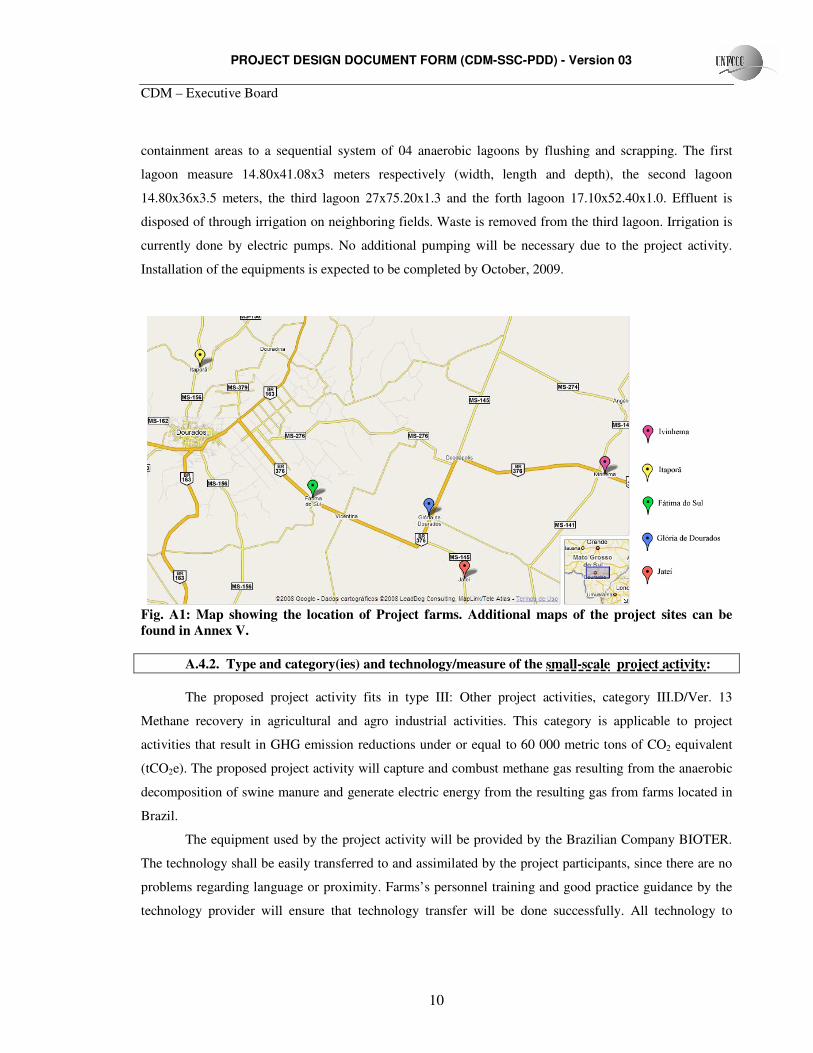
Fig. A1: Map showing the location of Project farms. Additional maps of the project sites can be found in Annex V. A.4.2. Type and category(ies) and technology/measure of the small-scale project activity:
The proposed project activity fits in type III: Other project activities, category III.D/Ver. 13
Methane recovery in agricultural and agro industrial activities. This category is applicable to project
activities that result in GHG emission reductions under or equal to 60 000 metric tons of CO2 equivalent
(tCO2e). The proposed project activity will capture and combust methane gas resulting from the anaerobic
decomposition of swine manure and generate electric energy from the resulting gas from farms located in
Brazil.
The equipment used by the project activity will be provided by the Brazilian Company BIOTER.
The technology shall be easily transferred to and assimilated by the project participants, since there are no
problems regarding language or proximity. Farms’s personnel training and good practice guidance by the
technology provider will ensure that technology transfer will be done successfully. All technology to
PROJECT DESIGN DOCUMENT FORM (CDM-SSC-PDD) - Version 03
CDM – Executive Board
11
operate the AWMS is produced in Brazil. Technology transfer from Annex I will only be necessary for the
monitoring equipment, such as the gas analyzer and the flow meters. However, this equipment is provided
by Brazilian companies that also provide training and maintenance, if necessary.
BIOTER was established in 1997 and has been working with anaerobic digesters since 2004.
BIOTER is specialized in energy generation from biogas. The technology installed by the project includes
the adaptation of existing anaerobic lagoons in order to create anaerobic digesters. The system will be
built as one or more anaerobic digesters, ensuring a minimum Hydraulic Retention Time (HRT) of 30
days, to guarantee a significant reduction in organic matter and volatile solids through anaerobic digestion.
The AWMS proposed includes technical components to ensure methane production, capture and
combustion by a motor to generated electric energy. A brief description of such components follows:
Manure loading system:
Animal waste is sent from the barns to the anaerobic digester through two sealed pipes made of
Polymer Polyvinyl Chloride (PVC). Manure is loaded from the barns to the anaerobic digesters.
Sludge removal and manure reflux system
PVC pipelines along the digester will remove manure from the bottom of the anaerobic digester
and pump it to the frontal part of the anaerobic digester and will prevent gas leakages under the bottom
geomembrane of the digester. Each AWMS will be equipped with one electric pump to operate this
system. The electric pump is equipped with a 5 horsepower (Hp) engine, providing a flow of 50 m3/hour.
The electric pump has an estimated consumption of 1.5 KWh.
Bottom geomembrane
The bottom geomembrane is made of HDPE. This geomembrane is 0,8mm thick.
Internal walls:
Each anaerobic digester will be equipped with two 0,8mm thick HDPE geomembranes, acting as
internal walls. These walls are made to retain solids, improving the system’s efficiency on organic matter
degradation. Internal walls will be held by steel wires and bolted in the concrete gutter surrounding the
anaerobic digester.
Agitation system:
PROJECT DESIGN DOCUMENT FORM (CDM-SSC-PDD) - Version 03
CDM – Executive Board
12
The agitation system will reflux the available biogas into the effluent through a gas compressor
and a 20mm PVC pipeline. Biogas will be periodically refluxed into the effluent to avoid solid
agglomeration in the bottom of the anaerobic digester, improving the system’s efficiency to decompose
organic matter. Each AWMS will be equipped with on gas compressor to operate this system. The gas
compressor is equipped with a 5 HP engine and an estimated consumption of 1.5 KWh.
Cover layer:
The anaerobic digester will have a 1.25mm thick HDPE layer to ensure biogas capture and storage.
This layer will be sealed and fixed in the concrete gutter.
Upon leaving the anaerobic digester, the treated effluent will flow into the existing storage
lagoons, through PVC pipelines. In the storage lagoons, the treated effluent will be collected and used to
irrigate cropping areas.
The captured biogas will be conducted to a motor and generate electric energy to the barn, after
passing through a flow meter. In the fraction of time the motor is not operational, biogas will be conducted
through another sealed PVC pipeline and flow meter to an open flare system
Motor to generate energy:
Motor GM. 1.8, 4 cylinders for biogas use, cooled by water with cogeneration system of by
thermal power of 15 kW, 1800 RPM, single grain coupling the asynchronous with power of 15 kW.h of
electric energy, three-phase electric generator, without brushs, 4 polos, tension 220/380/440 Volts, 60 Hz,
mounted on base in steel and supported on cushion anti vibration, Triernet model TT15.
The energy economizer by biogas called Triernet is an equipment of distributed generation,
developed to work in net, supplies electric chain and assumes the tension and frequency of the net,
therefore the synchronism of the equipment is made by the proper net.
The equipment is dependent of the electric net, and leaves to always generate chain that the supply
of energy of the concessionaire will be off, not compromising the security of the net operators.
The engines adapted by the company to work with biogas are deriving of the automobiles engines,
Oto cycle, type flex, with power of 20 40 CV.
Enclosed combustion System (flares)
PROJECT DESIGN DOCUMENT FORM (CDM-SSC-PDD) - Version 03
CDM – Executive Board
13
A total of ten stainless steel enclosed flaring equipments will be installed by the project activity.
The flaring system is automated to ensure that all produced biogas is flared (after passing through the flow
meter). Pressure control devices within the gas handling system maintain ideal biogas flow to the
combustion system.
The enclosed fares are built in thermo resistant material, such as stainless steel. Two temperature
meters are included to determine the combustion temperature. Ventilation devices regulate air flow to
allow the complete combustion of methane. Solar energy devices provide a constant and independent
energy source to the combustion system.
The system is designed to reach a minimum temperature of 500ºC in the flaring process (a second
ignition system is automatically activated if the exhaust gas temperature is below the programmed
temperature).
Programmable Logic Controller:
A Programmable Logic Controller will coordinate the combustion system and the monitoring
equipments. Through the PLC, data on biogas flow, biogas temperature, biogas pressure, flaring
temperature, etc will be recorded and stored. The PLC will record data hourly on a 16 Mb Data Flash,
allowing the project participants to determine emission reductions on an hourly basis in every farm. The
PLC will be interfaced to a PC terminal via Universal Serial Bus (USB) connection and appropriate
software. The components parts are verified functional on a quarterly basis, in accordance with
manufacturer and other technical specifications.
The PLC coordinates all systems through pressure controlling devices. Once the ideal biogas
pressure is present, the ignition system is activated and monitoring information recorded (regarding biogas
flow, temperature and temperature of the flaring process).
Flow meter:
Two flow meter will be installed at each barn; one to measure the flow in to the enclosed flare and another
one to measure the flow in to a motor to energy generated.
Biogas flow will be measured by ROOTS® G65 SSM – ICPWS flow meters.
ROOTS® special service meters (SSM) are continuous duty meters for measurement of gases
where entrained liquids may be present and where the gas being measured may have a corrosive effect on
some of the materials employed in meters of standard construction. Typical applications would be in a
PROJECT DESIGN DOCUMENT FORM (CDM-SSC-PDD) - Version 03
CDM – Executive Board
14
production pipeline with sour, wet gases or in a sewage treatment plant to measure gases produced by a
sludge digester.
SSM Construction
All carbon steel parts have been eliminated from the gas stream in a Special Service Meter. The
bearings are made of stainless steel as are the timing gears, spring clips, and internal cap screws. The
bearing retainers, clamps and magnet wheel housings are made of anodized aluminum to provide greater
resistance to corrosion.
The impellers are made from aluminum extrusions and hard-coated to impart wear and corrosion
resistance. The cylinder and head plates on the Series B meters (sizes 8C175 through the 56M175) are
manufactured from aluminum and hard-coat anodized. The anodizing also makes the meter highly resistant
to abrasion from particles which may be in the gas stream. More details can be found in Annex IV.
Gas analyzer
All biogas produced in the digester cells will be analyzed by a Dual wavelength Infra-red
Refrigerant Gas sensor. One gas analyzer will be available in every farm. This sensor has a measurement
range of 1% and an accuracy range of 2.5%. This gas sensor will be periodically connected to the gas
pipeline in a specific valve and perform gas analysis. More details can be found in Annex IV.
Biogas temperature analyzer
Biogas temperature will be determined on an hourly basis by sensors in the combustion system.
Biogas Pressure analyzer
Biogas pressure will be determined on an hourly basis by sensors in the combustion system.
The AWMS installed by the project activity is far more advanced then the existing AWMS.
BIOTER will perform training and guidance for all participating farms personnel prior to the crediting
period. Training will involve normal operation, emergency operation, maintenance, and request for
warranty service. Amazon Carbon will perform training for all participating farms personnel regarding
monitoring and emergency operations as well.
Physical description of the proposed AWMS:
In Granja Antonio Durval Góis, the AWMS will consist of one digester cell, measuring 15.0 x
60.0 x 3.5 meters (width, length and depth). The digester cell will be built adapting the existing anaerobic
lagoons. The digester cell will have a volume of 3 150 m3. The resulting effluent will flow to the existing
PROJECT DESIGN DOCUMENT FORM (CDM-SSC-PDD) - Version 03
CDM – Executive Board
15
storage lagoons. One motor to generated electric energy will be used to combust the produced biogas in a
controlled manner.
In Sítio Nossa Senhora Aparecida, the AWMS will consist of one digester cell, measuring 17.0 x
25.0 x 3.5 meters (width, length and depth). The digester cell will be built adapting the existing anaerobic
lagoons. The digester cell will have a volume of 1 487 m3. The resulting effluent will flow to the existing
storage lagoons. One motor to generated electric energy will be used to combust the produced biogas in a
controlled manner.
In Sítio São Geraldo, the AWMS will consist of one digester cell, measuring 14.0 x 35.0 x 3.5
meters (width, length and depth). The digester cell will be built adapting the existing anaerobic lagoons.
The digester cell will have a volume of 1 715 m3. The resulting effluent will flow to the existing storage
lagoons. One motor to generated electric energy will be used to combust the produced biogas in a
controlled manner.
In Sítio Esperança, the AWMS will consist of two digester cells, measuring 17.0 x 25.0 x 3.5
meters (width, length and depth) each. The digester cells will be built adapting the existing anaerobic
lagoons. The digester cells will have a volume of 2 975 m3. The resulting effluent will flow to the existing
storage lagoons. One motor to generated electric energy will be used to combust the produced biogas in a
controlled manner.
In Chacára Paraíso, the AWMS will consist of one digester cell, measuring 15.0 x 70.0 x 2.0
meters (width, length and depth). The digester cell will be built adapting the existing anaerobic lagoons.
The digester cell will have a volume of 2 100 m3. The resulting effluent will flow to the existing storage
lagoons. One motor to generated electric energy will be used to combust the produced biogas in a
controlled manner.
In Granja Osmar Rodrigues Caíres, the AWMS will consist of one digester cell, measuring 12.0
x 36.0 x 3.5 meters (width, length and depth). The digester cell will be built adapting the existing anaerobic
lagoons. The digester cell will have a volume of 1 512 m3. The resulting effluent will flow to the existing
storage lagoons. One motor to generated electric energy will be used to combust the produced biogas in a
controlled manner.
PROJECT DESIGN DOCUMENT FORM (CDM-SSC-PDD) - Version 03
CDM – Executive Board
16
In Granja Dulcemar José Grando, the AWMS will consist of one digester cell, measuring 12.0 x
40.0 x 3.5 meters (width, length and depth). The digester cell will be built adapting the existing anaerobic
lagoons. The digester cell will have a volume of 1 680 m3. The resulting effluent will flow to the existing
storage lagoons. One motor to generated electric energy will be used to combust the produced biogas in a
controlled manner.
In Granja Emerson Fernandes, the AWMS will consist of one digester cell, measuring 12,0 x
36,0 x 3,5 meters (width, length and depth). The digester cell will be built adapting the existing anaerobic
lagoons. The digester cell will have a volume of 1 512 m3. The resulting effluent will flow to the existing
storage lagoons. One motor to generated electric energy will be used to combust the produced biogas in a
controlled manner.
In Granja Antônio José Figueiredo Filho, the AWMS will consist of one digester cell, measuring
12.0 x 50.0 x 3.5 meters (width, length and depth). The digester cell will be built adapting the existing
anaerobic lagoons. The digester cell will have a volume of 2 100 m3. The resulting effluent will flow to the
existing storage lagoons. One motor to generated electric energy will be used to combust the produced
biogas in a controlled manner.
In Rancho Cosmo, the AWMS will consist of one digester cell, measuring 14.80 x 41.08 x 3.0
meters (width, length and depth). The digester cell will be built adapting the existing anaerobic lagoons.
The digester cell will have a volume of 1 823 m3. The resulting effluent will flow to the existing storage
lagoons. One motor to generated electric energy will be used to combust the produced biogas in a
controlled manner.
A.4.3 Estimated amount of emission reductions over the chosen crediting period:
Years Annual estimated emission
reductions in tCO2e 2008 1 349.664 2009 16 196 2010 16 196 2011 16 196 2012 16 196 2013 16 196 2014 16 196 2015 16 196 2016 16 196 2017 16 196
PROJECT DESIGN DOCUMENT FORM (CDM-SSC-PDD) - Version 03
CDM – Executive Board
17
2018 14 846.3 Total estimated reductions (tCo2e) 161 960 Crediting period (years) 10 Annual average of estimated reductions over the crediting period (CO2e)
16 196
Tab. A.3: Project activity estimated GHG emission reduction values. * For the first crediting year, the project will be operational for 31 days (from 01/12/2008 to 31/12/2008) ** For the last crediting year, the project will be operational for 334 days (from 01/01/2018 to
30/11/2018)
A.4.4. Public funding of the small-scale project activity:
No public funds will be invested in the project.
A.4.5. Confirmation that the small-scale project activity is not a debundled component of a large scale project activity: The project activity includes only the above mentioned farms and the associated estimated
emission reductions. Based on paragraph 2 of Appendix C of the Simplified Modalities and Procedures for
Small Scale CDM project activities, this project is not deblundled. There are no other registered (or on
application to register) large-scale CDM project activities with the same project participants, in the same
project category and technology/measure whose project boundaries is within 1 km of another proposed
small-scale project activity sites.
SECTION B. Application of a baseline and monitoring methodology B.1. Title and reference of the approved baseline and monitoring methodology applied to the small-scale project activity:
The title of the approved baseline methodology is AMS-III.D “Methane Recovery in agricultural
and agro industrial activities” version 13, and the reference is the United Nations Framework Convention
on Climate Change (UNFCCC) website:
(http://cdm.unfccc.int/methodologies/SSCmethodologies/approved.html).
B.2 Justification of the choice of the project category: The small-scale project activity category is methane recovery from manure and wastes from
agricultural or agro-industrial activities that would be decaying anaerobically in the absence of the project
activity by
(a) Installing methane recovery and combustion system to an existing source of methane
emissions, or
PROJECT DESIGN DOCUMENT FORM (CDM-SSC-PDD) - Version 03
CDM – Executive Board
18
(b) Changing the management practice of a biogenic waste or raw material in order to achieve the
controlled anaerobic digestion equipped with methane recovery and combustion system.
The project satisfies item 1(a) of the methodology III.D and items 2(a) and (b) that follows:
(a) The sludge must be handled aerobically. In case of soil application of the final
sludge the proper conditions and procedures (not resulting in methane emissions) must be ensured.
(b) Technical measures shall be used (e.g. flared, combusted) to ensure that all biogas
produced by the digester is used or flared.
The project consists in implementing a methane recovery and combustion system on an existing
source of methane that would continue to decay anaerobically without the project. The project activity also
satisfies the applicability conditions of item 2 of the adopted methodology, because all sludge will be used
to irrigate cropping areas, avoiding the occurrence of anaerobic conditions. An enclosed flare will be
installed to ensure that all methane produced by the anaerobic digester is efficiently combusted. Technical
measures will be adopted to ensure proper flare operation and maintenance. Based on historical data from
animal population and baseline studies, the estimated emission reduction of the project activity shall not
exceed 60 Kt CO2e in any year of the crediting period, as shown in Section A.4.3.
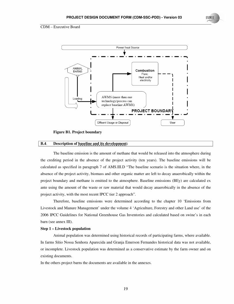
B.3. Description of the project boundary: The project boundary is the physical and geographic sites where methane recovery occurs.
Therefore, the application of treated waste to neighbouring fields occurs outside the project boundaries.
The project boundary includes only the emissions (and related reductions) from the AWMS that captures
and combusts methane installed by the project activity. This means that the anaerobic digester is the
physical boundary of the methane recovery facility. Project boundary is shown in Figure B1 that follows:
PROJECT DESIGN DOCUMENT FORM (CDM-SSC-PDD) - Version 03
CDM – Executive Board
19
Figure B1. Project boundary
B.4. Description of baseline and its development:
The baseline emission is the amount of methane that would be released into the atmosphere during
the crediting period in the absence of the project activity (ten years). The baseline emissions will be
calculated as specified in paragraph 7 of AMS.III.D “The baseline scenario is the situation where, in the
absence of the project activity, biomass and other organic matter are left to decay anaerobically within the
project boundary and methane is emitted to the atmosphere. Baseline emissions (BEy) are calculated ex
ante using the amount of the waste or raw material that would decay anaerobically in the absence of the
project activity, with the most recent IPCC tier 2 approach”.
Therefore, baseline emissions were determined according to the chapter 10 ‘Emissions from
Livestock and Manure Management’ under the volume 4 ‘Agriculture, Forestry and other Land use’ of the
2006 IPCC Guidelines for National Greenhouse Gas Inventories and calculated based on swine’s in each
barn (see annex III).
Step 1 – Livestock population
Animal population was determined using historical records of participating farms, where available.
In farms Sítio Nossa Senhora Aparecida and Granja Emerson Fernandes historical data was not available,
or incomplete. Livestock population was determined as a conservative estimate by the farm owner and on
existing documents.
In the others project barns the documents are available in the annexes.
PROJECT DESIGN DOCUMENT FORM (CDM-SSC-PDD) - Version 03
CDM – Executive Board
20
Description of the productive units follows:
• PPU (Piglet Producing Unit): This practice consists on gilts (weighting an average of 140 Kg),
gestating sows (weighting an average of 160 kg), sows (weighting an average of 220 to 240 kg)
that give birth 2.4 times a year on average, bearing an average 10.6 piglets per delivery and boars
(weighting an average of 240kg). Piglet’s are then breastfed for a 21-day period and after weaning
are taken to the nursery. Piglets are transferred to the nursery weighting 6 Kg on average.
Considering the 21-day periods, piglets weight around 3 Kg.
• Nursery: This unit consists only in swine coming from the PPU. Animals are fed for a 40-days
period and sold at the age of 60 days. Animals are then transferred to the Finishing Units
weighting 23 Kg on average. Considering the 40 days-period, animals in the nursery weight 14 -
15 Kg.
• FU (Finishing Unit): This unit contains only weanlings from the nursery. Animals proceed
through fattening up and growth until slaughter or transfer to the PPU. Slaughter is done when
animals weight around 110 kg. Animals usually remain in the FU for a period of 120 days.
Considering this period, animals in the FU unit weight 68 Kg.
The livestock population for each farm is demonstrated in Table B1, bellow:
PROJECT DESIGN DOCUMENT FORM (CDM-SSC-PDD) - Version 03
CDM – Executive Board
21
Animal category Data Granja Antonio
Durval Góis
Sítio Nossa Senhora
Aparecida
Sítio São Geraldo
Sítio Esperança
Piglet Producing Unit
Population 418 80 - 80
Gilts Average Weight
(Kg) 198 155 - 155
Population - 936 - 936
Sows in gestation Average Weight
(Kg) - 198 - 300
Population 761 144 - 144
Sows Average Weight
(Kg) 198 198 - 300
Population 7 5 - 5
Boars Average Weight
(Kg) 198 198 - 400
1 753 1585 - 1 585
Piglets Average Weight
(Kg) 3. 28 3.75 - 3.75
Nursery Unit
Population 2 757 3530 - 3530
Nursery Average Weight
(Kg) 15.18 15.5 - 15.5
Finishing Unit
Population - - 2 054 -
Finishers Average Weight
(Kg) - - 62.6 -
Total Livestock --- 5 703 6 280 2 054 6 280
Table B1. Information on farm’s livestock. Historic livestock data can be found in Annex III.
PROJECT DESIGN DOCUMENT FORM (CDM-SSC-PDD) - Version 03
CDM – Executive Board
22
Animal category Data Chacara Paraíso Granja Osmar
Rodrigues Caíres Granja Dulcemar
José Grando Granja Emerson
Fernandes Piglet Producing
Unit
Population - - - -
Gilts Average Weight
(Kg) - - - -
Population - - - -
Sows in gestation Average Weight
(Kg) - - - -
Population - - - -
Sows Average Weight
(Kg) - - - -
Population - - - -
Boars Average Weight
(Kg) - - - -
- - - -
Piglets Average Weight
(Kg) - - - -
Nursery Unit
Population - - - -
Nursery Average Weight
(Kg) - - - -
Finishing Unit
Population 2 973 3 067 5 039 3 800
Finishers Average Weight
(Kg) 59.2 62.3 60.3 70
Total Livestock --- 2 973 3 067 5 039 3 800
Table B1 (cont). Information on farm’s livestock. Historic livestock data can be found in Annex III. * Data on this animal category is not available. As a conservative action, IPCC default value for this parameter was chosen. See more details in Section B.6.1.
PROJECT DESIGN DOCUMENT FORM (CDM-SSC-PDD) - Version 03
CDM – Executive Board
23
Table B1 (cont.). Information on farm’s livestock. Historic livestock data can be found in Annex III. * Data on this animal category is not available. As a conservative action, IPCC default value for this parameter was chosen. See more details in Section B.6.1.
Animal category Data Granja Antônio José Figueiredo
Filho Rancho Cosmo
Piglet Producing Unit
Population
Gilts Average Weight
(Kg) - -
Population - -
Sows in gestation Average Weight
(Kg) - -
Population - -
Sows Average Weight
(Kg) - -
Population - -
Boars Average Weight
(Kg) - -
Population - -
Piglets Average Weight
(Kg) - -
Nursery Unit -
Population - -
Nursery Average Weight
(Kg) - -
Finishing Unit
Population 5 081 4 976
Finishers Average Weight
(Kg) 60.4 59.5
Total Livestock --- 5 081 4 976
PROJECT DESIGN DOCUMENT FORM (CDM-SSC-PDD) - Version 03
CDM – Executive Board
24
Step 2 – Methane Emission Factors
Emission factors were determined individually for every animal category shown on Table B1. The
baseline AWMS is an open anaerobic lagoon, as described on item A.4.1.4
The emission factor for each animal group is determined by the following equation:
EFCH4,i= (Vssite * Nd * Bo * DCH4 * MCF * MS% * GWP_CH4)/1000
Where,
EFCH4,i: Methane emission factor for the animal category i, expressed in tCO2e/animal/year.
Vssite: Adjusted volatile solids excretion per day, expressed in kg-dm/animal/day.
Nd Number of days animals are present in containment areas
Bo: Maximum methane production capacity, in m3 of CH4/kg-dm
DCH4: Density of CH4, in kg/m3
MCF: Methane conversion factor for the anaerobic lagoon.
MS% Fraction of waste that is treated in the baseline AWMS.
Adjusted volatile solids excretion (Vssite):
VSsite,i = (Wsite,i /Wdefault) * VSdefault
Where, VSsite,i: Adjusted daily volatile solid matter excretion for the animal category i, on a dry matter
basis, for a specific animal category on project site, in kg-dm/animal/day.
Wsite: Average weight of local animal for category i, in kg.
Wdefault : Default value (2006 IPCC) of average weight per animal for a specific category, in kg.
VSdefault: Default value (2006 IPCC) for daily volatile solid matter excretion, on a dry matter
basis, for a specific animal category, in kg-dm/animal/day.
The amount of methane emitted in the baseline scenario is calculated by the equation:
CH4a = EFCH4,i * Na
Where,
CH4a Methane produced by the animal population of category I, expressed in tCO2e/year.
Na Number of animals of the type i.
PROJECT DESIGN DOCUMENT FORM (CDM-SSC-PDD) - Version 03
CDM – Executive Board
25
Step 3 – Total Baseline emissions
BE = ∑CH4a,i
Where,
BE: Total baseline emissions, in tCO2e/year.
CH4a,i Methane produced by the population of animal categories i.
B.5. Description of how the anthropogenic emissions of GHG by sources are reduced below those that would have occurred in the absence of the registered small-scale CDM project activity:
The additionality of the proposed project activity was defined as per guidance of the Attachment A
to Appendix B of the Simplified modalities and procedures for small-scale clean development mechanism
project activities.
The most probable baseline hypotheses have been selected for the proposed Project activity. In this
case, the baseline scenario is determined as the scenario that represents “emissions from a technology
which is economically attractive as far as the investment barriers are concerned”. Therefore, this
hypothesis determines the baseline scenario under a cost-benefit assessment point of view and assumes that
high cost scenarios shall not be implemented. The various possible baseline scenarios, including different
effluent management technologies, are described in detail in the Revised 2006 IPCC Guidelines for
National Greenhouse Gas Inventories: Reference Manual (Chapter 10, Table 10.18) and also in the GHG
emissions inventory of the Ministry of Technology and Science
(http://www.mct.gov.br/index.php/content/ view /3881.html).
The baseline scenario for the participating farms has been defined per the following steps:
Step 1: Identifying the project activity alternatives
In the first step of the measurement and attempt to prove the additionality of the proposed project
activity, the complete set of possible baseline scenarios and project activity, which are listed in the 2006
IPCC Guidelines for National Greenhouse Gas Inventories should be taken into account.
This includes the following swine manure treatment options:
• Disposal of untreated manure to environment
• Daily spread
• Liquid/slurry
• Solid storage
• Dry lot
PROJECT DESIGN DOCUMENT FORM (CDM-SSC-PDD) - Version 03
CDM – Executive Board
26
• Anaerobic lagoon
• Pit storage below animal confinements
• Anaerobic digester
• Deep litter
• Composting
• Aerobic treatment
• Burned for fuel
Step 2: Identification of plausible scenarios
2.a: Consistency with mandatory laws and regulations.
Laws and regulations concerning swine confinement farms are defined by the Environmental
authority. In Mato Grosso do Sul, IMASUL (Instituto de Meio Ambiente do Mato Grosso do Sul) is
responsible for such regulation. According the Script of system project of environmental control for swine
rising (Roteiro de projeto de sistema de controle ambiental para Suinocultura) of IMASUL, the only
excluded scenario is the disposal of untreated manure to water streams or in Environmental Protected
areas. The referenced document is available at IMASUL website, below:
http://www.imasul.ms.gov.br/manual/index.php looks for (ROTEIRO-SUINOCULTURA)
Bearing current practice in Brazil, a number of plausible scenarios have been identified from the
list of possible options. The aspects that have been considered in order to identify the plausible baseline
scenarios are: historic or pre-existing practices within the organization, technology available, possible and
correct application of the technology in the context and assessment of national technological development.
These plausible scenarios are based on data described in the First Brazilian anthropogenic GHG
emissions inventory of the Ministry of Science and Technology and EMBRAPA, available at:
(http://www.mct.gov.br/index.php/content/view/17341.html):
• Daily spread
• Composting
• Pit storage below animal confinements
• Anaerobic lagoon
• Anaerobic digester
• Aerobic digester
PROJECT DESIGN DOCUMENT FORM (CDM-SSC-PDD) - Version 03
CDM – Executive Board
27
A justification for the inclusion/exclusion of the manure management systems that cannot be
considered a plausible baseline scenario (including the proposed project activity) was determined
according to the Technological Inventory of EMBRAPA for Swine Manure Management Systems,
available at:
(http://www.cnpsa.embrapa.br/invtec/15.html)
Excluded scenarios:
The criteria used to determine the scenarios excluded are practical and economical regarding the
type of technology. From these analyses, the excluded scenarios follow:
• Solid storage: Usually, the type of swine manure storage offers no protection against pathogenic
vectors and, because it’s a non-sealed area, releases odors that jeopardize the residents’ quality
of life.
• Daily spread: This system has been excluded due to the size of the livestock. Manure production
is too great to allow daily spread on cropping areas. Besides, manure is handled in liquid form,
as it is removed from the barns through a flushing system.
• Dry lot: This system has been excluded because it does not apply to confined animals.
• Liquid/slurry: This system was excluded because manure is removed by a flushing system that
adds a considerable amount of water to the manure.
• Pit storage below animal confinements: This treatment system has been excluded due to the fact
that biological manure digestion releases methane, which can intoxicate the herd when it’s not
properly eliminated through exhaustion systems.
• Deep litter: This type of treatment is not often used in Brazil since swine raisers regard it as hard
and disagreeable. The remaining users are choosing to replace it by liquid or solid waste
treatment systems in order to optimize cost/benefit.
• Composting: Composting systems are not suitable for great volumes of confined swine manure.
This occurs because there is too much water in the waste, which makes the drying process very
hard. This treatment is more effective when dealing with the sludge resulting from bacterial
decomposition processes.
• Aerobic treatment: This type of treatment is more commonly used when dealing with sludge or
diluted waste. The solids in the manure are difficult to homogenize and oxygenate, which
demands too much activity from the agitators. Another important consideration is the
ammonium release potential from the system when it is not properly aerated. This equipment
consumes high amounts of energy, which increases costs for the swine raiser.
PROJECT DESIGN DOCUMENT FORM (CDM-SSC-PDD) - Version 03
CDM – Executive Board
28
• Burned for fuel: Animal waste is handled in a liquid form, since flushing systems are used to
remove manure from the barns. Burning waste or organic matter is also not encouraged by
IMASUL due to odor and smoke emissions.
Through this analysis, the plausible scenarios have been reduced to two potential manure treatment
systems:
Plausible baseline scenario: Anaerobic lagoon.
Proposed project activity: Anaerobic Digester.
Included scenarios:
• Anaerobic Lagoon: This treatment system is easy to operate, which requires little workforce and
maintenance investment. It is a viable alternative and has been considered a plausible baseline
scenario.
• Anaerobic digester: This system is easy to operate, retrieves methane, which is responsible for
global warming, is capable of producing biogas and biofertilizer, and also reduces odors. It
requires high implementation costs and medium maintenance cost. This alternative is not very
popular among Brazilian swine raisers and has been considered the project activity.
After the identification of the plausible scenarios, following the process of measurement and
additionality demonstration, an analysis shall be made to demonstrate the barriers that the proposed project
activity selected above will face without the CDM project register.
Step 3: Barrier Analysis This Project activity is not adopted nationally due to the following barriers:
Investment Barriers: this manure management system is regarded as one of the most advanced practices
worldwide. A few countries use this technology due to high costs involved when compared to other
systems. The technology applied by the project demands an investment of U$23 to U$61 per cubic meter
of installed digester capacity. Less expensive AWMS are available, but result in higher GHG emissions, as
demonstrated in the Technological Inventory of EMBRAPA for Swine Manure Management Systems.
Technological Barriers: In order to justify the implementation of an anaerobic digester, a great deal of
manure is needed, as well as proximity and concentration of barns, since the smaller the herd, the more
expensive the implementation of the system regarding cost/benefit.
PROJECT DESIGN DOCUMENT FORM (CDM-SSC-PDD) - Version 03
CDM – Executive Board
29
Anaerobic digesters are systems that need detailed planning to be installed. Operating also involves
controlled manure handling practices, constant performance checking and maintenance. This is not usually
the case for baseline scenarios, where farmers have little to no control of the existing AWMS. The lack of
knowledge to operate anaerobic digesters was a serious barrier to the adoption of such system in Brazil, as
described by Mr. Airton Kunz, in his Article ‘EMBRAPA’s experience with anaerobic digestion of swine
waste – I (Experiência da EMBRAPA com biodigestão anaeróbica de dejetos de suínos - I), available at the
following website:
(http://www.cnpsa.embrapa.br/sgc/sgc_publicacoes/publicacao_r6e60d8p.pdf)
Legal Restrictions: The Brazilian legislation related to swine confinement farms is focused on the
protection of water sources and protected areas. A few water quality guidelines are determined. It is also
forbidden to dispose untreated effluent into the environment, as demonstrated by IMASUL - Script of
system project of environmental control for swine rising, amongst others. No specific effluent treatment or
GHG emission control in swine farm operations are required.
Step 4: Common practice analysis:
According to the First Brazilian anthropogenic GHG emissions inventory of the Ministry of
Science and Technology and EMBRAPA, the Brazilian swine manure systems can be divided into two
distinct groups. The first group (occurring mainly in the states of São Paulo, Goiás and Mato Grosso) with
large farms, over one thousand swine and usually treatment systems that consist of a series of stabilization
lagoons and, in some cases, partly digested waste spray. And the second group (occurring mainly in the
west of the state of Santa Catarina, state of Paraná and northwest of the state of Rio Grande do Sul), with
small farms, distributed as follows: small (up to 100 swine), medium (100 to 300 swine) and large (over
300 swine). The treatment system commonly used is the open tank (single anaerobic lagoon), which a
retention time that varies from 20 to 90 days. After that period it’s applied to the soil on site or in
neighboring areas.
As described above, we are able to conclude that the usual technology applied to Brazilian swine
confinement farms is based on anaerobic lagoons. Therefore the project activity, which consists on
anaerobic digesters, is not similar to what can be commonly found in Brazil.
Step 5: Impact caused by the registration of the project as CDM:
As shown in the steps above, the only way to implement the proposed project activity is by
overcoming the barriers mentioned and reducing the risks commonly associated to this type of project.
PROJECT DESIGN DOCUMENT FORM (CDM-SSC-PDD) - Version 03
CDM – Executive Board
30
The potential of the CDM project, mainly the environmental and financial one, was extremely
important in the decision-making process of the participating swine raisers. The implementation of such an
innovative technology into the production system, which can bring great environmental improvements due
to GHG emission reduction, would be impossible in the absence of the financial aid raised by the project
activity.
Within the process of gathering the producers to implement the project activity it was possible to
notice how resilient some of them were regarding the technology applied, which was caused mainly by the
lack of information regarding economic and environmental cost/benefit. This type of situation was only
clarified by the possibility of implementation of this system on the farms mentioned in the project activity.
We must also consider the development and encouragement of new technologies or the application
of well-known, widespread technologies to other productive activities, as they are adjusted for highly
atmospheric polluting activities (such as swine confinement farms).
As demonstrated in this fifth step of the additionality analysis, it becomes evident that the impact
caused by the registration of the CDM project was decisive to overcome the barriers to the implementation
of the proposed project activity.
B.6. Emission reductions:
B.6.1. Explanation of methodological choices:
Baseline emissions are calculated as described in Section B.4. Project emissions were determined
according to the approved small-scale methodology AMS.III.D. The project emissions for the proposed
project activity are defined as the amount of methane that would be emitted to the atmosphere during the
crediting period due to the project activity, besides emissions associated to fossil fuel and energy
consumption within project boundary. An anaerobic digester is considered the project activity and projects
emissions consist of:
Ex ante estimation of Emissions from project activity (PEex-ante):
Four factors are considered emissions from the project activity: methane emissions from digester,
methane emissions from inefficient flaring, CO2 emissions from fossil fuel combustion and CO2 emissions
from electricity consumption. The following formulae are used to calculate these factors:
PE = PEdigester + PEflare + PEFC + PEEC
Where,
PE Project emissions, in tCO2e.
PEdigester Methane emissions from anaerobic digester, in tCO2e.
PROJECT DESIGN DOCUMENT FORM (CDM-SSC-PDD) - Version 03
CDM – Executive Board
31
PEflare Methane emissions from inefficiency in methane flaring in tCO2e.
PEFC CO2 emissions from fossil fuel combusted to operate the AWMS
PEEC CO2 emissions from electricity consumption to operate the AWMS
Methane emissions from anaerobic digester (PEdigester)
Anaerobic digester emissions were also estimated according to the Tier 2 approach of the 2006
IPCC Guidelines for Greenhouse Gas Inventories, chapter 10 ‘Emissions from Livestock and Manure
Management’ under the volume 4 ‘Agriculture, Forestry and other Land use’. Emissions from this source
were determined through the following steps:
Step 1 – Livestock population
Livestock population was defined as described in section B.4. Livestock population will remain
constant during the project activity.
Step 2 – Methane Emission Factors
Emission factors were determined individually for every animal category shown on Table B1.
The emission factor for each animal group is determined by the following equation:
EFCH4,i= (Vssite * Nd * Bo * DCH4 * MCF * MS%* GWP_CH4)/1000
Where,
EFCH4,i: Methane emission factor for the animal category i, expressed in tCO2e/animal/year.
Vssite: Adjusted volatile solids excretion per day, expressed in kg-dm/animal/day.
Nd Number of days animals are present in containment areas
Bo: Maximum methane production capacity, in m3 of CH4/kg-dm
DCH4: Density of CH4, in kg/m3
MCF: Methane conversion factor for the anaerobic digester.
MS% Fraction of waste that is treated in the project AWMS.
Adjusted volatile solids excretion (Vssite):
VSsite,i = (Wsite,i /Wdefault) * VSdefault
Where, VSsite,i: Adjusted daily volatile solid matter excretion for the animal category i, on a dry matter
basis, for a specific animal category on project site, in kg-dm/animal/day.
Wsite: Average weight of local animal for category i, in kg.
PROJECT DESIGN DOCUMENT FORM (CDM-SSC-PDD) - Version 03
CDM – Executive Board
32
Wdefault : Default value of average weight per animal for a specific category, in kg.
VSdefault: Default value (2006 IPCC) for daily volatile solid matter excretion, on a dry matter
basis, for a specific animal category, in kg-dm/animal/day.
The amount of methane emitted by an animal population is calculated by the equation:
CH4a = EFCH4,i * Na
Where,
CH4a Methane emissions by the animal population of category i, expressed in tCO2e/year.
Na Average number of animals of the type i.
Step 3 – Total methane emissions from anaerobic digester
PECH4 = ∑CH4a,i
Where,
PECH4: Methane emissions from anaerobic digester.
CH4a,i Methane emissions by the population of animal categories , expressed in tCO2e/year.
Emissions from inefficiency in methane flaring (PEflare):
Emissions from this source were estimated per guidance of the “Tool to determine project
emissions from flaring gases containing methane, version 1,” available in the UNFCCC website below:
(http://cdm.unfccc.int/Reference/Guidclarif/index.html)
Where,
PEflare: Emissions from inefficient flaring, in tCO2e.
TMRG,h: Mass flow rate of methane in the residual gas in the hour h.
ηflare: Flare efficiency for methane destruction. 90% is the value used for flaring efficiency.
Mass flow rate of methane in the residual gas in the hour h (TMRG,h ): Mass flow rate of methane will be monitored during the project activity as described in Section
B.7.2. For ex-ante calculation of mass flow rate of gas sent to the flare, a default EMBRAPA value was
adopted to determine biogas production from swine manure. The reference is the Technical Report
(Comunicado Técnico) 417/2005. This report demonstrates results from biogas production in an anaerobic
PROJECT DESIGN DOCUMENT FORM (CDM-SSC-PDD) - Version 03
CDM – Executive Board
33
digester similar to the equipment installed by the project activity (same technology provider) and in a
region with similar climate as most of the project sites. In this report, the following information was
obtained:
Data Value Unit
Biogas/Volatile Solids rate 0,45 m3 biogas/Kg Vs
Yearly mass flow rate was estimated as:
∑TMRGh = Nai * Vssite * Nd * MS% * BVs * CCH4 * DCH4
Where,
BVs Biogas/Volatile Solids ratio.
CCH4 Methane concentration in biogas.
CO2 emissions from fossil fuel combusted to operate the AWMS
Project emissions from this source are considered negligible, because the AWMS installed as the
project activity will not result in increase in fossil fuel consumption.
CO2 emissions from electricity consumption to operate the AWMS
Project emissions from this source are considered negligible, because the AWMS installed as the
project activity will not result in significant increase in energy consumption. The combined electricity
consumption of the electric pumps and the gas compressors for each farm is approximately 0.8 MWh per
year. However our goal at this project is generated electrical energy from the biogas and the CO2 emissions
from electricity will be negative.
Leakage emissions (LE):
Leakage emissions are not considered, as defined as defined in paragraph 9 of approved small-
scale methodology AMS.III.D, version 13.
Emission Reductions (ER)
In order to obtain the project activity emission reductions, project activity emissions and leakage
emissions must be subtracted from the baseline emissions, as described below:
Estimated project activity emission reductions (ERPA_estimated):
ERPA_estimated = BE – PE - LE
Where,
PROJECT DESIGN DOCUMENT FORM (CDM-SSC-PDD) - Version 03
CDM – Executive Board
34
ERPA_estimated is expressed in tCO2e.
BE: Total baseline emissions in tCO2e.
PE: Total emissions from project activity.
LE Total leakage emissions.
Calculated project activity emission reductions (ERPA_calculated):
The actual emission reduction achieved by the project during the crediting period will be
calculated using the amount of methane recovered and destroyed by the project activity, calculated
as:
ERPA_calculated = MDy – PEy – Leakage
Where:
PEy actual project emissions in the year y
MDy methane captured and destroyed by the project activity in the year “y” (tCO2 e),
that will be measured using the conditions of the flaring process:
Where:
BGburnt,y biogas flared or used as fuel in the year “y” (m3).
wCH4,y methane content in biogas in the year “y” (mass fraction).
DCH4,y density of methane at the temperature and pressure of the biogas in the year “y”
(tonnes/m3).
FE flare efficiency in the year “y” (fraction)
GWPCH4 Methane global warming potential (21)
The actual project emissions will be calculated according to the monitored amount of methane
destined to the flares. The amount of methane sent to the flare will be determined as the mass flow rate of
methane in the residual gas in the hour h, described above. Hence,
PEdigester,y = TMRG,h * MCF * GWPCH4
Where,
MCF Methane conversion factor of the anaerobic digester
This data will also be used to determine project emissions from flaring (PEflare) during the crediting
period.
PROJECT DESIGN DOCUMENT FORM (CDM-SSC-PDD) - Version 03
CDM – Executive Board
35
Explanation of methodological choices
Default values are used to represent volatile solid excretion (Vs), methane production from treated
manure (Bo) and Methane Conversion Factors (MCF). Default values have been chosen to quantify the
emissions, since the existing AWMS did not include direct monitoring of such values. Determining these
parameters on site is not an economically viable option. Default values are taken from 2006 IPCC
Guidelines for Greenhouse Gas Inventories, chapter 10 ‘Emissions from Livestock and Manure
Management’ under the volume 4 ‘Agriculture, Forestry and other Land use’, unless otherwise stated.
Carbon dioxide emissions from methane combustion (burned in the flare) are biogenic. This
assumption is based on the fact that the organic matter consumed by the animals has a renewable origin
(and therefore is not considered fossil). CO2 emissions from anaerobic digestion do not represent any
difference in the emission volumes between each scenario since there is no possible additional
transformation once that compound is burned. Methane emissions from biogas flaring were determined as
described above
The characteristics of the livestock regarding number and weight of individuals were collected on
site by the collected company SEARA. SEARA are the swine provider and the swine buying of all barns
participants of this project.
The following sources have been used to calculate the baseline and project emissions: • Approved small-scale methodology AMS.III.D.
• 2006 IPCC Guidelines for National GHG Inventories;
• First Brazilian Inventory on GHG Anthropogenic Emissions – Support Report – Agriculture and
Animal Husbandry.
• Technological Inventory of EMBRAPA for Swine Manure Management Systems
• EMBRAPA Technical Report 417/2005
B.6.2. Data and parameters that are available at validation:
Data / Parameter: Na
Data unit: N/A Description: Average number of animals of type i Source of data used: Farms managers, sale receipts and monitoring spreadsheets (where available) Value applied: Values applied are described in TableB.1. Justification of the choice of data or description of
The procedures for determining this parameter are described in Section B.6.1.
PROJECT DESIGN DOCUMENT FORM (CDM-SSC-PDD) - Version 03
CDM – Executive Board
36
measurement methods and procedures actually applied: Any comment:
Data / Parameter: Nflare Data unit: Fraction or percentage Description: Flare efficiency for methane destruction Source of data used: Methodological Tool to determine project emissions from flaring gases
containing methane Value applied: 90% Justification of the choice of data or description of measurement methods and procedures actually applied:
A default value of 90% is adopted as a conservative action, since data to determine the actual efficiency will not available.
Any comment:
Data / Parameter: CCH4 Data unit: Fraction or percentage Description: Methane concentration in biogas Source of data used: BIOTER Value applied: 70% Justification of the choice of data or description of measurement methods and procedures actually applied:
Methane concentration in biogas is expected to range from 60 to 70%. For project emissions calculation, the higher the CCH4, the higher the emissions from this source. Therefore, 70% is a conservative value.
Any comment:
Data / Parameter: VSdefault
Data unit: Kg-dm/animal/day Description: Daily volatile solids excretion rate Source of data used: 2006 IPCC, Annex 10A.2, Table 10A-7 (market swine) and 10A-8 (breeding
swine) Value applied: 0.3 (market swine) (Eastern Europe)
0.5 (breeding swine) (Eastern Europe) Justification of the choice of data or description of measurement methods and procedures actually applied:
Default values are applied because local data is not available. Local data collection is not a viable option for excretion rate.
Any comment:
Data / Parameter: VSsite
Data unit: Kg-dm/animal/day Description: Daily volatile solids excretion rate, corrected for local animal weight
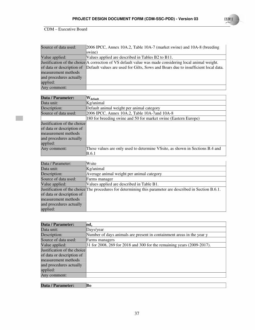
PROJECT DESIGN DOCUMENT FORM (CDM-SSC-PDD) - Version 03
CDM – Executive Board
37
Source of data used: 2006 IPCC, Annex 10A.2, Table 10A-7 (market swine) and 10A-8 (breeding swine)
Value applied: Values applied are described in Tables B2 to B11. Justification of the choice of data or description of measurement methods and procedures actually applied:
A correction of VS default value was made considering local animal weight. Default values are used for Gilts, Sows and Boars due to insufficient local data.
Any comment:
Data / Parameter: Wdefault
Data unit: Kg/animal Description: Default animal weight per animal category Source of data used: 2006 IPCC, Annex 10A.2, Table 10A-7and 10A-8
180 for breeding swine and 50 for market swine (Eastern Europe) Justification of the choice of data or description of measurement methods and procedures actually applied:
Any comment: These values are only used to determine VSsite, as shown in Sections B.4 and B.6.1
Data / Parameter: Wsite Data unit: Kg/animal Description: Average animal weight per animal category Source of data used: Farms manager Value applied: Values applied are described in Table B1. Justification of the choice of data or description of measurement methods and procedures actually applied:
The procedures for determining this parameter are described in Section B.6.1.
Data / Parameter: ndy
Data unit: Days/year Description: Number of days animals are present in containment areas in the year y Source of data used: Farms managers Value applied: 31 for 2008, 269 for 2018 and 300 for the remaining years (2009-2017). Justification of the choice of data or description of measurement methods and procedures actually applied:
Any comment:
Data / Parameter: Bo
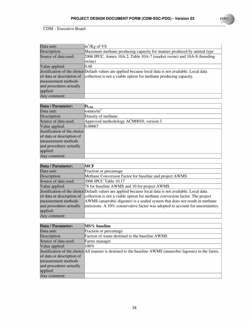
PROJECT DESIGN DOCUMENT FORM (CDM-SSC-PDD) - Version 03
CDM – Executive Board
38
Data unit: m3/Kg of VS Description: Maximum methane producing capacity for manure produced by animal type Source of data used: 2006 IPCC, Annex 10A.2, Table 10A-7 (market swine) and 10A-8 (breeding
swine) Value applied: 0.48 Justification of the choice of data or description of measurement methods and procedures actually applied:
Default values are applied because local data is not available. Local data collection is not a viable option for methane producing capacity.
Any comment:
Data / Parameter: DCH4
Data unit: tonnes/m3
Description: Density of methane Source of data used: Approved methodology ACM0010, version 3 Value applied: 0.00067 Justification of the choice of data or description of measurement methods and procedures actually applied:
Any comment:
Data / Parameter: MCF
Data unit: Fraction or percentage Description: Methane Conversion Factor for baseline and project AWMS Source of data used: 2006 IPCC Table 10.17 Value applied: 78 for baseline AWMS and 10 for project AWMS Justification of the choice of data or description of measurement methods and procedures actually applied:
Default values are applied because local data is not available. Local data collection is not a viable option for methane conversion factor. The project AWMS (anaerobic digester) is a sealed system that does not result in methane emissions. A 10% conservative factor was adopted to account for uncertainties.
Any comment:
Data / Parameter: MS% baseline Data unit: Fraction or percentage
Description: Faction of waste destined to the baseline AWMS Source of data used: Farms manager Value applied: 100% Justification of the choice of data or description of measurement methods and procedures actually applied:
All manure is destined to the baseline AWMS (anaerobic lagoons) in the farms.
Any comment:
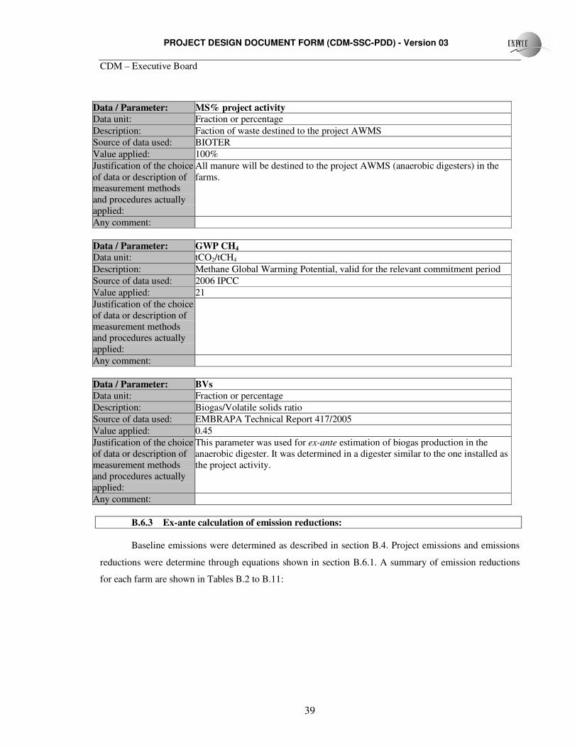
PROJECT DESIGN DOCUMENT FORM (CDM-SSC-PDD) - Version 03
CDM – Executive Board
39
Data / Parameter: MS% project activity Data unit: Fraction or percentage
Description: Faction of waste destined to the project AWMS Source of data used: BIOTER Value applied: 100% Justification of the choice of data or description of measurement methods and procedures actually applied:
All manure will be destined to the project AWMS (anaerobic digesters) in the farms.
Any comment:
Data / Parameter: GWP CH4 Data unit: tCO2/tCH4 Description: Methane Global Warming Potential, valid for the relevant commitment period Source of data used: 2006 IPCC Value applied: 21 Justification of the choice of data or description of measurement methods and procedures actually applied:
Any comment:
Data / Parameter: BVs Data unit: Fraction or percentage Description: Biogas/Volatile solids ratio Source of data used: EMBRAPA Technical Report 417/2005 Value applied: 0.45 Justification of the choice of data or description of measurement methods and procedures actually applied:
This parameter was used for ex-ante estimation of biogas production in the anaerobic digester. It was determined in a digester similar to the one installed as the project activity.
Any comment:
B.6.3 Ex-ante calculation of emission reductions: Baseline emissions were determined as described in section B.4. Project emissions and emissions
reductions were determine through equations shown in section B.6.1. A summary of emission reductions
for each farm are shown in Tables B.2 to B.11:
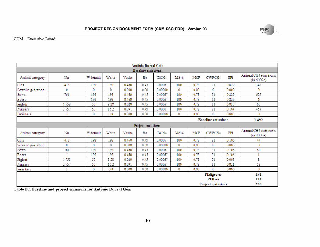
PROJECT DESIGN DOCUMENT FORM (CDM-SSC-PDD) - Version 03
CDM – Executive Board
40
Table B2. Baseline and project emissions for Antônio Durval Góis
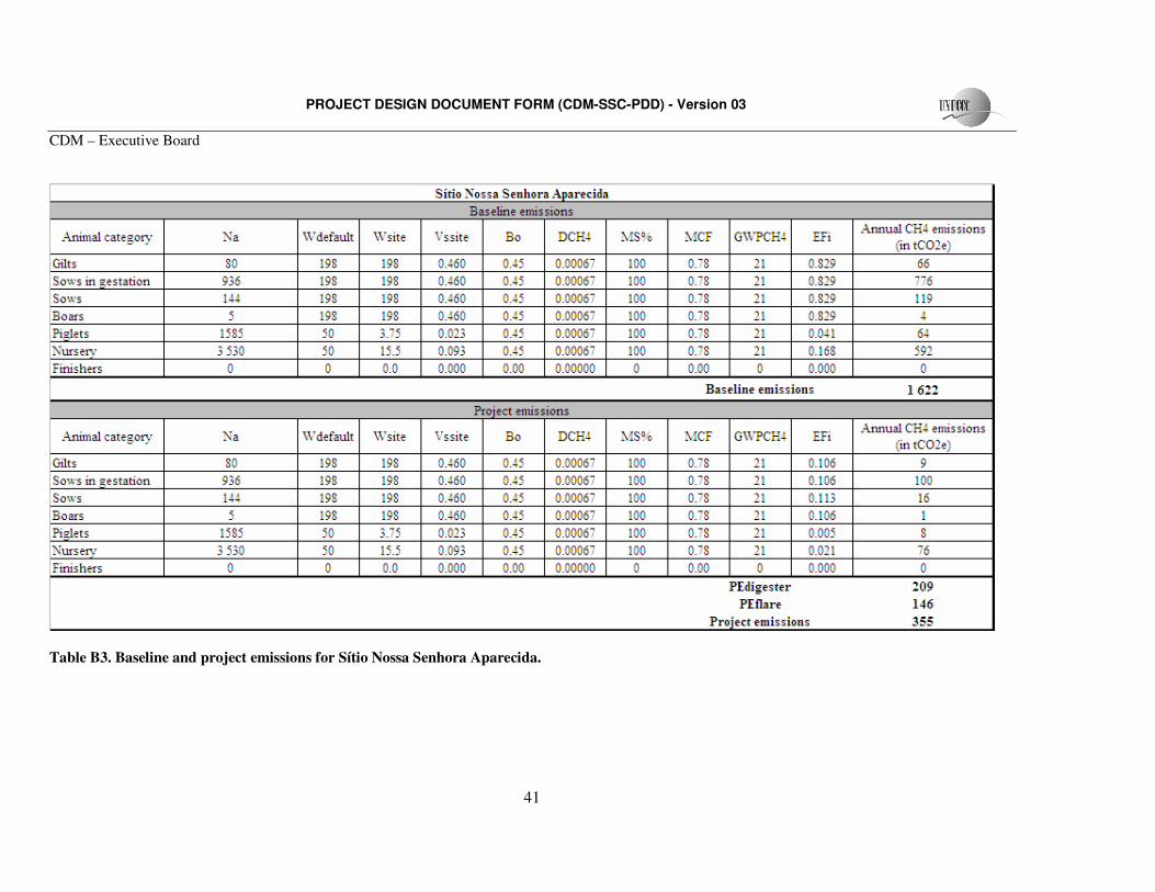
PROJECT DESIGN DOCUMENT FORM (CDM-SSC-PDD) - Version 03
CDM – Executive Board
41
Table B3. Baseline and project emissions for Sítio Nossa Senhora Aparecida.
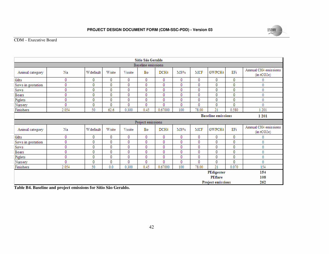
PROJECT DESIGN DOCUMENT FORM (CDM-SSC-PDD) - Version 03
CDM – Executive Board
42
Table B4. Baseline and project emissions for Sítio São Geraldo.
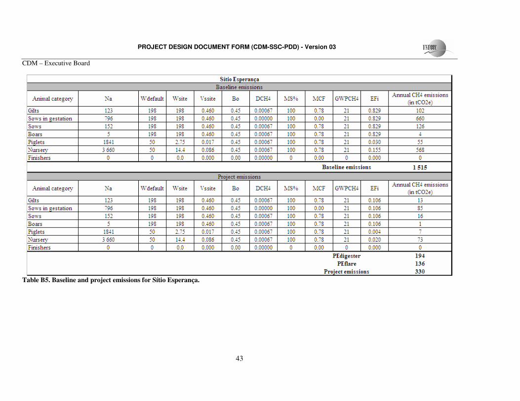
PROJECT DESIGN DOCUMENT FORM (CDM-SSC-PDD) - Version 03
CDM – Executive Board
43
Table B5. Baseline and project emissions for Sítio Esperança.
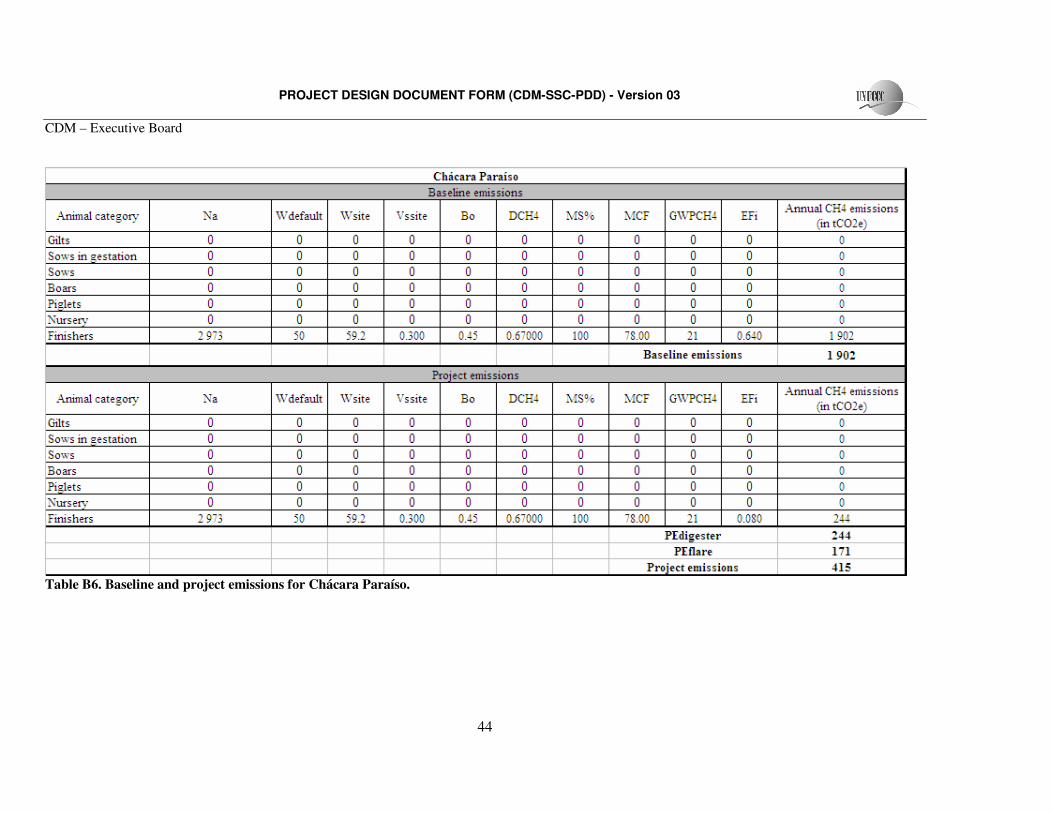
PROJECT DESIGN DOCUMENT FORM (CDM-SSC-PDD) - Version 03
CDM – Executive Board
44
Table B6. Baseline and project emissions for Chácara Paraíso.
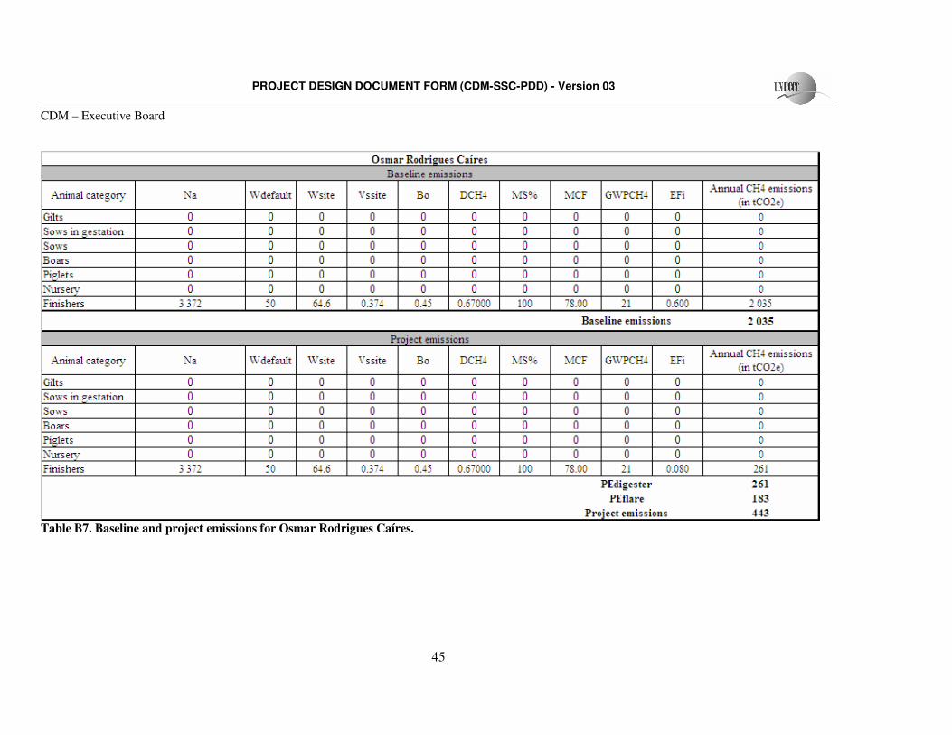
PROJECT DESIGN DOCUMENT FORM (CDM-SSC-PDD) - Version 03
CDM – Executive Board
45
Table B7. Baseline and project emissions for Osmar Rodrigues Caíres.
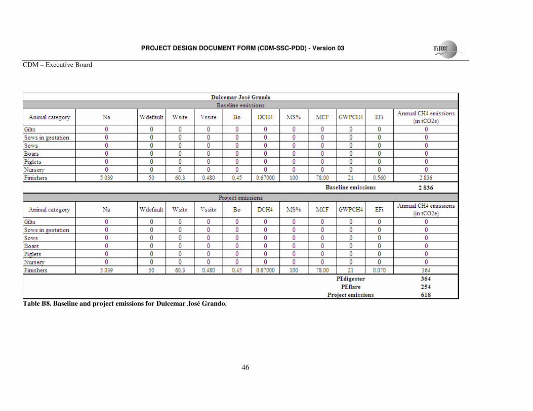
PROJECT DESIGN DOCUMENT FORM (CDM-SSC-PDD) - Version 03
CDM – Executive Board
46
Table B8. Baseline and project emissions for Dulcemar José Grando.
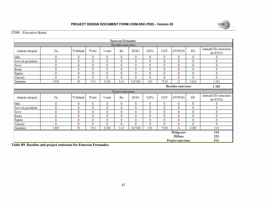
PROJECT DESIGN DOCUMENT FORM (CDM-SSC-PDD) - Version 03
CDM – Executive Board
47
Table B9. Baseline and project emissions for Emerson Fernandes.
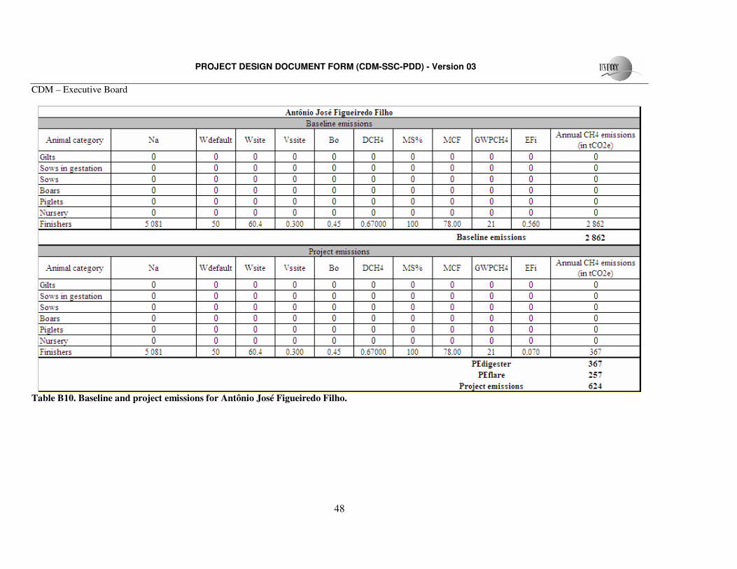
PROJECT DESIGN DOCUMENT FORM (CDM-SSC-PDD) - Version 03
CDM – Executive Board
48
Table B10. Baseline and project emissions for Antônio José Figueiredo Filho.
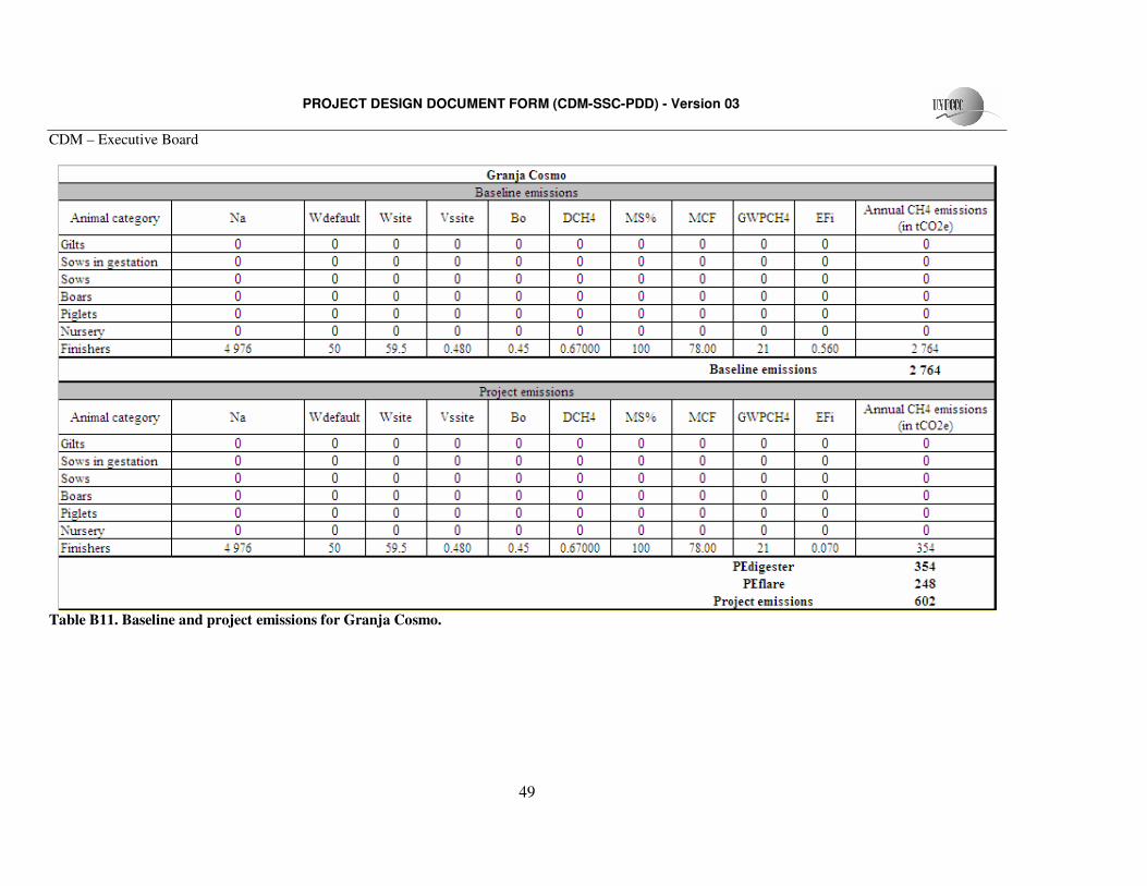
PROJECT DESIGN DOCUMENT FORM (CDM-SSC-PDD) - Version 03
CDM – Executive Board
49
Table B11. Baseline and project emissions for Granja Cosmo.
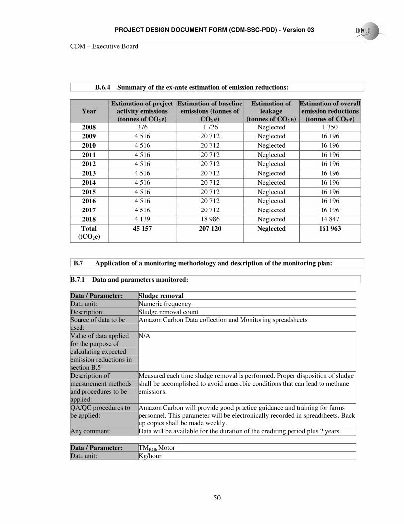
PROJECT DESIGN DOCUMENT FORM (CDM-SSC-PDD) - Version 03
CDM – Executive Board
50
B.6.4 Summary of the ex-ante estimation of emission reductions:
Year Estimation of project
activity emissions (tonnes of CO2 e)
Estimation of baseline emissions (tonnes of
CO2 e)
Estimation of leakage
(tonnes of CO2 e)
Estimation of overall emission reductions
(tonnes of CO2 e) 2008 376 1 726 Neglected 1 350 2009 4 516 20 712 Neglected 16 196 2010 4 516 20 712 Neglected 16 196
2011 4 516 20 712 Neglected 16 196 2012 4 516 20 712 Neglected 16 196 2013 4 516 20 712 Neglected 16 196 2014 4 516 20 712 Neglected 16 196 2015 4 516 20 712 Neglected 16 196 2016 4 516 20 712 Neglected 16 196 2017 4 516 20 712 Neglected 16 196
2018 4 139 18 986 Neglected 14 847 Total
(tCO2e) 45 157 207 120 Neglected 161 963
B.7 Application of a monitoring methodology and description of the monitoring plan:
B.7.1 Data and parameters monitored:
Data / Parameter: Sludge removal Data unit: Numeric frequency Description: Sludge removal count Source of data to be used:
Amazon Carbon Data collection and Monitoring spreadsheets
Value of data applied for the purpose of calculating expected emission reductions in section B.5
N/A
Description of measurement methods and procedures to be applied:
Measured each time sludge removal is performed. Proper disposition of sludge shall be accomplished to avoid anaerobic conditions that can lead to methane emissions.
QA/QC procedures to be applied:
Amazon Carbon will provide good practice guidance and training for farms personnel. This parameter will be electronically recorded in spreadsheets. Back up copies shall be made weekly.
Any comment: Data will be available for the duration of the crediting period plus 2 years.
Data / Parameter: TMRGh Motor Data unit: Kg/hour
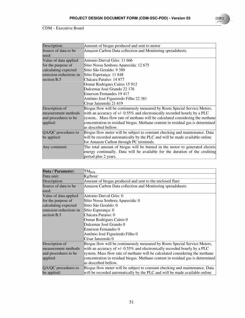
PROJECT DESIGN DOCUMENT FORM (CDM-SSC-PDD) - Version 03
CDM – Executive Board
51
Description: Amount of biogas produced and sent to motor Source of data to be used:
Amazon Carbon Data collection and Monitoring spreadsheets
Value of data applied for the purpose of calculating expected emission reductions in section B.5
Antonio Durval Góis: 11 666 Sítio Nossa Senhora Aparecida: 12 675 Sitio São Geraldo: 9 389 Sítio Esperança: 11 848 Chácara Paraíso: 14 877 Osmar Rodrigues Caíres 15 912 Dulcemar José Grando 22 176 Emerson Fernandes 19 417 Antônio José Figueiredo Filho 22 381 César Janzenski 21 619
Description of measurement methods and procedures to be applied:
Biogas flow will be continuously measured by Roots Special Service Meters, with an accuracy of +/- 0.55% and electronically recorded hourly by a PLC system,. Mass flow rate of methane will be calculated considering the methane concentration in residual biogas. Methane content in residual gas is determined as described bellow.
QA/QC procedures to be applied:
Biogas flow meter will be subject to constant checking and maintenance. Data will be recorded automatically by the PLC and will be made available online for Amazon Carbon through PC terminals.
Any comment: The total amount of biogas will be burned in the motor to generated electric energy continually. Data will be available for the duration of the crediting period plus 2 years.
Data / Parameter: TMRGh Data unit: Kg/hour Description: Amount of biogas produced and sent to the enclosed flare Source of data to be used:
Amazon Carbon Data collection and Monitoring spreadsheets
Value of data applied for the purpose of calculating expected emission reductions in section B.5
Antonio Durval Góis: 0 Sítio Nossa Senhora Aparecida: 0 Sitio São Geraldo: 0 Sítio Esperança: 0 Chácara Paraíso: 0 Osmar Rodrigues Caíres 0 Dulcemar José Grando 0 Emerson Fernandes 0 Antônio José Figueiredo Filho 0 César Janzenski 0
Description of measurement methods and procedures to be applied:
Biogas flow will be continuously measured by Roots Special Service Meters, with an accuracy of +/- 0.55% and electronically recorded hourly by a PLC system, Mass flow rate of methane will be calculated considering the methane concentration in residual biogas. Methane content in residual gas is determined as described bellow.
QA/QC procedures to be applied:
Biogas flow meter will be subject to constant checking and maintenance. Data will be recorded automatically by the PLC and will be made available online
PROJECT DESIGN DOCUMENT FORM (CDM-SSC-PDD) - Version 03
CDM – Executive Board
52
for Amazon Carbon through PC terminals. Any comment: The total amount of biogas will be burned in the motor to generated electric
energy continually. In rare situations, when the motors are not operational, such as oil change and any another replacement needs, the open flare will be used to combust the produced biogas. Data will be available for the duration of the crediting period plus 2 years.
Data / Parameter: CCH4
Data unit: Fraction or percentage Description: Methane concentration in residual gas (biogas) Source of data to be used:
Amazon Carbon Data collection and Monitoring spreadsheets
Value of data applied for the purpose of calculating expected emission reductions in section B.5
70%
Description of measurement methods and procedures to be applied:
Measured and recorded on a daily basis by dual wavelength Infra-red refrigerant gas sensors. This sensor has a accuracy of +-2.5%. Analysis will be stored in PC terminals, organized in spread sheets. A 95% confidence level will be ensured through maintenance and calibration of gas sensors.
QA/QC procedures to be applied:
Biogas analyser will be subject to constant checking and maintenance. Data will be recorded automatically and will be available online for Amazon Carbon
Any comment: Data will be available for the duration of the crediting period plus 2 years.
Data / Parameter: Methane flared Data unit: Kg Description: Amount of methane flared due to the project activity Source of data to be used:
Amazon Carbon Data collection and Monitoring spreadsheets
Value of data applied for the purpose of calculating expected emission reductions in section B.5
Not applicable
Description of measurement methods and procedures to be applied:
The amount of methane flared will be determined as the mass flow rate of methane multiplied by the system efficiency on methane destruction.
QA/QC procedures to be applied:
All sensors and meters will be subject to maintenance and calibration. Data to determine the methane flared will be digitally recorded and stored by the PLC.
Any comment: Data will be available for the duration of the crediting period plus 2 years.
Data / Parameter: RGT Data unit: ºC Description: Residual Gas temperature Source of data to be used:
Amazon Carbon Data collection and Monitoring spreadsheets
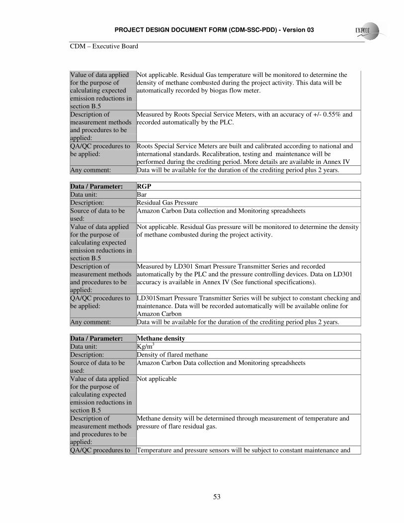
PROJECT DESIGN DOCUMENT FORM (CDM-SSC-PDD) - Version 03
CDM – Executive Board
53
Value of data applied for the purpose of calculating expected emission reductions in section B.5
Not applicable. Residual Gas temperature will be monitored to determine the density of methane combusted during the project activity. This data will be automatically recorded by biogas flow meter.
Description of measurement methods and procedures to be applied:
Measured by Roots Special Service Meters, with an accuracy of +/- 0.55% and recorded automatically by the PLC.
QA/QC procedures to be applied:
Roots Special Service Meters are built and calibrated according to national and international standards. Recalibration, testing and maintenance will be performed during the crediting period. More details are available in Annex IV
Any comment: Data will be available for the duration of the crediting period plus 2 years.
Data / Parameter: RGP Data unit: Bar Description: Residual Gas Pressure Source of data to be used:
Amazon Carbon Data collection and Monitoring spreadsheets
Value of data applied for the purpose of calculating expected emission reductions in section B.5
Not applicable. Residual Gas pressure will be monitored to determine the density of methane combusted during the project activity.
Description of measurement methods and procedures to be applied:
Measured by LD301 Smart Pressure Transmitter Series and recorded automatically by the PLC and the pressure controlling devices. Data on LD301 accuracy is available in Annex IV (See functional specifications).
QA/QC procedures to be applied:
LD301Smart Pressure Transmitter Series will be subject to constant checking and maintenance. Data will be recorded automatically will be available online for Amazon Carbon
Any comment: Data will be available for the duration of the crediting period plus 2 years. Data / Parameter: Methane density Data unit: Kg/m3 Description: Density of flared methane Source of data to be used:
Amazon Carbon Data collection and Monitoring spreadsheets
Value of data applied for the purpose of calculating expected emission reductions in section B.5
Not applicable
Description of measurement methods and procedures to be applied:
Methane density will be determined through measurement of temperature and pressure of flare residual gas.
QA/QC procedures to Temperature and pressure sensors will be subject to constant maintenance and
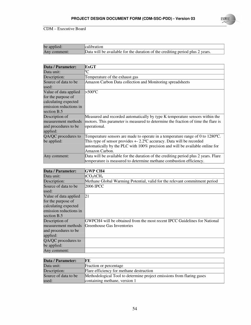
PROJECT DESIGN DOCUMENT FORM (CDM-SSC-PDD) - Version 03
CDM – Executive Board
54
be applied: calibration Any comment: Data will be available for the duration of the crediting period plus 2 years. Data / Parameter: ExGT Data unit: ºC Description: Temperature of the exhaust gas Source of data to be used:
Amazon Carbon Data collection and Monitoring spreadsheets
Value of data applied for the purpose of calculating expected emission reductions in section B.5
>500ºC
Description of measurement methods and procedures to be applied:
Measured and recorded automatically by type K temperature sensors within the motors. This parameter is measured to determine the fraction of time the flare is operational.
QA/QC procedures to be applied:
Temperature sensors are made to operate in a temperature range of 0 to 1280ºC. This type of sensor provides +- 2.2ºC accuracy. Data will be recorded automatically by the PLC with 100% precision and will be available online for Amazon Carbon.
Any comment: Data will be available for the duration of the crediting period plus 2 years. Flare temperature is measured to determine methane combustion efficiency.
Data / Parameter: GWP CH4 Data unit: tCO2/tCH4 Description: Methane Global Warming Potential, valid for the relevant commitment period Source of data to be used:
2006 IPCC
Value of data applied for the purpose of calculating expected emission reductions in section B.5
21
Description of measurement methods and procedures to be applied:
GWPCH4 will be obtained from the most recent IPCC Guidelines for National Greenhouse Gas Inventories
QA/QC procedures to be applied:
Any comment:
Data / Parameter: FE Data unit: Fraction or percentage Description: Flare efficiency for methane destruction Source of data to be used:
Methodological Tool to determine project emissions from flaring gases containing methane, version 1
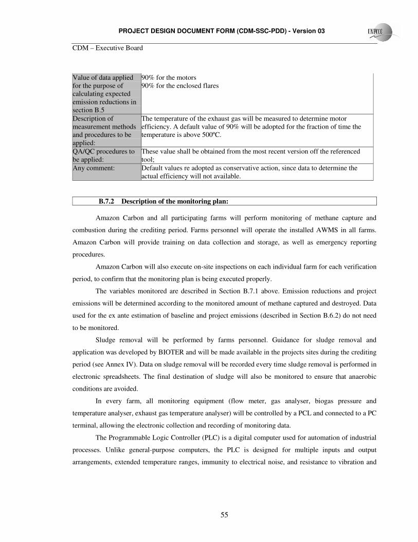
PROJECT DESIGN DOCUMENT FORM (CDM-SSC-PDD) - Version 03
CDM – Executive Board
55
Value of data applied for the purpose of calculating expected emission reductions in section B.5
90% for the motors 90% for the enclosed flares
Description of measurement methods and procedures to be applied:
The temperature of the exhaust gas will be measured to determine motor efficiency. A default value of 90% will be adopted for the fraction of time the temperature is above 500ºC.
QA/QC procedures to be applied:
These value shall be obtained from the most recent version off the referenced tool;
Any comment: Default values re adopted as conservative action, since data to determine the actual efficiency will not available.
B.7.2 Description of the monitoring plan:
Amazon Carbon and all participating farms will perform monitoring of methane capture and
combustion during the crediting period. Farms personnel will operate the installed AWMS in all farms.
Amazon Carbon will provide training on data collection and storage, as well as emergency reporting
procedures.
Amazon Carbon will also execute on-site inspections on each individual farm for each verification
period, to confirm that the monitoring plan is being executed properly.
The variables monitored are described in Section B.7.1 above. Emission reductions and project
emissions will be determined according to the monitored amount of methane captured and destroyed. Data
used for the ex ante estimation of baseline and project emissions (described in Section B.6.2) do not need
to be monitored.
Sludge removal will be performed by farms personnel. Guidance for sludge removal and
application was developed by BIOTER and will be made available in the projects sites during the crediting
period (see Annex IV). Data on sludge removal will be recorded every time sludge removal is performed in
electronic spreadsheets. The final destination of sludge will also be monitored to ensure that anaerobic
conditions are avoided.
In every farm, all monitoring equipment (flow meter, gas analyser, biogas pressure and
temperature analyser, exhaust gas temperature analyser) will be controlled by a PCL and connected to a PC
terminal, allowing the electronic collection and recording of monitoring data.
The Programmable Logic Controller (PLC) is a digital computer used for automation of industrial
processes. Unlike general-purpose computers, the PLC is designed for multiple inputs and output
arrangements, extended temperature ranges, immunity to electrical noise, and resistance to vibration and
PROJECT DESIGN DOCUMENT FORM (CDM-SSC-PDD) - Version 03
CDM – Executive Board
56
impact. The PLC will register monitoring information on an hourly basis. 100% precision is ensured due
to the automation of the process.
Through the PC terminals all participating farms and Amazon Carbon will have real time access to
monitoring variables via internet connection. Data will also be stored in data discs by all participating
farms and by Amazon Carbon, providing redundancy in data storage. All data will be stored and made
available for the crediting period plus two years.
The PC terminals in every farm will store all data necessary to determine the amount of methane
fuelled and flared in a given crediting year. These terminals will also store any additional data that is
necessary to calculate emission reductions.
The amount of biogas produced and sent to the motors and the flare will be continuously measured
by ROOTS Special Service Flow meters. Details on the flow meter are provided in Annex IV. The
amount of methane actually destroyed will be obtained by monitoring the methane content in the biogas,
the pressure and temperature of the biogas previous to the flaring process. Individual pipeline systems and
flow meters will be used for the fraction of biogas sent to the motors and for the fraction of biogas sent to
the enclosed flares.
The methane content in the biogas will be analysed by a Dual wavelength Infra-red Refrigerant
Gas sensor. This sensor has a measurement range of 1% and an accuracy range of 2.5%. This gas sensor
will be periodically connected to the gas pipeline in a specific valve and perform gas analysis. Additional
information on the gas analyzer is available in Annex IV. Biogas pressure and temperature will be
measured by monitoring components within the combustion system.
The efficiency of the flaring process will not be directly measured. Default values will be adopted,
and the temperature of the exhaust gas will be monitored. Flare efficiency will be considered 90% for the
motors in the fraction of time the exhaust gas temperature is higher than 500ºC. In the cases where the
temperature of the exhaust gas is lower than 500ºC the flaring efficiency will be considered 0%. Flare
efficiency will considered 90% for the enclosed flare.
B.8 Date of completion of the application of the baseline and monitoring methodology and the name of the responsible person(s)/entity(ies)
Date of completion of the application of the methodology to this project activity: 14/01/2008.
Name of the person/entity responsible for the application of the baseline and monitoring methodology to this project activity:
Amazon Carbon S/S Ltda (project participant).
Jorge Sebastião Bernardo-Silva (Project developer)
PROJECT DESIGN DOCUMENT FORM (CDM-SSC-PDD) - Version 03
CDM – Executive Board
57
Conselhero Mafra 758 sala 703
Florianópolis - SC, Brazil
CEP 88010-102
Phone: + 55 (51) 8140-1270
E-mail: [email protected]
SECTION C. Duration of the project activity / crediting period C.1 Duration of the project activity: C.1.1. Starting date of the project activity: The starting date of the project activity is 01/10/2008.
C.1.2. Expected operational lifetime of the project activity: 25 years, 0 months.
C.2 Choice of the crediting period and related information: C.2.1. Renewable crediting period
C.2.1.1. Starting date of the first crediting period: Not applicable.
C.2.1.2. Length of the first crediting period: Not applicable.
C.2.2. Fixed crediting period: C.2.2.1. Starting date: The start of the crediting period is 01/12/2008 or on the date of the registration of the project
activity, whichever is later.
C.2.2.2. Length: The duration of the project activity is 10 years, 0 months.
PROJECT DESIGN DOCUMENT FORM (CDM-SSC-PDD) - Version 03
CDM – Executive Board
58
SECTION D. Environmental impacts D.1. If required by the host Party, documentation on the analysis of the environmental impacts of the project activity:
The Brazilian environmental legislation forces swine breeders to go through a process of
environmental licensing where environmental impacts are assessed. All participating farms are in
accordance with the environmental authority. Licenses have already been issued or are in process. Local
environmental authorities shall be informed of the installation of anaerobic digesters, but no Environmental
Impact Study is necessary.
The AWMS proposed by the project will result in various environmental benefits, as described in
section A.4.3 of this report. The project, besides promoting GHG emission reduction, will also contribute
to sustainable development. The anaerobic digester reduces the organic matter in the effluent when
compared to anaerobic lagoons. Besides, the odour arising from the volatile molecules, which result from
the anaerobic digestion, is considerably diminished since the gases produced are contained by a sealed
cover and then flared. No transboundaries impacts are expected to result from the project activity.
The pro-active stand of Amazon Carbon and all participating farms to implement anaerobic
digesters on swine farms is a great challenge that must be regarded as an initiative that will encourage
other swine breeders to improve the existing AWMS, aiming to reduce the overall environmental impacts
caused by this activity.
D.2. If environmental impacts are considered significant by the project participants or the host Party, please provide conclusions and all references to support documentation of an environmental impact assessment undertaken in accordance with the procedures as required by the host Party:
No action required. Environmental impacts of the project activity are considered positive since
they contribute to local, regional and global sustainable development.
SECTION E. Stakeholders’ comments E.1. Brief description how comments by local stakeholders have been invited and compiled:
The invitation to the project stakeholders was made as per the “September 11th, 2003 Resolution No.
1 (Approved by Administrative Law Nr 863, of November 27th, 2003 and published in the “Diário Oficial da
República Federativa do Brasil” on December 2nd, 2003.)”. Invitations were sent by postal service, on
22/10/2007.The following stakeholders were invited:
Entity City PREFEITURA MUNICIPAL DE GLÓRIA DE
DOURADOS GLÓRIA DE DOURADOS
PROJECT DESIGN DOCUMENT FORM (CDM-SSC-PDD) - Version 03
CDM – Executive Board
59
SECRETARIA MUNICIPAL DE MEIO AMBIENTE DE GLÓRIA DE DOURADOS
GLÓRIA DE DOURADOS
CAMARA MUNICPAL DE GLÓRIA DE DOURADOS GLÓRIA DE DOURADOS
PROMOTORIA DE JUSTIÇADE GLÓRIA DE DOURADOS
GLÓRIA DE DOURADOS
SECRETARIA ESTADUAL DE MEIO AMBIENTE CAMPO GRANDE FÓRUM BRASILEIRO DE ONGS E MOVIMENTOS
SOCIAIS PARA O MEIO AMBIENTE E DESENVOLVIMENTO
BRASÍLIA
PREFEITURA MUNICIPAL DE IVINHEMA IVINHEMA SECRETARIA DE MEIO AMBIENTE DE IVINHEMA IVINHEMA
CÂMARA MUNICIPAL DE IVINHEMA IVINHEMA PROMOTORIA DE JUSTIÇA DE IVENHEMA IVINHEMA
AGÊNCIA DE DESENVOLVIMENTO AGRÁRIO E EXTENSÃO RURAL
GLÓRIA DE DOURADOS
ASSUGLORIA GLÓRIA DE DOURADOS
AVIGLORIA GLÓRIA DE DOURADOS
SECRETARIA DE AGRICULTURA IVINHEMA AGÊNCIA DE DESENVOLVIMENTO AGRÁRIO E
EXTENSÃO RURAL IVINHEMA
PREFEITURA MUNICIPAL DE JATÉI JATEÍ CÂMARA MUNICIPAL DE JATÉI JATEÍ
SECRETARIA MUNICPAL DE MEIO AMBIENTE JATEI ASSOCIAÇÃO DOS AMIGOS DE JATEÍ JATEI
SINDICATO RURAL DE JATEÍ JATEI PREFEITURA MUNICIPAL DE FÁTIMA DO SUL FÁTIMA DO SUL
CÂMARA MUNICIPAL DE FÁTIMA DO SUL FÁTIMA DO SUL PROMOTORIA DE JUSTIÇA FÁTIMA DO SUL
SECRETARIA MUNICIPAL DO MEIO AMBIENTE FÁTIMA DO SUL ASSOCIAÇÃO DE MORADORES DO JARDIM
BRASILÂNDIA FÁTIMA DO SUL
ASSOCIAÇÃO DE MORADORES DO JARDIM TATIANE E KATIRA
FÁTIMA DO SUL
ASSOCIAÇÃO DE MORADORES DO JARDIM O PIONEIRO
FÁTIMA DO SUL
PREFEITURA MUNICIPAL DE ITAPORÁ ITAPORÃ
CÂMARA MUNICIPAL DE ITAPORÁ ITAPORÃ
PROMOTORIA DE JUSTIÇA ITAPORÃ SECRETARIA MINICIPAL DA AGRICULTURA ITAPORÃ
COOPERAVI IVINHEMA SINDICATO RURAL DE IVINHEMA IVINHEMA
CMDR IVINHEMA FUMATUR – FUNDAÇÃO MUNICIPAL DE MEIO
AMBIENTE IVINHEMA
SINDICATO DOS TRABALHADORES RURAIS IVINHEMA
PROJECT DESIGN DOCUMENT FORM (CDM-SSC-PDD) - Version 03
CDM – Executive Board
60
A lecture was held in 20/02/2008, at Glória de Dourados/MS to expose the project to stake holders.
The lecture was presented by the Project Developer of Amazon Carbon and by the Production Manager of
all participating farms. The PDD was made publicly available on Amazon Carbon website for comments.
E.2. Summary of the comments received:
Comments by stakeholders and local community were received orally during and after the
presentation. No written commentaries were received, all questions were clarified orally and negative
comments were not registered.
E.3. Report on how due account was taken of any comments received: No action required.
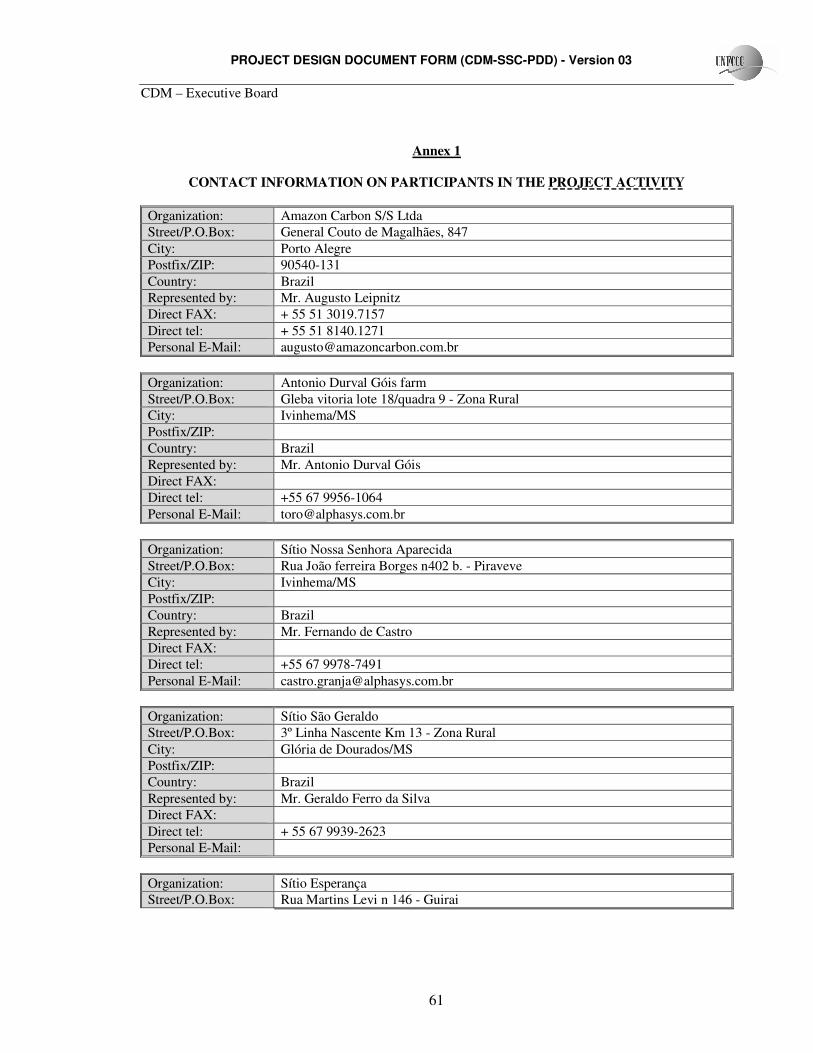
PROJECT DESIGN DOCUMENT FORM (CDM-SSC-PDD) - Version 03
CDM – Executive Board
61
Annex 1
CONTACT INFORMATION ON PARTICIPANTS IN THE PROJECT ACTIVITY
Organization: Amazon Carbon S/S Ltda Street/P.O.Box: General Couto de Magalhães, 847 City: Porto Alegre Postfix/ZIP: 90540-131 Country: Brazil Represented by: Mr. Augusto Leipnitz Direct FAX: + 55 51 3019.7157 Direct tel: + 55 51 8140.1271 Personal E-Mail: [email protected]
Organization: Antonio Durval Góis farm Street/P.O.Box: Gleba vitoria lote 18/quadra 9 - Zona Rural City: Ivinhema/MS Postfix/ZIP: Country: Brazil Represented by: Mr. Antonio Durval Góis Direct FAX: Direct tel: +55 67 9956-1064 Personal E-Mail: [email protected]
Organization: Sítio Nossa Senhora Aparecida Street/P.O.Box: Rua João ferreira Borges n402 b. - Piraveve City: Ivinhema/MS Postfix/ZIP: Country: Brazil Represented by: Mr. Fernando de Castro Direct FAX: Direct tel: +55 67 9978-7491 Personal E-Mail: [email protected]
Organization: Sítio São Geraldo Street/P.O.Box: 3º Linha Nascente Km 13 - Zona Rural City: Glória de Dourados/MS Postfix/ZIP: Country: Brazil Represented by: Mr. Geraldo Ferro da Silva Direct FAX: Direct tel: + 55 67 9939-2623 Personal E-Mail:
Organization: Sítio Esperança Street/P.O.Box: Rua Martins Levi n 146 - Guirai
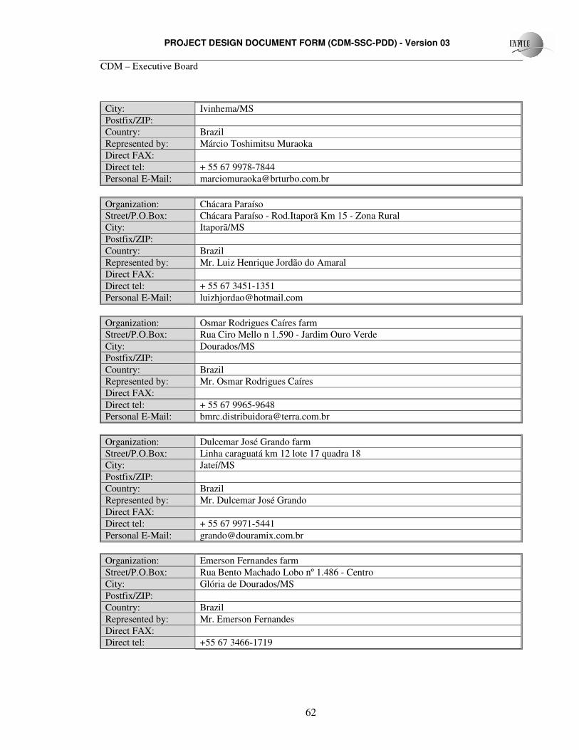
PROJECT DESIGN DOCUMENT FORM (CDM-SSC-PDD) - Version 03
CDM – Executive Board
62
City: Ivinhema/MS Postfix/ZIP: Country: Brazil Represented by: Márcio Toshimitsu Muraoka Direct FAX: Direct tel: + 55 67 9978-7844 Personal E-Mail: [email protected]
Organization: Chácara Paraíso Street/P.O.Box: Chácara Paraíso - Rod.Itaporã Km 15 - Zona Rural City: Itaporã/MS Postfix/ZIP: Country: Brazil Represented by: Mr. Luiz Henrique Jordão do Amaral Direct FAX: Direct tel: + 55 67 3451-1351 Personal E-Mail: [email protected]
Organization: Osmar Rodrigues Caíres farm Street/P.O.Box: Rua Ciro Mello n 1.590 - Jardim Ouro Verde City: Dourados/MS Postfix/ZIP: Country: Brazil Represented by: Mr. Osmar Rodrigues Caíres Direct FAX: Direct tel: + 55 67 9965-9648 Personal E-Mail: [email protected]
Organization: Dulcemar José Grando farm Street/P.O.Box: Linha caraguatá km 12 lote 17 quadra 18 City: Jateí/MS Postfix/ZIP: Country: Brazil Represented by: Mr. Dulcemar José Grando Direct FAX: Direct tel: + 55 67 9971-5441 Personal E-Mail: [email protected]
Organization: Emerson Fernandes farm Street/P.O.Box: Rua Bento Machado Lobo nº 1.486 - Centro City: Glória de Dourados/MS Postfix/ZIP: Country: Brazil Represented by: Mr. Emerson Fernandes Direct FAX: Direct tel: +55 67 3466-1719
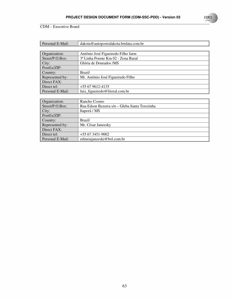
PROJECT DESIGN DOCUMENT FORM (CDM-SSC-PDD) - Version 03
CDM – Executive Board
63
Personal E-Mail: [email protected]
Organization: Antônio José Figueiredo Filho farm Street/P.O.Box: 3ª Linha Poente Km 02 - Zona Rural City: Glória de Dourados /MS Postfix/ZIP: Country: Brazil Represented by: Mr. Antônio José Figueiredo Filho Direct FAX: Direct tel: +55 67 9612-4135 Personal E-Mail: [email protected]
Organization: Rancho Cosmo Street/P.O.Box: Rua Edson Bezerra s/n – Gleba Santa Terezinha City: Itaporã / MS Postfix/ZIP: Country: Brazil Represented by: Mr. César Janzesky Direct FAX: Direct tel: +55 67 3451-9002 Personal E-Mail: [email protected]
PROJECT DESIGN DOCUMENT FORM (CDM-SSC-PDD) - Version 03
CDM – Executive Board
64
Annex 2
INFORMATION REGARDING PUBLIC FUNDING
No public funds will be invested in the project.
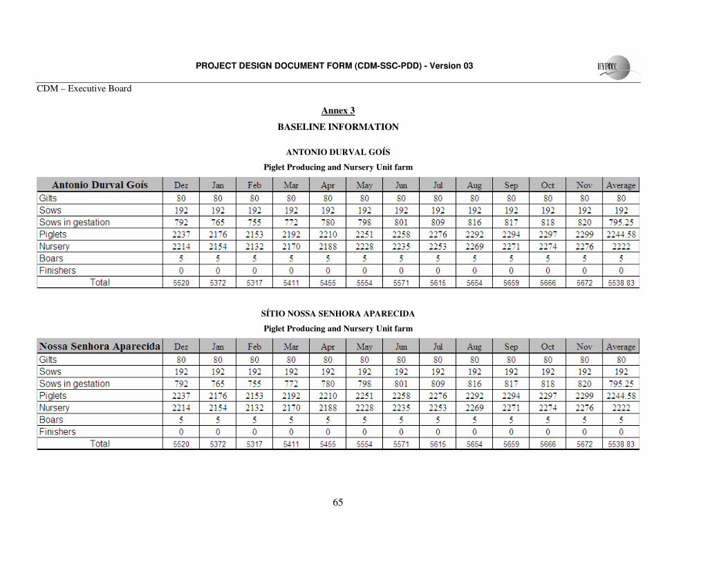
PROJECT DESIGN DOCUMENT FORM (CDM-SSC-PDD) - Version 03
CDM – Executive Board
65
Annex 3
BASELINE INFORMATION
ANTONIO DURVAL GOÍS
Piglet Producing and Nursery Unit farm
SÍTIO NOSSA SENHORA APARECIDA
Piglet Producing and Nursery Unit farm
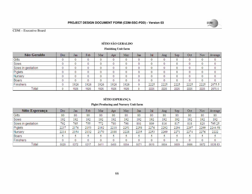
PROJECT DESIGN DOCUMENT FORM (CDM-SSC-PDD) - Version 03
CDM – Executive Board
66
SÍTIO SÃO GERALDO
Finishing Unit farm
SÍTIO ESPERANÇA
Piglet Producing and Nursery Unit farm
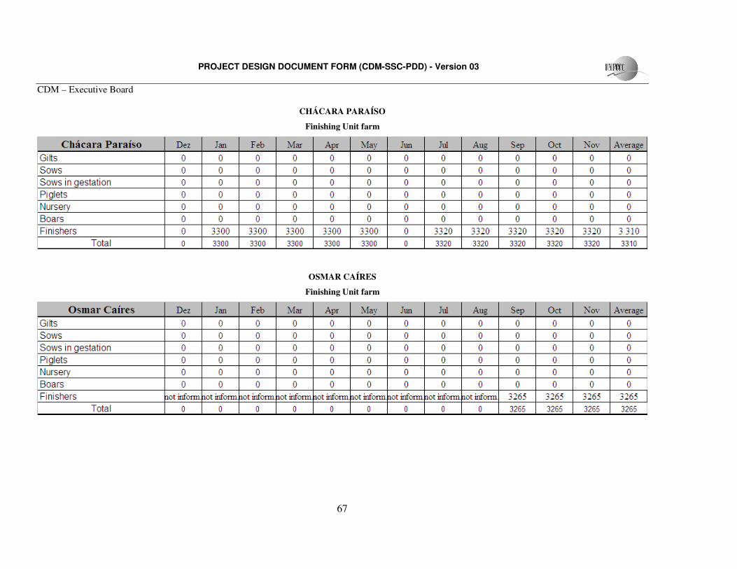
PROJECT DESIGN DOCUMENT FORM (CDM-SSC-PDD) - Version 03
CDM – Executive Board
67
CHÁCARA PARAÍSO
Finishing Unit farm
OSMAR CAÍRES
Finishing Unit farm
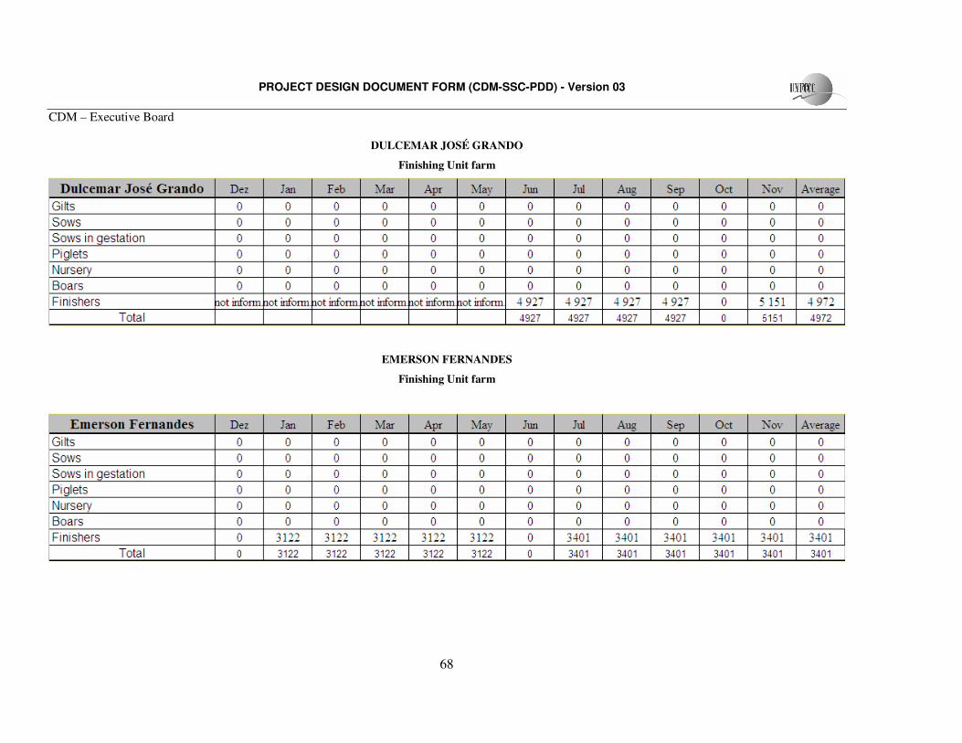
PROJECT DESIGN DOCUMENT FORM (CDM-SSC-PDD) - Version 03
CDM – Executive Board
68
DULCEMAR JOSÉ GRANDO
Finishing Unit farm
EMERSON FERNANDES
Finishing Unit farm
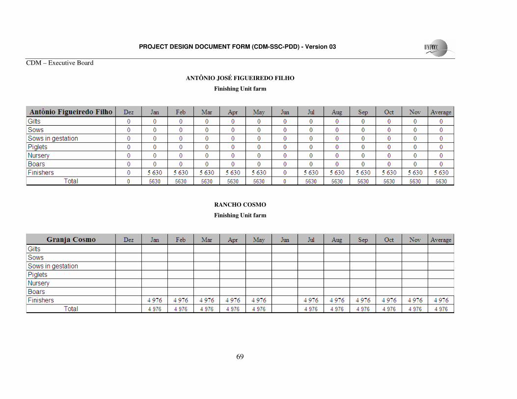
PROJECT DESIGN DOCUMENT FORM (CDM-SSC-PDD) - Version 03
CDM – Executive Board
69
ANTÔNIO JOSÉ FIGUEIREDO FILHO
Finishing Unit farm
RANCHO COSMO
Finishing Unit farm
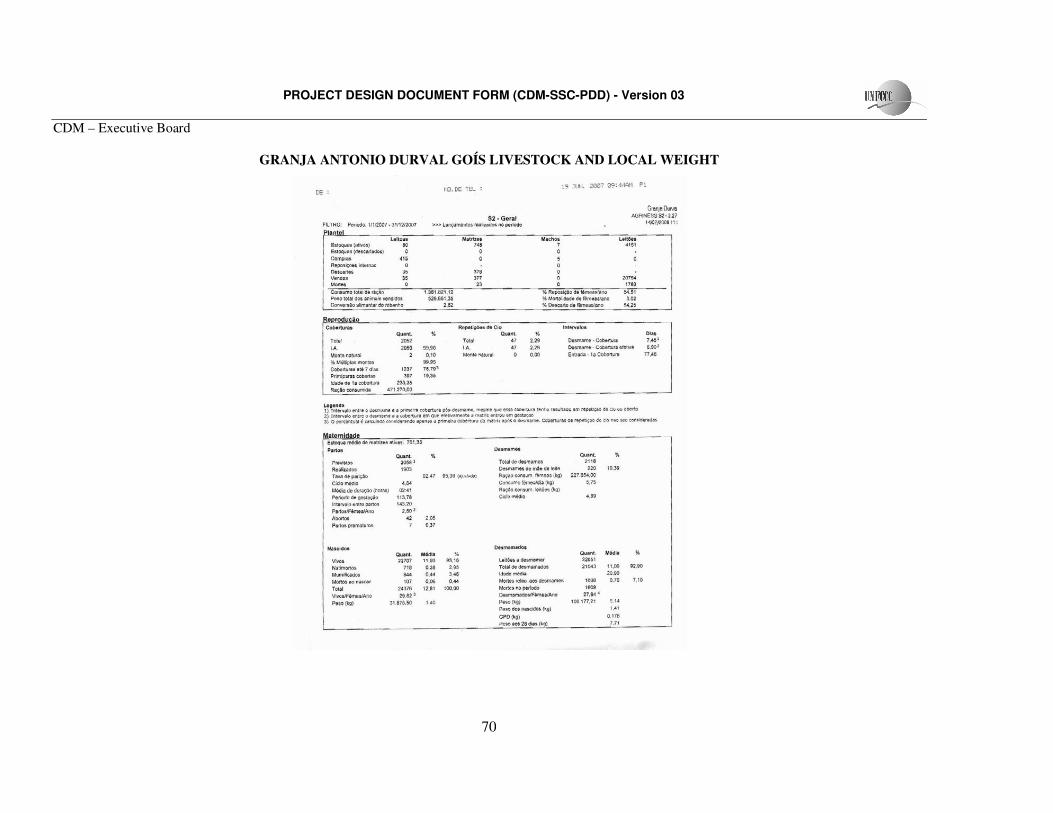
PROJECT DESIGN DOCUMENT FORM (CDM-SSC-PDD) - Version 03
CDM – Executive Board
70
GRANJA ANTONIO DURVAL GOÍS LIVESTOCK AND LOCAL WEIGHT
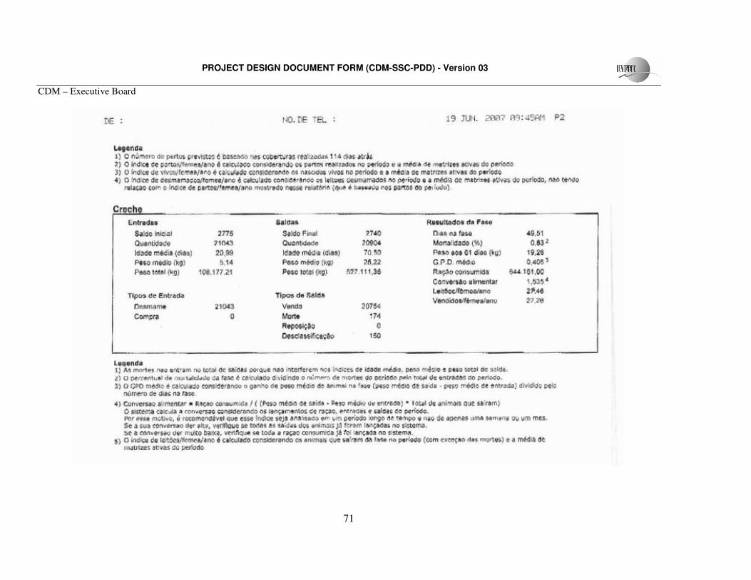
PROJECT DESIGN DOCUMENT FORM (CDM-SSC-PDD) - Version 03
CDM – Executive Board
71
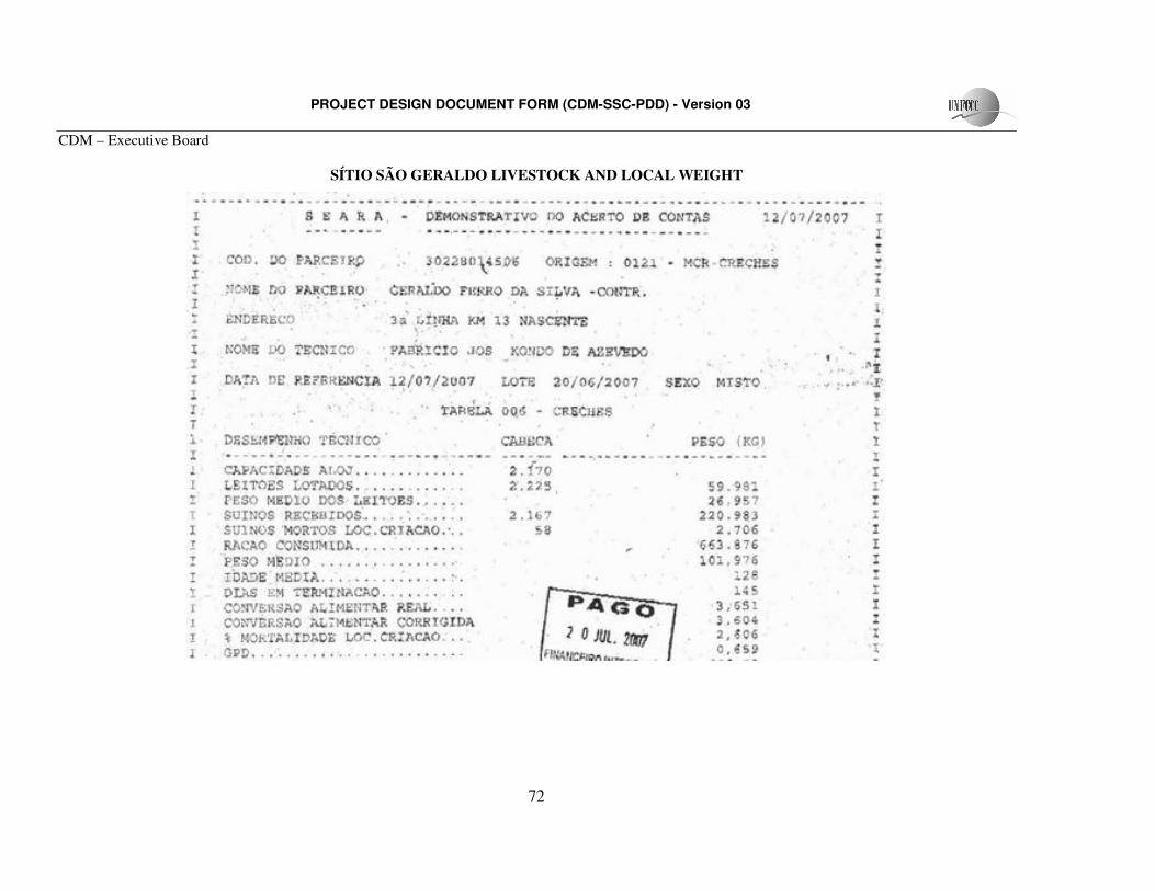
PROJECT DESIGN DOCUMENT FORM (CDM-SSC-PDD) - Version 03
CDM – Executive Board
72
SÍTIO SÃO GERALDO LIVESTOCK AND LOCAL WEIGHT
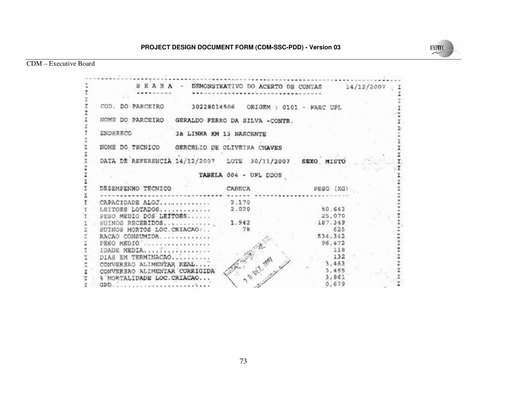
PROJECT DESIGN DOCUMENT FORM (CDM-SSC-PDD) - Version 03
CDM – Executive Board
73
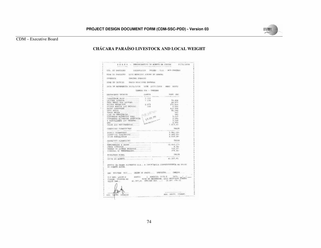
PROJECT DESIGN DOCUMENT FORM (CDM-SSC-PDD) - Version 03
CDM – Executive Board
74
CHÁCARA PARAÍSO LIVESTOCK AND LOCAL WEIGHT
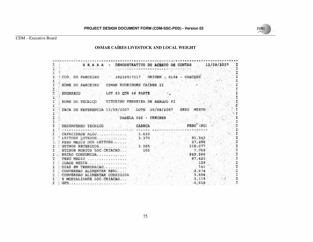
PROJECT DESIGN DOCUMENT FORM (CDM-SSC-PDD) - Version 03
CDM – Executive Board
75
OSMAR CAÍRES LIVESTOCK AND LOCAL WEIGHT
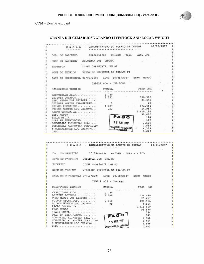
PROJECT DESIGN DOCUMENT FORM (CDM-SSC-PDD) - Version 03
CDM – Executive Board
76
GRANJA DULCEMAR JOSÉ GRANDO LIVESTOCK AND LOCAL WEIGHT
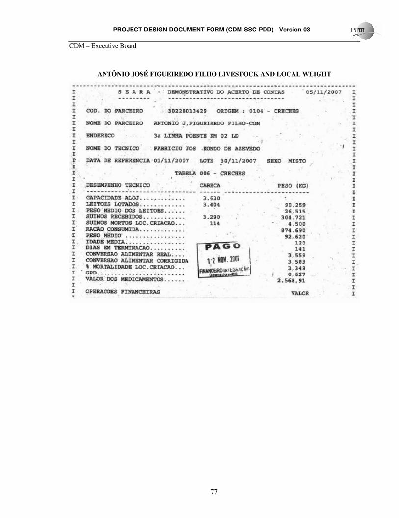
PROJECT DESIGN DOCUMENT FORM (CDM-SSC-PDD) - Version 03
CDM – Executive Board
77
ANTÔNIO JOSÉ FIGUEIREDO FILHO LIVESTOCK AND LOCAL WEIGHT
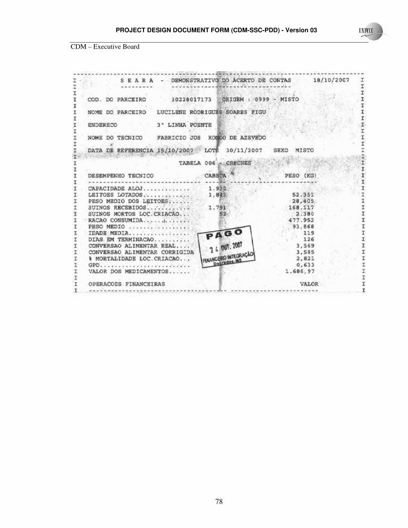
PROJECT DESIGN DOCUMENT FORM (CDM-SSC-PDD) - Version 03
CDM – Executive Board
78
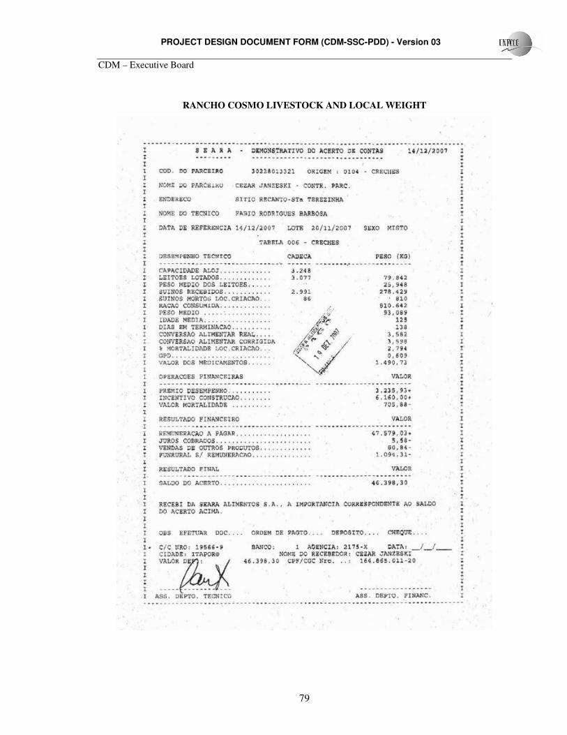
PROJECT DESIGN DOCUMENT FORM (CDM-SSC-PDD) - Version 03
CDM – Executive Board
79
RANCHO COSMO LIVESTOCK AND LOCAL WEIGHT
PROJECT DESIGN DOCUMENT FORM (CDM-SSC-PDD) - Version 03
CDM – Executive Board
80
Annex 4
MONITORING INFORMATION
This section provides further details on monitoring equipment, training, monitoring procedures,
data recording and maintenance.
System Overview:
The Animal Waste Management System installed by the project is illustrated in figure 1. The
system consists in four major components:
• Manure loading system
• Anaerobic digester cells
• Biogas transfer and flow meters
• Flaring system
PROJECT DESIGN DOCUMENT FORM (CDM-SSC-PDD) - Version 03
CDM – Executive Board
81
Figure 1. AWMS installed as the project acitivity.
PROJECT DESIGN DOCUMENT FORM (CDM-SSC-PDD) - Version 03
CDM – Executive Board
82
System components Operation and maintenance:
1. Manure loading system
Training: Training on manure loading system will be provided by the technology manufacturer. Training
shall include: system components, normal operation, emergency operations, maintenance and request for
warranty service. Reporting procedures shall be made directly to Amazon Carbon.
Normal Operation: The manure loading system installed by the project activity is not much different
than the existing system. Farms’ managers are familiar with the system operation and maintenance. Under
normal operations, manure is removed from the barns using water hoses and squeegees. This effluent is
collected and flushed from the barns periodically. The effluent is sent to the manure tanks and then to the
digester cells. To optimize manure treatment and biogas production, the excessive use of water shall be
avoided.
Safety issues: All personnel working on the barns make use of appropriated gear and clothing. Sanitary
and health issues are a serious concern. Care should be taken on handling animal manure and around the
manure tanks, to avoid falling into them.
Regular inspections: Regular inspections shall be executed at least on a weekly basis, and will include the
following procedures:
� Check for pipeline obstruction and leakages;
� Check for corrosion at exposed joints
� Check for clogging in the manure tanks
� Check the operational status of the pumping station, where applicable.
Alternative Operating procedures: In the event of malfunction of the manure loading system, all
participating farms personnel shall immediately notify Amazon Carbon. The AWMS manufacturer will be
notified to provide warranty or maintenance services, if required. Upon restoration of the system, Amazon
Carbon shall be notified.
The proximity between the project sites and the manufacturer Head Office will allow fast emergency
maintenance. Upon report by all participating farms, BIOTER maintenance team shall arrive on site in less
than 48 hours. In the mean time, all participating farms and Amazon Carbon shall work together to identify
PROJECT DESIGN DOCUMENT FORM (CDM-SSC-PDD) - Version 03
CDM – Executive Board
83
an alternative method to route the effluent in order not to affect the farm nor result in additional GHG
emissions.
2. Anaerobic digester:
The anaerobic digesters will be surrounded by a protection fence. Only authorized and trained
personnel shall be in contact with the digesters.
Training: Training on the anaerobic digesters shall be provided to all participating farms personnel by the
system manufacturer. Training shall include: construction and installation, system components, start-up
procedures, normal operation, biogas and sludge handling, emergency operation, safety issues,
maintenance and request for service. Reporting procedures shall be directly to Amazon Carbon.
Normal Operation:
Training on normal operation will include the basic operations of the system, biogas production,
sludge production and disposal, start-up procedures, safety procedures, daily inspections, technical
components and effluent quality.
Safety issues: Safety advice shall include the following instructions:
� No open flame permitted within 10 meters of the digester
� Do not allow the access of untrained personnel in the digester surroundings
� Do not use sharp objects or tools around the digester cover
Regular inspections: Regular inspections shall be executed at least on a weekly basis, and will include the
following procedures:
� Cover material – check for cracks, tears, points of distress and other irregularities around the
perimeter of the digester cell.
� Check for excessive ballooning of cover or presence of odor
� Check seams for signs of gas leakages
� Check for manure leakages
Alternative operation procedures: In the event of malfunction of the anaerobic digesters, all
participating farms personnel shall immediately notify Amazon Carbon. The AWMS manufacturer will be
PROJECT DESIGN DOCUMENT FORM (CDM-SSC-PDD) - Version 03
CDM – Executive Board
84
notified to provide warranty or maintenance services, if required. Upon restoration of the system, Amazon
Carbon shall be notified. The proximity between the project sites and the manufacturer Head Office will
allow fast emergency maintenance. Upon report by all participating farms, BIOTER maintenance team
shall arrive on site in less than 24 hours. In the mean time, all participating farms and Amazon Carbon
shall work together to identify an alternative method to route the effluent in order not to affect the farm nor
result in additional GHG emissions.
3. Biogas transfer and flow meter devices:
Training on the biogas transfer and flow meter devices shall be provided to all participating farms
personnel by the system manufacturer (BIOTER). Training shall include: system components, normal
operation, emergency operation, safety issues, maintenance and request for service. Reporting procedures
shall be directly to Amazon Carbon.
Normal operation: The biogas produced by the anaerobic digesters will be contained by a sealed
geomembrane and sent to the combustion system through PVC pipeline. The combustion system, through
the PLC will be regulated by pressure controlling devices to ensure ideal biogas pressure. ROOTS B3 G65
– SSM ICPWS Flow meters will be connected to the PVC pipeline and continuously measure biogas flow
to the combustion system. Biogas flow meters also monitor biogas temperature. The flow meters are
incorporated to the PLC, which will record biogas flow on an hourly basis. The PLC will be connected to a
PC terminal that will store monitoring data and transmit it via internet to Amazon Carbon personnel.
Safety issues: Measures will be taken to avoid biogas leakage and pipeline damages. Care shall be taken
when performing maintenance on the flow meters and when digging near the pipelines.
Preventive maintenance: Maintenance procedures shall be conducted according the manufacturer’s
recommendations. Preventive maintenance shall be executed on a quarterly basis.
Regular inspections: Regular inspections shall be executed at least on a weekly basis, and will include the
following procedures:
� Check for leaks in exposed pipelines
� Check for operational status of flow meters
� Check for PLC operational status.
� Check for PC terminal operational status (on a daily basis)
PROJECT DESIGN DOCUMENT FORM (CDM-SSC-PDD) - Version 03
CDM – Executive Board
85
� Make security copies of monitoring information on data discs (DVD).
Alternative operating procedures: In the event of malfunction of the biogas transfer system and flow
meter devices, farms’ personnel shall immediately notify Amazon Carbon. The AWMS manufacturer will
be notified to provide warranty or maintenance services, if required. Upon restoration of the system,
Amazon Carbon shall be notified. The proximity between the project sites and the manufacturer Head
Office will allow fast emergency maintenance. Upon report by all participating farms, BIOTER
maintenance team shall arrive on site in less than 48 hours. In the mean time, all participating farms and
Amazon Carbon shall work together to identify an alternative method to route the effluent in order not to
affect the farm nor result in additional GHG emissions.
4. Combustion System (flares):
Training: Training on the combustion system shall be provided to farms’ personnel by the system
manufacturer. Training shall include: system components, normal operation, emergency operation, safety
issues, maintenance and request for service. Reporting procedures shall be directly to Amazon Carbon.
Normal operation: The flare installed by the project activity has an automatic system designed to combust
methane whenever biogas is present at the combustion chamber. The system is also equipped with pressure
control devices to maintain ideal flow to the flares. More details on the flaring system are provided in
Section A.4.2.
Safety issues: This system will be surrounded by a protection fence. Only authorized and trained personnel
shall near the combustion system. Prior to maintenance, the gas flow must be turned off. Double checking
of operational status shall be performed prior to maintenance procedures.
Regular inspections: Regular inspections shall be executed at least on a weekly basis, and will include
the following procedures:
� Check for flaring operational status by checking the presence of a flame, the temperature of the
combustion system and data from PC terminal.
� Check for PLC operational status.
� Check for PC terminal operational status (on a daily basis)
� Store monitoring information on data discs (DVD).
Preventive maintenance: Preventive maintenance shall be conducted on a quarterly basis.
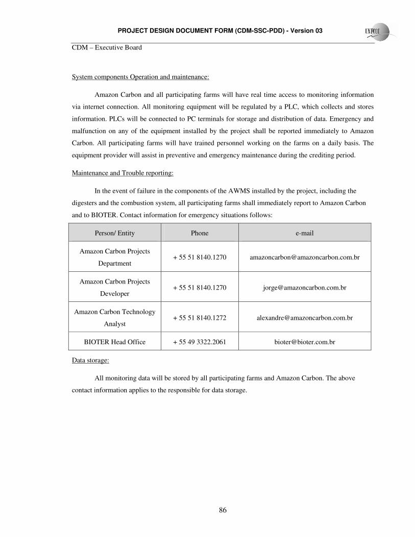
PROJECT DESIGN DOCUMENT FORM (CDM-SSC-PDD) - Version 03
CDM – Executive Board
86
System components Operation and maintenance:
Amazon Carbon and all participating farms will have real time access to monitoring information
via internet connection. All monitoring equipment will be regulated by a PLC, which collects and stores
information. PLCs will be connected to PC terminals for storage and distribution of data. Emergency and
malfunction on any of the equipment installed by the project shall be reported immediately to Amazon
Carbon. All participating farms will have trained personnel working on the farms on a daily basis. The
equipment provider will assist in preventive and emergency maintenance during the crediting period.
Maintenance and Trouble reporting:
In the event of failure in the components of the AWMS installed by the project, including the
digesters and the combustion system, all participating farms shall immediately report to Amazon Carbon
and to BIOTER. Contact information for emergency situations follows:
Person/ Entity Phone e-mail
Amazon Carbon Projects
Department + 55 51 8140.1270 [email protected]
Amazon Carbon Projects
Developer + 55 51 8140.1270 [email protected]
Amazon Carbon Technology
Analyst + 55 51 8140.1272 [email protected]
BIOTER Head Office + 55 49 3322.2061 [email protected]
Data storage:
All monitoring data will be stored by all participating farms and Amazon Carbon. The above
contact information applies to the responsible for data storage.
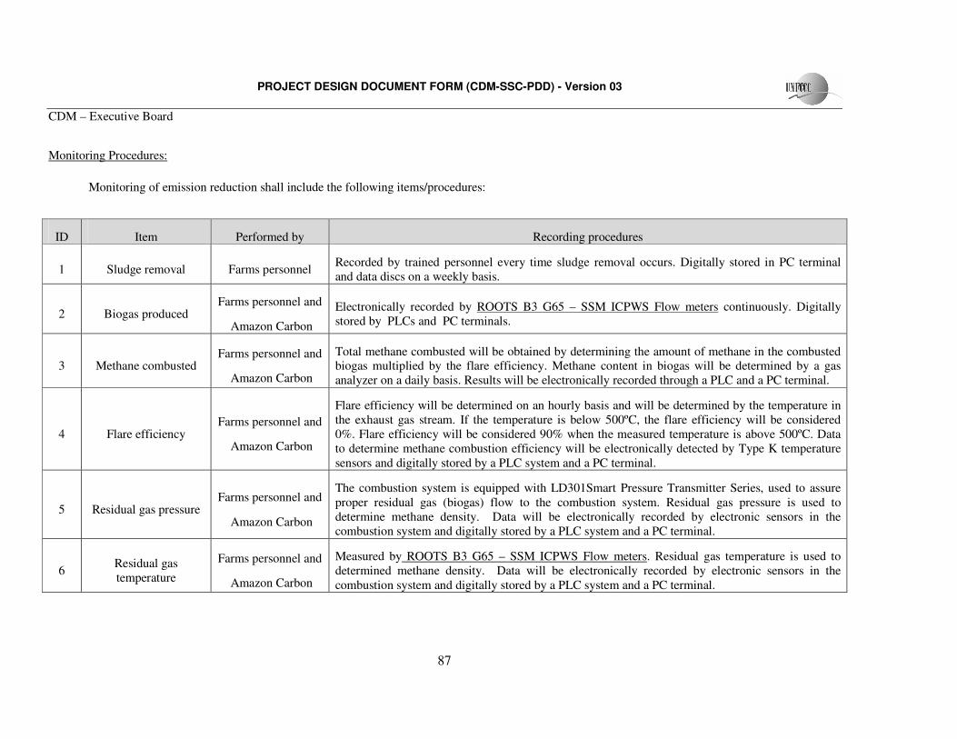
PROJECT DESIGN DOCUMENT FORM (CDM-SSC-PDD) - Version 03
CDM – Executive Board
87
Monitoring Procedures:
Monitoring of emission reduction shall include the following items/procedures:
ID Item Performed by Recording procedures
1 Sludge removal Farms personnel Recorded by trained personnel every time sludge removal occurs. Digitally stored in PC terminal and data discs on a weekly basis.
2 Biogas produced Farms personnel and
Amazon Carbon
Electronically recorded by ROOTS B3 G65 – SSM ICPWS Flow meters continuously. Digitally stored by PLCs and PC terminals.
3 Methane combusted Farms personnel and
Amazon Carbon
Total methane combusted will be obtained by determining the amount of methane in the combusted biogas multiplied by the flare efficiency. Methane content in biogas will be determined by a gas analyzer on a daily basis. Results will be electronically recorded through a PLC and a PC terminal.
4 Flare efficiency Farms personnel and
Amazon Carbon
Flare efficiency will be determined on an hourly basis and will be determined by the temperature in the exhaust gas stream. If the temperature is below 500ºC, the flare efficiency will be considered 0%. Flare efficiency will be considered 90% when the measured temperature is above 500ºC. Data to determine methane combustion efficiency will be electronically detected by Type K temperature sensors and digitally stored by a PLC system and a PC terminal.
5 Residual gas pressure Farms personnel and
Amazon Carbon
The combustion system is equipped with LD301Smart Pressure Transmitter Series, used to assure proper residual gas (biogas) flow to the combustion system. Residual gas pressure is used to determine methane density. Data will be electronically recorded by electronic sensors in the combustion system and digitally stored by a PLC system and a PC terminal.
6 Residual gas temperature
Farms personnel and
Amazon Carbon
Measured by ROOTS B3 G65 – SSM ICPWS Flow meters. Residual gas temperature is used to determined methane density. Data will be electronically recorded by electronic sensors in the combustion system and digitally stored by a PLC system and a PC terminal.
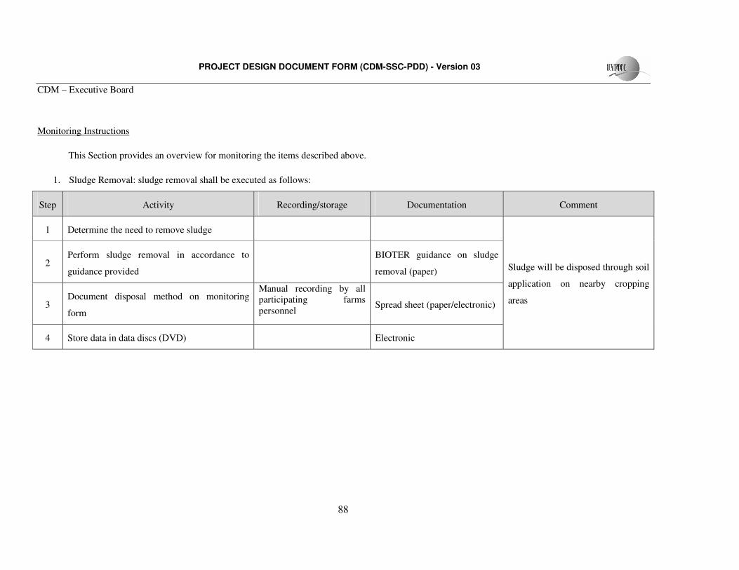
PROJECT DESIGN DOCUMENT FORM (CDM-SSC-PDD) - Version 03
CDM – Executive Board
88
Monitoring Instructions
This Section provides an overview for monitoring the items described above.
1. Sludge Removal: sludge removal shall be executed as follows:
Step Activity Recording/storage Documentation Comment
1 Determine the need to remove sludge
2 Perform sludge removal in accordance to
guidance provided
BIOTER guidance on sludge
removal (paper)
3 Document disposal method on monitoring
form
Manual recording by all participating farms personnel
Spread sheet (paper/electronic)
4 Store data in data discs (DVD)
Electronic
Sludge will be disposed through soil
application on nearby cropping
areas
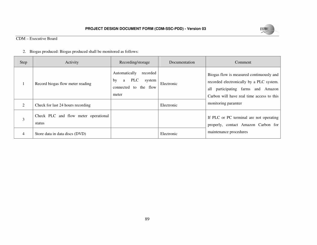
PROJECT DESIGN DOCUMENT FORM (CDM-SSC-PDD) - Version 03
CDM – Executive Board
89
2. Biogas produced: Biogas produced shall be monitored as follows:
Step Activity Recording/storage Documentation Comment
1 Record biogas flow meter reading
Automatically recorded
by a PLC system
connected to the flow
meter
Electronic
2 Check for last 24 hours recording
Electronic
Biogas flow is measured continuously and
recorded electronically by a PLC system.
all participating farms and Amazon
Carbon will have real time access to this
monitoring paramter
3 Check PLC and flow meter operational
status
4 Store data in data discs (DVD)
Electronic
If PLC or PC terminal are not operating
properly, contact Amazon Carbon for
maintenance procedures
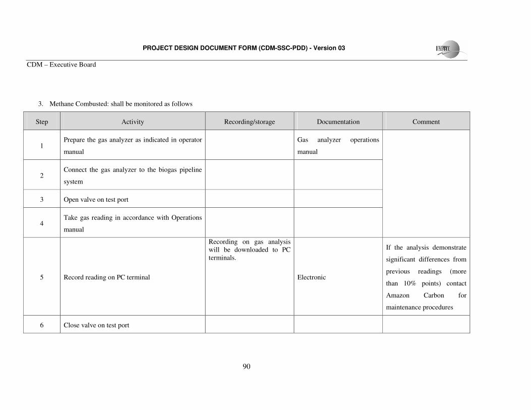
PROJECT DESIGN DOCUMENT FORM (CDM-SSC-PDD) - Version 03
CDM – Executive Board
90
3. Methane Combusted: shall be monitored as follows
Step Activity Recording/storage Documentation Comment
1 Prepare the gas analyzer as indicated in operator
manual
Gas analyzer operations
manual
2 Connect the gas analyzer to the biogas pipeline
system
3 Open valve on test port
4 Take gas reading in accordance with Operations
manual
5 Record reading on PC terminal
Recording on gas analysis will be downloaded to PC terminals.
Electronic
If the analysis demonstrate
significant differences from
previous readings (more
than 10% points) contact
Amazon Carbon for
maintenance procedures
6 Close valve on test port
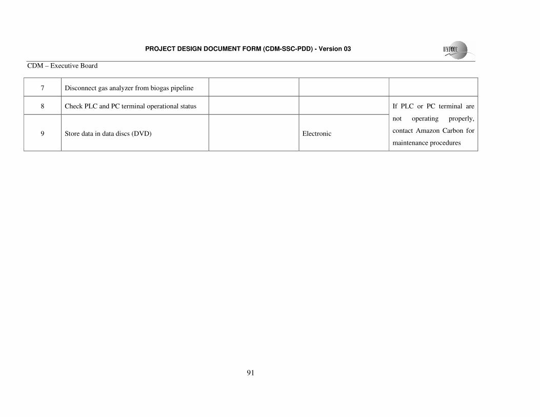
PROJECT DESIGN DOCUMENT FORM (CDM-SSC-PDD) - Version 03
CDM – Executive Board
91
7 Disconnect gas analyzer from biogas pipeline
8 Check PLC and PC terminal operational status
9 Store data in data discs (DVD)
Electronic
If PLC or PC terminal are
not operating properly,
contact Amazon Carbon for
maintenance procedures
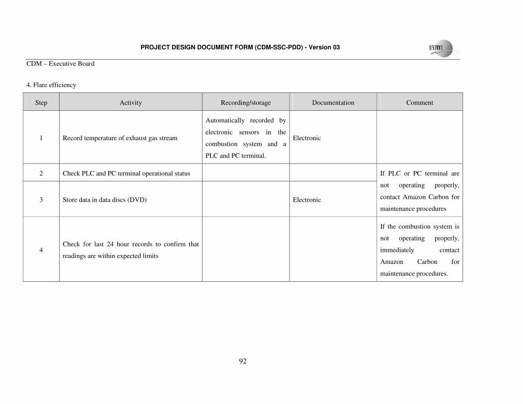
PROJECT DESIGN DOCUMENT FORM (CDM-SSC-PDD) - Version 03
CDM – Executive Board
92
4. Flare efficiency
Step Activity Recording/storage Documentation Comment
1 Record temperature of exhaust gas stream
Automatically recorded by
electronic sensors in the
combustion system and a
PLC and PC terminal.
Electronic
2 Check PLC and PC terminal operational status
3 Store data in data discs (DVD)
Electronic
If PLC or PC terminal are
not operating properly,
contact Amazon Carbon for
maintenance procedures
4 Check for last 24 hour records to confirm that
readings are within expected limits
If the combustion system is
not operating properly,
immediately contact
Amazon Carbon for
maintenance procedures.
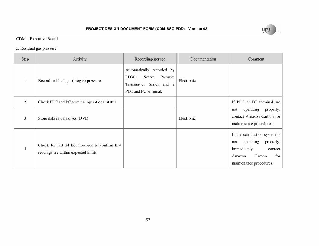
PROJECT DESIGN DOCUMENT FORM (CDM-SSC-PDD) - Version 03
CDM – Executive Board
93
5. Residual gas pressure
Step Activity Recording/storage Documentation Comment
1 Record residual gas (biogas) pressure
Automatically recorded by
LD301 Smart Pressure
Transmitter Series and a
PLC and PC terminal.
Electronic
2 Check PLC and PC terminal operational status
3 Store data in data discs (DVD)
Electronic
If PLC or PC terminal are
not operating properly,
contact Amazon Carbon for
maintenance procedures
4 Check for last 24 hour records to confirm that
readings are within expected limits
If the combustion system is
not operating properly,
immediately contact
Amazon Carbon for
maintenance procedures.
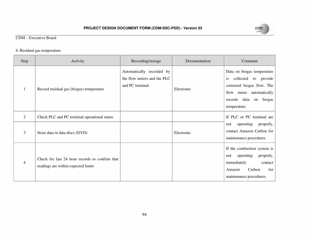
PROJECT DESIGN DOCUMENT FORM (CDM-SSC-PDD) - Version 03
CDM – Executive Board
94
6. Residual gas temperature
Step Activity Recording/storage Documentation Comment
1 Record residual gas (biogas) temperature
Automatically recorded by
the flow meters and the PLC
and PC terminal. Electronic
Data on biogas temperature
is collected to provide
corrected biogas flow. The
flow meter automatically
records data on biogas
temperature.
2 Check PLC and PC terminal operational status
3 Store data in data discs (DVD)
Electronic
If PLC or PC terminal are
not operating properly,
contact Amazon Carbon for
maintenance procedures
4 Check for last 24 hour records to confirm that
readings are within expected limits
If the combustion system is
not operating properly,
immediately contact
Amazon Carbon for
maintenance procedures.
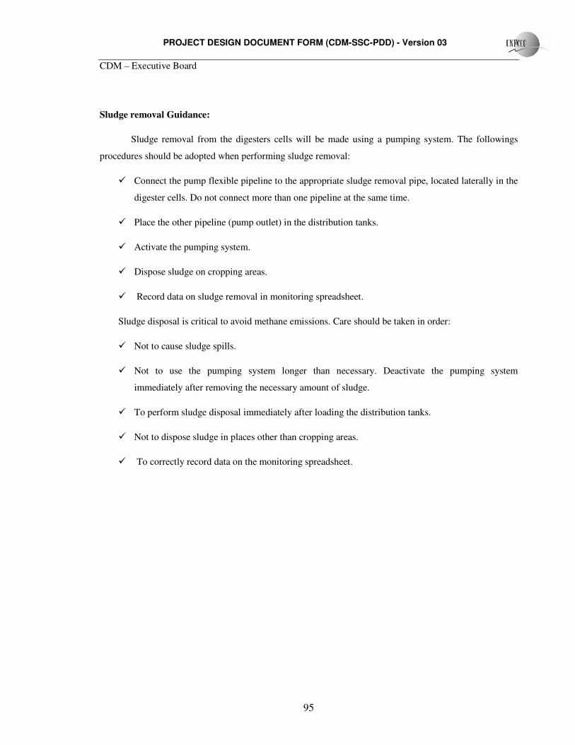
PROJECT DESIGN DOCUMENT FORM (CDM-SSC-PDD) - Version 03
CDM – Executive Board
95
Sludge removal Guidance:
Sludge removal from the digesters cells will be made using a pumping system. The followings
procedures should be adopted when performing sludge removal:
� Connect the pump flexible pipeline to the appropriate sludge removal pipe, located laterally in the
digester cells. Do not connect more than one pipeline at the same time.
� Place the other pipeline (pump outlet) in the distribution tanks.
� Activate the pumping system.
� Dispose sludge on cropping areas.
� Record data on sludge removal in monitoring spreadsheet.
Sludge disposal is critical to avoid methane emissions. Care should be taken in order:
� Not to cause sludge spills.
� Not to use the pumping system longer than necessary. Deactivate the pumping system
immediately after removing the necessary amount of sludge.
� To perform sludge disposal immediately after loading the distribution tanks.
� Not to dispose sludge in places other than cropping areas.
� To correctly record data on the monitoring spreadsheet.
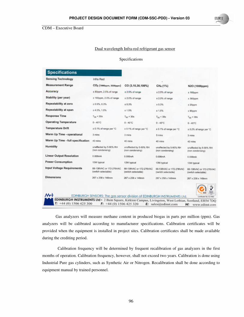
PROJECT DESIGN DOCUMENT FORM (CDM-SSC-PDD) - Version 03
CDM – Executive Board
96
Dual wavelength Infra-red refrigerant gas sensor
Specifications
Gas analyzers will measure methane content in produced biogas in parts per million (ppm). Gas
analyzers will be calibrated according to manufacturer specifications. Calibration certificates will be
provided when the equipment is installed in project sites. Calibration certificates shall be made available
during the crediting period.
Calibration frequency will be determined by frequent recalibration of gas analyzers in the first
months of operation. Calibration frequency, however, shall not exceed two years. Calibration is done using
Industrial Pure gas cylinders, such as Synthetic Air or Nitrogen. Recalibration shall be done according to
equipment manual by trained personnel.
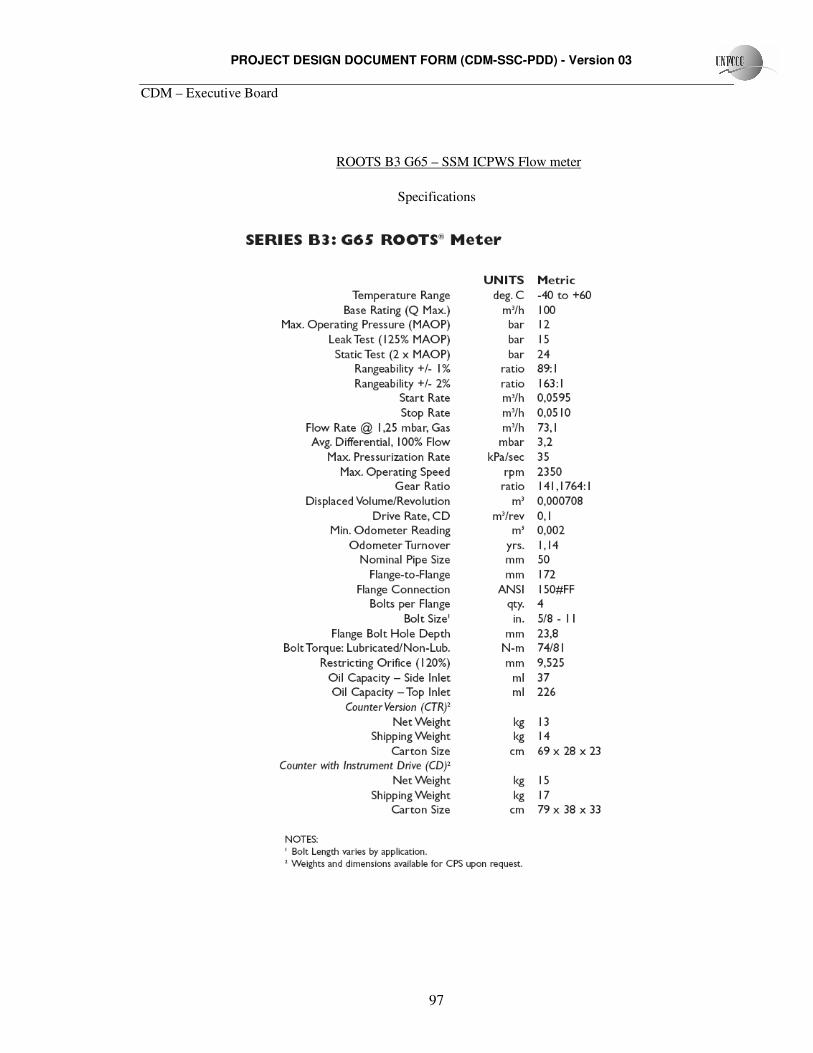
PROJECT DESIGN DOCUMENT FORM (CDM-SSC-PDD) - Version 03
CDM – Executive Board
97
ROOTS B3 G65 – SSM ICPWS Flow meter
Specifications
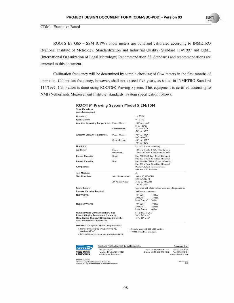
PROJECT DESIGN DOCUMENT FORM (CDM-SSC-PDD) - Version 03
CDM – Executive Board
98
ROOTS B3 G65 – SSM ICPWS Flow meters are built and calibrated according to INMETRO
(National Institute of Metrology, Standardization and Industrial Quality) Standard 114/1997 and OIML
(International Organization of Legal Metrology) Recommendation 32. Standards and recommendations are
annexed to this document.
Calibration frequency will be determined by sample checking of flow meters in the first months of
operation. Calibration frequency, however, shall not exceed five years, as stated in INMETRO Standard
114/1997. Calibration is done using ROOTS® Proving System. This equipment is certified according to
NMI (Netherlands Measurement Institute) standards. System specification follows:
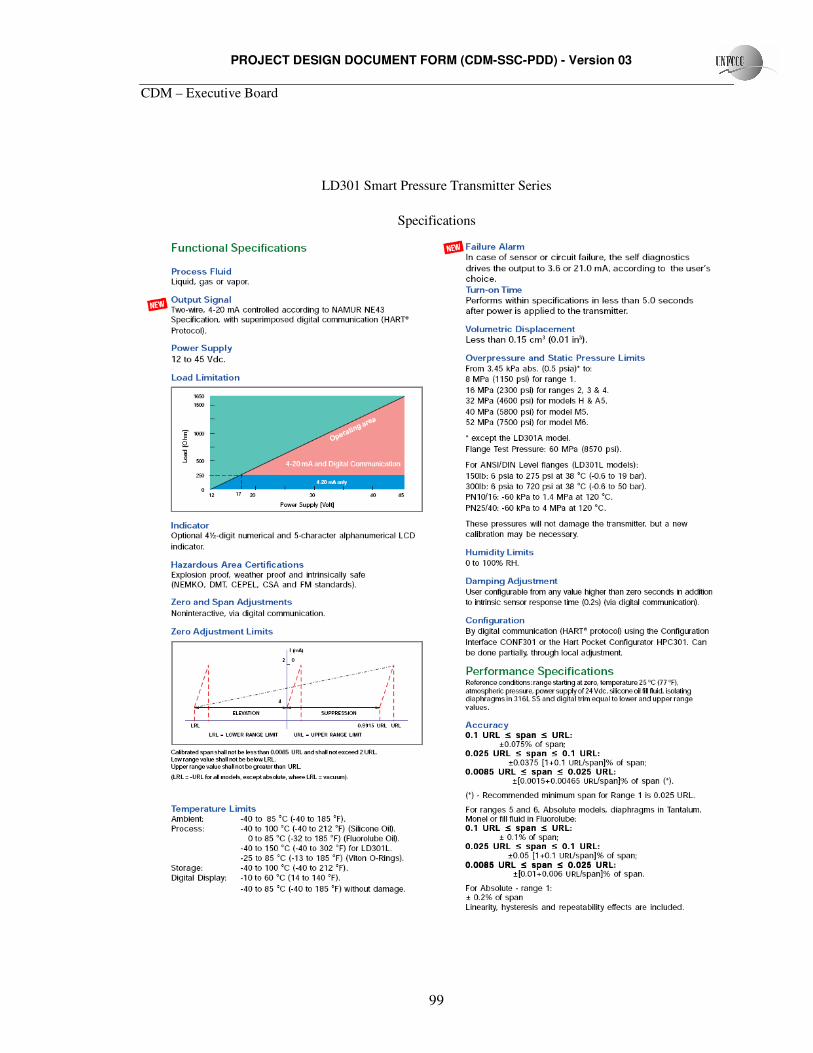
PROJECT DESIGN DOCUMENT FORM (CDM-SSC-PDD) - Version 03
CDM – Executive Board
99
LD301 Smart Pressure Transmitter Series
Specifications
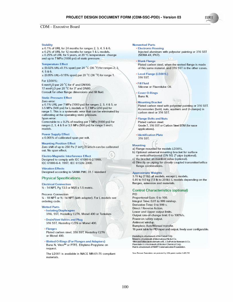
PROJECT DESIGN DOCUMENT FORM (CDM-SSC-PDD) - Version 03
CDM – Executive Board
100
PROJECT DESIGN DOCUMENT FORM (CDM-SSC-PDD) - Version 03
CDM – Executive Board
101
Calibration
LD301 Smart Pressure Transmitter Series are built and calibrated in accordance with INMETRO.
Conformity tests were made by the Centre of Electrical Energy Research, organization that is accredited by
INMETRO for such testing. Certificates of Conformity are annexed to this document. Testing and
certification will be executed during the crediting period to ensure proper operation of LD301
Transmitters.
EXHAUST GAS TEMPERATURE SENSOR
Exhaust gas temperature will be measured by Type K sensors are built and calibrated according to
ASTM standard ASTM-E 230/77. These sensors have a temperature range of 0 to 1 100ºC. Sensors will be
regulated to operate with maximal temperature of 600 to 700ºC.
The sensor provides +- 2.2 ºC accuracy in temperature reading. The sensors are connected to the
PLC, which records readings on an hourly basis, on Celsius degrees. These sensors do not need to be
recalibrated. Sensors will be replaced as needed.
PROJECT DESIGN DOCUMENT FORM (CDM-SSC-PDD) - Version 03
CDM – Executive Board
102
BIBLIOGRAPHY
The following references were used to determine the information described in this PDD:
• 2006 IPCC Guidelines for National GHG Inventories, Chapter 10;
• Approved methodology ACM0010, version 3, equation (2);
• Approved small-scale methodology AMS.III.D., version 13;
• First Brazilian Inventory on GHG Anthropogenic Emissions – Support Report – Agriculture and
Animal Husbandry;
• Methodological Tool to determine project emissions from flaring gases containing methane;
• Technological Inventory of EMBRAPA for Swine Manure Management Systems, pages 17 and 29
to 37


![swine flu kbk-1.ppt [Read-Only]ocw.usu.ac.id/.../1110000141-tropical-medicine/tmd175_slide_swine_… · MAP of H1 N1 Swine Flu. Swine Influenza (Flu) Swine Influenza (swine flu) is](https://img.pdfslide.us/doc/110x75/5f5a2f7aee204b1010391ac9/swine-flu-kbk-1ppt-read-onlyocwusuacid1110000141-tropical-medicinetmd175slideswine.jpg)