Embed Size (px)
Citation preview
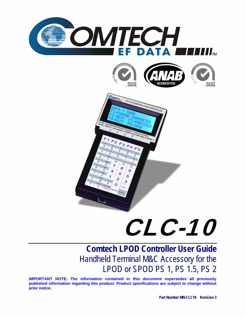
IMPORTANT NOTE: The information contained in this document supersedes all previously published information regarding this product. Product specifications are subject to change without prior notice.
Part Number MN-CLC10 Revision 3
CLC-10 Comtech LPOD Controller User Guide
Handheld Terminal M&C Accessory for the LPOD or SPOD PS 1, PS 1.5, PS 2

Copyright © 2013 Comtech EF Data. All rights reserved. Printed in the USA. Comtech EF Data, 2114 West 7th Street, Tempe, Arizona 85281 USA, 480.333.2200, FAX: 480.333.2161
CLC-10 Comtech LPOD Controller User Guide
Handheld Terminal M&C Accessory for the LPOD or SPOD PS 1, PS 1.5, PS 2
Part Number MN-CLC10 Revision 3

This page is intentionally blank.

iii
TABLE OF CONTENTS TABLE OF CONTENTS ............................................................................................................III
FIGURES ................................................................................................................................... V
PREFACE ................................................................................................................................ VII
About this Document ....................................................................................................................... vii Related Documents........................................................................................................................................................vii Disclaimer ........................................................................................................................................................................vii Reporting Comments or Suggestions Concerning this Document .......................................................................... viii
Conventions and References ........................................................................................................... viii Patents and Trademarks .............................................................................................................................................. viii Warnings, Cautions and Notes .................................................................................................................................... viii Examples of Multi-Hazard Notices .............................................................................................................................. viii Recommended Standard Designations ........................................................................................................................ix Metric Conversion ...........................................................................................................................................................ix
Electrical Safety Notifications ............................................................................................................ ix Safety Notice ....................................................................................................................................................................ix
Installation Guidelines Regarding Power Line Quality .......................................................................... x Statement of RoHS Compliance .................................................................................................................................... x
Warranty Policy ................................................................................................................................ xi Limitations of Warranty ..................................................................................................................................................xi Exclusive Remedies ........................................................................................................................................................ xii
Getting Help ................................................................................................................................... xiii
CHAPTER 1. INTRODUCTION ............................................................................................ 1–1
1.1 Overview ............................................................................................................................ 1–1
1.2 CLC-10 Specifications .......................................................................................................... 1–2
1.3 CLC-10 Dimensions .............................................................................................................. 1–3
CHAPTER 2. SETUP ........................................................................................................... 2–1
2.1 Getting Started ................................................................................................................... 2–1
2.2 Connecting the CLC-10 to the SSPA Using the CA-0020526 Serial Interface Cable .................. 2–3

CLC-10 Comtech LPOD Controller Handheld Terminal M&C Accessory Revision 3 Table of Contents MN-CLC10
iv
2.2.1 CA-0020526 RJ-11 Connector .................................................................................................................. 2–3 2.2.2 CA-0020526 19-pin Circular Connector .................................................................................................. 2–4
2.2.2.1 Circular Connector Connection for Standalone Applications .......................................................... 2–4 2.2.2.2 Circular Connector Connection for 1:1 Redundancy Applications ................................................. 2–5
2.3 1:1 Redundancy Applications – Cabling Requirements ......................................................... 2–5
2.4 Energizing the RF Equipment ............................................................................................... 2–8
2.5 CLC-10 –to– SSPA Initial Operation ...................................................................................... 2–8
2.6 CLC-10 Features and Configuration ...................................................................................... 2–9 2.6.1 CLC-10 Keypad Operation ...................................................................................................................... 2–10 2.6.2 CLC-10 Display ......................................................................................................................................... 2–11 2.6.3 CLC-10 –to– SSPA Communication Settings ........................................................................................ 2–11
2.6.3.1 Default CLC-10 Parameter Settings .................................................................................................. 2–12
CHAPTER 3. SERIAL-BASED M&C USING THE CLC-10 .................................................. 3–1
3.1 Important Disclaimer .......................................................................................................... 3–1
3.2 Introduction ....................................................................................................................... 3–1
3.3 Key Operational Parameters ............................................................................................... 3–2 3.3.1 RF Input Level ............................................................................................................................................ 3–2 3.3.2 Attenuator Control ................................................................................................................................... 3–2 3.3.3 Mute Control ............................................................................................................................................. 3–2 3.3.4 Faults .......................................................................................................................................................... 3–3 3.3.5 Power Detector ......................................................................................................................................... 3–4 3.3.6 Some Common Commands ..................................................................................................................... 3–4 3.3.7 End-of-Life Commands ............................................................................................................................. 3–4
3.4 Remote Control Protocol and Structure ............................................................................... 3–5 3.4.1 EIA-485 ....................................................................................................................................................... 3–5 3.4.2 EIA-232 ....................................................................................................................................................... 3–6 3.4.3 Basic Protocol ............................................................................................................................................ 3–6 3.4.4 Packet Structure ........................................................................................................................................ 3–7
3.4.4.1 Start of Packet ....................................................................................................................................... 3–7 3.4.4.2 Target Address ...................................................................................................................................... 3–7 3.4.4.3 Address Delimiter ................................................................................................................................. 3–8 3.4.4.4 Instruction Code ................................................................................................................................... 3–8 3.4.4.5 Instruction Code Qualifier ................................................................................................................... 3–8 3.4.4.6 Optional Message Arguments ............................................................................................................ 3–9 3.4.4.7 End of Packet ........................................................................................................................................ 3–9
3.5 Remote Commands and Queries ....................................................................................... 3–10

CLC-10 Comtech LPOD Controller Handheld Terminal M&C Accessory Revision 3 Table of Contents MN-CLC10
v
FIGURES Figure 1-1. CLC-10 Comtech LPOD Controller Unit Dimensions ............................................................... 1–3 Figure 2-1. CLC-10 M&C Accessory Kit (CEFD P/N KT-0020518) ............................................................... 2–1 Figure 2-2. Comtech EF Data’s LPOD Outdoor Amplifiers / Block Up Converters .................................... 2–2 Figure 2-3. Comtech EF Data’s SPOD Outdoor Amplifiers ........................................................................ 2–2 Figure 2-4. CA-0020526 Cable Connection Schematic .............................................................................. 2–3 Figure 2-5. CA-0020526 RJ-11 Connector to CLC-10 Connection ............................................................. 2–3 Figure 2-6. CA-0020526 19-pin Circular Connector .................................................................................. 2–4 Figure 2-7. CLC-10 to SSPA Connection – Standalone Applications.......................................................... 2–4 Figure 2-8. CA-0020526 Cable Connection for SSPA 1:1 Redundancy System ......................................... 2–5 Figure 2-9. LPOD 1:1 Redundancy System Cabling Schematic .................................................................. 2–6 Figure 2-10. SPOD 1:1 Redundancy System Cabling Schematic ............................................................... 2–7 Figure 2-11. CLC-10 Features .................................................................................................................... 2–9 Figure 2-12. CLC-10 Keypad Operation ................................................................................................... 2–10

CLC-10 Comtech LPOD Controller Handheld Terminal M&C Accessory Revision 3 Table of Contents MN-CLC10
vi
This page is intentionally blank.

vii
PREFACE
About this Document
This User Guide provides operation information for Comtech EF Data’s CLC-10 Comtech LPOD Controller, a handheld terminal Monitor and Control (M&C) accessory used with CEFD’s LPOD PS 1, PS 1.5, and PS 2 Outdoor Amplifiers / Block Up Converters (BUCs) and SPOD PS 1, PS 1.5, and PS 2 Outdoor Amplifiers. This guide is intended for use by the persons responsible for the operation and maintenance of the CLC-10 and these SSPAs.
Related Documents
• Comtech EF Data LPOD Outdoor Amplifier / Block Up Converter (BUC) Installation and Operation Manual (CEFD P/N MN-LPOD)
• Comtech EF Data SPOD Outdoor Amplifier Installation and Operation Manual (CEFD P/N MN-SPODPSX)
• Two Technologies, Inc. TechTerm® Technical Reference Manual (2T Document 15776,
available from www.2t.com)
Disclaimer
Comtech EF Data has reviewed this document thoroughly in order to provide an easy-to-use guide to your equipment. All statements, technical information, and recommendations in this document and in any guides or related documents are believed reliable, but the accuracy and completeness thereof are not guaranteed or warranted, and they are not intended to be, nor should they be understood to be, representations or warranties concerning the products described. Further, Comtech EF Data reserves the right to make changes in the specifications of the products described in this document at any time without notice and without obligation to notify any person of such changes. If you have any questions regarding this equipment or the information in this document, please contact the Comtech EF Data Customer Support Department.
CLC-10 Comtech LPOD Controller Handheld Terminal M&C Accessory Revision 3 Preface MN-CLC10
viii
Reporting Comments or Suggestions Concerning this Document
Comtech EF Data welcomes comments and suggestions regarding the content and design of this manual. Contact the Comtech EF Data Technical Publications Department:
Conventions and References
Patents and Trademarks
See all of Comtech EF Data's Patents and Patents Pending at http://patents.comtechefdata.com. Comtech EF Data acknowledges that all trademarks are the property of the trademark owners.
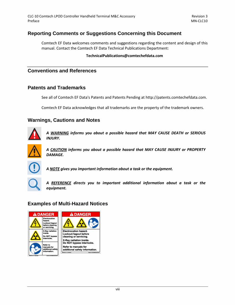
Warnings, Cautions and Notes
A WARNING
informs you about a possible hazard that MAY CAUSE DEATH or SERIOUS INJURY.
A CAUTION
informs you about a possible hazard that MAY CAUSE INJURY or PROPERTY DAMAGE.
A NOTE
gives you important information about a task or the equipment.
A REFERENCE
Examples of Multi-Hazard Notices
directs you to important additional information about a task or the equipment.

CLC-10 Comtech LPOD Controller Handheld Terminal M&C Accessory Revision 3 Preface MN-CLC10
ix
Recommended Standard Designations
The new designation of the Electronic Industries Association (EIA) supersedes the Recommended Standard (RS) designations. References to the old designations may be shown when depicting actual text (e.g., RS-232) displayed on the SSPA Web Server pages or serial remote interface. All other references in the manual refer to EIA designations.
Metric Conversion
This manual provides Metric conversion information on the inside back cover of this manual as a means to assist the operator in cross-referencing non-Metric to Metric conversions.
Electrical Safety Notifications
Safety Notice
The CLC-10 and LPOD/SPOD products are used with equipment that has been designed to minimize exposure of personnel to hazards. The operators and technicians must:
• Know how to work around, with and on high voltage equipment.
• Exercise every precaution to ensure personnel safety.
• Exercise extreme care when working near high voltages.
• Be familiar with the warnings presented in this document.
The LPOD and SPOD prime power supply inputs use Neutral Fusing – Double
pole / neutral fusing.
You should carefully review the information that follows.

CLC-10 Comtech LPOD Controller Handheld Terminal M&C Accessory Revision 3 Preface MN-CLC10
x
Installation Guidelines Regarding Power Line Quality
Comtech EF Data has become familiar with the varying quality of the AC power grid around the world. The following offers some installation guidelines that should help ensure a reliable installation.
• Surge suppression: High voltage surges can cause failure of the power supply. These surges
are typically caused by circuit switching on the main AC power grid, erratic generator operation, and also by lightning strikes. While the transceiver does have built in surge suppression, if the unit will be installed in a location with questionable power grid quality, Comtech EF Data recommends installation of additional power conditioning/surge suppression at the power junction box.
• Grounding: The SSPA rovides a grounding terminal. This is provided to allow you to ground the transceiver to the antenna’s grounding network. All components installed at the antenna should be grounded to a common grounding point at the antenna.
• Electrical welding: If welding needs to take place at the antenna, disconnect all cables from
the transceiver except for the ground wire. Cap all RF connections with terminations. This will prevent damage to the input/output circuitry of the transceiver.
• Lightning: Lightning strikes on or around the antenna will generate extremely high voltages
on all cables connected to the transceiver. Depending on the severity of the strike, the transceiver’s internal surge protection combined with the recommended external suppression may protect the transceiver’s power supply. However, if the installation will be in an area with a high probability of lightning strikes, Comtech EF Data recommends the installation of surge suppression on the RF and IF cables.
For further information, contact Comtech EF Data’s Customer Support Department.
Statement of RoHS Compliance
The RoHS (Restriction of Hazardous Substances) directive 2002/95/EC restricts the use of six hazardous materials found in electrical and electronic products. Restricted materials are hazardous to the environment and pollute landfills, and are dangerous in terms of occupational exposure during manufacturing and recycling. The Two Technologies, Inc. TechTerm Handheld Terminal, used as a serial M&C accessory for CEFD’s LPOD and SPOD families of products, has been certified to be free of the following substances mandated under RoHS: lead (Pb), mercury (Hg), cadmium (Cd), hexavalent chromium (Cr6+), polybrominated biphenyls (PBB), and polybrominated disphenyl ethers (PBDE).
CLC-10 Comtech LPOD Controller Handheld Terminal M&C Accessory Revision 3 Preface MN-CLC10
xi
Warranty Policy
Comtech EF Data products are warranted against defects in material and workmanship for a specific period from the date of shipment, and this period varies by product. In most cases, the warranty period is two years. During the warranty period, Comtech EF Data will, at its option, repair or replace products that prove to be defective. Repairs are warranted for the remainder of the original warranty or a 90 day extended warranty, whichever is longer. Contact Comtech EF Data for the warranty period specific to the product purchased. For equipment under warranty, the owner is responsible for freight to Comtech EF Data and all related customs, taxes, tariffs, insurance, etc. Comtech EF Data is responsible for the freight charges only for return of the equipment from the factory to the owner. Comtech EF Data will return the equipment by the same method (i.e., Air, Express, Surface) as the equipment was sent to Comtech EF Data. All equipment returned for warranty repair must have a valid RMA number issued prior to return and be marked clearly on the return packaging. Comtech EF Data strongly recommends all equipment be returned in its original packaging. Comtech EF Data Corporation’s obligations under this warranty are limited to repair or replacement of failed parts, and the return shipment to the buyer of the repaired or replaced parts.
Limitations of Warranty
The warranty does not apply to the Two Technologies, Inc. TechTerm Handheld Terminal (CEFD P/N PP-0020514, provided in Comtech EF Data Kit KT-0020518). In this instance, Two Technologies, Inc.’s manufacturer’s warranty and policies supercede any such warranties otherwise afforded Comtech EF Data products (e.g., the CA-0020526 cable provided in Kit KT-0020518). The warranty does not apply to any part of a product that has been installed, altered, repaired, or misused in any way that, in the opinion of Comtech EF Data Corporation, would affect the reliability or detracts from the performance of any part of the product, or is damaged as the result of use in a way or with equipment that had not been previously approved by Comtech EF Data Corporation. The warranty does not apply to any product or parts thereof where the serial number or the serial number of any of its parts has been altered, defaced, or removed. The warranty does not cover damage or loss incurred in transportation of the product.

CLC-10 Comtech LPOD Controller Handheld Terminal M&C Accessory Revision 3 Preface MN-CLC10
xii
The warranty does not cover replacement or repair necessitated by loss or damage from any cause beyond the control of Comtech EF Data Corporation, such as lightning or other natural and weather related events or wartime environments. The warranty does not cover any labor involved in the removal and or reinstallation of warranted equipment or parts on site, or any labor required to diagnose the necessity for repair or replacement. The warranty excludes any responsibility by Comtech EF Data Corporation for incidental or consequential damages arising from the use of the equipment or products, or for any inability to use them either separate from or in combination with any other equipment or products. A fixed charge established for each product will be imposed for all equipment returned for warranty repair where Comtech EF Data Corporation cannot identify the cause of the reported failure.
Exclusive Remedies
Comtech EF Data Corporation’s warranty, as stated is in lieu of all other warranties, expressed, implied, or statutory, including those of merchantability and fitness for a particular purpose. The buyer shall pass on to any purchaser, lessee, or other user of Comtech EF Data Corporation’s products, the aforementioned warranty, and shall indemnify and hold harmless Comtech EF Data Corporation from any claims or liability of such purchaser, lessee, or user based upon allegations that the buyer, its agents, or employees have made additional warranties or representations as to product preference or use. The remedies provided herein are the buyer’s sole and exclusive remedies. Comtech EF Data shall not be liable for any direct, indirect, special, incidental, or consequential damages, whether based on contract, tort, or any other legal theory.

CLC-10 Comtech LPOD Controller Handheld Terminal M&C Accessory Revision 3 Preface MN-CLC10
xiii
Getting Help
Contacting Comtech EF Data
Contact Comtech EF Data for:
• Technical Support – Product support or training.
• Customer Service – Information on returning an in-warranty or out-of-warranty product for upgrade or repair. Be prepared to provide the product model number and its serial number.
Contact Comtech EF Data Customer & Technical Support during normal business hours (Monday through Friday, 8 A.M. to 5 P.M Mountain Standard Time (MST)):
For: Contact:
LPOD/SPOD Technical Support and Service
Telephone +1.480.333.4357
Email [email protected]
Fax +1.480.333.2500
Comtech EF Data Web Site
Main Page http://www.comtechefdata.com
Customer and Technical Support http://www.comtechefdata.com/support.asp
RMA (Return Material Authorization)
http://www.comtechefdata.com/rmaform.asp
Comtech EF Data Main Number +1.480.333.2200
Mailing Address 2114 West 7th Street Tempe, Arizona 85281 USA
Review the Warranty Policy before contacting Comtech EF Data Technical Support or Customer Service.
CLC-10 Comtech LPOD Controller Handheld Terminal M&C Accessory Revision 3 Preface MN-CLC10
xiv
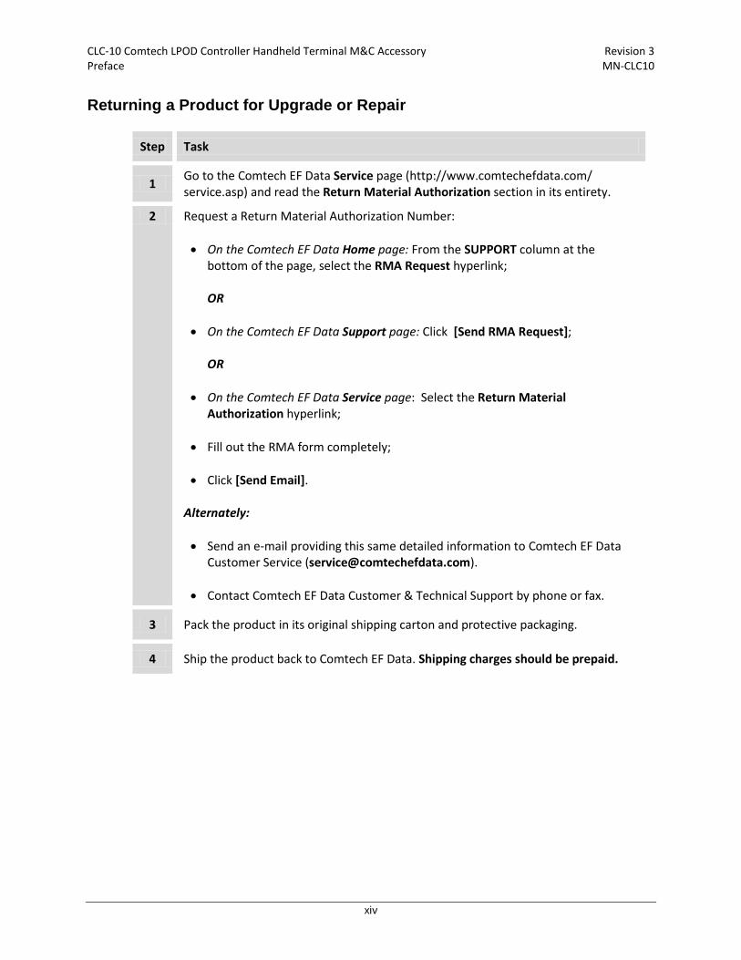
Returning a Product for Upgrade or Repair
Step Task
1 Go to the Comtech EF Data Service page (http://www.comtechefdata.com/ service.asp) and read the Return Material Authorization section in its entirety.
2 Request a Return Material Authorization Number: • On the Comtech EF Data Home page: From the SUPPORT column at the
bottom of the page, select the RMA Request hyperlink;
OR • On the Comtech EF Data Support page: Click [Send RMA Request];
OR
• On the Comtech EF Data Service page: Select the Return Material
Authorization hyperlink; • Fill out the RMA form completely; • Click [Send Email].
Alternately: • Send an e-mail providing this same detailed information to Comtech EF Data
Customer Service ([email protected]).
• Contact Comtech EF Data Customer & Technical Support by phone or fax.
3 Pack the product in its original shipping carton and protective packaging.
4 Ship the product back to Comtech EF Data. Shipping charges should be prepaid.

1–1
Chapter 1. INTRODUCTION
1.1 Overview
This User Guide is intended for the persons responsible for the operation and maintenance of Comtech EF Data’s LPOD Outdoor Amplifier / Block Up Converter (BUC) systems, and SPOD Outdoor Amplifier systems (the LPOD and SPOD are referred to collectively as the SSPAs throughout the remainder of this document). This guide is prepared with the assumption that you are familiar with the functionality and operability of the products with which this product is designed to interface, as well as the portable device – whether it is the Two Technologies, Inc. TechTerm Handheld terminal supplied by CEFD, or any other compatible desktop, portable, or handheld computing device – used to access the SSPA operational firmware. Comtech EF Data strongly recommends that you first become familiar with the LPOD or SPOD Installation and Operation Manual before proceeding.
Comtech EF Data’s CLC-10 M&C Accessory Kit (CEFD Kit KT-0020518) is used to access the monitor and control functionality of the SSPA. Serial communication between the unit and the CLC-10 is accomplished by connecting the provided RJ-11 to 19-pin adapter cable (CEFD P/N CA-0020526) between the RJ-11 interface jack on the Two Technologies, Inc. TechTerm Handheld Terminal (CEFD P/N PP-0020514) and the SSPA’s 19-pin circular COMM connection (either the ‘J6 | COM1’ remote communications port on the standalone unit, or the ‘J1’ receptacle on the 1:1 Redundant Loop Cable Assembly). Then, applicable for both Standalone and 1:1 Redundancy System applications, the CLC-10 permits you to access the SSPA Serial Remote Interface to monitor SSPA operations and execute remote commands and queries.

CLC-10 Comtech LPOD Controller Handheld Terminal M&C Accessory Revision 3 Introduction MN-CLC10
1–2
1.2 CLC-10 Specifications
Feature Specification
CEFD Part No. PP-0020514
Two Technologies, Inc. Manufacturer’s Part No. TT1NELR4-H-BK
Display • LED Supertwist Extended Temperature – Backlit • 4 rows @ 20 characters/row display format
Keypad • Membrane-type keypad with 45 keys (9 rows x 5 columns) • F1 through F5 programmable • Tactile and audible feedback
Power • Voltage: 9.5 – 28 VDC Switching Regulator • Current: 65-70 mA Nominal (EIA-422)
CPU • Type: Atmel AT89C55WD • Speed: 11.059 MHz
Interface
• Type: EIA-422 • Data Rate: 300 to 9600 bps • Parity Range: Even, Odd, Mark, Space, Ignore • Control Bits: 1-Start and 1-Stop • Standard Interface Connector: RJ-11 6-pin female modular jack
Environmental • Storage Temperature: -4° F to +158° F (-20° C to +70° C) • Operating Temperature (Extended): -4° F to +158° F (-20° C to +70° C) • Humidity: 5-95% non-condensing
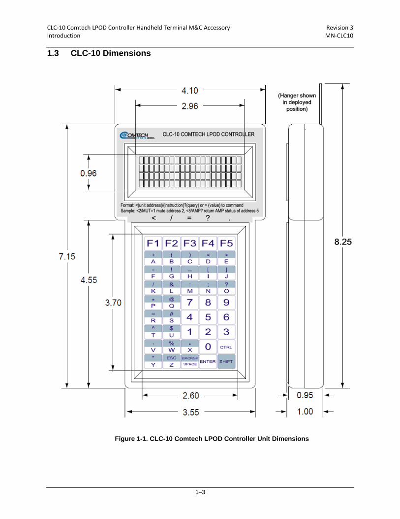
Physical • Dimensions:
8.25” (109.6 mm) H* x 4.10” (104.1 mm) W x 1.00” (25.4 mm) D (*with hanger extended) • Weight: 8 oz (227 g)
CLC-10 Comtech LPOD Controller Handheld Terminal M&C Accessory Revision 3 Introduction MN-CLC10
1–3
1.3 CLC-10 Dimensions
Figure 1-1. CLC-10 Comtech LPOD Controller Unit Dimensions

CLC-10 Comtech LPOD Controller Handheld Terminal M&C Accessory Revision 3 Introduction MN-CLC10
1–4
Notes:
2–1
Chapter 2. SETUP
2.1 Getting Started
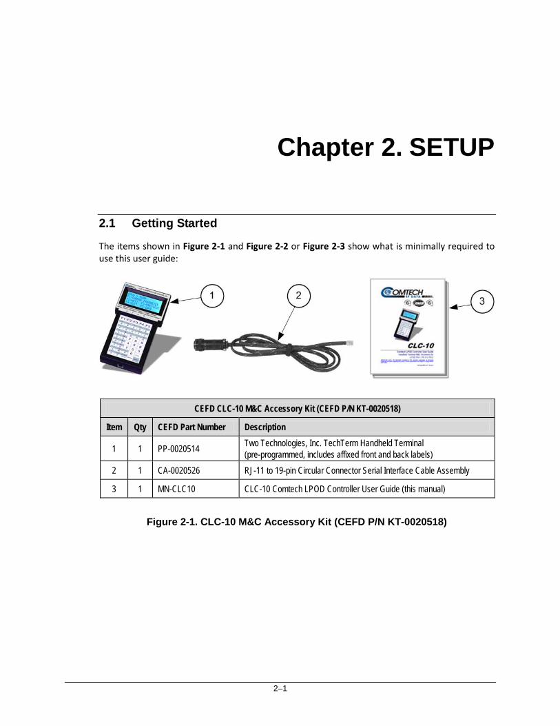
The items shown in Figure 2-1 and Figure 2-2 or Figure 2-3 show what is minimally required to use this user guide:
CEFD CLC-10 M&C Accessory Kit (CEFD P/N KT-0020518)
Item Qty CEFD Part Number Description
1 1 PP-0020514 Two Technologies, Inc. TechTerm Handheld Terminal (pre-programmed, includes affixed front and back labels)
2 1 CA-0020526 RJ-11 to 19-pin Circular Connector Serial Interface Cable Assembly
3 1 MN-CLC10 CLC-10 Comtech LPOD Controller User Guide (this manual)
Figure 2-1. CLC-10 M&C Accessory Kit (CEFD P/N KT-0020518)
CLC-10 Comtech LPOD Controller Handheld Terminal M&C Accessory Revision 3 Setup MN-CLC10
2–2
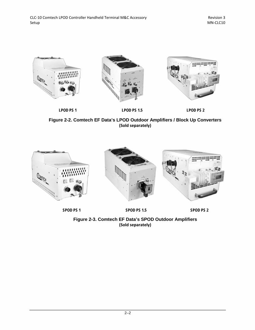
SPOD PS 1 SPOD PS 1.5 SPOD PS 2
LPOD PS 1 LPOD PS 1.5 LPOD PS 2
Figure 2-2. Comtech EF Data’s LPOD Outdoor Amplifiers / Block Up Converters (Sold separately)
Figure 2-3. Comtech EF Data’s SPOD Outdoor Amplifiers (Sold separately)

CLC-10 Comtech LPOD Controller Handheld Terminal M&C Accessory Revision 3 Setup MN-CLC10
2–3
2.2 Connecting the CLC-10 to the SSPA Using the CA-0020526 Serial Interface Cable
The Figure 2-4 diagram shows the connections for the CA-0020526 Serial Interface Cable. The cable’s RJ-11 end connects to the CLC-10 TechTerm Handheld Terminal. The 19-pin circular connector end connects to either the SSPA’s ‘J6 | COM1’ port in standalone applications, or the 1:1 Redundant Loop Cable Assembly’s ‘J1’ receptacle in 1:1 redundancy applications.
Figure 2-4. CA-0020526 Cable Connections Diagram
2.2.1 CA-0020526 RJ-11 Connector
Figure 2-5. CA-0020526 RJ-11 Connector to CLC-10 Connection
Typical for standalone or 1:1 redundancy configurations – Follow these steps to connect the CA-0020526 Serial Interface Cable to the CLC-10:
Step Task 1 Press down the tab on the CA-0020526 cable RJ-11 plug, and then insert the plug into the CLC-10’s
R-11 jack. 2 The connection is complete when the tab ‘clicks’ into position inside the jack (Figure 2-5).
CLC-10 Comtech LPOD Controller Handheld Terminal M&C Accessory Revision 3 Setup MN-CLC10
2–4
2.2.2 CA-0020526 19-pin Circular Connector
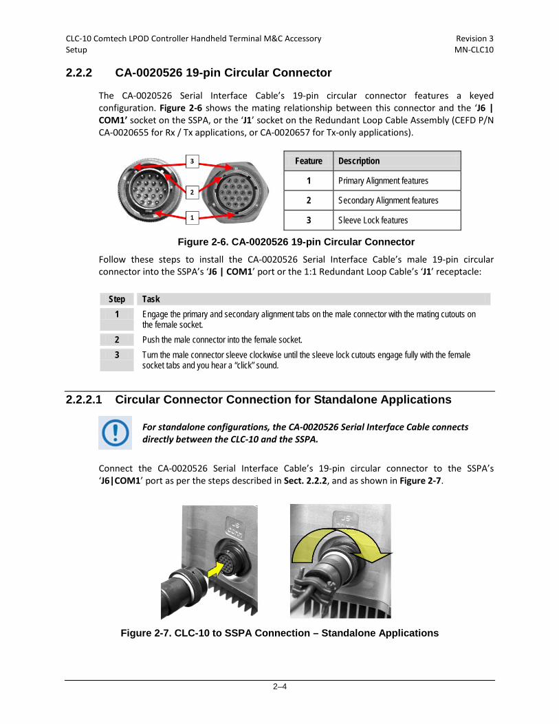
The CA-0020526 Serial Interface Cable’s 19-pin circular connector features a keyed configuration. Figure 2-6 shows the mating relationship between this connector and the ‘J6 | COM1’ socket on the SSPA, or the ‘J1’ socket on the Redundant Loop Cable Assembly (CEFD P/N CA-0020655 for Rx / Tx applications, or CA-0020657 for Tx-only applications).
Feature Description
1 Primary Alignment features
2 Secondary Alignment features
3 Sleeve Lock features
Figure 2-6. CA-0020526 19-pin Circular Connector Follow these steps to install the CA-0020526 Serial Interface Cable’s male 19-pin circular connector into the SSPA’s ‘J6 | COM1’ port or the 1:1 Redundant Loop Cable’s ‘J1’ receptacle:
Step Task 1 Engage the primary and secondary alignment tabs on the male connector with the mating cutouts on
the female socket. 2 Push the male connector into the female socket. 3 Turn the male connector sleeve clockwise until the sleeve lock cutouts engage fully with the female
socket tabs and you hear a “click” sound.
2.2.2.1 Circular Connector Connection for Standalone Applications
For standalone configurations, the CA-0020526 Serial Interface Cable connects directly between the CLC-10 and the SSPA.
Connect the CA-0020526 Serial Interface Cable’s 19-pin circular connector to the SSPA’s ‘J6|COM1’ port as per the steps described in Sect. 2.2.2, and as shown in Figure 2-7.
Figure 2-7. CLC-10 to SSPA Connection – Standalone Applications
CLC-10 Comtech LPOD Controller Handheld Terminal M&C Accessory Revision 3 Setup MN-CLC10
2–5
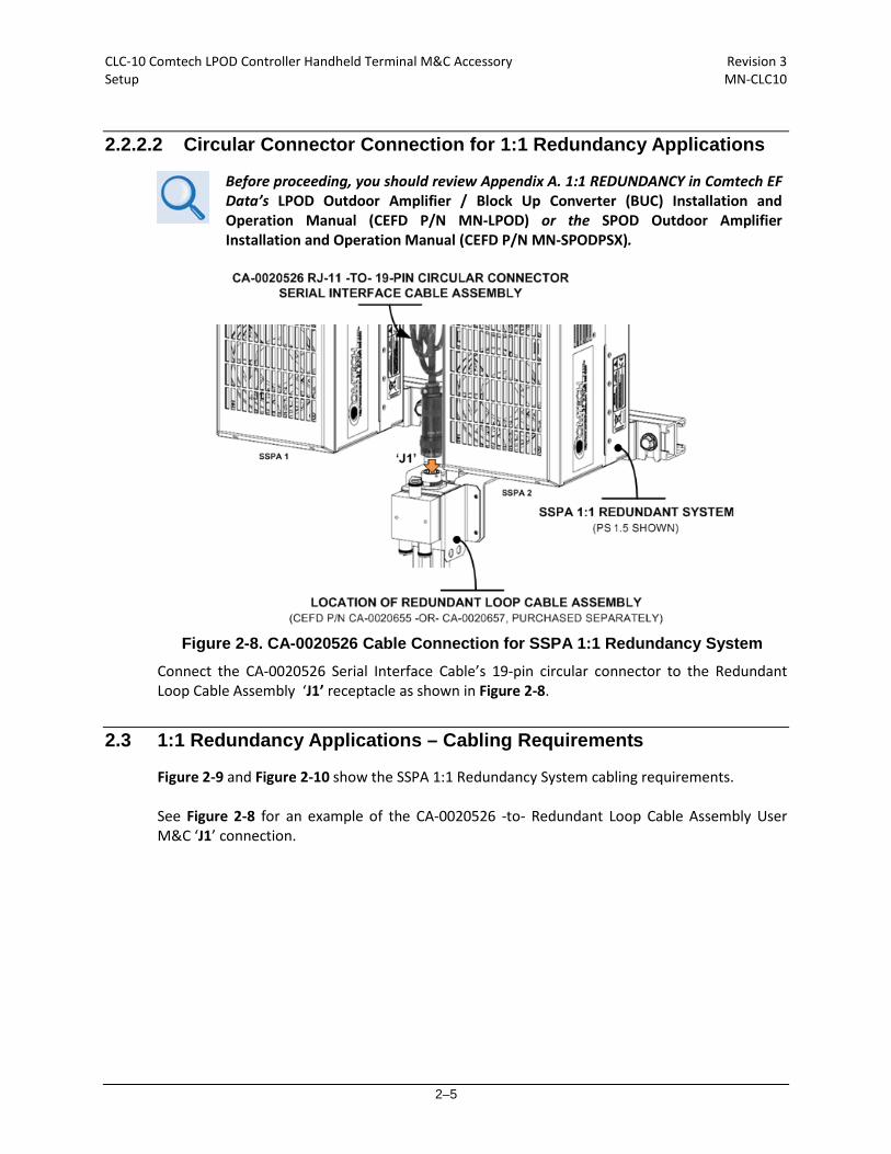
2.2.2.2 Circular Connector Connection for 1:1 Redundancy Applications
Before proceeding, you should review Appendix A. 1:1 REDUNDANCY in Comtech EF Data’s LPOD Outdoor Amplifier / Block Up Converter (BUC) Installation and Operation Manual (CEFD P/N MN-LPOD) or the SPOD Outdoor Amplifier Installation and Operation Manual (CEFD P/N MN-SPODPSX).
Figure 2-8. CA-0020526 Cable Connection for SSPA 1:1 Redundancy System
Connect the CA-0020526 Serial Interface Cable’s 19-pin circular connector to the Redundant Loop Cable Assembly ‘J1’ receptacle as shown in Figure 2-8.
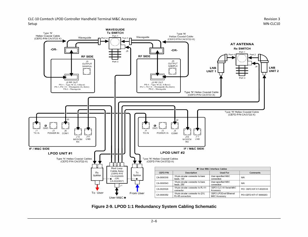
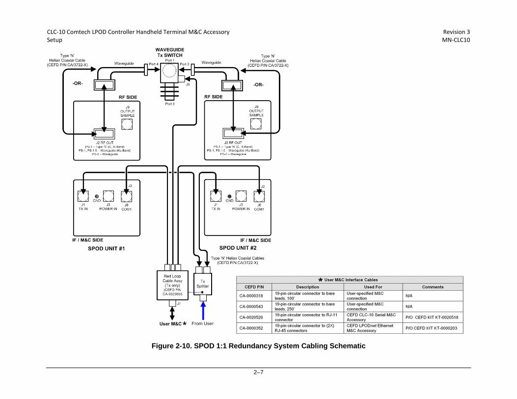
2.3 1:1 Redundancy Applications – Cabling Requirements
Figure 2-9 and Figure 2-10 show the SSPA 1:1 Redundancy System cabling requirements. See Figure 2-8 for an example of the CA-0020526 -to- Redundant Loop Cable Assembly User M&C ‘J1’ connection.
CLC-10 Comtech LPOD Controller Handheld Terminal M&C Accessory Revision 3 Setup MN-CLC10
2–6
Figure 2-9. LPOD 1:1 Redundancy System Cabling Schematic
CLC-10 Comtech LPOD Controller Handheld Terminal M&C Accessory Revision 3 Setup MN-CLC10
2–7
Figure 2-10. SPOD 1:1 Redundancy System Cabling Schematic

CLC-10 Comtech LPOD Controller Handheld Terminal M&C Accessory Revision 3 Setup MN-CLC10
2–8
2.4 Energizing the RF Equipment
If the waveguide is not terminated correctly, it transmits dangerous levels of electromagnetic radiation. THIS CAN CAUSE INJURY. Before you energize or operate any SSPA waveguide unit, make sure to correctly terminate the waveguide on the ‘J2 | RF OUT’ port.
The LPOD Outdoor Amplifiers / Block Up Converters (BUCs) and the SPOD Outdoor Amplifiers do not have Power On/Off switches. Use the ’J3 | POWER IN’ connector to energize the system.
Step Task
1 Make sure the SSPA is connected correctly to the CLC-10 as defined in Sect. 2.2.
2 Connect the applicable prime power source to the SSPA ‘J3 | POWER IN’ port.
3 Energize all components in the system.
2.5 CLC-10 –to– SSPA Initial Operation
The properly connected and configured CLC-10 initiates communication with the SSPA serial interface upon power-up of the unit. Proceed to Sect. 2.6 for an overview on the configuration and operation of the CLC-10 and its features. Chapter 3. SERIAL-BASED M&C USING THE CLC-10 provides complete information on using the CLC-10 for serial remote monitor and control of the SSPA.
CLC-10 Comtech LPOD Controller Handheld Terminal M&C Accessory Revision 3 Setup MN-CLC10
2–9
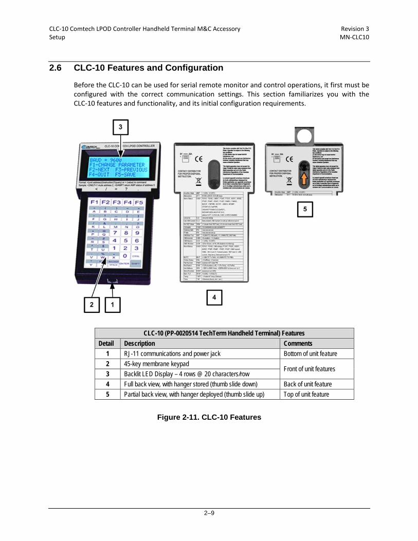
2.6 CLC-10 Features and Configuration
Before the CLC-10 can be used for serial remote monitor and control operations, it first must be configured with the correct communication settings. This section familiarizes you with the CLC-10 features and functionality, and its initial configuration requirements.
CLC-10 (PP-0020514 TechTerm Handheld Terminal) Features Detail Description Comments
1 RJ-11 communications and power jack Bottom of unit feature 2 45-key membrane keypad
Front of unit features 3 Backlit LED Display – 4 rows @ 20 characters/row 4 Full back view, with hanger stored (thumb slide down) Back of unit feature 5 Partial back view, with hanger deployed (thumb slide up) Top of unit feature
Figure 2-11. CLC-10 Features

CLC-10 Comtech LPOD Controller Handheld Terminal M&C Accessory Revision 3 Setup MN-CLC10
2–10
2.6.1 CLC-10 Keypad Operation
The CLC-10 ships pre-programmed and ready for plug-and-play interoperation with the SSPA. Refer to Figure 2-12 and its accompanying table for review of keys that have been customized for CLC-10/SSPA serial communications.
• When composing any Controller-to-Target command/query packet: Use the pre-programmed function keys F1 through F5 in combination with the pertinent alphanumeric keys comprising the pertinent Target Address, Instruction Coding, and Optional Arguments. Use the ENTER key to invoke End-of-Packet transmission (<cr>).
Sect. 3.4.4 Packet Structure in Chapter 3. SERIAL-BASED M&C USING
THE CLC-10.
• For alphabetical keys: Use of keys A-Z without the CTRL or SHIFT keys invokes
uppercase characters (ASCII Codes 65-90 A-Z). Press CTRL-SHIFT-key to invoke the desired lowercase characters (ASCII Codes 97-122 a-z).
• Use the shaded SHIFT key to invoke any shaded item (e.g., SHIFT-BACKSP).
Key Functional Description
F1 < (Start of Packet)
F2 / (Address Delimiter)
F3 = (‘Command’ code qualifier)
F4 ? (‘Query’ code qualifier)
F5 . (period/decimal point)
Figure 2-12. CLC-10 Keypad Operation

CLC-10 Comtech LPOD Controller Handheld Terminal M&C Accessory Revision 3 Setup MN-CLC10
2–11
2.6.2 CLC-10 Display
The CLC-10 features a LED backlit supertwist nematic display that affords you an expanded viewing angle, optimal readability in low-light conditions, and realizable operation in extreme temperature environments (-4° F to
+158° F / -20° C to +70° C). The display provides four content rows, at 20 characters per row, using the standard U.S. ASCII character set.
2.6.3 CLC-10 –to– SSPA Communication Settings
• Sect. 3.4.3 Basic Protocol in Chapter 3. SERIAL-BASED M&C USING THE CLC-10.
• Sect. 4.5.5.3.1 Config | Amplifier in Comtech EF Data’s LPOD Outdoor Amplifier / Block Up Converter (BUC) Installation and Operation Manual (CEFD P/N MN-LPOD) or SPOD Outdoor Amplifier Installation and Operation Manual (CEFD P/N MN-SPODPSX).
• Two Technologies, Inc. TechTerm® Technical Reference Manual (2T
Document 15776, available from www.2t.com).
SSPA Configuration: The CLC-10 ships preconfigured for interoperability with the SSPA. The character format should be 8N1 (8 data bits, no parity, 1 stop bit). The maximum allowable serial baud rate for the CLC-10 is 9600 bps. In order for the SSPA to properly communicate with the CLC-10, its serial baud rate must be preset to 9600 baud using the SBR command via the remote serial interface, or in the Serial section on the SSPA Web Server Interface Config | Amplifier page. CLC-10 Configuration: Should there be any reason to reconfigure the CLC-10 for proper communication with the SSPA, follow these steps:
Step Task
1 Hold CTRL and SHIFT and press F1 to access the CLC-10 Parameter menu. Alternately, disconnect the CA-0020526 Serial Interface Cable from the CLC-10 while simultaneously holding the CTRL, SHIFT, and F3 keys and then reconnect the cable to the CLC-10.
2 The CLC-10’s Parameter menu appears; its first configurable parameter appears on the top row of the display, and action prompts are provided on the next three rows:
To navigate between parameter settings: • Press F2 to move to the NEXT parameter
• Press F3 to return to the PREVISION parameter.
Press F1 to CHANGE (edit) the currently selected parameter.
CLC-10 Comtech LPOD Controller Handheld Terminal M&C Accessory Revision 3 Setup MN-CLC10
2–12
Step Task
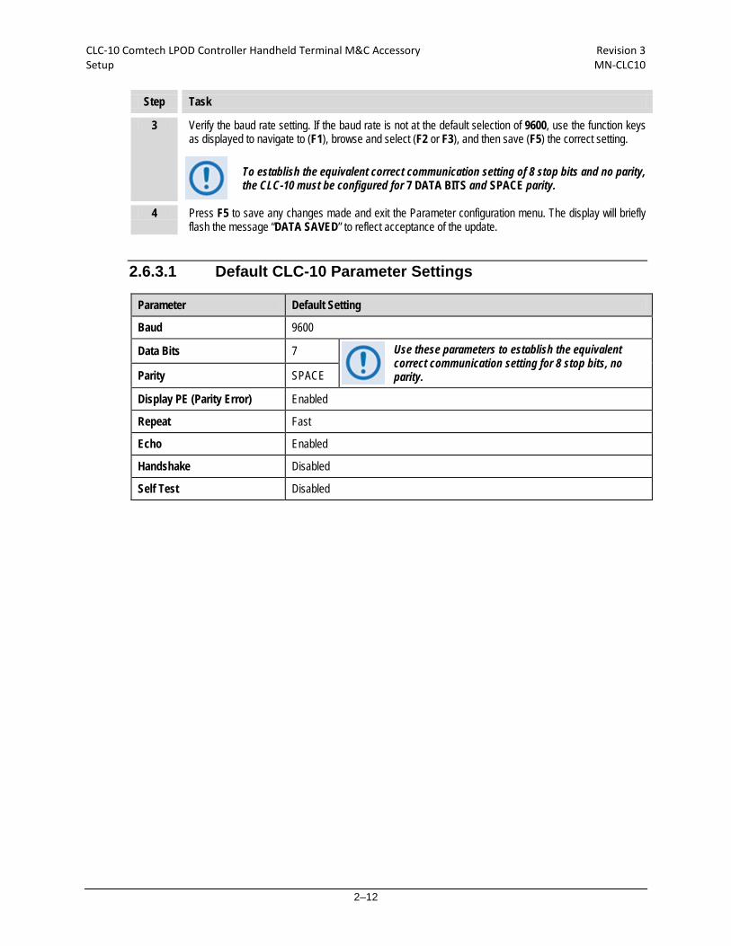
3 Verify the baud rate setting. If the baud rate is not at the default selection of 9600, use the function keys as displayed to navigate to (F1), browse and select (F2 or F3), and then save (F5) the correct setting.
To establish the equivalent correct communication setting of 8 stop bits and no parity, the CLC-10 must be configured for 7 DATA BITS and SPACE parity.
4 Press F5 to save any changes made and exit the Parameter configuration menu. The display will briefly flash the message “DATA SAVED” to reflect acceptance of the update.
2.6.3.1 Default CLC-10 Parameter Settings
Parameter Default Setting
Baud 9600
Data Bits 7 Use these parameters to establish the equivalent correct communication setting for 8 stop bits, no parity. Parity SPACE
Display PE (Parity Error) Enabled
Repeat Fast
Echo Enabled
Handshake Disabled
Self Test Disabled

3–1
Chapter 3. SERIAL-BASED M&C USING THE CLC-10
3.1 Important Disclaimer
This guide assumes user familiarity with operation of the LPOD or SPOD – referred collectively as the SSPA through the remainder of this chapter. The bulk of content in this chapter is taken directly from Chapter 5. SERIAL-BASED REMOTE PRODUCT MANAGEMENT in Comtech EF Data’s LPOD Outdoor Amplifier / Block Up Converter (BUC) Installation and Operation Manual (CEFD P/N MN-LPOD) and the SPOD Outdoor Amplifier Installation and Operation Manual (CEFD P/N MN-SPODPSX). The information provided in this chapter is intended for reference only. You should refer primarily to the latest revision of the pertinent SSPA manual for the most current Remote Commands and Queries available to the SSPA via serial remote control.
3.2 Introduction
This chapter describes the SSPA’s serial-based monitor and control (M&C) functions, accessible when the SSPA is connected to the CLC-10 in either Standalone or 1:1 Redundancy operation. This chapter summarizes key parameters and procedures, and their associated remote commands and queries. Detailed instructions for use of the serial remote control communication command and query interface are also provided.

CLC-10 Comtech LPOD Controller Handheld Terminal M&C Accessory Revision 3 Serial-Based M&C using the CLC-10 MN-CLC10
3–2
3.3 Key Operational Parameters
The back of the CLC-10 is labeled with a quick reference that lists frequently used remote commands and queries. Detailed information about the remote commands and queries mentioned on the back label of the CLC-10 and in this section is provided in Sect. 3.5 Remote Commands and Queries found later in this chapter.
3.3.1 RF Input Level
The required RF input level to reach the full rated output power of the SSPA is determined by the individual amplifier maximum gain and power rating. For example, if the test data of an SSPA rated for 250W (54 dBm) indicated a gain of 75 dB, then a signal of 54 dBm – 75 dB=-21 dBm would approximately give the rated output power. Increasing input power beyond this level would result in an output signal with increasingly higher levels of distortion. Of course, if the SSPA attenuation control is utilized, a higher-level input signal can be accommodated. The maximum input level should never exceed 15dBm, or permanent damage to the unit may occur.
3.3.2 Attenuator Control
The SSPA gain can be attenuated over its specified range by exercising the ATT command. The details for the format of this command are found later in this chapter.
3.3.3 Mute Control
The SSPA may be muted via software or discrete control. Exercising the MUT=1 command will “software” mute the unit. The SSPA also may be “hardware” muted by pulling Pin ‘S’ on the J6 | COM1 Discrete control connector to ground (see Chapter 2. SYSTEM CONNECTIONS, INSTALLATION AND OPERATION in the SSPA manual). The Mute command provides over 60 dB of RF on/off isolation. However, the Mute command only turns off the first few low power stages of the amplifier, the high power stages remain on. By allowing the higher-powered transistors to stay on, the SSPA remains in more thermally stable state should the mute condition be removed. Should you choose 7to completely turn off the bias to the entire amplifier (perhaps to conserve energy in a redundant system), both the MUT=1 and AMP=0 commands should be executed. For normal transmit operation, MUT=0 and AMP=1 are required.
CLC-10 Comtech LPOD Controller Handheld Terminal M&C Accessory Revision 3 Serial-Based M&C using the CLC-10 MN-CLC10
3–3
3.3.4 Faults
The M&C system monitors certain key functions of the SSPA for proper operation. Should any of these parameters exceed predetermined limits, the M&C system will declare a fault. The conditions that trigger a fault are:
• Any power supply more than ± 10% outside its nominal value.
• Fan less than 25% of maximum speed.
• I2C internal bus communications fault.
• Thermal Shutdown – A temperature fault is indicated if the unit is +>90°C. This creates a summary fault and will cause the unit to mute itself and switch to the back-up unit (if in a redundant system). However, the 10V supply to the FET transistors will remain on until the unit reaches the thermal shutdown temperature of ≥ >95°C. For protection reasons, the unit will shut down the 10V supply to the power transistors at temperatures >95°C.
• Firmware checksum error at power up.
• FPGA done indicator error at power up.
• *Block upconverter (BUC) unlocked.
• Redundant waveguide switch position fault (applies to redundant mode operation only).
• Redundant inter-unit link fault (applies to redundant mode operation only).
• Low noise block converter (LNB) current over limit. The following parameters can be user defined to report an alarm condition, a fault condition, or the parameter can be ignored completely by masking it:
• RF amplifier low output power (user adjustable value)
• Internal reference oscillator unlocked
• *LNB converter current outside specified window
• *LNB voltage out of tolerance *NOTE: If this parameter generates a fault condition, the RF output will be muted.

CLC-10 Comtech LPOD Controller Handheld Terminal M&C Accessory Revision 3 Serial-Based M&C using the CLC-10 MN-CLC10
3–4
3.3.5 Power Detector
A power detector is provided to monitor the output power. It has a useful range of over 20 dB, referenced to the unit’s rated P1dB point, and its value can be read by exercising the RMS command. The test data supplied with each unit gives an indication of the excellent accuracy and flatness of the power monitor over the frequency band of operation.
3.3.6 Some Common Commands
A few of the most common commands and queries are listed below. Full details for each of these are listed in Sect. 3.5 of this chapter.
• RMS: Retrieve Maintenance Status. Displays voltages, fan speeds, heat sink temperature, output power monitor reading, etc.
• RCS: Retrieve Configuration Status. Displays current attenuation, mute, amplifier, online, etc. status.
• RAS: Retrieve Alarm Status. Displays current alarm or fault status.
3.3.7 End-of-Life Commands
Certain commands/queries are being marked as End-of-Life (EOL). As noted in the format <description>E in the Parameter Type field (in the Remote Commands and Queries tables in Sect. 3.5), while these commands are fully supported in this product it is highly recommended that the equivalent new commands be used for new implementations. The new commands will generally follow the outdated commands:
EOL-designated Command/Query (Page #) New Command/Query (Page #) / Comment CAA (3-12) CAE (3-12) CUS (3-15) Functionality not included in any other remote command/query DAT (3-17) DAY (3-17) LNA (3-22) RNE (3-30) RET (3-28) PNM (3-25) New query provides more exact unit hardware information RSN (3-31) SNO (3-33) SFS (3-33) Functionality not included in any other remote command/query TNA (3-35) TNE (3-35)

CLC-10 Comtech LPOD Controller Handheld Terminal M&C Accessory Revision 3 Serial-Based M&C using the CLC-10 MN-CLC10
3–5
3.4 Remote Control Protocol and Structure
The electrical interface is either an EIA-485 multi-drop bus (for the control of many devices) or an EIA-232 connection (for the control of a single device), and data is transmitted in asynchronous serial form, using ASCII characters. Control and status information is transmitted in packets, of variable length, in accordance with the structure and protocol defined in later sections.
3.4.1 EIA-485
For applications where multiple devices are to be monitored and controlled, full duplex (or 4-wire) EIA-485 is preferred. Half duplex (2-wire) EIA-485 is possible, but is not preferred. In full-duplex EIA-485 communication there are two separate, isolated, independent, differential-mode twisted pairs, each handling serial data in different directions. It is assumed that there is a ‘Controller’ device (i.e., the CLC-10), which transmits data in a broadcast mode, via one of the pairs. Many ‘Target’ devices (i.e., the SSPA) are connected to this pair, which all simultaneously receive data from the Controller. The Controller is the only device with a line-driver connected to this pair – the Target devices only have line-receivers connected. In the other direction, on the other pair, each Target has a Tri-Stateable line driver connected, and the Controller has a line-receiver connected. All the line drivers are held in high-impedance mode until one (and only one) Target transmits back to the Controller. Each Target has a unique address, and each time the Controller transmits, in a framed ‘packet’ of data, the address of the intended recipient Target is included. All of the Targets receive the packet, but only one (the intended) will reply. The Target enables its output line driver, and transmits its return data packet back to the Controller, in the other direction, on the physically separate pair. EIA-485 (Full Duplex) Summary:
Two differential pairs One pair for Controller to Target, one pair for Target to Controller.
Controller-to-Target pair Pair has one line driver (Controller), and all Targets have line-receivers.
Target-to-Controller pair Pair has one line receiver (Controller), and all Targets have Tri-State drivers.
CLC-10 Comtech LPOD Controller Handheld Terminal M&C Accessory Revision 3 Serial-Based M&C using the CLC-10 MN-CLC10
3–6
3.4.2 EIA-232
This is a much simpler configuration in which the Controller device is connected directly to the Target via a two-wire-plus-ground connection. Controller-to-Target data is carried, via EIA-232 electrical levels, on one conductor, and Target-to-Controller data is carried in the other direction on the other conductor.
3.4.3 Basic Protocol
Whether in EIA-232 or EIA-485 mode, all data is transmitted as asynchronous serial characters, suitable for transmission and reception by a UART. The character format should be 8N1 (8 data bits, no parity, 1 stop bit). In general, the baud rate may vary between 2400 and 38400 baud. For proper communication with the CLC-10, the SSPA baud rate should be set to 9600 bps (see the SBR command /
query for configuration details).
All data is transmitted in framed packets. The Controller is assumed to be a PC or ASCII dumb terminal that is in charge of the process of monitor and control. The Controller is the only device that is permitted to initiate, at will, the transmission of data. Targets are only permitted to transmit when they have been specifically instructed to do so by the Controller. All bytes within a packet are printable ASCII characters, less than ASCII code 127. In this context, the Carriage Return and Line Feed characters are considered printable. All messages from Controller-to-Target require a response – with one exception. This will be either to return data that has been requested by the Controller, or to acknowledge reception of an instruction to change the configuration of the Target. The exception to this is when the Controller broadcasts a message (such as Set time/date) using Address 0, when the Target is set to EIA-485 mode.
CLC-10 Comtech LPOD Controller Handheld Terminal M&C Accessory Revision 3 Serial-Based M&C using the CLC-10 MN-CLC10
3–7
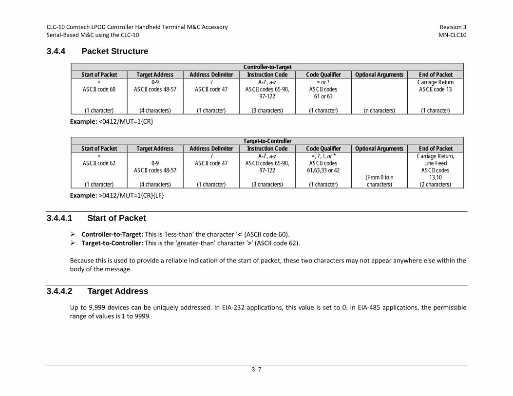
3.4.4 Packet Structure
Controller-to-Target Start of Packet Target Address Address Delimiter Instruction Code Code Qualifier Optional Arguments End of Packet
< ASCII code 60
(1 character)
0-9 ASCII codes 48-57
(4 characters)
/ ASCII code 47
(1 character)
A-Z, a-z ASCII codes 65-90,
97-122
(3 characters)
= or ? ASCII codes
61 or 63
(1 character)
(n characters)
Carriage Return ASCII code 13
(1 character)
Example: <0412/MUT=1{CR}
Target-to-Controller Start of Packet Target Address Address Delimiter Instruction Code Code Qualifier Optional Arguments End of Packet
> ASCII code 62
(1 character)
0-9 ASCII codes 48-57
(4 characters)
/ ASCII code 47
(1 character)
A-Z, a-z ASCII codes 65-90,
97-122
(3 characters)
=, ?, !, or * ASCII codes
61,63,33 or 42
(1 character) (From 0 to n characters)
Carriage Return, Line Feed
ASCII codes 13,10
(2 characters)
Example: >0412/MUT=1{CR}{LF}
3.4.4.1 Start of Packet
Controller-to-Target: This is ‘less-than’ the character '<' (ASCII code 60). Target-to-Controller: This is the ‘greater-than’ character '>' (ASCII code 62). Because this is used to provide a reliable indication of the start of packet, these two characters may not appear anywhere else within the body of the message.
3.4.4.2 Target Address
Up to 9,999 devices can be uniquely addressed. In EIA-232 applications, this value is set to 0. In EIA-485 applications, the permissible range of values is 1 to 9999.
CLC-10 Comtech LPOD Controller Handheld Terminal M&C Accessory Revision 3 Serial-Based M&C using the CLC-10 MN-CLC10
3–8
The Controller sends a packet with the address of a Target – the destination of the packet. When the Target responds, the address used is the same address, to indicate to the Controller the source of the packet. The Controller does not have its own address.
6B
3.4.4.3 Address Delimiter
This is the ‘forward slash’ character ' / ' (ASCII code 47).
3.4.4.4 Instruction Code
This is a three-character alphabetic sequence that identifies the subject of the message. Wherever possible, the instruction codes have been chosen to have some significance. For example: GAC for Global Amplifier Configuration; IPA for IP Address, etc. This aids in the readability of the message, should it be displayed in its raw ASCII form. Both upper case and lower case alphabetic characters may be used (A-Z and a-z, ASCII codes 65-90 and 97-122).
3.4.4.5 Instruction Code Qualifier
This single character further qualifies the preceding instruction code. Code Qualifiers obey the following rules: 1. From Controller-to-Target, the only permitted values are:
= (ASCII code 61
This character is used as the assignment operator, and is used to indicate that the parameter defined by the preceding byte should be set to the value of the argument(s) that follow it. For example: In a message from Controller-to-Target, MUT=1 would mean ‘enable the Mute function’.
? (ASCII code 63)
This character is used as the query operator, and is used to indicate that the Target should return the current value of the parameter defined by the preceding byte. For example: In a message from Controller-to-Target, SWR? would mean ‘returns the value of the internal software revision installed in the unit’.
2. From Target-to-Controller, the only permitted values are:
CLC-10 Comtech LPOD Controller Handheld Terminal M&C Accessory Revision 3 Serial-Based M&C using the CLC-10 MN-CLC10
3–9
= (ASCII code 61)
This character is used in two ways:
First, if the Controller has sent a query code to a Target (for example: MUT?, meaning ‘is the Mute enabled or disabled?’), the Target would respond with MUT=x, where x represents the state in question: 1 being ‘enable’ and 0 being ‘disable’.
Second, if the Controller sends an instruction to set a parameter to a particular value, and if the value sent in the argument is valid, then the Target will acknowledge the message by replying with MUT= (with no message arguments).
? (ASCII code 63)
This character is used only if the Controller sends an instruction to set a parameter to a particular value, then, if the value sent in the argument is not valid, the Target will acknowledge the message by replying, for example, with MUT? (with no message arguments). This indicates that there was an error in the message sent by the Controller.
! (ASCII code 33)
This character is used only if the Controller sends an instruction code which the Target does not recognize, the Target will acknowledge the message by echoing the invalid instruction, followed by the ! character. Example: XYZ!
* (ASCII code 42)
This character is used only if the Controller sends an instruction to set a parameter to a particular value, then, if the value sent in the argument is valid, BUT the Target is in the wrong mode (e.g., standby mode in redundancy configuration) and will not permit that particular parameter to be changed at that time, the Target will acknowledge the message by replying, for example, with MUT* (with no message arguments).
# (ASCII code 35)
This character is used only if the Controller sends an instruction code that the Target cannot currently perform because of hardware resource issues, then the Target will acknowledge the message by echoing the invalid instruction, followed by the # character. This response can only occur if the operator sends two or more ‘hardware configuration’ type commands without allowing adequate time between commands for the hardware to be configured. For example, if the operator issued commands to change both the frequency and the attenuation with less than 100 milliseconds between commands, and if this response is returned, then the command has not been accepted and the operator must resend the command.
3.4.4.6 Optional Message Arguments
Arguments are not required for all messages. Arguments are ASCII codes for any printable character.
3.4.4.7 End of Packet
Controller-to-Target: This is the 'carriage return' character (ASCII code 13). Target-to-Controller: This is the two-character sequence 'carriage return' (ASCII code 13), and 'line feed' (ASCII code 10). Both indicate the valid termination of a packet.

CLC-10 Comtech LPOD Controller Handheld Terminal M&C Accessory Revision 3 Serial-Based M&C using the CLC-10 MN-CLC10
3–10
3.5 Remote Commands and Queries
Column ‘C’=Command; Column ‘Q’=Query; columns marked ‘X’ designate instruction code as Command only, Query only, or Command/Query.
• Where an Instruction Code is noted XXXE this denotes a command/query designated as End of Life (EOL). See Sect. 3.3.7 for more information.
• Where an Instruction Code is noted XXXO this denotes a command/query that is available only when a reference oscillator is installed.
CODE C Q PAGE CODE C Q PAGE CODE C Q PAGE CODE C Q PAGE Note: The following codes are used in the ‘Response to Command’ column: AFR X X 3-11 GAC X X 3-19 PNM X 3-25 SRC X X 3-33
AMP X X 3-11 SSC X X 3-33 CODE MEANING AOF X X 3-11 IEP X 3-19 SSI X X 3-33 = Message OK ATT X X 3-12 IMG X X 3-19 RAS X 3-26 SSL X X 3-34 ? Received OK, but invalid arguments
found AUX X X 3-12 IPA X X 3-20 RBT X 3-27 SSN X X 3-34
IPG X X 3-20 RCS X 3-27 STA X X 3-34 * Message OK, but not permitted in Current mode CAAE X 3-12 ISP X 3-20 RED X X 3-27 STB X X 3-34
CAE X 3-12 REF X X 3-28 STV X X 3-34 # Message OK, but only permitted in Remote mode CAS X 3-13 LCS X X 3-20 RETE X 3-28 SWC X X 3-34
CCS X 3-14 LCW X X 3-21 RFS X 3-28 SWR X 3-34 ! Unknown command CFS X 3-14 LNAE X 3-21 RMS X 3-29 CID X X 3-14 LPT X X 3-21 RNE X 3-30 CLC X X 3-15 LRS X X 3-22 RNS X 3-31 CMS X 3-16 RSNE X 3-31 TIM X X 3-35 CSL X 3-15 MAC X 3-22 RUS X 3-31 TMP X 3-35
CUSE X 3-15 MOP X 3-23 TNAE X 3-35 CWE X X 3-16 MSK X X 3-24 TNE X 3-35
MUT X X 3-24 SBR X X 3-32 TPE X 3-35 DATE X X 3-17 SBT X X 3-32 TPS X X 3-35 DAY X X 3-17 NUE X 3-24 SFA X X 3-32 TSC X X 3-36
NUS X 3-24 SFSE X 3-32 ESA X X 3-17 SNA X X 3-33 ESL X X 3-17 OFM X X 3-25 SNM X X 3-33 ESW X X 3-18 ONL X X 3-25 SNO X X 3-33 XRM X X 3-36 FRW X 3-18 SPA X X 3-33
Note: Where Parameter Type is in the format <description>E, while the underlying command will remain, the specific functionality will be obsolete and should not be used for new implementations. There generally will be a different command elsewhere that encapsulates the marked functionality.

CLC-10 Comtech LPOD Controller Handheld Terminal M&C Accessory Revision 3 Serial-Based M&C using the CLC-10 MN-CLC10
3–11
Parameter Type Command
(Instruction Code and Qualifier)
Arguments for Command or Response
to Query
Description of Arguments (Note that all arguments are printable ASCII characters)
Response to Command (Target to Controller)
Query (Instruction Code and Qualifier)
Response to Query (Target to Controller)
Auto Fault Recovery
AFR= 1 byte
Command or Query. Sets or returns auto fault recovery in the form x, where:
0=Disabled 1=Enabled (Default value)
If auto fault recovery is enabled, it will cause the output return to its pre-fault mute condition if all faults are cleared. If disabled, the output will remain muted even if all faults are cleared. The SSPA output will automatically be muted if one of the following fault conditions occurs:
* BUC lock detect fault * LNB current fault (see Note) * LNB voltage fault (see Note)
Note: These faults can be user defined as faults, alarms, or masked (see MSK command for more info). Example: <1/AFR=1’cr’ >0001/AFR=’cr’’lf’
AFR= AFR? AFR*
AFR? AFR=x (See Description of Arguments)
RF Power Amplifier State
AMP= 1 byte Command or Query. Sets or returns the RF power amplifier state in the form x, where:
0=Off (Default value) 1=On
Note: turning the amplifier off will disable the +10V supply, and mask it during fault checking. Example: <1/AMP=1’cr’ >0001/AMP=’cr’’lf’
AMP= AMP? AMP*
AMP? AMP=x (See Description of Arguments)
Attenuation Offset
AOF= 5 bytes
Command or Query. Sets or returns the attenuation offset level in the form xx.xx, where:
xx.xx=00.00 to 20.00, in dB, in 0.25 dB steps as factory default. Default value: 00.00 This value is not copied to the offline unit in a redundant system, but is added to the attenuation value upon a switchover. This provides a unit-specific fine-tune to maintain power levels appropriately in a redundant system. Example: <1/AOF=12.25’cr’ >0001/AOF=’cr’’lf’
AOF= AOF? AOF*
AOF? AOF=xx.xx (See Description of Arguments)
CLC-10 Comtech LPOD Controller Handheld Terminal M&C Accessory Revision 3 Serial-Based M&C using the CLC-10 MN-CLC10
3–12
Parameter Type Command
(Instruction Code and Qualifier)
Arguments for Command or Response
to Query
Description of Arguments (Note that all arguments are printable ASCII characters)
Response to Command (Target to Controller)
Query (Instruction Code and Qualifier)
Response to Query (Target to Controller)
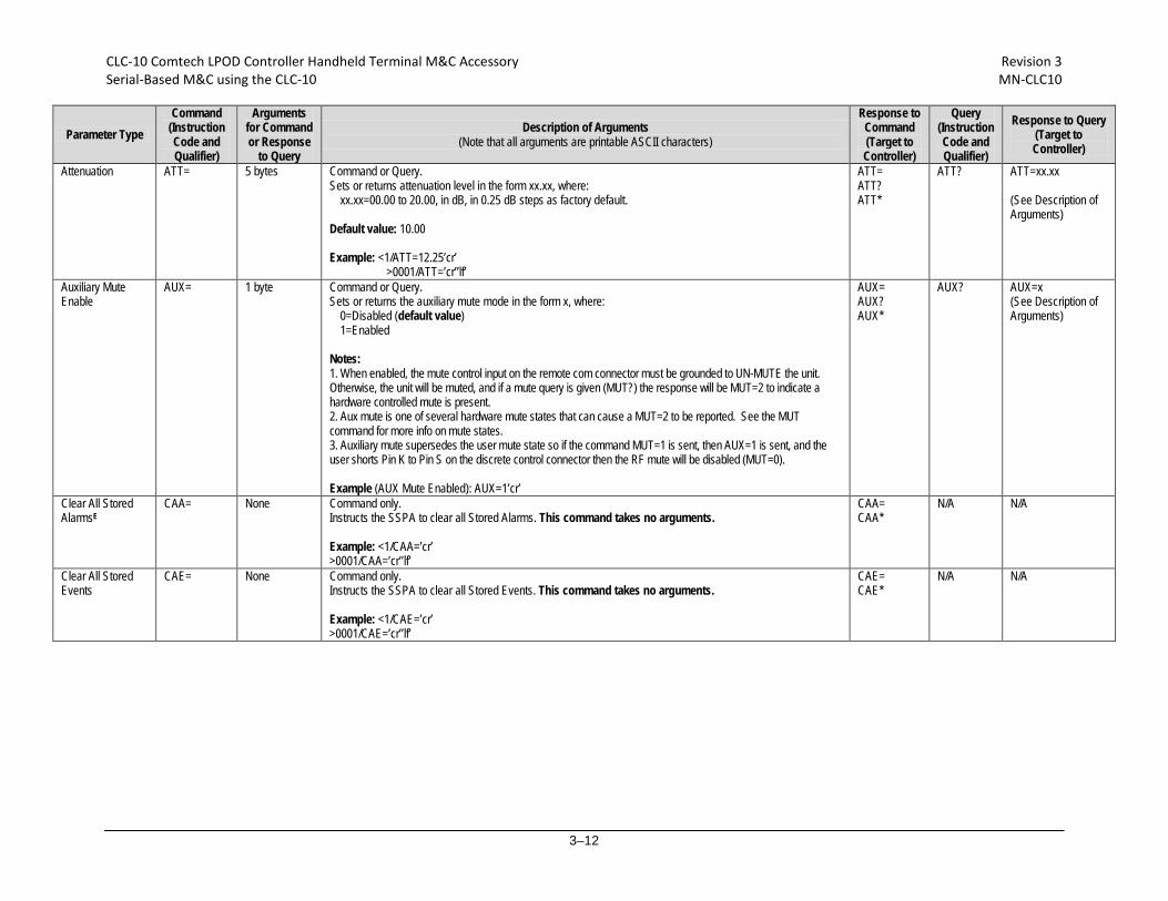
Attenuation ATT= 5 bytes
Command or Query. Sets or returns attenuation level in the form xx.xx, where:
xx.xx=00.00 to 20.00, in dB, in 0.25 dB steps as factory default. Default value: 10.00 Example: <1/ATT=12.25’cr’
>0001/ATT=’cr’’lf’
ATT= ATT? ATT*
ATT? ATT=xx.xx (See Description of Arguments)
Auxiliary Mute Enable
AUX= 1 byte Command or Query. Sets or returns the auxiliary mute mode in the form x, where:
0=Disabled (default value) 1=Enabled
Notes: 1. When enabled, the mute control input on the remote com connector must be grounded to UN-MUTE the unit. Otherwise, the unit will be muted, and if a mute query is given (MUT?) the response will be MUT=2 to indicate a hardware controlled mute is present. 2. Aux mute is one of several hardware mute states that can cause a MUT=2 to be reported. See the MUT command for more info on mute states. 3. Auxiliary mute supersedes the user mute state so if the command MUT=1 is sent, then AUX=1 is sent, and the user shorts Pin K to Pin S on the discrete control connector then the RF mute will be disabled (MUT=0). Example (AUX Mute Enabled): AUX=1’cr’
AUX= AUX? AUX*
AUX? AUX=x (See Description of Arguments)
Clear All Stored AlarmsE
CAA= None Command only. Instructs the SSPA to clear all Stored Alarms. This command takes no arguments. Example: <1/CAA=’cr’ >0001/CAA=’cr’’lf’
CAA= CAA*
N/A
N/A
Clear All Stored Events
CAE= None Command only. Instructs the SSPA to clear all Stored Events. This command takes no arguments. Example: <1/CAE=’cr’ >0001/CAE=’cr’’lf’
CAE= CAE*
N/A
N/A

CLC-10 Comtech LPOD Controller Handheld Terminal M&C Accessory Revision 3 Serial-Based M&C using the CLC-10 MN-CLC10
3–13
Parameter Type Command
(Instruction Code and Qualifier)
Arguments for Command or Response
to Query
Description of Arguments (Note that all arguments are printable ASCII characters)
Response to Command (Target to Controller)
Query (Instruction Code and Qualifier)
Response to Query (Target to Controller)
Concise Alarm Status
N/A 44 bytes
Query only. This is the concise version of the RAS query. Returns the alarm status of the unit, response is semicolon delimited. Example: CAS=a;b;c;d;e;f;g;h;i;j;k;I;m;n;o;p;q;r;s;t;u;v;w;x;y;’cr’’lf’ where:
a thru z=0 (FT), 1 (OK), 2 (AL), 3 (NO), 4 (YS), 5 (MS), 6 (??), or 7 (NA) a=+24V Power Supply b=+24V Switch Power Supply c=+13/18V LNB Power Supply (see Note) d=+13.5V Power Supply e=+10V Power Supply f=+10V1 Amplifier Power Supply g=+10V2 Amplifier Power Supply (see Note) h=+7.8V Power Supply i=+5.8V Power Supply j=+2.5V Power Supply k=+1.2V Power Supply l=-5.8V Power Supply m=Fan#1 State n=Fan#2 State (see Note) o=Heatsink Temp p=Overtemp Shutdown q=llC Status r=Forward Power Alarm s=Flash Checksum t=FPGA Done u=BUC Lock Detect (see Note) v=External Ref Lock Detect (see Note) w=LNB Current (see Note) x=Redundant Switch Condition (see Note) y=Redundant Link Status (see Note) z=Terminal Status Change
Notes: 1. c, g, n, u, v, w, x, and y appear if the appropriate model/options have been selected/installed. 2. ?? is an invalid fault condition because hardware failed to respond to query (this value is accompanied by an I2C fault). 3. NA=not applicable. The unit does not include hardware support for this parameter.
CAS= CAS?
CAS=x….x (See Description of Arguments)

CLC-10 Comtech LPOD Controller Handheld Terminal M&C Accessory Revision 3 Serial-Based M&C using the CLC-10 MN-CLC10
3–14
Parameter Type Command
(Instruction Code and Qualifier)
Arguments for Command or Response
to Query
Description of Arguments (Note that all arguments are printable ASCII characters)
Response to Command (Target to Controller)
Query (Instruction Code and Qualifier)
Response to Query (Target to Controller)
Concise Configuration Status
N/A 26 bytes Query only. This is the concise version of the RCS query. Returns the configuration status of the unit, in the form aa.aa;b;c;d;e;ff.ff;g;hhh, where:
aa.aa=attenuation in dB (ATT) b=RF power amplifier state, 0=Off, 1=On (AMP) c=mute state, 0=un-muted, 1=muted (MUT) d=online status (ONL) e=redundancy state and mode (ESW) ff.ff=Attenuator offset in dB (AOF) g=auto fault recovery mode (AFR) hhh=External reference status, N/A=no external reference, 05M for 5 MHz, and 10M for a 10 MHz (See Note)
Note: hhh will always be N/A if the internal reference oscillator option is not installed. Example: CCS=aa.aa;b;c;d;e;ff.ff;g;hhh; ’cr’’lf’
CCS= CCS? CCS= aa.aa;b;c;d;e; ff.ff;g;hhh (See Description of Arguments)
Concise RF Power FET Current Status
N/A Length varies depending on number of FETs installed in the amplifier
Query only. This is the concise version of the RFS query. Returns the RF Power FET Current status. Example: CFS=xxx,xxx,x.x,x.x,……….,x.x,
CFS= CFS? CFS=x…..x (See description of RFS. Note that each argument is separated by a comma.)
Circuit Identification
CID= 48 bytes
Command or Query. Sets or returns a 48-byte user-defined string that identifies or names the unit or station. The CID is entered as one line, but it reads back from the unit as two 24-byte lines of data. Default value: ------------------------ Examples: <1/CID= Station #001--SSPA #01--’cr’ >0001/CID= <1/CID?’cr’ >0001/CID=’cr’ Station #001’cr’ --SSPA #01--’cr’’lf’
CID= CID? CID*
CID? CID=x…x (See Description of Arguments)
CLC-10 Comtech LPOD Controller Handheld Terminal M&C Accessory Revision 3 Serial-Based M&C using the CLC-10 MN-CLC10
3–15
Parameter Type Command
(Instruction Code and Qualifier)
Arguments for Command or Response
to Query
Description of Arguments (Note that all arguments are printable ASCII characters)
Response to Command (Target to Controller)
Query (Instruction Code and Qualifier)
Response to Query (Target to Controller)
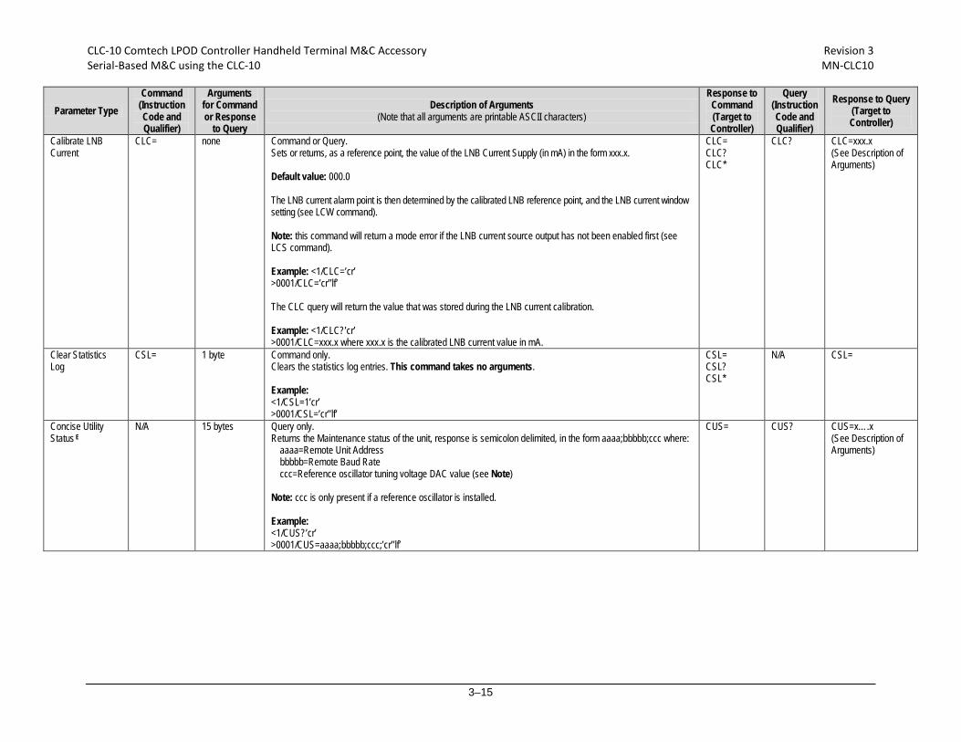
Calibrate LNB Current
CLC= none Command or Query. Sets or returns, as a reference point, the value of the LNB Current Supply (in mA) in the form xxx.x. Default value: 000.0 The LNB current alarm point is then determined by the calibrated LNB reference point, and the LNB current window setting (see LCW command). Note: this command will return a mode error if the LNB current source output has not been enabled first (see LCS command). Example: <1/CLC=’cr’ >0001/CLC=’cr’’lf’ The CLC query will return the value that was stored during the LNB current calibration. Example: <1/CLC?’cr’ >0001/CLC=xxx.x where xxx.x is the calibrated LNB current value in mA.
CLC= CLC? CLC*
CLC? CLC=xxx.x (See Description of Arguments)
Clear Statistics Log
CSL= 1 byte Command only. Clears the statistics log entries. This command takes no arguments. Example: <1/CSL=1’cr’ >0001/CSL=’cr’’lf’
CSL= CSL? CSL*
N/A CSL=
Concise Utility Status E
N/A 15 bytes
Query only. Returns the Maintenance status of the unit, response is semicolon delimited, in the form aaaa;bbbbb;ccc where:
aaaa=Remote Unit Address bbbbb=Remote Baud Rate ccc=Reference oscillator tuning voltage DAC value (see Note)
Note: ccc is only present if a reference oscillator is installed. Example: <1/CUS?’cr’ >0001/CUS=aaaa;bbbbb;ccc;’cr’’lf’
CUS= CUS?
CUS=x….x (See Description of Arguments)

CLC-10 Comtech LPOD Controller Handheld Terminal M&C Accessory Revision 3 Serial-Based M&C using the CLC-10 MN-CLC10
3–16
Parameter Type Command
(Instruction Code and Qualifier)
Arguments for Command or Response
to Query
Description of Arguments (Note that all arguments are printable ASCII characters)
Response to Command (Target to Controller)
Query (Instruction Code and Qualifier)
Response to Query (Target to Controller)
Concise Maintenance Status
N/A 95 bytes
Query only. This is the concise version of the RMS command. Returns the Maintenance status of the unit, response is semicolon delimited, in the form aaa.a;bbb.b;ccc.c;ddd.d;eee.e;fff.f;ggg.g;hhh.h;iii.i;jjj.j;kkk.k;lll.l;mmm.m;nnn.n; ooo.o;ppp.p;qqq.q;rrr.r;sss.s;ttt.t where:
aaa.a=P24V1 bbb.b=P24V2 ccc.c=LNBVT (see Note) ddd.d=P13VT eee.e=P10V1 fff.f=A10V1 ggg.g=A10V2 (see Note) hhh.h=P7V8T iii.i=P5V8T jjj.j=P2V5T kkk.k=P1V2T lll.l=N5V8T mmm.m=FANR1 (see Note) nnn.n=FANR2 (see Note) ooo.o=BUCVT (see Note) ppp.p=FWPWR qqq.q=REFVT (see Note) rrr.r=LNBCS (see Note) sss.s=ATEMP ttt.t=OTEMP (see Note)
Note: ccc.c, ggg.g, mmm.m, nnn.n, ooo.o, qqq.q, rrr.r, and ttt.t will appear if the appropriate model/options have been selected/installed. Otherwise, the unused fields will display XXXXX. Example: <1/CMS? >0001/CMS=aaa.a;bbb.b;ccc.c;ddd.d;eee.e;fff.f;ggg.g;hhh.h;iii.i;jjj.j;kkk.k;lll.l;mmm.m;nnn.n;ooo.o;ppp.p;qqq.q; rrr.r;sss.s;ttt.t’cr’’lf’
CMS= CMS?
CMS=x….x (See Description of Arguments)
LNB Current Window Enable
CWE= 1 bytes Command or Query. Sets or returns the LNB current window alarm in the form x, where:
0=Disabled (default value) 1=Enabled (see Note)
Note: If disabled, the LCW value will be retained, but unused. Example: <1/CWE=0’cr’ >0001/CWE=’cr’’lf’
CWE = CWE? CWE *
CWE? CWE =x (See Description of Arguments)

CLC-10 Comtech LPOD Controller Handheld Terminal M&C Accessory Revision 3 Serial-Based M&C using the CLC-10 MN-CLC10
3–17
Parameter Type Command
(Instruction Code and Qualifier)
Arguments for Command or Response
to Query
Description of Arguments (Note that all arguments are printable ASCII characters)
Response to Command (Target to Controller)
Query (Instruction Code and Qualifier)
Response to Query (Target to Controller)
Set RTC (Real-Time-Clock) Date E
DAT= 6 bytes Command or Query. Sets or returns the real-time clock date in the form mmddyy, where;
dd=day of the month, from 01 to 31, mm=month of the year, from 01 to 12 yy=year, from 00 to 96 (2000 to 2096)
Example (date=April 24, 2003): <1/DAT=042403’cr’ >0001/DAT=’cr’’lf’
DAT= DAT? DAT*
DAT?
DAT= mmddyy (See Description of Arguments)
Set RTC (Real-Time-Clock) Date
DAY= 6 bytes Command or Query. Sets or returns the real-time clock date in the form ddmmyy, where;
dd=day of the month, from 01 and 31, mm=month of the year, from 01 to 12 yy=year, from 00 to 99 (2000 to 2099)
Example (date=April 24, 2003): <1/DAY=240403’cr’ >0001/DAY=’cr’’lf’
DAY= DAY? DAY*
DAY?
DAY= ddmmyy (See Description of Arguments)
Enable Statistics Averaging
ESA= 1 byte Command or Query. Enables or Disables averaging of statistics data at a rate of once per second for 10 seconds, in the form x, where:
0=Disable (default value)(see Note) 1=Enable
Note: If Disabled, burst values will be logged instead of averaged values. Example: <1/ESA=0’cr’ >0001/ESA=’cr’’lf’
ESA= ESA? ESA*
ESA? ESA=x (See Description of Arguments)
Enable Statistics Logging
ESL= 1 byte Command or Query. Sets or returns the statistics logging function in the form x, where:
0=Disable (default value) 1=Enable
Example: <1/ESL=1’cr’ >0001/ESL=’cr’’lf’
ESL= ESL? ESL*
ESL? ESL=x (See Description of Arguments)

CLC-10 Comtech LPOD Controller Handheld Terminal M&C Accessory Revision 3 Serial-Based M&C using the CLC-10 MN-CLC10
3–18
Parameter Type Command
(Instruction Code and Qualifier)
Arguments for Command or Response
to Query
Description of Arguments (Note that all arguments are printable ASCII characters)
Response to Command (Target to Controller)
Query (Instruction Code and Qualifier)
Response to Query (Target to Controller)
Enable Redundancy Switch Mode
ESW= 1 byte Command or Query. Sets or returns the redundancy state in the form x, where:
0=Off (default value) 1=1:1 Redundancy TX (Only TX switch installed) 2=1:1 Redundancy TX + RX (TX and RX switch installed) 5=1:1 Manual redundancy mode (used for debugging, or redundant system setup)(see Note)
Note: Manual redundancy does not support automatic switching, and the offline unit will not poll the online unit to update its configuration. Example: <1/ESW=1’cr’ >0001/ESW=’cr’’lf’
ESW= ESW? ESW *
ESW? ESW=x
Retrieve Firmware Number
N/A Query only Returns the firmware type(s) loaded into the unit in the form FW-AAAAAAA B.B.BB DD/MM/YY, where:
FW-AAAAAAA=the firmware part number B.B.BB=the version number DD/MM/YY=Day/Month/Year firmware released
Example: <1/FRW?’cr’ >0001/FRW= Boot: FW-0000082 0.0.1a 04/09/08 Bulk1: FW-0000078 0.0.1a 04/09/08 FW-0000080 0.0.1a 04/09/08 FW-0000081 0.0.1a 04/09/08 Bulk2: FW-0000078 0.0.1a 04/09/08 FW-0000080 0.0.1a 04/09/08 FW-0000081 0.0.1a 04/09/08
FRW= FRW? FRW={CR}Boot:{CR}abc{CR}Bulki:{CR}abc{CR}abc (See Description of Arguments)

CLC-10 Comtech LPOD Controller Handheld Terminal M&C Accessory Revision 3 Serial-Based M&C using the CLC-10 MN-CLC10
3–19
Parameter Type Command
(Instruction Code and Qualifier)
Arguments for Command or Response
to Query
Description of Arguments (Note that all arguments are printable ASCII characters)
Response to Command (Target to Controller)
Query (Instruction Code and Qualifier)
Response to Query (Target to Controller)
Global Amplifier Configuration
GAC= 43 bytes Command or Query. Sets or returns the global status of the BUC/SSPA with a semicolon delimited string in the form a;b;cc.cc;dd.dd; e; fffff;g;hh;I;j;k;l;m;n;o where:
a=redundancy mode (ESW) b=online status (ONL) cc.cc=Attenuation Offset (AOF) dd.dd=Customer Attenuation(ATT) e=Auto Fault Recovery (AFR) fffff=Unit Alarm Mask (MSK) g=LNB Current Source (LCS) hh=LNB Current Window (LCW) i=LNB Current Window Enable (CWE) j=Enable Statistics Averaging (ESA) k=Set Statistics Interval (SSI) l=Enable Statistics Logging (ESL) m=Auxiliary Mute (AUX) n=user mute state (MUT) o=RF power amplifier state (AMP)
Example (set GAC): GAC=a;b;cc.cc;dd.dd;e;fffff;g;hh;I;j;k;l;m;n;o;’cr’
GAC= GAC* GAC? GAC#
GAC? GAC=x….x (See Description of Arguments)
Initialize Events Pointer
IEP= None Command only. Resets internal pointer to allow RNE? queries to start at the beginning of the stored events log. Example: <1/IEP=’cr’ >0001/IEP=’cr’lf
IEP= IEP? IEP*
N/A N/A
Software Image IMG= 1 byte
Command or Query. Sets or returns the current active software image in the form x, where:
1=Bulk Image # 1 currently active 2=Bulk Image # 2 currently active
Note: if you send the IMG command, and then query the IMG value the numbers may not be equal because the command tells the firmware which image to boot from at the next bootup, and the query reports the image that the firmware booted from on the last bootup. Examples: <1/IMG=1’cr’ (instructs the unit to load firmware from image #1 at the next reset / power up). <1/IMG?’cr’ (queries the image number that the firmware loaded during bootup)
IMG= IMG? IMG* IMG#
IMG?
IMG=x (See Description of Arguments)
CLC-10 Comtech LPOD Controller Handheld Terminal M&C Accessory Revision 3 Serial-Based M&C using the CLC-10 MN-CLC10
3–20
Parameter Type Command
(Instruction Code and Qualifier)
Arguments for Command or Response
to Query
Description of Arguments (Note that all arguments are printable ASCII characters)
Response to Command (Target to Controller)
Query (Instruction Code and Qualifier)
Response to Query (Target to Controller)
IP Address IPA= 18 bytes Command or Query. Sets or returns the IP address and network prefix for the 10/100 BaseT Ethernet management port, in the form xxx.xxx.xxx.xxx.yy, where:
xxx.xxx.xxx.xxx is the IP address, and yy is the network prefix (8-30)
Default value: 192.168.001.004.24 Note: Changing the IP address through the Telnet interface requires the user to power cycle the unit, and then restart a new Telnet session with the new IP address. The IP address that you type into the Telnet client software does not include the range parameter so it would be: 192.168.1.4 Example: <1/IPA=192.168.001.004.24’cr’ >0001/IPA=’cr’’lf’
IPA= IPA? IPA* IPA#
IPA? IPA= xx.xxx.xxx.xxx.yy (See Description of Arguments)
Gateway Address IPG= 15 bytes Command or Query. Sets or returns the Gateway IP address for the 10/100 Base Tx Ethernet management port, in the form xxx.xxx.xxx.xxx. Default value: 192.168.001.005 Example: <1/IPG=192.168.001.005’cr’ >0001/IPG=’cr’’lf’
IPG= IPG? IPG*
IPG? IPG=xxx.xxx.xxx.xxx
Initialize Statistics Pointer
ISP= None Command only. Resets internal pointer to allow RNS? queries to start at the beginning of the stored statistics log. Example: <1/ISP=’cr’ >0001/ISP=’cr’’lf’
ISP= ISP? ISP*
N/A N/A
LNB Current Source
LCS= 1 byte Command or Query. Sets or returns the LNB current source in the form x, where:
x= 0,1,2,3 or 4: 0=Disable (default value) 1=Enable (18V 22kHz Disabled – Note 2) 2=18V 22kHz Enabled (Note 2) 3=13V 22kHz Disabled (Note 2) 4=13V 22kHz Enabled (Note 2)
Notes: 1. LCS must be enabled before the LNB current can be calibrated 2. This feature is available on multi-band units only. Example: <1/LCS=1’cr’ >0001/LCS=’cr’’lf’
LCS= LCS? LCS*
LCS? LCS=x (See Description of Arguments)

CLC-10 Comtech LPOD Controller Handheld Terminal M&C Accessory Revision 3 Serial-Based M&C using the CLC-10 MN-CLC10
3–21
Parameter Type Command
(Instruction Code and Qualifier)
Arguments for Command or Response
to Query
Description of Arguments (Note that all arguments are printable ASCII characters)
Response to Command (Target to Controller)
Query (Instruction Code and Qualifier)
Response to Query (Target to Controller)
LNB Current Window
LCW= 2 bytes Command or Query. Sets or returns the alarm window in ±% of the calibrated LNB Current in the form xx, where:
xx=20 to 50, in increments of 1(%) 99 disables the alarm function (see Note)
Default value: 30 Note: When queried, a return value of 99 indicates that the current window is disabled. This method is due to become obsolete. Use of the CWE command/query is recommended instead of specifying 99 here. Example (sets the alarm window to ±30%): <1/LCW=30’cr’ >0001/LCW=’cr’’lf’
LCW= LCW? LCW*
LCW? LCW=xx (See Description of Arguments)
Retrieve next 5 unread Stored Alarms E
N/A 145 bytes Query only. Returns the five oldest stored events in the alarm log. If there are no events in the log the unit will reply with LNA*. All events that are read from the log are also automatically removed from the log. Reply format:
YYYYYYYYYY ZZ mmddyy hhmmss’cr’ YYYYYYYYYY ZZ mmddyy hhmmss’cr’ YYYYYYYYYY ZZ mmddyy hhmmss’cr’ YYYYYYYYYY ZZ mmddyy hhmmss’cr’ YYYYYYYYYY ZZ mmddyy hhmmss’cr’’lf’
Where: YYYYYYYYYY=fault description. ZZ=one of the following event types:
FT=Fault OK=Clear IF=Information
mmddyy hhmmss = date / time stamp. Example: <1/LNA?’cr’ >0001/LNA=’cr’ LOG CLR IF 175503 052307’cr’ FAN #1 FT 175504 052307’cr’ OVR TMP FT 175504 052307’cr’ FAN #1 OK 175504 052307’cr’ IIC BUS FT 175504 052307’cr’’lf’
LNA= LNA? LNA=YY..ss (See Description of Arguments)
Low Power Forward Threshold
LPT= 5 bytes Command or Query. Sets or returns the threshold for the low forward power alarm/fault in the form xx.xx. If the forward power drops below the specified value, the alarm/fault will be indicated. Setting this parameter to the default value of 00.00 effectively disables the threshold Example: <1/LPT=00.00’cr’ >0001LPT=’cr’’lf’
LPT = LPT? LPT *
LPT? LPT =xx.xx (See Description of Arguments)

CLC-10 Comtech LPOD Controller Handheld Terminal M&C Accessory Revision 3 Serial-Based M&C using the CLC-10 MN-CLC10
3–22
Parameter Type Command
(Instruction Code and Qualifier)
Arguments for Command or Response
to Query
Description of Arguments (Note that all arguments are printable ASCII characters)
Response to Command (Target to Controller)
Query (Instruction Code and Qualifier)
Response to Query (Target to Controller)
Local/Remote State
LRS= 1 byte Command or Query. Sets or returns Local or Remote state for Indoor SSPA (always in remote mode for Outdoor SSPA) in the form x, where x=0, 1, 2, or 3::
0=Local 1=Serial 2=Ethernet 3=Serial+Ethernet (default value)
Note: The user will always have query access in any mode. The LRS command is also available in all modes as a means of acquiring control. The intent of this command is to limit changes from being made on multiple interfaces at the same time. Units without a front panel will treat an entry of 0 as reserved, and will refuse the command by returning a mode error. The web page GUI will refuse connections unless LRS is set to enable Ethernet remote control. Example: <1/LRS=3’cr’ >0001/LRS=’cr’’lf’
LRS= LRS?
LRS? LRS=x (See Description of Arguments)
Unit MAC Address N/A 17 bytes Query only. Returns the MAC address of the unit, in hexadecimal format xx-xx-xx-xx-xx-xx Example: <1/MAC?’cr’ >0001/MAC=00-06-B0-00-D2-A7’cr’’lf’
MAC=
N/A MAC=xx-xx-xx-xx-xx-xx (See Description of Arguments)
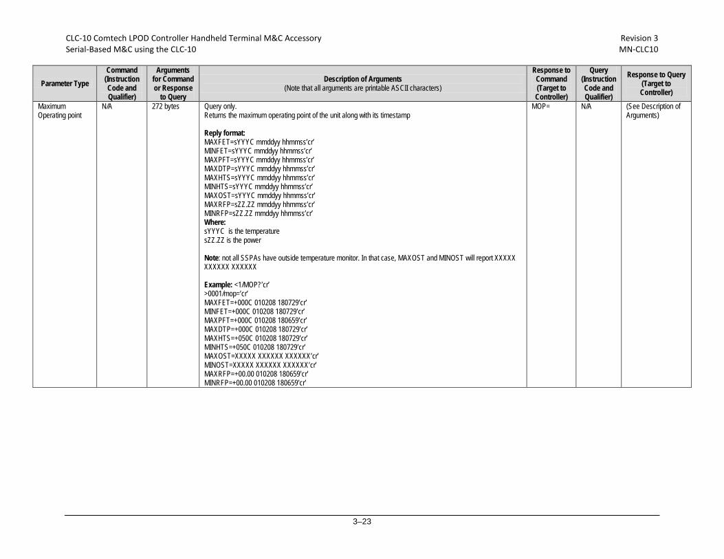
CLC-10 Comtech LPOD Controller Handheld Terminal M&C Accessory Revision 3 Serial-Based M&C using the CLC-10 MN-CLC10
3–23
Parameter Type Command
(Instruction Code and Qualifier)
Arguments for Command or Response
to Query
Description of Arguments (Note that all arguments are printable ASCII characters)
Response to Command (Target to Controller)
Query (Instruction Code and Qualifier)
Response to Query (Target to Controller)
Maximum Operating point
N/A 272 bytes Query only. Returns the maximum operating point of the unit along with its timestamp Reply format: MAXFET=sYYYC mmddyy hhmmss’cr’ MINFET=sYYYC mmddyy hhmmss’cr’ MAXPFT=sYYYC mmddyy hhmmss’cr’ MAXDTP=sYYYC mmddyy hhmmss’cr’ MAXHTS=sYYYC mmddyy hhmmss’cr’ MINHTS=sYYYC mmddyy hhmmss’cr’ MAXOST=sYYYC mmddyy hhmmss’cr’ MAXRFP=sZZ.ZZ mmddyy hhmmss’cr’ MINRFP=sZZ.ZZ mmddyy hhmmss’cr’ Where: sYYYC is the temperature sZZ.ZZ is the power Note: not all SSPAs have outside temperature monitor. In that case, MAXOST and MINOST will report XXXXX XXXXXX XXXXXX Example: <1/MOP?’cr’ >0001/mop=’cr’ MAXFET=+000C 010208 180729’cr’ MINFET=+000C 010208 180729’cr’ MAXPFT=+000C 010208 180659’cr’ MAXDTP=+000C 010208 180729’cr’ MAXHTS=+050C 010208 180729’cr’ MINHTS=+050C 010208 180729’cr’ MAXOST=XXXXX XXXXXX XXXXXX’cr’ MINOST=XXXXX XXXXXX XXXXXX’cr’ MAXRFP=+00.00 010208 180659’cr’ MINRFP=+00.00 010208 180659’cr’
MOP= N/A (See Description of Arguments)

CLC-10 Comtech LPOD Controller Handheld Terminal M&C Accessory Revision 3 Serial-Based M&C using the CLC-10 MN-CLC10
3–24
Parameter Type Command
(Instruction Code and Qualifier)
Arguments for Command or Response
to Query
Description of Arguments (Note that all arguments are printable ASCII characters)
Response to Command (Target to Controller)
Query (Instruction Code and Qualifier)
Response to Query (Target to Controller)
Unit Alarm Mask MSK= 5 bytes Command or Query. Sets or returns alarm mask conditions in the form abcde, where:
0=Fault, 1=Alarm, 2=Masked a=Low Forward RF Power b=External Reference Lock detect c=Fan Speed d=LNB Current Detect e=LNB 22V Power Supply
Default value: 22111 Example: <1/MSK=22111’cr’ >0001/MSK=1’cr’’lf’
MSK= MSK? MSK*
MSK? MSK=abcde (See Description of Arguments)
Mute State MUT= 1 byte Command or Query. Sets or return the unit mute state in the form x, where:
0=Disable (Not Muted) 1=Enable (Muted) (default value) 2=Unit muted due to AUX mute signal (see Note)
Note: This value is only shown in the response to a query, and cannot be given as a command. When MUT returns a ‘2’ it indicates that one of the “hardware” mute conditions is present. For example, an auxiliary mute could be present if the auxiliary mute has been enabled, and the signal to unmute the unit is not provided. Additionally, certain faults can generate a hardware mute such as the BUC lock detect, the LNB current draw (if enabled by the user), or the LNB voltage (if enabled by the user). If MUT returns an unexpected value of ‘2’ then checks the active faults and the status of the auxiliary mute. Example: <1/MUT=1’cr’ >0001/MUT=1’cr’’lf’
MUT= MUT? MUT*
MUT? MUT=x (See Description of Arguments)
Number of Unread Stored Events
N/A 3 bytes Query only. Returns the number, in the form xxx, of unread stored events Example: <1/NUE?’cr’ >0001/NUE=126’cr’’lf’
NUE= NUE? NUE=xxx
Number of Unread Stored Statistics
N/A 3 bytes Query only. Returns the number, in the form xxx, of unread stored statistics Example: NUS=126
NUS= NUS? NUS=xxx

CLC-10 Comtech LPOD Controller Handheld Terminal M&C Accessory Revision 3 Serial-Based M&C using the CLC-10 MN-CLC10
3–25
Parameter Type Command
(Instruction Code and Qualifier)
Arguments for Command or Response
to Query
Description of Arguments (Note that all arguments are printable ASCII characters)
Response to Command (Target to Controller)
Query (Instruction Code and Qualifier)
Response to Query (Target to Controller)
Offline Mute
OFM= 1 byte Command or Query. Sets or returns offline mute in the form x, where:
0=Disable (Not Muted) 1=Enable (Muted) 2=Mute RX 3=Mute Tx 4=Mute Rx+LNB 5= Mute Tx+LNB
Note: LNB Voltage of Online unit shows on Status page of Offline unit when Offline Mute is set to 4 or 5. This is caused by voltage feedback from Online unit to Offline unit via RF splitter. Example: <1/OFM=1’cr’ >0001/OFM=1’cr’’lf
OFM= OFM?
OFM? OFM=x
Online Status
ONL= 1 byte Command or Query. Sets or returns the Redundancy Online status in the form x, where:
0=Offline (Query only) (see Note 2) 1=Online
Notes: 1. The ONL query always returns an online response if the unit is not running in redundant mode. If redundancy is enabled then the query will indicate the position of the Tx waveguide switch that enables one of the units to be connected to the antenna. 2. Sending ONL=0 will not generate a syntax error; however setting ONL to zero will not cause the unit to go offline. The online status is determined by the TX waveguide redundant switch position, and only the offline unit may drive the switches. Instead of sending ONL=0 to the online unit the ONL=1 command should be sent to the offline unit to generate a redundant switchover. Example: <1/ONL=1’cr’ >0001/ONL=’cr’’lf’
ONL= ONL? ONL*
ONL? ONL=x
Part Number N/A Various 1-96 bytes
Query only. Returns the Comtech EF Data part number of the unit. This part number is the unit’s DOTCODE at the time of manufacture. The DOTCODE may be up to 96 printable ASCII characters long. Example: <1/PNM?’cr’ >0001/PNM=HPODC0.350WRSW00’cr’’lf’
PNM= PNM? PNM=x….x (See Description of Arguments)

CLC-10 Comtech LPOD Controller Handheld Terminal M&C Accessory Revision 3 Serial-Based M&C using the CLC-10 MN-CLC10
3–26
Parameter Type Command
(Instruction Code and Qualifier)
Arguments for Command or Response
to Query
Description of Arguments (Note that all arguments are printable ASCII characters)
Response to Command (Target to Controller)
Query (Instruction Code and Qualifier)
Response to Query (Target to Controller)
Retrieve Alarm Status
N/A 168 bytes
Query only. Returns the alarm status of the unit, where:
OK=no fault condition, FT=faulted, AL=alarm, YS=Yes, NO=No, MS=masked, ??=invalid due to hardware failure, NA=not applicable because hardware/options not installed.
Example: <1/RAS?’cr’ >0001/RAS=’cr’ P24V1=OK’cr’ +24V power supply P24V2=OK’cr’ +24V switch pwr supply LNBVT=OK’cr’ +13/18V LNB power supply P13VT=OK’cr’ +13.5V power supply P10V1=OK’cr’ +10V power supply A10V1=OK’cr’ +10V1 RF supply A10V2=OK’cr’ +10V2 RF supply P7V8T=OK’cr’ +7.8V power supply P5V8T=OK’cr’ +5.8V power supply P2V5T=OK’cr’ +2.5V power supply P1V2T=OK’cr’ +1.2V power supply N5V8T=OK’cr’ -5.8V power supply FANR1=OK’cr’ Fan 1 speed FANR2=OK’cr’ Fan 2 speed ATEMP=OK’cr’ Amplifier temperature SHTDN=OK’cr’ Over-temp shutdown IICST=OK’cr’ I2C bus status FWPWR=OK’cr’ Forward power in dBm CHKSM=OK’cr’ Flash checksum FPGAD=OK’cr’ FPGA done status BUCLD=OK’cr’ BUC lock detect REFLD=OK’cr’ Reference lock detect LNBCS=OK’cr’ LNB current status SWITC=OK’cr’ Waveguide switch position status RDLNK=OK’cr’ Redundant link status TRMST=YS’cr’’lf’ Terminal Status Note: LNBVT, A10V1, A10V2, FANR1, FANR2, BUCLD, REFLD, LNBCS, SWITC and RDLNK will only appear in the list if the appropriate model / options have been selected / installed.
RAS= RAS?
RAS=x….x (See Description of Arguments)

CLC-10 Comtech LPOD Controller Handheld Terminal M&C Accessory Revision 3 Serial-Based M&C using the CLC-10 MN-CLC10
3–27
Parameter Type Command
(Instruction Code and Qualifier)
Arguments for Command or Response
to Query
Description of Arguments (Note that all arguments are printable ASCII characters)
Response to Command (Target to Controller)
Query (Instruction Code and Qualifier)
Response to Query (Target to Controller)
Reboot RBT= 1 byte Command only. Performs a soft reboot in the form x, where:
1=Reboot System
RBT = RBT? RBT*
N/A RBT=x (See Description of Arguments)
Retrieve Configuration Status
N/A 45 bytes
Query only. Returns the configuration status of the unit. Examples: RCS=’cr’ ATT=12.75’cr’ AMP=1’cr’ MUT=1’cr’ ONL=1’cr’ ESW=1’cr’ AOF=00.00’cr’ AFR=1’cr’ XRF=N/A’cr’’lf’ (see Note) Where: ATT= attenuation in dB AMP= RF power amplifier state, 0=OFF, 1=ON MUT=RF mute state, 0=un-muted, 1=muted RED=Online status for redundancy ESW=Redundancy state and mode, states: 0=OFF, 1=ON Tx only, 2=ON Tx & Rx AOF=Attenuator Offset in dB AFR= auto fault recovery, 0=manual, 1=auto XRF=External reference status, N/A=no external reference, 05M for 5 MHz, and 10M for a 10 MHz Note: XRF will always be N/A if the internal reference oscillator option is not installed.
RCS= RCS?
RCS=x….x (See Description of Arguments)
Online Status
RED= 1 byte Command or Query. Sets or returns Redundancy Online status in the form x, where:
0=Offline 1=Online
Note: this command is functionally identical to the ONL command. Example: <1/RED=1’cr’ >0001/RED=’cr’’lf’
RED= RED? RED*
RED? RED=x
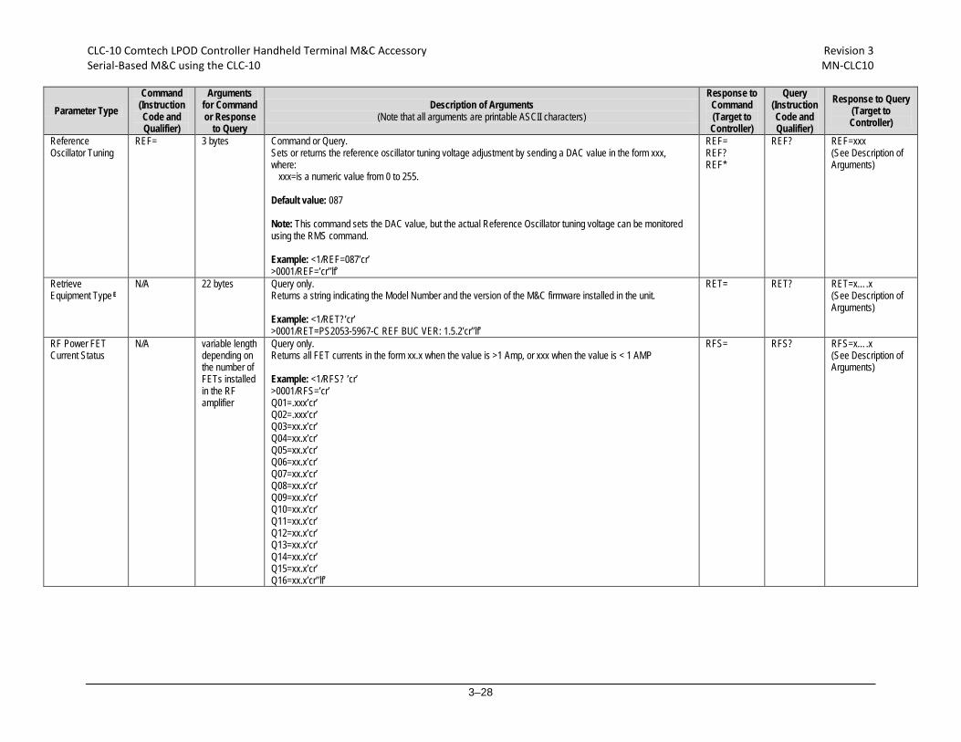
CLC-10 Comtech LPOD Controller Handheld Terminal M&C Accessory Revision 3 Serial-Based M&C using the CLC-10 MN-CLC10
3–28
Parameter Type Command
(Instruction Code and Qualifier)
Arguments for Command or Response
to Query
Description of Arguments (Note that all arguments are printable ASCII characters)
Response to Command (Target to Controller)
Query (Instruction Code and Qualifier)
Response to Query (Target to Controller)
Reference Oscillator Tuning
REF= 3 bytes Command or Query. Sets or returns the reference oscillator tuning voltage adjustment by sending a DAC value in the form xxx, where:
xxx=is a numeric value from 0 to 255. Default value: 087 Note: This command sets the DAC value, but the actual Reference Oscillator tuning voltage can be monitored using the RMS command. Example: <1/REF=087’cr’ >0001/REF=’cr’’lf’
REF= REF? REF*
REF? REF=xxx (See Description of Arguments)
Retrieve Equipment Type E
N/A 22 bytes Query only. Returns a string indicating the Model Number and the version of the M&C firmware installed in the unit. Example: <1/RET?’cr’ >0001/RET=PS2053-5967-C REF BUC VER: 1.5.2’cr’’lf’
RET= RET?
RET=x….x (See Description of Arguments)
RF Power FET Current Status
N/A variable length depending on the number of FETs installed in the RF amplifier
Query only. Returns all FET currents in the form xx.x when the value is >1 Amp, or xxx when the value is < 1 AMP Example: <1/RFS? ’cr’ >0001/RFS=’cr’ Q01=.xxx’cr’ Q02=.xxx’cr’ Q03=xx.x’cr’ Q04=xx.x’cr’ Q05=xx.x’cr’ Q06=xx.x’cr’ Q07=xx.x’cr’ Q08=xx.x’cr’ Q09=xx.x’cr’ Q10=xx.x’cr’ Q11=xx.x’cr’ Q12=xx.x’cr’ Q13=xx.x’cr’ Q14=xx.x’cr’ Q15=xx.x’cr’ Q16=xx.x’cr’’lf’
RFS= RFS? RFS=x….x (See Description of Arguments)
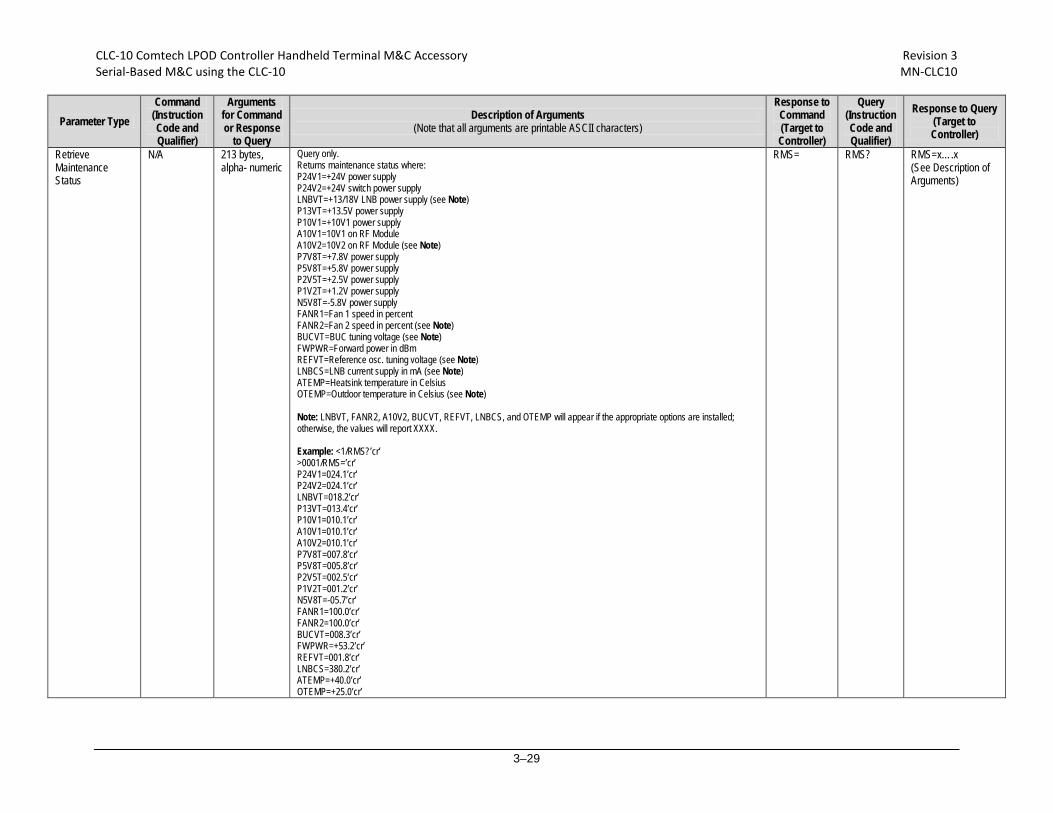
CLC-10 Comtech LPOD Controller Handheld Terminal M&C Accessory Revision 3 Serial-Based M&C using the CLC-10 MN-CLC10
3–29
Parameter Type Command
(Instruction Code and Qualifier)
Arguments for Command or Response
to Query
Description of Arguments (Note that all arguments are printable ASCII characters)
Response to Command (Target to Controller)
Query (Instruction Code and Qualifier)
Response to Query (Target to Controller)
Retrieve Maintenance Status
N/A 213 bytes, alpha- numeric
Query only. Returns maintenance status where: P24V1=+24V power supply P24V2=+24V switch power supply LNBVT=+13/18V LNB power supply (see Note) P13VT=+13.5V power supply P10V1=+10V1 power supply A10V1=10V1 on RF Module A10V2=10V2 on RF Module (see Note) P7V8T=+7.8V power supply P5V8T=+5.8V power supply P2V5T=+2.5V power supply P1V2T=+1.2V power supply N5V8T=-5.8V power supply FANR1=Fan 1 speed in percent FANR2=Fan 2 speed in percent (see Note) BUCVT=BUC tuning voltage (see Note) FWPWR=Forward power in dBm REFVT=Reference osc. tuning voltage (see Note) LNBCS=LNB current supply in mA (see Note) ATEMP=Heatsink temperature in Celsius OTEMP=Outdoor temperature in Celsius (see Note) Note: LNBVT, FANR2, A10V2, BUCVT, REFVT, LNBCS, and OTEMP will appear if the appropriate options are installed; otherwise, the values will report XXXX. Example: <1/RMS?’cr’ >0001/RMS=’cr’ P24V1=024.1’cr’ P24V2=024.1’cr’ LNBVT=018.2’cr’ P13VT=013.4’cr’ P10V1=010.1’cr’ A10V1=010.1’cr’ A10V2=010.1’cr’ P7V8T=007.8’cr’ P5V8T=005.8’cr’ P2V5T=002.5’cr’ P1V2T=001.2’cr’ N5V8T=-05.7’cr’ FANR1=100.0’cr’ FANR2=100.0’cr’ BUCVT=008.3’cr’ FWPWR=+53.2’cr’ REFVT=001.8’cr’ LNBCS=380.2’cr’ ATEMP=+40.0’cr’ OTEMP=+25.0’cr’
RMS= RMS?
RMS=x….x (See Description of Arguments)

CLC-10 Comtech LPOD Controller Handheld Terminal M&C Accessory Revision 3 Serial-Based M&C using the CLC-10 MN-CLC10
3–30
Parameter Type Command
(Instruction Code and Qualifier)
Arguments for Command or Response
to Query
Description of Arguments (Note that all arguments are printable ASCII characters)
Response to Command (Target to Controller)
Query (Instruction Code and Qualifier)
Response to Query (Target to Controller)
Retrieve Next 5 Unread Stored Events
N/A 75 bytes Query only. Returns the oldest 5 Stored Events which have not yet been read over the remote control in the format {CR}Sub-body{CR}Sub-body{CR}Sub-body{CR} Sub-body{CR}Sub-body, where:
Sub-body= ABCCddmmyyhhmmss: A being the fault/clear indicator. F=Fault C=Clear I=Info B being the fault type where: 1=Unit 2=RF 3=Log CC is Fault Code numbers, as in RAS? or Info Code, which is: 0=Power Off 1=Power On 2=Log Cleared 3=Global Config Change 4=Redundancy Config Change
RAS fault codes map as follows: 1) P24V1 2) P24V2 3) LNBVT 4) P13VT 5) A10V1 6) A10V2 7) 10VPS 8) P5V8T 9) P2V5T 10) P1V2T 11) N5V8T 12) P7V8T 13) FANR1 14) FANR2 15) ATEMP 16) SHTDN 17) IICST 18) FWPWR 19) CHKSM 20) FPGAD 21) BUCLD 22) REFLD 23) LNBCS 24) SWITC
If there are less than 5 events to be retrieved, the remaining positions are padded with zeros. If there are no new events, the response is RNE*. A Global Config Change is defined as any time a command is successfully executed. A query does not set the status change.
RNE= RNE? RNE={CR}ABCCddmmyyhhmmss{CR}ABCCddmmyyhhmmss{CR}ABCCddmmyyhhmmss{CR}ABCCddmmyyhhmmss{CR}ABCCddmmyyhhm mss (See Description of Arguments)

CLC-10 Comtech LPOD Controller Handheld Terminal M&C Accessory Revision 3 Serial-Based M&C using the CLC-10 MN-CLC10
3–31
Parameter Type Command
(Instruction Code and Qualifier)
Arguments for Command or Response
to Query
Description of Arguments (Note that all arguments are printable ASCII characters)
Response to Command (Target to Controller)
Query (Instruction Code and Qualifier)
Response to Query (Target to Controller)
Retrieve Next 5 Unread Stored Statistics
N/A 75 bytes Query only. Returns the oldest 5 unread stored statistics entries in the reply format: {CR}Sub-body{CR}Sub-body{CR}Sub-body{CR}Sub-body{CR}Sub-body, where:
Sub-body= ddmmyyhhmmssaaa.abbb.bccc.cdd.ddefghhh.hiii.i ddmmyy=day/month/year hhmmss=hour:minute:second aaa.a=Operating Temperature (I.E. +40.0) bbb.b=Amp Temperature (I.E. +40.0) ccc.c=RF Power output dd.dd=Attenuation Setting e=Amp On/Off f =Mute On/Off g=Online/Offline Status hhh.h=LNB Current (mA) iii.i=BUC Tuning Voltage
If there are less than 5 entries to be retrieved, the remaining positions are padded with zeros. If there are no new entries, the response is RNS*.
RNS= RNS? RNS={CR}Sub-body{CR}Sub-body{CR}Sub-body{CR}Sub-body{CR}Sub-body (See Description of Arguments)
Serial Number E N/A 9 bytes Query only. Returns the unit’s 9 digit serial number in the form of xxxxxxxxx. Example: <1/RSN?’cr’ >0001/RSN=072282040’cr’’lf’
RSN= RSN?
RSN=xxxxxxxxx (See Description of Arguments)
Retrieve Utility Status
N/A 23 bytes, alpha- numeric
Query only. Returns the utility status of the unit. Example: <1/RUS=’cr’ >0001/RUS=’cr’ ADR=0001’cr’ BDR=09600’cr’ REF=087’cr’’lf’ (see Note) Note: REF will only appear if a reference oscillator is installed.
RUS= RUS?
RUS=x….x (See Description of Arguments)
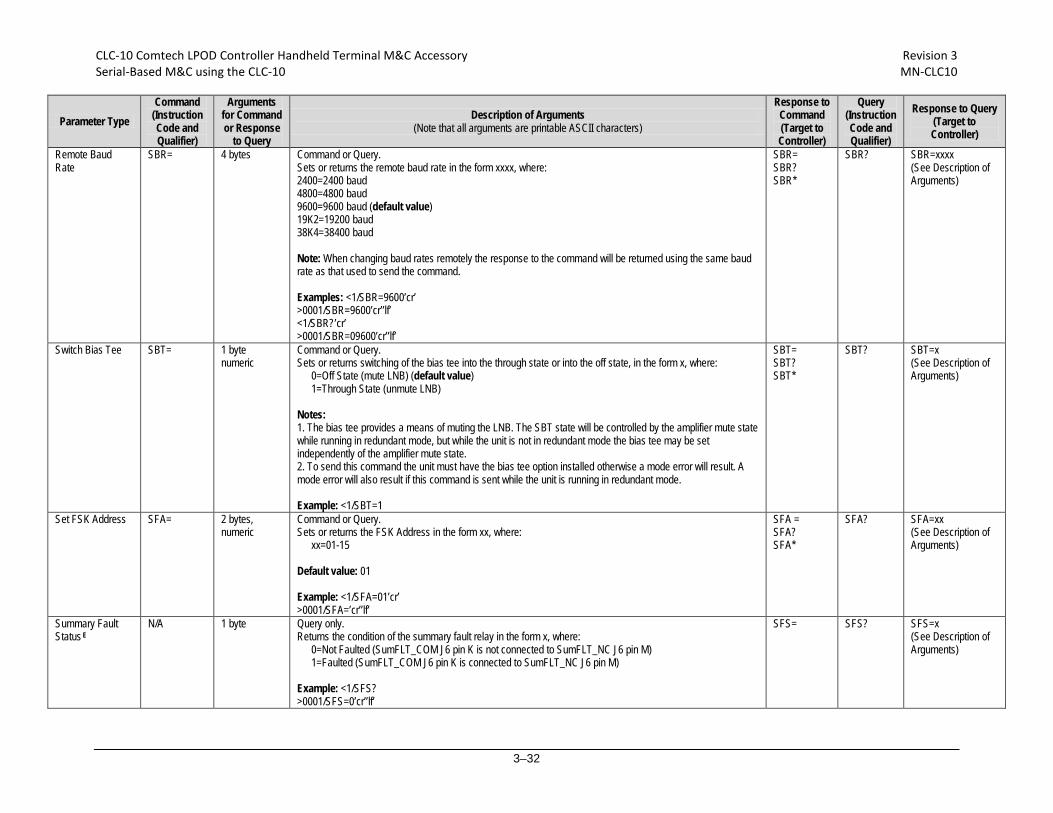
CLC-10 Comtech LPOD Controller Handheld Terminal M&C Accessory Revision 3 Serial-Based M&C using the CLC-10 MN-CLC10
3–32
Parameter Type Command
(Instruction Code and Qualifier)
Arguments for Command or Response
to Query
Description of Arguments (Note that all arguments are printable ASCII characters)
Response to Command (Target to Controller)
Query (Instruction Code and Qualifier)
Response to Query (Target to Controller)
Remote Baud Rate
SBR= 4 bytes Command or Query. Sets or returns the remote baud rate in the form xxxx, where: 2400=2400 baud 4800=4800 baud 9600=9600 baud (default value) 19K2=19200 baud 38K4=38400 baud Note: When changing baud rates remotely the response to the command will be returned using the same baud rate as that used to send the command. Examples: <1/SBR=9600’cr’ >0001/SBR=9600’cr’’lf’ <1/SBR?’cr’ >0001/SBR=09600’cr’’lf’
SBR= SBR? SBR*
SBR?
SBR=xxxx (See Description of Arguments)
Switch Bias Tee SBT= 1 byte numeric
Command or Query. Sets or returns switching of the bias tee into the through state or into the off state, in the form x, where:
0=Off State (mute LNB) (default value) 1=Through State (unmute LNB)
Notes: 1. The bias tee provides a means of muting the LNB. The SBT state will be controlled by the amplifier mute state while running in redundant mode, but while the unit is not in redundant mode the bias tee may be set independently of the amplifier mute state. 2. To send this command the unit must have the bias tee option installed otherwise a mode error will result. A mode error will also result if this command is sent while the unit is running in redundant mode. Example: <1/SBT=1
SBT= SBT? SBT*
SBT?
SBT=x (See Description of Arguments)
Set FSK Address SFA= 2 bytes, numeric
Command or Query. Sets or returns the FSK Address in the form xx, where:
xx=01-15 Default value: 01 Example: <1/SFA=01’cr’ >0001/SFA=’cr’’lf’
SFA = SFA? SFA*
SFA? SFA=xx (See Description of Arguments)
Summary Fault Status E
N/A 1 byte
Query only. Returns the condition of the summary fault relay in the form x, where:
0=Not Faulted (SumFLT_COM J6 pin K is not connected to SumFLT_NC J6 pin M) 1=Faulted (SumFLT_COM J6 pin K is connected to SumFLT_NC J6 pin M)
Example: <1/SFS? >0001/SFS=0’cr’’lf’
SFS= SFS?
SFS=x (See Description of Arguments)

CLC-10 Comtech LPOD Controller Handheld Terminal M&C Accessory Revision 3 Serial-Based M&C using the CLC-10 MN-CLC10
3–33
Parameter Type Command
(Instruction Code and Qualifier)
Arguments for Command or Response
to Query
Description of Arguments (Note that all arguments are printable ASCII characters)
Response to Command (Target to Controller)
Query (Instruction Code and Qualifier)
Response to Query (Target to Controller)
SNMP Authentication Trap Enable
SNA= 1 byte Command or Query. Sets or returns the SNMP Authentication in the form x, where:
0=Disabled 1=Enabled
Example: <1/SNA=0
SNA= SNA?
SNA? SNA=x (See Description of Arguments)
SNMP Enable
SNM= 1 byte Command or Query. Sets or returns SNMP in the form x, where:
0=Disabled 1=Enabled
Example: <1/SNM=0
SNM= SNM?
SNM? SNM=x (See Description of Arguments)
Serial Number N/A 9 bytes Query only. Returns the unit’s nine-digit serial number in the form xxxxxxxxx Note: this command is functionally identical to RSN. Example: <1/SNO?’cr’ >0001/SNO=072282040’cr’’lf’
SNO= SNO? SNO=xxxxxxxxx (See Description of Arguments)
Remote Address SPA= 4 bytes Command or Query. Sets or returns the Physical Address in the form xxxx, where:
xxxx=0001 to 9999, resolution=0001 Default value: 0001 Example: <1/SPA=0412’cr’ >0001/SPA=’cr’’lf’
SPA= SPA? SPA*
SPA?
SPA=xxxx (See Description of Arguments)
SNMP Read Community
SRC= 16 bytes, characters, no spaces
Command or Query. Sets or returns the SNMP Read Community string. Empty string is not allowed Example: <1/SRC=public
SRC = SRC!
SRC? SRC =x (see Description of Arguments))
SNMP System Contact
SSC= 255 bytes, characters,
Command or Query. Sets or returns the SNMP System Contact string. Example: <1/SSC=Joe Net Admin. If not configured it returns empty string: <1/SSC=
SSC = SSC!
SSC? SSC =x [1..128] (see Description of Arguments)
Set Statistics Interval
SSI= 2 bytes Command or Query. Sets or returns the interval at which statistics are logged, in the form xx, where: xx=01 to 99 minutes, resolution is in 01 minute increments Default value: 90 Example: <1/SSI=90’cr’ >0001/SSI=’cr’’lf’
SSI= SSI?
SSI? SSI=xx (See Description of Arguments)
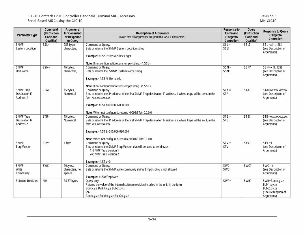
CLC-10 Comtech LPOD Controller Handheld Terminal M&C Accessory Revision 3 Serial-Based M&C using the CLC-10 MN-CLC10
3–34
Parameter Type Command
(Instruction Code and Qualifier)
Arguments for Command or Response
to Query
Description of Arguments (Note that all arguments are printable ASCII characters)
Response to Command (Target to Controller)
Query (Instruction Code and Qualifier)
Response to Query (Target to Controller)
SNMP System Location
SSL= 255 bytes, characters,
Command or Query. Sets or returns the SNMP System Location string Example: <1/SSL=Upstairs back right. Note: If not configured it returns empty string. <1/SSL=
SSL = SSL!
SSL? SSL =x [1..128] (see Description of Arguments)
SNMP Unit Name
SSN= 16 bytes, characters,
Command or Query. Sets or returns the SNMP System Name string Example: <1/SSN=Remote1. Note: If not configured it returns empty string. <1/SSC=
SSN = SSN!
SSN?
SSN =x [1..128] (see Description of Arguments)
SNMP Trap Destination IP Address 1
STA= 15 bytes, Numerical
Command or Query. Sets or returns the IP address of the first SNMP Trap destination IP Address 1 where traps will be sent, in the form xxx.xxx.xxx.xxx Example: <1/STA=010.006.030.001 Note: When not configured, returns >0001/STA=0.0.0.0
STA = STA!
STA? STA=xxx.xxx.xxx.xxx (see Description of Arguments)
SNMP Trap Destination IP Address 2
STB= 15 bytes, Numerical
Command or Query. Sets or returns the IP address of the first SNMP Trap destination IP Address 2 where traps will be sent, in the form xxx.xxx.xxx.xxx Example: <1/STB=010.006.030.001 Note: When not configured, returns >0001/STB=0.0.0.0
STB = STB!
STB? STB=xxx.xxx.xxx.xxx (see Description of Arguments)
SNMP Trap Version
STV= 1 byte Command or Query. Sets or returns the SNMP Trap Version that will be used to send traps.
1=SNMP Trap Version 1 2=SNMP Trap Version 2
Example: <1/STV=0
STV = STV!
STV? STV =x (see Description of Arguments)
SNMP Write Community
SWC= 16bytes, characters, no spaces
Command or Query. Sets or returns the SNMP write community string. Empty string is not allowed Example: <1/SWC=private
SWC = SWC!
SWC? SWC =x (see Description of Arguments)
Software Revision N/A 34-37 bytes Query only. Returns the value of the internal software revision installed in the unit, in the form: Boot:x.y.z Bulk1:x.y.z Bulk2:x.y.z -or- Boot:x.y.zz Bulk1:x.y.zz Bulk2:x.y.zz
SWR= SWR? SWR=Boot:x.y.zz Bulk1:x.y.zz Bulk2:x.y.zz (See Description of Arguments)
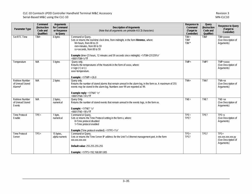
CLC-10 Comtech LPOD Controller Handheld Terminal M&C Accessory Revision 3 Serial-Based M&C using the CLC-10 MN-CLC10
3–35
Parameter Type Command
(Instruction Code and Qualifier)
Arguments for Command or Response
to Query
Description of Arguments (Note that all arguments are printable ASCII characters)
Response to Command (Target to Controller)
Query (Instruction Code and Qualifier)
Response to Query (Target to Controller)
Set RTC Time TIM= 6 bytes Command or Query. Sets or returns the real-time clock time, from midnight, in the form hhmmss, where:
hh=hours, from 00 to 23 mm=minutes, from 00 to 59 ss=seconds, from 00 to 59
Example (time=23 hours, 12 minutes and 59 seconds since midnight): <1/TIM=231259’cr’ >0001/TIM=’cr’’lf’
TIM = TIM? TIM *
TIM?
TIM=xxxxxx (See Description of Arguments)
Temperature N/A 5 bytes Query only. Returns the temperatures of the Heatsink in the form of sxxxx, where: s=sign (+) or (-) xxxx=temperature. Example: <1/TMP=+26.0
TMP= TMP? TMP=sxxxx (See Description of Arguments)
Retrieve Number of Unread Stored AlarmsE
N/A 2 bytes Query only. Returns the number of stored alarms that remain unread in the alarm log, in the form xx. A maximum of 255 events may be stored in the alarm log. Numbers over 99 are reported as 99. Example reply: <1/TNA? ’cr’ >0001/TNA=14’cr’’lf’
TNA= TNA? TNA=xx (See Description of Arguments)
Retrieve Number of Unread Stored Events
N/A 2 bytes, numerical
Query Only. Returns the number of stored events that remain unread in the events logs, in the form xx. Example: <1/TNE? ’cr’ >0001/TNE=18’cr’’lf’
TNE= TNE?
TNE=xx (See Description of Arguments)
Time Protocol Enable
TPE= 1 byte, numerical
Command or Query. Sets or returns the Time Protocol setting in the form x, where:
0=Time protocol disabled 1=Time protocol enabled
Example (Time protocol enabled): <1/TPE=1’cr’
TPE= TPE?
TPE? TPE=x (See Description of Arguments)
Time Protocol Server
TPS= 15 bytes, alpha-numeric
Command or Query. Sets or returns the Time Server IP address for the Unit Tx Ethernet management port, in the form xxx.xxx.xxx.xxx Default value: 255.255.255.255 Example: <1/TPS=192.168.001.005
TPS= TPS?
TPS? TPS= xxx.xxx.xxx.xxx.yy (See Description of Arguments)
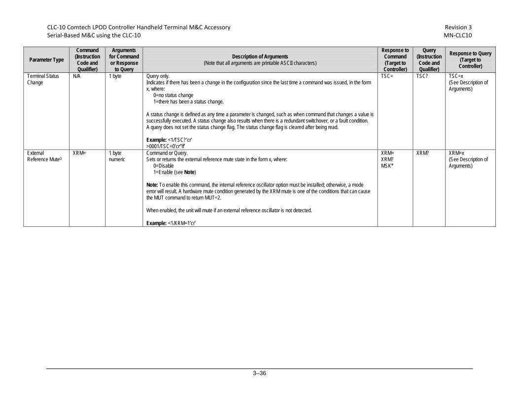
CLC-10 Comtech LPOD Controller Handheld Terminal M&C Accessory Revision 3 Serial-Based M&C using the CLC-10 MN-CLC10
3–36
Parameter Type Command
(Instruction Code and Qualifier)
Arguments for Command or Response
to Query
Description of Arguments (Note that all arguments are printable ASCII characters)
Response to Command (Target to Controller)
Query (Instruction Code and Qualifier)
Response to Query (Target to Controller)
Terminal Status Change
N/A 1 byte Query only. Indicates if there has been a change in the configuration since the last time a command was issued, in the form x, where:
0=no status change 1=there has been a status change.
A status change is defined as any time a parameter is changed, such as when command that changes a value is successfully executed. A status change also results when there is a redundant switchover, or a fault condition. A query does not set the status change flag. The status change flag is cleared after being read. Example: <1/TSC?’cr’ >0001/TSC=0’cr’’lf’
TSC= TSC? TSC=x (See Description of Arguments)
External Reference MuteO
XRM= 1 byte numeric
Command or Query. Sets or returns the external reference mute state in the form x, where:
0=Disable 1=Enable (see Note)
Note: To enable this command, the internal reference oscillator option must be installed; otherwise, a mode error will result. A hardware mute condition generated by the XRM mute is one of the conditions that can cause the MUT command to return MUT=2. When enabled, the unit will mute if an external reference oscillator is not detected. Example: <1/XRM=1’cr’
XRM= XRM? MSK*
XRM?
XRM=x (See Description of Arguments)

METRIC CONVERSIONS
Units of Length
Unit Millimeter Centimeter Inch Foot Yard Meter Kilometer Mile
1 millimeter 1 0.1 0.0394 0.0033 0.0011 0.001 1 x 10⁻⁶ 6.214 x 10⁻⁷
1 centimeter 10 1 0.3937 0.0328 0.0109 0.01 1 x 10⁻⁵ 6.214 x 10⁻⁶
1 inch 25.4 2.54 1 0.0833 0.0278 0.0254 2.54 x 10⁻⁵ 1.578 x 10⁻⁵
1 foot 304.8 30.48 12 1 0.3333 0.3048 3.048 x 10⁻⁴ 1.894 x 10⁻⁴
1 yard 914.4 91.44 36 3 1 0.9144 9.144 x 10⁻⁴ 5.682 x 10⁻⁴
1 meter 1000 100 39.37 3.2808 1.0936 1 0.001 6.214 x 10⁻⁴
1 kilometer 1 x 10⁶ 1 x 10⁵ 3.938 x 10⁴ 3.281 1093 1000 1 0.6214
1 mile 1.609 x 10⁶ 1.609 x 10⁵ 6.336 x 10⁴ 5280 1760 1609 1.609 1
Temperature Conversions
Units of Weight
Unit Gram Ounce Avoirdupois
Ounce Troy
Pound Avoirdupois
Pound Troy Kilogram
1 gram — 0.03527 0.03215 0.002205 0.002679 0.001
1 oz. avoir. 28.35 — 0.9115 0.0625 0.07595 0.02835
1 oz. troy 31.10 1.097 — 0.06857 0.08333 0.03110
1 lb. avoir. 453.6 16.0 14.58 — 1.215 0.4536
1 lb. Troy 373.2 13.17 12.0 0.8229 — 0.3732
1 kilogram 1.0 x 10³ 35.27 32.15 2.205 2.679 —
Temperature ° Fahrenheit ° Centigrade
Water freezes 32 0
Water boils 212 100
Absolute zero -459.69 -273.16
Formulas
° C = (F - 32) * 0.555
° F = (C * 1.8) + 32

2114 WEST 7TH STREET TEMPE ARIZONA 85281 USA 480 • 333 • 2200 PHONE
480 • 333 • 2161 FAX