Embed Size (px)
Citation preview

Sr.No Aim
1 To measure diameter of a small sphericallcylindrical body using Vernier Callipers
2 To measure internal diameter and depth of a given beaker/calorimeter using Vernier Callipers and hence find its volume
3 To measure diameter of a given wire using screw gauge
4 To determine radius of curvature of a given spherical surface by a spherometer
Activity
1 To make a paper scale of given least count, e.g., 0.2cm, 0.5 cm.
2 To determine mass of a given body using a metre scale by principle of moments
3 To plot a graph for a given set of data, with proper choice of scales and error bars.
CLASS – XI PHYSICS PRACTICAL TERM WISE (2021-22)
TERM - 1
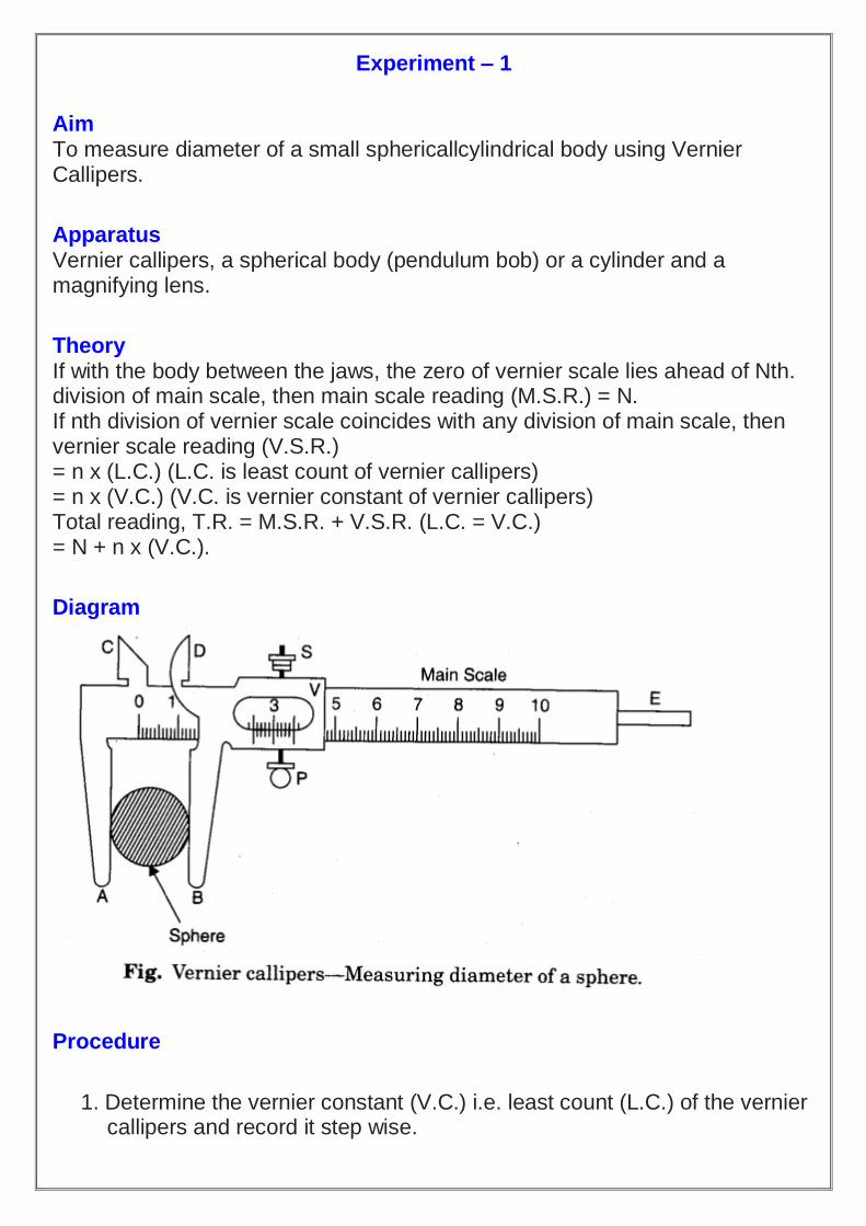
Experiment – 1
Aim To measure diameter of a small sphericallcylindrical body using Vernier Callipers.
Apparatus Vernier callipers, a spherical body (pendulum bob) or a cylinder and a magnifying lens.
Theory If with the body between the jaws, the zero of vernier scale lies ahead of Nth. division of main scale, then main scale reading (M.S.R.) = N. If nth division of vernier scale coincides with any division of main scale, then vernier scale reading (V.S.R.) = n x (L.C.) (L.C. is least count of vernier callipers) = n x (V.C.) (V.C. is vernier constant of vernier callipers) Total reading, T.R. = M.S.R. + V.S.R. (L.C. = V.C.) = N + n x (V.C.).
Diagram
Procedure
1. Determine the vernier constant (V.C.) i.e. least count (L.C.) of the vernier callipers and record it step wise.

2. Bring the movable jaw BD in close contact with the fixed jaw AC and find the zero error. Do it three times and record them. If there is no zero error, record zero error nil.
3. Open the jaws, place the sphere or cylinder between the two jaws A and B and adjust the jaw DB, such that it gently grips the body without any undue pressure on it. Tight the screw S attached to the vernier scale V.
4. Note the position of the zero mark of the vernier scale on the main scale. Record the main scale reading just before the zero mark of the vernier scale. This reading (1ST) is called main scale reading (M.S.R.).
5. Note the number (n) of the vernier scale division which coincides with some division of the main scale.
6. Repeat steps 4 and 5 after rotating the body by 90° for measuring the diameter in a perpendicular direction.
7. Repeat steps 3, 4, 5 and 6 for three different positions. Record the observations in each set in a tabular form.
8. Find total reading and apply zero correction. 9. Take mean of different values of diameter and show that in the result with
proper unit.
Observations
1. Determination of Vernier Constant (Least Count) of the Vernier Callipers 1 M.S.D. = 1mm 10VS.D.=9M.S.D. .-. 1 V.S.D. = 9/10 M.S.D. = 0.9 mm. Vernier Constant, V.C. = 1 M.S.D. – 1 V.S.D. = (1 – 0.9) mm = 0.1 mm = 0.01 cm.
Observations Table
Sr. No (Main Scale
Reading) M.S
Vernier Scale reading (V.S), (V.S. X LC)
Total Reading (M.S + V.S)in cm
1
2
3
Calculation

Result The diameter of the given sphere/cylinder is………….cm.
Precautions
1. Motion of vernier scale on main scale should be made smooth (by oiling if necessary).
2. Vernier constant and zero error should be carefully found and properly recorded.
3. The body should be gripped between the jaws firmly but gently (without undue pres-sure on it from the jaws).
4. Observations should be taken at right angles at one place and taken at least as three different places.
Sources of Error
1. The vernier scale may be loose on main scale. 2. The jaws may not be at right angles to the main scale. 3. The graduations on scale may not be correct and clear. 4. Parallax may be there in taking observations.

Experiment – 2
Aim To measure internal diameter and depth of a given beaker/calorimeter using Vernier Callipers and hence find its volume.
Apparatus Vernier callipers, a beaker or a calorimeter, magnifying glass.
Theory (i) For measuring internal diameter and depth. Same as in Experiment 1A. (ii) For volume: Volume of beaker or calorimeter = internal area of cross section x depth
Diagram

Procedure
1. Determine the vernier constant (V.C.) i.e., least count of the vernier callipers and record it stepwise.
2. Bring the movable jaw BD in close contact with the fixed jaw AC and find the zero error. Do it three times and record it. If there is no zero error, then record, zero error nil. Measurement of internal diameter
3. Put the jaws C and D inside the beaker or calorimeter and open them till each of them touches the inner wall of the beaker or calorimeter, , without any undue pressure on the walls. Tight the screw attached to the vernier scale gently.
4. Note the-position of the zero mark of the vernier scale on the main scale. Record the main scale reading just before the zero mark of the vernier scale. This reading (IV) is called main scale reading (M.S.R.).

5. Note the number (n) of the vernier scale division which coincides with some division of the main scale.
6. Repeat steps 4 and 5 after rotating the vernier callipers by 90° for measuring internal diameter in a perpendicular direction.
7. Find total reading and apply zero correction. Measurement of depth
8. Keep the edge of the main scale of vernier callipers on its peripheral edge. This should be done in such a way that the tip of the strip is able to go freely inside the beaker along its depth.
9. Keep sliding the moving jaw of the vernier callipers until the strip just touches the bottom of the beaker. Take care that it is just perpendicular to the bottom surface. Now tighten the screw of the vernier callipers.
10. Repeat steps 4 and 5 for four different positions along the circumference of the upper edge of the beaker or calorimeter.
11. Find total reading and apply zero correction. 12. Take mean of two different values of internal diameter and four
different values of the depth. 13. Calculate the volume by using proper formula and show that in the
result with proper unit.
Observations
1. Determination of Vernier Constant (Least Count) of the vernier callipers 1 M.S.D. = 1 mm 10 V.S.D. = 9 M.S.D. ∴ 1 V.S.D. = 9/10 M.S.D. = 0.9 mm Vernier constant, V.C. = 1 M.S.D. – 1 V.S.D. = (1 – 0.9) mm = 0.1 mm = 0.01 cm.
Observations Table
Table for the Internal Diameter (D)
Sr. No (Main Scale
Reading) M.S
Vernier Scale reading (V.S), (V.S. X LC)
Total Reading (M.S + V.S)in cm
1 2
3

Table for the depth (d)
Sr. No (Main Scale
Reading) M.S
Vernier Scale reading (V.S), (V.S. X LC)
Total Reading (M.S + V.S)in cm
1
2
3
Calculations
Result The volume of the beaker/calorimeter is …………cm3.
Precautions
1. Motion of vernier scale on main scale should be made smooth (by oiling if necessary).
2. Vernier constant and zero error should be carefully found and properly recorded.
3. The body should be gripped between the jaws firmly but gently (without undue pres-sure on it from the jaws).
4. Observations should be taken at right angles at one place and taken at least as three different places.
Sources of Error
1. The vernier scale may be loose on main scale. 2. The jaws may not be at right angles to the main scale. 3. The graduations on scale may not be correct and clear. 4. Parallax may be there in taking observations.

Experiment – 3
Aim
To measure diameter of a given wire using screw gauge.
Apparatus
Screw gauge, wire, half-metre scale and magnifying lens.
Theory
1. If with the wire between plane faces A and B, the edge of the cap lies ahead of Mb division of linear scale. Then, linear scale reading (L.S.R.) = N. If nth division of circular scale lies over reference line. Then, circular scale reading (C.S.R.) = n x (L.C.) (L.C. is least count of screw gauge) Total reading (T.R.) = L.S.R. + C.S.R. = N+n x (L.C.). 2. If D be the mean diameter and l be the mean length of the wire,Volume of the wire,
Diagram
Procedure
1. Find the value of one linear scale division (L.S.D.). 2. Determine the pitch and the least count of the screw gauge and record it step wise. 3. Bring the plane face B in contact with plane face A and find the zero error. Do it
three times and record them. If there is no zero error, then record zero error nil.

4. Move the face B away from face A. Place the wire lengthwise over face A and move the face B towards face A using the ratchet head R. Stop when R turns (slips) without moving the screw.
5. Note the number of divisions of the linear scale visible and uncovered by the edge of the cap. The reading (IV) is called linear scale reading (L.S.R.).
6. Note the number (n) of the division of the circular scale lying over reference line. 7. Repeat steps 5 and 6 after rotating the wire by 90° for measuring diameter in a
perpendicular direction. 8. Repeat steps 4, 5, 6 and 7 for five different positions separated equally throughout
the length of the wire. Record the observations in each set in a tabular form. 9. Find total reading and apply zero correction in each case. 10. Take mean of different values of diameter. 11. Measure the length of the wire by stretching it along a half-metre scale.
Keeping one end of wire at a known mark, note the position of other end. Difference in position of the two ends of the wire gives the length of the wire. Do it three times and record them.
Observations
1. Determination of Least Count of the Screw Gauge . 1 L.S.D. = 1 mm Number of full rotations given to screw = 4 Distance moved by the screw = 4 mm Hence, pitch p = 4 mm/4 = 1 mm Number of divisions on circular scale = 100 Hence, least count, =1 mm/100 = 0.01 mm = 0.001 cm.
Observations Table
Calculations

Result
The volume of the given wire is…………. cm3.
Precautions
1. To avoid undue pressure; the screw should always be rotated by ratchet R and not by cap K.
2. The screw should move freely without friction. 3. The zero correction, with proper sign should be noted very carefully and added
algebraically. 4. For same set of observations, the screw should be moved in the same direction to
avoid back-lash error of the screw. 5. At each place, the diameter of the wire should be measured in two perpendicular
directions and then the mean of the two be taken. 6. Readings should be taken at least for five different places equally spaced along the
whole length of the wire. 7. Error due to parallax should be avoided.
Sources of error
1. The screw may have friction. 2. The screw gauge may have back-lash error. 3. Circular scale divisions may not be of equal size. 4. The wire may not be uniform.

Experiment – 4
Aim To determine radius of curvature of a given spherical surface by a spherometer.
Apparatus Spherometer, convex surface (it may be unpolished convex mirror), a big size plane glass slab or plane mirror.
Diagram
Theory It works on the principle of micrometre screw (Section 2.09) It is used to measure either very small thickness or the radius of curvature of a spherical surface that is why it is called a spherometer.
Procedure
1. Raise the central screw of the spherometer and press the spherometer gently on the practical note-book so as to get pricks of the three legs. Mark these pricks as A, B and C.
2. Measure the distance between the pricks (points) by joining the points as to form a triangle ABC.
3. Note these distances (AB, BC, AC) on notebook and take their mean. 4. Find the value of one vertical {pitch) scale division. 5. Determine the pitch and the least count of the spherometer [Art. 2.13(c)]
and record it step wise. 6. Raise the screw sufficiently upwards. 7. Place the spherometer on the convex surface so that its three legs rest
on it.

8. Gently, turn the screw downwards till the screw tip just touches the convex surface. (The tip of the screw will just touch its image in the convex glass surface).
9. Note the reading of the circular (disc) scale which is in line with the vertical (pitch) scale. Let it be a (It will act as reference).
10. Remove the spherometer from over the convex surface and place over a large size plane glass slab.
11. Turn the screw downwards and count the number of complete rotations (n1) made by the disc (one rotation becomes complete when the reference reading crosses past the pitch scale).
12. Continue till the tip of the screw just touches the plane surface of the glass slab.
13. Note the reading of the circular scale which is finally in line with the vertical (pitch) scale. Let it be b.
14. Find the number of circular (disc) scale division in last incomplete rotation.
15. Repeat steps 6 to 14, three times. Record the observation in tabular form.
Observations

Observations Table
Calculations 1. Find value of h in each observation and record it in column 5. 2. Find mean of value of h recorded in column 5
Result The radius of curvature of the given convex surface is cm.
Precautions
1. The screw should move freely without friction. 2. The screw should be moved in same direction to avoid back-lash error of
the screw. 3. Excess rotation should be avoided.
Sources of error
1. The screw may have friction. 2. The spherometer may have back-lash error. 3. Circular (disc) scale divisions may not be of equal size.