Embed Size (px)
Citation preview
CLARK COUNTY
DEPARTMENT
OF
BUILDING
RESIDENTIAL INSPECTION
CHECKLISTS
2009 CODE
GENERAL NOTES
This checklist is intended for use as a GUIDE to assist and promote consistency in the
application of all the codes and standard practices within Clark County. This list is for
use of county inspectors and for the public in general.
This checklist is intended for wood frame structures. The information in this checklist is
not, nor was it ever intended to be, all-inclusive. It does not include all code or individual
plan requirements. It is intended to reflect local policies, procedures and practices within
Clark County. This checklist does not waive any specific code requirement not listed or
allow for the decrease in the requirements of an engineered design. It also does not add
requirements where the minimum of the code has been met.
All approved plans, documents and revisions to plans must be maintained on site and
available for review at all times the building is under construction.
All plans and paperwork will be reviewed before performing any inspection.
The owner, permit holder or responsible person on the job site is responsible for
establishing safe access to perform all inspections.
In the event that ladders are necessary to perform inspections, all ladders and equipment
shall meet minimum OSHA standards. Inspectors are not responsible for setting up or
moving ladders from one location to another, within or to other buildings or structures.
Inspectors are not responsible for unscrewing/unbolting of items to verify information
that is part of an inspection.
Code references coding
A= amendment
E= energy code
EL= NEC, electrical code
R= residential code
B= Building code
T=Table
Note: This is not a complete list and is not inclusive of all construction methods, materials or practices. Check Lists
are intended to serve as a reference point for a basic inspection only. Compliance with all the provisions of applicable
codes shall be required.
RESIDENTIAL GENERAL
PAGE 1 of 1
FOUNDATION FOOTING (2222)
22.02.460(A) Pad cert submitted and approved prier to any inspection being performed
Pad level and built 5 feet outside of house footprint
Plans Verify location of house, front and side and rear setbacks per site plan
Verify any encroachments into 3 foot setback of pop-outs (requires plans check
approved detail for 1 hour construction)
Verify any encroachments into 5 foot setback (requires plans check approved detail
for modified 1 hour construction)
403.1.4 Footing depth a minimum of 12 inches into undisturbed soil
403.1.5 Bottom of footings shall be clean and level
403.1.7 Check for zone of influence in relationship to retaining walls and property lines
Plans Verify all footings for size, location and per details
Plans Reinforcement in place per plan for location, size and grade of steel
Plans Steel in footings and special locations, with proper lap per engineering
Plans Check shear plans to verify hold-down type and locations
All hold downs are templated into place
Ufer in place and approved under the electrical permit
22.02.492.1 SWPPP compliance review performed
BASEMENT
22.02.460(A) A second pad cert is required when construction will be over fill material around
basement walls
Plans Verify footing size and location
Plans Connection of walls to footings and keying of slab to the walls
Plans Verify proper connection of footing to walls
406.1 Verify dampproofing/waterproofing requirements
405.1 Foundation drainage system installed at footings
406.1 Proper protection of dampproofing/waterproofing materials from damage and leaking
405.1 Drainage gravel area over drainage pipe minimum 1 foot out and 6 inches over
Note: This is not a complete list and is not inclusive of all construction methods, materials or practices. Check Lists
are intended to serve as a reference point for a basic inspection only. Compliance with all the provisions of applicable
codes shall be required.
RESIDENTIAL FOOTING (2222)
Page 1 of 1
CONCRETE SLAB ON GRADE (2229)
Items under slab in and approved (plumbing, mechanical, electrical inspections)
Plans Verify the slab thickness is per plan
Plans Check stem wall width and steel requirements
Plans Verify requirement for vapor barrier, if required, installed per plan
Plans Check all notes relating to the slab for construction detail requirements
ACI Post tension cables are properly supported, straight and level, or per plan detail (1 in 6
maximum deviation from straight)
ACI Cable jacketing not damaged or properly repaired
Forms level and supported
Plumbing piping in or thru concrete wrapped where required for movement
506.2.3 Vapor retarder under slab in place
Note: This is not a complete list and is not inclusive of all construction methods, materials or practices. Check Lists
are intended to serve as a reference point for a basic inspection only. Compliance with all the provisions of applicable
codes shall be required.
RESIDENTIAL CONCRETE SLAB ON GRADE (2229)
PAGE 1 of 1
FLOOR/ROOF SHEATHING (2235/2236)
22.02.525b2 Check for QAA contract requirements for wood or other related item
22.02.525 View QAA report for completeness and verify accuracy of the report
802.10 County approved truss calculations or engineering design on site
802.10 Follow truss layout plan and verify truss calculations for each truss
802.10.5 Attachment of trusses to top plate and bearing locations per engineer of record
802.10 Look for broken, damaged, or modified trusses
802.10 All truss repairs require County approval of engineered repair
Plans Verify blocking locations and completeness of blocking
Plans Drag strapping and blocking, locations and connections are per plan
Plans Verify gable end bracing requirements and spacing
Over-build areas, verify grade, size and bracing requirements of all members
806.2 Ventilation openings through overbuild areas
Plans Verify sheathing material grade type, thickness and span rating
803.2.3 Minimum 1/8 inch edge and end spacing of sheathing
803.2.3 Sheathing installed perpendicular to roof framing
Minimum width of sheathing 24 inches unless all edges blocked
803.2.1.1 Minimum grade “C” exposure rating for exposed underside (eves) edge material
(starter board)
T602.3(1) Minimum 6 and 12 edge and field nailing of all sheathing
Plans/T602.3(1) Spacing and size of nails or staples
Over and/or under driven nailing
Plans Shear transfer nailing locations and requirements
1001.4 Chimney anchoring
1003.20 Crickets for any roof obstruction wider than 30 inches
Note: This is not a complete list and is not inclusive of all construction methods, materials or practices. Check Lists
are intended to serve as a reference point for a basic inspection only. Compliance with all the provisions of applicable
codes shall be required.
RESIDENTIAL FLOOR/ROOF SHEATHING (2235/2236)
PAGE 1 of 1
SHEAR WALLS (2239)
22.02.525 Check for QAA contract requirements
Epoxy repair reports complete and ready for turn-in, [inspector to pick up reports and
return to office]
22.02.525 Review QAA report for completeness and verify accuracy of the report
ACI Check to see all post tension cables are tensioned
602.1 Verify framing materials for proper wood species and grade of lumber
Plans Verify all shear wall types, nailing requirements and location of shear walls
403.1.6 Anchor bolts per plan (max 6 feet O.C.)
Minimum 2 bolts per board. Min 4 inches and max 12 inches from the ends
602.11.1 Anchor bolts with 3x3 square washers (Seismic zone D) on all shear walls only
602.3.2 Top plates breaks minimum 2 foot separation, lapped and nailed or strapped
Plans Hold downs complete and on proper size framing member (not on trimmers)
Plans All structural framing details are complete and per plan
Plans Verify sizes and location of all headers, king studs, trimmer studs
Plans Verify beam sizes, with load transfer to foundation
Plans All transfers/drag, straps and miscellaneous hardware in place
801.2 Verify all points of bearing are continuous to the foundation
801.2 Verify continuous shear diaphragm from foundation to roof sheathing, unless shown
different on approved plans
801.2 Second floor shear walls transfer to the first floor
Note: This is not a complete list and is not inclusive of all construction methods, materials or practices. Check Lists
are intended to serve as a reference point for a basic inspection only. Compliance with all the provisions of applicable
codes shall be required.
RESIDENTIAL SHEAR WALL (2239)
PAGE 1 of 1
ROOF UNDERLAYMENT (2268)
905.3.3 Proper roof underlayment material is being used or approved to be used
905.3.3.2 Underlayment seams lapped 2 inches on sides, 6 inches on ends and secured to roof
903.2 Flashings in place for valleys and roof penetrations
903.2 Wall flashings and transitions per details
Battens installed, if required
905.3.3.2 Minimum 4:12 roof slope for tile roof material
905.5.2 Minimum 1:12 roof slope for roll roof material
Note: This is not a complete list and is not inclusive of all construction methods, materials or practices. Check Lists
are intended to serve as a reference point for a basic inspection only. Compliance with all the provisions of applicable
codes shall be required.
RESIDENTIAL ROOF UNDERLAYMENT (2268)
PAGE 1 of 1
FRAMING (2244)
J105.1.5 Finish floor certification must be submitted and approved before inspection can be
made
313.2 Sprinkler system piping installed and approved
22.02.460C1 All roughs and required inspections approved prior to framing approval
Check for any QAA requirements for wood, steel, welding, etc., verify field report
22.02.525 Review QAA report for completeness and verify accuracy of the report
602.8 Completeness of fireblocking at ceiling line
602.8 Fire block framing penetrations every 10 feet horizontally
602.8 Fireblocking at ceiling line, drop ceiling line, or soffit lines
602.8.1 Fireblock top plate penetrations sealed with Class one flame spread material
502.12 Check for floor truss draftstopping areas do not exceed 1000 sq. ft.
602.6 Maximum bored holes 40% bearing and exterior studs, 60% others
602.6 Maximum notches 25% bearing and exterior studs, 40% others
602.6.1 Top plates more than 50% bored or notched have metal strap with 8 nails each side
Trade damage to studs, shear walls, trusses and structural members
311.5.3 Verify stair max 7 ¾ inch rise and min 10 inch run
311.5.4 Landing width min 36 inches or width of stairs or doors whichever is greater
311.5.4 Landing length min 36 inches in direction of travel
311.5.2 Verify stairway head room clearance minimum 6 feet 8 inches
807.1 Attic access opening, location and minimum 22 inches x 30 inches
806.2 Attic ventilation 1/150 or 1/300 plus combustion air requirement (see Mechanical)
311.1.1 Escape/rescue window size min. 20 inches wide, 24 inches high, 5.7 square feet of
area
310.1 Escape/rescue window sill height maximum 44 inches
613.2 Second story windows minimum sill height of 24 inches
1001.11 Fireplace clearance to framing
1001.10 Fireplace hearth extensions
Fireplace opening to combustibles
FIG-B019 SWPPP compliance review
A314.3 Smoke detector/carbon monoxide detectors rough-in locations per code
Note: This is not a complete list and is not inclusive of all construction methods, materials or practices. Check Lists
are intended to serve as a reference point for a basic inspection only. Compliance with all the provisions of applicable
codes shall be required.
RESIDENTIAL FRAMING (2244)
PAGE 1 of 1
EXTERIOR LATH (2249)
One Coat 22.02.070 Review for compliance to ES report for foam and stucco system being used
Report Verify installers card
703.6.2.1 Weep screed location and tight to framing with 4 inch clearance to earth or 2 inch
clearance to concrete
703.6.3 Verify double layer weather barrier paper over wood sheathing
Report Foam tongue and grove joints tight with the tongue going up,
Report Foam vertical joints touching and on framing members
Report Lath tight and lapped properly
703.6 Lath shall have 2 inches horizontal and 6 inches vertical end laps
Report 6 inch on center nailing of lath field and perimeter
Report Verify nail/staple length in relation to foam thickness
Report Caulking of penetrations per the ES report requirements AND for energy code
requirements for sealing the moisture barrier
Report Verify doors and window openings flashed and weather tight
Report Check if foam is cut back at 45o angle minimum from windows and doors or per ES
report details
Report Outside corner edges shall have the foam held back from the edge or lath doubled
around the corner (corner bead)
ASTM C847 Minimum 2 inch transitions lap through corners from lath to high rib ceilings
Report Verify proper attachment of pop-outs
Report Electrical panel flashed and weather tight
314.5.3 Verify thermal barrier material for separation from foam materials and heat producing
appliances in an attic
316.4 Thermal barrier foam on gable ends
703.2 Water resistive barrier minimum 15 lb felt
Three Coat Stucco 703.6.2.1 Weep screed location and tight to framing with 4 inch clearance to earth or 2 inch
clearance to concrete
703.2 Water resistive barrier minimum 15 lb felt
703.6.3 Verify double layer water resistive barrier paper over wood sheathing
703.6 Lath tight to framing with 2 inches horizontal and 6 inches vertical laps
Verify doors and window openings are flashed and weather tight
703.6.1 6 inch on center nailing of lath field and perimeter (for shear, see plans)
Electrical panel flashed and weather tight
ASTM C847 Minimum 2 inch transitions lap through corners from lath to high rib ceilings
E402.4.1 Caulking of penetrations for energy code requirements for sealing the moisture
barrier
Note: This is not a complete list and is not inclusive of all construction methods, materials or practices. Check Lists
are intended to serve as a reference point for a basic inspection only. Compliance with all the provisions of applicable
codes shall be required.
RESIDENTIAL EXTERIOR LATH (2249)
Page 1 of 1
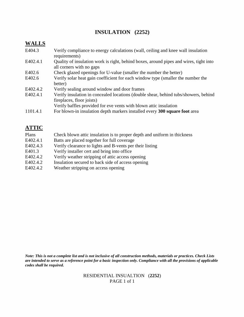
INSULATION (2252)
WALLS
E404.3 Verify compliance to energy calculations (wall, ceiling and knee wall insulation
requirements)
E402.4.1 Quality of insulation work is right, behind boxes, around pipes and wires, tight into
all corners with no gaps
E402.6 Check glazed openings for U-value (smaller the number the better)
E402.6 Verify solar heat gain coefficient for each window type (smaller the number the
better)
E402.4.2 Verify sealing around window and door frames
E402.4.1 Verify insulation in concealed locations (double shear, behind tubs/showers, behind
fireplaces, floor joists)
Verify baffles provided for eve vents with blown attic insulation
1101.4.1 For blown-in insulation depth markers installed every 300 square foot area
ATTIC
Plans Check blown attic insulation is to proper depth and uniform in thickness
E402.4.1 Batts are placed together for full coverage
E402.4.3 Verify clearance to lights and B-vents per their listing
E401.3 Verify installer cert and bring into office
E402.4.2 Verify weather stripping of attic access opening
E402.4.2 Insulation secured to back side of access opening
E402.4.2 Weather stripping on access opening
Note: This is not a complete list and is not inclusive of all construction methods, materials or practices. Check Lists
are intended to serve as a reference point for a basic inspection only. Compliance with all the provisions of applicable
codes shall be required.
RESIDENTIAL INSUALTION (2252)
PAGE 1 of 1
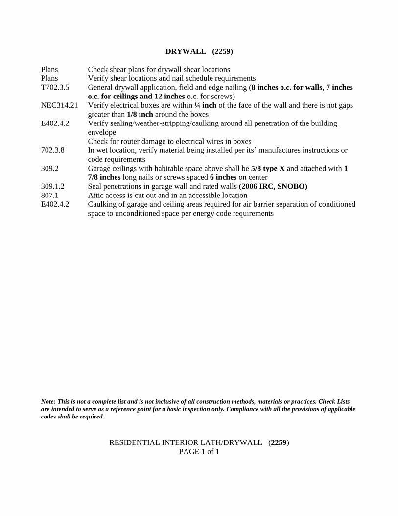
DRYWALL (2259)
Plans Check shear plans for drywall shear locations
Plans Verify shear locations and nail schedule requirements
T702.3.5 General drywall application, field and edge nailing (8 inches o.c. for walls, 7 inches
o.c. for ceilings and 12 inches o.c. for screws)
NEC314.21 Verify electrical boxes are within ¼ inch of the face of the wall and there is not gaps
greater than 1/8 inch around the boxes
E402.4.2 Verify sealing/weather-stripping/caulking around all penetration of the building
envelope
Check for router damage to electrical wires in boxes
702.3.8 In wet location, verify material being installed per its’ manufactures instructions or
code requirements
309.2 Garage ceilings with habitable space above shall be 5/8 type X and attached with 1
7/8 inches long nails or screws spaced 6 inches on center
309.1.2 Seal penetrations in garage wall and rated walls (2006 IRC, SNOBO)
807.1 Attic access is cut out and in an accessible location
E402.4.2 Caulking of garage and ceiling areas required for air barrier separation of conditioned
space to unconditioned space per energy code requirements
Note: This is not a complete list and is not inclusive of all construction methods, materials or practices. Check Lists
are intended to serve as a reference point for a basic inspection only. Compliance with all the provisions of applicable
codes shall be required.
RESIDENTIAL INTERIOR LATH/DRYWALL (2259)
PAGE 1 of 1
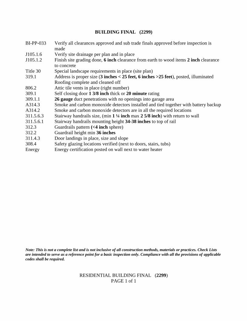
BUILDING FINAL (2299)
BI-PP-033 Verify all clearances approved and sub trade finals approved before inspection is
made
J105.1.6 Verify site drainage per plan and in place
J105.1.2 Finish site grading done, 6 inch clearance from earth to wood items 2 inch clearance
to concrete
Title 30 Special landscape requirements in place (site plan)
319.1 Address is proper size (3 inches < 25 feet, 6 inches >25 feet), posted, illuminated
Roofing complete and cleaned off
806.2 Attic tile vents in place (right number)
309.1 Self closing door 1 3/8 inch thick or 20 minute rating
309.1.1 26 gauge duct penetrations with no openings into garage area
A314.3 Smoke and carbon monoxide detectors installed and tied together with battery backup
A314.2 Smoke and carbon monoxide detectors are in all the required locations
311.5.6.3 Stairway handrails size, (min 1 ¼ inch max 2 5/8 inch) with return to wall
311.5.6.1 Stairway handrails mounting height 34-38 inches to top of rail
312.3 Guardrails pattern (<4 inch sphere)
312.2 Guardrail height min 36 inches
311.4.3 Door landings in place, size and slope
308.4 Safety glazing locations verified (next to doors, stairs, tubs)
Energy Energy certification posted on wall next to water heater
Note: This is not a complete list and is not inclusive of all construction methods, materials or practices. Check Lists
are intended to serve as a reference point for a basic inspection only. Compliance with all the provisions of applicable
codes shall be required.
RESIDENTIAL BUILDING FINAL (2299)
PAGE 1 of 1
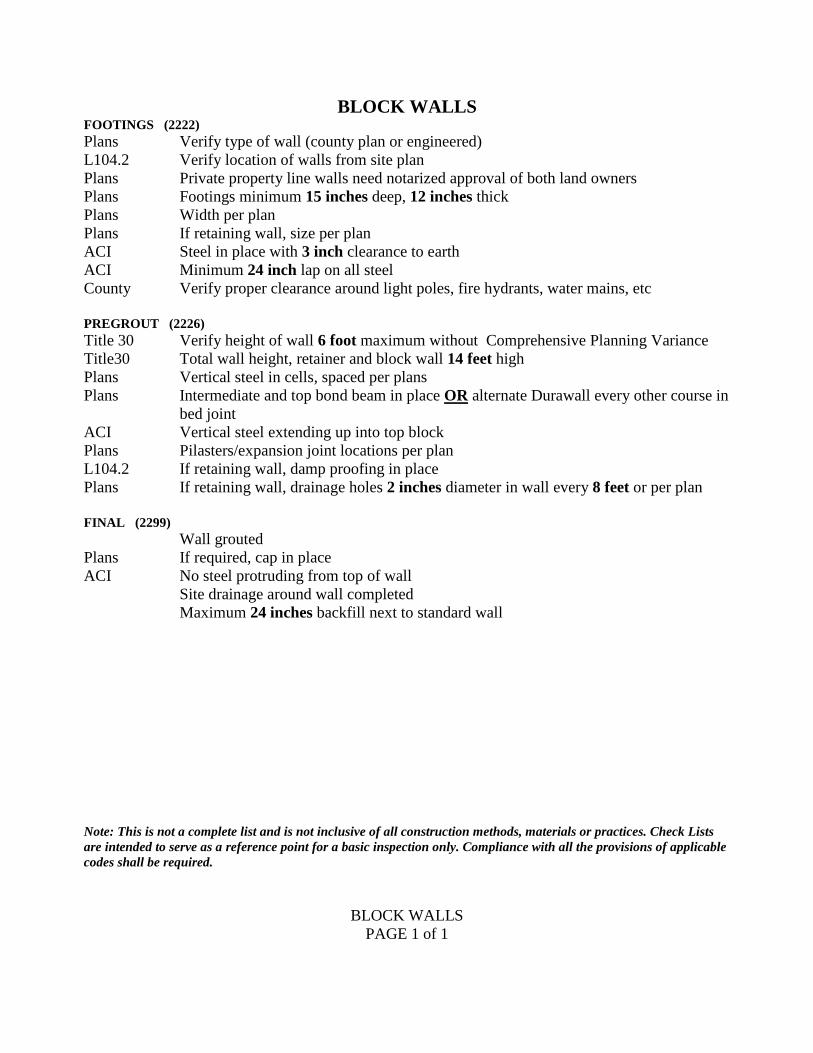
BLOCK WALLS FOOTINGS (2222)
Plans Verify type of wall (county plan or engineered)
L104.2 Verify location of walls from site plan
Plans Private property line walls need notarized approval of both land owners
Plans Footings minimum 15 inches deep, 12 inches thick
Plans Width per plan
Plans If retaining wall, size per plan
ACI Steel in place with 3 inch clearance to earth
ACI Minimum 24 inch lap on all steel
County Verify proper clearance around light poles, fire hydrants, water mains, etc
PREGROUT (2226)
Title 30 Verify height of wall 6 foot maximum without Comprehensive Planning Variance
Title30 Total wall height, retainer and block wall 14 feet high
Plans Vertical steel in cells, spaced per plans
Plans Intermediate and top bond beam in place OR alternate Durawall every other course in
bed joint
ACI Vertical steel extending up into top block
Plans Pilasters/expansion joint locations per plan
L104.2 If retaining wall, damp proofing in place
Plans If retaining wall, drainage holes 2 inches diameter in wall every 8 feet or per plan
FINAL (2299)
Wall grouted
Plans If required, cap in place
ACI No steel protruding from top of wall
Site drainage around wall completed
Maximum 24 inches backfill next to standard wall
Note: This is not a complete list and is not inclusive of all construction methods, materials or practices. Check Lists
are intended to serve as a reference point for a basic inspection only. Compliance with all the provisions of applicable
codes shall be required.
BLOCK WALLS
PAGE 1 of 1
GROUNDING ELECTRODE (3319)
250.50 The main grounding electrode in new construction is to be a concrete encased
electrode (UFER) per the Southern Nevada Electric Code Amendments
250.52A3 Verify the electrode is of the proper size, length and location in the bottom of the
footing (min 20 feet #4 rebar in bottom 3 inches of footing, with minimum 2”
encasement)
250.52A5 Existing structures may have a grounding electrode of any type prescribed in NEC as
limited by the Southern Nevada Electrical Code Amendments
Note: This is not a complete list and is not inclusive of all construction methods, materials or practices. Check Lists
are intended to serve as a reference point for a basic inspection only. Compliance with all the provisions of applicable
codes shall be required.
RESIDENTIAL GROUNDING ELECTRODE (3319)
PAGE 1 of 1
UNDERGROUND ELECTRICAL (3311)
This inspection is for wiring outside the footprint of the building. Wiring within the footprint
but under the slab is “slab electrical”
300.6 The wiring method and all associated fittings used are correct for an underground
application
300.5A Burial depth is the depth required by the NEC
300.5J Direct burial cables such as USE or UF are provided with S loops at each end and
protected by conduit to the required burial depth or 18 inches below grade
300.10 Metallic elbows and fittings that do not have earth coverage of 18 inches are to
extend in metallic raceways back to a panel board, box or other enclosure due to
grounding requirements. (Appropriate corrosion protection shall be required on
metallic raceway when installed below grade)
300.5D4 Rigid non-metallic conduit that is subject to physical damage shall be Schedule 80
RNMC
300.5D3 Warning tape at 12 inches above the Service lateral conductors is provided and tape
is verified prior to approval of underground electrical
Note: This is not a complete list and is not inclusive of all construction methods, materials or practices. Check Lists
are intended to serve as a reference point for a basic inspection only. Compliance with all the provisions of applicable
codes shall be required.
RESIDENTIAL UNDERGROUND ELECTRICAL (3311)
PAGE 1 of 1
RESIDENTIAL SLAB ELECTRICAL (3321)
300.5C No direct buried cables below slab
300.5C Conduits are supported and installed as prescribed in the International Building Code
300.5B Any conductor used under the slab required to be in conduit and wet location
conductors (i.e. THW, THWN, THHW, UF, etc.)
300.18 Conduit runs are continuous and not reduced in mid-run
300.10 Metallic elbows and fittings that do not have earth coverage of 18 inches are to
extend in metallic raceways back to a panel board, box or other enclosure due to
grounding requirements
300.5D4 Rigid non-metallic conduit that is subject to physical damage shall be Schedule 80
RNMC
Note: This is not a complete list and is not inclusive of all construction methods, materials or practices. Check Lists
are intended to serve as a reference point for a basic inspection only. Compliance with all the provisions of applicable
codes shall be required.
RESIDENTIAL SLAB ELECTRICAL (3321)
PAGE 1 of 1
ROUGH ELECTRICAL (3331)
Panelboards (All Panels)
408.30 Read and review the listing information on the panel label
UL The panelboard is the correct type for the location such as “Wet Location”, etc. and
installed per its’ listing
UL The panelboard is listed and installed per the terms of its’ listing and any installation
instructions provided by the manufacturer (including adjustable depth panels)
A110.12 Used electrical equipment shall not be used without the prior approval of the Building
Official
11014 Oxide inhibitor is required on all aluminum conductors at their terminations
250.66 Grounding Electrode Conductor, when required, is sized per Table 250.66
408.40 Grounding Electrode Conductor, when required, is terminated in an approved method
and on the correct buss
110.14A Only one grounded conductor (neutral) is permitted under a single screw on any buss
unless it is listed for multiple conductors
240.24D&E No panels are to be installed in bathrooms or clothes closets
(Special conditions may permit a clothes closet installation)
300.15 Number of cables terminated in cable connectors per listing of the cable connector
300.15 All wiring methods terminating in the panel are terminated, secured and supported as
required for that wiring method
240.24A No circuit breaker spaces higher than 6 feet, 7 inches above the floor or grade level
110.12C The electrical components of the panel are not damaged or contaminated by foreign
materials such as paint, plaster, cleaners, abrasives or corrosive residues
110.12A All unused openings are closed using knock out seals of the appropriate thickness and
type
408.36F Any back-fed breaker, that the conductors are not factory installed on, must be held to
the buss with a positive means such as clips, screws or bolts.
210.4 All multi-wire circuits are to have a simultaneous disconnecting means
Note: This is not a complete list and is not inclusive of all construction methods, materials or practices. Check Lists
are intended to serve as a reference point for a basic inspection only. Compliance with all the provisions of applicable
codes shall be required.
RESIDENTIAL ROUGH ELECTRICAL (3331)
PAGE 1 of 5
Service Equipment
230.42 Verify the service is the correct size and the service disconnect is located on the
exterior of the building
230.66 Verify the service equipment is listed and identified as “Service Equipment” or
“Suitable for Use as Service Equipment”
NV power Height of the center of the meter is no less than 48 inches, and not more than 75
inches above the floor or finish grade level
NV power Service entrance raceway is rigid metallic or intermediate metal conduit
250.92B Service riser is bonded to the service enclosure, if it does not terminate at a factory or
Myers type hub
250.64 Service is connected to the grounding electrode with the conductor sized per Table
250.66 and is terminated in an approved manner
250.104 Bond metal water piping system and gas piping and exposed structural metal frame to
the service equipment with conductor sized per Table 250.66
250.24A1 Grounding electrode conductor and main bonding jumper are not terminated in the
utility side of the enclosure (line side)
250.94 Phone and CATV grounds are not terminated on the inside of the service equipment
enclosure. A typical installation would be terminated on separate clamps on the re-bar
stub of the concrete-encased electrode. Note: one wire per terminal.
FIG-E-021 Check to see that the service will comply with NV Power Standards as detailed in
FIG-E-021, as well as NEC working clearances. Both requirements will be checked
again at electrical final.
Sub Panels at Detached Structures A250.50 A concrete-encased electrode is required at detached structures provided with power
per ‘05’ Amendments
A225.32 A disconnecting means is not required to be located on the exterior of the building, if
the building is an accessory to a single-family dwelling
250.32B The sub panel is required to be fed with a four-wire feeder. The grounded conductor
(neutral) must be isolated
250.94 Metallic water piping system and gas piping system are required to be bonded to the
sub panel
250.32A ex More than one branch circuit requires a grounding electrode to be connected to the
grounding buss in the sub panel (per NEC). The grounding electrode conductor is
sized per Table 250.66
225.33 A main breaker is required if the panel contains more than 6 handles.
RESIDENTIAL ROUGH ELECTRICAL (3331)
PAGE 2 of 5
Feeders
215.2 Feeders are sized per Table 310.15 (B)(6)
215.6 Feeder contains an equipment grounding conductor
300.5B Conductors run under slab or underground are wet location conductors or cables
215.12 Conductors are identified with the correct color for their use
338.10B4 SE or SER or UF Cables installed inside of the building are to be installed as required
in Article 334 for non-metallic sheathed cable
300.17 Feeders installed in raceways shall have that raceway installed per the appropriate
section of the code for that raceway
Required Outlets
A210.70 Every hallway 10 feet long or longer shall contain at least one 120 volt receptacle
outlet and a switch controlled light with switching at every end and within 6 feet of
each bedroom door
210.70A2 Every interior stairway with six or more risers shall have a luminaire to illuminate the
stairway, controlled by a three-way switch located at the top and bottom of the stairs
to control the luminaire at either location
210.52A The 120 volt receptacle outlets are placed throughout habitable rooms on every wall
space that is a minimum 2 feet wide. These outlets shall meet the 6 feet and 12 feet
rule Note: Fixed glazing and railings are considered wall space
210.70A1 Lighting outlets are provided in all rooms and switched where required to be switched
210.70A2 Switch controlled lights are installed illuminating all exits that have grade level
access with the exception of roll up garage doors
A210.70 Switches are provided at each keyed exterior entry and no switches are behind any
active door with the door in the fully open position
210.70A3 Light, switch, and 120 volt service receptacle are provided for attic or under floor
equipment requiring servicing, with the switch located at the usual point of entrance
into the space (if under floor, GFCI protection is required)
422.30 Appliances not permitted to be cord and plug connected shall be hard wired and
provided with a disconnecting means
210.52D Bathrooms require at least one 120 volt outlet within 36 inches of each basin and all
receptacles in a bathroom are to be GFCI protected
210.8 One GFCI protected outlet shall be required in the following locations; garage, on the
exterior front and rear of the dwelling. These receptacles are to be within 6 feet, 6
inches of grade or floor level
210.52C Kitchen countertops, 12 inches wide or wider, require an outlet with outlets spaced at
maximum 4 feet on center. No point on the counter top is to be more than 24 inches
from an outlet. All countertop outlets shall be GFCI protected
210.52C Peninsula and island countertops (12” X 24” or greater) that serve a kitchen are to
have at least one receptacle
Note: This is not a complete list and is not inclusive of all construction methods, materials or practices. Check Lists
are intended to serve as a reference point for a basic inspection only. Compliance with all the provisions of applicable
codes shall be required.
RESIDENTIAL ROUGH ELECTRICAL (3331)
PAGE 3 of 5
Branch Circuits
210.11C Kitchen shall have a minimum of two 20 amp small appliance branch circuits to serve
the kitchen countertops. All countertop receptacles shall be GFCI protected
A210.23 Kitchen countertop outlets are equally divided with no more than five duplex outlets
per circuit. Outlets for gas ranges and electric clocks may be on a small appliance
branch circuit and are not counted in the load limitation of five outlets per circuit.
Limit of five applies to any circuit that appears on the countertop
A210.23E4 Microwave oven, dishwashers and similar equipment in the kitchen require an
individual dedicated 20 Amp branch circuit per the Southern Nevada Electrical Code
Amendments.
210.52B1&2 Outlets in the kitchen, dining room, nook and/or pantry are on 20 Amp small
appliance branch circuits that feed no other outlets or rooms
210.11C2 The laundry is provided with an individual 20 Amp branch circuit. This circuit must
serve the clothes washer and may serve one additional outlet in the laundry area, such
as the 120 volt outlet for a gas dryer (duplex is two)
210.11C3 Bathroom 120 volt receptacle outlets shall be on a 20 Amp branch circuit with only
bathroom receptacle outlets on that branch circuit unless the circuit serves a single
bathroom. All bathroom 120 volt receptacles shall be GFCI protected
422.12 Forced Air Unit (FAU) is provided with an individual branch circuit with no other
outlets except for the unit and equipment associated with the unit such as condensate
pumps, air cleaners or humidifiers
A210.23E1 Branch circuits used exclusively for luminaires may be a 15 Amp branch circuit
A210.23E1 Branch circuits used for general use outlets or both general use outlets and luminaires
shall be a 20 Amp branch circuit
210.2 Branch circuits for dedicated appliances such as air conditioning equipment or water
heaters, shall be sized as required for the specific appliance
210.12 All 120 volt dwelling circuits except kitchen, bath, and garage are required to be
protected with Arc-Fault Circuit Interrupters (AFCI) and shall not be wired with
multi-wired branch circuits unless there is a listed two pole AFCI available from the
equipment manufacturer
Smoke Detectors
R313.2 Smoke detectors are interconnected with a single cable containing four conductors
(12-3 WG or 14-3 WG) (circuit AFCI protected)
Note: This is not a complete list and is not inclusive of all construction methods, materials or practices. Check Lists
are intended to serve as a reference point for a basic inspection only. Compliance with all the provisions of applicable
codes shall be required.
RESIDENTIAL ROUGH ELECTRICAL (3331)
PAGE 4 of 5
Nonmetallic Sheathed Cable (NM Cable) (Romex)
300.4 Cables installed 1-1/4 inch from face of studs or otherwise protected from damage
314.17C Cables secured within 8 inches of plastic SG boxes without clamps or within 12
inches for boxes with clamps. Cables supported every 4 and ½ feet thereafter where
run parallel to framing and every 6 feet where run perpendicular to trusses spaced 2
feet on center
200.7C Re-identify white wires permitted to be used as hot conductors
A210.23 Verify all receptacles are wired with #12 conductors (Southern Nevada Electrical
Code Amendments)
300.4 Cable is not in contact with truss gang plates or other abrasive construction elements
that may damage the cable
334.23 No unprotected Cables located within 6 feet of attic access opening
300.13B All neutrals in multi-wire branch circuit are pigtailed together
334.30 Cables must be stapled flat and not on their edge
250.140 Four-wire circuits must be used on all new 240 volt ovens, ranges, cook tops, and
dryers
Boxes
314.23B Boxes must be rigidly secured to the structure
300.14 3 inches of wire out of boxes before any joints, including ground wires
314.20 All boxes in walls and ceilings shall be within ¼ inch of finished surface in non-
combustible walls and flush if combustible surface. Use of box extensions (goof
rings) are acceptable and must be verified at final
250.148 Tie all ground wires in each box together. No tek or sheet metal screws are permitted
to be used on grounding conductor connections
314.4 Metallic boxes must be properly grounded
404.9B Snap switches, including dimmers, shall be grounded unless installed in a metal box
and self-grounding devices are used and properly installed. Grounding pigtails must
be present at time of rough
314.3 Plastic boxes that use connectors have only non-metallic connectors installed
314.3 Non-metallic boxes with plaster rings (mud rings or box extensions) are to be the
non-metallic type
314.3 Plastic boxes are to have no metallic fasteners on the inside of the box unless the box
is listed for such use
UL No box is to be field modified
R317.3.2 Boxes in fire rated walls are steel or are of the appropriate fire rating of the firewall
and meet any opening size limitation or offset requirement set by the other codes
RESIDENTIAL ROUGH ELECTRICAL (3331)
PAGE 5 of 5
FINAL ELECTRICAL (3399)
Panelboards
100.26 Panel cover opens and closes with a full 900 degree door swing
A408.35 Two spare full size breaker spaces (Southern Nevada Amendment)
408.30 Check label and only use breakers approved by the manufacturer for that
panelboard. Check multi-wire branch circuits and 240 volt loads to verify correct
phase configuration. Some panel manufacturers only allow mini-breakers in certain
locations.
110.12C No paint or overspray on panel buss bars and connections
110.26 Working clearance in front of all panels (min 30 inches wide 36 inches deep)
312.8 Splices are allowed in panels
408.4 All breakers in the panel are to be legibly marked and labeled to clearly indicate the
area and loads served
110.3B Oxide inhibitor on all aluminum conductors
110.3B All circuits phased correctly. Use caution on phases of branch circuits connected to
multi-wire branch circuits
408.4 All breakers are clearly labeled to indicate the loads served
210.4 Any multi-wire branch circuit is to be terminated on a 2 pole breaker
240.4 Check all breakers for correct wire size and corresponding breaker size
210.12 All 120 volt branch circuits are protected with arc-fault breakers, except kitchen,
bath, and garage
Receptacles
210.21B1 In the garage, all receptacles shall be GFCI protected
210.21B1 A 20 amp receptacle is required on any individual branch circuit with a single outlet
210.8 All outside receptacles are to be GFCI protected, including overhead, and any
receptacle outlet on the roof or within 25 feet of A/C equipment
406.8B1 All 15 and 20 amp receptacles in wet locations require bubble type covers
210.8 All receptacles serving kitchen counter tops and any bathroom receptacles shall be
GFCI protected
210.8 In the unfinished basements, all receptacles shall be GFCI protected, except
receptacles supplying a fire alarm system
406.11 All 15A & 20A 125V receptacles required by 210.52 are required to be listed tamper-
resistant
Note: This is not a complete list and is not inclusive of all construction methods, materials or practices. Check Lists
are intended to serve as a reference point for a basic inspection only. Compliance with all the provisions of applicable
codes shall be required.
RESIDENTIAL FINAL ELECTRICAL (3399)
PAGE 1 of 2
Light Fixtures
210.70 Required lighting fixtures are installed in all locations that require fixtures.
Bedrooms, living rooms, and dens may have switched receptacles in lieu of light
fixtures. Rooms with ceiling fans may have those outlets blanked off, provided there
are switched receptacle outlets in the room
410.16 Closet light clearances of 6 inches for recessed and fluorescent, 12 inches for surface
incandescent with no open or exposed lamps (except where listed for closet use)
410.14B Fluorescent and bar lights mounted over outlet boxes are required to have access to
box (large KO). Chain hung fixtures have a #18 grounding conductor to the fixture
and there is no tension on the conductors
410.4A All lighting fixtures in wet locations are sealed or installed with a gasket at the walls,
with a drip hole provided at the bottom of the seal
410.10D Fixtures above the tub/shower space are required to be suitable for a damp location,
or wet location if subject to spray.
90.7 All lighting luminaries are to be listed
Arc-Fault Protection
210.12 All 120 volt outlets are to be protected by Arc-Fault Circuit Interrupters, except in the
kitchen, bath, and garage. Any receptacle within 6 feet of a wet-bar sink is also
required to be GFCI protected in addition to the requirement for AFCI protection
440.65 Cord and plug connected room A/C units in any room require arc-fault or LCDI
installed in the factory cord
Appliances
110.3B The appliance is listed and installed to the terms of its’ listing
110.3B Manufacturers’ installation instructions are on site and the appliance is installed in
compliance with those instructions
422.30 Disconnecting means shall be in line of sight of the appliance and within 50 feet
422.33 All disconnecting means are to be accessible
422.16 If cord connections are permitted, check cord length to verify that length limitations
are not exceeded
422.16 Only appliances listed to be cord and plug connected may be cord and plug
connected. All others must be hard wired and be provided with an approved
disconnecting means
422.31B Circuit breakers that are not within line of sight and maximum of 50 feet of an
appliance, used as a disconnect under the lockout section, have to be capable of being
locked individually
Note: This is not a complete list and is not inclusive of all construction methods, materials or practices. Check Lists
are intended to serve as a reference point for a basic inspection only. Compliance with all the provisions of applicable
codes shall be required.
RESIDENTIAL FINAL ELECTRICAL (3399)
PAGE 2 of 2
TEMPORARY POWER POLE (3380)
590.4 Temporary power permits are to include all sub-panels connected to the service to be
included on the scope of work of the permit or a separate permit is to be issued for the
distribution system
FIG-E-005 Generators supplying other than portable wiring and portable equipment shall require
a permit and be installed per FIG-E-005
250.32 Grounding rod required for each pole
9037 All equipment shall be listed and free from damage
A110.12E Temporary power systems may not use used equipment without the prior approval of
the Building Official
A230.11 Distribution conductors on the load side of the service are to traverse only the
property under the control of the developer that holds ownership of the property
where the temporary power pole is located
230.24B Service drops and all overhead conductors are to meet the height requirements of
Section 230.24 (B) for services and Section 225.18 for overhead conductors on the
load side of the service
300.5B Service equipment, raceways, fittings and all boxes are rain tight
240.4 All loads shall be connected
590.6 All 120 and 240 volt receptacles of 30 amps or less shall have GFCI protection for
personnel
590.6 All GFCI breakers or receptacles shall be a class “A” GFCI (maximum of 6MA trip
settings)
590.4D Branch circuits in any raceway serving temporary power receptacle outlets that is not
continuous (has a coupling in the run) shall have an equipment grounding conductor
installed
408.4 All covers are to be in place and breakers identified
408.7 All openings in dead-front covers shall be closed
590.4C Extension cords used for temporary power are to be for extra-hard usage as described
in Article 400 and protected from accidental damage and meet OSHA standards
590.2 Bubble covers required in wet locations
Note: This is not a complete list and is not inclusive of all construction methods, materials or practices. Check Lists
are intended to serve as a reference point for a basic inspection only. Compliance with all the provisions of applicable
codes shall be required.
TEMPORARY POWER POLE (3399)
PAGE 1 of 1
SOLAR PHOTOVOLTAIC CHECKLIST
The solar array shall be secured and supported in compliance with building code
requirements.
690.4B Photovoltaic source and output circuits shall be kept separate from all other system
circuits unless separated by a partition or connected together.
690.4D Equipment for use in photovoltaic systems shall be identified and listed for the
application.
690.5 Grounded dc photovoltaic arrays shall be provided with dc ground-fault protection.
690.7C One and two-family dwelling PV systems limited to maximum 600 volts.
690.7(D) Live parts over 150 V shall not be accessible to other than qualified persons.
690.8A The maximum PV source current shall be the short-circuit currents ratings multiplied
by 125%.
690.8B PV systems currents shall be considered continuous.
(Conductors and overcurrent devices sized at 125%)
690.13 A means shall be provided to disconnect all current-carrying conductors of a PV
source from all other conductors in a building.
690.14C2 The disconnecting means shall be permanently marked to identify it as a PV system
disconnect
690.31E Where dc PV source or output circuits penetrate the building envelope they shall be in
metal raceways.
A690.14 Provide disconnecting means for the output circuit before penetrating the building
690.64B2 The maximum of the overcurrent devices feeding the load side of a panel shall be
120% of the rating of the bus
690.64B7 The 120% allowance is only if the overcurrent devices feed opposite ends of the bus.
Note: This is not a complete list and is not inclusive of all construction methods, materials or practices. Check Lists
are intended to serve as a reference point for a basic inspection only. Compliance with all the provisions of applicable
codes shall be required.
SOLAR PHOTOVOLTAIC
PAGE 1 of 1
PLUMBING GENERAL
Notes and Considerations
Plumbing plans are not required in residential applications with the exception of gas drawings or
isometrics. Gas plans may be drawn by the contractor of record or a Nevada Design
Professional.
General Inspections
1. Verify fixture (water (wsfu’s) drainage (dfu’s) counts
2. Proper fittings for directional changes
3. All piping wrapped (protected) or sleeved passing through concrete
4. Verify from plot plan or civil drawing the requirements for sewer backwater (BWV)
and water pressure reducing valves (PRV).
Prohibited Fittings
905.6 Combination fittings to catch or receive fixture trap arms
1002.4 Sanitary tees on their backs used for drainage
1002.4 Horizontal wet venting (excluding residential)
311.1 Double combination fitting used in the horizontal
311.1 Side inlet ¼ bends
Double ‘Wisconsin’ or ‘Nawlins’ fittings (singles are ok)
1003.3 Trap and trap arm shall be the same size (reduction may be made on the inlet side of
the trap only)
Note: This is not a complete list and is not inclusive of all construction methods, materials or practices. Check Lists
are intended to serve as a reference point for a basic inspection only. Compliance with all the provisions of applicable
codes shall be required.
GENERAL PLUMBING
PAGE 1 of 1
BUILDING SEWER (4455)
316.1.6 Transition cement limited to two locations, the street connection between the building
sewer and the utility tie in OR 2 feet outside the building between the building drain
and building sewer connection.
718.1 ¼ inch per foot minimum fall or grade (1/8 for 4 inch pipe and larger)
Test tee can be setout of the excavation hole. This is for safety of the inspector and
the installer.
Note: This is not a complete list and is not inclusive of all construction methods, materials or practices. Check
Lists are intended to serve as a reference point for a basic inspection only. Compliance with all the provisions of
applicable
UNDERGROUND PLUMBING (4412)
PAGE 1 of 1
Drain, Waste and Vent Piping
T7-3 Sizing per Table 7-3 and 7-5 (don’t forget the footnotes)
T7-6 Cleanout sizing per Table 7-6 Amended by Ordinance
T7-6 **Where a 2 ½ inch cleanout is required a 2 inch cleanout may be used in residential
applications.
a. 1 ½ inch pipe 1 ½ inch c.o.
b. 2 inch pipe 1 ½ inch c.o.
c. 2 ½ inch **2 ½ inch c.o.
d. 3 inch **2 ½ inch c.o.
e. 4 & larger 3 ½ inch c.o.
707.13 Cleanouts with raised square heads, or slotted heads at least to grade.
Plans Cleanouts may be placed in a yard box.
707.14 Jim Caps or Hubless Blind Plugs can be used as a cleanout access.
707.4 Two combination fittings may be used in lieu of a two way cleanout between the
building drain and the building sewer. The combination fitting closest to the house
shall be placed in the direction of flow (to allow cleaning towards the street) and the
combination downstream shall be placed against flow (to allow cleaning towards the
house). Both cleanout risers shall be brought at least to grade or placed in a yard box.
712.2 10 foot head water test, (tested in sections or in its entirety or 5 pound air test.
NOTE: Plastic pipe shall not be tested with air.
Cleanouts may be removed to assure that water has reached all parts of the plumbing
system. Screws placed in the piping and removed upon request may also be used to
verify water has reached all parts of the plumbing system.
708 ¼ inch per foot minimum fall or grade (1/8 for 4 inch pipe and larger)
Connection of building sewer to utility lateral required.
FIG-P-009 Cleanouts installed at underground or locations marked with a brightly colored paint.
707.4 Cleanouts shall be at all “sink locations”, urinals, and horizontal changes of direction
exceeding 135 degrees and horizontal drain lines greater than 5 feet off the main line.
719.4 Cleanout extensions shall be from a wye branch or drainage fitting.
707.4 Branch lines greater than 5 feet off the main line shall have a required cleanout, this
includes lines connecting the drainage from the first floor to the second or third floor
levels.
Plans Back water valves where required by plot or civil plan.
Manufacturer Back water valves shall be no greater than 24 inches deep unless they are of the
Mainline or Cleancheck type or placed in a vault for access.
Note: This is not a complete list and is not inclusive of all construction methods, materials or practices. Check Lists
are intended to serve as a reference point for a basic inspection only. Compliance with all the provisions of applicable
codes shall be required.
RESIDENTIAL UNDERGROUND PLUMBING (4412)
PAGE 1 of 1
WATER PIPING (4425) T6-4 Sizing per Table 6-4 and 6-5 (remember the footnotes)
T6-2 Backflow devices Table 6-2
T6-3 Minimum air gap Table 6-3
T6-6 Air chamber devices Table 6-6
609.9.4 Air hammer chambers on quick acting valves and copper piping systems
608.2 Pressure regulator valve (PRV) required where the psi is greater then 80 psi
E504.5 Weather protection (insulation) where exposed to freezing conditions
T3-2 Strapping and supports within the limits of Table 3-2
608.2 Accessible strainer ahead of PRV or integral of the device
315.4 Minimum of 12 inches of cover on piping below grade
313.10 Provide sleeving on copper piping below grade and passing through concrete
T3-2 Pex piping installed to manufacturer’s installation instructions and supported at 32
inches on center
Manufacture Pex piping to have “slack” for expansion and contraction
PE in stem wall, sleeved; sleeve to be a minimum 6 inches above stem wall with the
PE termination 6 inches above the sleeve before any transition
Piping within 1 inch of edge of framing members shall be protected by 18 gauge nail
plates
Note: This is not a complete list and is not inclusive of all construction methods, materials or practices. Check Lists
are intended to serve as a reference point for a basic inspection only. Compliance with all the provisions of applicable
codes shall be required.
RESIDENTIAL WATER PIPING (4425)
PAGE 1 of 1
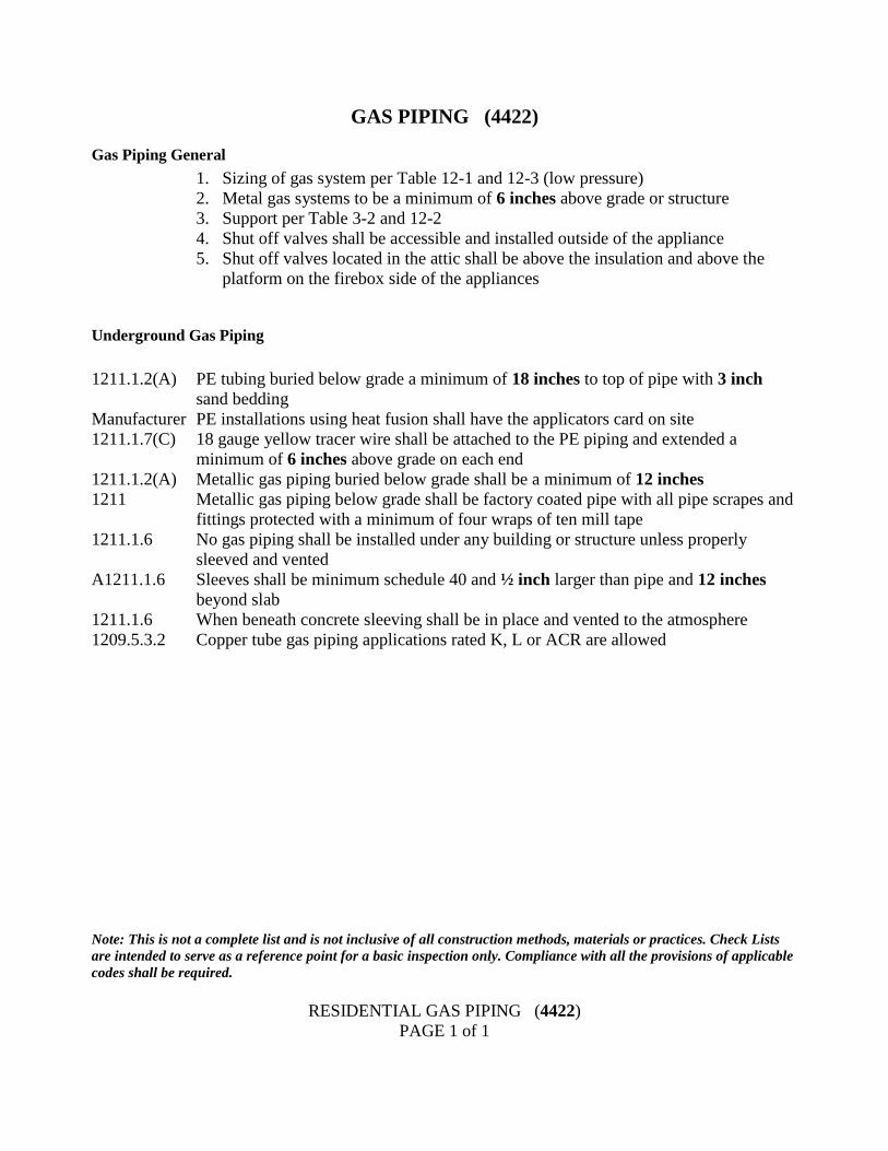
GAS PIPING (4422)
Gas Piping General
1. Sizing of gas system per Table 12-1 and 12-3 (low pressure)
2. Metal gas systems to be a minimum of 6 inches above grade or structure
3. Support per Table 3-2 and 12-2
4. Shut off valves shall be accessible and installed outside of the appliance
5. Shut off valves located in the attic shall be above the insulation and above the
platform on the firebox side of the appliances
Underground Gas Piping
1211.1.2(A) PE tubing buried below grade a minimum of 18 inches to top of pipe with 3 inch
sand bedding
Manufacturer PE installations using heat fusion shall have the applicators card on site
1211.1.7(C) 18 gauge yellow tracer wire shall be attached to the PE piping and extended a
minimum of 6 inches above grade on each end
1211.1.2(A) Metallic gas piping buried below grade shall be a minimum of 12 inches
1211 Metallic gas piping below grade shall be factory coated pipe with all pipe scrapes and
fittings protected with a minimum of four wraps of ten mill tape
1211.1.6 No gas piping shall be installed under any building or structure unless properly
sleeved and vented
A1211.1.6 Sleeves shall be minimum schedule 40 and ½ inch larger than pipe and 12 inches
beyond slab
1211.1.6 When beneath concrete sleeving shall be in place and vented to the atmosphere
1209.5.3.2 Copper tube gas piping applications rated K, L or ACR are allowed
Note: This is not a complete list and is not inclusive of all construction methods, materials or practices. Check Lists
are intended to serve as a reference point for a basic inspection only. Compliance with all the provisions of applicable
codes shall be required.
RESIDENTIAL GAS PIPING (4422)
PAGE 1 of 1
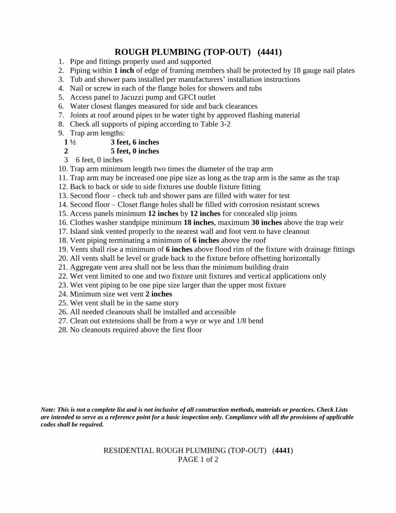
ROUGH PLUMBING (TOP-OUT) (4441) 1. Pipe and fittings properly used and supported
2. Piping within 1 inch of edge of framing members shall be protected by 18 gauge nail plates
3. Tub and shower pans installed per manufacturers’ installation instructions
4. Nail or screw in each of the flange holes for showers and tubs
5. Access panel to Jacuzzi pump and GFCI outlet
6. Water closest flanges measured for side and back clearances
7. Joints at roof around pipes to be water tight by approved flashing material
8. Check all supports of piping according to Table 3-2
9. Trap arm lengths:
1 ½ 3 feet, 6 inches
2 5 feet, 0 inches
3 6 feet, 0 inches
10. Trap arm minimum length two times the diameter of the trap arm
11. Trap arm may be increased one pipe size as long as the trap arm is the same as the trap
12. Back to back or side to side fixtures use double fixture fitting
13. Second floor – check tub and shower pans are filled with water for test
14. Second floor – Closet flange holes shall be filled with corrosion resistant screws
15. Access panels minimum 12 inches by 12 inches for concealed slip joints
16. Clothes washer standpipe minimum 18 inches, maximum 30 inches above the trap weir
17. Island sink vented properly to the nearest wall and foot vent to have cleanout
18. Vent piping terminating a minimum of 6 inches above the roof
19. Vents shall rise a minimum of 6 inches above flood rim of the fixture with drainage fittings
20. All vents shall be level or grade back to the fixture before offsetting horizontally
21. Aggregate vent area shall not be less than the minimum building drain
22. Wet vent limited to one and two fixture unit fixtures and vertical applications only
23. Wet vent piping to be one pipe size larger than the upper most fixture
24. Minimum size wet vent 2 inches
25. Wet vent shall be in the same story
26. All needed cleanouts shall be installed and accessible
27. Clean out extensions shall be from a wye or wye and 1/8 bend
28. No cleanouts required above the first floor
Note: This is not a complete list and is not inclusive of all construction methods, materials or practices. Check Lists
are intended to serve as a reference point for a basic inspection only. Compliance with all the provisions of applicable
codes shall be required.
RESIDENTIAL ROUGH PLUMBING (TOP-OUT) (4441)
PAGE 1 of 2
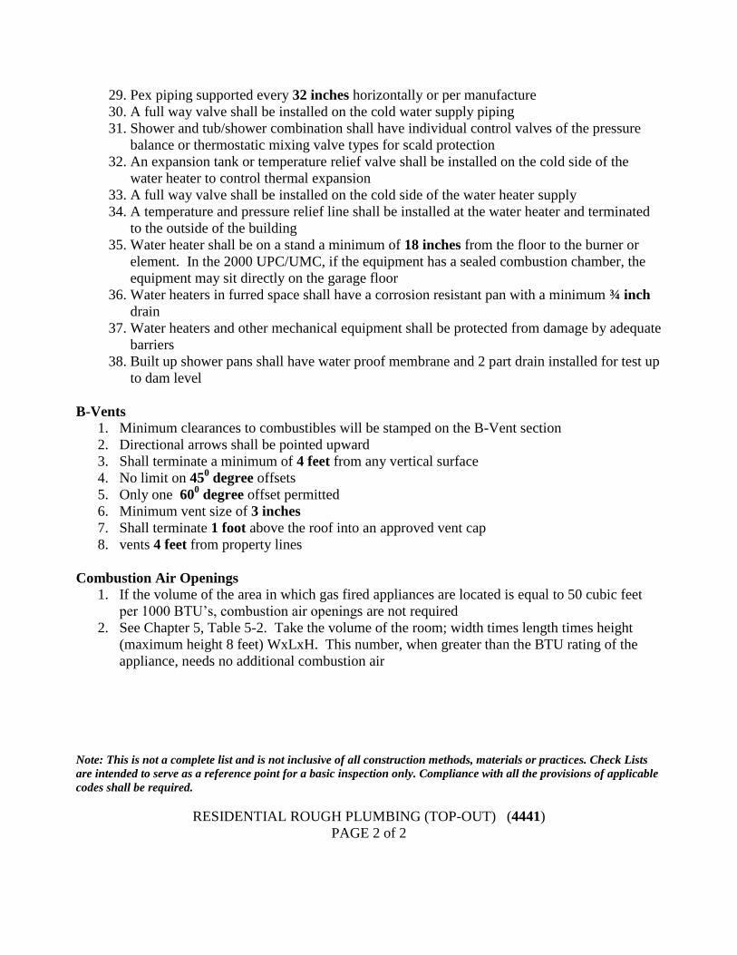
29. Pex piping supported every 32 inches horizontally or per manufacture
30. A full way valve shall be installed on the cold water supply piping
31. Shower and tub/shower combination shall have individual control valves of the pressure
balance or thermostatic mixing valve types for scald protection
32. An expansion tank or temperature relief valve shall be installed on the cold side of the
water heater to control thermal expansion
33. A full way valve shall be installed on the cold side of the water heater supply
34. A temperature and pressure relief line shall be installed at the water heater and terminated
to the outside of the building
35. Water heater shall be on a stand a minimum of 18 inches from the floor to the burner or
element. In the 2000 UPC/UMC, if the equipment has a sealed combustion chamber, the
equipment may sit directly on the garage floor
36. Water heaters in furred space shall have a corrosion resistant pan with a minimum ¾ inch
drain
37. Water heaters and other mechanical equipment shall be protected from damage by adequate
barriers
38. Built up shower pans shall have water proof membrane and 2 part drain installed for test up
to dam level
B-Vents
1. Minimum clearances to combustibles will be stamped on the B-Vent section
2. Directional arrows shall be pointed upward
3. Shall terminate a minimum of 4 feet from any vertical surface
4. No limit on 450 degree offsets
5. Only one 600 degree offset permitted
6. Minimum vent size of 3 inches
7. Shall terminate 1 foot above the roof into an approved vent cap
8. vents 4 feet from property lines
Combustion Air Openings
1. If the volume of the area in which gas fired appliances are located is equal to 50 cubic feet
per 1000 BTU’s, combustion air openings are not required
2. See Chapter 5, Table 5-2. Take the volume of the room; width times length times height
(maximum height 8 feet) WxLxH. This number, when greater than the BTU rating of the
appliance, needs no additional combustion air
Note: This is not a complete list and is not inclusive of all construction methods, materials or practices. Check Lists
are intended to serve as a reference point for a basic inspection only. Compliance with all the provisions of applicable
codes shall be required.
RESIDENTIAL ROUGH PLUMBING (TOP-OUT) (4441)
PAGE 2 of 2
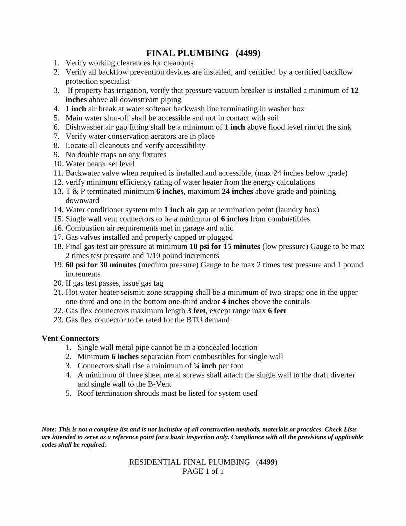
FINAL PLUMBING (4499) 1. Verify working clearances for cleanouts
2. Verify all backflow prevention devices are installed, and certified by a certified backflow
protection specialist
3. If property has irrigation, verify that pressure vacuum breaker is installed a minimum of 12
inches above all downstream piping
4. 1 inch air break at water softener backwash line terminating in washer box
5. Main water shut-off shall be accessible and not in contact with soil
6. Dishwasher air gap fitting shall be a minimum of 1 inch above flood level rim of the sink
7. Verify water conservation aerators are in place
8. Locate all cleanouts and verify accessibility
9. No double traps on any fixtures
10. Water heater set level
11. Backwater valve when required is installed and accessible, (max 24 inches below grade)
12. verify minimum efficiency rating of water heater from the energy calculations
13. T & P terminated minimum 6 inches, maximum 24 inches above grade and pointing
downward
14. Water conditioner system min 1 inch air gap at termination point (laundry box)
15. Single wall vent connectors to be a minimum of 6 inches from combustibles
16. Combustion air requirements met in garage and attic
17. Gas valves installed and properly capped or plugged
18. Final gas test air pressure at minimum 10 psi for 15 minutes (low pressure) Gauge to be max
2 times test pressure and 1/10 pound increments
19. 60 psi for 30 minutes (medium pressure) Gauge to be max 2 times test pressure and 1 pound
increments
20. If gas test passes, issue gas tag
21. Hot water heater seismic zone strapping shall be a minimum of two straps; one in the upper
one-third and one in the bottom one-third and/or 4 inches above the controls
22. Gas flex connectors maximum length 3 feet, except range max 6 feet
23. Gas flex connector to be rated for the BTU demand
Vent Connectors
1. Single wall metal pipe cannot be in a concealed location
2. Minimum 6 inches separation from combustibles for single wall
3. Connectors shall rise a minimum of ¼ inch per foot
4. A minimum of three sheet metal screws shall attach the single wall to the draft diverter
and single wall to the B-Vent
5. Roof termination shrouds must be listed for system used
Note: This is not a complete list and is not inclusive of all construction methods, materials or practices. Check Lists
are intended to serve as a reference point for a basic inspection only. Compliance with all the provisions of applicable
codes shall be required.
RESIDENTIAL FINAL PLUMBING (4499)
PAGE 1 of 1
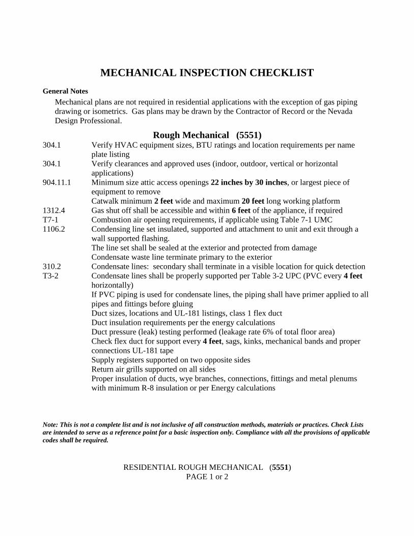
MECHANICAL INSPECTION CHECKLIST
General Notes
Mechanical plans are not required in residential applications with the exception of gas piping
drawing or isometrics. Gas plans may be drawn by the Contractor of Record or the Nevada
Design Professional.
Rough Mechanical (5551) 304.1 Verify HVAC equipment sizes, BTU ratings and location requirements per name
plate listing
304.1 Verify clearances and approved uses (indoor, outdoor, vertical or horizontal
applications)
904.11.1 Minimum size attic access openings 22 inches by 30 inches, or largest piece of
equipment to remove
Catwalk minimum 2 feet wide and maximum 20 feet long working platform
1312.4 Gas shut off shall be accessible and within 6 feet of the appliance, if required
T7-1 Combustion air opening requirements, if applicable using Table 7-1 UMC
1106.2 Condensing line set insulated, supported and attachment to unit and exit through a
wall supported flashing.
The line set shall be sealed at the exterior and protected from damage
Condensate waste line terminate primary to the exterior
310.2 Condensate lines: secondary shall terminate in a visible location for quick detection
T3-2 Condensate lines shall be properly supported per Table 3-2 UPC (PVC every 4 feet
horizontally)
If PVC piping is used for condensate lines, the piping shall have primer applied to all
pipes and fittings before gluing
Duct sizes, locations and UL-181 listings, class 1 flex duct
Duct insulation requirements per the energy calculations
Duct pressure (leak) testing performed (leakage rate 6% of total floor area)
Check flex duct for support every 4 feet, sags, kinks, mechanical bands and proper
connections UL-181 tape
Supply registers supported on two opposite sides
Return air grills supported on all sides
Proper insulation of ducts, wye branches, connections, fittings and metal plenums
with minimum R-8 insulation or per Energy calculations
Note: This is not a complete list and is not inclusive of all construction methods, materials or practices. Check Lists
are intended to serve as a reference point for a basic inspection only. Compliance with all the provisions of applicable
codes shall be required.
RESIDENTIAL ROUGH MECHANICAL (5551)
PAGE 1 or 2
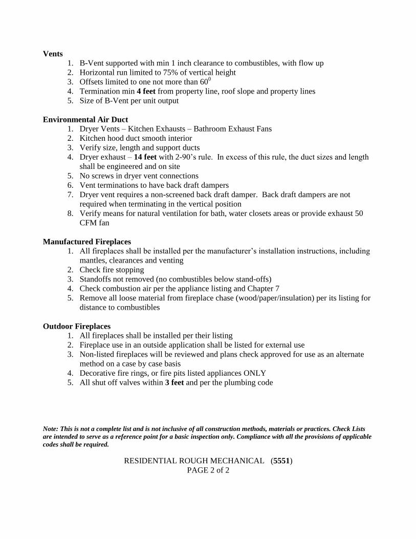
Vents
1. B-Vent supported with min 1 inch clearance to combustibles, with flow up
2. Horizontal run limited to 75% of vertical height
3. Offsets limited to one not more than 600
4. Termination min 4 feet from property line, roof slope and property lines
5. Size of B-Vent per unit output
Environmental Air Duct
1. Dryer Vents – Kitchen Exhausts – Bathroom Exhaust Fans
2. Kitchen hood duct smooth interior
3. Verify size, length and support ducts
4. Dryer exhaust – 14 feet with 2-90’s rule. In excess of this rule, the duct sizes and length
shall be engineered and on site
5. No screws in dryer vent connections
6. Vent terminations to have back draft dampers
7. Dryer vent requires a non-screened back draft damper. Back draft dampers are not
required when terminating in the vertical position
8. Verify means for natural ventilation for bath, water closets areas or provide exhaust 50
CFM fan
Manufactured Fireplaces
1. All fireplaces shall be installed per the manufacturer’s installation instructions, including
mantles, clearances and venting
2. Check fire stopping
3. Standoffs not removed (no combustibles below stand-offs)
4. Check combustion air per the appliance listing and Chapter 7
5. Remove all loose material from fireplace chase (wood/paper/insulation) per its listing for
distance to combustibles
Outdoor Fireplaces
1. All fireplaces shall be installed per their listing
2. Fireplace use in an outside application shall be listed for external use
3. Non-listed fireplaces will be reviewed and plans check approved for use as an alternate
method on a case by case basis
4. Decorative fire rings, or fire pits listed appliances ONLY
5. All shut off valves within 3 feet and per the plumbing code
Note: This is not a complete list and is not inclusive of all construction methods, materials or practices. Check Lists
are intended to serve as a reference point for a basic inspection only. Compliance with all the provisions of applicable
codes shall be required.
RESIDENTIAL ROUGH MECHANICAL (5551)
PAGE 2 of 2
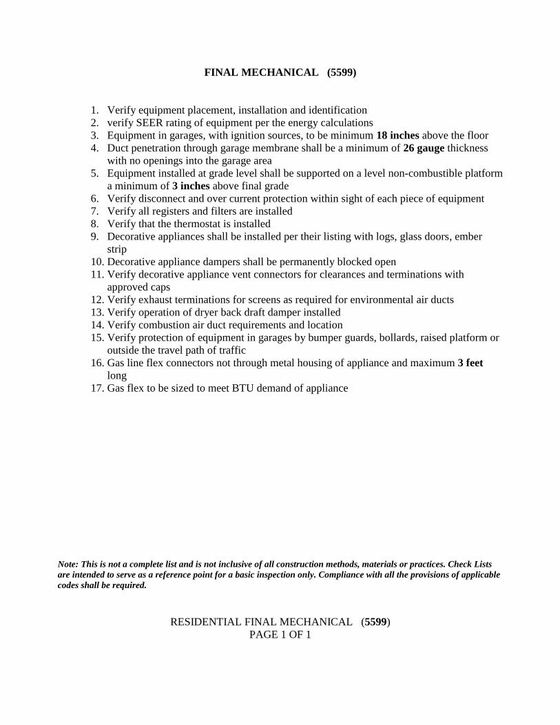
FINAL MECHANICAL (5599)
1. Verify equipment placement, installation and identification
2. verify SEER rating of equipment per the energy calculations
3. Equipment in garages, with ignition sources, to be minimum 18 inches above the floor
4. Duct penetration through garage membrane shall be a minimum of 26 gauge thickness
with no openings into the garage area
5. Equipment installed at grade level shall be supported on a level non-combustible platform
a minimum of 3 inches above final grade
6. Verify disconnect and over current protection within sight of each piece of equipment
7. Verify all registers and filters are installed
8. Verify that the thermostat is installed
9. Decorative appliances shall be installed per their listing with logs, glass doors, ember
strip
10. Decorative appliance dampers shall be permanently blocked open
11. Verify decorative appliance vent connectors for clearances and terminations with
approved caps
12. Verify exhaust terminations for screens as required for environmental air ducts
13. Verify operation of dryer back draft damper installed
14. Verify combustion air duct requirements and location
15. Verify protection of equipment in garages by bumper guards, bollards, raised platform or
outside the travel path of traffic
16. Gas line flex connectors not through metal housing of appliance and maximum 3 feet
long
17. Gas flex to be sized to meet BTU demand of appliance
Note: This is not a complete list and is not inclusive of all construction methods, materials or practices. Check Lists
are intended to serve as a reference point for a basic inspection only. Compliance with all the provisions of applicable
codes shall be required.
RESIDENTIAL FINAL MECHANICAL (5599)
PAGE 1 OF 1