Embed Size (px)
Citation preview
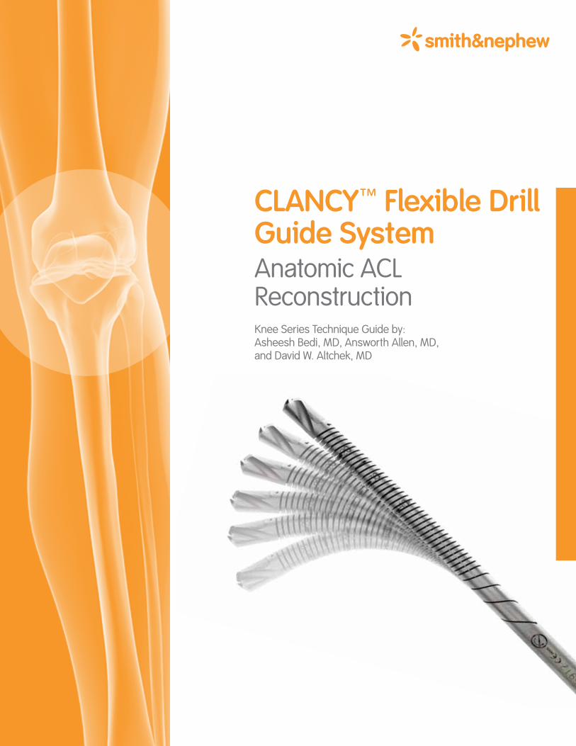
CLANCYT Flexible Drill Guide SystemAnatomic ACL Reconstruction Knee Series Technique Guide by: Asheesh Bedi, MD, Answorth Allen, MD, and David W. Altchek, MD

3CLANCYT Flexible Drill Guide System Anatomic ACL Reconstruction
As described by:Asheesh Bedi, MDSports Medicine & Shoulder Surgery Service Hospital for Special Surgery New York, NY
Sports Medicine & Shoulder Surgery University of Michigan Ann Arbor, MI
Answorth Allen, MDAssociate Attending Orthopaedic Surgeon Hospital for Special Surgery New York, NY
David W. Altchek, MD Co-Chief, Sports Medicine & Shoulder Surgery Service Hospital for Special Surgery New York, NY
Introduction . . . . . . . . . . . . . . . . . . . . . . . . . . . . . . . . . . . . . . . . . . . . . . . . . . . .4
Portal Placement . . . . . . . . . . . . . . . . . . . . . . . . . . . . . . . . . . . . . . . . . . . . . . . .5
Tibial Footprint Preparation . . . . . . . . . . . . . . . . . . . . . . . . . . . . . . . . . . . . . . . .5
Femoral Footprint Preparation . . . . . . . . . . . . . . . . . . . . . . . . . . . . . . . . . . . . . .6
Tibial Tunnel Drilling . . . . . . . . . . . . . . . . . . . . . . . . . . . . . . . . . . . . . . . . . . . . .6
Femoral Tunnel Drilling . . . . . . . . . . . . . . . . . . . . . . . . . . . . . . . . . . . . . . . . . . .7
Graft Passage and Fixation Bone-Patellar Tendon-Bone Graft Using Interference Screw Fixation . . .8
Soft Tissue Graft Using the ENDOBUTTON™ CL ULTRA Fixation Device . . . . .9
Alternative Techniques for Using ENDOBUTTON CL ULTRA Fixation Device with the CLANCYT Flexible Drill Guide System . . . . . . . . . . 10
Ordering Information . . . . . . . . . . . . . . . . . . . . . . . . . . . . . . . . . . . . . Back Cover
Table of Contents
4 CLANCYT Flexible Drill Guide System Anatomic ACL Reconstruction
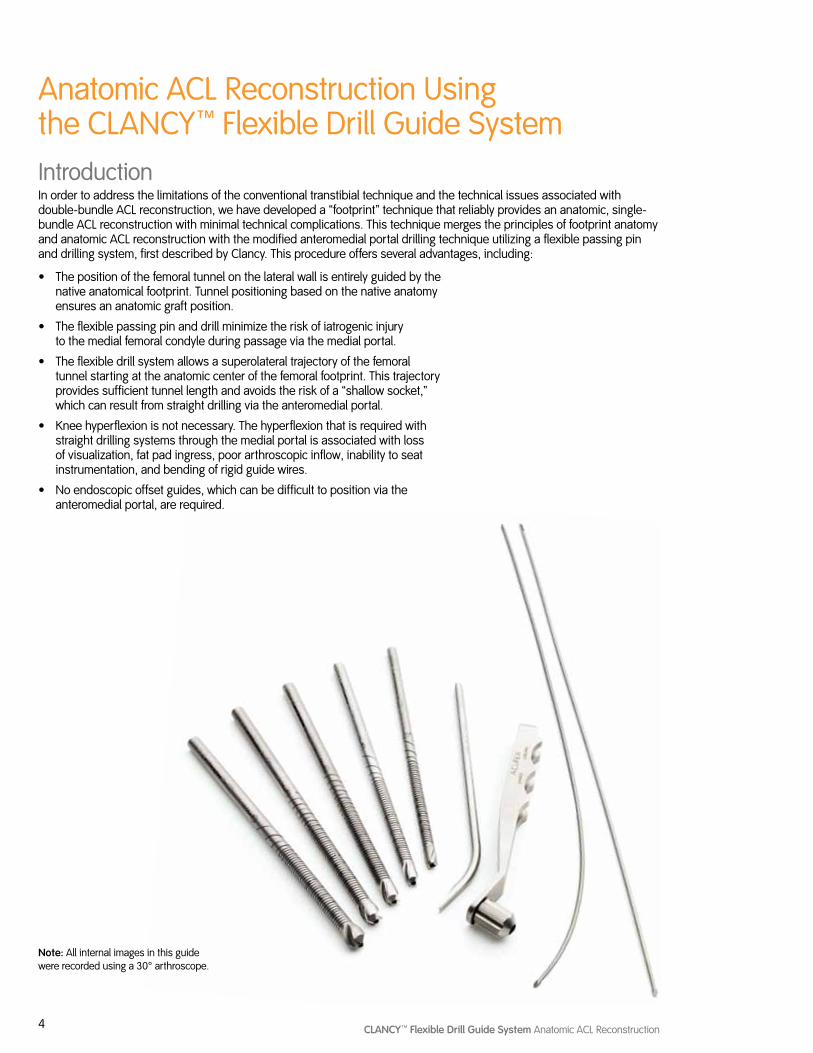
Anatomic ACL Reconstruction Using the CLANCYT Flexible Drill Guide SystemIntroductionIn order to address the limitations of the conventional transtibial technique and the technical issues associated with double-bundle ACL reconstruction, we have developed a “footprint” technique that reliably provides an anatomic, single-bundle ACL reconstruction with minimal technical complications. This technique merges the principles of footprint anatomy and anatomic ACL reconstruction with the modified anteromedial portal drilling technique utilizing a flexible passing pin and drilling system, first described by Clancy. This procedure offers several advantages, including:
• The position of the femoral tunnel on the lateral wall is entirely guided by the native anatomical footprint. Tunnel positioning based on the native anatomy ensures an anatomic graft position.
• The flexible passing pin and drill minimize the risk of iatrogenic injury to the medial femoral condyle during passage via the medial portal.
• The flexible drill system allows a superolateral trajectory of the femoral tunnel starting at the anatomic center of the femoral footprint. This trajectory provides sufficient tunnel length and avoids the risk of a “shallow socket,” which can result from straight drilling via the anteromedial portal.
• Knee hyperflexion is not necessary. The hyperflexion that is required with straight drilling systems through the medial portal is associated with loss of visualization, fat pad ingress, poor arthroscopic inflow, inability to seat instrumentation, and bending of rigid guide wires.
• No endoscopic offset guides, which can be difficult to position via the anteromedial portal, are required.
Note: All internal images in this guide were recorded using a 30° arthroscope.
5CLANCYT Flexible Drill Guide System Anatomic ACL Reconstruction
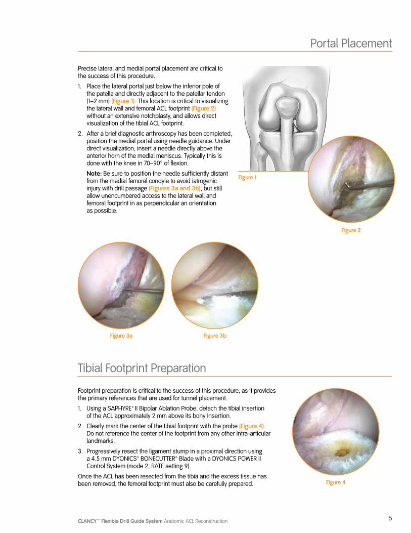
Precise lateral and medial portal placement are critical to the success of this procedure.
1. Place the lateral portal just below the inferior pole of the patella and directly adjacent to the patellar tendon (1–2 mm) (Figure 1). This location is critical to visualizing the lateral wall and femoral ACL footprint (Figure 2) without an extensive notchplasty, and allows direct visualization of the tibial ACL footprint.
2. After a brief diagnostic arthroscopy has been completed, position the medial portal using needle guidance. Under direct visualization, insert a needle directly above the anterior horn of the medial meniscus. Typically this is done with the knee in 70–90° of flexion.
Note: Be sure to position the needle sufficiently distant from the medial femoral condyle to avoid iatrogenic injury with drill passage (Figures 3a and 3b), but still allow unencumbered access to the lateral wall and femoral footprint in as perpendicular an orientation as possible.
Portal Placement
Figure 1
Figure 2
Tibial Footprint Preparation
Figure 3a Figure 3b
Footprint preparation is critical to the success of this procedure, as it provides the primary references that are used for tunnel placement.
1. Using a SAPHYRE™ II Bipolar Ablation Probe, detach the tibial insertion of the ACL approximately 2 mm above its bony insertion.
2. Clearly mark the center of the tibial footprint with the probe (Figure 4). Do not reference the center of the footprint from any other intra-articular landmarks.
3. Progressively resect the ligament stump in a proximal direction using a 4.5 mm DYONICS™ BONECUTTER™ Blade with a DYONICS POWER II Control System (mode 2, RATE setting 9).
Once the ACL has been resected from the tibia and the excess tissue has been removed, the femoral footprint must also be carefully prepared. Figure 4
6 CLANCYT Flexible Drill Guide System Anatomic ACL Reconstruction
Femoral Footprint Preparation
Tibial Tunnel Drilling
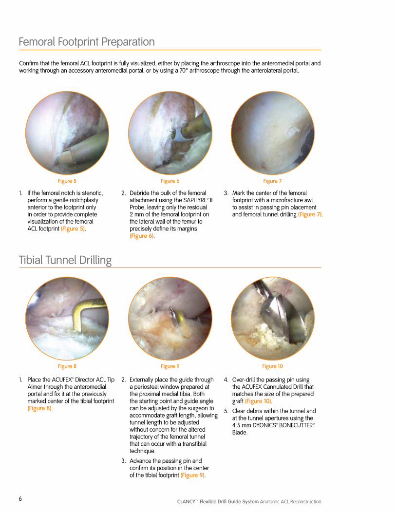
Confirm that the femoral ACL footprint is fully visualized, either by placing the arthroscope into the anteromedial portal and working through an accessory anteromedial portal, or by using a 70° arthroscope through the anterolateral portal.
1. If the femoral notch is stenotic, perform a gentle notchplasty anterior to the footprint only in order to provide complete visualization of the femoral ACL footprint (Figure 5).
1. Place the ACUFEX™ Director ACL Tip Aimer through the anteromedial portal and fix it at the previously marked center of the tibial footprint (Figure 8).
2. Debride the bulk of the femoral attachment using the SAPHYRE™ II Probe, leaving only the residual 2 mm of the femoral footprint on the lateral wall of the femur to precisely define its margins (Figure 6).
2. Externally place the guide through a periosteal window prepared at the proximal medial tibia. Both the starting point and guide angle can be adjusted by the surgeon to accommodate graft length, allowing tunnel length to be adjusted without concern for the altered trajectory of the femoral tunnel that can occur with a transtibial technique.
3. Advance the passing pin and confirm its position in the center of the tibial footprint (Figure 9).
3. Mark the center of the femoral footprint with a microfracture awl to assist in passing pin placement and femoral tunnel drilling (Figure 7).
4. Over-drill the passing pin using the ACUFEX Cannulated Drill that matches the size of the prepared graft (Figure 10).
5. Clear debris within the tunnel and at the tunnel apertures using the 4.5 mm DYONICS™ BONECUTTER™ Blade.
Figure 5
Figure 8
Figure 6
Figure 9
Figure 7
Figure 10
7CLANCYT Flexible Drill Guide System Anatomic ACL Reconstruction
Figure 15
Femoral Tunnel Drilling
Figure 11 Figure 12
Figure 13 Figure 14
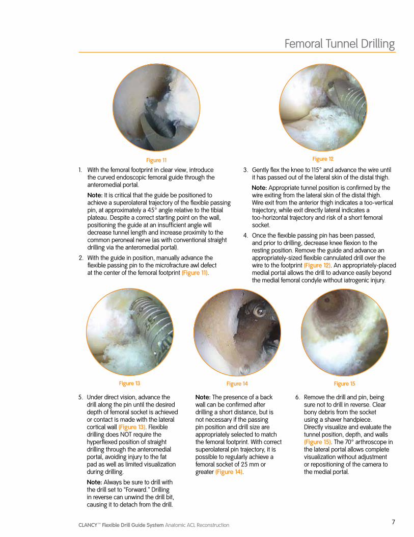
1. With the femoral footprint in clear view, introduce the curved endoscopic femoral guide through the anteromedial portal.
Note: It is critical that the guide be positioned to achieve a superolateral trajectory of the flexible passing pin, at approximately a 45° angle relative to the tibial plateau. Despite a correct starting point on the wall, positioning the guide at an insufficient angle will decrease tunnel length and increase proximity to the common peroneal nerve (as with conventional straight drilling via the anteromedial portal).
2. With the guide in position, manually advance the flexible passing pin to the microfracture awl defect at the center of the femoral footprint (Figure 11).
3. Gently flex the knee to 115° and advance the wire until it has passed out of the lateral skin of the distal thigh.
Note: Appropriate tunnel position is confirmed by the wire exiting from the lateral skin of the distal thigh. Wire exit from the anterior thigh indicates a too-vertical trajectory, while exit directly lateral indicates a too-horizontal trajectory and risk of a short femoral socket.
4. Once the flexible passing pin has been passed, and prior to drilling, decrease knee flexion to the resting position. Remove the guide and advance an appropriately-sized flexible cannulated drill over the wire to the footprint (Figure 12). An appropriately-placed medial portal allows the drill to advance easily beyond the medial femoral condyle without iatrogenic injury.
5. Under direct vision, advance the drill along the pin until the desired depth of femoral socket is achieved or contact is made with the lateral cortical wall (Figure 13). Flexible drilling does NOT require the hyperflexed position of straight drilling through the anteromedial portal, avoiding injury to the fat pad as well as limited visualization during drilling.
Note: Always be sure to drill with the drill set to “Forward.” Drilling in reverse can unwind the drill bit, causing it to detach from the drill.
Note: The presence of a back wall can be confirmed after drilling a short distance, but is not necessary if the passing pin position and drill size are appropriately selected to match the femoral footprint. With correct superolateral pin trajectory, it is possible to regularly achieve a femoral socket of 25 mm or greater (Figure 14).
6. Remove the drill and pin, being sure not to drill in reverse. Clear bony debris from the socket using a shaver handpiece. Directly visualize and evaluate the tunnel position, depth, and walls (Figure 15). The 70° arthroscope in the lateral portal allows complete visualization without adjustment or repositioning of the camera to the medial portal.
8 CLANCYT Flexible Drill Guide System Anatomic ACL Reconstruction
Graft Passage and Fixation Bone-Patellar Tendon-Bone Graft Using Interference Screw Fixation
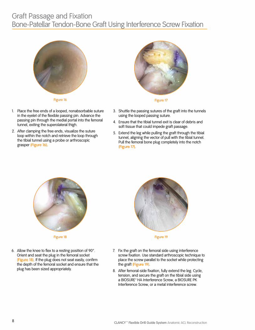
1. Place the free ends of a looped, nonabsorbable suture in the eyelet of the flexible passing pin. Advance the passing pin through the medial portal into the femoral tunnel, exiting the superolateral thigh.
2. After clamping the free ends, visualize the suture loop within the notch and retrieve the loop through the tibial tunnel using a probe or arthroscopic grasper (Figure 16).
3. Shuttle the passing sutures of the graft into the tunnels using the looped passing suture.
4. Ensure that the tibial tunnel exit is clear of debris and soft tissue that could impede graft passage.
5. Extend the leg while pulling the graft through the tibial tunnel, aligning the vector of pull with the tibial tunnel. Pull the femoral bone plug completely into the notch (Figure 17).
Figure 16 Figure 17
Figure 18 Figure 19
6. Allow the knee to flex to a resting position of 90°. Orient and seat the plug in the femoral socket (Figure 18). If the plug does not seat easily, confirm the depth of the femoral socket and ensure that the plug has been sized appropriately.
7. Fix the graft on the femoral side using interference screw fixation. Use standard arthroscopic technique to place the screw parallel to the socket while protecting the graft (Figure 19).
8. After femoral-side fixation, fully extend the leg. Cycle, tension, and secure the graft on the tibial side using a BIOSURE™ HA Interference Screw, a BIOSURE PK Interference Screw, or a metal interference screw.
9CLANCYT Flexible Drill Guide System Anatomic ACL Reconstruction
Soft Tissue Graft Using the ENDOBUTTON™ CL ULTRA Fixation Device
1. After drilling the femoral socket, remove the flexible passing pin from the medial portal.
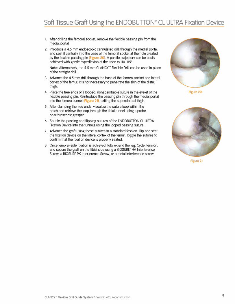
2. Introduce a 4.5 mm endoscopic cannulated drill through the medial portal and seat it centrally into the base of the femoral socket at the hole created by the flexible passing pin (Figure 20). A parallel trajectory can be easily achieved with gentle hyperflexion of the knee to 110–115°.
Note: Alternatively, the 4.5 mm CLANCYT Flexible Drill can be used in place of the straight drill.
3. Advance the 4.5 mm drill through the base of the femoral socket and lateral cortex of the femur. It is not necessary to penetrate the skin of the distal thigh.
4. Place the free ends of a looped, nonabsorbable suture in the eyelet of the flexible passing pin. Reintroduce the passing pin through the medial portal into the femoral tunnel (Figure 21), exiting the superolateral thigh.
5. After clamping the free ends, visualize the suture loop within the notch and retrieve the loop through the tibial tunnel using a probe or arthroscopic grasper.
6. Shuttle the passing and flipping sutures of the ENDOBUTTON CL ULTRA Fixation Device into the tunnels using the looped passing suture.
7. Advance the graft using these sutures in a standard fashion. Flip and seat the fixation device on the lateral cortex of the femur. Toggle the sutures to confirm that the fixation device is properly seated.
8. Once femoral-side fixation is achieved, fully extend the leg. Cycle, tension, and secure the graft on the tibial side using a BIOSURE™ HA Interference Screw, a BIOSURE PK Interference Screw, or a metal interference screw.
Figure 20
Figure 21
10 CLANCYT Flexible Drill Guide System Anatomic ACL Reconstruction
Alternative Techniques for Using ENDOBUTTON™ CL ULTRA Fixation Device with the CLANCYT Flexible Drill Guide System
1. After drilling the socket, place the scope in the anteromedial portal to view the inside of the tunnel. Alternatively, use a 70° scope through the lateral portal.
Note: Ensure that the socket depth is equal to the desired graft insertion depth plus 10 mm to allow for flipping the ENDOBUTTON CL ULTRA Fixation Device.
Example: For 20 mm of graft in the femoral tunnel, drill the socket to 30 mm.
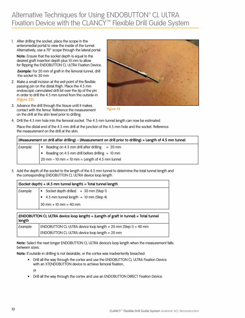
2. Make a small incision at the exit point of the flexible passing pin on the distal thigh. Place the 4.5 mm endoscopic cannulated drill bit over the tip of the pin in order to drill the 4.5 mm tunnel from the outside-in (Figure 22).
3. Advance the drill through the tissue until it makes contact with the femur. Reference the measurement on the drill at the skin level prior to drilling.
4. Drill the 4.5 mm hole into the femoral socket. The 4.5 mm tunnel length can now be estimated.
Place the distal end of the 4.5 mm drill at the junction of the 4.5 mm hole and the socket. Reference the measurement on the drill at the skin.
(Measurement on drill after drilling) – (Measurement on drill prior to drilling) = Length of 4.5 mm tunnel
Example: Ω Reading on 4.5 mm drill after drilling = 20 mm
Ω Reading on 4.5 mm drill before drilling = 10 mm
20 mm – 10 mm = 10 mm = Length of 4.5 mm tunnel
5. Add the depth of the socket to the length of the 4.5 mm tunnel to determine the total tunnel length and the corresponding ENDOBUTTON CL ULTRA device loop length.
(Socket depth) + (4.5 mm tunnel length) = Total tunnel length
Example: Ω Socket depth drilled = 30 mm (Step 1)
Ω 4.5 mm tunnel length = 10 mm (Step 4)
30 mm + 10 mm = 40 mm
(ENDOBUTTON CL ULTRA device loop length) + (Length of graft in tunnel) = Total tunnel length
Example: ENDOBUTTON CL ULTRA device loop length + 20 mm (Step 1) = 40 mm
ENDOBUTTON CL ULTRA device loop length = 20 mm
Note: Select the next longer ENDOBUTTON CL ULTRA device’s loop length when the measurement falls between sizes.
Note: If outside-in drilling is not desirable, or the cortex was inadvertently breached:
Ω Drill all the way through the cortex and use the ENDOBUTTON CL ULTRA Fixation Device with an XTENDOBUTTON device to achieve femoral fixation,
or
Ω Drill all the way through the cortex and use an ENDOBUTTON DIRECT Fixation Device.
Figure 22

Courtesy of Smith & Nephew, Inc., Endoscopy Division
™Trademarks of Smith & Nephew, registered U.S. Patent & Trademark Office. All trademarks acknowledged.
EndoscopySmith & Nephew, Inc.Andover, MA 01810USA
www.smith-nephew.com+1 978 749 1000+1 978 749 1108 Fax+1 800 343 5717 U.S. Customer Service
©2010 Smith & Nephew, Inc.All rights reserved.
08/2010 10600535 Rev. C
CAUTION: U.S. Federal law restricts this device to sale by or on the order of a physician.
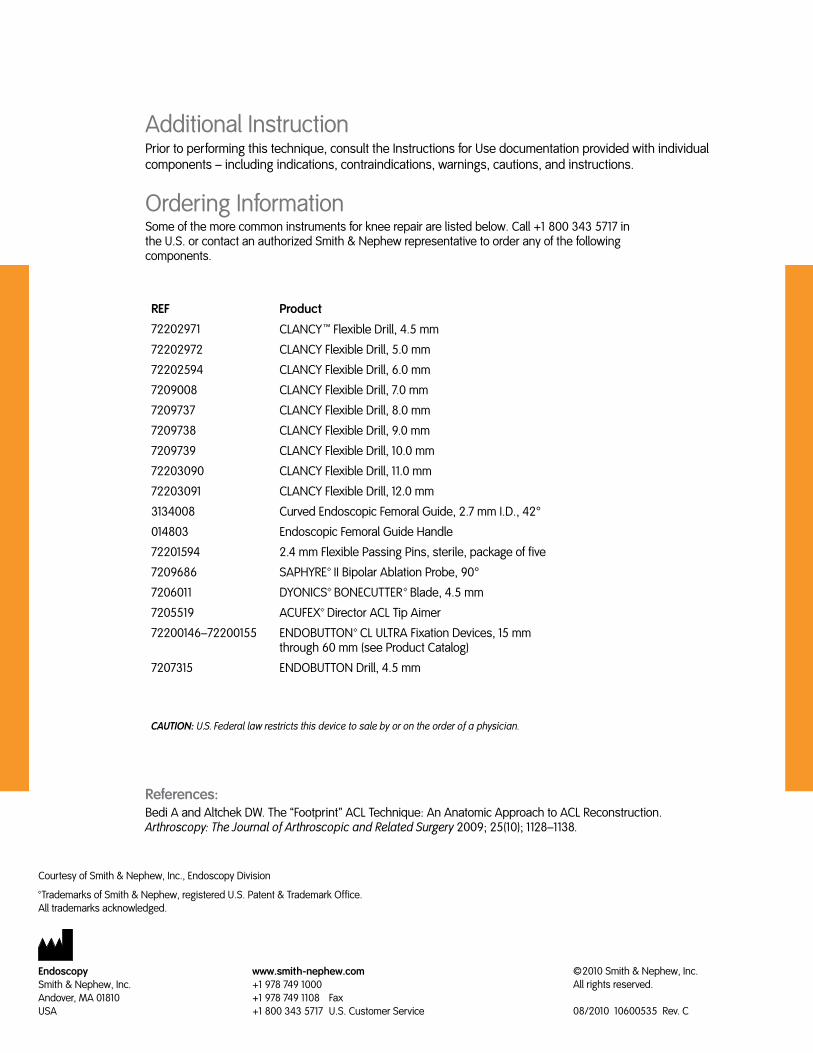
Ordering InformationSome of the more common instruments for knee repair are listed below. Call +1 800 343 5717 in the U.S. or contact an authorized Smith & Nephew representative to order any of the following components.
References:Bedi A and Altchek DW. The “Footprint” ACL Technique: An Anatomic Approach to ACL Reconstruction. Arthroscopy: The Journal of Arthroscopic and Related Surgery 2009; 25(10); 1128–1138.
Additional InstructionPrior to performing this technique, consult the Instructions for Use documentation provided with individual components – including indications, contraindications, warnings, cautions, and instructions.
REF Product
72202971 CLANCYT Flexible Drill, 4.5 mm
72202972 CLANCY Flexible Drill, 5.0 mm
72202594 CLANCY Flexible Drill, 6.0 mm
7209008 CLANCY Flexible Drill, 7.0 mm
7209737 CLANCY Flexible Drill, 8.0 mm
7209738 CLANCY Flexible Drill, 9.0 mm
7209739 CLANCY Flexible Drill, 10.0 mm
72203090 CLANCY Flexible Drill, 11.0 mm
72203091 CLANCY Flexible Drill, 12.0 mm
3134008 Curved Endoscopic Femoral Guide, 2.7 mm I.D., 42°
014803 Endoscopic Femoral Guide Handle
72201594 2.4 mm Flexible Passing Pins, sterile, package of five
7209686 SAPHYRE™ II Bipolar Ablation Probe, 90°
7206011 DYONICS™ BONECUTTER™ Blade, 4.5 mm
7205519 ACUFEX™ Director ACL Tip Aimer
72200146–72200155 ENDOBUTTON™ CL ULTRA Fixation Devices, 15 mm through 60 mm (see Product Catalog)
7207315 ENDOBUTTON Drill, 4.5 mm