Embed Size (px)
Citation preview

GN
Hydraulic Unit
CP
CR
GBQ
GBP
GBE
GBC
GBF
GBB
GD
GA
CPB
CPD
CPC
CPE
CQC
CQE
Pump Unit
CB
CD
CC
Valve Unit
BC
BH
MV
Operational Control Panel
YP
YA
Clamp
ClampHydraulic UnitOperation Control Panel
Die LifterPre-Roller
Accessories
CautionsCompany Profile
Specifications Model No. Indication Circuit Symbol External Dimensions
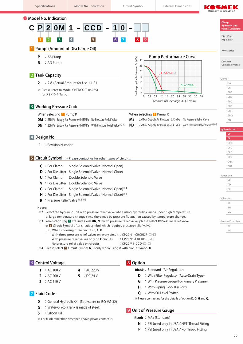
M3 : 25MPa Supply Air Pressure=0.45MPa No Pressure Relief ValveN3 : 25MPa Supply Air Pressure=0.41MPa With Pressure Relief Valve※2 ※3
When selecting Pump R 1Air-Powered Hydraulic Unit2ℓ Tank for Space-Saving
CP/CR Hydraulic Unit is the united type of CB/CD Pump Unit and BC Non-Leak
Valve Unit. Most suitable for hydraulic source of automatic clamp / RA Die Lifter.
Model CPModel CR
Model No. Indication
8 Option Blank : Standard (Air Regulator)
D : With Filter Regulator (Auto-Drain Type) G : With Pressure Gauge (For Primary Pressure) H : With Piping Block (PH Port) Q : With Oil Level Switch※ Please contact us for the details of option D, G, H and Q.
※ For fluids other than described above, please contact us.
※ Please refer to Model CP□/CQ□ (P.075) for 5ℓ/10ℓ Tank.
1 Pump (Amount of Discharge Oil)
P : AB PumpR : AD Pump
2 : 2ℓ (Actual Amount for Use 1.1ℓ)
2 Tank Capacity
3 Working Pressure Code
0M : 25MPa Supply Air Pressure=0.45MPa No Pressure Relief Valve0N : 25MPa Supply Air Pressure=0.41MPa With Pressure Relief Valve※2 ※3
When selecting Pump P 1
3 5 821 6 7 94
C P 2 0M 1 - CCD - 1 0 -
Notes: ※2. Select the hydraulic unit with pressure relief valve when using hydraulic clamps under high temperature or large temperature change since there may be pressure fluctuation caused by temperature change. ※3. When choosing Pressure Code 0N, N3:with pressure relief valve, please select R:Pressure relief valve at Circuit Symbol after circuit symbol which requires pressure relief valve. (Ex.) When choosing three circuits C, C, D With three pressure relief valves on every circuit : CP20N1-CRCRDR-□-□ With pressure relief valves only on C circuits : CP20N1-CRCRD-□-□ No pressure relief valve on circuits : CP20M1-CCD-□-□ ※4. Please select Circuit Symbol G, H only when using it with circuit symbol U.
C : For Clamp Single Solenoid Valve (Normal Open)
D : For Die Lifter Single Solenoid Valve (Normal Close) U : For Clamp Double Solenoid Valve
V : For Die Lifter Double Solenoid Valve G : For Clamp Single Solenoid Valve (Normal Open)※4
H : For Die Lifter Single Solenoid Valve (Normal Close)※4
R : Pressure Relief Valve ※2 ※3
7 Fluid Code
9 Unit of Pressure Gauge
6 Control Voltage
1 : AC 100 V 2 : AC 200 V 3 : AC 110 V
4 : AC 220 V 5 : DC 24 V
4 Design No.
1 : Revision Number
Notes: 1. If hydraulic oil with viscosity grade higher than listed on Hydraulic Fluid List (ISO-VG-32 or equivalnt), action time will be longer. 2. If using it at low temperature action time will be longer because of high viscosity of hydraulic oil. 3. Be sure to set an automatic drain air filter when air contains a large amount of moisture, or air supplying pipe is located at the end. 4. When setting a pressure gauge to hydraulic circuit, install a damper or use an oil filled (glycerin) pressure gauge in order to prevent damage caused by pressure surging. 5. Provide enough space at the bottom of the unit to compensate for hydraulic oil change. (Tank cleaning and suction strainer tightening becomes easier.)
SpecificationsModel No.Working Hydraulic PressureWithstanding Pressure
Tank Capacity
Operating TemperatureUse Frequency
Pump
Suction FilterNon-LeakValvePressure Switch(For Clamp)Pressure Switch(For RA Die Lifter)Pressure Relief Valve
Model No.Set Discharge PressureDischarge Volume Under No LoadSet Air PressureAir ConsumptionModel No.Filtration Degree
Model No.
Model No.Operation Mode / Set PressureModel No.Operation Mode / Set PressureModel No.Set Pressure
CP20M1
25 MPa1.36 ℓ/min0.45 MPa
BA5011-0
--
CP20N1
22.5 MPa1.32 ℓ/min0.41 MPa
BA5011-0BA5R11-0
BR5N11-025 MPa
CR2M31
25 MPa4.00 ℓ/min0.45 MPa
BA5011-0
--
CR2N31
22.5 MPa3.74 ℓ/min0.41 MPa
BA5011-0BA5R11-0
BR5N11-025 MPa
25 MPa37 MPa
0 ~ 70 ℃20 Cycles / Day or less Pressure Rising Time:2.5 min. / Cycle or less
JF1030174μm (100 Mesh)
JBA2700-0GPressure Increase Detection / INC. 17.6 MPa
JBA0700-0GPressure Decrease Detection / DEC. 2.94 MPa
AB7000-□ AD7300-□
max. 0.4 m3 (Normal)/min
2:2ℓ( Actual Amount for Use 1.1ℓ )
+ 2 0
+ 2 0
Blank : MPa (Standard)
N : PSI (used only in USA)/ NPT-Thread Fitting P : PSI (used only in USA)/ Rc-Thread Fitting
0 : General Hydraulic Oil (Equivalent to ISO-VG-32)G : Water-Glycol (Tank is made of steel.)S : Silicon Oil
2ℓ Tank
Hydraulic Unit
3
5
5
Pump Performance Curve
0
5
10
15
20
25
30
0 0.4 0.8 1.2 1.6 2.0 2.4 2.8 3.2 3.6 4.0
Amount of Discharge Oil (ℓ/min)
Discharge Hydraulic Pressure PH (MPa)
D : AD7300-□
B : AB7000-□
Main Components
※ Please contact us for other types of circuits.5 Circuit Symbol
7271
GN
Hydraulic Unit
CP
CR
GBQ
GBP
GBE
GBC
GBF
GBB
GD
GA
CPB
CPD
CPC
CPE
CQC
CQE
Pump Unit
CB
CD
CC
Valve Unit
BC
BH
MV
Operational Control Panel
YP
YA
Clamp
ClampHydraulic UnitOperation Control Panel
Die LifterPre-Roller
Accessories
CautionsCompany Profile
Specifications Model No. Indication Circuit Symbol External Dimensions
M3 : 25MPa Supply Air Pressure=0.45MPa No Pressure Relief ValveN3 : 25MPa Supply Air Pressure=0.41MPa With Pressure Relief Valve※2 ※3
When selecting Pump R 1Air-Powered Hydraulic Unit2ℓ Tank for Space-Saving
CP/CR Hydraulic Unit is the united type of CB/CD Pump Unit and BC Non-Leak
Valve Unit. Most suitable for hydraulic source of automatic clamp / RA Die Lifter.
Model CPModel CR
Model No. Indication
8 Option Blank : Standard (Air Regulator)
D : With Filter Regulator (Auto-Drain Type) G : With Pressure Gauge (For Primary Pressure) H : With Piping Block (PH Port) Q : With Oil Level Switch※ Please contact us for the details of option D, G, H and Q.
※ For fluids other than described above, please contact us.
※ Please refer to Model CP□/CQ□ (P.075) for 5ℓ/10ℓ Tank.
1 Pump (Amount of Discharge Oil)
P : AB PumpR : AD Pump
2 : 2ℓ (Actual Amount for Use 1.1ℓ)
2 Tank Capacity
3 Working Pressure Code
0M : 25MPa Supply Air Pressure=0.45MPa No Pressure Relief Valve0N : 25MPa Supply Air Pressure=0.41MPa With Pressure Relief Valve※2 ※3
When selecting Pump P 1
3 5 821 6 7 94
C P 2 0M 1 - CCD - 1 0 -
Notes: ※2. Select the hydraulic unit with pressure relief valve when using hydraulic clamps under high temperature or large temperature change since there may be pressure fluctuation caused by temperature change. ※3. When choosing Pressure Code 0N, N3:with pressure relief valve, please select R:Pressure relief valve at Circuit Symbol after circuit symbol which requires pressure relief valve. (Ex.) When choosing three circuits C, C, D With three pressure relief valves on every circuit : CP20N1-CRCRDR-□-□ With pressure relief valves only on C circuits : CP20N1-CRCRD-□-□ No pressure relief valve on circuits : CP20M1-CCD-□-□ ※4. Please select Circuit Symbol G, H only when using it with circuit symbol U.
C : For Clamp Single Solenoid Valve (Normal Open)
D : For Die Lifter Single Solenoid Valve (Normal Close) U : For Clamp Double Solenoid Valve
V : For Die Lifter Double Solenoid Valve G : For Clamp Single Solenoid Valve (Normal Open)※4
H : For Die Lifter Single Solenoid Valve (Normal Close)※4
R : Pressure Relief Valve ※2 ※3
7 Fluid Code
9 Unit of Pressure Gauge
6 Control Voltage
1 : AC 100 V 2 : AC 200 V 3 : AC 110 V
4 : AC 220 V 5 : DC 24 V
4 Design No.
1 : Revision Number
Notes: 1. If hydraulic oil with viscosity grade higher than listed on Hydraulic Fluid List (ISO-VG-32 or equivalnt), action time will be longer. 2. If using it at low temperature action time will be longer because of high viscosity of hydraulic oil. 3. Be sure to set an automatic drain air filter when air contains a large amount of moisture, or air supplying pipe is located at the end. 4. When setting a pressure gauge to hydraulic circuit, install a damper or use an oil filled (glycerin) pressure gauge in order to prevent damage caused by pressure surging. 5. Provide enough space at the bottom of the unit to compensate for hydraulic oil change. (Tank cleaning and suction strainer tightening becomes easier.)
SpecificationsModel No.Working Hydraulic PressureWithstanding Pressure
Tank Capacity
Operating TemperatureUse Frequency
Pump
Suction FilterNon-LeakValvePressure Switch(For Clamp)Pressure Switch(For RA Die Lifter)Pressure Relief Valve
Model No.Set Discharge PressureDischarge Volume Under No LoadSet Air PressureAir ConsumptionModel No.Filtration Degree
Model No.
Model No.Operation Mode / Set PressureModel No.Operation Mode / Set PressureModel No.Set Pressure
CP20M1
25 MPa1.36 ℓ/min0.45 MPa
BA5011-0
--
CP20N1
22.5 MPa1.32 ℓ/min0.41 MPa
BA5011-0BA5R11-0
BR5N11-025 MPa
CR2M31
25 MPa4.00 ℓ/min0.45 MPa
BA5011-0
--
CR2N31
22.5 MPa3.74 ℓ/min0.41 MPa
BA5011-0BA5R11-0
BR5N11-025 MPa
25 MPa37 MPa
0 ~ 70 ℃20 Cycles / Day or less Pressure Rising Time:2.5 min. / Cycle or less
JF1030174μm (100 Mesh)
JBA2700-0GPressure Increase Detection / INC. 17.6 MPa
JBA0700-0GPressure Decrease Detection / DEC. 2.94 MPa
AB7000-□ AD7300-□
max. 0.4 m3 (Normal)/min
2:2ℓ( Actual Amount for Use 1.1ℓ )
+ 2 0
+ 2 0
Blank : MPa (Standard)
N : PSI (used only in USA)/ NPT-Thread Fitting P : PSI (used only in USA)/ Rc-Thread Fitting
0 : General Hydraulic Oil (Equivalent to ISO-VG-32)G : Water-Glycol (Tank is made of steel.)S : Silicon Oil
2ℓ Tank
Hydraulic Unit
3
5
5
Pump Performance Curve
0
5
10
15
20
25
30
0 0.4 0.8 1.2 1.6 2.0 2.4 2.8 3.2 3.6 4.0
Amount of Discharge Oil (ℓ/min)
Discharge Hydraulic Pressure PH (MPa)
D : AD7300-□
B : AB7000-□
Main Components
※ Please contact us for other types of circuits.5 Circuit Symbol
7271

GN
Hydraulic Unit
CP
CR
GBQ
GBP
GBE
GBC
GBF
GBB
GD
GA
CPB
CPD
CPC
CPE
CQC
CQE
Pump Unit
CB
CD
CC
Valve Unit
BC
BH
MV
Operational Control Panel
YP
YA
Clamp
ClampHydraulic UnitOperation Control Panel
Die LifterPre-Roller
Accessories
CautionsCompany Profile
Hydraulic Unit model CP/CR Specifications Model No. Indication Circuit Symbol External Dimensions
External Dimensions:CP / CRCircuit Symbol / Main Circuit Examples
Circuit SymbolCCRCCCRCRUDV
Circuit Type (For Reference)
Clamp Circuit
Die Lifter Circuit
Number of Circuits1122111
BA Valve Number of Connections1122111
Pressure Relief Valve-○-○---
Pressure Switch○○○○○○○
Air Solenoid ValveSingle SolenoidSingle SolenoidSingle SolenoidSingle SolenoidDouble SolenoidSingle SolenoidDouble Solenoid
※Please contact us for other circuits.
A PortAB Pump
Pressure Switch
① ③
② ③
BA
Double Solenoid Valve for ClampU
PA Port
A PortAB Pump
BANon-Leak Valve
BANon-Leak Valve
Pressure Switch
① ②
Single Solenoid Valve for Clamp (Normal Open)C
PA PortA Port
AB Pump
Pressure Switch
① ②
Single Solenoid Valve for Die Lifter (Normal Close)D
PA Port
A PortAB Pump
Pressure Switch
① ③
② ③
B
A
Double Solenoid Valve for Die LifterV
PA Port
Note: 1. Please contact us for the specification (water-glycol type, with filter regulator, with hydraulic pressure switch, with piping block, with oil level switch) other than the drawing above.
Valve Number of Connection (n)ABC
1 Connection 2 Connections 3 Connections 4 Connections 295 345 395 445 90 140 190 240 359 409 459 510
2ℓ Tank
PA PortRc1/4 Thread
6-M8×1 Bolt Hole6-M8×1×16 BoltWith JIS SpringWasher (Included)
(mm)
BANon-Leak Valve
BANon-Leak Valve
OIL
H1.4ℓ
L0.3ℓ
C
55
30 Air RegulatorAir Pressure GaugeAB/ADPumpAir Bleed ValveAir Solenoid Valve
JBA Pressure Switch
Conduit Hole2-φ28
Oil Supply Port
157
85
185 10
Distance5045
B10A
87
70
n-A PortRc1/4 Thread
34.2
170
10150
10
310
259.5
BA Valve
④ ⑤
④ ⑤
④ ⑤
④ ⑤
Single Solenoid ValveSingle Solenoid Valve
Double Solenoid ValveDouble Solenoid Valve
Terminal Block
7473

Notes on Hydraulic CylinderSpeed Control Unit
Cautions
Hydraulic Fluid List
Notes on Handling
Maintenance / Inspection
Warranty
Company Profile
Company Profile
Our Products
History
Sales Office
ClampHydraulic UnitOperation Control Panel
Die LifterPre-Roller
Accessories
CautionsCompany Profile
CautionsInstallation Notes
(For Hydraulic Series) Hydraulic Fluid ListInstallation Notes(For Hydraulic Series) Maintenance / Inspection WarrantyNotes on HandlingHydraulic Fluid List Notes on Hydraulic Cylinder
Speed Control Unit
Installation Notes(For Hydraulic Series)
Cautions
● Installation Notes (Cautions for Hydraulic Series)
1)Check the fluid to use
● Please use the appropriate fluid by referring to the Hydraulic Fluid List.
● If hydraulic oil with viscosity grade higher than ISO-VG-32 is used, action time would be longer. ● If using it at low temperature, action time will be longer because the viscosity of hydraulic oil becomes higher.
2)Procedure before Piping
● The pipeline, piping connector and fixture circuits should be
cleaned by thorough flushing.
● The dust and cutting chips in the circuit may lead to fluid
leakage and malfunction.
● Our products except some valves are not equipped with
protective function to prevent dust and cutting chips going
into the hydraulic system and pipeline.
3)Applying Sealing Tape
● Wrap with tape 1 to 2 times following the screwing direction.
● Pieces of the sealing tape can lead to air leaks and malfunction.
● In order to prevent a foreign substance from going into
the product during piping, it should be carefully cleaned.
4)Air Bleeding in the Hydraulic Circuit
● If the hydraulic circuit has excessive air, the action time may
become very long.
After installing the hydraulic circuit, or if the pump run out of oil,
be sure to bleed air by the following step.
① Reduce hydraulic supply pressure to less than 2MPa.
② Please loosen the cap nut of pipe fitting that is closest to
clamps・RA die lifters by one full turn.
③ Wiggle the pipeline to loosen the outlet of pipeline fitting.
The hydraulic fluid mixed with air comes out.
④ Tighten the cap nut after bleeding.
⑤ It is more effective to bleed air at the highest point inside
the circuit or at the end of the circuit.
5)Checking Looseness and Retightening
● At the beginning of the machine installation, the bolt/nut
may be tightened lightly.
Check torque and re-tighten as required.
Showa Shell SekiyuIdemitsu KosanJX Nippon Oil & EnergyCosmo OilExxonMobilMatsumura OilCastrol
Maker Anti-Wear Hydraulic OilTellus S2 M 32
Daphne Hydraulic Fluid 32Super Hyrando 32Cosmo Hydro AW32Mobil DTE 24Hydol AW-32Hyspin AWS 32
Multi-Purpose Hydraulic OilMorlina S2 B 32
Daphne Super Multi Oil 32Super Mulpus DX 32Cosmo New Mighty Super 32Mobil DTE 24 Light
Note: As it may be difficult to purchase the products as shown in the table from overseas, please contact the respective manufacturer.
● Hydraulic Fluid ListISO Viscosity Grade ISO-VG-32
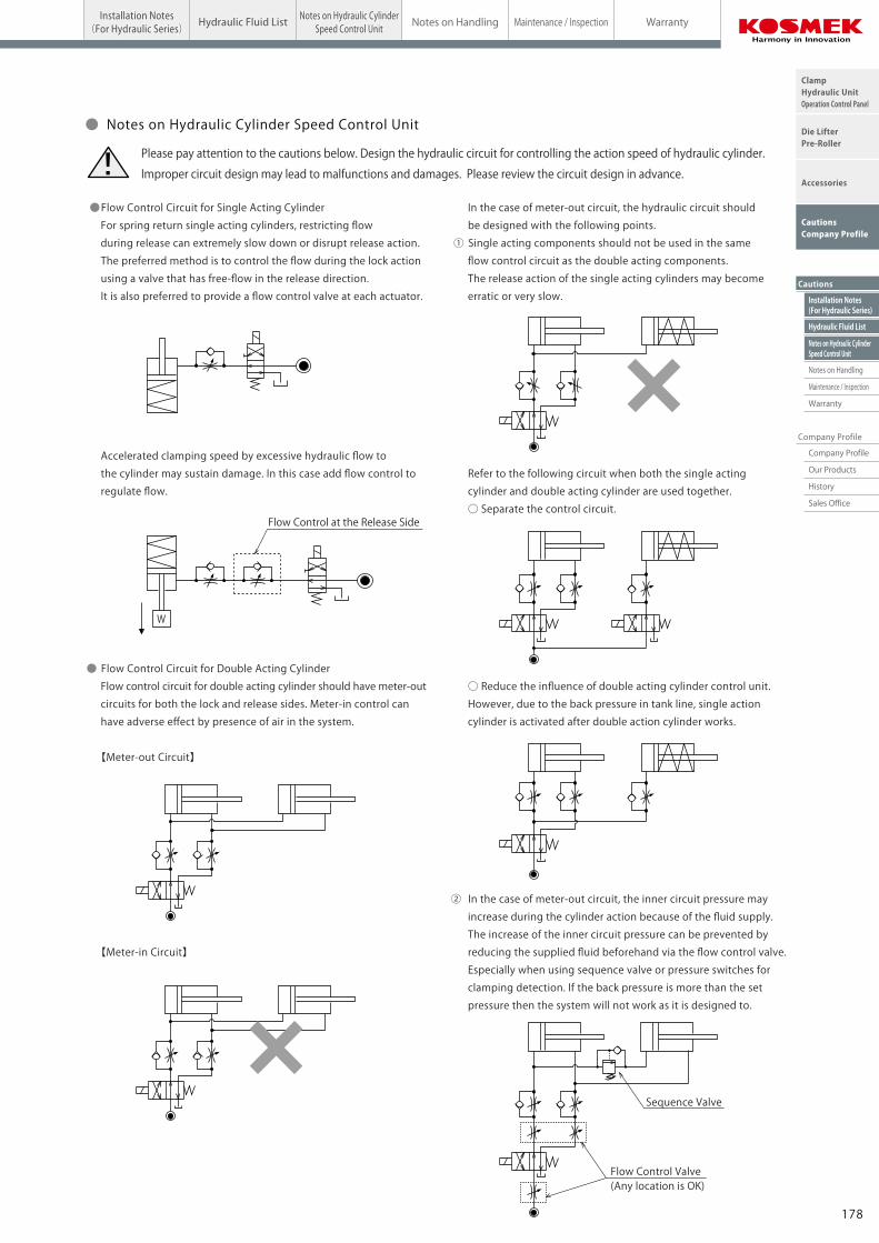
● Flow Control Circuit for Single Acting Cylinder
For spring return single acting cylinders, restricting flow
during release can extremely slow down or disrupt release action.
The preferred method is to control the flow during the lock action
using a valve that has free-flow in the release direction.
It is also preferred to provide a flow control valve at each actuator.
Accelerated clamping speed by excessive hydraulic flow to
the cylinder may sustain damage. In this case add flow control to
regulate flow.
● Flow Control Circuit for Double Acting Cylinder
Flow control circuit for double acting cylinder should have meter-out
circuits for both the lock and release sides. Meter-in control can
have adverse effect by presence of air in the system.
【Meter-out Circuit】
【Meter-in Circuit】
In the case of meter-out circuit, the hydraulic circuit should
be designed with the following points.
① Single acting components should not be used in the same
flow control circuit as the double acting components.
The release action of the single acting cylinders may become
erratic or very slow.
Refer to the following circuit when both the single acting
cylinder and double acting cylinder are used together.
○ Separate the control circuit.
○ Reduce the influence of double acting cylinder control unit.
However, due to the back pressure in tank line, single action
cylinder is activated after double action cylinder works.
② In the case of meter-out circuit, the inner circuit pressure may
increase during the cylinder action because of the fluid supply.
The increase of the inner circuit pressure can be prevented by
reducing the supplied fluid beforehand via the flow control valve.
Especially when using sequence valve or pressure switches for
clamping detection. If the back pressure is more than the set
pressure then the system will not work as it is designed to.
Flow Control at the Release Side
W
Flow Control Valve(Any location is OK)
Sequence Valve
● Notes on Hydraulic Cylinder Speed Control Unit
Please pay attention to the cautions below. Design the hydraulic circuit for controlling the action speed of hydraulic cylinder.
Improper circuit design may lead to malfunctions and damages. Please review the circuit design in advance.!
GA Clamp
178177
Notes on Hydraulic CylinderSpeed Control Unit
Cautions
Hydraulic Fluid List
Notes on Handling
Maintenance / Inspection
Warranty
Company Profile
Company Profile
Our Products
History
Sales Office
ClampHydraulic UnitOperation Control Panel
Die LifterPre-Roller
Accessories
CautionsCompany Profile
CautionsInstallation Notes
(For Hydraulic Series) Hydraulic Fluid ListInstallation Notes(For Hydraulic Series) Maintenance / Inspection WarrantyNotes on HandlingHydraulic Fluid List Notes on Hydraulic Cylinder
Speed Control Unit
Installation Notes(For Hydraulic Series)
Cautions
● Installation Notes (Cautions for Hydraulic Series)
1)Check the fluid to use
● Please use the appropriate fluid by referring to the Hydraulic Fluid List.
● If hydraulic oil with viscosity grade higher than ISO-VG-32 is used, action time would be longer. ● If using it at low temperature, action time will be longer because the viscosity of hydraulic oil becomes higher.
2)Procedure before Piping
● The pipeline, piping connector and fixture circuits should be
cleaned by thorough flushing.
● The dust and cutting chips in the circuit may lead to fluid
leakage and malfunction.
● Our products except some valves are not equipped with
protective function to prevent dust and cutting chips going
into the hydraulic system and pipeline.
3)Applying Sealing Tape
● Wrap with tape 1 to 2 times following the screwing direction.
● Pieces of the sealing tape can lead to air leaks and malfunction.
● In order to prevent a foreign substance from going into
the product during piping, it should be carefully cleaned.
4)Air Bleeding in the Hydraulic Circuit
● If the hydraulic circuit has excessive air, the action time may
become very long.
After installing the hydraulic circuit, or if the pump run out of oil,
be sure to bleed air by the following step.
① Reduce hydraulic supply pressure to less than 2MPa.
② Please loosen the cap nut of pipe fitting that is closest to
clamps・RA die lifters by one full turn.
③ Wiggle the pipeline to loosen the outlet of pipeline fitting.
The hydraulic fluid mixed with air comes out.
④ Tighten the cap nut after bleeding.
⑤ It is more effective to bleed air at the highest point inside
the circuit or at the end of the circuit.
5)Checking Looseness and Retightening
● At the beginning of the machine installation, the bolt/nut
may be tightened lightly.
Check torque and re-tighten as required.
Showa Shell SekiyuIdemitsu KosanJX Nippon Oil & EnergyCosmo OilExxonMobilMatsumura OilCastrol
Maker Anti-Wear Hydraulic OilTellus S2 M 32
Daphne Hydraulic Fluid 32Super Hyrando 32Cosmo Hydro AW32Mobil DTE 24Hydol AW-32Hyspin AWS 32
Multi-Purpose Hydraulic OilMorlina S2 B 32
Daphne Super Multi Oil 32Super Mulpus DX 32Cosmo New Mighty Super 32Mobil DTE 24 Light
Note: As it may be difficult to purchase the products as shown in the table from overseas, please contact the respective manufacturer.
● Hydraulic Fluid ListISO Viscosity Grade ISO-VG-32
● Flow Control Circuit for Single Acting Cylinder
For spring return single acting cylinders, restricting flow
during release can extremely slow down or disrupt release action.
The preferred method is to control the flow during the lock action
using a valve that has free-flow in the release direction.
It is also preferred to provide a flow control valve at each actuator.
Accelerated clamping speed by excessive hydraulic flow to
the cylinder may sustain damage. In this case add flow control to
regulate flow.
● Flow Control Circuit for Double Acting Cylinder
Flow control circuit for double acting cylinder should have meter-out
circuits for both the lock and release sides. Meter-in control can
have adverse effect by presence of air in the system.
【Meter-out Circuit】
【Meter-in Circuit】
In the case of meter-out circuit, the hydraulic circuit should
be designed with the following points.
① Single acting components should not be used in the same
flow control circuit as the double acting components.
The release action of the single acting cylinders may become
erratic or very slow.
Refer to the following circuit when both the single acting
cylinder and double acting cylinder are used together.
○ Separate the control circuit.
○ Reduce the influence of double acting cylinder control unit.
However, due to the back pressure in tank line, single action
cylinder is activated after double action cylinder works.
② In the case of meter-out circuit, the inner circuit pressure may
increase during the cylinder action because of the fluid supply.
The increase of the inner circuit pressure can be prevented by
reducing the supplied fluid beforehand via the flow control valve.
Especially when using sequence valve or pressure switches for
clamping detection. If the back pressure is more than the set
pressure then the system will not work as it is designed to.
Flow Control at the Release Side
W
Flow Control Valve(Any location is OK)
Sequence Valve
● Notes on Hydraulic Cylinder Speed Control Unit
Please pay attention to the cautions below. Design the hydraulic circuit for controlling the action speed of hydraulic cylinder.
Improper circuit design may lead to malfunctions and damages. Please review the circuit design in advance.!
GA Clamp
178177
Notes on Hydraulic CylinderSpeed Control Unit
Installation Notes(For Hydraulic Series)
Hydraulic Fluid List
Notes on Handling
Maintenance / Inspection
Warranty
Cautions
Company Profile
ClampHydraulic UnitOperation Control Panel
Die LifterPre-Roller
Accessories
CautionsCompany Profile
Company Profile
Our Products
History
Sales Office
CautionsInstallation Notes
(For Hydraulic Series) Hydraulic Fluid List Notes on Hydraulic CylinderSpeed Control Unit Maintenance / Inspection WarrantyNotes on Handling
1)Warranty Period
● The product warranty period is 18 months from shipment from
our factory or 12 months from initial use, whichever is earlier.
2)Warranty Scope
● If the product is damaged or malfunctions during the warranty
period due to faulty design, materials or workmanship, we will
replace or repair the defective part at our expense.
Defects or failures caused by the following are not covered.
① If the stipulated maintenance and inspection are not carried out.
② If the product is used while it is not suitable for use based on
the operator’ s judgment, resulting in defect.
③ If it is used or handled in inappropriate way by the operator.
(Including damage caused by the misconduct of the third party.)
④ If the defect is caused by reasons other than our responsibility.
⑤ If repair or modifications are carried out by anyone other than Kosmek,
or without our approval and confirmation, it will void warranty.
⑥ Other caused by natural disasters or calamities not attributable to
our company.
⑦ Parts or replacement expenses due to parts consumption and
deterioration.
(Such as rubber, plastic, seal material and some electric components.)
Damages excluding from direct result of a product defect shall be
excluded from the warranty.
● Warranty
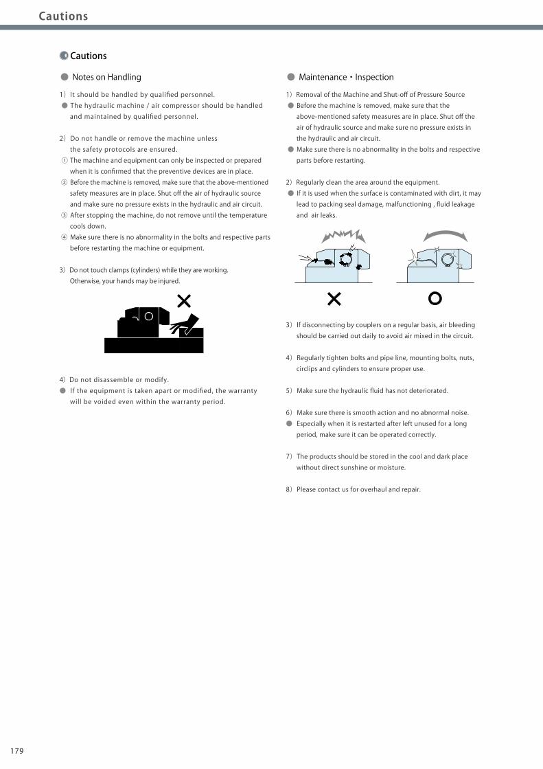
Cautions
1)It should be handled by qualified personnel.
● The hydraulic machine / air compressor should be handled
and maintained by qualified personnel.
2)Do not handle or remove the machine unless
the safety protocols are ensured.
① The machine and equipment can only be inspected or prepared
when it is confirmed that the preventive devices are in place.
② Before the machine is removed, make sure that the above-mentioned
safety measures are in place. Shut off the air of hydraulic source
and make sure no pressure exists in the hydraulic and air circuit.
③ After stopping the machine, do not remove until the temperature
cools down.
④ Make sure there is no abnormality in the bolts and respective parts
before restarting the machine or equipment.
3)Do not touch clamps (cylinders) while they are working.
Otherwise, your hands may be injured.
4)Do not disassemble or modify.
● If the equipment is taken apart or modified, the warranty
will be voided even within the warranty period.
1)Removal of the Machine and Shut-off of Pressure Source
● Before the machine is removed, make sure that the
above-mentioned safety measures are in place. Shut off the
air of hydraulic source and make sure no pressure exists in
the hydraulic and air circuit.
● Make sure there is no abnormality in the bolts and respective
parts before restarting.
2)Regularly clean the area around the equipment.
● If it is used when the surface is contaminated with dirt, it may
lead to packing seal damage, malfunctioning , fluid leakage
and air leaks.
3)If disconnecting by couplers on a regular basis, air bleeding
should be carried out daily to avoid air mixed in the circuit.
4)Regularly tighten bolts and pipe line, mounting bolts, nuts,
circlips and cylinders to ensure proper use.
5)Make sure the hydraulic fluid has not deteriorated.
6)Make sure there is smooth action and no abnormal noise.
● Especially when it is restarted after left unused for a long
period, make sure it can be operated correctly.
7)The products should be stored in the cool and dark place
without direct sunshine or moisture.
8)Please contact us for overhaul and repair.
● Notes on Handling ● Maintenance・Inspection
180179

Notes on Hydraulic CylinderSpeed Control Unit
Installation Notes(For Hydraulic Series)
Hydraulic Fluid List
Notes on Handling
Maintenance / Inspection
Warranty
Cautions
Company Profile
ClampHydraulic UnitOperation Control Panel
Die LifterPre-Roller
Accessories
CautionsCompany Profile
Company Profile
Our Products
History
Sales Office
CautionsInstallation Notes
(For Hydraulic Series) Hydraulic Fluid List Notes on Hydraulic CylinderSpeed Control Unit Maintenance / Inspection WarrantyNotes on Handling
1)Warranty Period
● The product warranty period is 18 months from shipment from
our factory or 12 months from initial use, whichever is earlier.
2)Warranty Scope
● If the product is damaged or malfunctions during the warranty
period due to faulty design, materials or workmanship, we will
replace or repair the defective part at our expense.
Defects or failures caused by the following are not covered.
① If the stipulated maintenance and inspection are not carried out.
② If the product is used while it is not suitable for use based on
the operator’ s judgment, resulting in defect.
③ If it is used or handled in inappropriate way by the operator.
(Including damage caused by the misconduct of the third party.)
④ If the defect is caused by reasons other than our responsibility.
⑤ If repair or modifications are carried out by anyone other than Kosmek,
or without our approval and confirmation, it will void warranty.
⑥ Other caused by natural disasters or calamities not attributable to
our company.
⑦ Parts or replacement expenses due to parts consumption and
deterioration.
(Such as rubber, plastic, seal material and some electric components.)
Damages excluding from direct result of a product defect shall be
excluded from the warranty.
● Warranty
Cautions
1)It should be handled by qualified personnel.
● The hydraulic machine / air compressor should be handled
and maintained by qualified personnel.
2)Do not handle or remove the machine unless
the safety protocols are ensured.
① The machine and equipment can only be inspected or prepared
when it is confirmed that the preventive devices are in place.
② Before the machine is removed, make sure that the above-mentioned
safety measures are in place. Shut off the air of hydraulic source
and make sure no pressure exists in the hydraulic and air circuit.
③ After stopping the machine, do not remove until the temperature
cools down.
④ Make sure there is no abnormality in the bolts and respective parts
before restarting the machine or equipment.
3)Do not touch clamps (cylinders) while they are working.
Otherwise, your hands may be injured.
4)Do not disassemble or modify.
● If the equipment is taken apart or modified, the warranty
will be voided even within the warranty period.
1)Removal of the Machine and Shut-off of Pressure Source
● Before the machine is removed, make sure that the
above-mentioned safety measures are in place. Shut off the
air of hydraulic source and make sure no pressure exists in
the hydraulic and air circuit.
● Make sure there is no abnormality in the bolts and respective
parts before restarting.
2)Regularly clean the area around the equipment.
● If it is used when the surface is contaminated with dirt, it may
lead to packing seal damage, malfunctioning , fluid leakage
and air leaks.
3)If disconnecting by couplers on a regular basis, air bleeding
should be carried out daily to avoid air mixed in the circuit.
4)Regularly tighten bolts and pipe line, mounting bolts, nuts,
circlips and cylinders to ensure proper use.
5)Make sure the hydraulic fluid has not deteriorated.
6)Make sure there is smooth action and no abnormal noise.
● Especially when it is restarted after left unused for a long
period, make sure it can be operated correctly.
7)The products should be stored in the cool and dark place
without direct sunshine or moisture.
8)Please contact us for overhaul and repair.
● Notes on Handling ● Maintenance・Inspection
180179

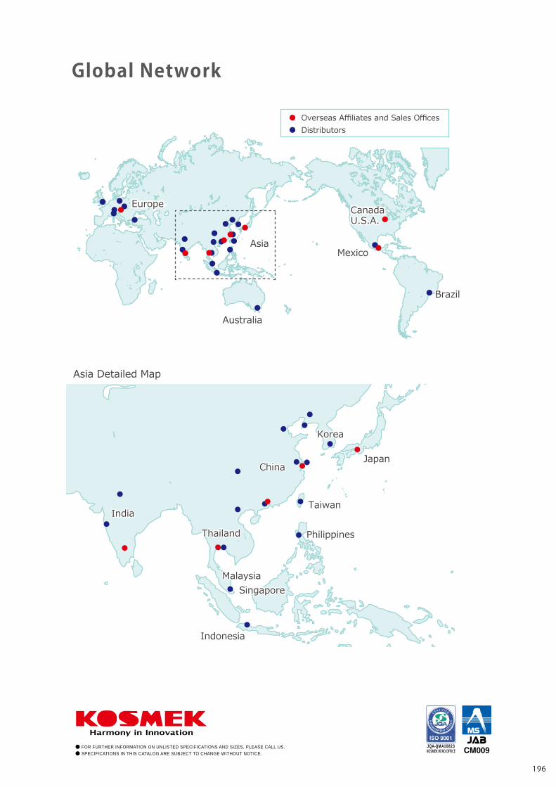
Company Profile
Global Network
Overseas Affiliates and Sales OfficesDistributors
Asia Detailed Map
● FOR FURTHER INFORMATION ON UNLISTED SPECIFICATIONS AND SIZES, PLEASE CALL US.● SPECIFICATIONS IN THIS CATALOG ARE SUBJECT TO CHANGE WITHOUT NOTICE.
JQA-QMA10823KOSMEK HEAD OFFICE
Sales Offices
TEL. 078-991-5162 FAX. 078-991-8787
Sales Offices in Japan
〒651-2241 兵庫県神戸市西区室谷2丁目1番5号
Tokyo Sales OfficeTEL. 048-652-8839 FAX. 048-652-8828
〒331-0815 埼玉県さいたま市北区大成町4丁目81番地
Nagoya Sales OfficeTEL. 0566-74-8778 FAX. 0566-74-8808
〒446-0076 愛知県安城市美園町2丁目10番地1
Fukuoka Sales OfficeTEL. 092-433-0424 FAX. 092-433-0426
〒812-0006 福岡県福岡市博多区上牟田1丁目8-10-101
Head OfficeOsaka Sales OfficeOverseas Sales
Japan
Overseas Sales
TEL. +81-78-991-5162 FAX. +81-78-991-8787
Sales Offices across the World
〒651-2241 兵庫県神戸市西区室谷2丁目1番5号
USA
KOSMEK(USA)LTD.
G.E.T. Inc, Phil.
TEL. +1-630-620-7650 FAX. +1-630-620-9015650 Springer Drive, Lombard, IL 60148 USA
EUROPE
KOSMEK EUROPE GmbH
TEL. +43-463-287587 FAX. +43-463-287587-20Schleppeplatz 2 9020 Klagenfurt am Wörthersee Austria
Thailand TEL. +66-2-300-5132 FAX. +66-2-300-513367 Soi 58, RAMA 9 Rd., Suanluang, Suanluang, Bangkok 10250, Thailand
Victoria Wave Special Economic Zone Mt. Apo Building, Brgy. 186, North Caloocan City, Metro Manila, Philippines 1427
China
考世美(上海)貿易有限公司
TEL. +86-21-54253000 FAX. +86-21-54253709
中国上海市浦东新区浦三路21弄55号银亿滨江中心601室 200125
Taiwan
盈生貿易有限公司
Thailand Representative Office
Mexico TEL. +52-442-161-2347Blvd Jurica la Campana 1040, B Colonia Punta Juriquilla Queretaro, QRO 76230 MexicoKOSMEK USA Mexico Office
TEL. +886-2-82261860 FAX. +886-2-82261890
台湾新北市中和區建八路2號 16F-4(遠東世紀廣場)
Philippines TEL. +63-2-310-7286 FAX. +63-2-310-7286
PT. Yamata Machinery Delta Commercial Park I, Jl. Kenari Raya B-08, Desa Jayamukti, Kec. Cikarang Pusat Kab. Bekasi 17530 Indonesia
Indonesia TEL. +62-21-29628607 FAX. +62-21-29628608
16F-4, No.2, Jian Ba Rd., Zhonghe District, New Taipei City Taiwan 23511
Room601, RIVERSIDE PYRAMID No.55, Lane21, Pusan Rd, Pudong Shanghai 200125, China
KOSMEK LTD. 1-5, 2-chome, Murotani, Nishi-ku, Kobe-city, Hyogo, Japan 651-2241
KOSMEK(CHINA)LTD.
Full Life Trading Co., Ltd.
(Indonesia Exclusive Distributor)
(Philippines Exclusive Distributor)
(Taiwan Exclusive Distributor)
India
KOSMEK LTD - INDIA
TEL. +91-9880561695F 203, Level-2, First Floor, Prestige Center Point, Cunningham Road, Bangalore -560052 India
CanadaU.S.A.CanadaU.S.A.
EuropeEurope
Asia
BrazilBrazil
Asia
Australia
MexicoMexico
JapanChina
Taiwan
PhilippinesThailand
Japan
Korea
China
Taiwan
PhilippinesThailand
IndiaIndia
Korea
SingaporeSingaporeMalaysiaMalaysia
IndonesiaIndonesia
196195