Embed Size (px)
Citation preview
GA
GD
GB
GE
GP
GN
CP
CR
CS
CB
CD
CC
BC
BH
MV
YP
YA
Clamp
Hydraulic Unit
Pump Unit
Valve Unit
Operational Control Panel
ClampHydraulic UnitOperation Control Panel
Die LifterPre-Roller
Accessories
CautionsCompany Profile
Features Model No. Indication / Specifications External Dimensions
Pump unit used in combination with BC / BH non-leak hydraulic valve unit.
Pump Unit
Model CBModel CDModel CC
Model No. Indication
321 65 74
C D 2 M3 0 - 0 -
4 Design No.
0 : Revision Number
6 Option
Blank : Standard (Air Regulator)
D : With Filter Regulator (Auto-Drain Type)
Q : With Oil Level Switch
7 Unit of Pressure Gauge
5 Fluid Code
※ Please contact us for the details of option D and Q.
0M : 24.5MPa Supply Air Pressure=0.45MPa 0N : 24.5MPa Supply Air Pressure=0.41MPa Compatible with BC valve unit with pressure relief valve
When selecting Pump B 1
0M : 24.5MPa Supply Air Pressure=0.47MPa 0N : 24.5MPa Supply Air Pressure=0.43MPa Compatible with BC valve unit with pressure relief valve
When selecting Pump C 1
M3 : 24.5MPa Supply Air Pressure=0.45MPa N3 : 24.5MPa Supply Air Pressure=0.41MPa Compatible with BC valve unit with pressure relief valve
When selecting Pump D 1
Pump unit easily generates hydraulic pressure
using factory compressed air.
CB/CD/CC Pump Unit
PH PortR Port
PA Port
CB/CC Pump Unit
CD Pump Unit
BC Valve Unit
Application ExampleThe drawing shows when controlling automatic
clamp and RA die lifter separately used in the
combination with two-circuit BC valve unit.
Circuit Symbol
Free LayoutHydraulic pressure is easily supplied and controlled with BC/BH non-leak valve unit. Since the pump unit
and non-leak valve unit are separated, it is more free to layout than the united type CP/CR/CS unit.
Prevention of Hydraulic Pressure ReductionWhen hydraulic pressure decreaces, a balanced-type hydraulic and pneumatic pump immediately supplies
additional hydraulic pressure.
Energy SavingPump drives only during pressurization. After the pressurization pneumatic and hydraulic pressure balance
and the pump stops. Air consumption is zero after pressurization completed.
To Automatic Clamp
Air
To RA Die Lifter
PA PortA1 Port
A2 Port
R Port
PH Port
Notes 1. PA Port : Air Source PH Port : Hydraulic Source R Port : Drain Port A Port : To Automatic Clamp or To RA Die Lifter
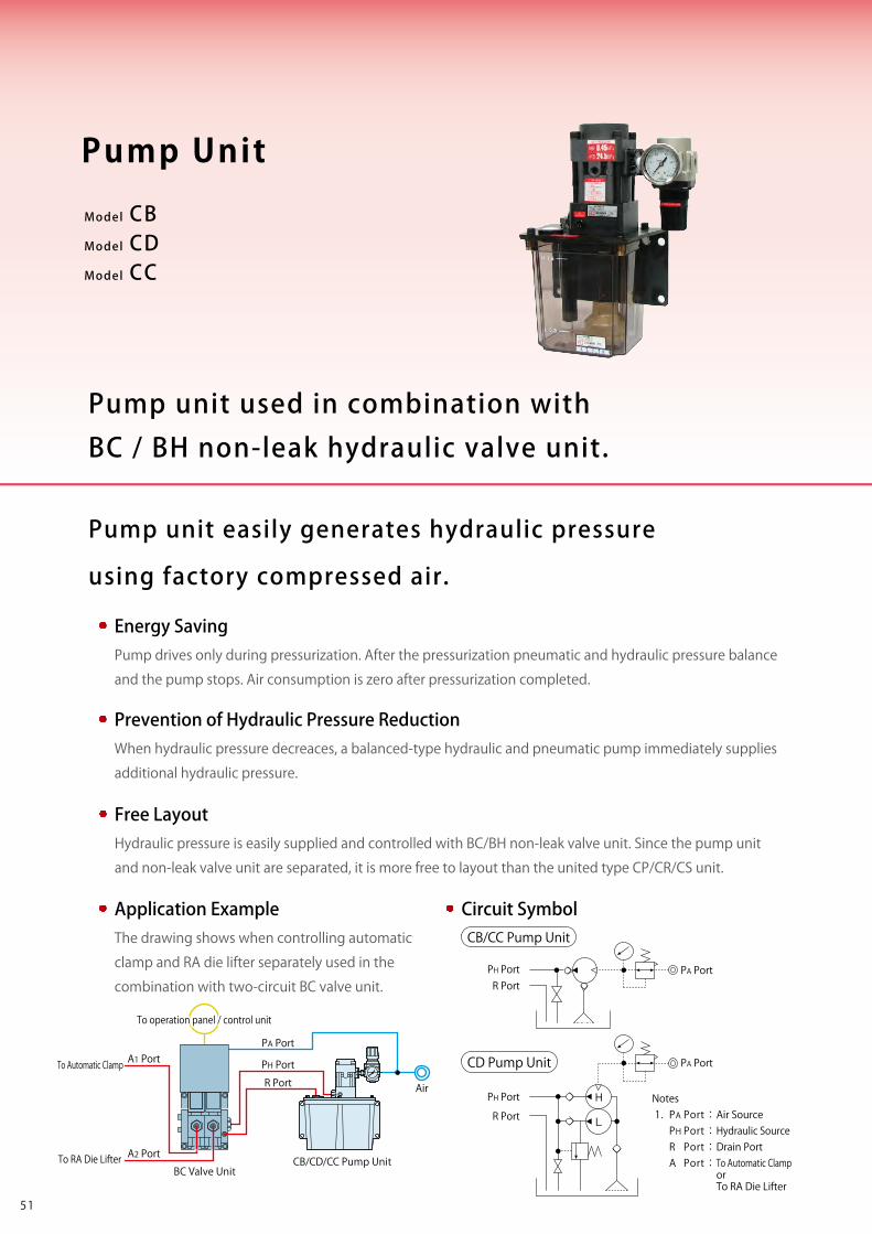
1 Pump (Amount of Discharge Oil)
B : Pump AB7000-0 (Standard Flow Rate / Compact)
D : Pump AD7300-0 (Large Flow Rate)
C : Pump AC7001-0 (Large Flow Rate)
2 : 2ℓ (Actual amount for use 1.1ℓ)※1
5 : 5ℓ (Actual amount for use 3.1ℓ)
2 Tank Capacity
3 Working Pressure Code
Pump Performance Curve
0
5
10
15
20
25
30
0 0.4 0.8 1.2 1.6 2.0 2.4 2.8 3.2 3.6 4.0
Amount of Discharge Oil (ℓ/min)
Discharge Hydraulic Pressure PH (MPa)
D : AD7300-0B : AB7000-0
C : AC7001-0
Notes 1. If viscosity of hydraulic oil is higher than listed on Hydraulic Fluid List (ISO-VG-32 or equivalnt), action time will be longer. 2. If using at low temperature action time will be longer because of high viscosity of hydraulic oil. 3. Be sure to set an automatic drain air filter when air contains a large amount of moisture, or air supplying pipe is located at the end. 4. When setting a pressure gauge to hydraulic circuit, install a damper or use an oil filled (glycerin) pressure gauge in order to prevent damage caused by pressure surging. 5. Provide enough space at the bottom of the unit to compensate for hydraulic oil change. (Tank cleaning and suction strainer tightening becomes easier.) 6. This product is not suitable for continuous operation (circulation / open circuit). Please use it for a closed circuit. 7. If using it with hydraulic valve on the market, pump does not stop due to internal leak, and pump life will be shortened. Please use Kosmek valve.
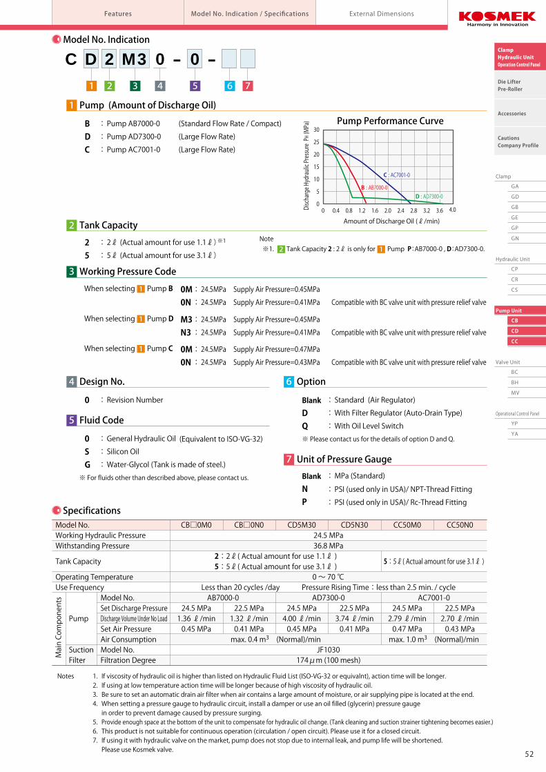
SpecificationsModel No.Working Hydraulic PressureWithstanding Pressure
Tank Capacity
Operating TemperatureUse Frequency
Pump
Suction Filter
Model No.Set Discharge PressureDischarge Volume Under No LoadSet Air PressureAir ConsumptionModel No.Filtration Degree
CB□0M0
24.5 MPa1.36 ℓ/min0.45 MPa
CB□0N0
22.5 MPa1.32 ℓ/min0.41 MPa
CC50M0
24.5 MPa2.79 ℓ/min0.47 MPa
CC50N0
22.5 MPa2.70 ℓ/min0.43 MPa
CD5M30
24.5 MPa4.00 ℓ/min0.45 MPa
CD5N30
22.5 MPa3.74 ℓ/min0.41 MPa
24.5 MPa36.8 MPa
0 ~ 70 ℃Less than 20 cycles /day Pressure Rising Time:less than 2.5 min. / cycle
AD7300-0
JF1030174μm (100 mesh)
5:5ℓ( Actual amount for use 3.1ℓ )
AB7000-0
2:2ℓ( Actual amount for use 1.1ℓ )5:5ℓ( Actual amount for use 3.1ℓ )
max. 0.4 m3 (Normal)/min
AC7001-0
max. 1.0 m3 (Normal)/min
PH Port
R Port
PA Port
H
L
Note ※1. Tank Capacity 2 : 2ℓ is only for Pump P:AB7000-0 , D:AD7300-0.2 1
※ For fluids other than described above, please contact us.
0 : General Hydraulic Oil (Equivalent to ISO-VG-32)S : Silicon OilG : Water-Glycol (Tank is made of steel.)
Blank : MPa (Standard)
N : PSI (used only in USA)/ NPT-Thread Fitting
P : PSI (used only in USA)/ Rc-Thread Fitting
Main Components
To operation panel / control unit
5251
GA
GD
GB
GE
GP
GN
CP
CR
CS
CB
CD
CC
BC
BH
MV
YP
YA
Clamp
Hydraulic Unit
Pump Unit
Valve Unit
Operational Control Panel
ClampHydraulic UnitOperation Control Panel
Die LifterPre-Roller
Accessories
CautionsCompany Profile
Features Model No. Indication / Specifications External Dimensions
Pump unit used in combination with BC / BH non-leak hydraulic valve unit.
Pump Unit
Model CBModel CDModel CC
Model No. Indication
321 65 74
C D 2 M3 0 - 0 -
4 Design No.
0 : Revision Number
6 Option
Blank : Standard (Air Regulator)
D : With Filter Regulator (Auto-Drain Type)
Q : With Oil Level Switch
7 Unit of Pressure Gauge
5 Fluid Code
※ Please contact us for the details of option D and Q.
0M : 24.5MPa Supply Air Pressure=0.45MPa 0N : 24.5MPa Supply Air Pressure=0.41MPa Compatible with BC valve unit with pressure relief valve
When selecting Pump B 1
0M : 24.5MPa Supply Air Pressure=0.47MPa 0N : 24.5MPa Supply Air Pressure=0.43MPa Compatible with BC valve unit with pressure relief valve
When selecting Pump C 1
M3 : 24.5MPa Supply Air Pressure=0.45MPa N3 : 24.5MPa Supply Air Pressure=0.41MPa Compatible with BC valve unit with pressure relief valve
When selecting Pump D 1
Pump unit easily generates hydraulic pressure
using factory compressed air.
CB/CD/CC Pump Unit
PH PortR Port
PA Port
CB/CC Pump Unit
CD Pump Unit
BC Valve Unit
Application ExampleThe drawing shows when controlling automatic
clamp and RA die lifter separately used in the
combination with two-circuit BC valve unit.
Circuit Symbol
Free LayoutHydraulic pressure is easily supplied and controlled with BC/BH non-leak valve unit. Since the pump unit
and non-leak valve unit are separated, it is more free to layout than the united type CP/CR/CS unit.
Prevention of Hydraulic Pressure ReductionWhen hydraulic pressure decreaces, a balanced-type hydraulic and pneumatic pump immediately supplies
additional hydraulic pressure.
Energy SavingPump drives only during pressurization. After the pressurization pneumatic and hydraulic pressure balance
and the pump stops. Air consumption is zero after pressurization completed.
To Automatic Clamp
Air
To RA Die Lifter
PA PortA1 Port
A2 Port
R Port
PH Port
Notes 1. PA Port : Air Source PH Port : Hydraulic Source R Port : Drain Port A Port : To Automatic Clamp or To RA Die Lifter
1 Pump (Amount of Discharge Oil)
B : Pump AB7000-0 (Standard Flow Rate / Compact)
D : Pump AD7300-0 (Large Flow Rate)
C : Pump AC7001-0 (Large Flow Rate)
2 : 2ℓ (Actual amount for use 1.1ℓ)※1
5 : 5ℓ (Actual amount for use 3.1ℓ)
2 Tank Capacity
3 Working Pressure Code
Pump Performance Curve
0
5
10
15
20
25
30
0 0.4 0.8 1.2 1.6 2.0 2.4 2.8 3.2 3.6 4.0
Amount of Discharge Oil (ℓ/min)
Discharge Hydraulic Pressure PH (MPa)
D : AD7300-0B : AB7000-0
C : AC7001-0
Notes 1. If viscosity of hydraulic oil is higher than listed on Hydraulic Fluid List (ISO-VG-32 or equivalnt), action time will be longer. 2. If using at low temperature action time will be longer because of high viscosity of hydraulic oil. 3. Be sure to set an automatic drain air filter when air contains a large amount of moisture, or air supplying pipe is located at the end. 4. When setting a pressure gauge to hydraulic circuit, install a damper or use an oil filled (glycerin) pressure gauge in order to prevent damage caused by pressure surging. 5. Provide enough space at the bottom of the unit to compensate for hydraulic oil change. (Tank cleaning and suction strainer tightening becomes easier.) 6. This product is not suitable for continuous operation (circulation / open circuit). Please use it for a closed circuit. 7. If using it with hydraulic valve on the market, pump does not stop due to internal leak, and pump life will be shortened. Please use Kosmek valve.
SpecificationsModel No.Working Hydraulic PressureWithstanding Pressure
Tank Capacity
Operating TemperatureUse Frequency
Pump
Suction Filter
Model No.Set Discharge PressureDischarge Volume Under No LoadSet Air PressureAir ConsumptionModel No.Filtration Degree
CB□0M0
24.5 MPa1.36 ℓ/min0.45 MPa
CB□0N0
22.5 MPa1.32 ℓ/min0.41 MPa
CC50M0
24.5 MPa2.79 ℓ/min0.47 MPa
CC50N0
22.5 MPa2.70 ℓ/min0.43 MPa
CD5M30
24.5 MPa4.00 ℓ/min0.45 MPa
CD5N30
22.5 MPa3.74 ℓ/min0.41 MPa
24.5 MPa36.8 MPa
0 ~ 70 ℃Less than 20 cycles /day Pressure Rising Time:less than 2.5 min. / cycle
AD7300-0
JF1030174μm (100 mesh)
5:5ℓ( Actual amount for use 3.1ℓ )
AB7000-0
2:2ℓ( Actual amount for use 1.1ℓ )5:5ℓ( Actual amount for use 3.1ℓ )
max. 0.4 m3 (Normal)/min
AC7001-0
max. 1.0 m3 (Normal)/min
PH Port
R Port
PA Port
H
L
Note ※1. Tank Capacity 2 : 2ℓ is only for Pump P:AB7000-0 , D:AD7300-0.2 1
※ For fluids other than described above, please contact us.
0 : General Hydraulic Oil (Equivalent to ISO-VG-32)S : Silicon OilG : Water-Glycol (Tank is made of steel.)
Blank : MPa (Standard)
N : PSI (used only in USA)/ NPT-Thread Fitting
P : PSI (used only in USA)/ Rc-Thread Fitting
Main Components
To operation panel / control unit
5251
GA
GD
GB
GE
GP
GN
CP
CR
CS
CB
CD
CC
BC
BH
MV
YP
YA
Clamp
Hydraulic Unit
Pump Unit
Valve Unit
Operational Control Panel
ClampHydraulic UnitOperation Control Panel
Die LifterPre-Roller
Accessories
CautionsCompany Profile
Pump Unit model CB/CD/CC Features Model No. Indication / Specifications External Dimensions
OIL
H 1.4
L 0.3
230
44.5 48 65
AB Pump
Air Bleed Valve
Air Pressure GaugeAir Regulator
Oil Supply Port
55
75
151
10
4.5
161
166
155175
2ℓ Tank
10
8050
287
239.5
130
42
138
R PortRc1/4 Thread
PA PortRc1/4 Thread
4-M8 Bolt Hole4-M8×16 BoltWith JIS Spring Washer (Included)
PH PortRc1/4 Thread
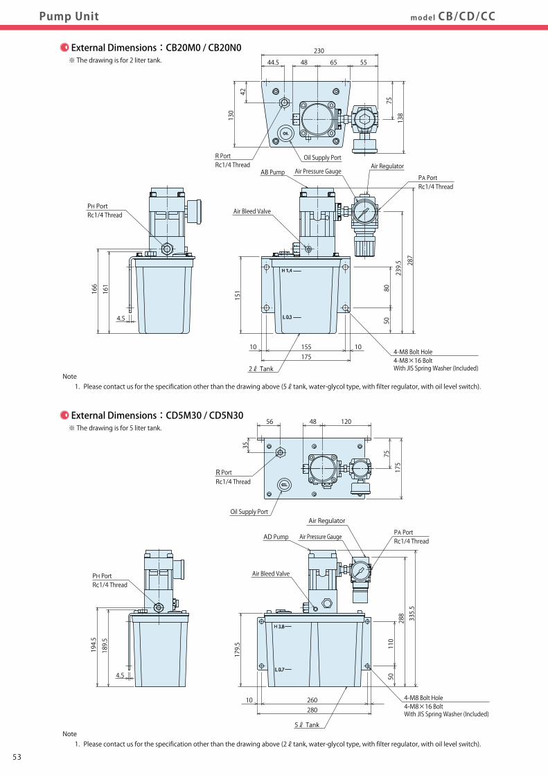
Note 1. Please contact us for the specification other than the drawing above (5ℓtank, water-glycol type, with filter regulator, with oil level switch).
※ The drawing is for 2 liter tank.
External Dimensions:CB20M0 / CB20N0
H 3.8
L 0.7
OIL
84 163 33
AC Pump
Air Bleed Valve
Air Pressure Gauge
134
203
10
6
260280
5ℓ Tank
10
110
50
409
321
159
88
174
PA PortRc1/2 Thread
4-M8 Bolt Hole4-M8×20 BoltWith JIS Spring Washer (Included)
PH PortRc1/4 Thread
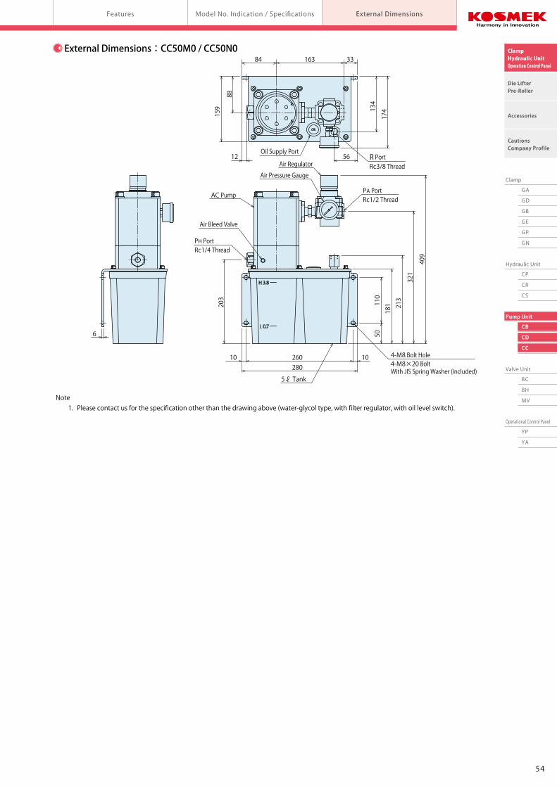
Note 1. Please contact us for the specification other than the drawing above (water-glycol type, with filter regulator, with oil level switch).
181 213
Air RegulatorR PortRc3/8 Thread
Oil Supply Port5612
External Dimensions:CC50M0 / CC50N0
4.5
189.5
194.5
※ The drawing is for 5 liter tank.
H 3.8
L 0.7
Note 1. Please contact us for the specification other than the drawing above (2ℓtank, water-glycol type, with filter regulator, with oil level switch).
AD Pump
Air Bleed Valve
Air Pressure Gauge
179.5
10 260280
5ℓ Tank
110
50
PA PortRc1/4 Thread
4-M8 Bolt Hole4-M8×16 BoltWith JIS Spring Washer (Included)
PH PortRc1/4 Thread
288335.5
Air Regulator
56 48 120
75
35
175
R PortRc1/4 Thread
Oil Supply Port
External Dimensions:CD5M30 / CD5N30
5453
GA
GD
GB
GE
GP
GN
CP
CR
CS
CB
CD
CC
BC
BH
MV
YP
YA
Clamp
Hydraulic Unit
Pump Unit
Valve Unit
Operational Control Panel
ClampHydraulic UnitOperation Control Panel
Die LifterPre-Roller
Accessories
CautionsCompany Profile
Pump Unit model CB/CD/CC Features Model No. Indication / Specifications External Dimensions
OIL
H 1.4
L 0.3
230
44.5 48 65
AB Pump
Air Bleed Valve
Air Pressure GaugeAir Regulator
Oil Supply Port
55
75
151
10
4.5
161
166
155175
2ℓ Tank
10
8050
287
239.5
130
42
138
R PortRc1/4 Thread
PA PortRc1/4 Thread
4-M8 Bolt Hole4-M8×16 BoltWith JIS Spring Washer (Included)
PH PortRc1/4 Thread
Note 1. Please contact us for the specification other than the drawing above (5ℓtank, water-glycol type, with filter regulator, with oil level switch).
※ The drawing is for 2 liter tank.
External Dimensions:CB20M0 / CB20N0
H 3.8
L 0.7
OIL
84 163 33
AC Pump
Air Bleed Valve
Air Pressure Gauge
134
203
10
6
260280
5ℓ Tank
10
110
50
409
321
159
88
174
PA PortRc1/2 Thread
4-M8 Bolt Hole4-M8×20 BoltWith JIS Spring Washer (Included)
PH PortRc1/4 Thread
Note 1. Please contact us for the specification other than the drawing above (water-glycol type, with filter regulator, with oil level switch).
181 213
Air RegulatorR PortRc3/8 Thread
Oil Supply Port5612
External Dimensions:CC50M0 / CC50N0
4.5
189.5
194.5
※ The drawing is for 5 liter tank.
H 3.8
L 0.7
Note 1. Please contact us for the specification other than the drawing above (2ℓtank, water-glycol type, with filter regulator, with oil level switch).
AD Pump
Air Bleed Valve
Air Pressure Gauge
179.5
10 260280
5ℓ Tank
110
50
PA PortRc1/4 Thread
4-M8 Bolt Hole4-M8×16 BoltWith JIS Spring Washer (Included)
PH PortRc1/4 Thread
288335.5
Air Regulator
56 48 120
75
35
175
R PortRc1/4 Thread
Oil Supply Port
External Dimensions:CD5M30 / CD5N30
5453
Speed Control Circuit ofHydraulic Cylinder & Notes
Cautions
Notes on Installation(For Hydraulic Series)
Hydraulic Fluid List
Notes on Handling
Maintenance / Inspection
Warranty
Company Profile
Company Profile
Our Products
History
Sales Office
ClampHydraulic UnitOperation Control Panel
Die LifterPre-Roller
Accessories
CautionsCompany Profile
Notes on Installation(For Hydraulic Series) Hydraulic Fluid ListCautionsNotes on Installation(For Hydraulic Series)
Speed Control Circuit ofHydraulic Cylinder & Notes Maintenance / Inspection WarrantyNotes on HandlingHydraulic Fluid List
Cautions
● Notes on Installation (Cautions for Hydraulic Series)
1)Check the fluid to use
● Please use the appropriate fluid by referring to the Hydraulic Fluid List.
● If hydraulic oil with viscosity grade higher than ISO-VG-32 is used, action time would be longer. ● If using it at low temperature, action time will be longer because the viscosity of hydraulic oil becomes higher.
2)Procedure before piping
● The pipeline, piping connector and fixture circuits should be
cleaned by thorough flushing.
● The dust and cutting chips in the circuit may lead to fluid
leakage and malfunction.
● Our products except some valves are not equipped with
protective function to prevent dust and cutting chips going
into the hydraulic system and pipeline.
3)Applying sealing tape
● Wrap with tape 1 to 2 times following the screwing direction.
● Pieces of the sealing tape can lead to air leaks and malfunction.
● In order to prevent a foreign substance from going into
the product during piping, it should be carefully cleaned.
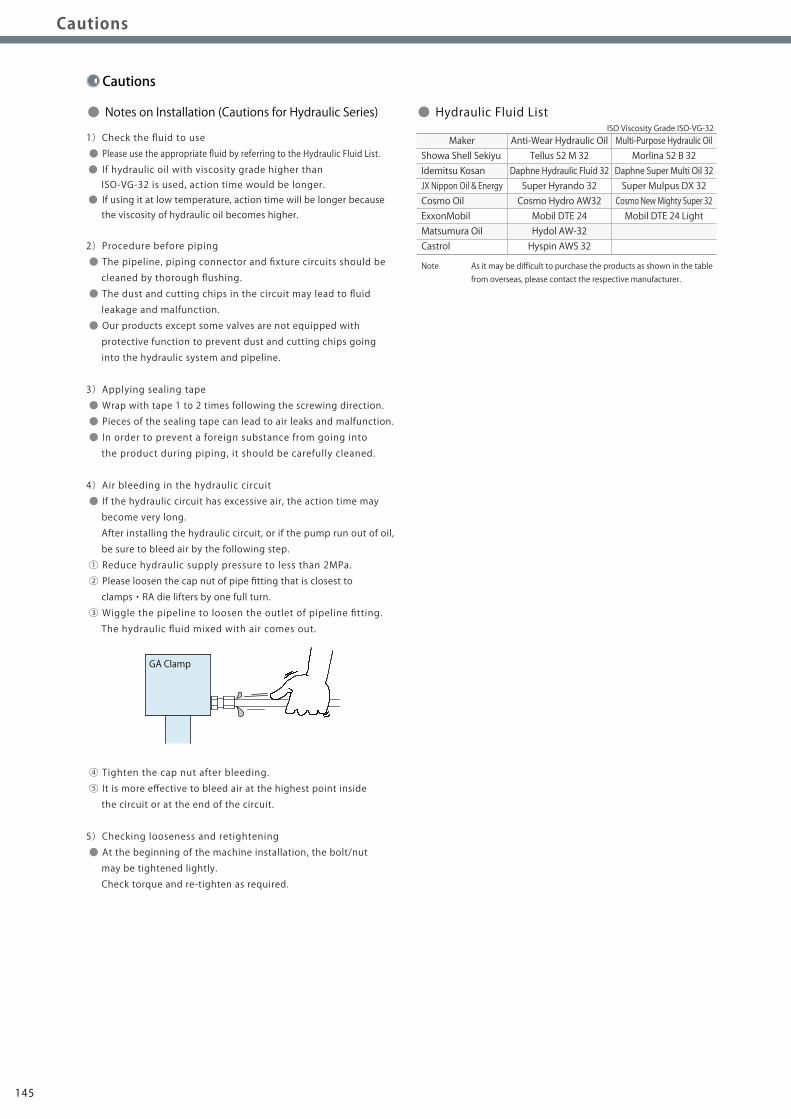
4)Air bleeding in the hydraulic circuit
● If the hydraulic circuit has excessive air, the action time may
become very long.
After installing the hydraulic circuit, or if the pump run out of oil,
be sure to bleed air by the following step.
① Reduce hydraulic supply pressure to less than 2MPa.
② Please loosen the cap nut of pipe fitting that is closest to
clamps・RA die lifters by one full turn.
③ Wiggle the pipeline to loosen the outlet of pipeline fitting.
The hydraulic fluid mixed with air comes out.
④ Tighten the cap nut after bleeding.
⑤ It is more effective to bleed air at the highest point inside
the circuit or at the end of the circuit.
5)Checking looseness and retightening
● At the beginning of the machine installation, the bolt/nut
may be tightened lightly.
Check torque and re-tighten as required.
GA Clamp
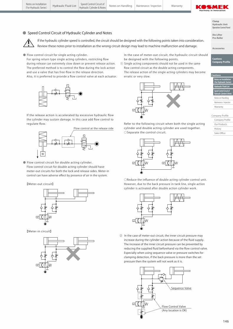
● Speed Control Circuit of Hydraulic Cylinder and Notes
● Flow control circuit for single acting cylinder. For spring return type single acting cylinders, restricting flow during release can extremely slow down or prevent release action. The preferred method is to control the flow during the lock action and use a valve that has free-flow in the release direction. Also, it is preferred to provide a flow control valve at each actuator.
If the release action is accelerated by excessive hydraulic flow the cylinder may sustain damage. In this case add flow control to regulate flow.
● Flow control circuit for double acting cylinder. Flow control circuit for double acting cylinder should have meter-out circuits for both the lock and release sides. Meter-in control can have adverse effect by presence of air in the system. 【Meter-out circuit】
【Meter-in circuit】
In the case of meter-out circuit, the hydraulic circuit should be designed with the following points. ① Single acting components should not be used in the same flow control circuit as the double acting components. The release action of the single acting cylinders may become erratic or very slow.
Refer to the following circuit when both the single acting cylinder and double acting cylinder are used together. ○Separate the control circuit.
○Reduce the influence of double acting cylinder control unit. However, due to the back pressure in tank line, single action cylinder is activated after double action cylinder work.
② In the case of meter-out circuit, the inner circuit pressure may increase during the cylinder action because of the fluid supply. The increase of the inner circuit pressure can be prevented by reducing the supplied fluid beforehand via the flow control valve. Especially when using sequence valve or pressure switches for clamping detection, if the back pressure is more than the set pressure then the system will not work as it is.
Flow Control Valve(Any location is OK)
Sequence Valve
If the hydraulic cylinder speed is controlled, the circuit should be designed with the following points taken into consideration.
Review these notes prior to installation as the wrong circuit design may lead to machine malfunction and damage.!
Flow control at the release side
W
● Hydraulic Fluid List
Showa Shell SekiyuIdemitsu KosanJX Nippon Oil & EnergyCosmo OilExxonMobilMatsumura OilCastrol
Maker Anti-Wear Hydraulic OilTellus S2 M 32
Daphne Hydraulic Fluid 32Super Hyrando 32Cosmo Hydro AW32Mobil DTE 24Hydol AW-32Hyspin AWS 32
Multi-Purpose Hydraulic OilMorlina S2 B 32
Daphne Super Multi Oil 32Super Mulpus DX 32Cosmo New Mighty Super 32Mobil DTE 24 Light
Note As it may be difficult to purchase the products as shown in the table from overseas, please contact the respective manufacturer.
ISO Viscosity Grade ISO-VG-32
146145
Speed Control Circuit ofHydraulic Cylinder & Notes
Cautions
Notes on Installation(For Hydraulic Series)
Hydraulic Fluid List
Notes on Handling
Maintenance / Inspection
Warranty
Company Profile
Company Profile
Our Products
History
Sales Office
ClampHydraulic UnitOperation Control Panel
Die LifterPre-Roller
Accessories
CautionsCompany Profile
Notes on Installation(For Hydraulic Series) Hydraulic Fluid ListCautionsNotes on Installation(For Hydraulic Series)
Speed Control Circuit ofHydraulic Cylinder & Notes Maintenance / Inspection WarrantyNotes on HandlingHydraulic Fluid List
Cautions
● Notes on Installation (Cautions for Hydraulic Series)
1)Check the fluid to use
● Please use the appropriate fluid by referring to the Hydraulic Fluid List.
● If hydraulic oil with viscosity grade higher than ISO-VG-32 is used, action time would be longer. ● If using it at low temperature, action time will be longer because the viscosity of hydraulic oil becomes higher.
2)Procedure before piping
● The pipeline, piping connector and fixture circuits should be
cleaned by thorough flushing.
● The dust and cutting chips in the circuit may lead to fluid
leakage and malfunction.
● Our products except some valves are not equipped with
protective function to prevent dust and cutting chips going
into the hydraulic system and pipeline.
3)Applying sealing tape
● Wrap with tape 1 to 2 times following the screwing direction.
● Pieces of the sealing tape can lead to air leaks and malfunction.
● In order to prevent a foreign substance from going into
the product during piping, it should be carefully cleaned.
4)Air bleeding in the hydraulic circuit
● If the hydraulic circuit has excessive air, the action time may
become very long.
After installing the hydraulic circuit, or if the pump run out of oil,
be sure to bleed air by the following step.
① Reduce hydraulic supply pressure to less than 2MPa.
② Please loosen the cap nut of pipe fitting that is closest to
clamps・RA die lifters by one full turn.
③ Wiggle the pipeline to loosen the outlet of pipeline fitting.
The hydraulic fluid mixed with air comes out.
④ Tighten the cap nut after bleeding.
⑤ It is more effective to bleed air at the highest point inside
the circuit or at the end of the circuit.
5)Checking looseness and retightening
● At the beginning of the machine installation, the bolt/nut
may be tightened lightly.
Check torque and re-tighten as required.
GA Clamp
● Speed Control Circuit of Hydraulic Cylinder and Notes
● Flow control circuit for single acting cylinder. For spring return type single acting cylinders, restricting flow during release can extremely slow down or prevent release action. The preferred method is to control the flow during the lock action and use a valve that has free-flow in the release direction. Also, it is preferred to provide a flow control valve at each actuator.
If the release action is accelerated by excessive hydraulic flow the cylinder may sustain damage. In this case add flow control to regulate flow.
● Flow control circuit for double acting cylinder. Flow control circuit for double acting cylinder should have meter-out circuits for both the lock and release sides. Meter-in control can have adverse effect by presence of air in the system. 【Meter-out circuit】
【Meter-in circuit】
In the case of meter-out circuit, the hydraulic circuit should be designed with the following points. ① Single acting components should not be used in the same flow control circuit as the double acting components. The release action of the single acting cylinders may become erratic or very slow.
Refer to the following circuit when both the single acting cylinder and double acting cylinder are used together. ○Separate the control circuit.
○Reduce the influence of double acting cylinder control unit. However, due to the back pressure in tank line, single action cylinder is activated after double action cylinder work.
② In the case of meter-out circuit, the inner circuit pressure may increase during the cylinder action because of the fluid supply. The increase of the inner circuit pressure can be prevented by reducing the supplied fluid beforehand via the flow control valve. Especially when using sequence valve or pressure switches for clamping detection, if the back pressure is more than the set pressure then the system will not work as it is.
Flow Control Valve(Any location is OK)
Sequence Valve
If the hydraulic cylinder speed is controlled, the circuit should be designed with the following points taken into consideration.
Review these notes prior to installation as the wrong circuit design may lead to machine malfunction and damage.!
Flow control at the release side
W
● Hydraulic Fluid List
Showa Shell SekiyuIdemitsu KosanJX Nippon Oil & EnergyCosmo OilExxonMobilMatsumura OilCastrol
Maker Anti-Wear Hydraulic OilTellus S2 M 32
Daphne Hydraulic Fluid 32Super Hyrando 32Cosmo Hydro AW32Mobil DTE 24Hydol AW-32Hyspin AWS 32
Multi-Purpose Hydraulic OilMorlina S2 B 32
Daphne Super Multi Oil 32Super Mulpus DX 32Cosmo New Mighty Super 32Mobil DTE 24 Light
Note As it may be difficult to purchase the products as shown in the table from overseas, please contact the respective manufacturer.
ISO Viscosity Grade ISO-VG-32
146145
Speed Control Circuit ofHydraulic Cylinder & Notes
Notes on Installation(For Hydraulic Series)
Hydraulic Fluid List
Notes on Handling
Maintenance / Inspection
Warranty
Cautions
Company Profile
ClampHydraulic UnitOperation Control Panel
Die LifterPre-Roller
Accessories
CautionsCompany Profile
Company Profile
Our Products
History
Sales Office
CautionsNotes on Installation(For hydraulic series)
Speed Control Circuit ofHydraulic Cylinder & Notes Maintenance / Inspection WarrantyNotes on HandlingHydraulic Fluid List
Cautions
1)Warranty period
● The product warranty period is 18 months from shipment from
our factory or 12 months from initial use, whichever is earlier.
2)Warranty scope
● If the product is damaged or malfunctions during the warranty
period due to faulty design, materials or workmanship, we will
replace or repair the defective part at our expense.
Defects or failures caused by the following are not covered.
① If the stipulated maintenance and inspection are not carried out.
② If the product is used while it is not suitable for use based on
operator judgment, resulting in defect.
③ If it is used or handled in inappropriate way by the operator.
(Including damage caused by the misconduct of a third party.)
④ If the defect is caused by reasons other than our responsibility.
⑤ If repair or modifications are carried out by anyone other than Kosmek,
or without our approval and confirmation, it will void warranty.
⑥ Defects caused by natural disasters or calamities not attributable to
our company.
⑦ Parts expenses or replacement expenses due to parts consumption
and deterioration.
(Such as rubber, plastic, seal material and some electric components.)
Damages from direct result of a product defect shall be
excluded from the warranty.
● Warranty
1)It should be handled by qualified personnel.
● The hydraulic machine / air compressor should be handled
and maintained by qualified personnel.
2)Do not handle or remove the machine unless
the safety is ensured.
① The machine and equipment can only be inspected or prepared
when it is confirmed that the preventive devices are in place.
② Before the machine is removed, make sure that the above-mentioned
safety measures are in place. Shut off the air of hydraulic source
and make sure no pressure exists in the hydraulic and air circuit.
③ After stopping the machine, do not remove until the temperature
cools down.
④ Make sure there is no abnormality in the bolts and respective parts
before restarting the machine or equipment.
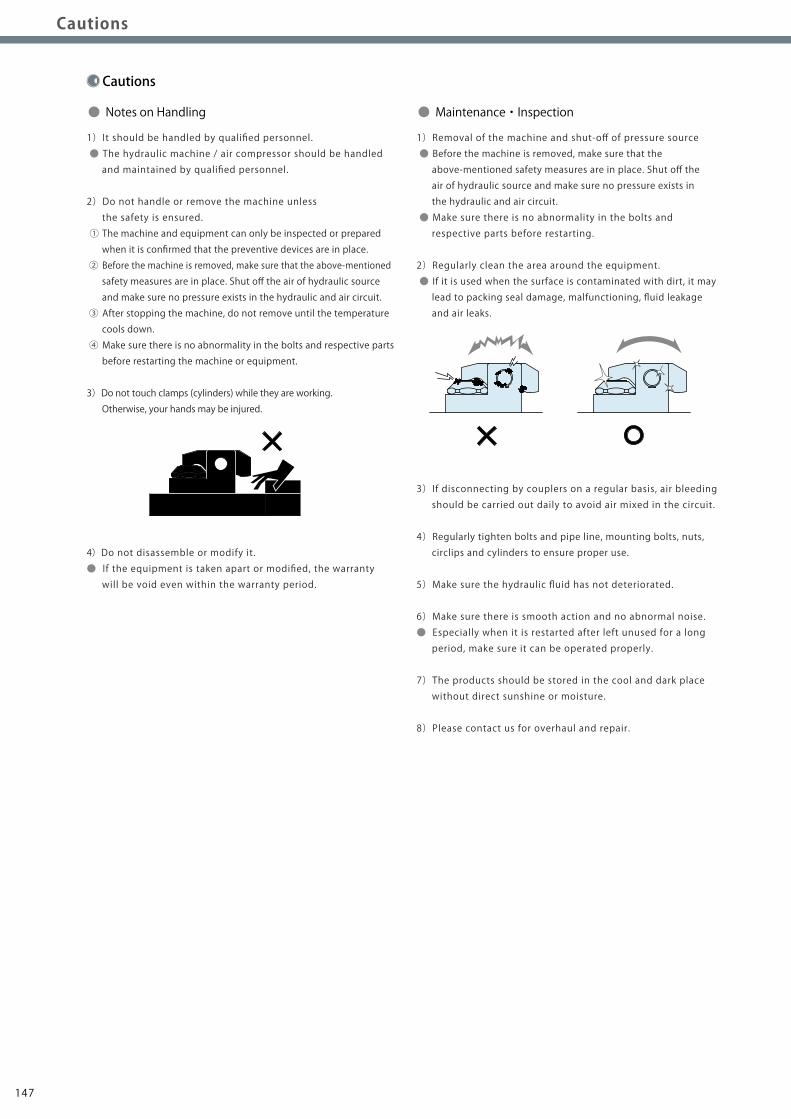
3)Do not touch clamps (cylinders) while they are working.
Otherwise, your hands may be injured.
4)Do not disassemble or modify it.
● If the equipment is taken apart or modified, the warranty
will be void even within the warranty period.
1)Removal of the machine and shut-off of pressure source
● Before the machine is removed, make sure that the
above-mentioned safety measures are in place. Shut off the
air of hydraulic source and make sure no pressure exists in
the hydraulic and air circuit.
● Make sure there is no abnormality in the bolts and
respective parts before restarting.
2)Regularly clean the area around the equipment.
● If it is used when the surface is contaminated with dirt, it may
lead to packing seal damage, malfunctioning, fluid leakage
and air leaks.
3)If disconnecting by couplers on a regular basis, air bleeding
should be carried out daily to avoid air mixed in the circuit.
4)Regularly tighten bolts and pipe line, mounting bolts, nuts,
circlips and cylinders to ensure proper use.
5)Make sure the hydraulic fluid has not deteriorated.
6)Make sure there is smooth action and no abnormal noise.
● Especially when it is restarted after left unused for a long
period, make sure it can be operated properly.
7)The products should be stored in the cool and dark place
without direct sunshine or moisture.
8)Please contact us for overhaul and repair.
● Notes on Handling ● Maintenance・Inspection
148147
Speed Control Circuit ofHydraulic Cylinder & Notes
Notes on Installation(For Hydraulic Series)
Hydraulic Fluid List
Notes on Handling
Maintenance / Inspection
Warranty
Cautions
Company Profile
ClampHydraulic UnitOperation Control Panel
Die LifterPre-Roller
Accessories
CautionsCompany Profile
Company Profile
Our Products
History
Sales Office
CautionsNotes on Installation(For hydraulic series)
Speed Control Circuit ofHydraulic Cylinder & Notes Maintenance / Inspection WarrantyNotes on HandlingHydraulic Fluid List
Cautions
1)Warranty period
● The product warranty period is 18 months from shipment from
our factory or 12 months from initial use, whichever is earlier.
2)Warranty scope
● If the product is damaged or malfunctions during the warranty
period due to faulty design, materials or workmanship, we will
replace or repair the defective part at our expense.
Defects or failures caused by the following are not covered.
① If the stipulated maintenance and inspection are not carried out.
② If the product is used while it is not suitable for use based on
operator judgment, resulting in defect.
③ If it is used or handled in inappropriate way by the operator.
(Including damage caused by the misconduct of a third party.)
④ If the defect is caused by reasons other than our responsibility.
⑤ If repair or modifications are carried out by anyone other than Kosmek,
or without our approval and confirmation, it will void warranty.
⑥ Defects caused by natural disasters or calamities not attributable to
our company.
⑦ Parts expenses or replacement expenses due to parts consumption
and deterioration.
(Such as rubber, plastic, seal material and some electric components.)
Damages from direct result of a product defect shall be
excluded from the warranty.
● Warranty
1)It should be handled by qualified personnel.
● The hydraulic machine / air compressor should be handled
and maintained by qualified personnel.
2)Do not handle or remove the machine unless
the safety is ensured.
① The machine and equipment can only be inspected or prepared
when it is confirmed that the preventive devices are in place.
② Before the machine is removed, make sure that the above-mentioned
safety measures are in place. Shut off the air of hydraulic source
and make sure no pressure exists in the hydraulic and air circuit.
③ After stopping the machine, do not remove until the temperature
cools down.
④ Make sure there is no abnormality in the bolts and respective parts
before restarting the machine or equipment.
3)Do not touch clamps (cylinders) while they are working.
Otherwise, your hands may be injured.
4)Do not disassemble or modify it.
● If the equipment is taken apart or modified, the warranty
will be void even within the warranty period.
1)Removal of the machine and shut-off of pressure source
● Before the machine is removed, make sure that the
above-mentioned safety measures are in place. Shut off the
air of hydraulic source and make sure no pressure exists in
the hydraulic and air circuit.
● Make sure there is no abnormality in the bolts and
respective parts before restarting.
2)Regularly clean the area around the equipment.
● If it is used when the surface is contaminated with dirt, it may
lead to packing seal damage, malfunctioning, fluid leakage
and air leaks.
3)If disconnecting by couplers on a regular basis, air bleeding
should be carried out daily to avoid air mixed in the circuit.
4)Regularly tighten bolts and pipe line, mounting bolts, nuts,
circlips and cylinders to ensure proper use.
5)Make sure the hydraulic fluid has not deteriorated.
6)Make sure there is smooth action and no abnormal noise.
● Especially when it is restarted after left unused for a long
period, make sure it can be operated properly.
7)The products should be stored in the cool and dark place
without direct sunshine or moisture.
8)Please contact us for overhaul and repair.
● Notes on Handling ● Maintenance・Inspection
148147
Company Profile
Sales Offices Across the World
Sales Office
Sales Offices in Japan
Kanto Office
Chubu Office
Kyusyu Office
JapanOverseas Sales
TEL. +81-78-991-5162 FAX. +81-78-991-8787KOSMEK LTD. 1-5 , 2-chome , Murotani , Nishi-ku , Kobe-city , Hyogo , 651-2241 , Japan 〒651-2241 兵庫県神戸市西区室谷2丁目1番5号
ChinaKOSMEK(CHINA)LTD.
TEL. +86-21-54253000 FAX. +86-21-5425370921/F, Orient International Technology Building, No.58, Xiangchen Rd, Pudong Shanghai 200122., P.R.China中国上海市浦东新区向城路58号东方国际科技大厦21F室 200122
USAKOSMEK(USA)LTD.
TEL. +1-630-241-3465 FAX. +1-630-241-38341441 Branding Avenue, Suite 110, Downers Grove, IL 60515 USA
ThailandThailand Representative Office
TEL. +66-2-715-3450 FAX. +66-2-715-3453 67 Soi 58, RAMA 9 Rd., Suanluang, Suanluang, Bangkok 10250, Thailand
考世美(上海)貿易有限公司
Taiwan
Full Life Trading Co., Ltd.
TEL. +886-2-82261860 FAX. +886-2-8226189016F-4, No.2, Jian Ba Rd., Zhonghe District, New Taipei City Taiwan 23511台湾新北市中和區建八路2號 16F-4(遠東世紀廣場) 盈生貿易有限公司
(Taiwan Exclusive Distributors)
Philippines
G.E.T. Inc, Phil.
TEL.+63-2-310-7286 FAX. +63-2-310-7286Victoria Wave Special Economic Zone Mt. Apo Building, Brgy. 186, North Caloocan City, Metro Manila, Philippines 1427
(Philippines Exclusive Distributors)
Indonesia
P.T PANDU HYDRO PNEUMATICS
TEL.+62-21-5818632 FAX. +62-21-5814857Ruko Green Garden Blok Z-Ⅱ No.51 Rt.005 Rw.008 Kedoya Utara-Kebon Jeruk Jakarta Barat 11520 Indonesia
(Indonesia Exclusive Distributors)
Europe
KOS-MECH GmbH
TEL. +43-463-287587-10 FAX. +43-463-287587-20Schleppeplatz 2 9020 Klagenfurt Austria
(Europe Exclusive Distributors)
Head OfficeKansai OfficeOverseas Sales
TEL. +81-78-991-5162 FAX. +81-78-991-8787KOSMEK LTD. 1-5, 2-chome , Murotani , Nishi-ku , Kobe-city , Hyogo , 651-2241 , Japan 〒651-2241 兵庫県神戸市西区室谷2丁目1番5号
TEL. +81-48-652-8839 FAX. +81-48-652-8828KOSMEK LTD. 81, 4-chome , Onari-cho , Kita-ku , Saitama City , Saitama , 331-0815 , Japan 〒331-0815 埼玉県さいたま市北区大成町4丁目81番地
TEL. +81-566-74-8778 FAX. +81-566-74-8808KOSMEK LTD. 10-1 , 2-chome , Misono-cho , Anjo City , Aichi , 446-0076 , Japan 〒446-0076 愛知県安城市美園町2丁目10番地1
TEL. +81-92-433-0424 FAX. +81-92-433-0426KOSMEK LTD. 8-10-101 , 1-chome , Kamimuta , Hakata-ku , Fukuoka City , Fukuoka , 812-0006 , Japan 〒812-0006 福岡県福岡市博多区上牟田1丁目8-10-101
■QUICK MOLD CHANGE SYSTEMS
Automatic clamping systems have reduced mold change
times and increased production efficiency for plastics
manufacturers in a multitude of industries.
We offer a variety of different clamping options, including
hydraulically powered clamps, pneumatic clamps with a
force multiplying mechanism, and magnetic clamping systems.
■QUICK DIE CHANGE SYSTEMS
Kosmek Quick Die Change Systems are a cost effective way
to improve the working environment, allow diversified and
small-lot production, and reduce press down time.
Available for a wide range of machines; from large size
transfer-presses to smaller high speed presses.
■DIECAST CLAMPING SYSTEMS
Kosmek Diecast Clamping Systems (KDCS) enable stable die
clamping for die casting and magnesium molding machines
that are subjected to severe conditions caused by
exposure to mold release agents and high temperature.
■Product Line-UpWe manufacture a wide range of clamping systems and components. Feel free to contact us.
■KOSMEK WORK CLAMPING SYSTEMS
Our clamping system enables boltless automation
making loading and unloading workpieces easier.
The non-leak valve enables the use of hydraulic source
and fixtures in a disconnected condition after locking
(clamping action).
● FOR FURTHER INFORMATION ON UNLISTED SPECIFICATIONS AND SIZES, PLEASE CALL US.● SPECIFICATIONS IN THIS LEAFLET ARE SUBJECT TO CHANGE WITHOUT NOTICE.
JQA-QMA10823KOSMEK HEAD OFFICE
162161