Embed Size (px)
Citation preview
Cladding Attachment Over Thick Exterior Rigid Insulation
Peter Baker, P.Eng.
BA Webinar: High Performance Enclosure Strategies: Part II, New Construction
Cladding Attachment Over Thick Exterior Rigid Insulation
Background
Industry trend to using exterior rigid insulation Increased thermal value Condensation resistance Increased air tightness (possibly) Increased rainwater management (possibly)
Need to develop a means to attach cladding over thick layers of exterior insulation that can meet the following requirements: Provides good thermal performance Low cost Easy to construct/install (low cost)
Cladding Attachment Over Thick Exterior Rigid Insulation
Background Current Building Code does provide prescriptive means to
attach cladding over exterior insulation Table R704.3 – Note v: Minimum nail length must accommodate
sheathing and penetrate framing a minimum 1 ½ inches.
Current pneumatic nailers have maximum fastener lengths of 3” to 3.5” which limits insulation thicknesses to 1.5” max 3.5” fastener, ¼” to ½” siding, 1 ½” embedment (3.5-0.5-1.5 = 1.5”
max insulation)
Therefore, for insulation greater than 1.5” direct attachment of cladding though the insulation back to the structure is often not practical
Cladding Attachment Over Thick Exterior Rigid Insulation
Background Current Building Codes do not provide any
prescriptive means to use a secondary support structure for cladding attachment
Without prescriptive code provisions, cladding support systems need to be designed (historically done with poor thermal performance and high cost) or pre-engineered solutions need to be used (generally higher cost)
Cladding Attachment Over Thick Exterior Rigid Insulation
Cladding Support System:Direct Attachment Through Insulation
Cladding Attachment Over Thick Exterior Rigid Insulation
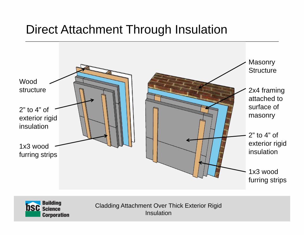
Direct Attachment Through Insulation
Wood structure
2” to 4” of exterior rigid insulation
1x3 wood furring strips
Masonry Structure
2x4 framing attached to surface of masonry
2” to 4” of exterior rigid insulation
1x3 wood furring strips
Cladding Attachment Over Thick Exterior Rigid Insulation
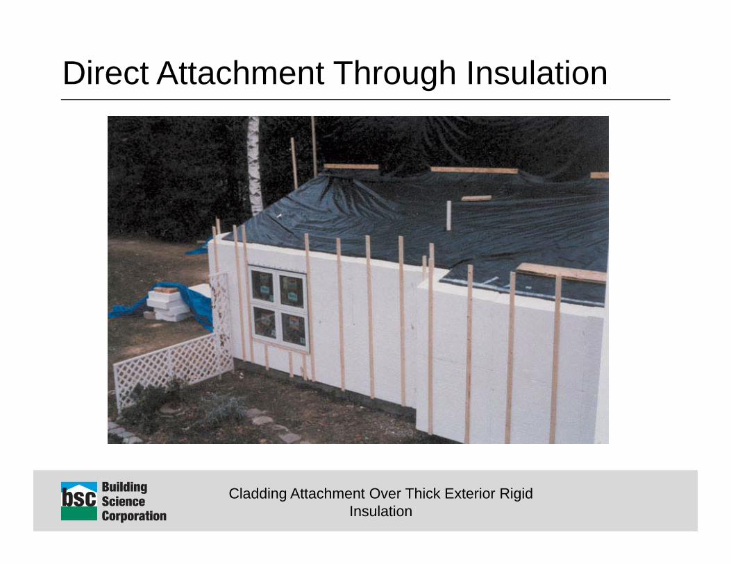
Direct Attachment Through Insulation
Cladding Attachment Over Thick Exterior Rigid Insulation
Direct Attachment Through Insulation Lots of practical experience with this approach for
lightweight cladding systems over thick layers of insulation (several decades).
Approach has demonstrated very good long term performance
High resistance from industry Compression resistance of insulation Long term creep
Cladding Attachment Over Thick Exterior Rigid Insulation
“Myths” “Does the insulation crush under load?” YES! Loading a system until failure (500lbs to 1000lbs or more
per screw fastener) will crush most rigid insulations
…..Unfortunately that is the wrong question
Cladding Attachment Over Thick Exterior Rigid Insulation
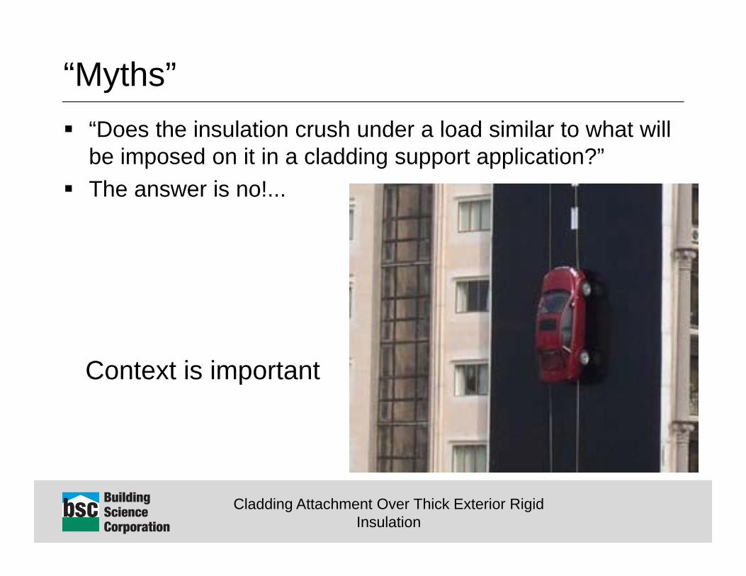
“Myths” “Does the insulation crush under a load similar to what will
be imposed on it in a cladding support application?” The answer is no!...
Context is important
Cladding Attachment Over Thick Exterior Rigid Insulation
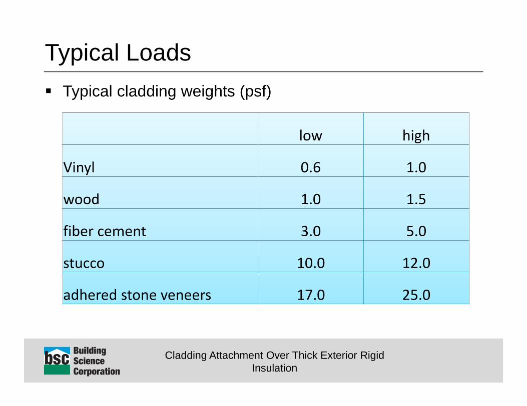
Typical Loads Typical cladding weights (psf)
low high
Vinyl 0.6 1.0
wood 1.0 1.5
fiber cement 3.0 5.0
stucco 10.0 12.0
adhered stone veneers 17.0 25.0
Cladding Attachment Over Thick Exterior Rigid Insulation
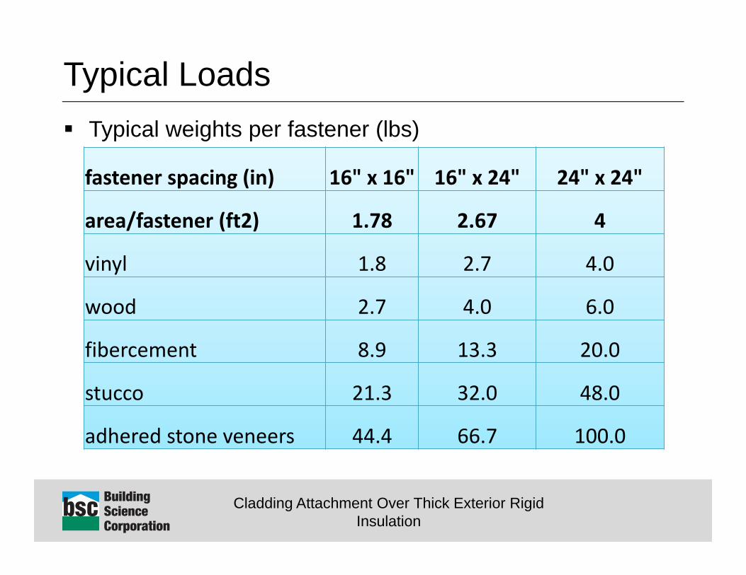
Typical Loads Typical weights per fastener (lbs)
fastener spacing (in) 16" x 16" 16" x 24" 24" x 24"
area/fastener (ft2) 1.78 2.67 4
vinyl 1.8 2.7 4.0
wood 2.7 4.0 6.0
fibercement 8.9 13.3 20.0
stucco 21.3 32.0 48.0
adhered stone veneers 44.4 66.7 100.0
Cladding Attachment Over Thick Exterior Rigid Insulation
Design Criteria Acceptable deflection not ultimate capacity governs What is acceptable deflection?
Movement a cladding system can accommodate without physical damage or exceeding aesthetic tolerances
Proposed limit of 1/16” vertical deflection
Cladding Attachment Over Thick Exterior Rigid Insulation
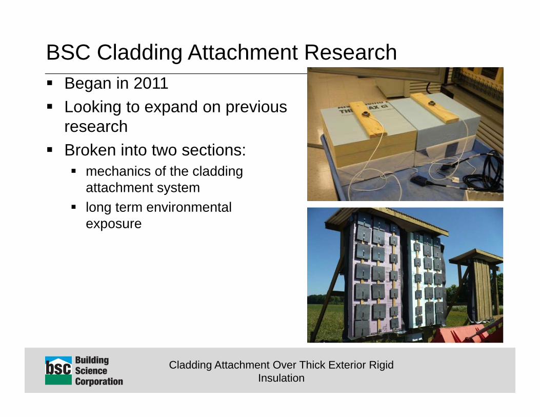
BSC Cladding Attachment Research Began in 2011 Looking to expand on previous
research Broken into two sections:
mechanics of the cladding attachment system
long term environmental exposure
Cladding Attachment Over Thick Exterior Rigid Insulation
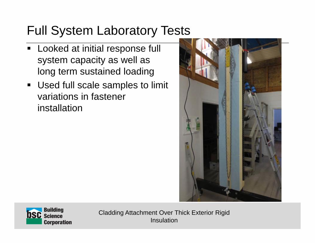
Full System Laboratory Tests Looked at initial response full
system capacity as well as long term sustained loading
Used full scale samples to limit variations in fastener installation
Cladding Attachment Over Thick Exterior Rigid Insulation
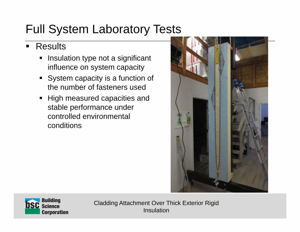
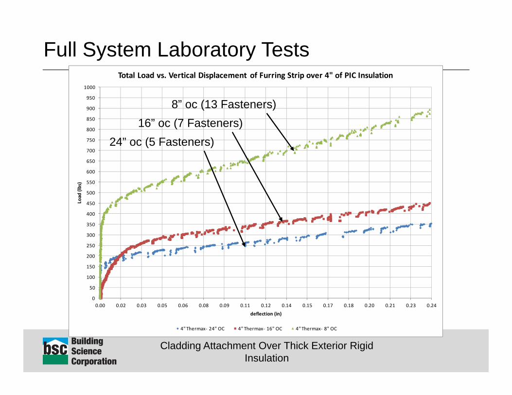
Full System Laboratory Tests Results
Insulation type not a significant influence on system capacity
System capacity is a function of the number of fasteners used
High measured capacities and stable performance under controlled environmental conditions
Cladding Attachment Over Thick Exterior Rigid Insulation
Full System Laboratory Tests
0
50
100
150
200
250
300
350
400
450
500
550
600
650
700
750
800
850
900
950
1000
0.00 0.02 0.03 0.05 0.06 0.08 0.09 0.11 0.12 0.14 0.15 0.17 0.18 0.20 0.21 0.23 0.24
Load
(lbs)
deflection (in)
Total Load vs. Vertical Displacement of Furring Strip over 4" of PIC Insulation
4" Thermax‐ 24" OC 4" Thermax‐ 16" OC 4" Thermax‐ 8" OC
8” oc (13 Fasteners)16” oc (7 Fasteners)
24” oc (5 Fasteners)
Cladding Attachment Over Thick Exterior Rigid Insulation
Full System Laboratory Tests
0
5
10
15
20
25
30
35
40
45
50
55
60
65
70
75
0.00 0.02 0.03 0.05 0.06 0.08 0.09 0.11 0.12 0.14 0.15 0.17 0.18 0.20 0.21 0.23 0.24
Load
(lbs per fasten
er)
defelction (in)
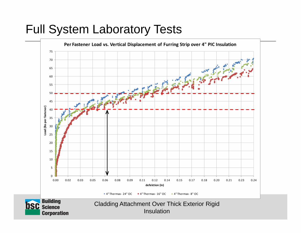
Per Fastener Load vs. Vertical Displacement of Furring Strip over 4" PIC Insulation
4" Thermax‐ 24" OC 4" Thermax‐ 16" OC 4" Thermax‐ 8" OC
Cladding Attachment Over Thick Exterior Rigid Insulation
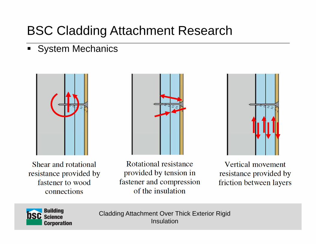
BSC Cladding Attachment Research System Mechanics
Cladding Attachment Over Thick Exterior Rigid Insulation
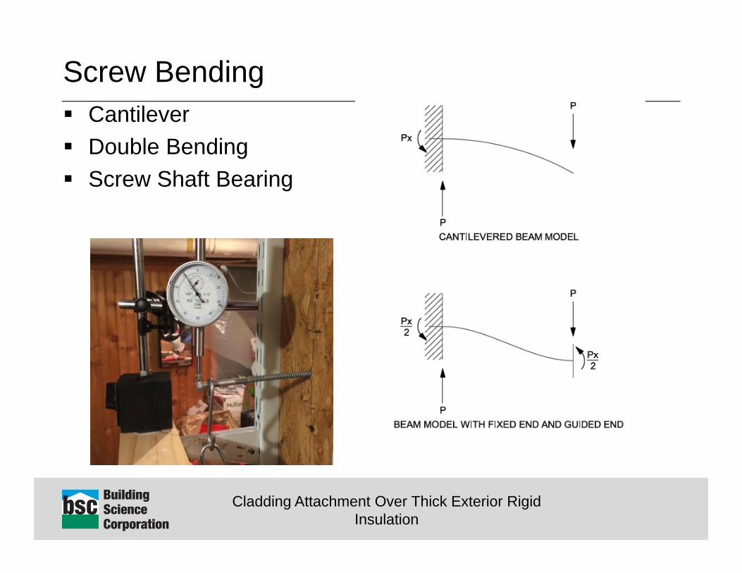
Screw Bending Cantilever Double Bending Screw Shaft Bearing

Cladding Attachment Over Thick Exterior Rigid Insulation
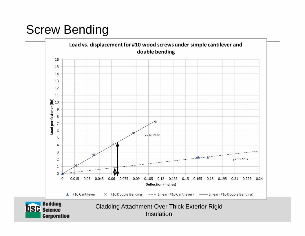
Screw Bending Double bending resistance was significantly higher (~4
times) than simple cantilever. Double bending is more in line with the expected
performance of the assemblies but still only accounted for a fraction of the total measured system capacity
Screw shaft bearing on the insulation was hard to quantify, but appeared to be significant in short term (initial response) tests
Cladding Attachment Over Thick Exterior Rigid Insulation
Screw Bending
y = 13.223x
y = 65.263x
0
1
2
3
4
5
6
7
8
9
10
11
12
13
14
15
16
0 0.015 0.03 0.045 0.06 0.075 0.09 0.105 0.12 0.135 0.15 0.165 0.18 0.195 0.21 0.225 0.24
Load
per fasten
er (lbf)
Deflection (inches)
Load vs. displacement for #10 wood screws under simple cantilever and double bending
#10 Cantilever #10 Double Bending Linear (#10 Cantilever) Linear (#10 Double Bending)
Cladding Attachment Over Thick Exterior Rigid Insulation
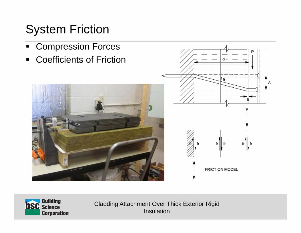
System Friction Compression Forces Coefficients of Friction
Cladding Attachment Over Thick Exterior Rigid Insulation
System Friction Compression Forces were measured at around
150lbf/fastener to drive a #10 wood screw flush with face of furring
Coefficients of frictions were typically around 0.25 Compression forces were also measured to drop off over
time (around 20% to 30%) after initial loading and be highly sensitive to environmental conditions
Cladding Attachment Over Thick Exterior Rigid Insulation
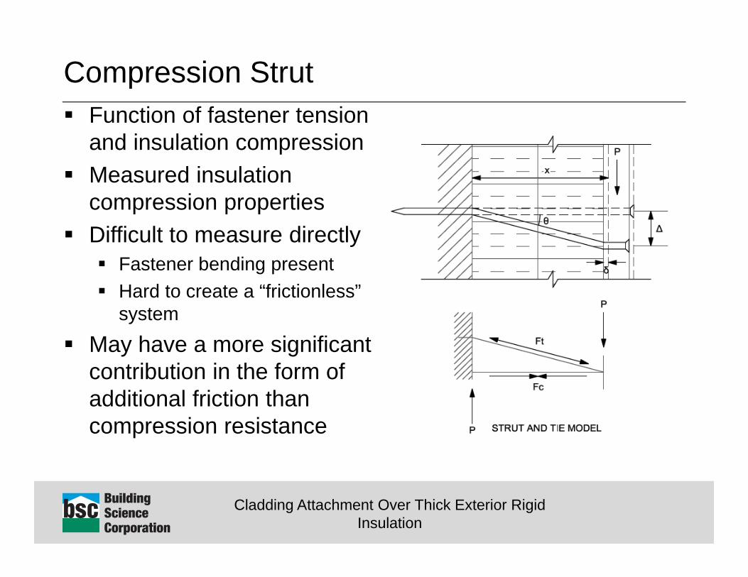
Compression Strut Function of fastener tension
and insulation compression Measured insulation
compression properties Difficult to measure directly
Fastener bending present Hard to create a “frictionless”
system
May have a more significant contribution in the form of additional friction than compression resistance
Cladding Attachment Over Thick Exterior Rigid Insulation
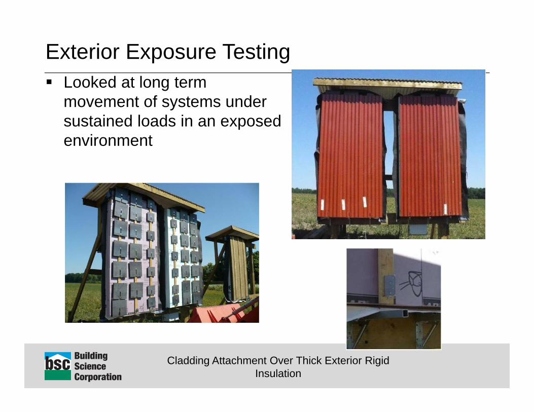
Exterior Exposure Testing Looked at long term
movement of systems under sustained loads in an exposed environment

Cladding Attachment Over Thick Exterior Rigid Insulation
Exterior Exposure Testing
‐1/32"
1/32"
1/16"
1/8"
1/4"
‐20
0
20
40
60
80
100
‐0.10
‐0.08
‐0.05
‐0.03
0.00
0.03
0.05
0.08
0.10
0.13
0.15
0.18
0.20
0.23
0.25
0.28
0.30
0.33
0.35
0.38
0.40
0.43
0.45
0.48
0.50
7/1/12 8/31/12 10/31/12 12/31/12 3/2/13 5/2/13 7/2/13 9/1/13
Tempe
rature (F) / Relative Hum
idity (%)
XPS EPS MF PIC Temperature RH
Vertical deflectionmovement of a wood furring strip (loaded to 8lbs/fastener) over time in an exposedenvironment
MF installed but not loaded during this timeDate
Deflection(in
)
MF and PIC assembliesloaded at this time
Cladding Attachment Over Thick Exterior Rigid Insulation
Exterior Exposure Testing
‐1/32"
1/32"
1/16"
1/8"
1/4"
‐20
0
20
40
60
80
100
‐0.10
‐0.08
‐0.05
‐0.03
0.00
0.03
0.05
0.08
0.10
0.13
0.15
0.18
0.20
0.23
0.25
0.28
0.30
0.33
0.35
0.38
0.40
0.43
0.45
0.48
0.50
7/1/12 8/31/12 10/31/12 12/31/12 3/2/13 5/2/13 7/2/13 9/1/13
Tempe
rature (F) / Relative Hum
idity (%)
XPS EPS MF PIC Temperature RH
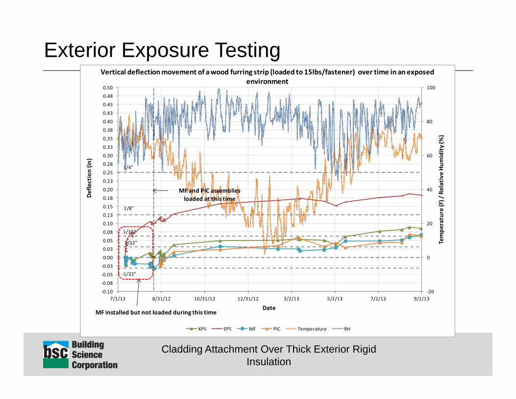
Vertical deflectionmovement of a wood furring strip (loaded to 15lbs/fastener) over time in an exposedenvironment
MF installed but not loaded during this timeDate
Deflection(in
)
MF and PIC assembliesloaded at this time
Cladding Attachment Over Thick Exterior Rigid Insulation
Exterior Exposure Testing
‐1/32"
1/32"
1/16"
1/8"
1/4"
‐20
0
20
40
60
80
100
‐0.10
‐0.08
‐0.05
‐0.03
0.00
0.03
0.05
0.08
0.10
0.13
0.15
0.18
0.20
0.23
0.25
0.28
0.30
0.33
0.35
0.38
0.40
0.43
0.45
0.48
0.50
7/1/12 8/31/12 10/31/12 12/31/12 3/2/13 5/2/13 7/2/13 9/1/13
Tempe
rature (F) / Relative Hum
idity (%)
XPS EPS MF PIC Temperature RH
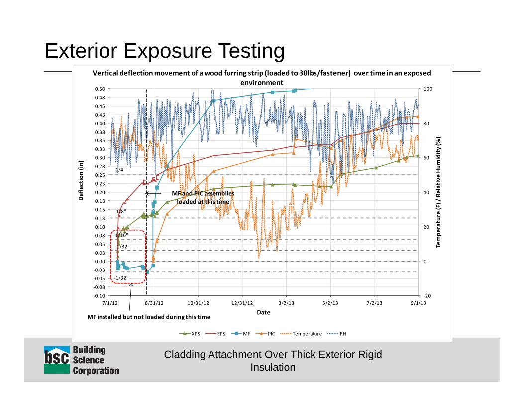
Vertical deflectionmovement of a wood furring strip (loaded to 30lbs/fastener) over time in an exposedenvironment
MF installed but not loaded during this timeDate
Deflection(in
)
MF and PIC assembliesloaded at this time
Cladding Attachment Over Thick Exterior Rigid Insulation
Exterior Exposure Testing
0
10
20
30
40
50
60
70
80
90
100
‐0.03
‐0.025
‐0.02
‐0.015
‐0.01
‐0.005
4E‐17
0.005
0.01
0.015
0.02
0.025
0.03
12/31 00/01 12/01 00/02 12/02 00/03 12/03
Tempe
rature and
Relative Hum
idity
(C, %)
Relativ
e De
flection (in
)
Time and Date (hours/day)
Deflection‐T‐Corrected (in) Ambient Air Temperature (°F) Relative Humidity (%)
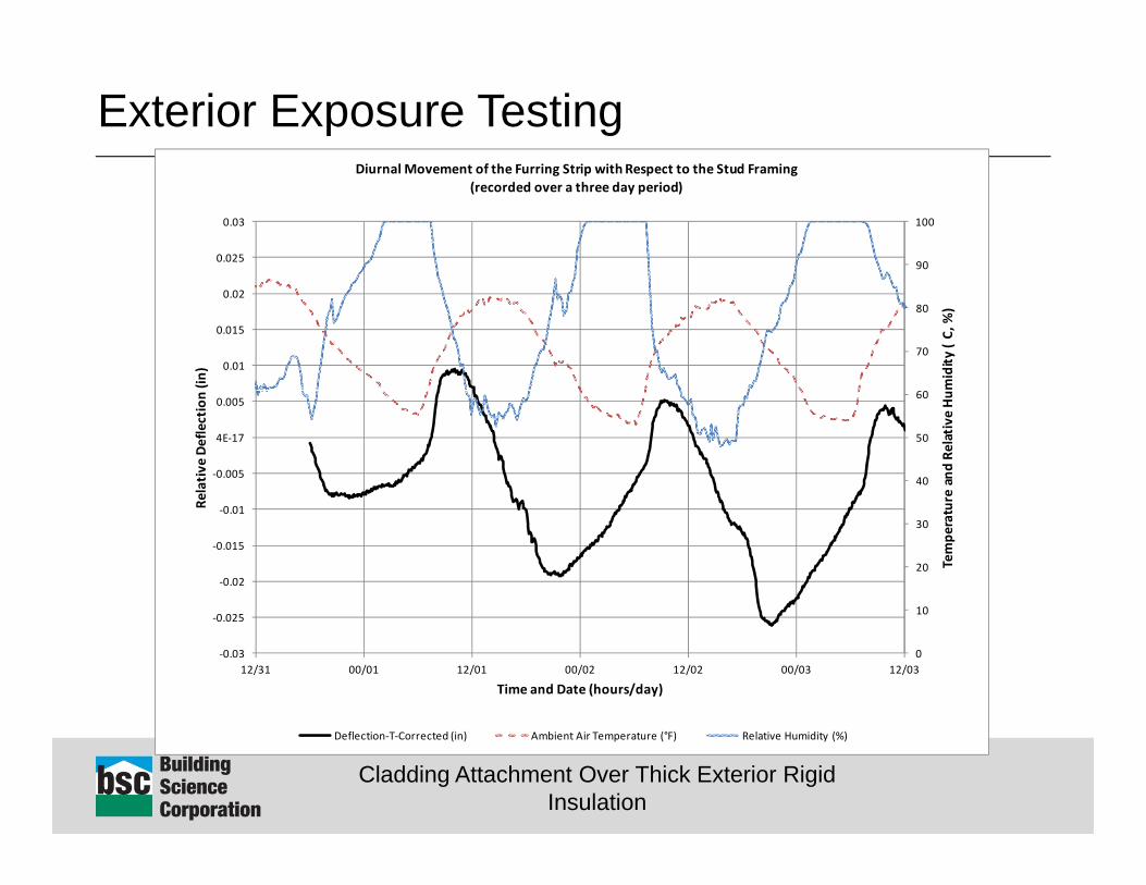
Diurnal Movement of the Furring Strip with Respect to the Stud Framing (recorded over a three day period)

Cladding Attachment Over Thick Exterior Rigid Insulation
Conclusions (System Mechanics) Initial load response measurements are on the order of 40
to 50lbf/fastener at 1/16” deflection and 4” of insulation Insulation type does not appear to be overly significant Capacity is a function of the number of fasteners used. Capacity would be expected to increase for less insulation
due to higher fastener component at a smaller cantilever Friction component is significant, but highly variable due to
initial clamping magnitudes and thermal expansion and contraction of materials
Compression strut component is present, however the magnitude of the impact is difficult to quantify.
Cladding Attachment Over Thick Exterior Rigid Insulation
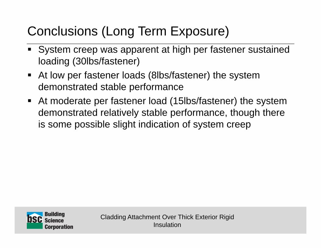
Conclusions (Long Term Exposure) System creep was apparent at high per fastener sustained
loading (30lbs/fastener) At low per fastener loads (8lbs/fastener) the system
demonstrated stable performance At moderate per fastener load (15lbs/fastener) the system
demonstrated relatively stable performance, though there is some possible slight indication of system creep
Cladding Attachment Over Thick Exterior Rigid Insulation
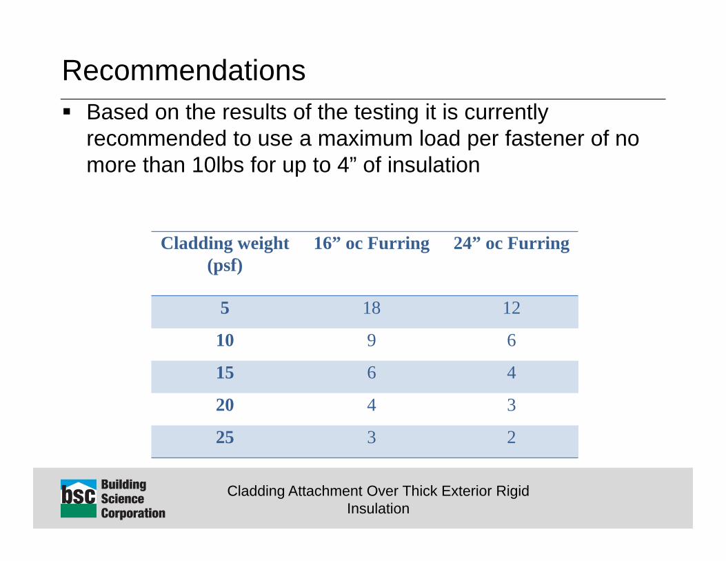
Recommendations Based on the results of the testing it is currently
recommended to use a maximum load per fastener of no more than 10lbs for up to 4” of insulation
Cladding weight (psf)
16” oc Furring 24” oc Furring
5 18 12
10 9 6
15 6 4
20 4 3
25 3 2
Cladding Attachment Over Thick Exterior Rigid Insulation
Questions?Peter Baker, P.Eng.