Embed Size (px)
Citation preview
CJ Series Position Control UnitModel CJ1W-NCF71Introduction to CJ1W-NCF71
www.infoPLC.net
2
1. CJ1W-NCF71 Overview
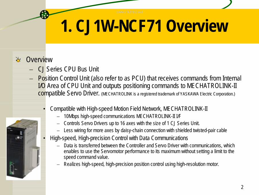
Overview– CJ Series CPU Bus Unit– Position Control Unit (also refer to as PCU) that receives commands from Internal
I/O Area of CPU Unit and outputs positioning commands to MECHATROLINK-II compatible Servo Driver. (MECHATROLINK is a registered trademark of YASKAWA Electric Corporation.)
• Compatible with High-speed Motion Field Network, MECHATROLINK-II– 10Mbps high-speed communications MECHATROLINK-II I/F– Controls Servo Drivers up to 16 axes with the size of 1 CJ Series Unit.– Less wiring for more axes by daisy-chain connection with shielded twisted-pair cable
• High-speed, High-precision Control with Data Communications– Data is transferred between the Controller and Servo Driver with communications, which
enables to use the Servomotor performance to its maximum without setting a limit to the speed command value.
– Realizes high-speed, high-precision position control using high-resolution motor.
www.infoPLC.net
3
1. CJ1W-NCF71 Overview
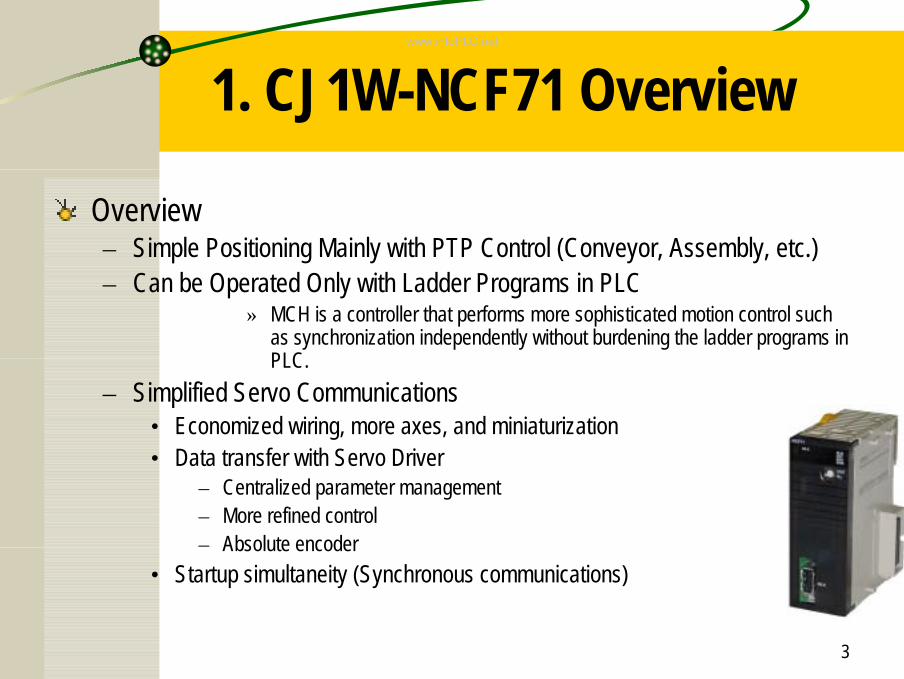
Overview– Simple Positioning Mainly with PTP Control (Conveyor, Assembly, etc.)– Can be Operated Only with Ladder Programs in PLC
» MCH is a controller that performs more sophisticated motion control such as synchronization independently without burdening the ladder programs in PLC.
– Simplified Servo Communications• Economized wiring, more axes, and miniaturization• Data transfer with Servo Driver
– Centralized parameter management– More refined control– Absolute encoder
• Startup simultaneity (Synchronous communications)
www.infoPLC.net
4
1. CJ1W-NCF71 Overview
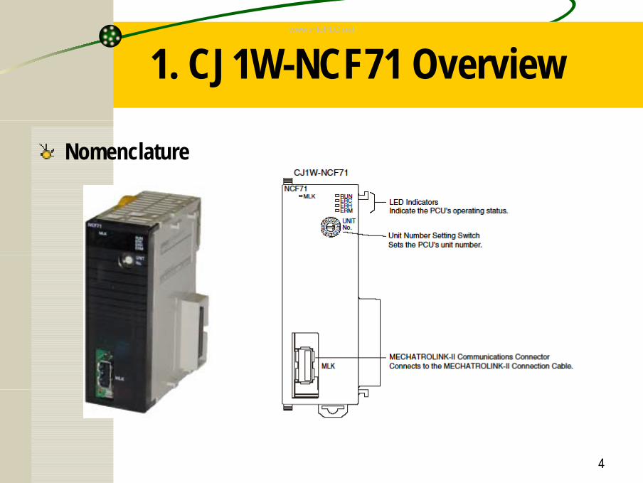
Nomenclature
www.infoPLC.net
5
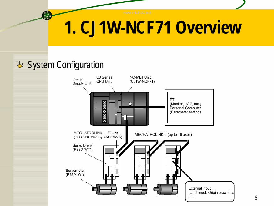
1. CJ1W-NCF71 Overview
System Configuration NC-MLII Unit
(CJ1W-NCF71) CJ Series CPU Unit Power
Supply Unit
Servo Driver(R88D-WT*)
MECHATROLINK-II (up to 16 axes)MECHATROLINK-II I/F Unit (JUSP-NS115: By YASKAWA)
Servomotor (R88M-W*)
PT (Monitor, JOG, etc.) Personal Computer (Parameter setting)
External input (Limit input, Origin proximity, etc.)
www.infoPLC.net
6
1. CJ1W-NCF71 FeaturesPosition Control (Direct Operation)
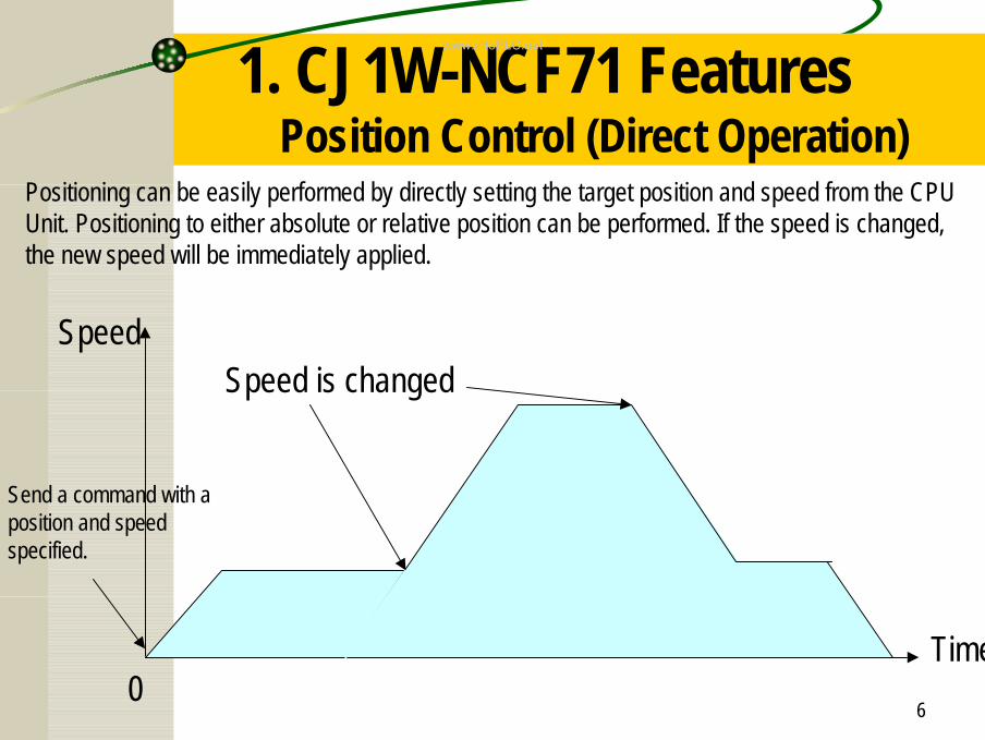
Speed
Time0
Send a command with a position and speed specified.
Positioning can be easily performed by directly setting the target position and speed from the CPU Unit. Positioning to either absolute or relative position can be performed. If the speed is changed, the new speed will be immediately applied.
Speed is changed
www.infoPLC.net
7
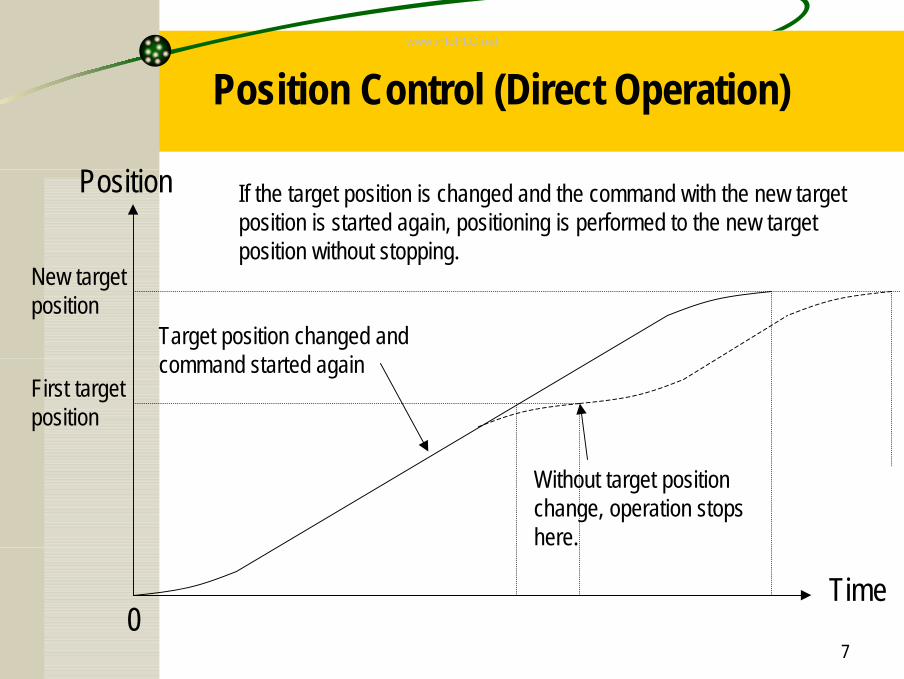
Position Control (Direct Operation)
First target position
New target position
Position
0
Target position changed and command started again
Time
If the target position is changed and the command with the new target position is started again, positioning is performed to the new target position without stopping.
Without target position change, operation stops here.
www.infoPLC.net
8
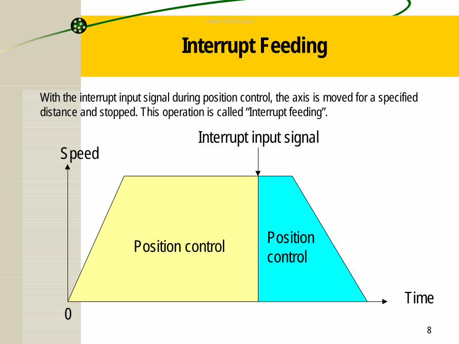
Interrupt Feeding
Speed
Position control
0
Position control
Interrupt input signal
With the interrupt input signal during position control, the axis is moved for a specified distance and stopped. This operation is called “Interrupt feeding”.
Time
www.infoPLC.net
9
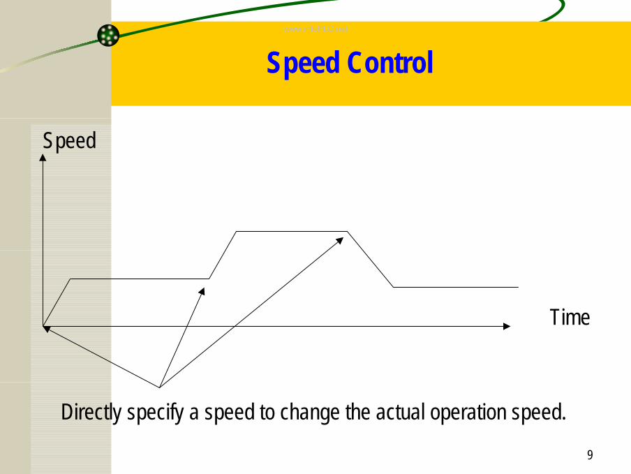
Speed Control
Time
Directly specify a speed to change the actual operation speed.
Speed
www.infoPLC.net
10
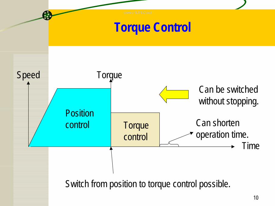
Torque Control
Time
SpeedCan be switched without stopping.
Torque control
Position control
Torque
Can shorten operation time.
Switch from position to torque control possible.
www.infoPLC.net
11
Absolute Encoder and Data Transfer
Compatible with servomotor with absolute encoder.CJ1W-NCF71 supports the servomotor with absolute encoder, which eliminates the need for routine origin searches. W series servo driver by OMRON can be used with the servomotor with absolute encoder.
Data transfer between host controller and servo driver.Parameter settings and various monitoring of the servo driver can be performed from the CPU unit on the PLC. Centralized management of all the data for the multi-axis system from the host controller simplifies data settings in startup of the machine or replacement of devices.
www.infoPLC.net
12
2. CJ1W-NCF71 Functions
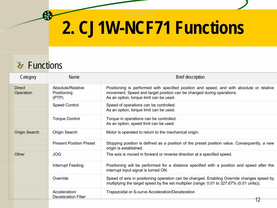
FunctionsCategory Name Brief description
Direct Operation
Absolute/Relative Positioning(PTP)
Positioning is performed with specified position and speed, and with absolute or relative movement. Speed and target position can be changed during operations.As an option, torque limit can be used.
Speed Control Speed of operations can be controlled.As an option, torque limit can be used.
Torque Control Torque in operations can be controlled.As an option, speed limit can be used.
Origin Search Origin Search Motor is operated to return to the mechanical origin.
Present Position Preset Stopping position is defined as a position of the preset position value. Consequently, a new origin is established.
Other JOG The axis is moved in forward or reverse direction at a specified speed.
Interrupt Feeding Positioning will be performed for a distance specified with a position and speed after the interrupt input signal is turned ON.
Override Speed of axis in positioning operation can be changed. Enabling Override changes speed by multiplying the target speed by the set multiplier (range: 0.01 to 327.67% (0.01 units)).
Acceleration/Deceleration Filter
Trapezoidal or S-curve Acceleration/Deceleration
www.infoPLC.net
13
2. CJ1W-NCF71 Functions
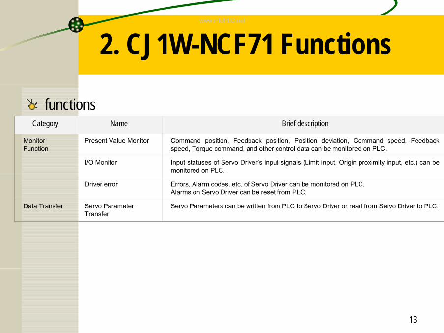
functions Category Name Brief description
Monitor Function
Present Value Monitor Command position, Feedback position, Position deviation, Command speed, Feedback speed, Torque command, and other control data can be monitored on PLC.
I/O Monitor Input statuses of Servo Driver’s input signals (Limit input, Origin proximity input, etc.) can be monitored on PLC.
Driver error Errors, Alarm codes, etc. of Servo Driver can be monitored on PLC.Alarms on Servo Driver can be reset from PLC.
Data Transfer Servo Parameter Transfer
Servo Parameters can be written from PLC to Servo Driver or read from Servo Driver to PLC.
www.infoPLC.net
14
3. MECHATROLINK
MECHATROLINK-II– MECHATROLINK is a high-speed motion field network developed by YASKAWA
ELECTRIC CORPORATION.– For MECHATROLINK-compatible devices (30 max.(*1)) connected with a single
communications line, high-speed, high-precision motion control can be realized with high-speed communications of 10Mbps max.*1: For NCF, up to 16 axes can be connected.
– There are 2 types of MECHATROLINK; MECHATROLINK-I has a baud rate of 4Mbps while MECHATROLINK-II of 10Mbps.
– CJ1W-NCF71 is compatible with MECHATROLINK-II only. Connected devices have to be compatible with MECHATROLINK-II as well.
www.infoPLC.net
15
3. MECHATROLINKMECHATROLINK-II
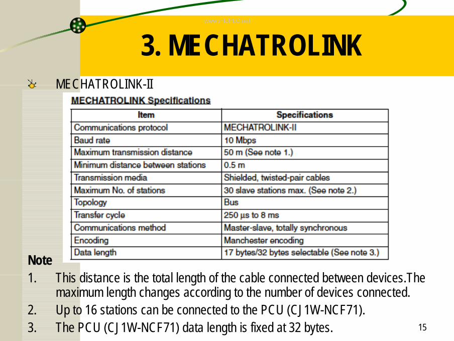
Note1. This distance is the total length of the cable connected between devices.The
maximum length changes according to the number of devices connected.2. Up to 16 stations can be connected to the PCU (CJ1W-NCF71).3. The PCU (CJ1W-NCF71) data length is fixed at 32 bytes.
www.infoPLC.net
16
3. MECHATROLINK
MECHATROLINK-II
www.infoPLC.net
17
3. MECHATROLINK
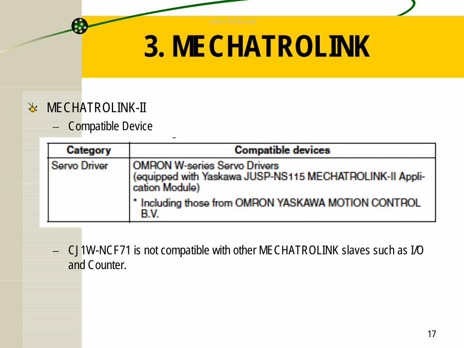
MECHATROLINK-II– Compatible Device
– CJ1W-NCF71 is not compatible with other MECHATROLINK slaves such as I/O and Counter.
www.infoPLC.net
18
3. MECHATROLINK
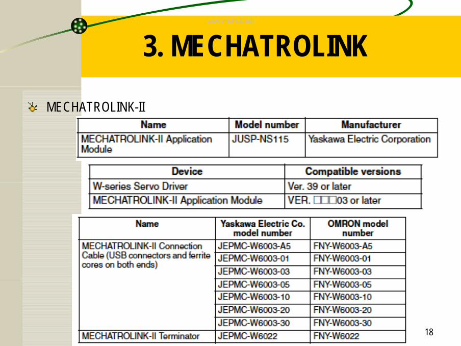
MECHATROLINK-II
www.infoPLC.net
19
4. How to Use CJ1W-NCF71
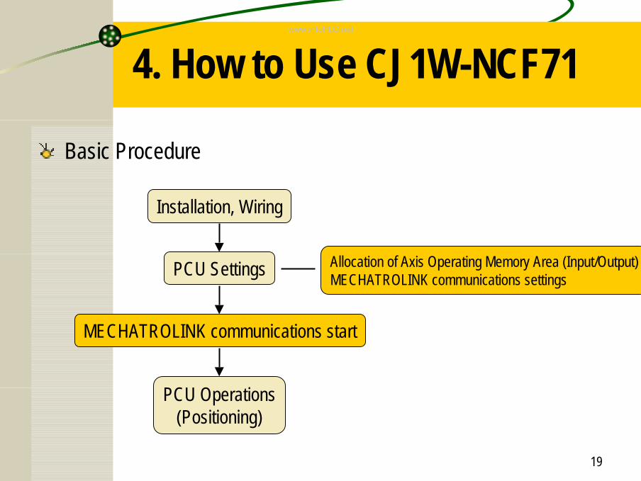
Basic Procedure
Installation, Wiring
PCU Settings
MECHATROLINK communications start
PCU Operations(Positioning)
Allocation of Axis Operating Memory Area (Input/Output)MECHATROLINK communications settings
www.infoPLC.net
20
4. How to Use CJ1W-NCF71
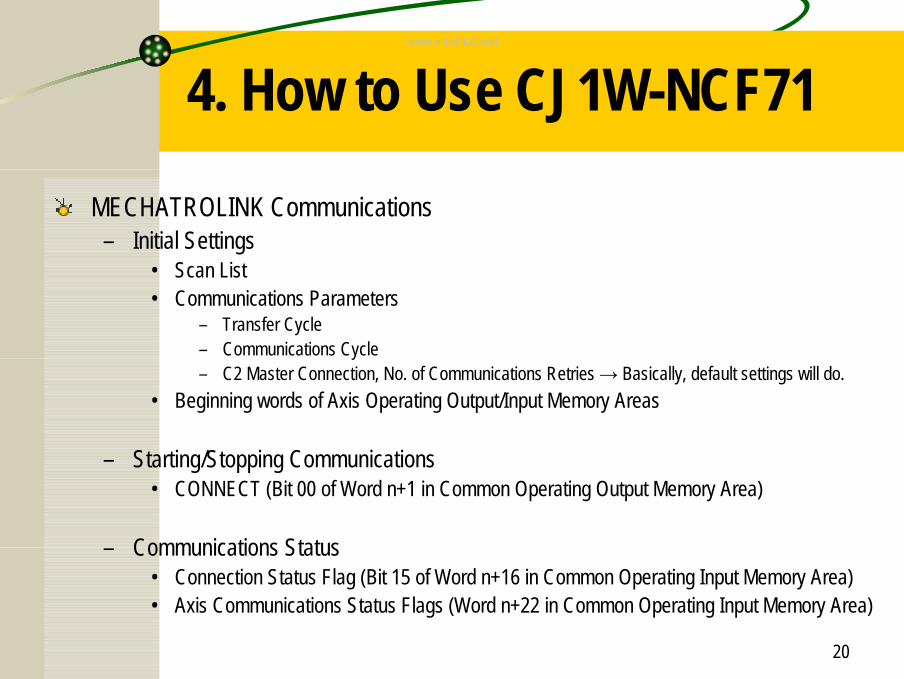
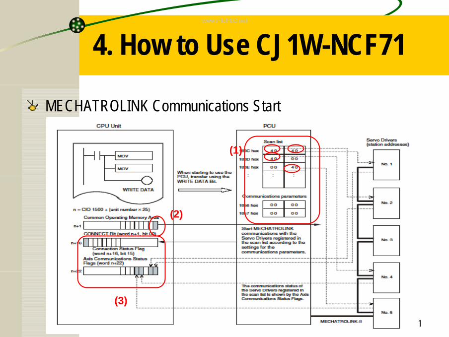
MECHATROLINK Communications– Initial Settings
• Scan List• Communications Parameters
– Transfer Cycle– Communications Cycle– C2 Master Connection, No. of Communications Retries → Basically, default settings will do.
• Beginning words of Axis Operating Output/Input Memory Areas
– Starting/Stopping Communications• CONNECT (Bit 00 of Word n+1 in Common Operating Output Memory Area)
– Communications Status• Connection Status Flag (Bit 15 of Word n+16 in Common Operating Input Memory Area)• Axis Communications Status Flags (Word n+22 in Common Operating Input Memory Area)
www.infoPLC.net
21
4. How to Use CJ1W-NCF71
MECHATROLINK Communications Start
(1)
(2)
(3)
www.infoPLC.net
22
4. How to Use CJ1W-NCF71
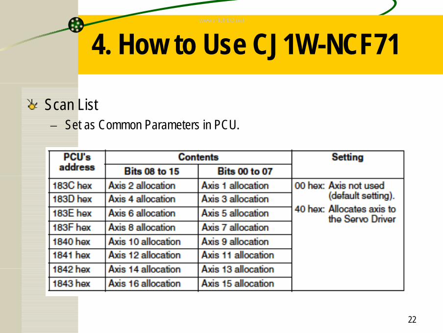
Scan List– Set as Common Parameters in PCU.
www.infoPLC.net
23
4. How to Use CJ1W-NCF71
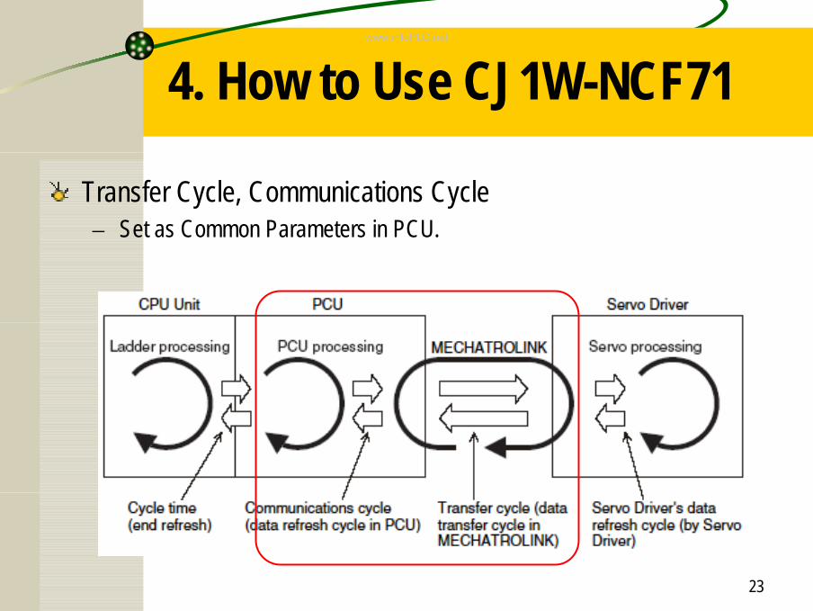
Transfer Cycle, Communications Cycle– Set as Common Parameters in PCU.
www.infoPLC.net
24
4. How to Use CJ1W-NCF71
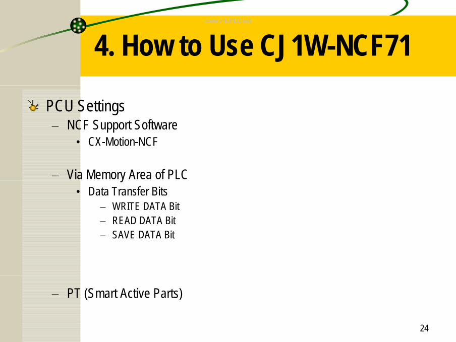
PCU Settings– NCF Support Software
• CX-Motion-NCF
– Via Memory Area of PLC• Data Transfer Bits
– WRITE DATA Bit– READ DATA Bit– SAVE DATA Bit
– PT (Smart Active Parts)
www.infoPLC.net
25
4. How to Use CJ1W-NCF71
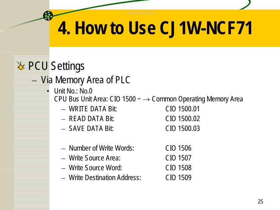
PCU Settings– Via Memory Area of PLC
• Unit No.: No.0CPU Bus Unit Area: CIO 1500 ~ → Common Operating Memory Area
– WRITE DATA Bit: CIO 1500.01– READ DATA Bit: CIO 1500.02– SAVE DATA Bit: CIO 1500.03
– Number of Write Words: CIO 1506– Write Source Area: CIO 1507– Write Source Word: CIO 1508– Write Destination Address: CIO 1509
www.infoPLC.net
26
4. How to Use CJ1W-NCF71
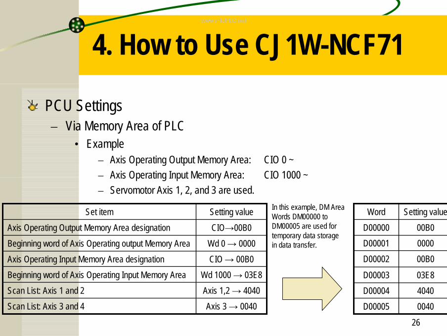
PCU Settings– Via Memory Area of PLC
• Example– Axis Operating Output Memory Area: CIO 0 ~– Axis Operating Input Memory Area: CIO 1000 ~– Servomotor Axis 1, 2, and 3 are used.
Axis 3 → 0040Scan List: Axis 3 and 4Axis 1,2 → 4040Scan List: Axis 1 and 2Wd 1000 → 03E8Beginning word of Axis Operating Input Memory Area
CIO → 00B0Axis Operating Input Memory Area designationWd 0 → 0000Beginning word of Axis Operating output Memory AreaCIO→00B0Axis Operating Output Memory Area designationSetting valueSet item
0040D000054040D0000403E8D00003
00B0D000020000D0000100B0D00000
Setting valueWordIn this example, DM Area Words DM00000 to DM00005 are used for temporary data storage in data transfer.
www.infoPLC.net
27
4. How to Use CJ1W-NCF71
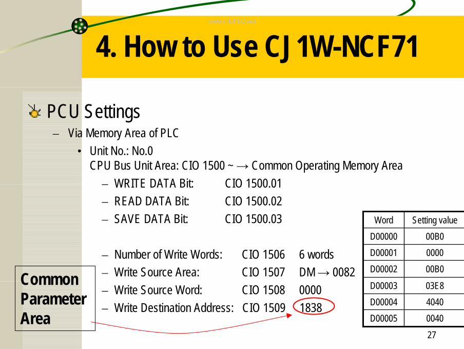
PCU Settings– Via Memory Area of PLC
• Unit No.: No.0CPU Bus Unit Area: CIO 1500 ~ → Common Operating Memory Area
– WRITE DATA Bit: CIO 1500.01– READ DATA Bit: CIO 1500.02– SAVE DATA Bit: CIO 1500.03
– Number of Write Words: CIO 1506 6 words– Write Source Area: CIO 1507 DM → 0082– Write Source Word: CIO 1508 0000– Write Destination Address: CIO 1509 1838
0040D000054040D0000403E8D00003
00B0D000020000D0000100B0D00000
Setting valueWord
Common Parameter Area
www.infoPLC.net
28
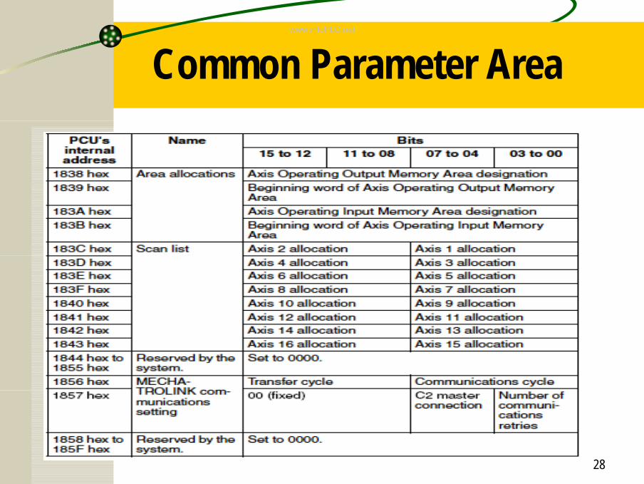
Common Parameter Areawww.infoPLC.net
29
4. How to Use CJ1W-NCF71
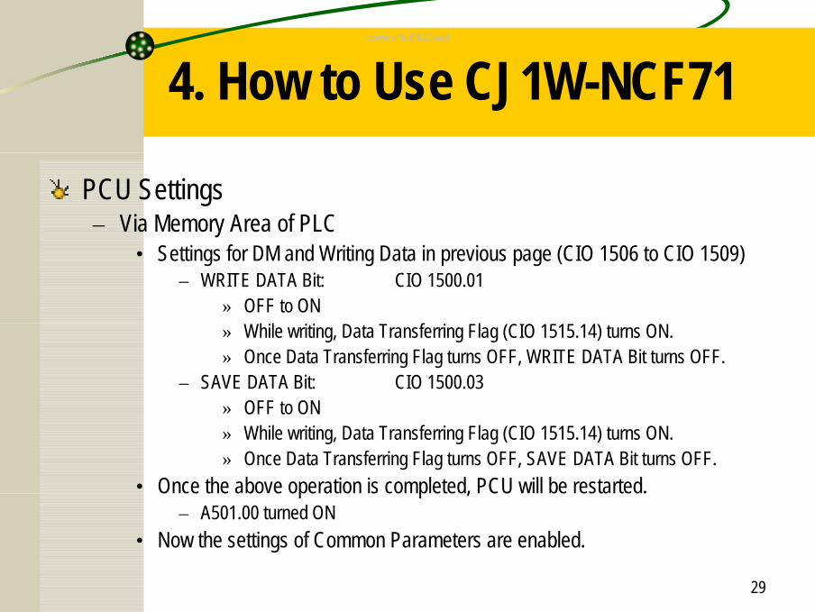
PCU Settings– Via Memory Area of PLC
• Settings for DM and Writing Data in previous page (CIO 1506 to CIO 1509)– WRITE DATA Bit: CIO 1500.01
» OFF to ON» While writing, Data Transferring Flag (CIO 1515.14) turns ON.» Once Data Transferring Flag turns OFF, WRITE DATA Bit turns OFF.
– SAVE DATA Bit: CIO 1500.03» OFF to ON» While writing, Data Transferring Flag (CIO 1515.14) turns ON.» Once Data Transferring Flag turns OFF, SAVE DATA Bit turns OFF.
• Once the above operation is completed, PCU will be restarted.– A501.00 turned ON
• Now the settings of Common Parameters are enabled.
www.infoPLC.net
30
4. How to Use CJ1W-NCF71
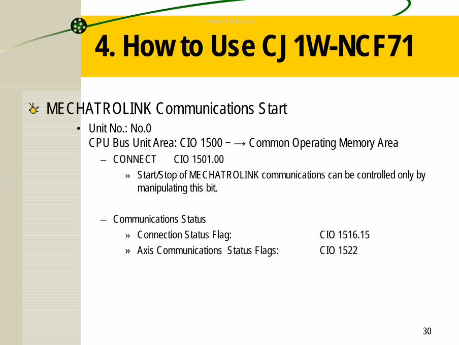
MECHATROLINK Communications Start• Unit No.: No.0
CPU Bus Unit Area: CIO 1500 ~ → Common Operating Memory Area– CONNECT CIO 1501.00
» Start/Stop of MECHATROLINK communications can be controlled only by manipulating this bit.
– Communications Status» Connection Status Flag: CIO 1516.15» Axis Communications Status Flags: CIO 1522
www.infoPLC.net
31
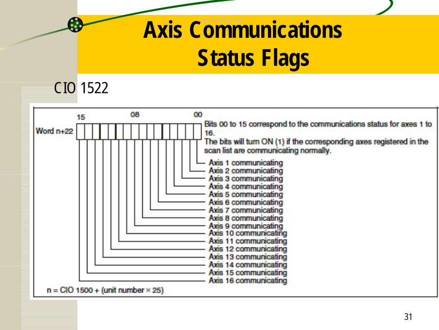
Axis Communications Status Flags
CIO 1522
www.infoPLC.net
32
4. How to Use CJ1W-NCF71
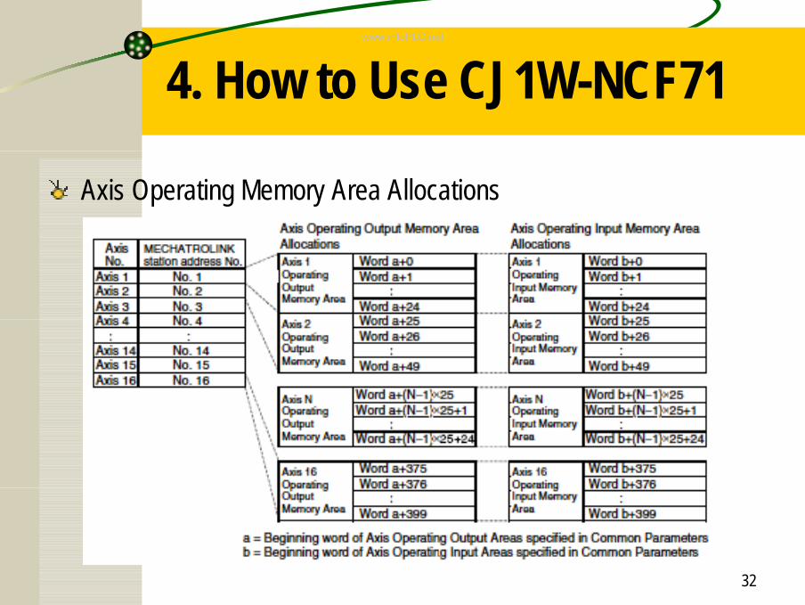
Axis Operating Memory Area Allocations
www.infoPLC.net
33
4. How to Use CJ1W-NCF71
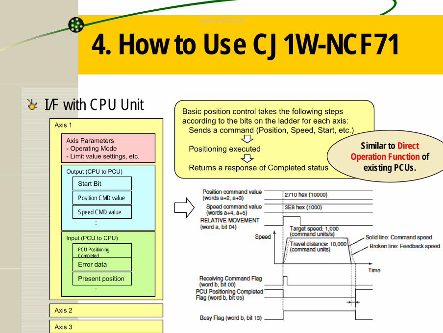
I/F with CPU UnitAxis 1
Axis Parameters- Operating Mode- Limit value settings, etc.
Output (CPU to PCU)
Start Bit
Position CMD value
Speed CMD value :
Input (PCU to CPU)
PCU Positioning Completed
Error data
Present position :
Axis 2
Axis 3
Basic position control takes the following steps according to the bits on the ladder for each axis:
Sends a command (Position, Speed, Start, etc.)
Positioning executed
Returns a response of Completed status
Similar to Direct Operation Function of
existing PCUs.
www.infoPLC.net
34
4. How to Use CJ1W-NCF71
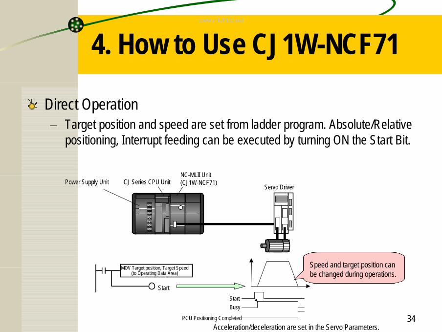
Direct Operation– Target position and speed are set from ladder program. Absolute/Relative
positioning, Interrupt feeding can be executed by turning ON the Start Bit.
MOV Target position, Target Speed(to Operating Data Area)
Start
Acceleration/deceleration are set in the Servo Parameters.
StartBusy
PCU Positioning Completed
NC-MLII Unit(CJ1W-NCF71)CJ Series CPU UnitPower Supply Unit
Servo Driver
Speed and target position can be changed during operations.
www.infoPLC.net
35
4. How to Use CJ1W-NCF71
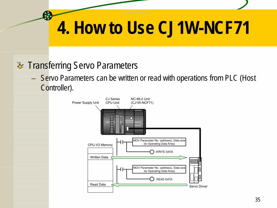
Transferring Servo Parameters– Servo Parameters can be written or read with operations from PLC (Host
Controller). NC-MLII Unit
(CJ1W-NCF71)CJ SeriesCPU UnitPower Supply Unit
Written Data
Read Data
MOV Parameter No. (address), Data size(to Operating Data Area)
WRITE DATA
Servo Driver
MOV Parameter No. (address), Data size(to Operating Data Area)
READ DATA
CPU I/O Memory
www.infoPLC.net
36
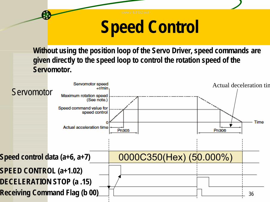
Speed ControlWithout using the position loop of the Servo Driver, speed commands are given directly to the speed loop to control the rotation speed of the Servomotor.
Speed control data (a+6, a+7) 0000C350(Hex) (50.000%)SPEED CONTROL (a+1.02)DECELERATION STOP (a .15)Receiving Command Flag (b 00)
ServomotorActual deceleration time
www.infoPLC.net
37
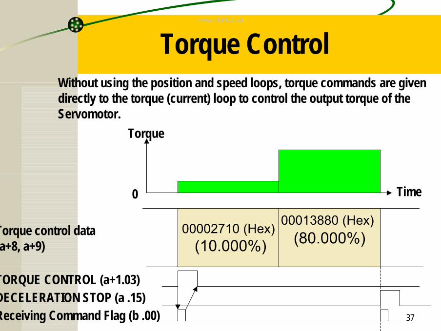
Torque ControlWithout using the position and speed loops, torque commands are given directly to the torque (current) loop to control the output torque of the Servomotor.
Torque control data(a+8, a+9)
00002710 (Hex)(10.000%)
TORQUE CONTROL (a+1.03)DECELERATION STOP (a .15)Receiving Command Flag (b .00)
00013880 (Hex)(80.000%)
Torque
Time0
www.infoPLC.net
38
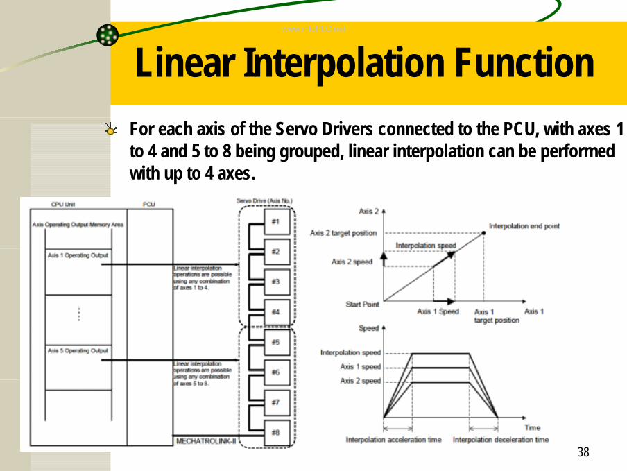
Linear Interpolation FunctionFor each axis of the Servo Drivers connected to the PCU, with axes 1 to 4 and 5 to 8 being grouped, linear interpolation can be performed with up to 4 axes.
www.infoPLC.net
39
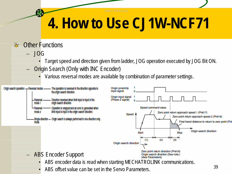
4. How to Use CJ1W-NCF71Other Functions– JOG
• Target speed and direction given from ladder, JOG operation executed by JOG Bit ON.– Origin Search (Only with INC Encoder)
• Various reversal modes are available by combination of parameter settings.
– ABS Encoder Support• ABS encoder data is read when starting MECHATROLINK communications.• ABS offset value can be set in the Servo Parameters.
www.infoPLC.net
40
4. How to Use CJ1W-NCF71
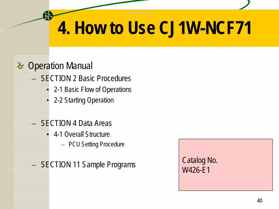
Operation Manual– SECTION 2 Basic Procedures
• 2-1 Basic Flow of Operations• 2-2 Starting Operation
– SECTION 4 Data Areas• 4-1 Overall Structure
– PCU Setting Procedure
– SECTION 11 Sample Programs Catalog No.W426-E1
www.infoPLC.net
41
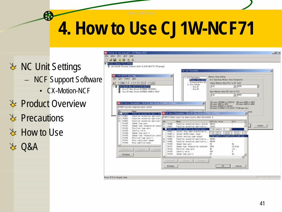
4. How to Use CJ1W-NCF71
NC Unit Settings– NCF Support Software
• CX-Motion-NCF
Product OverviewPrecautionsHow to UseQ&A
www.infoPLC.net
42
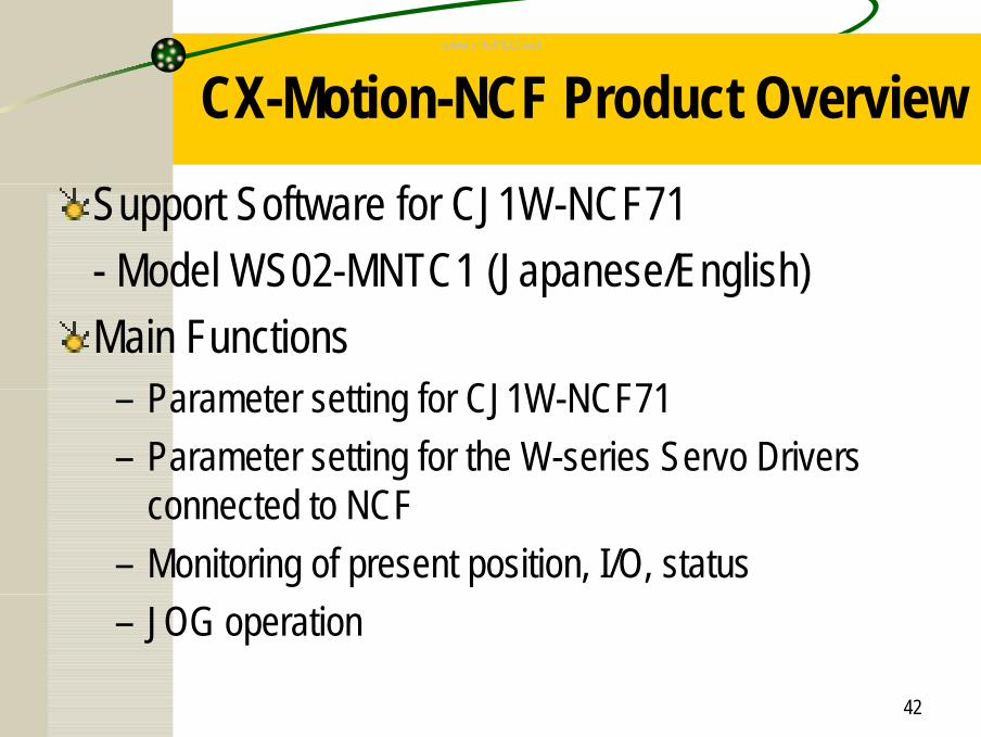
CX-Motion-NCF Product OverviewSupport Software for CJ1W-NCF71- Model WS02-MNTC1 (Japanese/English)Main Functions
– Parameter setting for CJ1W-NCF71– Parameter setting for the W-series Servo Drivers
connected to NCF– Monitoring of present position, I/O, status– JOG operation
www.infoPLC.net
43
CX-Motion-NCF Applicable OS
•Windows 98
•Windows Me
•Windows NT Service Pack 6
•Windows 2000 Service Pack 3 or higher
•Windows XP
www.infoPLC.net
44
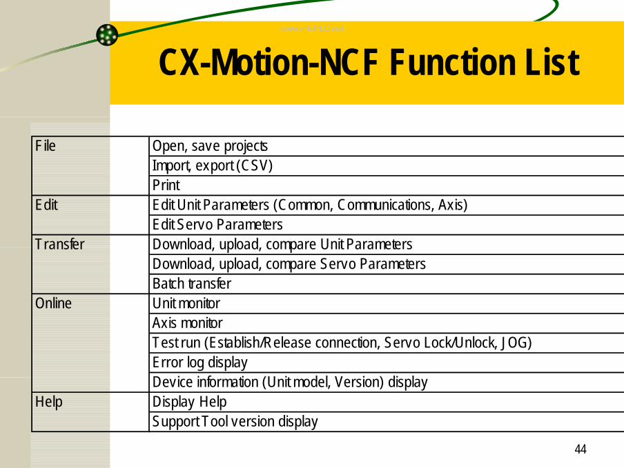
CX-Motion-NCF Function List
File Open, save projectsImport, export (CSV)Print
Edit Edit Unit Parameters (Common, Communications, Axis)Edit Servo Parameters
Transfer Download, upload, compare Unit ParametersDownload, upload, compare Servo ParametersBatch transfer
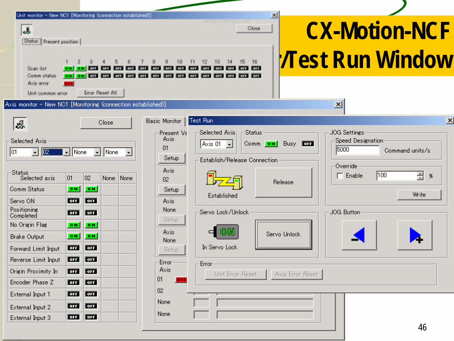
Online Unit monitorAxis monitorTest run (Establish/Release connection, Servo Lock/Unlock, JOG)Error log displayDevice information (Unit model, Version) display
Help Display HelpSupport Tool version display
www.infoPLC.net
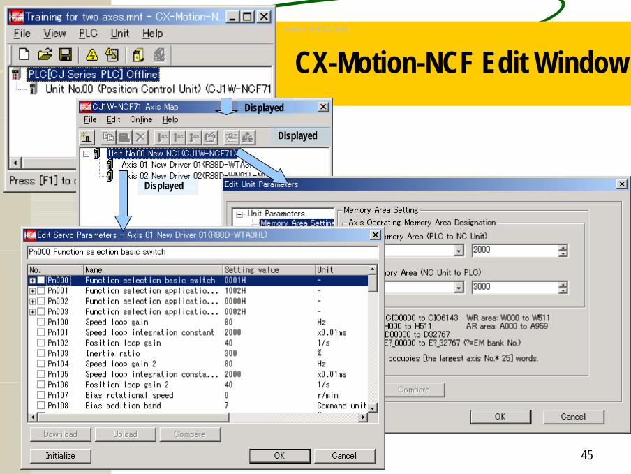
45
CX-Motion-NCF Edit WindowDisplayed
Displayed
Displayed
www.infoPLC.net
46
CX-Motion-NCFMonitor/Test Run Window
www.infoPLC.net
47
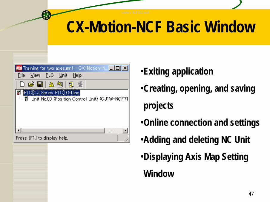
CX-Motion-NCF Basic Window
•Exiting application
•Creating, opening, and saving
projects
•Online connection and settings
•Adding and deleting NC Unit
•Displaying Axis Map Setting
Window
www.infoPLC.net
48
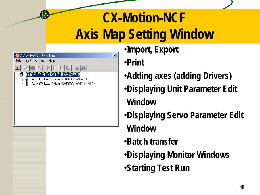
CX-Motion-NCFAxis Map Setting Window
•Import, Export•Print•Adding axes (adding Drivers)•Displaying Unit Parameter Edit Window
•Displaying Servo Parameter Edit Window
•Batch transfer•Displaying Monitor Windows•Starting Test Run
www.infoPLC.net
49
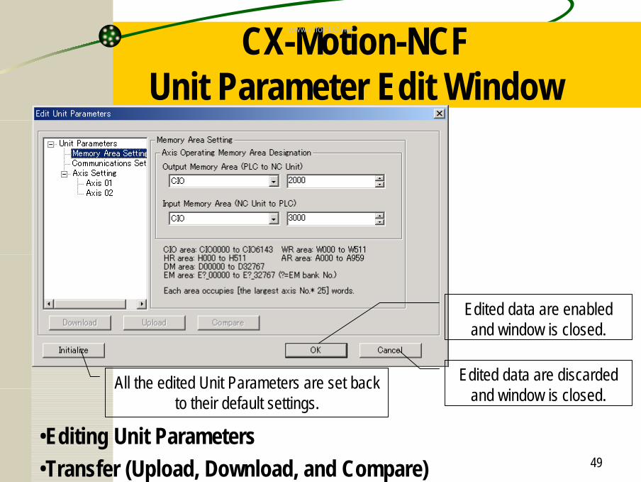
CX-Motion-NCF Unit Parameter Edit Window
•Editing Unit Parameters•Transfer (Upload, Download, and Compare)
Edited data are discarded and window is closed.
Edited data are enabled and window is closed.
All the edited Unit Parameters are set back to their default settings.
www.infoPLC.net
50
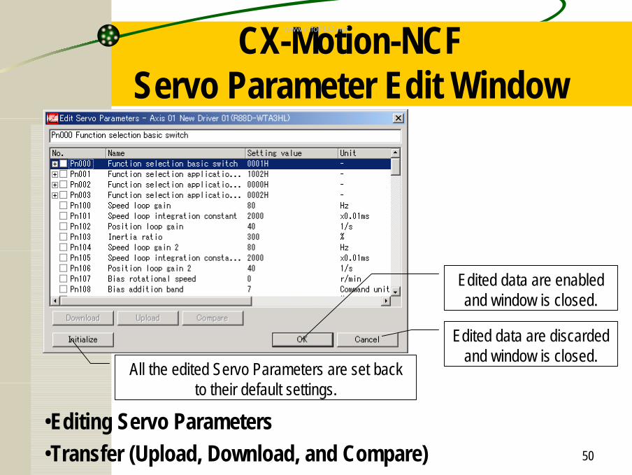
CX-Motion-NCFServo Parameter Edit Window
•Editing Servo Parameters•Transfer (Upload, Download, and Compare)
Edited data are discarded and window is closed.
Edited data are enabled and window is closed.
All the edited Servo Parameters are set back to their default settings.
www.infoPLC.net
51
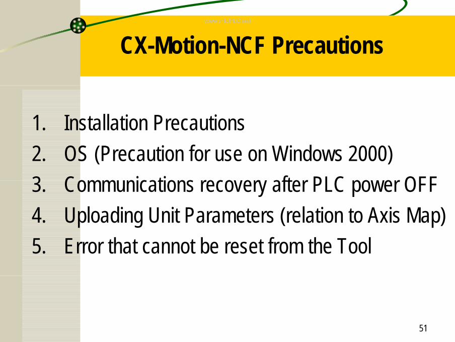
CX-Motion-NCF Precautions
1. Installation Precautions2. OS (Precaution for use on Windows 2000)3. Communications recovery after PLC power OFF4. Uploading Unit Parameters (relation to Axis Map)5. Error that cannot be reset from the Tool
www.infoPLC.net
52
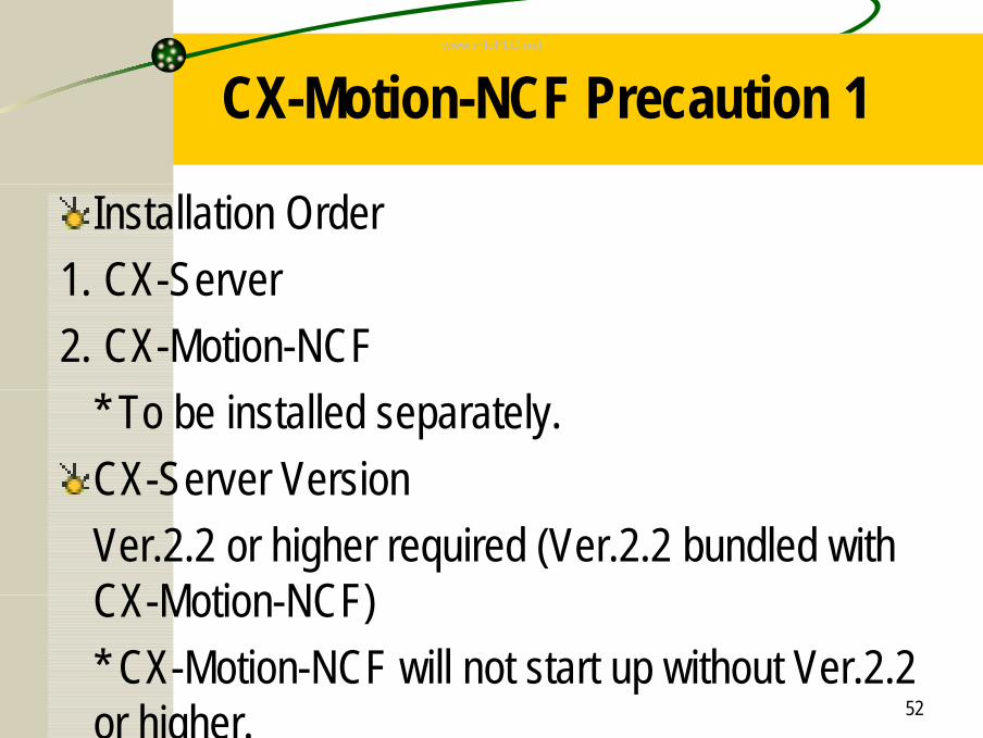
CX-Motion-NCF Precaution 1
Installation Order1. CX-Server2. CX-Motion-NCF
* To be installed separately.CX-Server VersionVer.2.2 or higher required (Ver.2.2 bundled with CX-Motion-NCF)* CX-Motion-NCF will not start up without Ver.2.2 or higher.
www.infoPLC.net
53
CX-Motion-NCF Precaution 2
When using CX-Motion-NCF on Windows 2000
Make sure to use Windows 2000 Service Pack 3 or higher. Otherwise, CX-Motion-NCF cannot be operated normally.
www.infoPLC.net
54
CX-Motion-NCF Precaution 3If PLC power is turned OFF once, and back ON again with CX-Motion-NCF connected online, establishing the next communications may fail.
Recovery Method:1: Connect online again.2: Try executing online operations several times.
www.infoPLC.net
55
CX-Motion-NCF Precaution 4
When the scan list in the Unit and the axis map on the Tool do not match with each other, uploading Unit Parameters on the Unit Parameter Edit Window cannot be executed.
Workaround:1: Batch uploading2: Compare scan list and axis map, and arrange
axes so that they could match.
www.infoPLC.net
56
CX-Motion-NCF Precaution 5
Errors that cannot be reset from the Tool• MECHATROLINK communications error→ Required to release the connection to reset the error
• Errors reset when Servo is turned OFF and back ON→ Turn OFF the Servo once, and then back ON again
www.infoPLC.net
57
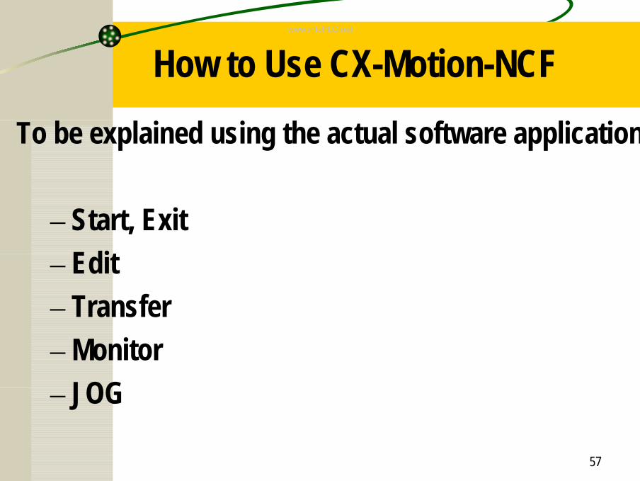
How to Use CX-Motion-NCFTo be explained using the actual software application.
– Start, Exit– Edit– Transfer– Monitor– JOG
www.infoPLC.net
58
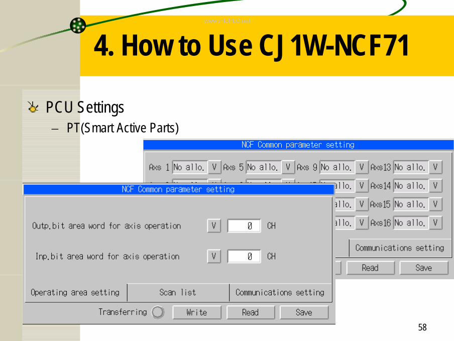
4. How to Use CJ1W-NCF71
PCU Settings– PT(Smart Active Parts)
www.infoPLC.net
59
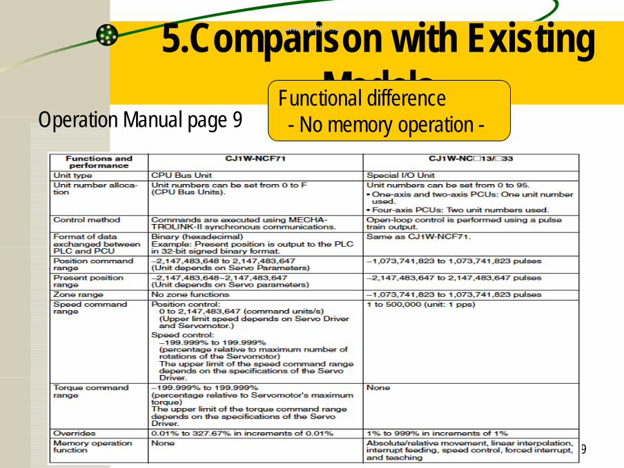
5.Comparison with Existing Models
Operation Manual page 9Functional difference- No memory operation -
www.infoPLC.net
60
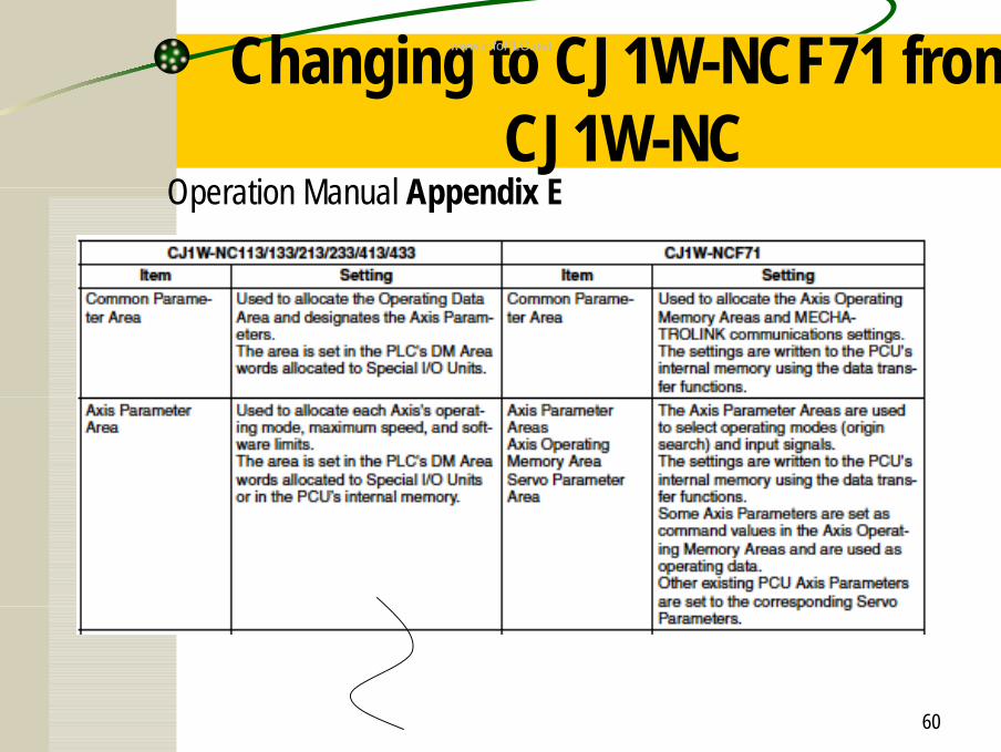
Changing to CJ1W-NCF71 from CJ1W-NC
Operation Manual Appendix E
www.infoPLC.net
61
6. Maintenance
Replacing PCUs– Backup Data of Unit Parameters
• Through either of the following 2 methods, Unit Parameters of PCU can be backed up into or restored from the CF Card inserted in the card slot on CPU Unit.
– Simple backup operation on CPU Unit (Entire system)– Individual Unit backup using PCU’s Operating Memory
* With this backup function, only the parameters saved in the built-in FROM on PCU can be backed up.Parameters set on the Servo Driver are not backed up into the CF Card.
www.infoPLC.net