Embed Size (px)
Citation preview
7/27/2019 Cj1w-Tc Dsheet Csm1622
http://slidepdf.com/reader/full/cj1w-tc-dsheet-csm1622 1/12
CJ Series Temperature Control Unit
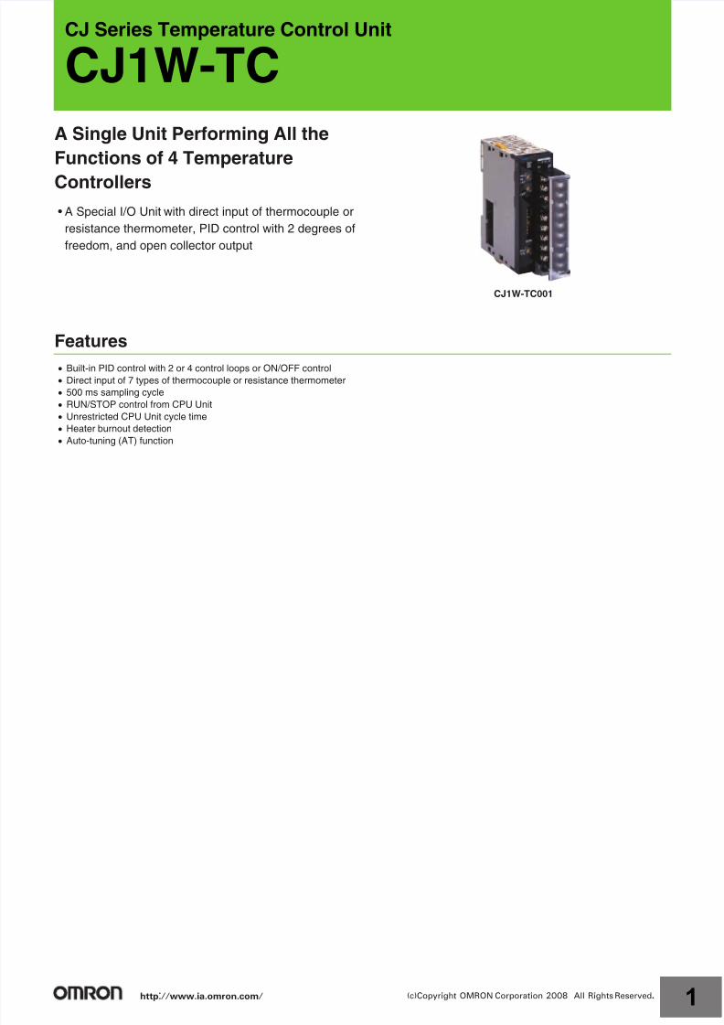
CJ1W-TCA Single Unit Performing All the
Functions of 4 Temperature
Controllers
• A Special I/O Unit with direct input of thermocouple or
resistance thermometer, PID control with 2 degrees of
freedom, and open collector output
Features
Built-in PID control with 2 or 4 control loops or ON/OFF control
Direct input of 7 types of thermocouple or resistance thermometer
500 ms sampling cycle
RUN/STOP control from CPU Unit
Unrestricted CPU Unit cycle time
Heater burnout detection
Auto-tuning (AT) function
CJ1W-TC001
http://www.ia.omron.com/ 1(c)Copyright OMRON Corporation 2008 All Rights Reserved.
7/27/2019 Cj1w-Tc Dsheet Csm1622
http://slidepdf.com/reader/full/cj1w-tc-dsheet-csm1622 2/12
CJ1W-TC
System Configuration
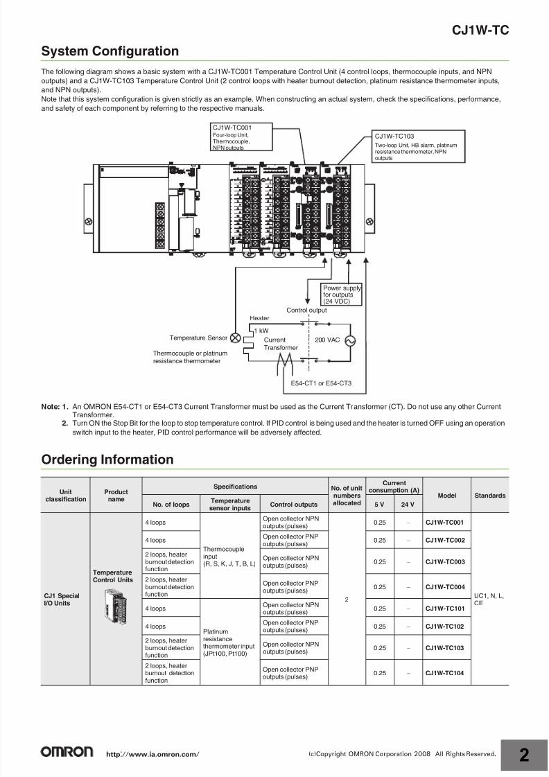
The following diagram shows a basic system with a CJ1W-TC001 Temperature Control Unit (4 control loops, thermocouple inputs, and NPN
outputs) and a CJ1W-TC103 Temperature Control Unit (2 control loops with heater burnout detection, platinum resistance thermometer inputs,
and NPN outputs).
Note that this system configuration is given strictly as an example. When constructing an actual system, check the specifications, performance,
and safety of each component by referring to the respective manuals.
Note: 1. An OMRON E54-CT1 or E54-CT3 Current Transformer must be used as the Current Transformer (CT). Do not use any other CurrentTransformer.
2. Turn ON the Stop Bit for the loop to stop temperature control. If PID control is being used and the heater is turned OFF using an operation
switch input to the heater, PID control performance will be adversely affected.
Ordering Information
Unitclassification
Productname
Specifications No. of unitnumbersallocated
Currentconsumption (A)
Model Standards
No. of loopsTemperaturesensor inputs
Control outputs 5 V 24 V
CJ1 SpecialI/O Units
TemperatureControl Units
4 loops
Thermocoupleinput(R, S, K, J, T, B, L)
Open collector NPNoutputs (pulses)
2
0.25 CJ1W-TC001
UC1, N, L,CE
4 loopsOpen collector PNP
outputs (pulses)0.25 CJ1W-TC002
2 loops, heaterburnout detectionfunction
Open collector NPNoutputs (pulses)
0.25 CJ1W-TC003
2 loops, heaterburnout detectionfunction
Open collector PNPoutputs (pulses)
0.25 CJ1W-TC004
4 loops
Platinumresistancethermometer input(JPt100, Pt100)
Open collector NPNoutputs (pulses)
0.25 CJ1W-TC101
4 loopsOpen collector PNPoutputs (pulses)
0.25 CJ1W-TC102
2 loops, heaterburnout detectionfunction
Open collector NPNoutputs (pulses)
0.25 CJ1W-TC103
2 loops, heaterburnout detection
function
Open collector PNPoutputs (pulses)
0.25 CJ1W-TC104
CJ1W-TC001
Four-loop Unit,Thermocouple,NPN outputs
CJ1W-TC103Two-loop Unit, HB alarm, platinumresistance thermometer, NPNoutputs
Power supplyfor outputs(24 VDC)
Heater
Current
Transformer
E54-CT1 or E54-CT3
Temperature Sensor
Thermocouple or platinumresistance thermometer
Control output
200 VAC
1 kW
http://www.ia.omron.com/ 2(c)Copyright OMRON Corporation 2008 All Rights Reserved.
7/27/2019 Cj1w-Tc Dsheet Csm1622
http://slidepdf.com/reader/full/cj1w-tc-dsheet-csm1622 3/12
CJ1W-TC
International Standards
The standards indicated in the "Standards" column are those current for UL, CSA, cULus, cUL, NK, and Lloyd standards and EC Directives as
of the end of February 2008. The standards are abbreviated as follows: U: UL, U1: UL Class I Division 2 Products for Hazardous Locations,
C: CSA, US: cULus Class I Division 2 Products for Hazardous Locations, CU: cUL, N: NK, L: Lloyd, and CE: EC Directives.
Ask your OMRON representative for the conditions under which the standards were met.
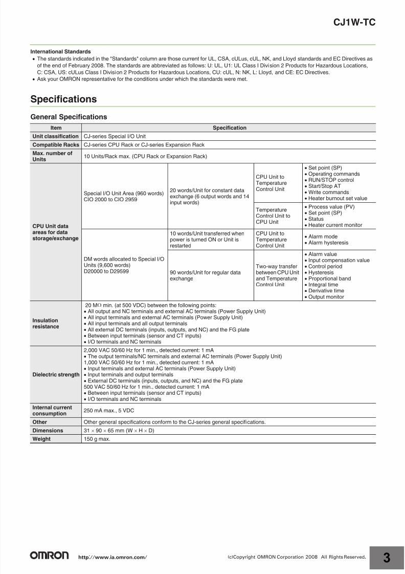
SpecificationsGeneral Specifications
Item Specification
Unit classification CJ-series Special I/O Unit
Compatible Racks CJ-series CPU Rack or CJ-series Expansion Rack
Max. number ofUnits
10 Units/Rack max. (CPU Rack or Expansion Rack)
CPU Unit dataareas for datastorage/exchange
Special I/O Unit Area (960 words)
CIO 2000 to CIO 2959
20 words/Unit for constant dataexchange (6 output words and 14
input words)
CPU Unit toTemperatureControl Unit
Set point (SP) Operating commands RUN/STOP control Start/Stop AT Write commands
Heater burnout set value
TemperatureControl Unit toCPU Unit
Process value (PV) Set point (SP) Status Heater current monitor
DM words allocated to Special I/OUnits (9,600 words)D20000 to D29599
10 words/Unit transferred whenpower is turned ON or Unit isrestarted
CPU Unit toTemperatureControl Unit
Alarm mode Alarm hysteresis
90 words/Unit for regular dataexchange
Two-way transferbetween CPU Unitand TemperatureControl Unit
Alarm value Input compensation value Control period Hysteresis Proportional band Integral time Derivative time Output monitor
Insulationresistance
20 M min. (at 500 VDC) between the following points: All output and NC terminals and external AC terminals (Power Supply Unit) All input terminals and external AC terminals (Power Supply Unit) All input terminals and all output terminals All external DC terminals (inputs, outputs, and NC) and the FG plate Between input terminals (sensor and CT inputs) I/O terminals and NC terminals
Dielectric strength
2,000 VAC 50/60 Hz for 1 min., detected current: 1 mA The output terminals/NC terminals and external AC terminals (Power Supply Unit)1,000 VAC 50/60 Hz for 1 min., detected current: 1 mA Input terminals and external AC terminals (Power Supply Unit) Input terminals and output terminals External DC terminals (inputs, outputs, and NC) and the FG plate500 VAC 50/60 Hz for 1 min., detected current: 1 mA Between input terminals (sensor and CT inputs) I/O terminals and NC terminals
Internal currentconsumption
250 mA max., 5 VDC
Other Other general specifications conform to the CJ-series general specifications.
Dimensions 31 90 65 mm (W H D)
Weight 150 g max.
http://www.ia.omron.com/ 3(c)Copyright OMRON Corporation 2008 All Rights Reserved.
7/27/2019 Cj1w-Tc Dsheet Csm1622
http://slidepdf.com/reader/full/cj1w-tc-dsheet-csm1622 4/12
CJ1W-TC
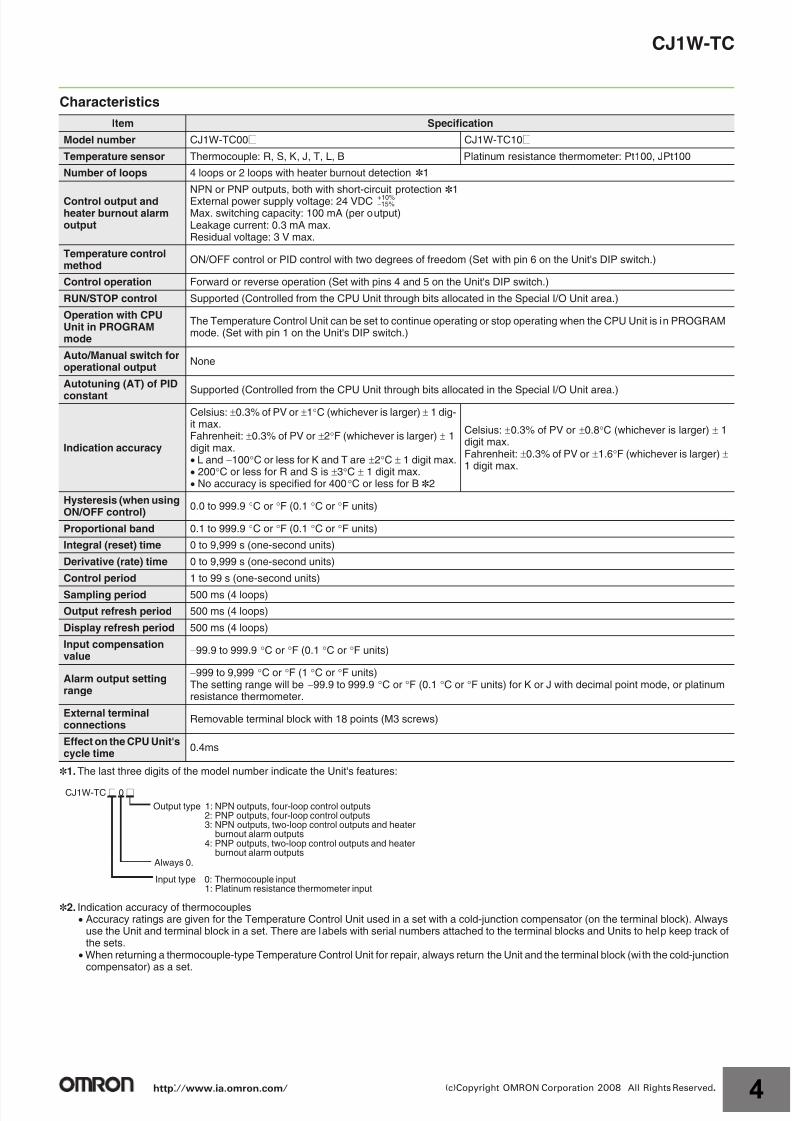
Characteristics
*1.The last three digits of the model number indicate the Unit's features:
*2. Indication accuracy of thermocouples Accuracy ratings are given for the Temperature Control Unit used in a set with a cold-junction compensator (on the terminal block). Always
use the Unit and terminal block in a set. There are labels with serial numbers attached to the terminal blocks and Units to help keep track ofthe sets.
When returning a thermocouple-type Temperature Control Unit for repair, always return the Unit and the terminal block (with the cold-junctioncompensator) as a set.
Item Specification
Model number CJ1W-TC00@ CJ1W-TC10@
Temperature sensor Thermocouple: R, S, K, J, T, L, B Platinum resistance thermometer: Pt100, JPt100
Number of loops 4 loops or 2 loops with heater burnout detection *1
Control output andheater burnout alarmoutput
NPN or PNP outputs, both with short-circuit protection *1External power supply voltage: 24 VDCMax. switching capacity: 100 mA (per output)Leakage current: 0.3 mA max.Residual voltage: 3 V max.
Temperature controlmethod
ON/OFF control or PID control with two degrees of freedom (Set with pin 6 on the Unit's DIP switch.)
Control operation Forward or reverse operation (Set with pins 4 and 5 on the Unit's DIP switch.)
RUN/STOP control Supported (Controlled from the CPU Unit through bits allocated in the Special I/O Unit area.)
Operation with CPUUnit in PROGRAMmode
The Temperature Control Unit can be set to continue operating or stop operating when the CPU Unit is in PROGRAMmode. (Set with pin 1 on the Unit's DIP switch.)
Auto/Manual switch foroperational output
None
Autotuning (AT) of PID
constant Supported (Controlled from the CPU Unit through bits allocated in the Special I/O Unit area.)
Indication accuracy
Celsius: 0.3% of PV or 1C (whichever is larger) 1 dig-it max.Fahrenheit: 0.3% of PV or 2F (whichever is larger) 1digit max. L and 100C or less for K and T are 2C 1 digit max. 200C or less for R and S is 3C 1 digit max. No accuracy is specified for 400C or less for B *2
Celsius: 0.3% of PV or 0.8C (whichever is larger) 1digit max.Fahrenheit: 0.3% of PV or 1.6F (whichever is larger) 1 digit max.
Hysteresis (when usingON/OFF control)
0.0 to 999.9 C or F (0.1 C or F units)
Proportional band 0.1 to 999.9 C or F (0.1 C or F units)
Integral (reset) time 0 to 9,999 s (one-second units)
Derivative (rate) time 0 to 9,999 s (one-second units)
Control period 1 to 99 s (one-second units)
Sampling period 500 ms (4 loops)
Output refresh period 500 ms (4 loops)
Display refresh period 500 ms (4 loops)
Input compensationvalue
99.9 to 999.9 C or F (0.1 C or F units)
Alarm output settingrange
999 to 9,999 C or F (1 C or F units)The setting range will be 99.9 to 999.9 C or F (0.1 C or F units) for K or J with decimal point mode, or platinumresistance thermometer.
External terminalconnections
Removable terminal block with 18 points (M3 screws)
Effect on the CPU Unit'scycle time
0.4ms
+10%15%
CJ1W-TC @ 0 @
Output type 1: NPN outputs, four-loop control outputs 2: PNP outputs, four-loop control outputs 3: NPN outputs, two-loop control outputs and heater
burnout alarm outputs 4: PNP outputs, two-loop control outputs and heater
burnout alarm outputsAlways 0.
Input type 0: Thermocouple input 1: Platinum resistance thermometer input
http://www.ia.omron.com/ 4(c)Copyright OMRON Corporation 2008 All Rights Reserved.
7/27/2019 Cj1w-Tc Dsheet Csm1622
http://slidepdf.com/reader/full/cj1w-tc-dsheet-csm1622 5/12
CJ1W-TC
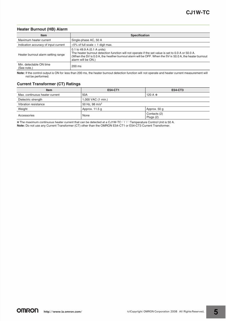
Heater Burnout (HB) Alarm
Note: If the control output is ON for less than 200 ms, the heater burnout detection function will not operate and heater current measurement willnot be performed.
Current Transformer (CT) Ratings
* The maximum continuous heater current that can be detected at a CJ1W-TC@@@ Temperature Control Unit is 50 A.Note: Do not use any Current Transformer (CT) other than the OMRON E54-CT1 or E54-CT3 Current Transformer.
Item Specification
Maximum heater current Single-phase AC, 50 A
Indication accuracy of input current 5% of full scale 1 digit max.
Heater burnout alarm setting range
0.1 to 49.9 A (0.1 A units)The heater burnout detection function will not operate if the set value is set to 0.0 A or 50.0 A.
(When the SV is 0.0 A, the heather burnout alarm will be OFF. When the SV is 50.0 A, the heater burnoutalarm will be ON.)
Min. detectable ON time(See note.)
200 ms
Item E54-CT1 E54-CT3
Max. continuous heater current 50A 120 A *
Dielectric strength 1,000 VAC (1 min.)
Vibration resistance 50 Hz, 98 m/s2
Weight Approx. 11.5 g Approx. 50 g
Accessories NoneContacts (2)Plugs (2)
http://www.ia.omron.com/ 5(c)Copyright OMRON Corporation 2008 All Rights Reserved.
7/27/2019 Cj1w-Tc Dsheet Csm1622
http://slidepdf.com/reader/full/cj1w-tc-dsheet-csm1622 6/12
CJ1W-TC
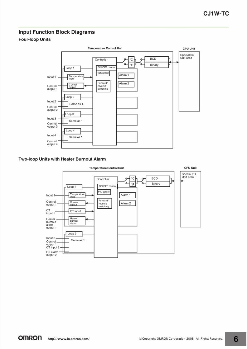
Input Function Block Diagrams
Four-loop Units
Two-loop Units with Heater Burnout Alarm
CPU Unit
Special I/OUnit AreaBCD
Binary°C°F
Alarm 1
Alarm 2
ON/OFF control
PID control
Forward/ reverseswitching
Controller
Temperature Control Unit
Loop 1
Temperatureinput
Controloutput
Loop 2
Loop 3
Loop 4
Same as 1.
Same as 1.
Same as 1.
Input 1
Controloutput 1
Input 2
Controloutput 2
Input 3
Controloutput 3
Input 4
Controloutput 4
CT input
Loop 2
Same as 1.
Heaterburnoutalarm
CTinput 1
Heaterburnoutalarmoutput 1
Input 2
Control
output 1CT input 2
HB alarmoutput 2
CPU Unit
Special I/OUnit Area
BCD
Binary
°C
°F
Alarm 1
Alarm 2
ON/OFF control
PID control
Forward/ reverseswitching
Controller
Temperature Control Unit
Loop 1
Temperatureinput
Controloutput
Input 1
Controloutput 1
http://www.ia.omron.com/ 6(c)Copyright OMRON Corporation 2008 All Rights Reserved.
7/27/2019 Cj1w-Tc Dsheet Csm1622
http://slidepdf.com/reader/full/cj1w-tc-dsheet-csm1622 7/12
CJ1W-TC
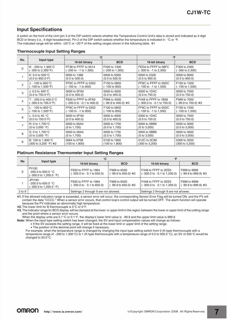
Input Specifications
A switch on the front of the Unit (pin 3 of the DIP switch) selects whether the Temperature Control Unit's data is stored and indicated as 4-digit
BCD or binary (i.e., 4-digit hexadecimal). Pin 2 of the DIP switch selects whether the temperature is indicated in C or F.
The indicated range will be within 20C or 20F of the setting ranges shown in the following table. *1
Thermocouple Input Setting Ranges
Platinum Resistance Thermometer Input Setting Ranges
*1. If the allowed indication range is exceeded, a sensor error will occur, the corresponding Sensor Error Flag will be turned ON, and the PV willcontain the data "CCCC." When a sensor error occurs, that control loop's control output will be turned OFF. The alarm function will operatebecause the PV indicates an abnormally high temperature.
*2.The lower limit for B thermocouple is 0C or 0F.*3.The indicator range for BCD display will be clamped at the lower or upper limit in the region between the lower or upper limit of the setting range
and the point where a sensor error occurs.When the display units are 0.1C or 0.1F, the display's lower limit value is 99.9 and the upper limit value is 999.9.
Note: When the input type setting switch has been changed, the SV and input compensation values will change as follows:
If the SV exceeds the setting range, it will be fixed at the lower limit or upper limit of the setting range. The position of the decimal point will change if necessary.
For example, when the temperature range is changed by changing the input type setting switch from 0 (K-type thermocouple with atemperature range of 200 to 1,300C) to 1 (K-type thermocouple with a temperature range of 0.0 to 500.0C), an SV of 200C would bechanged to 20.0C.
No. Input typeC F
16-bit binary BCD 16-bit binary BCD
0K: 200 to 1,300C(300 to 2,300F)
FF38 to FFFF to 0514(200 to 1 to 1,300)
F200 to 1300(200 to 1,300)
FED4 to FFFF to 08FC(300 to 1 to 2,300)
F300 to 2300(300 to 2,300)
1K: 0.0 to 500C(0.0 to 900.0F)
0000 to 1388(0.0 to 500.0)
0000 to 5000(0.0 to 500.0)
0000 to 2328(0.0 to 900.0)
0000 to 9000(0.0 to 900.0)
2J: 100 to 850C(100 to 1,500F)
FF9C to FFFF to 0352(100 to 1 to 850)
F100 to 0850(100 to 850)
FF9C to FFFF to 05DC(100 to 1 to 1,500)
F100 to 1500(100 to 1,500)
3J: 0.0 to 400C(0.0 to 750.0F)
0000 to 0FA0(0.0 to 400.0)
0000 to 4000(0.0 to 400.0)
0000 to 1D4C(0.0 to 750.0)
0000 to 7500(0.0 to 750.0)
4T: 200.0 to 400.0C(300.0 to 700.0F)
F830 to FFFF to 0FA0(200.0 to 0.1 to 400.0)
F999 to 4000(99.9 to 400.0) *3
F448 to FFFF to 1B58(300.0 to 0.1 to 700.0)
F999 to 7000(99.9 to 700.0) *3
5L: 100 to 850C
(
100 to 1,500
F)
FF9C to FFFF to 0352
(
100 to
1 to 850)
F100 to 0850
(
100 to 850)
FF9C to FFFF to 05DC
(
100 to
1 to 1,500)
F100 to 1500
(
100 to 1,500)
6L: 0.0 to 40 C(0.0 to 750.0F)
0000 to 0FA0(0.0 to 400.0)
0000 to 4000(0.0 to 400.0)
0000 to 1D4C(0.0 to 750.0)
0000 to 7500(0.0 to 750.0)
7R: 0 to 1,700C(0 to 3,000 F)
0000 to 06A4(0 to 1,700)
0000 to 1700(0.0 to 1,700)
0000 to 0BB8(0 to 3,000)
0000 to 3000(0.0 to 3,000)
8S: 0 to 1,700C(0 to 3,000 F)
0000 to 06A4(0 to 1,700)
0000 to 1700(0.0 to 1,700)
0000 to 0BB8(0 to 3,000)
0000 to 3000(0.0 to 3,000)
9B: 100 to 1,800C(300 to 3,200 F) *2
0064 to 0708(100 to 1,800)
0100 to 1800(100 to 1,800)
012C to 0C80(300 to 3,200)
0300 to 3200(300 to 3,200)
No Input typeC F
16-bit binary BCD 16-bit binary BCD
0Pt100:200.0 to 650.0 C(300.0 to 1,200.0 F)
F830 to FFFF to 1964(200.0 to 0.1 to 650.0)
F999 to 6500(99.9 to 650.0) *3
F448 to FFFF to 2EE0(300.0 to 0.1 to 1,200.0)
F999 to 9999(99.9 to 999.9) *3
1JPt100:200.0 to 650.0 C(300.0 to 1,200.0 F)
F830 to FFFF to 1964(200.0 to 0.1 to 650.0)
F999 to 6500(99.9 to 650.0) *3
F448 to FFFF to 2EE0(300.0 to 0.1 to 1,200.0)
F999 to 9999(99.9 to 999.9) *3
2 to 9 Settings 2 through 9 are not allowed. Settings 2 through 9 are not allowed.
http://www.ia.omron.com/ 7(c)Copyright OMRON Corporation 2008 All Rights Reserved.
7/27/2019 Cj1w-Tc Dsheet Csm1622
http://slidepdf.com/reader/full/cj1w-tc-dsheet-csm1622 8/12
CJ1W-TC
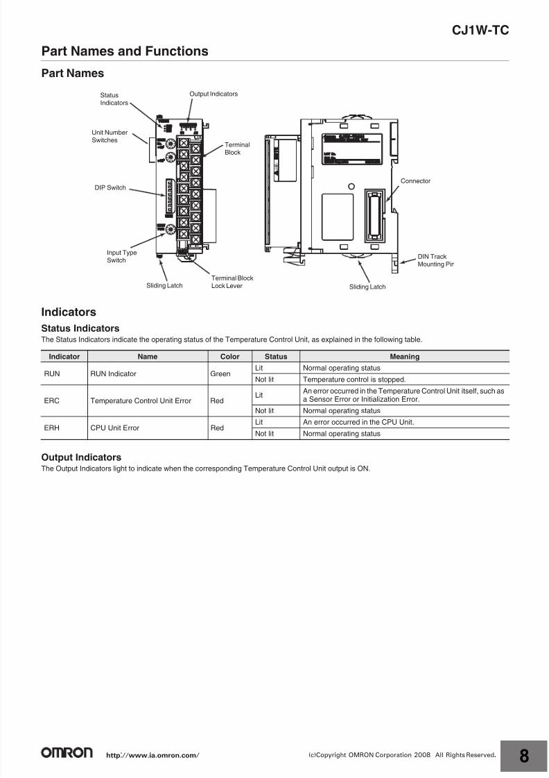
Part Names and Functions
Part Names
Indicators
Status IndicatorsThe Status Indicators indicate the operating status of the Temperature Control Unit, as explained in the following table.
Output IndicatorsThe Output Indicators light to indicate when the corresponding Temperature Control Unit output is ON.
Indicator Name Color Status Meaning
RUN RUN Indicator GreenLit Normal operating status
Not lit Temperature control is stopped.
ERC Temperature Control Unit Error RedLit
An error occurred in the Temperature Control Unit itself, such asa Sensor Error or Initialization Error.
Not lit Normal operating status
ERH CPU Unit Error RedLit An error occurred in the CPU Unit.
Not lit Normal operating status
0
9 8 7
6
5
4 3 2
1
0
9 8 7
6
5
4 3 2
1
0
9 8 7
6
5
4 3 2
1
Connector
DIN TrackMounting Pin
Sliding Latch
Terminal Block
Lock LeverSliding Latch
Input TypeSwitch
DIP Switch
Unit NumberSwitches
StatusIndicators
Output Indicators
TerminalBlock
http://www.ia.omron.com/ 8(c)Copyright OMRON Corporation 2008 All Rights Reserved.
7/27/2019 Cj1w-Tc Dsheet Csm1622
http://slidepdf.com/reader/full/cj1w-tc-dsheet-csm1622 9/12
CJ1W-TC
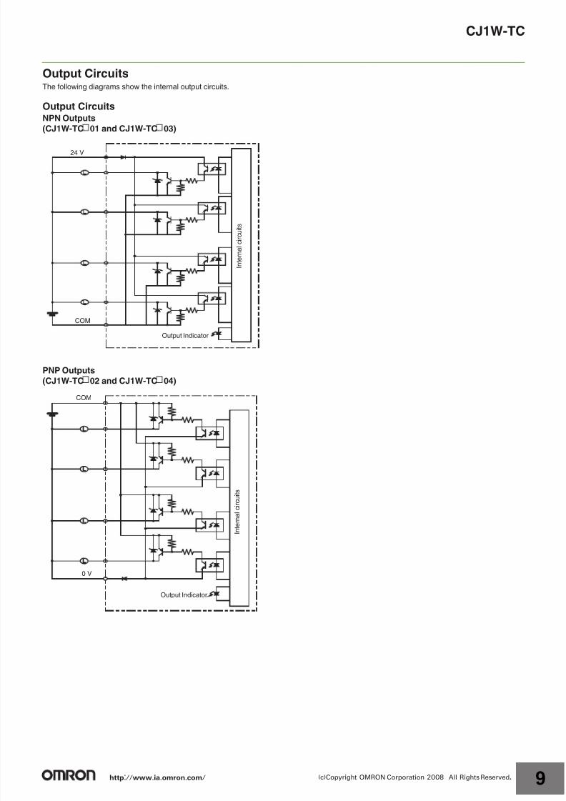
Output CircuitsThe following diagrams show the internal output circuits.
Output CircuitsNPN Outputs
(CJ1W-TC 01 and CJ1W-TC 03)
PNP Outputs
(CJ1W-TC 02 and CJ1W-TC 04)
24 V
COM
Output Indicator
I n t e r n a l c i r c u i t s
COM
0 V
Output Indicator
I n t e r n a l c i r c u i t s
http://www.ia.omron.com/ 9(c)Copyright OMRON Corporation 2008 All Rights Reserved.
7/27/2019 Cj1w-Tc Dsheet Csm1622
http://slidepdf.com/reader/full/cj1w-tc-dsheet-csm1622 10/12
CJ1W-TC
Wiring
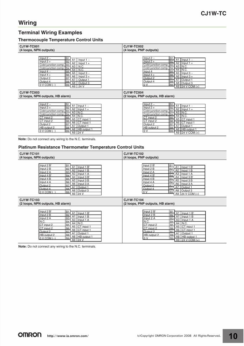
Terminal Wiring Examples
Thermocouple Temperature Control Units
Note: Do not connect any wiring to the N.C. terminals.
Platinum Resistance Thermometer Temperature Control Units
Note: Do not connect any wiring to the N.C. terminals.
CJ1W-TC001(4 loops, NPN outputs)
CJ1W-TC002(4 loops, PNP outputs)
CJ1W-TC003(2 loops, NPN outputs, HB alarm)
CJ1W-TC004(2 loops, PNP outputs, HB alarm)
CJ1W-TC101(4 loops, NPN outputs)
CJ1W-TC102(4 loops, PNP outputs)
CJ1W-TC103(2 loops, NPN outputs, HB alarm)
CJ1W-TC104(2 loops, PNP outputs, HB alarm)
Input 2 −
Input 2 +Cold-junction comp.Cold-junction comp.Input 4 − Input 4 +Output 2Output 40 V COM (−)
Input 1−
Input 1 +N.C.N.C.Input 3 −
Input 3 +Output 1Output 324 V
B1B2B3B4B5B6B7B8B9
A1A2A3A4A5A6A7A8A9
Input 2 −
Input 2 +Cold-junction comp.Cold-junction comp.Input 4 − Input 4 +Output 2Output 40 V
Input 1−Input 1 +
N.C.N.C.Input 3 −
Input 3 +Output 1Output 324 V COM (+)
B1
B2B3B4B5B6B7B8B9
A1A2A3A4A5A6A7A8A9
Input 2 −
Input 2 +Cold-junction comp.Cold-junction comp.CT input 2
CT input 2Output 2HB output 20 V COM (−)
Input 1 −
Input 1 +N.C.N.C.CT input 1CT input 1Output 1HB output 124 V
B1B2B3B4B5
B6B7B8B9
A1A2A3A4A5A6A7A8A9
Input 2 −
Input 2 +Cold-junction comp.Cold-junction comp.CT input 2
CT input 2Output 2HB output 20 V
Input 1 −
Input 1 +N.C.N.C.CT input 1CT input 1Output 1HB output 124 V COM (+)
B1B2B3B4B5
B6B7B8B9
A1A2A3A4A5A6A7A8A9
Input 2 B'Input 2 BInput 2 AInput 4 B'Input 4 B
Input 4 AOutput 2Output 40 V COM (−)
Input 1 B'Input 1 BInput 1 AInput 3 B'
Input 3 BInput 3 AOutput 1Output 324 V
B1B2B3B4B5
B6B7B8B9
A1A2A3A4
A5A6A7A8A9
Input 2 B'Input 2 BInput 2 AInput 4 B'Input 4 B
Input 4 AOutput 2Output 40 V
Input 1 B'Input 1 BInput 1 AInput 3 B'
Input 3 BInput 3 AOutput 1Output 324 V COM (+)
B1B2B3B4B5
B6B7B8B9
A1A2A3A4
A5A6A7A8A9
Input 2 B'Input 2 BInput 2 AN.C.CT input 2CT input 2Output 2HB output 20 V COM (−)
Input 1 B'Input 1 BInput 1 AN.C.CT input 1CT input 1Output 1HB output 124 V
B1B2B3B4B5B6B7B8B9
A1A2A3A4A5A6A7A8A9
Input 2 B'Input 2 BInput 2 AN.C.CT input 2CT input 2Output 2HB output 20 V
Input 1 B'Input 1 BInput 1 AN.C.CT input 1CT input 1Output 1HB output 124 V COM (+)
B1B2B3B4B5B6B7B8B9
A1A2A3A4A5A6A7A8A9
http://www.ia.omron.com/ 10(c)Copyright OMRON Corporation 2008 All Rights Reserved.
7/27/2019 Cj1w-Tc Dsheet Csm1622
http://slidepdf.com/reader/full/cj1w-tc-dsheet-csm1622 11/12
CJ1W-TC
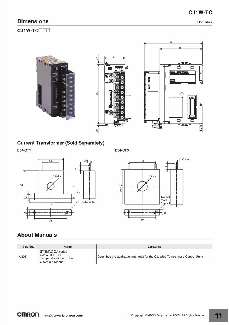
Dimensions (Unit: mm)
CJ1W-TC@@@
Current Transformer (Sold Separately)
About Manuals
E54-CT1 E54-CT3
Cat. No. Name Contents
W396
SYSMAC CJ SeriesCJ1W-TC@@@Temperature Control UnitsOperation Manual
Describes the application methods for the CJseries Temperature Control Units.
0
9 8 7
6
5
4 3 2
1
0
9 8 7
6
5
4 3 2
1
0
9 8 7
6
5
4 3 2
1
89
65
31 2 7
9 0
2 7
2.8
7.1
21
15
5.8 dia.
10.5
40
30
25
3
10
Two 3.5 dia. holes
302.36 dia.
4 0 × 4 0
1 5
30
9
12 dia.
Two M3
holes,
Depth 4
http://www.ia.omron.com/ 11(c)Copyright OMRON Corporation 2008 All Rights Reserved.

7/27/2019 Cj1w-Tc Dsheet Csm1622
http://slidepdf.com/reader/full/cj1w-tc-dsheet-csm1622 12/12
2008.5
OMRON CorporationIndustrial Automation Company
http://www.ia.omron.com/ (c)Copyright OMRON Corporation 2008 All Rights Reserved.
In the interest of product improvement, specifications are subject to change without notice.
Read and Understand This Catalog
Please read and understand this catalog before purchasing the products. Please consult your OMRON representative if you have any questions orcomments.
Warranty and Limitations of Liability
WARRANTYOMRON's exclusive warranty is that the products are free from defects in materials and workmanship for a period of one year (or other period ifspecified) from date of sale by OMRON.
OMRON MAKES NO WARR ANTY OR REPRESENTATION, EXPRESS OR IMPLIED, REGARDING NON-INFRINGEMENT, MERCHANTABILITY, OR
FITNESS FOR PARTICULAR PURPOSE OF THE PRODUCTS. ANY BUYER OR USER ACKNOWLEDGES THAT THE BUYER OR USER ALONEHAS DETERMINED THAT THE PRODUCTS WILL SUITABLY MEET THE REQUIREMENTS OF THEIR INTENDED USE . OMRON DISCLA IMS ALLOTHER WARRANTIES, EXPRESS OR IMPLIED.
LIMITATIONS OF LIABILITYOMRON SHALL NOT BE RESPONSIBLE FOR SPECIAL, INDIRECT, OR CONSEQUENTIAL DA MAGES, LOSS OF PROFITS, OR COMMERCIALLOSS IN ANY WAY CONNECTED WITH THE PRODUCTS, WHETHER SUCH CLAIM IS BASED ON CONTR ACT, WARRANT Y, NEGLIGENCE, ORSTRICT LIABILITY.
In no event shall responsibility of OMRON for any act exceed the individual price of the product on which liability is asserted.
IN NO EVENT SHALL OMRON BE RESPONSIBLE FOR WARRANT Y, REPAIR, OR OTHER CLAIMS REGARDING THE PRODUCTS UNLESSOMRON'S A NALYSIS CONFIRMS THAT THE PRODUCTS WERE PROPERLY HANDLED, STORED, INSTALLED, AND MAINTAINED AND NOTSUBJECT TO CONTAMINATION, ABUSE, MISUSE, OR INAPPROPRIATE MODIFICATION OR REPAIR.
Application Considerations
SUITABILITY FOR USEOMRON shall not be responsible for conformity with any standards, codes, or regulations that apply to the combination of products in the customer'sapplication or use of the product.
At the customer 's request, OMRON will provide applicable third par ty cert ification documents identifying ratings and limitations of use that apply to theproducts. This information by itself is not suf ficient for a complete determination of the suitability of the products in combination with the end product,machine, system, or other application or use.
The following are some examples of applications for which particular attention must be given. This is not intended to be an exhaustive list of all possibleuses of the products, nor is it intended to imply that the uses listed may be suitable for the products:
• Outdoor use, uses involving potential chemical contamination or electrical interference, or conditions or uses not described in this catalog.
• Nuclear energy control systems, combustion systems, railroad systems, aviation systems, medical equipment, amusement machines, vehicles, safetyequipment, and installations subject to separate industry or government regulations.
• Systems, machines, and equipment that could present a risk to life or property.
Please know and observe all prohibitions of use applicable to the products.
NEVER USE THE PRODUCTS FOR AN APPLICATION INVOLVING SERIOUS RISK TO LIFE OR PROPERTY WITHOUT ENSURING THAT THESYSTEM AS A WHOLE HAS BEEN DESIGNED TO ADDRESS THE RISKS, AND THAT THE OMRON PRODUCT IS PROPERLY RATED ANDINSTALLED FOR THE INTENDED USE WITHIN THE OVERA LL EQUIPMENT OR SYSTEM.
Disclaimers
CHANGE IN SPECIFICATIONSProduct specifications and accessories may be changed at any time based on improvements and other reasons.
It is our practice to change model numbers when published ratings or features are changed, or when significant construction changes are made.However, some specifications of the product may be changed without any notice. When in doubt, special model numbers may be assigned to fixor establish key specifications for your application on your request. Please consult with your OMRON representative at any time to con firm actualspecifications of purchased product.
DIMENSIONS AND WEIGHTSDimensions and weights are nominal and are not to be used for manufacturing purposes, even when tolerances are shown.
ERRORS AND OMISSIONSThe information in this catalog has been carefully checked and is believed to be accurate; however, no responsibility is assumed for clerical,typographical, or proofreading errors, or omissions.
PERFORMANCE DATA
Performance data given in this catalog is provided as a guide for the user in determining suitability and does not constitute a warranty. It may representthe result of OMRON’s test conditions, and the users must correlate it to actual application requirements. Actual performance is subject to the OMRONWarranty and Limitations of Liability.
PROGRAMMABLE PRODUCTSOMRON shall not be responsible for the user's programming of a programmable product, or any consequence thereof.
COPYRIGHT AND COPY PERMISSIONThis catalog shall not be copied for sales or promotions without permission.
This catalog is protected by copyright and is intended solely for use in conjunction with the product. Please notify us before copying or reproducing thiscatalog in any manner, for any other purpose. If copying or transmitting this catalog to another, please copy or transmit it in its entirety.