Embed Size (px)
Citation preview
7/25/2019 Civil2016 v11 Release Note
http://slidepdf.com/reader/full/civil2016-v11-release-note 1/31
DESIGN OF CIVIL STRUCTURESI n t e g r a t e d S o l u t i o n S y s t e m f o r B r i d g e a n d C i v i l E n g i n e e r i n g
Release NoteRelease Date : SEP. 1, 2015
Product Ver. : Civil 2016 (v1.1)
7/25/2019 Civil2016 v11 Release Note
http://slidepdf.com/reader/full/civil2016-v11-release-note 2/31
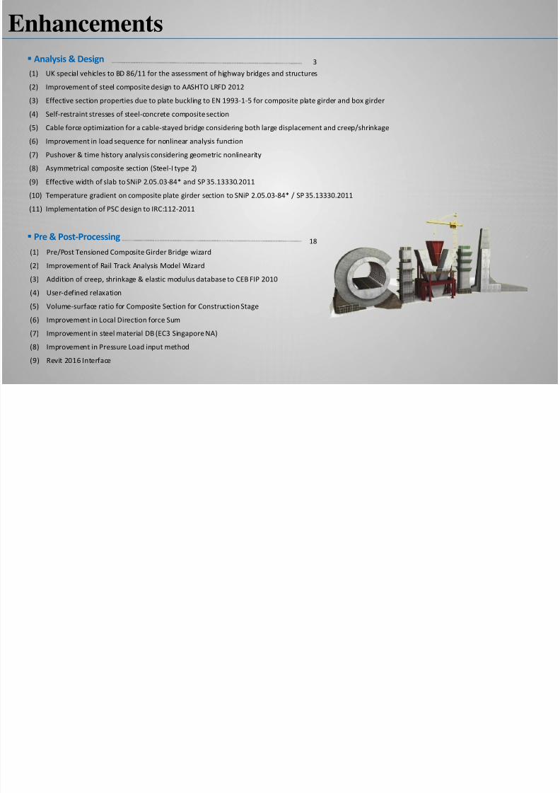
Enhancements
(1) UK special vehicles to BD 86/11 for the assessment of highway bridges and structures
(2) Improvement of steel composite design to AASHTO LRFD 2012
(3) Effective section properties due to plate buckling to EN 1993-1-5 for composite plate girder and box girder
(4) Self-restraint stresses of steel-concrete composite section
(5) Cable force optimization for a cable-stayed bridge considering both large displacement and creep/shrinkage
(6) Improvement in load sequence for nonlinear analysis function
(7) Pushover & time history analysis considering geometric nonlinearity
(8) Asymmetrical composite section (Steel-I type 2)
(9) Effective width of slab to SNiP 2.05.03-84* and SP 35.13330.2011
(10) Temperature gradient on composite plate girder section to SNiP 2.05.03-84* / SP 35.13330.2011
(11) Implementation of PSC design to IRC:112-2011
Analysis & Design 3
Pre & Post-Processing
(1) Pre/Post Tensioned Composite Girder Bridge wizard
(2) Improvement of Rail Track Analysis Model Wizard
(3) Addition of creep, shrinkage & elastic modulus database to CEB FIP 2010
(4) User-defined relaxation
(5) Volume-surface ratio for Composite Section for Construction Stage
(6) Improvement in Local Direction force Sum
(7) Improvement in steel material DB (EC3 Singapore NA)
(8) Improvement in Pressure Load input method
(9) Revit 2016 Interface
18
7/25/2019 Civil2016 v11 Release Note
http://slidepdf.com/reader/full/civil2016-v11-release-note 3/31
3 /
Civil 2016 (v1.1) Release NCivil 2016 Analysis & Design
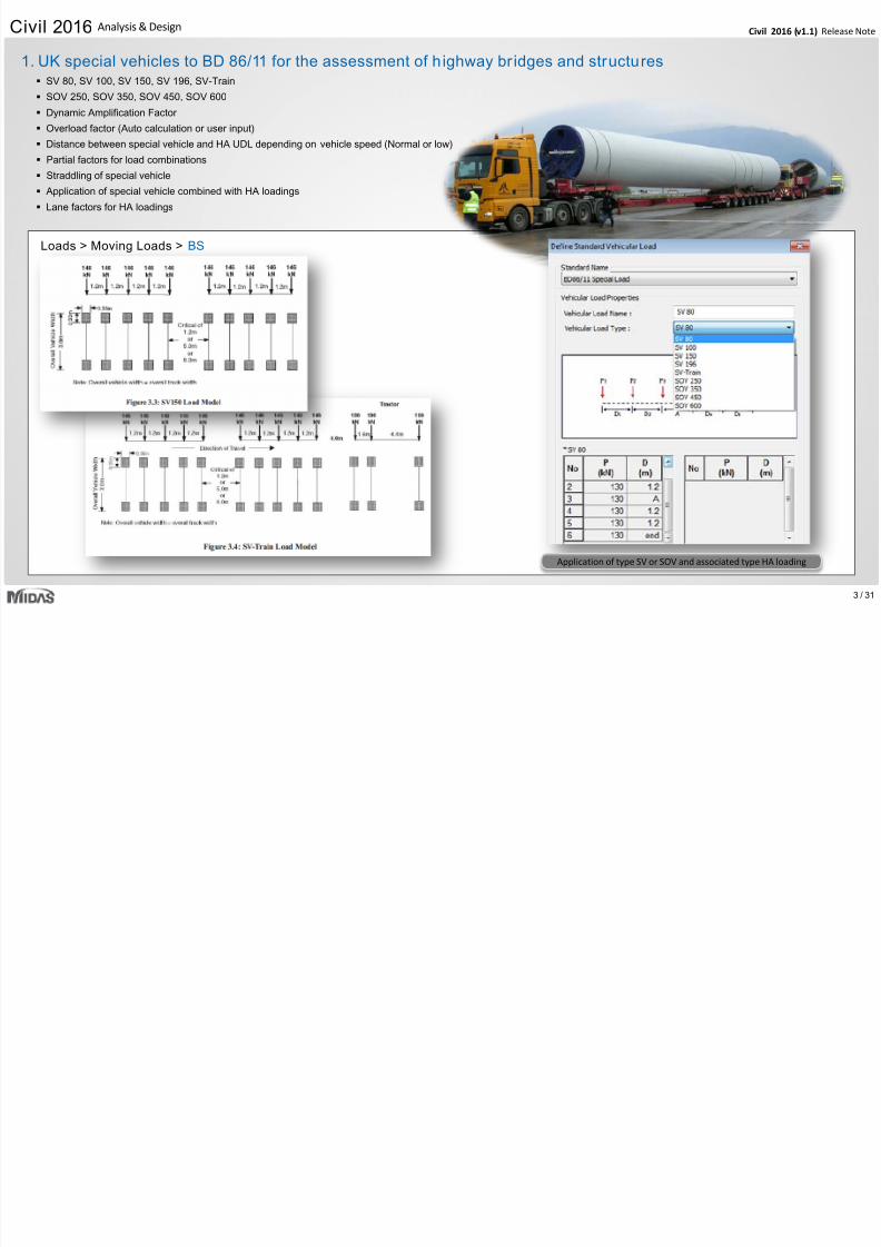
SV 80, SV 100, SV 150, SV 196, SV-Train
SOV 250, SOV 350, SOV 450, SOV 600
Dynamic Amplification Factor
Overload factor (Auto calculation or user input)
Distance between special vehicle and HA UDL depending on vehicle speed (Normal or low)
Partial factors for load combinations
Straddling of special vehicle
Application of special vehicle combined with HA loadings
Lane factors for HA loadings
Loads > Moving Loads > BS
1. UK special vehicles to BD 86/11 for the assessment of h ighway br idges and structures
Application of type SV or SOV and associated type HA loading
7/25/2019 Civil2016 v11 Release Note
http://slidepdf.com/reader/full/civil2016-v11-release-note 4/31
4 /
Civil 2016 (v1.1) Release NCivil 2016 Analysis & Design
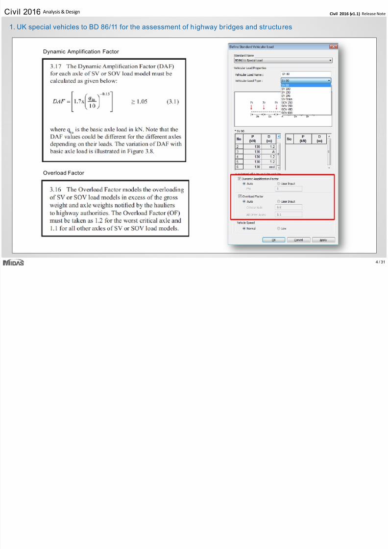
Dynamic Amplification Factor
Overload Factor
1. UK special vehicles to BD 86/11 for the assessment of h ighway br idges and structures
7/25/2019 Civil2016 v11 Release Note
http://slidepdf.com/reader/full/civil2016-v11-release-note 5/31 5 /
Civil 2016 (v1.1) Release NCivil 2016 Analysis & Design
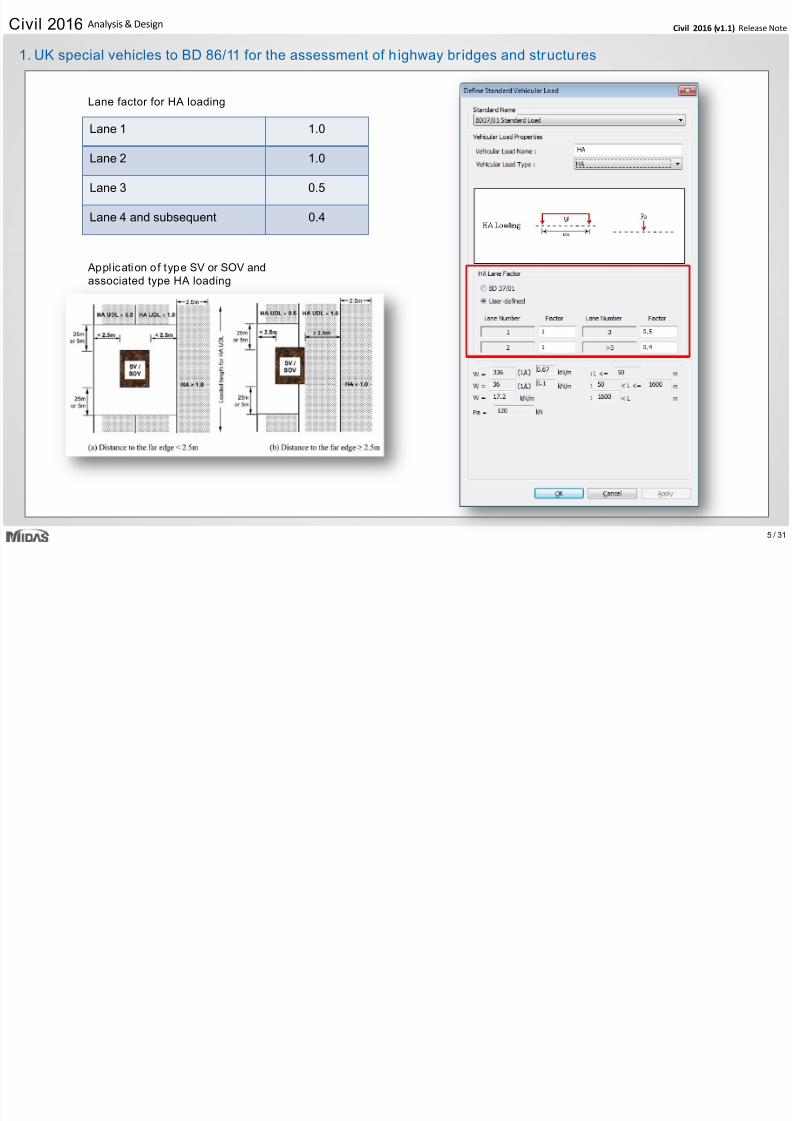
Lane factor for HA loading
Lane 1 1.0
Lane 2 1.0
Lane 3 0.5
Lane 4 and subsequent 0.4
1. UK special vehicles to BD 86/11 for the assessment of h ighway br idges and structures
Appl ication o f type SV or SOV and
associated type HA loading
7/25/2019 Civil2016 v11 Release Note
http://slidepdf.com/reader/full/civil2016-v11-release-note 6/31 6 /
Civil 2016 (v1.1) Release NCivil 2016 Analysis & Design
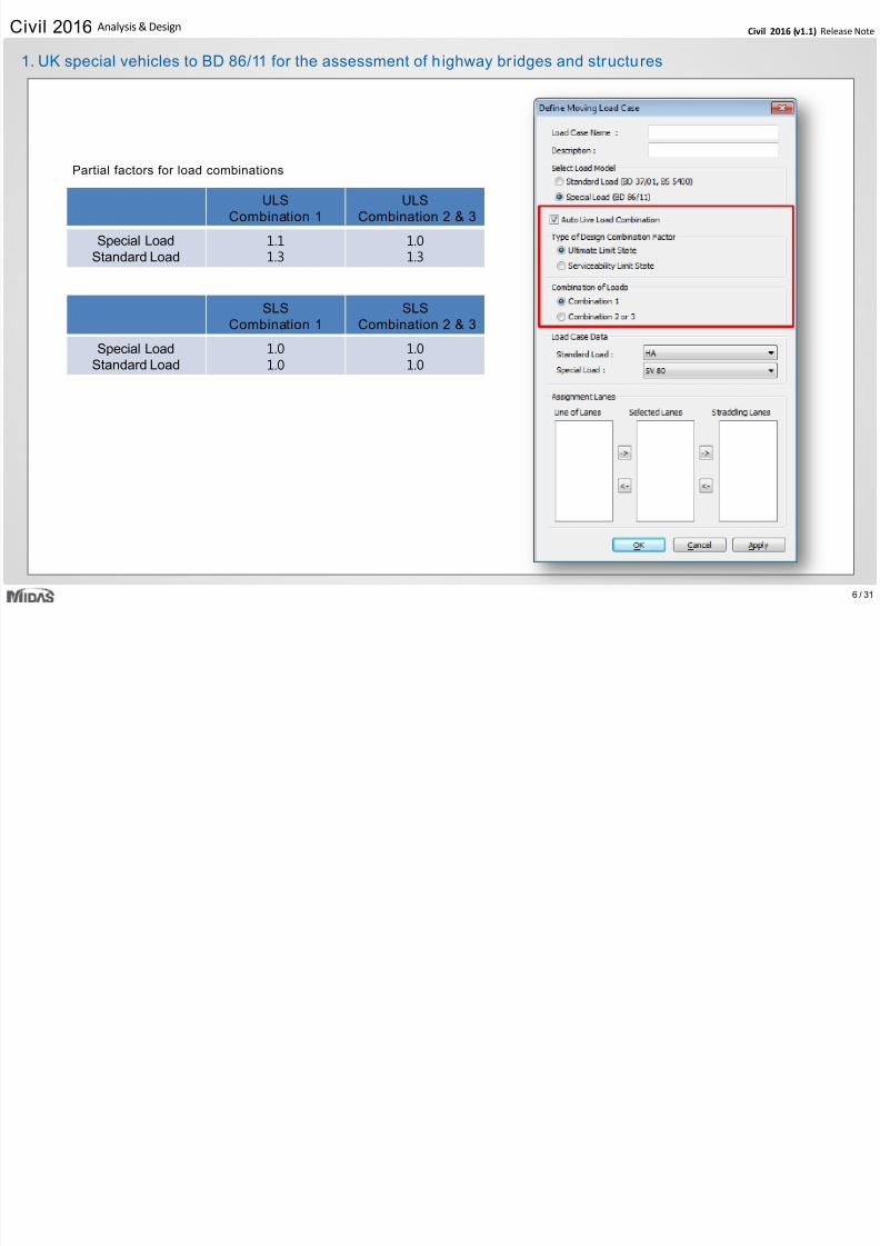
Partial factors for load combinations
ULS
Combination 1 ULS
Combination 2 & 3
Special Load
Standard Load 1.11.3
1.01.3
SLSCombination 1
SLSCombination 2 & 3
Special Load
Standard Load 1.01.0
1.01.0
1. UK special vehicles to BD 86/11 for the assessment of h ighway br idges and structures
7/25/2019 Civil2016 v11 Release Note
http://slidepdf.com/reader/full/civil2016-v11-release-note 7/31 7 /
Civil 2016 (v1.1) Release NCivil 2016 Analysis & Design
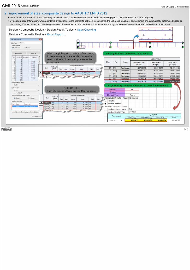
2. Improvement of steel composi te design to AASHTO LRFD 2012
Design > Composi te Design > Design Result Tables > Span Checking
Design > Composite Design > Excel Report…
In the previous version, the ‘Span Checking’ table results did not take into account support when defining spans. This is improved in Civil 2016 (v1.1).
By defining Span Information, when a girder is divided into several elements between cross beams, the unbraced lengths of each element are automatically determined based on
the spacing of cross beams, and the design moment of an element is taken as the maximum moment among the elements which are located between the cross beams.
Bending Moments of element 29, 31 and 33
Design Bending Moments of element 31 taken from element 33
When one girder group consisted of two spans,
in the previous version, span checking results
were provided as if the girder group consisted
of one span.
Civil 2016 (v1.1):
Span Checking results are provided for two spans.
7/25/2019 Civil2016 v11 Release Note
http://slidepdf.com/reader/full/civil2016-v11-release-note 8/31 8 /
Civil 2016 (v1.1) Release NCivil 2016 Analysis & Design
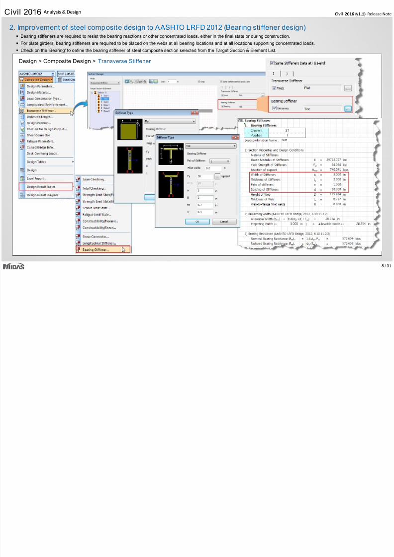
2. Improvement of steel composite design to AASHTO LRFD 2012 (Bearing sti ffener design)
Design > Composite Design > Transverse Stiffener
Bearing stiffeners are required to resist the bearing reactions or other concentrated loads, either in the final state or during construction.
For plate girders, bearing stiffeners are required to be placed on the webs at all bearing locations and at all locations supporting concentrated loads.
Check on the 'Bearing' to define the bearing stiffener of steel composite section selected from the Target Section & Element List.
7/25/2019 Civil2016 v11 Release Note
http://slidepdf.com/reader/full/civil2016-v11-release-note 9/31 9 /
Civil 2016 (v1.1) Release NCivil 2016 Analysis & Design
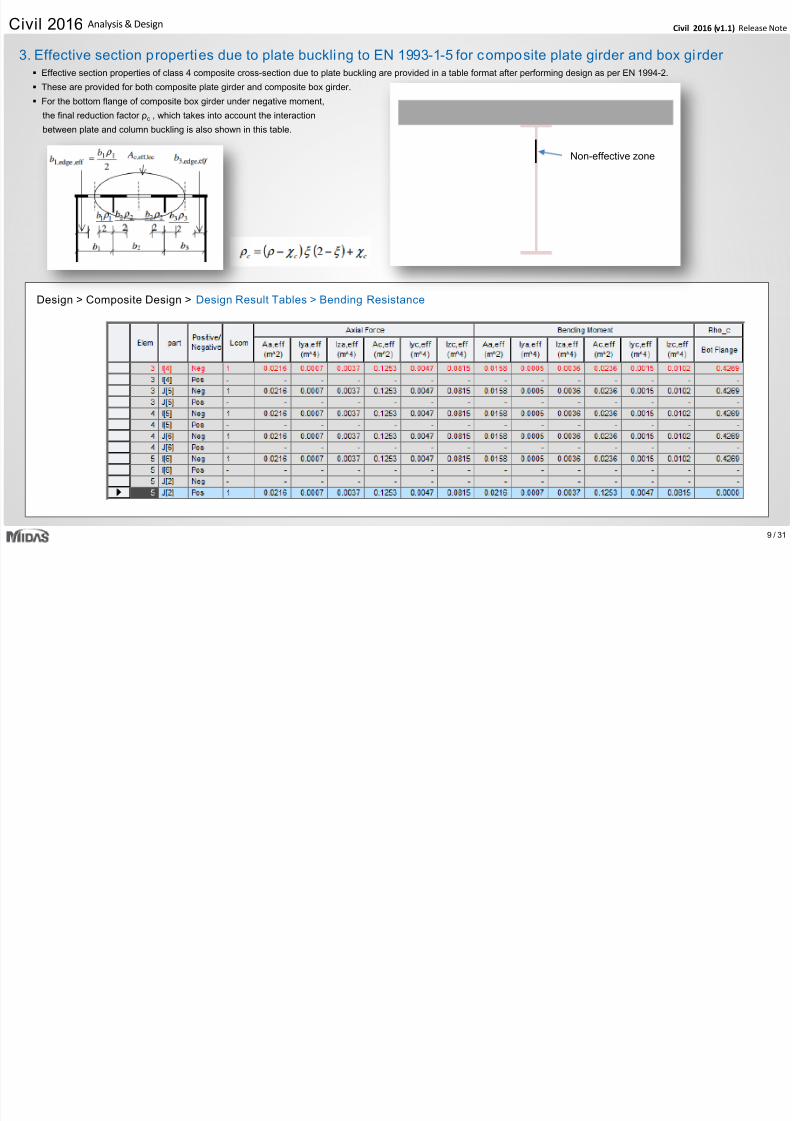
Effective section properties of class 4 composite cross-section due to plate buckling are provided in a table format after performing design as per EN 1994-2.
These are provided for both composite plate girder and composite box girder.
For the bottom flange of composite box girder under negative moment,
the final reduction factor ρc , which takes into account the interaction
between plate and column buckling is also shown in this table.
Design > Composite Design > Design Result Tables > Bending Resistance
3. Effective section properties due to plate buckling to EN 1993-1-5 for composite plate girder and box gi rder
Non-effective zone
7/25/2019 Civil2016 v11 Release Note
http://slidepdf.com/reader/full/civil2016-v11-release-note 10/3110 /
Civil 2016 (v1.1) Release NCivil 2016 Analysis & Design
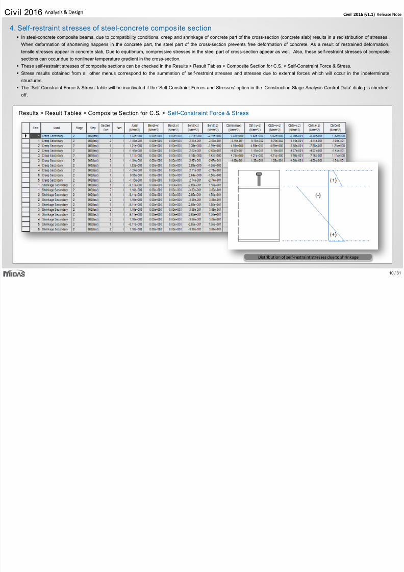
In steel-concrete composite beams, due to compatibility conditions, creep and shrinkage of concrete part of the cross-section (concrete slab) results in a redistribution of stresses.
When deformation of shortening happens in the concrete part, the steel part of the cross-section prevents free deformation of concrete. As a result of restrained deformation,
tensile stresses appear in concrete slab, Due to equilibrium, compressive stresses in the steel part of cross-section appear as well. Also, these self-restraint stresses of composite
sections can occur due to nonlinear temperature gradient in the cross-section.
These self-restraint stresses of composite sections can be checked in the Results > Result Tables > Composite Section for C.S. > Self-Constraint Force & Stress.
Stress results obtained from all other menus correspond to the summation of self-restraint stresses and stresses due to external forces which will occur in the indeterminate
structures.
The ‘Self-Constraint Force & Stress’ table will be inactivated if the ‘Self-Constraint Forces and Stresses’ option in the ‘Construction Stage Analysis Control Data’ dialog is checked
off.
Results > Result Tables > Composi te Section for C.S. > Self-Constraint Force & Stress
4. Self-restraint stresses of steel-concrete composite section
Distribution of self-restraint stresses due to shrinkage
7/25/2019 Civil2016 v11 Release Note
http://slidepdf.com/reader/full/civil2016-v11-release-note 11/3111 /
Civil 2016 (v1.1) Release NCivil 2016 Analysis & Design
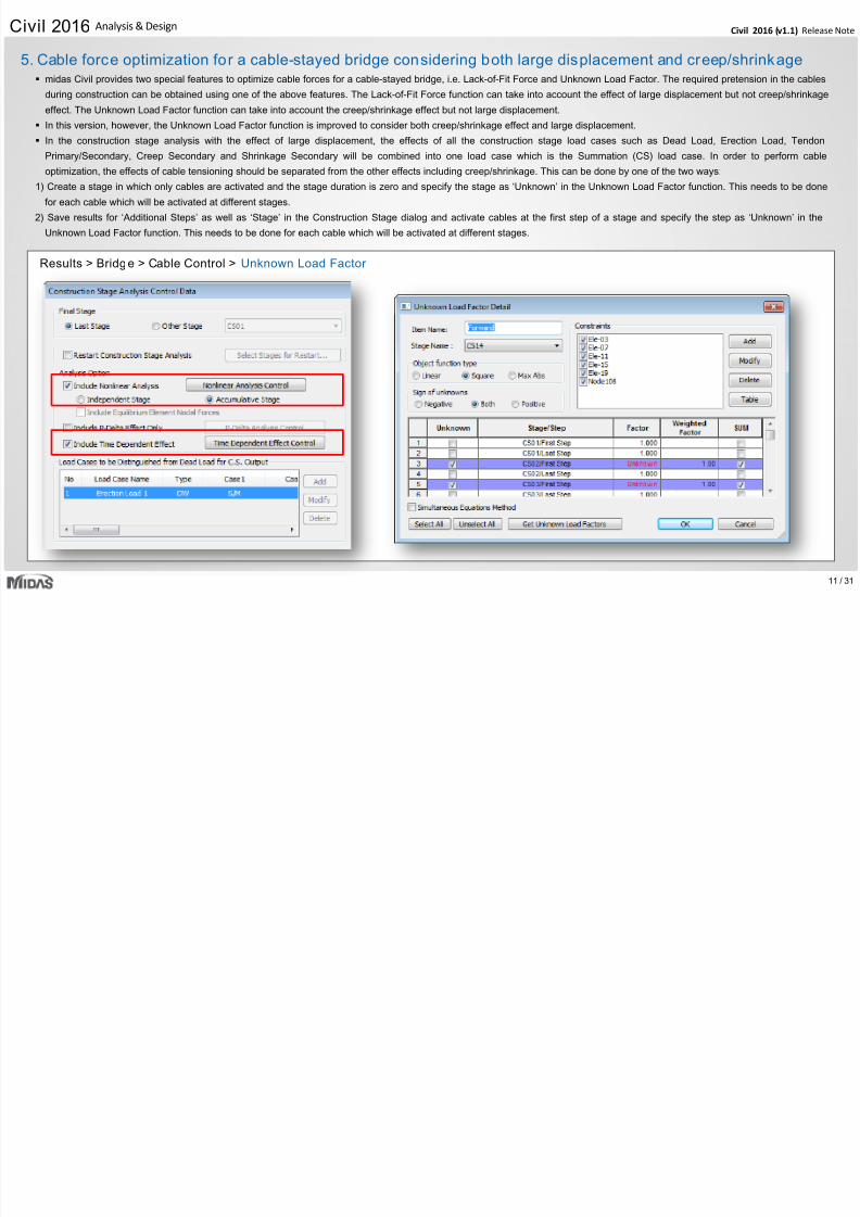
midas Civil provides two special features to optimize cable forces for a cable-stayed bridge, i.e. Lack-of-Fit Force and Unknown Load Factor. The required pretension in the cables
during construction can be obtained using one of the above features. The Lack-of-Fit Force function can take into account the effect of large displacement but not creep/shrinkage
effect. The Unknown Load Factor function can take into account the creep/shrinkage effect but not large displacement.
In this version, however, the Unknown Load Factor function is improved to consider both creep/shrinkage effect and large displacement.
In the construction stage analysis with the effect of large displacement, the effects of all the construction stage load cases such as Dead Load, Erection Load, Tendon
Primary/Secondary, Creep Secondary and Shrinkage Secondary will be combined into one load case which is the Summation (CS) load case. In order to perform cable
optimization, the effects of cable tensioning should be separated from the other effects including creep/shrinkage. This can be done by one of the two ways:
1) Create a stage in which only cables are activated and the stage duration is zero and specify the stage as ‘Unknown’ in the Unknown Load Factor function. This needs to be done
for each cable which will be activated at different stages.
2) Save results for ‘Additional Steps’ as well as ‘Stage’ in the Construction Stage dialog and activate cables at the first step of a stage and specify the step as ‘Unknown’ in the
Unknown Load Factor function. This needs to be done for each cable which will be activated at different stages.
Results > Bridge > Cable Control > Unknown Load Factor
5. Cable force optimization for a cable-stayed bridge considering both large displacement and creep/shrinkage
7/25/2019 Civil2016 v11 Release Note
http://slidepdf.com/reader/full/civil2016-v11-release-note 12/3112 /
Civil 2016 (v1.1) Release NCivil 2016 Analysis & Design
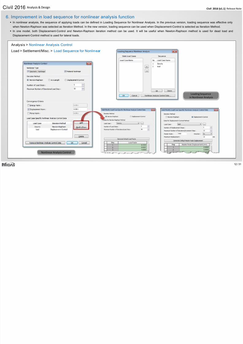
Analysis > Nonlinear Analysis Control
Load > Settlement/Misc. > Load Sequence for Nonlinear
Loading Sequence
in Nonlinear Analysis
Nonlinear Analysis Control
6. Improvement in load sequence for nonlinear analysis function In nonlinear analysis, the sequence of applying loads can be defined in Loading Sequence for Nonlinear Analysis. In the previous version, loading sequence was effective only
when Newton-Raphson was selected as Iteration Method. In the new version, loading sequence can be used when Displacement-Control is selected as Iteration Method.
In one model, both Displacement-Control and Newton-Raphson iteration method can be used. It will be useful when Newton-Raphson method is used for dead load and
Displacement-Control method is used for lateral loads.
7/25/2019 Civil2016 v11 Release Note
http://slidepdf.com/reader/full/civil2016-v11-release-note 13/31
13 /
Civil 2016 (v1.1) Release NCivil 2016 Analysis & Design
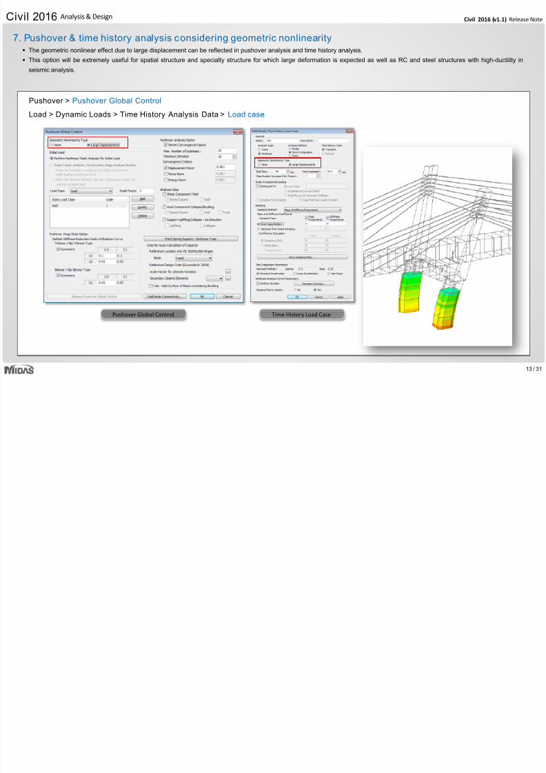
Pushover > Pushover Global Control
Load > Dynamic Loads > Time History Analysis Data > Load case
Pushover Global Control Time History Load Case
7. Pushover & time history analysis considering geometric nonlinearity The geometric nonlinear effect due to large displacement can be reflected in pushover analysis and time history analysis.
This option will be extremely useful for spatial structure and specialty structure for which large deformation is expected as well as RC and steel structures with high-ductility in
seismic analysis.
7/25/2019 Civil2016 v11 Release Note
http://slidepdf.com/reader/full/civil2016-v11-release-note 14/31
14 /
Civil 2016 (v1.1) Release NCivil 2016 Analysis & Design
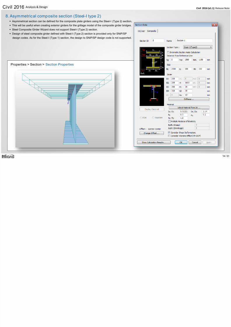
Asymmetrical section can be defined for the composite plate girders using the Steel-I (Type 2) section.
This will be useful when creating exterior girders for the grillage model of the composite girder bridges.
Steel Composite Girder Wizard does not support Steel-I (Type 2) section.
Design of steel composite girder defined with Steel-I (Type 2) section is provided only for SNiP/SP
design codes. As for the Steel-I (Type 1) section, the design to SNiP/SP design code is not supported.
Properties > Section > Section Properties
8. Asymmetrical composite section (Steel-I type 2)
C
7/25/2019 Civil2016 v11 Release Note
http://slidepdf.com/reader/full/civil2016-v11-release-note 15/31
15 /
Civil 2016 (v1.1) Release NCivil 2016 Analysis & Design
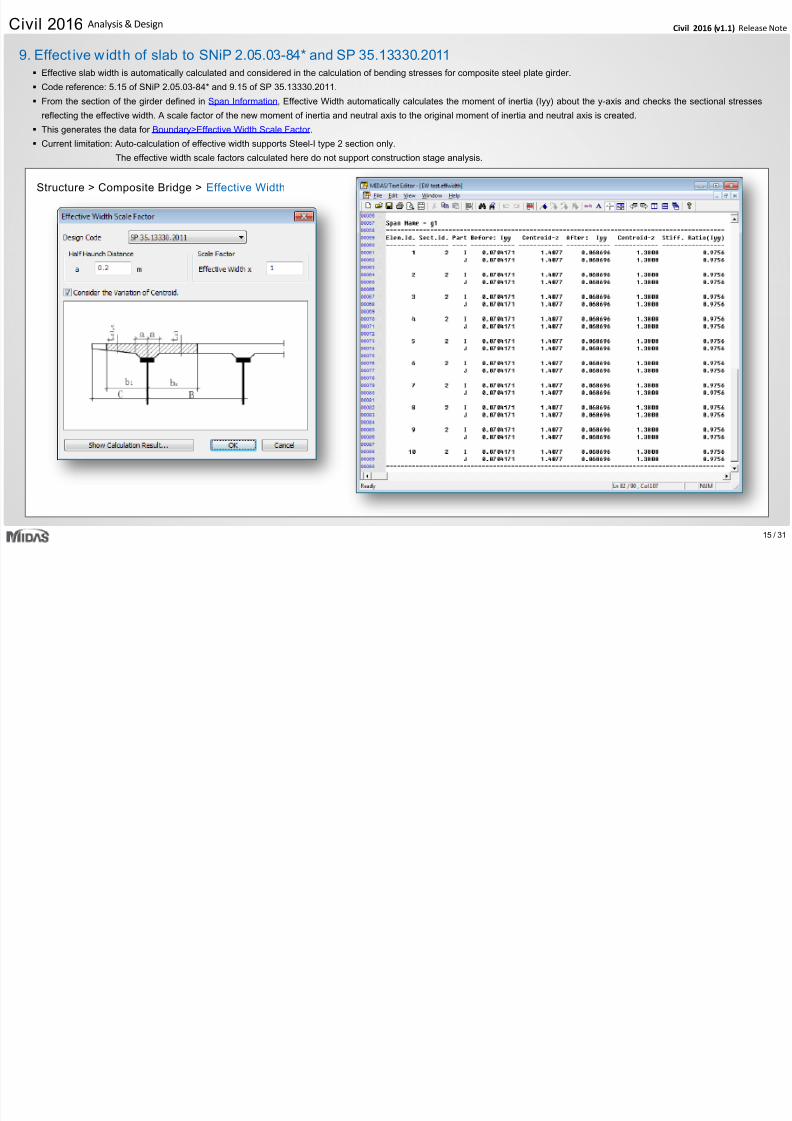
Effective slab width is automatically calculated and considered in the calculation of bending stresses for composite steel plate girder.
Code reference: 5.15 of SNiP 2.05.03-84* and 9.15 of SP 35.13330.2011.
From the section of the girder defined in Span Information, Effective Width automatically calculates the moment of inertia (Iyy) about the y-axis and checks the sectional stresses
reflecting the effective width. A scale factor of the new moment of inertia and neutral axis to the original moment of inertia and neutral axis is created.
This generates the data for Boundary>Effective Width Scale Factor .
Current limitation: Auto-calculation of effective width supports Steel-I type 2 section only.
The effective width scale factors calculated here do not support construction stage analysis.
Structure > Composite Bridge > Effective Width
9. Effect ive width of slab to SNiP 2.05.03-84* and SP 35.13330.2011
Ci il 2016
7/25/2019 Civil2016 v11 Release Note
http://slidepdf.com/reader/full/civil2016-v11-release-note 16/31
16 /
Civil 2016 (v1.1) Release NCivil 2016 Analysis & Design
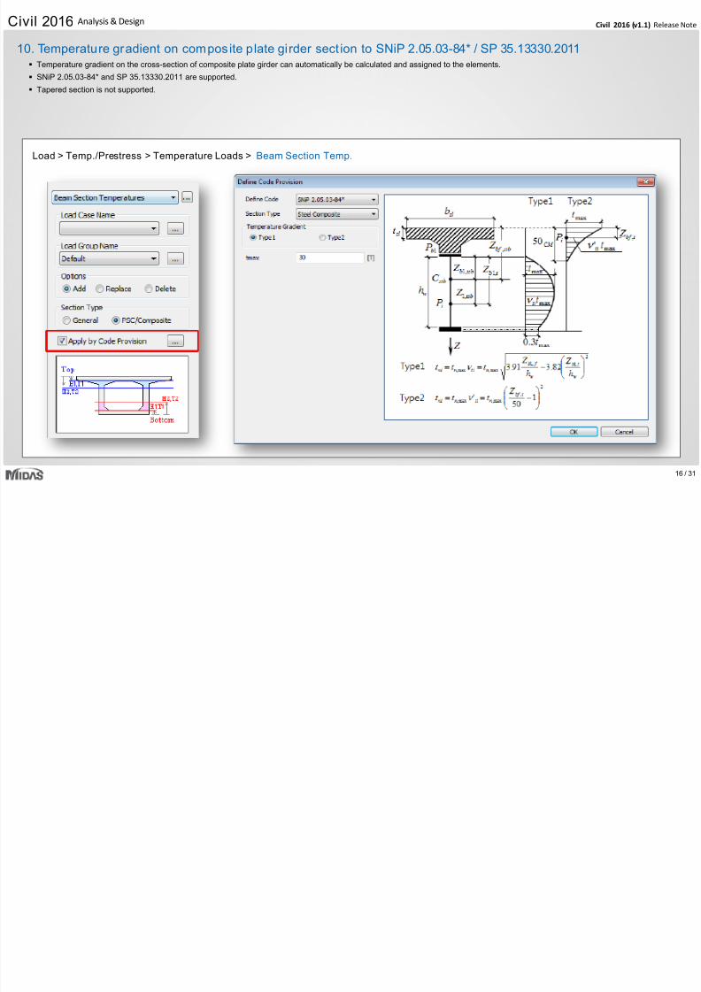
Temperature gradient on the cross-section of composite plate girder can automatically be calculated and assigned to the elements.
SNiP 2.05.03-84* and SP 35.13330.2011 are supported.
Tapered section is not supported.
Load > Temp./Prestress > Temperature Loads > Beam Section Temp.
10. Temperature gradient on composite plate girder sect ion to SNiP 2.05.03-84* / SP 35.13330.2011
Ci il 2016 l i & i
7/25/2019 Civil2016 v11 Release Note
http://slidepdf.com/reader/full/civil2016-v11-release-note 17/31
17 /
Civil 2016 (v1.1) Release NCivil 2016 Analysis & Design
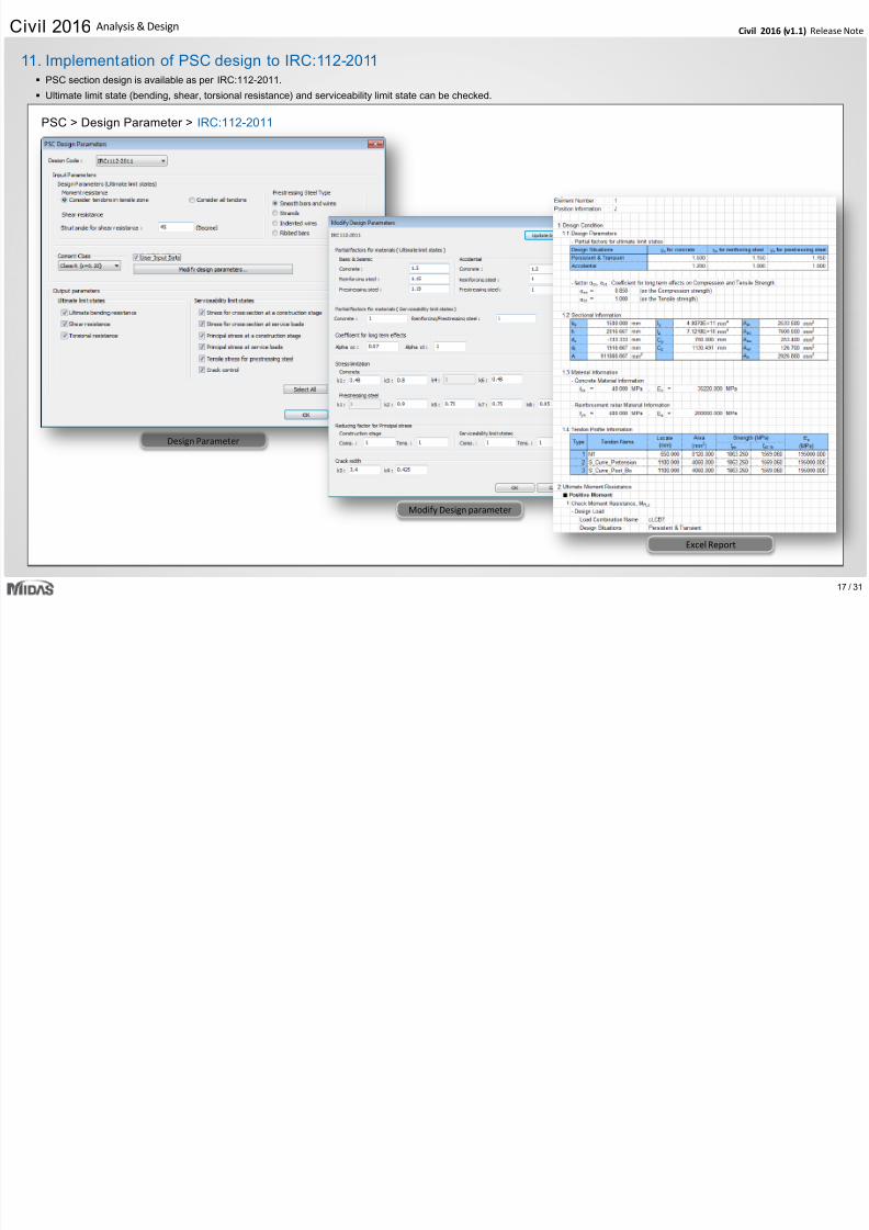
Design Parameter
11. Implementation of PSC design to IRC:112-2011
PSC > Design Parameter > IRC:112-2011
Modify Design parameter
PSC section design is available as per IRC:112-2011.
Ultimate limit state (bending, shear, torsional resistance) and serviceability limit state can be checked.
Excel Report
Civil 2016 P & P t P i
7/25/2019 Civil2016 v11 Release Note
http://slidepdf.com/reader/full/civil2016-v11-release-note 18/31
18 /
Civil 2016 (v1.1) Release NCivil 2016 Pre & Post-Processing
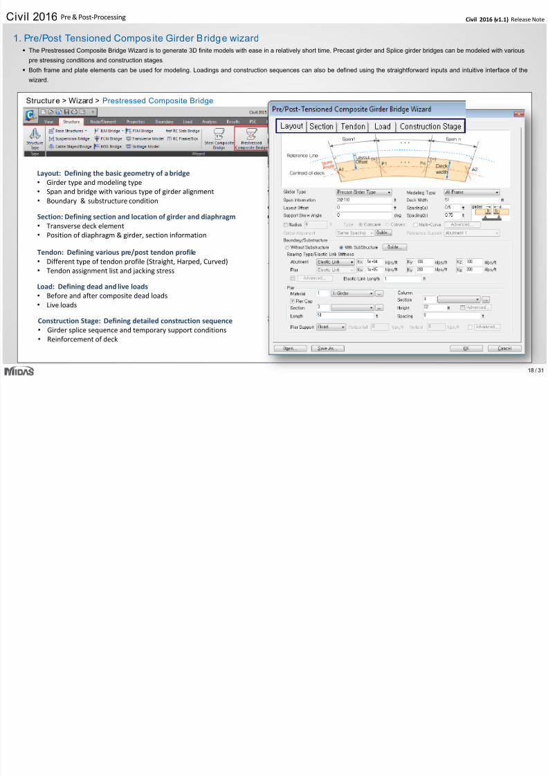
Layout: Defining the basic geometry of a bridge
• Girder type and modeling type
• Span and bridge with various type of girder alignment• Boundary & substructure condition
Section: Defining section and location of girder and diaphragm
• Transverse deck element
• Position of diaphragm & girder, section information
Tendon: Defining various pre/post tendon profile
• Different type of tendon profile (Straight, Harped, Curved)
• Tendon assignment list and jacking stress
Construction Stage: Defining detailed construction sequence
• Girder splice sequence and temporary support conditions
• Reinforcement of deck
1. Pre/Post Tensioned Composite Girder Bridge wizard
Structure > Wizard > Prestressed Composite Bridge
The Prestressed Composite Bridge Wizard is to generate 3D finite models with ease in a relatively short time. Precast girder and Splice girder bridges can be modeled with various
pre stressing conditions and construction stages.
Both frame and plate elements can be used for modeling. Loadings and construction sequences can also be defined using the straightforward inputs and intuitive interface of the
wizard.
Load: Defining dead and live loads
• Before and after composite dead loads
• Live loads
Civil 2016 Pre & Post Processing
7/25/2019 Civil2016 v11 Release Note
http://slidepdf.com/reader/full/civil2016-v11-release-note 19/31
19 /
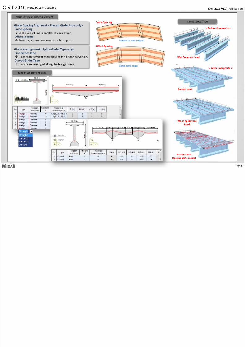
Civil 2016 (v1.1) Release NCivil 2016 Pre & Post-Processing
Various Load Type
Various type of girder alignment
Tendon assignment table
Girder Spacing Alignment < Precast Girder type only>
Same Spacing
Each support line is parallel to each other.
Offset Spacing
Skew angles are the same at each support.
Wet Concrete Load
< Before Composite >
Barrier Load
< After Composite >
Wearing Surface
Load
Barrier Load
Deck as plate model
Girder Arrangement < Splice Girder Type only>
Line Girder Type
Girders are straight regardless of the bridge curvature.
Curved Girder Type
Girders are arranged along the bridge curve.
Same Spacing
Offset Spacing
Civil 2016 Pre & Post Processing
7/25/2019 Civil2016 v11 Release Note
http://slidepdf.com/reader/full/civil2016-v11-release-note 20/31
20 /
Civil 2016 (v1.1) Release NCivil 2016 Pre & Post-Processing
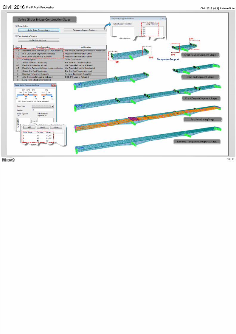
Remove Temporary Supports Stage
Post-tensioning Stage
Splice Girder Bridge Construction Stage
Temporary Support
Erect End Segment Stage
Erect Haunch Segment Stage
Erect Drop-in Segment Stage
SP1
SP4
SP2SP3
Ci il 2016 ( 1 1) R l NCivil 2016 Pre & Post-Processing
7/25/2019 Civil2016 v11 Release Note
http://slidepdf.com/reader/full/civil2016-v11-release-note 21/31
21 /
Civil 2016 (v1.1) Release NCivil 2016 Pre & Post Processing
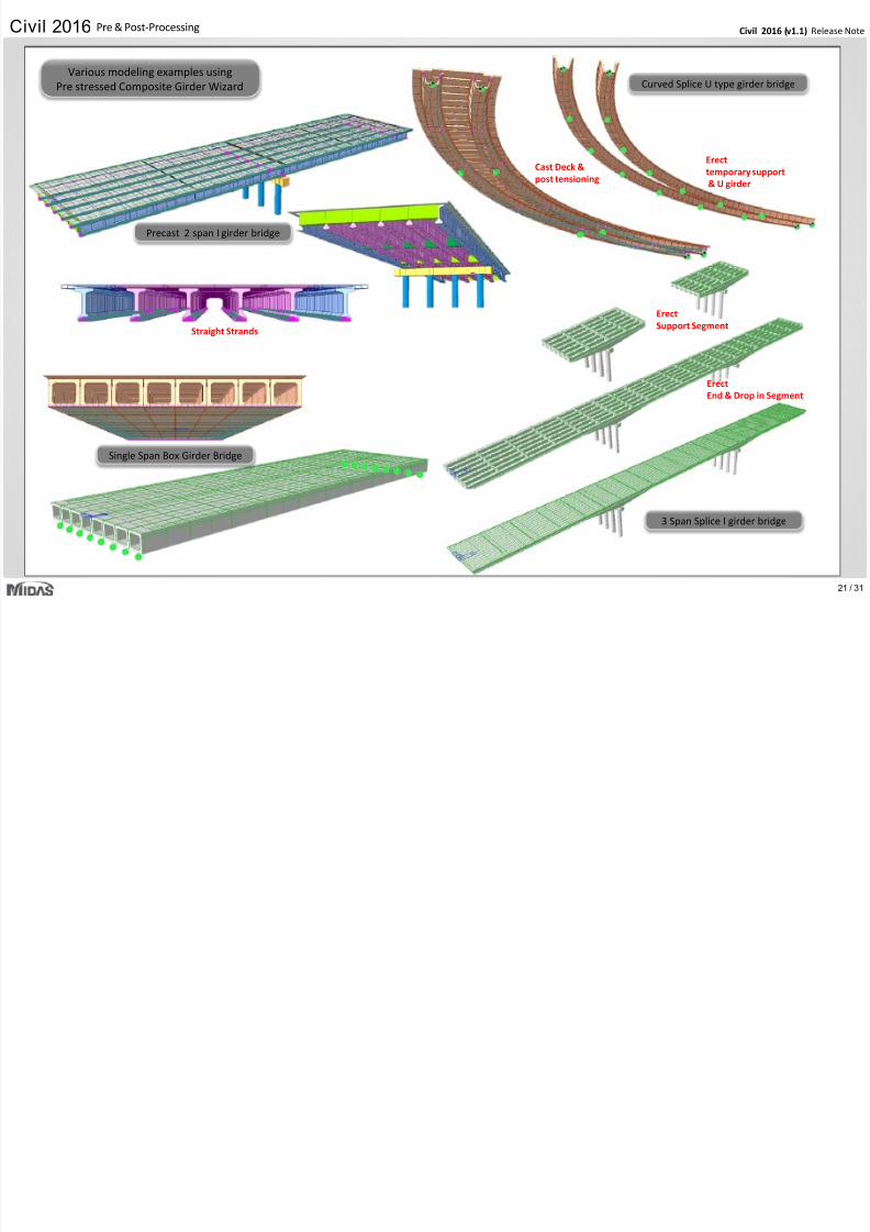
Single Span Box Girder Bridge
Precast 2 span I girder bridge
Straight Strands
3 Span Splice I girder bridge
Curved Splice U type girder bridge
Erecttemporary support
& U girder
Cast Deck &
post tensioning
ErectSupport Segment
Erect
End & Drop in Segment
Various modeling examples using
Pre stressed Composite Girder Wizard
Civil 2016 (v1 1) Release NCivil 2016 Pre & Post-Processing
7/25/2019 Civil2016 v11 Release Note
http://slidepdf.com/reader/full/civil2016-v11-release-note 22/31
22 /
Civil 2016 (v1.1) Release NCivil 2016 Pre & Post Processing
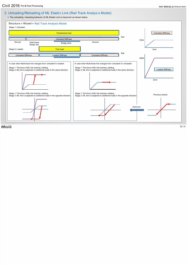
Structure > Wizard > Rail Track Analysis Model
2. Unloading/Reloading of ML Elastic Link (Rail Track Analysis Model)
Unloaded Stiffness
Temperature load
Rail
Bridge deckMulti-linear
Elastic link
Ground
Train load
RailUnloaded Stiffness Unloaded StiffnessLoaded Stiffness
Ground
Stage 1: Unloaded
Stage 2: Loaded
Unloaded Stiffness
20kN
2mm
Loaded Stiffness
2mm
60kN
In case when Multi-linear link changes from 'unloaded' to 'loaded'. In case when Multi-linear link changes from 'unloaded' to 'unloaded‘.
Stage 1: The force of ML link reaches yielding.
Stage 2: ML link is subjected to additional loads in the same direction.
Stage 1: The force of ML link reaches yielding.
Stage 2: ML link is subjected to additional loads in the same direction.
Stage 1: The force of ML link reaches yielding.
Stage 2: ML link is subjected to additional loads in the opposite direction.
Stage 1: The force of ML link reaches yielding.
Stage 2: ML link is subjected to additional loads in the opposite direction.Previous version
Improved
The unloading / reloading behavior of ML Elastic Link is improved as shown below.
Civil 2016 (v1 1) Release NCivil 2016 Pre & Post-Processing
7/25/2019 Civil2016 v11 Release Note
http://slidepdf.com/reader/full/civil2016-v11-release-note 23/31
23 /
Civil 2016 (v1.1) Release NCivil 2016 g
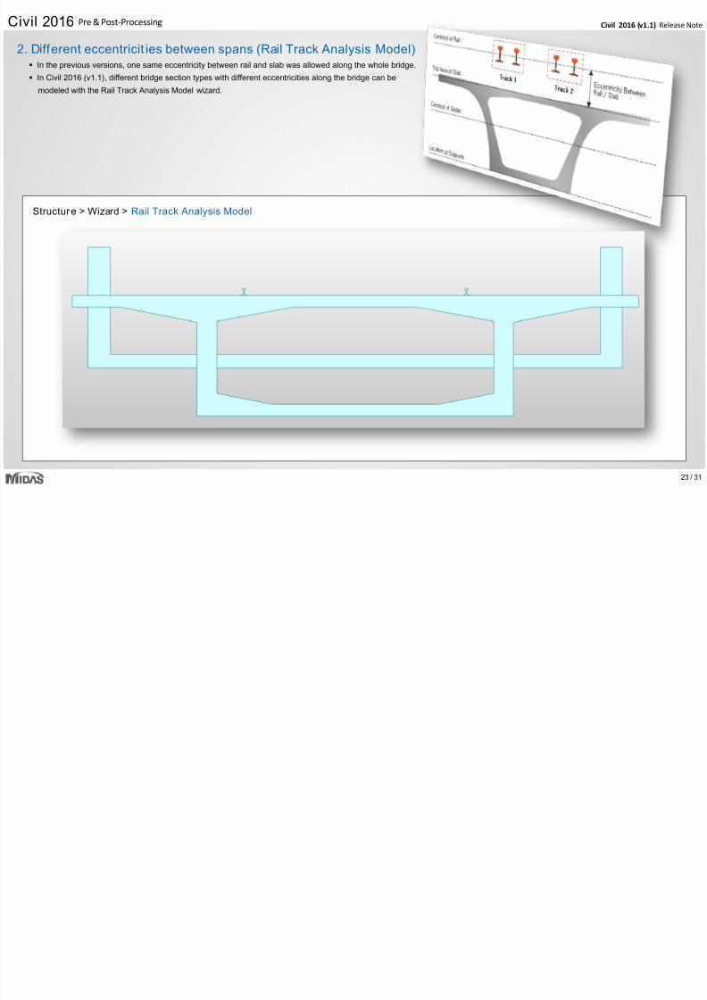
In the previous versions, one same eccentricity between rail and slab was allowed along the whole bridge.
In Civil 2016 (v1.1), different bridge section types with different eccentricities along the bridge can be
modeled with the Rail Track Analysis Model wizard.
Structure > Wizard > Rail Track Analysis Model
2. Different eccentricit ies between spans (Rail Track Analysis Model)
Civil 2016 (v1.1) Release NCivil 2016 Pre & Post-Processing
7/25/2019 Civil2016 v11 Release Note
http://slidepdf.com/reader/full/civil2016-v11-release-note 24/31
24 /
Civil 2016 (v1.1) Release Ng
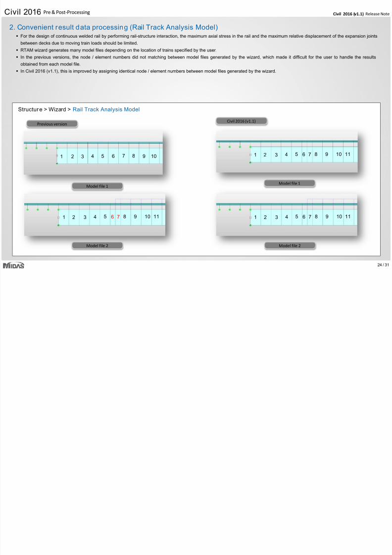
For the design of continuous welded rail by performing rail-structure interaction, the maximum axial stress in the rail and the maximum relative displacement of the expansion joints
between decks due to moving train loads should be limited.
RTAM wizard generates many model files depending on the location of trains specified by the user.
In the previous versions, the node / element numbers did not matching between model files generated by the wizard, which made it difficult for the user to handle the results
obtained from each model file.
In Civil 2016 (v1.1), this is improved by assigning identical node / element numbers between model files generated by the wizard.
Structure > Wizard > Rail Track Analysis Model
2. Convenient result data processing (Rail Track Analysis Model)
1 2
6 7 8 9 1054321 11
6543 7 8 9 10
6 7 8 9 1054321 11
6 7 8 9 1054321 11
Model file 1Model file 1
Model file 2 Model file 2
Civil 2016 (v1.1)Previous version
Civil 2016 (v1.1) Release NCivil 2016 Pre & Post-Processing
7/25/2019 Civil2016 v11 Release Note
http://slidepdf.com/reader/full/civil2016-v11-release-note 25/31
25 /
( )
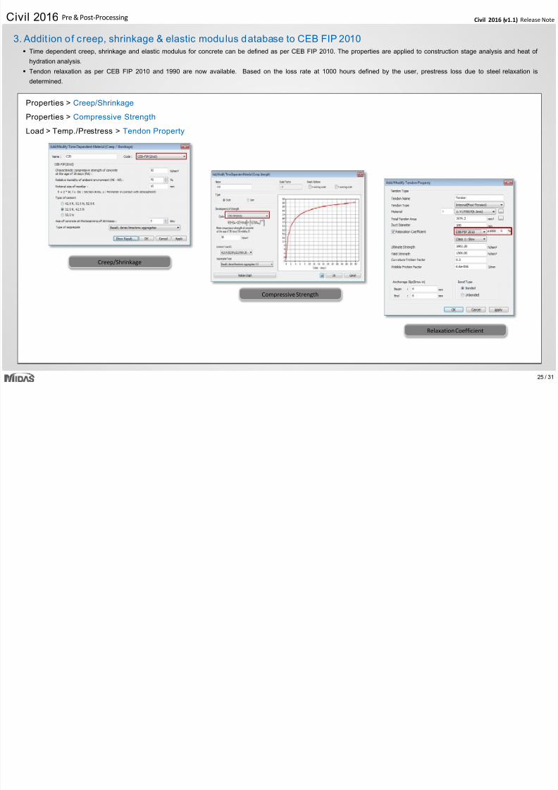
Properties > Creep/Shrinkage
Properties > Compressive Strength
Load > Temp./Prestress > Tendon Property
Creep/Shrinkage
3. Addit ion of creep, shrinkage & elastic modulus database to CEB FIP 2010 Time dependent creep, shrinkage and elastic modulus for concrete can be defined as per CEB FIP 2010. The properties are applied to construction stage analysis and heat of
hydration analysis.
Tendon relaxation as per CEB FIP 2010 and 1990 are now available. Based on the loss rate at 1000 hours defined by the user, prestress loss due to steel relaxation is
determined.
Compressive Strength
Relaxation Coefficient
Civil 2016 (v1.1) Release NCivil 2016 Pre & Post-Processing
7/25/2019 Civil2016 v11 Release Note
http://slidepdf.com/reader/full/civil2016-v11-release-note 26/31
26 /
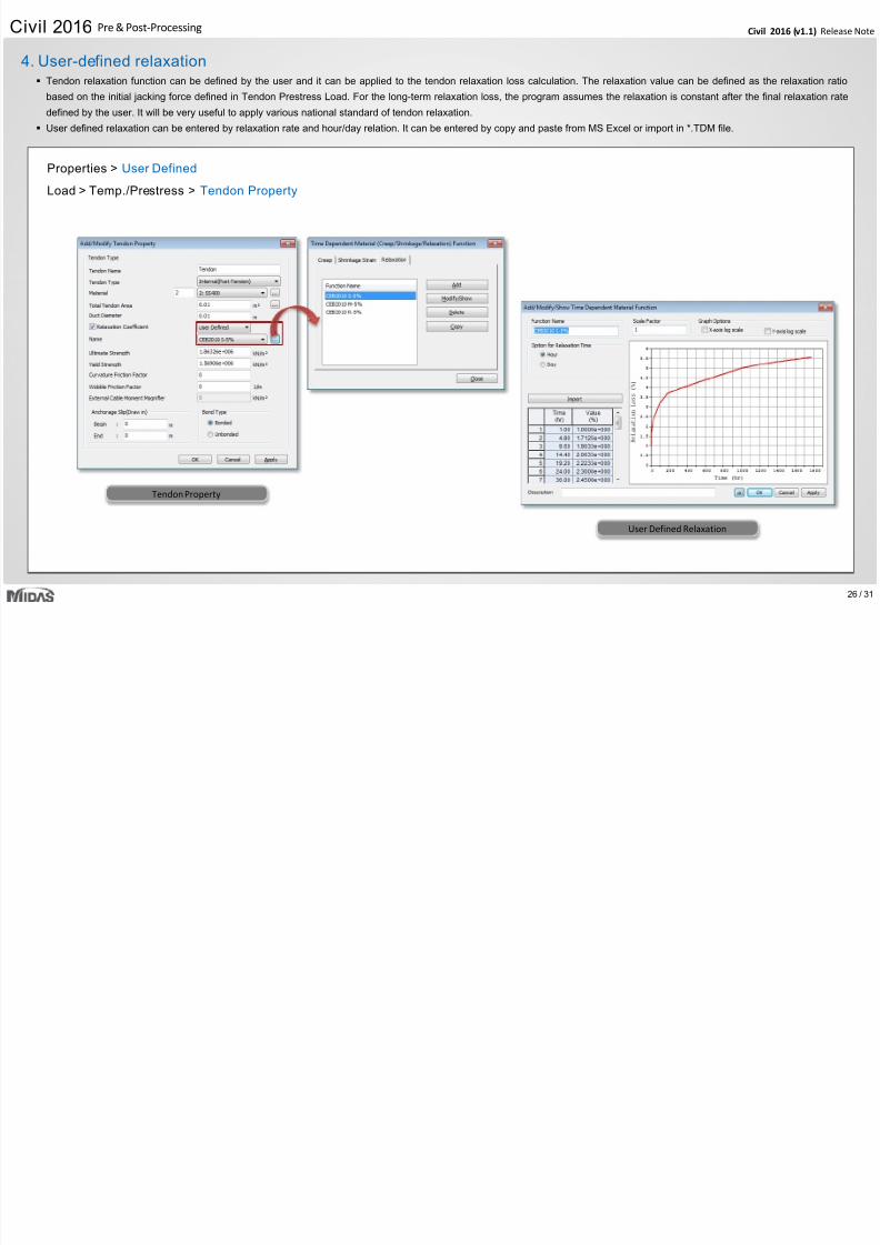
Properties > User Defined
Load > Temp./Prestress > Tendon Property
Tendon Property
User Defined Relaxation
4. User-defined relaxation Tendon relaxation function can be defined by the user and it can be applied to the tendon relaxation loss calculation. The relaxation value can be defined as the relaxation ratio
based on the initial jacking force defined in Tendon Prestress Load. For the long-term relaxation loss, the program assumes the relaxation is constant after the final relaxation rate
defined by the user. It will be very useful to apply various national standard of tendon relaxation.
User defined relaxation can be entered by relaxation rate and hour/day relation. It can be entered by copy and paste from MS Excel or import in *.TDM file.
Civil 2016 (v1.1) Release NCivil 2016 Pre & Post-Processing
7/25/2019 Civil2016 v11 Release Note
http://slidepdf.com/reader/full/civil2016-v11-release-note 27/31
27 /
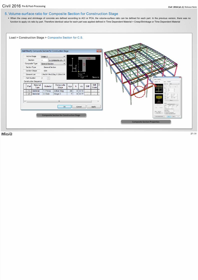
Load > Construct ion Stage > Composite Section for C.S.
Composite Section for Construction Stage
Composite Section Properties
5. Volume-surface ratio for Composi te Section for Construct ion Stage When the creep and shrinkage of concrete are defined according to ACI or PCA, the volume-surface ratio can be defined for each part. In the previous version, there was no
function to apply v/s ratio by part. Therefore identical value for each part was applied defined in Time Dependent Material > Creep/Shrinkage or Time Dependent Material
Civil 2016 (v1.1) Release NCivil 2016 Pre & Post-Processing
7/25/2019 Civil2016 v11 Release Note
http://slidepdf.com/reader/full/civil2016-v11-release-note 28/31
28 /
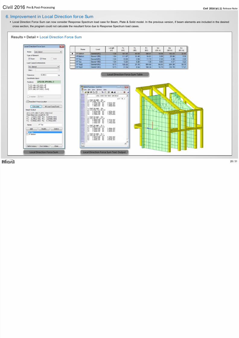
Results > Detail > Local Direction Force Sum
Local Direction Force Sum Table
Local Direction Force Sum Text OutputLocal Direction Force Sum
6. Improvement in Local Direction force Sum Local Direction Force Sum can now consider Response Spectrum load case for Beam, Plate & Solid model. In the previous version, if beam elements are included in the desired
cross section, the program could not calculate the resultant force due to Response Spectrum load cases.
Civil 2016 (v1.1) Release NCivil 2016 Pre & Post-Processing
7/25/2019 Civil2016 v11 Release Note
http://slidepdf.com/reader/full/civil2016-v11-release-note 29/31
29 /
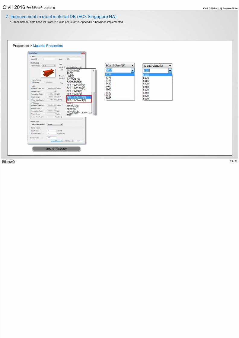
Properties > Material Properties
Material Properties
7. Improvement in s teel material DB (EC3 Singapore NA) Steel material data base for Class 2 & 3 as per BC1:12, Appendix A has been implemented.
Civil 2016 (v1.1) Release NCivil 2016 Pre & Post-Processing
7/25/2019 Civil2016 v11 Release Note
http://slidepdf.com/reader/full/civil2016-v11-release-note 30/31
30 /
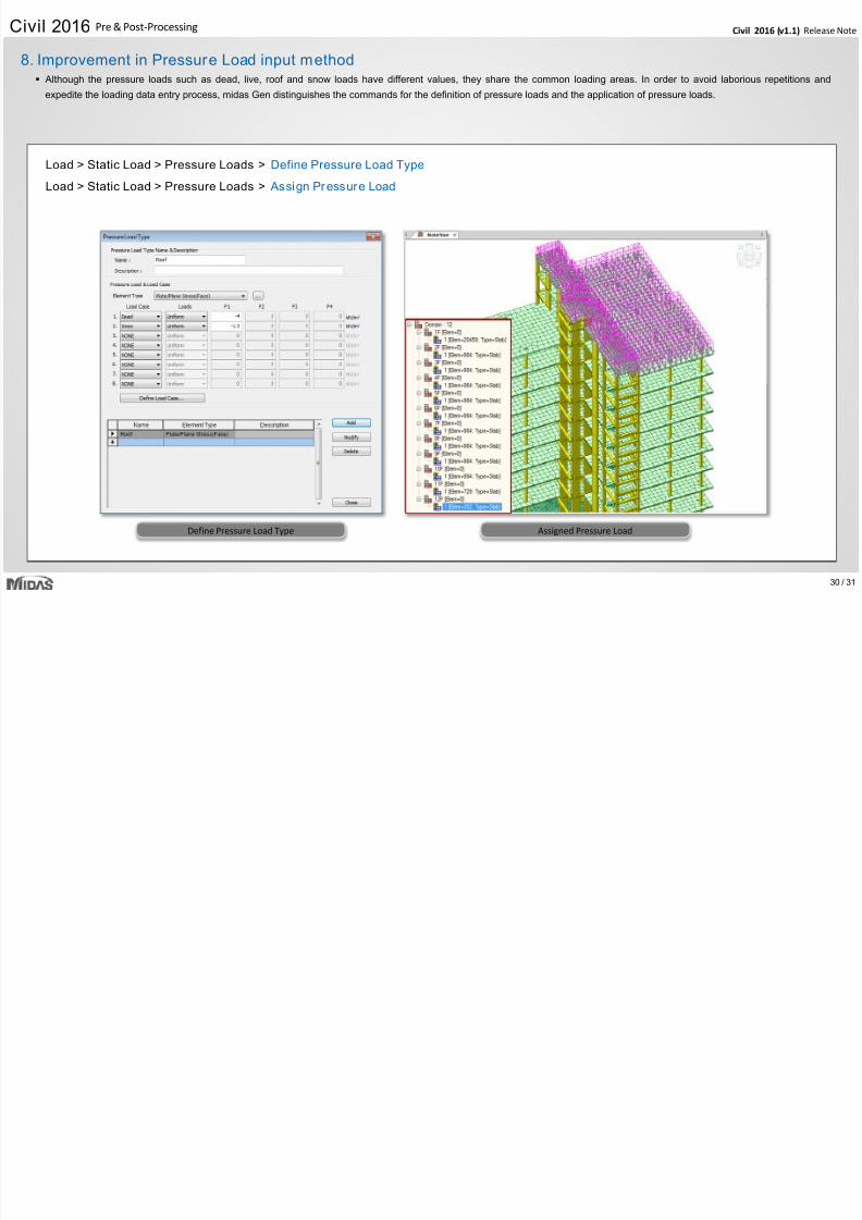
Load > Static Load > Pressure Loads > Define Pressure Load Type
Load > Static Load > Pressure Loads > Assign Pressure Load
Define Pressure Load Type Assigned Pressure Load
8. Improvement in Pressure Load input method Although the pressure loads such as dead, live, roof and snow loads have different values, they share the common loading areas. In order to avoid laborious repetitions and
expedite the loading data entry process, midas Gen distinguishes the commands for the definition of pressure loads and the application of pressure loads.
Civil 2016 (v1.1) Release NCivil 2016 Pre & Post-Processing
7/25/2019 Civil2016 v11 Release Note
http://slidepdf.com/reader/full/civil2016-v11-release-note 31/31
31 /
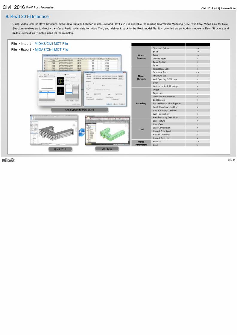
Functions Revit <> Civil
Linear
Elements
Structural Column <>
Beam <>
Brace <>
Curved Beam >
Beam System >
Truss >
Planar
Elements
Foundation Slab <>
Structural Floor <>
Structural Wall <>
Wall Opening & Window >
Door >
Vertical or Shaft Opening >
Boundary
Offset >
Rigid Link >
Cross-Section Rotation >
End Release >
Isolated Foundation Support >
Point Boundary Condition >
Line Boundary Condition >
Wall Foundation >
Area Boundary Condition >
Load
Load Nature >
Load Case >
Load Combination >
Hosted Point Load >
Hosted Line Load >
Hosted Area Load >
Other
Parameters
Material <>
Level >
Send Model to midas Civil
Revit 2016 Civil 2016
9. Revit 2016 Interface
• Using Midas Link for Revit Structure, direct data transfer between midas Civil and Revit 2016 is available for Building Information Modeling (BIM) workflow. Midas Link for Revit
Structure enables us to directly transfer a Revit model data to midas Civil, and deliver it back to the Revit model file. It is provided as an Add-In module in Revit Structure and
midas Civil text file (*.mct) is used for the roundtrip.
File > Import > MIDAS/Civil MCT File
File > Export > MIDAS/Civil MCT File


![Product Release Note Oracle FLEXCUBE Universal Banking Release · PDF fileProduct Release Note Oracle FLEXCUBE Universal Banking Release 12.0.2.0.0 [October] [2013] Product Release](https://img.pdfslide.us/doc/110x75/5ab76af57f8b9ad5338b88e3/product-release-note-oracle-flexcube-universal-banking-release-release-note.jpg)