Embed Size (px)
Citation preview

6ConstructionAutomation
6.1 Introduction
6.2 Fixed Construction AutomationExamples of Fixed Construction Automation
6.3 Programmable Construction AutomationConstruction Robots • Numerical Control
6.4 Computer-Integrated Construction (CIC) Computer-Aided Design (CAD) and Geometric Modeling • Automated Material Management • Network Communication • Example Application of Computer-Integrated Construction
6.5 Toward Advanced Construction AutomationEmerging Technologies • Construction Robot Path Planning • Examples of Recent Research and Applications
6.6 EconomicsAutomated Stone Cutting • Steel Bridge Deck Welding • Excavation • Large-Scale Manipulators • Interior Finishing Robot • Exterior Building Finishers • Automated Slab Placing and Finishing • Shimizu’s SMART System • Obayashi’s ABCS •
Maeda’s MCCS • Obayashi’s Big Canopy • Kajima’s AMURAD
6.7 Summary
6.1 Introduction
In the U.S., the construction industry is one of the largest industrial sectors. The expenditure on construc-tion between 1996 and 1999 was estimated at $416.4 billion dollars, which amounts to about 4.5% of theU.S. Gross Domestic Product (GDP) [Lum and Moyer, 2000]. The construction industry’s share increasedfrom 4 to 4.5% between 1996 and 1999. In addition, over 6.8 million people are employed in the con-struction industry, including design, construction, remodeling, maintenance, and equipment and materialssuppliers. This number represents 5.2% of the nonagricultural labor force of the U.S. [BLS, 2001]. Clearly,this enormous capital investment and expenditure and large number of employees highlight the crucialrole that the construction industry plays to enhance the overall national economy of the U.S.
Despite its importance to the national economy, the U.S. construction industry faces a number ofproblems in safety, quality, productivity, technology, and foreign competition. To overcome these prob-lems, automation and robotic technologies are often considered solutions [Everett and Saito, 1996; Cous-ineau and Miura, 1998; Warszawski and Navon, 1998]. Since 1980, significant efforts have been made tointroduce automation and robotic technologies into construction. However, only specialized applicationsof automation and robotics have been implemented due to economic and technical considerations.
In many cases, the work site poses a significant health hazard to humans involved. Hazards areassociated with work in undersea areas, underground, at high elevations, on chemically or radioactively
Jeffrey S. RussellUniversity of Wisconsin-Madison
Sung-Keun KimUniversity of Wisconsin-Madison
© 2003 by CRC Press LLC

6
-2
The Civil Engineering Handbook, Second Edition
contaminated sites, and in regions with prevailing harsh temperatures. The U.S. construction industrycontinues to be the industrial sector responsible for the most occupational accidents, injuries, andfatalities. Hinze [1997] mentioned that the construction sector has generally accounted for nearly 20%of all industry worker deaths. There were 1190 fatal occupational injuries and 501,400 nonfatal injuriesand illnesses in construction in 1999. Incidence rates for nonfatal injuries and illnesses were 8.6 per 100full-time equivalent workers in construction and 6.3 per 100 full-time equivalent workers in all privateindustry. The accidents in the construction industry alone cost over $17 billion annually [Levitt andSamelson, 1993; BLS, 2000a, b]. Even though the incidence of injuries and fatalities has reduced by about50% during the last three decades, the number of accidents, injuries, and deaths remains high whencompared to other industries [Smallwood and Haupt, 2000]. Consequently, liability insurance for mosttypes of construction work is costly. Replacing humans with robots for dangerous construction tasks cancontribute to the reduction of these costs.
Decline in construction productivity has been reported by many studies conducted throughout theworld. In the U.S., construction productivity, defined as gross product originating per person-hour inthe construction industry, has shown an average annual net decrease of nearly 1.7% since 1969. Theaverage of all industries for the same period has been a net annual increase of 0.9%, while the manufac-turing industry has posted an increase of 1.7% [Groover et al., 1989]. The Bureau of Labor Statistics’(BLS) productivity index also shows the declining tendency of construction productivity. This decline inconstruction productivity is a matter of global concern, because of its impact on the economy’s health.Recent trends have made availability of capital and innovation through the application of automatedtechnologies the defining parameters of competitiveness in today’s global economy. These trends enableprojects to be constructed with improved quality, shorter construction schedules, increased site safety,and lower construction costs.
Much of the increase in productivity in the manufacturing industry can be attributed to the develop-ment and application of automated manufacturing technologies. This, combined with concern aboutdeclining construction productivity, has motivated many industry professionals and researchers to inves-tigate the application of automation technology to construction. As a practical matter, these efforts haverecognized that complete automation of construction works is not presently technically and economicallyfeasible. Because of frequently reconfigured operations, often under severe environmental conditions,the construction industry has been slower than the manufacturing industry to adopt automation tech-nology [Paulson, 1985].
Tucker [1990] mentioned that complaints of poor construction quality have long been traditional inthe U.S. construction industry. Quality is defined as the conformance to requirements that are describedin contract documents such as specifications. To meet requirements, things should be done right the firsttime, and rework should be avoided. Nonconformation will result in extra cost and project delay. Thereare several major barriers to successful quality work, such as lack of skilled workers, poorly installedequipment, poor plans and specifications, poorly defined work scope, etc. Among them, the skilled workershortage problem is most critical. Many industrial nations, including Japan, France, Germany, and tosome extent the U.S., suffer from a shortage of skilled construction labor. This trend of worker shortagesin many traditional construction trades will most likely continue into the future. This will result, as ithas over the past two decades, in an increase in the real cost of construction labor. These facts, togetherwith the rapid advancement in automation and robotics technology, indicate promising potential forgradual automation and robotization of construction work.
Many experts stress that the future success of the construction industry may depend on the widespreadimplementation of advanced technologies. However, the construction industry is among the leastadvanced industries in the use of advanced technologies available for the performance of industrialprocesses and has lagged behind the manufacturing industry in technological improvement, innovation,and adoption. The physical nature of any construction project is a primary obstacle to meaningful workautomation. In batch manufacturing, the work object is mobile though the production facility, and worktools can be stationary. The manufacturing industry is similar in size to construction, is better coordinated,and is controlled by larger corporations with in-house management, planning, design, and production
© 2003 by CRC Press LLC

Construction Automation
6
-3
capabilities [Sanvido and Medeiros, 1990]. By contrast, in construction, the “work object” is stationary,of large dimensions, and constantly changing as work progresses, while tools are mobile, whether handheldor mechanized. In addition, construction processes are usually performed in dusty and noisy environ-ments, preventing the use of fragile, high-precision, and sensitive electronic devices. Most constructionjobs require a certain amount of on-site judgment, which automated equipment or robots cannot provide.In addition, there are many uncontrolled environmental factors on the construction site.
The investment in research and development of the U.S. construction industry is less than 0.5% ofsales volume. In Japan, the largest construction companies such as Shumizu, Taisei, Kajima, Obayashi,and Takenaka invest about 1% of annual gross revenue in research and development [Cousineau andMiura, 1998]. Questions have arisen regarding the construction industry’s ability to meet the demandsfor construction in the 21st century. To remain competitive in today’s construction marketplace, the U.S.construction industry must introduce advanced technologies, in particular, construction automation androbotics technologies, in order to solve the problems mentioned above.
Construction has traditionally been resistant to technical innovation. Past efforts to industrializeconstruction in the U.S. were undertaken at the time when industrial automation technology was at itsinfancy. Additionally, engineering and economic analyses of prefabrication processes and systems werelacking. On the other hand, numerous construction tasks have or will become more attracted to auto-mated technologies based upon the following characteristics: (1) repetitive, (2) tedious and boring,(3) hazardous to health, (4) physically dangerous, (5) unpleasant and dirty, (6) labor intensive,(7) vanishing skill area, (8) high skill requirement, (9) precision dexterity requirement, and (10) criticalto productivity [Kangari and Halpin, 1989]. For example, some construction tasks have been historicallynoted for their arduous, repetitive nature, with relatively little dynamic decision making required on thepart of a human laborer. Such tasks may include placing of concrete, placing of drywall screws, finishingof concrete, and placing of masonry block, among others. The work involved in these tasks is ratherunattractive for humans. Robots, however, are applicable to these types of work tasks provided that thetechnology and economics are feasible.
There have been increasing demands to enhance intelligence of construction equipment and systems.Many researchers have investigated the addition of sensors and control systems to existing constructionequipment. A limited amount of research, however, has been conducted in developing intelligent con-struction equipment and systems. For semiautonomous and autonomous equipment with great potentialfor impact on the construction industry, artificial intelligence (AI) is required to generate instructionsand plans necessary to perform tasks in dynamically changing environments on their own.
Construction automation refers to the use of a mechanical, electrical, and computer-based system tooperate and control construction equipment and devices. There are two types of construction automation:
1. Fixed construction automation2. Programmable construction automation
Fixed construction automation involves a sequence of operations performed by equipment fixed intheir locations. In other words, an automated facility, whether it is permanently indoors or temporarilyon the construction site, is set up specifically to perform only one function or produce one product. Inprogrammable construction automation, equipment has the ability to change its sequence of operationseasily to accommodate a wide variety of products.
6.2 Fixed Construction Automation
Fixed construction automation is useful in mass production or prefabrication of building componentssuch as:
1. Reinforcing steel2. Structural steel3. Exterior building components (e.g., masonry, granite stone, precast concrete)
© 2003 by CRC Press LLC

6
-4
The Civil Engineering Handbook, Second Edition
Examples of Fixed Construction Automation
In this section, selected examples of fixed construction automation are highlighted.
Automated Rebar Prefabrication SystemThe automated rebar prefabrication system places reinforcing bars for concrete slab construction. Thesystem consists of a NEC PC98000XL high-resolution-mode personal computer that uses AutoCAD™,DBASE III Plus™, and BASIC™ software. The information regarding number, spacing, grade and dimen-sion, and bending shapes of rebars is found from the database generated from an AutoCAD file. Thisinformation is used by an automatic assembly system to fabricate the rebar units.
The assembly system consists of two vehicles and a steel rebar arrangement support base. Of the twovehicles, one moves in the longitudinal direction and the other in the transverse direction. The longitu-dinally moving vehicle carries the rebars forward until it reaches the preset position. Then, it movesbackward and places the rebars one by one at preset intervals on the support base. Upon completion ofplacement of the rebars by the longitudinally moving vehicle, the transversely moving vehicle places therebars in a similar manner. The mesh unit formed by such a placement of rebars is tied togetherautomatically [Miyatake and Kangari, 1993].
Automated Brick MasonryThe automated brick masonry system, shown in Fig. 6.1, is designed to spread mortar and place bricksfor masonry wall construction. The system consists of:
1. Mortar-spreading module2. Brick-laying station
The controls of the system are centered around three personal computers responsible for:
1. Collecting and storing date in real time2. Interfacing a stepping-motor controller and a robot controller3. Controlling the mortar-spreading robot
A Lord 15/50 force-torque sensor is used to determine the placing force of each brick. The system isprovided with an integrated control structure that includes a conveyor for handling the masonry bricks[Bernold et al., 1992].
FIGURE 6.1 Automated brick masonry. (Source: Bernold et al. 1992. Computer-Controlled Brick Masonry. Journalof Computing in Civil Engineering, ASCE. 6(2):147–161. Reproduced by permission of ASCE.)
Sensor Controller
CNC MotorController
RM-501
Robot Controller
RM-501
Hand Controller
RM-501Mortar Spreader
Conveyer
Force Sensor
© 2003 by CRC Press LLC

Construction Automation
6
-5
Fully Automated Masonry Plant
The fully automated masonry plant is designed to produce different brick types with the productioncapacity of 300 m2 wall elements per shift. The system consists of several components: a master computer,a database server, a file server, stone cutters, masonry robots, pallet rotation systems, refinement systems,storage systems, transversal platforms, a disposition management system, an inventory managementsystem, and a CAD system.
Two individual brick types can be managed in parallel by unloading the gripper and the cutter-systemconsisting of two stone saws. By conveyer systems, stone units and fitting stones are transported to themasonry robot system. The masonry robots move two bricks at each cycle to the growing wall after amortar robot puts a layer of mortar on it. A pallet rotation system carries the wall to the drying chamber.After 48 hours, the wall is transported to destacking stations to group the wall elements of the sameorder. Finally, grouped wall elements are transported to the construction site [Hanser, 1999].
Automated Stone Cutting
The purpose of the automated stone-cutting facility is to precut stone elements for exterior wall facings.The facility consists of the following subsystems:
1. Raw materials storage2. Loading3. Primary workstation4. Detail workstation5. Inspection station6. End-product inventory
A special lifting device has been provided for automated materials handling. The boom’s rigidityenables the computation of exact location and orientation of the hook. Designs for the pallets, the primarysaw table, the vacuum lift assembly, and the detail workstation have also been proposed [Bernold et al.,1992].
6.3 Programmable Construction Automation
Programmable construction automation includes the application of the construction robots and numer-ical control machines described below.
Construction Robots
The International Standards Organization (ISO) defines a robot as “an automatically controlled, re-programmable, multi-purpose, manipulative machine with several reprogrammable axes, which may beeither fixed in place or mobile for use in industrial automation applications” [Rehg, 1992]. For construc-tion applications, robots have been categorized into three types [Hendrickson and Au, 1988]:
1. Tele-operated robots in hazardous or inaccessible environments2. Programmed robots as commonly seen in industrial applications3. Cognitive or intelligent robots that can sense, model the world, plan, and act to achieve working
goals
The important attributes of robots from a construction point of view are their (1) manipulators,(2) end effectors, (3) electronic controls, (4) sensors, and (5) motion systems [Warszawski, 1990]. Forfurther explanation of these attributes, refer to the definitions section at the end of this chapter.
Applications of Construction Robots
Table 6.1 presents a partial list of construction robot prototypes developed in the U.S. and in othercountries. Brief summaries of several of these prototypes are provided below. Several of these descriptionshave been adapted from Skibniewski and Russell [1989].
© 2003 by CRC Press LLC

6
-6
The Civil Engineering Handbook, Second Edition
John Deere 690C ExcavatorThe John Deere 690C excavator is a tele-operated machine; that is, it is fully controlled by a humanoperating from a remote site. It is equipped with a model 60466T, six-cylinder, four-stroke turbochargeddiesel engine, producing a maximum net torque of 450 ft-lb (62.2 kgf-m) at 1300 revolutions per minute(rpm) [Technical Specifications, 1985]. The engine propels the excavator at traveling speeds ranging from0 to 9.8 mph (15.8 km/h).
The arm on the 690C excavator has a lifting capacity of 11,560 lb (5243 kgf) over side and 10,700 lb(4853 kgf) over end. The rated arm force is 15,900 lb (7211 kgf), and the bucket digging force is 25,230 lb(11,442 kgf) [Technical Specifications, 1985].
The John Deere 690C excavator has been implemented in a cooperative development program withthe U.S. Air Force within the Rapid Runway Repair (RRR) project. The major task of the RRR is therepair of runways damaged during bombing raids. The Air Force is currently investigating other areasin which the 690C could be implemented, including heavy construction work, combat earthmoving inforward areas, mine-field clearing, and hazardous-material handling.
Robot Excavator (REX)The primary task of the robot excavator (REX) is to remove pipelines in areas where explosive gases maybe present. This robot is an autonomous machine able to sense and adjust to its environment. REXachieves its autonomous functions by incorporating three elements into its programming [Whittaker,1985a]:
1. Subsurface premapping of pipes, structures, and other objects is possible using available utilityrecords and ground-penetrating sensors. Magnetic sensing is the leading candidate for premappingmetallic pipes.
2. Primary excavation for gross access near target pipes is possible. Trenching and augering are theleading candidates for this operation.
3. Secondary excavation, the fine and benign digging that progresses from the primary excavationto clear piping, can be accomplished with the use of a supersonic air jet.
The hardware that REX uses for primary excavation is a conventional backhoe retrofitted with servovalves and joint resolvers that allow the computer to calculate arm positions within a three-dimensionalspace. The manipulator arm can lift a 300 lb (136 kg) payload at full extension and over 1000 lb (454 kg)in its optimal lifting position.
REX uses two primary sensor modes: tactile and acoustic. The tactile sensor is an instrumentedcompliant nozzle. The instrumentation on the nozzle is an embedded tape switch that is activated whenthe nozzle is bent. The second sensor employed in excavation is an acoustical sensor, allowing for three-dimensional imaging.
Haz-TrakHaz-Trak, developed by Kraft Telerobotics, is a remotely controlled excavator that can be fitted with abulldozer blade for grading, backfilling, and leveling operations [Jaselskis and Anderson, 1994]. Haz-Trak uses force feedback technology, allowing the operator to actually feel objects held by the robot’smanipulator. The operator controls the robot’s arm, wrist, and grip movements through devices attachedto his or her own arm. Thus, the robot arm instantly follows the operator’s movements.
Pile-Driving RobotThe Hitachi RX2000 is a pile-driving machine directed by a computer-assisted guiding system. It consistsof a piling attachment (such as an earth auger or a vibratory hammer) directly connected to the tip ofa multijointed pile driver arm. The pile driver arm uses a computer-assisted guiding system called an“arm tip locus control.” Coordinates of arm positions are calculated using feedback from angle sensorspositioned at joints along the arm. A control lever operation system is provided to increase efficiency.The compactness of the RX2000 and its leaderless front attachment enable efficient piling work even incongested locations with little ground stabilization. Further, the vibratory hammer has a center hole
© 2003 by CRC Press LLC

Construction Automation
6
-7
chuck that firmly chucks the middle part of a sheet pile or an H-steel pile. Hence, pile length is notlimited by the base machine’s dump height [Uchino et al., 1993].
Laser-Aided Grading SystemSpectra-Physics of Dayton, OH, developed a microcomputer-controlled, laser-guided soil-gradingmachine (see Fig. 6.2). A laser transmitter creates a plane of light over the job site. Laser light receptorsmounted on the equipment measure the height of the blade relative to the laser plane. Data from thereceiver are then sent to the microcomputer that controls the height of the blade through electronicallyactivated valves installed in the machine’s hydraulic system. A similar device has been developed by AgtekCompany in cooperation with a construction contractor in California [Paulson, 1985]. An automatedsoil-grading process implemented by these machines relieves the operator from having to manuallyposition and control the grading blades, thus increasing the speed and quality of grading, as well as workproductivity [Tatum and Funke, 1988].
Automatic Slipform MachinesMiller Formless Systems Company developed four automatic slipform machines — M1000, M7500,M8100, and M9000 — for sidewalk and curb and gutter construction [Technical Specifications, 1988].All machines are able to pour concrete closer to obstacles than is possible with alternative formingtechniques. They can be custom-assembled for the construction of bridge parapet walls, monolithicsidewalk, curb and gutter, barrier walls, and other continuously formed elements commonly used in roadconstruction.
The M1000 machine is suitable for midrange jobs, such as the forming of standard curb and gutter,sidewalks to 4 ft, and cul-de-sacs. The M7500 is a sidemount-design machine for pouring barrier walls,paved ditches, bridge parapets, bifurcated walls, and other types of light forming jobs. The M8100 is amidsize system with a sidemount design combined with straddle-paving capabilities. The machine canbe extended to 16-ft (4.88-m) slab widths with added bolt-on expansion sections. The M9000 multidi-rectional paver is designed for larger-volume construction projects. It can perform an 18-ft (5.49-m)wide paving in a straddle position. Options are available for wider pours, plus a variety of jobs fromcurbs to irrigation ditches, in its sidemount mode.
Horizontal Concrete DistributorThe HCD, developed by Takenaka Company, is a hydraulically driven, three-boom telescopic arm thatcantilevers from a steel column. The boom can extend 66 ft (20 m) in all directions over an 11,000-ft(1000-m) surface area. A cockpit located at the end of the distributor houses the controls for an operator
FIGURE 6.2 Laser-aided grading system. (Source: Tatum, C. B., and Funke, A. T. 1988. Partially Automated Grading:Construction Process Innovation. Journal of Construction Engineering and Management, ASCE. 114(1):19–35. Repro-duced by permission of ASCE.)
Laser Receiver
SignalsFrom Receiver
Microprocessor
Visual Display
Auto/ManualSwitch
Hydraulic Controls
Laser Transceiver
Laser Beam
© 2003 by CRC Press LLC

6
-8
The Civil Engineering Handbook, Second Edition
to manipulate the boom direction and flow of concrete. The weight of the robot is 4.97 tons (4508 kgf),and it can be raised along the column by jacks for the next concrete pour. On average, the relocationprocedure takes only 1.5 h [Sherman, 1988].
Shotcrete RobotTraditionally, in tunneling work, a skilled operator has been needed to regulate the amount of concreteto be sprayed on a tunnel surface and the quality of the hardening agent to be added, both of whichdepend on the consistency of the concrete. Kajima Construction Company of Japan developed andimplemented a semiautonomous robotic applicator by which high-quality shotcrete placement can beachieved [Sagawa and Nakahara, 1985].
Slab-Finishing RobotThe robot designed for finishing cast-in-place concrete slabs by Kajima Construction Company, shownin Fig. 6.3, is mounted on a computer-controlled mobile platform and equipped with mechanical trowelsthat produce a smooth, flat surface [Saito, 1985]. By means of a gyrocompass and a linear distance sensor,the machine navigates itself and automatically corrects any deviation from its prescheduled path. Thismobile floor-finishing robot is able to work to within 1 m of walls. It is designed to perform the workof at least six skilled workers.
Auto-Claw and Auto-ClampTwo robotic devices used for steel beam and column erection on construction sites have been developedby Obayashi Construction Company of Japan. Both construction robots have been developed to speedup erection time and to minimize the risks incurred by steelworkers. Both have been implemented onreal job sites.
The auto-claw consists of two steel clamps extended from a steel-encased unit containing a DC batterypack, electrical panel, and microprocessor unit, which is in turn suspended from a standard crane. Thetwo clamps have a rated capacity of two tons (1.824 kgf) each and can be adjusted to fit beam flangesfrom 8 to 12 in. (203.2 to 304.8 mm). The clamps are automatically released by remote radio controlonce the beam is securely in place. Fail-safe electronic circuitry prevents the accidental release of theclamps during erection by keeping the circuit broken at such times. The steel beams require no specialpreparation for using this robot.
The auto-clamp’s essential purpose and mechanics are the same as for the auto-claw, except that theauto-clamp uses a special electrosteel cylinder tube to secure and erect columns. A steel appendage platewith a hole in the center must be welded to one end of the column. The steel cylinder is electricallyinserted and locked into the hole by remote control, whereupon the column can be erected. The auto-clamp has a rated lifting capacity of 15 tons (13,605 kg). The appendage plates must be removed afterthe columns are erected. Like the auto-claw, the auto-clamp is equipped with a fail-safe system preventingthe cylinder from retracting from the hole during erection [Sherman, 1988].
Automated Pipe ConstructionResearch into automated pipe construction is under way at the University of Texas at Austin [O’Connoret al., 1987]. Research efforts are focused on developing and integrating three pipe production technol-ogies: bending, manipulation, and welding. The pipe manipulator, shown in Fig. 6.4, was adapted froma 20-ton rough-terrain hydraulic crane with an attachment to the main boom [Hughes et al., 1989]. Theattachment includes an elevating, telescoping, auxiliary boom with a wrist and pipe-gripping jaws.Associated research has concentrated on improving productivity through automated lifting and manip-ulating of horizontal piping [Fisher and O’Connor, 1991].
BlockbotsAnother application involves the design, development, and testing of the “blockbot” robot intended toautomate the placement of masonry blocks to form walls. The complete wall assembly consists of fourmajor components [Slocum et al., 1987]:
© 2003 by CRC Press LLC

Construction Automation
6
-9
1. A six-axis “head” that will actually place the blocks on the wall2. A 20- to 30-ft (6- to 9.1-m) hydraulic scissors lift used to roughly position the placement head
vertically and longitudinally3. A large-scale metrology system, sensors, and other related computer control equipment4. A block-feeding system/conveyor to continually supply the placement head
To facilitate construction, the blocks are stacked upon each other with no mortar between the levels.The wall is then surface-bonded using Surewall™, a commercial fiberglass-reinforced bonding cement.This process produces a wall with strength comparable to that of a traditional mortar wall.
WallbotsResearchers at the Massachusetts Institute of Technology (MIT) are engaged in the Integrated Construc-tion Automation Design Methodology (ICADM) project [Slocum et al., 1987]. This work attempts tointegrate the efforts of material suppliers, architects, contractors, and automated construction equipmentdesigners.
The process of building interior wall partitions is divided between two separate robots: a trackbot anda studbot. Circumventing the need for complex navigational systems, the trackbot is guided by a laserbeacon aligned manually by a construction worker. The trackbot is separated into two parallel worksta-tions: an upper station for the ceiling track and a lower station for the floor track. Detectors are mountedon the ends of the effector arms to ensure that the laser guidance system achieves the necessary precision.The placement of the track consists of four steps: (1) the effector arm grabs a piece of track, (2) theeffector arm positions the track, (3) two pneumatic nail guns fasten the track, and (4) the trackbot movesforward, stopping twice to add additional fasteners.
Once the trackbot has completed a run of track, the studbot can begin placing studs. Locationassessment is made by following the track and employing an encoding wheel or an electronic distancemeasuring (EDM) instrument. The studbot then references a previously sorted floor plan to ascertainlocations of studs to be placed. The stud is removed from its bin and placed into position. The positioningarm then spot-welds the stud into place.
Interior Finishing RobotAn interior finishing robot, shown in Fig. 6.5, can execute the following tasks: (1) building walls andpartitions, (2) plastering walls and ceilings, (3) painting walls and ceilings, and (4) tiling walls. The armof the robot has six degrees of freedom with a nominal reach of 5.3 ft (1.6 m) and a lifting capacity of66 lb (145 kgf). The robot is designed to perform interior finishing work in residential and commercialbuildings with single or multiple floor levels and interior heights of 8.5 to 8.8 ft (2.60 to 2.70 m). A three-wheel mobile carriage measuring 2.8 ¥ 2.8 ft (0.85 ¥ 0.85 m) enables motion of the robot between staticworkstations [Warszawski and Navon, 1991; Warszawski and Rosenfeld, 1993].
Fireproofing Spray RobotShimizu Company has developed two robot systems for spraying fireproofing material on structural steel[Yoshida and Ueno, 1985]. The first version, the SSR-1, was built to (1) use the same materials as inconventional fireproofing, (2) work sequentially and continuously with human help, (3) travel andposition itself, and (4) have sufficient safety functions for the protection of human workers and of buildingcomponents. The second robot version, the SSR-2, was developed to improve some of the job sitefunctions of SSR-1. The SSR-2 can spray faster than a human worker but requires time for transportationand setup. The SSR-2 takes about 22 min for one work unit, whereas a human worker takes about 51 min.The SSR-2 requires relatively little manpower for the spraying preparation — only some 2.1 person-dayscompared with 11.5 for the SSR-1. As the positional precision of the robot and supply of the rock woolfeeder were improved, the SSR-2 could achieve the same quality of dispersion of spray thickness as forthat applied by a human worker.
© 2003 by CRC Press LLC

6
-10
The Civil Engineering Handbook, Second Edition
Exterior Wall Painting RobotThe exterior wall painting robot, shown in Fig. 6.6, paints walls of high-rise buildings, including wallswith indentations and protrusions. The robot is mounted on mobile equipment that permits translationalmotion along the exterior wall of a building. The robot consists of the following:
1. Main body that sprays paint2. Moving equipment to carry the robot main body to the proper work position3. Paint supply equipment4. A controller
The robot main body consists of the following:
1. Main frame2. Painting gun3. Gun driver4. Control unit
The painting gun is driven in three principal translational directions (x, y, and z). The painting gunis also provided with two rotational degrees of freedom. The robot moving equipment consists of thefollowing:
1. A transporter that propels the moving equipment along the outside of the building being painted2. A work stage on which the robot main body is mounted3. A mast that serves as a guide for raising and lowering the work stage
The top of the mast is attached to a travel fitting, and the fitting moves along a guide rail mountedon the top of the building [Terauchi et al., 1993].
Integrated Surface Patcher (ISP)Secmar Company of France developed a prototype of the integrated surface patcher (ISP) [Point, 1988].The unit consists of the following components:
1. A 19-ton (17,234-kgf) carrier with rear-wheel steering2. A 3.9-yd3 (3-m3) emulsion tank3. A 5.2-yd3 (4-m3) aggregate container4. A built-in spreader working from the tipper tailboard (a pneumatic chip spreader with 10 flaps
and a 10-nozzle pressurized bar)5. A compaction unit
The ISP unit has a compressor to pressurize the emulsion tank and operate the chip-spreading flaps.The machine uses a hydraulic system driven by an additional motor to operate its functional modules.The electronic valve controls are operated with power supplied by the vehicle battery.
The ISP is used primarily for hot resurfacing repairs, including surface cutting, blowing and tackcoating with emulsion, as well as for repairs requiring continuous treated or nontreated granular mate-rials. The unit is suitable for deep repairs using aggregate-bitumen mix, cement-bound granular materials,and untreated well-graded aggregate, as well as for sealing wearing courses with granulates.
The current design of the ISP allows only carriageway surface sealing. It is thus not well suited forsurface reshaping or pothole filling. It is used only for routine maintenance tasks. In operational terms,ISP is not capable of on-line decision making on how to proceed in the case of an irregular crack orother nonpredetermined task. However, automated patching can be started manually or automatically,depending on the presence of optical readers mounted on the equipment that read the delimiters of thework area, and on the mode of action chosen by the operator.
Autonomous Pipe MappingAnother application is the development of an automated pipe-mapping system. Current manual methodsare slow, inefficient, qualitative, and nonrepetitive. The intention of the system is to autonomously
© 2003 by CRC Press LLC

Construction Automation
6
-11
TABLE 6.1 Example Construction Robotic Prototypes
System Description Application Research Center
Excavation
John Deere 690C Tele-operated excavation machine John Deere, Inc., Moline, ILRobot excavator (REX) Autonomous excavation, sandblasting,
spray washing, and wall finishingThe Robotics Institute, Carnegie-
Mellon Univ., Pittsburgh, PASuper hydrofraise excavation control
systemExcavate earth Obayashi Co., Japan
Haz-Trak Remotely controlled excavation Kraft TeleroboticsHitachi RX2000 Pile driving Hitachi Construction Machinery Co.,
JapanRemote core sampler (RCS) Concrete core sampling for radiated
settingsThe Robotics Institute, Carnegie-
Mellon Univ., Pittsburgh, PALaser-aided grading system Automatic grading control for earthwork Gradeway Const. Co. and Agtek Dev.
Co., San Francisco, CA; Spectra-Physics, Dayton, OH
Tunneling
Shield machine control sytem Collect and analyze data for controlling tunneling machine
Obayashi Co. and Kajima Co., Japan
Microtunneling machine Tele-operated microtunneling American Augers, Wooster, OHTunnel wall lining robot Assemble wall liner segments in tunnels for
sewer systems and power cablesIshikawajima-Harima Heavy Industries,
Japan; Electric Power Co., Japan; Kajima Co., Japan
Concrete
Automatic concrete distribution system
Carry concrete from batching plant to the cable crane
Obayashi Co., Japan
Automatic slipform machines Placement of concrete sidewalks, curbs, and gutters
Miller Formless Systems Co., McHenry, IL; Gomaco, Ida Grove, IA
Concrete placing robot for slurry walls
Place and withdraw tremie pipes and sense upper level of concrete as it is poured
Obayashi Co., Japan
Shotcrete robot Spray concrete tunnel liner Kajima Co., Japan; Obayashi Co., JapanHMC handling robot Transport and place HMC concrete forms Taisei Co., JapanRebar bending robot Bend rebar Obayashi Co., JapanRebar preassembly robot Place and tie rebar Shimizu Co., JapanRebar fabricating robot Fabricate beam rebar, place and tie rebar Taisei Co., JapanAutomatic concrete vibrator tamper Vibrate cast-in-place concrete Obayashi Co., JapanAutomatic laser beam-guided floor
robotFinish surface of cast-in-place concrete Obayashi Co., Japan
Slab-finishing robot Finish surface of cast-in-place concrete Kajima Co., JapanRebar placing robot Place heavy rebar Kajima Co., JapanRebar installation crane Place heavy rebar Takenaka Co., JapanHorizontal concrete distributor
(HCD)Place concrete for horizontal slabs Takenaka Komuten Co., Japan
Mobile concrete distributor Concrete distribution Tokyu Co., JapanCONDIS Concrete distribution Takenaka Co., JapanACSUS Concrete distribution Konoike Construction, JapanCALM Concrete leveling Fujita Co., JapanMobile screeding robot Level fresh concrete Shimizu Co., Japan; Yanmar Diesel,
JapanScreed Robo Level fresh concrete Takenaka Co., JapanKote-King Finish large floor areas Kajima Co., JapanSurf-Robo Finish large floor areas Takenaka Komuten Co., JapanFlat-kun Finish large floor areas Shimuzu Co., JapanConcrete floor finishing robot Finish large floor areas Hazama Co., Japan; Mitubishi Co.,
Japan; Eroika Co., JapanWater removing robot Remove surface water Takenaka Co., Japan
© 2003 by CRC Press LLC

6
-12
The Civil Engineering Handbook, Second Edition
TABLE 6.1 Example Construction Robotic Prototypes
System Description Application Research Center
Structural Members
Auto-claw, auto-clamp Erect structural steel beams and columns Obayashi Co., JapanMighty shackle ace Handle structural steel Shimizu Co., JapanStructural element placement Place reinforcing steel Kajima Co., JapanTAP system Straighten structural steel Taisei Co., JapanStructural element welding Weld large structural blocks for cranes and
bridgesMitsubishi Heavy Industries Co., Japan
Fujita welding robot Weld structural steel columns Fujita Co., JapanObayashi welding robot Weld structural steel columns Obayashi Co., JapanShimizu welding robot Weld structural steel columns Shimizu Co., JapanTaisei welding robot Weld structural steel columns Taisei Co., JapanTakenaka welding robot Weld structural steel columns Takenaka Co., JapanWelding robot Weld structural steel columns Kajima Co., Japan; Mitsubishi Heavy
Industry, JapanShear stud welder Weld shear connectors in composite
steel/concrete constructionMassachusetts Institute of Technology,
CambridgeAutomatic carbon fiber wrapper Wrap existing structures with carbon steel Obayashi Co., JapanSSR-1, SSR-2, and SSR-3 Spray fireproofing material on steel
structureShimizu Co., Japan
Fireproof spray robot Spray fireproofing material on steel structure
Fijita Co., Japan; Shimizu Co., Japan; Nichias Co., Japan
Automated pipe construction Pipe bending, pipe manipulation, and pipe welding
University of Texas, Austin
Blockbots Construction of concrete masonry walls Massachusetts Institute of Technology, Cambridge
Wallbots Construction of interior partitions, metal track studs
Massachusetts Institute of Technology, Cambridge
Interior finishing Building walls and partitions, plastering, painting, and tiling walls and ceilings
Israel Institute of Technology, National Building Research Institute
Non-concrete Spraying
Paint-spraying robot Paint balcony rails in high-rise buildings Shimizu Co., Fijita Co., Kajima Co., and Taisei Co., Japan
KFR-2 Spray paint Kumagai Co., JapanSB Multi Coater Spray paintOSR-1 Spray paint Shimizu Co., JapanTPR-02 Spray paint Taisei Co., Japan
Inspection
Wall inspection robot (Kabedohda I and II)
Inspect reinforced concrete wallsInspect façade
Obayashi Co., JapanKajima Co., Shimizu Construction Co.,
Takenaka Co., and Taisei Co., JapanBridge inspection robot Inspect structural surface of a bridge University of WalesGEO robot Finish façade/surface Eureka, FranceKajima tile inspection robot Detect bonding condition of both tile and
mortarKajima Co., Japan
Kumagai tile inspection robot Detect bonding condition of both tile and mortar
Kumagai Co., Japan
Takenaka Detect bonding condition of both tile and mortar
Takenaka Co., Japan
TG-02 Detect bonding condition of both tile and mortar
Taisei Co., Japan
Pipe inspection robot Measure pipe thickness Mitsui Construction, JapanPipero Measure pipe thickness Obayashi Co., Japan
© 2003 by CRC Press LLC

Construction Automation
6
-13
Other
Clean room inspection and monitoring robot (CRIMRO)
Inspect and monitor the amount of particles in the air
Obayashi Co., Japan
K-Creitor Inspect clean room Kumagai Gumi, JapanLeak robo Inspect clean room Hazama Gumi, JapanIntegrated surface patcher (ISP)
material handlingHot resurfacing on highways, pick and
distribute construction materials (e.g., prefabricated concrete materials and pipe)
Secmar Co., France; Tokyo Construction Co., Japan; Hitachi Construction Co., Japan
Autonomous pipe mapping Mapping subsurface pipes The Robotics Institute, Carnegie-Mellon Univ., Pittsburgh, PA
Terregator Autonomous navigation The Robotics Institute, Carnegie-Mellon Univ., Pittsburgh, PA
Remote work vehicle (RWV) Nuclear accident recovery work, wash contaminated surfaces, remove sediments, demolish radiation sources, apply surface treatment, package and transport materials
The Robotics Institute, Carnegie-Mellon Univ., Pittsburgh, PA
ODEX III Inspection, surveillance, material transport
Odetics, Inc., French Commissariat a l’Energie Atomique, France
CFR1 Material transport (ceiling board) Shimizu Co., JapanBoardman-100 Material transport (plaster board) Taisei Co., JapanMighty hand Material transport Kajima Co., JapanSky hand Material transport Komatsu Co., JapanBalance hand Material transport Komatsu Co., JapanLady bug Detect underground Tokyo Construction, Japan
FIGURE 6.3 Slab-finishing robot. (Source: Skibniewski, M. J. 1988. Robotics in Civil Engineering. Van NostrandReinhold, New York.)
optical fiber cablepower cable
Messenger wire
Travel device(computer, gyrocompass)
Frontobstructicdetector
Floor openingsensor
Line of travel
Touchsensor
Drive rollerSteering roller
Robot Arms-1.2Travel distance sensor
Trowel(revolving)
Touchsensor
Blade
Blade anglecontrolactuator
Electric power panel
Host computer
Operationpanel
Power source
ROBOT
© 2003 by CRC Press LLC

6-14 The Civil Engineering Handbook, Second Edition
establish size, depth, and orientation of buried pipes. This knowledge is extremely valuable in guidingexcavation, validating as-built drawings, and building databases of piping details [Motazed and Whittaker,1987].
The system is composed of a computer-controlled Cartesian x-y table that allows various sensors tobe swept across an arid area. The primary mapping is completed by a magnetic sensor that reads andrecords magnetic field intensities. These intensities are manipulated and interpreted, resulting in a linedrawing representing the pipe locations. Higher-level processing estimates the depth of pipes and iden-tifies interconnections such as elbows, tees, and crosses.
TerregatorA machine that may be used to transport the autonomous pipe mapping system is the terregator. Designedfor autonomous outdoor navigation, it can be directly applied on a construction site. The terregator hasbeen specifically designed to be extremely durable and powerful in order to prevent problems that inhibitmachines designed for interior use. Its gearing is adjustable to allow it to be configured as a low-speed,high-torque machine or as a high-speed, low-torque machine. The terregator has a six-wheel-drive designto ensure mobility on rough terrain.
The terregator is also designed as a fully enclosed modular system to facilitate repairs, additions, orsystem improvements. The subsystems include locomotion, power, backup power, computer and controls,serial links, sensors, and a video link [Whittaker, 1985b].
ODEXODEX III, developed by Odetics, Inc., is a six-legged, tele-operated, high-strength robot designed for inspec-tion, surveillance, and material handling in nuclear power plants and outdoor hazardous environments
FIGURE 6.4 Pipe manipulator. (Source: Fisher, D. J., and O’Connor, J. T. 1991. Constructability for Piping Auto-mation: Field Operations. Journal of Construction Engineering and Management, ASCE. 117(3):468–485. Reproducedby permission of ASCE.)
FIGURE 6.5 Interior finishing robot. (Source: Warszawski, A. and Navon, R. 1991. Robot for Interior-FinishingWorks. Journal of Construction Engineering and Management, ASCE. 117(3):402–422.)
P′x = 0 = C.G.
© 2003 by CRC Press LLC

Construction Automation 6-15
[Jaselskis and Anderson, 1994]. ODEX III has telescoping legs that can extend it to a full height of 7.9ft (2.4 m), a manipulator arm, and sensors on each foot to determine proper foot placement.
Numerical Control
Numerical control refers to control of construction equipment using numbers [Luggen, 1984]. Questionssuch as “What numbers are used to control a piece of equipment?” and “In what format are they presentedto the equipment?” are basic to understanding numerical control. Numerically controlled equipmentconsists of a machine control unit (MCU) and a machine tool (such as an end effector). The MCU cannotthink, judge, or reason in relation to the environment in which it works. The machine accepts andresponds to commands from the control unit [Luggen, 1984]. For example, a numerically controlled
FIGURE 6.6 Exterior wall painting robot. (Source: Terauchi et al. 1993. Development of an Exterior Wall PaintingRobot — Capable of Painting Walls with Indentations and Protrusions. Proceedings, Tenth International Symposiumon Automation and Robotics for Construction. Houston, TX, pp. 363–370.)
OutriggerTravel Equipment
Paint Supply Equipment
Painting Robot Operation Panel
Travel Control Panel
Air Compressor
Lift Motor
Painting Robot Control Panel
Mast
Travel Fitting
Rail Fastening Leg
Travel Rail
Nozzle Horizontal Travel Equipment
Nozzle Vertical Travel Equipment
Balance Cylinder
Nozzle Front to Rear, Extensionand Retraction Equipment
Ultrasonic Sensor
Spray Nozzle
Nozzle Rotation Equipment
Anti-spatter NetPainting Robot
Lift Control Panel
© 2003 by CRC Press LLC

6-16 The Civil Engineering Handbook, Second Edition
pumped-concrete placement system may use numbers corresponding to (1) position (x, y, z) of thedischarging end of the placement pipe, (2) pumping pressure, and (3) the speed at which the dischargingend of the placement pipe travels.
Numerical Control (NC) Programs
The numerically controlled tool concept is based on textualprogramming methods to describe the structural componentswith the help of control surfaces. The description of the struc-tural component is taken from the architectural drawing, con-verted to a code, and entered on a code carrier such as acomputer disk. The format of the control data and the equip-ment commands need to be defined in detail. The controlprogram consists of a sequence of commands in standardizedsymbolic format. The control program is transferred to theMCU, which translates the program to equipment-levelinstructions. The equipment-level instruction may be codedon perforated paper tape (NC tape), computer cards, magnetictape, or floppy disks [Rembold et al., 1985].
Computers are used to derive equipment-level instructionsusing information from the control program. For a computerto accept and process the NC program data, the input pro-grams must conform to the exacting requirements of the pro-gramming language of the computer. Hence, the general-purpose computer must be primed to handle the specific inputprogram. The general-purpose computer is converted to a spe-cial-purpose computer through insertion of the NC program[Maynard, 1971].
The NC program, when processed by a computer, passesthrough three modules, as shown in Fig. 6.7. The input trans-lator converts the NC program into a binary-coded system called machine language. Next, the machinelanguage instructions are passed to the arithmetic section, which performs the required mathematicaland geometric computations to calculate the path of the numerically controlled equipment. The post-processor checks the limitations of a particular piece of equipment (such as maximum pumping pressureor maximum velocity of the placing boom). The final output corresponds to the equipment-level instruc-tions [Maynard, 1971].
Computer Numerical Control (CNC)
A CNC system performs control functions similar to those of the NC system. However, CNC systemscan have a microcomputer or multiprocessor architecture that is highly flexible. Logic control, geometricdata processing, and NC program executions are supervised by a central processing unit (CPU). Hence,CNC is a software control system that performs the following tasks using a microcomputer: (1) systemmanagement, (2) data input/output, (3) data correction, (4) control of the NC program, (5) processingof operator commands, and (6) output of the NC process variables to the display [Rembold et al., 1985].
6.4 Computer-Integrated Construction (CIC)
Computer-integrated construction (CIC) is defined as “a strategy for linking existing and emergingtechnologies and people in order to optimize marketing, sales, accounting, planning, management,engineering, design, procurement and contracting, construction, operation and maintenance, and sup-port functions” [Miyatake and Kangari, 1993]. Computer-aided design/computer-aided construction(CAD/CAC) systems are a major subset of CIC that focus on design and construction issues [Kunigahalli
FIGURE 6.7 Software sections for NCprogramming processing.
NC Program
Input Translator
Arithmetic Section
Post Processor
Equipment-Level Instructions (NC Tape)
© 2003 by CRC Press LLC

Construction Automation 6-17
and Russell, 1995]. Figure 6.8 presents the architecture of CAD/CAC systems. The development ofCAD/CAC systems requires multidisciplinary research efforts in a variety of areas such as:
1. Computer-aided design (CAD) and geometric modeling2. Algorithms and data structures3. Artificial intelligence4. Computer numerical control (CNC) and robotics5. Group technology (GT)6. Computer-aided process planning (CAPP)
Veeramani et al. [1998] draw attention to some of the significant research opportunities and challengesthat exist in the areas of collaborative design and computer-integrated construction.
The implementation of CIC requires technologies related to (1) computer-aided engineering,(2) automatic material handling and data-identification systems, (3) network communications, (4) object-oriented programming, (5) knowledge-based systems (KBS), and (6) database management systems[Miyatake and Kangari, 1993]. Three of these areas are discussed below, followed by an example appli-cation of CIC.
Computer-Aided Design (CAD) and Geometric Modeling
Computer-aided design (CAD) can be described as using a computer in the design process. A CAD modelrequires graphical data processing that comprises many techniques to process and generate data in theform of lines and figures. Thus, the input representation of textual or pictorial data is performed withtechniques of character and pattern recognition [Rembold et al., 1985].
Models are used to represent physical abstract entities and phenomena, not just for the purpose ofmaking pictures (creating sectional views), but to represent their structure and behavior [Foley and VanDam, 1982]. CAD software modeling can be classified into the following three categories: (1) basic two-dimensional and three-dimensional wire-frame modeling, (2) surface modeling, and (3) solid modeling.
FIGURE 6.8 Framework of CAD/CAC systems.
General Contractorsite conditionscost, quality,safety, andschedule
Owner
facility-typefunctionalitycost,schedule, andquality
Computational Tools
geometric toolsoptimization toolsmathematical tools
ConstructionManagement Tools
cost estimationschedule generationsafety precautions
CAPP System Tools
process plansCNC path andexecution plansrobot path plans
Conceptual DesignTools
geometricprimitivessimulationthroughvirtual reality
Structural andFoundationAnalysis Tools
finite-elementmeshbending momentand shear forcebearing capacitysettlement
Design Tools
allowable stressesrequiredcross-sectionsreinforcementdetailsconnection details
Knowledge-Base
building codesmaterial propertiesergonomics andproduction dataequipmentcharacteristicscost data (materialand labor)OSHA and EPArequirements
FeedbackRecommendationsto Designer
ConstructabilityAnalysis Tools
Process SimulationTools
On-siteEquipment-LevelInstructions
Designer
structure typematerial typelife cyclecharacteristicsstructural analysisstructural design
© 2003 by CRC Press LLC

6-18 The Civil Engineering Handbook, Second Edition
Basic Two-Dimensional and Three-Dimensional Wire-Frame Modeling
In two-dimensional and three-dimensional wire-frame models, lines are stored as edges in an edge table,with each line pointing to its two end vertices stored in a vertex table. Wire-frame CAD models are notcapable of recognizing the faces delineated by lines and vertices of the object being represented. Wire-frame CAD models are generally used as a substitute for manual drafting.
Surface ModelingSurface modeling allows users to add faces to geometric models. Hence, hidden surface removal is possiblein surface models. However, surface models do not contain information on the interior and exterior ofthe object.
Solid ModelingA solid geometric model is an unambiguous and informationally complete mathematical representationof the physical shape of an object in a form that a computer can easily process [Mortenson, 1985].Topology and algebraic geometry provide the mathematical foundation for solid modeling. Solid mod-eling’s computational aspects include data structures and algorithms from computer science and appli-cation considerations from design and construction of engineering projects.
The following techniques are available for solid modeling of civil engineering facilities [Requicha, 1980]:
1. Primitive instancing2. Cell decompositions3. Spatial occupancy enumeration (SOE)4. Constructive solid geometry (CSG)5. Sweep representations6. Boundary representation (B-Rep)
Primitive InstancingThe primitive instancing modeling technique consists of an independent approach to solid-object rep-resentation in the context of the group technology (GT) paradigm. The modeling approach is based onthe notion of families of objects, with each member of the family being distinguishable by a few param-eters. For example, columns, beams, and slabs can be grouped as separate families in the case of generalbuildings. Each object family is called a generic primitive, and individual objects within a family arereferred to as primitive instances [Requicha, 1980].
Cell DecompositionsCell decompositions are generalizations of triangulations. Using the cell decomposition modeling tech-nique, a solid may be represented by decomposing it into cells and representing each cell in the decom-position. This modeling technique can be used for analysis of trusses and frames in industrial and generalbuildings, bridges, and other civil engineering facilities. In fact, the cell decomposition technique is thebasis for finite-element modeling [Mortenson, 1985].
Spatial Occupancy Enumeration (SOE)The spatial occupancy enumeration (SOE) technique is a special case of the cell decomposition technique.A solid in the SOE scheme is represented using a list of spatial cells occupied by the solid. The spatialcells, called voxels, are cubes of a fixed size lying in a fixed spatial grid. Each cell may be represented bythe coordinates of its centroid. Cell size determines the maximum resolution. This modeling techniquerequires large memory space, leading to inefficient space complexity. However, this technique may beused for motion planning of automated construction equipment under complete-information models[Requicha, 1980].
Constructive Solid Geometry (CSG)Constructive solid geometry (CSG), often referred to as building-block geometry, is a modeling techniquethat defines a complex solid as a composition of simpler primitives. Boolean operators are used to executethe composition. CSG concepts include regularized Boolean operators, primitives, boundary evaluation
© 2003 by CRC Press LLC

Construction Automation 6-19
procedures, and point membership classification. CSG representations are ordered binary trees. Operatorsspecify either rigid motion, regularized union, intersection, or difference and are represented by nonter-minal nodes. Terminal nodes are either primitive leaves that represent subsets of three-dimensionalEuclidean space or transformation leaves that contain the defining arguments of rigid motions. Eachsubtree that is not a transformation leaf represents a set resulting from the application of the motionaland combinational operators to the sets represented by the primitive leaves.
The CSG modeling technique can be adopted to develop computer-aided design and drafting (CADD)systems for civil engineering structures. It can be combined with primitive instancing that incorporatesthe group technology paradigm to assist the designer. Although CSG technique is most suitable for designengineering applications, it is not suitable for construction engineering applications, as it does not storetopological relationships required for construction process planning [Requicha, 1980].
Sweep RepresentationThe sweep representation technique is based on the idea of moving a point, curve, or surface along agiven path; the locus of points generated by this process results in one-dimensional, two-dimensional,and three-dimensional objects, respectively. Two basic ingredients are required for sweep representation:an object to be moved and a trajectory to move it along. The object can be a curve, surface, or solid.The trajectory is always an analytically definable path. There are two major types of trajectories: trans-lational and rotational [Mortenson, 1985].
Boundary Representation (B-Rep)The boundary representation modeling technique involves representing a solid’s boundary by decom-posing it into a set of faces. Each face is then represented by its bounding edges and the surface in whichit lies. Edges are often defined in the two-dimensional parametric space of the surface as segments ofpiecewise polynomial curves. A simple enumeration of a solid’s faces is sufficient to unambiguouslyseparate the solid from its complement. However, most boundary representation schemes store additionalinformation to aid feature extraction and determine topological relationships. The additional informationenables intelligent evaluation of CAD models for construction process planning and automated equip-ment path planning required in CAD/CAC systems [Requicha and Rossignac, 1992; Kunigahalli et al.,1995; Kunigahalli and Russell, 1995].
The boundary representation technique, storing topological relationships among geometric entities,is most suitable for computer-aided generation of construction process plans. However, primitive instanc-ing, sweep representation, and CSG techniques are useful in developing user friendly CAD softwaresystems for the design of civil engineering structures. Hence, CAD systems that incorporate CSG orprimitive instancing techniques during interactive design processes and that employ boundary represen-tation techniques for internal storage of design information are efficient for use in CAD/CAC systems[Kunigahalli and Russell, 1995].
CAD Applications in Civil Engineering
AutoCADAutoCAD is the most widely used CAD software in civil engineering applications. In an effort towardcomputer-integrated construction (CIC), researchers have developed a link between AutoCAD and aknowledge-based planning program [Cherneff et al., 1991].
CATIACATIA is a three-dimensional solid modeling software marketed by IBM Corporation. Stone & WebsterEngineering Corporation, in cooperation with IBM, developed an integrated database for engineering,design, construction, and facilities management. The system uses the DB2 relational database manage-ment system and the CATIA computer-aided-design software system [Reinschmidt et al., 1991].
Walkthrough™Bechtel Corporation developed a three-dimensional simulation system called Walkthrough to aid inmarketing, planning, and scheduling of construction projects. Walkthrough was developed to replace the
© 2003 by CRC Press LLC
6-20 The Civil Engineering Handbook, Second Edition
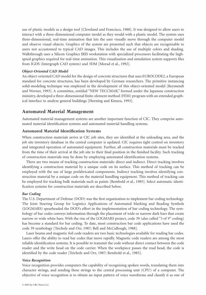
use of plastic models as a design tool [Cleveland and Francisco, 1988]. It was designed to allow users tointeract with a three-dimensional computer model as they would with a plastic model. The system usesthree-dimensional, real-time animation that lets the user visually move through the computer modeland observe visual objects. Graphics of the system are presented such that objects are recognizable tousers not accustomed to typical CAD images. This includes the use of multiple colors and shading.Walkthrough uses a Silicon Graphics IRIS workstation with specialized processors facilitating the high-speed graphics required for real-time animation. This visualization and simulation system supports filesfrom IGDS (Intergraph CAD system) and 3DM [Morad et al., 1992].
Object-Oriented CAD ModelAn object-oriented CAD model for the design of concrete structures that uses EUROCODE2, a Europeanstandard for concrete structures, has been developed by German researchers. The primitive instancingsolid-modeling technique was employed in the development of this object-oriented model [Reymendtand Worner, 1993]. A committee, entitled “NEW TECCMAR,” formed under the Japanese constructionministry, developed a three-dimensional finite-element method (FEM) program with an extended graph-ical interface to analyze general buildings [Horning and Kinura, 1993].
Automated Material Management
Automated material management systems are another important function of CIC. They comprise auto-mated material identification systems and automated material handling systems.
Automated Material Identification Systems
When construction materials arrive at CIC job sites, they are identified at the unloading area, and thejob site inventory database in the central computer is updated. CIC requires tight control on inventoryand integrated operation of automated equipment. Further, all construction materials must be trackedfrom the time of their arrival at the job site to their final position in the finished facility. Such trackingof construction materials may be done by employing automated identification systems.
There are two means of tracking construction materials: direct and indirect. Direct tracking involvesidentifying a construction material by a unique code on its surface. This method of tracking can beemployed with the use of large prefabricated components. Indirect tracking involves identifying con-struction material by a unique code on the material handling equipment. This method of tracking canbe employed for tracking bulk materials such as paints [Rembold et al., 1985]. Select automatic identi-fication systems for construction materials are described below.
Bar CodingThe U.S. Department of Defense (DOD) was the first organization to implement bar coding technology.The Joint Steering Group for Logistics Applications of Automated Marking and Reading Symbols(LOGMARS) spearheaded the DOD’s effort in the implementation of bar coding technology. The sym-bology of bar codes conveys information through the placement of wide or narrow dark bars that createnarrow or wide white bars. With the rise of the LOGMARS project, code 39 (also called “3 of 9” coding)has become a standard for bar coding. To date, most construction bar code applications have used thecode 39 symbology [Teicholz and Orr, 1987; Bell and McCullough, 1988].
Laser beams and magnetic foil code readers are two basic technologies available for reading bar codes.Lasers offer the ability to read bar codes that move rapidly. Magnetic code readers are among the mostreliable identification systems. It is possible to transmit the code without direct contact between the codereader and the write head on the code carrier. When the workpiece passes the read head, the code isidentified by the code reader [Teicholz and Orr, 1987; Rembold et al., 1985].
Voice RecognitionVoice recognition provides computers the capability of recognizing spoken words, translating them intocharacter strings, and sending these strings to the central processing unit (CPU) of a computer. Theobjective of voice recognition is to obtain an input pattern of voice waveforms and classify it as one of
© 2003 by CRC Press LLC

Construction Automation 6-21
a set of words, phrases, or sentences. This requires two steps: (1) analyze the voice signal to extract certainfeatures and characteristics sequentially in time and (2) compare the sequence of features with themachine knowledge of a voice, and apply a decision rule to arrive at a transcription of the spokencommand [Stukhart and Berry, 1992].
Vision SystemsA vision system takes a two-dimensional picture by either the vector or the matrix method. The pictureis divided into individual grid elements called pixels. From the varying gray levels of these pixels, thebinary information needed for determining the picture parameters is extracted. This information allowsthe system, in essence, to see and recognize objects.
The vector method is the only method that yields a high picture resolution with currently availablecameras. The vector method involves taking picture vectors of the scanned object and storing them atconstant time intervals. After the entire cycle is completed, a preprocessor evaluates the recomposedpicture information and extracts the parameters of interest [Rembold et al., 1985].
Automated Material Handling Systems
Automated material handling systems play an important role in CIC. Efficient handling of constructionmaterials, such as prefabricated and precast components, is possible through an effective automatedmaterial handling system operating in conjunction with an automated material identification system.
TowlinesA towline consists of a simple track with a powered chain that moves carts of other carriers from pickuppoints to assigned destinations. Towlines can be controlled by sophisticated computer electronic tech-niques. Towlines interface efficiently with other automated material handling systems. Automated mate-rial identification systems can be easily integrated with towline material handling systems. Opticalscanners or photoelectric readers can be used at important locations and intersections along the trackto read the bar-coded information attached to the cart and relay signals to the control system. The controlsystem then routes the cart to its destination [Considine and Considine, 1986].
Underhang CranesThere are two types of motor-driven underhang cranes: (1) single-bridge overhead cranes that can operateon multiple runways and (2) double-bridge overhead cranes that can achieve higher hook lifts withgreater load-carrying capacity. A motor-driven crane consists of a track used for crane runways andbridge girders, the end trucks, the control package, a drive assembly, drive wheels, a drive line shaft, atraveling pushbutton control, and runway and cross-bridge electrification.
Power and Free Conveyor SystemsConveyor systems allow precast or prefabricated components to be carried on a trolley or on multipletrolleys propelled by conveyors through some part of the system and by gravity or manual means throughanother part of the system. Conveyor systems provide the high weight capacities that are normallyrequired in construction.
Inverted Power and Free Conveyor SystemsAn inverted power and free conveyor system is an upside-down configuration of the power and freeconveyor system. The load is supported on a pedestal-type carrier for complete access.
Track and Drive Tube ConveyorsTrack and drive tube conveyors can be employed to transport components for prefabrication. Thisconveyor system consists of a spinning tube (drive tube) mounted between two rails. Carriers of prefab-ricated units need to be equipped with a drive wheel capable of moving between 0 and 45˚. This drivewheel is positioned against the spinning drive tube. Speed of the moving component can be controlledby varying the angle of the drive wheel. When the drive wheel is in the 0˚ position, the carrier remainsstationary. As the angle between the drive wheel and the drive tube is increased, the carrier acceleratesforward.
© 2003 by CRC Press LLC

6-22 The Civil Engineering Handbook, Second Edition
Automatic Vertical Transport System (AVTS)Fujita Corp.’s AVTS is a system under development that is designed to deliver material throughout thejob site. The system uses an automated elevator system that automatically loads material onto a lift, hoiststhe material to the designated floor, and automatically unloads the lift [Webster, 1993].
InterlocksInterlocks allow transfer of hoist carriers between adjacent crane runways, thereby maximizing the areacovered by the overhead material handling systems. Interlocks also eliminate duplicate handling. Cross-connected, double-locking pins help to ensure that the safety stops will not operate until the crane andconnecting track are in proper alignment.
Automatically Guided VehiclesAutomatically guided vehicles (AGVs) are the most flexible of all material handling equipment. AGVscan be controlled by programmable controllers, on-board microprocessors, or a central computer.Because of their lack of dependence on manual guidance and intervention, AGVs can also be categorizedas construction robots. AGVs have their own motive power aboard. The steering system is controlled bysignals emanating from a buried wire [Considine and Considine, 1986].
Autonomous Dump Truck SystemThe autonomous dump truck system, shown in Fig. 6.9, enables driverless hauling operations, such ashauling of earth and gravel by dump trucks, on heavy construction sites. The two major functions ofthis system are autonomous driving function and advanced measurement function.
The driving distance and velocity of the vehicle are detected by encoder sensors attached to the trucktires. Direction of the vehicle is detected by a fiber-optic gyroscope. Positions of the vehicle are determinedusing data from the encoder sensors and fiber-optic gyroscope.
A laser transmitter/receiver is equipped at the left side of the test vehicle, and laser reflectors areinstalled along the driving route at a spacing of approximately 50 m. Positional errors accumulated inlong-distance driving are corrected using the feedback information from the laser transmitter/receiver.The autonomous vehicle system recognizes the workers wearing helmets by utilizing a color imageprocessor [Sugiyura et al., 1993].
Network Communication
Communication technology, transferring information from one person or computer system to another,plays a vital role in the implementation of CIC. Establishment of an effective communications networksuch that originating messages receive the correct priority and accurate data arrive at the final destinationis a difficult task [Miyatake and Kangari, 1993]. To ensure smooth operations in CIC, many automateddevices and computers must be linked. Computer networking techniques enable a large number ofcomputers to be connected. Computer networks can be classified as wide-area networks (WANs), which
FIGURE 6.9 Autonomous dump truck system. (Source: Sugiyura et al. 1993. Autonomous Dump Truck Systems forTransporting and Positioning Heavy-Duty Materials in Heavy Construction Sites. Proceedings, Tenth InternationalSymposium on Automation and Robotics for Construction. Houston, TX, pp. 253–260.)
LOADING SITE
UNLOADING SITEUnmanned operation
One operator
Oneoperator DRIVING
ROAD
© 2003 by CRC Press LLC

Construction Automation 6-23
serve geometric areas larger than 10 km; local-area networks (LANs), which are confined to a 10-kmdistance; and high-speed local networks (HSLNs), which are confined to a distance less than 1 km.
Wide-area networks such as APPANET can be employed to connect the construction company’scorporate office to various automated project sites. LANs combined with HSLNs can be employed tofacilitate efficient data exchange among automated construction equipment (such as a CNC concreteplacement machine, floor-leveling robots, and wall-painting robots) operating on job sites. Variousgateways (computers that transfer a message from one network to another) can be used to link networks.
Three types of commonly used network arrangements — ring, star, and bus — are shown in Fig. 6.10.In a ring network arrangement, the connecting coaxial cable must be routed back to where it begins.This results in network breakdown whenever the ring breaks. The star network arrangement is easilyexpanded, but the network relies on a server at the center of the star. Further, all communications betweennodes must pass through the center. The bus network arrangement is open-ended, and hence, a nodecan be added easily to the network [Chang et al., 1991].
The efficiency of a network system depends on the following parameters [Rembold et al., 1985]:
1. Transmission speed and maximum transmission distance2. Time delay necessary to respond to interrupts and data requests3. Additional hardware and software needed for expansion
FIGURE 6.10 Three common network arrangements.
(a) Ring
(b) Star
(c) Bus
© 2003 by CRC Press LLC

6-24 The Civil Engineering Handbook, Second Edition
4. Reliability, fault tolerance, and availability5. Unique logic structure6. Standard plug-in principle7. Possible geographic distribution of communication processes8. Cost of the system components
In an attempt to enable network communications using computers and devices from different vendors,the International Standards Organization (ISO) developed a model for LANs called the Open SystemInterconnect (OSI) model, which is shown in Fig. 6.11. The OSI splits the communication process intoseven layers as described below:
1. Physical layer — The physical layer corresponds to electrical and mechanical means of datatransmission. It includes coaxial cable, connectors, fiber optics, and satellite links.
2. Data link layer — Functions of this layer include resolution of contention for use of the sharedtransmission medium, delineation and selection of data addressed to this node, detection of noise,and error correction.
3. Network layer — This layer is responsible for establishing, maintaining, and terminating connec-tions. Further, this layer enables internetwork routing using a global standard for assigningaddresses to nodes.
4. Transport layer — This layer provides a network-independent service to the session, presentation,and application layers. Loss or duplication of information is also checked by this layer.
5. Session layer — This layer controls the dialogue between applications and provides a checkpointand resynchronizing capability. In case of network interruptions during the communication ses-sion, this layer provides a means to recover from the failure.
6. Presentation layer — This layer is responsible for verifying the syntax of data exchanged betweenapplications. Thus, it enables data exchanges between devices using different data encoding systems.
7. Application layer — This layer corresponds to a number of applications such as CAD/CACsystems, construction robots, NC or CNC machines, and computer graphic interfaces. This is themost complex layer and ensures that data transferred between any two applications are clearlyunderstood [Chang et al., 1991].
FIGURE 6.11 Open Systems Interconnect (OSI) model developed by ISO.
Device A Device B
7
6
5
4
3
2
1
7
6
5
4
3
2
1
Transmission Medium
ProtocolApplication
Presentation
Session
Transport
Network
Data Link
Physical
© 2003 by CRC Press LLC

Construction Automation 6-25
Example Application of Computer-Integrated Construction
The SMART system, shown in Fig. 6.12, is part of an overall CIC strategy. The SMART system integrateshigh-rise construction processes such as erection and welding of steel frames, placement of precastconcrete floor slabs, and exterior and interior wall panel installation.
In the SMART system, steel-frame columns and beams are automatically conveyed to designatedlocations. Assembly of these structural components is greatly simplified by using specially designed joints.
The SMART system consists of an operating platform, jacking towers, a vertical lifting crane, andweather protection cover. The operating platform is an automated assembly system and consists of acomputer-control room, monorail hoists for automated material handling, and a structural steel framethat eventually becomes the top roof of the building. Upon completion of the foundation activity, theoperating platform is assembled and mounted on top of the four jacking towers of the lifting mechanism.After completion of construction work in each floor of the building, the entire automated system is liftedby vertical jacks. Thus, the automated construction work is performed, floor by floor, until the entirebuilding is completed [Miyatake and Kangari, 1993].
6.5 Toward Advanced Construction Automation
In this section, four emerging technologies and equipment path planning, which can be adapted toimplement cognitive or intelligent construction robots and systems, are described. Selected examples ofrecent applications and research on automation and robotic technologies in building construction andcivil engineering works are also presented.
FIGURE 6.12 Shimizu’s Manufacturing by Advanced Robotic Technology (SMART) system. (Source: Miyatake, Y.and Kangari, R. 1993. Experiencing Computer Integrated Construction. Journal of Construction Engineering andManagement, ASCE. 119(2):307–323. Reproduced by permission of ASCE.)
Control RoomSteel-frameOperating-platform
Monorail Hoist(Horizontal Transportation)
VerticalLiftingCrane
LiftingMechanism
AutomatedExteriorPanelInstallation
WeatherProtectionCover
JackingTowers
© 2003 by CRC Press LLC

6-26 The Civil Engineering Handbook, Second Edition
Emerging Technologies
There are several emerging technologies that can be adapted to implement cognitive or intelligentconstruction robots and systems. The intelligent construction robots and systems cannot be successfulwithout efficient and proper real-time monitoring and controlling of inputs and outputs about environ-ment and construction equipment itself [Kim and Russell, 2001]. Other industries, such as the mechanicaland manufacturing industries, are the valuable sources of these technologies. Although some technologiesfrom other industries are not directly suitable for the construction industry, a little modification willsatisfy the needs. This section will briefly review four technologies, namely, (1) distributed artificialintelligence, (2) global positioning system (GPS), (3) sensor and sensing technology, and (4) wirelesscommunication technology.
Distributed Artificial Intelligence
DAI is a subfield of artificial intelligence (AI). It is concerned with solving problems by applying bothartificial intelligence techniques and multiple problem solvers [Decker, 1987]. The world of DAI can bedivided into two primary arenas: Distributed Problem Solving (DPS) and Multi-Agent System (MAS).Research in DPS considers how the work of solving a particular problem can be divided among a numberof modules, or nodes, that cooperate at the level of dividing and sharing knowledge about the problemand about the developing solution [Smith and Davis, 1981]. In MAS, research is concerned with coor-dinating intelligent behavior among a collection of autonomous intelligent agents and with how theycan coordinate their knowledge, goals, skills, and plans jointly to take action or to solve problems.
There are some reasons why the DAI concept is appropriate for intelligent construction systems. First,due to possible changes in the initial conditions, the replanning of almost all task execution is oftennecessary. Equipment breakdowns, accidents, and other unexpected conditions are some causes of chang-ing the initial plan. DAI can provide an effective way to deal with these kinds of changes. Second, severalagents that have distributed and heterogeneous functions are involved in field operation at the same time.They should perform tasks in a cooperative manner. DAI can provide insights and understanding aboutinteraction among agents in the construction site in order to solve problems. In addition, data from theseagents should be interpreted and integrated. Third, every agent has different capacity and capability. Thisimplies that there are a great number of possible agent combinations that are time and cost effective toperform given tasks. Fourth, it is easy to decompose tasks for field operations. An example of tasksinvolved in earthwork operations are stripping, hauling, spreading, and compacting.
Global Positioning System (GPS)
The global positioning system (GPS) is a worldwide satellite-based navigation system operated andmaintained by the U.S. Department of Defense. GPS provides several important features, including itshigh position accuracy and velocity determination in three dimensions, global coverage, all-weathercapability, continuous availability to an unlimited number of users, accurate timing capability, ability tomeet the needs of a broad spectrum of users, and jam resistance [Leick, 1990].
Currently, GPS is used in various fields ranging from avionics, military, mapping, mining, and landsurveying, to construction. One example of construction application is SiteVision™ GPS system, whichis an earthmoving control system developed by Trimble Navigation Ltd. With horizontal and verticalaccuracies better than 30 mm, it allows the machine operator to work to design specifications withoutthe use of pegs, boards, or strings. This system can give the operators all the necessary direction forprecise grade, slope, and path control. Planned grade is achieved in fewer passes with less rework. Withthe SiteVision™ GPS system, accurate earthmoving operations take less time with lower fuel and main-tenance costs on large-scale earthmoving projects [Phair, 2000; Trimble Navigation Ltd., 2001]. There isanother possible application for construction equipment. An equipment motion strategy for the efficientand exact path for earthwork operations can be determined by GPS position data with preplanned motionmodels.
© 2003 by CRC Press LLC

Construction Automation 6-27
Sensor and Sensing Technology
A sensor is a device or transducer that receives information about various physical effects, such asmechanical, optical, electrical, acoustic, and magnetic effects and converts that information into electricalsignals. These electrical signals can be acted upon by the control unit [Warszawski and Sangrey, 1985].Construction equipment’s ability to sense its environment and change its behavior on that basis isimportant for an automated system. Without sensing ability, construction equipment would be nothingmore than a construction tool, going through the same task again and again in a human-controlledenvironment. Such a construction tool is commonly used for construction operation currently, andcertainly has its place and is often the right economic solution. With smart sensors, however, constructionequipment has the potential to do much more. It can perform given tasks in unstructured environmentsand adapt as the environment changes around it. It can work in dirty and dangerous environments wherehumans cannot work safely. The sensor technologies are used for real-time positioning, real-time datacollection during operation, equipment health monitoring, work quality verification and remediation,collision-free path planning, and equipment performance measurement.
Wireless Communication Technology
Wireless communication can be defined as a form of communication without using wires or fiber opticcables over distance by the use of arbitrary codes. Information is transmitted in the form of radiospectrum, not in the form of speech. So, information can be available to users at all time, in all places.The data transmitted can represent various types of information such as multivoice channels, full-motionvideo, and computer data [IBM Corp., 1995].
Wireless communication technology is important for the intelligent construction systems, becauseequipment moves from place to place on a construction site, and data and information needed shouldbe exchanged between construction equipment agents in real time. With wireless communication tech-nology, communication is not restricted by harsh construction environments due to remote data con-nection, and construction equipment agents and human operators can expect and receive the deliveryinformation and services no matter where they are on the construction site, even around the constructionsite.
Construction Robot Path Planning
The purpose of a path planning method for a construction robot is to find a continuous collision-freepath from the initial position of the robot to its target position. Several path-planning approaches havebeen suggested and applied to automated navigation of construction robots.
The research on robot path planning can be categorized into two models that are based on differentassumptions about the available information for planning: path planning with complete informationand path planning with incomplete information. The first model assumes that a construction robot hasperfect information about itself and its environment. Information, which fully describes the sizes, shapes,positions, and orientations of all obstacles in two-dimensional or three-dimensional space, is known.Because complete information is assumed, path planning is a one-time and off-line operation [Lumelskyand Stepanov, 1987; Lumelsky and Skewis, 1988]. Latombe [1991] categorizes path planning with com-plete information into three general approaches: road map, cell decomposition, and potential fieldmethod.
In the second model, an element of uncertainty is present, and the missing data is typically providedby some source of local information through sensory feedback using an ultrasound range or a visionmodule [Lumelsky and Skewis, 1988]. A robot has no information on its environment except a startposition and a target position. The sensory information is used to build a global model for path planningin real time. The path planning is a continuous on-line process. The construction and maintenance ofthe global model based on sensory information requires heavy computation, which is a burden on therobot [Kamon and Rivlin, 1997].
© 2003 by CRC Press LLC

6-28 The Civil Engineering Handbook, Second Edition
There are two approaches for path planning with incomplete information based on the way the sensoryinformation is incorporated in the path planning. One approach separates path planning from thefunctions of scene reconstruction. Another approach, called dynamic path planning, integrates sensoryability into the path planning function [Lumelsky and Skewis, 1988].
In the first approach, the whole environment or a part of it is reconstructed based on the sensor data,and then a path is generated using a path-planning algorithm. However, this approach requires largecomputational load to reconstruct and maintain the environmental model. Thus, it is difficult to implement.
Under the dynamic planning approach, themobile robot makes a decision on its next stepat each point based on the sensory information.Initially, the mobile robot moves toward the tar-get. When the robot encounters an object, itfollows the boundary of the obstacle. If a leavingcondition holds, it leaves the boundary of theobstacle and resumes its movement to the target[Kamon and Rivlin, 1997]. This approach min-imizes the computational load, because therobot memorizes some points such as the start,current, hit, and target points to generate itsnext path. Table 6.2 shows the dynamic path planning algorithms that are mostly Bug algorithm based.
The performance of algorithms can be measured by two evaluation criteria: the total path length andpath safety. Kamon and Rivlin [1997] state that path safety should be considered while evaluating pathquality. They suggest that minimal distance between the robot and the surrounding obstacles from everylocation along the path can be used for measuring path safety. The bigger the average distance, the saferthe path. However, it is difficult to do a direct comparison between algorithms, because the performancechanges based on different environments.
Examples of Recent Research and Applications
Building Construction Domain
From the late 1980s, Japanese contractors began to explore the application of manufacturing principlesto construction, because they began to understand that single-task automation could not provide bigpayoffs. By 1991, they achieved the first full-scale application of construction automation for buildingconstruction [Cousineau and Miura, 1998]. Some construction automation systems are listed in Table 6.3.These systems adapt the just-in-time principle for material delivery, bar-coding technology for trackingand placing delivered materials, and information technology for monitoring and coordinating construc-tion processes. In these systems, the numbers of single-task robots are used, efforts for integrating single-task robots are made, and more construction processes are automated. These construction systems havefour fundamental elements: an on-site factory protected by an all-weather enclosure, an automatedjacking system, an automated material-conveying system, and a centralized information-control system[Cousineau and Miura, 1998].
Civil Engineering Works Domain
Many of the recently developed systems for civil works are intelligent assistant tools that enhanceoperators’ ability to sense, plan, and monitor their works in real time. These tools integrate humanoperators and construction machines into a whole effective construction system. Tele or automatedsystems may be the only feasible alternative, when construction operations are performed in hazardousenvironments. In many cases, the cost of protecting human operators or workers may exceed the cost ofdeveloping tele or automated systems.
TABLE 6.2 Algorithms for Path Planning in an Unknown Environment
Researchers Algorithms
Lumelsky and Stepanov [1987] Bug1 and Bug2Lumelsky and Skewis [1988] VisBug21 and VisBug22Lumelsky and Tiwari [1994] AngulusKamon and Rivlin [1997] DistBugLee et al. [1997] TangentLee [2000] Tangent2 and CATKim [2001] SensBug
© 2003 by CRC Press LLC

Construction Automation 6-29
Semiautonomous Dump Truck SystemTo overcome worker shortage problems and to prevent accidents on heavy construction sites, an auton-omous dump truck system was developed by Saito et al. [1995]. The aim of HIVACS is to develop asemiautonomous dump truck system that has adaptability for changing surroundings such as long-distance driving, high-speed driving, driving within road width, and change of route, etc., with compre-hensive peripheral facilities. According to the report, this system enables two operators to manage fivedump trucks without truck drivers and results in a labor saving 17% at the studied dam construction site.
Tele-Earthwork SystemSakoh et al. [1996] developed the Tele-Earthwork System to provide a fail-safe, automated system to assistboth older and unskilled laborers, and to save labor. It is a remote-control system that can perform aseries of earthwork functions such as digging, loading, transporting, and disposal. In this system, anearthwork equipment control room is installed at a safe location away from the harmful and dangerousenvironment. An operator performs a series of earthwork tasks in the control room while observingequipment status and in-process tasks through three-dimensional images on the screen. All informationis transmitted via a mobile radio relay car. This proposed system was applied to a full-scale earthworkproject.
Automated Landfill SystemA conceptual framework for an automated landfill system (ALS) was developed by Tserng et al. [1996],Tserng [1997], and Tserng et al. [2000]. The research focused on space model development and man-agement, mapping and positioning methods, and equipment motion planning. The properties andlocation of job-site space are recorded into nodes of the quadtree data structure. In order to avoid collisionwith obstacles and other equipment, which are transformed to represent the locus of forbidden positions,the equipment becomes a point in the transformed geometric model called configuration space (CSpace).The quadtree-cube geometric model is employed for recording several CSpace in one quadtree structure.After the quadtree-cube system is established, the specific quadtree network is extracted for each pieceof equipment. Then, this system uses the k-shortest path algorithm to traverse the quadtree network.
Autonomous ExcavatorA pure autonomous excavator is being developed by Carnegie Mellon University. The range of automationcovers the whole excavation process from bucket path planning to material dump on a truck. It has ahigh-level planner that determines where and how to excavate, and a local-optimal planner that decidesthe shape of each dig [Stentz et al., 1998].
GPS-Based Guiding SystemPampagnin et al. [1998] developed an operator-aiding system for the real-time control of the positioningof road construction compactors. The main goal of this system was to assist the compactor operator inthe road compaction task, by helping him to perform the exact number of passes, at the right speed,
TABLE 6.3 Construction Automation Systems for Building Construction
System Description Project Year Company
Push-Up 1989–91, 1993–95 Takenaka Co., JapanSMART (Shimizu Manufacturing System by Advanced Robotics Technology) 1991–94, 1994–97 Shimizu Co., JapanABCS (Automated Building Construction System) 1991–94 Obayashi Co., JapanT-Up (Totally Mechanized Construction System) 1992–94 Taisei Co., JapanMCCS (Mast Climbing Construction System) 1992–94, 1995–98 Maeda Co., JapanAKWTSUKI 21 (Automated weather-unaffected building construction system) 1994–96 Fujita Co., JapanAMURAD (Automatic Up-Rising Construction by Advanced Technique) 1995–96 Kajima Co., JapanBig Canopy 1995–97 Obayashi Co., Japan
Source: Modified from Cousineau and Miura, 1998.
© 2003 by CRC Press LLC

6-30 The Civil Engineering Handbook, Second Edition
everywhere on the surface to be compacted. GPS, optical fiber gyrometer, and advanced filtering tech-niques were used for a civil engineering machine for the first time.
Computer Integrated Road ConstructionPeyret [1999] and Peyret et al. [2000] conducted a study on the computer integrated road construction(CIRC) project that aims to develop CIC systems for the real-time control and monitoring of taskoperations performed by road construction equipment. These systems mainly rely on CAD data estab-lished during the design phase and during the construction in real time. CIRC products, the one for thecompactors and the one for the asphalt pavers, can provide good tools for operator assistance, machinecontrol, and quality assessment and ensuring. They showed the benefits of new technologies applied toroad construction works.
Laser-Based SystemHaoud [1999] described a laser-based system for earthwork applications. On the construction machineand on both sides of the blade, electric receivers are installed on two guide masts that send signals to thecontrol system to notify the status of the blade. The construction machine is equipped with a manualchecking device, which is used for machine calibration and checking operation results, and a swivel-headlaser emitter, which defines a virtual plane. This virtual plane is parallel to the future plane for thepavement. The laser-based system offers the quality improvement of the end result due to lower tolerancelevels and better evenness of the surface. With this system, it is possible to save manpower significantlyand increase productivity greatly.
Automated System for Quality Control of Compaction OperationsIn road construction, the number of passes of compactors will directly affect the density of asphaltpavement, when roller frequency, wheel load, and compactor speed are kept constant. For this reason,monitoring the exact number of passes over the entire surface of pavement is important. An automatedsystem for mapping compaction equipment using GPS technology and an algorithm was developed. Itcan find the exact number of passes at each point in the roadway and graphically depict the number ofpasses of compactors (Oloufa et al., 1999).
Automated Earthmoving Status DeterminationPresent research conducted by the National Institute of Standards and Technology (NIST) is focused ondeveloping automated, nonintrusive production-measurement systems and procedures for monitoringthe status of general earthmoving operations. The effort of the research includes the development ofmethods for automated registration of 2–1/two-dimensional range data, for automated volume calcula-tion, and for web-based three-dimensional site simulators. Information on terrain changes in one locationis sent via wireless Ethernet to another location to display the instant terrain geometry and to performcut and fill calculations [Stone et al., 2000].
Open Communication SystemRecently, information technology and communication technology have been rapidly expanding andgrowing. They offer better possibilities for automation and robotization in earthmoving and road con-struction. The effective and efficient automation with mobile construction equipment can be possibleby effective data communication between electronic components and systems equipped with mobileconstruction machines. The University of Magdeburg, Germany, conducted a study on an open com-munication system (CANopen) for mobile construction equipment, which offers higher flexibility andextensive safety and control mechanisms. As a result of the integrated connection among sensors, actu-ators, and electronic systems, new possibilities are created for automation and robotization in construc-tion [Poppy and Unger, 2000].
Computer Aided Earthmoving System (CAES)There is a commercially available system for assisting human operators, a Computer Aided EarthmovingSystem (CAES) introduced by Caterpillar Inc. (2001). CAES integrates planning and design operations.
© 2003 by CRC Press LLC

Construction Automation 6-31
CAES consists of on-board computers, software, GPS, and data radios and receivers, which replace themanpower and time-intensive processes associated with conventional surveying. CAES allows engineersto transmit planning and designs wirelessly to the machine’s on-board computer. The machine operatorcan get information on where the machine is in the design area, what the current surface is, and wherethe final surface is. The operator uses this information to see where to cut and fill and by how much.The machine progress is measured and recorded to update information for the operator and is transmittedto the office for analysis and documentation. Caterpillar is continuing to develop advanced technologyproducts. These products include radio data communications, machine monitoring, diagnostics, job andbusiness-management software, and machine control that can be used for automated constructionsystems.
Intelligent Earthwork SystemKim [2001] developed a framework for an intelligent earthwork system (IES). This framework definesthe architecture and methodologies to serve as the foundation for developing an IES. The IES enablesmultiple pieces of equipment to automatically generate earthwork plans for construction robots andperform the given operations. The proposed framework defines the architecture and methodologies toserve as the foundation for developing an IES, such as a construction agent model for IES, a taskidentification and planning method for effective task execution, a resource allocation method in orderto maximize equipment utilization, and a dynamic path planning algorithm to avoid collisions in theconstruction site.
6.6 Economics
Three major factors contributing to economic benefits of construction automation are productivity,quality, and savings in skilled labor [Kangari and Halpin, 1989]. These benefits must be weighed againstthe costs of automation, including initial investment and operating costs; these are further described inTable 6.4. Economic data resulting from analyses of several robot applications and automated systemsare described below.
Automated Stone Cutting
Benefits of a partially automated stone-cutting mill were assessed through computer simulation [Hijaziet al., 1988]. In comparison to traditional stone-cutting methods, simulation of the automated systemresulted in a 74% increase in productivity and 42% less time to process identical orders.
Steel Bridge Deck Welding
The economic implications of using robot welders in steel bridge deck fabrication were studied by Touranand Ladick [1988]. Using the robot welders in the fabrication shop was predicted to reduce fabricationcosts by 5.6%.
TABLE 6.4 Costs Associated with Construction Robotics
Initial Investment Costs Robot Operating Costs
Research and development On-site programmingEngineering personnel Software adaptationProduct testing Labor cost (technicians)Robot components ElectricityControl hardware System dismantling and re-setup
Robot transporting costsMaintenance and repair
© 2003 by CRC Press LLC

6-32 The Civil Engineering Handbook, Second Edition
Excavation
Most reports related to construction automation indicate improvement in productivity and quality. In oneparticular instance, the development and use of partially automated laser-guided grading equipment notonly improved productivity of fine grading operations, but also increased the contractor’s flexibility inmanaging its fleet. The contractor gained a major competitive advantage that contributed to the contractor’sgrowth from an annual volume of $500,000 in 1976 to over $50,000,000 in 1984 [Tatum and Funke, 1988].
Large-Scale Manipulators
Use of large-scale manipulators (LSMs) can reduce the amount of non-value-added tasks and increaseproductivity. According to a case study by the Construction Industry Institute, LSMs have high potentialfor industrial construction. They can be used for elevated concrete placement, painting, and sandblasting,as well as pipe, cable tray, and structural steel erection. These tasks on average constitute 33% of totalproject work-hours [Hsieh and Haas, 1993].
Results from a productivity analysis performed by videotaping identical pipe-handling operations bya pipe manipulator and a telescopic rough-terrain crane indicate a shorter cycle time for the pipemanipulator [Hsieh et al., 1993].
Interior Finishing Robot
A performance study of an interior-finishing robot indicated that the net productivity of the robot canreach 10–19 m2/h in a one-layer coating and 8–8.5 m2/h in a dry (mortarless) building. These figures arefour to five times higher than for an average construction worker. Wages of $25 per hour, 1500 to2000 hours of robot usage per year, suitable site conditions, and proper organization of material packagingcan result in savings of 20 to 50% in the cost of interior finishing work [Warszawski and Navon, 1991;Warszawski and Rosenfeld, 1993].
Exterior Building Finishers
Results from an outdoor experiment using a tile-setting robot indicate a setting efficiency of 14 m2/day,with an average adhesive strength of 17.2 kg/cm, representing improved productivity and quality[Kikawada et al., 1993].
Automated Slab Placing and Finishing
According to a study on automated concrete placement and finishing [Moselhi et al., 1992], automationof placing and finishing concrete slabs would require a minimum annual work volume of 144,321 m2
(1,600,000 ft2) of pavement in order to be more economical than the conventional manual process. Thus,at present, the sizable capital cost of the initial investment precludes smaller paving contractors fromconsidering automation.
Shimizu’s SMART System
Shimizu Corporation’s experience with the SMART system includes improved productivity, attractiveworking environment, all-weather protection, higher quality and durability, reduced construction sched-ule duration, and reduced amount of waste and damage to materials. Upon further advancement of theSMART system, a 50% reduction in construction duration is expected [Miyatake and Kangari, 1993].
Obayashi’s ABCS
The evaluation of ABCS system shows that when cranes were operated automatically, a 30% reductionin power was achieved. During construction, sound measurement indicated a marked improvement in
© 2003 by CRC Press LLC

Construction Automation 6-33
the work environment at the factory floor level. The work environment was also improved by the all-weather sheeting [Cousineau and Miura, 1998].
Maeda’s MCCS
Observations made during construction included 30% reduction in manpower, significant reduction inwaste, and 20% reduction in the cycle time to complete one story. As workers learn how to use the MCCS,more reduction in manpower and schedule is expected [Cousineau and Miura, 1998].
Obayashi’s Big Canopy
Big Canopy is the first automated system to improve overall productivity. Use of this system resulted in60% reduction in labor for frame election and reduction in material cost [Cousineau and Miura, 1998].
Kajima’s AMURAD
According to observations on the use of AMURAD, significant improvement is achieved: (1) 30%reduction in construction time, (2) 50% reduction in manpower, (3) 50% reduction in waste, (4) morepredictable schedule by using the all-weather protective sheeting, and (5) more comfortable environmentfor workers [Kajima Corporation, 1996].
6.7 Summary
A brief description of construction industry characteristics followed a discussion on the importance ofconstruction automation. Fixed construction automation was defined, and selected examples of fixedconstruction automation were provided. Following this, programmable automation including roboticand numerical control applications were described. Computer-integrated construction (CIC), whichprovides an intelligent approach to planning, design, construction, and management of facilities, requiresemerging technology that encompasses research efforts from a variety of engineering and computerscience disciplines. A detailed description of CIC and supporting areas that play important roles inimplementing CIC was provided. Some emerging technologies and equipment path planning, which canbe adapted to implement cognitive or intelligent construction robots and systems, are described. Finally,selected examples of recent applications and research on automation and robotic technologies in buildingconstruction and civil engineering works are presented.
Defining Terms1
Electronic controls — Computer-based hardware units designated to control and coordinate the posi-tions and motions of manipulator arms and effectors. A controller is always equipped withmanipulator control software, enabling an operator to record a sequence of manipulatormotions and subsequently play back these motions a desired number of times. More sophisti-cated controllers may plan entire sequences of motions and tool activators given a desired worktask.
End effectors — Tools and devices on automated construction equipment, including discharge nozzles,sprayers, scrapers, grippers, and sensors. The robot tools are usually modified compared withtools used by human workers or even specially designed to accommodate unique characteristicsof the working machine.
Manipulators — Stationary, articulated arms that are essential components of industrial robotics. Therole of a manipulator arm is to move an effector tool to the proper location and orientation
1Source: Adapted from Hunt, V.D. 1983. Industrial Robotics Handbook. Industrial Press, New York.
© 2003 by CRC Press LLC

6-34 The Civil Engineering Handbook, Second Edition
relative to a work object. To achieve sufficient dexterity, arms typically require six axes of motions(i.e., six degrees of freedom), three translational motions (right/left, forward/back, up/down),and three rotational motions (pitch, roll, and yaw).
Motion systems — Systems that enable the essential features of mobility and locomotion for construc-tion equipment. A variety of mobile platforms can support stationary manipulator arms forperformance of required tasks. An example selection of automatically guided vehicle (AGV)platforms is presented in Skibniewski [1988]. However, most automated tasks supported byAGVs in construction will require modified control systems and larger payloads than those inautomated factories.
Sensors — A device for converting environmental conditions into electrical signals. An environmentalcondition might be a mechanical, optical, electrical, acoustic, magnetic, or other physical effect.These effects may occur with various levels of intensity and can be assessed quantitatively bymore sophisticated sensors. These measurements are used to control robot movements and, inadvanced robots, to plan operations. Sensors are important to robotics in construction becausethey instantaneously convey elements of the building environment to the control unit.
References
Bell, L.C. and McCullough, B.G. 1988. Bar Code Application in Construction. A Report to the ConstructionIndustry Institute, SD-33, University of Texas, Austin. February.
Bernold, L.E., Altobelli, F.R., and Taylor, H. 1992. Computer-controlled brick masonry. J. Comput. Civ.Eng., ASCE. 6(2):147–161.
BLS. 2000a. National Census of Fatal Occupational Injuries in 1999. NEWS, Bureau of Labor Statistics,http://stats.bls.gov/.
BLS. 2000b. Workplace Injuries and Illnesses in 1999. NEWS, Bureau of Labor Statistics,http://stats.bls.gov/.
BLS. 2001. Employment Situation Summary. Bureau of Labor Statistics, http://stats.bls.gov/news.release.Business Roundtable. 1982. Improving Construction Safety Performance, Construction Industry Cost
Effectiveness Report. Business Roundtable, New York.Caterpillar Inc. 2001. Computer Aided Earthmoving Systems (CASE). Caterpillar Inc., http://www.cater-
pillar.com/.Chang, T., Wysk, R.A., and Wang, S. 1991. Computer-Aided Manufacturing. Prentice Hall, Englewood
Cliffs, NJ.Cherneff, J., Logcher, R., and Sriram, D. 1991. Integrating CAD with Construction Schedule Generation.
J. Comput. Civ. Eng., ASCE. 5(1):64–86.Cleveland, A.B. and Francisco, V. 1988. Use of Real-Time Animation in the Construction Process. Transp.
Res. Rec. 1186:5–39.Considine, D.M. and Considine, G.D. 1986. Standard Handbook of Industrial Automation. Chapman &
Hall, New York.Cousineau, L. and Miura, N. 1998. Construction Robots: The Search for New Building Technology in
Japan, ASCE Press, Reston, VA.Decker, K. 1987. Distributed Problem-Solving Techniques: A Survey. IEEE Trans. Syst., Man Cyber., SMC
17:729–740.Everett, J.G. and Saito, H. 1996. Construction Automation: Demands and Satisfiers in the United States
and Japan. J. Constr. Eng. Manage., ASCE. 122(2):147–151.Fisher, D.J. and O’Connor, J.T. 1991. Constructability for Piping Automation: Field Operations. J. Constr.
Eng. Manage., ASCE. 117(3):468–485.Foley, J.D. and Van Dam, A.V. 1982. Fundamentals of Interactive Computer Graphics. Addison-Wesley,
Reading, MA.Groover, M.P., Parriera, N.D., Doydum, C., and Smith, R. 1989. A Survey of Robotics Technology in
Construction. SME Tech. Pap. May 7–11, 1–20.
© 2003 by CRC Press LLC

Construction Automation 6-35
Hanser, C. 1999. Fully Automated Masonry Plant, Proc. 16th Int. Symp. Automat. Robot. Constr., Madrid,Spain, 295–300.
Haoud, H. 1999. Laser Technology Applied to Earthworks. Proc. 16th Int. Symp. Automat. Robot. Constr.,Madrid, Spain, 33–40.
Hendrickson, C. and Au, T. 1988. Project Management for Construction: Fundamental Concepts forOwners, Engineers, Architects and Builders, p. 486. Prentice Hall, Englewood Cliffs, NJ.
Hijazi, A., AbouRizk, S., and Halpin, D.W. 1988. Impact of Automation on Construction Fixed PlantOperations. Technical Report. Purdue University, West Lafayette, IN.
Hinze, J.W. 1997. Construction Safety, Prentice-Hall, Inc., Englewood Cliffs, NJ.Horning, C. and Kinura, H. 1993. Three-Dimensional FEM analysis with Graphical Interface. Proc. 5th Int.
Conf. Comput. Civ. Build. Eng. Anaheim, CA, pp. 1283–1290.Hsieh, T. and Haas, C. 1993. Applications of Large-Scale Manipulators in the Construction Environment.
Proc. 10th Int. Symp. Automat. Robot. Constr., Houston, TX, 55–62.Hsieh, T.Y., Fulton, C., Gibson, G.E., and Haas, C.T. 1993. An Evaluation of the Pipe Manipulator
Performance in a Material Handling Yard. Proc. 10th Int. Symp. Automat. Robot. Constr., Houston,TX, 55–62.
Hughes, P.J., O’Connor, J.T., and Traver, A.E. 1989. Pipe Manipulator Enhancements for IncreasedAutomation. J. Constr. Eng. Manage., ASCE. 115(3):412–423.
Hunt, V.D. 1983. Industrial Robotics Handbook. Industrial Press, New York.IBM Corp. 1995. An Introduction to Wireless Technology, IBM International Technical Support Organi-
zation, Research Triangle Park, NC.Jaselskis, E.J. and Anderson, M.R. 1994. On Hazardous Waste and Robotic Applications. J. Environ. Eng.,
ASCE. 120(2):359–378.Kajima Corporation. 1996. 9-Story Company Housing is Under Construction Using a Fully Automated
System Called AMURAD. Kajima Press Release, Tokyo, Japan.Kamon, I. and Rivlin, E. 1997. Sensory-Based Motion Planning with Global Proofs. IEEE Trans. Robot.
Automat., 13(6): 814–822.Kangari, R. and Halpin, D.W. 1989. Potential Robotics Utilization in Construction. J. Constr. Eng. Man-
age., ASCE. 115(1):126–143.Kikawada, K., Ashikaga, S., Ishikawa, S., and Nishigaki, S. 1993. Practical Tile-Setting Robot for Exterior
Walls. Proc. 10th Int. Symp. Automat. Robot. Constr. Houston, TX, 71–75.Kim, S.K. 2001. Toward a Framework for an Intelligent Earthwork System. Ph.D. Thesis, University of
Wisconsin-Madison, Madison, WI.Kim, S.K., and Russell, J. S. 2001. Framework for an Intelligent Earthwork System: Part 1 — System
Architecture, Automation in Construction (In press).Kunigahalli, R. and Russell, J.S. 1995. Framework for Development of CAD/CAC Systems. Automation
in Construction, 3: 327–340.Kunigahalli, R., Russell, J.S. and Veeramani, D. 1995. Extracting Topological Relationships from a Wire-
Frame CAD Model. J. Comput. Civ. Eng., ASCE. 9(1):29–42.Latombe, J. 1991. Robot Motion Planning, Kluwer Academic Publishers, Boston, MA.Lee, S. 2000. Spatial Model and Decentralized Path Planning for Construction Automation. Ph.D. Thesis,
University of Wisconsin-Madison, Madison, WI.Lee, S., Adams, T.M., and Ryoo, B. 1997. A Fuzzy Navigation System for Mobile Construction Robots.
Automation in Construction, 6: 97–107.Leick, A. 1990. GPS Satellite Surveying, John Wiley & Sons, New York.Levitt, R.E. and Samelson, N.M. 1993. Construction Safety Management, John Wiley and Sons, Inc., New York.Luggen, W.W. 1984. Fundamentals of Numerical Control. Delmar, Albany, NY.Lum, S.K.S. and Moyer, B.C. 2000. Gross Domestic Product by Industry for 1997–99. Survey of Current
Business, Bureau of Economic Analysis, 24–45.Lumelsky, V.J. and Skewis, T. 1988. A Paradigm for Incorporating Vision in the Robot Navigation Func-
tion. IEEE Int. Conf. Robot. Automat., 2, Philadelphia, PA, 734–739.
© 2003 by CRC Press LLC

6-36 The Civil Engineering Handbook, Second Edition
Lumelsky, V.J. and Stepanov, A.A. 1987. Path-Planning Strategies for a Point Mobile Automaton MovingAmidst Unknown Obstacles of Arbitrary Shape. Algorithmica, 2: 403–430.
Lumelsky, V.J. and Tiwari, S. 1994. An Algorithm for Maze Searching with Azimuth Input. IEEE Int. Conf.Robot. Automat., 1, San Diego, CA, 111–116.
Maynard, H.B. 1971. Industrial Engineering Handbook. McGraw-Hill, New York.Miyatake, Y. and Kangari, R. 1993. Experiencing Computer Integrated Construction. J. Constr. Eng.
Manage., ASCE. 119(2):307–323.Morad, A.A., Cleveland, A.B., Beliveau, Y.J., Francisco, V.D., and Dixit, S.S. 1992. Path Finder: AI-Based
Path Planning System. J. Comput. Civ. Eng., ASCE. 6(2):114–128.Mortenson, M.E. 1985. Geometric Modeling. John Wiley & Sons, New York.Moselhi, O., Fazio, P., and Hanson, S. 1992. Automation of Concrete Slab-on-Grade Construction.
J. Constr. Eng. Manage., ASCE. 118(4):731–748.Motazed, B. and Whittaker, W.L. 1987. Automated Pipe Mapping. The Robotics Institute, Carnegie-Mellon
University, Pittsburgh, PA. March.O’Connor, J. T., Traver, A.E., and Tucker, R.L. 1987. Research into Automated Piping Construction. Proc.
4th Int. Symp. Robot. Artif. Intel. Build. Constr. Building Research Station, Haifa, Israel. June,268–273.
Oloufa, A.A., Do, W., and Thomas, H.R. 1999. An Automated System for Quality Control of CompactionOperations: Receiver Tests & Algorithms. Proc. 16th Int. Symp. Automat. Robot. Constr., Madrid,Spain, 67–71.
Pampagnin, L., Martinez, F., Peyret, F., Backlund, K., Fliedner, J., Gorham, B., Marchand, J., and Becker,J. 1998. A New GPS-Based Guiding System for Compactors. Proc. 15th Int. Symp. Automat. Robot.Constr., Munich, Germany, 153–162.
Paulson, B.C. 1985. Automation and Robotics for Construction. J. Constr. Eng. Manage., ASCE.111(3):190–207.
Peyret, F. 1999. The Computer Integrated Road Construction Project. Proc. 16th Int. Symp. Automat.Robot. Constr., Madrid, Spain, 593–598.
Peyret, F., Jurasz, J., Carrel, A., Zekri, E., and Gorham, B. 2000. The Computer Integrated Road Con-struction Project. Automation in Construction, 9:447–461.
Phair, M. 2000. Satellite Positioning System Moves from Dozers to Motor Graders. ENR, 244(12):49.Point, G. 1988. Two Major Innovations in Current Maintenance: The Multipurpose Vehicle and the
Integrated Surface Patcher. 67th TRB Annu. Meet., Transportation Research Board, Washington,D.C., 29.
Poppy, W. and Unger, E. 2000. CANopen for Mobile Construction Machines — An Open CommunicationNetwork for Control and Automation. Proc. 17th Int. Symp. Automat. Robot. Constr., Taipei, Taiwan,515–518.
Rehg, J. A. 1992. Introduction to Robotics in CIM Systems. Prentice Hall, Englewood Cliffs, NJ.Reinschmidt, K.F., Griffs, F.H., Browner, P.L. 1991. Integrated Engineering, Design, and Construction.
J. Constr. Eng. Manage., ASCE. 117(4):756–772.Rembold, V., Bleme, C., and Dillmann, R. 1985. Computer-Integrated Manufacturing Technology and
Systems. Marcel Dekker, New York.Requicha, A.A.G. 1980. Representations of Rigid Solids: Theory, Methods, and Systems. ACM Comp.
Surv. 12(4):439–465.Requicha, A.A.G. and Rossignac, J.R. 1992. Solid Modeling and Beyond. IEEE Comp. Graph. Appl.
September, 31–44.Reymendt, J. and Worner, J.D. 1993. Object-Oriented Modeling of Concrete Structures. Proc. 5th Int. Conf.
Comput. Civ. Build. Eng. Anaheim, CA, 86–93.Sagawa, Y. and Nakahara, Y. 1985. Robots for the Japanese Construction Industry. IABSE Proceedings.
May, 86.Saito, M. 1985. The Development of a Mobile Robot for Concrete Slab Finishing. Technical Report. Mechan-
ical Engineering Development Dept., Kajima Co., Tokyo, Japan.
© 2003 by CRC Press LLC

Construction Automation 6-37
Saito, H., Sugiura, H., and Yuta, S. 1995. Development of Autonomous Dump Trucks System (HIVACS)in Heavy Construction Sites. Proc. 1995 IEEE Int. Conf. Robot. Automat., Aichi, Japan, 2524–2529.
Sakoh, S., Okano, M., Kita, S., and Okumatsu, T. 1996. Development and Practice of the Tele-EarthworkSystem. Advanced Robotics, 10(4): 425–438.
Sanvido, V.E. and Medeiros, D.J. 1990. Applying Computer-Integrated Manufacturing Concepts to Con-struction. J. Constr. Eng. Manage., ASCE. 116(2):365–379.
Sherman, P.J. 1988. Japanese Construction R&D: Entrée into U.S. Market. J. Constr. Eng. Manage., ASCE.114(1):138–142.
Skibniewski, M.J. 1988. Robotics in Civil Engineering, Van Nostrand Reinhold, New York.Skibniewski, M.J. and Russell, J.S. 1989. Robotic Applications to Construction. Cost Eng. 31(6):10–18.Slocum, A.H., Laura, D., Levy, D., Schena, B., and Ziegler, A. 1987. Construction Automation Research
at the Massachusetts Institute of Technology. Proc. 4th Int. Symp. Robot. Artif. Intel. Build Constr.Building Research Station, Haifa, Israel. June, 222–233.
Smallwood, J. and Haupt, T.C. 2000. Safety and Health Team Building. Construction Safety and HealthManagement, Prentice-Hall Inc., Englewood Cliffs, NJ.
Smith, R.G. and Davis, R. 1981. Framework for Cooperation in Distributed Problem Solving. IEEE Trans.Syst., Man Cyber., SMC. 11(1):61–70.
Stentz, A., Bares, J., Singh, S., and Rowe, P. 1998. A Robotic Excavator for Autonomous Truck Loading.Proc. 1998 IEEE/RSJ Int. Conf. Intel. Robot. Syst., Victoria, B.C., Canada, 1885–1893.
Stone, W.C., Cheok, G., and Lipman, R. 2000. Automated Earthmoving Status Determination. Robotics2000, Proc. 4th Int. Conf. Expo./Demon. Robot. Chall. Situa. Envir., Albuquerque, NM, 111–119.
Stukhart, G. and Berry, W.D. 1992. Evaluation of Voice Recognition Technology. Report to ConstructionIndustry Institute, SD-76. University of Texas, Austin. June.
Sugiyura, H., Yute, S., Nishide, K., Hatekeyama, O., and Nishigaki, S. 1993. Autonomous Dump TrucksSystems for Transporting and Positioning Heavy-Duty Materials in Heavy Construction Sites. Proc.10th Int. Symp. Automat. Robot. Constr. Houston, TX, 253–260.
Tatum, C.B. and Funke, A.T. 1988. Partially Automated Grading: Construction Process Innovation.J. Constr. Eng. Manage., ASCE. 114(1):19–35.
Technical Specifications for Miller Formless Systems, Automated Slip Forming Systems, Bulk Cementand Unloading Systems. 1988. Miller Formless Systems Co., McHenry, IL.
Technical Specifications of the John Deere 690C Excavator. 1985. John Deere, Inc. Moline, IL. August.Teicholz, E. and Orr, J.N. 1987. Computer-Integrated Manufacturing Handbook. McGraw-Hill, New York.Terauchi, S., Miyajima, T., Mirjamoto, T., Arai, K., and Takiwaza, S. 1993. Development of an Exterior
Wall Painting Robot — Capable of Painting Walls with Indentations and Protrusions. Proc. 10th
Int. Symp. Automat. Robot. Contr. Houston, TX, 285–292.Touran, A. and Ladick, D. 1988. Applications of Robotics on Bridge Deck Fabrication. J. Constr. Eng.
Manage., ASCE. 115(1):35–52.Trimble Navigation Ltd. 2001. http://www.trimble.com/.Tserng, H.P. 1997. Towards a Framework for an Automated Landfill System (ALS). Ph.D. Thesis, University
of Wisconsin-Madison, Madison.Tserng, H.P., Ran, B., and Jeffrey, S.R. 2000. Interactive Path Planning for Multi-Equipment Landfill
Operations, Automation in Construction, 10(1):155–168.Tserng, H.P., Veeramani, Kunigahalli, R., and Russell, J.S. 1996. OPSALC: A Computer-Integrated Operations
Planning System for Autonomous Landfill Compaction, Automation in Construction, 5(1):39–50.Tucker, R.L. 1990. Construction Automation in the United States. Proc. 7th Int. Sympo. Automat. Robot.
Constr., Bristol, England.Uchino, T., Narisawa, J., Sato, Y., and Kumazawa, K. 1993. Multi-Jointed Pile Driving Machine with a
Computer-Assisted Guiding System. Proc. 10th Int. Symp. Automat. Robot. Constr. Houston, TX,363–370.
Veeramani, D., Tserng, H.P., and Russell, J.S. 1998. Computer-Integrated Collaborative Design andOperation in the Construction Industry, Automation in Construction, 7(6):485–492.
© 2003 by CRC Press LLC

6-38 The Civil Engineering Handbook, Second Edition
Warszawski, A. 1990. Industrialization and Robotics in Building: A Managerial Approach. Harper & Row,New York.
Warszawski, A. and Navon, R., 1991. Robot for Interior-Finishing Works. J. Constr. Eng. Manage., ASCE.117(3):402–422.
Warszawski, A. and Navon, R. 1998. Implementation of Robotics in Building: Current Status and FutureProspects. J. Constr. Eng. Manage., ASCE. 124(1):31–41.
Warszawski, A. and Rosenfeld, Y. 1993. Feasibility Analysis of Robotized vs. Manual Performance ofInterior Finishing Tasks. Proc. 10th Symp. Automat. Robot. Constr. Houston, TX, 383–390.
Warszawski, A. and Sangrey, D.A. 1985. Robotics in Building Construction. J. Constr. Eng. Manage., ASCE.111(3): 260–280.
Webster, A.C. 1993. Japanese Building Design and Construction Technology. J. Prof. Issues Eng. Educ.Prac., ASCE. 119(4):358–377.
Whittaker, W.L. 1985a. REX: A Robot Excavator. The Robotics Institute, Carnegie-Mellon University,Pittsburgh, PA. August.
Whittaker, W.L. 1985b. Terregator. Technical Report. The Robotics Institute, Carnegie-Mellon University,Pittsburgh, PA. August.
Yoshida, T. and Ueno, T. 1985. Development of a Spray Robot for Fireproof Treatment, 48–63. ShimizuTechnical Research Bulletin 4. Tokyo, Japan.
Further Information
Proceedings of the International Symposium on Automation and Robotics in Construction (ISARC)provide information on the latest developments in the field of construction automation. The InternationalJournal of Automation in Construction, the ASCE Journal of Computing in Civil Engineering, and the ASCEJournal of Construction Engineering and Management document the advances in computer-integratedconstruction.
The following books provide a basic introduction to construction robotics: Robotics in Civil Engineeringby M. J. Skibniewski, Industrialization and Robotics in Building: A Managerial Approach by A. Warszawski.,and Construction Robots: The Search for New Building Technology in Japan by L. Cousineau and N. Miura.
© 2003 by CRC Press LLC