Embed Size (px)
Citation preview
1

2
10AEE02 BASIC CIVIL & MECHANICAL ENGINEERING
A – CIVIL ENGINEERING (For circuit branches) L4 T0 P0 C 4
UNIT I SURVEYING AND CIVIL ENGINEERING MATERIALS
Surveying: Objects - types – classification – principles – measurements of distances –
angles – leveling – determination of areas – illustrative examples
Civil Engineering Materials: Bricks – stones – sand – cement – concrete- steel
Sections 12
UNIT II BUILDING COMPONENTS AND STRUCTURES
Foundations: Types, Bearing capacity – Requirement of good foundations
Superstructure: Brick masonry – stone masonry – beams – columns – lintels – roofing
– flooring – plastering – Mechanics – Internal and external forces – stress – strain –
elasticity – types of Bridges and Dams – Basics of Interior Design and Landscaping
12
B – MECHANICAL ENGINEERING
UNIT III POWER PLANT ENGINEERING
Introduction, Classification of Power Plants – Working principle of steam, Gas,
Diesel, Hydro-electric and Nuclear power Plants – Merits and Demerits – Pumps and
turbines – working principle of Reciprocating pumps (single acting and double acting)
– Centrifugal Pump 12
UNIT IV I C ENGINES
Internal combustion engines as automobile power plant – Working principle of Petrol
and Diesel Engines – Four stroke and two stroke cycles – Comparison of four stroke
and two stroke engines – Boiler as power plant 12
UNIT VREFRIGERATION AND AIR CONDITIONING SYSTEMS
Terminology of Refrigeration and Air Conditioning, Principle of vapor compression
and absorption system – Layout of typical domestic refrigerator – Window and Split
type room Air conditioner. 12
TEXT BOOKS:
1. “Basic Mechanical Engineering”, Venugopal K and Prahu Raja V, Anuradha
Publishers, Kumbakonam, (2000).
2. “Basic Civil and Mechanical Engineering”, Shanmugam G and Palanichamy M S,
Tata McGraw Hill Publishing Co., New Delhi, (1996).
REFERENCES:
1. “Basic Civil Engineering”, Ramamrutham. S, Dhanpat Rai Publishing Co. (P)
Ltd. (1999).
2. “Basic Civil Engineering”, Seetharaman S. Anuradha Agencies, (2005).
3. “Basic Mechanical Engineering”, Shantha Kumar S R J., Hi-tech Publications,
Mayiladuthurai, (2000)
3
BASIC CIVIL ENGINEERING Unit I
Surveying:
• It is defined as the process of measuring horizontal distances, vertical distances and included angles to determine the location of points on, above or below the earth surfaces.
• The term surveying is the representation of surface features in a horizontal plane. • The process of determining the relative heights in the vertical plane is referred as
levelling.
Objectives of Surveying:
• The data obtained by surveying are used to prepare the plan or map showing the ground features.
• When the area surveyed is small and the scale to which its result plotted is large, then it is known as Plan
• When the area surveyed is large and the scale to which its result plotted is small, then it is called as a Map
• Setting out of any engineering work like buildings, roads, railway tracks, bridges and dams involves surveying
Main divisions of surveying: Types of Surveying
• Plane surveying • Geodetic surveying
Concept: • Since the shape of the earth is spheroidal, the line connecting any two points on the
earth surface is not a straight line, but a curve. • When the surveys extend over a large areas or when the accuracy required is great, the
curvature of earth has also to be taken into account.
• For small distances the difference and the subtended chord Plane Surveying:
• The surveying where the effect of curvature of earth is neglected and earth’s surface is treated as plane, is called surveying.
• The degree of accuracy in this type of surveying is comparatively low. • Generally when the surveying is conducted over the area less than 260 Sq.Km., they are
treated as plane surveying. • Plane surveying is conducted for the purpose of engineering projects.
4
Geodetic Surveying:
• The effect of curvature is taken into account. • It is also known as “Trigonometrical Surveying”. • It is a special branch of surveying in which measurements are taken with high precision
instruments. • Calculations are also made with help of spherical trigonometry. • It is generally adopted by the Great Trigonometrical Survey Department of India”.
(GTS).
Classification of surveying:
• Land Surveying • Marine or Navigation or Hydrographic Surveying • Astronomical Survey.
Land Surveying: Land survey is a one, in which the relative points or objects on the earth’s surface is determined. Marine or Navigational or Hydrographic Survey: Marine surveying is one in which in which the relative position of objects under water is determined. Astronomical Surveying: It is one in which observations are made to locate the heavenly bodies such as sun, moon and stars.
Classification of Land surveying: Topographical Survey:
• It is used for determining the natural and artificial features of the country such as rivers, lakes, hills and canals.
Cadastral Survey: • It is used to locate additional details such as boundaries of fields of fields, houses and
other properties. City Survey:
• It is used for town planning schemes such as laying out plots, constructing streets, laying water supply and sewer lines.
• Engineering Survey : It is used to collect data for design and construction of Engineering works such as roads, railways, bridges dams etc.,
Principles of Surveying: Principle 1:
• A number of control points are fixed in the area concerned by adopting very accurate and precise methods.
• The lines joining these control points will be control lines. • Other measurements are made to locate points inside these control lines. • Thus, main triangles and traverses are formed first.
5
• The main triangles and traverses are divided into smaller ones by using less rigorous methods.
• By doing so, accumulation of errors is avoided and any local error can be easily identified.
• If survey work is started from a part (smaller triangle or traverse) and proceeded to whole there are chances of errors getting multiplied at every stage.
• Hence any survey work should be from whole to part and not from part to whole.
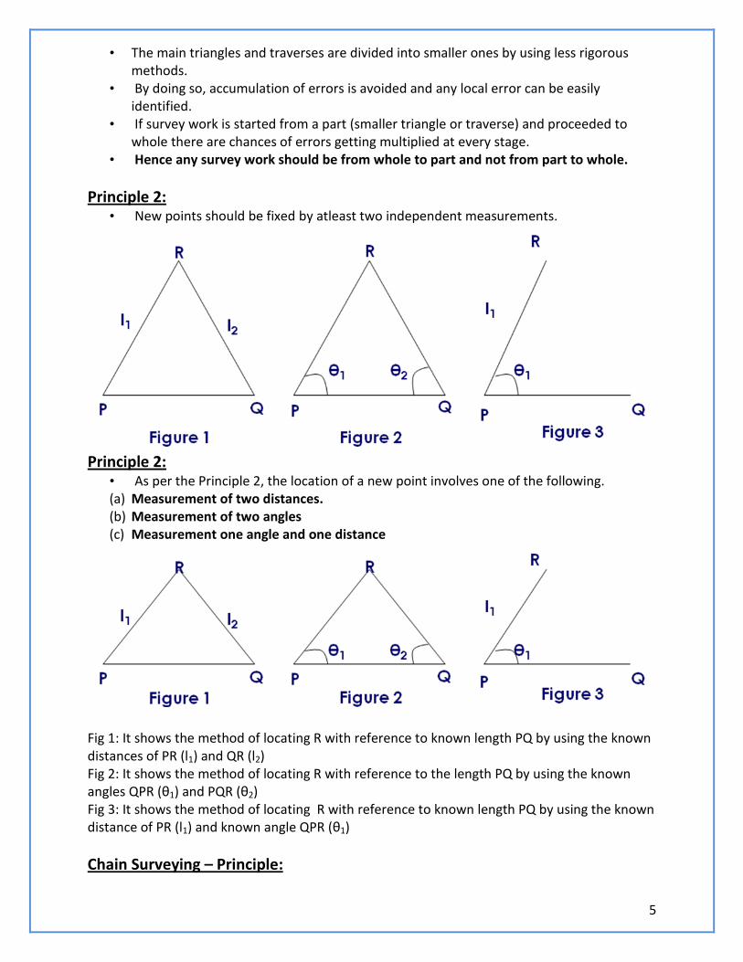
Principle 2: • New points should be fixed by atleast two independent measurements.
Principle 2:
• As per the Principle 2, the location of a new point involves one of the following. (a) Measurement of two distances. (b) Measurement of two angles (c) Measurement one angle and one distance
Fig 1: It shows the method of locating R with reference to known length PQ by using the known distances of PR (l1) and QR (l2) Fig 2: It shows the method of locating R with reference to the length PQ by using the known angles QPR (θ1) and PQR (θ2) Fig 3: It shows the method of locating R with reference to known length PQ by using the known distance of PR (l1) and known angle QPR (θ1)
Chain Surveying – Principle:
6
• In chain surveying only linear distances on the field are measured. • These distances are used to define the boundary of field and mark simple details.
Principle : • It is to form a network of triangles by using the distances measured. • Better accuracy will be obtained if the triangles thus formed are nearly equilateral in
shape.
Classification of surveying:
• Chain Surveying • Compass Surveying • Theodolite surveying • Plane Surveying • Techeometric Surveying
Accessories used in Chain Surveying: The different accessories used in chain surveying are
(a) Metre Chain (b) Chain Pins (arrows) (c) Measuring Tape (d) Ranging rod/Offset rod.
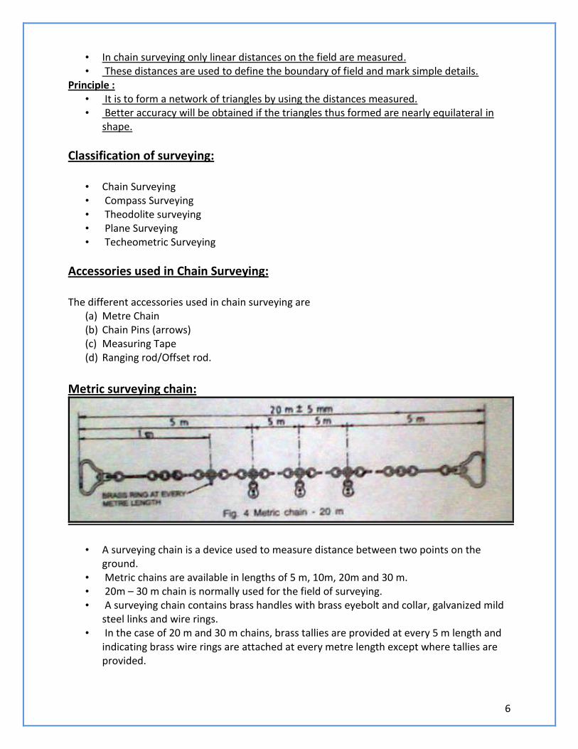
Metric surveying chain:
• A surveying chain is a device used to measure distance between two points on the ground.
• Metric chains are available in lengths of 5 m, 10m, 20m and 30 m. • 20m – 30 m chain is normally used for the field of surveying. • A surveying chain contains brass handles with brass eyebolt and collar, galvanized mild
steel links and wire rings. • In the case of 20 m and 30 m chains, brass tallies are provided at every 5 m length and
indicating brass wire rings are attached at every metre length except where tallies are provided.
7
• The distance between the outside faces of handles of a fully stretched out chain is the length of the chain.
• The length of the chain, like 20m is engraved on the handles. • While measuring the long distance, the chain will have to be used a number of times. • Arrows are driven at the end of every chain length. • For holding the arrows in position, grooves are cut in the outside face of the handles. • The radius of the groove is the same as that the arrows. • For convenient handling of the chain, the handle joint is made flexible so that it is
possible to swivel to handle round the eye bolt.
Chain Pins: • Chain pins or arrows are used with the chain for marking each chain length on the
ground. • The arrow is driven into the ground at the end of each chain length is measured. • Chain pins the arrow should be made of good quality hardened and tempered steel
wire of minimum tensile strength of 70 kg/mm2. • The overall length is 400 mm and thickness is 4mm. • The wire should be black enamelled. • The arrow has a circular eye at the one end is pointed at the other end .
Pegs: • Wooden pegs of 15cm length and 3 cm square in section are used to establish the
station points or the end points of a line on the ground. • They are tapered one end and are driven into the ground by using a wooden hammer. • About 4 cm is left projecting above the ground.
Measuring Tape:
• There are different types of tapes are used. They are (a) Cloth or linen type (b) Metallic Tape (c) Steel Tape (d) Invar Tube.
Metallic tape and steel tapes are most commonly used. • Metallic Tape is made of varnished waterproof linen. • It is reinforced with fine brass copper or bronze wires. • Tapes are available in lengths of 10, 15, 20, 30 or 50 metres. • In metallic tapes every metre is divided into 100 divisions (cms). • In steel tapes, the centimetre division are also subdivided.
Ranging Rod:
• It is also known as ranging pole or picket. • Ranging rod is used for ranging or aligning long lines on the ground in field surveying. • Ranging is a straight line means fixing a series of pegs or other marks such that they all
lie on a straight line.

8
• Ranging rods are used marking points on the ground so that the positions of the points are distinctly visible from some distant way.
• The length of ranging rod may be 2 m and 3 m and its diameter is 30 mm. • Ranging rod made of steel tube has an internal diameter of 32 mm. • The ranging rods are made of well seasoned, straight grained timber of circular cross
section. • Ranging rods should be straight and free from warps. • The deviation in straightness should not exceed 5mm in a 2 m length. • The ranging rod is painted in red and white in alternate band lengths of 200 mm each. • The bottom end of the rod is fitted with a pointed, hollow, cast iron shoe or steel shoe
of 15 cm length.
Offset Rod: • It is a ranging rod with two short, narrow, vertical sighting slots passing through the
centre of the section. • A hook is fitted of a groove is cut at the top to enable pulling or pushing of the chain
through obstruction like hedges. • Offset rods are meant for setting outlines approximately at right angles to the main
line.
Cross Staff:
• It is used to set out right angles in chain surveying • It consists of four metal arms vertical slits mounted on a pole. • Two opposite slits are positioned along the length of a line (Main Line) • A line perpendicular to the main line is formed or sighted through the other two slits
Plumb Bob:
• It consists of a solid conical piece and a string attached to it at its centre. • When in use, the solid piece is at the bottom. • It is used to test the verticality of the ranging rods and to transfer the points to the
ground. • Plumb bob is used while doing chain surveying on sloping ground.
Unfolding and folding of chain:
• Both the handles of the chain are held in the left hand and the other portions in the right hand.
• The portion held in the right hand is thrown forward; • The person throwing moving backward himself. • The leader takes one handle of the chain and moves forward himself.
9
• The leader takes one handle of the chain and moves forward till the chain is stretched to its full length.
• The chain should be free from any kinks or bends. • After the completion of the work, the two handles are brought together and the chain
is folded started with the middle pair. • The links are placed obliquely across each pair. • The folded chain is securely tied with a rope
Ranging a line:
• It means fixing a series of pegs or other marks such that they all lie on a straight line. • Suppose P and Q are the two ends of a survey line. • One ranging rod is driven Q. • The surveyor holds another ranging rod at P and stands at about 30 cm behind ranging
rod. • The assistant goes with another ranging rod along the survey line and positions himself
approximately in line with PQ at a distance less than a chain length from P. • The surveyor at P keeps his eye in line with PQ and signals to the assistant by way of
adjusting the position of the ranging rod held by the assistant traversely. • This adjustment is continued till the intermediate ranging rod is truly in line with P and
Q.
Outline of Chain surveying: • A base line which is a chain line is fixed. • The base line is aligned by ranging. • The length of the line is measured by chaining. • For this follower holds the zero end of the chain and the leader drags the chain to an
intermediate point on the line • The leader straightens the chain by jerking till the chain lies exactly over the line. • The leader marks the end of the chain by driving the chain pin (arrow) • The follower holds the zero end of the chain at the chain pin point again • Thus the chaining is continued till the entire length is covered. • For locating the details, lateral measurements are taken to the objects. • These lateral measurements are called offsets. • If the offset is at right angles to the base line, it is called perpendicular offset. • If it is inclined to the base line, it is called oblique offset. • Depending upon the situation, perpendicular or oblique offsets are taken • The length are measured are entered.
Advantages and disadvantages of chain surveying: Advantages:
• It is simple • It does not require any costly equipment • It is adopted for preparing plans for small area
Disadvantages:
10
• It cannot be used for large areas • It cannot be used in thick bushy areas with ups and downs. • Chain surveying is not always accurate.
Compass Surveying – Prismatic Compass:
• Whenever a number of base lines are to be run for obtaining the details as in traversing, just linear measurements made by chain surveying will not be sufficient.
• The angles included between the adjacent lines should also be measured • Compass is one of the instruments used to measure the angles.
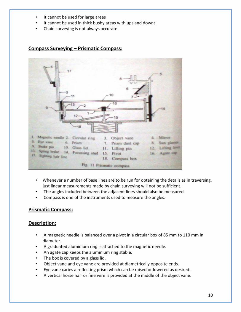
Prismatic Compass: Description:
• A magnetic needle is balanced over a pivot in a circular box of 85 mm to 110 mm in
diameter. • A graduated aluminium ring is attached to the magnetic needle. • An agate cap keeps the aluminium ring stable. • The box is covered by a glass lid. • Object vane and eye vane are provided at diametrically opposite ends. • Eye vane caries a reflecting prism which can be raised or lowered as desired. • A vertical horse hair or fine wire is provided at the middle of the object vane.
11
• The graduations in the aluminium ring are made in the clockwise direction starting with 0o at South and 180o at North with inverted markings.
• A triangular prism fitted below the eye slit enables magnification of readings to suit observer’s eye.
• Based on this prism arrangement, the compass is named prismatic compass. • Compass is fixed over a tripod with ball and socket arrangement. • A braked pin is provided below the object vane to damp the oscillations of the magnetic
needle while taking readings.
Working Principle:
• The magnetic field aligns itself with the magnetic meridian (N-S direction) • The line of sight is actually the line joining the object vane and eye vane • The angle between the N-S direction and the line of sight is observed in the compass • This angle is actually the angle between N-S direction and the line on the ground • This angle made by the line with the N-S direction is called the bearing of the line. • Compass is used to measure the bearing of the different lines from which the angles
included between the adjacent lines are computed.
How to take reading using compass:
• The compass is centered over the station by dropping a small piece of stone from the centre of the bottom of the compass.
• A plumb bob is used for centering. • The compass is levelled by adjusting the ball and socket till the top of the box is
horizontal. • The graduated ring should move freely after having levelled the instrument. • Suppose the bearing of a line PQ is to be observed. • The compass is centered over P. • It is levelled. • The prism and the object vane are kept in vertical position. • The compass is turned slowly till the ranging rod already erected at Q is bisected. • In this position, the ranging rod, the object and the eye vane all lie in the same line. • The focusing prism is raised or lowered till the readings were clear and sharp. • The reading in the ring cut by the object hair line is taken after damping the oscillations
of the ring by pressing the brake pin.
Definitions: Magnetic Bearing:
• • It is the angle between the magnetic meridian and the line. • The angle is always measured in the clockwise direction • It is the direction shown by a freely suspended magnetic needle
12
• The magnetic meridian is also called bearing.
True Bearing:
• True bearing of a line is the angle between the true meridian and the line. • The angle is always measured in the anticlockwise direction. • The true meridian is the line joining the geographical north and south bearings.
Whole Circle Bearing:
• The bearing of lines measured from the North is called Whole Circle Bearing. • The angle is reckoned in the clockwise direction from 0o coinciding with the north.
Quadrant Bearing:
• The whole circle is divided into four quadrants. • The bearing is expressed with N or S as prefix and E or W as suffix. • Quadrant Bearing is also known as Reduced Bearing.
Fore Bearing and Back bearing:
• Every line has two bearing namely fore bearing and back back bearing • Fore bearing is the bearing taken in the direction of surveying and Back bearing is the
bearing taken in the reverse direction. • The difference between the fore bearing and the back bearing should be 180o. • It means that one or both stations of the line are subjected to local attraction. • Thus, local attraction is the influence caused on the measured bearings of lines due to
the presence of materials like railway track, current carrying wires or cables, etc.,
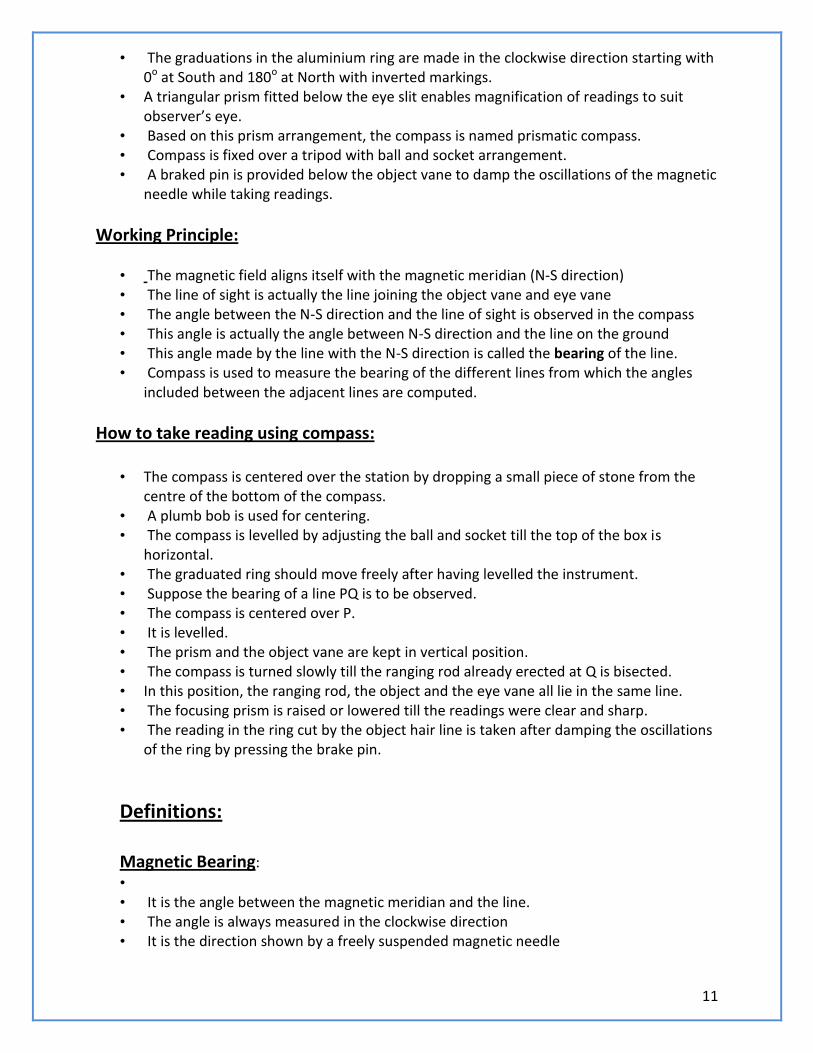
To find QB from WCB: Solution : Line PA lies in 1st quadrant. Quadrant Bearing bearing of PA = N 35o 15’ E
13
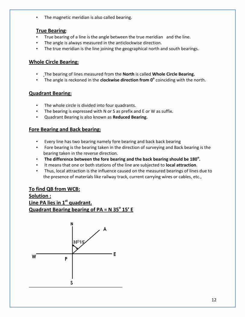
Solution : Line PB lies in 2nd quadrant. Quadrant Bearing bearing of PB = S 50o 00’ E
Solution : Line PC lies in 3rd quadrant. Quadrant Bearing bearing of PC = S 30o 15’ W
14
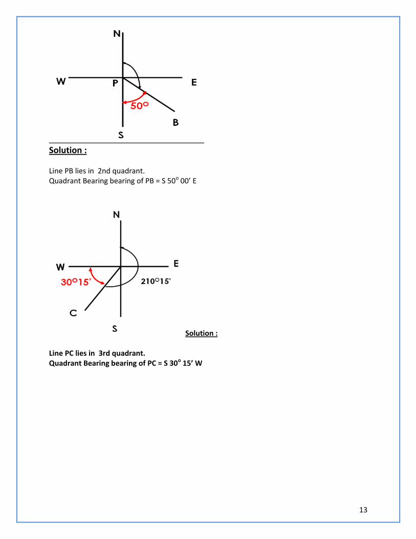
Solution : Line PD lies in 4th quadrant.Quadrant Bearing bearing of PD = N 69o 15’ W
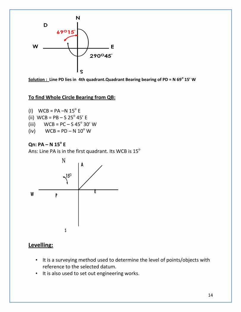
To find Whole Circle Bearing from QB: (I) WCB = PA –N 15o E (ii) WCB = PB – S 25o 45’ E (iii) WCB = PC – S 45o 30’ W (iv) WCB = PD – N 10o W Qn: PA – N 15o E Ans: Line PA is in the first quadrant. Its WCB is 15o
Levelling:
• It is a surveying method used to determine the level of points/objects with reference to the selected datum.
• It is also used to set out engineering works.
15
Uses of Levelling: • To determine the difference in levels of points/Objects • To obtain contour map of an area • To obtain cross section of roads, canals etc., • To determine the depth cutting and filling in engineering works. • To establish points or erect machinery or construct a building component
at a predetermined level. Important Terms: Bench Mark: It is surveyor’s mark cut on a stone/ rock or any reference point used to indicate
a level in a levelling survey.
Reduced Level:
• Reduced level of a point is the level of the point with respect to the level of permanent feature or bench mark.
• It indicates whether the point is above or below the reference point (datum).
Instruments used in leveling: Instruments used in levelling are,
(i) Levelling instrument (ii) Levelling staff
Levelling Instrument :
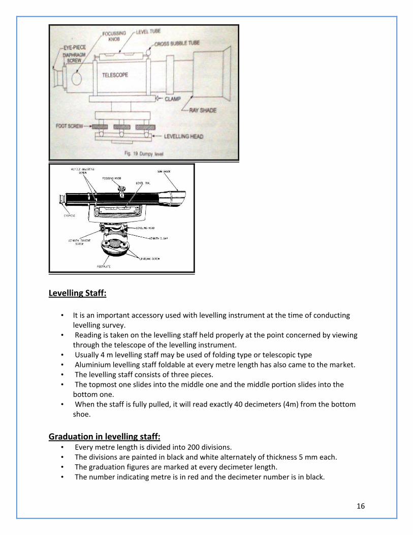
• Simplest form of levelling instrument is dumpy level. • The different parts of levelling instrument are, (a) Telescope (b) Eye-piece (c) focussing knob (d) level tube (e) cross bubble (f) foot screws
(g) levelling head (h) diaphragm (i) ray shade
Dumpy Level:
16
Levelling Staff:
• It is an important accessory used with levelling instrument at the time of conducting levelling survey.
• Reading is taken on the levelling staff held properly at the point concerned by viewing through the telescope of the levelling instrument.
• Usually 4 m levelling staff may be used of folding type or telescopic type • Aluminium levelling staff foldable at every metre length has also came to the market. • The levelling staff consists of three pieces. • The topmost one slides into the middle one and the middle portion slides into the
bottom one. • When the staff is fully pulled, it will read exactly 40 decimeters (4m) from the bottom
shoe.
Graduation in levelling staff:
• Every metre length is divided into 200 divisions. • The divisions are painted in black and white alternately of thickness 5 mm each. • The graduation figures are marked at every decimeter length. • The number indicating metre is in red and the decimeter number is in black.
17
• Thus, a graduation figure of 24 indicates 2 metres and 4 decimeters. • The graduation are made continuously one above the other in the same line. • The division lines should be parallel to the base of the bottom shoe and perpendicular
to the length of the staff. • The edges of the division lines should be straight sharply defined. • They should be clear and made distinctly visible by properly contrasting. • The graduation colour paints used should not crack or blister when exposed to adverse
or atmospheric conditions.
Important Terms in leveling:
• Station : In Levelling, the term station always refers to the point where the levelling
staff is held and not the instrument station.
• Height of Instrument : It is the elevation of the line of sight with reference to the
assumed datum.
• Back Sight (B.S) : It is the reading taken on the staff held at a point, the elevation of
which is known already. It is useful to know the new height of the instrument.
• Foresight (F.S): It is the reading taken on the staff held at a point of unknown
elevation. From, F.S., the height of the line of instrument above the point can be obtained. It is useful to find the elevation of the point.
• Change Point : It is the point at which the fore sight is taken from one instrument
station and back sight is taken from the next instrument station.
• Intermediate station : A point between two change points is known as
intermediate station. Only one reading is taken on the intermediate station.
Methods of Levelling:
• Method 1 : It is done with only one setting of the instrument. • Method 2: When the two station points are wide apart and the instrument is set up at
more than one point and the levelling is carried out.
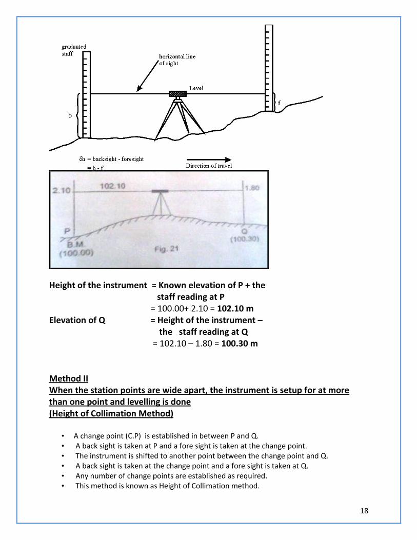
Method 1 With only one setting of the instrument:
• The instrument is set up at a point between P and Q and the temporary adjustments carried out.
• The levelling staff is held at P, the elevation of which is known already. • A back sight is taken on the staff held at P. The staff is then held at Q and the foresight
is taken.
18
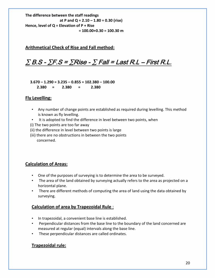
Height of the instrument = Known elevation of P + the staff reading at P = 100.00+ 2.10 = 102.10 m Elevation of Q = Height of the instrument – the staff reading at Q = 102.10 – 1.80 = 100.30 m Method II When the station points are wide apart, the instrument is setup for at more than one point and levelling is done (Height of Collimation Method)
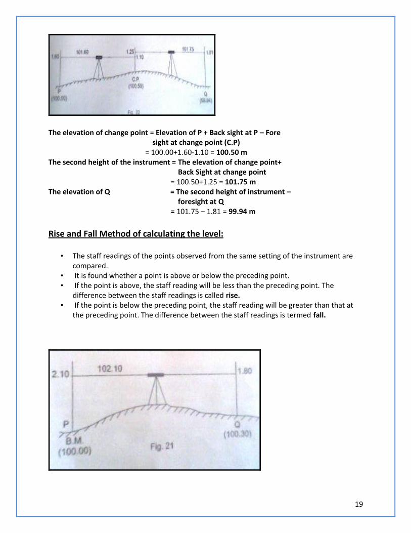
• A change point (C.P) is established in between P and Q. • A back sight is taken at P and a fore sight is taken at the change point. • The instrument is shifted to another point between the change point and Q. • A back sight is taken at the change point and a fore sight is taken at Q. • Any number of change points are established as required. • This method is known as Height of Collimation method.
19
The elevation of change point = Elevation of P + Back sight at P – Fore sight at change point (C.P) = 100.00+1.60-1.10 = 100.50 m The second height of the instrument = The elevation of change point+ Back Sight at change point = 100.50+1.25 = 101.75 m The elevation of Q = The second height of instrument – foresight at Q = 101.75 – 1.81 = 99.94 m
Rise and Fall Method of calculating the level:
• The staff readings of the points observed from the same setting of the instrument are compared.
• It is found whether a point is above or below the preceding point. • If the point is above, the staff reading will be less than the preceding point. The
difference between the staff readings is called rise. • If the point is below the preceding point, the staff reading will be greater than that at
the preceding point. The difference between the staff readings is termed fall.
20
The difference between the staff readings at P and Q = 2.10 – 1.80 = 0.30 (rise) Hence, level of Q = Elevation of P + Rise = 100.00+0.30 = 100.30 m
Arithmetical Check of Rise and Fall method:
∑ B.S - ∑F.S = ∑Rise - ∑ Fall = Last R.L – First R.L. 3.670 – 1.290 = 3.235 – 0.855 = 102.380 – 100.00 2.380 = 2.380 = 2.380
Fly Levelling:
• Any number of change points are established as required during levelling. This method is known as fly levelling.
• It is adopted to find the difference in level between two points, when (i) The two points are too far away (ii) the difference in level between two points is large (iii) there are no obstructions in between the two points concerned.
Calculation of Areas:
• One of the purposes of surveying is to determine the area to be surveyed. • The area of the land obtained by surveying actually refers to the area as projected on a
horizontal plane. • There are different methods of computing the area of land using the data obtained by
surveying.
Calculation of area by Trapezoidal Rule : • In trapezoidal, a convenient base line is established. • Perpendicular distances from the base line to the boundary of the land concerned are
measured at regular (equal) intervals along the base line. • These perpendicular distances are called ordinates.
Trapezoidal rule:
21
Total Area, A = d/2 (h1+hn+2(h2+h3+…….+hn-1))
Simpsons Rule:
• This rule is applicable only if the number of ordinates is odd.
•
A = d/3 (First Ordinate+ Last Ordinate + 2 (sum of odd ordinates)+
4(sum of even ordinates)
i. e. A = d/3 (h1+hn+ 2(h3+h5+h7+…..+hn-2)+ 4(h2+h4+….+hn-1)
• If the number of ordinates is even, the area of the last trapezoid is calculated
separately and added to the result.
Problems on Simpsnon’s Rule and Trapezoidal Rule:
The following perpendicular offsets were taken at 10 m intervals from a survey line to an irregular boundary line: 3.60, 2.80, 4.50, 8.25, 7.85, 6.45, 5.35. Calculate the area enclosed between the survey line and boundary line by trapezoidal rule and Simpson’s rule. 2. A series of offsets were taken at 5 m intervals from a chain line to a curved edge. 1.50, 1.66, 2.25, 2.80, 1.75, 1.95, 0. Calculate the area between the chain line and the irregular boundary to the curved edge by the Simpson’s rule and Trapezoidal Rule
22
UNIT – I (SURVEYING AND CIVIL ENGINEERING MATERIALS)
PART – A (2 MARKS)
1. What is surveying?
2. What is the objective of surveying?
3. What are the two major types of surveying?
4. What is meant by observation in geodetic surveying?
5. Differentiate between plane surveying and geodetic surveying.
6. How the surveying is classified based on purpose?
7. Define bearing of a line.
8. What are the systems of bearing?
9. Distinguish between Fore bearing and Back bearing.
10. What is meant by local
attraction & state its effects?
11. Define leveling and state its objectives.
12. Define benchmark and state its effects.
13. What are the different types of bench marks?
14. Name the two methods for calculating R.L.
15. What are the instruments used for leveling? Give some notes on that.
16. Define contour & contouring.
17. What is meant by Contour Level?
18. List the characteristics of contours. Mention any three uses of contour maps.
19. What is horizontal equivalent?
20. Define Survey station & Tie station.
21. Define Base line & Check line.
22. What is the difference between a plan and a map?
23. What are the methods used to measure the distances? Explain that.
24. What are the accessories used in chain surveying?
25. Clarify the suitability of chain surveying.
26. State any three limitations of chain surveying.
27. What is metric chain?
28. Name the two ways for measuring the horizontal angles and explain that.
29. What are the two types of compass used in surveying? Write few lines about that.
30. What is W.C.B and R.B in surveying?
31. What are B.S, I.S, and F.S in Leveling?
32. What are rules adopted for calculating the area?
33. State the accuracy to which a reading can be taken on a leveling staff.
34. Compare the height of Collimation method and rise and fall method of determining the
difference in level between two consecutive points.
35. State the assumptions made in the Simpson’s rule method of finding the area.
36. State the Simpson’s rule.
37. State the Trapezoidal Rule of finding the area.
38. How rocks are classified? Explain in detail.
39. What is quarrying & dressing of stones
40. Discuss the various types of building stones and their uses.
41. State the uses of cement concrete?
42. State the properties of cement concrete.
43. What is proportioning of concrete?
44. Define workability of concrete.
23
45. Discuss the various physical and mechanical properties of building materials.
46. Explain the various constituents of good brick earth.
47. State and explain the various essential qualities of good bricks.
48. Explain the features and working principles of Hoffman’s continuous kiln.
49. Compare Clamp burning with kiln burning.
50. Discuss the classification of bricks in detail.
51. Explain the various special types of bricks and their uses.
52. What are the various tests to be conducted on bricks to decide the suitability? Explain in
detail.
53. List the various applications of different types of bricks.
54. What are igneous, sedimentary and metamorphic rocks? Give examples.
55. Describe the requirements or properties of good building stone in details.
56. Explain the type of test to be conducted for the suitability of building stones.
57. List the various tests for sand and explain briefly.
58. What are the various ingredients of Portland cement? Explain their functions.
59. Discuss the various physical and chemical properties of Portland cement in detail.
60. Explain the process of manufacture of Portland cement in a rotary kiln.
61. Lists the various tests to be conducted to ascertain the quality of Portland cement.
62. Explain the various kinds of cement and their uses.
63. Explain the different constituents of concrete and their functions.
64. Discuss the characteristics of cement concrete as a building material.
65. Discuss the process of preparation of cement concrete.
66. Describe the classification of concrete based on various factor.
67. Discuss the proportions of ingredients, properties and uses of reinforced cement concrete.
68. Explain how the measurement of workability of concrete is done. Describe the slump test
with necessary diagrams.
69. What are the classification of steel, their properties and uses?
70. Describe the various forms of rolled steel sections meant for structural uses.
PART – B (10 MARKS)
1. Explain prismatic compass and surveyors compass in detail. And give the comparison
between these.
2. State the principles of surveying.
3. Explain differential leveling with a neat sketch.
4. Explain with neat sketch of chain and principles of chain surveying.
5. Explain with suitable sketches the measurements of horizontal angle and vertical angle.
6. Explain the working principle of dumpy level with a neat sketch.
7. Explain two methods of computing reduced levels of points.
8. Distinguish between simple leveling and differential leveling with suitable sketches.
9. Describe the principle of operation of a transit theodolite with a neat sketch.
The following staff readings were observed successively with level, the instrument
have been shifted after second and fifth readings:
0.870; 1.635; 2.135; 1.280; 2.980
3.125; 0.120; 1.825; 2.765; 2.015
first reading was taken with the staff held upon a bench mark of elevation +
100.00. Enter the readings in level book and final reduced levels. Apply the usual
checks. Find also the difference in level between the first and last points.
10. Following readings are taken successively with an instrument in leveling work:
24
0.345, 0.760, 1.485, 2.390, 3.750, 1.835, 0.765, 2.300, 2.005, 0.075, 0.995,
1.870, 3.565, 1.340 and 2.170.
The position of the instrument was changed after 5th
, 9th
and 13th
readings.
Make the entries in the level book and find the reduced levels of all the points if the R.L
of first point is 100.000m. Apply the usual check. Solve this problem by using,
a). Height of Collimation method
b). Rise and fall method
11. The following perpendicular offset were taken at 10 meter intervals from an
survey line to an irregular boundary line
3.145m, 4.30m, 8.20m, 5.60m,7.60m, 4.2m, 5.6m, 4.3m.
calculate the area enclosed between the survey lines, the irregular boundary line,
and first and last offsets by the application of
a) Average ordinate method
b) Trapezoidal rule and
c) Simpson’s rule
12. What are the requirements of good building stone & state important varieties of
building stones.
13. What are the different types of cement? Explain the properties and uses.
14. What are the different types of steel? Explain the properties and uses.
25
BASIC CIVIL AND MECHANICAL ENGINEERING
UNIT II
Foundation, Superstructure, Simple Stresses
and Strains, Dams,
Bridges and Interior Design
Super structure and Substructure
A structure consists of two parts. Namely,
1. Superstructure – Above the plinth level
2. Sub Structure - Below the plinth level.
It is also known as foundation.
The soil on which the foundation rests is called
foundation soil.
Foundation:
Objectives of foundation: To distribute the total load coming on the
structure on a larger area
To support the structures
To give enough stability to the structure against various disturbing forces, such as wind
and rain.
Types of foundation
Foundation may be broadly classified,
1. Shallow Foundation
2. Deep Foundation
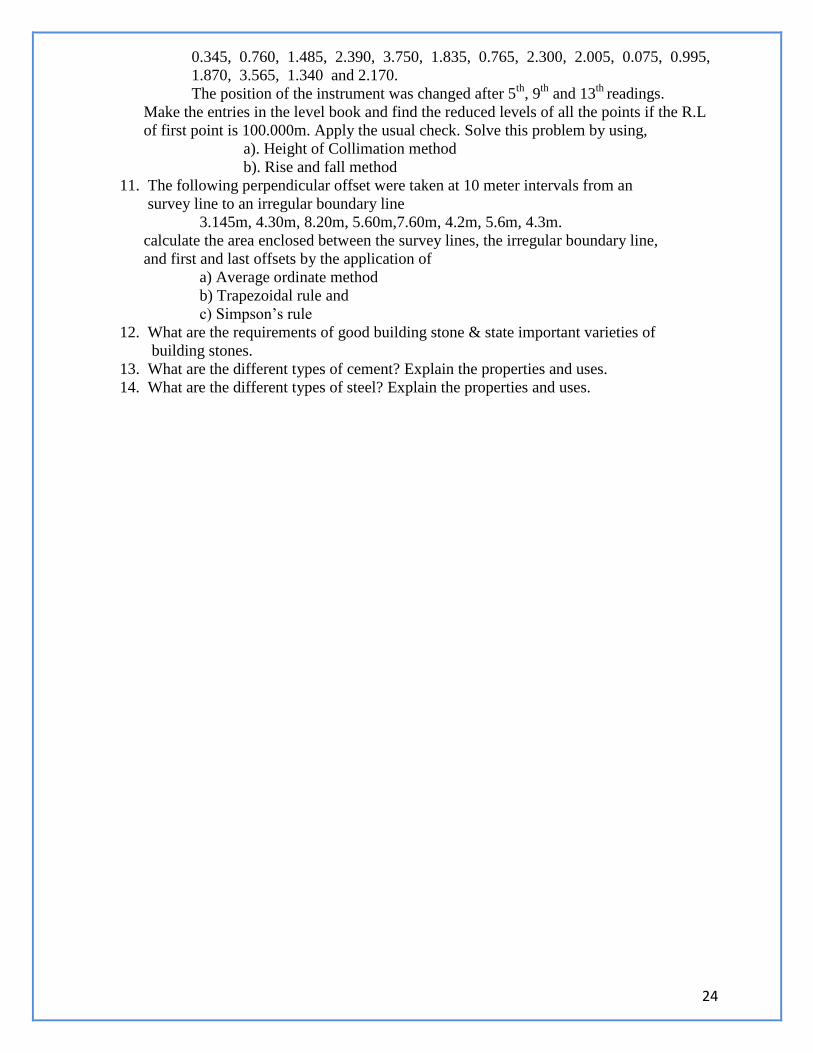
Shallow Foundation: When the depth of the foundation is less than or equal to its width, it is defined as shallow
foundation.
Isolated Column footing
26
Deep foundation : Deep foundation consists of pile and pier foundation.Pier foundations are rarely used for
buildings.This consists in carrying down through the soil a huge masonry cylinder
which may be supported on solid rock.
Types of shallow foundation:
Types of shallow foundation:
Isolated column footing : It is used in framed structures where several columns are to be constructed, isolated buildings
can be adopted.
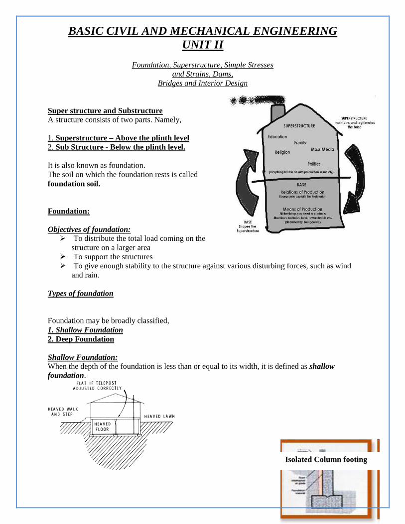
Wall footing: It is the footing provided throughout the length of the wall in the
load bearing walls, then it is called wall footing.
Stepped Footing: When the ground is sloping, stepped footings are provided.
It consists of two or more footings of brick or stone masonry and a concrete bed below
the ground level.
The overlap between two layers of foundation concrete slab is
equal to the depth of concrete slab or two times the height of
the step, whichever is more.
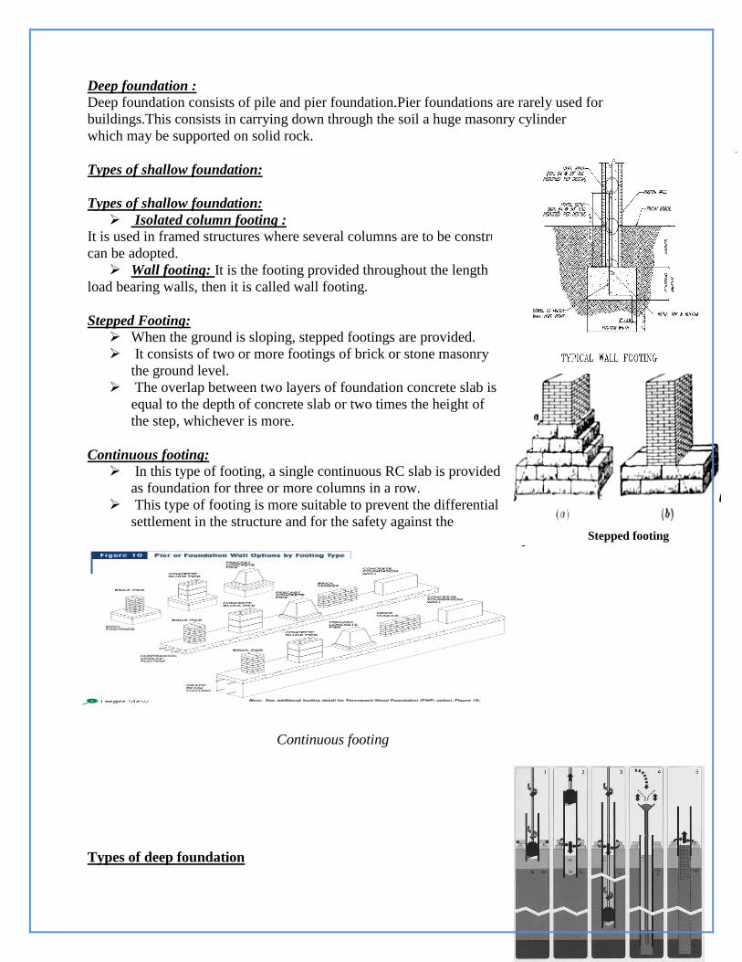
Continuous footing:
In this type of footing, a single continuous RC slab is provided
as foundation for three or more columns in a row.
This type of footing is more suitable to prevent the differential
settlement in the structure and for the safety against the
earthquake.
Continuous footing
Types of deep foundation
Stepped footing
27
1. Pile foundation: Pile is an element of construction used as foundation.
It may be driven in the ground vertically or with some inclination to transfer the load
safely.
Loads are supported in two ways. i.e., either by the effect of friction between the soil and
the pile skin or by resting the pile on a very hard stratum.
The former is called friction pile and later one is the load bearing pile.
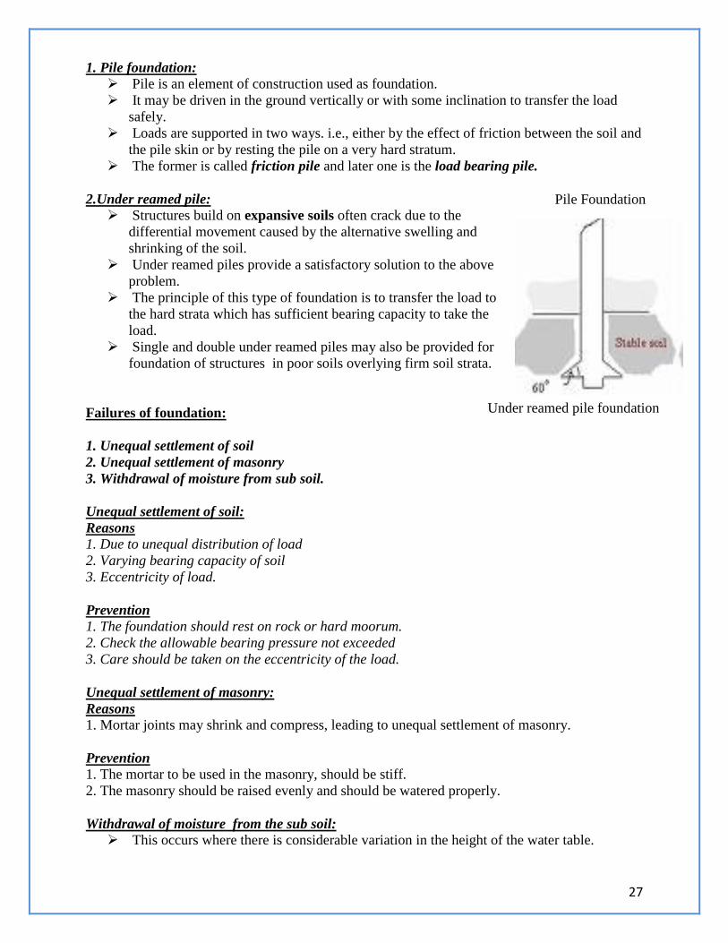
2.Under reamed pile:
Structures build on expansive soils often crack due to the
differential movement caused by the alternative swelling and
shrinking of the soil.
Under reamed piles provide a satisfactory solution to the above
problem.
The principle of this type of foundation is to transfer the load to
the hard strata which has sufficient bearing capacity to take the
load.
Single and double under reamed piles may also be provided for
foundation of structures in poor soils overlying firm soil strata.
Failures of foundation:
1. Unequal settlement of soil
2. Unequal settlement of masonry
3. Withdrawal of moisture from sub soil.
Unequal settlement of soil:
Reasons
1. Due to unequal distribution of load
2. Varying bearing capacity of soil
3. Eccentricity of load.
Prevention
1. The foundation should rest on rock or hard moorum.
2. Check the allowable bearing pressure not exceeded
3. Care should be taken on the eccentricity of the load.
Unequal settlement of masonry:
Reasons
1. Mortar joints may shrink and compress, leading to unequal settlement of masonry.
Prevention 1. The mortar to be used in the masonry, should be stiff.
2. The masonry should be raised evenly and should be watered properly.
Withdrawal of moisture from the sub soil: This occurs where there is considerable variation in the height of the water table.
Pile Foundation
Under reamed pile foundation
28
The precaution needed to avoid this type of failure is to drive piles up to the hard rock
level.
Superstructure:
Superstructure mainly consists of walls, doors windows and lintels.
The purpose of superstructure is to provide the necessary utility of the building,
structural safety, fire safety, sanitation and ventilation.
MASONRY
Types of masonries: Brick Masonry
Stone Masonry
Brick Masonry (Bonds in Brick work):
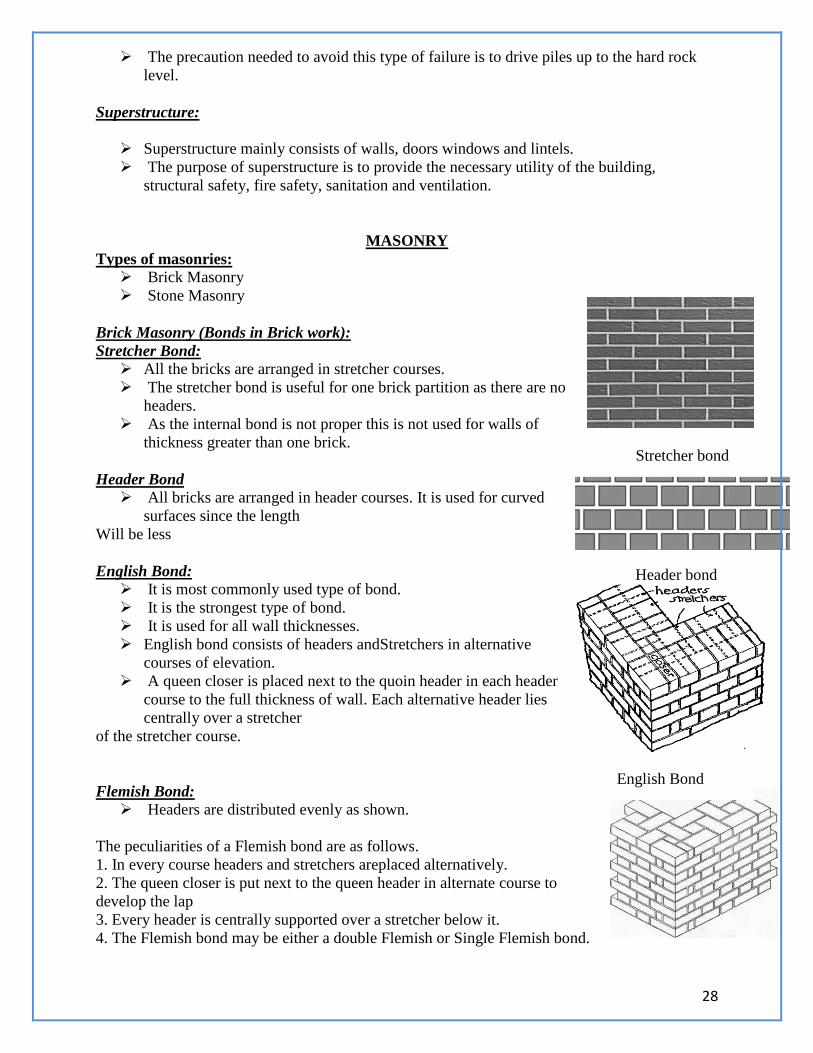
Stretcher Bond: All the bricks are arranged in stretcher courses.
The stretcher bond is useful for one brick partition as there are no
headers.
As the internal bond is not proper this is not used for walls of
thickness greater than one brick.
Header Bond All bricks are arranged in header courses. It is used for curved
surfaces since the length
Will be less
English Bond: It is most commonly used type of bond.
It is the strongest type of bond.
It is used for all wall thicknesses.
English bond consists of headers andStretchers in alternative
courses of elevation.
A queen closer is placed next to the quoin header in each header
course to the full thickness of wall. Each alternative header lies
centrally over a stretcher
of the stretcher course.
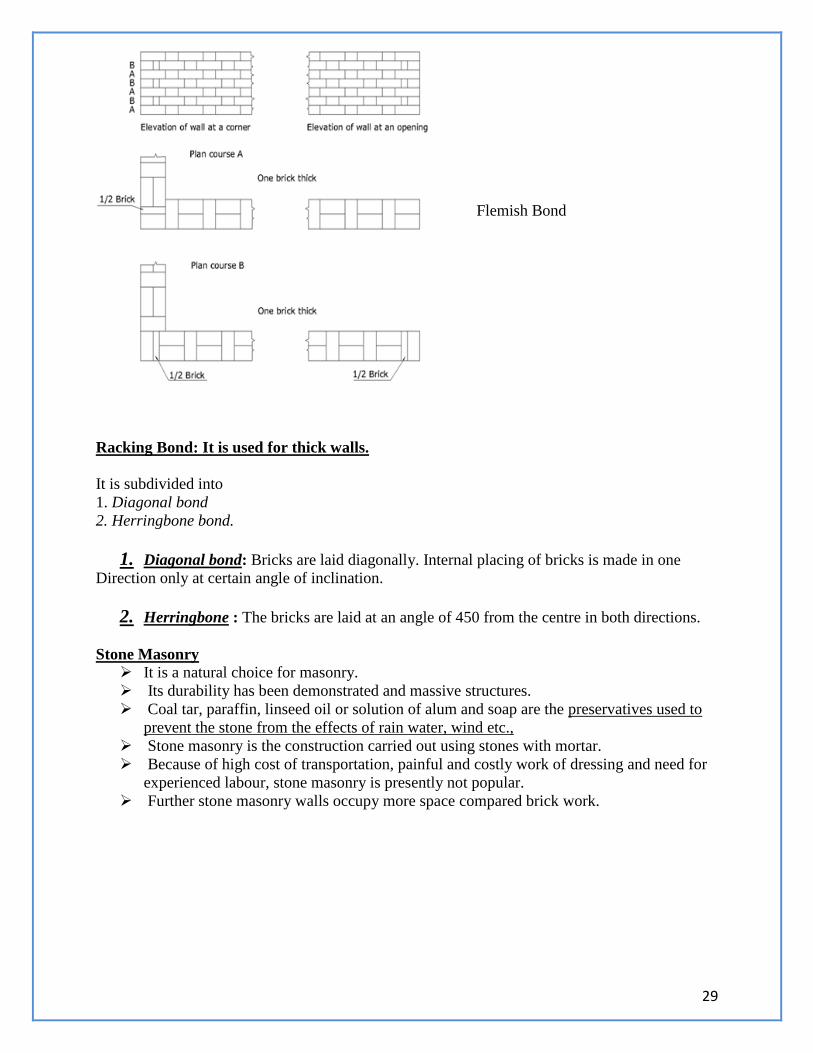
Flemish Bond: Headers are distributed evenly as shown.
The peculiarities of a Flemish bond are as follows.
1. In every course headers and stretchers areplaced alternatively.
2. The queen closer is put next to the queen header in alternate course to
develop the lap
3. Every header is centrally supported over a stretcher below it.
4. The Flemish bond may be either a double Flemish or Single Flemish bond.
Stretcher bond
Header bond
English Bond
29
Racking Bond: It is used for thick walls.
It is subdivided into
1. Diagonal bond
2. Herringbone bond.
1. Diagonal bond: Bricks are laid diagonally. Internal placing of bricks is made in one
Direction only at certain angle of inclination.
2. Herringbone : The bricks are laid at an angle of 450 from the centre in both directions.
Stone Masonry
It is a natural choice for masonry.
Its durability has been demonstrated and massive structures.
Coal tar, paraffin, linseed oil or solution of alum and soap are the preservatives used to
prevent the stone from the effects of rain water, wind etc.,
Stone masonry is the construction carried out using stones with mortar.
Because of high cost of transportation, painful and costly work of dressing and need for
experienced labour, stone masonry is presently not popular.
Further stone masonry walls occupy more space compared brick work.
Flemish Bond
30
Types and Uses of stones
Types of stone masonry : Dense stones like granites and quartzite
Fire resistant stones and sand stones
Soft stones like lime stones, marble and slate used for carvings, arches etc.,
Uses of stone masonry: Foundation, floor, walls, lintels, column, roofs, etc.,
Walls, roofs, lintels for temples, monuments etc.,
For facing works in brick masonry to give massive appearance.
Classification of stone masonry
Rubble Masonry Random rubble masonry
Uncoursed and coursed Squared rubble masonry
Uncoursed and coursed Polygonal rubble masonry
Ashlar Masonry Ashlar fine masonry
Ashlar rough tooled masonry
Ashlar rock or quarry faced masonry
Ashlar chamfered masonry
Ashlar facing masonry
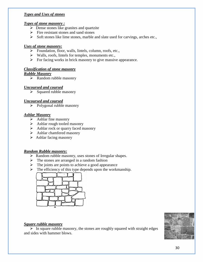
Random Rubble masonry:
Random rubble masonry, uses stones of Irregular shapes.
The stones are arranged in a random fashion
The joints are points to achieve a good appearance
The efficiency of this type depends upon the workmanship.
Square rubble masonry
In square rubble masonry, the stones are roughly squared with straight edges
and sides with hammer blows.
31
Ashlar Masonry:
In Ashlar masonry, no irregular stones are used.
The entire construction is done using square or rectangular dressed stones.
The sides and faces of the stones are dressed finely with chisel.
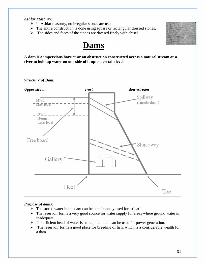
Dams
A dam is a impervious barrier or an obstruction constructed across a natural stream or a
river to hold up water on one side of it upto a certain level.
Structure of Dam:
Upper stream crest downstream
Purpose of dams:
The stored water in the dam can be continuously used for irrigation.
The reservoir forms a very good source for water supply for areas where ground water is
inadequate
If sufficient head of water is stored, then that can be used for power generation.
The reservoir forms a good place for breeding of fish, which is a considerable wealth for
a dam
32
Classification of dams:
Dams are broadly classified into,
1. Rigid Dams
2. Non rigid dams.
Rigid dams:
These dams are constructed using rigid construction materials.
The construction materials used are, stone or brick or reinforced cement concrete.
Rigid dams are further Classified into,
1. Solid gravity dam
2. Arch Dam
3. Buttress dam
4. Timber and steel dam
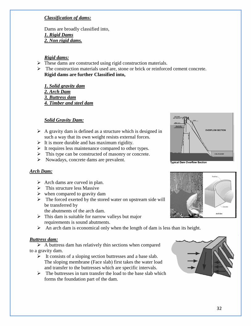
Solid Gravity Dam:
A gravity dam is defined as a structure which is designed in
such a way that its own weight resists external forces.
It is more durable and has maximum rigidity.
It requires less maintenance compared to other types.
This type can be constructed of masonry or concrete.
Nowadays, concrete dams are prevalent.
Arch Dam:
Arch dams are curved in plan.
This structure less Massive
when compared to gravity dam
The forced exerted by the stored water on upstream side will
be transferred by
the abutments of the arch dam.
This dam is suitable for narrow valleys but major
requirements is sound abutments.
An arch dam is economical only when the length of dam is less than its height.
Buttress dam:
A buttress dam has relatively thin sections when compared
to a gravity dam.
It consists of a sloping section buttresses and a base slab.
The sloping membrane (Face slab) first takes the water load
and transfer to the buttresses which are specific intervals.
The buttresses in turn transfer the load to the base slab which
forms the foundation part of the dam.
33
Timber and Steel Dam:
Timber and steel dams are not generally used for
bigger dam sections.
A timber dam is generally adopted for temporary
requirements to enclose certain work
sites or to divert the flow.
After the main structure is built the timber dam will be
dismantled.
Timber dams are generally made water tight.
Steel dams are not common in use. But it is possible to
construct the dam with steel upto a height of 15-18 m
Non Rigid Dams:
Non rigid dams have a trapezoidal basic profile.
Types of Non Rigid dams
Earth Dams
Rock fill dams.
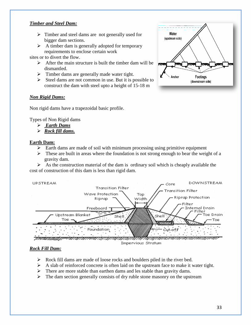
Earth Dam: Earth dams are made of soil with minimum processing using primitive equipment
These are built in areas where the foundation is not strong enough to bear the weight of a
gravity dam.
As the construction material of the dam is ordinary soil which is cheaply available the
cost of construction of this dam is less than rigid dam.
Rock Fill Dam:
Rock fill dams are made of loose rocks and boulders piled in the river bed.
A slab of reinforced concrete is often laid on the upstream face to make it water tight.
There are more stable than earthen dams and les stable than gravity dams.
The dam section generally consists of dry ruble stone masonry on the upstream
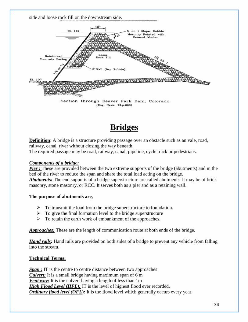
34
side and loose rock fill on the downstream side.
Bridges
Definition: A bridge is a structure providing passage over an obstacle such as an vale, road,
railway, canal, river without closing the way beneath.
The required passage may be road, railway, canal, pipeline, cycle track or pedestrians.
Components of a bridge:
Pier : These are provided between the two extreme supports of the bridge (abutments) and in the
bed of the river to reduce the span and share the total load acting on the bridge.
Abutments: The end supports of a bridge superstructure are called abutments. It may be of brick
masonry, stone masonry, or RCC. It serves both as a pier and as a retaining wall.
The purpose of abutments are,
To transmit the load from the bridge superstructure to foundation.
To give the final formation level to the bridge superstructure
To retain the earth work of embankment of the approaches.
Approaches: These are the length of communication route at both ends of the bridge.
Hand rails: Hand rails are provided on both sides of a bridge to prevent any vehicle from falling
into the stream.
Technical Terms:
Span : IT is the centre to centre distance between two approaches
Culvert: It is a small bridge having maximum span of 6 m
Vent way: It is the culvert having a length of less than 1m
High Flood Level (HFL): IT is the level of highest flood ever recorded.
Ordinary flood level (OFL): It is the flood level which generally occurs every year.
35
1.Permanent bridges
2. Back bridges
3. Through bridges
4. Semi through bridges
5. Straight bridges
6. Skew bridge
According to type of superstructure:
1.Arch Bridge
2. Slab Bridge
3. T beam and slab bridge
4. Bow string and girder bridge
5. Steel Arch bridge
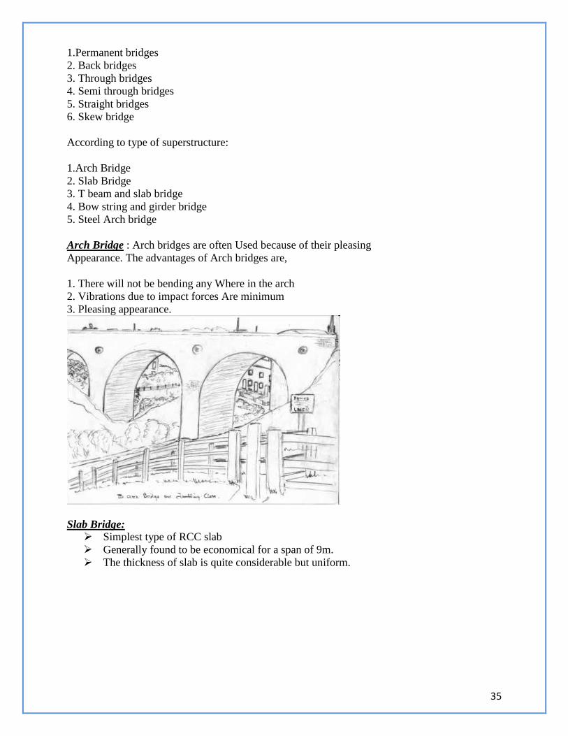
Arch Bridge : Arch bridges are often Used because of their pleasing
Appearance. The advantages of Arch bridges are,
1. There will not be bending any Where in the arch
2. Vibrations due to impact forces Are minimum
3. Pleasing appearance.
Slab Bridge: Simplest type of RCC slab
Generally found to be economical for a span of 9m.
The thickness of slab is quite considerable but uniform.
36
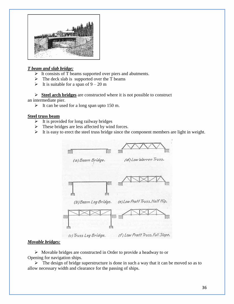
T beam and slab bridge:
It consists of T beams supported over piers and abutments.
The deck slab is supported over the T beams
It is suitable for a span of 9 – 20 m
Steel arch bridges are constructed where it is not possible to construct
an intermediate pier.
It can be used for a long span upto 150 m.
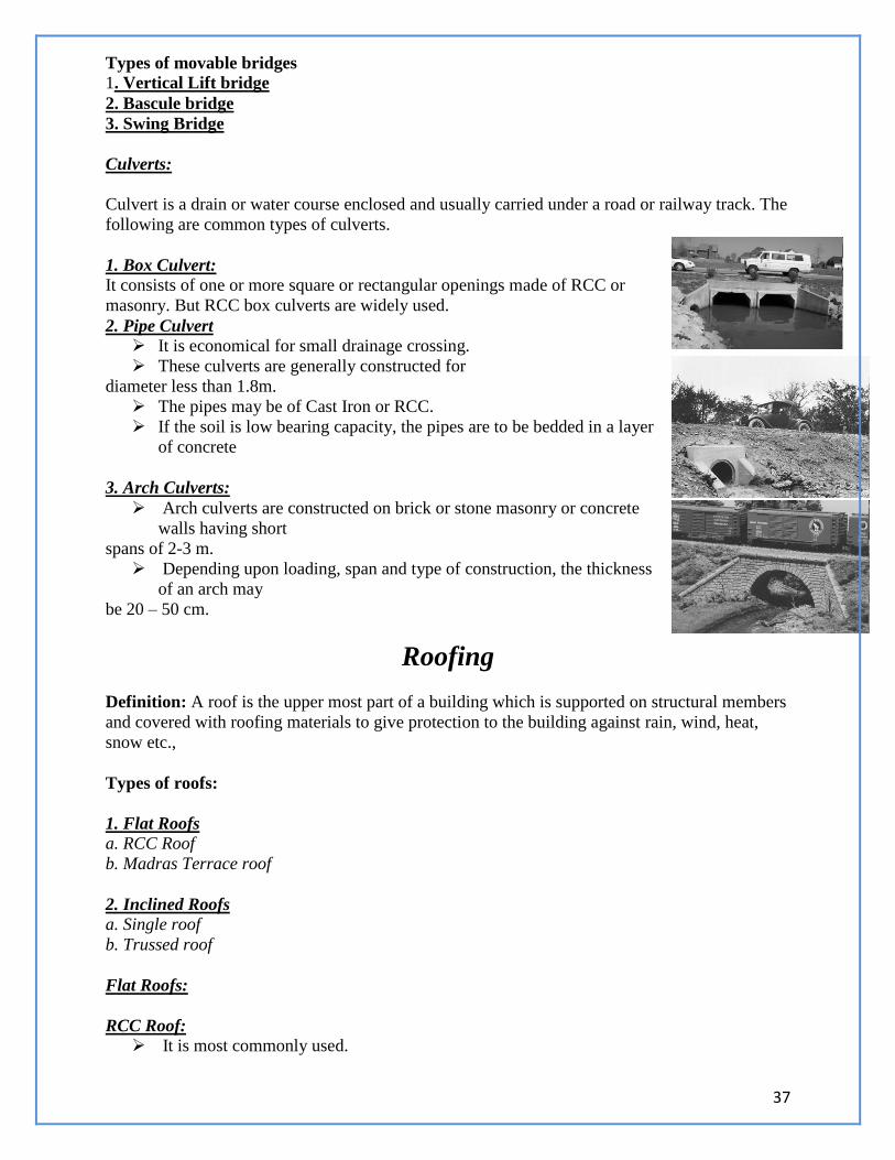
Steel truss beam It is provided for long railway bridges
These bridges are less affected by wind forces.
It is easy to erect the steel truss bridge since the component members are light in weight.
Movable bridges:
Movable bridges are constructed in Order to provide a headway to or
Opening for navigation ships.
The design of bridge superstructure is done in such a way that it can be moved so as to
allow necessary width and clearance for the passing of ships.
37
Types of movable bridges 1. Vertical Lift bridge
2. Bascule bridge
3. Swing Bridge
Culverts:
Culvert is a drain or water course enclosed and usually carried under a road or railway track. The
following are common types of culverts.
1. Box Culvert:
It consists of one or more square or rectangular openings made of RCC or
masonry. But RCC box culverts are widely used.
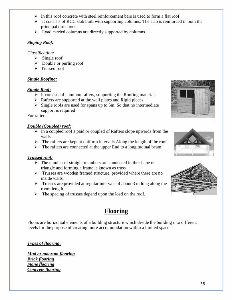
2. Pipe Culvert
It is economical for small drainage crossing.
These culverts are generally constructed for
diameter less than 1.8m.
The pipes may be of Cast Iron or RCC.
If the soil is low bearing capacity, the pipes are to be bedded in a layer
of concrete
3. Arch Culverts:
Arch culverts are constructed on brick or stone masonry or concrete
walls having short
spans of 2-3 m.
Depending upon loading, span and type of construction, the thickness
of an arch may
be 20 – 50 cm.
Roofing
Definition: A roof is the upper most part of a building which is supported on structural members
and covered with roofing materials to give protection to the building against rain, wind, heat,
snow etc.,
Types of roofs:
1. Flat Roofs
a. RCC Roof
b. Madras Terrace roof
2. Inclined Roofs
a. Single roof
b. Trussed roof
Flat Roofs:
RCC Roof: It is most commonly used.
38
In this roof concrete with steel reinforcement bars is used to form a flat roof
It consists of RCC slab built with supporting columns. The slab is reinforced in both the
principal directions.
Load carried columns are directly supported by columns
Sloping Roof:
Classification:
Single roof
Double or purling roof
Trussed roof
Single Roofing:
Single Roof:
It consists of common rafters, supporting the Roofing material.
Rafters are supported at the wall plates and Rigid pieces.
Single roofs are used for spans up to 5m, So that no intermediate
support is required
For rafters.
Double (Coupled) roof:
In a coupled roof a paid or coupled of Rafters slope upwards from the
walls.
The rafters are kept at uniform intervals Along the length of the roof.
The rafters are connected at the upper End to a longitudinal beam.
Trussed roof:
The number of straight members are connected in the shape of
triangle and forming a frame is known as truss.
Trusses are wooden framed structure, provided where there are no
inside walls.
Trusses are provided at regular intervals of about 3 m long along the
room length.
The spacing of trusses depend upon the load on the roof.
Flooring
Floors are horizontal elements of a building structure which divide the building into different
levels for the purpose of creating more accommodation within a limited space
Types of flooring:
Mud or moorum flooring
Brick flooring
Stone flooring
Concrete flooring
39
Granolithic flooring
Terrazzo flooring
Mosaic Flooring
Marble Flooring
Wood or timber flooring
Asphalt flooring
Granite flooring
Industrial floorint
Mud or moorum flooring:
The floor bed should be well prepared and a 250 mm thick layer of selected moist earth is
evenly spread and is rammed well so as to get a consolidated thickness of 150 mm
No water is used during ramming.
In order to prevent formation of cracks after drying, chopped straw in small quantity is
mixed with the moist earth before ramming.
Upon this bed, a thin coat of cement, cowdung plaster is applied evenly and wiped clean
by hand.
Brick flooring:
The sub grade is compacted properly to the desired level.
10-15cm layer of lean cement concrete or lime concrete is laid over the prepared
subgrade.
This forms the base course, over which bricks are laid in desired on 12 mm thick mortar
in such a way that all the joints are filled with mortar.
Brick floors are suitable for ware houses, stones and godowns or in place places where
the bricks are available economically.
This floor is cheap
Stone flooring:
The subgrade is prepared by laying a 100mm to 150 mm layer of cement or lime
concrete over a bed of well consolidated earth
The stone slabs may be square or rectangular usually 300x300 mm to 600x600 mm size.
The thickness of stone varies from 20 mm to 40 mm.
The selected stone should be hard, durable and uniform thickness.
Cement Concrete Flooring:
Base concrete: The base course is laid over well compacted soil, compacted properly and levelled to a
rough surface.
The base course consists of 7.5 cm to 10 cm thick cement concrete.
The top surface of the concrete base is roughly finished to develop a good bond between
the base and topping
40
Wearing surface: After the base has hardened, its surface is brushed with stiff broom and cleaned
thoroughly.
The entire surface is divided into a square of rectangular not exceeding 2.5 cm in length.
Cement concrete is 25mm to 40 mm is then laid in alternate panels.
The top surface is beaten and made in a uniform line and level and smoothened by
trowelling.
Mosaic Flooring:
Mosaic flooring is made of small pieces of broken tiles of glazed china, cement, or of
marble, arranged in different patterns.
These pieces are cut to the desired shapes and sizes.
This floor is laid normally a hard bed of cement concrete.
The top surface of concrete base is cleaned and wetted.
On a small portion of the floor, a layer of rich cement, mortar is evenly spread to a
thickness of 1cm and mosaic tiles are coloured and sprinkled pressed in the joints.
The process is continued for the whole is continued for the whole set, the surface is
completely polished with a mosaic polishing machine.
Marble Flooring:
The flooring is laid over the prepared subgrade which is cleaned wetted and mopped
properly.
A layer of cement mortar of 1:4 is spread in an average thickness of about 20 mm.
Marble slabs are laid in this bedding mortar, pressed and levelled.
The marble slabs may be rectangular and square in shape and their thickness varies out
of the 20 mm to 40 mm.
The joints between two slabs must be very thin.
The cement that oozes out of the joints are cleaned.
Timber flooring:
The timber used for flooring should be well seasoned.
It should be free from knots and defects
A base course of cement concrete of 75 mm thickness is prepared.
Wooden fillet strips of size 20 mm x 40 mm are embedded in concrete to a depth about
12 mm along the short span.
Hence, they project above the level of the base course.
On these fillets timber flooring planks of 25 mm thickness are laid.
Tiled Flooring & Terrazzo flooring:
Tiled Flooring:
Tiled flooring may be used for both ground floor and upper floors.
In tiled flooring tiles made of clay or cement concrete or Glazed tiles, manufactured in
different shapes and sizes are used.
Using coloured cement attractive patterns and coloured surface can be used.
41
Terrazzo flooring:
Terrazzo is a special type of cement concrete.
This concrete consists of white cement instead of grey cement and marble powder
instead of sand and marble chips as coarse aggregate instead of stone aggregates.
Plastering
Plastering : Plastering is the process of covering the rough surfaces of walls, beams, columns
and ceilings with a protective cover.This protective layer is plastic material like cement mortar or
lime mortar.
Purpose of plastering:
Appearance: Plastering provides smooth, regular and clean surfaces to walls, beams,
etc., to improve the appearance.
Durability : Plastering improves the durability of the exposed surfaces of walls.
Concealing defects: It conceals the defects in the workmanship. IT conceals use of
inferior and porous materials in masonry walls, concrete, beams etc.,
Effect of atmospheric agencies : Plastering in external surfaces prevents damping of the
walls, etc., due to atmospheric agencies like rain, sun, wind etc.,
Types of mortars used for plastering
Cement Mortar
Lime Mortar
Cement-lime mortar
Water – proof mortar.
Cement Mortar:
It is a mixture of ordinary portland cement and coarse sand in predetermined
proportions.
The proportions of cement and sand depends on the nature of plastering work.
The usual mix for cement mortar for plastering varies from 1:3 for the surfaces in cntact
with water to 1:4 to 1:6 for other surfaces.
Lime mortar:
Equal volumes of lime and fine sand are thoroughly mixed.
Either fat lime or poor lime may be used in lime mortar.
The mixture is ground in a mortar mill by adding required quantity of water to form a
paste of required consistency and workability
Cement Lime mortar:
42
Cement lime mortar is prepared by first mixing cement and sand in a dry state in the
requirement proportions.
Fat lime is mixed with water and is added to the cement sand mix.
The materials are thoroughly mixed till a mortar of the desired consistency and
workability is obtained.
Water proof mortar:
Water proof mortar for plastering is prepared by mixing 1 part of cement with 2 parts of
sand and pulverized alum at the rate of 12 kg/m3 of sand.
Soap water is added to the dry mixture to make it water proof and to obtain required
consistency and workability.
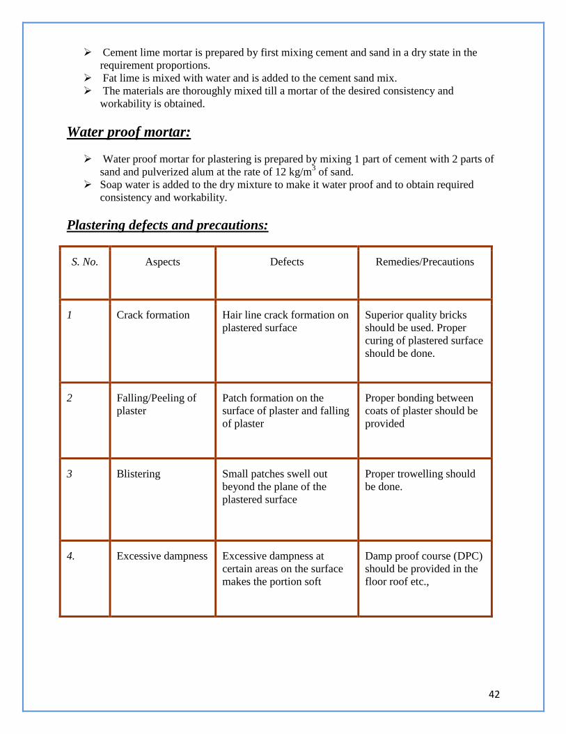
Plastering defects and precautions:
S. No. Aspects Defects Remedies/Precautions
1 Crack formation Hair line crack formation on
plastered surface
Superior quality bricks
should be used. Proper
curing of plastered surface
should be done.
2 Falling/Peeling of
plaster
Patch formation on the
surface of plaster and falling
of plaster
Proper bonding between
coats of plaster should be
provided
3 Blistering Small patches swell out
beyond the plane of the
plastered surface
Proper trowelling should
be done.
4. Excessive dampness Excessive dampness at
certain areas on the surface
makes the portion soft
Damp proof course (DPC)
should be provided in the
floor roof etc.,
43
Land scaping
Definition: Interior design process follows a systematic and coordinated methodology,
including research, analysis and integration of knowledge into a creative process.
Landscaping: It is the activity of modifying variable visible features of an area of land to give a
pleasant appearance.
It includes gardening to create beautiful environment.
Systematic arrangement of plants
It includes beautification of land forms such as lilly pond, fountain, trees, lawns, etc.,
It covers weather and lighting arrangements, colouring etc.,
UNIT – II (BUILDING COMPONENTS AND STRUCTURES)
PART – A (2 MARKS)
1. Name any four important types of buildings. Give examples.
2. Define the terms: i). Plinth area ii). Floor area iii). Carpet area
3. Mention any three factors which affect the bearing capacity of soil.
4. Define the terms: i). Dead load ii). Live load iii). Wind load
5. What do you understand by differential settlement of foundation?
6. Mention three precautions to be taken to prevent unequal settlement of subsoil.
7. List the various types of foundations.
8. What do you understand by stepped footing?
9. What do you understand by continuous footing of foundations?
10. Name any three types of end bearing piles.
11. Suggest any three methods by which the frictional resistance of the surrounding soil
against the downward movement of the pile can be increased.
12. Name any three types of friction piles.
13. Mention any three uses of well foundation.
14. What are three groups of machines requiring different types of foundations? Give
examples to each.
15. Name the three different types of machine foundations.
16. State the objectives and requirements of good foundation?
17. Differentiate between shallow foundation and deep foundation.
18. Define bearing capacity of soil.
19. How the stone masonry is classified?
20. Define the following terms.
i) Corbel
I i) Cornice
iii) Coping
iv) String course
v) Through stone
21. Compare stone masonry and Brick masonry
22. Why bonding in brick wall is essential?
23. State the special features of English and Flemish bond.
44
24. Define beam, column and Lintel.
25. Classify the types of column based on its conditions.
26. State the purpose of plastering.
27. Define Dam, Bridge and classify them.
28. What are the basic components of a bridge?
29. What is the purpose of reinforced concrete?
30. Define factor of safety.
31. Give a list of type of bonds in brickwork.
32. State any three important salient features of English bond.
33. State any three important salient features of Flemish bond.
34. What are the two types of stone masonry?
35. Mention any three types of dressing of stones.
36. Name the various types of beams.
37. What are the different types of loads on a beam?
38. What is a column?
39. State any three important uses of R.C.C columns.
40. What is lintel? Where do you provide it in a building?
41. Name the different types of lintels.
42. How do you classify the roofs?
43. Name the types of sloping roofs.
44. Name at least four types of steel roof trusses.
45. State any three roof covering materials.
46. Mention the various requirements of good flooring.
47. Name the types of mortars used for plastering.
48. What is stress?
49. What is strain?
50. Define- elasticity.
51. State the purpose of plastering.
52. What are the important factors to be considered while working with the interior design?
53. How the lighting is classified?
54. How the colors are classified?
55. What is landscaping?
56. State the principle of landscaping.
57. What are the elements of landscaping?
58. What are the factors to be considered while selecting a suitable landscape design?
PART – B (10 MARKS)
1. What are the factors to be considered in the selection of a suitable site?
2. Describe the components of a building with a neat sketch.
3. What are the types of Foundations? Describe the various requirements of good
foundations.
4. What are the various possible foundation failures, their causes and precautions?
5. Discuss any two types of spread foundations with neat sketches.
6. What is a pile foundation? State its applications. List the classification of piles.
7. Discuss the classification of soils, their constituents and uses.
8. Define the terms: i). bearing capacity of a soil
ii). Ultimate bearing capacity of a soil.
iii). Safe bearing capacity of a soil
45
iv). Allowable soil pressure
9. List the six important points to be considered while selecting a site for
a. Construction of Dam.
b. Construction of bridge.
10. Explain with neat sketch the different types of piles.
11. A square bar of 75 mm side is subjected to an axial pull of 240 kN. The extension of the
bar is 0.18 mm over a gauge length of 200 mm. The change in lateral dimension is 0.010
mm. Compute the Young’s modules, Poisson’s ratio, Rigidity modulus and Bulk modulus.
12. A hollow steel column has an internal diameter 0.6 times as that of the external. The
material attains an ultimate stress of 420 N/mm2. If the working load is 1250 kN and the
factor of safety allowed is 4, determine the outer (external) and internal diameters.
13. List out the different types of bond in brick wall and explain any three in detail.
14. Distinguish between:
i). English bond and Flemish bond
ii). Brick masonry and stone masonry
15. Draw a neat sketch of a reinforced cement concrete column and explain.
16. Explain the types of floor suitable for residential and commercial building.
17. Explain briefly the different types of pitched roof coverings.
18. What are the purposes of plastering? List the various requirements of a good plaster.
19. Explain the procedure to be adopted for plastering work.
46
BASIC CIVIL AND MECHANICAL ENGINEERING Unit III
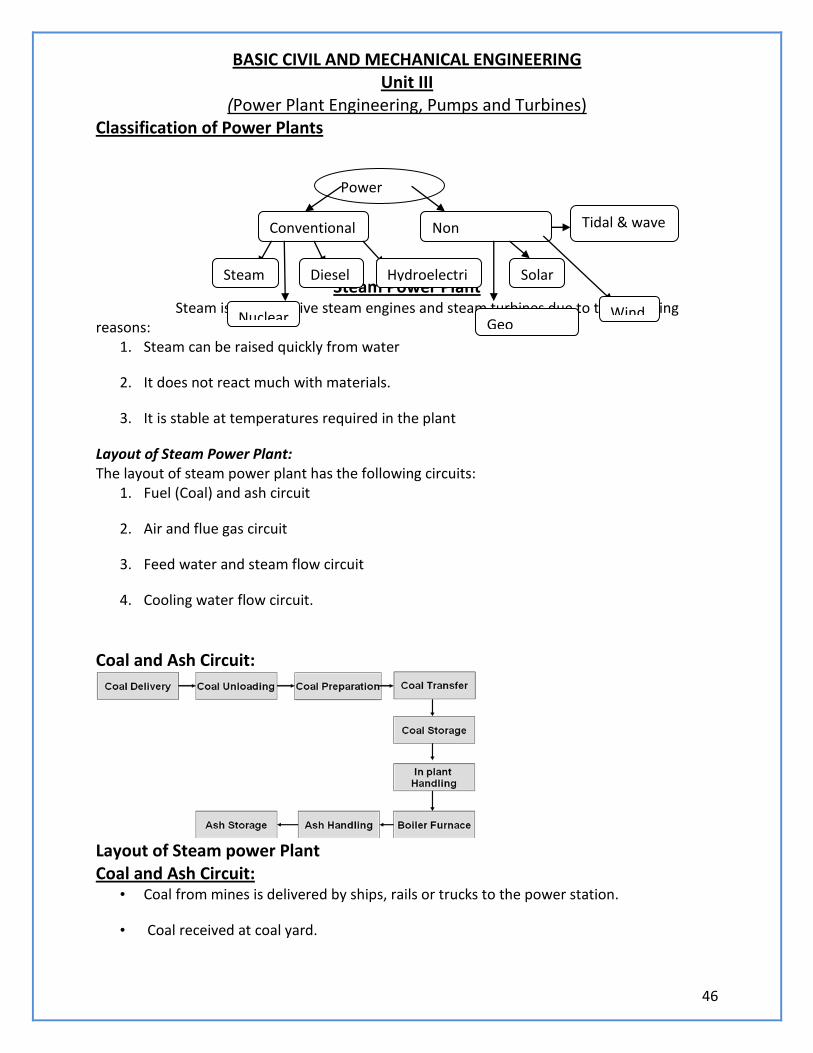
(Power Plant Engineering, Pumps and Turbines) Classification of Power Plants
Steam Power Plant Steam is used to drive steam engines and steam turbines due to the following reasons:
1. Steam can be raised quickly from water
2. It does not react much with materials.
3. It is stable at temperatures required in the plant
Layout of Steam Power Plant: The layout of steam power plant has the following circuits:
1. Fuel (Coal) and ash circuit
2. Air and flue gas circuit
3. Feed water and steam flow circuit
4. Cooling water flow circuit.
Coal and Ash Circuit:
Layout of Steam power Plant Coal and Ash Circuit:
• Coal from mines is delivered by ships, rails or trucks to the power station.
• Coal received at coal yard.
Power plants
Conventional
Steam Diesel Hydroelectric
Nuclear
Non conventional
Solar
Tidal & wave
Geo thermal
Wind
47
• Coal is sized by crushers, breakers etc.,
• The sized coal is stored in coal storage.
• From stock yard, the coal is transferred to the boiler furnace by means of conveyors,
elevators etc.,
• The coal is burnt in the boiler and ash is formed.
• Ash coming out of the furnace will be too hot, dusty and accompanied by poisonous
gases.
• The ash is transferred to the ash storage.
• Generally the ash will be quenched to reduce the temperature and the dust content.
Air and Flue Gas Circuit: • Air is taken from the atmosphere by the action of FD fan.
• It is passed through an air pre heater
• The air is preheated by the flue gases in the pre heater.
• This preheated air is supplied to the furnace to aid the combustion of fuel.
• Due to the combustion of fuel the flue gases are formed.
• The flue gases from the furnace pass over the boiler tubes and super heater tubes.
• Then the flue gases pass through economiser to heat the feed water.
• After that it passes through a dust collector.
It is then exhausted to atmosphere through chimney Water and Steam Circuit:
48
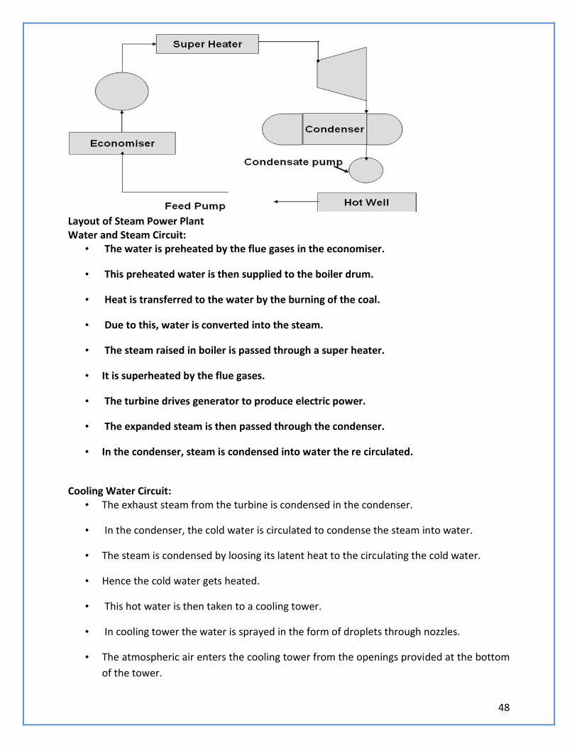
Layout of Steam Power Plant Water and Steam Circuit:
• The water is preheated by the flue gases in the economiser.
• This preheated water is then supplied to the boiler drum.
• Heat is transferred to the water by the burning of the coal.
• Due to this, water is converted into the steam.
• The steam raised in boiler is passed through a super heater.
• It is superheated by the flue gases.
• The turbine drives generator to produce electric power.
• The expanded steam is then passed through the condenser.
• In the condenser, steam is condensed into water the re circulated.
Cooling Water Circuit:
• The exhaust steam from the turbine is condensed in the condenser.
• In the condenser, the cold water is circulated to condense the steam into water.
• The steam is condensed by loosing its latent heat to the circulating the cold water.
• Hence the cold water gets heated.
• This hot water is then taken to a cooling tower.
• In cooling tower the water is sprayed in the form of droplets through nozzles.
• The atmospheric air enters the cooling tower from the openings provided at the bottom
of the tower.
49
• This cold water is again circulated through the pump, condenser and the cooling
• Some amount of water may be lost during circulation.
• Hence make up water is added to the pond by means of a pump
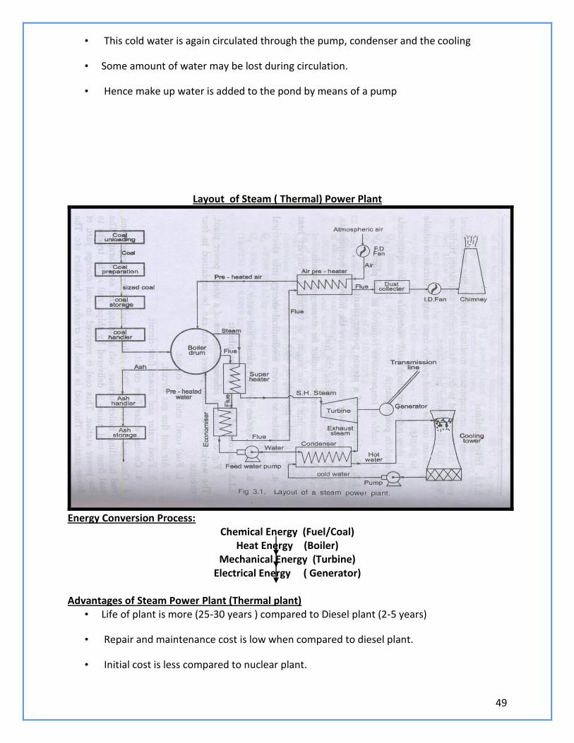
Layout of Steam ( Thermal) Power Plant
Energy Conversion Process:
Chemical Energy (Fuel/Coal) Heat Energy (Boiler)
Mechanical Energy (Turbine) Electrical Energy ( Generator)
Advantages of Steam Power Plant (Thermal plant)
• Life of plant is more (25-30 years ) compared to Diesel plant (2-5 years)
• Repair and maintenance cost is low when compared to diesel plant.
• Initial cost is less compared to nuclear plant.
50
• Suitable for varying load conditions.
• No radio active harmful wastes are produced
• Unskilled operators can operate the plant.
• The power generation does not depend on the water storage.
• There are no transmission losses, as they are located near load centres.
Disadvantages of thermal power plant: • Less efficient than diesel plants.
• Starting up and bringing into service takes more time.
• Cooling water required is more.
• Space required is more.
• Storage required for the fuel is more.
• Ash handling is a big problem
• Not economical in areas which are remote from coal fields.
• Manpower required is more.
• For large units, the capital cost is more.
List down the factors to be considered for selection of site for thermal power plant: Availability of coal:
• A thermal plant of 400M, capacity requires nearly 6000 tons of coal every day.
• Power plant should be located near coal mines.
Ash Disposal Facilities: • Ash comes out in hot condition and handling is difficult.
The ash can be disposed into sea or river. Water Availability :
• Water consumption is more as feed water into boiler, condenser and for ash disposal.
• Water is required for drinking purpose.
• Hence plant should be located near water source.
Transport Facility : • Railway lines or other mode of transport for bringing heavy machineries for installation
also for bringing coal.
51
Public Problems: • The plant should be far away from residential area to avoid nuisance from smoke, fly
ash and noise.
Nature of Land : • Many power plants have failed due to weak foundations.
• Land (soil) should have good bearing capacity to withstand dead load of plant.
Thermal power plants in Tamil Nadu: Neyveli Tuticorin Ennore Mettur Explain about the pollution caused by Thermal Power Plant (Steam Power Plant): • Main pollutants from thermal plants are SO2, CO2, CO as minute particles such as fly ash.
• SO2 causes suffocation, irritation to throat and eyes and respiratory for people. It destroys
crop.
• CO is a poisonous gas.
• Dust particles cause respiratory troubles like cough, cold, sneezing etc.,
Thermal Pollution: • Thermal plants produce 40 millions kJ of heat to the environment through condenser water
and exhaust gases.
• Thermal pollution of atmosphere can be reduced using the low grade energy exhausted
steam.
Noise Pollution: • The sources of noise in a power plant are turbo alternators, fans and power
transformers.
• Sound proofing can be done to reduce the noise.
Gas Power Plant • A gas power plant uses gas turbine as the prime mover for generating electricity.
• It uses natural gas or kerosene or benzene as fuel.
• Gas plant can produce only limited amount of the electricity.
• Efficiency of the plant is only 35%
• Generally a gas plant is expensive to operate.
52
• Hence it is usually installed with steam power plant in closed combined cycle.
• It is generally used in combination with steam/thermal power plant during peak load
• When the gas power plant is combined with thermal/steam power plant efficiency of
the plant is up to 60% - 70%
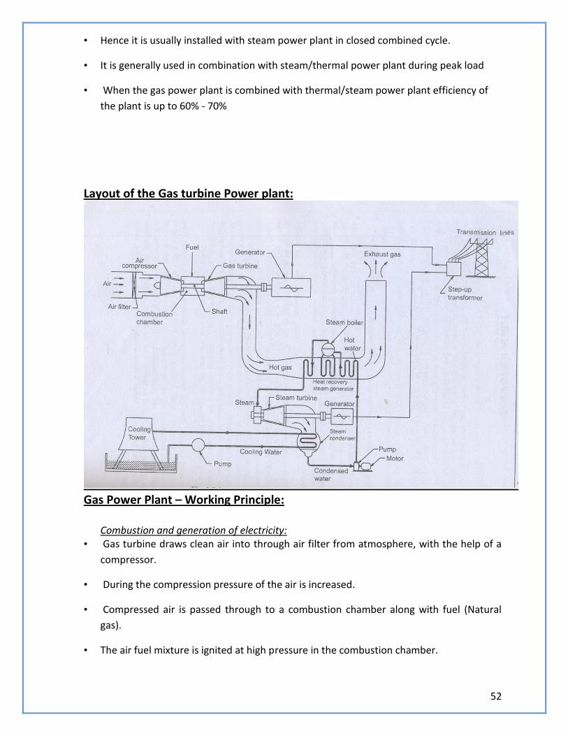
Layout of the Gas turbine Power plant:
Gas Power Plant – Working Principle:
Combustion and generation of electricity: • Gas turbine draws clean air into through air filter from atmosphere, with the help of a
compressor.
• During the compression pressure of the air is increased.
• Compressed air is passed through to a combustion chamber along with fuel (Natural
gas).
• The air fuel mixture is ignited at high pressure in the combustion chamber.
53
• Combustion takes place.
• The generated hot gas of compression is passed through the gas turbine.
• Hot gases expand, and the turbine blades are connected to the turbine shaft are
rotated.
• The turbine shaft which is coupled to the shaft of the electrical generator at the other
end also rotates and drives the electrical generator.
• A portion of the energy developed by the hot gases through the gas turbine is used to
run the compressor.
• The residual hot gases from gas turbine are passed through a heat exchanger (heat
recovery steam generator)
• The heat exchanger produces steam with high pressure with the help of a steam boiler.
• The steam is allowed to expand in the steam turbine.
• when it passes through the turbine blades, the turbine shaft is rotated. The shaft is
coupled to the generator, which generates electricity.
• Gas turbine and steam turbine combination enables increased power generation.
Transmission and distribution : • The generated electricity from both gas and steam turbines is fed to the step up
transformer where its voltage is increased.
• Then the electricity is conveyed through transmission lines for distribution.
MERITS: Natural gas is readily available.
• Setting up cost can be reduced if the plant is installed near the source of natural gas.
• Less gas storage cost
• Less space occupation.
• Compared to steam power plant, smaller in size.
• Low operating cost.
• Low maintenance cost.
• No standby losses.
• Cheaper fuels like natural gas.
54
Demerits: • 2/3 rd of generated power is used for driving the compressor.
• Gas turbine has low thermal efficiency.
• Has starting problem.
• Efficient only in combined cycle configuration.
• Temperature of combustion chamber is too high, which results in shorter life time.
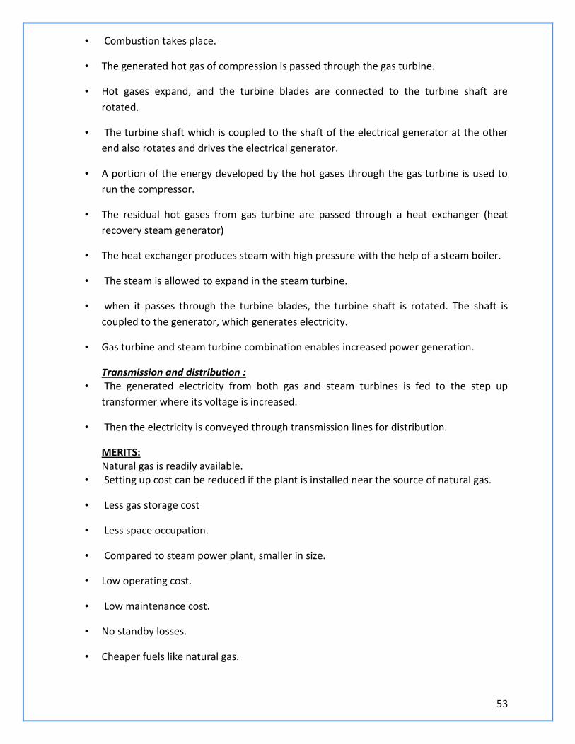
Diesel Power Plant
Working of Diesel Power plant:
• Air from atmosphere is drawn into the compressor and is compressed.
• The compressed air is sent to diesel engine through filter.
• In the filter, dust, dirt from air are filtered and only clean air is sent to diesel engine.
• Fuel oil from tank is passed through filter where it gets filtered and clean oil is injected
into the diesel engine through fuel pump and fuel injector
• Mixture of compressed air and spray of fuel oil are ignited into the engine and
combustion takes place.
• The heat energy is utilized for driving the generator, which produces power.
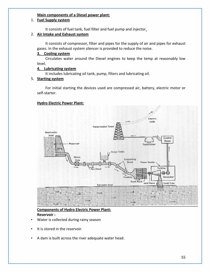
55
Main components of a Diesel power plant: 1. Fuel Supply system
It consists of fuel tank, fuel filter and fuel pump and injector. 2. Air Intake and Exhaust system
It consists of compressor, filter and pipes for the supply of air and pipes for exhaust gases. In the exhaust system silencer is provided to reduce the noise. 3. Cooling system Circulates water around the Diesel engines to keep the temp at reasonably low level. 4. Lubricating system It includes lubricating oil tank, pump, filters and lubricating oil.
5. Starting system
For initial starting the devices used are compressed air, battery, electric motor or self-starter. Hydro Electric Power Plant:
Components of Hydro Electric Power Plant: Reservoir :
• Water is collected during rainy season
• It is stored in the reservoir.
• A dam is built across the river adequate water head.
56
Penstock : • It is a passage through which water flows from reservoir to turbine.
Surge Tank : • It is installed along the penstock (between turbine and reservoir)
• To control or regulate the sudden water over flow and to protect the penstock from
bursting.
• It reduces the pressure and avoids damage to the penstock due to the water hammer
effect.
• When the load on the turbine is decreased there will be a back flow, which causes
increase or decrease in pressure. It is known as water hammer.
• Power House :
• It is building that houses that water turbine, generator, transformer and control room.
• Water Turbine:
• Water turbines such as Pelton, Kaplan and Francis are used to convert pressure and
kinetic energy of flowing water into mechanical energy.
• Draft Tube:
• It is connected to the outlet of the turbine.
• Tailrace:
• It refers to the downstream level of water discharged from turbine.
• Generator :
• It is a machine used to convert mechanical energy into electrical energy.
• Step up transformer:
• It converts the Alternating Current (AC) into high voltage current suitable for
transmission.
Working Principle of Hydro Electric Power Plant: • It uses the potential energy of water of water stored in a reservoir.
• The water from the reservoir through a penstock and then forced through nozzle or
nozzles before reaching the turbine.
• The hydraulic turbine converts the kinetic energy of water under pressure into
mechanical energy.
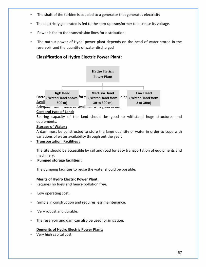
57
• The shaft of the turbine is coupled to a generator that generates electricity
• The electricity generated is fed to the step-up transformer to increase its voltage.
• Power is fed to the transmission lines for distribution.
• The output power of Hydel power plant depends on the head of water stored in the
reservoir and the quantity of water discharged
Classification of Hydro Electric Power Plant: Factors to be considered for the location of hydro electric Power Plant: Availability of Water: Adequate water must be available with good head. Cost and type of Land: Bearing capacity of the land should be good to withstand huge structures and equipments. Storage of Water : A dam must be constructed to store the large quantity of water in order to cope with variations of water availability through out the year.
• Transportation Facilities :
The site should be accessible by rail and road for easy transportation of equipments and machinery.
• Pumped storage facilities :
The pumping facilities to reuse the water should be possible. Merits of Hydro Electric Power Plant:
• Requires no fuels and hence pollution free.
• Low operating cost.
• Simple in construction and requires less maintenance.
• Very robust and durable.
• The reservoir and dam can also be used for irrigation.
Demerits of Hydro Electric Power Plant: • Very high capital cost
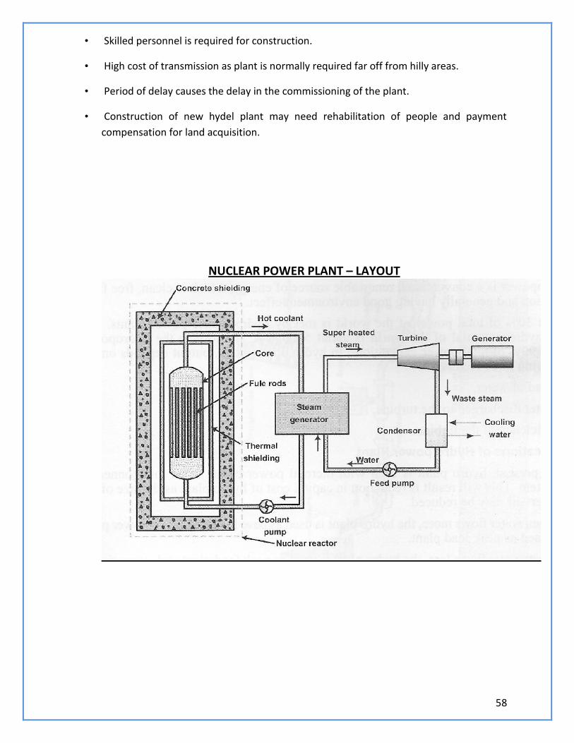
58
• Skilled personnel is required for construction.
• High cost of transmission as plant is normally required far off from hilly areas.
• Period of delay causes the delay in the commissioning of the plant.
• Construction of new hydel plant may need rehabilitation of people and payment
compensation for land acquisition.
NUCLEAR POWER PLANT – LAYOUT
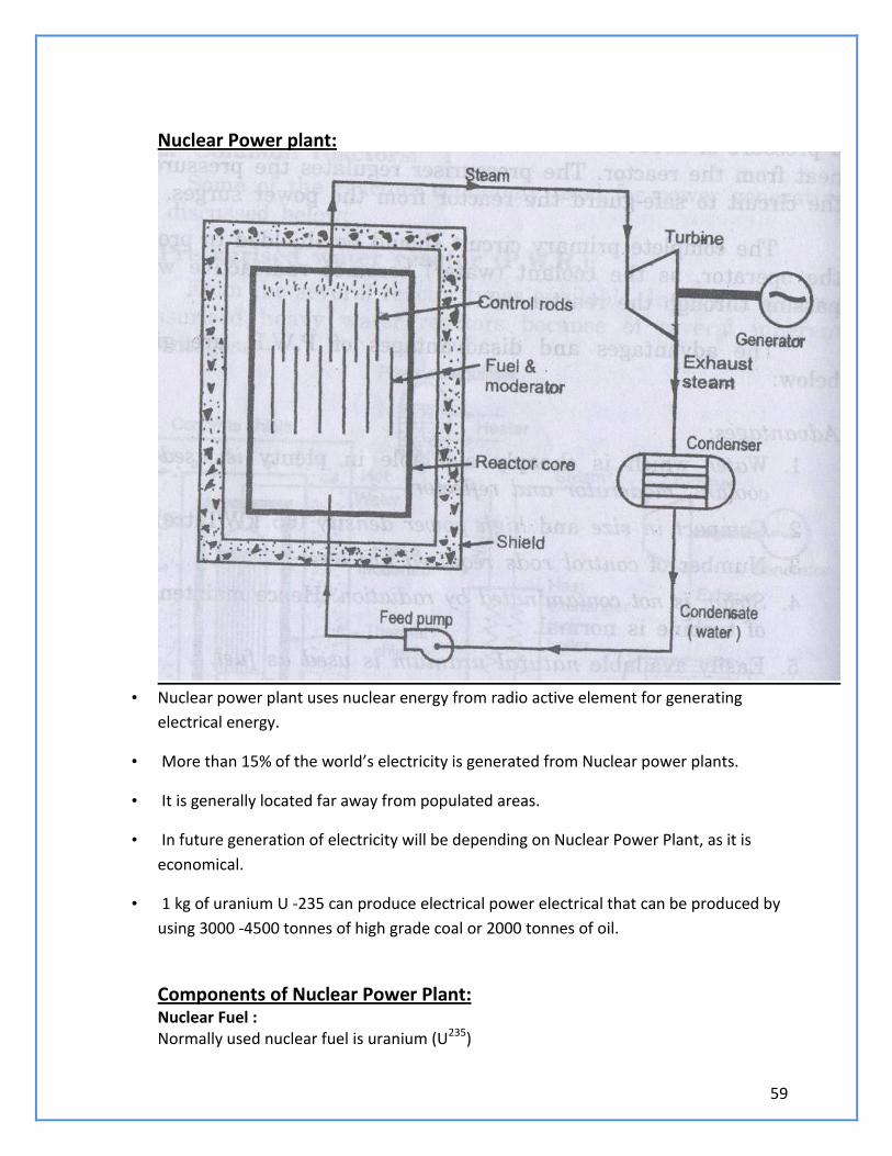
59
Nuclear Power plant:
• Nuclear power plant uses nuclear energy from radio active element for generating
electrical energy.
• More than 15% of the world’s electricity is generated from Nuclear power plants.
• It is generally located far away from populated areas.
• In future generation of electricity will be depending on Nuclear Power Plant, as it is
economical.
• 1 kg of uranium U -235 can produce electrical power electrical that can be produced by
using 3000 -4500 tonnes of high grade coal or 2000 tonnes of oil.
Components of Nuclear Power Plant: Nuclear Fuel : Normally used nuclear fuel is uranium (U235)
60
Fuel Rods: The fuel rods hold nuclear fuel in a nuclear power plant. Neutron Source: A source of neutron is required to initiate the fission for the first time. A mixture of beryllium with plutonium is commonly used as a source of neutron. Reactor:
• Nuclear fission takes place in the reactor only.
• Nuclear fission produces large quantity of heat.
• The heat generated in the reactor is carried by coolant circulated through the reactor.
Control Rods: • They are used to control the chain reaction.
• They are absorbers of neutrons.
• The commonly used control rods are made up of cadmium or boron.
Moderator: • Moderators are used to slow down the fast neutrons.
• It reduces 2 MeV to an average velocity of 0.025 eV.
• Ordinary or heavy water are used as moderators.
• Fuel Rods:
• The fuel rods hold nuclear fuel in a nuclear power plant.
• Neutron Reflectors:
• To prevent the leakage of neutrons to large extent.
• In PHWR, the moderator itself acts as reflectors.
• Shielding:
• To protect from harmful radiations the reactor is surrounded b a concrete wall of
thickness about 2 to 2.5 m.
Nuclear Fission
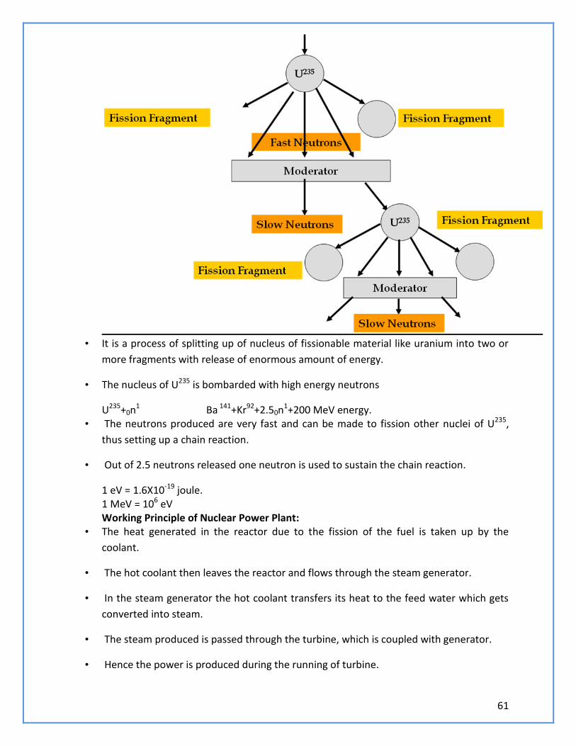
61
• It is a process of splitting up of nucleus of fissionable material like uranium into two or
more fragments with release of enormous amount of energy.
• The nucleus of U235 is bombarded with high energy neutrons
U235+0n1 Ba 141+Kr92+2.50n1+200 MeV energy. • The neutrons produced are very fast and can be made to fission other nuclei of U235,
thus setting up a chain reaction.
• Out of 2.5 neutrons released one neutron is used to sustain the chain reaction.
1 eV = 1.6X10⁻¹⁹ joule. 1 MeV = 106 eV Working Principle of Nuclear Power Plant:
• The heat generated in the reactor due to the fission of the fuel is taken up by the
coolant.
• The hot coolant then leaves the reactor and flows through the steam generator.
• In the steam generator the hot coolant transfers its heat to the feed water which gets
converted into steam.
• The steam produced is passed through the turbine, which is coupled with generator.
• Hence the power is produced during the running of turbine.
62
• The exhaust steam from the turbine is condensed in the condenser.
• The condensate then flows to the steam generator through the feed pump.
• The cycle is thus repeated.
Advantages of Nuclear Power Plant: • Requires less space compared to steam power plant.
• Fuel required is negligible compared to coal requirement.
• Fuel transport cost is less.
• Reliable in operation.
• Cost of erection is less.
• Water required is very less.
Disadvantages of Nuclear Power Plant: • Initial Cost is higher.
• Not suitable for varying load condition.
• Radioactive wastes are hazardous. Hence these are to be handled with much care.
• Maintenance cost is higher.
• Trained workers are required to operate the plant.
Nuclear Power Plants in India: • IGCAR, Kalpakkam in Chennai.
• Rana Pratap Sagar in Rajasthan
• Narora in Uttar Pradesh
• Kakarpur near Surat at Gujarat
Kaiga Power Plant at Karnataka
Pumps • A pump is a machine which is used to raise or transfer the fluids.
• It is also used to maintain the constant flow rate or constant pressure.
• It is normally driven by a engine or a motor.
• Pumps are rated by the horse power.
63
• Important specifications for pump maximum discharge flow, maximum discharge
pressure, inlet size and discharges size.
Classification of pumps: It is classified into positive displacement pumps and roto dynamic pumps. • In positive displacement pumps, fluid is drawn or forced into a finite space and it is
sealed.
• It is then forced out and the cycle is repeated.
In roto dynamic pumps, centrifugal force is used to move the fluid into a pipe. Reciprocating Pumps: • It is a positive displacement pump
• It uses a piston and cylinder arrangement with suction and delivery valves integrated
with the pump.
• It can be single acting and double acting
• There may be single or multi cylinders also.
• It is a positive displacement pump
• It sucks and raises the liquid by actually displacing it with a piston/plunger that executes
a reciprocating motion in a closely fitting cylinder.
Working of single acting Reciprocating Pump: During suction stroke the piston moves to the left, causing the inlet valve to open.
Water is admitted into the cylinder through the inlet valve.
During the discharge stroke the piston moves to the right closes the suction valve and
opens the out let valve.
Through the outlet valve the volume of liquid moved out of the cylinder.
Double Acting Reciprocating Pump – Working:
• Each cycle consists of two strokes.
• Both the strokes are effective, hence it is known as double acting pump
• Liquid is filled at one end and discharged at other end during forward stroke.
• During the return stroke, end of cylinder just emptied is filled and the end just filled is
emptied.
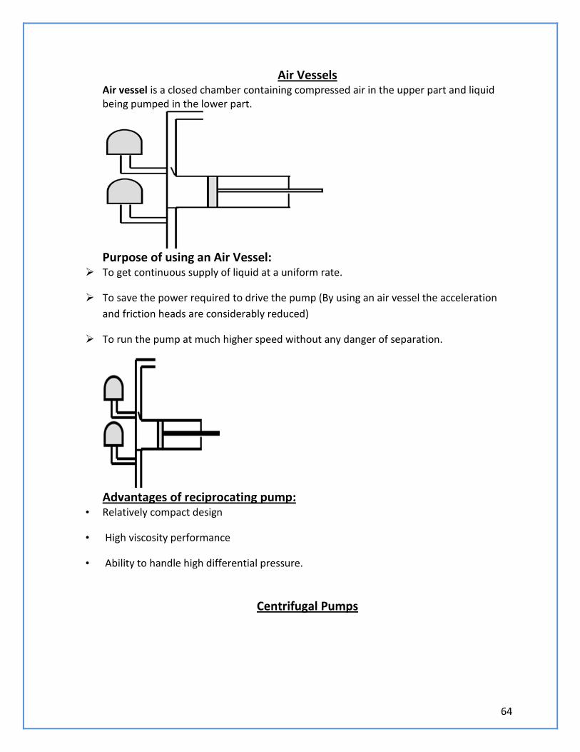
64
Air Vessels Air vessel is a closed chamber containing compressed air in the upper part and liquid being pumped in the lower part.
Purpose of using an Air Vessel:
To get continuous supply of liquid at a uniform rate.
To save the power required to drive the pump (By using an air vessel the acceleration
and friction heads are considerably reduced)
To run the pump at much higher speed without any danger of separation.
Advantages of reciprocating pump:
• Relatively compact design
• High viscosity performance
• Ability to handle high differential pressure.
Centrifugal Pumps
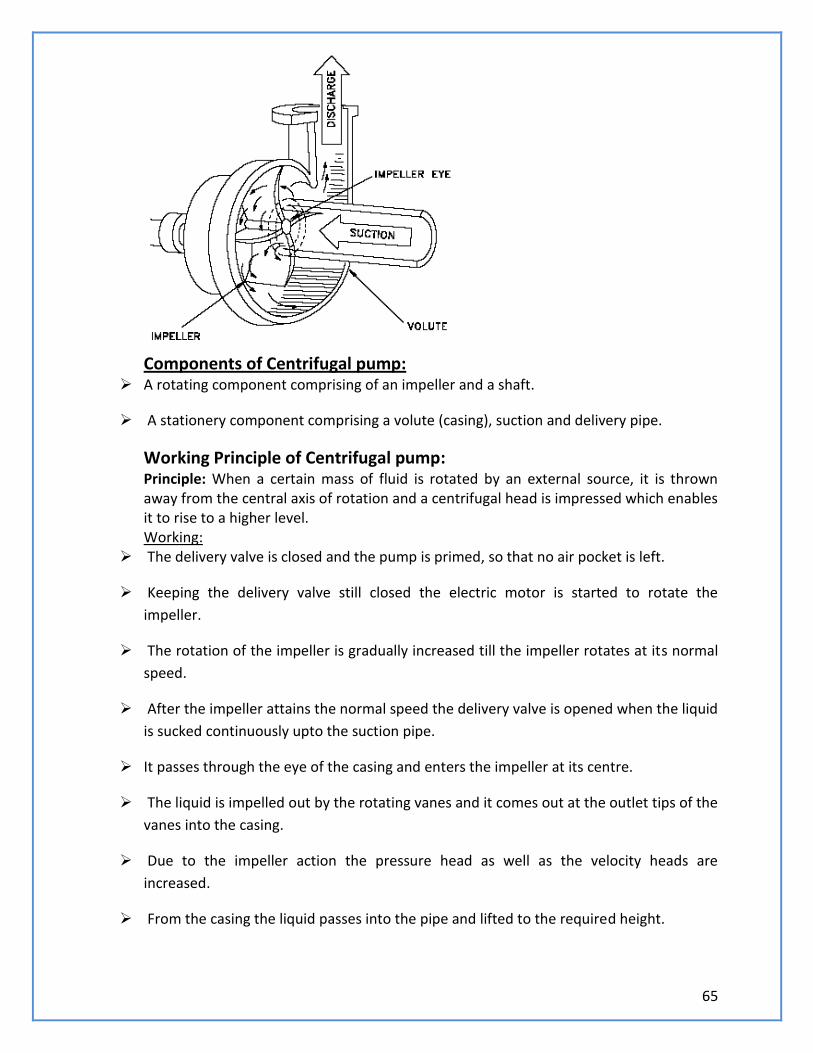
65
Components of Centrifugal pump:
A rotating component comprising of an impeller and a shaft.
A stationery component comprising a volute (casing), suction and delivery pipe.
Working Principle of Centrifugal pump: Principle: When a certain mass of fluid is rotated by an external source, it is thrown away from the central axis of rotation and a centrifugal head is impressed which enables it to rise to a higher level. Working:
The delivery valve is closed and the pump is primed, so that no air pocket is left.
Keeping the delivery valve still closed the electric motor is started to rotate the
impeller.
The rotation of the impeller is gradually increased till the impeller rotates at its normal
speed.
After the impeller attains the normal speed the delivery valve is opened when the liquid
is sucked continuously upto the suction pipe.
It passes through the eye of the casing and enters the impeller at its centre.
The liquid is impelled out by the rotating vanes and it comes out at the outlet tips of the
vanes into the casing.
Due to the impeller action the pressure head as well as the velocity heads are
increased.
From the casing the liquid passes into the pipe and lifted to the required height.
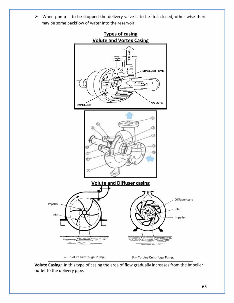
66
When pump is to be stopped the delivery valve is to be first closed, other wise there
may be some backflow of water into the reservoir.
Types of casing Volute and Vortex Casing
Volute and Diffuser casing
Volute Casing: In this type of casing the area of flow gradually increases from the impeller outlet to the delivery pipe.
67
Vortex Casing: If a circular chamber is provided between the impeller and volute chamber the casing is known as Vortex Chamber. Diffuser C : The impeller is surrounded by a diffuser.
The guide vanes are designed in such a way that the water from the impeller enters the
guide vanes without shock.
It reduces the vibration of the pump.
Diffuser casing, the diffuser and the outer casing are stationery parts.
Priming of a centrifugal Pump: The operation of filling the suction pipe, casing and a portion of delivery pipe with the
liquid to be raised, before starting the pump is known as Priming
It is done to remove any air, gas or vapour from these parts of pump.
If a Centrifugal pump is not primed before starting air pockets inside impeller may give
rise to vortices and causes discontinuity of flow
Losses in Centrifugal pump: Hydraulic Losses:
Shock or eddy losses at the entrance to and exit from the impeller
Losses due to friction in the impeller
Friction and eddy losses in the guide vanes/diffuser and casing
Mechanical Losses: Losses due to disc friction between the impeller and the liquid which fills the clearance
spaces between the impeller and casing
Losses pertaining to friction of the main bearing and glands.
Specific speed of Centrifugal Pump: • It is the speed in revolutions per minute at which a geometrically similar impeller would
deliver one cubic meter of liquid per second against a delivery head of one meter.
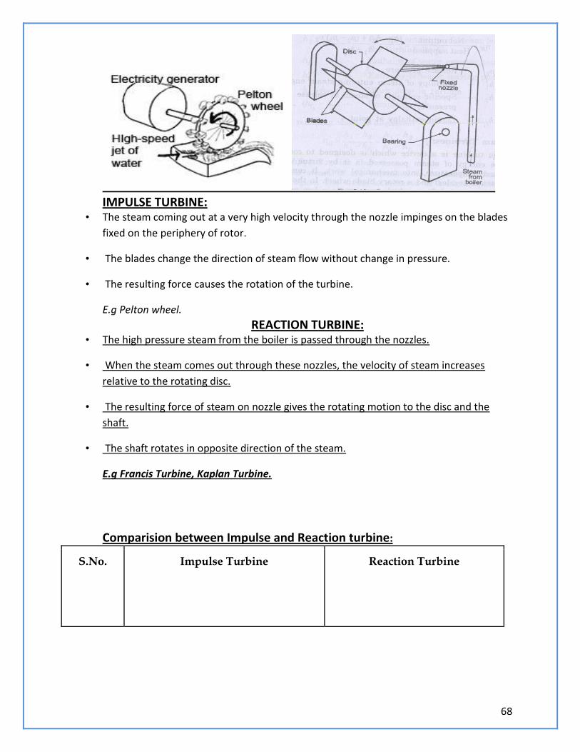
68
IMPULSE TURBINE:
• The steam coming out at a very high velocity through the nozzle impinges on the blades
fixed on the periphery of rotor.
• The blades change the direction of steam flow without change in pressure.
• The resulting force causes the rotation of the turbine.
E.g Pelton wheel.
REACTION TURBINE: • The high pressure steam from the boiler is passed through the nozzles.
• When the steam comes out through these nozzles, the velocity of steam increases
relative to the rotating disc.
• The resulting force of steam on nozzle gives the rotating motion to the disc and the
shaft.
• The shaft rotates in opposite direction of the steam.
E.g Francis Turbine, Kaplan Turbine.
Comparision between Impulse and Reaction turbine:
S.No. Impulse Turbine Reaction Turbine
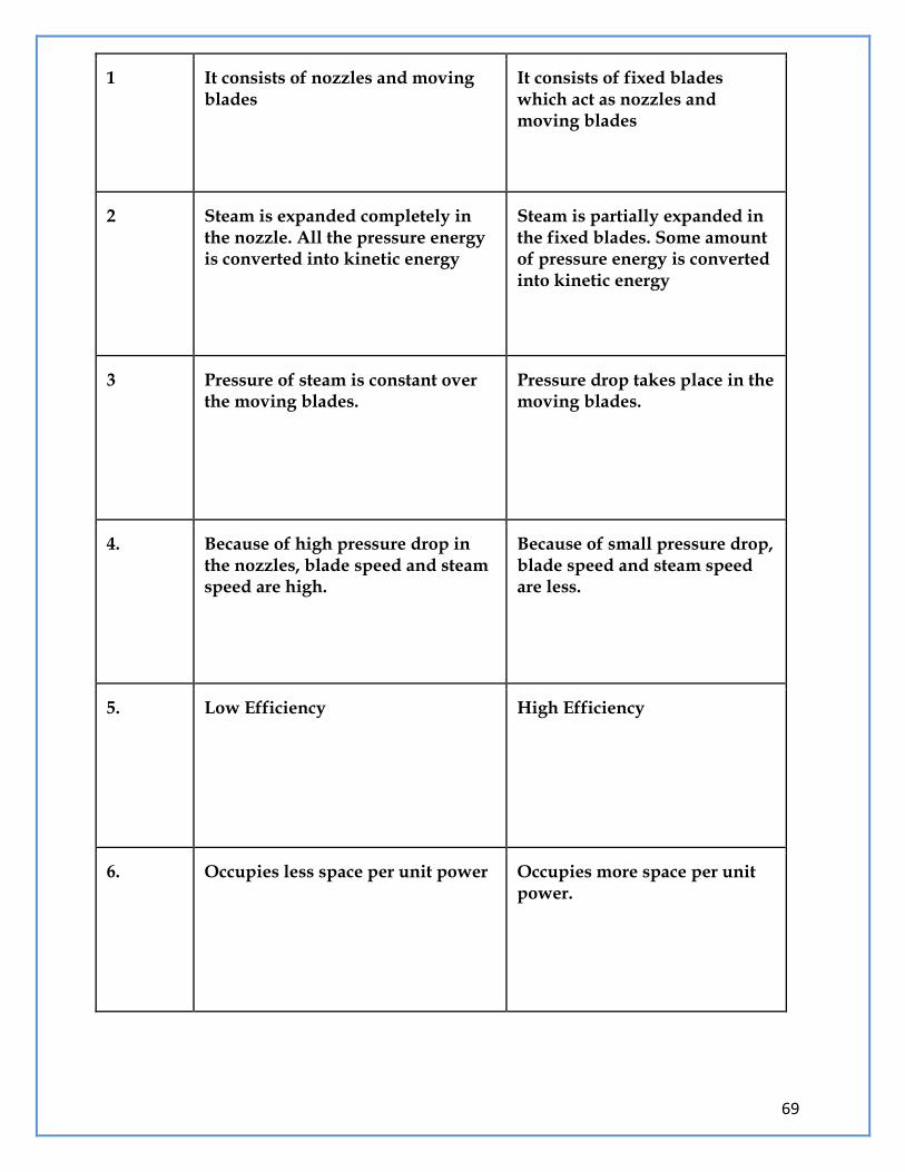
69
1 It consists of nozzles and moving blades
It consists of fixed blades which act as nozzles and moving blades
2 Steam is expanded completely in the nozzle. All the pressure energy is converted into kinetic energy
Steam is partially expanded in the fixed blades. Some amount of pressure energy is converted into kinetic energy
3 Pressure of steam is constant over the moving blades.
Pressure drop takes place in the moving blades.
4. Because of high pressure drop in the nozzles, blade speed and steam speed are high.
Because of small pressure drop, blade speed and steam speed are less.
5. Low Efficiency High Efficiency
6. Occupies less space per unit power Occupies more space per unit power.

70
7. Suitable for small power requirements
Suitable for medium and high power requirements.
71
UNIT – III (POWER PLANT ENGINEERING)
PART – A (2 MARKS)
1. What are the types of power plant?
2. What are the parts of thermal power plant?
3. What is the purpose of Surge tank in hydro power plant?
4. Classify the hydro power plant.
5. What is the function of Draft tube?
6. Define Nuclear Fission. Write chain reaction.
7. What is the function of Moderator?
8. Write down the Merits and Demerits of Diesel engine power plant.
9. List out the parts of the Gas turbine power plant.
10. Define Pump and Turbine.
11. Define Cavitations.
12. Define Primiming in Centrifugal Pump.
13. What is impulse turbine? Give example
14. What is Reaction turbine? Give example.
15. What does the study of power plant engineering include?
16. Define the term: Prime mover.
17. Define power plant.
18. What are the different types of power plants?
19. Give the function of condenser in steam power plant.
20. What is the function of moderator in a nuclear power plant?
21. Give four important factors to be considered for selecting hydroelectric power plant.
22. Mention the reason for preferring steam power plant to other power plants.
23. What is the cooling tower? Give its uses.
24. What are the nuclear fuels used in the nuclear reactor?
25. What is the function of penstock pipe?
26. What is meant by nuclear fission?
27. What is the function of intercooler in gas turbine power plant?
28. Name the different components of a gas turbine power plant.
29. Briefly explain what radiation shielding means?
30. What are the different types of hydro power plants?
31. State the disadvantages of steam power plant.
32. Mention the applications of gas turbine power plant.
33. What are the different types of wind mills?
34. State the advantages of tidal power plant.
35. Define steam turbine.
36. State the main parts of a steam turbine.
37. How steam turbines are classified?
38. Give an example for reaction turbine.
39. State the limitations of impulse turbine.
40. What is the difference between impulse and reaction turbine?
41. Relative velocity of steam increases in reaction turbine. Give reason.
PART – B (10 MARKS)
1. Explain the working principle of thermal power plant with neat sketch.
2. Explain the working principle of steam power plant with neat sketch.
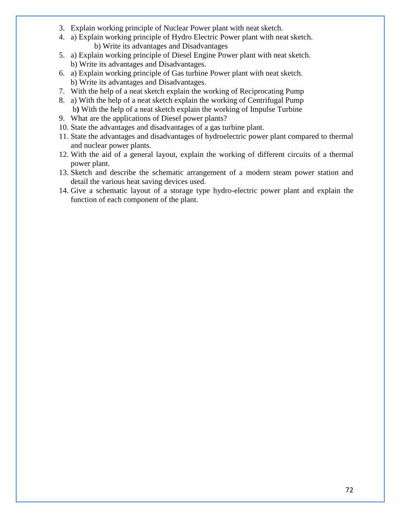
72
3. Explain working principle of Nuclear Power plant with neat sketch.
4. a) Explain working principle of Hydro Electric Power plant with neat sketch.
b) Write its advantages and Disadvantages
5. a) Explain working principle of Diesel Engine Power plant with neat sketch.
b) Write its advantages and Disadvantages.
6. a) Explain working principle of Gas turbine Power plant with neat sketch.
b) Write its advantages and Disadvantages.
7. With the help of a neat sketch explain the working of Reciprocating Pump
8. a) With the help of a neat sketch explain the working of Centrifugal Pump
b) With the help of a neat sketch explain the working of Impulse Turbine
9. What are the applications of Diesel power plants?
10. State the advantages and disadvantages of a gas turbine plant.
11. State the advantages and disadvantages of hydroelectric power plant compared to thermal
and nuclear power plants.
12. With the aid of a general layout, explain the working of different circuits of a thermal
power plant.
13. Sketch and describe the schematic arrangement of a modern steam power station and
detail the various heat saving devices used.
14. Give a schematic layout of a storage type hydro-electric power plant and explain the
function of each component of the plant.
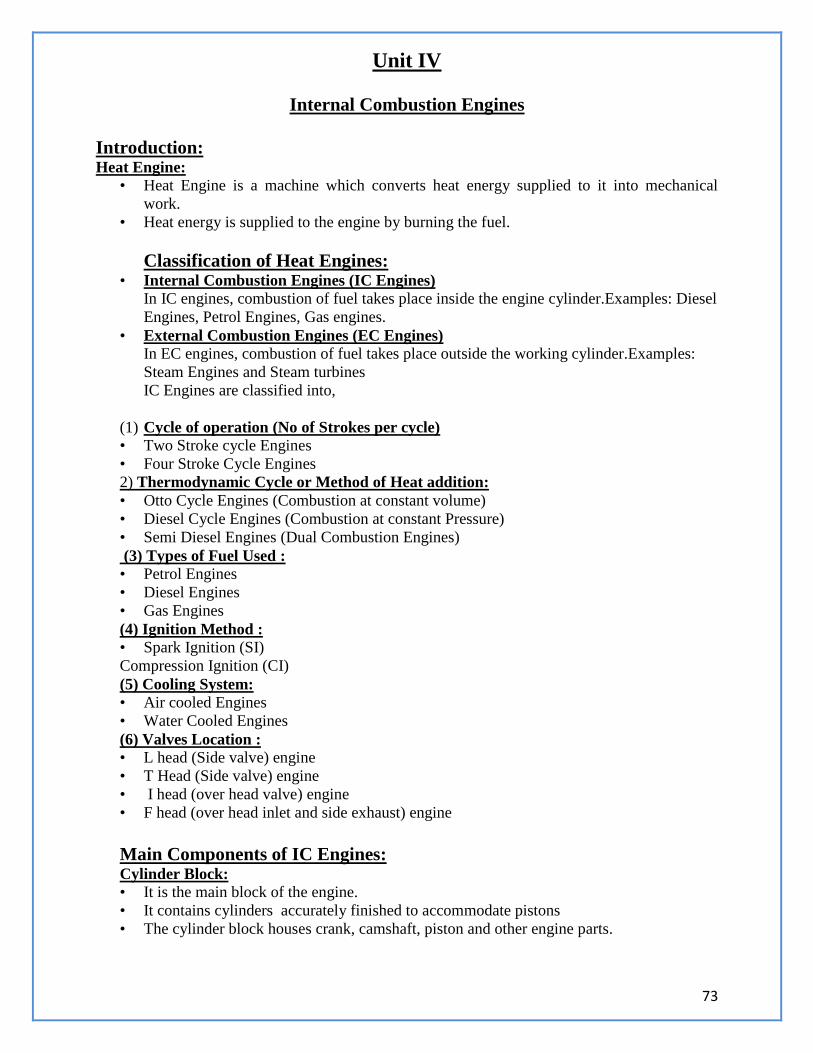
73
Unit IV
Internal Combustion Engines
Introduction: Heat Engine:
• Heat Engine is a machine which converts heat energy supplied to it into mechanical
work.
• Heat energy is supplied to the engine by burning the fuel.
Classification of Heat Engines:
• Internal Combustion Engines (IC Engines) In IC engines, combustion of fuel takes place inside the engine cylinder.Examples: Diesel
Engines, Petrol Engines, Gas engines.
• External Combustion Engines (EC Engines) In EC engines, combustion of fuel takes place outside the working cylinder.Examples:
Steam Engines and Steam turbines
IC Engines are classified into,
(1) Cycle of operation (No of Strokes per cycle) • Two Stroke cycle Engines
• Four Stroke Cycle Engines
2) Thermodynamic Cycle or Method of Heat addition:
• Otto Cycle Engines (Combustion at constant volume)
• Diesel Cycle Engines (Combustion at constant Pressure)
• Semi Diesel Engines (Dual Combustion Engines)
(3) Types of Fuel Used :
• Petrol Engines
• Diesel Engines
• Gas Engines
(4) Ignition Method :
• Spark Ignition (SI)
Compression Ignition (CI)
(5) Cooling System: • Air cooled Engines
• Water Cooled Engines
(6) Valves Location : • L head (Side valve) engine
• T Head (Side valve) engine
• I head (over head valve) engine
• F head (over head inlet and side exhaust) engine
Main Components of IC Engines: Cylinder Block: • It is the main block of the engine.
• It contains cylinders accurately finished to accommodate pistons
• The cylinder block houses crank, camshaft, piston and other engine parts.
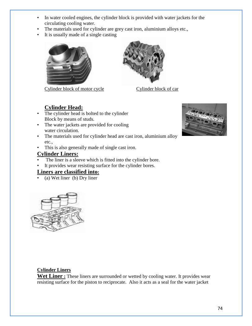
74
• In water cooled engines, the cylinder block is provided with water jackets for the
circulating cooling water.
• The materials used for cylinder are grey cast iron, aluminium alloys etc.,
• It is usually made of a single casting
Cylinder block of motor cycle Cylinder block of car
Cylinder Head: • The cylinder head is bolted to the cylinder
Block by means of studs.
• The water jackets are provided for cooling
water circulation.
• The materials used for cylinder head are cast iron, aluminium alloy
etc.,
• This is also generally made of single cast iron.
Cylinder Liners: • The liner is a sleeve which is fitted into the cylinder bore.
• It provides wear resisting surface for the cylinder bores.
Liners are classified into:
• (a) Wet liner (b) Dry liner
Cylinder Liners
Wet Liner : These liners are surrounded or wetted by cooling water. It provides wear
resisting surface for the piston to reciprocate. Also it acts as a seal for the water jacket
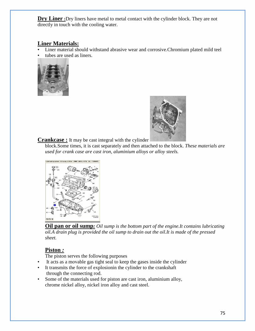
75
Dry Liner :Dry liners have metal to metal contact with the cylinder block. They are not
directly in touch with the cooling water.
Liner Materials: • Liner material should withstand abrasive wear and corrosive.Chromium plated mild teel
• tubes are used as liners.
Crankcase : It may be cast integral with the cylinder
block.Some times, it is cast separately and then attached to the block. These materials are
used for crank case are cast iron, aluminium alloys or alloy steels.
Oil pan or oil sump: Oil sump is the bottom part of the engine.It contains lubricating
oil.A drain plug is provided the oil sump to drain out the oil.It is made of the pressed
sheet.
Piston : The piston serves the following purposes
• It acts as a movable gas tight seal to keep the gases inside the cylinder
• It transmits the force of explosionin the cylinder to the crankshaft
through the connecting rod.
• Some of the materials used for piston are cast iron, aluminium alloy,
chrome nickel alloy, nickel iron alloy and cast steel.
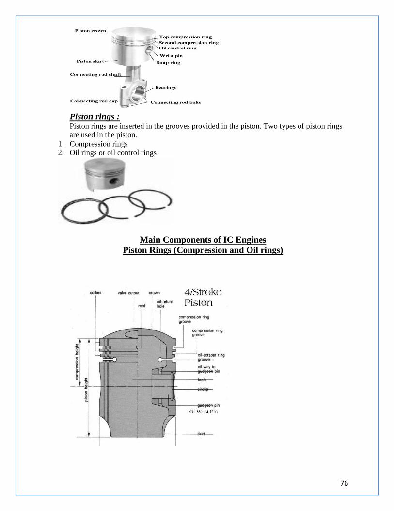
76
Piston rings : Piston rings are inserted in the grooves provided in the piston. Two types of piston rings
are used in the piston.
1. Compression rings
2. Oil rings or oil control rings
Main Components of IC Engines
Piston Rings (Compression and Oil rings)
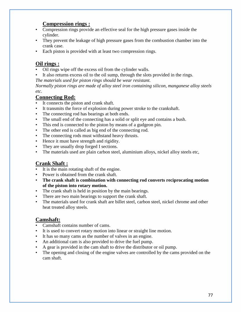
77
Compression rings : • Compression rings provide an effective seal for the high pressure gases inside the
cylinder.
• They prevent the leakage of high pressure gases from the combustion chamber into the
crank case.
• Each piston is provided with at least two compression rings.
Oil rings : • Oil rings wipe off the excess oil from the cylinder walls.
• It also returns excess oil to the oil sump, through the slots provided in the rings.
The materials used for piston rings should be wear resistant.
Normally piston rings are made of alloy steel iron containing silicon, manganese alloy steels
etc.
Connecting Rod: • It connects the piston and crank shaft.
• It transmits the force of explosion during power stroke to the crankshaft.
• The connecting rod has bearings at both ends.
• The small end of the connecting has a solid or split eye and contains a bush.
• This end is connected to the piston by means of a gudgeon pin.
• The other end is called as big end of the connecting rod.
• The connecting rods must withstand heavy thrusts.
• Hence it must have strength and rigidity.
• They are usually drop forged I sections.
• The materials used are plain carbon steel, aluminium alloys, nickel alloy steels etc,
Crank Shaft : • It is the main rotating shaft of the engine.
• Power is obtained from the crank shaft.
• The crank shaft is combination with connecting rod converts reciprocating motion
of the piston into rotary motion. • The crank shaft is held in position by the main bearings.
• There are two main bearings to support the crank shaft.
• The materials used for crank shaft are billet steel, carbon steel, nickel chrome and other
heat treated alloy steels.
Camshaft: • Camshaft contains number of cams.
• It is used to convert rotary motion into linear or straight line motion.
• It has so many cams as the number of valves in an engine.
• An additional cam is also provided to drive the fuel pump.
• A gear is provided in the cam shaft to drive the distributor or oil pump.
• The opening and closing of the engine valves are controlled by the cams provided on the
cam shaft.
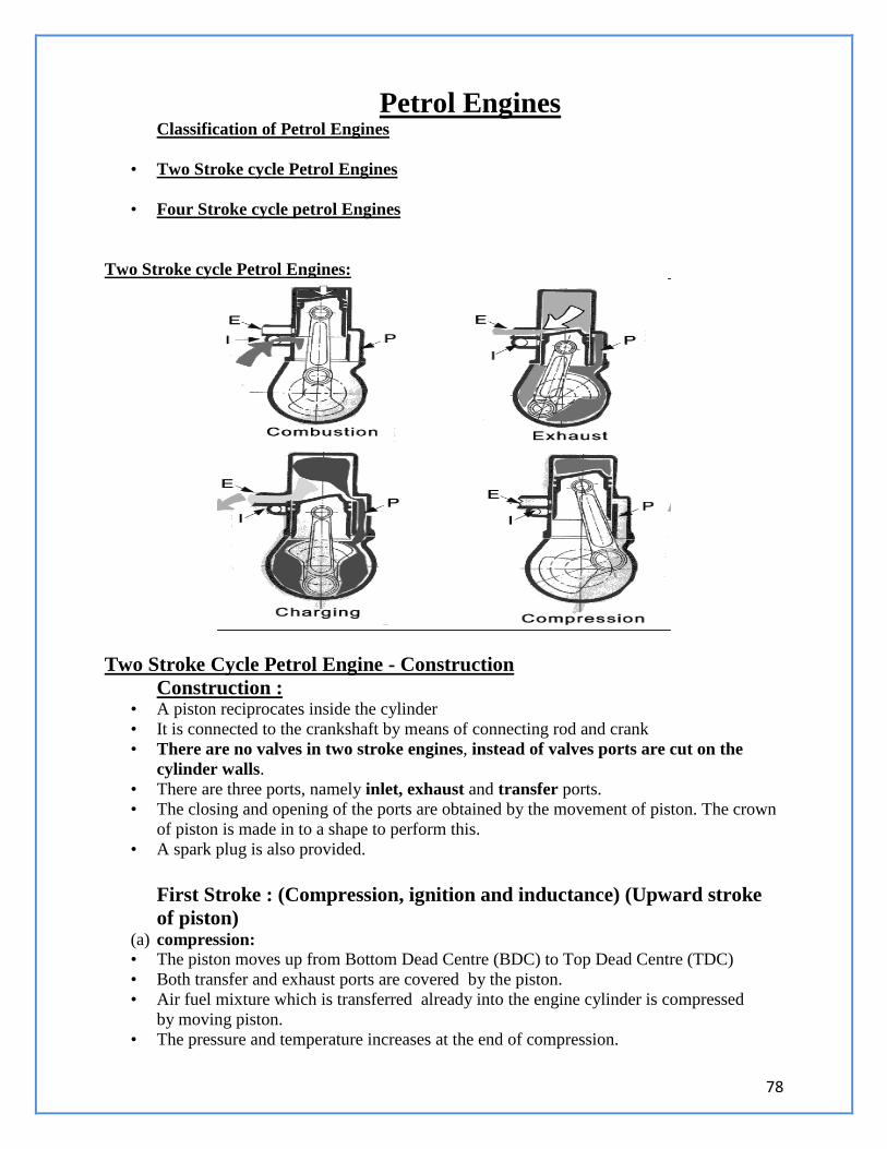
78
Petrol Engines Classification of Petrol Engines
• Two Stroke cycle Petrol Engines
• Four Stroke cycle petrol Engines
Two Stroke cycle Petrol Engines:
Two Stroke Cycle Petrol Engine - Construction
Construction : • A piston reciprocates inside the cylinder
• It is connected to the crankshaft by means of connecting rod and crank
• There are no valves in two stroke engines, instead of valves ports are cut on the
cylinder walls.
• There are three ports, namely inlet, exhaust and transfer ports.
• The closing and opening of the ports are obtained by the movement of piston. The crown
of piston is made in to a shape to perform this.
• A spark plug is also provided.
First Stroke : (Compression, ignition and inductance) (Upward stroke
of piston) (a) compression: • The piston moves up from Bottom Dead Centre (BDC) to Top Dead Centre (TDC)
• Both transfer and exhaust ports are covered by the piston.
• Air fuel mixture which is transferred already into the engine cylinder is compressed
by moving piston.
• The pressure and temperature increases at the end of compression.
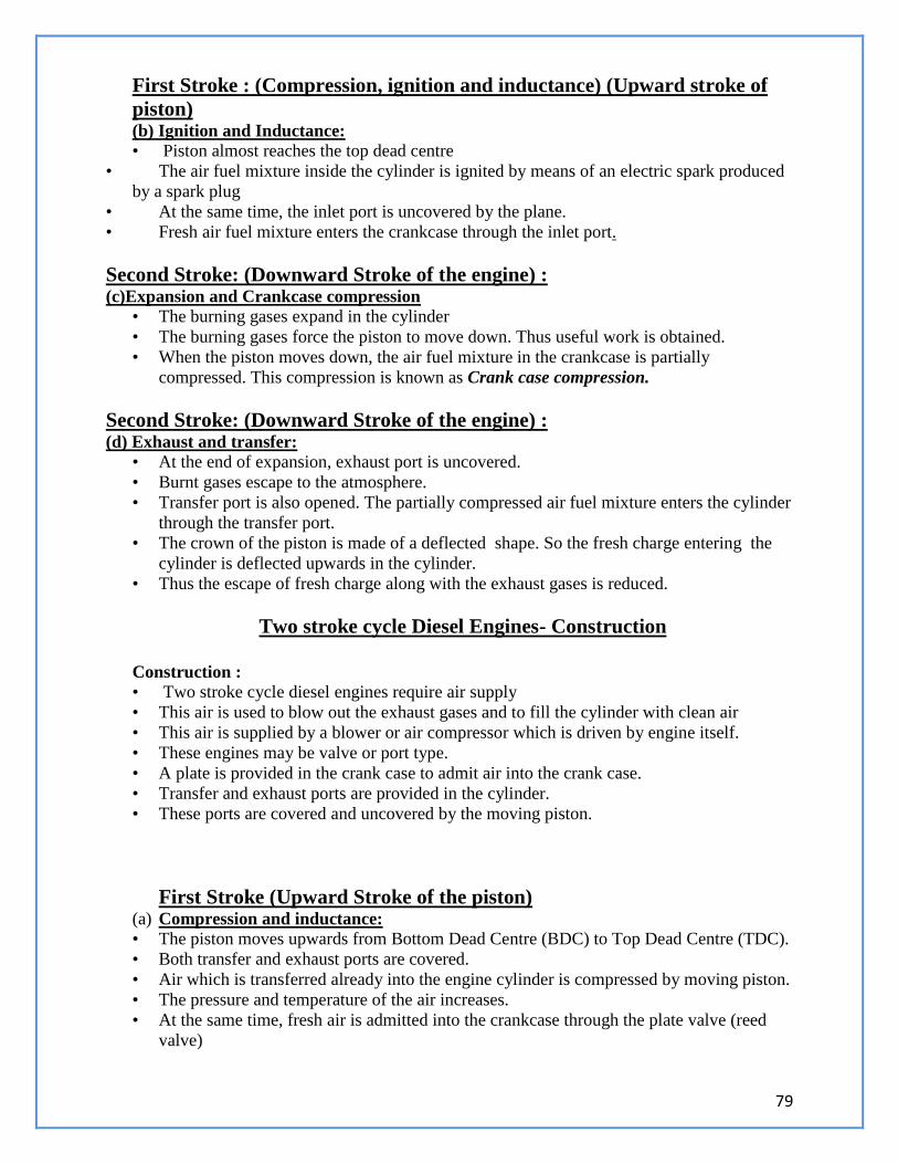
79
First Stroke : (Compression, ignition and inductance) (Upward stroke of
piston) (b) Ignition and Inductance: • Piston almost reaches the top dead centre
• The air fuel mixture inside the cylinder is ignited by means of an electric spark produced
by a spark plug
• At the same time, the inlet port is uncovered by the plane.
• Fresh air fuel mixture enters the crankcase through the inlet port.
Second Stroke: (Downward Stroke of the engine) : (c)Expansion and Crankcase compression
• The burning gases expand in the cylinder
• The burning gases force the piston to move down. Thus useful work is obtained.
• When the piston moves down, the air fuel mixture in the crankcase is partially
compressed. This compression is known as Crank case compression.
Second Stroke: (Downward Stroke of the engine) : (d) Exhaust and transfer:
• At the end of expansion, exhaust port is uncovered.
• Burnt gases escape to the atmosphere.
• Transfer port is also opened. The partially compressed air fuel mixture enters the cylinder
through the transfer port.
• The crown of the piston is made of a deflected shape. So the fresh charge entering the
cylinder is deflected upwards in the cylinder.
• Thus the escape of fresh charge along with the exhaust gases is reduced.
Two stroke cycle Diesel Engines- Construction
Construction : • Two stroke cycle diesel engines require air supply
• This air is used to blow out the exhaust gases and to fill the cylinder with clean air
• This air is supplied by a blower or air compressor which is driven by engine itself.
• These engines may be valve or port type.
• A plate is provided in the crank case to admit air into the crank case.
• Transfer and exhaust ports are provided in the cylinder.
• These ports are covered and uncovered by the moving piston.
First Stroke (Upward Stroke of the piston) (a) Compression and inductance: • The piston moves upwards from Bottom Dead Centre (BDC) to Top Dead Centre (TDC).
• Both transfer and exhaust ports are covered.
• Air which is transferred already into the engine cylinder is compressed by moving piston.
• The pressure and temperature of the air increases.
• At the same time, fresh air is admitted into the crankcase through the plate valve (reed
valve)
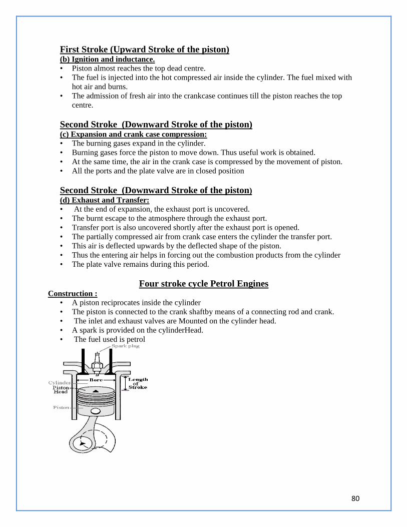
80
First Stroke (Upward Stroke of the piston) (b) Ignition and inductance. • Piston almost reaches the top dead centre.
• The fuel is injected into the hot compressed air inside the cylinder. The fuel mixed with
hot air and burns.
• The admission of fresh air into the crankcase continues till the piston reaches the top
centre.
Second Stroke (Downward Stroke of the piston) (c) Expansion and crank case compression: • The burning gases expand in the cylinder.
• Burning gases force the piston to move down. Thus useful work is obtained.
• At the same time, the air in the crank case is compressed by the movement of piston.
• All the ports and the plate valve are in closed position
Second Stroke (Downward Stroke of the piston)
(d) Exhaust and Transfer: • At the end of expansion, the exhaust port is uncovered.
• The burnt escape to the atmosphere through the exhaust port.
• Transfer port is also uncovered shortly after the exhaust port is opened.
• The partially compressed air from crank case enters the cylinder the transfer port.
• This air is deflected upwards by the deflected shape of the piston.
• Thus the entering air helps in forcing out the combustion products from the cylinder
• The plate valve remains during this period.
Four stroke cycle Petrol Engines Construction :
• A piston reciprocates inside the cylinder
• The piston is connected to the crank shaftby means of a connecting rod and crank.
• The inlet and exhaust valves are Mounted on the cylinder head.
• A spark is provided on the cylinderHead.
• The fuel used is petrol
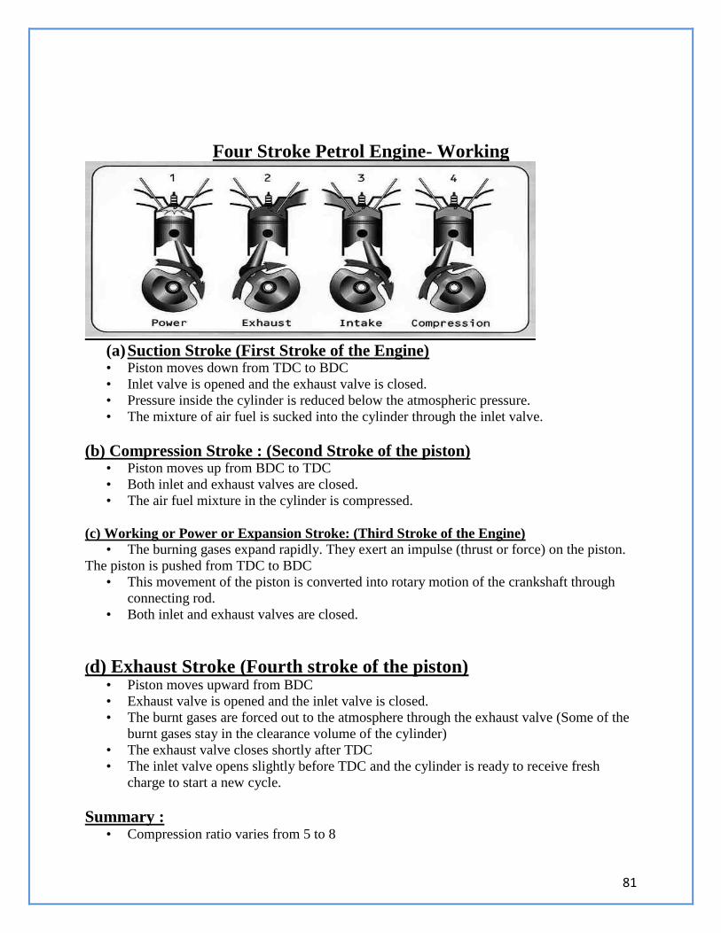
81
Four Stroke Petrol Engine- Working
(a) Suction Stroke (First Stroke of the Engine) • Piston moves down from TDC to BDC
• Inlet valve is opened and the exhaust valve is closed.
• Pressure inside the cylinder is reduced below the atmospheric pressure.
• The mixture of air fuel is sucked into the cylinder through the inlet valve.
(b) Compression Stroke : (Second Stroke of the piston) • Piston moves up from BDC to TDC
• Both inlet and exhaust valves are closed.
• The air fuel mixture in the cylinder is compressed.
(c) Working or Power or Expansion Stroke: (Third Stroke of the Engine) • The burning gases expand rapidly. They exert an impulse (thrust or force) on the piston.
The piston is pushed from TDC to BDC
• This movement of the piston is converted into rotary motion of the crankshaft through
connecting rod.
• Both inlet and exhaust valves are closed.
(d) Exhaust Stroke (Fourth stroke of the piston)
• Piston moves upward from BDC
• Exhaust valve is opened and the inlet valve is closed.
• The burnt gases are forced out to the atmosphere through the exhaust valve (Some of the
burnt gases stay in the clearance volume of the cylinder)
• The exhaust valve closes shortly after TDC
• The inlet valve opens slightly before TDC and the cylinder is ready to receive fresh
charge to start a new cycle.
Summary : • Compression ratio varies from 5 to 8
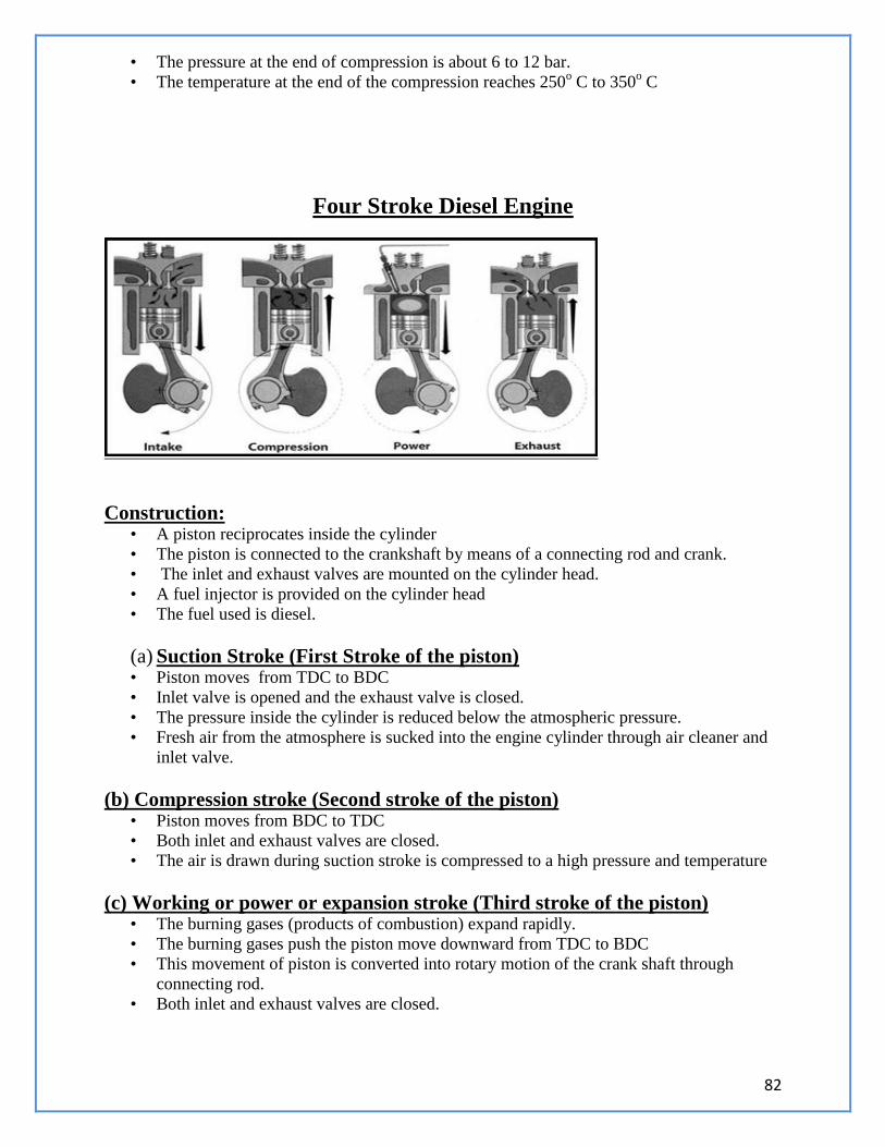
82
• The pressure at the end of compression is about 6 to 12 bar.
• The temperature at the end of the compression reaches 250o C to 350
o C
Four Stroke Diesel Engine
Construction: • A piston reciprocates inside the cylinder
• The piston is connected to the crankshaft by means of a connecting rod and crank.
• The inlet and exhaust valves are mounted on the cylinder head.
• A fuel injector is provided on the cylinder head
• The fuel used is diesel.
(a) Suction Stroke (First Stroke of the piston) • Piston moves from TDC to BDC
• Inlet valve is opened and the exhaust valve is closed.
• The pressure inside the cylinder is reduced below the atmospheric pressure.
• Fresh air from the atmosphere is sucked into the engine cylinder through air cleaner and
inlet valve.
(b) Compression stroke (Second stroke of the piston) • Piston moves from BDC to TDC
• Both inlet and exhaust valves are closed.
• The air is drawn during suction stroke is compressed to a high pressure and temperature
(c) Working or power or expansion stroke (Third stroke of the piston) • The burning gases (products of combustion) expand rapidly.
• The burning gases push the piston move downward from TDC to BDC
• This movement of piston is converted into rotary motion of the crank shaft through
connecting rod.
• Both inlet and exhaust valves are closed.
83
(d) Exhaust Stroke (Fourth stroke of the piston) • Piston moves from BDC to TDC
• Exhaust valve is opened the inlet valve is closed.
• The burnt gases are forced out to the atmosphere through the exhaust valve. (some of the
burnt gases stay in the clearance volume of the cylinder)
• The exhaust valve closes shortly after TDC
• The inlet valve opens slightly before TDC and the cylinder is ready to receive fresh air to
start a new cycle.
Scavenging
Scavenging : • It is the process of forcing out the burnt exhaust gases from the cylinder for admitting the
fresh charge into the cylinder.
• This action takes place in the two stroke cylinder.
Scavenging Process
• The charge (air fuel mixture or air) enters the engine cylinder from the crank
case at a pressure higher than the exhaust gases.
• This fresh charge forces the exhaust gases to the atmosphere through the
exhaust port.
• During the period both the transfer and exhaust ports are kept open for a
short period.
• Hence there is a possibility of the fresh charge escaping out with the burnt
gases.
• This is over come by designing the piston to have a deflected shape.
• This shape of piston deflects the fresh charge upward in the engine cylinder.
• It also helps out in forcing out the exhaust gases to atmosphere.
• This process is known as Scavenging.
Comparison between SI and CI Engines
(General Comparison):
S.
N
o.
Spark Ignition Engines (SI) Compression Ignition Engines (CI)
1 It draws air fuel mixture into the cylinder
during suction stroke
It draws only air into the cylinder during
suction stroke.
2 Petrol engines operate with low pressure
and temperature
Diesel engines operate with high pressure
and temperature
3. Pressure ranges from 6 to 12 bar
Temperature ranges from 250o
to 300o
C
Pressure ranges from 35 to 40 bar
Temperature ranges from 600o
to 700o
C
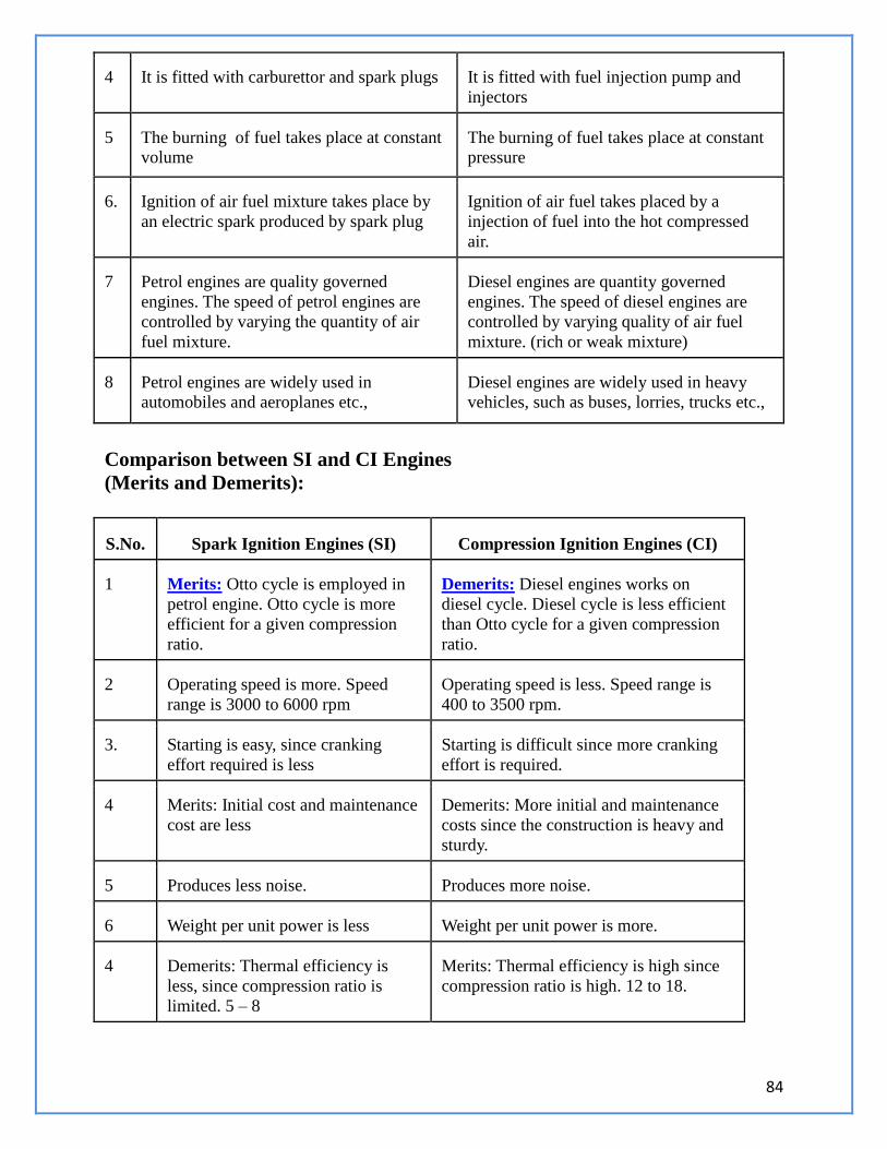
84
4 It is fitted with carburettor and spark plugs It is fitted with fuel injection pump and
injectors
5 The burning of fuel takes place at constant
volume
The burning of fuel takes place at constant
pressure
6. Ignition of air fuel mixture takes place by
an electric spark produced by spark plug
Ignition of air fuel takes placed by a
injection of fuel into the hot compressed
air.
7 Petrol engines are quality governed
engines. The speed of petrol engines are
controlled by varying the quantity of air
fuel mixture.
Diesel engines are quantity governed
engines. The speed of diesel engines are
controlled by varying quality of air fuel
mixture. (rich or weak mixture)
8 Petrol engines are widely used in
automobiles and aeroplanes etc.,
Diesel engines are widely used in heavy
vehicles, such as buses, lorries, trucks etc.,
Comparison between SI and CI Engines
(Merits and Demerits):
S.No. Spark Ignition Engines (SI) Compression Ignition Engines (CI)
1 Merits: Otto cycle is employed in
petrol engine. Otto cycle is more
efficient for a given compression
ratio.
Demerits: Diesel engines works on
diesel cycle. Diesel cycle is less efficient
than Otto cycle for a given compression
ratio.
2 Operating speed is more. Speed
range is 3000 to 6000 rpm
Operating speed is less. Speed range is
400 to 3500 rpm.
3. Starting is easy, since cranking
effort required is less
Starting is difficult since more cranking
effort is required.
4 Merits: Initial cost and maintenance
cost are less
Demerits: More initial and maintenance
costs since the construction is heavy and
sturdy.
5 Produces less noise. Produces more noise.
6 Weight per unit power is less Weight per unit power is more.
4 Demerits: Thermal efficiency is
less, since compression ratio is
limited. 5 – 8
Merits: Thermal efficiency is high since
compression ratio is high. 12 to 18.
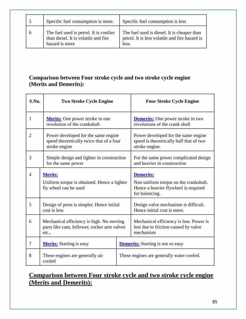
85
5 Specific fuel consumption is more. Specific fuel consumption is less
6 The fuel used is petrol. It is costlier
than diesel. It is volatile and fire
hazard is more
The fuel used is diesel. It is cheaper than
petrol. It is less volatile and fire hazard is
less.
Comparison between Four stroke cycle and two stroke cycle engine
(Merits and Demerits):
S.No. Two Stroke Cycle Engine Four Stroke Cycle Engine
1 Merits: One power stroke in one
revolution of the crankshaft
Demerits: One power stroke in two
revolutions of the crank shaft
2 Power developed for the same engine
speed theoretically twice that of a four
stroke engine
Power developed for the same engine
speed is theoretically half that of two
stroke engine.
3 Simple design and lighter in construction
for the same power
For the same power complicated design
and heavier in construction
4 Merits:
Uniform torque is obtained. Hence a lighter
fly wheel can be used
Demerits:
Non uniform torque on the crankshaft.
Hence a heavier flywheel is required
for balancing.
5 Design of ports is simpler. Hence initial
cost is less
Design valve mechanism is difficult.
Hence initial cost is more.
6 Mechanical efficiency is high. No moving
parts like cam, follower, rocker arm valves
etc.,
Mechanical efficiency is less. Power is
lost due to friction caused by valve
mechanism
7 Merits: Starting is easy Demerits: Starting is not so easy
8 These engines are generally air
cooled
These engines are generally water cooled.
Comparison between Four stroke cycle and two stroke cycle engine
(Merits and Demerits):
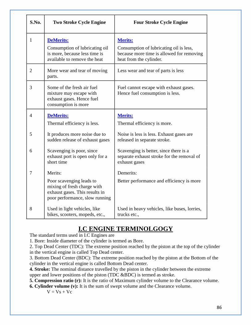
86
S.No. Two Stroke Cycle Engine Four Stroke Cycle Engine
1 DeMerits:
Consumption of lubricating oil
is more, because less time is
available to remove the heat
Merits:
Consumption of lubricating oil is less,
because more time is allowed for removing
heat from the cylinder.
2 More wear and tear of moving
parts.
Less wear and tear of parts is less
3 Some of the fresh air fuel
mixture may escape with
exhaust gases. Hence fuel
consumption is more
Fuel cannot escape with exhaust gases.
Hence fuel consumption is less.
4 DeMerits:
Thermal efficiency is less.
Merits:
Thermal efficiency is more.
5 It produces more noise due to
sudden release of exhaust gases
Noise is less is less. Exhaust gases are
released in separate stroke.
6 Scavenging is poor, since
exhaust port is open only for a
short time
Scavenging is better, since there is a
separate exhaust stroke for the removal of
exhaust gases
7 Merits:
Poor scavenging leads to
mixing of fresh charge with
exhaust gases. This results in
poor performance, slow running
Demerits:
Better performance and efficiency is more
8 Used in light vehicles, like
bikes, scooters, mopeds, etc.,
Used in heavy vehicles, like buses, lorries,
trucks etc.,
I.C ENGINE TERMINOLGOGY The standard terms used in I.C Engines are
1. Bore: Inside diameter of the cylinder is termed as Bore.
2. Top Dead Center (TDC): The extreme position reached by the piston at the top of the cylinder
in the vertical engine is called Top Dead center.
3. Bottom Dead Center (BDC): The extreme position reached by the piston at the Bottom of the
cylinder in the vertical engine is called Bottom Dead center.
4. Stroke: The nominal distance travelled by the piston in the cylinder between the extreme
upper and lower positions of the piston (TDC &BDC) is termed as stroke.
5. Compression ratio (r): It is the ratio of Maximum cylinder volume to the Clearance volume.
6. Cylinder volume (v): It is the sum of swept volume and the Clearance volume.
V = Vs + Vc
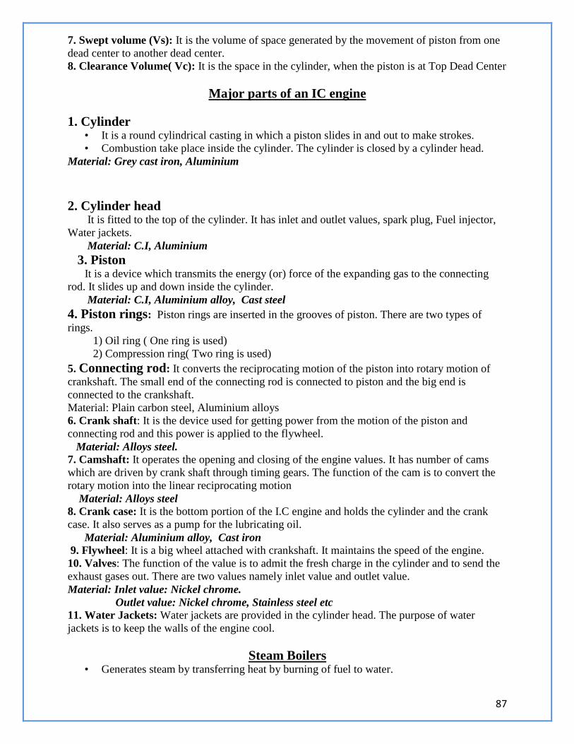
87
7. Swept volume (Vs): It is the volume of space generated by the movement of piston from one
dead center to another dead center.
8. Clearance Volume( Vc): It is the space in the cylinder, when the piston is at Top Dead Center
Major parts of an IC engine
1. Cylinder • It is a round cylindrical casting in which a piston slides in and out to make strokes.
• Combustion take place inside the cylinder. The cylinder is closed by a cylinder head.
Material: Grey cast iron, Aluminium
2. Cylinder head It is fitted to the top of the cylinder. It has inlet and outlet values, spark plug, Fuel injector,
Water jackets.
Material: C.I, Aluminium
3. Piston It is a device which transmits the energy (or) force of the expanding gas to the connecting
rod. It slides up and down inside the cylinder.
Material: C.I, Aluminium alloy, Cast steel
4. Piston rings: Piston rings are inserted in the grooves of piston. There are two types of
rings.
1) Oil ring ( One ring is used)
2) Compression ring( Two ring is used)
5. Connecting rod: It converts the reciprocating motion of the piston into rotary motion of
crankshaft. The small end of the connecting rod is connected to piston and the big end is
connected to the crankshaft.
Material: Plain carbon steel, Aluminium alloys
6. Crank shaft: It is the device used for getting power from the motion of the piston and
connecting rod and this power is applied to the flywheel.
Material: Alloys steel. 7. Camshaft: It operates the opening and closing of the engine values. It has number of cams
which are driven by crank shaft through timing gears. The function of the cam is to convert the
rotary motion into the linear reciprocating motion
Material: Alloys steel 8. Crank case: It is the bottom portion of the I.C engine and holds the cylinder and the crank
case. It also serves as a pump for the lubricating oil.
Material: Aluminium alloy, Cast iron 9. Flywheel: It is a big wheel attached with crankshaft. It maintains the speed of the engine.
10. Valves: The function of the value is to admit the fresh charge in the cylinder and to send the
exhaust gases out. There are two values namely inlet value and outlet value.
Material: Inlet value: Nickel chrome.
Outlet value: Nickel chrome, Stainless steel etc
11. Water Jackets: Water jackets are provided in the cylinder head. The purpose of water
jackets is to keep the walls of the engine cool.
Steam Boilers • Generates steam by transferring heat by burning of fuel to water.
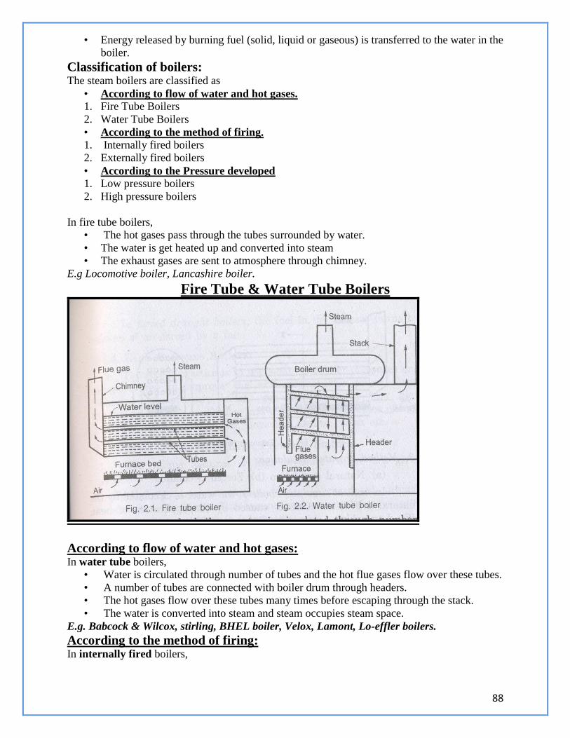
88
• Energy released by burning fuel (solid, liquid or gaseous) is transferred to the water in the
boiler.
Classification of boilers: The steam boilers are classified as
• According to flow of water and hot gases. 1. Fire Tube Boilers
2. Water Tube Boilers
• According to the method of firing. 1. Internally fired boilers
2. Externally fired boilers
• According to the Pressure developed 1. Low pressure boilers
2. High pressure boilers
In fire tube boilers,
• The hot gases pass through the tubes surrounded by water.
• The water is get heated up and converted into steam
• The exhaust gases are sent to atmosphere through chimney.
E.g Locomotive boiler, Lancashire boiler.
Fire Tube & Water Tube Boilers
According to flow of water and hot gases:
In water tube boilers,
• Water is circulated through number of tubes and the hot flue gases flow over these tubes.
• A number of tubes are connected with boiler drum through headers.
• The hot gases flow over these tubes many times before escaping through the stack.
• The water is converted into steam and steam occupies steam space.
E.g. Babcock & Wilcox, stirling, BHEL boiler, Velox, Lamont, Lo-effler boilers.
According to the method of firing: In internally fired boilers,
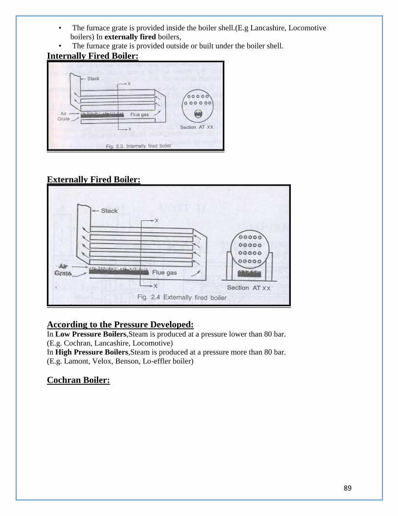
89
• The furnace grate is provided inside the boiler shell.(E.g Lancashire, Locomotive
boilers) In externally fired boilers,
• The furnace grate is provided outside or built under the boiler shell.
Internally Fired Boiler:
Externally Fired Boiler:
According to the Pressure Developed: In Low Pressure Boilers,Steam is produced at a pressure lower than 80 bar.
(E.g. Cochran, Lancashire, Locomotive)
In High Pressure Boilers,Steam is produced at a pressure more than 80 bar.
(E.g. Lamont, Velox, Benson, Lo-effler boiler)
Cochran Boiler:
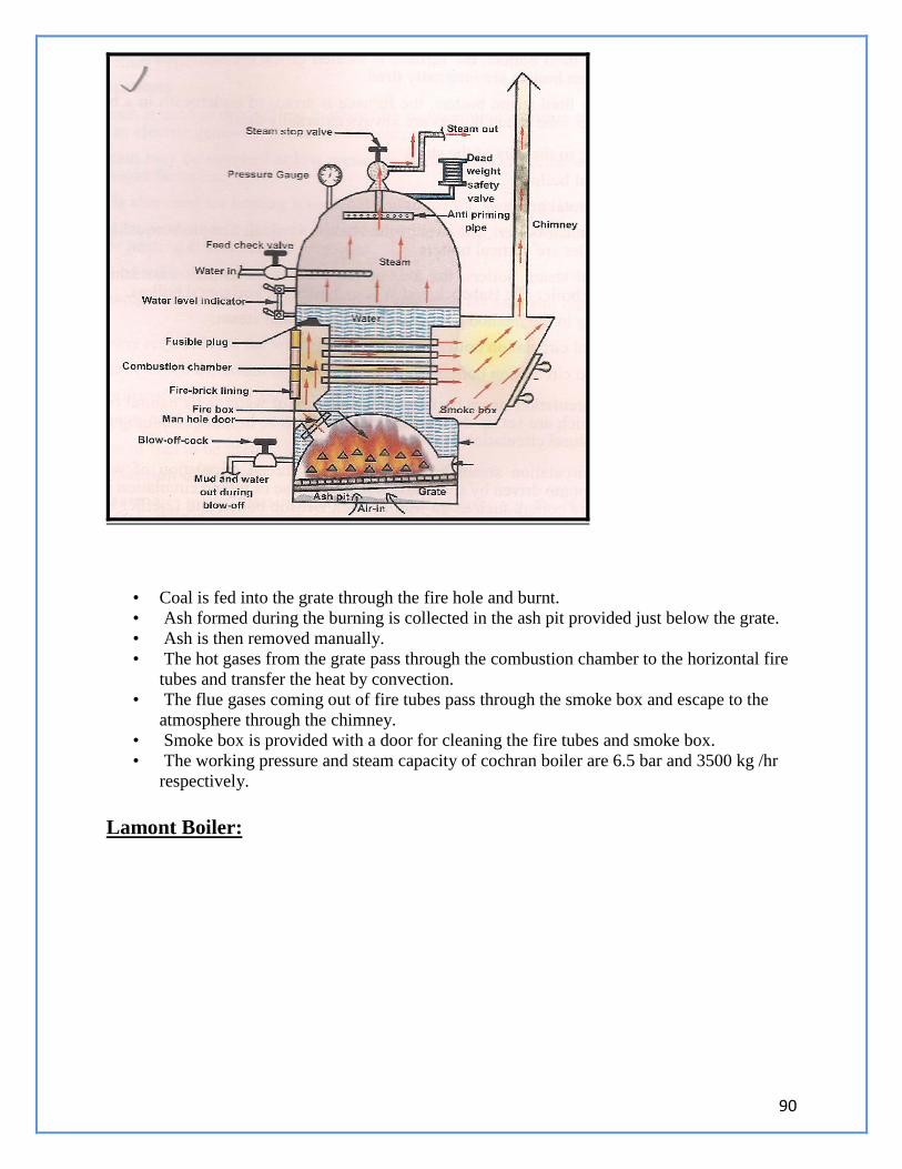
90
• Coal is fed into the grate through the fire hole and burnt.
• Ash formed during the burning is collected in the ash pit provided just below the grate.
• Ash is then removed manually.
• The hot gases from the grate pass through the combustion chamber to the horizontal fire
tubes and transfer the heat by convection.
• The flue gases coming out of fire tubes pass through the smoke box and escape to the
atmosphere through the chimney.
• Smoke box is provided with a door for cleaning the fire tubes and smoke box.
• The working pressure and steam capacity of cochran boiler are 6.5 bar and 3500 kg /hr
respectively.
Lamont Boiler:
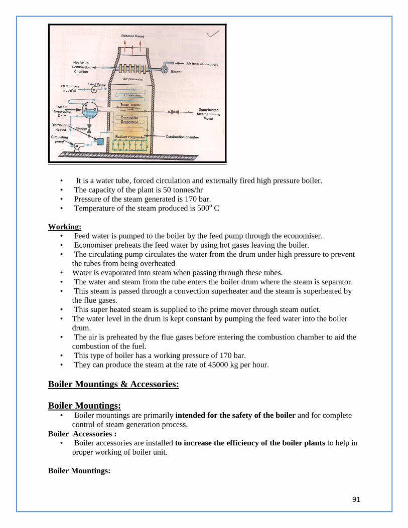
91
• It is a water tube, forced circulation and externally fired high pressure boiler.
• The capacity of the plant is 50 tonnes/hr
• Pressure of the steam generated is 170 bar.
• Temperature of the steam produced is 500o C
Working: • Feed water is pumped to the boiler by the feed pump through the economiser.
• Economiser preheats the feed water by using hot gases leaving the boiler.
• The circulating pump circulates the water from the drum under high pressure to prevent
the tubes from being overheated
• Water is evaporated into steam when passing through these tubes.
• The water and steam from the tube enters the boiler drum where the steam is separator.
• This steam is passed through a convection superheater and the steam is superheated by
the flue gases.
• This super heated steam is supplied to the prime mover through steam outlet.
• The water level in the drum is kept constant by pumping the feed water into the boiler
drum.
• The air is preheated by the flue gases before entering the combustion chamber to aid the
combustion of the fuel.
• This type of boiler has a working pressure of 170 bar.
• They can produce the steam at the rate of 45000 kg per hour.
Boiler Mountings & Accessories:
Boiler Mountings: • Boiler mountings are primarily intended for the safety of the boiler and for complete
control of steam generation process.
Boiler Accessories : • Boiler accessories are installed to increase the efficiency of the boiler plants to help in
proper working of boiler unit.
Boiler Mountings:
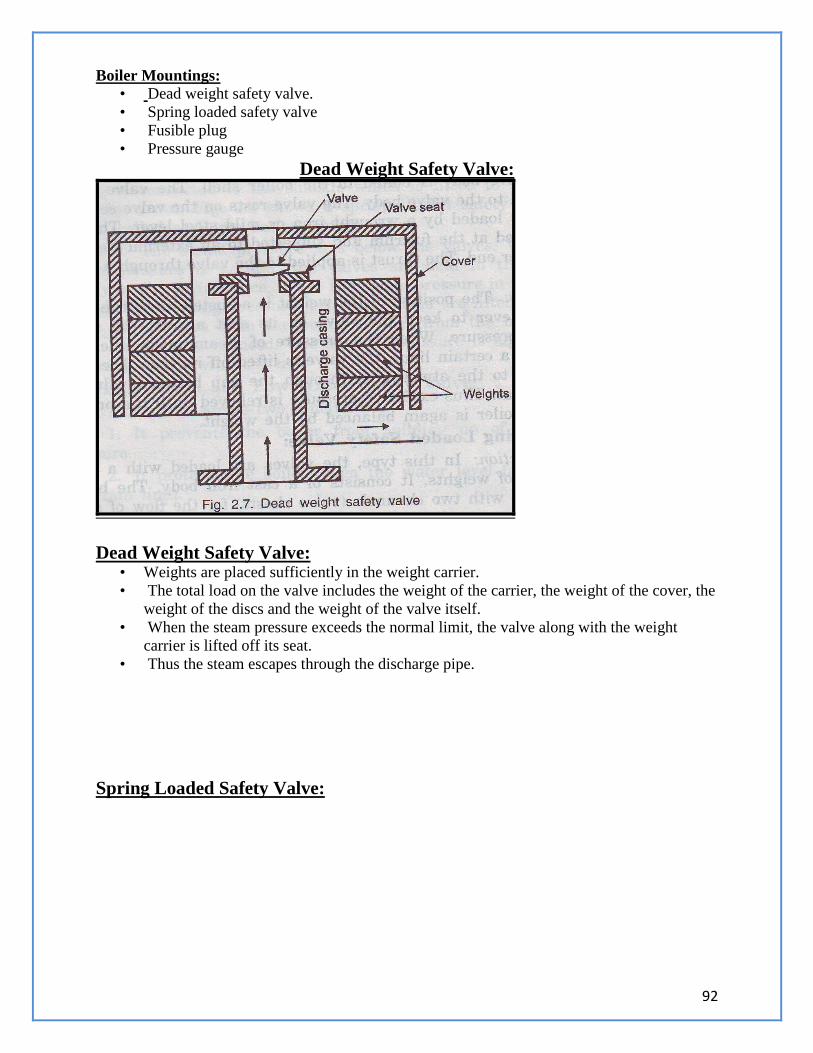
92
Boiler Mountings: • Dead weight safety valve.
• Spring loaded safety valve
• Fusible plug
• Pressure gauge
Dead Weight Safety Valve:
Dead Weight Safety Valve: • Weights are placed sufficiently in the weight carrier.
• The total load on the valve includes the weight of the carrier, the weight of the cover, the
weight of the discs and the weight of the valve itself.
• When the steam pressure exceeds the normal limit, the valve along with the weight
carrier is lifted off its seat.
• Thus the steam escapes through the discharge pipe.
Spring Loaded Safety Valve:
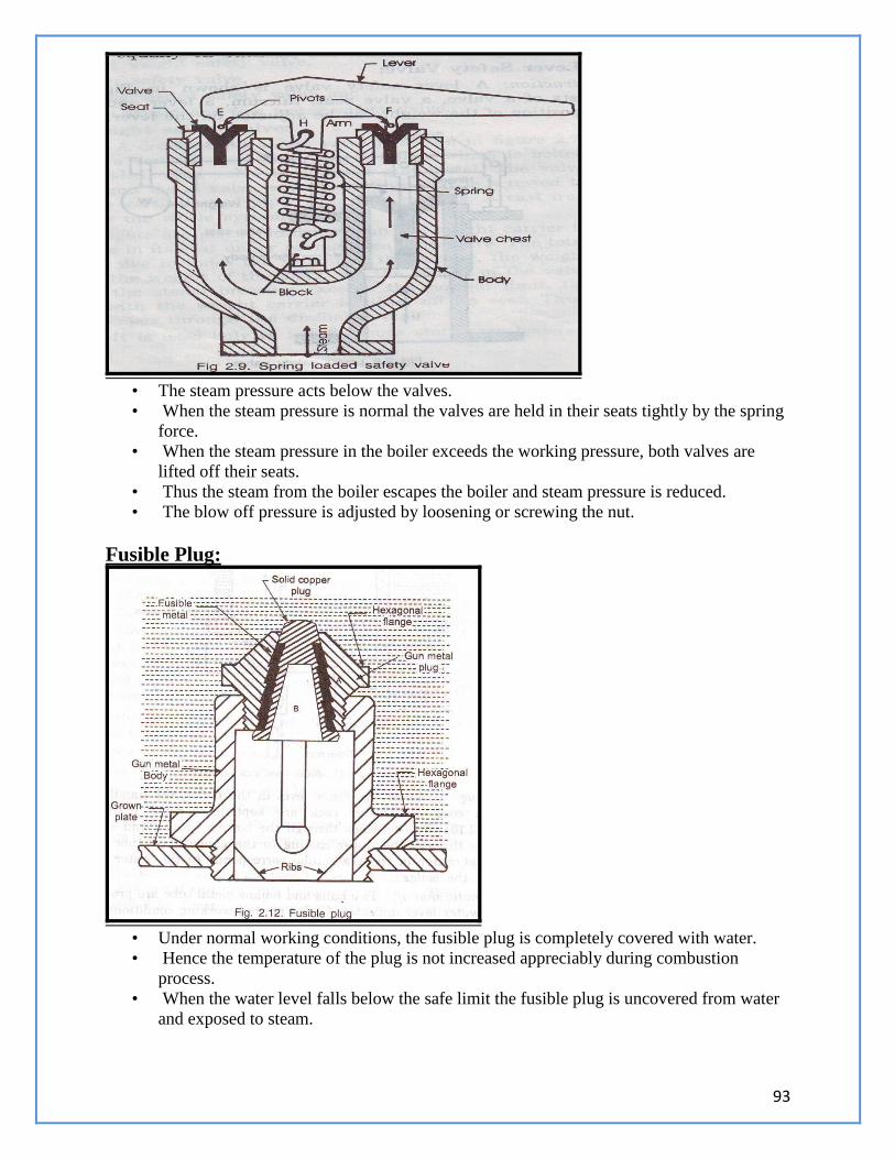
93
• The steam pressure acts below the valves.
• When the steam pressure is normal the valves are held in their seats tightly by the spring
force.
• When the steam pressure in the boiler exceeds the working pressure, both valves are
lifted off their seats.
• Thus the steam from the boiler escapes the boiler and steam pressure is reduced.
• The blow off pressure is adjusted by loosening or screwing the nut.
Fusible Plug:
• Under normal working conditions, the fusible plug is completely covered with water.
• Hence the temperature of the plug is not increased appreciably during combustion
process.
• When the water level falls below the safe limit the fusible plug is uncovered from water
and exposed to steam.
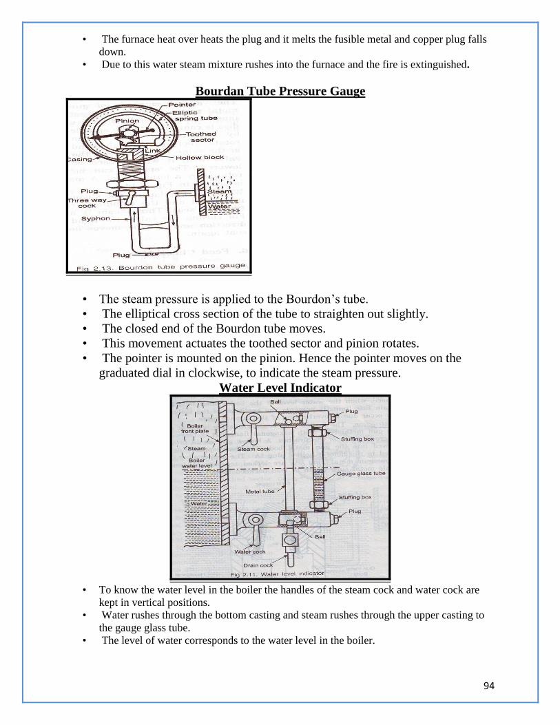
94
• The furnace heat over heats the plug and it melts the fusible metal and copper plug falls
down.
• Due to this water steam mixture rushes into the furnace and the fire is extinguished.
Bourdan Tube Pressure Gauge
• The steam pressure is applied to the Bourdon’s tube.
• The elliptical cross section of the tube to straighten out slightly.
• The closed end of the Bourdon tube moves.
• This movement actuates the toothed sector and pinion rotates.
• The pointer is mounted on the pinion. Hence the pointer moves on the
graduated dial in clockwise, to indicate the steam pressure.
Water Level Indicator
• To know the water level in the boiler the handles of the steam cock and water cock are
kept in vertical positions.
• Water rushes through the bottom casting and steam rushes through the upper casting to
the gauge glass tube.
• The level of water corresponds to the water level in the boiler.
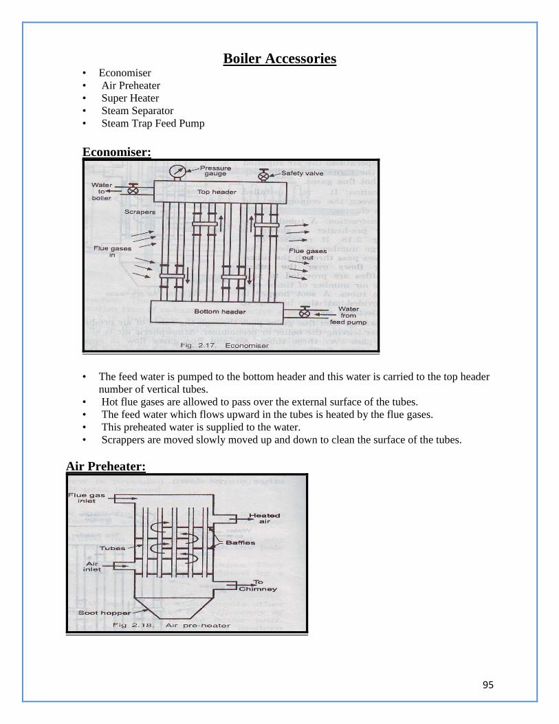
95
Boiler Accessories • Economiser
• Air Preheater
• Super Heater
• Steam Separator
• Steam Trap Feed Pump
Economiser:
• The feed water is pumped to the bottom header and this water is carried to the top header
number of vertical tubes.
• Hot flue gases are allowed to pass over the external surface of the tubes.
• The feed water which flows upward in the tubes is heated by the flue gases.
• This preheated water is supplied to the water.
• Scrappers are moved slowly moved up and down to clean the surface of the tubes.
Air Preheater:
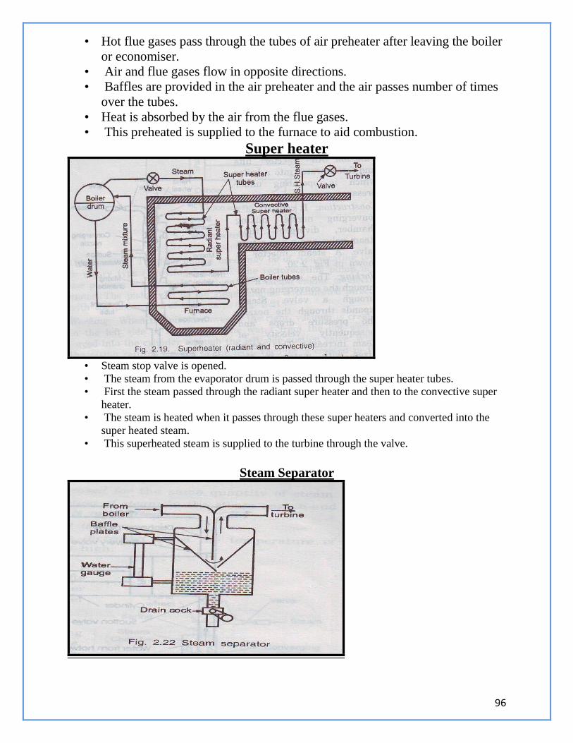
96
• Hot flue gases pass through the tubes of air preheater after leaving the boiler
or economiser.
• Air and flue gases flow in opposite directions.
• Baffles are provided in the air preheater and the air passes number of times
over the tubes.
• Heat is absorbed by the air from the flue gases.
• This preheated is supplied to the furnace to aid combustion.
Super heater
• Steam stop valve is opened.
• The steam from the evaporator drum is passed through the super heater tubes.
• First the steam passed through the radiant super heater and then to the convective super
heater.
• The steam is heated when it passes through these super heaters and converted into the
super heated steam.
• This superheated steam is supplied to the turbine through the valve.
Steam Separator
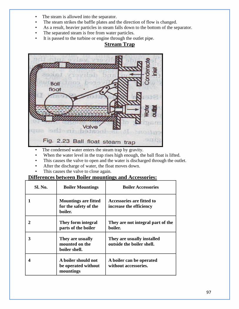
97
• The steam is allowed into the separator.
• The steam strikes the baffle plates and the direction of flow is changed.
• As a result, heavier particles in steam falls down to the bottom of the separator.
• The separated steam is free from water particles.
• It is passed to the turbine or engine through the outlet pipe.
Stream Trap
• The condensed water enters the steam trap by gravity.
• When the water level in the trap rises high enough, the ball float is lifted.
• This causes the valve to open and the water is discharged through the outlet.
• After the discharge of water, the float moves down.
• This causes the valve to close again.
Differences between Boiler mountings and Accessories:
Sl. No. Boiler Mountings Boiler Accessories
1 Mountings are fitted
for the safety of the
boiler.
Accessories are fitted to
increase the efficiency
2 They form integral
parts of the boiler
They are not integral part of the
boiler.
3 They are usually
mounted on the
boiler shell.
They are usually installed
outside the boiler shell.
4 A boiler should not
be operated without
mountings
A boiler can be operated
without accessories.
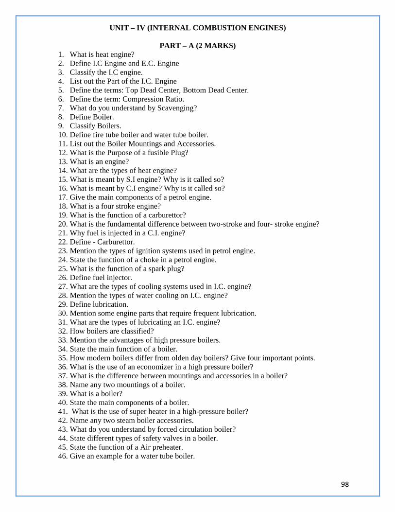
98
UNIT – IV (INTERNAL COMBUSTION ENGINES)
PART – A (2 MARKS)
1. What is heat engine?
2. Define I.C Engine and E.C. Engine
3. Classify the I.C engine.
4. List out the Part of the I.C. Engine
5. Define the terms: Top Dead Center, Bottom Dead Center.
6. Define the term: Compression Ratio.
7. What do you understand by Scavenging?
8. Define Boiler.
9. Classify Boilers.
10. Define fire tube boiler and water tube boiler.
11. List out the Boiler Mountings and Accessories.
12. What is the Purpose of a fusible Plug?
13. What is an engine?
14. What are the types of heat engine?
15. What is meant by S.I engine? Why is it called so?
16. What is meant by C.I engine? Why is it called so?
17. Give the main components of a petrol engine.
18. What is a four stroke engine?
19. What is the function of a carburettor?
20. What is the fundamental difference between two-stroke and four- stroke engine?
21. Why fuel is injected in a C.I. engine?
22. Define - Carburettor.
23. Mention the types of ignition systems used in petrol engine.
24. State the function of a choke in a petrol engine.
25. What is the function of a spark plug?
26. Define fuel injector.
27. What are the types of cooling systems used in I.C. engine?
28. Mention the types of water cooling on I.C. engine?
29. Define lubrication.
30. Mention some engine parts that require frequent lubrication.
31. What are the types of lubricating an I.C. engine?
32. How boilers are classified?
33. Mention the advantages of high pressure boilers.
34. State the main function of a boiler.
35. How modern boilers differ from olden day boilers? Give four important points.
36. What is the use of an economizer in a high pressure boiler?
37. What is the difference between mountings and accessories in a boiler?
38. Name any two mountings of a boiler.
39. What is a boiler?
40. State the main components of a boiler.
41. What is the use of super heater in a high-pressure boiler?
42. Name any two steam boiler accessories.
43. What do you understand by forced circulation boiler?
44. State different types of safety valves in a boiler.
45. State the function of a Air preheater.
46. Give an example for a water tube boiler.
99
47. Define the terms: External Combustion Engine and Internal Combustion engine.
48. Define compression ratio of an I.C. engine.
49. What is the function of deflector in a two stroke engine?
50. What is the function of a choke in a carburettor?
51. What is meant by carburetion?
52. What is the function of the float, float chamber and needle valve assembly in a single jet
carburettor?
53. State any two limitations of a single jet carburettor.
54. How do you provide an extra-rich mixture to the petrol engine during starting in cold
weather?
55. Name the three ports provided at the cylinder walls in a two stroke engine function.
56. Why is diesel engine called as compression ignition engine?
57. How do the three ports in a two stroke engine function?
58. What is the function of a spark plug?
59. State any two advantages of LPG as SI engine fuel.
PART – B (10 MARKS)
1. Describe the principal parts and functions of a Four Stroke Diesel engine with neat
sketch.
2. What is heat engine? How do you classify heat engines?
3. What do you understand by scavenging?
4. Compare and contrast four stroke engines with two stroke engines?
5. Discuss briefly the ignition system of SI engine.
6. Explain the working principle of spark plug with a neat diagram.
7. Sketch and explain the working of a Diesel fuel pump.
8. Explain the working principle of Diesel engine power plant with neat sketch. Also give
its advantages and disadvantages.
9. Describe the principal parts and functions of a Four Stroke Petrol engine with neat
sketch.
10. Describe the principal parts and functions of a Two Stroke Diesel engine with neat
sketch.
11. Describe the principal parts and functions of a Two Stroke Petrol engine with neat sketch.
12. Describe the principal parts and functions of any one high pressure boiler with neat
sketch.
13. Describe the principal parts and functions of Babcock Wilcox boiler with neat sketch.
Explain the construction and working principle of Cochran Boiler
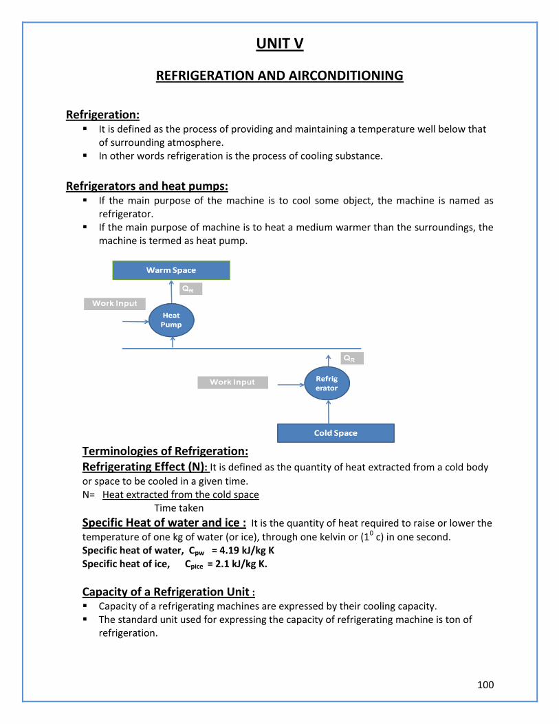
100
UNIT V
REFRIGERATION AND AIRCONDITIONING
Refrigeration: It is defined as the process of providing and maintaining a temperature well below that
of surrounding atmosphere. In other words refrigeration is the process of cooling substance.
Refrigerators and heat pumps: If the main purpose of the machine is to cool some object, the machine is named as
refrigerator. If the main purpose of machine is to heat a medium warmer than the surroundings, the
machine is termed as heat pump.
Terminologies of Refrigeration: Refrigerating Effect (N): It is defined as the quantity of heat extracted from a cold body
or space to be cooled in a given time. N= Heat extracted from the cold space Time taken
Specific Heat of water and ice : It is the quantity of heat required to raise or lower the
temperature of one kg of water (or ice), through one kelvin or (10 c) in one second. Specific heat of water, Cpw
= 4.19 kJ/kg K Specific heat of ice, Cpice
= 2.1 kJ/kg K.
Capacity of a Refrigeration Unit :
Capacity of a refrigerating machines are expressed by their cooling capacity. The standard unit used for expressing the capacity of refrigerating machine is ton of
refrigeration.
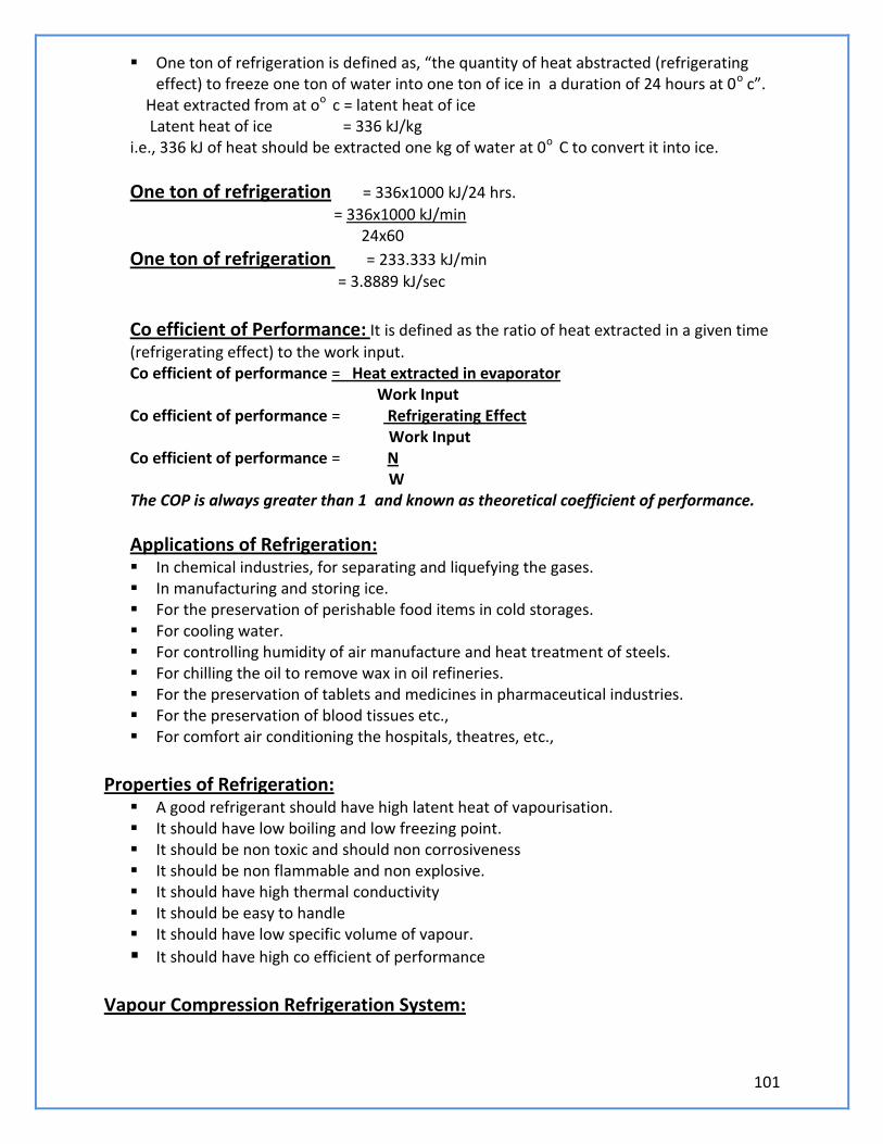
101
One ton of refrigeration is defined as, “the quantity of heat abstracted (refrigerating effect) to freeze one ton of water into one ton of ice in a duration of 24 hours at 0o c”.
Heat extracted from at oo c = latent heat of ice Latent heat of ice = 336 kJ/kg i.e., 336 kJ of heat should be extracted one kg of water at 0o C to convert it into ice.
One ton of refrigeration = 336x1000 kJ/24 hrs.
= 336x1000 kJ/min 24x60
One ton of refrigeration = 233.333 kJ/min
= 3.8889 kJ/sec
Co efficient of Performance: It is defined as the ratio of heat extracted in a given time
(refrigerating effect) to the work input. Co efficient of performance = Heat extracted in evaporator Work Input Co efficient of performance = Refrigerating Effect Work Input Co efficient of performance = N W The COP is always greater than 1 and known as theoretical coefficient of performance.
Applications of Refrigeration: In chemical industries, for separating and liquefying the gases. In manufacturing and storing ice. For the preservation of perishable food items in cold storages. For cooling water. For controlling humidity of air manufacture and heat treatment of steels. For chilling the oil to remove wax in oil refineries. For the preservation of tablets and medicines in pharmaceutical industries. For the preservation of blood tissues etc., For comfort air conditioning the hospitals, theatres, etc.,
Properties of Refrigeration: A good refrigerant should have high latent heat of vapourisation. It should have low boiling and low freezing point. It should be non toxic and should non corrosiveness It should be non flammable and non explosive. It should have high thermal conductivity It should be easy to handle It should have low specific volume of vapour.
It should have high co efficient of performance Vapour Compression Refrigeration System:
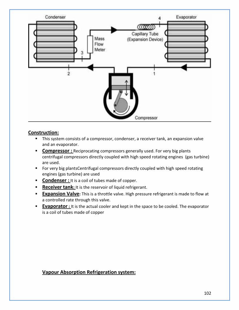
102
Construction: This system consists of a compressor, condenser, a receiver tank, an expansion valve
and an evaporator.
Compressor : Reciprocating compressors generally used. For very big plants
centrifugal compressors directly coupled with high speed rotating engines (gas turbine) are used.
For very big plantsCentrifugal compressors directly coupled with high speed rotating engines (gas turbine) are used
Condenser : It is a coil of tubes made of copper.
Receiver tank: It is the reservoir of liquid refrigerant.
Expansion Valve: This is a throttle valve. High pressure refrigerant is made to flow at
a controlled rate through this valve.
Evaporator : It is the actual cooler and kept in the space to be cooled. The evaporator
is a coil of tubes made of copper
Vapour Absorption Refrigeration system:
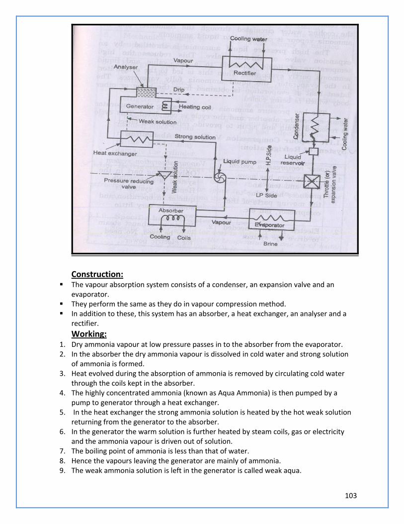
103
Construction:
The vapour absorption system consists of a condenser, an expansion valve and an evaporator.
They perform the same as they do in vapour compression method. In addition to these, this system has an absorber, a heat exchanger, an analyser and a
rectifier.
Working: 1. Dry ammonia vapour at low pressure passes in to the absorber from the evaporator. 2. In the absorber the dry ammonia vapour is dissolved in cold water and strong solution
of ammonia is formed. 3. Heat evolved during the absorption of ammonia is removed by circulating cold water
through the coils kept in the absorber. 4. The highly concentrated ammonia (known as Aqua Ammonia) is then pumped by a
pump to generator through a heat exchanger. 5. In the heat exchanger the strong ammonia solution is heated by the hot weak solution
returning from the generator to the absorber. 6. In the generator the warm solution is further heated by steam coils, gas or electricity
and the ammonia vapour is driven out of solution. 7. The boiling point of ammonia is less than that of water. 8. Hence the vapours leaving the generator are mainly of ammonia. 9. The weak ammonia solution is left in the generator is called weak aqua.
104
10. This weak solution is returned to the absorber through the heat exchanger. 11. Ammonia vapours leaving the generator may contain some water vapour. 12. If this water vapour is allowed to the condenser and expansion valve, it may freeze
resulting in chocked flow. 13. Analyser and rectifiers are incorporated in the system before condenser. 14. The ammonia vapour from the generator passes through a series of trays in the
analyser and ammonia is separated from water vapour. 15. The separated water vapour returned to generator. 16. Then the ammonia vapour passes through a rectifier. 17. The rectifier resembles a condenser and water vapour still present in ammonia vapour
condenses and the condensate is returned to analyser. 18. The virtually pure ammonia vapour then passes through the condenser. 19. The latent heat of ammonia vapour is rejected to the cooling water circulated through
the condenser and the ammonia vapour is condensed to liquid ammonia. 20. The high pressure liquid ammonia is throttled by an expansion valve or throttle valve. 21. This reduces the high temperature of the liquid ammonia to a low value and liquid
ammonia partly evaporates. 22. Then this is led to the evaporator. 23. In the evaporator the liquid fully vaporizes. 24. The latent heat of evaporation is obtained from the brine or other body which is being
cooled. 25. The low pressure ammonia vapour leaving the evaporator again enters the absorber
and the cycle is completed. 26. This cycle is repeated again to provide the refrigerating effect.
Applications of refrigeration system: Preservation of food items like vegetables, milk and eggs. Preservation of medicines. Preservation of blood, tissues, etc., Preservation and cooling of cool drinks. Preservation of chemicals (Chemical industries) Cooling of water. Industrial and comfort airconditioning. Processing of dairy products.
Comparison between Vapour compression & Vapour Absorption refrigeration systems:
S.No. Vapour Compression System Vapour Absorption System
1 This system has more wear and tear and produces more noise
Only moving part in this system is an aqua pump. Hence the quieter in
105
due to the moving parts of the compressor.
operation and less wear and tear
2. Electric power is needed to drive the system
Waste of exhaust steam may be used. No need of electric power
3. Capacity of the system drops rapidly with lowered evaporator pressure
Capacity of the system decreases with the lowered evaporative pressure, by increasing the steam pressure in generator.
4. At partial loads performance is poor.
At partial loads performance is not affected.
5. Mechanical energy is supplied through compressor
Heat energy is utilised
6. Energy supplied is ¼ to ½ of the refrigerating effect
Energy supplied is about one and half times the refrigerating effect
7. Charging of the refrigerating to the system is easy
Charging of refrigerant is difficult
8. Preventive measure is needed, since liquid refrigerant accumulated in the cylinder may damage to the cylinder
Liquid refrigerant has no bad effect on the system.
AIR CONDITIONING: Air Conditioning is the process of conditioning the air according to the human comfort, irrespective of external conditions.
Applications of Air Conditioning
Used in offices, hotels, buses, cars.,etc Used in industries having tool room machines. Used in textile industries to control moisture. Used in printing press. Used in Food industries, Chemical plants.
CLASSIFICATION OF AIR CONDITIONING: Air conditioning systems are classified as 1) According to the purpose
106
a) Comfort Air conditioning. b) Industrial Air conditioning. 2) According to Season of the year a) Summer Air conditioning. b) Winter Air conditioning. c) Year round Air conditioning. Types of Air conditioners a) Room Air conditioners b) Winter Air conditioners c) Central Air conditioners Functions of Air conditioners a) Cleaning air. b) Controlling the temp of air. c) Controlling the moisture content. d) Circulating the air.
BASIC CONCEPTS:
1) Dry air: The atmospheric air which no water vapour is called dry air. 2) Psychometry: Psychometry is the study of the properties of atmospheric air. 3) Temperature: The degree of hotness (or) Coldness is called the temperature. 4) Moisture: Moisture is the water vapour present in the air. 5) Relative humidity: Relative humidity is the ratio of actual mass of water vapour in a given volume to the mass of water vapour. 6) Dry bulb temperature: The temperature of air measured by the ordinary thermometer is called dry bulb temperature: 7) Wet bulb Temperature: The temperature of air measured by the thermometer when it is covered by the wet cloth is known as wet bulb Temperature. 8) Dew point Temperature: The temperature at which the water vapour starts condensing is called dew point Temperature
Window Type Air Conditioner:
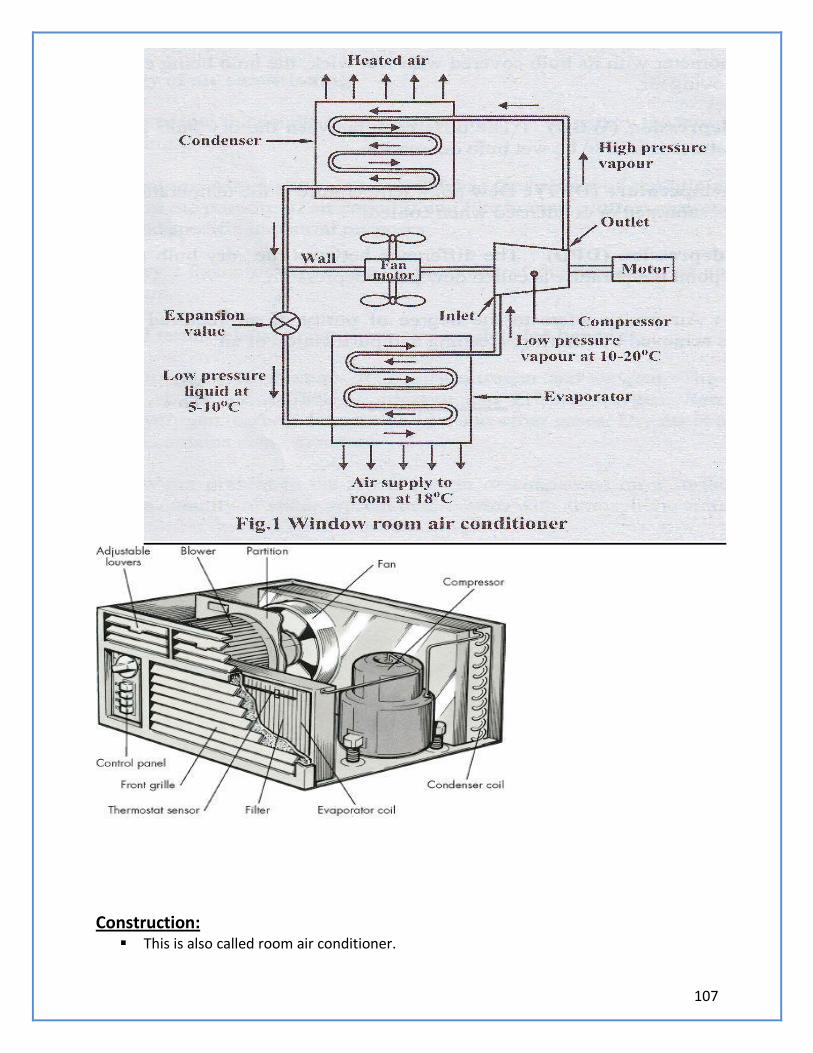
107
Construction: This is also called room air conditioner.
108
This unit consists of the following. 1. A cooling system to cool and dehumidify the air involves a condenser, a compressor and
a refrigerant coil. 2. A filter to any impurities in the air. The filter is made of mesh, glass wool or fibre. 3. A fan and adjustable grills to circulate the air. 4. Controls to regulate the equipment operation. 5. The low pressure refrigerant vapour is drawn from the evaporator to the hermetic
compressor through suction pipe. 6. It is compressed from low pressure to the high pressure and supplied to the condenser. 7. It is condensed in the condenser by passing the outdoor air over the condenser coil by a
fan. 8. The liquid refrigerant is passed through the capillary into the evaporator. 9. . In the evaporator the liquid refrigerant picks up the heat from the refrigerator surface
and gets vaporized. 10. A motor driven fan draws air from the room through the air filter and this air is cooled
by losing its heat to the low temperature refrigerant and cold air is circulated back into the room.
11. The vapour refrigerant from the evaporator goes to the compressor from evaporator and the cycle is repeated.
12. Thus the room is air conditioned 13. . The quantity of air circulated can be controlled by the dampers. 14. The moisture in the air passing over the evaporator coil is dehumidified and drips into
the trays. 15. This water evaporator to certain extent and thus helps in cooling the compressor and
condenser. 16. The unit automatically stops when the required temperature is reached in the room.
This is accomplished by the thermostat and control panel.
Merits and Demerits of Window type air conditioner:
Merits : A separate temperature control is provided in each room. Ducts are not required for distribution. Cost is less. Skilled technician is required for installation.
Demerits: It makes noise.
Large hole is made in the external wall or a large opening to be created in the window
panel. This leads to insecurity to inmates. Split Type Air Conditioner - Layout:
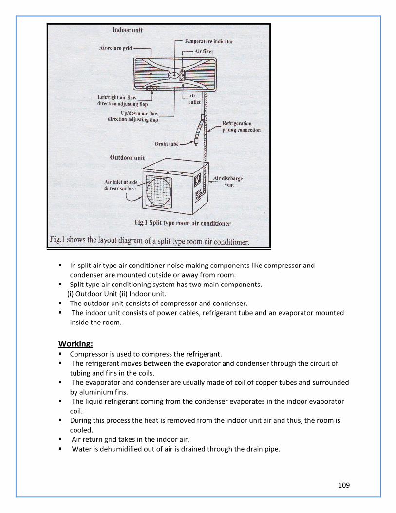
109
In split air type air conditioner noise making components like compressor and
condenser are mounted outside or away from room. Split type air conditioning system has two main components. (i) Outdoor Unit (ii) Indoor unit. The outdoor unit consists of compressor and condenser. The indoor unit consists of power cables, refrigerant tube and an evaporator mounted
inside the room.
Working: Compressor is used to compress the refrigerant. The refrigerant moves between the evaporator and condenser through the circuit of
tubing and fins in the coils. The evaporator and condenser are usually made of coil of copper tubes and surrounded
by aluminium fins. The liquid refrigerant coming from the condenser evaporates in the indoor evaporator
coil. During this process the heat is removed from the indoor unit air and thus, the room is
cooled. Air return grid takes in the indoor air. Water is dehumidified out of air is drained through the drain pipe.
110
The hot refrigerant vapour is passed to the compressor and then to the condenser where it becomes liquid.
Thus the cycle is repeated. A thermostat is used to keep the room at a constant, comfortable temperature avoiding
the frequent turning on off.
Merits and Demerits of Split type air conditioner: Merits : It is compact Upto four indoor AHU’s may be connected to one outdoor unit. It is energy and money saving. Duct is not used. Easier to install. It is noiseless, because rotary air compressor used is, kept outside. It is more efficient and powerful. It has the flexibility for zoning.
DeMerits : Initial cost is higher than window air conditioner Skilled technician is required for installation. Each zone or room requires thermostat to control the air cooling.
Applications of air conditioning:
Used in houses, hospitals, offices, computer centres, theatres, departmental stores etc., Air-conditioning of transport media such as buses, cars trains, aeroplanes and ships. Wide application in food processing, printing, chemical, pharmaceutical and machine
tool, etc.,
111
UNIT – V (REFRIGERATION AND AIR CONDITIONING SYSTEM)
PART – A (2 MARKS)
1. Define Refrigeration.
2. Mention the ways of achieving refrigeration effect.
3. Mention some of the applications of refrigeration
4. Define the term refrigeration effect.
5. What is the meaning of “one tonne of refrigeration”?
6. How the capacity of the refrigeration system specified?
7. Define the term “Coefficient of performance”?
8. Classify the refrigerating system.
9. What is the function of compressor in refrigerating system?
10. What is the function of condenser in refrigerating system?
11. What is Evaporator?
12. Mention any three desirable properties of good refrigerant.
13. List the properties of absorbent.
14. What is the function of the Absorber in Vapour – Absorption refrigerator?
15. Mention the advantages of Absorption refrigeration system over compression
refrigeration system.
16. What are primary refrigerants?
17. List some important refrigerants.
18. Why Ammonia is preferred in absorption system?
19. What is the technical name of Freon-12?
20. What are the properties of Freon-12?
21. Write short notes on compressors.
22. What are the types of compressors?
23. Define C.O.P.
24. Define refrigerant. Give some examples of refrigerant.
25. Give some properties of good refrigerant.
26. Mention the types of refrigerators.
27. Give some properties of a good refrigerant.
28. State the function of a compressor.
29. Define relative humidity
30. Define psychrometry.
31. What is dry air?
32. What is moist air?
33. Define the term absolute humidity.
34. Define the term Dry bulb temperature.
35. Define the term Wet bulb temperature.
36. What is called Wet bulb depression?
37. Define the term Dew point temperature.
38. What is the use of Psychrometric chart?
39. Define DBT and WBT.
40. Define humidity.
41. Define air conditioning.
42. What are the control systems used in domestic refrigerators?
43. Mention the classification of air conditioning system.
44. Define year–round air conditioning system.
45. What is the function of thermostat?
112
46. What is called defrosting?
47. Mention the loads encountered in air conditioning systems.
48. What is window air conditioner?
49. What are the limitations of Window air conditioners?
50. What are the requirements of comfort air conditioning?
PART – B (10 MARKS)
1. Explain the principle and working of vapour compression refrigeration system.
2. Explain the principle and working of the vapour absorption refrigeration system.
3. Give the comparison of vapour absorption with vapour compression refrigeration system.
4. How do you classify the air conditioning system?
5. Explain the summer air-conditioning system for hot and dry weather.
6. With the neat sketch explain the layout of a window room air conditioning.
7. Explain the layout of the split type air conditioning system.
8. Mention and explain the different types of refrigerant used.
9. Explain the advantages and disadvantages of the window air conditioning unit.
10. State the principle of air conditioning. What are the parameters required for the human
comfort in air conditioning?
11. Discuss the advantages and disadvantages of split type room air conditioner.
113
UNIVERSTITY QUESTION
B.E/B.TECH DEGREE EXAMINATION,JUNE 2010
SECOND SEMESTER-II
GE1251-BASIC CIVIL AND MECHANICAL ENGINEERING
(REGULATION 2008)
PART A( 10X2=20 MARKS )
1. State the principles of surveying?
2. How are bricks classified?.
3. Define bering capacity of soil.
4. Define stress and strain.
5. What is the use of surge tank in hydro power plants?
6. Give two examples for positive displacement pumps.
7. What is the function of carburetor?
8. Compare two stroke and four stroke engines with regard to power output and thermal
efficiency, for the same speed and cylinder capacity.
9. Define ton of refrigeration.
10. State the values of DBT and RH for human comfort in India.
PART B-(5 X 16=80)
11.i. The following perpendicular offsets were taken at 10m intervals from a survey line to n
irregular boundary line: 3.15m,4.30m,8.20m,6.85m,7.60m,4.20m,5.60m,4.30m.Calculate the
area enclosed Between the survey line ,irregular boundary line, first and last offsets by
trapezoidal rule.(OR)
12. What are the different types of cement? Explain their properties properties and uses.
13. Describe with neat sketches’)Any one of shallow foundation.ii)Pile foundation. (OR)
14.Dexcribe with neat sketches’). Arch culvert. ii). T-Beam and Slab bridge.
15. Draw a neat layout of a typical steam power plant and explain the various circuits involved.
(OR)
16.With the help of suitable sketches, explain the working of a reciprocating pump. What are the
Advantages of centrifugal pumps over reciprocating pumps?
17. Explain the working of a two stroke petrol engine. What are the advantages and
disadvantages of two?
Stroke engines? (OR)
18.Explain the principle of working of a four stroke diesel engine with suitable sketches. What
are the Merits and demerits of four stroke engines?
19.With the help of flow diagram explain the principle of working of a vapour compression
refrigeration system. Compare vapour absorption refrigeration with vapour compression
refrigeration. (OR)
20.With a neat sketch, explain in detail the working of a window type room air conditioner