Embed Size (px)
Citation preview
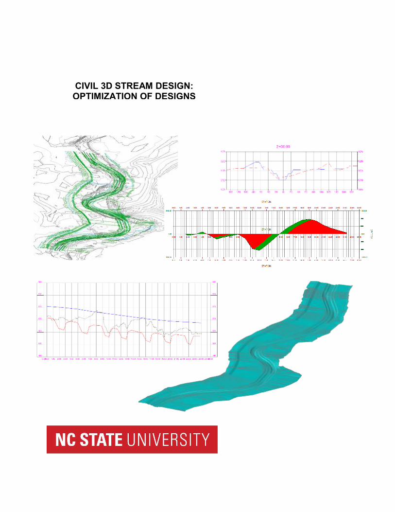
CIVIL 3D STREAM DESIGN: OPTIMIZATION OF DESIGNS

ii
STREAM DESIGN OPTIMIZATION
Table of Contents
1 INTRODUCTION ......................................................................................................... 1
2 EXISTING SURFACE ................................................................................................. 1
3 STREAM DESIGN ...................................................................................................... 2
3.1 DESIGN ALIGNMENT ................................................................................... 2
3.2 EXISTING PROFILE ...................................................................................... 3
3.3 DESIGN PROFILE ......................................................................................... 3
4 BREAKLINE PROGRAM ........................................................................................... 3
4.1 Cover Sheet .................................................................................................. 3
4.2 Import Existing Ground Data ...................................................................... 4
4.3 Process Alignment Data .............................................................................. 4
4.4 Setting Profile ............................................................................................... 6
4.5 Exporting Points .......................................................................................... 7
5 CREATING DESIGN SURFACE ................................................................................ 8
6 GRADING ................................................................................................................. 10
7 FINAL ANALYSIS .................................................................................................... 10
STREAM DESIGN OPTIMIZATION
1
1 INTRODUCTION
When designing anything that requires moving of earth materials, whether it is roads, parking lots, subdivisions or streams, being able to quantify the amount of materials is one of the most beneficial analyses that can be done. Being able to minimize the amount and distance of material needed to be moved can reduce costs, save time, and produce a better product. Reducing the material that needs to be cut or filled and limiting the distance the material must be moved can decrease the number of pieces of equipment and workers on site.
The basis of “optimization” for stream designs involves the process of adjusting the design though iterations to limit the volume of material while still meeting the engineering design parameters. The process involves creating 3-Dimensional Surfaces to check quantities quickly and adjusting the design though iterations. It takes a design from a 1-Dimensial Plan View to a Profile with typical cross-sections added to a 3-Dimensional Surface. Turning the design into a 3-Dimensional Surface allows for the computation of volumetric quantities from design to existing conditions. Optimization occurs by evaluating the quantities, readjusting the design (alignment and profile), rebuilding the surface, and evaluating new quantities. The process involves the creation of an existing surface, creating a design alignment, using the “breakline program” to set and adjust profiles, creating a design surface, checking volumes numbers, and then readjusting design for optimization. Through this process, designers can perform multiple iterations on a single design quickly, saving time and money and producing better designs on projects.
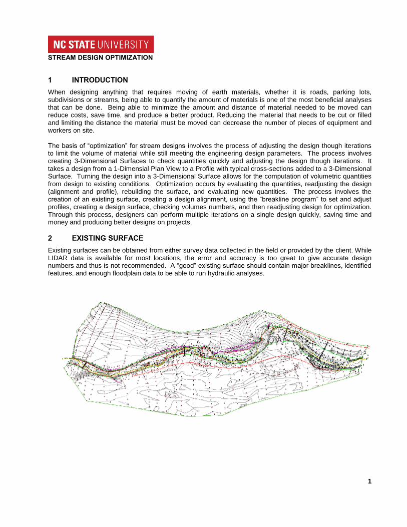
2 EXISTING SURFACE
Existing surfaces can be obtained from either survey data collected in the field or provided by the client. While LIDAR data is available for most locations, the error and accuracy is too great to give accurate design numbers and thus is not recommended. A “good” existing surface should contain major breaklines, identified features, and enough floodplain data to be able to run hydraulic analyses.
STREAM DESIGN OPTIMIZATION
2
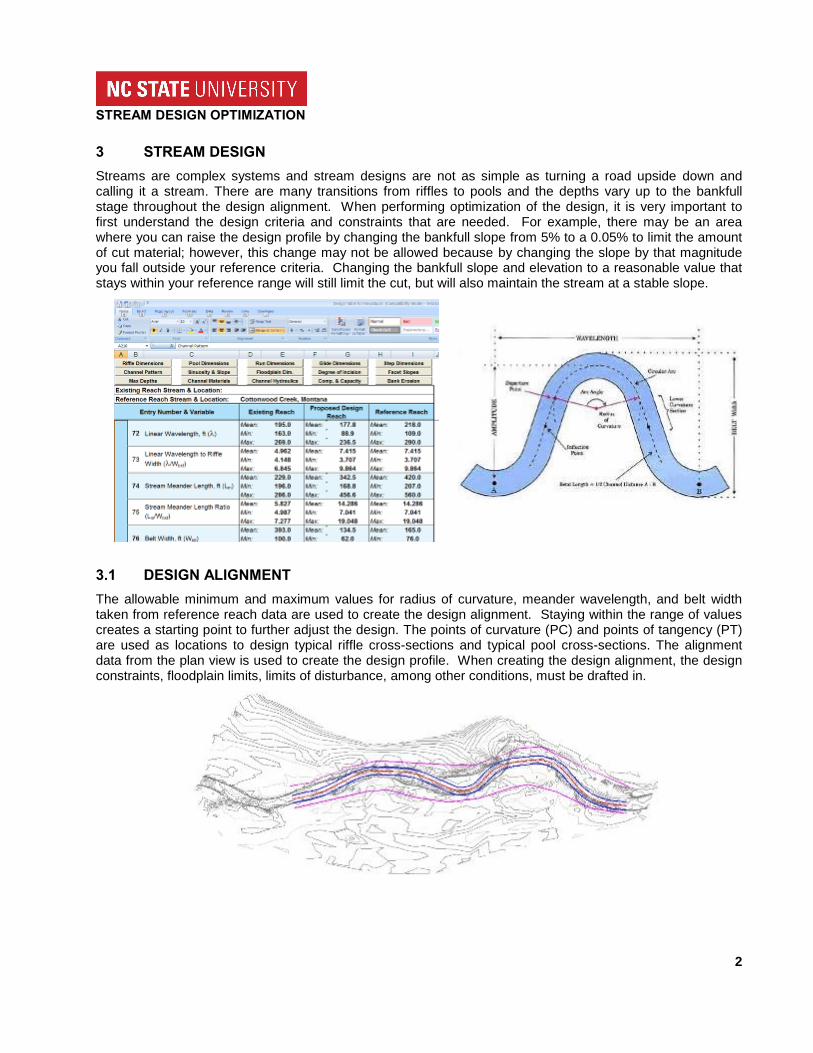
3 STREAM DESIGN
Streams are complex systems and stream designs are not as simple as turning a road upside down and calling it a stream. There are many transitions from riffles to pools and the depths vary up to the bankfull stage throughout the design alignment. When performing optimization of the design, it is very important to first understand the design criteria and constraints that are needed. For example, there may be an area where you can raise the design profile by changing the bankfull slope from 5% to a 0.05% to limit the amount of cut material; however, this change may not be allowed because by changing the slope by that magnitude you fall outside your reference criteria. Changing the bankfull slope and elevation to a reasonable value that stays within your reference range will still limit the cut, but will also maintain the stream at a stable slope.
3.1 DESIGN ALIGNMENT
The allowable minimum and maximum values for radius of curvature, meander wavelength, and belt width taken from reference reach data are used to create the design alignment. Staying within the range of values creates a starting point to further adjust the design. The points of curvature (PC) and points of tangency (PT) are used as locations to design typical riffle cross-sections and typical pool cross-sections. The alignment data from the plan view is used to create the design profile. When creating the design alignment, the design constraints, floodplain limits, limits of disturbance, among other conditions, must be drafted in.
STREAM DESIGN OPTIMIZATION
3
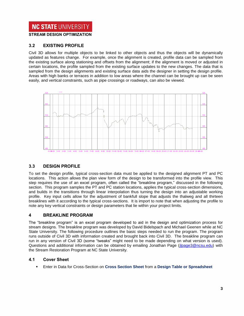
3.2 EXISTING PROFILE
Civil 3D allows for multiple objects to be linked to other objects and thus the objects will be dynamically updated as features change. For example, once the alignment is created, profile data can be sampled from the existing surface along stationing and offsets from the alignment; if the alignment is moved or adjusted in certain locations, the profile sampled from the existing surface updates to the new changes. The data that is sampled from the design alignments and existing surface data aids the designer in setting the design profile. Areas with high banks or terraces in addition to low areas where the channel can be brought up can be seen easily, and vertical constraints, such as pipe crossings or roadways, can also be viewed.
3.3 DESIGN PROFILE
To set the design profile, typical cross-section data must be applied to the designed alignment PT and PC locations. This action allows the plan view form of the design to be transformed into the profile view. This step requires the use of an excel program, often called the “breakline program,” discussed in the following section. This program samples the PT and PC station locations, applies the typical cross-section dimensions, and builds in the transitions through linear interpolation thus turning the design into an adjustable working profile. Key input cells allow for the adjustment of bankfull slope that adjusts the thalweg and all thirteen breaklines with it according to the typical cross-sections. It is import to note that when adjusting the profile to note any key vertical constraints or design parameters that lie within your project limits.
4 BREAKLINE PROGRAM
The “breakline program” is an excel program developed to aid in the design and optimization process for stream designs. The breakline program was developed by David Bidelspach and Michael Geenen while at NC State University. The following procedure outlines the basic steps needed to run the program. The program runs outside of Civil 3D with information created and brought back into Civil 3D. The breakline program can run in any version of Civil 3D (some “tweaks” might need to be made depending on what version is used). Questions and additional information can be obtained by emailing Jonathan Page ([email protected]) with the Stream Restoration Program at NC State University.
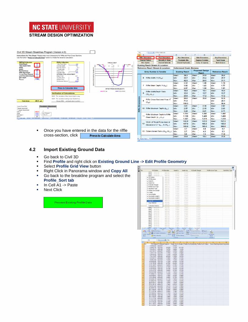
4.1 Cover Sheet
Enter in Data for Cross-Section on Cross Section Sheet from a Design Table or Spreadsheet
STREAM DESIGN OPTIMIZATION
4
Once you have entered in the data for the riffle
cross-section, click
4.2 Import Existing Ground Data
Go back to Civil 3D Find Profile and right click on Existing Ground Line -> Edit Profile Geometry Select Profile Grid View button Right Click in Panorama window and Copy All Go back to the breakline program and select the
Profile_Sort tab In Cell A1 -> Paste Next Click
STREAM DESIGN OPTIMIZATION
5
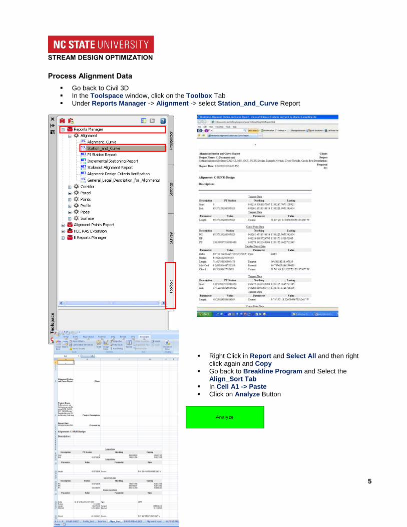
Process Alignment Data
Go back to Civil 3D In the Toolspace window, click on the Toolbox Tab Under Reports Manager -> Alignment -> select Station_and_Curve Report
Right Click in Report and Select All and then right click again and Copy
Go back to Breakline Program and Select the Align_Sort Tab
In Cell A1 -> Paste Click on Analyze Button
STREAM DESIGN OPTIMIZATION
6
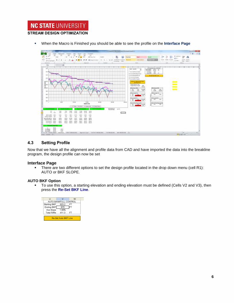
When the Macro is Finished you should be able to see the profile on the Interface Page
4.3 Setting Profile
Now that we have all the alignment and profile data from CAD and have imported the data into the breakline program, the design profile can now be set
Interface Page There are two different options to set the design profile located in the drop down menu (cell R1):
AUTO or BKF SLOPE.
AUTO BKF Option To use this option, a starting elevation and ending elevation must be defined (Cells V2 and V3), then
press the Re-Set BKF Line.
STREAM DESIGN OPTIMIZATION
7
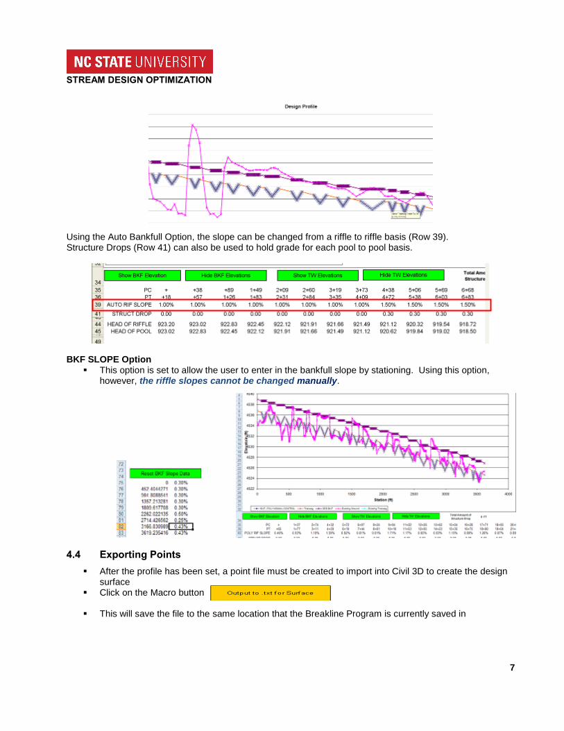
Using the Auto Bankfull Option, the slope can be changed from a riffle to riffle basis (Row 39). Structure Drops (Row 41) can also be used to hold grade for each pool to pool basis.
BKF SLOPE Option This option is set to allow the user to enter in the bankfull slope by stationing. Using this option,
however, the riffle slopes cannot be changed manually.
4.4 Exporting Points
After the profile has been set, a point file must be created to import into Civil 3D to create the design surface
Click on the Macro button
This will save the file to the same location that the Breakline Program is currently saved in
STREAM DESIGN OPTIMIZATION
8
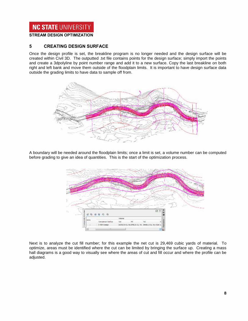
5 CREATING DESIGN SURFACE
Once the design profile is set, the breakline program is no longer needed and the design surface will be created within Civil 3D. The outputted .txt file contains points for the design surface; simply import the points and create a 3dpolyline by point number range and add it to a new surface. Copy the last breakline on both right and left bank and move them outside of the floodplain limits. It is important to have design surface data outside the grading limits to have data to sample off from.
A boundary will be needed around the floodplain limits; once a limit is set, a volume number can be computed before grading to give an idea of quantities. This is the start of the optimization process.
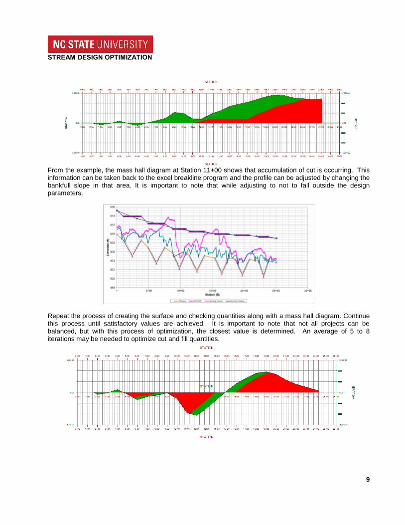
Next is to analyze the cut fill number; for this example the net cut is 29,469 cubic yards of material. To optimize, areas must be identified where the cut can be limited by bringing the surface up. Creating a mass hall diagrams is a good way to visually see where the areas of cut and fill occur and where the profile can be adjusted.
STREAM DESIGN OPTIMIZATION
9
From the example, the mass hall diagram at Station 11+00 shows that accumulation of cut is occurring. This information can be taken back to the excel breakline program and the profile can be adjusted by changing the bankfull slope in that area. It is important to note that while adjusting to not to fall outside the design parameters.
Repeat the process of creating the surface and checking quantities along with a mass hall diagram. Continue this process until satisfactory values are achieved. It is important to note that not all projects can be balanced, but with this process of optimization, the closest value is determined. An average of 5 to 8 iterations may be needed to optimize cut and fill quantities.
STREAM DESIGN OPTIMIZATION
10
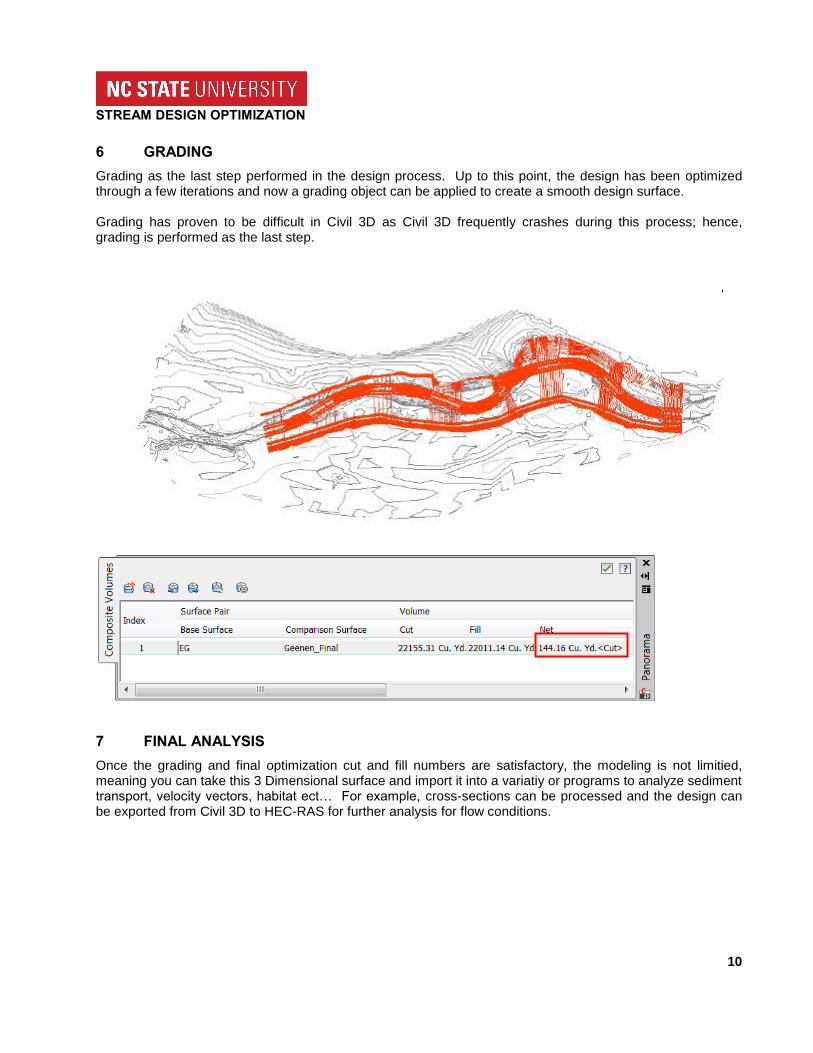
6 GRADING
Grading as the last step performed in the design process. Up to this point, the design has been optimized through a few iterations and now a grading object can be applied to create a smooth design surface. Grading has proven to be difficult in Civil 3D as Civil 3D frequently crashes during this process; hence, grading is performed as the last step.
7 FINAL ANALYSIS
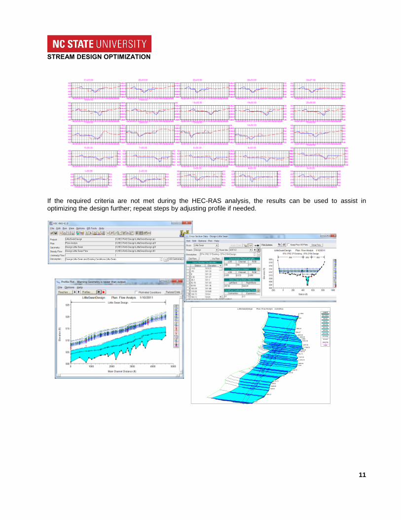
Once the grading and final optimization cut and fill numbers are satisfactory, the modeling is not limitied, meaning you can take this 3 Dimensional surface and import it into a variatiy or programs to analyze sediment transport, velocity vectors, habitat ect… For example, cross-sections can be processed and the design can be exported from Civil 3D to HEC-RAS for further analysis for flow conditions.
STREAM DESIGN OPTIMIZATION
11
If the required criteria are not met during the HEC-RAS analysis, the results can be used to assist in optimizing the design further; repeat steps by adjusting profile if needed.
9534
9337
8849.34
8644.37
8524.68
8426.93
8356
8261.03
8037.56
7838.23
7639.08 7553.19
7411.71
7247.63
7076.79
6875.41
6745
6468.78
6297.63
6093
5755.73
5599.5
5455.85
5320.9
4994.12
4553
LittleSwanDesign Plan: Flow Analyis 1/10/2011
Legend
WS 750cfs
WS 2yr
WS 5yr
WS 10yr
WS 25yr
WS 50yr
WS 100yr
WS 500yr
Ground
Bank Sta
Levee