Embed Size (px)
Citation preview

AutoCAD Civil 3D 2010 P.0 [email protected]
Rho Engineering © 2010
A U T O D E S K @ R H O - E N G . C O M
B Y
S M A D I M .
MSc Transportation Engineering
Infra Structures and Highway Design Engineer
Autodesk Authorized AutoCAD Civil 3D Instructor
This material used for training purposes, and its Rho Engineering property.

AutoCAD Civil 3D 2010 P.1 [email protected]
Rho Engineering © 2010
AutoCAD Civil 3D 2010
Course Name: Highway Design and Quantity Surveying using AutoCAD Civil 3D 2010
Course Description:
This course will review the basic parameters for highway design, and introduce AutoCAD Civil 3D 2010 as a tool to create a surveying plans, and how to lay out roadways and subdivision lots. The course will focus on the creation of road profiles, corridors and cross sections, also the generation of quantities takeoff sheets for earthworks and pavement layers.
Credit Hours:
18 hours distributed on three weeks
Attendance:
Civil Engineers and Civil Engineering Technicians as: Land Surveyors and Quantity Surveyors
Prerequisites: Highway Design Parameters Background
AutoCAD basic knowledge
Microsoft office basic knowledge, namely (MS Excels and MS word)
Task: Each Trainee shall submit a full project as a show case of his proficiency of using AutoCAD Civil 3D.
Certification:
Each one success to handle the task will receive an Autodesk brand Certificate of completion
Earn a valuable certificate of completion that’s recognized in your profession and validate your product knowledge as an Autodesk Certified User or Autodesk Certified Expert when you take a certification exam at a participating ATC test delivery facility.

AutoCAD Civil 3D 2010 P.2 [email protected]
Rho Engineering © 2010
Course Outline
Stage –I 6 Hours Includes:
Road geometrical design overview
Understanding user interface
Importing surveying Data:
o Points
o 3D polylines (GIS, Countours, breaklines)
o Google earth
Creating surfaces and contours
Editing surfaces
Creation of road alignment
Design of horizontal curves
Creating alignment superelevation
Create alignment offsets and widening
Stage -II 12 Hours Includes:
Working with profiles:
o Creation of road center line existing profile
o Creation of road centerline design profile
o Design of vertical curves
o Tabular output of profile elevations
Working with Corridors
o Creating existing ground cross sections
o Definition of assembly
Basic assembly
Super elevation and transition assembly
Assembly with median
o Creating Coridors
o Creating design cross sections
Compute materials:
o generating cut and fill quantities takeoff sheets
o generating materials quantities
Selected Advanced Topic (elective topics)
o Working with intersections
o Drawings production
o Takeoff / pay items
o Importing land project
o Design to local codes
o Creating customized subassemblies
o Sharing assemblies (creating palettes and Catalog)
o Parcels & Grading objects
o Combined Cross Sedctions
o Tips & Tricks

AutoCAD Civil 3D 2010 P.3 [email protected]
Rho Engineering © 2010
What is the new in AutoCAD Civil 3D comparing to LAND?
Automatic Dynamic link between Plan–Profile–Cross Sections,
Ease to modify plan and/or profile by just moving the vertices (PI’s),
Easier drawing format and production,
Connected to Google earth,
Built-in Cross Sections templates,
Everything in one drawing; No project folders,
Intersection Design Tools,
Extension of existing alignment and/or profile,
Design check
Labeling existing ground for cross sections at grade break
Maintain pavement layers side slope (i.e. 3:1) while changing offset according to super
elevation.
Generating 3D rendering and transferred to 3D Max.
AutoCAD Civil 3D 2010 P.4 [email protected]
Rho Engineering © 2010
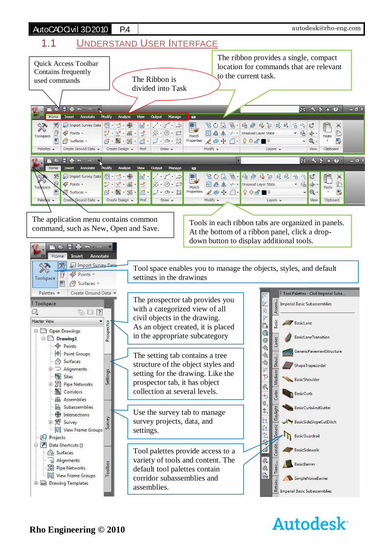
1.1 UNDERSTAND USER INTERFACE
The application menu contains common
command, such as New, Open and Save.
Quick Access Toolbar Contains frequently
used commands
The ribbon provides a single, compact
location for commands that are relevant
to the current task. The Ribbon is
divided into Task
Based Tabs
Tools in each ribbon tabs are organized in panels.
At the bottom of a ribbon panel, click a drop-
down button to display additional tools.
Tool space enables you to manage the objects, styles, and default
settings in the drawings
The prospector tab provides you
with a categorized view of all
civil objects in the drawing.
As an object created, it is placed
in the appropriate subcategory
The setting tab contains a tree
structure of the object styles and
setting for the drawing. Like the
prospector tab, it has object
collection at several levels.
Use the survey tab to manage
survey projects, data, and
settings.
Tool palettes provide access to a
variety of tools and content. The
default tool palettes contain
corridor subassemblies and
assemblies.
AutoCAD Civil 3D 2010 P.5 [email protected]
Rho Engineering © 2010
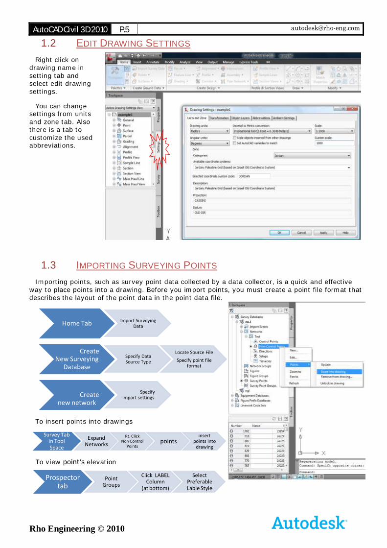
1.2 EDIT DRAWING SETTINGS
Right click on drawing name in setting tab and select edit drawing settings.
You can change settings from units and zone tab. Also there is a tab to
customize the used abbreviations.
1.3 IMPORTING SURVEYING POINTS
Importing points, such as survey point data collected by a data collector, is a quick and effective way to place points into a drawing. Before you import points, you must create a point file format that
describes the layout of the point data in the point data file.
To insert points into drawings
To view point’s elevation
Home Tab Import Surveying Data
Create New Surveying
Database
Specify Data Source Type
Locate Source File
Specify point file format
Create new network
Specify Import settings
Survey Tab in Tool Space
Expand Networks
Rt. Click Non Control
Pointspoints
insert points into
drawing
Prospector tab
Point Groups
Click LABEL Column
(at bottom)
Select Preferable Lable Style
AutoCAD Civil 3D 2010 P.6 [email protected]
Rho Engineering © 2010
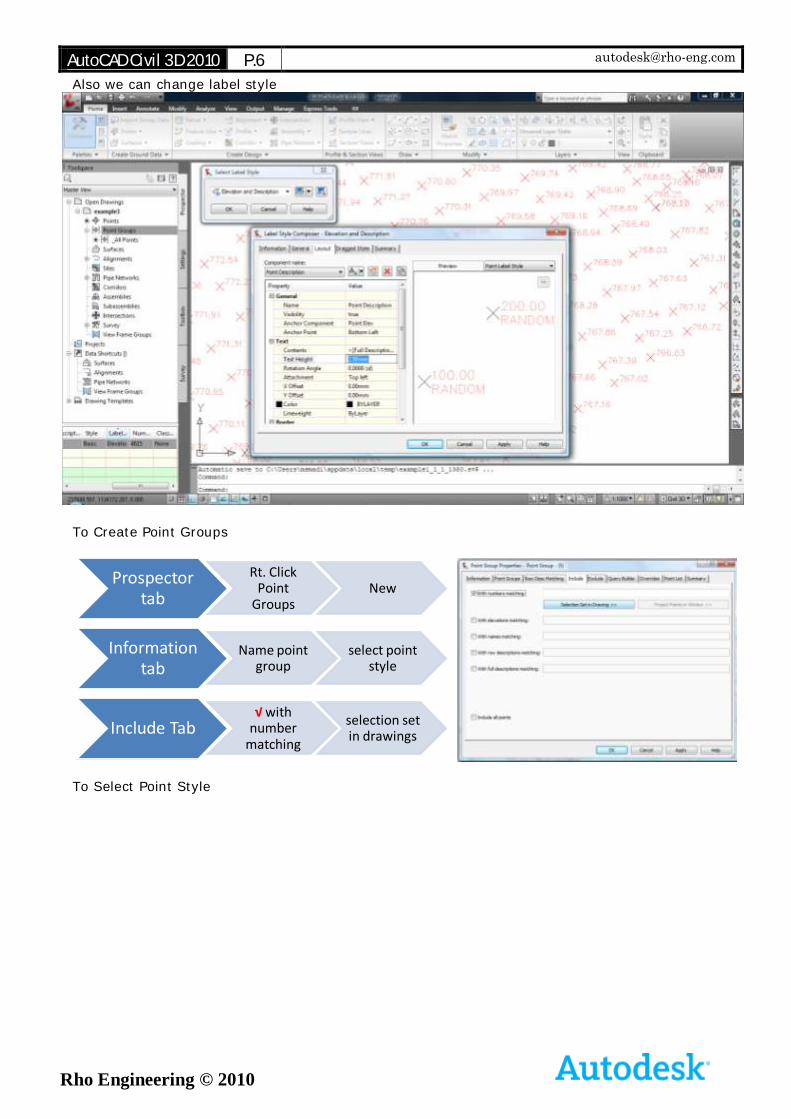
Also we can change label style
To Create Point Groups
To Select Point Style
Prospector tab
Rt. Click Point
GroupsNew
Information tab
Name point group
select point style
Include Tab√ with
number matching
selection set in drawings
AutoCAD Civil 3D 2010 P.7 [email protected]
Rho Engineering © 2010
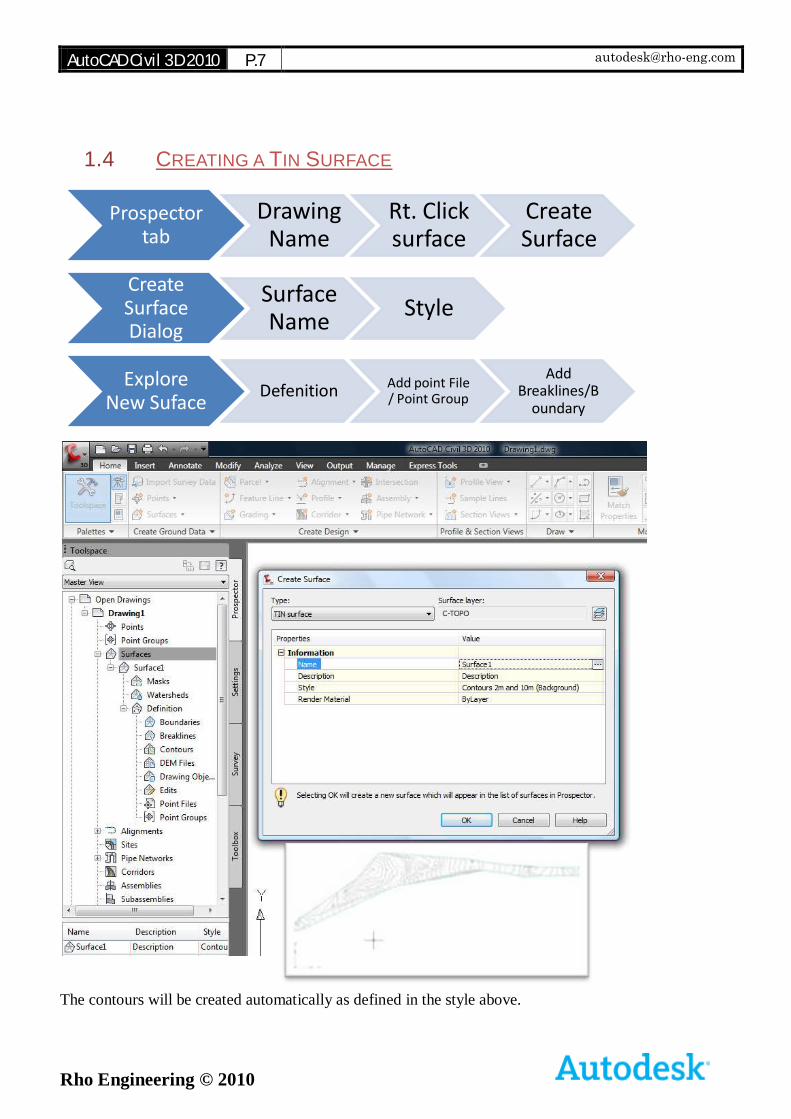
1.4 CREATING A TIN SURFACE
The contours will be created automatically as defined in the style above.
Prospector tab
Drawing Name
Rt. Click surface
Create Surface
Create Surface Dialog
Surface Name
Style
Explore New Suface
Defenition Add point File / Point Group
Add Breaklines/B
oundary
AutoCAD Civil 3D 2010 P.8 [email protected]
Rho Engineering © 2010
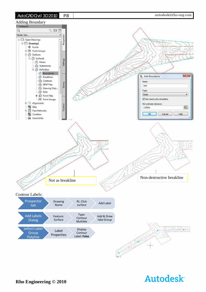
Adding Boundary
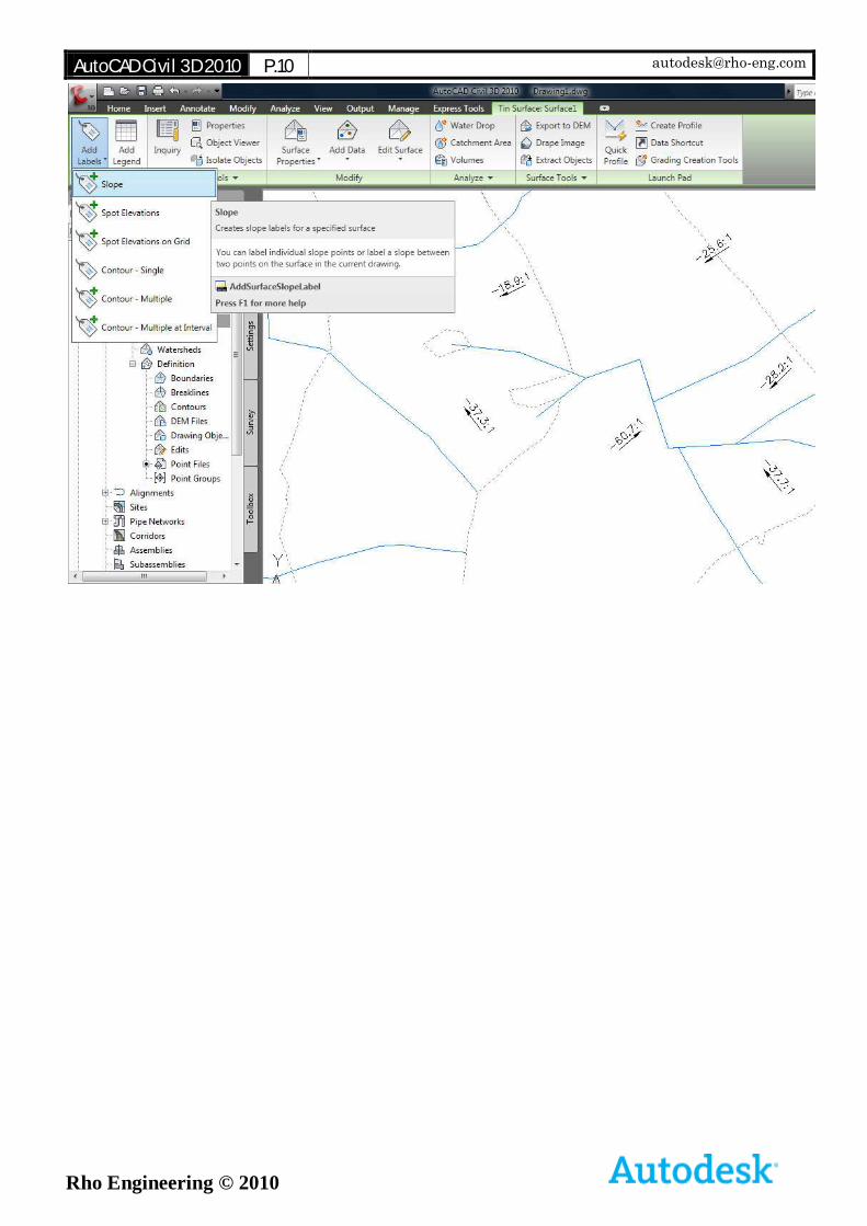
Contour Labels:
Prospector tab
Drawing Name
Rt. Click surface
Add Label
Add Labels Dialog
Feature: Surface
Type: Contour Multible
Add & Draw labe Group
sellect Label Group
Polyline
Label Properties
Display Contour
Label: False
Non-destructive breakline Not as breakline
AutoCAD Civil 3D 2010 P.9 [email protected]
Rho Engineering © 2010
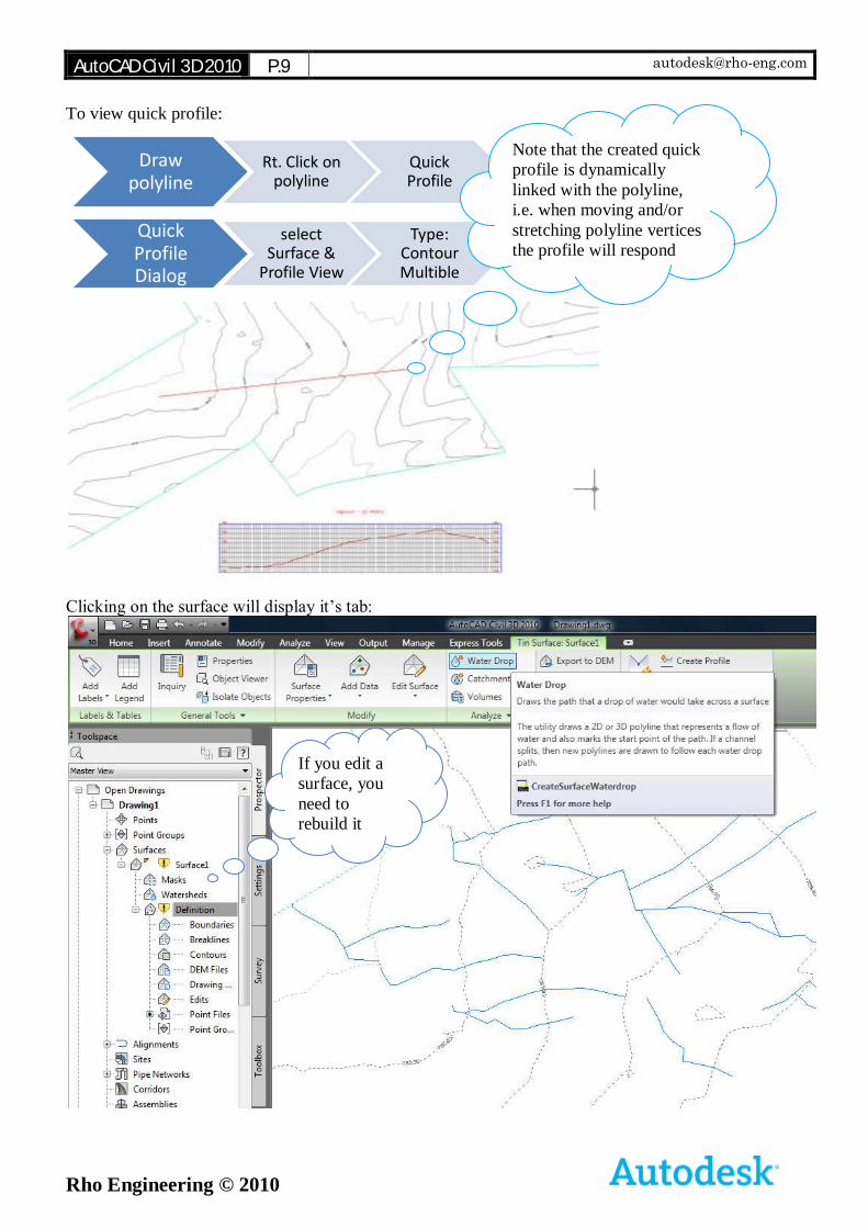
To view quick profile:
Clicking on the surface will display it’s tab:
Draw polyline
Rt. Click on polyline
Quick Profile
Quick Profile Dialog
select Surface &
Profile View
Type: Contour Multible
Note that the created quick
profile is dynamically
linked with the polyline,
i.e. when moving and/or
stretching polyline vertices
the profile will respond
automatically
If you edit a
surface, you
need to
rebuild it
AutoCAD Civil 3D 2010 P.11 [email protected]
Rho Engineering © 2010
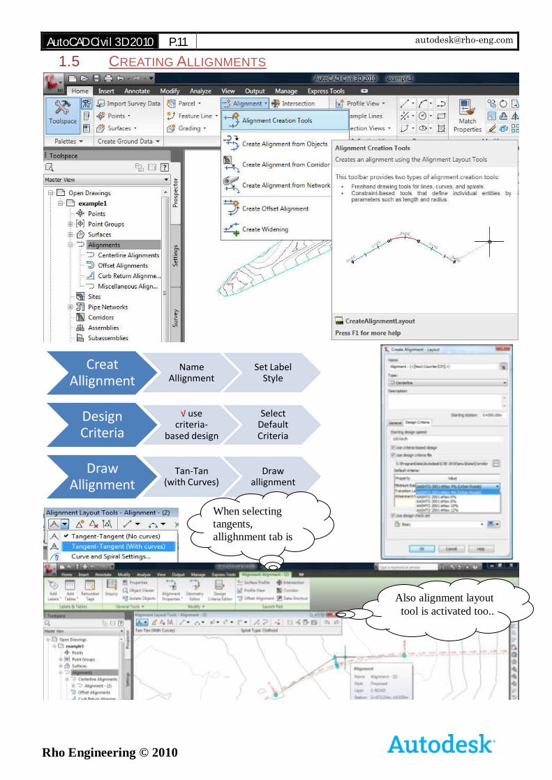
1.5 CREATING ALLIGNMENTS
Creat Allignment
Name Allignment
Set Label Style
Design Criteria
√ use criteria-
based design
Select Default Criteria
Draw Allignment
Tan-Tan (with Curves)
Draw allignment
When selecting
tangents,
allighnment tab is
displayed
Also alignment layout
tool is activated too..
AutoCAD Civil 3D 2010 P.12 [email protected]
Rho Engineering © 2010
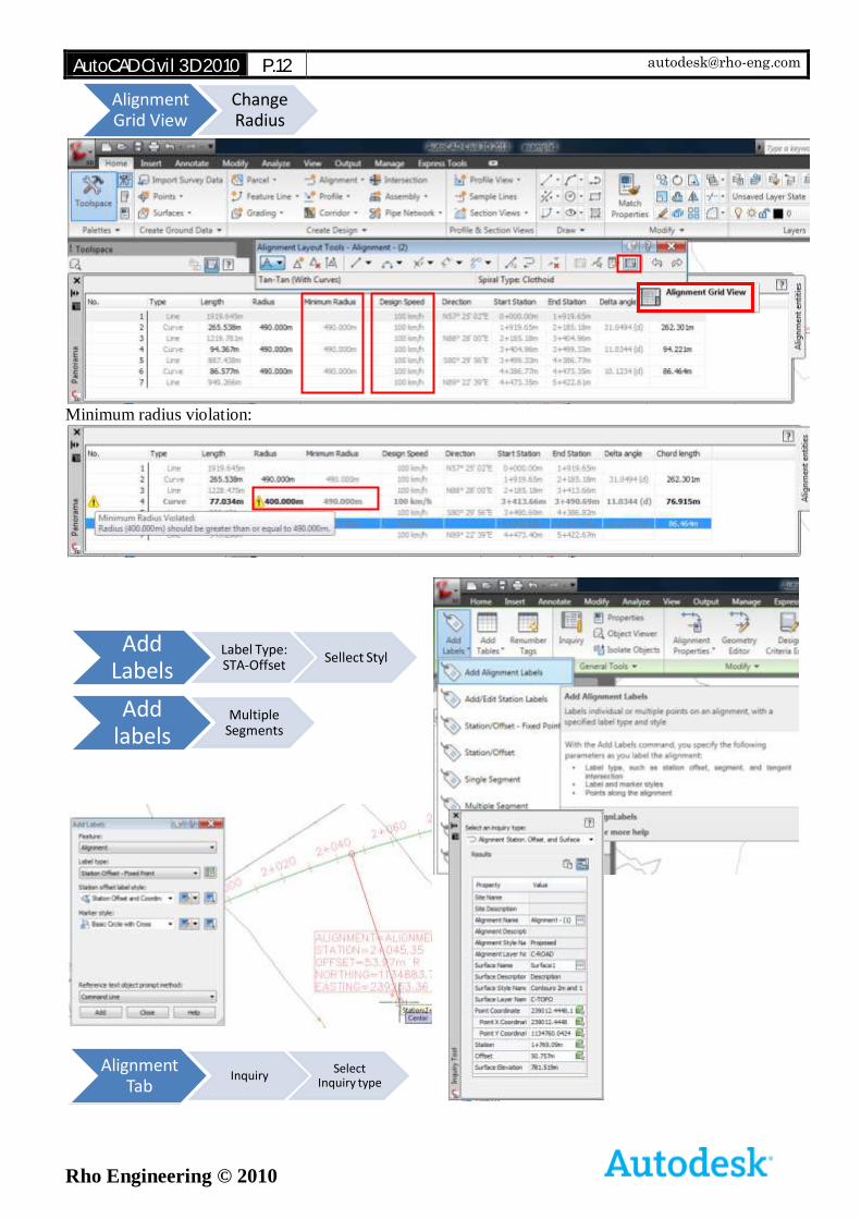
Minimum radius violation:
Alignment Grid View
Change Radius
Add Labels
Label Type: STA-Offset
Sellect Styl
Add labels
Multiple Segments
Alignment Tab
InquirySelect
Inquiry type
AutoCAD Civil 3D 2010 P.13 [email protected]
Rho Engineering © 2010
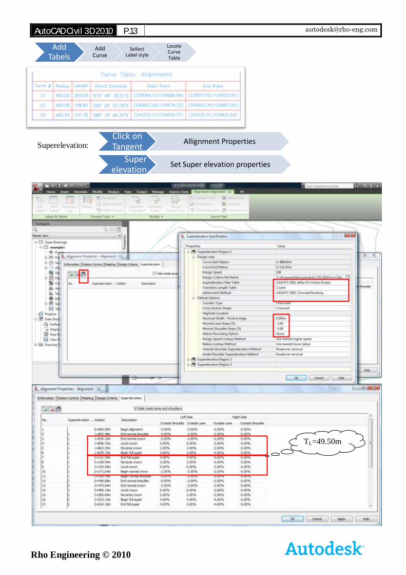
Add Tabels
Add Curve
Sellect Label style
Locate Curve Table
Click on Tangent
Allignment Properties
Super elevation
Tab
Set Super elevation properties
Superelevation:
TL=49.50m
AutoCAD Civil 3D 2010 P.14 [email protected]
Rho Engineering © 2010
Design Rules
In this section you specify the tables to use for superelevation rate, transition length, and attainment method.
Design Speed
Displays the design speed for the curve group. This value is derived from the Design Criteria tab of the Alignment Properties. If the curve group has two or more design speeds, the highest design speed is displayed.
Design Criteria File Name
Specifies the name of the design criteria file. This file defines minimum radius tables, superelevation attainment methods and formulae, superelevation rates and transition lengths for various roadway types and design speeds. Click in the cell to browse to the location of the design criteria file.
Superelevation Rate Table
Specifies the name of the superelevation rate table used to determine the maximum
superelevation rate for the curve group. Click the arrow to display a list of the superelevation rate tables associated with the specified design criteria file.
Transition Length Table
Specifies the name of the superelevation transition length table used to calculate the transition stations for the curve group. Click the arrow to display a list of the transition length tables associated with the specified superelevation rate table.
Attainment Method
Specifies the name of the superelevation attainment method for the curve group. Click the arrow to display a list of the attainment methods associated with the specified design criteria file.
Default Options
In this section, you specify the general settings used to calculate superelevation specifications.
Corridor Type
Specifies the type of roadway as Undivided (single carriage way) or Divided (dual carriage
way).
Cross Section Shape
Specifies the cross sectional shape of the roadway as Planar or Crowned:
Planar: There is no change in slope between the travel lanes.
Crowned: When no superelevation is applied, travel lanes slope downward in opposite directions from a common crown point.
Highside Location
Specifies the default Highside Location for planar roads.
Left Edge: Specifies that the high side of the roadway is on the left edge on tangent (unsuperelevated) sections when the corridor type is Undivided and the Cross Section Shape is planar.
Level: The roadway is level (0% slope) on tangent sections.
Right Edge: Specifies that the high side of the roadway is on the right edge on tangent (unsuperelevated) sections, when the corridor type is Undivided and the Cross Section Shape is planar.
AutoCAD Civil 3D 2010 P.15 [email protected]
Rho Engineering © 2010
Nominal Width - Pivot To Edge
Specifies the typical width of the roadway from the superelevation pivot point to the outer edge-of-traveled way. Some superelevation attainment methods require that you specify this value in order to calculate the length of the superelevation transition.
Outside Shoulder Superelevation Method
Specifies the method that is applied to the outside shoulder during superelevation:
Default Slopes: Default slopes are retained and shoulders are not superelevated.
Match Lane Slopes: Shoulder slopes match the slopes applied to the adjacent traveled ways through out the superelevation process.
Breakover Removal: Shoulders on the outside edge of the curve are adjusted upward to match the Normal Lane Slope (%) before the lane begins to superelevate. The high-side shoulder slope matches the high-side lane slope throughout the superelevation process, and it then rotates downward back to the Normal Shoulder Slope (%) value when the lanes are back to the un-superelevated condition.
Inside Shoulder Superelevation Method
Specifies the method that is applied to the inside shoulder during superelevation:
Default Slopes: Default slopes are retained and shoulders are not superelevated.
Match Lane Slopes: Shoulder slopes match the slopes applied to the adjacent traveled ways through out the superelevation process.
Breakover Removal: Shoulders on the outside edge of the curve are adjusted upward to match the Normal Lane Slope (%) before the lane begins to superelevate. The high-
side shoulder slope matches the high-side lane slope throughout the superelevation process, and it then rotates downward back to the Normal Shoulder Slope (%) value when the lanes are back to the unsuperelevated condition.
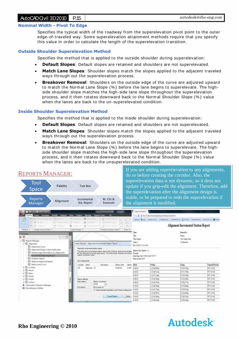
REPORTS MANAGER:
Tool Space
Paletts Tool Box
Reports Manager
AllignmentIncremental Sta. Report
Rt. Clic & Excecute
If you are adding superelevation to any alignments,
do so before creating the corridor. Also, the
superelevation data is not dynamic, so it does not
update if you grip-edit the alignment. Therefore, add
the superelevation after the alignment design is
stable, or be prepared to redo the superelevation if
the alignment is modified.
AutoCAD Civil 3D 2010 P.16 [email protected]
Rho Engineering © 2010
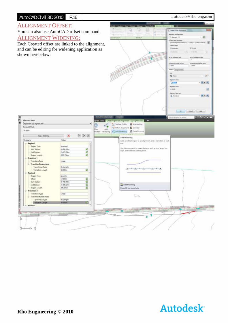
ALLIGNMENT OFFSET: You can also use AutoCAD offset command.
ALLIGNMENT WIDENING: Each Created offset are linked to the alignment,
and can be editing for widening application as
shown herebelow:
AutoCAD Civil 3D 2010 P.17 [email protected]
Rho Engineering © 2010
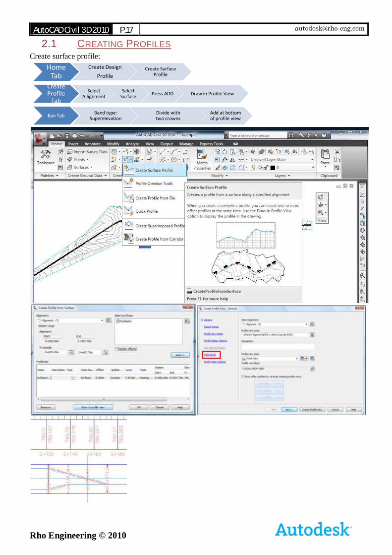
2.1 CREATING PROFILES Create surface profile:
Home Tab
Create Design
Profile
Create Surface Profile
Create Profile
Tab
Select Allignment
Select Surface
Press ADD Draw in Profile View
Ban TabBand type:
SuperelevationDivide with two crowns
Add at bottom of profile view
AutoCAD Civil 3D 2010 P.18 [email protected]
Rho Engineering © 2010
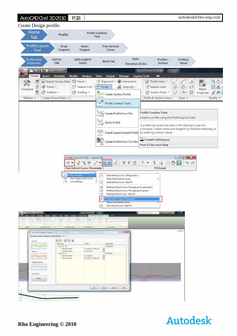
Create Design profile:
Home Tab
ProfileProfile Creation
Tool
Profile Layout Tool
Draw Tangents
Select Tangent
Free Vertical Curve
Profile View Properties
HATCH TAB
ADD Cut&Fill Hatch
Band TabStyle:
Elevations & Sta.
Profile1: Surface
Profile2: latout
AutoCAD Civil 3D 2010 P.19 [email protected]
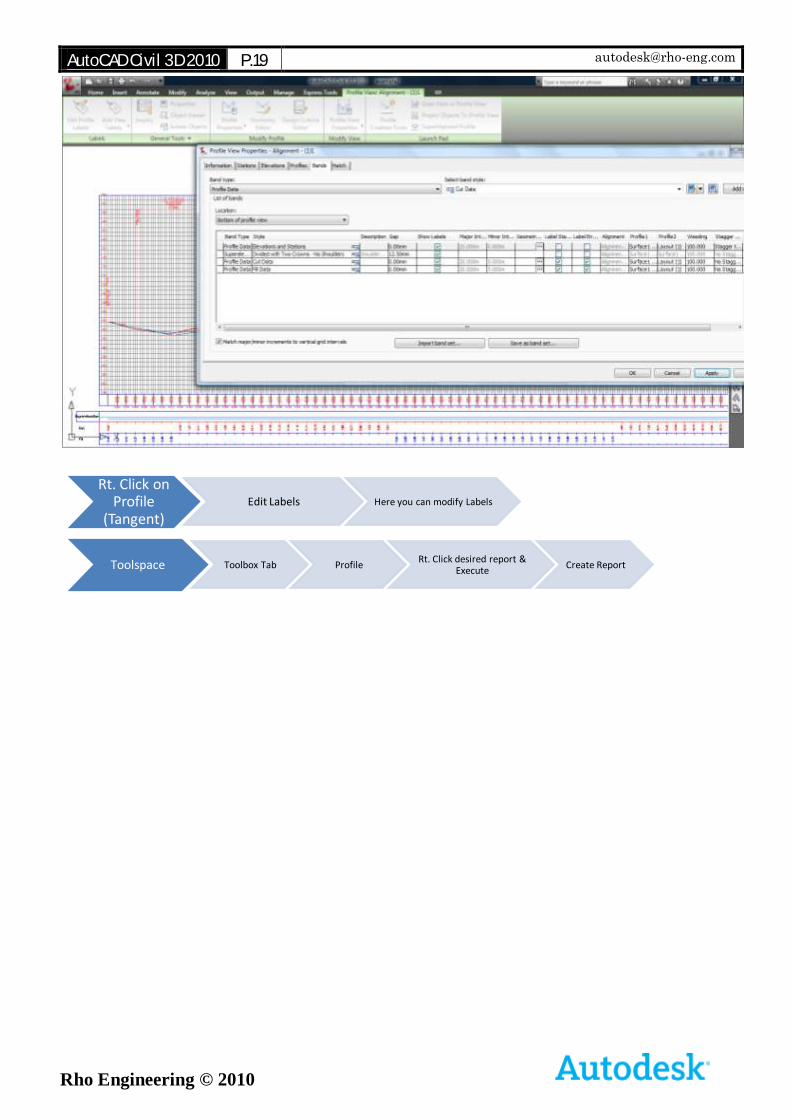
Rho Engineering © 2010
Rt. Click on Profile
(Tangent)Edit Labels Here you can modify Labels
Toolspace Toolbox Tab ProfileRt. Click desired report &
ExecuteCreate Report
AutoCAD Civil 3D 2010 P.20 [email protected]
Rho Engineering © 2010
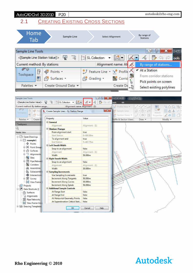
2.1 CREATING EXISTING CROSS SECTIONS
Home Tab
Sample Line Select AllignmentBy range of
Stations
AutoCAD Civil 3D 2010 P.21 [email protected]
Rho Engineering © 2010
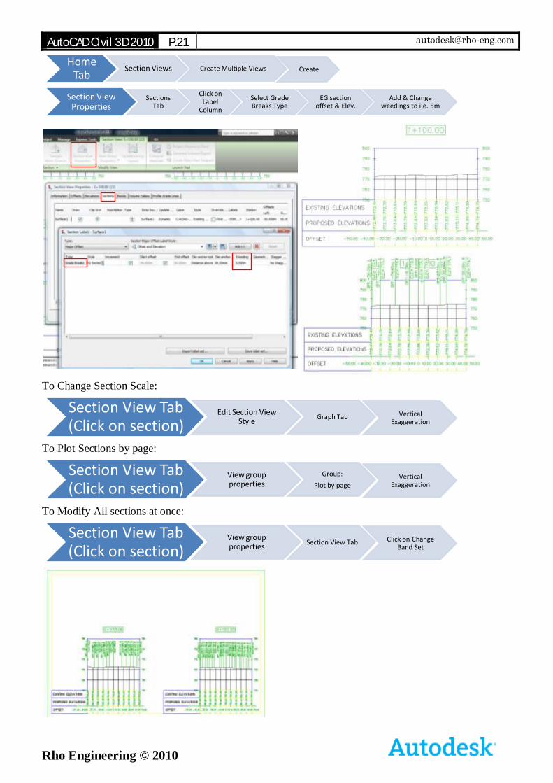
To Change Section Scale:
To Plot Sections by page:
To Modify All sections at once:
Home Tab
Section Views Create Multiple Views Create
Section View Properties
Sections Tab
Click on Label
Column
Select Grade Breaks Type
EG section offset & Elev.
Add & Change weedings to i.e. 5m
Section View Tab (Click on section)
Edit Section View Style
Graph Tab Vertical Exaggeration
Section View Tab (Click on section)
View group properties
Group:
Plot by pageVertical
Exaggeration
Section View Tab (Click on section)
View group properties
Section View Tab Click on Change Band Set
AutoCAD Civil 3D 2010 P.22 [email protected]
Rho Engineering © 2010
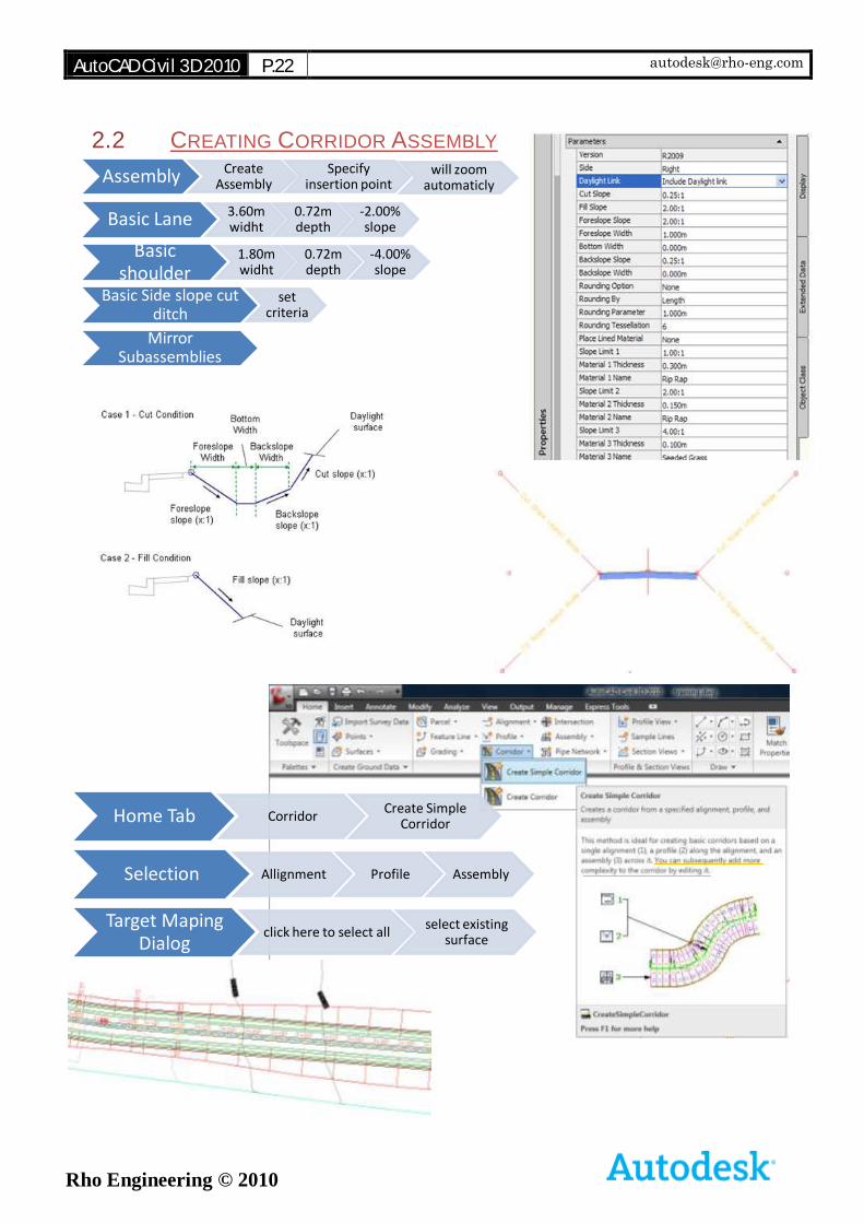
2.2 CREATING CORRIDOR ASSEMBLY
Assembly Create Assembly
Specify insertion point
will zoom automaticly
Basic Lane 3.60m widht
0.72m depth
-2.00% slope
Basic shoulder
1.80m widht
0.72m depth
-4.00% slope
Basic Side slope cut ditch
set criteria
Mirror Subassemblies
Home Tab CorridorCreate Simple
Corridor
Selection Allignment Profile Assembly
Target Maping Dialog
click here to select allselect existing
surface
AutoCAD Civil 3D 2010 P.23 [email protected]
Rho Engineering © 2010
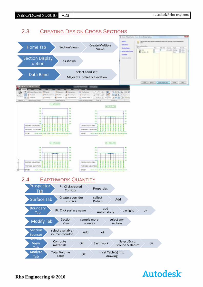
2.3 CREATING DESIGN CROSS SECTIONS
2.4 EARTHWORK QUANTITY
Home Tab Section ViewsCreate Multiple
Views
Section Display option
as shown
Data Bandselect band set:
Major Sta. offset & Elevation
Prospector Tab
Rt. Click created Corridor
Properties
Surface Tab Create a corridor surface
sellect Datum
Add
Boundary Tab
Rt. Click surface nameadd
Automaticlydaylight ok
Modify Tab Section View
sample more sources
select any section
Section Sources
select available source: corridor
Add ok
Section View Tab
Compute materials
OK EarthworkSelect Exist.
Ground & DatumOK
Analyze Tab
Total Volume Table
OKInset Table(s) into
drawing
AutoCAD Civil 3D 2010 P.24 [email protected]
Rho Engineering © 2010
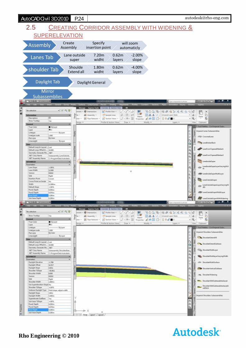
2.5 CREATING CORRIDOR ASSEMBLY WITH WIDENING &
SUPERELEVATION
Assembly Create Assembly
Specify insertion point
will zoom automaticly
Lanes Tab Lane outside super
7.20m widht
0.62m layers
-2.00% slope
shoulder Tab Shoulde Extend all
1.80m widht
0.62m layers
-4.00% slope
Daylight Tab Daylight General
Mirror Subassemblies
AutoCAD Civil 3D 2010 P.25 [email protected]
Rho Engineering © 2010
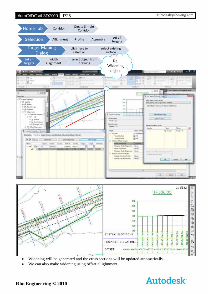
Widening will be generated and the cross sections will be updated automatically…
We can also make widening using offset allighnment.
Home Tab CorridorCreate Simple
Corridor
Selection Allignment Profile Assemblyset all
tergets
Target Maping Dialog
click here to select all
select existing surface
Set all targets
width allignment
select object from drawing
Rt.
Widening
object
AutoCAD Civil 3D 2010 P.26 [email protected]
Rho Engineering © 2010
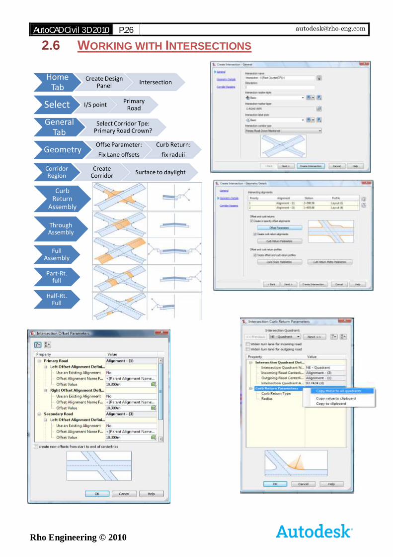
2.6 WORKING WITH INTERSECTIONS
Home Tab
Create Design Panel
Intersection
Select I/S pointPrimary
Road
General Tab
Select Corridor Tpe: Primary Road Crown?
GeometryOffse Parameter:
Fix Lane offsets
Curb Return:
fix raduii
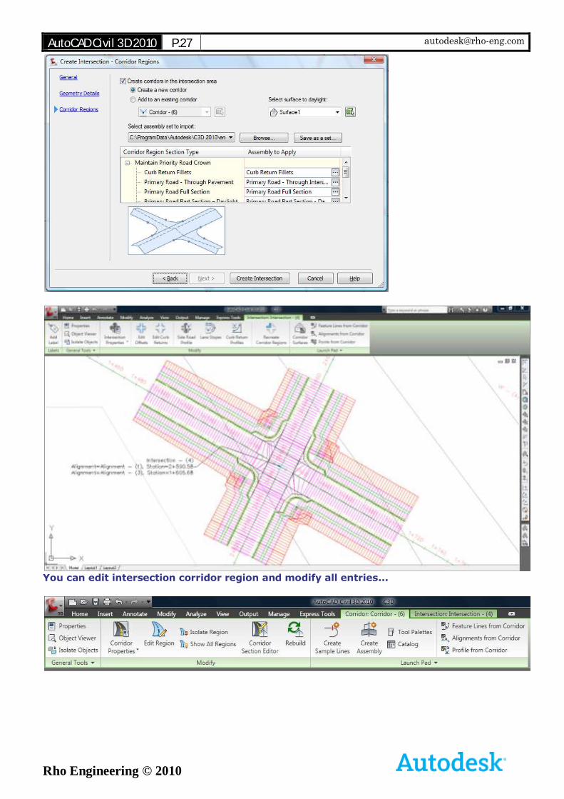
Corridor Region
Create Corridor
Surface to daylight
Curb Return
Assembly
Through Assembly
Full Assembly
Part-Rt. full
Half-Rt. Full
AutoCAD Civil 3D 2010 P.27 [email protected]
Rho Engineering © 2010
You can edit intersection corridor region and modify all entries...
AutoCAD Civil 3D 2010 P.28 [email protected]
Rho Engineering © 2010
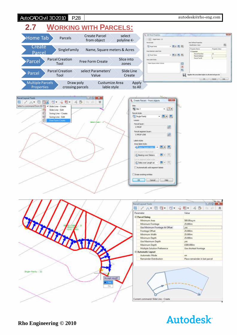
2.7 WORKING WITH PARCELS:
Home Tab ParcelsCreate Parcel from object
select polyline ←
Create Parcel
SingleFamily Name, Square meters & Acres
Parcel Parcel Creation Tool
Free Form CreateSlice into
zones
ParcelParcel Creation
Toolselect Parameters'
ValueSlide Line
Create
Multiple Parcels Properties
Draw poly crossing parcels
Custumize Area lable style
Apply to All
AutoCAD Civil 3D 2010 P.29 [email protected]
Rho Engineering © 2010
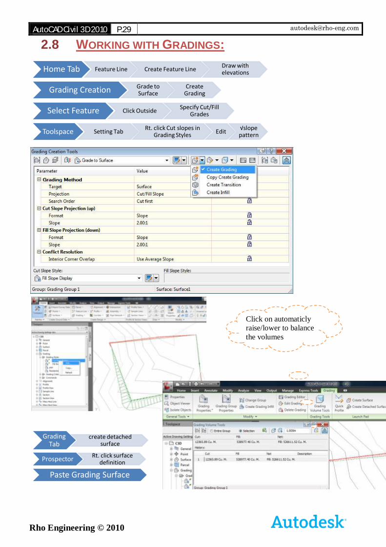
2.8 WORKING WITH GRADINGS:
Home Tab Feature Line Create Feature LineDraw with elevations
Grading Creation Grade to Surface
Create Grading
Select Feature Click OutsideSpecify Cut/Fill
Grades
Toolspace Setting TabRt. click Cut slopes in
Grading StylesEdit
√slope pattern
Grading Tab
create detached surface
ProspectorRt. click surface
definition
Paste Grading Surface
Click on automaticly
raise/lower to balance
the volumes
AutoCAD Civil 3D 2010 P.30 [email protected]
Rho Engineering © 2010
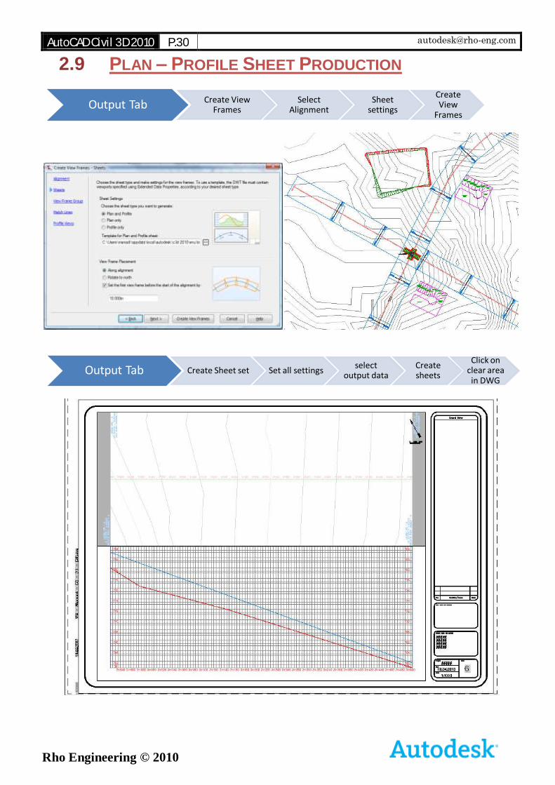
2.9 PLAN – PROFILE SHEET PRODUCTION
Output Tab Create View Frames
Select Alignment
Sheet settings
Create View
Frames
Output Tab Create Sheet set Set all settingsselect
output dataCreate sheets
Click on clear area in DWG
AutoCAD Civil 3D 2010 P.31 [email protected]
Rho Engineering © 2010
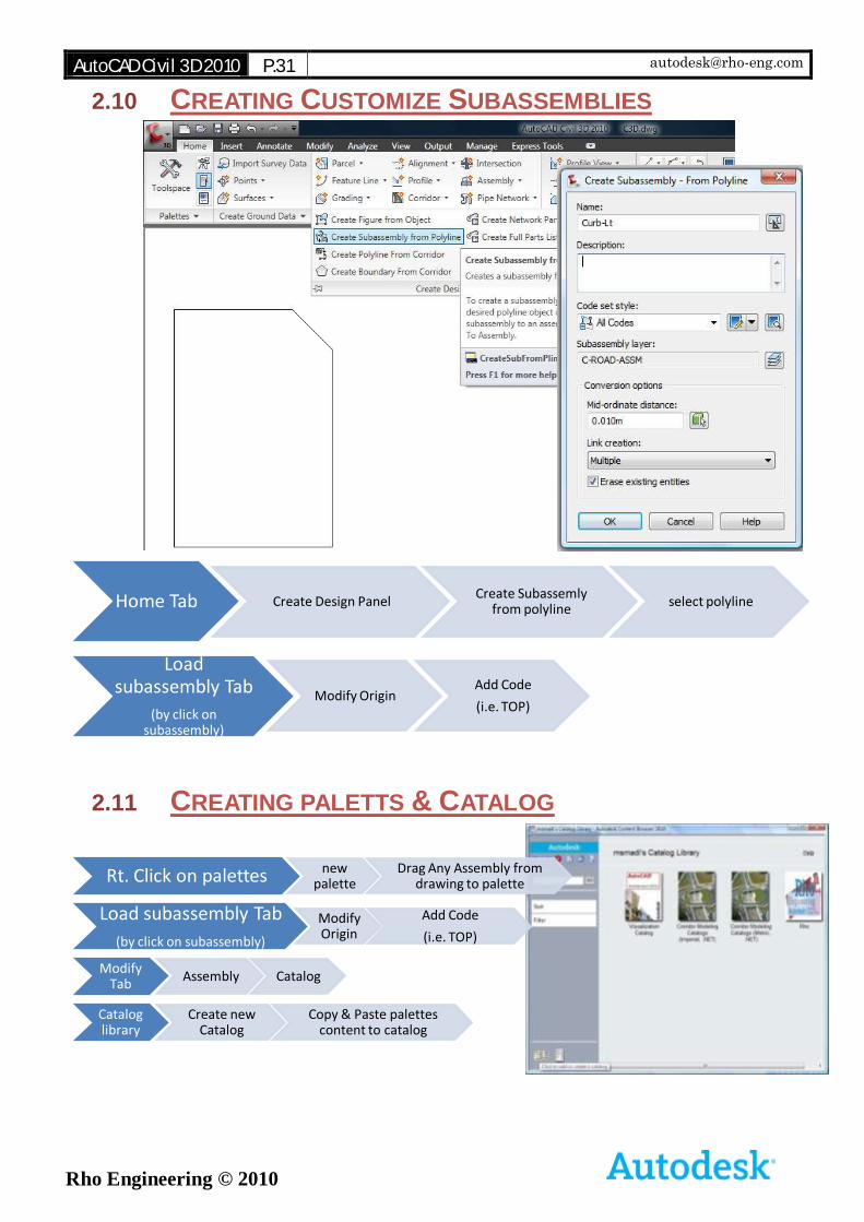
2.10 CREATING CUSTOMIZE SUBASSEMBLIES
2.11 CREATING PALETTS & CATALOG
Home Tab Create Design PanelCreate Subassemly
from polylineselect polyline
Load subassembly Tab
(by click on subassembly)
Modify OriginAdd Code
(i.e. TOP)
Rt. Click on palettes new palette
Drag Any Assembly from drawing to palette
Load subassembly Tab
(by click on subassembly)
Modify Origin
Add Code
(i.e. TOP)
Modify Tab
Assembly Catalog
Catalog library
Create new Catalog
Copy & Paste palettes content to catalog