Embed Size (px)
Citation preview
8/12/2019 CIV4001-CIV4002 Intermediate Report - Research Proposal Template
http://slidepdf.com/reader/full/civ4001-civ4002-intermediate-report-research-proposal-template 1/19
CIV 6020 Intermediate Report – Research Proposal
Department of Civil and Structural Engineering, University of Sheffield, 2012
Seismic Response of Reinforced
Concrete Structures with FRP
Strengthening
The University of SheffieldDepartment of Civil and Structural Engineering
CIV6020 Intermediate Report – Research Proposal
Candidate: MSc Structural Engineering
Supervisor: Prof. Kypros Pilakoutas
8/12/2019 CIV4001-CIV4002 Intermediate Report - Research Proposal Template
http://slidepdf.com/reader/full/civ4001-civ4002-intermediate-report-research-proposal-template 2/19
i
Abstract
The phenomenon of earthquakes has been far too old and the study on seismology has been
far too young to understand its true nature. The in depth-science of earthquakes has been a big
question since no can precisely predict when it is going to occur how it is going to occur and
what consequences in would bring into to the surface. Therefore it is very important in this
day and age to at least predict the outcome due to this on mad made structures. Many scientist
and seismologist and engineers have been working intensely on this subject because the
general consequence it brings is often catastrophic, devastating and fatal.
This MSc dissertation project briefly covers a basic study on earthquake loads and its
behaviour on reinforced concrete structures and its methods of failures to enable the reader to
understand a full picture of the response characteristics of a reinforced concrete structure.
This project mainly experiments a model which was chosen to be the Ecoleader Project n2
which is a seismically designed R/C frame structure used to test different strengthening
techniques to develop simple rational techniques for use in FRP strengthening on Beam-
Column joints to quantify their effectiveness on the response of the structure. Special cases of
Tsunami loadings on reinforced concrete structures are also reviewed. The main aim to
research this is to apply this loading condition onto this projects model if time permits.
8/12/2019 CIV4001-CIV4002 Intermediate Report - Research Proposal Template
http://slidepdf.com/reader/full/civ4001-civ4002-intermediate-report-research-proposal-template 3/19
ii
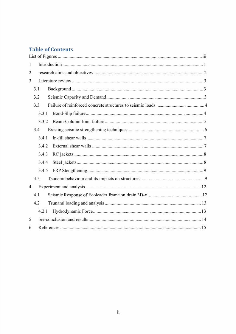
Table of Contents
List of Figures ........................................................................................................................... iii
1 Introduction ........................................................................................................................ 1
2 research aims and objectives .............................................................................................. 2
3 Literature review ................................................................................................................ 3
3.1 Background ................................................................................................................ 3
3.2 Seismic Capacity and Demand ................................................................................... 3
3.3 Failure of reinforced concrete structures to seismic loads ......................................... 4
3.3.1 Bond-Slip failure .................................................................................................... 4
3.3.2 Beam-Column Joint failure .................................................................................... 5
3.4 Existing seismic strengthening techniques ................................................................. 6
3.4.1 In-fill shear walls .................................................................................................... 7
3.4.2 External shear walls ............................................................................................... 7
3.4.3 RC jackets .............................................................................................................. 8
3.4.4 Steel jackets ............................................................................................................ 8
3.4.5 FRP Stengthening ................................................................................................... 9
3.5 Tsunami behaviour and its impacts on structures ...................................................... 9
4 Experiment and analysis ................................................................................................... 12
4.1 Seismic Response of Ecoleader frame on drain 3D-x .............................................. 12
4.2 Tsunami loading and analysis .................................................................................. 13
4.2.1 Hydrodynamic Force ............................................................................................ 13
5 pre-conclusion and results ................................................................................................ 14
6 References ........................................................................................................................ 15
8/12/2019 CIV4001-CIV4002 Intermediate Report - Research Proposal Template
http://slidepdf.com/reader/full/civ4001-civ4002-intermediate-report-research-proposal-template 4/19
iii
List of Figures
Figure 1 Example of Dissipative and non-dissipative global behaviour of structures [1] ......... 1
Figure 2 Damage on reinforcement column due to insufficient lap splice ............................... 2
Figure 3 ...................................................................................................................................... 3
Figure 4 General issues and causes for failure of reinforced concrete joints. ............................ 4
Figure 5 Typical Failure of Beam-Column Joint ....................................................................... 5
Figure 6- Change in the displacement demand and capacity of the structure after
strengthening [6] ................................................................................................................ 6
Figure 7 Reinforcement of in fill shear walls ............................................................................. 7
Figure 8 Application of external shear walls ............................................................................. 7
Figure 9 RC jacketing in beam-column joint ............................................................................. 8
Figure 10 Typical application of steel jacketing ........................................................................ 8
Figure 11- FRP strengthened frame ........................................................................................... 9
Figure 12- Uplift of water column due to earthquake .............................................................. 10
Figure 13- Tsunami wave generation ....................................................................................... 10
Figure 14- Tsunami wave with collected debris ...................................................................... 11
Figure 15 Damage on RC structures due to Tsunami water born objects ................................ 11
Figure 16- FRP strengthened Ecoleader frame ........................................................................ 12
8/12/2019 CIV4001-CIV4002 Intermediate Report - Research Proposal Template
http://slidepdf.com/reader/full/civ4001-civ4002-intermediate-report-research-proposal-template 5/19
1
1 INTRODUCTION
New lessons are always learnt earthquakes in intense magnitude. One of the common lessons
is learnt in many concrete structures around the world. In the days of rapid growth and
research in high performance material technology, the need for a ductile, strong, efficient
material is very essential to keep the world away from devastating results due to the curtsy of
natural disasters. The expertise show us that r/c structures strengthened with FRP are one of
the effective and efficient strengthening technique that can be adopted when its subjected
loads to seismic actions. In technical terms there are two primary methods in which the
seismic loads can be resisted:
Where the structure is constructed with large member sections that they are limited
only to take elastic stresses.
Where in a structure constructed of small sections, those are designed to create many
plastic hinges.
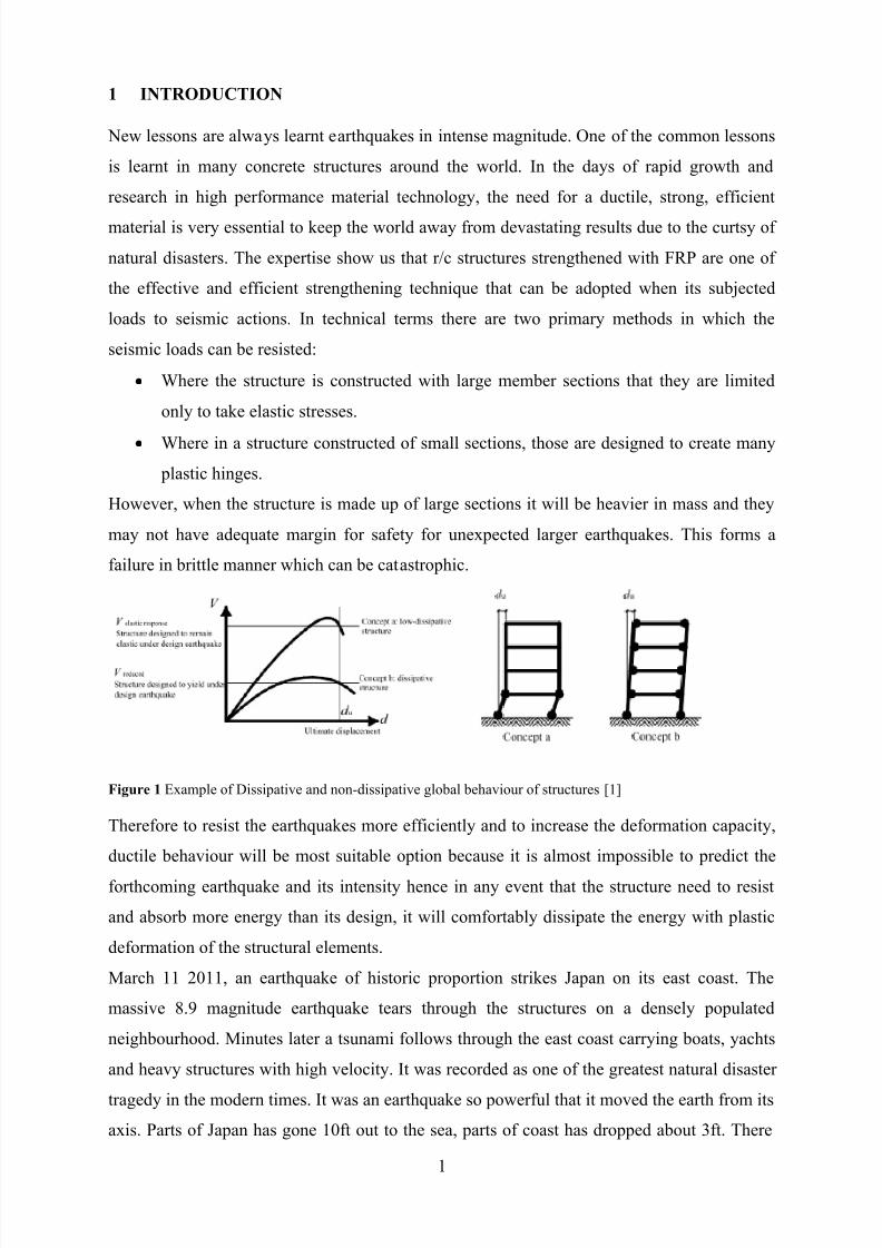
However, when the structure is made up of large sections it will be heavier in mass and they
may not have adequate margin for safety for unexpected larger earthquakes. This forms a
failure in brittle manner which can be catastrophic.
Figure 1 Example of Dissipative and non-dissipative global behaviour of structures [1]
Therefore to resist the earthquakes more efficiently and to increase the deformation capacity,
ductile behaviour will be most suitable option because it is almost impossible to predict the
forthcoming earthquake and its intensity hence in any event that the structure need to resist
and absorb more energy than its design, it will comfortably dissipate the energy with plastic
deformation of the structural elements.
March 11 2011, an earthquake of historic proportion strikes Japan on its east coast. The
massive 8.9 magnitude earthquake tears through the structures on a densely populated
neighbourhood. Minutes later a tsunami follows through the east coast carrying boats, yachts
and heavy structures with high velocity. It was recorded as one of the greatest natural disaster
tragedy in the modern times. It was an earthquake so powerful that it moved the earth from its
axis. Parts of Japan has gone 10ft out to the sea, parts of coast has dropped about 3ft. There
8/12/2019 CIV4001-CIV4002 Intermediate Report - Research Proposal Template
http://slidepdf.com/reader/full/civ4001-civ4002-intermediate-report-research-proposal-template 6/19
2
are no mysteries in the event of this earthquake. Many people were able to survive due the
science and engineering understanding of earthquake behaviour and Tsunami, but this disaster
shows there is much more to learn for engineering purposes.
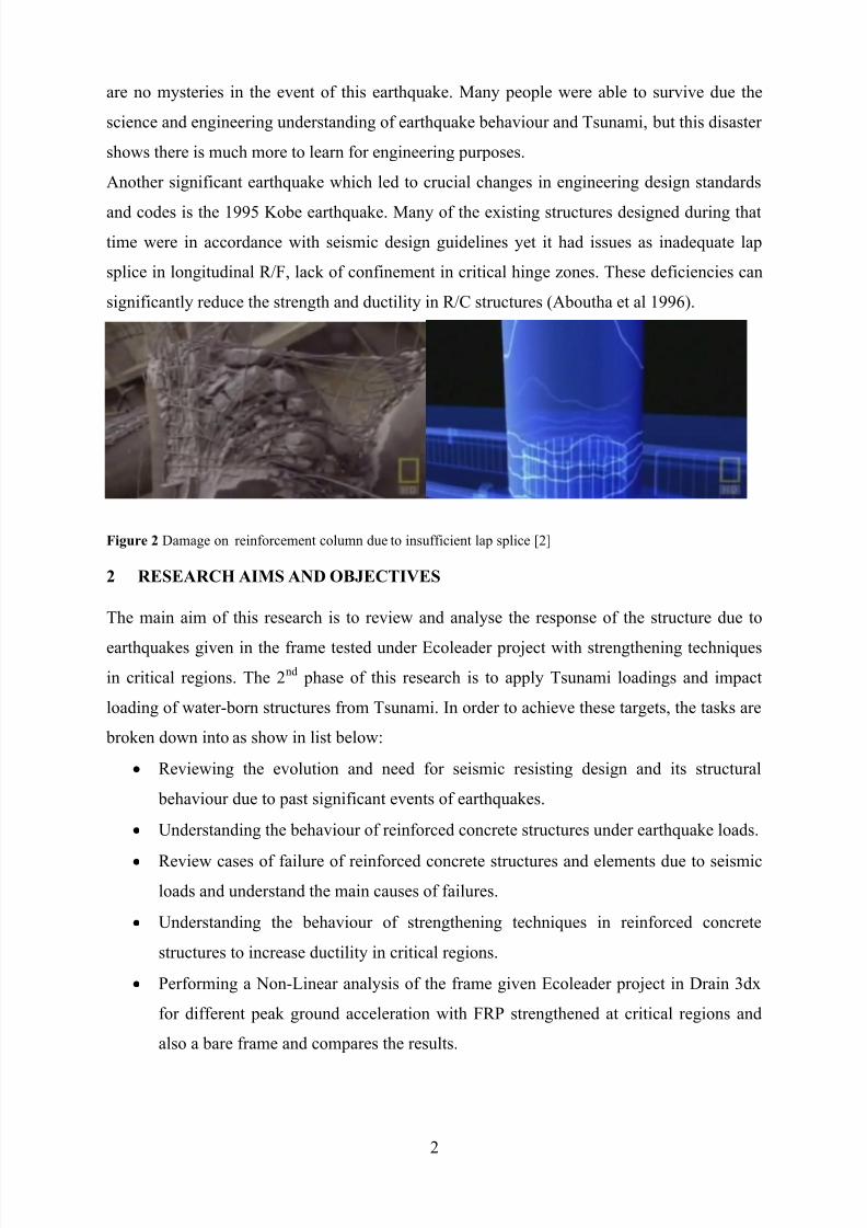
Another significant earthquake which led to crucial changes in engineering design standards
and codes is the 1995 Kobe earthquake. Many of the existing structures designed during that
time were in accordance with seismic design guidelines yet it had issues as inadequate lap
splice in longitudinal R/F, lack of confinement in critical hinge zones. These deficiencies can
significantly reduce the strength and ductility in R/C structures (Aboutha et al 1996).
Figure 2 Damage on reinforcement column due to insufficient lap splice [2]
2 RESEARCH AIMS AND OBJECTIVES
The main aim of this research is to review and analyse the response of the structure due to
earthquakes given in the frame tested under Ecoleader project with strengthening techniques
in critical regions. The 2nd phase of this research is to apply Tsunami loadings and impact
loading of water-born structures from Tsunami. In order to achieve these targets, the tasks are
broken down into as show in list below:
Reviewing the evolution and need for seismic resisting design and its structural
behaviour due to past significant events of earthquakes.
Understanding the behaviour of reinforced concrete structures under earthquake loads.
Review cases of failure of reinforced concrete structures and elements due to seismic
loads and understand the main causes of failures.
Understanding the behaviour of strengthening techniques in reinforced concrete
structures to increase ductility in critical regions.
Performing a Non-Linear analysis of the frame given Ecoleader project in Drain 3dx
for different peak ground acceleration with FRP strengthened at critical regions and
also a bare frame and compares the results.
8/12/2019 CIV4001-CIV4002 Intermediate Report - Research Proposal Template
http://slidepdf.com/reader/full/civ4001-civ4002-intermediate-report-research-proposal-template 7/19
3
Study the phenomenon of Tsunami loading effects on reinforced concrete structures
and understand the behaviour of impulse loading due to water-born structures during a
Tsunami.
Application of Tsunami loads in to model in Drain 3dx and analyse results with a
frame strengthened with FRP.
3 LITERATURE REVIEW
3.1 Background
Existing reinforced concrete structures which were designed using only gravity loads or old
seismic standards should be modified on its structural configurations and material properties
to increase seismic performance. However information gathered from last few decades of
experimental and analytical studies from researches has given a rigid foundation of guidelines
for dealing with problems that are specific and in a logical manner due to high uncertainty on
the estimation of earthquake loads on structures.
Current seismic design accepts that damage will occur in moderate to large seismic events,
although attempts are made via special detailing and strengthening techniques to limit this
damage to specific plastic hinge zones. These zones, designed to sustain sever damage under
multiple cyclic rotations, tend to act like a fuse, essentially protecting the structure from
forming unfavourable mechanisms. Although this design philosophy ensures good protection
to occupants by preventing collapse, there is a strong likelihood a moderate to large
earthquake will render a structure irreparable. As a result, economic costs, both direct and
indirect, can be significant; this has been confirmed from recent earthquakes in the United
States (Northridge, 1994) and Japan (Kobe, 1995).
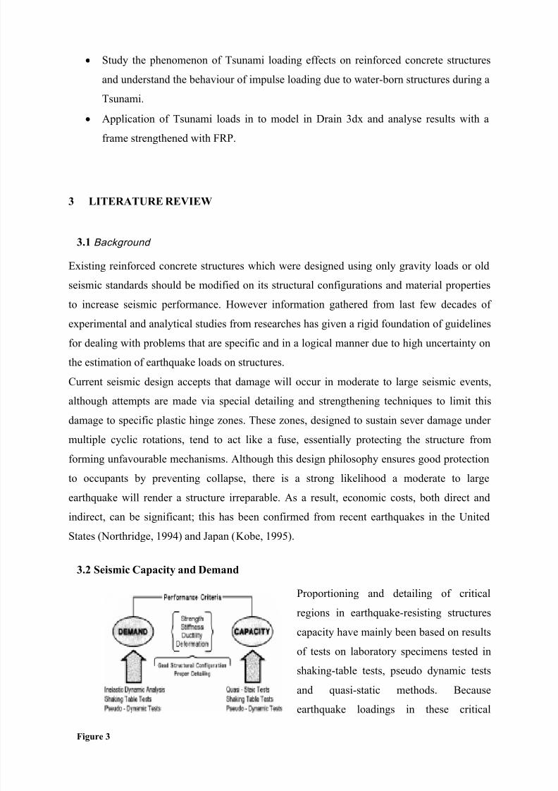
3.2 Seismic Capacity and Demand
Proportioning and detailing of critical
regions in earthquake-resisting structures
capacity have mainly been based on results
of tests on laboratory specimens tested in
shaking-table tests, pseudo dynamic tests
and quasi-static methods. Becauseearthquake loadings in these critical
Figure 3
8/12/2019 CIV4001-CIV4002 Intermediate Report - Research Proposal Template
http://slidepdf.com/reader/full/civ4001-civ4002-intermediate-report-research-proposal-template 8/19
4
regions require additional requirements apart from proving sufficient strength and stiffness to
structural elements, a another basic requirement must be considered in the earthquake
resisting design which is ductility or inelastic deformation capacity. This is mainly because its
not economically feasible to design structures to behave elastically to strong-moderate
earthquakes [4]. Thus providing ductility in the critical regions will allow the structure to
dissipate most amount of energy by inelastic deformation as shown in Figure 3.
Since yielding at critically stressed regions and subsequent redistribution of forces to less
stressed regions is central to the ductile performance of a structure, good practice suggests
providing as much redundancy as possible in a structure.
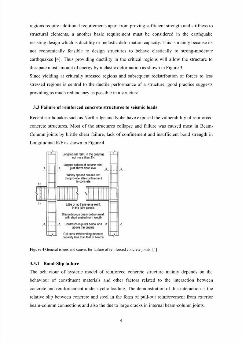
3.3 Failure of reinforced concrete structures to seismic loads
Recent earthquakes such as Northridge and Kobe have exposed the vulnerability of reinforced
concrete structures. Most of the structures collapse and failure was caused most in Beam-
Column joints by brittle shear failure, lack of confinement and insufficient bond strength in
Longitudinal R/F as shown in Figure 4.
Figure 4 General issues and causes for failure of reinforced concrete joints. [4]
3.3.1 Bond-Slip failure
The behaviour of hysteric model of reinforced concrete structure mainly depends on the
behaviour of constituent materials and other factors related to the interaction between
concrete and reinforcement under cyclic loading. The demonstration of this interaction is the
relative slip between concrete and steel in the form of pull-out reinforcement from exterior
beam-column connections and also the due to large cracks in internal beam-column joints.
8/12/2019 CIV4001-CIV4002 Intermediate Report - Research Proposal Template
http://slidepdf.com/reader/full/civ4001-civ4002-intermediate-report-research-proposal-template 9/19
5
During the design reinforced concrete elements it is assumed that perfect bond takes place.
This is true for low loads but when the load increases, cracking and breaking of bond happens
unavoidably and bond slip takes place in the beam. Near the cracks high bond stresses
develop causing relative displacement between reinforcement and concrete.
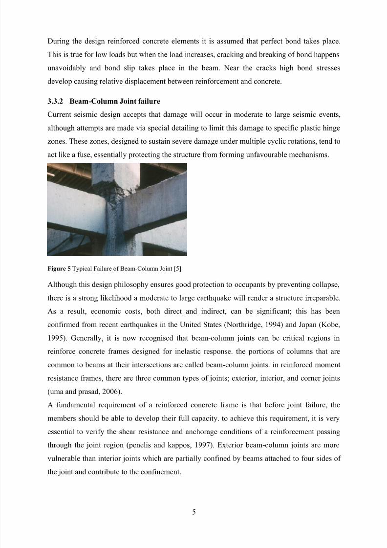
3.3.2 Beam-Column Joint failure
Current seismic design accepts that damage will occur in moderate to large seismic events,
although attempts are made via special detailing to limit this damage to specific plastic hinge
zones. These zones, designed to sustain severe damage under multiple cyclic rotations, tend to
act like a fuse, essentially protecting the structure from forming unfavourable mechanisms.
Figure 5 Typical Failure of Beam-Column Joint [5]
Although this design philosophy ensures good protection to occupants by preventing collapse,there is a strong likelihood a moderate to large earthquake will render a structure irreparable.
As a result, economic costs, both direct and indirect, can be significant; this has been
confirmed from recent earthquakes in the United States (Northridge, 1994) and Japan (Kobe,
1995). Generally, it is now recognised that beam-column joints can be critical regions in
reinforce concrete frames designed for inelastic response. the portions of columns that are
common to beams at their intersections are called beam-column joints. in reinforced moment
resistance frames, there are three common types of joints; exterior, interior, and corner joints
(uma and prasad, 2006).
A fundamental requirement of a reinforced concrete frame is that before joint failure, the
members should be able to develop their full capacity. to achieve this requirement, it is very
essential to verify the shear resistance and anchorage conditions of a reinforcement passing
through the joint region (penelis and kappos, 1997). Exterior beam-column joints are more
vulnerable than interior joints which are partially confined by beams attached to four sides of
the joint and contribute to the confinement.
8/12/2019 CIV4001-CIV4002 Intermediate Report - Research Proposal Template
http://slidepdf.com/reader/full/civ4001-civ4002-intermediate-report-research-proposal-template 10/19
6
3.4 Existing seismic strengthening techniques
In the past a large number of reinforced concrete structures have been damaged by severe
earthquakes, and some of these structures have been repaired and strengthened. Several
examples of the repair and strengthening of reinforced concrete buildings damaged by
earthquakes have been reported in earthquake-prone countries. The need for the strengthening
of structures also arises in cases where existing structures must comply with more recent code
requirements. This was the case for a number of structures in Japan after the 1978 Miyagiken-
oki Earthquake.
In New Zealand there are many structures constructed before the 1970's that would have
inadequate response during a strong earthquake. Comparison of the design levels for
seismic lateral loads between previous codes and the current loading code (NZS 4203 [9])
indicates that buildings designed to the previous codes often do not satisfy the strength and
ductility requirements of the current loading code. Typical deficiencies of moment resisting
frames are: inadequate shear strength of columns and beam-column joints, and inadequate
flexural strength and ductility of columns (Brunsdon and Priestley, Park).
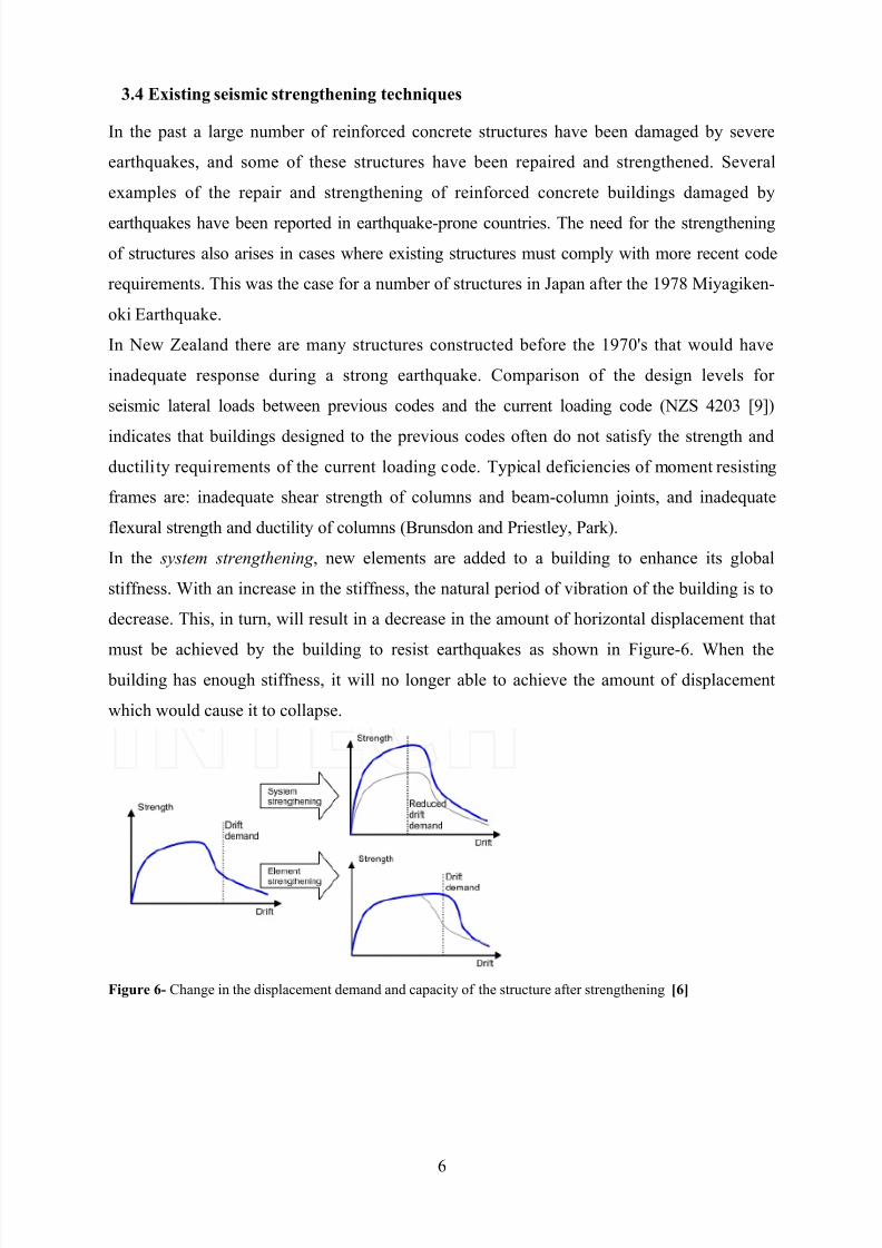
In the system strengthening , new elements are added to a building to enhance its global
stiffness. With an increase in the stiffness, the natural period of vibration of the building is to
decrease. This, in turn, will result in a decrease in the amount of horizontal displacement that
must be achieved by the building to resist earthquakes as shown in Figure-6. When the building has enough stiffness, it will no longer able to achieve the amount of displacement
which would cause it to collapse.
Figure 6- Change in the displacement demand and capacity of the structure after strengthening [6]
8/12/2019 CIV4001-CIV4002 Intermediate Report - Research Proposal Template
http://slidepdf.com/reader/full/civ4001-civ4002-intermediate-report-research-proposal-template 11/19
7
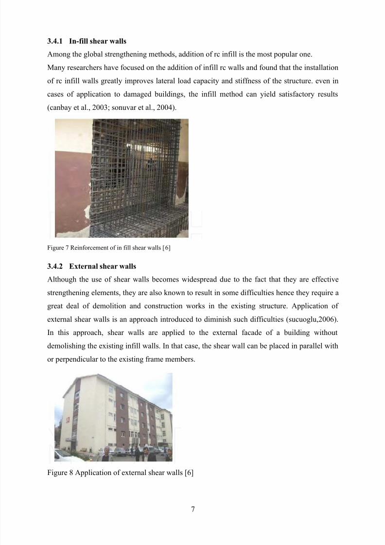
3.4.1 In-fill shear walls
Among the global strengthening methods, addition of rc infill is the most popular one.
Many researchers have focused on the addition of infill rc walls and found that the installation
of rc infill walls greatly improves lateral load capacity and stiffness of the structure. even in
cases of application to damaged buildings, the infill method can yield satisfactory results
(canbay et al., 2003; sonuvar et al., 2004).
Figure 7 Reinforcement of in fill shear walls [6]
3.4.2 External shear walls
Although the use of shear walls becomes widespread due to the fact that they are effective
strengthening elements, they are also known to result in some difficulties hence they require a
great deal of demolition and construction works in the existing structure. Application of
external shear walls is an approach introduced to diminish such difficulties (sucuoglu,2006).
In this approach, shear walls are applied to the external facade of a building without
demolishing the existing infill walls. In that case, the shear wall can be placed in parallel with
or perpendicular to the existing frame members.
Figure 8 Application of external shear walls [6]
8/12/2019 CIV4001-CIV4002 Intermediate Report - Research Proposal Template
http://slidepdf.com/reader/full/civ4001-civ4002-intermediate-report-research-proposal-template 12/19
8
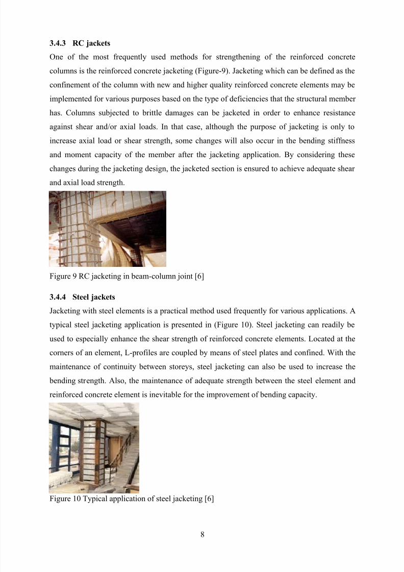
3.4.3 RC jackets
One of the most frequently used methods for strengthening of the reinforced concrete
columns is the reinforced concrete jacketing (Figure-9). Jacketing which can be defined as the
confinement of the column with new and higher quality reinforced concrete elements may be
implemented for various purposes based on the type of deficiencies that the structural member
has. Columns subjected to brittle damages can be jacketed in order to enhance resistance
against shear and/or axial loads. In that case, although the purpose of jacketing is only to
increase axial load or shear strength, some changes will also occur in the bending stiffness
and moment capacity of the member after the jacketing application. By considering these
changes during the jacketing design, the jacketed section is ensured to achieve adequate shear
and axial load strength.
Figure 9 RC jacketing in beam-column joint [6]
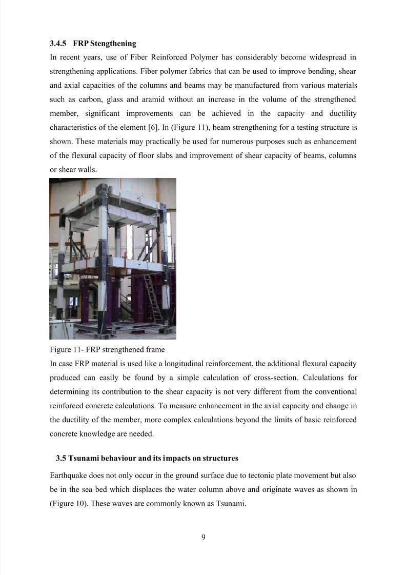
3.4.4 Steel jacketsJacketing with steel elements is a practical method used frequently for various applications. A
typical steel jacketing application is presented in (Figure 10). Steel jacketing can readily be
used to especially enhance the shear strength of reinforced concrete elements. Located at the
corners of an element, L-profiles are coupled by means of steel plates and confined. With the
maintenance of continuity between storeys, steel jacketing can also be used to increase the
bending strength. Also, the maintenance of adequate strength between the steel element and
reinforced concrete element is inevitable for the improvement of bending capacity.
Figure 10 Typical application of steel jacketing [6]
8/12/2019 CIV4001-CIV4002 Intermediate Report - Research Proposal Template
http://slidepdf.com/reader/full/civ4001-civ4002-intermediate-report-research-proposal-template 13/19
9
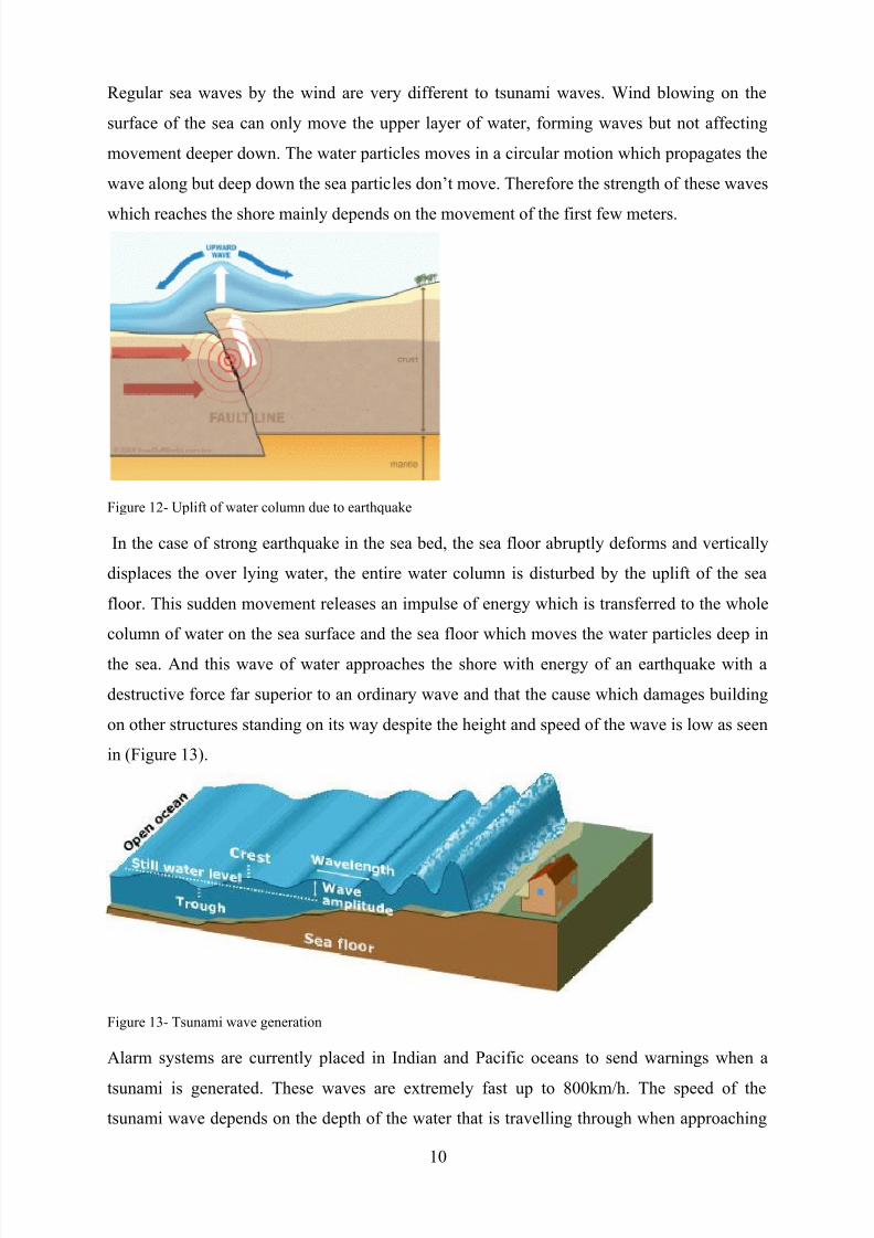
3.4.5 FRP Stengthening
In recent years, use of Fiber Reinforced Polymer has considerably become widespread in
strengthening applications. Fiber polymer fabrics that can be used to improve bending, shear
and axial capacities of the columns and beams may be manufactured from various materials
such as carbon, glass and aramid without an increase in the volume of the strengthened
member, significant improvements can be achieved in the capacity and ductility
characteristics of the element [6]. In (Figure 11), beam strengthening for a testing structure is
shown. These materials may practically be used for numerous purposes such as enhancement
of the flexural capacity of floor slabs and improvement of shear capacity of beams, columns
or shear walls.
Figure 11- FRP strengthened frame
In case FRP material is used like a longitudinal reinforcement, the additional flexural capacity
produced can easily be found by a simple calculation of cross-section. Calculations for
determining its contribution to the shear capacity is not very different from the conventional
reinforced concrete calculations. To measure enhancement in the axial capacity and change in
the ductility of the member, more complex calculations beyond the limits of basic reinforced
concrete knowledge are needed.
3.5 Tsunami behaviour and its impacts on structures
Earthquake does not only occur in the ground surface due to tectonic plate movement but also
be in the sea bed which displaces the water column above and originate waves as shown in
(Figure 10). These waves are commonly known as Tsunami.
8/12/2019 CIV4001-CIV4002 Intermediate Report - Research Proposal Template
http://slidepdf.com/reader/full/civ4001-civ4002-intermediate-report-research-proposal-template 14/19
10
Regular sea waves by the wind are very different to tsunami waves. Wind blowing on the
surface of the sea can only move the upper layer of water, forming waves but not affecting
movement deeper down. The water particles moves in a circular motion which propagates the
wave along but deep down the sea particles don’t move. Therefore the strength of these waves
which reaches the shore mainly depends on the movement of the first few meters.
Figure 12- Uplift of water column due to earthquake
In the case of strong earthquake in the sea bed, the sea floor abruptly deforms and vertically
displaces the over lying water, the entire water column is disturbed by the uplift of the sea
floor. This sudden movement releases an impulse of energy which is transferred to the whole
column of water on the sea surface and the sea floor which moves the water particles deep in
the sea. And this wave of water approaches the shore with energy of an earthquake with a
destructive force far superior to an ordinary wave and that the cause which damages building
on other structures standing on its way despite the height and speed of the wave is low as seen
in (Figure 13).
Figure 13- Tsunami wave generation
Alarm systems are currently placed in Indian and Pacific oceans to send warnings when a
tsunami is generated. These waves are extremely fast up to 800km/h. The speed of the
tsunami wave depends on the depth of the water that is travelling through when approaching
8/12/2019 CIV4001-CIV4002 Intermediate Report - Research Proposal Template
http://slidepdf.com/reader/full/civ4001-civ4002-intermediate-report-research-proposal-template 15/19
11
the shore therefore the tsunamis speed diminishes but the wave amplitude increases as it
approaches the shore as shown in (Figure-13).
During the Japan 2011 earthquake 95% of buildings were destroyed by Tsunami. As
witnessed heavy boats and cars were on top of buildings because as water pushes through
restricted areas in dense towns, its being tunnelled therefore it squeezes and increases its
height. Once the wave starts to move, it moves like glacier with collected heavy debris of
boats, trucks and cars including full scale houses as show in (Figure 14).
Figure 14- Tsunami wave with collected debris
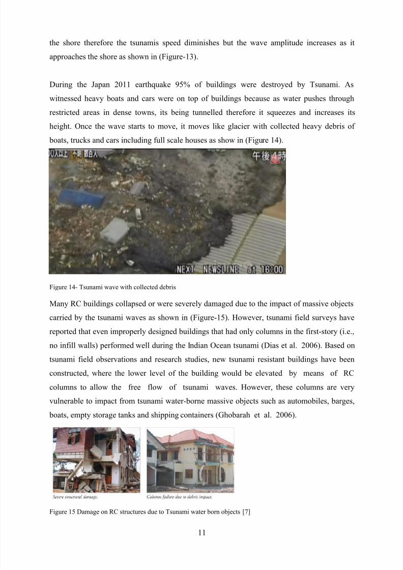
Many RC buildings collapsed or were severely damaged due to the impact of massive objects
carried by the tsunami waves as shown in (Figure-15). However, tsunami field surveys have
reported that even improperly designed buildings that had only columns in the first-story (i.e.,
no infill walls) performed well during the Indian Ocean tsunami (Dias et al. 2006). Based on
tsunami field observations and research studies, new tsunami resistant buildings have been
constructed, where the lower level of the building would be elevated by means of RC
columns to allow the free flow of tsunami waves. However, these columns are very
vulnerable to impact from tsunami water-borne massive objects such as automobiles, barges,
boats, empty storage tanks and shipping containers (Ghobarah et al. 2006).
Figure 15 Damage on RC structures due to Tsunami water born objects [7]
8/12/2019 CIV4001-CIV4002 Intermediate Report - Research Proposal Template
http://slidepdf.com/reader/full/civ4001-civ4002-intermediate-report-research-proposal-template 16/19
12
4 EXPERIMENT AND ANALYSIS
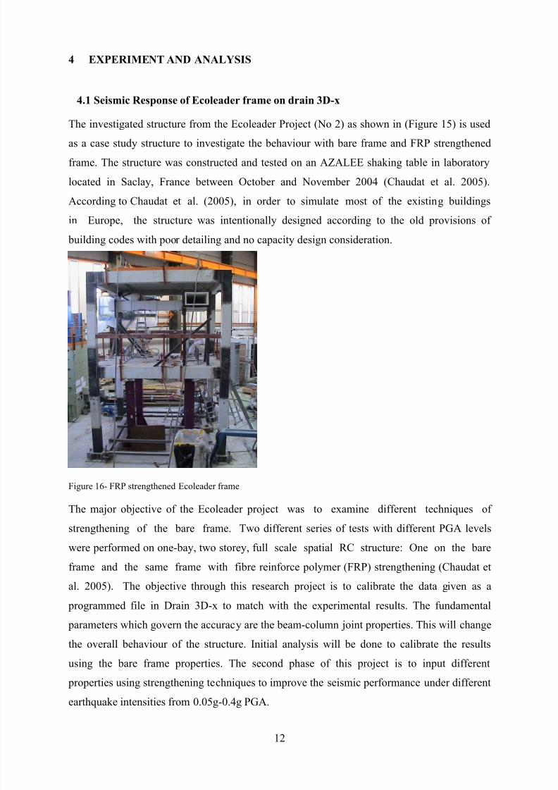
4.1 Seismic Response of Ecoleader frame on drain 3D-x
The investigated structure from the Ecoleader Project (No 2) as shown in (Figure 15) is used
as a case study structure to investigate the behaviour with bare frame and FRP strengthened
frame. The structure was constructed and tested on an AZALEE shaking table in laboratory
located in Saclay, France between October and November 2004 (Chaudat et al. 2005).
According to Chaudat et al. (2005), in order to simulate most of the existing buildings
in Europe, the structure was intentionally designed according to the old provisions of
building codes with poor detailing and no capacity design consideration.
Figure 16- FRP strengthened Ecoleader frame
The major objective of the Ecoleader project was to examine different techniques of
strengthening of the bare frame. Two different series of tests with different PGA levels
were performed on one-bay, two storey, full scale spatial RC structure: One on the bare
frame and the same frame with fibre reinforce polymer (FRP) strengthening (Chaudat et
al. 2005). The objective through this research project is to calibrate the data given as a
programmed file in Drain 3D-x to match with the experimental results. The fundamental
parameters which govern the accuracy are the beam-column joint properties. This will change
the overall behaviour of the structure. Initial analysis will be done to calibrate the results
using the bare frame properties. The second phase of this project is to input different
properties using strengthening techniques to improve the seismic performance under different
earthquake intensities from 0.05g-0.4g PGA.
8/12/2019 CIV4001-CIV4002 Intermediate Report - Research Proposal Template
http://slidepdf.com/reader/full/civ4001-civ4002-intermediate-report-research-proposal-template 17/19
13
4.2 Tsunami loading and analysis
Building damage due to tsunami water-borne massive objects has been studied in seveal other
p, impact on a RC building with elevated lower level due to boats and shipping containers is
discussed. Nonlinear dynamic analysis of ecoleader RC frame systems is considered, namely
ordinary moment bare frame and FRP strengthened frame for high tsunami prone zones. At
the column impact section the displacement, shear force and moment-curvature responses are
investigated. In addition, the stress-strain behaviour of cover concrete, core concrete and
tension reinforcement at the impact section are studied. Finally, the behaviour of both frames
is compared.
Some of the main forces acting on structures due to a tsunami are breaking wave force,
buoyant force, hydrostatic force, surge force, hydrodynamic (drag) force and impact force due
to water-borne objects (Yeh 2006). In the present study, the dominant forces are the
hydrodynamic force and the impact force from tsunami water-borne massive objects.
4.2.1 Hydrodynamic Force
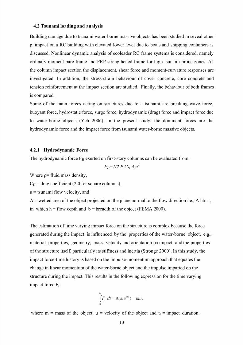
The hydrodynamic force FH exerted on first-story columns can be evaluated from:
F H =1/2. Ρ .C D.A.u2
Where ρ= fluid mass density,
CD = drag coefficient (2.0 for square columns),
u = tsunami flow velocity, and
A = wetted area of the object projected on the plane normal to the flow direction i.e., A hb = ,
in which h = flow depth and b = breadth of the object (FEMA 2000).
The estimation of time varying impact force on the structure is complex because the force
generated during the impact is influenced by the properties of the water-borne object, e.g.,
material properties, geometry, mass, velocity and orientation on impact; and the properties
of the structure itself, particularly its stiffness and inertia (Stronge 2000). In this study, the
impact force-time history is based on the impulse-momentum approach that equates the
change in linear momentum of the water-borne object and the impulse imparted on the
structure during the impact. This results in the following expression for the time varying
impact force FI:
where m = mass of the object, u = velocity of the object and t I = impact duration.
8/12/2019 CIV4001-CIV4002 Intermediate Report - Research Proposal Template
http://slidepdf.com/reader/full/civ4001-civ4002-intermediate-report-research-proposal-template 18/19
14
In Eqn above it is assumed that the velocity of the object before impact is the same as the
tsunami flow velocity u for the given inundation depth and that the linear momentum of
the object after impact is zero. The impact force-time history for the dynamic analysis is
assumed to be of triangular shape and the impact duration is taken as t I =0.1s following the
recommendation for RC construction in CCH (2000).
5 PRE-CONCLUSION AND RESULTS
Seismic performance of old buildings designed for old standards are vulnerable to both
seismic and tsunami load hazards. It was clearly seen the requirement of efficient
strengthening material to improve the performance of sub-standard buildings. Previous
research on the Ecoleader model using Drain 3D-x by using FRP and PTMS techniques reveal
significant change in overall structural behaviour. The analytical frequency dropped by 54%
for the first mode which is higher than the previous model by 10%. The analytical
results showed better agreement (by 15%) with the experimental results in contrast to the
previous model.
Considering the cases of previous research on the response of Tsunami loading due to water- born structures will be used in reference for this project. It shows that the peak displacement
due to a 1500 kg boat is more than 2.5 times the peak displacement due to impact of the 1200
kg boat at the same level. Degradation of the axial load carrying capacity, longitudinal bar in
tension has yielded and the maximum strain is 0.011 which is 5.5 times the yield strain due to
impact of the 1500 kg boat (Anil C, Kavinda 2008).
8/12/2019 CIV4001-CIV4002 Intermediate Report - Research Proposal Template
http://slidepdf.com/reader/full/civ4001-civ4002-intermediate-report-research-proposal-template 19/19
15
6 REFERENCES
[1] ArcelorMittal Technical Brochure: Earthquake Resistant Steel Structures, Figure-3
[2] http://natgeotv.com.au/tv/seconds-from-disaster/episode.aspx?id=1875
[3] Seismic Design of Reinforced Concrete Structures, ASO OMER MOHAMAD AMINE,
1.4-1.6
[4] Repair and Strengthening of Reinforced Concrete Beam-Column Joints: State of
the Art by Murat Engindeniz, Lawrence F. Kahn, and Abdul-Hamid Zureick, ACI
structural journal technical paper
[5] http://www.engr.psu.edu/ae/newsletters/newsletter/Sp01/India.htm
[6] Seismic Strengthening of Reinforced Concrete Buildings Hasan Kaplan and Salih
Yılmaz Pamukkale University, Department of Civil Engineering Turkey
[7] Tsunami-Induced Loading on StructuresDan Palermo, Ph.D., P.Eng., and Ioan Nistor,Ph.D., P.Eng.