Embed Size (px)
Citation preview
2017 City of Renton Surface Water Design Manual 12/12/2016
CHAPTER 6 WATER QUALITY DESIGN
CITY OF RENTON
SURFACE WATER DESIGN MANUAL
Section Page 6.1 Water Quality Menus 6-3 6.1.1 Basic Water Quality Menu 6-5 6.1.2 Enhanced Basic Water Quality Menu 6-8 6.1.3 Sensitive Lake Protection Menu 6-10 6.1.4 Sphagnum Bog Protection Menu 6-14 6.1.5 High-Use Menu 6-15 6.1.6 Pretreatment Facilities 6-17 6.2 General Requirements for WQ
Facilities 6-19 6.2.1 Water Quality Design Flows and
Treatment Volumes 6-19 6.2.2 Sequence of Facilities 6-22 6.2.3 Setbacks, Slopes, and Embankments 6-24 6.2.4 Facility Liners 6-28 6.2.5 Flow Splitter Designs 6-32 6.2.6 Flow Spreading Options 6-36 6.3 Vegetated Flowpath Facility Designs 6-41 6.3.1 Basic Bioswales 6-41 6.3.2 Wet Bioswales 6-57 6.3.3 Lateral Inflow Bioswales 6-59 6.3.4 Standard Filter Strips 6-60 6.3.5 Narrow Area Filter Strips 6-68 6.4 Wetpool Facility Designs 6-69 6.4.1 Wetponds — Basic and Large 6-69 6.4.2 Wetvaults 6-84 6.4.3 Stormwater Wetlands 6-90 6.4.4 Combined Detention and Wetpool
Facilities 6-96 6.5 Filtration Facility Designs 6-101 6.5.1 General Requirements For Filtration
Facilities 6-101 6.5.2 Sand Filters — Basic and Large 6-102 6.5.3 Sand Filter Vaults 6-118 6.5.4 Linear Sand Filters 6-123 6.6 Oil Control Facility Designs 6-127 6.6.1 Catch Basin Inserts 6-127 6.6.2 Oil/Water Separators 6-127 6.7 Proprietary Facility Designs 6-141 6.7.1 Ecology Requirements 6-141 6.7.2 City of Renton Requirements 6-141 6.8 Bioretention Facility Designs 6-145 6.8.1 Bioretention 6-145

CITY OF RENTON SURFACE WATER DESIGN MANUAL
12/12/2016 2017 City of Renton Surface Water Design Manual
6.9 WSDOT WQ Facility Designs 6-159 6.9.1 Media Filter Drain 6-159 6.9.2 Compost-Amended Filter Strips 6-169 6.9.3 Compost-Amended Biofiltration Swales 6-170
CITY OF RENTON SURFACE WATER DESIGN MANUAL
2017 City of Renton Surface Water Design Manual 12/12/2016 6-1
CHAPTER 6 WATER QUALITY DESIGN
This chapter presents the City of Renton approved methods, criteria, and details for analysis and design of water quality facilities pursuant to Core Requirement #8, discussed in Section 1.2.8, and Special Requirement #5, discussed in Section 1.3.5.
Chapter Organization The information in this chapter is organized into the following nine main sections.
• Section 6.1, “Water Quality Menus,” details the area-specific water quality menus referred to in Core Requirement #8 of Chapter 1, and the High-Use Menu referred to in Special Requirement #5, also in Chapter 1.
• Section 6.2, “General Requirements for WQ Facilities,” presents general design requirements and details pertinent to all water quality facilities.
• Section 6.3, “Vegetated Flowpath Facility Designs,” presents the details for analysis and design of bioswales and filter strips.
• Section 6.4, “Wetpool Facility Designs,” presents the details for analysis and design of wetponds, wetvaults, stormwater wetlands, and combinations of these facilities with detention facilities.
• Section 6.5, “Filtration Facility Designs,” presents the details for analysis and design of sand filters. • Section 6.6, “Oil Control Facility Designs,” presents the details for analysis and design of catch
basin inserts and coalescing-plate oil/water separators. • Section 6.7, “Proprietary Facility Designs,” discusses general considerations for proprietary
manufactured facilities, including summary notes regarding City requirements for approval for use of these systems. This section points to Reference Section 14-A and Reference Section 14-B, which includes design and maintenance considerations for proprietary facilities which have been approved by the City.
• Section 6.8, “Bioretention Facility Designs,” presents the details for analysis and design of bioretention facilities.
• Section 6.9, “WSDOT WQ Facility Designs,” presents the details for analysis and design of media filter drains, compost-amended vegetated filter strips, and compost-amended biofiltration swales.
Required vs. Recommended Design Criteria Both required and recommended design criteria are presented in this chapter. Criteria stated using “shall” or “must” are mandatory, to be used unless there is a good reason to deviate as allowed under the adjustment process in Section 1.4. These criteria are required design criteria and generally affect facility performance or critical maintenance factors.
Sometimes options are stated as part of the required design criteria using the language “should” or “may.” These criteria are recommended design criteria, but are closely related to the required criteria, so they

CHAPTER 6 WATER QUALITY DESIGN
12/12/2016 2017 City of Renton Surface Water Design Manual 6-2
are placed in the same section. In some cases, recommended design features are presented under a separate heading in the “Design Criteria” sections.
Design Criteria Applicable To All Facilities All facilities must be designed and constructed to allow inspection and maintenance.
Use of Chapter 6 Figures The figures included in this chapter are provided as schematic representations and should not be used for design. Refer to the City of Renton Standard Details for specific design information. The figures provided in this chapter illustrate one example of how the WQ facility design criteria may be applied. Although the figures are meant to illustrate many of the most important design criteria, they may not show all criteria that apply. In general, the figures are not used to specify requirements unless they are indicated elsewhere in the manual. If this manual refers to a standard detail not included in the City of Renton Standard Details, the applicant shall use the figures provided in the manual.1
Water Quality Facility Sizing Worksheets To make the water quality facility sizing methods more standardized for plan review purposes, sizing worksheets are included in Reference Section 8-C for the major water quality facilities. These worksheets are based on the step by step sizing methods given for the water quality facilities in this Chapter. Most design criteria that are not required for facility sizing are omitted from the worksheets. It is the designer’s responsibility to make sure that all the required design criteria for each water quality facility are provided on submitted plans. Facility sizing credits for water quality facilities may be used as allowed and specified in Chapter 1, Section 1.2.9.3 “Requirements for Use of BMP Credits.”
Please note that the worksheets are dated in the footer of each page. It is the designer’s responsibility to ensure that any Manual updates affecting the sizing procedure or design criteria after that date are incorporated into the worksheet. Updates, errata, and clarifications are posted at the City of Renton’s Surface Water Design Standards website: <http://rentonwa.gov/government/default.aspx?id=7122>.
If there are instances in which the worksheet differs from the design criteria in the text of this Chapter, the criteria as given in this Chapter, and as modified by subsequent updates, shall be considered the governing criteria.
1 Footnote 1 is not used.

CITY OF RENTON SURFACE WATER DESIGN MANUAL
2017 City of Renton Surface Water Design Manual 12/12/2016 6-3
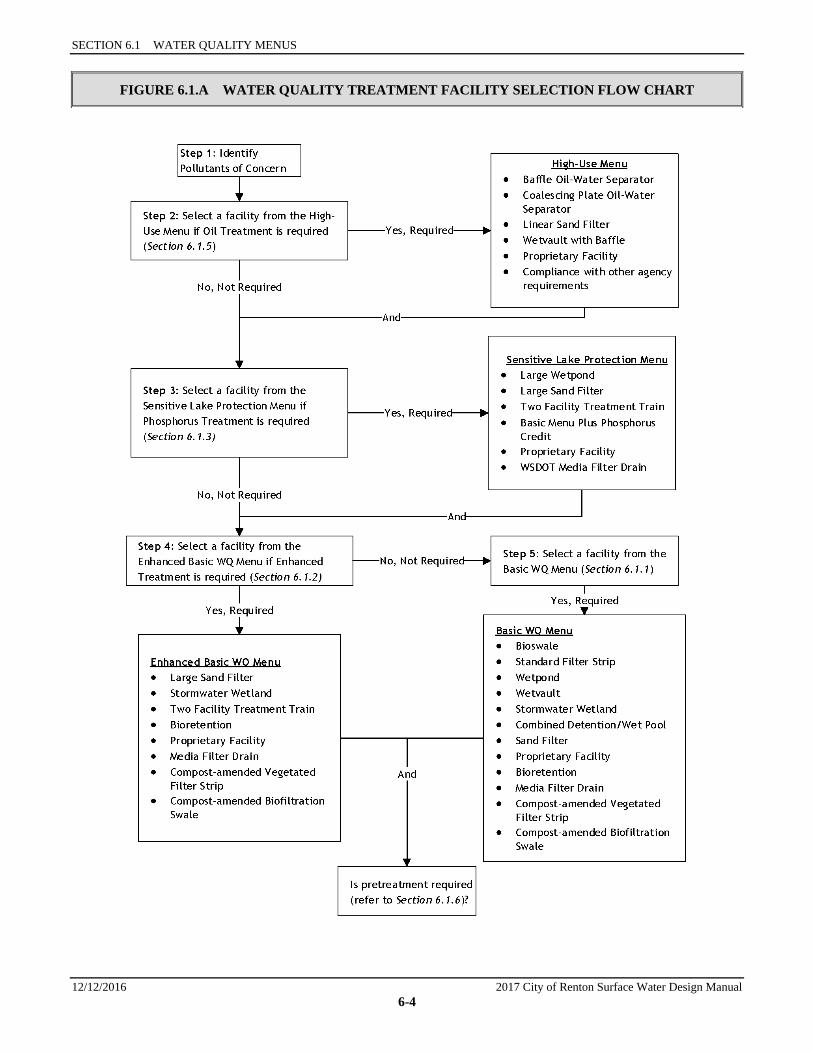
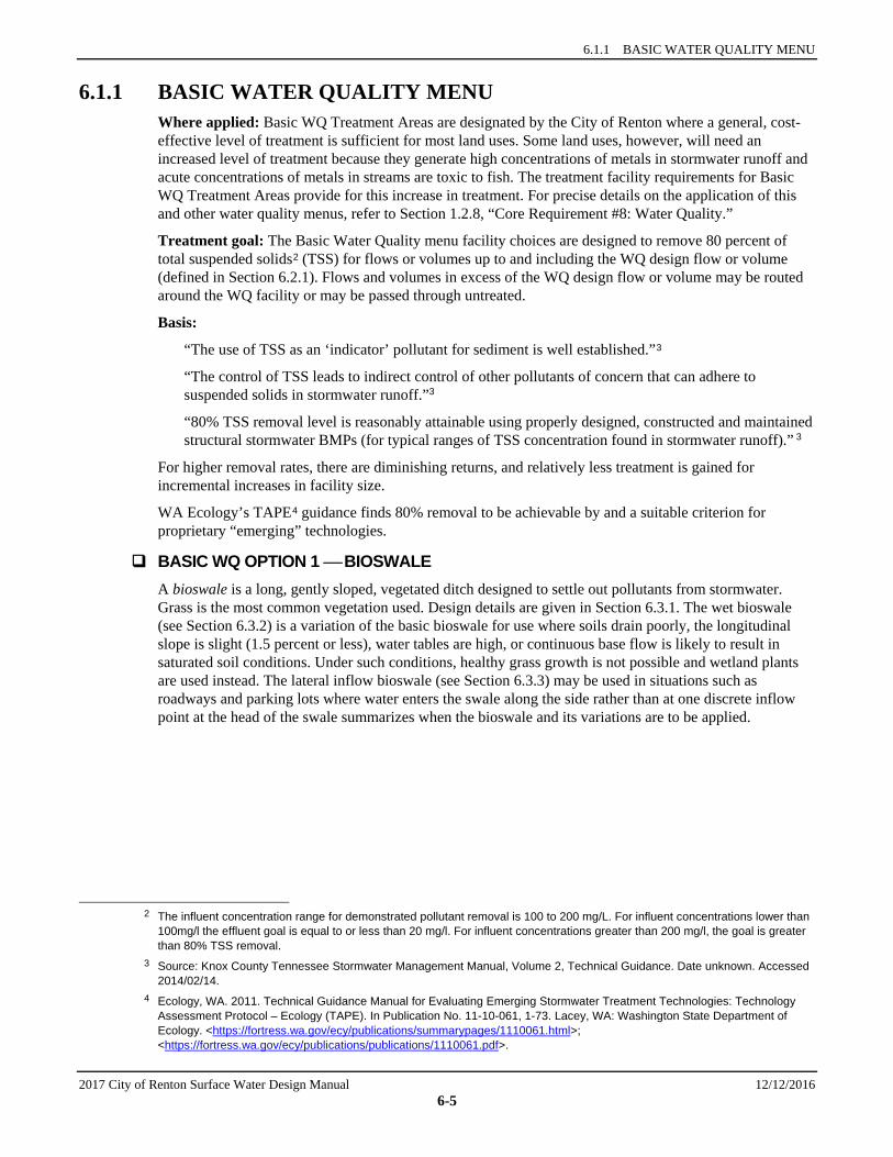
6.1 WATER QUALITY MENUS This section identifies facility choices and, in some cases, non-structural options that comprise the water quality (WQ) menus referred to in Chapter 1. The menus covered in this section and summarized in Figure 6.1.A are as follows:
• “Basic Water Quality Menu,” Section 6.1.1 • “Enhanced Basic Water Quality Menu,” Section 6.1.2 • “Sensitive Lake Protection Menu,” Section 6.1.3 • “Sphagnum Bog Protection Menu,” Section 6.1.4 • “High-Use Menu,” Section 6.1.5
Guide to Applying Water Quality Menus 1. Check the exemption language on Section 1.2.8 to determine if or which threshold discharge areas of
the project site must provide WQ treatment per Core Requirement #8.
2. Use the Basic WQ treatment areas Section 1.2.8.1.A to determine if basic or enhanced treatment is required.
3. Consult Section 1.2.8.1 for other design requirements, allowances, and flexible compliance provisions related to implementing water quality treatment.
4. Read the implementation requirements in Chapter 1 (Section 1.2.8.2) that address pollution generating pervious surface. For some WQ menus, and in some situations, the facility requirements for these surfaces are eased.
5. Determine if your project fits the definition of a high-use site (see Special Requirement #5 in Chapter 1). If it does, or if you elect to provide enhanced oil pollution control, choose one of the options presented in the High-Use menu, Section 6.1.5. Detailed designs for oil control facilities are given in Section 6.6.
6. General water quality facility requirements (see Section 6.2) apply to all menus and may affect the placement of facilities on your site.
SECTION 6.1 WATER QUALITY MENUS
12/12/2016 2017 City of Renton Surface Water Design Manual 6-4
FIGURE 6.1.A WATER QUALITY TREATMENT FACILITY SELECTION FLOW CHART
6.1.1 BASIC WATER QUALITY MENU
2017 City of Renton Surface Water Design Manual 12/12/2016 6-5
6.1.1 BASIC WATER QUALITY MENU Where applied: Basic WQ Treatment Areas are designated by the City of Renton where a general, cost-effective level of treatment is sufficient for most land uses. Some land uses, however, will need an increased level of treatment because they generate high concentrations of metals in stormwater runoff and acute concentrations of metals in streams are toxic to fish. The treatment facility requirements for Basic WQ Treatment Areas provide for this increase in treatment. For precise details on the application of this and other water quality menus, refer to Section 1.2.8, “Core Requirement #8: Water Quality.”
Treatment goal: The Basic Water Quality menu facility choices are designed to remove 80 percent of total suspended solids2 (TSS) for flows or volumes up to and including the WQ design flow or volume (defined in Section 6.2.1). Flows and volumes in excess of the WQ design flow or volume may be routed around the WQ facility or may be passed through untreated.
Basis:
“The use of TSS as an ‘indicator’ pollutant for sediment is well established.”3
“The control of TSS leads to indirect control of other pollutants of concern that can adhere to suspended solids in stormwater runoff.”3
“80% TSS removal level is reasonably attainable using properly designed, constructed and maintained structural stormwater BMPs (for typical ranges of TSS concentration found in stormwater runoff).” 3
For higher removal rates, there are diminishing returns, and relatively less treatment is gained for incremental increases in facility size.
WA Ecology’s TAPE4 guidance finds 80% removal to be achievable by and a suitable criterion for proprietary “emerging” technologies.
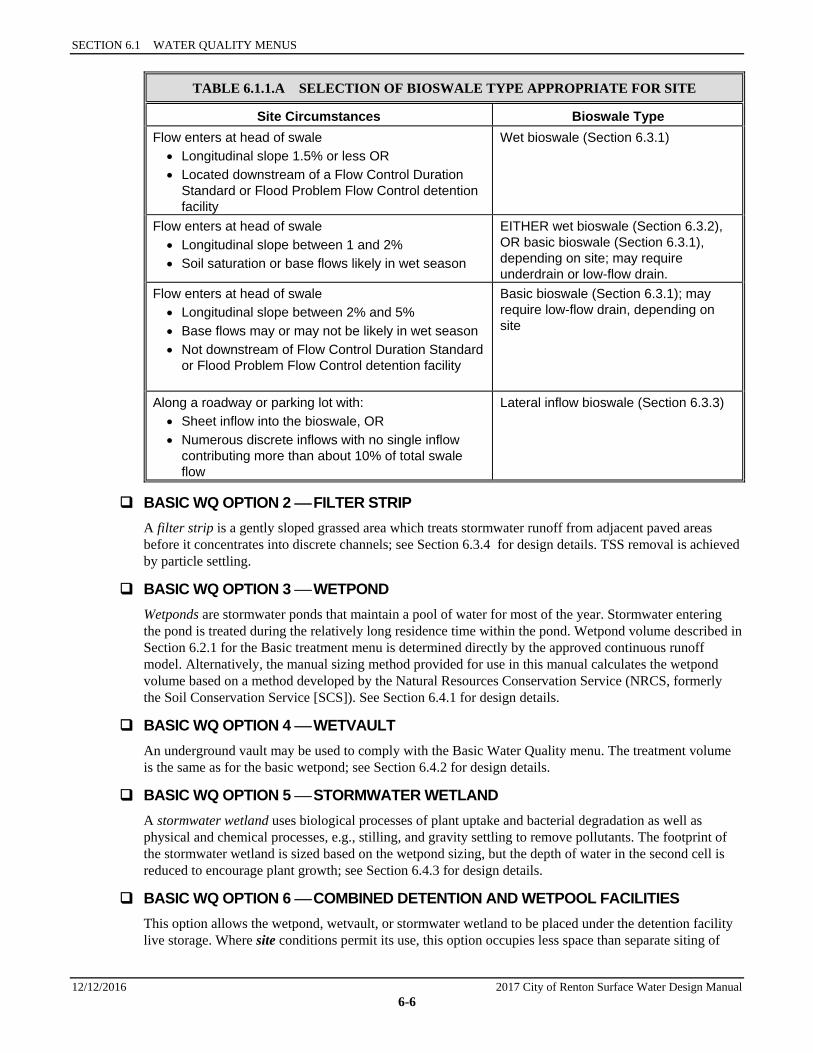
BASIC WQ OPTION 1 BIOSWALE A bioswale is a long, gently sloped, vegetated ditch designed to settle out pollutants from stormwater. Grass is the most common vegetation used. Design details are given in Section 6.3.1. The wet bioswale (see Section 6.3.2) is a variation of the basic bioswale for use where soils drain poorly, the longitudinal slope is slight (1.5 percent or less), water tables are high, or continuous base flow is likely to result in saturated soil conditions. Under such conditions, healthy grass growth is not possible and wetland plants are used instead. The lateral inflow bioswale (see Section 6.3.3) may be used in situations such as roadways and parking lots where water enters the swale along the side rather than at one discrete inflow point at the head of the swale summarizes when the bioswale and its variations are to be applied.
2 The influent concentration range for demonstrated pollutant removal is 100 to 200 mg/L. For influent concentrations lower than
100mg/l the effluent goal is equal to or less than 20 mg/l. For influent concentrations greater than 200 mg/l, the goal is greater than 80% TSS removal.
3 Source: Knox County Tennessee Stormwater Management Manual, Volume 2, Technical Guidance. Date unknown. Accessed 2014/02/14.
4 Ecology, WA. 2011. Technical Guidance Manual for Evaluating Emerging Stormwater Treatment Technologies: Technology Assessment Protocol – Ecology (TAPE). In Publication No. 11-10-061, 1-73. Lacey, WA: Washington State Department of Ecology. <https://fortress.wa.gov/ecy/publications/summarypages/1110061.html>; <https://fortress.wa.gov/ecy/publications/publications/1110061.pdf>.
SECTION 6.1 WATER QUALITY MENUS
12/12/2016 2017 City of Renton Surface Water Design Manual 6-6
TABLE 6.1.1.A SELECTION OF BIOSWALE TYPE APPROPRIATE FOR SITE
Site Circumstances Bioswale Type Flow enters at head of swale • Longitudinal slope 1.5% or less OR • Located downstream of a Flow Control Duration
Standard or Flood Problem Flow Control detention facility
Wet bioswale (Section 6.3.1)
Flow enters at head of swale • Longitudinal slope between 1 and 2% • Soil saturation or base flows likely in wet season
EITHER wet bioswale (Section 6.3.2), OR basic bioswale (Section 6.3.1), depending on site; may require underdrain or low-flow drain.
Flow enters at head of swale • Longitudinal slope between 2% and 5% • Base flows may or may not be likely in wet season • Not downstream of Flow Control Duration Standard
or Flood Problem Flow Control detention facility
Basic bioswale (Section 6.3.1); may require low-flow drain, depending on site
Along a roadway or parking lot with: • Sheet inflow into the bioswale, OR • Numerous discrete inflows with no single inflow
contributing more than about 10% of total swale flow
Lateral inflow bioswale (Section 6.3.3)
BASIC WQ OPTION 2 FILTER STRIP A filter strip is a gently sloped grassed area which treats stormwater runoff from adjacent paved areas before it concentrates into discrete channels; see Section 6.3.4 for design details. TSS removal is achieved by particle settling.
BASIC WQ OPTION 3 WETPOND Wetponds are stormwater ponds that maintain a pool of water for most of the year. Stormwater entering the pond is treated during the relatively long residence time within the pond. Wetpond volume described in Section 6.2.1 for the Basic treatment menu is determined directly by the approved continuous runoff model. Alternatively, the manual sizing method provided for use in this manual calculates the wetpond volume based on a method developed by the Natural Resources Conservation Service (NRCS, formerly the Soil Conservation Service [SCS]). See Section 6.4.1 for design details.
BASIC WQ OPTION 4 WETVAULT An underground vault may be used to comply with the Basic Water Quality menu. The treatment volume is the same as for the basic wetpond; see Section 6.4.2 for design details.
BASIC WQ OPTION 5 STORMWATER WETLAND A stormwater wetland uses biological processes of plant uptake and bacterial degradation as well as physical and chemical processes, e.g., stilling, and gravity settling to remove pollutants. The footprint of the stormwater wetland is sized based on the wetpond sizing, but the depth of water in the second cell is reduced to encourage plant growth; see Section 6.4.3 for design details.
BASIC WQ OPTION 6 COMBINED DETENTION AND WETPOOL FACILITIES This option allows the wetpond, wetvault, or stormwater wetland to be placed under the detention facility live storage. Where site conditions permit its use, this option occupies less space than separate siting of
6.1.1 BASIC WATER QUALITY MENU
2017 City of Renton Surface Water Design Manual 12/12/2016 6-7
detention and water quality facilities. The basic wetpond portion of the combined facility is sized using the same method as the wetpond in Option 3; see Section 6.4.4 for design details.
BASIC WQ OPTION 7 SAND FILTER A sand filter is a land depression, pond, or vault, with a bed of sand near the bottom. Stormwater is treated as it percolates downward through the sand layer. Removal efficiency for sand filters is much less sensitive to particle density distribution as compared to that of particle settling facilities (e.g., ponds, vaults, bioswales), which include an assumption that the particle density is close to that of silica sand.
Sand filters may be built as open ponds, underground vaults or linear perimeter trenches; see Section 6.5.2 for basic and large sand filters, Section 6.5.3 for sand filter vaults, and Section 6.5.4 for linear sand filters. A sand layer may also be installed above an infiltration pond or vault to treat stormwater before it infiltrates. Note: Presettling is required prior to sand filtration as described in Section 6.5.1.
BASIC WQ OPTION 8 PROPRIETARY FACILITIES Most proprietary facilities for basic treatment are cartridge filters, although there are some media filter designs that do not involve cartridges. A cartridge filter system is a flow-through stormwater filtration system comprised of a manhole or vault that houses one or more media-filled or porous membrane cartridges through which stormwater is filtered.
Note: a presettling cell or facility is required for both cartridge filters and for non-cartridge media filters.
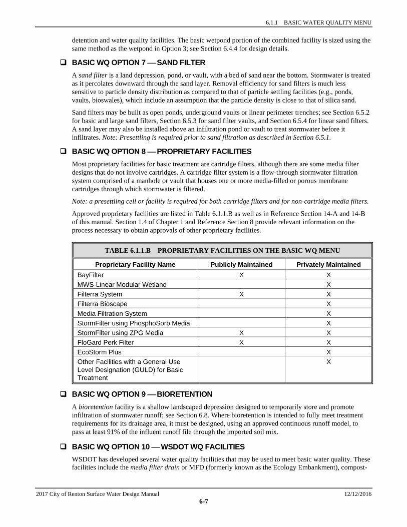
Approved proprietary facilities are listed in Table 6.1.1.B as well as in Reference Section 14-A and 14-B of this manual. Section 1.4 of Chapter 1 and Reference Section 8 provide relevant information on the process necessary to obtain approvals of other proprietary facilities.
TABLE 6.1.1.B PROPRIETARY FACILITIES ON THE BASIC WQ MENU
Proprietary Facility Name Publicly Maintained Privately Maintained BayFilter X X MWS-Linear Modular Wetland X Filterra System X X Filterra Bioscape X Media Filtration System X StormFilter using PhosphoSorb Media X StormFilter using ZPG Media X X FloGard Perk Filter X X EcoStorm Plus X Other Facilities with a General Use Level Designation (GULD) for Basic Treatment
X
BASIC WQ OPTION 9 BIORETENTION A bioretention facility is a shallow landscaped depression designed to temporarily store and promote infiltration of stormwater runoff; see Section 6.8. Where bioretention is intended to fully meet treatment requirements for its drainage area, it must be designed, using an approved continuous runoff model, to pass at least 91% of the influent runoff file through the imported soil mix.
BASIC WQ OPTION 10 WSDOT WQ FACILITIES WSDOT has developed several water quality facilities that may be used to meet basic water quality. These facilities include the media filter drain or MFD (formerly known as the Ecology Embankment), compost-

SECTION 6.1 WATER QUALITY MENUS
12/12/2016 2017 City of Renton Surface Water Design Manual 6-8
amended vegetated filter strips (CAVFS), and compost-amended biofiltration swales (CABS); see Section 6.9.
The MFD is a linear flow-through treatment facility that includes four basic components: a gravel no-vegetation zone, a grass strip, the MFD mix bed, and a conveyance system for flows leaving the MFD mix (typically a gravel-filled underdrain trench or a layer of crushed surfacing base course). MFDs are typically used in areas with limited right-of-way such as highway side slopes, medians, ditches and other linear depressions.
CAVFS and CABS are variations of the basic vegetated filter strip and bioswale, respectively, which incorporate compost to provide Enhanced Basic WQ treatment. The addition of compost into native soils also improves plant health and sustainability, increases surface roughness, and improves infiltration capacity.
6.1.2 ENHANCED BASIC WATER QUALITY MENU Where applied: The Enhanced Basic Water Quality menu5 is applied where an enhanced level of treatment is required for those development sites with land uses that generate the highest concentrations of metals in stormwater runoff and drain by surface flows to a fish-bearing stream. Metals including but not limited to copper and zinc are toxic to fish and other aquatic biota.6 For precise details on the application of this and other water quality menus, refer to Section 1.2.8, “Core Requirement #8: Water Quality Facilities.”
Note: The Enhanced Basic menu is a stand-alone menu. It integrates the Basic menu level of protection (TSS removal) and the additional measures needed to achieve a higher level of metals removal. When this menu is required in Basic WQ Treatment Areas per Section 1.2.8.1.A of Core Requirement #8, it is intended to replace the Basic WQ menu on development sites or portions of development sites that generate the highest concentrations of metals in stormwater runoff. When this menu is required in Sensitive Lake WQ Treatment Areas per Section 1.2.8.1.B, it is intended to be combined with the Sensitive Lake Protection Menu such that a facility design option common to both menus must be used.
Treatment goal: The Enhanced Basic WQ menu is designed to achieve > 30% dissolved copper removal and > 60% dissolved zinc removal; in addition to Basic treatment (80% TSS removal) for flows up to and including the WQ design flow or volume (defined in Section 6.2.1). The goal assumes that dissolved copper concentrations for untreated runoff are between 5 and 20 micrograms per liter (u/L), and that dissolved zinc concentrations for untreated runoff are between 20 and 300 micrograms per liter (ug/L).7
Basis: The treatment goal is expressed in terms of dissolved copper and zinc removal. Copper and zinc are reliable indicators of a wider range of heavy metals and are typically found in stormwater runoff from industrial, commercial, and high density residential land uses at levels that are toxic to fish and other aquatic biota. Many metals are readily adsorbed onto particulates in the runoff, usually the finer fraction of the particulates. Facility combinations that remove more of the particulate load than the Basic menu, including the finer fraction, are specified by the Enhanced Basic menu. Facilities providing organic binding sites that enhance metal adsorption are also specified. The treatment goals have been found by WA Ecology to be achievable.
ENHANCED BASIC OPTION 1 LARGE SAND FILTER This option includes use of a large sand filter, large sand filter vault, or large linear sand filter. Sizing specifications for these facilities can be found in Sections 6.5.2, 6.5.3, and 6.5.4, respectively. Note: Presettling is required prior to sand filtration as described in Section 6.5.1.
5 The Enhanced Basic WQ menu targets different pollutants than the lake or bog protection menus. It does not necessarily
provide a higher level of treatment except for the target pollutant, metal contaminants. 6 Other metals, e.g., lead, are toxic to humans and may build up in sediments. 7 This goal assumes total zinc concentrations for untreated runoff are between 0.10 and 0.25 milligrams per liter (mg/L).

6.1.2 ENHANCED BASIC WATER QUALITY MENU
2017 City of Renton Surface Water Design Manual 12/12/2016 6-9
ENHANCED BASIC OPTION 2 STORMWATER WETLAND Provision of a stormwater wetland (see Section 6.4.3) or combined detention and stormwater wetland (see Section 6.4.4) satisfies the Basic (TSS) and Enhanced Basic (dissolved copper and zinc) removal goals without additional facilities.
ENHANCED BASIC OPTION 3 TWO-FACILITY TREATMENT TRAIN This option uses one of the basic water quality treatment options listed in followed by a basic sand filter (see Section 6.5.2), sand filter vault (see Section 6.5.3), or a linear sand filter (see Section 6.5.4).
TABLE 6.1.2.A PAIRED FACILITIES FOR ENHANCED BASIC TREATMENT TRAIN, OPTION 3
First Basic WQ Facility: Second WQ Facility: Bioswale
(Sections 6.3.1, 6.3.2, and 6.3.3) Basic sand filter or sand filter vault
(Section 6.5.2 or 6.5.3) or proprietary facility8 Filter strip
(Sections 6.3.4 and 6.3.5) Linear sand filter (Section 6.5.4) with no presettling
cell needed Linear sand filter (Section 6.5.4) Filter strip (Sections 6.3.4 and 6.3.5) Basic wetpond (Section 6.4.1) Basic sand filter or sand filter vault
(Section 6.5.2 or 6.5.3) or proprietary facility8 Wetvault (Section 6.4.2) Basic sand filter or sand filter vault
(Section 6.5.2 or 6.5.3) or proprietary facility8 Basic combined detention and wetpool
facility (Section 6.4.4) Basic sand filter or sand filter vault
(Section 6.5.2 or 6.5.3) or proprietary facility8 Basic sand filter or sand filter vault
(Sections 6.5.2 or 6.5.3). A presettling cell is required if the sand filter is not
preceded by a detention facility.
Proprietary facility8
Proprietary facility approved by the City for Basic WQ8 (Section 6.7)
Basic sand filter or sand filter vault (Section 6.5.2 or 6.5.3)
ENHANCED BASIC OPTION 4 BIORETENTION Provision of a bioretention facility (see Section 6.4.3) satisfies the Basic (TSS) and Enhanced Basic (dissolved copper and zinc) removal goals without additional facilities. Stormwater runoff that infiltrates through the imported soil mix will have received Enhanced Basic treatment.
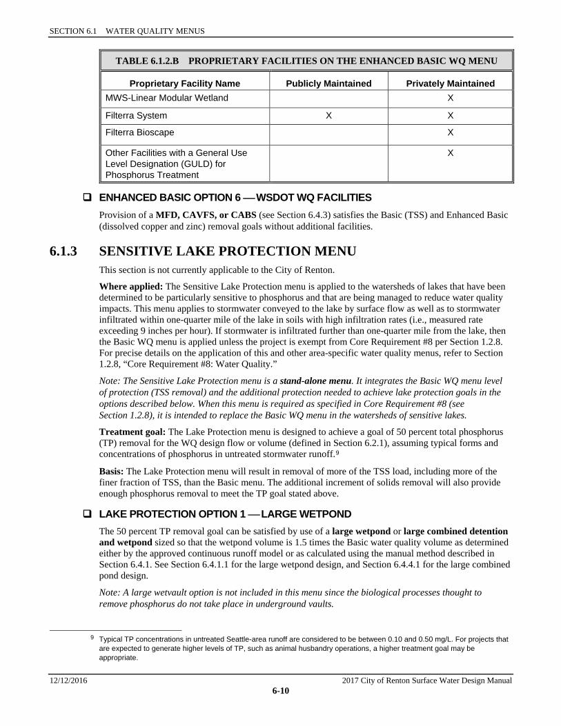
ENHANCED BASIC OPTION 5 PROPRIETARY FACILITY Section 6.7, “Proprietary Facility Designs,” discusses general considerations for proprietary manufactured facilities. Current approvals for publicly and privately maintained systems are included in Table 6.1.2.B and Reference Section 14-A and 14-B.
8 See Reference Section 14-A for City-approved proprietary facilities.
SECTION 6.1 WATER QUALITY MENUS
12/12/2016 2017 City of Renton Surface Water Design Manual 6-10
TABLE 6.1.2.B PROPRIETARY FACILITIES ON THE ENHANCED BASIC WQ MENU
Proprietary Facility Name Publicly Maintained Privately Maintained MWS-Linear Modular Wetland X
Filterra System X X
Filterra Bioscape X
Other Facilities with a General Use Level Designation (GULD) for Phosphorus Treatment
X
ENHANCED BASIC OPTION 6 WSDOT WQ FACILITIES Provision of a MFD, CAVFS, or CABS (see Section 6.4.3) satisfies the Basic (TSS) and Enhanced Basic (dissolved copper and zinc) removal goals without additional facilities.
6.1.3 SENSITIVE LAKE PROTECTION MENU This section is not currently applicable to the City of Renton.
Where applied: The Sensitive Lake Protection menu is applied to the watersheds of lakes that have been determined to be particularly sensitive to phosphorus and that are being managed to reduce water quality impacts. This menu applies to stormwater conveyed to the lake by surface flow as well as to stormwater infiltrated within one-quarter mile of the lake in soils with high infiltration rates (i.e., measured rate exceeding 9 inches per hour). If stormwater is infiltrated further than one-quarter mile from the lake, then the Basic WQ menu is applied unless the project is exempt from Core Requirement #8 per Section 1.2.8. For precise details on the application of this and other area-specific water quality menus, refer to Section 1.2.8, “Core Requirement #8: Water Quality.”
Note: The Sensitive Lake Protection menu is a stand-alone menu. It integrates the Basic WQ menu level of protection (TSS removal) and the additional protection needed to achieve lake protection goals in the options described below. When this menu is required as specified in Core Requirement #8 (see Section 1.2.8), it is intended to replace the Basic WQ menu in the watersheds of sensitive lakes.
Treatment goal: The Lake Protection menu is designed to achieve a goal of 50 percent total phosphorus (TP) removal for the WQ design flow or volume (defined in Section 6.2.1), assuming typical forms and concentrations of phosphorus in untreated stormwater runoff.9
Basis: The Lake Protection menu will result in removal of more of the TSS load, including more of the finer fraction of TSS, than the Basic menu. The additional increment of solids removal will also provide enough phosphorus removal to meet the TP goal stated above.
LAKE PROTECTION OPTION 1 LARGE WETPOND The 50 percent TP removal goal can be satisfied by use of a large wetpond or large combined detention and wetpond sized so that the wetpond volume is 1.5 times the Basic water quality volume as determined either by the approved continuous runoff model or as calculated using the manual method described in Section 6.4.1. See Section 6.4.1.1 for the large wetpond design, and Section 6.4.4.1 for the large combined pond design.
Note: A large wetvault option is not included in this menu since the biological processes thought to remove phosphorus do not take place in underground vaults.
9 Typical TP concentrations in untreated Seattle-area runoff are considered to be between 0.10 and 0.50 mg/L. For projects that
are expected to generate higher levels of TP, such as animal husbandry operations, a higher treatment goal may be appropriate.
6.1.2 ENHANCED BASIC WATER QUALITY MENU
2017 City of Renton Surface Water Design Manual 12/12/2016 6-11
LAKE PROTECTION OPTION 2 LARGE SAND FILTER This option includes use of a large sand filter, large sand filter vault, or large linear sand filter. Sizing specifications for these facilities can be found in Sections 6.5.2, 6.5.3, and 6.5.4, respectively.
Note: Presettling is required prior to sand filtration as described in Section 6.5.1.
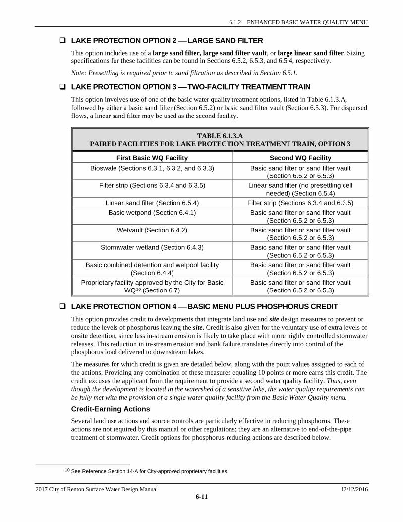
LAKE PROTECTION OPTION 3 TWO-FACILITY TREATMENT TRAIN This option involves use of one of the basic water quality treatment options, listed in Table 6.1.3.A, followed by either a basic sand filter (Section 6.5.2) or basic sand filter vault (Section 6.5.3). For dispersed flows, a linear sand filter may be used as the second facility.
TABLE 6.1.3.A PAIRED FACILITIES FOR LAKE PROTECTION TREATMENT TRAIN, OPTION 3
First Basic WQ Facility Second WQ Facility Bioswale (Sections 6.3.1, 6.3.2, and 6.3.3) Basic sand filter or sand filter vault
(Section 6.5.2 or 6.5.3) Filter strip (Sections 6.3.4 and 6.3.5) Linear sand filter (no presettling cell
needed) (Section 6.5.4) Linear sand filter (Section 6.5.4) Filter strip (Sections 6.3.4 and 6.3.5) Basic wetpond (Section 6.4.1) Basic sand filter or sand filter vault
(Section 6.5.2 or 6.5.3) Wetvault (Section 6.4.2) Basic sand filter or sand filter vault
(Section 6.5.2 or 6.5.3) Stormwater wetland (Section 6.4.3) Basic sand filter or sand filter vault
(Section 6.5.2 or 6.5.3) Basic combined detention and wetpool facility
(Section 6.4.4) Basic sand filter or sand filter vault
(Section 6.5.2 or 6.5.3) Proprietary facility approved by the City for Basic
WQ10 (Section 6.7) Basic sand filter or sand filter vault
(Section 6.5.2 or 6.5.3)
LAKE PROTECTION OPTION 4 BASIC MENU PLUS PHOSPHORUS CREDIT This option provides credit to developments that integrate land use and site design measures to prevent or reduce the levels of phosphorus leaving the site. Credit is also given for the voluntary use of extra levels of onsite detention, since less in-stream erosion is likely to take place with more highly controlled stormwater releases. This reduction in in-stream erosion and bank failure translates directly into control of the phosphorus load delivered to downstream lakes.
The measures for which credit is given are detailed below, along with the point values assigned to each of the actions. Providing any combination of these measures equaling 10 points or more earns this credit. The credit excuses the applicant from the requirement to provide a second water quality facility. Thus, even though the development is located in the watershed of a sensitive lake, the water quality requirements can be fully met with the provision of a single water quality facility from the Basic Water Quality menu.
Credit-Earning Actions Several land use actions and source controls are particularly effective in reducing phosphorus. These actions are not required by this manual or other regulations; they are an alternative to end-of-the-pipe treatment of stormwater. Credit options for phosphorus-reducing actions are described below.
10 See Reference Section 14-A for City-approved proprietary facilities.
SECTION 6.1 WATER QUALITY MENUS
12/12/2016 2017 City of Renton Surface Water Design Manual 6-12
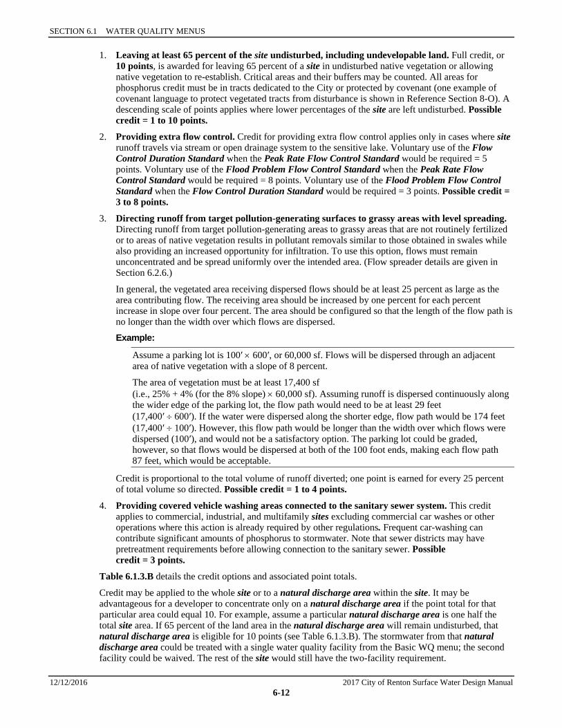
1. Leaving at least 65 percent of the site undisturbed, including undevelopable land. Full credit, or 10 points, is awarded for leaving 65 percent of a site in undisturbed native vegetation or allowing native vegetation to re-establish. Critical areas and their buffers may be counted. All areas for phosphorus credit must be in tracts dedicated to the City or protected by covenant (one example of covenant language to protect vegetated tracts from disturbance is shown in Reference Section 8-O). A descending scale of points applies where lower percentages of the site are left undisturbed. Possible credit = 1 to 10 points.
2. Providing extra flow control. Credit for providing extra flow control applies only in cases where site runoff travels via stream or open drainage system to the sensitive lake. Voluntary use of the Flow Control Duration Standard when the Peak Rate Flow Control Standard would be required = 5 points. Voluntary use of the Flood Problem Flow Control Standard when the Peak Rate Flow Control Standard would be required = 8 points. Voluntary use of the Flood Problem Flow Control Standard when the Flow Control Duration Standard would be required = 3 points. Possible credit = 3 to 8 points.
3. Directing runoff from target pollution-generating surfaces to grassy areas with level spreading. Directing runoff from target pollution-generating areas to grassy areas that are not routinely fertilized or to areas of native vegetation results in pollutant removals similar to those obtained in swales while also providing an increased opportunity for infiltration. To use this option, flows must remain unconcentrated and be spread uniformly over the intended area. (Flow spreader details are given in Section 6.2.6.)
In general, the vegetated area receiving dispersed flows should be at least 25 percent as large as the area contributing flow. The receiving area should be increased by one percent for each percent increase in slope over four percent. The area should be configured so that the length of the flow path is no longer than the width over which flows are dispersed.
Example:
Assume a parking lot is 100′ × 600′, or 60,000 sf. Flows will be dispersed through an adjacent area of native vegetation with a slope of 8 percent.
The area of vegetation must be at least 17,400 sf (i.e., 25% + 4% (for the 8% slope) × 60,000 sf). Assuming runoff is dispersed continuously along the wider edge of the parking lot, the flow path would need to be at least 29 feet (17,400′ ÷ 600′). If the water were dispersed along the shorter edge, flow path would be 174 feet (17,400′ ÷ 100′). However, this flow path would be longer than the width over which flows were dispersed (100′), and would not be a satisfactory option. The parking lot could be graded, however, so that flows would be dispersed at both of the 100 foot ends, making each flow path 87 feet, which would be acceptable.
Credit is proportional to the total volume of runoff diverted; one point is earned for every 25 percent of total volume so directed. Possible credit = 1 to 4 points.
4. Providing covered vehicle washing areas connected to the sanitary sewer system. This credit applies to commercial, industrial, and multifamily sites excluding commercial car washes or other operations where this action is already required by other regulations. Frequent car-washing can contribute significant amounts of phosphorus to stormwater. Note that sewer districts may have pretreatment requirements before allowing connection to the sanitary sewer. Possible credit = 3 points.
Table 6.1.3.B details the credit options and associated point totals.
Credit may be applied to the whole site or to a natural discharge area within the site. It may be advantageous for a developer to concentrate only on a natural discharge area if the point total for that particular area could equal 10. For example, assume a particular natural discharge area is one half the total site area. If 65 percent of the land area in the natural discharge area will remain undisturbed, that natural discharge area is eligible for 10 points (see Table 6.1.3.B). The stormwater from that natural discharge area could be treated with a single water quality facility from the Basic WQ menu; the second facility could be waived. The rest of the site would still have the two-facility requirement.
6.1.3 SENSITIVE LAKE PROTECTION MENU
2017 City of Renton Surface Water Design Manual 12/12/2016 6-13
Alternatively, if the entire site were considered, the undisturbed area decreases to 35 percent, eligible for only 3 points. In this case, the developer would need to implement other controls worth 7 points in order to waive the second water quality facility for the entire site.
If the credit option is used, it shall be applied for during initial drainage review by CED. The application shall include a written request for credit based on either the site plan or the grading plan for the project, and the threshold discharge areas shall be delineated on the plans. The request shall outline where the credit would be applied and how the point totals are to be achieved. CED would then evaluate the request and may waive the second water quality treatment requirement for the site or threshold discharge area based on point totals outlined in Table 6.1.3.B (below). Credit is not given unless requested.
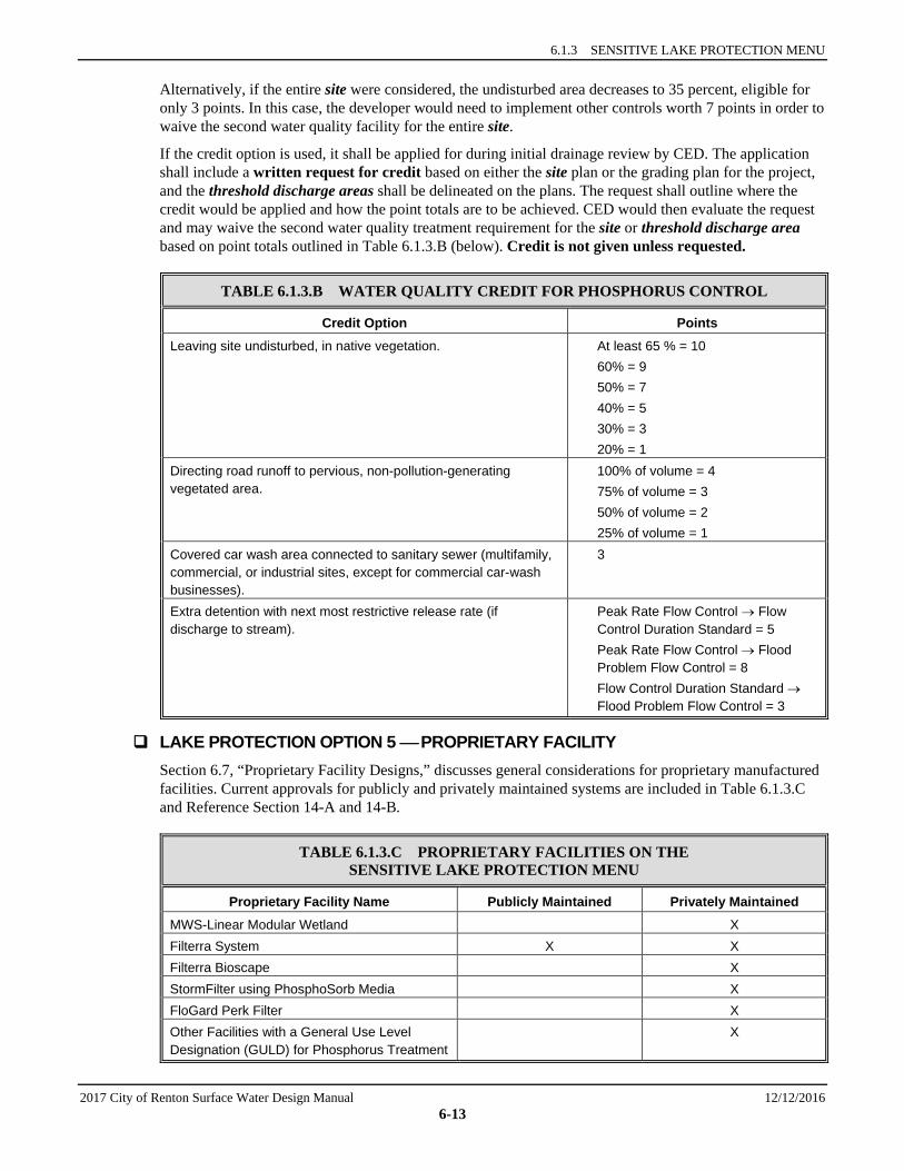
TABLE 6.1.3.B WATER QUALITY CREDIT FOR PHOSPHORUS CONTROL
Credit Option Points Leaving site undisturbed, in native vegetation. At least 65 % = 10
60% = 9 50% = 7 40% = 5 30% = 3 20% = 1
Directing road runoff to pervious, non-pollution-generating vegetated area.
100% of volume = 4 75% of volume = 3 50% of volume = 2 25% of volume = 1
Covered car wash area connected to sanitary sewer (multifamily, commercial, or industrial sites, except for commercial car-wash businesses).
3
Extra detention with next most restrictive release rate (if discharge to stream).
Peak Rate Flow Control → Flow Control Duration Standard = 5 Peak Rate Flow Control → Flood Problem Flow Control = 8 Flow Control Duration Standard → Flood Problem Flow Control = 3
LAKE PROTECTION OPTION 5 PROPRIETARY FACILITY Section 6.7, “Proprietary Facility Designs,” discusses general considerations for proprietary manufactured facilities. Current approvals for publicly and privately maintained systems are included in Table 6.1.3.C and Reference Section 14-A and 14-B.
TABLE 6.1.3.C PROPRIETARY FACILITIES ON THE SENSITIVE LAKE PROTECTION MENU
Proprietary Facility Name Publicly Maintained Privately Maintained MWS-Linear Modular Wetland X Filterra System X X Filterra Bioscape X StormFilter using PhosphoSorb Media X FloGard Perk Filter X Other Facilities with a General Use Level Designation (GULD) for Phosphorus Treatment
X
SECTION 6.1 WATER QUALITY MENUS
12/12/2016 2017 City of Renton Surface Water Design Manual 6-14
LAKE PROTECTION OPTION 6 WSDOT WQ FACILITIES WSDOT has developed the media filter drain that may be used to meet lake protection.
6.1.4 SPHAGNUM BOG PROTECTION MENU This section is not currently applicable to the City of Renton.
Where applied: The Sphagnum Bog Protection menu11 covers sphagnum bog wetlands12 greater than 0.25 acres in size.13 It applies to stormwater conveyed by surface flow to the sphagnum bog vegetation community. If stormwater is infiltrated by the project per Section 5.2, then the Basic WQ menu is applied unless the project is exempt from Core Requirement #8, “Water Quality.” For precise details on the application of this and other area-specific water quality menus, refer to Section 1.2.8.
Note: The Sphagnum Bog Protection menu is a stand-alone menu. It integrates the Basic WQ menu level of protection and the additional measures needed to achieve bog protection goals in the options described below. When this menu is required as specified in Core Requirement #8 (see Section 1.2.8), it is intended to replace the Basic WQ menu in areas draining to sphagnum bogs.
Treatment goal: If surface water must be discharged to a bog, the treatment goal is to reduce total phosphorus by 50 percent, reduce nitrate + nitrite by 40 percent, maintain alkalinity below 10 mg/L, calcium concentrations should be less than 2 mg/L, and maintain pH below 6.0.14
Basis: In their undeveloped condition, bogs are isolated from surface water, being supplied almost solely by rainwater. The best strategy for protection of bog water quality is to infiltrate the water quality design volume while routing high flows around the bog. Although it is not known whether alkalinity or nitrogen can be reduced sufficiently by the options outlined below, there are no other technologically-feasible alternatives at this time. An adjustment (see Section 1.4) could be pursued as additional technologies become available.
SPHAGNUM BOG PROTECTION OPTION 1 LARGE WETPOND FOLLOWED BY LARGE SAND FILTER This option uses a large wetpond (see Section 6.4.1) or a large combined detention and wetpond (see Section 6.4.2), sized so that wetpond volume is 1.5 times the Basic water quality volume as determined either by the approved continuous runoff model or as calculated using the manual method described in Section 6.4.1. A large sand filtration facility (see Section 6.5.2 or 6.5.3) must follow the pond. In order to ensure that algae and sources of alkalinity from the pond are not washed from the pond into the bog, the sand filter must be the last facility. The sand used for filtration must be silica-based sand rather than an aragonite15 sand.
SPHAGNUM BOG PROTECTION OPTION 2 STORMWATER WETLAND IN SERIES WITH A LARGE SAND FILTER This option uses a stormwater wetland (see Section 6.4.3) or combined detention and stormwater wetland (see Section 6.4.4) to remove solids and enhance the concentration of organic acids, and a large
11 The Bog Protection menu targets a different set of pollutants than the Sensitive Lake or Enhanced Basic menus. Since the
targeted pollutants are more difficult to remove, use of larger and/or additional water quality facilities is required. 12 A sphagnum bog wetland is defined as a wetland having a predominance of sphagnum moss creating a substrate upon which
a distinctive community of acid-loving plants is established (see Section 1.2.8.C and "Definitions" for more detail). 13 The size of a sphagnum bog wetland is defined by the boundaries of the sphagnum bog plant community. 14 Calcium, alkalinity, and pH values are from : Kulzer, L., S. Luchessa, S. Cooke, R. Errington, F. Weinmann, and D. Vitt. 2001.
Characteristics of the low-elevation sphagnum-dominated peatlands of western Washington: A community profile. King County, WA: King County Water and Land Resources Division.
15 Aragonite is the second most common type of sand, and is composed of calcium carbonate from biota including but not limited to coral and shellfish. (Sand. (2014, April 12). In Wikipedia, The Free Encyclopedia. Retrieved 20:38, April 15, 2014, from <http://en.wikipedia.org/w/index.php?title=Sand&oldid=603938376>)
6.1.4 SPHAGNUM BOG PROTECTION MENU
2017 City of Renton Surface Water Design Manual 12/12/2016 6-15
sand filter (see Section 6.5.2) to remove the finer sediment for alkalinity and nutrient reduction. The sand used for filtration must be silica-based sand rather than an aragonite sand. The order of facilities is interchangeable since there are both advantages and disadvantages to having the sand filter last in the train. Note: Presettling is required prior to sand filtration as described in Section 6.5.1.
SPHAGNUM BOG PROTECTION OPTION 3 LARGE SAND FILTER IN SERIES WITH A PROPRIETARY FACILITY This option uses a large sand filter or large sand filter vault followed by a proprietary facility. Sizing specifications for the large sand filters can be found in Sections 6.5.2 and 6.5.3. Proprietary facilities are detailed in Reference Section 14-A and 14-B. The sand used for filtration must be silica-based sand rather than an aragonite sand.
Note: Presettling is required prior to sand filtration as described in Section 6.5.1.
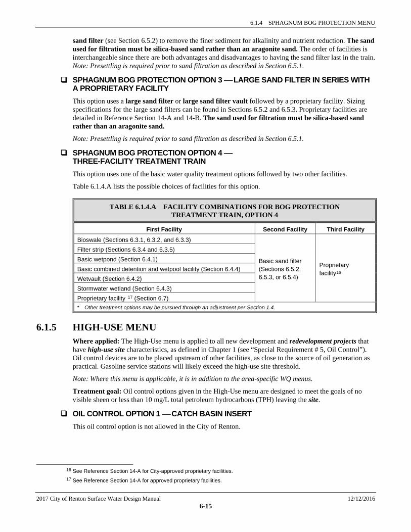
SPHAGNUM BOG PROTECTION OPTION 4 THREE-FACILITY TREATMENT TRAIN This option uses one of the basic water quality treatment options followed by two other facilities.
Table 6.1.4.A lists the possible choices of facilities for this option.
TABLE 6.1.4.A FACILITY COMBINATIONS FOR BOG PROTECTION TREATMENT TRAIN, OPTION 4
First Facility Second Facility Third Facility Bioswale (Sections 6.3.1, 6.3.2, and 6.3.3)
Basic sand filter (Sections 6.5.2, 6.5.3, or 6.5.4)
Proprietary facility16
Filter strip (Sections 6.3.4 and 6.3.5) Basic wetpond (Section 6.4.1) Basic combined detention and wetpool facility (Section 6.4.4) Wetvault (Section 6.4.2) Stormwater wetland (Section 6.4.3) Proprietary facility 17 (Section 6.7) * Other treatment options may be pursued through an adjustment per Section 1.4.
6.1.5 HIGH-USE MENU Where applied: The High-Use menu is applied to all new development and redevelopment projects that have high-use site characteristics, as defined in Chapter 1 (see “Special Requirement # 5, Oil Control”). Oil control devices are to be placed upstream of other facilities, as close to the source of oil generation as practical. Gasoline service stations will likely exceed the high-use site threshold.
Note: Where this menu is applicable, it is in addition to the area-specific WQ menus.
Treatment goal: Oil control options given in the High-Use menu are designed to meet the goals of no visible sheen or less than 10 mg/L total petroleum hydrocarbons (TPH) leaving the site.
OIL CONTROL OPTION 1 CATCH BASIN INSERT This oil control option is not allowed in the City of Renton.
16 See Reference Section 14-A for City-approved proprietary facilities. 17 See Reference Section 14-A for approved proprietary facilities.
SECTION 6.1 WATER QUALITY MENUS
12/12/2016 2017 City of Renton Surface Water Design Manual 6-16
OIL CONTROL OPTION 2 BAFFLE OIL/WATER SEPARATOR Baffle oil/water separators (see Section 6.6.2) may be used to treat stormwater runoff from high-use developments and facilities that produce relatively high concentrations of oil and grease. Baffle separators historically have been effective in removing oil having droplet sizes of 150 microns or larger. If sized properly, they can achieve effluent concentrations as low as 10 to 15 mg/L.
OIL CONTROL OPTION 3 COALESCING PLATE OIL/WATER SEPARATOR Coalescing plate separators (see Section 6.6.2) may be used to treat stormwater runoff from high-use developments and facilities that can produce relatively high concentrations of oil and grease. Current technology and design of coalescing plate separators achieve effluent concentrations as low as 10 mg/L with removal of oil droplet sizes as small as 20 to 60 microns.
OIL CONTROL OPTION 4 LINEAR SAND FILTER The linear sand filter (see Section 6.5.4) is used in the Core Requirement #8 water quality menus (i.e., the Basic, Enhanced Basic, Sensitive Lake, and Sphagnum Bog menus), as well as for oil control in the High-Use menu (Special Requirement #5). However, if used to satisfy Core Requirement #8, the same facility shall not also be used to satisfy the oil control requirement (Special Requirement #5) unless enhanced maintenance is ensured. This is to prevent clogging of the filter by oil so that it will function for suspended solids, metals, and phosphorus removal as well. Quarterly cleaning is required at a minimum unless more frequent cleaning is specified otherwise by the designer.
OIL CONTROL OPTION 5 WETVAULT WITH BAFFLE A wetvault may be modified to fulfill requirements for oil control provided the following are true:
1. The criteria given at the end of Section 6.4.2.2 for modification of wetvaults for use as a baffle oil/water separators shall be met, and
2. Assurance is provided that the maintenance frequency and oil removal frequency for baffle oil/water separators will be followed (see Section 6.6.2).
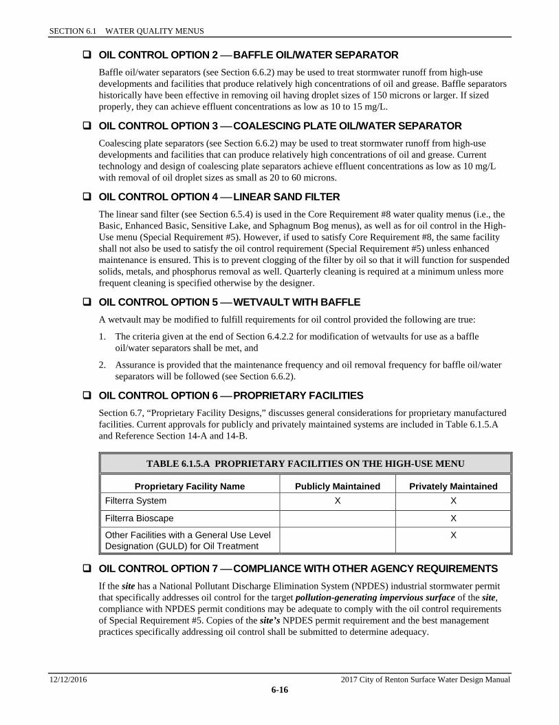
OIL CONTROL OPTION 6 PROPRIETARY FACILITIES Section 6.7, “Proprietary Facility Designs,” discusses general considerations for proprietary manufactured facilities. Current approvals for publicly and privately maintained systems are included in Table 6.1.5.A and Reference Section 14-A and 14-B.
TABLE 6.1.5.A PROPRIETARY FACILITIES ON THE HIGH-USE MENU
Proprietary Facility Name Publicly Maintained Privately Maintained Filterra System X X
Filterra Bioscape X
Other Facilities with a General Use Level Designation (GULD) for Oil Treatment
X
OIL CONTROL OPTION 7 COMPLIANCE WITH OTHER AGENCY REQUIREMENTS If the site has a National Pollutant Discharge Elimination System (NPDES) industrial stormwater permit that specifically addresses oil control for the target pollution-generating impervious surface of the site, compliance with NPDES permit conditions may be adequate to comply with the oil control requirements of Special Requirement #5. Copies of the site’s NPDES permit requirement and the best management practices specifically addressing oil control shall be submitted to determine adequacy.
6.1.6 PRETREATMENT FACILITIES
2017 City of Renton Surface Water Design Manual 12/12/2016 6-17
If the area under the covered fueling island drains to the sanitary sewer, then only the remaining high-use area actually draining to the storm drainage system (normally ingress and egress routes) need comply with the High-Use menu.
Note: Ecology requires that fueling islands be paved with Portland cement concrete (or equivalent, not including asphaltic concrete) and must drain to a dead-end sump or spill control separator in compliance with the UFC or IFC, and recommends draining from the sump to a sanitary sewer. An alternative to discharge to a sanitary sewer is to collect stormwater from the fuel island containment pad and hold for proper off-site disposal.
Drains to treatment facilities must have a normally closed shutoff valve. The spill control sump must be sized in compliance with Section 7901.8 of the Uniform Fire Code (UFC). Alternatively the fueling island must be designed as a spill containment pad with a sill or berm raised to a minimum of four inches (Section 7901.8 of the UFC) to prevent the runoff of spilled liquids and to prevent run-on of stormwater from the surrounding area. (See Ecology’s Stormwater Management Manual for Western Washington, Volume IV, Section 2.2, S409 BMPs for Fueling At Dedicated Stations. These BMPs are also required by the City of Renton for new construction.
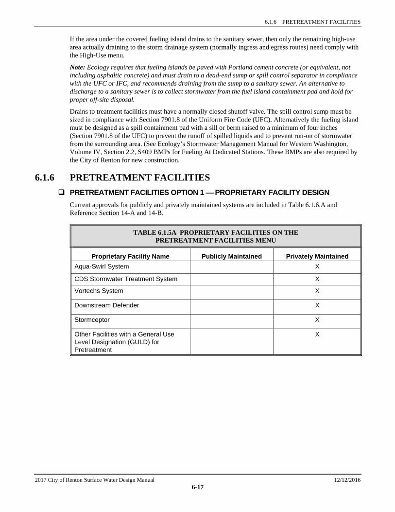
6.1.6 PRETREATMENT FACILITIES PRETREATMENT FACILITIES OPTION 1 PROPRIETARY FACILITY DESIGN
Current approvals for publicly and privately maintained systems are included in Table 6.1.6.A and Reference Section 14-A and 14-B.
TABLE 6.1.5A PROPRIETARY FACILITIES ON THE PRETREATMENT FACILITIES MENU
Proprietary Facility Name Publicly Maintained Privately Maintained Aqua-Swirl System X
CDS Stormwater Treatment System X
Vortechs System X
Downstream Defender X
Stormceptor X
Other Facilities with a General Use Level Designation (GULD) for Pretreatment
X

SECTION 6.1 WATER QUALITY MENUS
12/12/2016 2017 City of Renton Surface Water Design Manual 6-18
( T h i s p a g e i n t e n t i o n a l l y l e f t b l a n k . )

CITY OF RENTON SURFACE WATER DESIGN MANUAL
2017 City of Renton Surface Water Design Manual 12/12/2016 6-19
6.2 GENERAL REQUIREMENTS FOR WQ FACILITIES This section presents general requirements and other information applicable to the design of water quality (WQ) facilities. Topics covered include the following:
• “Water Quality Design Flows,” Section 6.2.1 • “Sequence of Facilities,” Section 6.2.2 • “Setbacks, Slopes, and Embankments,” Section 6.2.3 • “Facility Liners,” Section 6.2.4 • “Flow Splitter Designs,” Section 6.2.5 • “Flow Spreading Options,” Section 6.2.6
When detail in the WQ designs is lacking, refer to Chapter 5 for guidance. In cases where requirements are extremely costly, a less expensive alternative that is functionally equivalent in terms of performance, environmental effects, health and safety, and maintenance may be sought through the adjustment process (see Section 1.4).
Proprietary Facility Designs Current proprietary facility approvals for publicly and privately maintained systems are included in Reference Section 14-A and 14-B. Other proprietary facilities that have received a general use level designation (GULD) through the state Department of Ecology’s Technology Assessment Protocol – Ecology (TAPE) program will be considered for approval by the City through an adjustment process for water quality treatment. A list of Ecology GULD approved proprietary facilities can be found on the Department of Ecology website at <http://www.ecy.wa.gov/programs/wq/stormwater/newtech/index.html>.18
Use of Materials Galvanized metals leach zinc into the environment, especially in standing water situations. High zinc concentrations, sometimes in the range that can be toxic to aquatic life, have been observed in the region.19 Therefore, use of galvanized materials in stormwater facilities and conveyance systems is discouraged. Where other metals, such as aluminum or stainless steel, or plastics are available, they shall be used.
Groundwater Protection
Open water quality facilities including wetponds, biofiltration swales, bioretention facilities, infiltration facilities and stormwater wetlands are prohibited in Zone 1 of the Aquifer Protection Area.
6.2.1 WATER QUALITY DESIGN FLOWS AND TREATMENT VOLUMES Water Quality Design Flow The water quality design flow is defined as follows:
• Downstream of detention: The full 2-year release rate from the detention facility, determined using the approved continuous runoff model.
• Preceding detention, or when detention facilities are not required: The flow rate from the drainage basin at or below which 91% of the total runoff volume will be treated. Design criteria for treatment facilities are assigned to achieve the applicable performance goal at the water quality design flow rate (e.g., 80 percent TSS removal). At a minimum, 91% of the total runoff volume, as estimated by an approved continuous runoff model with 15-minute time steps calibrated to site conditions, must
18 Footnote 18 is not used. 19 Finlayson, 1990. Unpublished data from reconnaissance of Metro Park and Ride lot stormwater characteristics.
SECTION 6.2 GENERAL REQUIREMENTS FOR WQ FACILITIES
12/12/2016 2017 City of Renton Surface Water Design Manual 6-20
pass through the treatment facility(ies) at or below the approved hydraulic loading rate for the facility(ies).
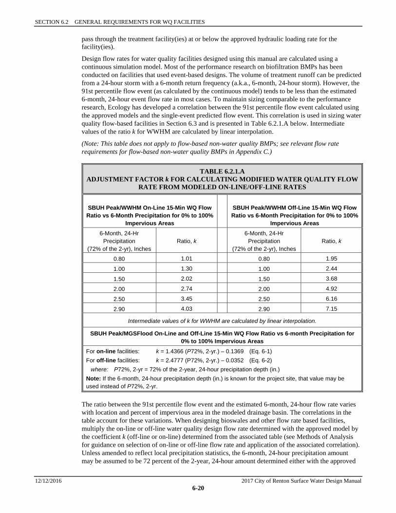
Design flow rates for water quality facilities designed using this manual are calculated using a continuous simulation model. Most of the performance research on biofiltration BMPs has been conducted on facilities that used event-based designs. The volume of treatment runoff can be predicted from a 24-hour storm with a 6-month return frequency (a.k.a., 6-month, 24-hour storm). However, the 91st percentile flow event (as calculated by the continuous model) tends to be less than the estimated 6-month, 24-hour event flow rate in most cases. To maintain sizing comparable to the performance research, Ecology has developed a correlation between the 91st percentile flow event calculated using the approved models and the single-event predicted flow event. This correlation is used in sizing water quality flow-based facilities in Section 6.3 and is presented in Table 6.2.1.A below. Intermediate values of the ratio k for WWHM are calculated by linear interpolation.
(Note: This table does not apply to flow-based non-water quality BMPs; see relevant flow rate requirements for flow-based non-water quality BMPs in Appendix C.)
TABLE 6.2.1.A ADJUSTMENT FACTOR k FOR CALCULATING MODIFIED WATER QUALITY FLOW
RATE FROM MODELED ON-LINE/OFF-LINE RATES
SBUH Peak/WWHM On-Line 15-Min WQ Flow Ratio vs 6-Month Precipitation for 0% to 100%
Impervious Areas
SBUH Peak/WWHM Off-Line 15-Min WQ Flow Ratio vs 6-Month Precipitation for 0% to 100%
Impervious Areas 6-Month, 24-Hr
Precipitation (72% of the 2-yr), Inches
Ratio, k 6-Month, 24-Hr
Precipitation (72% of the 2-yr), Inches
Ratio, k
0.80 1.01 0.80 1.95
1.00 1.30 1.00 2.44
1.50 2.02 1.50 3.68
2.00 2.74 2.00 4.92
2.50 3.45 2.50 6.16
2.90 4.03 2.90 7.15
Intermediate values of k for WWHM are calculated by linear interpolation.
SBUH Peak/MGSFlood On-Line and Off-Line 15-Min WQ Flow Ratio vs 6-month Precipitation for 0% to 100% Impervious Areas
For on-line facilities: k = 1.4366 (P72%, 2-yr.) – 0.1369 (Eq. 6-1) For off-line facilities: k = 2.4777 (P72%, 2-yr.) – 0.0352 (Eq. 6-2) where: P72%, 2-yr = 72% of the 2-year, 24-hour precipitation depth (in.) Note: If the 6-month, 24-hour precipitation depth (in.) is known for the project site, that value may be used instead of P72%, 2-yr.
The ratio between the 91st percentile flow event and the estimated 6-month, 24-hour flow rate varies with location and percent of impervious area in the modeled drainage basin. The correlations in the table account for these variations. When designing bioswales and other flow rate based facilities, multiply the on-line or off-line water quality design flow rate determined with the approved model by the coefficient k (off-line or on-line) determined from the associated table (see Methods of Analysis for guidance on selection of on-line or off-line flow rate and application of the associated correlation). Unless amended to reflect local precipitation statistics, the 6-month, 24-hour precipitation amount may be assumed to be 72 percent of the 2-year, 24-hour amount determined either with the approved

6.2.1 WATER QUALITY DESIGN FLOWS AND TREATMENT VOLUMES
2017 City of Renton Surface Water Design Manual 12/12/2016 6-21
model or by interpolating between isopluvials for the 2-year, 24-hour precipitation. Isopluvials for 2-year, 24-hour amounts for Western Washington are reprinted in Section 3.2.1, Figure 3.2.1.A.
Flow Volume to be Treated When water quality treatment is required pursuant to the core and special requirements of this manual, the water quality design storm volume, when using an approved continuous runoff model, shall be equal to the simulated daily volume that represents the upper limit of the range of daily volumes that accounts for 91% of the entire runoff volume over a multi-decade period of record.
Alternatively, the water quality design volume of runoff can be predicted from a 24-hour storm with a 6-month return frequency (a.k.a., 6-month, 24-hour storm). Wetpool facilities are sized based upon use of the NRCS (formerly known as SCS) curve number equations for the 6-month, 24-hour storm.20 Treatment facilities sized by this simple runoff volume-based approach are the same size whether they precede detention, follow detention, or are integral with the detention facility (i.e., a combined detention and wetpool facility).
The approved model calculates the water quality design volume directly. Alternatively, the NRCS method described in Section 6.4.1.1 may be used. Unless amended to reflect local precipitation statistics, the 6-month, 24-hour precipitation amount may be assumed to be 72 percent of the 2-year, 24-hour amount. Interpolating between isopluvials for the 2-year, 24-hour precipitation and multiplying by 72% yields the appropriate storm size. Isopluvials detailed for 2-year, 24-hour amounts for western King County (including the City of Renton) are reprinted in Section 3.2.1, Figure 3.2.1.A. For locations east of the figure limits, precipitation amounts are more variable; use the 2-year, 24-hour isopluvial map located on the National Oceanic and Atmospheric Administration (NOAA) website at <http://www.nws.noaa.gov/oh/hdsc/PF_documents/Atlas2_Volume9.pdf>.
Note that facilities which are sized based on volume and which include routing of flows through a detention facility, such as the detailed sand filter method, are significantly smaller when located downstream of detention, even though the same volume of water is treated in either situation. This is because the detention facility routing sequence stores peaks within the pond and releases them at a slow rate, reducing the size of the sand filter pond subsequently needed (the volume needed to store the peaks need not be provided again in the sand filter pond).
Treatable Flows As stated in Chapter 1, only runoff from target pollution-generating surfaces must be treated using the water quality facility options indicated in the applicable water quality menu. These surfaces include both pollution-generating impervious surface and pollution-generating pervious surface. “Target” means that portion from which runoff must be treated using a water quality facility as specified in Chapter 1. Pollution-generating impervious surfaces are those impervious surfaces which are subject to vehicular use, industrial activities, or storage of erodible or leachable materials, wastes, or chemicals; and which receive direct rainfall or the run-on or blow-in of rainfall. Target pollution-generating impervious surfaces typically include right-of-way improvements (roads), parking areas and driveways that are not fully dispersed as specified in Section 1.2.3.2. Metal roofs are also considered to be pollution-generating impervious surface unless they are coated with an inert, non-leachable material (see Reference Section 11-E); or roofs that are subject to venting significant amounts of dusts, mists, or fumes from manufacturing, commercial, or other indoor activities. Pollution-generating pervious surfaces are those non-impervious surfaces subject to use of pesticides and fertilizers, loss of soil, or the use or storage of erodible or leachable materials, wastes, or chemicals. Target pollution-generating pervious surfaces typically include lawns and landscaped areas that are not fully dispersed and from which there will be some concentrated surface discharge in a natural channel or man-made conveyance system from the site.
20 For more information, see Urban Hydrology for Small Watersheds, Technical Release 55 (TR-55), June 1986, published by the
NRCS. See Table 6.4.1.1.xx for CN values to be used with this manual.
SECTION 6.2 GENERAL REQUIREMENTS FOR WQ FACILITIES
12/12/2016 2017 City of Renton Surface Water Design Manual 6-22
The following points summarize which site flows must be treated and under what circumstances:
• All runoff from target pollution-generating impervious surfaces is to be treated through the water quality facility or facilities required in Chapter 1 and specified in the Chapter 6 menus.
• Runoff from lawns and landscaped areas often overflows toward street drainage systems where it is conveyed to treatment facilities along with the road runoff. However, sometimes runoff from commercial areas and residential backyards drains into open space or vegetated buffer areas. In these cases, buffers may be used to provide the requisite water quality treatment provided:
1. Runoff sheet flows into the buffer or a dispersal trench is provided to disperse flows broadly into the buffer, and
2. The flow path through the pollution-generating area is limited to 200 feet, and
3. The buffer contains only native vegetation and is not itself subject to application of any fertilizers or pesticides.
• Drainage from impervious surfaces that are not pollution-generating (such as patios, walkways, and some roofs) or are not target pollution-generating surfaces may bypass the water quality facility. However, this allowance to bypass does not excuse target impervious surfaces from, meeting the flow control requirements per Core Requirement #3. Note that metal roofs are considered pollution-generating unless they are treated to prevent leaching (see Reference Section 11-E), as are roofs that are subject to venting significant amounts of dusts, mists, or fumes from manufacturing, commercial, or other indoor activities.
• Drainage from areas in native vegetation should not be mixed with untreated runoff from streets and driveways, if possible. It is best to infiltrate or disperse this relatively clean runoff to maximize recharge to shallow groundwater, wetlands, and streams.
• Where runoff from non-pollution-generating impervious areas (non-PGIS), areas in native vegetation, or any other area not targeted for water quality treatment reaches a water quality facility, flows from those areas must be included in the sizing calculations for the facility. Once runoff from non-pollution-generating areas and non-target pollution-generating areas is combined with runoff from target pollution-generating areas, it cannot be separated before treatment.
6.2.2 SEQUENCE OF FACILITIES As specified in the water quality menus, where more than one water quality facility is used, the order is often prescribed. This is because the specific pollutant removal role of the second or third facility in a treatment train often assumes that significant solids settling has already occurred. For example, phosphorus removal using a two-facility treatment train relies on the second facility (sand filter) to remove a finer fraction of solids than those removed by the first facility.
There is a larger question, however, of whether water quality facilities should be placed upstream or downstream of detention facilities. In general, all water quality facilities may be installed upstream of detention facilities, although presettling basins are needed for sand filters and infiltration basins. Not all water quality facilities, however, can be located downstream of detention facilities. Those facilities that treat sheet flows, such as filter strips and narrow-area filter strips, will seldom be practical downstream of detention facilities. Other facilities present special problems that must be considered before placement downstream is advisable.
Two facilities that fall into this latter category are the basic bioswale (see Section 6.3.1) and the sand filter or sand filter vault (see Sections 6.5.2 or 6.5.3). For these facilities, the prolonged low flows resulting from Flow Control Duration Standard or Flood Problem Flow Control Standard may interfere with facility operation. In the case of basic bioswales, prolonged flows, generally in excess of about two weeks, will cause the grass to die. This can be dealt with by using the wet bioswale design.
In the case of sand filters, prolonged flows may result in the sand being saturated for long periods. Saturated sand can become hypoxic or anoxic (lose most or all oxygen) when dissolved oxygen in the pore water becomes depleted. Under these conditions, some previously trapped phosphorus can become soluble

6.2.2 SEQUENCE OF FACILITIES
2017 City of Renton Surface Water Design Manual 12/12/2016 6-23
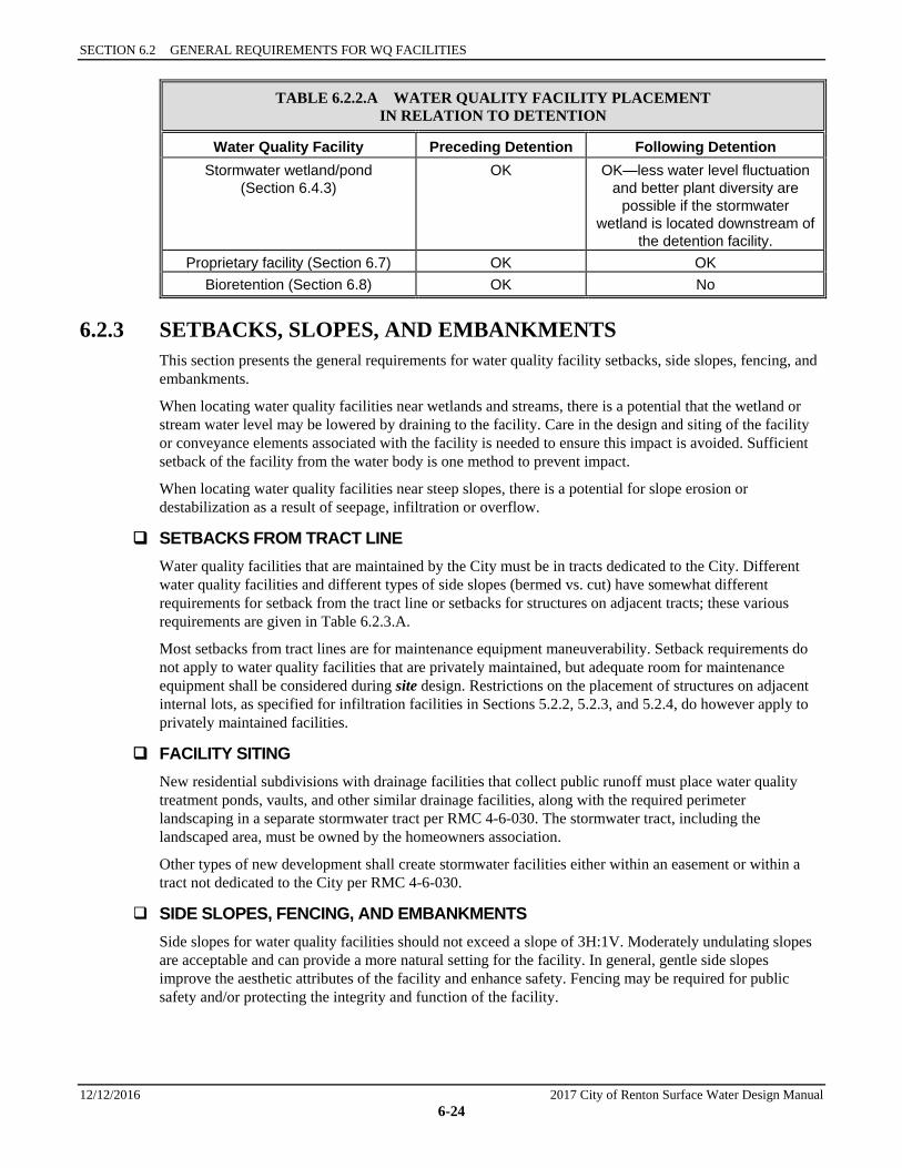
and be released,21 resulting in phosphorus releases in excess of influent concentrations. To prevent long periods of sand saturation, adjustments may be necessary after the sand filter is in operation to bypass some areas of the filter, allowing them to drain completely. If saturated conditions are present after facility operation, adjustments to the design shall be required. It may also be possible to employ a different alternative that uses facilities less sensitive to prolonged flows. Table 6.2.2.A summarizes placement considerations of water quality facilities in relation to detention.
Oil control facilities must be located upstream of water quality facilities and as close to the source of oil-generating activity as possible. They should also be located upstream of detention facilities, if possible.
TABLE 6.2.2.A WATER QUALITY FACILITY PLACEMENT IN RELATION TO DETENTION
Water Quality Facility Preceding Detention Following Detention Basic bioswale (Section 6.3.1)
OK OK if downstream of detention sized to meet Peak Rate Flow Control Standard. However,
prolonged flows may cause soil saturation and injure grass.
If downstream of a pond sized to meet Flow Control Duration
Standard or Flood Problem Flow Control Standard, the wet bioswale may be needed
(see Section 6.3.2) Wet bioswale (Section 6.3.2) OK OK
Lateral inflow bioswale (Section 6.3.3)
OK No—must be installed before flows concentrate.
Filter strip or roadway filter strip (Sections 6.3.4 and 6.3.5)
OK No—must be installed before flows concentrate.
Basic or large wetpond (Section 6.4.1)
OK OK—less water level fluctuation in ponds downstream of detention may improve aesthetic qualities.
Basic or large combined detention and wetpond (Section 6.4.4)
Not applicable Not applicable
Wetvault (Section 6.4.2) OK OK Basic or large sand filter or sand filter vault (Section 6.5.2 or 6.5.3)
OK, but presettling and control of floatables
needed
OK—sand filters downstream of a pond sized to meet Flow Control
Duration Standard or Flood Problem Flow Control Standard may require field adjustments if
prolonged flows cause sand saturation and resultant hypoxic, anoxic or anaerobic conditions, interfering with the phosphorus removal mechanism and likely
resulting in episodic phosphorus releases in excess of influent
concentrations.
21 Bicudo, D. D. C., et al. (2007). "Undesirable side-effects of water hyacinth control in a shallow tropical reservoir." Freshwater
Biology 52(6): 1120-1133.
SECTION 6.2 GENERAL REQUIREMENTS FOR WQ FACILITIES
12/12/2016 2017 City of Renton Surface Water Design Manual 6-24
TABLE 6.2.2.A WATER QUALITY FACILITY PLACEMENT IN RELATION TO DETENTION
Water Quality Facility Preceding Detention Following Detention Stormwater wetland/pond
(Section 6.4.3) OK OK—less water level fluctuation
and better plant diversity are possible if the stormwater
wetland is located downstream of the detention facility.
Proprietary facility (Section 6.7) OK OK Bioretention (Section 6.8) OK No
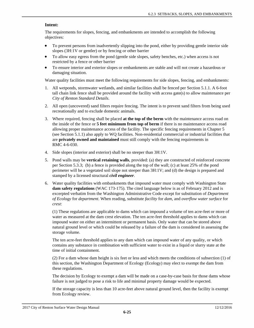
6.2.3 SETBACKS, SLOPES, AND EMBANKMENTS This section presents the general requirements for water quality facility setbacks, side slopes, fencing, and embankments.
When locating water quality facilities near wetlands and streams, there is a potential that the wetland or stream water level may be lowered by draining to the facility. Care in the design and siting of the facility or conveyance elements associated with the facility is needed to ensure this impact is avoided. Sufficient setback of the facility from the water body is one method to prevent impact.
When locating water quality facilities near steep slopes, there is a potential for slope erosion or destabilization as a result of seepage, infiltration or overflow.
SETBACKS FROM TRACT LINE Water quality facilities that are maintained by the City must be in tracts dedicated to the City. Different water quality facilities and different types of side slopes (bermed vs. cut) have somewhat different requirements for setback from the tract line or setbacks for structures on adjacent tracts; these various requirements are given in Table 6.2.3.A.
Most setbacks from tract lines are for maintenance equipment maneuverability. Setback requirements do not apply to water quality facilities that are privately maintained, but adequate room for maintenance equipment shall be considered during site design. Restrictions on the placement of structures on adjacent internal lots, as specified for infiltration facilities in Sections 5.2.2, 5.2.3, and 5.2.4, do however apply to privately maintained facilities.
FACILITY SITING New residential subdivisions with drainage facilities that collect public runoff must place water quality treatment ponds, vaults, and other similar drainage facilities, along with the required perimeter landscaping in a separate stormwater tract per RMC 4-6-030. The stormwater tract, including the landscaped area, must be owned by the homeowners association.
Other types of new development shall create stormwater facilities either within an easement or within a tract not dedicated to the City per RMC 4-6-030.
SIDE SLOPES, FENCING, AND EMBANKMENTS Side slopes for water quality facilities should not exceed a slope of 3H:1V. Moderately undulating slopes are acceptable and can provide a more natural setting for the facility. In general, gentle side slopes improve the aesthetic attributes of the facility and enhance safety. Fencing may be required for public safety and/or protecting the integrity and function of the facility.
6.2.3 SETBACKS, SLOPES, AND EMBANKMENTS
2017 City of Renton Surface Water Design Manual 12/12/2016 6-25
Intent: The requirements for slopes, fencing, and embankments are intended to accomplish the following objectives:
• To prevent persons from inadvertently slipping into the pond, either by providing gentle interior side slopes (3H:1V or gentler) or by fencing or other barrier
• To allow easy egress from the pond (gentle side slopes, safety benches, etc.) when access is not restricted by a fence or other barrier
• To ensure interior and exterior slopes or embankments are stable and will not create a hazardous or damaging situation.
Water quality facilities must meet the following requirements for side slopes, fencing, and embankments:
1. All wetponds, stormwater wetlands, and similar facilities shall be fenced per Section 5.1.1. A 6-foot tall chain link fence shall be provided around the facility with access gate(s) to allow maintenance per City of Renton Standard Details.
2. All open (uncovered) sand filters require fencing. The intent is to prevent sand filters from being used recreationally and to exclude domestic animals.
3. Where required, fencing shall be placed at the top of the berm with the maintenance access road on the inside of the fence or 5 feet minimum from top of berm if there is no maintenance access road allowing proper maintenance access of the facility. The specific fencing requirements in Chapter 5 (see Section 5.1.1) also apply to WQ facilities. Non-residential commercial or industrial facilities that are privately owned and maintained must still comply with the fencing requirements in RMC 4-6-030.
4. Side slopes (interior and exterior) shall be no steeper than 3H:1V.
5. Pond walls may be vertical retaining walls, provided: (a) they are constructed of reinforced concrete per Section 5.3.3; (b) a fence is provided along the top of the wall; (c) at least 25% of the pond perimeter will be a vegetated soil slope not steeper than 3H:1V; and (d) the design is prepared and stamped by a licensed structural civil engineer.
6. Water quality facilities with embankments that impound water must comply with Washington State dam safety regulations (WAC 173-175). The cited language below is as of February 2012 and is excerpted verbatim from the Washington Administrative Code except for substitution of Department of Ecology for department. When reading, substitute facility for dam, and overflow water surface for crest:
(1) These regulations are applicable to dams which can impound a volume of ten acre-feet or more of water as measured at the dam crest elevation. The ten acre-feet threshold applies to dams which can impound water on either an intermittent or permanent basis. Only water that can be stored above natural ground level or which could be released by a failure of the dam is considered in assessing the storage volume.
The ten acre-feet threshold applies to any dam which can impound water of any quality, or which contains any substance in combination with sufficient water to exist in a liquid or slurry state at the time of initial containment.
(2) For a dam whose dam height is six feet or less and which meets the conditions of subsection (1) of this section, the Washington Department of Ecology (Ecology) may elect to exempt the dam from these regulations.
The decision by Ecology to exempt a dam will be made on a case-by-case basis for those dams whose failure is not judged to pose a risk to life and minimal property damage would be expected.
If the storage capacity is less than 10 acre-feet above natural ground level, then the facility is exempt from Ecology review.
SECTION 6.2 GENERAL REQUIREMENTS FOR WQ FACILITIES
12/12/2016 2017 City of Renton Surface Water Design Manual 6-26
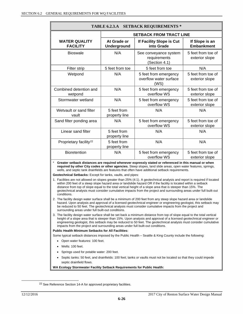
TABLE 6.2.3.A SETBACK REQUIREMENTS *
WATER QUALITY FACILITY
SETBACK FROM TRACT LINE At Grade or
Underground If Facility Slope is Cut
into Grade If Slope is an Embankment
Bioswale N/A See conveyance system requirements (Section 4.1)
5 feet from toe of exterior slope
Filter strip 5 feet from toe 5 feet from toe N/A Wetpond N/A 5 feet from emergency
overflow water surface (WS)
5 feet from toe of exterior slope
Combined detention and wetpond
N/A 5 feet from emergency overflow WS
5 feet from toe of exterior slope
Stormwater wetland N/A 5 feet from emergency overflow WS
5 feet from toe of exterior slope
Wetvault or sand filter vault
5 feet from property line
N/A N/A
Sand filter ponding area N/A 5 feet from emergency overflow WS
5 feet from toe of exterior slope
Linear sand filter 5 feet from property line
N/A N/A
Proprietary facility22 5 feet from property line
N/A N/A
Bioretention N/A 5 feet from emergency overflow WS
5 feet from toe of exterior slope
* Greater setback distances are required whenever expressly stated or referenced in this manual or when required by other City codes or other agencies. Steep slopes, land slide areas, open water features, springs, wells, and septic tank drainfields are features that often have additional setback requirements.
Geotechnical Setbacks: Except for tanks, vaults, and pipes: 1. Facilities are not allowed on slopes greater than 25% (4:1). A geotechnical analysis and report is required if located
within 200 feet of a steep slope hazard area or landslide hazard OR if the facility is located within a setback distance from top of slope equal to the total vertical height of a slope area that is steeper than 15%. The geotechnical analysis must consider cumulative impacts from the project and surrounding areas under full built-out conditions.
2. The facility design water surface shall be a minimum of 200 feet from any steep slope hazard area or landslide hazard. Upon analysis and approval of a licensed geotechnical engineer or engineering geologist, this setback may be reduced to 50 feet. The geotechnical analysis must consider cumulative impacts from the project and surrounding areas under full built-out conditions.
3. The facility design water surface shall be set back a minimum distance from top of slope equal to the total vertical height of a slope area that is steeper than 15%. Upon analysis and approval of a licensed geotechnical engineer or engineering geologist, this setback may be reduced to 50 feet. The geotechnical analysis must consider cumulative impacts from the project and surrounding areas under full built-out conditions.
Public Health Minimum Setbacks for All Facilities: Some typical setback distances imposed by the Public Health – Seattle & King County include the following:
• Open water features: 100 feet.
• Wells: 100 feet.
• Springs used for potable water: 200 feet.
• Septic tanks: 50 feet, and drainfields: 100 feet; tanks or vaults must not be located so that they could impede septic drainfield flows.
WA Ecology Stormwater Facility Setback Requirements for Public Health:
22 See Reference Section 14-A for approved proprietary facilities.

6.2.3 SETBACKS, SLOPES, AND EMBANKMENTS
2017 City of Renton Surface Water Design Manual 12/12/2016 6-27
TABLE 6.2.3.A SETBACK REQUIREMENTS *
• Stormwater infiltration systems shall be set back at least 100 feet from open water features and 200 feet from springs used for drinking water supply. Infiltration facilities up-gradient of drinking water supplies must comply with State Health Department requirements (Washington Wellhead Protection Program, Department of Health, 12/93).
• Stormwater infiltration systems, and unlined wetponds and detention ponds shall be located at least 100 feet from drinking water wells and septic tanks and drainfields.
Where one agency’s setback requirements are more or less restrictive than another’s, the more restrictive setback is required.
SECTION 6.2 GENERAL REQUIREMENTS FOR WQ FACILITIES
12/12/2016 2017 City of Renton Surface Water Design Manual 6-28
6.2.4 FACILITY LINERS Water quality facilities, detention facilities, and open conveyance systems in which untreated water is in direct contact with the soil may require liners for any of three reasons: groundwater quality protection, steep slope or building protection, and/or stormwater treatment facility performance.
Liners are intended to:
1. Reduce the likelihood that pollutants in stormwater will reach ground water by transmission through soil from earthen facilities and conveyances.
2. Prevent infiltration where underflow could cause problems with steep slopes or nearby structures.
3. Ensure permanent wet pools for proper functioning of wetponds, treatment wetlands, and pre-settling ponds.
4. Ensure wet conditions in the second cell of stormwater treatment wetland sufficient to maintain wetland plant vegetation.
Types of Liners Low Permeability Liners Low permeability liners reduce infiltration to a very slow rate, generally less than 0.02 inches per hour (1.22 cm/day). Low permeability liners may be fashioned from compacted till, clay, geomembrane, or concrete as detailed in Section 6.2.4.1.
Treatment Liners Treatment liners are soil layers meeting specific quality criteria. Depending on design requirements, treatment liners may include in-place native soils, amended soils, or imported soils. Treatment liners are assumed to treat infiltrating stormwater before it reaches more freely draining soils. Treatment liners have slow rates of infiltration; the initial measured rate should be less than 2.4 inches per hour (1.7 x 10⁻³ cm/s), but rates are not as slow as with low permeability liners. See Section 6.2.4.2 for details.
Where Liners Are Required for Groundwater Protection Outside of Groundwater Protections Areas A liner is required for facilities and conveyances handling untreated water that is in direct contact with the soil if the soil has an initial infiltration rate23 greater than 9 inches per hour (0.15 inches per minute) and the soil suitability criteria for groundwater protection given in Chapter 5, Section 5.2.1 is not met.
Inside Groundwater Protections Areas Open facilities are not allowed in Zone 1 of the Aquifer Protection Area. Other areas may be required to incorporate liners for groundwater protection. A liner is required for facilities and conveyances handling untreated water that is in direct contact with the soil when the soil infiltration rate exceeds an initial infiltration rate of 2.4 inches per hour (0.04 inches per minute) and the soil suitability criteria for groundwater protection given in Chapter 5, Section 5.2.1, is not met.
Where Liners are Required to Ensure Permanent Pools and Wet Conditions 1. Both cells of a two-cell wetpond and the single cell of a one cell wetpond must retain a permanent
pool of water throughout the wet season. A wetpond is considered non-compliant if the pond level drops more than 12 inches in any 7-day measurement period. A low permeability liner will be required to achieve this standard in infiltrative soils.
23 Infiltration rates can either be measured in the field using methods given in Chapter 5 or inferred from the USDA soil textural triangle
included in “Groundwater Protection,” Section 5.2.1.
6.2.4 FACILITY LINERS
2017 City of Renton Surface Water Design Manual 12/12/2016 6-29
2. Presettling ponds must retain a permanent pool of water throughout the wet season. A presettling pond is considered non-compliant if the pond level drops more than 12 inches in any 7-day measurement period. A low permeability liner will be required to achieve this standard in infiltrative soils.
3. Both cells of a stormwater wetland shall be lined in infiltrative soils as follows:
a) The first cell of a treatment wetland must retain a permanent pool of water throughout the wet season. It is considered non-compliant if the pond level drops more than 12 inches in any 7-day measurement period. A low permeability liner will be required to achieve this standard in infiltrative soils.
b) The second cell must retain water for at least 10 months of the year. A low permeability liner will be required to achieve this standard in infiltrative soils. A treatment liner is an alternative where groundwater levels and/or existing soil infiltration rates are sufficient to achieve the standard.
General Design Criteria 1. Table 6.2.4.A identifies the type of liner for use with various water quality treatment facilities. If a
facility requires a liner, a treatment liner shall be provided, except where a low permeability liner is noted in Table 6.2.4.A.
2. Liners shall be evenly placed over the bottom and/or sides of the treatment area of the facility as indicated in Table 6.2.4.A. Areas above the treatment volume that are required to pass flows greater than the water quality treatment flow (or volume) need not be lined, except in groundwater protection areas which must be lined to the 2 year water surface in a combined facility or overflow water surface in a non-combined facility. Note: If the liner cannot be anchored at the required elevation, the lining must be extended to the top of the interior side slope and anchored.
3. For low permeability liners, the following criteria apply:
a) Where the seasonal high groundwater elevation is likely to contact a low permeability liner, liner buoyancy may be a concern. A low permeability liner shall not be used in this situation unless evaluated and recommended by a geotechnical engineer.
b) Where grass must be planted over a low permeability liner per the facility design, a minimum of 6 inches of good topsoil or compost-amended24 native soil (2 inches compost24 tilled into 6 inches of native soil) must be placed over the liner in the area to be planted. Twelve inches is preferred.
c) If an identification sign is required for the facility (see detention pond requirements in Section 5.1.1), the face of the sign shall bear a note indicating the facility is lined to protect water quality. In addition, the back of the sign shall include information indicating which facilities are lined, the extent of lining, the liner material used, the liner thickness (if clay or till), and the type and distance of the marker above the liner (if a geomembrane). This information need only be readable by someone standing at arms-length from the sign.
4. If a treatment liner will be below the seasonal high water level, the pollutant removal performance of the liner must be evaluated by a geotechnical or groundwater specialist and found to be as protective as if the liner were above the level of the groundwater.
See Sections 6.2.4.1 and 6.2.4.2 for more specific design criteria on the various options for low permeability liners and treatment liners.
24 Compost must meet the compost quality requirements in Reference Section 11-C.
SECTION 6.2 GENERAL REQUIREMENTS FOR WQ FACILITIES
12/12/2016 2017 City of Renton Surface Water Design Manual 6-30
TABLE 6.2.4.A LINING TYPES FOR WQ FACILITIES
WQ Facility Area to be Lined Type of Liner
Bioswale Bottom and sides Treatment liner
Wet bioswale Bottom and sides Low permeability liner (If the swale will intercept the seasonal high groundwater table, a treatment liner is recommended.)
Lateral inflow bioswale Bottom and sides Treatment liner
Presettling pond or basin Bottom and sides Low permeability liner (If the cell will intercept the seasonal high groundwater table, a treatment liner is recommended.)
Wetpond First cell: bottom and sides to WQ design water surface, (except in groundwater protection areas which must be lined to the overflow water surface
Low permeability liner (If the cell will intercept the seasonal high groundwater table, a treatment liner is recommended.)
Second cell: bottom and sides to WQ design water surface, (except in groundwater protection areas which must be lined to the overflow water surface
Low permeability liner (If the cell will intercept the seasonal high groundwater table, a treatment liner is recommended.)
Single cell: bottom and sides to WQ design water surface, (except in groundwater protection areas which must be lined to the overflow water surface
Low permeability liner
Combined detention/WQ facility First cell: bottom and sides to the 2-year live storage elevation
Low permeability liner (If the cell will intercept the seasonal high groundwater table, a treatment liner is recommended.)
Second cell: bottom and sides to the 2-year live storage elevation
Low permeability liner (If the cell will intercept the seasonal high groundwater table, a treatment liner is recommended.)
Single cell: bottom and sides to the 2-year live storage elevation
Low permeability liner
Wet vault Not applicable No liner needed
Stormwater wetland Bottom and sides, both cells Low permeability liner (If the facility will intercept the seasonal high groundwater table, a treatment liner is recommended.)
Sand filter Pond sides only Treatment liner
Detention pond Bottom and sides to the 2-year live storage elevation
Treatment Liner
Sand filter vault Not applicable No liner needed
Linear sand filter Not applicable if in vault
Bottom and sides of presettling cell if not in vault
No liner needed
Low permeability or treatment liner
Proprietary filter (in vault) Not applicable No liner needed
Bioretention Bottom and sides (when required per Section 6.8)
Low permeability liner
6.2.4 FACILITY LINERS
2017 City of Renton Surface Water Design Manual 12/12/2016 6-31
6.2.4.1 DESIGN CRITERIA FOR LOW PERMEABILITY LINER OPTIONS This section presents the design criteria for each of the following four low permeability liner options:
• Compacted till liners • Clay liners • Geomembrane liners • Concrete liners
COMPACTED TILL LINERS 1. Liner thickness shall be 18 inches after compaction.
2. Soil shall be compacted to 95% minimum dry density, modified proctor method (ASTM D-1557).
3. Soil should be placed in 6 inch lifts.
4. Soils may be used that meet the following gradation:
Sieve Size Percent Passing 6 inch 100 4 inch 90
#4 70–100 #200 30–100
CLAY LINERS 1. Minimum dry (un-swollen) thickness of 12 inches
2. Compacted to 95% minimum dry density, standard proctor method ASTM D-698
3. Clay Particles Passing, ASTM D-422, not less than 30 percent
4. Plasticity Index of Clay, ASTM D4318, not less than 15 percent
5. The slope of clay liners must be restricted to 3H:IV for all areas requiring soil cover; otherwise, the soil layer must be stabilized by another method so that soil slippage into the facility does not occur. Any alternative soil stabilization method must take maintenance access into consideration.
6. Where clay liners form the sides of ponds, the interior side slope should not be steeper than 3H:1V, irrespective of fencing. This restriction is to ensure that anyone falling into the pond may climb out safely.
GEOMEMBRANE LINERS 1. Geomembrane liners shall be UV resistant and have a minimum thickness of 30 mils. A thickness of
40 mils shall be used in areas of maintenance access or where heavy machinery must be operated over the membrane. Protect the geomembrane liner from puncture, tearing, and abrasion by installing geotextile fabric on the top and bottom of the geomembrane.
2. Geomembranes shall be bedded according to the manufacturer’s recommendations.
3. Liners shall be installed so that they can be covered with 12 inches of top dressing forming the bottom and sides of the water quality facility. Top dressing shall consist of 6 inches of crushed rock covered with 6 inches of native soil. The rock layer is to mark the location of the liner for future maintenance operations. As an alternative to crushed rock, 12 inches of native soil may be used if orange plastic “safety fencing” or another highly-visible, continuous marker is embedded 6 inches above the membrane.
4. If possible, liners should be of a contrasting color so that maintenance workers are aware of any areas where a liner may have become exposed when maintaining the facility.
SECTION 6.2 GENERAL REQUIREMENTS FOR WQ FACILITIES
12/12/2016 2017 City of Renton Surface Water Design Manual 6-32
5. Where top dressing is required, liners shall not be used on slopes steeper than 5H:1V, to prevent the top dressing material from slipping. Textured liners may be used on slopes up to 3H:1V upon recommendation by a geotechnical engineer or engineering geologist that the top dressing will be stable for all site conditions, including maintenance.
CONCRETE LINERS 1. Portland cement concrete liners are allowed irrespective of facility size, and shotcrete may be used on
slopes; however, specifications must be developed by an engineer who certifies the liner against cracking or losing water retention ability under expected conditions of operation, including facility maintenance operations. Cautionary design note: weight of maintenance equipment can be up to 80,000 pounds when fully loaded.
2. Asphaltic concrete may not be used for a liner because of asphalt’s permeability to many organic pollutants, and potential for asphalt to leach pollutants into stored or conveyed water.
3. If grass is to be grown in soil over a concrete liner, slopes must be no steeper than 5H:1V to prevent the top dressing material from slipping.
6.2.4.2 DESIGN CRITERIA FOR TREATMENT LINER OPTIONS This section presents the design criteria for the organic soil layer used as a treatment liner.
ORGANIC SOIL LAYER 1. A two-foot thick layer of soil with a minimum organic matter (OM) content of 1.0% AND a minimum
cation exchange capacity (CEC) of 8 milliequivalents per 100 grams (meq/100g) can be used as a treatment layer beneath a water quality or detention facility. If the soil is amended or imported, the top 8 inches must have a minimum cation exchange capacity of 10 meq/100g and the remainder of the depth no less than 8 meq/100g. An 18-inch layer with the same CEC and OM profile will suffice for ditch conveyances, based on unsaturated flow as a result of alternating wet-dry periods.
2. To demonstrate that in-place soils meet the above criteria, one sample per 1,000 square feet of facility area, or 500 linear feet of ditch, and no fewer than three samples shall be tested. Each sample shall be a composite of equally spaced subsamples taken throughout the full extent of the treatment layer depth (usually two to six feet below the expected facility invert for facilities), except stratified composite sampling is required where the top 8 inches are required to meet a higher CEC level (composite of top eight inches and separate composite of the remainder below).
3. Organic content shall be measured on a dry weight basis using ASTM D2974.
4. Laboratory results shall be provided for cation exchange capacity (CEC).
5. Certification by a soils testing laboratory that imported soil meets the organic content and CEC criteria above shall be provided to the local approval authority.
6. Soil amendment may only be compost meeting the requirements of Reference Section 11-C.
7. If a treatment liner will be below the seasonal high water level, the pollutant removal performance of the liner must be evaluated by a geotechnical or ground water specialist and found to be as protective as if the liner were above the level of the ground water.
6.2.5 FLOW SPLITTER DESIGNS Most water quality facilities may be designed as flow-through, or on-line, systems with flows above the water quality design flow or volume simply passing through the facility untreated. However, it is sometimes desirable to restrict flows to water quality treatment facilities and bypass the remaining higher flows around them (off-line facilities). This can be accomplished by splitting flows in excess of the water quality design flow upstream of the facility and diverting higher flows to a bypass pipe or channel. The bypass typically enters a detention facility or the downstream receiving drainage system, depending on

6.2.5 FLOW SPLITTER DESIGNS
2017 City of Renton Surface Water Design Manual 12/12/2016 6-33
flow control requirements. In most cases, it is a designer’s choice whether WQ facilities are designed as on-line or off-line; an exception is oil/water separators, which must be designed off-line.
A crucial factor in designing flow splitters is to ensure that low flows are delivered to the treatment facility up to the WQ design flow rate. Above this rate, additional flows are diverted to the bypass system with minimal increase in head at the flow splitter structure to avoid surcharging the water quality facility under high flow conditions.
Flow splitters are typically catch basins or vaults with concrete baffles. In place of baffles, the splitter mechanism may be a half tee section with a solid top and an orifice in the bottom of the tee section. A full tee option may also be used (see “Design Criteria” below). Two possible schematic representations for flow splitters are shown in Figure 6.2.5.A and Figure 6.2.5.B. Other designs that achieve the result of splitting low flows, up to the WQ design flow, into the WQ treatment facility and divert higher flows around the facility may be considered (an adjustment per Section 1.4 may be required upon evaluation by CED staff).
6.2.5.1 METHODS OF ANALYSIS Flow splitters are modeled with the approved model using the design flow rates as described in Section 6.2.1. The stage/discharge relationship of the outflow pipes should be determined using the backwater analysis techniques in Chapter 4. The orifice shall be sized per Section 5.1.4.2. Weirs should be analyzed as sharp-crested weirs.
6.2.5.2 DESIGN CRITERIA General 1. A flow splitter shall be designed to deliver the required water quality design flow rate specified in
Section 6.2.1 to the WQ treatment facility.
2. The top of the weir shall be located at the water surface for the design flow. Remaining flows enter the bypass line. Flows shall be modeled using 15-minute time steps.
3. The maximum head shall be minimized for flow in excess of the water quality design flow. Specifically, flow to the WQ facility at the 100-year water surface shall not increase the design WQ flow by more than 10%.
4. Either design shown in Figure 6.2.5.A or Figure 6.2.5.B shall be used.
5. Special applications, such as roads, may require the use of a modified flow splitter. The baffle wall may be fitted with a notch and adjustable weir plate to proportion runoff volumes other than high flows.
6. For ponding facilities, backwater effects must be included in designing the height of the standpipe in the catch basin.
7. Ladder or step and handhold access (per City of Renton Standard Details) shall be provided. If the weir wall is higher than 36 inches, two ladders, one to either side of the wall, are required.
Material Requirements 1. The splitter baffle shall be installed in a Type 2 catch basin or vault.
2. The baffle wall shall be made of reinforced concrete or another suitable material resistant to corrosion, and have a minimum 4-inch thickness. The minimum clearance between the top of the baffle wall and the bottom of the catch basin cover shall be 4 feet; otherwise, dual access points shall be provided.
3. All metal parts shall be corrosion resistant. Examples of preferred materials include aluminum, stainless steel, and plastic. Zinc and galvanized materials, bronze and brass, and cadmium-plated hardware shall not be used unless there is no substitute, because of aquatic toxicity. Painting or other coating of metal parts shall not be allowed because of poor longevity and lack of standardization or assurance of non-toxic coatings.
SECTION 6.2 GENERAL REQUIREMENTS FOR WQ FACILITIES
12/12/2016 2017 City of Renton Surface Water Design Manual 6-34
FIGURE 6.2.5.A SCHEMATIC REPRESENTATION OF FLOW SPLITTER, OPTION A
SECTION A-ANTS
PLAN VIEWNTS
INFLOW
NOTE:THE WATER QUALITY DISCHARGE PIPE MAY REQUIRE AN ORIFICE PLATE TO BE INSTALLED ONTHE OUTLET TO CONTROL THE HEIGHT OF THE DESIGN WATER SURFACE (WEIR HEIGHT). THEDESIGN WATER SURFACE SHOULD BE SET TO PROVIDE A MINIMUM HEADWATER/DIAMETERRATIO OF 2.0 ON THE OUTLET PIPE.
TO WQ FACILITY
TO BYPASS CONVEYANCESYSTEM OR DETENTION POND
A
4" MIN. THICKNESSREINFORCED CONCRETEBAFFLE WALL OR OTHER
SUITABLE MATERIALBYPASS PIPE
4' MIN.OR PROVIDE SEPARATEACCESS TO EITHER SIDEOF BAFFLE WALL
WQ DESIGN WATERSURFACE ELEVATION
HANDHOLD AND STEPS ORLADDER ACCESS (PROVIDE
LADDERS TO BOTH SIDESOF WALL IF WEIR >36" HIGH)
ROUND SOLID LID(KCRDCS DWG 7-022 AND 7-023)
INFLOW
REINFORCED BAFFLE WALLGROUTED TO MANHOLESTRUCTURE (BOTH ENDS)
TYPE 2 C.B.
4' M
IN.
2' MIN.
A
TO WQ FACILITY
6.2.5 FLOW SPLITTER DESIGNS
2017 City of Renton Surface Water Design Manual 12/12/2016 6-35
FIGURE 6.2.5.B SCHEMATIC REPRESENTATION OF FLOW SPLITTER, OPTION B
INFLOW
SECTION A-ANTS
PLAN VIEWNTS
TO WATER QUALITYFACILITY
TO WATER QUALITYFACILITY
TO BYPASS CONVEYANCESYSTEM OR DETENTION POND
INFLOW
*NOTE:DIAMETER OF STANDPIPE SHOULD BE LARGE ENOUGH TO MINIMIZEHEAD ABOVE WQ DESIGN WS AND TO KEEP WQ DESIGN FLOWS FROMINCREASING MORE THAN 10% DURING 100-YEAR FLOWS.
A 2d*
6"6"
7' M
IN.
2' M
IN.
d
SOLID BOTTOM(PROVIDE
MAINTENANCEACCESS)
LADDER (TYP.)
TOP OF PIPE AT WQ DESIGNWATER SURFACE ELEVATION
ROUND SOLID LID (SEEKCRDCS DWG 7-022 AND 7-023)
BAFFLE TO CONTROL FLOATABLES, ORPROVIDE SPILL CONTROL UPSTREAM
"TEE" SECTION WITH CLEANOUT(OR REMOVABLE BEND-DOWNELBOW)
ORIFICE SIZED TO PASSWQ DESIGN FLOW
TOP OF RISER ATDESIGN WS ELEVATION
TYPE II CBNO BASE CHANNEL REQ'D
DIA. OF STANDPIPE*(2 X DIA. OF OUTLET PIPERECOMMENDED ASSTARTING POINT, SEENOTE)
BAFFLE TO CONTROLFLOATABLES
SECTION 6.2 GENERAL REQUIREMENTS FOR WQ FACILITIES
12/12/2016 2017 City of Renton Surface Water Design Manual 6-36
6.2.6 FLOW SPREADING OPTIONS Flow spreaders function to uniformly spread flows across the inflow portion of water quality facilities (e.g., sand filter, bioswale, or filter strip).
There are five flow spreader options presented in this section:
• Anchored section: Anchored plate or board (Option A) • Concrete sump box (Option B) • Notched curb spreader (Option C) • Through-curb ports (Option D) • Interrupted curbing (Option E)
Options A through C may be used for spreading flows that are concentrated. Any one of these options may be used when spreading is required by the facility design criteria. Options A through C may also be used for unconcentrated (sheet) flows, and in some cases must be used, such as to correct for moderate grade changes along a filter strip.
Options D and E are only for flows that are already unconcentrated when they enter a filter strip or lateral inflow bioswale. Other flow spreader options are possible with approval from CED.
6.2.6.1 DESIGN CRITERIA FOR FLOW SPREADER OPTIONS General Design Criteria 1. Flow must not escape around ends or through any breaks in a flow spreader.
2. Where flow enters the flow spreader through a pipe, it is recommended that the pipe be submerged to the extent practical to dissipate energy as much as possible.
3. For higher velocity inflows (greater than 5 cfs for the 100-yr storm), a Type 1 catch basin should be positioned in the spreader, and the inflow pipe should enter the catch basin with flows exiting through the top grate. The top of the grate should be lower than the level spreader plate, or if a notched spreader is used, lower than the bottom of the v-notches.
4. Table 4.2.2.F in Chapter 4 provides general guidance for rock protection at outfalls.
OPTION A ANCHORED PLATE OR BOARD (FIGURE 6.2.6.A) 1. An adjustable-level anchored plate or board flow spreader shall be preceded by a sump having a
minimum depth of 8 inches and minimum width of 24 inches. If not otherwise stabilized, the sump area shall be lined to reduce erosion and to provide energy dissipation.
2. The top surface of the flow spreader plate or board shall be level, projecting a minimum of 2 inches above the ground surface of the water quality facility, or v-notched with notches 6 to 10 inches on center and 1 to 6 inches deep (use shallower notches with closer spacing). Alternative designs are allowed. The anchored plate or board level shall be adjustable using slotted bolt holes in the anchored plate or board.
3. A flow spreader plate or board shall extend horizontally beyond the bottom width of the facility to prevent water from eroding the side slope. The horizontal extent should be such that the bank is protected for all flows up to the 100-year flow or the maximum flow that will enter the WQ facility.
4. Flow spreader plates or boards shall be securely fixed in place by bolts through slotted holes for adjustability in establishing and maintaining level.
5. Flow spreader plates or boards may be made of either wood, metal, fiberglass reinforced plastic, or other durable material. If wood, untreated 4 by 10-inch cedar heartwood lumber or cedar landscape timbers are acceptable.
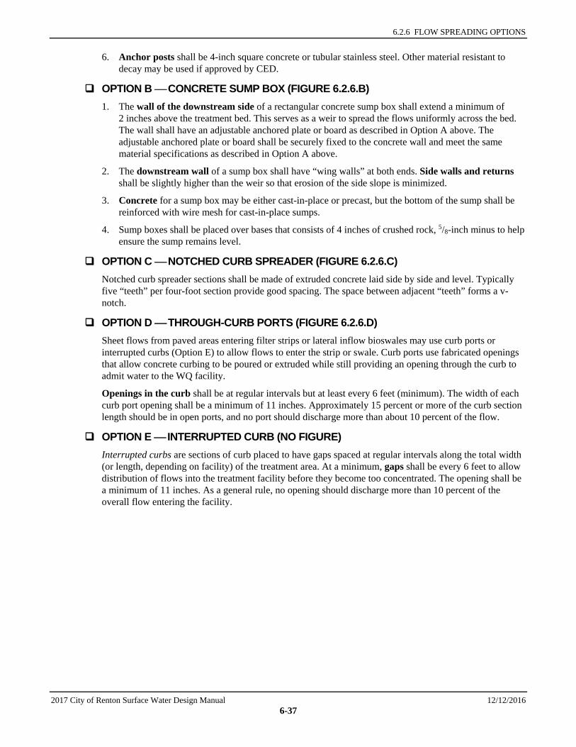
6.2.6 FLOW SPREADING OPTIONS
2017 City of Renton Surface Water Design Manual 12/12/2016 6-37
6. Anchor posts shall be 4-inch square concrete or tubular stainless steel. Other material resistant to decay may be used if approved by CED.
OPTION B CONCRETE SUMP BOX (FIGURE 6.2.6.B) 1. The wall of the downstream side of a rectangular concrete sump box shall extend a minimum of
2 inches above the treatment bed. This serves as a weir to spread the flows uniformly across the bed. The wall shall have an adjustable anchored plate or board as described in Option A above. The adjustable anchored plate or board shall be securely fixed to the concrete wall and meet the same material specifications as described in Option A above.
2. The downstream wall of a sump box shall have “wing walls” at both ends. Side walls and returns shall be slightly higher than the weir so that erosion of the side slope is minimized.
3. Concrete for a sump box may be either cast-in-place or precast, but the bottom of the sump shall be reinforced with wire mesh for cast-in-place sumps.
4. Sump boxes shall be placed over bases that consists of 4 inches of crushed rock, 5/8-inch minus to help ensure the sump remains level.
OPTION C NOTCHED CURB SPREADER (FIGURE 6.2.6.C) Notched curb spreader sections shall be made of extruded concrete laid side by side and level. Typically five “teeth” per four-foot section provide good spacing. The space between adjacent “teeth” forms a v-notch.
OPTION D THROUGH-CURB PORTS (FIGURE 6.2.6.D) Sheet flows from paved areas entering filter strips or lateral inflow bioswales may use curb ports or interrupted curbs (Option E) to allow flows to enter the strip or swale. Curb ports use fabricated openings that allow concrete curbing to be poured or extruded while still providing an opening through the curb to admit water to the WQ facility.
Openings in the curb shall be at regular intervals but at least every 6 feet (minimum). The width of each curb port opening shall be a minimum of 11 inches. Approximately 15 percent or more of the curb section length should be in open ports, and no port should discharge more than about 10 percent of the flow.
OPTION E INTERRUPTED CURB (NO FIGURE) Interrupted curbs are sections of curb placed to have gaps spaced at regular intervals along the total width (or length, depending on facility) of the treatment area. At a minimum, gaps shall be every 6 feet to allow distribution of flows into the treatment facility before they become too concentrated. The opening shall be a minimum of 11 inches. As a general rule, no opening should discharge more than 10 percent of the overall flow entering the facility.
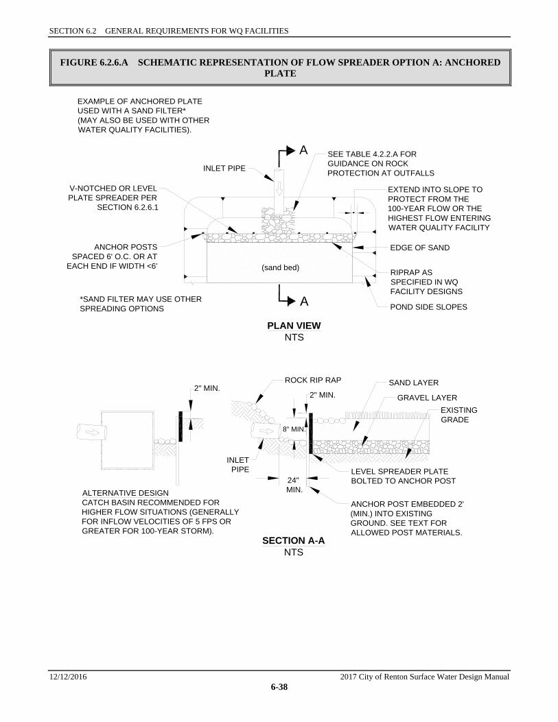
SECTION 6.2 GENERAL REQUIREMENTS FOR WQ FACILITIES
12/12/2016 2017 City of Renton Surface Water Design Manual 6-38
FIGURE 6.2.6.A SCHEMATIC REPRESENTATION OF FLOW SPREADER OPTION A: ANCHORED PLATE
ALTERNATIVE DESIGNCATCH BASIN RECOMMENDED FORHIGHER FLOW SITUATIONS (GENERALLYFOR INFLOW VELOCITIES OF 5 FPS ORGREATER FOR 100-YEAR STORM).
*SAND FILTER MAY USE OTHERSPREADING OPTIONS
EXAMPLE OF ANCHORED PLATEUSED WITH A SAND FILTER*(MAY ALSO BE USED WITH OTHERWATER QUALITY FACILITIES).
PLAN VIEWNTS
SECTION A-ANTS
(sand bed)
A SEE TABLE 4.2.2.A FORGUIDANCE ON ROCKPROTECTION AT OUTFALLS
EXTEND INTO SLOPE TOPROTECT FROM THE100-YEAR FLOW OR THEHIGHEST FLOW ENTERINGWATER QUALITY FACILITY
EDGE OF SAND
RIPRAP ASSPECIFIED IN WQFACILITY DESIGNS
POND SIDE SLOPES
V-NOTCHED OR LEVELPLATE SPREADER PER
SECTION 6.2.6.1
ANCHOR POSTSSPACED 6' O.C. OR AT
EACH END IF WIDTH <6'
INLET PIPE
SAND LAYER
GRAVEL LAYEREXISTINGGRADE
LEVEL SPREADER PLATEBOLTED TO ANCHOR POST
ANCHOR POST EMBEDDED 2'(MIN.) INTO EXISTINGGROUND. SEE TEXT FORALLOWED POST MATERIALS.
ROCK RIP RAP2" MIN.
INLETPIPE
2" MIN.
8" MIN.
24" MIN.
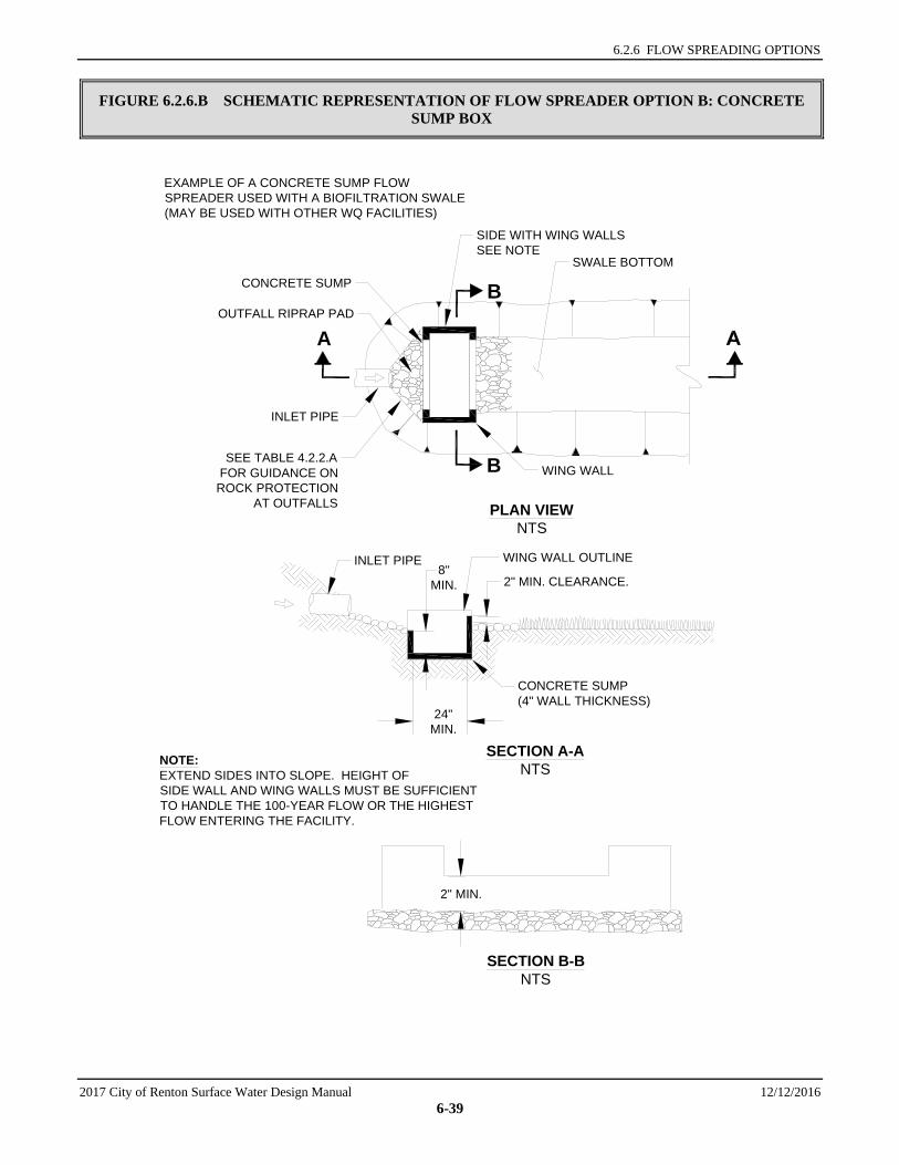
6.2.6 FLOW SPREADING OPTIONS
2017 City of Renton Surface Water Design Manual 12/12/2016 6-39
FIGURE 6.2.6.B SCHEMATIC REPRESENTATION OF FLOW SPREADER OPTION B: CONCRETE SUMP BOX
NOTE:EXTEND SIDES INTO SLOPE. HEIGHT OFSIDE WALL AND WING WALLS MUST BE SUFFICIENTTO HANDLE THE 100-YEAR FLOW OR THE HIGHESTFLOW ENTERING THE FACILITY.
EXAMPLE OF A CONCRETE SUMP FLOWSPREADER USED WITH A BIOFILTRATION SWALE(MAY BE USED WITH OTHER WQ FACILITIES)
PLAN VIEWNTS
SECTION A-ANTS
SECTION B-BNTS
WING WALL
A
B
B
SIDE WITH WING WALLSSEE NOTE
SWALE BOTTOMCONCRETE SUMP
OUTFALL RIPRAP PAD
INLET PIPE
SEE TABLE 4.2.2.AFOR GUIDANCE ON
ROCK PROTECTIONAT OUTFALLS
INLET PIPE WING WALL OUTLINE
CONCRETE SUMP(4" WALL THICKNESS)
8"MIN.
24"MIN.
2" MIN. CLEARANCE.
2" MIN.
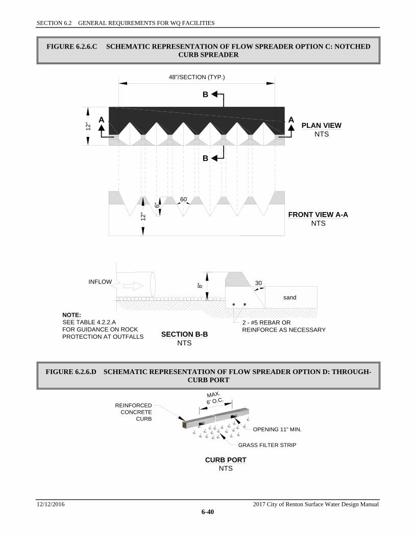
SECTION 6.2 GENERAL REQUIREMENTS FOR WQ FACILITIES
12/12/2016 2017 City of Renton Surface Water Design Manual 6-40
FIGURE 6.2.6.C SCHEMATIC REPRESENTATION OF FLOW SPREADER OPTION C: NOTCHED CURB SPREADER
FIGURE 6.2.6.D SCHEMATIC REPRESENTATION OF FLOW SPREADER OPTION D: THROUGH-CURB PORT
NOTE:SEE TABLE 4.2.2.AFOR GUIDANCE ON ROCKPROTECTION AT OUTFALLS
FRONT VIEW A-ANTS
SECTION B-BNTS
2 - #5 REBAR ORREINFORCE AS NECESSARY
sand
30INFLOW
60
6"
PLAN VIEWNTS
B
B
48"/SECTION (TYP.)
12"
12"
8"
CURB PORTNTS
REINFORCEDCONCRETE
CURB
OPENING 11" MIN.
GRASS FILTER STRIP
MAX.6' O.C.
CITY OF RENTON SURFACE WATER DESIGN MANUAL
2017 City of Renton Surface Water Design Manual 12/12/2016 6-41
6.3 VEGETATED FLOWPATH FACILITY DESIGNS This section presents the methods, details of analysis, and design criteria for bioswales and filter strips. Included in this section are the following specific facility designs:
• “Basic Bioswales,” Section 6.3.1 • “Wet Bioswales,” Section 6.3.2 • “Lateral Inflow Bioswales,” Section 6.3.3 • “Standard Filter Strips,” Section 6.3.4
GENERAL CONSIDERATIONS Vegetated flowpath facilities are subject to a number of concerns that do not affect other facilities. Failure mechanisms can include adverse change in plant community, vegetation loss, erosion or channelization, detrimental change in slope or cross-section from siltation, and ponding. The relationship between the surface soil, subsurface soil, groundwater interactions, vegetation type, weather, and shading all contribute to the success or failure of a vegetated flowpath facility. Successful establishment of vegetation requires seeding or planting at a time of year that ensures optimal moisture and temperature/sunlight for growth. Typical maintenance requires mowing, mechanical weed control, and silt removal (e.g., in the bed of a bioswale, or to remove a ‘micro-berm’ forming at the entry edge of a filter strip), which may require re-planting. While there is initial control over vegetation type, the plant community can change on its own over time, and soil profile and content can change over time (compaction from mowing, siltation, holes from voles, etc.). Solutions are site-specific, may require seasonal observation, covering the full range of climatic conditions, and even then, something that works in a normal rainfall year may not to work in an excessively dry or wet year.
The information presented for each facility is organized into the following two categories:
1. Methods of Analysis: Contains a step-by-step procedure for designing and sizing each facility.
2. Design Criteria: Contains the details, specifications, and material requirements for each facility, plus construction and maintenance considerations as applicable.
6.3.1 BASIC BIOSWALES A bioswale is an open, gently sloped, vegetated channel designed for treatment of stormwater (see the schematic representations in Figure 6.3.1.A through Figure 6.3.1.E). The primary pollutant removal mechanism is sedimentation enhanced by plant stems and to a lesser extent by potential trapping and adhesion of pollutants to the plants and thatch. Bioswales generally do not remove dissolved pollutants effectively, although some infiltration to underlying soils may occur depending on the nature of those soils and any required facility liners.
Applications and Limitations Data suggest that the performance of bioswales is highly variable from storm to storm. Ecology and the City of Renton recommend considering other treatment methods that perform more consistently, such as sand filters or wet ponds, before using a bioswale.
A bioswale is designed so that water will flow evenly across the entire width of a densely-vegetated area. A swale may be designed for both treatment and conveyance of onsite stormwater flow. This combined use can reduce development costs by eliminating the need for separate conveyance systems.
Bioswales are best applied on a relatively small scale (generally less than 5 acres of impervious surface). They fit well along roadways, driveways, and parking lots. Swales are more costly to apply in situations where the swale channel would be deep; in deep swales, self-shading can inhibit the necessary grass
SECTION 6.3 VEGETATED FLOW PATH FACILITY DESIGNS
12/12/2016 2017 City of Renton Surface Water Design Manual 6-42
growth, resulting in poor pollutant removal performance. Some specific considerations for bioswale applications are as follows:
• A bioswale shall not be located in a shaded area. For healthy vegetation growth, a swale should receive a minimum of 6 hours sunlight daily throughout the year, throughout the length of the swale.
• To maintain healthy vegetation growth, a basic bioswale must dry between storms. It shall not receive continuous base flows (such as seepage from a hill slope throughout the winter) or be located in a high groundwater area, because saturated soil conditions will kill grass. If these conditions are likely to occur, design options given under “Design Criteria” shall be used, or the wet bioswale design may be used (see Section 6.3.2, for details).
• Stormwater runoff carrying high concentrations of oil and grease kills vegetation and impairs the treatment capability of a swale. Where a high use site is tributary to a proposed bioswale, an oil control facility option listed in Section 6.6 shall be installed to treat the subject runoff prior to entering the bioswale.
• Modifying an existing drainage ditch to create an engineered bioswale may be difficult due to physical constraints and because ditches often serve as conveyance for higher flows from larger offsite areas.
• Utilities may be located in swale side slopes above the WQ design depth. However, the repair or placement of utilities in swale side slopes requires aggressive implementation of erosion control practices to prevent soil and sediment from reaching the treatment area of the swale.
Note: Consult the water quality menus in Section 6.1 for information on how this facility may be used to meet Core Requirement #8. Also see for guidance on which type of bioswale (basic, wet or lateral inflow) to use for a given set of site characteristics.
6.3.1.1 METHODS OF ANALYSIS Bioswale sizing is based on several variables, including the peak water quality design flow, longitudinal slope, vegetation height, bottom width, side slope, required hydraulic residence time (i.e., the time required for flow to travel the full length of the swale), and design flow depth. Swales sized and built using the method of analysis outlined in this section and the required design criteria presented in Section 6.3.1.2 are expected to meet the Basic Water Quality menu goal of 80% TSS removal. Procedures for sizing bioswales are summarized below.
Step 1: Calculate design flows. The swale design is based on the water quality design flow Qwq (see Section 6.2.1, for a definition of water quality design flow). If a bioswale is used for conveyance, the capacity requirements of Core Requirement #4 must be met. These flows must be estimated using the hydrologic analysis procedures described in detail in Chapter 3 and applying the flow rate modifications described in Section 6.2.1.
If the bioswale is located upstream of an onsite detention facility, or if a detention facility is not required, the bioswale design flow shall be the on-line or off-line (as applicable) water quality flow rate determined from the approved continuous model, modified by a factor k, the on-line or off-line ratio determined from Table 6.2.1. This modified design flow rate is an estimate of the design flow rate determined by using SBUH procedures.
Guidance for Bypassing Off-Line Facilities Most bioswales are currently designed to be on-line facilities. However, an off-line design is possible. Bioswales designed in an off-line mode should not engage a bypass until the flow rate exceeds the modified off-line water quality design flow rate.
If the bioswale is located downstream of an onsite detention facility, the swale design flow shall be the 2-year release rate from the detention facility.
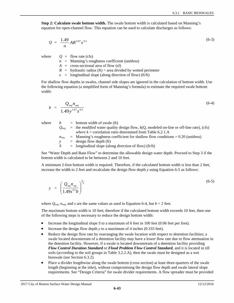
6.3.1 BASIC BIOSWALES
2017 City of Renton Surface Water Design Manual 12/12/2016 6-43
Step 2: Calculate swale bottom width. The swale bottom width is calculated based on Manning’s equation for open-channel flow. This equation can be used to calculate discharges as follows:
Q = (6-3)
where Q = flow rate (cfs) n = Manning’s roughness coefficient (unitless) A = cross-sectional area of flow (sf) R = hydraulic radius (ft) = area divided by wetted perimeter s = longitudinal slope (along direction of flow) (ft/ft)
For shallow flow depths in swales, channel side slopes are ignored in the calculation of bottom width. Use the following equation (a simplified form of Manning’s formula) to estimate the required swale bottom width:
b = (6-4)
where b = bottom width of swale (ft) Qwq = the modified water quality design flow, k(Q, modeled on-line or off-line rate), (cfs) where k = correlation ratio determined from Table 6.2.1.A nwq = Manning’s roughness coefficient for shallow flow conditions = 0.20 (unitless) y = design flow depth (ft) S = longitudinal slope (along direction of flow) (ft/ft)
See “Water Depth and Base Flow” to determine the allowable design water depth. Proceed to Step 3 if the bottom width is calculated to be between 2 and 10 feet.
A minimum 2-foot bottom width is required. Therefore, if the calculated bottom width is less than 2 feet, increase the width to 2 feet and recalculate the design flow depth y using Equation 6-5 as follows:
y =
(6-5)
where Qwq, nwq, and s are the same values as used in Equation 6-4, but b = 2 feet.
The maximum bottom width is 10 feet; therefore if the calculated bottom width exceeds 10 feet, then one of the following steps is necessary to reduce the design bottom width:
• Increase the longitudinal slope S to a maximum of 6 feet in 100 feet (0.06 feet per foot). • Increase the design flow depth y to a maximum of 4 inches (0.333 feet). • Reduce the design flow rate by rearranging the swale location with respect to detention facilities; a
swale located downstream of a detention facility may have a lower flow rate due to flow attenuation in the detention facility. However, if a swale is located downstream of a detention facility providing Flow Control Duration Standard or Flood Problem Flow Control Standard, and it is located in till soils (according to the soil groups in Table 3.2.2.A), then the swale must be designed as a wet bioswale (see Section 6.3.2).
• Place a divider lengthwise along the swale bottom (cross section) at least three-quarters of the swale length (beginning at the inlet), without compromising the design flow depth and swale lateral slope requirements. See “Design Criteria” for swale divider requirements. A flow spreader must be provided
5.067.049.1 sARn
5.067.149.1 synQ wqwq
53
5.049.1
bsnQ wqwq
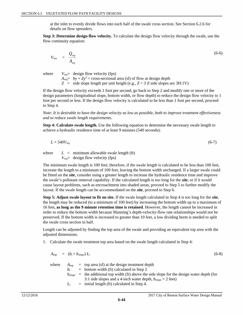
SECTION 6.3 VEGETATED FLOW PATH FACILITY DESIGNS
12/12/2016 2017 City of Renton Surface Water Design Manual 6-44
at the inlet to evenly divide flows into each half of the swale cross section. See Section 6.2.6 for details on flow spreaders.
Step 3: Determine design flow velocity. To calculate the design flow velocity through the swale, use the flow continuity equation:
Vwq = (6-6)
where Vwq= design flow velocity (fps) Awq= by + Zy2 = cross-sectional area (sf) of flow at design depth Z = side slope length per unit height (e.g., Z = 3 if side slopes are 3H:1V)
If the design flow velocity exceeds 1 foot per second, go back to Step 2 and modify one or more of the design parameters (longitudinal slope, bottom width, or flow depth) to reduce the design flow velocity to 1 foot per second or less. If the design flow velocity is calculated to be less than 1 foot per second, proceed to Step 4.
Note: It is desirable to have the design velocity as low as possible, both to improve treatment effectiveness and to reduce swale length requirements.
Step 4: Calculate swale length. Use the following equation to determine the necessary swale length to achieve a hydraulic residence time of at least 9 minutes (540 seconds):
L = 540Vwq (6-7)
where L = minimum allowable swale length (ft) Vwq= design flow velocity (fps)
The minimum swale length is 100 feet; therefore, if the swale length is calculated to be less than 100 feet, increase the length to a minimum of 100 feet, leaving the bottom width unchanged. If a larger swale could be fitted on the site, consider using a greater length to increase the hydraulic residence time and improve the swale’s pollutant removal capability. If the calculated length is too long for the site, or if it would cause layout problems, such as encroachment into shaded areas, proceed to Step 5 to further modify the layout. If the swale length can be accommodated on the site, proceed to Step 6.
Step 5: Adjust swale layout to fit on site. If the swale length calculated in Step 4 is too long for the site, the length may be reduced (to a minimum of 100 feet) by increasing the bottom width up to a maximum of 16 feet, as long as the 9 minute retention time is retained. However, the length cannot be increased in order to reduce the bottom width because Manning’s depth-velocity-flow rate relationships would not be preserved. If the bottom width is increased to greater than 10 feet, a low dividing berm is needed to split the swale cross section in half.
Length can be adjusted by finding the top area of the swale and providing an equivalent top area with the adjusted dimensions.
1. Calculate the swale treatment top area based on the swale length calculated in Step 4:
Atop = (bi + bslope) Li (6-8)
where Atop = top area (sf) at the design treatment depth bi = bottom width (ft) calculated in Step 2 bslope = the additional top width (ft) above the side slope for the design water depth (for
3:1 side slopes and a 4-inch water depth, bslope = 2 feet) Li = initial length (ft) calculated in Step 4.
wq
wq
AQ
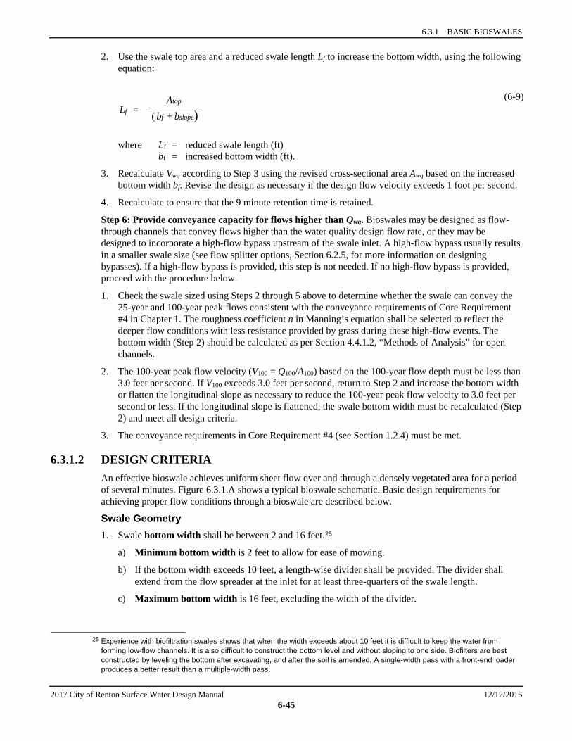
6.3.1 BASIC BIOSWALES
2017 City of Renton Surface Water Design Manual 12/12/2016 6-45
2. Use the swale top area and a reduced swale length Lf to increase the bottom width, using the following equation:
Lf = (6-9)
where Lf = reduced swale length (ft) bf = increased bottom width (ft).
3. Recalculate Vwq according to Step 3 using the revised cross-sectional area Awq based on the increased bottom width bf. Revise the design as necessary if the design flow velocity exceeds 1 foot per second.
4. Recalculate to ensure that the 9 minute retention time is retained.
Step 6: Provide conveyance capacity for flows higher than Qwq. Bioswales may be designed as flow-through channels that convey flows higher than the water quality design flow rate, or they may be designed to incorporate a high-flow bypass upstream of the swale inlet. A high-flow bypass usually results in a smaller swale size (see flow splitter options, Section 6.2.5, for more information on designing bypasses). If a high-flow bypass is provided, this step is not needed. If no high-flow bypass is provided, proceed with the procedure below.
1. Check the swale sized using Steps 2 through 5 above to determine whether the swale can convey the 25-year and 100-year peak flows consistent with the conveyance requirements of Core Requirement #4 in Chapter 1. The roughness coefficient n in Manning’s equation shall be selected to reflect the deeper flow conditions with less resistance provided by grass during these high-flow events. The bottom width (Step 2) should be calculated as per Section 4.4.1.2, “Methods of Analysis” for open channels.
2. The 100-year peak flow velocity (V100 = Q100/A100) based on the 100-year flow depth must be less than 3.0 feet per second. If V100 exceeds 3.0 feet per second, return to Step 2 and increase the bottom width or flatten the longitudinal slope as necessary to reduce the 100-year peak flow velocity to 3.0 feet per second or less. If the longitudinal slope is flattened, the swale bottom width must be recalculated (Step 2) and meet all design criteria.
3. The conveyance requirements in Core Requirement #4 (see Section 1.2.4) must be met.
6.3.1.2 DESIGN CRITERIA An effective bioswale achieves uniform sheet flow over and through a densely vegetated area for a period of several minutes. Figure 6.3.1.A shows a typical bioswale schematic. Basic design requirements for achieving proper flow conditions through a bioswale are described below.
Swale Geometry 1. Swale bottom width shall be between 2 and 16 feet.25
a) Minimum bottom width is 2 feet to allow for ease of mowing.
b) If the bottom width exceeds 10 feet, a length-wise divider shall be provided. The divider shall extend from the flow spreader at the inlet for at least three-quarters of the swale length.
c) Maximum bottom width is 16 feet, excluding the width of the divider.
25 Experience with biofiltration swales shows that when the width exceeds about 10 feet it is difficult to keep the water from
forming low-flow channels. It is also difficult to construct the bottom level and without sloping to one side. Biofilters are best constructed by leveling the bottom after excavating, and after the soil is amended. A single-width pass with a front-end loader produces a better result than a multiple-width pass.
)+ ( slopef
top
bbA
SECTION 6.3 VEGETATED FLOW PATH FACILITY DESIGNS
12/12/2016 2017 City of Renton Surface Water Design Manual 6-46
Note: Multiple swales may be placed side by side provided the flow to each swale is split at the inlet and spread separately for each swale. Adjacent swales may be separated with a vertical wall, but a low berm is preferred for easier maintenance and better landscape integration.
2. The longitudinal slope (along the direction of flow) should be between 1.5 percent and 6 percent.
a) If the longitudinal slope is less than 1.5 percent, underdrains must be provided (see next page and Figure 6.3.1.C, for underdrain specifications) or the swale must be designed according to the criteria presented in Section 6.3.2 for wet bioswales.
b) Wet bioswales in outwash soils and low groundwater conditions are discouraged as plant survival may be compromised.
c) If the longitudinal slope exceeds 6 percent, check dams with vertical drops of 12 inches or less shall be provided to achieve a bottom slope of 6 percent or less between the drop sections.
3. The swale bottom shall be flat in cross section (perpendicular to the flow direction) to promote even flow across the whole width of the swale.
4. The minimum swale length shall be 100 feet; no maximum length is set.
5. The swale treatment area (below the WQ design water depth) shall be trapezoidal in cross-section. Side slopes within the treatment area should be 3H:1V or flatter whenever possible, but shall not steeper than 2H:1V.
6. Side slope sections above the treatment area may be steeper than 3H:1V, subject to the following provisions:
a) If there is an interior side slope between 1H:1V and 2H:1V outside the treatment area, the slope shall be reinforced with erosion control netting or matting during construction.
b) Any interior slope steeper than 1H:1V shall be constructed as a rockery or structural retaining wall26 to prevent the swale slope from sloughing. To ensure that adequate sunlight reaches the swale bottom, only one wall can be taller than 2 feet. If possible, the higher wall should be on the northern or eastern side of the swale to maximize the amount of light reaching the swale bottom.
7. Curved swales are encouraged for aesthetic reasons, but curves must be gentle to prevent erosion and allow for vehicle access to remove sediment. Criteria for maintenance access road curves shall also be applied for swale curves (see Section 5.1.1.1 for design of access roads).
Water Depth and Base Flow 1. A swale that will be frequently mowed, as in commercial or landscaped areas, shall have a design
water depth of no more than 2 inches (0.17 feet) under the water quality design flow conditions.
2. A swale that will not be frequently mowed, such as along roadsides or in rural areas, shall have a design water depth of no more than 4 inches (0.33 feet) under the water quality design flow conditions.
3. If a swale is located downstream of a detention facility providing Flow Control Duration Standard or Flood Problem Flow Control Standard, and it is located in till soils (according to the soil groups in Table 3.2.2.B, Chapter 3), then the swale must be designed as a wet bioswale (see Section 6.3.2).
4. If a swale will receive base flows because of seeps and springs onsite, then either a low-flow drain shall be provided or a wet bioswale shall be used. Low-flow drains are narrow surface drains filled with pea gravel that run lengthwise through the swale to bleed off base flows; they should not be confused with underdrains. In general, base flows less than 0.01 cfs per acre can be handled with a low-flow drain. If flows are likely to be in excess of this level, a wet bioswale shall be used.
26 Soil bioengineering techniques may be used as an alternative to a rockery or structural retaining wall.
6.3.1 BASIC BIOSWALES
2017 City of Renton Surface Water Design Manual 12/12/2016 6-47
5. If a low-flow drain is used, it shall extend the entire length of the swale. The drain shall be a minimum of 6 inches deep, and its width shall be no greater than 5 percent of the calculated swale bottom width; the width of the drain shall be in addition to the required bottom width. If an anchored plate or concrete sump is used for flow spreading at the swale inlet, the plate or sump wall shall have a v-notch (maximum top width = 5% of swale width) or holes to allow preferential exit of low flows into the drain. See Figure 6.3.1.D for low-flow drain specifications and details.
Flow Velocity, Energy Dissipation, and Flow Spreading 1. The maximum flow velocity through the swale under the water quality design flow conditions shall
not exceed 1.0 foot per second.
2. The maximum flow velocity through the swale under the peak 100-year flow conditions shall not exceed 3.0 feet per second.
3. A flow spreader shall be used at the inlet of a swale to dissipate energy and evenly spread runoff as sheet flow over the swale bottom. Flow spreaders are recommended but not required at mid-length. For details on various types of flow spreaders, see Section 6.2.6.
4. If check dams are used to reduce the longitudinal slope of the swale, a flow spreader shall be provided at the toe of each vertical drop. The spreader must span the width of the swale. An energy dissipater shall also be provided if flows leaving the spreader could be erosive.
5. If a swale discharges flows to a slope rather than to a piped system or confined channel, an energy dissipater shall be provided at the swale outlet. This requirement also applies to discharges from swale underdrains. The outlet energy dissipater may be a riprap pad sized according to the specifications described in Table 4.2.2.A for conveyance system outfalls.
Underdrains If underdrains are required by Criterion 2 under “Swale Geometry,” they must meet the following criteria:
1. Underdrains must be made of PVC perforated pipe (SDR 35), laid parallel to the swale bottom and backfilled and bedded as shown in Figure 6.3.1.C.
2. For facilities to be maintained by the City, the underdrain pipe must be 6 inches or greater in diameter. (Six inches is the smallest diameter pipe that can be cleaned without damage to the pipe.)
3. Six inches of clean drain rock (5/8-inch minus) must be above the top of the pipe.
4. The drain rock must be wrapped in geotextile. See WSDOT Standard Specifications (2014), 9-33.2(1) Geotextile Properties/Table 1/Moderate Survivability/Woven, and Table 2, Class A
5. The underdrain must drain freely to an acceptable discharge point.
Swale Divider 1. If a swale divider is used (such as when swale bottom widths are greater than 10 feet), the divider
shall be constructed of a firm material that will resist weathering and not erode, such as concrete, compacted soil seeded with grass, untreated heartwood cedar, or untreated whole de-barked cedar logs. Selection of divider material shall take into consideration swale maintenance, especially mowing.
2. The divider shall have a minimum height of one inch higher than the water quality design water depth.
3. Earthen berms shall be no steeper than 2H:1V.
4. Materials other than earth (e.g., concrete, untreated heartwood cedar lumber, etc.) shall be embedded to a depth sufficient to be stable.
SECTION 6.3 VEGETATED FLOW PATH FACILITY DESIGNS
12/12/2016 2017 City of Renton Surface Water Design Manual 6-48
Access 1. For swales to be maintained by the City, an access road shall be provided to the swale inlet and along
one side of the swale according to the schedule shown in Table 6.3.1.B below.
Note: City streets and paved parking areas adjacent to the top of slope may be counted as access.
TABLE 6.3.1.B REQUIREMENTS FOR BIOSWALE ACCESS ROAD
Swale Bottom Area*: L x w (sf) Access Road Length 200–1000 1/2 swale length L 1000–1600 2/3 swale length L Over 1600 entire swale length L
* The swale area used for computing access road length may be the bottom area.
2. In areas outside critical area buffers, wheel strips made of modular grid pavement may be built into the swale bottom for maintenance vehicle access instead of an access road. The subgrade for the strips must be engineered to support a vehicle weight of 16,000 pounds and installed according to the manufacturer’s recommendations on firm native soil or structural fill, not on the amended topsoils. Each strip shall be 18 inches wide and spaced as shown in Figure 6.3.1.E. The strip lattice should be filled or covered with native soil (no amendments required) and overseeded with grass. If a low-flow drain is also needed (see “Water Depth and Base Flow” in Section 6.3.1.2), a portion of the wheel strip may be filled with pea gravel as appropriate to form the drain. Continuous vehicle access shall be provided to the wheel strips from the access road. If access to the wheel strips is over the flow-spreader, then a grate (or other CED approved method) shall be placed over the flow-spreader for vehicle access. Wheel strips shall not be counted as treatment area; therefore, the swale bottom width must be increased accordingly.
Soil Amendment 1. If the soil has an organic content of 1 percent or greater, do not amend. If the soil has an organic
content of less than 1%, two inches of mature, stable compost shall be tilled into the entire swale treatment area. This applies to both till soils as well as sandy soils. In very coarse soils (gravels or coarser), top soil must be imported and amended to the required organic content.
a) Compost must be tilled into the underlying native soil to a depth of 6 inches to prevent the compost from being washed out and to avoid creating a defined layer of different soil types that can prevent downward percolation of water.
b) Compost must meet Specification 1 described in Reference Section 11-C.
2. Soil or sod with a clay content of greater than 10 percent should be avoided. If there is concern for contamination of the underlying groundwater, the swale bottom shall be lined with a treatment liner to prevent groundwater contamination. See “Facility Liners,” Section 6.2.4, for details on treatment liner options.
Planting Requirements 1. Vegetation shall be established throughout the entire treatment area of the swale subject to the
following provisions:
a) Seeding is best performed in fall (late September to October) or in spring (mid-March to June). For summer seeding or seeding during dry conditions, sprinkler systems or other measures for watering the seed must be provided. Soil temperatures should be between 50 and 65 degrees to allow for seed germination of cool season grasses.
b) Seed may be applied via hydroseeding or broadcast application.
c) Irrigation is required during the first summer following installation if seeding occurs in spring or summer or during prolonged dry times of year. Swales seeded in the fall may not need irrigation. However, the maintenance and defect financial guarantee will not be released unless a healthy grass cover is established. Therefore, site planning should address the need for sprinklers or other means of irrigation.

6.3.1 BASIC BIOSWALES
2017 City of Renton Surface Water Design Manual 12/12/2016 6-49
2. Swale treatment areas are subject to both dry and wet conditions, as well as accumulation of sediment and debris. A mixture of dry-area and wet-area grass, rush, and sedge species that can continue to grow through silt deposits is most effective. Two acceptable grass seed mixes for the City of Renton are listed in Table 6.3.1.C. The mixes shall be applied throughout the swale in the treatment area at a rate of 120 to 140 seeds per square foot. As an alternative to these mixes, a horticultural or erosion control specialist may develop a seed specification tailored to the site. Table 6.3.1.D lists grasses or other plants particularly tolerant of wet conditions. Some of these seed types, however, may not be commercially available.
3. A newly constructed swale shall be protected from stormwater flows until vegetation has been established. This may be done by diverting flows or by placing an erosion control blanket over the freshly applied seed mix until the grass is well rooted. See Appendix D, ESC Standards, for details on erosion control blankets.
4. Above the design treatment elevation, either a typical lawn seed mix or landscape plants may be used. However, for swales also used to convey high flows, consideration shall be given to the soil binding capacity of the vegetation. Acceptable grasses and groundcovers are presented in Table 6.3.1.E. Plant material other than that given in the table may be used if the swale is privately maintained and the plants selected will not spread into the swale treatment area. Ivy shall not be used because of its tendency to spread. Native plant species (e.g., kinnikinnick) are preferred.
5. Sod may be used as a temporary cover during the wet season, but sodded areas must be reseeded with a suitable grass seed mix as soon as the weather is conducive to seed germination, unless the sod is grown from a seed mix suitable for the wetter conditions of a bioswale. Sod must be removed or rototilled into the underlying soil before reseeding. Criteria #1 and 2 above for seeding shall then be followed.
TABLE 6.3.1.C GRASS SEED MIXES SUITABLE FOR BIOSWALE TREATMENT AREAS
MIX 1 STANDARD SEED MIX MIX 2 LOW GROWING SEED MIX Species
Composition Latin Name Common
Name Species
Composition Latin Name Common
Name 15% Beckmannia
syzigachne American
sloughgrass 15% Bromus carinatus California
brome 20% Deschampsia
cespitosa Tufted
hairgrass 18% Bromus vulgaris Columbia
brome 18% Elymus glaucus Blue wildrye 15% Deschampsia
cespitosa Tufted
hairgrass 20% Festuca rubra
var. rubra Native red
fescue 15% Danthonia
californica California oatgrass
12% Hordeum brachyantherum
Meadow barley
17% Festuca rubra var. rubra
Native red fescue
15% Glyceria occidentalis
Northwestern mannagrass
10% Glyceria occidentalis
Western manna grass
10% Hordeum brachyantherum
Meadow barley
Notes: All percentages are targeted species composition of seed. Mixes are comprised of species native to King County and are not considered turf grass mixes. Mowing, if necessary,
is best done after mature seeds have dispersed to continue self-propagation of plant community. Sow Mix 1 at a rate of 31 pounds of pure live seed (PLS) per acre. Sow Mix 2 at a rate of 39 pounds of pure live seed (PLS) per acre.

SECTION 6.3 VEGETATED FLOW PATH FACILITY DESIGNS
12/12/2016 2017 City of Renton Surface Water Design Manual 6-50
TABLE 6.3.1.C FINELY-TEXTURED PLANTS TOLERANT OF FREQUENT SATURATED SOIL CONDITIONS OR STANDING WATER
Grasses Wetland Plants
Latin Name Common Name Latin Name Common Name Alopecurus aequalis Shortawn Foxtail Carex deweyana Dewey Sedge
Agrosits spp. Bentgrass Carex stipata Sawbeak Sedge A. exarata Spike Bentgrass Carex pachystachya Thick Headed Sedge
A. alba or gigantea Redtop Eleocharis palustris Spike Rush Glyceria spp. Mannagrass Juncus tenuis Slender Rush
G. occidentalis Western Juncus ensifolius Swordleaf Rush G. borealis Northern
G. leptostachya Slender-Spiked Poa palustris Fowl Bluegrass
Deschampsia cespitosa Tufted hairgrass Holcus mollis Velvet Grass

6.3.1 BASIC BIOSWALES
2017 City of Renton Surface Water Design Manual 12/12/2016 6-51
TABLE 6.3.1.D GROUNDCOVERS AND GRASSES SUITABLE FOR THE UPPER SIDE SLOPES OF A BIOSWALE
Groundcovers
Common Name Latin Name Kinnikinnick* Arctostaphylos uva-ursi
Alumroot* Heuchera micrantha Fringecup Tellima grandiflora
Strawberry* Fragaria chiloensis Broadleaf Lupine* Lupinus latifolius
Dull Oregon grape* Mahonia nervosa Creeping raspberry Rubus calycinoides
Creeping snowberry* Symphoricarpos mollis Yarrow* Achillea millifolium
Youth on age Tolmiea menziesii
Grasses (drought-tolerant, minimum mowing) California brome* Bromus carinatus
California oatgrass* Danthonia californica Blue wildrye* Elymus glaucus
Tufted Fescue Festuca amethystina Hard Fescue Festuca ovina duriuscula (e.g., Reliant, Aurora) Red Fescue* Festuca rubra var. rubra Blue Oatgrass Helictotrichon sempervirens
Low-growing turf mix (% species composition): • Hard fescue/Festuca brevipila (25%) • Sheep fescue/Festuca ovina (30%) • Red fescue/Festuca rubra var. rubra (25%) • Prairie junegrass/Koeleria macrantha (20%)
*Native species. Notes: Many other ornamental grasses which require only annual mowing are suitable. Ivy is not permitted.
Recommended Design Features The following features should be incorporated into bioswale designs where site conditions allow.
Swale Layout and Grading 1. If the longitudinal slope is less than 1.5 percent, and an underdrain is used per Section 6.3.1.2,
“Design Criteria,” the subgrade should contain 10 percent or more of sand to promote infiltration of standing water. If sand is added to promote drainage, the soil or sand substrate must still be amended with compost. Compost must meet Specification 1 described in Reference Section 11-C.
2. Underdrains may be necessary for swales greater than 1.5 percent longitudinal slope on poorly drained till soils, especially if it is likely that the swale will intercept groundwater.
3. Bioswales should be aligned to avoid sharp bends where erosion of the swale side slope can occur. However, gradual meandering bends in the swale are desirable for aesthetic purposes and to promote slower flow.
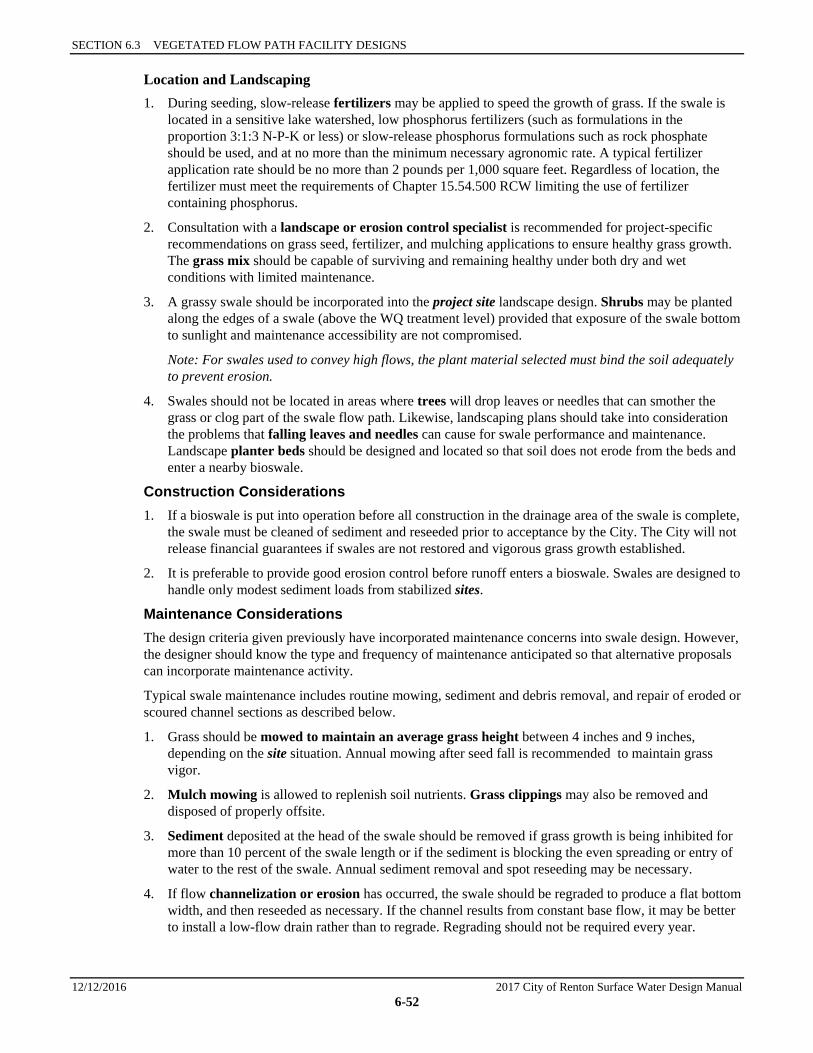
SECTION 6.3 VEGETATED FLOW PATH FACILITY DESIGNS
12/12/2016 2017 City of Renton Surface Water Design Manual 6-52
Location and Landscaping 1. During seeding, slow-release fertilizers may be applied to speed the growth of grass. If the swale is
located in a sensitive lake watershed, low phosphorus fertilizers (such as formulations in the proportion 3:1:3 N-P-K or less) or slow-release phosphorus formulations such as rock phosphate should be used, and at no more than the minimum necessary agronomic rate. A typical fertilizer application rate should be no more than 2 pounds per 1,000 square feet. Regardless of location, the fertilizer must meet the requirements of Chapter 15.54.500 RCW limiting the use of fertilizer containing phosphorus.
2. Consultation with a landscape or erosion control specialist is recommended for project-specific recommendations on grass seed, fertilizer, and mulching applications to ensure healthy grass growth. The grass mix should be capable of surviving and remaining healthy under both dry and wet conditions with limited maintenance.
3. A grassy swale should be incorporated into the project site landscape design. Shrubs may be planted along the edges of a swale (above the WQ treatment level) provided that exposure of the swale bottom to sunlight and maintenance accessibility are not compromised.
Note: For swales used to convey high flows, the plant material selected must bind the soil adequately to prevent erosion.
4. Swales should not be located in areas where trees will drop leaves or needles that can smother the grass or clog part of the swale flow path. Likewise, landscaping plans should take into consideration the problems that falling leaves and needles can cause for swale performance and maintenance. Landscape planter beds should be designed and located so that soil does not erode from the beds and enter a nearby bioswale.
Construction Considerations 1. If a bioswale is put into operation before all construction in the drainage area of the swale is complete,
the swale must be cleaned of sediment and reseeded prior to acceptance by the City. The City will not release financial guarantees if swales are not restored and vigorous grass growth established.
2. It is preferable to provide good erosion control before runoff enters a bioswale. Swales are designed to handle only modest sediment loads from stabilized sites.
Maintenance Considerations The design criteria given previously have incorporated maintenance concerns into swale design. However, the designer should know the type and frequency of maintenance anticipated so that alternative proposals can incorporate maintenance activity.
Typical swale maintenance includes routine mowing, sediment and debris removal, and repair of eroded or scoured channel sections as described below.
1. Grass should be mowed to maintain an average grass height between 4 inches and 9 inches, depending on the site situation. Annual mowing after seed fall is recommended to maintain grass vigor.
2. Mulch mowing is allowed to replenish soil nutrients. Grass clippings may also be removed and disposed of properly offsite.
3. Sediment deposited at the head of the swale should be removed if grass growth is being inhibited for more than 10 percent of the swale length or if the sediment is blocking the even spreading or entry of water to the rest of the swale. Annual sediment removal and spot reseeding may be necessary.
4. If flow channelization or erosion has occurred, the swale should be regraded to produce a flat bottom width, and then reseeded as necessary. If the channel results from constant base flow, it may be better to install a low-flow drain rather than to regrade. Regrading should not be required every year.

6.3.1 BASIC BIOSWALES
2017 City of Renton Surface Water Design Manual 12/12/2016 6-53
5. For swales with underdrains, vehicular access to the swale bottom (other than grass mowing equipment) should be avoided because the drainpipe cannot support vehicle weight. Consideration should be given to providing wheel strips in the swale bottom if access is needed.
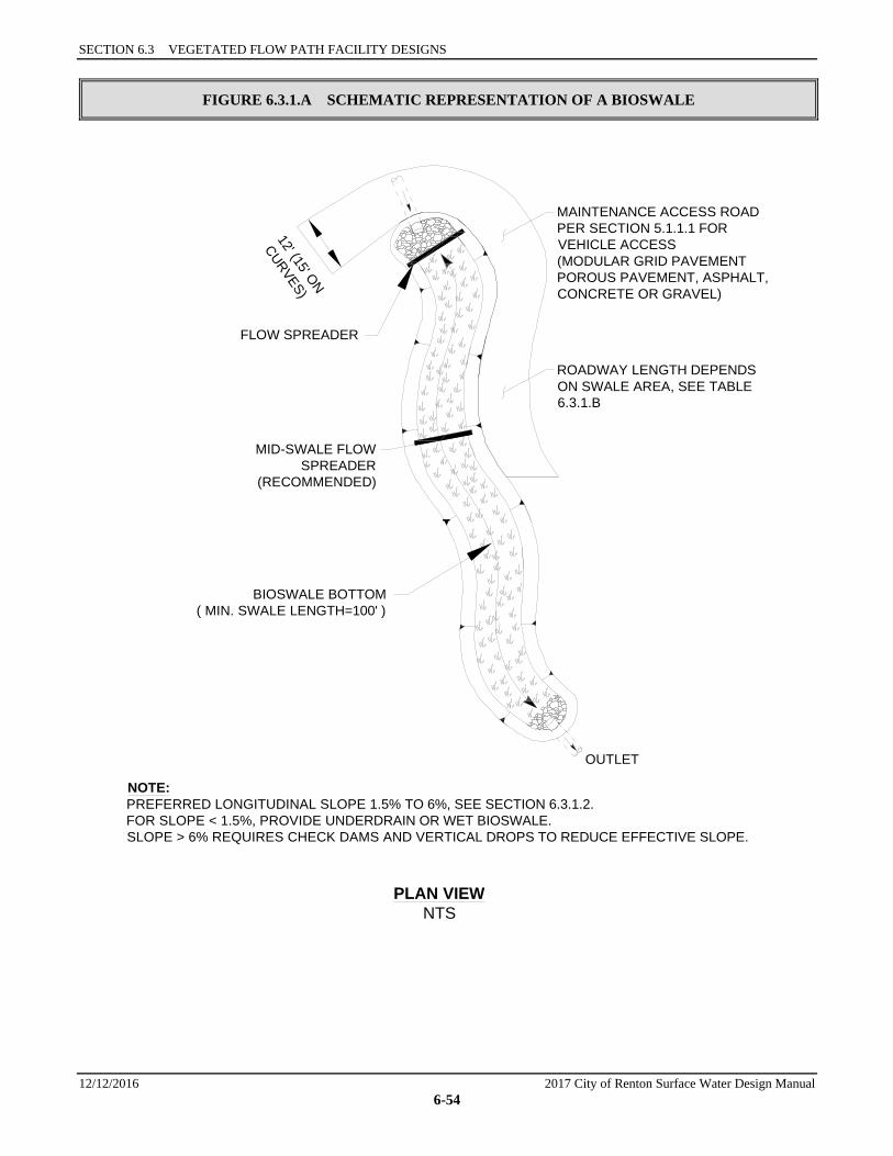
SECTION 6.3 VEGETATED FLOW PATH FACILITY DESIGNS
12/12/2016 2017 City of Renton Surface Water Design Manual 6-54
FIGURE 6.3.1.A SCHEMATIC REPRESENTATION OF A BIOSWALE
MID-SWALE FLOWSPREADER
(RECOMMENDED)
BIOSWALE BOTTOM( MIN. SWALE LENGTH=100' )
FLOW SPREADER
OUTLET
NOTE:PREFERRED LONGITUDINAL SLOPE 1.5% TO 6%, SEE SECTION 6.3.1.2.FOR SLOPE < 1.5%, PROVIDE UNDERDRAIN OR WET BIOSWALE.SLOPE > 6% REQUIRES CHECK DAMS AND VERTICAL DROPS TO REDUCE EFFECTIVE SLOPE.
PLAN VIEWNTS
12' (15' ON
CURVES)
MAINTENANCE ACCESS ROADPER SECTION 5.1.1.1 FORVEHICLE ACCESS(MODULAR GRID PAVEMENTPOROUS PAVEMENT, ASPHALT,CONCRETE OR GRAVEL)
ROADWAY LENGTH DEPENDSON SWALE AREA, SEE TABLE6.3.1.B
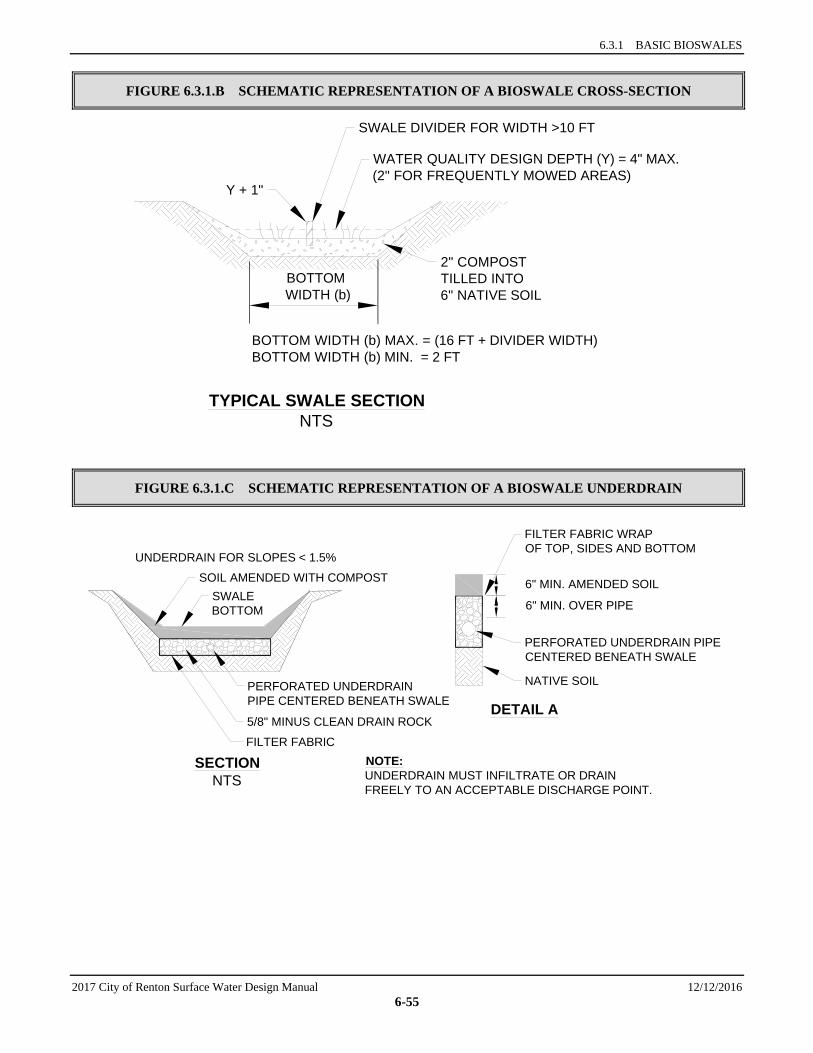
6.3.1 BASIC BIOSWALES
2017 City of Renton Surface Water Design Manual 12/12/2016 6-55
FIGURE 6.3.1.B SCHEMATIC REPRESENTATION OF A BIOSWALE CROSS-SECTION
FIGURE 6.3.1.C SCHEMATIC REPRESENTATION OF A BIOSWALE UNDERDRAIN
BOTTOM WIDTH (b) MAX. = (16 FT + DIVIDER WIDTH)BOTTOM WIDTH (b) MIN. = 2 FT
TYPICAL SWALE SECTIONNTS
SWALE DIVIDER FOR WIDTH >10 FT
WATER QUALITY DESIGN DEPTH (Y) = 4" MAX.(2" FOR FREQUENTLY MOWED AREAS)
Y + 1"
2" COMPOSTTILLED INTO6" NATIVE SOIL
BOTTOM WIDTH (b)
DETAIL A
SECTIONNTS
UNDERDRAIN FOR SLOPES < 1.5%
NOTE:UNDERDRAIN MUST INFILTRATE OR DRAINFREELY TO AN ACCEPTABLE DISCHARGE POINT.
PERFORATED UNDERDRAIN PIPECENTERED BENEATH SWALE
FILTER FABRIC WRAPOF TOP, SIDES AND BOTTOM
NATIVE SOIL
6" MIN. AMENDED SOILSWALEBOTTOM
SOIL AMENDED WITH COMPOST
PERFORATED UNDERDRAINPIPE CENTERED BENEATH SWALE
5/8" MINUS CLEAN DRAIN ROCK
FILTER FABRIC
6" MIN. OVER PIPE

SECTION 6.3 VEGETATED FLOW PATH FACILITY DESIGNS
12/12/2016 2017 City of Renton Surface Water Design Manual 6-56
FIGURE 6.3.1.D SCHEMATIC REPRESENTATION OF A BIOSWALE LOW-FLOW DRAIN
FIGURE 6.3.1.E SCHEMATIC REPRESENTATION OF BIOSWALE WHEEL STRIPS
PLAN VIEWNTS
SECTION ANTS
TOP NOTCH OPENING NOMORE THAN 5% OF SWALEBOTTOM WIDTH OR USEWEEP HOLES
2"
SWALE GRADE
A
6" MIN. DEEP PEA GRAVELTRENCH LENGTH OF SWALE(SEE TEXT FOR APPLICATION)
NOTCH ORWEEP HOLES
LONGITUDINALSLOPE 1.5-6%
CONCRETESUMP
SECTIONNTS
6' O.C.COMPOSTAMENDED SOIL
MODULAR GRID PAVERS ONNATIVE SOIL OR ENGINEERED
FILL PER MANUFACTURER'SRECOMMENDATIONS
8" MIN.
b1 18" b2 18" b3
DESIGN BOTTOM WIDTH(b) = b1 + b2 + b3
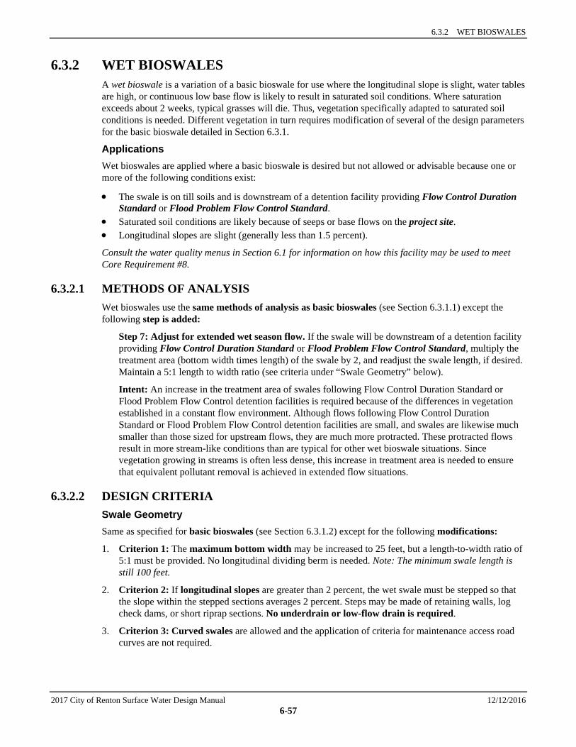
6.3.2 WET BIOSWALES
2017 City of Renton Surface Water Design Manual 12/12/2016 6-57
6.3.2 WET BIOSWALES A wet bioswale is a variation of a basic bioswale for use where the longitudinal slope is slight, water tables are high, or continuous low base flow is likely to result in saturated soil conditions. Where saturation exceeds about 2 weeks, typical grasses will die. Thus, vegetation specifically adapted to saturated soil conditions is needed. Different vegetation in turn requires modification of several of the design parameters for the basic bioswale detailed in Section 6.3.1.
Applications Wet bioswales are applied where a basic bioswale is desired but not allowed or advisable because one or more of the following conditions exist:
• The swale is on till soils and is downstream of a detention facility providing Flow Control Duration Standard or Flood Problem Flow Control Standard.
• Saturated soil conditions are likely because of seeps or base flows on the project site. • Longitudinal slopes are slight (generally less than 1.5 percent).
Consult the water quality menus in Section 6.1 for information on how this facility may be used to meet Core Requirement #8.
6.3.2.1 METHODS OF ANALYSIS Wet bioswales use the same methods of analysis as basic bioswales (see Section 6.3.1.1) except the following step is added:
Step 7: Adjust for extended wet season flow. If the swale will be downstream of a detention facility providing Flow Control Duration Standard or Flood Problem Flow Control Standard, multiply the treatment area (bottom width times length) of the swale by 2, and readjust the swale length, if desired. Maintain a 5:1 length to width ratio (see criteria under “Swale Geometry” below).
Intent: An increase in the treatment area of swales following Flow Control Duration Standard or Flood Problem Flow Control detention facilities is required because of the differences in vegetation established in a constant flow environment. Although flows following Flow Control Duration Standard or Flood Problem Flow Control detention facilities are small, and swales are likewise much smaller than those sized for upstream flows, they are much more protracted. These protracted flows result in more stream-like conditions than are typical for other wet bioswale situations. Since vegetation growing in streams is often less dense, this increase in treatment area is needed to ensure that equivalent pollutant removal is achieved in extended flow situations.
6.3.2.2 DESIGN CRITERIA Swale Geometry Same as specified for basic bioswales (see Section 6.3.1.2) except for the following modifications:
1. Criterion 1: The maximum bottom width may be increased to 25 feet, but a length-to-width ratio of 5:1 must be provided. No longitudinal dividing berm is needed. Note: The minimum swale length is still 100 feet.
2. Criterion 2: If longitudinal slopes are greater than 2 percent, the wet swale must be stepped so that the slope within the stepped sections averages 2 percent. Steps may be made of retaining walls, log check dams, or short riprap sections. No underdrain or low-flow drain is required.
3. Criterion 3: Curved swales are allowed and the application of criteria for maintenance access road curves are not required.
SECTION 6.3 VEGETATED FLOW PATH FACILITY DESIGNS
12/12/2016 2017 City of Renton Surface Water Design Manual 6-58
High-Flow Bypass A high-flow bypass is required for flows greater than the water quality design flow to protect wetland vegetation from damage.27 The bypass may be an open channel parallel to the wet bioswale.
Water Depth and Base Flow Same as for basic bioswales (see Section 6.3.1.2), except the design water depth shall be 4 inches or less for all wetland vegetation selections, and no underdrains or low-flow drains are required.
Flow Velocity, Energy Dissipation, and Flow Spreading Same as for basic bioswales (see Section 6.3.1.2), except no flow spreader is needed.
Access Same as for basic bioswales (see Section 6.3.1.2) except access is only required to the inflow and the outflow of the swale; access along the length of the swale is not required. Also, wheel strips may not be used for access in the swale.
Intent: An access road is not required along the length of a wet swale because of infrequent access needs. Frequent mowing or harvesting is not desirable. In addition, wetland plants are fairly resilient to sediment-induced changes in water depth, so the need for access should be infrequent.
Soil Amendment Same as for basic bioswales (see Section 6.3.1.2).
Planting Requirements Same as for basic bioswales (see Section 6.3.1.2) except for the following modifications:
1. A list of acceptable plants with recommended spacing is given in Table 6.3.2.A. In general, it is best to plant several species to increase the likelihood that at least some of the selected species will find growing conditions favorable.
2. A wetland seed mix may be applied by hydroseeding, but if coverage is poor, planting of rootstock or nursery stock is required. Poor coverage is considered to be more than 30 percent bare area through the upper 2/3 of the swale after four weeks.
Recommended Design Features Same as for basic bioswales (see Section 6.3.1.2).
Construction Considerations Same as for basic bioswales (see Section 6.3.1.2).
Maintenance Considerations Same as for basic bioswales (see Section 6.3.1.2), except mowing of wetland vegetation is not required. However, harvesting of very dense vegetation may be desirable in the fall after plant die-back to prevent the sloughing of excess organic material into receiving waters. Many native Juncus species remain green throughout the winter; therefore, fall harvesting of Juncus species is not recommended.
27 Unlike grass, wetland vegetation will not quickly regain an upright attitude after being laid down by high flows. New growth,
usually from the base of the plant, often taking several weeks, is required to regain its upright form.
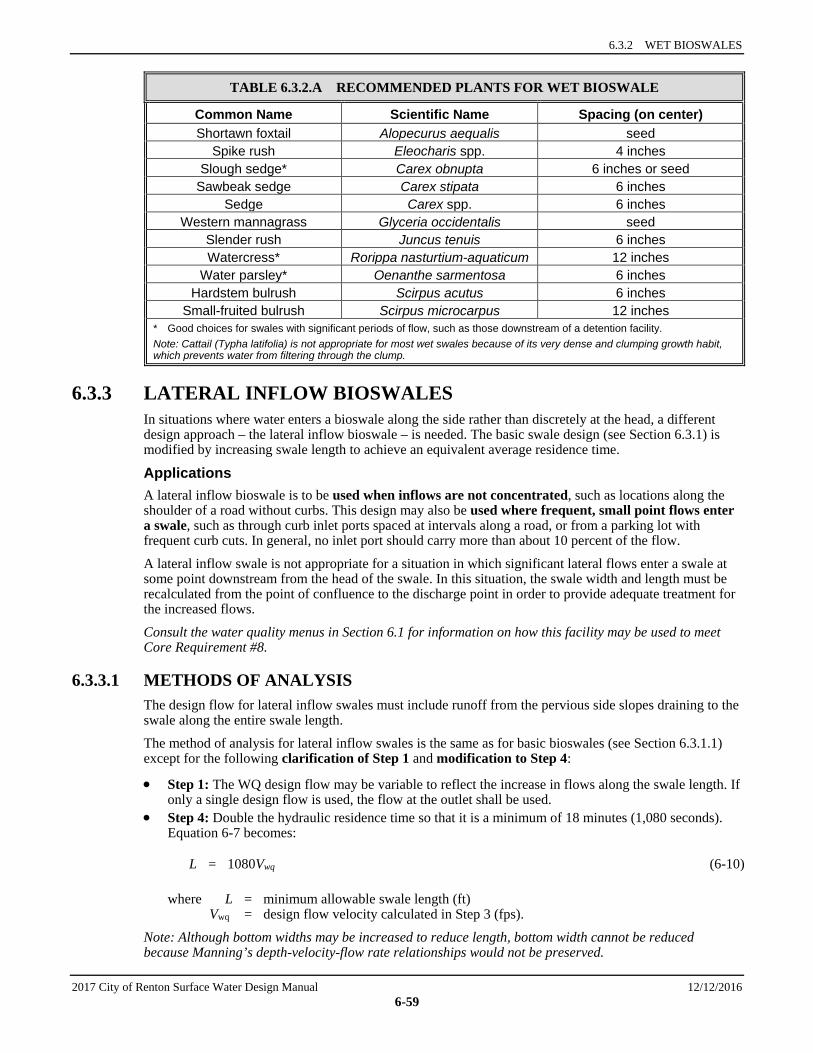
6.3.2 WET BIOSWALES
2017 City of Renton Surface Water Design Manual 12/12/2016 6-59
TABLE 6.3.2.A RECOMMENDED PLANTS FOR WET BIOSWALE
Common Name Scientific Name Spacing (on center) Shortawn foxtail Alopecurus aequalis seed
Spike rush Eleocharis spp. 4 inches Slough sedge* Carex obnupta 6 inches or seed
Sawbeak sedge Carex stipata 6 inches Sedge Carex spp. 6 inches
Western mannagrass Glyceria occidentalis seed Slender rush Juncus tenuis 6 inches Watercress* Rorippa nasturtium-aquaticum 12 inches
Water parsley* Oenanthe sarmentosa 6 inches Hardstem bulrush Scirpus acutus 6 inches
Small-fruited bulrush Scirpus microcarpus 12 inches * Good choices for swales with significant periods of flow, such as those downstream of a detention facility. Note: Cattail (Typha latifolia) is not appropriate for most wet swales because of its very dense and clumping growth habit, which prevents water from filtering through the clump.
6.3.3 LATERAL INFLOW BIOSWALES In situations where water enters a bioswale along the side rather than discretely at the head, a different design approach – the lateral inflow bioswale – is needed. The basic swale design (see Section 6.3.1) is modified by increasing swale length to achieve an equivalent average residence time.
Applications A lateral inflow bioswale is to be used when inflows are not concentrated, such as locations along the shoulder of a road without curbs. This design may also be used where frequent, small point flows enter a swale, such as through curb inlet ports spaced at intervals along a road, or from a parking lot with frequent curb cuts. In general, no inlet port should carry more than about 10 percent of the flow.
A lateral inflow swale is not appropriate for a situation in which significant lateral flows enter a swale at some point downstream from the head of the swale. In this situation, the swale width and length must be recalculated from the point of confluence to the discharge point in order to provide adequate treatment for the increased flows.
Consult the water quality menus in Section 6.1 for information on how this facility may be used to meet Core Requirement #8.
6.3.3.1 METHODS OF ANALYSIS The design flow for lateral inflow swales must include runoff from the pervious side slopes draining to the swale along the entire swale length.
The method of analysis for lateral inflow swales is the same as for basic bioswales (see Section 6.3.1.1) except for the following clarification of Step 1 and modification to Step 4:
• Step 1: The WQ design flow may be variable to reflect the increase in flows along the swale length. If only a single design flow is used, the flow at the outlet shall be used.
• Step 4: Double the hydraulic residence time so that it is a minimum of 18 minutes (1,080 seconds). Equation 6-7 becomes:
L = 1080Vwq (6-10)
where L = minimum allowable swale length (ft) Vwq = design flow velocity calculated in Step 3 (fps).
Note: Although bottom widths may be increased to reduce length, bottom width cannot be reduced because Manning’s depth-velocity-flow rate relationships would not be preserved.
SECTION 6.3 VEGETATED FLOW PATH FACILITY DESIGNS
12/12/2016 2017 City of Renton Surface Water Design Manual 6-60
6.3.3.2 DESIGN CRITERIA Same as specified for basic bioswales (in Section 6.3.1.2) except for the following modification:
Planting Requirements, Criterion 4: For lateral inflow bioswales, interior side slopes above the WQ design treatment elevation shall be planted in grass. A typical lawn seed mix or the bioswale seed mixes are acceptable. Landscape plants or groundcovers other than grass shall not be used anywhere between the runoff inflow elevation and the bottom of the swale.
Intent: The use of grass on interior side slopes reduces the chance of soil erosion and transfer of pollutants from landscape areas to the bioswale treatment area.
6.3.4 STANDARD FILTER STRIPS A filter strip is a grassy slope located adjacent and parallel to an impervious area such as a parking lot, driveway, or roadway (see the detail in Figure 6.3.4.A). A filter strip is graded to maintain sheet flow of stormwater runoff over the entire width of the strip. Pollutants are removed primarily by means of sedimentation, which is enhanced as a consequence of the resistance that the grass blades present to flowing water. To a much lesser degree, pollutants may adhere or sorb to grass and thatch. Some dissolved pollutants may also be sorbed by the underlying soil when infiltration occurs, but the extent of infiltration depends on the type of soil, the density of the grass, and the slope of the strip. The primary pollutant removal mechanism is particle settling.
Applications and Limitations Filter strip design is based on the expectation that water will flow fairly evenly across the entire width and length of the strip area. Thus, paved areas without underground stormwater collection systems, gutters, or other runoff control features are good candidates for filter strips.
Filter strips are suitable for areas that meet the following conditions:
• Stormwater runoff from the area requiring treatment shall be uniformly distributed along the top of the entire filter strip. If stormwater runoff from the entire area cannot be spread evenly along the top of the filter strip, the filter strip shall be applied only to flows that can be uniformly distributed. A different stormwater treatment facility, such as a swale, should be used for areas of the project site with concentrated flow (for instance, at road intersections).
• The flowpath draining to the filter strip shall not exceed 150 feet. Runoff flows traveling greater distances tend to concentrate before entering the filter strip.
• The lateral slope of the drainage area contributing flows to the filter strip (parallel to the edge of pavement) shall be less than 2 percent. A stepped series of flow spreaders installed at the head of the strip could compensate for slightly steeper slopes (see “Flow Spreading and Energy Dissipation”).
• The longitudinal slope of the contributing drainage area (parallel to the direction of flow entering the filter strip) should be less than 5 percent. Contributing drainage areas with slopes steeper than 5 percent shall either use a different WQ facility or must provide energy dissipation and flow spreading mechanisms upslope of the upper edge of the filter strip.
A filter strip generally requires more land area than a bioswale because the flow depth through the filter is shallower than through a swale. Although the space requirements may be greater, the filter strip is a viable water quality treatment option in locations where grassy slopes already exist, or where a slope can be incorporated easily into the landscape design for the project site. Other limitations that shall be considered are listed below:
1. Filter strips are susceptible to short-circuiting via flow channelization because they rely on a large smoothly graded area. If rills, gullies, or channels occur in the filter strip area, inflows will travel too quickly through the filter strip, reducing contact time and pollutant removal performance. A filter strip slope with uneven grading perpendicular to the sheet flow path will develop flow channels over time. These problems can be overcome with careful site planning, good soil compaction, skillful grading, and periodic maintenance.
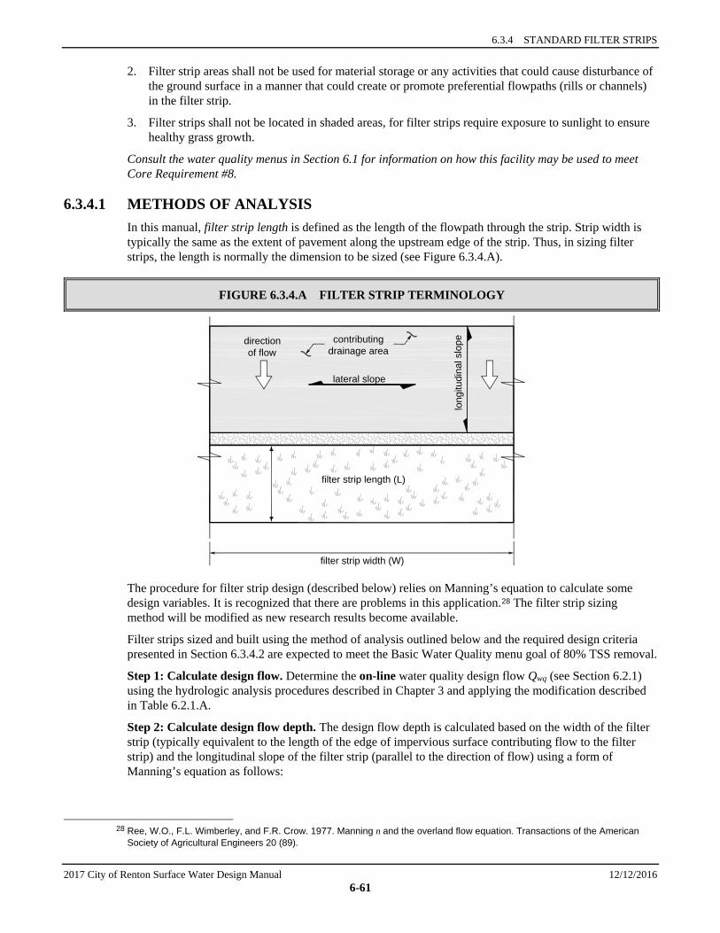
6.3.4 STANDARD FILTER STRIPS
2017 City of Renton Surface Water Design Manual 12/12/2016 6-61
2. Filter strip areas shall not be used for material storage or any activities that could cause disturbance of the ground surface in a manner that could create or promote preferential flowpaths (rills or channels) in the filter strip.
3. Filter strips shall not be located in shaded areas, for filter strips require exposure to sunlight to ensure healthy grass growth.
Consult the water quality menus in Section 6.1 for information on how this facility may be used to meet Core Requirement #8.
6.3.4.1 METHODS OF ANALYSIS In this manual, filter strip length is defined as the length of the flowpath through the strip. Strip width is typically the same as the extent of pavement along the upstream edge of the strip. Thus, in sizing filter strips, the length is normally the dimension to be sized (see Figure 6.3.4.A).
FIGURE 6.3.4.A FILTER STRIP TERMINOLOGY
The procedure for filter strip design (described below) relies on Manning’s equation to calculate some design variables. It is recognized that there are problems in this application.28 The filter strip sizing method will be modified as new research results become available.
Filter strips sized and built using the method of analysis outlined below and the required design criteria presented in Section 6.3.4.2 are expected to meet the Basic Water Quality menu goal of 80% TSS removal.
Step 1: Calculate design flow. Determine the on-line water quality design flow Qwq (see Section 6.2.1) using the hydrologic analysis procedures described in Chapter 3 and applying the modification described in Table 6.2.1.A.
Step 2: Calculate design flow depth. The design flow depth is calculated based on the width of the filter strip (typically equivalent to the length of the edge of impervious surface contributing flow to the filter strip) and the longitudinal slope of the filter strip (parallel to the direction of flow) using a form of Manning’s equation as follows:
28 Ree, W.O., F.L. Wimberley, and F.R. Crow. 1977. Manning n and the overland flow equation. Transactions of the American
Society of Agricultural Engineers 20 (89).
lateral slope
contributingdrainage area
directionof flow
filter strip length (L)
filter strip width (W)
long
itudi
nal s
lope
SECTION 6.3 VEGETATED FLOW PATH FACILITY DESIGNS
12/12/2016 2017 City of Renton Surface Water Design Manual 6-62
Qwq = (6-11)
where Qwq = water quality design flow, k(Q, modeled on-line rate), (cfs) where k = correlation ratio determined from Table 6.2.1.A nwq = Manning’s roughness coefficient (either 0.35 or 0.45; see the criteria under “Filter
Strip Geometry and Flow Resistance”) W = width of filter strip perpendicular to the direction of flow (ft) (≅ length of impervious
surface contributing flow) df = design depth of flow (ft), which is also assumed to be the hydraulic radius (maximum
1 inch, or 0.083 feet; see the criteria under “Water Depth and Velocity”) s = longitudinal slope of filter strip parallel to the direction of flow (ft/ft) (averaged over
the width of the filter strip; all portions averaged must also meet the slope design criteria).
Rearranging the above equation, the design depth of flow can be calculated using the following equation:
df = (6-12)
If the calculated flow depth exceeds 1 inch (0.083 feet), the design flow rate routed through the strip must be reduced. If this is not feasible, it is not possible to use a filter strip.
Step 3: Calculate design flow velocity through filter strip. The design flow velocity Vwq is based on the water quality design flow rate, the width of the filter strip, and the calculated design flow depth from Step 2 using the following equation:
Vwq = (6-13)
where Vwq = design flow velocity (fps) W = strip width (ft) (parallel to the edge of pavement) df = water depth (ft).
If Vwq exceeds 0.5 feet per second, a filter strip shall not be used. Either redesign the area to provide a gentler longitudinal slope for the strip, or select a different WQ facility.
Step 4: Calculate required length of filter strip. Determine the required length L of the filter strip to achieve a desired hydraulic residence time of at least 9 minutes (540 seconds) using the following equation:
L = 540Vwq (6-14)
where L = filter strip length (ft) Vwq = design flow velocity from Step 3 (fps)
5.067.149.1 sWdn f
wq
6.0
5.049.1
WsnQ wqwq
f
wq
Wd
Q
6.3.4 STANDARD FILTER STRIPS
2017 City of Renton Surface Water Design Manual 12/12/2016 6-63
6.3.4.2 DESIGN CRITERIA Figure 6.3.4.B shows typical filter strip details. The most effective filter strips achieve uniform sheet flow under all runoff flow conditions. To achieve proper flow conditions, the following basic design requirements apply.
Drainage Area Restrictions 1. The longest flowpath from the area contributing sheet flow to the filter strip shall not exceed 150 feet.
2. The lateral slope of the contributing drainage (parallel to the edge of pavement) shall be 2 percent or less.
3. A stepped series of flow spreaders installed at the head of the strip may be used to compensate for drainage areas having lateral slopes of up to 4 percent (see Section 6.2.6 for information on flow spreader designs).
4. The longitudinal slope of the contributing drainage area (parallel to the direction of flow entering the filter strip) should be 5 percent or less.
5. Contributing drainage areas with longitudinal slopes steeper than 5 percent shall either use a different WQ facility or provide energy dissipation and flow spreading options upslope of the upper edge of the filter strip to achieve flow characteristics equivalent to those meeting the criteria in items 2 and 4 above.
Filter Strip Geometry and Flow Resistance 1. The longitudinal slope of a filter strip (along the direction of flow) shall be between 1 percent
minimum and 15 percent maximum.
2. The lateral slope of a strip (parallel to the edge of pavement, perpendicular to the direction of flow) shall be less than 2 percent.
3. The ground surface at the upper edge of a filter strip (adjacent to the contributing drainage area) shall be at least 1 inch lower than the edge of the impervious area contributing flows.
4. Manning’s roughness coefficient (nwq) for flow depth calculations shall be 0.35. An exception to this requirement may be made for situations where the filter strip will be mowed weekly in the growing season to consistently provide a grass height of less than 4 inches; in this case, the value of nwq in Equation 6-12 may be set to 0.45.
Note: In filter strip design, a larger n value results in a smaller strip size.
Water Depth and Velocity 1. The maximum depth of flow through a filter strip for the WQ design flow shall be 1.0 inch.
2. The maximum allowable flow velocity for the water quality design flow Vwq shall be 0.5 feet per second.
Flow Spreading and Energy Dissipation 1. Runoff entering a filter strip must not be concentrated. A flow spreader shall be installed at the edge
of the pavement to uniformly distribute the flow along the entire width of the filter strip.
2. At a minimum, a gravel flow spreader (gravel-filled trench) shall be placed between the impervious area contributing flows and the filter strip, and meet the following requirements:
a) The gravel flow spreader shall be a minimum of 6 inches deep and shall be 18 inches wide for every 50 feet of contributing flowpath.
b) The gravel shall be a minimum of 1 inch below the pavement surface.
c) Intent: This allows sediment from the paved surface to be accommodated without blocking drainage onto the strip.

SECTION 6.3 VEGETATED FLOW PATH FACILITY DESIGNS
12/12/2016 2017 City of Renton Surface Water Design Manual 6-64
d) For contributing flowpaths less than 50 feet, the spreader width may be reduced to a minimum of 12 inches.
e) Where the ground surface is not level, the gravel spreader must be installed so that the bottom of the gravel trench and the outlet lip are level.
f) Along roadways, gravel flow spreaders must meet the specification for shoulder ballast given in Section 9-03.9(2) of the current WSDOT/APWA Standard Specifications for Road, Bridge and Municipal Construction. The ballast shall be compacted to 90 percent standard proctor.
Intent: This specification was chosen to meet traffic safety concerns as well as to limit fines to less than 2 percent passing the No. 100 sieve.
3. Other flow spreaders (see Section 6.2.6) may also be used. For filter strip applications, the notched curb spreader and through-curb port spreaders shall not be used without also adding a gravel spreader to better ensure that water sheet-flows onto the strip.
4. Energy dissipaters are needed in a filter strip if sudden slope drops occur, such as locations where flows in a filter strip pass over a rockery or retaining wall aligned perpendicular to the direction of flow. Adequate energy dissipation at the base of a drop section can be provided by a riprap pad (see Chapter 4, Table 4.2.2.A, for guidance).
Access Access shall be provided at the upper edge of a filter strip to enable maintenance of the inflow spreader throughout the strip width and allow access for mowing equipment.
Soil Quality 1. Native topsoil six inches deep with no less than 1% organic matter (OM) does not require soil
amendment, except where grading has occurred and topsoil meeting that OM standard has not been replaced.
2. Where topsoil has been removed or if native soil OM is less than 1%, Two inches (minimum) of well-rotted compost shall be provided for the entire filter strip treatment area to amend the topsoil. The compost must be tilled into the underlying native soil to a depth of 6 inches to prevent washing out the compost and avoid creating a defined layer of different soil types that can prevent downward percolation of water. Compost shall meet Specification 1 described in Reference Section 11-C.
3. Soil or sod with a clay content of greater than 10 percent should be avoided. If there is potential for contamination of the underlying groundwater, the filter strip shall be lined with a treatment liner to prevent groundwater contamination. See Section 6.2.4, for details on soil liner options.
Planting Requirements 1. Grass shall be established throughout the entire treatment area of the filter strip.
2. Sod may be used instead of grass seed as long as the entire filter strip area is completely covered with no gaps between sod pieces.
3. Filter strips are subject to drier conditions than bioswales and also may be more vulnerable to erosion than swales. For these reasons, the following permanent erosion-control grass seed mix shall be applied at a rate of 39 pounds per acre in filter strips (percentages are by weight):
a) 6 percent spiked bentgrass (Agrostis exarata)
b) 15 percent California brome (Bromus carinatus)
c) 15 percent tufted hairgrass (Deschampsia cespitosa)
d) 18 percent blue wildrye (Elymus glaucus)
e) 18 percent California oatgrass (Danthonia californica)
f) 18 percent red fescue (Festuca rubra var. rubra)
g) 10 percent Meadow barley (Hordeum brachyantherum)

6.3.4 STANDARD FILTER STRIPS
2017 City of Renton Surface Water Design Manual 12/12/2016 6-65
4. Alternate seed mixes may be used if a horticultural or erosion-control specialist recommends a different mix and if erosion prevention is adequately addressed by other erosion-control measures.
5. Seed may be applied by hydroseeding or broadcast application.
6. Seeding is best performed in fall (late September to October) or in spring (mid-March to June). For summer seeding or seeding during dry conditions, sprinkler systems or other measures for watering the seed must be provided. Soil temperatures should be between 50 and 65 degrees to allow for seed germination of cool season grasses.
7. Runoff shall be diverted around a filter strip until the grass is established, or an erosion control blanket shall be placed over the freshly applied seed mix. See ESC Standards (Appendix D) for information on erosion control blankets.
Recommended Design Features Where conditions allow, the following features should be incorporated into a filter strip’s design and its corresponding site configuration.
Site Layout and Landscaping 1. Filter strips should be incorporated into the landscape design of the site; however, the treatment areas
(i.e., grassy areas) should not be fertilized unless needed for healthy grass growth.
2. Curbs should be avoided, if possible, at the downslope edge of the contributing area. If curbing is needed, through-curb ports shall be provided (see Section 6.2.6).
3. If parking lot wheel stops are necessary, individual wheel stops should have gaps for water to pass through. The shorter the wheel stops, the better for sheet flow purposes. See Section 6.2.6 for requirements.
4. During seeding, slow-release fertilizers may be applied to speed the growth of grass. If the filter strip is located in a sensitive lake watershed, low phosphorus fertilizers (such as formulations in the proportion 3:1:3 N-P-K or less) or slow-release phosphorus formulations should be used, and at no more than the minimum necessary agronomic rate. Regardless of location, the fertilizer must meet the requirements of Chapter 15.54 RCW limiting the use of fertilizer containing phosphorus.
5. Filter strips should be well defined on a site and marked with signs to prevent future destruction or alteration of the treatment areas. Small at-grade signage is preferred.
Maintenance Features 1. Irrigation may be required in the summer months following initial filter strip construction to prevent
the filter strip grass from wilting or dying. Site planning should address the need for sprinklers or other means of irrigation.
2. Flatter slopes are preferred for filter strips to make grass mowing easier.
Use with Oil Control Facilities A project providing oil control (see the high-use definition in Chapter 1) may employ a filter strip for runoff treatment if a linear sand filter (see Section 6.5.4) is used for oil control preceding the filter strip. In this situation, the sand filter should be designed so that flows exit the underdrain gravel along the whole length of the trench directly to the filter strip.
Construction Considerations 1. If a filter strip is put into operation before all construction in the contributing drainage catchment has
been completed, the strip must be cleaned of sediment and reseeded prior to acceptance by the City. The City will not release financial guarantees if the filter strip is not restored and vigorous grass growth re-established.
2. It is preferable to provide erosion control before construction-phase sediment enters the filter strip. Filter strips are designed to handle only modest sediment loads without frequent maintenance.

SECTION 6.3 VEGETATED FLOW PATH FACILITY DESIGNS
12/12/2016 2017 City of Renton Surface Water Design Manual 6-66
Maintenance Considerations Maintenance considerations, including mowing frequency and sediment removal, are similar to those for bioswales (see Section 6.3.1.2).
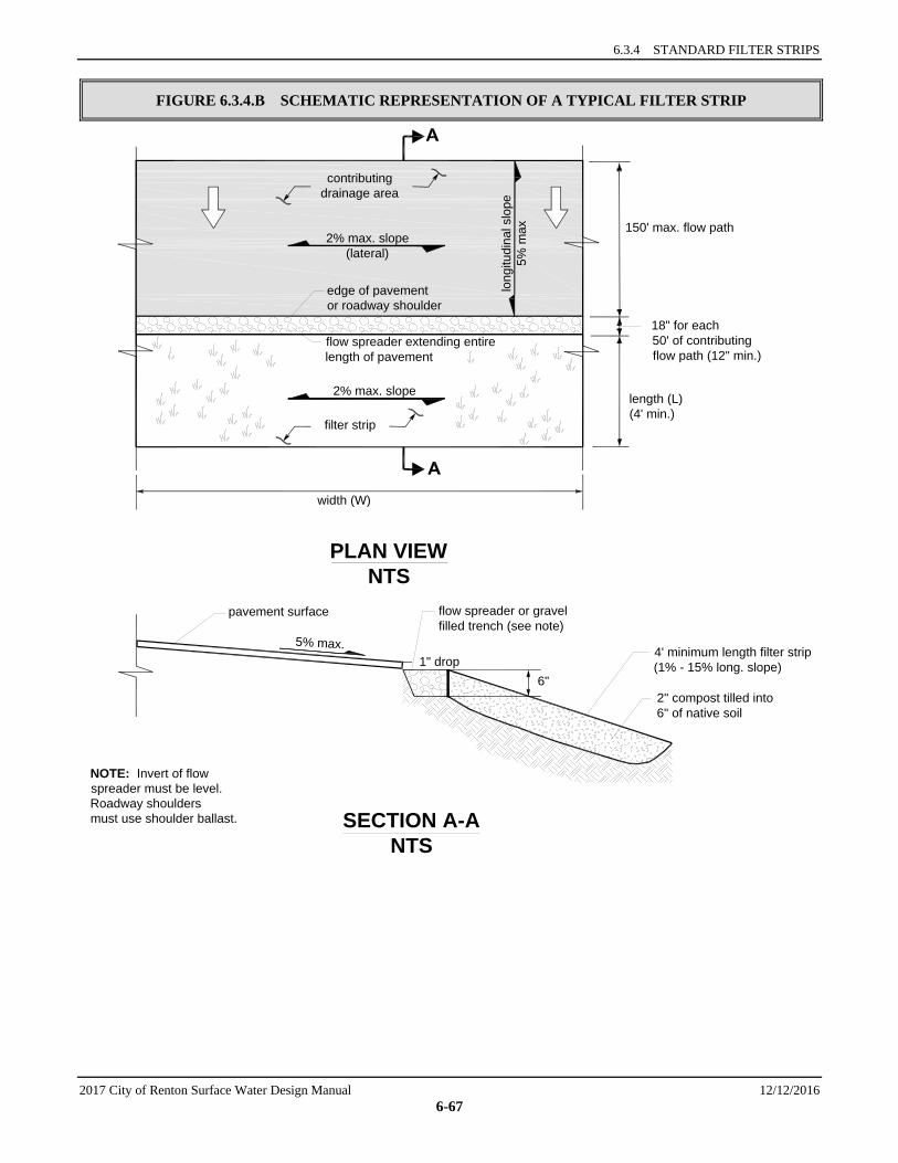
6.3.4 STANDARD FILTER STRIPS
2017 City of Renton Surface Water Design Manual 12/12/2016 6-67
FIGURE 6.3.4.B SCHEMATIC REPRESENTATION OF A TYPICAL FILTER STRIP
2% max. slope(lateral)
contributingdrainage area
edge of pavementor roadway shoulder
long
itudi
nal s
lope
5% m
ax 150' max. flow path
18" for each50' of contributingflow path (12" min.)
length (L)(4' min.)
flow spreader extending entirelength of pavement
2% max. slope
filter strip
width (W)
PLAN VIEWNTS
SECTION A-ANTS
4' minimum length filter strip(1% - 15% long. slope)
6"2" compost tilled into6" of native soil
flow spreader or gravelfilled trench (see note)
1" drop5% max.
pavement surface
NOTE: Invert of flowspreader must be level.Roadway shouldersmust use shoulder ballast.

SECTION 6.3 VEGETATED FLOW PATH FACILITY DESIGNS
12/12/2016 2017 City of Renton Surface Water Design Manual 6-68
6.3.5 NARROW AREA FILTER STRIPS This BMP is not allowed in the City for Basic WQ. Designers should refer to the Standard Filter Strip.29 30
29 Footnote 29 does not apply. 30 Footnote 30 does not apply.

CITY OF RENTON SURFACE WATER DESIGN MANUAL
2017 City of Renton Surface Water Design Manual 12/12/2016 6-69
6.4 WETPOOL FACILITY DESIGNS This section presents the methods, criteria, and details for analysis and design of wetponds, wetvaults, and stormwater wetlands. These facilities have as a common element a permanent pool of water, the wetpool. Each of the wetpool facilities may be combined with a detention or flow control pond in a combined facility. Included are the following specific facility designs:
• “Wetponds — Basic and Large,” Section 6.4.1 • “Wetvaults,” Section 6.4.2 • “Stormwater Wetlands,” Section 6.4.3 • “Combined Detention and Wetpool Facilities,” Section 6.4.4.
The information presented for each facility is organized into the following two categories:
1. Methods of Analysis: Contains a step-by-step procedure for designing and sizing each facility.
2. Design Criteria: Contains the details, specifications, and material requirements for each facility.
6.4.1 WETPONDS — BASIC AND LARGE A wetpond is a constructed stormwater pond that retains a permanent pool of water (a “wetpool”) at least during the wet season (see the schematic representation in Figure 6.4.1.A and Figure 6.4.1.B). The volume of the wetpool is related to the effectiveness of the pond in settling particulate pollutants. The following design procedures, requirements, and recommendations cover two wetpond applications, the basic wetpond and the large wetpond. The two sizes are designed for two different levels of pollutant removal.
Applications and Limitations A wetpond requires a larger area than a bioswale or a sand filter, but it can be integrated to the contours of a site fairly easily. In till soils, the wetpond holds a permanent pool of water that provides an attractive aesthetic feature. In more porous soils, wetponds may still be used, but water seepage from unlined cells could result in a dry pond, particularly in the summer months. Lining with impervious material is one way to deal with this situation.
Wetponds may be single-purpose facilities, providing only water quality treatment, or they may be combined with a detention pond to also provide flow control. If combined, the wetpond can often be stacked under the detention pond with little further loss of development area. See Section 6.4.4 for a description of combined WQ and detention facilities.
Wetponds treat water primarily by gravity settling and to some degree by biological uptake by algae and transformation and degradation by microorganisms. Wetponds can remove some dissolved pollutants such as soluble phosphorus (phosphate) by uptake, and phosphate may react and combine with cations in solution, forming solid particulates. Wetponds are therefore used in the Sensitive Lake Protection menu for phosphorus control in addition to the Basic WQ menu for solids removal. Wetponds work best when the water already in the pond is moved out en masse by incoming flows, a phenomena called plug flow. Because treatment works on this displacement principle, the dead storage pool of wetponds may be provided below the groundwater level without interfering unduly with treatment effectiveness. However, if combined with a detention function, the live storage must be above the seasonal high groundwater level.
Consult the water quality menus in Section 6.1 for information on how basic and large wetponds may be used to meet Core Requirement #8.
SECTION 6.4 WETPOOL FACILITY DESIGNS
12/12/2016 2017 City of Renton Surface Water Design Manual 6-70
6.4.1.1 METHODS OF ANALYSIS This section describes methods of analysis for the following two wetpond sizes:
• Basic wetpond • Large wetpond.
BASIC WETPOND The primary design factor that determines a wetpond’s particulate removal efficiency is the volume of the wetpool in relation to the volume of stormwater runoff. The larger the wetpond volume in relation to the volume of runoff, the greater the potential for pollutant removal. Also important are the avoidance of short-circuiting and the promotion of plug flow. Plug flow describes the hypothetical condition of stormwater moving through the pond as a unit, displacing the “old” water in the pond with incoming flows. To prevent short-circuiting, water is forced to flow, to the extent practical, to all potentially available flow routes, avoiding “dead zones,” and maximizing the time water stays in the pond during the active part of a storm.
Design features that encourage plug flow and avoid dead zones are as follows:
• Dissipating energy at the inlet • Providing a large length-to-width ratio • Providing a broad surface for water exchange across cells rather than a constricted area.
Maximizing the flowpath between inlet and outlet, including the vertical path, also enhances treatment by increasing residence time.
The basic wetpond volume is equal to the 91% water quality treatment volume (see Section 6.2.1), calculated with the approved model or by using the Natural Resources Conservation Service (NRCS, formerly Soil Conservation Service [SCS]) curve number method described in Urban Hydrology for Small Watersheds, Technical Release 55 (TR-55), June 1986, published by the NRCS. Wetponds designed with the basic wetpond volume using the method below, and the required design criteria in Section 6.4.1.2 are expected to meet the Basic WQ menu goal of 80% TSS removal. The actual performance of a wetpond may vary, however, due to a number of factors, including but not limited to design features, maintenance frequency, storm characteristics, pond algae dynamics, and waterfowl use.
Procedures for determining a wetpond’s dimensions and volume are outlined below.
Step 1: Identify the required wetpool volume. A basic wetpond requires a volume equal to the 91% treatment volume, calculated with the approved model or by using the NRCS curve number method. When using the water quality treatment volume reported by the approved model, skip Steps 2 through 4.
Step 2: Determine the weighted NRCS curve number for the developed tributary area. Table 6.4.1.1.A shows the CNs, by land use description, for the four hydrologic soil groups. These numbers are for a 24-hour duration storm and typical antecedent soil moisture condition preceding 24-hour storms.
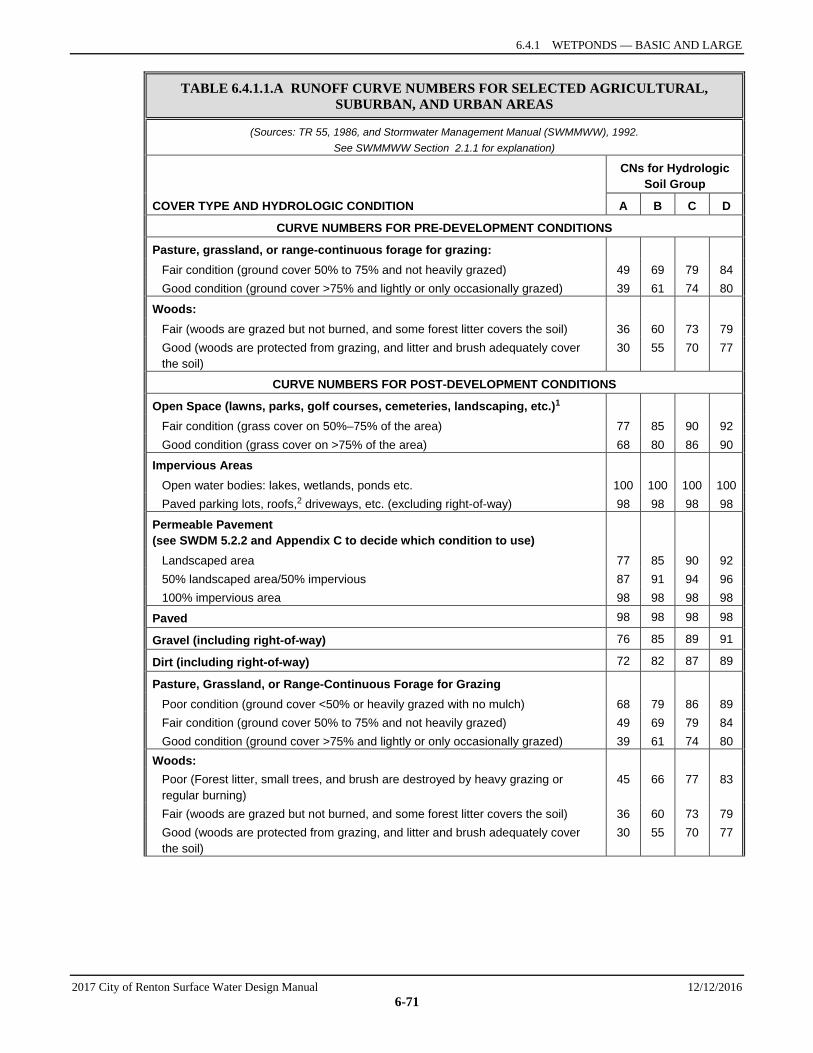
6.4.1 WETPONDS — BASIC AND LARGE
2017 City of Renton Surface Water Design Manual 12/12/2016 6-71
TABLE 6.4.1.1.A RUNOFF CURVE NUMBERS FOR SELECTED AGRICULTURAL, SUBURBAN, AND URBAN AREAS
(Sources: TR 55, 1986, and Stormwater Management Manual (SWMMWW), 1992. See SWMMWW Section 2.1.1 for explanation)
COVER TYPE AND HYDROLOGIC CONDITION
CNs for Hydrologic Soil Group
A B C D
CURVE NUMBERS FOR PRE-DEVELOPMENT CONDITIONS
Pasture, grassland, or range-continuous forage for grazing:
Fair condition (ground cover 50% to 75% and not heavily grazed) 49 69 79 84 Good condition (ground cover >75% and lightly or only occasionally grazed) 39 61 74 80
Woods:
Fair (woods are grazed but not burned, and some forest litter covers the soil) 36 60 73 79 Good (woods are protected from grazing, and litter and brush adequately cover
the soil) 30 55 70 77
CURVE NUMBERS FOR POST-DEVELOPMENT CONDITIONS
Open Space (lawns, parks, golf courses, cemeteries, landscaping, etc.)1
Fair condition (grass cover on 50%–75% of the area) 77 85 90 92 Good condition (grass cover on >75% of the area) 68 80 86 90
Impervious Areas
Open water bodies: lakes, wetlands, ponds etc. 100 100 100 100 Paved parking lots, roofs,2 driveways, etc. (excluding right-of-way) 98 98 98 98
Permeable Pavement (see SWDM 5.2.2 and Appendix C to decide which condition to use)
Landscaped area 77 85 90 92 50% landscaped area/50% impervious 87 91 94 96 100% impervious area 98 98 98 98
Paved 98 98 98 98
Gravel (including right-of-way) 76 85 89 91
Dirt (including right-of-way) 72 82 87 89
Pasture, Grassland, or Range-Continuous Forage for Grazing
Poor condition (ground cover <50% or heavily grazed with no mulch) 68 79 86 89 Fair condition (ground cover 50% to 75% and not heavily grazed) 49 69 79 84 Good condition (ground cover >75% and lightly or only occasionally grazed) 39 61 74 80 Woods: Poor (Forest litter, small trees, and brush are destroyed by heavy grazing or
regular burning) 45 66 77 83
Fair (woods are grazed but not burned, and some forest litter covers the soil) 36 60 73 79 Good (woods are protected from grazing, and litter and brush adequately cover
the soil) 30 55 70 77

SECTION 6.4 WETPOOL FACILITY DESIGNS
12/12/2016 2017 City of Renton Surface Water Design Manual 6-72
TABLE 6.4.1.1.A RUNOFF CURVE NUMBERS FOR SELECTED AGRICULTURAL, SUBURBAN, AND URBAN AREAS
Single Family Residential:3 Dwelling Unit/Gross Acre
Should only be used for subdivisions > 50 acres
Average Percent impervious
area3,4 1.0 DU/GA 15 Separate curve
number shall be selected for pervious and impervious portions of the site or basin
1.5 DU/GA 20 2.0 DU/GA 25 2.5 DU/GA 30 3.0 DU/GA 34 3.5 DU/GA 38 4.0 DU/GA 42 4.5 DU/GA 46 5.0 DU/GA 48 5.5 DU/GA 50 6.0 DU/GA 52 6.5 DU/GA 54 7.0 DU/GA 56 7.5 DU/GA 58 PUDs, condos, apartments, commercial businesses, industrial areas, and subdivisions < 50 acres
% impervious must be computed5
Separate curve numbers shall be selected for pervious and impervious portions of the site
For a more detailed and complete description of land use curve numbers refer to Chapter 2, NRCS <Technical Release No. 55 (June 1986)>. 1 Composite CNs may be computed for other combinations of open space cover type. 2 Where roof runoff and driveway runoff are infiltrated or dispersed according to the requirements in Chapter 5 and
Appendix C, the average percent impervious area may be adjusted in accordance with the procedure described under Section 5.2.2.
3 Assumes roof and driveway runoff is directed into street/storm system. 4 All the remaining pervious areas (lawn) are considered to be in good condition for these curve numbers. 5 See Section 5.2 and Table 3.2.2.E for application of effective impervious area in percentage calculation.
The following are important criteria/considerations for selection of CN values:
Many factors may affect the CN value for a given land use. For example, the movement of heavy equipment over bare ground may compact the soil so that it has a lesser infiltration rate and greater runoff potential than would be indicated by strict application of the CN value to developed site conditions.
CN values can be area weighted when they apply to pervious areas of similar CNs (within 20 CN points). However, high CN areas should not be combined with low CN areas. In this case, separate estimates of S (potential maximum natural detention) and Qd (runoff depth) should be generated and summed to obtain the cumulative runoff volume unless the low CN areas are less than 15 percent of the subbasin.
Separate CN values must be selected for the pervious and impervious areas of an urban basin or subbasin. For residential districts, for subdivisions larger than 50 acres, the percent impervious area given in Table 6.4.1.1.A must be used to compute the respective pervious and impervious areas; for subdivisions of 50 acres or less, the percentage must be computed. For proposed commercial areas, planned unit developments, etc., the percent impervious area must be computed from the site plan. For all other land uses the percent impervious area must be estimated from best available aerial topography and/or field
6.4.1 WETPONDS — BASIC AND LARGE
2017 City of Renton Surface Water Design Manual 12/12/2016 6-73
reconnaissance. The pervious area CN value must be a weighted average of all the pervious area CNs within the subbasin. The impervious area CN value shall be 98.
Cover categories are based on existing U.S. Department of Agriculture soil survey data or site-specific data where available.
Example: The following is an example of how CN values are selected for a sample project.
Select CNs for the following development:
Existing Land Use – forest (undisturbed)
Future Land Use – residential plat (3.6 DU/GA)
Basin Size – 60 acres
Soil Type – 80 percent Alderwood, 20 percent Ragnor
Table 3.2.2.B shows that Alderwood soil belongs to the “C” hydrologic soil group and Ragnor soil belongs to the “B” group. Therefore, for the existing condition, CNs of 70 and 55 are read from Table 6.4.1.1.A and areal weighted to obtain a CN value of 67. For the developed condition with 3.6 DU/GA the percent impervious of 39 percent is interpolated from Table 6.4.1.1.A and used to compute pervious and impervious areas of 36.6 acres and 23.4 acres, respectively. The 36.6 acres of pervious area is assumed to be in Fair condition (for a conservative design) with residential yards and lawns covering the same proportions of Alderwood and Ragnor soil (80 percent and 20 percent respectively). Therefore, CNs of 90 and 85 are read from Table 6.4.1.1.A and areal weighted to obtain a pervious area CN value of 89. The impervious area CN value is 98. The result of this example is summarized below:
Onsite Condition Existing Developed
Land use Forest Residential
Pervious area 60 ac. 36.6 ac.
CN of pervious area 67 89
Impervious area 0 ac. 23.4 ac.
CN of impervious area – 98
Step 3: Calculate runoff depth for the developed tributary area. The rainfall-runoff equations of the NRCS curve number method relate a land area’s runoff depth (precipitation excess) to the precipitation it receives and to its natural storage capacity, as follows:
Qd = (P - 0.2S)² /(P + 0.8S) for P ≥ 0.2S (6-15)
Qd = 0 for P < 0.2S (6-16)
Where:
Qd = runoff depth in inches over the area, P = precipitation depth in inches over the area, and S = potential maximum natural detention, in inches over the area, due to infiltration, storage, etc.
The area’s potential maximum detention, S, is related to its curve number, CN:
S = (1000 /CN) - 10 (6-17)
The combination of the above equations allows for estimation of the total runoff volume by computing total runoff depth, Qd, given the total precipitation depth, P. For example, if the curve number of the area

SECTION 6.4 WETPOOL FACILITY DESIGNS
12/12/2016 2017 City of Renton Surface Water Design Manual 6-74
is 70, then the value of S is 4.29. With a total precipitation for the design event of 2.0 inches, the total runoff depth would be:
Qd = [2.0 - 0.2 (4.29)]² /[2.0 + 0.8 (4.29)] = 0.24 inches
This computed runoff represents inches over the tributary area.
Step 4: Calculate the design wetpool volume. The total volume of runoff is found by multiplying Qd by the area (with necessary conversions):
Total runoff volume = 3,630 x Qd x A
(cu. ft.) (cu. ft./ac. in.) (in) (ac)
If the area is 10 acres, the total runoff volume is:
3,630 cu. ft./ac. in. x 0.24 in. x 10 ac. = 8,712 cu. ft.
This is the design volume for treatment facilities for which the design criterion is based on the volume of runoff.
Step 5: Determine wetpool dimensions. Determine the wetpool dimensions satisfying the design criteria outlined below. A simple way to check the volume of each wetpool cell is to use the following equation:
Vb = (6-18)
where Vb = wetpool volume (cf) (from Step 4 or as determined from the approved model) h = wetpool depth (ft) A1 = water quality design surface area of wetpool (sf) A2 = bottom area of wetpool (sf)
Step 6: Design pond outlet pipe and determine primary overflow water surface. The design criteria for wetponds (see Section 6.4.1.2) calls for a pond outlet pipe to be placed on a reverse grade from the pond’s wetpool to the outlet structure. Use the following procedure to design the pond outlet pipe and determine the primary overflow water surface elevation:
1. Use the nomographs in Section 4.3 (Figures 4.3.1.B and 4.3.1.C) to select a trial size for the pond outlet pipe sufficient to pass the WQ design flow Qwq.
2. Use Figure 4.3.1.F to determine the critical depth dc at the outflow end of the pipe for Qwq.
3. Use Figure 4.2.1.G to determine the flow area Ac at critical depth.
4. Calculate the flow velocity at critical depth using continuity equation (Vc = Qwq /Ac).
5. Calculate the velocity head VH (VH =Vc2/2g), where g is the gravitational constant, 32.2 feet per
second).
6. Determine the primary overflow water surface elevation by adding the velocity head and critical depth to the invert elevation at the outflow end of the pond outlet pipe (i.e., overflow water surface elevation = outflow invert + dc + VH)
7. Adjust outlet pipe diameter as needed and repeat Steps (a) through (e).
LARGE WETPOND Large wetponds are expected to meet the Sensitive Lake Protection menu goal of 50% total phosphorus removal. The actual performance of a wetpond may vary, however, due to a number of factors.
221 )+( AAh
6.4.1 WETPONDS — BASIC AND LARGE
2017 City of Renton Surface Water Design Manual 12/12/2016 6-75
The methods of analysis presented above for basic wetponds apply to large wetponds, except that a large wetpond requires an increased volume of 1.5 times the volume reported by the approved model, or calculated per the NRCS hand method.
6.4.1.2 DESIGN CRITERIA This section sets forth design criteria for the following:
• Basic wetpond • Large wetpond
General wetpond design criteria and concepts are shown in Figure 6.4.1.A.
BASIC WETPOND Wetpool Geometry 1. The wetpool shall be divided into two cells separated by a baffle or berm.31 The first cell shall contain
between 25 to 35 percent of the total wetpool volume. The baffle or berm volume shall not count as part of the total wetpool volume.
Intent: The full-length berm or baffle promotes plug flow and enhances quiescence and laminar flow through as much of the entire water volume as possible. Use of a pipe and full-width manifold system to introduce water into the second cell is possible on a case-by-case basis if approved by CED.
2. Wetponds with wetpool volumes less than or equal to 4,000 cubic feet may be single celled (i.e., no baffle or berm is required).
3. Both cells of a two-cell wetpond and the single cell of a one cell wetpond must retain a permanent pool of water throughout the wet season. A wetpond is considered non-compliant if the pond level drops more than 12″ in any 7-day measurement period. A low permeability liner per Section 6.2.4 will be required to achieve this standard in infiltrative soils.
4. Sediment storage shall be provided in the first cell. The sediment storage shall have a minimum depth of 1 foot.
5. The minimum depth of the first cell shall be 4 feet, exclusive of sediment storage requirements. The depth of the first cell may be greater than the depth of the second cell. If the wetpool is a single cell, the volume equivalent to the first cell shall have a minimum depth of 4 feet.
6. The maximum depth of each cell shall not exceed 8 feet (exclusive of sediment storage in the first cell). Pool depths of 3 feet or shallower (second cell) shall be planted with emergent wetland vegetation (see Planting Requirements).
7. Inlets and outlets shall be placed to maximize the flowpath through the facility. The ratio of flowpath length to width from the inlet to the outlet shall be at least 3:1. The flowpath length is defined as the distance from the inlet to the outlet, as measured at mid-depth. The width at mid-depth can be found as follows: width = (average top width + average bottom width)/2.
8. All inlets shall enter the first cell. If there are multiple inlets, the length-to-width ratio shall be based on the average flowpath length for all inlets.
Berms, Baffles, and Slopes 1. A berm or baffle shall extend across the full width of the wetpool, and tie into the wetpond side
slopes. If the berm embankments are greater than 4 feet in height, the berm must be constructed by
31 As used here, the term baffle means a vertical divider placed across the entire width of the pond, stopping short of the pond
bottom. A berm is a vertical divider typically built up from the bottom, or if in a vault, connects all the way to the bottom.
SECTION 6.4 WETPOOL FACILITY DESIGNS
12/12/2016 2017 City of Renton Surface Water Design Manual 6-76
excavating a key equal to 50% of the embankment cross-sectional height and width. This requirement may be waived if recommended by a geotechnical engineer for specific site conditions.32
2. The top of the berm shall extend to the WQ design water surface or be one foot below the WQ design water surface. If at the WQ design water surface, berm side slopes must be 3H:1V. Berm side slopes may be steeper (up to 2:1) if the berm is submerged one foot.
3. Intent: Submerging the berm is intended to enhance safety by discouraging pedestrian access when side slopes are steeper than 3H:1V.
4. If good vegetation cover is not established on the berm, erosion control measures shall be used to prevent erosion of the berm back-slope when the pond is initially filled.
5. The interior berm or baffle may be a retaining wall provided that the design is prepared and stamped by a civil engineer. If a baffle or retaining wall is used, it shall be submerged one foot below the design water surface to discourage access by pedestrians.
6. Criteria for wetpond side slopes and fencing are given under “General Requirements for WQ Facilities,” Section 6.2.3.
7. Berm embankments shall be the same as for detention ponds (see Section 5.1.1).
8. Internal berms to lengthen the flow path or allow the inlet and outlet to be at the same side of the pond may be used if an adjustment is granted. An adjustment may be granted only if physical site constraints prevent the standard configuration and design features promote water quality treatment. Required design features to approve an adjustment include minimizing dead spaces, minimizing turbulence, and promoting plug flow. Internal berms must extend to the 2-year water elevation, a minimum of 10 feet must be between the berms, and a distance equal to the width between the internal berms must be provided between the internal berm and the pond side at the point that the flow turns around the berm.
Inlet and Outlet See Figure 6.4.1.A for details on the following requirements:
1. The inlet to the wetpond shall be submerged with the inlet pipe invert a minimum of two feet from the pond bottom (not including sediment storage). The top of the inlet pipe shall be submerged at least 1 foot.
Intent: The inlet is submerged to dissipate energy of the incoming flow. The distance from the bottom is set to minimize resuspension of settled sediments. Alternative inlet designs that accomplish these objectives are acceptable.
2. An outlet structure shall be provided. Either a Type 2 catch basin with a grated opening (jail house window) or a manhole with a cone grate (birdcage) may be used (see Section 5.1.1.1). No sump is required in the outlet structure for wetponds not providing detention storage. The outlet structure receives flow from the pond outlet pipe. The grate or birdcage openings provide an overflow route should the pond outlet pipe become clogged. Criterion 5 below specifies the sizing and position of the grate opening.
3. The pond outlet pipe (as opposed to the structure outlet) shall be back-sloped or have a turn-down elbow, and extend 1 foot below the WQ design water surface.
Note: A floating outlet, set to draw water from 1 foot below the water surface, is also acceptable if vandalism concerns are adequately addressed.
Intent: The inverted outlet pipe provides for trapping of oils and floatables in the wetpond.
32 The geotechnical analysis must address situations in which one of the two cells is empty while the other remains full of water.
These situations can occur, for example, during pump down of either cell for sediment removal, or when water from the second unlined cell percolates into the ground.
6.4.1 WETPONDS — BASIC AND LARGE
2017 City of Renton Surface Water Design Manual 12/12/2016 6-77
4. The pond outlet pipe shall be sized, at a minimum, to pass the WQ design flow.
Note: The highest invert of the outlet pipe sets the WQ design water surface elevation.
5. The overflow criteria for single-purpose wetponds are as follows:
a) The requirement for primary overflow as described for flow control ponds is satisfied by either the grated inlet to the outlet structure or by a birdcage above the pond outlet structure as shown in Figure 5.1.1.C.
b) The bottom of the grate opening in the outlet structure shall be set at or above the height needed to pass the WQ design flow through the pond outlet pipe (see Section 6.4.1.1 for sizing details). Note: The grate invert elevation sets the overflow water surface elevation.
c) In flow-through ponds, the grated opening shall be sized to pass the 100-year design flow.
6. An emergency spillway shall be provided and designed according to the requirements for detention ponds (see Section 5.1.1).
7. A gravity drain for maintenance shall be provided if grade allows.
Intent: It is anticipated that sediment removal will only be needed for the first cell in the majority of cases. The gravity drain is intended to allow water from the first cell to be drained to the second cell when the first cell is pumped dry for cleaning.
a) The drain invert shall be at least 6 inches below the top elevation of the dividing berm or baffle. Deeper drains are encouraged where feasible, but must be no deeper than 18 inches above the pond bottom.
b) Intent: to prevent highly sediment-laden water from escaping the pond when drained for maintenance.
c) The drain shall be at least 8 inches (minimum) diameter and shall be controlled by a valve. Use of a shear gate is allowed only at the inlet end of a pipe located within an approved structure.
Intent: Shear gates often leak if water pressure pushes on the side of the gate opposite the seal. The gate should be situated so that water pressure pushes toward the seal.
8. Operational access to the valve shall be provided to the finished ground surface.
a) The valve location shall be accessible and well-marked with one foot of paving placed around the box. It must also be protected from damage and unauthorized operation.
b) A valve box is allowed to a maximum depth of 5 feet without an access manhole. If over 5 feet deep, an access manhole or vault is required.
9. All metal parts shall be corrosion-resistant. Galvanized materials are discouraged where substitutes are available.
Access and Setbacks 1. The location of the pond relative to site constraints (e.g., buildings, property lines, etc.) shall be the
same as for detention ponds (see Section 5.1.1). See Section 6.2.3 for typical setback requirements for WQ facilities.
2. Access and maintenance roads shall be provided and designed according to the requirements for detention ponds (see Section 5.1.1). Access and maintenance roads shall extend to both the wetpond inlet and outlet structures. An access ramp (7H:1V or flatter) shall be provided to the bottom of the first cell unless all portions of the cell can be reached and sediment loaded from the top of the pond. Also see Section 5.1.1, “Access Requirements” for more information on access alternatives.
3. If the dividing berm is also used for access, it must be built to sustain loads of up to 80,000 pounds.
SECTION 6.4 WETPOOL FACILITY DESIGNS
12/12/2016 2017 City of Renton Surface Water Design Manual 6-78
Signage General signage shall be provided according to the requirements for detention ponds (see Section 5.1.1).
Planting Requirements 1. Planting requirements for detention ponds (see Section 5.1.1.1) also apply to wetponds.
If the second cell of the wetpond is 3 feet or shallower, the bottom area shall be planted with emergent wetland vegetation. See Table 6.4.1.A for recommended emergent wetland plant species for wetponds.
Intent: Planting of shallow pond areas helps to stabilize settled sediment and prevent resuspension.
Note: The recommendations in Table 6.4.1.A are for western Washington only. Local knowledge should be used to adapt this information if used in other areas.
2. Cattails (Typha latifolia) are not allowed because they tend to crowd out other species, and the dead shoots need to be removed to prevent oxygen depletion in the wetpool.
3. If the wetpond is in a sensitive lake or sphagnum bog protection area, shrubs that form a dense cover shall be planted on slopes above the WQ design water surface on at least three sides. For banks that are berms, no planting is allowed if the berm is regulated by dam safety requirements (see Section 5.1.1). The purpose of planting is to discourage waterfowl use of the pond and to provide shading.33 Some suitable trees and shrubs include vine maple (Acer circinatum), wild cherry (Prunus emarginata), red osier dogwood (Cornus stolonifera), California myrtle (Myrica californica), Indian plum (Oemleria cerasiformis), and Pacific yew (Taxus brevifolia) as well as numerous ornamental species.
Recommended Design Features The following design features should be incorporated into the wetpond design where site conditions allow:
1. For wetpool depths in excess of 6 feet, it is recommended that some form of recirculation be provided in the summer, such as a fountain or aerator, to prevent stagnation and low dissolved oxygen conditions. A special use permit is needed for a pump or fountain in a City maintained pond.
2. A flow length-to-width ratio greater than the 3:1 minimum is desirable. If the ratio is 4:1 or greater, then the dividing berm is not required, and the pond may consist of one cell rather than two.
3. A tear-drop shape, with the inlet at the narrow end, rather than a rectangular pond is preferred since it minimizes dead zones caused by corners.
4. A small amount of base flow may maintain circulation and reduce the potential for low oxygen conditions during late summer.
5. Evergreen or columnar deciduous trees along the west and south sides of ponds are recommended to reduce thermal heating, except that no trees or shrubs shall be planted on berms meeting the criteria of dams regulated for safety (see “Dam Safety Compliance” in Section 5.1.1). In addition to shade, trees and shrubs also discourage waterfowl use and the attendant phosphorus enrichment problems they cause. Trees should be set back so that the branches will not extend over the pond.
Intent: Evergreen trees or shrubs are preferred to avoid problems associated with leaf drop. Columnar deciduous trees (e.g., hornbeam, Lombardy poplar, etc.) typically have fewer leaves than other deciduous trees.
6. The number of inlets to the facility should be limited; ideally there should be only one inlet. The flowpath length should be maximized from inlet to outlet for all inlets to the facility.
33 Waterfowl are believed to limit use of areas where their view of predator approach paths is blocked. Some suitable native
shrubs include vine maple, Indian plum, bitter cherry, red osier dogwood, cascara, and red elderberry. Ornamental hedge plants such as English laurel, privet and barberry are also good choices.
6.4.1 WETPONDS — BASIC AND LARGE
2017 City of Renton Surface Water Design Manual 12/12/2016 6-79
7. The access and maintenance road could be extended along the full length of the wetpond and could double as playcourts or picnic areas. Placing finely ground bark or other natural material over the road surface would render it more pedestrian friendly.
8. Stormwater facilities may be incorporated within the open space, common space or recreation space on a case by case basis if:
a) The stormwater facility utilizes the techniques and landscape requirements set forth in The Integrated Pond, King County Water and Land Resources Division, or an equivalent manual, or
b) The surface water feature serves areas outside of the planned urban development and is appropriate in size and creates a benefit.
9. The following design features should be incorporated to enhance aesthetics where possible:
a) Subject to dam safety restrictions (WAC 175-175), provide visual enhancement with clusters of trees and shrubs around the wetpond, above the emergency overflow water surface elevation. In most pond areas, it is important to amend the soil with compost before planting since ponds are typically placed well below the native soil horizon in very poor soils. Compost must meet quality criteria in Reference Section 11-C.
b) Orient the pond length along the direction of prevailing summer winds (typically west or southwest) to enhance aeration.34 This is beneficial for both aesthetics and treatment.
Construction Considerations 1. Sediment that has accumulated in the pond must be removed after construction in the drainage area of
the pond is complete (unless used for a liner—see Criteria 2 below). If no more than 12 inches of sediment have accumulated after plat construction, cleaning may be left until after building construction is complete. In general, sediment accumulation from stabilized drainage areas is not expected to exceed an average of 4 inches per year in the first cell. If sediment accumulation is greater than this amount, it will be assumed to be from construction unless it can be shown otherwise. The City will not release maintenance and defect financial guarantees or assume maintenance responsibility for a facility unless it has been cleaned of construction phase sediments.
2. Sediment that has accumulated in the pond at the end of construction may be used as a liner in excessively drained soils if the sediment meets the criteria for low permeability or treatment liners defined in Section 6.24 and in keeping with guidance given in Table 6.2.4.A. Sediment used for a soil liner must be graded to provide uniform coverage and thickness.
Maintenance Considerations 1. The pond should be inspected annually. Floating debris and accumulated petroleum products should
be removed as needed, but at least annually.
2. Nearby vegetation should be trimmed as necessary to keep the pond free of leaves and to maintain the aesthetic appearance of the area. Slope areas that have become bare should be revegetated and eroded areas should be regraded prior to being revegetated.
3. Sediment should be removed when the 1-foot sediment zone is full plus 6 inches. Sediments should be tested for toxicants in compliance with current disposal requirements if land uses in the catchment include commercial or industrial zones, or if visual or olfactory indications of pollution are noticed.
4. Water drained or pumped from ponds prior to sediment removal may be discharged to storm drains if it is not excessively turbid (i.e., if water appears translucent when held to light) and if floatable debris
34 Wind moving over the surface of standing water can often induce some mixing of surface and near-surface water, replenishing
oxygen and reducing stagnant conditions. If the pond is aligned with the prevailing wind direction, this effect can be maximized. See Bentzen et al. 2009. Predictions of Resuspension of Highway Detention Pond Deposits in Interrain Event Periods due to Wind-Induced Currents and Waves. Journal of Environmental Engineering 135 (12):1286-1293
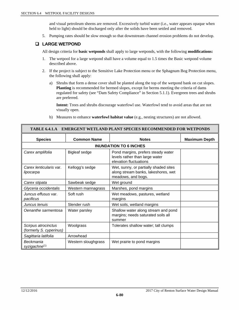
SECTION 6.4 WETPOOL FACILITY DESIGNS
12/12/2016 2017 City of Renton Surface Water Design Manual 6-80
and visual petroleum sheens are removed. Excessively turbid water (i.e., water appears opaque when held to light) should be discharged only after the solids have been settled and removed.
5. Pumping rates should be slow enough so that downstream channel erosion problems do not develop.
LARGE WETPOND All design criteria for basic wetponds shall apply to large wetponds, with the following modifications:
1. The wetpool for a large wetpond shall have a volume equal to 1.5 times the Basic wetpond volume described above.
2. If the project is subject to the Sensitive Lake Protection menu or the Sphagnum Bog Protection menu, the following shall apply:
a) Shrubs that form a dense cover shall be planted along the top of the wetpond bank on cut slopes. Planting is recommended for bermed slopes, except for berms meeting the criteria of dams regulated for safety (see “Dam Safety Compliance” in Section 5.1.1). Evergreen trees and shrubs are preferred.
Intent: Trees and shrubs discourage waterfowl use. Waterfowl tend to avoid areas that are not visually open.
b) Measures to enhance waterfowl habitat value (e.g., nesting structures) are not allowed.
TABLE 6.4.1.A EMERGENT WETLAND PLANT SPECIES RECOMMENDED FOR WETPONDS
Species Common Name Notes Maximum Depth INUNDATION TO 6 INCHES
Carex amplifolia Bigleaf sedge Pond margins, prefers steady water levels rather than large water elevation fluctuations
Carex lenticularis var. lipocarpa
Kellogg’s sedge Wet, sunny, or partially shaded sites along stream banks, lakeshores, wet meadows, and bogs.
Carex stipata Sawbeak sedge Wet ground Glyceria occidentalis Western mannagrass Marshes, pond margins Juncus effusus var. pacificus
Soft rush Wet meadows, pastures, wetland margins
Juncus tenuis Slender rush Wet soils, wetland margins Oenanthe sarmentosa Water parsley Shallow water along stream and pond
margins; needs saturated soils all summer
Scirpus atrocinctus (formerly S. cyperinus)
Woolgrass Tolerates shallow water; tall clumps
Sagittaria latifolia Arrowhead Beckmania syzigachne(1)
Western sloughgrass Wet prairie to pond margins
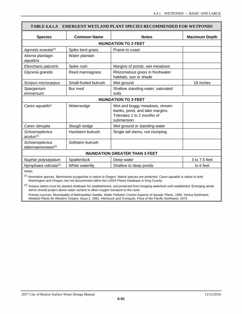
6.4.1 WETPONDS — BASIC AND LARGE
2017 City of Renton Surface Water Design Manual 12/12/2016 6-81
TABLE 6.4.1.A EMERGENT WETLAND PLANT SPECIES RECOMMENDED FOR WETPONDS
Species Common Name Notes Maximum Depth INUNDATION TO 2 FEET
Agrostis exarata(1) Spike bent grass Prairie to coast Alisma plantago-aquatica
Water plantain
Eleocharis palustris Spike rush Margins of ponds, wet meadows Glyceria grandis Reed mannagrass Rhizomatous grass in freshwater
habitats, sun or shade
Scirpus microcarpus Small-fruited bulrush Wet ground 18 inches Sparganium emmersum
Bur reed Shallow standing water, saturated soils
INUNDATION TO 3 FEET Carex aquatilis* Watersedge Wet and boggy meadows, stream
banks, pond, and lake margins. Tolerates 1 to 2 months of submersion.
Carex obnupta Slough sedge Wet ground or standing water Schoenoplectus acutus(2)
Hardstem bulrush Single tall stems, not clumping
Schoenoplectus tabernaemontani(2)
Softstem bulrush
INUNDATION GREATER THAN 3 FEET Nuphar polysepalum Spatterdock Deep water 3 to 7.5 feet Nymphaea odorata(1) White waterlily Shallow to deep ponds to 6 feet Notes: (1) Nonnative species. Beckmania syzigachne is native to Oregon. Native species are preferred. Carex aquatilis is native to both
Washington and Oregon, but not documented within the USDA Plants Database in King County. (2) Scirpus tubers must be planted shallower for establishment, and protected from foraging waterfowl until established. Emerging aerial
stems should project above water surface to allow oxygen transport to the roots. Primary sources: Municipality of Metropolitan Seattle, Water Pollution Control Aspects of Aquatic Plants, 1990. Hortus Northwest,
Wetland Plants for Western Oregon, Issue 2, 1991. Hitchcock and Cronquist, Flora of the Pacific Northwest, 1973.
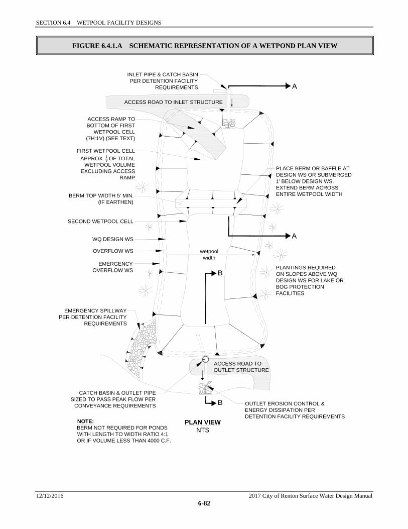
SECTION 6.4 WETPOOL FACILITY DESIGNS
12/12/2016 2017 City of Renton Surface Water Design Manual 6-82
FIGURE 6.4.1.A SCHEMATIC REPRESENTATION OF A WETPOND PLAN VIEW
PLANTINGS REQUIREDON SLOPES ABOVE WQDESIGN WS FOR LAKE ORBOG PROTECTIONFACILITIES
ACCESS ROAD TO INLET STRUCTURE
NOTE:BERM NOT REQUIRED FOR PONDSWITH LENGTH TO WIDTH RATIO 4:1OR IF VOLUME LESS THAN 4000 C.F.
wetpoolwidth
PLAN VIEWNTS
ACCESS ROAD TOOUTLET STRUCTURE
PLACE BERM OR BAFFLE ATDESIGN WS OR SUBMERGED1' BELOW DESIGN WS.EXTEND BERM ACROSSENTIRE WETPOOL WIDTH
CATCH BASIN & OUTLET PIPESIZED TO PASS PEAK FLOW PER
CONVEYANCE REQUIREMENTS OUTLET EROSION CONTROL &ENERGY DISSIPATION PERDETENTION FACILITY REQUIREMENTS
EMERGENCY SPILLWAY PER DETENTION FACILITY
REQUIREMENTS
EMERGENCYOVERFLOW WS
OVERFLOW WS
WQ DESIGN WS
SECOND WETPOOL CELL
BERM TOP WIDTH 5' MIN.(IF EARTHEN)
FIRST WETPOOL CELLAPPROX. 13 OF TOTAL
WETPOOL VOLUMEEXCLUDING ACCESS
RAMP
ACCESS RAMP TOBOTTOM OF FIRST
WETPOOL CELL(7H:1V) (SEE TEXT)
INLET PIPE & CATCH BASINPER DETENTION FACILITY
REQUIREMENTS

6.4.1 WETPONDS — BASIC AND LARGE
2017 City of Renton Surface Water Design Manual 12/12/2016 6-83
FIGURE 6.4.1.B SCHEMATIC REPRESENTATION OF A WETPOND PROFILE
EMERGENCY OVERFLOW WSOVERFLOW WS
WQ DESIGN WS
SECTION A-ANTS
INLET
SECTION B-BNTS
EMERGENCY OVERFLOW WSOVERFLOW WS
WQ DESIGN WS
NOTE:SEE DETENTION FACILITY REQUIREMENTS FORLOCATION AND SETBACK REQUIREMENTS.
12" MIN.
18" MIN.
FENCE REQUIRED FOR SIDE SLOPESSTEEPER THAN 3(H):1(V)
ACCESS ROAD
CAPACITY OF OUTLET SYSTEMSIZED TO PASS PEAK FLOWFOR CONVEYANCEREQUIREMENT
EXTERIOR BERMS DESIGNED PERDAM SAFETY REQUIREMENTSIF APPLICABLE
MANHOLE ORTYPE 2CATCH BASIN
OUTLET PIPE INVERT ATWETPOOL WS ELEVATION
GRAVITY DRAIN(IF GRADE ALLOWS)
8" MIN. DIAMETER
VALVE(MAY BE LOCATED INSIDE MH
OR OUTSIDE WITH APPROVEDOPERATIONAL ACCESS)
INVERT 6" MIN.BELOW TOP
OF INTERNALBERM. LOWER
PLACEMENTIS DESIRABLE
EMERGENT VEGETATIONREQUIRED FOR WETPOOLDEPTHS 3' OR LESS
KEYED BERM
NOTE: BERM SLOPE MAY BE2:1 WHEN TOP SUBMERGED1' BELOW WQ DESIGN WS
SLOPE VEGETATIONPER DETENTION
FACILITY REQUIREMENTS
WETPOOL FLOW LENGTH (INLET TO OUTLET) = 3 (MIN.) x WIDTH
INLET EROSION CONTROL/SLOPE PROTECTION PER
DETENTION FACILITYREQUIREMENTS
SEDIMENT STORAGEDEPTH = 1' MIN.
2' MIN.
FIRST CELL DEPTH4' TO 8' MAX. WETPOOL DEPTH 8' MAX.
RECIRCULATION RECOMMENDEDFOR DEPTH >6'
SECTION 6.4 WETPOOL FACILITY DESIGNS
12/12/2016 2017 City of Renton Surface Water Design Manual 6-84
6.4.2 WETVAULTS A wetvault is an underground structure similar in appearance to a detention vault, except that a wetvault has a permanent pool of water that dissipates energy and improves the settling of particulate pollutants (see the schematic representation in Figure 6.4.2.A). Being underground, the wetvault lacks the biological pollutant removal mechanisms, such as algae uptake, present in surface wetponds.
Applications and Limitations A wetvault may be used in any type or size of development. However, it is most practical in relatively small catchments (less than 10 acres of impervious surface) with high land values because vaults are relatively expensive. Combined detention and wetvaults are allowed; see Section 6.4.4.
A wetvault is believed to be ineffective in removing dissolved pollutants such as soluble phosphorus or metals such as copper. There is also concern that oxygen levels will decline, especially in warm summer months, because of limited contact with air and wind. However, the extent to which this potential problem occurs has not been documented.
If oil control is required for a project, the wetvault may be combined with the baffle oil/water separator facility (see Section 6.6.2) to fulfill Special Requirement #5, “Oil Control” (see Option 5, Section 6.1.5).
Consult the water quality menus in Section 6.1 for information on how this facility may be used to meet Core Requirement #8 and Special Requirement #5.
6.4.2.1 METHODS OF ANALYSIS As with wetponds, the primary design factor that determines the removal efficiency of a wetvault is the volume of the wetpool in relationship to the volume of runoff. The larger the volume, the higher the potential for pollutant removal. Performance is also improved by avoiding dead zones (like corners) where little exchange occurs, using large length-to-width ratios, dissipating energy at the inlet, and ensuring that flow rates are uniform to the extent possible and not increased between cells.
Wetvaults sized using the design methodology below (with a volume equal to the 91% treatment volume per Section 6.2.1) and following the required design criteria in Section 6.4.2.2 are expected to meet the Basic WQ menu goal of 80% TSS removal.
The methods of analysis for a wetvault are identical to the methods of analysis for the wetpond. Follow the procedure specified in Section 6.4.1.1 to determine the wetpool volume for a wetvault.
6.4.2.2 DESIGN CRITERIA A schematic representation of a wetvault is shown in Figure 6.4.2.A.
Wetpool Geometry Same as specified for wetponds (see Section 6.4.1.2) except for the following two modifications:
1. Criterion 3: The sediment storage in the first cell shall be an average of 1 foot. Because of the v-shaped bottom, the depth of sediment storage needed above the bottom of the side wall is roughly proportional to vault width according to the schedule below:
Vault Width 15′ 20′ 40′ 60′
Sediment Depth (from bottom of side wall) 10″ 9″ 6″ 4″
2. Criterion 5: The second cell shall be a minimum of 3 feet deep since planting cannot be used to prevent resuspension of sediment in shallow water as it can in open ponds.

6.4.2 WETVAULTS
2017 City of Renton Surface Water Design Manual 12/12/2016 6-85
Vault Structure 1. Wetvaults shall be designed as flow-through systems.
2. The vault shall be separated into two cells by a wall or a removable baffle.35 If a wall or non-removable baffle is used, a 5-foot by 10-foot removable maintenance access must be provided for both cells. If a removable baffle is used, the following criteria apply:
a) The baffle shall extend from a minimum of 1-foot above the WQ design water surface to a minimum of 1 foot below the invert elevation of the inlet pipe.
b) The lowest point of the baffle shall be a minimum of 2 feet from the bottom of the vault, and greater if feasible.
3. If the vault is less than 2,000 cubic feet (inside dimensions) or if the length-to-width ratio of the vault pool is 5:1 or greater, the baffle or wall may be omitted and the vault may be one-celled.
4. The two cells of a wetvault shall not be divided into additional subcells by internal walls. If internal structural support is needed, post and pier construction may be used to support the vault lid rather than walls. Any walls used within cells must be positioned so as to lengthen, rather than divide, the flowpath.
Intent: Treatment effectiveness in wetpool facilities is related to the extent to which plug flow is achieved and short-circuiting and dead zones are avoided. Structural walls placed within the cells can interfere with plug flow and create significant dead zones, reducing treatment effectiveness.
5. Internal walls to lengthen the flow path or allow the inlet and outlet to be at the same side of the vault may be used if an adjustment is granted. An adjustment may be granted only if physical site constraints prevent the standard configuration and design features promote water quality treatment. Required design features to approve an adjustment include minimizing dead spaces, minimizing turbulence, and promoting plug flow. Internal walls must extend to the 2-year water elevation, a minimum of 10 feet must be between the walls, and a distance equal to the width between the internal walls must be provided between the internal wall and the vault wall at the point that the flow turns around the wall. All vault requirements apply to each length/segment.
Intent: Confined movement around the internal walls creates turbulence, creates dead zones and decreases treatment effectiveness.
6. The bottom of the first cell shall be sloped toward the access opening. Slope shall be between 0.5 percent (minimum) and 2 percent (maximum). The second cell may be level (longitudinally) sloped toward the outlet, with a high point between the first and second cells.
7. The vault bottom shall slope laterally a minimum of 5% from each side towards the center, forming a broad “v” to facilitate sediment removal.
Note: More than one “v” may be used to minimize vault depth. Exception: The vault bottom may be flat if removable panels are provided over the entire vault. Removable panels shall be at grade, have stainless steel lifting eyes, and weigh no more than 5 tons per panel.
8. The highest point of a vault bottom must be at least 6 inches below the outlet elevation to provide for sediment storage over the entire bottom.
9. Provision for passage of flows should the outlet plug shall be provided.
35 As used here, the term baffle means a divider that does not extend all the way to the bottom of the vault, or if a bottom baffle,
does not extend all the way to the top of the water surface. A wall is used here to mean a divider that extends all the way from near the water surface to the bottom of the vault.
SECTION 6.4 WETPOOL FACILITY DESIGNS
12/12/2016 2017 City of Renton Surface Water Design Manual 6-86
10. Wetvaults may be constructed using arch culvert sections provided the top area at the WQ design water surface is, at a minimum, equal to that of a vault with vertical walls designed with an average depth of 6 feet. If arched culverts are used, the manufacturer must certify that they are water-tight.
Intent: To prevent decreasing the surface area available for oxygen exchange.
11. Wetvaults shall conform to the “Materials” and “Structural Stability” criteria specified for detention vaults in Section 5.1.3.
12. Where pipes enter and leave the vault below the WQ design water surface, they shall be sealed using a non-porous, non-shrinking grout.
Inlet and Outlet 1. The inlet to the wetvault shall be submerged with the inlet pipe invert a minimum of 3 feet from the
vault bottom (not including sediment storage). The top of the inlet pipe shall be submerged at least 1 foot.
Note: These dimensional requirements may increase the minimum 4 foot depth of the first cell, depending on the size of the inlet pipe.
Intent: The submerged inlet is to dissipate energy of the incoming flow. The distance from the bottom is to minimize resuspension of settled sediments. Alternative inlet designs that accomplish these objectives are acceptable.
2. Unless designed as an off-line facility, the capacity of the outlet pipe and available head above the outlet pipe shall be designed to convey the 100-year design flow for developed site conditions (as described in Section 5.1.4.2) without overtopping the vault. The available head above the outlet pipe must be a minimum of 6 inches.
3. The outlet pipe shall be back-sloped or have tee section, the lower arm of which shall extend 1 foot below the WQ design water surface to provide for trapping of oils and floatables in the vault.
4. A gravity drain for maintenance shall be provided if grade allows.
a) The gravity drain should be as low as the site situation allows; however, the invert shall be no lower than the average sediment storage depth. At a minimum, the invert shall be 6 inches above the base elevation of the vault side walls.
Intent: This placement prevents highly sediment-laden water from escaping when the vault is drained for maintenance. A lower placement is allowed than for wetponds since the v-shaped vault bottom will capture and retain additional sediments.
b) The drain shall be 8 inches (minimum) diameter and shall be controlled by a valve. Use of a shear gate is allowed only at the inlet end of a pipe located within an approved structure.
Intent: Shear gates often leak if water pressure pushes on the side of the gate opposite the seal. The gate should be situated so that water pressure pushes toward the seal.
c) Operational access to the valve shall be provided to the finished ground surface. The valve location shall be accessible and well-marked with one foot of paving placed around the box. It must also be protected from damage and unauthorized operation.
d) If not located in the vault, a valve box is allowed to a maximum depth of 5 feet without an access manhole. If over 5 feet deep, an access manhole is required.
Access Requirements Same as for detention vaults (see Section 5.1.3).
Note: If the 5-foot by 10-foot removable maintenance access also provides inlet/outlet access, then a 3-foot by 3-foot inspection port must be provided at the inlet pipe and outlet structure.
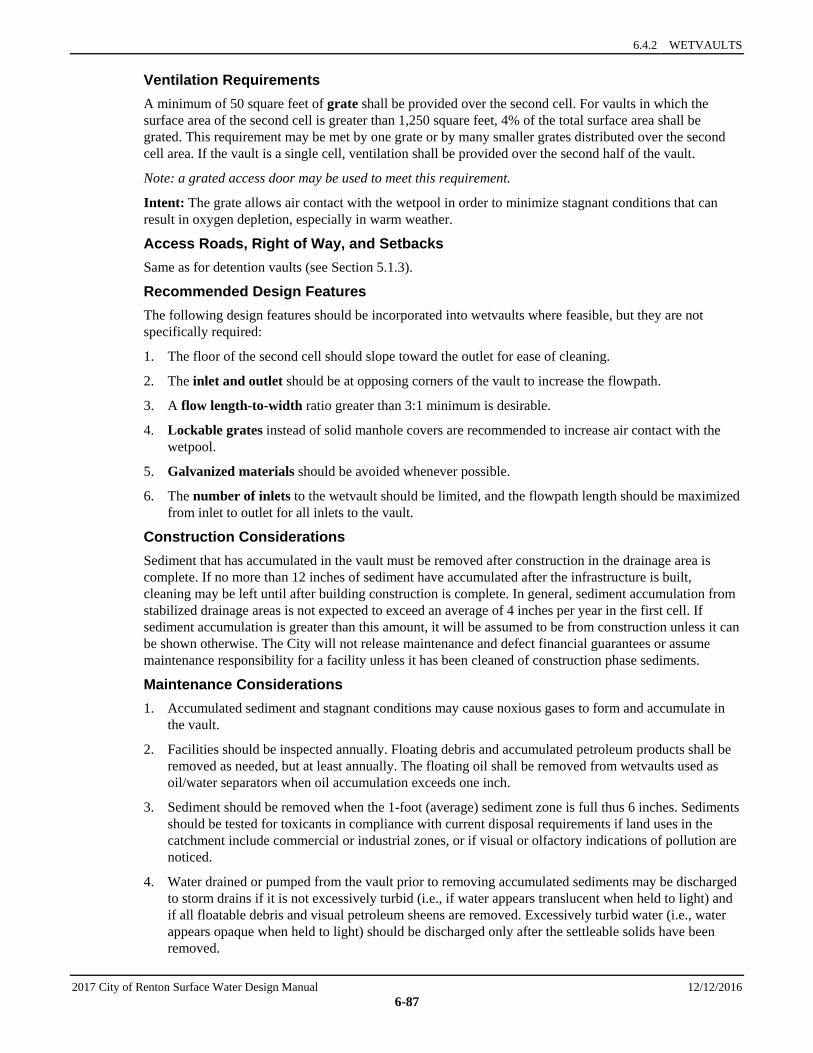
6.4.2 WETVAULTS
2017 City of Renton Surface Water Design Manual 12/12/2016 6-87
Ventilation Requirements A minimum of 50 square feet of grate shall be provided over the second cell. For vaults in which the surface area of the second cell is greater than 1,250 square feet, 4% of the total surface area shall be grated. This requirement may be met by one grate or by many smaller grates distributed over the second cell area. If the vault is a single cell, ventilation shall be provided over the second half of the vault.
Note: a grated access door may be used to meet this requirement.
Intent: The grate allows air contact with the wetpool in order to minimize stagnant conditions that can result in oxygen depletion, especially in warm weather.
Access Roads, Right of Way, and Setbacks Same as for detention vaults (see Section 5.1.3).
Recommended Design Features The following design features should be incorporated into wetvaults where feasible, but they are not specifically required:
1. The floor of the second cell should slope toward the outlet for ease of cleaning.
2. The inlet and outlet should be at opposing corners of the vault to increase the flowpath.
3. A flow length-to-width ratio greater than 3:1 minimum is desirable.
4. Lockable grates instead of solid manhole covers are recommended to increase air contact with the wetpool.
5. Galvanized materials should be avoided whenever possible.
6. The number of inlets to the wetvault should be limited, and the flowpath length should be maximized from inlet to outlet for all inlets to the vault.
Construction Considerations Sediment that has accumulated in the vault must be removed after construction in the drainage area is complete. If no more than 12 inches of sediment have accumulated after the infrastructure is built, cleaning may be left until after building construction is complete. In general, sediment accumulation from stabilized drainage areas is not expected to exceed an average of 4 inches per year in the first cell. If sediment accumulation is greater than this amount, it will be assumed to be from construction unless it can be shown otherwise. The City will not release maintenance and defect financial guarantees or assume maintenance responsibility for a facility unless it has been cleaned of construction phase sediments.
Maintenance Considerations 1. Accumulated sediment and stagnant conditions may cause noxious gases to form and accumulate in
the vault.
2. Facilities should be inspected annually. Floating debris and accumulated petroleum products shall be removed as needed, but at least annually. The floating oil shall be removed from wetvaults used as oil/water separators when oil accumulation exceeds one inch.
3. Sediment should be removed when the 1-foot (average) sediment zone is full thus 6 inches. Sediments should be tested for toxicants in compliance with current disposal requirements if land uses in the catchment include commercial or industrial zones, or if visual or olfactory indications of pollution are noticed.
4. Water drained or pumped from the vault prior to removing accumulated sediments may be discharged to storm drains if it is not excessively turbid (i.e., if water appears translucent when held to light) and if all floatable debris and visual petroleum sheens are removed. Excessively turbid water (i.e., water appears opaque when held to light) should be discharged only after the settleable solids have been removed.
SECTION 6.4 WETPOOL FACILITY DESIGNS
12/12/2016 2017 City of Renton Surface Water Design Manual 6-88
MODIFICATIONS FOR COMBINING WITH A BAFFLE OIL/WATER SEPARATOR If the project site is a high-use site and a wetvault is proposed to meet the Basic WQ menu criteria, the vault may be combined with a baffle oil/water separator (see Section 6.6.2) to meet the requirements of Special Requirement #5 with one facility rather than two. Structural modifications and added design criteria are given below. However, the maintenance requirements for baffle oil/water separators must be adhered to, in addition to those for a wetvault. This will result in more frequent inspection and cleaning than for a wetvault used only for TSS removal. See Section 6.6.2.2 for information on maintenance of baffle oil/water separators.
1. The sizing procedures for the baffle oil/water separator should be run as a check to ensure the vault is large enough. If the oil/water separator sizing procedures result in a larger vault size, increase the wetvault size to match.
2. An oil retaining baffle shall be provided in the second cell near the vault outlet. The baffle should not contain a high-flow overflow, or else the retained oil will be washed out of the vault during large storms.
3. The vault shall have a minimum length-to-width ratio of 5:1.
4. The vault shall have a design water depth-to-width ratio of between 1:3 to 1:2.
5. The vault shall be watertight and shall be coated to protect from corrosion.
6. Separator vaults shall have a shutoff mechanism on the outlet pipe to prevent oil discharges during maintenance and to provide emergency shut-off capability in case of a spill. A valve box and riser shall also be provided.
7. Wetvaults used as oil/water separators must be off-line and must bypass flows greater than the off-line WQ design flow described in Section 6.2.1
Intent: This design minimizes the entrainment and/or emulsification of previously captured oil during very high flow events.
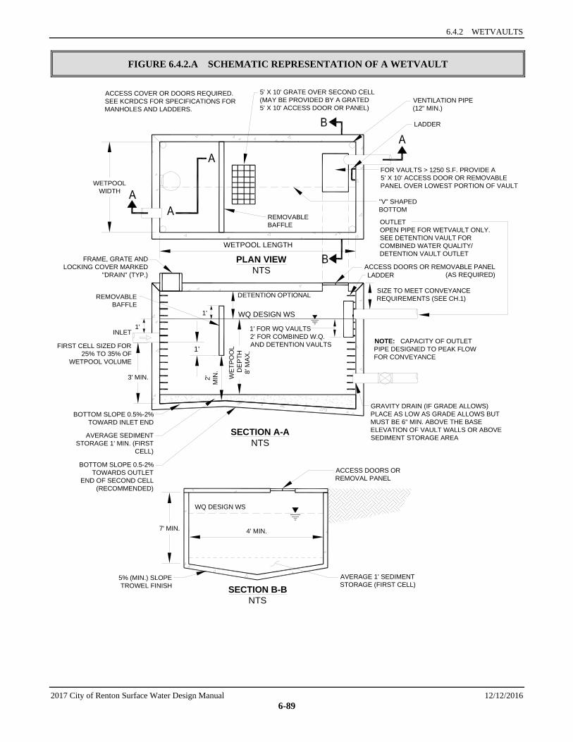
6.4.2 WETVAULTS
2017 City of Renton Surface Water Design Manual 12/12/2016 6-89
FIGURE 6.4.2.A SCHEMATIC REPRESENTATION OF A WETVAULT
SECTION B-BNTS
SECTION A-ANTS
PLAN VIEWNTS
ACCESS COVER OR DOORS REQUIRED.SEE KCRDCS FOR SPECIFICATIONS FORMANHOLES AND LADDERS.
SIZE TO MEET CONVEYANCEREQUIREMENTS (SEE CH.1)
NOTE: CAPACITY OF OUTLETPIPE DESIGNED TO PEAK FLOWFOR CONVEYANCE
WQ DESIGN WS
DETENTION OPTIONAL
1' FOR WQ VAULTS2' FOR COMBINED W.Q.AND DETENTION VAULTS
INLET
FIRST CELL SIZED FOR25% TO 35% OF
WETPOOL VOLUME
WQ DESIGN WS
1'
7' MIN. 4' MIN.
AVERAGE 1' SEDIMENTSTORAGE (FIRST CELL)
ACCESS DOORS ORREMOVAL PANEL
5% (MIN.) SLOPETROWEL FINISH
GRAVITY DRAIN (IF GRADE ALLOWS)PLACE AS LOW AS GRADE ALLOWS BUTMUST BE 6" MIN. ABOVE THE BASEELEVATION OF VAULT WALLS OR ABOVESEDIMENT STORAGE AREA
BOTTOM SLOPE 0.5-2%TOWARDS OUTLET
END OF SECOND CELL(RECOMMENDED)
BOTTOM SLOPE 0.5%-2%TOWARD INLET END
AVERAGE SEDIMENTSTORAGE 1' MIN. (FIRST
CELL)
3' MIN.
FRAME, GRATE ANDLOCKING COVER MARKED
"DRAIN" (TYP.)
WETPOOLWIDTH
WETPOOL LENGTH
VENTILATION PIPE(12" MIN.)
LADDER
FOR VAULTS > 1250 S.F. PROVIDE A5' X 10' ACCESS DOOR OR REMOVABLEPANEL OVER LOWEST PORTION OF VAULT
"V" SHAPEDBOTTOM
OUTLETOPEN PIPE FOR WETVAULT ONLY.SEE DETENTION VAULT FORCOMBINED WATER QUALITY/DETENTION VAULT OUTLET
5' X 10' GRATE OVER SECOND CELL(MAY BE PROVIDED BY A GRATED5' X 10' ACCESS DOOR OR PANEL)
LADDER
WET
POO
L D
EPT
H8'
MAX
.
2'M
IN.
1'
REMOVABLEBAFFLE
REMOVABLEBAFFLE
ACCESS DOORS OR REMOVABLE PANEL(AS REQUIRED)
1'
SECTION 6.4 WETPOOL FACILITY DESIGNS
12/12/2016 2017 City of Renton Surface Water Design Manual 6-90
6.4.3 STORMWATER WETLANDS In land development situations, wetlands are usually constructed for two main reasons: to replace or mitigate impacts when natural wetlands are filled or impacted by development (mitigation wetlands), and to treat stormwater runoff (stormwater treatment wetlands). Stormwater wetlands are shallow man-made ponds that are designed to treat stormwater through the biological processes associated with emergent aquatic plants (see the schematic representations in Figure 6.4.3.A and Figure 6.4.3.B).
In the City, wetlands created to mitigate disturbance impacts, such as filling, shall not also be used as stormwater treatment facilities. This is because of the different, incompatible functions of the two kinds of wetlands. Mitigation wetlands are intended to function as full replacement habitat for fish and wildlife, providing the same functions and harboring the same species diversity and biotic richness as the wetlands they replace. Stormwater treatment wetlands are used to capture and transform pollutants, just as wetponds are, and over time the sediment will concentrate pollutants. This is not a healthy environment for aquatic life. Stormwater treatment wetlands are used to capture pollutants in a managed environment so that they will not reach natural wetlands and other ecologically important habitats. In addition, vegetation must be harvested and sediment dredged in stormwater treatment wetlands, further interfering with use for wildlife habitat.
In general, stormwater wetlands perform well to remove sediment, metals, and pollutants which bind to humic or organic acids. Phosphorus removal in stormwater wetlands is highly variable.36
Applications and Limitations This stormwater wetland design occupies about the same surface area as wetponds, but has the potential to be better integrated aesthetically into a site because of the abundance of emergent aquatic vegetation. The most critical factor for a successful design is the provision of an adequate supply of water for most of the year to replace any lost by infiltration or evapotranspiration. Careful planning is needed to be sure sufficient water will be retained to sustain good wetland plant growth. Since water depths are shallower than in wetponds, water loss by evapotranspiration is an important concern, especially during the relatively warm dry season. Stormwater wetlands may be a good WQ facility choice in areas with high winter groundwater levels, if there is also some pond intrusion of summer base flow.
Consult the water quality menus in Section 6.1 for information on how this facility may be used to meet Core Requirement #8.
6.4.3.1 METHODS OF ANALYSIS When used for stormwater treatment, stormwater wetlands employ some of the same design features as wetponds. However, in addition to gravity settling, some degree of pollutant removal is mediated by aquatic vegetation and the microbiological community associated with that vegetation. When designing wetlands, water volume and factors which affect plant vigor and biomass are all concerns.
Stormwater wetlands designed and constructed using the criteria below are expected to meet both the Basic and Enhanced Basic water quality treatment goals.
Steps 1 through 5: Determine the volume of a basic wetpond. Follow Steps 1 through 5 for wetponds (see Section 6.4.1.1). The volume of a basic wetpond is used as a template for sizing the stormwater wetland.
Step 6: Calculate the surface area of the stormwater wetland. The surface area of the wetland shall be the same as the top area of a wetpond sized for the same site conditions. Calculate the surface area of the stormwater wetland by using the volume from Step 5 and dividing by the average water depth (use 3 feet).
Step 7: Determine the surface area of the first cell of the stormwater wetland. Use the volume determined from Criterion 2 under “Wetland Geometry,” and the actual depth of cell 1.
36 Richardson, C. 1987. "Mechanisms controlling phosphorus retention capacity in freshwater wetlands," Science, 228: 1424.
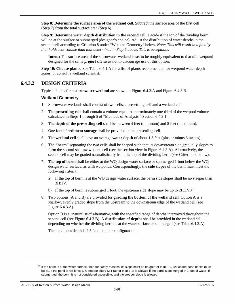
6.4.3 STORMWATER WETLANDS
2017 City of Renton Surface Water Design Manual 12/12/2016 6-91
Step 8: Determine the surface area of the wetland cell. Subtract the surface area of the first cell (Step 7) from the total surface area (Step 6).
Step 9: Determine water depth distribution in the second cell. Decide if the top of the dividing berm will be at the surface or submerged (designer’s choice). Adjust the distribution of water depths in the second cell according to Criterion 8 under “Wetland Geometry” below. Note: This will result in a facility that holds less volume than that determined in Step 5 above. This is acceptable.
Intent: The surface area of the stormwater wetland is set to be roughly equivalent to that of a wetpond designed for the same project site so as not to discourage use of this option.
Step 10: Choose plants. See Table 6.4.1.A for a list of plants recommended for wetpond water depth zones, or consult a wetland scientist.
6.4.3.2 DESIGN CRITERIA Typical details for a stormwater wetland are shown in Figure 6.4.3.A and Figure 6.4.3.B.
Wetland Geometry 1. Stormwater wetlands shall consist of two cells, a presettling cell and a wetland cell.
2. The presettling cell shall contain a volume equal to approximately one-third of the wetpool volume calculated in Steps 1 through 5 of “Methods of Analysis,” Section 6.4.3.1.
3. The depth of the presettling cell shall be between 4 feet (minimum) and 8 feet (maximum).
4. One foot of sediment storage shall be provided in the presettling cell.
5. The wetland cell shall have an average water depth of about 1.5 feet (plus or minus 3 inches).
6. The “berm” separating the two cells shall be shaped such that its downstream side gradually slopes to form the second shallow wetland cell (see the section view in Figure 6.4.3.A). Alternatively, the second cell may be graded naturalistically from the top of the dividing berm (see Criterion 8 below).
7. The top of berm shall be either at the WQ design water surface or submerged 1 foot below the WQ design water surface, as with wetponds. Correspondingly, the side slopes of the berm must meet the following criteria:
a) If the top of berm is at the WQ design water surface, the berm side slopes shall be no steeper than 3H:1V.
b) If the top of berm is submerged 1 foot, the upstream side slope may be up to 2H:1V.37
8. Two options (A and B) are provided for grading the bottom of the wetland cell. Option A is a shallow, evenly graded slope from the upstream to the downstream edge of the wetland cell (see Figure 6.4.3.A).
Option B is a “naturalistic” alternative, with the specified range of depths intermixed throughout the second cell (see Figure 6.4.3.B). A distribution of depths shall be provided in the wetland cell depending on whether the dividing berm is at the water surface or submerged (see Table 6.4.3.A).
The maximum depth is 2.5 feet in either configuration.
37 If the berm is at the water surface, then for safety reasons, its slope must be no greater than 3:1, just as the pond banks must
be 3:1 if the pond is not fenced. A steeper slope (2:1 rather than 3:1) is allowed if the berm is submerged in 1 foot of water. If submerged, the berm it is not considered accessible, and the steeper slope is allowed.
SECTION 6.4 WETPOOL FACILITY DESIGNS
12/12/2016 2017 City of Renton Surface Water Design Manual 6-92
TABLE 6.4.3.A DISTRIBUTION OF DEPTHS IN WETLAND CELL (OPTION B)
DIVIDING BERM AT WQ DESIGN WATER SURFACE DIVIDING BERM SUBMERGED 1 FOOT
Depth Range (feet) Percent of Cell 2
Surface Area Depth Range (feet) Percent of Cell 2
Surface Area 0.1 to 1 25 1 to 1.5 40 1 to 2 55 1.5 to 2 40
2 to 2.5 20 2 to 2.5 20
Lining Requirements 1. In infiltrative soils, both cells of the stormwater wetland shall be lined. To determine whether a low-
permeability liner or a treatment liner is required, determine whether the following conditions will be met. If low soil permeability will ensure sufficient water retention, lining may be waived.
• The first cell of a treatment wetland must retain a permanent pool of water throughout the wet season. It is considered non-compliant if the pond level drops more than 12″ in any 7-day measurement period. A low permeability liner, per Section 6.2.4 will be required to achieve this standard in infiltrative soils.
• The second cell must retain water for at least 10 months of the year. • The complete historical precipitation record should be used in the approved model when
establishing these conditions.
Intent: Many wetland plants can adapt to periods of summer drought, so a limited drought period is allowed in the second cell. This may allow a treatment liner rather than a low permeability liner to be used for the second cell. The first cell must retain a permanent pool of water throughout the wet season in order for the presettling function to be effective.
2. If a low permeability liner is used, a minimum of 18 inches of native soil amended with good topsoil or compost (one part compost mixed with 3 parts native soil) meeting the compost quality requirements in Reference Section 11-C must be placed over the liner. For geomembrane or geotextile liner, a soil depth of 3 feet covering the liner is required to prevent damage to the liner during planting. Hydric soils are not required.
3. The criteria for liners given in Section 6.2.4 must be observed.
Inlet and Outlet Same as for basic wetponds (see Section 6.4.1.2) but with the added requirement that spill control be provided as detailed in Section 4.2.1.1 prior to discharge of runoff from non-roof-top pollution generating impervious surface into the stormwater wetland.
Access and Setbacks 1. Location of the stormwater wetland relative to site constraints (e.g., buildings, property lines, etc.)
shall be the same as for detention ponds (see Section 5.1.1). See Section 6.2.3 for typical setback requirements for WQ facilities.
2. Access and maintenance roads shall be provided and designed according to the requirements for detention ponds (see Section 5.1.1). Access and maintenance roads shall extend to both the wetland inlet and outlet structures. An access ramp (7H minimum:1V) shall be provided to the bottom of the first cell unless all portions of the cell can be reached and sediment loaded from the top of the wetland side slopes. Also see “Access Requirements” in Section 5.1.1, for more information on access alternatives.
3. If the dividing berm is also used for access, it must be built to sustain loads of up to 80,000 pounds.
6.4.3 STORMWATER WETLANDS
2017 City of Renton Surface Water Design Manual 12/12/2016 6-93
Signage General signage shall be provided according to the requirements for detention ponds (see Section 5.1.1).
Planting Requirements 1. The wetland cell shall be planted with emergent wetland plants following the recommendations given
in Table 6.4.1.A or the recommendations of a wetland specialist.
Note: Cattails (Typha latifolia) are not allowed. They tend to escape to natural wetlands and crowd out other species. In addition, the shoots die back each fall and will result in oxygen depletion in the wetpool unless they are removed.
2. If the stormwater wetland is in a sensitive lake or sphagnum bog protection area, shrubs that form a dense cover shall be planted on slopes above the WQ design water surface on at least three sides of the presettling cell. For banks that are berms, no planting is allowed if the berm is regulated by dam safety requirements (see Section 5.1.1). The purpose of planting is to discourage waterfowl use of the pond and to provide shading.38 Some suitable trees and shrubs include vine maple (Acer circinatum), wild cherry (Prunus emarginata), red osier dogwood (Cornus stolonifera), California myrtle (Myrica californica), Indian plum (Oemleria cerasiformis), and Pacific yew (Taxus brevifolia) as well as numerous ornamental species.
Construction and Maintenance Considerations Construction and maintenance considerations are the same as for basic wetponds. Construction of the naturalistic alternative (Option B) can be easily done by first excavating the entire area to the 1.5-foot average depth. Then soil subsequently excavated to form deeper areas can be deposited to raise other areas until the distribution of depths indicated in the design is achieved.
38 Waterfowl are believed to limit use of areas where their view of predator approach paths is blocked. Some suitable native
shrubs include vine maple, Indian plum, bitter cherry, red osier dogwood, cascara, and red elderberry. Ornamental hedge plants such as English laurel, privet and barberry are also good choices.
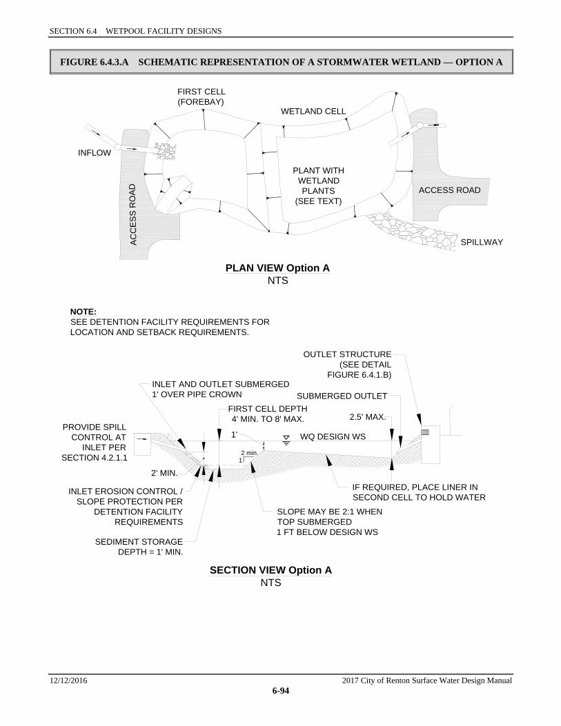
SECTION 6.4 WETPOOL FACILITY DESIGNS
12/12/2016 2017 City of Renton Surface Water Design Manual 6-94
FIGURE 6.4.3.A SCHEMATIC REPRESENTATION OF A STORMWATER WETLAND — OPTION A
SECTION VIEW Option ANTS
PLAN VIEW Option ANTS
PLANT WITHWETLANDPLANTS
(SEE TEXT)
AC
CE
SS
RO
AD ACCESS ROAD
SPILLWAY
WETLAND CELL
FIRST CELL(FOREBAY)
INFLOW
PROVIDE SPILLCONTROL AT
INLET PERSECTION 4.2.1.1
NOTE:SEE DETENTION FACILITY REQUIREMENTS FORLOCATION AND SETBACK REQUIREMENTS.
WQ DESIGN WS1'
2 min.1
OUTLET STRUCTURE(SEE DETAIL
FIGURE 6.4.1.B)INLET AND OUTLET SUBMERGED1' OVER PIPE CROWN
FIRST CELL DEPTH4' MIN. TO 8' MAX. 2.5' MAX.
IF REQUIRED, PLACE LINER INSECOND CELL TO HOLD WATER
SLOPE MAY BE 2:1 WHENTOP SUBMERGED1 FT BELOW DESIGN WS
INLET EROSION CONTROL /SLOPE PROTECTION PER
DETENTION FACILITYREQUIREMENTS
SEDIMENT STORAGEDEPTH = 1' MIN.
2' MIN.
SUBMERGED OUTLET

6.4.3 STORMWATER WETLANDS
2017 City of Renton Surface Water Design Manual 12/12/2016 6-95
FIGURE 6.4.3.B SCHEMATIC REPRESENTATION OF A STORMWATER WETLAND — OPTION B
PLAN VIEW Option BNTS
Pond Depth2.5 ft2.0 ft1.0 ft0.5 ft
BERM OR BAFFLEAT DESIGN WSOR SUBMERGED 1'BELOW DESIGN WSEXTEND BERMACROSS ENTIREWIDTH
INLET PIPE &CATCH BASINPER DETENTIONFACILITYREQUIREMENTS
OUTLET EROSION CONTROLENERGY DISSIPATION PERDETENTION FACILITYREQUIREMENTS
CATCH BASIN & OUTLET PIPE,DESIGNED TO PEAK FLOW
FOR CONVEYANCE
EMERGENCY SPILLWAYPER DETENTION FACILITY
REQUIREMENTS
BERM TOP WIDTH 5' MIN. (IF EARTHEN)
PLANTINGS REQUIRED ONFIRST CELL SLOPES FOR
LAKE AND BOG PROTECTIONFACILITIES
EMERGENCYOVERFLOW WS
OVERFLOW WS
DESIGN WS
FIRST WETPOOL CELLVOLUME (EXCLUDING
ACCESS RAMP) = APPROX.13 OF TOTAL WQ VOLUME
ACCESS RAMP TO BOTTOM OF FIRST
CELL (7H:1V)
ACCESS ROAD TO INLET STRUCTURE
SECTION 6.4 WETPOOL FACILITY DESIGNS
12/12/2016 2017 City of Renton Surface Water Design Manual 6-96
6.4.4 COMBINED DETENTION AND WETPOOL FACILITIES Combined detention and WQ wetpool facilities have the appearance of a detention facility but contain a permanent pool of water as well. The following design procedures, requirements, and recommendations cover differences in the design of the stand-alone WQ facility when combined with detention storage. The following combined facilities are addressed:
• Detention/wetpond (basic and large) • Detention/wetvault • Detention/stormwater wetland.
There are two sizes of the combined wetpond, a basic and a large, but only a basic size for the combined wetvault and combined stormwater wetland. The facility sizes (basic and large) are related to the pollutant removal goals stated in the WQ menus. See Section 6.1 for more information on the WQ menus and treatment goals.
Applications and Limitations Combined detention and water quality facilities are very efficient for sites that also have detention requirements. The water quality facility may often be placed beneath the detention facility without increasing the facility surface area. However, the fluctuating water surface of the live storage will create unique challenges for plant growth and for aesthetics alike.
The basis for pollutant removal in combined facilities is the same as in the stand-alone WQ facilities. However, in the combined facility, the detention function creates fluctuating water levels and added turbulence. For simplicity, the positive effect of the extra live storage volume and the negative effect of increased turbulence are assumed to balance, and are thus ignored when sizing the wetpool volume.39 For the combined detention/stormwater wetland, criteria that limit the extent of water level fluctuation are specified to better ensure survival of the wetland plants.
Unlike the wetpool volume, the live storage component of the facility should be provided above the seasonal high water table.
Consult the water quality menus in Section 6.1 for information on how these combined facilities may be used to meet Core Requirement #8.
6.4.4.1 METHODS OF ANALYSIS
COMBINED DETENTION AND WETPOND (BASIC AND LARGE) The methods of analysis for combined detention and wetponds are identical to those outlined for wetponds and for detention facilities. Follow the procedure specified in Section 6.4.1.1 to determine the wetpool volume for a combined facility. Follow the standard procedure specified in Chapter 5 to size the detention portion of the pond.
COMBINED DETENTION AND WETVAULT The methods of analysis for combined detention and wetvaults are identical to those outlined for wetvaults and for detention facilities. Follow the procedure specified in Section 6.4.2 to determine the wetvault volume for a combined facility. Follow the standard procedure specified in Chapter 5 to size the detention portion of the vault.
COMBINED DETENTION AND STORMWATER WETLAND The methods of analysis for combined detention and stormwater wetlands are identical to those outlined for stormwater wetlands and for detention facilities. Follow the procedure specified in Section 6.4.3.1 to
39 Many of the ponds studied in the Nationwide Urban Runoff Program were combined ponds.
6.4.4 COMBINED DETENTION AND WETPOOL FACILITIES
2017 City of Renton Surface Water Design Manual 12/12/2016 6-97
determine the stormwater wetland size. Follow the standard procedure specified in Chapter 5 to size the detention portion of the wetland.
6.4.4.2 DESIGN CRITERIA
COMBINED DETENTION AND WETPOND (BASIC AND LARGE) Schematic representations of a combined detention and wetpond are shown in Figure 6.4.4.A and Figure 6.4.4.B. The detention portion of the facility shall meet the design criteria set forth in Chapter 5 and sizing procedures in Chapter 3.
Detention and Wetpool Geometry 1. The wetpool and sediment storage volumes shall not be included in the required detention volume.
2. The “Wetpool Geometry” criteria for wetponds (see Section 6.4.1.2) shall apply with the following modification:
Criterion 4: The minimum sediment storage depth in the first cell is 1 foot. The 6 inches of sediment storage required for detention ponds does not need to be added to this, but 6 inches of sediment storage must be added to the second cell to comply with the detention sediment storage requirement.
Berms, Baffles, and Slopes Same as for wetponds (see Section 6.4.1.2).
Inlet and Outlet The “Inlet and Outlet” criteria for wetponds (see Section 6.4.1.2) shall apply with the following modifications:
1. Criterion 2: A sump must be provided in the outlet structure of combined ponds.
2. The detention flow restrictor and its outlet pipe shall be designed according to the requirements for detention ponds (see Section 5.1.4.2).
Access and Setbacks Same as for wetponds (see Section 6.4.1.2).
Signage Signage shall be provided according to the requirements for detention ponds (see Section 5.1.1).
1. Planting Requirements
Same as for wetponds (see Section 6.4.1.2).
COMBINED DETENTION AND WETVAULT The design criteria for detention vaults and wetvaults must both be met, except for the following modifications or clarifications:
1. The minimum sediment storage depth in the first cell shall average 1 foot. The 6 inches of sediment storage required for detention vaults does not need to be added to this, but 6 inches of sediment storage must be added to the second cell to comply with detention vault sediment storage requirements.
2. The oil retaining baffle shall extend a minimum of 2 feet below the WQ design water surface.
Intent: The greater depth of the baffle in relation to the WQ design water surface compensates for the greater water level fluctuations experienced in the combined vault. The greater depth is deemed prudent to better ensure that separated oils remain within the vault, even during storm events.
SECTION 6.4 WETPOOL FACILITY DESIGNS
12/12/2016 2017 City of Renton Surface Water Design Manual 6-98
Note: If a vault is used for detention as well as water quality control, the facility shall not be modified to function as a baffle oil/water separator as allowed for wetvaults in Section 6.4.2.2. This is because the added pool fluctuation in the combined vault does not allow for the quiescent conditions needed for oil separation.
COMBINED DETENTION AND STORMWATER WETLAND The design criteria for detention ponds and stormwater wetlands must both be met, except for the following modifications or clarifications:
1. The “Wetland Geometry” criteria for stormwater wetlands (see Section 6.4.3.2) are modified as follows:
Criterion 4: The minimum sediment storage depth in the first cell is 1 foot. The 6 inches of sediment storage required for detention ponds does not need to be added to this, nor does the 6 inches of sediment storage in the second cell of detention ponds need to be added.
Intent: Since emergent plants are limited to shallower water depths, the deeper water created before sediments accumulate is considered detrimental to robust emergent growth. Therefore, sediment storage is confined to the first cell which functions as a presettling cell.
2. The “Inlet and Outlet” criteria for wetponds (see Section 6.4.1.2) shall apply with the following modifications:
a) Criterion 2: A sump must be provided in the outlet structure of combined facilities.
b) The detention flow restrictor and its outlet pipe shall be designed according to the requirements for detention ponds (see Section 5.1.4.2).
3. The “Planting Requirements” for stormwater wetlands (see Section 6.4.3.2) are modified to use the following plants which are better adapted to water level fluctuations:
• Scirpus acutus (hardstem bulrush) 2′ to 6′ depth • Scirpus microcarpus (small-fruited bulrush) 1′ to 2.5′ depth • Sparganium emersum (burreed) 1′ to 2′ depth • Sparganium eurycarpum (burreed) 1′ to 2′ depth • Veronica sp. (marsh speedwell) 0′ to 1′ depth
In addition, the shrub Spirea douglasii (Douglas spirea) may be used in combined facilities.
Water Level Fluctuation Restrictions: The difference between the WQ design water surface and the maximum water surface associated with the 2-year runoff shall not be greater than 3 feet. If this restriction cannot be met, the size of the stormwater wetland must be increased. The additional area may be placed in the first cell, second cell, or both. If placed in the second cell, the additional area need not be planted with wetland vegetation or counted in calculating the average depth.
Intent: This criterion is designed to dampen the most extreme water level fluctuations expected in combined facilities to better ensure that fluctuation-tolerant wetland plants will be able to survive in the facility. It is not intended to protect native wetland plant communities and is not to be applied to natural wetlands.
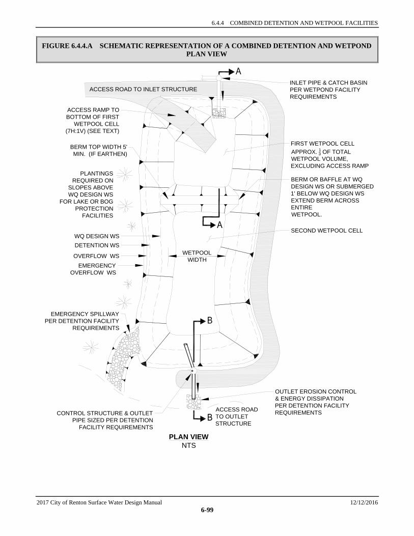
6.4.4 COMBINED DETENTION AND WETPOOL FACILITIES
2017 City of Renton Surface Water Design Manual 12/12/2016 6-99
FIGURE 6.4.4.A SCHEMATIC REPRESENTATION OF A COMBINED DETENTION AND WETPOND PLAN VIEW
ACCESS ROAD TO INLET STRUCTURE
PLAN VIEWNTS
ACCESS ROADTO OUTLETSTRUCTURE
PLANTINGSREQUIRED ON
SLOPES ABOVEWQ DESIGN WS
FOR LAKE OR BOGPROTECTION
FACILITIES
OUTLET EROSION CONTROL& ENERGY DISSIPATIONPER DETENTION FACILITYREQUIREMENTSCONTROL STRUCTURE & OUTLET
PIPE SIZED PER DETENTIONFACILITY REQUIREMENTS
SECOND WETPOOL CELL
BERM OR BAFFLE AT WQDESIGN WS OR SUBMERGED1' BELOW WQ DESIGN WSEXTEND BERM ACROSSENTIREWETPOOL.
FIRST WETPOOL CELLAPPROX. 13 OF TOTALWETPOOL VOLUME,EXCLUDING ACCESS RAMP
INLET PIPE & CATCH BASINPER WETPOND FACILITYREQUIREMENTS
EMERGENCY SPILLWAY PER DETENTION FACILITY
REQUIREMENTS
WETPOOLWIDTH
ACCESS RAMP TO BOTTOM OF FIRST
WETPOOL CELL (7H:1V) (SEE TEXT)
BERM TOP WIDTH 5'MIN. (IF EARTHEN)
WQ DESIGN WSDETENTION WS
OVERFLOW WSEMERGENCY
OVERFLOW WS

SECTION 6.4 WETPOOL FACILITY DESIGNS
12/12/2016 2017 City of Renton Surface Water Design Manual 6-100
FIGURE 6.4.4.B SCHEMATIC REPRESENTATION OF A COMBINED DETENTION AND WETPOND PROFILE VIEW
SECTION A-ANTS
SECTION B-BNTSNOTE:
SEE DETENTION FACILITY REQUIREMENTSFOR LOCATION, INTERIOR & EXTERIOR SIDESLOPES, AND SETBACK REQUIREMENTS.
31
EMERGENCY OVERFLOW WSDETENTION OVERFLOW WS
DETENTION DESIGN WS
WQ DESIGN WS
WQ DESIGN WS
WETPOOL LENGTH (INLET TO OUTLET) = 3 (MIN.) x WIDTH
EMERGENCY OVERFLOW WSDETENTION OVERFLOW WS
DETENTION DESIGN WS
DETENTION PERDETENTION FACILITYREQUIREMENTS
EMERGENT VEGETATIONREQUIRED FOR WETPOOLDEPTHS 3' OR LESS.NOTE: BERM SLOPE
MAY BE 2:1 WHEN TOPOF BERM SUBMERGED1' BELOW WQ DESIGN WS
WETPOOL DEPTH 8' MAX.RECIRCULATION RECOMMENDEDFOR DEPTH > 6'.
KEYEDBERM
FIRST CELL DEPTH4' MIN. TO 8' MAX.
TOP OF BERM OR BAFFLE LEVELAND AT WETPOOL DESIGN
ELEVATION (FLOW EXITS FIRSTCELL OVER BERM) OR AS NOTED
ACCESS ROADPER DETENTION
FACILITYREQUIREMENTS
SEDIMENT STORAGEDEPTH = 1' MIN
INLET EROSION CONTROL/SLOPE PROTECTION PER
DETENTION FACILITYREQUIREMENTS
SUBMERGED INLET (WQDESIGN WS 1' ABOVE CROWN)
SLOPE VEGETATIONPER DETENTION
FACILITYREQUIREMENTS
2' MIN.
1'MIN.
OUTLET PIPE INVERT OUT ATWETPOOL WS ELEVATION
1' MIN.
INVERT 6" MIN.BELOW TOP
OF INTERNALBERM. LOWER
PLACEMENTIS DESIRABLE
GRAVITY DRAIN(IF GRADE ALLOWS)
8" MIN. DIAMETER
VALVETYPE 2 CATCHBASIN w/SUMP
FENCE REQUIRED FORINTERIOR SIDE SLOPESSTEEPER THAN 3(H):1 (V)ACCESS
ROAD
CAPACITY OF OUTLETSYSTEM PER DETENTIONFACILITY REQUIREMENTS
EXTERIOR BERMSDESIGNED PER DAMSAFETY REQUIREMENTSIF APPLICABLE
18" MIN.
CITY OF RENTON SURFACE WATER DESIGN MANUAL
2017 City of Renton Surface Water Design Manual 12/12/2016 6-101
6.5 FILTRATION FACILITY DESIGNS This section presents the methods, criteria, and details for analysis and design of sand filters and generic information for proprietary cartridge filters. The following specific facility designs are included in this section:
• “Sand Filters — Basic and Large,” Section 6.5.2 • “Sand Filter Vaults,” Section 6.5.3 • “Linear Sand Filters,” Section 6.5.4
The information presented for each filtration facility is organized into the following categories:
1. Methods of Analysis: Contains a step-by-step procedure for designing and sizing each facility.
2. Design Criteria: Contains the details, specifications, and material requirements for each facility.
6.5.1 GENERAL REQUIREMENTS FOR FILTRATION FACILITIES Presettling Requirement Filtration facilities are particularly susceptible to clogging. Presettling must therefore be provided before stormwater enters a filtration facility to prolong the periods between required maintenance activities. The presettling treatment goal is to remove 50 percent of the total suspended solids (TSS). This requirement may be met by any of the following:
1. A water quality facility from the Basic WQ Menu (Section 6.1.1), except for Basic WQ options 7 (sand filter) and 8 (proprietary media/membrane filter), which shall not be used to meet the presettling requirement.
2. A presettling pond or vault, which may be integrated as the first cell of the filtration facility, with a treatment volume equal to 0.25 times the basic water quality treatment volume (see Section 6.2.1) calculated by the approved model or by using the NRCS curve number method (see Section 6.4.1.1). See design requirements below.
Note: For the linear sand filter, use the sediment cell sizing given in the design instead of the above sizing. 3. A detention facility sized to meet the Flow Control Duration Standard.
4. An alternative City approved pretreatment technology (see New Facility Designs in Section 6.2, Section 6.7, “Proprietary Facility Designs,” and Reference Section 14-A and 14-B).
Other Pretreatment Requirements, Limitations, and Notes 1. Sand filters not preceded by a facility that captures floatables, such as a spill control tee, must provide
additional pretreatment to remove floatable trash and debris before flows reach the sand bed. This requirement may be met by providing a catch basin with a capped riser on the inlet to the sand filter (see Figure 6.5.2.C).
2. For high-use sites, sand filters must be preceded by an oil control option from the High-Use menu, Section 6.1.5.
3. The presettling requirement (with 50% TSS treatment goal) for filtration facilities is in addition to and exclusive of the treatment requirement for the filtration facility (80% TSS treatment goal).
Design Criteria for Presettling Cells 1. If water in the presettling cell or upstream WQ facility will be in direct contact with the soil, the cell
or WQ facility must be lined per the liner requirements in Section 6.2.4.
Intent: to prevent groundwater contamination from untreated stormwater runoff in areas of excessively drained soils.

SECTION 6.5 FILTRATION FACILITY DESIGNS
12/12/2016 2017 City of Renton Surface Water Design Manual 6-102
2. The presettling cell shall conform to the following:
a) The length-to-width ratio shall be 2:1, at minimum. A 3:1 ratio is recommended. Berms or baffles may be used to lengthen the flowpath.
b) The minimum depth shall be 3 feet; the maximum depth shall be 6 feet.
c) One foot of sediment storage shall be provided.
3. Inlets and outlets shall be designed to minimize velocity and reduce turbulence. The top of the inlet pipe shall be submerged at least 1 foot. The bottom of the inlet pipe shall be at least 1 foot above sediment storage.
4. If the presettling cell is in a sensitive lake or sphagnum bog protection area, shrubs that form a dense cover shall be planted on slopes above the WQ design water surface on at least three sides (see the wetpond planting requirements in Section 6.4.1.2).
5. See Section 6.5.3.2 for details of presettling vault structures.
6.5.2 SAND FILTERS — BASIC AND LARGE A sand filter operates much like an infiltration pond (see schematic representations in Figure 6.5.2.A and Figure 6.5.2.B). However, instead of infiltrating into native soils, stormwater filters through a constructed sand bed with an underdrain system. Runoff enters the pond and spreads over the surface of the filter. As flows increase, water backs up in the pond where it is held until it can percolate through the sand. The treatment pathway is vertical (downward through the sand). High flows in excess of the WQ treatment goal simply spill out over the top of the pond. Water that percolates through the sand is collected in an underdrain system of drain rock and pipes which directs the treated runoff to the downstream drainage system.
A sand filter removes pollutants primarily by physical filtration. As stormwater passes through the sand, pollutants are trapped in the small spaces between sand grains or adhere to the sand surface. Over time, silt will build up on the surface and soil organisms (bacteria, fungi, protozoa, nematodes, etc.) will populate the slit layer and sand bed. The silt will enhance pollutant filtration while the organisms may be responsible for some biological treatment and some filtration by formation of a biofilm. Over time, either may decrease the sand filter infiltration rate sufficient to require removal and replacement of some to all of the media. A large sand filter will treat more of the annual flow than will a basic sand filter and will therefore remove more pollutant load on an annual basis. Increasing the sand thickness will not appreciably improve performance.
The following design procedures, requirements, and recommendations cover two sand filter sizes: a basic size and a large size. The basic sand filter is designed to meet the Basic WQ menu goal of 80% TSS removal. The large sand filter is expected to meet the Enhanced Basic WQ menu goal of > 30% reduction of dissolved copper and > 60% removal of dissolved zinc, and the Sensitive Lake Protection menu goal of 50% total phosphorus removal.
Applications and Limitations A sand filter may be used in most residential, commercial, and industrial developments where site topography and drainage provide adequate hydraulic head to operate the filter. An elevation difference of about 4 feet between the inlet and outlet of the filter is usually needed to install a sand filter.
Landscaping may be somewhat constrained because the vegetation capable of surviving in sand and not interfering with sand filter operation, maintenance, or longevity is limited. Trees and shrubs which generate a large leaf fall shall be avoided in the immediate vicinity of the filter because leaves and other debris can clog the surface of the filter.
Sand filters are designed to prevent water from backing up into the sand layer (the underdrain system must drain freely). Therefore, a sand filter is more difficult to install, and may not be suitable, in areas with high water tables where groundwater could potentially flood the underdrain system. Water standing in the
6.5.2 SAND FILTERS — BASIC AND LARGE
2017 City of Renton Surface Water Design Manual 12/12/2016 6-103
underdrain system will also keep the sand saturated. Under these conditions, oxygen can be depleted, releasing pollutants such as metals and phosphorus that are more mobile under anoxic conditions.
Sand filter discharge must be by gravity, and must not rely on a pump system. If the pump fails, the sand will become saturated, create anoxic conditions, and release pollutants. Pumped inflow is only allowed for privately maintained systems meeting the criteria in Section 4.2.3.
Because the surface of the sand filter will clog from sediment and other debris, this facility should not be used in areas where heavy sediment loads are expected. A sand filter should not be used during construction to control sediments unless the sand bed is replaced periodically during construction and after the project site is stabilized.
Consult the water quality menus in Section 6.1 for information on how basic and large sand filters may be used to meet Core Requirement #8.
6.5.2.1 METHODS OF ANALYSIS This section presents the methods of analysis for both basic and large sand filters.
A sand filter is designed with two parts: (1) a temporary storage reservoir to store runoff, and (2) a sand filter bed through which the stored runoff must percolate. Usually the storage reservoir is simply placed directly above the filter, and the floor of the reservoir pond is the top of the sand bed. For this case, the storage volume also determines the hydraulic head over the filter surface, which increases the rate of flow through the sand.
The modeled routing method described below uses the approved continuous runoff computer model to determine sand filter area and pond size based on individual site conditions. The method includes parameters for sizing either a basic or a large sand filter.
Background There are several variables used in sand filter design which are similar and often confused, even by well-trained individuals. Use of these variables is explained below.
The sand filter design is based on Darcy’s law:
Q = KiA (6-19)
where Q = WQ design flow (cfs) K = hydraulic conductivity (fps) A = surface area perpendicular to the direction of flow (sf) i = hydraulic gradient (ft/ft) for a constant head and constant media depth, computed as
follows:
i = (6-20)
where h = average depth of water above filter (ft), defined for this design as d/2 d = maximum storage depth above filter (ft) l = thickness of sand media (ft)
Although it is not seen directly, Darcy’s law underlies the modeled routing design method. V is the direct input in the sand filter design. The relationship between V and K is revealed by equating Darcy’s law and the equation of continuity, Q = VA.
Note: When water is flowing into the ground, V is commonly called the filtration rate. It is ordinarily measured in a percolation test.
llh +
SECTION 6.5 FILTRATION FACILITY DESIGNS
12/12/2016 2017 City of Renton Surface Water Design Manual 6-104
Specifically:
Q = KiA and Q = VA
So,
VA = KiA or V = Ki (6-21)
Note that V ≠ K—that is, the filtration rate is not the same as the hydraulic conductivity, but they do have the same units (distance per time). K can be equated to V by dividing V by the hydraulic gradient i, which is defined above in Equation 6-20.
The hydraulic conductivity K does not change with head nor is it dependent on the thickness of the media, only on the characteristics of the media and the fluid. The hydraulic conductivity of 1 inch per hour (2.315 x 10⁻⁵ fps) used in this design is based on bench-scale tests of conditioned rather than clean sand. This design hydraulic conductivity represents the average sand bed condition as silt is captured and held in the filter bed.40
Unlike the hydraulic conductivity, the filtration rate V changes with head and media thickness, although the media thickness is constant in the sand filter design.
Modeled Routing Method The modeled routing method allows the designer to optimize filter geometry and sizing to meet specific site conditions. The modeled method requires a trial and error solution using the approved model to route the developed inflow runoff time series through various sand filter configurations until the amount of runoff that passes through the filter media and is treated meets or exceeds the treatment objective defined for the facility. Refer to the approved model’s computer software reference manual for specific instructions on using the program. The general design process is described below.
Step 1: Determine whether a basic or large sand filter is required. Consult the water quality menus in Section 6.1 to determine the size of filter needed. A basic sand filter is sized so that 91% of the runoff volume will pass through the filter. A large sand filter is sized such that a minimum of 95% of the runoff volume passes through the filter. See Section 6.2.1 for discussion of the WQ design volume.
Step 2: Prepare the inflow time series. The developed inflow time series is prepared using the approved model as generally described in Chapter 3. Detailed instructions for preparing the time series can be found in the approved model’s computer software reference manual. If the sand filter is upstream of detention, the time series is that of the developed site. If the sand filter is downstream of detention, the time series is the outflow time series leaving the detention facility.
Note: Sand filters located downstream from detention facilities are significantly smaller than those treating runoff before it is detained. Likewise, sand filters receiving flows from Flow Control Duration Standard detention facilities are smaller than those below Peak Rate Flow Control facilities.
Step 3: Determine whether the sand filter will be on-line or off-line. For most WQ facilities, the designer may choose to design the facility as either on-line (all flow goes through the facility) or off-line (flows above the WQ design flow bypass the facility). An off-line sand filter has a high-flow bypass with an upstream flow splitter designed to bypass flows above the WQ design flow (see Section 6.2.5, for more information on flow splitter design).
Note that the WQ design flow rate for the flow splitter is the rate required to pass the WQ volume (basic or large). For the basic sand filter, the rate is reported directly by the approved model (i.e., not modified in
40 King County has tested various sand mixes conditioned with simulated stormwater to establish realistic design standards.
Tests were conducted under falling head conditions in columns containing 18 inches of sand underlain with a 2-inch layer of washed drain gravel containing a section of 2-inch perforated PVC pipe to simulate the underdrain system. Details are given in Koon, John, "Determination of infiltration rate and hydraulic conductivity for various sand filter media." January 1996.
6.5.2 SAND FILTERS — BASIC AND LARGE
2017 City of Renton Surface Water Design Manual 12/12/2016 6-105
the manner for bioswales in Section 6.2.1); for the large sand filter, derive the rate from the ratio of the basic and large water quality volumes. The basic sand filter uses the 91% runoff volume as the water quality design volume, corresponding to a 2-year return interval peak flow from the approved continuous model. The large sand filter design flow can be calculated by increasing the 2-year return interval peak flow by the ratio of the 95% runoff volume (water quality design volume for the large sand filter) and the 91% runoff volume (water quality design volume for the basic sand filter). In equation form,
Design Flow Rate for Large Sand Filter
=
(95% Runoff Volume)
x 2-year return interval peak flow (6-22)
(91% Runoff Volume)
Step 4: Define sand filter modeling parameters. Sand filters can be sized in WWHM using the sand filter element, or in MGS Flood using the infiltration pond element with the Sand Filter Data tab. Follow the guidance in the approved model’s reference manual and apply the additional guidance below for the parameters required for the analysis:
1. The surface area of the filter computed by the approved model using inputs of the bottom length and width of the infiltration pond (ft).
2. Maximum water depth over filter: depth at which runoff begins to overflow the sand filter
3. Permeable surfaces: bottom only.
4. Riser and orifice information:
• Riser head: same as the maximum water depth. • Number of orifices: zero. All runoff will either percolate through sand or overflow the riser. • Top of riser: flat.
5. Vertical infiltration: Assume a design filtration rate of 1 inch per hour. Though the sand specified below will initially infiltrate at a much higher rate, that rate will slow as the filter accumulates sediment. When the filtration rate falls to 1 inch per hour, removal of sediment is necessary to maintain rates above the rate assumed for sizing purposes.
Step 5: Size the sand filter. Follow the facility sizing guidance in the approved model’s reference manual to input the preliminary design configuration of the sand filter.
Step 6: Route the inflow time series through the sand filter and compare volumes. Compare the volume percentage passing through the filter with the percentage required for the treatment volume (91% or 95%). The approved model calculates the routed volume percentage for the comparison.
• If the volume percentage of water passing through the filter exceeds the design treatment volume percentage, decrease the bottom area of the facility. Repeat this step until the desired performance is achieved.
• If the volume percentage of water passing through the filter is less than the design treatment volume percentage, increase the bottom area until the desired performance is achieved.
Step 7: Size the underdrain system. The underdrain system is sized to convey the peak filtered flows to the outlet. For the basic sand filter, the central collector pipe(s) shall be sized to convey, at a minimum, the 2-year return frequency flow into the facility using the KCBW program’s backwater analysis techniques described in Chapter 4.
For large sand filter design, the design flows for the underdrain collector pipe(s) must be increased from the basic sand filter, which uses the 91% runoff volume as the water quality design volume, corresponding to a 2-year return interval peak flow from the approved continuous model. For the large sand filter, the underdrain design flow can be calculated by increasing the 2 year return interval peak flow by the ratio of

SECTION 6.5 FILTRATION FACILITY DESIGNS
12/12/2016 2017 City of Renton Surface Water Design Manual 6-106
the 95% runoff volume (water quality design volume for the large sand filter) and the 91% runoff volume (water quality design volume for the basic sand filter). In equation form:
Design Flow Rate for Large Sand Filter Underdrain
= (95% Runoff Volume)
x 2-year return interval peak flow (6-23)
(91% Runoff Volume)
To simplify the analysis, all flows for basic and large sand filters may be assumed to enter the collector pipe at the upstream end. Typically, the collector pipe will not be inlet controlled, so a simple square inlet type may be assumed. The full head of the facility may be utilized to convey flows through the pipe.
Feeder pipes may be sized using the design criteria in “Underdrain Systems” instead of analyzing the conveyance capacity as described above.
Strip drains must be analyzed for conveyance per manufacturer’s specifications.
Intent: The underdrain must be able to remove standing water from beneath the sand. If standing water remains, the sand will remain saturated. This could cause reducing conditions in the sand, allowing some pollutants to become mobile and be released from the filter to downstream receiving waters.
6.5.2.2 DESIGN CRITERIA Schematic representations of a sand filter are shown in Figure 6.5.2.A, Figure 6.5.2.B, Figure 6.5.2.C, and Figure 6.5.2.D.
Sand Filter Geometry 1. Any shape sand bed may be used, including circular or free-form designs.
Note: The treatment process is governed by vertical flow, so short-circuiting is not a concern as it is in wetponds.
2. Sand depth (l) shall be 18 inches (1.5 feet) minimum.
3. Depth of storage over the filter media (d) shall be 6 feet maximum.
Pretreatment, Flow Spreading, and Energy Dissipation 1. See general presettling and pretreatment requirements for filtration facilities in Section 6.5.1.
2. A flow spreader shall be installed at the inlet along one side of the filter to evenly distribute incoming runoff across the filter and prevent erosion of the filter surface. See Section 6.2.6 for details on flow spreaders.
a) If the sand filter is curved or an irregular shape, a flow spreader shall be provided for a minimum of 20 percent of the filter perimeter.
b) If the length-to-width ratio of the filter is 2:1 or greater, a flow spreader must be located on the longer side and for a minimum length of 20 percent of the facility perimeter.
c) In other situations, use good engineering judgment in positioning the spreader.
3. Erosion protection shall be provided along the first foot of the sand bed adjacent to the flow spreader. Geotextile meeting the specifications in WSDOT Standard Specifications, 9-33.2(1) Geotextile Properties/Table 1/Moderate Survivability/Woven, and Table 2, Class A, weighted with sand bags at 15-foot intervals may be used. Quarry spalls may also be used.
6.5.2 SAND FILTERS — BASIC AND LARGE
2017 City of Renton Surface Water Design Manual 12/12/2016 6-107
Overflow and Bypass Structures 1. On-line filters41 shall be equipped with overflows (primary, secondary, and emergency) in
accordance with the design criteria for detention ponds (see Section 5.1.1.1, criteria for “Overflow” and “Emergency Overflow Spillway”).
Note: The primary overflow may be incorporated into the emergency spillway in cases where the spillway discharges into a downstream detention facility, or where overflows can be safely controlled and redirected into the downstream conveyance system.
2. For off-line filters, the outlet structure for the basic sand filter must be designed to pass the 2-yr peak inflow rate, as determined using the approved model with 15-minute time steps calibrated to specific site conditions.
For large sand filter design, the design flows for the overflow must be increased from the basic sand filter, which uses the 91% runoff volume as the water quality design volume, corresponding to a 2-year return interval peak flow from the approved continuous model. For the large sand filter, the overflow design flow can be calculated by increasing the 2 year return interval peak flow by the ratio of the 95% runoff volume (water quality design volume for the large sand filter) and the 91% runoff volume (water quality design volume for the basic sand filter). In equation form:
Design Flow Rate for Large Sand Filter Overflow
=
(95% Runoff Volume)
x 2-year return interval peak flow (6-24)
(91% Runoff Volume)
Intent: Overflow capacity is required for low-flow, high-volume storms which may exceed the storage capacity of the filter.
3. To the extent base flow conditions can be identified, base flow must be bypassed around the filter to keep the sand from remaining saturated for extended periods of time.
Filter Composition A sand filter consists of three or four layers:
• Top layer (optional): grass seed or sod grown in sand • Second layer: sand • Third layer: geotextile fabric • Fourth layer: underdrain system.
Sand Specifications The sand in a filter shall consist of a medium sand with few fines meeting the size gradation (by weight) given in Table 6.5.2.A. The contractor must obtain a grain size analysis from the supplier to certify that the No. 100 and No. 200 sieve requirements are met.
Note: Many sand mixes supplied locally meet this specification. However, standard backfill for sand drains (as specified in the Washington Standard Specifications 9-03.13) does not meet this specification and shall not be used for sand filters.
41 Whether a WQ facility is designed as on-line (all flow going through the facility) or off-line (high flows bypassing the facility) is a
choice made by the designer. Section 6.2.5 contains information on flow splitters for WQ facilities.
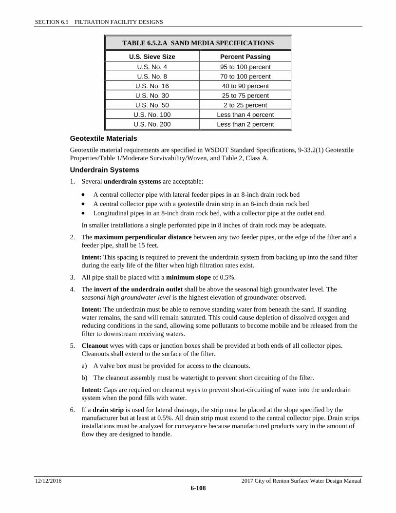
SECTION 6.5 FILTRATION FACILITY DESIGNS
12/12/2016 2017 City of Renton Surface Water Design Manual 6-108
TABLE 6.5.2.A SAND MEDIA SPECIFICATIONS
U.S. Sieve Size Percent Passing U.S. No. 4 95 to 100 percent U.S. No. 8 70 to 100 percent U.S. No. 16 40 to 90 percent U.S. No. 30 25 to 75 percent U.S. No. 50 2 to 25 percent U.S. No. 100 Less than 4 percent U.S. No. 200 Less than 2 percent
Geotextile Materials Geotextile material requirements are specified in WSDOT Standard Specifications, 9-33.2(1) Geotextile Properties/Table 1/Moderate Survivability/Woven, and Table 2, Class A.
Underdrain Systems 1. Several underdrain systems are acceptable:
• A central collector pipe with lateral feeder pipes in an 8-inch drain rock bed • A central collector pipe with a geotextile drain strip in an 8-inch drain rock bed • Longitudinal pipes in an 8-inch drain rock bed, with a collector pipe at the outlet end.
In smaller installations a single perforated pipe in 8 inches of drain rock may be adequate.
2. The maximum perpendicular distance between any two feeder pipes, or the edge of the filter and a feeder pipe, shall be 15 feet.
Intent: This spacing is required to prevent the underdrain system from backing up into the sand filter during the early life of the filter when high filtration rates exist.
3. All pipe shall be placed with a minimum slope of 0.5%.
4. The invert of the underdrain outlet shall be above the seasonal high groundwater level. The seasonal high groundwater level is the highest elevation of groundwater observed.
Intent: The underdrain must be able to remove standing water from beneath the sand. If standing water remains, the sand will remain saturated. This could cause depletion of dissolved oxygen and reducing conditions in the sand, allowing some pollutants to become mobile and be released from the filter to downstream receiving waters.
5. Cleanout wyes with caps or junction boxes shall be provided at both ends of all collector pipes. Cleanouts shall extend to the surface of the filter.
a) A valve box must be provided for access to the cleanouts.
b) The cleanout assembly must be watertight to prevent short circuiting of the filter.
Intent: Caps are required on cleanout wyes to prevent short-circuiting of water into the underdrain system when the pond fills with water.
6. If a drain strip is used for lateral drainage, the strip must be placed at the slope specified by the manufacturer but at least at 0.5%. All drain strip must extend to the central collector pipe. Drain strips installations must be analyzed for conveyance because manufactured products vary in the amount of flow they are designed to handle.

6.5.2 SAND FILTERS — BASIC AND LARGE
2017 City of Renton Surface Water Design Manual 12/12/2016 6-109
7. At least 8 inches of drain rock must be maintained over all underdrain piping or drain strip, and 6 inches must be maintained on either side to prevent damage by heavy equipment during maintenance.
Note: If drain strip is used, it may be easier to install the central collector pipe in an 8-inch trench filled with drain rock, making the cover over the drain strip and the collector pipe the same thickness. In this case the pipe shall be wrapped with geotextile to prevent clogging. Use the same geotextile specification as given in WSDOT Standard Specifications, 9-33.2(1) Geotextile Properties/Table 1/Moderate Survivability/Woven, and Table 2, Class A.
8. A geotextile fabric shall be used between the sand layer and the drain rock and be placed so that one inch of drain rock is above the fabric.
Intent: The position of the geotextile fabric provides a transition layer of mixed sand and drain rock. A distinct layer of finely textured sand above a coarser one may cause water to pool at the interface and not readily drain downward due to the greater capillary forces in the finer material.
9. Sand filters shall not be used in combination with a downstream pump system.
Intent: Sand filters are designed to prevent water from backing up into the sand layer; the underdrain system must drain freely. If the pump fails, the sand will become saturated, create anoxic conditions, and release pollutants.
Underdrain Materials 1. Underdrain pipe shall be minimum 6 inch diameter perforated PVC, SDR 35. One acceptable
specification for perforations is as follows: 2 rows of holes (1/2-inch diameter) spaced 6 inches apart longitudinally (max), with rows 120 degrees apart (laid with holes downward). Other drain pipe may be used if it adequately drains the filter.
2. Drain rock shall be 11/2- to 3/4-inch rock, washed and free from clay or organic material.
3. If a geotextile drain strip system is used, the attached geotextile fabric should not be used, or the fabric side should be positioned away from the sand blanket. Geotextile is already required between the sand and drain rock layers, and must meet the specifications in WSDOT Standard Specifications, 9-33.2(1) Geotextile Properties/Table 1/Moderate Survivability/Woven, and Table 2, Class A, to avoid clogging the filter prematurely.
Access Roads and Setbacks 1. An access road shall be provided to the inlet and outlet of a sand filter for inspection and maintenance
purposes. Requirements for access roads are the same as for detention ponds (see Section 5.1.1.1, “Design of Access Roads” and “Construction of Access Roads”).
2. The location of the facility relative to site constraints (e.g., buildings, property lines, etc.) shall be the same as for detention ponds (see Section 5.1.1) except as noted in 3, below. See Section 6.2.3 for typical setback requirements for WQ facilities.
3. For a sand filter that infiltrates to ground, setbacks shall be same as those for infiltration ponds, (see Section 5.2.2).
Grass Cover 1. No top soil shall be added to sand filter beds because fine-grained materials (e.g., silt and clay) reduce
the hydraulic capacity of the filter.
2. Growing grass will require selecting species that can tolerate the demanding environment of the sand bed. Sand filters experience long periods of saturation during the winter wet season, followed by extended dry periods during the summer. Modeling predicts that sand filters will be dry about 60 percent of the time in a typical year. Consequently, vegetation must be capable of surviving drought as well as wetness.
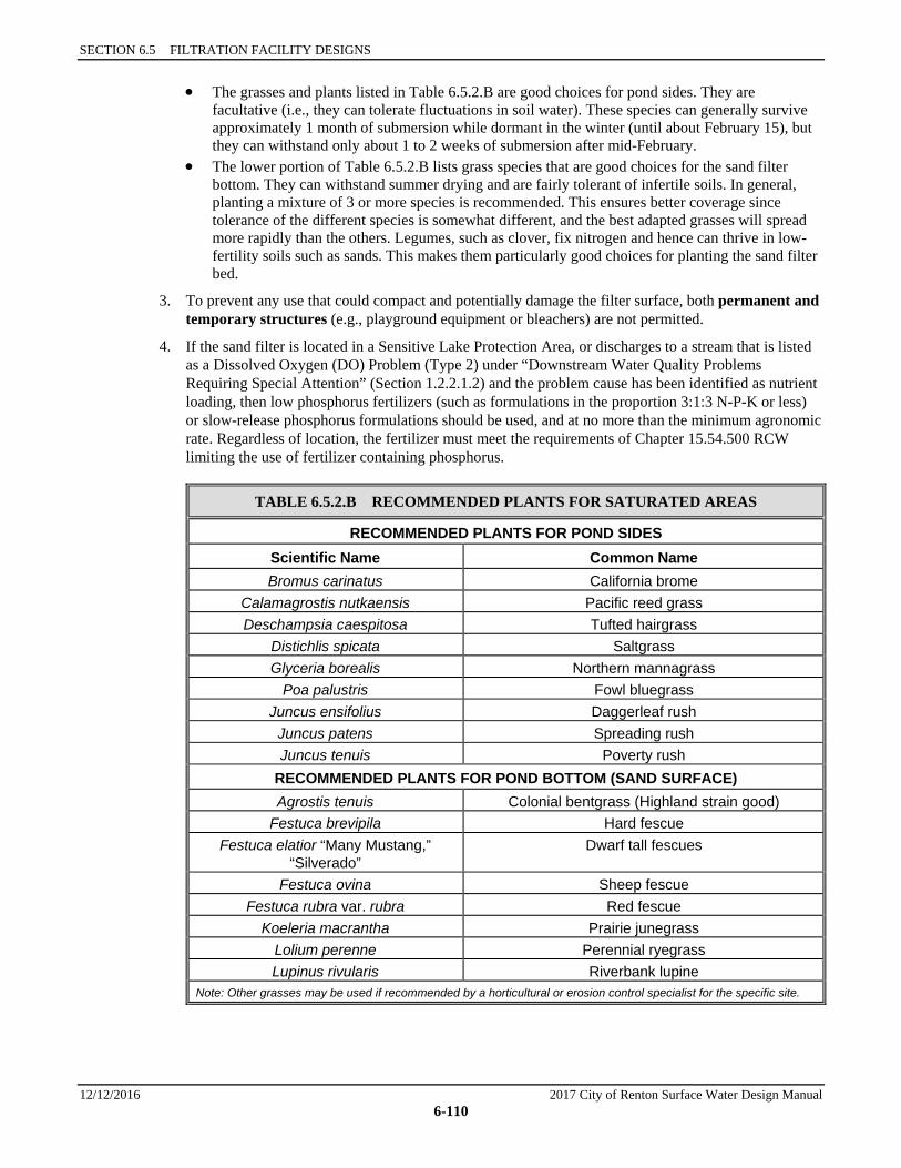
SECTION 6.5 FILTRATION FACILITY DESIGNS
12/12/2016 2017 City of Renton Surface Water Design Manual 6-110
• The grasses and plants listed in Table 6.5.2.B are good choices for pond sides. They are facultative (i.e., they can tolerate fluctuations in soil water). These species can generally survive approximately 1 month of submersion while dormant in the winter (until about February 15), but they can withstand only about 1 to 2 weeks of submersion after mid-February.
• The lower portion of Table 6.5.2.B lists grass species that are good choices for the sand filter bottom. They can withstand summer drying and are fairly tolerant of infertile soils. In general, planting a mixture of 3 or more species is recommended. This ensures better coverage since tolerance of the different species is somewhat different, and the best adapted grasses will spread more rapidly than the others. Legumes, such as clover, fix nitrogen and hence can thrive in low-fertility soils such as sands. This makes them particularly good choices for planting the sand filter bed.
3. To prevent any use that could compact and potentially damage the filter surface, both permanent and temporary structures (e.g., playground equipment or bleachers) are not permitted.
4. If the sand filter is located in a Sensitive Lake Protection Area, or discharges to a stream that is listed as a Dissolved Oxygen (DO) Problem (Type 2) under “Downstream Water Quality Problems Requiring Special Attention” (Section 1.2.2.1.2) and the problem cause has been identified as nutrient loading, then low phosphorus fertilizers (such as formulations in the proportion 3:1:3 N-P-K or less) or slow-release phosphorus formulations should be used, and at no more than the minimum agronomic rate. Regardless of location, the fertilizer must meet the requirements of Chapter 15.54.500 RCW limiting the use of fertilizer containing phosphorus.
TABLE 6.5.2.B RECOMMENDED PLANTS FOR SATURATED AREAS
RECOMMENDED PLANTS FOR POND SIDES Scientific Name Common Name Bromus carinatus California brome
Calamagrostis nutkaensis Pacific reed grass Deschampsia caespitosa Tufted hairgrass
Distichlis spicata Saltgrass Glyceria borealis Northern mannagrass
Poa palustris Fowl bluegrass Juncus ensifolius Daggerleaf rush
Juncus patens Spreading rush Juncus tenuis Poverty rush
RECOMMENDED PLANTS FOR POND BOTTOM (SAND SURFACE) Agrostis tenuis Colonial bentgrass (Highland strain good)
Festuca brevipila Hard fescue Festuca elatior “Many Mustang,”
“Silverado” Dwarf tall fescues
Festuca ovina Sheep fescue Festuca rubra var. rubra Red fescue
Koeleria macrantha Prairie junegrass Lolium perenne Perennial ryegrass Lupinus rivularis Riverbank lupine
Note: Other grasses may be used if recommended by a horticultural or erosion control specialist for the specific site.
6.5.2 SAND FILTERS — BASIC AND LARGE
2017 City of Renton Surface Water Design Manual 12/12/2016 6-111
Recommended Design Features The following design features should be incorporated into sand filter designs where site conditions allow:
1. A horticultural specialist should be consulted for advice on planting.
2. Seeding is best performed in fall (late September to October) or in spring (mid-March to June). For summer seeding or seeding during dry conditions, sprinkler systems or other measures for watering the seed must be provided. Soil temperatures should be between 50 and 65 degrees to allow for seed germination of cool season grasses.
3. Seed should be applied at 80 to 100 seeds per square foot. Pounds of seed per acre will depend on actual species composition as number of seeds vary dramatically by species per pound.
4. During seeding, Slow-release fertilizers may be applied to speed the growth of grass. If the sand filter is located in a sensitive lake watershed or discharges to a stream that is listed as a Dissolved Oxygen (DO) Problem (Type 2) under “Downstream Water Quality Problems Requiring Special Attention” (Section 1.2.2.1.2) and the problem cause has been identified as nutrient loading, then low phosphorus fertilizers (such as formulations in the proportion 3:1:3 N-P-K or less) or slow-release phosphorus formulations should be used, and at no more than the minimum agronomic rate. Regardless of location, the fertilizer must meet the requirements of Chapter 15.54.500 RCW limiting the use of fertilizer containing phosphorus.
5. A sand filter can add landscape interest and may be incorporated into the project landscape design. Interior side slopes may be stepped with flat areas for planting (Figure 6.5.2.E). Perennial beds may be planted above the overflow water surface elevation. However, large shrubs and trees are not allowed because falling leaves and needles can clog the filter surface, requiring more frequent maintenance, and roots may damage the structure and/or function of the filter.
Note: Examples of areas with stepped side slopes can be found at the Ballard Locks in Seattle and at Luther Burbank Park on Mercer Island.
6. Recreational use of the filter surface is not allowed as activity can disrupt the structure and function of the filter media. Signage discouraging recreation is required. Signage shall be placed for maximum visibility from adjacent streets, sidewalks, and paths. More than one sign may be required to be sure the advisory will be noted by anyone approaching the facility.
Construction Considerations 1. If sand filters are put into service before construction of all parcels within the catchment is complete
and all disturbed soil in the sand filter catchment has been stabilized, the filter will very likely clog prematurely. If individual lots are not stabilized, the options for protection from upstream erosion given in Section 5.2.1 for infiltration ponds may be used.
An alternative is to install the sand filter pond including full excavation for the filter sand and underdrain layers, delaying placement of the sand and underdrains until the project site is stabilized. The partially complete sand filter will then function like a small wetpond. Later, the accumulated sediment must be removed and the underdrain with gravel, geotextile separator, and sand layers placed. A second alternative is to place only the gravel underdrain during the construction phase. Then clean the gravel and place the geotextile separator and sand layer after the project site is stabilized.
The City will not assume maintenance responsibility or release financial guarantees unless the sand filter is installed per design and functioning properly. If the final sand layer cannot be completed before the typical two-year holding period for financial guarantees, the applicant may elect to pay the City to clean and install the sand when the watershed is stabilized, or may arrange a smaller financial guarantee specifically for completion of the sand filter.
2. Careful placement of the sand is necessary to avoid formation of voids within the sand that could lead to short-circuiting, particularly around penetrations for underdrain cleanouts, as well as to prevent
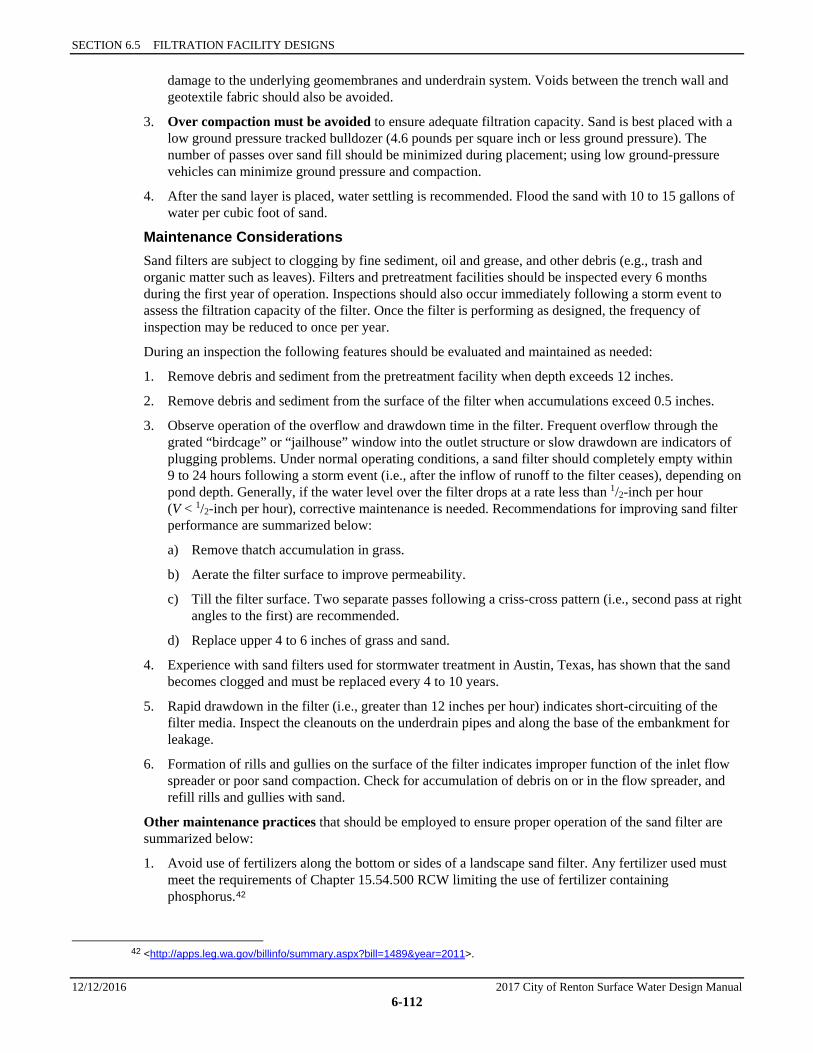
SECTION 6.5 FILTRATION FACILITY DESIGNS
12/12/2016 2017 City of Renton Surface Water Design Manual 6-112
damage to the underlying geomembranes and underdrain system. Voids between the trench wall and geotextile fabric should also be avoided.
3. Over compaction must be avoided to ensure adequate filtration capacity. Sand is best placed with a low ground pressure tracked bulldozer (4.6 pounds per square inch or less ground pressure). The number of passes over sand fill should be minimized during placement; using low ground-pressure vehicles can minimize ground pressure and compaction.
4. After the sand layer is placed, water settling is recommended. Flood the sand with 10 to 15 gallons of water per cubic foot of sand.
Maintenance Considerations Sand filters are subject to clogging by fine sediment, oil and grease, and other debris (e.g., trash and organic matter such as leaves). Filters and pretreatment facilities should be inspected every 6 months during the first year of operation. Inspections should also occur immediately following a storm event to assess the filtration capacity of the filter. Once the filter is performing as designed, the frequency of inspection may be reduced to once per year.
During an inspection the following features should be evaluated and maintained as needed:
1. Remove debris and sediment from the pretreatment facility when depth exceeds 12 inches.
2. Remove debris and sediment from the surface of the filter when accumulations exceed 0.5 inches.
3. Observe operation of the overflow and drawdown time in the filter. Frequent overflow through the grated “birdcage” or “jailhouse” window into the outlet structure or slow drawdown are indicators of plugging problems. Under normal operating conditions, a sand filter should completely empty within 9 to 24 hours following a storm event (i.e., after the inflow of runoff to the filter ceases), depending on pond depth. Generally, if the water level over the filter drops at a rate less than 1/2-inch per hour (V < 1/2-inch per hour), corrective maintenance is needed. Recommendations for improving sand filter performance are summarized below:
a) Remove thatch accumulation in grass.
b) Aerate the filter surface to improve permeability.
c) Till the filter surface. Two separate passes following a criss-cross pattern (i.e., second pass at right angles to the first) are recommended.
d) Replace upper 4 to 6 inches of grass and sand.
4. Experience with sand filters used for stormwater treatment in Austin, Texas, has shown that the sand becomes clogged and must be replaced every 4 to 10 years.
5. Rapid drawdown in the filter (i.e., greater than 12 inches per hour) indicates short-circuiting of the filter media. Inspect the cleanouts on the underdrain pipes and along the base of the embankment for leakage.
6. Formation of rills and gullies on the surface of the filter indicates improper function of the inlet flow spreader or poor sand compaction. Check for accumulation of debris on or in the flow spreader, and refill rills and gullies with sand.
Other maintenance practices that should be employed to ensure proper operation of the sand filter are summarized below:
1. Avoid use of fertilizers along the bottom or sides of a landscape sand filter. Any fertilizer used must meet the requirements of Chapter 15.54.500 RCW limiting the use of fertilizer containing phosphorus.42
42 <http://apps.leg.wa.gov/billinfo/summary.aspx?bill=1489&year=2011>.
6.5.2 SAND FILTERS — BASIC AND LARGE
2017 City of Renton Surface Water Design Manual 12/12/2016 6-113
2. Avoid driving heavy machinery or equipment on the sand filter to minimize compaction of the filter media, prevent the formation of ruts in the surface of the filter that could concentrate or channelize flow, and prevent damage to the underdrain system. Use only low ground pressure tracked equipment (4.6 pounds per square inch or less ground pressure). The number of passes over sand fill should be minimized to the greatest extent possible.
3. Mow grass as needed, and remove the cut grass from the sand filter.
4. If vegetation is present, water it periodically when needed, especially during the summer dry season.
5. Discourage use of the sand bed by pets by installing signs reminding residents of scoop laws, providing scoop stations near the facilities, planting barriers such as barberry, and/or providing other measures as appropriate.
MODIFICATIONS FOR COMBINING WITH AN INFILTRATION POND Where an infiltration pond is proposed for flow control, a sand filter (basic or large) may be combined with the infiltration pond by making the following modifications in design criteria:
1. The “100-year Overflow Conveyance” requirements for infiltration ponds (see Section 5.2.1) shall apply in place of the “Overflow and Bypass” requirements for sand filters.
2. The “Filter Composition” criteria are changed to eliminate the requirement for an underdrain system. The fourth layer of the filter becomes the native infiltrative soils.
3. The “Underdrain System” and “Underdrain Materials” criteria for sand filters are not applied. Water infiltrating through the sand layer need not be collected but may simply continue infiltrating downward into native soils.
4. The sides of the infiltration pond must be provided with a treatment liner up to the WQ design water surface elevation, at a minimum. In a groundwater protection area, the liner must extend up to the overflow water surface elevation of the pond. See Section 6.2.4 (Facility Liners) for information on liners.
SECTION 6.5 FILTRATION FACILITY DESIGNS
12/12/2016 2017 City of Renton Surface Water Design Manual 6-114
FIGURE 6.5.2.A SCHEMATIC REPRESENTATION OF A SAND FILTER WITH LEVEL SPREADER PLAN VIEW
PLAN VIEWNTS
ACCESS ROAD
3:1
0.5% 0.5%
0.5%
ACCESS ROAD
OUTLET STRUCTURE AND OVERFLOWPER SECTION 5.1.1 DETENTION PONDS
LATERAL FEEDERPIPE OR DRAIN STRIP
UNDERDRAINCOLLECTOR(PERF. PIPE)
CLEANOUT WYES W/CAPIN VALVE BOX (BOTHENDS)
15' SPACING BETWEENFEEDER PIPES (MAX)
FLOW SPREADER PERSECTION 6.2.6.1
(CONCRETE CHANNELOR OTHER) FOR20% OF BOTTOM
PERIMETER (MIN)
EMERGENCYSPILLWAY
EROSION PROTECTION
GRATING OVERFLOW SPREADER
(OPTIONAL)
INLET STRUCTURE

6.5.2 SAND FILTERS — BASIC AND LARGE
2017 City of Renton Surface Water Design Manual 12/12/2016 6-115
FIGURE 6.5.2.B SCHEMATIC REPRESENTATION OF A SAND FILTER WITH LEVEL SPREADER PROFILE VIEW
SECTION A-ANTS
8"min.
24" min.
TRENCH DETAILNTS
WQ DESIGN WS
INLET
SECTION B-BNTS
3H:1V SLOPERECOMMENDED
INVERT OF UNDERDRAIN ABOVESEASONAL HIGH GROUND WATER LEVELTRENCH OPTIONAL, BUT 8" CRUSHED
GRAVEL REQUIRED OVER DRAIN PIPE
EROSION PROTECTION
GRASS (OPTIONAL)NO TOPSOIL MAY BE ADDED
DESIGN WS
6' MAX.
FLOW SPREADER PER SECTION 6.2.6.1
SAND
1" COVER OFDRAIN ROCK OVERGEOTEXTILE
GEOTEXTILEFABRIC, SEETABLE 6.5.2.D
DRAIN ROCK, 1-12" TO 34"
GRATING(OPTIONAL)
UNDERDRAINCOLLECTOR PIPE
(6" MIN.)
18" MIN.
8" MIN.
SPILL CONTROL PROVIDED BY TEESECTION IN TYPE II CATCH BASIN
(NOT REQUIRED IF FILTER PROCEEDEDBY FACILITY WITH SPILL CONTROL)
SECTION 6.5 FILTRATION FACILITY DESIGNS
12/12/2016 2017 City of Renton Surface Water Design Manual 6-116
FIGURE 6.5.2.C SCHEMATIC REPRESENTATION OF A SAND FILTER WITH PRETREATMENT CELL PLAN VIEW
ACCESS ROAD
NOTE:SEE SECTION 6.2.6 FOROTHER TYPES OF FLOWSPREADERS
0.5% 0.5%
0.5%
PLAN VIEWNTS
Lc (INLET TO OUTLET)= 2 (MIN.) x (Wc AT
MID-DEPTH)
PRESETTLING CELL(IF NO WQ ORDETENTIONFACILITY UPSTREAM),VOLUME PERSECTION 6.5.1
Wc
AT
MID
-DEP
TH
ARMORED OUTLETDITCH INTOFLOW SPREADER
EROSION PROTECTION
INLET FLOW SPREADER(SECTION 6.2.6.1) FOR20% (MIN.) OF PERIMETEROF POND BOTTOM
UNDERDRAINCOLLECTOR(PERF. PIPE)
EMERGENCY SPILLWAY
DRAIN STRIP(SPACING PER
MANUFACTURER'SRECOMMENDATIONS)
OR FEEDER PIPES
CLEANOUT WYESW/WATERTIGHT
CAP IN VALVEBOX (BOTH ENDS)
INFLOW
5' MIN. TOP WIDTH
A
A
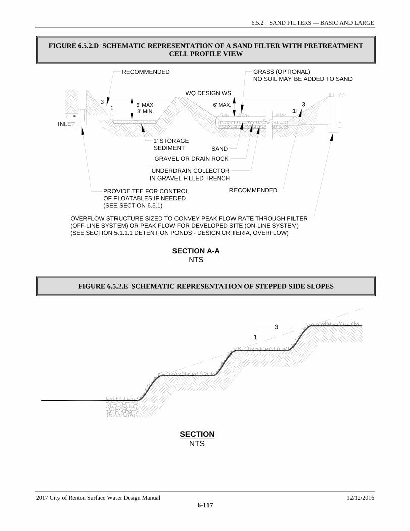
6.5.2 SAND FILTERS — BASIC AND LARGE
2017 City of Renton Surface Water Design Manual 12/12/2016 6-117
FIGURE 6.5.2.D SCHEMATIC REPRESENTATION OF A SAND FILTER WITH PRETREATMENT CELL PROFILE VIEW
FIGURE 6.5.2.E SCHEMATIC REPRESENTATION OF STEPPED SIDE SLOPES
SECTION A-ANTS
INLET
31
31
WQ DESIGN WS
OVERFLOW STRUCTURE SIZED TO CONVEY PEAK FLOW RATE THROUGH FILTER(OFF-LINE SYSTEM) OR PEAK FLOW FOR DEVELOPED SITE (ON-LINE SYSTEM)(SEE SECTION 5.1.1.1 DETENTION PONDS - DESIGN CRITERIA, OVERFLOW)
RECOMMENDED
SAND
GRAVEL OR DRAIN ROCK
UNDERDRAIN COLLECTORIN GRAVEL FILLED TRENCH
1' STORAGESEDIMENT
PROVIDE TEE FOR CONTROLOF FLOATABLES IF NEEDED(SEE SECTION 6.5.1)
GRASS (OPTIONAL)NO SOIL MAY BE ADDED TO SAND
RECOMMENDED
6' MAX.3' MIN.
6' MAX.
SECTIONNTS
31
SECTION 6.5 FILTRATION FACILITY DESIGNS
12/12/2016 2017 City of Renton Surface Water Design Manual 6-118
6.5.3 SAND FILTER VAULTS A sand filter vault is similar to an open sand filter except that the sand layer and underdrains are installed below grade in a vault. Like a sand filter, a sand filter vault may be sized as either a basic or a large facility to meet different water quality objectives. The basic sand filter vault is designed to meet the Basic WQ menu goal of 80% TSS removal for the water quality design flow. The large sand filter vault is expected to meet the Sensitive Lake Protection menu goal of 50% total phosphorus removal.
Applications and Limitations A sand filter vault may be used on sites where space limitations preclude the installation of above ground facilities. In highly urbanized areas, particularly on redevelopment and infill projects, a vault is a viable alternative to other treatment technologies that require more area to construct.
Like sand filters, sand filter vaults are not suitable for areas with high water tables where infiltration of groundwater into the vault and underdrain system will interfere with the hydraulic operation of the filter. Soil conditions in the vicinity of the vault installation should also be evaluated to identify special design or construction requirements for the vault.
It is desirable to have an elevation difference of 4 feet between the inlet and outlet of the filter for efficient operation. Therefore, site topography and drainage system hydraulics must be evaluated to determine whether use of an underground filter is feasible.
Because the surface of a sand filter vault is prone to clogging from sediment and other debris, this facility should not be used in areas where heavy sediment loads are expected.
Refer to the WQ menus, Section 6.1, for information on how sand filter vaults may be used to meet Core Requirement #8.
6.5.3.1 METHODS OF ANALYSIS The methods of analysis for basic and large sand filter vaults are identical to the methods described for basic and large sand filters. Follow the procedures described in Section 6.5.2.1.
6.5.3.2 DESIGN CRITERIA Schematic representations of sand filter vaults are shown in Figure 6.5.3.A and Figure 6.5.3.B.
Sand Filter Geometry Same as for sand filters (see Section 6.5.2.2).
Pretreatment, Flow-Spreading, and Energy Dissipation 1. See general presettling and pretreatment requirements for filtration facilities, Section 6.5.1.
2. A flow spreader shall be installed at the inlet to the filter bed to evenly distribute incoming runoff across the filter and prevent erosion of the filter surface.
3. For vaults with presettling cells, the presettling cells shall be constructed so that the divider wall extends from the floor of the vault to the WQ design water surface and is water tight
4. The flow spreader shall be positioned so that the top of the spreader is no more than 8 inches above the top of the sand bed (and at least 2 inches higher than the top of the inlet pipe if a pipe and manifold distribution system is used). See Section 6.2.6 for details on flow spreaders. For vaults with presettling cells, a concrete sump-type flow spreader (see Figure 6.2.6.B) shall be built into or affixed to the divider wall. The sump shall be a minimum of 1 foot wide and extend the width of the sand filter. The downstream lip of the sump shall be no more than 8 inches above the top of the sand bed.
6.5.3 SAND FILTER VAULTS
2017 City of Renton Surface Water Design Manual 12/12/2016 6-119
5. Flows shall enter the sand bed by spilling over the top of the wall into a flow spreader pad, or alternatively a pipe and manifold system may be designed and approved at the discretion of CED to deliver water through the wall to the flow spreader.
Note: Water in the first or presettling cell is dead storage. Any pipe and manifold system designed must retain the required dead storage volume in the first cell, minimize turbulence, and be readily maintainable.
6. If a pipe and manifold system is used, the minimum pipe size shall be 8 inches. Multiple inlets are recommended to minimize turbulence and reduce local flow velocities.
7. Erosion protection shall be provided along the first foot of the sand bed adjacent to the spreader. Geotextile weighted at the corners with sand bags, quarry spalls, or other suitable erosion control may be used.
Overflow and Bypass Structures Same as for sand filters (see Section 6.5.2.2).
Filter Composition The filter bed shall consist of three layers as follows:
• Top layer: sand • Second layer: geotextile fabric • Third layer: underdrain system.
Sand Specifications and Geotextile Materials Same as for sand filters (see Section 6.5.2.2).
Underdrain Systems and Underdrain Materials Same as for sand filters (see Section 6.5.2.2).
Vault Structure 1. Sand filter vaults are typically designed as on-line (flow-through) systems with a flat bottom under the
filter bed.
2. If a presettling cell is provided, the cell bottom may be longitudinally level or inclined toward the inlet. To facilitate sediment removal, the bottom shall also slope from each side towards the center at a minimum of 5%, forming a broad “v.”
Note: More than one “v” may be used to minimize cell depth.
Exception: The bottom of the presettling cell may be flat rather than v-shaped if removable panels are provided over the entire presettling cell. Removable panels shall be at grade, have stainless steel lifting eyes, and weigh no more than 5 tons per panel.
3. One foot (average) of sediment storage must be provided in the presettling cell.
4. Where pipes enter and leave the presettling cell below the WQ design water surface, they shall be sealed using a non-porous, non-shrinking grout.
5. If an oil retaining baffle is used for control of floatables in the presettling cell, it must conform to the following:
a) The baffle shall extend from 1 foot above to 1 foot below the WQ design water surface (minimum requirements) and be spaced a minimum of 5 feet horizontally from the inlet and 4 feet horizontally from the outlet.
b) Provision for passage of flows in the event of plugging shall be provided.
c) An access opening and ladder shall be provided on both sides of the baffle into the presettling cell.
SECTION 6.5 FILTRATION FACILITY DESIGNS
12/12/2016 2017 City of Renton Surface Water Design Manual 6-120
6. Sand filter vaults shall conform to the “Materials” and “Structural Stability” criteria specified for detention vaults in Section 5.1.3.
7. The arch culvert sections allowed for wetvaults shall not be used for sand filter vaults. Free access to the entire sand bed is needed for maintenance.
Access Requirements Same as for detention vaults (see Section 5.1.3) except for the following modifications:
1. For facilities maintained by the City, removable panels must be provided over the entire sand bed. Panels shall be at grade, have stainless steel lifting eyes, and weigh no more than 5 tons per panel. Concrete bridge decking or industrial decking are options. If within the roadway and outside the travel lane, the panels must meet traffic loading requirements.
2. A minimum of 24 square feet of ventilation grate must be provided for each 250 square feet of sandbed surface area. Grates may be located in one area if the sand filter is small, but placement at each end is preferred. Small grates may also be dispersed over the entire sand bed.
Intent: Grates are important to allow air exchange above the sand. Poor air exchange will hasten anoxic conditions which may result in release of pollutants such as phosphorus and metals and cause objectionable odors.
Access Roads, Right of Way, and Setbacks Same as for detention vaults (see Section 5.1.3).
Recommended Design Features The following design features should be incorporated into sand filter vaults where feasible but are not specifically required:
1. The floor of the presettling cell should be sloped toward the inlet to allow for sediment accumulation and ease of cleaning.
2. A geotextile fabric is recommended over the sand bed to make sand bed maintenance easier. If used, the geotextile should be a flexible, high-permeability, three-dimensional matrix of the kind commonly used for erosion control. Sand bags should be used at 10 to 15 foot intervals to hold the geotextile in place.
3. Additional grates are recommended instead of solid panels to increase air contact with the sand bed.
Construction Considerations Same as for sand filters (see Section 6.5.2.2) plus, upon completion of installation, the vault shall be thoroughly cleaned and flushed prior to placement of sand and drain rock.
Maintenance Considerations Maintenance considerations for sand filter vaults are similar to those described for sand. Maintenance practices need to be modified somewhat due to the sand filter being in a vault, including the use of safe confined space entry procedures.
MODIFICATIONS FOR COMBINING WITH AN INFILTRATION VAULT Where an infiltration vault is proposed for flow control, a sand filter vault (basic or large) may be combined with the infiltration facility by making the following modifications in design criteria:
1. The “100-year Overflow Conveyance” requirements for infiltration ponds (see Section 5.2.1) shall apply in place of the “Overflow and Bypass” requirements for sand filter vaults.
2. The “Filter Composition” criteria are changed to eliminate the requirement for an underdrain system. The third layer of the filter becomes the native infiltrative soils.
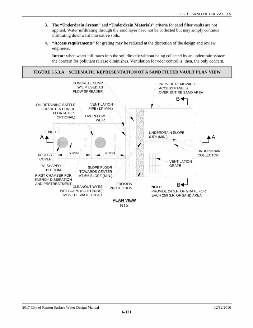
6.5.3 SAND FILTER VAULTS
2017 City of Renton Surface Water Design Manual 12/12/2016 6-121
3. The “Underdrain System” and “Underdrain Materials” criteria for sand filter vaults are not applied. Water infiltrating through the sand layer need not be collected but may simply continue infiltrating downward into native soils.
4. “Access requirements” for grating may be reduced at the discretion of the design and review engineers.
Intent: when water infiltrates into the soil directly without being collected by an underdrain system, the concern for pollutant release diminishes. Ventilation for odor control is, then, the only concern.
FIGURE 6.5.3.A SCHEMATIC REPRESENTATION OF A SAND FILTER VAULT PLAN VIEW
PLAN VIEWNTS
INLET
B
B
AAUNDERDRAIN SLOPE0.5% (MIN.)
UNDERDRAINCOLLECTOR
NOTE:PROVIDE 24 S.F. OF GRATE FOREACH 250 S.F. OF SAND AREA
VENTILATIONGRATESLOPE FLOOR
TOWARDS CENTERAT 5% SLOPE (MIN.)FIRST CHAMBER FOR
ENERGY DISSIPATION AND PRETREATMENT
PROVIDE REMOVABLEACCESS PANELSOVER ENTIRE SAND AREA
CONCRETE SUMPW/LIP USED AS
FLOW SPREADER
OVERFLOWWEIR
OIL RETAINING BAFFLEFOR RETENTION OF
FLOATABLES(OPTIONAL)
VENTILATIONPIPE (12" MIN.)
ACCESSCOVER
"V" SHAPEDBOTTOM
5' MIN. 4' MIN.
EROSIONPROTECTIONCLEANOUT WYES
WITH CAPS (BOTH ENDS)MUST BE WATERTIGHT
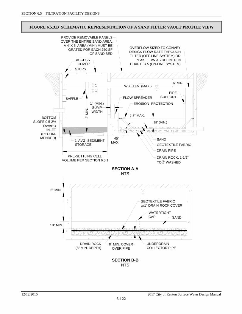
SECTION 6.5 FILTRATION FACILITY DESIGNS
12/12/2016 2017 City of Renton Surface Water Design Manual 6-122
FIGURE 6.5.3.B SCHEMATIC REPRESENTATION OF A SAND FILTER VAULT PROFILE VIEW
SECTION A-ANTS
WS ELEV. (MAX.)6" MIN.
8" MAX.
OVERFLOW SIZED TO CONVEYDESIGN FLOW RATE THROUGHFILTER (OFF-LINE SYSTEM) OR
PEAK FLOW AS DEFINED INCHAPTER 5 (ON-LINE SYSTEM)
PROVIDE REMOVABLE PANELSOVER THE ENTIRE SAND AREA.
A 4' X 6' AREA (MIN.) MUST BEGRATED FOR EACH 250 SF
OF SAND BED
STEPS
2' M
IN.
BOTTOMSLOPE 0.5-2%
TOWARDINLET
(RECOM-MENDED)
1' AVG. SEDIMENTSTORAGE
PRE-SETTLING CELLVOLUME PER SECTION 6.5.1
SANDGEOTEXTILE FABRIC
DRAIN PIPE
DRAIN ROCK, 1-1/2"TO 34" WASHED
45°MAX.
FLOW SPREADER
EROSION PROTECTION1' (MIN.)SUMPWIDTH
PIPESUPPORT
18" (MIN.)
GEOTEXTILE FABRICw/1" DRAIN ROCK COVER
WATERTIGHTCAP SAND
UNDERDRAINCOLLECTOR PIPE
6" MIN.
18" MIN.
DRAIN ROCK(8" MIN. DEPTH)
8" MIN. COVEROVER PIPE
BAFFLE
ACCESSCOVER
1'1'
SECTION B-BNTS
6.5.4 LINEAR SAND FILTERS
2017 City of Renton Surface Water Design Manual 12/12/2016 6-123
6.5.4 LINEAR SAND FILTERS Linear sand filters are typically long, shallow, rectangular vaults. The vaults consist of two cells or chambers, one for settling coarse sediment from the runoff and the other containing sand. Stormwater flows into the second cell via a weir section that also functions as a flow spreader to distribute the flow over the sand. The outlet consists of an underdrain pipe system that connects to the storm drain system. As with other sand filters, linear filters come in two sizes, basic and large. The basic linear sand filter is designed to meet the Basic WQ menu goal of 80% TSS removal for the water quality design flow. The large linear sand filter is expected to meet the Sensitive Lake Protection menu goal of 50% total phosphorus removal.
Applications and Limitations The linear sand filter is used for stormwater flows for two different treatment purposes:
1. To provide basic or second-tier water quality treatment, and
2. To treat runoff from high-use sites (i.e., sites generating higher than typical concentrations of oil and grease).
The presettling cell in a linear sand filter does not meet standard presettling cell requirements, so it is not expected to achieve the presettling goal of 50% TSS removal. Sediment storage capacity will also be more limited. These factors will necessitate more frequent maintenance than for a standard sand filter, and are likely to result in poorer net pollutant removal overall. Therefore, linear sand filters are discouraged where a different facility can be used. Linear sand filters are best suited for treating small drainages (less than two acres), particularly long, narrow areas. A linear sand filter may be located along the perimeter of a paved impervious surface or may be installed downstream of a filter strip where additional treatment is needed. If used for oil control, the filter should be located upstream from the main water quality treatment facility (i.e., wetpond, bioswale, or combined detention and wetpond).
Consult the water quality menus in Section 6.1 for information on how linear sand filters may be used to meet Core Requirement #8 or Special Requirement #5.
6.5.4.1 METHODS OF ANALYSIS Size the sand filter bed. A linear sand filter is sized based on the infiltration rate of the sand and the amount of runoff draining to the facility. The filter is sized to infiltrate the sand filter design flow without significant ponding above the sand. The sand filter bed for linear sand filters, basic and large, is sized using the modeled routing procedure of Section 6.5.2.1.
Size the sediment cell. The sediment cell width should be set after the sand filter width is determined. Use Table 6.5.4.A below to set the width of the sediment cell. If another WQ facility precedes the sand filter, the sediment cell may be waived.
TABLE 6.5.4.A SEDIMENT CELL WIDTH, LINEAR SAND FILTER
If Sand Filter Width Is: Width of Sediment Cell Shall Be: 1 to 2 feet 12 inches 2 to 4 feet 18 inches 4 to 6 feet 24 inches Over 6 feet One-third of sand cell width
SECTION 6.5 FILTRATION FACILITY DESIGNS
12/12/2016 2017 City of Renton Surface Water Design Manual 6-124
6.5.4.2 DESIGN CRITERIA A schematic representation is shown in Figure 6.5.4.A.
Geometry, Sizing, and Overflow 1. A linear sand filter shall consist of two cells or chambers, a sediment cell and a sand bed cell, divided
by a low divider wall. If the sand filter is preceded by another WQ facility, and the flow enters the sand filter along the side as sheet flow, the sediment cell may be waived.
2. Stormwater may enter the sediment cell by sheet flow or via a piped inlet.
3. Minimum inside width of the sand filter cell shall be 1 foot. Maximum width shall be 15 feet.
4. The two cells must be separated by a divider wall that is level and extends a minimum of 6 inches and a maximum of 12 inches above the sand bed. The riser overflow elevation must be adjusted for the wall height.
5. The sand filter bed shall be 18 inches deep, reducible to no less than 12 inches deep if grade limitations show a greater depth is not feasible. An 8-inch layer of drain rock with perforated drainpipe shall be installed beneath the sand layer.
6. The drainpipe shall have a minimum diameter of 6 inches and be wrapped in geotextile and sloped 0.5 % (min) to drain.
7. For design, the maximum depth of ponding over the sand shall be 1 foot.
8. If separated from traffic areas, a linear sand filter may be covered or open, but if covered, the cover must be removable for the entire length of the filter. Covers must be grated if flow to the filter is from sheet flow.
9. A linear sand filter shall have an emergency overflow route, either surface overland, tightline, or other structure for safely controlling the overflow, and shall meet the conveyance requirements specified in Chapter 1.
Structure Specifications 1. A linear sand filter vault shall be concrete (precast/prefabricated or cast-in-place). The concrete must
conform to the “Material” requirements for detention vaults in Section 5.1.3.
2. Where linear sand filters are located in traffic areas, they must meet the “Structural Stability” requirements specified for detention vaults in Section 5.1.3. The sediment cell shall have a removable grated cover that meets HS-25 traffic loading requirements. The cover over the sand filter cell may be either solid or grated.
3. A minimum of 24 square feet of ventilation grate must be provided for each 250 square feet of sandbed surface area. Grates located over the sediment chamber are preferred. Grates may be in one central location or dispersed over the entire sand bed. Vertical grates may also be used such as at a curb inlet. If a sediment chamber is not required, ventilation shall be provided over the sandbed.
Intent: Grates are important to allow air exchange above the sand. Poor air exchange will hasten anoxic conditions which may result in release of pollutants such as phosphorus and metals and cause objectionable odors.
Sand Specifications Same as for sand filters (see Table 6.5.2.A).
Geotextile Materials Same as for sand filters (see WSDOT Standard Specifications (2014), 9-33.2(1) Geotextile Properties/Table 1/Moderate Survivability/Woven, and Table 2, Class A).

6.5.4 LINEAR SAND FILTERS
2017 City of Renton Surface Water Design Manual 12/12/2016 6-125
Underdrain Materials Same as for sand filters (see Section 6.5.2.2).
Access Roads, Right of Way, and Setbacks Same as for detention vaults (see Section 5.1.3).
Construction Considerations If put into service before the project site is stabilized, placement of the sand layer should be delayed, and the linear sand filter may be used with the gravel layer only. The gravel layer must be replaced and the vault cleaned when the project site is stabilized and the sand bed installed. The City will not assume maintenance responsibility or release financial guarantees until the final installation is complete.
Maintenance Considerations Maintenance considerations for linear sand filters are similar to those for basic sand filters (see Section 6.5.2.2) except sediment should be removed from the sediment cell when the sediment depth exceeds 6 inches.
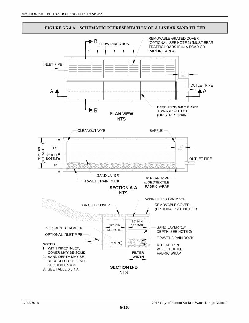
SECTION 6.5 FILTRATION FACILITY DESIGNS
12/12/2016 2017 City of Renton Surface Water Design Manual 6-126
FIGURE 6.5.4.A SCHEMATIC REPRESENTATION OF A LINEAR SAND FILTER
PLAN VIEWNTS
SECTION A-ANTS
SECTION B-BNTS
NOTES1. WITH PIPED INLET,
COVER MAY BE SOLID2. SAND DEPTH MAY BE
REDUCED TO 12", SEESECTION 6.5.4.2
3. SEE TABLE 6.5.4.A
INLET PIPE
FLOW DIRECTIONB REMOVABLE GRATED COVER(OPTIONAL, SEE NOTE 1) (MUST BEARTRAFFIC LOADS IF IN A ROAD ORPARKING AREA)
PERF. PIPE, 0.5% SLOPETOWARD OUTLET(OR STRIP DRAIN)
OUTLET PIPE
CLEANOUT WYE
GRAVEL DRAIN ROCKSAND LAYER
BAFFLE
6" PERF. PIPEw/GEOTEXTILEFABRIC WRAP
OUTLET PIPE3'-6
" MIN
.(S
EE
NO
TE 2
)
18" (SEENOTE 2)
12"
8"
SAND FILTER CHAMBER
REMOVABLE COVER(OPTIONAL, SEE NOTE 1)
GRATED COVER
SAND LAYER (18"DEPTH, SEE NOTE 2)
GRAVEL DRAIN ROCK
6" PERF. PIPEw/GEOTEXTILEFABRIC WRAPFILTER
WIDTH
SEDIMENT CHAMBER
OPTIONAL INLET PIPE
12" MIN.12" MIN.15" MAX.
8" MIN.
SEE NOTE 3
CITY OF RENTON SURFACE WATER DESIGN MANUAL
2017 City of Renton Surface Water Design Manual 12/12/2016 6-127
6.6 OIL CONTROL FACILITY DESIGNS This section presents the methods, criteria, and details for oil control facilities that are not discussed in other sections. Included are the following facility designs:
• “Oil/Water Separators,” Section 6.6.2.
Other oil control facilities include wetvaults, with minor modifications (see Section 6.4.2), and linear sand filters (see Section 6.5.4). Non-facility options include parking lot washing with proper disposal of wash water and compliance with a NPDES permit that already addresses oil control. More information on non-structural options can be found in the High-Use menu, Section 6.1.5.
The information presented for each facility is organized into the following two categories:
1. Methods of Analysis: Contains a step-by-step procedure for designing and sizing each facility.
2. Design Criteria: Contains the details, specifications, and material requirements for each facility.
6.6.1 CATCH BASIN INSERTS A catch basin insert is a device installed underneath a catch basin inlet that treats stormwater through filtration, settling, absorption, adsorption, or a combination of these mechanisms. This BMP is not allowed in the City for oil control for compliance with Special Requirement #5.43,44
6.6.2 OIL/WATER SEPARATORS Oil/water separators rely on passive mechanisms that take advantage of oil being lighter than water. Oil rises to the surface and can be periodically removed. The two types of oil/water separators typically used for stormwater treatment are the baffle type or API (American Petroleum Institute) oil/water separator and the coalescing plate oil/water separator.
Baffle oil/water separators use vaults that have multiple cells separated by baffles extending down from the top of the vault (see Figure 6.6.2.D for schematic representation). The baffles block oil flow out of the vault. Baffles are also commonly installed at the bottom of the vault to trap solids and sludge that accumulate over time. In many situations, simple floating or more sophisticated mechanical oil skimmers are installed to remove the oil once it has separated from the water.
Coalescing plate separators are typically manufactured units consisting of a baffled vault containing several inclined corrugated plates stacked and bundled together (see Figure 6.6.2.E for schematic representation). The plates are equally spaced (typical plate spacing ranges from 1/4-inch to 1 inch) and are made of a variety of materials, the most common being fiberglass and polypropylene. Efficient separation results because the plates reduce the vertical distance oil droplets must rise in order to separate from the stormwater. Once they reach a plate, oil droplets form a film on the plate surface. The film builds up over time until it becomes thick enough to migrate upward because of oil’s lower density relative to water. When the film reaches the edge of the plate, oil is released as large droplets which rise rapidly to the surface, where the oil accumulates until the unit is maintained. Because the plate pack increases treatment effectiveness significantly, coalescing plate separators can achieve a specified treatment level with a smaller vault size than a simple baffle separator.
Oil/water separators are meant to treat stormwater runoff from more intensive land uses, such as high-use sites, and facilities that produce relatively high concentrations of oil and grease. Although baffle separators historically have been used to remove larger oil droplets (150 microns or larger), they may also be sized to
43 Footnote 43 is not used. 44 Footnote 44 is not used.
SECTION 6.6 OIL CONTROL FACILITY DESIGNS
12/12/2016 2017 City of Renton Surface Water Design Manual 6-128
remove smaller oil droplets. Both separators may be used to meet a performance goal of 10 to 15 mg/L by designing the unit to removal oil particles 60 microns and larger.
Applications and Limitations Oil/water separators are designed to remove free oil and are not generally effective in separating oil that has become either chemically or mechanically emulsified and dissolved in water. Therefore, it is desirable for separators be installed upstream of facilities and conveyance structures that introduce turbulence and consequently promote emulsification. Emulsification of oil can also result if surfactants or detergents are used to wash parking areas that drain to the separator. Detergents shall not be used to clean parking areas unless the wash water is collected and disposed of properly (usually to the sanitary sewer).
There is concern that oil/water separators used for stormwater treatment have not performed to expectations.45 Therefore, emphasis should be given to proper application, design, operations and maintenance – particularly sludge and oil removal, and prevention of coalescing-plate fouling and plugging.46
Oil/water separators are best located in areas where the tributary drainage area is nearly all impervious, and a fairly high load of petroleum hydrocarbons is likely to be generated. Oil/water separators are not recommended for areas with very dilute concentrations of petroleum hydrocarbons since their performance is not effective at low concentrations. Excluding unpaved areas helps to minimize the amount of sediment entering the vault, reducing the need for maintenance. A unit that fails and ceases to function can release previously trapped oil to the downstream receiving water, both in release from the oily sediments and from entrainment of surface oils.
Wetvaults may also be modified to function as baffle oil/water separators (see design criteria for wetvaults, Section 6.4.2.2).
Consult the water quality menus in Section 6.1 for information on how baffle and coalescing plate oil/water separators may be used to meet Special Requirement # 5.
6.6.2.1 METHODS OF ANALYSIS Background Generally speaking, in most oil and water mixtures the degree of oil/water separation that occurs is dependent on both the time the water is detained in the separator and the oil droplet size. The sizing methods in this section are based on Stokes’ law:
VT = (6-25)
where VT = rise velocity of oil droplet g = gravitational constant dp = density of oil droplet to be removed dc = density of carrier fluid Do = diameter of oil droplet µ = absolute viscosity of carrier fluid
45 WA Ecology 2014, SWMMWW, citing: Schueler, Thomas R., “Water Quality inlets/Oil Grit Separators,” BMP Fact Sheet #11,
Current Assessment of Urban Best Management Practices, March 1992.; Watershed Protection Techniques, “Hydrocarbon Hotspots in the Urban Landscape: Can They be Controlled?,” February 1994.
46 WA Ecology 2014, SWMMWW, citing: U.S. Army Corps of Engineers, “Selection and Design of Oil and Water Separators,” August 26, 1994.
( )µ18
2ocp Dddg −
6.6.2 OIL/WATER SEPARATORS
2017 City of Renton Surface Water Design Manual 12/12/2016 6-129
The basic assumptions inherent in Stokes’ law are: (1) flow is laminar, and (2) the oil droplets are spherical.
Traditional baffle separators are designed to provide sufficient hydraulic residence time to permit oil droplets to rise to the surface. The residence time Tr is mathematically expressed as follows:
Tr = (6-26)
where V = effective volume of the unit or container, or As x H, where As = surface area of the separator unit, and
H = height of water column in the unit Q = hydraulic capacity or flow through the separator
The time required for the oil droplet to rise to the surface within the unit is found by the relation:
TT = (6-27)
where VT = rise velocity of the oil droplet
The oil droplet rises to the water surface if the residence time in the separator is at least equal to the oil droplet rise time. This can be expressed as follows:
Tr = TT
By substituting terms and simplifying:
VT = (6-28)
where As = surface area of the separator unit
The ratio in Equation 6-28 is designated as the surface overflow rate or loading rate. It is this rate that governs the removal efficiency of the process and predicts whether an oil droplet will be removed by the separator.
Method for Baffle Separators Design steps for the baffle separator are summarized below:
Step 1: Determine the WQ design flow (Q). The facility is sized based on the WQ design flow (see Section 6.2.1). The separator must be designed as an off-line facility. That is, flows higher than the WQ design flow (i.e., the modified off-line flow rate) must bypass the separator.
Step 2: Calculate the minimum vertical cross-sectional area. Use the following equation:
Ac = (6-29)
where Ac = minimum cross-sectional area (sf) Q = modified off-line water quality design flow per Section 6.2.1 (cfs) VH = design horizontal velocity (fps)
QV
TVH
sAQ
HVQ
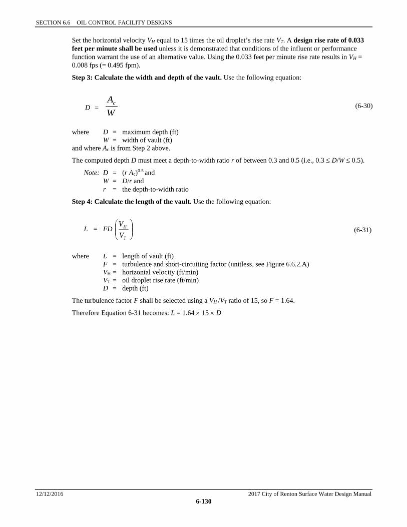
SECTION 6.6 OIL CONTROL FACILITY DESIGNS
12/12/2016 2017 City of Renton Surface Water Design Manual 6-130
Set the horizontal velocity VH equal to 15 times the oil droplet’s rise rate VT. A design rise rate of 0.033 feet per minute shall be used unless it is demonstrated that conditions of the influent or performance function warrant the use of an alternative value. Using the 0.033 feet per minute rise rate results in VH = 0.008 fps (= 0.495 fpm).
Step 3: Calculate the width and depth of the vault. Use the following equation:
D = (6-30)
where D = maximum depth (ft) W = width of vault (ft) and where Ac is from Step 2 above.
The computed depth D must meet a depth-to-width ratio r of between 0.3 and 0.5 (i.e., 0.3 ≤ D/W ≤ 0.5).
Note: D = (r Ac)0.5 and W = D/r and r = the depth-to-width ratio
Step 4: Calculate the length of the vault. Use the following equation:
L = FD (6-31)
where L = length of vault (ft) F = turbulence and short-circuiting factor (unitless, see Figure 6.6.2.A) VH = horizontal velocity (ft/min) VT = oil droplet rise rate (ft/min) D = depth (ft)
The turbulence factor F shall be selected using a VH /VT ratio of 15, so F = 1.64.
Therefore Equation 6-31 becomes: L = 1.64 × 15 × D
WAc
T
H
VV
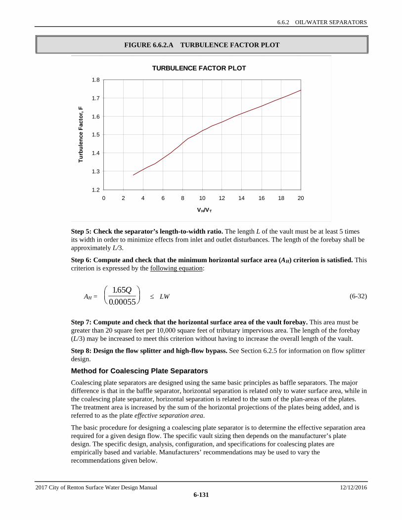
6.6.2 OIL/WATER SEPARATORS
2017 City of Renton Surface Water Design Manual 12/12/2016 6-131
FIGURE 6.6.2.A TURBULENCE FACTOR PLOT
Step 5: Check the separator’s length-to-width ratio. The length L of the vault must be at least 5 times its width in order to minimize effects from inlet and outlet disturbances. The length of the forebay shall be approximately L/3.
Step 6: Compute and check that the minimum horizontal surface area (AH) criterion is satisfied. This criterion is expressed by the following equation:
AH = ≤ LW (6-32)
Step 7: Compute and check that the horizontal surface area of the vault forebay. This area must be greater than 20 square feet per 10,000 square feet of tributary impervious area. The length of the forebay (L/3) may be increased to meet this criterion without having to increase the overall length of the vault.
Step 8: Design the flow splitter and high-flow bypass. See Section 6.2.5 for information on flow splitter design.
Method for Coalescing Plate Separators Coalescing plate separators are designed using the same basic principles as baffle separators. The major difference is that in the baffle separator, horizontal separation is related only to water surface area, while in the coalescing plate separator, horizontal separation is related to the sum of the plan-areas of the plates. The treatment area is increased by the sum of the horizontal projections of the plates being added, and is referred to as the plate effective separation area.
The basic procedure for designing a coalescing plate separator is to determine the effective separation area required for a given design flow. The specific vault sizing then depends on the manufacturer’s plate design. The specific design, analysis, configuration, and specifications for coalescing plates are empirically based and variable. Manufacturers’ recommendations may be used to vary the recommendations given below.
1650 00055
..
Q
TURBULENCE FACTOR PLOT
1.2
1.3
1.4
1.5
1.6
1.7
1.8
0 2 4 6 8 10 12 14 16 18 20
VH/VT
Turb
ulen
ce F
acto
r, F
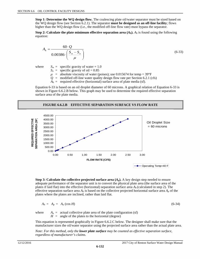
SECTION 6.6 OIL CONTROL FACILITY DESIGNS
12/12/2016 2017 City of Renton Surface Water Design Manual 6-132
Step 1: Determine the WQ design flow. The coalescing plate oil/water separator must be sized based on the WQ design flow (see Section 6.2.1). The separator must be designed as an off-line facility; flows higher than the WQ design flow (i.e., the modified off-line flow rate) must bypass the separator. Step 2: Calculate the plate minimum effective separation area (Ah). Ah is found using the following equation:
−⋅
⋅=
µow
h SSQA
00386.0
60 (6-33)
where Sw = specific gravity of water = 1.0 So = specific gravity of oil = 0.85 µ = absolute viscosity of water (poises); use 0.015674 for temp = 39°F Q = modified off-line water quality design flow rate per Section 6.2.1 (cfs) Ah = required effective (horizontal) surface area of plate media (sf). Equation 6-33 is based on an oil droplet diameter of 60 microns. A graphical relation of Equation 6-33 is shown in Figure 6.6.2.B below. This graph may be used to determine the required effective separation surface area of the plate media.
FIGURE 6.6.2.B EFFECTIVE SEPARATION SURFACE VS FLOW RATE
Step 3: Calculate the collective projected surface area (Ap). A key design step needed to ensure adequate performance of the separator unit is to convert the physical plate area (the surface area of the plates if laid flat) into the effective (horizontal) separation surface area Ah (calculated in step 2). The effective separation surface area Ah is based on the collective projected horizontal surface area Ap of the plates where the plates are inclined, rather than laid flat.
Ah = Ap = Aa (cos H) (6-34)
where Aa = actual collective plate area of the plate configuration (sf) H = angle of the plates to the horizontal (degree) This equation is represented graphically in Figure 6.6.2.C below. The designer shall make sure that the manufacturer sizes the oil/water separator using the projected surface area rather than the actual plate area. Note: For this method, only the lower plate surface may be counted as effective separation surface, regardless of manufacturer’s claims.
0.00500.00
1000.001500.002000.002500.003000.003500.004000.004500.00
0.00 0.50 1.00 1.50 2.00 2.50 3.00
FLOW RATE (CFS)
REQ
UIRE
D EF
FECT
IVE
SEPA
RATI
ON
AREA
(SF)
Operating Temp=40 F
Oil Droplet Size = 60 microns
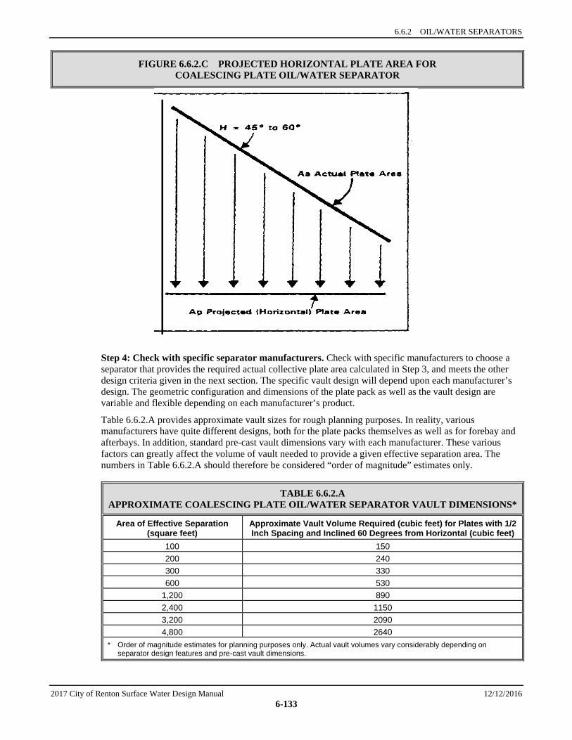
6.6.2 OIL/WATER SEPARATORS
2017 City of Renton Surface Water Design Manual 12/12/2016 6-133
FIGURE 6.6.2.C PROJECTED HORIZONTAL PLATE AREA FOR COALESCING PLATE OIL/WATER SEPARATOR
Step 4: Check with specific separator manufacturers. Check with specific manufacturers to choose a separator that provides the required actual collective plate area calculated in Step 3, and meets the other design criteria given in the next section. The specific vault design will depend upon each manufacturer’s design. The geometric configuration and dimensions of the plate pack as well as the vault design are variable and flexible depending on each manufacturer’s product.
Table 6.6.2.A provides approximate vault sizes for rough planning purposes. In reality, various manufacturers have quite different designs, both for the plate packs themselves as well as for forebay and afterbays. In addition, standard pre-cast vault dimensions vary with each manufacturer. These various factors can greatly affect the volume of vault needed to provide a given effective separation area. The numbers in Table 6.6.2.A should therefore be considered “order of magnitude” estimates only.
TABLE 6.6.2.A APPROXIMATE COALESCING PLATE OIL/WATER SEPARATOR VAULT DIMENSIONS*
Area of Effective Separation (square feet)
Approximate Vault Volume Required (cubic feet) for Plates with 1/2 Inch Spacing and Inclined 60 Degrees from Horizontal (cubic feet)
100 150 200 240 300 330 600 530
1,200 890 2,400 1150 3,200 2090 4,800 2640
* Order of magnitude estimates for planning purposes only. Actual vault volumes vary considerably depending on separator design features and pre-cast vault dimensions.
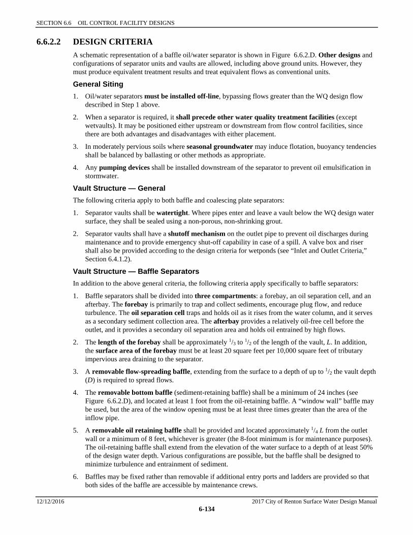
SECTION 6.6 OIL CONTROL FACILITY DESIGNS
12/12/2016 2017 City of Renton Surface Water Design Manual 6-134
6.6.2.2 DESIGN CRITERIA A schematic representation of a baffle oil/water separator is shown in Figure 6.6.2.D. Other designs and configurations of separator units and vaults are allowed, including above ground units. However, they must produce equivalent treatment results and treat equivalent flows as conventional units.
General Siting 1. Oil/water separators must be installed off-line, bypassing flows greater than the WQ design flow
described in Step 1 above.
2. When a separator is required, it shall precede other water quality treatment facilities (except wetvaults). It may be positioned either upstream or downstream from flow control facilities, since there are both advantages and disadvantages with either placement.
3. In moderately pervious soils where seasonal groundwater may induce flotation, buoyancy tendencies shall be balanced by ballasting or other methods as appropriate.
4. Any pumping devices shall be installed downstream of the separator to prevent oil emulsification in stormwater.
Vault Structure — General The following criteria apply to both baffle and coalescing plate separators:
1. Separator vaults shall be watertight. Where pipes enter and leave a vault below the WQ design water surface, they shall be sealed using a non-porous, non-shrinking grout.
2. Separator vaults shall have a shutoff mechanism on the outlet pipe to prevent oil discharges during maintenance and to provide emergency shut-off capability in case of a spill. A valve box and riser shall also be provided according to the design criteria for wetponds (see “Inlet and Outlet Criteria,” Section 6.4.1.2).
Vault Structure — Baffle Separators In addition to the above general criteria, the following criteria apply specifically to baffle separators:
1. Baffle separators shall be divided into three compartments: a forebay, an oil separation cell, and an afterbay. The forebay is primarily to trap and collect sediments, encourage plug flow, and reduce turbulence. The oil separation cell traps and holds oil as it rises from the water column, and it serves as a secondary sediment collection area. The afterbay provides a relatively oil-free cell before the outlet, and it provides a secondary oil separation area and holds oil entrained by high flows.
2. The length of the forebay shall be approximately 1/3 to 1/2 of the length of the vault, L. In addition, the surface area of the forebay must be at least 20 square feet per 10,000 square feet of tributary impervious area draining to the separator.
3. A removable flow-spreading baffle, extending from the surface to a depth of up to 1/2 the vault depth (D) is required to spread flows.
4. The removable bottom baffle (sediment-retaining baffle) shall be a minimum of 24 inches (see Figure 6.6.2.D), and located at least 1 foot from the oil-retaining baffle. A “window wall” baffle may be used, but the area of the window opening must be at least three times greater than the area of the inflow pipe.
5. A removable oil retaining baffle shall be provided and located approximately 1/4 L from the outlet wall or a minimum of 8 feet, whichever is greater (the 8-foot minimum is for maintenance purposes). The oil-retaining baffle shall extend from the elevation of the water surface to a depth of at least 50% of the design water depth. Various configurations are possible, but the baffle shall be designed to minimize turbulence and entrainment of sediment.
6. Baffles may be fixed rather than removable if additional entry ports and ladders are provided so that both sides of the baffle are accessible by maintenance crews.

6.6.2 OIL/WATER SEPARATORS
2017 City of Renton Surface Water Design Manual 12/12/2016 6-135
7. Baffle separator vaults shall have a minimum length-to-width ratio of 5.
8. The design water depth (D) shall be no deeper than 8 feet unless approved by CED.
9. Baffle separator vaults shall have a design water depth-to-width ratio of between 0.3 and 0.5.
Vault Structure — Coalescing Plate Separators In addition to the above general criteria, the following criteria apply specifically to coalescing plate separators:
1. Coalescing plate separators shall be divided by baffles or berms into three compartments: a forebay, an oil separation cell which houses the plate pack, and an afterbay. The forebay controls turbulence and traps and collects debris. The oil separation cell captures and holds oil. The afterbay provides a relatively oil-free exit cell before the outlet.
2. The length of the forebay shall be a minimum of 1/3 the length of the vault, L (but 1/2 L is recommended). In addition, it is recommended that the surface area of the forebay be at least 20 square feet per 10,000 square feet of tributary impervious area draining to the separator. In lieu of an attached forebay, a separate grit chamber, sized to provide be at least 20 square feet per 10,000 square feet of tributary impervious area, may precede the oil/water separator.
3. An oil-retaining baffle shall be provided. If maintained by the City, the baffle must be a minimum of 8 feet from the outlet wall (for maintenance purposes). For large units, a baffle position of 0.25L from the outlet wall is recommended. The oil-retaining baffle shall extend from the water surface to a depth of at least 50% of the design water depth. Various configurations are possible, but the baffle shall be designed to minimize turbulence and entrainment of sediment.
4. A bottom sediment-retaining baffle shall be provided upstream of the plate pack. The minimum height of the sludge-retaining baffle shall be 18 inches. Window walls may be used, but the window opening must be a minimum of three times greater than the area of the inflow pipe.
5. It is recommended that entire space between the sides of the plate pack and the vault wall be filled with a solid but light-weight removable material such as a plastic or polyethylene foam to reduce short-circuiting around the plate pack. Rubber flaps are not effective for this purpose.
6. If a separator will be maintained by the City, the separator plates shall meet the following requirements:
a) Plates shall be inclined at 45° to 60° from the horizontal. This range of angles exceeds the angle of repose of many solids and therefore provides more effective droplet separation while minimizing the accumulation of solids on the individual plates.
b) Plates shall have a minimum plate spacing of 1/2-inch and have corrugations.
c) Plates shall be securely bundled in a plate pack so that they can be removed as a unit.
d) The plate pack shall be a minimum of 6 inches from the vault bottom.
e) There should be 1 foot of head space between the top of the plate pack and the bottom of the vault cover.
Inlet and Outlet 1. The inlet shall be submerged. A tee section may be used to submerge the incoming flow and must be
at least 2 feet from the bottom of the tank and extend above the WQ design water surface.
Intent: The submerged inlet is to dissipate energy of the incoming flow. The distance from the bottom is to minimize resuspension of settled sediments. Extending the tee to the surface allows air to escape the flow, thus reducing turbulence. Alternative inlet designs that accomplish these objectives are acceptable.
SECTION 6.6 OIL CONTROL FACILITY DESIGNS
12/12/2016 2017 City of Renton Surface Water Design Manual 6-136
2. The vault outlet pipe shall be sized to pass the modified off-line WQ design flow before overflow (using the pipe sizing methods in Chapter 4). The vault outlet pipe shall be back-sloped or have a tee extending 1 foot above and below the WQ design water surface to provide for secondary trapping of oils and floatables in the wetvault.
Note: The invert of the outlet pipe sets the WQ design water surface elevation.
Material Requirements 1. All metal parts shall be corrosion-resistant. Zinc and galvanized materials shall not be used unless
there is no substitute, because of aquatic toxicity potential. Painting or other coating of metal parts for corrosion resistance is not allowed due to lack of longevity and lack of standardization or assurance of non-toxic coatings.
2. Vault baffles shall be concrete, stainless steel or other acceptable material and shall be securely fastened to the vault.
3. Gate valves, if used, shall be designed for seating and unseating heads appropriate for the design conditions.
4. For coalescing plate separators, plate packs shall be made of stainless steel or polypropylene.
Access Requirements Same as for detention vaults (see Section 5.1.3) except for the following modifications:
1. Access to each compartment is required. If the length or width of any compartment exceeds 50 feet, an additional access point for each 50 feet is required.
2. Access points for the forebay and afterbay shall be positioned partially over the inlet or outlet tee to allow visual inspection as well as physical access to the bottom of the vault.
3. For coalescing plate separators, the following also apply:
a) Access to the compartment containing the plate pack shall be a removable panel or other access able to be opened wide enough to remove the entire coalescing plate bundle from the cell for cleaning or replacement. Doors or panels shall have stainless steel lifting eyes, and panels shall weigh no more than 5 tons per panel.
b) A parking area or access pad (25-foot by 15-foot minimum) shall be provided near the coalescing plate bundles to allow for their removal from the vault by a truck-mounted crane or backhoe, and to allow for extracting accumulated solids and oils from the vault using a vactor truck.
Access Roads, Right of Way, and Setbacks Same as for detention vaults (see Section 5.1.3).
Recommended Design Features 1. A gravity drain for maintenance is recommended if grade allows. The drain invert should be at a
depth equal to the depth of the oil retaining baffle. Deeper drains are encouraged where feasible.
2. The recommended design features for wetvaults should be applied.
3. If large amounts of oil are likely to be captured, a bleed-off pipe and separate waste oil tank may be located adjacent to the vault to channel separated oils into the tank. This improves the overall effectiveness of the facility, especially if maintenance is only annually. It also improves the quality of the waste oil recovered from the facility.
6.6.2 OIL/WATER SEPARATORS
2017 City of Renton Surface Water Design Manual 12/12/2016 6-137
Construction Considerations 1. Construction of oil/water separators shall follow and conform to the manufacturer’s recommended
construction procedures and installation instructions as well as the City of Renton Standard Details. Where the possibility of vault flotation exists, the vault shall be properly anchored in accordance with the manufacturer’s recommendations or an engineer’s design and recommendations.
2. Particular care must be taken when inserting coalescing plate packs in the vault so as not to damage or deform the plates.
3. Upon completion of installation, the oil/water separator shall be thoroughly cleaned and flushed prior to operating.
Maintenance Considerations 1. Oil/water separators must be cleaned regularly to ensure that accumulated oil does not escape from the
separator. Separators should be cleaned by November 15 of each year to remove accumulation during the dry season. They must also be cleaned after spills of polluting substances such as oil, chemicals, or grease. Vaults must also be cleaned when inspection reveals any of the following conditions:
a) Oil accumulation in the oil separation compartment equals or exceeds 1 inch, unless otherwise rated for greater oil accumulation depths recommended by the specific separator manufacturer.
b) Sediment deposits in the bottom of the vaults equals or exceeds 6 inches in depth.
2. For the first several years, oil/water separators should be checked on a quarterly basis for proper functioning and to ensure that accumulations of oil, grease, and solids in the separator are at acceptable levels. Effluent from the vault shall also be observed for an oil sheen to ensure that oil concentrations are at acceptable levels and that expected treatment is occurring. Separators should also be inspected after large storm events (about 2 inches in 24 hours).
3. Access to separators shall be maintained free of all obstructions, and units shall be readily accessible at all times for inspection and maintenance.
4. Maintenance personnel entering oil/water separator vaults should follow the state regulations pertaining to confined space entry, if applicable.
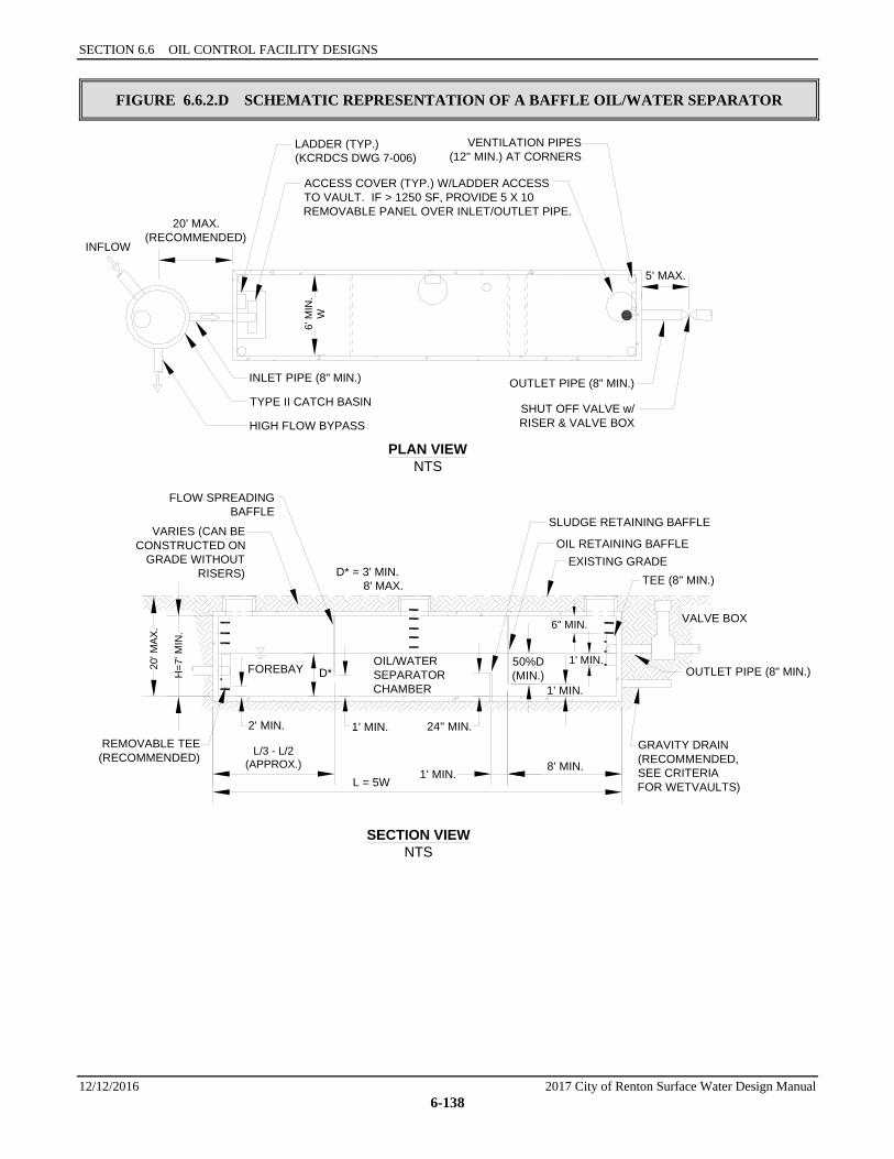
SECTION 6.6 OIL CONTROL FACILITY DESIGNS
12/12/2016 2017 City of Renton Surface Water Design Manual 6-138
FIGURE 6.6.2.D SCHEMATIC REPRESENTATION OF A BAFFLE OIL/WATER SEPARATOR
PLAN VIEWNTS
SECTION VIEWNTS
INFLOW
ACCESS COVER (TYP.) W/LADDER ACCESSTO VAULT. IF > 1250 SF, PROVIDE 5 X 10REMOVABLE PANEL OVER INLET/OUTLET PIPE.
VENTILATION PIPES(12" MIN.) AT CORNERS
LADDER (TYP.)(KCRDCS DWG 7-006)
INLET PIPE (8" MIN.)
TYPE II CATCH BASIN
HIGH FLOW BYPASS
OUTLET PIPE (8" MIN.)
SHUT OFF VALVE w/RISER & VALVE BOX
20' MAX.(RECOMMENDED)
6' M
IN.
W
5' MAX.
VARIES (CAN BECONSTRUCTED ON
GRADE WITHOUTRISERS)
SLUDGE RETAINING BAFFLE
OIL RETAINING BAFFLEEXISTING GRADE
TEE (8" MIN.)
GRAVITY DRAIN(RECOMMENDED,SEE CRITERIAFOR WETVAULTS)
REMOVABLE TEE(RECOMMENDED)
L = 5W
L/3 - L/2(APPROX.) 8' MIN.
1' MIN.
FOREBAYOIL/WATERSEPARATORCHAMBER
20' M
AX.
H=7
' MIN
.
2' MIN.
D*
D* = 3' MIN. 8' MAX.
1' MIN. 24" MIN.
50%D(MIN.)
1' MIN.
1' MIN.
FLOW SPREADINGBAFFLE
6" MIN.
OUTLET PIPE (8" MIN.)
VALVE BOX

6.6.2 OIL/WATER SEPARATORS
2017 City of Renton Surface Water Design Manual 12/12/2016 6-139
FIGURE 6.6.2.E SCHEMATIC REPRESENTATION OF A COALESCING PLATE OIL/WATER SEPARATOR
PLAN VIEWNTS
SECTION VIEWNTS
WQWATERSURFACE
SUBMERGEDINLET PIPE
AFTERBAYFOREBAY
LADDER (TYP.)(KCRDCS DWG. 7-006)
8" TEE
OUTLET PIPE (8" MIN.)
SHUT OFF VALVE w/RISER & VALVE BOXACCESS DOOR ALLOWING REMOVAL OF
PLATE PACK OR PROVIDE FULL LENGTHREMOVABLE COVERS ACROSS ENTIRE CELL
ACCESS COVER(OVER OUTLET)
ACCESS COVER(OVER INLET)
VENTILATION PIPES(12" MIN.) AT CORNERS
COALESCINGPLATE PACK
20' MAX.(RECOMMENDED)
LADDERAND
ACCESS
INLETPIPE
(8" MIN.)
HIGH FLOW BYPASS
5' MAX.
VARIES (CAN BE CONSTRUCTEDON GRADE WITHOUT RISERS)
OIL RETAINING BAFFLE(50% D, MIN.)
COALESCING PLATE PACK
INLET WEIR-SOLIDSRETAINING BAFFLEOR WINDOW WALL(SEE TEXT)
20' M
AX.
7' M
IN.
18"MIN.
D
1' MIN.
1' MIN.
6" MIN.
L
(L/2 RECOMM.)
L/3 MIN. 8' MIN.
(L/4 RECOMM.)
1' MIN.6" MIN.
2' MIN.

SECTION 6.6 OIL CONTROL FACILITY DESIGNS
12/12/2016 2017 City of Renton Surface Water Design Manual 6-140
( T h i s p a g e i n t e n t i o n a l l y l e f t b l a n k . )
CITY OF RENTON SURFACE WATER DESIGN MANUAL
2017 City of Renton Surface Water Design Manual 12/12/2016 6-141
6.7 PROPRIETARY FACILITY DESIGNS Traditional public domain water quality treatment facilities such as wetponds and bioswales may not be feasible or appropriate in some situations due to size and space constraints or limited ability or inability to remove target pollutants.47 Even where public domain facilities are feasible, development applicants may seek to use proprietary manufactured alternatives for economic, aesthetic, or other reasons. This is a narrower range of facilities than those referred to by Ecology as “Emerging Technologies,”48 which also include some public domain facilities that are in process of or have been approved through Ecology’s TAPE program, e.g., WSDOT’s Media Filter Drain. Proprietary designs have been and are continuing to be developed by the stormwater treatment industry.
Approval by Ecology through TAPE, CTAPE or Ecology’s Approved as Equivalent process does not itself constitute approval by the City. An adjustment is required for use of proprietary facilities approved by Ecology but not yet approved by the City.
Proprietary facilities which have been approved by the City are listed in Reference Section 14-A.
6.7.1 ECOLOGY REQUIREMENTS Ecology refers to proprietary facilities as emerging technologies, and more broadly includes under that designation stormwater treatment devices and some public domain facilities for which Ecology has required testing through its Technology Assessment Protocol – Ecology (TAPE) program. All proprietary facilities are emerging technologies, but not all emerging technologies are proprietary.
Proprietary systems include both permanent and constructionsite treatment technologies. Many of these have not undergone complete performance testing so their performance claims cannot be verified. Some have been tested and approved by Ecology through its TAPE program or Chemical Technology Assessment Protocol Ecology (CTAPE) protocols (see <http://www.ecy.wa.gov/programs/wq/stormwater/newtech/tapectape.html> and <http://www.ecy.wa.gov/programs/wq/stormwater/newtech/>).
In addition, Ecology also has a category designated Approved as Equivalent to Existing Technologies, with the following description: These technologies …
“… have been approved by Ecology as equivalent to existing water quality treatment technologies that are currently listed in the 2014 Stormwater Management Manual for Western Washington and/or the 2004 Stormwater Management Manual for Eastern Washington. These technologies did not pass through the Technology Assessment Protocol – Ecology (TAPE) process.”
6.7.2 CITY OF RENTON REQUIREMENTS Only water quality facilities listed in Chapter 6 of this manual, Reference Section 14-A or 14-B, or approved via a Blanket Adjustment may be used for water quality treatment required per Core Requirement #8.
47 “Traditional” target pollutants are TSS, heavy metals, phosphorus, and petroleum hydrocarbons (“high-use” oil, etc.). There are many
TMDLs for bacteria, but no facilities approved by Ecology for bacteria treatment. Other pollutants of concern for which there are no designated facilities include but are not limited to e.g., nitrate, PAHs, and phthalates. The SWDM presents treatment trains for alkalinity (sphagnum bog wetland menu), but there is evidence that at least one of the allowed treatment trains does not work for alkalinity, hence, potential need for other options.
48 “Emerging” implies previously unknown, undeveloped, or unused. While some of these technologies are new, others are not, nor is their application for stormwater management necessarily new. While performance demonstration through TAPE is required for use of all proprietary facilities, it has also been required by Ecology for the public domain Ecology-approved Media Filter Drain and Compost Amended Bioswales (CABS), but not for the Ecology-approved Compost Amended Vegetated Filter Strips (CAVFS), or any of the legacy stormwater facilities, e.g., ponds, vaults, bioswales, or sand filters.
SECTION 6.7 PROPRIETARY FACILITY DESIGNS
12/12/2016 2017 City of Renton Surface Water Design Manual 6-142
6.7.2.1 GENERAL The following requirements are expected to be applicable to any proprietary facility included in Reference Section 14-A, and may be applicable to other proprietary facilities depending on the details of those designs.
1. At a minimum, all proprietary facilities must meet design, construction, and maintenance requirements required by Ecology, as documented at Ecology’s Emerging Technologies website.49
2. In addition, vaults used for cartridge filters shall conform to the “Materials” and “Structural Stability” requirements specified for detention vaults (see Section 5.1.3).
Presettling For any proprietary facilities included in Reference Section 14-A, presettling requirements will be described in detail within the design criteria for the approved facility in Reference Section 14-A.
Note that where a proprietary facility is used as the second or third facility in a treatment train for Enhanced Basic treatment, presettling is provided by the first facility. Use of a proprietary facility for Basic treatment or as the first facility (Basic) in a treatment train may require presettling. See Section 6.5.1, for general presettling requirements for filtration facilities.
Access Requirements for Vaults 1. Access must be provided by either removable panels or other City approved accesses to allow for
removal and replacement of the filter cartridges. Approved access examples are available in Reference Section 7-C. Removable panels, if used, shall be at grade, have stainless steel lifting eyes, and weight no more than 5 tons per panel.
2. Access to the inflow and outlet cells must also be provided.
3. Ladder access is required when vault height exceeds 4 feet.
4. Required clear space for ladder access is a minimum two foot diameter floor-to-ceiling space at the ladder, and between the ladder and any cartridges or other vertical obstructions on the vault floor.
5. Locking lids shall be provided as specified for detention (see Section 5.1.3).
6. If removable panels or the Reference Section 7-C access configurations are not used, corner ventilation pipes shall be provided, and the minimum internal height and width and maximum depth shall be met (see Section 5.1.3).
Access Roads, Right of Way, and Setbacks for Vaults Same as for detention vaults (see Section 5.1.3).
Construction Considerations Installation of a proprietary facility shall follow the manufacturer’s recommended procedures.
Maintenance Requirements Maintenance needs vary depending on the facility, and from site to site based on the type of land use activity, implementation of source controls, and weather conditions. The facility shall be inspected quarterly or at a frequency recommended by the supplier. Inspection and maintenance shall include the following:
1. The operation and maintenance instructions from the manufacturer shall be kept along with an inspection and maintenance log. The maintenance log shall be available for review by City inspectors.
2. Routine maintenance criteria can be found in Appendix A and Reference Section 14-A.
49 <http://www.ecy.wa.gov/programs/wq/stormwater/newtech/technologies.html>.
SECTION 6.7.2 CITY OF RENTON REQUIREMENTS
2017 City of Renton Surface Water Design Manual 12/12/2016 6-143
3. Media shall be disposed of in accordance with applicable regulations, including RMC Title VIII, Chapter 1 and state dangerous waste regulations (WAC 173-303). In most cases, the media may be disposed of as solid waste.
6.7.2.2 FACILITY APPROVAL The City’s facility approval process is summarized as follows:
• Ecology may assign General Use Level Designation (GULD) or Conditional Use Level Designation (CULD) to a given facility.
• Before the City will consider adding a proprietary facility to the list of water quality facilities approved for use without adjustments, Ecology must grant GULD approval and the City must determine that sufficient performance monitoring data satisfying all requirements of TAPE are met. City approval may require that monitoring data satisfying requirements of TAPE be provided for 3 or more sites and that qualified samples equal 12 or more at each site. The City’s evaluation for inclusion of facilities in this manual will also consider maintenance, operation, and durability factors. For facilities to be maintained by the City, regular maintenance frequency must be no more than once per year.
• During the permitting process with CED, an applicant for an alternative facility may apply for an adjustment to use a device or system not listed in this manual. There is no guarantee that an adjustment will be granted, but if one is, monitoring will be required. All TAPE monitoring requirements and criteria are applicable. The City does not pay for this monitoring. The cost of monitoring commercial products is covered by the applicant and/or the facility vendor according to their agreement. The cost of testing public domain devices or systems for which an adjustment is requested is borne by the applicant.
6.7.2.3 DIFFERENCES BETWEEN CITY MAINTAINED AND PRIVATELY MAINTAINED PROPRIETARY FACILITIES • The City will not consider adoption of proprietary facilities for public maintenance which are likely to
require maintenance more frequently than annually. A privately maintained proprietary facility may have an inspection/maintenance cycle as short as quarterly.
• Where the City will be taking over maintenance responsibilities from a developer, the City may consider maintenance costs in deciding which proprietary facilities to allow.

SECTION 6.7 PROPRIETARY FACILITY DESIGNS
12/12/2016 2017 City of Renton Surface Water Design Manual 6-144
( T h i s p a g e i n t e n t i o n a l l y l e f t b l a n k . )

CITY OF RENTON SURFACE WATER DESIGN MANUAL
2017 City of Renton Surface Water Design Manual 12/12/2016 6-145
6.8 BIORETENTION FACILITY DESIGNS This section presents the methods, details of analysis, and design criteria for bioretention facilities. Included in this section are the following specific facility designs:
• “Bioretention cells” • “Bioretention swales” • “Bioretention planters”
6.8.1 BIORETENTION Bioretention cells are shallow depressions with a designed planting soil mix and a variety of plant material, including trees, shrubs, grasses, and/or other herbaceous plants. Bioretention cells are not designed as a conveyance system.
Bioretention swales incorporate the same design features as bioretention cells; however, bioretention swales are designed as part of a system that can convey stormwater when maximum ponding depth is exceeded. Bioretention swales have relatively gentle side slopes and ponding depths that are typically 6 to 12 inches.
Bioretention planters include a designed soil mix and a variety of plant material including trees, shrubs, grasses, and/or other herbaceous plants within a vertical walled container usually constructed from formed concrete, but could include other materials. Planters have an open bottom and allow infiltration to the subgrade. These designs are often used in ultra-urban settings.
Applications and Limitations 1. A minimum of 3 feet of clearance is necessary between the lowest elevation of the bioretention soil, or
any underlying gravel layer, and the seasonal high groundwater elevation or other impermeable layer if the area tributary to the bioretention facility meets or exceeds any of the following limitations:
• 5,000 square feet of pollution-generating impervious surface; or • 10,000 square feet of impervious area; or • ¾ acres of lawn and landscape.
2. If the tributary area to an individual bioretention facility does not exceed the areal limitations above, a minimum of 1 foot of clearance is adequate between the lowest elevation of the bioretention soil (or any underlying gravel layer) and the seasonal high groundwater elevation or other impermeable layer.
Because bioretention facilities use an imported soil mix that has a moderate design infiltration rate, they are best applied for small drainages, and near the source of the stormwater. Cells may be scattered throughout a subdivision; a swale may run alongside the access road; or a series of planter boxes may serve the road. In these situations, they can but are not required to fully meet the requirement to treat 91% of the stormwater runoff file from pollution-generating surfaces. But the amount of stormwater that is predicted to pass through the soil profile may be estimated and subtracted from the 91% volume that must be treated. Downstream treatment facilities may be significantly smaller as a result.
When used in combination with other BMPs, they can also help achieve compliance with the 0.15 cfs threshold for Core Requirement #3.
Applications with or without underdrains vary extensively and can be applied in new development, redevelopment and retrofits. Typical applications include:
• Individual lots for rooftop, driveway, and other on-lot impervious surface. • Shared facilities located in common areas for individual lots. • Areas within loop roads or cul-de-sacs.
SECTION 6.8 BIORETENTION FACILITY DESIGNS
12/12/2016 2017 City of Renton Surface Water Design Manual 6-146
• Landscaped parking lot islands. • Within right-of-ways along roads (often linear bioretention swales and cells). • Common landscaped areas in apartment complexes or other multifamily housing designs. • Planters on building roofs, patios, and as part of streetscapes.
Setbacks Note: Criteria with setback distances are as measured from the outermost edge of the bioretention soil mix.
1. Bioretention areas should have a minimum shoulder of 6 inches between the road edge and beginning of the bioretention side slope where flush curbs are used.
2. A minimum 5-foot setback shall be maintained between the outermost edge of the bioretention soil mix and any building structure or property line.
3. For sites with septic systems, bioretention must be located downgradient of the primary and reserve drainfield areas. CED review staff can waive this requirement if site topography clearly prohibits subsurface flows from intersecting the drainfield.
4. Bioretention is not allowed in critical area buffers or on slopes steeper than 20%.
5. Bioretention is not allowed within 50 feet of a steep slope hazard area, erosion hazard area, or landslide hazard.
6. Bioretention proposed on slopes steeper than 15% must be approved by a geotechnical engineer or engineering geologist unless otherwise approved by CED. The geotechnical analysis must consider cumulative impacts from the project and surrounding areas under full built-out conditions.
7. Bioretention proposed near slopes steeper than 15% must be approved by a geotechnical engineer or engineering geologist if the facility is located within a setback from the top of slope equal to the total vertical height of the slope area that is steeper than 15% unless otherwise approved by CED. The geotechnical analysis must consider cumulative impacts from the project and surrounding areas under full built-out conditions.
8. Bioretention that directs overflow towards slopes steeper than 15% may require evaluation and approval of the proposal by a geotechnical engineer or engineering geologist as determined by CED. The geotechnical analysis must consider cumulative impacts from the project and surrounding areas under full built-out conditions.
9. Bioretention proposed within 200 feet of a steep slope hazard area, erosion hazard area, or landslide hazard must be approved by a geotechnical engineer or engineering geologist unless otherwise approved by CED. The geotechnical analysis must consider cumulative impacts from the project and surrounding areas under full built-out conditions.
10. Bioretention must not create flooding or erosion impacts as determined by CED. If bioretention is proposed near or directs overflows towards a landslide hazard, erosion hazard area, or a steep slope hazard area, CED may require evaluation and approval of the proposal by a geotechnical engineer or engineering geologist. The geotechnical analysis must consider cumulative impacts from the project and surrounding areas under full built-out conditions.
6.8.1.1 DESIGN CRITERIA This section provides a description, recommendations, and requirements for the components of bioretention facilities. Refer to Appendix C for additional infeasibility criteria for Core Requirement #9.
Design criteria are provided in this section for the following elements:
• Contributing area • Flow entrance
SECTION 6.8.1 BIORETENTION
2017 City of Renton Surface Water Design Manual 12/12/2016 6-147
• Presettling • Water storage area • Bioretention soil • Subgrade • Underdrain (if required) • Overflow • Liners (optional) • Plant material • Mulch layer • Check dams and weirs • UIC discharge
Contributing Area Bioretention cells are small and distributed. The contributing area to a bioretention facility is limited as follows:
• No single cell may receive runoff from more than 5,000 square feet of impervious area, except as noted below for a series of bioretention cells.
• Runoff from more than 5,000 square feet of impervious area may be directed to an upstream cell in a bioretention series (interconnected series of cells).
The bioretention facility should be sized for the contributing area routed to the facility. It is recommended that facilities not be oversized because the vegetation in oversized facilities may not receive sufficient stormwater runoff for irrigation, increasing maintenance.
Stormwater flows from other areas (beyond the area for which the facility is sized) should be bypassed around the facility in order to reduce sediment loading to the cell and the potential for bioretention soil clogging and increased maintenance needs. If bypass is not feasible, facilities shall be sized to treat runoff from the entire area draining to the facility.
Additional flows may pass through a bioretention facility with the following limitations:
• The maximum additional area (i.e., areas beyond the area for which the facility is sized) that may pass through a bioretention facility shall not exceed twice the area for which it is sized due to sediment loading concerns;
• If additional area is routed to the bioretention facility, it shall be clearly noted on submitted plans; • The overflow infrastructure shall be sized for the full contributing area; and • Presettling calculations shall demonstrate that the water velocities in the vegetated areas of the
bioretention facility do not exceed 2 feet per second during peak flows with 4 percent annual probability (the 25 year recurrence interval flow) (calculated through the narrowest vegetated cross section of the facility).
Flow Entrance Flow entrances shall be sized to capture flow from the drainage area and designed to both reduce the potential for clogging at the inlet and prevent inflow from causing erosion in the facility. Four primary types of flow entrances can be used for bioretention facilities: dispersed flow (e.g., vegetated buffer strips), sheet flow, curb cuts, and concentrated flow (e.g., piped flow). Where feasible and appropriate within the site context, vegetated buffer strips are the preferred entrance type because they slow incoming flows and provide initial settling of particulates.

SECTION 6.8 BIORETENTION FACILITY DESIGNS
12/12/2016 2017 City of Renton Surface Water Design Manual 6-148
Requirements associated with the flow entrance design include the following:
• For facilities in the right-of-way, the flow entrance elevation shall be above the overflow elevation. • For sheet flow into a facility, a minimum 1 inch drop from the edge of a contributing hard surface to
the vegetated flow entrance is required. This drop is intended to allow for less frequent maintenance by allowing some sediment/debris buildup at the edge where flow enters the facility.
• The following requirements apply to roadway and parking lot curb cut flow entrances: o The curb cut width shall be sized based on the drainage area, longitudinal slope along the curb,
and the cross slope at the inlet. o The minimum curb cut opening shall be 12 inches; however, 18 inches is recommended. o The curb cut shall have either a minimum of 8 percent slope from the outer curb face extending to
a minimum of 12 inches beyond the back of curb, or provide a minimum of a 2 inch vertical drop from the back of curb to the vegetated surface of the facility.
• If concentrated flows are entering the facility (e.g., pipe or curb cut), flow energy dissipation (e.g., rock/cobble pad or flow dispersion weir) shall be incorporated to reduce the potential for erosion at the inlet.
Presettling Presettling to capture debris and sediment load from contributing drainage areas is required at the flow entrance for some bioretention facilities. By having a designated presettling zone, maintenance can be targeted in this area to remove sediment build-up.
Requirements associated with the presettling design include the following:
• Presettling requirements for bioretention facilities are provided in Table 6.8.1.A. • If the cell will receive flows from impervious areas beyond the area for which the facility is sized, the
presettling measures shall be designed for the entire area draining to the facility.
The area designated as the presettling zone shall not be included in the calculation of the bottom area of the bioretention facility.
TABLE 6.8.1.A PRESETTLING REQUIREMENTS FOR BIORETENTION FACILITIES
IMPERVIOUS AREA (SQUARE FEET) CONTRIBUTING RUNOFF TO A SINGLE FLOW
ENTRANCE PRESETTLING REQUIREMENTS
< 5,000 No presettling is required. Designer to determine if site specific presettling is needed based on upstream area conditions.
≥ 5,000 and < 10,000 The bottom of the first 2 to 3 feet of the upstream bioretention cell (at the flow entrance) shall be designated the presettling zone. This bottom area of the cell shall be constructed of cobbles, concrete open celled paving grids, plastic lattices filled with gravel or groundcover vegetation, a roughened concrete pad, or similar material for collection of sediment for maintenance. Alternatively, a catch basin with a minimum 2-foot sump may be used as the presettling zone. Where the pipe (from the catch basin) daylights into the bioretention cell, provide energy dissipation within the cell.
≥ 10,000 Presettling requirements are project specific, to be determined by designer and approved by the City.
SECTION 6.8.1 BIORETENTION
2017 City of Renton Surface Water Design Manual 12/12/2016 6-149
Water Storage Area The water storage area provides space for storm flows and the first stages of pollutant treatment within the bioretention facility. Requirements for water storage area design for bioretention facilities with both side slopes and vertical sides include:
• The bottom area of an individual cell shall be no larger than 800 square feet (limitation is to ensure that bioretention facilities are small-scale and distributed).
• The bottom area of an individual cell shall be no less than 4 square feet. • The average ponding depth shall be no less than 2 inches. • The ponding depth shall be no more than 12 inches. In right-of-way areas with high pedestrian traffic,
the ponding depth may be restricted to 6 inches or less. • The maximum allowable drawdown time of the water storage area is 24 hours. A correction factor of
0.33 to 1 (no correction factor) as recommended by a licensed geotechnical professional should be applied to initial measured infiltration rates of the in situ soils to determine the design rate for this drawdown calculation. The designed water storage depth (2″ minimum to 12″ maximum) must be considered in light of the drawdown time requirement (e.g., in slow draining soils, the designed ponding depth may need to be decreased in order to meet the drawdown criteria). As an example, a 6″ deep pool with an initial measured rate of 0.5 in/hour and a correction factor of 0.5 applied will achieve drawdown in exactly 24 hours (0.5 in/hour x 0.5 correction factor x 24 hours = 6 inches).
• The bottom slope shall be no more than 6 percent.
Additional requirements for water storage area design specific to bioretention facilities with side slopes include the following:
• The maximum planted side slope is 2.5H:1V. In the ROW, if the facility is on a curbless street and less than 50 feet of an intersection, the maximum planted sides slope is 3H:1V. If total facility depth exceeds 3 feet, the maximum planted side slope is 3H:1V. If steeper sides are necessary, rockery, concrete walls, or steeper soil wraps may be used.
• If berming is used to achieve the minimum top facility elevation needed to meet ponding depth and freeboard needs, the following requirements apply: o Maximum berm slope is 2.5H:1V o Minimum berm top width is 6 inches. o Soil used for berming where the permanent restoration is landscape shall meet the bioretention
soil mix specification and be compacted to a minimum of 90 percent dry density. o A catch basin or rock pad must be provided to release water when the water level exceeds the
12 inches of water depth. The catch basin may discharge to the local drainage system or other acceptable discharge location via a 6-inch rigid pipe (private) or 8-inch rigid pipe (public). The rock pad may be used with or without a constructed drainage system downstream. If a rock pad is used, it must be composed of crushed or fractured rock, 6 inches deep and 2 feet wide (perpendicular to flow) and must extend at least 4 feet or beyond the containment berm, whichever is greater. The rock pad must be situated so that overflow does not cause erosion damage or unplanned inundation
• For trees planted alongside slopes of the bioretention cell, the maximum side slope around the tree is 1H:1V.
• The average bottom width for the facility shall be no less than 18 inches.
Additional requirements for water storage area design specific to bioretention facilities with vertical sides include the following:
• The facility width (planted area between walls) shall be no less than 2 feet. For plant health, the recommended minimum facility width is 4 feet.
SECTION 6.8 BIORETENTION FACILITY DESIGNS
12/12/2016 2017 City of Renton Surface Water Design Manual 6-150
Additional requirements for bioretention swales:
• Bioretention swales shall have a minimum 18-inch bottom width. Swales shall be flat in cross section to promote event flow across the width of the swale. See Renton Standard Details for design details for bioretention swales in the ROW.
• Bioretention swales shall meet the conveyance requirements described in Section 1.2.4.1 of this manual. Maximum 100-year peak flow velocity through bioretention swales is 3 feet per second.
• Maximum longitudinal (along direction of flow) slope of bioretention swales shall be 6%.
To address traffic and pedestrian safety concerns, the following additional requirements apply to bioretention facilities in the right-of-way:
• The following minimum setbacks shall be provided for facilities with sloped sides: o 2 feet minimum from face of curb to top of slope on non-major arterial streets o 4 feet minimum from face of curb to top of slope for major arterial street o 1 foot minimum from edge of sidewalk to top of slope
• A minimum of one access path across planting strip shall be provided between the street and public sidewalk for each parcel. Access paths shall be a minimum of 5 feet wide. It is preferred that the access path is within 15 feet of the structure access point (such as path to doorway or stairs).
• Bioretention cells shall not impact driveway/alley access. A 2-foot minimum setback shall be provided from the pavement edge of the driveway curb cut wing to the top (top of slope) of bioretention cell.
• A 2-foot minimum setback shall be provided from the edge of paving for the public sidewalk/curb ramp at the intersection to the top of slope of the bioretention cell. Curb ramp improvements are required whenever the construction of bioretention cells and associated street improvements remove pavement within the crosswalk area of the street or sidewalk, impact curbs, sidewalks, curb ramps, curb returns or landings within the intersection area, or affect access to or use of a public facility.
Bioretention Soil Mix Requirements for the bioretention soil mix include:
1. An 18″-thick bioretention soil mix liner extending up slopes to maximum water storage depth is required in the bioretention cell, swale, or planter. The bioretention soil mix shall be per Reference Section 11-C. Compost shall meet Specification 1 described in Reference Section 11-C.
2. Do not use filter fabrics between the subgrade and the Bioretention Soil Mix. The gradation between existing soils and Bioretention Soil Mix is typically not great enough to allow significant migration of fines into the Bioretention Soil Mix. Additionally, filter fabrics may clog with downward migration of fines from the Bioretention Soil Mix.
3. Onsite soil mixing or placement shall not be performed if Bioretention Soil Mix or subgrade soil is saturated. The bioretention soil mixture should be placed and graded by machinery operating adjacent to the bioretention facility.
4. If machinery must operate in the bioretention cell for soil placement, use light weight equipment with low ground-contact pressure. The soil mixture shall be placed in horizontal layers not to exceed 12 inches per lift for the entire area of the bioretention facility.
5. Compact the Bioretention Soil Mix to a relative compaction of 85 percent of modified maximum dry density (ASTM D 1557). Compaction can be achieved by boot packing (simply walking over all areas of each lift), and then apply 0.2 inches (0.5 cm) of water per 1 inch (2.5 cm) of Bioretention Soil Mix depth. Water for settling should be applied by spraying or sprinkling.
6. Prior to placement of the BSM, the finished subgrade shall: (a) Be scarified to a minimum depth of 3 inches; (b) have any sediment deposited from construction runoff removed (to remove all introduced sediment, subgrade soil should be removed to a depth of 3–6 inches and replaced with BSM); and (c) be inspected by the responsible engineer to verify required subgrade condition.
SECTION 6.8.1 BIORETENTION
2017 City of Renton Surface Water Design Manual 12/12/2016 6-151
7. If using the default bioretention soil mix described in Reference Section 11-C, pre-placement laboratory analysis for saturated hydraulic conductivity of the bioretention soil mix is not required. Verification of the mineral aggregate gradation, compliance with the compost specifications, and the mix ratio must be provided.
8. Custom bioretention soil mixes may be considered under the adjustment process described in Section 1.4.
9. Bioretention constructed with imported compost materials are not allowed within one-quarter mile of a sensitive lake if the underlying native soil does not meet the soil suitability criteria for treatment in Section 5.2.1.
10. Bioretention constructed with imported compost materials are not allowed within ¼ mile of those waterbodies listed as category 2, 4, or 5 for either nutrients or low DO determined to be caused by nutrients. These waterbodies are found on Ecology’s combined 303(d)/305(b) Water Quality Assessment list. The exception to this prohibition is where phosphorous is the identified nutrient and the underlying native soil meets soil suitability criteria for treatment described in Section 5.2.1.
Subgrade The minimum measured subgrade infiltration rate for bioretention facilities without underdrains is 0.3 inches per hour. For bioretention facilities with underdrains, there is no minimum subgrade infiltration rate.
During construction, the subgrade soil surface can become smeared and sealed by excavation equipment. The design shall require scarification or raking of the side walls and bottom of the bioretention facility excavation to a minimum depth of 4 inches after excavation to restore infiltration rate.
Follow the process outlined in Section 5.2.1 for determining the design infiltration rate for the subgrade.
Underdrain (if required) Underdrain systems must be installed if the bioretention facility is:
• Located near sensitive infrastructure (e.g., unsealed basements) and potential for flooding is likely • Used for filtering stormwater flows from gas stations or other pollutant hotspots (requires an
impermeable liner) • Located above subgrade soils with a measured infiltration rate of less than 0.3 inches per hour. • In an area that does not provide a minimum of 3 feet of clearance between the lowest elevation of the
bioretention soil mix, or any underlying gravel layer, and the seasonal high groundwater elevation or other impermeable layer
The underdrain pipe diameter will depend on hydraulic capacity required. The underdrain shall be connected to an acceptable discharge point which can either be an enclosed drainage system (i.e., pipe system, culvert, or tightline) or an open drainage feature (e.g., second bioretention cell, ditch, channel).
Requirements associated with the underdrain design include:
• Slotted subsurface drain PVC per ASTM D1785 SCH 40. • Slots should be cut perpendicular to the long axis of the pipe and be 0.04 to 0.069 inches by 1 inch
long and be spaced 0.25 inches apart (spaced longitudinally). Slots should be arranged in four rows spaced on 45-degree centers and cover ½ of the circumference of the pipe.
• Underdrain pipe shall have a minimum diameter of 8 inches in the public ROW and 6 inches for private property.
• Underdrain pipe slope shall be no less than 0.5 percent unless otherwise specified by an engineer. • Pipe shall be placed in filter material and have a minimum cover depth of 12 inches and bedding depth
of 6 inches. Cover depth may be reduced up to 6 inches in order to discharge stormwater from the facility under gravity flow conditions while meeting the applicable engineering standards, if approved by the City.
• Filter material shall meet the specifications in Table 6.8.1.C.
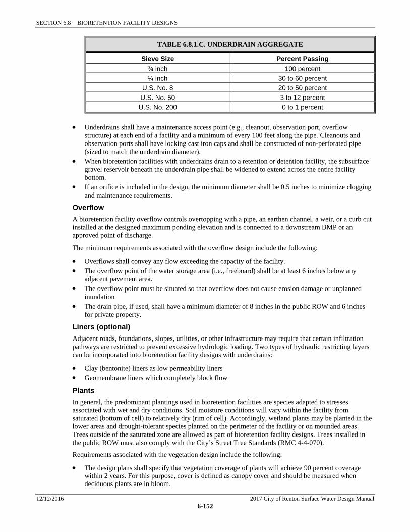
SECTION 6.8 BIORETENTION FACILITY DESIGNS
12/12/2016 2017 City of Renton Surface Water Design Manual 6-152
TABLE 6.8.1.C. UNDERDRAIN AGGREGATE
Sieve Size Percent Passing ¾ inch 100 percent ¼ inch 30 to 60 percent
U.S. No. 8 20 to 50 percent U.S. No. 50 3 to 12 percent U.S. No. 200 0 to 1 percent
• Underdrains shall have a maintenance access point (e.g., cleanout, observation port, overflow structure) at each end of a facility and a minimum of every 100 feet along the pipe. Cleanouts and observation ports shall have locking cast iron caps and shall be constructed of non-perforated pipe (sized to match the underdrain diameter).
• When bioretention facilities with underdrains drain to a retention or detention facility, the subsurface gravel reservoir beneath the underdrain pipe shall be widened to extend across the entire facility bottom.
• If an orifice is included in the design, the minimum diameter shall be 0.5 inches to minimize clogging and maintenance requirements.
Overflow A bioretention facility overflow controls overtopping with a pipe, an earthen channel, a weir, or a curb cut installed at the designed maximum ponding elevation and is connected to a downstream BMP or an approved point of discharge.
The minimum requirements associated with the overflow design include the following:
• Overflows shall convey any flow exceeding the capacity of the facility. • The overflow point of the water storage area (i.e., freeboard) shall be at least 6 inches below any
adjacent pavement area. • The overflow point must be situated so that overflow does not cause erosion damage or unplanned
inundation • The drain pipe, if used, shall have a minimum diameter of 8 inches in the public ROW and 6 inches
for private property.
Liners (optional) Adjacent roads, foundations, slopes, utilities, or other infrastructure may require that certain infiltration pathways are restricted to prevent excessive hydrologic loading. Two types of hydraulic restricting layers can be incorporated into bioretention facility designs with underdrains:
• Clay (bentonite) liners as low permeability liners • Geomembrane liners which completely block flow
Plants In general, the predominant plantings used in bioretention facilities are species adapted to stresses associated with wet and dry conditions. Soil moisture conditions will vary within the facility from saturated (bottom of cell) to relatively dry (rim of cell). Accordingly, wetland plants may be planted in the lower areas and drought-tolerant species planted on the perimeter of the facility or on mounded areas. Trees outside of the saturated zone are allowed as part of bioretention facility designs. Trees installed in the public ROW must also comply with the City’s Street Tree Standards (RMC 4-4-070).
Requirements associated with the vegetation design include the following:
• The design plans shall specify that vegetation coverage of plants will achieve 90 percent coverage within 2 years. For this purpose, cover is defined as canopy cover and should be measured when deciduous plants are in bloom.
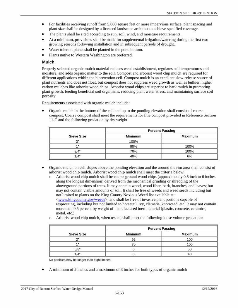
SECTION 6.8.1 BIORETENTION
2017 City of Renton Surface Water Design Manual 12/12/2016 6-153
• For facilities receiving runoff from 5,000 square feet or more impervious surface, plant spacing and plant size shall be designed by a licensed landscape architect to achieve specified coverage.
• The plants shall be sited according to sun, soil, wind, and moisture requirements. • At a minimum, provisions shall be made for supplemental irrigation/watering during the first two
growing seasons following installation and in subsequent periods of drought. • Water tolerant plants shall be planted in the pond bottom. • Plants native to Western Washington are preferred.
Mulch Properly selected organic mulch material reduces weed establishment, regulates soil temperatures and moisture, and adds organic matter to the soil. Compost and arborist wood chip mulch are required for different applications within the bioretention cell. Compost mulch is an excellent slow-release source of plant nutrients and does not float, but compost does not suppress weed growth as well as bulkier, higher carbon mulches like arborist wood chips. Arborist wood chips are superior to bark mulch in promoting plant growth, feeding beneficial soil organisms, reducing plant water stress, and maintaining surface soil porosity.
Requirements associated with organic mulch include:
• Organic mulch in the bottom of the cell and up to the ponding elevation shall consist of coarse compost. Coarse compost shall meet the requirements for fine compost provided in Reference Section 11-C and the following gradation by dry weight:
Sieve Size Percent Passing
Minimum Maximum 3″ 100% 1″ 90% 100%
3/4″ 70% 100% 1/4″ 40% 6%
• Organic mulch on cell slopes above the ponding elevation and the around the rim area shall consist of arborist wood chip mulch. Arborist wood chip mulch shall meet the criteria below: o Arborist wood chip mulch shall be coarse ground wood chips (approximately 0.5 inch to 6 inches
along the longest dimension) derived from the mechanical grinding or shredding of the aboveground portions of trees. It may contain wood, wood fiber, bark, branches, and leaves; but may not contain visible amounts of soil. It shall be free of weeds and weed seeds Including but not limited to plants on the King County Noxious Weed list available at: <www.kingcounty.gov/weeds>, and shall be free of invasive plant portions capable of resprouting, including but not limited to horsetail, ivy, clematis, knotweed, etc. It may not contain more than 0.5 percent by weight of manufactured inert material (plastic, concrete, ceramics, metal, etc.).
o Arborist wood chip mulch, when tested, shall meet the following loose volume gradation:
Sieve Size Percent Passing
Minimum Maximum 2″ 95 100 1″ 70 100
5/8″ 0 50 1/4″ 0 40
No particles may be longer than eight inches.
• A minimum of 2 inches and a maximum of 3 inches for both types of organic mulch
SECTION 6.8 BIORETENTION FACILITY DESIGNS
12/12/2016 2017 City of Renton Surface Water Design Manual 6-154
In bioretention areas where higher flow velocities are anticipated, an aggregate mulch may be used to dissipate flow energy and protect underlying bioretention soil. Aggregate mulch varies in size and type, but 1- to 1.5-inch gravel (rounded) decorative rock is typical. The aggregate mulch shall be washed rock (free of fines) and the area covered with aggregate mulch shall not exceed one-fourth of the facility bottom area.
As an alternative to mulch, a dense groundcover may be used. Mulch is required in conjunction with the groundcover until groundcover is established.
Check Dams and Weirs Check dams are necessary for reducing flow velocity and potential erosion, as well as increasing detention time and infiltration capability on sloped sites. Typical materials include concrete, rock, compacted dense soil covered with vegetation, and vegetated hedge rows. Design depends on flow control goals, local regulations for structures within road right-of-ways and aesthetics. Optimum spacing is determined by modeling and cost considerations.
UIC Discharge Stormwater that has passed through the bioretention soil mix may also discharge to a gravel-filled dug or drilled drain. Underground Injection Control (UIC) regulations are applicable and must be followed (Chapter 173-218 WAC).
6.8.1.2 INSTALLATION Excavation Soil compaction can lead to facility failure; accordingly, minimizing compaction of the base and sidewalls of the bioretention area is critical. Excavation should never be allowed during wet or saturated conditions (compaction can reach depths of 2-3 feet during wet conditions and mitigation is likely not be possible). Excavation should be performed by machinery operating adjacent to the bioretention facility and no heavy equipment with narrow tracks, narrow tires, or large lugged, high pressure tires should be allowed on the bottom of the bioretention facility. If machinery must operate in the bioretention cell for excavation, use light weight, low ground-contact pressure equipment and rip the base at completion to refracture soil to a minimum of 12 inches. If machinery operates in the facility, subgrade infiltration rates must be field tested and compared to design rates. Failure to meet or exceed the design infiltration rate will require revised engineering designs to verify achievement of treatment and flow control benefits that were estimated in the Stormwater Site Plan.
Prior to placement of the bioretention soil mix, the finished subgrade shall:
• Be scarified to a minimum depth of 3 inches. • Have any sediment deposited from construction runoff removed. To remove all introduced sediment,
subgrade soil should be removed to a depth of 3–6 inches and replaced with bioretention soil mix. • Be inspected by the responsible engineer to verify required subgrade condition.
Sidewalls of the facility, beneath the surface of the bioretention soil mix, can be vertical if soil stability is adequate. Exposed sidewalls of the completed bioretention area with bioretention soil mix in place should be no steeper than 3H:1V. The bottom of the facility should be flat.
Soil Placement Onsite soil mixing or placement shall not be performed if bioretention soil mix or subgrade soil is saturated. The bioretention soil mixture should be placed and graded by machinery operating adjacent to the bioretention facility. If machinery must operate in the bioretention cell for soil placement, use light weight equipment with low ground-contact pressure. If machinery operates in the facility, subgrade infiltration rates must be field tested and compared to design rates. Failure to meet or exceed the design infiltration rate will require revised engineering designs to verify achievement of treatment and flow control benefits that were estimated in the Stormwater Site Plan.
SECTION 6.8.1 BIORETENTION
2017 City of Renton Surface Water Design Manual 12/12/2016 6-155
The soil mixture shall be placed in horizontal layers not to exceed 12 inches per lift for the entire area of the bioretention facility.
Compact the bioretention soil mix to a relative compaction of 85 percent of modified maximum dry density (ASTM D 1557). Compaction can be achieved by boot packing (simply walking over all areas of each lift), and then apply 0.2 inches (0.5 cm) of water per 1 inch (2.5 cm) of bioretention soil mix depth. Water for settling should be applied by spraying or sprinkling.
Temporary Erosion and Sediment Control (TESC) Controlling erosion and sediment are most difficult during clearing, grading, and construction; accordingly, minimizing site disturbance to the greatest extent practicable is the most effective sediment management. During construction:
• Bioretention facilities should not be used as sediment control facilities and all drainage should be directed away from bioretention facilities after initial rough grading. Flow can be directed away from the facility with temporary diversion swales or other approved protection. If introduction of construction runoff cannot be avoided see below for guidelines.
• Construction on bioretention facilities should not begin until all contributing drainage areas are stabilized according to erosion and sediment control BMPs and to the satisfaction of the engineer.
• If the design includes curb and gutter, the curb cuts and inlets should be blocked until bioretention soil mix and mulch have been placed and planting completed (when possible), and dispersion pads are in place.
Every effort during design, construction sequencing and construction should be made to prevent sediment from entering bioretention facilities. However, bioretention areas are often distributed throughout the project area and can present unique challenges during construction.
Erosion and sediment control practices must be inspected and maintained on a regular basis.
6.8.1.3 VERIFICATION If using the default bioretention soil mix, pre-placement laboratory analysis for saturated hydraulic conductivity of the bioretention soil mix is not required. Verification of the mineral aggregate gradation, compliance with the compost specifications, and the mix ratio must be provided.
If using a custom bioretention soil media, verification of compliance with the minimum design criteria cited above for such custom mixes must be provided. This will require laboratory testing of the material that will be used in the installation. Testing shall be performed by a Seal of Testing Assurance, AASHTO, ASTM or other standards organization accredited laboratory with current and maintained certification. Samples for testing must be supplied from the bioretention soil mix that will be placed in the bioretention areas.
If testing infiltration rates is necessary for post-construction verification use the Pilot Infiltration Test (PIT) method or a double ring infiltrometer test (or other small-scale testing allowed by the local government with jurisdiction). If using the PIT method, do not excavate bioretention soil mix (conduct test at level of finished bioretention soil mix elevation), use a maximum of 6 inch ponding depth and conduct test before plants are installed.
6.8.1.4 RUNOFF MODEL REPRESENTATION IN WWHM2012 Use new bioretention element for each type: cell, swale, or planter box.
The equations used by the elements are intended to simulate the wetting and drying of soil as well as how the soils function once they are saturated. This group of LID elements uses the modified Green Ampt equation to compute the surface infiltration into the amended soil. The water then moves through the top amended soil layer at the computed rate, determined by Darcy’s and Van Genuchten’s equations. As the soil approaches field capacity (i.e., gravity head is greater than matric head), the model determines when
SECTION 6.8 BIORETENTION FACILITY DESIGNS
12/12/2016 2017 City of Renton Surface Water Design Manual 6-156
water will begin to infiltrate into the second soil layer (lower layer). This occurs when the matric head is less than the gravity head in the first layer (top layer). The second layer is intended to prevent loss of the amended soil layer. As the second layer approaches field capacity, the water begins to move into the third layer – the gravel underlayer. For each layer, the user inputs the depth of the layer and the type of soil.
For the bioretention soil mix, the model will automatically assign pre-determined appropriate values for parameters that determine water movement through that soil. These include: wilting point, minimum hydraulic conductivity, maximum saturated hydraulic conductivity, and Van Genuchten number.
If a user opts to use soils that deviate from the bioretention soil mix specifications, the default parameter values do not apply. The user will have to use the “Gravel trench/bed” element to represent the bioretention facility and follow the procedures identified for WWHM3 in Section 6.8.1.5.
For bioretention facilities with underdrains, the only volume available for storage (and modeled as storage as explained herein) is the void space within the aggregate bedding layer below the invert of the drain pipe. Use 40% void space for the Type 26 mineral aggregate specified in Table 6.8.1.C.
Using one of the procedures explained in Section 5.2.1, estimate the initial measured (a.k.a., short-term) infiltration rate of the native soils beneath the bioretention soil and any base materials. Because these soils are protected from fouling, no correction factor will be applied.
6.8.1.5 RUNOFF MODEL REPRESENTATION IN WWHM3 Pothole design (bioretention cells) Bioretention is represented by using the “Gravel trench/bed” element with a steady-state infiltration rate. Proper infiltration rate selection is described in Section 5.2.1. The user inputs the dimensions of the gravel trench. Layer 1 on the input screen is the bioretention soil layer. Enter the soil depth and a porosity of 40%. Layer 2 is the free standing water above the bioretention soil. Enter the maximum depth of free standing water (i.e., up to the invert of an overflow pipe or a spillway, whatever engages first for surface release of water), and 100% for porosity. Bioretention with underdrains can also be modeled as a gravel trench/bed with a steady-state infiltration rate. However, the only volume available for storage (and modeled as storage as explained herein) is the void space within the imported material (usually sand or gravel) below the bioretention soil layer and below the invert of the drain pipe.
Using one of the procedures explained in Section 5.2.1, estimate the initial measured (a.k.a., short-term) infiltration rate of the native soils beneath the bioretention soil and any base materials. Because these soils are protected from fouling, no correction factor will be applied.
Facilities without an underdrain If using the default bioretention soil mix, 12 inches per hour is the initial infiltration rate. The long-term rate is either 3 inches per hour or 6 inches per hour depending upon the size of the drainage area and the use of a pretreatment device for solids removal prior to the bioretention facility. See Section 5.2.1. If using a custom imported soil mix other than the default, its saturated hydraulic conductivity (used as the infiltration rate) must be determined using the procedures described in Section 5.2.1. The long-term infiltration rate is one-fourth or one-half of that rate depending upon the size of the drainage area and the use of a pretreatment device for solids removal. See Section 5.2.1.
Facilities with an elevated underdrain Note that only the estimated void space of the aggregate bedding layer that is below the invert of the underdrain pipe provides storage volume that provides a flow control benefit. Assume a 40% void volume for the Type 26 mineral aggregate specified in Table 6.8.1.C.
Linear Design: (bioretention swale or slopes) Where a bioretention swale has a roadside slope and a back slope between which water can pond, and an overflow/drainage pipe at the lower end of the swale, the swale may be modeled as a gravel trench/bed
SECTION 6.8.1 BIORETENTION
2017 City of Renton Surface Water Design Manual 12/12/2016 6-157
with a steady state infiltration rate. This method does not apply to bioretention swales that are underlain by a drainage pipe.
If the long-term infiltration rate through the imported bioretention soil is lower than the infiltration rate of the underlying soil, the surface dimensions and slopes of the swale should be entered into WWHM3 as the trench dimensions and slopes. The effective depth is the distance from the soil surface at the bottom of the swale to the invert of the overflow/drainage pipe. If the infiltration rate through the underlying soil is lower than the estimated long-term infiltration rate through the imported bioretention soil mix, the gravel trench/bed dimensions entered into WWHM3 should be adjusted to account for the storage volume in the void space of the bioretention soil. Use 40 percent porosity for the bioretention soil mix.
This procedure to estimate storage space should only be used on bioretention swales with a 1% slope or less. Swales with higher slopes should more accurately compute the storage volume in the swale below the drainage pipe invert.
For a bioretention swale with an underdrain, follow the directions provided above.
WWHM Routing and Runoff File Evaluation In WWHM3, all infiltrating facilities must have an overflow riser to model overflows that occur should the available storage be exceeded. In the Riser/Weir screen, for the Riser head enter a value slightly smaller than the effective depth of the trench (e.g., 0.1 ft below the Effective Depth); and for the Riser diameter enter a large number (e.g., 10,000 inches) to ensure that there is ample capacity for overflows.
Within the model, route the runoff into the gravel trench by placing the gravel trench/bed element below the tributary “basin” area. Include the surface area of the bioretention area in the tributary “basin” area. Run the model to produce the effluent runoff file from the theoretical gravel trench.
6.8.1.6 MODELING OF MULTIPLE BIORETENTION FACILITIES Where multiple bioretention facilities are scattered throughout a development, it may be possible to cumulatively represent a group of them that have similar characteristics as one large bioretention facility serving the cumulative area tributary to those facilities. For this to be a reasonable representation, the design of each bioretention facility in the group should be similar (e.g., same depth of soil, same depth of surface ponded water, roughly the same ratio of impervious area to bioretention volume). In addition, the group should have similar (0.5x to 1.5x the average) controlling infiltration rates (i.e., either the long-term rate of the bioretention soil mix, or the initial rate of the underlying soil) that can be averaged as a single infiltration rate.

SECTION 6.8 BIORETENTION FACILITY DESIGNS
12/12/2016 2017 City of Renton Surface Water Design Manual 6-158
( T h i s p a g e i n t e n t i o n a l l y l e f t b l a n k . )

CITY OF RENTON SURFACE WATER DESIGN MANUAL
2017 City of Renton Surface Water Design Manual 12/12/2016 6-159
6.9 WSDOT WQ FACILITY DESIGNS This section presents the methods, details of analysis, and design criteria for the following WSDOT WQ facilities:
• “Media Filter Drain (MFD),” Section 6.9.1 • “Compost-Amended Vegetated Filter Strips (CAVFS),” Section 6.9.2 • “Compost-amended biofiltration swales (CABS),” Section 6.9.3
6.9.1 MEDIA FILTER DRAIN The media filter drain (MFD), previously referred to as the ecology embankment, is a linear flow-through stormwater runoff treatment device that can be sited along highway side slopes (conventional design) and medians (dual MFDs), borrow ditches, or other linear depressions. Cut-slope applications may also be considered. The MFD can be used where available right of way is limited, sheet flow from the highway surface is feasible, and lateral gradients are generally less than 25% (4H:1V).
MFDs have four basic components: a gravel no-vegetation zone, a grass strip, the MFD mix bed, and a conveyance system for flows leaving the MFD mix. This conveyance system usually consists of a gravel-filled underdrain trench or a layer of crushed surfacing base course (CSBC). This layer of CSBC must be porous enough to allow treated flows to freely drain away from the MFD mix.
Typical MFD configurations are shown in Figures 6.9.1.A, 6.9.1.B, and 6.9.1.C.

SECTION 6.9 WSDOT WQ FACILITY DESIGNS
12/12/2016 2017 City of Renton Surface Water Design Manual 6-160
FIGURE 6.9.1.A MEDIA FILTER DRAIN: SIDE SLOPE APPLICATION WITH UNDERDRAIN

SECTION 6.9.1 MEDIA FILTER DRAIN
2017 City of Renton Surface Water Design Manual 12/12/2016 6-161
FIGURE 6.9.1.B DUAL MEDIA FILTER DRAIN: MEDIAN APPLICATION
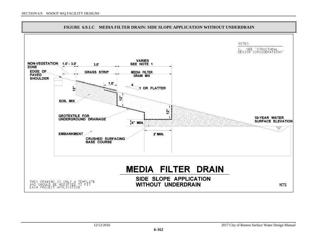
SECTION 6.9 WSDOT WQ FACILITY DESIGNS
12/12/2016 2017 City of Renton Surface Water Design Manual 6-162
FIGURE 6.9.1.C MEDIA FILTER DRAIN: SIDE SLOPE APPLICATION WITHOUT UNDERDRAIN
SECTION 6.9.1 MEDIA FILTER DRAIN
2017 City of Renton Surface Water Design Manual 12/12/2016 6-163
Functional Description The MFD removes suspended solids, phosphorus, and metals from highway runoff through physical straining, ion exchange, carbonate precipitation, and biofiltration.
Stormwater runoff is conveyed to the MFD via sheet flow over a vegetation-free gravel zone to ensure sheet dispersion and provide some pollutant trapping. Next, a grass strip, which may be amended with composted material, is incorporated into the top of the fill slope to provide pretreatment, further enhancing filtration and extending the life of the system. The runoff is then filtered through a bed of porous, alkalinity-generating granular medium—the MFD mix. MFD mix is a fill material composed of crushed rock (sized by screening), dolomite, gypsum, and perlite. The dolomite and gypsum additives serve to buffer acidic pH conditions and exchange light metals for heavy metals. Perlite is incorporated to improve moisture retention, which is critical for the formation of biomass epilithic biofilm to assist in the removal of solids, metals, and nutrients. Treated water drains from the MFD mix bed into the conveyance system below the MFD mix. Geotextile lines the underside of the MFD mix bed and the conveyance system.
The underdrain trench is an option for hydraulic conveyance of treated stormwater to a desired location, such as a downstream flow control facility or stormwater outfall. The trench’s perforated underdrain pipe is a protective measure to ensure free flow through the MFD mix and to prevent prolonged ponding. It may be possible to omit the underdrain pipe if it can be demonstrated that the pipe is not necessary to maintain free flow through the MFD mix and underdrain trench.
It is critical to note that water should sheet flow across the MFD. Channelized flows or ditch flows running down the middle of the dual MFD (continuous off-site inflow) should be minimized.
Applications and Limitations In many instances, conventional runoff treatment is not feasible due to right of way constraints (such as adjoining wetlands and geotechnical considerations). The MFD and the dual MFD designs are runoff treatment options that can be sited in most right of way confined situations. In many cases, a MFD or a dual MFD can be sited without the acquisition of additional right of way needed for conventional stormwater facilities or capital-intensive expenditures for underground wet vaults.
Media Filter Drains
• The longest flow path from the contributing area delivering sheet flow to the MFD should not exceed 150 feet.
• If there is sufficient roadway embankment width, the designer should consider placing the grass strip and MFD mix downslope when feasible.
• Steep slopes. Avoid construction on longitudinal slopes steeper than 5%. As side slopes approach 3H:1V, without design modifications, sloughing may become a problem due to friction limitations between the separation geotextile and underlying soils. Avoid construction on 3H:1V lateral slopes, and preferably use less than 4H:1V slopes. In areas where lateral slopes exceed 4H:1V, it may be possible to construct terraces to create 4H:1V slopes or to otherwise stabilize up to 3H:1V slopes.
• Wetlands. Do not construct in wetlands and wetland buffers. In many cases, a MFD (due to its small lateral footprint) can fit within the highway fill slopes adjacent to a wetland buffer. In those situations where the highway fill prism is located adjacent to wetlands, an interception trench/underdrain will need to be incorporated as a design element in the MFD.
• Shallow ground water. The designer should ensure the MFD does not intercept seeps, springs, or ground water. Mean high water table levels at the project site need to be determined to ensure the MFD mix bed and the underdrain (if needed) will not become saturated by shallow ground water.
• Unstable slopes. In areas where slope stability may be problematic, consult a geotechnical engineer. • Areas of seasonal ground water inundations or basement flooding. Site-specific piezometer data
may be needed in areas of suspected seasonal high ground water inundations. The hydraulic and runoff treatment performance of the dual MFD may be compromised due to backwater effects and lack of sufficient hydraulic gradient.
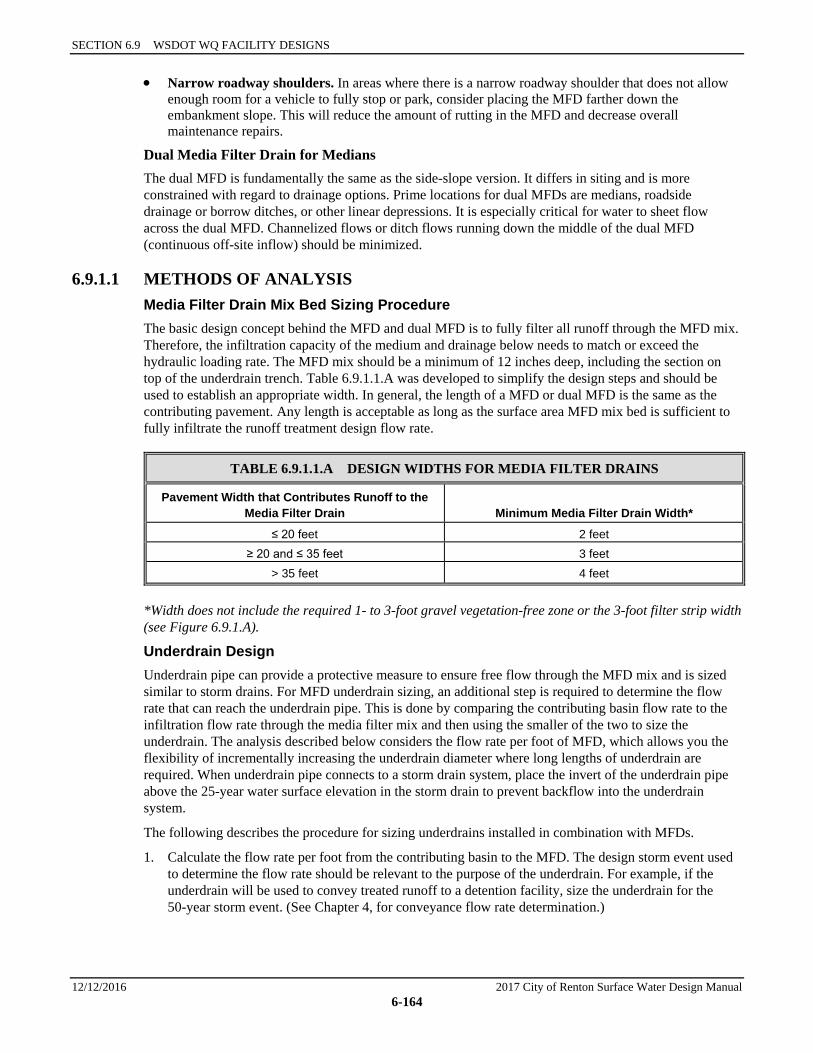
SECTION 6.9 WSDOT WQ FACILITY DESIGNS
12/12/2016 2017 City of Renton Surface Water Design Manual 6-164
• Narrow roadway shoulders. In areas where there is a narrow roadway shoulder that does not allow enough room for a vehicle to fully stop or park, consider placing the MFD farther down the embankment slope. This will reduce the amount of rutting in the MFD and decrease overall maintenance repairs.
Dual Media Filter Drain for Medians The dual MFD is fundamentally the same as the side-slope version. It differs in siting and is more constrained with regard to drainage options. Prime locations for dual MFDs are medians, roadside drainage or borrow ditches, or other linear depressions. It is especially critical for water to sheet flow across the dual MFD. Channelized flows or ditch flows running down the middle of the dual MFD (continuous off-site inflow) should be minimized.
6.9.1.1 METHODS OF ANALYSIS Media Filter Drain Mix Bed Sizing Procedure The basic design concept behind the MFD and dual MFD is to fully filter all runoff through the MFD mix. Therefore, the infiltration capacity of the medium and drainage below needs to match or exceed the hydraulic loading rate. The MFD mix should be a minimum of 12 inches deep, including the section on top of the underdrain trench. Table 6.9.1.1.A was developed to simplify the design steps and should be used to establish an appropriate width. In general, the length of a MFD or dual MFD is the same as the contributing pavement. Any length is acceptable as long as the surface area MFD mix bed is sufficient to fully infiltrate the runoff treatment design flow rate.
TABLE 6.9.1.1.A DESIGN WIDTHS FOR MEDIA FILTER DRAINS
Pavement Width that Contributes Runoff to the Media Filter Drain Minimum Media Filter Drain Width*
≤ 20 feet 2 feet ≥ 20 and ≤ 35 feet 3 feet
> 35 feet 4 feet
*Width does not include the required 1- to 3-foot gravel vegetation-free zone or the 3-foot filter strip width (see Figure 6.9.1.A).
Underdrain Design Underdrain pipe can provide a protective measure to ensure free flow through the MFD mix and is sized similar to storm drains. For MFD underdrain sizing, an additional step is required to determine the flow rate that can reach the underdrain pipe. This is done by comparing the contributing basin flow rate to the infiltration flow rate through the media filter mix and then using the smaller of the two to size the underdrain. The analysis described below considers the flow rate per foot of MFD, which allows you the flexibility of incrementally increasing the underdrain diameter where long lengths of underdrain are required. When underdrain pipe connects to a storm drain system, place the invert of the underdrain pipe above the 25-year water surface elevation in the storm drain to prevent backflow into the underdrain system.
The following describes the procedure for sizing underdrains installed in combination with MFDs.
1. Calculate the flow rate per foot from the contributing basin to the MFD. The design storm event used to determine the flow rate should be relevant to the purpose of the underdrain. For example, if the underdrain will be used to convey treated runoff to a detention facility, size the underdrain for the 50-year storm event. (See Chapter 4, for conveyance flow rate determination.)
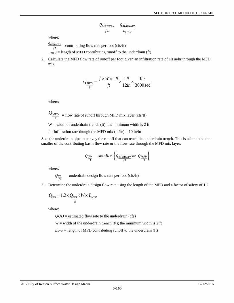
SECTION 6.9.1 MEDIA FILTER DRAIN
2017 City of Renton Surface Water Design Manual 12/12/2016 6-165
𝑄𝑄ℎ𝑖𝑖𝑖𝑖ℎ𝑤𝑤𝑤𝑤𝑤𝑤𝑓𝑓𝑓𝑓
=𝑄𝑄ℎ𝑖𝑖𝑖𝑖ℎ𝑤𝑤𝑤𝑤𝑤𝑤𝐿𝐿𝑀𝑀𝑀𝑀𝑀𝑀
where: 𝑄𝑄ℎ𝑖𝑖𝑖𝑖ℎ𝑤𝑤𝑤𝑤𝑤𝑤
𝑓𝑓𝑓𝑓 = contributing flow rate per foot (cfs/ft)
LMFD = length of MFD contributing runoff to the underdrain (ft)
2. Calculate the MFD flow rate of runoff per foot given an infiltration rate of 10 in/hr through the MFD mix.
sec36001
1211 hr
inft
ftftWfQ
ftMFD ××
××=
where:
= flow rate of runoff through MFD mix layer (cfs/ft)
W = width of underdrain trench (ft); the minimum width is 2 ft
f = infiltration rate though the MFD mix (in/hr) = 10 in/hr
Size the underdrain pipe to convey the runoff that can reach the underdrain trench. This is taken to be the smaller of the contributing basin flow rate or the flow rate through the MFD mix layer.
𝑄𝑄𝑈𝑈𝑀𝑀𝑓𝑓𝑓𝑓
= 𝑠𝑠𝑠𝑠𝑠𝑠𝑠𝑠𝑠𝑠𝑠𝑠𝑠𝑠 �𝑄𝑄ℎ𝑖𝑖𝑖𝑖ℎ𝑤𝑤𝑤𝑤𝑤𝑤𝑓𝑓𝑓𝑓
𝑜𝑜𝑠𝑠 𝑄𝑄𝑀𝑀𝑀𝑀𝑀𝑀𝑓𝑓𝑓𝑓�
where:
𝑄𝑄𝑈𝑈𝑈𝑈𝑓𝑓𝑓𝑓
= underdrain design flow rate per foot (cfs/ft)
3. Determine the underdrain design flow rate using the length of the MFD and a factor of safety of 1.2.
MFDft
UDUD LWQQ ×××= 2.1
where:
QUD = estimated flow rate to the underdrain (cfs)
W = width of the underdrain trench (ft); the minimum width is 2 ft
LMFD = length of MFD contributing runoff to the underdrain (ft)
ftMFDQ
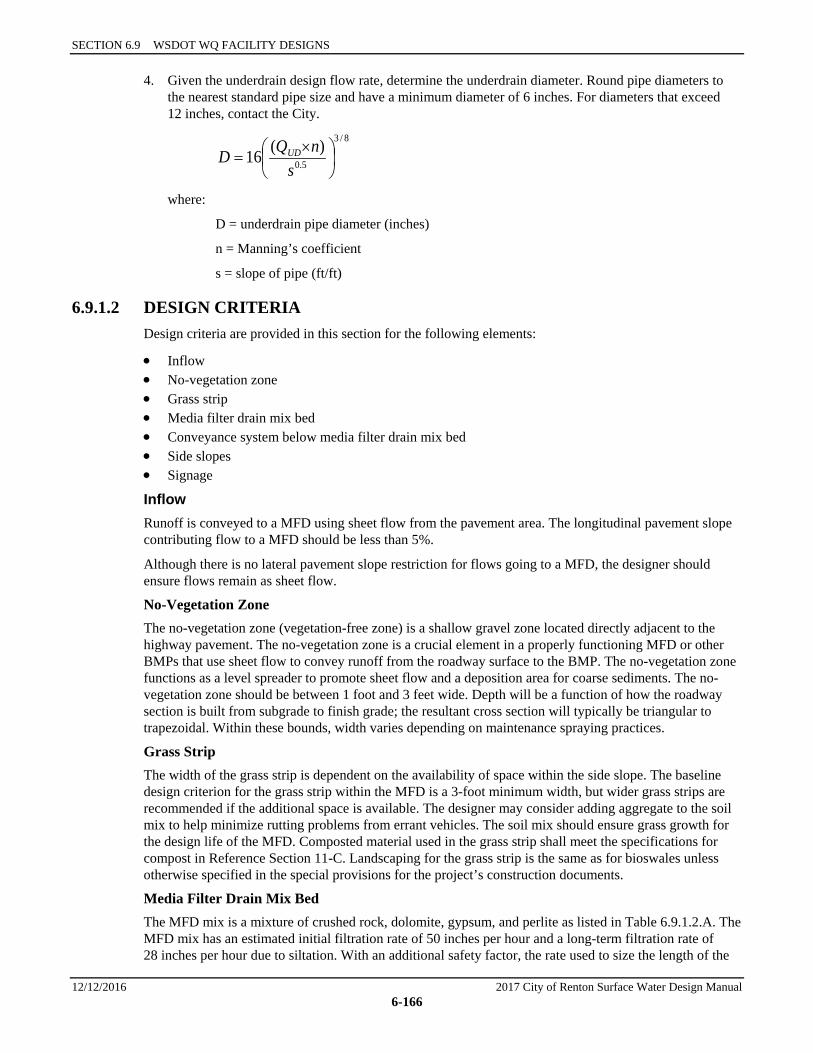
SECTION 6.9 WSDOT WQ FACILITY DESIGNS
12/12/2016 2017 City of Renton Surface Water Design Manual 6-166
4. Given the underdrain design flow rate, determine the underdrain diameter. Round pipe diameters to the nearest standard pipe size and have a minimum diameter of 6 inches. For diameters that exceed 12 inches, contact the City.
8/3
5.0)(16
×
=s
nQD UD
where:
D = underdrain pipe diameter (inches)
n = Manning’s coefficient
s = slope of pipe (ft/ft)
6.9.1.2 DESIGN CRITERIA Design criteria are provided in this section for the following elements:
• Inflow • No-vegetation zone • Grass strip • Media filter drain mix bed • Conveyance system below media filter drain mix bed • Side slopes • Signage
Inflow Runoff is conveyed to a MFD using sheet flow from the pavement area. The longitudinal pavement slope contributing flow to a MFD should be less than 5%.
Although there is no lateral pavement slope restriction for flows going to a MFD, the designer should ensure flows remain as sheet flow.
No-Vegetation Zone The no-vegetation zone (vegetation-free zone) is a shallow gravel zone located directly adjacent to the highway pavement. The no-vegetation zone is a crucial element in a properly functioning MFD or other BMPs that use sheet flow to convey runoff from the roadway surface to the BMP. The no-vegetation zone functions as a level spreader to promote sheet flow and a deposition area for coarse sediments. The no-vegetation zone should be between 1 foot and 3 feet wide. Depth will be a function of how the roadway section is built from subgrade to finish grade; the resultant cross section will typically be triangular to trapezoidal. Within these bounds, width varies depending on maintenance spraying practices.
Grass Strip The width of the grass strip is dependent on the availability of space within the side slope. The baseline design criterion for the grass strip within the MFD is a 3-foot minimum width, but wider grass strips are recommended if the additional space is available. The designer may consider adding aggregate to the soil mix to help minimize rutting problems from errant vehicles. The soil mix should ensure grass growth for the design life of the MFD. Composted material used in the grass strip shall meet the specifications for compost in Reference Section 11-C. Landscaping for the grass strip is the same as for bioswales unless otherwise specified in the special provisions for the project’s construction documents.
Media Filter Drain Mix Bed The MFD mix is a mixture of crushed rock, dolomite, gypsum, and perlite as listed in Table 6.9.1.2.A. The MFD mix has an estimated initial filtration rate of 50 inches per hour and a long-term filtration rate of 28 inches per hour due to siltation. With an additional safety factor, the rate used to size the length of the
SECTION 6.9.1 MEDIA FILTER DRAIN
2017 City of Renton Surface Water Design Manual 12/12/2016 6-167
MFD should be 10 inches per hour. Mixing and transportation must occur in a manner that ensures the materials are thoroughly mixed prior to placement and that separation does not occur during transportation or construction operations.
Conveyance System Below Media Filter Drain Mix The gravel underdrain trench provides hydraulic conveyance when treated runoff needs to be conveyed to a desired location such as a downstream flow control facility or stormwater outfall.
In Group C and D soils, an underdrain pipe would help to ensure free flow of the treated runoff through the MFD mix bed. In some Group A and B soils, an underdrain pipe may be unnecessary if most water percolates into subsoil from the underdrain trench. The need for underdrain pipe should be evaluated in all cases. The underdrain trench should be a minimum of 2 feet wide for either the conventional or the dual MFD.
The gravel underdrain trench may be eliminated if there is evidence to support that flows can be conveyed laterally to an adjacent ditch or onto a fill slope that is properly vegetated to protect against erosion. The MFD mix should be kept free draining up to the 50-year storm event water surface elevation represented in the downstream ditch.
Side Slopes In profile, the surface of the MFD should preferably have a lateral slope less than 4H:1V (<25%). On steeper terrain, it may be possible to construct terraces to create a 4H:1V slope, or other engineering may be employed if approved by the City, to ensure slope stability up to 3H:1V. If sloughing is a concern on steeper slopes, consideration should be given to incorporating permeable soil reinforcements, such as geotextiles, open-graded/permeable pavements, or commercially available ring and grid reinforcement structures, as top layer components to the MFD mix bed. Consultation with a geotechnical engineer is required.
Signage Nonreflective guideposts will delineate the MFD. This practice allows personnel to identify where the system is installed and to make appropriate repairs should damage occur to the system. If the MFD is located in an Aquifer Protection Area, signage prohibiting the use of pesticides must be provided.
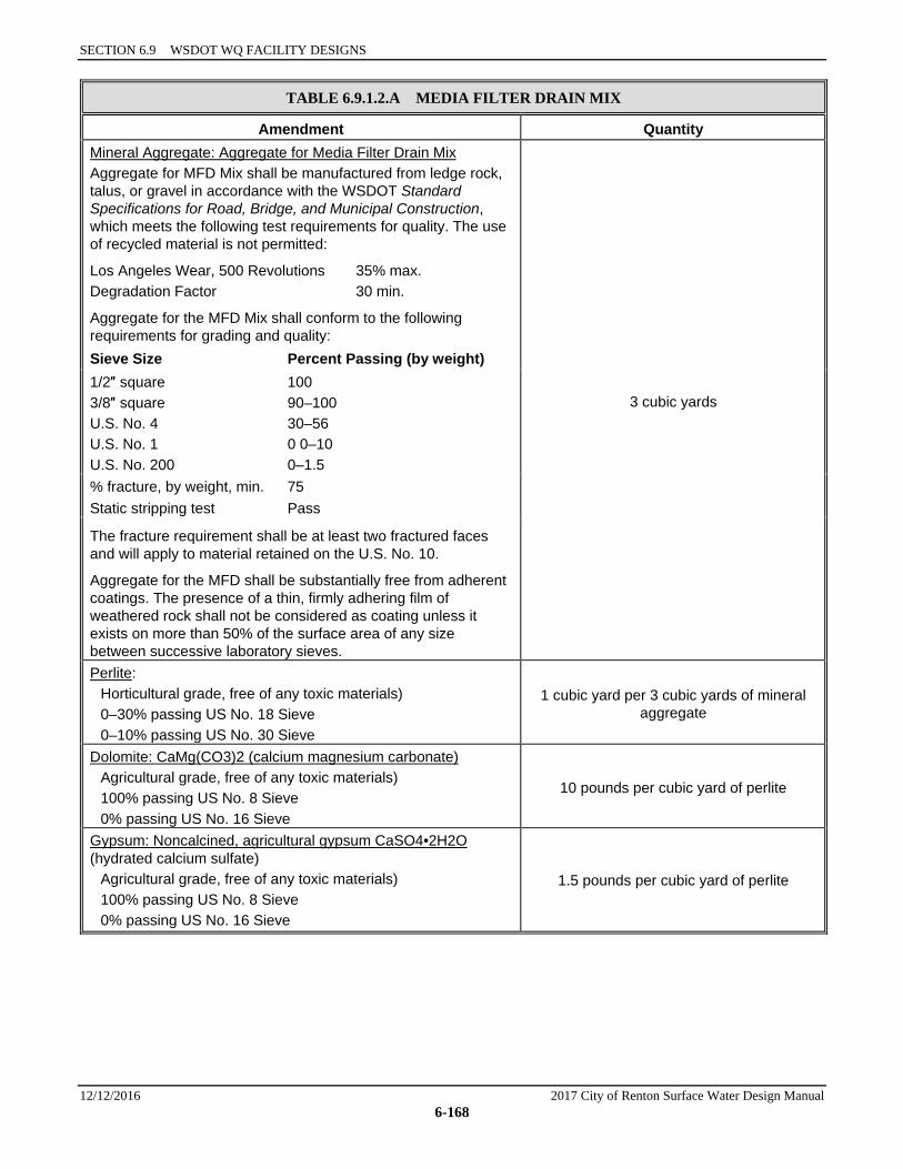
SECTION 6.9 WSDOT WQ FACILITY DESIGNS
12/12/2016 2017 City of Renton Surface Water Design Manual 6-168
TABLE 6.9.1.2.A MEDIA FILTER DRAIN MIX
Amendment Quantity Mineral Aggregate: Aggregate for Media Filter Drain Mix Aggregate for MFD Mix shall be manufactured from ledge rock, talus, or gravel in accordance with the WSDOT Standard Specifications for Road, Bridge, and Municipal Construction, which meets the following test requirements for quality. The use of recycled material is not permitted:
Los Angeles Wear, 500 Revolutions 35% max. Degradation Factor 30 min.
Aggregate for the MFD Mix shall conform to the following requirements for grading and quality:
3 cubic yards
Sieve Size Percent Passing (by weight) 1/2″ square 3/8″ square U.S. No. 4 U.S. No. 1 U.S. No. 200
100 90–100 30–56 0 0–10 0–1.5
% fracture, by weight, min. 75 Static stripping test Pass
The fracture requirement shall be at least two fractured faces and will apply to material retained on the U.S. No. 10.
Aggregate for the MFD shall be substantially free from adherent coatings. The presence of a thin, firmly adhering film of weathered rock shall not be considered as coating unless it exists on more than 50% of the surface area of any size between successive laboratory sieves. Perlite:
Horticultural grade, free of any toxic materials) 0–30% passing US No. 18 Sieve 0–10% passing US No. 30 Sieve
1 cubic yard per 3 cubic yards of mineral aggregate
Dolomite: CaMg(CO3)2 (calcium magnesium carbonate) Agricultural grade, free of any toxic materials) 100% passing US No. 8 Sieve 0% passing US No. 16 Sieve
10 pounds per cubic yard of perlite
Gypsum: Noncalcined, agricultural gypsum CaSO4•2H2O (hydrated calcium sulfate)
Agricultural grade, free of any toxic materials) 100% passing US No. 8 Sieve 0% passing US No. 16 Sieve
1.5 pounds per cubic yard of perlite
SECTION 6.9.2 COMPOST-AMENDED FILTER STRIPS
2017 City of Renton Surface Water Design Manual 12/12/2016 6-169
6.9.2 COMPOST-AMENDED FILTER STRIPS The CAVFS is a variation of the basic vegetated filter strip that adds soil amendments to the roadside embankment (See Figure 6.9.2.A). The soil amendments improve infiltration characteristics, increase surface roughness, and improve plant sustainability. Once permanent vegetation is established, the advantages of the CAVFS are higher surface roughness; greater retention and infiltration capacity; improved removal of soluble cationic contaminants through sorption; improved overall vegetative health; and a reduction of invasive weeds. Compost-amended systems have somewhat higher construction costs due to more expensive materials, but require less land area for runoff treatment, which can reduce overall costs.
6.9.2.1 METHODS OF ANALYSIS Use the “CAVFS” element in an approved continuous runoff model to determine the amount of water that is treated by the CAVFS. To fully meet treatment requirements, 91 percent of the influent runoff file must pass through the soil profile of the CAVFS. Water that merely flows over the surface is not considered treated. Approved continuous runoff models should be able to report the amount of water that it estimates will pass through the soil profile.
6.9.2.2 DESIGN CRITERIA Soil Component
• The texture for the soil component should be loamy sand (USDA Soil Textural Classification).
Compost Component
• Compost shall be per the specifications in Reference Section 11-C. • Compost must not contain biosolids, manure, any street or highway sweepings, or any catch basin
solids.
Soil/Compost Mix
• Presumptive approach: Place and rototill 1.75 inches of composted material into 6.25 inches of soil (a total amended depth of about 9.5 inches), for a settled depth of 8 inches. Water or roll to compact soil to 85% maximum. Plant grass.
• Custom approach: Place and rototill the calculated amount of composted material into a depth of soil needed to achieve 8 inches of settled soil at 5% organic content. Water or roll to compact soil to 85% maximum. Plant grass. The amount of compost or other soil amendments used varies by soil type and organic matter content. If there is a good possibility that site conditions may already contain a relatively high organic content, then it may be possible to modify the pre-approved rate described above and still be able to achieve the 5% organic content target.
• The final soil mix (including compost and soil) should have an initial saturated hydraulic conductivity less than 12 inches per hour, and a minimum long-term hydraulic conductivity of 1.0 inch/hour per ASTM Designation D 2434 (Standard Test Method for Permeability of Granular Soils) at 85% compaction per ASTM Designation D 1557 (Standard Test Method for Laboratory Compaction Characteristics of Soil Using Modified Effort. Infiltration rate and hydraulic conductivity are assumed to be approximately the same in a uniform mix soil. Note: Long term saturated hydraulic conductivity is determined by applying the appropriate infiltration correction factors as explained in Section 5.2.1.
• The final soil mixture should have a minimum organic content of 5% by dry weight per ASTM Designation D 2974 (Standard Test Method for Moisture, Ash and Organic Matter of Peat and Other Organic Soils).
• Achieving the above recommendations will depend on the specific soil and compost characteristics. In general, the recommendation can be achieved with 60% to 65% loamy sand mixed with 25% to 30% compost or 30% sandy loam, 30% coarse sand, and 30% compost.
SECTION 6.9 WSDOT WQ FACILITY DESIGNS
12/12/2016 2017 City of Renton Surface Water Design Manual 6-170
• The final soil mixture should be tested prior to installation for fertility, micronutrient analysis, and organic material content.
• Clay content for the final soil mix should be less than 5%. • The pH for the soil mix should be between 5.5 and 7.0. If the pH falls outside the acceptable range, it
may be modified with lime to increase the pH or iron sulfate plus sulfur to lower the pH. The lime or iron sulfate must be mixed uniformly into the soil.
• The soil mix should be uniform and free of stones, stumps, roots, or other similar material larger than 2 inches.
• When placing topsoil, it is important that the first lift of topsoil is mixed into the top of the existing soil. This allows the roots to penetrate the underlying soil easier and helps prevent the formation of a slip plane between the two soil layers.
6.9.3 COMPOST-AMENDED BIOFILTRATION SWALES The CABS is a variation of the basic biofiltration swale (bioswale) that adds soil amendments. The soil amendments improve infiltration characteristics, increase surface roughness, and improve plant sustainability. Once permanent vegetation is established, the advantages of the CABS are higher surface roughness; greater retention and infiltration capacity; improved removal of soluble cationic contaminants through sorption; improved overall vegetative health; and a reduction of invasive weeds. Compost-amended systems have somewhat higher construction costs due to more expensive materials, but require less land area for runoff treatment, which can reduce overall costs.
6.9.3.1 METHODS OF ANALYSIS Follow the methods of analysis outlined in Section 6.3.1 for Basic Bioswales.
6.9.3.2 DESIGN CRITERIA Follow the design criteria outlined in Section 6.3.1 for Basic Bioswales with the addition of a compost blanket with the following requirements:
Compost Component
• Compost depth shall be 3 inches • Compost shall be per the specifications in Reference Section 11-C. • Compost must not contain biosolids, manure, any street or highway sweepings, or any catch basin
solids.