Embed Size (px)
Citation preview

CITY OF PETALUMA
PETALUMA, CALIFORNIA
PUBLIC WORKS DEPARTMENT CONTRACT DOCUMENTS
FOR
Petaluma Transit Maintenance Facility
IN
THE CITY OF PETALUMA, SONOMA COUNTY, CALIFORNIA
FOR USE WITH STANDARD SPECIFICATIONS AND STANDARD PLANS DATED MAY 2010, OF THE CALIFORNIA DEPARTMENT OF
TRANSPORTATION (CALTRANS)
Federal Project No. CA-04-0206
CITY PROJECT NO. C65201201
BID OPENING DATE: May 30, 2012 AT 3:00 P.M.


INTRODUCTORY NOTICE TO BIDDERS
PLAN PROCUREMENT
Plans, contract documents and engineer’s estimates are available from the City of
Petaluma Public Works Department at $50.00 per set (non-refundable).
If you would like a copy of the plan holders list, please e-mail Shelly Kappel
A Type “B” California State Contractor’s License is required.
QUESTIONS CONCERNING PLANS AND BID ITEMS:
Questions concerning interpretation of the bid documents shall be directed to:
City of Petaluma, Transit Division
555 N. McDowell Blvd.
Petaluma, CA 94954
(707) 778-4421
Attention: Joseph Rye, Transit Manager
Office hours: Monday through Thursday, 8:00 AM to 5:00 PM.
Closed every Friday
PRE-BID CONFERENCE: SEE NOTICE TO BIDDERS


TABLE OF CONTENTS
Section A Notice Inviting Bids
Special Provisions
Section 1 Governing Documents/General Conditions
1-1 Governing Documents
1-2 City of Petaluma General Conditions
Article 1: Definitions
Article 2: Preliminary Matters
Article 3: Intent and Use of Contract Documents
Article 4: Site of the Work
Article 5: Bonds and Insurance
Article 6: Contractor’s Responsibilities
Article 7: Other Work
Article 8: PCDC’s Responsibilities
Article 9: Engineer’s Status During Construction
Article 10: Changes in the Work
Article 11: Change of Contract Price
Article 12: Change of Contract Times
Article 13: Inspections and Tests; Correction, Removal, or Acceptance of
Defective Work
Article 14: Payments to Contractor and Completion
Article 15: Suspension of Work and Termination
Article 16: General Terms
Article 17: California State Requirements
Section 2 Supplementary General Conditions
2-1 Description of Work
2-2 Order of Precedence of Contract Documents
2-3 Cooperation
2-4 Obstructions
2-5 Order of Work
2-6 Project and Construction Area Signs
2-7 Maintaining Bus Circulation and Employee and Pedestrian Access
2-8 Clearing and Grubbing
2-9 Schedule
2-10 Superintendence
2-11 Safety Requirement
2-12 Project Appearance
2-13 Responsibility for Damage
2-14 Guarantee of Work
2-15 Record (As Built) Drawings
2-16 Notice of Potential Claim
2-17 Payment for Material on Hand
2-18 Archaeological Monitoring
2-19 Storm Water Management, and Sediment and Erosion Control
2-20 Hours of Work

2-21 Beginning of Work, Time of Completion and Liquidated Damages
2-22 Item Increases and Decreases
2-23 Existing Water Values, Monuments and Manholes
2-24 Wage Rates
2-25 Cost of Work Based on Time and Materials
2-26 Prompt Payment of Subcontractors
2-27 Subcontracting-Contract Compliance
2-28 Instructions to Bidders
Section 3 Bidding Requirements
3-1 Instructions to Bidders
3-2 Proposal
3-3 Bid Schedule
3-4 Non-Collusion Affidavit
3-5 Questionnaire and Financial Assurance Statement Form
3-6 Bid Bond
3-7 List of Subcontractors
3-8 List of Materials, Suppliers, and Material Guarantee
3-9 Bid Proposal Certificates
3-10 Equal Employment Opportunity Certification
3-11 Debarment and Suspension Certification
3-12 Non-Lobbying Certification for Federal Aide Contracts
3-13 Disclosure of Lobbying Activities
3-14 Instructions for Completion of SF-LLL, Disclosure of Lobbying Activities
3-15 Final Report Utilization of Disadvantaged Businesses
3-16A Local Agency Bidder – DBE Information Forms
3-16B UDBE Information – Good Faith Efforts
3-17 Final Report Utilization of DBE
3-18 Buy America Certification
Section 4 Federal Contract Provisions
4-1 No Federal Government Obligations to Third Parties
4-2 False or Fraudulent Statements or Claims
4-3 Access to Third Party Contract Records
4-4 Changes to Federal Requirements
4-5 Civil Rights
4-6 Disadvantaged Business Enterprise
4-7 Terminations
4-8 Special EEO Provisions for Construction Contracts
4-9 Debarment and Suspension
4-10 Buy America
4-11 Resolution of Disputes, Breaches, or Other Litigation
4-12 Lobbying
4-13 Clean Air
4-14 Clean Water
4-15 Construction Employee Protections – Davis- Bacon and Copeland Anti-
Kickback
4-16 Construction Employee Protections – Contract Work Hours & Safety
Standards Act
4-17 Bonding
4-18 Seismic Safety
4-19- Energy Conservation
4-20 ADA Access
4-21 Incorporation of FTA Terms
4-22 Privacy Act
4-23 Bid Protest
Section 5 Award and Execution of Contract
Section 6 Construction Agreement
Section 7 Technical Specifications

1 NOTICE INVITING BIDS (City) 4/1/12 (fmk)
NOTICE INVITING BIDS
1. RECEIPT OF BIDS: Sealed Bids will be received at the office of the City Clerk of the
City of Petaluma located at 11 English Street, Room 4, Petaluma, California, 94952-
2610, until 3:00 p.m. (enter time) on Wednesday, May 30, 2012, for the Petaluma Transit
Facility Rehabilitation Project. Any Bids received after the specified time and date will
not be considered. Fax and other electronically transmitted Bids will not be accepted.
2. OPENING OF BIDS: The Bids will be publicly opened and read at 3:00 p.m. (enter time)
on Wednesday, May 30, 2012 at the above-mentioned office of the CITY. The CITY
reserves the right to postpone the date and time for opening of Bids at any time prior to
the aforesaid date and time.
3. COMPLETION OF WORK: The WORK must be completed within 60 working days
after the commencement date stated in the Notice to Proceed.
4. DESCRIPTION OF WORK: The WORK includes an addition/remodel of the existing
Petaluma Transit maintenance building. It includes the removal of the west end of the
existing maintenance shop areato make way for a new higher maintenance bay and bus
wash bay. It also includes interior improvements with the remaining existing building for
accomodating required office functions and a new parts room. The existing accessible
(ADA) toilet room will remain and will continue to serve the shop facility. Two new
concrete aprons, miscellaneous paving repair, restriping the bus parking lot, and a new
accessible ramp between the buildings are the only proposed site impovements.
The City of Petaluma affirms that in any contract entered into pursuant to this
advertisement, disadvantaged business enterprises (DBE) will be afforded full
opportunity to submit bids in response to this invitation. Bidders are advised that, as
required by federal law, the City of Petaluma is implementing DBE requirements for
Underutilized Disadvantaged Business Enterprises (UDBE) for this project. Section 2,
"Proposal Requirements and Conditions," under subsection titled "Disadvantaged
Business Enterprises (DBE)" and Section 5, "General," under subsection titled
"Performance of Subcontractors" of these special provisions cover the UDBE
requirements.
The UDBE contract goal is 1.2 percent (1.2%).
This project is subject to the “Buy America” provisions of the Surface Transportation
Assistance Act of 1982 as amended by the Intermodal Surface Transporation Efficiency
act of 1991.
The award of the contract, if awarded, will be to the lowest responsible bidder for the
base bid, whose proposal complies with all the requirements prescribed and who has met
the goal for UDBE participation or has demonstrated, to the satisfaction of the City,
adequate good faith efforts to do so. The City Council may decide, at the time of the
2 NOTICE INVITING BIDS (City) 4/1/12 (fmk)
award, to choose the base bid and bid alternate. The low bidder will remain the same,
regardless of the City Council's decision on the base bid or bid alternate.
.
5. SITE OF WORK: The site of the WORK is located: 555 N. McDowell Blvd Petaluma
CA.
6. OBTAINING CONTRACT DOCUMENTS: The Contract Documents are entitled
“Petaluma Transit Facility Rehabilitation Project.”
The Contract Documents may be obtained by 4:00 p.m. Monday through Thursday (City
Hall is closed every Friday) (enter time) at the office of Public Works Department, 11
English Street, Petaluma, CA 94952 , Phone No. (707) 778-4474, Attention: Shelly
Kappel, upon payment of $50.00 (non-refundable) for each set of Contract Documents
(including technical specifications and accompanying reduced scale drawings). The scale
of the reduced drawings is about one-half of the original scale. At the Bidder’s request
and expense, the Contract Documents may be sent by overnight mail.
X Full-scale drawings are not available.
If full-scale drawings are available and desired, they may be purchased at
reproduction cost from .
7. BID SECURITY: Each Bid shall be accompanied by a certified or cashier’s check or Bid
Bond executed by an admitted surety in the amount of 10 percent of the Total Bid Price
payable to the City of Petaluma as a guarantee that the Bidder, if its Bid is accepted, will
promptly execute the Agreement. A Bid shall not be considered unless one of the forms
of Bidder’s security is enclosed with it. Upon acceptance of the Bid, if the Bidder refuses
to or fails to promptly execute the Agreement, the Bidder’s security shall be forfeited to
the CITY.
8. CONTRACTOR’S LICENSE CLASSIFICATION: In accordance with the provisions of
California Public Contract Code Section 3300, the CITY has determined that the
CONTRACTOR shall possess a valid Class B license at the time that the Contract is
awarded. Failure to possess the specified license shall render the Bid as non-responsive
and shall act as a bar to award of the Contract to any bidder not possessing said license at
the time of award.
9. PREFERENCE FOR MATERIAL: Substitute products will be considered prior to award
of the Contract in accordance with Section 3400 of the California Public Contract Code.
The Bidder will submit data substantiating its request for a substitution of “an equal” item
within 14 days following submission of its Bid. Substantiation data will conform to the
requirements of the instructions for Proposed Substitutions or “or equal” items contained
in the Bid Forms. The ENGINEER will make a determination of approval or rejection of
the proposed substitution prior to the award of the Contract. No request for substitution
of “an equal” item will be considered by the ENGINEER after award of the Contract.

3 NOTICE INVITING BIDS (City) 4/1/12 (fmk)
10. REJECTION OF PROPOSALS: The CITY reserves the right to reject all or any part of
all bids submitted, waive informalities and irregularities, and will not, to the extent
allowed by law, be bound to accept the lowest bid.
11. BIDS TO REMAIN OPEN: The Bidder shall guarantee the total bid price for a period of
90 calendar days from the date of bid opening.
12. CALIFORNIA WAGE RATE AND FEDERAL MINIMUM WAGE RATE
REQUIREMENTS: The Federal minimum wage rates for this project as predetermined
by the United States Secretary of Labor are set forth in the books issued for bidding
purposes entitled “Contract Documents,” and in copies of this book that may be
examined at the offices described above where project plans, special provisions, and
proposal forms may be seen. Addenda to modify the Federal minimum wage rates, if
necessary, will be issued to holders of “Contract Documents” books. Future effective
general prevailing wage rates which have been predetermined and are on file with the
California Department of Industrial Relations are referenced but not printed in the general
prevailing wage rates. A copy of these wage rates is included in this document.
In accordance with the provisions of California Labor Code Sections 1770, 1773, 1773.1,
1773.6 and 1773.7 as amended, the Director of the Department of Industrial Relations has
determined the general prevailing rate of per diem wages in accordance with the
standards set forth in Section 1773 for the locality in which the WORK is to be
performed. A copy of said wage rates is available from the California Department of
Industrial Relations’ Internet web site at www.dir.ca.gov/DLSR/PWD. It shall be
mandatory upon the CONTRACTOR to whom the WORK is awarded and upon any
subcontractor under the CONTRACTOR to pay not less than said specified rates to all
workers employed by them in the execution of the WORK.
Attention is directed to the Federal minimum wage rate requirements in the books
entitled “Contract Documents.” If there is a difference between the minimum wage rates
predetermined by the Secretary of Labor and the general prevailing wage rates
determined by the Director of the California Department of Industrial Relations for
similar classifications of labor, the Contractor and subcontractors shall pay not less than
the higher wage rate. The Department will not accept lower State wage rates not
specifically included in the Federal minimum wage determinations. This includes
“helper” (or other classifications based on hours of experience) or any other classification
not appearing in the Federal wage determinations. Where Federal wage determinations
do not contain the State wage rate determination otherwise available for use by the
Contractor and subcontractors, the Contractor and subcontractors shall pay not less than
the Federal minimum wage rate which most closely approximates the duties of the
employees in question.
13. RETAINAGE FROM PAYMENTS: The CONTRACTOR may elect to receive 100
percent of payments due under the Contract Documents from time to time, without
retention of any portion of the payment by the CITY, by depositing securities of
equivalent value with the CITY in accordance with the provisions of Section 22300 of the

4 NOTICE INVITING BIDS (City) 4/1/12 (fmk)
Public Contract Code. Alternatively, the CONTRACTOR may request and the CITY
shall make payment of retentions earned directly to the escrow agent at the expense of
CONTRACTOR. At the expense of the CONTRACTOR, the CONTRACTOR may
direct the investments of the payments into securities and the CONTRACTOR shall
receive the interest earned on the investments upon the same terms as provided in Section
22300 of the Public Contract Code for securities deposited by the CONTRACTOR. The
CONTRACTOR shall be responsible for paying all fees for the expenses incurred by the
escrow agent in administering the escrow account and all expenses of the CITY. These
expenses and payment terms shall be determined by the CITY’s Finance Director or
his/her designee and the escrow agent. Upon satisfactory completion of the WORK, the
CONTRACTOR shall receive from the escrow agent all securities, interest, and payments
received by the escrow agent from the CITY, pursuant to the terms of Section 22300 of
the Public Contract Code. Such securities, if deposited by the CONTRACTOR, shall be
valued by the CITY, whose decision on valuation of the securities shall be final.
Securities eligible for investment under this provision shall be limited to those listed in
Section 16430 of the Government Code, bank or savings and loan certificates of deposit,
interest-bearing demand deposit accounts, standby letters of credit, or any other security
mutually agreed to by the CONTRACTOR and the CITY.
14. PAYMENT BOND: Pursuant to and in accordance with California Civil Code Section
3247, a payment (labor and materials) bond must be filed if the expenditure for the
WORK is in excess of Twenty-Five Thousand Dollars ($25,000).
15. MANDATORY PRE-BID CONFERENCE [ Check only if no pre-bid
conference is to be held]: Prospective bidders are required to attend a pre-bid
conference to discuss the scope of the project and bidding requirements at 3:00 p.m.
(enter time) on May 22, 2012, at the Transit offices at 555 N. McDowell Blvd. Detailed
technical questions may be submitted in writing, but technical questions will be
answered, if warranted, by addenda later. Oral statements may not be relied upon and
will not be binding or legally effective.
Following the conference, the meeting will reconvene at the project Site. Transportation
to the project site will be the responsibility of prospective bidders. The purposes of the
conference and site visit are to discuss the scope of the project and bidding requirements
and to acquaint bidders with Site conditions.
16. PROJECT ADMINISTRATION: All communications relative to this WORK shall be
directed to the ENGINEER prior to opening of the Bids.
NAME JOE RYE
ADDRESS 555 N. MCDOWELL
PETALUMA, CA 94954
(707) 778-4421
EMAIL [email protected]


6 NOTICE INVITING BIDS (City) 4/1/12 (fmk)


SECTION 1. GOVERNING DOCUMENTS/GENERAL CONDITIONS
1-1 GOVERNING DOCUMENTS/GENERAL CONDITIONS
All work shall be governed by and done in accordance with the following:
Contract Documents, consisting of the Notice Inviting Bids, Bidder’s Proposal, Proposal
Requirements and Conditions, Affidavits, Bid Bond, Designation of
Subcontractors, Experience and Financial Qualifications, Faithful Performance
Bond, Labor and Materials Bond, Construction Contract, Insurance Certificates
and Endorsements, Supplemental General Conditions, Technical Specifications,
and Addenda, if any, and project plans.
General Conditions, City, dated November 2004.
City of Petaluma Design and Construction Standards.
State of California Business and Transportation Agency, Department of Transportation,
Standard Plans and Specifications, 2010 edition, - hereinafter called
State/Caltrans Standard Plans and/or Standard Specifications. All references
therein to the State of California shall be deemed references to the City. Likewise,
all references to the Director shall be deemed to mean the Director of Public
Works of the City of Petaluma or his/her designee. Provisions requiring binding
arbitration, such as section 9-1.10, are expressly excluded and not applicable.
Any and all work and requirements called for in any one or more of the above
listed documents shall be deemed to be called for in all.

PAGE i GENERAL CONDITIONS (City) November 2004
CITY OF PETALUMA - GENERAL CONDITIONS
TABLE OF CONTENTS
ARTICLE 1 - DEFINITIONS ........................................................................................................ 1
Addenda .............................................................................................................................. 1
Agreement .......................................................................................................................... 1
Application for Payment ..................................................................................................... 1
Asbestos .............................................................................................................................. 1
Bid ...................................................................................................................................... 1
Bonds .................................................................................................................................. 1
Change Order ...................................................................................................................... 1
CITY ................................................................................................................................... 1
Clarification ........................................................................................................................ 1
Contract Documents ........................................................................................................... 1
Contract Price ..................................................................................................................... 2
Contract Times ................................................................................................................... 2
CONTRACTOR ................................................................................................................. 2
Day ..................................................................................................................................... 2
Defective Work................................................................................................................... 2
Drawings ............................................................................................................................. 2
Effective Date of the Agreement ........................................................................................ 2
ENGINEER ........................................................................................................................ 2
Field Order .......................................................................................................................... 2
Hazardous Waste ................................................................................................................ 2
Laws and Regulations; Laws or Regulations ..................................................................... 2
Lien or Mechanic’s Lien..................................................................................................... 2
Milestone ............................................................................................................................ 3
Notice of Award ................................................................................................................. 3
Notice of Completion ......................................................................................................... 3
Notice to Proceed................................................................................................................ 3
Partial Utilization ................................................................................................................ 3
Petroleum ............................................................................................................................ 3
Project ................................................................................................................................. 3
Record Drawings ................................................................................................................ 3
Resident Project Representative ......................................................................................... 3
Samples ............................................................................................................................... 3
Shop Drawings ................................................................................................................... 3
Site ...................................................................................................................................... 3
Special Provisions .............................................................................................................. 4
Specifications ..................................................................................................................... 4
Stop Notice ......................................................................................................................... 4
Subcontractor ...................................................................................................................... 4

PAGE ii GENERAL CONDITIONS (City) November 2004
Supplementary General Conditions .................................................................................... 4
Supplier ............................................................................................................................... 4
Utilities ............................................................................................................................... 4
WORK ................................................................................................................................ 4
Working day ....................................................................................................................... 4
ARTICLE 2 - PRELIMINARY MATTERS .................................................................................. 4
2.1 DELIVERY OF BONDS AND INSURANCE CERTIFICATES .......................... 4
2.2 COPIES OF DOCUMENTS ................................................................................... 5
2.3 COMMENCEMENT OF CONTRACT TIMES; NOTICE TO PROCEED .......... 5
2.4 STARTING THE WORK ....................................................................................... 5
2.5 PRECONSTRUCTION CONFERENCE ............................................................... 5
ARTICLE 3 - INTENT AND USE OF CONTRACT DOCUMENTS .......................................... 5
3.1 INTENT .................................................................................................................. 5
3.2 REFERENCE TO STANDARDS........................................................................... 6
3.3 REVIEW OF CONTRACT DOCUMENTS ........................................................... 6
3.4 ORDER OF PRECEDENCE OF CONTRACT DOCUMENTS ............................ 7
3.5 AMENDING CONTRACT DOCUMENTS........................................................... 7
3.6 REUSE OF DOCUMENTS .................................................................................... 7
ARTICLE 4 - SITE OF THE WORK ............................................................................................. 8
4.1 AVAILABILITY OF LANDS ................................................................................ 8
4.2 REPORTS OF PHYSICAL CONDITIONS ........................................................... 8
4.3 PHYSICAL CONDITIONS - UNDERGROUND UTILITIES .............................. 9
4.4 DIFFERING SITE CONDITIONS ......................................................................... 9
4.5 HAZARDOUS MATERIALS .............................................................................. 10
4.6 REFERENCE POINTS ......................................................................................... 11
ARTICLE 5 - BONDS AND INSURANCE ................................................................................ 11
5.1 BONDS ................................................................................................................. 11
5.2 INSURANCE ........................................................................................................ 12
ARTICLE 6 - CONTRACTOR’S RESPONSIBILITIES............................................................. 15
6.1 COMMUNICATIONS .......................................................................................... 15
6.2 SUPERVISION AND SUPERINTENDENCE .................................................... 15
6.3 LABOR, MATERIALS, AND EQUIPMENT ...................................................... 15
6.4 SCHEDULE .......................................................................................................... 20
6.5 SUBSTITUTES OR “OR EQUAL” ITEMS ........................................................ 20
6.6 CONCERNING SUBCONTRACTORS, SUPPLIERS, AND OTHERS............. 20
6.7 PERMITS .............................................................................................................. 20
6.8 PATENT FEES AND ROYALTIES .................................................................... 21
6.9 LAWS AND REGULATIONS ............................................................................. 21
6.10 TAXES .................................................................................................................. 21
6.11 USE OF PREMISES ............................................................................................. 21
6.12 SAFETY AND PROTECTION ............................................................................ 22
PAGE iii GENERAL CONDITIONS (City) November 2004
6.13 EMERGENCIES ................................................................................................... 24
6.14 SUBMITTALS ...................................................................................................... 24
6.15 CONTINUING THE WORK ................................................................................ 27
6.16 CONTRACTOR’S GENERAL WARRANTY AND GUARANTEE ................. 27
6.17 INDEMNIFICATION ........................................................................................... 30
6.18 CONTRACTOR’S DAILY REPORTS ................................................................ 31
6.19 CONTRACT DOCUMENTS AND RECORD DRAWINGS .............................. 31
6.20 CLEAN UP ........................................................................................................... 32
6.21 STORM WATER POLLUTION PREVENTION ................................................ 34
ARTICLE 7 - OTHER WORK ..................................................................................................... 38
7.1 RELATED WORK AT SITE ................................................................................ 39
7.2 COORDINATION ................................................................................................ 40
ARTICLE 8 - CITY’S RESPONSIBILITIES .............................................................................. 40
8.1 COMMUNICATIONS .......................................................................................... 40
8.2 PAYMENTS ......................................................................................................... 40
8.3 LANDS, EASEMENTS, AND SURVEYS .......................................................... 40
8.4 REPORTS AND DRAWINGS ............................................................................. 41
8.5 CHANGE ORDERS ............................................................................................. 41
8.6 INSPECTIONS AND TESTS ............................................................................... 41
8.7 SUSPENSION OF WORK ................................................................................... 41
8.8 TERMINATION OF AGREEMENT ................................................................... 41
8.9 LIMITATION ON CITY’S RESPONSIBILITIES .............................................. 41
8.10 UNDISCLOSED HAZARDOUS ENVIRONMENTAL CONDITIONS ............ 41
ARTICLE 9 - ENGINEER’S STATUS DURING CONSTRUCTION ....................................... 42
9.1 CITY’S REPRESENTATIVE .............................................................................. 42
9.2 OBSERVATIONS ON THE SITE ....................................................................... 42
9.3 PROJECT REPRESENTATION .......................................................................... 42
9.4 CLARIFICATIONS .............................................................................................. 42
9.5 AUTHORIZED VARIATIONS IN WORK ......................................................... 42
9.6 REJECTING DEFECTIVE WORK ..................................................................... 43
9.7 CONTRACTOR SUBMITTALS, CHANGE ORDERS, AND PAYMENTS ..... 43
9.8 DECISIONS ON DISPUTES ............................................................................... 43
9.9 LIMITATIONS ON ENGINEER’S RESPONSIBILITIES.................................. 43
ARTICLE 10 - CHANGES IN THE WORK ............................................................................... 44
10.1 GENERAL ............................................................................................................ 44
10.2 ALLOWABLE QUANTITY VARIATIONS ....................................................... 45
ARTICLE 11 - CHANGE OF CONTRACT PRICE .................................................................... 45
11.1 GENERAL ............................................................................................................ 45
11.2 COSTS RELATING TO WEATHER .................................................................. 46
11.3 COST OF WORK (BASED ON TIME AND MATERIALS) ............................ 46
11.4 CONTRACTOR’S OVERHEAD AND PROFIT ................................................. 50

PAGE iv GENERAL CONDITIONS (City) November 2004
11.5 EXCLUDED COSTS ............................................................................................ 51
11.6 CONTRACTOR’S EXTRA WORK REPORT .................................................... 51
ARTICLE 12 - CHANGE OF CONTRACT TIMES ................................................................... 52
12.1 GENERAL ............................................................................................................ 52
12.2 EXTENSIONS OF CONTRACT TIMES FOR DELAY DUE TO WEATHER . 53
ARTICLE 13 - INSPECTIONS AND TESTS; CORRECTION, REMOVAL OR
ACCEPTANCE OF DEFECTIVE WORK ................................................................................ 53
13.1 NOTICE OF DEFECTIVE WORK ...................................................................... 53
13.2 ACCESS TO WORK ............................................................................................ 53
13.3 INSPECTIONS AND TESTS ............................................................................... 53
13.4 CITY MAY STOP THE WORK .......................................................................... 55
13.5 CORRECTION OR REMOVAL OF DEFECTIVE WORK ................................ 55
13.6 ACCEPTANCE OF DEFECTIVE WORK .......................................................... 56
13.7 CITY MAY CORRECT DEFECTIVE WORK .................................................... 56
13.8 CORRECTION PERIOD ...................................................................................... 57
ARTICLE 14 - PAYMENTS TO CONTRACTOR AND COMPLETION ................................. 57
14.1 SCHEDULE OF VALUES (LUMP SUM PRICE BREAKDOWN) ................... 57
14.2 UNIT PRICE BID SCHEDULE ........................................................................... 57
14.3 APPLICATION FOR PROGRESS PAYMENT .................................................. 58
14.4 CONTRACTOR’S WARRANTY OF TITLE ...................................................... 59
14.5 REVIEW OF APPLICATIONS FOR PROGRESS PAYMENT ......................... 59
14.6 COMPLETION ..................................................................................................... 61
14.7 PARTIAL UTILIZATION .................................................................................... 61
14.8 FINAL APPLICATION FOR PAYMENT ........................................................... 61
14.9 FINAL PAYMENT AND ACCEPTANCE .......................................................... 62
ARTICLE 15 - SUSPENSION OF WORK AND TERMINATION ........................................... 63
15.1 SUSPENSION OF WORK BY CITY .................................................................. 63
15.2 TERMINATION OF AGREEMENT BY ENGINEER FOR DEFAULT ............ 63
15.2 TERMINATION OF AGREEMENT BY CITY FOR CONVENIENCE ............ 64
15.4 TERMINATION OF AGREEMENT BY CONTRACTOR................................. 64
ARTICLE 16 - GENERAL TERMS ............................................................................................ 65
16.1 GIVING NOTICE ................................................................................................. 65
16.2 TITLE TO MATERIALS FOUND ON THE WORK .......................................... 65
16.3 RIGHT TO AUDIT ............................................................................................... 65
16.4 SURVIVAL OF OBLIGATIONS......................................................................... 66
16.5 CONTROLLING LAW ........................................................................................ 66
16.6 SEVERABILITY .................................................................................................. 66
16.7 WAIVER ............................................................................................................... 66
ARTICLE 17 - CALIFORNIA STATE REQUIREMENTS ........................................................ 67
17.1 STATE WAGE DETERMINATIONS ................................................................. 67
PAGE v GENERAL CONDITIONS (City) November 2004
17.2 WORKERS’ COMPENSATION.......................................................................... 67
17.3 APPRENTICES ON PUBLIC WORKS ............................................................... 67
17.4 WORKING HOURS ............................................................................................. 68
17.5 CONTRACTOR NOT RESPONSIBLE FOR DAMAGE RESULTING
FROM CERTAIN ACTS OF GOD ...................................................................... 68
17.6 NOTICE OF COMPLETION ............................................................................... 68
17.7 UNPAID CLAIMS................................................................................................ 68
17.8 RETAINAGE FROM MONTHLY PAYMENTS ................................................ 69
17.9 PUBLIC WORKS CONTRACTS; ASSIGNMENT TO AWARDING BODY... 69
17.10 PAYROLL RECORDS; RETENTION; INSPECTION, NONCOMPLIANCE
PENALTIES; RULES AND REGULATIONS .................................................... 70
17.11 CULTURAL RESOURCES ................................................................................. 71
17.12 PROTECTION OF WORKERS IN TRENCH EXCAVATIONS........................ 71
17.13 CONCRETE FORMS, FALSEWORK, AND SHORING ................................... 72
17.14 REMOVAL, RELOCATION, OR PROTECTION OF EXISTING UTILITIES. 72
17.15 CONTRACTOR LICENSE REQUIREMENTS .................................................. 73
17.16 DIGGING TRENCHES OR EXCAVATIONS; NOTICE ON DISCOVERY OF
HAZARDOUS WASTE OR OTHER UNUSUAL CONDITIONS;
INVESTIGATIONS; CHANGE ORDERS’ EFFECT ON CONTRACT ............ 74
17.17 RETENTION PROCEEDS; WITHHOLDING; DISBURSEMENT ................... 75
17.18 TIMELY PROGRESS PAYMENTS; INTEREST; PAYMENT REQUESTS .... 77
17.19 PREFERENCE FOR MATERIAL ....................................................................... 77
17.20 RESOLUTION OF CONSTRUCTION CLAIMS................................................ 78
1 GENERAL CONDITIONS May 2002
ARTICLE 1 - DEFINITIONS
Whenever used in these General Conditions or in the other Contract Documents, the following
terms have the meanings indicated in this Article 1 which meanings are applicable to both the
singular and plural thereof. If a word which is entirely in upper case in these definitions is found
in lower case in the Contract Documents, then the lower case word will have its ordinary
meaning.
Addenda - Written or graphic instruments issued prior to the opening of Bids which make
additions, deletions, or revisions to the Contract Documents.
Agreement - The written contract between the CITY and the CONTRACTOR covering the
WORK to be performed; other documents are attached to the Agreement and made a part thereof
as provided therein.
Application for Payment - The form accepted by the ENGINEER which is to be used by the
CONTRACTOR to request progress payments or final payment and which is to be accompanied
by such supporting documentations as is required by the Contract Documents.
Asbestos - Any material that contains more than one percent asbestos and is friable or is
releasing asbestos fibers into the air above current action levels established by the United States
Occupational Safety and Health Administration.
Bid - The offer or proposal of the bidder submitted on the prescribed form setting forth the price
or prices for the WORK.
Bonds - Bid, Performance, and Labor and Materials, and Maintenance Bonds and other
instruments of security.
Change Order - A document recommended by the ENGINEER, which is signed by the
CONTRACTOR and the CITY, and authorizes an addition, deletion, or revision in the WORK,
or an adjustment in the Contract Price or the Contract Times, issued on or after the Effective
Date of the Agreement.
CITY - The City of Petaluma.
Clarification - A document issued by the ENGINEER to the CONTRACTOR that clarifies the
requirements(s) and/or design intent of the Contract Documents, which may not represent an
addition, deletion, or revision in the WORK or an adjustment in the Contract Price or the
Contract Times.
Contract Documents - The Notice Inviting Bids, Instructions to Bidders, Bid Forms (including
the Bid, Bid Schedule(s), Information Required of Bidder, Bid Bond, and all required
certificates, affidavits and other documentation), Agreement, Performance Bond, Labor and
Materials Bond, Maintenance Bond, General Conditions, any Supplementary General
2 GENERAL CONDITIONS November 2004
Conditions, Special Provisions, Specifications, Drawings, all Addenda, and Change Orders
executed pursuant to the provisions of the Contract Documents. Shop Drawings are not Contract
Documents.
Contract Price - The total monies payable by the CITY to the CONTRACTOR under the terms
and conditions of the Contract Documents.
Contract Times - The number or numbers of successive calendar days or dates stated in the
Contract Documents for the completion of the WORK.
CONTRACTOR - The individual, partnership, corporation, joint-venture, or other legal entity
with whom the CITY has executed the Agreement.
Day - A calendar day of 24 hours measured from midnight to the next midnight.
Defective Work - Work that is unsatisfactory, faulty, or deficient; or that does not conform to
the Contract Documents; or that does not meet the requirements of any inspection, reference
standard, test, or approval referred to in the Contract Documents; or work that has been damaged
prior to the ENGINEER’s recommendation of final payment.
Drawings - The drawings, plans, maps, profiles, diagrams, and other graphic representations
which indicate the character, location, nature, extent, and scope of the WORK and which have
been prepared by the ENGINEER and are included and/or referred to in the Contract Documents.
Shop Drawings are not Drawings as so defined.
Effective Date of the Agreement - The date indicated in the Agreement on which it becomes
effective, but if no such date is indicated it means the date which the Agreement is signed and
delivered by the last of the two parties to sign and deliver.
ENGINEER - The City Manager or his/her designee.
Field Order - A written order issued by the ENGINEER which may or may not involve a
change in the WORK.
Hazardous Waste - The term Hazardous Waste shall have the meaning provided in Section
1004 of the Solid Waste Disposal Act (42 U.S.C. Section 6906) as amended from time to time.
Laws and Regulations; Laws or Regulations - Any and all applicable laws, rules, regulations,
ordinances, codes, and/or orders of any and all governmental bodies, agencies, authorities and
courts having jurisdiction.
Lien or Mechanic’s Lien - A form of security, an interest in real property, which is held to
secure the payment of an obligation. When related to public works construction, Lien or
Mechanic’s Lien may be called Stop Notice.
3 GENERAL CONDITIONS November 2004
Milestone - A principal event specified in the Contract Documents relating to an intermediate
completion date of a separately identifiable part of the WORK or a period of time within which
the separately identifiable part of the WORK should be performed prior to completion of all the
WORK.
Notice of Award - The written notice by the CITY to the apparent successful bidder stating that
upon compliance by the apparent successful bidder with the conditions precedent enumerated
therein within the time specified, the CITY will enter into an Agreement.
Notice of Completion - A form signed by the ENGINEER and the CONTRACTOR
recommending to the CITY that the WORK is Complete and fixing the date of completion.
After acceptance of the WORK by the CITY Council, the form is signed by the CITY and filed
with the County Recorder. This filing starts the 30 day lien filing period on the WORK.
Notice to Proceed - The written notice issued by the CITY to the CONTRACTOR authorizing
the CONTRACTOR to proceed with the WORK for the purpose for which it is intended prior to
completion of all the WORK.
Partial Utilization - Use by the CITY of a completed part of the WORK for the purpose for
which it is intended prior to completion of all the WORK.
Petroleum - Petroleum, including crude oil or any fraction thereof which is liquid at standard
conditions of temperature and pressure (60 degrees Fahrenheit and 14.7 pounds per square inch
absolute), such as oil, petroleum, fuel oil, oil sludge, oil refuse, gasoline, kerosene, and oil mixed
with other non-Hazardous Wastes and crude oils.
Project - The total construction project of which the WORK to be provided under the Contract
Documents may be the whole, or as part as indicated elsewhere in the Contract Documents.
Record Drawings - Drawings generated by marking a set of Drawings to reflect all of the
changes that have occurred during construction of the Project.
Resident Project Representative - The authorized representative of the ENGINEER who is
assigned to the Site or any part thereof.
Samples - Physical examples of materials, equipment, or workmanship that are representative of
some portion of the WORK and which establish the standards by which such portion of the
WORK will be judged.
Shop Drawings - All drawings, diagrams, illustrations, schedules, and other data which are
specifically prepared by or for the CONTRACTOR and submitted by the CONTRACTOR to
illustrate some portion of WORK.
Site - Lands or other areas designated in the Contract Documents as being furnished by the CITY
for the performance of the construction, storage, or access.

4 GENERAL CONDITIONS November 2004
Special Provisions - Specific clauses setting forth conditions or requirements peculiar to the
work and supplementary to the Standard Specifications.
Specifications - The directions, provisions and requirements set forth in the Standard
Specifications as supplemental and modified by the special provisions.
Stop Notice - A legal remedy for subcontractors and suppliers who contribute to public works,
but who are not paid for their work, which secures payment from construction funds possessed
by the CITY. In some states, for public property, the Stop Notice remedy is designed to
substitute for a mechanic’s lien.
Subcontractor - An individual, partnership, corporation, joint-venture, or other legal entity
having a direct contract with the CONTRACTOR or with any other subcontractor for the
performance of a part of the WORK at the Site.
Supplementary General Conditions - The part of the Contract Documents which make
additions, deletions, or revisions to these General Conditions.
Supplier - A manufacturer, fabricator, distributor, materialman, or vendor having a direct
contract with the CONTRACTOR or with any Subcontractor to furnish materials, equipment, or
product to be incorporated in the WORK by the CONTRACTOR or any Subcontractor.
Utilities - All pipelines, conduits, ducts, cables, wires, tracks, manholes, vaults, tanks, tunnels, or
other such facilities or attachments, and any encasements containing such facilities which have
been installed underground or above the ground to furnish any of the following services or
materials; water, sewage, sludge, drainage, fluids, electricity, gases, steam, liquid petroleum
products, telephone or other communications, cable television, traffic control, or other control
systems.
WORK - The entire completed construction or the various separately identifiable parts thereof
required to be furnished under the Contract Documents. WORK is the result of performing or
furnishing labor and furnishing and incorporating materials and equipment into the construction,
and performing or furnishing services and furnishing documents, all as required by the Contract
Documents.
Working day - Any day except Saturdays, Sundays and CITY holidays.
ARTICLE 2 – PRELIMINARY MATTERS
2.1 DELIVERY OF BONDS AND INSURANCE CERTIFICATES
A. When the CONTRACTOR delivers the signed Agreement to the CITY, the
CONTRACTOR shall also deliver to the CITY such Bonds and insurance policies
5 GENERAL CONDITIONS November 2004
and certificates as the CONTRACTOR may be required to furnish in accordance
with the Contract Documents.
2.2 COPIES OF DOCUMENTS
A. The CITY will furnish to the CONTRACTOR the required number of copies of
the Contract Documents specified in the Supplementary General Conditions.
2.3 COMMENCEMENT OF CONTRACT TIMES; NOTICE TO PROCEED
A. The Contract Times will start to run on the commencement date stated in the
Notice to Proceed.
2.4 STARTING THE WORK
A. The CONTRACTOR shall begin to perform the WORK on the commencement
date stated in the Notice to Proceed, but no work shall be done at the Site prior to
said commencement date.
B. Before undertaking each part of the WORK, the CONTRACTOR shall review the
Contract Documents in accordance with Paragraph 3.3.
2.5 PRECONSTRUCTION CONFERENCE
A. The CONTRACTOR is required to attend a preconstruction conference. This
conference will be attended by the CITY, ENGINEER, and others as appropriate
in order to discuss the WORK.
B. The CONTRACTOR’s initial schedule submittals for shop drawings, obtaining
permits, and Plan of Operation and CPM Schedule will be reviewed and finalized.
At a minimum, the CONTRACTOR’s representatives shall include its project
manager, project superintendent and schedule expert. If the submittals are not
finalized at the end of the meeting, additional meetings will be held so that the
submittals can be finalized prior to the submittal of the first Application for
Payment. No Application for Payment will be processed prior to receiving
acceptable initial submittals from the CONTRACTOR.
ARTICLE 3 – INTENT AND USE OF CONTRACT DOCUMENTS
3.1 INTENT
A. The Contract Documents comprise the entire agreement between the CITY and
the CONTRACTOR concerning the WORK. The Contract Documents are
complementary; what is called for by one is as binding as if called for by all. The
6 GENERAL CONDITIONS November 2004
Contract Documents will be construed in accordance with the law of the State of
California .
B. It is the intent of the Contract Documents to describe the WORK, functionally
complete, to be constructed in accordance with the Contract Documents. Any
labor, documentation, services, materials, or equipment that may reasonably be
inferred from the Contract Documents or from prevailing custom or trade usage as
being required to produce the intended result will be provided whether or not
called for specifically.
C. When words or phrases which have a well-known technical or construction
industry or trade meaning are used to describe work, materials, or equipment such
words or phrases shall be interpreted in accordance with that meaning unless a
definition has been provided in Article 1 of the General Conditions.
3.2 REFERENCE TO STANDARDS
A. Reference to standard specifications, manuals, or codes of any technical society,
organization, or association, or to the Laws or Regulations of any governmental
authority, whether such reference be specific or by implication, shall mean the
latest standard specification, manual, code, or Laws or Regulations in effect at the
time of opening of Bids, except as may be otherwise specifically stated. However,
no provision of any referenced standard specification, manual or code shall be
effective to change the duties and responsibilities of the CITY or the
CONTRACTOR or any of their consultants, agents or employees, from those set
forth in the CONTRACT Documents, nor shall it be effective to assign to CITY
any duty or authority to direct the performance of the WORK or any duty or
authority to undertake responsibility inconsistent with the provisions of the
Contract Documents.
3.3 REVIEW OF CONTRACT DOCUMENTS
A. If, during the performance of the WORK, CONTRACTOR discovers any conflict,
error, ambiguity or discrepancy within the Contract Documents or between the
Contract Documents and any provision of any such Law or Regulation applicable
to the performance of the WORK or of any such standard, specification, manual,
or code, or of any instruction of any Supplier, CONTRACTOR shall report it to
ENGINEER in writing at once, and CONTRACTOR shall not proceed with the
work affected thereby (except in an emergency as authorized by Paragraph 6.13
until a Clarification, Field Order, or Change Order to the Contract Documents has
been issued.
7 GENERAL CONDITIONS November 2004
3.4 ORDER OF PRECEDENCE OF CONTRACT DOCUMENTS
A. Unless otherwise noted herein, conflicts or inconsistencies between parts of the
Contract will be resolved by the ENGINEER with a Change Order or an
Addendum, if required. Addenda and Change Orders bearing the most recent date
shall prevail over Addenda or Change Orders bearing earlier dates. Any reference
to addenda-changed specifications or drawings shall be considered to have been
changed accordingly. In resolving conflicts resulting from errors or discrepancies
in any of the Contract Documents, the order of precedence shall be as follows:
1. Change Orders/Addenda (most recent in time take precedence)
2. Agreement and Bond Forms
3. Referenced Standard Specifications
4. Special Provisions
5. Drawings
6. General Conditions
7. Instructions to Bidders
8. Contractor’s Bid (Bid Form)
9. Notice Inviting Bids
10. Supplementary General Conditions (if any)
11. Permits from other agencies as may be required by law
B. With reference to the Drawings the order of precedence is as follows:
1. Figures govern over scaled dimensions
2. Detail drawings govern over general drawings
3. Addenda/Change Order drawings govern over any other drawings
4. Drawings govern over standard drawings
3.5 AMENDING CONTRACT DOCUMENTS
A. The Contract Documents may be amended to provide for additions, deletions, and
revisions in the WORK or to modify the terms and conditions thereof by a
Change Order (pursuant to Article 10).
3.6 REUSE OF DOCUMENTS
A. Neither the CONTRACTOR, nor any Subcontractor or Supplier, nor any other
person or organization performing any of the WORK under a contract with the
CITY shall have or acquire any title to or ownership rights in any of the
Drawings, Technical Specifications, or other documents used on the WORK, and
they shall no reuse any of them on the extensions of the Project or any other
project without written consent of CITY.

8 GENERAL CONDITIONS November 2004
ARTICLE 4 – SITE OF THE WORK
4.1 AVAILABILITY OF LANDS
A. The CITY will furnish, as indicated in the Contract Documents, the lands upon
which the WORK is to be performed, rights-of-way and easements for access
thereto, and such other lands which are designated for the use of the
CONTRACTOR. Easements for permanent structures or permanent changes in
existing facilities will be obtained and paid for by the CITY, unless otherwise
provided in the Contract Documents. Nothing contained in the Contract
Documents shall be interpreted as giving the CONTRACTOR exclusive
occupancy of the lands or rights-of-way provided. The CONTRACTOR shall
provide for all additional lands and access thereto that may be required for
temporary construction facilities or storage of materials and equipment; provided,
that the CONTRACTOR shall not enter upon nor use any property not under the
control of the CITY until a written temporary construction easement agreement
has been executed by the CONTRACTOR and the property owner, and a copy of
said easement furnished to the ENGINEER prior to said use; and the CITY will
not be liable for any claims or damages resulting from the CONTRACTOR’s
trespass on or use of any such properties. The CONTRACTOR shall provide the
CITY with a signed release from the property owner confirming that the lands
have been satisfactorily restored upon completion of the WORK.
4.2 REPORTS OF PHYSICAL CONDITIONS
A. Subsurface Explorations: Reference is made to any Supplementary General
Conditions for identification of those reports of explorations and tests of
subsurface conditions at the Site that have been utilized by the ENGINEER in the
preparation of the Contract Documents.
B. Existing Structures: Reference is made to any Supplementary General
Conditions for identification of those drawings of physical conditions in or
relating to existing surface and subsurface structures (except underground
Utilities referred to in Paragraph 4.3 herein) which are at or contiguous to the Site
that have been utilized in the preparation of the Contract Documents.
C. The CITY makes no representation as to the completeness of the reports or
drawings referred to in Paragraph 4.2 A or B above or the accuracy of any data or
information contained therein. The CONTRACTOR may rely upon the accuracy
of the technical data contained in such reports and drawings. However, the
CONTRACTOR may not rely upon any interpretation of such technical data,
including any interpolation or extrapolation thereof, or any non-technical data,
interpretations, and opinions contained therein.

9 GENERAL CONDITIONS November 2004
4.3 PHYSICAL CONDITIONS - UNDERGROUND UTILITIES
A. Indicated: The information and data indicated in the Contract Documents with
respect to existing underground Utilities at or contiguous to the Site are based on
information and data furnished to the CITY or the ENGINEER by the owners of
such underground Utilities or by others. Unless it is expressly provided in any
Supplementary General Conditions the CITY will not be responsible for the
accuracy or completeness of any such information or data, and the
CONTRACTOR shall have full responsibility for reviewing and checking all such
information and data, for locating all underground Utilities indicated in the
Contract Documents, for coordination of the WORK with the owners of such
underground Utilities during construction, for the safety and protection thereof
and repairing any damage thereto resulting from the WORK, the cost of all of
which are deemed to have been included in the Contract Price.
B. Not Indicated: If an underground Utility is uncovered or revealed at or
contiguous to the Site which was not indicated in the Contract Documents and
which the CONTRACTOR could not reasonably have been expected to be aware
of, the CONTRACTOR shall identify the owner of such underground Utility and
give written notice thereof to that owner and shall notify the ENGINEER.
4.4 DIFFERING SITE CONDITIONS
A. The CONTRACTOR shall notify the ENGINEER, in writing, of the following
unforeseen conditions, hereinafter called differing Site conditions, promptly upon
their discovery (but in no event later than 14 days after their discovery) and before
they are disturbed:
1. Subsurface or latent physical conditions at the Site of the WORK differing
materially from those indicated, described, or delineated in the Contract
Documents, including those reports discussed in Paragraph 4.2, 4.3, and
4.5.
B. The ENGINEER will review the pertinent conditions, determine the necessity of
obtaining additional explorations or tests with respect thereto.
C. If the ENGINEER concludes that because of newly discovered conditions a
change in the Contract Documents is required, a Change Order will be issued as
provided in Article 10 to reflect and document the consequences of the difference.
D. In each such case, an increase or decrease in the Contract Price or an extension or
shortening the Contract Times, or any combination thereof, will be allowable to
the extent that they are attributable to any such difference. If the ENGINEER and
the CONTRACTOR are unable to agree as to the amount or length thereof, a
claim may be made therefor as provided in Articles 11 and 12.

10 GENERAL CONDITIONS November 2004
E. The CONTRACTOR’s failure to give notice of differing Site conditions within 14
days of their discovery and before they are disturbed shall constitute a waiver of
all claims in connection therewith, whether direct or consequential in nature.
4.5 HAZARDOUS MATERIALS
A. CITY shall be responsible for any Asbestos, Hazardous Waste, Petroleum, or
Radioactive Material uncovered or revealed at the Site which was not shown or
indicated in Drawings or Specifications or identified in the Contract Documents
to be within the scope of the WORK and which may present a substantial danger
to persons or property exposed thereto in connection with the WORK at the Site.
CITY will not be responsible for any such material brought to the Site by
CONTRACTOR, Subcontractors, Suppliers, or anyone else for whom
CONTRACTOR is responsible.
1. Upon discovery of any Asbestos, Hazardous Waste, Petroleum, or
Radioactive Material, the CONTRACTOR shall immediately stop all
work in any area affected thereby (except in an emergency as required by
Paragraph 6.13) and notify ENGINEER (and therefore confirm such
notice in writing). CONTRACTOR shall not be required to resume any
work in any such affected area until after CITY has obtained any required
permits related thereto and delivered to CONTRACTOR special written
notice. Such written notice will specify that such condition and any
affected area is or has been rendered safe for the resumption of the work
or specify any special conditions under which the work may be resumed
safely. If ENGINEER and CONTRACTOR cannot agree as to entitlement
to or the amount or extent of adjustment, if any, in Contract Price or
Contract Times as a result of such work stoppage or such special
conditions under which work is agreed by CONTRACTOR to be resumed,
either party may make a claim therefor as provided in Articles 11 and 12.
2. If, after receipt of such special written notice, CONTRACTOR does not
agree to resume such WORK based on a reasonable belief it is unsafe, or
does not agree to resume such WORK under special conditions,
ENGINEER may order such portion of the WORK that is in connection
with such hazardous condition or in such affected area to be deleted from
the WORK. If ENGINEER and CONTRACTOR cannot agree as to
entitlement to or the amount or extent of an adjustment, if any, in Contract
Price or Contract Times as a result of deleting such portion of the WORK
then either party may make a claim therefor as provided in Articles 11 and
12. CITY may have such deleted portion of the WORK performed by
CITY’s own forces or others in accordance with Article 7.
11 GENERAL CONDITIONS November 2004
B. The provisions of Paragraphs 4.2, 4.3, and 4.4 are not intended to apply to
Asbestos, Petroleum, Hazardous Waste, or Radioactive Material uncovered or
revealed at the Site.
4.6 REFERENCE POINTS
A. The ENGINEER will provide the location and elevation of one bench mark, near
or on the Site of the WORK, for use by the CONTRACTOR for alignment and
elevation control. Unless otherwise specified in any Supplementary General
Conditions, the CONTRACTOR shall furnish all other lines, grades, and bench
marks required for proper execution of the WORK.
B. The CONTRACTOR shall preserve or replace any and all bench marks, section
corners, witness corners, stakes, and other survey marks, and in case of their
removal or destruction by any party, the CONTRACTOR shall be responsible for
the accurate replacement of such reference points by surveyor licensed under the
applicable state codes governing land surveyors.
ARTICLE 5 – BONDS AND INSURANCE
5.1 BONDS
A. The CONTRACTOR shall furnish Performance and Labor and Materials Bonds,
each in the amount of one hundred percent (100%) of the contract price, as
security for the faithful performance and payment of all the CONTRACTOR’s
obligations under the Contract Documents. These Bonds shall remain in effect at
least until one year after the date of completion, except as otherwise provided by
Law or Regulation or by the Contract Documents. The CONTRACTOR shall
also furnish such other Bonds as are required by the Supplementary General
Conditions.
B. The CONTRACTOR shall guarantee the WORK to be free of defects in material
and workmanship for a period of five (5) years following the CITY’s acceptance
of the WORK. The CONTRACTOR shall agree to make, at the
CONTRACTOR’s own expense, any repairs or replacements made necessary by
defects in material or workmanship which become evident within the five-year
guarantee period. The CONTRACTOR’s guarantee against defects required by
this provision shall be secured by a Maintenance Bond, in the amount of ten
percent (10%) of the contract price, which shall be delivered by the
CONTRACTOR to the CITY prior to acceptance of the WORK. The
Maintenance Bond shall remain in force for two (2) years from the date of
acceptance of the contracted WORK. This bond may be a one-year bond
renewable for an additional year. The CONTRACTOR shall make all repairs and
replacements within the time required during the guarantee period upon receipt of
written order from the ENGINEER. If the CONTRACTOR fails to make the
12 GENERAL CONDITIONS November 2004
repairs and replacements within the required time, the CITY may do the work and
the CONTRACTOR and the CONTRACTOR’s surety for the Maintenance Bond
shall be liable to the CITY for the cost. The expiration of the Maintenance Bond
during the five-year guarantee period does not operate to waive or void the five-
year guarantee, as set forth herein and in paragraph 6.16 of these General
Conditions.
C. All Bonds shall be in the form prescribed by the Contract Documents except as
provided otherwise by Laws or Regulations, and shall be executed by such
sureties as are named in the current list of “Companies Holding Certificates of
Authority as Acceptable Sureties on Federal bonds and as Acceptable Reinsuring
Companies” as published in Circular 570 (amended) by the Audit Staff, Bureau of
Government Financial Operations, U.S. Treasury Department. All Bonds signed
by an agent must be accompanied by a certified copy of such agent’s authority to
act.
D. If the surety on any Bond furnished by the CONTRACTOR is declared a
bankrupt or becomes insolvent or its right to do business is terminated in any state
where any part of the WORK is located, the CONTRACTOR shall within 7 days
thereafter substitute another Bond and surety, which must be acceptable to the
CITY.
E. All Bonds required by the Contract Documents to be purchased and maintained
by CONTRACTOR shall be obtained from surety companies that are duly
licensed or authorized in the State of California to issue Bonds for the limits so
required. Such surety companies shall also meet such additional requirements and
qualifications as may be provided in the Supplementary General Conditions.
5.2 INSURANCE
Contractor and any subcontractor shall not commence work under this Agreement until
Contractor shall have obtained all insurance required under this paragraph and such
insurance shall have been approved by the City Attorney as to form and carrier and the
City Manager as to sufficiency, nor shall Contractor allow any contractor or
subcontractor to commence work on this contract or subcontract until all similar
insurance required of the contractor and/or subcontractor shall have been so obtained and
approved. All requirements herein provided shall appear either in the body of the
insurance policies or as endorsements and shall specifically bind the insurance carrier.
CONTRACTOR shall procure and maintain for the duration of the contract all necessary
insurance against claims for injuries to persons or damages to property which may arise
from or in connection with the performance of the work hereunder by the Contractor, the
Contractor’s agents, representatives, employees or subcontractors.

13 GENERAL CONDITIONS November 2004
A. Minimum Scope of Insurance
Coverage shall be at least as broad as:
1. Insurance Services Office Commercial General Liability coverage.
2. Insurance Services Office form number CA covering Automobile
Liability, code 1 (any auto).
3. Workers’ Compensation insurance as required by the State of California
and Employer’s Liability Insurance.
4. [Optional] Such other insurance coverages and limits as may be required
by the CITY as follows: _______________________________________.
B. Minimum Limits of Insurance
CONTRACTOR shall maintain limits no less than:
1. General Liability: $2,000,000 per occurrence for bodily injury, personal
injury and property damage. If Commercial General Liability Insurance
or other form with a general aggregate liability is used, either the general
aggregate limit shall apply separately to this project/location or the general
aggregate limit shall be twice the required occurrence limit.
2. Automobile Liability: $1,000,000 per accident for bodily injury and
property damage.
3. Employer’s Liability: Bodily Injury by Accident - $1,000,000 each
accident
Bodily Injury by Disease - $1,000,000 policy limit
Bodily Injury by Disease - $1,000,000 each employee
C. Deductibles and Self-Insured Retentions
Any deductibles or self-insured retentions must be declared to and approved by
the CITY. At the option of the CITY, either: the insurer shall reduce or eliminate
such deductibles or self-insured retentions as respects the CITY, its officers,
officials, employees, and volunteers; or the CONTRACTOR shall procure a bond
guaranteeing payment of losses and related investigations, claim administration
and defense expenses.
14 GENERAL CONDITIONS November 2004
D. Other Insurance Provisions
The required general liability and automobile policies are to contain, or be
endorsed to contain the following provisions:
1. The CITY, its officers, officials, employees, agents and volunteers are to
be covered as insureds as respects: liability arising out of activities
performed by or on behalf of the CONTRACTOR; products and
completed operations of the CONTRACTOR; premises owned, occupied
or used by the CONTRACTOR; or automobiles owned, leased, hired or
borrowed by the CONTRACTOR. The coverage shall contain no special
limitations on the scope of protection afforded to the CITY, its officers,
officials, employees, agents or volunteers.
2. For any claims related to this project, the CONTRACTOR’s insurance
coverage shall be primary insurance as respects the CITY, its officers,
officials, employees, agents and volunteers. Any insurance or self-
insurance maintained by the CITY, its officers, officials, employees,
agents or volunteers shall be excess of the CONTRACTOR’s insurance
and shall not contribute with it.
3. Any failure to comply with reporting or other provisions of the policies
including breaches of warranties shall not affect coverage provided to the
CITY, its officers, officials, employees, agents or volunteers.
4. The CONTRACTOR’s insurance shall apply separately to each insured
against whom claim is made or suit is brought except, with respect to the
limits of the insurer’s liability.
5. Each insurance policy required by this clause shall be endorsed to state
that coverage shall not be suspended, voided, canceled by either party,
reduced in coverage or in limits except after thirty (30) days’ prior written
notice by certified mail, return receipt requested, has been given to the
CITY.
E. Acceptability of Insurers
Insurance is to be placed with insurers with a current A.M. Best’s ration of no less
than A:VII.
F. Verification of Coverage
CONTRACTOR shall furnish the CITY with original endorsements effecting
coverage required by this clause. The endorsements are to be signed by a person
authorized by that insurer to bind coverage on its behalf. The endorsements are to

15 GENERAL CONDITIONS November 2004
be on forms provided by the CITY. All endorsements are to be received and
approved by the CITY before work commences. As an alternative to the CITY’s
forms, the CONTRACTOR’s insurer may provide complete, certified copies of all
required insurance policies, including endorsements effecting the coverage
required by these specifications.
ARTICLE 6 – CONTRACTOR’S RESPONSIBILITIES
6.1 COMMUNICATIONS
A. Written communications with the CITY shall be only through or as directed by
the ENGINEER.
6.2 SUPERVISION AND SUPERINTENDENCE
A. The CONTRACTOR shall supervise, inspect, and direct the WORK competently
and efficiently, devoting such attention thereto and applying such skills and
expertise as may be necessary to perform the WORK in accordance with the
Contract Documents. The CONTRACTOR shall be solely responsible for the
means, methods, techniques, sequences, and procedures of construction and all
safety precautions and programs incidental thereto. The CONTRACTOR shall be
responsible to see that the completed WORK complies accurately with the
Contract Documents.
B. The CONTRACTOR shall designate in writing and keep on the Site at all times
during the performance of the WORK a technically qualified, English-speaking
superintendent, who is an employee of the CONTRACTOR and who shall not be
replaced without written notice to the ENGINEER. The superintendent will be
the CONTRACTOR’s representative at the Site and shall have authority to act on
behalf of the CONTRACTOR. All communications given to the superintendent
shall be as binding as if given to the CONTRACTOR.
C. The CONTRACTOR’s superintendent shall be present at the Site at all times
while work is in progress and shall be available by phone for emergencies 24
hours per day, 7 days per week. Failure to observe this requirement shall be
considered suspension of the WORK by the CONTRACTOR until such time as
such superintendent is again present at the Site.
6.3 LABOR, MATERIALS, AND EQUIPMENT
A. The CONTRACTOR shall provide competent, suitably qualified personnel to
survey and lay out the WORK and perform construction as required by the
Contract Documents. The CONTRACTOR shall furnish, erect, maintain, and
remove the construction plant and any required temporary works. The
CONTRACTOR shall at all times maintain good discipline and order at the Site.
16 GENERAL CONDITIONS November 2004
Except in connection with the safety or protection of persons or the WORK or
property at the Site or adjacent thereto, and except as otherwise indicated in the
Contract Documents, all work at the Site shall be performed during regular
working hours, and the CONTRACTOR will not permit overtime work or the
performance of work on Saturday, Sunday, or any federally observed holiday
without the CITY’s written consent. The CONTRACTOR shall apply for this
consent through the ENGINEER in writing a minimum of 24 hours in advance.
B. Except as otherwise provided in this Paragraph, the CONTRACTOR shall receive
no additional compensation for overtime work, i.e., work in excess of 8 hours in
any one calendar day or hours in any one calendar week, even though such
overtime work may be required under emergency conditions and may be ordered
by the ENGINEER in writing. Additional compensation will be paid to the
CONTRACTOR for overtime work only in the event extra work is ordered by the
ENGINEER and the Change Order specifically authorizes the use of overtime
work and then only to such extent as overtime wages are regularly being paid by
the CONTRACTOR for overtime work of a similar nature in the same locality.
C. All increased costs of inspection and testing performed during overtime work by
the CONTRACTOR which is allowed solely for the convenience of the
CONTRACTOR shall be borne by the CONTRACTOR. The CITY has the
authority to deduct the cost of all such inspection and testing from any partial
payments otherwise due to the CONTRACTOR.
D. Unless otherwise specified in the Contract Documents, the CONTRACTOR shall
furnish and assume full responsibility for all materials, equipment, labor,
transportation, construction equipment and machinery, tools, appliances, fuel,
lubricants, power, light, heat, telephone, water, sanitary facilities, and all other
facilities, consumables, and incidentals necessary for the furnishing, performance,
testing, start-up, and completion of the WORK.
E. All materials and equipment incorporated into the WORK shall be of specified
quality and new, except as otherwise provided in the Contract Documents. All
warranties and guarantees specifically called for by the Specifications shall
expressly run to the benefit of the CITY. If required by the ENGINEER, the
CONTRACTOR shall furnish satisfactory evidence (including reports of required
tests) as to the source, kind and quality of materials and equipment. All materials
and equipment shall be stored, applied, installed, connected, erected, protected,
used, cleaned, and conditioned in accordance with the instructions of the
applicable Supplier except as otherwise provided in the Contract Documents; but
no provisions of any such instructions will be effective to assign to the CITY or
any of its consultants, agents, or employees, any duty or authority to supervise or
direct the furnishing or performance of the WORK or any duty or authority to
undertake responsibility contrary to the provisions of Paragraph 9.9 C.

17 GENERAL CONDITIONS November 2004
F. The work, unless otherwise permitted or approved by the ENGINEER, shall be
completed with the incorporated use of equipment, materials, and/or products
where such are specified. Substitutions and equal alternatives will be permitted as
provided in this article; however, neither the request for substitution nor the offer
of alternatives shall in any way by their submittal obligate the CITY to assent to
any request or offer. Failure of the CONTRACTOR awarded the work to either
submit requests for substitutions or to offer alternatives within the required times
provided in this General Condition will be considered as evidence that the work
shall be accomplished with trade-named equipment, materials, and/or products as
identified in the Specifications and/or the Drawings.
G. Unless otherwise provided elsewhere in the Contract, all equipment, materials,
and/or products incorporated into the work shall be new and, where not specified,
shall be of the highest quality of the respective kinds for the intended use, and all
workmanship shall meet or exceed applicable construction industry standards and
practices. If equipment, materials, and/or products are designated by listing
named manufacturers of particular equipment, materials, and/or products followed
by the words "or equal," then the CONTRACTOR may furnish the named
equipment, materials, and/or products or any equal equipment, materials, and/or
products. The first-named manufacturer of particular equipment, materials,
and/or products is the basis for the design shown on the Project Drawings. A
subsequently named manufacturer or particular equipment, materials, and/or
products has been determined to be an acceptable substitution but may require
modifications in the Project's design and its ultimate construction to accommodate
its use. If such subsequently named items are selected by the CONTRACTOR for
incorporation into the work, the CONTRACTOR shall assume all costs required
for modifications to the equipment, materials, and/or products, and Project design
and construction as may be required for said items' use. Substitutions for an
unnamed "equal" item of material shall be permitted upon compliance of the
procedures set forth in Paragraph I of this article. If a CONTRACTOR makes use
of an unnamed "equal" product as a substitute for a specifically named material or
product, the CONTRACTOR shall assume all costs required to make the
necessary revisions or modifications to accommodate the use of said unnamed
product.
H. Before beginning the work and within thirty-five (35) calendar days after award
of the Contract, the CONTRACTOR shall submit a List of Materials to the
ENGINEER for review. The List shall include all items of equipment, materials,
and/or products to be incorporated into the work and the names of suppliers with
whom purchase orders have been placed. The names on the List shall be arranged
in the same order as in the specifications, and shall contain sufficient data to
identify precisely the items of equipment, materials, and/or products the
CONTRACTOR proposes to furnish. The List shall include Specifications or
Drawing references. Once the submission is determined to be acceptable to the
ENGINEER, it shall be returned to the CONTRACTOR.

18 GENERAL CONDITIONS November 2004
I. Substitution for those equipment, materials, and/or products specified shall only
be permitted when the proposed unnamed "equal" product or material to be
furnished is both equal in quality and utility and after the CONTRACTOR has
complied with the following provisions: (1) All substitutions shall be reviewed by
the ENGINEER. (2) The ENGINEER must approve such substitution in writing
prior to its incorporation into the work. (3) Unless otherwise authorized in writing
by the CITY, the CONTRACTOR shall, within thirty-five (35) calendar days of
award and prior to placing any purchase orders, but at least thirty (30) calendar
days before it requires approval of any such alternative item, submit to the CITY
sufficient data, drawings, samples, literature, or other detailed information as will
demonstrate to the ENGINEER that the proposed substitute is equal in quality and
utility to the equipment, materials and/or products specified.
1. Within thirty (30) calendar days following receipt of all requested
information from the CONTRACTOR, the ENGINEER will determine
whether the proposed alternative is equal in quality and utility and meets
the requirements of the Contract and will inform the CONTRACTOR in
writing of such determination. The burden of substantiating the quality
and utility of alternatives shall be upon the CONTRACTOR, and the
CONTRACTOR shall furnish all necessary information requested and
required by the ENGINEER. The ENGINEER will be the sole judge as to
the quality and utility of alternative equipment, materials, and/or products,
and the ENGINEER's decision shall be final. An acceptance by the
ENGINEER of a substitution shall not relieve the CONTRACTOR from
complying with the requirements of the Drawings and Specifications.
Acceptance by the ENGINEER shall not relieve the CONTRACTOR from
full responsibility for the efficiency, sufficiency, and quality and
performance of the substitute equipment, materials, and/or products, in the
same manner and degree as the equipment, materials, and/or products
specified by name.
2. Failure of the CONTRACTOR to submit proposed substitutions for
review in the manner described above and within the time prescribed shall
be sufficient cause for rejection by the CITY of any other proposed
substitutions.
3. In determining whether a proposed product is equal in quality and utility,
the ENGINEER is not restricted to such basic issues as performance and
durability, but may consider any other issues that the ENGINEER, in the
discretion of the ENGINEER, deems appropriate. Said issues may, but are
not required to include, nor are they limited to, such additional factors as
comparable performance, reliability, efficiency of operation, ease of
operation, adaptability, ease of maintenance, capital costs, life-cycle costs,
operational characteristics, costs of training personnel, maintenance
19 GENERAL CONDITIONS November 2004
history, warranties, problems created by the resulting overall warranty
system, availability of qualified service, availability of parts, the history of
any supplier and compatibility with existing facilities.
4. No one factor or group of factors, including such issues as savings on
capital costs, shall be determinative of whether the proposed product or
material is equal in quality and utility. The decision of the ENGINEER
shall be based on those factors deemed by the ENGINEER to be relevant
and any data, drawings, samples, literature, or other detailed information
furnished by the CONTRACTOR with respect to the proposed
substitution. Each decision as to whether a product or material is equal in
quality and utility shall be made by the ENGINEER on a case-by-case
basis.
5. The CONTRACTOR shall be responsible for any and all costs, including
consultant costs, incurred by the CITY with respect to the proposed
substitution that exceed the costs inherent in the normal and reasonable
review of drawings and other standard data, information, and documents
concerning any proposed substitution. The CONTRACTOR shall be
responsible for this cost, regardless of whether or not the substitution is
approved by the ENGINEER.
J. Unless otherwise provided in the Contract, the title and interest in the right to the
use of all water, and the title to all soil, stone, gravel, sand, minerals, timber, and
all other materials developed or obtained within the Project limits from operations
by the CONTRACTOR or any of its subcontractors, of any of their
representatives or employees, and the right to use or dispose of the same are
hereby expressly reserved in the CITY; and neither the CONTRACTOR nor any
of its subcontractors, nor any of their representatives or employees, shall have any
right, title, or interest in or to any part thereof.
K. All material used under the Contract after it has been attached or affixed to the
work or soil and after partial payment has been made therefore shall become the
property of the CITY.
L In the event that any Indian relics or items possessing archaeological or historical
value are discovered by the CONTRACTOR or any of its subcontractors or any of
their representatives or employees, the CONTRACTOR shall immediately notify
the ENGINEER and await the ENGINEER's decision before proceeding with any
work. The CONTRACTOR shall have no property right in such relics and items.
M. The CONTRACTOR shall be satisfied as to the quantity of acceptable materials
or products which may be produced or obtained at local sources, and the CITY
will not assume any responsibility as to the quantities or quality of acceptable
materials or products available.
20 GENERAL CONDITIONS November 2004
N. The CONTRACTOR, with the permission of the ENGINEER, may use in the
proposed construction such stone, gravel, sand, or other material suitable in the
opinion of the ENGINEER as may be found in excavation.
O. Existing equipment, materials, and/or products to be salvaged shall remain the
property of the CITY. Salvage to be reinstalled in the work shall be refurbished as
required before reinstallation. Other work to be salvaged shall be carefully
removed and handled in such a manner as to avoid damage and shall be delivered
to storage at a location designated by the ENGINEER.
6.4 SCHEDULE
A. The CONTRACTOR shall comply with the schedule requirements in the Special
Provisions or as otherwise provided in the Contract Documents.
6.5 SUBSTITUTES OR “OR EQUAL” ITEMS
A. The CONTRACTOR shall submit proposed substitutes or “or equal” items in
accordance with the Bidding Requirements. No request for substitution of an “or
equal” item will be considered by the ENGINEER after award of the Contract,
except as provided in Paragraph 6.3I herein.
6.6 CONCERNING SUBCONTRACTORS, SUPPLIERS, AND OTHERS
A. The CONTRACTOR shall be responsible to the CITY for the acts and omissions
of its Subcontractors, Suppliers, and their employees to the same extent as
CONTRACTOR is responsible for the acts and omissions of its own employees.
Nothing contained in this Paragraph shall create any contractual relationship
between any Subcontractor and the CITY nor relieve the CONTRACTOR of any
liability or obligation under the Contract Documents. The CONTRACTOR shall
include these General Conditions and the Supplementary General Conditions as
part of all its subcontract and supply agreements.
6.7 PERMITS
A. Unless otherwise provided in any Supplementary General Conditions, the
CONTRACTOR shall obtain and pay for all constructions permits and licenses
from the agencies having jurisdiction, including the furnishing of insurance and
bonds if required by such agencies. The enforcement of such requirements shall
not be made the basis for claims for additional compensation by CONTRACTOR.
When necessary, the CITY will assist the CONTRACTOR, in obtaining such
permits and licenses. The CONTRACTOR shall pay all charges of utility owners
for inspection or connections to the WORK.

21 GENERAL CONDITIONS November 2004
6.8 PATENT FEES AND ROYALTIES
A. The CONTRACTOR shall pay all license fees and royalties and assume all costs
incident to the use in the performance of the WORK or the incorporation in the
WORK of any invention, design, process, product, or device which is the subject
of patent rights or copyrights held by others. If a particular invention, design,
process, product, or device is specified in the Contract Documents for use in the
performance of the WORK and if to the actual knowledge of the ENGINEER its
use is subject to patent rights or copyrights calling for the payment of any license
fee or royalty to others, the existence of such rights will be disclosed by the
ENGINEER in the Contract Documents. The CONTRACTOR’s indemnification
obligation under this Paragraph 6.8 A. for all claims and liabilities arising out of
any infringement of patent rights or copyrights incident to the use in the
performance of the WORK or resulting from the incorporation in the WORK of
any invention, design, process, product or device not specified in the Contract
Documents shall be in accordance with Paragraph 6.16 of these General
Conditions.
6.9 LAWS AND REGULATIONS
A. The CONTRACTOR shall observe and comply with all Laws and Regulations
which in any manner affect those engaged or employed on the WORK, the
materials used in the WORK, or the conduct of the WORK including, but not
limited to, all applicable safety Laws and Regulations. If any discrepancy or
inconsistency should be discovered between the Contract Documents and any
such Laws or Regulations, the CONTRACTOR shall report the same in writing to
the ENGINEER. Any particular Law or Regulation specified or referred to
elsewhere in the Contract Documents shall not in any way limit the obligation of
the CONTRACTOR to comply with al other provisions of federal, state, and local
laws and regulations. The CONTRACTOR’s indemnification obligations for all
claims or liability arising from violation of any such law, ordinance, code, order,
or regulation, whether by CONTRACTOR or by its employees, Subcontractors or
Suppliers shall be in accordance with Paragraph 6.16 of these General Conditions.
6.10 TAXES
A. The CONTRACTOR shall pay all sales, consumer, use, and other similar taxes
required to be paid by the CONTRACTOR in accordance with the laws and
regulations of the place of the Project which are applicable during the
performance of the WORK.
6.11 USE OF PREMISES
A. The CONTRACTOR shall confine construction equipment, the storage of
materials and equipment, and the operations of workers to the Site, the land and
22 GENERAL CONDITIONS November 2004
areas identified in and permitted by the Contract Documents, and the other land
and areas permitted by Laws and Regulations, rights-of-way, permits, and
easements. The CONTRACTOR shall assume full liability and responsibility for
any damage to any such land or area, or to the owner or occupant thereof or of
any land or areas contiguous thereto, resulting from the performance of the
WORK. Should any claim be made against the CITY by any such owner or
occupant because of the performance of the WORK, the CONTRACTOR shall
promptly attempt to settle with such other party by agreement or otherwise
resolve the claim through litigation at the CONTRACTOR’s sole liability
expense. The CONTRACTOR’s indemnification obligations for all claims and
liability, arising directly, indirectly, or consequentially out of any action, legal or
equitable, brought by any such owner or occupant against the CITY, its
consultants, subconsultants, and the officers, directors, employees and agents of
each and any of them to the extent caused by or based upon the
CONTRACTOR’s performance of the WORK shall be in accordance with
Paragraph 6.16 of these General Conditions.
6.12 SAFETY AND PROTECTION
A. The CONTRACTOR shall be solely responsible for initiating, maintaining, and
supervising all safety precautions and programs in connection with the WORK.
The CONTRACTOR shall be responsible for the direction and control of the
work assigned and for assuring that all workers on the project understand the
hazards of the work involved and the safe work procedures required for each job.
The CONTRACTOR shall assure that its subcontractors of all tiers shall, without
expense to the CITY, comply with this safety responsibility. No work shall
proceed until each worker and subcontractor understands the scope of the work
and all safety rules and work procedures to be followed. The CONTRACTOR
shall not allow a new employee or new subcontractor to begin work on CITY
projects without a full and proper safety orientation. The CONTRACTOR shall
take all necessary precautions for the safety of, and shall provide the necessary
protection to prevent damage to prevent damage, injury or loss to:
1. All persons at the Site and other persons and organizations who may be
affected thereby;
2. All the WORK and materials and equipment to be incorporated therein,
whether in storage on or off the Site; and
3. Other property at the Site or adjacent thereto, including trees, shrubs,
lawns, walks, pavements, roadways, structures, and utilities not designated
for removal, relocation, or replacement in the course of the performance of
the WORK.

23 GENERAL CONDITIONS November 2004
B. The CONTRACTOR shall comply with all applicable Laws and Regulations
relating to the safety of persons or property or to the protection of persons or
property from damage, injury, or loss and shall erect and maintain all necessary
safeguards for such safety and protection. The CONTRACTOR shall notify
owners of adjacent property and utilities when prosecution of the WORK may
effect them, and shall cooperate with them in the protection, removal, relocation,
and replacement of their property. CONTRACTOR’S duties and responsibilities
for safety and for protection of the WORK shall continue until such time as all the
WORK is completed and ENGINEER has issued a notice to the CONTRACTOR
in accordance with Paragraph 14.7 B. that the WORK is acceptable.
C. The CONTRACTOR shall designate a qualified and experienced safety
representative at the Site whose duties and responsibilities shall be the prevention
of accidents and the maintaining and supervising of safety precautions and
programs.
D. Materials that contain hazardous substances or mixtures may be required on the
WORK. A Material Safety Data Sheet shall be made available at the Site by the
CONTRACTOR for every hazardous product used.
E. Material usage shall strictly conform to OSHA safety requirements and all
manufacturer’s warnings and application instructions listed on the Material Safety
Data Sheet and on the product container label.
F. The CONTRACTOR shall be responsible for the exchange of material safety data
sheets or other hazard communication information required to be made available
to or exchanged between or among employers at the Site in accordance with Laws
or Regulations.
G. The CONTRACTOR shall notify the ENGINEER if it considers a specified
product or its intended use to be unsafe. This notification must be given to the
ENGINEER prior to the product being ordered, or if provided by some other
party, prior to the product being incorporated in the WORK.
H. Before starting work, the CONTRACTOR shall submit a written safety program
to the CITY. The objective of the safety program shall be accident prevention.
Such program shall include, but not be limited to, the following:
1. An organization chart and accompanying narrative which describes the
responsibility for employee and public safety of those individuals who
control each phase of operations and set forth in writing the policies and
procedures to be followed by all personnel. The chart shall also show the
CONTRACTOR's internal lines of communication (including
subcontractors) for the program.

24 GENERAL CONDITIONS November 2004
2. A specific program for communication between the CONTRACTOR and
CITY on safety matters. The CONTRACTOR shall also designate one
person with whom official contact can be made by the CITY on safety
matters.
3. Evidence that the CONTRACTOR has become thoroughly familiar with
the potential hazards of the work and applicable federal and state
regulations.
4. Specific safety procedures and guidelines for conduct of the Work.
5. The CITY's review, comment upon, and/or acceptance of the
CONTRACTOR's safety program and/or plan does not in any way negate
the responsibilities of the CONTRACTOR for safety or place any
responsibility upon the CITY for such safety. Such review comment
and/or acceptance shall not be construed as limiting in any manner the
CONTRACTOR's obligation to undertake any action which may be
necessary or required to establish and maintain safe working conditions at
the site.
6.13 EMERGENCIES
A. In emergencies affecting the safety or protection of persons or the WORK or
property at the Site or adjacent thereto, CONTRACTOR, without special
instruction or authorization from ENGINEER, is obligated to immediately act to
prevent threatened damage, injury, or loss. CONTRACTOR shall give
ENGINEER prompt written notice if CONTRACTOR believes that any
significant changes in the WORK or variations from the Contract Documents
have been caused thereby. If ENGINEER determines that a change in the
Contract Documents have been caused thereby. If ENGINEER determines that a
change in the Contract Documents is required because of the action taken by
CONTRACTOR in response to such an emergency, a Change Order will be
issued to document the consequences of such action.
6.14 SUBMITTALS
A. After checking and verifying all field measurements and after complying with
applicable procedures specified in the Special Provisions, the CONTRACTOR
shall submit to the ENGINEER for review all Shop Drawings and details of all
structural and reinforcing steel, equipment, electrical controls, structural
fabrications, pipe, pipe joints, special pipe sections, and other appurtenances in
accordance with the accepted schedule of Shop Drawing submittals specified in
the Special Provisions or as otherwise provided in the Contract Documents.
25 GENERAL CONDITIONS November 2004
B. The ENGINEER’S review will be only to determine if the items covered by the
submittals will, after installation or incorporation in the WORK, generally
conform to the Contract Documents and with the design concept of the completed
Project. The ENGINEER's favorable review shall be obtained before any such
items are manufactured or used in the work. The favorable review of Drawings by
the ENGINEER shall apply in general design only and shall in no way relieve the
CONTRACTOR from responsibility for errors or omissions contained therein.
Favorable review by the ENGINEER shall not relieve the CONTRACTOR of its
obligation to meet safety requirements and all other requirements of law. The
ENGINEER will start reviewing the CONTRACTOR's submittals only after the
Notice to Proceed is issued by the CITY with the exception of some unusual long
lead items which may require submittals prior to issuing the Notice to Proceed.
C. The CONTRACTOR shall also submit to the ENGINEER for review all Samples
in accordance with the accepted schedule of Sample submittals specified in the
Special Provisions or as otherwise provided in the Contract Documents.
D. Before submittal of each Shop Drawing or Sample, the CONTRACTOR shall
have determined and verified all quantities, dimensions, specified performance
criteria, installation requirements, materials, catalog numbers, and similar data
with respect thereto and reviewed or coordinated each Shop Drawing or Sample
with other Shop Drawings and Samples and with the requirements of the WORK
and the Contract Documents. The CONTRACTOR shall provide submittals in
accordance with the requirements of the Special Provisions or as otherwise
provided in the Contract Documents.
E. Shop-drawing submittal and coordination are the responsibility of the prime
contractor; this responsibility shall not be delegated in whole or in part to
subcontractors or suppliers. Any designation of work "by others," shown on Shop
Drawings, shall mean that the work will be the responsibility of the
CONTRACTOR rather than the subcontractor or supplier who has prepared the
Shop Drawings.
Submittals shall be prepared in such form that data can be identified with the
applicable Specification paragraph. The data shall demonstrate clearly compliance
with the Drawings and Specifications and shall relate to the specific equipment to
be furnished. Where manufacturer's standard drawings are employed, they shall
be marked clearly to show what portions of the data are applicable to this Project.
F. Review of shop-drawing submittals by the ENGINEER has as its primary
objective the completion for the CITY of a Project in full conformance with the
Drawings and Specifications, unmarred by field corrections, and within the time
provided. In addition to this primary objective, shop-drawing review as a
secondary objective will assist the CONTRACTOR in its procurement of
equipment that will meet all requirements of the Drawings and Specifications,
26 GENERAL CONDITIONS November 2004
will fit the structures detailed on the Drawings, will be complete with respect to
piping, electrical, and control connections, will have the proper functional
characteristics, and will become an integral part of a complete operating facility.
Acceptance of Shop Drawings and submittals does not constitute a change order
to the Contract requirements.
G. Where the CONTRACTOR is required by these Specifications to make
submittals, they shall be submitted to the ENGINEER with a letter of transmittal
and in sufficient number of copies to allow a distribution of at least one (1) copy
to all parties needing a copy to carry out the provisions of the Specifications,
including three (3) copies to be retained by the ENGINEER. The ENGINEER
shall determine the appropriate number of such copies required at the time of the
preconstruction conference.
H. Within twenty-five (25) calendar days of receipt by the ENGINEER of each of
the CONTRACTOR's submissions and all appurtenant data required for their
review, the appropriate number of copies will be returned to the CONTRACTOR
with one of the following notations:
1. Resubmittal not required; correction, if any, noted.
2. Correct and resubmit; corrections noted.
Returned copies of Drawings marked with Notation "1" authorize the
CONTRACTOR to proceed with the operations covered by such returned copies,
provided that such operations be subject to the comments, if any, shown on such
returned copies. Returned copies of Drawings marked with Notation "2" shall be
corrected, as necessary and required, and shall be submitted in the same manner
as before.
I. When submittals are favorably reviewed, the ENGINEER will retain three (3)
copies and will return all other copies to the CONTRACTOR. When submittals
are not favorably reviewed, the ENGINEER will retain only two (2) copies and
will return all others to the CONTRACTOR. It is considered reasonable that the
CONTRACTOR shall make a complete and acceptable submission to the
ENGINEER at least by the second submission of data. The CITY reserves the
right to deduct monies from payments due the CONTRACTOR to cover
additional costs of the ENGINEER's review beyond the second submission.
J. Favorable review by the ENGINEER will not constitute acceptance by the
ENGINEER of any responsibility for the accuracy, coordination, and
completeness of the Shop Drawings or the items of equipment represented on the
Drawings. Accuracy, coordination, and completeness of Shop Drawings shall be
the sole responsibility of the CONTRACTOR, including responsibility to back
check comments, corrections, and modifications from the ENGINEER's review

27 GENERAL CONDITIONS November 2004
before fabrication. Supplemental, specific requirements for Shop Drawings and
details are contained in the applicable technical sections of these Specifications.
K. Copies of schedules and Shop Drawings submitted to the ENGINEER for review
shall be such as to provide three (3) copies for the ENGINEER's files, and such
additional copies as the CONTRACTOR may desire for its own office files and/or
for distribution by it to subcontractors or vendors. Exceptions will be noted in
specific sections of Specifications. All Shop Drawings and supporting data,
catalogs, and schedules shall be submitted as the instruments of the
CONTRACTOR, who shall be responsible for their accuracy and completeness.
These submittals may be prepared by the CONTRACTOR, subcontractors, or
suppliers, but the CONTRACTOR shall ascertain that submittals meet all of the
requirements of the Contract, while conforming to structural, space, and access
conditions at the point of installation. The CONTRACTOR shall check all
submittals before submitting them to the ENGINEER.
L. The ENGINEER shall check and review schedules, drawings, etc., submitted by
the CONTRACTOR only for general design conformance with the concept of the
Project and compliance with the Contract. Shop Drawings shall not be used to
order products' fabrication or delivery for construction or installation unless
submitted to and favorably reviewed by the ENGINEER. Acceptance by the
ENGINEER of any drawings, method of work, or any information regarding
materials and equipment the CONTRACTOR proposes to furnish shall not relieve
the CONTRACTOR of its responsibility for any errors therein and shall not be
regarded as an assumption of risks or liability by the Design ENGINEER or the
CITY, or any officer or employee thereof, and the CONTRACTOR shall have no
recourse against the CITY under the Contract on account of the failure or partial
failure or inefficiency or insufficiency of any plan or method of work or material
and equipment so accepted. Such acceptance shall be considered to mean merely
that the ENGINEER has no objection to the CONTRACTOR using, upon its own
full responsibility, the plan or method of work proposed or furnishing the
materials and equipment proposed.
6.15 CONTINUING THE WORK
A. The CONTRACTOR shall carry on the WORK and adhere to the progress
schedule during all disputes or disagreements with the CITY. No WORK shall be
delayed or postponed pending resolution of any disputes or disagreements, except
as the CONTRACTOR and the CITY may otherwise agree in writing.
6.16 CONTRACTOR’S GENERAL WARRANTY AND GUARANTEE
A. CONTRACTOR warrants and guarantees that all WORK will be in accordance
with the Contract Documents and will not be defective. The CONTRACTOR
represents that the WORK performed pursuant to the Contract shall be of the
28 GENERAL CONDITIONS November 2004
quality specified or of the highest quality if no quality is specified, and shall
conform to the Contract Documents. The CONTRACTOR warrants all
equipment, material, products, and workmanship furnished and all work
performed under the Contract against defects for a period of five (5) years after
final acceptance regardless of whether the same were furnished or performed by
the CONTRACTOR or by any of its subcontractors or suppliers of any tier.
B. The CONTRACTOR shall make, at its own expense, all repairs and/or
replacements necessitated by defects in the equipment, materials, and/or products
and in the workmanship provided by the CONTRACTOR or any of its
subcontractors that become evident within the warranty period.
C. Upon receipt of written notice from the CITY of any breach of warranty during
the applicable warranty period, the affected item shall be redesigned, repaired, or
replaced by the CONTRACTOR and the CONTRACTOR shall perform such
tests as the CITY may require to verify that such redesign, repair, and
replacement comply with the requirements of the Contract. The CITY shall have
the right to operate and use such equipment, materials, and/or products until they
can, without damage to the CITY, be taken out of service for correction or
replacement by the CONTRACTOR. As to the redesigned, repaired, or replaced
work, the CONTRACTOR warrants such redesigned, repaired, or replaced work
against defective design, equipment, materials, products, and workmanship for a
period of five (5) years from and after the date of satisfactory completion of such
redesigned, repaired, or replaced work. The CITY reserves the right to require
that the CONTRACTOR performs such repair or replacement work.
D. The CITY also reserves the right to make such repairs or replacements, if, within
seven (7) calendar days after the mailing of a notice in writing to the
CONTRACTOR and Surety, the CONTRACTOR shall neglect to make or
undertake with due diligence the aforesaid repairs or replacements and that Surety
within seven (7) calendar days after mailing of a notice in writing of such
negligence of the CONTRACTOR shall neglect to make or undertake with due
diligence the aforesaid repairs or replacements itself, provided, however, that in
the case of an emergency where in the opinion of the CITY delay would cause
hazard to health or serious loss or damage, repair may be made without notice
being sent to the CONTRACTOR or Surety, and the CONTRACTOR shall pay
the cost thereof.
E. All costs including workforce and materials incidental to such redesign, repair,
replacement, and testing, including the removal, replacement, and reinstallation of
equipment necessary to gain access and all other costs incurred as the result of a
breach of warranty shall be borne by the CONTRACTOR whether performed by
the CITY or the CONTRACTOR.
29 GENERAL CONDITIONS November 2004
F. Nothing in this section shall be construed to limit, relieve, or release the
CONTRACTOR, subcontractor's, and equipment, materials, and/or products
suppliers, and other service providers' liability to the CITY for damages sustained
as the result of latent defects in the workmanship, equipment, materials, and/or
products done and/or furnished by the CONTRACTOR, its subcontractors,
suppliers and/or other service providers.
G. The Performance Bond shall extend for a period of one (1) year after acceptance
of the Contract by the CITY and shall cover the CONTRACTOR’s obligations
resulting from the warranty requirements herein specified.
H. CONTRACTOR’s warranty and guarantee hereunder excludes defects or damage
caused by:
1. Abuse, modification, or improper maintenance or operation by persons
other than CONTRACTOR, Subcontractors, or Suppliers, or other
individual or entity for whom CONTRACTOR is responsible;
2. Normal wear and tear under normal usage.
I. CONTRACTOR’s obligation to perform and complete the WORK in accordance
with the Contract Documents shall be absolute. None of the following will
constitute an acceptance of WORK that is not in accordance with the Contract
Documents or a release of CONTRACTOR’s obligation to perform the WORK in
accordance with the Contract Documents:
1. Observations by ENGINEER;
2. Recommendation by ENGINEER or payment by CITY of any progress or
final payment;
3. The issuance of a Certificate of Completion by the CITY;
4. Use or occupancy of the WORK or any part thereof by the CITY;
5. Any acceptance by CITY or any failure to do so;
6. Any review and approval of a Shop Drawing or Sample submittal or the
issuance of a notice or acceptability by ENGINEER pursuant to Paragraph
14.7 B.;
7. Any inspection, test, or approval by others; or
8. Any correction of Defective Work by CITY.
30 GENERAL CONDITIONS November 2004
6.17 INDEMNIFICATION
A. Contractor shall indemnify, defend with counsel acceptable to City, and hold
harmless to the full extent permitted by law, City and its officers, officials,
employees, agents and volunteers from and against any and all liability, loss,
damage, claims, expenses and costs (including, without limitation, attorney fees
and costs and fees of litigation) (collectively, “Liability”) of every nature arising
out of or in connection with Contractor’s performance of the WORK or its failure
to comply with any of its obligations contained in this Agreement, except such
Liability caused by the active negligence, sole negligence or willful misconduct of
the City. Such indemnification by the CONTRACTOR shall include, but not be
limited to, the following:
1. Liability or claims resulting directly or indirectly from the negligence or
carelessness of the CONTRACTOR, its subcontractors, employees, or
agents in the performance of the WORK, or in guarding or maintaining the
same, or from any improper materials, implements, or appliances used in
its construction, or by or on account of any act or omission of the
CONTRACTOR, its employees, or agents;
2. Liability or claims arising directly or indirectly from bodily injury,
occupational sickness or disease, or death of the CONTRACTOR’s, or
Supplier’s own employees, or agents engaged in the WORK resulting in
actions brought by or on behalf of such employees against the CITY
and/or the ENGINEER;
3. Liability or claims arising directly or indirectly from or based on the
violation of any Laws or Regulations, whether by the CONTRACTOR, its
subcontractors, employees, or agents;
4. Liability or claims arising directly or indirectly from the use or
manufacture by the CONTRACTOR, its subcontractors, employees, or
agents in the performance of this Agreement of any copyrighted or
uncopyrighted composition, secret process, patented or unpatented
invention, article, or appliance, unless otherwise specified stipulated in
this Agreement;
5. Liability or claims arising directly or indirectly from the breach of any
warranties, whether express or implied, made to the CITY or any other
parties by the CONTRACTOR, its subcontractors, employees, or agents;
6. Liability or claims arising directly or indirectly from the willful
misconduct of the CONTRACTOR, its subcontractors, employees, or
agents;

31 GENERAL CONDITIONS November 2004
7. Liability or claims arising directly or indirectly from any breach of the
obligations assumed in this Agreement by the CONTRACTOR;
8. Liability or claims arising directly or indirectly from, relating to, or
resulting from a hazardous condition created by the CONTRACTOR,
Subcontractors, Suppliers, or any of their employees or agents, and;
9. Liability or claims arising directly, or indirectly, or consequentially out of
any action, legal or equitable, brought against the CITY, the ENGINEER,
their consultants, subconsultants, and the officers, directors, employees
and agents of each or any of them, to the extent caused by the
CONTRACTOR’s use of any premises acquired by permits, rights of way,
or easements, the Site, or any land or area contiguous thereto or its
performance of the WORK thereon.
B. The CONTRACTOR shall reimburse the CITY for all costs and expenses,
(including but not limited to fees and charges of engineers, architects, attorneys,
and other professionals and court costs of appeal) incurred by said CITY in
enforcing the provisions of this Paragraph.
C. The indemnification obligation under this Article 11 shall not be limited in any
way by any limitation on the amount or type of insurance carried by
CONTRACTOR or by the amount or type of damages, compensation, or benefits
payable by or for the CONTRACTOR or any Subcontractor or other person or
organization under workers’ compensation acts, disability benefit acts, or other
employee benefit acts.
D. Pursuant to California Public Contract Code Section 9201, City shall timely notify
Contractor of receipt of any third-party claim relating to this Agreement.
6.18 CONTRACTOR’S DAILY REPORTS
A. The CONTRACTOR shall complete a daily report indicating location worked,
total manpower for each construction trade, major equipment on Site, each
Subcontractor’s manpower and equipment, weather conditions, and other related
information involved in the performance of the WORK. These components will
be decided by the ENGINEER.
6.19 CONTRACT DOCUMENTS AND RECORD DRAWINGS
A. The CONTRACTOR shall keep on the work site a copy of the Contract
Documents and shall at all times give the ENGINEER access thereto. Any
drawings included in the Specifications shall be regarded as part thereto and of
the Contract. Anything mentioned in these Specifications and not shown on the
Project Drawings, or shown on the Project Drawings and not mentioned in these
32 GENERAL CONDITIONS November 2004
Specifications, shall be of like effect as though shown or mentioned in both. The
ENGINEER will furnish from time to time such detail drawings, plans, profiles,
and information as he may consider necessary for the CONTRACTOR's
guidance. It shall be the duty of the CONTRACTOR to see that the provisions of
the Contract Documents are complied with in detail irrespective of the inspection
given the work during its progress by the ENGINEER. Any failure on the part of
the CONTRACTOR to observe the requirements contained in the Contract
Documents will be sufficient cause for the rejection of the work at any time
before its acceptance.
B. The CONTRACTOR shall maintain, at the jobsite, one record set of Drawings in
good order and clearly marked to show any deviations which have been made
from the Drawings, including concealed construction and utility features which
are revealed during the course of construction. Marked prints shall be updated at
least once each week and shall be available to the ENGINEER for review as to
currency prior to developing partial payment estimates. Upon completion of the
work, the marked set of prints shall be delivered to the ENGINEER.
C. In the case of those drawings which depict the detail requirement for equipment to
be assembled and wired in the factory, such as motor control centers and the like,
the Record Drawings shall be updated by indicating those portions which are
superseded by change order drawings or final shop drawings, and by including
appropriate reference information describing the change orders by number and the
shop drawings by manufacturer, drawing, and revision numbers.
D. Requests for partial payments will not be approved if the updated set of Drawings
is not in good order or is not kept current. Request for final payment will not be
approved until the complete and correct Record Drawings are delivered to the
ENGINEER.
6.20 CLEAN UP
The CONTRACTOR shall, at all times, keep the premises, occupied by it in relation to
this Contract, in a neat, clean, and safe condition and at all times provide reasonable
access thereto. The CONTRACTOR shall, as a minimum, conduct daily inspections to
verify that requirements of this Article are being met.
A. During the progress of the WORK, the CONTRACTOR shall:
1. Retain all stored items in an orderly arrangement allowing maximum
access, not impeding drainage or traffic, and providing the required
protection of material.

33 GENERAL CONDITIONS November 2004
2. Provide adequate storage of all items awaiting removal from the jobsite,
observing all requirements for fire protection and protection of the
environment.
3. Remove any accumulation of scrap, debris, waste material, and other
items not required for construction of this work.
4. Dispose of existing materials and equipment to be demolished and
removed and all trash such as broken concrete, wood blocking, shipping
containers, etc., resulting from the contract work off the premises
occupied by the CONTRACTOR, including CITY property, at the
CONTRACTOR's expense. CITY-leased dumpsters and other disposal
containers on CITY’s property, unless specifically provided by the
CONTRACTOR, shall not be used by the CONTRACTOR.
5. Maintain all excavation, embankments, haul roads, permanent access
roads, Plant site, waste disposal areas, borrow areas, and all other work
areas within contract work limits free from dust, as determined by the
ENGINEER. Industry-accepted methods of dust control suitable for the
area involved, such as sprinkling, chemical treatment, light bituminous
treatment, or similar methods, will be permitted. No separate payment will
be made to the CONTRACTOR for dust control.
B. If the CONTRACTOR fails to comply with any of the foregoing, the CITY will
transmit written notification of noncompliance. If, within five (5) calendar days of
the written notification, the CONTRACTOR fails to comply, cleanup may be
undertaken by the CITY at the expense of the CONTRACTOR.
C. Upon completion of any portion of any WORK, the CONTRACTOR shall
promptly remove all of its equipment, temporary structures, and surplus
construction and other materials not to be used at or near the same location during
later stages of work. Upon completion of any WORK and before final inspection
is made, the CONTRACTOR shall unless otherwise specifically directed by the
ENGINEER:
1. Remove from the job site all plant, buildings, tools, surplus materials,
equipment, forms, rubbish, scrap, debris, and waste.
2. Clean all paved areas on the site. Completely remove all resultant debris.
3. Visually inspect all interior surfaces, and remove all traces of soil, waste
material, smudges, and other foreign matter. Remove all traces of splashed
materials from adjacent surfaces. Remove all paint droppings, spots,
stains, and dirt from finished surfaces. Use only approved cleaning
materials and equipment.
34 GENERAL CONDITIONS November 2004
4. Restore any improved area used for the CONTRACTOR's work or
material storage to its condition at the time the CONTRACTOR moved
onto the site or to the satisfaction of the ENGINEER.
5. Schedule final cleaning and improvement restoration to enable the CITY
to accept a completely clean and restored project.
6.21 STORM WATER POLLUTION PREVENTION
A. General
1. Prevention - The CONTRACTOR shall prevent the pollution of storm
drain systems and creeks on or near the construction project site(s)
resulting from the construction operation. The CONTRACTOR shall keep
pollution out of storm drains by reducing the possibility of accidental
discharge of materials and wastes, by reducing erosion and sedimentation,
and by any action as required. The CONTRACTOR shall train all
employees and subcontractors on the storm water pollution prevention
requirements contained in these Specifications and ensure that all
employees and subcontractors are aware of the consequences as described
in subsection A.3. below. The CONTRACTOR shall include appropriate
subcontract provisions to ensure that these requirements are met by all
subcontractors.
2. Notification - If the CONTRACTOR causes or permits the spillage or
overflow of any sewage, oil, or petroleum product, hazardous substance,
contaminant, or waste that may result in the fluid or substance being
discharged directly or indirectly into any storm drains, creeks, wetlands, or
other manmade or natural waterways the CONTRACTOR shall notify the
CITY as soon as possible to the extent notification can be provided
without substantially impeding cleanup or other emergency measures. In
no event shall such notification be later than one hour after knowledge of
the occurrence.
3. Cleanup - Immediately upon gaining knowledge of such spillage,
overflow, or discharge, the CONTRACTOR shall eliminate the cause of
the spillage, overflow, or discharge and take action to minimize any
damages. The CONTRACTOR shall also immediately implement a
cleanup program. The cleanup, including sampling and testing required by
regulatory agencies to determine the nature and level of contamination
shall be performed and completed to the satisfaction of the various
regulatory agencies involved and the CITY, at the expense of the
CONTRACTOR. Any fines, penalties, and/or subsequent actions imposed
upon the CITY and/or the CONTRACTOR by regulatory agencies related

35 GENERAL CONDITIONS November 2004
to the spillage, overflow, or discharge and any subsequent monitoring,
testing, and reporting, as required by regulatory agencies, shall also be at
the expense of the CONTRACTOR. The CONTRACTOR shall keep a
stockpile of spill cleanup materials, such as rags or absorbents, readily
accessible on site. The quantity of cleanup materials shall be appropriate
in consideration of the risk of an occurrence of a spill, overflow or
discharge.
B. Management of Nonhazardous Material and/or Waste
1. Designated Area - The CONTRACTOR shall propose designated areas of
the project site, for approval by the ENGINEER, suitable for material
delivery, storage, and waste collection that to the maximum extent
practicable are near construction entrances and away from catch basins,
gutters, drainage courses, and creeks.
2. Backfill or Excavated Material - The CONTRACTOR shall not allow
backfill or excavated material to enter the storm drains or creeks. When
rain is forecast within 24 hours or during wet weather, the
CONTRACTOR may be required to cover such material with a tarpaulin
and to surround the material with sand bags.
3. Street Sweeping - At least once per week or more frequently as directed
by the ENGINEER, the CONTRACTOR shall clean and sweep roadways
and on-site paved areas of all materials attributed to or involved in the
work. The CONTRACTOR shall not use water to flush down streets in
place of street sweeping.
4. Disposal - At the end of each working day, the CONTRACTOR shall
collect all scrap, debris, and waste material, and dispose of such materials
properly. The materials may be stored in the CONTRACTOR’s yard in
stockpiles or placed in dumpsters. The CONTRACTOR shall inspect
dumpsters for leaks and replace or repair dumpsters that leak. The
CONTRACTOR shall not discharge water from cleaning dumpsters on
site. The CONTRACTOR shall arrange for regular waste collection before
dumpsters overflow.
C. Management of Hazardous Material and/or Waste
1. Storage - The CONTRACTOR shall label and store all hazardous
materials, such as pesticides, paints, thinners, solvents, and fuels, and all
hazardous wastes, such as waste oil and antifreeze in accordance with all
applicable state and federal regulations. The CONTRACTOR shall store
all hazardous materials and all hazardous wastes in accordance with
secondary containment regulations. All such materials and wastes shall be

36 GENERAL CONDITIONS November 2004
covered, as needed, to avoid rainwater becoming polluted with hazardous
constituents which could result in potential management of collected rain
water as a hazardous waste. The CONTRACTOR shall keep an accurate,
up-to-date inventory, including Material Safety Data Sheets (MSDSs), of
hazardous materials and hazardous wastes stored on site.
2. Usage - When rain is forecast within 24 hours or during wet weather, the
CONTRACTOR shall refrain from applying chemicals in outside areas.
The CONTRACTOR shall follow material manufacturer's instructions
regarding uses, protective equipment, ventilation, flammability, and
mixing of chemicals. The CONTRACTOR shall post warning signs in
areas treated with chemicals.
3. Disposal - The CONTRACTOR shall arrange for regular hazardous waste
collection to comply with time limits on storage of hazardous wastes. The
CONTRACTOR shall dispose of hazardous waste in accordance with all
applicable local, state and federal regulations. The CONTRACTOR shall
not wash any spilled material into streets, gutters, storm drains, or creeks
and shall not bury spilled hazardous materials. The CONTRACTOR shall
report any hazardous materials spill to the CITY in accordance with
Section A.2 above.
D. Vehicle/Equipment Cleaning, Maintenance, and Fueling
1. General - The CONTRACTOR shall inspect vehicles and equipment
arriving on site for leaking fluids and shall promptly repair leaking
vehicles and equipment. Drip pans shall be used to catch leaks until
repairs are made.
The CONTRACTOR shall comply with federal, state, and city
requirements for aboveground storage tanks.
2. Cleaning - The CONTRACTOR shall perform vehicle or equipment
cleaning with water only in a designated, bermed area that will not allow
rinse water to run off site into streets, gutters, storm drains, or creeks.
Soaps, solvents, degreasers, steam-cleaning equipment, or equivalent
methods shall not be allowed.
3. Maintenance and Fueling - The CONTRACTOR shall perform
maintenance and fueling of vehicles or equipment in areas that will not
allow run-on of storm water or runoff of spills to storm drains and provide
for confined clean-up. Examples are working in bermed areas or utilizing
drip pans. The CONTRACTOR shall not contaminate the soils or
groundwater with such maintenance and fueling activities.
37 GENERAL CONDITIONS November 2004
The CONTRACTOR shall use secondary containment, such as a drip pan,
to catch leaks or spills any time that vehicle or equipment fluids are
dispensed, changed, or poured, and shall clean up leaks and spills of
vehicle or equipment fluids immediately and dispose of the waste and
cleanup materials as hazardous waste, as described in Section C.3 above.
E. Dewatering Operations
1. Sediment Control - The CONTRACTOR shall route water through a
control measure, such as a sediment trap, sediment basin, or Baker tank, to
remove settleable solids prior to discharge to the storm drain system.
Straw bales shall be placed in front of storm drain inlets as required.
Filtration of the water following the control measure may be required on a
case-by-case basis. Approval of the control measure shall be obtained in
advance from the ENGINEER. If the ENGINEER determines that the
dewatering operation would not generate an appreciable amount of
settleable solids, the control measure requirement above may be waived.
2. Contaminated Groundwater - If the project is within an area of known
groundwater contamination or if contamination is found, water from
dewatering operations shall be tested prior to discharge. If the water
quality meets Regional Water Quality Control Board (RWQCB)
standards, it may be discharged to a storm drain or creek. Otherwise, the
water shall be hauled off site for proper disposal.
F. Paving or Oiling Operations
1. When rain is forecast within 24 hours or during wet weather, the
ENGINEER may prevent the CONTRACTOR from paving or oiling the
street. The ENGINEER may direct the CONTRACTOR to protect
drainage courses by using control measures, such as earth dike, straw bale,
and sand bag, to divert runoff or trap and filter sediment.
2. The CONTRACTOR shall prevent saw-cut slurry from entering catch
basins and storm drains by limiting the area over which the slurry may
spread.
3. The CONTRACTOR shall cover catch basins and manholes when paving
or applying seal coat, tack coat, slurry seal, or fog seal.
4. The CONTRACTOR shall not sweep or wash down excess sand (placed
as part of a sand seal or to absorb excess oil) into gutters, storm drains, or
creeks. The CONTRACTOR shall either collect the sand and return it to
the stockpile or dispose of it in a trash container.
38 GENERAL CONDITIONS November 2004
G. Concrete, Grout, and Mortar Waste Management
1. Concrete Truck/Equipment Washout - The CONTRACTOR shall not
wash out concrete trucks or equipment into streets, gutters, storm drains,
or creeks. The CONTRACTOR shall perform washout of concrete trucks
or equipment off site or in a designated area on site where the water will
flow onto dirt or into a temporary pit in a dirt area. The CONTRACTOR
shall let the water percolate into the soil and dispose of the hardened
concrete in a trash container. If a suitable dirt area is not available, the
CONTRACTOR shall collect the wash water and remove it off site.
2. Exposed Aggregate Concrete Wash Water - The CONTRACTOR shall
avoid creating runoff by draining water from washing of exposed
aggregate concrete to a dirt area. If a suitable dirt area is not available, the
CONTRACTOR shall filter the wash water through straw bales or
equivalent material before discharging to a storm drain. The
CONTRACTOR shall collect sweepings from exposed aggregate concrete
for disposal.
H. Paint Disposal and Clean-up
1. Disposal of Unused Paint - The CONTRACTOR shall carefully use, store
and dispose of paint, solvents, chemicals, and waste materials in
compliance with all applicable state and federal regulations. The
CONTRACTOR shall not dispose of paint to sanitary sewer systems or
storm drains. The CONTRACTOR shall utilize other recycling and
disposal services as follows:
a. “Recycling Centers” and “Waste Disposals” as may be listed in the
yellow pages.
b. Local household hazardous waste facility if appropriate.
The CONTRACTOR may dispose of small amounts of leftover
latex (water-based) paint by applying the paint to the surface of an
item to be discarded and allowing it to dry thoroughly, then
disposing of it in a dumpster.
The CONTRACTOR shall store these materials and conduct
cleaning of painting equipment and tools in a designated area that
will not allow run-on of storm water or runoff of spills. The
CONTRACTOR shall not allow wash water from cleaning of
painting equipment and tools into streets, gutters, storm drains, or
creeks.

39 GENERAL CONDITIONS November 2004
2. Disposal of Paint Clean-up Waste - The CONTRACTOR shall remove as
much excess paint as possible from brushes, rollers, and equipment before
starting cleanup.
a. The CONTRACTOR shall not discharge cleaning wastes from oil-
based paints, buckets, brushes or tools to the sanitary sewer
system. The CONTRACTOR shall retain a certified waste hauler
to recycle or to dispose of cleaning wastes from oil-based paints at
the CONTRACTOR’s expense.
b. The CONTRACTOR may discharge very small amounts of
cleaning wastes from brushes, rollers, buckets, and tools
contaminated with latex (water-based) paints to the sanitary sewer
system provided they do not contain additives with pollutants of
concern (e.g., mercury, tributyltin). Brushes, rollers, and tools
containing latex paints may be washed over a sink with plenty of
water. Buckets containing latex paints shall first be emptied into
the original can or discarded as specified in paragraph 1 above.
Should excessive amounts of paint or solvent be found in the
wastewater discharged, the CONTRACTOR may be subject to
enforcement action by the CITY in accordance with the City
Codes.
c. The CONTRACTOR shall not discharge any of these paint clean-
up wastes to storm drains, streets, gutters, or creeks.
d. Waste Disposal - The CONTRACTOR shall dispose of waste
thinner, solvent, and sludge from cleaning of equipment and tools
as hazardous waste, as described in Section C.3 above. The
CONTRACTOR shall dispose of excess thinners, solvents, and oil-
and water-based paint as hazardous waste.
I. Contaminated Soil - If the project is within an area of known soil contamination
or evidence of soil contamination is found, the CONTRACTOR shall comply
with the requirements of all applicable local, state and federal regulations.
ARTICLE 7 – OTHER WORK
7.1 RELATED WORK AT SITE
A. The CITY may perform other work related to the Project at the Site by the
CITY’s own forces, have other work performed by utility owners, or let other
direct contracts for such other work. If the fact that such other work is to be
performed was not noted in the Contract Documents, written notice thereof will
be given to the CONTRACTOR prior to starting any such other work.
40 GENERAL CONDITIONS November 2004
B. The CONTRACTOR shall afford each person who is performing the other work
(including the CITY’s employees) proper and safe access to the Site and a
reasonable opportunity for the introduction and storage of materials and
equipment and the execution of such other work, and shall properly coordinate the
WORK with theirs. The CONTRACTOR shall do all cutting, fitting, and
patching of the WORK that may be required to properly connect or otherwise
make its several parts come together and properly integrate with such other work.
The CONTRACTOR shall not endanger any work of others by cutting,
excavating, or otherwise altering their work and will not only cut or alter their
work with the written consent of the ENGINEER and the others whose work will
be affected.
C. If the proper execution or results of any part of the CONTRACTOR’s work
depends upon such other work by another, the CONTRACTOR shall inspect and
report to the ENGINEER in writing any delays, defects, or deficiencies in such
other work that render it unavailable or unsuitable for such proper execution and
results. The CONTRACTOR’s failure to report such delays, defects, or
deficiencies will constitute an acceptance of the other work as fit and proper for
integration with the CONTRACTOR’s work except for latent or nonapparent
defects and deficiencies in the other work.
7.2 COORDINATION
A. If the CITY contracts with others for the performance of other work at the Site,
CITY will have sole authority and responsibility in respect of such coordination,
unless otherwise provided in the Supplementary General Conditions.
ARTICLE 8 – CITY’S RESPONSIBILITIES
8.1 COMMUNICATIONS
A. Except as may be otherwise provided in these General Conditions or the
Supplementary General Conditions, the CITY will issue all its communications to
the CONTRACTOR through the ENGINEER.
8.2 PAYMENTS
A. The CITY will make payments to the CONTRACTOR as provided in Article 14.
8.3 LANDS, EASEMENTS, AND SURVEYS
A. The CITY’s duties in respect of providing lands and easements and providing
engineering surveys to establish reference points are set forth in Paragraphs 4.1
and 4.6.

41 GENERAL CONDITIONS November 2004
8.4 REPORTS AND DRAWINGS
A. The CITY will identify and make available to the CONTRACTOR copies of
reports of physical conditions at the Site and drawings of existing structures
which have been utilized in preparing the Contract Documents as set forth in
Paragraph 4.2.
8.5 CHANGE ORDERS
A. The CITY will execute Change Orders as indicated in Article 10.
8.6 INSPECTIONS AND TESTS
A. The CITY’S responsibility for inspections and tests is set forth in Paragraph 13.3.
8.7 SUSPENSION OF WORK
A. The CITY’s right to stop work or suspend work is set forth in Paragraphs 13.4 and
15.1.
8.8 TERMINATION OF AGREEMENT
A. The CITY’s right to terminate services of the CONTRACTOR is set forth in
Paragraphs 15.2 and 15.3.
8.9 LIMITATION ON CITY’S RESPONSIBILITIES
A. The CITY shall not supervise, direct or have control or authority over, nor be
responsible for CONTRACTOR’s means, methods, techniques, sequences, or
procedures of construction or the safety precautions and programs incident
thereto, or for any failure of CONTRACTOR to comply with Laws and
Regulations applicable to the furnishing or performance of the WORK. CITY
will not be responsible for CONTRACTOR’s failure to perform or furnish the
WORK in accordance with the Contract Documents.
8.10 UNDISCLOSED HAZARDOUS ENVIRONMENTAL CONDITIONS
A. CITY’s responsibility in respect to an undisclosed hazardous environmental
condition is set forth in Paragraph 4.5.

42 GENERAL CONDITIONS November 2004
ARTICLE 9 – ENGINEER’S STATUS DURING CONSTRUCTION
9.1 CITY’S REPRESENTATIVE
A. The ENGINEER will be the CITY’S representative during the construction
period. The ENGINEER shall decide any and all questions which may arise as to
the quality or acceptability of materials furnished and work performed, and as to
the manner of performance and rate of progress of the work; all questions which
arise as to the interpretation of the plans and specifications, the proposal and the
contract documents therefor; all questions as to the acceptable fulfillment of the
contract on the part of the CONTRACTOR; and all questions as to claim and
compensation.
9.2 OBSERVATIONS ON THE SITE
A. The ENGINEER will make observations on the Site during construction to
monitor the progress and quality of the WORK and to determine, in general, if the
WORK is proceeding in accordance with the Contract Documents. The
ENGINEER will not be required to make exhaustive or continuous inspections to
check the quality or quantity of the WORK.
9.3 PROJECT REPRESENTATION
A. The ENGINEER may furnish a Resident Project Representative to assist in
observing the performance of the WORK. The duties, responsibilities, and
limitations of authority of any such Resident Project Representative will be as
provided in the Supplementary General Conditions.
9.4 CLARIFICATIONS
A. The ENGINEER will issue with reasonable promptness such written
Clarifications of the requirements of the Contract Documents as the ENGINEER
may determine necessary, which shall be consistent with or reasonably inferable
from the overall intent of the Contract Documents.
9.5 AUTHORIZED VARIATIONS IN WORK
A. The ENGINEER may authorize variations in the WORK from the requirements of
the Contract Documents. These may be accomplished by a Field Order and will
require the CONTRACTOR to perform the WORK involved in a manner that
minimizes the impact to the WORK and the Contract Times. If the
CONTRACTOR believes that a Field Order justifies an increase in the Contract
Price or an extension of the Contract Times, the CONTRACTOR may make a
claim therefor as provided in Article 11 or 12.
43 GENERAL CONDITIONS November 2004
9.6 REJECTING DEFECTIVE WORK
A. The ENGINEER will have authority to reject Defective Work and will also have
authority to require special inspection or testing of the WORK as provided in
Article 13.
9.7 CONTRACTOR SUBMITTALS, CHANGE ORDERS, AND PAYMENTS
A. In accordance with the procedures set forth in the General Requirements, the
ENGINEER will review all CONTRACTOR submittals.
B. The ENGINEER’s responsibilities for Change Orders are set forth in Articles 10,
11, and 12.
C. The ENGINEER’s responsibilities for Applications for payment are set forth in
Article 14.
9.8 DECISIONS ON DISPUTES
A. The ENGINEER will be the initial interpreter of the requirements of the Contract
Documents and of the acceptability of the WORK thereunder. Claims, disputes,
and other matters relating to the acceptability of the WORK and interpretation of
the requirements of the Contract Document pertaining to the performance of the
work shall be determined by the ENGINEER. Any claims in respect to changes
in the Contract Price or Contract Times shall be resolved in accordance with the
requirements set forth in Articles 10, 11, and 12.
9.9 LIMITATIONS ON ENGINEER’S RESPONSIBILITIES
A. Neither the ENGINEER’s authority to act under this Article 9 or other provisions
of the Contract Documents nor any decision made by the ENGINEER in good
faith either to exercise or not exercise such authority shall give rise to any duty or
responsibility of the ENGINEER to the CONTRACTOR, any Subcontractor, any
Supplier, any surety for any of them, or any other person or organization
performing any of the WORK.
B. Whenever in the Contract Documents the terms “as ordered,” “as directed,” “as
required,” “as allowed,” “as reviewed,” “as approved,” or terms of like effect or
import are used, or the adjectives “reasonable,” “suitable,” “acceptable,”
“proper,” or “satisfactory,” or adjectives of like effect or import are used to
describe a requirement, direction, review, or direction, review, or judgment will
be solely to evaluate the WORK for compliance with the requirements of the
Contract Documents, and conformance with the design concept of the completed
Project as a functioning whole as indicated by the Contract Documents, unless
there is a specific statement indicating otherwise. The use of any such term or

44 GENERAL CONDITIONS November 2004
adjective shall not be effective to assign to the ENGINEER any duty or authority
to supervise or direct the performance of the WORK or any duty or authority to
undertake responsibility contrary to the provisions of Paragraph 9.9 C.
C. The ENGINEER will not supervise, direct, control, or have authority over or be
responsible for the CONTRACTOR’s means, methods, techniques, sequences, or
procedures of construction, or the safety precautions and programs incident
thereto, or for any failure of the CONTRACTOR to comply with Laws and
Regulations applicable to the performance of the WORK. The ENGINEER will
not be responsible for the CONTRACTOR’s failure to perform the WORK in
accordance with the Contract Documents. The ENGINEER will not be
responsible for the acts or omissions of the CONTRACTOR nor of any
Subcontractor, Supplier, or any other person or organization performing any of
the WORK.
ARTICLE 10 – CHANGES IN THE WORK
10.1 GENERAL
A. Without invalidating the Agreement and without notice to any surety, the CITY
may at any time or from time to time, order additions, deletions, or revisions in
the WORK. Such additions, deletions or revisions will be authorized by a Change
Order or Field Order. Upon receipt of any such document, CONTRACTOR shall
promptly proceed to implement the additions, deletions, or revisions in the
WORK in accordance with the applicable conditions of the Contract Documents.
B. The CONTRACTOR shall not be entitled to an increase in the contract Price nor
an extension of the Contract Times with respect to any work performed that is not
required by the Contract Documents as amended, modified, or supplemented by
Change Order, except in the case of an emergency and except in the case of
uncovering work as provided in Paragraph 13.3.F and G.
C. The CITY and the CONTRACTOR shall execute appropriate Change Orders
covering:
1. Changes in the WORK which are ordered by the CITY pursuant to
Paragraph 10.1 A.;
2. Changes required because of acceptance of Defective Work under
Paragraph 13.6; and
3. Changes in the Contract Price or Contract Times which are agreed to by
the parties under Articles 11 and/or 12, respectively.

45 GENERAL CONDITIONS November 2004
D. If notice of any change in the WORK is required to be given to a surety, the
giving of any such notice shall be the CONTRACTOR’s responsibility. If the
change in the WORK affects the Contract Price, the CITY may require an
adjustment to the amount of any applicable Bond and the amount of each
applicable Bond shall be adjusted accordingly.
E. If the CITY and CONTRACTOR agree as to the extent, if any, of an increase in
the Contract Price or an extension or shortening of the Contract Times that should
be allowed as a result of a Field Order, the CONTRACTOR shall proceed so as to
minimize the impact on and delays to the WORK pending the issuance of a
Change Order.
F. If the CITY and the CONTRACTOR are unable to agree as to the extent, if any,
of an increase in the Contract Price or an extension or shortening of the Contract
Times that should be allowed as a result of a Field Order, the ENGINEER can
direct the CONTRACTOR to proceed on the basis of time and materials so as to
minimize the impact on and delays to the WORK, and the CONTRACTOR may
make a claim as provided in Articles 11 and 12.
10.2 ALLOWABLE QUANTITY VARIATIONS
A. In the event of an increase or decrease in the quantity of any bid item under a unit
price contract, the total amount of work actually done or materials or equipment
furnished will be paid for according to the unit price established for such work
under the Contract Documents, wherever such unit price has been established;
provided, that an adjustment in the Contract Price may be made for changes
which result in an increase or decrease in excess of 25 percent of the estimated
quantity of any unit price bid item of the WORK.
B. In the event a part of the WORK is to be entirely eliminated and no lump sum or
unit price is named in the Contract Documents to cover such eliminated work, the
price of the eliminated work shall be agreed upon by the CITY and the
CONTRACTOR by Change Order.
ARTICLE 11 – CHANGE OF CONTRACT PRICE
11.1 GENERAL
A. The Contract Price constitutes the total compensation payable to the
CONTRACTOR FOR PERFORMING THE work. All duties, responsibilities,
and obligations assigned to or undertaken by the CONTRACTOR to complete the
WORK shall be at its expense without change in the Contract Price.
46 GENERAL CONDITIONS November 2004
B. The Contract Price may only be changed by a Change Order. The value of any
work covered by a Change Order or of any claim for an increase or decrease in
the Contract Price shall be determined in one of the following ways:
1. Where the work involved is covered by unit prices contained in the
Contract Documents, by application of unit prices to the qualities o the
items involved.
2. By mutual acceptance of a lump sum, which may include an allowance for
overhead and profit not necessarily in accordance with Paragraph 11.4; or
3. On the basis of the cost of work (determined as provided in Paragraph
11.3) plus the CONTRACTOR’s overhead and profit (determined as
provided in Paragraph 11.4).
C. Any claim for an increase in the Contract Price shall be based on written notice
delivered by the CONTRACTOR to the ENGINEER promptly (but in no event
later than 10 days) after the start of the event giving rise to the claim and shall
state the general nature of the claim. Notice of the amount of the claim with
supporting data shall be delivered within 60 days after the start of such event
(unless the ENGINEER allows an additional period of time to ascertain more
accurate data in support of the claim) and shall be accompanied by the
CONTRACTOR’s written statement that the amount claimed covers all known
amounts (direct, indirect, and consequential) to which the CONTRACTOR is
entitled as a result of such event. All claims for adjustment in the Contract Price
will be determined by the ENGINEER. No claim for an adjustment in the
Contract Price will be valid if not submitted in accordance with this Paragraph
11.1 C.
11.2 COSTS RELATING TO WEATHER
A. The CONTRACTOR shall have no claims against the CITY for damages for any
injury to work, materials, or equipment, resulting from the action of the elements.
If, however, in the opinion of the ENGINEER, the CONTRACTOR has made all
reasonable efforts to protect the materials, equipment, and work, the
CONTRACTOR may be granted a reasonable extension of Contract Times to
make proper repairs, renewals, and replacements of the work, materials, or
equipment.
11.3 COST OF WORK (BASED ON TIME AND MATERIALS)
A. General: The term “cost of work” means the sum of all costs necessarily incurred
and paid by the CONTRACTOR for labor, materials, and equipment in the proper
performance of extra work. Except as otherwise may be agreed to in writing by
the CITY, such costs shall be in amounts no higher than those prevailing in the

47 GENERAL CONDITIONS November 2004
locality of the Project, shall include only the following items and shall not include
any of the costs itemized in Paragraph 11.5.
B. Labor: The costs of labor will be the actual cost for wages prevailing for each
craft or type of workers performing the extra work at the time the extra work is
done, plus employer payments of payroll taxes, workers compensation insurance,
liability insurance, health and welfare, pension, vacation, apprenticeship funds,
and other direct costs resulting from federal, state or local laws, as well as
assessments or benefits required by lawful collective bargaining agreements.
Labor costs for equipment operators and helpers will be paid only when such
costs are not included in the invoice for equipment rental. The labor costs for
foremen shall be proportioned to all of their assigned work and only that
applicable to extra work shall be paid. Nondirect labor costs including
superintendence shall be considered part of the markup set out in Paragraph 11.4.
C. Materials: Materials must be specifically authorized by the ENGINEER. The
cost of materials reported shall be at invoice or lowest current price at which
materials are locally available and delivered to the Site in the quantities involved,
plus the cost of freight, delivery and storage, subject to the following:
1. All trade discounts and rebaters shall accrue to the CITY, and the
CONTRACTOR shall make provisions so that they may be obtained;
2. For materials secured by other than a direct purchase and direct billing to
the purchaser, the cost shall be deemed to be the price paid to the actual
supplier as determined by the ENGINEER. Except for actual costs
incurred in the handling of such materials, markup will not be allowed;
3. Payment for materials from sources owned wholly or in part by the
purchaser shall not exceed the price paid by the purchaser for similar
materials from said sources on extra work items or the current wholesale
price for such materials delivered to the Site, whichever price is lower;
and
4. If in the opinion of the ENGINEER the cost of material is excessive, or
the CONTRACTOR does not furnish satisfactory evidence of the cost of
such material, then the cost shall be deemed to be the lowest current
wholesale price for the quantity concerned delivered to the Site less trade
discount. The CITY reserves the right to furnish materials for the extra
work and no claim will be allowed by the CONTRACTOR for costs and
profit on such materials.
D. Equipment: The CONTRACTOR will be paid for the use of equipment at the
rental rate listed for such equipment specified in the current California
Department of Transportation publication entitled “Labor Surcharge and

48 GENERAL CONDITIONS November 2004
Equipment Rental Rates.” Such rental rate will be used to compute payments for
equipment whether the equipment is under the CONTRACTOR’s control through
direct ownership, leasing, renting, or another method of acquisition. The rental
rate to be applied for use of each item of equipment will be the rate resulting in
the least total cost to the CITY for the total period of use. If it is deemed
necessary by the CONTRACTOR to use equipment not listed in the above-
referenced publication, an equitable rental rate for the equipment will be
established by the ENGINEER. The CONTRACTOR may furnish cost data
which might assist the ENGINEER in the establishment of the rental rate.
Payment for equipment shall be subject to the following:
1. All equipment shall, in the opinion of the ENGINEER, be in good
working condition and suitable for the purpose for which the equipment is
to be used;
2. Before construction equipment is used on the extra work, the
CONTRACTOR shall plainly stencil or stamp an identifying number
thereon at a conspicuous location, and shall furnish to the ENGINEER, in
duplicate, a description of the equipment and its identifying number;
3. Unless otherwise specified, manufacturer’s ratings and manufacturer
approved modifications shall be used to classify equipment for
determination of applicable rental rates. Equipment which has no direct
power unit shall be powered by a unit of at least the minimum rating
recommended by the manufacturer;
4. Individual pieces of equipment or tools having a replacement value of
$500 or less, whether or not consumed by use, will be considered to be
small tools and no payment will be made therefore.
E. Equipment Rental Time: The rental time to be paid for equipment on the Site
will be the time the equipment is in productive operation on the extra work being
performed and, in addition, will include the time required to move the equipment
to the location of the extra work and return it to the original location or to another
location requiring no more time than that required to return it to its original
location; except, that moving time will not be paid if the equipment is used on
other than the extra work, even though located at the Site of the extra work.
Loading and transporting costs will be allowed, in lieu of moving time, when the
equipment is moved by means other than its own power, except that no payment
will be made for loading and transporting costs when the equipment is used at the
Site of the extra work on other than the extra work. Rental time will not be
allowed while equipment is inoperative due to breakdowns. The rental time of
equipment on the work Site will be computed subject to the following:
49 GENERAL CONDITIONS November 2004
1. When hourly rates are listed, any part of an hour less than 30 minutes of
operation will be considered to be half-hour of operation, and any part of
an hour in excess of 30 minutes will be considered one hour of operation;
2. When daily rates are listed, any part of a day less than 4 hours operation
will be considered to be half-day of operation. When owner-operated
equipment is used to perform extra work to be paid for on a time and
materials basis, the CONTRACTOR will be paid for the equipment and
operator, as set forth in Paragraphs 3, 4, and 5, following;
3. Payment for the equipment will be made in accordance with the provisions
in Paragraph 11.3 D., herein;
4. Payment for the cost of labor and subsistence or travel allowance will be
made at the rates paid by the CONTRACTOR to other workers operating
similar equipment already on the Site, or in the absence of such labor,
established by collective bargaining agreements for the type of workmen
and location of the extra work, whether or not the operator is actually
covered by such an agreement. A labor surcharge will be added to the
cost of labor described herein accordance with the provisions of Paragraph
11.3 B., herein, which surcharge shall constitute full compensation for
payments imposed by state and federal laws and all other payments made
to or on behalf of workers other than actual wages; and
5. To the direct cost of equipment rental and labor, computed as provided
herein, will be added the allowances for equipment rental and labor as
provided in Paragraph 11.4, herein.
F. Special Services: Special work or services are defined as that work characterized
by extraordinary complexity, sophistication, innovation, or a combination of the
foregoing attributes which are unique to the construction industry. The
ENGINEER will make estimates for payment for special services and may
consider the following:
1. When the ENGINEER and the CONTRACTOR, determine that a special
service or work is required which cannot be performed by the forces of the
CONTRACTOR or those of any of its Subcontractors, the special service
or work may be performed by an entity especially skilled in the work to be
performed. After validation of invoices and determination of market
values by the ENGINEER, invoices for special services or work based
upon the current fair market value thereof may be accepted without
complete itemization of labor, material, and equipment rental costs;
2. When the CONTRACTOR is required to perform work necessitating
special fabrication or matching process in a fabrication or a machine shop
50 GENERAL CONDITIONS November 2004
facility away from the Site, the charges for that portion of the work
performed at the off-site facility may, by agreement, be accepted as a
special service and accordingly, the invoices for the work may be accepted
without detailed itemization; and
3. All invoices for special services will be adjusted by deducting all trade
discounts. In lieu of the allowances for overhead and profit specified in
Paragraph 11.4, herein, an allowance of 15 percent will be added to
invoices for special services.
G. Sureties; All work performed hereunder shall be subject to all provisions of the
Contract Documents and the CONTRACTOR’s sureties shall be bound with
reference thereto as under the original Agreement. Copies of all amendments to
Bonds or supplemental Bonds shall be submitted to the CITY for review prior to
the performance of any work hereunder.
11.4 CONTRACTOR’S OVERHEAD AND PROFIT
A. Extra work ordered on the basis of time and materials will be paid for at the actual
necessary cost as determined by the ENGINEER, plus allowances for overhead
and profit. No additional mark-ups and/or surcharges will be added to the cost.
The allowance for overhead and profit will include full compensation for
superintendence, taxes, field office expense, extended overhead, home office
overhead, and all other items of expense or cost not included in the cost of labor,
materials, or equipment provided for under Paragraph 11.3. The allowance for
overhead and profit will be made in accordance with the following schedule:
Overhead and Profit Allowance
Labor ........... 20 percent
Materials ..... 15 percent
Equipment ... 15 percent
To the sum of the costs and markups provided for in this Article, an additional 2
percent of the sum will be added as compensation for Bonds and insurance.
B. It is understood that labor, materials, and equipment for extra work may be
furnished by the CONTRACTOR or by the Subcontractor on behalf of the
CONTRACTOR. When all or any part of the extra work is performed by a
Subcontractor, the allowance specified herein will be applied to the labor,
materials, and equipment costs of the Subcontractor, to which the
CONTRACTOR may add 5 percent of the Subcontractor’s total cost for the extra
work. Regardless of the number of hierarchical tiers of Subcontractors, the 5
percent increase above the Subcontractor’s total cost which includes the
allowances for overhead and profit specified herein may be applied one time only.
51 GENERAL CONDITIONS November 2004
11.5 EXCLUDED COSTS
A. The term “cost of the work” shall not include any of the following:
1. Payroll costs and other compensation of CONTRACTOR’s officers,
executives, proprietors, partners, principals, general managers, engineers,
architects, estimators, attorneys, auditors, accountants, purchasing and
contracting agents, expediters, timekeepers, clerks, and other personnel
employed by CONTRACTOR whether at the Site or in CONTRACTOR’s
principal or a branch office for general administration of the WORK all of
which are to be considered administrative costs covered by the
CONTRACTOR’s allowance for overhead and profit;
2. Non-direct labor costs, including superintendence, shall be considered part
of the markup for overhead and profit, and no additional payment will be
allowed for such;
3. Expenses of CONTRACTOR’s principal and branch offices other than
CONTRACTOR’s office at the Site;
4. Any part of CONTRACTOR’s capital expenses, including interest on
CONTRACTOR’s capital employed for the WORK and charges against
CONTRACTOR for delinquent payments;
5. Cost of premiums for all Bonds and for all insurance whether or no
CONTRACTOR is required by the Contract Documents to purchase and
maintain the same (except as provided by Paragraph 11.4 above);
6. Costs due to the negligence of CONTRACTOR, any Subcontractor, or
anyone directly or indirectly employed by any of them or for whose acts
any of them may be liable, including but not limited to, the correction of
Defective Work, disposal of materials or equipment wrongly supplied, and
making good any damages to property; and
7. Other overhead or general expense costs of any kind and the cost of any
item not specifically and expressly included in Paragraph 11.4.
11.6 CONTRACTOR’S EXTRA WORK REPORT
A. In order to be paid for extra work, the CONTRACTOR must submit a daily extra
work report on the form furnished by the ENGINEER. The form must be
completely filled out based on the provisions of Paragraphs 11.3 through 11.5 and
signed by the CONTRACTOR and ENGINEER at the end of each work day.
Failure to complete the form and obtain appropriate signatures by the next

52 GENERAL CONDITIONS November 2004
working day after the extra work of the previous day was completed will result in
CONTRACTOR’s costs for extra work being disallowed.
ARTICLE 12 – CHANGE OF CONTRACT TIMES
12.1 GENERAL
A. The Contract Times may only be changed by a Change Order. Any claim for an
extension of the Contract Times shall be based on written notice delivered by the
CONTRACTOR to the ENGINEER promptly (but in no event later than 10 days)
after the start of the event giving rise to the claim and stating the general nature of
the claim. Notice of the extent of the claim with supporting data shall be
delivered within 30 days after the start of such event (unless the ENGINEER
allows an additional period of time for the submission of additional or more
accurate data in support of the claim) and shall be accompanied by the
CONTRACTOR’s written statement that the adjustment claimed is the entire
adjustment to which the CONTRACTOR is entitled as a result of said event. All
claims for adjustment in the Contract Times will be determined by the
ENGINEER. No claim for an adjustment in the Contract Times will be valid if
not submitted in accordance with the requirements of this Paragraph 12.1 A. An
increase in Contract Times does not mean that the CONTRACTOR is due an
increase in Contract Price. Only compensable time extensions will result in an
increase in Contract Price.
B. All time limits stated in the Contract Documents are of the essence of the
Agreement.
C. When CONTRACTOR is prevented from completing any part of the WORK
within the Contract Times (or Milestones) due to delay beyond the control of
CONTRACTOR, the Contract Times (or Milestones) will be extended in an
amount equal to the time lost on the critical path of the WORK due to such delay,
if a claim is made therefor as provided in Paragraph 12.1.A. Delays beyond the
control of CONTRACTOR shall include, but not be limited to, acts or neglect by
CITY; acts or neglect of those performing other work as contemplated by Article
7; and fires, floods, epidemics, abnormal weather conditions, or acts of God.
Delays attributable to and within the control of any Subcontractor or Supplier
shall be deemed to be delays within the control of the CONTRACTOR.
D. In no event will CITY be liable to CONTRACTOR, any Subcontractor, any
Supplier, any other person or organization, or to any surety for or employee or
agent of any of them, for any increase in the Contract Price or other damages
arising out of or resulting from the following:
1. Delays caused by or within the control of CONTRACTOR; or

53 GENERAL CONDITIONS November 2004
2. Delays beyond the control of both CITY and CONTRACTOR including
but not limited to fires, floods, epidemics, abnormal weather conditions,
acts of God, or acts or neglect by those performing other work as
contemplated by Article 7.
12.2 EXTENSIONS OF CONTRACT TIMES FOR DELAY DUE TO WEATHER
A. The CONTRACTOR’s construction schedule shall anticipate delay due to
unusually severe weather. The number of days of anticipated delay is set forth in
the Supplementary General Conditions.
B. Contract Times may be extended by the ENGINEER because of delays in excess
of the anticipated delay. The CONTRACTOR shall , within 10 days of the
beginning of any such delay, notify the ENGINEER in writing and request an
extension of Contract Times. The ENGINEER will ascertain the facts and the
extent of the delay and extend the Contract Times when, in its judgment, the
findings of the fact justify such an extension.
ARTICLE 13 – INSPECTIONS AND TESTS; CORRECTION, REMOVAL, OR
ACCEPTANCE OF DEFECTIVE WORK
13.1 NOTICE OF DEFECTIVE WORK
A. Prompt notice of Defective Work known to the ENGINEER will be given to the
CONTRACTOR. All Defective Work, whether or not in place, may be rejected,
corrected, or accepted as provided in this Article 13. Defective Work may be
rejected even if approved by prior inspection.
13.2 ACCESS TO WORK
A. ENGINEER and other representatives and personnel of CITY, independent
testing laboratories, and governmental agencies with jurisdictional interests shall
have access to the WORK at reasonable times for their observation, inspecting,
and testing. CONTRACTOR shall provide them proper and safe conditions for
such access and advise them of CONTRACTOR’s Site safety procedures and
programs so that they may comply therewith as applicable.
13.3 INSPECTIONS AND TESTS
A. The CONTRACTOR shall give the ENGINEER not less than 24 hours notice of
readiness of the WORK for all required inspections, tests, or approvals, and shall
cooperate with inspection and testing personnel to facilitate required inspections
or tests.
54 GENERAL CONDITIONS November 2004
B. The CITY shall employ and pay for the services of an independent testing
laboratory to perform all inspections, tests, or approvals required by the Contract
Documents except:
1. For inspection, tests, or approvals covered by Paragraphs 13.3C. and
13.3D. below;
2. That costs incurred in connection with tests or inspections conducted
pursuant to Paragraph 13.3G. shall be paid as provided in said Paragraph
13.3G.; and
3. As otherwise provided in the Contract Documents.
C. If Laws and Regulations of any public body having jurisdiction require any
WORK (or any part thereof) to be inspected, tested, or approved by an employee
or other representative of such public body, CONTRACTOR shall assume full
responsibility for arranging and obtaining such inspections, tests or approvals; pay
all costs in connection therewith; and furnish the ENGINEER the required
certificates of inspection or approval.
D. The CONTRACTOR shall be responsible for arranging and obtaining and shall
pay all costs in connection with any inspections, tests, or approvals required for
the ENGINEER’s acceptance of materials or equipment to be incorporated in the
WORK or acceptance of materials, mix designs, or equipment submitted for
approval prior to the CONTRACTOR’s purchase thereof for incorporation in the
WORK. Such inspections, tests, or approvals shall be performed by organizations
acceptable to the ENGINEER.
E. The ENGINEER will make, or have made, such inspections and tests as the
ENGINEER deems necessary to see that the WORK is being accomplished in
accordance with the requirements of the Contract Documents. Unless otherwise
specified in any Supplementary General Conditions, the cost of such inspection
and testing will be borne by the CITY. In the event such inspections or tests
reveal non-compliance with the requirements of the Contract Documents, the
CONTRACTOR shall bear the cost of corrective measures deemed necessary by
the ENGINEER, as well as the cost of subsequent reinspection and retesting.
Neither observations by the ENGINEER nor inspections, tests, or approvals by
others shall relieve the CONTRACTOR from the CONTRACTOR’s obligation to
perform the WORK in accordance with the Contract Documents.
F. If any WORK (including the work of others) that is to be inspected, tested, or
approved is covered without written concurrence of the ENGINEER, it must, if
requested by the ENGINEER, be uncovered for observation. Such uncovering
shall be at the CONTRACTOR’s expense unless the CONTRACTOR has given
the ENGINEER not less than 24 hours notice of the CONTRACTOR’s intention

55 GENERAL CONDITIONS November 2004
to perform such test or to cover the same and the ENGINEER has not acted with
reasonable promptness in response to such notice.
G. If any WORK is covered contrary to the written request of the ENGINEER, it
must, if requested by the ENGINEER, be uncovered for the ENGINEER’s
observation and recovered at the CONTRACTOR’s expense.
H. If the ENGINEER considers it necessary or advisable that covered WORK be
observed by the ENGINEER or inspected or tested by others, the
CONTRACTOR, at the ENGINEER’s request shall uncover, expose, or otherwise
make available for observation, inspection, or testing as the ENGINEER may
require, that portion of the WORK in question, furnishing all necessary labor,
material, and equipment. If it is found that such work is Defective Work, the
CONTRACTOR shall bear all direct, indirect, and consequential costs and
damages of such uncovering, exposure, observation, inspection, and testing and of
satisfactory reconstruction, including but not limited to, fees and charges of
engineers, architects, attorneys, and other professionals. However, if such work is
not found to be Defective Work, the CONTRACTOR will be allowed an increase
in the Contract Price or an extension of the Contract Time, or both, directly
attributable to such uncovering, exposure, observation, inspection, testing, and
reconstruction; and, if the parties are unable to agree as to the amount or extent
thereof, the CONTRACTOR may make a claim therefor as provided in Articles
11 and 12.
I. No acceptance of equipment, materials, or work shall be construed to result from
such inspections by the ENGINEER. Any inspections or tests or waivers thereof
shall not relieve the CONTRACTOR of its responsibility for meeting the
requirement of the Contract.
13.4 CITY MAY STOP THE WORK
A. If Defective Work is identified, the ENGINEER may order the CONTRACTOR
to stop performance of the WORK, or any portion thereof, until the cause for such
order has been eliminated; however, this right of the ENGINEER to stop the
WORK shall not give rise to any duty on the part of the ENGINEER to exercise
this right for the benefit of the CONTRACTOR or any other party.
13.5 CORRECTION OR REMOVAL OF DEFECTIVE WORK
A. If required by the ENGINEER, the CONTRACTOR shall promptly either correct
all Defective Work, whether or not fabricated, installed, or completed, or, if the
work has been rejected by the ENGINEER, remove it from the Site and replace it
with non-defective WORK. The CONTRACTOR shall bear all direct, indirect,
and consequential costs and damages of such correction or removal, including but

56 GENERAL CONDITIONS November 2004
not limited to fees and charges of engineers, architects, attorneys, and other
professionals made necessary thereby.
13.6 ACCEPTANCE OF DEFECTIVE WORK
A. If, instead of requiring correction or removal and replacement of Defective Work,
the CITY prefers to accept the Defective Work, the CITY may do so. The
CONTRACTOR shall bear all direct, indirect, and consequential costs attributable
to the CITY’s evaluation of and determination to accept such Defective Work. If
any such acceptance occurs prior to final payment, a Change Order will be issued
incorporating the necessary revisions in the Contract Documents with respect to
the WORK, and the CITY shall be entitled to an appropriate decrease in the
Contract Price.
13.7 CITY MAY CORRECT DEFECTIVE WORK
A. If the CONTRACTOR fails within a reasonable time after written notice from the
ENGINEER to correct Defective Work, or to remove and replace Defective Work
as required by the ENGINEER in accordance with Paragraph 13.5A., or if the
CONTRACTOR fails to perform the WORK in accordance with the Contract
Documents, or if the CONTRACTOR fails to comply with any other provision of
the Contract Documents, the CITY may, after seven days written notice to the
CONTRACTOR, correct and remedy any such deficiency.
B. In exercising the rights and remedies under this paragraph, the CITY shall
proceed with corrective and remedial action. In connection with such corrective
and remedial action, the CITY may exclude the CONTRACTOR from all or part
of the Site, take possession of all or part of the WORK, and suspend the
CONTRACTOR’s services related thereto and incorporate in the WORK all
materials and equipment for which the CITY has paid the CONTRACTOR
whether stored at the Site or elsewhere. The CONTRACTOR shall provide the
CITY and its ENGINEER, access to the Site to enable CITY to exercise the rights
and remedies under this paragraph.
C. All direct, indirect, and consequential cost and damages incurred by the CITY in
exercising the rights and remedies under this paragraph will be charged against
the CONTRACTOR and a Change Order will be issued incorporating the
necessary revisions in the Contract Documents with respect to the WORK; and
the CITY shall be entitled to an appropriate decrease in the Contract Price. If the
parties are unable to agree as to the amount of the adjustment, the CITY may
make a claim therefor as provided in Article 11. Such claim will include, but not
be limited to, all costs of repair or replacement of work of others, destroyed or
damaged by correction, removal, or replacement of CONTRACTOR’s Defective
Work and all direct, indirect, and consequential damages associated therewith.
57 GENERAL CONDITIONS November 2004
D. The CONTRACTOR shall not be allowed an extension of Contract Times (or
Milestones) because of any delay in the performance of the WORK attributable to
the exercise by CITY of CITY’s rights and remedies under this paragraph.
13.8 CORRECTION PERIOD
A. The correction period for Defective Work shall be the longer of:
1. One year after the date of final acceptance;
2. Such time as may be prescribed by Laws and Regulations;
3. Such time as specified by the terms of any applicable special guarantee
required by the Contract Documents; or
4. Such time as specified by any specific provision of the Contract
Documents.
B. If, during the correction period as defined in Paragraph 13.8A above, any work is
found to be Defective Work, the CITY shall have the same remedies as set forth
in Paragraphs 13.5, 13.6, and 3.7 above.
C. Where Defective Work (and damage to other work resulting therefrom) has been
corrected, removed, or replaced under this paragraph, the correction period
hereunder with respect to such work will be extended for an additional period of
one year after such correction or removal and replacement has been satisfactorily
completed.
ARTICLE 14 – PAYMENTS TO CONTRACTOR AND COMPLETION
14.1 SCHEDULE OF VALUES (LUMP SUM PRICE BREAKDOWN)
A. The schedule of values or lump sum price breakdown established as provided in
the General Requirements shall serve as the basis for progress payments and shall
be incorporated into a form of “Application for Payment acceptable to the
ENGINEER.
14.2 UNIT PRICE BID SCHEDULE
A. Progress payments on account of unit price work will be based on the number of
units completed.

58 GENERAL CONDITIONS November 2004
14.3 APPLICATION FOR PROGRESS PAYMENT
A. Unless otherwise prescribed by law, on the 25th of each month, the
CONTRACTOR shall submit to the ENGINEER for review, the Application for
Payment filled out and signed by the CONTRACTOR covering the WORK
completed as of the Application for Payment and accompanied by such
supporting documentation as is required by the Contract Documents.
B. The Application for Payment shall identify, as a subtotal, the amount of the
CONTRACTOR total earnings to date; plus the value of materials stored at the
Site which have not yet been incorporated in the WORK; and less a deductive
adjustment for materials installed which were not previously incorporated in the
WORK, but for which payment was allowed under the provisions for payment for
materials stored at the Site, but not yet incorporated in the WORK.
C. The net payment due the CONTRACTOR shall be the above-mentioned subtotal
from which shall be deducted the amount of retainage specified in the
Supplementary General Conditions and the total amount of all previous payments
made to the CONTRACTOR.
D. The value of materials stored at the Site shall be an amount equal to the specified
percent of the value of such materials as set forth in any Supplementary General
Conditions. Said amount shall be based upon the value of all acceptable materials
and equipment not incorporated in the WORK but delivered and suitably stored at
the Site or at another location agreed to in writing; provided, each such individual
item has a value of more than $5,000 and will become a permanent part of he
WORK. The Application for Payment shall also be accompanied by a bill of sale,
invoice, or other documentation warranting that the CONTRACTOR has received
the materials and equipment free and clear of all Liens and evidence that the
materials and equipment are covered by appropriate property insurance and other
arrangements to protect the CITY’s interest therein, all of which will be
satisfactory to the CITY.
E. A ten percent (10%) retention of payment amount shall be held by the CITY from
the amount of each Application for Payment.
F. OPTIONAL: Partial payments for mobilization/demobilization costs shall be as
follows:
1. Thirty-five percent (35%) of the amount bid for mobilization/
demobilization or 1.75 percent of the original Contract Price, whichever is
less, shall be paid in each of the first two progress payments.
2. The balance of the amount bid for mobilization/demobilization shall be
paid upon completion of all WORK on the project.
59 GENERAL CONDITIONS November 2004
14.4 CONTRACTOR’S WARRANTY OF TITLE
A. The CONTRACTOR warrants and guarantees that title to all WORK, materials,
and equipment covered by an Application for Payment, whether incorporated in
the WORK or not, will pass to the CITY no later than the time of payment, free
and clear of all Liens.
14.5 REVIEW OF APPLICATIONS FOR PROGRESS PAYMENT
A. The ENGINEER will, within 7 days after receipt of each Application for
Payment, either indicate in writing a recommendation of payment and present the
application to the CITY, or return the application to the CONTRACTOR
indicating in writing the ENGINEER’S REASONS FOR REFUSING TO
RECOMMEND PAYMENT. In the latter case, the CONTRACTOR may make
the necessary corrections and resubmit the application. If the ENGINEER still
disagrees with a portion of the application, it will submit the application
recommending the undisputed portion of the application to the CITY for payment
and provide reasons for recommending non-payment of the disputed amount.
Thirty days after presentation of the Application for Payment with the
ENGINEER’S recommendation, the amount recommended will (subject to the
provisions of Paragraph 14.5B.) become due and when due will be paid by the
CITY to the CONTRACTOR.
B. The ENGINEER, in its discretion, may refuse to recommend the whole or any
part of any payment. ENGINEER may also refuse to recommend any such
payment, or, because of subsequently discovered evidence or the results of
subsequent inspections or tests, nullify any such payment previously
recommended, to such extent as may be necessary in ENGINEER’s opinion to
protect CITY from loss because:
1. The work is Defective Work or the completed WORK has been damaged
requiring correction or replacement.
2. The Contract Price has been reduced by written amendment or Change
Order.
3. The CITY has been required to correct Defective Work or complete
WORK in accordance with Paragraph 13.7.
4. ENGINEER has actual knowledge of the occurrence of any of the events
enumerated in Paragraph 15.1 through 15.4 inclusive.
5. Third party claims filed or reasonable evidence indicating probable filing
of such claims; or
60 GENERAL CONDITIONS November 2004
6. Failure of the Contractor to make payments properly to subcontractors or
for labor, materials, or equipment; or
7. Reasonable evidence that the work cannot be completed for the unpaid
balance of the contract sum; or
8. Failure of the Contractor to submit an acceptable construction schedule or
failure to update the schedule; or
9. Damage to the City or another contractor; or
10. Reasonable evidence that the work will not be completed within the time
provided for in the Contract; or
11. Contractor's failure or inability to obtain or maintain insurance coverage
and bonds as required by the Contract throughout the course of the job; or
12. Persistent failure to carry out the work in accordance with the Contract; or
13. Failure to deliver copies of certified payrolls, as specified in Section
17.11, General Conditions.
14. In addition, the City may deduct from any such payments due the
Contractor any amounts the City may be currently or in the future
authorized to retain pursuant to federal, state, or local laws or regulations,
any amounts due the City from the Contractor, and any other amounts
which the City is otherwise authorized to retain as specified in Special
Provisions.
C. The CITY may refuse to make payment of the full amount recommended by the
ENGINEER because:
1. Claims have been made against CITY on account of CONTRACTOR’s
performance or furnishing of the WORK.
2. Liens have been filed in connection with the WORK, except where
CONTRACTOR has delivered a specific Bond satisfactory to CITY to
secure the satisfaction and discharge of such Liens.
3. There are other items entitling CITY to set-off against the amount
recommended, or
61 GENERAL CONDITIONS November 2004
4. CITY has actual knowledge of the occurrence of any of the events
enumerated in Paragraphs 14.5B. through 14.5C and 15.1 through 15.4
inclusive.
The CITY must give the CONTRACTOR immediate written notice stating the reasons
for such action and promptly pay the CONTRACTOR the amount so withheld, or any
adjustment thereto agreed to by CITY and CONTRACTOR, when CONTRACTOR
corrects to CITY’s satisfaction the reasons for such action.
14.6 COMPLETION
A. When the CONTRACTOR considers the WORK ready for its intended use, the
CONTRACTOR shall notify the ENGINEER in writing that the WORK is
complete. The CONTRACTOR shall attach to this request a list of all work items
that remain to be completed and a request that the ENGINEER prepare a Notice
of Completion. Within a reasonable time thereafter, the CONTRACTOR, and the
ENGINEER shall make an inspection of the WORK to determine the status of
completion. If the ENGINEER considers the WORK complete, the ENGINEER
will prepare and execute and deliver for City Council approval and recordation
the Notice of Completion signed by the ENGINEER and CONTRACTOR, which
shall fix the date of completion.
14.7 PARTIAL UTILIZATION
A. The CITY shall have the right to utilize or place into service any item of
equipment or other usable portion of the WORK prior to completion of the
WORK. Whenever the CITY plans to exercise said right, the CONTRACTOR
will be notified in writing by the ENGINEER, identifying the specific portion or
portions of the WORK to be so utilized or otherwise placed into service.
B. It shall be understood by the CONTRACTOR that until such written notification
is issued, all responsibility for care and maintenance of all of the WORK shall be
borne by the CONTRACTOR. Upon issuance of said written notice of Partial
Utilization, the CITY will accept responsibility for the protection and
maintenance of all such items or portions of the WORK described in the written
notice.
C. The CONTRACTOR shall retain full responsibility for satisfactory completion of
the WORK, regardless of whether a portion thereof has been partially utilized by
the CITY prior to completion of the WORK.
14.8 FINAL APPLICATION FOR PAYMENT
A. After the CONTRACTOR has completed all of the remaining work items referred
to in Paragraph 14.6 and delivered all maintenance and operating instructions,

62 GENERAL CONDITIONS November 2004
schedules, guarantees, Bonds, certificates of inspection, marked-up record
documents (as provided in the General Requirements), and other documents, all
as required by the Contract Documents, and after the ENGINEER has indicated
that the WORK is acceptable, the CONTRACTOR may make application for final
payment following the procedure for progress payments. The final Application
for Payment shall be accompanied by all documentation called for in the Contract
Documents, together with complete and legally effective releases or waivers
(satisfactory to the CITY) of all Liens arising out of or filed in connection with
the WORK.
14.9 FINAL PAYMENT AND ACCEPTANCE
A. If, on the basis of the ENGINEER’s observation of the WORK during
construction and final inspection, and the ENGINEER’s review of the final
Application for Payment and accompanying documentation, all as required by the
Contract Documents, the ENGINEER is satisfied that the WORK has been
completed and the CONTRACTOR’s other obligations under the Contract
Documents have been fulfilled, the ENGINEER will, within 14 days after receipt
of the final Application for Payment, indicate in writing the ENGINEER’s
recommendation of payment and present the application to the CITY for payment.
B. After acceptance of the WORK by the City Council, the CITY will make final
payment to the CONTRACTOR of the amount remaining after deducting all prior
payments and all amounts to be kept or retained under the provisions of the
Contract Documents, including the following items:
1. Liquidated damages, as applicable;
2. Amounts withheld by CITY under Paragraph 14.5B. and C. which have
not been released; and
3. In accordance with Section 17.6, one-and-one-half times the value of
outstanding items of correction work or punch list items yet uncompleted
or uncorrected, as applicable. All such work shall be completed or
corrected to the satisfaction of the ENGINEER as required by the Contract
Documents, otherwise the CONTRACTOR does hereby waive any and all
claims to all monies withheld by the CITY to cover the value of all such
uncompleted or uncorrected items.
C. Prior to final payment by the CITY, the CONTRACTOR must provide the CITY
a fully-executed Conditional Waiver and Release Upon Final Payment in
accordance with California Civil Code Section 3262.
63 GENERAL CONDITIONS November 2004
ARTICLE 15 – SUSPENSION OF WORK AND TERMINATION
15.1 SUSPENSION OF WORK BY CITY
A. The CITY may, at any time and without cause, suspend the WORK or any portion
thereof for a period of not more than 90 days by notice in writing to the
CONTRACTOR. The CONTRACTOR shall resume the WORK on receipt of a
notice of resumption of work. The CONTRACTOR will be allowed an increase
in the Contract Price or an extension of the Contract Time, or both directly
attributable to any suspension if the CONTRACTOR makes an approval claim
therefor as provided in Articles 11 and 12.
15.2 TERMINATION OF AGREEMENT BY ENGINEER FOR DEFAULT
A. In the event of default by the CONTRACTOR, the ENGINEER may give seven
days written notice to the CONTRACTOR and the CONTRACTOR’s surety of
CITY’s intent to terminate the Agreement and provide the CONTRACTOR an
opportunity to remedy the conditions constituting the default within a specified
period of time. It will be considered a default by the CONTRACTOR whenever
CONTRACTOR shall:
1. Declare bankruptcy, become insolvent, or assign its assets for the benefit
of its creditors;
2. Disregard or violate the Laws or Regulations of any public body having
jurisdiction;
3. Fail to provide materials or workmanship meeting the requirements of the
Contract Documents;
4. Disregard or violate provisions of the Contract Documents or
ENGINEER’s instructions;
5. Fail to prosecute the WORK according to the approved progress schedule;
6. Fail to provide a qualified superintendent, competent workmen, or
materials or equipment meeting the requirements of the Contract
Documents;
7. Disregard the authority of the ENGINEER; or
8. Assign or subcontract any part of the work without the ENGINEER’s
consent.
64 GENERAL CONDITIONS November 2004
B. If the CONTRACTOR fails to remedy the conditions constituting default within
the time allowed, the ENGINEER may then issue the notice of termination.
C. In the event the Agreement is terminated in accordance with Paragraph 15.2A.,
herein, the CITY may take possession of the WORK and may complete the
WORK by whatever method or means the CITY may select. The cost of
completing the WORK will be deducted from the balance which would have been
due the CONTRACTOR had the Agreement not been terminated and the WORK
completed in accordance with the Contract Documents. If such cost exceeds the
balance which would have been due, the CONTRACTOR shall pay the excess
amount to the CITY. If such cost is less than the balance which would have been
due, the CONTRACTOR shall not have claim to the difference.
15.3 TERMINATION OF AGREEMENT BY CITY FOR CONVENIENCE
A. Upon seven days’ written notice to the CONTRACTOR, the CITY may, without
cause and without prejudice to any other right or remedy of the CITY, elect to
terminate the Agreement. In such case, the CONTRACTOR shall be paid
(without duplication of any items):
1. For completed and acceptable WORK executed in accordance with the
Contract Documents, prior to the effective date of termination, including
fair and reasonable sums for overhead and profit of such WORK;
2. For expenses sustained prior to the effective date of termination in
performing services and furnishing labor, materials, or equipment as
required by the Contract Documents in connection with uncompleted
WORK, plus fair and reasonable sums or overhead and profit on such
expenses;
3. For all reasonable claims, costs, losses, and damages incurred in
settlement of terminated contracts with Subcontractors, Suppliers, and
others; and
4. For reasonable expenses directly attributable to termination.
CONTRACTOR shall not be paid on account of loss of anticipated profits or
revenue or other economic loss arising out of or resulting from such termination.
15.4 TERMINATION OF AGREEMENT BY CONTRACTOR
A. The CONTRACTOR may terminate the Agreement upon 14 days written notice
to the ENGINEER whenever:
65 GENERAL CONDITIONS November 2004
1. The WORK has been suspended under the provisions of Paragraph 15.1,
herein, for more than 90 consecutive days through no fault or negligence
of the CONTRACTOR, and notice to resume work or to terminate the
Agreement has not been received from the ENGINEER within this time
period; or
2. The CITY should fail to pay the CONTRACTOR any monies due him in
accordance with the terms of the Contract Documents and within 60 days
after presentation to the ENGINEER by the CONTRACTOR of a request
therefor, unless within said 14-day period the CITY shall have remedied
the condition upon which the payment delay was based.
B. In the event of such termination, the CONTRACTOR shall have no claims against
the CITY except for those claims specifically enumerated n Paragraph 15.3,
herein, and as determined in accordance with the requirements of said paragraph.
ARTICLE 16 – GENERAL TERMS
16.1 GIVING NOTICE
A. Whenever any provision of the Contract Documents requires the giving of written
notice, it will be deemed to have been validly given if delivered in person to the
individual or to a member of the firm or to an officer of the corporation for whom
it is intended, or if delivered at or sent by registered or certified mail, postage
prepaid, to the last business address known to the giver of the notice.
16.2 TITLE TO MATERIALS FOUND ON THE WORK
A. The CITY reserves the right to retain title to all soils, stone, sand, gravel, and
other materials developed and obtained from excavations and other operations
connected with the WORK. Unless otherwise specified in the Contract
Documents, neither the CONTRACTOR nor any Subcontractor shall have any
right, title, or interest in or to any such materials. The CONTRACTOR will be
permitted to use in the WORK, without charge, any such materials which meet
the requirements of the Contract Documents.
16.3 RIGHT TO AUDIT
A. If the CONTRACTOR submits a claim to the ENGINEER for additional
compensation, the CITY shall have the right, as a condition to considering the
claim, and as a basis for evaluation of the claim, and until the claim has been
settled, to audit the CONTRACTOR’s books to the extent they are relevant. This
right shall include the right to examine books, records, documents, and other
evidence and accounting procedures and practices, sufficient to discovery and
verify all direct and indirect costs of whatever nature claimed to have been
66 GENERAL CONDITIONS November 2004
incurred or anticipated to be incurred and for which the claim has been submitted.
The right to audit shall include the right to inspect the CONTRACTOR’s plant or
such parts thereof, as may be or have been engaged in the performance of the
WORK. The CONTRACTOR further agrees that the right to audit encompasses
all subcontracts and is binding upon Subcontractors. The rights to examine and
inspect herein provided for shall be exercisable through such representatives as
the CITY deems desirable during the CONTRACTOR’s normal business hours at
the office of the CONTRACTOR. The CONTRACTOR shall make available to
the ENGINEER for auditing, all relevant accounting records and documents, and
other financial data, and upon request, shall submit true copies of requested
records to the ENGINEER.
16.4 SURVIVAL OF OBLIGATIONS
A. All representations, indemnifications, warranties, and guaranties made in,
required by or given in accordance with the Contract Documents, as well as all
continuing obligations indicated in the Contract Documents, will survive final
payment, completion and acceptance of the WORK or termination or completion
of the Agreement.
16.5 CONTROLLING LAW
A. This Agreement is to be governed by the law of the state in which the Project is
located.
16.6 SEVERABILITY
A. If any term or provision of this Agreement is declared invalid or unenforceable by
any court of lawful jurisdiction, the remaining terms and provisions of the
Agreement shall not be affected thereby and shall remain in full force and effect.
16.7 WAIVER
A. The waiver by the CITY of any breach or violation of any term, covenant or
condition of this Agreement or of any provision, ordinance, or law shall not be
deemed to be a waiver of any other term, covenant, condition, ordinance, or law
or of any subsequent breach or violation of the same or of any other term,
covenant, condition, ordinance, or law. The subsequent payment of any monies
or fee by the CITY which may become due hereunder shall not be deemed to be a
waiver of any preceding breach or violation by CONTRACTOR or any term,
covenant, condition of this Agreement or of any applicable law or ordinance.
67 GENERAL CONDITIONS November 2004
ARTICLE 17 – CALIFORNIA STATE REQUIREMENTS
17.1 STATE WAGE DETERMINATIONS
A. As required by Section 1770 and following, of the California Labor Code, the
CONTRACTOR shall pay not less than the prevailing rate of per diem wages as
determined by the Director of the California Department of Industrial Relations.
Copies of such prevailing rate of per diem wages available file at the office of the
City Clerk, which copies shall be made available to any interested party on
request. The CONTRACTOR shall post a copy of such determination at each job
site.
B. In accordance with Section 1775 of the California Labor Code, the
CONTRACTOR shall, as a penalty to the CITY, forfeit not more than $50.00 for
each calendar day or portion thereof, for each worker paid less than the prevailing
rates as determined by the Director for the work or craft in which the worker is
employed for any public work done under the contract by him or her or by any
subcontractor under him or her.
17.2 WORKERS’ COMPENSATION
A. In accordance with the provisions of Section 3700 of the California Labor Code,
the CONTRACTOR shall secure the payment of compensation to its employees.
B. Prior to beginning work under the Contract, the CONTRACTOR shall sign and
file with the ENGINEER the following certification:
“I am aware of the provisions of Section 3700 of the Labor Code, which
require every employer to be insured against liability for workers’
compensation or to undertake self-insurance in accordance with the
provisions of that code, and I will comply with such provisions before
commencing the performance of the WORK of this Contract.”
C. Notwithstanding the foregoing provisions, before the Contract is executed on
behalf of the CITY, a bidder to whom a contract has been awarded shall furnish
satisfactory evidence that it has secured in the manner required and provided by
law the payment of workers’ compensation.
17.3 APPRENTICES ON PUBLIC WORKS
A. The CONTRACTOR shall comply with all applicable provisions of Section
1777.5 of the California Labor Code relating to employment of apprentices on
public works.
68 GENERAL CONDITIONS November 2004
17.4 WORKING HOURS
A. The CONTRACTOR shall comply with all applicable provisions of Section 1810
to 1815, inclusive, of the California Labor Code relating to working hours. The
CONTRACTOR shall, as a penalty to the CITY, forfeit $25.00 for each worker
employed in the execution of the Contract by the CONTRACTOR or by any
subcontractor for each calendar day during which such worker is required or
permitted to work more than 8 hours in any one calendar day and 40 hours in any
one calendar week, unless such worker receives compensation for all hours
worked in excess of 8 hours at not less than 1-1/2 times the basic rate of pay.
17.5 CONTRACTOR NOT RESPONSIBLE FOR DAMAGE RESULTING FROM
CERTAIN ACTS OF GOD
A. As provided in Section 7105 of the California Public Contract Code, the
CONTRACTOR shall not be responsible for the cost of repairing or restoring
damage to the WORK which damage is determined to have been proximately
caused by an act of God, in excess of 5 percent of the contracted amount,
provided, that the WORK damaged was built in accordance with accepted and
applicable building standards and the plans and specifications of the CITY. The
CONTRACTOR shall obtain insurance to indemnify the CITY for any damage to
the WORK caused by an act of God if the insurance premium is a separate bid
item in the bidding schedule for the WORK. For purposes of this Section, the
term “acts of God” shall include only the following occurrences or conditions and
effects: earthquakes in excess of a magnitude of 3.5 on the Richter Scale and tidal
waves.
17.6 NOTICE OF COMPLETION
A. In accordance with the Sections 3086 and 3093 of the California Civil Code,
within 10 days after date of acceptance of the WORK BY THE City Council the
ENGINEER will file, in the County Recorder’s office, a Notice of Completion of
the WORK.
17.7 UNPAID CLAIMS
A. If, at any time prior to the expiration of the period for service of a stop notice,
there is served upon the CITY a stop notice as provided in Sections 3179 and
3210 of the California Civil Code, the CITY shall, until the discharge thereof,
withhold from the monies under its control so much of said monies due or to
become due to the CONTRACTOR under this Contract as shall be sufficient to
answer the claim stated in such stop notice and to provide for the reasonable cost
of any litigation thereunder; provided, that if the ENGINEER shall, in its
discretion, permit CONTRACTOR to file with the ENGINEER the bond referred
69 GENERAL CONDITIONS November 2004
to in Section 3196 of the Civil Code of the State of California, said monies shall
not thereafter be withheld on account of such stop notice.
17.8 RETAINAGE FROM MONTHLY PAYMENTS
A. Pursuant to Section 22300 of the California Public Contract Code, the
CONTRACTOR may substitute securities for any money withheld by the CITY
to insure performance under the Contract. At the request and expense of the
CONTRACTOR, securities equivalent to the amount withheld shall be deposited
with the CITY or with a state or federally chartered bank in California as to the
escrow agent, who shall return such securities to the CONTRACTOR upon
satisfactory completion of the Contract.
B. Alternatively, the CONTRACTOR may request and the CITY shall make
payment of retentions earned directly to the escrow agent at the expense of the
CONTRACTOR. At the expense of the CONTRACTOR, the CONTRACTOR
may direct the investment of the payments into securities and the
CONTRACTOR shall receive the interest earned on the investments upon the
same terms provided in Section 22300 of the Public Contract Code securities
deposited by the CONTRACTOR. The CONTRACTOR shall be responsible for
paying all fees for the expenses incurred by the escrow agent in administering the
escrow account and all expenses of the CITY. These expenses and payment terms
shall be determined by the CITY’s Finance Director or his/her designee and the
escrow agent. Upon satisfactory completion of the Contract, the CONTRACTOR
shall receive from the escrow agent all securities, interest, and payments received
by the escrow agent from the CITY, pursuant to the terms of Section 22300 of the
Public Contract Code. The CONTRACTOR shall pay to each subcontractor, not
later than 20 days of receipt of the payment, the respective amount of interest
earned, net of costs attributed to retention withheld from each subcontractor, on
the amount of retention withheld to insure the performance of the
CONTRACTOR.
C. Securities eligible for investment under Section 22300 shall be limited to those
listed in Section 16430 of the Government Code and to bank or savings and loan
certificates of deposit, interest bearing demand deposit accounts, standby letters of
credit, or any other security mutually agreed to by the CONTRACTOR and the
CITY.
17.9 PUBLIC WORKS CONTRACTS; ASSIGNMENT TO AWARDING BODY
A. In accordance with Section 7103.5 of the California Public Contract Code, the
CONTRACTOR and Subcontractors shall conform to the following requirements.
In entering into a public works contract or a subcontract to supply goods, services,
or materials pursuant to a public works contract, the CONTRACTOR or
subcontractor offers and agrees to assign to the CITY all rights, title, and interest

70 GENERAL CONDITIONS November 2004
in and to all causes of action it may have under Section 4 of the Clayton Act (15
U.S.C. 15) or under the Cartwright Act (Chapter 2 (commencing with Section
16700) of Part 2 of Division 7 of the Business and Professions Code), arising
from purchases of goods, services, or materials pursuant to the public works
contract or the subcontract. This assignment shall be made and become effective
at the time the awarding body tenders final payment to the CONTRACTOR,
without further acknowledgment by the parties.
17.10 PAYROLL RECORDS; RETENTION; INSPECTION; NONCOMPLIANCE
PENALTIES; RULES AND REGULATIONS
A. In accordance with Section 1776 of the California Labor Code the
CONTRACTOR and each Subcontractor shall keep an accurate payroll record,
showing the name, address, social security number, work classification, straight
time and overtime hours worked each day and week, and the actual per diem
wages paid to each journeyman, apprentice, worker, or other employee employed
by him or her in connection with the public work. Each payroll record shall
contain or be verified by a written declaration that it is made under penalty of
perjury, stating both of the following:
1. The information contained in the payroll record is true and correct.
2. The employer has complied with the requirements of Sections 1771, 1811,
and 1815 for any work performed by his or her employees on the public
works project.
B. The payroll records shall be certified and shall be available for inspection at all
reasonable hours at the principal office of the CONTRACTOR on the following
basis:
1. A certified copy of an employee’s payroll record shall be made available
for inspection or furnished to the employee or his or her authorized
representative on request.
2. A certified copy of all payroll records shall be made available for
inspection or furnished upon request to a representative of the body
awarding the contract, the Division of Labor Standards Enforcement, and
the Division of Apprenticeship Standards of the Department of Industrial
Relations.
3. A certified copy of all payroll records shall be made available upon
request by the public for inspection or copies thereof made; provided,
however, that a request by the public shall be made through either the
body awarding the contract, the Division of Apprenticeship Standards, or
the Division of Labor Standards Enforcement. If the requested payroll

71 GENERAL CONDITIONS November 2004
records have not been provided the requesting party shall, prior to being
provided the records, reimburse the costs of preparation by the
CONTRACTOR, Subcontractors, and the entity through which the request
was made. The public shall not be given access to the records at the
principal office of the CONTRACTOR.
C. The certified payroll records shall be on forms provided by the Division of Labor
Standards Enforcement or shall contain the same information as the forms
provided by the division.
D. Any copy of records made available for inspection as copies and furnished upon
request to the public or any public agency by the awarding body, the Division of
Apprenticeship Standards, or the Division of Labor Standards Enforcement shall
be marked or obliterated in such a manner as to prevent disclosure of an
individual’s name, address, and social security number. The name and address of
the CONTRACTOR awarded the contract or performing the contract shall not be
marked or obliterated.
E. The CONTRACTOR shall inform the ENGINEER of the location of the records
including the street address, city and county, and shall, within 5 working days,
provide a notice of change of location and address.
F. The CONTRACTOR shall have 10 days in which to comply subsequent to receipt
of written notice specifying in what respects the CONTRACTOR must comply
with this Section. In the event that the CONTRACTOR fails to comply within the
10-day period, he or she shall, as a penalty to the state or political subdivision on
whose behalf the contract is made or awarded, forfeit twenty-five dollars ($25.00)
for each calendar day, or portion thereof, for each worker, until strict compliance
is effectuated. Upon the request of the Division of Apprenticeship Standards or
the Division of Labor Standards Enforcement, these penalties shall be withheld
from progress payments then due. A contractor is not subject to a penalty
assessment pursuant to this section due to the failure of a subcontractor to comply
with this section.
17.11 CULTURAL RESOURCES
A. The CONTRACTOR’s attention is directed to the provisions of the Clean Water
Grant Program Bulletin 76A which augments the National Historic Preservation
Act of 1966 (16 U.S.C. 470) as specified under Section 01560 - Temporary
Environmental Controls, of the General Requirements.
17.12 PROTECTION OF WORKERS IN TRENCH EXCAVATIONS
A. As required by Section 6705 of the California Labor Code and in addition thereto,
whenever work under the Contract involves the excavation of any trench or
72 GENERAL CONDITIONS November 2004
trenches 5 feet or more in depth, the CONTRACTOR shall submit for acceptance
by the ENGINEER, to whom authority to accept has been delegated, in advance
of excavation, a detailed plan showing the design of shoring, bracing, sloping, or
other provisions to be made for worker protection from the hazard of caving
ground during the excavation, of such trench or trenches. If such plan varies from
the shoring system standards established by the Construction Safety Orders of the
Division of Occupational Safety and Health, the plan shall be prepared by a
registered civil or structural engineer employed by the CONTRACTOR, and all
costs therefore shall be included in the price named in the Contract for completion
of the WORK as set forth in the Contract Documents. Nothing in this Section
shall be deemed to allow the use of a shoring, sloping, or other protective system
less effective than that required by the Construction Safety Orders. Nothing in
this Section shall be construed to impose tort liability on the CITY or any of its
officers, agents, representatives, or employees.
B. Excavation shall not start until the CONTRACTOR has obtained a permit from
the California Division of Industrial Safety and has posted it at the site.
17.13 CONCRETE FORMS, FALSEWORK, AND SHORING
A. The CONTRACTOR shall comply fully with the requirements of Section 1717 of
the Construction Safety Orders, State of California, Department of Industrial
Relations, regarding the design of concrete forms, falsework and shoring, and the
inspection of same prior to placement of concrete. Where the said Section 1717
requires the services of a civil engineer registered in the State of California to
approve design calculations and working drawings of the falsework or shoring
system, or to inspect such system prior to placement of concrete, the
CONTRACTOR shall employ a registered civil engineer for these purposes, and
all costs therefore shall be included in the price named in the Contract for
completion of the WORK as set forth in the Contract Documents.
17.14 REMOVAL, RELOCATION, OR PROTECTION OF EXISTING UTILITIES
A. In accordance with the provisions with the provisions of Section 4215 of the
California Government Code, the CITY shall assume the responsibility for the
timely removal, relocation, or protection of existing main or trunkline utility
facilities located on the site of any construction project that is a subject of the
Contract, if such utilities are not identified by the CITY in the plans and
specifications made a part of the invitation for bids. The CITY will compensate
CONTRACTOR for the costs of locating, repairing damage not due to the failure
of the CONTRACTOR to exercise reasonable care, and removing or relocating
such utility facilities not indicated in the plans and specifications with reasonable
accuracy, and for equipment on the project necessarily idled during such work.

73 GENERAL CONDITIONS November 2004
B. The CONTRACTOR shall not be assessed liquidated damages for delay in
completion of the project, when such delay was caused by the failure of the public
agency or the owner of the utility to provide for removal or relocation of such
utility facilities.
C. Nothing herein shall be deemed to require the public agency to indicate the
presence of existing service laterals or appurtenances when the presence of such
utilities on the site of the construction project can be inferred from the presence of
other visible facilities, such as buildings, meter and junction boxes, on or adjacent
to the site of construction; provided however, nothing herein shall relieve the
public agency from identifying main or trunklines in the plans and specifications.
D. If the CONTRACTOR while performing the Contract discovers utility facilities
not identified by the public agency in the Contract Documents it shall
immediately notify the public agency and utility in writing.
E. The public utility, where they are the owner, shall have the sole discretion to
perform such repairs or relocation work or permit the CONTRACTOR to do such
repairs or relocation work at a reasonable price.
17.15 CONTRACTOR LICENSE REQUIREMENTS
A. In accordance with Section 7028.15 of the California Business and Professions
Code:
B. It is a misdemeanor for any person to submit a bid to a public agency in order to
engage in the business or act in the capacity of a contractor within this state
without having a license therefor, except in any of the following cases:
1. The person is particularly exempted from this chapter.
2. The bid is submitted on a state project governed by Section 10164 of the
Public Contract Code or any local agency project governed by Section
20103.5 of the Public Contract Code.
C. If a person has previously been convicted of the offense described in this section,
the court shall impose a fine of 20 percent of the price of the contract under which
the unlicensed person performed contract work, or four thousand five hundred
dollars ($4,500), whichever is greater, or imprisonment in the county jail for not
less than 10 days nor more than six months, or both.
D. In the event the person performing the contracting work has agreed to furnish
materials and labor on an hourly basis, “the price of the contract” for the purpose
of this subdivision means the aggregate sum of the cost of materials and labor
furnished and the cost of completing the work to be performed.

74 GENERAL CONDITIONS November 2004
E. This section shall not apply to a joint venture license, as required by Section
7029.1 of the California Business and Professions Code. However, at the time of
making a bid as a joint venture, each person submitting the bid shall be subject to
this section with respect to his or her individual licensure.
F. This section shall not affect the right or ability of a licensed architect, land
surveyor, or registered professional engineer to form joint ventures with licensed
contractors to render services within the scope of their respective practices.
G. Unless one of the foregoing exceptions applies, a bid submitted to a public agency
by a contractor who is not licensed in accordance with this chapter shall be
considered nonresponsive and shall be rejected by the public agency. Unless one
of the foregoing exceptions applies, a local public agency shall, before awarding a
contract or issuing a purchase order, verify that the contractor was properly
licensed when the contractor submitted the bid. Notwithstanding any other
provision of law, unless one of the foregoing exceptions applies, the registrar may
issue a citation to any public officer or employee of a public entity who
knowingly awards a contract or issues a purchase order to a contractor who is not
licensed pursuant to this chapter. The amount of civil penalties, appeal, and
finality of such citations shall be subject to Sections 7028.7 and 7028.13 inclusive
of the California Business and Professions Code. Any contract awarded to, or any
purchase order issued to, a contractor who is not licensed pursuant to this chapter
is void.
H. Any compliance or noncompliance with subdivision (G) of this paragraph shall
not invalidate any contract or bid awarded by a public agency during which time
that subdivision was in effect.
I. A public employee or officer shall not be subject to a citation pursuant to this
section if the public employee, officer, or employing agency mad an inquiry to the
board for the purposes of verifying the license status of any person or contractor
and the board failed to respond to the inquiry within three business days. For the
purposes of this section, a telephone response by the board s hall be deemed
sufficient.
17.16 DIGGING TRENCHES OR EXCAVATIONS; NOTICE ON DISCOVERY OF
HAZARDOUS WASTE OR OTHER UNUSUAL CONDITIONS; INVESTIGATIONS;
CHANGE ORDERS; EFFECT ON CONTRACT
A. If this Contract involves digging trenches or other excavations that extend deeper
than four feet below the surface, the following shall apply:
1. The CONTRACTOR shall promptly, and before the following conditions
are disturbed, notify the ENGINEER in writing, of any:
75 GENERAL CONDITIONS November 2004
a. Material that the CONTRACTOR believes may be material that is
hazardous waste, as defined in Section 25117 of the Health and
Safety Code, that is required to be removed to a Class I, Class II,
or Class III disposal site in accordance with provisions of existing
law.
b. Subsurface or latent physical conditions at the site differing from
those indicated.
c. Unknown physical conditions at the site of any unusual nature,
different materially from those ordinarily encountered and
generally recognized as inherent in work of the character provided
for in the contract.
d. The ENGINEER shall promptly investigate the conditions, and if it
finds that the conditions do materially so differ, or do involve
hazardous waste, and cause a decrease or increase in the
CONTRACTOR’S cost of, or the time required for, performance
of any part of the work shall issue a change order the procedures
described in the Contract.
e. In the event that a dispute arises between the ENGINEER and the
CONTRACTOR whether the conditions materially differ, or
involve hazardous waste, or cause a decrease or increase in the
CONTRACTOR’S cost of, or time required for, performance of
any part of the work, the CONTRACTOR shall not be excused
from any scheduled completion date provided for by the Contract,
but shall proceed with all work to be performed under the Contract.
The CONTRACTOR shall retain any and all rights provided either
by contract or by law which pertain to the resolution of disputes
and protests between the contracting parties.
17.17 RETENTION PROCEEDS; WITHHOLDING; DISBURSEMENT
A. In accordance with Section 7107 of the Public Contract Code with respects to all
contracts entered into on or after January 1, 1993 relating to the construction of
any public work of improvement the following shall apply:
1. The retention proceeds withheld from any payment by the CITY from the
original CONTRACTOR, or by the original CONTRACTOR from any
subcontractor, shall be subject to this paragraph 17.18.
2. Within 60 days after the date of completion of the WORK, including any
punch-list WORK, the retention withheld by the CITY shall be released.
76 GENERAL CONDITIONS November 2004
In the event of a dispute between the ENGINEER and the original
CONTRACTOR, the CITY may withhold from the final payment an
amount not to exceed 150 percent of the disputed amount. For the
purposes of this paragraph, “completion” means any of the following:
a. The occupation, beneficial use, and enjoyment of a work of
improvement, excluding any operation only for testing, startup, or
commissioning, by the CITY, accompanied by cessation of labor
on the work of improvement.
b. The acceptance by the City Council of the work of improvement.
c. After the commencement of a work of improvement, a cessation of
labor on the work of improvement for a continuous period of 100
days or more, due to factors beyond the control of the
CONTRACTOR.
d. After the commencement of a work of improvement, a cessation of
labor on the work of improvement for a continuous period of 30
days or more, if the ENGINEER files for record a notice of
cessation or a notice of completion.
3. Subject to subparagraph 17.18 A.4, within 10 days from the time that all
or any portion of the retention proceeds are received by the original
CONTRACTOR, the original CONTRACTOR shall pay each of its
subcontractors from whom retention has been withheld, each
subcontractor’s share of the retention received. However, if a retention
payment received by the original CONTRACTOR is specifically
designated for a particular subcontractor, payment of the retention shall be
made to the designated subcontractor, if the payment is consistent with the
terms of the subcontract.
4. The original CONTRACTOR may withhold from a subcontractor its
portion of the retention proceeds if a bona fide dispute exists between the
subcontractor and the original CONTRACTOR. The amount withheld
from the retention payment shall not exceed 150 percent of the estimated
value of the disputed amount.
5. In the event that retention payments are not made within the time periods
required by this paragraph 17.18, the CITY or original CONTRACTOR
shall be subject to a charge of 2 percent per month on the improperly
withheld amount, in lieu of any interest otherwise due. Additionally, in
any action for the collection of funds wrongfully withheld, the prevailing
party shall be entitled to attorney’s fees and costs.

77 GENERAL CONDITIONS November 2004
6. Any attempted waiver of the provisions of this section shall be void as
against the public policy of this state.
17.18 TIMELY PROGRESS PAYMENTS; INTEREST; PAYMENT REQUESTS
A. If the CITY fails to make any progress payment within 30 days after receipt of an
undisputed and properly submitted payment request from the CONTRACTOR,
the CITY shall pay interest to the CONTRACTOR equivalent to the legal rate set
forth in subdivision (a) of Section 685.010 of the Code of Civil Procedure.
B. Upon receipt of a payment request, the ENGINEER shall act in accordance with
both of the following:
1. Each payment request shall be reviewed by the ENGINEER as soon as
practicable after receipt for the purpose of determining that the payment
request is a proper payment request.
2. Any payment request determined not to be a proper payment request
suitable for payment shall be returned to the CONTRACTOR as soon as
practicable, but not later than seven days, after receipt. A request returned
pursuant to this paragraph shall be accompanied by a document setting
forth in writing the reasons why the payment request is not proper.
C. The number of days available to the CITY to make a payment without incurring
interest pursuant to this paragraph shall be reduced by the number of days by
which the CITY exceeds the seven-day requirement set forth above.
D. For purposes of this paragraph:
1. A “progress payment” includes all payments due the CONTRACTOR,
except that portion of the final payment designated by the contract as
retention earnings.
2. A payment request shall be considered properly executed if funds are
available for payment of the payment request, and payments is not delayed
due to an audit inquiry by the financial officer of the CITY.
17.19 PREFERENCE FOR MATERIAL
A. In accordance with Section 3400 of the California Public Contract Code, the
CONTRACTOR will be provided a period prior to award of the contract for
submission of data substantiating a request for a substitution of “as equal” item.
78 GENERAL CONDITIONS November 2004
17.20 RESOLUTION OF CONSTRUCTION CLAIMS
A. In accordance with Section 20104 et Seq. of the California Public Contract Code.
This paragraph applies to all claims of $375,000 or less which arise between the
CONTRACTOR and the CITY under this Contract for:
1. A time extension;
2. Payment of money or damages arising from work done by or on behalf of,
the CONTRACTOR pursuant to this CONTRACT and payment of which
is not otherwise expressly provided for or the CONTRACTOR is not
otherwise entitled to; or
3. An amount the payment of which is disputed by the ENGINEER.
B. For any claim set out in Paragraphs A.1, 2, or 3 above, the following requirements
apply:
1. The claim shall be in writing and include the documents necessary to
substantiate the claim and be accompanied by the following certification:
“CONTRACT PROVISION REQUIRING PERSONAL
CERTIFICATION OF ALL CLAIMS:
I, _________________, BEING THE __________________
(MUST BE AN OFFICER) OF ______________ (GENERAL
CONTRACTOR), DECLARE UNDER PENALTY OF PERJURY
UNDER THE LAWS OF THE STATE OF CALIFORNIA, AND
DO PERSONALLY CERTIFY AND ATTEST THAT: I HAVE
THOROUGHLY REVIEWED THE ATTACHED CLAIM FOR
ADDITIONAL COMPENSATION AND/OR EXTENSION OF
TIME, AND KNOW ITS CONTENTS, AND SAID CLAIM IS
MADE IN GOOD FAITH; THE SUPPORTING DATA IS
TRUTHFUL AND ACCURATE; THAT THE AMOUNT
REQUESTED ACCURATELY REFLECTS THE CONTRACT
ADJUSTMENT FOR WHICH THE CONTRACTOR BELIEVES
THE CITY IS LIABLE; AND, FURTHER THAT I AM
FAMILIAR WITH CALIFORNIA PENAL CODE SECTION
12650, ET SEQ. PERTAINING TO FALSE CLAIMS, AND
FURTHER KNOW AND UNDERSTAND THAT SUBMISSION
OR CERTIFICATION OF A FALSE CLAIM MAY LEAD TO
FINES, IMPRISONMENT AND/OR OTHER SEVERE LEGAL
CONSEQUENCES.”

79 GENERAL CONDITIONS November 2004
Claims must be filed on or before the date of final payment. Nothing
herein is intended to extend the time limit or supersede notice
requirements otherwise provided by Contract for the filing of claims.
The claim must include an actual cost documentation, including hours of
work performed, equipment operation costs, and labor and overhead costs,
which should be established at a standard percentage. Any overhead costs
listed when paid, shall provide full and complete payment for any and all
overhead, including jobsite overhead, home office overhead, as well as
additional costs arising from disruption, resequencing or acceleration. A
notice of POTENTIAL CLAIM shall be submitted in advance of the
performance of any work, regardless of type, in which the
CONTRACTOR may claim an additional cost. CONTRACTOR shall
provide prompt notification of any disagreement in quantities of work
performed along with a detailed accounting by means of a schedule update
demonstrating any delays incurred.
2. For claims of less than fifty thousand dollars ($50,000), the ENGINEER
shall respond in writing to any written claim within 45 days of receipt of
the claim, or may request, in writing, within 30 days of receipt of the
claim, any additional documentation supporting the claim or relating to
defenses to the claim the CITY may have against the CONTRACTOR.
If additional information is thereafter required, it shall be requested and
provided upon mutual agreement of the ENGINEER and the
CONTRACTOR.
The ENGINEER’s written response to the claim, as further documented,
shall be submitted to the CONTRACTOR within 15 days after receipt of
further documentation or within a period of time no greater than that taken
by the CONTRACTOR in producing the additional information,
whichever is greater.
3. For claims of over fifty thousand dollars ($50,000) and less than or equal
to three hundred seventy-five thousand dollars ($375,000), the
ENGINEER shall respond in writing to all written claims within 60 days
of receipt of the claim, or may request, in writing, within 30 days of
receipt of the claim, any additional documentation supporting the claim or
relating to defenses to the claim the CITY may have against the
CONTRACTOR.
If additional information is thereafter required, it shall be requested and
provided upon mutual agreement of the ENGINEER and the
CONTRACTOR.

80 GENERAL CONDITIONS November 2004
The ENGINEER’s written response to the claim, as further documented,
shall be submitted to CONTRACTOR within 30 days after receipt of the
further documentation, or within a period of time no greater than that
taken by the CONTRACTOR in producing the additional information or
requested documentation, whichever is greater.
4. If the CONTRACTOR disputes the ENGINEER’s written response, or the
ENGINEER fails to respond within the time prescribed, the
CONTRACTOR may notify the ENGINEER, in writing, either within 15
days of receipt of the ENGINEER’s response or within 15 days of the
ENGINEER’s failure to respond within the time prescribed, respectively,
and demand an informal conference to meet and confer for settlement of
the issues in dispute. Upon a demand, the ENGINEER shall schedule a
meet and confer conference within 30 days for settlement of the dispute.
5. Following the meet and confer conference, if the claim or any portion
remains in dispute, the CONTRACTOR may file a claim pursuant to
Chapter 1 (commencing with Section 900) and Chapter 2 (commencing
with Section 910) of Part 3 of Division 3.6 of Title 1 of the Government
Code. For purposes of those provisions, the running of the period of time
within which a claim must be filed shall be tolled from the time
CONTRACTOR submits its written claim pursuant to subdivision (a) until
the time the claim is denied as a result of the meet and confer process,
including any period of time utilized by the meet and confer process.
C. The following procedures are established for all civil actions filed to resolve
claims subject to this article:
1. Within 60 days, but no earlier than 30 days, following the filing or
responsive pleadings, the court shall submit the matter to nonbinding
mediation unless waived by mutual stipulation of both parties. The
mediation process shall provide for the selection within 15 days by both
parties of a disinterested third person as mediator, shall be commenced
within 30 days of the submittal, and shall be concluded within 15 days
from the commencement of the mediation unless a time requirement is
extended upon a good cause showing to the court or by stipulation of both
parties. If the parties fail to select a mediator within the 15-day period,
any party may petition the court to appoint the mediator.
2. If the matter remains in dispute, the case shall be submitted to judicial
arbitration pursuant to Chapter 2.5 (commencing with Section 1141.10) of
Title 3 of Part 3 of the Code of Civil Procedure, notwithstanding Section
1141.11 of that code. The Civil Discovery Act of 1986 (Article 3
(commencing with Section 2016) of Chapter 3 of Title 3 of Part 4 of the

81 GENERAL CONDITIONS November 2004
Code of Civil Procedure) shall apply to any proceeding brought under this
subdivision consistent with the rules pertaining to judicial arbitration.
Notwithstanding any other provision of law, upon stipulation of the
parties, arbitrators appointed for purposes of Article 1.5 of Chapter 1 of
Part 3 of Division 2 of the California Public Contract Code shall be
experienced in construction law, and, upon stipulation of the parties,
mediators and arbitrators shall be paid necessary and reasonable hourly
rates of pay not to exceed their customary rate, and such fees and expenses
shall be paid equally by the parties, except in the case of arbitration where
the arbitrator, for good cause, determines a different division. In no event
shall these fees or expenses be paid by state or county funds.
In addition to Chapter 2.5 (commencing with Section 1141.10 of Title 3 of
Part 3 of the Code of Civil Procedure any party who after receiving an
arbitration award requests a trial de novo but does not obtain a more
favorable judgment shall, in addition to payment of costs and fees under
that chapter, also pay the attorney’s fees of the other party arising out of
the trial de novo .
3. The CITY shall not fail to pay money as to any portion of a claim which is
undisputed except as otherwise provided in this Contract.
4. In any suit filed under Section 20104.4 of the California Public Contract
Code, the CITY shall pay interest at the legal rate on any arbitration award
or judgment. The interest shall begin to accrue on the date the suit is filed
in a court of law.
END OF GENERAL CONDITIONS

PAGE lxxxii GENERAL CONDITIONS 3/27/02


SP-1
Section 2. SUPPLEMENTARY GENERAL CONDITIONS
2-1 DESCRIPTION OF WORK - The project is an addition/remodel of the existing Petaluma
Transit maintenance building. It includes the removal of the west end of the existing
maintenance shop area to make way for a new higher maintenance bay and bus wash bay.
It also includes interior improvements with the remaining existing building for
accommodating required office functions and a new parts room. The existing accessible
(ADA) toilet room will remain and will continue to serve the shop facility. Two new
concrete aprons, miscellaneous paving repair, restriping the bus parking lot, and a new
accessible ramp between the buildings are the only proposed site improvements
2-2 ORDER OF PRECEDENCE OF CONTRACT DOCUMENTS – Attention is directed to
Section 3.4A, “Order of Precedence of Contract Documents”, of the General Conditions
is amended to read: If the CONTRACTOR discovers any errors, omissions,
discrepancies, or conflicts in the Contract, he/she shall immediately so inform the
ENGINEER in writing. The ENGINEER will promptly resolve such matters by issuing
addenda or change orders. Failure or delay to act on the part of the ENGINEER shall not
constitute a waiver of any right afforded the CITY or the ENGINEER by the Contract or
constitute an implied approval. Any work affected by such discoveries that is performed
by the CONTRACTOR prior to authorization by the CITY shall be at the
CONTRACTOR’S risk.
Unless otherwise noted below, conflicts or inconsistencies between parts of the Contract
will be resolved by the ENGINEER with a change order or an addendum, if required.
Addenda and change orders bearing the most recent date shall prevail over addenda or
change orders bearing earlier dates. Any reference to addenda-changed specifications or
drawings shall be considered to have been changed accordingly.
In resolving conflicts, errors, or discrepancies, the order of precedence shall be as
follows:
1) Change Orders/Addenda (most recent in time takes precedence)
2) Agreement and Bond Forms
3) Supplementary General Conditions
4) Technical Specifications
5) Drawings
6) City Standard Details
7) General Conditions
8) Standard Specifications (Caltrans Standard Specifications 2010 or latest revision
whichever later)
9) Instructions to Bidders
10) CONTRACTOR’S Bid (Bid Schedule)
SP-2
11) Notice Inviting Bids
2-3 COOPERATION - Attention is directed to Sections 7-1.14, "Cooperation", and 8-1.10,
"Utility and Non-Highway Facilities", of the Standard Specifications and these
supplementary general conditions.
The Contractor shall not adjust gas, electric, television cable, telephone, and Sonoma
County structures. The Contractor will notify each agency at least seven (7) working days
prior to covering/burying these facilities. Failure to do so shall result in the Contractor
being liable for the utility agencies’ claims. The contractor shall keep a record of the
locations of all the facilities buried by the work and shall provide details (or show
physical location) to the respective owners and the City whenever required. All costs for
performing the aforementioned work shall be included in the cost of the associated item
and no separate payment will be made.
If any structures/manholes are required to be adjusted before carrying out the work, the
contractor will notify, schedule, cooperate with, and follow up with the respective utility
owners for completing these adjustments. The contractor should take into account the
time required by various agencies for performing their work and will not be eligible for
any time extension whatsoever.
2-4 OBSTRUCTIONS - Attention is directed to Sections 8-1.10, "Utility and Non-Highway
Facilities", and 15, "Existing Highway Facilities", of the Standard Specifications and
these supplementary general conditions.
The Contractor's attention is directed to the existence of certain underground facilities
that may require special precautions be taken by the Contractor to protect the health,
safety and welfare of workmen and of the public. Facilities requiring special precautions
include, but are not limited to: conductors of petroleum products, oxygen, chlorine and
toxic or flammable gases; natural gas in pipelines greater than 6 inches in diameter or
pipelines operating at pressures greater than 60 psi (gage); underground electric supply
system conductors or cables either directly buried or in duct or conduit which do not have
concentric neutral conductors or other effectively grounded metal shields or sheaths; and
underground electrical conductors with potential to ground of more than 300 volts.
The Contractor shall notify the Engineer and the appropriate regional notification center
for operators of subsurface installations at least 5 working days prior to performing any
excavation or other work close to any underground pipeline, conduit, duct, wire or other
structure. Regional notification centers include but are not limited to the following:
Underground Service Alert
Northern California (USA)
Telephone: (800) 227-2600 or 811
If the Contractor's certain operation is delayed, in the opinion of the Engineer, by the
discovery of an underground utility not indicated on the plans or not marked by USA, the

SP-3
Contractor shall be paid a fair and reasonable compensation for the actual loss. Actual
loss shall be understood to include no items of expense other than idle time of equipment
exclusively used in such operation and necessary payments for idle time of labor
exclusively required for such operation only, determined as follows:
1) Compensation for idle equipment shall be applied at the reduced Caltrans'
Equipment Rental Rates where the right of way delay factor for each
classification of equipment shall be applied to such equipment rental rate. No
markup shall be applied for overhead or profit.
2) Compensation for idle time of labor shall be actual wages paid to the workers. No
markup shall be added for overhead and profit.
3) The time for which such compensation will be paid will not exceed eight (8)
hours for each incident.
4) The Contractor shall be granted an extension of time for the delay.
5) No monetary compensation will be allowed for delays due to utilities indicated on
the plans or marked by USA.
2-5 ORDER OF WORK – Order of work shall conform to the provision in Section 5-1.05,
“Order of Work”, of the Standard Specifications and these supplementary general
conditions. 2-6 PROJECT AND CONSTRUCTION AREA SIGNS – Project sign and construction area
signs shall be furnished, installed, maintained, and removed when no longer required in
accordance with the provisions in Section 12, “Construction Area Traffic Control
Devices”, of the Standard Specifications.
Two (2) project signs with a minimum dimension of 4’X5’X3/4” plywood bolted to two
(2) 4”X4” posts shall be furnished and installed by the Contractor. Letters and numbers
shall be black on a white background. The sign information shall be as shown below:
CITY OF PETALUMA (4” LETTERS)
PROJECT: PETALUMA TRANSIT MAINTENANCE FACILITY (4” LETTERS)
FUNDING: FEDERAL & CITY FUNDS (4” LETTERS)
PROJECT MANAGER: FLEMING NGUYEN (4” LETTERS)
PHONE: (707) 778-4474
The signs shall be submitted for the Engineer’s review and approval prior to
fabrication and posted as directed by the Engineer. All costs involved in purchasing

SP-4
and installing construction area and project signs shall be considered as included in
the Lump Sum price paid for Traffic Control System.
Construction area signs will be installed prior to start of construction and maintained in
place for the duration of the project by the Contractor. Signs shall be repaired or replaced
at no cost to the City, if damaged or stolen. The Contractor shall remove the signs and
posts at the completion of the project and with prior approval of the Engineer.
2.7 MAINTAINING BUS CIRCULATION AND EMPLOYEE AND PEDESTRIAN
ACCESS
2-8 CLEARING AND GRUBBING - Clearing and grubbing shall conform to the provisions
in Section 4102.1, "Clearing and Grubbing and Concrete Removal", of the Street
Construction Detail Specification No. 41 and these supplementary general conditions.
Full compensation for this item of work shall be considered as included in the prices paid
for the various contract items of work and no additional compensation will be allowed
therefore.
2-9 SCHEDULE - The Contractor shall submit a baseline, Gantt chart, project schedule,
using the Critical Path Method, which includes all major tasks and milestones for review
at the pre-construction meeting. The schedule shall show the order in which the
Contractor proposes to carry out the various work tasks, the dates on which he will start
the several salient features of the work (including procurement of materials, plants and
equipment), the contemplated dates for completing the said salient features, and all
contract submittals including the Engineer’s review time. The schedule shall have a
minimum of five activities. The progress schedules submitted shall be consistent in all
respects with the time and the order of work requirements of the contract and will be used
by the Contractor and the Engineer to monitor and evaluate progress, determine
controlling items of work, analyze possible time impacts from contract changes or work
delays, and display milestones such as placing traffic detours or new pavement and
beginning and ending new phases of work in new construction. The Engineer shall be
allowed 10 days to review and accept or reject the baseline schedule. Rejected schedules
shall be resubmitted within 5 days, at which time a new 10-day review period by the
Engineer will begin.
The Contractor shall submit, for review, a Monthly Update Schedule to the Engineer
once in each month, which shall include all information available as of the same date of
the progress payment cutoff date as established by the Engineer. A detailed explanation
of all proposed changes to the baseline project schedule, such as logic, duration, lead/lag,
forecasted completion date, work additions and deletions shall be submitted with the
update for review.
The Contractor shall also submit to the Engineer a 2-week look ahead at each weekly
meeting. The schedule shall show the order which the Contractor proposes to carry out
the next two (2) weeks’ work from the date of the weekly meeting. The 2-week schedule

SP-5
shall include, for each working day, the contemplated work for all work locations
including, but not limited to, the order in which the Contractor proposes to carry out the
work, and the dates on which he/she will start, continue, or complete the salient features
of the work. Each 2-week schedule submitted to the Engineer shall comply with all
requirements of the contract, with all specified intermediate milestone and completion
dates, with all constraints, restraints, orders of work or sequences included in the
contract, and the monthly update schedule.
Compensation for preparing, furnishing, and correcting project schedules for the baseline
and monthly updates and preparing and furnishing a 2-week look ahead schedule will be
included in the various items of work and no additional compensation will be
forthcoming.
The intent of this section is to aid in public relations, evaluate progress, determine
controlling items of work, and analyze possible time impacts from contract changes or
work delays. The City will retain an amount equal to 25% of the estimated value of work
performed during the first estimate period in which the Contractor fails to submit an
acceptable baseline or monthly update project schedule. Thereafter, on subsequent
successive estimate periods the percentage the City will retain will be increased at the
rate of 25% per estimate period in which acceptable baseline or monthly update project
schedules have been submitted to the Engineer. Retention’s for failure to submit
acceptable schedules shall be in addition to all other retention’s provided for in the
contract. The retention for failure to submit acceptable schedules will be released for
payment on the next monthly estimate for partial payment following the date that
acceptable schedules are submitted to the Engineer.
2-10 SUPERINTENDENCE - The Contractor shall designate in writing before starting work,
an authorized representative who shall have the authority to represent and act for the
Contractor for the duration of the contract. Any change in the designation shall require
prior approval of the Engineer.
When the Contractor is comprised of 2 or more persons, firms, partnerships or
corporations functioning on a joint venture basis, said Contractor shall designate in
writing before starting work, the name of one authorized representative who shall have
the authority to represent and act for the Contractor.
Said authorized representative shall be present at the site of work at all times while work
is actually in progress on the contract. When work is not in progress and during periods
when work is suspended, arrangements acceptable to the Engineer shall be made for any
emergency work, which may be required.
If work is in progress and the authorized representative is not on site, the City reserves
the right to stop the work at no cost to the City.
Once the work begins, the Authorized Representative shall keep the Engineer informed
of the Contractor's daily schedule. The Engineer shall have at least 24 hour advance
SP-6
notice of all work, on a daily basis, including subcontractor's work. If the Contractor fails
to notify the Engineer, the Engineer reserves the right to stop the work at no cost to the
City.
In the case of urgency or emergency where the Contractor's authorized representative is
not present on any particular part of the work and where the Engineer wishes to give
notification or direction, it will be given to and be obeyed by the superintendent or
foreperson who may have charge of the particular work or it will be given to and be
obeyed by any worker in the area should the superintendent or foreperson not be
immediately available.
All costs involved in superintendence shall be included in the contract prices paid for
various items of work and no additional payment will be allowed therefor.
2-11 SAFETY REQUIREMENT - The Contractor shall comply with all CAL/OSHA safety
requirements. It shall be the Contractor's sole responsibility for making sure these safety
requirements are met and the Contractor shall fully assume all liabilities for any damages
and/or injuries resulting from his or her failure to comply with the safety requirements.
Failure on the City's part to stop unsafe practices shall, in no way, relieve the Contractor
of his/her responsibility.
The Contractor shall call City Emergency Dispatch Center at 911 first, from a regular
telephone or (707) 762-2727 from a cellular phone then call PG&E, if gas is smelled.
Notify PG&E immediately at (800) 743-5000 if contact, scrape, dent, nick or otherwise
damage any gas or electric line.
2-12 PROJECT APPEARANCE - Contractor shall maintain a neat work site appearance.
When practicable, debris developed during construction shall be disposed of concurrently
with its removal. Stockpiling on the street shall not be allowed. Off-site staging of
equipment, storage of materials, and on-site refueling shall not be allowed.
The Contractor shall provide dust control as often as required during the construction,
and shall clean the roads/streets with street sweepers at least once a day at the end of each
working day or more often if safety or appearance conditions warrant. Failure to maintain
dust control, street cleaning and/or any required work specified in this section shall result
in the City performing the work with other forces and back charge the Contractor for the
costs.
Full compensation for conforming to the provisions in this section, not otherwise
provided for, shall be considered as included in prices paid for the various contract items
of work involved and no additional compensation will be allowed therefor.
2-13 RESPONSIBILITY FOR DAMAGE - The Contractor shall indemnify, hold harmless,
release and defend the City of Petaluma, its officers, officials, employees and agents from
and against any and all liabilities, claims, demands, losses, damages, expenses, costs
(including without limitation costs and fees of litigation) of every nature arising out of or

SP-7
in connection with the activities of the Contractor, his/her subcontractors, employees and
agents, except such loss or damage which was caused by the sole negligence or willful
misconduct of the City, its employees or agents. The City may retain so much of the
money due the Contractor as shall be considered necessary, until disposition has been
made of claims or suits for damages as aforesaid.
2-14 GUARANTEE OF WORK - Neither the final certificate of payment nor any provision in
the contract nor partial or entire use of the improvements embraced in this contract by the
City or the public shall constitute an acceptance of work not done in accordance with the
contract or relieve the Contractor of liability in respect to any warranties or responsibility
for faulty materials or workmanship. The Contractor shall promptly remedy any defects
in the work and materials and pay for the costs of any damages resulting there from,
which shall appear within a period of five (5) years from the date of final acceptance of
the work. The City will give notice of defective materials and work with the reasonable
promptness. Before requesting acceptance of the project, the Contractor shall execute a
certificate of guaranty that all work shall be free from defects in material and
workmanship for a period of at least five years after acceptance of the work and provide a
2-year Maintenance Bond. The contractor’s attention is directed to Article 5, “Bonds and
Insurance”, of the General Conditions.
2-15 RECORD ("AS-BUILT") DRAWINGS - Contractor shall furnish Record Drawings of
the complete project and procure from the Director of Public Works a full sized set of
Contract Drawings. Construction drawings shall be on the construction site at all times
while the work is in progress. Drawings shall show approved substitutions, if any, of
material including manufacturer's name and catalog number. The Drawings shall be to
scale and all indications shall be neat and legible. All information noted on the
Contractor's job-site print shall be transferred to the Record Drawings by Contractor and
all indications shall be recorded in a neat, legible and orderly way. The Record Drawings
shall be signed by the Contractor and turned over to the Director of Public Works before
the final acceptance of the project. If the Contractor fails to provide the City with an
acceptable “Record Drawings” prior to acceptance of the project, the City shall deduct
$5,000 from the retention amount due Contractor.
2-16 NOTICE OF POTENTIAL CLAIM - If for any reason the Contractor deems that
additional compensation is due him/her for work or materials not clearly provided for in
the contract, plans, or specifications or previously authorized extra work, a Notice of
Potential Claim shall be made. The Contractor shall give the Engineer a written Notice of
Potential Claim for such additional compensation before work begins on the items on
which the claim is based. The notice shall set forth the reasons for which the Contractor
believes additional compensation will or may be due and the nature of the costs involved.
The Contractor shall afford the Engineer every opportunity and facility for keeping
records of the actual cost of the work. The Contractor shall keep records of the disputed
work in accordance with Contract General Conditions, Section 11.3, “Cost of Work
(Based on Time and Materials)”.

SP-8
If such notification is not given or the Engineer is not afforded proper opportunity by the
Contractor for keeping strict account of actual cost as required, then the Contractor
hereby agrees to waive any claim for such additional compensation. Such notice by the
Contractor and the fact that the Engineer has kept account of the cost of the work shall
not in any way be construed as proving or substantiating the validity of the claim. When
the work on which the claim for additional compensation is based has been completed,
the Contractor shall, within 10 calendar days, submit his/her written claim to the
Engineer who will present it to the City for consideration in accordance with local laws
or ordinances.
Any claim for overhead type expenses or costs, in addition to being certified as stated
above, shall be supported by an audit report of an independent Certified Public
Accountant. Any claim for overhead shall also be subject to audit by the City at its
discretion.
Any costs or expenses incurred by the City in reviewing or auditing any claims that are
not supported by the Contractor's cost accounting or other records shall be deemed to be
damages incurred by the City within the meaning of the California False Claims Act.
Nothing in this subsection shall be construed as a waiver of the Contractor’s right to
dispute final payment based on differences in in-place quantity measurements or
computations of unit priced pay items.
2-17 PAYMENT FOR MATERIALS ON HAND - At the discretion of the Engineer, partial
payments may be made to the extent of the delivered cost of materials to be incorporated
in the work, provided that such materials meet the requirements of the contract, plans,
and specifications. Such delivered costs of stored or stockpile materials may be included
in the next partial payment after the following conditions are met:
1. The material has been stored or stockpiled and protected at the sole expense of the
contractor at a location acceptable to the City and in a manner acceptable to the
Engineer.
2. The Contractor has furnished the Engineer with acceptable evidence of the
quantity and quality of such stored or stockpiled materials.
3. The Contractor has furnished the Engineer with satisfactory evidence that the
material and transportation costs have been paid.
4. The Contractor has furnished the City legal title (free of liens or encumbrances of
any kind) to the material so stored or stockpiled.
5. The Contractor has furnished the City evidence that the material so stored or
stockpiled is insured against loss by damage to or disappearance of such materials
at anytime prior to use in the work.

SP-9
6. The Contractor shall bear all costs associated with the partial payment of stored or
stockpiled materials in accordance with the provisions of this subsection.
It is understood and agreed that the transfer of title and the City’s payment for such stored
or stockpiled materials shall in no way relieve the Contractor of his/her responsibility for
furnishing and placing such materials in accordance with the requirements of the
contract, plans, and specifications. In no case will the amount of partial payments for
materials on hand exceed 70% of the contract price for the contract items in which the
material is intended to be used.
2-18 ARCHAEOLOGICAL MONITORING – In the event that archaeological materials are
found during construction, Contractor shall notify the Engineer immediately and shall
temporarily cease work in the area until a determination or investigation of the site can be
made by a qualified archaeologist. Archaeologist services shall be provided by the City at
no cost to the Contractor.
2-19 STORM WATER MANAGEMENT, AND SEDIMENT AND EROSION CONTROL –
Contractor shall prepare storm water management, and sediment and erosion control
measures for implementation and shall maintain these measures during the construction
period as required by the State Water Resources Control Board (SWRCB) Construction
General Permit Order No. 2009-0009-DWQ (CGP), the San Francisco Bay Regional
Water Quality Control Board (RWQCB), and the City of Petaluma.
If the area to be disturbed by construction activities is more than one acre, the Contractor
shall be required to assess Risk Level, file a Notice of Intent (NOI), pay the fee, prepare
the SWPPP, BMP plans, provide periodic inspection, monitoring and sampling, etc. as
required by SWRCB’s CGP and any RWQCB additional requirements.
Storm water management, and sediment and erosion control shall include, but not be
limited to minimizing site disturbance, installing and having extra on hand of fiber rolls
(sediment logs or wattles), erosion control blankets, tarps, drain rock, check dams, silt
fencing, siltation basins and as required for construction conditions. Measures shall be
submitted to the Engineer for review seven (7) days prior to start of construction. The
Contractor shall be responsible for providing the measures that would comply with
SWRCB and RWQCB requirements.
The Contractor shall also place drain rock bags around storm drain inlets/catch basins,
and install drain rock check dams at 50-foot intervals within 100 feet upstream from the
inlets/catch basins.
The Contractor shall comply with all Federal, State and local regulations and ordinances
governing storm water pollution prevention.
If required, the Contractor shall file a Notice of Intent (NOI) with the SWRCB, and shall
comply with the National Pollutant Discharge Elimination System (NPDES) General
Permit for Storm Water Discharges Associated with Construction and Land Disturbance
SP-10
Activities . The Contractor shall prepare and implement a Storm Water Pollution Plan
(SWPPP). Resources used in developing the SWPPP shall include the “California
Stormwater Quality Association (CASQA) and the San Francisco Bay Regional Water
Quality Control Board’s “Information on Erosion and Sediment Controls for
Construction Projects.” The SWPPP and any necessary Permit Registration Documents
(PRD’s) shall be submitted for review and acceptance prior to start of work. The
Contractor shall have an accepted and implemented SWPPP as part of Mobilization. The
SWPPP shall, at a minimum, include Best Management Practices (BMPs), acceptable to
the City, to address the following:
1. Housekeeping
2. Waste Containment and Control.
3. Minimizing Disturbed Areas.
4. Stabilize Disturbed Areas.
5. Protect Slopes and Channels.
6. Control Site Perimeter.
7. Control of Internal Erosion.
8. Disposal of Storm Water and Ground Water (refer to specification 02140 for
additional and more specific dewatering requirements).
9. Sediment Control.
10. Liquid Waste Management.
11. Concrete Waste Management.
12. Hazardous Waste Management.
13. Employee and Subcontractor Training.
14. Vehicle and Equipment Fueling and Maintenance.
15. Spill Prevention and Control.
16. Contaminated Soil Management.
17. Sawcutting.
18. Paving and Asphalt Work.
SP-11
19. Street Cleaning.
20. Revisions to Changed Conditions.
Employ and utilize environmental protection methods, obtain all necessary permits, and
fully observe all local, state, and federal regulations.
Payment for Storm Water Management and Sediment/Erosion Control shall be for a lump
sum price for “Storm Water Management and Sediment/Erosion Control” and no
additional payment or compensation shall be allowed.
2-20 HOURS OF WORK
A. Monday through Friday hours shall be from 7:00 a.m. to 5:00 p.m. except as specified in
Section 10-5, “Order of Work”, and/or specified elsewhere in the Technical Specifications.
B. “Night Hours” shall not be permitted unless in case of emergency.
C. Weekdays (Monday through Friday) - No work will be permitted to begin within the City
Right-of-Way prior to 7:00 AM or continue past 5:00 PM, including the installation of
traffic control equipment, unloading of equipment or materials, etc. with the exception of
“Night Hours” work permitted in (B.) above or approved by the Engineer.
D. Lane Closures – All lane closures shall conform to City of Petaluma Traffic Control
Standards
At least one lane of traffic in each direction shall remain open at all times. Traffic
detours shall not be allowed.
A liquidated damage of Five Hundred Dollars ($500) per day will be assessed against the
Contractor if he fails to comply with any of the daily conditions or operations such as
maintaining erosion control facilities, job site/street cleanliness and daily cleanup and
traffic control and flagging, as described in the General Conditions, these Supplementary
General Conditions, or Technical Provisions.
If the Contractor closes a street or sidewalk without prior notice and approval of the
Engineer within 24 hours, the associated operation will be shutdown at Contractor’s
expense.
Holidays - Designated legal holidays are: January 1st, the third Monday in January, the
third Monday in February, the last Monday in May, July 4th, the first Monday in
September, the second Monday in October, November 11th, Thanksgiving Day, the day
after Thanksgiving, December 24th and December 25th. When a designated legal holiday
falls on a Sunday, the following Monday shall be a designated legal holiday. When

SP-12
November 11th falls on a Saturday, the preceding Friday shall be a designated legal
holiday.
Holiday Shutdown - No work shall be allowed to be performed in the downtown business
district between Thanksgiving Day and January 2nd
of the following year.
2-21 BEGINNING OF WORK, TIME COMPLETION, AND LIQUIDATED DAMAGES
The Contractor shall submit a baseline schedule at the pre-construction meeting. The
Contractor shall begin work within 5 working days from the date of notice to proceed. All
contract work shall be diligently prosecuted to completion before the expiration of 85
working days beginning on the date specified in the Notice to Proceed or from the date of
starting work, whichever comes first. The Contractor shall complete all of the work
directed by the Engineer in all parts and requirements within the time set forth. A
working day is defined in these specifications.
Since this project is a Federally-funded project, the Contractor is on notice that it may
take approximately eight (8) weeks from the bid opening to obtain the City Council’s
award of contract, obtain Caltrans and/or Federal concurrence of the award, and process
the construction agreement.
The Contractor shall pay to the City the sum of $1,000.00 per day in liquidated
damages, for each and every working’s day delay in finishing the WORK in excess
of the number of days prescribed above and/or in excess of the number of days
prescribed for any scheduled operations or works described in these Supplementary
General Conditions.
Actions required by the Engineer performing normal inspection, testing, review and such
other duties as described elsewhere in the contract documents, shall be considered as
included in the number of working days bid for completion of the contract.
A working day is defined as any day, except as follows:
a. Days on which the Contractor is prevented by inclement weather or conditions
resulting immediately therefrom adverse to the current controlling operation or
operations, as determined by the Engineer, from proceeding with at least 75 percent of
the normal labor and equipment force engaged on that operation or operations for at least
60 percent of the total daily time being currently spent on the controlling operation or
operations.
Should the Contractor prepare to begin work at the regular starting time of any day on
which inclement weather, or the conditions resulting from the weather, or the condition
of the work, prevents the work from beginning at the usual starting time and the crew is
dismissed as a result thereof and the Contractor does not proceed with at least 75 percent
of the normal labor and equipment force engaged in the current controlling operation or
operations for at least 60 percent of the total daily time being currently spent on the
controlling operation or operations, the Contractor will not be charged for a working day

SP-13
whether or not conditions should change thereafter during that day and the major portion
of the day could be considered to be suitable for those construction operations.
Determination that a day is a non-working day by reason of inclement weather or
conditions resulting immediately therefore, shall be made by the Engineer. The
Contractor will be allowed 10 days from the issuance of the weekly statement of working
days in which to file a written protest setting forth in what respects the Contractor differs
from the Engineer; otherwise, the decision of the Engineer shall be deemed to have been
accepted by the Contractor as correct. The Engineer will furnish the Contractor a weekly
statement showing the number of working days charged to the contract for the preceding
week, the number of working days of time extensions being considered or approved, the
number of working days originally specified for the completion of the contract, and the
number of working days remaining to complete the contract and any time extensions
thereof.
2-22 ITEM INCREASES AND DECREASES -
Increased or Decreased Quantities
Increases or decreases in the quantity of a contract item of work will be determined by
comparing the total pay quantity of that item of work with the Engineer’s Estimate
therefor.
If the total pay quantity of any item of work required under the contract varies from the
Engineer’s Estimate therefore by 25 percent or less for increases and 25 percent or less
for decreases, payment will be made for the quantity of work of the item performed at the
contract unit price. Compensation adjustments for asphalt price index shall not be
considered.
If the total pay quantity of any item of work required under the contract varies from the
Engineer’s Estimate therefor by more than 25 percent for increases and 25 percent for
decreases, in the absence of an executed contract change order specifying the
compensation to be paid, the compensation payable to the Contractor will be determined
in accordance with the following sections.
Increases of More Than 25 Percent
Should the total pay quantity of any item of work required under the contract exceed the
Engineer’s Estimate therefore by more than 25 percent, the work in excess of 125 percent
of the estimate and not covered by an executed contract change order specifying the
compensation to be paid therefor will be paid for by adjusting the contract unit price
based upon a force account analysis.
The adjustment of the contract unit price will be the difference between the contract unit
price and the actual unit cost which will be determined as hereinafter provided, of the
total pay quantity of the item. If the costs applicable to the item of work include fixed

SP-14
costs, the fixed costs will be deemed to have been recovered by the Contractor by the
payments made for 125 percent of the Engineer’s Estimate of the quantity for the item,
and in computing the actual unit cost, the fixed costs will be excluded. Subject to the
above provisions, the actual unit cost will be determined by the Engineer in the same
manner as if the work were to be paid for on a force account basis.
When the compensation payable for the number of units of an item of work performed in
excess of 125 percent of the Engineer’s Estimate is less than $5,000 at the applicable
contract unit price, the Engineer reserves the right to make no adjustment in the contract
unit price if the Engineer so elects, except that an adjustment will be made if requested in
writing by the Contractor.
Decreases of More Than 25 Percent
Should the total pay quantity of any item of work required under the contract be less than
25 percent of the Engineer’s Estimate therefor, an adjustment in compensation pursuant
to this Section will not be made unless the Contractor so requests in writing. If the
Contractor so requests, the quantity of the item performed, unless covered by an executed
contract change order specifying the compensation payable therefor, will be paid for by
adjusting the contract unit price based upon a force account analysis. In no case shall the
payment for that work be less than that which would be made at the contract unit price.
The adjustment of the contract unit price will be the difference between the contract unit
price and the actual unit cost, which will be determined as hereinafter provided, of the
total pay quantity of the item, including fixed costs. The actual unit cost will be
determined by the Engineer in the same manner as if the work were to be paid for on a
force account basis; or the adjustment will be as agreed to by the Contractor and the
Engineer.
The payment for the total pay quantity of the item of work will in no case exceed the
payment which would be made for the performance of 25 percent of the Engineer’s
Estimate of the quantity for the item at the original contract unit price.
2-23 EXISTING WATER VALVES, MONUMENTS AND MANHOLES – The City shall
have access at all times to water valves, monuments, and manholes except immediately
following a construction operation as noted below.
Throughout the construction process, the City shall have access to manholes, monuments,
and valves within 48 hours of any operation affecting the manholes, monuments and
valves.
Prior to placement of paving, all manholes, monuments, and valves covered by paving,
shall be clearly marked in white paint before the close of that work day.
SP-15
A penalty of Fifty Dollars ($50) per each valve, monument, and manhole that is not
raised, or the City provided easy access to, will be assessed against the contractor
for each working day.
2-24 WAGE RATES – See Paragraph 12 Notice Inviting Bids
2-25 COST OF WORK (BASED ON TIME AND MATERIALS)
Section B of Article 11.3, Cost of Work (Based on Time and Materials), of the General Conditions is amended to read:
Labor: Actual wages will be the actual cost for wages prevailing for each craft or type of workers performing the extra work at the time the extra work is done, plus employer payments of health and welfare, pension, vacation and apprenticeship funds.
The cost of labor is defined as the actual wages multiplied by the labor surcharge.
Labor Surcharge: The labor surcharge compensates the Contractor for statutory payroll items stipulated by federal, state or local laws. These items include Workers’ Compensation, Social Security, Medicare, Federal Unemployment, State Unemployment and State Training taxes, costs of payroll taxes, liability insurance and any other direct costs resulting from federal, state or local laws, as well as assessments or benefits required by lawful collective bargaining agreements.
The surcharge percentage to be applied to the actual wages paid for the above mentioned items will be based on the current Caltrans Labor Surcharge and Equipment Rental Rates publication.
Labor cost for equipment operators and helpers will be paid only when such costs are not
included in the invoice for equipment rental. The labor costs for foremen shall be
proportioned to all of their assigned work and only that applicable to extra work shall be
paid. Non-direct labor costs including superintendence shall be considered part of the
markup set out in Paragraph 11.4.
When the Contractor performs work at Force Account, the summary of work costs
shall be submitted to the Engineer within 7 working days.
2-26 PROMPT PAYMENT OF SUBCONTRACTORS
The prime contract shall pay all retainage owed to the subcontractor for satisfactory
completion of the accepted work after City’s payment to the prime contractor within the
time required by the Title 49 code of Federal Regulations (CFR) par 26.29.
2-27 SUBCONTRACTING-CONTRACT COMPLIANCE
The prime construction contractor shall provide copies of subcontracts, lower tiered
subcontracts and purchase orders upon written request by the Engineer per Federal
Regulations 633.102(e) and the Federal form 1273.
2-28 INSTRUCTIONS TO BIDDERS
SP-16
Section 17, “Award of Contract” of the Instruction to Bidders is amended to read:
“The award of the contract, if awarded, will be made to the lowest responsive,
responsible bidder for the base bid, whose proposal complies with all the requirements
prescribed and who has met the goal for UDBE participation or has demonstrated, to the
satisfaction of the City, adequate good faith efforts to do so. The City Council may
decide, at the time of award, to choose the base bid or bid alternate as specified in the
award action. The low bidder will remain the same, regardless of the City Council
decision on the base bid or alternate bid.

1 INSTRUCTIONS TO BIDDERS (City) February 2004
INSTRUCTIONS TO BIDDERS
1. DEFINED TERMS. Terms used in these Instructions to Bidders and the Notice Inviting
Bids which are defined in the General Conditions have the meanings assigned to them in
the General Conditions. The term “Bidder” means one who submits a Bid directly to
CITY, as distinct from a sub-bidder, who submits a price or quote to a Bidder.
2. LOCAL BUSINESS LICENSE. All CONTRACTORS, including subcontractors, not
already having a local business license for the work contemplated, will be required to
secure the appropriate license before a Contract can be executed.
3. INTERPRETATIONS AND ADDENDA.
3.1 All questions about the meaning or intent of the Contract Documents are to be directed to
the ENGINEER. Additions, deletions, or revisions to the Contract Documents
considered necessary by the ENGINEER in response to such questions will be issued by
Addenda mailed or delivered to all parties recorded by the ENGINEER as having
received the Contract Documents. Questions received less than 14 days prior to the date
of Bids may not be answered. Only answers to such questions issued by formal written
Addenda will be binding. Oral and other interpretations or clarifications will be without
legal effect.
3.2 Addenda may also be issued to make other additions, deletions, or revisions to the
Contract Documents.
3.3 Bidders shall make no special interpretation or inference of intent from differing formats
in the Technical Specifications.
4. BIDDER’S EXAMINATION OF CONTRACT DOCUMENTS AND SITE.
4.1 It is the responsibility of each Bidder before submitting a Bid:
A. To examine thoroughly the Contract Documents and other related data identified
in the Bidding Documents (including “technical” data referred to below);
B. To visit the site to become familiar with local conditions that may affect cost,
progress, or performance of the WORK;
C. To consider federal, state, and local Laws and Regulations that may affect cost,
progress, or performance of the WORK;
D. To study and carefully correlate the Bidder’s observations with the Contract
Documents; and

2 INSTRUCTIONS TO BIDDERS (City) February 2004
E. To notify the ENGINEER of all conflicts, errors, ambiguities, or discrepancies in
or between the Contract Documents and such other related data.
4.2 Reference is made to the Supplementary General Conditions for identification of:
A. Those reports of explorations and tests of subsurface conditions at the site which
have been utilized by the ENGINEER in the preparation of the Contract
Documents.
B. Those drawings of physical conditions in or relating to existing surface and
subsurface conditions (except Underground Utilities) which are at or contiguous
to the site which have been utilized by the ENGINEER in the preparation of the
Contract Documents.
C. Those environmental reports or drawings relating to Asbestos, Hazardous Waste,
PCBs, Petroleum, and/or Radioactive Materials identified at the site which have
been utilized by the ENGINEER in the preparation of the Contract Documents.
D. The ENGINEER makes representation as to the completeness of the reports or
drawings referred to in Paragraphs 4.2A, 4.2B, and 4.2C. above or the accuracy of
any data or information contained therein. The Bidder may rely upon the
accuracy of the technical data contained in such reports and drawings. However,
the Bidder may not rely upon any interpretation of such technical data, including
any interpretation or extrapolation thereof, or any non-technical data,
interpretations, and opinions contained therein.
4.3 Copies of reports and drawings referred to in Paragraph 4.2 will be made available by the
CITY to any Bidder on request, if said reports and drawings are not bound herein. Those
reports and drawings are not part of the Contract Documents, but the technical data
contained therein upon which the Bidder is entitled to rely, are incorporated herein by
reference.
4.4 Information and data reflected in the Contract Documents with respect to Underground
Utilities at or contiguous to the site are based upon information and data furnished to the
ENGINEER by the owners of such Underground Utilities or others, and the CITY does
not assume responsibility for the accuracy or completeness thereof unless it is expressly
provided otherwise in the Supplementary General Conditions.
4.5 Provisions concerning responsibilities for the adequacy of data furnished to prospective
Bidders on subsurface conditions, Underground Utilities, and other physical conditions,
and possible changes in the Contract Documents due to differing conditions appear in
Paragraphs 4.2, 4.3, and 4.4 of the General Conditions.
4.6 Before submitting a Bid, each Bidder will, at Bidder’s own expense, make or obtain any
additional examinations, investigations, explorations, tests, and studies and obtain any
additional information and data which pertain to the physical conditions (surface,
3 INSTRUCTIONS TO BIDDERS (City) February 2004
subsurface, and Underground Utilities) at or contiguous to the site or otherwise which
may affect cost, progress, or performance of the WORK and which the Bidder deems
necessary to determine its Bid for performing the WORK in accordance with the time,
price, and other terms and conditions of the Contract Documents.
4.7 On request a minimum of 2 working days in advance, the ENGINEER will provide each
Bidder access to the site to conduct such examinations, investigations, explorations, tests,
and studies as each Bidder deems necessary for submission of a Bid. Location of any
excavation or boring shall be subject to prior approval of ENGINEER and applicable
agencies. Bidder shall fill all holes, restore all pavement to match existing structural
section, and shall clean up and restore the site to its former condition upon completion of
such explorations. ENGINEER reserves the right to require Bidder to execute an Access
Agreement with the CITY prior to accessing the site.
4.8 The lands upon which the WORK is to be performed, rights-of-way, and easements for
access thereto and other lands designated for use by the CONTRACTOR in performing
the WORK are identified in the Contract Documents. All additional lands and access
thereto required for temporary construction facilities or storage of materials and
equipment are to be provided by the CONTRACTOR. Easements for permanent
structures or permanent changes in existing structures are to be obtained and paid for by
the CITY unless otherwise provided in the Contract Documents.
4.9 The submission of a Bid will constitute an incontrovertible representation by the Bidder
that the Bidder has complied with every requirement of this Paragraph 4 and the
following:
A. That the Bid is premised upon performing the WORK required by the Contract
Documents without exception and such means, methods, techniques, sequences,
or procedures of construction (if any) as may be required by the Contract
Documents;
B. That Bidder has given the ENGINEER written notice of all conflicts, errors,
ambiguities, and discrepancies in the Contract Documents and the written
resolution thereof by the ENGINEER is acceptable to the Bidder; and
C. That the Contract Documents are sufficient in scope and detail to indicate and
convey understanding of all terms and conditions for performance of the WORK.
5. BID FORMS. The Bid shall be submitted on the Bid Forms provided by the City. All
blanks on the Bid Forms shall be completed in ink. All names must be printed below the
signatures. The Bid shall be submitted in a sealed envelope which shall be plainly
marked in the upper left hand corner with the name and address of the Bidder and shall
bear the words “BID FOR” followed by the title of the Contract Documents for the
WORK, the name of the CITY, the address where Bids are to be delivered or mailed to,
and the date and hour of opening of Bids.

4 INSTRUCTIONS TO BIDDERS (City) February 2004
5.2 The Bid must set forth the name and location of the place of business of each
subcontractor who will perform work or labor or render service to the prime contractor in
or about the construction of the WORK, or a subcontractor licensed by the State of
California who, under subcontract to the prime contractor, specially fabricates and
installs a portion of the WORK according to detailed Drawings contained in the plans and
specifications, in an amount in excess of one-half of 1 percent of the prime contractor’s
total bid or, in the case of bids or offers for the construction of streets and highways,
including bridges, in excess of one-half of 1 percent of the prime contractor’s total bid or
ten thousand dollars ($10,000), whichever is greater.
6. CERTIFICATES.
6.1 Bids by corporations must be executed in the corporate name by the president, a vice-
president, or other corporate officer. Such Bid shall be accompanied by the enclosed
Certificate of Authority to sign, attested by the secretary or assistant secretary, and with
the corporate seal affixed. The corporate address and sate of incorporation must appear
below the signature.
6.2 Bids by partnerships must be executed in the partnership name and be signed by a
managing partner, accompanied by the enclosed Certificate of Authority to sign, and
his/her title must appear under the signature and the official address of the partnership
must appear below the signature.
6.3 Bids by joint venture must be executed in the joint venture name and be signed by a joint
venture managing partner, accompanied by the enclosed Certificate of Authority to sign,
and his/her title must appear under the signature and the official address of the joint
venture must appear below the signature.
7. DISQUALIFICATION OF BIDDERS. More than one Bid from an individual, firm,
partnership, corporation, or association under the same or different names will not be
considered. If the CITY believes that any Bidder is interested in more than one Bid for
the WORK contemplated, all Bids in which such Bidder is interested will be rejected. If
the CITY believes that collusion exists among the Bidders, all Bids will be rejected. A
party who has quoted prices to a bidder is not hereby disqualified from quoting prices to
other Bidders, or from submitting a Bid directly for the WORK.
8. QUANTITIES OF WORK. The quantities of work or material stated in unit price items
of the Bid are supplied only to give an indication of the general scope of the WORK; the
OWNER does not expressly or by implication agree that the actual amount of work or
material will correspond therewith, and reserves the right after award to increase or
decrease the quantity of any unit price item of the WORK by an amount up to and
including 25 percent of any Bid item in its entirety, or to add additional Bid items up to
and including an aggregate total amount not to exceed 25 percent of the Bid price.
9. SUBSTITUTE OR “OR EQUAL” ITEMS. Whenever materials or equipment are
specified or described in the Contract Documents by using the name of a particular

5 INSTRUCTIONS TO BIDDERS (City) February 2004
manufacturer and the name is followed by the words “or equal”, the Bidder may write the
name of a substitute manufacturer (which the Bidder considers as an “or equal”) in the
List of Proposed Substitutions in the Bid Forms. The ENGINEER will make a
determination of approval or rejection of the proposed substitution prior to award of the
Contract. No request for substitution of an “or equal” item will be considered by the
ENGINEER after award of the Contract. The procedure for the submittal of substitute or
“or equal” products is contained in the Bid Forms. The Bidder shall not be relieved of
any obligations of the Contract Documents or be entitled to an adjustment in the Contract
Price in the event any proposed substitution is not approved.
10. COMPETENCY OF BIDDERS. In selecting the lowest responsive, responsible Bidder,
consideration will be given not only to the financial standing but also to the general
competency of the Bidder for the performance of the WORK covered by the Bid. To this
end, each Bid shall be supported by a statement of the Bidder’s experience as of recent
date including: (a) all projects worked on by the Bidder over the past three (3) years
including the contract amount for each project; (b) all complaints made against the
Contractor’s license in the past ten (10) years; and (c) all claims and lawsuits presented or
filed in the last five (5) years, regardless of the form, regarding any public works project.
11. SUBMISSION OF BIDS. The Bid shall be delivered by the time and to the place
stipulated in the Notice Inviting Bids. It is the Bidder’s sole responsibility to see that its
Bid is received in proper time and at the proper place.
12. BID SECURITY, BONDS, AND INSURANCE. Each Bid shall be accompanied by a
certified or cashier’s check or approved Bid Bond in the amount stated in the Notice
Inviting Bids. Said check or bond shall be made payable to the CITY and shall be given
as a guarantee that the Bidder, if awarded the WORK, will enter into an Agreement with
the CITY and will furnish the necessary insurance certificates, Payment Bond, and
Performance Bond. In case of refusal or failure to enter into said Agreement, the check
or Bid Bond, as the case may be, shall be forfeited to the CITY. If the Bidder elects to
furnish a Bid Bond as its Bid security, the Bidder shall use the Bid Bond form bound
herein. Bid Bonds shall comply with the requirements applicable to payment and
performance bonds in the General Conditions.
12.1 BIDDING CAPACITY. Each Bid shall be accompanied by a list of the projects
currently being worked on by Bidder, their size, contract price, scheduled completion
date, location, and owner. Additionally, Bidder shall provide certified evidence of its
current bonding capacity.
13. DISCREPANCIES IN BIDS. In the event there is more than one Bid item in a Bid
Schedule, the Bidder shall furnish a price for all Bid Items in the Schedule, and failure to
do so will render the Bid non-responsive and shall cause its rejection. In the event there
are unit price Bid items in a Bidding schedule and the amount indicated for a unit price
Bid item does not equal the product of the unit price and quantity, the unit price shall
govern and the amount will be corrected accordingly, and the BIDDER shall be bound by
said correction. In the event there is more than one Bid item in a Bid Schedule and the

6 INSTRUCTIONS TO BIDDERS (City) February 2004
total indicated for the Schedule does not agree with the sum of the prices Bid on the
individual items, the prices Bid on the individual items shall govern and the total for the
Schedule will be corrected accordingly, and the BIDDER shall be bound by said
correction.
14. MODIFICATIONS AND UNAUTHORIZED ALTERNATIVE BIDS. Unauthorized
conditions, limitations, or provisos attached to the Bid shall render it informal and may
cause its rejection as being non-responsive. The Bid forms shall be completed without
interlineations, alterations, or erasures in the printed text. Alternative Bids will not be
considered unless called for. Oral, telegraphic, or telephonic Bids or modifications will
not be considered.
15. WITHDRAWAL OF BID. The Bid may be withdrawn by the Bidder by means of a
written request, signed by the Bidder or its properly authorized representative. Such
written request must be delivered to the place stipulated in the Notice Inviting Bids for
receipt of Bids prior to the scheduled closing time for receipt of Bids.
16. BID PROTEST. Any Bid protest must be submitted in writing to the City Manager
before 5:00 p.m. on the fifth (5th
) working day following Bid opening.
A. The initial protest document must contain a complete statement of the basis for
the protest, and all supporting documentation.
B. The party filing the protest must have actually submitted a Bid for the WORK. A
subcontractor of a party submitting a Bid for the WORK may not submit a Bid
protest. A party may not rely on the Bid protest submitted by another Bidder, but
must timely pursue its own protest.
C. The protest must refer to the specific portion of the bid document which forms the
basis for the protest.
D. The protest must include the name, address and telephone number of the person
representing the protesting party.
E. The party filing the protest must concurrently transmit a copy of the initial protest
document and any attached documentation to all other parties with a direct
financial interest which may be adversely affected by the outcome of the protest.
Such parties shall include all other Bidders who appear to have a reasonable
prospect of receiving an award depending upon the outcome of the protest.
F. The CITY will give the protested Bidder five (5) working days after the receipt of
the protest to submit a written response. The responding Bidder shall transmit the
response to the protesting Bidder concurrent with delivery to the CITY.
G. The procedure and time limits set forth in this paragraph are mandatory and are
the Bidder’s sole and exclusive remedy in the event of Bid protest. The Bidder’s
7 INSTRUCTIONS TO BIDDERS (City) February 2004
failure to comply with these procedures shall constitute a waiver of any right to
further pursue the Bid protest, including filing a Government Code Claim or legal
proceedings. A Bidder may not rely on a protest submitted by another Bidder, but
must timely pursue its own protest.
H. If the CITY determines that a protest is frivolous, the protesting bidder may be
determined to be non-responsible and that bidder may be determined to be
ineligible for future contract awards.
17. AWARD OF CONTRACT. Award of the contract, if awarded, will be made to the
lowest responsive, responsible Bidder whose Bid complies with the requirements of the
Contract Documents. Unless otherwise specified, any such award will be made within
the period stated in the Notice Inviting Bids that the bids are to remain open. Unless
otherwise indicated, a single award will be made for all the Bid items in an individual Bid
Schedule. In the event the WORK is contained in more than one Bid Schedule, the CITY
may award Schedules individually or in combination. In the case of two Bid Schedules
which are alternative to each other, only one of such alternative schedules will be
awarded. The CITY may condition the award upon the Bidder’s timely submission of all
items required by the Contract Documents, including, but not limited to the executed
Agreement, performance, labor and materials, and maintenance bonds, and required
certificates of insurance and endorsements.
18. RETURN OF BID SECURITY. Within 14 days after award of the contract, the CITY
will, if requested, return the Bid securities accompanying such Bids that are not being
considered in making the award. All other Bid securities will be held until the
Agreement has been finally executed. They will then be returned, if requested, to the
respective Bidders whose Bids they accompany.
19. EXECUTION OF AGREEMENT. The Bidder to whom award is made shall execute a
written Agreement with the CITY on the form of agreement provided, shall secure all
insurance, and shall furnish all certificates and bonds required by the Contract
Documents within five (5) working days after receipt of Notice of Award from the CITY.
Failure or refusal to enter into an Agreement as herein provided or to conform to any of
the stipulated requirements in connection therewith shall be just cause for annulment of
the award and forfeiture of the Bid security. If the lowest responsive, responsible Bidder
refuses or fails to execute the Agreement, the CITY may award the Contract to the
second lowest responsive, responsible Bidder. If the second lowest responsive,
responsible Bidder refuses or fails to execute the Agreement, the OWNER may award the
contract to the third lowest responsive, responsible Bidder. On the failure or refusal of
such second or third lowest Bidder to execute the Agreement, each such Bidder’s Bid
securities shall be likewise forfeited to the CITY.
20. LIQUIDATED DAMAGES. Provisions for liquidated damages, if any, are set forth in
the Agreement.

8 INSTRUCTIONS TO BIDDERS (City) February 2004
21. WORKERS’ COMPENSATION REQUIREMENT. The Bidder should be aware that in
accordance with Section 3700 of the California Labor Code it will, if awarded the
Contract, be required to secure the payment of compensation to its employees and
execute the Workers’ Compensation Certification in the form contained in these Contract
Documents.
22. NON-COLLUSION AFFIDAVIT. Bidders must execute the following affidavit and
submit the same with his/her bid:
23. MATERIALS SUPPLIERS LIST. Bidders and their subcontractors must complete the
List of Materials Suppliers and Material Guarantee form provided with the Bid Forms
and must submit the completed form with the Bid.
END OF INSTRUCTIONS TO BIDDERS
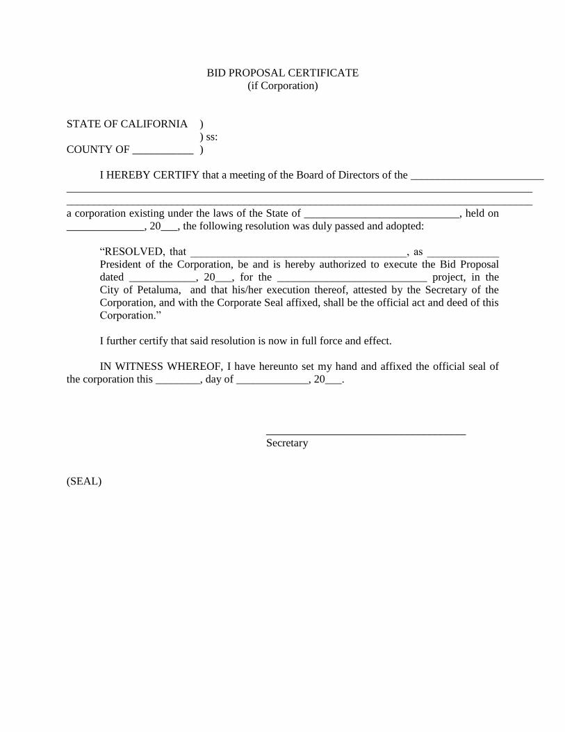
BID PROPOSAL CERTIFICATE
(if Corporation)
STATE OF CALIFORNIA )
) ss:
COUNTY OF ___________ )
I HEREBY CERTIFY that a meeting of the Board of Directors of the ________________________
____________________________________________________________________________________
____________________________________________________________________________________
a corporation existing under the laws of the State of ____________________________, held on
______________, 20___, the following resolution was duly passed and adopted:
“RESOLVED, that _______________________________________, as _____________
President of the Corporation, be and is hereby authorized to execute the Bid Proposal
dated ____________, 20___, for the ___________________________ project, in the
City of Petaluma, and that his/her execution thereof, attested by the Secretary of the
Corporation, and with the Corporate Seal affixed, shall be the official act and deed of this
Corporation.”
I further certify that said resolution is now in full force and effect.
IN WITNESS WHEREOF, I have hereunto set my hand and affixed the official seal of
the corporation this ________, day of _____________, 20___.
____________________________________
Secretary
(SEAL)
BID PROPOSAL CERTIFICATE
(if Partnership)
STATE OF CALIFORNIA )
) ss:
COUNTY OF ___________ )
I HEREBY CERTIFY that a meeting of the Partners of the ________________________________
____________________________________________________________________________________
____________________________________________________________________________________
a partnership existing under the laws of the State of _______________________________, held
on ____________, 20___, the following resolution was duly passed and adopted:
“RESOLVED, that ___________________________________________, as the General
Partner of the Partnership, be and is hereby authorized to execute the Bid Proposal dated
____________, 20___, for the _____________________ project in the City of Petaluma
and that his/her execution thereof, attested by the _________________ shall be the
official act and deed of this Partnership.”
I further certify that said resolution is now in full force and effect.
IN WITNESS WHEREOF, I have hereunto set my hand this ________, day of
_____________, 20___.
____________________________________
Partner
(SEAL)

BID PROPOSAL CERTIFICATE
(if Joint Venture)
STATE OF CALIFORNIA )
) ss:
COUNTY OF ___________ )
I HEREBY CERTIFY that a meeting of the Principals of the _______________________________
____________________________________________________________________________________
____________________________________________________________________________________
a joint venture existing under the laws of the State of _______________________________,
held on ____________, 20___, the following resolution was duly passed and adopted:
“RESOLVED, that ___________________________________________,
as_______________, of the joint venture, be and is hereby authorized to execute the Bid
Proposal dated _____________, 20___, for _________________project, in the City of
Petaluma, and that his/her execution thereof, attested by the ___________________ shall
be the official act and deed of this Joint Venture.”
I further certify that said resolution is now in full force and effect.
IN WITNESS WHEREOF, I have hereunto set my hand this ________, day of
_____________, 20___.
____________________________________
Managing Partner
(SEAL)


PROPOSAL (City) March 2005
PROPOSAL
To the City Council of the City of Petaluma:
The undersigned declares that he/she has carefully examined the location of the proposed work,
that he/she has examined the plans and specifications, and read the accompanying instructions to
bidders, and hereby proposes to furnish all materials and do all the work required to complete the
said work in accordance with said plans, specifications, and special provisions for the unit or
lump sum prices set forth in the attached Bid Schedule.
It is understood and agreed that the undersigned shall complete the work of the contract within
the time provided for in the Contract Documents and Specifications governing said work.
If awarded the contract, the undersigned hereby agrees to sign said contract and to furnish the
necessary bonds, insurance certificates and agreements within five (5) working days after receipt
of Notice of Award of said contract from the City.
The undersigned has examined the location of the proposed work and is familiar with the plans,
specifications and other contract documents and the local conditions at the place where the work
is to be done.
The undersigned has checked carefully all the figures on the attached Bid Schedule and
understands that the City will not be responsible for any errors or omissions on the part of the
undersigned in making up the bid.
Enclosed find bidder's bond, certified check, or cashier's check no. __________ of the
_________________________________________________________ (Company) (Bank) for
_____________________________________________ Dollars ($____________).
This project requires a Class B California State Contractor's License.
Contractor's License No. _________________________ License Class _________________
Expiration Date of Contractor's License __________________________________
A bid submitted to a public agency by a contractor who is not licensed shall be considered non-
responsive and shall be rejected by the public agency. The undersigned contractor declares that

PROPOSAL (City) March 2005
the contractor's license number and expiration date stated herein are made under penalty of
perjury under the laws of the State of California.
Contractor:
Signed by:
Title:
Address:
Phone:
Fax:
Dated this ______ day of ___________________, 20___.
END OF PROPOSAL

PROPOSAL (City) March 2005

BASE BID SCHEDULE
PETALUMA TRANSIT MAINTENANCE FACILITY
(555 N MCDOWELL BLVD.)
Bidder:
ITEMS:
No. DESCRIPTION Quantity Unit Unit Price Total
1 Mobilization/Demobilization 1 Lump Sum
2 Storm Water Management and
Sedimentation/Erosion Control 1 Lump Sum
3 All work and activities in accordance with
the Contract Documents, including all of its
component parts, and to furnish all required
labor, materials, equipment, transportation
and services required for the construction of
the Project in strict conformity with the
Contract Documents, including but not
limited to the Plans and Specifications. 1 Lump Sum
TOTAL BID (in figures) $
*Note: In case of error in extension of price into the total price column, the unit price will govern.
Total Amount of Base Bid (written in words is:
Dollars and
Cents.
In the event of discrepancy between words and figures, the words shall prevail.
$
Figures
Address of Bidder Signature of Bidder
City Name of Bidder (Print)
Telephone Number of Bidder Fax Number of Bidder
Contractor’s License Number License’s Expiration Date

1
QUESTIONNAIRE AND FINANCIAL ASSURANCE STATEMENT FORM
July 2004
QUESTIONNAIRE AND FINANCIAL ASSURANCE STATEMENT FORM
The following statements as to experience and financial qualifications of the Bidder are
submitted in conjunction with the proposal as a part thereof, and the truthfulness and accuracy of
the information is guaranteed by the Bidder.
The Bidder has been engaged in the contracting business under the present business for _______
years. Experience in work of a nature similar to that covered in the proposal extends over a
period of _______ years.
The Bidder, as a contractor, has never failed to satisfactorily complete a contract awarded to
contractor, except as follows:
List all claims and lawsuits presented or filed in the last five (5) years, regardless of the form,
regarding any public works project:
The following contracts for work have been completed in the last three (3) years for the persons,
firm or authority indicated and to whom reference is made:
Type of Work-Size, Length and
Year Contract Amount Location and For Whom Performed
______ __________________________________ ______________________________
______ __________________________________ ______________________________
______ __________________________________ ______________________________
______ __________________________________ ______________________________
The following complaints have been made against the Bidder’s contractor’s license within the
past ten (10) years:
Date: Nature of Complaint

2
QUESTIONNAIRE AND FINANCIAL ASSURANCE STATEMENT FORM
July 2004
Reference is hereby made to the following bank or banks as to the financial responsibility of the
bidder:
NAME OF BANK ADDRESS
Reference is hereby made to the following surety companies as to the financial responsibility and
general reliability of the bidder:
NAME OF SURETY COMPANY:
I, the undersigned, declare under penalty of perjury under the laws of the State of California, that
the foregoing is true and correct.
SIGNATURE OF BIDDER
NAME OF BIDDER
END OF
QUESTIONNAIRE AND FINANCIAL STATEMENT FORM

3
QUESTIONNAIRE AND FINANCIAL ASSURANCE STATEMENT FORM
July 2004
1 BID BOND (City)
July 2004
BID BOND
We, as Principal, and as Surety, jointly and severally, bind ourselves, our heirs,
representatives, successors and assigns, as set forth herein, to the City of Petaluma (herein called
"the Owner") for the payment of the penal sum of Dollars ($ ), lawful money of the
United States, which is ten (10) percent of the total amount bid by bidder to the Owner.
Principal has submitted the accompanying bid for the construction of the project.
If the Principal is awarded the contract and enters into a written contract, in the form prescribed
by the Owner, at the price designated by his bid, and files the bonds required by the Agreement
with the Owner, and carries all insurance in type and amount which conforms to the contract
documents and furnishes required certificates and endorsements thereof, then this obligation
shall be null and void; otherwise it shall remain in full force and effect.
Forfeiture of this bond, or any deposit made in lieu thereof, shall not preclude the Owner from
seeking all other remedies provided by law to cover losses sustained as a result of the Principal's
failure to do any of the foregoing.
Principal and Surety agree that if the Owner is required to engage the services of an attorney in
connection with the enforcement of this bond, each shall pay the Owner's reasonable attorney's
fees, witness fees and other costs incurred with or without suit.
Executed on _____________________, _______.
PRINCIPAL
By Signature
Title

2 BID BOND (City)
July 2004
Any claims under this bond may be
addressed to:
(Name and address of Surety's agent for
service of process in California, if
different from above)
(Telephone number of Surety's agent in
California)
(Attach Acknowledgment)
SURETY
By (Attorney-in-Fact)
NOTICE:
No substitution or revision to this bond form will be accepted. Be sure that all bonds submitted
have a certified copy of the bonding agent's power of attorney attached. Also verify that Surety
is an "Admitted Surety" (i.e., qualified to do business in California), and attach proof of
verification (website printout from the California Department of Insurance website
(http://www.insurance.ca.gov/docs/index.html) or certificate from County Clerk).
END OF BID BOND
LIST OF SUBCONTRACTORS (City)
July 2004
LIST OF SUBCONTRACTORS
In accordance with the provisions of Section 4102 and 4108, inclusive, of the Government Code of the
State of California, each bidder shall list below the name and location of place of business of each
subcontractor who will perform a portion of the contract work in an amount in excess of one-half of
one percent of the total contract price. In each such instance, the nature and extent of the work to be
performed shall be described.
If a prime contractor fails to specify a subcontractor or if a prime contractor specifies more than one
subcontractor for the same portion of work to be performed under the contract in excess of one-half of
one percent of the prime contractor’s total bid, the prime contractor agrees that he or she is fully
qualified to perform that portion himself or herself, and that the prime contractor shall perform that
portion himself or herself. The subcontracting of work for which no subcontractor was designated in
the original bid and which is in excess of one-half of one percent of the total contract price, will be
allowed only with the written consent of the City.
Description of Work to be Performed
Name of Subcontractor Address of Office, Mill or Shop (Also Show Bid Schedule Item Number)
END OF LIST OF SUBCONTRACTORS

LIST OF SUBCONTRACTORS (City)
July 2004
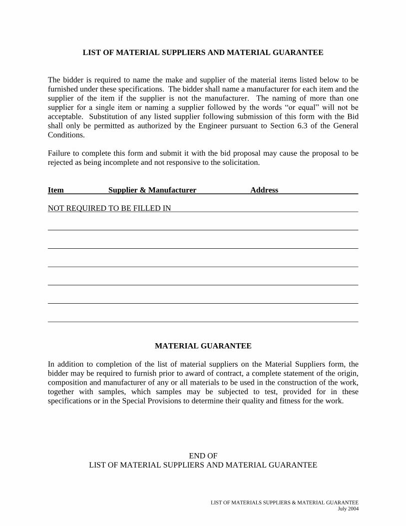
LIST OF MATERIALS SUPPLIERS & MATERIAL GUARANTEE July 2004
LIST OF MATERIAL SUPPLIERS AND MATERIAL GUARANTEE
The bidder is required to name the make and supplier of the material items listed below to be
furnished under these specifications. The bidder shall name a manufacturer for each item and the
supplier of the item if the supplier is not the manufacturer. The naming of more than one
supplier for a single item or naming a supplier followed by the words “or equal” will not be
acceptable. Substitution of any listed supplier following submission of this form with the Bid
shall only be permitted as authorized by the Engineer pursuant to Section 6.3 of the General
Conditions.
Failure to complete this form and submit it with the bid proposal may cause the proposal to be
rejected as being incomplete and not responsive to the solicitation.
Item Supplier & Manufacturer Address
NOT REQUIRED TO BE FILLED IN
MATERIAL GUARANTEE
In addition to completion of the list of material suppliers on the Material Suppliers form, the
bidder may be required to furnish prior to award of contract, a complete statement of the origin,
composition and manufacturer of any or all materials to be used in the construction of the work,
together with samples, which samples may be subjected to test, provided for in these
specifications or in the Special Provisions to determine their quality and fitness for the work.
END OF
LIST OF MATERIAL SUPPLIERS AND MATERIAL GUARANTEE

LIST OF MATERIALS SUPPLIERS & MATERIAL GUARANTEE July 2004

BID PROPOSAL CERTIFICATE March 2004
BID PROPOSAL CERTIFICATE
(if Corporation)
STATE OF CALIFORNIA )
) ss:
COUNTY OF )
I HEREBY CERTIFY that a meeting of the Board of Directors of the _______________
_________________________________________________________________________, a
corporation existing under the laws of the State of ____________________________, held on
________________, 20____, the following resolution was duly passed and adopted:
“RESOLVED, that __________________________________, as ____________
President of the Corporation, be and is hereby authorized to execute the Bid
Proposal dated __________________, 20____, for the _____________________
___________________________ project, in the City of Petaluma, and that his/her
execution thereof, attested by the Secretary of the Corporation, and with the
Corporate Seal affixed, shall be the official act and deed of this Corporation.”
I further certify that said resolution is now in full force and effect.
IN WITNESS WHEREOF, I have hereunto set my hand and affixed the official seal of
the corporation this ________, day of ______________, 20____.
____________________________________
Secretary
(SEAL)
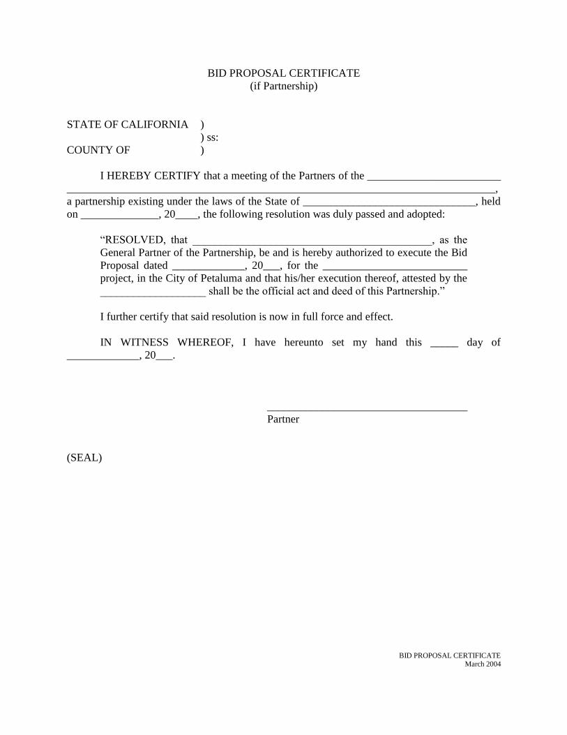
BID PROPOSAL CERTIFICATE March 2004
BID PROPOSAL CERTIFICATE
(if Partnership)
STATE OF CALIFORNIA )
) ss:
COUNTY OF )
I HEREBY CERTIFY that a meeting of the Partners of the ________________________
_____________________________________________________________________________,
a partnership existing under the laws of the State of _______________________________, held
on ______________, 20____, the following resolution was duly passed and adopted:
“RESOLVED, that ___________________________________________, as the
General Partner of the Partnership, be and is hereby authorized to execute the Bid
Proposal dated _____________, 20___, for the __________________________
project, in the City of Petaluma and that his/her execution thereof, attested by the
___________________ shall be the official act and deed of this Partnership.”
I further certify that said resolution is now in full force and effect.
IN WITNESS WHEREOF, I have hereunto set my hand this _____ day of
_____________, 20___.
____________________________________
Partner
(SEAL)
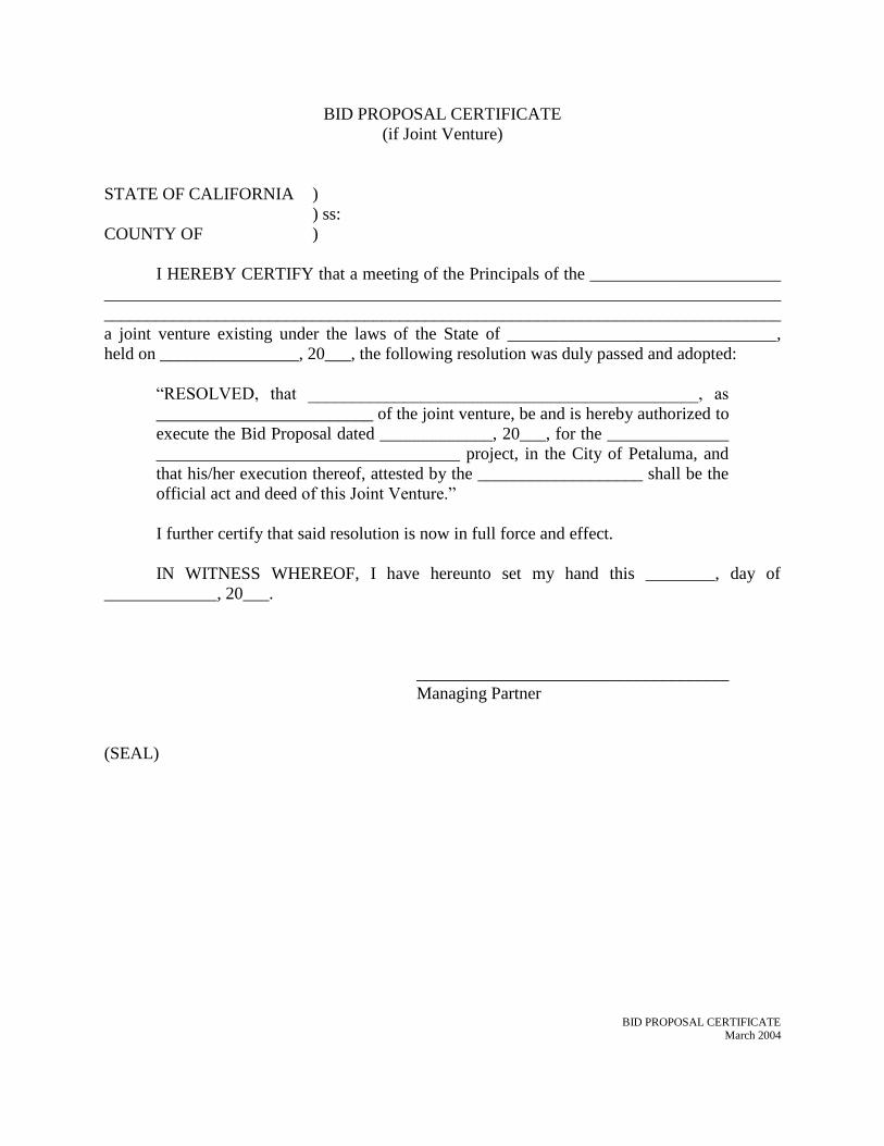
BID PROPOSAL CERTIFICATE March 2004
BID PROPOSAL CERTIFICATE
(if Joint Venture)
STATE OF CALIFORNIA )
) ss:
COUNTY OF )
I HEREBY CERTIFY that a meeting of the Principals of the ______________________
______________________________________________________________________________
______________________________________________________________________________
a joint venture existing under the laws of the State of _______________________________,
held on ________________, 20___, the following resolution was duly passed and adopted:
“RESOLVED, that _____________________________________________, as
_________________________ of the joint venture, be and is hereby authorized to
execute the Bid Proposal dated _____________, 20___, for the ______________
___________________________________ project, in the City of Petaluma, and
that his/her execution thereof, attested by the ___________________ shall be the
official act and deed of this Joint Venture.”
I further certify that said resolution is now in full force and effect.
IN WITNESS WHEREOF, I have hereunto set my hand this ________, day of
_____________, 20___.
____________________________________
Managing Partner
(SEAL)

BID PROPOSAL CERTIFICATE January 2008
BID PROPOSAL CERTIFICATE
(if Proprietorship)
STATE OF CALIFORNIA )
) ss:
COUNTY OF )
I HEREBY CERTIFY that ______________________________________, as owner of
_______________________________________________ that I am authorized to execute the
Bid Proposal dated ___________________, 20____, for the ________________________
_____________________________ project, in the City of Petaluma, and that my execution
thereof shall be the official act and deed of this proprietorship.
IN WITNESS WHEREOF, I have hereunto set my hand and affixed the official seal of
the corporation this ________, day of ______________, 20____.
____________________________________
Owner
(SEAL)

BID PROPOSAL CERTIFICATE January 2008
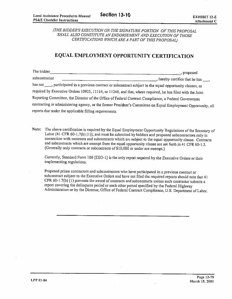
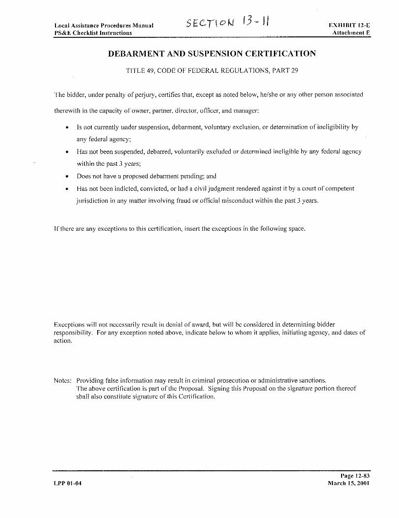
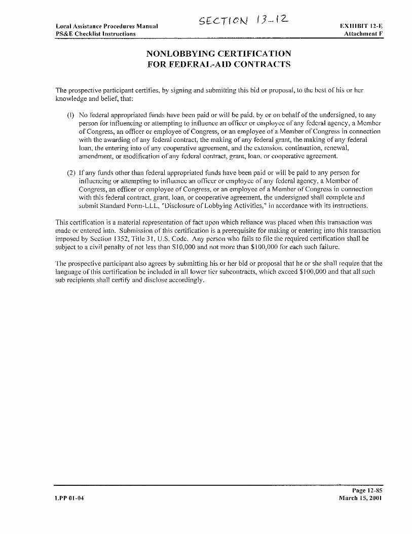
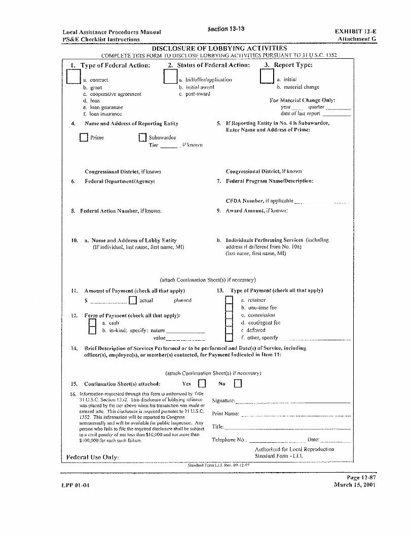


Local Assistance Procedures Manual EXHIBIT 15-G2
Local Agency Bidder DBE Information (Construction Contracts)
EXHIBIT 15-G2 LOCAL AGENCY BIDDER DBE INFORMATION (CONTRUCTION CONTRACTS)
(Inclusive of all DBEs including the UDBEs listed at bid proposal)
NOTE: PLEASE REFER TO INSTRUCTIONS ON THE REVERSE SIDE OF THIS FORM
LOCAL AGENCY: LOCATION:
PROJECT DESCRIPTION:
TOTAL CONTRACT AMOUNT: $
BID DATE:
BIDDER'S NAME:
CONTRACT UDBE GOAL:
CONTRACT ITEM NO.
ITEM OF WORK AND DESCRIPTION OR SERVICES TO BE SUBCONTRACTED OR MATERIALS
TO BE PROVIDED (or contracted if the bidder is a DBE)
DBE CERT NO. AND EXPIRATION DATE
NAME OF EACH DBE
(Must be certified on the date bids are opened - include DBE address
and phone number)
DOLLAR AMOUNT DBE
For Local Agency to Complete:
Local Agency Contract Number:
Federal-aid Project Number:
Federal Share:
Contract Award Date:
Local Agency certifies that all DBE certification have been verified and Information is complete and accurate.
Print Name Signature Date
Local Agency Representative
(Area Code) Telephone Number:
Total Claimed DBE
Participation
$
%
Signature of Bidder
Date (Area Code) Tel. No.
Person to Contact (Please Type or Print)
Local Agency Bidder DBE Information (Construction Contarcts)
(Rev 6/26/09)
For Caltrans Review:
Print Name Signature Date Caltrans District Local Assistance Engineer
Distribution: (1) Copy – Fax or scan a copy to the Caltrans District Local Assistance Engineer (DLAE) within 15 days of contract execution. Failure to send a copy to the DLAE within 15 days of contract execution may result in de-obligation of funds for this project.
(2) Copy – Include in award package to Caltrans District Local Assistance (3) Original – Local agency files
Page 15-32a LPP 09-02 July 31, 2009
EXHIBIT 15-G2 Local Assistance Procedures Manual
Local Agency Bidder DBE Information (Construction Contracts)
INSTRUCTIONS - LOCAL AGENCY BIDDER DBE INFORMATION
(CONSTRUCTION CONTRACTS)
SUCCESSFUL BIDDER:
The form requires specific information regarding the construction contract: Local Agency, Location, Project
Description, Total Contract Amount, Bid Date, Bidder’s Name, and Contract UDBE Goal.
The form has a column for the Contract Item Number and Item of Work and Description or Services to be Subcontracted or Materials to be provided by DBEs. Prime contractors shall indicate all work to be performed by DBEs including work performed by its own forces, if a DBE.The DBE shall provide a certification number to the Contractor and expiration date. Enter DBE prime and subcontractors certification number. The DBE contractors should notify the Contractor in writing with the date of the decertification if their status should change during the course of the contract. The form has a column for the Names of DBE certified contractors to perform the work (must be certified on the date bids are opened and include DBE address and phone number.
IMPORTANT: Identify all DBE firms participating in the project--including all UDBEs listed on the UDBE Commitment form (Exhibit 15-G1), regardless of tier. Names of the First-Tier DBE subcontractors and their respective item(s) of work listed should be consistent, where applicable, with the names and items of work in the "List of Subcontractors" submitted with your bid.
There is a column for the DBE participation dollar amount. Enter the Total Claimed DBE Participation dollars and percentage amount of items of work submitted with your bid pursuant to the Special Provisions. (If 100% of item is not to be performed or furnished by the DBE, describe exact portion of time to be performed or furnished by the DBE.) See Section "Disadvantaged Business Enterprise (DBE)," of the Special Provisions (construction contracts) to determine how to count the participation of DBE firms.
Exhibit 15-G2 must be signed and dated by the successful bidder. Also list a phone number in the space provided and print the name of the person to contact.
Local agencies should complete the Local Agency Contract Number, Federal-aid Project Number,
Federal Share, Contract Award Date fields and verify that all information is complete and accurate before signing and sending a copy of the form to the District Local Assistance Engineer within 15 days of contract execution. Failure to submit a completed and accurate form within the 15-day time period may result in the de-obligation of funds on this project.
District DBE Coordinator should verify that all informations is complete and accurate. Once the
information has been verified, the District Local Assistance Engineer signs and dates the form.
Page 15-32b July 31, 2009 LPP 09-02
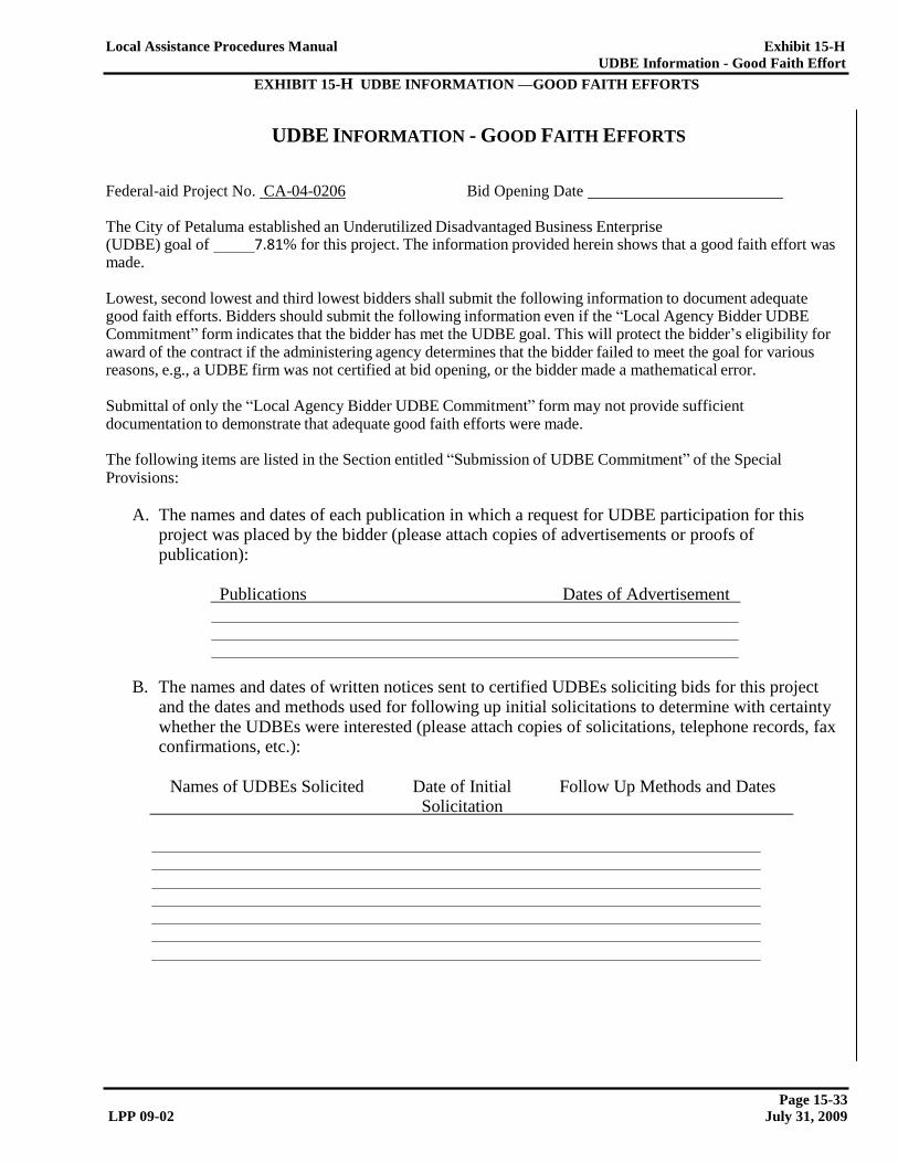
Local Assistance Procedures Manual Exhibit 15-H
UDBE Information - Good Faith Effort
EXHIBIT 15-H UDBE INFORMATION —GOOD FAITH EFFORTS
UDBE INFORMATION - GOOD FAITH EFFORTS
Federal-aid Project No. CA-04-0206 Bid Opening Date
The City of Petaluma established an Underutilized Disadvantaged Business Enterprise
(UDBE) goal of made.
7.81% for this project. The information provided herein shows that a good faith effort was
Lowest, second lowest and third lowest bidders shall submit the following information to document adequate good faith efforts. Bidders should submit the following information even if the “Local Agency Bidder UDBE Commitment” form indicates that the bidder has met the UDBE goal. This will protect the bidder’s eligibility for award of the contract if the administering agency determines that the bidder failed to meet the goal for various reasons, e.g., a UDBE firm was not certified at bid opening, or the bidder made a mathematical error.
Submittal of only the “Local Agency Bidder UDBE Commitment” form may not provide sufficient documentation to demonstrate that adequate good faith efforts were made.
The following items are listed in the Section entitled “Submission of UDBE Commitment” of the Special Provisions:
A. The names and dates of each publication in which a request for UDBE participation for this
project was placed by the bidder (please attach copies of advertisements or proofs of publication):
Publications Dates of Advertisement
B. The names and dates of written notices sent to certified UDBEs soliciting bids for this project and the dates and methods used for following up initial solicitations to determine with certainty whether the UDBEs were interested (please attach copies of solicitations, telephone records, fax confirmations, etc.):
Names of UDBEs Solicited Date of Initial Follow Up Methods and Dates
Solicitation
Page 15-33 LPP 09-02 July 31, 2009
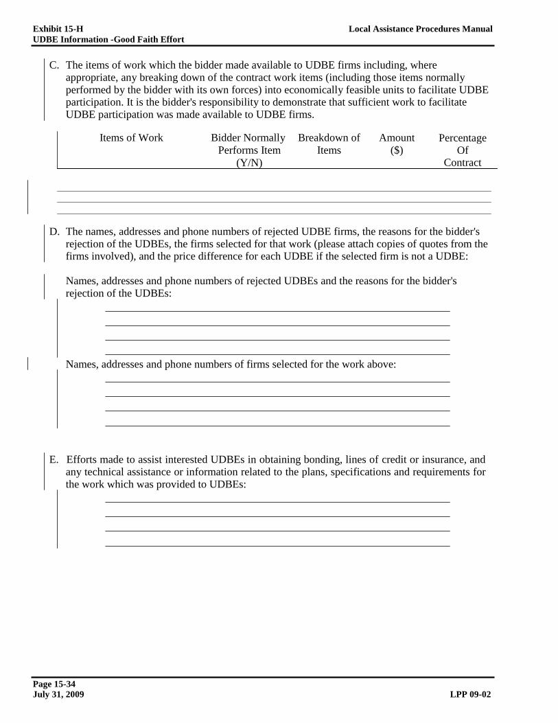
Exhibit 15-H Local Assistance Procedures Manual
UDBE Information -Good Faith Effort
C. The items of work which the bidder made available to UDBE firms including, where
appropriate, any breaking down of the contract work items (including those items normally performed by the bidder with its own forces) into economically feasible units to facilitate UDBE participation. It is the bidder's responsibility to demonstrate that sufficient work to facilitate UDBE participation was made available to UDBE firms.
Items of Work Bidder Normally
Performs Item
(Y/N)
Breakdown of
Items
Amount
($) Percentage
Of Contract
D. The names, addresses and phone numbers of rejected UDBE firms, the reasons for the bidder's rejection of the UDBEs, the firms selected for that work (please attach copies of quotes from the firms involved), and the price difference for each UDBE if the selected firm is not a UDBE:
Names, addresses and phone numbers of rejected UDBEs and the reasons for the bidder's rejection of the UDBEs:
Names, addresses and phone numbers of firms selected for the work above:
E. Efforts made to assist interested UDBEs in obtaining bonding, lines of credit or insurance, and any technical assistance or information related to the plans, specifications and requirements for the work which was provided to UDBEs:
Page 15-34 July 31, 2009 LPP 09-02

Local Assistance Procedures Manual Exhibit 15-H
UDBE Information - Good Faith Effort
F. Efforts made to assist interested UDBEs in obtaining necessary equipment, supplies, materials or related assistance or services, excluding supplies and equipment the UDBE subcontractor purchases or leases from the prime contractor or its affiliate:
G. The names of agencies, organizations or groups contacted to provide assistance in contacting, recruiting and using UDBE firms (please attach copies of requests to agencies and any responses received, i.e., lists, Internet page download, etc.):
Name of Agency/Organization Method/Date of Contact Results
H. Any additional data to support a demonstration of good faith efforts (use additional sheets if necessary):
NOTE: USE ADDITIONAL SHEETS OF PAPER IF NECESSARY.
Page 15-34a LPP 09-02 July 31, 2009

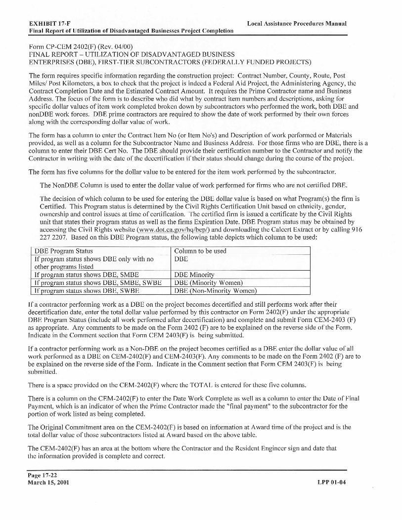

BUY AMERICA CERTIFICATION
A bidder or offeror must submit to the City of Petaluma this Buy America certification with all bids or
offers on FTA-funded contracts, except those subject to a general waiver. Bids or offers that are not
accompanied by a completed Buy America certification must be rejected as nonresponsive. This
requirement does not apply to lower tier subcontractors.
Certification requirement for procurement of steel, iron, or manufactured products.
Certificate of Compliance with 49 U.S.C. 5323(j)(1)
The bidder or offeror hereby certifies that it will meet the requirements of 49 U.S.C. 5323(j)(1) and the
applicable regulations in 49 C.F.R. Part 661.5.
Date _______________________________________________________________________________
Signature ____________________________________________________________________________
Company Name ______________________________________________________________________
Title _______________________________________________________________________________
Certificate of Non-Compliance with 49 U.S.C. 5323(j)(1)
The bidder or offeror hereby certifies that it cannot comply with the requirements of 49 U.S.C. 5323(j)(1)
and 49 C.F.R. 661.5, but it may qualify for an exception pursuant to 49 U.S.C. 5323(j)(2)(A),
5323(j)(2)(B), or 5323(j)(2)(D), and 49 C.F.R. 661.7.
Date _______________________________________________________________________________
Signature ___________________________________________________________________________
Company Name ______________________________________________________________________
Title _______________________________________________________________________________
Certification requirement for procurement of buses, other rolling stock and associated equipment.
Certificate of Compliance with 49 U.S.C. 5323(j)(2)(C).
The bidder or offeror hereby certifies that it will comply with the requirements of 49 U.S.C. 5323(j)(2)(C)
and the regulations at 49 C.F.R. Part 661.11.
Date _______________________________________________________________________________
Signature ___________________________________________________________________________
Company Name ______________________________________________________________________
Title _______________________________________________________________________________

Certificate of Non-Compliance with 49 U.S.C. 5323(j)(2)(C)
The bidder or offeror hereby certifies that it cannot comply with the requirements of 49 U.S.C.
5323(j)(2)(C) and 49 C.F.R. 661.11, but may qualify for an exception pursuant to 49 U.S.C.
5323(j)(2)(A), 5323(j)(2)(B), or 5323(j)(2)(D), and 49 CFR 661.7.
Date _______________________________________________________________________________
Signature ___________________________________________________________________________
Company Name ______________________________________________________________________
Title _______________________________________________________________________________
Section 4. FEDERAL CONTRACT PROVISIONS
The successful bidder will be subject to the following federal contract provisions in addition to the terms
of the Standard City of Petaluma Construction Agreement.
4-1 NO FEDERAL GOVERNMENT OBLIGATIONS TO THIRD PARTIES
(1) The Purchaser and Contractor acknowledge and agree that, notwithstanding any concurrence
by the Federal Government in or approval of the solicitation or award of the underlying contract,
absent the express written consent by the Federal Government, the Federal Government is not a
party to this contract and shall not be subject to any obligations or liabilities to the Purchaser,
Contractor, or any other party (whether or not a party to that contract) pertaining to any matter
resulting from the underlying contract.
(2) The Contractor agrees to include the above clause in each subcontract financed in whole or in
part with Federal assistance provided by FTA. It is further agreed that the clause shall not be
modified, except to identify the subcontractor who will be subject to its provisions.
4-2 FALSE OR FRAUDULENT STATEMENTS OR CLAIMS – CIVIL CRIMINAL
FRAUD
(1) The Contractor acknowledges that the provisions of the Program Fraud Civil Remedies Act of
1986, as amended, 31 U.S.C. § 3801 et seq. and U.S. DOT regulations, "Program Fraud Civil
Remedies," 49 C.F.R. Part 31, apply to its actions pertaining to this Project. Upon execution of
the underlying contract, the Contractor certifies or affirms the truthfulness and accuracy of any
statement it has made, it makes, it may make, or causes to be made, pertaining to the underlying
contract or the FTA assisted project for which this contract work is being performed. In addition
to other penalties that may be applicable, the Contractor further acknowledges that if it makes, or
causes to be made, a false, fictitious, or fraudulent claim, statement, submission, or certification,
the Federal Government reserves the right to impose the penalties of the Program Fraud Civil
Remedies Act of 1986 on the Contractor to the extent the Federal Government deems appropriate.
(2) The Contractor also acknowledges that if it makes, or causes to be made, a false, fictitious, or
fraudulent claim, statement, submission, or certification to the Federal Government under a
contract connected with a project that is financed in whole or in part with Federal assistance
originally awarded by FTA under the authority of 49 U.S.C. § 5307, the Government reserves the
right to impose the penalties of 18 U.S.C. § 1001 and 49 U.S.C. § 5307(n)(1) on the Contractor,
to the extent the Federal Government deems appropriate.
(3) The Contractor agrees to include the above two clauses in each subcontract financed in whole
or in part with Federal assistance provided by FTA. It is further agreed that the clauses shall not
be modified, except to identify the subcontractor who will be subject to the provisions.
4-3 ACCESS TO THIRD PARTY CONTRACT RECORDS
The following access to records requirements apply to this Contract:
(1) The Contractor agrees to provide the City of Petaluma, the FTA Administrator, the
Comptroller General of the United States or any of their authorized representatives access to any
books, documents, papers and records of the Contractor which are directly pertinent to this
contract for the purposes of making audits, examinations, excerpts and transcriptions. Contractor
also agrees, pursuant to 49 C.F.R. 633.17 to provide the FTA Administrator or his authorized
representatives including any PMO Contractor access to Contractor's records and construction
sites pertaining to a major capital project, defined at 49 U.S.C. 5302(a)1, which is receiving
federal financial assistance through the programs described at 49 U.S.C. 5307, 5309 or 5312.

(2) The Contractor agrees to permit any of the foregoing parties to reproduce by any means
whatsoever or to copy excerpts and transcriptions as reasonably needed.
(3) The Contractor agrees to maintain all books, records, accounts and reports required under this
contract for a period of not less than three years after the date of termination or expiration of this
contract, except in the event of litigation or settlement of claims arising from the performance of
this contract, in which case Contractor agrees to maintain same until the City of Petaluma, the
FTA Administrator, the Comptroller General, or any of their duly authorized representatives,
have disposed of all such litigation, appeals, claims or exceptions related thereto. Reference 49
CFR 18.39(i)(11).
(4) FTA does not require the inclusion of these requirements in subcontracts.
4-4 CHANGES TO FEDERAL REQUIREMENTS
Contractor shall at all times comply with all applicable FTA regulations, policies, procedures and
directives, including without limitation those listed directly or by reference in the Master
Agreement between the City of Petaluma and FTA, as they may be amended or promulgated from
time to time during the term of this contract. Contractor's failure to so comply shall constitute a
material breach of this contract.
4-5 CIVIL RIGHTS
The following requirements apply to the underlying contract:
(1) Nondiscrimination - In accordance with Title VI of the Civil Rights Act, as amended, 42
U.S.C. § 2000d, section 303 of the Age Discrimination Act of 1975, as amended, 42 U.S.C. §
6102, section 202 of the Americans with Disabilities Act of 1990, 42 U.S.C. § 12132, and Federal
transit law at 49 U.S.C. § 5332, the Contractor agrees that it will not discriminate against any
employee or applicant for employment because of race, color, creed, national origin, sex, age, or
disability. In addition, the Contractor agrees to comply with applicable Federal implementing
regulations and other implementing requirements FTA may issue.
(2) Equal Employment Opportunity - The following equal employment opportunity requirements
apply to the underlying contract:
(a) Race, Color, Creed, National Origin, Sex - In accordance with Title VII of the Civil Rights
Act, as amended, 42 U.S.C. § 2000e, and Federal transit laws at 49 U.S.C. § 5332, the Contractor
agrees to comply with all applicable equal employment opportunity requirements of U.S.
Department of Labor (U.S. DOL) regulations, "Office of Federal Contract Compliance Programs,
Equal Employment Opportunity, Department of Labor," 41 C.F.R. Parts 60 et seq., (which
implement Executive Order No. 11246, "Equal Employment Opportunity," as amended by
Executive Order No. 11375, "Amending Executive Order 11246 Relating to Equal Employment
Opportunity," 42 U.S.C. § 2000e note), and with any applicable Federal statutes, executive
orders, regulations, and Federal policies that may in the future affect construction activities
undertaken in the course of the Project. The Contractor agrees to take affirmative action to
ensure that applicants are employed, and that employees are treated during employment, without
regard to their race, color, creed, national origin, sex, or age. Such action shall include, but not be
limited to, the following: employment, upgrading, demotion or transfer, recruitment or
recruitment advertising, layoff or termination; rates of pay or other forms of compensation; and
selection for training, including apprenticeship. In addition, the Contractor agrees to comply with
any implementing requirements FTA may issue.
(b) Age - In accordance with section 4 of the Age Discrimination in Employment Act of 1967, as
amended, 29 U.S.C. § § 623 and Federal transit law at 49 U.S.C. § 5332, the Contractor agrees to
refrain from discrimination against present and prospective employees for reason of age. In
addition, the Contractor agrees to comply with any implementing requirements FTA may issue.
(c) Disabilities - In accordance with section 102 of the Americans with Disabilities Act, as
amended, 42 U.S.C. § 12112, the Contractor agrees that it will comply with the requirements of

U.S. Equal Employment Opportunity Commission, "Regulations to Implement the Equal
Employment Provisions of the Americans with Disabilities Act," 29 C.F.R. Part 1630, pertaining
to employment of persons with disabilities. In addition, the Contractor agrees to comply with any
implementing requirements FTA may issue.
(3) The Contractor also agrees to include these requirements in each subcontract financed in
whole or in part with Federal assistance provided by FTA, modified only if necessary to identify
the affected parties.
4-6 DISADVANTAGED BUSINESS ENTERPRISE
This project is subject to Title 49 CFR 26.13(b):
The Contractor, sub-recipient or subcontractor shall not discriminate on the basis of race, color,
national origin, or sex in the performance of this contract. The Contractor shall carry out
applicable requirements of 49 CFR, Part 26 in the award and administration of DOT-assisted
contracts. Failure by the contractor to carry out these requirements is a material breach of this
contract, which may result in the termination of this contract or such other remedy as the recipient
deems appropriate.
Take necessary and reasonable steps to ensure that DBEs have opportunity to participate in the
contract (49 CFR 26).
To ensure there is equal participation of the DBE groups specified in 49 CFR 26.5, the Agency
specifies a goal for Underutilized Disadvantaged Business Enterprises (UDBEs). UDBE is a firm
that meets the definition of DBE and is a member of one of the following groups:
1. Black Americans
2. Native Americans
3. Asian-Pacific Americans
4. Women
References to DBEs include UDBEs, but references to UDBEs do not include all DBEs.
Make work available to UDBEs and select work parts consistent with available UDBE
subcontractors and suppliers.
Meet the UDBE goal shown in the Notice to Bidders or demonstrate that you made adequate
good faith efforts to meet this goal.
It is your responsibility to verify that the UDBE firm is certified as DBE at date of bid opening.
For a list of DBEs certified by the California Unified Certification Program, go to:
http://www.dot.ca.gov/hq/bep/find_certified.htm
Only UDBE participation will count towards the UDBE goal. DBE participation will count
towards the Agency's Annual Anticipated DBE Participation Level and the California statewide
goal.
Credit for materials or supplies you purchase from UDBEs counts towards the goal in the
following manner:
1. 100 percent counts if the materials or supplies are obtained from a UDBE manufacturer.
2. 60 percent counts if the materials or supplies are obtained from a UDBE regular dealer.
3. Only fees, commissions, and charges for assistance in the procurement and delivery of
materials or supplies count if obtained from a UDBE that is neither a manufacturer, nor a regular
dealer. 49 CFR 26.55 defines “manufacturer” and “regular dealer.”
You receive credit towards the goal if you employ a UDBE trucking company that performs a
commercially useful function as defined in 49 CFR 26.55.
UDBE Commitment Submittal
Submit UDBE information on the “Local Agency Bidder UDBE Commitment (Construction
Contracts),” Exhibit 15-G1 form, included in the Bid book. If the form is not submitted with the
bid, remove the form from the Bid book before submitting your bid.
If the UDBE Commitment form is not submitted with the bid, the apparent low bidder, the 2nd
low bidder, and the 3rd low bidder must complete and submit the UDBE Commitment form to
the Agency. UDBE Commitment form must be received by the Agency no later than 4:00 p.m. on
the 4th business day after bid opening.
Other bidders do not need to submit the UDBE Commitment form unless the Agency requests it.
If the Agency requests you to submit a UDBE Commitment form, submit the completed form
within 4 business days of the request.
Submit written confirmation from each UDBE stating that it is participating in the contract.
Include confirmation with the UDBE Commitment form. A copy of a UDBE's quote will serve as
written confirmation that the UDBE is participating in the contract.
If you do not submit the UDBE Commitment form within the specified time, the Agency finds
your bid nonresponsive.
Good Faith Efforts Submittal
If you have not met the UDBE goal, complete and submit the “UDBE Information - Good Faith
Efforts,” Exhibit 15-H form with the bid showing that you made adequate good faith efforts to
meet the goal. Only good faith efforts directed towards obtaining participation by UDBEs will be
considered. If good faith efforts documentation is not submitted with the bid, it must be received
by the Agency no later than 4:00 p.m. on the 4th business day after bid opening.
If your UDBE Commitment form shows that you have met the UDBE goal or if you are required
to submit the UDBE Commitment form, you must also submit good faith efforts documentation
within the specified time to protect your eligibility for award of the contract in the event the
Agency finds that the UDBE goal has not been met.
Good faith efforts documentation must include the following information and supporting
documents, as necessary:
1. Items of work you have made available to UDBE firms. Identify those items of work you might
otherwise perform with its own forces and those items that have been broken down into
economically feasible units to facilitate UDBE participation. For each item listed, show the dollar
value and percentage of the total contract. It is your responsibility to demonstrate that sufficient
work to meet the goal was made available to UDBE firms.
2. Names of certified UDBEs and dates on which they were solicited to bid on the project.
Include the items of work offered. Describe the methods used for following up initial solicitations
to determine with certainty if the UDBEs were interested, and the dates of the follow-up. Attach
supporting documents such as copies of letters, memos, facsimiles sent, telephone logs, telephone
billing statements, and other evidence of solicitation. You are reminded to solicit certified
UDBEs through all reasonable and available means and provide sufficient time to allow UDBEs
to respond.
3. Name of selected firm and its status as a UDBE for each item of work made available. Include
name, address, and telephone number of each UDBE that provided a quote and their price quote.
If the firm selected for the item is not a UDBE, provide the reasons for the selection.
4. Name and date of each publication in which you requested UDBE participation for the project.
Attach copies of the published advertisements.
5. Names of agencies and dates on which they were contacted to provide assistance in contacting,
recruiting, and using UDBE firms. If the agencies were contacted in writing, provide copies of
supporting documents.
6. List of efforts made to provide interested UDBEs with adequate information about the plans,
specifications, and requirements of the contract to assist them in responding to a solicitation. If
you have provided information, identify the name of the UDBE assisted, the nature of the
information provided, and date of contact. Provide copies of supporting documents, as
appropriate.

7. List of efforts made to assist interested UDBEs in obtaining bonding, lines of credit, insurance,
necessary equipment, supplies, and materials, excluding supplies and equipment that the UDBE
subcontractor purchases or leases from the prime contractor or its affiliate. If such assistance is
provided by you, identify the name of the UDBE assisted, nature of the assistance offered, and
date. Provide copies of supporting documents, as appropriate.
8. Any additional data to support demonstration of good faith efforts.
4-7 TERMINATIONS
(1) Termination for Convenience (General Provision) The City of Petaluma may terminate this
contract, in whole or in part, at any time by written notice to the Contractor when it is in the
Government's best interest. The Contractor shall be paid its costs, including contract close-out
costs, and profit on work performed up to the time of termination. The Contractor shall promptly
submit its termination claim to City of Petaluma to be paid the Contractor. If the Contractor has
any property in its possession belonging to the City of Petaluma, the Contractor will account for
the same, and dispose of it in the manner the City of Petaluma directs.
(2) Termination for Default (Construction) If the Contractor refuses or fails to prosecute the
work or any separable part, with the diligence that will insure its completion within the time
specified in this contract or any extension or fails to complete the work within this time, or if the
Contractor fails to comply with any other provisions of this contract, the City of Petaluma may
terminate this contract for default. The City of Petaluma shall terminate by delivering to the
Contractor a Notice of Termination specifying the nature of the default. In this event, the City of
Petaluma may take over the work and compete it by contract or otherwise, and may take
possession of and use any materials, appliances, and plant on the work site necessary for
completing the work. The Contractor and its sureties shall be liable for any damage to the City of
Petaluma resulting from the Contractor's refusal or failure to complete the work within specified
time, whether or not the Contractor's right to proceed with the work is terminated. This liability
includes any increased costs incurred by the City of Petaluma in completing the work.
The Contractor's right to proceed shall not be terminated nor the Contractor charged with
damages under this clause if-
a. the delay in completing the work arises from unforeseeable causes beyond the control and
without the fault or negligence of the Contractor. Examples of such causes include: acts of God,
acts of the Recipient, acts of another Contractor in the performance of a contract with the City of
Petaluma, epidemics, quarantine restrictions, strikes, freight embargoes; and
b. the contractor, within [10] days from the beginning of any delay, notifies the City of Petaluma
in writing of the causes of delay. If in the judgment of the City of Petaluma, the delay is
excusable, the time for completing the work shall be extended. The judgment of the City of
Petaluma shall be final and conclusive on the parties, but subject to appeal under the Disputes
clauses. If, after termination of the Contractor's right to proceed, it is determined that the
Contractor was not in default, or that the delay was excusable, the rights and obligations of the
parties will be the same as if the termination had been issued for the convenience of the City of
Petaluma.
(3) Opportunity to Cure (General Provision) The City of Petaluma in its sole discretion may,
in the case of a termination for breach or default, allow the Contractor pre-determined period of
time in which to cure the defect. In such case, the notice of termination will state the time period
in which cure is permitted and other appropriate conditions. If Contractor fails to remedy to City
of Petaluma's satisfaction the breach or default of any of the terms, covenants, or conditions of
this Contract within [ten (10) days] after receipt by Contractor of written notice from City of
Petaluma setting forth the nature of said breach or default, City of Petaluma shall have the right to
terminate the Contract without any further obligation to Contractor. Any such termination for
default shall not in any way operate to preclude City of Petaluma from also pursuing all available
remedies against Contractor and its sureties for said breach or default.

(4) Waiver of Remedies for any Breach In the event that City of Petaluma elects to waive its
remedies for any breach by Contractor of any covenant, term or condition of this Contract, such
waiver by City of Petaluma shall not limit City of Petaluma's remedies for any succeeding breach
of that or of any other term, covenant, or condition of this Contract.
4-8 SPECIAL EEO PROVISIONS FOR CONSTRUCTION CONTRACTS Selected contractor must comply with DOL regulations, ―Office of Federal Contract
Compliance Programs, Equal Employment Opportunity, Department of Labor, 41 CFR Chapter
60, which implement Executive Order No. 11246, ―Equal Employment Opportunity, September
24, 1965, as amended by Executive Order No. 11375, ―Amending Executive Order No. 11246
Relating to Equal Employment Opportunity, October 13, 1967.
4-9 DEBARMENT AND SUSPENSION
This contract is a covered transaction for purposes of 49 CFR Part 29. As such, the
contractor is required to verify that none of the contractor, its principals, as defined at 49
CFR 29.995, or affiliates, as defined at 49 CFR 29.905, are excluded or disqualified as
defined at 49 CFR 29.940 and 29.945.
The contractor is required to comply with 49 CFR 29, Subpart C and must include the
requirement to comply with 49 CFR 29, Subpart C in any lower tier covered transaction it
enters into. By signing and submitting its bid or proposal, the bidder or proposer certifies
as follows:
The certification in this clause is a material representation of fact relied upon by The City
of Petaluma. If it is later determined that the bidder or proposer knowingly rendered an
erroneous certification, in addition to remedies available to The City of Petaluma the
Federal Government may pursue available remedies, including but not limited to
suspension and/or debarment. The bidder or proposer agrees to comply with the
requirements of 49 CFR 29, Subpart C while this offer is valid and throughout the period
of any contract that may arise from this offer. The bidder or proposer further agrees to
include a provision requiring such compliance in its lower tier covered transactions.
4-10 BUY AMERICA The contractor agrees to comply with 49 U.S.C. 5323(j) and 49 C.F.R. Part 661, which provide
that Federal funds may not be obligated unless steel, iron, and manufactured products used in
FTA-funded projects are produced in the United States, unless a waiver has been granted by FTA
or the product is subject to a general waiver. General waivers are listed in 49 C.F.R. 661.7, and
include final assembly in the United States for 15 passenger vans and 15 passenger wagons
produced by Chrysler Corporation, and microcomputer equipment and software. Separate
requirements for rolling stock are set out at 49 U.S.C. 5323(j)(2)(C) and 49 C.F.R. 661.11.
Rolling stock must be assembled in the United States and have a 60 percent domestic content.
4-11 RESOLUTION OF DISPUTES BREACHES OR OTHER LITIGATION (1) Disputes - Disputes arising in the performance of this Contract which are not resolved by
agreement of the parties shall be decided in writing by the authorized representative of City of
Petaluma's City Manager. This decision shall be final and conclusive unless within [ten (10)] days
from the date of receipt of its copy, the Contractor mails or otherwise furnishes a written appeal
to the General Manager. In connection with any such appeal, the Contractor shall be afforded an
opportunity to be heard and to offer evidence in support of its position. The decision of the
General Manager shall be binding upon the Contractor and the Contractor shall abide be the
decision.
(2) Performance During Dispute - Unless otherwise directed by City of Petaluma, Contractor
shall continue performance under this Contract while matters in dispute are being resolved.
(3) Claims for Damages - Should either party to the Contract suffer injury or damage to person or
property because of any act or omission of the party or of any of his employees, agents or others
for whose acts he is legally liable, a claim for damages therefore shall be made in writing to such
other party within a reasonable time after the first observance of such injury of damage.
(4) Remedies - Unless this contract provides otherwise, all claims, counterclaims, disputes and
other matters in question between City of Petaluma and the Contractor arising out of or relating to
this agreement or its breach will be decided by arbitration if the parties mutually agree, or in a
court of competent jurisdiction within the State of California.
(5) Rights and Remedies - The duties and obligations imposed by the Contract Documents and
the rights and remedies available there under shall be in addition to and not a limitation of any
duties, obligations, rights and remedies otherwise imposed or available by law. No action or
failure to act by City of Petaluma or Contractor shall constitute a waiver of any right or duty
afforded any of them under the Contract, nor shall any such action or failure to act constitute an
approval of or acquiescence in any breach there under, except as may be specifically agreed in
writing.
4-12 LOBBYING
Byrd Anti-Lobbying Amendment, 31 U.S.C. 1352, as amended by the Lobbying Disclosure Act
of 1995, P.L. 104-65 [to be codified at 2 U.S.C. § 1601, et seq.] - Contractors who apply or bid
for an award of $100,000 or more shall file the certification required by 49 CFR part 20, "New
Restrictions on Lobbying." Each tier certifies to the tier above that it will not and has not used
Federal appropriated funds to pay any person or organization for influencing or attempting to
influence an officer or employee of any agency, a member of Congress, officer or employee of
Congress, or an employee of a member of Congress in connection with obtaining any Federal
contract, grant or any other award covered by 31 U.S.C. 1352. Each tier shall also disclose the
name of any registrant under the Lobbying Disclosure Act of 1995 who has made lobbying
contacts on its behalf with non-Federal funds with respect to that Federal contract, grant or award
covered by 31 U.S.C. 1352. Such disclosures are forwarded from tier to tier up to the recipient.
4-13 CLEAN AIR (1) The Contractor agrees to comply with all applicable standards, orders or regulations issued
pursuant to the Clean Air Act, as amended, 42 U.S.C. §§ 7401 et seq. The Contractor agrees to
report each violation to the Purchaser and understands and agrees that the Purchaser will, in turn,
report each violation as required to assure notification to FTA and the appropriate EPA Regional
Office.
(2) The Contractor also agrees to include these requirements in each subcontract exceeding
$100,000 financed in whole or in part with Federal assistance provided by FTA
4-14 CLEAN WATER (1) The Contractor agrees to comply with all applicable standards, orders or regulations issued
pursuant to the Federal Water Pollution Control Act, as amended, 33 U.S.C. 1251 et seq. The
Contractor agrees to report each violation to the Purchaser and understands and agrees that the

Purchaser will, in turn, report each violation as required to assure notification to FTA and the
appropriate EPA Regional Office.
(2) The Contractor also agrees to include these requirements in each subcontract exceeding
$100,000 financed in whole or in part with Federal assistance provided by FTA.
4-15 CONSTRUCTION EMPOLYEE PROTECTIONS – DAVIS-BACON ACT (1) Minimum wages - (i) All laborers and mechanics employed or working upon the site of the
work (or under the United States Housing Act of 1937 or under the Housing Act of 1949 in the
construction or development of the project), will be paid unconditionally and not less often than
once a week, and without subsequent deduction or rebate on any account (except such payroll
deductions as are permitted by regulations issued by the Secretary of Labor under the Copeland
Act (29 CFR part 3)), the full amount of wages and bona fide fringe benefits (or cash equivalents
thereof) due at time of payment computed at rates not less than those contained in the wage
determination of the Secretary of Labor which is attached hereto and made a part hereof,
regardless of any contractual relationship which may be alleged to exist between the contractor
and such laborers and mechanics.
Contributions made or costs reasonably anticipated for bona fide fringe benefits under section
1(b)(2) of the Davis-Bacon Act on behalf of laborers or mechanics are considered wages paid to
such laborers or mechanics, subject to the provisions of paragraph (1)(iv) of this section; also,
regular contributions made or costs incurred for more than a weekly period (but not less often
than quarterly) under plans, funds, or programs which cover the particular weekly period, are
deemed to be constructively made or incurred during such weekly period. Such laborers and
mechanics shall be paid the appropriate wage rate and fringe benefits on the wage determination
for the classification of work actually performed, without regard to skill, except as provided in 29
CFR Part 5.5(a)(4). Laborers or mechanics performing work in more than one classification may
be compensated at the rate specified for each classification for the time actually worked therein:
Provided, That the employer's payroll records accurately set forth the time spent in each
classification in which work is performed. The wage determination (including any additional
classifications and wage rates conformed under paragraph (1)(ii) of this section) and the Davis-
Bacon poster (WH-1321) shall be posted at all times by the contractor and its subcontractors at
the site of the work in a prominent and accessible place where it can be easily seen by the
workers.
(ii)(A) The contracting officer shall require that any class of laborers or mechanics, including
helpers, which is not listed in the wage determination and which is to be employed under the
contract shall be classified in conformance with the wage determination. The contracting officer
shall approve an additional classification and wage rate and fringe benefits therefore only when
the following criteria have been met:
(1) Except with respect to helpers as defined as 29 CFR 5.2(n)(4), the work to be performed by
the classification requested is not performed by a classification in the wage determination; and
(2) The classification is utilized in the area by the construction industry; and
(3) The proposed wage rate, including any bona fide fringe benefits, bears a reasonable
relationship to the wage rates contained in the wage determination; and
(4) With respect to helpers as defined in 29 CFR 5.2(n)(4), such a classification prevails in the
area in which the work is performed.

(B) If the contractor and the laborers and mechanics to be employed in the classification (if
known), or their representatives, and the contracting officer agree on the classification and wage
rate (including the amount designated for fringe benefits where appropriate), a report of the action
taken shall be sent by the contracting officer to the Administrator of the Wage and Hour Division,
Employment Standards Administration, U.S. Department of Labor, Washington, DC 20210. The
Administrator, or an authorized representative, will approve, modify, or disapprove every
additional classification action within 30 days of receipt and so advise the contracting officer or
will notify the contracting officer within the 30-day period that additional time is necessary.
(C) In the event the contractor, the laborers or mechanics to be employed in the classification or
their representatives, and the contracting officer do not agree on the proposed classification and
wage rate (including the amount designated for fringe benefits, where appropriate), the
contracting officer shall refer the questions, including the views of all interested parties and the
recommendation of the contracting officer, to the Administrator for determination. The
Administrator, or an authorized representative, will issue a determination within 30 days of
receipt and so advise the contracting officer or will notify the contracting officer within the 30-
day period that additional time is necessary.
(D) The wage rate (including fringe benefits where appropriate) determined pursuant to
paragraphs (a)(1)(ii) (B) or (C) of this section, shall be paid to all workers performing work in the
classification under this contract from the first day on which work is performed in the
classification.
(iii) Whenever the minimum wage rate prescribed in the contract for a class of laborers or
mechanics includes a fringe benefit which is not expressed as an hourly rate, the contractor shall
either pay the benefit as stated in the wage determination or shall pay another bona fide fringe
benefit or an hourly cash equivalent thereof.
(iv) If the contractor does not make payments to a trustee or other third person, the contractor
may consider as part of the wages of any laborer or mechanic the amount of any costs reasonably
anticipated in providing bona fide fringe benefits under a plan or program, Provided, That the
Secretary of Labor has found, upon the written request of the contractor, that the applicable
standards of the Davis-Bacon Act have been met. The Secretary of Labor may require the
contractor to set aside in a separate account assets for the meeting of obligations under the plan or
program.
(v)(A) The contracting officer shall require that any class of laborers or mechanics which is not
listed in the wage determination and which is to be employed under the contract shall be
classified in conformance with the wage determination. The contracting officer shall approve an
additional classification and wage rate and fringe benefits therefor only when the following
criteria have been met:
(1) The work to be performed by the classification requested is not performed by a classification
in the wage determination; and
(2) The classification is utilized in the area by the construction industry; and
(3) The proposed wage rate, including any bona fide fringe benefits, bears a reasonable
relationship to the wage rates contained in the wage determination.

(B) If the contractor and the laborers and mechanics to be employed in the classification (if
known), or their representatives, and the contracting officer agree on the classification and wage
rate (including the amount designated for fringe benefits where appropriate), a report of the action
taken shall be sent by the contracting officer to the Administrator of the Wage and Hour Division,
Employment Standards Administration, Washington, DC 20210. The Administrator, or an
authorized representative, will approve, modify, or disapprove every additional classification
action within 30 days of receipt and so advise the contracting officer or will notify the contracting
officer within the 30-day period that additional time is necessary.
(C) In the event the contractor, the laborers or mechanics to be employed in the classification or
their representatives, and the contracting officer do not agree on the proposed classification and
wage rate (including the amount designated for fringe benefits, where appropriate), the
contracting officer shall refer the questions, including the views of all interested parties and the
recommendation of the contracting officer, to the Administrator for determination. The
Administrator, or an authorized representative, will issue a determination with 30 days of receipt
and so advise the contracting officer or will notify the contracting officer within the 30-day
period that additional time is necessary.
(D) The wage rate (including fringe benefits where appropriate) determined pursuant to
paragraphs (a)(1)(v) (B) or (C) of this section, shall be paid to all workers performing work in the
classification under this contract from the first day on which work is performed in the
classification.
(2) Withholding - The [ insert name of grantee ] shall upon its own action or upon written request
of an authorized representative of the Department of Labor withhold or cause to be withheld from
the contractor under this contract or any other Federal contract with the same prime contractor, or
any other federally-assisted contract subject to Davis-Bacon prevailing wage requirements, which
is held by the same prime contractor, so much of the accrued payments or advances as may be
considered necessary to pay laborers and mechanics, including apprentices, trainees, and helpers,
employed by the contractor or any subcontractor the full amount of wages required by the
contract. In the event of failure to pay any laborer or mechanic, including any apprentice, trainee,
or helper, employed or working on the site of the work (or under the United States Housing Act
of 1937 or under the Housing Act of 1949 in the construction or development of the project), all
or part of the wages required by the contract, the [ insert name of grantee ] may, after written
notice to the contractor, sponsor, applicant, or owner, take such action as may be necessary to
cause the suspension of any further payment, advance, or guarantee of funds until such violations
have ceased.
(3) Payrolls and basic records - (i) Payrolls and basic records relating thereto shall be maintained
by the contractor during the course of the work and preserved for a period of three years
thereafter for all laborers and mechanics working at the site of the work (or under the United
States Housing Act of 1937, or under the Housing Act of 1949, in the construction or
development of the project). Such records shall contain the name, address, and social security
number of each such worker, his or her correct classification, hourly rates of wages paid
(including rates of contributions or costs anticipated for bona fide fringe benefits or cash
equivalents thereof of the types described in section 1(b)(2)(B) of the Davis-Bacon Act), daily
and weekly number of hours worked, deductions made and actual wages paid. Whenever the
Secretary of Labor has found under 29 CFR 5.5(a)(1)(iv) that the wages of any laborer or
mechanic include the amount of any costs reasonably anticipated in providing benefits under a
plan or program described in section 1(b)(2)(B) of the Davis-Bacon Act, the contractor shall
maintain records which show that the commitment to provide such benefits is enforceable, that

the plan or program is financially responsible, and that the plan or program has been
communicated in writing to the laborers or mechanics affected, and records which show the costs
anticipated or the actual cost incurred in providing such benefits. Contractors employing
apprentices or trainees under approved programs shall maintain written evidence of the
registration of apprenticeship programs and certification of trainee programs, the registration of
the apprentices and trainees, and the ratios and wage rates prescribed in the applicable programs.
(ii)(A) The contractor shall submit weekly for each week in which any contract work is
performed a copy of all payrolls to the [ insert name of grantee ] for transmission to the Federal
Transit Administration. The payrolls submitted shall set out accurately and completely all of the
information required to be maintained under section 5.5(a)(3)(i) of Regulations, 29 CFR part 5.
This information may be submitted in any form desired. Optional Form WH-347 is available for
this purpose and may be purchased from the Superintendent of Documents (Federal Stock
Number 029-005-00014-1), U.S. Government Printing Office, Washington, DC 20402. The
prime contractor is responsible for the submission of copies of payrolls by all subcontractors.
(B) Each payroll submitted shall be accompanied by a "Statement of Compliance," signed by the
contractor or subcontractor or his or her agent who pays or supervises the payment of the persons
employed under the contract and shall certify the following: mation required to be maintained
under section 5.5(a)(3)(i) of Regulations, 29 CFR part 5 and that such information is correct and
complete;
(2) That each laborer or mechanic (including each helper, apprentice, and trainee) employed on
the contract during the payroll period has been paid the full weekly wages earned, without rebate,
either directly or indirectly, and that no deductions have been made either directly or indirectly
from the full wages earned, other than permissible deductions as set forth in Regulations, 29 CFR
part 3;
(3) That each laborer or mechanic has been paid not less than the applicable wage rates and fringe
benefits or cash equivalents for the classification of work performed, as specified in the
applicable wage determination incorporated into the contract.
(C) The weekly submission of a properly executed certification set forth on the reverse side of
Optional Form WH-347 shall satisfy the requirement for submission of the "Statement of
Compliance" required by paragraph (a)(3)(ii)(B) of this section.
(D) The falsification of any of the above certifications may subject the contractor or subcontractor
to civil or criminal prosecution under section 1001 of title 18 and section 231 of title 31 of the
United States Code.
(iii) The contractor or subcontractor shall make the records required under paragraph (a)(3)(i) of
this section available for inspection, copying, or transcription by authorized representatives of the
Federal Transit Administration or the Department of Labor, and shall permit such representatives
to interview employees during working hours on the job. If the contractor or subcontractor fails
to submit the required records or to make them available, the Federal agency may, after written
notice to the contractor, sponsor, applicant, or owner, take such action as may be necessary to
cause the suspension of any further payment, advance, or guarantee of funds. Furthermore,
failure to submit the required records upon request or to make such records available may be
grounds for debarment action pursuant to 29 CFR 5.12.
(4) Apprentices and trainees - (i) Apprentices - Apprentices will be permitted to work at less than

the predetermined rate for the work they performed when they are employed pursuant to and
individually registered in a bona fide apprenticeship program registered with the U.S. Department
of Labor, Employment and Training Administration, Bureau of Apprenticeship and Training, or
with a State Apprenticeship Agency recognized by the Bureau, or if a person is employed in his
or her first 90 days of probationary employment as an apprentice in such an apprenticeship
program, who is not individually registered in the program, but who has been certified by the
Bureau of Apprenticeship and Training or a State Apprenticeship Agency (where appropriate) to
be eligible for probationary employment as an apprentice. The allowable ratio of apprentices to
journeymen on the job site in any craft classification shall not be greater than the ratio permitted
to the contractor as to the entire work force under the registered program. Any worker listed on a
payroll at an apprentice wage rate, who is not registered or otherwise employed as stated above,
shall be paid not less than the applicable wage rate on the wage determination for the
classification of work actually performed. In addition, any apprentice performing work on the job
site in excess of the ratio permitted under the registered program shall be paid not less than the
applicable wage rate on the wage determination for the work actually performed. Where a
contractor is performing construction on a project in a locality other than that in which its
program is registered, the ratios and wage rates (expressed in percentages of the journeyman's
hourly rate) specified in the contractor's or subcontractor's registered program shall be observed.
Every apprentice must be paid at not less than the rate specified in the registered program for the
apprentice's level of progress, expressed as a percentage of the journeymen hourly rate specified
in the applicable wage determination. Apprentices shall be paid fringe benefits in accordance with
the provisions of the apprenticeship program. If the apprenticeship program does not specify
fringe benefits, apprentices must be paid the full amount of fringe benefits listed on the wage
determination for the applicable classification. If the Administrator of the Wage and Hour
Division of the U.S. Department of Labor determines that a different practice prevails for the
applicable apprentice classification, fringes shall be paid in accordance with that determination.
In the event the Bureau of Apprenticeship and Training, or a State Apprenticeship Agency
recognized by the Bureau, withdraws approval of an apprenticeship program, the contractor will
no longer be permitted to utilize apprentices at less than the applicable predetermined rate for the
work performed until an acceptable program is approved.
(ii) Trainees - Except as provided in 29 CFR 5.16, trainees will not be permitted to work at less
than the predetermined rate for the work performed unless they are employed pursuant to and
individually registered in a program which has received prior approval, evidenced by formal
certification by the U.S. Department of Labor, Employment and Training Administration. The
ratio of trainees to journeymen on the job site shall not be greater than permitted under the plan
approved by the Employment and Training Administration. Every trainee must be paid at not less
than the rate specified in the approved program for the trainee's level of progress, expressed as a
percentage of the journeyman hourly rate specified in the applicable wage determination.
Trainees shall be paid fringe benefits in accordance with the provisions of the trainee program. If
the trainee program does not mention fringe benefits, trainees shall be paid the full amount of
fringe benefits listed on the wage determination unless the Administrator of the Wage and Hour
Division determines that there is an apprenticeship program associated with the corresponding
journeyman wage rate on the wage determination which provides for less than full fringe benefits
for apprentices. Any employee listed on the payroll at a trainee rate who is not registered and
participating in a training plan approved by the Employment and Training Administration shall be
paid not less than the applicable wage rate on the wage determination for the classification of
work actually performed. In addition, any trainee performing work on the job site in excess of
the ratio permitted under the registered program shall be paid not less than the applicable wage
rate on the wage determination for the work actually performed. In the event the Employment
and Training Administration withdraws approval of a training program, the contractor will no

longer be permitted to utilize trainees at less than the applicable predetermined rate for the work
performed until an acceptable program is approved.
(iii) Equal employment opportunity - The utilization of apprentices, trainees and journeymen
under this part shall be in conformity with the equal employment opportunity requirements of
Executive Order 11246, as amended, and 29 CFR part 30.
(5) Compliance with Copeland Act requirements - The contractor shall comply with the
requirements of 29 CFR part 3, which are incorporated by reference in this contract.
(6) Subcontracts - The contractor or subcontractor shall insert in any subcontracts the clauses
contained in 29 CFR 5.5(a)(1) through (10) and such other clauses as the Federal Transit
Administration may by appropriate instructions require, and also a clause requiring the
subcontractors to include these clauses in any lower tier subcontracts. The prime contractor shall
be responsible for the compliance by any subcontractor or lower tier subcontractor with all the
contract clauses in 29 CFR 5.5.
(7) Contract termination: debarment - A breach of the contract clauses in 29 CFR 5.5 may be
grounds for termination of the contract, and for debarment as a contractor and a subcontractor as
provided in 29 CFR 5.12.
(8) Compliance with Davis-Bacon and Related Act requirements - All rulings and interpretations
of the Davis-Bacon and Related Acts contained in 29 CFR parts 1, 3, and 5 are herein
incorporated by reference in this contract.
(9) Disputes concerning labor standards - Disputes arising out of the labor standards provisions of
this contract shall not be subject to the general disputes clause of this contract. Such disputes shall
be resolved in accordance with the procedures of the Department of Labor set forth in 29 CFR
parts 5, 6, and 7. Disputes within the meaning of this clause include disputes between the
contractor (or any of its subcontractors) and the contracting agency, the U.S. Department of
Labor, or the employees or their representatives.
(10) Certification of eligibility - (i) By entering into this contract, the contractor certifies that
neither it (nor he or she) nor any person or firm who has an interest in the contractor's firm is a
person or firm ineligible to be awarded Government contracts by virtue of section 3(a) of the
Davis-Bacon Act or 29 CFR 5.12(a)(1).
(ii) No part of this contract shall be subcontracted to any person or firm ineligible for award of a
Government contract by virtue of section 3(a) of the Davis-Bacon Act or 29 CFR 5.12(a)(1).
(iii) The penalty for making false statements is prescribed in the U.S. Criminal Code, 18 U.S.C.
1001.
4-16 CONSTRUCTION EMPLOYEE PROTECTIONS – CONTRACT WORK HOURS &
SAFETY STANDARDS (1) Overtime requirements - No contractor or subcontractor contracting for any part of the
contract work which may require or involve the employment of laborers or mechanics shall
require or permit any such laborer or mechanic in any workweek in which he or she is employed
on such work to work in excess of forty hours in such workweek unless such laborer or mechanic
receives compensation at a rate not less than one and one-half times the basic rate of pay for all
hours worked in excess of forty hours in such workweek.

(2) Violation; liability for unpaid wages; liquidated damages - In the event of any violation of the
clause set forth in paragraph (1) of this section the contractor and any subcontractor responsible
therefor shall be liable for the unpaid wages. In addition, such contractor and subcontractor shall
be liable to the United States for liquidated damages. Such liquidated damages shall be computed
with respect to each individual laborer or mechanic, including watchmen and guards, employed in
violation of the clause set forth in paragraph (1) of this section, in the sum of $10 for each
calendar day on which such individual was required or permitted to work in excess of the
standard workweek of forty hours without payment of the overtime wages required by the clause
set forth in paragraph (1) of this section. (3) Withholding for unpaid wages and liquidated
damages - The City of Petaluma shall upon its own action or upon written request of an
authorized representative of the Department of Labor withhold or cause to be withheld, from any
moneys payable on account of work performed by the contractor or subcontractor under any such
contract or any other Federal contract with the same prime contractor, or any other federally-
assisted contract subject to the Contract Work Hours and Safety Standards Act, which is held by
the same prime contractor, such sums as may be determined to be necessary to satisfy any
liabilities of such contractor or subcontractor for unpaid wages and liquidated damages as
provided in the clause set forth in paragraph (2) of this section.
(4) Subcontracts - The contractor or subcontractor shall insert in any subcontracts the clauses set
forth in paragraphs (1) through (4) of this section and also a clause requiring the subcontractors to
include these clauses in any lower tier subcontracts. The prime contractor shall be responsible for
compliance by any subcontractor or lower tier subcontractor with the clauses set forth in
paragraphs (1) through (4) of this section.
4-17 BONDING (a) Bid Guarantee. Bidder is required to provide a bid guarantee equivalent to 10 percent of its
bid price. The bid guarantee must consist of a firm commitment such as a bid bond, certified
check, or other negotiable instrument accompanying a bid to ensure that the bidder will honor its
bid upon acceptance.
(b) Performance Bond. Selected contractor will be required to obtain a performance bond for 100
percent of the contract price.
(c) Payment Bond. Selected contractor will be required to obtain a standard payment bond for 100
percent of the contract price.
The City of Petaluma requires the contractor to obtain construction bonds from companies
holding certificates of authority as acceptable sureties under Department of the Treasury
regulations, Surety Companies Doing Business with the United States, 31 CFR Part 223. For a
current list of approved sureties, see Department of the Treasury‘s Listing of Approved Sureties
(Department Circular 570), http://fms.treas.gov/c570/c570.html.
4-18 SEISMIC SAFETY The contractor agrees that any new building or addition to an existing building will be designed
and constructed in accordance with the standards for Seismic Safety required in Department of
Transportation Seismic Safety Regulations 49 CFR Part 41 and will certify to compliance to the
extent required by the regulation. The contractor also agrees to ensure that all work performed
under this contract including work performed by a subcontractor is in compliance with the
standards required by the Seismic Safety Regulations and the certification of compliance issued
on the project.
4-19 ENERGY CONSERVATION

The contractor agrees to comply with mandatory standards and policies relating to energy
efficiency which are contained in the state energy conservation plan issued in compliance with
the Energy Policy and Conservation Act.
4-20 ADA ACCESS Facilities to be used in public transportation service must comply with 42 U.S.C. Sections 12101
et seq.; DOT regulations, ―Transportation Services for Individuals with Disabilities (ADA),‖ 49
CFR Part 37; and Joint ATBCBDOT regulations, ―Americans with Disabilities (ADA)
Accessibility Specifications for Transportation Vehicles, 36 CFR Part 1192 and 49 CFR Part 38.
Notably, DOT incorporated by reference into Appendix A of its regulations at 49 CFR Part 37 the
ATBCB‘s ―Americans with Disabilities Act Accessibility Guidelines (ADAAG), revised July
2004, which include accessibility guidelines for buildings and facilities. DOT also added specific
provisions to Appendix A of 49 CFR Part 37 modifying the ADAAG, with the result that
buildings and facilities must comply with both the ADAAG and the DOT amendments.
4-21 INCORPORATION OF FTA TERMS The preceding provisions include, in part, certain Standard Terms and Conditions required by
DOT, whether or not expressly set forth in the preceding contract provisions. All contractual
provisions required by DOT, as set forth in FTA Circular 4220.1F, are hereby incorporated by
reference. Anything to the contrary herein notwithstanding, all FTA mandated terms shall be
deemed to control in the event of a conflict with other provisions contained in this Agreement.
The Contractor shall not perform any act, fail to perform any act, or refuse to comply with any
(name of grantee) requests which would cause (name of grantee) to be in violation of the FTA
terms and conditions.
4-22 PRIVACY ACT
The following requirements apply to the Contractor and its employees that administer any system
of records on behalf of the Federal Government under any contract:
(1) The Contractor agrees to comply with, and assures the compliance of its employees with, the
information restrictions and other applicable requirements of the Privacy Act of 1974,
5 U.S.C. § 552a. Among other things, the Contractor agrees to obtain the express consent of the
Federal Government before the Contractor or its employees operate a system of records on behalf
of the Federal Government. The Contractor understands that the requirements of the Privacy Act,
including the civil and criminal penalties for violation of that Act, apply to those individuals
involved, and that failure to comply with the terms of the Privacy Act may result in termination of
the underlying contract.
(2) The Contractor also agrees to include these requirements in each subcontract to administer
any system of records on behalf of the Federal Government financed in whole or in part with
Federal assistance provided by FTA.
4-23 BID PROTESTS
The City of Petaluma has adopted specific Bid Protest Procedures for FTA funded
procurements which supplement those found in Section 16 of the “Instructions to
Bidders” and can be obtained by contacting the City of Petaluma.


SECTION 5. AWARD AND EXECUTION OF CONTRACT
The bidder's attention is directed to the provisions in Section 5, "Award and Execution of Contract," of
the Standard Specifications and these special provisions for the requirements and conditions concerning
award and execution of contract.
Bid protests are to be delivered to the following address: City of Petaluma, Attn: City Clerk, 11
English Street, Petaluma, CA 94952.
The award of the contract, if it be awarded, will be to the lowest responsible bidder whose bid complies
with all the requirements prescribed.
The contract shall be executed by the successful bidder and shall be returned together with the contract
bonds, to the Agency so that it is received within 10 days, not including Saturdays, Sundays and legal
holidays, after the bidder has received the contract for execution. Failure to do so shall be just cause for
forfeiture of the proposal guaranty. The executed contract documents shall be delivered to the following
address: City of Petaluma, Public Works Department, 11 English Street, Petaluma, CA 94952.
A “Local Agency Bidder DBE Information (Construction Contracts),” Section 3-16A form is included
in the Bid book to be executed by the successful bidder. The purpose of the form is to collect data
required under 49 CFR 26. Even if no DBE participation will be reported, the successful bidder must
execute and return the form.
The successful bidder’s “Local Agency Bidder DBE Information (Construction Contracts),” Section 3-
16A form should include the names, addresses and phone numbers of DBE firms that will participate,
with a complete description of work or supplies to be provided by each and the dollar value of each
DBE transaction. When 100 percent of a contract item of work is not to be performed or furnished by a
DBE, a description of the exact portion of that work to be performed or furnished by that DBE should be
included in the DBE information, including the planned location of that work. A successful bidder
certified as a DBE should describe the work it has committed to performing with its own forces as well
as any other work that it has committed to be performed by DBE subcontractors, suppliers and trucking
companies.
The successful bidder is encouraged to provide written confirmation from each DBE that the DBE is
participating in the contract. A copy of a DBE’s quote will serve as written confirmation that the DBE is
participating in the contract. If a DBE is participating as a joint venture partner, the successful bidder is
encouraged to submit a copy of the joint venture agreement. The “Local Agency Bidder DBE
Information (Construction Contracts),” Section 3-16A form shall be completed and returned to the
Agency by the successful bidder with the executed contract and contract bonds.
1 CONSTRUCTION AGREEMENT (City) March 2009
AGREEMENT
FY 12-13 Fund # Exp. Acct. # C________________ Project # C652012012 Amount $
For multi-year contracts or contracts with multiple accounts:
FY Fund # Exp. Acct. # Project # Amount $
FY Fund # Exp. Acct. # Project # Amount $
FY Fund # Exp. Acct. # Project # Amount $
THIS AGREEMENT is dated as of the ______ day of ______________ in the year 20____, by
and between CITY OF PETALUMA (hereinafter called “CITY”) and (hereinafter called
“CONTRACTOR”).
CITY and CONTRACTOR, in consideration of the mutual covenants hereinafter set forth, agree
as follows:
ARTICLE 1. WORK
CONTRACTOR shall complete the WORK as specified or indicated in the CITY’S Contract
Documents entitled Petaluma Transit Maintenance Facility.
ARTICLE 2. COMPLETION OF WORK
The WORK shall be completed to the satisfaction of CITY within ____ (__) working days from
the commencement date stated in the Notice to Proceed. In no event, however, shall the WORK
to be performed under this contract be considered to be complete until all construction items
called for on the drawings, and specifications have been completed and the contract price paid in
full.
ARTICLE 3. LIQUIDATED DAMAGES
A. CITY and the CONTRACTOR recognize that time is of the essence of this Agreement
and that the CITY will suffer financial loss if the WORK is not completed within the time
specified in Article 2 herein, plus any extensions thereof allowed in accordance with
Article 12 of the General Conditions. It is hereby understood and agreed that it is and
will be difficult and/or impossible to ascertain and determine the actual damage which
the CITY will sustain in the event of and by reason of the CONTRACTOR’s failure to
fully perform the WORK or to fully perform all of its contract obligations that have
accrued by the time for completion as specified in Article 2 herein and/or as specified for
completion of any scheduled operations or works described in the Special Provisions. It
is, therefore, agreed in accordance with California Government Code Section 53069.85
that the CONTRACTOR will forfeit and pay to the CITY liquidated damages in the sum
of One Thousand Dollars ($1,000.00) per day for each and every calendar day that
expires after the time for completion specified in Article 2 herein and/or as specified for
completion of any scheduled operations or works described in the Special Provisions
except as otherwise provided by extension of time pursuant to Article 12 of the General
Conditions. It is further understood and agreed in accordance with California

2 CONSTRUCTION AGREEMENT (City) March 2009
Government Code Section 53069.85 that the liquidated damages sum specified in this
provision is not manifestly unreasonable under the circumstances existing at the time this
contract was made, and that the CITY may deduct liquidated damages sums in
accordance with this provision from any payments due or that may become due the
CONTRACTOR.
B. Liquidated damages will continue to accrue at the stated rate until final completion of the
WORK. Accrued liquidated damages may be deducted by the CITY from amounts due
or that become due to the CONTRACTOR for performance of the WORK. Liquidated
damages may not be waived or reduced by CITY unless expressly waived or reduced in
writing by the ENGINEER.
ARTICLE 4. PREVAILING WAGES
A. Pursuant to California Labor Code Section 1771, CONTRACTOR and any subcontractor
shall pay all workers employed in execution of the WORK in accordance with the general
rate of per diem wages specified for each craft, classification, or type of worker needed to
execute the WORK. Copies of the prevailing rates of per diem wages are on file at the
City Clerk’s office, and shall be made available to any interested party on request.
B. CONTRACTOR is required to pay all applicable penalties and back wages in the event of
violation of prevailing wage law, and CONTRACTOR and any subcontractor shall fully
comply with California Labor Code Section 1775, which is incorporated by this reference
as though fully set forth herein.
C. CONTRACTOR and any subcontractor shall maintain and make available for inspection
payroll records as required by California Labor Code Section 1776, which is incorporated
by this reference as though fully set forth herein. CONTRACTOR is responsible for
ensuring compliance with this section.
D. CONTRACTOR and any subcontractor shall fully comply with California Labor Code
Section 1777.5, concerning apprentices, which is incorporated by this reference as though
fully set forth herein. CONTRACTOR is responsible for ensuring compliance with this
section.
E. In accordance with California Labor Code Section 1810, eight (8) hours of labor in
performance of the WORK shall constitute a legal day’s work under this Agreement.
CONTRACTOR and any subcontractor shall pay workers overtime pay as required by
California Labor Code Section 1815. CONTRACTOR and any subcontractor shall, as a
penalty to the CITY, forfeit twenty-five dollars ($25) for each worker employed in the
execution of the contract by the respective contractor or subcontractor for each calendar
day during which the worker is required or permitted to work more that 8 hours in any
one calendar day and 40 hours in any one calendar week in violation so the provisions of
Article 3 of Chapter 1 of Part 7, Division 2 of the California Labor Code, which is
incorporated by this reference as though fully set forth herein.

3 CONSTRUCTION AGREEMENT (City) March 2009
ARTICLE 5 CONTRACT PRICE
A. CITY shall pay CONTRACTOR for completion of the WORK the sum of Dollars
($ ), based on the bid price of same and in accordance with the Contract
Documents.
B. Notwithstanding any provisions herein, CONTRACTOR shall not be paid any
compensation until such time as CONTRACTOR has on file with the City Finance
Department current information requested on the “Vendor Information” form available
from the CITY and has obtained a currently valid Petaluma business license pursuant to
the Petaluma Municipal Code.
C. In no case shall the total contract compensation exceed Dollars ($ ) without
the prior written authorization by the City Manager. Further, no compensation for a
section or work program component attached with a specific budget shall be exceeded
without the prior written authorization of the City Manager.
ARTICLE 6. BONDS
A. Before entering upon the performance of the WORK, the CONTRACTOR shall furnish
Performance and Labor and Materials Bonds, each in the amount of one hundred percent
(100%) of the contract price, as security for the faithful performance and payment of all
the CONTRACTOR’s obligations under the Contract Documents. These Bonds shall
remain in effect at least until one year after the date of Completion, except as otherwise
provided by Law or Regulation or by the Contract Documents. The CONTRACTOR
shall also furnish such other Bonds as are required by the Supplementary General
Conditions.
B. The CONTRACTOR shall guarantee the WORK to be free of defects in material and
workmanship for a period of five (5) years following the CITY’s acceptance of the
WORK. The CONTRACTOR shall agree to make, at the CONTRACTOR’s own
expense, any repairs or replacements made necessary by defects in material or
workmanship which become evident within the five-year guarantee period. The
CONTRACTOR’s guarantee against defects required by this provision shall be secured
by a Maintenance Bond, in the amount of ten percent (10%) of the contract price, which
shall be delivered by the CONTRACTOR to the CITY prior to acceptance of the WORK.
The Maintenance Bond shall remain in force for two (2) years from the date of
acceptance of the contracted WORK. This bond may be a one-year bond renewable for
an additional one year. The CONTRACTOR shall make all repairs and replacements
within the time required during the guarantee period upon receipt of written order from
the ENGINEER. If the CONTRACTOR fails to make the repairs and replacements
within the required time, the CITY may do the work and the CONTRACTOR and the
CONTRACTOR’s surety for the Maintenance Bond shall be liable to the CITY for the
cost. The expiration of the Maintenance Bond during the five-year guarantee period does
not operate to waive or void the five-year guarantee, as set forth herein.
C. The form of the Performance, Labor and Materials, and Maintenance Bonds are provided
4 CONSTRUCTION AGREEMENT (City) March 2009
by the CITY as part of the Contract Documents. Only such bond forms provided by the
CITY are acceptable, and shall be executed by such sureties as are named in the current
list of “Companies Holding Certificates of Authority as Acceptable Sureties on Federal
bonds and as Acceptable Reinsuring Companies” as published in Circular 570 (amended)
by the Audit Staff, Bureau of Government Financial Operations, U.S. Treasury
Department. All Bonds signed by an agent must be accompanied by a certified copy of
such agent’s authority to act.
D. If the surety on any Bond furnished by the CONTRACTOR is declared a bankrupt or
becomes insolvent or its right to do business is terminated in any state where any part of
the WORK is located, the CONTRACTOR shall within 7 days thereafter substitute
another Bond and surety, which must be acceptable to the CITY.
E. All Bonds required by the Contract Documents to be purchased and maintained by
CONTRACTOR shall be obtained from surety companies that are duly licensed or
authorized in the State of California to issue Bonds for the limits so required. Such
surety companies shall also meet such additional requirements and qualifications as may
be provided in the Supplementary General Conditions.
ARTICLE 7. PAYMENT PROCEDURES
CONTRACTOR shall submit Applications for Payment in accordance with Article 14 of the
General Conditions. Applications for Payment will be processed by ENGINEER as provided in
the General Conditions.
ARTICLE 8. RETENTION
A. Pursuant to Section 22300 of the California Public Contract Code, the CONTRACTOR
may substitute securities for any money withheld by the CITY to ensure performance
under the Contract. At the request and expense of the CONTRACTOR, securities
equivalent to the amount withheld shall be deposited with the CITY or with a state or
federally chartered bank in California as to the escrow agent, who shall return such
securities to the CONTRACTOR upon satisfactory completion of the Contract.
B. Alternatively, the CONTRACTOR may request and the CITY shall make payment of
retentions earned directly to the escrow agent at the expense of the CONTRACTOR. At
the expense of the CONTRACTOR, the CONTRACTOR may direct the investment of
the payments into securities and the CONTRACTOR shall receive the interest earned on
the investments upon the same terms provided for in this section for securities deposited
by the CONTRACTOR. The CONTRACTOR shall be responsible for paying all fees for
the expenses incurred by the escrow account and all expenses of the CITY. These
expenses and payment terms shall be determined by the CITY’s Finance Director of
his/her designee and the escrow agent. Upon satisfactory completion of the Contract, the
CONTRACTOR shall receive from the escrow agent all securities, interest, and payments
received by the escrow agent from the CITY, pursuant to the terms of this section. The
CONTRACTOR shall pay to each subcontractor, not later than 20 days of receipt of the
payment, the respective amount of interest earned, net of costs attributed to retention

5 CONSTRUCTION AGREEMENT (City) March 2009
withheld from each subcontractor, on the amount of retention withheld to ensure the
performance of the CONTRACTOR.
C. Securities eligible for investment under Section 22300 shall be limited to those listed in
Section 16430 of the Government Code and to bank or savings and loan certificates of
deposit, interest-bearing demand deposit accounts, standby letters of credit, or any other
security mutually agreed to by the CONTRACTOR and the CITY.
ARTICLE 9. CONTRACT DOCUMENTS
The Contract Documents which comprise the entire agreement between the CITY and the
CONTRACTOR concerning the WORK consist of this Agreement and the following
attachments to this Agreement:
Notice Inviting Bids
Instructions to Bidders
Bid Forms including the Bid, Bid Schedule(s), Information Required of Bidder,
Bid Bond, and all required certificates and affidavits
Labor and Materials Bond
Performance Bond
Maintenance Bond
General Conditions
Supplementary General Conditions (if any)
Specifications
Special Provisions
Drawings
Addenda (if any)
Change Orders which may be delivered or issued after Effective Date of the
Agreement and are not attached hereto.
There are no Contract Documents other than those listed in this Article 9. The Contract
Documents may only be amended by Change Order as provided in Paragraph 3.5 of the General
Conditions.
ARTICLE 10. INSURANCE
CONTRACTOR and any subcontractor shall not commence work under this Agreement until
CONTRACTOR shall have obtained all insurance required under this paragraph and such
insurance shall have been approved by the City Attorney as to form and carrier and the City
Manager as to sufficiency, nor shall CONTRACTOR allow any contractor or subcontractor to
commence work on this contract or subcontract until all similar insurance required of the
CONTRACTOR and/or subcontractor shall have been so obtained and approved. All
requirements herein provided shall appear either in the body of the insurance policies or as
endorsements and shall specifically bind the insurance carrier.
CONTRACTOR shall procure and maintain for the duration of the contract all necessary
insurance against claims for injuries to persons or damages to property which may arise from or

6 CONSTRUCTION AGREEMENT (City) March 2009
in connection with the performance of the work hereunder by the Contractor, the Contractor’s
agents, representatives, employees or subcontractors.
A. Minimum Scope of Insurance
Coverage shall be at least as broad as:
1. Insurance Services Office Commercial General Liability coverage.
2. Insurance Services Office form number covering Automobile Liability, code 1
(any auto).
3. Workers’ Compensation insurance as required by the State of California and
Employer’s Liability Insurance.
4. [Optional] Such other insurance coverages and limits as may be required by the
CITY as follows: ___________________________.
B. Minimum Limits of Insurance
CONTRACTOR shall maintain limits no less than:
1. General Liability: $2,000,000 per occurrence for bodily injury, personal injury
and property damage. If Commercial General Liability Insurance or other form
with a general aggregate liability is used, either the general aggregate limit shall
apply separately to this project/location or the general aggregate limit shall be
twice the required occurrence limit.
2. Automobile Liability: $1,000,000 per accident for bodily injury and property
damage.
3. Employer’s Liability: Bodily Injury by Accident - $1,000,000 each accident
Bodily Injury by Disease - $1,000,000 policy limit
Bodily Injury by Disease - $1,000,000 each employee
C. Deductibles and Self-Insured Retentions
Any deductibles or self-insured retentions must be declared to and approved by the
CITY. At the option of the CITY, either: the insurer shall reduce or eliminate such
deductibles or self-insured retentions as respects the CITY, its officers, officials,
employees, and volunteers; or the CONTRACTOR shall procure a bond guaranteeing
payment of losses and related investigations, claim administration and defense expenses.
D. Other Insurance Provisions
The required general liability and automobile policies are to contain, or be endorsed to
contain the following provisions:
1. The CITY, its officers, officials, employees, agents and volunteers are to be
covered as insureds as respects: liability arising out of activities performed by or
on behalf of the CONTRACTOR; products and completed operations of the
CONTRACTOR; premises owned, occupied or used by the CONTRACTOR; or
automobiles owned, leased, hired or borrowed by the CONTRACTOR. The
coverage shall contain no special limitations on the scope of protection afforded
to the CITY, its officers, officials, employees, agents or volunteers.
2. For any claims related to this project, the CONTRACTOR’s insurance coverage
shall be primary insurance as respects the CITY, its officers, officials, employees,
agents and volunteers. Any insurance or self-insurance maintained by the CITY,

7 CONSTRUCTION AGREEMENT (City) March 2009
its officers, officials, employees, agents or volunteers shall be excess of the
CONTRACTOR’s insurance and shall not contribute with it.
3. Any failure to comply with reporting or other provisions of the policies including
breaches of warranties shall not affect coverage provided to the CITY, its officers,
officials, employees, agents or volunteers.
4. The CONTRACTOR’s insurance shall apply separately to each insured against
whom claim is made or suit is brought except, with respect to the limits of the
insurer’s liability.
5. Each insurance policy required by this clause shall be endorsed to state that
coverage shall not be suspended, voided, canceled by either party, reduced in
coverage or in limits except after thirty (30) days’ prior written notice by certified
mail, return receipt requested, has been given to the CITY.
E. Acceptability of Insurers
Insurance is to be placed with insurers with a current A.M. Best’s rating of no less than
A:VII.
F. Verification of Coverage
CONTRACTOR shall furnish the CITY with original endorsements effecting coverage
required by this clause. The endorsements are to be signed by a person authorized by that
insurer to bind coverage on its behalf. The endorsements are to be on forms provided by
the CITY. All endorsements are to be received and approved by the CITY before work
commences. As an alternative to the CITY’s forms, the CONTRACTOR’s insurer may
provide complete, certified copies of all required insurance policies, including
endorsements effecting the coverage required by these specifications.
ARTICLE 11. INDEMNIFICATION
A. CONTRACTOR shall indemnify, defend with counsel acceptable to CITY, and hold
harmless to the full extent permitted by law, CITY and its officers, officials, employees,
agents and volunteers from and against any and all liability, loss, damage, claims,
expenses and costs (including, without limitation, attorney fees and costs and fees of
litigation) (collectively, “Liability”) of every nature arising out of or in connection with
CONTRACTOR’s performance of the WORK or its failure to comply with any of its
obligations contained in this Agreement, except such Liability caused by the active
negligence, sole negligence or willful misconduct of the CITY. Such indemnification by
the CONTRACTOR shall include, but not be limited to, the following:
1. Liability or claims resulting directly or indirectly from the negligence or
carelessness of the CONTRACTOR, its subcontractors, employees, or agents in
the performance of the WORK, or in guarding or maintaining the same, or from
any improper materials, implements, or appliances used in its construction, or by
or on account of any act or omission of the CONTRACTOR, its employees, or
agents;
2. Liability or claims arising directly or indirectly from bodily injury, occupational
sickness or disease, or death of the CONTRACTOR’s, or Supplier’s own
8 CONSTRUCTION AGREEMENT (City) March 2009
employees, or agents engaged in the WORK resulting in actions brought by or on
behalf of such employees against the CITY and/or the ENGINEER;
3. Liability or claims arising directly or indirectly from or based on the violation of
any Laws or Regulations, whether by the CONTRACTOR, its subcontractors,
employees, or agents;
4. Liability or claims arising directly or indirectly from the use or manufacture by
the CONTRACTOR, its subcontractors, employees, or agents in the performance
of this Agreement of any copyrighted or uncopyrighted composition, secret
process, patented or unpatented invention, article, or appliance, unless otherwise
specified stipulated in this Agreement;
5. Liability or claims arising directly or indirectly from the breach of any warranties,
whether express or implied, made to the CITY or any other parties by the
CONTRACTOR, its subcontractors, employees, or agents;
6. Liability or claims arising directly or indirectly from the willful misconduct of the
CONTRACTOR, its subcontractors, employees, or agents;
7. Liability or claims arising directly or indirectly from any breach of the obligations
assumed in this Agreement by the CONTRACTOR;
8. Liability or claims arising directly or indirectly from, relating to, or resulting from
a hazardous condition created by the CONTRACTOR, Subcontractors, Suppliers,
or any of their employees or agents, and;
9. Liability or claims arising directly, or indirectly, or consequentially out of any
action, legal or equitable, brought against the CITY, the ENGINEER, their
consultants, subconsultants, and the officers, directors, employees and agents of
each or any of them, to the extent caused by the CONTRACTOR’s use of any
premises acquired by permits, rights of way, or easements, the Site, or any land or
area contiguous thereto or its performance of the WORK thereon.
B. The CONTRACTOR shall reimburse the CITY for all costs and expenses, (including but
not limited to fees and charges of engineers, architects, attorneys, and other professionals
and court costs of appeal) incurred by said CITY in enforcing the provisions of this
Paragraph.
C. The indemnification obligation under this Article 11 shall not be limited in any way by
any limitation on the amount or type of insurance carried by CONTRACTOR or by the
amount or type of damages, compensation, or benefits payable by or for the
CONTRACTOR or any Subcontractor or other person or organization under workers’
compensation acts, disability benefit acts, or other employee benefit acts.
D. Pursuant to California Public Contract Code Section 9201, City shall timely notify
Contractor of receipt of any third-party claim relating to this Agreement.
ARTICLE 12. DISCLAIMER AND INDEMNITY
CONCERNING LABOR CODE SECTION 6400
By executing this agreement the CONTRACTOR understands and agrees that with respect to the
WORK, and notwithstanding any provision in this contract to the contrary, the CONTRACTOR,
and/or its privities, including, without limitation, subcontractors, suppliers and other engaged by
9 CONSTRUCTION AGREEMENT (City) March 2009
the CONTRACTOR in the performance of the WORK shall be “employers” for purposes of
California Labor Code Section 6400 and related provisions of law, and that neither CITY nor its
officials, officers, employees, agents, volunteers or consultants shall be “employers” pursuant to
California Labor Code Section 6400 with respect to the performance of the WORK by the
CONTRACTOR and/or its privities.
The CONTRACTOR shall take all responsibility for the WORK, shall bear all losses and
damages directly or indirectly resulting to the CONTRACTOR, any subcontractors, the CITY,
its officials, officers, employees, agents, volunteers and consultants, on account of the
performance or character of the WORK, unforeseen difficulties, accidents, or occurrences of
other causes predicated on active or passive negligence of the CONTRACTOR or of any
subcontractor, including, without limitation, all losses, damages or penalties directly or indirectly
resulting from exposure to hazards in performance of the WORK in violation of the California
Labor Code. The CONTRACTOR shall indemnify, defend and hold harmless the CITY, its
officials, officers, employees, agents, volunteers and consultants from and against any or all
losses, liability, expense, claim costs (including costs of defense), suits, damages and penalties
(including, without limitation, penalties pursuant to the California Labor Code) directly or
indirectly resulting from exposure to hazards in performance of the WORK in violation of the
California Labor Code, except such liability or costs caused by the active negligence, sole
negligence or willful misconduct of the CITY.
ARTICLE 13. INDEPENDENT CONTRACTOR
It is understood and agreed that in the performance of this Agreement, CONTRACTOR
(including its employees and agents) is acting in the capacity of an independent contractor, and
not as an agent or employee of the CITY. CONTRACTOR has full control over the means and
methods of performing said services and is solely responsible for its acts and omissions,
including the acts and omissions of its employees and agents.
ARTICLE 14. SUBCONTRACTORS
CONTRACTOR must obtain the CITY’s prior written consent for subcontracting any WORK
pursuant to this Agreement. Any such subcontractor shall comply, to the extent applicable, with
the terms and conditions of this Agreement. Any agreement between CONTRACTOR and a
subcontractor pursuant to this Agreement shall provide that the subcontractor procure and
maintain insurance coverage as required herein and which shall name CITY as an additional
insured.
ARTICLE 15. COMPLIANCE WITH LAWS/NON-DISCRIMINATION
CONTRACTOR shall comply with all applicable local, state and federal laws, regulations and
ordinances in the performance of this Agreement. CONTRACTOR shall not discriminate in the
provision of service or in the employment of persons engaged in the performance of this
Agreement on account of race, color, national origin, ancestry, religion, gender, marital status,
sexual orientation, age, physical or mental disability in violation of any applicable local, state or
federal laws or regulations.
10 CONSTRUCTION AGREEMENT (City) March 2009
ARTICLE 16. NOTICES
All notices required or permitted by this Agreement, including notice of change of address, shall
be in writing and given by personal delivery or sent postage prepaid and addressed to the parties
intended to be notified, as set forth herein. Notice shall be deemed given as of the date of
delivery in person or as of the date deposited in any post office or post office box regularly
maintained by the United States Postal Service, unless otherwise stated herein. Notice shall be
given as follows:
CITY: City Clerk
City of Petaluma
Post Office Box 61
Petaluma, California 94953
Telephone: (707) 778-4360
CONTRACTOR: [Contact Name]
[Business Name]
[Address]
[City, State, Zip]
[Telephone]
ARTICLE 17. GOVERNING LAW/VENUE
This Agreement shall be construed and its performance enforced under California law. Venue
shall be in the Superior Court of the State of California in the County of Sonoma.
ARTICLE 18. NON-WAIVER
The CITY’s failure to enforce any provision of this Agreement or the waiver of any provision in
a particular instance shall not be construed as a general waiver of any part of such provision.
The provision shall remain in full force and effect.
ARTICLE 19. THIRD PARTY BENEFICIARIES
The Parties do not intend, by any provision of this Agreement, to create in any third party any
benefit or right owed by one party, under the terms and conditions of this Agreement, to the
other party.
ARTICLE 20. ASSIGNMENT
No assignment by a party hereto of any rights under or interests in the Contract Documents will
be binding on another party hereto without the written consent of the party sought to be bound;
and specifically but without limitation monies that may become due and monies that are due may

11 CONSTRUCTION AGREEMENT (City) March 2009
not be assigned without such consent (except to the extent that the effect of this restriction may
be limited by law), and unless specifically stated to the contrary in any written consent to an
assignment, no assignment will release or discharge the assignor from any duty or responsibility
under the Contract Documents.
CITY and CONTRACTOR each binds itself, its partners, successors, assigns and legal
representatives to the other party hereto, its partners, successors, assigns and legal
representatives in respect of all covenants, agreements and obligations contained in the Contract
Documents.
ARTICLE 21. SEVERABILITY
If any term or portion of this Agreement is held to be invalid, illegal, or otherwise enforceable by
a court of competent jurisdiction, the remaining provisions of this Agreement shall continue in
full force and effect.
IN WITNESS WHEREOF, CITY and CONTRACTOR have caused this Agreement to be
executed the day and year first above written.
CITY CONTRACTOR By City Manager (CORPORATE SEAL)
ATTEST: Attest: Address for giving notices: City Clerk APPROVED AS TO FORM: Agent for service of process: City Attorney License Number
APPROVED: Taxpayer I.D. Number
Department Director Petaluma Business Tax Certificate Number
(Signatures continued on next page)

12 CONSTRUCTION AGREEMENT (City) March 2009
APPROVED: Risk Manager
APPROVED: Finance Director
END OF AGREEMENT
file name:
AGREEMENT CERTIFICATE
(if Corporation)
STATE OF CALIFORNIA )
) ss:
COUNTY OF )
I HEREBY CERTIFY that a meeting of the Board of Directors of the _______________
___________________________________________________________________________ a
corporation existing under the laws of the State of ____________________________, held on
________________, 20____, the following resolution was duly passed and adopted:
“RESOLVED, that __________________________________, as ____________
President of the Corporation, be and is hereby authorized to execute the
Agreement dated _____________________________, 20____, by and between
this Corporation and _______________________ and that his/her execution
thereof, attested by the Secretary of the Corporation, and with the Corporate Seal
affixed, shall be the official act and deed of this Corporation.”
I further certify that said resolution is now in full force and effect.
IN WITNESS WHEREOF, I have hereunto set my hand and affixed the official seal of
the corporation this ________, day of ______________, 20____.
____________________________________
Secretary
(SEAL)

AGREEMENT CERTIFICATE
(if Partnership)
STATE OF CALIFORNIA )
) ss:
COUNTY OF )
I HEREBY CERTIFY that a meeting of the Partners of the ________________________
_____________________________________________________________________________
a partnership existing under the laws of the State of _______________________________, held
on ______________, 20____, the following resolution was duly passed and adopted:
“RESOLVED, that ___________________________________________, as the
General Partner of the Partnership, be and is hereby authorized to execute the
Agreement dated _____________, 20___, by and between this Partnership and
______________________________________ and that his/her execution thereof,
attested by the ___________________ shall be the official act and deed of this
Partnership.”
I further certify that said resolution is now in full force and effect.
IN WITNESS WHEREOF, I have hereunto set my hand this _____ day of
_____________, 20___.
____________________________________
Partner
(SEAL)

AGREEMENT CERTIFICATE
(if Joint Venture)
STATE OF CALIFORNIA )
) ss:
COUNTY OF )
I HEREBY CERTIFY that a meeting of the Principals of the ______________________
______________________________________________________________________________
___________________________________________________________________________ a
joint venture existing under the laws of the State of _______________________________, held
on ________________, 20___, the following resolution was duly passed and adopted:
“RESOLVED, that ___________________________________________,
as_______________, of the joint venture, be and is hereby authorized to execute
the Agreement dated _____________, 20___, by and between this Joint Venture
and ______________________________________ and that his/her execution
thereof, attested by the ___________________ shall be the official act and deed
of this Joint Venture.”
I further certify that said resolution is now in full force and effect.
IN WITNESS WHEREOF, I have hereunto set my hand this ________, day of
_____________, 20___.
____________________________________
Managing Partner
(SEAL)

PROJECT ADDRESS
555 N. McDOWELL BOULEVARD PETALUMA, CA OWNER
PETALUMA DEPARTMENT OF PUBLIC WORKS & UTILITIES 11 ENGLISH STREET PETALUMA, CA 95404 DATE
05/09/2012 SUBMITTAL
BID DOCUMENTS TLCD PROJECT NUMBER
11039.00
PETALUMA TRANSIT FACILITY
BID DOCUMENTS PROJECT MANUAL


TLCD Project No.: 11039.00 PETALUMA TRANSIT FACILITYCity of Petaluma Department Of Public Works & Utilities
Petaluma, CA
TLCD Architecture TABLE OF CONTENTS00 0110-1
00 0110 TABLE OF CONTENTS DIVISION 00 PROCUREMENT AND CONTRACTING REQUIREMENTS 00 0110 TABLE OF CONTENTS 00 3132 GEOTECHNICAL DATA CITY OF PETALUMA DEPARTMENT OF PUBLIC WORKS & UTILITIES
CONTRACT DOCUMENTS INTRODUCTORY NOTICE TO BIDDERS
SECTION A NOTICE INVITING BIDS SECTION 1 GOVERNING DOCUMENTS/ GENERAL CONDITIONS SECTION 2 SUPPLEMENTARY GENERAL CONDITIONS SECTION 3 BIDDING REQUIREMENTS SECTION 4 FEDERAL CONTRACT PROVISIONS SECTION 5 AWARD AND EXECUTION OF CONTRACT SECTION 6 CONSTRUCTION AGREEMENT SECTION 7 TECHNICAL PROVISIONS
DIVISION 01 GENERAL REQUIREMENTS 01 1000 SUMMARY 01 2500 SUBSTITUTION PROCEDURES 01 2600 CONTRACT MODIFICATION PROCEDURES 01 2900 PAYMENT PROCEDURES 01 3100 PROJECT MANAGEMENT AND COORDINATION 01 3200 CONSTRUCTION PROGRESS DOCUMENTATION 01 3300 SUBMITTAL PROCEDURES 01 4000 QUALITY REQUIREMENTS 01 4200 REFERENCES 01 5000 TEMPORARY FACILITIES AND CONTROLS 01 6000 PRODUCT REQUIREMENTS 01 7300 EXECUTION 01 7419 CONSTRUCTION WASTE MANAGEMENT AND DISPOSAL 01 7700 CLOSEOUT PROCEDURES 01 7823 OPERATION AND MAINTENANCE DATA 01 7839 PROJECT RECORD DOCUMENTS 01 7900 DEMONSTRATION AND TRAINING
DIVISION 02 EXISTING CONDITIONS 02 4119 SELECTIVE STRUCTURE DEMOLITION DIVISION 03 CONCRETE 03 1000 CONCRETE FORMS AND ACCESSORIES 03 2000 CONCRETE REINFORCEMENT 03 3000 CAST-IN-PLACE CONCRETE DIVISION 04 NOT USED DIVISION 05 METALS
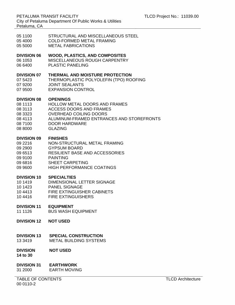
PETALUMA TRANSIT FACILITY City of Petaluma Department Of Public Works & Utilities Petaluma, CA
TLCD Project No.: 11039.00
TABLE OF CONTENTS 00 0110-2
TLCD Architecture
05 1100 STRUCTURAL AND MISCELLANEOUS STEEL 05 4000 COLD-FORMED METAL FRAMING 05 5000 METAL FABRICATIONS DIVISION 06 WOOD, PLASTICS, AND COMPOSITES 06 1053 MISCELLANEOUS ROUGH CARPENTRY 06 6400 PLASTIC PANELING DIVISION 07 THERMAL AND MOISTURE PROTECTION 07 5423 THERMOPLASTIC POLYOLEFIN (TPO) ROOFING 07 9200 JOINT SEALANTS 07 9500 EXPANSION CONTROL DIVISION 08 OPENINGS 08 1113 HOLLOW METAL DOORS AND FRAMES 08 3113 ACCESS DOORS AND FRAMES 08 3323 OVERHEAD COILING DOORS 08 4113 ALUMINUM-FRAMED ENTRANCES AND STOREFRONTS 08 7100 DOOR HARDWARE 08 8000 GLAZING DIVISION 09 FINISHES 09 2216 NON-STRUCTURAL METAL FRAMING 09 2900 GYPSUM BOARD 09 6513 RESILIENT BASE AND ACCESSORIES 09 9100 PAINTING 09 6816 SHEET CARPETING 09 9600 HIGH PERFORMANCE COATINGS DIVISION 10 SPECIALTIES 10 1419 DIMENSIONAL LETTER SIGNAGE 10 1423 PANEL SIGNAGE 10 4413 FIRE EXTINGUISHER CABINETS 10 4416 FIRE EXTINGUISHERS DIVISION 11 EQUIPMENT 11 1126 BUS WASH EQUIPMENT DIVISION 12 NOT USED DIVISION 13 SPECIAL CONSTRUCTION 13 3419 METAL BUILDING SYSTEMS DIVISION 14 to 30
NOT USED
DIVISION 31 EARTHWORK 31 2000 EARTH MOVING
TLCD Project No.: 11039.00 PETALUMA TRANSIT FACILITYCity of Petaluma Department Of Public Works & Utilities
Petaluma, CA
TLCD Architecture TABLE OF CONTENTS00 0110-3
DIVISION 32 EXTERIOR IMPROVEMENTS 32 1313 CONCRETE PAVING
APPENDIX I MECHANICAL & PLUMBING DESIGN-BUILD DIRECTIVES
APPENDIX II ELECTRICAL DESIGN-BUILD DIRECTIVES
END OF SECTION

PETALUMA TRANSIT FACILITY City of Petaluma Department Of Public Works & Utilities Petaluma, CA
TLCD Project No.: 11039.00
TABLE OF CONTENTS 00 0110-4
TLCD Architecture
THIS PAGE INTENTIONALLY LEFT BLANK

TLCD Project No.: 11039.00 PETALUMA TRANSIT FACILITYCity Of Petaluma Department Of Public Works & Utilities
Petaluma, CA
TLCD Architecture GEOTECHNICAL DATA00 3132- 1
SECTION 00 3132 – GEOTECHNICAL DATA
1.1 SUMMARY
A. The geotechnical data was prepared from the Owner’s subsurface exploration and geotechnical evaluation includes location plan, exploration results, borings, general notes, and soil classification system. 1. A geotechnical investigation has been conducted for the Project site by the Owner's
Geotechnical Engineering Consultant, independent of the Architect, to reasonably determine existing site conditions. The Owner's Geotechnical Engineering Consultant has prepared a Geotechnical Investigation Report (Soils Report) to provide recommendations to the design professionals, and provide requirements for construction of the Project by the Contractor. a. Owner's Geotechnical Consultant:
1) Name: Kleinfelder 2) Address: 2240 Northpoint Parkway, Santa Rosa, CA 95407-5009 3) Phone: 707.571.1883
b. Title of Report: “Limited Geotechnical Exploration, Petaluma Transit Project.” c. Date of Report: 12.19.2011 d. Geotechnical Firm's Project Number: 123449.
2. The Owner's Soils Report is on file at the office of the Owner and Architect, where it may be inspected by prospective bidders. a. Copies of the Owner's Soils Report may be obtained by prospective bidders
upon written request addressed to the Owner and payment for the cost of reproduction and handling by the Owner. Full payment for reproduction and handling must accompany the written request prior to release of the Soils Report by the Owner.
3. Prior to bidding, bidders may make their own subsurface investigations to satisfy themselves as to site and subsurface conditions. Such investigations may be performed only under time schedules and arrangements approved in advance by the Owner. a. Costs for Contractor’s site investigations are solely the responsibility of the
Contractor, including repairs for damages to existing surfaces.
B. Data on indicated subsurface conditions provided by the Owner are not intended as representations or warranties of continuity of such conditions. It is expressly understood that the Owner is not responsible for interpretations or conclusions drawn from the data by the Contractor. Data are made available for the convenience of the Contractor and are not guaranteed to represent conditions that may be encountered. 1. The report identifies properties of below grade conditions and offers
recommendations for the design of foundations, paving and other construction components primarily for the use of the Architect and Engineers.
2. The recommendations described shall not be construed as a requirement of the Contract unless specifically referenced in the Contract Documents.
3. The report, by its nature, cannot reveal all conditions existing on the site. Should subsurface conditions be fount to vary substantially from this report, changes in the design and construction of foundations, paving and other construction components will be made with resulting credits or additions to the Contract sum accruing to the Owner.

PETALUMA TRANSIT FACILITY City Of Petaluma Department Of Public Works & Utilities Petaluma, CA
TLCD Project No.: 11039.00
GEOTECHNICAL DATA 00 3132- 2
TLCD Architecture
PART 2 - PRODUCTS (Not Used
PART 3 - EXECUTION (Not Used)
END OF SECTION
TLCD Project No.: 11039.00 PETALUMA TRANSIT FACILITYCity Of Petaluma Department Of Public Works & Utilities
Petaluma, CA
TLCD Architecture SUMMARY01 1000 - 1
SECTION 01 1000 - SUMMARY
PART 1 - GENERAL
1.1 RELATED DOCUMENTS
A. Drawings and general provisions of the Contract, including General and Supplementary Conditions and other Division 01 Specification Sections, apply to this Section.
1.2 SUMMARY
A. Section includes: 1. Project information. 2. Work covered by Contract Documents. 3. Access to site. 4. Coordination with occupants. 5. Work restrictions. 6. Specification and drawing conventions. 7. Miscellaneous provisions
B. Related Section: 1. Section 01 5000 "Temporary Facilities and Controls" for limitations and procedures
governing temporary use of Owner's facilities.
1.3 PROJECT INFORMATION
A. Project Identification: Petaluma Transit Facility Project Location: 555 N. McDowell Blvd. Petaluma, CA
B. Owner: 1. City of Petaluma Department of Public Works & Utilities
a. 11 English Street, Petaluma, CA 94952 b. Owner's Representative: Joseph Rye, Transit Manager.
C. Architect: 1. TLCD Architecture.
a. Address: 111 Santa Rosa Avenue, Suite 300, Santa Rosa, California 95404. b. Phone: (707) 525-5600. c. Facsimile: (707) 525-5616. d. Contact: To Be Determined.

PETALUMA TRANSIT FACILITY City Of Petaluma Department Of Public Works & Utilities Petaluma, CA
TLCD Project No.: 11039.00
SUMMARY 01 1000 - 2
TLCD Architecture
1.4 WORK COVERED BY CONTRACT DOCUMENTS
A. The Work of the Project is defined by the Contract Documents and consists of the following: 1. Addition to and renovation of transit facilities and associated sitework. 2. Design-build services associated with:
a. Metal Building Systems. b. Bus Wash Equipment. c. HVAC, Plumbing, and Fire Protection Systems. d. Electrical Systems, including power, lighting, fire alarm, telephone/ data
communications and security. 3. Preparation of documents including drawings and calculations required by the City
of Petaluma for building permit, including title 24 documentation demonstrating compliance with the California Energy Code.
4. Such plancheck corrections as the City may require. 5. Meetings with the City of Petaluma Building Department as necessary to obtain the
building permit for the project.
B. Type of Contract 1. Project will be constructed under a single prime contract.
1.5 WORK UNDER SEPARATE CONTRACTS
A. General: Cooperate fully with separate contractors so work on those contracts may be carried out smoothly, without interfering with or delaying work under this Contract or other contracts. Coordinate the Work of this Contract with work performed under separate contracts.
1.6 ACCESS TO SITE
A. General: Contractor shall have limited use of Project site for construction operations as indicated on Drawings by the Contract limits and as indicated by requirements of this Section.
B. Use of Site: Limit use of Project site to work in areas indicated for each phase. Do not disturb portions of Project site beyond areas in which the Work is indicated. 1. The project site is also the main operational center for the Transit Authority. Their
continuous uninterrupted operations must be maintained during the entire duration of construction.
1.7 COORDINATION WITH OCCUPANTS
A. Partial Owner Occupancy: Owner will occupy the premises during entire construction period, with the exception of areas under construction. Cooperate with Owner during construction operations to minimize conflicts and facilitate Owner usage. Perform the Work so as not to interfere with Owner's operations. Maintain existing exits unless otherwise indicated.

TLCD Project No.: 11039.00 PETALUMA TRANSIT FACILITYCity Of Petaluma Department Of Public Works & Utilities
Petaluma, CA
TLCD Architecture SUMMARY01 1000 - 3
1. Maintain access to existing walkways, corridors, and other adjacent occupied or used facilities. Do not close or obstruct walkways, corridors, or other occupied or used facilities without written permission from Owner and authorities having jurisdiction.
2. Provide not less than 72 hours' notice to Owner of activities that will affect Owner's operations.
B. Owner Limited Occupancy of Completed Areas of Construction: Owner reserves the right to occupy and to place and install equipment in completed portions of the Work, prior to Final Completion, provided such occupancy does not interfere with completion of the Work. Such placement of equipment and limited occupancy shall not constitute acceptance of the total Work. 1. Architect will prepare a Certificate of Substantial Completion for each specific
portion of the Work to be occupied prior to Owner acceptance of the completed Work.
2. Obtain a Certificate of Occupancy from authorities having jurisdiction before limited Owner occupancy.
3. Before limited Owner occupancy, mechanical and electrical systems shall be fully operational, and required tests and inspections shall be successfully completed. On occupancy, Owner will operate and maintain mechanical and electrical systems serving occupied portions of Work.
4. On occupancy, Owner will assume responsibility for maintenance and custodial service for occupied portions of Work.
1.8 WORK RESTRICTIONS
A. Work Restrictions, General: Comply with restrictions on construction operations. 1. Comply with limitations on use of public streets and other requirements of
authorities having jurisdiction.
B. On-Site Work Hours: Limit work in the existing building to normal business working hours of 6:00 a.m. to 7:00 p.m., Monday through Friday, except as otherwise indicated. 1. Weekend Hours: Coordinate with Owner and obtain authorization in writing.. 2. Early Morning Hours: Restricted to hours allowed by local authorities having
jurisdiction for restrictions on noisy work. 3. Hours for Utility Shutdowns: Comply with Owner’s restrictions. 4. Hours for deliveries: 10:00AM to Noon, 2PM to 4PM.
C. Existing Utility Interruptions: Do not interrupt utilities serving facilities occupied by Owner or others unless permitted under the following conditions and then only after providing temporary utility services according to requirements indicated: 1. Notify Owner not less than two days in advance of proposed utility interruptions. 2. Obtain Owner's written permission before proceeding with utility interruptions.
D. Noise, Vibration, and Odors: Coordinate operations that may result in high levels of noise and vibration, odors, or other disruption to Owner occupancy with Owner. 1. Notify Owner not less than two days in advance of proposed disruptive operations. 2. Obtain Owner's written permission before proceeding with disruptive operations.
PETALUMA TRANSIT FACILITY City Of Petaluma Department Of Public Works & Utilities Petaluma, CA
TLCD Project No.: 11039.00
SUMMARY 01 1000 - 4
TLCD Architecture
E. Nonsmoking Site: Smoking is not permitted on the project site.
F. Controlled Substances: Use of controlled substances on the Project site is not permitted.
1.9 SPECIFICATION AND DRAWING CONVENTIONS
A. Specification Content: The Specifications use certain conventions for the style of language and the intended meaning of certain terms, words, and phrases when used in particular situations. These conventions are as follows: 1. Imperative mood and streamlined language are generally used in the Specifications.
The words "shall," "shall be," or "shall comply with," depending on the context, are implied where a colon (:) is used within a sentence or phrase.
2. Specification requirements are to be performed by Contractor unless specifically stated otherwise.
B. Division 01 General Requirements: Requirements of Sections in Division 01 apply to the Work of all Sections in the Specifications.
C. Drawing Coordination: Requirements for materials and products identified on the Drawings are described in detail in the Specifications. One or more of the following are used on the Drawings to identify materials and products: 1. Terminology: Materials and products are identified by the typical generic terms
used in the individual Specifications Sections. 2. Abbreviations: Materials and products are identified by abbreviations scheduled on
Drawings.
PART 2 - PRODUCTS (Not Used)
PART 3 - EXECUTION (Not Used)
END OF SECTION
TLCD Project No.: 11039.00 PETALUMA TRANSIT FACILITYCity Of Petaluma Department Of Public Works & Utilities
Petaluma, CA
TLCD Architecture SUBSTITUTION PROCEDURES01 2500 - 1
SECTION 01 2500 - SUBSTITUTION PROCEDURES
PART 1 - GENERAL
1.1 RELATED DOCUMENTS
A. Drawings and general provisions of the Contract, including General and Supplementary Conditions and other Division 01 Specification Sections, apply to this Section.
1.2 SUMMARY
A. Section includes administrative and procedural requirements for substitutions.
B. Related Sections: 1. Section 01 6000 "Product Requirements" for requirements for submitting
comparable product submittals for products by listed manufacturers and for requirements for submitting “or equal” substitutions consistent with California Public Contract Code Section 3400.
2. Divisions 02 through 32 Sections and Design Build Directives for specific requirements and limitations for substitutions.
1.3 DEFINITIONS
A. Substitutions: Changes in products, materials, equipment, and methods of construction from those required by the Contract Documents and proposed by Contractor. 1. Substitutions for Cause: Changes proposed by Contractor that are required due to
changed Project conditions, such as unavailability of product, regulatory changes, or unavailability of required warranty terms.
2. Substitutions for Convenience: Changes proposed by Contractor or Owner that are not required in order to meet other Project requirements but may offer advantage to Contractor or Owner.
1.4 ACTION SUBMITTALS
A. Substitution Requests: Submit three copies of each request for consideration. Identify product or fabrication or installation method to be replaced. Include Specification Section number and title and Drawing numbers and titles. 1. Substitution Request Form: Use facsimile of form provided in the Project Manual.
a. Substitutions for Cause or Convenience: Use “Substitution Request Form (After the Bid Date).”

PETALUMA TRANSIT FACILITY City Of Petaluma Department Of Public Works & Utilities Petaluma, CA
TLCD Project No.: 11039.00
SUBSTITUTION PROCEDURES 01 2500 - 2
TLCD Architecture
2. Documentation: Show compliance with requirements for substitutions and the following, as applicable: a. Statement indicating why specified product or fabrication or installation cannot
be provided, if applicable. b. Coordination information, including a list of changes or modifications needed
to other parts of the Work and to construction performed by Owner and separate contractors, that will be necessary to accommodate proposed substitution.
c. Detailed comparison of significant qualities of proposed substitution with those of the Work specified. Include annotated copy of applicable specification section. Significant qualities may include attributes such as performance, weight, size, durability, visual effect, warranties, and specific features and requirements indicated. Indicate deviations, if any, from the Work specified.
d. Product Data, including drawings and descriptions of products and fabrication and installation procedures.
e. Samples, where applicable or requested. f. Certificates and qualification data, where applicable or requested. g. List of similar installations for completed projects with project names and
addresses and names and addresses of architects and owners. h. Material test reports from a qualified testing agency indicating and interpreting
test results for compliance with requirements indicated. i. Research reports evidencing compliance with building code in effect for
Project, from ICC-ES. j. Detailed comparison of Contractor's construction schedule using proposed
substitution with products specified for the Work, including effect on the overall Contract Time. If specified product or method of construction cannot be provided within the Contract Time, include letter from manufacturer, on manufacturer's letterhead, stating date of receipt of purchase order, lack of availability, or delays in delivery.
k. Cost information, including a proposal of change, if any, in the Contract Sum. l. Contractor's certification that proposed substitution complies with
requirements in the Contract Documents except as indicated in substitution request, is compatible with related materials, and is appropriate for applications indicated.
m. Contractor's waiver of rights to additional payment or time that may subsequently become necessary because of failure of proposed substitution to produce indicated results.
3. Architect's Action: If necessary, Architect will request additional information or documentation for evaluation within seven days of receipt of a request for substitution. Architect will notify Contractor of acceptance or rejection of proposed substitution within 15 days of receipt of request, or seven days of receipt of additional information or documentation, whichever is later. a. Forms of Acceptance: Change Order, Construction Change Directive, or
Architect's Supplemental Instructions for minor changes in the Work. b. Decision by Architect is final. Resubmittal of substitution requests will not be
allowed. c. Use product specified if Architect does not issue a decision on use of a
proposed substitution within time allocated.

TLCD Project No.: 11039.00 PETALUMA TRANSIT FACILITYCity Of Petaluma Department Of Public Works & Utilities
Petaluma, CA
TLCD Architecture SUBSTITUTION PROCEDURES01 2500 - 3
1.5 QUALITY ASSURANCE
A. Compatibility of Substitutions: Investigate and document compatibility of proposed substitution with related products and materials. Engage qualified testing agency to perform compatibility tests recommended by manufacturers.
1.6 PROCEDURES
A. Coordination: Modify or adjust affected work as necessary to integrate work of the approved substitutions.
PART 2 - PRODUCTS
2.1 SUBSTITUTIONS
A. Substitutions for Cause: Submit requests for substitution immediately upon discovery of need for change, but not later than 15 days prior to time required for preparation and review of related submittals. 1. Conditions: Architect will consider Contractor's request for substitution when the
following conditions are satisfied. If the following conditions are not satisfied, Architect will return requests without action, except to record noncompliance with these requirements: a. Requested substitution is consistent with the Contract Documents and will
produce indicated results. b. Substitution request is fully documented and properly submitted. c. Requested substitution will not adversely affect Contractor's construction
schedule. d. Requested substitution has received necessary approvals of authorities
having jurisdiction. e. Requested substitution is compatible with other portions of the Work. f. Requested substitution has been coordinated with other portions of the Work. g. Requested substitution provides specified warranty. h. If requested substitution involves more than one contractor, requested
substitution has been coordinated with other portions of the Work, is uniform and consistent, is compatible with other products, and is acceptable to all contractors involved.
B. Substitutions for Convenience: Architect will consider requests for substitution if received within 30 days after the Notice of Award. Requests received after that time may be considered or rejected at discretion of Architect. 1. Conditions: Architect will consider Contractor's request for substitution when the
following conditions are satisfied. If the following conditions are not satisfied, Architect will return requests without action, except to record noncompliance with these requirements: a. Requested substitution offers Owner a substantial advantage in cost, time,
energy conservation, or other considerations, after deducting additional responsibilities Owner must assume. Owner's additional responsibilities may
PETALUMA TRANSIT FACILITY City Of Petaluma Department Of Public Works & Utilities Petaluma, CA
TLCD Project No.: 11039.00
SUBSTITUTION PROCEDURES 01 2500 - 4
TLCD Architecture
include compensation to Architect for redesign and evaluation services, increased testing and inspection costs, increased cost of other construction by Owner, and similar considerations.
b. Requested substitution does not require extensive revisions to the Contract Documents.
c. Requested substitution is consistent with the Contract Documents and will produce indicated results.
d. Substitution request is fully documented and properly submitted. e. Requested substitution will not adversely affect Contractor's construction
schedule. f. Requested substitution has received necessary approvals of authorities
having jurisdiction. g. Requested substitution is compatible with other portions of the Work. h. Requested substitution has been coordinated with other portions of the Work. i. Requested substitution provides specified warranty. j. If requested substitution involves more than one contractor, requested
substitution has been coordinated with other portions of the Work, is uniform and consistent, is compatible with other products, and is acceptable to all contractors involved.
PART 3 - EXECUTION (Not Used)
END OF SECTION
Attachments: Substitution Request Form (After the Bid Date)
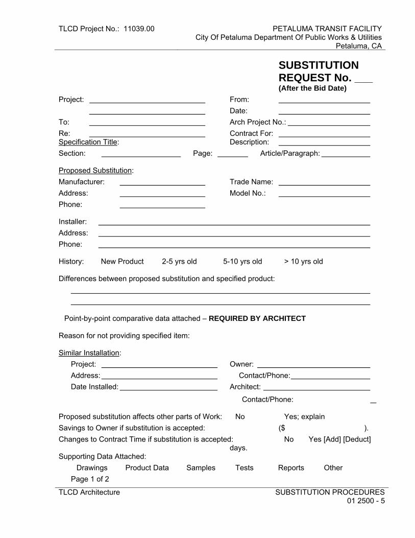
TLCD Project No.: 11039.00 PETALUMA TRANSIT FACILITYCity Of Petaluma Department Of Public Works & Utilities
Petaluma, CA
TLCD Architecture SUBSTITUTION PROCEDURES01 2500 - 5
SUBSTITUTION REQUEST No. ___ (After the Bid Date)
Project: From:
Date:
To: Arch Project No.:
Re: Contract For: Specification Title: Description:
Section: Page: Article/Paragraph: Proposed Substitution:
Manufacturer: Trade Name:
Address: Model No.:
Phone: Installer:
Address:
Phone: History: �New Product �2-5 yrs old �5-10 yrs old �> 10 yrs old Differences between proposed substitution and specified product:
�Point-by-point comparative data attached – REQUIRED BY ARCHITECT Reason for not providing specified item: Similar Installation:
Project: Owner:
Address: Contact/Phone:
Date Installed: Architect:
Contact/Phone: Proposed substitution affects other parts of Work: �No �Yes; explain
Savings to Owner if substitution is accepted: ($ ).
Changes to Contract Time if substitution is accepted: �No �Yes [Add] [Deduct] days. Supporting Data Attached:
�Drawings �Product Data �Samples �Tests �Reports �Other
Page 1 of 2
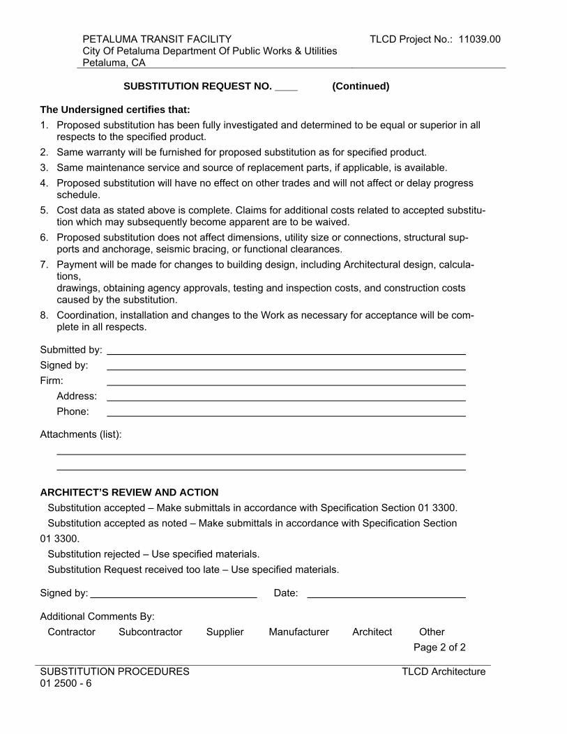
PETALUMA TRANSIT FACILITY City Of Petaluma Department Of Public Works & Utilities Petaluma, CA
TLCD Project No.: 11039.00
SUBSTITUTION PROCEDURES 01 2500 - 6
TLCD Architecture
SUBSTITUTION REQUEST NO. ____ (Continued) The Undersigned certifies that:
1. Proposed substitution has been fully investigated and determined to be equal or superior in all respects to the specified product.
2. Same warranty will be furnished for proposed substitution as for specified product.
3. Same maintenance service and source of replacement parts, if applicable, is available.
4. Proposed substitution will have no effect on other trades and will not affect or delay progress schedule.
5. Cost data as stated above is complete. Claims for additional costs related to accepted substitu-tion which may subsequently become apparent are to be waived.
6. Proposed substitution does not affect dimensions, utility size or connections, structural sup-ports and anchorage, seismic bracing, or functional clearances.
7. Payment will be made for changes to building design, including Architectural design, calcula-tions, drawings, obtaining agency approvals, testing and inspection costs, and construction costs caused by the substitution.
8. Coordination, installation and changes to the Work as necessary for acceptance will be com-plete in all respects.
Submitted by:
Signed by:
Firm:
Address:
Phone:
Attachments (list):
ARCHITECT’S REVIEW AND ACTION
�Substitution accepted – Make submittals in accordance with Specification Section 01 3300.
�Substitution accepted as noted – Make submittals in accordance with Specification Section
01 3300.
�Substitution rejected – Use specified materials.
�Substitution Request received too late – Use specified materials. Signed by: Date: Additional Comments By:
�Contractor �Subcontractor �Supplier �Manufacturer �Architect �Other
Page 2 of 2
TLCD Project No.: 11039.00 PETALUMA TRANSIT FACILITYCity Of Petaluma Department Of Public Works & Utilities
Petaluma, CA
TLCD Architecture CONTRACT MODIFICATION PROCEDURES01 2600 - 1
SECTION 01 2600 - CONTRACT MODIFICATION PROCEDURES
PART 1 - GENERAL
1.1 RELATED DOCUMENTS
A. Drawings and general provisions of the Contract, including General and Supplementary Conditions and other Division 01 Specification Sections, apply to this Section.
1.2 SUMMARY
A. Section includes administrative and procedural requirements for handling and processing Contract modifications.
B. Related Sections: 1. Section 01 6000 "Product Requirements" for administrative procedures for handling
requests for substitutions made after Contract award.
1.3 MINOR CHANGES IN THE WORK
A. Architect will issue supplemental instructions authorizing minor changes in the Work, not involving adjustment to the Contract Sum or the Contract Time, on Field Order form included in the Project Manual. 1. Notify Architect immediately and request direction if Contractor deems Field Order
Work requires modification to the Contract Sum or Contract Time
1.4 COST REQUESTS
A. Owner-Initiated Cost Requests: Architect will issue a detailed description of proposed changes in the Work that may require adjustment to the Contract Sum or the Contract Time. If necessary, the description will include supplemental or revised Drawings and Specifications. 1. Cost Requests issued by Architect are not instructions either to stop work in
progress or to execute the proposed change. 2. Within time specified in Proposal Request or 20 days, when not otherwise specified,
after receipt of Proposal Request, submit a quotation estimating cost adjustments to the Contract Sum and the Contract Time necessary to execute the change. a. Include a list of quantities of products required or eliminated and unit costs,
with total amount of purchases and credits to be made. If requested, furnish survey data to substantiate quantities.
b. Indicate applicable taxes, delivery charges, equipment rental, and amounts of trade discounts.
c. Include costs of labor and supervision directly attributable to the change.

PETALUMA TRANSIT FACILITY City Of Petaluma Department Of Public Works & Utilities Petaluma, CA
TLCD Project No.: 11039.00
CONTRACT MODIFICATION PROCEDURES 01 2600 - 2
TLCD Architecture
d. Include an updated Contractor's construction schedule that indicates the effect of the change, including, but not limited to, changes in activity duration, start and finish times, and activity relationship. Use available total float before requesting an extension of the Contract Time.
e. Quotation Form: Use CSI Form 13.6B "Proposal Worksheet Summary" and 13.6C "Proposal Worksheet Detail" or Contractor’s forms containing equivalent information and acceptable to Architect.
B. Contractor-Initiated Proposals: If latent or changed conditions require modifications to the Contract, Contractor may initiate a claim by submitting a request for a change to Architect and Construction Manager in the form of a Proposed Change Order. 1. Include a statement outlining reasons for the change and the effect of the change on
the Work. Provide a complete description of the proposed change. Indicate the effect of the proposed change on the Contract Sum and the Contract Time.
2. Include a list of quantities of products required or eliminated and unit costs, with total amount of purchases and credits to be made. If requested, furnish survey data to substantiate quantities.
3. Indicate applicable taxes, delivery charges, equipment rental, and amounts of trade discounts.
4. Include costs of labor and supervision directly attributable to the change. 5. Include an updated Contractor's construction schedule that indicates the effect of
the change, including, but not limited to, changes in activity duration, start and finish times, and activity relationship. Use available total float before requesting an extension of the Contract Time.
6. Comply with requirements in Section 01 2500 "Substitution Procedures" if the proposed change requires substitution of one product or system for product or system specified.
7. Proposed Change Order Form: Use form acceptable to Architect.
1.5 ADMINISTRATIVE CHANGE ORDERS
A. Unit Price Adjustment: Refer to Section 01 2200 "Unit Prices" for administrative procedures for preparation of Change Order Proposal for adjusting the Contract Sum to reflect measured scope of unit price work.
1.6 CHANGE ORDER PROCEDURES
A. On Owner's approval of a Cost Request, Construction Change Directive or Proposed Change Order, Architect will issue a Change Order for signatures of Owner and Contractor on form included in Project Manual. 1. Owner reserves the right to compile individual Cost Request, Construction Change
Directive or Proposed Change Orders into cumulative Change Orders.

TLCD Project No.: 11039.00 PETALUMA TRANSIT FACILITYCity Of Petaluma Department Of Public Works & Utilities
Petaluma, CA
TLCD Architecture CONTRACT MODIFICATION PROCEDURES01 2600 - 3
1.7 CONSTRUCTION CHANGE DIRECTIVE
A. Construction Change Directive: Architect may issue a Construction Change Directive on form included in Project Manual. Construction Change Directive instructs Contractor to proceed with a change in the Work, for subsequent inclusion in a Change Order. 1. Construction Change Directive contains a complete description of change in the
Work. It also designates method to be followed to determine change in the Contract Sum or the Contract Time.
B. Documentation: Maintain detailed records on a time and material basis of work required by the Construction Change Directive. 1. After completion of change, submit an itemized account and supporting data
necessary to substantiate cost and time adjustments to the Contract.
PART 2 - PRODUCTS (Not Used)
PART 3 - EXECUTION (Not Used)
END OF SECTION
ATTACHED FORMS TLCD Architecture Field Order Form TLCD Architecture Cost Request Form TLCD Architecture Change Order Form TLCD Architecture Construction Change Directive Form

PETALUMA TRANSIT FACILITY City Of Petaluma Department Of Public Works & Utilities Petaluma, CA
TLCD Project No.: 11039.00
CONTRACT MODIFICATION PROCEDURES 01 2600 - 4
TLCD Architecture
THIS PAGE INTENTIONALLY LEFT BLANK
TLCD Project No.: 11039.00 PETALUMA TRANSIT FACILITYCity Of Petaluma Department Of Public Works & Utilities
Petaluma, CA
TLCD Architecture CONTRACT MODIFICATION PROCEDURES01 2600 - 5

PETALUMA TRANSIT FACILITY City Of Petaluma Department Of Public Works & Utilities Petaluma, CA
TLCD Project No.: 11039.00
CONTRACT MODIFICATION PROCEDURES 01 2600 - 6
TLCD Architecture
THIS PAGE INTENTIONALLY LEFT BLANK
TLCD Project No.: 11039.00 PETALUMA TRANSIT FACILITYCity Of Petaluma Department Of Public Works & Utilities
Petaluma, CA
TLCD Architecture CONTRACT MODIFICATION PROCEDURES01 2600 - 7
PETALUMA TRANSIT FACILITY City Of Petaluma Department Of Public Works & Utilities Petaluma, CA
TLCD Project No.: 11039.00
CONTRACT MODIFICATION PROCEDURES 01 2600 - 8
TLCD Architecture
THIS PAGE INTENTIONALLY LEFT BLANK

TLCD Project No.: 11039.00 PETALUMA TRANSIT FACILITYCity Of Petaluma Department Of Public Works & Utilities
Petaluma, CA
TLCD Architecture CONTRACT MODIFICATION PROCEDURES01 2600 - 9
PETALUMA TRANSIT FACILITY City Of Petaluma Department Of Public Works & Utilities Petaluma, CA
TLCD Project No.: 11039.00
CONTRACT MODIFICATION PROCEDURES 01 2600 - 10
TLCD Architecture
TLCD Project No.: 11039.00 PETALUMA TRANSIT FACILITYCity Of Petaluma Department Of Public Works & Utilities
Petaluma, CA
TLCD Architecture CONTRACT MODIFICATION PROCEDURES01 2600 - 11

PETALUMA TRANSIT FACILITY City Of Petaluma Department Of Public Works & Utilities Petaluma, CA
TLCD Project No.: 11039.00
CONTRACT MODIFICATION PROCEDURES 01 2600 - 12
TLCD Architecture
THIS PAGE INTENTIONALLY LEFT BLANK
TLCD Project No.: 11039.00 PETALUMA TRANSIT FACILITYCity Of Petaluma Department Of Public Works & Utilities
Petaluma, CA
TLCD Architecture CONTRACT MODIFICATION PROCEDURES01 2600 - 13
PETALUMA TRANSIT FACILITY City Of Petaluma Department Of Public Works & Utilities Petaluma, CA
TLCD Project No.: 11039.00
CONTRACT MODIFICATION PROCEDURES 01 2600 - 14
TLCD Architecture
THIS PAGE INTENTIONALLY LEFT BLANK

TLCD Project No.: 11039.00 PETALUMA TRANSIT FACILITYCity Of Petaluma Department Of Public Works & Utilities
Petaluma, CA
TLCD Architecture PAYMENT PROCEDURES01 2900 - 1
SECTION 01 2900 - PAYMENT PROCEDURES
PART 1 - GENERAL
1.1 RELATED DOCUMENTS
A. Drawings and general provisions of the Contract, including General and Supplementary Conditions and other Division 01 Specification Sections, apply to this Section.
1.2 SUMMARY
A. This Section specifies administrative and procedural requirements necessary to prepare and process Applications for Payment.
B. Related Sections: 1. Section 01 2600 "Contract Modification Procedures" for administrative procedures
for handling changes to the Contract. 2. Section 01 3200 "Construction Progress Documentation" for administrative
requirements governing the preparation and submittal of Contractor's construction schedule.
1.3 DEFINITIONS
A. Schedule of Values: A statement furnished by Contractor allocating portions of the Contract Sum to various portions of the Work and used as the basis for reviewing Contractor's Applications for Payment.
1.4 SCHEDULE OF VALUES
A. Coordination: Coordinate preparation of the schedule of values with preparation of Contractor's construction schedule. 1. Correlate line items in the schedule of values with other required administrative
forms and schedules, including the following: a. Application for Payment forms with continuation sheets. b. Submittal schedule. c. Items required to be indicated as separate activities in Contractor's
construction schedule. 2. Submit the schedule of values to Architect at earliest possible date but no later than
fifteen days before the date scheduled for submittal of initial Applications for Payment.
3. Subschedules for Phased Work: Where the Work is separated into phases requiring separately phased payments, provide subschedules showing values correlated with each phase of payment.

PETALUMA TRANSIT FACILITY City Of Petaluma Department Of Public Works & Utilities Petaluma, CA
TLCD Project No.: 11039.00
PAYMENT PROCEDURES 01 2900 - 2
TLCD Architecture
4. Subschedules for Separate Elements of Work: Where the Contractor's construction schedule defines separate elements of the Work, provide subschedules showing values correlated with each element.
B. Format and Content: Use the Project Manual table of contents as a guide to establish line items for the schedule of values. Provide at least one line item for each Specification Section. 1. Identification: Include the following Project identification on the schedule of values:
a. Project name and location. b. Name of Architect. c. Architect's project number. d. Contractor's name and address. e. Date of submittal.
2. Arrange schedule of values consistent with format of AIA Document G703 . 3. Provide a breakdown of the Contract Sum in enough detail to facilitate continued
evaluation of Applications for Payment and progress reports. Coordinate with the Project Manual table of contents. Provide multiple line items for principal subcontract amounts in excess of two percent of Contract Sum. a. Include separate line items for the following:
1) General Contractor: a) Profit. b) Bond and insurance. c) Home office management and supervision. d) On site management and supervision. e) Initial site mobilization at the start of Work. f) Temporary facilities for the duration of the Work. g) Shop Drawing and Submittal preparation and review. h) Site demobilization at the end of Work. i) Punch list activities. j) Final Project cleaning. k) Operation and maintenance manuals. l) Demonstration and training. m) Project Record Documents.
2) Under required principal subcontracts: a) Punch list activities. b) Operation and maintenance manuals. c) Project Record Documents. d) Demonstration and training.
4. Round amounts to nearest whole dollar; total shall equal the Contract Sum. 5. Payment for materials or equipment purchased or fabricated and stored but not yet
installed will be allowed only for specialty or long-lead time items and only when approved by the Owner in advance. Submit proposed list to the Owner for approval no later than 30 days after Notice to Proceed. For approved items, provide a separate line item in the schedule of values for each part of the Work where Applications for Payment may include materials or equipment purchased or fabricated and stored, but not yet installed. a. Differentiate between items stored on-site and items stored off-site. Include
evidence of insurance.
TLCD Project No.: 11039.00 PETALUMA TRANSIT FACILITYCity Of Petaluma Department Of Public Works & Utilities
Petaluma, CA
TLCD Architecture PAYMENT PROCEDURES01 2900 - 3
6. Provide separate line items in the schedule of values for initial cost of materials, for each subsequent stage of completion, and for total installed value of that part of the Work.
7. Allowances: Provide a separate line item in the schedule of values for each allowance. Show line-item value of unit-cost allowances, as a product of the unit cost, multiplied by measured quantity. Use information indicated in the Contract Documents to determine quantities.
8. Purchase Contracts: Provide a separate line item in the schedule of values for each purchase contract. Show line-item value of purchase contract. Indicate owner payments or deposits, if any, and balance to be paid by Contractor.
9. Each item in the schedule of values and Applications for Payment shall be complete. Include total cost and proportionate share of general overhead and profit for each item. a. Temporary facilities and other major cost items that are not direct cost of
actual work-in-place may be shown either as separate line items in the schedule of values or distributed as general overhead expense, at Contractor's option.
10. Schedule Updating: Update and resubmit the schedule of values before the next Applications for Payment when Change Orders or Construction Change Directives result in a change in the Contract Sum.
1.5 APPLICATIONS FOR PAYMENT
A. Each Application for Payment shall be consistent with previous applications and payments as certified by Architect and paid for by Owner. 1. Initial Application for Payment and final Application for Payment involve additional
requirements.
B. Payment Application Times: The date for each progress payment is indicated in the Agreement between Owner and Contractor. The period of construction work covered by each Application for Payment is the period indicated in the Agreement.
C. Application for Payment Forms: Use AIA Document G702 and AIA Document G703 as form for Applications for Payment.
D. Application Preparation: Complete every entry on form. Notarize and execute by a person authorized to sign legal documents on behalf of Contractor. Architect will return incomplete applications without action. 1. Entries shall match data on the schedule of values and Contractor's construction
schedule. Use updated schedules if revisions were made. 2. Include amounts for work completed following previous Application for Payment,
whether or not payment has been received. Include only amounts for work completed at time of Application for Payment.
3. Include amounts of Change Orders and Construction Change Directives issued before last day of construction period covered by application.
4. Indicate separate amounts for work being carried out under Owner-requested project acceleration.

PETALUMA TRANSIT FACILITY City Of Petaluma Department Of Public Works & Utilities Petaluma, CA
TLCD Project No.: 11039.00
PAYMENT PROCEDURES 01 2900 - 4
TLCD Architecture
E. Stored Materials: Payment for materials or equipment purchased or fabricated and stored but not yet installed will be allowed only for specialty or long-lead time items and only when approved by the Owner in advance. Include in Application for Payment amounts applied for materials or equipment purchased or fabricated and stored, but not yet installed. Differentiate between items stored on-site and items stored off-site. 1. Provide certificate of insurance, evidence of transfer of title to Owner, and consent
of surety to payment, for stored materials. 2. Provide supporting documentation that verifies amount requested, such as paid
invoices. Match amount requested with amounts indicated on documentation; do not include overhead and profit on stored materials.
3. Provide summary documentation for stored materials indicating the following: a. Materials previously stored and included in previous Applications for Payment. b. Work completed for this Application utilizing previously stored materials. c. Additional materials stored with this Application. d. Total materials remaining stored, including materials with this Application.
F. Transmittal: Submit three signed and notarized original copies of each Application for Payment to Architect by a method ensuring receipt. One copy shall include waivers of lien and similar attachments if required. 1. Transmit each copy with a transmittal form listing attachments and recording
appropriate information about application.
G. Project Record Document Review: Submit statement indicating that project record documents are current with the status of the Work. Obtain Inspector of Record’s signature indicating they have reviewed the documents and concur with the status indicated.
H. Waivers of Mechanic's Lien: With each Application for Payment, submit waivers of mechanic's liens from subcontractors, sub-subcontractors, and suppliers for construction period covered by the previous application. 1. Submit partial waivers on each item for amount requested in previous application,
after deduction for retainage, on each item. 2. When an application shows completion of an item, submit conditional final or full
waivers. 3. Owner reserves the right to designate which entities involved in the Work must
submit waivers. 4. Submit final Application for Payment with or preceded by conditional final waivers
from every entity involved with performance of the Work covered by the application who is lawfully entitled to a lien.
5. Waiver Forms: Submit waivers of lien on forms, executed in a manner acceptable to Owner.
I. Initial Application for Payment: Administrative actions and submittals that must precede or coincide with submittal of first Application for Payment include the following: 1. List of subcontractors. 2. Schedule of values. 3. Contractor's construction schedule (preliminary if not final). 4. Products list (preliminary if not final). 5. Submittal schedule (preliminary if not final).
TLCD Project No.: 11039.00 PETALUMA TRANSIT FACILITYCity Of Petaluma Department Of Public Works & Utilities
Petaluma, CA
TLCD Architecture PAYMENT PROCEDURES01 2900 - 5
6. List of Contractor's staff assignments. 7. List of Contractor's principal consultants. 8. Copies of building permits. 9. Copies of authorizations and licenses from authorities having jurisdiction for
performance of the Work. 10. Initial progress report. 11. Report of preconstruction conference. 12. Certificates of insurance and insurance policies. 13. Performance and payment bonds. 14. Data needed to acquire Owner's insurance.
J. Final Payment Application: Submit final Application for Payment with releases and supporting documentation not previously submitted and accepted, including, but not limited, to the following: 1. Evidence of completion of Project closeout requirements. 2. Insurance certificates for products and completed operations where required and
proof that taxes, fees, and similar obligations were paid. 3. Updated final statement, accounting for final changes to the Contract Sum. 4. AIA Document G706, "Contractor's Affidavit of Payment of Debts and Claims." 5. AIA Document G706A, "Contractor's Affidavit of Release of Liens." 6. AIA Document G707, "Consent of Surety to Final Payment." 7. Evidence that claims have been settled. 8. Final meter readings for utilities as of date when Owner took possession of and
assumed responsibility for corresponding elements of the Work. 9. Final liquidated damages settlement statement. 10. Completion of punchlist items. 11. Transmittal of required Project construction records to Owner. 12. Removal of temporary facilities and services. 13. Removal of surplus materials, rubbish and similar elements. 14. Other requirements indicated in Contract Documents.
PART 2 - PRODUCTS (Not Used)
PART 3 - EXECUTION (Not Used)
END OF SECTION
PETALUMA TRANSIT FACILITY City Of Petaluma Department Of Public Works & Utilities Petaluma, CA
TLCD Project No.: 11039.00
PAYMENT PROCEDURES 01 2900 - 6
TLCD Architecture
THIS PAGE INTENTIONALLY LEFT BLANK

TLCD Project No.: 11039.00 PETALUMA TRANSIT FACILITYCity Of Petaluma Department Of Public Works & Utilities
Petaluma, CA
TLCD Architecture PROJECT MANAGEMENT AND COORDINATION01 3100 - 1
SECTION 01 3100 - PROJECT MANAGEMENT AND COORDINATION
PART 1 - GENERAL
1.1 RELATED DOCUMENTS
A. Drawings and general provisions of the Contract, including General and Supplementary Conditions and other Division 01 Specification Sections, apply to this Section.
1.2 SUMMARY
A. Section includes administrative provisions for coordinating construction operations on Project including, but not limited to, the following: 1. General coordination procedures. 2. Coordination drawings. 3. Requests for Information (RFIs). 4. Web-Based Project Information Management System (PIM) 5. Project meetings.
B. Related Requirements: 1. Section 01 3200 "Construction Progress Documentation" for preparing and
submitting Contractor's construction schedule. 2. Section 01 7300 "Execution" for procedures for coordinating general installation and
field-engineering services, including establishment of benchmarks and control points.
3. Section 01 7700 "Closeout Procedures" for coordinating closeout of the Contract.
1.3 DEFINITIONS
A. PIM: Web-Based Project Information Management System.
B. RFI: Request from Owner, Architect, or Contractor seeking information required by or clarifications of the Contract Documents.
1.4 INFORMATIONAL SUBMITTALS
A. Subcontract List: Prepare a written summary identifying individuals or firms proposed for each portion of the Work, including those who are to furnish products or equipment fabricated to a special design. Include the following information in tabular form: 1. Name, address, and telephone number of entity performing subcontract or supplying
products. 2. Number and title of related Specification Section(s) covered by subcontract. 3. Drawing number and detail references, as appropriate, covered by subcontract.

PETALUMA TRANSIT FACILITY City Of Petaluma Department Of Public Works & Utilities Petaluma, CA
TLCD Project No.: 11039.00
PROJECT MANAGEMENT AND COORDINATION 01 3100 - 2
TLCD Architecture
B. Key Personnel Names: Within 15 days of starting construction operations, submit a list of key personnel assignments, including superintendent and other personnel in attendance at Project site. Identify individuals and their duties and responsibilities; list addresses and telephone numbers, including home, office, and cellular telephone numbers and e-mail addresses. Provide names, addresses, and telephone numbers of individuals assigned as alternates in the absence of individuals assigned to Project. 1. Post copies of list in project meeting room, in temporary field office, to Project Web-
Based Project Information Management System, and by each temporary telephone. Keep list current at all times.
1.5 GENERAL COORDINATION PROCEDURES
A. Coordination: Coordinate construction operations included in different Sections of the Specifications to ensure efficient and orderly installation of each part of the Work. Coordinate construction operations, included in different Sections, that depend on each other for proper installation, connection, and operation. 1. Schedule construction operations in sequence required to obtain the best results
where installation of one part of the Work depends on installation of other components, before or after its own installation.
2. Coordinate installation of different components to ensure maximum performance and accessibility for required maintenance, service, and repair.
3. Make adequate provisions to accommodate items scheduled for later installation.
B. Prepare memoranda for distribution to each party involved, outlining special procedures required for coordination. Include such items as required notices, reports, and list of attendees at meetings. 1. Prepare similar memoranda for Owner and separate contractors if coordination of
their Work is required.
C. Administrative Procedures: Coordinate scheduling and timing of required administrative procedures with other construction activities to avoid conflicts and to ensure orderly progress of the Work. Such administrative activities include, but are not limited to, the following: 1. Preparation of Contractor's construction schedule. 2. Preparation of the schedule of values. 3. Installation and removal of temporary facilities and controls. 4. Delivery and processing of submittals. 5. Progress meetings. 6. Preinstallation conferences. 7. Project closeout activities. 8. Startup and adjustment of systems.
D. Conservation: Coordinate construction activities to ensure that operations are carried out with consideration given to conservation of energy, water, and materials. Coordinate use of temporary utilities to minimize waste. 1. Salvage materials and equipment involved in performance of, but not actually
incorporated into, the Work. See other Sections for disposition of salvaged materials that are designated as Owner's property.

TLCD Project No.: 11039.00 PETALUMA TRANSIT FACILITYCity Of Petaluma Department Of Public Works & Utilities
Petaluma, CA
TLCD Architecture PROJECT MANAGEMENT AND COORDINATION01 3100 - 3
1.6 REQUESTS FOR INFORMATION (RFIs)
A. General: Immediately on discovery of the need for additional information or interpretation of the Contract Documents, Contractor shall prepare and submit an RFI in the form specified. 1. Architect will return RFIs submitted to Architect by other entities controlled by
Contractor with no response. 2. Coordinate and submit RFIs in a prompt manner so as to avoid delays in
Contractor's work or work of subcontractors.
B. Content of the RFI: Include a detailed, legible description of item needing information or interpretation and the following: 1. Project name. 2. Project number. 3. Date. 4. Name of Contractor. 5. Name of Architect. 6. RFI number, numbered sequentially. 7. RFI subject. 8. Specification Section number and title and related paragraphs, as appropriate. 9. Drawing number and detail references, as appropriate. 10. Field dimensions and conditions, as appropriate. 11. Contractor's suggested resolution. If Contractor's suggested resolution impacts the
Contract Time or the Contract Sum, Contractor shall state impact in the RFI. 12. Contractor's signature. 13. Attachments: Include sketches, descriptions, measurements, photos, Product Data,
Shop Drawings, coordination drawings, and other information necessary to fully describe items needing interpretation. a. Include dimensions, thicknesses, structural grid references, and details of
affected materials, assemblies, and attachments on attached sketches.
C. RFI Forms: Software-generated form with substantially the same content as AIA Document G716, acceptable to Architect. 1. Attachments shall be digital files in Adobe Acrobat PDF format.
D. Architect's Action: Architect will review each RFI, determine action required, and respond. Allow ten working days for Architect's response for each RFI. RFIs posted to PIM system after 1:00 p.m. will be considered as received the following working day. 1. The following Contractor-generated RFIs will be returned without action:
a. Requests for approval of submittals. b. Requests for approval of substitutions. c. Requests for approval of Contractor's means and methods. d. Requests for coordination information already indicated in the Contract
Documents. e. Requests for adjustments in the Contract Time or the Contract Sum. f. Requests for interpretation of Architect's actions on submittals. g. Incomplete RFIs or inaccurately prepared RFIs.
2. Architect's action may include a request for additional information, in which case Architect's time for response will date from time of receipt of additional information.

PETALUMA TRANSIT FACILITY City Of Petaluma Department Of Public Works & Utilities Petaluma, CA
TLCD Project No.: 11039.00
PROJECT MANAGEMENT AND COORDINATION 01 3100 - 4
TLCD Architecture
3. Architect's action on RFIs that may result in a change to the Contract Time or the Contract Sum may be eligible for Contractor to submit Change Proposal according to Section 01 3100 "Contract Modification Procedures." a. If Contractor believes the RFI response warrants change in the Contract Time
or the Contract Sum, notify Architect in writing within 10 days of receipt of the RFI response.
E. RFI Log: RFI log will be maintained by project’s web-based project information management system. Print a tabular log of RFIs organized by the RFI number for review at project meetings.
F. On receipt of Architect's action, update the RFI log and immediately distribute the RFI response to affected parties. Review response and notify Architect within seven days if Contractor disagrees with response. 1. Identification of related Minor Change in the Work, Construction Change Directive,
and Proposal Request, as appropriate. 2. Identification of related Field Order, Work Change Directive, and Proposal Request,
as appropriate.
1.7 WEB-BASED PROJECT INFORMATION MANAGEMENT SYSTEM
A. Unless otherwise approved, use Architect's Web-Based Project Information Management System for purposes of managing project communication and documentation until Final Completion. 1. Software: Architrek by Architrek, LLC. 2. Functions include the following:
a. Meeting minutes. b. Contract modifications forms and logs. c. RFI forms and logs. d. Calendar management. e. Submittals forms and logs. f. Payment application forms. g. Drawing and specification revision hosting, viewing, and updating. h. Archiving functions.
1.8 PROJECT MEETINGS
A. General: Schedule and conduct meetings and conferences at Project site unless otherwise indicated. 1. Attendees: Inform participants and others involved, and individuals whose presence
is required, of date and time of each meeting. Notify Owner and Architect of scheduled meeting dates and times.
2. Agenda: Prepare the meeting agenda. Distribute the agenda to all invited attendees.
3. Minutes: Entity responsible for conducting meeting will record significant discussions and agreements achieved. Distribute the meeting minutes to everyone concerned, including Owner and Architect, within three days of the meeting.
TLCD Project No.: 11039.00 PETALUMA TRANSIT FACILITYCity Of Petaluma Department Of Public Works & Utilities
Petaluma, CA
TLCD Architecture PROJECT MANAGEMENT AND COORDINATION01 3100 - 5
B. Preconstruction Conference: Architect will schedule and conduct a preconstruction conference before starting construction, at a time convenient to Owner and Architect, but no later than 15 days after execution of the Agreement. 1. Conduct the conference to review responsibilities and personnel assignments. 2. Attendees: Authorized representatives of Owner, Architect, and their consultants;
Contractor and its superintendent; major subcontractors; suppliers; and other concerned parties shall attend the conference. Participants at the conference shall be familiar with Project and authorized to conclude matters relating to the Work.
3. Agenda: Discuss items of significance that could affect progress, including the following: a. Tentative construction schedule. b. Phasing. c. Critical work sequencing and long-lead items. d. Designation of key personnel and their duties. e. Lines of communications. f. Procedures for processing field decisions and Change Orders. g. Procedures for RFIs. h. Procedures for testing and inspecting.
1) Owner’s Testing Agency procedures and responsibilities. 2) Inspector of Record’s responsibilities.
i. Procedures for processing Applications for Payment. j. Distribution of the Contract Documents. k. Submittal procedures. l. Preparation of record documents. m. Use of the premises. n. Work restrictions. o. Working hours. p. Owner's occupancy requirements. q. Responsibility for temporary facilities and controls. r. Procedures for moisture and mold control. s. Procedures for disruptions and shutdowns. t. Construction waste management and recycling. u. Parking availability. v. Office, work, and storage areas. w. Equipment deliveries and priorities. x. First aid. y. Security. z. Progress cleaning.
4. Minutes: Entity responsible for conducting meeting will record and distribute meeting minutes.
C. Project Information Management System Training: Architect will schedule and conduct a Project Information Management System Training session before the start of construction.
D. Preinstallation Conferences: Conduct a preinstallation conference at Project site before each construction activity that requires coordination with other construction. 1. Attendees: Installer and representatives of manufacturers and fabricators involved
in or affected by the installation and its coordination or integration with other
PETALUMA TRANSIT FACILITY City Of Petaluma Department Of Public Works & Utilities Petaluma, CA
TLCD Project No.: 11039.00
PROJECT MANAGEMENT AND COORDINATION 01 3100 - 6
TLCD Architecture
materials and installations that have preceded or will follow, shall attend the meeting. Advise Architect of scheduled meeting dates.
2. Agenda: Review progress of other construction activities and preparations for the particular activity under consideration, including requirements for the following: a. Contract Documents. b. Options. c. Related RFIs. d. Related Change Orders. e. Purchases. f. Deliveries. g. Submittals. h. Review of mockups. i. Possible conflicts. j. Compatibility requirements. k. Time schedules. l. Weather limitations. m. Manufacturer's written instructions. n. Warranty requirements. o. Compatibility of materials. p. Acceptability of substrates. q. Temporary facilities and controls. r. Space and access limitations. s. Regulations of authorities having jurisdiction. t. Testing and inspecting requirements. u. Installation procedures. v. Coordination with other work. w. Required performance results. x. Protection of adjacent work. y. Protection of construction and personnel.
3. Record significant conference discussions, agreements, and disagreements, including required corrective measures and actions.
4. Reporting: Distribute minutes of the meeting to each party present and to other parties requiring information.
5. Do not proceed with installation if the conference cannot be successfully concluded. Initiate whatever actions are necessary to resolve impediments to performance of the Work and reconvene the conference at earliest feasible date.
E. Project Closeout Conference: Schedule and conduct a project closeout conference, at a time convenient to Owner and Architect, but no later than 90 days prior to the scheduled date of Substantial Completion. 1. Conduct the conference to review requirements and responsibilities related to
Project closeout. 2. Attendees: Authorized representatives of Owner, Architect, and their consultants;
Contractor and its superintendent; major subcontractors; suppliers; and other concerned parties shall attend the meeting. Participants at the meeting shall be familiar with Project and authorized to conclude matters relating to the Work.
3. Agenda: Discuss items of significance that could affect or delay Project closeout, including the following: a. Preparation of record documents.

TLCD Project No.: 11039.00 PETALUMA TRANSIT FACILITYCity Of Petaluma Department Of Public Works & Utilities
Petaluma, CA
TLCD Architecture PROJECT MANAGEMENT AND COORDINATION01 3100 - 7
b. Procedures required prior to inspection for Substantial Completion and for final inspection for acceptance.
c. Submittal of written warranties. d. Requirements for preparing operations and maintenance data. e. Requirements for delivery of material samples, attic stock, and spare parts. f. Requirements for demonstration and training. g. Preparation of Contractor's punch list. h. Procedures for processing Applications for Payment at Substantial Completion
and for final payment. i. Submittal procedures. j. Coordination of separate contracts. k. Owner's partial occupancy requirements. l. Installation of Owner's furniture, fixtures, and equipment. m. Responsibility for removing temporary facilities and controls.
4. Minutes: Entity conducting meeting will record and distribute meeting minutes.
F. Progress Meetings: Conduct progress meetings at biweekly intervals. 1. Coordinate dates of meetings with preparation of payment requests. 2. Attendees: In addition to representatives of Owner, and Architect, each contractor,
subcontractor, supplier, and other entity concerned with current progress or involved in planning, coordination, or performance of future activities shall be represented at these meetings. All participants at the meeting shall be familiar with Project and authorized to conclude matters relating to the Work.
3. Agenda: Review and correct or approve minutes of previous progress meeting. Review other items of significance that could affect progress. Include topics for discussion as appropriate to status of Project. a. Contractor's Construction Schedule: Review progress since the last meeting.
Determine whether each activity is on time, ahead of schedule, or behind schedule, in relation to Contractor's construction schedule. Determine how construction behind schedule will be expedited; secure commitments from parties involved to do so. Discuss whether schedule revisions are required to ensure that current and subsequent activities will be completed within the Contract Time. 1) Review schedule for next period.
b. Review present and future needs of each entity present, including the following: 1) Interface requirements. 2) Sequence of operations. 3) Resolution of BIM component conflicts. 4) Status of submittals. 5) Deliveries. 6) Off-site fabrication. 7) Access. 8) Site utilization. 9) Temporary facilities and controls. 10) Progress cleaning. 11) Quality and work standards. 12) Status of correction of deficient items. 13) Field observations. 14) Status of RFIs.

PETALUMA TRANSIT FACILITY City Of Petaluma Department Of Public Works & Utilities Petaluma, CA
TLCD Project No.: 11039.00
PROJECT MANAGEMENT AND COORDINATION 01 3100 - 8
TLCD Architecture
15) Status of proposal requests. 16) Pending changes. 17) Status of Change Orders. 18) Pending claims and disputes. 19) Documentation of information for payment requests.
4. Minutes: Entity responsible for conducting the meeting will record and distribute the meeting minutes to each party present and to parties requiring information. a. Schedule Updating: Revise Contractor's construction schedule after each
progress meeting where revisions to the schedule have been made or recognized. Issue revised schedule concurrently with the report of each meeting.
G. Progress Payment Meetings: Conduct a progress payment meeting each month prior to submittal of Application for Payment. Progress payment meeting shall coincide with last Progress Meeting of the month whenever possible. 1. Attendees: Representatives of Owner, Architect, and Contractor’s Project Manager. 2. Prepare draft of the current month’s proposed billing (pencil copy pay application)
for review with the Architect, and Inspector of Record at the progress payment meeting.
3. Following review of the proposed payment application, revise as required, prepare Application for Payment and submit per the requirements of Section 01 2900 “Payment Procedures.”
PART 2 - PRODUCTS (Not Used)
PART 3 - EXECUTION (Not Used)
END OF SECTION
TLCD Project No.: 11039.00 PETALUMA TRANSIT FACILITYCity Of Petaluma Department Of Public Works & Utilities
Petaluma, CA
TLCD Architecture CONSTRUCTION PROGRESS DOCUMENTATION01 3200 - 1
SECTION 01 3200 - CONSTRUCTION PROGRESS DOCUMENTATION
PART 1 - GENERAL
1.1 RELATED DOCUMENTS
A. Drawings and general provisions of the Contract, including General and Supplementary Conditions and other Division 01 Specification Sections, apply to this Section.
1.2 SUMMARY
A. Section includes administrative and procedural requirements for documenting the progress of construction during performance of the Work, including the following: 1. Start-up construction schedule. 2. Contractor's construction schedule. 3. Construction schedule updating reports. 4. Daily construction reports. 5. Site condition reports. 6. Special reports.
B. Related Sections: 1. Section 01 3300 "Submittal Procedures" for submitting schedules and reports. 2. Section 01 4000 "Quality Requirements" for submitting a schedule of tests and
inspections.
1.3 DEFINITIONS
A. Activity: A discrete part of a project that can be identified for planning, scheduling, monitoring, and controlling the construction project. Activities included in a construction schedule consume time and resources. 1. Critical Activity: An activity on the critical path that must start and finish on the
planned early start and finish times. 2. Predecessor Activity: An activity that precedes another activity in the network. 3. Successor Activity: An activity that follows another activity in the network.
B. Cost Loading: The allocation of the schedule of values for the completion of an activity as scheduled. The sum of costs for all activities must equal the total Contract Sum, unless otherwise approved by Architect.
C. CPM: Critical path method, which is a method of planning and scheduling a construction project where activities are arranged based on activity relationships. Network calculations determine when activities can be performed and the critical path of the Project.
PETALUMA TRANSIT FACILITY City Of Petaluma Department Of Public Works & Utilities Petaluma, CA
TLCD Project No.: 11039.00
CONSTRUCTION PROGRESS DOCUMENTATION 01 3200 - 2
TLCD Architecture
D. Critical Path: The longest connected chain of interdependent activities through the network schedule that establishes the minimum overall Project duration and contains no float.
E. Event: The starting or ending point of an activity.
F. Float: The measure of leeway in starting and completing an activity. 1. Float time is not for the exclusive use or benefit of either Owner or Contractor, but is
a jointly owned, expiring Project resource available to both parties as needed to meet schedule milestones and Contract completion date.
2. Free float is the amount of time an activity can be delayed without adversely affecting the early start of the successor activity.
3. Total float is the measure of leeway in starting or completing an activity without adversely affecting the planned Project completion date.
G. Resource Loading: The allocation of manpower and equipment necessary for the completion of an activity as scheduled.
1.4 INFORMATIONAL SUBMITTALS
A. Format for Submittals: Submit required submittals in the following format: 1. PDF electronic file. 2. Two paper copies.
B. Start-up construction schedule. 1. Approval of cost-loaded start-up construction schedule will not constitute approval of
schedule of values for cost-loaded activities.
C. Start-up Network Diagram: Of size required to display entire network for entire construction period. Show logic ties for activities.
D. Contractor's Construction Schedule: Initial schedule, of size required to display entire schedule for entire construction period.
E. CPM Reports: Concurrent with CPM schedule, submit each of the following reports. Format for each activity in reports shall contain activity number, activity description, cost and resource loading, original duration, remaining duration, early start date, early finish date, late start date, late finish date, and total float in calendar days. 1. Activity Report: List of all activities sorted by activity number and then early start
date, or actual start date if known. 2. Logic Report: List of preceding and succeeding activities for all activities, sorted in
ascending order by activity number and then early start date, or actual start date if known.
3. Total Float Report: List of all activities sorted in ascending order of total float. 4. Earnings Report: Compilation of Contractor's total earnings from the Notice to
Proceed until most recent Application for Payment.
F. Construction Schedule Updating Reports: Submit with Applications for Payment

TLCD Project No.: 11039.00 PETALUMA TRANSIT FACILITYCity Of Petaluma Department Of Public Works & Utilities
Petaluma, CA
TLCD Architecture CONSTRUCTION PROGRESS DOCUMENTATION01 3200 - 3
G. Daily Construction Reports: Submit at monthly intervals.
H. Field Condition Reports: Submit at time of discovery of differing conditions.
I. Special Reports: Submit at time of unusual event.
J. Qualification Data: For scheduling consultant.
1.5 QUALITY ASSURANCE
A. Scheduling Consultant Qualifications: An experienced specialist in CPM scheduling and reporting, with capability of producing CPM reports and diagrams within 24 hours of Architect's request.
B. Prescheduling Conference: Conduct conference at Project site to comply with requirements in Section 01 3100 "Project Management and Coordination." Review methods and procedures related to the preliminary construction schedule and Contractor's construction schedule, including, but not limited to, the following: 1. Review software limitations and content and format for reports. 2. Verify availability of qualified personnel needed to develop and update schedule. 3. Discuss constraints. 4. Review time required for review of submittals and resubmittals. 5. Review requirements for tests and inspections by independent testing and
inspecting agencies. 6. Review time required for completion and startup procedures. 7. Review and finalize list of construction activities to be included in schedule. 8. Review submittal requirements and procedures. 9. Review procedures for updating schedule.
1.6 COORDINATION
A. Coordinate preparation and processing of schedules and reports with performance of construction activities and with scheduling and reporting of separate contractors.
B. Coordinate Contractor's construction schedule with the schedule of values, list of subcontracts, submittal schedule, progress reports, payment requests, and other required schedules and reports. 1. Secure time commitments for performing critical elements of the Work from entities
involved. 2. Coordinate each construction activity in the network with other activities and
schedule them in proper sequence.
PETALUMA TRANSIT FACILITY City Of Petaluma Department Of Public Works & Utilities Petaluma, CA
TLCD Project No.: 11039.00
CONSTRUCTION PROGRESS DOCUMENTATION 01 3200 - 4
TLCD Architecture
PART 2 - PRODUCTS
2.1 CONTRACTOR'S CONSTRUCTION SCHEDULE, GENERAL
A. Time Frame: Extend schedule from date established for the Notice to Proceed to date of final completion. 1. Contract completion date shall not be changed by submission of a schedule that
shows an early completion date, unless specifically authorized by Change Order.
B. Activities: Treat each story or separate area as a separate numbered activity for each principal element of the Work. Comply with the following: 1. Activity Duration: Define activities so no activity is longer than 20 days, unless
specifically allowed by Architect. a. Procurement Activities: Include procurement process activities for the
following long lead items and major items, requiring a cycle of more than 60 days, as separate activities in schedule. Procurement cycle activities include, but are not limited to, submittals, approvals, purchasing, fabrication, and delivery.
2. Submittal Review Time: Include review and resubmittal times indicated in Section 01 3300 "Submittal Procedures" in schedule. Coordinate submittal review times in Contractor's construction schedule with submittal schedule.
3. Startup and Testing Time: Include not less than 15 days for startup and testing. 4. Punch List and Final Completion: Include not more than 30 days for punch list and
final completion.
C. Constraints: Include constraints and work restrictions indicated in the Contract Documents and as follows in schedule, and show how the sequence of the Work is affected. 1. Phasing: Arrange list of activities on schedule by phase. 2. Work under More Than One Contract: Include a separate activity for each contract. 3. Work by Owner: Include a separate activity for each portion of the Work performed
by Owner. 4. Products Ordered in Advance: Include a separate activity for each product. Include
delivery date indicated in Section 01 1000 "Summary." Delivery dates indicated stipulate the earliest possible delivery date.
5. Owner-Furnished Products: Include a separate activity for each product. Include delivery date indicated in Section 01 1000 "Summary." Delivery dates indicated stipulate the earliest possible delivery date.
6. Work Restrictions: Show the effect of the following items on the schedule: a. Coordination with existing construction. b. Limitations of continued occupancies. c. Uninterruptible services. d. Partial occupancy before Final Completion. e. Use of premises restrictions. f. Provisions for future construction. g. Seasonal variations. h. Environmental control.

TLCD Project No.: 11039.00 PETALUMA TRANSIT FACILITYCity Of Petaluma Department Of Public Works & Utilities
Petaluma, CA
TLCD Architecture CONSTRUCTION PROGRESS DOCUMENTATION01 3200 - 5
7. Work Stages: Indicate important stages of construction for each major portion of the Work, including, but not limited to, the following: a. Subcontract awards. b. Submittals. c. Purchases. d. Mockups. e. Fabrication. f. Sample testing. g. Deliveries. h. Installation. i. Tests and inspections. j. Adjusting. k. Curing. l. Startup and placement into final use and operation.
8. Construction Areas: Identify each major area of construction for each major portion of the Work.
9. Milestones: Include milestones indicated in the Contract Documents in schedule, including, but not limited to, the Notice to Proceed, and final completion.
D. Upcoming Work Summary: Prepare summary report indicating activities scheduled to occur or commence prior to submittal of next schedule update. Summarize the following issues: 1. Unresolved issues. 2. Unanswered Requests for Information. 3. Rejected or unreturned submittals. 4. Notations on returned submittals. 5. Pending modifications affecting the Work and Contract Time.
E. Recovery Schedule: When periodic update indicates the Work is 14 or more calendar days behind the current approved schedule, submit a separate recovery schedule indicating means by which Contractor intends to regain compliance with the schedule. Indicate changes to working hours, working days, crew sizes, and equipment required to achieve compliance, and date by which recovery will be accomplished.
F. Computer Scheduling Software: Prepare schedules using current version of a program that has been developed specifically to manage construction schedules.
2.2 START-UP CONSTRUCTION SCHEDULE
A. Bar-Chart Schedule: Submit start-up horizontal bar-chart-type construction schedule within 15 days of date established for the Notice to Proceed.
B. Preparation: Indicate each significant construction activity separately. Identify first workday of each week with a continuous vertical line. Outline significant construction activities for first 60 days of construction. Include skeleton diagram for the remainder of the Work and a cash requirement prediction based on indicated activities.

PETALUMA TRANSIT FACILITY City Of Petaluma Department Of Public Works & Utilities Petaluma, CA
TLCD Project No.: 11039.00
CONSTRUCTION PROGRESS DOCUMENTATION 01 3200 - 6
TLCD Architecture
2.3 CONTRACTOR'S CONSTRUCTION SCHEDULE (CPM SCHEDULE)
A. General: Prepare network diagrams using AON (activity-on-node) format.
B. Start-up Network Diagram: Submit diagram within 14 days of date established for the Notice of Award. Outline significant construction activities for the first 90 days of construction. Include skeleton diagram for the remainder of the Work and a cash requirement prediction based on indicated activities.
C. CPM Schedule: Prepare Contractor's construction schedule using a cost- and resource-loaded, time-scaled CPM network analysis diagram for the Work. 1. Develop network diagram in sufficient time to submit CPM schedule so it can be
accepted for use no later than 30 days after date established for the Notice of Award. a. Failure to include any work item required for performance of this Contract shall
not excuse Contractor from completing all work within applicable completion dates, regardless of Architect's approval of the schedule.
2. Conduct educational workshops to train and inform key Project personnel, including subcontractors' personnel, in proper methods of providing data and using CPM schedule information.
3. Establish procedures for monitoring and updating CPM schedule and for reporting progress. Coordinate procedures with progress meeting and payment request dates.
4. Use "one workday" as the unit of time for individual activities. Indicate nonworking days and holidays incorporated into the schedule in order to correlate with Contract Time.
D. CPM Schedule Preparation: Prepare a list of all activities required to complete the Work. Using the start-up network diagram, prepare a skeleton network to identify probable critical paths. 1. Activities: Indicate the estimated time duration, sequence requirements, and
relationship of each activity in relation to other activities. Include estimated time frames for the following activities: a. Preparation and processing of submittals. b. Delegated Design c. Mobilization and demobilization. d. Purchase of materials. e. Delivery. f. Fabrication. g. Utility interruptions. h. Installation. i. Work by Owner that may affect or be affected by Contractor's activities. j. Testing. k. Punch list and final completion. l. Activities occurring following final completion.
2. Critical Path Activities: Identify critical path activities, including those for interim completion dates. Scheduled start and completion dates shall be consistent with Contract milestone dates.

TLCD Project No.: 11039.00 PETALUMA TRANSIT FACILITYCity Of Petaluma Department Of Public Works & Utilities
Petaluma, CA
TLCD Architecture CONSTRUCTION PROGRESS DOCUMENTATION01 3200 - 7
3. Processing: Process data to produce output data on a computer-drawn, time-scaled network. Revise data, reorganize activity sequences, and reproduce as often as necessary to produce the CPM schedule within the limitations of the Contract Time.
4. Format: Mark the critical path. Locate the critical path near center of network; locate paths with most float near the edges. a. Subnetworks on separate sheets are permissible for activities clearly off the
critical path. 5. Cost- and Resource-Loading of CPM Schedule: Assign cost to construction
activities on the CPM schedule. Do not assign costs to submittal activities. Obtain Architect's approval prior to assigning costs to fabrication and delivery activities. Assign costs under principal subcontracts for testing and commissioning activities, operation and maintenance manuals, punch list activities, Project record documents, and demonstration and training (if applicable), in the amount of 5 percent of the Contract Sum. a. Each activity cost shall reflect an appropriate value subject to approval by
Architect. b. Total cost assigned to activities shall equal the total Contract Sum.
E. Contract Modifications: For each proposed contract modification and concurrent with its submission, prepare a time-impact analysis using a network fragment to demonstrate the effect of the proposed change on the overall project schedule.
F. Initial Issue of Schedule: Prepare initial network diagram from a sorted activity list indicating straight "early start-total float." Identify critical activities. Prepare tabulated reports showing the following: 1. Contractor or subcontractor and the Work or activity. 2. Description of activity. 3. Principal events of activity. 4. Immediate preceding and succeeding activities. 5. Early and late start dates. 6. Early and late finish dates. 7. Activity duration in workdays. 8. Total float or slack time. 9. Average size of workforce. 10. Dollar value of activity (coordinated with the schedule of values).
G. Schedule Updating: Concurrent with making revisions to schedule, prepare tabulated reports showing the following: 1. Identification of activities that have changed. 2. Changes in early and late start dates. 3. Changes in early and late finish dates. 4. Changes in activity durations in workdays. 5. Changes in the critical path. 6. Changes in total float or slack time. 7. Changes in the Contract Time.
H. Value Summaries: Prepare two cumulative value lists, sorted by finish dates. 1. In first list, tabulate activity number, early finish date, dollar value, and cumulative
dollar value.

PETALUMA TRANSIT FACILITY City Of Petaluma Department Of Public Works & Utilities Petaluma, CA
TLCD Project No.: 11039.00
CONSTRUCTION PROGRESS DOCUMENTATION 01 3200 - 8
TLCD Architecture
2. In second list, tabulate activity number, late finish date, dollar value, and cumulative dollar value.
3. In subsequent issues of both lists, substitute actual finish dates for activities completed as of list date.
4. Prepare list for ease of comparison with payment requests; coordinate timing with Progress Payment meetings. a. In both value summary lists, tabulate "actual percent complete" and
"cumulative value completed" with total at bottom. b. Submit value summary printouts at each month’s Progress Payment meeting.
2.4 REPORTS
A. Daily Construction Reports: Prepare a daily construction report recording the following information concerning events at Project site: 1. List of subcontractors at Project site. 2. List of separate contractors at Project site. 3. Approximate count of personnel at Project site. 4. Equipment at Project site. 5. Material deliveries. 6. High and low temperatures and general weather conditions, including presence of
rain or snow. 7. Accidents. 8. Meetings and significant decisions. 9. Unusual events (refer to special reports). 10. Stoppages, delays, shortages, and losses. 11. Meter readings and similar recordings. 12. Emergency procedures. 13. Orders and requests of authorities having jurisdiction. 14. Change Orders received and implemented. 15. Construction Change Directives received and implemented. 16. Services connected and disconnected. 17. Equipment or system tests and startups. 18. Partial completions and occupancies.
B. Site Condition Reports: Immediately on discovery of a difference between site conditions and the Contract Documents, prepare and submit a detailed report. Submit with a Request for Information. Include a detailed description of the differing conditions, together with recommendations for changing the Contract Documents.
2.5 SPECIAL REPORTS
A. General: Submit special reports directly to Owner within one day of an occurrence. Distribute copies of report to parties affected by the occurrence.
B. Reporting Unusual Events: When an event of an unusual and significant nature occurs at Project site, whether or not related directly to the Work, prepare and submit a special report. List chain of events, persons participating, response by Contractor's personnel,
TLCD Project No.: 11039.00 PETALUMA TRANSIT FACILITYCity Of Petaluma Department Of Public Works & Utilities
Petaluma, CA
TLCD Architecture CONSTRUCTION PROGRESS DOCUMENTATION01 3200 - 9
evaluation of results or effects, and similar pertinent information. Advise Owner in advance when these events are known or predictable.
PART 3 - EXECUTION
3.1 CONTRACTOR'S CONSTRUCTION SCHEDULE
A. Scheduling Consultant: Engage a consultant to provide planning, evaluation, and reporting using CPM scheduling. 1. In-House Option: Owner may waive the requirement to retain a consultant if
Contractor employs skilled personnel with experience in CPM scheduling and reporting techniques. Submit qualifications.
2. Meetings: Scheduling consultant shall attend all meetings related to Project progress, alleged delays, and time impact.
B. Contractor's Construction Schedule Updating: At monthly intervals, update schedule to reflect actual construction progress and activities. Issue schedule one week before each regularly scheduled progress meeting. 1. Revise schedule immediately after each meeting or other activity where revisions
have been recognized or made. Issue updated schedule concurrently with the report of each such meeting.
2. Include a report with updated schedule that indicates every change, including, but not limited to, changes in logic, durations, actual starts and finishes, and activity durations.
3. As the Work progresses, indicate final completion percentage for each activity.
C. Distribution: Distribute copies of approved schedule to Architect Owner, separate contractors, testing and inspecting agencies, and other parties identified by Contractor with a need-to-know schedule responsibility. 1. Post copies in Project meeting rooms and temporary field offices. 2. When revisions are made, distribute updated schedules to the same parties and
post in the same locations. Delete parties from distribution when they have completed their assigned portion of the Work and are no longer involved in performance of construction activities.
END OF SECTION

PETALUMA TRANSIT FACILITY City Of Petaluma Department Of Public Works & Utilities Petaluma, CA
TLCD Project No.: 11039.00
CONSTRUCTION PROGRESS DOCUMENTATION 01 3200 - 10
TLCD Architecture
THIS PAGE INTENTIONALLY LEFT BLANK

TLCD Project No.: 11039.00 PETALUMA TRANSIT FACILITYCity Of Petaluma Department Of Public Works & Utilities
Petaluma, CA
TLCD Architecture SUBMITTAL PROCEDURES01 3300 - 1
SECTION 01 3300 - SUBMITTAL PROCEDURES
PART 1 - GENERAL
1.1 RELATED DOCUMENTS
A. Drawings and general provisions of the Contract, including General and Supplementary Conditions and other Division 01 Specification Sections, apply to this Section.
1.2 SUMMARY
A. Section includes requirements for the submittal schedule and administrative and procedural requirements for submitting Shop Drawings, Product Data, Samples, Deferred-Approval Submittals and other submittals.
B. Related Sections: 1. Section 01 2900 "Payment Procedures" for submitting Applications for Payment and
the schedule of values. 2. Section 01 3200 "Construction Progress Documentation" for submitting schedules
and reports, including Contractor's construction schedule. 3. Section 01 7839 "Project Record Documents" for submitting record Drawings,
record Specifications, and record Product Data. 4. Section 01 7823 "Operation and Maintenance Data" for submitting operation and
maintenance manuals.
1.3 DEFINITIONS
A. Action Submittals: Written and graphic information and physical samples that require Architect's responsive action. Action submittals are those submittals indicated in individual Specification Sections as action submittals.
B. Informational Submittals: Written and graphic information and physical samples that do not require Architect's responsive action. Submittals may be rejected for not complying with requirements. Informational submittals are those submittals indicated in individual Specification Sections as informational submittals.
C. Deferred Approval Submittal: Written information, graphic information, calculations, test data and other required documentation prepared by the Contractor and submitted to Architect, for submission by the Architect to the Authority Having Jurisdiction for approval.
D. Portable Document Format (PDF): An open standard file format licensed by Adobe Systems used for representing documents in a device-independent and display resolution-independent fixed-layout document format.

PETALUMA TRANSIT FACILITY City Of Petaluma Department Of Public Works & Utilities Petaluma, CA
TLCD Project No.: 11039.00
SUBMITTAL PROCEDURES 01 3300 - 2
TLCD Architecture
1.4 ACTION SUBMITTALS
A. Submittal Schedule: Submit a schedule of submittals, arranged in chronological order by dates required by construction schedule. Include time required for review, ordering, manufacturing, fabrication, and delivery when establishing dates. Include additional time required for making corrections or modifications to submittals noted by the Architect and additional time for handling and reviewing submittals required by those corrections. 1. Coordinate submittal schedule with list of subcontracts, the schedule of values, and
Contractor's construction schedule. 2. Initial Submittal: Submit concurrently with start-up construction schedule. Include
submittals required during the first 60 days of construction. List those submittals required to maintain orderly progress of the Work and those required early because of long lead time for manufacture or fabrication.
3. Final Submittal: Submit concurrently with the first complete submittal of Contractor's construction schedule. a. Submit revised submittal schedule to reflect changes in current status and
timing for submittals. 4. Format: Arrange the following information in a tabular format:
a. Scheduled date for first submittal. b. Specification Section number and title. c. Submittal category: Action, informational. d. Name of subcontractor. e. Description of the Work covered. f. Scheduled date for Architect's final release or approval. g. Scheduled dates for purchasing. h. Scheduled dates for installation. i. Activity or event number.
1.5 SUBMITTAL ADMINISTRATIVE REQUIREMENTS
A. Architect's Digital Data Files: Digital copies of Architect’s CAD Drawings of the Contract Drawings may be made available by Architect, solely at Architect’s discretion, for Contractor's use in preparing submittals. Digital data prepared by the Architect’s Consultants are not included in this offer. Contact the Architect’s Consultants directly for information on availability, cost and conditions for digital data prepared by Consultants 1. Architect will furnish Contractor one set of digital data drawing files of the Contract
Drawings for use in preparing Shop Drawings and Project record drawings. a. Architect makes no representations as to the accuracy or completeness of
digital data drawing files as they relate to the Contract Drawings. b. Digital Drawing Software Program: The Contract Drawings are available in
Autocad 2007. c. Contractor shall execute a data licensing agreement in the form of AIA
Document C106, Digital Data Licensing Agreement and pay licensing fees of $1,250.00.
B. Coordination: Coordinate preparation and processing of submittals with performance of construction activities. 1. Coordinate each submittal with fabrication, purchasing, testing, delivery, other
submittals, and related activities that require sequential activity.

TLCD Project No.: 11039.00 PETALUMA TRANSIT FACILITYCity Of Petaluma Department Of Public Works & Utilities
Petaluma, CA
TLCD Architecture SUBMITTAL PROCEDURES01 3300 - 3
2. Submit all submittal items required for each Specification Section concurrently unless partial submittals for portions of the Work are indicated on approved submittal schedule.
3. Submit action submittals and informational submittals required by the same Specification Section as separate packages under separate transmittals.
4. Coordinate transmittal of different types of submittals for related parts of the Work so processing will not be delayed because of need to review submittals concurrently for coordination. a. Architect reserves the right to withhold action on a submittal requiring
coordination with other submittals until related submittals are received.
C. Processing Time: Allow time for submittal review, including time for resubmittals, as follows. Time for review shall commence on Architect's receipt of submittal. No extension of the Contract Time will be authorized because of failure to transmit submittals enough in advance of the Work to permit processing, including resubmittals. 1. Initial Review: Allow 14 days for initial review of each submittal. Allow additional
time if coordination with subsequent submittals is required. Architect will advise Contractor when a submittal being processed must be delayed for coordination.
2. Intermediate Review: If intermediate submittal is necessary, process it in same manner as initial submittal.
3. Resubmittal Review: Allow 14 days for review of each resubmittal. 4. Sequential Review: Where sequential review of submittals by Architect's
consultants, Owner, or other parties is indicated, allow 21days for initial review of each submittal.
5. Deferred Approval Submittals: Allow 60 days for review by Authority Having Jurisdiction and receipt of comments by Architect. a. Resubmittal Review: Allow 60 days for review of each resubmittal.
D. Paper Submittals: Place a permanent label or title block on each paper copy submittal item for identification. 1. Indicate name of firm or entity that prepared each submittal on label or title block. 2. Provide a space approximately 6 by 8 inches on label or beside title block to record
Contractor's review and approval markings and action taken by Architect. 3. Include the following information for processing and recording action taken:
a. Project name. b. Date. c. Name of Architect. d. Name of Construction Manager. e. Name of Contractor. f. Name of subcontractor. g. Name of supplier. h. Name of manufacturer. i. Submittal number or other unique identifier, including revision identifier.
1) Submittal number shall use Specification Section number followed by a decimal point and then a sequential number (e.g., 061000.01). Resubmittals shall include a sequential number suffix after another decimal point (e.g., 061000.01.01).
j. Number and title of appropriate Specification Section. k. Drawing number and detail references, as appropriate. l. Location(s) where product is to be installed, as appropriate.
PETALUMA TRANSIT FACILITY City Of Petaluma Department Of Public Works & Utilities Petaluma, CA
TLCD Project No.: 11039.00
SUBMITTAL PROCEDURES 01 3300 - 4
TLCD Architecture
m. Other necessary identification. 4. Additional Paper Copies: Unless additional copies are required for final submittal,
and unless Architect observes noncompliance with provisions in the Contract Documents, initial submittal may serve as final submittal.
5. Transmittal for Paper Submittals: Assemble each submittal individually and appropriately for transmittal and handling. Transmit each submittal using a transmittal form. Architect will discard submittals received from sources other than Contractor. a. Transmittal Form for Paper Submittals: Use AIA Document G810,
CSI Form 12.1A, or Contractor’s software-generated form with substantially the same content, acceptable to Architect.
E. Digital Submittals: Identify and incorporate information in each electronic submittal file as follows: 1. Assemble complete submittal package into a single indexed file incorporating
submittal requirements of a single Specification Section and transmittal form with links enabling navigation to each item.
2. Name file with submittal number or other unique identifier, including revision identifier. a. File name shall use project identifier and Specification Section number
followed by a decimal point and then a sequential number (e.g., LNHS-061000.01). Resubmittals shall include a sequential number suffix after another decimal point (e.g., LNHS-061000.01.01).
3. Provide means for insertion to permanently record Contractor's review and approval markings and action taken by Architect.
4. Transmittal Form for Digital Submittals: Use digital form acceptable to Architect, containing the following information: a. Project name. b. Date. c. Name and address of Architect. d. Name of Construction Manager. e. Name of Contractor. f. Name of firm or entity that prepared submittal. g. Names of subcontractor, manufacturer, and supplier. h. Category and type of submittal. i. Submittal purpose and description. j. Specification Section number and title. k. Specification paragraph number or drawing designation and generic name for
each of multiple items. l. Drawing number and detail references, as appropriate. m. Location(s) where product is to be installed, as appropriate. n. Related physical samples submitted directly. o. Indication of full or partial submittal. p. Transmittal number. q. Submittal and transmittal distribution record. r. Other necessary identification. s. Remarks.
5. Metadata: Include the following information as keywords in the electronic submittal file metadata:

TLCD Project No.: 11039.00 PETALUMA TRANSIT FACILITYCity Of Petaluma Department Of Public Works & Utilities
Petaluma, CA
TLCD Architecture SUBMITTAL PROCEDURES01 3300 - 5
a. Project name. b. Number and title of appropriate Specification Section. c. Manufacturer name. d. Product name..
F. Options: Identify options requiring selection by the Architect.
G. Deviations and Additional Information: On an attached separate sheet, prepared on Contractor's letterhead, record relevant information, requests for data, revisions other than those requested by Architect on previous submittals, and deviations from requirements in the Contract Documents, including minor variations and limitations. Include same identification information as related submittal.
H. Resubmittals: Make resubmittals in same form and number of copies as initial submittal. 1. Note date and content of previous submittal. 2. Note date and content of revision in label or title block and clearly indicate extent of
revision. 3. Resubmit submittals until they are marked with approval notation from Architect's
action stamp.
I. Distribution: Furnish copies of final submittals to manufacturers, subcontractors, suppliers, fabricators, installers, authorities having jurisdiction, and others as necessary for performance of construction activities. Show distribution on transmittal forms.
J. Use for Construction: Use only final submittals that are marked with approval notation from Architect's action stamp.
K. Material Safety Data Sheets (MSDSs): Submit information directly to Owner; do not submit to Architect. 1. Architect will not review submittals that include MSDSs and will return them for
resubmittal without MSDSs
PART 2 - PRODUCTS
2.1 SUBMITTAL PROCEDURES
A. General Submittal Procedure Requirements: Prepare and submit submittals required by individual Specification Sections. Types of submittals are indicated in individual Specification Sections. If submittal type (Action or Informational) is not indicated, comply with action submittal procedures. 1. Post digital submittals as PDF electronic files directly to Project Web site specifically
established for Project. a. Architect will return annotated file. Annotate and retain one copy of file as an
electronic Project record document file. 2. Action Submittals: Submit three paper copies of each submittal, unless otherwise
indicated. Architect will return one copy. 3. Informational Submittals: At Contractor’s Option, Contractor may submit either:
a. PDF Digital file.

PETALUMA TRANSIT FACILITY City Of Petaluma Department Of Public Works & Utilities Petaluma, CA
TLCD Project No.: 11039.00
SUBMITTAL PROCEDURES 01 3300 - 6
TLCD Architecture
b. Two paper copies of each submittal, unless otherwise indicated. Architect will not return copies.
4. Closeout Submittals and Maintenance Material Submittals: Comply with requirements specified in Section 01 7700 "Closeout Procedures."
5. Certificates and Certifications Submittals: Provide a statement that includes signature of entity responsible for preparing certification. Certificates and certifications shall be signed by an officer or other individual authorized to sign documents on behalf of that entity. a. Provide a digital signature with digital certificate on electronically-submitted
certificates and certifications where indicated. b. Provide a notarized statement on original paper copy certificates and
certifications where indicated. 6. Test and Inspection Reports Submittals: Comply with requirements specified in
Section 01 4000 "Quality Requirements."
B. Product Data: Collect information into a single submittal for each element of construction and type of product or equipment. 1. If information must be specially prepared for submittal because standard published
data are not suitable for use, submit as Shop Drawings, not as Product Data. 2. Mark each copy of each submittal to show which products and options are
applicable. 3. Include the following information, as applicable:
a. Manufacturer's catalog cuts. b. Manufacturer's product specifications. c. Standard color charts. d. Statement of compliance with specified referenced standards. e. Testing by recognized testing agency. f. Application of testing agency labels and seals. g. Notation of coordination requirements. h. Availability and delivery time information.
4. For equipment, include the following in addition to the above, as applicable: a. Wiring diagrams showing factory-installed wiring. b. Printed performance curves. c. Operational range diagrams. d. Clearances required to other construction, if not indicated on accompanying
Shop Drawings. 5. Submit Product Data before or concurrent with Samples. 6. Submit Product Data in the following format:
a. Three paper copies of Product Data, unless otherwise indicated. Architect will return one copy.
C. Shop Drawings: Prepare Project-specific information, drawn accurately to scale. Do not base Shop Drawings on reproductions of the Contract Documents or standard printed data, unless submittal based upon Architect's digital data drawing files is otherwise permitted. 1. Preparation: Fully illustrate requirements in the Contract Documents. Include the
following information, as applicable: a. Identification of products. b. Schedules.
TLCD Project No.: 11039.00 PETALUMA TRANSIT FACILITYCity Of Petaluma Department Of Public Works & Utilities
Petaluma, CA
TLCD Architecture SUBMITTAL PROCEDURES01 3300 - 7
c. Compliance with specified standards. d. Notation of coordination requirements. e. Notation of dimensions established by field measurement. f. Relationship and attachment to adjoining construction clearly indicated. g. Seal and signature of professional engineer if specified.
2. Sheet Size: Except for templates, patterns, and similar full-size drawings, submit Shop Drawings on sheets at least 8-1/2 by 11 inches but no larger than 30 by 42 inches.
3. Submit Shop Drawings in the following format: a. Two opaque (bond) copies of each submittal. Architect will return one copy.
D. Samples: Submit Samples for review of kind, color, pattern, and texture for a check of these characteristics with other elements and for a comparison of these characteristics between submittal and actual component as delivered and installed. 1. Transmit Samples that contain multiple, related components such as accessories
together in one submittal package. 2. Identification: Attach label on unexposed side of Samples that includes the
following: a. Generic description of Sample. b. Product name and name of manufacturer. c. Sample source. d. Number and title of applicable Specification Section.
3. Disposition: Maintain sets of approved Samples at Project site, available for quality-control comparisons throughout the course of construction activity. Sample sets may be used to determine final acceptance of construction associated with each set. a. Samples that may be incorporated into the Work are indicated in individual
Specification Sections. Such Samples must be in an undamaged condition at time of use.
b. Samples not incorporated into the Work, or otherwise designated as Owner's property, are the property of Contractor.
4. Samples for Initial Selection: Submit manufacturer's color charts consisting of units or sections of units showing the full range of colors, textures, and patterns available. a. Number of Samples: Submit one full set(s) of available choices where color,
pattern, texture, or similar characteristics are required to be selected from manufacturer's product line. Architect will return submittal with options selected.
5. Samples for Verification: Submit full-size units or Samples of size indicated, prepared from same material to be used for the Work, cured and finished in manner specified, and physically identical with material or product proposed for use, and that show full range of color and texture variations expected. Samples include, but are not limited to, the following: partial sections of manufactured or fabricated components; small cuts or containers of materials; complete units of repetitively used materials; swatches showing color, texture, and pattern; color range sets; and components used for independent testing and inspection. a. Number of Samples: Submit three sets of Samples. Architect will retain two
Sample sets; remainder will be returned. Mark up and retain one returned Sample set as a Project record sample. 1) Submit a single Sample where assembly details, workmanship,
fabrication techniques, connections, operation, and other similar characteristics are to be demonstrated.

PETALUMA TRANSIT FACILITY City Of Petaluma Department Of Public Works & Utilities Petaluma, CA
TLCD Project No.: 11039.00
SUBMITTAL PROCEDURES 01 3300 - 8
TLCD Architecture
2) If variation in color, pattern, texture, or other characteristic is inherent in material or product represented by a Sample, submit at least three sets of paired units that show approximate limits of variations.
E. Product Schedule: As required in individual Specification Sections, prepare a written summary indicating types of products required for the Work and their intended location. Include the following information in tabular form: 1. Type of product. Include unique identifier for each product indicated in the Contract
Documents. 2. Manufacturer and product name, and model number if applicable. 3. Number and name of room or space. 4. Location within room or space. 5. Submit product schedule in the following format:
a. PDF digital file.
F. Contractor's Construction Schedule: Comply with requirements specified in Section 01 3200 "Construction Progress Documentation."
G. Application for Payment: Comply with requirements specified in Section 01 2900 "Payment Procedures."
H. Schedule of Values: Comply with requirements specified in Section 01 2900 "Payment Procedures."
I. Subcontract List: Prepare a written summary identifying individuals or firms proposed for each portion of the Work, including those who are to furnish products or equipment fabricated to a special design. Include the following information in tabular form: 1. Name, address, and telephone number of entity performing subcontract or supplying
products. 2. Number and title of related Specification Section(s) covered by subcontract. 3. Drawing number and detail references, as appropriate, covered by subcontract. 4. Submit subcontract list in the following format:
a. PDF electronic file.
J. Qualification Data: Prepare written information that demonstrates capabilities and experience of firm or person. Include lists of completed projects with project names and addresses, contact information of architects and owners, and other information specified.
K. Welding Certificates: Prepare written certification that welding procedures and personnel comply with requirements in the Contract Documents. Submit record of Welding Procedure Specification and Procedure Qualification Record on American Welding Society (AWS) forms. Include names of firms and personnel certified.
L. Installer Certificates: Submit written statements on manufacturer's letterhead certifying that Installer complies with requirements in the Contract Documents and, where required, is authorized by manufacturer for this specific Project.
M. Manufacturer Certificates: Submit written statements on manufacturer's letterhead certifying that manufacturer complies with requirements in the Contract Documents. Include evidence of manufacturing experience where required.
TLCD Project No.: 11039.00 PETALUMA TRANSIT FACILITYCity Of Petaluma Department Of Public Works & Utilities
Petaluma, CA
TLCD Architecture SUBMITTAL PROCEDURES01 3300 - 9
N. Product Certificates: Submit written statements on manufacturer's letterhead certifying that product complies with requirements in the Contract Documents.
O. Material Certificates: Submit written statements on manufacturer's letterhead certifying that material complies with requirements in the Contract Documents.
P. Material Test Reports: Submit reports written by a qualified testing agency, on testing agency's standard form, indicating and interpreting test results of material for compliance with requirements in the Contract Documents.
Q. Product Test Reports: Submit written reports indicating current product produced by manufacturer complies with requirements in the Contract Documents. Base reports on evaluation of tests performed by manufacturer and witnessed by a qualified testing agency, or on comprehensive tests performed by a qualified testing agency.
R. Research Reports: Submit written evidence, from a model code organization acceptable to authorities having jurisdiction, that product complies with building code in effect for Project. Include the following information: 1. Name of evaluation organization. 2. Date of evaluation. 3. Time period when report is in effect. 4. Product and manufacturers' names. 5. Description of product. 6. Test procedures and results. 7. Limitations of use.
S. Schedule of Tests and Inspections: Comply with requirements specified in Section 01 4000 "Quality Requirements."
T. Preconstruction Test Reports: Submit reports written by a qualified testing agency, on testing agency's standard form, indicating and interpreting results of tests performed before installation of product, for compliance with performance requirements in the Contract Documents.
U. Compatibility Test Reports: Submit reports written by a qualified testing agency, on testing agency's standard form, indicating and interpreting results of compatibility tests performed before installation of product. Include written recommendations for primers and substrate preparation needed for adhesion.
V. Field Test Reports: Submit reports indicating and interpreting results of field tests performed either during installation of product or after product is installed in its final location, for compliance with requirements in the Contract Documents.
W. Maintenance Data: Comply with requirements specified in Section 01 7823 "Operation and Maintenance Data."
X. Design Data: Prepare and submit written and graphic information, including, but not limited to, performance and design criteria, list of applicable codes and regulations, and calculations. Include list of assumptions and other performance and design criteria and a summary of loads. Include load diagrams if applicable. Provide name and version of software, if any, used for calculations. Include page numbers.

PETALUMA TRANSIT FACILITY City Of Petaluma Department Of Public Works & Utilities Petaluma, CA
TLCD Project No.: 11039.00
SUBMITTAL PROCEDURES 01 3300 - 10
TLCD Architecture
2.2 DELEGATED-DESIGN SERVICES
A. Performance and Design Criteria: Where professional design services or certifications by a design professional are specifically required of Contractor by the Contract Documents, provide products and systems complying with specific performance and design criteria indicated. 1. If criteria indicated are not sufficient to perform services or certification required,
submit a written request for additional information to Architect.
B. Delegated-Design Services Certification: In addition to Shop Drawings, Product Data, and other required submittals, submit three paper copies of certificate, signed and sealed by the responsible design professional, for each product and system specifically assigned to Contractor to be designed or certified by a design professional. 1. Where professional design services are required, use design professional with a
valid California license. 2. Indicate that products and systems comply with performance and design criteria in
the Contract Documents. Include list of codes, loads, and other factors used in performing these services.
PART 3 - EXECUTION
3.1 CONTRACTOR'S REVIEW
A. Action and Informational Submittals: Review each submittal and check for coordination with other Work of the Contract and for compliance with the Contract Documents. Note corrections and field dimensions. Mark with approval stamp before submitting to Architect.
B. Project Closeout and Maintenance/Material Submittals: Refer to requirements in Section 01 7700 "Closeout Procedures."
C. Approval Stamp: Stamp each submittal with a uniform, approval stamp. Include Project name and location, submittal number, Specification Section title and number, name of reviewer, date of Contractor's approval, and statement certifying that submittal has been reviewed, checked, and approved for compliance with the Contract Documents.
3.2 ARCHITECT'S ACTION
A. General: Architect will not review submittals that do not bear Contractor's approval stamp and will return them without action.
B. Action Submittals: Architect will review each submittal, make marks to indicate corrections or modifications required, and return it. Architect will stamp each submittal with an action stamp and will mark stamp appropriately to indicate action, as follows: 1. “No Exceptions Taken” indicates final unrestricted release: the Work covered by the
submittal may proceed provided it complies with the Contract Documents. Final acceptance will depend on that compliance.

TLCD Project No.: 11039.00 PETALUMA TRANSIT FACILITYCity Of Petaluma Department Of Public Works & Utilities
Petaluma, CA
TLCD Architecture SUBMITTAL PROCEDURES01 3300 - 11
2. “Make Corrections Noted” indicates final, but restricted release: the Work covered by the submittal may proceed provided it complies both with the Architect’s notations and corrections on the submittal and with the Contract Documents. Final acceptance will depend on that compliance.
3. “Rejected” indicates do not proceed with the Work covered by the submittal. Prepare a new submittal for a product that complies with the Contract Documents.
4. “Revise and Resubmit” indicates do not proceed with the Work covered by the submittal, including purchasing, fabrication, delivery, or other activity for the product submitted. Revise or prepare a new submittal according to Architect’s notations and corrections.
5. “Submit Specified Item” indicates do not proceed with the Work covered by the submittal. Prepare additional information requested, or required by the Contract Documents, that indicates compliance with requirements..
C. Informational Submittals: Architect will review each submittal and will not return it, or will return it if it does not comply with requirements. Architect will forward each submittal to appropriate party.
D. Partial submittals prepared for a portion of the Work will be reviewed when use of partial submittals has received prior approval from Architect.
E. Incomplete submittals are unacceptable, will be considered nonresponsive, and will be returned for resubmittal without review.
F. Submittals not required by the Contract Documents may be returned by the Architect without action..
END OF SECTION

PETALUMA TRANSIT FACILITY City Of Petaluma Department Of Public Works & Utilities Petaluma, CA
TLCD Project No.: 11039.00
SUBMITTAL PROCEDURES 01 3300 - 12
TLCD Architecture
THIS PAGE INTENTIONALLY LEFT BLANK

TLCD Project No.: 11039.00 PETALUMA TRANSIT FACILITYCity Of Petaluma Department Of Public Works & Utilities
Petaluma, CA
TLCD Architecture QUALITY REQUIREMENTS01 4000 - 1
SECTION 01 4000 - QUALITY REQUIREMENTS
PART 1 - GENERAL
1.1 RELATED DOCUMENTS
A. Drawings and general provisions of the Contract, including General and Supplementary Conditions and other Division 01 Specification Sections, apply to this Section.
1.2 SUMMARY
A. Section includes administrative and procedural requirements for quality assurance and quality control : 1. Inspection of materials, products, fabrication and installation by Owner’s Inspector of
Record. 2. Testing of materials, products, fabrication and installation by Owner’s Testing
Agency. 3. Mock ups. 4. Contractor’s quality assurance and control services. 5. Other quality assurance and control services, as applicable
B. Testing and inspecting services are required to verify compliance with requirements specified or indicated. These services do not relieve Contractor of responsibility for compliance with the Contract Document requirements. 1. Specific quality-assurance and -control requirements for individual construction
activities are specified in the Sections that specify those activities. Requirements in those Sections may also cover production of standard products.
2. Specified tests, inspections, and related actions do not limit Contractor's other quality-assurance and -control procedures that facilitate compliance with the Contract Document requirements or applicable building code requirements. a. Testing shall comply with requirements of:
1) California Building Code, Title 24, Part 7, Chapter 4, Section 4-335. 2) Requirements indicated in specification Sections Division 02 through 33. 3) Other requirements of authorities having jurisdiction.
3. Requirements for Contractor to provide quality-assurance and -control services required by Architect, Owner, Construction Manager, or authorities having jurisdiction are not limited by provisions of this Section.
C. Related Sections: 1. Section 01 3200 "Construction Progress Documentation" for developing a schedule
of required tests and inspections. 2. Divisions 02 through 33 Sections for specific test and inspection requirements.
PETALUMA TRANSIT FACILITY City Of Petaluma Department Of Public Works & Utilities Petaluma, CA
TLCD Project No.: 11039.00
QUALITY REQUIREMENTS 01 4000 - 2
TLCD Architecture
1.3 DEFINITIONS
A. Quality-Assurance Services: Activities, actions, and procedures performed before and during execution of the Work to guard against defects and deficiencies and substantiate that proposed construction will comply with requirements.
B. Quality-Control Services: Tests, inspections, procedures, and related actions during and after execution of the Work to evaluate that actual products incorporated into the Work and completed construction comply with requirements. Services do not include contract enforcement activities performed by Architect or Construction Manager.
C. Mockups: Full size physical assemblies that are constructed on-site. Mockups are constructed to verify selections made under sample submittals; to demonstrate aesthetic effects and, where indicated, qualities of materials and execution; to review coordination, testing, or operation; to show interface between dissimilar materials; and to demonstrate compliance with specified installation tolerances. Mockups are not Samples. Unless otherwise indicated, approved mockups establish the standard by which the Work will be judged. 1. Laboratory Mockups: Full-size, physical assemblies constructed at testing facility to
verify performance characteristics. 2. Integrated Exterior Mockups: Mockups of the exterior envelope erected separately
from the building but on the project site, consisting of multiple products, assemblies and subassemblies.
3. Room Mockups: Mockups of typical interior spaces complete with wall, floor, and ceiling finishes, doors, windows, millwork, casework, specialties, furnishings and equipment, and lighting.
D. Preconstruction Testing: Tests and inspections performed specifically for the Project before products and materials are incorporated into the Work to verify performance or compliance with specified criteria.
E. Product Testing: Tests and inspections that are performed by an NRTL, an NVLAP, or a testing agency qualified to conduct product testing and acceptable to authorities having jurisdiction, to establish product performance and compliance with specified requirements.
F. Source Quality-Control Testing: Tests and inspections that are performed at the source, i.e., plant, mill, factory, or shop.
G. Field Quality-Control Testing: Tests and inspections that are performed on-site for installation of the Work and for completed Work.
H. Testing Agency: An entity engaged to perform specific tests, inspections, or both. Testing laboratory shall mean the same as testing agency. 1. Owner’s Testing Agency: Testing agency hired by the Owner. 2. Costs for testing and inspections not indicated to be performed by Owner’s testing
agency and inspector are solely at the expense of the Contractor.
I. Installer/Applicator/Erector: Contractor or another entity engaged by Contractor as an employee, Subcontractor, or Sub-subcontractor, to perform a particular construction operation, including installation, erection, application, and similar operations.

TLCD Project No.: 11039.00 PETALUMA TRANSIT FACILITYCity Of Petaluma Department Of Public Works & Utilities
Petaluma, CA
TLCD Architecture QUALITY REQUIREMENTS01 4000 - 3
1. Use of trade-specific terminology in referring to a trade or entity does not require that certain construction activities be performed by accredited or unionized individuals, or that requirements specified apply exclusively to specific trade or trades.
J. Experienced: When used with an entity or individual, "experienced" means having successfully completed a minimum of five previous projects similar in nature, size, and extent to this Project; being familiar with special requirements indicated; and having complied with requirements of authorities having jurisdiction.
1.4 CONFLICTING REQUIREMENTS
A. Referenced Standards: If compliance with two or more standards is specified and the standards establish different or conflicting requirements for minimum quantities or quality levels, comply with the most stringent requirement. Refer conflicting requirements that are different, but apparently equal, to Architect for a decision before proceeding.
B. Minimum Quantity or Quality Levels: The quantity or quality level shown or specified shall be the minimum provided or performed. The actual installation may comply exactly with the minimum quantity or quality specified, or it may exceed the minimum within reasonable limits. To comply with these requirements, indicated numeric values are minimum or maximum, as appropriate, for the context of requirements. Refer uncertainties to Architect for a decision before proceeding.
1.5 ACTION SUBMITTALS
A. Shop Drawings: For mockups, provide plans, sections, and elevations, indicating materials and size of mockup construction. 1. Indicate manufacturer and model number of individual components. 2. Provide axonometric drawings for conditions difficult to illustrate in two dimensions.
1.6 INFORMATIONAL SUBMITTALS
A. Contractor's Quality-Control Plan: For quality-assurance and quality-control activities and responsibilities.
B. Qualification Data: For Contractor's quality-control personnel.
C. Contractor's Statement of Responsibility: When required by authorities having jurisdiction, submit copy of written statement of responsibility sent to authorities having jurisdiction before starting work on the following systems. 1. Seismic-force resisting system, designated seismic system, or component listed in
the designated seismic system quality assurance plan prepared by the Architect. 2. Main wind-force resisting system or a wind-resisting component listed in the wind-
force-resisting system quality assurance plan prepared by the Architect.
PETALUMA TRANSIT FACILITY City Of Petaluma Department Of Public Works & Utilities Petaluma, CA
TLCD Project No.: 11039.00
QUALITY REQUIREMENTS 01 4000 - 4
TLCD Architecture
D. Testing Agency Qualifications: For testing agencies specified in "Quality Assurance" Article to demonstrate their capabilities and experience. Include proof of qualifications in the form of a recent report on the inspection of the testing agency by a recognized authority.
E. Schedule of Tests and Inspections: Prepare in tabular form and include the following: 1. Specification Section number and title. 2. Entity responsible for performing tests and inspections. 3. Description of test and inspection. 4. Identification of applicable standards. 5. Identification of test and inspection methods. 6. Number of tests and inspections required. 7. Time schedule or time span for tests and inspections. 8. Requirements for obtaining samples. 9. Unique characteristics of each quality-control service.
1.7 CONTRACTOR'S QUALITY-CONTROL PLAN
A. Quality-Control Plan, General: Submit quality-control plan within 10 days of Notice to Proceed, and not less than five days prior to preconstruction conference. Submit in format acceptable to Architect. Identify personnel, procedures, controls, instructions, tests, records, and forms to be used to carry out Contractor's quality-assurance and quality-control responsibilities. Coordinate with Contractor's construction schedule.
B. Quality-Control Personnel Qualifications: Engage qualified full-time personnel trained and experienced in managing and executing quality-assurance and quality-control procedures similar in nature and extent to those required for Project. 1. Project quality-control manager may also serve as Project superintendent.
C. Submittal Procedure: Describe procedures for ensuring compliance with requirements through review and management of submittal process. Indicate qualifications of personnel responsible for submittal review.
D. Testing and Inspection: Include in quality-control plan a comprehensive schedule of Work requiring testing or inspection, including the following: 1. Contractor-performed tests and inspections including subcontractor-performed tests
and inspections. Include required tests and inspections and Contractor-elected tests and inspections.
2. Special inspections required by authorities having jurisdiction and indicated on Statement of Structural Tests and Special Inspections.
3. Owner-performed tests and inspections indicated in the Contract Documents.
TLCD Project No.: 11039.00 PETALUMA TRANSIT FACILITYCity Of Petaluma Department Of Public Works & Utilities
Petaluma, CA
TLCD Architecture QUALITY REQUIREMENTS01 4000 - 5
E. Continuous Inspection of Workmanship: Describe process for continuous inspection during construction to identify and correct deficiencies in workmanship in addition to testing and inspection specified. Indicate types of corrective actions to be required to bring work into compliance with standards of workmanship established by Contract requirements and approved mockups.
F. Monitoring and Documentation: Maintain testing and inspection reports including log of approved and rejected results. Include work Architect has indicated as nonconforming or defective. Indicate corrective actions taken to bring nonconforming work into compliance with requirements. Comply with requirements of authorities having jurisdiction.
1.8 REPORTS AND DOCUMENTS
A. Test and Inspection Reports: Prepare and submit certified written reports specified in other Sections. Include the following: 1. Date of issue. 2. Project title and number. 3. Name, address, and telephone number of testing agency. 4. Dates and locations of samples and tests or inspections. 5. Names of individuals making tests and inspections. 6. Description of the Work and test and inspection method. 7. Identification of product and Specification Section. 8. Complete test or inspection data. 9. Test and inspection results and an interpretation of test results. 10. Record of temperature and weather conditions at time of sample taking and testing
and inspecting. 11. Comments or professional opinion on whether tested or inspected Work complies
with the Contract Document requirements. 12. Name and signature of laboratory inspector. 13. Recommendations on retesting and reinspecting.
B. Manufacturer's Technical Representative's Field Reports: Prepare written information documenting manufacturer's technical representative's tests and inspections specified in other Sections. Include the following: 1. Name, address, and telephone number of technical representative making report. 2. Statement on condition of substrates and their acceptability for installation of
product. 3. Statement that products at Project site comply with requirements. 4. Summary of installation procedures being followed, whether they comply with
requirements and, if not, what corrective action was taken. 5. Results of operational and other tests and a statement of whether observed
performance complies with requirements. 6. Statement whether conditions, products, and installation will affect warranty. 7. Other required items indicated in individual Specification Sections.
C. Factory-Authorized Service Representative's Reports: Prepare written information documenting manufacturer's factory-authorized service representative's tests and inspections specified in other Sections. Include the following:
PETALUMA TRANSIT FACILITY City Of Petaluma Department Of Public Works & Utilities Petaluma, CA
TLCD Project No.: 11039.00
QUALITY REQUIREMENTS 01 4000 - 6
TLCD Architecture
1. Name, address, and telephone number of factory-authorized service representative making report.
2. Statement that equipment complies with requirements. 3. Results of operational and other tests and a statement of whether observed
performance complies with requirements. 4. Statement whether conditions, products, and installation will affect warranty. 5. Other required items indicated in individual Specification Sections.
D. Permits, Licenses, and Certificates: For Owner's records, submit copies of permits, licenses, certifications, inspection reports, releases, jurisdictional settlements, notices, receipts for fee payments, judgments, correspondence, records, and similar documents, established for compliance with standards and regulations bearing on performance of the Work.
1.9 QUALITY ASSURANCE
A. General: Qualifications paragraphs in this article establish the minimum qualification levels required; individual Specification Sections specify additional requirements.
B. Manufacturer Qualifications: A firm experienced in manufacturing products or systems similar to those indicated for this Project and with a record of successful in-service performance, as well as sufficient production capacity to produce required units.
C. Fabricator Qualifications: A firm experienced in producing products similar to those indicated for this Project and with a record of successful in-service performance, as well as sufficient production capacity to produce required units.
D. Installer Qualifications: A firm or individual experienced in installing, erecting, or assembling work similar in material, design, and extent to that indicated for this Project, whose work has resulted in construction with a record of successful in-service performance.
E. Professional Engineer Qualifications: A professional engineer who is legally qualified to practice in jurisdiction where Project is located and who is experienced in providing engineering services of the kind indicated. Engineering services are defined as those performed for installations of the system, assembly, or product that are similar in material, design, and extent to those indicated for this Project.
F. Specialists: Certain Specification Sections require that specific construction activities shall be performed by entities who are recognized experts in those operations. Specialists shall satisfy qualification requirements indicated and shall be engaged for the activities indicated. 1. Requirements of authorities having jurisdiction shall supersede requirements for
specialists.
G. Testing Agency Qualifications: An NRTL, an NVLAP, or an independent agency with the experience and capability to conduct testing and inspecting indicated, as documented according to ASTM E 329; and with additional qualifications specified in individual

TLCD Project No.: 11039.00 PETALUMA TRANSIT FACILITYCity Of Petaluma Department Of Public Works & Utilities
Petaluma, CA
TLCD Architecture QUALITY REQUIREMENTS01 4000 - 7
Sections; and where required by authorities having jurisdiction, that is acceptable to authorities. 1. NRTL: A nationally recognized testing laboratory according to 29 CFR 1910.7. 2. NVLAP: A testing agency accredited according to NIST's National Voluntary
Laboratory Accreditation Program.
H. Manufacturer's Technical Representative Qualifications: An authorized representative of manufacturer who is trained and approved by manufacturer to observe and inspect installation of manufacturer's products that are similar in material, design, and extent to those indicated for this Project.
I. Factory-Authorized Service Representative Qualifications: An authorized representative of manufacturer who is trained and approved by manufacturer to inspect installation of manufacturer's products that are similar in material, design, and extent to those indicated for this Project.
J. Preconstruction Testing: Where testing agency is indicated to perform preconstruction testing for compliance with specified requirements for performance and test methods, comply with the following: 1. Contractor responsibilities include the following:
a. Provide test specimens representative of proposed products and construction. b. Submit specimens in a timely manner with sufficient time for testing and
analyzing results to prevent delaying the Work. c. Provide sizes and configurations of test assemblies, mockups, and laboratory
mockups to adequately demonstrate capability of products to comply with performance requirements.
d. Build site-assembled test assemblies and mockups using installers who will perform same tasks for Project.
e. Build laboratory mockups at testing facility using personnel, products, and methods of construction indicated for the completed Work.
f. When testing is complete, remove test specimens, assemblies, mockups; do not reuse products on Project.
2. Testing Agency Responsibilities: Submit a certified written report of each test, inspection, and similar quality-assurance service to Architect and Construction Manager, with copy to Contractor. Interpret tests and inspections and state in each report whether tested and inspected work complies with or deviates from the Contract Documents.
K. Mockups: Before installing portions of the Work requiring mockups, build mockups for each form of construction and finish required to comply with the following requirements, using materials indicated for the completed Work: 1. Build mockups in location and of size indicated or, if not indicated, as directed by
Architect. 2. Notify Architect and Construction Manager seven days in advance of dates and
times when mockups will be constructed. 3. Employ supervisory personnel who will oversee mockup construction. Employ
workers that will be employed during the construction at the Project. 4. Demonstrate the proposed range of aesthetic effects and workmanship. 5. Obtain Architect's and Construction Manager's approval of mockups before starting
work, fabrication, or construction.

PETALUMA TRANSIT FACILITY City Of Petaluma Department Of Public Works & Utilities Petaluma, CA
TLCD Project No.: 11039.00
QUALITY REQUIREMENTS 01 4000 - 8
TLCD Architecture
a. Allow seven days for initial review and each re-review of each mockup. 6. Maintain mockups during construction in an undisturbed condition as a standard for
judging the completed Work. 7. Demolish and remove mockups when directed, unless otherwise indicated.
L. Laboratory Mockups: Comply with requirements of preconstruction testing and those specified in individual Specification Sections in Divisions 02 through 49.
1.10 QUALITY CONTROL
A. Owner Responsibilities: Where quality-control services are indicated as Owner's responsibility, Owner will engage a qualified testing agency to perform these services. Owner will pay for these services. 1. Owner will furnish Contractor with names, addresses, and telephone numbers of
testing agencies engaged and a description of types of testing and inspecting they are engaged to perform.
2. Costs for travel, per diems premium time/ overtime and other expenses associated with tests, inspections and special inspections performed outside of the State of California will be charged to Contractor, and the Contract Sum will be adjusted by Change Order.
3. Premium time/ overtime costs associated with tests and inspections required to be performed outside of normal work hours for the convenience of the Contractor or because of Contractor’s scheduling requirements will be charged to Contractor and the Contract Sum will be adjusted by Change Order.
4. Costs for retesting and reinspecting construction that replaces or is necessitated by work that failed to comply with the Contract Documents will be charged to Contractor, and the Contract Sum will be adjusted by Change Order.
B. Contractor Responsibilities: Tests and inspections not explicitly assigned to Owner are Contractor's responsibility. Perform additional quality-control activities required to verify that the Work complies with requirements, whether specified or not. 1. Unless otherwise indicated, provide quality-control services specified and those
required by authorities having jurisdiction. Perform quality-control services required of Contractor by authorities having jurisdiction, whether specified or not.
2. Where services are indicated as Contractor's responsibility, engage a qualified testing agency to perform these quality-control services. a. Contractor shall not employ same entity engaged by Owner, unless agreed to
in writing by Owner. 3. Notify testing agencies at least 24 hours in advance of time when Work that requires
testing or inspecting will be performed. 4. Where quality-control services are indicated as Contractor's responsibility, submit a
certified written report, in duplicate, of each quality-control service. 5. Testing and inspecting requested by Contractor and not required by the Contract
Documents are Contractor's responsibility. 6. Submit additional copies of each written report directly to authorities having
jurisdiction, when they so direct.
C. Manufacturer's Field Services: Where indicated, engage a factory-authorized service representative to inspect field-assembled components and equipment installation,
TLCD Project No.: 11039.00 PETALUMA TRANSIT FACILITYCity Of Petaluma Department Of Public Works & Utilities
Petaluma, CA
TLCD Architecture QUALITY REQUIREMENTS01 4000 - 9
including service connections. Report results in writing as specified in Section 01 3300 "Submittal Procedures."
D. Manufacturer's Technical Services: Where indicated, engage a manufacturer's technical representative to observe and inspect the Work. Manufacturer's technical representative's services include participation in preinstallation conferences, examination of substrates and conditions, verification of materials, observation of Installer activities, inspection of completed portions of the Work, and submittal of written reports.
E. Retesting/Reinspecting: Regardless of whether original tests or inspections were Contractor's responsibility, provide quality-control services, including retesting and reinspecting, for construction that replaced Work that failed to comply with the Contract Documents.
F. Testing Agency Responsibilities: Cooperate with Architect, Construction Manager, and Contractor in performance of duties. Provide qualified personnel to perform required tests and inspections. 1. Notify Architect, Construction Manager, and Contractor promptly of irregularities or
deficiencies observed in the Work during performance of its services. 2. Determine the location from which test samples will be taken and in which in-situ
tests are conducted. 3. Conduct and interpret tests and inspections and state in each report whether tested
and inspected work complies with or deviates from requirements. 4. Submit a certified written report, in duplicate, of each test, inspection, and similar
quality-control service through Contractor. 5. Do not release, revoke, alter, or increase the Contract Document requirements or
approve or accept any portion of the Work. 6. Do not perform any duties of Contractor.
G. Associated Services: Cooperate with agencies performing required tests, inspections, and similar quality-control services, and provide reasonable auxiliary services as requested. Notify agency sufficiently in advance of operations to permit assignment of personnel. Provide the following: 1. Access to the Work. 2. Incidental labor and facilities necessary to facilitate tests and inspections. 3. Adequate quantities of representative samples of materials that require testing and
inspecting. Assist agency in obtaining samples. 4. Facilities for storage and field curing of test samples. 5. Delivery of samples to testing agencies. 6. Preliminary design mix proposed for use for material mixes that require control by
testing agency. 7. Security and protection for samples and for testing and inspecting equipment at
Project site.
H. Coordination: Coordinate sequence of activities to accommodate required quality-assurance and -control services with a minimum of delay and to avoid necessity of removing and replacing construction to accommodate testing and inspecting. 1. Schedule times for tests, inspections, obtaining samples, and similar activities.

PETALUMA TRANSIT FACILITY City Of Petaluma Department Of Public Works & Utilities Petaluma, CA
TLCD Project No.: 11039.00
QUALITY REQUIREMENTS 01 4000 - 10
TLCD Architecture
I. Schedule of Tests and Inspections: Prepare a schedule of tests, inspections, and similar quality-control services required by the Contract Documents as a component of the Contractor's quality-control plan. Coordinate and submit concurrently with Contractor's construction schedule. Update as the Work progresses. 1. Distribution: Distribute schedule to Owner, Architect, Construction Manager, testing
agencies, and each party involved in performance of portions of the Work where tests and inspections are required.
1.11 SPECIAL TESTS AND INSPECTIONS
A. Special Tests and Inspections: Owner will engage a qualified testing agency special inspector to conduct special tests and inspections required by authorities having jurisdiction as the responsibility of Owner, as indicated in Statement of Special Inspections attached to this Section, and as follows:
B. Special Tests and Inspections: Conducted by a qualified testing agency or special inspector as required by authorities having jurisdiction, as indicated in individual Specification Sections, and in Statement of Special Inspections, and as follows: 1. Verifying that manufacturer maintains detailed fabrication and quality-control
procedures and reviewing the completeness and adequacy of those procedures to perform the Work.
2. Notifying Architect, Construction Manager, and Contractor promptly of irregularities and deficiencies observed in the Work during performance of its services.
3. Submitting a certified written report of each test, inspection, and similar quality-control service to Architect and Construction Manager, with copy to Contractor and to authorities having jurisdiction.
4. Submitting a final report of special tests and inspections at Substantial Completion, which includes a list of unresolved deficiencies.
5. Interpreting tests and inspections and stating in each report whether tested and inspected work complies with or deviates from the Contract Documents.
6. Retesting and reinspecting corrected work..
PART 2 - PRODUCTS (Not Used)
PART 3 - EXECUTION
3.1 TEST AND INSPECTION LOG
A. Prepare a record of tests and inspections. Include the following: 1. Date test or inspection was conducted. 2. Description of the Work tested or inspected. 3. Date test or inspection results were transmitted to Architect. 4. Identification of testing agency or special inspector conducting test or inspection.
TLCD Project No.: 11039.00 PETALUMA TRANSIT FACILITYCity Of Petaluma Department Of Public Works & Utilities
Petaluma, CA
TLCD Architecture QUALITY REQUIREMENTS01 4000 - 11
B. Maintain log at Project site. Post changes and modifications as they occur. Provide access to test and inspection log for Architect's and Construction Manager's reference during normal working hours.
3.2 REPAIR AND PROTECTION
A. General: On completion of testing, inspecting, sample taking, and similar services, repair damaged construction and restore substrates and finishes. 1. Provide materials and comply with installation requirements specified in other
Specification Sections or matching existing substrates and finishes. Restore patched areas and extend restoration into adjoining areas with durable seams that are as invisible as possible. Comply with the Contract Document requirements for cutting and patching in Section 01 7300 "Execution."
B. Protect construction exposed by or for quality-control service activities.
C. Repair and protection are Contractor's responsibility, regardless of the assignment of responsibility for quality-control services.
END OF SECTION

PETALUMA TRANSIT FACILITY City Of Petaluma Department Of Public Works & Utilities Petaluma, CA
TLCD Project No.: 11039.00
QUALITY REQUIREMENTS 01 4000 - 12
TLCD Architecture
THIS PAGE INTENTIONALLY LEFT BLANK
TLCD Project No.: 11039.00 PETALUMA TRANSIT FACILITYCity Of Petaluma Department Of Public Works & Utilities
Petaluma, CA
TLCD Architecture TEMPORARY FACILITIES AND CONTROLS01 5000 - 1
SECTION 01 5000 - TEMPORARY FACILITIES AND CONTROLS
PART 1 - GENERAL
1.1 RELATED DOCUMENTS
A. Drawings and general provisions of the Contract, including General and Supplementary Conditions and other Division 01 Specification Sections, apply to this Section.
1.2 SUMMARY
A. Section includes requirements for temporary utilities, support facilities, and security and protection facilities.
B. Related Requirements: 1. Section 01 1000 "Summary" for work restrictions and limitations on utility
interruptions.
1.3 USE CHARGES
A. General: Installation and removal of and use charges for temporary facilities shall be included in the Contract Sum unless otherwise indicated. Allow other entities to use temporary services and facilities without cost, including, but not limited to, Owner's construction forces, Architect, occupants of Project, testing agencies, and authorities having jurisdiction.
B. Sewer Service: Owner will pay sewer-service use charges for sewer usage by all entities for construction operations.
C. Water Service: Owner will pay water-service use charges for water used by all entities for construction operations.
D. Electric Power Service: Owner will pay electric-power-service use charges for electricity used by all entities for construction operations.
E. Water and Sewer Service from Existing System: Water from Owner's existing water system is available for use without metering and without payment of use charges. Provide connections and extensions of services as required for construction operations.
F. Electric Power Service from Existing System: Electric power from Owner's existing system is available for use without metering and without payment of use charges. Provide connections and extensions of services as required for construction operations.
PETALUMA TRANSIT FACILITY City Of Petaluma Department Of Public Works & Utilities Petaluma, CA
TLCD Project No.: 11039.00
TEMPORARY FACILITIES AND CONTROLS 01 5000 - 2
TLCD Architecture
1.4 INFORMATIONAL SUBMITTALS
A. Site Plan: Show temporary facilities, utility hookups, staging areas, and parking areas for construction personnel.
B. Erosion- and Sedimentation-Control Plan: Show compliance with requirements of EPA Construction General Permit or authorities having jurisdiction, whichever is more stringent.
C. Fire-Safety Program: Show compliance with requirements of NFPA 241 and authorities having jurisdiction. Indicate Contractor personnel responsible for management of fire-prevention program.
D. Moisture-Protection Plan: Describe procedures and controls for protecting materials and construction from water absorption and damage. 1. Describe delivery, handling, and storage provisions for materials subject to water
absorption or water damage. 2. Indicate procedures for discarding water-damaged materials, protocols for mitigating
water intrusion into completed Work, and replacing water-damaged Work. 3. Indicate sequencing of work that requires water, such as sprayed fire-resistive
materials, plastering, and terrazzo grinding, and describe plans for dealing with water from these operations. Show procedures for verifying that wet construction has dried sufficiently to permit installation of finish materials.
E. Dust- and HVAC-Control Plan: Submit coordination drawing and narrative that indicates the dust- and HVAC-control measures proposed for use, proposed locations, and proposed time frame for their operation. Identify further options if proposed measures are later determined to be inadequate. Include the following: 1. Locations of dust-control partitions at each phase of work. 2. HVAC system isolation schematic drawing. 3. Location of proposed air-filtration system discharge. 4. Waste handling procedures. 5. Other dust-control measures.
1.5 QUALITY ASSURANCE
A. Electric Service: Comply with NECA, NEMA, and UL standards and regulations for temporary electric service. Install service to comply with NFPA 70.
B. Tests and Inspections: Arrange for authorities having jurisdiction to test and inspect each temporary utility before use. Obtain required certifications and permits.
C. Accessible Temporary Egress: Comply with applicable provisions in the U.S. Architectural & Transportation Barriers Compliance Board's ADA-ABA Accessibility Guidelines and ICC/ANSI A117.1.

TLCD Project No.: 11039.00 PETALUMA TRANSIT FACILITYCity Of Petaluma Department Of Public Works & Utilities
Petaluma, CA
TLCD Architecture TEMPORARY FACILITIES AND CONTROLS01 5000 - 3
1.6 PROJECT CONDITIONS
A. Temporary Use of Permanent Facilities: Engage Installer of each permanent service to assume responsibility for operation, maintenance, and protection of each permanent service during its use as a construction facility before Owner's acceptance, regardless of previously assigned responsibilities.
PART 2 - PRODUCTS
2.1 MATERIALS
A. Chain-Link Fencing: Minimum 2-inch, 0.148-inch- thick, galvanized-steel, chain-link fabric fencing; minimum 6 feet high with galvanized-steel pipe posts; minimum 2-3/8-inch- OD line posts and 2-7/8-inch- OD corner and pull posts.
B. Portable Chain-Link Fencing: Minimum 2-inch, 0.148-inch- thick, galvanized-steel, chain-link fabric fencing; minimum 6 feet high with galvanized-steel pipe posts; minimum 2-3/8-inch- OD line posts and 2-7/8-inch- OD corner and pull posts, with 1-5/8-inch- OD top and bottom rails. Provide concrete or galvanized-steel bases for supporting posts.
C. Wood Enclosure Fence: Plywood, 6 feet high, framed with four 2-by-4-inch rails, with preservative-treated wood posts spaced not more than 8 feet apart.
D. Polyethylene Sheet: Reinforced, fire-resistive sheet, 10-mil minimum thickness, with flame-spread rating of 15 or less per ASTM E 84 and passing NFPA 701 Test Method 2.
E. Dust-Control Adhesive-Surface Walk-off Mats: Provide mats minimum 36 by 60 inches.
F. Insulation: Unfaced mineral-fiber blanket, manufactured from glass, slag wool, or rock wool; with maximum flame-spread and smoke-developed indexes of 25 and 50, respectively.
2.2 TEMPORARY FACILITIES
A. Field Offices, General: Prefabricated or mobile units with serviceable finishes, temperature controls, and foundations adequate for normal loading.
B. Field Office: Of sufficient size to accommodate needs of Owner, Architect, and construction personnel office activities and to accommodate Project meetings specified in other Division 01 Sections. Keep office clean and orderly. Furnish and equip offices as follows: 1. Furniture required for Project-site documents including file cabinets, plan tables,
plan racks, and bookcases. 2. Conference room of sufficient size to accommodate meetings of 10 individuals.
Provide electrical power service and 120-V ac duplex receptacles, with no fewer than one receptacle on each wall. Furnish room with conference table, chairs, and 4-foot- square tack and marker boards.
3. Drinking water and private toilet.

PETALUMA TRANSIT FACILITY City Of Petaluma Department Of Public Works & Utilities Petaluma, CA
TLCD Project No.: 11039.00
TEMPORARY FACILITIES AND CONTROLS 01 5000 - 4
TLCD Architecture
4. Coffee machine and supplies. 5. Heating and cooling equipment necessary to maintain a uniform indoor temperature
of 68 to 72 deg F. 6. Lighting fixtures capable of maintaining average illumination of 20 fc at desk height.
C. Storage and Fabrication Sheds: Provide sheds sized, furnished, and equipped to accommodate materials and equipment for construction operations. 1. Store combustible materials apart from building.
2.3 EQUIPMENT
A. Fire Extinguishers: Portable, UL rated; with class and extinguishing agent as required by locations and classes of fire exposures.
PART 3 - EXECUTION
3.1 INSTALLATION, GENERAL
A. Locate facilities where they will serve Project adequately and result in minimum interference with performance of the Work. Relocate and modify facilities as required by progress of the Work. 1. Locate facilities to limit site disturbance as specified in Section 01 1000 "Summary."
B. Provide each facility ready for use when needed to avoid delay. Do not remove until facilities are no longer needed or are replaced by authorized use of completed permanent facilities.
3.2 TEMPORARY UTILITY INSTALLATION
A. General: Install temporary service or connect to existing service. 1. Arrange with utility company, Owner, and existing users for time when service can
be interrupted, if necessary, to make connections for temporary services.
B. Sewers and Drainage: Provide temporary utilities to remove effluent lawfully. 1. Connect temporary sewers to municipal system as directed by authorities having
jurisdiction.
C. Water Service: Install water service and distribution piping in sizes and pressures adequate for construction.
D. Water Service: Connect to Owner's existing water service facilities. Clean and maintain water service facilities in a condition acceptable to Owner. At Final Completion, restore these facilities to condition existing before initial use.

TLCD Project No.: 11039.00 PETALUMA TRANSIT FACILITYCity Of Petaluma Department Of Public Works & Utilities
Petaluma, CA
TLCD Architecture TEMPORARY FACILITIES AND CONTROLS01 5000 - 5
E. Sanitary Facilities: Provide temporary toilets, wash facilities, and drinking water for use of construction personnel. Comply with requirements of authorities having jurisdiction for type, number, location, operation, and maintenance of fixtures and facilities. 1. Toilets: Use of Owner's existing toilet facilities will be permitted, as long as facilities
are cleaned and maintained in a condition acceptable to Owner. At Final Completion, restore these facilities to condition existing before initial use.
F. Isolation of Work Areas in Occupied Facilities: Prevent dust, fumes, and odors from entering occupied areas. 1. Prior to commencing work, isolate the HVAC system in area where work is to be
performed according to coordination drawings. a. Disconnect supply and return ductwork in work area from HVAC systems
servicing occupied areas. b. Maintain negative air pressure within work area using HEPA-equipped air-
filtration units, starting with commencement of temporary partition construction, and continuing until removal of temporary partitions is complete.
2. Maintain dust partitions during the Work. Use vacuum collection attachments on dust-producing equipment. Isolate limited work within occupied areas using portable dust-containment devices.
3. Perform daily construction cleanup and final cleanup using approved, HEPA-filter-equipped vacuum equipment.
G. Electric Power Service: Connect to Owner's existing electric power service. Maintain equipment in a condition acceptable to Owner.
H. Lighting: Provide temporary lighting with local switching that provides adequate illumination for construction operations, observations, inspections, and traffic conditions. 1. Install and operate temporary lighting that fulfills security and protection
requirements without operating entire system. 2. Install lighting for Project identification sign.
I. Telephone Service: Provide temporary telephone service in common-use facilities for use by all construction personnel. Install one telephone line(s) for each field office. 1. Provide additional telephone lines for the following:
a. Provide a dedicated telephone line for each facsimile machine in each field office.
2. At each telephone, post a list of important telephone numbers. a. Police and fire departments. b. Ambulance service. c. Contractor's home office. d. Contractor's emergency after-hours telephone number. e. Architect's office. f. Engineers' offices. g. Owner's office. h. Principal subcontractors' field and home offices.
3. Provide superintendent with cellular telephone or portable two-way radio for use when away from field office.
PETALUMA TRANSIT FACILITY City Of Petaluma Department Of Public Works & Utilities Petaluma, CA
TLCD Project No.: 11039.00
TEMPORARY FACILITIES AND CONTROLS 01 5000 - 6
TLCD Architecture
3.3 SUPPORT FACILITIES INSTALLATION
A. General: Comply with the following: 1. Provide construction for temporary offices, shops, and sheds located within
construction area or within 30 feet of building lines that is noncombustible according to ASTM E 136. Comply with NFPA 241.
2. Maintain support facilities until Architect schedules Final Completion inspection. Remove before Final Completion. Personnel remaining after Final Completion will be permitted to use permanent facilities, under conditions acceptable to Owner.
B. Temporary Roads and Paved Areas: Construct and maintain temporary roads and paved areas adequate for construction operations. Locate temporary roads and paved areas within construction limits indicated on Drawings. 1. Provide dust-control treatment that is nonpolluting and nontracking. Reapply
treatment as required to minimize dust.
C. Traffic Controls: Comply with requirements of authorities having jurisdiction. 1. Protect existing site improvements to remain including curbs, pavement, and
utilities. 2. Maintain access for fire-fighting equipment and access to fire hydrants.
D. Parking: Use parking areas for construction personnel as designated by the Owner.
E. Dewatering Facilities and Drains: Comply with requirements of authorities having jurisdiction. Maintain Project site, excavations, and construction free of water. 1. Dispose of rainwater in a lawful manner that will not result in flooding Project or
adjoining properties or endanger permanent Work or temporary facilities. 2. Remove snow and ice as required to minimize accumulations.
F. Project Signs: Provide Project signs as indicated. Unauthorized signs are not permitted. 1. Identification Signs: Provide Project identification signs as indicated on Drawings. 2. Temporary Signs: Provide other signs as indicated and as required to inform public
and individuals seeking entrance to Project. a. Provide temporary, directional signs for construction personnel and visitors.
3. Maintain and touchup signs so they are legible at all times.
G. Waste Disposal Facilities: Comply with requirements specified in Section 01 7419 "Construction Waste Management and Disposal."
H. Lifts and Hoists: Provide facilities necessary for hoisting materials and personnel. 1. Truck cranes and similar devices used for hoisting materials are considered "tools
and equipment" and not temporary facilities.
3.4 SECURITY AND PROTECTION FACILITIES INSTALLATION
A. Protection of Existing Facilities: Protect existing vegetation, equipment, structures, utilities, and other improvements at Project site and on adjacent properties, except those indicated to be removed or altered. Repair damage to existing facilities.

TLCD Project No.: 11039.00 PETALUMA TRANSIT FACILITYCity Of Petaluma Department Of Public Works & Utilities
Petaluma, CA
TLCD Architecture TEMPORARY FACILITIES AND CONTROLS01 5000 - 7
B. Environmental Protection: Provide protection, operate temporary facilities, and conduct construction as required to comply with environmental regulations and that minimize possible air, waterway, and subsoil contamination or pollution or other undesirable effects. 1. Comply with work restrictions specified in Division 01 Section "Summary."
C. Temporary Erosion and Sedimentation Control: Provide measures to prevent soil erosion and discharge of soil-bearing water runoff and airborne dust to undisturbed areas and to adjacent properties and walkways, according to erosion- and sedimentation-control Drawings. 1. Verify that flows of water redirected from construction areas or generated by
construction activity do not enter or cross tree- or plant- protection zones. 2. Inspect, repair, and maintain erosion- and sedimentation-control measures during
construction until permanent vegetation has been established. 3. Clean, repair, and restore adjoining properties and roads affected by erosion and
sedimentation from Project site during the course of Project. 4. Remove erosion and sedimentation controls and restore and stabilize areas
disturbed during removal.
D. Stormwater Control: Comply with requirements of authorities having jurisdiction. Provide barriers in and around excavations and subgrade construction to prevent flooding by runoff of stormwater from heavy rains.
E. Tree and Plant Protection: Install temporary fencing located as indicated or outside the drip line of trees to protect vegetation from damage from construction operations. Protect tree root systems from damage, flooding, and erosion.
F. Pest Control: Engage pest-control service to recommend practices to minimize attraction and harboring of rodents, roaches, and other pests and to perform extermination and control procedures at regular intervals so Project will be free of pests and their residues at Final Completion. Perform control operations lawfully, using environmentally safe materials.
G. Site Enclosure Fence: Prior to commencing earthwork, furnish and install site enclosure fence in a manner that will prevent people and animals from easily entering site except by entrance gates. 1. Extent of Fence: As required to enclose entire Project site or portion determined
sufficient to accommodate construction operations. 2. Maintain security by limiting number of keys and restricting distribution to authorized
personnel. Furnish one set of keys to Owner.
H. Security Enclosure and Lockup: Install temporary enclosure around partially completed areas of construction. Provide lockable entrances to prevent unauthorized entrance, vandalism, theft, and similar violations of security. Lock entrances at end of each work day.
I. Barricades, Warning Signs, and Lights: Comply with requirements of authorities having jurisdiction for erecting structurally adequate barricades, including warning signs and lighting.
J. Temporary Egress: Maintain temporary egress from existing occupied facilities as indicated and as required by authorities having jurisdiction.
PETALUMA TRANSIT FACILITY City Of Petaluma Department Of Public Works & Utilities Petaluma, CA
TLCD Project No.: 11039.00
TEMPORARY FACILITIES AND CONTROLS 01 5000 - 8
TLCD Architecture
3.5 OPERATION, TERMINATION, AND REMOVAL
A. Supervision: Enforce strict discipline in use of temporary facilities. To minimize waste and abuse, limit availability of temporary facilities to essential and intended uses.
B. Maintenance: Maintain facilities in good operating condition until removal. 1. Maintain operation of temporary enclosures, heating, cooling, humidity control,
ventilation, and similar facilities on a 24-hour basis where required to achieve indicated results and to avoid possibility of damage.
C. Operate Project-identification-sign lighting daily from dusk until 12:00 midnight.
D. Temporary Facility Changeover: Do not change over from using temporary security and protection facilities to permanent facilities until Final Completion.
E. Termination and Removal: Remove each temporary facility when need for its service has ended, when it has been replaced by authorized use of a permanent facility, or no later than Final Completion. Complete or, if necessary, restore permanent construction that may have been delayed because of interference with temporary facility. Repair damaged Work, clean exposed surfaces, and replace construction that cannot be satisfactorily repaired. 1. Materials and facilities that constitute temporary facilities are property of Contractor.
Owner reserves right to take possession of Project identification signs. 2. Remove temporary roads and paved areas not intended for or acceptable for
integration into permanent construction. Where area is intended for landscape development, remove soil and aggregate fill that do not comply with requirements for fill or subsoil. Remove materials contaminated with road oil, asphalt and other petrochemical compounds, and other substances that might impair growth of plant materials or lawns. Repair or replace street paving, curbs, and sidewalks at temporary entrances, as required by authorities having jurisdiction.
3. At Final Completion, repair, renovate, and clean permanent facilities used during construction period. Comply with final cleaning requirements specified in Section 01 7700 "Closeout Procedures."
END OF SECTION
TLCD Project No.: 11039.00 PETALUMA TRANSIT FACILITYCity Of Petaluma Department Of Public Works & Utilities
Petaluma, CA
TLCD Architecture PRODUCT REQUIREMENTS01 6000 - 1
SECTION 01 6000 - PRODUCT REQUIREMENTS
PART 1 - GENERAL
1.1 RELATED DOCUMENTS
A. Drawings and general provisions of the Contract, including General and Supplementary Conditions and other Division 01 Specification Sections, apply to this Section.
1.2 SUMMARY
A. Section includes administrative and procedural requirements for selection of products for use in Project; product delivery, storage, and handling; manufacturers' standard warranties on products; special warranties; and comparable products.
B. Related Sections: 1. Section 01 2500 "Substitution Procedures" for requests for substitutions. 2. Section 01 4200 "References" for applicable industry standards for products
specified.
1.3 DEFINITIONS
A. Products: Items obtained for incorporating into the Work, whether purchased for Project or taken from previously purchased stock. The term "product" includes the terms "material," "equipment," "system," and terms of similar intent. 1. Named Products: Items identified by manufacturer's product name, including make
or model number or other designation shown or listed in manufacturer's published product literature, that is current as of date of the Contract Documents.
2. New Products: Items that have not previously been incorporated into another project or facility. Products salvaged or recycled from other projects are not considered new products.
3. Comparable Product: Product not identified by manufacturer's product name, make or model number or other designation that is demonstrated and approved through submittal process to have the indicated qualities related to type, function, dimension, in-service performance, physical properties, appearance, and other characteristics that equal or exceed those of specified product.
4. “Or approved equal” Product: Comparable Product.
B. Basis-of-Design Product Specification: A specification in which a specific manufacturer's product is named and accompanied by the words "basis-of-design product," including make or model number or other designation, to establish the significant qualities related to type, function, dimension, in-service performance, physical properties, appearance, and other characteristics for purposes of evaluating comparable products of additional manufacturers named in the specification.
PETALUMA TRANSIT FACILITY City Of Petaluma Department Of Public Works & Utilities Petaluma, CA
TLCD Project No.: 11039.00
PRODUCT REQUIREMENTS 01 6000 - 2
TLCD Architecture
1.4 ACTION SUBMITTALS
A. Comparable Product Requests: Submit request for consideration of each comparable product. Identify product or fabrication or installation method to be replaced. Include Specification Section number and title and Drawing numbers and titles. 1. Include data to indicate compliance with the requirements specified in "Comparable
Products" Article. 2. Architect's Action: If necessary, Architect will request additional information or
documentation for evaluation within one week of receipt of a comparable product request. Architect will notify Contractor of approval or rejection of proposed comparable product request within 14 days of receipt of request, or seven days of receipt of additional information or documentation, whichever is later. a. Form of Approval: As specified in Section 01 3300 "Submittal Procedures." b. Use product specified if Architect does not issue a decision on use of a
comparable product request within time allocated.
B. “Or approved equal” request: Same requirements as for comparable product request.
C. Basis-of-Design Product Specification Submittal: Comply with requirements in Section 01 3300 "Submittal Procedures." Show compliance with requirements.
1.5 QUALITY ASSURANCE
A. Compatibility of Options: If Contractor is given option of selecting between two or more products for use on Project, select product compatible with products previously selected, even if previously selected products were also options.
1.6 PRODUCT DELIVERY, STORAGE, AND HANDLING
A. Deliver, store, and handle products using means and methods that will prevent damage, deterioration, and loss, including theft and vandalism. Comply with manufacturer's written instructions.
B. Delivery and Handling: 1. Schedule delivery to minimize long-term storage at Project site and to prevent
overcrowding of construction spaces. 2. Coordinate delivery with installation time to ensure minimum holding time for items
that are flammable, hazardous, easily damaged, or sensitive to deterioration, theft, and other losses.
3. Deliver products to Project site in an undamaged condition in manufacturer's original sealed container or other packaging system, complete with labels and instructions for handling, storing, unpacking, protecting, and installing.
4. Inspect products on delivery to determine compliance with the Contract Documents and to determine that products are undamaged and properly protected.
C. Storage: 1. Store products to allow for inspection and measurement of quantity or counting of
units.
TLCD Project No.: 11039.00 PETALUMA TRANSIT FACILITYCity Of Petaluma Department Of Public Works & Utilities
Petaluma, CA
TLCD Architecture PRODUCT REQUIREMENTS01 6000 - 3
2. Store materials in a manner that will not endanger Project structure. 3. Store products that are subject to damage by the elements, under cover in a
weathertight enclosure above ground, with ventilation adequate to prevent condensation.
4. Store foam plastic from exposure to sunlight, except to extent necessary for period of installation and concealment.
5. Comply with product manufacturer's written instructions for temperature, humidity, ventilation, and weather-protection requirements for storage.
6. Protect stored products from damage and liquids from freezing. 7. Provide a secure location and enclosure at Project site for storage of materials and
equipment by Owner's construction forces. Coordinate location with Owner.
1.7 PRODUCT WARRANTIES
A. Warranties specified in other Sections shall be in addition to, and run concurrent with, other warranties required by the Contract Documents. Manufacturer's disclaimers and limitations on product warranties do not relieve Contractor of obligations under requirements of the Contract Documents. 1. Manufacturer's Warranty: Written warranty furnished by individual manufacturer for
a particular product and specifically endorsed by manufacturer to Owner. 2. Special Warranty: Written warranty required by the Contract Documents to provide
specific rights for Owner.
B. Special Warranties: Prepare a written document that contains appropriate terms and identification, ready for execution. 1. Manufacturer's Standard Form: Modified to include Project-specific information and
properly executed. 2. Specified Form: When specified forms are included with the Specifications, prepare
a written document using indicated form properly executed. 3. See other Sections for specific content requirements and particular requirements for
submitting special warranties.
C. Submittal Time: Comply with requirements in Section 01 7700 "Closeout Procedures."
PART 2 - PRODUCTS
2.1 PRODUCT SELECTION PROCEDURES
A. General Product Requirements: Provide products that comply with the Contract Documents, are undamaged and, unless otherwise indicated, are new at time of installation. 1. Provide products complete with accessories, trim, finish, fasteners, and other items
needed for a complete installation and indicated use and effect. 2. Standard Products: If available, and unless custom products or nonstandard
options are specified, provide standard products of types that have been produced and used successfully in similar situations on other projects.
PETALUMA TRANSIT FACILITY City Of Petaluma Department Of Public Works & Utilities Petaluma, CA
TLCD Project No.: 11039.00
PRODUCT REQUIREMENTS 01 6000 - 4
TLCD Architecture
3. Owner reserves the right to limit selection to products with warranties not in conflict with requirements of the Contract Documents.
4. Where products are accompanied by the term "as selected," Architect will make selection.
5. Descriptive, performance, and reference standard requirements in the Specifications establish salient characteristics of products.
6. Or Approved Equal: For products specified by name and accompanied by the term "or equal," or "or approved equal," or "or approved," comply with requirements in "Comparable Products" Article to obtain approval for use of an unnamed product.
B. Product Selection Procedures: 1. Product: Where Specifications explicitly state “no substitutions” or “substitutions not
permitted” and name a single product and manufacturer, provide the named product that complies with requirements. Comparable products or substitutions for Contractor's convenience will not be considered.
2. Products: Where Specifications include a list of names of both available manufacturers and products, provide one of the products listed, or an unnamed product, that complies with requirements. Comply with requirements in "Comparable Products" Article for consideration of an unnamed product.
3. Manufacturers: Where Specifications include a list of available manufacturers, provide a product by one of the manufacturers listed, or a product by an unnamed manufacturer, that complies with requirements. Comply with requirements in "Comparable Products" Article for consideration of an unnamed manufacturer's product.
4. Basis-of-Design Product: Where Specifications name a product, or refer to a product indicated on Drawings, and include a list of manufacturers, provide the specified or indicated product or a comparable product by one of the other named manufacturers. Drawings and Specifications indicate sizes, profiles, dimensions, and other characteristics that are based on the product named. Comply with requirements in "Comparable Products" Article for consideration of an unnamed product by one of the other named manufacturers.
C. Visual Matching Specification: Where Specifications require "match Architect's sample", provide a product that complies with requirements and matches Architect's sample. Architect's decision will be final on whether a proposed product matches. 1. If no product available within specified category matches and complies with other
specified requirements, comply with requirements in Section 01 2500 "Substitution Procedures" for proposal of product.
D. Visual Selection Specification: Where Specifications include the phrase "as selected by Architect from manufacturer's full range" or similar phrase, select a product that complies with requirements. Architect will select color, gloss, pattern, density, or texture from manufacturer's product line that includes both standard and premium items.
2.2 COMPARABLE PRODUCTS
A. Conditions for Consideration: Architect will consider Contractor's request for comparable product when the following conditions are satisfied. If the following conditions are not
TLCD Project No.: 11039.00 PETALUMA TRANSIT FACILITYCity Of Petaluma Department Of Public Works & Utilities
Petaluma, CA
TLCD Architecture PRODUCT REQUIREMENTS01 6000 - 5
satisfied, Architect may return requests without action, except to record noncompliance with these requirements: 1. Evidence that the proposed product does not require revisions to the Contract
Documents, that it is consistent with the Contract Documents and will produce the indicated results, and that it is compatible with other portions of the Work.
2. Detailed comparison of significant qualities of proposed product with those named in the Specifications. Significant qualities include attributes such as performance, weight, size, durability, visual effect, and specific features and requirements indicated.
3. Evidence that proposed product provides specified warranty. 4. List of similar installations for completed projects with project names and addresses
and names and addresses of architects and owners, if requested. 5. Samples, if requested.
PART 3 - EXECUTION (Not Used)
END OF SECTION
PETALUMA TRANSIT FACILITY City Of Petaluma Department Of Public Works & Utilities Petaluma, CA
TLCD Project No.: 11039.00
PRODUCT REQUIREMENTS 01 6000 - 6
TLCD Architecture
THIS PAGE INTENTIONALLY LEFT BLANK
TLCD Project No.: 11039.00 PETALUMA TRANSIT FACILITYCity Of Petaluma Department Of Public Works & Utilities
Petaluma, CA
TLCD Architecture EXECUTION01 7300 - 1
SECTION 01 7300 - EXECUTION
PART 1 - GENERAL
1.1 RELATED DOCUMENTS
A. Drawings and general provisions of the Contract, including General and Supplementary Conditions and other Division 01 Specification Sections, apply to this Section.
1.2 SUMMARY
A. Section includes general administrative and procedural requirements governing execution of the Work including, but not limited to, the following: 1. Construction layout. 2. Field engineering and surveying. 3. Installation of the Work. 4. Cutting and patching. 5. Progress cleaning. 6. Starting and adjusting. 7. Protection of installed construction. 8. Correction of the Work.
B. Related Sections: 1. Section 01 1000 "Summary" for limits on use of Project site. 2. Section 01 3300 "Submittal Procedures" for submitting surveys. 3. Section 01 7700 "Closeout Procedures" for submitting final property survey with
Project Record Documents, recording of Owner-accepted deviations from indicated lines and levels, and final cleaning.
1.3 DEFINITIONS
A. Cutting: Removal of in-place construction necessary to permit installation or performance of other work.
B. Patching: Fitting and repair work required to restore construction to original conditions after installation of other work.
1.4 INFORMATIONAL SUBMITTALS
A. Qualification Data: For professional engineer.
B. Certificates: Submit certificate signed by professional engineer certifying that location and elevation of improvements comply with requirements.
PETALUMA TRANSIT FACILITY City Of Petaluma Department Of Public Works & Utilities Petaluma, CA
TLCD Project No.: 11039.00
EXECUTION 01 7300 - 2
TLCD Architecture
C. Cutting and Patching Plan: Submit plan describing procedures at least 10 days prior to the time cutting and patching will be performed. Include the following information: 1. Extent: Describe reason for and extent of each occurrence of cutting and patching. 2. Changes to In-Place Construction: Describe anticipated results. Include changes to
structural elements and operating components as well as changes in building appearance and other significant visual elements.
3. Products: List products to be used for patching and firms or entities that will perform patching work.
4. Dates: Indicate when cutting and patching will be performed. 5. Utilities and Mechanical and Electrical Systems: List services and systems that
cutting and patching procedures will disturb or affect. List services and systems that will be relocated and those that will be temporarily out of service. Indicate how long services and systems will be disrupted.
D. Landfill Receipts: Submit copy of receipts issued by a landfill facility, licensed to accept hazardous materials, for hazardous waste disposal.
E. Certified Surveys: Submit two copies signed by professional engineer.
F. Final Property Survey: Submit 2 copies showing the Work performed and record survey data.
1.5 QUALITY ASSURANCE
A. Land Surveyor Qualifications: A professional land surveyor who is legally qualified to practice in jurisdiction where Project is located and who is experienced in providing land-surveying services of the kind indicated.
B. Cutting and Patching: Comply with requirements for and limitations on cutting and patching of construction elements. 1. Structural Elements: When cutting and patching structural elements, notify Architect
of locations and details of cutting and await directions from the Architect before proceeding. Shore, brace, and support structural element during cutting and patching. Do not cut and patch structural elements in a manner that could change their load-carrying capacity or increase deflection
2. Operational Elements: Do not cut and patch operating elements and related components in a manner that results in reducing their capacity to perform as intended or that result in increased maintenance or decreased operational life or safety. Operational elements include the following: a. Primary operational systems and equipment. b. Fire separation assemblies. c. Air or smoke barriers. d. Fire-suppression systems. e. Mechanical systems piping and ducts. f. Control systems. g. Communication systems. h. Conveying systems. i. Electrical wiring systems. j. Operating systems of special construction.

TLCD Project No.: 11039.00 PETALUMA TRANSIT FACILITYCity Of Petaluma Department Of Public Works & Utilities
Petaluma, CA
TLCD Architecture EXECUTION01 7300 - 3
3. Other Construction Elements: Do not cut and patch other construction elements or components in a manner that could change their load-carrying capacity, that results in reducing their capacity to perform as intended, or that results in increased maintenance or decreased operational life or safety. Other construction elements include but are not limited to the following: a. Water, moisture, or vapor barriers. b. Membranes and flashings. c. Exterior curtain-wall construction. d. Sprayed fire-resistive material. e. Equipment supports. f. Piping, ductwork, vessels, and equipment. g. Noise- and vibration-control elements and systems.
4. Visual Elements: Do not cut and patch construction in a manner that results in visual evidence of cutting and patching. Do not cut and patch exposed construction in a manner that would, in Architect's opinion, reduce the building's aesthetic qualities. Remove and replace construction that has been cut and patched in a visually unsatisfactory manner.
C. Cutting and Patching Conference: Before proceeding, meet at Project site with parties involved in cutting and patching, including mechanical and electrical trades. Review areas of potential interference and conflict. Coordinate procedures and resolve potential conflicts before proceeding.
D. Manufacturer's Installation Instructions: Obtain and maintain on-site manufacturer's written recommendations and instructions for installation of products and equipment.
PART 2 - PRODUCTS
2.1 MATERIALS
A. General: Comply with requirements specified in other Sections.
B. In-Place Materials: Use materials for patching identical to in-place materials. For exposed surfaces, use materials that visually match in-place adjacent surfaces to the fullest extent possible. 1. If identical materials are unavailable or cannot be used, use materials that, when
installed, will provide a match acceptable to the Architect for the visual and functional performance of in-place materials.
PART 3 - EXECUTION
3.1 EXAMINATION
A. Existing Conditions: The existence and location of underground and other utilities and construction indicated as existing are not guaranteed. Before beginning sitework,
PETALUMA TRANSIT FACILITY City Of Petaluma Department Of Public Works & Utilities Petaluma, CA
TLCD Project No.: 11039.00
EXECUTION 01 7300 - 4
TLCD Architecture
investigate and verify the existence and location of underground utilities, mechanical and electrical systems, and other construction affecting the Work. 1. Before construction, verify the location and invert elevation at points of connection of
sanitary sewer, storm sewer, and water-service piping; underground electrical services, and other utilities.
2. Furnish location data for work related to Project that must be performed by public utilities serving Project site.
B. Examination and Acceptance of Conditions: Before proceeding with each component of the Work, examine substrates, areas, and conditions, with Installer or Applicator present where indicated, for compliance with requirements for installation tolerances and other conditions affecting performance. Record observations. 1. Examine roughing-in for mechanical and electrical systems to verify actual locations
of connections before equipment and fixture installation. 2. Examine walls, floors, and roofs for suitable conditions where products and systems
are to be installed. 3. Verify compatibility with and suitability of substrates, including compatibility with
existing finishes or primers.
C. Written Report: Where a written report listing conditions detrimental to performance of the Work is required by other Sections, include the following: 1. Description of the Work. 2. List of detrimental conditions, including substrates. 3. List of unacceptable installation tolerances. 4. Recommended corrections.
D. Proceed with installation only after unsatisfactory conditions have been corrected. Proceeding with the Work indicates acceptance of surfaces and conditions.
3.2 PREPARATION
A. Existing Utility Information: Furnish information to local utility and Owner that is necessary to adjust, move, or relocate existing utility structures, utility poles, lines, services, or other utility appurtenances located in or affected by construction. Coordinate with authorities having jurisdiction.
B. Field Measurements: Take field measurements as required to fit the Work properly. Recheck measurements before installing each product. Where portions of the Work are indicated to fit to other construction, verify dimensions of other construction by field measurements before fabrication. Coordinate fabrication schedule with construction progress to avoid delaying the Work.
C. Space Requirements: Verify space requirements and dimensions of items shown diagrammatically on Drawings.
D. Review of Contract Documents and Field Conditions: Immediately on discovery of the need for clarification of the Contract Documents caused by differing field conditions outside the control of the Contractor, submit a request for information to Architect according to requirements in Section 01 3100 "Project Management and Coordination."
TLCD Project No.: 11039.00 PETALUMA TRANSIT FACILITYCity Of Petaluma Department Of Public Works & Utilities
Petaluma, CA
TLCD Architecture EXECUTION01 7300 - 5
E. Surface and Substrate Preparation: Comply with manufacturer's recommendations for preparation of substrates to receive subsequent work.
3.3 CONSTRUCTION LAYOUT
A. All Work shall be constructed to the lines, grades, and elevations indicated on the Drawings. Owner has provided engineering surveys for design and established reference points to enable Contractor to proceed with the Work. Contactor shall be responsible for laying out the work, shall protect and preserve the established reference points, and shall make no changes or relocations without the prior written approval of the Owner. Contractor shall report to Owner or Construction Manager whenever any reference point is lost or destroyed or requires relocation because of necessary changes in grades or locations. Contractor shall be responsible for the cost of replacement or relocation of such reference points by a professionally licensed land surveyor. These points shall be used as datum for work under this Contract. All additional survey, layout, and measurement work shall be performed by the Contractor as a part of the work under this Contract.
B. The Contractor shall provide experienced personnel, competent assistants, and such instruments, tools, stakes, and other materials as required to complete the survey, layout, and measurement work. In addition, the Contractor shall furnish, without charge, competent personnel and such tools, stakes, and other materials as may require in establishing or designating control points, and as the Construction Manager may require in checking survey, layout, and measurement work performed by the Contractor. The Contractor shall keep the Construction Manager informed, a minimum of seven (7) calendar days in advance, of the times and locations where work is planned to ensure that horizontal and vertical control points are established with minimum inconvenience to the Owner and minimum delay to the Contractor.
C. Verification: Before proceeding to lay out the Work, verify layout information shown on Drawings, in relation to the property survey and existing benchmarks. If discrepancies are discovered, notify Architect promptly.
D. General: Engage a professional engineer to lay out the Work using accepted surveying practices. 1. Establish benchmarks and control points to set lines and levels at each story of
construction and elsewhere as needed to locate each element of Project. 2. Establish dimensions within tolerances indicated. Do not scale Drawings to obtain
required dimensions. 3. Inform installers of lines and levels to which they must comply. 4. Check the location, level and plumb, of every major element as the Work
progresses. 5. Notify Architect when deviations from required lines and levels exceed allowable
tolerances. 6. Close site surveys with an error of closure equal to or less than the standard
established by authorities having jurisdiction.
E. Site Improvements: Locate and lay out site improvements, including pavements, grading, fill and topsoil placement, utility slopes, and rim and invert elevations.
PETALUMA TRANSIT FACILITY City Of Petaluma Department Of Public Works & Utilities Petaluma, CA
TLCD Project No.: 11039.00
EXECUTION 01 7300 - 6
TLCD Architecture
F. Building Lines and Levels: Locate and lay out control lines and levels for structures, building foundations, column grids, and floor levels, including those required for mechanical and electrical work. Transfer survey markings and elevations for use with control lines and levels. Level foundations and piers from two or more locations.
G. Record Log: Maintain a log of layout control work. Record deviations from required lines and levels. Include beginning and ending dates and times of surveys, weather conditions, name and duty of each survey party member, and types of instruments and tapes used. Make the log available for reference by Architect.
3.4 FIELD ENGINEERING
A. Identification: Owner will identify existing benchmarks, control points, and property corners.
B. Reference Points: Locate existing permanent benchmarks, control points, and similar reference points before beginning the Work. Preserve and protect permanent benchmarks and control points during construction operations. 1. Do not change or relocate existing benchmarks or control points without prior written
approval of Architect. Report lost or destroyed permanent benchmarks or control points promptly. Report the need to relocate permanent benchmarks or control points to Architect before proceeding.
2. Replace lost or destroyed permanent benchmarks and control points promptly. Base replacements on the original survey control points.
C. Benchmarks: Establish and maintain a minimum of two permanent benchmarks on Project site, referenced to data established by survey control points. Comply with authorities having jurisdiction for type and size of benchmark. 1. Record benchmark locations, with horizontal and vertical data, on Project Record
Documents. 2. Where the actual location or elevation of layout points cannot be marked, provide
temporary reference points sufficient to locate the Work. 3. Remove temporary reference points when no longer needed. Restore marked
construction to its original condition.
D. Certified Survey: On completion of foundation walls, major site improvements, and other work requiring field-engineering services, prepare a certified survey showing dimensions, locations, angles, and elevations of construction and sitework.
E. Final Property Survey: Engage a professional engineer to prepare a final property survey showing significant features (real property) for Project. Include on the survey a certification, signed by professional engineer, that principal metes, bounds, lines, and levels of Project are accurately positioned as shown on the survey. 1. Show boundary lines, monuments, streets, site improvements and utilities, existing
improvements and significant vegetation, adjoining properties, acreage, grade contours, and the distance and bearing from a site corner to a legal point.
2. Recording: At Final Completion, have the final property survey recorded by or with authorities having jurisdiction as the official "property survey."

TLCD Project No.: 11039.00 PETALUMA TRANSIT FACILITYCity Of Petaluma Department Of Public Works & Utilities
Petaluma, CA
TLCD Architecture EXECUTION01 7300 - 7
3.5 INSTALLATION
A. General: Locate the Work and components of the Work accurately, in correct alignment and elevation, as indicated. 1. Make vertical work plumb and make horizontal work level. 2. Where space is limited, install components to maximize space available for
maintenance and ease of removal for replacement. 3. Conceal pipes, ducts, and wiring in finished areas, unless otherwise indicated. 4. Maintain minimum headroom clearance of 96 inches in occupied spaces and 90
inches in unoccupied spaces.
B. Comply with manufacturer's written instructions and recommendations for installing products in applications indicated.
C. Install products at the time and under conditions that will ensure the best possible results. Maintain conditions required for product performance until Final Completion.
D. Conduct construction operations so no part of the Work is subjected to damaging operations or loading in excess of that expected during normal conditions of occupancy.
E. Sequence the Work and allow adequate clearances to accommodate movement of construction items on site and placement in permanent locations.
F. Tools and Equipment: Do not use tools or equipment that produce harmful noise levels.
G. Templates: Obtain and distribute to the parties involved templates for work specified to be factory prepared and field installed. Check Shop Drawings of other work to confirm that adequate provisions are made for locating and installing products to comply with indicated requirements.
H. Attachment: Provide blocking and attachment plates and anchors and fasteners of adequate size and number to securely anchor each component in place, accurately located and aligned with other portions of the Work. Where size and type of attachments are not indicated, verify size and type required for load conditions. 1. Mounting Heights: Where mounting heights are not indicated, mount components at
heights directed by Architect. 2. Allow for building movement, including thermal expansion and contraction. 3. Coordinate installation of anchorages. Furnish setting drawings, templates, and
directions for installing anchorages, including sleeves, concrete inserts, anchor bolts, and items with integral anchors, that are to be embedded in concrete or masonry. Deliver such items to Project site in time for installation.
I. Joints: Make joints of uniform width. Where joint locations in exposed work are not indicated, arrange joints for the best visual effect. Fit exposed connections together to form hairline joints.
J. Hazardous Materials: Use products, cleaners, and installation materials that are not considered hazardous.

PETALUMA TRANSIT FACILITY City Of Petaluma Department Of Public Works & Utilities Petaluma, CA
TLCD Project No.: 11039.00
EXECUTION 01 7300 - 8
TLCD Architecture
3.6 CUTTING AND PATCHING
A. Cutting and Patching, General: Employ skilled workers to perform cutting and patching. Proceed with cutting and patching at the earliest feasible time, and complete without delay. 1. Cut in-place construction to provide for installation of other components or
performance of other construction, and subsequently patch as required to restore surfaces to their original condition.
B. Existing Warranties: Remove, replace, patch, and repair materials and surfaces cut or damaged during installation or cutting and patching operations, by methods and with materials so as not to void existing warranties.
C. Temporary Support: Provide temporary support of work to be cut.
D. Protection: Protect in-place construction during cutting and patching to prevent damage. Provide protection from adverse weather conditions for portions of Project that might be exposed during cutting and patching operations.
E. Adjacent Occupied Areas: Where interference with use of adjoining areas or interruption of free passage to adjoining areas is unavoidable, coordinate cutting and patching in accordance with requirements of Section 01 1000 "Summary."
F. Existing Utility Services and Mechanical/Electrical Systems: Where existing services/systems are required to be removed, relocated, or abandoned, bypass such services/systems before cutting to prevent interruption to occupied areas.
G. Cutting: Cut in-place construction by sawing, drilling, breaking, chipping, grinding, and similar operations, including excavation, using methods least likely to damage elements retained or adjoining construction. If possible, review proposed procedures with original Installer; comply with original Installer's written recommendations. 1. In general, use hand or small power tools designed for sawing and grinding, not
hammering and chopping. Cut holes and slots neatly to minimum size required, and with minimum disturbance of adjacent surfaces. Temporarily cover openings when not in use.
2. Finished Surfaces: Cut or drill from the exposed or finished side into concealed surfaces.
3. Excavating and Backfilling: Comply with requirements in applicable Division 31 Sections where required by cutting and patching operations.
4. Mechanical and Electrical Services: Cut off pipe or conduit in walls or partitions to be removed. Cap, valve, or plug and seal remaining portion of pipe or conduit to prevent entrance of moisture or other foreign matter after cutting.
5. Proceed with patching after construction operations requiring cutting are complete.
H. Patching: Patch construction by filling, repairing, refinishing, closing up, and similar operations following performance of other work. Patch with durable seams that are as invisible as practicable. Provide materials and comply with installation requirements specified in other Sections, where applicable. 1. Inspection: Where feasible, test and inspect patched areas after completion to
demonstrate physical integrity of installation.
TLCD Project No.: 11039.00 PETALUMA TRANSIT FACILITYCity Of Petaluma Department Of Public Works & Utilities
Petaluma, CA
TLCD Architecture EXECUTION01 7300 - 9
2. Exposed Finishes: Restore exposed finishes of patched areas and extend finish restoration into retained adjoining construction in a manner that will minimize evidence of patching and refinishing. a. Clean piping, conduit, and similar features before applying paint or other
finishing materials. b. Restore damaged pipe covering to its original condition.
3. Floors and Walls: Where walls or partitions that are removed extend one finished area into another, patch and repair floor and wall surfaces in the new space. Provide an even surface of uniform finish, color, texture, and appearance. Remove in-place floor and wall coverings and replace with new materials, if necessary, to achieve uniform color and appearance. a. Where patching occurs in a painted surface, prepare substrate and apply
primer and intermediate paint coats appropriate for substrate over the patch, and apply final paint coat over entire unbroken surface containing the patch. Provide additional coats until patch blends with adjacent surfaces.
4. Ceilings: Patch, repair, or rehang in-place ceilings as necessary to provide an even-plane surface of uniform appearance.
5. Exterior Building Enclosure: Patch components in a manner that restores enclosure to a weathertight condition.
I. Cleaning: Clean areas and spaces where cutting and patching are performed. Remove paint, mortar, oils, putty, and similar materials from adjacent finished surfaces.
3.7 PROGRESS CLEANING
A. General: Clean Project site and work areas daily, including common areas. Enforce requirements strictly. Dispose of materials lawfully. 1. Comply with requirements in NFPA 241 for removal of combustible waste materials
and debris. 2. Do not hold waste materials more than seven days during normal weather or three
days if the temperature is expected to rise above 80 deg F. 3. Containerize hazardous and unsanitary waste materials separately from other
waste. Mark containers appropriately and dispose of legally, according to regulations. a. Utilize containers intended for holding waste materials of type to be stored.
4. Coordinate progress cleaning for joint-use areas where more than one installer has worked.
B. Site: Maintain Project site free of waste materials and debris.
C. Work Areas: Clean areas where work is in progress to the level of cleanliness necessary for proper execution of the Work. 1. Remove liquid spills promptly. 2. Where dust would impair proper execution of the Work, broom-clean or vacuum the
entire work area, as appropriate.
D. Installed Work: Keep installed work clean. Clean installed surfaces according to written instructions of manufacturer or fabricator of product installed, using only cleaning materials specifically recommended. If specific cleaning materials are not recommended,
PETALUMA TRANSIT FACILITY City Of Petaluma Department Of Public Works & Utilities Petaluma, CA
TLCD Project No.: 11039.00
EXECUTION 01 7300 - 10
TLCD Architecture
use cleaning materials that are not hazardous to health or property and that will not damage exposed surfaces.
E. Concealed Spaces: Remove debris from concealed spaces before enclosing the space.
F. Exposed Surfaces in Finished Areas: Clean exposed surfaces and protect as necessary to ensure freedom from damage and deterioration at time of Final Completion.
G. Waste Disposal: Do not bury or burn waste materials on-site. Do not wash waste materials down sewers or into waterways. Comply with waste disposal requirements in Section 01 7419 "Construction Waste Management."
H. During handling and installation, clean and protect construction in progress and adjoining materials already in place. Apply protective covering where required to ensure protection from damage or deterioration at Final Completion.
I. Clean and provide maintenance on completed construction as frequently as necessary through the remainder of the construction period. Adjust and lubricate operable components to ensure operability without damaging effects.
J. Limiting Exposures: Supervise construction operations to assure that no part of the construction, completed or in progress, is subject to harmful, dangerous, damaging, or otherwise deleterious exposure during the construction period.
3.8 STARTING AND ADJUSTING
A. Start equipment and operating components to confirm proper operation. Remove malfunctioning units, replace with new units, and retest.
B. Adjust equipment for proper operation. Adjust operating components for proper operation without binding.
C. Test each piece of equipment to verify proper operation. Test and adjust controls and safeties. Replace damaged and malfunctioning controls and equipment.
D. Manufacturer's Field Service: Comply with qualification requirements in Section 01 4000 "Quality Requirements."
3.9 PROTECTION OF INSTALLED CONSTRUCTION
A. Provide final protection and maintain conditions that ensure installed Work is without damage or deterioration at time of Final Completion.
B. Comply with manufacturer's written instructions for temperature and relative humidity.
END OF SECTION

TLCD Project No.: 11039.00 PETALUMA TRANSIT FACILITYCity Of Petaluma Department Of Public Works & Utilities
Petaluma, CA
TLCD Architecture CONSTRUCTION WASTE MANAGEMENT AND DISPOSAL01 7419 - 1
SECTION 01 7419 - CONSTRUCTION WASTE MANAGEMENT AND DISPOSAL
PART 1 - GENERAL
1.1 RELATED DOCUMENTS
A. Drawings and general provisions of the Contract, including General and Supplementary Conditions and other Division 01 Specification Sections, apply to this Section.
1.2 SUMMARY
A. Section includes administrative and procedural requirements for the following: 1. Salvaging nonhazardous demolition and construction waste. 2. Recycling nonhazardous demolition and construction waste. 3. Disposing of nonhazardous demolition and construction waste.
1.3 DEFINITIONS
A. Construction Waste: Building and site improvement materials and other solid waste resulting from construction, remodeling, renovation, or repair operations. Construction waste includes packaging.
B. Demolition Waste: Building and site improvement materials resulting from demolition or selective demolition operationsDisposal: Removal off-site of demolition and construction waste and subsequent sale, recycling, reuse, or deposit in landfill or incinerator acceptable to authorities having jurisdiction.
C. Recycle: Recovery of demolition or construction waste for subsequent processing in preparation for reuse.
D. Salvage: Recovery of demolition or construction waste and subsequent sale or reuse in another facility.
E. Salvage and Reuse: Recovery of demolition or construction waste and subsequent incorporation into the Work.
1.4 PERFORMANCE REQUIREMENTS
A. General: Achieve end-of-Project rates for salvage/recycling of 50 percent by weight of total non-hazardous solid waste generated by the Work. Practice efficient waste management in the use of materials in the course of the Work. Use all reasonable means to divert construction and demolition waste from landfills and incinerators. Facilitate recycling and salvage of materials.
PETALUMA TRANSIT FACILITY City Of Petaluma Department Of Public Works & Utilities Petaluma, CA
TLCD Project No.: 11039.00
CONSTRUCTION WASTE MANAGEMENT AND DISPOSAL 01 7419 - 2
TLCD Architecture
1.5 ACTION SUBMITTALS
A. Waste Management Plan (as required below): Submit plan within 7 days of date established for the Notice to Proceed.
1.6 INFORMATIONAL SUBMITTALS
A. Waste Reduction Progress Reports: Concurrent with each Application for Payment, submit report. Use Form CWM-7 for construction waste. Also use the County of Mendocino’s CWM Plan Form. Include the following information: 1. Material category. 2. Generation point of waste. 3. Total quantity of waste in tons. 4. Quantity of waste salvaged, both estimated and actual in tons. 5. Quantity of waste recycled, both estimated and actual in tons. 6. Total quantity of waste recovered (salvaged plus recycled) in tons. 7. Total quantity of waste recovered (salvaged plus recycled) as a percentage of total
waste.
B. Waste Reduction Calculations: Before request for Substantial Completion, submit calculated end-of-Project rates for salvage, recycling, and disposal as a percentage of total waste generated by the Work.
C. Records of Donations: Indicate receipt and acceptance of salvageable waste donated to individuals and organizations. Indicate whether organization is tax exempt.
D. Records of Sales: Indicate receipt and acceptance of salvageable waste sold to individuals and organizations. Indicate whether organization is tax exempt.
E. Recycling and Processing Facility Records: Indicate receipt and acceptance of recyclable waste by recycling and processing facilities licensed to accept them. Include manifests, weight tickets, receipts, and invoices.
F. Landfill and Incinerator Disposal Records: Indicate receipt and acceptance of waste by landfills and incinerator facilities licensed to accept them. Include manifests, weight tickets, receipts, and invoices.
1.7 QUALITY ASSURANCE
A. Regulatory Requirements: Comply with hauling and disposal regulations of authorities having jurisdiction (County of Mendocino in general, and the Mendocino Waste Management Authority specifically).
B. Waste Management Conference: Conduct conference at Project site to comply with requirements in Section 01 3100 "Project Management and Coordination." Review methods and procedures related to waste management including, but not limited to, the following:
TLCD Project No.: 11039.00 PETALUMA TRANSIT FACILITYCity Of Petaluma Department Of Public Works & Utilities
Petaluma, CA
TLCD Architecture CONSTRUCTION WASTE MANAGEMENT AND DISPOSAL01 7419 - 3
1. Review and discuss waste management plan including responsibilities of waste management coordinator.
2. Review requirements for documenting quantities of each type of waste and its disposition.
3. Review and finalize procedures for materials separation and verify availability of containers and bins needed to avoid delays.
4. Review procedures for periodic waste collection and transportation to recycling and disposal facilities.
5. Review waste management requirements for each trade.
1.8 WASTE MANAGEMENT PLAN
A. General: Develop a waste management plan according to the Mendocino Waste Management authority and requirements in this Section. Plan shall consist of waste identification, waste reduction work plan, and cost/revenue analysis. Distinguish between demolition and construction waste. Indicate quantities by weight or volume, but use same units of measure throughout waste management plan.
B. Waste Identification: Indicate anticipated types and quantities of demolition site-clearing and construction waste generated by the Work. Use Form CWM-1 for construction waste. Include estimated quantities and assumptions for estimates.
C. Waste Reduction Work Plan: List each type of waste and whether it will be salvaged, recycled, or disposed of in landfill or incinerator. Use Form CWM-3 for construction waste. Include points of waste generation, total quantity of each type of waste, quantity for each means of recovery, and handling and transportation procedures. 1. Salvaged Materials for Reuse: For materials that will be salvaged and reused in this
Project, describe methods for preparing salvaged materials before incorporation into the Work.
2. Salvaged Materials for Sale: For materials that will be sold to individuals and organizations, include list of their names, addresses, and telephone numbers.
3. Salvaged Materials for Donation: For materials that will be donated to individuals and organizations, include list of their names, addresses, and telephone numbers.
4. Recycled Materials: Include list of local receivers and processors and type of recycled materials each will accept. Include names, addresses, and telephone numbers.
5. Disposed Materials: Indicate how and where materials will be disposed of. Include name, address, and telephone number of each landfill and incinerator facility.
6. Handling and Transportation Procedures: Include method that will be used for separating recyclable waste including sizes of containers, container labeling, and designated location where materials separation will be performed.
D. Cost/Revenue Analysis: Indicate total cost of waste disposal as if there was no waste management plan and net additional cost or net savings resulting from implementing waste management plan. Use Form CWM-5 for construction waste. Include the following: 1. Total quantity of waste. 2. Estimated cost of disposal (cost per unit). Include hauling and tipping fees and cost
of collection containers for each type of waste. 3. Total cost of disposal (with no waste management).
PETALUMA TRANSIT FACILITY City Of Petaluma Department Of Public Works & Utilities Petaluma, CA
TLCD Project No.: 11039.00
CONSTRUCTION WASTE MANAGEMENT AND DISPOSAL 01 7419 - 4
TLCD Architecture
4. Revenue from salvaged materials. 5. Revenue from recycled materials. 6. Savings in hauling and tipping fees by donating materials. 7. Savings in hauling and tipping fees that are avoided. 8. Handling and transportation costs. Include cost of collection containers for each
type of waste. 9. Net additional cost or net savings from waste management plan.
PART 2 - PRODUCTS (Not Used)
PART 3 - EXECUTION
3.1 PLAN IMPLEMENTATION
A. General: Implement approved waste management plan. Provide handling, containers, storage, signage, transportation, and other items as required to implement waste management plan during the entire duration of the Contract. 1. Comply with operation, termination, and removal requirements in Section 01 5000
"Temporary Facilities and Controls."
B. Training: Train workers, subcontractors, and suppliers on proper waste management procedures, as appropriate for the Work. 1. Distribute waste management plan to everyone concerned within three days of
submittal return. 2. Distribute waste management plan to entities when they first begin work on-site.
Review plan procedures and locations established for salvage, recycling, and disposal.
C. Site Access and Temporary Controls: Conduct waste management operations to ensure minimum interference with roads, streets, walks, walkways, and other adjacent occupied and used facilities. 1. Designate and label specific areas on Project site necessary for separating
materials that are to be salvaged, recycled, reused, donated, and sold. 2. Comply with Section 01 5000 "Temporary Facilities and Controls" for controlling
dust and dirt, environmental protection, and noise control.
3.2 SALVAGING DEMOLITION WASTE
A. Salvaged Items for Reuse in the Work: Salvage items for reuse and handle as follows: 1. Clean salvaged items. 2. Pack or crate items after cleaning. Identify contents of containers with label
indicating elements, date of removal, quantity, and location where removed. 3. Store items in a secure area until installation. 4. Protect items from damage during transport and storage.
TLCD Project No.: 11039.00 PETALUMA TRANSIT FACILITYCity Of Petaluma Department Of Public Works & Utilities
Petaluma, CA
TLCD Architecture CONSTRUCTION WASTE MANAGEMENT AND DISPOSAL01 7419 - 5
5. Install salvaged items to comply with installation requirements for new materials and equipment. Provide connections, supports, and miscellaneous materials necessary to make items functional for use indicated.
B. Salvaged Items for Sale and Donation: Not permitted on Project site.
C. Doors and Hardware: Brace open end of door frames. Except for removing door closers, leave door hardware attached to doors.
D. Equipment: Drain tanks, piping, and fixtures. Seal openings with caps or plugs. Protect equipment from exposure to weather.
E. Plumbing Fixtures: Separate by type and size.
F. Lighting Fixtures: Separate lamps by type and protect from breakage.
G. Electrical Devices: Separate switches, receptacles, switchgear, transformers, meters, panelboards, circuit breakers, and other devices by type.
3.3 RECYCLING DEMOLITION AND CONSTRUCTION WASTE, GENERAL
A. General: Recycle paper and beverage containers used by on-site workers.
B. Recycling Incentives: Revenues, savings, rebates, tax credits, and other incentives received for recycling waste materials shall accrue to Contractor.
C. Preparation of Waste: Prepare and maintain recyclable waste materials according to recycling or reuse facility requirements. Maintain materials free of dirt, adhesives, solvents, petroleum contamination, and other substances deleterious to the recycling process.
D. Procedures: Separate recyclable waste from other waste materials, trash, and debris. Separate recyclable waste by type at Project site to the maximum extent practical according to approved construction waste management plan. 1. Provide appropriately marked containers or bins for controlling recyclable waste until
removed from Project site. Include list of acceptable and unacceptable materials at each container and bin. a. Inspect containers and bins for contamination and remove contaminated
materials if found. 2. Stockpile processed materials on-site without intermixing with other materials.
Place, grade, and shape stockpiles to drain surface water. Cover to prevent windblown dust.
3. Stockpile materials away from construction area. Do not store within drip line of remaining trees.
4. Store components off the ground and protect from the weather. 5. Remove recyclable waste from Owner's property and transport to recycling receiver
or processor.

PETALUMA TRANSIT FACILITY City Of Petaluma Department Of Public Works & Utilities Petaluma, CA
TLCD Project No.: 11039.00
CONSTRUCTION WASTE MANAGEMENT AND DISPOSAL 01 7419 - 6
TLCD Architecture
3.4 RECYCLING DEMOLITION WASTE
A. Asphalt Paving: Break up and transport paving to asphalt-recycling facility.
B. Concrete: Remove reinforcement and other metals from concrete and sort with other metals. 1. Pulverize concrete to maximum 1-1/2-inch size. 2. Crush concrete and screen to comply with requirements in Section 31 2000 "Earth
Moving " for use as satisfactory soil for fill or subbase.
C. Masonry: Remove metal reinforcement, anchors, and ties from masonry and sort with other metals. 1. Pulverize masonry to maximum 1-1/2-inch size.
a. Crush masonry and screen to comply with requirements in Section 31 2000 "Earth Moving" for use as satisfactory soil for fill or subbase.
2. Clean and stack undamaged, whole masonry units on wood pallets.
D. Wood Materials: Sort and stack members according to size, type, and length. Separate lumber, engineered wood products, panel products, and treated wood materials.
E. Metals: Separate metals by type. 1. Structural Steel: Stack members according to size, type of member, and length. 2. Remove and dispose of bolts, nuts, washers, and other rough hardware.
F. Asphalt Shingle Roofing: Separate organic and glass-fiber asphalt shingles and felts. Remove and dispose of nails, staples, and accessories.
G. Gypsum Board: Stack large clean pieces on wood pallets or in container and store in a dry location. Remove edge trim and sort with other metals. Remove and dispose of fasteners.
H. Acoustical Ceiling Panels and Tile: Stack large clean pieces on wood pallets and store in a dry location.
I. Metal Suspension System: Separate metal members including trim, and other metals from acoustical panels and tile and sort with other metals.
J. Carpet: Roll large pieces tightly after removing debris, trash, adhesive, and tack strips. 1. Store clean, dry carpet in a closed container or trailer provided by Carpet
Reclamation Agency or carpet recycler.
K. Carpet Tile: Remove debris, trash, and adhesive. 1. Stack tile on pallet and store clean, dry carpet in a closed container or trailer
provided by Carpet Reclamation Agency or carpet recycler.
L. Piping: Reduce piping to straight lengths and store by type and size. Separate supports, hangers, valves, sprinklers, and other components by type and size.
TLCD Project No.: 11039.00 PETALUMA TRANSIT FACILITYCity Of Petaluma Department Of Public Works & Utilities
Petaluma, CA
TLCD Architecture CONSTRUCTION WASTE MANAGEMENT AND DISPOSAL01 7419 - 7
M. Conduit: Reduce conduit to straight lengths and store by type and size.
3.5 RECYCLING CONSTRUCTION WASTE
A. Packaging: 1. Cardboard and Boxes: Break down packaging into flat sheets. Bundle and store in
a dry location. 2. Polystyrene Packaging: Separate and bag materials. 3. Pallets: As much as possible, require deliveries using pallets to remove pallets from
Project site. For pallets that remain on-site, break down pallets into component wood pieces and comply with requirements for recycling wood.
4. Crates: Break down crates into component wood pieces and comply with requirements for recycling wood.
B. Wood Materials: 1. Clean Cut-Offs of Lumber: Grind or chip into small pieces. 2. Clean Sawdust: Bag sawdust that does not contain painted or treated wood.
C. Gypsum Board: Stack large clean pieces on wood pallets or in container and store in a dry location. 1. Clean Gypsum Board: Grind scraps of clean gypsum board using small mobile
chipper or hammer mill. Screen out paper after grinding.
3.6 DISPOSAL OF WASTE
A. General: Except for items or materials to be salvaged, recycled, or otherwise reused, remove waste materials from Project site and legally dispose of them in a landfill or incinerator acceptable to authorities having jurisdiction. 1. Except as otherwise specified, do not allow waste materials that are to be disposed
of accumulate on-site. 2. Remove and transport debris in a manner that will prevent spillage on adjacent
surfaces and areas.
B. Burning: Do not burn waste materials.
C. Burning: Burning of waste materials is permitted only at designated areas on Owner's property, provided required permits are obtained. Provide full-time monitoring for burning materials until fires are extinguished.
D. Disposal: Remove waste materials and dispose of at designated spoil areas on Owner's property.
E. Disposal: Remove waste materials from Owner's property and legally dispose of them.

PETALUMA TRANSIT FACILITY City Of Petaluma Department Of Public Works & Utilities Petaluma, CA
TLCD Project No.: 11039.00
CONSTRUCTION WASTE MANAGEMENT AND DISPOSAL 01 7419 - 8
TLCD Architecture
3.7 ATTACHMENTS
A. Form CWM-1 for construction waste identification.
B. Form CWM-2 for demolition waste identification.
C. Form CWM-3 for construction waste reduction work plan.
D. Form CWM-4 for demolition waste reduction work plan.
E. Form CWM-5 cost/revenue analysis of construction waste reduction work plan.
F. Form CWM-6 cost/revenue analysis of demolition waste reduction work plan.
G. Form CWM-7 for construction waste
H. Form CWM-8 for demolition waste.
END OF SECTION
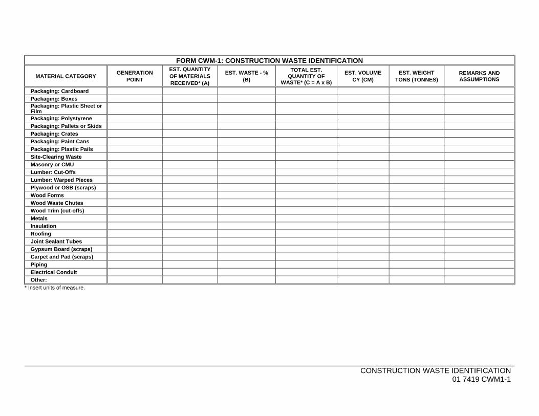
CONSTRUCTION WASTE IDENTIFICATION
01 7419 CWM1-1
FORM CWM-1: CONSTRUCTION WASTE IDENTIFICATION
MATERIAL CATEGORY GENERATION
POINT
EST. QUANTITY OF MATERIALS RECEIVED* (A)
EST. WASTE - % (B)
TOTAL EST. QUANTITY OF
WASTE* (C = A x B)
EST. VOLUME CY (CM)
EST. WEIGHT TONS (TONNES)
REMARKS AND ASSUMPTIONS
Packaging: Cardboard
Packaging: Boxes Packaging: Plastic Sheet or Film
Packaging: Polystyrene
Packaging: Pallets or Skids
Packaging: Crates
Packaging: Paint Cans
Packaging: Plastic Pails
Site-Clearing Waste
Masonry or CMU
Lumber: Cut-Offs
Lumber: Warped Pieces
Plywood or OSB (scraps)
Wood Forms
Wood Waste Chutes
Wood Trim (cut-offs)
Metals
Insulation
Roofing
Joint Sealant Tubes
Gypsum Board (scraps)
Carpet and Pad (scraps)
Piping
Electrical Conduit
Other:
* Insert units of measure.

CONSTRUCTION WASTE IDENTIFICATION
01 7419 CWM1-2
THIS PAGE INTENTIONALLY LEFT BLANK
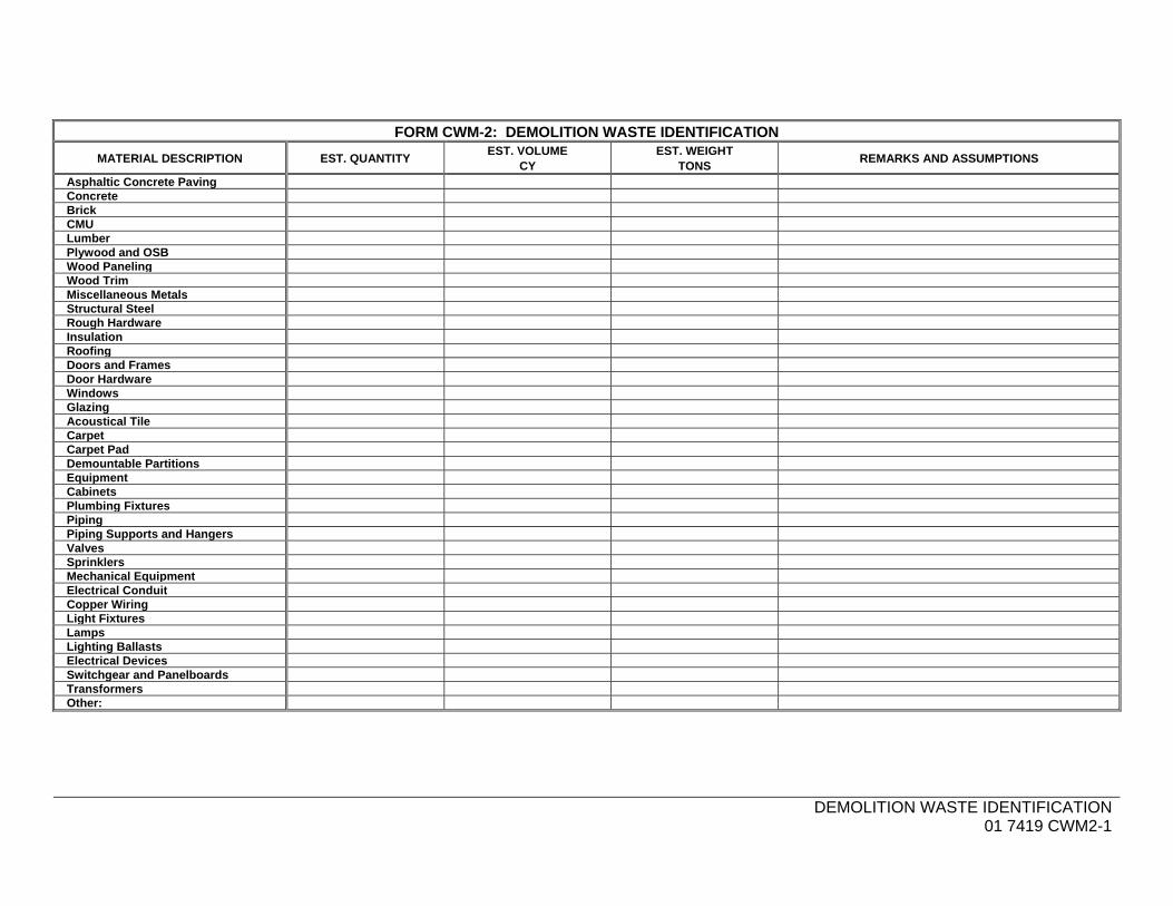
DEMOLITION WASTE IDENTIFICATION
01 7419 CWM2-1
FORM CWM-2: DEMOLITION WASTE IDENTIFICATION
MATERIAL DESCRIPTION EST. QUANTITY EST. VOLUME
CY EST. WEIGHT
TONS REMARKS AND ASSUMPTIONS
Asphaltic Concrete Paving Concrete Brick CMU Lumber Plywood and OSB Wood Paneling Wood Trim Miscellaneous Metals Structural Steel Rough Hardware Insulation Roofing Doors and Frames Door Hardware Windows Glazing Acoustical Tile Carpet Carpet Pad Demountable Partitions Equipment Cabinets Plumbing Fixtures Piping Piping Supports and Hangers Valves Sprinklers Mechanical Equipment Electrical Conduit Copper Wiring Light Fixtures Lamps Lighting Ballasts Electrical Devices Switchgear and Panelboards Transformers Other:
DEMOLITION WASTE IDENTIFICATION
01 7419 CWM2-2
THIS PAGE INTENTIONALLY LEFT BLANK
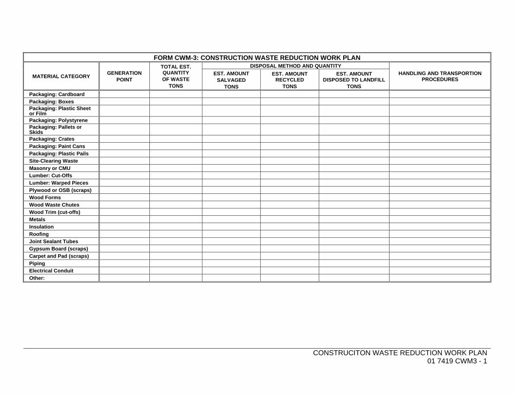
CONSTRUCITON WASTE REDUCTION WORK PLAN
01 7419 CWM3 - 1
FORM CWM-3: CONSTRUCTION WASTE REDUCTION WORK PLAN
MATERIAL CATEGORY GENERATION
POINT
TOTAL EST. QUANTITY OF WASTE
TONS
DISPOSAL METHOD AND QUANTITY
HANDLING AND TRANSPORTION PROCEDURES
EST. AMOUNT SALVAGED
TONS
EST. AMOUNT RECYCLED
TONS
EST. AMOUNT DISPOSED TO LANDFILL
TONS
Packaging: Cardboard
Packaging: Boxes Packaging: Plastic Sheet or Film
Packaging: Polystyrene Packaging: Pallets or Skids
Packaging: Crates
Packaging: Paint Cans
Packaging: Plastic Pails
Site-Clearing Waste
Masonry or CMU
Lumber: Cut-Offs
Lumber: Warped Pieces
Plywood or OSB (scraps)
Wood Forms
Wood Waste Chutes
Wood Trim (cut-offs)
Metals
Insulation
Roofing
Joint Sealant Tubes
Gypsum Board (scraps)
Carpet and Pad (scraps)
Piping
Electrical Conduit
Other:
CONSTRUCITON WASTE REDUCTION WORK PLAN
01 7419 CWM3 - 2
THIS PAGE INTENTIONALLY LEFT BLANK

DEMOLITION WASTE REDUCTION WORK PLAN
01 7419 CWM4 - 1
FORM CWM-4: DEMOLITION WASTE REDUCTION WORK PLAN
MATERIAL CATEGORY GENERATION
POINT
TOTAL EST. QUANTITY OF WASTE
TONS
DISPOSAL METHOD AND QUANTITY
HANDLING AND TRANSPORTION PROCEDURES
EST. AMOUNT SALVAGED
TONS
EST. AMOUNT RECYCLED
TONS
EST. AMOUNT DISPOSED TO LANDFILL
TONS
Asphaltic Concrete Paving Concrete Brick CMU Lumber Plywood and OSB Wood Paneling Wood Trim Miscellaneous Metals Structural Steel Rough Hardware Insulation Roofing Doors and Frames Door Hardware Windows Glazing Acoustical Tile Carpet Carpet Pad Demountable Partitions Equipment Cabinets Plumbing Fixtures Piping Supports and Hangers Valves Sprinklers Mechanical Equipment Electrical Conduit Copper Wiring Light Fixtures Lamps Lighting Ballasts Electrical Devices Switchgear and Panelboards
Transformers Other:

DEMOLITION WASTE REDUCTION WORK PLAN
01 7419 CWM4 - 2
THIS PAGE INTENTIONALLY LEFT BLANK
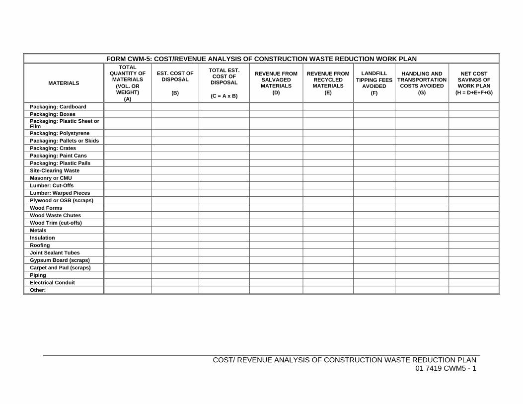
COST/ REVENUE ANALYSIS OF CONSTRUCTION WASTE REDUCTION PLAN
01 7419 CWM5 - 1
FORM CWM-5: COST/REVENUE ANALYSIS OF CONSTRUCTION WASTE REDUCTION WORK PLAN
MATERIALS
TOTAL QUANTITY OF MATERIALS
(VOL. OR WEIGHT)
(A)
EST. COST OF DISPOSAL
(B)
TOTAL EST. COST OF
DISPOSAL
(C = A x B)
REVENUE FROM SALVAGED MATERIALS
(D)
REVENUE FROM RECYCLED MATERIALS
(E)
LANDFILL TIPPING FEES
AVOIDED (F)
HANDLING AND TRANSPORTATION COSTS AVOIDED
(G)
NET COST SAVINGS OF WORK PLAN
(H = D+E+F+G)
Packaging: Cardboard
Packaging: Boxes Packaging: Plastic Sheet or Film
Packaging: Polystyrene
Packaging: Pallets or Skids
Packaging: Crates
Packaging: Paint Cans
Packaging: Plastic Pails
Site-Clearing Waste
Masonry or CMU
Lumber: Cut-Offs
Lumber: Warped Pieces
Plywood or OSB (scraps)
Wood Forms
Wood Waste Chutes
Wood Trim (cut-offs)
Metals
Insulation
Roofing
Joint Sealant Tubes
Gypsum Board (scraps)
Carpet and Pad (scraps)
Piping
Electrical Conduit
Other:

COST/ REVENUE ANALYSIS OF CONSTRUCTION WASTE REDUCTION PLAN
01 7419 CWM5 - 2
THIS PAGE INTENTIONALLY LEFT BLANK
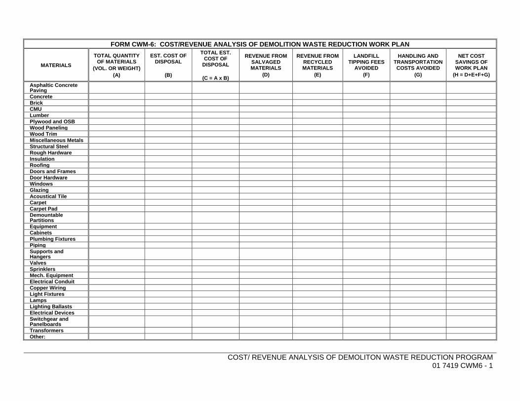
COST/ REVENUE ANALYSIS OF DEMOLITON WASTE REDUCTION PROGRAM
01 7419 CWM6 - 1
FORM CWM-6: COST/REVENUE ANALYSIS OF DEMOLITION WASTE REDUCTION WORK PLAN
MATERIALS
TOTAL QUANTITY OF MATERIALS
(VOL. OR WEIGHT) (A)
EST. COST OF DISPOSAL
(B)
TOTAL EST. COST OF
DISPOSAL
(C = A x B)
REVENUE FROM SALVAGED MATERIALS
(D)
REVENUE FROM RECYCLED MATERIALS
(E)
LANDFILL TIPPING FEES
AVOIDED (F)
HANDLING AND TRANSPORTATION COSTS AVOIDED
(G)
NET COST SAVINGS OF WORK PLAN
(H = D+E+F+G)
Asphaltic Concrete Paving
Concrete Brick CMU Lumber Plywood and OSB Wood Paneling Wood Trim Miscellaneous Metals Structural Steel Rough Hardware Insulation Roofing Doors and Frames Door Hardware Windows Glazing Acoustical Tile Carpet Carpet Pad Demountable Partitions
Equipment Cabinets Plumbing Fixtures Piping Supports and Hangers
Valves Sprinklers Mech. Equipment Electrical Conduit Copper Wiring Light Fixtures Lamps Lighting Ballasts Electrical Devices Switchgear and Panelboards
Transformers Other:

COST/ REVENUE ANALYSIS OF DEMOLITON WASTE REDUCTION PROGRAM
01 7419 CWM6 - 2
THIS PAGE INTENTIONALLY LEFT BLANK
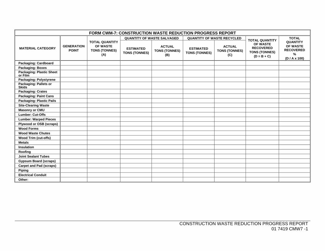
CONSTRUCTION WASTE REDUCTION PROGRESS REPORT
01 7419 CMW7 -1
FORM CWM-7: CONSTRUCTION WASTE REDUCTION PROGRESS REPORT
MATERIAL CATEGORY GENERATION
POINT
TOTAL QUANTITY OF WASTE
TONS (TONNES) (A)
QUANTITY OF WASTE SALVAGED QUANTITY OF WASTE RECYCLED TOTAL QUANTITY
OF WASTE RECOVERED
TONS (TONNES) (D = B + C)
TOTAL QUANTITY OF WASTE
RECOVERED %
(D / A x 100)
ESTIMATED TONS (TONNES)
ACTUAL TONS (TONNES)
(B)
ESTIMATED TONS (TONNES)
ACTUAL TONS (TONNES)
(C)
Packaging: Cardboard
Packaging: Boxes Packaging: Plastic Sheet or Film
Packaging: Polystyrene Packaging: Pallets or Skids
Packaging: Crates
Packaging: Paint Cans
Packaging: Plastic Pails
Site-Clearing Waste
Masonry or CMU
Lumber: Cut-Offs
Lumber: Warped Pieces
Plywood or OSB (scraps)
Wood Forms
Wood Waste Chutes
Wood Trim (cut-offs)
Metals
Insulation
Roofing
Joint Sealant Tubes
Gypsum Board (scraps)
Carpet and Pad (scraps)
Piping
Electrical Conduit
Other:

CONSTRUCTION WASTE REDUCTION PROGRESS REPORT
01 7419 CMW7 -2
THIS PAGE INTENTIONALLY LEFT BLANK

DEMOLITION WASTE REDUCTION PROGRESS REPORT
01 7419 CWM8 - 1
FORM CWM-8: DEMOLITION WASTE REDUCTION PROGRESS REPORT
MATERIAL CATEGORY GENERATION
POINT
TOTAL QUANTITY OF WASTE TONS (A)
QUANTITY OF WASTE SALVAGED
QUANTITY OF WASTE RECYCLED TOTAL QUANTITY OF
WASTE RECOVERED
TONS (D = B + C)
TOTAL QUANTITY OF WASTE
RECOVERED %
(D / A x 100)
ESTIMATED TONS
ACTUAL TONS (B)
ESTIMATED TONS
ACTUAL TONS (C)
Asphaltic Concrete Paving Concrete Brick CMU Lumber Plywood and OSB Wood Paneling Wood Trim Miscellaneous Metals Structural Steel Rough Hardware Insulation Roofing Doors and Frames Door Hardware Windows Glazing Acoustical Tile Carpet Carpet Pad Demountable Partitions Equipment Cabinets Plumbing Fixtures Piping Supports and Hangers Valves Sprinklers Mechanical Equipment Electrical Conduit Copper Wiring Light Fixtures Lamps Lighting Ballasts Electrical Devices Switchgear and Panelboards
Transformers Other:
DEMOLITION WASTE REDUCTION PROGRESS REPORT
01 7419 CWM8 - 2
THIS PAGE INTENTIONALLY LEFT BLANK
TLCD Project No.: 11039.00 PETALUMA TRANSIT FACILITYCity Of Petaluma Department Of Public Works & Utilities
Petaluma, CA
TLCD Architecture CLOSEOUT PROCEDURES01 7700 - 1
SECTION 01 7700 - CLOSEOUT PROCEDURES
PART 1 - GENERAL
1.1 RELATED DOCUMENTS
A. Drawings and general provisions of the Contract, including General and Supplementary Conditions and other Division 01 Specification Sections, apply to this Section.
1.2 SUMMARY
A. Section includes administrative and procedural requirements for contract closeout, including, but not limited to, the following: 1. Substantial Completion procedures. 2. Final completion procedures. 3. Warranties. 4. Final cleaning. 5. Repair of the Work.
B. Related Requirements: 1. Section 01 7300 "Execution" for progress cleaning of Project site. 2. Section 01 7839 "Project Record Documents" for submitting record Drawings,
record Specifications, and record Product Data. 3. Divisions 02 through 32 Sections for specific closeout and special cleaning
requirements for the Work in those Sections.
1.3 ACTION SUBMITTALS
A. Product Data: For cleaning agents.
B. Contractor's List of Incomplete Items: Initial submittal at Substantial Completion.
C. Certified List of Incomplete Items: Final submittal at Final Completion.
1.4 CLOSEOUT SUBMITTALS
A. Certificates of Release: From authorities having jurisdiction.
B. Certificate of Insurance: For continuing coverage.
C. Field Report: For pest control inspection.
PETALUMA TRANSIT FACILITY City Of Petaluma Department Of Public Works & Utilities Petaluma, CA
TLCD Project No.: 11039.00
CLOSEOUT PROCEDURES 01 7700 - 2
TLCD Architecture
1.5 MAINTENANCE MATERIAL SUBMITTALS
A. Schedule of Maintenance Material Items: For maintenance material submittal items specified in other Sections.
1.6 FINAL COMPLETION PROCEDURES
A. Pre-Final Inspection: In preparation for Final Completion, Contractor may, at their option, request a pre-final inspection. 1. Contractor shall prepare and submit to Architect prior to the inspection a list of items
to be completed and corrected (punch list) prior to Final Completion. 2. Included in this inspection will be the Contractor, and Subcontractor representatives
for Fire Protection, Plumbing, HVAC and Electrical (as applicable). 3. If the inspection discloses additional items, the Architect shall add these items to the
Contractor’s list. Failure to include items on this list does not relieve the Contractor from fulfilling all requirements of the Contract.
4. The Architect will promptly deliver the amended list of items to be completed and corrected (punch list) to the Contractor.
B. Preliminary Procedures: Before requesting final inspection for determining date of Final Completion, complete the following: 1. Submit a final Application for Payment according to Division 01 Section "Payment
Procedures." 2. Submit certified copy of Architect's inspection list of items to be completed or
corrected (punch list), endorsed and dated by Architect. The certified copy of the list shall state that each item has been completed or otherwise resolved for acceptance.
3. Make final changeover of permanent locks and deliver keys to Owner. Advise Owner's personnel of changeover in security provisions.
4. Complete startup and testing of systems and equipment. 5. Perform preventive maintenance on equipment used prior to Substantial
Completion. 6. Instruct Owner's personnel in operation, adjustment, and maintenance of products,
equipment, and systems. Submit demonstration and training video recordings specified in Division 01 Section "Demonstration and Training."
7. Advise Owner of changeover in heat and other utilities. 8. Participate with Owner in conducting inspection and walkthrough with local
emergency responders. 9. Terminate and remove temporary facilities from Project site, along with mockups,
construction tools, and similar elements. 10. Complete final cleaning requirements, including touchup painting. 11. Touch up and otherwise repair and restore marred exposed finishes to eliminate
visual defects. 12. Submit evidence of final, continuing insurance coverage complying with insurance
requirements. 13. Instruct Owner's personnel in operation, adjustment, and maintenance of products,
equipment, and systems. 14. Submit pest-control final inspection report.
TLCD Project No.: 11039.00 PETALUMA TRANSIT FACILITYCity Of Petaluma Department Of Public Works & Utilities
Petaluma, CA
TLCD Architecture CLOSEOUT PROCEDURES01 7700 - 3
C. Inspection: Submit a written request for final inspection to determine acceptance a minimum of 10 days prior to date the work will be completed and ready for final inspection and tests. On receipt of request, Architect will either proceed with inspection or notify Contractor of unfulfilled requirements. Architect will prepare a final Certificate for Payment after inspection or will notify Contractor of construction that must be completed or corrected before certificate will be issued. 1. Reinspection: Request reinspection when the Work identified in previous
inspections as incomplete is completed or corrected. a. Make request for reinspection only upon completion of all punch list items.
Architect will make one reinspection only. Additional reinspection by Architect due to unfulfilled requirements shall be at the Contractor’s expense.
1.7 LIST OF INCOMPLETE ITEMS (PUNCH LIST)
A. Organization of List: Include name and identification of each space and area affected by construction operations for incomplete items and items needing correction including, if necessary, areas disturbed by Contractor that are outside the limits of construction. Use CSI Form 14.1A or Contractor’s own form containing the same information. 1. Organize list of spaces in sequential order, starting with exterior areas first. 2. Organize items applying to each space by major element, including categories for
ceiling, individual walls, floors, equipment, and building systems. 3. Include the following information at the top of each page:
a. Project name. b. Date. c. Name of Architect. d. Name of Contractor. e. Page number.
4. Submit list of incomplete items in the following format: a. MS Excel electronic file. Architect will return annotated file.
1.8 SUBMITTAL OF PROJECT WARRANTIES
A. Time of Submittal: Submit written warranties on request of Architect for designated portions of the Work where commencement of warranties other than date of Substantial Completion is indicated, or when delay in submittal of warranties might limit Owner's rights under warranty.
B. Partial Occupancy: Submit properly executed warranties within 15 days of completion of designated portions of the Work that are completed and occupied or used by Owner during construction period by separate agreement with Contractor.
C. Organize warranty documents into an orderly sequence based on the table of contents of Project Manual. 1. Bind warranties and bonds in heavy-duty, three-ring, vinyl-covered, loose-leaf
binders, thickness as necessary to accommodate contents, and sized to receive 8-1/2-by-11-inch paper.
2. Provide heavy paper dividers with plastic-covered tabs for each separate warranty. Mark tab to identify the product or installation. Provide a typed description of the
PETALUMA TRANSIT FACILITY City Of Petaluma Department Of Public Works & Utilities Petaluma, CA
TLCD Project No.: 11039.00
CLOSEOUT PROCEDURES 01 7700 - 4
TLCD Architecture
product or installation, including the name of the product and the name, address, and telephone number of Installer.
3. Identify each binder on the front and spine with the typed or printed title "WARRANTIES," Project name, and name of Contractor.
4. Warranty Digital File: Scan warranties and bonds and assemble complete warranty and bond submittal package into a single indexed electronic PDF file with links enabling navigation to each item. Provide bookmarked table of contents at beginning of document.
D. Provide additional copies of each warranty to include in operation and maintenance manuals.
PART 2 - PRODUCTS
2.1 MATERIALS
A. Cleaning Agents: Use cleaning materials and agents recommended by manufacturer or fabricator of the surface to be cleaned. Do not use cleaning agents that are potentially hazardous to health or property or that might damage finished surfaces. 1. Use cleaning products that comply with Green Seal's GS-37, or if GS-37 is not
applicable, use products that comply with the California Code of Regulations maximum allowable VOC levels.
PART 3 - EXECUTION
3.1 FINAL CLEANING
A. General: Perform final cleaning. Conduct cleaning and waste-removal operations to comply with local laws and ordinances and Federal and local environmental and antipollution regulations.
B. Cleaning: Employ experienced workers or professional cleaners for final cleaning. Clean each surface or unit to condition expected in an average commercial building cleaning and maintenance program. Comply with manufacturer's written instructions. 1. Complete the following cleaning operations before requesting inspection for
certification of Substantial Completion for entire Project or for a designated portion of Project: a. Clean Project site, yard, and grounds, in areas disturbed by construction
activities, including landscape development areas, of rubbish, waste material, litter, and other foreign substances.
b. Sweep paved areas broom clean. Remove petrochemical spills, stains, and other foreign deposits.
c. Rake grounds that are neither planted nor paved to a smooth, even-textured surface.
d. Remove tools, construction equipment, machinery, and surplus material from Project site.
TLCD Project No.: 11039.00 PETALUMA TRANSIT FACILITYCity Of Petaluma Department Of Public Works & Utilities
Petaluma, CA
TLCD Architecture CLOSEOUT PROCEDURES01 7700 - 5
e. Remove snow and ice to provide safe access to building. f. Clean exposed exterior and interior hard-surfaced finishes to a dirt-free
condition, free of stains, films, and similar foreign substances. Avoid disturbing natural weathering of exterior surfaces. Restore reflective surfaces to their original condition.
g. Remove debris and surface dust from limited access spaces, including roofs, plenums, shafts, trenches, equipment vaults, manholes, attics, and similar spaces.
h. Sweep concrete floors broom clean in unoccupied spaces. i. Vacuum carpet and similar soft surfaces, removing debris and excess nap;
clean according to manufacturer's recommendations if visible soil or stains remain.
j. Clean transparent materials, including mirrors and glass in doors and windows. Remove glazing compounds and other noticeable, vision-obscuring materials. Polish mirrors and glass, taking care not to scratch surfaces.
k. Remove labels that are not permanent. l. Wipe surfaces of mechanical and electrical equipment and similar equipment.
Remove excess lubrication, paint and mortar droppings, and other foreign substances.
m. Clean plumbing fixtures to a sanitary condition, free of stains, including stains resulting from water exposure.
n. Replace disposable air filters and clean permanent air filters. Clean exposed surfaces of diffusers, registers, and grills.
o. Clean ducts, blowers, and coils if units were operated without filters during construction or that display contamination with particulate matter on inspection. 1) Clean HVAC system in compliance with NADCA Standard 1992-01.
Provide written report on completion of cleaning. p. Clean light fixtures, lamps, globes, and reflectors to function with full
efficiency. q. Leave Project clean and ready for occupancy.
C. Pest Control: Comply with pest control requirements in Section 01 5000 "Temporary Facilities and Controls." Prepare written report.
D. Construction Waste Disposal: Comply with waste disposal requirements in Section 01 7419 "Construction Waste Management and Disposal."
3.2 REPAIR OF THE WORK
A. Complete repair and restoration operations before requesting inspection for determination of Substantial Completion.
B. Repair or remove and replace defective construction. Repairing includes replacing defective parts, refinishing damaged surfaces, touching up with matching materials, and properly adjusting operating equipment. Where damaged or worn items cannot be repaired or restored, provide replacements. Remove and replace operating components that cannot be repaired. Restore damaged construction and permanent facilities used during construction to specified condition.

PETALUMA TRANSIT FACILITY City Of Petaluma Department Of Public Works & Utilities Petaluma, CA
TLCD Project No.: 11039.00
CLOSEOUT PROCEDURES 01 7700 - 6
TLCD Architecture
1. Remove and replace chipped, scratched, and broken glass, reflective surfaces, and other damaged transparent materials.
2. Touch up and otherwise repair and restore marred or exposed finishes and surfaces. Replace finishes and surfaces that that already show evidence of repair or restoration. a. Do not paint over "UL" and other required labels and identification, including
mechanical and electrical nameplates. Remove paint applied to required labels and identification.
3. Replace parts subject to operating conditions during construction that may impede operation or reduce longevity.
4. Replace burned-out bulbs, bulbs noticeably dimmed by hours of use, and defective and noisy starters in fluorescent and mercury vapor fixtures to comply with requirements for new fixtures.
END OF SECTION
Attachments: CSI Form 14.1A Punch List
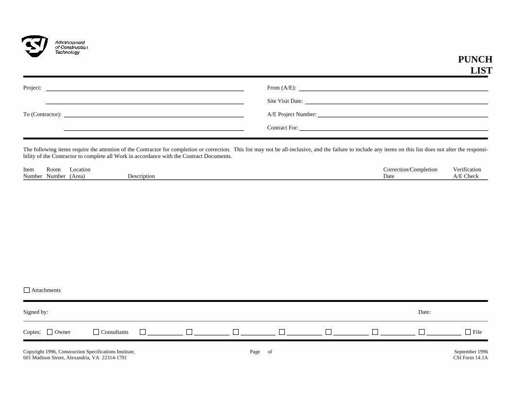
PUNCH LIST
Project:
To (Contractor):
From (A/E): Site Visit Date: A/E Project Number: Contract For:
The following items require the attention of the Contractor for completion or correction. This list may not be all-inclusive, and the failure to include any items on this list does not alter the responsi-bility of the Contractor to complete all Work in accordance with the Contract Documents. Item Room Location Correction/Completion Verification Number Number (Area) Description Date A/E Check
Attachments Signed by: Date: Copies: Owner Consultants File Copyright 1996, Construction Specifications Institute, 601 Madison Street, Alexandria, VA 22314-1791
Page of September 1996 CSI Form 14.1A


TLCD Project No.: 11039.00 PETALUMA TRANSIT FACILITYCity Of Petaluma Department Of Public Works & Utilities
Petaluma, CA
TLCD Architecture OPERATION AND MAINTENANCE DATA01 7823 - 1
SECTION 01 7823 - OPERATION AND MAINTENANCE DATA
PART 1 - GENERAL
1.1 RELATED DOCUMENTS
A. Drawings and general provisions of the Contract, including General and Supplementary Conditions and other Division 01 Specification Sections, apply to this Section.
1.2 SUMMARY
A. Section includes administrative and procedural requirements for preparing operation and maintenance manuals, including the following: 1. Operation and maintenance documentation directory. 2. Emergency manuals. 3. Operation manuals for systems, subsystems, and equipment. 4. Product maintenance manuals. 5. Systems and equipment maintenance manuals.
B. Related Requirements: 1. Section 01 3300 "Submittal Procedures" for submitting copies of submittals for
operation and maintenance manuals.
1.3 DEFINITIONS
A. System: An organized collection of parts, equipment, or subsystems united by regular interaction.
B. Subsystem: A portion of a system with characteristics similar to a system.
1.4 CLOSEOUT SUBMITTALS
A. Manual Content: Operations and maintenance manual content is specified in individual Specification Sections to be reviewed at the time of Section submittals. Submit reviewed manual content formatted and organized as required by this Section. 1. Architect will comment on whether content of operations and maintenance
submittals are acceptable. 2. Where applicable, clarify and update reviewed manual content to correspond to
revisions and field conditions.
B. Format: Submit operations and maintenance manuals in the following format: 1. PDF electronic file. Assemble each manual into a composite electronically indexed
file. Submit on digital media acceptable to Architect.
PETALUMA TRANSIT FACILITY City Of Petaluma Department Of Public Works & Utilities Petaluma, CA
TLCD Project No.: 11039.00
OPERATION AND MAINTENANCE DATA 01 7823 - 2
TLCD Architecture
a. Name each indexed document file in composite electronic index with applicable item name. Include a complete electronically linked operation and maintenance directory.
b. Enable inserted reviewer comments on draft submittals. 2. Three paper copies. Include a complete operation and maintenance directory.
Enclose title pages and directories in clear plastic sleeves. Architect will return one copy.
C. Initial Manual Submittal: Submit draft copy of each manual at least 30 days before commencing demonstration and training. Architect will comment on whether general scope and content of manual are acceptable.
D. Final Manual Submittal: Submit each manual in final form prior to requesting inspection for Substantial Completion and at least 15 days before commencing demonstration and training. Architect will return copy with comments. 1. Correct or revise each manual to comply with comments. Submit copies of each
corrected manual within 15 days of receipt of Architect's comments and prior to commencing demonstration and training.
PART 2 - PRODUCTS
2.1 OPERATION AND MAINTENANCE DOCUMENTATION DIRECTORY
A. Directory: Prepare a single, comprehensive directory of emergency, operation, and maintenance data and materials, listing items and their location to facilitate ready access to desired information. Include a section in the directory for each of the following: 1. List of documents. 2. List of systems. 3. List of equipment. 4. Table of contents.
B. List of Systems and Subsystems: List systems alphabetically. Include references to operation and maintenance manuals that contain information about each system.
C. List of Equipment: List equipment for each system, organized alphabetically by system. For pieces of equipment not part of system, list alphabetically in separate list.
D. Tables of Contents: Include a table of contents for each emergency, operation, and maintenance manual.
E. Identification: In the documentation directory and in each operation and maintenance manual, identify each system, subsystem, and piece of equipment with same designation used in the Contract Documents. If no designation exists, assign a designation according to ASHRAE Guideline 4, "Preparation of Operating and Maintenance Documentation for Building Systems."
TLCD Project No.: 11039.00 PETALUMA TRANSIT FACILITYCity Of Petaluma Department Of Public Works & Utilities
Petaluma, CA
TLCD Architecture OPERATION AND MAINTENANCE DATA01 7823 - 3
2.2 REQUIREMENTS FOR EMERGENCY, OPERATION, AND MAINTENANCE MANUALS
A. Organization: Unless otherwise indicated, organize each manual into a separate section for each system and subsystem, and a separate section for each piece of equipment not part of a system. Each manual shall contain the following materials, in the order listed: 1. Title page. 2. Table of contents. 3. Manual contents.
B. Title Page: Include the following information: 1. Subject matter included in manual. 2. Name and address of Project. 3. Name and address of Owner. 4. Date of submittal. 5. Name and contact information for Contractor. 6. Name and contact information for Architect. 7. Names and contact information for major consultants to the Architect that designed
the systems contained in the manuals. 8. Cross-reference to related systems in other operation and maintenance manuals.
C. Table of Contents: List each product included in manual, identified by product name, indexed to the content of the volume, and cross-referenced to Specification Section number in Project Manual. 1. If operation or maintenance documentation requires more than one volume to
accommodate data, include comprehensive table of contents for all volumes in each volume of the set.
D. Manual Contents: Organize into sets of manageable size. Arrange contents alphabetically by system, subsystem, and equipment. If possible, assemble instructions for subsystems, equipment, and components of one system into a single binder.
E. Manuals, Electronic Files: Submit manuals in the form of a multiple file composite electronic PDF file for each manual type required. 1. Electronic Files: Use electronic files prepared by manufacturer where available.
Where scanning of paper documents is required, configure scanned file for minimum readable file size.
2. File Names and Bookmarks: Enable bookmarking of individual documents based on file names. Name document files to correspond to system, subsystem, and equipment names used in manual directory and table of contents. Group documents for each system and subsystem into individual composite bookmarked files, then create composite manual, so that resulting bookmarks reflect the system, subsystem, and equipment names in a readily navigated file tree. Configure electronic manual to display bookmark panel on opening file.
F. Manuals, Paper Copy: Submit manuals in the form of hard copy, bound and labeled volumes. 1. Binders: Heavy-duty, three-ring, vinyl-covered, post-type binders, in thickness
necessary to accommodate contents, sized to hold 8-1/2-by-11-inch paper; with clear plastic sleeve on spine to hold label describing contents and with pockets inside covers to hold folded oversize sheets.
PETALUMA TRANSIT FACILITY City Of Petaluma Department Of Public Works & Utilities Petaluma, CA
TLCD Project No.: 11039.00
OPERATION AND MAINTENANCE DATA 01 7823 - 4
TLCD Architecture
a. If two or more binders are necessary to accommodate data of a system, organize data in each binder into groupings by subsystem and related components. Cross-reference other binders if necessary to provide essential information for proper operation or maintenance of equipment or system.
b. Identify each binder on front and spine, with printed title "OPERATION AND MAINTENANCE MANUAL," Project title or name, subject matter of contents, and indicate Specification Section number on bottom of spine. Indicate volume number for multiple-volume sets.
2. Dividers: Heavy-paper dividers with plastic-covered tabs for each section of the manual. Mark each tab to indicate contents. Include typed list of products and major components of equipment included in the section on each divider, cross-referenced to Specification Section number and title of Project Manual.
3. Protective Plastic Sleeves: Transparent plastic sleeves designed to enclose diagnostic software storage media for computerized electronic equipment.
4. Supplementary Text: Prepared on 8-1/2-by-11-inch white bond paper. 5. Drawings: Attach reinforced, punched binder tabs on drawings and bind with text.
a. If oversize drawings are necessary, fold drawings to same size as text pages and use as foldouts.
b. If drawings are too large to be used as foldouts, fold and place drawings in labeled envelopes and bind envelopes in rear of manual. At appropriate locations in manual, insert typewritten pages indicating drawing titles, descriptions of contents, and drawing locations.
2.3 EMERGENCY MANUALS
A. Content: Organize manual into a separate section for each of the following: 1. Type of emergency. 2. Emergency instructions. 3. Emergency procedures.
B. Type of Emergency: Where applicable for each type of emergency indicated below, include instructions and procedures for each system, subsystem, piece of equipment, and component: 1. Fire. 2. Flood. 3. Gas leak. 4. Water leak. 5. Power failure. 6. Water outage. 7. System, subsystem, or equipment failure. 8. Chemical release or spill.
C. Emergency Instructions: Describe and explain warnings, trouble indications, error messages, and similar codes and signals. Include responsibilities of Owner's operating personnel for notification of Installer, supplier, and manufacturer to maintain warranties.
D. Emergency Procedures: Include the following, as applicable: 1. Instructions on stopping. 2. Shutdown instructions for each type of emergency.

TLCD Project No.: 11039.00 PETALUMA TRANSIT FACILITYCity Of Petaluma Department Of Public Works & Utilities
Petaluma, CA
TLCD Architecture OPERATION AND MAINTENANCE DATA01 7823 - 5
3. Operating instructions for conditions outside normal operating limits. 4. Required sequences for electric or electronic systems. 5. Special operating instructions and procedures.
2.4 OPERATION MANUALS
A. Content: In addition to requirements in this Section, include operation data required in individual Specification Sections and the following information: 1. System, subsystem, and equipment descriptions. Use designations for systems and
equipment indicated on Contract Documents. 2. Performance and design criteria if Contractor has delegated design responsibility. 3. Operating standards. 4. Operating procedures. 5. Operating logs. 6. Wiring diagrams. 7. Control diagrams. 8. Piped system diagrams. 9. Precautions against improper use. 10. License requirements including inspection and renewal dates.
B. Descriptions: Include the following: 1. Product name and model number. Use designations for products indicated on
Contract Documents. 2. Manufacturer's name. 3. Equipment identification with serial number of each component. 4. Equipment function. 5. Operating characteristics. 6. Limiting conditions. 7. Performance curves. 8. Engineering data and tests. 9. Complete nomenclature and number of replacement parts.
C. Operating Procedures: Include the following, as applicable: 1. Startup procedures. 2. Equipment or system break-in procedures. 3. Routine and normal operating instructions. 4. Regulation and control procedures. 5. Instructions on stopping. 6. Normal shutdown instructions. 7. Seasonal and weekend operating instructions. 8. Required sequences for electric or electronic systems. 9. Special operating instructions and procedures.
D. Systems and Equipment Controls: Describe the sequence of operation, and diagram controls as installed.
E. Piped Systems: Diagram piping as installed, and identify color-coding where required for identification.
PETALUMA TRANSIT FACILITY City Of Petaluma Department Of Public Works & Utilities Petaluma, CA
TLCD Project No.: 11039.00
OPERATION AND MAINTENANCE DATA 01 7823 - 6
TLCD Architecture
2.5 PRODUCT MAINTENANCE MANUALS
A. Content: Organize manual into a separate section for each product, material, and finish. Include source information, product information, maintenance procedures, repair materials and sources, and warranties and bonds, as described below.
B. Source Information: List each product included in manual, identified by product name and arranged to match manual's table of contents. For each product, list name, address, and telephone number of Installer or supplier and maintenance service agent, and cross-reference Specification Section number and title in Project Manual and drawing or schedule designation or identifier where applicable.
C. Product Information: Include the following, as applicable: 1. Product name and model number. 2. Manufacturer's name. 3. Color, pattern, and texture. 4. Material and chemical composition. 5. Reordering information for specially manufactured products.
D. Maintenance Procedures: Include manufacturer's written recommendations and the following: 1. Inspection procedures. 2. Types of cleaning agents to be used and methods of cleaning. 3. List of cleaning agents and methods of cleaning detrimental to product. 4. Schedule for routine cleaning and maintenance. 5. Repair instructions.
E. Repair Materials and Sources: Include lists of materials and local sources of materials and related services.
F. Warranties and Bonds: Include copies of warranties and bonds and lists of circumstances and conditions that would affect validity of warranties or bonds. 1. Include procedures to follow and required notifications for warranty claims.
2.6 SYSTEMS AND EQUIPMENT MAINTENANCE MANUALS
A. Content: For each system, subsystem, and piece of equipment not part of a system, include source information, manufacturers' maintenance documentation, maintenance procedures, maintenance and service schedules, spare parts list and source information, maintenance service contracts, and warranty and bond information, as described below.
B. Source Information: List each system, subsystem, and piece of equipment included in manual, identified by product name and arranged to match manual's table of contents. For each product, list name, address, and telephone number of Installer or supplier and maintenance service agent, and cross-reference Specification Section number and title in Project Manual and drawing or schedule designation or identifier where applicable.
C. Manufacturers' Maintenance Documentation: Manufacturers' maintenance documentation including the following information for each component part or piece of equipment:

TLCD Project No.: 11039.00 PETALUMA TRANSIT FACILITYCity Of Petaluma Department Of Public Works & Utilities
Petaluma, CA
TLCD Architecture OPERATION AND MAINTENANCE DATA01 7823 - 7
1. Standard maintenance instructions and bulletins. 2. Drawings, diagrams, and instructions required for maintenance, including
disassembly and component removal, replacement, and assembly. 3. Identification and nomenclature of parts and components. 4. List of items recommended to be stocked as spare parts.
D. Maintenance Procedures: Include the following information and items that detail essential maintenance procedures: 1. Test and inspection instructions. 2. Troubleshooting guide. 3. Precautions against improper maintenance. 4. Disassembly; component removal, repair, and replacement; and reassembly
instructions. 5. Aligning, adjusting, and checking instructions. 6. Demonstration and training video recording, if available.
E. Maintenance and Service Schedules: Include service and lubrication requirements, list of required lubricants for equipment, and separate schedules for preventive and routine maintenance and service with standard time allotment. 1. Scheduled Maintenance and Service: Tabulate actions for daily, weekly, monthly,
quarterly, semiannual, and annual frequencies. 2. Maintenance and Service Record: Include manufacturers' forms for recording
maintenance.
F. Spare Parts List and Source Information: Include lists of replacement and repair parts, with parts identified and cross-referenced to manufacturers' maintenance documentation and local sources of maintenance materials and related services.
G. Maintenance Service Contracts: Include copies of maintenance agreements with name and telephone number of service agent.
H. Warranties and Bonds: Include copies of warranties and bonds and lists of circumstances and conditions that would affect validity of warranties or bonds. 1. Include procedures to follow and required notifications for warranty claims.
PART 3 - EXECUTION
3.1 MANUAL PREPARATION
A. Operation and Maintenance Documentation Directory: Prepare a separate manual that provides an organized reference to emergency, operation, and maintenance manuals.
B. Emergency Manual: Assemble a complete set of emergency information indicating procedures for use by emergency personnel and by Owner's operating personnel for types of emergencies indicated.
C. Product Maintenance Manual: Assemble a complete set of maintenance data indicating care and maintenance of each product, material, and finish incorporated into the Work.

PETALUMA TRANSIT FACILITY City Of Petaluma Department Of Public Works & Utilities Petaluma, CA
TLCD Project No.: 11039.00
OPERATION AND MAINTENANCE DATA 01 7823 - 8
TLCD Architecture
D. Operation and Maintenance Manuals: Assemble a complete set of operation and maintenance data indicating operation and maintenance of each system, subsystem, and piece of equipment not part of a system. 1. Engage a factory-authorized service representative to assemble and prepare
information for each system, subsystem, and piece of equipment not part of a system.
2. Prepare a separate manual for each system and subsystem, in the form of an instructional manual for use by Owner's operating personnel.
E. Manufacturers' Data: Where manuals contain manufacturers' standard printed data, include only sheets pertinent to product or component installed. Mark each sheet to identify each product or component incorporated into the Work. If data include more than one item in a tabular format, identify each item using appropriate references from the Contract Documents. Identify data applicable to the Work and delete references to information not applicable. 1. Prepare supplementary text if manufacturers' standard printed data are not available
and where the information is necessary for proper operation and maintenance of equipment or systems.
F. Drawings: Prepare drawings supplementing manufacturers' printed data to illustrate the relationship of component parts of equipment and systems and to illustrate control sequence and flow diagrams. Coordinate these drawings with information contained in record Drawings to ensure correct illustration of completed installation. 1. Do not use original project record documents as part of operation and maintenance
manuals. 2. Comply with requirements of newly prepared record Drawings in Section 01 7839
"Project Record Documents."
G. Comply with Section 0 17700 "Closeout Procedures" for schedule for submitting operation and maintenance documentation.
END OF SECTION
TLCD Project No.: 11039.00 PETALUMA TRANSIT FACILITYCity Of Petaluma Department Of Public Works & Utilities
Petaluma, CA
TLCD Architecture PROJECT RECORD DOCUMENTS01 7839 - 1
SECTION 01 7839 - PROJECT RECORD DOCUMENTS
PART 1 - GENERAL
1.1 RELATED DOCUMENTS
A. Drawings and general provisions of the Contract, including General and Supplementary Conditions and other Division 01 Specification Sections, apply to this Section.
1.2 SUMMARY
A. Section includes administrative and procedural requirements for project record documents, including the following: 1. Record Drawings. 2. Record Specifications. 3. Record Product Data. 4. Miscellaneous record submittals.
B. Related Requirements: 1. Section 01 7300 "Execution" for final property survey. 2. Section 01 7700 "Closeout Procedures" for general closeout procedures. 3. Section 01 7823 "Operation and Maintenance Data" for operation and maintenance
manual requirements.
1.3 CLOSEOUT SUBMITTALS
A. Record Drawings: Comply with the following: 1. Number of Copies: Submit copies of record Drawings as follows:
a. Initial Submittal: 1) Submit one paper-copy set(s) of marked-up record prints. 2) Submit PDF electronic files of scanned record prints and one of file
prints. 3) Architect will indicate whether general scope of changes, additional
information recorded, and quality of drafting are acceptable. b. Final Submittal:
1) Submit one paper-copy set(s) of marked-up record prints. 2) Submit record digital data files, PDF’s of record digital data files, and
two set(s) of record digital data file plots. 3) Plot each drawing file, whether or not changes and additional
information were recorded.
B. Record Specifications: Submit one paper copy and annotated PDF electronic files of Project's Specifications, including addenda and contract modifications.

PETALUMA TRANSIT FACILITY City Of Petaluma Department Of Public Works & Utilities Petaluma, CA
TLCD Project No.: 11039.00
PROJECT RECORD DOCUMENTS 01 7839 - 2
TLCD Architecture
C. Record Product Data: Submit one paper copy and annotated PDF electronic files and directories of each submittal. 1. Where record Product Data are required as part of operation and maintenance
manuals, submit duplicate marked-up Product Data as a component of manual.
D. Miscellaneous Record Submittals: See other Specification Sections for miscellaneous record-keeping requirements and submittals in connection with various construction activities. Submit one paper copy and annotated PDF electronic files and directories of each submittal.
E. Reports: Submit written report monthly with payment application indicating items incorporated into project record documents concurrent with progress of the Work, including revisions, concealed conditions, field changes, product selections, and other notations incorporated.
PART 2 - PRODUCTS
2.1 RECORD DRAWINGS
A. Record Prints: Maintain one set of marked-up paper copies of the Contract Drawings and Shop Drawings, incorporating new and revised drawings as modifications are issued. 1. Preparation: Mark record prints to show the actual installation where installation
varies from that shown originally. Require individual or entity who obtained record data, whether individual or entity is Installer, subcontractor, or similar entity, to provide information for preparation of corresponding marked-up record prints. a. Give particular attention to information on concealed elements that would be
difficult to identify or measure and record later. b. Accurately record information in an acceptable drawing technique. c. Record data as soon as possible after obtaining it. d. Record and check the markup before enclosing concealed installations. e. Cross-reference record prints to corresponding archive photographic
documentation. 2. Content: Types of items requiring marking include, but are not limited to, the
following: a. Dimensional changes to Drawings. b. Revisions to details shown on Drawings. c. Depths of foundations below first floor. d. Locations and depths of underground utilities. e. Revisions to routing of piping and conduits. f. Revisions to electrical circuitry. g. Actual equipment locations. h. Duct size and routing. i. Locations of concealed internal utilities. j. Changes made by Change Order or Construction Change Directive. k. Changes made following Architect's written orders. l. Details not on the original Contract Drawings. m. Field records for variable and concealed conditions. n. Record information on the Work that is shown only schematically.

TLCD Project No.: 11039.00 PETALUMA TRANSIT FACILITYCity Of Petaluma Department Of Public Works & Utilities
Petaluma, CA
TLCD Architecture PROJECT RECORD DOCUMENTS01 7839 - 3
3. Mark the Contract Drawings and Shop Drawings completely and accurately. Use personnel proficient at recording graphic information in production of marked-up record prints.
4. Mark record sets with erasable, red-colored pencil. Use other colors to distinguish between changes for different categories of the Work at same location.
5. Mark important additional information that was either shown schematically or omitted from original Drawings.
6. Note Construction Change Directive numbers, alternate numbers, Change Order numbers, and similar identification, where applicable.
B. Record Digital Data Files: Immediately before inspection for Final Completion, review marked-up record prints with Architect. When authorized, prepare a full set of corrected digital data files of the Contract Drawings, as follows: 1. Format: Same digital data software program, version, and operating system as the
original Contract Drawings. 2. Incorporate changes and additional information previously marked on record prints.
Delete, redraw, and add details and notations where applicable. 3. Refer instances of uncertainty to Architect for resolution. 4. Architect may make available, solely at Architect’s discretion, for the Contractor’s
use digital data files of the Contract Drawings for use in recording information. a. See Section 01 3300 "Submittal Procedures" for requirements related to
licensing and use of Architect's digital data files.
C. Newly Prepared Record Drawings: Prepare new Drawings instead of preparing record Drawings where Architect determines that neither the original Contract Drawings nor Shop Drawings are suitable to show actual installation. 1. New Drawings may be required when a Change Order is issued as a result of
accepting an alternate, substitution, or other modification. 2. Consult Architect for proper scale and scope of detailing and notations required to
record the actual physical installation and its relation to other construction. Integrate newly prepared record Drawings into record Drawing sets; comply with procedures for formatting, organizing, copying, binding, and submitting.
D. Format: Identify and date each record Drawing; include the designation "PROJECT RECORD DRAWING" in a prominent location. 1. Record Prints: Organize record prints and newly prepared record Drawings into
manageable sets. Bind each set with durable paper cover sheets. Include identification on cover sheets.
2. Format: Annotated PDF electronic file with comment function enabled. 3. Record Digital Data Files: Organize digital data information into separate electronic
files that correspond to each sheet of the Contract Drawings. Name each file with the sheet identification. Include identification in each digital data file.
4. Identification: As follows: a. Project name. b. Date. c. Designation "PROJECT RECORD DRAWINGS." d. Name of Architect. e. Name of Contractor.
PETALUMA TRANSIT FACILITY City Of Petaluma Department Of Public Works & Utilities Petaluma, CA
TLCD Project No.: 11039.00
PROJECT RECORD DOCUMENTS 01 7839 - 4
TLCD Architecture
2.2 RECORD SPECIFICATIONS
A. Preparation: Mark Specifications to indicate the actual product installation where installation varies from that indicated in Specifications, addenda, and contract modifications. 1. Give particular attention to information on concealed products and installations that
cannot be readily identified and recorded later. 2. Mark copy with the proprietary name and model number of products, materials, and
equipment furnished, including substitutions and product options selected. 3. Record the name of manufacturer, supplier, Installer, and other information
necessary to provide a record of selections made. 4. For each principal product, indicate whether record Product Data has been
submitted in operation and maintenance manuals instead of submitted as record Product Data.
5. Note related Change Orders, record Product Data, and record Drawings where applicable.
B. Format: Submit record Specifications as annotated PDF electronic file or scanned PDF electronic file(s) of marked-up paper copy of Specifications.
2.3 RECORD PRODUCT DATA
A. Preparation: Mark Product Data to indicate the actual product installation where installation varies substantially from that indicated in Product Data submittal. 1. Give particular attention to information on concealed products and installations that
cannot be readily identified and recorded later. 2. Include significant changes in the product delivered to Project site and changes in
manufacturer's written instructions for installation. 3. Note related Change Orders, record Specifications, and record Drawings where
applicable.
B. Format: Submit record Product Data as annotated PDF electronic file or scanned PDF electronic file(s) of marked-up paper copy of Product Data. 1. Include record Product Data directory organized by Specification Section number
and title, electronically linked to each item of record Product Data.
2.4 MISCELLANEOUS RECORD SUBMITTALS
A. Assemble miscellaneous records required by other Specification Sections for miscellaneous record keeping and submittal in connection with actual performance of the Work. Bind or file miscellaneous records and identify each, ready for continued use and reference.
B. Format: Submit miscellaneous record submittals as PDF electronic file or scanned PDF electronic file(s) of marked-up miscellaneous record submittals. 1. Include miscellaneous record submittals directory organized by Specification
Section number and title, electronically linked to each item of miscellaneous record submittals.
TLCD Project No.: 11039.00 PETALUMA TRANSIT FACILITYCity Of Petaluma Department Of Public Works & Utilities
Petaluma, CA
TLCD Architecture PROJECT RECORD DOCUMENTS01 7839 - 5
PART 3 - EXECUTION
3.1 RECORDING AND MAINTENANCE
A. Recording: Maintain one copy of each submittal during the construction period for project record document purposes. Post changes and revisions to project record documents as they occur; do not wait until end of Project.
B. Maintenance of Record Documents and Samples: Store record documents and Samples in the field office apart from the Contract Documents used for construction. Do not use project record documents for construction purposes. Maintain record documents in good order and in a clean, dry, legible condition, protected from deterioration and loss. Provide access to project record documents for Architect's reference during normal working hours.
END OF SECTION

PETALUMA TRANSIT FACILITY City Of Petaluma Department Of Public Works & Utilities Petaluma, CA
TLCD Project No.: 11039.00
PROJECT RECORD DOCUMENTS 01 7839 - 6
TLCD Architecture
THIS PAGE INTENTIONALLY LEFT BLANK

TLCD Project No.: 11039.00 PETALUMA TRANSIT FACILITYCity Of Petaluma Department Of Public Works & Utilities
Petaluma, CA
TLCD Architecture DEMONSTRATION AND TRAINING01 7900 - 1
SECTION 01 7900 - DEMONSTRATION AND TRAINING
PART 1 - GENERAL
1.1 RELATED DOCUMENTS
A. Drawings and general provisions of the Contract, including General and Supplementary Conditions and other Division 01 Specification Sections, apply to this Section.
1.2 SUMMARY
A. Section includes administrative and procedural requirements for instructing Owner's personnel, including the following: 1. Demonstration of operation of systems, subsystems, and equipment. 2. Training in operation and maintenance of systems, subsystems, and equipment.
B. Related Sections: 1. Divisions 02 through 32 Sections for specific requirements for demonstration and
training for products in those Sections.
1.3 INFORMATIONAL SUBMITTALS
A. Instruction Program: Submit outline of instructional program for demonstration and training, including a list of training modules and a schedule of proposed dates, times, length of instruction time, and instructors' names for each training module. Include learning objective and outline for each training module.
B. Qualification Data: For instructor.
C. Attendance Record: For each training module, submit list of participants and length of instruction time.
D. Evaluations: For each participant and for each training module, submit results and documentation of performance-based test.
1.4 CLOSEOUT SUBMITTALS
A. At completion of training, submit complete training manual(s) for Owner's use.
1.5 QUALITY ASSURANCE
A. Instructor Qualifications: A factory-authorized service representative, complying with requirements in Section 01 4000 "Quality Requirements," experienced in operation and maintenance procedures and training.
PETALUMA TRANSIT FACILITY City Of Petaluma Department Of Public Works & Utilities Petaluma, CA
TLCD Project No.: 11039.00
DEMONSTRATION AND TRAINING 01 7900 - 2
TLCD Architecture
B. Pre-instruction Conference: Conduct conference at Project site to comply with requirements in Section 01 3100 "Project Management and Coordination." Review methods and procedures related to demonstration and training including, but not limited to, the following: 1. Inspect and discuss locations and other facilities required for instruction. 2. Review and finalize instruction schedule and verify availability of educational
materials, instructors' personnel, audiovisual equipment, and facilities needed to avoid delays.
3. Review required content of instruction. 4. For instruction that must occur outside, review weather and forecasted weather
conditions and procedures to follow if conditions are unfavorable.
1.6 COORDINATION
A. Coordinate instruction schedule with Owner's operations. Adjust schedule as required to minimize disrupting Owner's operations.
B. Coordinate instructors, including providing notification of dates, times, length of instruction time, and course content.
C. Coordinate content of training modules with content of approved emergency, operation, and maintenance manuals. Do not submit instruction program until operation and maintenance data has been reviewed and approved by Architect.
PART 2 - PRODUCTS
2.1 INSTRUCTION PROGRAM
A. Program Structure: Develop an instruction program that includes individual training modules for each system and for equipment not part of a system, as required by individual Specification Sections.
B. Training Modules: Develop a learning objective and teaching outline for each module. Include a description of specific skills and knowledge that participant is expected to master. For each module, include instruction for the following as applicable to the system, equipment, or component: 1. Basis of System Design, Operational Requirements, and Criteria: Include the
following: a. System, subsystem, and equipment descriptions. b. Performance and design criteria if Contractor is delegated design
responsibility. c. Operating standards. d. Regulatory requirements. e. Equipment function. f. Operating characteristics. g. Limiting conditions.
TLCD Project No.: 11039.00 PETALUMA TRANSIT FACILITYCity Of Petaluma Department Of Public Works & Utilities
Petaluma, CA
TLCD Architecture DEMONSTRATION AND TRAINING01 7900 - 3
h. Performance curves. 2. Documentation: Review the following items in detail:
a. Emergency manuals. b. Operations manuals. c. Maintenance manuals. d. Project record documents. e. Identification systems. f. Warranties and bonds. g. Maintenance service agreements and similar continuing commitments.
3. Emergencies: Include the following, as applicable: a. Instructions on meaning of warnings, trouble indications, and error messages. b. Instructions on stopping. c. Shutdown instructions for each type of emergency. d. Operating instructions for conditions outside of normal operating limits. e. Sequences for electric or electronic systems. f. Special operating instructions and procedures.
4. Operations: Include the following, as applicable: a. Startup procedures. b. Equipment or system break-in procedures. c. Routine and normal operating instructions. d. Regulation and control procedures. e. Control sequences. f. Safety procedures. g. Instructions on stopping. h. Normal shutdown instructions. i. Operating procedures for emergencies. j. Operating procedures for system, subsystem, or equipment failure. k. Seasonal and weekend operating instructions. l. Required sequences for electric or electronic systems. m. Special operating instructions and procedures.
5. Adjustments: Include the following: a. Alignments. b. Checking adjustments. c. Noise and vibration adjustments. d. Economy and efficiency adjustments.
6. Troubleshooting: Include the following: a. Diagnostic instructions. b. Test and inspection procedures.
7. Maintenance: Include the following: a. Inspection procedures. b. Types of cleaning agents to be used and methods of cleaning. c. List of cleaning agents and methods of cleaning detrimental to product. d. Procedures for routine cleaning e. Procedures for preventive maintenance. f. Procedures for routine maintenance. g. Instruction on use of special tools.
8. Repairs: Include the following: a. Diagnosis instructions. b. Repair instructions.
PETALUMA TRANSIT FACILITY City Of Petaluma Department Of Public Works & Utilities Petaluma, CA
TLCD Project No.: 11039.00
DEMONSTRATION AND TRAINING 01 7900 - 4
TLCD Architecture
c. Disassembly; component removal, repair, and replacement; and reassembly instructions.
d. Instructions for identifying parts and components. e. Review of spare parts needed for operation and maintenance.
PART 3 - EXECUTION
3.1 PREPARATION
A. Assemble educational materials necessary for instruction, including documentation and training module. Assemble training modules into a training manual organized in coordination with requirements in Section 01 7823 "Operations and Maintenance Data."
B. Set up instructional equipment at instruction location.
3.2 INSTRUCTION
A. Engage qualified instructors to instruct Owner's personnel to adjust, operate, and maintain systems, subsystems, and equipment not part of a system. 1. Architect will furnish an instructor to describe basis of system design, operational
requirements, criteria, and regulatory requirements. 2. Owner will furnish an instructor to describe Owner's operational philosophy. 3. Owner will furnish Contractor with names and positions of participants.
B. Scheduling: Provide instruction at mutually agreed on times. For equipment that requires seasonal operation, provide similar instruction at start of each season. 1. Schedule training with Owner with at least seven days' advance notice.
C. Evaluation: At conclusion of each training module, assess and document each participant's mastery of module by use of an oral, written, or demonstration performance-based test.
D. Cleanup: Collect used and leftover educational materials and remove from Project site. Remove instructional equipment. Restore systems and equipment to condition existing before initial training use.
END OF SECTION

TLCD Project No.: 11039.00 PETALUMA TRANSIT FACILITYCity Of Petaluma Department Of Public Works & Utilities
Petaluma, CA
TLCD Architecture SELECTIVE STRUCTURE DEMOLITION02 4119 - 1
SECTION 02 4119 - SELECTIVE STRUCTURE DEMOLITION
PART 1 - GENERAL
1.1 RELATED DOCUMENTS
A. Drawings and general provisions of the Contract, including General and Supplementary Conditions and Division 01 Specification Sections, apply to this Section.
1.2 SUMMARY
A. Section Includes: 1. Demolition and removal of selected portions of building or structure. 2. Demolition and removal of selected site elements. 3. Salvage of existing items to be reused or recycled.
B. Related Requirements: 1. Section 01 1000 "Summary" for restrictions on the use of the premises, Owner-
occupancy requirements, and phasing requirements. 2. Section 01 7300 "Execution" for cutting and patching procedures.
1.3 DEFINITIONS
A. Remove: Detach items from existing construction and legally dispose of them off-site unless indicated to be removed and salvaged or removed and reinstalled.
B. Remove and Reinstall: Detach items from existing construction, prepare for reuse, and reinstall where indicated.
C. Existing to Remain: Existing items of construction that are not to be permanently removed and that are not otherwise indicated to be removed, removed and salvaged, or removed and reinstalled.
1.4 MATERIALS OWNERSHIP
A. Unless otherwise indicated, demolition waste becomes property of Contractor.
1.5 PREINSTALLATION MEETINGS
A. Predemolition Conference: Conduct conference at Project site. 1. Inspect and discuss condition of construction to be selectively demolished. 2. Review areas of building which cannot be occupied because of demolition activities
involving removal of or modifications to shear walls that temporarily compromise

PETALUMA TRANSIT FACILITY City Of Petaluma Department Of Public Works & Utilities Petaluma, CA
TLCD Project No.: 11039.00
SELECTIVE STRUCTURE DEMOLITION 02 4119 - 2
TLCD Architecture
lateral stability of the building. Review duration of time during which such areas cannot be occupied.
3. Review and finalize selective demolition schedule and verify availability of materials, demolition personnel, equipment, and facilities needed to make progress and avoid delays.
4. Review requirements of work performed by other trades that rely on substrates exposed by selective demolition operations.
5. Review areas where existing construction is to remain and requires protection.
1.6 INFORMATIONAL SUBMITTALS
A. Proposed Protection Measures: Submit report, including drawings, that indicates the measures proposed for protecting individuals and property, for environmental protection, for dust control and for noise control. Indicate proposed locations and construction of barriers.
B. Schedule of Selective Demolition Activities: Indicate the following: 1. Detailed sequence of selective demolition and removal work, with starting and
ending dates for each activity. Ensure Owner's on-site operations are uninterrupted. 2. Interruption of utility services. Indicate how long utility services will be interrupted. 3. Coordination of Owner's continuing occupancy of portions of existing building and of
Owner's partial occupancy of completed Work.
1.7 FIELD CONDITIONS
A. Owner will occupy portions of building immediately adjacent to selective demolition area. Conduct selective demolition so Owner's operations will not be disrupted.
B. Conditions existing at time of inspection for bidding purpose will be maintained by Owner as far as practical.
C. Notify Architect of discrepancies between existing conditions and Drawings before proceeding with selective demolition.
D. Hazardous Materials: It is not expected that hazardous materials will be encountered in the Work. 1. If suspected hazardous materials are encountered, do not disturb; immediately
notify Architect and Owner. Hazardous materials will be removed by Owner under a separate contract.
E. Storage or sale of removed items or materials on-site is not permitted.
F. Utility Service: Maintain existing utilities indicated to remain in service and protect them against damage during selective demolition operations. 1. Maintain fire-protection facilities in service during selective demolition operations.
TLCD Project No.: 11039.00 PETALUMA TRANSIT FACILITYCity Of Petaluma Department Of Public Works & Utilities
Petaluma, CA
TLCD Architecture SELECTIVE STRUCTURE DEMOLITION02 4119 - 3
PART 2 - PRODUCTS
2.1 PEFORMANCE REQUIREMENTS
A. Regulatory Requirements: Comply with governing EPA notification regulations before beginning selective demolition. Comply with hauling and disposal regulations of authorities having jurisdiction.
B. Standards: Comply with ANSI/ASSE A10.6 and NFPA 241.
PART 3 - EXECUTION
3.1 EXAMINATION
A. Verify that utilities have been disconnected and capped before starting selective demolition operations.
B. Review record documents of existing construction provided by Owner. Owner does not guarantee that existing conditions are same as those indicated in record documents.
C. Survey existing conditions and correlate with requirements indicated to determine extent of selective demolition required.
D. When unanticipated mechanical, electrical, or structural elements that conflict with intended function or design are encountered, investigate and measure the nature and extent of conflict. Promptly submit a written report to Architect.
3.2 PREPARATION
A. Site Access and Temporary Controls: Conduct selective demolition and debris-removal operations to ensure minimum interference with roads, streets, walks, walkways, and other adjacent occupied and used facilities. 1. Comply with requirements for access and protection specified in Section 01 5000
"Temporary Facilities and Controls."
B. Temporary Facilities: Provide temporary barricades and other protection required to prevent injury to people and damage to adjacent buildings and facilities to remain. 1. Provide protection to ensure safe passage of people around selective demolition
area and to and from occupied portions of building. 2. Provide temporary weather protection, during interval between selective demolition
of existing construction on exterior surfaces and new construction, to prevent water leakage and damage to structure and interior areas.
3. Protect walls, ceilings, floors, and other existing finish work that are to remain or that are exposed during selective demolition operations.
4. Cover and protect furniture, furnishings, and equipment that have not been removed.
PETALUMA TRANSIT FACILITY City Of Petaluma Department Of Public Works & Utilities Petaluma, CA
TLCD Project No.: 11039.00
SELECTIVE STRUCTURE DEMOLITION 02 4119 - 4
TLCD Architecture
5. Comply with requirements for temporary enclosures, dust control, heating, and cooling specified in Section 01 5000 "Temporary Facilities and Controls."
C. Temporary Shoring: Provide and maintain shoring, bracing, and structural supports as required to preserve stability and prevent movement, settlement, or collapse of construction and finishes to remain, and to prevent unexpected or uncontrolled movement or collapse of construction being demolished. 1. Strengthen or add new supports when required during progress of selective
demolition.
3.3 SELECTIVE DEMOLITION, GENERAL
A. General: Demolish and remove existing construction only to the extent required by new construction and as indicated. Use methods required to complete the Work within limitations of governing regulations and as follows: 1. Neatly cut openings and holes plumb, square, and true to dimensions required. Use
cutting methods least likely to damage construction to remain or adjoining construction. Use hand tools or small power tools designed for sawing or grinding, not hammering and chopping, to minimize disturbance of adjacent surfaces. Temporarily cover openings to remain.
2. Cut or drill from the exposed or finished side into concealed surfaces to avoid marring existing finished surfaces.
3. Maintain adequate ventilation when using cutting torches. 4. Remove decayed, vermin-infested, or otherwise dangerous or unsuitable materials
and promptly dispose of off-site. 5. Dispose of demolished items and materials promptly. Comply with requirements in
Section 01 7419 "Construction Waste Management and Disposal."
B. Removed and Reinstalled Items: 1. Clean and repair items to functional condition adequate for intended reuse. 2. Pack or crate items after cleaning and repairing. Identify contents of containers. 3. Protect items from damage during transport and storage. 4. Reinstall items in locations indicated. Comply with installation requirements for new
materials and equipment. Provide connections, supports, and miscellaneous materials necessary to make item functional for use indicated.
C. Existing Items to Remain: Protect construction indicated to remain against damage and soiling during selective demolition. When permitted by Architect, items may be removed to a suitable, protected storage location during selective demolition and cleaned and reinstalled in their original locations after selective demolition operations are complete.
3.4 SELECTIVE DEMOLITION PROCEDURES FOR SPECIFIC MATERIALS
A. Concrete Slabs-on-Grade: Saw-cut perimeter of area to be demolished, then break up and remove.

TLCD Project No.: 11039.00 PETALUMA TRANSIT FACILITYCity Of Petaluma Department Of Public Works & Utilities
Petaluma, CA
TLCD Architecture SELECTIVE STRUCTURE DEMOLITION02 4119 - 5
B. Roofing: Remove no more existing roofing than what can be covered in one day by new roofing and so that building interior remains watertight and weathertight. See Section 07 5423 "Thermoplastic Polyolefin (TPO) Roofing" for new roofing requirements. 1. Remove existing roof membrane, flashings, copings, and roof accessories. 2. Remove existing roofing system down to substrate.
3.5 DISPOSAL OF DEMOLISHED MATERIALS
A. General: Except for items or materials indicated to be reused, salvaged, reinstalled, or otherwise indicated to remain Owner's property, remove demolished materials from Project site. 1. Do not allow demolished materials to accumulate on-site. 2. Remove and transport debris in a manner that will prevent spillage on adjacent
surfaces and areas. 3. Comply with requirements specified in Section 01 7419 "Construction Waste
Management and Disposal."
B. Burning: Do not burn demolished materials.
C. Disposal: Transport demolished materials off Owner's property and legally dispose of them.
3.6 CLEANING
A. Clean adjacent structures and improvements of dust, dirt, and debris caused by selective demolition operations. Return adjacent areas to condition existing before selective demolition operations began.
END OF SECTION

PETALUMA TRANSIT FACILITY City Of Petaluma Department Of Public Works & Utilities Petaluma, CA
TLCD Project No.: 11039.00
SELECTIVE STRUCTURE DEMOLITION 02 4119 - 6
TLCD Architecture
THIS PAGE INTENTIONALLY LEFT BLANK

TLCD Project No.: 11039.00 PETALUMA TRANSIT FACILITY 555 N. McDowell Blvd.
ZFA Structural Engineers 11393.00
CONCRETE FORMS AND ACCESSORIES 03 1000-1
SECTION 03 1000 CONCRETE FORMS AND ACCESSORIES
PART 1 – GENERAL
1.1 SUMMARY
A. Section Includes: All labor, materials and equipment and all operations required to complete all formwork as indicated on the drawings; to produce shapes and configurations as shown, as required; and as specified herein, including: 1. Forms, shores, bracing, removal and other operations as necessary for all cast-in-
place concrete and masonry placed. 2. Setting and securing anchor bolts and other metal items embedded in concrete into
formwork, using materials and layouts furnished and delivered to jobsite as specified under other sections.
B. Related Sections: 1. Pertinent Sections of other Divisions specifying site concrete: Formwork for site
concrete. 2. Section 03 2000 - Concrete Reinforcement. 3. Section 03 3000 - Cast-in-Place Concrete. 4. Section 03 4300 - Tilt-Up Concrete Construction. 5. Pertinent Sections of other Divisions specifying work to be embedded in concrete. 6. Pertinent Sections of other Divisions specifying work penetrating concrete
foundations and formwork.
1.2 REFERENCES
A. ACI 347 "Recommended Practice for Concrete Formwork."
B. American Plywood Association (APA).
C. West Coast Lumberman's Association (WCLA).
D. ACI SP-66 – ACI Detailing Manual; American Concrete Institute International
E. ASTM A185 – Standard Specification for Steel Welded Wire Reinforcement, Plain, for Concrete, 2005.
F. ASTM A 615 – Standard Specification for Deformed and Plain Billet-Steel Bars for Concrete Reinforcement
G. ASTM A706 – Standard Specification for Low-Alloy Steel Deformed and Plain Bars for Concrete Reinforcement, 2005.
H. AWS/ANSI/D1.4/D1.4M – American Welding Society (Structural Welding Code-Reinforcing Steel).
I. California Building Code; California Code and Regulations, Latest Edition (CBC), Chapter 19
J. CRSI (DA4) – Manual of Standard Practice; Concrete Reinforcing Steel Institute.
PETALUMA TRANSIT FACILITY 555 N. McDowell Blvd.
TLCD Project No.: 11039.00
CONCRETE FORMS AND ACCESSORIES 03 1000-2
ZFA Structural Engineers 11393.00
1.3 DESIGN REQUIREMENTS
A. Design, engineer and construct formwork, shoring and bracing to conform to design and code requirements, resist imposed loads; resultant concrete to conform to required shape, line and dimension.
1.4 SUBMITTALS
A. Limitation of review: Structural Engineer's review will be required only where specifically requested for general architectural applications and features only. Contractor is responsible for structural stability, load-resisting characteristics and sufficiency of form work design.
B. Submit elevations for formwork at cambered slabs.
1.5 QUALITY ASSURANCE
A. General: All form materials shall be new at start of work. Produce high quality concrete construction. Minimize defects due to joints, deflection of forms, roughness of forms, nonconforming materials, concrete or workmanship.
B. Reuse of Forms: Plywood forms may be reused, if thoroughly cleaned of all dirt, mortar, and foreign materials, and undamaged at edges and contact face. Reuse shall be subject to permission from the Architect without exception, and issued in writing. Reuse of any panel which will produce a blemish on exposed concrete, will not be permitted.
PART 2 – PRODUCTS
2.1 MATERIALS
A. Form Materials: 1. Non-Exposed Surface Formwork Facing: Forms for concrete which is not exposed to
view, may be of plywood as specified for exposed surfaces, or square edge 1" x nominal Douglas Fir, Construction Grade, S4S.
2. Exposed Surface Formwork Facing: a. Forms for all exterior and interior concrete flat surfaces unless otherwise
specified as board formed shall be new Douglas Fir Plywood (APA) ply, 5/8-inch, B-B Plyform, Class 1, Exterior Type, oiled and edged and edge-sealed conforming to U.S. Product Standard PS 1-83 in large sheet sizes to achieve joint patterns shown.
b. All exposed concrete edges shall be chamfered 3/4" minimum or as noted on the drawings.
3. Exposed Surface Formwork - Special Pattern Form Liner: a. Forms for all exterior and interior concrete flat surfaces indicated shall be as
designated by Architect.
B. Earth Forms: Allowed, subject to soil standing in excavations without ravel or caving.
C. Form Release Agent: Spray-on compound, not affecting color, bond or subsequent treatment of concrete surfaces; "Formfilm" by W. R. Grace, www.grace.com, "Nox-Crete Form Coating", www.nox-crete.com, or approved equal.

TLCD Project No.: 11039.00 PETALUMA TRANSIT FACILITY 555 N. McDowell Blvd.
ZFA Structural Engineers 11393.00
CONCRETE FORMS AND ACCESSORIES 03 1000-3
D. Accessories: Types recommended by manufacturers or referenced standards to suit conditions indicated; 1. Anchors, spacers, void in-fill materials: sized to resist imposed loads. 2. Waterstops: Profiles and locations indicated, configured to provide continuous
waterproof barrier. a. Products by J. P. Specialties, "Earthshield® ", www.jpspecialties.com;
Greenstreak, www.greenstreak.com; or approved equal. 3. Form Ties: Prefabricated rod, flat band, or wire snap ties with 1" break-back or
threaded internal disconnecting type with external holding devices of adequate bearing area. Ties shall permit tightening and spreading of forms and leave no metal closer than 1" to surface.
E. Corner Chamfers and Rustications: Filleted, wood strip or foam type; sizes and shapes as detailed, or 3/4 x 3/4 inch size minimum if not detailed; maximum possible lengths.
F. Nails, Spikes, Lag Bolts, Through Bolts, Anchorages: Sized as required, of sufficient strength and character to maintain formwork in place while placing concrete.
PART 3 – EXECUTION
3.1 EXAMINATION
A. Inspect the substrate and the conditions under which concrete formwork is to be performed. Correct conditions detrimental to timely and proper completion of the work. Do not proceed with the work until unsatisfactory conditions have been corrected. Commencement of work indicates acceptance of substrates and conditions.
B. Verify lines, levels and centers before proceeding with formwork. Ensure that dimensions agree with drawings.
3.2 EARTH FORMS
A. If natural soil or compacted fill can be accurately cut and maintained, foundations and grade beams may be poured against earth without forming when requested by Contractor and approved by Architect. Provide positive protection of trench top corners.
B. Maintain earth forms free of water and foreign materials.
3.3 ERECTION – FORMWORK
A. General: Construct formwork in accordance with calculations, and recommendations of Section 401 of ACI 347. Construct forms to the sizes, shapes, lines and dimensions shown, and as required to obtain accurate alignment, location, grades, level and plumb work in finished structure. Provide for openings, offsets, sinkages, keyways, recesses, moldings, rustications, reglets, chamfers, blocking, screeds, bulkheads, anchorages and inserts, and other features required. Use selected materials to obtain required finishes. 1. Construct cambers specified in concrete members and slabs in the formwork. 2. Schedule the work and notify other trades in ample time so that provisions for their
work in the formwork can be made without delaying progress of the project. Install all sleeves, pipes, etc. for building services systems, or other work. Secure information about and provide for all openings, offsets, recessed nailing blocks, channel chases, anchors, ties, inserts, etc. in the formwork before concrete placement.
PETALUMA TRANSIT FACILITY 555 N. McDowell Blvd.
TLCD Project No.: 11039.00
CONCRETE FORMS AND ACCESSORIES 03 1000-4
ZFA Structural Engineers 11393.00
3. Deflection: Formwork and concrete with excessive deflection after concrete placement will be rejected. Excessive deflection is that which will produce visible and noticeable waves in the finished concrete.
4. Measure formwork for elevated structural slabs, columns, wall elevations points of maximum camber and submit in writing to the Architect/Engineer prior to placing concrete.
B. Formwork Construction: Erect formwork, shoring and bracing to achieve design requirements, in accordance with requirements of ACI 301. Uniform, substantial and sufficiently tight to prevent leakage of concrete paste, readily removable without impact, shock or damage to cast-in-place concrete surfaces and adjacent materials. Tie, brace, shore, and support to insure stability against pressures from any source, without failure of any component part and without excessive deflection. Solidly butt joints and provide backup material at joints as required to prevent leakage and fins.
C. Provide all openings, offsets, inserts, anchorages, blocking, and other features of the work as shown or required. Refer to Article 3.5 titled INSERTS, EMBEDDED PARTS, AND OPENINGS for detailed requirements.
D. Warped, checked or scuffed forms will be rejected.
E. Maintain membranes, reinforcing and other work free of damage; protect with plywood runway boards or other positive, durable means.
F. Align joints and make watertight. Keep form joints to a minimum.
G. Provide fillet and chamfer strips on external corners of exposed locations and as indicated to form patterns in finished work. Extend patterns around corners and into alcoves, on backs of columns and similar locations not otherwise shown. 1. Produce beveled, smooth, solid, unbroken lines, except as otherwise indicated to
conform to patterns. 2. Form corners and chamfers with 3/4 inch x 3/4 inch strips, unless otherwise
indicated, accurately formed and surfaced to produce uniformly straight lines and tight edge joints. Extend terminal edges to required limit and miter chamfer at changes in direction.
H. Unexposed corners may be formed either square or chamfered.
I. Ties and Spreaders: Arrange in a pattern acceptable to the Architect when exposed. Snap-ties may be used except at joints between pours where threaded internal disconnecting type shall be used.
J. Coordinate this section with other sections of work that require attachment of components to formwork.
K. Reglets and Rebates: Accurately locate, size, and form all reglets and rebates required to receive work of other trades, including flashing, frames, and equipment.
3.4 APPLICATION - FORM RELEASE AGENT
A. Apply form release agent on formwork in accordance with manufacturer's recommendations.

TLCD Project No.: 11039.00 PETALUMA TRANSIT FACILITY 555 N. McDowell Blvd.
ZFA Structural Engineers 11393.00
CONCRETE FORMS AND ACCESSORIES 03 1000-5
B. Apply prior to placement of reinforcing steel, anchoring devices, and embedded items.
C. Do not allow excess form coating material to accumulate in the forms or to come into contact with reinforcement or surfaces which will be bonded to fresh concrete.
D. Coat steel forms with a non-staining, rust-preventative form oil or otherwise protect against rusting. Rust-stained steel formwork will be rejected.
E. Leave no residue or stain on the face of the concrete, nor affect bonding of subsequent finishes or work specified in other sections.
3.5 INSERTS, EMBEDDED PARTS, AND OPENINGS
A. Provide formed openings where required for items to be embedded in passing through concrete work. 1. Provide openings in concrete formwork to accommodate work of other sections
including those under separate contracts (if any). Size and location of openings, recesses and chases shall be in accordance with the section requiring such items. Accurately place and securely support items to be built into forms.
B. Construction Joints: Construct and locate generally as indicated on Drawings and only at locations approved by Structural Engineer, so as not to impair the strength of the structure. Form keys in all cold joints shown or required.
C. Locate and set in place items that will be cast directly into concrete.
D. Rough Hardware and Miscellaneous Metal: Set inserts, sleeves, bolts, anchor, angles, and other items to be embedded in concrete. Set embedded bolts and sleeves for equipment to template and approved shop drawings prepared by trades supplying equipment.
E. Coordinate with work of other sections in forming and placing openings, slots, reglets, recesses, sleeves, bolts, anchors, other inserts, and components of other work.
F. Wood Inserts and Nailers: Provide approved preservative-treated lumber. Set all required nailing blocks, grounds, and other inserts as required to produce results shown. Wood plugs shall not be used.
G. Install accessories in accordance with manufacturer's instructions, so they are straight, level, and plumb. Ensure items are not disturbed during concrete placement.
H. Piping: Do not embed piping in structural concrete unless locations specifically approved by Structural Engineer.
I. Conduit: Place conduit below slabs-on-grade and only as specifically detailed on structural drawings. Minimum clear distance between conduits shall be 3 diameters. Location shall be subject to Engineer's written approval and shall not impair the strength of the structure.
J. Provide temporary ports or openings in formwork where required to facilitate cleaning and inspection. Locate openings at bottom of forms to allow flushing water to drain. 1. Provide openings for the introduction of vibrators at intervals necessary for proper
placement.

PETALUMA TRANSIT FACILITY 555 N. McDowell Blvd.
TLCD Project No.: 11039.00
CONCRETE FORMS AND ACCESSORIES 03 1000-6
ZFA Structural Engineers 11393.00
2. Close temporary openings with tight fitting panels, flush with inside face of forms, and neatly fitted so joints will not be apparent in exposed concrete surfaces.
K. Install Form Liner inserts in accordance with manufacturer's recommendations, to produce patterns and textures indicated.
L. Install waterstops in accordance with manufacturer's recommendations to provide continuous waterproof barrier.
3.6 FORM CLEANING
A. Clean forms as erection proceeds, remove foreign matter within forms.
B. Clean formed cavities of debris prior to placing concrete. 1. Remove all dirt, chips, sawdust, rubbish, water and foreign materials detrimental to
concrete. 2. Flush with water or use compressed air to remove remaining foreign matter. Ensure
that water and debris drain to exterior through clean-out ports.
3.7 FOOTINGS
A. Verify elevations and provide final excavation required for footings prior to placing of concrete.
3.8 EQUIPMENT BASES
A. Form concrete bases for all mechanical and electrical equipment in accordance with approved shop details furnished by other sections.
B. Sizes and locations as indicated and as required to produce results shown.
C. Provide coved base for all equipment bases placed on concrete slabs.
3.9 FORMWORK TOLERANCES
A. Construct formwork to maintain tolerances required by ACI 301.
3.10 FIELD QUALITY CONTROL
A. Inspect erected formwork, shoring, and bracing to ensure that work is in accordance with formwork design, and to verify that supports, fastenings, wedges, ties, and items are secure.
B. Do not reuse wood formwork more than 2 times for concrete surfaces to be exposed to view. Do not patch formwork.
C. Clean and repair surfaces to be re-used in the work. Split, frayed, delaminated or otherwise damaged form facing material will not be acceptable. Apply new form coating compound material to concrete contact surfaces as specified for new formwork.

TLCD Project No.: 11039.00 PETALUMA TRANSIT FACILITY 555 N. McDowell Blvd.
ZFA Structural Engineers 11393.00
CONCRETE FORMS AND ACCESSORIES 03 1000-7
D. When forms are extended for successive concrete placement, thoroughly clean surfaces, remove fins and laitance, and tighten forms to close all joints. Align and secure joints to avoid offsets.
3.11 FORM REMOVAL
A. Do not loosen or remove forms before minimum curing period has elapsed without employment of appropriate alternate curing methods, approved by the Architect in writing.
B. Remove forms without damage to the concrete using means to insure complete safety of the structure and without damage to exposed beams, columns, wall edges, chamfers and inserts. Loosen forms carefully. Do not wedge pry bars, hammers, or tools against finish concrete surfaces scheduled for exposure to view.
C. Do not remove forms until the concrete has hardened sufficiently to permit safe removal and the concrete has attained sufficient strength to safely support imposed loads. The minimum elapsed time for removal of forms after concrete has been placed shall be as follows: 1. Columns and Walls: 7 days, provided members are not subjected to overhead loads. 2. Retaining Walls: 21 days minimum. 3. Footings: 7 days minimum. If backfilled immediately, side forms may be removed 24
hours after concrete is placed. 4. Beams, elevated slab, and similar overhead conditions: 28 days unless adequate
shoring is provided.
D. Durations listed above are minimums and are subject to extension at the sole judgment of the Architect/Engineer.
E. Reshoring: Reshore members where and if required by Formwork Design Engineer.
F. Elevated slabs with Camber: Submit measured elevations of completed work at the same locations as provided for formwork, within 7 days of removing forms.
G. Do not subject concrete to superimposed loads (structure or construction) until it has attained full specified design strength, nor for a period of at least 14 days after placing.
H. Store removed forms to prevent damage to form materials or to fresh concrete. Discard damaged forms.
3.12 CLEANING
A. Remove excess material and debris associated with this work from the job site.
END OF SECTION 03 1000

PETALUMA TRANSIT FACILITY City Of Petaluma Department Of Public Works & Utilities Petaluma, CA
TLCD Project No.: 11039.00
THIS PAGE INTENTIONALLY LEFT BLANK
TLCD Project No.: 11039.00 PETALUMA TRANSIT FACILITY 555 N. McDowell Blvd.
ZFA Structural Engineers 11393.00
CONCRETE REINFORCEMENT 03 2000-1
SECTION 03 2000 - CONCRETE REINFORCEMENT
PART 1 – GENERAL
1.1 SUMMARY
A. Section Includes: 1. Reinforcing steel work for all concrete and masonry work as indicated on the
drawings and specified herein. 2. Coordinate this work with the other work affected by these operations, such as forms,
electrical work, mechanical work, structural steel, masonry and concrete.
B. Related Sections: 1. Pertinent sections of Division 01 specifying Quality Control and Testing Laboratory
services. 2. Pertinent sections of Division 02 (32) specifying site concrete paving requiring
reinforcement. 3. Pertinent Sections of other Divisions specifying reinforcement, including, concrete,
masonry, and rough carpentry. 4. Pertinent sections of other Divisions specifying work to be embedded in concrete. 5. Pertinent sections of other Divisions specifying work penetrating concrete work.
1.2 REFERENCE STANDARDS
A. ACI 301 - Specifications for Structural Concrete for Buildings; American Concrete Institute International.
B. ACI 315 - Manual of Standard Practice for Detailing Reinforced Concrete.
C. ACI 318 - Building Code Requirements For Reinforced Concrete and Commentary; American Concrete Institute International.
D. ACI SP-66 - ACI Detailing Manual; American Concrete Institute International.
E. ASTM A185- Standard Specification for Steel Welded Wire Reinforcement, Plain, for Concrete, 2005.
F. ASTM A 615- Standard Specification for Deformed and Plain Billet-Steel Bars for Concrete Reinforcement.
G. ASTM A706- Standard Specification for Low-Alloy Steel Deformed and Plain Bars for Concrete Reinforcement, 2005
H. AWS/ANSI/D1.4/D1.4M - American Welding Society, Structural welding code- for reinforcing steel.
I. California Building Code, latest edition, Chapter 19.
J. CRSI (DA4) - Manual of Standard Practice; Concrete Reinforcing Steel Institute.
1.3 SUBMITTALS

PETALUMA TRANSIT FACILITY 555 N. McDowell Blvd.
TLCD Project No.: 11039.00
CONCRETE REINFORCEMENT 03 2000-2
ZFA Structural Engineers 11393.00
A. Submit in accordance with pertinent sections of Division 01 specifying submittal procedures. Submit for review prior to fabrication.
B. Limitation of Review: Structural Engineer's review will be for general conformance with design intent as indicated in the Contract Documents and does not relieve Contractor of full responsibility for conformance with the Contract Documents. The General Contractor shall review and approve shop drawings prior to submittal to the Architect/Engineer.
C. Shop Drawings: Show complete fabrication and placing details of all reinforcing steel. Comply with requirements of ACI SP-66. Include: 1. Bar sizes and schedules; 2. Shapes of bent bars, layout and spacing of bars, location of splices. 3. Stirrup spacing, arrangements and assemblies, 4. References to Contract Documents detail numbers and designations. 5. Wall elevations corresponding to elevations shown in Contract Documents.
D. Product Data: Submit manufacturer's product data, specifications, location and installation instructions for proprietary materials and reinforcement accessories. Provide samples of these items upon request.
E. Certificates: Submit all certifications of physical and chemical properties of steel for each heat number as manufactured, including location of material in structure as specified below in Article titled QUALITY ASSURANCE. All materials supplied shall be tagged with heat numbers matching submitted Mill Test Report analyses.
F. Samples: Provide to the Owner's Testing laboratory as specified in Article SOURCE QUALITY CONTROL.
1.4 QUALITY ASSURANCE
A. Perform work of this Section in accordance with CRSI (DA4), CRSI (P1), ACI 301, and ACI 318.
B. Requirements of Regulatory Agencies, refer to pertinent Sections of Division 01.
C. Certification and Identification of Materials and Uses: Provide Owner's Testing Agency with access to fabrication plant to facilitate inspection of reinforcement. Provide notification of commencement and duration of shop fabrication in sufficient time to allow inspection and all material identification/test information listed below. 1. Provide manufacturer's Mill Test Reports for all materials. Include chemical and
physical properties of the material for each heat number manufactured. Tag all fabricated materials with heat number.
2. Provide letter certifying all materials supplied are from heat numbers covered by supplied mill certificates. Include in letter the physical location of each grade of reinforcing and/or heat number in the project (i.e. foundations, walls, etc.).
3. Unidentified Material Tests: Where identification of materials by heat number to mill tests cannot be made, Owner's Testing Agency shall test unidentified materials as described below.
D. Testing and Inspection: Tests and Inspections required by Independent Testing Agency are specified below in Articles SOURCE QUALITY CONTROL and FIELD QUALITY

TLCD Project No.: 11039.00 PETALUMA TRANSIT FACILITY 555 N. McDowell Blvd.
ZFA Structural Engineers 11393.00
CONCRETE REINFORCEMENT 03 2000-3
CONTROL. Duties and limitations of Independent Testing Agency, test costs and test reports in conformance with pertinent Sections of Division 01.
1.5 DELIVERY, STORAGE AND HANDLING
A. Comply with pertinent requirements of Division 01.
B. Deliver reinforcement to project site in bundles marked with durable tags indicating heat number, mill, bar size and length, proposed location in the structure and other information corresponding with markings shown on placement diagrams.
C. Handle and store materials above ground to prevent damage, contamination or accumulation of dirt or rust.
PART 2 – PRODUCTS
2.1 MATERIALS
A. Reinforcing Steel: Deformed billet steel bars, conform to ASTM A706; or to ASTM 615, Grade 60, except (1) the maximum yield strength shall be 78,000 psi, and (2) the tensile strength shall not be less than 1.25 times the actual yield strength. 1. Exception: Bars used as column ties, stirrups, and field bent dowels shall be Grade
40 minimum, unless otherwise noted on the drawings. 2. All reinforcement to be welded shall be ASTM A 706 or shall meet the carbon and
carbon equivalent requirements for ASTM A706 reinforcement. 3. All reinforcement to be unfinished.
B. Welded Wire Fabric: ASTM A185.
C Tie Wire: No. 16 AWG or heavier, black annealed.
D. Reinforcing Supports: Plastic or galvanized steel chairs, bolsters, bar supports, or spacers sized and shaped for adequate support of reinforcement and construction loads imposed during concrete placement, meeting ACI and CRSI standards. 1. For use over formwork: Galvanized wire bar type supports complying with CRSI
recommendations. Provide plastic tips where exposed to view or weather after removal of formwork. Do not use wood, brick, or other unacceptable materials.
2. For slabs on grade: Supports with sand plates or horizontal runners where base material will not support chair legs.
E. Concrete blocks: Slab-on-grade conditions only, as required to support reinforcing bars in position.
F. Reinforcement Splice Couplers: Products recommended by manufacturer to suit conditions indicated. "Bar Lock" Reinforcement Splicing systems, ESR-2495 April 2010, by Dayton-Superior Corporation, www.daytonsuperior.com.
G. Fabricate concrete reinforcing in accordance with CRSI (DA4) - Manual of Standard Practice, unless specifically shown otherwise. Details not specifically shown or indicated shall conform to ACI 315 and specified codes and standards. 1. Accurately shop-fabricate to shapes, bends, sizes, gauges and lengths indicated or
otherwise required.

PETALUMA TRANSIT FACILITY 555 N. McDowell Blvd.
TLCD Project No.: 11039.00
CONCRETE REINFORCEMENT 03 2000-4
ZFA Structural Engineers 11393.00
2. Bend bars once only. Discard bars improperly bent due to fabricating or other errors and provide new material; do not re-bend or straighten unless specifically indicated. Rebending of reinforcement in the field is not allowed.
3. Do not bend reinforcement in a manner that will injure or weaken the material or the embedding concrete.
4. Do not heat reinforcement for bending. Heat-bent materials will be rejected.
H. Unacceptable materials: Reinforcement with any of the following defects will not be permitted in the work. 1. Bar lengths, depths and bends exceeding specified fabrication tolerances. 2. Bends or kinks not indicated on Drawings or final shop drawings. 3. Bars with reduced cross-section due to rusting or other cause.
I. Tag reinforcement with durable identification to facilitate sorting and placing.
2.2 SOURCE QUALITY CONTROL
A. The Testing Agency, as specified in the Article QUALITY ASSURANCE, will perform the following: 1. Material Testing:
a. Identified Steel: When samples are taken from bundled steel identified by heat number, matched with accompanying mill analyses as delivered from the mill, Owner's Testing Agency will perform one tensile test and one bend test per each ten tons or fraction thereof for each required size of reinforcing steel.
b. Unidentified Steel: When identification of materials by heat number matched to accompanying mill analyses cannot be made, perform one tensile test and one bend test per each two and one-half tons or fraction thereof for each required size of reinforcing steel. Tests of unidentified steel shall be performed by the Owner's Testing Agency and costs for these tests shall be paid by the Contractor by deductive change order.
PART 3 – EXECUTION
3.1 EXAMINATION
A. Inspect the conditions under which concrete reinforcement is to be placed. Do not proceed with the work until unsatisfactory conditions have been corrected.
B. Coordinate with work of other sections to avoid conflicts or interference. Bring conflicts between reinforcement and other elements to Architect's attention. Resolve conflicts before concrete is placed.
C. Notify Architect and Structural Engineer for review of steel placement observation not less than 48 hours before placing concrete.
3.2 PLACEMENT
A. General: Comply with the specified codes and standards, and Concrete Reinforcing Steel Institute recommended practice for "Placing Reinforcing Bars", for details and methods of reinforcement placement and supports, and as herein specified.
TLCD Project No.: 11039.00 PETALUMA TRANSIT FACILITY 555 N. McDowell Blvd.
ZFA Structural Engineers 11393.00
CONCRETE REINFORCEMENT 03 2000-5
B. Clean bars free of substances which are detrimental to bonding. Maintain reinforcement clean until embedded in concrete.
C. Place reinforcement to obtain the minimum coverages for concrete protection. Do not deviate from required position. Maintain required distance, spacing and clearance between bars, forms and ground.
D. Location and Support: Provide metal chairs, runners, bolsters, spacers and hangers, as required.
E. Provide additional steel reinforcement as necessary or as directed, to act as spreaders or separators to maintain proper positioning.
F. Tying and Attachment: Securely tie at all intersections and supports with wire. Prevent dislocation or movement during placement of concrete. Direct twisted ends of wire ties away from exposed concrete surfaces.
G. Separate reinforcing from pipes or conduits with approved non-metallic separators. Do not use wood or steel form stakes or reinforcement used as stakes as support for reinforcement.
H. Accommodate placement of formed openings required by other sections.
I. Obstructions: 1. Where obstructions, block-outs or penetrations (conduits, raceways, ductwork)
prevent continuous placement of reinforcement as indicated, provide additional reinforcing as detailed and as directed by the Structural Engineer to supplement the indicated reinforcement around the obstruction.
2. Place additional trim bars, ties, stirrups, or other elements as detailed and as directed at all opening, sleeves, pipes or other penetrations through structural elements.
J. Welded Wire Fabric: Reinforce slabs with 6"x 6"-W1.4 x W1.4 welded wire fabric reinforcing, unless otherwise noted on drawings. 1. Roll out, straighten, cut to required size, and lay out flat in place. 2. Securely wire-tie fabric to other reinforcement at frequent intervals. 3. Extend fabric over supporting beams and walls, and to within 1 inch of edge of slabs,
construction joints, and expansion joints. 4. Support fabric in mid-depth of slab. 5. Lift fabric reinforcement at intervals as slab concrete is placed, ensure proper
embedment.
K. Provide minimum 1-1/2 inch clearance between sets of splices. Stagger splices in horizontal bars so that adjacent splices will be 4 feet apart.
L. Laps of welded wire fabric shall be at least two times the spacing of the members in the direction lapped but not less than twelve inches.
M. Splices of reinforcement shall not be made at points of maximum stress. Provide splice lengths as noted on the structural drawings, with sufficient lap to transfer the stress between bars by bond and shear.

PETALUMA TRANSIT FACILITY 555 N. McDowell Blvd.
TLCD Project No.: 11039.00
CONCRETE REINFORCEMENT 03 2000-6
ZFA Structural Engineers 11393.00
N. Spacing: 1. Space bars minimum distance specified and all lapped bars 2 bar diameters
(minimum) clear of the next bar. 2. Stagger splices of adjacent bars where possible and where required to maintain bar
clearance. 3. Beam or slab top bars shall be spliced mid-span of column support and bottom bars
spliced at column supports. 4. Request Architect/Engineer review prior to placement for all splices not shown on the
drawings.
O. Reinforcement Couplers: Install at all locations indicated and may be used as an alternate to lap splices in general. Install couplers in accordance with manufacturer’s recommendations.
3.3 REINFORCING SPACING AND COVERAGE
A. Spacing: Do not space bars closer than four (4) diameters of the largest of two adjacent bars, except at bar laps, which shall be placed such that a minimum of 2 bar diameters is clear between bars. 1. Where reinforcing in members is placed in two layers, the distance between layers
shall not be less than four bar diameters of the largest bar and the bars in the upper layers shall be placed directly above those in the bottom layer, unless otherwise detailed or dimensioned.
B. Coverage of bars (including stirrups and columns ties) shall be as follows, unless otherwise shown: 1. Footings and Mat Foundation: 3 inches to any soil face, 2 inches to top. 2. Slabs (on grade): 2 inches to grade face, 1-1/2 inches to top face. 3. Slabs (elevated): 1-1/2 inches top and bottom. 4. Beam & Column: 1-1/2"inches to form. 5. Walls: 1-1/2" clear to form and 2 inches clear to form at soil face.
3.4 DOWELS, SPLICES, OFFSETS AND BENDS
A. Provide standard reinforcement splices at splices, corners, and intersections by lapping ends, placing bars in contact, and tightly tying with wire at each end. Comply with details shown on structural drawings and requirements of ACI 318.
B. Provide minimum 1-1/2 inch clearance between sets of splices. Stagger splices in horizontal bars so that adjacent splices will be 4 feet apart.
C. Laps of welded wire fabric shall be at least two times the spacing of the members in the direction lapped but not less than twelve inches.
D. Splices of reinforcement shall not be made at points of maximum stress. Provide splice lengths as noted on the structural drawings, with sufficient lap to transfer the stress between bars by bond and shear.
E. Spacing: 1. Space bars minimum distance specified and all lapped bars 2 bar diameters
(minimum) clear of the next bar.

TLCD Project No.: 11039.00 PETALUMA TRANSIT FACILITY 555 N. McDowell Blvd.
ZFA Structural Engineers 11393.00
CONCRETE REINFORCEMENT 03 2000-7
2. Stagger splices of adjacent bars where possible and where required to maintain bar clearance.
3. Beam or slab top bars shall be spliced mid-span of column support and bottom bars spliced at column supports.
4. Request Architect/Engineer review prior to placement for all splices not shown on the drawings.
F. Reinforcement Couplers: Install at all locations indicated and may be used as an alternate to lap splices in general. Install couplers in accordance with manufacturer’s recommendations.
3.5 WELDING
A. No reinforcing shall be welded unless specifically indicated or without prior approval of the Structural Engineer.
B. Only when so approved for use as noted above, all welding shall conform to the AWS D1.4, and the following; 1. All welding performed by certified welders. 2. All reinforcement requires preheat prior to welding. All preheat and welding shall be
continuously inspected by the Testing Agency.
3.6 MISPLACED REINFORCEMENT
A. Notify Architect/Engineer immediately if reinforcing bars are known to be misplaced after concrete has been placed.
B. Perform no correction or cutting without specific direction. Do not bend or kink misplaced bars.
C. Correct misplaced reinforcing only as directed in writing by the Architect/Engineer. Bear all costs of redesign, new, or additional reinforcing required because of misplaced bars at Contractor's expense.
3.7 FIELD QUALITY CONTROL
A. The Testing Agency as specified in the Article QUALITY ASSURANCE, will inspect the work for conformance to contract documents before concrete placement. 1. Inspection: Provide inspection and verifiable installed reinforcement. 2. All preheat and welding activities for steel reinforcement, when these occur. Confirm
that the surface of the rebar is free of form release oil or other coatings. 3. Exception: Foundations and slabs for buildings less then 3 stories with specified
concrete design strength of 2500 psi do not require reinforcement inspection.
3.8 CLEANING
A. Remove excess material and debris associated with this work from the job site
END OF SECTION 03 2000

PETALUMA TRANSIT FACILITY City Of Petaluma Department Of Public Works & Utilities Petaluma, CA
TLCD Project No.: 11039.00
THIS PAGE INTENTIONALLY LEFT BLANK

TLCD Project No.: 11039.00 PETALUMA TRANSIT FACILITY 555 N. McDowell Blvd.
ZFA Structural Engineers 11393.00
CAST-IN-PLACE CONCRETE 03 3000-1
SECTION 03 3000 - CAST-IN-PLACE CONCRETE
PART 1 – GENERAL
1.1 SUMMARY
A. Section Includes: Provide all labor, materials, equipment and services to complete all concrete work required, including, but not limited to, the following: 1. Foundations, beams, columns, elevated slabs, slabs-on-grade, walls, and retaining
walls. 2. Installation of all bolts, inserts, sleeves, connections, etc. in the concrete. 3. Joint devices associated with concrete work. 4. Miscellaneous concrete elements, including, but not limited to: equipment pads, light
pole bases, flagpole bases, thrust blocks, and manholes. 5. Concrete curing. 6. Coordination with other sections:
a. Make all preparations and do all work necessary to receive or adjoin other work. Install all bolts and anchors, including those furnished by other sections, into formwork and provide all required blocking.
b. Install all accessories embedded in the concrete and provide all holes, blockouts and similar provisions necessary for the work of other sections. Provide all patching or cutting made necessary by failure or delay in complying with this requirement at the Contractor's expense.
c. Coordinate with other sections for the accurate location of embedded accessories.
B. Related Sections: 1. Pertinent Sections of Division 01 specifying Quality Control and Testing Laboratory
services. 2. Pertinent Sections of other Divisions specifying site concrete: Formwork for site
concrete. 3. Section 03 1000 - Concrete Formwork. 4. Section 03 2000 - Concrete Reinforcement. 5. Pertinent Sections of Division 03 specifying concrete construction. 6. Pertinent Sections of other Divisions specifying work to be embedded in concrete. 7. Pertinent Sections of other Divisions specifying work penetrating concrete
foundations and formwork. 8. Pertinent sections of other Divisions specifying floor finishes and sealants applied to
concrete substrates.
1.2 REFERENCES
A. ACI 211.1 - Standard Practice for Selecting Proportions for Normal, Heavyweight, and Mass Concrete; ACI 211.2-Standard practice for selecting proportions for lightweight concrete; American Concrete Institute International.
B. ACI 301 - Specifications for Structural Concrete for Buildings; American Concrete Institute International.

PETALUMA TRANSIT FACILITY 555 N. McDowell Blvd.
TLCD Project No.: 11039.00
CANST-IN-PLACE CONCRETE 03 3000-2
ZFA Structural Engineers 11393.00
C. ACI 302.1R - Guide for Concrete Floor and Slab Construction; American Concrete Institute International.
D. ACI 304R - Guide for Measuring, Mixing, Transporting, and Placing Concrete; American Concrete Institute International.
E. ACI 305R - Hot Weather Concreting; American Concrete Institute International.
F. ACI 306R - Cold Weather Concreting; American Concrete Institute International.
G. ACI 308 - Standard Practice for Curing Concrete; American Concrete Institute International.
H. ACI 318 - Building Code Requirements for Reinforced Concrete and Commentary; American Concrete Institute International.
I. California Building Code, CBC, California Code of Regulations, Chapter 19, Concrete, latest adopted edition.
1.3 SUBMITTALS
A. Submit in accordance with pertinent sections of Division 01 specifying submittal procedures. The General Contractor shall review and approve shop drawings prior to submittal to the Architect/Engineer. Submittals that do not meet these requirements will be returned for correction without review. Submit for review prior to fabrication.
B. Limitation of Review: Structural Engineer's review will be for general conformance with design intent as indicated in the Contract Documents and does not relieve Contractor of full responsibility for conformance with the Contract Documents.
C. Product Data: Submit manufacturers' data on manufactured products and other concrete related materials such as bond breakers, cure/sealer, admixtures, etc. Demonstrate compliance with specified characteristics. Provide samples of items upon request.
D. Mix Designs: Submit Mix Designs for each concrete type required for work per requirements of articles CONCRETE MIXES and QUALITY ASSURANCE. Resubmit revised designs review if original designs are adjusted or changed for any reason.
E. Shop Drawings: Proposed location of construction and cold joints when different or in addition to those shown on the drawings.
F. Shop Drawings: Proposed location of all slab construction joints, dowel joints and blockouts.
G. Manufacturer's Installation Instructions: Indicate installation procedures and interface required with adjacent construction for concrete accessories.
H. Batch Plant Certificates: Include with delivery of each load of concrete. Provide Certificates to the Testing Agency and the Architect/Engineer as separate submittals. Concrete delivered to the site without such certificate shall be rejected and returned to the plant. Each certificate shall include all information specified in Article SOURCE QUALITY CONTROL below.
TLCD Project No.: 11039.00 PETALUMA TRANSIT FACILITY 555 N. McDowell Blvd.
ZFA Structural Engineers 11393.00
CAST-IN-PLACE CONCRETE 03 3000-3
I. Engineering Analysis: Prepared by a California-licensed Civil or Structural Engineer, justifying construction-imposed loads on slabs, beams, and walls which exceed those allowed by CBC for the specified use. 1. 2000 lbs maximum allowable construction load without analysis. 2. 10,000 lbs maximum allowable construction load with analysis.
J. Project Record Documents: Accurately record actual locations of embedded utilities and components that will be concealed from view upon completion of concrete work.
1.4 QUALITY ASSURANCE
A. Perform work of this section in accordance with ACI 301 and ACI 318.
B. Concrete construction verification and inspection to conform to CBC 1704.4.
C. Common Sourcing: Provide each of the following materials from a single source for entire project. 1. Cement. 2. Fly ash or Slag. 3. Aggregate.
D. Follow recommendations of ACI 305R when concreting during hot weather.
E. Follow recommendations of ACI 306R when concreting during cold weather.
F. Services by the Independent Testing Agency (includes "Special" Inspections) as specified in this Section and as follows: 1. Perform tests and inspections specified below in articles SOURCE QUALITY
CONTROL and FIELD QUALITY CONTROL. Duties and limitations of Independent Testing Agency, test costs and reports to be in conformance with pertinent Sections of Division 01.
2. Review mix designs and certifications. Provide letter authored by a Civil Engineer licensed in California recommending acceptance or rejection based upon conformance to specifications, and suitability of mix design for proposed use. Submit to Architect / Engineer for review and final distribution.
3. Review Contractor submittals specified in this section; batch plant certificates; admixtures, and similar information.
G. Contractor shall bear the entire cost of remediation, removal, and/or replacement of concrete determined defective or non-conforming, including Architect/Engineer fees for redesign.
1.5 DELIVERY, STORAGE, AND HANDLING
A. Materials specified by brand name shall be delivered in unbroken packages bearing manufacturer's label and shall be brand specified or an approved equal.
B. Delivery, Handling and Storage of other materials shall conform to the applicable sections of the current editions of the various reference standards listed in this Section.
PETALUMA TRANSIT FACILITY 555 N. McDowell Blvd.
TLCD Project No.: 11039.00
CANST-IN-PLACE CONCRETE 03 3000-4
ZFA Structural Engineers 11393.00
C. Protect materials from weather or other damage. Sort to prevent inclusion of foreign materials.
D. Specific Requirements: 1. Cement: Protect against dampness, contamination, and warehouse set. Store in
weather tight enclosures. 2. Aggregates: Prevent excessive segregation, or contamination with other materials
or other sizes of aggregates. Use only one supply source for each aggregate stock pile.
3. Admixtures: a. Store to prevent contamination, evaporation, or damage. b. Protect liquid admixtures from freezing and extreme temperature ranges. c. Agitate emulsions prior to use.
1.6 ENVIRONMENTAL REQUIREMENTS
A. Cold Weather (Freezing or near-freezing temperatures) per ACI 306R: 1. Heat concrete materials before mixing, as necessary to deposit concrete at a
temperature of at least fifty (50) degrees F but not more than ninety (90) degrees F. 2. Do not place concrete during freezing, near-freezing weather, snow, rain or sleet
unless protection from moisture and/or cold is provided. 3. Protect from freezing and maintain at a temperature of at least fifty (50) degrees F
for not less than seven days after placing. Take special precautions to protect transit-mixed concrete.
4. No salts, chemical protection or admixture are permitted without written approval of Architect/Engineer.
5. Contractor shall maintain an air temperature log for the first 7 days after placement with entry intervals not to exceed 8 hours.
B. Hot Weather per ACI 305R: 1. Cool concrete materials before mixing, or add ice in lieu of mix water as necessary
to deposit concrete at a temperature below 85 degrees F. 2. Do not place concrete in hot/windy weather without Architect/ Engineer review of
procedures. 3. Provide sunshades and/or wind breakers to protect flat work during finishing and
immediate curing operations. Do not place flatwork concrete at air temperature exceeding 90 degrees F.
4. Provide modified mix designs, adding retarders to improve initial set times and adding evaporative retardants during hot/windy weather for review by Independent Testing Agency prior to use.
1.7 MOCK-UP
A. Construct and erect mock-up panel for architectural concrete surfaces indicated to receive special treatment or finish, as result of formwork. 1. Panel Size: Sufficient to illustrate full range of treatment. 2. Number of Panels: 2. 3. Locate as indicated on drawings.
B. If requested by Architect / Engineer, cast concrete against mock-up panel. Obtain acceptance of resulting surface finish prior to erecting formwork.

TLCD Project No.: 11039.00 PETALUMA TRANSIT FACILITY 555 N. McDowell Blvd.
ZFA Structural Engineers 11393.00
CAST-IN-PLACE CONCRETE 03 3000-5
C. Accepted mock-up panel is considered basis of quality for the finished work. Keep mock-up exposed to view for duration of concrete work.
D. Mock-up may remain as part of the Work.
1.8 SCHEDULING AND SEQUENCING
A. Organize the work and employ shop and field crew(s) of sufficient size to minimize inspections by the Testing Agency.
B. Provide schedule and sequence information to Testing Agency in writing upon request. Update information as work progresses.
PART 2 – PRODUCTS
2.1 FORMWORK
A. Comply with requirements of Section 03 1000.
2.2 REINFORCEMENT
A. Comply with requirements of Section 03 2000.
2.3 MATERIALS
A. General Requirements: All materials shall be new and best of their class or kind. All materials found defective, unsuitable, or not as specified, will be condemned and promptly removed from the premises.
B. Cementitious Materials: 1. Portland Cement: ASTM C150, Type II, low alkali conforming to CBC 1903. 2. Fly Ash (Pozzolan): ASTM C618, Class F.
C. Concrete Aggregates: 1. Coarse and Fine Aggregates: ASTM C33; Stone aggregate and sand. Specific
source aggregate and/or sand or shrinkage characteristics as required for class of concrete specified.
2. Lightweight aggregate: ASTM C330 and C332. 3. Source shall remain constant throughout the duration of the job. The exact portions
of the fine aggregates and coarse aggregates to be used in the mix shall be determined by the mix design.
D. Water: Potable, clean, from domestic source.
E. Admixtures: All admixtures shall be used in strict accordance with the manufacturer's recommendations. Admixtures containing calcium chlorides or other accelerators shall not be used without the approval of the Architect/Engineer and the Owner's Testing Laboratory. 1. Mid Range Water Reducing Admixtures: ASTM C-494, Type A, "Polyheed 997" by
BASF, "WRDA 79" by W.R. Grace or equal. 2. High Range Water-Reducing Admixtures(Super Plasticizer): "Rheobuild 1000" by
BASF or equal.
PETALUMA TRANSIT FACILITY 555 N. McDowell Blvd.
TLCD Project No.: 11039.00
CANST-IN-PLACE CONCRETE 03 3000-6
ZFA Structural Engineers 11393.00
3. Water Reducing Admixture and Retarder: ASTM C-494, Type D, "Pozzolith 300R", by BASF; "Plastiflow-R" by Nox-crete; or acceptable equivalent.
4. Air Entrainment – MB-AE - 90 (BASF Air Entrainment).
F. Slurry: Same proportion of cement to fine aggregates used in the regular concrete mix (i.e. only coarse aggregate omitted); well mixed with water to produce a thick consistency.
G. Non-shrink Grout: ASTM C 1107 and CRD-C621, premixed compound consisting of aggregate, cement, water reducing and plasticizing agents. 1. Minimum Compressive Strength at 48 Hours: 2,400 psi. 2. Minimum Compressive Strength at 28 days: 7000 psi, when placed in a “fluid” state. 3. Acceptable Grout Types for Base Plates:
a. Concealed Work: Provide metallic or non-metallic type. b. Exposed Work: Provide non-metallic type only.
4. Manufacturer / Product: Meet or exceed properties of BASF "Master Flow 928" mixed to fluid consistency. a. Other Acceptable Manufacturers: The Burke Company, and W.R. Meadows,
Inc.
H. Dry Pack: Dry pack (used only for cosmetic concrete repairs) shall consist of: 1. One part cement to 2-1/2 parts fine aggregate (screen out all materials retained on
No.4 sieve), mixed with a minimum amount of water, added in small amounts. 2. Mix to consistency such that a ball of the mixture compressed in the hand will retain
its shape, showing finger marks, but without showing any surface water.
2.4 ACCESSORIES
A. Bonding Agent: ASTM C 1059, Type II acrylic non-redispersible type. 1. "Concresive" Liquid LPL, BASF Inc. or equal; 2. "Top Bond #40", Nox-Chem, "Rezi-Weld 1000" by W.R. Meadows or equal.
B. Epoxy Bonding System: ASTM C 881, type as required by project conditions. 1. SET-XP Epoxy-Tie manufactured by Simpson. 2. Hilti HIT-RE-500 SD manufactured by Hilti.
C. Chemical Hardener: Fluosilicate solution designed for densification of cured concrete slabs. BASF “LAPIDOLITH”, W.R. Meadows Co. "LIQUI-HARD" or equal.
D. Moisture-Retaining Cover: ASTM C 171, type 1, one of the following; 1. Regular Curing Paper, Type I, reinforced waterproof: Fortifiber Corporation "Orange
Label Sisalkraft", "Pabcotite" paper, or equal. 2. Polyethylene Film: ASTM D 2103, 4 mil thick, clear or white color. 3. White-burlap-polyethylene sheet, weighing not less than 10 oz/per linear yd.
E. Liquid Curing Compound: ASTM C 309, Type 1, Class B, clear or translucent, 25% minimum solids, water base acrylic cure/sealer which will not discolor concrete and compatible with bonding of finishes specified in related sections. W.R. Meadows Co. “Vocomp 25”, “Vocomp 30" or equal.
TLCD Project No.: 11039.00 PETALUMA TRANSIT FACILITY 555 N. McDowell Blvd.
ZFA Structural Engineers 11393.00
CAST-IN-PLACE CONCRETE 03 3000-7
F. Under Slab Water Vapor Retarder: Vapor retarder sheet to be ASTM E 1745, performance classification A; 15 mil, single ply extruded polyolefin; .03 U. S. perm water vapor permeance per ASTM E154, E96 procedure B or ASTM F1249. 1. Raven Industries, Inc. Sioux Falls SD, www.ravenind.com, 605-335-0174; Product:
“Vapor Block 15”. 2. Stego Industries, LLC, San Juan Capistrano, CA www.stegoindustries.com, 1-877-
GO-4-STEGO; Product: “Stego Wrap Class A Vapor Retarder (15mil).” 3. Approved Equal.
G. Evaporation Reducer: "ConFilm", by BASF.
H. Permeability Reducer: Use only where specifically referred to. 1. Admixture Type: Xypex Chemical Corporation "XYPEX Admix C-500". Dosage: 2-3% of cement content by weight; 15 lb/cu. yd. max. 2. Surface-Applied Type: Xypex Chemical Corporation "XYPEX Concentrate. Brush application: 1.25-1.50lb/sq. yd., 5 parts powder to 2 parts water. 3. Approved equal.
2.5 JOINT DEVICES AND MATERIALS
A. Waterstops: Resilient type, COE CRD-C 513. Provide W. R. Meadows Co."Seal Tight PVC Water Stop" or equal.
B. Expansion Joint Filler: ASTM D 1751, Nonextruding, resilient asphalt impregnated fiberboard or felt, 3/8 inch thick and 4 inches deep; tongue and groove profile. 1. Products: "Servicised Products", W.R. Meadows, Inc., "National Expansion Joint
Company", "Celotex Corporation", or equal.
C. Joint Filler: ASTM D 944, Compressible asphalt mastic with felt facers, 1/4 inch thick and 4 inches deep.
D. Sealant and Primer: As specified in Section 07 9000 (07-9105).
E. Slab Joint Sealant: Compatible with floor finishes specified in related sections.
2.6 CONCRETE MIXES
A. General Requirements for Mix Design and Submittal: 1. Provide Contractor submittals to Architect / Engineer and the Owners Testing
Laboratory not less than fifteen (15) days before placing concrete. 2. Contractor shall review mix designs and proposed placing requirements prior to
submittal for compatibility to insure that the concrete as designed can be placed in accordance with the drawings and specifications.
3. Changes or Revisions require re-submittal: All variations to approved mix designs, including changing type and / or quantity of admixtures shall be resubmitted to the Architect/Engineer and the Testing Agency for review prior to use.
4. Mix design(s) for all structural classes of concrete to be prepared by qualified person experienced in mix design. Allow for time necessary to do trial batch testing when required.
5. Certification of Mix Design: Preparer to certify in writing that mix design meets: a. Requirements of the specifications for concrete durability and quality;

PETALUMA TRANSIT FACILITY 555 N. McDowell Blvd.
TLCD Project No.: 11039.00
CANST-IN-PLACE CONCRETE 03 3000-8
ZFA Structural Engineers 11393.00
b. Requirements of the California Building Code and ACI 318, Sections 5.2 to 5.5 including a historical background for designs based on field experience.
6. Clearly note on mix designs with specified maximum WCR if design permits addition of water on site, or clearly identify in the mix design, that no water is to be added on site.
7. Deviations: Clearly indicate proposed deviations, and provide written explanation explaining how the deviating mix design(s) will provide equivalent or better concrete product(s) than those specified.
8. Include adjustments to reviewed mix designs to account for weather conditions and similar factors.
B. Proportioning - General: The following provisions apply to all Mix Designs: 1. Proportion concrete mixes to produce concrete of required average strength (as
defined by California Building Code Section 1905). a. Select slump, aggregate sizes, shrinkage, and consistency that will allow
thorough compaction without excessive puddling, spading, or vibration, and without permitting the materials to segregate, or allow free water to collect on the surface.
2. Select aggregate size and type to produce dense, uniform concrete with low to moderate shrinkage, free from rock pockets, honeycomb and other irregularities.
3. All concrete mixes shall have entrained air, four (4) percent maximum to improve workability.
4. Mix designs may include water reducing and retarding admixtures to meet or exceed minimum set times (time required to place and finish) and to minimize Water Cement Ratios (WCR). Minimum and maximum criteria presented in this section are guidelines and do not represent a specific mix design.
5. Cement Content: Minimum cement content indicates minimum sacks of cementitious material. Increasing cement content to increase early strengths or to achieve specified WCR while maintaining water content is discouraged in order to minimize effects of shrinkage. a. Substitution of Fly Ash for Portland cement on an equivalent weight basis up to
15% replacement is permitted. Replacement in excess of 15% is not permitted unless part of a specified mix design that has been submitted for review.
b. Such substitution requests may be denied by the Engineer. 6. Water Content: Mix designs with a specified maximum Water Cement Ratio (WCR)
may be designed with a lower WCR than specified in order to allow addition of water at the site.
7. Concrete Strength: Establish required average strength for each type of concrete on the basis of field experience or trial mixtures, as specified in ACI 301 and this section. a. For trial mixtures method, employ independent testing agency acceptable to
Architect / Engineer for preparing and reporting proposed mix designs. 8. Placement Options: Mix Designs may, at the Contractor's option, be designed for
either pump or conventional placement with aggregate size, slumps, etc. to be maintained as specified in this section.
C. Proportioning Normal Weight Concrete: Comply with ACI 211.1 recommendations and this section.
D. Special mix design requirements for interior concrete floor slabs on grade to receive floor coverings:

TLCD Project No.: 11039.00 PETALUMA TRANSIT FACILITY 555 N. McDowell Blvd.
ZFA Structural Engineers 11393.00
CAST-IN-PLACE CONCRETE 03 3000-9
1. Proportion concrete mixes per this specification, ACI 211.1, and the requirements below:
2. Minimum strength at 28 days to be 3000 psi; minimum strength at 56 days to be 4000 psi.
3. Fly Ash Type F, shall be substituted for cement on a 1 lb. per 1 lb. basis, with a minimum replacement of 25% and a maximum of 35%.
4. Total cementitious materials to exceed 6.1 sacks of cementitious material per 27 cubic feet (1 cubic yard).
5. Water Cement Ratio (WCR): Maximum on-site 0.45. 6. Coarse aggregates to be 1 in. x #4, per ACI 211.1, with the addition of 200 lbs. of
3/8(-) aggregate which shall be added to reduce total sand. 7. Reduce Total Sand and blend sand to minimum practical. Blend sand 100 lb.
maximum. 8. Entrained and/or entrapped air: Four (4) percent maximum. 9. Water reducing, and high slump water reducing, admixtures are to be based on
cement content only, not total cementitious materials. Dosage may be increased for workability as long as set times are not excessive for placement and finishing.
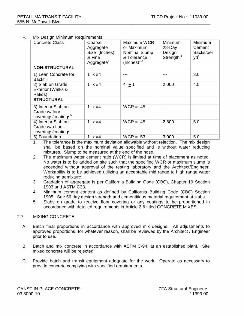
PETALUMA TRANSIT FACILITY 555 N. McDowell Blvd.
TLCD Project No.: 11039.00
CANST-IN-PLACE CONCRETE 03 3000-10
ZFA Structural Engineers 11393.00
F. Mix Design Minimum Requirements: Concrete Class Coarse
Aggregate Size (Inches) & Fine Aggregate3
Maximum WCR or Maximum Nominal Slump & Tolerance (Inches)1,2
Minimum 28-Day Design Strength 4
Minimum Cement Sacks/per yd4
NON-STRUCTURAL
1) Lean Concrete for Backfill
1" x #4 --- --- 3.0
2) Slab on Grade Exterior (Walks & Patios)
1" x #4 4" + 1" 2,000 4.5
STRUCTURAL
3) Interior Slab on Grade w/floor coverings/coatings5
1” x #4 WCR = .45 __ __
4) Interior Slab on Grade w/o floor coverings/coatings
1" x #4 WCR = .45 2,500 5.0
5) Foundation 1" x #4 WCR = .53 3,000 5.0 1. The tolerance is the maximum deviation allowable without rejection. The mix design
shall be based on the nominal value specified and is without water reducing mixtures. Slump to be measured at the end of the hose.
2. The maximum water cement ratio (WCR) is limited at time of placement as noted. No water is to be added on site such that the specified WCR or maximum slump is exceeded without approval of the testing laboratory and the Architect/Engineer. Workability is to be achieved utilizing an acceptable mid range to high range water reducing admixture.
3. Gradation of aggregate is per California Building Code (CBC), Chapter 19 Section 1903 and ASTM C33.
4. Minimum cement content as defined by California Building Code (CBC) Section 1905. See 56 day design strength and cementitious material requirement at slabs.
5. Slabs on grade to receive floor covering or any coatings to be proportioned in accordance with detailed requirements in Article 2.6 titled CONCRETE MIXES.
2.7 MIXING CONCRETE
A. Batch final proportions in accordance with approved mix designs. All adjustments to approved proportions, for whatever reason, shall be reviewed by the Architect / Engineer prior to use.
B. Batch and mix concrete in accordance with ASTM C-94, at an established plant. Site mixed concrete will be rejected.
C. Provide batch and transit equipment adequate for the work. Operate as necessary to provide concrete complying with specified requirements.
TLCD Project No.: 11039.00 PETALUMA TRANSIT FACILITY 555 N. McDowell Blvd.
ZFA Structural Engineers 11393.00
CAST-IN-PLACE CONCRETE 03 3000-11
D. Place mixed concrete in forms within 1-1/2 hours from the time of introduction of cement and water into mixer. Use of, re-mixing and/or tempering mixed concrete older than 1 hour will not be permitted.
E. Do not add water at the site to concrete mixes with a maximum specified WCR unless the water content at batch time provides for a WCR less than specified and this provision, including the quantity of water which may be added at the site, is specifically noted on the Mix Design and Certification by the mix preparer.
2.8 SOURCE QUALITY CONTROL
A. Services by independent Testing Agency: 1. Batch Plant Certificates: Obtain the weighmaster's Batch Plant Certificate at arrival
of truck at the site. If no batch plant certificate is provided, recommend to the General Contractor that the truckload of concrete be rejected. So note in daily log, along with the location of the load of concrete in the structure if the load is not rejected. a. Laboratory's inspector shall obtain for each transit mixer Batch Plant
Certificates to verify mix design quantities and condition upon delivery to the site.
b. Certificates to include: Date, time, ingredient quantities, water added at plant and on job, total mixer revolutions at time of placement, and time of departure.
c. Concrete with specified water cement ratio: Add no water on site unless mix design and batch records each show additional water may be added.
PART 3 – EXECUTION
3.1 EXAMINATION
A. Verify lines, levels, and dimensions before proceeding with work of this section.
B. Verify work of other sections is complete and tested as required before proceeding.
3.2 PREPARATION
A. Observation, Inspection and Testing: 1. Architect/Engineer: Notify not less than 48 hours (2 working days) before each
concrete placement, for observation and review of reinforcing, forms, and other work prior to placement of concrete.
2. Testing Agency: Notify not less than 24 hours before each placement for inspection and testing.
B. Placement Records: Contractor shall maintain records of time, temperature and date of concrete placement including mix design and location in the structure. Retain records until completion of the contract. Make available for review by Testing Agency and Architect/Engineer.
C. Coordinate placement of joint devices with erection of concrete formwork and placement of form accessories.
D. Verify location, position and inclusion of all embedded and concealed items.
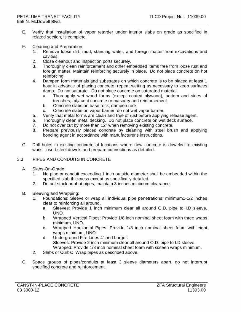
PETALUMA TRANSIT FACILITY 555 N. McDowell Blvd.
TLCD Project No.: 11039.00
CANST-IN-PLACE CONCRETE 03 3000-12
ZFA Structural Engineers 11393.00
E. Verify that installation of vapor retarder under interior slabs on grade as specified in related section, is complete.
F. Cleaning and Preparation: 1. Remove loose dirt, mud, standing water, and foreign matter from excavations and
cavities. 2. Close cleanout and inspection ports securely. 3. Thoroughly clean reinforcement and other embedded items free from loose rust and
foreign matter. Maintain reinforcing securely in place. Do not place concrete on hot reinforcing.
4. Dampen form materials and substrates on which concrete is to be placed at least 1 hour in advance of placing concrete; repeat wetting as necessary to keep surfaces damp. Do not saturate. Do not place concrete on saturated material. a. Thoroughly wet wood forms (except coated plywood), bottom and sides of
trenches, adjacent concrete or masonry and reinforcement. b. Concrete slabs on base rock, dampen rock. c. Concrete slabs on vapor barrier, do not wet vapor barrier.
5. Verify that metal forms are clean and free of rust before applying release agent. 6. Thoroughly clean metal decking. Do not place concrete on wet deck surface. 7. Do not over cut by more than 12” when removing existing concrete. 8. Prepare previously placed concrete by cleaning with steel brush and applying
bonding agent in accordance with manufacturer's instructions.
G. Drill holes in existing concrete at locations where new concrete is doweled to existing work. Insert steel dowels and prepare connections as detailed.
3.3 PIPES AND CONDUITS IN CONCRETE
A. Slabs-On-Grade: 1. No pipe or conduit exceeding 1 inch outside diameter shall be embedded within the
specified slab thickness except as specifically detailed. 2. Do not stack or abut pipes, maintain 3 inches minimum clearance.
B. Sleeving and Wrapping: 1. Foundations: Sleeve or wrap all individual pipe penetrations, minimum1-1/2 inches
clear to reinforcing all around. a. Sleeves: Provide 1 inch minimum clear all around O.D. pipe to I.D sleeve,
UNO. b. Wrapped Vertical Pipes: Provide 1/8 inch nominal sheet foam with three wraps
minimum, UNO. c. Wrapped Horizontal Pipes: Provide 1/8 inch nominal sheet foam with eight
wraps minimum, UNO. d. Underground Fire Lines 4” and Larger:
Sleeves: Provide 2 inch minimum clear all around O.D. pipe to I.D sleeve. Wrapped: Provide 1/8 inch nominal sheet foam with sixteen wraps minimum.
2. Slabs or Curbs: Wrap pipes as described above.
C. Space groups of pipes/conduits at least 3 sleeve diameters apart, do not interrupt specified concrete and reinforcement.

TLCD Project No.: 11039.00 PETALUMA TRANSIT FACILITY 555 N. McDowell Blvd.
ZFA Structural Engineers 11393.00
CAST-IN-PLACE CONCRETE 03 3000-13
1. Provide block-outs as detailed when grouping of pipes/conduits in foundation or other structural member prevents spacing as described,. Notify Architect/Engineer for review of any conditions not conforming to details.
2. Center pipe/conduit penetrations in the depth and/or thickness of foundations. 3. Maximum size of pipe/conduit penetrations shall not exceed the least dimension of
concrete divided by 3.
D. Do not embed pipes/conduits in concrete slabs on metal deck.
E. Provide the following at pipes/conduits detailed to be embedded in a concrete beam, wall or column: 1. Place as near as possible to center of member with reinforcing as specified on each
side. 2. Where reinforcing is located near or at center of member, place pipe or conduit 1
inch minimum clear from reinforcing and provide #3 at 12 inches on center perpendicular to the pipe/conduit. Reinforcing to extend 1’-0” minimum past pipe/conduit each side.
3. Maintain ¾ inch clear minimum from added reinforcing to face of concrete where not exposed to weather, and 1-1/2 inches clear where exposed to weather.
4. Space embedded items, (groups of pipe/conduit, junction boxes or other elements) minimum 3 inches apart.
5. Provide reinforcing in walls, beams, columns as detailed for groups of pipe/conduit. Provide minimum replacement reinforcement of same size and number for interrupted or displaced reinforcement for the full height, length, width of the wall, beam, column on each side of the “effective opening.”
3.4 CONCRETE PLACEMENT
A. Transporting: 1. Provide clean, well-maintained equipment of sufficient quantity and capacity to
execute the work and produce concrete of quality specified. 2. Handle and transport concrete from mixer to final deposit location as rapidly as
practicable. Prevent separation or loss of ingredients.
B. Perform concrete placement by methods which will not puncture, damage or disturb vapor retarder membrane. Repair all damage to vapor retarder membrane before covering.
C. Placement - General: Placement, once started, shall be carried on as a continuous operation until section of approved size and shape is completed. Provide construction joints as detailed on the drawings. Engineer's written approval required for all deviations. 1. Deposition:
a. Deposit concrete to maintain an approximately horizontal plastic surface until the completion of the unit placement.
b. Deposit as neatly as practicable in final position, minimize re-handling or flow. c. Do not drop concrete freely where reinforcing bars will cause segregation, or
for more than four vertical feet. Provide spouts, elephant trunks or other means to prevent segregation during placement.
2. Depth: Layered placement in columns and walls, shall not exceed ten feet vertical depth. a. Place concrete in minimum 32 inch horizontal lifts.
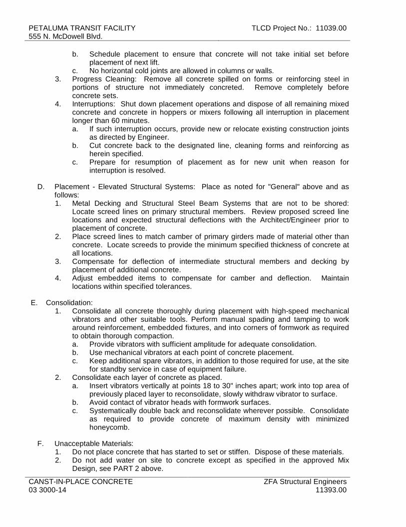
PETALUMA TRANSIT FACILITY 555 N. McDowell Blvd.
TLCD Project No.: 11039.00
CANST-IN-PLACE CONCRETE 03 3000-14
ZFA Structural Engineers 11393.00
b. Schedule placement to ensure that concrete will not take initial set before placement of next lift.
c. No horizontal cold joints are allowed in columns or walls. 3. Progress Cleaning: Remove all concrete spilled on forms or reinforcing steel in
portions of structure not immediately concreted. Remove completely before concrete sets.
4. Interruptions: Shut down placement operations and dispose of all remaining mixed concrete and concrete in hoppers or mixers following all interruption in placement longer than 60 minutes. a. If such interruption occurs, provide new or relocate existing construction joints
as directed by Engineer. b. Cut concrete back to the designated line, cleaning forms and reinforcing as
herein specified. c. Prepare for resumption of placement as for new unit when reason for
interruption is resolved.
D. Placement - Elevated Structural Systems: Place as noted for "General" above and as follows: 1. Metal Decking and Structural Steel Beam Systems that are not to be shored:
Locate screed lines on primary structural members. Review proposed screed line locations and expected structural deflections with the Architect/Engineer prior to placement of concrete.
2. Place screed lines to match camber of primary girders made of material other than concrete. Locate screeds to provide the minimum specified thickness of concrete at all locations.
3. Compensate for deflection of intermediate structural members and decking by placement of additional concrete.
4. Adjust embedded items to compensate for camber and deflection. Maintain locations within specified tolerances.
E. Consolidation: 1. Consolidate all concrete thoroughly during placement with high-speed mechanical
vibrators and other suitable tools. Perform manual spading and tamping to work around reinforcement, embedded fixtures, and into corners of formwork as required to obtain thorough compaction. a. Provide vibrators with sufficient amplitude for adequate consolidation. b. Use mechanical vibrators at each point of concrete placement. c. Keep additional spare vibrators, in addition to those required for use, at the site
for standby service in case of equipment failure. 2. Consolidate each layer of concrete as placed.
a. Insert vibrators vertically at points 18 to 30" inches apart; work into top area of previously placed layer to reconsolidate, slowly withdraw vibrator to surface.
b. Avoid contact of vibrator heads with formwork surfaces. c. Systematically double back and reconsolidate wherever possible. Consolidate
as required to provide concrete of maximum density with minimized honeycomb.
F. Unacceptable Materials: 1. Do not place concrete that has started to set or stiffen. Dispose of these materials. 2. Do not add water on site to concrete except as specified in the approved Mix
Design, see PART 2 above.

TLCD Project No.: 11039.00 PETALUMA TRANSIT FACILITY 555 N. McDowell Blvd.
ZFA Structural Engineers 11393.00
CAST-IN-PLACE CONCRETE 03 3000-15
G. Protection of installed work: 1. Do not introduce any foreign material into any specified drainage, piping or duct
systems. 2. Contractor shall bear all costs of work required to repair or clean this affected work
as a result of failure to comply with this requirement.
3.5 CONCRETE JOINTS
A. Structural Joints (Construction/Cold Joints): 1. Locate joints only where shown, or as approved. 2. Review Required: Joints not indicated on the plans shall be located to meet the
minimum requirements below, shall not impair the strength of the structure and shall be submitted to Architect/Engineer for review prior to placement of concrete. a. Indicate proposed location(s) of construction/cold/expansion joints on shop
drawing submittals for review prior to placing concrete. 3. Clean and roughen all surfaces of previously placed concrete at construction joints
by washing and sandblasting to expose aggregate to 1/4 inch amplitude. 4. Slabs-On-Grade: Maximum Length of continuous placement shall not exceed 60’
without special review by the Architect/Engineer. Alternate or stagger placement sections.
5. Foundations, Beams, Elevated Slabs and Joists: Maximum Length of continuous placement shall not exceed 200 foot increments. Provide “keyed” shut-off locations made up with form boards. Extend reinforcing one lap length or more through shut-off. a. All reinforcement shall be continuous through construction/cold joint, lapping to
adjacent reinforcing in future placement. b. Construction Joints in Elevated Slabs: Review all proposed locations with
Architect/Engineer. c. Construction Joints in Slabs on Metal Decking: Review all proposed locations
with Architect/Engineer. Do not locate closer than 24 inches to faces of girder or beam.
6. Horizontal Construction Joints: Place 2 inch slurry (specified concrete mix less coarse aggregate) at beginning of pour at the bottom of walls unless a prior review of a mock-up section demonstrates that segregation of aggregate will not occur.
B. Expansion/Construction Joints (Dowel Joints and Control Joints): 1. Exterior Concrete Paving (walkways, patios) and other non-structural concrete
flatwork at grade: a. Expansion/ construction joints: Provide a 2 inch deep troweled groove or
asphalt impregnated joint material embedded 50 percent of the slab depth at 12 feet on center, maximum.
b. Proportions: Place no section with a length larger than two times width. Additionally, place joints at all inside corners and at all intersections with other work.
2. Interior and Exterior Floor Slabs at Grade: Provide dowel joints or control joints at a maximum dimension (in feet) of three times the slab thickness (in inches) in each direction unless noted otherwise. Install joints to match slab level and in straight lines. Locate joints at all reentrant corners including blockouts, and maintain maximum slab ratio of 2 to 1 length to width between slab joints.
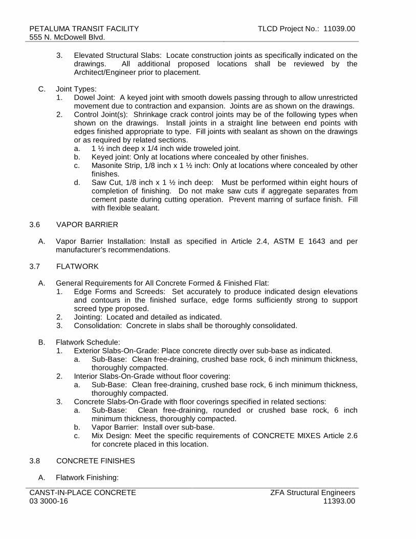
PETALUMA TRANSIT FACILITY 555 N. McDowell Blvd.
TLCD Project No.: 11039.00
CANST-IN-PLACE CONCRETE 03 3000-16
ZFA Structural Engineers 11393.00
3. Elevated Structural Slabs: Locate construction joints as specifically indicated on the drawings. All additional proposed locations shall be reviewed by the Architect/Engineer prior to placement.
C. Joint Types: 1. Dowel Joint: A keyed joint with smooth dowels passing through to allow unrestricted
movement due to contraction and expansion. Joints are as shown on the drawings. 2. Control Joint(s): Shrinkage crack control joints may be of the following types when
shown on the drawings. Install joints in a straight line between end points with edges finished appropriate to type. Fill joints with sealant as shown on the drawings or as required by related sections. a. 1 ½ inch deep x 1/4 inch wide troweled joint. b. Keyed joint: Only at locations where concealed by other finishes. c. Masonite Strip, 1/8 inch x 1 ½ inch: Only at locations where concealed by other
finishes. d. Saw Cut, 1/8 inch x 1 ½ inch deep: Must be performed within eight hours of
completion of finishing. Do not make saw cuts if aggregate separates from cement paste during cutting operation. Prevent marring of surface finish. Fill with flexible sealant.
3.6 VAPOR BARRIER
A. Vapor Barrier Installation: Install as specified in Article 2.4, ASTM E 1643 and per manufacturer’s recommendations.
3.7 FLATWORK
A. General Requirements for All Concrete Formed & Finished Flat: 1. Edge Forms and Screeds: Set accurately to produce indicated design elevations
and contours in the finished surface, edge forms sufficiently strong to support screed type proposed.
2. Jointing: Located and detailed as indicated. 3. Consolidation: Concrete in slabs shall be thoroughly consolidated.
B. Flatwork Schedule: 1. Exterior Slabs-On-Grade: Place concrete directly over sub-base as indicated.
a. Sub-Base: Clean free-draining, crushed base rock, 6 inch minimum thickness, thoroughly compacted.
2. Interior Slabs-On-Grade without floor covering: a. Sub-Base: Clean free-draining, crushed base rock, 6 inch minimum thickness,
thoroughly compacted. 3. Concrete Slabs-On-Grade with floor coverings specified in related sections:
a. Sub-Base: Clean free-draining, rounded or crushed base rock, 6 inch minimum thickness, thoroughly compacted.
b. Vapor Barrier: Install over sub-base. c. Mix Design: Meet the specific requirements of CONCRETE MIXES Article 2.6
for concrete placed in this location.
3.8 CONCRETE FINISHES
A. Flatwork Finishing:

TLCD Project No.: 11039.00 PETALUMA TRANSIT FACILITY 555 N. McDowell Blvd.
ZFA Structural Engineers 11393.00
CAST-IN-PLACE CONCRETE 03 3000-17
1. Perform with experienced operators. 2. Finish surfaces monolithically. Establish uniform slopes or level grades as indicated.
Maintain full design thickness. 3. In areas with floor drains, maintain design floor elevation at walls; slope surfaces
uniformly to drains as indicated on drawings. 4. Flatwork Finish Types:
a. Wood Float Finish: Surfaces to receive quarry tile, ceramic tile, or cementitious terrazzo with full bed setting system, or wood frame for raised finished floors.
b. Steel Trowel Finish: Surfaces to receive carpeting, resilient flooring, seamless flooring, thin set terrazzo, thin set tile or similar finishes specified in related sections. Trowel twice, minimum.
c. Broom Texture Finish: Exterior surfaces as indicated or for which no other finish is indicated. Finish as for steel trowel finish, except immediately following first troweling, (depending on conditions of concrete and nature of finish required) provide uniform surfaces texture using a medium or coarse fiber broom.
B. Other Concrete: Provide as required to achieve appearance indicated on structural and architectural drawings and related sections. 1. Repair surface defects, including tie holes, immediately after removing formwork. 2. Unexposed Form Finish: Rub down or chip off fins or other raised areas 1/4 inch or
more in height. 3. Exposed Form Finish: Finish concrete to match forms. Rub down or chip off and
smooth fins or other raised areas 1/4 inch or more in height. Provide finish as follows: a. Smooth Rubbed Finish: Wet concrete and rub with carborundum brick or other
abrasive, not more than 24 hours after form removal. b. Grout Cleaned Finish: Wet areas to be cleaned and apply grout mixture by
brush or spray; scrub immediately to remove excess grout. After drying, rub vigorously with clean burlap, and keep moist for 36 hours.
c. Cork Floated Finish: Immediately after form removal, apply grout with trowel or firm rubber float; compress grout with low-speed grinder, and apply final texture with cork float.
4. Intermediate joint and score marks and edges: Tool smooth and flush unless otherwise indicated or as directed by the Architect.
5. Use steel tools of standard patterns and as required to achieve details shown or specified. All exposed corners not specified to be chamfered shall have radiused edges.
3.9 TOLERANCES
A. Minimum Flatwork Tolerances: Measure flatness of slabs with in 48 hours after slab installation in accordance with ACI 302.1R and ASTM E1155 and to achieve the following FF and FL tolerances: 1. Exterior surfaces: 1/8 inch minimum per foot where sloped to drain. Level
otherwise. FF 20 and FL15. 2. Interior surfaces not otherwise shown or required: Level throughout. FF25 and
FL20 3. Interior surfaces required to be sloped for drainage: 1/8 inch in 10 ft. 4. Finish concrete to achieve the following tolerances:
a. Under Glazed Tile on Setting Bed: FF 30 and FL 20.
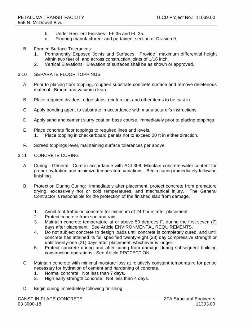
PETALUMA TRANSIT FACILITY 555 N. McDowell Blvd.
TLCD Project No.: 11039.00
CANST-IN-PLACE CONCRETE 03 3000-18
ZFA Structural Engineers 11393.00
b. Under Resilient Finishes: FF 35 and FL 25. c. Flooring manufactureer and pertainent section of Division 9.
B. Formed Surface Tolerances: 1. Permanently Exposed Joints and Surfaces: Provide maximum differential height
within two feet of, and across construction joints of 1/16 inch. 2. Vertical Elevations: Elevation of surfaces shall be as shown or approved.
3.10 SEPARATE FLOOR TOPPINGS
A. Prior to placing floor topping, roughen substrate concrete surface and remove deleterious material. Broom and vacuum clean.
B. Place required dividers, edge strips, reinforcing, and other items to be cast in.
C. Apply bonding agent to substrate in accordance with manufacturer's instructions.
D. Apply sand and cement slurry coat on base course, immediately prior to placing toppings.
E. Place concrete floor toppings to required lines and levels. 1. Place topping in checkerboard panels not to exceed 20 ft in either direction.
F. Screed toppings level, maintaining surface tolerances per above.
3.11 CONCRETE CURING
A. Curing - General: Cure in accordance with ACI 308. Maintain concrete water content for proper hydration and minimize temperature variations. Begin curing immediately following finishing.
B. Protection During Curing: Immediately after placement, protect concrete from premature drying, excessively hot or cold temperatures, and mechanical injury. The General Contractor is responsible for the protection of the finished slab from damage.
1. Avoid foot traffic on concrete for minimum of 24-hours after placement. 2. Protect concrete from sun and rain. 3. Maintain concrete temperature at or above 50 degrees F. during the first seven (7)
days after placement. See Article ENVIRONMENTAL REQUIREMENTS. 4. Do not subject concrete to design loads until concrete is completely cured, and until
concrete has attained its full specified twenty-eight (28) day compressive strength or until twenty-one (21) days after placement, whichever is longer.
5. Protect concrete during and after curing from damage during subsequent building construction operations. See Article PROTECTION.
C. Maintain concrete with minimal moisture loss at relatively constant temperature for period necessary for hydration of cement and hardening of concrete. 1. Normal concrete: Not less than 7 days. 2. High early strength concrete: Not less than 4 days.
D. Begin curing immediately following finishing.
TLCD Project No.: 11039.00 PETALUMA TRANSIT FACILITY 555 N. McDowell Blvd.
ZFA Structural Engineers 11393.00
CAST-IN-PLACE CONCRETE 03 3000-19
E. Formed Surfaces: Cure by moist curing with forms in place for full curing period.
F. Surfaces Not in Contact with Forms: 1. Start initial curing as soon as free water has disappeared and before surface is dry.
Keep continuously moist for not less than three days by water ponding, water-saturated sand, water-fog spray, or saturated burlap.
2. Begin final curing after initial curing but before surface is dry. a. Moisture-retaining cover: Seal in place with waterproof tape or adhesive. b. Curing compound: Apply in two coats at right angles, using application rate
recommended by manufacturer.
G. Flatwork on Grade: Cure by one of the following methods: 1. Water Cure (Ponding): Maintain 100 percent coverage of water over floor slab
areas, continuously for minimum seven (7) calendar days. 2. Spraying: Spray water over floor slab areas and maintain wet for 7 days. 3. Moisture-Retaining Film or Paper: Lap strips not less than 6 inches and seal with
waterproof tape or adhesive; extend beyond slab or paving perimeters minimum 6 inches and secure at edges; maintain in place for minimum seven (7) days.
4. Absorptive Moisture-Retaining Covering: Saturate burlap-polyethylene and place burlap-side down over floor slab areas, lapping ends and sides and extend beyond slab or paving perimeters 6 inches minimum; maintain in place for minimum seven (7) days.
5. Liquid Membrane-forming Curing Compound: Provide only when subsequent concrete treatments or finish flooring specified in related sections will not be affected by cure/sealer. Apply curing compound in accordance with manufacturer's instructions at the maximum recommended application rate in two coats, with second coat applied at right angles to first.
H. Elevated Flatwork: Cure by one of the following methods. 1. Moisture-Retaining Sheet: As specified for Flatwork on Grade above. 2 Water Cure: As specified above for minimum fourteen (14) days. 3. Apply Membrane Curing Compound as specified above after initial curing period.
I. Flatwork on Metal Decking: Moisture-Retaining Sheet method as specified above.
J. Formed Concrete Members: Cure by moist curing with forms in place for full curing period. 1. Protect free-standing elements from temperature extremes. 2. Maintain forms tight for minimum seven (7) days. Maintain exposed surfaces
continuously damp and completely covered by sheet materials thereafter. 3. Maintain all shoring in place. Refer to related sections specifying formwork. 4. Membrane Curing Compound: Apply compound in accordance with manufacturer's
instructions in one coat.
K. Foundations: Apply curing compound immediately after floating.
3.12 CONCRETE HARDENER
A. Apply hardener to all floor slabs not receiving other finishes after 30 days minimum curing. Clean slabs of non-compatible cure/sealers or other foreign material(s) and apply in strict accordance with the manufacturer's directions.
PETALUMA TRANSIT FACILITY 555 N. McDowell Blvd.
TLCD Project No.: 11039.00
CANST-IN-PLACE CONCRETE 03 3000-20
ZFA Structural Engineers 11393.00
3.13 GROUTING AND DRY PACK
A. Set steel plates on concrete or masonry with grout bed, completely fill all voids; thoroughly compact in place.
B. Bolts or inserts dry packed or grouted in place shall cure for minimum seven (7) days before tensioning.
3.14 FIELD QUALITY CONTROL
A. Testing and Inspections by Independent Testing Agency: Provided verification and inspection of concrete per CBC Table 1704.4. Provide written reports for to Engineer, Architect, Contractor and Building Official for the following tests and inspections: 1. Inspection: Provide periodic inspection of reinforcing steel. Provide periodic
inspection during placement of structural class concrete, 3000 psi or more, on a 150 cubic yard basis as required to assure conformance. a. Provide continuous inspection of bolts in concrete prior to and during
placement where so noted on the construction documents. 2. Structural Concrete Cylinder Tests: Perform in accordance with ASTM C-31.
a. Take four standard 6 inch x 12 inch cylinder specimens on the site, of each class of concrete as specified in PART 2, not less then a day or for each 50 cubic yards or 2000 sq ft or fraction thereof placed each day.
b. Record the location of each concrete batch in the building in a log and also note on each specimen.
c. Perform standard compression test of cylinders in accordance with ASTM C-39, one at 7 days and two at 28 days.
d. Hold fourth cylinder untested until specified concrete strengths are attained. 3. Structural Concrete Slump Test and Air Tests: Perform in accordance with ASTM D
143 at the time of taking test cylinders, and/or at one-hour intervals during concrete placing.
4. Measure and record concrete temperature upon arrival of transit mixers and when taking specimens. Note weather conditions and temperature.
5. Propose adjustments to reviewed mix designs for Architect / Engineer review to account for variations in site or weather conditions, or other factors as appropriate.
6. Water Vapor Transmission Tests: Floors receiving floor finishes specified in related sections will be tested prior to installation of flooring systems. Refer to sections specifying floor finishes for related requirements.
B. Services by Contractor: 1. Rejection of Concrete Materials: Do not use the following without prior written
approval of the Architect/Engineer; a. Materials without batch plant certificates. b. Materials not conforming to the requirements of these specifications.
3.15 ADJUSTING
A. Inspect all concrete surfaces immediately upon formwork removal. Notify Architect/Engineer of identified minor defects. Repair all minor defects as directed.

TLCD Project No.: 11039.00 PETALUMA TRANSIT FACILITY 555 N. McDowell Blvd.
ZFA Structural Engineers 11393.00
CAST-IN-PLACE CONCRETE 03 3000-21
B. Surface and Finish Defects: Repair as directed by the Architect/Engineer, at no added expense to the Owner. Repairs include all necessary materials; reinforcement grouts, dry pack, admixtures, epoxy and aggregates to perform required repair. 1. Repair minor defective surface defects by use of drypack and surface grinding.
Specific written approval of Architect/Engineer is required. Submit proposed patching mixture and methods for approval prior to commencing work.
2. Slabs On Grade, Elevated Slabs and on Slabs On Metal Deck: Review for "curled" slab edges and shrinkage cracks prior to installation of other floor finishes. Grind curled edges flush, fill cracks of 1/16 inch and greater with cementitious grout.
3. Grind high spots, fins or protrusions caused by formwork; Fill-in pour joints, voids, rock pockets, tie holes and other void not impairing structural strength. Provide surfaces flush with surrounding concrete.
3.16 DEFECTIVE CONCRETE
A. Defective Concrete: Concrete not conforming to required compressive strength, lines, details, dimensions, tolerances, finishes or specified requirements; as determined by the Architect/Engineer.
B. Repair or replacement of defective concrete will be determined by the Architect/Engineer who may order additional testing and inspection at his option. The cost of additional testing shall be borne by Contractor when defective concrete is identified.
C. Specific Defects: 1. "Low-Strength"; Concrete Not Meeting Specified Compressive Strength after 28
days: a. Concrete with less than 25% Fly Ash as cementitious material: Test remaining
cylinder(s) at 56 days. If strength requirements are met, concrete strength is acceptable.
b. Concrete with 25% or more Fly Ash as cementitious material: Test remaining cylinder(s) at 70 days. If strength requirements are met, concrete strength is acceptable.
2. Excessive Shrinkage, Cracking, Crazing or Curling; Defective Finish: Remove and replace if repair to acceptable condition is not feasible.
3. Lines, Details, Dimensions, Tolerances: Remove and replace if repair to acceptable condition is not feasible.
4. Slab sections not meeting specified tolerances for trueness/flatness or lines/levels: Remove and replace unless otherwise directed by the Architect/Engineer. a. Minimum area for removal: Fifteen square feet area unless directed otherwise
by the Architect/Engineer. 5. Defective work affecting the strength of the structure or the appearance: Complete
removal and replacement of defective concrete, as directed by the Architect/Engineer.
3.17 CLEANING
A. Maintain site free of debris and rubbish. Remove all materials and apparatus from the premises and streets at completion of work. Remove all drippings, leave the entire work clean and free of debris.
PETALUMA TRANSIT FACILITY 555 N. McDowell Blvd.
TLCD Project No.: 11039.00
CANST-IN-PLACE CONCRETE 03 3000-22
ZFA Structural Engineers 11393.00
B. Slabs to Receive Floor Finishes Specified in other sections: Remove non-compatible cure/sealers or other foreign material(s) which may affect bonding of subsequent finishes. Leave in condition to receive work of related sections.
3.18 PROTECTION
A. Protect completed work from damage until project is complete and accepted by Owner.
B. Construction Loads: Submit engineering analysis for equipment, where wheel point loads (including all carried loads) are in excess of the following: 1. Slabs on grade and structural slabs above grade: 4,000 lbs. 2. Slabs above grade on metal deck: 2,000 lbs.
C. Keep finished areas free from all equipment traffic for a minimum of 4 additional days following attainment of design strength and completion of curing.
D. Protection of Drainage Systems: 1. Care shall be taken not to introduce any foreign material into any specified drainage,
piping or duct system. 2. Cost of work to repair or clean drainage system as a result of failure to comply with
this requirement will be back charged to the contractor.
E. Cover traffic areas with plywood sheets or other protective devices; maintain protection in place and in good repair for as long as necessary to protect against damage by subsequent construction operations.
END OF SECTION 03 3000
TLCD Project No.: 11039.00 PETALUMA TRANSIT FACILITYCity Of Petaluma Department Of Public Works & Utilities
Petaluma, CA
TLCD Architecture DIVISION 04 – NOT USED
DIVISION 04 – NOT USED
PETALUMA TRANSIT FACILITY City Of Petaluma Department Of Public Works & Utilities Petaluma, CA
TLCD Project No.: 11039.00
DIVISION 04 – NOT USED
TLCD Architecture
DIVISION 04 – NOT USED

TLCD Project No.: 11039.00 PETALUMA TRANSIT FACILITY 555 N. McDowell Blvd.
ZFA Structural Engineers STRUCTURAL STEEL 11393.00 05 1100- 1
SECTION 05 1100 - STRUCTURAL AND MISCELLANEOUS STEEL
PART 1 – GENERAL 1.1 SUMMARY
A. Section Includes: All labor, materials, equipment and operations required to complete
structural and miscellaneous metals in shapes and configurations indicated; including:
1. Structural steel columns, beams, bracing, base plates, bolts, joist hangers, and stud bolts welded to structural steel.
2. Miscellaneous structural steel and connections; fabricated connectors and hangers installed by related sections.
3. Anchor bolts and steel inserts embedded in concrete or masonry, installed by related sections.
4. Fabricated steel items embedded in concrete or masonry installed by related sections.
5. Supervision of anchor bolt setting, leveling and elevations to insure required fit of steel work.
6. Shop priming and field touch-up, galvanizing. 7. Bracing, Shoring, Fabrication and Erection.
B. Related Sections:
1. Pertinent sections of Division 01 specifying Quality Control and Testing Agency services.
2. Pertinent Sections of other Divisions specifying concrete reinforcement, formwork, concrete, and rough carpentry.
3. Pertinent Sections of other Divisions specifying structural and miscellaneous metal fabrications, steel joists, metal decking, cold-formed metal framing.
1.2 REFERENCES
A. AISC 360- Specification for Structural Steel Buildings; American Institute of Steel
Construction, Inc. B. AISC 303 - Code of Standard Practice for Steel Buildings and Bridges; AISC, Inc. C. ANSI/AWS D1.1/D1.1M - Structural Welding Code - Steel; American Welding Society. D. California Building Code, CBC, California Code of Regulations, Chapter 22, latest
edition. E. UL (FRD) - Fire Resistance Directory; Underwriters Laboratories Inc.
1.3 SUBMITTALS
PETALUMA TRANSIT FACILITY 555 N. McDowell Blvd.
TLCD Project No.: 11039.00
ZFA Structural Engineers STRUCTURAL STEEL 11393.00 05 1100- 2
A. Submit in accordance with pertinent sections of Division 01 specifying submittal procedures. The General Contractor shall review and approve shop drawings prior to submittal to the Architect/Engineer. Submittals that do not meet these requirements will be returned for correction without review.
B. Limitation of Review: Structural Engineer's review will be for general conformance with
design intent as indicated in the Contract Documents and does not relieve Contractor of full responsibility for conformance with the Contract Documents.
C. Product Data: Submit manufacturer's product data, specifications, location and
installation instructions for proprietary materials and reinforcement accessories. Provide samples of these items upon request.
D. Shop drawings: Submit each building as a complete unit. Do not mix components from
multiple buildings or units of work in a submittal. Include all of the following;
1. Indicate profiles, sizes, spacing, locations of structural members, openings, attachments, and fasteners.
2. Indicate fabrication tolerances for all steel. 3. Connections: All, including type and location of shop and field connections 4. Indicate welded connections with AWS A2.4 welding symbols. Indicate net weld
lengths, type, size, and sequence. 5. Cross-reference all shop drawing detail references to contract document detail
references. 6. Secure all field measurements as necessary to complete this work. 7. Provide holes, welded studs, etc. as necessary to secure work of other sections. 8. Provide the following as separate submittals for each building or unit of work:
a. Bolt and Anchor setting plans. b. Layout, Fabrication and Erection Drawings.
E. Certifications:
1. Steel Materials: Submit the following for identified materials.
a. Manufacturer's Mill Certificate: Certify that products meet or exceed specified requirements.
b. Mill Test Reports: Indicate structural strength, destructive test analysis and non-destructive test analysis.
c. Contractor's affidavit certifying that all identified steel materials provided are of the grades specified and match the certificates supplied.
2. Welders Certificates: Certify welders employed on the Work, verifying AWS qualification per AWS D1.1.
F. Samples: Provide samples to the Testing Agency as specified in Article SOURCE
QUALITY CONTROL, at no additional costs. 1.4 QUALITY ASSURANCE
A. Requirements of Regulatory Agencies, refer to pertinent sections of Division 01 and
CBC Chapter 19.
TLCD Project No.: 11039.00 PETALUMA TRANSIT FACILITY 555 N. McDowell Blvd.
ZFA Structural Engineers STRUCTURAL STEEL 11393.00 05 1100- 3
B. All tests shall be performed by a recognized testing agency as specified in pertinent sections of Division 01.
C. Certification and Identification of Materials and Uses: Provide Testing Agency with
access to fabrication plant to facilitate inspection of steel. Provide notification of commencement and duration of shop fabrication in sufficient time to allow inspection and all material identification/test information listed below.
1. Test all steel as required by ASTM A6. 2. Provide manufacturer's Mill Test Reports for all materials. Include chemical and
physical properties of the material for each heat number manufactured. Tag all fabricated materials with heat number.
3. Provide letter certifying all materials supplied are from heat numbers covered by supplied mill certificates. Include in letter the physical location of each material type and/or heat number in the project (i.e. walls, braced frames etc.).
4. Unidentified Material Tests: Where identification of materials by heat number to mill tests cannot be made, Owner's Testing Agency shall test unidentified materials as described below.
5. Provide all certification, verifications, and other test data required to substantiate specified material properties at no additional cost to the Owner.
D. Testing and Inspection: Tests and Inspections performed by Independent Testing
Agency are specified below in Articles SOURCE QUALITY CONTROL and FIELD QUALITY CONTROL. Duties and limitations of Independent Testing Agency, test costs and test reports in conformance with pertinent sections of Division 01.
E. The following standards are the minimum level of quality required. Provide higher
quality work as specifically indicated in the Contract Documents.
1. Workmanship and details of structural steel work, shall conform to the California Building Code, and the AISC Specification for Structural Steel Building.
2. The quality of materials and the fabrication of all welded connections shall conform to the American Welding Society, AWS D1.1 - Structural Welding Code.
3. Comply with Section 10 of AISC "Code of Standard Practice for Steel Buildings and Bridges" for architecturally exposed structural steel.
F. The Testing Agency will review all submittals and testing of materials. G. All re-inspections made necessary by non-conforming work shall be at the Contractor's
expense. 1.5 DELIVERY, STORAGE AND HANDLING
A. Deliver materials to project site in bundles marked with durable tags indicating heat
number, mill, member size and length, proposed location in the structure and other information corresponding with markings shown on placement diagrams.
B. Handle and store materials above ground to prevent damage, contamination or
accumulation of dirt or rust.
PETALUMA TRANSIT FACILITY 555 N. McDowell Blvd.
TLCD Project No.: 11039.00
ZFA Structural Engineers STRUCTURAL STEEL 11393.00 05 1100- 4
1.6 SCHEDULING AND SEQUENCING
A. Organize the work and employ shop and field crew(s) of sufficient size to minimize inspections by the Testing Agency.
B. Provide schedule and sequence information to Testing Agency in writing upon request.
Update information as work progresses. PART 2 – PRODUCTS 2.1 MATERIALS
A. Structural Steel W Shapes: ASTM A 572 Grade 50 or ASTM A 992 Grade 50. B. Structural Steel Plates, Channels, Angles: ASTM A36. C. HSS (Hollow Structural Sections – formerly SSP & TS):
1. Round: ASTM A500, Grade B. 2. Rectangular or Square: ASTM A-500, Grade B.
D. Pipe: ASTM A53, Grade B. E. Machine Bolts and Washers: Bearing and Shear connections (denoted as “MB”); ASTM
A-307. Provide hot-dipped galvanized finish at all connection where steel is required to be galvanized.
F. Anchor Bolts/Rods: ASTM F1554, Grade 36 or ASTM A36. No upset thread allowed. G. Arc-Welding Electrodes: AWS Standards E70 or equivalent, except no E70T-4 allowed. H. Other Welding Materials: AWS D1.1; type required for materials being welded.
2.2 ACCESSORIES
A. Grout: ASTM C 1107, Non-shrink, non-metallic aggregate type, capable of developing
minimum compressive strength of 7,000 psi at 28 days. Provide "Masterflow 928" manufactured by Master Builders.
B. Building Structural Steel Primers: Comply with local VOC limitations of authorities having jurisdiction and compatible with finish coats specified in other sections. Follow manufacturers printed instructions. Apply one coat unless otherwise directed.
1. Type A: Modified Alkyd type, Tnemec Series V10 Primer (2.0 to 3.5 mils DFT). 2. Type B: Organic Zinc-rich Urethane, Tenemec 90-97 Tnemec-Zinc Primer (2.5 to
3.5 mils DFT). 3. Type C: MIO-Zinc Filled Primer, Tnemec 394 PerimePrime (2.5 to 2.5 mils DFT).
C. Galvanizing: ASTM A153, and A123.
TLCD Project No.: 11039.00 PETALUMA TRANSIT FACILITY 555 N. McDowell Blvd.
ZFA Structural Engineers STRUCTURAL STEEL 11393.00 05 1100- 5
D. Touch-Up Primer for Galvanized Surfaces: Type B primer.
2.3 FABRICATION
A. Shop fabricate to greatest extent possible. B. Continuously seal joined members by continuous welds. Grind exposed welds smooth. C. Fabricate connections for bolt, nut, and washer connectors. D. Protect all materials, before and after fabrication, from rust, corrosion, dirt, grease and
other foreign matter. E. Fabricate framing members free from twists or bends. Form holes, cut and sheared
edges neatly without kinks, burrs, or warped edges. F. Exposed Steel: Straight, smooth, free of nicks, scars or dents. G. Gas Cutting: Gas cutting of holes in a member shall not be permitted. H. Splicing of members: Members requiring splicing due to length requirements may be
spliced using full penetration butt welds when such welds and procedures are inspected and certified by the Testing Agency, in conformance with AWS and AISC standards. The location of splices shall be approved by the Architect/Engineer in writing prior to fabrication.
I. Welding: Welding of structural steel connections shall be performed by qualified
welders in accordance with AWS Standards. All weld sizes shall match those shown on the drawings.
1. Preparation: Clean all surfaces free of rust, paint and all foreign matter. Remove
paint or scale by brushing, chipping or hammering as required. Chip clean and wire brush burned or flame cut edges before welding. Space and alternate welds, clamping as necessary to prevent warp or misalignment.
2. Sequence Welding: When welds enclose, or partially enclose, the perimeter or portion of the surface of a member, make weld bead in sequence, or staggered. Minimize internal stresses. Weld groups of members occurring in a single line in staggered sequence to minimize distortion of the structural frame.
3. Faulty and Defective Welding: Welds failing to meet AWS standards and the Contract Documents shall be rejected and remade at Contractor expense. All welds showing cracks, slag inclusion, lack of fusion, bad undercut or other defects, ascertained by visual or other means of inspection shall be removed and replaced with conforming work.
4. Minimum Weld Strengths: All welds shall match the minimum weld sizes recommended by AISC. Details of fabrication not specifically shown shall match similar details which are specifically shown. All bevel and groove welds shall be full penetration unless size is noted otherwise.
J. Camber: Fabricate all beams cambered as indicated on the drawings.

PETALUMA TRANSIT FACILITY 555 N. McDowell Blvd.
TLCD Project No.: 11039.00
ZFA Structural Engineers STRUCTURAL STEEL 11393.00 05 1100- 6
1. Fabricate beams without camber for installation with any "natural" crown up. 2. Exception: Fabricate cantilever beams with "crown" down.
K. Grinding: Grind smooth the following structural steel and connections;
1. Exposed cut ends of structural and fabricated shapes. 2. All welds exposed to view. 3. Mitered and fit-up corners and intersections.
L. Back-Up Bars: Required for all complete penetration welds. M. Bolt Holes: Edge, end distances and spacing shall conform to dimensions shown on the
drawings, and as follows;
1. Round: Size indicated and 1/16 inch maximum oversize 2. Slotted: At locations specifically noted on the drawings, provide size indicated and
1/16 inch by 1/4 inch oversize slotted in direction perpendicular to applied loads. 3. Holes in base plates for anchor bolts may be 1/8" oversize.
2.4 FINISHES
A. Prepare and finish structural component surfaces as follows:
1. Structural and miscellaneous Steel for interior dry exposure (finish painted or
unpainted): a. Surface preparation: SSPC-SP2 hand tool or SP3 Power Tool Cleaning.
Where jobsite exposure is expected to exceed 6 months, SSPC-SP6 Commercial Blast Cleaning is required.
b. Apply Primer Type A. 2. Structural and miscellaneous exterior steel or interior steel subjected to wet
conditions or fumes (finish painted): a. Surface preparation: SSPC-SP6 Commercial Blast Cleaning. For severe
(immersion) exposure, SSPS-SP10 Near-White Blast Cleaning is required. b. Apply Primer Type B.
3. Structural steel to be fire proofed, all interior perimeter steel, steel that will be inaccessible after erection, steel to receive high performance finish coatings and slip critical bolted connection surfaces (finish painted or unpainted): a. Surface preparation: SSPC-SP3 Power Tool Cleaning. b. Apply Primer Type C.
B. Do not prime the following surfaces unless otherwise indicated:
1. Connections to be field welded. 2. Steel in contact with concrete. 3. Surfaces to receive welded metal decking.
C. Galvanize structural steel members exposed to weather and not finish painted, or as otherwise indicated to receive galvanizing, to comply with ASTM A 123/A 123M. Provide minimum 1.3 oz/sq ft galvanized coating. Passivation agents are not permitted

TLCD Project No.: 11039.00 PETALUMA TRANSIT FACILITY 555 N. McDowell Blvd.
ZFA Structural Engineers STRUCTURAL STEEL 11393.00 05 1100- 7
on galvanized metal that is to be painted. Galvanize all bolts and washers. D. Field prime with Type B after connections are complete. E. Do not finish work until inspection is complete and work approved by Testing Agency.
2.5 SOURCE QUALITY CONTROL
A. An independent Testing Agency will perform source quality control tests and submit
reports, as specified in pertinent sections of Division 01. B. Steel Materials Testing:
1. Unidentified steel- General: Test all structural shapes. In addition, test to verify Fy
and Fu values when engineering requirements exceed Fy = 25 ksi for design. 2. No testing is required for Materials identified in accordance with CBC 2203 (heat
number, grade stencil, etc.).
C. Shop Welding Inspection:
1. Testing Agency shall inspect and certify all structural welds, unless the fabricating shop has been accredited in conformance with CBC requirements. Submit certification to the Architect/Engineer for review and the Building Official for approval.
2. Welder Qualifications: Welding inspector shall verify that all the welders are properly qualified prior to steel fabrication and state the qualifications of each welder in the welding inspection report.
3. Welding Inspection: Continuous inspection required unless otherwise noted below. Comply with requirements of AWS D1.1 a. Welding Inspector shall check all welds, materials, equipment and
procedures. b. Welding Inspector shall provide reports certifying the welding is as required
and has been done in conformity with the plans, specifications and codes. c. Welding Inspector shall use radiographic, ultrasonic, magnetic particle, or
any other necessary aid to visual inspection to assure adequacy of welds. 4. Periodic Inspection Acceptable:
a. Single pass fillet welds not exceeding 5/16 b. Welding of studs to beams.
D. Bolts, Nuts and Washers: Provide samples to Testing Agency for required testing, at no
additional cost. PART 3 – EXECUTION 3.1 EXAMINATION
A. Verify that conditions are appropriate for erection of structural steel and that the work
may properly proceed. 3.2 ERECTION
PETALUMA TRANSIT FACILITY 555 N. McDowell Blvd.
TLCD Project No.: 11039.00
ZFA Structural Engineers STRUCTURAL STEEL 11393.00 05 1100- 8
A. Erect structural steel in compliance with AISC "Code of Standard Practice for Steel
Buildings and Bridges".
B. Framing:
1. Erect all structural steel true and plumb. 2. Verify proper final alignment prior to making final connections.
C. Field Connections:
1. Workmanship of field bolted and welded connections shall conform in all respects to methods and tolerances specified for fabrication.
2. Field weld components indicated on shop drawings. Sequence field welds to minimize built-up stress and distortion of the structural frame. Verify sequence with Engineer. Coordinate field welding schedule with Testing Laboratory.
3. Welded Studs: Install in accordance with manufacturer's instructions and structural welding code AWS D1.1.
D. Templates: Provide bolt setting templates for all anchor bolts. Provide instructions for
the setting of anchors and bearing plates, verify these items are set correctly as work progresses.
E. Column base plates: Set level to correct elevations, support temporarily on steel
wedges, shims, or leveling nuts where shown, until the supported members are plumbed and grouted.
1. Grout solid the full bearing area under base plates prior to installation of floor
and/or roof decks. See Section 03300 - Cast-In-Place Concrete. 2. Comply with manufacturer's instructions for nonshrink grout. Trowel grouted
surfaces smooth, splaying neatly to 45 degrees.
F. Bolting - General:
1. Inspect mating surfaces to insure that bolt head and nut will have full bearing and that metal plies will mate flush between bolts.
2. Install bolts in matching holes; Do not distort metal or enlarge holes by drifting during assembly. Remake mismatched components to achieve tolerances indicated.
3. Holes mismatched in excess of 1/8 inch will be rejected. 4. Ream holes mismatched in excess of 3/32 inch to the next larger size bolt. 5. Do not enlarge holes by flame cutting or air/arc (“plasma“) cutting. 6. Provide flat washer(s) at over-size holes. 7. Provide ASTM F-436 beveled washers when the slope of the surfaces of parts in
contact with the bolt head or nut is greater than 1:20. 8. Do not install bolts with damaged threads. 9. Threads shall commence outside of the shear plane.
G. Bolting - Specific:
TLCD Project No.: 11039.00 PETALUMA TRANSIT FACILITY 555 N. McDowell Blvd.
ZFA Structural Engineers STRUCTURAL STEEL 11393.00 05 1100- 9
1. Machine Bolts (MB): Install and tighten to a snug condition (ST) such that laminated surfaces bear fully on one another, using an impact wrench or “full effort” of an installer using a standard spud wrench.
H. Supports, Shoring and Bracing: Allow for erection loads and provide sufficient temporary
bracing to maintain structure in safe condition, plumb, and in true alignment until completion of erection and installation of permanent bracing. Conform to requirements of all applicable laws and governing safety regulations. Resist imposed loads, including those of stored materials and equipment.
1. Provide all temporary supports, shoring and bracing necessary to achieve work of
tolerances indicated. 2. Provide all necessary temporary flooring, planking and scaffolding required for
erection of steel, and support of erection machinery. 3. Construction Loading: Do not overload the structure or temporary supports with
stored materials, equipment or other loads. 4. Maintain temporary bracing and shoring until work is complete, and longer as
required to ensure stability and safety of structure.
I. Do not make final connections until structure is aligned to meet specified tolerances. 3.3 ERECTION TOLERANCES
A. Maximum Variation From Plumb: 1/4 inch per story, non-cumulative. B. Maximum Offset From True Alignment: 1/4 inch.
3.4 FIELD QUALITY CONTROL
A. The independent Testing Agency will perform field quality control tests, as specified in
pertinent sections of Division 01. B. Field Welding Inspection: Conform to all requirements of section SOURCE QUALITY
CONTROL. 3.5 ADJUSTING
A. Touch-up damaged finishes with compatible specified primer. B. Replace all defective work at Contractor's expense. C. Replace defective or damaged work with conforming work. D. Straighten materials by means that will not injure the materials. E. Replace defective or damaged work which cannot be corrected in the field with new
work, or return defective items to the shop for repair. F. Architect/Engineer shall review all proposals for the repair or replacement of damaged,
defective, or missing work.

PETALUMA TRANSIT FACILITY 555 N. McDowell Blvd.
TLCD Project No.: 11039.00
ZFA Structural Engineers STRUCTURAL STEEL 11393.00 05 1100- 10
G. Pay expenses incurred by Owner for Architect/Engineer's costs for (re-)design and
obtaining approvals of Authorities Having Jurisdiction (AHJ) necessitated by incomplete, inefficiently scheduled, improperly performed, defective or nonconforming work, as specified in pertinent sections of Division 01.
H. Pay expenses due to re-testing and re-inspection necessitated by incomplete,
inefficiently scheduled, improperly performed, defective or nonconforming work, as specified in pertinent sections of Division 01.
3.6 CLEANING AND PROTECTION
A. Clean all surfaces upon completion of erection, leave free of grime and dirt. Remove
unused materials, tools, equipment and debris from the premises and leave surfaces broomed clean.
B. Protect work from damage by subsequent operations.
END OF SECTION
TLCD Project No.: 11039.00 PETALUMA TRANSIT FACILITY 555 N. McDowell Blvd.
ZFA Structural Engineers 11393.00
COLD-FORMED METAL FRAMING 05 4000-1
SECTION 05 4000 - COLD-FORMED METAL FRAMING
PART 1 - GENERAL
1.1 SUMMARY
A. Section Includes: 1. All design and other services, material, labor and equipment as necessary for the
fabrication, erection and completion of all cold formed metal framing including all bracing and shoring required for erection, miscellaneous metal, and related work.
B. Related Sections: 1. Pertinent Sections of Division 01 Specifying Quality Control and Testing Agency
Sections 2. Pertinent Sections of Division 05 Specifying Structural Steel.
1.2 REFERENCE STANDARDS
A. North American Specification for the Design of Cold-Formed Steel Structural Members AISI S100, latest edition with Addendums, American Iron and Steel Institute.
B. AISI North American Standards, latest addition: 1. S200 - General Provisions 2. S210 - Floor and Roof System Design 3. S211 - Wall Stud Design 4. S212 - Header Design 5. S213 - Lateral Wall Design 6. S214 - Truss Design
C. Cold-Formed Steel Design Manual, latest edition, American Iron and Steel Institute.
D. California Building Code, California Code and Regulations, Title 24, (CBC) Chapter 22A, latest edition.
E. American Society for Testing and Materials (ASTM), latest edition: 1. ASTM A 307 carbon steel externally and internally threaded standard fasteners. 2. ASTM A 653 steel sheet, zinc coated (galvanized) by the hot-dip process, physical
(structural) quality. 3. ASTM A 449 Quenched and Tempered Steel Bolts and Studs. 4. ASTM A 1011(-09) Hot-Rolled Carbon Steel Sheet and Strip, Structural Quality. 5. ASTM A 606 Steel Sheet and Strip, Hot-Rolled and Cold-Rolled, High-Strength, Low-
Alloy, with Improved Corrosion Resistance. 6. ASTM A 606 Steel Sheet and Strip, Hot-Rolled and Cold-Rolled, High-Strength, Low
Alloy Columbian and/or Vanadium. 7. ASTM A 611 Steel, Cold-Rolled Sheet, Carbon, Structural. 8. ASTM C 1513 Standard Specifications for steel tapping screws for cold-formed steel.
F. American Welding Society (AWS), latest edition. 1. ANSI/AWS D1.1 Structural Welding Code - Steel. 2. ANSI/AWS D1.3 Structural Welding Code - Sheet Steel.

PETALUMA TRANSIT FACILITY 555 N. McDowell Blvd.
TLCD Project No.: 11039.00
COLD-FORMED METAL FRAMING 05 4000-2
ZFA Structural Engineers 11393.00
G. Federal Specifications (FS) 1. TT-P-664C(1), Primer Coating, Synthetic, Rust-inhibiting, Lacquer-resisting.
H. Industrial Fasteners Institute (IFI) 1. IFI-112, High Performance Thread Rolling Screws. 2. IFI-113, Steel Self-Drilling Tapping Screws.
1.3 SUBMITTALS
A. Shop Drawings: 1. Show size and locations of all framing members in conformance to the criteria shown
on the drawings. 2. Shop and field assembly details, including cuts and connections. All details must
reference detail callouts on the construction documents. 3. Type and location of shop and field welds, screws, bolts, and fastening devices. 4. General Contractor shall review and approve shop drawings prior to submittal. 5. Shop drawing submittals that do not meet these requirements will be returned for
correction without review.
B. Manufacturer's Literature: 1. Descriptive data illustrating cold-formed framing system components including
fasteners and accessories, including ICC-ES reports. 2. Erection instructions containing sequence of operations.
C. Samples: Provide adequate samples of unidentified material to the Owner's Testing Laboratory for testing purposes.
1.4 QUALITY ASSURANCE
A. Erector Qualifications: 1. Minimum of three years successful experience on comparable cold-formed metal
framing projects. 2. Welders Qualified in accordance AWS D1.3.
B. Cold form carbon and low alloy steel used for structural purposes shall be identified per CBC Section 2203A.1.
C. Welding inspections shall conform to AWS D1.3.
PART 2 - PRODUCTS
2.1 ACCEPTABLE MANUFACTURERS
A. Members of the "Steel Stud Manufacturer’s Association" with products meeting all the requirements of ICC-ES ER-4943P, latest revision.
2.2 MATERIALS
A. Steel Framing System: 1. All stud and/or joist framing members shall be of the type, size as shown on the plans
and reviewed shop drawings.
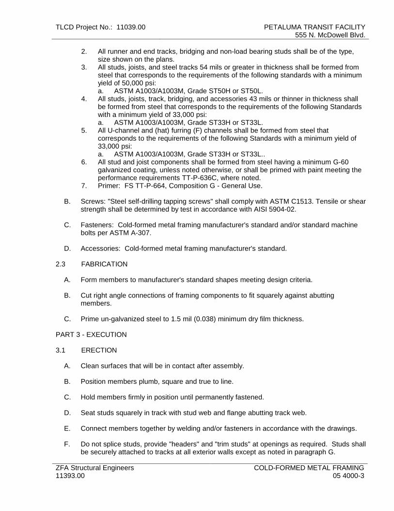
TLCD Project No.: 11039.00 PETALUMA TRANSIT FACILITY 555 N. McDowell Blvd.
ZFA Structural Engineers 11393.00
COLD-FORMED METAL FRAMING 05 4000-3
2. All runner and end tracks, bridging and non-load bearing studs shall be of the type, size shown on the plans.
3. All studs, joists, and steel tracks 54 mils or greater in thickness shall be formed from steel that corresponds to the requirements of the following standards with a minimum yield of 50,000 psi: a. ASTM A1003/A1003M, Grade ST50H or ST50L.
4. All studs, joists, track, bridging, and accessories 43 mils or thinner in thickness shall be formed from steel that corresponds to the requirements of the following Standards with a minimum yield of 33,000 psi: a. ASTM A1003/A1003M, Grade ST33H or ST33L.
5. All U-channel and (hat) furring (F) channels shall be formed from steel that corresponds to the requirements of the following Standards with a minimum yield of 33,000 psi: a. ASTM A1003/A1003M, Grade ST33H or ST33L..
6. All stud and joist components shall be formed from steel having a minimum G-60 galvanized coating, unless noted otherwise, or shall be primed with paint meeting the performance requirements TT-P-636C, where noted.
7. Primer: FS TT-P-664, Composition G - General Use.
B. Screws: "Steel self-drilling tapping screws" shall comply with ASTM C1513. Tensile or shear strength shall be determined by test in accordance with AISI 5904-02.
C. Fasteners: Cold-formed metal framing manufacturer's standard and/or standard machine bolts per ASTM A-307.
D. Accessories: Cold-formed metal framing manufacturer's standard.
2.3 FABRICATION
A. Form members to manufacturer's standard shapes meeting design criteria.
B. Cut right angle connections of framing components to fit squarely against abutting members.
C. Prime un-galvanized steel to 1.5 mil (0.038) minimum dry film thickness.
PART 3 - EXECUTION
3.1 ERECTION
A. Clean surfaces that will be in contact after assembly.
B. Position members plumb, square and true to line.
C. Hold members firmly in position until permanently fastened.
D. Seat studs squarely in track with stud web and flange abutting track web.
E. Connect members together by welding and/or fasteners in accordance with the drawings.
F. Do not splice studs, provide "headers" and "trim studs" at openings as required. Studs shall be securely attached to tracks at all exterior walls except as noted in paragraph G.

PETALUMA TRANSIT FACILITY 555 N. McDowell Blvd.
TLCD Project No.: 11039.00
COLD-FORMED METAL FRAMING 05 4000-4
ZFA Structural Engineers 11393.00
G. Provide for expansion and contraction between floors at solid wall sections of two stories or more by providing a slip joint between stud and track at one end. This connection shall be capable of transmitting lateral loads to the structure.
H. Tracks, studs, etc. shall be securely attached to the structure in order to properly transmit all imposed loads.
I. Provide and install bridging, fire blocking, etc. per manufacturer's recommendations, the plans and code requirements.
J. Perform welding in accordance with AWS D1.3.
K. Remove erection bolts and screws used in welded construction.
L. Do not use gas cutting for field correction of fabrication without concurrence of Architect/Engineer.
M. Touch-up field connections and breaks in shop coating with same primer used for shop priming.
3.2 DEFECTIVE WORK AND MATERIALS
A. Work found to be defective, missing or damaged shall be immediately replaced with proper work. Such replaced work and the inspection for same shall be at the expense of the Contractor.
B. Straightening of any materials, if necessary, shall be done by a process and in a manner that will not injure the materials, and which is approved by the Architect. Sharp kinks or bends shall be cause for rejection. Heating will not be allowed.
C. If defects or damaged work cannot be corrected in the field, the material shall be returned to the shop or new parts furnished, as the Architect directs; the Contractor shall replace all work at his own expense.
3.3 CLEANING
A. After erection, all surfaces shall be cleaned and left free of all grime and dirt. Remove unused materials, tools, equipment and debris from the premises and leave broom clean.
END OF SECTION 05 4000

TLCD Project No.: 11039.00 PETALUMA TRANSIT FACILITYCity Of Petaluma Department Of Public Works & Utilities
Petaluma, CA
TLCD Architecture METAL FABRICATIONS05 5000 - 1
SECTION 05 5000 - METAL FABRICATIONS
PART 1 - GENERAL
1.1 RELATED DOCUMENTS
A. Drawings and general provisions of the Contract, including General and Supplementary Conditions and Division 01 Specification Sections, apply to this Section.
1.2 SUMMARY
A. Section Includes: 1. Steel framing and supports for mechanical and electrical equipment. 2. Steel framing and supports for applications where framing and supports are not
specified in other Sections. 3. Metal bollards. 4. Loose bearing and leveling plates for applications where they are not specified in
other Sections.
B. Products furnished, but not installed, under this Section: 1. Anchor bolts, steel pipe sleeves, slotted-channel inserts, and wedge-type inserts
indicated to be cast into concrete or built into unit masonry. 2. Steel weld plates and angles for casting into concrete for applications where they
are not specified in other Sections.
C. Related Sections: 1. Section 09 9100 "Painting" and Section 09 9600 "High-Performance Coatings" for
surface-preparation and priming requirements.
1.3 PERFORMANCE REQUIREMENTS
A. Thermal Movements: Allow for thermal movements from ambient and surface temperature changes acting on exterior metal fabrications by preventing buckling, opening of joints, overstressing of components, failure of connections, and other detrimental effects. 1. Temperature Change: 120 deg F, ambient; 180 deg F, material surfaces.
1.4 ACTION SUBMITTALS
A. Product Data: For the following: 1. Paint products. 2. Grout.
B. Shop Drawings: Show fabrication and installation details for metal fabrications.

PETALUMA TRANSIT FACILITY City Of Petaluma Department Of Public Works & Utilities Petaluma, CA
TLCD Project No.: 11039.00
METAL FABRICATIONS 05 5000 - 2
TLCD Architecture
1. Include plans, elevations, sections, and details of metal fabrications and their connections. Show anchorage and accessory items.
C. Samples for Verification: For each type and finish of extruded nosing.
1.5 INFORMATIONAL SUBMITTALS
A. Welding certificates.
B. Paint Compatibility Certificates: From manufacturers of topcoats applied over shop primers certifying that shop primers are compatible with topcoats.
1.6 QUALITY ASSURANCE
A. Welding Qualifications: Qualify procedures and personnel according to AWS D1.1/D1.1M, "Structural Welding Code - Steel."
1.7 PROJECT CONDITIONS
A. Field Measurements: Verify actual locations of walls and other construction contiguous with metal fabrications by field measurements before fabrication.
1.8 COORDINATION
A. Coordinate selection of shop primers with topcoats to be applied over them. Comply with paint and coating manufacturers' written recommendations to ensure that shop primers and topcoats are compatible with one another.
B. Coordinate installation of anchorages. Furnish setting drawings, templates, and directions for installing anchorages, including sleeves, concrete inserts, anchor bolts, and items with integral anchors, that are to be embedded in concrete or masonry. Deliver such items to Project site in time for installation.
PART 2 - PRODUCTS
2.1 METALS, GENERAL
A. Metal Surfaces, General: Provide materials with smooth, flat surfaces unless otherwise indicated. For metal fabrications exposed to view in the completed Work, provide materials without seam marks, roller marks, rolled trade names, or blemishes.
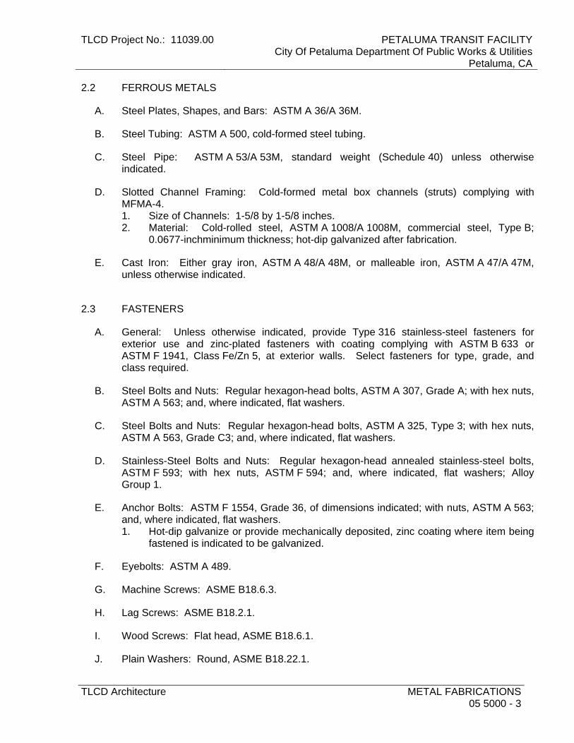
TLCD Project No.: 11039.00 PETALUMA TRANSIT FACILITYCity Of Petaluma Department Of Public Works & Utilities
Petaluma, CA
TLCD Architecture METAL FABRICATIONS05 5000 - 3
2.2 FERROUS METALS
A. Steel Plates, Shapes, and Bars: ASTM A 36/A 36M.
B. Steel Tubing: ASTM A 500, cold-formed steel tubing.
C. Steel Pipe: ASTM A 53/A 53M, standard weight (Schedule 40) unless otherwise indicated.
D. Slotted Channel Framing: Cold-formed metal box channels (struts) complying with MFMA-4. 1. Size of Channels: 1-5/8 by 1-5/8 inches. 2. Material: Cold-rolled steel, ASTM A 1008/A 1008M, commercial steel, Type B;
0.0677-inchminimum thickness; hot-dip galvanized after fabrication.
E. Cast Iron: Either gray iron, ASTM A 48/A 48M, or malleable iron, ASTM A 47/A 47M, unless otherwise indicated.
2.3 FASTENERS
A. General: Unless otherwise indicated, provide Type 316 stainless-steel fasteners for exterior use and zinc-plated fasteners with coating complying with ASTM B 633 or ASTM F 1941, Class Fe/Zn 5, at exterior walls. Select fasteners for type, grade, and class required.
B. Steel Bolts and Nuts: Regular hexagon-head bolts, ASTM A 307, Grade A; with hex nuts, ASTM A 563; and, where indicated, flat washers.
C. Steel Bolts and Nuts: Regular hexagon-head bolts, ASTM A 325, Type 3; with hex nuts, ASTM A 563, Grade C3; and, where indicated, flat washers.
D. Stainless-Steel Bolts and Nuts: Regular hexagon-head annealed stainless-steel bolts, ASTM F 593; with hex nuts, ASTM F 594; and, where indicated, flat washers; Alloy Group 1.
E. Anchor Bolts: ASTM F 1554, Grade 36, of dimensions indicated; with nuts, ASTM A 563; and, where indicated, flat washers. 1. Hot-dip galvanize or provide mechanically deposited, zinc coating where item being
fastened is indicated to be galvanized.
F. Eyebolts: ASTM A 489.
G. Machine Screws: ASME B18.6.3.
H. Lag Screws: ASME B18.2.1.
I. Wood Screws: Flat head, ASME B18.6.1.
J. Plain Washers: Round, ASME B18.22.1.
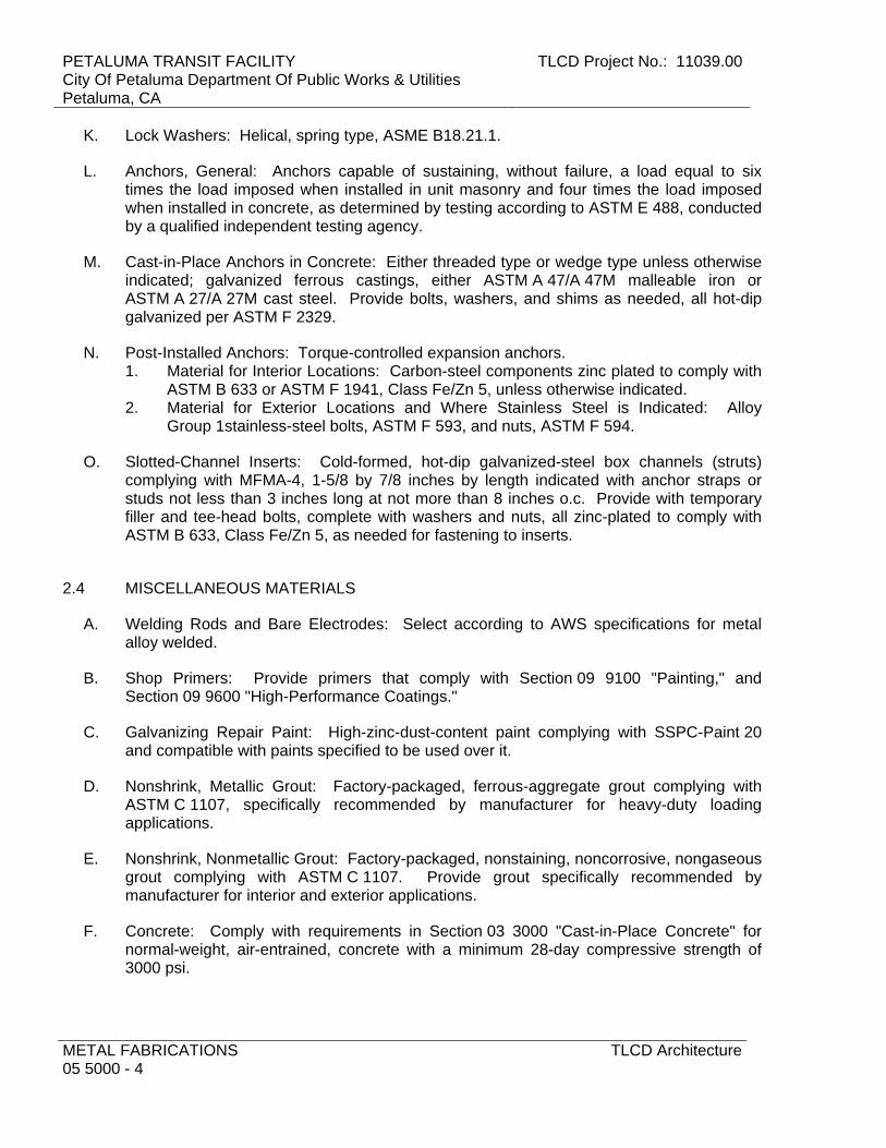
PETALUMA TRANSIT FACILITY City Of Petaluma Department Of Public Works & Utilities Petaluma, CA
TLCD Project No.: 11039.00
METAL FABRICATIONS 05 5000 - 4
TLCD Architecture
K. Lock Washers: Helical, spring type, ASME B18.21.1.
L. Anchors, General: Anchors capable of sustaining, without failure, a load equal to six times the load imposed when installed in unit masonry and four times the load imposed when installed in concrete, as determined by testing according to ASTM E 488, conducted by a qualified independent testing agency.
M. Cast-in-Place Anchors in Concrete: Either threaded type or wedge type unless otherwise indicated; galvanized ferrous castings, either ASTM A 47/A 47M malleable iron or ASTM A 27/A 27M cast steel. Provide bolts, washers, and shims as needed, all hot-dip galvanized per ASTM F 2329.
N. Post-Installed Anchors: Torque-controlled expansion anchors. 1. Material for Interior Locations: Carbon-steel components zinc plated to comply with
ASTM B 633 or ASTM F 1941, Class Fe/Zn 5, unless otherwise indicated. 2. Material for Exterior Locations and Where Stainless Steel is Indicated: Alloy
Group 1stainless-steel bolts, ASTM F 593, and nuts, ASTM F 594.
O. Slotted-Channel Inserts: Cold-formed, hot-dip galvanized-steel box channels (struts) complying with MFMA-4, 1-5/8 by 7/8 inches by length indicated with anchor straps or studs not less than 3 inches long at not more than 8 inches o.c. Provide with temporary filler and tee-head bolts, complete with washers and nuts, all zinc-plated to comply with ASTM B 633, Class Fe/Zn 5, as needed for fastening to inserts.
2.4 MISCELLANEOUS MATERIALS
A. Welding Rods and Bare Electrodes: Select according to AWS specifications for metal alloy welded.
B. Shop Primers: Provide primers that comply with Section 09 9100 "Painting," and Section 09 9600 "High-Performance Coatings."
C. Galvanizing Repair Paint: High-zinc-dust-content paint complying with SSPC-Paint 20 and compatible with paints specified to be used over it.
D. Nonshrink, Metallic Grout: Factory-packaged, ferrous-aggregate grout complying with ASTM C 1107, specifically recommended by manufacturer for heavy-duty loading applications.
E. Nonshrink, Nonmetallic Grout: Factory-packaged, nonstaining, noncorrosive, nongaseous grout complying with ASTM C 1107. Provide grout specifically recommended by manufacturer for interior and exterior applications.
F. Concrete: Comply with requirements in Section 03 3000 "Cast-in-Place Concrete" for normal-weight, air-entrained, concrete with a minimum 28-day compressive strength of 3000 psi.

TLCD Project No.: 11039.00 PETALUMA TRANSIT FACILITYCity Of Petaluma Department Of Public Works & Utilities
Petaluma, CA
TLCD Architecture METAL FABRICATIONS05 5000 - 5
2.5 FABRICATION, GENERAL
A. Shop Assembly: Preassemble items in the shop to greatest extent possible. Disassemble units only as necessary for shipping and handling limitations. Use connections that maintain structural value of joined pieces. Clearly mark units for reassembly and coordinated installation.
B. Cut, drill, and punch metals cleanly and accurately. Remove burrs and ease edges to a radius of approximately 1/32 inch unless otherwise indicated. Remove sharp or rough areas on exposed surfaces.
C. Form bent-metal corners to smallest radius possible without causing grain separation or otherwise impairing work.
D. Form exposed work with accurate angles and surfaces and straight edges.
E. Weld corners and seams continuously to comply with the following: 1. Use materials and methods that minimize distortion and develop strength and
corrosion resistance of base metals. 2. Obtain fusion without undercut or overlap. 3. Remove welding flux immediately. 4. At exposed connections, finish exposed welds and surfaces smooth and blended so
no roughness shows after finishing and contour of welded surface matches that of adjacent surface.
F. Form exposed connections with hairline joints, flush and smooth, using concealed fasteners or welds where possible. Where exposed fasteners are required, use Phillips flat-head (countersunk) fasteners unless otherwise indicated. Locate joints where least conspicuous.
G. Fabricate seams and other connections that will be exposed to weather in a manner to exclude water. Provide weep holes where water may accumulate.
H. Cut, reinforce, drill, and tap metal fabrications as indicated to receive finish hardware, screws, and similar items.
I. Provide for anchorage of type indicated; coordinate with supporting structure. Space anchoring devices to secure metal fabrications rigidly in place and to support indicated loads. 1. Where units are indicated to be cast into concrete or built into masonry, equip with
integrally welded steel strap anchors, 1/8 by 1-1/2 inches, with a minimum 6-inch embedment and 2-inch hook, not less than 8 inches from ends and corners of units and 24 inches o.c., unless otherwise indicated.
2.6 MISCELLANEOUS FRAMING AND SUPPORTS
A. General: Provide steel framing and supports not specified in other Sections as needed to complete the Work.

PETALUMA TRANSIT FACILITY City Of Petaluma Department Of Public Works & Utilities Petaluma, CA
TLCD Project No.: 11039.00
METAL FABRICATIONS 05 5000 - 6
TLCD Architecture
B. Fabricate units from steel shapes, plates, and bars of welded construction unless otherwise indicated. Fabricate to sizes, shapes, and profiles indicated and as necessary to receive adjacent construction. 1. Fabricate units from slotted channel framing where indicated. 2. Furnish inserts for units installed after concrete is placed.
C. Fabricate supports for operable partitions from continuous steel beams of sizes indicated with attached bearing plates, anchors, and braces as indicated. Drill or punch bottom flanges of beams to receive partition track hanger rods; locate holes where indicated on operable partition Shop Drawings.
D. Galvanize miscellaneous framing and supports where indicated.
E. Prime miscellaneous framing and supports with zinc-rich primer where indicated.
2.7 METAL BOLLARDS
A. Fabricate metal bollards from Schedule 40 steel pipe. 1. Cap bollards with 1/4-inch- thick steel plate.
B. Fabricate sleeves for bollard anchorage from steel pipe or tubing with 1/4-inch- thick steel plate welded to bottom of sleeve. Make sleeves not less than 8 inches deep and 3/4 inch larger than OD of bollard.
C. Prime bollards with zinc-rich primer.
2.8 FINISHES, GENERAL
A. Comply with NAAMM's "Metal Finishes Manual for Architectural and Metal Products" for recommendations for applying and designating finishes.
B. Finish metal fabrications after assembly.
C. Finish exposed surfaces to remove tool and die marks and stretch lines, and to blend into surrounding surface.
2.9 STEEL AND IRON FINISHES
A. Galvanizing: Hot-dip galvanize items as indicated to comply with ASTM A 153/A 153M for steel and iron hardware and with ASTM A 123/A 123M for other steel and iron products. 1. Do not quench or apply post galvanizing treatments that might interfere with paint
adhesion.
B. Shop prime iron and steel items not indicated to be galvanized unless they are to be embedded in concrete, sprayed-on fireproofing, or masonry, or unless otherwise indicated. 1. Shop prime with universal shop primer unless zinc-rich primer is indicated.

TLCD Project No.: 11039.00 PETALUMA TRANSIT FACILITYCity Of Petaluma Department Of Public Works & Utilities
Petaluma, CA
TLCD Architecture METAL FABRICATIONS05 5000 - 7
C. Preparation for Shop Priming: Prepare surfaces to comply with requirements indicated below: 1. Exterior Items: SSPC-SP 6/NACE No. 3, "Commercial Blast Cleaning." 2. Items Indicated to Receive Zinc-Rich Primer: SSPC-SP 6/NACE No. 3,
"Commercial Blast Cleaning." 3. Other Items: SSPC-SP 3, "Power Tool Cleaning."
D. Shop Priming: Apply shop primer to comply with SSPC-PA 1, "Paint Application Specification No. 1: Shop, Field, and Maintenance Painting of Steel," for shop painting. 1. Stripe paint corners, crevices, bolts, welds, and sharp edges.
PART 3 - EXECUTION
3.1 INSTALLATION, GENERAL
A. Cutting, Fitting, and Placement: Perform cutting, drilling, and fitting required for installing metal fabrications. Set metal fabrications accurately in location, alignment, and elevation; with edges and surfaces level, plumb, true, and free of rack; and measured from established lines and levels.
B. Fit exposed connections accurately together to form hairline joints. Weld connections that are not to be left as exposed joints but cannot be shop welded because of shipping size limitations. Do not weld, cut, or abrade surfaces of exterior units that have been hot-dip galvanized after fabrication and are for bolted or screwed field connections.
C. Field Welding: Comply with the following requirements: 1. Use materials and methods that minimize distortion and develop strength and
corrosion resistance of base metals. 2. Obtain fusion without undercut or overlap. 3. Remove welding flux immediately. 4. At exposed connections, finish exposed welds and surfaces smooth and blended so
no roughness shows after finishing and contour of welded surface matches that of adjacent surface.
D. Provide temporary bracing or anchors in formwork for items that are to be built into concrete, masonry, or similar construction.
3.2 INSTALLING MISCELLANEOUS FRAMING AND SUPPORTS
A. General: Install framing and supports to comply with requirements of items being supported, including manufacturers' written instructions and requirements indicated on Shop Drawings.
B. Anchor supports for operable partitions securely to and rigidly brace from building structure.

PETALUMA TRANSIT FACILITY City Of Petaluma Department Of Public Works & Utilities Petaluma, CA
TLCD Project No.: 11039.00
METAL FABRICATIONS 05 5000 - 8
TLCD Architecture
3.3 INSTALLING METAL BOLLARDS
A. Fill metal-capped bollards solidly with concrete and allow concrete to cure seven days before installing. 1. Do not fill removable bollards with concrete.
B. Anchor bollards in place with concrete footings. Center and align bollards in holes 3 inches above bottom of excavation. Place concrete and vibrate or tamp for consolidation. Support and brace bollards in position until concrete has cured.
C. Anchor internal sleeves for removable bollards in place with concrete footings. Center and align sleeves in holes 3 inches above bottom of excavation. Place concrete and vibrate or tamp for consolidation. Support and brace sleeves in position until concrete has cured.
D. Fill bollards solidly with concrete, mounding top surface to shed water. 1. Do not fill removable bollards with concrete.
3.4 ADJUSTING AND CLEANING
A. Touchup Painting: Immediately after erection, clean field welds, bolted connections, and abraded areas. Paint uncoated and abraded areas with the same material as used for shop painting to comply with SSPC-PA 1 for touching up shop-painted surfaces. 1. Apply by brush or spray to provide a minimum 2.0-mil dry film thickness.
B. Touchup Painting: Cleaning and touchup painting of field welds, bolted connections, and abraded areas of shop paint are specified in Section 09 9100 "Painting."
C. Galvanized Surfaces: Clean field welds, bolted connections, and abraded areas and repair galvanizing to comply with ASTM A 780.
END OF SECTION

TLCD Project No.: 11039.00 PETALUMA TRANSIT FACILITYCity Of Petaluma Department Of Public Works & Utilities
Petaluma, CA
TLCD Architecture MISCELLANEOUS ROUGH CARPENTRY06 1053 - 1
SECTION 06 1053 - MISCELLANEOUS ROUGH CARPENTRY
PART 1 - GENERAL
1.1 RELATED DOCUMENTS
A. Drawings and general provisions of the Contract, including General and Supplementary Conditions and Division 01 Specification Sections, apply to this Section.
1.2 SUMMARY
A. This Section includes the following: 1. Wood blocking and nailers.
1.3 DEFINITIONS
A. Dimension Lumber: Lumber of 2 inches nominal or greater but less than 5 inches nominal in least dimension.
B. Lumber grading agencies, and the abbreviations used to reference them, include the following: 1. NeLMA: Northeastern Lumber Manufacturers' Association. 2. NHLA: National Hardwood Lumber Association. 3. NLGA: National Lumber Grades Authority. 4. SPIB: The Southern Pine Inspection Bureau. 5. WCLIB: West Coast Lumber Inspection Bureau. 6. WWPA: Western Wood Products Association.
1.4 ACTION SUBMITTALS
A. Product Data: For each type of process and factory-fabricated product. Indicate component materials and dimensions and include construction and application details. 1. Include data for wood-preservative treatment from chemical treatment manufacturer
and certification by treating plant that treated materials comply with requirements. Indicate type of preservative used and net amount of preservative retained.
2. For products receiving a waterborne treatment, include statement that moisture content of treated materials was reduced to levels specified before shipment to Project site.
3. Include copies of warranties from chemical treatment manufacturers for each type of treatment.
1.5 INFORMATIONAL SUBMITTALS
A. Evaluation Reports: For the following, from ICC-ES:
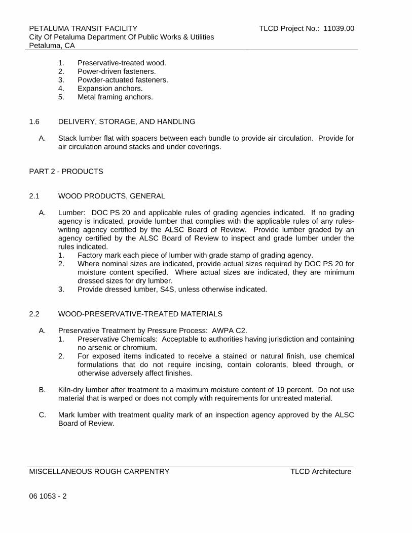
PETALUMA TRANSIT FACILITY City Of Petaluma Department Of Public Works & Utilities Petaluma, CA
TLCD Project No.: 11039.00
MISCELLANEOUS ROUGH CARPENTRY
06 1053 - 2
TLCD Architecture
1. Preservative-treated wood. 2. Power-driven fasteners. 3. Powder-actuated fasteners. 4. Expansion anchors. 5. Metal framing anchors.
1.6 DELIVERY, STORAGE, AND HANDLING
A. Stack lumber flat with spacers between each bundle to provide air circulation. Provide for air circulation around stacks and under coverings.
PART 2 - PRODUCTS
2.1 WOOD PRODUCTS, GENERAL
A. Lumber: DOC PS 20 and applicable rules of grading agencies indicated. If no grading agency is indicated, provide lumber that complies with the applicable rules of any rules-writing agency certified by the ALSC Board of Review. Provide lumber graded by an agency certified by the ALSC Board of Review to inspect and grade lumber under the rules indicated. 1. Factory mark each piece of lumber with grade stamp of grading agency. 2. Where nominal sizes are indicated, provide actual sizes required by DOC PS 20 for
moisture content specified. Where actual sizes are indicated, they are minimum dressed sizes for dry lumber.
3. Provide dressed lumber, S4S, unless otherwise indicated.
2.2 WOOD-PRESERVATIVE-TREATED MATERIALS
A. Preservative Treatment by Pressure Process: AWPA C2. 1. Preservative Chemicals: Acceptable to authorities having jurisdiction and containing
no arsenic or chromium. 2. For exposed items indicated to receive a stained or natural finish, use chemical
formulations that do not require incising, contain colorants, bleed through, or otherwise adversely affect finishes.
B. Kiln-dry lumber after treatment to a maximum moisture content of 19 percent. Do not use material that is warped or does not comply with requirements for untreated material.
C. Mark lumber with treatment quality mark of an inspection agency approved by the ALSC Board of Review.

TLCD Project No.: 11039.00 PETALUMA TRANSIT FACILITYCity Of Petaluma Department Of Public Works & Utilities
Petaluma, CA
TLCD Architecture MISCELLANEOUS ROUGH CARPENTRY06 1053 - 3
D. Application: Treat items indicated on Drawings, and the following: 1. Wood nailers, curbs, equipment support bases, blocking, stripping, and similar
members in connection with roofing, flashing, vapor barriers, and waterproofing. 2. Wood sills, sleepers, blocking, stripping, and similar concealed members in contact
with concrete. 3. Wood framing members that are less than 18 inches above the ground in crawl
spaces or unexcavated areas. 4. Wood floor plates that are installed over concrete slabs-on-grade.
2.3 MISCELLANEOUS LUMBER
A. General: Provide miscellaneous lumber indicated and lumber for support or attachment of other construction, including the following: 1. Blocking. 2. Nailers. 3. Grounds.
B. For items of dimension lumber size, provide Standard, Stud, or No. 3 grade lumber with 19 percent maximum moisture content of any species.
C. For blocking not used for attachment of other construction Utility, Stud, or No. 3 grade lumber of any species may be used provided that it is cut and selected to eliminate defects that will interfere with its attachment and purpose.
D. For blocking and nailers used for attachment of other construction, select and cut lumber to eliminate knots and other defects that will interfere with attachment of other work.
2.4 FASTENERS
A. General: Provide fasteners of size and type indicated that comply with requirements specified in this Article for material and manufacture. 1. Where carpentry is exposed to weather, in ground contact, pressure-preservative
treated, or in area of high relative humidity, provide fasteners with hot-dip zinc coating complying with ASTM A 153/A 153M.
B. Nails, Brads, and Staples: ASTM F 1667.
C. Power-Driven Fasteners: NES NER-272.
D. Wood Screws: ASME B18.6.1.
E. Screws for Fastening to Cold-Formed Metal Framing: ASTM C 954, except with wafer heads and reamer wings, length as recommended by screw manufacturer for material being fastened.
F. Lag Bolts: ASME B18.2.1.
G. Bolts: Steel bolts complying with ASTM A 307, Grade A; with ASTM A 563 hex nuts and, where indicated, flat washers.

PETALUMA TRANSIT FACILITY City Of Petaluma Department Of Public Works & Utilities Petaluma, CA
TLCD Project No.: 11039.00
MISCELLANEOUS ROUGH CARPENTRY
06 1053 - 4
TLCD Architecture
H. Expansion Anchors: Anchor bolt and sleeve assembly of material indicated below with capability to sustain, without failure, a load equal to 6 times the load imposed when installed in unit masonry assemblies and equal to 4 times the load imposed when installed in concrete as determined by testing per ASTM E 488 conducted by a qualified independent testing and inspecting agency. 1. Material: Carbon-steel components, zinc plated to comply with ASTM B 633,
Class Fe/Zn 5. 2. Material: Stainless steel with bolts and nuts complying with ASTM F 593 and
ASTM F 594, Alloy Group 1 or 2.
2.5 METAL FRAMING ANCHORS
A. Available Manufacturers: Subject to compliance with requirements, manufacturers offering products that may be incorporated into the Work include, but are not limited to, the following: 1. Cleveland Steel Specialty Co. 2. KC Metals Products, Inc. 3. Phoaenix Metal Products, Inc. 4. Simpson Strong-Tie Co., Inc. 5. USP Structural Connectors. 6. Approved equal.
B. Galvanized Steel Sheet: Hot-dip, zinc-coated steel sheet complying with ASTM A 653/A 653M, G60 coating designation.
C. Hot-Dip Heavy-Galvanized Steel Sheet: ASTM A 653/A 653M; Structural Steel (SS), high-strength low-alloy steel Type A (HSLAS Type A), or high-strength low-alloy steel Type B (HSLAS Type B); G185 coating designation; and not less than 0.036 inch thick. 1. Use for wood-preservative-treated lumber and where indicated.
2.6 MISCELLANEOUS MATERIALS
A. Flexible Flashing: Self-adhesive, rubberized-asphalt compound, bonded to a high-density, polyethylene film to produce an overall thickness of not less than 0.025 inch.
PART 3 - EXECUTION
3.1 INSTALLATION, GENERAL
A. Set carpentry to required levels and lines, with members plumb, true to line, cut, and fitted. Fit carpentry to other construction; scribe and cope as needed for accurate fit. Locate nailers, blocking, grounds, and similar supports to comply with requirements for attaching other construction.
TLCD Project No.: 11039.00 PETALUMA TRANSIT FACILITYCity Of Petaluma Department Of Public Works & Utilities
Petaluma, CA
TLCD Architecture MISCELLANEOUS ROUGH CARPENTRY06 1053 - 5
B. Where wood-preservative-treated lumber is installed adjacent to metal decking, install continuous flexible flashing separator between wood and metal decking.
C. Framing Standard: Comply with AF&PA's "Details for Conventional Wood Frame Construction," unless otherwise indicated.
D. Metal Framing Anchors: Install metal framing to comply with manufacturer's written instructions.
E. Provide blocking and framing as indicated and as required to support facing materials, fixtures, specialty items, and trim.
F. Sort and select lumber so that natural characteristics will not interfere with installation or with fastening other materials to lumber. Do not use materials with defects that interfere with function of member or pieces that are too small to use with minimum number of joints or optimum joint arrangement.
G. Comply with AWPA M4 for applying field treatment to cut surfaces of preservative-treated lumber. 1. Use copper naphthenate for items not continuously protected from liquid water.
H. Securely attach carpentry work to substrate by anchoring and fastening as indicated, complying with the following: 1. NES NER-272 for power-driven fasteners. 2. Table 2304.9.1, "Fastening Schedule," in California Building Code.
I. Use common wire nails, unless otherwise indicated. Select fasteners of size that will not fully penetrate members where opposite side will be exposed to view or will receive finish materials. Make tight connections between members. Install fasteners without splitting wood; do not countersink nail heads, unless otherwise indicated.
3.2 WOOD GROUND, BLOCKING, AND NAILER INSTALLATION
A. Install where indicated and where required for screeding or attaching other work. Form to shapes indicated and cut as required for true line and level of attached work. Coordinate locations with other work involved.
B. Attach items to substrates to support applied loading. Recess bolts and nuts flush with surfaces, unless otherwise indicated.
C. Provide permanent grounds of dressed, pressure-preservative-treated, key-beveled lumber not less than 1-1/2 inches wide and of thickness required to bring face of ground to exact thickness of finish material. Remove temporary grounds when no longer required.
3.3 PROTECTION
A. Protect wood that has been treated with inorganic boron (SBX) from weather. If, despite protection, inorganic boron-treated wood becomes wet, apply EPA-registered borate treatment. Apply borate solution by spraying to comply with EPA-registered label.
PETALUMA TRANSIT FACILITY City Of Petaluma Department Of Public Works & Utilities Petaluma, CA
TLCD Project No.: 11039.00
MISCELLANEOUS ROUGH CARPENTRY
06 1053 - 6
TLCD Architecture
B. Protect miscellaneous rough carpentry from weather. If, despite protection, rough carpentry becomes wet, apply EPA-registered borate treatment. Apply borate solution by spraying to comply with EPA-registered label.
END OF SECTION

TLCD Project No.: 11039.00 PETALUMA TRANSIT FACILITYCity Of Petaluma Department Of Public Works & Utilities
Petaluma, CA
TLCD Architecture PLASTIC PANELING06 6400 - 1
SECTION 06 6400 - PLASTIC PANELING
PART 1 - GENERAL
1.1 RELATED DOCUMENTS
A. Drawings and general provisions of the Contract, including General and Supplementary Conditions and Division 01 Specification Sections, apply to this Section.
1.2 SUMMARY
A. Section Includes: 1. Plastic sheet paneling.
1.3 ACTION SUBMITTALS
A. Product Data: For each type of product.
B. Samples: For plastic paneling and trim accessories, in manufacturer's standard sizes.
1.4 QUALITY ASSURANCE
A. Testing Agency: Acceptable to authorities having jurisdiction.
PART 2 - PRODUCTS
2.1 MANUFACTURERS
A. Source Limitations: Obtain plastic paneling and trim accessories from single manufacturer.
2.2 PLASTIC SHEET PANELING
A. Glass-Fiber-Reinforced Plastic Paneling: Composite panel comprised of corrugated polypropylene core with a fiberglass reinforced plastic face. 1. Basis-of-Design Product: Subject to compliance with requirements, provide Nudo
Products Inc. “FiberCorr” wall panels or approved equal 2. Surface Burning Characteristics per ASTM E84: Class C. 3. Nominal Thickness: Not less than 0.32 inch. 4. Surface Finish: Pebble texture. 5. Color: White (050).

PETALUMA TRANSIT FACILITY City Of Petaluma Department Of Public Works & Utilities Petaluma, CA
TLCD Project No.: 11039.00
PLASTIC PANELING 06 6400 - 2
TLCD Architecture
B. PVC Paneling: Tongue-and-groove, rib-reinforced PVC wall panels. 1. Manufacturers: Subject to compliance with requirements, available manufacturers
offering products that may be incorporated into the Work include, but are not limited to, the following: a. Extrutech Plastics, Inc. “P2400.” b. DelPro 1238.
2. Surface-Burning Characteristics: As follows when tested by a qualified testing agency according to ASTM E 84. Identify products with appropriate markings of applicable testing agency. a. Flame-Spread Index: 25 or less. b. Smoke-Developed Index: 450 or less.
3. Nominal Thickness: 0.32 inch minimum. 4. Surface Finish: Molded pebble texture. 5. Color: White.
2.3 ACCESSORIES
A. Trim Accessories: Manufacturer's standard vinyl extrusions designed to retain and cover edges of panels. Provide division bars, inside corners, outside corners, and caps as needed to conceal edges. 1. Color: Match panels.
B. Exposed Fasteners: Nylon drive rivets recommended by panel manufacturer.
C. Adhesive: VOC compliant, as recommended by plastic paneling manufacturer .
D. Sealant: Latex sealant recommended by plastic paneling manufacturer and complying with requirements in Section 07 9200 "Joint Sealants."
PART 3 - EXECUTION
3.1 EXAMINATION
A. Examine substrates and conditions, with Installer present, for compliance with requirements for installation tolerances and other conditions affecting performance of the Work.
B. Proceed with installation only after unsatisfactory conditions have been corrected.
3.2 PREPARATION
A. Remove materials that might interfere with adhesive bond.
B. Prepare substrate by sanding high spots and filling low spots as needed to provide flat, even surface for panel installation.

TLCD Project No.: 11039.00 PETALUMA TRANSIT FACILITYCity Of Petaluma Department Of Public Works & Utilities
Petaluma, CA
TLCD Architecture PLASTIC PANELING06 6400 - 3
C. Clean substrates of substances that could impair adhesive bond, including oil, grease, dirt, and dust.
D. Condition panels by unpacking and placing in installation space before installation according to manufacturer's written recommendations.
E. Lay out paneling before installing. Locate panel joints to provide equal panels at ends of walls not less than half the width of full panels. 1. Mark plumb lines on substrate at trim accessory locations for accurate installation. 2. Locate trim accessories to allow clearance at panel edges according to
manufacturer's written instructions.
3.3 INSTALLATION
A. Install plastic paneling according to manufacturer's written instructions.
B. Install panels in a full spread of adhesive.
C. Install panels with fasteners. Layout fastener locations and mark on face of panels so that fasteners are accurately aligned. 1. Drill oversized fastener holes in panels and center fasteners in holes. 2. Apply sealant to fastener holes before installing fasteners.
D. Install trim accessories with adhesive. Do not fasten through panels.
E. Fill grooves in trim accessories with sealant before installing panels, and bed inside corner trim in a bead of sealant.
F. Maintain uniform space between panels and wall fixtures. Fill space with sealant.
G. Maintain uniform space between adjacent panels and between panels and floors, ceilings, and fixtures. Fill space with sealant.
H. Remove excess sealant and smears as paneling is installed. Clean with solvent recommended by sealant manufacturer and then wipe with clean dry cloths until no residue remains.
END OF SECTION
PETALUMA TRANSIT FACILITY City Of Petaluma Department Of Public Works & Utilities Petaluma, CA
TLCD Project No.: 11039.00
PLASTIC PANELING 06 6400 - 4
TLCD Architecture
THIS PAGE INTENTIONALLY LEFT BLANK

TLCD Project No.: 11039.00 PETALUMA TRANSIT FACILITYCity Of Petaluma Department Of Public Works & Utilities
Petaluma, CA
TLCD Architecture THERMOPLASTIC POLYOLEFIN (TPO) ROOFING07 5423 - 1
SECTION 07 5423 - THERMOPLASTIC POLYOLEFIN (TPO) ROOFING
PART 1 - GENERAL
1.1 RELATED DOCUMENTS
A. Drawings and general provisions of the Contract, including General and Supplementary Conditions and Division 01 Specification Sections, apply to this Section.
1.2 SUMMARY
A. Section Includes: 1. Removal and disposal of existing low-slope roof system down to deck 2. Adhered TPO membrane roofing system. 3. Air barrier. 4. Roof insulation.
B. Related Sections: 1. Section 06 1053 "Miscellaneous Rough Carpentry" for wood nailers, curbs, and
blocking. 2. Section 07 6200 "Sheet Metal Flashing and Trim" for metal roof penetration
flashings, flashings, and counterflashings. 3. Section 07 9200 "Joint Sealants" for joint sealants, joint fillers, and joint preparation.
1.3 DEFINITIONS
A. TPO: Thermoplastic polyolefin.
B. Roofing Terminology: See ASTM D 1079 and glossary in NRCA's "The NRCA Roofing and Waterproofing Manual" for definitions of terms related to roofing work in this Section.
1.4 PERFORMANCE REQUIREMENTS
A. General Performance: Installed membrane roofing and base flashings shall withstand specified uplift pressures, thermally induced movement, and exposure to weather without failure due to defective manufacture, fabrication, installation, or other defects in construction. Membrane roofing and base flashings shall remain watertight.
B. Material Compatibility: Provide roofing materials that are compatible with one another under conditions of service and application required, as demonstrated by membrane roofing manufacturer based on testing and field experience.
C. Roofing System Design: Provide membrane roofing system that is identical to systems that have been successfully tested by a qualified testing and inspecting agency to resist uplift pressure calculated according to ASCE/SEI 7.
PETALUMA TRANSIT FACILITY City Of Petaluma Department Of Public Works & Utilities Petaluma, CA
TLCD Project No.: 11039.00
THERMOPLASTIC POLYOLEFIN (TPO) ROOFING 07 5423 - 2
TLCD Architecture
D. Energy Performance: Provide roofing system with initial solar reflectance not less than 0.70 and emissivity not less than 0.75 when tested according to CRRC-1.
1.5 ACTION SUBMITTALS
A. Product Data: For each type of product indicated.
B. Shop Drawings: For roofing system. Include plans, elevations, sections, details, and attachments to other work. 1. Base flashings and membrane terminations. 2. Tapered insulation, including slopes. 3. Roof plan showing orientation of steel roof deck and orientation of membrane
roofing and fastening spacings and patterns for mechanically fastened membrane roofing.
4. Insulation fastening patterns for corner, perimeter, and field-of-roof locations.
C. Samples for Verification: For the following products: 1. Sheet roofing, of color specified, including T-shaped side and end lap seam. 2. Roof insulation. 3. Walkway pads or rolls. 4. Metal termination bars. 5. Six insulation fasteners of each type, length, and finish.
1.6 INFORMATIONAL SUBMITTALS
A. Qualification Data: For qualified Installer and manufacturer.
B. Manufacturer Certificates: Signed by roofing manufacturer certifying that roofing system complies with requirements specified in "Performance Requirements" Article. 1. Submit evidence of compliance with performance requirements.
C. Product Test Reports: Based on evaluation of comprehensive tests performed by manufacturer and witnessed by a qualified testing agency, for components of membrane roofing system.
D. Research/Evaluation Reports: For components of membrane roofing system, from the ICC-ES.
E. Field quality-control reports.
F. Warranties: Sample of special warranties.
1.7 CLOSEOUT SUBMITTALS
A. Maintenance Data: For roofing system to include in maintenance manuals.

TLCD Project No.: 11039.00 PETALUMA TRANSIT FACILITYCity Of Petaluma Department Of Public Works & Utilities
Petaluma, CA
TLCD Architecture THERMOPLASTIC POLYOLEFIN (TPO) ROOFING07 5423 - 3
1.8 QUALITY ASSURANCE
A. Manufacturer Qualifications: A qualified manufacturer that is UL listed for membrane roofing system identical to that used for this Project.
B. Installer Qualifications: A qualified firm that is approved, authorized, or licensed by membrane roofing system manufacturer to install manufacturer's product and that is eligible to receive manufacturer's special warranty.
C. Source Limitations: Obtain components including roof insulation and fasteners for membrane roofing system from same manufacturer as membrane roofing or approved by membrane roofing manufacturer.
D. Exterior Fire-Test Exposure: ASTM E 108, Class A; for application and roof slopes indicated, as determined by testing identical membrane roofing materials by a qualified testing agency. Materials shall be identified with appropriate markings of applicable testing agency.
E. Fire-Resistance Ratings: Where indicated, provide fire-resistance-rated roof assemblies identical to those of assemblies tested for fire resistance per ASTM E 119 by a qualified testing agency. Identify products with appropriate markings of applicable testing agency.
F. Preinstallation Roofing Conference: Conduct conference at Project site. 1. Meet with Owner, Architect, Owner's insurer if applicable, testing and inspecting
agency representative, roofing Installer, roofing system manufacturer's representative, and installers whose work interfaces with or affects roofing, including installers of roof accessories and roof-mounted equipment.
2. Review methods and procedures related to roofing installation, including manufacturer's written instructions.
3. Review and finalize construction schedule and verify availability of materials, Installer's personnel, equipment, and facilities needed to make progress and avoid delays.
4. Examine substrate conditions and finishes for compliance with requirements, including flatness and fastening.
5. Review structural loading limitations of roof deck during and after roofing. 6. Review base flashings, special roofing details, roof drainage, roof penetrations,
equipment curbs, and condition of other construction that will affect roofing system. 7. Review governing regulations and requirements for insurance and certificates if
applicable. 8. Review temporary protection requirements for roofing system during and after
installation. 9. Review roof observation and repair procedures after roofing installation.
1.9 DELIVERY, STORAGE, AND HANDLING
A. Deliver roofing materials to Project site in original containers with seals unbroken and labeled with manufacturer's name, product brand name and type, date of manufacture, approval or listing agency markings, and directions for storing and mixing with other components.
PETALUMA TRANSIT FACILITY City Of Petaluma Department Of Public Works & Utilities Petaluma, CA
TLCD Project No.: 11039.00
THERMOPLASTIC POLYOLEFIN (TPO) ROOFING 07 5423 - 4
TLCD Architecture
B. Store liquid materials in their original undamaged containers in a clean, dry, protected location and within the temperature range required by roofing system manufacturer. Protect stored liquid material from direct sunlight. 1. Discard and legally dispose of liquid material that cannot be applied within its stated
shelf life.
C. Protect roof insulation materials from physical damage and from deterioration by sunlight, moisture, soiling, and other sources. Store in a dry location. Comply with insulation manufacturer's written instructions for handling, storing, and protecting during installation.
D. Handle and store roofing materials and place equipment in a manner to avoid permanent deflection of deck.
1.10 PROJECT CONDITIONS
A. Weather Limitations: Proceed with installation only when existing and forecasted weather conditions permit roofing system to be installed according to manufacturer's written instructions and warranty requirements.
1.11 WARRANTY
A. Special Warranty: Manufacturer's standard or customized form, without monetary limitation, in which manufacturer agrees to repair or replace components of membrane roofing system that fail in materials or workmanship within specified warranty period. 1. Special warranty includes membrane roofing, base flashings, roof insulation,
fasteners, cover boards, substrate board, roofing accessories, and other components of membrane roofing system.
2. Warranty Period: 15 years from date of Final Completion.
B. Special Project Warranty: Submit roofing Installer's warranty, on warranty form at end of this Section, signed by Installer, covering the Work of this Section, including all components of membrane roofing system such as membrane roofing, base flashing, roof insulation, fasteners, cover boards, substrate boards, air barriers, roof pavers, and walkway products, for the following warranty period: 1. Warranty Period: Two years from date of Final Completion.
PART 2 - PRODUCTS
2.1 TPO MEMBRANE ROOFING
A. Fabric-Reinforced Thermoplastic Polyolefin Sheet: ASTM D 6878, internally fabric or scrim reinforced, uniform, flexible TPO sheet. 1. Manufacturers: Subject to compliance with requirements, available manufacturers
offering products that may be incorporated into the Work include, but are not limited to, the following: a. Carlisle SynTec Incorporated.

TLCD Project No.: 11039.00 PETALUMA TRANSIT FACILITYCity Of Petaluma Department Of Public Works & Utilities
Petaluma, CA
TLCD Architecture THERMOPLASTIC POLYOLEFIN (TPO) ROOFING07 5423 - 5
b. Custom Seal Roofing. c. Firestone Building Products Company. d. GAF Materials Corporation. e. GenFlex Roofing Systems. f. Johns Manville. g. Mule-Hide Products Co., Inc. h. Versico Incorporated. i. Approved equal.
2. Thickness: 60 mils, nominal. 3. Exposed Face Color: White.
2.2 AUXILIARY MEMBRANE ROOFING MATERIALS
A. General: Auxiliary membrane roofing materials recommended by roofing system manufacturer for intended use, and compatible with membrane roofing. 1. Liquid-type auxiliary materials shall comply with VOC limits of authorities having
jurisdiction.
B. Sheet Flashing: Manufacturer's standard unreinforced thermoplastic polyolefin sheet flashing, 55 mils thick, minimum, of same color as sheet membrane.
C. Bonding Adhesive: Manufacturer's standard, water based.
D. Slip Sheet: Manufacturer's standard, of thickness required for application.
E. Metal Termination Bars: Manufacturer's standard, predrilled stainless-steel or aluminum bars, approximately 1 by 1/8 inch thick; with anchors.
F. Fasteners: Factory-coated steel fasteners and metal or plastic plates complying with corrosion-resistance provisions in FM Approvals 4470, designed for fastening membrane to substrate, and acceptable to membrane roofing system manufacturer.
G. Miscellaneous Accessories: Provide pourable sealers, preformed cone and vent sheet flashings, preformed inside and outside corner sheet flashings, T-joint covers, lap sealants, termination reglets, and other accessories.
2.3 SUBSTRATE BOARDS
A. Substrate Board: ASTM C 1177/C 1177M, glass-mat, water-resistant gypsum substrate, Type X, 5/8 inch thick. 1. Products: Subject to compliance with requirements, available products that may be
incorporated into the Work include, but are not limited to, the following: a. Georgia-Pacific Corporation; Dens Deck. b. Approved equal.
B. Fasteners: Factory-coated steel fasteners and metal or plastic plates complying with corrosion-resistance provisions in FM Approvals 4470, designed for fastening substrate board to roof deck.

PETALUMA TRANSIT FACILITY City Of Petaluma Department Of Public Works & Utilities Petaluma, CA
TLCD Project No.: 11039.00
THERMOPLASTIC POLYOLEFIN (TPO) ROOFING 07 5423 - 6
TLCD Architecture
2.4 AIR BARRIER
A. Air Barrier Sheet: Provide self-adhering, cold-applied, sheet underlayment, a minimum of 30 mils thick, consisting of slip-resistant, polyethylene-film top surface laminated to a layer of butyl or SBS-modified asphalt adhesive, with release-paper backing. Provide primer when recommended by underlayment manufacturer. 1. Thermal Stability: Stable after testing at 240 deg F; ASTM D 1970. 2. Low-Temperature Flexibility: Passes after testing at minus 20 deg F; ASTM D 1970. 3. Products: Subject to compliance with requirements, available products that may be
incorporated into the Work include, but are not limited to, the following: a. Carlisle Residential, a division of Carlisle Construction Materials; WIP 300HT. b. Grace Construction Products, a unit of W. R. Grace & Co.; Grace Ice and
Water Shield HT. c. Henry Company; Blueskin PE200 HT. d. Kirsch Building Products, LLC; Sharkskin Ultra SA. e. Metal-Fab Manufacturing, LLC; MetShield. f. Owens Corning; WeatherLock Metal High Temperature Underlayment. g. Approved equal.
B. Accessories: 1. Primer: Liquid waterborne primer recommended for substrate by air-barrier material
manufacturer.
2.5 ROOF INSULATION
A. General: Preformed roof insulation boards manufactured or approved by TPO membrane roofing manufacturer, selected from manufacturer's standard sizes suitable for application, of thicknesses indicated.
B. Extruded-Polystyrene Board Insulation: ASTM C 578, Type IV, 1.6-lb/cu. ft. minimum density, square edged.
C. Tapered Insulation: Provide factory-tapered insulation boards fabricated to slope of 1/4 inch per 12 inches unless otherwise indicated.
D. Provide preformed saddles, crickets, tapered edge strips, and other insulation shapes where indicated for sloping to drain. Fabricate to slopes indicated.
2.6 INSULATION ACCESSORIES
A. General: Furnish roof insulation accessories recommended by insulation manufacturer for intended use and compatibility with membrane roofing.
B. Fasteners: Factory-coated steel fasteners and metal or plastic plates complying with corrosion-resistance provisions in FM Approvals 4470, designed for fastening roof insulation and cover boards to substrate, and acceptable to roofing system manufacturer.
TLCD Project No.: 11039.00 PETALUMA TRANSIT FACILITYCity Of Petaluma Department Of Public Works & Utilities
Petaluma, CA
TLCD Architecture THERMOPLASTIC POLYOLEFIN (TPO) ROOFING07 5423 - 7
C. Full-Spread Applied Insulation Adhesive: Insulation manufacturer's recommended spray-applied, low-rise, two-component urethane adhesive formulated to attach roof insulation to substrate or to another insulation layer.
D. Cover Board: ASTM C 1177/C 1177M, glass-mat, water-resistant gypsum substrate, 1/4 inch thick, factory primed. 1. Products: Subject to compliance with requirements, available products that may be
incorporated into the Work include, but are not limited to, the following: a. Georgia-Pacific Corporation; Dens Deck Prime. b. Approved equal.
2.7 WALKWAYS
A. Flexible Walkways: Factory-formed, nonporous, heavy-duty, slip-resisting, surface-textured walkway pads or rolls, approximately 3/16 inch thick, and acceptable to membrane roofing system manufacturer.
PART 3 - EXECUTION
3.1 EXAMINATION
A. Examine substrates, areas, and conditions, with Installer present, for compliance with the following requirements and other conditions affecting performance of roofing system: 1. Verify that roof openings and penetrations are in place and curbs are set and braced
and that roof drain bodies are securely clamped in place. 2. Verify that wood blocking, curbs, and nailers are securely anchored to roof deck at
penetrations and terminations and that nailers match thicknesses of insulation.
B. Proceed with installation only after unsatisfactory conditions have been corrected.
3.2 PREPARATION
A. Clean substrate of dust, debris, moisture, and other substances detrimental to roofing installation according to roofing system manufacturer's written instructions. Remove sharp projections.
B. Prevent materials from entering and clogging roof drains and conductors and from spilling or migrating onto surfaces of other construction. Remove roof-drain plugs when no work is taking place or when rain is forecast.
C. Complete terminations and base flashings and provide temporary seals to prevent water from entering completed sections of roofing system at the end of the workday or when rain is forecast. Remove and discard temporary seals before beginning work on adjoining roofing.

PETALUMA TRANSIT FACILITY City Of Petaluma Department Of Public Works & Utilities Petaluma, CA
TLCD Project No.: 11039.00
THERMOPLASTIC POLYOLEFIN (TPO) ROOFING 07 5423 - 8
TLCD Architecture
3.3 SUBSTRATE BOARD
A. Install substrate board with long joints in continuous straight lines, perpendicular to roof slopes with end joints staggered between rows. Tightly butt substrate boards together. 1. Fasten substrate board to top flanges of steel deck according to recommendations
in FM Approvals' "RoofNav" and FM Global Loss Prevention Data Sheet 1-29 for specified Windstorm Resistance Classification.
2. Fasten substrate board to top flanges of steel deck to resist uplift pressure at corners, perimeter, and field of roof according to membrane roofing system manufacturers' written instructions.
3.4 AIR BARRIER INSTALLATION
A. General: Install modified bituminous sheets and accessory materials according to air-barrier manufacturer's written instructions and according to recommendations in ASTM D 6135. 1. When ambient and substrate temperatures range between 25 and 40 deg F, install
self-adhering, modified bituminous air-barrier sheet produced for low-temperature application. Do not install low-temperature sheet if ambient or substrate temperature is higher than 60 deg F.
B. Prepare, treat, and seal vertical and horizontal surfaces at terminations and penetrations with termination mastic and according to ASTM D 6135.
C. Apply primer to substrates at required rate and allow it to dry. Limit priming to areas that will be covered by air-barrier sheet on same day. Reprime areas exposed for more than 24 hours. 1. Prime glass-fiber-surfaced gypsum substrate board with number of prime coats
needed to achieve required bond, with adequate drying time between coats.
D. Apply and firmly adhere modified bituminous sheets horizontally over area to receive air barrier. Accurately align sheets and maintain uniform 2-1/2-inch- minimum lap widths and end laps. Overlap and seal seams, and stagger end laps to ensure airtight installation. 1. Apply sheets in a shingled manner to shed water without interception by any
exposed sheet edges. 2. Roll sheets firmly to enhance adhesion to substrate.
E. Install air-barrier sheet and accessory materials to form a seal with adjacent construction and to maintain a continuous air barrier. Connect and seal roof air-barrier membrane continuously to exterior wall membrane air barrier.
F. At end of each working day, seal top edge of air-barrier material to substrate with termination mastic.
G. Apply joint sealants forming part of air-barrier assembly within manufacturer's recommended application temperature ranges. Consult manufacturer when sealant cannot be applied within these temperature ranges.

TLCD Project No.: 11039.00 PETALUMA TRANSIT FACILITYCity Of Petaluma Department Of Public Works & Utilities
Petaluma, CA
TLCD Architecture THERMOPLASTIC POLYOLEFIN (TPO) ROOFING07 5423 - 9
H. Repair punctures, voids, and deficient lapped seams in air barrier. Slit and flatten fishmouths and blisters. Patch with air-barrier sheet extending 6 inches beyond repaired areas in all directions.
I. Correct deficiencies in or remove air barrier that does not comply with requirements; repair substrates and reapply air-barrier components.
3.5 INSULATION INSTALLATION
A. Coordinate installing membrane roofing system components so insulation is not exposed to precipitation or left exposed at the end of the workday.
B. Comply with membrane roofing system and insulation manufacturer's written instructions for installing roof insulation.
C. Install tapered insulation under area of roofing to conform to slopes indicated.
D. Install insulation under area of roofing to achieve required thickness. Where overall insulation thickness is 2.7 inches or greater, install two or more layers with joints of each succeeding layer staggered from joints of previous layer a minimum of 6 inches in each direction.
E. Trim surface of insulation where necessary at roof drains so completed surface is flush and does not restrict flow of water.
F. Install insulation with long joints of insulation in a continuous straight line with end joints staggered between rows, abutting edges and ends between boards. Fill gaps exceeding 1/4 inch with insulation. 1. Cut and fit insulation within 1/4 inch of nailers, projections, and penetrations.
G. Adhered Insulation: Install each layer of insulation and adhere to substrate as follows: 1. Set each layer of insulation in ribbons of bead-applied insulation adhesive, firmly
pressing and maintaining insulation in place. 2. Set each layer of insulation in a uniform coverage of full-spread insulation adhesive,
firmly pressing and maintaining insulation in place.
H. Mechanically Fastened and Adhered Insulation: Install each layer of insulation and secure first layer of insulation to deck using mechanical fasteners specifically designed and sized for fastening specified board-type roof insulation to deck type. 1. Fasten first layer of insulation according to requirements in FM Approvals'
"RoofNav" for specified Windstorm Resistance Classification. 2. Fasten first layer of insulation to resist uplift pressure at corners, perimeter, and field
of roof. 3. Set each subsequent layer of insulation in ribbons of bead-applied insulation
adhesive, firmly pressing and maintaining insulation in place. 4. Set each subsequent layer of insulation in a uniform coverage of full-spread
insulation adhesive, firmly pressing and maintaining insulation in place.
PETALUMA TRANSIT FACILITY City Of Petaluma Department Of Public Works & Utilities Petaluma, CA
TLCD Project No.: 11039.00
THERMOPLASTIC POLYOLEFIN (TPO) ROOFING 07 5423 - 10
TLCD Architecture
I. Install cover boards over insulation with long joints in continuous straight lines with end joints staggered between rows. Offset joints of insulation below a minimum of 6 inches in each direction. Loosely butt cover boards together and fasten to roof deck. 1. Fasten cover boards according to requirements in FM Approvals' "RoofNav" for
specified Windstorm Resistance Classification. 2. Fasten cover boards to resist uplift pressure at corners, perimeter, and field of roof.
3.6 ADHERED MEMBRANE ROOFING INSTALLATION
A. Adhere membrane roofing over area to receive roofing and install according to membrane roofing system manufacturer's written instructions.
B. Start installation of membrane roofing in presence of membrane roofing system manufacturer's technical personnel.
C. Accurately align membrane roofing and maintain uniform side and end laps of minimum dimensions required by manufacturer. Stagger end laps.
D. Bonding Adhesive: Apply to substrate and underside of membrane roofing at rate required by manufacturer and allow to partially dry before installing membrane roofing. Do not apply to splice area of membrane roofing.
E. In addition to adhering, mechanically fasten membrane roofing securely at terminations, penetrations, and perimeter of roofing.
F. Apply membrane roofing with side laps shingled with slope of roof deck where possible.
G. Seams: Clean seam areas, overlap membrane roofing, and hot-air weld side and end laps of membrane roofing and sheet flashings according to manufacturer's written instructions to ensure a watertight seam installation. 1. Test lap edges with probe to verify seam weld continuity. Apply lap sealant to seal
cut edges of sheet membrane. 2. Verify field strength of seams a minimum of twice daily and repair seam sample
areas. 3. Repair tears, voids, and lapped seams in roofing that does not comply with
requirements.
H. Spread sealant bed over deck drain flange at roof drains and securely seal membrane roofing in place with clamping ring.
3.7 BASE FLASHING INSTALLATION
A. Install sheet flashings and preformed flashing accessories and adhere to substrates according to membrane roofing system manufacturer's written instructions.
B. Apply bonding adhesive to substrate and underside of sheet flashing at required rate and allow to partially dry. Do not apply to seam area of flashing.
TLCD Project No.: 11039.00 PETALUMA TRANSIT FACILITYCity Of Petaluma Department Of Public Works & Utilities
Petaluma, CA
TLCD Architecture THERMOPLASTIC POLYOLEFIN (TPO) ROOFING07 5423 - 11
C. Flash penetrations and field-formed inside and outside corners with cured or uncured sheet flashing.
D. Clean seam areas, overlap, and firmly roll sheet flashings into the adhesive. Hot-air weld side and end laps to ensure a watertight seam installation.
E. Terminate and seal top of sheet flashings and mechanically anchor to substrate through termination bars.
3.8 WALKWAY INSTALLATION
A. Flexible Walkways: Install walkway products in locations indicated. Heat weld to substrate or adhere walkway products to substrate with compatible adhesive according to roofing system manufacturer's written instructions.
3.9 FIELD QUALITY CONTROL
A. Testing Agency: Owner will engage a qualified testing agency to perform tests and inspections.
B. Final Roof Inspection: Arrange for roofing system manufacturer's technical personnel to inspect roofing installation on completion.
C. Repair or remove and replace components of membrane roofing system where inspections indicate that they do not comply with specified requirements.
D. Additional inspections, at Contractor's expense, will be performed to determine compliance of replaced or additional work with specified requirements.
3.10 PROTECTING AND CLEANING
A. Protect membrane roofing system from damage and wear during remainder of construction period. When remaining construction will not affect or endanger roofing, inspect roofing for deterioration and damage, describing its nature and extent in a written report, with copies to Architect and Owner.
B. Correct deficiencies in or remove membrane roofing system that does not comply with requirements; repair substrates; and repair or reinstall membrane roofing system to a condition free of damage and deterioration at time of Final Completion and according to warranty requirements.
C. Clean overspray and spillage from adjacent construction using cleaning agents and procedures recommended by manufacturer of affected construction.

PETALUMA TRANSIT FACILITY City Of Petaluma Department Of Public Works & Utilities Petaluma, CA
TLCD Project No.: 11039.00
THERMOPLASTIC POLYOLEFIN (TPO) ROOFING 07 5423 - 12
TLCD Architecture
3.11 ROOFING INSTALLER'S WARRANTY
A. WHEREAS <Insert name> of <Insert address>, herein called the "Roofing Installer," has performed roofing and associated work ("work") on the following project: 1. Owner: <Insert name of Owner>. 2. Address: <Insert address>. 3. Building Name/Type: <Insert information>. 4. Address: <Insert address>. 5. Area of Work: <Insert information>. 6. Acceptance Date: <Insert date>. 7. Warranty Period: <Insert time>. 8. Expiration Date: <Insert date>.
B. AND WHEREAS Roofing Installer has contracted (either directly with Owner or indirectly as a subcontractor) to warrant said work against leaks and faulty or defective materials and workmanship for designated Warranty Period,
C. NOW THEREFORE Roofing Installer hereby warrants, subject to terms and conditions herein set forth, that during Warranty Period he will, at his own cost and expense, make or cause to be made such repairs to or replacements of said work as are necessary to correct faulty and defective work and as are necessary to maintain said work in a watertight condition.
D. This Warranty is made subject to the following terms and conditions: 1. Specifically excluded from this Warranty are damages to work and other parts of the
building, and to building contents, caused by: a. Lightning; b. Peak gust wind speed exceeding <Insert wind speed> mph; c. Fire; d. Failure of roofing system substrate, including cracking, settlement, excessive
deflection, deterioration, and decomposition; e. Faulty construction of parapet walls, copings, chimneys, skylights, vents,
equipment supports, and other edge conditions and penetrations of the work; f. Vapor condensation on bottom of roofing; and g. Activity on roofing by others, including construction contractors, maintenance
personnel, other persons, and animals, whether authorized or unauthorized by Owner.
2. When work has been damaged by any of foregoing causes, Warranty shall be null and void until such damage has been repaired by Roofing Installer and until cost and expense thereof have been paid by Owner or by another responsible party so designated.
3. Roofing Installer is responsible for damage to work covered by this Warranty but is not liable for consequential damages to building or building contents resulting from leaks or faults or defects of work.
4. During Warranty Period, if Owner allows alteration of work by anyone other than Roofing Installer, including cutting, patching, and maintenance in connection with penetrations, attachment of other work, and positioning of anything on roof, this Warranty shall become null and void on date of said alterations, but only to the extent said alterations affect work covered by this Warranty. If Owner engages Roofing Installer to perform said alterations, Warranty shall not become null and

TLCD Project No.: 11039.00 PETALUMA TRANSIT FACILITYCity Of Petaluma Department Of Public Works & Utilities
Petaluma, CA
TLCD Architecture THERMOPLASTIC POLYOLEFIN (TPO) ROOFING07 5423 - 13
void unless Roofing Installer, before starting said work, shall have notified Owner in writing, showing reasonable cause for claim, that said alterations would likely damage or deteriorate work, thereby reasonably justifying a limitation or termination of this Warranty.
5. During Warranty Period, if original use of roof is changed and it becomes used for, but was not originally specified for, a promenade, work deck, spray-cooled surface, flooded basin, or other use or service more severe than originally specified, this Warranty shall become null and void on date of said change, but only to the extent said change affects work covered by this Warranty.
6. Owner shall promptly notify Roofing Installer of observed, known, or suspected leaks, defects, or deterioration and shall afford reasonable opportunity for Roofing Installer to inspect work and to examine evidence of such leaks, defects, or deterioration.
7. This Warranty is recognized to be the only warranty of Roofing Installer on said work and shall not operate to restrict or cut off Owner from other remedies and resources lawfully available to Owner in cases of roofing failure. Specifically, this Warranty shall not operate to relieve Roofing Installer of responsibility for performance of original work according to requirements of the Contract Documents, regardless of whether Contract was a contract directly with Owner or a subcontract with Owner's General Contractor.
E. IN WITNESS THEREOF, this instrument has been duly executed this <Insert day> day of <Insert month>, <Insert year>.
1. Authorized Signature: <Insert signature>. 2. Name: <Insert name>. 3. Title: <Insert title>.
END OF SECTION
PETALUMA TRANSIT FACILITY City Of Petaluma Department Of Public Works & Utilities Petaluma, CA
TLCD Project No.: 11039.00
THERMOPLASTIC POLYOLEFIN (TPO) ROOFING 07 5423 - 14
TLCD Architecture
THIS PAGE INTENTIONALLY LEFT BLANK

TLCD Project No.: 11039.00 PETALUMA TRANSIT FACILITYCity Of Petaluma Department Of Public Works & Utilities
Petaluma, CA
TLCD Architecture JOINT SEALANTS07 9200-1
SECTION 07 9200 - JOINT SEALANTS
PART 1 - GENERAL
1.1 RELATED DOCUMENTS
A. Drawings and general provisions of the Contract, including General and Supplementary Conditions and Division 01 Specification Sections, apply to this Section.
1.2 SUMMARY
A. Section Includes: 1. Silicone joint sealants. 2. Urethane joint sealants. 3. Latex joint sealants.
B. Related Sections: 1. Section 08 8000 "Glazing" for glazing sealants. 2. Section 09 2900 "Gypsum Board" for sealing perimeter joints.
1.3 PRECONSTRUCTION TESTING
A. Preconstruction Compatibility and Adhesion Testing: Submit to joint-sealant manufacturers, for testing indicated below, samples of materials that will contact or affect joint sealants. 1. Use ASTM C 1087 to determine whether priming and other specific joint preparation
techniques are required to obtain rapid, optimum adhesion of joint sealants to joint substrates.
2. Submit not fewer than eight pieces of each kind of material, including joint substrates, shims, joint-sealant backings, secondary seals, and miscellaneous materials.
3. Schedule sufficient time for testing and analyzing results to prevent delaying the Work.
4. For materials failing tests, obtain joint-sealant manufacturer's written instructions for corrective measures including use of specially formulated primers.
5. Testing will not be required if joint-sealant manufacturers submit joint preparation data that are based on previous testing, not older than 24 months, of sealant products for adhesion to, and compatibility with, joint substrates and other materials matching those submitted.
1.4 ACTION SUBMITTALS
A. Product Data: For each joint-sealant product indicated.
PETALUMA TRANSIT FACILITY City Of Petaluma Department Of Public Works & Utilities Petaluma, CA
TLCD Project No.: 11039.00
JOINT SEALANTS 07 9200 - 2
TLCD Architecture
B. Samples for Initial Selection: Manufacturer's color charts consisting of strips of cured sealants showing the full range of colors available for each product exposed to view.
C. Samples for Verification: For each kind and color of joint sealant required, provide Samples with joint sealants in 1/2-inch- wide joints formed between two 6-inch- long strips of material matching the appearance of exposed surfaces adjacent to joint sealants.
D. Joint-Sealant Schedule: Include the following information: 1. Joint-sealant application, joint location, and designation. 2. Joint-sealant manufacturer and product name. 3. Joint-sealant formulation. 4. Joint-sealant color.
1.5 INFORMATIONAL SUBMITTALS
A. Qualification Data: For qualified Installer.
B. Product Certificates: For each kind of joint sealant and accessory, from manufacturer.
C. Product Test Reports: Based on evaluation of comprehensive tests performed by a qualified testing agency, indicating that sealants comply with requirements.
D. Preconstruction Compatibility and Adhesion Test Reports: From sealant manufacturer, indicating the following: 1. Materials forming joint substrates and joint-sealant backings have been tested for
compatibility and adhesion with joint sealants. 2. Interpretation of test results and written recommendations for primers and substrate
preparation needed for adhesion.
E. Preconstruction Field-Adhesion Test Reports: Indicate which sealants and joint preparation methods resulted in optimum adhesion to joint substrates based on testing specified in "Preconstruction Testing" Article.
F. Field-Adhesion Test Reports: For each sealant application tested.
G. Warranties: Sample of special warranties.
1.6 QUALITY ASSURANCE
A. Installer Qualifications: Manufacturer's authorized representative who is trained and approved for installation of units required for this Project.
B. Source Limitations: Obtain each kind of joint sealant from single source from single manufacturer.
C. Product Testing: Test joint sealants using a qualified testing agency. 1. Testing Agency Qualifications: An independent testing agency qualified according
to ASTM C 1021 to conduct the testing indicated.
TLCD Project No.: 11039.00 PETALUMA TRANSIT FACILITYCity Of Petaluma Department Of Public Works & Utilities
Petaluma, CA
TLCD Architecture JOINT SEALANTS07 9200-3
D. Preinstallation Conference: Conduct conference at Project site.
1.7 PROJECT CONDITIONS
A. Do not proceed with installation of joint sealants under the following conditions: 1. When ambient and substrate temperature conditions are outside limits permitted by
joint-sealant manufacturer or are below 40 deg F. 2. When joint substrates are wet. 3. Where joint widths are less than those allowed by joint-sealant manufacturer for
applications indicated. 4. Where contaminants capable of interfering with adhesion have not yet been
removed from joint substrates.
1.8 WARRANTY
A. Special Installer's Warranty: Manufacturer's standard form in which Installer agrees to repair or replace joint sealants that do not comply with performance and other requirements specified in this Section within specified warranty period. 1. Warranty Period: Two years from date of Final Completion.
PART 2 - PRODUCTS
2.1 MATERIALS, GENERAL
A. Compatibility: Provide joint sealants, backings, and other related materials that are compatible with one another and with joint substrates under conditions of service and application, as demonstrated by joint-sealant manufacturer, based on testing and field experience.
B. Liquid-Applied Joint Sealants: Comply with ASTM C 920 and other requirements indicated for each liquid-applied joint sealant specified, including those referencing ASTM C 920 classifications for type, grade, class, and uses related to exposure and joint substrates.
C. Stain-Test-Response Characteristics: Where sealants are specified to be nonstaining to porous substrates, provide products that have undergone testing according to ASTM C 1248 and have not stained porous joint substrates indicated for Project.
D. Colors of Exposed Joint Sealants: As selected by Architect from manufacturer's full range.
2.2 SILICONE JOINT SEALANTS
A. Single-Component, Nonsag, Traffic-Grade, Neutral-Curing Silicone Joint Sealant: ASTM C 920, Type S, Grade NS, Class 100/50, for Use T.

PETALUMA TRANSIT FACILITY City Of Petaluma Department Of Public Works & Utilities Petaluma, CA
TLCD Project No.: 11039.00
JOINT SEALANTS 07 9200 - 4
TLCD Architecture
1. Products: Subject to compliance with requirements, available products that may be incorporated into the Work include, but are not limited to, the following: a. Dow Corning Corporation; 790. b. Pecora Corporation; 301 NS. c. Tremco Incorporated; Spectrem 800. d. Approved equal.
B. Mildew-Resistant, Single-Component, Acid-Curing Silicone Joint Sealant: ASTM C 920, Type S, Grade NS, Class 25, for Use NT. 1. Products: Subject to compliance with requirements, available products that may be
incorporated into the Work include, but are not limited to, the following: a. BASF Building Systems; Omniplus. b. Dow Corning Corporation; 786 Mildew Resistant. c. GE Advanced Materials - Silicones; Sanitary SCS1700. d. Tremco Incorporated; Tremsil 200 Sanitary. e. Approved equal.
2.3 URETHANE JOINT SEALANTS
A. Single-Component, Nonsag, Urethane Joint Sealant: ASTM C 920, Type S, Grade NS, Class 25, for Use NT. 1. Products: Subject to compliance with requirements, available products that may be
incorporated into the Work include, but are not limited to, the following: a. BASF Building Systems; Sonolastic NP1 . b. Bostik, Inc.; Chem-Calk 900. c. Pacific Polymers International, Inc.; Elasto-Thane 230 Type II. d. Pecora Corporation; Dynatrol I-XL. e. Polymeric Systems, Inc.; Flexiprene 1000. f. Schnee-Morehead, Inc.; Permathane SM7108. g. Sika Corporation, Construction Products Division; Sikaflex - 1a. h. Tremco Incorporated; Dymonic. i. Approved equal.
2.4 LATEX JOINT SEALANTS
A. Latex Joint Sealant: Acrylic latex or siliconized acrylic latex, ASTM C 834, Type OP, Grade NF. 1. Products: Subject to compliance with requirements, available products that may be
incorporated into the Work include, but are not limited to, the following: a. BASF Building Systems; Sonolac. b. Bostik, Inc.; Chem-Calk 600. c. Pecora Corporation; AC-20+. d. Schnee-Morehead, Inc.; SM 8200. e. Tremco Incorporated; Tremflex 834. f. Approved equal.

TLCD Project No.: 11039.00 PETALUMA TRANSIT FACILITYCity Of Petaluma Department Of Public Works & Utilities
Petaluma, CA
TLCD Architecture JOINT SEALANTS07 9200-5
2.5 JOINT SEALANT BACKING
A. General: Provide sealant backings of material that are nonstaining; are compatible with joint substrates, sealants, primers, and other joint fillers; and are approved for applications indicated by sealant manufacturer based on field experience and laboratory testing.
B. Cylindrical Sealant Backings: ASTM C 1330, Type C (closed-cell material with a surface skin), Type O (open-cell material), Type B (bicellular material with a surface skin) or any of the preceding types, as approved in writing by joint-sealant manufacturer for joint application indicated, and of size and density to control sealant depth and otherwise contribute to producing optimum sealant performance.
C. Bond-Breaker Tape: Polyethylene tape or other plastic tape recommended by sealant manufacturer for preventing sealant from adhering to rigid, inflexible joint-filler materials or joint surfaces at back of joint. Provide self-adhesive tape where applicable.
2.6 MISCELLANEOUS MATERIALS
A. Primer: Material recommended by joint-sealant manufacturer where required for adhesion of sealant to joint substrates indicated, as determined from preconstruction joint-sealant-substrate tests and field tests.
B. Cleaners for Nonporous Surfaces: Chemical cleaners acceptable to manufacturers of sealants and sealant backing materials, free of oily residues or other substances capable of staining or harming joint substrates and adjacent nonporous surfaces in any way, and formulated to promote optimum adhesion of sealants to joint substrates.
C. Masking Tape: Nonstaining, nonabsorbent material compatible with joint sealants and surfaces adjacent to joints.
PART 3 - EXECUTION
3.1 EXAMINATION
A. Examine joints indicated to receive joint sealants, with Installer present, for compliance with requirements for joint configuration, installation tolerances, and other conditions affecting joint-sealant performance.
B. Proceed with installation only after unsatisfactory conditions have been corrected.
3.2 PREPARATION
A. Surface Cleaning of Joints: Clean out joints immediately before installing joint sealants to comply with joint-sealant manufacturer's written instructions and the following requirements:

PETALUMA TRANSIT FACILITY City Of Petaluma Department Of Public Works & Utilities Petaluma, CA
TLCD Project No.: 11039.00
JOINT SEALANTS 07 9200 - 6
TLCD Architecture
1. Remove all foreign material from joint substrates that could interfere with adhesion of joint sealant, including dust, paints (except for permanent, protective coatings tested and approved for sealant adhesion and compatibility by sealant manufacturer), old joint sealants, oil, grease, waterproofing, water repellents, water, surface dirt, and frost.
2. Clean porous joint substrate surfaces by brushing, grinding, mechanical abrading, or a combination of these methods to produce a clean, sound substrate capable of developing optimum bond with joint sealants. Remove loose particles remaining after cleaning operations above by vacuuming or blowing out joints with oil-free compressed air. Porous joint substrates include the following: a. Concrete.
3. Remove laitance and form-release agents from concrete. 4. Clean nonporous joint substrate surfaces with chemical cleaners or other means
that do not stain, harm substrates, or leave residues capable of interfering with adhesion of joint sealants. Nonporous joint substrates include the following: a. Metal. b. Glass. c. Porcelain enamel.
B. Joint Priming: Prime joint substrates where recommended by joint-sealant manufacturer or as indicated by preconstruction joint-sealant-substrate tests or prior experience. Apply primer to comply with joint-sealant manufacturer's written instructions. Confine primers to areas of joint-sealant bond; do not allow spillage or migration onto adjoining surfaces.
C. Masking Tape: Use masking tape where required to prevent contact of sealant or primer with adjoining surfaces that otherwise would be permanently stained or damaged by such contact or by cleaning methods required to remove sealant smears. Remove tape immediately after tooling without disturbing joint seal.
3.3 INSTALLATION OF JOINT SEALANTS
A. General: Comply with joint-sealant manufacturer's written installation instructions for products and applications indicated, unless more stringent requirements apply.
B. Sealant Installation Standard: Comply with recommendations in ASTM C 1193 for use of joint sealants as applicable to materials, applications, and conditions indicated.
C. Install sealant backings of kind indicated to support sealants during application and at position required to produce cross-sectional shapes and depths of installed sealants relative to joint widths that allow optimum sealant movement capability. 1. Do not leave gaps between ends of sealant backings. 2. Do not stretch, twist, puncture, or tear sealant backings. 3. Remove absorbent sealant backings that have become wet before sealant
application and replace them with dry materials.
D. Install bond-breaker tape behind sealants where sealant backings are not used between sealants and backs of joints.

TLCD Project No.: 11039.00 PETALUMA TRANSIT FACILITYCity Of Petaluma Department Of Public Works & Utilities
Petaluma, CA
TLCD Architecture JOINT SEALANTS07 9200-7
E. Install sealants using proven techniques that comply with the following and at the same time backings are installed: 1. Place sealants so they directly contact and fully wet joint substrates. 2. Completely fill recesses in each joint configuration. 3. Produce uniform, cross-sectional shapes and depths relative to joint widths that
allow optimum sealant movement capability.
F. Tooling of Nonsag Sealants: Immediately after sealant application and before skinning or curing begins, tool sealants according to requirements specified in subparagraphs below to form smooth, uniform beads of configuration indicated; to eliminate air pockets; and to ensure contact and adhesion of sealant with sides of joint. 1. Remove excess sealant from surfaces adjacent to joints. 2. Use tooling agents that are approved in writing by sealant manufacturer and that do
not discolor sealants or adjacent surfaces. 3. Provide concave joint profile per Figure 8A in ASTM C 1193, unless otherwise
indicated. 4. Provide flush joint profile where indicated per Figure 8B in ASTM C 1193. 5. Provide recessed joint configuration of recess depth and at locations indicated per
Figure 8C in ASTM C 1193. a. Use masking tape to protect surfaces adjacent to recessed tooled joints.
3.4 FIELD QUALITY CONTROL
A. Field-Adhesion Testing: Field test joint-sealant adhesion to joint substrates as follows: 1. Extent of Testing: Test completed and cured sealant joints as follows:
a. Perform 10 tests for the first 1000 feet of joint length for each kind of sealant and joint substrate.
b. Perform 1 test for each 1000 feet of joint length thereafter or 1 test per each floor per elevation.
2. Test Method: Test joint sealants according to Method A, Field-Applied Sealant Joint Hand Pull Tab, in Appendix X1 in ASTM C 1193 or Method A, Tail Procedure, in ASTM C 1521. a. For joints with dissimilar substrates, verify adhesion to each substrate
separately; extend cut along one side, verifying adhesion to opposite side. Repeat procedure for opposite side.
3. Inspect tested joints and report on the following: a. Whether sealants filled joint cavities and are free of voids. b. Whether sealant dimensions and configurations comply with specified
requirements. c. Whether sealants in joints connected to pulled-out portion failed to adhere to
joint substrates or tore cohesively. Include data on pull distance used to test each kind of product and joint substrate. Compare these results to determine if adhesion passes sealant manufacturer's field-adhesion hand-pull test criteria.
4. Record test results in a field-adhesion-test log. Include dates when sealants were installed, names of persons who installed sealants, test dates, test locations, whether joints were primed, adhesion results and percent elongations, sealant fill, sealant configuration, and sealant dimensions.
PETALUMA TRANSIT FACILITY City Of Petaluma Department Of Public Works & Utilities Petaluma, CA
TLCD Project No.: 11039.00
JOINT SEALANTS 07 9200 - 8
TLCD Architecture
5. Repair sealants pulled from test area by applying new sealants following same procedures used originally to seal joints. Ensure that original sealant surfaces are clean and that new sealant contacts original sealant.
B. Evaluation of Field-Adhesion Test Results: Sealants not evidencing adhesive failure from testing or noncompliance with other indicated requirements will be considered satisfactory. Remove sealants that fail to adhere to joint substrates during testing or to comply with other requirements. Retest failed applications until test results prove sealants comply with indicated requirements.
3.5 CLEANING
A. Clean off excess sealant or sealant smears adjacent to joints as the Work progresses by methods and with cleaning materials approved in writing by manufacturers of joint sealants and of products in which joints occur.
3.6 PROTECTION
A. Protect joint sealants during and after curing period from contact with contaminating substances and from damage resulting from construction operations or other causes so sealants are without deterioration or damage at time of Final Completion. If, despite such protection, damage or deterioration occurs, cut out and remove damaged or deteriorated joint sealants immediately so installations with repaired areas are indistinguishable from original work.
3.7 JOINT-SEALANT SCHEDULE
A. Joint-Sealant Application: Exterior joints in horizontal traffic surfaces JS-1. 1. Joint Locations:
a. Isolation and contraction joints in cast-in-place concrete slabs. b. Joints between cast-in-place concrete slabs and building edge.
2. Silicone Joint Sealant: Single component, nonsag, traffic grade, neutral curing. 3. Joint-Sealant Color: As selected by Architect from manufacturer's full range of
colors.
B. Joint-Sealant Application: Exterior joints in vertical surfaces and horizontal nontraffic surfaces JS-2. 1. Joint Locations:
a. Joints in metal siding. b. Joints between metal siding and doors, windows, storefront and other
penetrations. c. Other joints as indicated.
2. Urethane Joint Sealant: Single component, nonsag, Class 25.
C. Joint-Sealant Application: Interior joints in horizontal traffic surfaces JS-3. 1. Joint Locations:
a. Isolation joints in cast-in-place concrete slabs.
TLCD Project No.: 11039.00 PETALUMA TRANSIT FACILITYCity Of Petaluma Department Of Public Works & Utilities
Petaluma, CA
TLCD Architecture JOINT SEALANTS07 9200-9
b. Control and expansion joints in flooring. c. Other joints as indicated.
2. Silicone Joint Sealant: Single component, nonsag, traffic grade, neutral curing . 3. Joint-Sealant Color: As selected by Architect from manufacturer's full range of
colors.
D. Joint-Sealant Application: Interior joints in vertical surfaces and horizontal nontraffic surfaces JS-4. 1. Joint Locations:
a. Control and expansion joints on exposed interior surfaces of exterior walls. b. Perimeter joints of exterior openings where indicated. c. Perimeter joints between interior wall surfaces and frames of interior doors
and windows. d. Other joints as indicated.
2. Joint Sealant: Latex. 3. Joint-Sealant Color: As selected by Architect from manufacturer's full range of
colors.
E. Joint-Sealant Application: Mildew-resistant interior joints in vertical surfaces and horizontal nontraffic surfaces JS-5. 1. Joint Sealant Location:
a. Joints between plumbing fixtures and adjoining walls, floors, and counters. b. Other joints as indicated.
2. Joint Sealant: Single component, nonsag, mildew resistant, acid curing. 3. Joint-Sealant Color: As selected by Architect from manufacturer's full range of
colors.
END OF SECTION

PETALUMA TRANSIT FACILITY City Of Petaluma Department Of Public Works & Utilities Petaluma, CA
TLCD Project No.: 11039.00
JOINT SEALANTS 07 9200 - 10
TLCD Architecture
THIS PAGE INTENTIONALLY LEFT BLANK
TLCD Project No.: 11039.00 PETALUMA TRANSIT FACILITYCity Of Petaluma Department Of Public Works & Utilities
Petaluma, CA
TLCD Architecture
EXPANSION CONTROL07 9500 - 1
SECTION 07 9500 - EXPANSION CONTROL
PART 1 - GENERAL
1.1 RELATED DOCUMENTS
A. Drawings and general provisions of the Contract, including General and Supplementary Conditions and Division 01 Specification Sections, apply to this Section.
1.2 SUMMARY
A. Section Includes: 1. Interior expansion control systems. 2. Exterior wall expansion control systems.
B. Related Requirements: 1. Section 07 6200 “Sheet Metal Flashing and Trim” for formed sheet-metal
assemblies. 2. Section 07 9200 "Joint Sealants" for liquid-applied joint sealants and for elastomeric
sealants without metal frames.
1.3 PREINSTALLATION MEETINGS
A. Preinstallation Conference: Conduct conference at Project site. 1. Conduct conference after review of complete submittal package. 2. Review expansion joint requirements and installation, special details, mockups,
testing, protection, and work scheduling that covers expansion control assemblies. 3. Meet with Contractor, Installers, Manufacturer Representative, Architect and
Owner’s Representative.
1.4 ACTION SUBMITTALS
A. Product Data.
B. Shop Drawings: For each expansion control system specified. Include plans, elevations, sections, details, splices, attachments to other work, and line diagrams showing entire route of each expansion control system. 1. Base shop drawings on field measurements. 2. Where expansion control systems change planes, provide isometric drawing
depicting how components interconnect. 3. Include details of interfaces with other materials including, but not limited to,
flashings, adjacent waterproofing membranes and sealants.
C. Samples: For each exposed expansion control system and for each color and texture specified, full width by 6 inches long in size.
PETALUMA TRANSIT FACILITY City Of Petaluma Department Of Public Works & Utilities Petaluma, CA
TLCD Project No.: 11039.00
EXPANSION CONTROL 07 9500 - 2
TLCD Architecture
D. Samples for Verification: For each type of expansion control system indicated, full width by 6 inches long in size.
E. Product Schedule: Prepared by or under the supervision of the supplier. Include the following information in tabular form: 1. Manufacturer and model number for each expansion control system. 2. Expansion control system location cross-referenced to Drawings. 3. Nominal joint width. 4. Movement capability. 5. Classification as thermal or seismic. 6. Materials, colors, and finishes. 7. Product options.
1.5 INFORMATIONAL SUBMITTALS
A. Product Test Reports: For each fire barrier provided as part of an expansion control system, for tests performed by a qualified testing agency.
1.6 QUALITY ASSURANCE
A. Installer Qualifications: An entity that employs installers and supervisors who are trained and approved by manufacturer and having a minimum of 5 years of installation experience installing the specified products under similar conditions.
1.7 COORDINATION
A. Coordinate delivery and installation of expansion control assemblies to prevent damage and provide timely integration of units with flashing and other related work.
1.8 WARRANTY
A. Special Warranty: Written warranty, signed by expansion control assembly manufacturer and Installer agreeing to repair or replace expansion assemblies that leak, deteriorate in excess of rates specified in manufacturer’s published product literature, or otherwise fail to perform within specified warranty period. 1. Warranty Period: 10 years from date of Substantial Completion.
PART 2 - PRODUCTS
2.1 SYSTEM DESCRIPTION
A. General: Provide expansion control systems of design, basic profile, materials, and operation indicated. Provide units with capability to accommodate variations in adjacent surfaces.

TLCD Project No.: 11039.00 PETALUMA TRANSIT FACILITYCity Of Petaluma Department Of Public Works & Utilities
Petaluma, CA
TLCD Architecture
EXPANSION CONTROL07 9500 - 3
1. Furnish units in longest practicable lengths to minimize field splicing. Install with hairline mitered corners where expansion control systems change direction or abut other materials.
2. Include factory-fabricated closure materials and transition pieces, T-joints, corners, curbs, cross-connections, and other accessories as required to provide continuous expansion control systems.
B. Coordination: Coordinate installation of exterior wall and soffit expansion control systems with roof expansion control systems to ensure that wall transitions are watertight. Roof expansion joint assemblies are specified elsewhere.
2.2 PERFORMANCE REQUIREMENTS
A. Seismic Performance: Expansion control systems shall withstand the effects of earthquake motions determined according to ASCE/SEI 7. 1. The term "withstand" means "the system will remain in place without separation of
any parts when subjected to the seismic forces specified and the system will be fully operational after the seismic event."
2. Component Importance Factor is 1.0.
2.3 INTERIOR EXPANSION CONTROL SYSTEMS
A. Basis-of-Design Product: Subject to compliance with requirements, provide product indicated or a comparable product by one of the following: 1. Architectural Art Mfg., Inc.; Division of Pittcon Industries. 2. Balco, Inc. 3. Construction Specialties, Inc. 4. JointMaster/InPro Corporation. 5. Michael Rizza Company, LLC. 6. MM Systems Corporation. 7. Nystrom, Inc. 8. RJ Watson, Inc. 9. Watson Bowman Acme Corp.; a BASF Construction Chemicals business. 10. Approved equal.
B. Source Limitations: Obtain expansion control systems from single source from single manufacturer.
C. Wall-to-Wall, Ceiling-to-Ceiling, Wall-to-Ceiling, and Corner: 1. Basis-of-Design Product: Construction Specialties, Inc. SFC Series. 2. Design Criteria:
a. Nominal Joint Width: 4 inches. b. Minimum Joint Width: 1.25 inches. c. Maximum Joint Width: 8 inches. d. Type of Movement: Seismic.
3. Type: Cover plate. a. Metal: Aluminum. b. Gasket: Duroflex
4. Color: As selected.
PETALUMA TRANSIT FACILITY City Of Petaluma Department Of Public Works & Utilities Petaluma, CA
TLCD Project No.: 11039.00
EXPANSION CONTROL 07 9500 - 4
TLCD Architecture
2.4 EXTERIOR WALL EXPANSION CONTROL SYSTEMS
A. Basis-of-Design Product: Subject to compliance with requirements, provide product indicated or a comparable product by one of the following: 1. Architectural Art Mfg., Inc.; Division of Pittcon Industries. 2. Balco, Inc. 3. Construction Specialties, Inc. 4. JointMaster/InPro Corporation. 5. Michael Rizza Company, LLC. 6. MM Systems Corporation. 7. Nystrom, Inc. 8. RJ Watson, Inc. 9. Watson Bowman Acme Corp.; a BASF Construction Chemicals business. 10. Approved equal.
B. Source Limitations: Obtain expansion control systems from single source from single manufacturer.
C. Wall-to-Wall, Soffit-to-Soffit, Wall-to-Soffit, and Corner: 1. Basis-of-Design Product: Construction Specialties, Inc. SC Series. 2. Design Criteria:
a. Nominal Joint Width: 4 inches. b. Minimum Joint Width: 1.25 inches. c. Maximum Joint Width: 8 inches. d. Type of Movement: Seismic.
3. Type: Flat seal. a. Metal: Aluminum. b. Seal Material:
1) Primary Seal: Santoprene. a) Color: Gray.
2) Secondary Seal: EPDM.
2.5 ACCESSORIES
A. Moisture Barriers: Manufacturer's standard moisture barrier consisting of a continuous, waterproof membrane within joint and attached to substrate on sides of joint below the primary cover. 1. Drain-Tube Assemblies: Equip moisture barrier with drain tubes and seals to direct
collected moisture to drain.
2.6 MATERIALS
A. Aluminum: ASTM B 221, Alloy 6063-T5 for extrusions; ASTM B 209, Alloy 6061-T6 for sheet and plate. 1. Apply manufacturer's standard protective coating on aluminum surfaces to be
placed in contact with cementitious materials.

TLCD Project No.: 11039.00 PETALUMA TRANSIT FACILITYCity Of Petaluma Department Of Public Works & Utilities
Petaluma, CA
TLCD Architecture
EXPANSION CONTROL07 9500 - 5
B. Elastomeric Seals: ASTM E 1783; preformed elastomeric membranes or extrusions to be installed in metal frames.
C. Moisture Barrier: Flexible elastomeric material, Santoprene.
D. Accessories: Manufacturer's standard anchors, clips, fasteners, set screws, spacers, and other accessories compatible with material in contact, as indicated or required for complete installations.
2.7 GENERAL FINISH REQUIREMENTS
A. Comply with NAAMM's "Metal Finishes Manual for Architectural and Metal Products" for recommendations for applying and designating finishes.
B. Protect mechanical finishes on exposed surfaces from damage by applying a strippable, temporary protective covering before shipping.
C. Appearance of Finished Work: Noticeable variations in same piece are not acceptable. Variations in appearance of adjoining components are acceptable if they are within the range of approved Samples and are assembled or installed to minimize contrast.
2.8 ALUMINUM FINISHES
A. Mill finish.
B. Clear Anodic Finish: AAMA 611, AA-M12C22A31, Class II, 0.010 mm or thicker.
PART 3 - EXECUTION
3.1 EXAMINATION
A. Examine surfaces where expansion control systems will be installed for installation tolerances and other conditions affecting performance of work. 1. Proceed with installation only after unsatisfactory conditions have been corrected.
3.2 PREPARATION
A. Prepare substrates according to expansion control system manufacturer's written instructions.
B. Coordinate and furnish anchorages, setting drawings, and instructions for installing expansion control systems. Provide fasteners of metal, type, and size to suit type of construction indicated and to provide for secure attachment of expansion control systems.
PETALUMA TRANSIT FACILITY City Of Petaluma Department Of Public Works & Utilities Petaluma, CA
TLCD Project No.: 11039.00
EXPANSION CONTROL 07 9500 - 6
TLCD Architecture
3.3 INSTALLATION
A. Comply with manufacturer's written instructions for storing, handling, and installing expansion control systems and materials unless more stringent requirements are indicated.
B. Metal Frames: Perform cutting, drilling, and fitting required to install expansion control systems. 1. Install in true alignment and proper relationship to joints and adjoining finished
surfaces measured from established lines and levels. 2. Adjust for differences between actual structural gap and nominal design gap due to
ambient temperature at time of installation. Notify Architect where discrepancies occur that will affect proper expansion control system installation and performance.
3. Cut and fit ends to accommodate thermal expansion and contraction of metal without buckling of frames.
4. Install frames in continuous contact with adjacent surfaces. a. Shimming is not permitted.
5. Locate anchors at interval recommended by manufacturer, but not less than 3 inches from each end and not more than 24 inches o.c.
C. Seals in Metal Frames: Install elastomeric seals and membranes in frames to comply with manufacturer's written instructions. Install with minimum number of end joints. 1. Provide in continuous lengths for straight sections. 2. Seal transitions according to manufacturer's written instructions. Vulcanize or heat-
weld field-spliced joints as recommended by manufacturer. 3. Installation: Mechanically lock seals into frames or adhere to frames with adhesive
or pressure-sensitive tape as recommended by manufacturer.
D. Terminate exposed ends of expansion control systems with field- or factory-fabricated termination devices.
E. Moisture Barrier: Provide at all exterior joints and where indicated on Drawings. Provide drainage fittings at a maximum of 50 feet or where indicated on Drawings.
3.4 PROTECTION
A. Do not remove protective covering until finish work in adjacent areas is complete. When protective covering is removed, clean exposed metal surfaces to comply with manufacturer's written instructions.
B. Protect the installation from damage by work of other Sections. Where necessary due to heavy construction traffic, remove and properly store cover plates or seals and install temporary protection over expansion control systems. Reinstall cover plates or seals prior to Substantial Completion of the Work.
END OF SECTION

TLCD Project No.: 11039.00 PETALUMA TRANSIT FACILITYCity Of Petaluma Department Of Public Works & Utilities
Petaluma, CA
TLCD Architecture HOLLOW METAL DOORS AND FRAMES08 1113 - 1
SECTION 08 1113 - HOLLOW METAL DOORS AND FRAMES
PART 1 - GENERAL
1.1 RELATED DOCUMENTS
A. Drawings and general provisions of the Contract, including General and Supplementary Conditions and Division 01 Specification Sections, apply to this Section.
1.2 SUMMARY
A. Section includes hollow-metal work.
B. Related Requirements: 1. Section 08 7100 "Door Hardware" for door hardware for hollow-metal doors.
1.3 DEFINITIONS
A. Minimum Thickness: Minimum thickness of base metal without coatings according to NAAMM-HMMA 803 or SDI A250.8.
1.4 COORDINATION
A. Coordinate anchorage installation for hollow-metal frames. Furnish setting drawings, templates, and directions for installing anchorages, including sleeves, concrete inserts, anchor bolts, and items with integral anchors. Deliver such items to Project site in time for installation.
1.5 PREINSTALLATION MEETINGS
A. Preinstallation Conference: Conduct conference at Project site.
1.6 ACTION SUBMITTALS
A. Product Data: For each type of product. 1. Include construction details, material descriptions, core descriptions, fire-resistance
ratings, and finishes.
B. Shop Drawings: Include the following: 1. Elevations of each door type. 2. Details of doors, including vertical- and horizontal-edge details and metal
thicknesses. 3. Frame details for each frame type, including dimensioned profiles and metal
thicknesses.

PETALUMA TRANSIT FACILITY City Of Petaluma Department Of Public Works & Utilities Petaluma, CA
TLCD Project No.: 11039.00
HOLLOW METAL DOORS AND FRAMES 08 1113 - 2
TLCD Architecture
4. Locations of reinforcement and preparations for hardware. 5. Details of each different wall opening condition. 6. Details of anchorages, joints, field splices, and connections. 7. Details of accessories. 8. Details of moldings, removable stops, and glazing.
C. Samples for Verification: 1. For each type of exposed finish required, prepared on Samples of not less than 3 by
5 inches. 2. For "Doors" and "Frames" subparagraphs below, prepare Samples approximately
12 by 12 inches to demonstrate compliance with requirements for quality of materials and construction: a. Doors: Show vertical-edge, top, and bottom construction; core construction;
and hinge and other applied hardware reinforcement. Include separate section showing glazing if applicable.
b. Frames: Show profile, corner joint, floor and wall anchors, and silencers. Include separate section showing fixed hollow-metal panels and glazing if applicable.
D. Schedule: Provide a schedule of hollow-metal work prepared by or under the supervision of supplier, using same reference numbers for details and openings as those on Drawings. Coordinate with final Door Hardware Schedule.
1.7 DELIVERY, STORAGE, AND HANDLING
A. Deliver hollow-metal work palletized, packaged, or crated to provide protection during transit and Project-site storage. Do not use nonvented plastic. 1. Provide additional protection to prevent damage to factory-finished units.
B. Deliver welded frames with two removable spreader bars across bottom of frames, tack welded to jambs and mullions.
C. Store hollow-metal work vertically under cover at Project site with head up. Place on minimum 4-inch- high wood blocking. Provide minimum 1/4-inch space between each stacked door to permit air circulation.
PART 2 - PRODUCTS
2.1 MANUFACTURERS
A. Manufacturers: Subject to compliance with requirements, available manufacturers offering products that may be incorporated into the Work include, but are not limited to, the following: 1. Ceco Door Products; an Assa Abloy Group company. 2. Curries Company; an Assa Abloy Group company. 3. Door Components, Inc. 4. Pioneer Industries, Inc.

TLCD Project No.: 11039.00 PETALUMA TRANSIT FACILITYCity Of Petaluma Department Of Public Works & Utilities
Petaluma, CA
TLCD Architecture HOLLOW METAL DOORS AND FRAMES08 1113 - 3
5. Republic Doors and Frames. 6. Steelcraft; an Ingersoll-Rand company. 7. Stiles Custom Metal, Inc. 8. Approved equal.
B. Source Limitations: Obtain hollow-metal work from single source from single manufacturer.
2.2 INTERIOR DOORS AND FRAMES
A. Construct interior doors and frames to comply with the standards indicated for materials, fabrication, hardware locations, hardware reinforcement, tolerances, and clearances, and as specified.
B. Extra-Heavy-Duty Doors and Frames: SDI A250.8, Level 3.. 1. Physical Performance: Level A according to SDI A250.4. 2. Doors:
a. Type: As indicated in the Door and Frame Schedule. b. Thickness: 1-3/4 inches. c. Face: Uncoated, cold-rolled steel sheet, minimum thickness of 0.053 inch. d. Edge Construction: Model 2, Seamless. e. Core: Manufacturer's standard kraft-paper honeycomb, polystyrene,
polyurethane, polyisocyanurate, mineral-board, or vertical steel-stiffener core at manufacturer's discretion.
3. Frames: a. Materials: Uncoated, steel sheet, minimum thickness of 0.053 inch. b. Construction: Full profile welded.
4. Exposed Finish: Prime.
2.3 EXTERIOR HOLLOW-METAL DOORS AND FRAMES
A. Construct exterior doors and frames to comply with the standards indicated for materials, fabrication, hardware locations, hardware reinforcement, tolerances, and clearances, and as specified.
B. Extra-Heavy-Duty Doors and Frames: SDI A250.8, Level 3.. 1. Physical Performance: Level A according to SDI A250.4. 2. Doors:
a. Type: As indicated in the Door and Frame Schedule. b. Thickness: 1-3/4 inches c. Face: Metallic-coated steel sheet, minimum thickness of 0.053 inch, with
minimum A40 coating. d. Edge Construction: Model 2, Seamless. e. Core: Polystyrene, Polyurethane or Polyisocyanurate.
1) Thermal-Rated Doors: Provide doors fabricated with thermal-resistance value (R-value) of not less than 3.0 deg F x h x sq. ft./Btu when tested according to ASTM C 1363.

PETALUMA TRANSIT FACILITY City Of Petaluma Department Of Public Works & Utilities Petaluma, CA
TLCD Project No.: 11039.00
HOLLOW METAL DOORS AND FRAMES 08 1113 - 4
TLCD Architecture
3. Frames: a. Materials: Metallic-coated steel sheet, minimum thickness of 0.053 inch, with
minimum A40 coating. b. Construction: Full profile welded.
4. Exposed Finish: Prime.
2.4 FRAME ANCHORS
A. Jamb Anchors: 1. Stud-Wall Type: Designed to engage stud, welded to back of frames; not less than
0.042 inch thick.
B. Floor Anchors: Formed from same material as frames, minimum thickness of 0.042 inch, and as follows: 1. Monolithic Concrete Slabs: Clip-type anchors, with two holes to receive fasteners.
2.5 MATERIALS
A. Cold-Rolled Steel Sheet: ASTM A 1008/A 1008M, Commercial Steel (CS), Type B; suitable for exposed applications.
B. Hot-Rolled Steel Sheet: ASTM A 1011/A 1011M, Commercial Steel (CS), Type B; free of scale, pitting, or surface defects; pickled and oiled.
C. Metallic-Coated Steel Sheet: ASTM A 653/A 653M, Commercial Steel (CS), Type B.
D. Frame Anchors: ASTM A 879/A 879M, Commercial Steel (CS), 04Z coating designation; mill phosphatized. 1. For anchors built into exterior walls, steel sheet complying with
ASTM A 1008/A 1008M or ASTM A 1011/A 1011M, hot-dip galvanized according to ASTM A 153/A 153M, Class B.
E. Inserts, Bolts, and Fasteners: Hot-dip galvanized according to ASTM A 153/A 153M.
F. Power-Actuated Fasteners in Concrete: Fastener system of type suitable for application indicated, fabricated from corrosion-resistant materials, with clips or other accessory devices for attaching hollow-metal frames of type indicated.
G. Grout: ASTM C 476, except with a maximum slump of 4 inches, as measured according to ASTM C 143/C 143M.
H. Mineral-Fiber Insulation: ASTM C 665, Type I (blankets without membrane facing); consisting of fibers manufactured from slag or rock wool; with maximum flame-spread and smoke-developed indexes of 25 and 50, respectively; passing ASTM E 136 for combustion characteristics.
I. Glazing: Comply with requirements in Section 08 8000 "Glazing."
TLCD Project No.: 11039.00 PETALUMA TRANSIT FACILITYCity Of Petaluma Department Of Public Works & Utilities
Petaluma, CA
TLCD Architecture HOLLOW METAL DOORS AND FRAMES08 1113 - 5
J. Bituminous Coating: Cold-applied asphalt mastic, compounded for 15-mil dry film thickness per coat. Provide inert-type noncorrosive compound free of asbestos fibers, sulfur components, and other deleterious impurities.
2.6 FABRICATION
A. Fabricate hollow-metal work to be rigid and free of defects, warp, or buckle. Accurately form metal to required sizes and profiles, with minimum radius for metal thickness. Where practical, fit and assemble units in manufacturer's plant. To ensure proper assembly at Project site, clearly identify work that cannot be permanently factory assembled before shipment.
B. Hollow-Metal Doors: 1. Steel-Stiffened Door Cores: Provide minimum thickness 0.026 inch, steel vertical
stiffeners of same material as face sheets extending full-door height, with vertical webs spaced not more than 6 inches apart. Spot weld to face sheets no more than 5 inches o.c. Fill spaces between stiffeners with glass- or mineral-fiber insulation.
2. Vertical Edges for Single-Acting Doors: Provide beveled or square edges at manufacturer's discretion.
3. Top Edge Closures: Close top edges of doors with inverted closures, except provide flush closures at exterior doors of same material as face sheets.
4. Bottom Edge Closures: Close bottom edges of doors with end closures or channels of same material as face sheets.
5. Exterior Doors: Provide weep-hole openings in bottoms of exterior doors to permit moisture to escape. Seal joints in top edges of doors against water penetration.
6. Astragals: Provide overlapping astragal on one leaf of pairs of doors where required by NFPA 80 for fire-performance rating or where indicated. Extend minimum 3/4 inch beyond edge of door on which astragal is mounted or as required to comply with published listing of qualified testing agency.
C. Hollow-Metal Frames: Where frames are fabricated in sections due to shipping or handling limitations, provide alignment plates or angles at each joint, fabricated of same thickness metal as frames. 1. Sidelight and Transom Bar Frames: Provide closed tubular members with no visible
face seams or joints, fabricated from same material as door frame. Fasten members at crossings and to jambs by butt welding.
2. Provide countersunk, flat- or oval-head exposed screws and bolts for exposed fasteners unless otherwise indicated.
3. Grout Guards: Weld guards to frame at back of hardware mortises in frames to be grouted.
4. Floor Anchors: Weld anchors to bottoms of jambs with at least four spot welds per anchor; however, for slip-on drywall frames, provide anchor clips or countersunk holes at bottoms of jambs.
5. Jamb Anchors: Provide number and spacing of anchors as follows: a. Stud-Wall Type: Locate anchors not more than 18 inches from top and
bottom of frame. Space anchors not more than 32 inches o.c. and as follows: 1) Three anchors per jamb up to 60 inches high. 2) Four anchors per jamb from 60 to 90 inches high. 3) Five anchors per jamb from 90 to 96 inches high.

PETALUMA TRANSIT FACILITY City Of Petaluma Department Of Public Works & Utilities Petaluma, CA
TLCD Project No.: 11039.00
HOLLOW METAL DOORS AND FRAMES 08 1113 - 6
TLCD Architecture
4) Five anchors per jamb plus one additional anchor per jamb for each 24 inches or fraction thereof above 96 inches high.
6. Head Anchors: Two anchors per head for frames more than 42 inches wide and mounted in metal-stud partitions.
7. Door Silencers: Except on weather-stripped frames, drill stops to receive door silencers as follows. Keep holes clear during construction. a. Single-Door Frames: Drill stop in strike jamb to receive three door silencers. b. Double-Door Frames: Drill stop in head jamb to receive two door silencers.
D. Fabricate concealed stiffeners and edge channels from either cold- or hot-rolled steel sheet.
E. Hardware Preparation: Factory prepare hollow-metal work to receive templated mortised hardware; include cutouts, reinforcement, mortising, drilling, and tapping according to SDI A250.6, the Door Hardware Schedule, and templates. 1. Reinforce doors and frames to receive nontemplated, mortised, and surface-
mounted door hardware. 2. Comply with applicable requirements in SDI A250.6 and BHMA A156.115 for
preparation of hollow-metal work for hardware.
F. Stops and Moldings: Provide stops and moldings around glazed lites and louvers where indicated. Form corners of stops and moldings with mitered hairline joints. 1. Single Glazed Lites: Provide fixed stops and moldings welded on secure side of
hollow-metal work. 2. Multiple Glazed Lites: Provide fixed and removable stops and moldings so that
each glazed lite is capable of being removed independently. 3. Provide fixed frame moldings on outside of exterior and on secure side of interior
doors and frames. 4. Provide loose stops and moldings on inside of hollow-metal work. 5. Coordinate rabbet width between fixed and removable stops with glazing and
installation types indicated.
2.7 STEEL FINISHES
A. Prime Finish: Clean, pretreat, and apply manufacturer's standard primer. 1. Shop Primer: Manufacturer's standard, fast-curing, lead- and chromate-free primer
complying with SDI A250.10; recommended by primer manufacturer for substrate; compatible with substrate and field-applied coatings despite prolonged exposure.
2.8 ACCESSORIES
A. Louvers: Provide louvers for interior doors, where indicated, which comply with SDI 111C, with blades or baffles formed of 0.020-inch- thick, cold-rolled steel sheet set into 0.032-inch- thick steel frame. 1. Sightproof Louver: Stationary louvers constructed with inverted-V or inverted-Y
blades.
TLCD Project No.: 11039.00 PETALUMA TRANSIT FACILITYCity Of Petaluma Department Of Public Works & Utilities
Petaluma, CA
TLCD Architecture HOLLOW METAL DOORS AND FRAMES08 1113 - 7
B. Mullions and Transom Bars: Join to adjacent members by welding or rigid mechanical anchors.
C. Grout Guards: Formed from same material as frames, not less than 0.016 inch thick.
PART 3 - EXECUTION
3.1 EXAMINATION
A. Examine substrates, areas, and conditions, with Installer present, for compliance with requirements for installation tolerances and other conditions affecting performance of the Work.
B. Examine roughing-in for embedded and built-in anchors to verify actual locations before frame installation.
C. Prepare written report, endorsed by Installer, listing conditions detrimental to performance of the Work.
D. Proceed with installation only after unsatisfactory conditions have been corrected.
3.2 PREPARATION
A. Remove welded-in shipping spreaders installed at factory. Restore exposed finish by grinding, filling, and dressing, as required to make repaired area smooth, flush, and invisible on exposed faces.
B. Drill and tap doors and frames to receive nontemplated, mortised, and surface-mounted door hardware.
3.3 INSTALLATION
A. General: Install hollow-metal work plumb, rigid, properly aligned, and securely fastened in place. Comply with Drawings and manufacturer's written instructions.
B. Hollow-Metal Frames: Install hollow-metal frames of size and profile indicated. Comply with SDI A250.11 or NAAMM-HMMA 840 as required by standards specified. 1. Set frames accurately in position; plumbed, aligned, and braced securely until
permanent anchors are set. After wall construction is complete, remove temporary braces, leaving surfaces smooth and undamaged. a. At fire-rated openings, install frames according to NFPA 80. b. Where frames are fabricated in sections because of shipping or handling
limitations, field splice at approved locations by welding face joint continuously; grind, fill, dress, and make splice smooth, flush, and invisible on exposed faces.
c. Install frames with removable stops located on secure side of opening. d. Install door silencers in frames before grouting.
PETALUMA TRANSIT FACILITY City Of Petaluma Department Of Public Works & Utilities Petaluma, CA
TLCD Project No.: 11039.00
HOLLOW METAL DOORS AND FRAMES 08 1113 - 8
TLCD Architecture
e. Remove temporary braces necessary for installation only after frames have been properly set and secured.
f. Check plumb, square, and twist of frames as walls are constructed. Shim as necessary to comply with installation tolerances.
g. Field apply bituminous coating to backs of frames that will be filled with grout containing antifreezing agents.
2. Floor Anchors: Provide floor anchors for each jamb and mullion that extends to floor, and secure with postinstalled expansion anchors. a. Floor anchors may be set with power-actuated fasteners instead of
postinstalled expansion anchors if so indicated and approved on Shop Drawings.
3. Metal-Stud Partitions: Solidly pack mineral-fiber insulation inside frames. 4. Installation Tolerances: Adjust hollow-metal door frames for squareness, alignment,
twist, and plumb to the following tolerances: a. Squareness: Plus or minus 1/16 inch, measured at door rabbet on a line 90
degrees from jamb perpendicular to frame head. b. Alignment: Plus or minus 1/16 inch, measured at jambs on a horizontal line
parallel to plane of wall. c. Twist: Plus or minus 1/16 inch, measured at opposite face corners of jambs
on parallel lines, and perpendicular to plane of wall. d. Plumbness: Plus or minus 1/16 inch, measured at jambs at floor.
C. Hollow-Metal Doors: Fit hollow-metal doors accurately in frames, within clearances specified below. Shim as necessary. 1. Non-Fire-Rated Steel Doors:
a. Between Door and Frame Jambs and Head: 1/8 inch plus or minus 1/32 inch. b. Between Edges of Pairs of Doors: 1/8 inch to 1/4 inch plus or minus 1/32
inch. c. At Bottom of Door: 3/4 inch plus or minus 1/32 inch. d. Between Door Face and Stop: 1/16 inch to 1/8 inch plus or minus 1/32 inch.
D. Glazing: Comply with installation requirements in Section 08 8000 "Glazing" and with hollow-metal manufacturer's written instructions. 1. Secure stops with countersunk flat- or oval-head machine screws spaced uniformly
not more than 9 inches o.c. and not more than 2 inches o.c. from each corner.
3.4 ADJUSTING AND CLEANING
A. Final Adjustments: Check and readjust operating hardware items immediately before final inspection. Leave work in complete and proper operating condition. Remove and replace defective work, including hollow-metal work that is warped, bowed, or otherwise unacceptable.
B. Remove grout and other bonding material from hollow-metal work immediately after installation.
C. Prime-Coat Touchup: Immediately after erection, sand smooth rusted or damaged areas of prime coat and apply touchup of compatible air-drying, rust-inhibitive primer.
TLCD Project No.: 11039.00 PETALUMA TRANSIT FACILITYCity Of Petaluma Department Of Public Works & Utilities
Petaluma, CA
TLCD Architecture HOLLOW METAL DOORS AND FRAMES08 1113 - 9
D. Metallic-Coated Surface Touchup: Clean abraded areas and repair with galvanizing repair paint according to manufacturer's written instructions.
E. Factory-Finish Touchup: Clean abraded areas and repair with same material used for factory finish according to manufacturer's written instructions.
F. Touchup Painting: Cleaning and touchup painting of abraded areas of paint are specified in painting Sections.
END OF SECTION
PETALUMA TRANSIT FACILITY City Of Petaluma Department Of Public Works & Utilities Petaluma, CA
TLCD Project No.: 11039.00
HOLLOW METAL DOORS AND FRAMES 08 1113 - 10
TLCD Architecture
THIS PAGE INTENTIONALLY LEFT BLANK
TLCD Project No.: 11039.00 PETALUMA TRANSIT FACILITYCity Of Petaluma Department Of Public Works & Utilities
Petaluma, CA
TLCD Architecture ACCESS DOORS AND FRAMES08 3113 - 1
SECTION 08 3113 - ACCESS DOORS AND FRAMES
PART 1 - GENERAL
1.1 RELATED DOCUMENTS
A. Drawings and general provisions of the Contract, including General and Supplementary Conditions and Division 01 Specification Sections, apply to this Section.
1.2 SUMMARY
A. Section Includes: 1. Access doors and frames for walls and ceilings.
1.3 ACTION SUBMITTALS
A. Product Data: For each type of product. 1. Include construction details, fire ratings, materials, individual components and
profiles, and finishes.
B. Shop Drawings: 1. Include plans, elevations, sections, details, and attachments to other work. 2. Detail fabrication and installation of access doors and frames for each type of
substrate.
C. Samples: For each door face material, at least 3 by 5 inches in size, in specified finish.
D. Product Schedule: Provide complete access door and frame schedule, including types, locations, sizes, latching or locking provisions, and other data pertinent to installation.
PART 2 - PRODUCTS
2.1 ACCESS DOORS AND FRAMES FOR WALLS AND CEILINGS
A. Manufacturers: Subject to compliance with requirements, available manufacturers offering products that may be incorporated into the Work include, but are not limited to, the following: 1. Acudor Products, Inc. 2. Babcock-Davis. 3. Elmdor/Stoneman Manufacturing Co.; Div. of Acorn Engineering Co. 4. J. L. Industries, Inc.; Div. of Activar Construction Products Group. 5. Karp Associates, Inc.

PETALUMA TRANSIT FACILITY City Of Petaluma Department Of Public Works & Utilities Petaluma, CA
TLCD Project No.: 11039.00
ACCESS DOORS AND FRAMES 08 3113 - 2
TLCD Architecture
6. Milcor Inc. 7. Nystrom, Inc. 8. Williams Bros. Corporation of America (The). 9. Approved equal.
B. Source Limitations: Obtain each type of access door and frame from single source from single manufacturer.
C. Flush Access Doors with Exposed Flanges (AD1, AD2): 1. Assembly Description: Fabricate door to fit flush to frame. Provide
manufacturer's standard-width exposed flange, proportional to door size. 2. Locations: Wall and ceiling. 3. Door Size: As required. 4. AD1: Uncoated Steel Sheet for Door: Nominal 0.060 inch.
a. Finish: Factory prime. 5. AD2: Stainless-Steel Sheet for Door: Nominal 0.062 inch, 16 gage.
a. Finish: No. 4. 6. Frame Material: Same material, thickness, and finish as door. 7. Hinges: Manufacturer's standard. 8. Hardware: Lock.
D. Exterior Flush Access Doors (AD3): 1. Assembly Description: Fabricate door to be weatherproof and fit flush to frame.
Provide manufacturer's standard 2-inch- thick fiberglass insulation and extruded door gaskets. Provide manufacturer's standard-width frame for surface mounting, proportional to door size.
2. Locations: Wall. 3. Door Size: As required. 4. Stainless-Steel Sheet for Door: Nominal 0.062 inch, 16 gage.
a. Finish: No. 4. 5. Frame Material: Same material, thickness, and finish as door. 6. Hinges: Manufacturer's standard. 7. Hardware: Lock.
2.2 MATERIALS
A. Steel Plates, Shapes, and Bars: ASTM A 36/A 36M.
B. Steel Sheet: Uncoated or electrolytic zinc coated, ASTM A 879/A 879M, with cold-rolled steel sheet substrate complying with ASTM A 1008/A 1008M, Commercial Steel (CS), exposed.
C. Metallic-Coated Steel Sheet: ASTM A 653/A 653M, Commercial Steel (CS), Type B; with minimum G60 or A60 metallic coating.
D. Stainless-Steel Sheet, Strip, Plate, and Flat Bars: ASTM A 666, Type 304. Remove tool and die marks and stretch lines or blend into finish.
E. Frame Anchors: Same type as door face.

TLCD Project No.: 11039.00 PETALUMA TRANSIT FACILITYCity Of Petaluma Department Of Public Works & Utilities
Petaluma, CA
TLCD Architecture ACCESS DOORS AND FRAMES08 3113 - 3
F. Inserts, Bolts, and Anchor Fasteners: Hot-dip galvanized steel according to ASTM A 153/A 153M or ASTM F 2329.
2.3 FABRICATION
A. General: Provide access door and frame assemblies manufactured as integral units ready for installation.
B. Metal Surfaces: For metal surfaces exposed to view in the completed Work, provide materials with smooth, flat surfaces without blemishes. Do not use materials with exposed pitting, seam marks, roller marks, rolled trade names, or roughness.
C. Doors and Frames: Grind exposed welds smooth and flush with adjacent surfaces. Furnish attachment devices and fasteners of type required to secure access doors to types of supports indicated. 1. For concealed flanges with drywall bead, provide edge trim for gypsum board
securely attached to perimeter of frames. 2. Provide mounting holes in frames for attachment of units to metal or wood
framing.
D. Latching Mechanisms: Furnish number required to hold doors in flush, smooth plane when closed. 1. For cylinder locks, furnish two keys per lock and key all locks alike.
2.4 FINISHES
A. Comply with NAAMM's "Metal Finishes Manual for Architectural and Metal Products" for recommendations for applying and designating finishes.
B. Protect mechanical finishes on exposed surfaces from damage by applying a strippable, temporary protective covering before shipping.
C. Appearance of Finished Work: Noticeable variations in same piece are not acceptable. Variations in appearance of adjoining components are acceptable if they are within the range of approved Samples and are assembled or installed to minimize contrast.
D. Stainless-Steel Finishes: 1. Surface Preparation: Remove tool and die marks and stretch lines, or blend into
finish. 2. Polished Finishes: Grind and polish surfaces to produce uniform finish, free of
cross scratches. a. Run grain of directional finishes with long dimension of each piece. b. When polishing is completed, passivate and rinse surfaces. Remove
embedded foreign matter and leave surfaces chemically clean. c. Directional Satin Finish: No. 4.
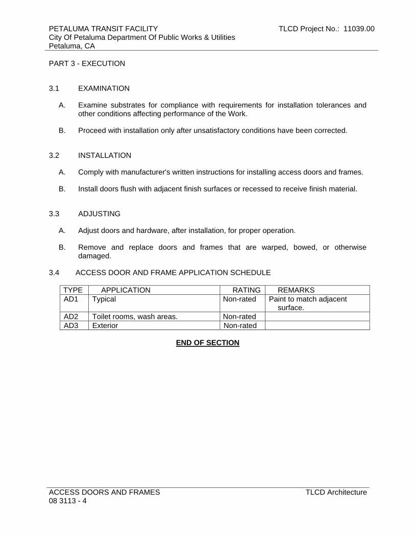
PETALUMA TRANSIT FACILITY City Of Petaluma Department Of Public Works & Utilities Petaluma, CA
TLCD Project No.: 11039.00
ACCESS DOORS AND FRAMES 08 3113 - 4
TLCD Architecture
PART 3 - EXECUTION
3.1 EXAMINATION
A. Examine substrates for compliance with requirements for installation tolerances and other conditions affecting performance of the Work.
B. Proceed with installation only after unsatisfactory conditions have been corrected.
3.2 INSTALLATION
A. Comply with manufacturer's written instructions for installing access doors and frames.
B. Install doors flush with adjacent finish surfaces or recessed to receive finish material.
3.3 ADJUSTING
A. Adjust doors and hardware, after installation, for proper operation.
B. Remove and replace doors and frames that are warped, bowed, or otherwise damaged.
3.4 ACCESS DOOR AND FRAME APPLICATION SCHEDULE
TYPE APPLICATION RATING REMARKS AD1 Typical Non-rated Paint to match adjacent
surface. AD2 Toilet rooms, wash areas. Non-rated AD3 Exterior Non-rated
END OF SECTION

TLCD Project No.: 11039.00 PETALUMA TRANSIT FACILITYCity Of Petaluma Department Of Public Works & Utilities
Petaluma, CA
TLCD Architecture OVERHEAD COILING DOORS08 3323 - 1
SECTION 08 3323 - OVERHEAD COILING DOORS
PART 1 - GENERAL
1.1 RELATED DOCUMENTS
A. Drawings and general provisions of the Contract, including General and Supplementary Conditions and Division 01 Specification Sections, apply to this Section.
1.2 SUMMARY
A. Section Includes: 1. Insulated service doors.
B. Related Sections: 1. Section 05 5000 "Metal Fabrications" for miscellaneous steel supports.
1.3 PERFORMANCE REQUIREMENTS
A. Delegated Design: Design overhead coiling doors, including comprehensive engineering analysis by a qualified professional engineer, using performance requirements and design criteria indicated.
B. Structural Performance, Exterior Doors: Exterior overhead coiling doors shall withstand the wind loads, the effects of gravity loads, and loads and stresses within limits and under conditions indicated according to SEI/ASCE 7. 1. Wind Loads: As indicated on Drawings. 2. Deflection Limits: Design overhead coiling doors to withstand design wind load
without evidencing permanent deformation or disengagement of door components.
C. Operability under Wind Load: Design overhead coiling doors to remain operable under uniform pressure (velocity pressure) of 20 lbf/sq. ft. wind load, acting inward and outward.
D. Seismic Performance: Overhead coiling doors shall withstand the effects of earthquake motions determined according to SEI/ASCE 7. 1. The term "withstand" means "the unit will remain in place without separation of any
parts from the device when subjected to the seismic forces specified." 2. Seismic Component Importance Factor: 1.0.
E. Operation Cycles: Provide overhead coiling door components and operators capable of operating for not less than number of cycles indicated for each door. One operation cycle is complete when a door is opened from the closed position to the fully open position and returned to the closed position.
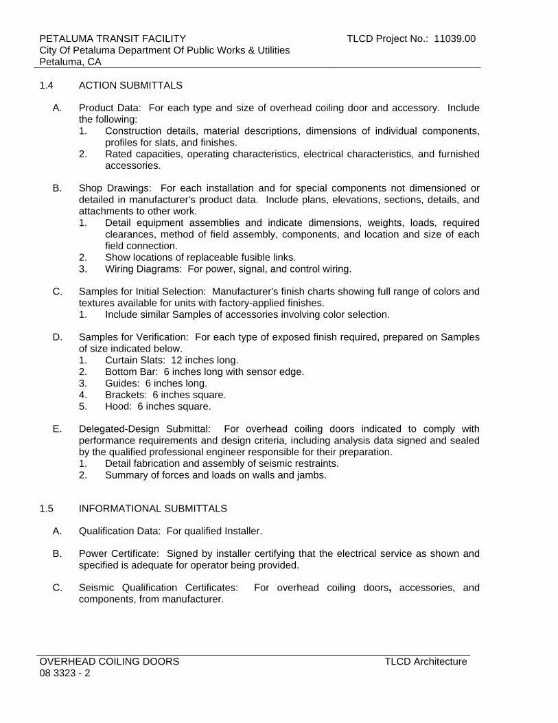
PETALUMA TRANSIT FACILITY City Of Petaluma Department Of Public Works & Utilities Petaluma, CA
TLCD Project No.: 11039.00
OVERHEAD COILING DOORS 08 3323 - 2
TLCD Architecture
1.4 ACTION SUBMITTALS
A. Product Data: For each type and size of overhead coiling door and accessory. Include the following: 1. Construction details, material descriptions, dimensions of individual components,
profiles for slats, and finishes. 2. Rated capacities, operating characteristics, electrical characteristics, and furnished
accessories.
B. Shop Drawings: For each installation and for special components not dimensioned or detailed in manufacturer's product data. Include plans, elevations, sections, details, and attachments to other work. 1. Detail equipment assemblies and indicate dimensions, weights, loads, required
clearances, method of field assembly, components, and location and size of each field connection.
2. Show locations of replaceable fusible links. 3. Wiring Diagrams: For power, signal, and control wiring.
C. Samples for Initial Selection: Manufacturer's finish charts showing full range of colors and textures available for units with factory-applied finishes. 1. Include similar Samples of accessories involving color selection.
D. Samples for Verification: For each type of exposed finish required, prepared on Samples of size indicated below. 1. Curtain Slats: 12 inches long. 2. Bottom Bar: 6 inches long with sensor edge. 3. Guides: 6 inches long. 4. Brackets: 6 inches square. 5. Hood: 6 inches square.
E. Delegated-Design Submittal: For overhead coiling doors indicated to comply with performance requirements and design criteria, including analysis data signed and sealed by the qualified professional engineer responsible for their preparation. 1. Detail fabrication and assembly of seismic restraints. 2. Summary of forces and loads on walls and jambs.
1.5 INFORMATIONAL SUBMITTALS
A. Qualification Data: For qualified Installer.
B. Power Certificate: Signed by installer certifying that the electrical service as shown and specified is adequate for operator being provided.
C. Seismic Qualification Certificates: For overhead coiling doors, accessories, and components, from manufacturer.

TLCD Project No.: 11039.00 PETALUMA TRANSIT FACILITYCity Of Petaluma Department Of Public Works & Utilities
Petaluma, CA
TLCD Architecture OVERHEAD COILING DOORS08 3323 - 3
1.6 CLOSEOUT SUBMITTALS
A. Maintenance Data: For overhead coiling doors to include in maintenance manuals.
1.7 QUALITY ASSURANCE
A. Installer Qualifications: Manufacturer's authorized representative who is trained and approved for both installation and maintenance of units required for this Project.
B. Source Limitations: Obtain overhead coiling doors from single source from single manufacturer. 1. Obtain operators and controls from overhead coiling door manufacturer.
C. Electrical Components, Devices, and Accessories: Listed and labeled as defined in NFPA 70, by a qualified testing agency, and marked for intended location and application.
D. Regulatory Requirements: Comply with applicable provisions in the U.S. Architectural & Transportation Barriers Compliance Board's ADA-ABA Accessibility Guidelines and CAC Title 24.
PART 2 - PRODUCTS
2.1 DOOR CURTAIN MATERIALS AND CONSTRUCTION
A. Door Curtains: Fabricate overhead coiling-door curtain of interlocking metal slats, designed to withstand wind loading indicated, in a continuous length for width of door without splices. Unless otherwise indicated, provide slats of thickness and mechanical properties recommended by door manufacturer for performance, size, and type of door indicated, and as follows: 1. Steel Door Curtain Slats: Zinc-coated (galvanized), cold-rolled structural steel
sheet; complying with ASTM A 653/A 653M, with G90 (Z275) zinc coating; nominal sheet thickness (coated) of 0.028 inch and as required to meet requirements.
2. Insulation: Fill slats for insulated doors with manufacturer's standard thermal insulation complying with maximum flame-spread and smoke-developed indexes of 75 and 450, respectively, according to ASTM E 84. Enclose insulation completely within slat faces.
3. Metal Interior Curtain-Slat Facing: Match metal of exterior curtain-slat face. 4. Gasket Seal: Provide insulated slats with manufacturer's standard interior-to-
exterior thermal break or with continuous gaskets between slats.
B. Endlocks and Windlocks for Service Doors: Malleable-iron casings galvanized after fabrication, secured to curtain slats with galvanized rivets or high-strength nylon. Provide locks on not less than alternate curtain slats for curtain alignment and resistance against lateral movement.
C. Bottom Bar for Service Doors: Consisting of two angles, each not less than 1-1/2 by 1-1/2 by 1/8 inch thick; fabricated from manufacturer's standard hot-dip galvanized steel, stainless steel, or aluminum extrusions to match curtain slats and finish.

PETALUMA TRANSIT FACILITY City Of Petaluma Department Of Public Works & Utilities Petaluma, CA
TLCD Project No.: 11039.00
OVERHEAD COILING DOORS 08 3323 - 4
TLCD Architecture
D. Curtain Jamb Guides: Manufacturer's standard angles or channels and angles of same material and finish as curtain slats unless otherwise indicated, with sufficient depth and strength to retain curtain, to allow curtain to operate smoothly, and to withstand loading. Slot bolt holes for guide adjustment. Provide removable stops on guides to prevent overtravel of curtain, and a continuous bar for holding windlocks.
2.2 HOOD
A. General: Form sheet metal hood to entirely enclose coiled curtain and operating mechanism at opening head. Contour to fit end brackets to which hood is attached. Roll and reinforce top and bottom edges for stiffness. Form closed ends for surface-mounted hoods and fascia for any portion of between-jamb mounting that projects beyond wall face. Equip hood with intermediate support brackets as required to prevent sagging. 1. Galvanized Steel: Nominal 0.028-inch- thick, hot-dip galvanized steel sheet with
G90 (Z275) zinc coating, complying with ASTM A 653/A 653M.
2.3 LOCKING DEVICES
A. Slide Bolt: Fabricate with side-locking bolts to engage through slots in tracks for locking by padlock, located on both left and right jamb sides, operable from coil side.
B. Locking Device Assembly: Fabricate with cylinder lock, spring-loaded dead bolt, operating handle, cam plate, and adjustable locking bars to engage through slots in tracks. 1. Lock Cylinders: Provide cylinders specified in Section 08 7100 "Door Hardware"
and keyed to building keying system. 2. Keys: Provide two for each cylinder.
C. Safety Interlock Switch: Equip power-operated doors with safety interlock switch to disengage power supply when door is locked.
2.4 CURTAIN ACCESSORIES
A. Weatherseals: Equip each exterior door with weather-stripping gaskets fitted to entire perimeter of door for a weathertight installation, unless otherwise indicated. 1. At door head, use 1/8-inch- thick, replaceable, continuous sheet secured to inside of
hood. 2. At door jambs, use replaceable, adjustable, continuous, flexible, 1/8-inch- thick
seals of flexible vinyl, rubber, or neoprene.
2.5 COUNTERBALANCING MECHANISM
A. General: Counterbalance doors by means of manufacturer's standard mechanism with an adjustable-tension, steel helical torsion spring mounted around a steel shaft and contained in a spring barrel connected to top of curtain with barrel rings. Use grease-sealed bearings or self-lubricating graphite bearings for rotating members.

TLCD Project No.: 11039.00 PETALUMA TRANSIT FACILITYCity Of Petaluma Department Of Public Works & Utilities
Petaluma, CA
TLCD Architecture OVERHEAD COILING DOORS08 3323 - 5
B. Counterbalance Barrel: Fabricate spring barrel of manufacturer's standard hot-formed, structural-quality, welded or seamless carbon-steel pipe, of sufficient diameter and wall thickness to support rolled-up curtain without distortion of slats and to limit barrel deflection to not more than 0.03 in./ft. of span under full load.
C. Spring Balance: One or more oil-tempered, heat-treated steel helical torsion springs. Size springs to counterbalance weight of curtain, with uniform adjustment accessible from outside barrel. Secure ends of springs to barrel and shaft with cast-steel barrel plugs.
D. Torsion Rod for Counterbalance Shaft: Fabricate of manufacturer's standard cold-rolled steel, sized to hold fixed spring ends and carry torsional load.
E. Brackets: Manufacturer's standard mounting brackets of either cast iron or cold-rolled steel plate.
2.6 ELECTRIC DOOR OPERATORS
A. General: Electric door operator assembly of size and capacity recommended and provided by door manufacturer for door and operation-cycles requirement specified, with electric motor and factory-prewired motor controls, starter, gear-reduction unit, solenoid-operated brake, clutch, remote-control stations, control devices, integral gearing for locking door, and accessories required for proper operation. 1. Comply with NFPA 70. 2. Provide control equipment complying with NEMA ICS 1, NEMA ICS 2, and
NEMA ICS 6, with NFPA 70 Class 2 control circuit, maximum 24 V, ac or dc.
B. Usage Classification: Electric operator and components capable of operating for not less than number of cycles per hour indicated for each door.
C. Door Operator Location(s): Operator location indicated for each door. 1. Front-of-Hood Mounted: Operator is mounted to the right or left door head plate
with the operator on coil side of the door-hood assembly and connected to the door drive shaft with drive chain and sprockets. Front clearance is required for this type of mounting.
D. Electric Motors: Comply with NEMA designation, temperature rating, service factor, enclosure type, and efficiency requirements specified in Section 110513 "Common Motor Requirements for Equipment" unless otherwise indicated. 1. Electrical Characteristics:
a. Phase: Polyphase. b. Volts: 230 V. c. Hertz: 60.
2. Motor Type and Controller: Reversible motor and controller (disconnect switch) for motor exposure indicated.
3. Motor Size: Minimum size as indicated. If not indicated, large enough to start, accelerate, and operate door in either direction from any position, at a speed not less than 8 in./sec. and not more than 12 in./sec., without exceeding nameplate ratings or service factor.
4. Operating Controls, Controllers (Disconnect Switches), Wiring Devices, and Wiring: Manufacturer's standard unless otherwise indicated.

PETALUMA TRANSIT FACILITY City Of Petaluma Department Of Public Works & Utilities Petaluma, CA
TLCD Project No.: 11039.00
OVERHEAD COILING DOORS 08 3323 - 6
TLCD Architecture
5. Coordinate wiring requirements and electrical characteristics of motors and other electrical devices with building electrical system and each location where installed.
E. Limit Switches: Equip each motorized door with adjustable switches interlocked with motor controls and set to automatically stop door at fully opened and fully closed positions.
F. Obstruction Detection Device: Equip motorized door with indicated external automatic safety sensor capable of protecting full width of door opening. For non-fire-rated doors, activation of device immediately stops and reverses downward door travel. 1. Photoelectric Sensor: Manufacturer's standard system designed to detect an
obstruction in door opening without contact between door and obstruction. a. Self-Monitoring Type: Designed to interface with door operator control circuit
to detect damage to or disconnection of sensing device. When self-monitoring feature is activated, door closes only with sustained pressure on close button.
2. Sensor Edge: Automatic safety sensor edge, located within astragal or weather stripping mounted to bottom bar. Contact with sensor activates device. Connect to control circuit using manufacturer's standard take-up reel or self-coiling cable. a. Self-Monitoring Type: Four-wire configured device designed to interface with
door operator control circuit to detect damage to or disconnection of sensor edge.
G. Remote-Control Station: Momentary-contact, three-button control station with push-button controls labeled "Open," "Close," and "Stop." 1. Interior units, full-guarded, surface-mounted, heavy-duty type, with general-purpose
NEMA ICS 6, Type 1 enclosure. 2. Exterior units, full-guarded, standard-duty, surface-mounted, weatherproof type,
NEMA ICS 6, Type 4 enclosure, key operated.
H. Emergency Manual Operation: Equip each electrically powered door with capability for emergency manual operation. Design manual mechanism so required force for door operation does not exceed 25 lbf.
I. Emergency Operation Disconnect Device: Equip operator with hand-operated disconnect mechanism for automatically engaging manual operator and releasing brake for emergency manual operation while disconnecting motor without affecting timing of limit switch. Mount mechanism so it is accessible from floor level. Include interlock device to automatically prevent motor from operating when emergency operator is engaged.
J. Motor Removal: Design operator so motor may be removed without disturbing limit-switch adjustment and without affecting emergency manual operation.
K. Audible and Visual Signals: Audible alarm and visual indicator lights in compliance with regulatory requirements for accessibility.
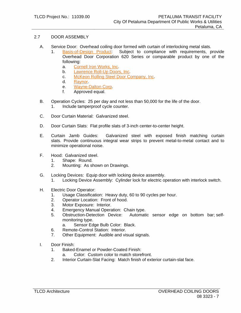
TLCD Project No.: 11039.00 PETALUMA TRANSIT FACILITYCity Of Petaluma Department Of Public Works & Utilities
Petaluma, CA
TLCD Architecture OVERHEAD COILING DOORS08 3323 - 7
2.7 DOOR ASSEMBLY
A. Service Door: Overhead coiling door formed with curtain of interlocking metal slats. 1. Basis-of-Design Product: Subject to compliance with requirements, provide
Overhead Door Corporation 620 Series or comparable product by one of the following: a. Cornell Iron Works, Inc. b. Lawrence Roll-Up Doors, Inc. c. McKeon Rolling Steel Door Company, Inc. d. Raynor. e. Wayne-Dalton Corp. f. Approved equal.
B. Operation Cycles: 25 per day and not less than 50,000 for the life of the door. 1. Include tamperproof cycle counter.
C. Door Curtain Material: Galvanized steel.
D. Door Curtain Slats: Flat profile slats of 3-inch center-to-center height.
E. Curtain Jamb Guides: Galvanized steel with exposed finish matching curtain slats. Provide continuous integral wear strips to prevent metal-to-metal contact and to minimize operational noise.
F. Hood: Galvanized steel. 1. Shape: Round. 2. Mounting: As shown on Drawings.
G. Locking Devices: Equip door with locking device assembly. 1. Locking Device Assembly: Cylinder lock for electric operation with interlock switch.
H. Electric Door Operator: 1. Usage Classification: Heavy duty, 60 to 90 cycles per hour. 2. Operator Location: Front of hood. 3. Motor Exposure: Interior. 4. Emergency Manual Operation: Chain type. 5. Obstruction-Detection Device: Automatic sensor edge on bottom bar; self-
monitoring type. a. Sensor Edge Bulb Color: Black.
6. Remote-Control Station: Interior. 7. Other Equipment: Audible and visual signals.
I. Door Finish: 1. Baked-Enamel or Powder-Coated Finish:
a. Color: Custom color to match storefront. 2. Interior Curtain-Slat Facing: Match finish of exterior curtain-slat face.

PETALUMA TRANSIT FACILITY City Of Petaluma Department Of Public Works & Utilities Petaluma, CA
TLCD Project No.: 11039.00
OVERHEAD COILING DOORS 08 3323 - 8
TLCD Architecture
2.8 GENERAL FINISH REQUIREMENTS
A. Comply with NAAMM's "Metal Finishes Manual for Architectural and Metal Products" for recommendations for applying and designating finishes.
B. Appearance of Finished Work: Noticeable variations in same piece are not acceptable. Variations in appearance of adjoining components are acceptable if they are within the range of approved Samples and are assembled or installed to minimize contrast.
2.9 STEEL AND GALVANIZED-STEEL FINISHES
A. Baked-Enamel or Powder-Coat Finish: Manufacturer's standard baked-on finish consisting of prime coat and thermosetting topcoat. Comply with coating manufacturer's written instructions for cleaning, pretreatment, application, and minimum dry film thickness.
PART 3 - EXECUTION
3.1 EXAMINATION
A. Examine substrates areas and conditions, with Installer present, for compliance with requirements for substrate construction and other conditions affecting performance of the Work.
B. Examine locations of electrical connections.
C. Proceed with installation only after unsatisfactory conditions have been corrected.
3.2 INSTALLATION
A. Install overhead coiling doors and operating equipment complete with necessary hardware, anchors, inserts, hangers, and equipment supports; according to manufacturer's written instructions and as specified.
B. Install overhead coiling doors, hoods, and operators at the mounting locations indicated for each door.
C. Accessibility: Install overhead coiling doors, switches, and controls along accessible routes in compliance with regulatory requirements for accessibility.
3.3 STARTUP SERVICE
A. Engage a factory-authorized service representative to perform startup service. 1. Perform installation and startup checks according to manufacturer's written
instructions.

TLCD Project No.: 11039.00 PETALUMA TRANSIT FACILITYCity Of Petaluma Department Of Public Works & Utilities
Petaluma, CA
TLCD Architecture OVERHEAD COILING DOORS08 3323 - 9
2. Test and adjust controls and safeties. Replace damaged and malfunctioning controls and equipment.
3. Test door closing when activated by detector or alarm-connected fire-release system. Reset door-closing mechanism after successful test.
3.4 ADJUSTING
A. Adjust hardware and moving parts to function smoothly so that doors operate easily, free of warp, twist, or distortion.
B. Lubricate bearings and sliding parts as recommended by manufacturer.
C. Adjust seals to provide weathertight fit around entire perimeter.
3.5 DEMONSTRATION
A. Engage a factory-authorized service representative to train Owner's maintenance personnel to adjust, operate, and maintain overhead coiling doors.
END OF SECTION

PETALUMA TRANSIT FACILITY City Of Petaluma Department Of Public Works & Utilities Petaluma, CA
TLCD Project No.: 11039.00
OVERHEAD COILING DOORS 08 3323 - 10
TLCD Architecture
THIS PAGE INTENTIONALLY LEFT BLANK
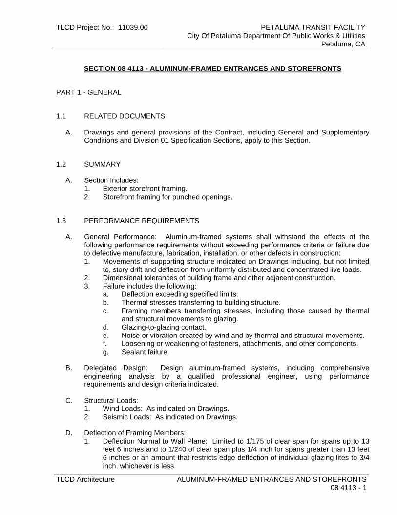
TLCD Project No.: 11039.00 PETALUMA TRANSIT FACILITYCity Of Petaluma Department Of Public Works & Utilities
Petaluma, CA
TLCD Architecture ALUMINUM-FRAMED ENTRANCES AND STOREFRONTS08 4113 - 1
SECTION 08 4113 - ALUMINUM-FRAMED ENTRANCES AND STOREFRONTS
PART 1 - GENERAL
1.1 RELATED DOCUMENTS
A. Drawings and general provisions of the Contract, including General and Supplementary Conditions and Division 01 Specification Sections, apply to this Section.
1.2 SUMMARY
A. Section Includes: 1. Exterior storefront framing. 2. Storefront framing for punched openings.
1.3 PERFORMANCE REQUIREMENTS
A. General Performance: Aluminum-framed systems shall withstand the effects of the following performance requirements without exceeding performance criteria or failure due to defective manufacture, fabrication, installation, or other defects in construction: 1. Movements of supporting structure indicated on Drawings including, but not limited
to, story drift and deflection from uniformly distributed and concentrated live loads. 2. Dimensional tolerances of building frame and other adjacent construction. 3. Failure includes the following:
a. Deflection exceeding specified limits. b. Thermal stresses transferring to building structure. c. Framing members transferring stresses, including those caused by thermal
and structural movements to glazing. d. Glazing-to-glazing contact. e. Noise or vibration created by wind and by thermal and structural movements. f. Loosening or weakening of fasteners, attachments, and other components. g. Sealant failure.
B. Delegated Design: Design aluminum-framed systems, including comprehensive engineering analysis by a qualified professional engineer, using performance requirements and design criteria indicated.
C. Structural Loads: 1. Wind Loads: As indicated on Drawings.. 2. Seismic Loads: As indicated on Drawings.
D. Deflection of Framing Members: 1. Deflection Normal to Wall Plane: Limited to 1/175 of clear span for spans up to 13
feet 6 inches and to 1/240 of clear span plus 1/4 inch for spans greater than 13 feet 6 inches or an amount that restricts edge deflection of individual glazing lites to 3/4 inch, whichever is less.
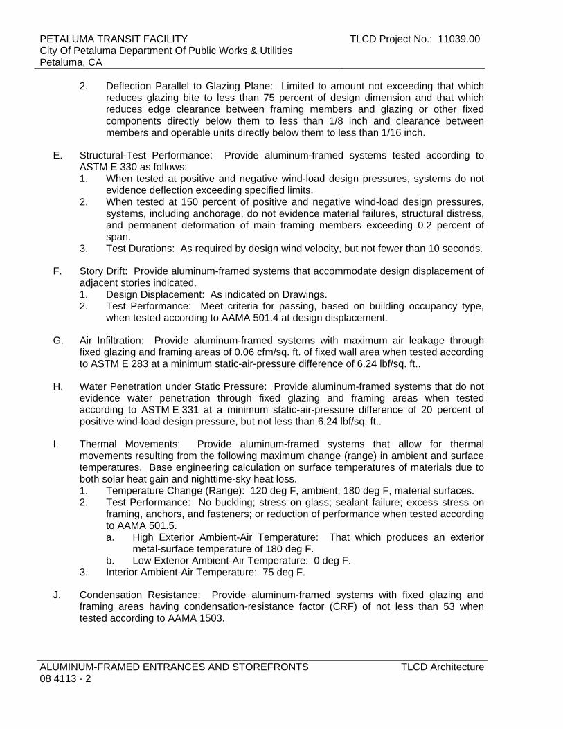
PETALUMA TRANSIT FACILITY City Of Petaluma Department Of Public Works & Utilities Petaluma, CA
TLCD Project No.: 11039.00
ALUMINUM-FRAMED ENTRANCES AND STOREFRONTS 08 4113 - 2
TLCD Architecture
2. Deflection Parallel to Glazing Plane: Limited to amount not exceeding that which reduces glazing bite to less than 75 percent of design dimension and that which reduces edge clearance between framing members and glazing or other fixed components directly below them to less than 1/8 inch and clearance between members and operable units directly below them to less than 1/16 inch.
E. Structural-Test Performance: Provide aluminum-framed systems tested according to ASTM E 330 as follows: 1. When tested at positive and negative wind-load design pressures, systems do not
evidence deflection exceeding specified limits. 2. When tested at 150 percent of positive and negative wind-load design pressures,
systems, including anchorage, do not evidence material failures, structural distress, and permanent deformation of main framing members exceeding 0.2 percent of span.
3. Test Durations: As required by design wind velocity, but not fewer than 10 seconds.
F. Story Drift: Provide aluminum-framed systems that accommodate design displacement of adjacent stories indicated. 1. Design Displacement: As indicated on Drawings. 2. Test Performance: Meet criteria for passing, based on building occupancy type,
when tested according to AAMA 501.4 at design displacement.
G. Air Infiltration: Provide aluminum-framed systems with maximum air leakage through fixed glazing and framing areas of 0.06 cfm/sq. ft. of fixed wall area when tested according to ASTM E 283 at a minimum static-air-pressure difference of 6.24 lbf/sq. ft..
H. Water Penetration under Static Pressure: Provide aluminum-framed systems that do not evidence water penetration through fixed glazing and framing areas when tested according to ASTM E 331 at a minimum static-air-pressure difference of 20 percent of positive wind-load design pressure, but not less than 6.24 lbf/sq. ft..
I. Thermal Movements: Provide aluminum-framed systems that allow for thermal movements resulting from the following maximum change (range) in ambient and surface temperatures. Base engineering calculation on surface temperatures of materials due to both solar heat gain and nighttime-sky heat loss. 1. Temperature Change (Range): 120 deg F, ambient; 180 deg F, material surfaces. 2. Test Performance: No buckling; stress on glass; sealant failure; excess stress on
framing, anchors, and fasteners; or reduction of performance when tested according to AAMA 501.5. a. High Exterior Ambient-Air Temperature: That which produces an exterior
metal-surface temperature of 180 deg F. b. Low Exterior Ambient-Air Temperature: 0 deg F.
3. Interior Ambient-Air Temperature: 75 deg F.
J. Condensation Resistance: Provide aluminum-framed systems with fixed glazing and framing areas having condensation-resistance factor (CRF) of not less than 53 when tested according to AAMA 1503.
TLCD Project No.: 11039.00 PETALUMA TRANSIT FACILITYCity Of Petaluma Department Of Public Works & Utilities
Petaluma, CA
TLCD Architecture ALUMINUM-FRAMED ENTRANCES AND STOREFRONTS08 4113 - 3
K. Thermal Conductance: Provide aluminum-framed systems with fixed glazing and framing areas having an average U-factor of not more than 0.69 Btu/sq. ft. x h x deg F when tested according to AAMA 1503.
1.4 ACTION SUBMITTALS
A. Product Data: For each type of product indicated. Include construction details, material descriptions, dimensions of individual components and profiles, and finishes for aluminum-framed systems.
B. Shop Drawings: For aluminum-framed systems. Include plans, elevations, sections, details, and attachments to other work. 1. Include details of provisions for system expansion and contraction and for drainage
of moisture in the system to the exterior. 2. For entrance doors, include hardware schedule and indicate operating hardware
types, functions, quantities, and locations.
C. Samples for Initial Selection: For units with factory-applied color finishes.
D. Samples for Verification: For each type of exposed finish required, in manufacturer's standard sizes.
E. Fabrication Sample: Of each vertical-to-horizontal intersection of aluminum-framed systems, made from 12-inch lengths of full-size components and showing details of the following: 1. Joinery, including concealed welds. 2. Anchorage. 3. Expansion provisions. 4. Glazing. 5. Flashing and drainage.
F. Delegated-Design Submittal: For aluminum-framed systems indicated to comply with performance requirements and design criteria, including analysis data signed and sealed by the qualified professional engineer responsible for their preparation. 1. Detail fabrication and assembly of aluminum-framed systems. 2. Include design calculations.
1.5 INFORMATIONAL SUBMITTALS
A. Qualification Data: For qualified Installer and testing agency.
B. Seismic Qualification Certificates: For aluminum-framed systems, accessories, and components, from manufacturer. 1. Basis for Certification: Indicate whether withstand certification is based on actual
test of assembled components or on calculation.
C. Welding certificates.

PETALUMA TRANSIT FACILITY City Of Petaluma Department Of Public Works & Utilities Petaluma, CA
TLCD Project No.: 11039.00
ALUMINUM-FRAMED ENTRANCES AND STOREFRONTS 08 4113 - 4
TLCD Architecture
D. Product Test Reports: Based on evaluation of comprehensive tests performed by a qualified testing agency, for aluminum-framed systems, indicating compliance with performance requirements.
E. Source quality-control reports.
F. Field quality-control reports.
G. Warranties: Sample of special warranties.
1.6 CLOSEOUT SUBMITTALS
A. Maintenance Data: For aluminum-framed systems to include in maintenance manuals.
1.7 QUALITY ASSURANCE
A. Installer Qualifications: Manufacturer's authorized representative who is trained and approved for installation of units required for this Project.
B. Testing Agency Qualifications: Qualified according to ASTM E 699 for testing indicated.
C. Engineering Responsibility: Prepare data for aluminum-framed systems, including Shop Drawings, based on testing and engineering analysis of manufacturer's standard units in systems similar to those indicated for this Project.
D. Product Options: Information on Drawings and in Specifications establishes requirements for systems' aesthetic effects and performance characteristics. Aesthetic effects are indicated by dimensions, arrangements, alignment, and profiles of components and assemblies as they relate to sightlines, to one another, and to adjoining construction. Performance characteristics are indicated by criteria subject to verification by one or more methods including preconstruction testing, field testing, and in-service performance. 1. Do not revise intended aesthetic effects, as judged solely by Architect, except with
Architect's approval. If revisions are proposed, submit comprehensive explanatory data to Architect for review.
E. Source Limitations for Aluminum-Framed Systems: Obtain from single source from single manufacturer.
F. Welding Qualifications: Qualify procedures and personnel according to AWS D1.2, "Structural Welding Code - Aluminum."
G. Mockups: Build mockups to verify selections made under sample submittals and to demonstrate aesthetic effects and set quality standards for fabrication and installation. 1. Build mockup of typical wall area where directed by Architect. 2. Field testing shall be performed on mockups according to requirements in "Field
Quality Control" Article.

TLCD Project No.: 11039.00 PETALUMA TRANSIT FACILITYCity Of Petaluma Department Of Public Works & Utilities
Petaluma, CA
TLCD Architecture ALUMINUM-FRAMED ENTRANCES AND STOREFRONTS08 4113 - 5
3. Approval of mockups does not constitute approval of deviations from the Contract Documents contained in mockups unless Architect specifically approves such deviations in writing.
4. Approved mockups may become part of the completed Work if undisturbed at time of Final Completion.
H. Preinstallation Conference: Conduct conference at Project site.
1.8 PROJECT CONDITIONS
A. Field Measurements: Verify actual locations of structural supports for aluminum-framed systems by field measurements before fabrication and indicate measurements on Shop Drawings.
1.9 WARRANTY
A. Special Warranty: Manufacturer's standard form in which manufacturer agrees to repair or replace components of aluminum-framed systems that do not comply with requirements or that fail in materials or workmanship within specified warranty period. 1. Failures include, but are not limited to, the following:
a. Structural failures including, but not limited to, excessive deflection. b. Noise or vibration caused by thermal movements. c. Deterioration of metals, metal finishes, and other materials beyond normal
weathering. d. Adhesive or cohesive sealant failures. e. Water leakage through fixed glazing and framing areas. f. Failure of operating components.
2. Warranty Period: Two years from date of Substantial Completion.
B. Special Finish Warranty: Manufacturer's standard form in which manufacturer agrees to repair or replace components on which finishes do not comply with requirements or that fail in materials or workmanship within specified warranty period. Warranty does not include normal weathering. 1. Warranty Period: 10 years from date of Substantial Completion.
PART 2 - PRODUCTS
2.1 MANUFACTURERS
A. Basis-of-Design Product: Subject to compliance with requirements, provide Kawneer North America “Trifab Versaglaze 451-T” or comparable product by one of the following: 1. Arch Aluminum & Glass Co., Inc. 2. EFCO Corporation. 3. Kawneer North America; an Alcoa company. 4. Oldcastle Building Envelope (Formerly Vistawall) 5. Tubelite. 6. Approved equal.
PETALUMA TRANSIT FACILITY City Of Petaluma Department Of Public Works & Utilities Petaluma, CA
TLCD Project No.: 11039.00
ALUMINUM-FRAMED ENTRANCES AND STOREFRONTS 08 4113 - 6
TLCD Architecture
2.2 MATERIALS
A. Aluminum: Alloy and temper recommended by manufacturer for type of use and finish indicated. 1. Sheet and Plate: ASTM B 209. 2. Extruded Bars, Rods, Profiles, and Tubes: ASTM B 221. 3. Extruded Structural Pipe and Tubes: ASTM B 429. 4. Structural Profiles: ASTM B 308/B 308M. 5. Welding Rods and Bare Electrodes: AWS A5.10/A5.10M.
B. Steel Reinforcement: Manufacturer's standard zinc-rich, corrosion-resistant primer, complying with SSPC-PS Guide No. 12.00; applied immediately after surface preparation and pretreatment. Select surface preparation methods according to recommendations in SSPC-SP COM and prepare surfaces according to applicable SSPC standard. 1. Structural Shapes, Plates, and Bars: ASTM A 36/A 36M. 2. Cold-Rolled Sheet and Strip: ASTM A 1008/A 1008M. 3. Hot-Rolled Sheet and Strip: ASTM A 1011/A 1011M.
2.3 FRAMING SYSTEMS
A. Framing Members: Manufacturer's standard extruded-aluminum framing members of thickness required and reinforced as required to support imposed loads. 1. Construction: Thermally broken. 2. Glazing System: Retained mechanically with gaskets on four sides. 3. Glazing Plane: Front. 4. Profile: 2 by 4 ½ inches nominal dimension.
B. Brackets and Reinforcements: Manufacturer's standard high-strength aluminum with nonstaining, nonferrous shims for aligning system components.
C. Fasteners and Accessories: Manufacturer's standard corrosion-resistant, nonstaining, nonbleeding fasteners and accessories compatible with adjacent materials. 1. Use self-locking devices where fasteners are subject to loosening or turning out
from thermal and structural movements, wind loads, or vibration. 2. Reinforce members as required to receive fastener threads. 3. Use exposed fasteners with countersunk Phillips screw heads, fabricated from
stainless steel.
D. Concrete and Masonry Inserts: Hot-dip galvanized cast-iron, malleable-iron, or steel inserts, complying with ASTM A 123/A 123M or ASTM A 153/A 153M.
E. Concealed Flashing: Manufacturer's standard corrosion-resistant, nonstaining, nonbleeding flashing compatible with adjacent materials.
F. Framing System Gaskets and Sealants: Manufacturer's standard, recommended by manufacturer for joint type.
TLCD Project No.: 11039.00 PETALUMA TRANSIT FACILITYCity Of Petaluma Department Of Public Works & Utilities
Petaluma, CA
TLCD Architecture ALUMINUM-FRAMED ENTRANCES AND STOREFRONTS08 4113 - 7
2.4 GLAZING SYSTEMS
A. Glazing: As specified in Section 08 8000 "Glazing."
B. Glazing Gaskets: Manufacturer's standard compression types; replaceable, molded or extruded, of profile and hardness required to maintain watertight seal.
C. Spacers and Setting Blocks: Manufacturer's standard elastomeric type.
D. Bond-Breaker Tape: Manufacturer's standard TFE-fluorocarbon or polyethylene material to which sealants will not develop adhesion.
2.5 ACCESSORY MATERIALS
A. Joint Sealants: For installation at perimeter of aluminum-framed systems, as specified in Section 07 9200 "Joint Sealants." 1. Sealants used inside the weatherproofing system shall comply with the testing and
product requirements of the California Department of Health Services' "Standard Practice for the Testing of Volatile Organic Emissions from Various Sources Using Small-Scale Environmental Chambers."
B. Bituminous Paint: Cold-applied, asphalt-mastic paint complying with SSPC-Paint 12 requirements except containing no asbestos; formulated for 30-mil thickness per coat.
2.6 FABRICATION
A. Form or extrude aluminum shapes before finishing.
B. Weld in concealed locations to greatest extent possible to minimize distortion or discoloration of finish. Remove weld spatter and welding oxides from exposed surfaces by descaling or grinding.
C. Framing Members, General: Fabricate components that, when assembled, have the following characteristics: 1. Profiles that are sharp, straight, and free of defects or deformations. 2. Accurately fitted joints with ends coped or mitered. 3. Means to drain water passing joints, condensation within framing members, and
moisture migrating within the system to exterior. 4. Physical and thermal isolation of glazing from framing members. 5. Accommodations for thermal and mechanical movements of glazing and framing to
maintain required glazing edge clearances. 6. Provisions for field replacement of glazing from interior. 7. Fasteners, anchors, and connection devices that are concealed from view to
greatest extent possible.
D. Mechanically Glazed Framing Members: Fabricate for flush glazing without projecting stops.

PETALUMA TRANSIT FACILITY City Of Petaluma Department Of Public Works & Utilities Petaluma, CA
TLCD Project No.: 11039.00
ALUMINUM-FRAMED ENTRANCES AND STOREFRONTS 08 4113 - 8
TLCD Architecture
E. After fabrication, clearly mark components to identify their locations in Project according to Shop Drawings.
2.7 ALUMINUM FINISHES
A. High-Performance Organic Finish: 3-coat fluoropolymer finish complying with AAMA 2605 and containing not less than 70 percent PVDF resin by weight in both color coat and clear topcoat. Prepare, pretreat, and apply coating to exposed metal surfaces to comply with coating and resin manufacturers' written instructions. 1. Color and Gloss: ”Dove Gray.”
2.8 SOURCE QUALITY CONTROL
A. Prepare test and inspection reports.
PART 3 - EXECUTION
3.1 EXAMINATION
A. Examine areas and conditions, with Installer present, for compliance with requirements for installation tolerances and other conditions affecting performance of the Work.
B. Proceed with installation only after unsatisfactory conditions have been corrected.
3.2 INSTALLATION
A. General: 1. Comply with manufacturer's written instructions. 2. Do not install damaged components. 3. Fit joints to produce hairline joints free of burrs and distortion. 4. Rigidly secure nonmovement joints. 5. Install anchors with separators and isolators to prevent metal corrosion and
electrolytic deterioration. 6. Seal joints watertight unless otherwise indicated.
B. Metal Protection: 1. Where aluminum will contact dissimilar metals, protect against galvanic action by
painting contact surfaces with primer or applying sealant or tape, or by installing nonconductive spacers as recommended by manufacturer for this purpose.
2. Where aluminum will contact concrete or masonry, protect against corrosion by painting contact surfaces with bituminous paint.
C. Install components to drain water passing joints, condensation occurring within framing members, and moisture migrating within the system to exterior.
D. Set continuous sill members and flashing in full sealant bed as specified in Section 07 9200 "Joint Sealants" to produce weathertight installation.
E. Install components plumb and true in alignment with established lines and grades, and without warp or rack.
TLCD Project No.: 11039.00 PETALUMA TRANSIT FACILITYCity Of Petaluma Department Of Public Works & Utilities
Petaluma, CA
TLCD Architecture ALUMINUM-FRAMED ENTRANCES AND STOREFRONTS08 4113 - 9
F. Install glazing as specified in Section 08 8000 "Glazing."
G. Install perimeter joint sealants as specified in Section 07 9200 "Joint Sealants" to produce weathertight installation.
3.3 ERECTION TOLERANCES
A. Install aluminum-framed systems to comply with the following maximum erection tolerances: 1. Location and Plane: Limit variation from true location and plane to 1/8 inch in 12
feet; 1/4 inch over total length. 2. Alignment:
a. Where surfaces abut in line, limit offset from true alignment to 1/16 inch. b. Where surfaces meet at corners, limit offset from true alignment to 1/32 inch.
B. Diagonal Measurements: Limit difference between diagonal measurements to 1/8 inch.
3.4 FIELD QUALITY CONTROL
A. Testing Agency: Owner will engage a qualified independent testing and inspecting agency to perform field tests and inspections.
B. Testing Services: Testing and inspecting of representative areas to determine compliance of installed systems with specified requirements shall take place as follows and in successive phases as indicated on Drawings. Do not proceed with installation of the next area until test results for previously completed areas show compliance with requirements. 1. Water Spray Test: Before installation of interior finishes has begun, a minimum
area of 75 feet by 1 story of aluminum-framed systems designated by Architect shall be tested according to AAMA 501.2 and shall not evidence water penetration.
C. Repair or remove work if test results and inspections indicate that it does not comply with specified requirements.
D. Additional testing and inspecting, at Contractor's expense, will be performed to determine compliance of replaced or additional work with specified requirements.
E. Aluminum-framed assemblies will be considered defective if they do not pass tests and inspections.
F. Prepare test and inspection reports.
END OF SECTION

PETALUMA TRANSIT FACILITY City Of Petaluma Department Of Public Works & Utilities Petaluma, CA
TLCD Project No.: 11039.00
ALUMINUM-FRAMED ENTRANCES AND STOREFRONTS 08 4113 - 10
TLCD Architecture
THIS PAGE INTENTIONALLY LEFT BLANK

TLCD Project No.: 11039.00 PETALUMA TRANSIT FACILITYCity Of Petaluma Department Of Public Works & Utilities
Petaluma, CA
TLCD Architecture DOOR HARDWARE08 7100-1
SECTION 08 7100 - DOOR HARDWARE PART 1 - GENERAL 1.01 RELATED DOCUMENTS
A. Drawings and general provisions of Contract, including General and Supplementary Conditions of Division 01 Specification Sections, apply to this Section.
1.02 SUMMARY
A. This Section includes items known commercially as finish or door hardware that are required for swing, sliding, and folding doors, except special types of unique hardware specified in the same sections as the doors and door frames on which they are installed.
B. This Section includes the following, but is not necessarily limited to:
1. Door Hardware. 2. Thresholds, gasketing and weather-stripping. 3. Door silencers or mutes. 4. Knox Box
1.03 REFERENCES (Use date of standard in effect as of Bid date.)
A. 2010 California Building Code, CCR, Title 24.
B. BHMA - Builders' Hardware Manufacturers Association.
C. CCR - California Code of Regulations, Tile 24, Part 2, California State Accessibility Standards.
D. DHI - Door and Hardware Institute.
E. WHI - Warnock Hersey Incorporated
F. SDI - Steel Door Institute
1.04 SUBMITTALS & SUBSTITUTIONS
A. General: Submit in accordance with Conditions of the Contract and Division 01 Specification sections.
B. Submit product data (catalog cuts) including manufacturers' technical product information for each item of door hardware, installation instructions, maintenance of operating parts and finish, and other information necessary to show compliance with requirements.

PETALUMA TRANSIT FACILITY City Of Petaluma Department Of Public Works & Utilities Petaluma, CA
TLCD Project No.: 11039.00
DOOR HARDWARE 08 7100-2
TLCD Architecture
C. Submit six (6) copies of schedule organized vertically into “Hardware Sets” with index of doors and headings, indicating complete designations of every item required for each door or opening. Include following information: 1. Include a Cover Sheet with;
a. Job Name, location, telephone number. b. Architects name, location and telephone number. c. Contractors name, location, telephone number and job number. d. Suppliers name, location, telephone number and job number. e. Hardware consultant's name, location and telephone number.
2. Job Index information included; a. Numerical door number index including; door number, hardware heading
number and page number. b. Complete keying information (referred to DHI hand-book "Keying Systems and
Nomenclature"). Provision should be made in the schedule to provide keying information when available; if it is not available at the time the preliminary schedule is submitted.
c. Manufacturers' names and abbreviations for all materials. d. Explanation of abbreviations, symbols, and codes used in the schedule. e. Mounting locations for hardware. f. Clarification statements or questions. g. Catalog cuts and manufacturer’s technical data and instructions.
3. Vertical schedule format sample: Heading Number 1 (Hardware group or set number – HW -1) (a) 1 Single Door #1 - Exterior from Corridor 101 (b)90 (c) RH
(d) 3' 0"x7' 0" x 1-3/4" x (e) 20 Minute (f) WD x HM
(g) 1
(h) (i) ea (j) Hinges - (k) 5BB1HW 4.5 x 4.5 NRP (l) ½ TMS
(m) 626
(n) IVE
2 6AA
1 ea Lockset - ND50PD x RHO x RH x 10-025 x JTMS
626 SCH
(a) - Single or pair with opening number and location. (b) - Degree of opening (c) - Hand of door(s) (d) - Door and frame dimensions and door thickness. (e) - Label requirements if any. (f) - Door by frame material. (g) - (Optional) Hardware item line #. (h) - Keyset Symbol. (i) - Quantity. (j) - Product description. (k) - Product Number. (l) - Fastenings and other pertinent information. (m) - Hardware finish codes per ANSI A156.18. (n) - Manufacture abbreviation.
D. Make substitution requests in accordance with Division 01. Substitution requests must
be made prior to bid date. Include product data and indicate benefit to the project. Furnish samples of any proposed substitution.
E. Wiring Diagrams: Provide product data and wiring and riser diagrams for all electrical
products listed in the Hardware Schedule portion of this section.
F. Keying Schedule: Submit separate detailed schedule indicating clearly how the Owner's final instructions on keying of locks has been fulfilled.

TLCD Project No.: 11039.00 PETALUMA TRANSIT FACILITYCity Of Petaluma Department Of Public Works & Utilities
Petaluma, CA
TLCD Architecture DOOR HARDWARE08 7100-3
G. Templates for doors, frames, and other work specified to be factory prepared for the
installation of door hardware. Check shop drawings of other work to confirm that adequate provisions are made for locating and installing door hardware to comply with indicated requirements.
H. Furnish as-built/as-installed schedule with close-out documents, including keying
schedule and transcript, wiring/riser diagrams, manufacturers’ installation and adjustment and maintenance information.
1.05 QUALITY ASSURANCE
A. Obtain each type of hardware (latch and lock sets, hinges, closers, exit devices, etc.) from a single manufacturer.
B. Supplier Qualifications: A recognized architectural door hardware supplier, with
warehousing facilities in the project's vicinity, that has a record of successful in-service performance for supplying door hardware similar in quantity, type, and quality to that indicated for this project and that employs an experienced architectural hardware consultant (AHC) who is available to Owner, Architect, and Contractor, at reasonable times during the course of the Work, for consultation. 1. Responsible for detailing, scheduling and ordering of finish hardware. 2. Meet with Owner to finalize keying requirements and to obtain final instructions in
writing. 3. Stock parts for products supplied and are capable of repairing and replacing
hardware items found defective within warranty periods.
C. Hardware Installer: Company specializing in the installation of commercial door hardware with five years documented experience.
E. Exit Doors: Operable from inside with single motion without the use of a key or special
knowledge or effort.
1.06 DELIVERY, STORAGE AND HANDLING
A. Coordinate delivery of packaged hardware items to the appropriate locations (shop or field) for installation.
B. Hardware items shall be individually packaged in manufacturers’ original containers,
complete with proper fasteners. Clearly mark packages on outside to indicate contents and locations in hardware schedule and in work.
C. Provide locked storage area for hardware, protect from moisture, sunlight, paint,
chemicals, etc.
D. Inventory door hardware jointly with representatives of hardware supplier and hardware installer until each is satisfied that count is correct.
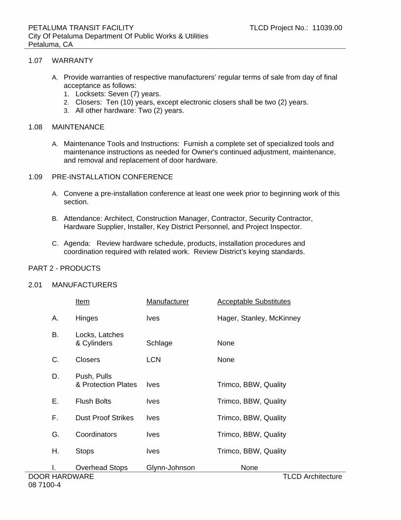
PETALUMA TRANSIT FACILITY City Of Petaluma Department Of Public Works & Utilities Petaluma, CA
TLCD Project No.: 11039.00
DOOR HARDWARE 08 7100-4
TLCD Architecture
1.07 WARRANTY
A. Provide warranties of respective manufacturers’ regular terms of sale from day of final acceptance as follows: 1. Locksets: Seven (7) years. 2. Closers: Ten (10) years, except electronic closers shall be two (2) years. 3. All other hardware: Two (2) years.
1.08 MAINTENANCE
A. Maintenance Tools and Instructions: Furnish a complete set of specialized tools and maintenance instructions as needed for Owner's continued adjustment, maintenance, and removal and replacement of door hardware.
1.09 PRE-INSTALLATION CONFERENCE
A. Convene a pre-installation conference at least one week prior to beginning work of this section.
B. Attendance: Architect, Construction Manager, Contractor, Security Contractor,
Hardware Supplier, Installer, Key District Personnel, and Project Inspector.
C. Agenda: Review hardware schedule, products, installation procedures and coordination required with related work. Review District's keying standards.
PART 2 - PRODUCTS 2.01 MANUFACTURERS
Item Manufacturer Acceptable Substitutes
A. Hinges Ives Hager, Stanley, McKinney
B. Locks, Latches & Cylinders Schlage None
C. Closers LCN None
D. Push, Pulls
& Protection Plates Ives Trimco, BBW, Quality
E. Flush Bolts Ives Trimco, BBW, Quality
F. Dust Proof Strikes Ives Trimco, BBW, Quality
G. Coordinators Ives Trimco, BBW, Quality
H. Stops Ives Trimco, BBW, Quality I. Overhead Stops Glynn-Johnson None

TLCD Project No.: 11039.00 PETALUMA TRANSIT FACILITYCity Of Petaluma Department Of Public Works & Utilities
Petaluma, CA
TLCD Architecture DOOR HARDWARE08 7100-5
J. Thresholds National Guard Pemko, Zero
K. Seals & Bottoms National Guard Pemko, Zero
2.02 MATERIALS
A. Hinges: Exterior out-swinging door butts shall be non-ferrous material and shall have stainless steel hinge pins. All doors to have non-rising pins. 1. Hinges shall be sized in accordance with the following:
a. Height: 1) Doors up to 41" wide: 4-1/2" inches. 2) Doors 42" to 48" wide: 5 inches.
b. Width: Sufficient to clear frame and trim when door swings 180 degrees. c. Number of Hinges: Furnish 3 hinges per leaf to 7'-5" in height. Add one for
each additional 2 feet in height. 2. Furnish non-removable pins (NRP) at all exterior out-swing doors and interior key
lock doors with reverse bevels.
B. Heavy Duty Cylindrical Locks and Latches: Schlage "ND" Series as scheduled with "Rhodes" design, fastened with through-bolts and threaded chassis hubs. 1. Locksets to comply with ANSI A156.2, Series 4000, Grade 1; tested to exceed
3,000,000 cycles. Locksets shall meet ANSI A117.1, Accessible Code. 2. Chassis: One piece modular assembly and multi-functional allowing function
interchange without disassembly of lockset. 3. Spindle shall be deep-draw manufactured not stamped. Spindle and spring cage to
be one-piece integrated assembly. 4. Anti-rotation plate to be interlocking to the lock chassis. Lock design utilizing bit-
tabs are not acceptable. 5. Lever Trim: Accessible design, bi-directional, independent assemblies. 6. Locks shall be of such construction that when locked, the door may be opened from
within by using lever and without the use of a key or special knowledge. 7. Thru-bolts to secure anti-rotation plate without sheer line. Fully threaded thru-bolts
are not acceptable. 8. Spring cage to have double compression springs. Manufacturers utilizing torsion
springs are not acceptable. 9. Latchbolt to be steel with minimum ½” throw deadlatch on keyed and exterior
functions; ¾” throw anti-friction latchbolt on pairs of doors. 10. Strikes: ANSI curved lip,1-1/4” x 4-7/8”, with 1” deep dust box (K510-066). Lips
shall be of sufficient length to clear trim and protect clothing. C. Closers: LCN as scheduled. Place closers inside building, stairs, room, etc.
1. Door closer cylinders shall be of high strength cast iron construction with double heat treated pinion shaft to provide low wear operating capabilities of internal parts throughout the life of the installation. All door closers shall be tested to ANSI/BHMA A156.4 test requirements by a BHMA certified testing laboratory. A written certification showing successful completion of a minimum of 10,000,000 cycles must be provided.
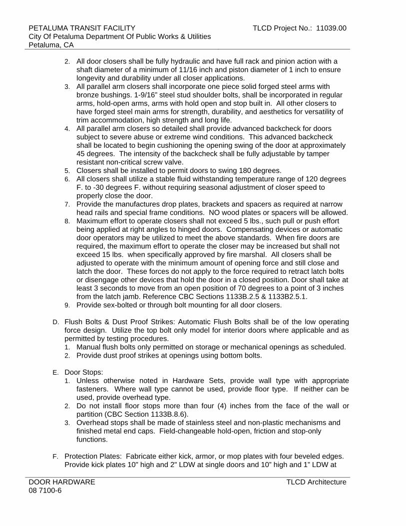
PETALUMA TRANSIT FACILITY City Of Petaluma Department Of Public Works & Utilities Petaluma, CA
TLCD Project No.: 11039.00
DOOR HARDWARE 08 7100-6
TLCD Architecture
2. All door closers shall be fully hydraulic and have full rack and pinion action with a shaft diameter of a minimum of 11/16 inch and piston diameter of 1 inch to ensure longevity and durability under all closer applications.
3. All parallel arm closers shall incorporate one piece solid forged steel arms with bronze bushings. 1-9/16” steel stud shoulder bolts, shall be incorporated in regular arms, hold-open arms, arms with hold open and stop built in. All other closers to have forged steel main arms for strength, durability, and aesthetics for versatility of trim accommodation, high strength and long life.
4. All parallel arm closers so detailed shall provide advanced backcheck for doors subject to severe abuse or extreme wind conditions. This advanced backcheck shall be located to begin cushioning the opening swing of the door at approximately 45 degrees. The intensity of the backcheck shall be fully adjustable by tamper resistant non-critical screw valve.
5. Closers shall be installed to permit doors to swing 180 degrees. 6. All closers shall utilize a stable fluid withstanding temperature range of 120 degrees
F. to -30 degrees F. without requiring seasonal adjustment of closer speed to properly close the door.
7. Provide the manufactures drop plates, brackets and spacers as required at narrow head rails and special frame conditions. NO wood plates or spacers will be allowed.
8. Maximum effort to operate closers shall not exceed 5 lbs., such pull or push effort being applied at right angles to hinged doors. Compensating devices or automatic door operators may be utilized to meet the above standards. When fire doors are required, the maximum effort to operate the closer may be increased but shall not exceed 15 lbs. when specifically approved by fire marshal. All closers shall be adjusted to operate with the minimum amount of opening force and still close and latch the door. These forces do not apply to the force required to retract latch bolts or disengage other devices that hold the door in a closed position. Door shall take at least 3 seconds to move from an open position of 70 degrees to a point of 3 inches from the latch jamb. Reference CBC Sections 1133B.2.5 & 1133B2.5.1.
9. Provide sex-bolted or through bolt mounting for all door closers.
D. Flush Bolts & Dust Proof Strikes: Automatic Flush Bolts shall be of the low operating force design. Utilize the top bolt only model for interior doors where applicable and as permitted by testing procedures. 1. Manual flush bolts only permitted on storage or mechanical openings as scheduled. 2. Provide dust proof strikes at openings using bottom bolts.
E. Door Stops:
1. Unless otherwise noted in Hardware Sets, provide wall type with appropriate fasteners. Where wall type cannot be used, provide floor type. If neither can be used, provide overhead type.
2. Do not install floor stops more than four (4) inches from the face of the wall or partition (CBC Section 1133B.8.6).
3. Overhead stops shall be made of stainless steel and non-plastic mechanisms and finished metal end caps. Field-changeable hold-open, friction and stop-only functions.
F. Protection Plates: Fabricate either kick, armor, or mop plates with four beveled edges.
Provide kick plates 10" high and 2" LDW at single doors and 10” high and 1” LDW at

TLCD Project No.: 11039.00 PETALUMA TRANSIT FACILITYCity Of Petaluma Department Of Public Works & Utilities
Petaluma, CA
TLCD Architecture DOOR HARDWARE08 7100-7
pairs of doors. Sizes of armor and mop plates shall be listed in the Hardware Schedule. Furnish with machine or wood screws of bronze or stainless to match other hardware.
G. Thresholds: As Scheduled and per details.
1. Thresholds shall not exceed 1/2" in height, with a beveled surface of 1:2 maximum slope.
2. Set thresholds in silicone sealant complying with requirements in Section 07 9200 “Joint Sealants”.
3. Use ¼” fasteners, red-head flat-head sleeve anchors (SS/FHSL). 4. Thresholds shall comply with CBC Section 1133B.2.4.1.
H. Seals: Provide silicone gasket at all exterior doors.
I. Door Shoes & Door Top Caps: Provide door shoes at all exterior wood doors and top
caps at all exterior out-swing doors.
J. Silencers: Furnish silencers for interior hollow metal frames, 3 for single doors, 2 for pairs of doors. Omit where sound or light seals occurs, or for fire-resistive-rated door assemblies.
K. Knox Box: 3200 Series Hinged Door Model with Recessed Mount Kit.
1. Color: As selected. 2. Contact Fire Department for signature sheet as required.
2.03 KEYING
A. Furnish a keying system coordinated with the system the Owner has in use on the site.
B. A detailed keying schedule is to be prepared by the owner in consultation with a representative of Ingersoll Rand Security Consultants or an Authorized Key Center or Authorized Security Center. Each keyed cylinder on every keyed lock is to be listed separately showing the door #, key group (in BHMA terminology), cylinder type, finish and location on the door.
C. Furnish Patent Protected Schlage keys and cylinders on all locks. D. Furnish all keys with visual key control.
1. Stamp key “Do Not Duplicate”.
F. Furnish mechanical keys as follows: 1. Furnish 2 cut change keys for each different change key code. 2. Furnish 1 uncut key blank for each change key code. 3. Furnish 6 cut masterkeys for each different masterkey set. 4. Furnish 3 uncut key blanks for each masterkey set. 5. Furnish 2 cut control keys cut to the top masterkey for permanent I/C cylinders. 6. Furnish 1 cut control key cut to each SKD combination.
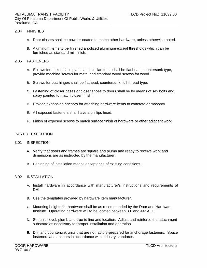
PETALUMA TRANSIT FACILITY City Of Petaluma Department Of Public Works & Utilities Petaluma, CA
TLCD Project No.: 11039.00
DOOR HARDWARE 08 7100-8
TLCD Architecture
2.04 FINISHES A. Door closers shall be powder-coated to match other hardware, unless otherwise noted.
B. Aluminum items to be finished anodized aluminum except thresholds which can be
furnished as standard mill finish. 2.05 FASTENERS
A. Screws for strikes, face plates and similar items shall be flat head, countersunk type, provide machine screws for metal and standard wood screws for wood.
B. Screws for butt hinges shall be flathead, countersunk, full-thread type.
C. Fastening of closer bases or closer shoes to doors shall be by means of sex bolts and
spray painted to match closer finish.
D. Provide expansion anchors for attaching hardware items to concrete or masonry.
E. All exposed fasteners shall have a phillips head.
F. Finish of exposed screws to match surface finish of hardware or other adjacent work. PART 3 - EXECUTION 3.01 INSPECTION
A. Verify that doors and frames are square and plumb and ready to receive work and dimensions are as instructed by the manufacturer.
B. Beginning of installation means acceptance of existing conditions.
3.02 INSTALLATION
A. Install hardware in accordance with manufacturer's instructions and requirements of DHI.
B. Use the templates provided by hardware item manufacturer.
C. Mounting heights for hardware shall be as recommended by the Door and Hardware
Institute. Operating hardware will to be located between 30" and 44" AFF. D. Set units level, plumb and true to line and location. Adjust and reinforce the attachment
substrate as necessary for proper installation and operation.
E. Drill and countersink units that are not factory-prepared for anchorage fasteners. Space fasteners and anchors in accordance with industry standards.

TLCD Project No.: 11039.00 PETALUMA TRANSIT FACILITYCity Of Petaluma Department Of Public Works & Utilities
Petaluma, CA
TLCD Architecture DOOR HARDWARE08 7100-9
F. Set thresholds for exterior doors in full bed of butyl-rubber sealant.
G. If hand of door is changed during construction, make necessary changes in hardware at no additional cost.
3.03 ADJUST AND CLEAN
A. Adjust and check each operating item of hardware and each door, to ensure proper operation or function of every unit. Replace units which cannot be adjusted to operate freely and smoothly as intended for the application made.
B. Clean adjacent surface soiled by hardware installation.
C. Final Adjustment: Wherever hardware installation is made more than one month prior
to acceptance or occupancy, return to that work area and make final check and adjustment of all hardware items in such space or area. Clean operating items as necessary to restore proper function and finish of hardware and doors. Adjust door control devices to compensate for final operation of heating and ventilating equipment.
D. Instruct Owner's Personnel in proper adjustment and maintenance of hardware finishes,
during the final adjustment of hardware.
E. Continued Maintenance Service: Approximately six months after the completion of the project, the Contractor accompanied by the Architectural Hardware Consultant, shall return to the project and re-adjust every item of hardware to restore proper functions of doors and hardware. Consult with and instruct Owner's personnel in recommended additions to the maintenance procedures. Replace hardware items which have deteriorated or failed due to faulty design, materials or installation of hardware units. Prepare a written report of current and predictable problems (of substantial nature) in the performance of the hardware.
3.04 HARDWARE LOCATIONS
A. Conform to CCR, Title 24, Part 2; and ADAAG; and the drawings for access-compliant positioning requirements for the disabled.
3.05 FIELD QUALITY CONTROL
A. Architectural Hardware Consultant (AHC) to inspect installation and certify that hardware and its installation have been furnished and installed in accordance with manufacturer's instructions and as specified herein.
3.06 SCHEDULE
A. The items listed in the following schedule shall conform to the requirements of the foregoing specifications.
B. The Door Schedule on the Drawings indicates which hardware set is used with each
door.

PETALUMA TRANSIT FACILITY City Of Petaluma Department Of Public Works & Utilities Petaluma, CA
TLCD Project No.: 11039.00
DOOR HARDWARE 08 7100-10
TLCD Architecture
Manufacturers Abbreviations (Mfr.) GLY = Glynn-Johnson Corporation Overhead Door Stops & Holders IVE = Ives Hinges, Bolts, Coordinators, Dust Proof
Strikes, Push Pull & Kick Plates, Door Stops & Silencers
LCN = LCN Door Closers NGP = National Guard Products Thresholds, Gasketing & Weather-stripping SCH = Schlage Lock Company Locks, Latches & Cylinders HW SET: 01
1 HARDWARE BY DOOR MANUFACTURER HW SET: 02
6 EA HINGE 5BB1 5 X 4.5 630 IVE 1 EA AUTO FLUSH BOLT FB31T 630 IVE 1 EA CLASSROOM LOCK ND70RD RHO 626 SCH1 EA COORDINATOR COR X FL 628 IVE 2 EA MOUNTING
BRACKET MB1 600 IVE
2 EA SURFACE CLOSER 4040XP HEDA 689 LCN 2 EA KICK PLATE 8400 30" X 1" LDW 630 IVE 2 EA SILENCER SR64 GRY IVE
HW SET: 03
3 EA HINGE 5BB1 4.5 X 4.5 630 IVE 1 EA CLASSROOM LOCK ND70RD RHO 626 SCH1 EA WALL STOP WS401CCV/WS402CCV 626 IVE 1 EA KICK PLATE 8400 10" X 2" LDW 630 IVE 3 EA SILENCER SR64 GRY IVE
HW SET: 04
3 EA HINGE 5BB1 4.5 X 4.5 630 IVE 1 EA ENTRANCE LOCK ND53RD RHO 626 SCH1 EA WALL STOP WS401CCV/WS402CCV 626 IVE 3 EA SILENCER SR64 GRY IVE
END OF SECTION

TLCD Project No.: 11039.00 PETALUMA TRANSIT FACILITYCity Of Petaluma Department Of Public Works & Utilities
Petaluma, CA
TLCD Architecture GLAZING08 8000 - 1
SECTION 08 8000 - GLAZING
PART 1 - GENERAL
1.1 RELATED DOCUMENTS
A. Drawings and general provisions of the Contract, including General and Supplementary Conditions and Division 01 Specification Sections, apply to this Section.
1.2 SUMMARY
A. Section includes glazing for the following products and applications, including those specified in other Sections where glazing requirements are specified by reference to this Section: 1. Windows. 2. Doors. 3. Storefront framing. 4. Interior borrowed lites.
1.3 DEFINITIONS
A. Glass Manufacturers: Firms that produce primary glass, fabricated glass, or both, as defined in referenced glazing publications.
B. Glass Thicknesses: Indicated by thickness designations in millimeters according to ASTM C 1036.
C. Interspace: Space between lites of an insulating-glass unit.
1.4 PERFORMANCE REQUIREMENTS
A. General: Installed glazing systems shall withstand normal thermal movement and wind and impact loads (where applicable) without failure, including loss or glass breakage attributable to the following: defective manufacture, fabrication, or installation; failure of sealants or gaskets to remain watertight and airtight; deterioration of glazing materials; or other defects in construction.
B. Thermal Movements: Allow for thermal movements from ambient and surface temperature changes acting on glass framing members and glazing components. 1. Temperature Change: 120 deg F, ambient; 180 deg F, material surfaces.
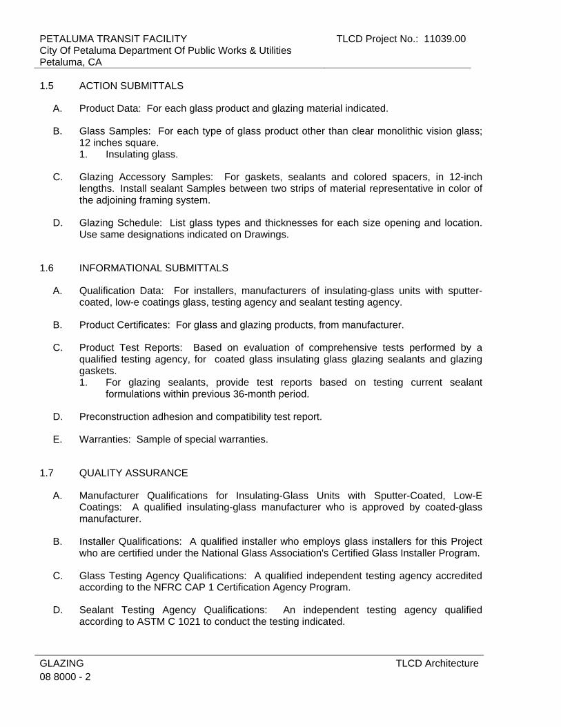
PETALUMA TRANSIT FACILITY City Of Petaluma Department Of Public Works & Utilities Petaluma, CA
TLCD Project No.: 11039.00
GLAZING 08 8000 - 2
TLCD Architecture
1.5 ACTION SUBMITTALS
A. Product Data: For each glass product and glazing material indicated.
B. Glass Samples: For each type of glass product other than clear monolithic vision glass; 12 inches square. 1. Insulating glass.
C. Glazing Accessory Samples: For gaskets, sealants and colored spacers, in 12-inch lengths. Install sealant Samples between two strips of material representative in color of the adjoining framing system.
D. Glazing Schedule: List glass types and thicknesses for each size opening and location. Use same designations indicated on Drawings.
1.6 INFORMATIONAL SUBMITTALS
A. Qualification Data: For installers, manufacturers of insulating-glass units with sputter-coated, low-e coatings glass, testing agency and sealant testing agency.
B. Product Certificates: For glass and glazing products, from manufacturer.
C. Product Test Reports: Based on evaluation of comprehensive tests performed by a qualified testing agency, for coated glass insulating glass glazing sealants and glazing gaskets. 1. For glazing sealants, provide test reports based on testing current sealant
formulations within previous 36-month period.
D. Preconstruction adhesion and compatibility test report.
E. Warranties: Sample of special warranties.
1.7 QUALITY ASSURANCE
A. Manufacturer Qualifications for Insulating-Glass Units with Sputter-Coated, Low-E Coatings: A qualified insulating-glass manufacturer who is approved by coated-glass manufacturer.
B. Installer Qualifications: A qualified installer who employs glass installers for this Project who are certified under the National Glass Association's Certified Glass Installer Program.
C. Glass Testing Agency Qualifications: A qualified independent testing agency accredited according to the NFRC CAP 1 Certification Agency Program.
D. Sealant Testing Agency Qualifications: An independent testing agency qualified according to ASTM C 1021 to conduct the testing indicated.

TLCD Project No.: 11039.00 PETALUMA TRANSIT FACILITYCity Of Petaluma Department Of Public Works & Utilities
Petaluma, CA
TLCD Architecture GLAZING08 8000 - 3
E. Source Limitations for Glass: Obtain coated float glass and insulating glass from single source from single manufacturer for each glass type.
F. Source Limitations for Glazing Accessories: Obtain from single source from single manufacturer for each product and installation method.
G. Glazing Publications: Comply with published recommendations of glass product manufacturers and organizations below, unless more stringent requirements are indicated. Refer to these publications for glazing terms not otherwise defined in this Section or in referenced standards. 1. IGMA Publication for Insulating Glass: SIGMA TM-3000, "North American Glazing
Guidelines for Sealed Insulating Glass Units for Commercial and Residential Use."
H. Safety Glazing Labeling: Where safety glazing labeling is indicated, permanently mark glazing with certification label of the SGCC or another certification agency acceptable to authorities having jurisdiction. Label shall indicate manufacturer's name, type of glass, thickness, and safety glazing standard with which glass complies.
I. Insulating-Glass Certification Program: Permanently marked either on spacers or on at least one component lite of units with appropriate certification label of IGCC.
J. Preinstallation Conference: Conduct conference at Project site. 1. Review and finalize construction schedule and verify availability of materials,
Installer's personnel, equipment, and facilities needed to make progress and avoid delays.
2. Review temporary protection requirements for glazing during and after installation.
1.8 DELIVERY, STORAGE, AND HANDLING
A. Protect glazing materials according to manufacturer's written instructions. Prevent damage to glass and glazing materials from condensation, temperature changes, direct exposure to sun, or other causes.
B. Comply with insulating-glass manufacturer's written recommendations for venting and sealing units to avoid hermetic seal ruptures due to altitude change.
1.9 PROJECT CONDITIONS
A. Environmental Limitations: Do not proceed with glazing when ambient and substrate temperature conditions are outside limits permitted by glazing material manufacturers and when glazing channel substrates are wet from rain, frost, condensation, or other causes. 1. Do not install glazing sealants when ambient and substrate temperature conditions
are outside limits permitted by sealant manufacturer or below 40 deg F.

PETALUMA TRANSIT FACILITY City Of Petaluma Department Of Public Works & Utilities Petaluma, CA
TLCD Project No.: 11039.00
GLAZING 08 8000 - 4
TLCD Architecture
1.10 WARRANTY
A. Manufacturer's Special Warranty on Insulating Glass: Manufacturer's standard form in which insulating-glass manufacturer agrees to replace insulating-glass units that deteriorate within specified warranty period. Deterioration of insulating glass is defined as failure of hermetic seal under normal use that is not attributed to glass breakage or to maintaining and cleaning insulating glass contrary to manufacturer's written instructions. Evidence of failure is the obstruction of vision by dust, moisture, or film on interior surfaces of glass. 1. Warranty Period: 10 years from date of Substantial Completion.
PART 2 - PRODUCTS
2.1 GLASS PRODUCTS, GENERAL
A. Thickness: Where glass thickness is indicated, it is a minimum. Provide glass lites in thicknesses as needed to comply with requirements indicated.
B. Strength: Where fully tempered glass is indicated, provide Kind FT heat-treated float glass.
C. Thermal and Optical Performance Properties: Provide glass with performance properties specified, as indicated in manufacturer's published test data, based on procedures indicated below: 1. For monolithic-glass lites, properties are based on units with lites of thickness
indicated. 2. For insulating-glass units, properties are based on units of thickness indicated for
overall unit and for each lite. 3. U-Factors: Center-of-glazing values, according to NFRC 100 and based on LBL's
WINDOW 5.2 computer program, expressed as Btu/sq. ft. x h x deg F. 4. Solar Heat-Gain Coefficient and Visible Transmittance: Center-of-glazing values,
according to NFRC 200 and based on LBL's WINDOW 5.2 computer program. 5. Visible Reflectance: Center-of-glazing values, according to NFRC 300.
2.2 GLASS PRODUCTS
A. Float Glass: ASTM C 1036, Type I, Quality-Q3, Class I (clear) unless otherwise indicated.
B. Heat-Treated Float Glass: ASTM C 1048; Type I; Quality-Q3; Class I (clear) unless otherwise indicated; of kind and condition indicated. 1. Fabrication Process: By horizontal (roller-hearth) process with roll-wave distortion
parallel to bottom edge of glass as installed unless otherwise indicated. 2. For uncoated glass, comply with requirements for Condition A. 3. For coated vision glass, comply with requirements for Condition C (other coated
glass).

TLCD Project No.: 11039.00 PETALUMA TRANSIT FACILITYCity Of Petaluma Department Of Public Works & Utilities
Petaluma, CA
TLCD Architecture GLAZING08 8000 - 5
2.3 INSULATING GLASS
A. Manufacturers: Subject to compliance with requirements, available manufacturers offering products that may be incorporated into the Work include, but are not limited to, the following: 1. Oldcastle Glass. 2. PPG Industries. 3. Viracron. 4. Approved equal.
B. Insulating-Glass Units: Factory-assembled units consisting of sealed lites of glass separated by a dehydrated interspace, qualified according to ASTM E 2190, and complying with other requirements specified. 1. Sealing System: Dual seal, with manufacturer's standard primary and secondary. 2. Spacer: Manufacturer's standard spacer material and construction. 3. Desiccant: Molecular sieve or silica gel, or blend of both.
C. Glass: Comply with applicable requirements in "Glass Products" Article as indicated by designations in "Insulating-Glass Types" Article.
2.4 GLAZING GASKETS
A. Dense Compression Gaskets: Molded or extruded gaskets of profile and hardness required to maintain watertight seal, made from one of the following: 1. Neoprene complying with ASTM C 864. 2. EPDM complying with ASTM C 864. 3. Silicone complying with ASTM C 1115. 4. Thermoplastic polyolefin rubber complying with ASTM C 1115.
B. Soft Compression Gaskets: Extruded or molded, closed-cell, integral-skinned neoprene, EPDM, silicone or thermoplastic polyolefin rubber gaskets complying with ASTM C 509, Type II, black; of profile and hardness required to maintain watertight seal. 1. Application: Use where soft compression gaskets will be compressed by inserting
dense compression gaskets on opposite side of glazing or pressure applied by means of pressure-glazing stops on opposite side of glazing.
C. Lock-Strip Gaskets: Neoprene extrusions in size and shape indicated, fabricated into frames with molded corner units and zipper lock-strips, complying with ASTM C 542, black.
2.5 GLAZING SEALANTS
A. General: 1. Compatibility: Provide glazing sealants that are compatible with one another and
with other materials they will contact, including glass products, seals of insulating-glass units, and glazing channel substrates, under conditions of service and application, as demonstrated by sealant manufacturer based on testing and field experience.

PETALUMA TRANSIT FACILITY City Of Petaluma Department Of Public Works & Utilities Petaluma, CA
TLCD Project No.: 11039.00
GLAZING 08 8000 - 6
TLCD Architecture
2. Suitability: Comply with sealant and glass manufacturers' written instructions for selecting glazing sealants suitable for applications indicated and for conditions existing at time of installation.
3. Colors of Exposed Glazing Sealants: As selected by Architect from manufacturer's full range.
B. Glazing Sealant: Neutral-curing silicone glazing sealant complying with ASTM C 920, Type S, Grade NS, Class 100/50, Use NT. 1. Products: Subject to compliance with requirements, available products that may be
incorporated into the Work include, but are not limited to, the following: a. Dow Corning Corporation; 790. b. GE Advanced Materials - Silicones; SilPruf LM SCS2700. c. May National Associates, Inc.; Bondaflex Sil 290. d. Pecora Corporation; 890. e. Sika Corporation, Construction Products Division; SikaSil-C990. f. Tremco Incorporated; Spectrem 1. g. Approved equal.
2.6 GLAZING TAPES
A. Back-Bedding Mastic Glazing Tapes: Preformed, butyl-based, 100 percent solids elastomeric tape; nonstaining and nonmigrating in contact with nonporous surfaces; with or without spacer rod as recommended in writing by tape and glass manufacturers for application indicated; and complying with ASTM C 1281 and AAMA 800 for products indicated below: 1. AAMA 804.3 tape, where indicated. 2. AAMA 806.3 tape, for glazing applications in which tape is subject to continuous
pressure. 3. AAMA 807.3 tape, for glazing applications in which tape is not subject to continuous
pressure.
B. Expanded Cellular Glazing Tapes: Closed-cell, PVC foam tapes; factory coated with adhesive on both surfaces; and complying with AAMA 800 for the following types: 1. AAMA 810.1, Type 1, for glazing applications in which tape acts as the primary
sealant. 2. AAMA 810.1, Type 2, for glazing applications in which tape is used in combination
with a full bead of liquid sealant.
2.7 MISCELLANEOUS GLAZING MATERIALS
A. General: Provide products of material, size, and shape complying with referenced glazing standard, requirements of manufacturers of glass and other glazing materials for application indicated, and with a proven record of compatibility with surfaces contacted in installation.
B. Cleaners, Primers, and Sealers: Types recommended by sealant or gasket manufacturer.
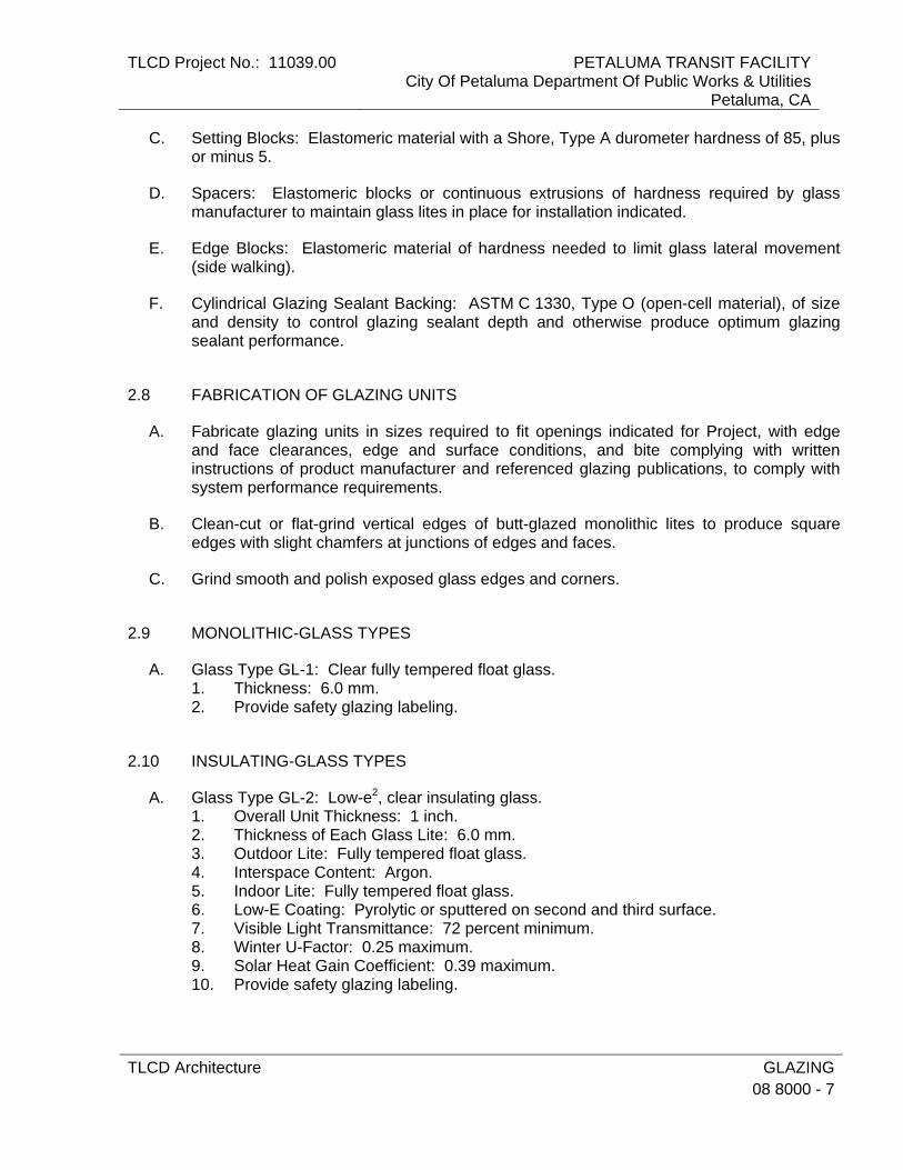
TLCD Project No.: 11039.00 PETALUMA TRANSIT FACILITYCity Of Petaluma Department Of Public Works & Utilities
Petaluma, CA
TLCD Architecture GLAZING08 8000 - 7
C. Setting Blocks: Elastomeric material with a Shore, Type A durometer hardness of 85, plus or minus 5.
D. Spacers: Elastomeric blocks or continuous extrusions of hardness required by glass manufacturer to maintain glass lites in place for installation indicated.
E. Edge Blocks: Elastomeric material of hardness needed to limit glass lateral movement (side walking).
F. Cylindrical Glazing Sealant Backing: ASTM C 1330, Type O (open-cell material), of size and density to control glazing sealant depth and otherwise produce optimum glazing sealant performance.
2.8 FABRICATION OF GLAZING UNITS
A. Fabricate glazing units in sizes required to fit openings indicated for Project, with edge and face clearances, edge and surface conditions, and bite complying with written instructions of product manufacturer and referenced glazing publications, to comply with system performance requirements.
B. Clean-cut or flat-grind vertical edges of butt-glazed monolithic lites to produce square edges with slight chamfers at junctions of edges and faces.
C. Grind smooth and polish exposed glass edges and corners.
2.9 MONOLITHIC-GLASS TYPES
A. Glass Type GL-1: Clear fully tempered float glass. 1. Thickness: 6.0 mm. 2. Provide safety glazing labeling.
2.10 INSULATING-GLASS TYPES
A. Glass Type GL-2: Low-e2, clear insulating glass. 1. Overall Unit Thickness: 1 inch. 2. Thickness of Each Glass Lite: 6.0 mm. 3. Outdoor Lite: Fully tempered float glass. 4. Interspace Content: Argon. 5. Indoor Lite: Fully tempered float glass. 6. Low-E Coating: Pyrolytic or sputtered on second and third surface. 7. Visible Light Transmittance: 72 percent minimum. 8. Winter U-Factor: 0.25 maximum. 9. Solar Heat Gain Coefficient: 0.39 maximum. 10. Provide safety glazing labeling.

PETALUMA TRANSIT FACILITY City Of Petaluma Department Of Public Works & Utilities Petaluma, CA
TLCD Project No.: 11039.00
GLAZING 08 8000 - 8
TLCD Architecture
PART 3 - EXECUTION
3.1 EXAMINATION
A. Examine framing, glazing channels, and stops, with Installer present, for compliance with the following: 1. Manufacturing and installation tolerances, including those for size, squareness, and
offsets at corners. 2. Presence and functioning of weep systems. 3. Minimum required face and edge clearances. 4. Effective sealing between joints of glass-framing members.
B. Proceed with installation only after unsatisfactory conditions have been corrected.
3.2 PREPARATION
A. Clean glazing channels and other framing members receiving glass immediately before glazing. Remove coatings not firmly bonded to substrates.
B. Examine glazing units to locate exterior and interior surfaces. Label or mark units as needed so that exterior and interior surfaces are readily identifiable. Do not use materials that will leave visible marks in the completed work.
3.3 GLAZING, GENERAL
A. Comply with combined written instructions of manufacturers of glass, sealants, gaskets, and other glazing materials, unless more stringent requirements are indicated, including those in referenced glazing publications.
B. Adjust glazing channel dimensions as required by Project conditions during installation to provide necessary bite on glass, minimum edge and face clearances, and adequate sealant thicknesses, with reasonable tolerances.
C. Protect glass edges from damage during handling and installation. Remove damaged glass from Project site and legally dispose of off Project site. Damaged glass is glass with edge damage or other imperfections that, when installed, could weaken glass and impair performance and appearance.
D. Apply primers to joint surfaces where required for adhesion of sealants, as determined by preconstruction testing.
E. Install setting blocks in sill rabbets, sized and located to comply with referenced glazing publications, unless otherwise required by glass manufacturer. Set blocks in thin course of compatible sealant suitable for heel bead.
F. Do not exceed edge pressures stipulated by glass manufacturers for installing glass lites.

TLCD Project No.: 11039.00 PETALUMA TRANSIT FACILITYCity Of Petaluma Department Of Public Works & Utilities
Petaluma, CA
TLCD Architecture GLAZING08 8000 - 9
G. Provide spacers for glass lites where length plus width is larger than 50 inches. 1. Locate spacers directly opposite each other on both inside and outside faces of
glass. Install correct size and spacing to preserve required face clearances, unless gaskets and glazing tapes are used that have demonstrated ability to maintain required face clearances and to comply with system performance requirements.
2. Provide 1/8-inch minimum bite of spacers on glass and use thickness equal to sealant width. With glazing tape, use thickness slightly less than final compressed thickness of tape.
H. Provide edge blocking where indicated or needed to prevent glass lites from moving sideways in glazing channel, as recommended in writing by glass manufacturer and according to requirements in referenced glazing publications.
I. Set glass lites in each series with uniform pattern, draw, bow, and similar characteristics.
J. Set glass lites with proper orientation so that coatings face exterior or interior as specified.
K. Where wedge-shaped gaskets are driven into one side of channel to pressurize sealant or gasket on opposite side, provide adequate anchorage so gasket cannot walk out when installation is subjected to movement.
L. Square cut wedge-shaped gaskets at corners and install gaskets in a manner recommended by gasket manufacturer to prevent corners from pulling away; seal corner joints and butt joints with sealant recommended by gasket manufacturer.
3.4 TAPE GLAZING
A. Position tapes on fixed stops so that, when compressed by glass, their exposed edges are flush with or protrude slightly above sightline of stops.
B. Install tapes continuously, but not necessarily in one continuous length. Do not stretch tapes to make them fit opening.
C. Cover vertical framing joints by applying tapes to heads and sills first and then to jambs. Cover horizontal framing joints by applying tapes to jambs and then to heads and sills.
D. Place joints in tapes at corners of opening with adjoining lengths butted together, not lapped. Seal joints in tapes with compatible sealant approved by tape manufacturer.
E. Do not remove release paper from tape until right before each glazing unit is installed.
F. Apply heel bead of elastomeric sealant.
G. Center glass lites in openings on setting blocks and press firmly against tape by inserting dense compression gaskets formed and installed to lock in place against faces of removable stops. Start gasket applications at corners and work toward centers of openings.
H. Apply cap bead of elastomeric sealant over exposed edge of tape.
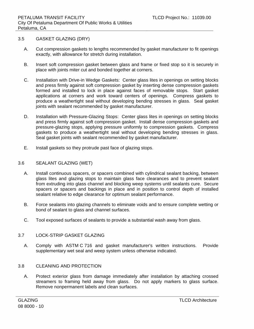
PETALUMA TRANSIT FACILITY City Of Petaluma Department Of Public Works & Utilities Petaluma, CA
TLCD Project No.: 11039.00
GLAZING 08 8000 - 10
TLCD Architecture
3.5 GASKET GLAZING (DRY)
A. Cut compression gaskets to lengths recommended by gasket manufacturer to fit openings exactly, with allowance for stretch during installation.
B. Insert soft compression gasket between glass and frame or fixed stop so it is securely in place with joints miter cut and bonded together at corners.
C. Installation with Drive-in Wedge Gaskets: Center glass lites in openings on setting blocks and press firmly against soft compression gasket by inserting dense compression gaskets formed and installed to lock in place against faces of removable stops. Start gasket applications at corners and work toward centers of openings. Compress gaskets to produce a weathertight seal without developing bending stresses in glass. Seal gasket joints with sealant recommended by gasket manufacturer.
D. Installation with Pressure-Glazing Stops: Center glass lites in openings on setting blocks and press firmly against soft compression gasket. Install dense compression gaskets and pressure-glazing stops, applying pressure uniformly to compression gaskets. Compress gaskets to produce a weathertight seal without developing bending stresses in glass. Seal gasket joints with sealant recommended by gasket manufacturer.
E. Install gaskets so they protrude past face of glazing stops.
3.6 SEALANT GLAZING (WET)
A. Install continuous spacers, or spacers combined with cylindrical sealant backing, between glass lites and glazing stops to maintain glass face clearances and to prevent sealant from extruding into glass channel and blocking weep systems until sealants cure. Secure spacers or spacers and backings in place and in position to control depth of installed sealant relative to edge clearance for optimum sealant performance.
B. Force sealants into glazing channels to eliminate voids and to ensure complete wetting or bond of sealant to glass and channel surfaces.
C. Tool exposed surfaces of sealants to provide a substantial wash away from glass.
3.7 LOCK-STRIP GASKET GLAZING
A. Comply with ASTM C 716 and gasket manufacturer's written instructions. Provide supplementary wet seal and weep system unless otherwise indicated.
3.8 CLEANING AND PROTECTION
A. Protect exterior glass from damage immediately after installation by attaching crossed streamers to framing held away from glass. Do not apply markers to glass surface. Remove nonpermanent labels and clean surfaces.
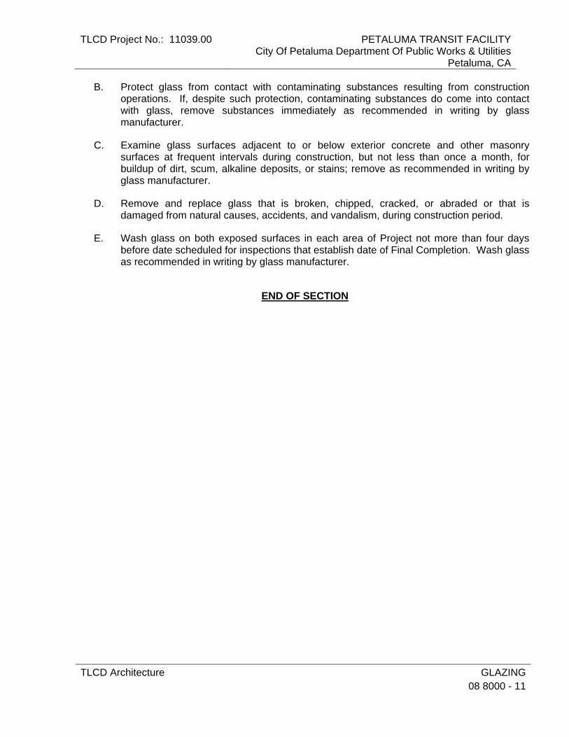
TLCD Project No.: 11039.00 PETALUMA TRANSIT FACILITYCity Of Petaluma Department Of Public Works & Utilities
Petaluma, CA
TLCD Architecture GLAZING08 8000 - 11
B. Protect glass from contact with contaminating substances resulting from construction operations. If, despite such protection, contaminating substances do come into contact with glass, remove substances immediately as recommended in writing by glass manufacturer.
C. Examine glass surfaces adjacent to or below exterior concrete and other masonry surfaces at frequent intervals during construction, but not less than once a month, for buildup of dirt, scum, alkaline deposits, or stains; remove as recommended in writing by glass manufacturer.
D. Remove and replace glass that is broken, chipped, cracked, or abraded or that is damaged from natural causes, accidents, and vandalism, during construction period.
E. Wash glass on both exposed surfaces in each area of Project not more than four days before date scheduled for inspections that establish date of Final Completion. Wash glass as recommended in writing by glass manufacturer.
END OF SECTION

PETALUMA TRANSIT FACILITY City Of Petaluma Department Of Public Works & Utilities Petaluma, CA
TLCD Project No.: 11039.00
GLAZING 08 8000 - 12
TLCD Architecture
THIS PAGE INTENTIONALY LEFT BLANK

TLCD Project No.: 11039.00 PETALUMA TRANSIT FACILITYCity Of Petaluma Department Of Public Works & Utilities
Petaluma, CA
TLCD Architecture NON-STRUCTURAL METAL FRAMING 09 2216 - 1
SECTION 09 2216 - NON-STRUCTURAL METAL FRAMING
PART 1 - GENERAL
1.1 RELATED DOCUMENTS
A. Drawings and general provisions of the Contract, including General and Supplementary Conditions and Division 01 Specification Sections, apply to this Section.
1.2 SUMMARY
A. This Section: 1. Non-load-bearing steel framing systems for interior gypsum board assemblies. 2. Suspension systems for interior gypsum ceilings, soffits, and grid systems.
1.3 ACTION SUBMITTALS
A. Product Data: For each type of product indicated.
PART 2 - PRODUCTS
2.1 FRAMING SYSTEMS
A. Framing Members, General: Comply with ASTM C 754 for conditions indicated. 1. Steel Sheet Components: Comply with ASTM C 645 requirements for metal, unless
otherwise indicated. 2. Protective Coating: ASTM A 653/A 653M, G40, hot-dip galvanized, unless
otherwise indicated.
B. Steel Studs and Runners: ASTM C 645. 1. Minimum Base-Metal Thickness: 0.0312 inch. 2. Depth: As indicated on Drawings.
C. Slip-Type Head Joints: Where indicated, provide one of the following: 1. Single Long-Leg Runner System: ASTM C 645 top runner with 2-inch- deep flanges
in thickness not less than indicated for studs, installed with studs friction fit into top runner and with continuous bridging located within 12 inches of the top of studs to provide lateral bracing.
2. Double-Runner System: ASTM C 645 top runners, inside runner with 2-inch- deep flanges in thickness not less than indicated for studs and fastened to studs, and outer runner sized to friction fit inside runner.
3. Deflection Track: Steel sheet top runner manufactured to prevent cracking of finishes applied to interior partition framing resulting from deflection of structure
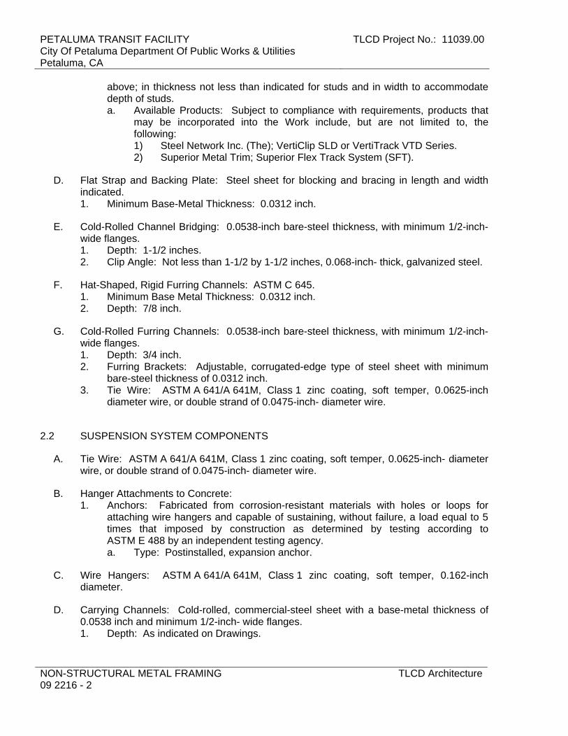
PETALUMA TRANSIT FACILITY City Of Petaluma Department Of Public Works & Utilities Petaluma, CA
TLCD Project No.: 11039.00
NON-STRUCTURAL METAL FRAMING 09 2216 - 2
TLCD Architecture
above; in thickness not less than indicated for studs and in width to accommodate depth of studs. a. Available Products: Subject to compliance with requirements, products that
may be incorporated into the Work include, but are not limited to, the following: 1) Steel Network Inc. (The); VertiClip SLD or VertiTrack VTD Series. 2) Superior Metal Trim; Superior Flex Track System (SFT).
D. Flat Strap and Backing Plate: Steel sheet for blocking and bracing in length and width indicated. 1. Minimum Base-Metal Thickness: 0.0312 inch.
E. Cold-Rolled Channel Bridging: 0.0538-inch bare-steel thickness, with minimum 1/2-inch- wide flanges. 1. Depth: 1-1/2 inches. 2. Clip Angle: Not less than 1-1/2 by 1-1/2 inches, 0.068-inch- thick, galvanized steel.
F. Hat-Shaped, Rigid Furring Channels: ASTM C 645. 1. Minimum Base Metal Thickness: 0.0312 inch. 2. Depth: 7/8 inch.
G. Cold-Rolled Furring Channels: 0.0538-inch bare-steel thickness, with minimum 1/2-inch- wide flanges. 1. Depth: 3/4 inch. 2. Furring Brackets: Adjustable, corrugated-edge type of steel sheet with minimum
bare-steel thickness of 0.0312 inch. 3. Tie Wire: ASTM A 641/A 641M, Class 1 zinc coating, soft temper, 0.0625-inch
diameter wire, or double strand of 0.0475-inch- diameter wire.
2.2 SUSPENSION SYSTEM COMPONENTS
A. Tie Wire: ASTM A 641/A 641M, Class 1 zinc coating, soft temper, 0.0625-inch- diameter wire, or double strand of 0.0475-inch- diameter wire.
B. Hanger Attachments to Concrete: 1. Anchors: Fabricated from corrosion-resistant materials with holes or loops for
attaching wire hangers and capable of sustaining, without failure, a load equal to 5 times that imposed by construction as determined by testing according to ASTM E 488 by an independent testing agency. a. Type: Postinstalled, expansion anchor.
C. Wire Hangers: ASTM A 641/A 641M, Class 1 zinc coating, soft temper, 0.162-inch diameter.
D. Carrying Channels: Cold-rolled, commercial-steel sheet with a base-metal thickness of 0.0538 inch and minimum 1/2-inch- wide flanges. 1. Depth: As indicated on Drawings.
TLCD Project No.: 11039.00 PETALUMA TRANSIT FACILITYCity Of Petaluma Department Of Public Works & Utilities
Petaluma, CA
TLCD Architecture NON-STRUCTURAL METAL FRAMING 09 2216 - 3
E. Furring Channels (Furring Members): 1. Cold-Rolled Channels: 0.0538-inch bare-steel thickness, with minimum 1/2-inch-
wide flanges, 3/4 inch deep. 2. Steel Studs: ASTM C 645.
a. Minimum Base-Metal Thickness: 0.0312 inch. b. Depth: As indicated on Drawings.
3. Hat-Shaped, Rigid Furring Channels: ASTM C 645, 7/8 inch deep. a. Minimum Base Metal Thickness: 0.0312 inch.
F. Grid Suspension System for Ceilings: ASTM C 645, direct-hung system composed of main beams and cross-furring members that interlock. 1. Available Products: Subject to compliance with requirements, products that may be
incorporated into the Work include, but are not limited to, the following: 2. Products: Subject to compliance with requirements, provide one of the following:
a. Armstrong World Industries, Inc.; Drywall Grid Systems. b. Chicago Metallic Corporation; 640/ 660 Non-Fire Rated Drywall Grid System. c. USG Corporation; Drywall Suspension System.
2.3 AUXILIARY MATERIALS
A. General: Provide auxiliary materials that comply with referenced installation standards. 1. Fasteners for Metal Framing: Of type, material, size, corrosion resistance, holding
power, and other properties required to fasten steel members to substrates.
B. Isolation Strip at Exterior Walls: Provide one of the following: 1. Asphalt-Saturated Organic Felt: ASTM D 226, Type I (No. 15 asphalt felt),
nonperforated. 2. Foam Gasket: Adhesive-backed, closed-cell vinyl foam strips that allow fastener
penetration without foam displacement, 1/8 inch thick, in width to suit steel stud size.
PART 3 - EXECUTION
3.1 EXAMINATION
A. Examine areas and substrates, with Installer present, and including welded hollow-metal frames, cast-in anchors, and structural framing, for compliance with requirements and other conditions affecting performance. 1. Proceed with installation only after unsatisfactory conditions have been corrected.
3.2 PREPARATION
A. Suspended Assemblies: Coordinate installation of suspension systems with installation of overhead structure to ensure that inserts and other provisions for anchorages to building structure have been installed to receive hangers at spacing required to support the Work and that hangers will develop their full strength.
PETALUMA TRANSIT FACILITY City Of Petaluma Department Of Public Works & Utilities Petaluma, CA
TLCD Project No.: 11039.00
NON-STRUCTURAL METAL FRAMING 09 2216 - 4
TLCD Architecture
3.3 INSTALLATION, GENERAL
A. Installation Standard: ASTM C 754, except comply with framing sizes and spacing indicated. 1. Gypsum Board Assemblies: Also comply with requirements in ASTM C 840 that
apply to framing installation.
B. Install supplementary framing, and blocking to support fixtures, equipment services, heavy trim, grab bars, toilet accessories, furnishings, or similar construction.
C. Install bracing at terminations in assemblies.
D. Do not bridge building control and expansion joints with non-load-bearing steel framing members. Frame both sides of joints independently.
3.4 INSTALLING FRAMED ASSEMBLIES
A. Where studs are installed directly against exterior masonry walls or dissimilar metals at exterior walls, install isolation strip between studs and exterior wall.
B. Install studs so flanges within framing system point in same direction. 1. Space studs as follows: 16 inches o.c. unless otherwise indicated.
a. Single-Layer Application: 16 inches o.c., unless otherwise indicated.
C. Install tracks (runners) at floors and overhead supports. Extend framing full height to structural supports or substrates above suspended ceilings, except where partitions are indicated to terminate at suspended ceilings. Continue framing around ducts penetrating partitions above ceiling. 1. Slip-Type Head Joints: Where framing extends to overhead structural supports,
install to produce joints at tops of framing systems that prevent axial loading of finished assemblies.
2. Door Openings: Screw vertical studs at jambs to jamb anchor clips on door frames; install runner track section (for cripple studs) at head and secure to jamb studs. a. Install two studs at each jamb, unless otherwise indicated. b. Install cripple studs at head adjacent to each jamb stud, with a minimum 1/2-
inch clearance from jamb stud to allow for installation of control joint in finished assembly.
c. Extend jamb studs through suspended ceilings and attach to underside of overhead structure.
3. Other Framed Openings: Frame openings other than door openings the same as required for door openings, unless otherwise indicated. Install framing below sills of openings to match framing required above door heads.
D. Direct Furring: 1. Attach to concrete or masonry with stub nails, screws designed for masonry
attachment, or powder-driven fasteners spaced 24 inches o.c.
E. Installation Tolerance: Install each framing member so fastening surfaces vary not more than 1/8 inch from the plane formed by faces of adjacent framing.

TLCD Project No.: 11039.00 PETALUMA TRANSIT FACILITYCity Of Petaluma Department Of Public Works & Utilities
Petaluma, CA
TLCD Architecture NON-STRUCTURAL METAL FRAMING 09 2216 - 5
3.5 INSTALLING SUSPENSION SYSTEMS
A. Install suspension system components in sizes and spacings indicated on Drawings, but not less than those required by referenced installation standards for assembly types and other assembly components indicated.
B. Isolate suspension systems from building structure where they abut or are penetrated by building structure to prevent transfer of loading imposed by structural movement.
C. Suspend hangers from building structure as follows: 1. Install hangers plumb and free from contact with insulation or other objects within
ceiling plenum that are not part of supporting structural or suspension system. a. Splay hangers only where required to miss obstructions and offset resulting
horizontal forces by bracing, countersplaying, or other equally effective means.
2. Where width of ducts and other construction within ceiling plenum produces hanger spacings that interfere with locations of hangers required to support standard suspension system members, install supplemental suspension members and hangers in the form of trapezes or equivalent devices. a. Size supplemental suspension members and hangers to support ceiling loads
within performance limits established by referenced installation standards. 3. Wire Hangers: Secure by looping and wire tying, either directly to structures or to
inserts, eye screws, or other devices and fasteners that are secure and appropriate for substrate, and in a manner that will not cause hangers to deteriorate or otherwise fail.
4. Do not attach hangers to steel roof deck. 5. Do not attach hangers to permanent metal forms. Furnish cast-in-place hanger
inserts that extend through forms. 6. Do not attach hangers to rolled-in hanger tabs of composite steel floor deck. 7. Do not connect or suspend steel framing from ducts, pipes, or conduit.
D. Seismic Bracing: Sway-brace suspension systems with hangers used for support.
E. Grid Suspension Systems: Attach perimeter wall track or angle where grid suspension systems meet vertical surfaces. Mechanically join main beam and cross-furring members to each other and butt-cut to fit into wall track.
F. Installation Tolerances: Install suspension systems that are level to within 1/8 inch in 12 feet measured lengthwise on each member that will receive finishes and transversely between parallel members that will receive finishes.
END OF SECTION
PETALUMA TRANSIT FACILITY City Of Petaluma Department Of Public Works & Utilities Petaluma, CA
TLCD Project No.: 11039.00
NON-STRUCTURAL METAL FRAMING 09 2216 - 6
TLCD Architecture
THIS PAGE INTENTIONALLY LEFT BLANK

TLCD Project No.: 11039.00 PETALUMA TRANSIT FACILITYCity Of Petaluma Department Of Public Works & Utilities
Petaluma, CA
TLCD Architecture GYPSUM BOARD09 2900 - 1
SECTION 09 2900 - GYPSUM BOARD
PART 1 - GENERAL
1.1 RELATED DOCUMENTS
A. Drawings and general provisions of the Contract, including General and Supplementary Conditions and Division 01 Specification Sections, apply to this Section.
1.2 SUMMARY
A. Section Includes: 1. Interior gypsum board.
B. Related Requirements: 1. Section 09 2216 "Non-Structural Metal Framing" for non-structural framing and
suspension systems that support gypsum board panels.
1.3 ACTION SUBMITTALS
A. Product Data: For each type of product.
B. Samples: For the following products: 1. Trim Accessories: Full-size Sample in 12-inch long length for each trim accessory
indicated.
1.4 QUALITY ASSURANCE
A. Mockups: Before beginning gypsum board installation, install mockups of at least 100 sq. ft. in surface area to demonstrate aesthetic effects and set quality standards for materials and execution. 1. Install mockups for the following:
a. Each level of gypsum board finish indicated for use in exposed locations. b. Each texture finish indicated.
2. Apply or install final decoration indicated, including painting and wallcoverings, on exposed surfaces for review of mockups.
3. Simulate finished lighting conditions for review of mockups. 4. Subject to compliance with requirements, approved mockups may become part of
the completed Work if undisturbed at time of Substantial Completion.

PETALUMA TRANSIT FACILITY City Of Petaluma Department Of Public Works & Utilities Petaluma, CA
TLCD Project No.: 11039.00
GYPSUM BOARD 09 2900 - 2
TLCD Architecture
1.5 DELIVERY, STORAGE AND HANDLING
A. Store materials inside under cover and keep them dry and protected against weather, condensation, direct sunlight, construction traffic, and other potential causes of damage. Stack panels flat and supported on risers on a flat platform to prevent sagging.
1.6 FIELD CONDITIONS
A. Environmental Limitations: Comply with ASTM C 840 requirements or gypsum board manufacturer's written recommendations, whichever are more stringent.
B. Do not install paper-faced gypsum panels until installation areas are enclosed and conditioned.
C. Do not install panels that are wet, those that are moisture damaged, and those that are mold damaged. 1. Indications that panels are wet or moisture damaged include, but are not limited to,
discoloration, sagging, or irregular shape. 2. Indications that panels are mold damaged include, but are not limited to, fuzzy or
splotchy surface contamination and discoloration.
PART 2 - PRODUCTS
2.1 GYPSUM BOARD, GENERAL
A. Size: Provide maximum lengths and widths available that will minimize joints in each area and that correspond with support system indicated.
2.2 INTERIOR GYPSUM BOARD
A. Manufacturers: Subject to compliance with requirements, available manufacturers offering products that may be incorporated into the Work include, but are not limited to, the following: 1. American Gypsum. 2. CertainTeed Corp. 3. Georgia-Pacific Gypsum LLC. 4. Lafarge North America Inc. 5. National Gypsum Company. 6. PABCO Gypsum. 7. Temple-Inland. 8. USG Corporation. 9. Approved equal.
B. Gypsum Board, Type X: ASTM C 1396/C 1396M. 1. Thickness: 5/8 inch. 2. Long Edges: Tapered and featured (rounded or beveled) for prefilling.
TLCD Project No.: 11039.00 PETALUMA TRANSIT FACILITYCity Of Petaluma Department Of Public Works & Utilities
Petaluma, CA
TLCD Architecture GYPSUM BOARD09 2900 - 3
C. Moisture- and Mold-Resistant Gypsum Board: ASTM C 1396/C 1396M. With moisture- and mold-resistant core and paper surfaces. 1. Core: 5/8 inch, Type X. 2. Long Edges: Tapered. 3. Mold Resistance: ASTM D 3273, score of 10 as rated according to ASTM D 3274.
2.3 TRIM ACCESSORIES
A. Interior Trim: ASTM C 1047. 1. Material: Galvanized or aluminum-coated steel sheet or rolled zinc. 2. Shapes:
a. Cornerbead. b. LC-Bead: J-shaped; exposed long flange receives joint compound. c. L-Bead: L-shaped; exposed long flange receives joint compound. d. Expansion (control) joint.
2.4 JOINT TREATMENT MATERIALS
A. General: Comply with ASTM C 475/C 475M.
B. Joint Tape: 1. Interior Gypsum Board: Paper.
C. Joint Compound for Interior Gypsum Board: For each coat use formulation that is compatible with other compounds applied on previous or for successive coats. 1. Prefilling: At open joints, rounded or beveled panel edges, and damaged surface
areas, use setting-type taping compound. 2. Embedding and First Coat: For embedding tape and first coat on joints, fasteners,
and trim flanges, use drying-type, all-purpose compound. a. Use setting-type compound for installing paper-faced metal trim accessories.
3. Fill Coat: For second coat, use drying-type, all-purpose compound. 4. Finish Coat: For third coat, use drying-type, all-purpose compound. 5. Skim Coat: For final coat of Level 5 finish, drying-type, all-purpose compound high-
build or interior coating product designed for application by airless sprayer and to be used instead of skim coat to produce Level 5 finish.
2.5 AUXILIARY MATERIALS
A. General: Provide auxiliary materials that comply with referenced installation standards and manufacturer's written recommendations.
B. Steel Drill Screws: ASTM C 1002, unless otherwise indicated. 1. Use screws complying with ASTM C 954 for fastening panels to steel members from
0.033 to 0.112 inch thick.

PETALUMA TRANSIT FACILITY City Of Petaluma Department Of Public Works & Utilities Petaluma, CA
TLCD Project No.: 11039.00
GYPSUM BOARD 09 2900 - 4
TLCD Architecture
PART 3 - EXECUTION
3.1 EXAMINATION
A. Examine areas and substrates including welded hollow-metal frames and framing, with Installer present, for compliance with requirements and other conditions affecting performance.
B. Examine panels before installation. Reject panels that are wet, moisture damaged, and mold damaged.
C. Proceed with installation only after unsatisfactory conditions have been corrected.
3.2 APPLYING AND FINISHING PANELS, GENERAL
A. Comply with ASTM C 840.
B. Install ceiling panels across framing to minimize the number of abutting end joints and to avoid abutting end joints in central area of each ceiling. Stagger abutting end joints of adjacent panels not less than one framing member.
C. Install panels with face side out. Butt panels together for a light contact at edges and ends with not more than 1/16 inch of open space between panels. Do not force into place.
D. Locate edge and end joints over supports, except in ceiling applications where intermediate supports or gypsum board back-blocking is provided behind end joints. Do not place tapered edges against cut edges or ends. Stagger vertical joints on opposite sides of partitions. Do not make joints other than control joints at corners of framed openings.
E. Form control and expansion joints with space between edges of adjoining gypsum panels.
F. Cover both faces of support framing with gypsum panels in concealed spaces (above ceilings, etc.), except in chases braced internally. 1. Unless concealed application is indicated or required for sound, fire, air, or smoke
ratings, coverage may be accomplished with scraps of not less than 8 sq. ft. in area. 2. Fit gypsum panels around ducts, pipes, and conduits. 3. Where partitions intersect structural members projecting below underside of
floor/roof slabs and decks, cut gypsum panels to fit profile formed by structural members; allow 1/4- to 3/8-inch- wide joints to install sealant.
G. Isolate perimeter of gypsum board applied to non-load-bearing partitions at structural abutments, except floors. Provide 1/4- to 1/2-inch- wide spaces at these locations and trim edges with edge trim where edges of panels are exposed. Seal joints between edges and abutting structural surfaces with acoustical sealant.

TLCD Project No.: 11039.00 PETALUMA TRANSIT FACILITYCity Of Petaluma Department Of Public Works & Utilities
Petaluma, CA
TLCD Architecture GYPSUM BOARD09 2900 - 5
H. Attachment to Steel Framing: Attach panels so leading edge or end of each panel is attached to open (unsupported) edges of stud flanges first.
3.3 APPLYING INTERIOR GYPSUM BOARD
A. Install interior gypsum board in the following locations: 1. Type X: Typical unless otherwise indicated. 2. Ceiling Type: Ceiling surfaces. 3. Moisture- and Mold-Resistant Type: At wash bay and as indicated.
B. Single-Layer Application: 1. On ceilings, apply gypsum panels before wall/partition board application to greatest
extent possible and at right angles to framing unless otherwise indicated. 2. On partitions/walls, apply gypsum panels horizontally (perpendicular to framing)
unless otherwise indicated or required by fire-resistance-rated assembly, and minimize end joints. a. Stagger abutting end joints not less than one framing member in alternate
courses of panels. b. At high walls, install panels horizontally unless otherwise indicated.
3. Fastening Methods: Apply gypsum panels to supports with steel drill screws.
C. Comply with manufacturer’s installation recommendations.
3.4 INSTALLING TRIM ACCESSORIES
A. General: For trim with back flanges intended for fasteners, attach to framing with same fasteners used for panels. Otherwise, attach trim according to manufacturer's written instructions.
B. Control Joints: Install control joints according to ASTM C 840 and in specific locations approved by Architect for visual effect.
C. Interior Trim: Install in the following locations: 1. Cornerbead: Use at outside corners. 2. LC-Bead: Use at exposed panel edges. 3. L-Bead: Use where indicated and at intersections with dissimilar materials.
3.5 FINISHING GYPSUM BOARD
A. General: Treat gypsum board joints, interior angles, edge trim, control joints, penetrations, fastener heads, surface defects, and elsewhere as required to prepare gypsum board surfaces for decoration. Promptly remove residual joint compound from adjacent surfaces.
B. Prefill open joints, rounded or beveled edges, and damaged surface areas.
C. Apply joint tape over gypsum board joints, except for trim products specifically indicated as not intended to receive tape.

PETALUMA TRANSIT FACILITY City Of Petaluma Department Of Public Works & Utilities Petaluma, CA
TLCD Project No.: 11039.00
GYPSUM BOARD 09 2900 - 6
TLCD Architecture
D. Gypsum Board Finish Levels: Finish panels to levels indicated below and according to ASTM C 840: 1. Level 1: Ceiling plenum areas, concealed areas, and where indicated. 2. Level 2: Panels that are substrate for FRP. 3. Level 4: At panel surfaces that will be exposed to view unless otherwise indicated.
a. Primer and its application to surfaces are specified in Section 09 9100 "Painting."
4. Level 5: Where indicated on Drawings. a. Primer and its application to surfaces are specified in other Section 09 9100
"Painting."
3.6 PROTECTION
A. Protect adjacent surfaces from drywall compound and promptly remove from floors and other non-drywall surfaces. Repair surfaces stained, marred, or otherwise damaged during drywall application.
B. Protect installed products from damage from weather, condensation, direct sunlight, construction, and other causes during remainder of the construction period.
C. Remove and replace panels that are wet, moisture damaged, and mold damaged. 1. Indications that panels are wet or moisture damaged include, but are not limited to,
discoloration, sagging, or irregular shape. 2. Indications that panels are mold damaged include, but are not limited to, fuzzy or
splotchy surface contamination and discoloration.
END OF SECTION
TLCD Project No.: 11039.00 PETALUMA TRANSIT FACILITYCity Of Petaluma Department Of Public Works & Utilities
Petaluma, CA
TLCD Architecture RESILIENT BASE AND ACCESSORIES09 6513 - 1
SECTION 09 6513 - RESILIENT BASE AND ACCESSORIES
PART 1 - GENERAL
1.1 RELATED DOCUMENTS
A. Drawings and general provisions of the Contract, including General and Supplementary Conditions and Division 01 Specification Sections, apply to this Section.
1.2 SUMMARY
A. Section Includes: 1. Resilient base.
1.3 ACTION SUBMITTALS
A. Product Data: For each type of product indicated.
B. Samples for Verification: For each type of product indicated, in manufacturer's standard-size Samples but not less than 12 inches long, of each resilient product color, texture, and pattern required.
C. Product Schedule: For resilient products. Use same designations indicated on Drawings.
1.4 MAINTENANCE MATERIAL SUBMITTALS
A. Furnish extra materials that match products installed and that are packaged with protective covering for storage and identified with labels describing contents. 1. Furnish not less than 10 linear feet for every 500 linear feet or fraction thereof, of
each type, color, pattern, and size of resilient product installed.
1.5 QUALITY ASSURANCE
A. Fire-Test-Response Characteristics: As determined by testing identical products according to ASTM E 648 or NFPA 253 by a qualified testing agency. 1. Critical Radiant Flux Classification: Class I, not less than 0.45 W/sq. cm.
1.6 DELIVERY, STORAGE, AND HANDLING
A. Store resilient products and installation materials in dry spaces protected from the weather, with ambient temperatures maintained within range recommended by manufacturer, but not less than 50 deg F or more than 90 deg F.
PETALUMA TRANSIT FACILITY City Of Petaluma Department Of Public Works & Utilities Petaluma, CA
TLCD Project No.: 11039.00
RESILIENT BASE AND ACCESSORIES 09 6513 - 2
TLCD Architecture
1.7 PROJECT CONDITIONS
A. Maintain ambient temperatures within range recommended by manufacturer, but not less than 70 deg F or more than 95 deg F, in spaces to receive resilient products during the following time periods: 1. 48 hours before installation. 2. During installation. 3. 48 hours after installation.
B. Until Substantial Completion, maintain ambient temperatures within range recommended by manufacturer, but not less than 55 deg F or more than 95 deg F.
C. Install resilient products after other finishing operations, including painting, have been completed.
PART 2 - PRODUCTS
2.1 RESILIENT BASE
A. Resilient Base: 1. Basis of Design: Subject to compliance with requirements, provide Burke Mercer
Flooring Products “BurkeBase” or equal products by one of the following: a. Allstate Rubber Corp.; Stoler Industries. b. Armstrong World Industries, Inc. c. Endura Rubber Flooring; Division of Burke Industries, Inc. d. Estrie Products International; American Biltrite (Canada) Ltd. e. Flexco, Inc. f. Johnsonite. g. Mondo Rubber International, Inc. h. Musson, R. C. Rubber Co. i. Nora Rubber Flooring; Freudenberg Building Systems, Inc. j. PRF USA, Inc. k. Roppe Corporation, USA. l. VPI, LLC; Floor Products Division. m. Approved equal.
B. Resilient Base Standard: ASTM F 1861. 1. Material Requirement: Type TS (rubber, vulcanized thermoset) or Type TP (rubber,
thermoplastic). 2. Manufacturing Method: Group I (solid, homogeneous). 3. Style: Cove (base with toe)
C. Minimum Thickness: 0.125 inch.
D. Height: 4 inches.
E. Lengths: Coils in manufacturer's standard length.
F. Outside Corners: Preformed.
TLCD Project No.: 11039.00 PETALUMA TRANSIT FACILITYCity Of Petaluma Department Of Public Works & Utilities
Petaluma, CA
TLCD Architecture RESILIENT BASE AND ACCESSORIES09 6513 - 3
G. Inside Corners: Preformed.
H. Colors and Patterns: As selected.
2.2 INSTALLATION MATERIALS
A. Trowelable Leveling and Patching Compounds: Latex-modified, portland cement based or blended hydraulic-cement-based formulation provided or approved by manufacturer for applications indicated.
B. Adhesives: Water-resistant type recommended by manufacturer to suit resilient products and substrate conditions indicated. 1. Adhesives shall comply with the testing and product requirements of the California
Department of Health Services' "Standard Practice for the Testing of Volatile Organic Emissions from Various Sources Using Small-Scale Environmental Chambers."
C. Metal Edge Strips: Extruded aluminum with mill finish of width shown, of height required to protect exposed edges of tiles, and in maximum available lengths to minimize running joints.
PART 3 - EXECUTION
3.1 EXAMINATION
A. Examine substrates, with Installer present, for compliance with requirements for maximum moisture content and other conditions affecting performance of the Work.
B. Verify that finishes of substrates comply with tolerances and other requirements specified in other Sections and that substrates are free of cracks, ridges, depressions, scale, and foreign deposits that might interfere with adhesion of resilient products.
C. Proceed with installation only after unsatisfactory conditions have been corrected.
3.2 PREPARATION
A. Prepare substrates according to manufacturer's written instructions to ensure adhesion of resilient products.
B. Fill cracks, holes, and depressions in substrates with trowelable leveling and patching compound and remove bumps and ridges to produce a uniform and smooth substrate.
C. Do not install resilient products until they are same temperature as the space where they are to be installed. 1. Move resilient products and installation materials into spaces where they will be
installed at least 48 hours in advance of installation.

PETALUMA TRANSIT FACILITY City Of Petaluma Department Of Public Works & Utilities Petaluma, CA
TLCD Project No.: 11039.00
RESILIENT BASE AND ACCESSORIES 09 6513 - 4
TLCD Architecture
D. Sweep and vacuum clean substrates to be covered by resilient products immediately before installation.
3.3 RESILIENT BASE INSTALLATION
A. Comply with manufacturer's written instructions for installing resilient base.
B. Apply resilient base to walls, columns, pilasters, casework and cabinets in toe spaces, and other permanent fixtures in rooms and areas where base is required.
C. Install resilient base in lengths as long as practicable without gaps at seams and with tops of adjacent pieces aligned.
D. Tightly adhere resilient base to substrate throughout length of each piece, with base in continuous contact with horizontal and vertical substrates.
E. Do not stretch resilient base during installation.
F. On masonry surfaces or other similar irregular substrates, fill voids along top edge of resilient base with manufacturer's recommended adhesive filler material.
G. Preformed Corners: Install preformed corners before installing straight pieces.
3.4 CLEANING AND PROTECTION
A. Comply with manufacturer's written instructions for cleaning and protection of resilient products.
B. Perform the following operations immediately after completing resilient product installation: 1. Remove adhesive and other blemishes from exposed surfaces.
C. Protect resilient products from mars, marks, indentations, and other damage from construction operations and placement of equipment and fixtures during remainder of construction period.
D. Cover resilient products until Substantial Completion.
END OF SECTION
TLCD Project No.: 11039.00 PETALUMA TRANSIT FACILITYCity Of Petaluma Department Of Public Works & Utilities
Petaluma, CA
TLCD Architecture SHEET CARPETING09 6816 - 1
SECTION 09 6816 - SHEET CARPETING
PART 1 - GENERAL
1.1 RELATED DOCUMENTS
A. Drawings and general provisions of the Contract, including General and Supplementary Conditions and Division 01 Specification Sections, apply to this Section.
1.2 SUMMARY
A. Section Includes: 1. Tufted carpet.
B. Related Requirements: 1. Section 09 6513 "Resilient Base and Accessories" for resilient wall base and
accessories installed with carpet.
1.3 PREINSTALLATION MEETINGS
A. Preinstallation Conference: Conduct conference at Project site. 1. Review methods and procedures related to carpet installation including, but not
limited to, the following: a. Review delivery, storage, and handling procedures. b. Review ambient conditions and ventilation procedures. c. Review subfloor preparation procedures.
1.4 ACTION SUBMITTALS
A. Product Data: For the following, including installation recommendations for each type of substrate: 1. Carpet: For each type indicated. Include manufacturer's written data on physical
characteristics, durability, and fade resistance.
B. Shop Drawings: Show the following: 1. Columns, doorways, enclosing walls or partitions, built-in cabinets, and locations
where cutouts are required in carpet. 2. Carpet type, color, and dye lot. 3. Locations where dye lot changes occur. 4. Seam locations, types, and methods. 5. Type of subfloor. 6. Type of installation. 7. Pattern type, repeat size, location, direction, and starting point. 8. Pile direction. 9. Type, color, and location of insets and borders.
PETALUMA TRANSIT FACILITY City Of Petaluma Department Of Public Works & Utilities Petaluma, CA
TLCD Project No.: 11039.00
SHEET CARPETING 09 6816 - 2
TLCD Architecture
10. Type, color, and location of edge, transition, and other accessory strips. 11. Transition details to other flooring materials. 12. Type of carpet cushion.
C. Samples: For each of the following products and for each color and texture required. Label each Sample with manufacturer's name, material description, color, pattern, and designation indicated on Drawings and in schedules. 1. Carpet: 12-inch- square Sample. 2. Exposed Edge, Transition, and Other Accessory Stripping: 12-inch- long Samples. 3. Carpet Seam: 6-inch Sample. 4. Mitered Carpet Border Seam: 12-inch- square Sample. Show carpet pattern
alignment.
1.5 INFORMATIONAL SUBMITTALS
A. Qualification Data: For qualified Installer.
B. Product Test Reports: For carpet, for tests performed by a qualified testing agency.
C. Sample Warranties: For special warranties.
1.6 CLOSEOUT SUBMITTALS
A. Maintenance Data: For carpet to include in maintenance manuals. Include the following: 1. Methods for maintaining carpet, including cleaning and stain-removal products and
procedures and manufacturer's recommended maintenance schedule. 2. Precautions for cleaning materials and methods that could be detrimental to carpet.
1.7 MAINTENANCE MATERIAL SUBMITTALS
A. Furnish extra materials, from the same product run, that match products installed and that are packaged with protective covering for storage and identified with labels describing contents. 1. Carpet: Full-width rolls equal to 5 percent of amount installed for each type
indicated, but not less than 10 sq. yd..
1.8 QUALITY ASSURANCE
A. Fire-Test-Response Ratings: Where indicated, provide carpet identical to those of assemblies tested for fire response per NFPA 253 by a qualified testing agency.
1.9 DELIVERY, STORAGE, AND HANDLING
A. Comply with CRI ”Carpet Installation Standard 2011.”.

TLCD Project No.: 11039.00 PETALUMA TRANSIT FACILITYCity Of Petaluma Department Of Public Works & Utilities
Petaluma, CA
TLCD Architecture SHEET CARPETING09 6816 - 3
1.10 FIELD CONDITIONS
A. Comply with CRI “Carpet Installation Standard” for temperature, humidity, and ventilation limitations.
B. Environmental Limitations: Do not deliver or install carpet until spaces are enclosed and weathertight, wet work in spaces is complete and dry, and ambient temperature and humidity conditions are maintained at occupancy levels during the remainder of the construction period.
C. Do not install carpet over concrete slabs until slabs have cured, are sufficiently dry to bond with adhesive, and have pH range recommended by carpet manufacturer.
D. Where demountable partitions or other items are indicated for installation on top of carpet, install carpet before installing these items.
PART 2 - PRODUCTS
2.1 TUFTED CARPET
A. Basis-of-Design Product: Subject to compliance with requirements, provide products by Bigelow Commercial or approved equal.
B. Style: Artist.
C. Style No.: BQ199
D. Color: As selected.
E. Fiber Type: Colorstrand Nylon.
F. Surface Appearance: Texturd Multi Colored Loop.
G. Density: 4,898
H. Pile Weight: 20.0 ounces per square yard.
I. Pile Thickness: 0.147 inches for finished carpet.
J. Stitches: 11.0 per inch.
K. Gage: 1/10.
L. Primary Backing: Woven polypropylene.
M. Secondary Backing: Woven polypropylene.
N. Width: 12 feet.
O. Applied Soil-Resistance Treatment: Sentry Plus.
PETALUMA TRANSIT FACILITY City Of Petaluma Department Of Public Works & Utilities Petaluma, CA
TLCD Project No.: 11039.00
SHEET CARPETING 09 6816 - 4
TLCD Architecture
P. Performance Characteristics: As follows: 1. Appearance Retention Rating: Heavy traffic, 3.0 minimum per ASTM D 7330. 2. Antimicrobial Activity: Not less than 2-mm halo of inhibition for gram-positive
bacteria; not less than 1-mm halo of inhibition for gram-negative bacteria; no fungal growth; per AATCC 174.
3. Electrostatic Propensity: Less than 3.5 kV per AATCC 134. 4. Emissions: Provide carpet that complies with the product requirements of the
California Department of Health Services' "Standard Practice for the Testing of Volatile Organic Emissions from Various Sources Using Small-Scale Environmental Chambers."
2.2 INSTALLATION ACCESSORIES
A. Trowelable Leveling and Patching Compounds: Latex-modified, hydraulic-cement-based formulation provided or recommended by carpet manufacturer.
B. Adhesives: Water-resistant, mildew-resistant, nonstaining type to suit products and subfloor conditions indicated, that complies with flammability requirements for installed carpet and is recommended or provided by carpet manufacturer. 1. Use adhesives with VOC content not more than 50 g/L when calculated according to
40 CFR 59, Subpart D (EPA Method 24). 2. Use adhesives that comply with the product requirements of the California
Department of Health Services' "Standard Practice for the Testing of Volatile Organic Emissions from Various Sources Using Small-Scale Environmental Chambers."
C. Seam Adhesive: Hot-melt adhesive tape or similar product recommended by carpet manufacturer for sealing and taping seams and butting cut edges at backing to form secure seams and to prevent pile loss at seams.
D. Metal Edge/Transition Strips: Extruded aluminum with mill finish of profile and width shown, of height required to protect exposed edge of carpet, and of maximum lengths to minimize running joints.
PART 3 - EXECUTION
3.1 EXAMINATION
A. Examine substrates, areas, and conditions, with Installer present, for compliance with requirements for maximum moisture content, alkalinity range, installation tolerances, and other conditions affecting carpet performance. Examine carpet for type, color, pattern, and potential defects.
B. Concrete Subfloors: Verify that concrete slabs comply with ASTM F 710 and the following: 1. Slab substrates are dry and free of curing compounds, sealers, hardeners, and
other materials that may interfere with adhesive bond. Determine adhesion and
TLCD Project No.: 11039.00 PETALUMA TRANSIT FACILITYCity Of Petaluma Department Of Public Works & Utilities
Petaluma, CA
TLCD Architecture SHEET CARPETING09 6816 - 5
dryness characteristics by performing bond and moisture tests recommended by carpet manufacturer.
2. Subfloor finishes comply with requirements specified in Section 033000 "Cast-in-Place Concrete" for slabs receiving carpet.
3. Subfloors are free of cracks, ridges, depressions, scale, and foreign deposits.
C. For wood subfloors, verify the following: 1. Underlayment surface is free of irregularities and substances that may interfere with
adhesive bond or show through surface.
D. Proceed with installation only after unsatisfactory conditions have been corrected.
3.2 PREPARATION
A. General: Comply with CRI ”Carpet Installation Standards”, Section 7.3, "Site Conditions; Floor Preparation," and with carpet manufacturer's written installation instructions for preparing substrates.
B. Use trowelable leveling and patching compounds, according to manufacturer's written instructions, to fill cracks, holes, depressions, and protrusions in substrates. Fill or level cracks, holes and depressions 1/8 inch wide or wider, and protrusions more than 1/32 inch, unless more stringent requirements are required by manufacturer's written instructions.
C. Remove coatings, including curing compounds, and other substances that are incompatible with adhesives and that contain soap, wax, oil, or silicone, without using solvents. Use mechanical methods recommended in writing by carpet manufacturer.
D. Broom and vacuum clean substrates to be covered immediately before installing carpet.
3.3 INSTALLATION
A. Comply with CRI “Carpet Installation Standard” and carpet manufacturer's written installation instructions for the following: 1. Direct-Glue-Down Installation: Comply with CRI ”Carpet Installation Standard” ,
Section 13, "Direct Glue-Down Installation."
B. Comply with carpet manufacturer's written recommendations and Shop Drawings for seam locations and direction of carpet; maintain uniformity of carpet direction and lay of pile. At doorways, center seams under the door in closed position.
C. Do not bridge building expansion joints with carpet.
D. Cut and fit carpet to butt tightly to vertical surfaces, permanent fixtures, and built-in furniture including cabinets, pipes, outlets, edgings, thresholds, and nosings. Bind or seal cut edges as recommended by carpet manufacturer.
E. Extend carpet into toe spaces, door reveals, closets, open-bottomed obstructions, removable flanges, alcoves, and similar openings.

PETALUMA TRANSIT FACILITY City Of Petaluma Department Of Public Works & Utilities Petaluma, CA
TLCD Project No.: 11039.00
SHEET CARPETING 09 6816 - 6
TLCD Architecture
F. Maintain reference markers, holes, and openings that are in place or marked for future cutting by repeating on finish flooring as marked on subfloor. Use nonpermanent, nonstaining marking device.
G. Install pattern parallel to walls and borders to comply with CRI 104, Section 15, "Patterned Carpet Installations" and with carpet manufacturer's written recommendations.
3.4 CLEANING AND PROTECTING
A. Perform the following operations immediately after installing carpet: 1. Remove excess adhesive, seam sealer, and other surface blemishes using cleaner
recommended by carpet manufacturer. 2. Remove yarns that protrude from carpet surface. 3. Vacuum carpet using commercial machine with face-beater element.
B. Protect installed carpet to comply with CRI ”Carpet Installation Standard”, Section 20, "Protecting Indoor Installations."
C. Protect carpet against damage from construction operations and placement of equipment and fixtures during the remainder of construction period. Use protection methods indicated or recommended in writing by carpet manufacturer and carpet adhesive manufacturer.
END OF SECTION

TLCD Project No.: 11039.00 PETALUMA TRANSIT FACILITYCity Of Petaluma Department Of Public Works & Utilities
Petaluma, CA
TLCD Architecture PAINTING09 9100-1
SECTION 09 9100 - PAINTING
PART 1 - GENERAL
1.1 RELATED DOCUMENTS
A. Drawings and general provisions of the Contract, including General and Supplementary Conditions and Division 01 Specification Sections, apply to this Section.
1.2 SUMMARY
A. This Section includes surface preparation and the application of paint systems on the following substrates: 1. Exterior substrates:
a. Steel. b. Galvanized metal.
2. Interior substrates: a. Steel. b. Galvanized metal. c. Aluminum (not anodized or otherwise coated). d. Wood. e. Gypsum board. f. Cotton or canvas insulation covering.
B. Related Sections include the following: 1. Division 05 and 13 Sections for shop priming of metal substrates with primers
specified in this Section. 2. Section 09 9600 “High Performance Coatings” for special-use coatings.
1.3 DEFINITIONS
A. Gloss/ Sheen Ratings: Paint gloss shall be defined as the sheen rating of applied paint according to ASTM D523 and the following MPI values:
Gloss Level Description Units at 60 degrees Units at 85 degrees G1 Matte or Flat finish 0 to 5 10 maximum G2 Velvet finish 0 to 10 10 to 35 G3 Eggshell finish 10 to 25 10 to 35 G4 Satin finish 20 to 35 35 minimum. G5 Semi-gloss finish 35 to 70 G6 Gloss finish 70 to 85 G7 High-Gloss finish Greater than 85
1.4 ACTION SUBMITTALS
A. Product Data: For each type of product indicated.
B. Samples for Initial Selection: For each type of topcoat product indicated.

PETALUMA TRANSIT FACILITY City Of Petaluma Department Of Public Works & Utilities Petaluma, CA
TLCD Project No.: 11039.00
PAINTING 09 9100-2
TLCD Architecture
C. Samples for Verification: For each type of paint system and in each color and gloss of topcoat indicated. 1. Submit Samples on rigid backing, 8 inches square. 2. Step coats on Samples to show each coat required for system. 3. Label each coat of each Sample. 4. Label each Sample for location and application area.
D. Product List: For each product indicated, include the following: 1. Cross-reference to paint system and locations of application areas. Use same
designations indicated on Drawings and in schedules.
1.5 INFORMATIONAL SUBMITTALS
A. Qualification Data: For Applicator.
1.6 QUALITY ASSURANCE
A. Applicator Qualifications: A firm or individual with a minimum of five (5) years of experience in applying paints and coatings similar in material, design, and extent to those indicated for this Project whose work has resulted in applications with a record of successful in-service performance.
B. MPI Standards: 1. Products: Complying with MPI standards indicated and listed in "MPI Approved
Products List." 2. Preparation and Workmanship: Comply with requirements in "MPI Architectural
Painting Specification Manual" for products and paint systems indicated.
C. Mockups: Apply benchmark samples of each paint system indicated and each color and finish selected to verify preliminary selections made under sample submittals and to demonstrate aesthetic effects and set quality standards for materials and execution. 1. Architect will select one surface to represent surfaces and conditions for application
of each paint system specified in Part 3. a. Wall and Ceiling Surfaces: Provide samples of at least 100 sq. ft. b. Other Items: Architect will designate items or areas required.
2. Apply benchmark samples after permanent lighting and other environmental services have been activated.
3. Final approval of color selections will be based on benchmark samples. a. If preliminary color selections are not approved, apply additional benchmark
samples of additional colors selected by Architect at no added cost to Owner.
1.7 DELIVERY, STORAGE, AND HANDLING
A. Store materials not in use in tightly covered containers in well-ventilated areas with ambient temperatures continuously maintained at not less than 45 deg F. 1. Maintain containers in clean condition, free of foreign materials and residue. 2. Remove rags and waste from storage areas daily.

TLCD Project No.: 11039.00 PETALUMA TRANSIT FACILITYCity Of Petaluma Department Of Public Works & Utilities
Petaluma, CA
TLCD Architecture PAINTING09 9100-3
1.8 FIELD CONDITIONS
A. Apply paints only when temperature of surfaces to be painted and ambient air temperatures are between 50 and 95 deg F.
B. Do not apply paints in snow, rain, fog or mist; when relative humidity exceeds 85 percent; at temperatures less than 5 deg F above the dew point; or to damp or wet surfaces.
1.9 EXTRA MATERIALS
A. Furnish extra materials described below that are from same production run (batch mix) as materials applied and that are packaged for storage and identified with labels describing contents. 1. Quantity: Furnish an additional 5 percent, but not less than 1 gal. of each material
and color applied.
PART 2 - PRODUCTS
2.1 MANUFACTURERS
A. Basis of Design: Subject to compliance with requirements, provide products by Kelly-Moore Paints or equal products by one of the following: 1. Benjamin Moore & Co. 2. Dunn-Edwards Corporation. 3. Frazee Paint Company 4. ICI Dulux 5. Messmer 6. Sherwin-Williams Company (The). 7. Approved equal.
2.2 PAINT, GENERAL
A. Material Compatibility: 1. Provide materials for use within each paint system that are compatible with one
another and substrates indicated, under conditions of service and application as demonstrated by manufacturer, based on testing and field experience.
2. For each coat in a paint system, provide products recommended in writing by manufacturers of topcoat for use in paint system and on substrate indicated.
B. Chemical Components of Field-Applied Interior Paints and Coatings: Provide products that comply with the following limits for VOC content, exclusive of colorants added to a tint base, when calculated according to 40 CFR 59, Subpart D (EPA Method 24) and the following chemical restrictions; these requirements do not apply to primers or finishes that are applied in a fabrication or finishing shop: 1. Flat Paints and Coatings: VOC content of not more than 50 g/L. 2. Nonflat Paints and Coatings: VOC content of not more than 150 g/L. 3. Aromatic Compounds: Paints and coatings shall not contain more than 1.0 percent
by weight of total aromatic compounds (hydrocarbon compounds containing one or more benzene rings).

PETALUMA TRANSIT FACILITY City Of Petaluma Department Of Public Works & Utilities Petaluma, CA
TLCD Project No.: 11039.00
PAINTING 09 9100-4
TLCD Architecture
C. Colors: As indicated in a color schedule.
PART 3 - EXECUTION
3.1 EXAMINATION
A. Examine substrates and conditions, with Applicator present, for compliance with requirements for maximum moisture content and other conditions affecting performance of work.
B. Maximum Moisture Content of Substrates: When measured with an electronic moisture meter as follows: 1. Concrete: 12 percent. 2. Wood: 15 percent. 3. Gypsum Board: 12 percent.
C. Verify suitability of substrates, including surface conditions and compatibility with existing finishes and primers.
D. Begin coating application only after unsatisfactory conditions have been corrected and surfaces are dry. 1. Beginning coating application constitutes Contractor's acceptance of substrates and
conditions.
3.2 PREPARATION
A. Comply with manufacturer's written instructions and recommendations in "MPI Architectural Painting Specification Manual" applicable to substrates indicated.
B. Remove plates, machined surfaces, and similar items already in place that are not to be painted. If removal is impractical or impossible because of size or weight of item, provide surface-applied protection before surface preparation and painting. 1. After completing painting operations, use workers skilled in the trades involved to
reinstall items that were removed. Remove surface-applied protection if any. 2. Do not paint over labels of independent testing agencies or equipment name,
identification, performance rating, or nomenclature plates.
C. Clean substrates of substances that could impair bond of paints, including dirt, oil, grease, and incompatible paints and encapsulants. 1. Remove incompatible primers and reprime substrate with compatible primers as
required to produce paint systems indicated.
D. Steel Substrates: Remove rust and loose mill scale. Clean using methods recommended in writing by paint manufacturer.
E. Galvanized-Metal Substrates: Remove grease and oil residue from galvanized sheet metal fabricated from coil stock by mechanical methods to produce clean, lightly etched surfaces that promote adhesion of subsequently applied paints.
F. Aluminum Substrates: Remove surface oxidation.

TLCD Project No.: 11039.00 PETALUMA TRANSIT FACILITYCity Of Petaluma Department Of Public Works & Utilities
Petaluma, CA
TLCD Architecture PAINTING09 9100-5
G. Wood Substrates: 1. Scrape and clean knots, and apply coat of knot sealer before applying primer. 2. Sand surfaces that will be exposed to view, and dust off. 3. Prime edges, ends, faces, undersides, and backsides of wood. 4. After priming, fill holes and imperfections in the finish surfaces with putty or plastic
wood filler. Sand smooth when dried.
H. Gypsum Board Substrates: Do not begin paint application until finishing compound is dry and sanded smooth.
I. Cotton or Canvas Insulation Covering Substrates: Remove dust, dirt, and other foreign material that might impair bond of paints to substrates.
3.3 APPLICATION
A. Apply paints according to manufacturer's written instructions. 1. Use applicators and techniques suited for paint and substrate indicated. 2. Paint surfaces behind movable equipment and furniture same as similar exposed
surfaces. Before final installation, paint surfaces behind permanently fixed equipment or furniture with prime coat only.
3. Paint front and backsides of access panels, removable or hinged covers, and similar hinged items to match exposed surfaces.
4. Back-prime and paint plywood backer panels (electrical, telephone, and data backboards), including edges, to match wall mounted on unless otherwise indicated. If unpainted masonry or concrete wall, paint flat gray unless otherwise indicated.
5. Paint inside of light valances or light coves gloss white unless otherwise indicated.
B. Tint each undercoat a lighter shade to facilitate identification of each coat if multiple coats of same material are to be applied. Tint undercoats to match color of topcoat, but provide sufficient difference in shade of undercoats to distinguish each separate coat.
C. If undercoats or other conditions show through topcoat, apply additional coats until cured film has a uniform paint finish, color, and appearance. 1. Where deep or bright colors are indicated, apply a minimum of four coats of paint to
achieve satisfactory results.
D. Apply paints to produce surface films without cloudiness, spotting, holidays, laps, brush marks, roller tracking, runs, sags, ropiness, or other surface imperfections. Cut in sharp lines and color breaks.
E. Painting Mechanical and Electrical Work: Paint items exposed in equipment rooms and occupied spaces including, but not limited to, the following: 1. Mechanical Work:
a. Uninsulated metal piping. b. Uninsulated plastic piping. c. Pipe hangers and supports. d. Tanks that do not have factory-applied final finishes. e. Visible portions of internal surfaces of metal ducts, without liner, behind air inlets
and outlets for a minimum of 18 inches or beyond sight line shall be painted flat black.

PETALUMA TRANSIT FACILITY City Of Petaluma Department Of Public Works & Utilities Petaluma, CA
TLCD Project No.: 11039.00
PAINTING 09 9100-6
TLCD Architecture
f. Duct, equipment, and pipe insulation having cotton or canvas insulation covering or other paintable jacket material.
g. Mechanical equipment that is indicated to have a factory-primed finish for field painting.
2. Electrical Work: a. Switchgear. b. Panelboards. c. Electrical equipment that is indicated to have a factory-primed finish for field
painting.
F. Gloss level for surfaces: Unless otherwise noted, surfaces shall be painted in accordance with the following gloss levels: 1. Exterior surfaces:
a. Exterior wall surfaces: G2 Velvet finish. b. Exterior soffits: G1 Matte or flat finish. c. Exterior trim: G2 Velvet finish. d. Scuppers, gutters, and roof leaders not factory finished: G2 Velvet finish. e. Exterior face of doors and windows not factory finished: G5 Semi-gloss. f. Metals not otherwise identified: G5 Semi-gloss. g. Wood not otherwise identified: G2 Velvet finish.
2. Interior surfaces: a. Interior wall surfaces:
1) Typical interior walls: G3 Eggshell. 2) Interior walls at high-moisture environments including public toilet rooms,
kitchens, laboratories, janitor closets: G5 Semi-gloss. b. Interior ceilings:
1) Typical interior ceilings: G1 Matte or flat finish. 2) Ceilings in high-moisture environments including public toilet rooms,
kitchens, laboratories, janitor closets: G5 Semi-gloss. c. Opaque finish trim not otherwise finished: G5 Semi-gloss. d. Opaque finish doors and windows not factory finished: G5 Semi-gloss. e. Cotton or canvas insulation covering: G1 Matte or flat finish. f. Handrails and guardrails not factory finished: G5 Semi-gloss.
3.4 FIELD QUALITY CONTROL
A. Dry Film Thickness Testing: Owner may engage the services of a qualified testing and inspecting agency to inspect and test paint for dry film thickness. 1. Contractor shall touch up and restore painted surfaces damaged by testing. 2. If test results show that dry film thickness of applied paint does not comply with paint
manufacturer's written recommendations, Contractor shall pay for testing and apply additional coats as needed to provide dry film thickness that complies with paint manufacturer's written recommendations.
3.5 CLEANING AND PROTECTION
A. At end of each workday, remove rubbish, empty cans, rags, and other discarded materials from Project site.

TLCD Project No.: 11039.00 PETALUMA TRANSIT FACILITYCity Of Petaluma Department Of Public Works & Utilities
Petaluma, CA
TLCD Architecture PAINTING09 9100-7
B. After completing paint application, clean spattered surfaces. Remove spattered paints by washing, scraping, or other methods. Do not scratch or damage adjacent finished surfaces.
C. Protect work of other trades against damage from paint application. Correct damage to work of other trades by cleaning, repairing, replacing, and refinishing, as approved by Architect, and leave in an undamaged condition.
D. At completion of construction activities of other trades, touch up and restore damaged or defaced painted surfaces.
3.6 SITE ENVIRONMENTAL PROCEDURES
A. Waste Management: As specified in Section 01 7419 “Construction Waste Management and Disposal”.
3.7 EXTERIOR PAINTING SCHEDULE
A. Galvanized Metal Substrates: G5 Semi-Gloss 1. Pretreatment: Jasco Prep & Prime 2. Prime coat: 5725 DTM 3. Two finish coats: 5885 DTM
3.8 INTERIOR PAINTING SUBSTRATES
A. Steel Substrates: G5 Semi-Gloss 1. Prime coat: 1725 Acry-Shield 2. Two finish coats: 1685 Dura Poxy + or 1520 Enviro-Cote
B. Galvanized Metal Substrates: G5 Semi-Gloss 1. Pretreatment: Jasco Prep & Prime 2. Prime coat: 1725 Acry-Shield 3. Two finish coats: 1685 Dura Poxy + or 1520 Enviro-Cote
C. Aluminum Substrates: G5 Semi-Gloss 1. Pretreatment: Jasco Prep & Prime 2. Prime coat: 1725 Acry-Shield 3. Two finish coats: 1685 Dura Poxy + or 1520 Enviro-Cote
D. Wood Panel Substrates: Including painted plywood, medium-density fiberboard, and hardboard. G3 Eggshell or G5 Semi-Gloss 1. Prime coat: Rust-Oleum Griptec 2. Two G3 finish coats: 1686 Dura Poxy + or 1510 Enviro-Cote 3. Two G5 finish coats: 1685 Dura Poxy + or 1520 Enviro-Cote
PETALUMA TRANSIT FACILITY City Of Petaluma Department Of Public Works & Utilities Petaluma, CA
TLCD Project No.: 11039.00
PAINTING 09 9100-8
TLCD Architecture
E. Gypsum Board Substrates: G1 Matte or Flat 1. Prime coat: 971 Acry-Plex 2. Two finish coats: 1500 Enviro-Cote
F. Gypsum Board Substrates: G3 Eggshell 1. Prime coat: 971 Acry-Plex 2. Two G3 finish coats: 1686 Dura Poxy + or 1510 Enviro-Cote
G. Gypsum Board Substrates: G5 Semi-Gloss 1. Prime coat: 971 Acry-Plex 2. Two G5 finish coats: 1685 Dura Poxy + or 1520 Enviro-Cote
END OF SECTION
TLCD Project No.: 11039.00 PETALUMA TRANSIT FACILITYCity Of Petaluma Department Of Public Works & Utilities
Petaluma, CA
TLCD Architecture HIGH-PERFORMANCE COATINGS09 9600 - 1
SECTION 09 9600 - HIGH-PERFORMANCE COATINGS
PART 1 - GENERAL
1.1 RELATED DOCUMENTS
A. Drawings and general provisions of the Contract, including General and Supplementary Conditions and Division 01 Specification Sections, apply to this Section.
1.2 SUMMARY
A. Section includes surface preparation and application of high-performance coating systems on the following substrates: 1. Exterior Substrates:
a. Steel. b. Galvanized metal.
2. Interior Substrates: a. Steel. b. Galvanized metal.
B. Related Requirements: 1. Section 13 3419 "Metal Building Systems" for shop priming of metal substrates with
primers specified in this Section. 2. Section 09 9100 "Painting" for general field painting.
1.3 DEFINITIONS
A. Gloss Level 6: 70 to 85 units at 60 degrees, according to ASTM D 523.
B. Gloss Level 7: More than 85 units at 60 degrees, according to ASTM D 523.
1.4 ACTION SUBMITTALS
A. Product Data: For each type of product indicated. Include preparation requirements and application instructions.
B. Samples for Initial Selection: For each type of topcoat product indicated.
C. Samples for Verification: For each type of coating system and in each color and gloss of topcoat indicated. 1. Submit Samples on rigid backing, 8 inches square. 2. Step coats on Samples to show each coat required for system. 3. Label each coat of each Sample. 4. Label each Sample for location and application area.

PETALUMA TRANSIT FACILITY City Of Petaluma Department Of Public Works & Utilities Petaluma, CA
TLCD Project No.: 11039.00
HIGH-PERFORMANCE COATINGS 09 9600 - 2
TLCD Architecture
D. Product List: For each product indicated, include the following: 1. Cross-reference to paint system and locations of application areas. Use same
designations indicated on Drawings and in schedules.
1.5 MAINTENANCE MATERIAL SUBMITTALS
A. Furnish extra materials, from the same product run, that match products installed and that are packaged with protective covering for storage and identified with labels describing contents. 1. Coatings: 5 percent, but not less than 1 gal. of each material and color applied.
1.6 QUALITY ASSURANCE
A. Mockups: Apply mockups of each coating system indicated to verify preliminary selections made under sample submittals and to demonstrate aesthetic effects and set quality standards for materials and execution. 1. Architect will select one surface to represent surfaces and conditions for application
of each coating system specified in Part 3. a. Other Items: Architect will designate items or areas required.
2. Final approval of color selections will be based on mockups. a. If preliminary color selections are not approved, apply additional mockups of
additional colors selected by Architect at no added cost to Owner. 3. Approval of mockups does not constitute approval of deviations from the Contract
Documents contained in mockups unless Architect specifically approves such deviations in writing.
4. Subject to compliance with requirements, approved mockups may become part of the completed Work if undisturbed at time of Substantial Completion.
1.7 DELIVERY, STORAGE, AND HANDLING
A. Store materials not in use in tightly covered containers in well-ventilated areas with ambient temperatures continuously maintained at not less than 45 deg F. 1. Maintain containers in clean condition, free of foreign materials and residue. 2. Remove rags and waste from storage areas daily.
1.8 FIELD CONDITIONS
A. Apply coatings only when temperature of surfaces to be coated and surrounding air temperatures are between 50 and 95 deg F.
B. Do not apply coatings when relative humidity exceeds 85 percent; at temperatures less than 5 deg F above the dew point; or to damp or wet surfaces.
C. Do not apply exterior coatings in snow, rain, fog, or mist.
TLCD Project No.: 11039.00 PETALUMA TRANSIT FACILITYCity Of Petaluma Department Of Public Works & Utilities
Petaluma, CA
TLCD Architecture HIGH-PERFORMANCE COATINGS09 9600 - 3
PART 2 - PRODUCTS
2.1 MANUFACTURERS
A. Basis of Design: Subject to compliance with requirements, provide products by Tnemec Company or equal products by the following: 1. Benjamin Moore & Co. 2. Dunn-Edwards Corporation. 3. Frazee Paint. 4. General Paint. 5. ICI Paints. 6. Kelly-Moore Paints. 7. Sherwin-Williams Company (The). 8. Approved equal.
B. Products: Subject to compliance with requirements, available products that may be incorporated into the Work include, but are not limited to products listed in other Part 2 articles for the paint category indicated.
2.2 HIGH-PERFORMANCE COATINGS, GENERAL
A. Material Compatibility: 1. Provide materials for use within each coating system that are compatible with one
another and substrates indicated, under conditions of service and application as demonstrated by manufacturer, based on testing and field experience.
2. For each coat in a coating system, provide products recommended in writing by manufacturers of topcoat for use in coating system and on substrate indicated.
3. Provide products of same manufacturer for each coat in a coating system.
B. VOC Content: Products shall comply with VOC limits of authorities having jurisdiction. 1. Flat Paints and Coatings: 50 g/L. 2. Nonflat Paints and Coatings: 150 g/L. 3. Anti-Corrosive and Anti-Rust Paints Applied to Ferrous Metals: 250 g/L. 4. Zinc-Rich Industrial Maintenance Primers: 340 g/L. 5. Pre-Treatment Wash Primers: 420 g/L.
C. Colors: As selected by Architect from manufacturer's full range.
2.3 METAL PRIMERS
A. Primer, Zinc-Rich: 1. Tnemec Tneme-Zinc H90-97.
2.4 EPOXY COATINGS
A. Epoxy: 1. Tnemec Typoxy Series 27.
PETALUMA TRANSIT FACILITY City Of Petaluma Department Of Public Works & Utilities Petaluma, CA
TLCD Project No.: 11039.00
HIGH-PERFORMANCE COATINGS 09 9600 - 4
TLCD Architecture
2.5 ACRYLIC POLYMER COATINGS
A. HDP Acrylic Polymer: 1. Tnemec Enduratone Series 1028.
2.6 SOURCE QUALITY CONTROL
A. Testing of Coating Materials: Owner reserves the right to invoke the following procedure: 1. Owner will engage the services of a qualified testing agency to sample coating
materials. Contractor will be notified in advance and may be present when samples are taken. If coating materials have already been delivered to Project site, samples may be taken at Project site. Samples will be identified, sealed, and certified by testing agency.
2. Testing agency will perform tests for compliance with product requirements. 3. Owner may direct Contractor to stop applying paints if test results show materials
being used do not comply with product requirements. Contractor shall remove noncomplying coating materials from Project site, pay for testing, and recoat surfaces coated with rejected materials. Contractor will be required to remove rejected materials from previously coated surfaces if, on recoating with complying materials, the two coatings are incompatible.
PART 3 - EXECUTION
3.1 EXAMINATION
A. Examine substrates and conditions, with Applicator present, for compliance with requirements for maximum moisture content and other conditions affecting performance of the Work.
3.2 PREPARATION
A. Comply with manufacturer's written instructions and recommendations in "MPI Architectural Painting Specification Manual" applicable to substrates indicated.
B. Remove hardware, covers, plates, and similar items already in place that are removable and are not to be painted. If removal is impractical or impossible because of size or weight of item, provide surface-applied protection before surface preparation and painting. 1. After completing painting operations, use workers skilled in the trades involved to
reinstall items that were removed. Remove surface-applied protection.
C. Clean substrates of substances that could impair bond of coatings, including dust, dirt, oil, grease, and incompatible paints and encapsulants. 1. Remove incompatible primers and reprime substrate with compatible primers or
apply tie coat as required to produce coating systems indicated.

TLCD Project No.: 11039.00 PETALUMA TRANSIT FACILITYCity Of Petaluma Department Of Public Works & Utilities
Petaluma, CA
TLCD Architecture HIGH-PERFORMANCE COATINGS09 9600 - 5
D. Steel Substrates: Remove rust, loose mill scale, and shop primer if any. Clean using methods recommended in writing by paint manufacturer but not less than the following: 1. SSPC-SP 6/NACE No. 3, "Commercial Blast Cleaning."
E. Shop-Primed Steel Substrates: Clean field welds, bolted connections, and abraded areas of shop paint, and paint exposed areas with the same material as used for shop priming to comply with SSPC-PA 1 for touching up shop-primed surfaces.
F. Galvanized-Metal Substrates: Remove grease and oil residue from galvanized sheet metal by mechanical methods to produce clean, lightly etched surfaces that promote adhesion of subsequently applied coatings.
3.3 APPLICATION
A. Apply high-performance coatings according to manufacturer's written instructions and recommendations in "MPI Architectural Painting Specification Manual." 1. Use applicators and techniques suited for coating and substrate indicated. 2. Coat surfaces behind movable equipment and furniture same as similar exposed
surfaces. Before final installation, coat surfaces behind permanently fixed equipment or furniture with prime coat only.
3. Coat back sides of access panels, removable or hinged covers, and similar hinged items to match exposed surfaces.
4. Do not apply coatings over labels of independent testing agencies or equipment name, identification, performance rating, or nomenclature plates.
B. Tint each undercoat a lighter shade to facilitate identification of each coat if multiple coats of the same material are to be applied. Tint undercoats to match color of finish coat, but provide sufficient difference in shade of undercoats to distinguish each separate coat.
C. If undercoats or other conditions show through final coat, apply additional coats until cured film has a uniform coating finish, color, and appearance.
D. Apply coatings to produce surface films without cloudiness, spotting, holidays, laps, brush marks, runs, sags, ropiness, or other surface imperfections. Produce sharp glass lines and color breaks.
3.4 FIELD QUALITY CONTROL
A. Dry Film Thickness Testing: Owner will engage the services of a qualified testing and inspecting agency to inspect and test coatings for dry film thickness. 1. Contractor shall touch up and restore coated surfaces damaged by testing. 2. If test results show that dry film thickness of applied coating does not comply with
coating manufacturer's written recommendations, Contractor shall pay for testing and apply additional coats as needed to provide dry film thickness that complies with coating manufacturer's written recommendations.
PETALUMA TRANSIT FACILITY City Of Petaluma Department Of Public Works & Utilities Petaluma, CA
TLCD Project No.: 11039.00
HIGH-PERFORMANCE COATINGS 09 9600 - 6
TLCD Architecture
3.5 CLEANING AND PROTECTION
A. At end of each workday, remove rubbish, empty cans, rags, and other discarded materials from Project site.
B. After completing coating application, clean spattered surfaces. Remove spattered coatings by washing, scraping, or other methods. Do not scratch or damage adjacent finished surfaces.
C. Protect work of other trades against damage from coating operation. Correct damage by cleaning, repairing, replacing, and recoating, as approved by Architect, and leave in an undamaged condition.
D. At completion of construction activities of other trades, touch up and restore damaged or defaced coated surfaces.
3.6 EXTERIOR HIGH-PERFORMANCE COATING SCHEDULE
A. Steel Substrates: 1. Prime Coat: Tneme-Zinc 90-97. 2. Intermediate Coat: Typoxy Series 27. 3. Topcoat: Enduratone Series 1028.
B. Galvanized-Metal Substrates: 1. Prime Coat: Tneme-Zinc 90-97. 2. Intermediate Coat: Typoxy Series 27. 3. Topcoat: Enduratone Series 1028.
3.7 INTERIOR HIGH-PERFORMANCE COATING SCHEDULE
A. Steel Substrates: 1. Prime Coat: Tneme-Zinc 90-97. 2. Intermediate Coat: Typoxy Series 27. 3. Topcoat: Enduratone Series 1028.
B. Galvanized-Metal Substrates: 1. Prime Coat: Tneme-Zinc 90-97. 2. Intermediate Coat: Typoxy Series 27. 3. Topcoat: Enduratone Series 1028.
END OF SECTION
TLCD Project No.: 11039.00 PETALUMA TRANSIT FACILITYCity Of Petaluma Department Of Public Works & Utilities
Petaluma, CA
TLCD Architecture DIMENSIONAL LETTER SIGNAGE10 1419 - 1
SECTION 10 1419 - DIMENSIONAL LETTER SIGNAGE
PART 1 - GENERAL
1.1 RELATED DOCUMENTS
A. Drawings and general provisions of the Contract, including General and Supplementary Conditions and Division 01 Specification Sections, apply to this Section.
1.2 SUMMARY
A. Section Includes: 1. Illuminated, fabricated channel dimensional characters.
1.3 DEFINITIONS
A. Illuminated: Illuminated by lighting source integrally constructed as part of the sign unit.
1.4 COORDINATION
A. Furnish templates for placement of electrical service embedded in permanent construction by other installers.
1.5 ACTION SUBMITTALS
A. Product Data: For each type of product.
B. Shop Drawings: For dimensional letter signs. 1. Include fabrication and installation details and attachments to other work. 2. Show sign mounting heights, locations of supplementary supports to be provided by
others, and accessories. 3. Show locations of electrical service connections. 4. Include diagrams for power, signal, and control wiring.
C. Samples for Initial Selection: For each type of sign assembly, exposed component, and exposed finish. 1. Include representative Samples of available typestyles and graphic symbols.
D. Samples for Verification: For each type of sign assembly showing all components and with the required finish(es), in manufacturer's standard size unless otherwise indicated and as follows: 1. Dimensional Characters: Half-size Sample of dimensional character. 2. Exposed Accessories: Full-size Sample of each accessory type.

PETALUMA TRANSIT FACILITY City Of Petaluma Department Of Public Works & Utilities Petaluma, CA
TLCD Project No.: 11039.00
DIMENSIONAL LETTER SIGNAGE 10 1419 - 2
TLCD Architecture
E. Delegated-Design Submittal: For signs indicated in "Performance Requirements" Article. 1. Include structural analysis calculations for signs indicated to comply with design
loads; signed and sealed by the qualified professional engineer responsible for their preparation.
1.6 INFORMATIONAL SUBMITTALS
A. Qualification Data: For Installer and manufacturer.
B. Sample Warranty: For special warranty.
1.7 CLOSEOUT SUBMITTALS
A. Maintenance Data: For signs to include in maintenance manuals.
1.8 QUALITY ASSURANCE
A. Installer Qualifications: An entity that employs installers and supervisors who are trained and approved by manufacturer.
1.9 FIELD CONDITIONS
A. Field Measurements: Verify locations of electrical service embedded in permanent construction by other installers by field measurements before fabrication, and indicate measurements on Shop Drawings.
1.10 WARRANTY
A. Special Warranty: Manufacturer agrees to repair or replace components of signs that fail in materials or workmanship within specified warranty period. 1. Failures include, but are not limited to, the following:
a. Deterioration of finishes beyond normal weathering. b. Separation or delamination of sheet materials and components.
2. Warranty Period: Five years from date of Substantial Completion.
PART 2 - PRODUCTS
2.1 PERFORMANCE REQUIREMENTS
A. Delegated Design: Engage a qualified professional engineer, as defined in Section 014000 "Quality Requirements," to design sign structure and anchorage of dimensional character sign type(s) to withstand design loads as indicated on Drawings.
TLCD Project No.: 11039.00 PETALUMA TRANSIT FACILITYCity Of Petaluma Department Of Public Works & Utilities
Petaluma, CA
TLCD Architecture DIMENSIONAL LETTER SIGNAGE10 1419 - 3
B. Thermal Movements: For exterior fabricated channel dimensional characters, allow for thermal movements from ambient and surface temperature changes. 1. Temperature Change: 120 deg F, ambient; 180 deg F, material surfaces.
C. Electrical Components, Devices, and Accessories: Listed and labeled as defined in NFPA 70, by a qualified testing agency, and marked for intended location and application.
2.2 DIMENSIONAL CHARACTERS
A. Fabricated Channel Characters: Translucent face with metal side returns, formed free from warp and distortion; with uniform faces, sharp corners, and precisely formed lines and profiles; internally braced for stability and for securing fasteners; and as follows. 1. Manufacturers: Subject to compliance with requirements, available manufacturers
offering products that may be incorporated into the Work include, but are not limited to, the following: a. ACE Sign Systems, Inc. b. Allen Industries, Inc.; Architectural Division. c. APCO Graphics, Inc. d. A. R. K. Ramos Signage Systems. e. ASI Sign Systems, Inc. f. Diskey Sign Company. g. Gemini Incorporated. h. Metallic Arts. i. Nelson-Harkins Industries. j. Poblocki Sign Company, LLC. k. Sign Dynamics. l. Steel Art Company. m. Approved equal.
2. Illuminated Characters: Backlighted character construction with neon tube lighting including transformers, insulators, and other accessories for operability, with provision for servicing and concealing connections to building electrical system. Use tight or sealed joint construction to prevent unintentional light leakage. Space lamps apart from each other and away from character surfaces as needed to illuminate evenly. a. Power: 120 V, 60 Hz, 1 phase, 15 A. b. Weeps: Provide weep holes to drain water at lowest part of exterior
characters. Equip weeps with permanent baffles to block light leakage without inhibiting drainage.
3. Character Material: Sheet or plate aluminum. 4. Material Thickness: Manufacturer's standard for size and design of character. 5. Translucent Face Sheet: Acrylic sheet, manufacturer's standard thickness for size
of character, and with integral color as selected by Architect from manufacturer's full range.
6. Character Height: 12 inches. 7. Character Depth: 4 inches. 8. Baked-Enamel or Powder-Coat Finish: To match Dunn Edwards DE5844 “Splish
Splash.” 9. Mounting: As indicated.
a. Hold characters at distance as selected by Architect from wall surface. 10. Typeface: Helvetica itallic.
PETALUMA TRANSIT FACILITY City Of Petaluma Department Of Public Works & Utilities Petaluma, CA
TLCD Project No.: 11039.00
DIMENSIONAL LETTER SIGNAGE 10 1419 - 4
TLCD Architecture
2.3 DIMENSIONAL CHARACTER MATERIALS
A. Aluminum Sheet and Plate: ASTM B 209, alloy and temper recommended by aluminum producer and finisher for type of use and finish indicated.
B. Aluminum Extrusions: ASTM B 221, alloy and temper recommended by aluminum producer and finisher for type of use and finish indicated.
C. Acrylic Sheet: ASTM D 4802, category as standard with manufacturer for each sign, Type UVF (UV filtering).
D. Paints and Coatings for Sheet Materials: Inks, dyes, and paints that are recommended by manufacturer for optimum adherence to surface and are UV and water resistant for colors and exposure indicated.
2.4 ACCESSORIES
A. Fasteners and Anchors: Manufacturer's standard as required for secure anchorage of signage, noncorrosive and compatible with each material joined, and complying with the following: 1. Use concealed fasteners and anchors unless indicated to be exposed. 2. For exterior exposure, furnish nonferrous-metal or stainless-steel devices unless
otherwise indicated.
B. Bituminous Paint: Cold-applied asphalt emulsion complying with ASTM D 1187.
2.5 FABRICATION
A. General: Provide manufacturer's standard sign assemblies according to requirements indicated. 1. Preassemble signs and assemblies in the shop to greatest extent possible.
Disassemble signs and assemblies only as necessary for shipping and handling limitations. Clearly mark units for reassembly and installation; apply markings in locations concealed from view after final assembly.
2. Mill joints to a tight, hairline fit. Form assemblies and joints exposed to weather to resist water penetration and retention.
3. Conceal connections if possible; otherwise, locate connections where they are inconspicuous.
4. Internally brace signs for stability and for securing fasteners.
2.6 GENERAL FINISH REQUIREMENTS
A. Protect mechanical finishes on exposed surfaces from damage by applying a strippable, temporary protective covering before shipping.
TLCD Project No.: 11039.00 PETALUMA TRANSIT FACILITYCity Of Petaluma Department Of Public Works & Utilities
Petaluma, CA
TLCD Architecture DIMENSIONAL LETTER SIGNAGE10 1419 - 5
B. Appearance of Finished Work: Noticeable variations in same piece are not acceptable. Variations in appearance of adjoining components are acceptable if they are within the range of approved Samples and are assembled or installed to minimize contrast.
C. Organic, Anodic, and Chemically Produced Finishes: Apply to formed metal after fabrication but before applying contrasting polished finishes on raised features unless otherwise indicated.
2.7 ALUMINUM FINISHES
A. Baked-Enamel or Powder-Coat Finish: AAMA 2603 except with a minimum dry film thickness of 1.5 mils. Comply with coating manufacturer's written instructions for cleaning, conversion coating, and applying and baking finish.
PART 3 - EXECUTION
3.1 EXAMINATION
A. Examine substrates, areas, and conditions, with Installer present, for compliance with requirements for installation tolerances and other conditions affecting performance of signage work.
B. Verify that sign-support surfaces are within tolerances to accommodate signs without gaps or irregularities between backs of signs and support surfaces unless otherwise indicated.
C. Verify that electrical service is correctly sized and located to accommodate signs.
D. Proceed with installation only after unsatisfactory conditions have been corrected.
3.2 INSTALLATION
A. General: Install signs using mounting methods indicated and according to manufacturer's written instructions. 1. Install signs level, plumb, true to line, and at locations and heights indicated, with
sign surfaces free of distortion and other defects in appearance. 2. Before installation, verify that sign surfaces are clean and free of materials or debris
that would impair installation. 3. Corrosion Protection: Coat concealed surfaces of exterior aluminum in contact with
grout, concrete, masonry, wood, or dissimilar metals, with a heavy coat of bituminous paint.
B. Mounting Methods: 1. Through Fasteners: Drill holes in substrate using predrilled holes in sign as
template. Countersink holes in sign if required. Place sign in position and flush to surface. Install through fasteners and tighten.

PETALUMA TRANSIT FACILITY City Of Petaluma Department Of Public Works & Utilities Petaluma, CA
TLCD Project No.: 11039.00
DIMENSIONAL LETTER SIGNAGE 10 1419 - 6
TLCD Architecture
3.3 ADJUSTING AND CLEANING
A. Remove and replace damaged or deformed characters and signs that do not comply with specified requirements. Replace characters with damaged or deteriorated finishes or components that cannot be successfully repaired by finish touchup or similar minor repair procedures.
B. Remove temporary protective coverings and strippable films as signs are installed.
C. On completion of installation, clean exposed surfaces of signs according to manufacturer's written instructions, and touch up minor nicks and abrasions in finish. Maintain signs in a clean condition during construction and protect from damage until acceptance by Owner.
END OF SECTION
TLCD Project No.: 11039.00 PETALUMA TRANSIT FACILITYCity Of Petaluma Department Of Public Works & Utilities
Petaluma, CA
TLCD Architecture PANEL SIGNAGE10 1423-1
SECTION 10 1423 – PANEL SIGNAGE
PART 1 - GENERAL
1.1 RELATED DOCUMENTS
A. Drawings and general provisions of the Contract, including General and Supplementary Conditions and Division 01 Specification Sections, apply to this Section.
1.2 SUMMARY
A. This Section includes the following: 1. Panel signs.
B. Related Sections include the following: 1. Section 01 5000 "Temporary Facilities and Controls" for temporary Project
identification signs and for temporary information and directional signs. 2. Division 22 Sections for labels, tags, and nameplates for plumbing systems and
equipment. 3. Division 23 Sections for labels, tags, and nameplates for HVAC systems and
equipment. 4. Division 26 Sections for illuminated Exit signs and labels, tags, and nameplates for
electrical equipment.
1.3 DEFINITIONS
A. ADA-ABA Accessibility Guidelines: U.S. Architectural & Transportation Barriers Compliance Board's "Americans with Disabilities Act (ADA) Accessibility Guidelines for Buildings and Facilities; Architectural Barriers Act (ABA) Accessibility Guidelines."
1.4 ACTION SUBMITTALS
A. Product Data: Include construction details, material descriptions, dimensions of individual components and profiles, and finishes for each type of sign.
B. Shop Drawings: Include plans, elevations, and large-scale sections of typical members and other components. Show mounting methods, grounds, mounting heights, layout, spacing, reinforcement, accessories, and installation details. 1. Provide message list for each sign, including large-scale details of wording, lettering,
and braille layout.
C. Samples for Initial Selection: For each type of sign material indicated that involves color selection.
1.5 INFORMATIONAL SUBMITTALS
A. Qualification Data: For Installer.

PETALUMA TRANSIT FACILITY City Of Petaluma Department Of Public Works & Utilities Petaluma, CA
TLCD Project No.: 11039.00
PANEL SIGNAGE
10 1423-2
TLCD Architecture
B. Maintenance Data: For signage cleaning and maintenance requirements to include in maintenance manuals.
1.6 QUALITY ASSURANCE
A. Installer Qualifications: An employer of workers trained and approved by signage manufacturer.
B. Fabricator Qualifications: Shop that employs skilled workers who custom-fabricate products similar to those required for this Project and whose products have a record of successful in-service performance.
C. Source Limitations: Obtain each sign type through one source from a single manufacturer.
D. Regulatory Requirements: Comply with the Americans with Disabilities Act (ADA) and with California Building Code 1114B, 1115B.5, and 1117B.5 as adopted by authorities having jurisdiction. 1. Interior Code Signage: Provide signage as required by accessibility regulations and
requirements of authorities having jurisdiction. These include, but are not limited to, the following: a. Illuminated Exit Signs: Refer to Division 26. b. Signs for Accessible Spaces.
1.7 PROJECT CONDITIONS
A. Field Measurements: Where sizes of signs are determined by dimensions of surfaces on which they are installed, verify dimensions by field measurement before fabrication and indicate measurements on Shop Drawings.
1.8 COORDINATION
A. Coordinate placement of anchorage devices with templates for installing signs.
PART 2 - PRODUCTS
2.1 MANUFACTURERS
A. In other Part 2 articles where titles below introduce lists, the following requirements apply for product selection: 1. Available Manufacturers: Subject to compliance with requirements, manufacturers
offering products that may be incorporated into the Work include, but are not limited to, the manufacturers specified.
2.2 PANEL SIGNS

TLCD Project No.: 11039.00 PETALUMA TRANSIT FACILITYCity Of Petaluma Department Of Public Works & Utilities
Petaluma, CA
TLCD Architecture PANEL SIGNAGE10 1423-3
A. General: Provide panel signs that comply with requirements indicated for materials, thicknesses, finishes, colors, designs, shapes, sizes, and details of construction. 1. Produce smooth panel sign surfaces constructed to remain flat under installed
conditions within tolerance of plus or minus 1/16 inch measured diagonally.
B. Panel Signs: Type, size, and shape for each as indicated. 1. Basis-of-Design Product: Subject to compliance with requirements, provide Mohawk
Sign Systems, “Mohawk 1000 ADA System”, or comparable product by one of the following:
a. Approved Equal
C. Cast-Acrylic Sheet: 1. Color: 116 Blue.
D. Phenolic-Backed Photopolymer Sheet: Provide light-sensitive, water-wash photopolymer face layer bonded to a phenolic base layer to produce a composite sheet with overall, face-layer, and base-layer thicknesses, respectively, of 0.160 inch, 0.040 inch, and 0.120 inch; and a Type D Shore durometer hardness of 80. 1. Available Product: Subject to compliance with requirements, a product that may be
incorporated into Work includes, but is not limited to, "Jet-388 Phenolic Interior Signage" by JetUSA.
E. Unframed Panel Signs: Fabricate signs with edges mechanically and smoothly finished to comply with the following requirements: 1. Edge Condition: Bull nose. 2. Corner Condition: Rounded to radius indicated.
F. Graphic Content and Style: Provide sign copy that complies with requirements indicated on Drawings for size, style, spacing, content, mounting height and location, material, finishes, and colors of signage. 1. Font: Helvitica sans serif 2. Font Color: White 3. Font Size: As indicated on the Drawings.
G. Tactile and Braille Copy: Manufacturer's standard process for producing copy complying with ADA Accessibility Guidelines and ICC/ANSI A117.1. Text shall be accompanied by California Grade 2 braille. Produce precisely formed characters with square cut edges free from burrs and cut marks. 1. Panel Material: Opaque acrylic sheet. 2. Raised-Copy Thickness: Not less than 1/32 inch.
H. Applied Copy: Die-cut characters from vinyl film of nominal thickness of 3 mils with pressure-sensitive adhesive backing. Apply copy to exposed face of panel sign. 1. Panel Material: Opaque acrylic sheet.
I. Colored Coatings for Acrylic Sheet: For copy and background colors, provide Pantone Matching System (PMS) colored coatings, including inks and paints, that are recommended by acrylic manufacturers for optimum adherence to acrylic surface and are nonfading for application intended.
PETALUMA TRANSIT FACILITY City Of Petaluma Department Of Public Works & Utilities Petaluma, CA
TLCD Project No.: 11039.00
PANEL SIGNAGE
10 1423-4
TLCD Architecture
2.3 ACCESSORIES
A. Anchors and Inserts: Provide nonferrous-metal or hot-dip galvanized anchors and inserts for exterior installations and elsewhere as required for corrosion resistance. Use toothed steel or lead expansion-bolt devices for drilled-in-place anchors. Furnish inserts, as required, to be set into concrete or masonry work.
2.4 FABRICATION
A. General: Provide manufacturer's standard signs of configurations indicated. 1. Welded Connections: Comply with AWS standards for recommended practices in
shop welding. Provide welds behind finished surfaces without distortion or discoloration of exposed side. Clean exposed welded surfaces of welding flux and dress exposed and contact surfaces.
2. Mill joints to tight, hairline fit. Form joints exposed to weather to exclude water penetration.
3. Preassemble signs in the shop to greatest extent possible. Disassemble signs only as necessary for shipping and handling limitations. Clearly mark units for reassembly and installation, in location not exposed to view after final assembly.
B. Conceal fasteners if possible; otherwise, locate fasteners where they will be inconspicuous
2.5 FINISHES, GENERAL
A. Comply with NAAMM's "Metal Finishes Manual for Architectural and Metal Products" for recommendations for applying and designating finishes.
B. Protect mechanical finishes on exposed surfaces from damage by applying strippable, temporary protective covering before shipping.
C. Appearance of Finished Work: Variations in appearance of abutting or adjacent pieces are acceptable if they are within one-half of range of approved Samples. Noticeable variations in same piece are not acceptable. Variations in appearance of other components are acceptable if they are within range of approved Samples and are assembled or installed to minimize contrast.
PART 3 - EXECUTION
3.1 EXAMINATION
A. Examine substrates, areas, and conditions, with Installer present, for compliance with requirements for installation tolerances and other conditions affecting performance of work.
B. Verify that items, including anchor inserts, provided under other sections of Work are sized and located to accommodate signs.
TLCD Project No.: 11039.00 PETALUMA TRANSIT FACILITYCity Of Petaluma Department Of Public Works & Utilities
Petaluma, CA
TLCD Architecture PANEL SIGNAGE10 1423-5
C. Examine supporting members to ensure that surfaces are at elevations indicated or required to comply with authorities having jurisdiction and are free from dirt and other deleterious matter.
D. Proceed with installation only after unsatisfactory conditions have been corrected.
3.2 INSTALLATION
A. General: Locate signs and accessories where indicated, using mounting methods of types described and in compliance with manufacturer's written instructions. 1. Install signs level, plumb, and at heights indicated, with sign surfaces free from
distortion and other defects in appearance. 2. Interior Wall Signs: Install signs on walls adjacent to latch side of door where
applicable. Where not indicated or possible, such as double doors, install signs on nearest adjacent walls. Locate to allow approach within 3 inches of sign without encountering protruding objects or standing within swing of door.
B. Wall-Mounted Panel Signs: Attach panel signs to wall surfaces using methods indicated below: 1. Mechanical Fasteners: Use nonremovable mechanical fasteners placed through
predrilled holes. Attach signs with fasteners and anchors suitable for secure attachment to substrate as recommended in writing by sign manufacturer.
2. Where panel signs are scheduled or indicated to be mounted on glass, provide matching plate on opposite side of glass to conceal mounting materials.
3.3 CLEANING AND PROTECTION
A. After installation, clean soiled sign surfaces according to manufacturer's written instructions. Protect signs from damage until acceptance by Owner.
END OF SECTION

PETALUMA TRANSIT FACILITY City Of Petaluma Department Of Public Works & Utilities Petaluma, CA
TLCD Project No.: 11039.00
PANEL SIGNAGE
10 1423-6
TLCD Architecture
THIS PAGE INTENTIONALLY LEFT BLANK
TLCD Project No.: 11039.00 PETALUMA TRANSIT FACILITYCity Of Petaluma Department Of Public Works & Utilities
Petaluma, CA
TLCD Architecture FIRE EXTINGUISHER CABINETS10 4413 - 1
SECTION 10 4413 - FIRE EXTINGUISHER CABINETS
PART 1 - GENERAL
1.1 RELATED DOCUMENTS
A. Drawings and general provisions of the Contract, including General and Supplementary Conditions and Division 01 Specification Sections, apply to this Section.
1.2 SUMMARY
A. Section Includes: 1. Fire protection cabinets for the following:
a. Portable fire extinguishers.
B. Related Sections: 1. Section 10 4416 "Fire Extinguishers."
1.3 ACTION SUBMITTALS
A. Product Data: For each type of product indicated. Include construction details, material descriptions, dimensions of individual components and profiles, and finishes for fire protection cabinets. 1. Fire Protection Cabinets: Include roughing-in dimensions, details showing mounting
methods, relationships of box and trim to surrounding construction, door hardware, cabinet type, trim style, and panel style.
2. Show location of knockouts for hose valves.
B. Shop Drawings: For fire protection cabinets. Include plans, elevations, sections, details, and attachments to other work.
C. Samples for Initial Selection: For each type of fire protection cabinet indicated.
D. Samples for Verification: For each type of exposed finish required, prepared on Samples of size indicated below: 1. Size: 6 by 6 inches square.
E. Product Schedule: For fire protection cabinets. Coordinate final fire protection cabinet schedule with fire extinguisher schedule to ensure proper fit and function. Use same designations indicated on Drawings.
1.4 CLOSEOUT SUBMITTALS
A. Maintenance Data: For fire protection cabinets to include in maintenance manuals.
PETALUMA TRANSIT FACILITY City Of Petaluma Department Of Public Works & Utilities Petaluma, CA
TLCD Project No.: 11039.00
FIRE EXTINGUISHER CABINETS 10 4413 - 2
TLCD Architecture
1.5 COORDINATION
A. Coordinate size of fire protection cabinets to ensure that type and capacity of fire extinguishers indicated are accommodated.
B. Coordinate size of fire protection cabinets to ensure that type and capacity of fire hoses, hose valves, and hose racks indicated are accommodated.
C. Coordinate sizes and locations of fire protection cabinets with wall depths.
PART 2 - PRODUCTS
2.1 MATERIALS
A. Cold-Rolled Steel Sheet: ASTM A 1008/A 1008M, Commercial Steel (CS), Type B.
B. Aluminum: Alloy and temper recommended by aluminum producer and manufacturer for type of use and finish indicated, and as follows: 1. Sheet: ASTM B 209. 2. Extruded Shapes: ASTM B 221.
C. Tempered Break Glass: ASTM C 1048, Kind FT, Condition A, Type I, Quality q3, 1.5 mm thick.
2.2 FIRE PROTECTION CABINET
A. Cabinet Type: Suitable for fire extinguisher. 1. Basis of Design Products: Subject to compliance with requirements, provide Potter
Roemer LLC “Alta” or equal products by the following: a. Fire End & Croker Corporation. b. J. L. Industries, Inc., a division of Activar Construction Products Group. c. Kidde Residential and Commercial Division, Subsidiary of Kidde plc. d. Larsen's Manufacturing Company. e. Modern Metal Products, Division of Technico Inc. f. Moon-American. g. Watrous Division, American Specialties, Inc. h. Approved equal.
B. Inside Box Dimensions: 9 by 18 by 5 inches.
C. Cabinet Construction: Nonrated.
D. Cabinet Material: Steel sheet.
TLCD Project No.: 11039.00 PETALUMA TRANSIT FACILITYCity Of Petaluma Department Of Public Works & Utilities
Petaluma, CA
TLCD Architecture FIRE EXTINGUISHER CABINETS10 4413 - 3
E. Semirecessed Cabinet: Cabinet box partially recessed in walls of sufficient depth to suit style of trim indicated; with one-piece combination trim and perimeter door frame overlapping surrounding wall surface with exposed trim face and wall return at outer edge (backbend). 1. Rolled-Edge Trim: 2 inch backbend depth.
F. Cabinet Trim Material: Extruded-aluminum shapes.
G. Door Material: Aluminum sheet.
H. Door Style: Vertical duo panel with frame.
I. Door Glazing: Tempered break glass.
J. Door Hardware: Manufacturer's standard door-operating hardware of proper type for cabinet type, trim style, and door material and style indicated. 1. Provide projecting lever handle with cam-action latch. 2. Provide continuous hinge, of same material and finish as trim, permitting door to
open 180 degrees. 3. Cabinet hardware shall be easy to grasp with one hand, shall not require tight
grasping, pinching or twisting of the wrist to operate. Max effort to operate doors shall not exceed 5 lbs.
K. Accessories: 1. Identification: Lettering complying with authorities having jurisdiction for letter style,
size, spacing, and location. Locate as directed by Architect. a. Identify fire extinguisher in fire protection cabinet with the words "FIRE
EXTINGUISHER." 1) Location: Applied to cabinet door. 2) Application Process: Pressure-sensitive vinyl letters. 3) Lettering Color: Black. 4) Orientation: Vertical.
L. Finishes: 1. Aluminum: Clear anodic . 2. Steel: Baked enamel or powder coat.
2.3 FABRICATION
A. Fire Protection Cabinets: Provide manufacturer's standard box (tub) with trim, frame, door, and hardware to suit cabinet type, trim style, and door style indicated. 1. Weld joints and grind smooth. 2. Provide factory-drilled mounting holes. 3. Prepare doors and frames to receive locks. 4. Install door locks at factory.
B. Cabinet Doors: Fabricate doors according to manufacturer's standards, from materials indicated and coordinated with cabinet types and trim styles selected.

PETALUMA TRANSIT FACILITY City Of Petaluma Department Of Public Works & Utilities Petaluma, CA
TLCD Project No.: 11039.00
FIRE EXTINGUISHER CABINETS 10 4413 - 4
TLCD Architecture
1. Fabricate door frames with tubular stiles and rails and hollow-metal design, minimum 1/2 inch thick.
2. Fabricate door frames of one-piece construction with edges flanged. 3. Miter and weld perimeter door frames.
C. Cabinet Trim: Fabricate cabinet trim in one piece with corners mitered, welded, and ground smooth.
2.4 GENERAL FINISH REQUIREMENTS
A. Comply with NAAMM's "Metal Finishes Manual for Architectural and Metal Products" for recommendations for applying and designating finishes.
B. Protect mechanical finishes on exposed surfaces of fire protection cabinets from damage by applying a strippable, temporary protective covering before shipping.
C. Finish fire protection cabinets after assembly.
D. Appearance of Finished Work: Noticeable variations in same piece are not acceptable. Variations in appearance of adjoining components are acceptable if they are within the range of approved Samples and are assembled or installed to minimize contrast.
2.5 ALUMINUM FINISHES
A. Clear Anodic Finish: AAMA 611, AA-M12C22A31, Class II, 0.010 mm or thicker.
2.6 STEEL FINISHES
A. Surface Preparation: Remove mill scale and rust, if present, from uncoated steel, complying with SSPC-SP 5/NACE No. 1, "White Metal Blast Cleaning" or SSPC-SP 8, "Pickling". After cleaning, apply a conversion coating suited to the organic coating to be applied over it.
B. Baked-Enamel or Powder-Coat Finish: Immediately after cleaning and pretreating, apply manufacturer's standard two-coat, baked-on finish consisting of prime coat and thermosetting topcoat. Comply with coating manufacturer's written instructions for applying and baking to achieve a minimum dry film thickness of 2 mils. 1. Color and Gloss: As selected by Architect from manufacturer's full range.
PART 3 - EXECUTION
3.1 EXAMINATION
A. Examine walls and partitions for suitable framing depth and blocking where semirecessed cabinets will be installed.
TLCD Project No.: 11039.00 PETALUMA TRANSIT FACILITYCity Of Petaluma Department Of Public Works & Utilities
Petaluma, CA
TLCD Architecture FIRE EXTINGUISHER CABINETS10 4413 - 5
B. Proceed with installation only after unsatisfactory conditions have been corrected.
3.2 PREPARATION
A. Prepare recesses for semirecessed fire protection cabinets as required by type and size of cabinet and trim style.
3.3 INSTALLATION
A. General: Install fire protection cabinets in locations and at mounting heights indicated or, if not indicated, at heights indicated below: : 1. Fire Protection Cabinets: 48 inches above finished floor to fire extinguisher handle.
B. Fire Protection Cabinets: Fasten cabinets to structure, square and plumb. 1. Unless otherwise indicated, provide recessed fire protection cabinets. If wall
thickness is not adequate for recessed cabinets, provide semirecessed fire protection cabinets.
2. Provide inside latch and lock for break-glass panels. 3. Fasten mounting brackets to inside surface of fire protection cabinets, square and
plumb.
C. Identification: Apply vinyl lettering at locations indicated.
3.4 ADJUSTING AND CLEANING
A. Remove temporary protective coverings and strippable films, if any, as fire protection cabinets are installed unless otherwise indicated in manufacturer's written installation instructions.
B. Adjust fire protection cabinet doors to operate easily without binding. Verify that integral locking devices operate properly.
C. On completion of fire protection cabinet installation, clean interior and exterior surfaces as recommended by manufacturer.
D. Touch up marred finishes, or replace fire protection cabinets that cannot be restored to factory-finished appearance. Use only materials and procedures recommended or furnished by fire protection cabinet and mounting bracket manufacturers.
E. Replace fire protection cabinets that have been damaged or have deteriorated beyond successful repair by finish touchup or similar minor repair procedures.
END OF SECTION

PETALUMA TRANSIT FACILITY City Of Petaluma Department Of Public Works & Utilities Petaluma, CA
TLCD Project No.: 11039.00
FIRE EXTINGUISHER CABINETS 10 4413 - 6
TLCD Architecture
THIS PAGE INTENTIONALLY LEFT BLANK
TLCD Project No.: 11039.00 PETALUMA TRANSIT FACILITYCity Of Petaluma Department Of Public Works & Utilities
Petaluma, CA
TLCD Architecture FIRE EXTINGUISHERS10 4416 - 1
SECTION 10 4416 - FIRE EXTINGUISHERS
PART 1 - GENERAL
1.1 RELATED DOCUMENTS
A. Drawings and general provisions of the Contract, including General and Supplementary Conditions and Division 01 Specification Sections, apply to this Section.
1.2 SUMMARY
A. Section includes portable, hand-carried fire extinguishers and mounting brackets for fire extinguishers.
B. Related Sections: 1. Section 10 4413 "Fire Extinguisher Cabinets."
1.3 ACTION SUBMITTALS
A. Product Data: For each type of product indicated. Include rating and classification, material descriptions, dimensions of individual components and profiles, and finishes for fire extinguisher and mounting brackets.
B. Product Schedule: For fire extinguishers. Coordinate final fire extinguisher schedule with fire protection cabinet schedule to ensure proper fit and function.
1.4 INFORMATIONAL SUBMITTALS
A. Warranty: Sample of special warranty.
1.5 CLOSEOUT SUBMITTALS
A. Operation and Maintenance Data: For fire extinguishers to include in maintenance manuals.
1.6 QUALITY ASSURANCE
A. NFPA Compliance: Fabricate and label fire extinguishers to comply with NFPA 10, "Portable Fire Extinguishers."
B. Fire Extinguishers: Listed and labeled for type, rating, and classification by an independent testing agency acceptable to authorities having jurisdiction. 1. Provide fire extinguishers approved, listed, and labeled by FMG.

PETALUMA TRANSIT FACILITY City Of Petaluma Department Of Public Works & Utilities Petaluma, CA
TLCD Project No.: 11039.00
FIRE EXTINGUISHERS 10 4416 - 2
TLCD Architecture
1.7 COORDINATION
A. Coordinate type and capacity of fire extinguishers with fire protection cabinets to ensure fit and function.
1.8 WARRANTY
A. Special Warranty: Manufacturer's standard form in which manufacturer agrees to repair or replace fire extinguishers that fail in materials or workmanship within specified warranty period. 1. Failures include, but are not limited to, the following:
a. Failure of hydrostatic test according to NFPA 10. b. Faulty operation of valves or release levers.
2. Warranty Period: Six years from date of Final Completion.
PART 2 - PRODUCTS
2.1 PORTABLE, HAND-CARRIED FIRE EXTINGUISHERS
A. Fire Extinguishers: Type, size, and capacity for each fire protection cabinet and mounting bracket indicated. 1. Manufacturers: Subject to compliance with requirements, available manufacturers
offering products that may be incorporated into the Work include, but are not limited to, the following: a. Ansul Incorporated; Tyco International Ltd. b. Buckeye Fire Equipment Company. c. Fire End & Croker Corporation. d. J. L. Industries, Inc.; a division of Activar Construction Products Group. e. Kidde Residential and Commercial Division; Subsidiary of Kidde plc. f. Larsen's Manufacturing Company. g. Moon-American. h. Pem All Fire Extinguisher Corp.; a division of PEM Systems, Inc. i. Potter Roemer LLC. j. Pyro-Chem; Tyco Safety Products. k. Approved equal.
2. Valves: Manufacturer's standard. 3. Handles and Levers: Manufacturer's standard. 4. Instruction Labels: Include pictorial marking system complying with NFPA 10,
Appendix B and bar coding for documenting fire extinguisher location, inspections, maintenance, and recharging.
B. Types:Typical: Multipurpose Dry-Chemical Type in Steel Container: UL-rated 2-A:10-B:C, 5-lb nominal capacity, with monoammonium phosphate-based dry chemical in enameled-steel container. a. California State Fire Marshal Approved.

TLCD Project No.: 11039.00 PETALUMA TRANSIT FACILITYCity Of Petaluma Department Of Public Works & Utilities
Petaluma, CA
TLCD Architecture FIRE EXTINGUISHERS10 4416 - 3
2.2 MOUNTING BRACKETS
A. Mounting Brackets: Manufacturer's standard steel, designed to secure fire extinguisher to wall or structure, of sizes required for types and capacities of fire extinguishers indicated, with plated or black baked-enamel finish. 1. Manufacturers: Subject to compliance with requirements, available manufacturers
offering products that may be incorporated into the Work include, but are not limited to, the following: a. Ansul Incorporated; Tyco International Ltd. b. Buckeye Fire Equipment Company. c. Fire End & Croker Corporation. d. J. L. Industries, Inc.; a division of Activar Construction Products Group. e. Larsen's Manufacturing Company. f. Potter Roemer LLC. g. Approved equal.
B. Identification: Lettering complying with authorities having jurisdiction for letter style, size, spacing, and location. Locate as indicated by Architect. 1. Identify bracket-mounted fire extinguishers with the words "FIRE EXTINGUISHER"
in red letter decals applied to mounting surface. a. Orientation: Horizontal.
PART 3 - EXECUTION
3.1 EXAMINATION
A. Examine fire extinguishers for proper charging and tagging. 1. Remove and replace damaged, defective, or undercharged fire extinguishers.
B. Proceed with installation only after unsatisfactory conditions have been corrected.
3.2 INSTALLATION
A. General: Install fire extinguishers and mounting brackets in locations indicated and in compliance with requirements of authorities having jurisdiction. 1. Mounting Brackets: 48 inches above finished floor to top of fire extinguisher
bracket.
B. Mounting Brackets: Fasten mounting brackets to surfaces, square and plumb, at locations indicated.
END OF SECTION
PETALUMA TRANSIT FACILITY City Of Petaluma Department Of Public Works & Utilities Petaluma, CA
TLCD Project No.: 11039.00
FIRE EXTINGUISHERS 10 4416 - 4
TLCD Architecture
THIS PAGE INTENTIONALLY LEFT BLANK
TLCD Project No.: 11039.00 PETALUMA TRANSIT FACILITYCity Of Petaluma Department Of Public Works & Utilities
Petaluma, CA
TLCD Architecture BUS WASH EQUIPMENT11 1126-1
SECTION 11 1126 - BUS WASH EQUIPMENT
PART1 - GENERAL
1.1 RELATED DOCUMENTS
A. Drawings and general provisions of the Contract, including General and Supplementary Conditions and Division 01 Specification Sections, apply to this Section.
1.2 SUMMARY
A. This Section includes the supply, installation, testing, and startup of a complete new Bus Washing and Water Reclamation System. The equipment furnished shall be as indicated on the Contract Drawings and as specified herein and shall include, but not be limited to, the following: 1. Supporting Structure, Brush and oscillating mitter assemblies, pumps, control
equipment, detergent spray arches, final rinse arch, blower/dryer and a water reclamation system.
2. All associated piping, valves and fittings required for a functioning system and as required for connecting to water sources as specified herein and as indicated on the Contract Drawings.
3. All controls, motor starters, switches, wiring, and connections to the power supply.
B. Section includes vehicle washing equipment designed for the following types of vehicles: 1. Transit and Para-Transit Styles 2. Cars, vans, pick-up trucks 3. Total Fleet: 18 vehicles. 4. Estimated daily wash traffic approximately 10 vehicles 5. Peak hourly usage, estimated 3/hour.
1.3 SYSTEM DESCRIPTION
A. Section includes associated components, fittings, and accessories, including but not necessarily limited to, the following: 1. Vehicle wash systems shall be of commercial-duty, and satisfactorily clean the
Owner’s fleet including buses, paratransit, and all street legal Petaluma Transit vehicles up to 108” high and 40’ long for front, roof, rear and both sides.
2. The supplier is to be responsible for the supply of necessary equipment, materials and service for the complete assembly and erection of the equipment so that it is ready for operation as per all applicable specifications.
3. The bus washing equipment to be installed under this Contract shall be designed to automatically wash the exterior surfaces of a vehicle being driven through the
PETALUMA TRANSIT FACILITY City Of Petaluma Department Of Public Works & Utilities Petaluma, CA
TLCD Project No.: 11039.00
BUS WASH EQUIPMENT 11 1126-2
TLCD Architecture
washer. Starting, stopping, and operation of the wash system shall be completely automatic and shall not require the actions of an attendant during normal operation. The washer shall be designed to accommodate vehicle travel in one direction only. The washing operation shall include the application of a detergent spray followed by an intensified rear detergent application spray, an oscillating scrubbing roof mitter and a pair of gyro-head wrap around brushes as indicated on the Contract Drawings, a final rinse arch, and a blower/dyer system positioned at the exit to reduce water carry-off into the bus lot. The system shall be designed to thoroughly clean the front, sides, rear and top of a bus, without causing damage to windshields, windows, side view mirrors or other standard external equipment.
4. The Water Reclamation System shall function to reclaim the wash water for reuse through the use of particle settlement, filtration, particle acceleration, and enzyme injection through constant circulation.
1.4 SEQUENCE OF OPERATION
A. A lighted red/green traffic signal system shall direct the driver when to enter the bus wash, and when to exit the wash area.
B. The first set of photo-eyes sense the presence of the vehicle as it enters, and shall cause that lane's signal light to change from green to red and shall automatically activate the detergent arches and first underchassis spray.
C. The second set of photo eyes shall activate the Gyro-Wrap brushes and dual oscillating mitters. The brushes shall activate according to their programming and extend inward to the ready position.
D. Each component of the wash system shall remain on for a specific programmable period of time, controlled by the vehicle’s location in the wash lane as sensed by a series of photo-eyes located at each major function. The time duration of all functions shall be controllable with an adjustable timer in the panel program. Each function may also be turned off as a selected photo-eye is re-made. This level of control is required as a means to reduce detergent, water, electric and other consumables to a minimum “per wash” amount and cost.
E. The detergent arches shall apply a cleaning solution to the front, roof and sides of the vehicle as it enters the wash lane. When photo-eyes sense the rear of the vehicle at the chemical arch location, the front, roof and side sprays shall shut-off, and an intensified rear chemical spray bar shall turn on, directing an intensified concentration of cleaning solution on the rear of the vehicle.
TLCD Project No.: 11039.00 PETALUMA TRANSIT FACILITYCity Of Petaluma Department Of Public Works & Utilities
Petaluma, CA
TLCD Architecture BUS WASH EQUIPMENT11 1126-3
F. Additionally, during the detergent application phase the underchassis spray shall activate, spraying recycled water underneath the vehicle to clean off mud, dirt or other debris from the underchassis. The underchassis shall have a ball valve to control the flow or turn that function on or off as desired.
G. The brushes and mitter shall remain on until the rear of the vehicle is sensed by the photo-eyes, and then be turned off after a time delay adjustable within the PLC program in the control panel.
H. A set of twin oscillating mitters are provided to clean the roofs of the buses.
I. As the vehicle approaches the rinse arch and underchassis rinse spray, a set of photo-eyes shall activate the rinse water solenoid. The rinse arch shall remain on until the rear of the vehicle is sensed by the photo-eyes, and then turned off after an adjustable time delay. The underchassis shall have a ball valve to control the flow or turn that function on or off as desired.
1.5 SUBMITTALS
A. Product Data: Submit manufacturer's Product Data and installation instructions for each item of vehicle washing equipment, including data indicating compliance with requirements. Include operating and maintenance instructions for each item of vehicle washing equipment. 1. If vehicle washing equipment being furnished is by a manufacturer other than the
manufacturer whose products are referenced in the Contract Documents, submit two copies of catalog cuts of vehicle washing equipment being furnished for the Project, along with two copies of catalog cuts of corresponding vehicle washing equipment by referenced manufacturer, each properly marked-up and cross-referenced to show compliance with Project requirements.
B. Shop Drawings: Show layout and connections for all equipment. In addition, the Shop Drawings shall include the following items specific to the bus washer system:
C. Mechanical Equipment Schedule indicating information such as pump capacity, piping and conduit sizes, and framework dimensioning.
D. Provide a preliminary description of operation with the first set of shop drawings.
E. Wiring Diagrams which detail wiring for power, signal, and control systems and differentiate between manufacturer-installed and field-installed wiring.
PETALUMA TRANSIT FACILITY City Of Petaluma Department Of Public Works & Utilities Petaluma, CA
TLCD Project No.: 11039.00
BUS WASH EQUIPMENT 11 1126-4
TLCD Architecture
F. Operation and Maintenance Data: Include maintenance manuals specified in Division 1 for all installed equipment associated with the Bus Washer and Reclamation System. Data shall include:
G. Description of system components.
H. Instructions: Manufacturer's printed operating and maintenance literature.
I. List of original manufacturer's parts including suppliers' part numbers and cuts, recommended spare parts stocking quantity and local parts and service source.
J. Closeout Submittals: 1. Maintenance and Operating Manuals: Submit bound maintenance and operating
manuals, including operating and maintenance instructions, emergency information, a full set of the shop drawings as described above in section 1.4, b, spare parts list and similar information, for each item of vehicle washing equipment required. Comply with requirements of Section 01 7700 - "Closeout Procedures."
1.6 QUALITY ASSURANCE
A. Manufacturer Qualifications: 1. A firm experienced in manufacturing vehicle-washing equipment similar to that
indicated for this Project and that has a record of successful in-service performance.
B. Vehicle Wash Equipment manufacturer must be currently ISO 9001-2008 certified. Bidders must provide a copy of their ISO Certification with bid.
C. Provide a Manufacturer’s representative on site to supervise work related to equipment installation, check out and start-up.
D. Installer Qualifications: Vehicle washing equipment manufacturer or an experienced installer approved by the vehicle washing equipment manufacturer who has completed vehicle washing equipment installations similar in material, design, and extent to that indicated for this Project, who has a record of successful in-service performance, and who services and maintains the type of equipment installed.
E. Maintenance Proximity: Not more than 3 hours' normal travel time from the Installer's place of business to the Project site. The service provider shall respond within 24 hours of the service call.
TLCD Project No.: 11039.00 PETALUMA TRANSIT FACILITYCity Of Petaluma Department Of Public Works & Utilities
Petaluma, CA
TLCD Architecture BUS WASH EQUIPMENT11 1126-5
1.7 DELIVERY, STORAGE, AND HANDLING
A. Deliver equipment in Manufacturer's containers, appropriately packaged and/or crated for protection during domestic shipment and storage in humid, dusty conditions.
B. Indelibly label all containers, including those contained in others, on outside with item description(s) per title and Mark Number of this Specification.
C. Regulatory Requirements: 1. Electrical Code: Comply with NFPA 70/ANSI C1 “National Electrical Code” for
electrical components incorporated into the vehicle washing equipment.
D. Catalog Standards: Manufacturer's model numbers may be shown in the Contract Documents for convenience in identifying certain vehicle washing equipment. Unless modified by notation in the Contract Documents, the model number description for the indicated model number constitutes requirements for that item of vehicle washing equipment. 1. The use of model numbers, and the specific requirements set forth in the Contract
Documents are not intended to preclude use of any other acceptable manufacturer's product which may be equivalent, but are given for the purpose of establishing a standard of design, function, and quality of materials, construction, and workmanship.
1.8 COORDINATION
A. Coordinate equipment layout and installation with existing building and existing site conditions.
B. Coordinate locations and requirements of service-utility connections.
C. Verify size, location, and requirements of concrete bases, trench drains, and positive slopes to drains for their suitability for the new water reclaim system. Additional in ground water holding tanks, if required, are the responsibility of the bidder.
1.9 WARRANTY
A. General Warranty: The special warranty specified in this Article shall not deprive the Owner of other rights the Owner may have under other provisions of the Contract Documents and shall be in addition to, and run concurrent with, other warranties made by the Contractor under requirements of the Contract Documents.
B. Special Warranty: Submit a written warranty, executed by the manufacturer of each item specified, agreeing to repair or replace vehicle washing equipment or their components
PETALUMA TRANSIT FACILITY City Of Petaluma Department Of Public Works & Utilities Petaluma, CA
TLCD Project No.: 11039.00
BUS WASH EQUIPMENT 11 1126-6
TLCD Architecture
that fail in materials or workmanship, excluding damage and neglect, within the specified warranty period.
C. Warranty Period: 1 year Parts and Labor from date of acceptance.
PART 2 - PRODUCTS
2.1 MANUFACTURERS
A. The Bus Washer and Reclamation System shall include the components indicated on the Contract drawings and as specified herein. The products identified were used as the basis of the design shown on the Contract drawings.
B. Prime manufacturer: Specifications are based on equipment identified herein by manufacturer’s name and model to establish minimal acceptable standards of quality, features, performance, and construction. 1. Belanger Inc., Northville, MI (248) 349-7010 2. Model: Pro Class 20 Heavy Duty Bus Wash
C. Alternate manufacturers: Contingent upon compliance with these specifications and documentation requirements set forth in SUBMITTALS, equipment produced by other manufacturers may be considered as equal:
2.2 DESIGN PARAMETERS
A. Vehicle Speed: 1 to 1-1/4 feet per second (FPS)
B. Maximum vehicle dimensions: 1. Length: 40 feet 2. Width: 102 inches 3. Height: 108 inches
C. Wash Lane Dimensions (Per lane, nominal, overall as-installed, excluding the equipment room for the water reclaim system): 1. Length: 44 feet 2. Width: 16 feet 3. Height: 16 feet
The brush and mitter module shall be freestanding structures constructed of 6061-T6 structural aluminum members with minimum yield strength of 40,547 PSI, minimum tensile strength of 43,245 PSI and an elongation of 6.5%. Support structure shall be engineered to distribute the weight and operating stress of mounted working components between vertical supports and overhead framework.

TLCD Project No.: 11039.00 PETALUMA TRANSIT FACILITYCity Of Petaluma Department Of Public Works & Utilities
Petaluma, CA
TLCD Architecture BUS WASH EQUIPMENT11 1126-7
The washer framework, exclusive of spray arch supports shall consist of a minimum of three primary support members. Vertical supports shall be of a double legged, “ladderized” construction consisting of two (2) each center-captured I-beam construction 6” X 4” x 3/16” 6061 T6 aircraft grade non-corrosive aluminum uprights for superior lateral strength. Standard square or rectangular tubing, without an added center web, is not acceptable to the owner. This center-captured I-beam construction shall not require lateral bridging to the other structures for stability and each module shall be completely stand-alone. The vertical sections shall incorporate suitable base plates and gussets. Each vertical support tower shall be secured to the floor with not less than four (4) steel lag bolts.
The vertical support members shall carry a horizontal crosspiece, installed perpendicular to traffic flow. The horizontal crosspiece shall consist of a double legged, “ladderized” construction consisting of two (2) each center-captured I-beam construction 6” X 4” x 3/16” 6061 T6 aircraft grade non-corrosive aluminum beams for superior lateral and torsional strength. Standard square or rectangular tubing, without an added center web, is not acceptable to the owner. The crosspiece shall connect to the vertical supports using a minimum of four stainless steel bolts.
Each 2-brush framework shall be rigid enough to stand-alone, without having to be connected with lateral bracing to any other framework for stability.
2.3 DETERGENT SPRAY SYSTEM
A. The detergent spray arch shall be constructed of 1-inch stainless steel pipe and equipped with 21 pc. of adjustable Spraying Systems Quick-Jet Nozzle bodies and check bodies. The spray arch pipe shall be supported on both sides with an upright framework of 4” x 4” x 3/16” center-captured I-beam construction corrosion resistant 6061 T-6 structural aluminum for superior lateral strength, with each base plate bolted to the slab with no fewer than four (4) ½” anchor bolts. FNPT nozzle openings in the SS pipe shall be machined exclusively using a Thermal Drilling System that produces a bushing formed from the parent material itself. This bushing significantly increases the area available for tapping. Straight drilling and tapping of the pipe and welded nuts are not acceptable to the owner.
B. Detergent arches shall evenly apply detergent / water solution to the front, sides and roof of the vehicle proceeding through the arch. The spray activation system shall initiate detergent spray to the front of the passing vehicle and continue to spray to the rear of the vehicle. After the vehicle passes the sensors, the spray pipes shall be ready to spray the next vehicle to be washed.
C. The detergent spray arches shall be drainable and allow flushing of debris by the means of ball valves installed at the bottom of each spray arm.
PETALUMA TRANSIT FACILITY City Of Petaluma Department Of Public Works & Utilities Petaluma, CA
TLCD Project No.: 11039.00
BUS WASH EQUIPMENT 11 1126-8
TLCD Architecture
D. Intensified Rear Detergent Feature: A separate, horizontal spray manifold constructed of stainless steel pipe shall be supported off the top of the detergent spray arches. This spray manifold is activated immediately as the rear of the vehicle passes the detergent arch location and shall apply a concentrated (intensified) detergent solution to the rear of the passing vehicle. The spray bar shall be constructed of 1-inch stainless steel pipe and equipped with 5 pc. of adjustable Spraying Systems Quick-Jet 2-gpm Nozzle bodies and check bodies. FNPT nozzle openings in the SS pipe shall be machined exclusively using a Thermal Drilling System that produces a bushing formed from the parent material itself. This bushing significantly increases the area available for tapping. Straight drilling and tapping of the pipe and welded nuts are not acceptable to the owner.
E. 110-volt, dual activator switches shall activate the detergent spray arch and intensified rear spray manifold. The primary activation will be by electronic photo-eyes. Activation shall be adjustable timer “on” control and “off” control through the PLC in the main control panel.
F. Chemical Pumps: The chemical pump shall be an air driven diaphragm type design pump –one for each type of detergent - with a maximum output of 4.0-gpm. It shall be self-priming and provide trouble-free operation and virtually maintenance-free performance. The pump shall draw pre-mixed solution from a rotational molded reservoir tank, with a HydroMinder proportioning and dispensing system and pump it directly to the detergent arches. When the reservoir solution tank level drops, a float automatically opens and siphons liquid concentrate into the water stream to produce the desired solution initial dilution. This dilution ratio is adjusted by changing the metering tip selection (supplied) pushed into the siphon stub on the inductor body. The system automatically maintains a level of ready-to-use solution without the need for manual handling, measuring, or mixing of concentrated chemicals.
2.4 GYRO WRAP-AROUND BRUSH
A. Gyro Wrap-Around Brush Assembly 1. Gyro Wrap-Around Brush Modules: One (1) Brush Gyro Wrap-Around Brush
Module shall be provided. The module shall consist of a pair of vertical support legs, carrying a horizontal gyro-head frame with two (2) gyro-head brush assemblies for a total of two (2) wrap-around brushes. The 2-brush module shall be freestanding, and not require lateral bridging to any other structure for stability.
2. Each of the wrap-around brushes shall be capable of cleaning one-half of its respective front and rear of a bus, as well as one side. The brush shall be capable of continuously changing brush-cleaning angles to accommodate various size vehicles without any pneumatic or positioning controls. The two (2) wrap around brushes shall be constructed with a self-centering, compressed socket joint design acting as a gyrostabilizer to aid in positioning the rotating brush wheel for optimal
TLCD Project No.: 11039.00 PETALUMA TRANSIT FACILITYCity Of Petaluma Department Of Public Works & Utilities
Petaluma, CA
TLCD Architecture BUS WASH EQUIPMENT11 1126-9
cleaning. In operation, the four rotating brush wheels shall firmly hug the contour of the bus as they wash the front, sides and rear of the bus.
3. The weight of the shaft / brush assembly shall be supported by a dual flange bearing arrangement with locking collars on the shaft carrying the weight to the bearings. Brush designs that place loads directly to the drive gearbox output bearings are not acceptable to the owner
4. The Gyro Wrap-Around Brush Assemblies shall be constructed of center-captured I-beam construction 6” X 4” x 3/16” 6061-T6 structural aluminum members with minimum yield strength of 40,547 PSI, minimum tensile strength of 43,245 PSI and an elongation of 6.5%. Standard rectangular tubing, without an added center web, is not acceptable to the owner. Support structure shall be engineered to distribute the weight and operating stress of mounted working components between vertical supports and overhead framework.
B. Vertical Support Legs: Vertical brush support legs shall be of a double legged, “ladderized” construction consisting of two (2) each center-captured I-beam construction 6” X 4” x 3/16” 6061 T6 aircraft grade non-corrosive aluminum uprights for superior lateral strength. Standard rectangular tubing, without an added center web, is not acceptable to the owner. This double walled construction shall not require lateral bridging to any other structure for stability. The vertical support legs shall incorporate suitable base plates, secured to the floor with not less than four (4) steel lag bolts.
C. Gyro Head Frames: The Gyro-Wrap head frames shall be mounted as a horizontal crosspiece, positioned perpendicular to traffic flow, supported by the vertical brush support legs. Each Gyro-Wrap-Around head frame shall support two (2) Gyro-Wrap-Around boom assemblies with upper and lower 2” Pillow-Block bearing / shaft assemblies. The gyro head frame shall consist of double legged, “ladderized” construction consisting of two (2) each center-captured I-beam construction 6” X 4” x 3/16” 6061 T6 aircraft grade non-corrosive aluminum beams for superior lateral and torsional strength. Standard rectangular tubing, without an added center web, is not acceptable to the owner. The gyro head frame shall connect to the vertical supports using a minimum of four stainless steel bolts.
D. Gyro-Wrap Boom Arms: The Gyro-Wrap boom arms shall be mounted in driver-side / passenger-side pairs to the head frames by a vertical pivoting shaft. The vertical pivoting shaft shall be positioned and contained by upper and lower 2” Pillow-Block bearings mounted to the head frames. The boom arm frames shall be fabricated weldments, constructed entirely of aircraft grade non-corrosive aluminum. Each Gyro Wrap-Around boom assembly shall adequately support a Gyro-Head drive transmission / shaft / rotating brush assembly at the end of each boom arm.
PETALUMA TRANSIT FACILITY City Of Petaluma Department Of Public Works & Utilities Petaluma, CA
TLCD Project No.: 11039.00
BUS WASH EQUIPMENT 11 1126-10
TLCD Architecture
E. The mounting of each Gyro-Wrap boom arm shall allow it to return by gravity to a position of rest in the center of the traffic lane. No pneumatics or counterweight devices shall be required to assist closing of the brush arms during the wash operation.
F. Gyro-Head: The Gyro-Head assembly shall be mounted at the ends of each Gyro-Wrap boom arm. The Gyro-Head assemblies shall be a self-centering, compressed socket joint design that acts as a gyrostabilizer to aid in positioning the rotating brush for optimal cleaning. This socket joint design shall center itself vertically by gravity, but allow the brush assembly to swivel through a full 360 degrees of motion. The Gyro-Head assemblies shall be mounted on pivotal aluminum break away plates to reduce damage to the wash equipment and bus in the event of a runaway vehicle.
G. Each Gyro-Head assembly shall consist of an electric drive motor / gearbox assembly mounted to an isolation motor torque plate. The motor torque plate shall be designed to prevent direct loads from the rotating brush shaft to be reflected back to the gearbox bearings, and shall be prevented from rotating by a spin stop mechanism. A maximum 2-hp motor shall drive each brush. The rotating brush shaft shall be attached to the output shaft of the drive gear box with a steel key. The weight of the shaft / brush assembly shall be supported by a dual flange bearing arrangement with locking collars on the shaft carrying the weight to the bearings. Brush designs that place loads directly to the drive gearbox output bearings are not acceptable to the owner.
H. The Gyro-Head self-centering, compressed socket joint shall consist of an 8.5” diameter urethane hemispherical bearing, seated in a UHMW bushing. UHMW bushing shall be machined to match the geometry of the hemispherical bearing. This socket joint design shall allow the brush assembly to swivel through a full 360 degrees of motion.
I. Brush Mounting: The brush shafts shall be welded to the top of a 4 ¾” tube manufactured of carbon steel with a minimum 70,000 psi yield strength and shall not exceed 2.6 lbs./ft in weight. 24” brush hubs shall be mounted to the steel tube by means of self-tapping tech screws. The brush hubs shall be made from an aluminum extrusion with vertical brush material mounting slots. Hub mounting slots shall be loaded with the brush material.
J. Brush material: The brush fill material shall be polyethylene fiber of a type and style pre-flagged (soft ends) so as not to scratch glass windows. Brushes, when mounted on the brush shafts, shall have a diameter not less than 48". Brush sections shall vary in density and diameter per customer requirements.
K. Spray Pipe: Brush spray pipes shall be fabricated of 1/2" copper and branched off the brush module header. Each spray pipe shall have a minimum of 7 brass spray nozzles and check valves. Each pipe shall be designed to deliver 6 GPM using an overlapping spray pattern, resulting in an overall reclaimed wash water flow of 15 GPM per four-brush

TLCD Project No.: 11039.00 PETALUMA TRANSIT FACILITYCity Of Petaluma Department Of Public Works & Utilities
Petaluma, CA
TLCD Architecture BUS WASH EQUIPMENT11 1126-11
assembly. The spray pipes shall be supported vertically on the frame to cover the entire length of the brush for the application of detergent and/or lubricant.
L. Gyro-Wrap Controls: Each gyro-wrap brush shall be equipped with a mechanically adjustable switch that retracts the wrap when the sensor is triggered. The output will be in the retract state for a user selectable period of time after sensor triggered. The intention of this switch is to assist the wraps around front mirrors of vehicles.
M. The pneumatics shall be plumbed to retract the wraps when retract valve is not powered in order to retract wraps when power is off. Power is off when E-STOP is pressed. The output will turn off to retract the wraps. The system shall be supplied with one (1) wrap retract outputs to accommodate one (1) sets of wrap brushes. The wraps will also retract in the event one (or more) of the motor overloads are tripped.
2.5 OSCILLATING MITTER CURTAIN
A. The oscillating overhead mitter curtain shall consist of an overhead mitter curtain assembly frame freestanding structure constructed of 6061-T6 structural aluminum. Support structure shall be engineered to distribute the weight and operating stress of mounted working components between vertical supports and overhead framework.
B. The overhead mitter curtain assembly shall be mounted as part of the brush frame horizontal crosspiece, positioned perpendicular to traffic flow, to the mitter curtain vertical support legs. The mitter curtain frame shall consist of two (2) 5” diameter structural aluminum tubes, fabricated with aluminum end plates as a weldment. The frame shall be constructed entirely of aircraft grade non-corrosive aircraft aluminum. The crosspiece shall connect to the vertical supports using a minimum of four stainless steel bolts per side.
C. Drive: The mitter curtain shall be driven by a 2-horsepower, 208-230/460 VAC, 3 phase, 60 hertz, totally enclosed non-ventilated motor coupled to an industrial grade gearbox.
D. Bearings: The overhead curtain machinery bearings shall be fabricated UHMW polyethylene material on pivoting points. In order to improve reliability and reduce maintenance expense, mitter curtain bearings shall require no lubrication. Mitter curtain bearing with grease points, or otherwise require periodic lubrication are not acceptable to the owner.
E. Mitter shall be provided with two (2) plastic baskets loaded with cloth scrubber material. Mitter shall be designed to accommodate the addition of an optional second pair of plastic baskets loaded with cloth scrubber material on the same frame, using the same drive system.
PETALUMA TRANSIT FACILITY City Of Petaluma Department Of Public Works & Utilities Petaluma, CA
TLCD Project No.: 11039.00
BUS WASH EQUIPMENT 11 1126-12
TLCD Architecture
F. Spray Pipe: Mitter spray pipes shall be fabricated of 1/2" copper and teed off the mitter module header. Each side spray pipe shall have a minimum of 2 brass spray nozzles and check valves. Each pipe shall be designed to deliver 3 GPM using an overlapping spray pattern, resulting in an overall reclaimed wash water flow of 6 GPM. The spray pipes shall be supported on the frame to cover the entire length of the mitter for the application of detergent and/or lubricant.
G. Mitter Scrubber Cloth: The top mitter curtain shall incorporate a soft cloth fiber scrubber material and shall be of sufficient length to provide scrubbing coverage for the full width of all bus and paratransit vehicle roofs. Cloth fabric shall be non-woven saturate polyester fabric to prevent stretching and tearing. A saturate shall interlock the fibers throughout the thickness of the cloth to provide high wear resistance without losing the inherent flexibility and softness of the fabric. Tear strength in accordance with the ASTM standard.
H. Activation: The wrap brush and mitter shall have its own activation system, which shall control on/off and off/retract functions. This is to minimize the amount of time these modules operate so as to reduce power consumption and extend motor life.
2.6 TIRE GUIDE SYSTEM
A. Tire Guides: The Contractor shall furnish and install tire guides, as indicated on the Contract Drawings. The guides shall be constructed of 4-inch extra heavy-galvanized steel pipe support brackets mounted on 5-foot centers. Tire guides shall be provided and installed for both sides of the vehicle, for the entire length of the bus wash lane.
B. Angled entry and all subsequent pipe sections shall rotate freely to help prevent tires from climbing guide as well as protect system equipment and vehicles from collision damage. Guide spacing shall accommodate maximum vehicle design width. Ends of rails shall be capped and all sections and joints shall be smoothly finished to prevent tire damage. The height as measured to the top of the tire guides shall not be less than 7 inches above the wash bay floor. All pipes and supports shall be hot dipped galvanized in accordance with ASTM A125 or A385 with the highest grade of zinc commercially available. Guides shall be installed to accommodate the vehicle width as specified by the engineer.
C. The support bracket of the guide rail shall be fabricated of 1/2" thick x 10.5 long x 6” wide" steel plate. The brackets shall be additionally braced with two (2) 3" x 5" x 3/8" structural angles to form a heavy-duty weldment. The angles shall be anchored to the floor by means five (5) 1/2" diameter (minimum) bolts each. The straight sections shall be anchored to the floor by means five (5) 1/2" diameter (minimum) bolts each. The tubular section shall rotate freely in the brackets to reduce the chance of wheels climbing rails.

TLCD Project No.: 11039.00 PETALUMA TRANSIT FACILITYCity Of Petaluma Department Of Public Works & Utilities
Petaluma, CA
TLCD Architecture BUS WASH EQUIPMENT11 1126-13
D. Skid Plates: Furnish and install a rectangular, solid, mill finished, stainless steel plate, 1/4-inch thick, on the floor between the extended tire guide rails at the approach end of each bus washing lane. These plates shall allow the vehicle tires to slip sideways as they enter the tire guide rails, thereby minimizing any tendency to ride up on the tire guides. The plates shall be securely fastened to the floor using 1/4-inch anchor bolts located so as to minimize the probability of contact with the vehicle tires. After the plates are securely anchored to the concrete, each anchor head shall be ground off and the top welded to the skid plate to provide a smooth surface, free of obstructions that may damage vehicle tires or create a trip and fall hazard. Alternatively, counter-sunk, flat head anchors may be used. Skid plates shall be nominally 44” wide tapering with the tire guide angle to 36” wide at the entrance to the straight section of the guides.
2.7 FINAL RINSE ARCH
A. Construction: Final rinse arch shall be constructed of 1-inch stainless steel pipes, equipped with 21 pc. of adjustable Spraying Systems Quick-Jet Nozzle bodies and check bodies. The spray arch pipe shall be supported on both sides with an upright framework of 4” x 4” x 3/16” center-captured I-beam construction corrosion resistant 6061 T-6 structural aluminum for superior lateral strength, with each base plate bolted to the slab with no fewer than four (4) ½” anchor bolts. Final rinse arches shall evenly apply fresh rinse water to the front, sides, rear and roof of the vehicle proceeding through the arch.
B. FNPT nozzle openings in the pipe shall be machined exclusively using a Thermal Drilling System that produces a bushing formed from the parent material itself. This bushing significantly increases the area available for tapping. Straight drilling, or drilling and tapping of the pipe and welded nuts are not acceptable to the owner.
C. Activation: The spray activation system shall initiate rinse spray to the front of the passing vehicle and continue to spray onto the rear of the vehicle. After the vehicle passes the sensors, the spray pipes shall be ready to spray the next vehicle to be washed.
D. The rinse spray bar shall have a minimum water supply capability of 35 GPM of fresh water. The rinse spray arch shall be drainable and allow flushing of debris.
2.8 BUS WASH SYSTEM CONTROLS
A. Controls: System control shall be based on a 24 output version Mitsubishi PLC. A PC-based control system is not acceptable to the Owner. The 24 output system shall have an HMI surface mounted into the door of the enclosure. All inputs are 24VDC sinking and all outputs are optically isolated 120VAC. The controls are designed for “one vehicle at a time” operation. The control system shall have the capability to run up to three (3) different washes to accommodate different types of vehicles.

PETALUMA TRANSIT FACILITY City Of Petaluma Department Of Public Works & Utilities Petaluma, CA
TLCD Project No.: 11039.00
BUS WASH EQUIPMENT 11 1126-14
TLCD Architecture
B. Human / Machine Interface (HMI): A password protectable HMI as manufactured by Mitsubishi, Model GOT1000, shall be provided to allow the operator to create up to three (3) automatic wash “packages” with an optional Package Selection Switch, monitor wash functions, diagnose machine faults, monitor wash usage, including counts of vehicles driven at correct speed, over-speed, and machine fault over-speed. Four (4) selectable screens will be accessible on the HMI.
C. Operating Modes: Controls shall allow the bus wash system to operate in two (2) modes; automatic mode and manual mode. Automatic mode shall be the default operating mode. When the controls are in automatic mode, the wash system shall start and stop automatically, activated by the presence of the vehicle. The controls shall have the capability to execute up to three (3) user defined automatic wash “packages” to accommodate different types of vehicles.
D. A manual operating mode shall be selectable through the HMI that will run each piece of equipment independently according to the input configuration and timers per function. The functions will run their routine regardless of wash initiation at entrance and/or one vehicle at a time logic that latches equipment into a wash cycle. Speed control is not active in this manual mode. If the wash was put into manual mode from the HMI, it will reset back to auto if power is cycled.
E. Control Panel: Provide a pre-wired panel, enclosed in a NEMA 4 X cabinet made of non-metallic, corrosion proof material. All motor starters, control relays, timing relays, override switches, control circuits, fuse blocks, circuit breakers, program switches, and other necessary components required for proper washer operation shall be mounted within the panel. Provide a circuit breaker main disconnect switch operable through the panel door. The switch shall have provisions for padlocking in the off position. "Start" and "Stop" push buttons and an indication lamp shall be mounted through the panel door, maintaining the watertight integrity of the enclosure. Mount panel a minimum of 4 feet above the floor and connect to a panel board.
F. The momentary contact "Start" push-button in the electrical control panel shall energize a holding relay which in turn shall energize all control circuits so that in the event of a power failure and subsequent power restoration, the washer shall not function until manually restarted. The "Stop" push-button shall function to de-energize all control circuits.
G. All control panel wiring shall conform to the Electrical Design-Build Directives of these Specifications.
H. Electric Counter: Control panel shall be supplied with a six-digit counter for total vehicle count mounted internally on the sub-plate. It shall also have a door mounted display that displays total vehicle count.
TLCD Project No.: 11039.00 PETALUMA TRANSIT FACILITYCity Of Petaluma Department Of Public Works & Utilities
Petaluma, CA
TLCD Architecture BUS WASH EQUIPMENT11 1126-15
I. Timer Shutdown: The system shall be equipped with a master timer that will shut down the wash if the vehicle was not detected to have passed through the last photo eye in the wash lane. This prevents the wash from endlessly running in the event of a stalled vehicle or failed sensor.
J. Wash Activation: Pairs of photo-eye emitters and receivers, located along the length of each wash lane, shall activate the bus washer functions. The photo-eyes shall be mounted in an approved manner and shall function to control the spray arches, brushes, wheel washer, and signal lights by energizing and de-energizing electric relays and suitable solenoid valves, as required. All photo-eyes themselves shall be watertight and conform to IP67 (NEMA 6).
K. Activator Mounting: The photo-eyes shall be mounted in an aluminum extrusion to protect them from damage. Each photo-eye assembly shall be mounted to its own adjustable photo-eye stand assembly. The quantity and placement of the switches shall be determined by the wash equipment manufacturer's design for proper operation of the washer and as shown on the Contract drawings.
2.9 SAFETY SWITCH
A. Safety Switches: The Contractor shall furnish and install all safety switches if required by local codes. Each switch shall be single throw, non-fusible, heavy duty, enclosed safety type, of the quick-make / quick-break variety, with cadmium plated current carrying parts and non-carbonizing arch shields. The current carrying parts shall be of sturdy milled construction and of the proper size to carry the specified current at the required voltages. The safety switches described herein shall be as manufactured by the “Westinghouse Electric Corp.”, heavy-duty series, or approved equal.
B. Switch Enclosures: Each switch enclosure shall be of sturdy construction and shall be designed such that the hinged door cannot be opened while the switch is closed and that the switch cannot be closed while the door is open. Provisions shall be made for locking the switch in the "On" or "Off" position. The switch enclosure shall be provided with an unlocking attachment, which, by the use of key or hidden screw, will enable the door to be opened while the switch is closed. The door shall fit tightly and shall be formed to permit free operation of the switch mechanism. Wire rod handles will not be accepted. The enclosure shall be of non-metallic corrosion proof construction. A switch label plate shall be firmly affixed to the switch enclosure. Mount switch enclosure a minimum of 4 feet above the floor.
2.10 CIRCUIT BREAKERS
A. Furnish and install circuit breakers to be located within the control panel. The circuit breakers shall be quick-make/quick-break type for manual or automatic operation. The
PETALUMA TRANSIT FACILITY City Of Petaluma Department Of Public Works & Utilities Petaluma, CA
TLCD Project No.: 11039.00
BUS WASH EQUIPMENT 11 1126-16
TLCD Architecture
handle mechanism shall be trip free to prevent holding contacts closed against a short circuit or sustained overload. Circuit breaker contacts shall be of the high-pressure type and shall be made of silver composition material. Chutes shall be provided to confine, cool and quench the arc drawn at interruption. Automatic operation of the circuit breaker shall be achieved by means of thermal and magnetic tripping devices located in each pole of the breaker. The thermal device shall provide time delay tripping on overloads and the magnetic device shall provide instantaneous tripping on short circuits.
B. The breakers shall be ITE Circuits breaker Co., or approved equal, designed to operate on the current and voltage shown on Contract Drawings.
2.11 MOTOR STARTERS
A. Furnish and install line starters for the control and activation of all motor driven equipment. The line starters shall be magnetic, full voltage, non-reversing, suitable for operation on 230 volt, alternating current 3-phase supply.
B. The motor starters shall be a combination motor starter that has all three overloads contained in one unit, designed to trip all three phases simultaneously and prevent them coming back on until manually reset. Thermal overloads shall operate on the bimetallic principle. Starters shall also allow overload to trip if three phase load is unbalanced for better protection. For safety, the combination motor starter shall require manual reset, regardless of reason why it tripped.
C. Where special motor control equipment is required to ensure the proper functioning of any motor driven equipment, or in order to maintain the manufacturer's warranty or guarantee, such motor control equipment shall be provided, installed, and modified, if necessary, to satisfy both the manufacturer's requirements and the operating requirements.
D. Line starters shall be as manufactured by “Moeller Electric”, the “Allen Bradley Company”, “Cutler-Hammer Company”, or approved equal.
2.12 MOTORS
A. All motors shall be TEFC, A.C. induction type, and shall be explosion proof if specified. Motors coupled to equipment of the same size, speed and type shall have the same horsepower rating and shall be alike in details of manufacture to ensure interchangeability of parts.
B. Motors shall be manufactured in conformity with the latest standards of the I.E.E.E., N.E.M.A. Motors shall be of the squirrel cage, constant speed, induction type, designed for the "across-the-line" starting. Motors shall be as manufactured by Motovario, Baldor,

TLCD Project No.: 11039.00 PETALUMA TRANSIT FACILITYCity Of Petaluma Department Of Public Works & Utilities
Petaluma, CA
TLCD Architecture BUS WASH EQUIPMENT11 1126-17
General Electric Co. Type "K", Westinghouse Type "CS" Line Start Class I, or approved equal.
C. All motors shall be rated 208, 230 or 460 volts, as required, 3-phase, 60 hertz, and shall operate satisfactorily at voltage variations of 10 percent above or below the rated voltage. The minimum acceptable motor sizes shall be as specified herein. The actual sizes, except as otherwise herein specified shall be such that the maximum brake horsepower required to drive the equipment at normal speed under all possible conditions of load shall not exceed the normal rated horsepower of the motors.
D. All motors shall be capable of continuous operation at the specified rated output with a temperature rise not exceeding 60 degrees Centigrade above the temperature of the surrounding air as determined by the resistance method in accordance with the latest revision of the I.E.E.E test procedure No. 112A. Insulation shall be Class "B".
E. The motor leads shall be brought through suitable insulating bushings in the center of the side of the motor frame to an approved cast-iron terminal box unless otherwise approved by the Engineer. Provision shall be made in the terminal box for a flexible conduit connection of proper size. Each motor lead and line lead entering the terminal box shall be provided with an approved type of copper terminal that shall be clearly stamped with identification designation.
F. Each motor shall be given a running test and other short commercial tests at the plant of its manufacturer. At least one motor of each size shall be given a heat run and all other tests prescribed by the Standards of the I.E.E.E.
2.13 MOTOR BEARINGS
A. Vertical Motors: Bearings for vertical motors shall be fitted with a dust-proof upper ball thrust and guide bearing designed to operate in an oil bath or grease packing. Bearings shall be of ample size to carry the rotor weight and any additional stresses, which may develop in the service to which the motors are subjected. The lower bearing shall be either a babbit sleeve bearing or a ball bearing. Oil bath bearings shall be equipped with oil level indicators of an approved type. All motor bearings shall have reservoirs of sufficient capacity to provide adequate lubrication for a period of one month under continuous service without adding lubricant. The reservoir shall be provided with suitable means for filling and draining. Suitable means shall be provided to prevent oil seepage along the rotor shaft or oil from being thrown into the motor or out of the filler pipes during operation. All grease packed ball bearings shall be provided with lubricating Alemite fittings, conveniently located.
B. Horizontal Motors: Bearings for horizontal motors shall be of the bushed sleeve, dust-proof type of approved design, of sufficient area to carry the rotor weight and any

PETALUMA TRANSIT FACILITY City Of Petaluma Department Of Public Works & Utilities Petaluma, CA
TLCD Project No.: 11039.00
BUS WASH EQUIPMENT 11 1126-18
TLCD Architecture
additional stresses which may occur in the service to which the motors are subjected. Sleeve bearings shall be lubricated by means of oil rings. The design of bearings shall be such as to keep wear to a minimum under continuous operation. The bearing metal shall be of an approved high grade babbit. Each bearing shall be equipped with an oil reservoir capable of holding one month's supply of oil, an approved oil level indicator, and convenient means for draining the bearing and reservoir. Ball bearings may be substituted for sleeve bearings, subject to the approval of the Engineer. Bearings of similar type shall be furnished for pumps and motors. All grease packed ball bearings shall be provided with lubricating Alemite fittings, or approved equal, conveniently located.
2.14 WATER RECLAMATION SYSTEM
A. General: The water reclamation system shall be designed to reclaim the wash water by cleaning through sedimentation in wash lane trench drains, sump pits and ground oil/water separators, pumped through hydro-cyclone particle separation, and continuous recirculation with air sparging to oxidize organic materials in the reclaimed water such as emulsified oils and odor causing bacteria.
B. The system shall remove all floating material and all particles that are heavier than water and above 70 microns in size. The system shall have a minimum recovery to provide a continuous reclaimed water supply to bus washer. The reclaim system shall de-particle the wash water as it is pumped to the wash and into the below-ground reclaim tanks for further conditioning when not demanded by the bus wash system.
C. The water reclaim equipment shall be composed of an above-ground, self priming sump pump module, cyclone particle separator module, vortex separation to 70 microns, (2) air spargers for odor control, and repressurize the water to the wash system. The filter pump shall employ a VFD motor and control to ramp down pump operation when the wash is not in use to provide continuous recycling of the wash water with air sparging.
D. The air sparger shall use the venturi principle and draw in atmospheric air into the recirculated water stream to control anaerobic bacterial growth. Make-up water to the reclamation system shall normally be provided indirectly via the runoff from the rinse operation, which is to be supplied from the city water supply.
E. Sedimentation Pits: In the wash lane, water shall flow by gravity from the existing trench drain/ water collection and oil / water separator tank sump.
F. De-particled water from the discharge of the hydro-cyclones shall be piped to the first chamber of the clarifier. The reclaim pit system shall provide detention time for specific gravity separation utilizing time to allow finer solids to settle. Water pumped or draining

TLCD Project No.: 11039.00 PETALUMA TRANSIT FACILITYCity Of Petaluma Department Of Public Works & Utilities
Petaluma, CA
TLCD Architecture BUS WASH EQUIPMENT11 1126-19
into the first reclaim tank forces the gravity flow of fluids from tank to tank. The recycle system pump shall draw from the exit end reclaim tank.
G. Sludge Removal: It is the intention of this system for mud management to occur primarily through sedimentation, with heavy soils and sludge settled out of solution and held in trench drains and sumps. The trench drains and sumps are then cleaned out on a periodic basis, as opposed to capturing and handling solids with sludge carts or sludge bagging systems.
H. Sump Pump: To start the water reclaiming process the self priming above ground sump pump shall pull water as it is returned to the transfer pit. The pump shall have a 1/8” stainless steel mesh suction screen. The suction filter screen shall be installed above-grade to allow for easy removal for cleaning. The sump pump shall be driven by a Variable Frequency Drive (VFD) motor drive in order to maintain a constant inlet pressure to the hydro-cyclones to ensure their optimum performance. The sump pump shall be skid mounted. Hydro-Cyclones: Multiple Hydro-Cyclones shall be provided to accelerate particles through centrifugal force removing particles that have a specific gravity heavier than water, filtering particles down to 70 microns. The hydro-cyclones shall be equipped with inlet and outlet pressure gauges easily visible in the console. The pressure gauges must be properly located and designed to enable anyone viewing them to determine the functional ability of the complete reclaim system. Hydro-cyclones shall be pre-mounted to the sump pump mounting framework. The cyclones will be made of polyurethane and each section of the cyclone will be accessible for cleaning. Solids separated by the cyclones will gravity flow back to the wash bay trench or reclaim tanks for settling through the underflow line.
I. Pre-treatment / Circulation Module: A constant circulation pre-treatment function shall be supplied using the main sump/filter pump that constantly draws from the wash pump draw down pit, and returns to the first reclaim pit. During down time the VFD control shall ramp down the filter pump to a lower flow. Although multiple cyclones shall be used to meet treated water demands, the reclaim unit will automatically utilize the proper number of cyclones needed to provide the best separation efficiency for a given operating condition.
J. The recirculation piping shall incorporate two gas/liquid injectors (air sparger), into the circulation flow to remove organic materials from the wash water and provide odor control. The unit shall recirculate continuously back into the reclaim tanks treated water through an air sparger located in the reclaim tanks. The air sparger shall use the venturi principle and draw in atmospheric air into the recirculated water stream to control anaerobic bacterial growth.
K. Reclaim System Control Panel: Motor control and monitoring equipment shall be housed in an adequately sized, corrosion resistant, housing with a hinged door for access. The

PETALUMA TRANSIT FACILITY City Of Petaluma Department Of Public Works & Utilities Petaluma, CA
TLCD Project No.: 11039.00
BUS WASH EQUIPMENT 11 1126-20
TLCD Architecture
control panel shall contain proper NEMA sized starter for the motor, proper thermal protection across all three legs and a through the door disconnect.
L. Control of the above ground reclaim unit shall be performed by a windowed PLC that will provide text messages indicating run modes and error codes. Level switches in the underground reclaim tanks and a preset pressure sensor will provide protection to the system process pump in event the tanks run dry or the system loses prime.
2.15 RECLAIMED WASH WATER PUMP
A. Wash Pumps: The pumping system shall consist of a properly sized pump, adequate to supply the bus wash system. 1. The pump shall be centrifugal design with cast iron epoxy coated volute case. They
shall have a sealed lubrication chamber with easy access for seal lubrication. The impeller shall be bronze, dynamically and hydraulically balanced to reduce axial thrust, supported by two single rows, single shielded grease packed radial ball bearings. The pumps shall have stainless steel input shaft with a molded rubber slinger to protect against contaminants entering the bearing chamber. The filter pump shall be capable of producing a minimum of 60 PSI discharge pressure rated against the gallons per minute required by the wash when driven by the proper horsepower motor.
2. The wash pump motor shall be totally enclosed, fan cooled and utilize the latest in Class B insulating technologies. It shall be built for a water intensive environment. It shall utilize self lubricating ball bearings to minimize maintenance and ensure contamination free bearing life. Motor shall be rated to run continuously, have a CSA approval L.R. 2262 and be batch tested for efficiency performance per EEE-112 Method B.
2.16 PIPING
A. All pipe, unless otherwise specified herein or directed by the Engineer shall be standard, full weight, galvanized, steel pipe.
B. All flanged fittings, where specified shall be standard, 125-pound steam pressure, of the best quality, close grained, gray cast iron, Crane or approved equal. Flanged connections may be used where necessary with the approval of the Engineer.
C. All screwed fittings or special pieces, shall be galvanized malleable iron, and shall be in full conformity with the standards of the U.S.A. Standards institute.
TLCD Project No.: 11039.00 PETALUMA TRANSIT FACILITYCity Of Petaluma Department Of Public Works & Utilities
Petaluma, CA
TLCD Architecture BUS WASH EQUIPMENT11 1126-21
D. Unions shall be galvanized malleable iron, threaded end ground ball joints, bronze-to- bronze seats for 250-pound minimum steam working pressure, Fairbanks Dart Fig. No. 0832, or approved equal. Unions shall be installed in each run of screwed pipe.
2.17 VALVES
A. Gate Valves: 2-1/2 inches and larger shall be standard, full port type 125 pound steam pressure, of the best quality Fairbanks, Pratt and Cady, or approved equal having close grained cast iron bodies and yokes, brass or bronze fitted, with rising brass stem and iron wheels, unless otherwise specified herein. They shall be of the wedge disc type with taper seats designed to allow repacking while fully open and under pressure. The valves shall be flanged, except where valves of the screwed type are indicated on the Contract Drawings.
B. 2 inches and smaller, shall be standard, full area type, 125 pound steam pressure, of the best quality, brass or bronze, wrought bodies and finished trimming. They shall be of the wedge disc type, Fairbanks, Pratt and Cady, or approved equal, with tapered seats, so designed to allow repacking while fully opened and under pressure. The valves shall be of the screwed end type with non-rising stems.
C. Check Valves: 2-1/2 inches and larger, shall be standard 125 pound steam pressure flanged, swing check type valves, Fairbanks, Pratt and Cady, or approved equal, of the best quality, close grained, gray cast iron bodies and brass or bronze seats, with rubber faced discs. Check valves, 2 inches and smaller, shall be standard, 125 pound steam pressure, best quality brass or bronze bodies and shall be of the screwed end type.
D. Globe Valves: All globe valves shall be standard, union bonnet type valves, Fairbanks, Pratt and Cady, or approved equal, of the best quality, close grained, gray cast iron bodies and brass or bronze seats, with rubber faced discs.
2.18 HIGH EFFICIENCY DRIVE-THROUGH DRYER SYSTEM
A. A 60 HP Dryer system shall be supplied with the bus wash system. The dryer system shall consist of two (2) 10 HP Air Blade nozzles mounted on the top frame, and two (2) 10 HP Side Kick nozzles mounted on each side on the upright frame with dryer located at the exit end of the vehicle wash. Each dryer assembly shall be supplied on its own adjustable mounting frame, to allow the owner to adjust each dryer in three (3) axis to optimize dryer placement.
B. The system is to be automatically operated and controlled by switch actuators and through the programmable controller in the main bus washer electrical motor control panel.

PETALUMA TRANSIT FACILITY City Of Petaluma Department Of Public Works & Utilities Petaluma, CA
TLCD Project No.: 11039.00
BUS WASH EQUIPMENT 11 1126-22
TLCD Architecture
C. A 60 HP dryer motor starter panel in water tight enclosure shall be provided with a minimum of six (6) 10 HP motor starters and control circuitry to stagger start the motors in pairs.
D. Main Support Frame: The vertical column shall be freestanding structures constructed of 6061-T6 structural aluminum members with minimum yield strength of 40,547 PSI, minimum tensile strength of 43,245 PSI and an elongation of 6.5%. Support structure shall be engineered to distribute the weight and operating stress of mounted working components between vertical supports and overhead framework.
E. The framework shall consist of a minimum of three primary support members. Vertical supports shall be of a double legged, “ladderized” construction consisting of two (2) each center-captured I-beam construction 6” X 4” x 1/16” 6061 T6 aircraft grade non-corrosive aluminum uprights for superior lateral strength. Standard rectangular tubing, without an added center web, is not acceptable to the owner. This double walled construction shall not require lateral bridging to the brush structure for stability and each module shall be completely stand-alone. The vertical sections shall incorporate suitable base plates. Each vertical support tower shall be secured to the floor with not less than four (4) steel lag bolts. The vertical support members shall carry a horizontal crosspiece, installed perpendicular to traffic flow. The horizontal crosspiece shall consist of a double legged, “ladderized” construction consisting of two (2) each center-captured I-beam construction 6” X 4” x 1/16” 6061 T6 aircraft grade non-corrosive aluminum beams for superior lateral and torsional strength. Standard rectangular tubing, without an added center web, is not acceptable to the owner. The crosspiece shall connect to the vertical supports using a minimum of four stainless steel bolts.
F. Blower Nozzle Assemblies: There shall be a total of six (6) 10HP blower housing and nozzle assemblies (two on the top, two on each side) for a total of 60HP. Each assembly is fully adjustable with aluminum mounting brackets. The blower shall be comprised of a forward-curved painted- steel impeller. The nozzle shall be manufactured from a roto-cast plastic and a minimum 3/8” thickness. The height and angle of each blower shall be adjustable for optimal coverage.
G. Motor/Fans 10HP each: Each blower assembly is complete with a 10 HP, TEFC, 208, 230 or 460V, 3-phase, 60Hz, 3500RPM motor and impeller fan. Both are high efficiency and dynamically balanced. Each assembly shall produce 4500 CFM.
PART 3 - EXECUTION

TLCD Project No.: 11039.00 PETALUMA TRANSIT FACILITYCity Of Petaluma Department Of Public Works & Utilities
Petaluma, CA
TLCD Architecture BUS WASH EQUIPMENT11 1126-23
3.1 INSTALLATION
A. Comply with manufacturer's written instructions, recommendations, and placement drawings.
B. Securely anchor equipment to floors and walls with type anchors and fasteners recommended by equipment manufacturer for type substrate indicated to be secured to.
C. Place freestanding equipment in final locations after finishes have been completed in each area.
D. Equipment related utility connections. 1. Mechanical Interconnecting Piping:
a. Water, gas and compressed air adequate to the requirements of the wash system shall be supplied and terminated in the wash equipment area, and connected to the wash system components by others (Mechanical Contractor).
b. Mechanical Contractor shall supply and install all hard line piping connections (copper, steel, stainless steel, PVC) both above ground and under the slab that plumb together wash equipment components.
c. Vehicle wash equipment installer shall supply and install all soft line (hose and tubing) lines that plumb together wash equipment components.
2. Electrical Interconnecting Wiring: a. Electrical service, 3 phase and 120 v single phase, adequate to the
requirements of the wash system shall be supplied and terminated in the wash equipment area, and connected to the wash system panels by others (Electrical Contractor).
b. Electrical Contractor shall supply and install all conduits and wiring, both above ground and under the slab that connect together wash equipment components.
c. Vehicle wash equipment installer shall terminate all manufacture supplied bus wash equipment control wiring (24VDC and under).
3.2 FIELD QUALITY CONTROL
A. Test each operational component of the vehicle washing equipment to verify proper operations. Make necessary adjustments.
3.3 TRAINING
A. Instruct Owner's personnel in proper use, operation, and daily maintenance of vehicle washing equipment. Review emergency provisions, including procedures to be followed

PETALUMA TRANSIT FACILITY City Of Petaluma Department Of Public Works & Utilities Petaluma, CA
TLCD Project No.: 11039.00
BUS WASH EQUIPMENT 11 1126-24
TLCD Architecture
at time of operational failure. Train Owner's personnel in procedures to follow in identifying sources of operational failures or malfunctions. Confer with Owner on requirements for a complete vehicle washing equipment maintenance program.
B. Make a final check of each vehicle washing equipment operation with Owner's personnel present and before date of Substantial Completion. Determine that operation systems and devices are functioning properly.
3.4 CLEANUP
A. The Contractor shall touch-up damage to painted finishes.
B. The Contractor shall wipe and clean equipment of any oil, grease, and solvents, and make ready for use.
C. The Contractor shall clean around equipment installation and remove packing or installation debris from job site.
D. The Contractor shall notify the Engineer for acceptance inspection.
END OF SECTION

TLCD Project No.: 11039.00 PETALUMA TRANSIT FACILITYCity Of Petaluma Department Of Public Works & Utilities
Petaluma, CA
TLCD Architecture DIVISION 12 – NOT USED
DIVISION 12 – NOT USED

PETALUMA TRANSIT FACILITY City Of Petaluma Department Of Public Works & Utilities Petaluma, CA
TLCD Project No.: 11039.00
DIVISION 12 – NOT USED
TLCD Architecture
DIVISION 12 – NOT USED

TLCD Project No.: 11039.00 PETALUMA TRANSIT FACILITYCity Of Petaluma Department Of Public Works & Utilities
Petaluma, CA
TLCD Architecture METAL BUILDING SYSTEMS13 3419 - 1
SECTION 13 3419 - METAL BUILDING SYSTEMS
PART 1 - GENERAL
1.1 RELATED DOCUMENTS
A. Drawings and general provisions of the Contract, including General and Supplementary Conditions and Division 01 Specification Sections, apply to this Section.
1.2 SUMMARY
A. Section Includes: 1. Structural-steel framing. 2. Foam-insulation-core metal roof panels. 3. Formed metal roof panels. 4. Foam-insulation-core metal wall panels. 5. Accessories. 6. System design and engineering.
a. Preparation of drawings and calculations for submission to the City of Petaluma for building permit.
b. Plancheck corrections including meetings with the City of Petaluma Building Department as necessary to obtain the building permit.
7. Preparation of Title 24 documentation demonstrating compliance with the California Energy Code.
B. Related Sections: 1. Section 08 1113 “Hollow Meal Doors and Frames.” 2. Section 08 3323 "Overhead Coiling Doors." 3. Section 08 4113 “Aluminum-Framed Entrances and Storefronts.”
1.3 DEFINITIONS
A. Terminology Standard: See MBMA's "Metal Building Systems Manual" for definitions of terms for metal building system construction not otherwise defined in this Section or in referenced standards.
1.4 ACTION SUBMITTALS
A. Product Data: For each type of metal building system component. Include construction details, material descriptions, dimensions of individual components and profiles, and finishes for the following: 1. Structural-steel-framing system. 2. Accessories.

PETALUMA TRANSIT FACILITY City Of Petaluma Department Of Public Works & Utilities Petaluma, CA
TLCD Project No.: 11039.00
METAL BUILDING SYSTEMS 13 3419 - 2
TLCD Architecture
B. Shop Drawings: For the following metal building system components. Include plans, elevations, sections, details, and attachments to other work. 1. Anchor-Bolt Plans: Submit anchor-bolt plans and templates before foundation
work begins. Include location, diameter, and projection of anchor bolts required to attach metal building to foundation. Indicate column reactions at each location.
2. Structural-Framing Drawings: Show complete fabrication of primary and secondary framing; include provisions for openings. Indicate welds and bolted connections, distinguishing between shop and field applications. Include transverse cross-sections.
3. Metal Roof and Wall Panel Layout Drawings: Show layouts of metal panels including methods of support. Include details of edge conditions, joints, panel profiles, corners, anchorages, trim, flashings, closures, and special details. Distinguish between factory- and field-assembled work; show locations of exposed fasteners. a. Show roof-mounted items including roof hatches, equipment supports, pipe
supports and penetrations, lighting fixtures, and items mounted on roof curbs.
b. Show wall-mounted items including doors, windows, louvers, and lighting fixtures.
c. Show translucent panels. 4. Accessory Drawings: Include details of the following items, at a scale of not less
than 1-1/2 inches per 12 inches: a. Flashing and trim. b. Gutters. c. Downspouts. d. Louvers.
C. Samples for Initial Selection: For units with factory-applied color finish.
D. Samples for Verification: For each type of exposed finish required, prepared on Samples of sizes indicated below: 1. Metal Panels: Nominal 12 inches long by actual panel width. Include fasteners,
closures, and other exposed panel accessories. 2. Flashing and Trim: Nominal 12 inches long. Include fasteners and other
exposed accessories. 3. Accessories: Nominal 12-inch- long Samples for each type of accessory.
E. Delegated-Design Submittal: For metal building systems indicated to comply with performance requirements and design criteria, including analysis data signed and sealed by the qualified professional engineer responsible for their preparation.
1.5 INFORMATIONAL SUBMITTALS
A. Qualification Data: For qualified erector, manufacturer, professional engineer, land surveyor and testing agency.
TLCD Project No.: 11039.00 PETALUMA TRANSIT FACILITYCity Of Petaluma Department Of Public Works & Utilities
Petaluma, CA
TLCD Architecture METAL BUILDING SYSTEMS13 3419 - 3
B. Manufacturer Accreditation: Statement that metal building system and components were designed and produced by a manufacturer accredited according to the International Accreditation Service's AC472.
C. Welding certificates.
D. Metal Building System Certificates: For each type of metal building system, from manufacturer. 1. Letter of Design Certification: Signed and sealed by a qualified professional
engineer. Include the following: a. Name and location of Project. b. Order number. c. Name of manufacturer. d. Name of Contractor. e. Building dimensions including width, length, height, and roof slope. f. Indicate compliance with AISC standards for hot-rolled steel and AISI
standards for cold-rolled steel, including edition dates of each standard. g. Governing building code and year of edition. h. Design Loads: Include dead load, roof live load, collateral loads, roof snow
load, deflection, wind loads/speeds and exposure, seismic design category or effective peak velocity-related acceleration/peak acceleration, and auxiliary loads (cranes).
i. Load Combinations: Indicate that loads were applied acting simultaneously with concentrated loads, according to governing building code.
j. Building-Use Category: Indicate category of building use and its effect on load importance factors.
E. Erector Certificates: For each product, from manufacturer.
F. Manufacturer Certificates: For each product, from manufacturer.
G. Material Test Reports: For each of the following products: 1. Structural steel including chemical and physical properties. 2. Bolts, nuts, and washers including mechanical properties and chemical analysis. 3. Tension-control, high-strength, bolt-nut-washer assemblies. 4. Shop primers. 5. Nonshrink grout.
H. Product Test Reports: Based on evaluation of comprehensive tests performed by manufacturer and witnessed by a qualified testing agency, for insulation and vapor-retarder facings. Include reports for thermal resistance, fire-test-response characteristics, water-vapor transmission, and water absorption.
I. Source quality-control reports.
J. Field quality-control reports.
K. Surveys: Show final elevations and locations of major members. Indicate discrepancies between actual installation and the Contract Documents. Have surveyor who performed surveys certify their accuracy.

PETALUMA TRANSIT FACILITY City Of Petaluma Department Of Public Works & Utilities Petaluma, CA
TLCD Project No.: 11039.00
METAL BUILDING SYSTEMS 13 3419 - 4
TLCD Architecture
L. Warranties: Sample of special warranties.
1.6 CLOSEOUT SUBMITTALS
A. Maintenance Data: For metal panel finishes to include in maintenance manuals.
1.7 QUALITY ASSURANCE
A. Manufacturer Qualifications: A qualified manufacturer and member of MBMA. 1. Accreditation: According to the International Accreditation Service's AC472. 2. Engineering Responsibility: Preparation of comprehensive engineering analysis
and Shop Drawings by a professional engineer who is legally qualified to practice in jurisdiction where Project is located.
B. Land Surveyor Qualifications: A professional land surveyor who practices in jurisdiction where Project is located and who is experienced in providing surveying services of the kind indicated.
C. Erector Qualifications: An experienced erector who specializes in erecting and installing work similar in material, design, and extent to that indicated for this Project and who is acceptable to manufacturer.
D. Testing Agency Qualifications: Qualified according to ASTM E 329 for testing indicated.
E. Source Limitations: Obtain metal building system components, including primary and secondary framing and metal panel assemblies, from single source from single manufacturer.
F. Welding Qualifications: Qualify procedures and personnel according to the following: 1. AWS D1.1/D1.1M, "Structural Welding Code - Steel." 2. AWS D1.3, "Structural Welding Code - Sheet Steel."
G. Structural Steel: Comply with AISC 360, "Specification for Structural Steel Buildings," for design requirements and allowable stresses.
H. Cold-Formed Steel: Comply with AISI's "North American Specification for the Design of Cold-Formed Steel Structural Members" for design requirements and allowable stresses.
I. Mockups: Build mockups to verify selections made under sample submittals and to demonstrate aesthetic effects and set quality standards for materials and execution. 1. Build mockups for typical wall metal panel including accessories.
a. Size: 48 incheslong by 48 inches. 2. Approval of mockups does not constitute approval of deviations from the
Contract Documents contained in mockups unless Architect specifically approves such deviations in writing.
TLCD Project No.: 11039.00 PETALUMA TRANSIT FACILITYCity Of Petaluma Department Of Public Works & Utilities
Petaluma, CA
TLCD Architecture METAL BUILDING SYSTEMS13 3419 - 5
J. Preinstallation Conference: Conduct conference at Project site. 1. Review methods and procedures related to metal building systems including, but
not limited to, the following: a. Condition of foundations and other preparatory work performed by other
trades. b. Structural load limitations. c. Construction schedule. Verify availability of materials and erector's
personnel, equipment, and facilities needed to make progress and avoid delays.
d. Required tests, inspections, and certifications. e. Unfavorable weather and forecasted weather conditions.
2. Review methods and procedures related to metal roof panel assemblies including, but not limited to, the following: a. Compliance with requirements for purlin and rafter conditions, including
flatness and attachment to structural members. b. Structural limitations of purlins and rafters during and after roofing. c. Flashings, special roof details, roof drainage, roof penetrations, equipment
curbs, and condition of other construction that will affect metal roof panels. d. Temporary protection requirements for metal roof panel assembly during
and after installation. e. Roof observation and repair after metal roof panel installation.
3. Review methods and procedures related to metal wall panel assemblies including, but not limited to, the following: a. Compliance with requirements for support conditions, including alignment
between and attachment to structural members. b. Structural limitations of girts and columns during and after wall panel
installation. c. Flashings, special siding details, wall penetrations, openings, and condition
of other construction that will affect metal wall panels. d. Temporary protection requirements for metal wall panel assembly during
and after installation. e. Wall observation and repair after metal wall panel installation.
1.8 DELIVERY, STORAGE, AND HANDLING
A. Deliver components, sheets, panels, and other manufactured items so as not to be damaged or deformed. Package metal panels for protection during transportation and handling.
B. Unload, store, and erect metal panels in a manner to prevent bending, warping, twisting, and surface damage.
C. Stack metal panels horizontally on platforms or pallets, covered with suitable weathertight and ventilated covering. Store metal panels to ensure dryness, with positive slope for drainage of water. Do not store metal panels in contact with other materials that might cause staining, denting, or other surface damage.

PETALUMA TRANSIT FACILITY City Of Petaluma Department Of Public Works & Utilities Petaluma, CA
TLCD Project No.: 11039.00
METAL BUILDING SYSTEMS 13 3419 - 6
TLCD Architecture
1.9 PROJECT CONDITIONS
A. Weather Limitations: Proceed with installation only when weather conditions permit metal panels to be installed according to manufacturers' written instructions and warranty requirements.
B. Field Measurements: 1. Established Dimensions for Foundations: Comply with established dimensions
on approved anchor-bolt plans, establishing foundation dimensions and proceeding with fabricating structural framing without field measurements. Coordinate anchor-bolt installation to ensure that actual anchorage dimensions correspond to established dimensions.
2. Established Dimensions for Metal Panels: Where field measurements cannot be made without delaying the Work, either establish framing and opening dimensions and proceed with fabricating metal panels without field measurements, or allow for field trimming metal panels. Coordinate construction to ensure that actual building dimensions, locations of structural members, and openings correspond to established dimensions.
1.10 COORDINATION
A. Coordinate sizes and locations of concrete foundations and casting of anchor-bolt inserts into foundation walls and footings. Concrete, reinforcement, and formwork requirements are specified in Section 03 3000 "Cast-in-Place Concrete."
B. Coordinate metal panel assemblies with rain drainage work, flashing, trim, and construction of supports and other adjoining work to provide a leakproof, secure, and noncorrosive installation.
1.11 WARRANTY
A. Special Warranty on Metal Panel Finishes: Manufacturer's standard form in which manufacturer agrees to repair finish or replace metal panels that show evidence of deterioration of factory-applied finishes within specified warranty period. 1. Exposed Panel Finish: Deterioration includes, but is not limited to, the following:
a. Color fading more than 5 Hunter units when tested according to ASTM D 2244.
b. Chalking in excess of a No. 8 rating when tested according to ASTM D 4214.
c. Cracking, checking, peeling, or failure of paint to adhere to bare metal. 2. Finish Warranty Period: 20 years from date of Substantial Completion.

TLCD Project No.: 11039.00 PETALUMA TRANSIT FACILITYCity Of Petaluma Department Of Public Works & Utilities
Petaluma, CA
TLCD Architecture METAL BUILDING SYSTEMS13 3419 - 7
PART 2 - PRODUCTS
2.1 MANUFACTURERS
A. Manufacturers: Subject to compliance with requirements, available manufacturers offering products that may be incorporated into the Work include, but are not limited to, the following: 1. American Buildings Company; Division of Magnatrax Corp. 2. American Steel Building Co., Inc. 3. Butler Manufacturing Company; a BlueScope Steel company. 4. CBC Steel Buildings; Division of Magnatrax Corp. 5. Garco Building Systems; Division of NCI Building Systems, L.P. 6. Metallic Building Company; Division of NCI Building Systems, L.P. 7. Metco Metal Supply. 8. Mid-West Steel Building Company; Division of NCI Building Systems, L.P. 9. Star Building Systems; an NCI company. 10. VP Buildings; a United Dominion company. 11. Approved equal.
2.2 METAL BUILDING SYSTEMS
A. Description: Provide a complete, integrated set of metal building system manufacturer's standard mutually dependent components and assemblies that form a metal building system capable of withstanding structural and other loads, thermally induced movement, and exposure to weather without failure or infiltration of water into building interior. 1. Provide metal building system of size and with bay spacings, roof slopes, and
spans indicated.
B. Primary-Frame Type: 1. Rigid Clear Span: Solid-member, structural-framing system without interior
columns.
C. End-Wall Framing: Manufacturer's standard, for buildings not required to be expandable, consisting of primary frame, capable of supporting one-half of a bay design load, and end-wall columns.
D. Secondary-Frame Type: Manufacturer's standard purlins and joists and exterior-framed (bypass) girts.
E. Eave Height: As indicated.
F. Bay Spacing: As determined by manufacturer.
G. Roof Slope: 1 inch per 12 inches.
H. Roof System: Foam-insulated core metal roof panels.

PETALUMA TRANSIT FACILITY City Of Petaluma Department Of Public Works & Utilities Petaluma, CA
TLCD Project No.: 11039.00
METAL BUILDING SYSTEMS 13 3419 - 8
TLCD Architecture
I. Exterior Wall System: Foam-insulation-core metal wall panels.
2.3 METAL BUILDING SYSTEM PERFORMANCE
A. Delegated Design: Design metal building system, including comprehensive engineering analysis by a qualified professional engineer, using performance requirements and design criteria indicated.
B. Structural Performance: Metal building systems shall withstand the effects of gravity loads and the following loads and stresses within limits and under conditions indicated according to procedures in MBMA's "Metal Building Systems Manual." 1. Design Loads: As indicated on Drawings. 2. Deflection Limits: Design metal building system assemblies to withstand design
loads with deflections no greater than the following: a. Purlins and Rafters: Vertical deflection of 1/240 of the span. b. Girts: Horizontal deflection of 1/240 of the span. c. Metal Roof Panels: Vertical deflection of 1/240 of the span. d. Metal Wall Panels: Horizontal deflection of 1/240 of the span. e. Design secondary-framing system to accommodate deflection of primary
framing and construction tolerances, and to maintain clearances at openings.
3. Drift Limits: Engineer building structure to withstand design loads with drift limits no greater than the following: a. Lateral Drift: Maximum of 1/400 of the building height.
C. Seismic Performance: Metal building systems shall withstand the effects of earthquake motions determined according to California Building Code.
D. Thermal Movements: Allow for thermal movements resulting from the following maximum change (range) in ambient and surface temperatures by preventing buckling, opening of joints, overstressing of components, failure of joint sealants, failure of connections, and other detrimental effects. Base engineering calculations on surface temperatures of materials due to both solar heat gain and nighttime-sky heat loss. 1. Temperature Change (Range): 120 deg F, ambient; 180 deg F, material
surfaces.
E. Water Penetration for Metal Roof Panels: No water penetration when tested according to ASTM E 1646 at test-pressure difference of 20 psf.
F. Water Penetration for Metal Wall Panels: No water penetration when tested according to ASTM E 331 at a wind-load design pressure of not less than 20 psf.
G. Energy Performance: Provide roof panels with initial solar reflectance not less than 0.70 and emissivity not less than 0.75 when tested according to CRRC.
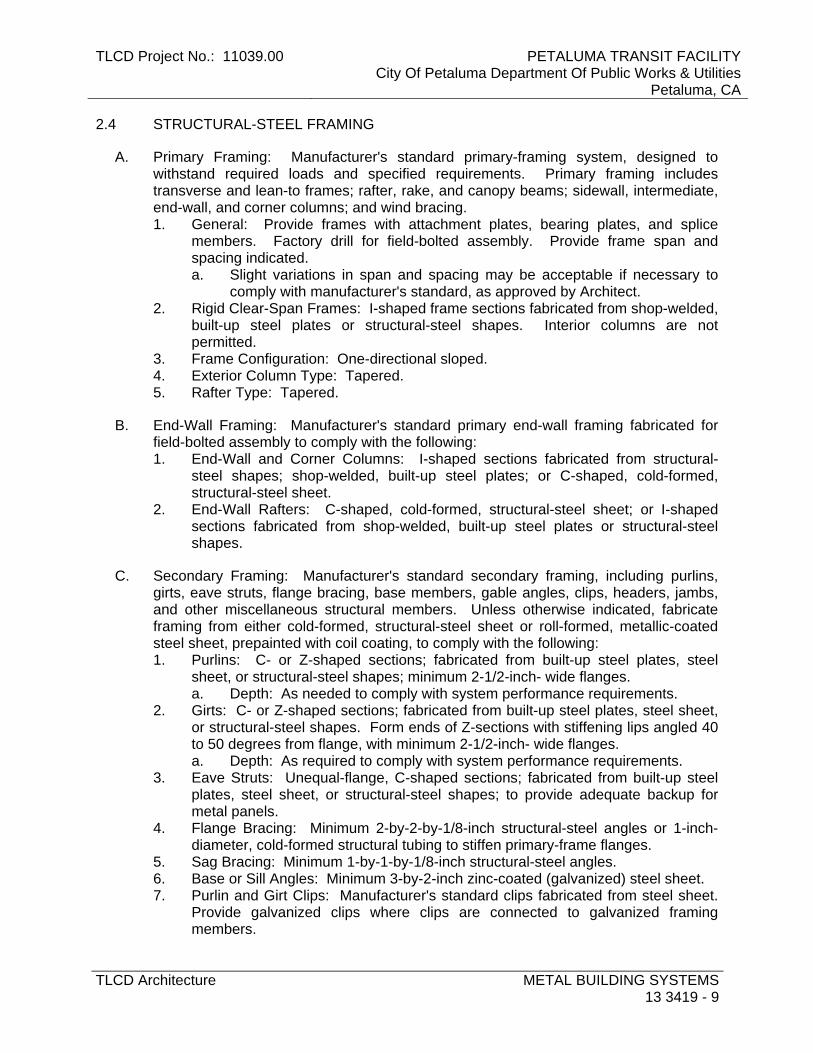
TLCD Project No.: 11039.00 PETALUMA TRANSIT FACILITYCity Of Petaluma Department Of Public Works & Utilities
Petaluma, CA
TLCD Architecture METAL BUILDING SYSTEMS13 3419 - 9
2.4 STRUCTURAL-STEEL FRAMING
A. Primary Framing: Manufacturer's standard primary-framing system, designed to withstand required loads and specified requirements. Primary framing includes transverse and lean-to frames; rafter, rake, and canopy beams; sidewall, intermediate, end-wall, and corner columns; and wind bracing. 1. General: Provide frames with attachment plates, bearing plates, and splice
members. Factory drill for field-bolted assembly. Provide frame span and spacing indicated. a. Slight variations in span and spacing may be acceptable if necessary to
comply with manufacturer's standard, as approved by Architect. 2. Rigid Clear-Span Frames: I-shaped frame sections fabricated from shop-welded,
built-up steel plates or structural-steel shapes. Interior columns are not permitted.
3. Frame Configuration: One-directional sloped. 4. Exterior Column Type: Tapered. 5. Rafter Type: Tapered.
B. End-Wall Framing: Manufacturer's standard primary end-wall framing fabricated for field-bolted assembly to comply with the following: 1. End-Wall and Corner Columns: I-shaped sections fabricated from structural-
steel shapes; shop-welded, built-up steel plates; or C-shaped, cold-formed, structural-steel sheet.
2. End-Wall Rafters: C-shaped, cold-formed, structural-steel sheet; or I-shaped sections fabricated from shop-welded, built-up steel plates or structural-steel shapes.
C. Secondary Framing: Manufacturer's standard secondary framing, including purlins, girts, eave struts, flange bracing, base members, gable angles, clips, headers, jambs, and other miscellaneous structural members. Unless otherwise indicated, fabricate framing from either cold-formed, structural-steel sheet or roll-formed, metallic-coated steel sheet, prepainted with coil coating, to comply with the following: 1. Purlins: C- or Z-shaped sections; fabricated from built-up steel plates, steel
sheet, or structural-steel shapes; minimum 2-1/2-inch- wide flanges. a. Depth: As needed to comply with system performance requirements.
2. Girts: C- or Z-shaped sections; fabricated from built-up steel plates, steel sheet, or structural-steel shapes. Form ends of Z-sections with stiffening lips angled 40 to 50 degrees from flange, with minimum 2-1/2-inch- wide flanges. a. Depth: As required to comply with system performance requirements.
3. Eave Struts: Unequal-flange, C-shaped sections; fabricated from built-up steel plates, steel sheet, or structural-steel shapes; to provide adequate backup for metal panels.
4. Flange Bracing: Minimum 2-by-2-by-1/8-inch structural-steel angles or 1-inch- diameter, cold-formed structural tubing to stiffen primary-frame flanges.
5. Sag Bracing: Minimum 1-by-1-by-1/8-inch structural-steel angles. 6. Base or Sill Angles: Minimum 3-by-2-inch zinc-coated (galvanized) steel sheet. 7. Purlin and Girt Clips: Manufacturer's standard clips fabricated from steel sheet.
Provide galvanized clips where clips are connected to galvanized framing members.

PETALUMA TRANSIT FACILITY City Of Petaluma Department Of Public Works & Utilities Petaluma, CA
TLCD Project No.: 11039.00
METAL BUILDING SYSTEMS 13 3419 - 10
TLCD Architecture
8. Secondary End-Wall Framing: Manufacturer's standard sections fabricated from zinc-coated (galvanized) steel sheet.
9. Framing for Openings: Channel shapes; fabricated from cold-formed, structural-steel sheet or structural-steel shapes. Frame head and jamb of door openings and head, jamb, and sill of other openings.
10. Miscellaneous Structural Members: Manufacturer's standard sections fabricated from cold-formed, structural-steel sheet; built-up steel plates; or zinc-coated (galvanized) steel sheet; designed to withstand required loads.
D. Canopy Framing: Manufacturer's standard structural-framing system, designed to withstand required loads; fabricated from shop-welded, built-up steel plates or structural-steel shapes. Provide frames with attachment plates and splice members, factory drilled for field-bolted assembly. 1. Type: As indicated.
E. Bracing: Provide adjustable wind bracing as follows: 1. Rods: ASTM A 36/A 36M; ASTM A 572/A 572M, Grade 50; or
ASTM A 529/A 529M, Grade 50; minimum 1/2-inch- diameter steel; threaded full length or threaded a minimum of 6 inches at each end.
2. Cable: ASTM A 475, 1/4-inch- diameter, extra-high-strength grade, Class B, zinc-coated, seven-strand steel; with threaded end anchors.
3. Angles: Fabricated from structural-steel shapes to match primary framing, of size required to withstand design loads.
4. Rigid Portal Frames: Fabricated from shop-welded, built-up steel plates or structural-steel shapes to match primary framing; of size required to withstand design loads.
5. Fixed-Base Columns: Fabricated from shop-welded, built-up steel plates or structural-steel shapes to match primary framing; of size required to withstand design loads.
6. Diaphragm Action of Metal Panels: Design metal building to resist wind forces through diaphragm action of metal panels.
7. Bracing: Provide wind bracing using any method specified above, at manufacturer's option.
F. Bolts: Provide plain-finish bolts for structural-framing components that are primed or finish painted. Provide zinc-plated or hot-dip galvanized bolts for structural-framing components that are galvanized.
G. Materials: 1. W-Shapes: ASTM A 992/A 992M; ASTM A 572/A 572M, Grade 50 or 55; or
ASTM A 529/A 529M, Grade 50 or 55. 2. Channels, Angles, M-Shapes, and S-Shapes: ASTM A 36/A 36M;
ASTM A 572/A 572M, Grade 50 or 55; or ASTM A 529/A 529M, Grade 50 or 55. 3. Plate and Bar: ASTM A 36/A 36M; ASTM A 572/A 572M, Grade 50 or 55; or
ASTM A 529/A 529M, Grade 50 or 55. 4. Steel Pipe: ASTM A 53/A 53M, Type E or S, Grade B. 5. Cold-Formed Hollow Structural Sections: ASTM A 500, Grade B or C, structural
tubing. 6. Structural-Steel Sheet: Hot-rolled, ASTM A 1011/A 1011M, Structural Steel (SS),
Grades 30 through 55, or High-Strength Low-Alloy Steel (HSLAS), Grades 45

TLCD Project No.: 11039.00 PETALUMA TRANSIT FACILITYCity Of Petaluma Department Of Public Works & Utilities
Petaluma, CA
TLCD Architecture METAL BUILDING SYSTEMS13 3419 - 11
through 70; or cold-rolled, ASTM A 1008/A 1008M, Structural Steel (SS), Grades 25 through 80, or High-Strength Low-Alloy Steel (HSLAS), Grades 45 through 70.
7. Metallic-Coated Steel Sheet: ASTM A 653/A 653M, Structural Steel (SS), Grades 33 through 80 or High-Strength Low-Alloy Steel (HSLAS), Grades 50 through 80; with G60 coating designation; mill phosphatized.
8. Metallic-Coated Steel Sheet Prepainted with Coil Coating: Steel sheet, metallic coated by the hot-dip process and prepainted by the coil-coating process to comply with ASTM A 755/A 755M. a. Zinc-Coated (Galvanized) Steel Sheet: ASTM A 653/A 653M, Structural
Steel (SS), Grades 33 through 80 or High-Strength Low-Alloy Steel (HSLAS), Grades 50 through 80; with G90 coating designation.
b. Aluminum-Zinc Alloy-Coated Steel Sheet: ASTM A 792/A 792M, Structural Steel (SS), Grade 50 or 80; with Class AZ50 coating.
9. Non-High-Strength Bolts, Nuts, and Washers: ASTM A 307, Grade A, carbon-steel, hex-head bolts; ASTM A 563 carbon-steel hex nuts; and ASTM F 844 plain (flat) steel washers. a. Finish: Plain.
10. High-Strength Bolts, Nuts, and Washers: ASTM A 325, Type 1, heavy-hex steel structural bolts; ASTM A 563 heavy-hex carbon-steel nuts; and ASTM F 436 hardened carbon-steel washers. a. Finish: Plain.
11. High-Strength Bolts, Nuts, and Washers: ASTM A 490, Type 1, heavy-hex steel structural bolts or tension-control, bolt-nut-washer assemblies with spline ends; ASTM A 563 heavy-hex carbon-steel nuts; and ASTM F 436 hardened carbon-steel washers, plain.
12. Tension-Control, High-Strength Bolt-Nut-Washer Assemblies: ASTM F 1852, Type 1, heavy-hex-head steel structural bolts with spline ends. a. Finish: Plain.
13. Unheaded Anchor Rods: ASTM F 1554, Grade 36. a. Configuration: Straight. b. Nuts: ASTM A 563 hex carbon steel. c. Plate Washers: ASTM A 36/A 36M carbon steel. d. Washers: ASTM F 436 hardened carbon steel. e. Finish: Plain.
14. Headed Anchor Rods: ASTM F 1554, Grade 36. a. Configuration: Straight. b. Nuts: ASTM A 563hex carbon steel. c. Plate Washers: ASTM A 36/A 36M carbon steel. d. Washers: ASTM F 436 hardened carbon steel. e. Finish: Plain.
15. Threaded Rods: ASTM A 36/A 36M. a. Nuts: ASTM A 563 hex carbon steel. b. Washers: ASTM F 436 hardened carbon steel. c. Finish: Plain.
H. Finish: Factory primed. Apply specified primer immediately after cleaning and pretreating. 1. Apply primer to primary and secondary framing to a minimum dry film thickness
of 1 mil.

PETALUMA TRANSIT FACILITY City Of Petaluma Department Of Public Works & Utilities Petaluma, CA
TLCD Project No.: 11039.00
METAL BUILDING SYSTEMS 13 3419 - 12
TLCD Architecture
a. Prime secondary framing formed from uncoated steel sheet to a minimum dry film thickness of 0.5 mil on each side.
2. Prime galvanized members with specified primer after phosphoric acid pretreatment.
3. Primer: SSPC-Paint 15, Type I, red oxide.
2.5 FOAMED-INSULATION-CORE METAL ROOF PANELS
A. General: Provide factory-formed and -assembled metal roof panels fabricated from two sheets of metal with insulation core foamed in place during fabrication with joints between panels designed to form weathertight seals. Include accessories required for weathertight installation. 1. Panel Performance:
a. Flatwise Tensile Strength: 30 psi when tested according to ASTM C 297/C 297M.
b. Humid Aging: Volume increase not greater than 6.0 percent and no delamination or metal corrosion when tested for seven days at 140 deg F and 100 percent relative humidity according to ASTM D 2126.
c. Heat Aging: Volume increase not greater than 2.0 percent and no delamination, surface blistering, or permanent bowing when tested for seven days at 200 deg F according to ASTM D 2126.
d. Cold Aging: Volume decrease not more than 1.0 percent and no delamination, surface blistering, or permanent bowing when tested for seven days at minus 20 deg F according to ASTM D 2126.
e. Fatigue: No evidence of delamination, core cracking, or permanent bowing when tested to a 20-lbf/sq. ft. positive and negative wind load and with deflection of L/180 for 2 million cycles.
f. Autoclave: No delamination when exposed to 2-psi pressure at a temperature of 212 deg F for 2-1/2 hours.
g. Fire-Test-Response Characteristics: Class A according to ASTM E 108. 2. Insulation Core: Modified isocyanurate or polyurethane foam using a non-CFC
blowing agent, with maximum flame-spread and smoke-developed indexes of 25 and 450, respectively. a. Closed-Cell Content: 90 percent when tested according to ASTM D 6226. b. Density: 2.0 to 2.6 lb/cu. ft. when tested according to ASTM D 1622. c. Compressive Strength: Minimum 20 psi when tested according to
ASTM D 1621. d. Shear Strength: 26 psi when tested according to ASTM C 273.
B. Standing-Seam-Profile, Foamed-Insulation-Core Metal Roof Panels: Formed with vertical tongue-and-groove ribs at panel edges and intermediate stiffening ribs symmetrically spaced between ribs; designed for sequential installation by interlocking tongue-and-groove panel edges and mechanically attaching panels to supports using concealed clips located between panels and engaging edges of adjacent panels, and mechanically seaming panels together. 1. Basis-of-Design Product: Subject to compliance with requirements, provide
Kingspan Insulated Panels “KingZip” or approved equal. 2. Metallic-Coated Steel Sheet: Facings of zinc-coated (galvanized) steel sheet
complying with ASTM A 653/A 653M, G90 coating designation, or aluminum-zinc

TLCD Project No.: 11039.00 PETALUMA TRANSIT FACILITYCity Of Petaluma Department Of Public Works & Utilities
Petaluma, CA
TLCD Architecture METAL BUILDING SYSTEMS13 3419 - 13
alloy-coated steel sheet complying with ASTM A 792/A 792M, Class AZ50 coating designation; structural quality. Prepainted by the coil-coating process to comply with ASTM A 755/A 755M. a. Nominal Thickness: 0.028 inch. b. Exterior Finish: Two-coat fluoropolymer.
1) Color: Regal White. c. Interior Finish: Manufacturer’s standard.
1) Color: As selected by Architect from manufacturer's full range. 3. Joint Type: As standard with manufacturer. 4. Panel Coverage: 42 inches. 5. Panel Thickness: 4.0 inches. 6. Thermal-Resistance Value (R-Value): 33 according to ASTM C 1363. 7. Solar Reflectance Index: 85 minimum
2.6 EXPOSED-FASTENER, LAP-SEAM, METAL ROOF PANELS
A. General: Provide factory-formed metal roof panels designed to be installed by lapping side edges of adjacent panels and mechanically attaching panels to supports using exposed fasteners in side laps. Include accessories required for weathertight installation.
B. Vee-Rib-Profile, Exposed-Fastener Metal Roof Panels: Formed with raised, V-shaped ribs and recesses that are approximately same size, evenly spaced across panel width, and with rib/recess sides angled at approximately 45 degrees. 1. Basis-of-Design Product: Subject to compliance with requirements, provide AEP
Span “HR-36” or comparable product by one of the following: a. AEP Span; a BlueScope Steel company. b. Alcoa Inc. c. Berridge Manufacturing Company. d. CENTRIA Architectural Systems. e. Fabral. f. Flexospan Steel Buildings, Inc. g. MBCI; a division of NCI Building Systems, L.P. h. Metal Sales Manufacturing Corporation. i. Morin; a Kingspan Group company. j. Petersen Aluminum Corporation. k. VICWEST. l. Approved equal.
2. Metallic-Coated Steel Sheet: Zinc-coated (galvanized) steel sheet complying with ASTM A 653/A 653M, G90 coating designation, or aluminum-zinc alloy-coated steel sheet complying with ASTM A 792/A 792M, Class AZ50 coating designation; structural quality. Prepainted by the coil-coating process to comply with ASTM A 755/A 755M. a. Nominal Thickness: 0.028 inch. b. Exterior Finish: Two-coat fluoropolymer. c. Color: As selected by Architect from manufacturer's full range.

PETALUMA TRANSIT FACILITY City Of Petaluma Department Of Public Works & Utilities Petaluma, CA
TLCD Project No.: 11039.00
METAL BUILDING SYSTEMS 13 3419 - 14
TLCD Architecture
2.7 FOAMED-INSULATION-CORE METAL WALL PANELS
A. General: Provide factory-formed and -assembled metal wall panels fabricated from two metal facing sheets and insulation core foamed in place during fabrication, and with joints between panels designed to form weathertight seals. Include accessories required for weathertight installation. 1. Panel Performance:
a. Flatwise Tensile Strength: 30 psi when tested according to ASTM C 297/C 297M.
b. Humid Aging: Volume increase not greater than 6.0 percent and no delamination or metal corrosion when tested for seven days at 140 deg F and 100 percent relative humidity according to ASTM D 2126.
c. Heat Aging: Volume increase not greater than 2.0 percent and no delamination, surface blistering, or permanent bowing when tested for seven days at 200 deg F according to ASTM D 2126.
d. Cold Aging: Volume decrease not more than 1.0 percent and no delamination, surface blistering, or permanent bowing when tested for seven days at minus 20 deg F according to ASTM D 2126.
e. Fatigue: No evidence of delamination, core cracking, or permanent bowing when tested to a 20-lbf/sq. ft. positive and negative wind load and with deflection of L/180 for 2 million cycles.
2. Insulation Core: Polyisocyanurate core, ASTM C591 foam CFC and HCFC free, with maximum flame-spread and smoke-developed indexes of 25 and 450, respectively. a. Closed-Cell Content: 91 percent when tested according to ASTM D 6226. b. Density: 2.3 to 2.6 lb/cu. ft. when tested according to ASTM D 1622. c. Compressive Strength: Minimum 20 psi when tested according to
ASTM D 1621. d. Shear Strength: 26 psi when tested according to ASTM C 273/C 273M.
B. Concealed-Fastener, Foamed-Insulation-Core Metal Wall Panels: Formed with V-wave, continuous sinewave profile; nominal 13/16 inch deep at 5 inches on center and tongue-and-groove panel edges; designed for sequential installation by interlocking panel edges and mechanically attaching panels to supports using concealed clips or fasteners. 1. Basis-of-Design Product: Subject to compliance with requirements, provide
Kingspan 400 V-Wave Series wall panels or comparable product by one of the following:
2. Metallic-Coated Steel Sheet: Facings of zinc-coated (galvanized) steel sheet complying with ASTM A 653/A 653M, G90 coating designation, or aluminum-zinc alloy-coated steel sheet complying with ASTM A 792/A 792M, Class AZ50 coating designation; structural quality. Prepainted by the coil-coating process to comply with ASTM A 755/A 755M. a. Nominal Thickness: 0.034 inch. b. Exterior Finish: Two-coat fluoropolymer.
1) Color: Silversmith. c. Interior Finish: Siliconized polyester.
1) Color: USDA Imperial White. 3. Panel Coverage: 40 inches nominal.
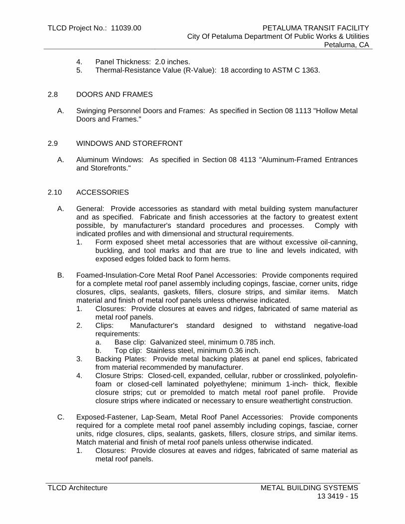
TLCD Project No.: 11039.00 PETALUMA TRANSIT FACILITYCity Of Petaluma Department Of Public Works & Utilities
Petaluma, CA
TLCD Architecture METAL BUILDING SYSTEMS13 3419 - 15
4. Panel Thickness: 2.0 inches. 5. Thermal-Resistance Value (R-Value): 18 according to ASTM C 1363.
2.8 DOORS AND FRAMES
A. Swinging Personnel Doors and Frames: As specified in Section 08 1113 "Hollow Metal Doors and Frames."
2.9 WINDOWS AND STOREFRONT
A. Aluminum Windows: As specified in Section 08 4113 "Aluminum-Framed Entrances and Storefronts."
2.10 ACCESSORIES
A. General: Provide accessories as standard with metal building system manufacturer and as specified. Fabricate and finish accessories at the factory to greatest extent possible, by manufacturer's standard procedures and processes. Comply with indicated profiles and with dimensional and structural requirements. 1. Form exposed sheet metal accessories that are without excessive oil-canning,
buckling, and tool marks and that are true to line and levels indicated, with exposed edges folded back to form hems.
B. Foamed-Insulation-Core Metal Roof Panel Accessories: Provide components required for a complete metal roof panel assembly including copings, fasciae, corner units, ridge closures, clips, sealants, gaskets, fillers, closure strips, and similar items. Match material and finish of metal roof panels unless otherwise indicated. 1. Closures: Provide closures at eaves and ridges, fabricated of same material as
metal roof panels. 2. Clips: Manufacturer's standard designed to withstand negative-load
requirements: a. Base clip: Galvanized steel, minimum 0.785 inch. b. Top clip: Stainless steel, minimum 0.36 inch.
3. Backing Plates: Provide metal backing plates at panel end splices, fabricated from material recommended by manufacturer.
4. Closure Strips: Closed-cell, expanded, cellular, rubber or crosslinked, polyolefin-foam or closed-cell laminated polyethylene; minimum 1-inch- thick, flexible closure strips; cut or premolded to match metal roof panel profile. Provide closure strips where indicated or necessary to ensure weathertight construction.
C. Exposed-Fastener, Lap-Seam, Metal Roof Panel Accessories: Provide components required for a complete metal roof panel assembly including copings, fasciae, corner units, ridge closures, clips, sealants, gaskets, fillers, closure strips, and similar items. Match material and finish of metal roof panels unless otherwise indicated. 1. Closures: Provide closures at eaves and ridges, fabricated of same material as
metal roof panels.

PETALUMA TRANSIT FACILITY City Of Petaluma Department Of Public Works & Utilities Petaluma, CA
TLCD Project No.: 11039.00
METAL BUILDING SYSTEMS 13 3419 - 16
TLCD Architecture
2. Clips: Manufacturer's standard, formed from steel sheet, designed to withstand negative-load requirements.
3. Cleats: Manufacturer's standard, mechanically seamed cleats formed from steel sheet.
4. Backing Plates: Provide metal backing plates at panel end splices, fabricated from material recommended by manufacturer.
5. Closure Strips: Closed-cell, expanded, cellular, rubber or crosslinked, polyolefin-foam or closed-cell laminated polyethylene; minimum 1-inch- thick, flexible closure strips; cut or premolded to match metal roof panel profile. Provide closure strips where indicated or necessary to ensure weathertight construction.
D. Wall Panel Accessories: Provide components required for a complete metal wall panel assembly including copings, fasciae, mullions, sills, corner units, clips, sealants, gaskets, fillers, closure strips, and similar items. Match material and finish of metal wall panels unless otherwise indicated. 1. Perimeter Trim: Extruded perimeter trim, aluminum 6063-T5 alloy with spray-
applied PVF coating in same color as exterior face of insulated metal wall panel.
E. Flashing and Trim: Formed from 0.022-inch nominal-thickness, metallic-coated steel sheet or aluminum-zinc alloy-coated steel sheet prepainted with coil coating; finished to match adjacent metal panels. 1. Provide flashing and trim as required to seal against weather and to provide
finished appearance. Locations include, but are not limited to, eaves, rakes, corners, bases, framed openings, ridges, fasciae, and fillers.
2. Opening Trim: Formed from 0.034-inch nominal-thickness, metallic-coated steel sheet or aluminum-zinc alloy-coated steel sheet prepainted with coil coating. Trim head and jamb of door openings, and head, jamb, and sill of other openings.
F. Gutters: Formed from 0.022-inch nominal-thickness, metallic-coated steel sheet or aluminum-zinc alloy-coated steel sheet prepainted with coil coating; finished to match roof fascia and rake trim. Match profile of gable trim, complete with end pieces, outlet tubes, and other special pieces as required. Fabricate in minimum 96-inch- long sections, sized according to SMACNA's "Architectural Sheet Metal Manual." 1. Gutter Supports: Fabricated from same material and finish as gutters. 2. Strainers: Bronze, copper, or aluminum wire ball type at outlets.
G. Downspouts: Formed from 0.022-inch nominal-thickness, zinc-coated (galvanized) steel sheet or aluminum-zinc alloy-coated steel sheet prepainted with coil coating; finished to match metal wall panels. Fabricate in minimum 10-foot- long sections, complete with formed elbows and offsets. 1. Mounting Straps: Fabricated from same material and finish as gutters.
H. Louvers: Size and design indicated; self-framing and self-flashing. Fabricate welded frames from minimum 0.052-inch nominal-thickness, metallic-coated steel sheet; finished to match metal wall panels. Form blades from 0.040-inch nominal-thickness, metallic-coated steel sheet; folded or beaded at edges, set at an angle that excludes driving rains, and secured to frames by riveting or welding. Fabricate louvers with equal blade spacing to produce uniform appearance. 1. Blades: Fixed.

TLCD Project No.: 11039.00 PETALUMA TRANSIT FACILITYCity Of Petaluma Department Of Public Works & Utilities
Petaluma, CA
TLCD Architecture METAL BUILDING SYSTEMS13 3419 - 17
2. Blades: Adjustable type, with weather-stripped edges, and manually operated by hand crank or pull chain.
3. Free Area: Not less than 7.0 sq. ft. for 48-inch- wide by 48-inch- high louver. 4. Bird Screening: Galvanized steel, 1/2-inch- square mesh, 0.041-inch wire; with
rewirable frames, removable and secured with clips; fabricated of same kind and form of metal and with same finish as louvers. a. Mounting: Interior face of louvers.
5. Vertical Mullions: Provide mullions at spacings recommended by manufacturer, or 72 inches o.c., whichever is less.
I. Pipe Flashing: Premolded, EPDM pipe collar with flexible aluminum ring bonded to base.
J. Materials: 1. Fasteners: Self-tapping screws, bolts, nuts, self-locking rivets and bolts, end-
welded studs, and other suitable fasteners designed to withstand design loads. Provide fasteners with heads matching color of materials being fastened by means of plastic caps or factory-applied coating. a. Fasteners for Metal Roof Panels: Self-drilling or self-tapping, zinc-plated,
hex-head carbon-steel screws, with a stainless-steel cap or zinc-aluminum-alloy head and EPDM sealing washer.
b. Fasteners for Metal Wall Panels: Self-drilling or self-tapping, zinc-plated, hex-head carbon-steel screws.
c. Fasteners for Flashing and Trim: Blind fasteners or self-drilling screws with hex washer head.
d. Blind Fasteners: High-strength aluminum or stainless-steel rivets. 2. Corrosion-Resistant Coating: Cold-applied asphalt mastic, compounded for 15-
mil dry film thickness per coat. Provide inert-type noncorrosive compound free of asbestos fibers, sulfur components, and other deleterious impurities.
3. Nonmetallic, Shrinkage-Resistant Grout: ASTM C 1107, factory-packaged, nonmetallic aggregate grout, noncorrosive, nonstaining, mixed with water to consistency suitable for application and a 30-minute working time.
4. Metal Panel Sealants: a. Sealant Tape: Pressure-sensitive, 100 percent solids, gray
polyisobutylene-compound sealant tape with release-paper backing. Provide permanently elastic, nonsag, nontoxic, nonstaining tape of manufacturer's standard size.
b. Joint Sealant: ASTM C 920; one-part elastomeric polyurethane or polysulfide; of type, grade, class, and use classifications required to seal joints in metal panels and remain weathertight; and as recommended by metal building system manufacturer.
2.11 SOURCE QUALITY CONTROL
A. Testing Agency: Engage a qualified testing agency to evaluate product.
B. Special Inspector: Owner will engage a qualified special inspector to perform the following tests and inspections and to submit reports. Special inspector will verify that

PETALUMA TRANSIT FACILITY City Of Petaluma Department Of Public Works & Utilities Petaluma, CA
TLCD Project No.: 11039.00
METAL BUILDING SYSTEMS 13 3419 - 18
TLCD Architecture
manufacturer maintains detailed fabrication and quality-control procedures and will review the completeness and adequacy of those procedures to perform the Work. 1. Special inspections will not be required if fabrication is performed by
manufacturer registered and approved by authorities having jurisdiction to perform such Work without special inspection. a. After fabrication, submit copy of certificate of compliance to authorities
having jurisdiction, certifying that Work was performed according to Contract requirements.
C. Testing: Test and inspect shop connections for metal buildings according to the following: 1. Bolted Connections: Shop-bolted connections shall be tested and inspected
according to RCSC's "Specification for Structural Joints Using ASTM A 325 or A 490 Bolts."
2. Welded Connections: In addition to visual inspection, shop-welded connections shall be tested and inspected according to AWS D1.1/D1.1M and the following inspection procedures, at inspector's option: a. Liquid Penetrant Inspection: ASTM E 165. b. Magnetic Particle Inspection: ASTM E 709; performed on root pass and on
finished weld. Cracks or zones of incomplete fusion or penetration will not be accepted.
c. Ultrasonic Inspection: ASTM E 164. d. Radiographic Inspection: ASTM E 94.
D. Product will be considered defective if it does not pass tests and inspections.
E. Prepare test and inspection reports.
2.12 FABRICATION
A. General: Design components and field connections required for erection to permit easy assembly. 1. Mark each piece and part of the assembly to correspond with previously
prepared erection drawings, diagrams, and instruction manuals. 2. Fabricate structural framing to produce clean, smooth cuts and bends. Punch
holes of proper size, shape, and location. Members shall be free of cracks, tears, and ruptures.
B. Tolerances: Comply with MBMA's "Metal Building Systems Manual" for fabrication and erection tolerances.
C. Primary Framing: Shop fabricate framing components to indicated size and section, with baseplates, bearing plates, stiffeners, and other items required for erection welded into place. Cut, form, punch, drill, and weld framing for bolted field assembly. 1. Make shop connections by welding or by using high-strength bolts. 2. Join flanges to webs of built-up members by a continuous, submerged arc-
welding process.

TLCD Project No.: 11039.00 PETALUMA TRANSIT FACILITYCity Of Petaluma Department Of Public Works & Utilities
Petaluma, CA
TLCD Architecture METAL BUILDING SYSTEMS13 3419 - 19
3. Brace compression flange of primary framing with steel angles or cold-formed structural tubing between frame web and purlin web or girt web, so flange compressive strength is within allowable limits for any combination of loadings.
4. Weld clips to frames for attaching secondary framing. 5. Shop Priming: Prepare surfaces for shop priming according to SSPC-SP 2.
Shop prime primary framing with specified primer after fabrication.
D. Secondary Framing: Shop fabricate framing components to indicated size and section by roll-forming or break-forming, with baseplates, bearing plates, stiffeners, and other plates required for erection welded into place. Cut, form, punch, drill, and weld secondary framing for bolted field connections to primary framing. 1. Make shop connections by welding or by using non-high-strength bolts. 2. Shop Priming: Prepare uncoated surfaces for shop priming according to SSPC-
SP 2. Shop prime uncoated secondary framing with specified primer after fabrication.
E. Metal Panels: Fabricate and finish metal panels at the factory to greatest extent possible, by manufacturer's standard procedures and processes, as necessary to fulfill indicated performance requirements. Comply with indicated profiles and with dimensional and structural requirements. 1. Provide panel profile, including major ribs and intermediate stiffening ribs, if any,
for full length of metal panel.
PART 3 - EXECUTION
3.1 EXAMINATION
A. Examine substrates, areas, and conditions, with erector present, for compliance with requirements for installation tolerances and other conditions affecting performance of the Work.
B. Before erection proceeds, survey elevations and locations of concrete- and masonry-bearing surfaces and locations of anchor rods, bearing plates, and other embedments to receive structural framing, with erector present, for compliance with requirements and metal building system manufacturer's tolerances.
1. Engage land surveyor to perform surveying.
C. Proceed with erection only after unsatisfactory conditions have been corrected.
3.2 PREPARATION
A. Clean and prepare surfaces to be painted according to manufacturer's written instructions for each particular substrate condition.
B. Provide temporary shores, guys, braces, and other supports during erection to keep structural framing secure, plumb, and in alignment against temporary construction

PETALUMA TRANSIT FACILITY City Of Petaluma Department Of Public Works & Utilities Petaluma, CA
TLCD Project No.: 11039.00
METAL BUILDING SYSTEMS 13 3419 - 20
TLCD Architecture
loads and loads equal in intensity to design loads. Remove temporary supports when permanent structural framing, connections, and bracing are in place unless otherwise indicated.
3.3 ERECTION OF STRUCTURAL FRAMING
A. Erect metal building system according to manufacturer's written erection instructions and erection drawings.
B. Do not field cut, drill, or alter structural members without written approval from metal building system manufacturer's professional engineer.
C. Set structural framing accurately in locations and to elevations indicated, according to AISC specifications referenced in this Section. Maintain structural stability of frame during erection.
D. Base Plates: Clean concrete- and masonry-bearing surfaces of bond-reducing materials, and roughen surfaces prior to setting plates. Clean bottom surface of plates. 1. Set plates for structural members on wedges, shims, or setting nuts as required. 2. Tighten anchor rods after supported members have been positioned and
plumbed. Do not remove wedges or shims but, if protruding, cut off flush with edge of plate before packing with grout.
3. Promptly pack grout solidly between bearing surfaces and plates so no voids remain. Neatly finish exposed surfaces; protect grout and allow to cure. Comply with manufacturer's written installation instructions for shrinkage-resistant grouts.
E. Align and adjust structural framing before permanently fastening. Before assembly, clean bearing surfaces and other surfaces that will be in permanent contact with framing. Perform necessary adjustments to compensate for discrepancies in elevations and alignment. 1. Level and plumb individual members of structure. 2. Make allowances for difference between temperature at time of erection and
mean temperature when structure will be completed and in service.
F. Primary Framing and End Walls: Erect framing level, plumb, rigid, secure, and true to line. Level baseplates to a true even plane with full bearing to supporting structures, set with double-nutted anchor bolts. Use grout to obtain uniform bearing and to maintain a level base-line elevation. Moist-cure grout for not less than seven days after placement. 1. Make field connections using high-strength bolts installed according to RCSC's
"Specification for Structural Joints Using ASTM A 325 or A 490 Bolts" for bolt type and joint type specified. a. Joint Type: Snug tightened or pretensioned.
G. Secondary Framing: Erect framing level, plumb, rigid, secure, and true to line. Field bolt secondary framing to clips attached to primary framing. 1. Provide rake or gable purlins with tight-fitting closure channels and fasciae. 2. Locate and space wall girts to suit openings such as doors and windows. 3. Locate canopy framing as indicated.
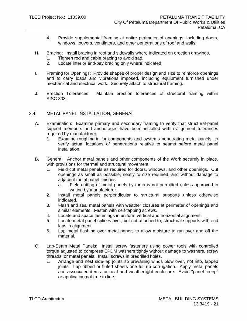
TLCD Project No.: 11039.00 PETALUMA TRANSIT FACILITYCity Of Petaluma Department Of Public Works & Utilities
Petaluma, CA
TLCD Architecture METAL BUILDING SYSTEMS13 3419 - 21
4. Provide supplemental framing at entire perimeter of openings, including doors, windows, louvers, ventilators, and other penetrations of roof and walls.
H. Bracing: Install bracing in roof and sidewalls where indicated on erection drawings. 1. Tighten rod and cable bracing to avoid sag. 2. Locate interior end-bay bracing only where indicated.
I. Framing for Openings: Provide shapes of proper design and size to reinforce openings and to carry loads and vibrations imposed, including equipment furnished under mechanical and electrical work. Securely attach to structural framing.
J. Erection Tolerances: Maintain erection tolerances of structural framing within AISC 303.
3.4 METAL PANEL INSTALLATION, GENERAL
A. Examination: Examine primary and secondary framing to verify that structural-panel support members and anchorages have been installed within alignment tolerances required by manufacturer. 1. Examine roughing-in for components and systems penetrating metal panels, to
verify actual locations of penetrations relative to seams before metal panel installation.
B. General: Anchor metal panels and other components of the Work securely in place, with provisions for thermal and structural movement. 1. Field cut metal panels as required for doors, windows, and other openings. Cut
openings as small as possible, neatly to size required, and without damage to adjacent metal panel finishes. a. Field cutting of metal panels by torch is not permitted unless approved in
writing by manufacturer. 2. Install metal panels perpendicular to structural supports unless otherwise
indicated. 3. Flash and seal metal panels with weather closures at perimeter of openings and
similar elements. Fasten with self-tapping screws. 4. Locate and space fastenings in uniform vertical and horizontal alignment. 5. Locate metal panel splices over, but not attached to, structural supports with end
laps in alignment. 6. Lap metal flashing over metal panels to allow moisture to run over and off the
material.
C. Lap-Seam Metal Panels: Install screw fasteners using power tools with controlled torque adjusted to compress EPDM washers tightly without damage to washers, screw threads, or metal panels. Install screws in predrilled holes. 1. Arrange and nest side-lap joints so prevailing winds blow over, not into, lapped
joints. Lap ribbed or fluted sheets one full rib corrugation. Apply metal panels and associated items for neat and weathertight enclosure. Avoid "panel creep" or application not true to line.
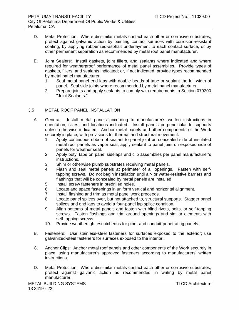
PETALUMA TRANSIT FACILITY City Of Petaluma Department Of Public Works & Utilities Petaluma, CA
TLCD Project No.: 11039.00
METAL BUILDING SYSTEMS 13 3419 - 22
TLCD Architecture
D. Metal Protection: Where dissimilar metals contact each other or corrosive substrates, protect against galvanic action by painting contact surfaces with corrosion-resistant coating, by applying rubberized-asphalt underlayment to each contact surface, or by other permanent separation as recommended by metal roof panel manufacturer.
E. Joint Sealers: Install gaskets, joint fillers, and sealants where indicated and where required for weatherproof performance of metal panel assemblies. Provide types of gaskets, fillers, and sealants indicated; or, if not indicated, provide types recommended by metal panel manufacturer. 1. Seal metal panel end laps with double beads of tape or sealant the full width of
panel. Seal side joints where recommended by metal panel manufacturer. 2. Prepare joints and apply sealants to comply with requirements in Section 079200
"Joint Sealants."
3.5 METAL ROOF PANEL INSTALLATION
A. General: Install metal panels according to manufacturer's written instructions in orientation, sizes, and locations indicated. Install panels perpendicular to supports unless otherwise indicated. Anchor metal panels and other components of the Work securely in place, with provisions for thermal and structural movement. 1. Apply continuous ribbon of sealant to panel joint on concealed side of insulated
metal roof panels as vapor seal; apply sealant to panel joint on exposed side of panels for weather seal.
2. Apply butyl tape on panel sidelaps and clip assemblies per panel manufacturer’s instructions.
3. Shim or otherwise plumb substrates receiving metal panels. 4. Flash and seal metal panels at perimeter of all openings. Fasten with self-
tapping screws. Do not begin installation until air- or water-resistive barriers and flashings that will be concealed by metal panels are installed.
5. Install screw fasteners in predrilled holes. 6. Locate and space fastenings in uniform vertical and horizontal alignment. 7. Install flashing and trim as metal panel work proceeds. 8. Locate panel splices over, but not attached to, structural supports. Stagger panel
splices and end laps to avoid a four-panel lap splice condition. 9. Align bottoms of metal panels and fasten with blind rivets, bolts, or self-tapping
screws. Fasten flashings and trim around openings and similar elements with self-tapping screws.
10. Provide weathertight escutcheons for pipe- and conduit-penetrating panels.
B. Fasteners: Use stainless-steel fasteners for surfaces exposed to the exterior; use galvanized-steel fasteners for surfaces exposed to the interior.
C. Anchor Clips: Anchor metal roof panels and other components of the Work securely in place, using manufacturer's approved fasteners according to manufacturers' written instructions.
D. Metal Protection: Where dissimilar metals contact each other or corrosive substrates, protect against galvanic action as recommended in writing by metal panel manufacturer.

TLCD Project No.: 11039.00 PETALUMA TRANSIT FACILITYCity Of Petaluma Department Of Public Works & Utilities
Petaluma, CA
TLCD Architecture METAL BUILDING SYSTEMS13 3419 - 23
E. Standing-Seam, Foamed-Insulation-Core Metal Roof Panels: Fasten insulated metal roof panels to supports with concealed clips at each standing-seam joint at location, spacing, and with fasteners recommended in writing by manufacturer. 1. Install clips to supports with self-tapping fasteners. 2. Seamed Joint: Crimp standing seams with manufacturer-approved, motorized
seamer tool so cleat, insulated metal roof panel, and factory-applied side-lap sealant are completely engaged.
F. Lap-Seam Metal Roof Panels: Fasten metal roof panels to supports with exposed fasteners at each lapped joint, at location and spacing recommended by manufacturer. 1. Provide metal-backed sealing washers under heads of exposed fasteners
bearing on weather side of metal roof panels. 2. Provide sealant tape at lapped joints of metal roof panels and between panels
and protruding equipment, vents, and accessories. 3. Apply a continuous ribbon of sealant tape to weather-side surface of fastenings
on end laps and on side laps of nesting-type metal panels, on side laps of ribbed or fluted metal panels, and elsewhere as needed to make metal panels weatherproof to driving rains.
4. At metal panel splices, nest panels with minimum 6-inch end lap, sealed with butyl-rubber sealant and fastened together by interlocking clamping plates.
G. Pipe Flashing: Form flashing around pipe penetration and metal roof panels. Fasten and seal to metal roof panels as recommended by manufacturer.
H. Metal Fascia Panels: Align bottom of metal panels and fasten with blind rivets, bolts, or self-drilling or self-tapping screws. Flash and seal metal panels with weather closures where fasciae meet soffits, along lower panel edges, and at perimeter of all openings.
I. Metal Roof Panel Installation Tolerances: Shim and align metal roof panels within installed tolerance of 1/4 inch in 20 feet on slope and location lines as indicated and within 1/8-inch offset of adjoining faces and of alignment of matching profiles.
3.6 METAL WALL PANEL INSTALLATION
A. General: Install metal panels according to manufacturer's written instructions in orientation, sizes, and locations indicated. Install panels perpendicular to supports unless otherwise indicated. Anchor metal panels and other components of the Work securely in place, with provisions for thermal and structural movement. 1. Shim or otherwise plumb substrates receiving metal panels. 2. Flash and seal metal panels at perimeter of all openings. Fasten with self-
tapping screws. Do not begin installation until air- or water-resistive barriers and flashings that will be concealed by metal panels are installed.
3. Install screw fasteners in predrilled holes. 4. Locate and space fastenings in uniform vertical and horizontal alignment. 5. Install flashing and trim as metal panel work proceeds. 6. Locate panel splices over, but not attached to, structural supports. Stagger panel
splices and end laps to avoid a four-panel lap splice condition.
PETALUMA TRANSIT FACILITY City Of Petaluma Department Of Public Works & Utilities Petaluma, CA
TLCD Project No.: 11039.00
METAL BUILDING SYSTEMS 13 3419 - 24
TLCD Architecture
7. Align bottoms of metal panels and fasten with blind rivets, bolts, or self-tapping screws. Fasten flashings and trim around openings and similar elements with self-tapping screws.
8. Provide weathertight escutcheons for pipe- and conduit-penetrating panels.
B. Insulated Metal Wall Panels: Install insulated metal wall panels on exterior side of girts. Attach panels to supports at each panel joint using concealed clip and fasteners at maximum 42 inches o.c., spaced not more than manufacturer's recommendation. Fully engage tongue and groove of adjacent insulated metal wall panels. 1. Install clips to supports with self-tapping fasteners. 2. Apply a continuous ribbon of sealant tape to panel side laps and elsewhere as
needed to make panels weathertight. 3. Apply continuous ribbon of sealant to panel joint on concealed side of insulated
metal wall panels as vapor seal.
C. Installation Tolerances: Shim and align metal wall panels within installed tolerance of 1/4 inch in 20 feet, nonaccumulative, on level, plumb, and on location lines as indicated, and within 1/8-inch offset of adjoining faces and of alignment of matching profiles.
3.7 ACCESSORY INSTALLATION
A. General: Install accessories with positive anchorage to building and weathertight mounting, and provide for thermal expansion. Coordinate installation with flashings and other components. 1. Install components required for a complete metal roof panel assembly, including
trim, copings, ridge closures, seam covers, flashings, sealants, gaskets, fillers, closure strips, and similar items.
2. Install components for a complete metal wall panel assembly, including trim, copings, corners, seam covers, flashings, sealants, gaskets, fillers, closure strips, and similar items.
3. Where dissimilar metals contact each other or corrosive substrates, protect against galvanic action by painting contact surfaces with corrosion-resistant coating, by applying rubberized-asphalt underlayment to each contact surface, or by other permanent separation as recommended by manufacturer.
B. Flashing and Trim: Comply with performance requirements, manufacturer's written installation instructions, and SMACNA's "Architectural Sheet Metal Manual." Provide concealed fasteners where possible, and set units true to line and level as indicated. Install work with laps, joints, and seams that will be permanently watertight and weather resistant. 1. Install exposed flashing and trim that is without excessive oil-canning, buckling,
and tool marks and that is true to line and levels indicated, with exposed edges folded back to form hems. Install sheet metal flashing and trim to fit substrates and to result in waterproof and weather-resistant performance.
2. Expansion Provisions: Provide for thermal expansion of exposed flashing and trim. Space movement joints at a maximum of 10 feet with no joints allowed within 24 inches of corner or intersection. Where lapped or bayonet-type expansion provisions cannot be used or would not be sufficiently weather

TLCD Project No.: 11039.00 PETALUMA TRANSIT FACILITYCity Of Petaluma Department Of Public Works & Utilities
Petaluma, CA
TLCD Architecture METAL BUILDING SYSTEMS13 3419 - 25
resistant and waterproof, form expansion joints of intermeshing hooked flanges, not less than 1 inch deep, filled with mastic sealant (concealed within joints).
C. Gutters: Join sections with riveted-and-soldered or lapped-and-sealed joints. Attach gutters to eave with gutter hangers spaced as required for gutter size, but not more than 36 inches o.c. using manufacturer's standard fasteners. Provide end closures and seal watertight with sealant. Provide for thermal expansion.
D. Downspouts: Join sections with 1-1/2-inch telescoping joints. Provide fasteners designed to hold downspouts securely 1 inch away from walls; locate fasteners at top and bottom and at approximately 60 inches o.c. in between. 1. Provide elbows at base of downspouts to direct water away from building. 2. Tie downspouts to underground drainage system indicated.
E. Louvers: Locate and place louver units level, plumb, and at indicated alignment with adjacent work. 1. Use concealed anchorages where possible. Provide brass or lead washers fitted
to screws where required to protect metal surfaces and to make a weathertight connection.
2. Provide perimeter reveals and openings of uniform width for sealants and joint fillers.
3. Protect galvanized- and nonferrous-metal surfaces from corrosion or galvanic action by applying a heavy coating of corrosion-resistant paint on surfaces that will be in contact with concrete, masonry, or dissimilar metals.
4. Install concealed gaskets, flashings, joint fillers, and insulation as louver installation progresses, where weathertight louver joints are required. Comply with Section 07 9200 "Joint Sealants" for sealants applied during louver installation.
F. Pipe Flashing: Form flashing around pipe penetration and metal roof panels. Fasten and seal to panel as recommended by manufacturer.
3.8 FIELD QUALITY CONTROL
A. Special Inspections: Owner will engage a qualified special inspector to perform the following special inspections: 1. Inspection of fabricators. 2. Steel construction.
B. Testing Agency: Owner will engage a qualified testing agency to perform tests and inspections.
C. Tests and Inspections: 1. High-Strength, Field-Bolted Connections: Connections shall be tested and
inspected during installation according to RCSC's "Specification for Structural Joints Using ASTM A 325 or A 490 Bolts."
2. Welded Connections: In addition to visual inspection, field-welded connections shall be tested and inspected according to AWS D1.1/D1.1M and the following inspection procedures, at inspector's option:

PETALUMA TRANSIT FACILITY City Of Petaluma Department Of Public Works & Utilities Petaluma, CA
TLCD Project No.: 11039.00
METAL BUILDING SYSTEMS 13 3419 - 26
TLCD Architecture
a. Liquid Penetrant Inspection: ASTM E 165. b. Magnetic Particle Inspection: ASTM E 709; performed on root pass and on
finished weld. Cracks or zones of incomplete fusion or penetration will not be accepted.
c. Ultrasonic Inspection: ASTM E 164. d. Radiographic Inspection: ASTM E 94.
D. Product will be considered defective if it does not pass tests and inspections.
E. Prepare test and inspection reports.
3.9 ADJUSTING
A. Doors: After completing installation, test and adjust doors to operate easily, free of warp, twist, or distortion.
B. Door Hardware: Adjust and check each operating item of door hardware and each door to ensure proper operation and function of every unit. Replace units that cannot be adjusted to operate as intended.
C. Windows: Adjust operating sashes and ventilators, screens, hardware, and accessories for a tight fit at contact points and at weather stripping to ensure smooth operation and weathertight closure. Lubricate hardware and moving parts.
3.10 CLEANING AND PROTECTION
A. Repair damaged galvanized coatings on galvanized items with galvanized repair paint according to ASTM A 780 and manufacturer's written instructions.
B. Remove and replace glass that has been broken, chipped, cracked, abraded, or damaged during construction period.
C. Touchup Painting: After erection, promptly clean, prepare, and prime or reprime field connections, rust spots, and abraded surfaces of prime-painted structural framing and accessories. 1. Clean and prepare surfaces by SSPC-SP 2, "Hand Tool Cleaning," or by SSPC-
SP 3, "Power Tool Cleaning." 2. Apply a compatible primer of same type as shop primer used on adjacent
surfaces.
D. Touchup Painting: Cleaning and touchup painting are specified in Section 09 9110 "Painting" .
E. Metal Panels: Remove temporary protective coverings and strippable films, if any, as metal panels are installed. On completion of metal panel installation, clean finished surfaces as recommended by metal panel manufacturer. Maintain in a clean condition during construction.

TLCD Project No.: 11039.00 PETALUMA TRANSIT FACILITYCity Of Petaluma Department Of Public Works & Utilities
Petaluma, CA
TLCD Architecture METAL BUILDING SYSTEMS13 3419 - 27
1. Replace metal panels that have been damaged or have deteriorated beyond successful repair by finish touchup or similar minor repair procedures.
F. Doors and Frames: Immediately after installation, sand rusted or damaged areas of prime coat until smooth and apply touchup of compatible air-drying primer. 1. Immediately before final inspection, remove protective wrappings from doors and
frames.
G. Windows: Clean metal surfaces immediately after installing windows. Avoid damaging protective coatings and finishes. Remove excess sealants, glazing materials, dirt, and other substances. Clean factory-glazed glass immediately after installing windows.
H. Louvers: Clean exposed surfaces that are not protected by temporary covering, to remove fingerprints and soil during construction period. Do not let soil accumulate until final cleaning. 1. Restore louvers damaged during installation and construction period so no
evidence remains of corrective work. If results of restoration are unsuccessful, as determined by Architect, remove damaged units and replace with new units. a. Touch up minor abrasions in finishes with air-dried coating that matches
color and gloss of, and is compatible with, factory-applied finish coating.
END OF SECTION
PETALUMA TRANSIT FACILITY City Of Petaluma Department Of Public Works & Utilities Petaluma, CA
TLCD Project No.: 11039.00
METAL BUILDING SYSTEMS 13 3419 - 28
TLCD Architecture
THIS PAGE INTENTIONALLY LEFT BLANK

TLCD Project No.: 11039.00 PETALUMA TRANSIT FACILITYCity Of Petaluma Department Of Public Works & Utilities
Petaluma, CA
TLCD Architecture DIVISION 14 to 30 – NOT USED
DIVISION 14 to 30 – NOT USED
PETALUMA TRANSIT FACILITY City Of Petaluma Department Of Public Works & Utilities Petaluma, CA
TLCD Project No.: 11039.00
DIVISION 14 to 30 – NOT USED
TLCD Architecture
DIVISION 14 to 30 – NOT USED

TLCD Project No.: 11039.00 PETALUMA TRANSIT FACILITYCity Of Petaluma Department Of Public Works & Utilities
Petaluma, CA
TLCD Architecture EARTH MOVING31 2000 - 1
SECTION 31 2000 - EARTH MOVING
PART 1 - GENERAL
1.1 RELATED DOCUMENTS
A. Drawings and general provisions of the Contract, including General and Supplementary Conditions and Division 01 Specification Sections, apply to this Section.
1.2 SUMMARY
A. Section Includes: 1. Preparing subgrades for slabs-on-grade and pavements. 2. Excavating and backfilling for buildings and structures. 3. Drainage course for concrete slabs-on-grade. 4. Subbase course for concrete pavements. 5. Excavating and backfilling trenches for utilities and pits for buried utility structures.
B. Related Sections: 1. Section 015000 "Temporary Facilities and Controls" for temporary controls, utilities,
and support facilities; also for temporary site fencing if not in another Section.
1.3 DEFINITIONS
A. Backfill: Soil material or controlled low-strength material used to fill an excavation. 1. Initial Backfill: Backfill placed beside and over pipe in a trench, including haunches
to support sides of pipe. 2. Final Backfill: Backfill placed over initial backfill to fill a trench.
B. Base Course: Aggregate layer placed between the subbase course and hot-mix asphalt paving.
C. Bedding Course: Aggregate layer placed over the excavated subgrade in a trench before laying pipe.
D. Borrow Soil: Satisfactory soil imported from off-site for use as fill or backfill.
E. Drainage Course: Aggregate layer supporting the slab-on-grade that also minimizes upward capillary flow of pore water.
F. Excavation: Removal of material encountered above subgrade elevations and to lines and dimensions indicated. 1. Authorized Additional Excavation: Excavation below subgrade elevations or beyond
indicated lines and dimensions as directed by Architect. Authorized additional excavation and replacement material will be paid for according to Contract provisions for changes in the Work.

PETALUMA TRANSIT FACILITY City Of Petaluma Department Of Public Works & Utilities Petaluma, CA
TLCD Project No.: 11039.00
EARTH MOVING 31 2000 - 2
TLCD Architecture
2. Bulk Excavation: Excavation more than 10 feet in width and more than 30 feet in length.
3. Unauthorized Excavation: Excavation below subgrade elevations or beyond indicated lines and dimensions without direction by Architect. Unauthorized excavation, as well as remedial work directed by Architect, shall be without additional compensation.
G. Fill: Soil materials used to raise existing grades.
H. Structures: Buildings, footings, foundations, retaining walls, slabs, tanks, curbs, mechanical and electrical appurtenances, or other man-made stationary features constructed above or below the ground surface.
I. Subbase Course: Aggregate layer placed between the subgrade and base course for hot-mix asphalt pavement, or aggregate layer placed between the subgrade and a cement concrete pavement or a cement concrete or hot-mix asphalt walk.
J. Subgrade: Uppermost surface of an excavation or the top surface of a fill or backfill immediately below subbase, drainage fill, drainage course, or topsoil materials.
K. Utilities: On-site underground pipes, conduits, ducts, and cables, as well as underground services within buildings.
1.4 ACTION SUBMITTALS
A. Product Data: For each type of the following manufactured products required: 1. Warning tapes.
B. Samples for Verification: For the following products, in sizes indicated below: 1. Warning Tape: 12 inches long; of each color.
1.5 INFORMATIONAL SUBMITTALS
A. Qualification Data: For qualified testing agency.
B. Material Test Reports: For each on-site and borrow soil material proposed for fill and backfill as follows: 1. Classification according to ASTM D 2487. 2. Laboratory compaction curve according to ASTM D 1557.
1.6 QUALITY ASSURANCE
A. Preexcavation Conference: Conduct conference at Project site.

TLCD Project No.: 11039.00 PETALUMA TRANSIT FACILITYCity Of Petaluma Department Of Public Works & Utilities
Petaluma, CA
TLCD Architecture EARTH MOVING31 2000 - 3
1.7 PROJECT CONDITIONS
A. Traffic: Minimize interference with adjoining roads, streets, walks, and other adjacent occupied or used facilities during earth moving operations. 1. Do not close or obstruct streets, walks, or other adjacent occupied or used facilities
without permission from Owner and authorities having jurisdiction. 2. Provide alternate routes around closed or obstructed traffic ways if required by
Owner or authorities having jurisdiction.
B. Improvements on Adjoining Property: Authority for performing earth moving indicated on property adjoining Owner's property will be obtained by Owner before award of Contract. 1. Do not proceed with work on adjoining property until directed by Architect.
C. Utility Locator Service: Notify utility locator service for area where Project is located before beginning earth moving operations.
D. Do not commence earth moving operations until temporary erosion- and sedimentation-control measures, specified in Section 015000 "Temporary Facilities and Controls," are in place.
E. The following practices are prohibited within protection zones: 1. Storage of construction materials, debris, or excavated material. 2. Parking vehicles or equipment. 3. Foot traffic. 4. Erection of sheds or structures. 5. Impoundment of water. 6. Excavation or other digging unless otherwise indicated. 7. Attachment of signs to or wrapping materials around trees or plants unless
otherwise indicated.
F. Do not direct vehicle or equipment exhaust towards protection zones.
G. Prohibit heat sources, flames, ignition sources, and smoking within or near protection zones.
PART 2 - PRODUCTS
2.1 SOIL MATERIALS
A. General: Provide borrow soil materials when sufficient satisfactory soil materials are not available from excavations.
B. Satisfactory Soils: Soil Classification Groups GW, GP, GM, SW, SP, and SM according to ASTM D 2487, or a combination of these groups; free of rock or gravel larger than 3 inches in any dimension, debris, waste, frozen materials, vegetation, and other deleterious matter.
C. Unsatisfactory Soils: Soil Classification Groups GC, SC, CL, ML, OL, CH, MH, OH, and PT according to ASTM D 2487, or a combination of these groups.
PETALUMA TRANSIT FACILITY City Of Petaluma Department Of Public Works & Utilities Petaluma, CA
TLCD Project No.: 11039.00
EARTH MOVING 31 2000 - 4
TLCD Architecture
1. Unsatisfactory soils also include satisfactory soils not maintained within 2 percent of optimum moisture content at time of compaction.
D. Subbase Material: Naturally or artificially graded mixture of natural or crushed gravel, crushed stone, and natural or crushed sand; ASTM D 2940; with at least 90 percent passing a 1-1/2-inch sieve and not more than 12 percent passing a No. 200 sieve.
E. Base Course: Naturally or artificially graded mixture of natural or crushed gravel, crushed stone, and natural or crushed sand; ASTM D 2940; with at least 95 percent passing a 1-1/2-inch sieve and not more than 8 percent passing a No. 200 sieve.
F. Engineered Fill: Naturally or artificially graded mixture of natural or crushed gravel, crushed stone, and natural or crushed sand; ASTM D 2940; with at least 90 percent passing a 1-1/2-inch sieve and not more than 12 percent passing a No. 200 sieve.
G. Bedding Course: Naturally or artificially graded mixture of natural or crushed gravel, crushed stone, and natural or crushed sand; ASTM D 2940; except with 100 percent passing a 1-inch sieve and not more than 8 percent passing a No. 200 sieve.
H. Drainage Course: Narrowly graded mixture ofcrushed stone, or crushed or uncrushed gravel; ASTM D 448; coarse-aggregate grading Size 57; with 100 percent passing a 1-1/2-inch sieve and 0 to 5 percent passing a No. 8 sieve.
I. Sand: ASTM C 33; fine aggregate.
J. Impervious Fill: Clayey gravel and sand mixture capable of compacting to a dense state.
2.2 ACCESSORIES
A. Warning Tape: Acid- and alkali-resistant, polyethylene film warning tape manufactured for marking and identifying underground utilities, 6 inches wide and 4 mils thick, continuously inscribed with a description of the utility; colored as follows: 1. Red: Electric. 2. Yellow: Gas, oil, steam, and dangerous materials. 3. Orange: Telephone and other communications. 4. Blue: Water systems. 5. Green: Sewer systems.
B. Detectable Warning Tape: Acid- and alkali-resistant, polyethylene film warning tape manufactured for marking and identifying underground utilities, a minimum of 6 inches wide and 4 mils thick, continuously inscribed with a description of the utility, with metallic core encased in a protective jacket for corrosion protection, detectable by metal detector when tape is buried up to 30 inches deep; colored as follows: 1. Red: Electric. 2. Yellow: Gas, oil, steam, and dangerous materials. 3. Orange: Telephone and other communications. 4. Blue: Water systems. 5. Green: Sewer systems.

TLCD Project No.: 11039.00 PETALUMA TRANSIT FACILITYCity Of Petaluma Department Of Public Works & Utilities
Petaluma, CA
TLCD Architecture EARTH MOVING31 2000 - 5
PART 3 - EXECUTION
3.1 PREPARATION
A. Protect structures, utilities, sidewalks, pavements, and other facilities from damage caused by settlement, lateral movement, undermining, washout, and other hazards created by earth moving operations.
B. Protect and maintain erosion and sedimentation controls during earth moving operations.
C. Protect subgrades and foundation soils from freezing temperatures and frost. Remove temporary protection before placing subsequent materials.
3.2 EXCAVATION, GENERAL
A. Unclassified Excavation: Excavate to subgrade elevations regardless of the character of surface and subsurface conditions encountered. Unclassified excavated materials may include rock, soil materials, and obstructions. No changes in the Contract Sum or the Contract Time will be authorized for rock excavation or removal of obstructions. 1. If excavated materials intended for fill and backfill include unsatisfactory soil
materials and rock, replace with satisfactory soil materials. 2. Remove rock to lines and grades indicated to permit installation of permanent
construction without exceeding the following dimensions: a. 24 inches outside of concrete forms other than at footings. b. 12 inches outside of concrete forms at footings. c. 6 inches outside of minimum required dimensions of concrete cast against
grade. d. 6 inches beneath bottom of concrete slabs-on-grade. e. 6 inches beneath pipe in trenches, and the greater of 24 inches wider than
pipe or 42 inches wide.
B. Classified Excavation: Excavate to subgrade elevations. Material to be excavated will be classified as earth and rock. Do not excavate rock until it has been classified and cross sectioned by Architect. The Contract Sum will be adjusted for rock excavation according to unit prices included in the Contract Documents. Changes in the Contract Time may be authorized for rock excavation. 1. Earth excavation includes excavating pavements and obstructions visible on
surface; underground structures, utilities, and other items indicated to be removed; together with soil, boulders, and other materials not classified as rock or unauthorized excavation. a. Intermittent drilling; ram hammering; or ripping of material not classified as
rock excavation is earth excavation.
3.3 EXCAVATION FOR STRUCTURES
A. Excavate to indicated elevations and dimensions within a tolerance of plus or minus 1 inch. If applicable, extend excavations a sufficient distance from structures for placing

PETALUMA TRANSIT FACILITY City Of Petaluma Department Of Public Works & Utilities Petaluma, CA
TLCD Project No.: 11039.00
EARTH MOVING 31 2000 - 6
TLCD Architecture
and removing concrete formwork, for installing services and other construction, and for inspections. 1. Excavations for Footings and Foundations: Do not disturb bottom of excavation.
Excavate by hand to final grade just before placing concrete reinforcement. Trim bottoms to required lines and grades to leave solid base to receive other work.
B. Excavations at Edges of Tree- and Plant-Protection Zones: 1. Excavate by hand to indicated lines, cross sections, elevations, and subgrades.
Use narrow-tine spading forks to comb soil and expose roots. Do not break, tear, or chop exposed roots. Do not use mechanical equipment that rips, tears, or pulls roots.
2. Cut and protect roots according to requirements in Section 015639 "Temporary Tree and Plant Protection."
3.4 EXCAVATION FOR WALKS AND PAVEMENTS
A. Excavate surfaces under walks and pavements to indicated lines, cross sections, elevations, and subgrades.
3.5 EXCAVATION FOR UTILITY TRENCHES
A. Excavate trenches to indicated gradients, lines, depths, and elevations. 1. Beyond building perimeter, excavate trenches to allow installation of top of pipe
below frost line.
B. Excavate trenches to uniform widths to provide the following clearance on each side of pipe or conduit. Excavate trench walls vertically from trench bottom to 12 inches higher than top of pipe or conduit unless otherwise indicated. 1. Clearance: 12 inches each side of pipe or conduit unless otherwise indicated.
C. Trench Bottoms: Excavate and shape trench bottoms to provide uniform bearing and support of pipes and conduit. Shape subgrade to provide continuous support for bells, joints, and barrels of pipes and for joints, fittings, and bodies of conduits. Remove projecting stones and sharp objects along trench subgrade. 1. For pipes and conduit less than 6 inches in nominal diameter, hand-excavate trench
bottoms and support pipe and conduit on an undisturbed subgrade. 2. For pipes and conduit 6 inches or larger in nominal diameter, shape bottom of
trench to support bottom 90 degrees of pipe or conduit circumference. Fill depressions with tamped sand backfill.
3. For flat-bottomed, multiple-duct conduit units, hand-excavate trench bottoms and support conduit on an undisturbed subgrade.
4. Excavate trenches 6 inches deeper than elevation required in rock or other unyielding bearing material to allow for bedding course.
D. Trench Bottoms: Excavate trenches 4 inches deeper than bottom of pipe and conduit elevations to allow for bedding course. Hand-excavate deeper for bells of pipe. 1. Excavate trenches 6 inches deeper than elevation required in rock or other
unyielding bearing material to allow for bedding course.

TLCD Project No.: 11039.00 PETALUMA TRANSIT FACILITYCity Of Petaluma Department Of Public Works & Utilities
Petaluma, CA
TLCD Architecture EARTH MOVING31 2000 - 7
E. Trenches in Tree- and Plant-Protection Zones: 1. Hand-excavate to indicated lines, cross sections, elevations, and subgrades. Use
narrow-tine spading forks to comb soil and expose roots. Do not break, tear, or chop exposed roots. Do not use mechanical equipment that rips, tears, or pulls roots.
2. Do not cut main lateral roots or taproots; cut only smaller roots that interfere with installation of utilities.
3. Cut and protect roots according to requirements in Section 015639 "Temporary Tree and Plant Protection."
3.6 SUBGRADE INSPECTION
A. Notify Architect when excavations have reached required subgrade.
B. If Architect determines that unsatisfactory soil is present, continue excavation and replace with compacted backfill or fill material as directed.
C. Proof-roll subgrade below the building slabs and pavements with a pneumatic-tired and loaded 10-wheel, tandem-axle dump truck weighing not less than 15 tons to identify soft pockets and areas of excess yielding. Do not proof-roll wet or saturated subgrades. 1. Completely proof-roll subgrade in one direction, repeating proof-rolling in direction
perpendicular to first direction. Limit vehicle speed to 3 mph. 2. Excavate soft spots, unsatisfactory soils, and areas of excessive pumping or rutting,
as determined by Architect, and replace with compacted backfill or fill as directed.
D. Authorized additional excavation and replacement material will be paid for according to Contract provisions for changes in the Work.
E. Reconstruct subgrades damaged by freezing temperatures, frost, rain, accumulated water, or construction activities, as directed by Architect, without additional compensation.
3.7 UNAUTHORIZED EXCAVATION
A. Fill unauthorized excavation under foundations or wall footings by extending bottom elevation of concrete foundation or footing to excavation bottom, without altering top elevation. Lean concrete fill, with 28-day compressive strength of 2500 psi, may be used when approved by Architect. 1. Fill unauthorized excavations under other construction, pipe, or conduit as directed
by Architect.
3.8 STORAGE OF SOIL MATERIALS
A. Stockpile borrow soil materials and excavated satisfactory soil materials without intermixing. Place, grade, and shape stockpiles to drain surface water. Cover to prevent windblown dust. 1. Stockpile soil materials away from edge of excavations. Do not store within drip line
of remaining trees.
PETALUMA TRANSIT FACILITY City Of Petaluma Department Of Public Works & Utilities Petaluma, CA
TLCD Project No.: 11039.00
EARTH MOVING 31 2000 - 8
TLCD Architecture
3.9 BACKFILL
A. Place and compact backfill in excavations promptly, but not before completing the following: 1. Construction below finish grade including, where applicable, subdrainage,
dampproofing, waterproofing, and perimeter insulation. 2. Surveying locations of underground utilities for Record Documents. 3. Testing and inspecting underground utilities. 4. Removing concrete formwork. 5. Removing trash and debris. 6. Removing temporary shoring and bracing, and sheeting. 7. Installing permanent or temporary horizontal bracing on horizontally supported
walls.
B. Place backfill on subgrades free of mud, frost, snow, or ice.
3.10 UTILITY TRENCH BACKFILL
A. Place backfill on subgrades free of mud, frost, snow, or ice.
B. Place and compact bedding course on trench bottoms and where indicated. Shape bedding course to provide continuous support for bells, joints, and barrels of pipes and for joints, fittings, and bodies of conduits.
C. Trenches under Footings: Backfill trenches excavated under footings and within 18 inches of bottom of footings with satisfactory soil; fill with concrete to elevation of bottom of footings. Concrete is specified in Section 033000 "Cast-in-Place Concrete"
D. Backfill voids with satisfactory soil while removing shoring and bracing.
E. Place and compact initial backfill of subbase material, free of particles larger than 1 inch in any dimension, to a height of 12 inches over the pipe or conduit. 1. Carefully compact initial backfill under pipe haunches and compact evenly up on
both sides and along the full length of piping or conduit to avoid damage or displacement of piping or conduit. Coordinate backfilling with utilities testing.
F. Controlled Low-Strength Material: Place initial backfill of controlled low-strength material to a height of 12 inches over the pipe or conduit. Coordinate backfilling with utilities testing.
G. Place and compact final backfill of satisfactory soil to final subgrade elevation.
H. Install warning tape directly above utilities, 12 inches below finished grade, except 6 inches below subgrade under pavements and slabs.
TLCD Project No.: 11039.00 PETALUMA TRANSIT FACILITYCity Of Petaluma Department Of Public Works & Utilities
Petaluma, CA
TLCD Architecture EARTH MOVING31 2000 - 9
3.11 SOIL FILL
A. Plow, scarify, bench, or break up sloped surfaces steeper than 1 vertical to 4 horizontal so fill material will bond with existing material.
B. Place and compact fill material in layers to required elevations as follows: 1. Under grass and planted areas, use satisfactory soil material. 2. Under walks and pavements, use satisfactory soil material. 3. Under steps and ramps, use engineered fill. 4. Under building slabs, use engineered fill. 5. Under footings and foundations, use engineered fill.
C. Place soil fill on subgrades free of mud, frost, snow, or ice.
3.12 SOIL MOISTURE CONTROL
A. Uniformly moisten or aerate subgrade and each subsequent fill or backfill soil layer before compaction to within 2 percent of optimum moisture content. 1. Do not place backfill or fill soil material on surfaces that are muddy, frozen, or
contain frost or ice. 2. Remove and replace, or scarify and air dry, otherwise satisfactory soil material that
exceeds optimum moisture content by 2 percent and is too wet to compact to specified dry unit weight.
3.13 COMPACTION OF SOIL BACKFILLS AND FILLS
A. Place backfill and fill soil materials in layers not more than 8 inches in loose depth for material compacted by heavy compaction equipment, and not more than 4 inches in loose depth for material compacted by hand-operated tampers.
B. Place backfill and fill soil materials evenly on all sides of structures to required elevations, and uniformly along the full length of each structure.
C. Compact soil materials to not less than the following percentages of maximum dry unit weight according to ASTM D 1557: 1. Under structures, building slabs, steps, and pavements, scarify and recompact top
12 inches of existing subgrade and each layer of backfill or fill soil material at 95 percent.
2. Under walkways, scarify and recompact top 6 inches below subgrade and compact each layer of backfill or fill soil material at 95 percent.
3. Under turf or unpaved areas, scarify and recompact top 6 inches below subgrade and compact each layer of backfill or fill soil material at 85 percent.
4. For utility trenches, compact each layer of initial and final backfill soil material at 85 percent.
PETALUMA TRANSIT FACILITY City Of Petaluma Department Of Public Works & Utilities Petaluma, CA
TLCD Project No.: 11039.00
EARTH MOVING 31 2000 - 10
TLCD Architecture
3.14 GRADING
A. General: Uniformly grade areas to a smooth surface, free of irregular surface changes. Comply with compaction requirements and grade to cross sections, lines, and elevations indicated. 1. Provide a smooth transition between adjacent existing grades and new grades. 2. Cut out soft spots, fill low spots, and trim high spots to comply with required surface
tolerances.
B. Site Rough Grading: Slope grades to direct water away from buildings and to prevent ponding. Finish subgrades to required elevations within the following tolerances: 1. Turf or Unpaved Areas: Plus or minus 1 inch. 2. Walks: Plus or minus 1 inch. 3. Pavements: Plus or minus 1/2 inch.
C. Grading inside Building Lines: Finish subgrade to a tolerance of 1/2 inch when tested with a 10-foot straightedge.
3.15 SUBBASE AND BASE COURSES UNDER PAVEMENTS AND WALKS
A. Place subbase course and base course on subgrades free of mud, frost, snow, or ice.
B. On prepared subgrade, place subbase course and base course under pavements and walks as follows: 1. Place base course material over subbase course under hot-mix asphalt pavement. 2. Shape subbase course and base course to required crown elevations and cross-
slope grades. 3. Place subbase course and base course 6 inches or less in compacted thickness in a
single layer. 4. Place subbase course and base course that exceeds 6 inches in compacted
thickness in layers of equal thickness, with no compacted layer more than 6 inches thick or less than 3 inches thick.
5. Compact subbase course and base course at optimum moisture content to required grades, lines, cross sections, and thickness to not less than 95 percent of maximum dry unit weight according to ASTM D 1557.
C. Pavement Shoulders: Place shoulders along edges of subbase course and base course to prevent lateral movement. Construct shoulders, at least 12 inches wide, of satisfactory soil materials and compact simultaneously with each subbase and base layer to not less than 95 percent of maximum dry unit weight according to ASTM D 1557.
3.16 DRAINAGE COURSE UNDER CONCRETE SLABS-ON-GRADE
A. Place drainage course on subgrades free of mud, frost, snow, or ice.
B. On prepared subgrade, place and compact drainage course under cast-in-place concrete slabs-on-grade as follows:

TLCD Project No.: 11039.00 PETALUMA TRANSIT FACILITYCity Of Petaluma Department Of Public Works & Utilities
Petaluma, CA
TLCD Architecture EARTH MOVING31 2000 - 11
1. Install subdrainage geotextile on prepared subgrade according to manufacturer's written instructions, overlapping sides and ends.
2. Place drainage course 6 inches or less in compacted thickness in a single layer. 3. Place drainage course that exceeds 6 inches in compacted thickness in layers of
equal thickness, with no compacted layer more than 6 inches thick or less than 3 inches thick.
4. Compact each layer of drainage course to required cross sections and thicknesses to not less than 95 percent of maximum dry unit weight according to ASTM D 698.
3.17 FIELD QUALITY CONTROL
A. Special Inspections: Owner will engage a qualified special inspector to perform the following special inspections: 1. Determine prior to placement of fill that site has been prepared in compliance with
requirements. 2. Determine that fill material and maximum lift thickness comply with requirements. 3. Determine, at the required frequency, that in-place density of compacted fill
complies with requirements.
B. Testing Agency: Owner will engage a qualified geotechnical engineering testing agency to perform tests and inspections.
C. Allow testing agency to inspect and test subgrades and each fill or backfill layer. Proceed with subsequent earth moving only after test results for previously completed work comply with requirements.
D. Footing Subgrade: At footing subgrades, at least one test of each soil stratum will be performed to verify design bearing capacities. Subsequent verification and approval of other footing subgrades may be based on a visual comparison of subgrade with tested subgrade when approved by Architect.
E. Testing agency will test compaction of soils in place according to ASTM D 1556, ASTM D 2167, ASTM D 2922, and ASTM D 2937, as applicable. Tests will be performed at the following locations and frequencies: 1. Paved and Building Slab Areas: At subgrade and at each compacted fill and backfill
layer, at least one test for every 2000 sq. ft. or less of paved area or building slab, but in no case fewer than three tests.
2. Trench Backfill: At each compacted initial and final backfill layer, at least one test for every 150 feet or less of trench length, but no fewer than two tests.
F. When testing agency reports that subgrades, fills, or backfills have not achieved degree of compaction specified, scarify and moisten or aerate, or remove and replace soil materials to depth required; recompact and retest until specified compaction is obtained.
3.18 PROTECTION
A. Protecting Graded Areas: Protect newly graded areas from traffic, freezing, and erosion. Keep free of trash and debris.
PETALUMA TRANSIT FACILITY City Of Petaluma Department Of Public Works & Utilities Petaluma, CA
TLCD Project No.: 11039.00
EARTH MOVING 31 2000 - 12
TLCD Architecture
B. Repair and reestablish grades to specified tolerances where completed or partially completed surfaces become eroded, rutted, settled, or where they lose compaction due to subsequent construction operations or weather conditions. 1. Scarify or remove and replace soil material to depth as directed by Architect;
reshape and recompact.
C. Where settling occurs before Project correction period elapses, remove finished surfacing, backfill with additional soil material, compact, and reconstruct surfacing. 1. Restore appearance, quality, and condition of finished surfacing to match adjacent
work, and eliminate evidence of restoration to greatest extent possible.
3.19 DISPOSAL OF SURPLUS AND WASTE MATERIALS
A. Remove surplus satisfactory soil and waste materials, including unsatisfactory soil, trash, and debris, and legally dispose of them off Owner's property.
B. Transport surplus satisfactory soil to designated storage areas on Owner's property. Stockpile or spread soil as directed by Architect. 1. Remove waste materials, including unsatisfactory soil, trash, and debris, and legally
dispose of them off Owner's property.
END OF SECTION

TLCD Project No.: 11039.00 PETALUMA TRANSIT FACILITYCity Of Petaluma Department Of Public Works & Utilities
Petaluma, CA
TLCD Architecture CONCRETE PAVING32 1313 - 1
SECTION 32 1313 - CONCRETE PAVING
PART 1 - GENERAL
1.1 RELATED DOCUMENTS
A. Drawings and general provisions of the Contract, including General and Supplementary Conditions and Division 01 Specification Sections, apply to this Section.
1.2 SUMMARY
A. Section Includes: 1. Parking lots.
B. Related Sections: 1. Division 03 Concrete Sections for general building applications of concrete.
1.3 DEFINITIONS
A. Cementitious Materials: Portland cement alone or in combination with one or more of blended hydraulic cement, fly ash and other pozzolans, and ground granulated blast-furnace slag.
1.4 ACTION SUBMITTALS
A. Product Data: For each type of product indicated.
B. Shop Drawings: Indicate pavement markings, lane separations, and defined parking spaces. Indicate, with international symbol of accessibility, spaces allocated for people with disabilities.
C. Other Action Submittals: 1. Design Mixtures: For each concrete paving mixture. Include alternate design
mixtures when characteristics of materials, Project conditions, weather, test results, or other circumstances warrant adjustments.
1.5 INFORMATIONAL SUBMITTALS
A. Qualification Data: For qualified ready-mix concrete manufacturer and testing agency.
B. Material Certificates: For the following, from manufacturer: 1. Cementitious materials. 2. Steel reinforcement and reinforcement accessories. 3. Fiber reinforcement.
PETALUMA TRANSIT FACILITY City Of Petaluma Department Of Public Works & Utilities Petaluma, CA
TLCD Project No.: 11039.00
CONCRETE PAVING 32 1313 - 2
TLCD Architecture
4. Admixtures. 5. Curing compounds. 6. Applied finish materials. 7. Bonding agent or epoxy adhesive. 8. Joint fillers.
C. Material Test Reports: For each of the following: 1. Aggregates.
D. Field quality-control reports.
1.6 QUALITY ASSURANCE
A. Ready-Mix-Concrete Manufacturer Qualifications: A firm experienced in manufacturing ready-mixed concrete products and that complies with ASTM C 94/C 94M requirements for production facilities and equipment. 1. Manufacturer certified according to NRMCA's "Certification of Ready Mixed
Concrete Production Facilities" (Quality Control Manual - Section 3, "Plant Certification Checklist").
B. Testing Agency Qualifications: Qualified according to ASTM C 1077 and ASTM E 329 for testing indicated. 1. Personnel conducting field tests shall be qualified as ACI Concrete Field Testing
Technician, Grade 1, according to ACI CP-1 or an equivalent certification program.
C. Concrete Testing Service: Engage a qualified testing agency to perform material evaluation tests and to design concrete mixtures.
D. ACI Publications: Comply with ACI 301unless otherwise indicated.
E. Preinstallation Conference: Conduct conference at Project site. 1. Review methods and procedures related to concrete paving, including but not
limited to, the following: a. Concrete mixture design. b. Quality control of concrete materials and concrete paving construction
practices. 2. Require representatives of each entity directly concerned with concrete paving to
attend, including the following: a. Contractor's superintendent. b. Independent testing agency responsible for concrete design mixtures. c. Ready-mix concrete manufacturer. d. Concrete paving subcontractor.
1.7 PROJECT CONDITIONS
A. Traffic Control: Maintain access for vehicular and pedestrian traffic as required for other construction activities.
TLCD Project No.: 11039.00 PETALUMA TRANSIT FACILITYCity Of Petaluma Department Of Public Works & Utilities
Petaluma, CA
TLCD Architecture CONCRETE PAVING32 1313 - 3
PART 2 - PRODUCTS
2.1 FORMS
A. Form Materials: Plywood, metal, metal-framed plywood, or other approved panel-type materials to provide full-depth, continuous, straight, and smooth exposed surfaces. 1. Use flexible or uniformly curved forms for curves with a radius of 100 feet or
less. Do not use notched and bent forms.
B. Form-Release Agent: Commercially formulated form-release agent that will not bond with, stain, or adversely affect concrete surfaces and that will not impair subsequent treatments of concrete surfaces.
2.2 STEEL REINFORCEMENT
A. Reinforcing Bars: ASTM A 615/A 615M, Grade 60; deformed.
B. Plain-Steel Wire: ASTM A 82/A 82M, as drawn.
C. Deformed-Steel Wire: ASTM A 496/A 496M.
D. Joint Dowel Bars: ASTM A 615/A 615M, Grade 60 plain-steel bars; zinc coated (galvanized) after fabrication according to ASTM A 767/A 767M, Class I coating. Cut bars true to length with ends square and free of burrs.
E. Tie Bars: ASTM A 615/A 615M, Grade 60, deformed.
F. Hook Bolts: ASTM A 307, Grade A, internally and externally threaded. Design hook-bolt joint assembly to hold coupling against paving form and in position during concreting operations, and to permit removal without damage to concrete or hook bolt.
G. Bar Supports: Bolsters, chairs, spacers, and other devices for spacing, supporting, and fastening reinforcing bars, welded wire reinforcement, and dowels in place. Manufacture bar supports according to CRSI's "Manual of Standard Practice" from steel wire, plastic, or precast concrete of greater compressive strength than concrete specified, and as follows: 1. Equip wire bar supports with sand plates or horizontal runners where base material
will not support chair legs.
2.3 CONCRETE MATERIALS
A. Cementitious Material: Use the following cementitious materials, of same type, brand, and source throughout Project: 1. Portland Cement: ASTM C 150, gray portland cement Type I’ Type II’ Type I/II or
Type III. Supplement with the following: a. Fly Ash: ASTM C 618, Class C or Class F. b. Ground Granulated Blast-Furnace Slag: ASTM C 989, Grade 100 or 120.

PETALUMA TRANSIT FACILITY City Of Petaluma Department Of Public Works & Utilities Petaluma, CA
TLCD Project No.: 11039.00
CONCRETE PAVING 32 1313 - 4
TLCD Architecture
B. Normal-Weight Aggregates: ASTM C 33, Class 4M, uniformly graded. Provide aggregates from a single source. 1. Maximum Coarse-Aggregate Size: 1 inch nominal. 2. Fine Aggregate: Free of materials with deleterious reactivity to alkali in cement.
C. Water: Potable and complying with ASTM C 94/C 94M.
D. Air-Entraining Admixture: ASTM C 260.
E. Chemical Admixtures: Admixtures certified by manufacturer to be compatible with other admixtures and to contain not more than 0.1 percent water-soluble chloride ions by mass of cementitious material. 1. Water-Reducing Admixture: ASTM C 494/C 494M, Type A. 2. Retarding Admixture: ASTM C 494/C 494M, Type B. 3. Water-Reducing and Retarding Admixture: ASTM C 494/C 494M, Type D. 4. High-Range, Water-Reducing Admixture: ASTM C 494/C 494M, Type F. 5. High-Range, Water-Reducing and Retarding Admixture: ASTM C 494/C 494M,
Type G. 6. Plasticizing and Retarding Admixture: ASTM C 1017/C 1017M, Type II.
2.4 CURING MATERIALS
A. Absorptive Cover: AASHTO M 182, Class 3, burlap cloth made from jute or kenaf, weighing approximately 9 oz./sq. yd. dry or cotton mats.
B. Moisture-Retaining Cover: ASTM C 171, polyethylene film or white burlap-polyethylene sheet.
C. Water: Potable.
D. Evaporation Retarder: Waterborne, monomolecular, film forming, manufactured for application to fresh concrete. 1. Products: Subject to compliance with requirements, available products that may be
incorporated into the Work include, but are not limited to, the following: a. Axim Italcementi Group, Inc.; Caltexol CIMFILM. b. BASF Construction Chemicals, LLC; Confilm. c. ChemMasters; Spray-Film. d. Conspec by Dayton Superior; Aquafilm. e. Dayton Superior Corporation; Sure Film (J-74). f. Edoco by Dayton Superior; BurkeFilm. g. Euclid Chemical Company (The), an RPM company; Eucobar. h. Kaufman Products, Inc.; VaporAid. i. Lambert Corporation; LAMBCO Skin. j. L&M Construction Chemicals, Inc.; E-CON. k. Meadows, W. R., Inc.; EVAPRE. l. Metalcrete Industries; Waterhold. m. Nox-Crete Products Group; MONOFILM. n. Sika Corporation, Inc.; SikaFilm. o. SpecChem, LLC; Spec Film.

TLCD Project No.: 11039.00 PETALUMA TRANSIT FACILITYCity Of Petaluma Department Of Public Works & Utilities
Petaluma, CA
TLCD Architecture CONCRETE PAVING32 1313 - 5
p. Symons by Dayton Superior; Finishing Aid. q. TK Products, Division of Sierra Corporation; TK-2120 TRI-FILM. r. Unitex; PRO-FILM. s. Vexcon Chemicals Inc.; Certi-Vex EnvioAssist. t. Approved equal.
2.5 RELATED MATERIALS
A. Joint Fillers: ASTM D 1751, asphalt-saturated cellulosic fiber or ASTM D 1752, cork or self-expanding cork in preformed strips.
B. Bonding Agent: ASTM C 1059, Type II, non-redispersible, acrylic emulsion or styrene butadiene.
2.6 PAVEMENT MARKINGS
A. Pavement-Marking Paint: MPI #32 Alkyd Traffic Marking Paint.
B. Pavement-Marking Paint: MPI #97 Latex Traffic Marking Paint.
2.7 WHEEL STOPS
A. Wheel Stops: Existing to be reused. If reuse is not possible, provide precast, air-entrained concrete, 2500-psi minimum compressive strength, 4-1/2 inches high by 9 inches wide by 48 inches long. Provide chamfered corners and drainage slots on underside and holes for anchoring to substrate. 1. Dowels: Galvanized steel, 3/4 inch in diameter, 10-inch minimum length.
2.8 CONCRETE MIXTURES
A. Prepare design mixtures, proportioned according to ACI 301, for each type and strength of normal-weight concrete, and as determined by either laboratory trial mixtures or field experience. 1. Use a qualified independent testing agency for preparing and reporting proposed
concrete design mixtures for the trial batch method. 2. When automatic machine placement is used, determine design mixtures and obtain
laboratory test results that meet or exceed requirements.
B. Proportion mixtures to provide normal-weight concrete with the following properties: 1. Compressive Strength (28 Days): 3000 psi. 2. Maximum Water-Cementitious Materials Ratio at Point of Placement: 0.50. 3. Slump Limit: 4 inches, plus or minus 1 inch.
C. Limit water-soluble, chloride-ion content in hardened concrete to 0.30 percent by weight of cement.
D. Chemical Admixtures: Use admixtures according to manufacturer's written instructions.

PETALUMA TRANSIT FACILITY City Of Petaluma Department Of Public Works & Utilities Petaluma, CA
TLCD Project No.: 11039.00
CONCRETE PAVING 32 1313 - 6
TLCD Architecture
1. Use water-reducing and retarding admixture when required by high temperatures, low humidity, or other adverse placement conditions.
E. Cementitious Materials: Limit percentage by weight of cementitious materials other than portland cement according to ACI 301 requirements as follows: 1. Fly Ash or Pozzolan: 25 percent. 2. Ground Granulated Blast-Furnace Slag: 50 percent. 3. Combined Fly Ash or Pozzolan, and Ground Granulated Blast-Furnace Slag: 50
percent, with fly ash or pozzolan not exceeding 25 percent.
2.9 CONCRETE MIXING
A. Ready-Mixed Concrete: Measure, batch, and mix concrete materials and concrete according to ASTM C 94/C 94M. Furnish batch certificates for each batch discharged and used in the Work. 1. When air temperature is between 85 and 90 deg F, reduce mixing and delivery time
from 1-1/2 hours to 75 minutes; when air temperature is above 90 deg F, reduce mixing and delivery time to 60 minutes.
PART 3 - EXECUTION
3.1 EXAMINATION
A. Examine exposed subgrades and subbase surfaces for compliance with requirements for dimensional, grading, and elevation tolerances.
B. At vehicular paving: Proof-roll prepared subbase surface below concrete paving to identify soft pockets and areas of excess yielding. 1. Completely proof-roll subbase in one direction and repeat in perpendicular direction.
Limit vehicle speed to 3 mph. 2. Proof-roll with a pneumatic-tired and loaded, 10-wheel, tandem-axle dump truck
weighing not less than 15 tons. 3. Correct subbase with soft spots and areas of pumping or rutting exceeding depth of
1/2 inch according to requirements in Section 31 1200 "Earth Moving."
C. At sidewalks and flatwork: Scarify subgrade to depth of not less than 6 inches and compact to 95 percent of maximum density.
D. Proceed with installation only after unsatisfactory conditions have been corrected.
3.2 PREPARATION
A. Remove loose material from compacted subbase surface immediately before placing concrete.

TLCD Project No.: 11039.00 PETALUMA TRANSIT FACILITYCity Of Petaluma Department Of Public Works & Utilities
Petaluma, CA
TLCD Architecture CONCRETE PAVING32 1313 - 7
3.3 EDGE FORMS AND SCREED CONSTRUCTION
A. Set, brace, and secure edge forms, bulkheads, and intermediate screed guides to required lines, grades, and elevations. Install forms to allow continuous progress of work and so forms can remain in place at least 24 hours after concrete placement.
B. Clean forms after each use and coat with form-release agent to ensure separation from concrete without damage.
3.4 STEEL REINFORCEMENT
A. General: Comply with CRSI's "Manual of Standard Practice" for fabricating, placing, and supporting reinforcement.
B. Clean reinforcement of loose rust and mill scale, earth, ice, or other bond-reducing materials.
C. Arrange, space, and securely tie bars and bar supports to hold reinforcement in position during concrete placement. Maintain minimum cover to reinforcement.
D. Install welded wire reinforcement in lengths as long as practicable. Lap adjoining pieces at least one full mesh, and lace splices with wire. Offset laps of adjoining widths to prevent continuous laps in either direction.
E. Zinc-Coated Reinforcement: Use galvanized-steel wire ties to fasten zinc-coated reinforcement. Repair cut and damaged zinc coatings with zinc repair material.
F. Install fabricated bar mats in lengths as long as practicable. Handle units to keep them flat and free of distortions. Straighten bends, kinks, and other irregularities, or replace units as required before placement. Set mats for a minimum 2-inch overlap of adjacent mats.
3.5 JOINTS
A. General: Form construction, isolation, and contraction joints and tool edges true to line, with faces perpendicular to surface plane of concrete. Construct transverse joints at right angles to centerline unless otherwise indicated. 1. When joining existing paving, place transverse joints to align with previously placed
joints unless otherwise indicated.
B. Construction Joints: Set construction joints at side and end terminations of paving and at locations where paving operations are stopped for more than one-half hour unless paving terminates at isolation joints. 1. Continue steel reinforcement across construction joints unless otherwise indicated.
Do not continue reinforcement through sides of paving strips unless otherwise indicated.
2. Provide tie bars at sides of paving strips where indicated. 3. Butt Joints: Use bonding agent at joint locations where fresh concrete is placed
against hardened or partially hardened concrete surfaces.
PETALUMA TRANSIT FACILITY City Of Petaluma Department Of Public Works & Utilities Petaluma, CA
TLCD Project No.: 11039.00
CONCRETE PAVING 32 1313 - 8
TLCD Architecture
4. Keyed Joints: Provide preformed keyway-section forms or bulkhead forms with keys unless otherwise indicated. Embed keys at least 1-1/2 inches into concrete.
5. Doweled Joints: Install dowel bars and support assemblies at joints where indicated. Lubricate or coat with asphalt one-half of dowel length to prevent concrete bonding to one side of joint.
C. Isolation Joints: Form isolation joints of preformed joint-filler strips abutting concrete curbs, catch basins, manholes, inlets, structures, other fixed objects, and where indicated. 1. Locate expansion joints at intervals of 15 feet unless otherwise indicated. 2. Extend joint fillers full width and depth of joint. 3. Terminate joint filler not less than 1/2 inch or more than 1 inch below finished
surface if joint sealant is indicated. 4. Place top of joint filler flush with finished concrete surface if joint sealant is not
indicated. 5. Furnish joint fillers in one-piece lengths. Where more than one length is required,
lace or clip joint-filler sections together. 6. During concrete placement, protect top edge of joint filler with metal, plastic, or other
temporary preformed cap. Remove protective cap after concrete has been placed on both sides of joint.
D. Contraction Joints: Form weakened-plane contraction joints, sectioning concrete into areas as indicated. Construct contraction joints for a depth equal to at least one-fourth of the concrete thickness, as follows: 1. Grooved Joints: Form contraction joints after initial floating by grooving and
finishing each edge of joint with grooving tool to a 1/4-inch radius. Repeat grooving of contraction joints after applying surface finishes. Eliminate grooving-tool marks on concrete surfaces. a. Tolerance: Ensure that grooved joints are within 3 inches either way from
centers of dowels. 2. Sawed Joints: Form contraction joints with power saws equipped with shatterproof
abrasive or diamond-rimmed blades. Cut 1/8-inch- wide joints into concrete when cutting action will not tear, abrade, or otherwise damage surface and before developing random contraction cracks. a. Tolerance: Ensure that sawed joints are within 3 inches either way from
centers of dowels. 3. Doweled Contraction Joints: Install dowel bars and support assemblies at joints
where indicated. Lubricate or coat with asphalt one-half of dowel length to prevent concrete bonding to one side of joint.
E. Edging: After initial floating, tool edges of paving and joints in concrete with an edging tool to a 1/4-inch radius unless otherwise noted. Repeat tooling of edges after applying surface finishes. Eliminate edging-tool marks on concrete surfaces.
3.6 CONCRETE PLACEMENT
A. Before placing concrete, inspect and complete formwork installation, steel reinforcement, and items to be embedded or cast-in.

TLCD Project No.: 11039.00 PETALUMA TRANSIT FACILITYCity Of Petaluma Department Of Public Works & Utilities
Petaluma, CA
TLCD Architecture CONCRETE PAVING32 1313 - 9
B. Remove snow, ice, or frost from subbase surface and steel reinforcement before placing concrete. Do not place concrete on frozen surfaces.
C. Moisten subbase to provide a uniform dampened condition at time concrete is placed. Do not place concrete around manholes or other structures until they are at required finish elevation and alignment.
D. Comply with ACI 301 requirements for measuring, mixing, transporting, and placing concrete.
E. Do not add water to concrete during delivery or at Project site. Do not add water to fresh concrete after testing.
F. Deposit and spread concrete in a continuous operation between transverse joints. Do not push or drag concrete into place or use vibrators to move concrete into place.
G. Consolidate concrete according to ACI 301 by mechanical vibrating equipment supplemented by hand spading, rodding, or tamping. 1. Consolidate concrete along face of forms and adjacent to transverse joints with an
internal vibrator. Keep vibrator away from joint assemblies, reinforcement, or side forms. Use only square-faced shovels for hand spreading and consolidation. Consolidate with care to prevent dislocating reinforcement, dowels and joint devices.
H. Screed paving surface with a straightedge and strike off.
I. Commence initial floating using bull floats or darbies to impart an open-textured and uniform surface plane before excess moisture or bleed water appears on the surface. Do not further disturb concrete surfaces before beginning finishing operations or spreading surface treatments.
J. Cold-Weather Placement: Protect concrete work from physical damage or reduced strength that could be caused by frost, freezing, or low temperatures. Comply with ACI 306.1 and the following: 1. When air temperature has fallen to or is expected to fall below 40 deg F, uniformly
heat water and aggregates before mixing to obtain a concrete mixture temperature of not less than 50 deg F and not more than 80 deg F at point of placement.
2. Do not use frozen materials or materials containing ice or snow. 3. Do not use calcium chloride, salt, or other materials containing antifreeze agents or
chemical accelerators unless otherwise specified and approved in design mixtures.
K. Hot-Weather Placement: Comply with ACI 301 and as follows when hot-weather conditions exist: 1. Cool ingredients before mixing to maintain concrete temperature below 90 deg F at
time of placement. Chilled mixing water or chopped ice may be used to control temperature, provided water equivalent of ice is calculated in total amount of mixing water. Using liquid nitrogen to cool concrete is Contractor's option.
2. Cover steel reinforcement with water-soaked burlap so steel temperature will not exceed ambient air temperature immediately before embedding in concrete.
3. Fog-spray forms, steel reinforcement, and subgrade just before placing concrete. Keep subgrade moisture uniform without standing water, soft spots, or dry areas.

PETALUMA TRANSIT FACILITY City Of Petaluma Department Of Public Works & Utilities Petaluma, CA
TLCD Project No.: 11039.00
CONCRETE PAVING 32 1313 - 10
TLCD Architecture
3.7 FLOAT FINISHING
A. General: Do not add water to concrete surfaces during finishing operations.
B. Float Finish: Begin the second floating operation when bleed-water sheen has disappeared and concrete surface has stiffened sufficiently to permit operations. Float surface with power-driven floats or by hand floating if area is small or inaccessible to power units. Finish surfaces to true planes. Cut down high spots and fill low spots. Refloat surface immediately to uniform granular texture. 1. Medium-to-Fine-Textured Broom Finish: Draw a soft-bristle broom across float-
finished concrete surface perpendicular to line of traffic to provide a uniform, fine-line texture.
2. Medium-to-Coarse-Textured Broom Finish: Provide a coarse finish by striating float-finished concrete surface 1/16 to 1/8 inch deep with a stiff-bristled broom, perpendicular to line of traffic.
3.8 CONCRETE PROTECTION AND CURING
A. General: Protect freshly placed concrete from premature drying and excessive cold or hot temperatures.
B. Comply with ACI 306.1 for cold-weather protection.
C. Evaporation Retarder: Apply evaporation retarder to concrete surfaces if hot, dry, or windy conditions cause moisture loss approaching 0.2 lb/sq. ft. x h before and during finishing operations. Apply according to manufacturer's written instructions after placing, screeding, and bull floating or darbying concrete but before float finishing.
D. Begin curing after finishing concrete but not before free water has disappeared from concrete surface.
E. Curing Methods: Cure concrete by moisture curing moisture-retaining-cover curing or a combination of these as follows: 1. Moisture Curing: Keep surfaces continuously moist for not less than seven days
with the following materials: a. Water. b. Continuous water-fog spray. c. Absorptive cover, water saturated and kept continuously wet. Cover concrete
surfaces and edges with 12-inch lap over adjacent absorptive covers. 2. Moisture-Retaining-Cover Curing: Cover concrete surfaces with moisture-retaining
cover, placed in widest practicable width, with sides and ends lapped at least 12 inches and sealed by waterproof tape or adhesive. Immediately repair any holes or tears occurring during installation or curing period using cover material and waterproof tape.
3.9 PAVING TOLERANCES
A. Comply with tolerances in ACI 117 and as follows:
TLCD Project No.: 11039.00 PETALUMA TRANSIT FACILITYCity Of Petaluma Department Of Public Works & Utilities
Petaluma, CA
TLCD Architecture CONCRETE PAVING32 1313 - 11
1. Elevation: 3/4 inch. 2. Thickness: Plus 3/8 inch, minus 1/4 inch. 3. Surface: Gap below 10-foot- long, unleveled straightedge not to exceed 1/2 inch. 4. Alignment of Tie-Bar End Relative to Line Perpendicular to Paving Edge: 1/2 inch
per 12 inches of tie bar. 5. Lateral Alignment and Spacing of Dowels: 1 inch. 6. Vertical Alignment of Dowels: 1/4 inch. 7. Alignment of Dowel-Bar End Relative to Line Perpendicular to Paving Edge: 1/4
inch per 12 inches of dowel. 8. Joint Spacing: 3 inches. 9. Contraction Joint Depth: Plus 1/4 inch, no minus. 10. Joint Width: Plus 1/8 inch, no minus.
3.10 PAVEMENT MARKING
A. Allow concrete paving to cure for a minimum of 28 days and be dry before starting pavement marking.
B. Sweep and clean surface to eliminate loose material and dust.
C. Apply paint with mechanical equipment to produce markings of dimensions indicated with uniform, straight edges. Apply at manufacturer's recommended rates to provide a minimum wet film thickness of 15 mils.
3.11 WHEEL STOPS
A. Securely attach wheel stops to paving with not less than two galvanized-steel dowels located at one-quarter to one-third points. Install dowels in drilled holes in the paving and bond dowels to wheel stop. Recess head of dowel beneath top of wheel stop.
3.12 FIELD QUALITY CONTROL
A. Testing Agency: Owner will engage a qualified testing agency to perform tests and inspections.
B. Testing Services: Testing of composite samples of fresh concrete obtained according to ASTM C 172 shall be performed according to the following requirements: 1. Testing Frequency: Obtain at least one composite sample for each 5000 sq. ft. or
fraction thereof of each concrete mixture placed each day. a. When frequency of testing will provide fewer than five compressive-strength
tests for each concrete mixture, testing shall be conducted from at least five randomly selected batches or from each batch if fewer than five are used.
2. Slump: ASTM C 143/C 143M; one test at point of placement for each composite sample, but not less than one test for each day's pour of each concrete mixture. Perform additional tests when concrete consistency appears to change.
3. Air Content: ASTM C 231, pressure method; one test for each composite sample, but not less than one test for each day's pour of each concrete mixture.

PETALUMA TRANSIT FACILITY City Of Petaluma Department Of Public Works & Utilities Petaluma, CA
TLCD Project No.: 11039.00
CONCRETE PAVING 32 1313 - 12
TLCD Architecture
4. Concrete Temperature: ASTM C 1064/C 1064M; one test hourly when air temperature is 40 deg F and below and when it is 80 deg F and above, and one test for each composite sample.
5. Compression Test Specimens: ASTM C 31/C 31M; cast and laboratory cure one set of three standard cylinder specimens for each composite sample.
6. Compressive-Strength Tests: ASTM C 39/C 39M; test one specimen at seven days and two specimens at 28 days. a. A compressive-strength test shall be the average compressive strength from
two specimens obtained from same composite sample and tested at 28 days.
C. Strength of each concrete mixture will be satisfactory if average of any three consecutive compressive-strength tests equals or exceeds specified compressive strength and no compressive-strength test value falls below specified compressive strength by more than 500 psi.
D. Test results shall be reported in writing to Architect, concrete manufacturer, and Contractor within 48 hours of testing. Reports of compressive-strength tests shall contain Project identification name and number, date of concrete placement, name of concrete testing and inspecting agency, location of concrete batch in Work, design compressive strength at 28 days, concrete mixture proportions and materials, compressive breaking strength, and type of break for both 7- and 28-day tests.
E. Nondestructive Testing: Impact hammer, sonoscope, or other nondestructive device may be permitted by Architect but will not be used as sole basis for approval or rejection of concrete.
F. Additional Tests: Testing and inspecting agency shall make additional tests of concrete when test results indicate that slump, air entrainment, compressive strengths, or other requirements have not been met, as directed by Architect.
G. Concrete paving will be considered defective if it does not pass tests and inspections.
H. Additional testing and inspecting, at Contractor's expense, will be performed to determine compliance of replaced or additional work with specified requirements.
I. Prepare test and inspection reports.
3.13 REPAIRS AND PROTECTION
A. Remove and replace concrete paving that is broken, damaged, or defective or that does not comply with requirements in this Section. Remove work in complete sections from joint to joint unless otherwise approved by Architect.
B. Drill test cores, where directed by Architect, when necessary to determine magnitude of cracks or defective areas. Fill drilled core holes in satisfactory paving areas with portland cement concrete bonded to paving with epoxy adhesive.
TLCD Project No.: 11039.00 PETALUMA TRANSIT FACILITYCity Of Petaluma Department Of Public Works & Utilities
Petaluma, CA
TLCD Architecture CONCRETE PAVING32 1313 - 13
C. Protect concrete paving from damage. Exclude traffic from paving for at least 14 days after placement. When construction traffic is permitted, maintain paving as clean as possible by removing surface stains and spillage of materials as they occur.
D. Maintain concrete paving free of stains, discoloration, dirt, and other foreign material. Sweep paving not more than two days before date scheduled for Substantial Completion inspections.
END OF SECTION

PETALUMA TRANSIT FACILITY City Of Petaluma Department Of Public Works & Utilities Petaluma, CA
TLCD Project No.: 11039.00
CONCRETE PAVING 32 1313 - 14
TLCD Architecture
THIS PAGE INTENTIONALLY LEFT BLANK
TLCD Project No.: 11039.00 PETALUMA TRANSIT FACILITYCity Of Petaluma Department Of Public Works & Utilities
Petaluma, CA
TLCD Architecture MECHANICAL & PLUMBING DESIGN-BUILD DIRECTIVESAPPENDIX I
APPENDIX I – MECHANICAL & PLUMBING DESIGN-BUILD DIRECTIVES

PETALUMA TRANSIT FACILITY City Of Petaluma Department Of Public Works & Utilities Petaluma, CA
TLCD Project No.: 11039.00
MECHANICAL & PLUMBING DESIGN-BUILD DIRECTIVES APPENDIX I
TLCD Architecture
THIS PAGE INTENTIONALLY LEFT BLANK
1 GHD Inc. 2235 Mercury Way Suite 150 Santa Rosa CA 95407 USA T 1 707 523 1010 F 1 707 527 8679 E [email protected] W www.ghd.com
Mechanical & Plumbing Design-Build Directives, Bid Submittal To: TLCD Architecture From: GHD Date: April 27, 2012 Re: Petaluma Transit Facility Rehabilitation Project Electrical Design Build directives GHD Job #: 10307-11-002 Mechanical Systems General Design and installation of mechanical and plumbing systems shall be in compliance with 2010 California Building Codes, which include California Mechanical Code, California Plumbing Code, California Energy Code, and California Fire Code. Submit shop drawings and submittals for each system (HVAC, plumbing, fire suppression), including equipment sizing, distribution sizing, and Energy Code compliance documentation prior to starting work. Construction Base Bid: General description of work: Work on the maintenance building will include demolition of approximately 2,000 square feet of existing slab and structure for maintenance bays and storage, and replacement in place with approximately 2,000 square feet of taller metal building on a new slab, and interior renovation of existing office HVAC 1. Demolish and decommission (2) existing through-the-wall package terminal air conditioning units,
(3) existing through-the-wall package terminal air conditioning units to remain. 2. Heating and air-conditioning in the offices: Provide a 4-zone ductless split heat pump system for
four (4) offices, with (4) wall mounted indoor fan-coils and a single outdoor condensing unit on a concrete pad on grade. Size equipment per Title 24 compliance documentation and control heat pump and fan-coils with a wall mounted thermostat in each office.
3. Ventilation in the offices: Provide outside air to each fan-coil with a small duct from a screened roof cap to the fan-coil, with a motorized damper. Provide outside air to meet Title 24 requirements. Control the damper from the heat pump, to remain open whenever fan-coil is operating and otherwise remain closed in compliance with energy code requirements.
4. Heating in the shop: Relocate the existing gas-fired radiant heater in the break room to the tool area in the shop. Control the radiant heater with a wall mounted thermostat in the tool area in the shop. Extend gas piping from break room to tool area in the shop.
5. Ventilation in the shop: Provide (2) wall mounted exhaust fans in the new high maintenance bay of the shop area, 36”X36” (size fans for 6 air changes per hour), with a backdraft damper and high bay wall louver. Control the exhaust fans with a low voltage wall mounted thermostat, set to start at 85F, capable of manual override. Provide (2) 2’x2’ low door louvers in the man-doors in
2
the low maintenance bay in the shop for exhaust make-up air to sweep through the shop when roll-up doors are all shut.
Plumbing Utility sink in the shop: Provide a utility sink in the shop area, with cold water and hot water piping
extended from the existing toilet room. Provide drain to oil/water separator with a cleanout, and a plumbing vent through the roof.
2. Emergency eyewash/shower: Provide an emergency combination eyewash/shower near the lubricant containment/storage area in the shop, with tepid water supplied from a new instantaneous water heater and mixing valve. Paint ferrous piping.
3. Air Compressor: Relocate the existing air compressor to shop area as shown on sheet A202, with automatic condensate drain valve and drain pipe extended to nearest trench drain. Extend compressed air piping in a high loop around the shop, with (5) distributed drops around the shop. Each drop shall consist of a ball valve, coalescing filter, regulator with pressure gauge, lubricator, ¼” disconnect, and a 6” drip leg with ball valve, for point of use at 3 feet above finished floor. Paint ferrous piping.
4. Bus wash: Provide new ¼” per ft trench drain in new bus wash bay, with 2 cubic foot sump pit in center, coffer dam strainers in trench, and 4” underground piping to bus wash water recycling system. Provide (1) 3” pipe and (2) 1” underground pipes from oil/water separator to approved location of automated bus wash equipment skid. Extend existing 1-1/2” water supply in demolished area to bus wash equipment skid. Extend existing water supply in demolished area to point of connection to automated bus wash equipment in new bus wash bay with strainer and reduced pressure zone backflow preventer.
5. Provide domestic water piping loop inside shop perimeter with (3) hose bibbs inside and (3) lockable wall hydrants outside of new building with vacuum breakers.
6. Provide new trench drains at Large Vehicle Maintenance Bay roll-up doors, with underground piping to existing oil/water separator.
7. Natural gas piping: Extend gas piping to radiant heater in shop as described in HVAC above with dirt leg and shut off valve at heater. Paint ferrous piping.
1. Provide new interior lighting in the wash bay consisting of the following:
i) Provide an average of 30-foot candles with a minimum uniformity of 3:1 (avg:min) at floor level.
ii) Provide 2 or 3-lamp linear fluorescent T-5 or T-8 pendant mounted fixtures suitable for mounting at approximately 16’ AFF. Fixtures shall be enclosed and gasketed, listed for use in a wet environment.
iii) Provide wire, conduit, and controls, and connect lighting to the existing panel.
iv) Required controls consist of timeclock or occupancy sensor on/off with a local (weatherproof) override switch.
2. Provide new interior lighting in the office and adjacent spaces consisting of the following:
i) Provide an average of 30-foot candles with a minimum uniformity of 3:1 (avg:min) at desk level.
ii) Provide 2-foot by 4-foot, 2 lamp T-8 recessed fixtures, Daybrite Softrace or equal, in the office and storage room hard ceiling. Provide trim kits as required for mounting in gypsum board ceiling.

3
iii) Provide wire, conduit, and controls, and connect lighting to the existing panel.
iv) Required controls consist of local switches, timeclock or occupancy sensor on/off, and daylight sensor control in spaces with exterior windows or skylights to switch or dim lighting in response to ambient light levels.
3. Provide new exterior lighting with timeclock and photocell control on the new building as follows:
i) Provide 70W pulse-start metal halide or equivalent fixtures over each exterior door. Provide wire and conduit and connect new fixtures to the existing exterior lighting circuit.
ii) Provide (2) 100W pulse-start metal halide or equivalent fixtures on the south wall, gridline A between 1 and 3, of the building. Wall mount the fixtures +15’ AFG. Provide wire and conduit and connect new fixtures to the existing exterior lighting circuit.
Fire Protection
1. Design all revisions to existing automatic fire sprinkler system for the renovated shop and office
areas in accordance with all local code requirements. 2. Office areas shall be served by the existing wet pipe riser as ordinary hazard class, group 1. 3. Shop and maintenance areas shall be served by the existing wet pipe riser as ordinary hazard
class, group 2. 4. Fire protection revisions shall be designed to NFPA 13 requirements by a design/build contractor. 5. Provide approved backflow prevention devices to meet the requirements of the local authority.

4
THIS PAGE INTENTIONALLY LEFT BLANK
TLCD Project No.: 11039.00 PETALUMA TRANSIT FACILITYCity Of Petaluma Department Of Public Works & Utilities
Petaluma, CA
TLCD Architecture ELECTRICAL DESIGN-BUILD DIRECTIVESAPPENDIX II
APPENDIX II – ELECTRICAL DESIGN-BUILD DIRECTIVES

PETALUMA TRANSIT FACILITY City Of Petaluma Department Of Public Works & Utilities Petaluma, CA
TLCD Project No.: 11039.00
ELECTRICAL DESIGN-BUILD DIRECTIVES APPENDIX II
TLCD Architecture
THIS PAGE INTENTIONALLY LEFT BLANK

1 GHD Inc. 2235 Mercury Way Suite 150 Santa Rosa CA 95407 USA T 1 707 523 1010 F 1 707 527 8679 E [email protected] W www.ghd.com
Electrical Design-Build Directives, Bid Submittal To: TLCD Architecture From: GHD Date: April 27, 2012 Re: Petaluma Transit Facility Rehabilitation Project Electrical Design Build directives GHD Job #: 10307-11-002 Electrical Systems General Design for electrical elements will be in accordance with the 2010 California Building Code and California Electrical Codes. Particular attention must be paid to CEC sections 511 and 514 dealing with hazardous area classifications associated with maintenance facilities and fuel dispensing facilities. This facility is to be considered a minor repair garage. All conduit, boxes, and devices must be installed to meet the requirements of the space. Submit shop drawings of each system (power, lighting, fire alarm, and telecom) including all components, wiring, pathways, and accessories for review prior to starting work. Construction Base Bid: General description of work: The work on the maintenance building will consist of the demolition of approximately 2,000 square feet of the existing maintenance building and the installation of an approximately 2,500 square foot metal building in its place. Additional modifications to the existing maintenance building will include alterations to the existing utility service, lighting, receptacles, and additional power, lighting, and switching circuits and devices to accommodate layout changes. Power The existing buildings on the site are fed by an underground 240/120-volt 3-phase transformer and power service into the existing office building. The existing power panels in the maintenance building are fed by a 175 amp 3-phase feeder from the main service panel.
This project will provide a new electrical utility service switchboard and feeder to support the increased load of the wash system and to allow connection of a future grid interactive solar photovoltaic power system. New distribution feeders and equipment will be provided to re-energize the two existing buildings and to support the new systems.
1. Provide a new utility service, consisting of a new padmount utility transformer, 800-amp 208Y/120-volt NEMA 3R freestanding service entrance switchboard, associated metering, circuit breakers, concrete pad, and utility feeder. Provide a 150-Amp 3-pole circuit breaker ahead of the main for connection of a solar photovoltaic system to be installed by others at a future date.
2
Provide distribution within the switchboard with a minimum of (6) 200-amp frame circuit breakers and (4) 100-amp frame circuit breakers. Provide trip ratings for the circuit breakers to match panels and/or equipment fed. Provide underground feeders between the switchboard and the maintenance building. Provide (4) spare 2” conduits between the switchboard and maintenance building for future use. Stub spare conduits up on wall to 18” above grade and cap.
2. Coordinate the provision of a new 800-amp, 208Y/120-volt utility service with PG&E. Provide a service application, engineering fees, and substructures as noted below.
3. Provide PG&E substructures including but not limited to: a transformer pad, primary and secondary conduits, pullboxes as required, and other items as required by PG&E. Provide these in accordance with PG&E standards. Demolish existing PG&E subsurface transformer vault after removal of transformer as directed by PG&E.
4. Provide (2) new 200-amp 208Y/120-volt panelboards, surface mounted within the new maintenance building, to supply the equipment for the bus wash station. Provide 200-amp 4-wire feeders for each back to the new service switchboard. Coordinate circuit breaker quantities and trip ratings with wash equipment vendor. Provide power circuits including wire, conduit, disconnects, and mounting hardware as required to supply the wash bay equipment. Refer to bus wash system vendor specification for further detail.
5. Disconnect and remove the existing service switchboard. In its place, provide a new 100A 208Y/120-volt panelboard with branch circuit breakers as required to pick up the building loads. Extend building circuits to the new panel.
6. Provide a new 100-amp 208Y/120-volt feeder underground in the existing 1-1/4” conduit between the buildings and re-feed the new panelboard from the new service entrance switchboard.
7. Provide a new 100-amp 208Y/120-volt feeder within the maintenance building and re-feed the existing maintenance building panels. Rewire existing panels for operation at 208Y/120 volts in lieu of 240/120V 3-phase. Provide 20A/1p circuit breakers in existing unused spaces and verify voltage and connections prior to reenergizing panel.
8. Provide new feeder(s) within the building to supply the new eyewash/shower tempering water heater. Coordinate circuit breaker(s), feeder(s), and conduit(s) with water heater vendor.
9. Provide (2) new exhaust fan feeders from the new switchboard. Provide a combination starter on the wall near the exhaust fan and connect for local thermostat control. Size circuit and starter for final motor horsepower. Coordinate exact location and size with Mechanical.
10. Provide power circuits including wire, conduit, disconnects, and mounting hardware as required to supply new mechanical equipment.
11. Disconnect and remove (2) existing 50 amp welding receptacles and (1) existing 60 amp lift system receptacles and prepare for reuse in new building. Remove conductors and demolish conduit back to remaining edge of existing building.
12. Disconnect and remove the existing safety switch for the existing compressor. Remove conductors and demolish conduit back to remaining edge of existing building.
13. Demolish existing equipment and convenience outlets, associated conduit, switching, and wiring back to the edge of the existing building. Remove existing unused circuit wiring back to source panel and mark unused circuit breakers “spare”.

3
14. Reinstall or provide new welding receptacle and lift receptacle on inside of new building wall near the intersection of column lines B and 1. Extend existing 50 and 60-amp 3-phase circuits from edge of original building (see #1) to new receptacle location.
15. Reinstall or provide new welding receptacle on inside of new building wall near the intersection of column lines B and 3. Extend existing 50-amp 3-pase circuit from edge of original building (see #1) to new receptacle locations.
16. Reinstall or provide new safety switch at new compressor location (see Architectural sketch). Extend existing circuits from edge of original building (see #1) to new switch location.
17. Provide (6) new 20-amp 120-volt GFCI duplex convenience receptacles +24” AFF within the maintenance bay and provide (3) #12 in ¾” conduit to the existing power panel within the building. Connect to an existing spare circuit breaker. Verify circuit voltage prior to energizing circuit.
18. Provide (4) new weatherproof 20-amp 120-volt GFCI duplex convenience receptacles +24” AFF within the wash bay and provide (3) #12 in ¾” conduit to the existing power panel within the building. Connect to an existing spare circuit breaker. Verify circuit voltage prior to energizing circuit.
19. Provide (4) new weatherproof 20-amp 120-volt GFCI duplex convenience receptacles on the new building exterior, and provide (3) #12 in ¾” conduit to the existing power panel within the building. Connect to an existing spare circuit breaker. Verify circuit voltage prior to energizing circuit. Place the receptacles +24” AFG near the following column lines: C-1, A-2, A-3, C-3
20. Provide new convenience receptacles in existing portion of maintenance building as follows:
i) Receptacles consist of a 20-amp 120-volt duplex outlet with backbox and cover plate and associated feeders consisting of (3) #12 in ¾” conduit to the existing panel in elec/data room 6. Utilize spare circuit breakers and assign no more than 4 receptacles to a given circuit. Mount receptacles +24” AFF uon.
ii) New receptacles will be located as follows:
(a) Corridor outside Mechanic’s Office 109 – (1) receptacle on new wall.
(b) Mechanic’s Office 109 – (3) new receptacles, 2 on new southwest wall, 1 on new northwest wall.
(c) Parts Room 111 – (3) new receptacles, 1 on the new northeast wall, 1 below the parts window on the southeast wall, and 1 on the new southwest wall.
(d) Traffic Tech 112 – (4) new receptacles. 2 on the new northeast wall and 2 on the existing northwest wall.
(e) Office 105 – (1) receptacle on the new northeast wall
(f) Office 106 – (1) receptacle on the new southwest wall
21. Provide (1) new 50-amp 208-volt welding receptacle inside the building near the intersection of column lines D and 2. Provide a new 50-amp circuit consisting of (4) #6 and (1) #10 gnd in a min 1-1/4” conduit between the new switchboard and the receptacle.
22. Provide building grounding as follows:

4
i) New building perimeter ground shall be bonded to intermittent ground rods, all metal structures in the building, and to reinforcement bars in the concrete.
ii) New concrete slab floor reinforcing steel shall be bonded into a grid pattern, and all conductive surfaces shall be bonded to the grid.
iii) Radio antenna equipment shall have bonding and lightning protection as recommended by industry standard publications.
iv) Telecom backboards shall have a ground bus bar bonded to the grounding system for telecom equipment grounding.
Lighting All new lighting shall conform to the energy limits and include the necessary controls to meet the requirements of CA title 24 and local green building ordinances. Each room / area shall include local manual controls in addition to automatic controls required by Title 24.
23. Demolish all existing lighting in the maintenance building, associated conduit, switching, and wiring back to the source panel and mark unused circuit breakers “spare”.
24. Provide new interior lighting in the maintenance bays consisting of the following:
i) Provide an average of 40-foot candles with a minimum uniformity of 3:1 (avg:min) at floor level..
ii) Provide 2 or 3-lamp linear fluorescent T-5 or T-8 pendant mounted fixtures suitable for mounting at approximately 16’ AFF.
iii) Provide wire, conduit, and controls, and connect lighting to the existing panel.
iv) Required controls consist of local switches, timeclock or occupancy sensor on/off, and daylight sensor control to switch or dim lighting in response to ambient light levels.
25. Provide new interior lighting in the wash bay consisting of the following:
i) Provide an average of 30-foot candles with a minimum uniformity of 3:1 (avg:min) at floor level.
ii) Provide 2 or 3-lamp linear fluorescent T-5 or T-8 pendant mounted fixtures suitable for mounting at approximately 16’ AFF. Fixtures shall be enclosed and gasketed, listed for use in a wet environment.
iii) Provide wire, conduit, and controls, and connect lighting to the existing panel.
iv) Required controls consist of timeclock or occupancy sensor on/off with a local (weatherproof) override switch.
26. Provide new interior lighting in the office and adjacent spaces consisting of the following:
i) Provide an average of 30-foot candles with a minimum uniformity of 3:1 (avg:min) at desk level.
ii) Provide 2-foot by 4-foot, 2 lamp T-8 recessed fixtures, Daybrite Softrace or equal, in the office and storage room hard ceiling. Provide trim kits as required for mounting in gypsum board ceiling.
iii) Provide wire, conduit, and controls, and connect lighting to the existing panel.
5
iv) Required controls consist of local switches, timeclock or occupancy sensor on/off, and daylight sensor control in spaces with exterior windows or skylights to switch or dim lighting in response to ambient light levels.
27. Provide new exterior lighting with timeclock and photocell control on the new building as follows:
i) Provide 70W pulse-start metal halide or equivalent fixtures over each exterior door. Provide wire and conduit and connect new fixtures to the existing exterior lighting circuit.
ii) Provide (2) 100W pulse-start metal halide or equivalent fixtures on the south wall, gridline A between 1 and 3, of the building. Wall mount the fixtures +15’ AFG. Provide wire and conduit and connect new fixtures to the existing exterior lighting circuit.
Fire Alarm The existing fire alarm system currently monitors the fire sprinkler riser flow switch and the PIV tamper switch. It is equipped with a DACT and necessary phone lines and has dial out capability.
28. Provide (1) pull station and (1) horn/strobe in an occupied location and connect to the existing fire alarm panel.
29. If a new riser is required, provide new flow and tamper switches and connect them to the existing fire alarm panel.
Telephone/Data Communications The existing maintenance building has an IDF located in Elec/Data room 102 in the northeast corner of the building.
1. Provide new data receptacles in existing portion of maintenance building as follows:
i) Receptacles consist of a duplex cat-6 jack with backbox and cover plate, 1-1/4” conduit to ceiling space, and (2) cat-6 cables to the existing patch panel in elec/data room 6. Provide (1) orange and (1) blue jack/cable per receptacle. Mount receptacles +24” AFF uon.
ii) New receptacles will be located as follows:
(a) Mechanic’s Office 109 – (2) new receptacles, 1 on new southwest wall, 1 on new northwest wall.
(b) Parts Room 111 – (3) new receptacles, 1 on the new northeast wall, 1 below the parts window on the southeast wall, and 1 on the new southwest wall.
(c) Traffic Tech 112 – (2) new receptacles. 1 on the new northeast wall and 1 on the existing northwest wall.
(d) Office 105 – (1) receptacle on the new northeast wall
(e) Office 106 – (1) receptacle on the new southwest wall
2. Provide a new surface mounted wall phone outlet +48” AFF in the new maintenance bay near column lines C and 1. Provide (1) cat-5e cable in ½” conduit between the phone and the building IDF.
3. Relocate the existing mast antenna array associated with the traffic control equipment from the existing office building to the existing maintenance building. Provide support wires and mounting hardware as required. Provide roof jack and waterproof penetration into building for antenna cabling and connect to owner relocated equipment.
6
4. Relocate the (3) existing omnidirectional antennas associated with the dispatch equipment from the existing maintenance building to the existing office building. Provide support wires and mounting hardware as required. Provide roof jack and waterproof penetration into building for antenna cabling and connect to owner relocated equipment.