Embed Size (px)
Citation preview
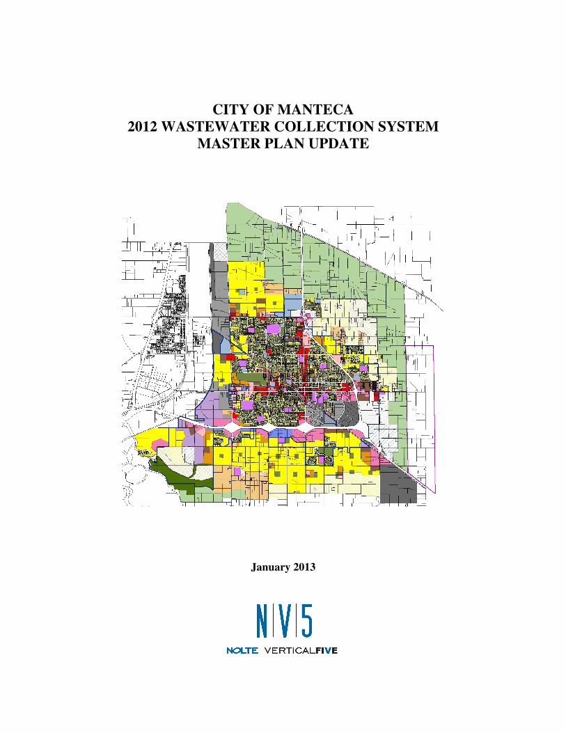
CITY OF MANTECA 2012 WASTEWATER COLLECTION SYSTEM
MASTER PLAN UPDATE
January 2013
2012 WW Collection System Master Plan Update ES-1 MTB015906 January 2013 n:\mtb015906\documents\2010 update\final 201301\201301.doc
Executive Summary
The City of Manteca (City) desires to update the 2006 Wastewater Collection System Master Plan (2006 Master Plan) with current planning and sewer alignment information, revised wastewater generation factors (WGFs) incorporating water conservation requirements and historic commercial and industrial water use data, and updated construction costs. The primary objective of this 2012 Wastewater Collection System Master Plan Update (2012 Master Plan) is to ensure that the City’s trunk system can cost-effectively meet the demands of development goals adopted in the General Plan with appropriate consideration of construction costs and operation and maintenance issues. In particular, the 2012 Master Plan will address the following:
1. Current and future land uses from the General Plan 2023 Policy Document (General
Plan).
2. Design of trunk sewers, force mains, pump stations, and lift stations to accommodate service areas.
3. Capacity of the trunk sewer system.
4. Phased capital improvement plan (CIP) for the proposed conveyance option.
As part of the 2012 Master Plan, residential WGFs for future development have been reduced to reflect upcoming water conservation legislation for residential development based on a generation factors study. The study also focuses on reduction of industrial and general commercial WGFs to reflect historical water use data from local businesses. The overall collection sewer strategy will consist of a combination trunk sewer gravity collection system with pump or lift stations located along the alignment to convey wastewater to an influent pump station located at the City Wastewater Quality Control Facility (WQCF). The North Manteca Collection Strategy (NMCS) and South Manteca Collection Strategy (SMCS) will collect flow from areas where future growth is expected. The Central Manteca Collection Strategy (CMCS) will connect the existing collection system to the NMCS. The continued use of existing pump stations and addition of pump and lift stations allows for a reduction in the depth of the trunk sewers proposed in previous master plans. Additionally, an increase in the ratio of liquid depth to pipe diameter (d/D) design criteria for pipe capacity from 40-60 percent full in previous master plans to 70-80 percent full at peak flow resulted in the downsizing of several links within the proposed trunk sewer strategy.
City of Manteca
2012 Wastewater Collection System Master Plan Update
Executive Summary
2012 WW Collection System Master Plan Update ES-2 MTB015906 January 2013 n:\mtb015906\documents\2010 update\final 201301\201301.doc
Unit construction costs for sewers were updated and used to estimate construction costs for the overall trunk sewer strategy. Construction of the NMCS, SMCS, and CMCS were grouped into potential projects for implementation in the future as part of the City CIP. The total wastewater collection system CIP cost is approximately $54,936,000. Revisions to the overall collection system strategy reflect savings of approximately $32.1 million as compared to the 2006 Master Plan.
2012 WW Collection System Master Plan Update TC-1 MTB015906 January 2013 n:\mtb015906\documents\2010 update\final 201301\201301.doc
CONTENTS
Executive Summary ...................................................................................................................ES-1
Chapter 1 Introduction ................................................................................................................1–1
1.1 Background and Purpose .......................................................................................... 1–1
1.2 Scope of 2012 Master Plan ....................................................................................... 1–2
Chapter 2 Summary of Previous Sewer Master Plans ................................................................2–1
2.1 1993 Sewer System Master Plan ............................................................................... 2–1
2.2 2006 Wastewater Collection System Master Plan Update ....................................... 2–4
2.3 2008 Addendum to 2006 Wastewater Collection System Master Plan Update ........ 2–4
Chapter 3 Design Criteria ...........................................................................................................3–1
3.1 Study Area ................................................................................................................ 3–1
3.2 Land Use ................................................................................................................... 3–1
3.3 Wastewater Generation Factors ................................................................................ 3–1
3.4 Peaking Factor .......................................................................................................... 3–3
3.5 Rationale for Estimating Projected Flows ................................................................ 3–5
3.6 Pump/Lift Stations .................................................................................................... 3–6
3.7 Gravity Pipelines and Force Mains ......................................................................... 3–12
Chapter 4 Recommended Collection System Strategy ...............................................................4–1
4.1 Sewer Collection System Strategy ............................................................................ 4–1
4.2 Projected Flows ......................................................................................................... 4–3
4.3 Vertical Design Constraints ...................................................................................... 4–3
4.4 Description of Proposed Trunk Sewer ...................................................................... 4–4
a. North Manteca Collection Strategy .......................................................................... 4–4
b. South Manteca Collection Strategy .......................................................................... 4–9
c. Central Manteca Collection Strategy ...................................................................... 4–13
Chapter 5 Recommended System Improvements .......................................................................5–1
5.1 Recommended Collection System Strategy .............................................................. 5–1
a. North Manteca Collection Strategy .......................................................................... 5–1
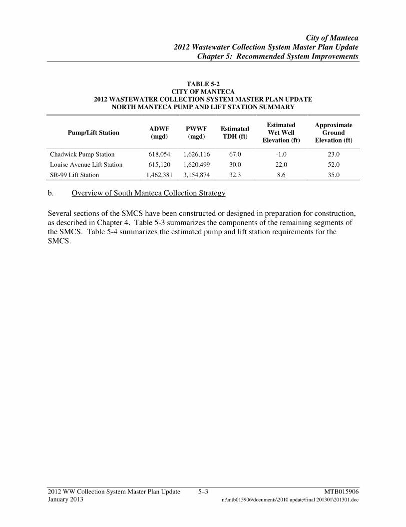
b. Overview of South Manteca Collection Strategy ..................................................... 5–3
c. Phasing of SMCS Improvements .............................................................................. 5–5
d. Central Manteca Collection Strategy ...................................................................... 5–12
Chapter 6 Probable Construction Costs ......................................................................................6–1
6.1 Unit Costs for Pipe .................................................................................................... 6–1
6.2 Unit Costs for Manholes ........................................................................................... 6–8
6.3 Total Pipe and Manhole Costs .................................................................................. 6–9
6.4 Pump and Lift Station Costs ................................................................................... 6–14
6.5 Force Main Costs .................................................................................................... 6–15
6.6 Probable Construction Costs for Recommended Improvements ............................ 6–16
a. North Manteca Collection Strategy ........................................................................ 6–16
2012 WW Collection System Master Plan Update TC–2 MTB015906 January 2013 n:\mtb015906\documents\2010 update\final 201301\201301.doc
b. South Manteca Collection Strategy ........................................................................ 6–18
c. Central Manteca Collection Strategy ...................................................................... 6–20
Chapter 7 Capital Improvement Plan .........................................................................................7–1
7.1 Projects ...................................................................................................................... 7–1
Chapter 8 References .................................................................................................................. 8-1
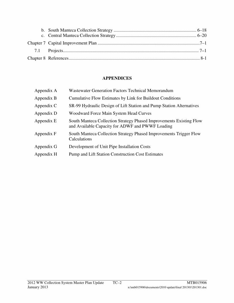
APPENDICES
Appendix A Wastewater Generation Factors Technical Memorandum
Appendix B Cumulative Flow Estimates by Link for Buildout Conditions
Appendix C SR-99 Hydraulic Design of Lift Station and Pump Station Alternatives
Appendix D Woodward Force Main System Head Curves
Appendix E South Manteca Collection Strategy Phased Improvements Existing Flow and Available Capacity for ADWF and PWWF Loading
Appendix F South Manteca Collection Strategy Phased Improvements Trigger Flow Calculations
Appendix G Development of Unit Pipe Installation Costs
Appendix H Pump and Lift Station Construction Cost Estimates
2012 WW Collection System Master Plan Update TC–3 MTB015906 January 2013 n:\mtb015906\documents\2010 update\final 201301\201301.doc
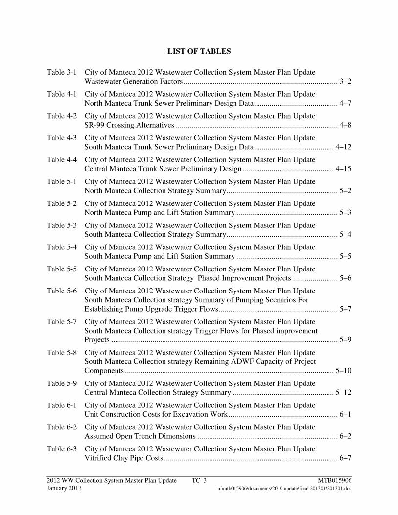
LIST OF TABLES
Table 3-1 City of Manteca 2012 Wastewater Collection System Master Plan Update Wastewater Generation Factors ............................................................................... 3–2
Table 4-1 City of Manteca 2012 Wastewater Collection System Master Plan Update North Manteca Trunk Sewer Preliminary Design Data ........................................... 4–7
Table 4-2 City of Manteca 2012 Wastewater Collection System Master Plan Update SR-99 Crossing Alternatives ................................................................................... 4–8
Table 4-3 City of Manteca 2012 Wastewater Collection System Master Plan Update South Manteca Trunk Sewer Preliminary Design Data ......................................... 4–12
Table 4-4 City of Manteca 2012 Wastewater Collection System Master Plan Update Central Manteca Trunk Sewer Preliminary Design ............................................... 4–15
Table 5-1 City of Manteca 2012 Wastewater Collection System Master Plan Update North Manteca Collection Strategy Summary ......................................................... 5–2
Table 5-2 City of Manteca 2012 Wastewater Collection System Master Plan Update North Manteca Pump and Lift Station Summary .................................................... 5–3
Table 5-3 City of Manteca 2012 Wastewater Collection System Master Plan Update South Manteca Collection Strategy Summary ......................................................... 5–4
Table 5-4 City of Manteca 2012 Wastewater Collection System Master Plan Update South Manteca Pump and Lift Station Summary .................................................... 5–5
Table 5-5 City of Manteca 2012 Wastewater Collection System Master Plan Update South Manteca Collection Strategy Phased Improvement Projects ....................... 5–6
Table 5-6 City of Manteca 2012 Wastewater Collection System Master Plan Update South Manteca Collection strategy Summary of Pumping Scenarios For Establishing Pump Upgrade Trigger Flows ............................................................. 5–7
Table 5-7 City of Manteca 2012 Wastewater Collection System Master Plan Update South Manteca Collection strategy Trigger Flows for Phased improvement Projects .................................................................................................................... 5–9
Table 5-8 City of Manteca 2012 Wastewater Collection System Master Plan Update South Manteca Collection strategy Remaining ADWF Capacity of Project Components ........................................................................................................... 5–10
Table 5-9 City of Manteca 2012 Wastewater Collection System Master Plan Update Central Manteca Collection Strategy Summary .................................................... 5–12
Table 6-1 City of Manteca 2012 Wastewater Collection System Master Plan Update Unit Construction Costs for Excavation Work ........................................................ 6–1
Table 6-2 City of Manteca 2012 Wastewater Collection System Master Plan Update Assumed Open Trench Dimensions ........................................................................ 6–2
Table 6-3 City of Manteca 2012 Wastewater Collection System Master Plan Update Vitrified Clay Pipe Costs ......................................................................................... 6–7
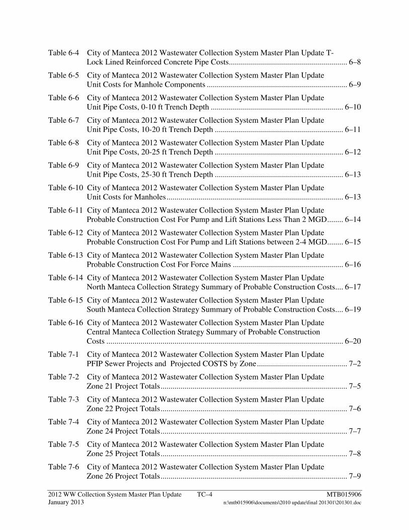
2012 WW Collection System Master Plan Update TC–4 MTB015906 January 2013 n:\mtb015906\documents\2010 update\final 201301\201301.doc
Table 6-4 City of Manteca 2012 Wastewater Collection System Master Plan Update T-Lock Lined Reinforced Concrete Pipe Costs ........................................................... 6–8
Table 6-5 City of Manteca 2012 Wastewater Collection System Master Plan Update Unit Costs for Manhole Components ...................................................................... 6–9
Table 6-6 City of Manteca 2012 Wastewater Collection System Master Plan Update Unit Pipe Costs, 0-10 ft Trench Depth .................................................................. 6–10
Table 6-7 City of Manteca 2012 Wastewater Collection System Master Plan Update Unit Pipe Costs, 10-20 ft Trench Depth ................................................................ 6–11
Table 6-8 City of Manteca 2012 Wastewater Collection System Master Plan Update Unit Pipe Costs, 20-25 ft Trench Depth ................................................................ 6–12
Table 6-9 City of Manteca 2012 Wastewater Collection System Master Plan Update Unit Pipe Costs, 25-30 ft Trench Depth ................................................................ 6–13
Table 6-10 City of Manteca 2012 Wastewater Collection System Master Plan Update Unit Costs for Manholes ........................................................................................ 6–13
Table 6-11 City of Manteca 2012 Wastewater Collection System Master Plan Update Probable Construction Cost For Pump and Lift Stations Less Than 2 MGD ........ 6–14
Table 6-12 City of Manteca 2012 Wastewater Collection System Master Plan Update Probable Construction Cost For Pump and Lift Stations between 2-4 MGD........ 6–15
Table 6-13 City of Manteca 2012 Wastewater Collection System Master Plan Update Probable Construction Cost For Force Mains ....................................................... 6–16
Table 6-14 City of Manteca 2012 Wastewater Collection System Master Plan Update North Manteca Collection Strategy Summary of Probable Construction Costs .... 6–17
Table 6-15 City of Manteca 2012 Wastewater Collection System Master Plan Update South Manteca Collection Strategy Summary of Probable Construction Costs .... 6–19
Table 6-16 City of Manteca 2012 Wastewater Collection System Master Plan Update Central Manteca Collection Strategy Summary of Probable Construction Costs ...................................................................................................................... 6–20
Table 7-1 City of Manteca 2012 Wastewater Collection System Master Plan Update PFIP Sewer Projects and Projected COSTS by Zone ............................................. 7–2
Table 7-2 City of Manteca 2012 Wastewater Collection System Master Plan Update Zone 21 Project Totals ............................................................................................. 7–5
Table 7-3 City of Manteca 2012 Wastewater Collection System Master Plan Update Zone 22 Project Totals ............................................................................................. 7–6
Table 7-4 City of Manteca 2012 Wastewater Collection System Master Plan Update Zone 24 Project Totals ............................................................................................. 7–7
Table 7-5 City of Manteca 2012 Wastewater Collection System Master Plan Update Zone 25 Project Totals ............................................................................................. 7–8
Table 7-6 City of Manteca 2012 Wastewater Collection System Master Plan Update Zone 26 Project Totals ............................................................................................. 7–9
2012 WW Collection System Master Plan Update TC–5 MTB015906 January 2013 n:\mtb015906\documents\2010 update\final 201301\201301.doc
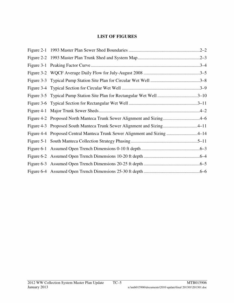
LIST OF FIGURES
Figure 2-1 1993 Master Plan Sewer Shed Boundaries ..............................................................2–2
Figure 2-2 1993 Master Plan Trunk Shed and System Map ......................................................2–3
Figure 3-1 Peaking Factor Curve ...............................................................................................3–4
Figure 3-2 WQCF Average Daily Flow for July-August 2008 .................................................3–5
Figure 3-3 Typical Pump Station Site Plan for Circular Wet Well ...........................................3–8
Figure 3-4 Typical Section for Circular Wet Well ....................................................................3–9
Figure 3-5 Typical Pump Station Site Plan for Rectangular Wet Well ...................................3–10
Figure 3-6 Typical Section for Rectangular Wet Well ............................................................3–11
Figure 4-1 Major Trunk Sewer Sheds ........................................................................................4–2
Figure 4-2 Proposed North Manteca Trunk Sewer Alignment and Sizing ................................4–6
Figure 4-3 Proposed South Manteca Trunk Sewer Alignment and Sizing ..............................4–11
Figure 4-4 Proposed Central Manteca Trunk Sewer Alignment and Sizing ...........................4–14
Figure 5-1 South Manteca Collection Strategy Phasing ..........................................................5–11
Figure 6-1 Assumed Open Trench Dimensions 0-10 ft depth ...................................................6–3
Figure 6-2 Assumed Open Trench Dimensions 10-20 ft depth .................................................6–4
Figure 6-3 Assumed Open Trench Dimensions 20-25 ft depth .................................................6–5
Figure 6-4 Assumed Open Trench Dimensions 25-30 ft depth .................................................6–6
2012 WW Collection System Master Plan Update TC–6 MTB015906 January 2013 n:\mtb015906\documents\2010 update\final 201301\201301.doc
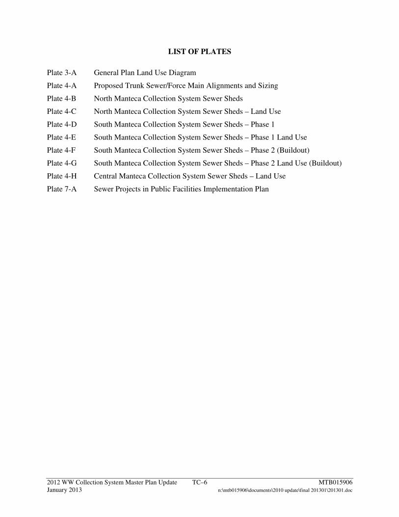
LIST OF PLATES
Plate 3-A General Plan Land Use Diagram
Plate 4-A Proposed Trunk Sewer/Force Main Alignments and Sizing
Plate 4-B North Manteca Collection System Sewer Sheds
Plate 4-C North Manteca Collection System Sewer Sheds – Land Use
Plate 4-D South Manteca Collection System Sewer Sheds – Phase 1
Plate 4-E South Manteca Collection System Sewer Sheds – Phase 1 Land Use
Plate 4-F South Manteca Collection System Sewer Sheds – Phase 2 (Buildout)
Plate 4-G South Manteca Collection System Sewer Sheds – Phase 2 Land Use (Buildout)
Plate 4-H Central Manteca Collection System Sewer Sheds – Land Use
Plate 7-A Sewer Projects in Public Facilities Implementation Plan
2012 WW Collection System Master Plan Update TC–7 MTB015906 January 2013 n:\mtb015906\documents\2010 update\final 201301\201301.doc
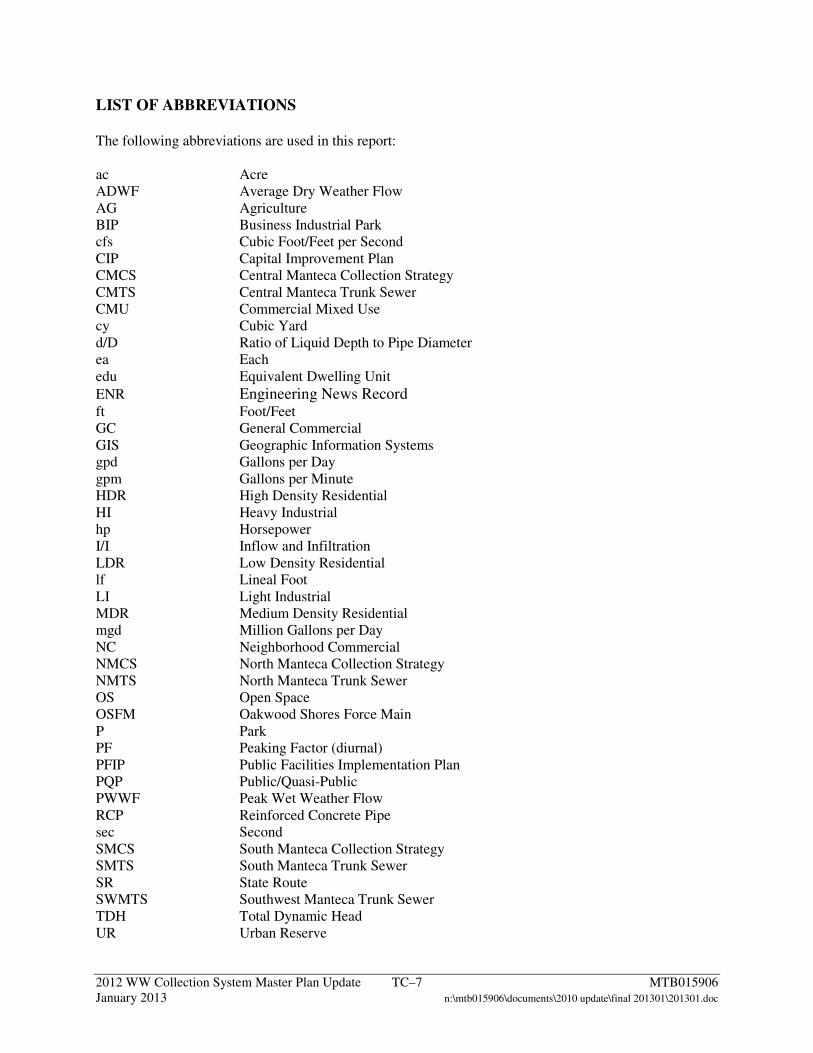
LIST OF ABBREVIATIONS The following abbreviations are used in this report: ac Acre ADWF Average Dry Weather Flow AG Agriculture BIP Business Industrial Park cfs Cubic Foot/Feet per Second CIP Capital Improvement Plan CMCS Central Manteca Collection Strategy CMTS Central Manteca Trunk Sewer CMU Commercial Mixed Use cy Cubic Yard d/D Ratio of Liquid Depth to Pipe Diameter ea Each edu Equivalent Dwelling Unit
ENR Engineering News Record ft Foot/Feet GC General Commercial GIS Geographic Information Systems gpd Gallons per Day gpm Gallons per Minute HDR High Density Residential HI Heavy Industrial hp Horsepower I/I Inflow and Infiltration LDR Low Density Residential lf Lineal Foot LI Light Industrial MDR Medium Density Residential mgd Million Gallons per Day NC Neighborhood Commercial NMCS North Manteca Collection Strategy NMTS North Manteca Trunk Sewer OS Open Space OSFM Oakwood Shores Force Main P Park PF Peaking Factor (diurnal) PFIP Public Facilities Implementation Plan PQP Public/Quasi-Public PWWF Peak Wet Weather Flow RCP Reinforced Concrete Pipe sec Second SMCS South Manteca Collection Strategy SMTS South Manteca Trunk Sewer SR State Route SWMTS Southwest Manteca Trunk Sewer TDH Total Dynamic Head UR Urban Reserve
2012 WW Collection System Master Plan Update TC–8 MTB015906 January 2013 n:\mtb015906\documents\2010 update\final 201301\201301.doc
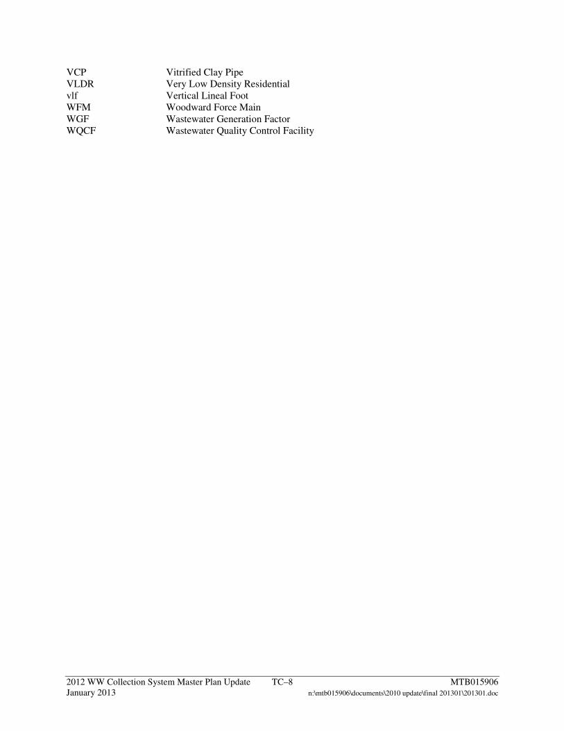
VCP Vitrified Clay Pipe VLDR Very Low Density Residential vlf Vertical Lineal Foot WFM Woodward Force Main WGF Wastewater Generation Factor WQCF Wastewater Quality Control Facility
2012 WW Collection System Master Plan Update 1–1 MTB015906 January 2013 n:\mtb015906\documents\2010 update\final 201301\201301.doc
1 Introduction
In support of the City of Manteca (City) General Plan 2023 Policy Document (General Plan) and Public Facilities Implementation Plan (PFIP), a wastewater collection system master plan is required. Background information and intended master planning tasks are presented in this chapter.
1.1 Background and Purpose On October 6, 2003, the City adopted the General Plan [1] which identifies areas to be developed within the City to the year 2023. The General Plan expanded the areas to be served by the sewer collection system in comparison to those areas identified in prior master planning documents. The City adopted an updated Housing Element to the General Plan on June 15, 2010 [2].
The 2006 Wastewater Collection System Master Plan Update (2006 Master Plan) [3] proposed the construction of three large diameter trunk sewers to collect wastewater from the north, central, and south sections of the City for conveyance to an influent pump station located at the Wastewater Quality Control Facility (WQCF). This strategy of deep gravity trunk sewers was consistent with previous master plans. The depth and size of trunk sewers required to implement the strategy set forth in the 2006 Master Plan presented significant capital costs. A revised conveyance strategy including a combination of gravity sewers, force mains, lift stations, and pump stations was evaluated as part of the 2008 Addendum to the Wastewater Collection System Master Plan (2008 Addendum) [4]. The City desires to update the 2008 Addendum with current planning and alignment information, revised wastewater generation factors (WGFs) incorporating water conservation requirements and historic commercial and industrial water use data, and updated construction costs. The conveyance strategy to be evaluated as part of this 2012 Wastewater Collection System Master Plan Update (2012 Master Plan) seeks to minimize pipe size and depth based on pipes flowing 70-80 percent full at peak flows. Lift or pump stations will be constructed as needed to reach the trunk sewers. The primary objective of this 2012 Master Plan is to ensure that the City trunk system can cost-effectively meet the demands of development goals adopted in the General Plan. In particular, the 2012 Master Plan will address the following:
1. Current and future land uses from the General Plan 2023.
2. Design of trunk sewers, force mains, pump stations, and lift stations to accommodate
service areas.
3. Capacity of the trunk sewer system.
City of Manteca
2012 Wastewater Collection System Master Plan Update
Chapter 1: Introduction
2012 WW Collection System Master Plan Update 1–2 MTB015906 January 2013 n:\mtb015906\documents\2010 update\final 201301\201301.doc
4. Phased capital improvement plan (CIP) for the proposed conveyance option.
1.2 Scope of 2012 Master Plan The following tasks were completed as part of the 2012 Master Plan:
1. Summarize current and future land use by sewer catchment.
2. Revise WGFs based on recent water conservation legislation and historic water use data.
3. Estimate wastewater flows using data from Tasks 1 and 2 (above) and peaking factor
(PF) and inflow/infiltration (I/I) values established in the 2008 Addendum.
4. Update the trunk sewer hydraulic model, with emphasis on minimizing sewer size and depth while incorporating lift/pumping stations.
5. Develop a CIP which identifies capital projects required for the proposed conveyance
option.
Each of these tasks is summarized in the following chapters.
2012 WW Collection System Master Plan Update 2–1 MTB015906 January 2013 n:\mtb015906\documents\2010 update\final 201301\201301.doc
2 Summary of Previous Sewer Master Plans
This 2012 Master Plan was developed based on information provided in previous sewer master plans. The two preceding sewer master plans and a subsequent addendum are summarized in the following chapter.
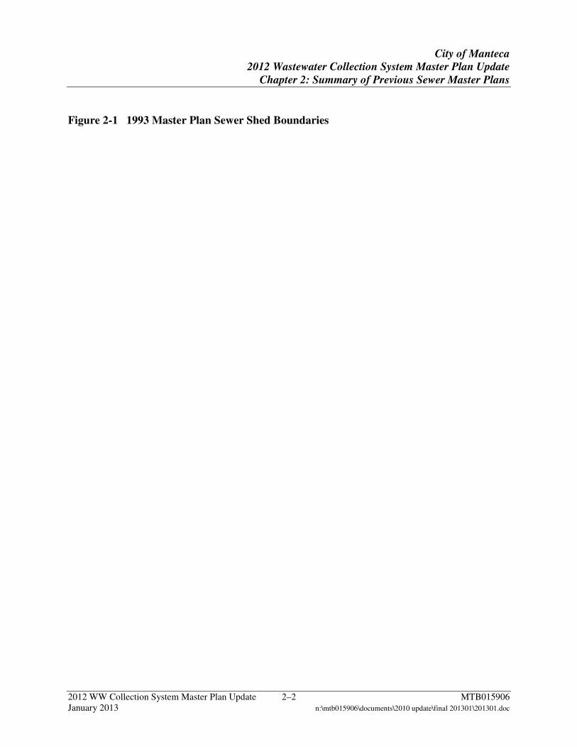
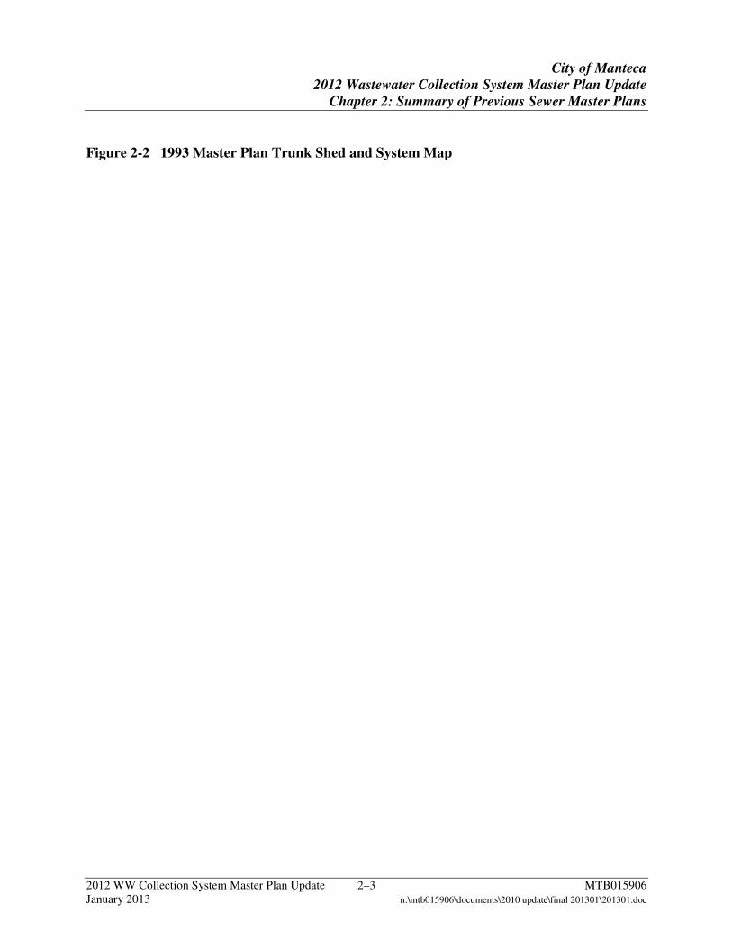
2.1 1993 Sewer System Master Plan The 1993 Sewer System Master Plan (1993 Master Plan) [5] addressed a 17-year planning period (1993-2014) and concentrated on areas of future growth, referred to as the Expanded Service Area. The Expanded Service Area accounted for growth in areas around the existing core of the City. The 1993 Master Plan separated the Expanded Service Area into two principal sections, the North and South Service Areas, divided by Yosemite Avenue. Additionally, the North Service Area was subdivided into the North Shed and Central Shed and the South Service Area was subdivided into the South Shed and Southwest Shed. Figure 2-1 shows the boundaries of the different service areas and sheds. The 1993 Master Plan proposed construction of two major trunk sewers: the North Manteca Trunk Sewer (NMTS) and South Manteca Trunk Sewer (SMTS). Two other trunk sewers, the Central Manteca Trunk Sewer (CMTS) and Southwest Manteca Trunk Sewer (SWMTS), would connect to the NMTS and SMTS. The NMTS extended gravity service to new development north of State Route (SR) 120. Additionally, the CMTS, serving the developed core of the City, would be constructed along Yosemite Avenue and drain to the NMTS. Construction of the CMTS would allow for the decommissioning of the Union Road Pump Station. The SMTS and SWMTS extended gravity service to areas south of SR-120. The SMTS would extend south from Austin Road, west along Woodward Avenue to Airport Way, then north to the WQCF. A collector would receive flow from areas along Spreckels Road north of SR-120. The Southwest Service Area is west of the WQCF and south of SR-120, beyond the gravity service limits of the SMTS. Due to the low ground elevations and large size of this area, a regional pump station was recommended. Trunk sewers from the southwest areas would flow into the regional pump station. A force main would extend from the regional pump station to the SMTS. The NMTS and SMTS would converge at the influent pump station for the WQCF. The trunk sewer alignments presented in the 1993 Master Plan are shown in Figure 2-2.
City of Manteca
2012 Wastewater Collection System Master Plan Update
Chapter 2: Summary of Previous Sewer Master Plans
2012 WW Collection System Master Plan Update 2–2 MTB015906 January 2013 n:\mtb015906\documents\2010 update\final 201301\201301.doc
Figure 2-1 1993 Master Plan Sewer Shed Boundaries
City of Manteca
2012 Wastewater Collection System Master Plan Update
Chapter 2: Summary of Previous Sewer Master Plans
2012 WW Collection System Master Plan Update 2–3 MTB015906 January 2013 n:\mtb015906\documents\2010 update\final 201301\201301.doc
Figure 2-2 1993 Master Plan Trunk Shed and System Map
City of Manteca
2012 Wastewater Collection System Master Plan Update
Chapter 2: Summary of Previous Sewer Master Plans
2012 WW Collection System Master Plan Update 2–4 MTB015906 January 2013 n:\mtb015906\documents\2010 update\final 201301\201301.doc
2.2 2006 Wastewater Collection System Master Plan Update The 2006 Update [3] addressed future expansion of the tributary areas served by the NMTS and SMTS and proposed alternate trunk sewer alignments to mitigate potential traffic disruption and to reduce total construction costs. To assess the overall condition of the collection system, existing system deficiencies were identified through discussions with City staff and a review of historical records. Based on historical data, WGFs for residential services were revised. I/I rates and a system-wide diurnal PF were established through a flow monitoring program. The data were utilized to develop a hydraulic model to assess the capacity of the trunk sewer system. Trunk sewers were designed to flow 40-60 percent full at peak flow. The results of the trunk sewer assessment were used to update preliminary NMTS and SMTS design information and in the development of a phased CIP to support the demands of future development. The total construction cost for the proposed trunk sewers was approximately $87 million.
2.3 2008 Addendum to 2006 Wastewater Collection System Master Plan Update The 2008 Addendum [4] presented a revised conveyance strategy which included a combination of gravity sewers, force mains, pump stations, and lift stations. The addition of pump and lift stations to the strategy allowed for reduced depths of the trunk sewers. The 2008 Addendum presented revised design criteria for diurnal peaking and I/I as well as pump selection and pump station design criteria. Probable construction costs for elements of the revised conveyance strategy were developed on a unit basis. These costs were applied to the revised improvement recommendations for the development of a revised CIP. The total construction cost for the revised CIP was approximately $71 million.
2012 WW Collection System Master Plan Update 3–1 MTB015906 January 2013 n:\mtb015906\documents\2010 update\final 201301\201301.doc
3 Design Criteria
Design criteria for the 2012 Master Plan include a discussion of the study area boundaries, land use, WGFs, and hydraulic parameters. Each is discussed in this chapter.
3.1 Study Area The study area for the 2012 Master Plan is based on the secondary urban service boundary, the total planning area presented in the General Plan land use diagram. For master planning purposes, the study area extends beyond the current City limits and primary urban service boundary. Land use information was provided by City staff.
3.2 Land Use Land use information from the General Plan land use diagram provided by the City in September 2010 was used to project wastewater flows. City Geographic Information Systems (GIS) data were reviewed to determine the development status of all parcels within the study area. The General Plan land use diagram is provided as Plate 3-A.
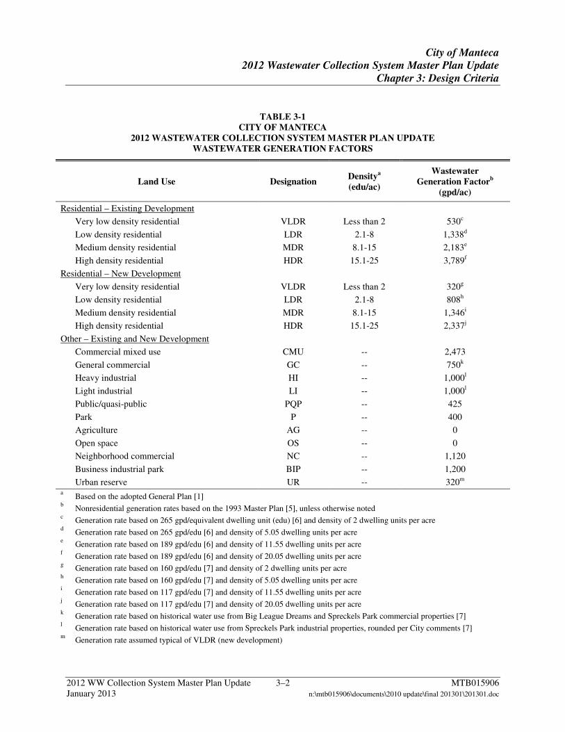
3.3 Wastewater Generation Factors WGFs for land uses defined in the General Plan are summarized in Table 3-1. Residential WGFs for future development are proposed to reflect upcoming water conservation legislation for residential development based on a generation factors study (Appendix A). The study also focused on updating industrial and general commercial WGFs to reflect historical water use data from local businesses. A portion of the existing industrial and general commercial businesses within the City have low water usage. Reviewing historical water use data provided an improved basis for appropriate WGFs. Residential WGFs for existing development were updated in the 2006 Update based on a flow monitoring study. Heavy Industrial (HI) and Light Industrial (LI) WGFs are based on historical water use from Spreckels Park industrial properties (Appendix A), and rounded to 1,000 gallons per day per acre (gpd/ac) incorporating comments from City staff. The Urban Reserve (UR) land use has been assigned a WGF typical of Very Low Density Residential (VLDR). All other WGFs presented in Table 3-1 are from the 1993 Master Plan. However, the Business Industrial Park (BIP) WGF was reduced by 10 percent from the 2006 Update to the 2008 Addendum to reflect information obtained from water use data.
City of Manteca
2012 Wastewater Collection System Master Plan Update
Chapter 3: Design Criteria
2012 WW Collection System Master Plan Update 3–2 MTB015906 January 2013 n:\mtb015906\documents\2010 update\final 201301\201301.doc
TABLE 3-1 CITY OF MANTECA
2012 WASTEWATER COLLECTION SYSTEM MASTER PLAN UPDATE WASTEWATER GENERATION FACTORS
Land Use Designation Densitya (edu/ac)
Wastewater Generation Factorb
(gpd/ac)
Residential – Existing Development
Very low density residential VLDR Less than 2 530c
Low density residential LDR 2.1-8 1,338d
Medium density residential MDR 8.1-15 2,183e
High density residential HDR 15.1-25 3,789f
Residential – New Development
Very low density residential VLDR Less than 2 320g
Low density residential LDR 2.1-8 808h
Medium density residential MDR 8.1-15 1,346i
High density residential HDR 15.1-25 2,337j
Other – Existing and New Development
Commercial mixed use CMU -- 2,473
General commercial GC -- 750k
Heavy industrial HI -- 1,000l
Light industrial LI -- 1,000l
Public/quasi-public PQP -- 425
Park P -- 400
Agriculture AG -- 0
Open space OS -- 0
Neighborhood commercial NC -- 1,120
Business industrial park BIP -- 1,200
Urban reserve UR -- 320m a Based on the adopted General Plan [1] b Nonresidential generation rates based on the 1993 Master Plan [5], unless otherwise noted c Generation rate based on 265 gpd/equivalent dwelling unit (edu) [6] and density of 2 dwelling units per acre d Generation rate based on 265 gpd/edu [6] and density of 5.05 dwelling units per acre e Generation rate based on 189 gpd/edu [6] and density of 11.55 dwelling units per acre f Generation rate based on 189 gpd/edu [6] and density of 20.05 dwelling units per acre g Generation rate based on 160 gpd/edu [7] and density of 2 dwelling units per acre h Generation rate based on 160 gpd/edu [7] and density of 5.05 dwelling units per acre i Generation rate based on 117 gpd/edu [7] and density of 11.55 dwelling units per acre j Generation rate based on 117 gpd/edu [7] and density of 20.05 dwelling units per acre k Generation rate based on historical water use from Big League Dreams and Spreckels Park commercial properties [7] l Generation rate based on historical water use from Spreckels Park industrial properties, rounded per City comments [7] m Generation rate assumed typical of VLDR (new development)
City of Manteca
2012 Wastewater Collection System Master Plan Update
Chapter 3: Design Criteria
2012 WW Collection System Master Plan Update 3–3 MTB015906 January 2013 n:\mtb015906\documents\2010 update\final 201301\201301.doc
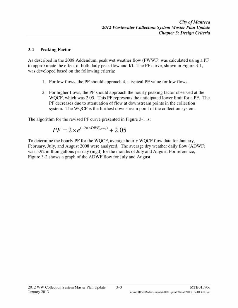
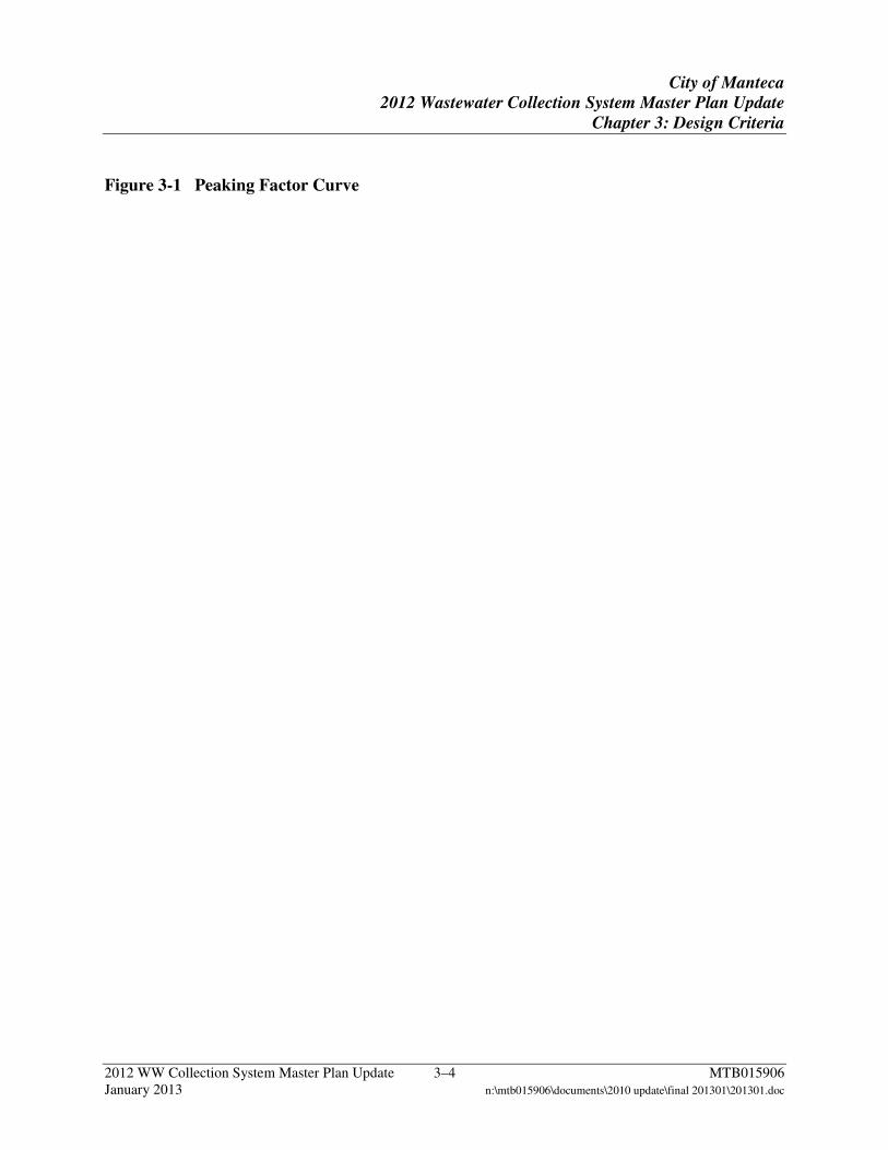
3.4 Peaking Factor As described in the 2008 Addendum, peak wet weather flow (PWWF) was calculated using a PF to approximate the effect of both daily peak flow and I/I. The PF curve, shown in Figure 3-1, was developed based on the following criteria:
1. For low flows, the PF should approach 4, a typical PF value for low flows.
2. For higher flows, the PF should approach the hourly peaking factor observed at the WQCF, which was 2.05. This PF represents the anticipated lower limit for a PF. The PF decreases due to attenuation of flow at downstream points in the collection system. The WQCF is the furthest downstream point of the collection system.
The algorithm for the revised PF curve presented in Figure 3-1 is:
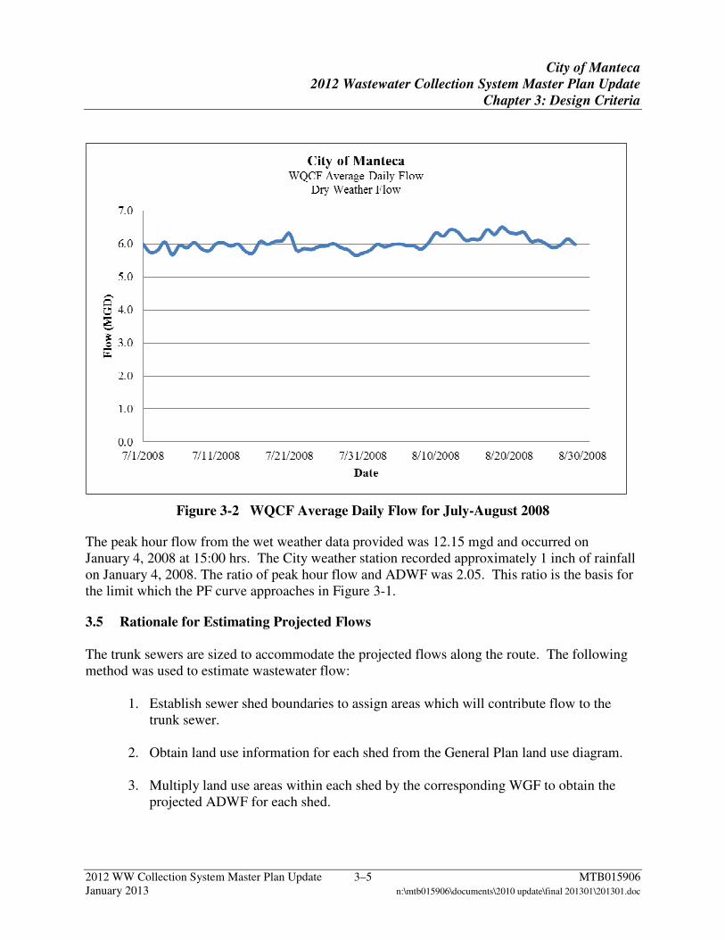
To determine the hourly PF for the WQCF, average hourly WQCF flow data for January, February, July, and August 2008 were analyzed. The average dry weather daily flow (ADWF) was 5.92 million gallons per day (mgd) for the months of July and August. For reference, Figure 3-2 shows a graph of the ADWF flow for July and August.
05.22 )2(+×=
×− MGDADWFePF
City of Manteca
2012 Wastewater Collection System Master Plan Update
Chapter 3: Design Criteria
2012 WW Collection System Master Plan Update 3–4 MTB015906 January 2013 n:\mtb015906\documents\2010 update\final 201301\201301.doc
Figure 3-1 Peaking Factor Curve
City of Manteca
2012 Wastewater Collection System Master Plan Update
Chapter 3: Design Criteria
2012 WW Collection System Master Plan Update 3–5 MTB015906 January 2013 n:\mtb015906\documents\2010 update\final 201301\201301.doc
Figure 3-2 WQCF Average Daily Flow for July-August 2008
The peak hour flow from the wet weather data provided was 12.15 mgd and occurred on January 4, 2008 at 15:00 hrs. The City weather station recorded approximately 1 inch of rainfall on January 4, 2008. The ratio of peak hour flow and ADWF was 2.05. This ratio is the basis for the limit which the PF curve approaches in Figure 3-1.
3.5 Rationale for Estimating Projected Flows The trunk sewers are sized to accommodate the projected flows along the route. The following method was used to estimate wastewater flow:
1. Establish sewer shed boundaries to assign areas which will contribute flow to the trunk sewer.
2. Obtain land use information for each shed from the General Plan land use diagram.
3. Multiply land use areas within each shed by the corresponding WGF to obtain the
projected ADWF for each shed.
City of Manteca
2012 Wastewater Collection System Master Plan Update
Chapter 3: Design Criteria
2012 WW Collection System Master Plan Update 3–6 MTB015906 January 2013 n:\mtb015906\documents\2010 update\final 201301\201301.doc
4. Estimate PWWF by multiplying the projected ADWF with the PF, considering the relationship between PF and ADWF in Figure 3-1. PWWF is the flow used to size trunk sewers, pump/lift stations, and force mains.
3.6 Pump/Lift Stations Construction of pump or lift stations are anticipated for some connections to the proposed trunk sewers. The pump/lift station should meet the following criteria:
1. Duplex pump/lift stations are preferred and will be used for PWWF up to 2 mgd. When necessary, triplex stations will be used if a single pump capable of meeting the anticipated range of flows is not available. For planning purposes, triplex pump stations should be assumed for PWWFs greater than 2 mgd.
2. Pump and impeller sizes will be selected with operating points within 60-115 percent of the pump’s best efficiency point.
3. Each pump in a duplex pump station will be designed to meet 100 percent of PWWF.
4. Triplex pump stations are designed to meet 100 percent of PWWF with two pumps operating.
5. Variable frequency drives will be provided to allow for pumps to meet the anticipated range of flows.
6. Wet well inverts are approximated by assuming 8 foot (ft) minimum cover for upstream gravity sewers and an average slope of 0.0042 from the furthest point within a sewer shed. This average slope is based on a review of record drawings for developments within the City.
7. Static lift is calculated as the difference between the wet well invert and the upstream springline of the trunk sewer immediately downstream of the lift station.
Preliminary design criteria developed with City staff for pump and lift stations are summarized below:
1. Pump and lift stations will be furnished with submersible pumps and are to include the redundancy of one stand-by pump.
2. Pump station lot to be sized to fit all lift station equipment and a vactor truck.
3. Vaults to be provided to house valving, bypass capability, and flowmeters.
City of Manteca
2012 Wastewater Collection System Master Plan Update
Chapter 3: Design Criteria
2012 WW Collection System Master Plan Update 3–7 MTB015906 January 2013 n:\mtb015906\documents\2010 update\final 201301\201301.doc
4. Provide traffic rated wet well and vault hatches.
5. Provide utility stubs and concrete pads for chemical addition and biofilters in triplex stations.
6. Include a generator receptacle for connection to a portable emergency generator.
7. Provide ability to bypass the pump station with piping for portable pump.
8. On-site drainage will be routed to wet well.
9. Provide an on-site pump retrieval system such as a hoist.
10. Include sufficient area for pump washdown.
11. All wet wells will be lined.
12. Provide site lighting and water for washdown purposes.
13. Provide concrete masonry unit or ornamental site fencing for security and aesthetics.
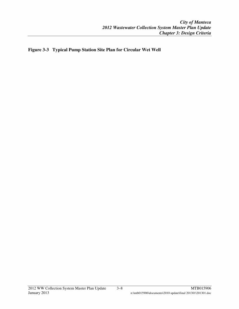
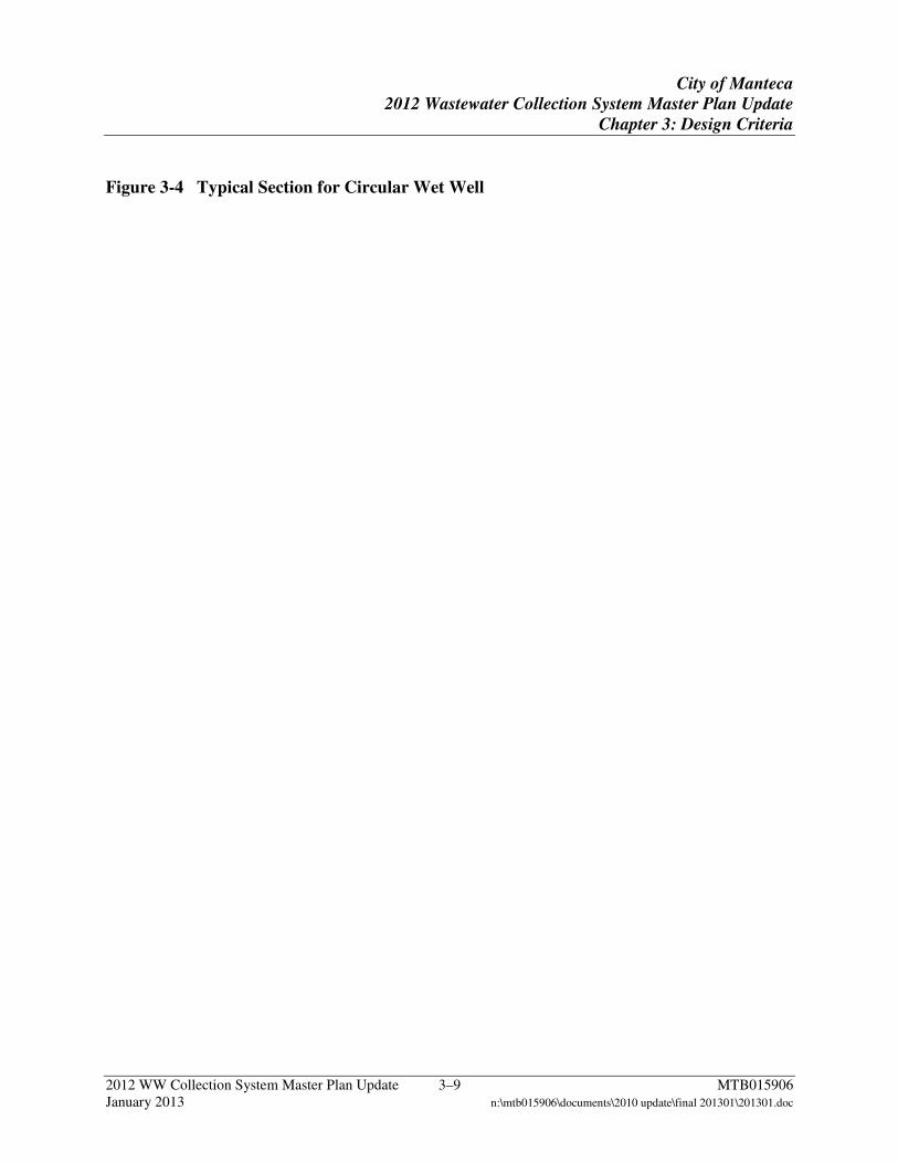
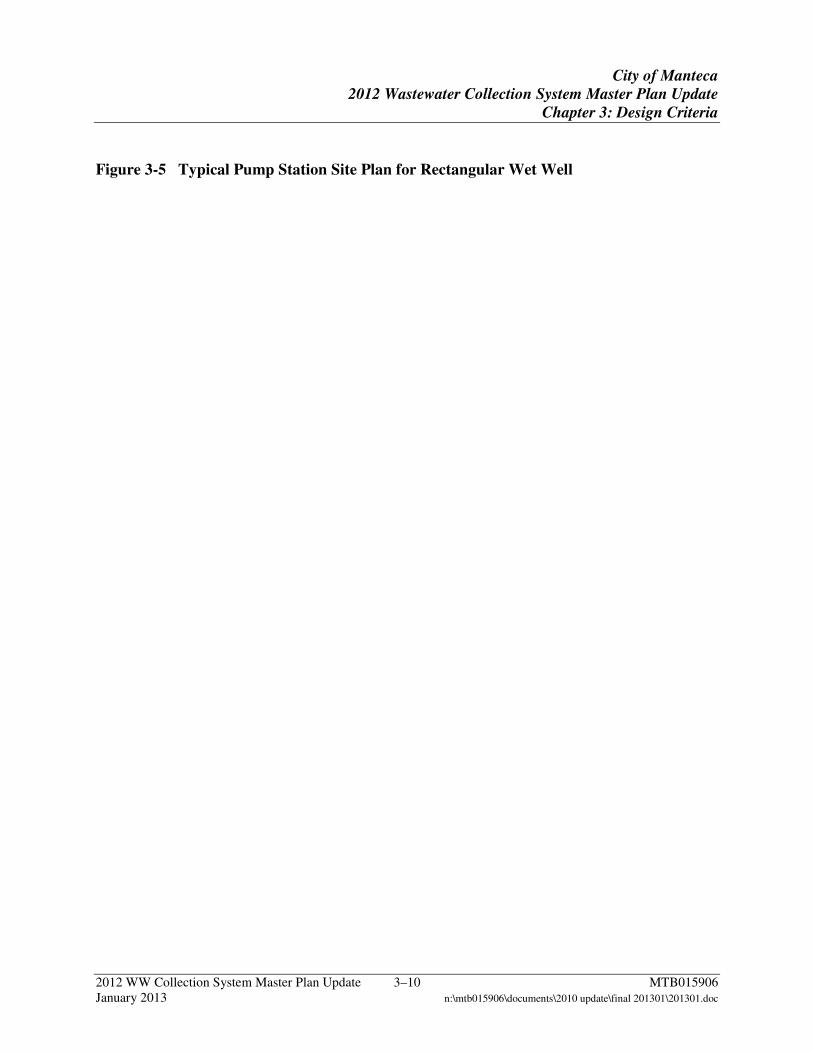
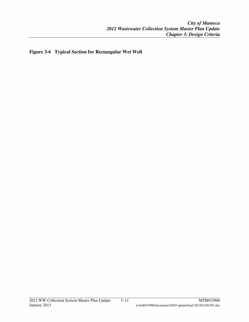
Preliminary layouts for submersible pump/lift stations are presented in Figures 3-3 through 3-6. Figures 3-3 and 3-4 illustrate plan and section views of a typical submersible pump station with a circular wet well. Figures 3-5 and 3-6 illustrate plan and section views of a typical submersible pump station with a rectangular wet well. Circular wet wells will be used for duplex pumps which can be accommodated within a 7 ft diameter reinforced concrete section. Rectangular wet wells will be used for triplex pump stations. Pump stations and lift stations will be similar to each other. However, the pump station will discharge to a force main and the lift station will discharge to a gravity sewer.
City of Manteca
2012 Wastewater Collection System Master Plan Update
Chapter 3: Design Criteria
2012 WW Collection System Master Plan Update 3–8 MTB015906 January 2013 n:\mtb015906\documents\2010 update\final 201301\201301.doc
Figure 3-3 Typical Pump Station Site Plan for Circular Wet Well
City of Manteca
2012 Wastewater Collection System Master Plan Update
Chapter 3: Design Criteria
2012 WW Collection System Master Plan Update 3–9 MTB015906 January 2013 n:\mtb015906\documents\2010 update\final 201301\201301.doc
Figure 3-4 Typical Section for Circular Wet Well
City of Manteca
2012 Wastewater Collection System Master Plan Update
Chapter 3: Design Criteria
2012 WW Collection System Master Plan Update 3–10 MTB015906 January 2013 n:\mtb015906\documents\2010 update\final 201301\201301.doc
Figure 3-5 Typical Pump Station Site Plan for Rectangular Wet Well
City of Manteca
2012 Wastewater Collection System Master Plan Update
Chapter 3: Design Criteria
2012 WW Collection System Master Plan Update 3–11 MTB015906 January 2013 n:\mtb015906\documents\2010 update\final 201301\201301.doc
Figure 3-6 Typical Section for Rectangular Wet Well
City of Manteca
2012 Wastewater Collection System Master Plan Update
Chapter 3: Design Criteria
2012 WW Collection System Master Plan Update 3–12 MTB015906 January 2013 n:\mtb015906\documents\2010 update\final 201301\201301.doc
3.7 Gravity Pipelines and Force Mains The use of gravity sewers for the collection system is the preferred method of conveyance. Although initially more expensive due to larger size and depth of installation, gravity sewers tend to have lower operation and maintenance costs and a reduced risk of failure. Pump stations, lift stations, and force mains will be selected for conditions where the topography is relatively flat or adverse for the use of gravity sewers. The following criteria are used in the design of the gravity sewers:
1. The minimum depth of cover is 8 ft.
2. The maximum depth of cover is 30 ft.
3. Manholes are assumed every 400 ft for pipe diameters ranging from 8 to 18 inch, every 500 ft for pipe diameters ranging from 21 to 30 inch, and every 600 ft for pipe diameters larger than 30-inch; manholes are also assumed at every junction or change in pipe diameter.
4. Gravity sewer lines will be sized to flow 70-80 percent full.
5. Pipe velocities will range from 2-6 feet per second (ft/sec).
The following design criteria will be used for force mains:
1. Minimum cover of 3 ft.
2. Velocities will range from 2-6 ft/sec.
3. Plug valves will be installed every 1,000 ft and at major crossings.
4. Tracer wire will be provided.
5. Force mains will be constructed of PVC, AWWA C900/C905.
6. A redundant 18-inch force main will be constructed between Woodbridge and Chadwick pump stations.
2012 WW Collection System Master Plan Update 4–1 MTB015906 January 2013 n:\mtb015906\documents\2010 update\final 201301\201301.doc
4 Recommended Collection System Strategy
This chapter summarizes the recommended sewer collection system strategy for the City. Specifically, the following topics are included: 1) flow projections; 2) sizing and invert elevations; and 3) exhibits illustrating proposed alignments, sizing, and sheds for the NMCS, SMCS, and CMCS.
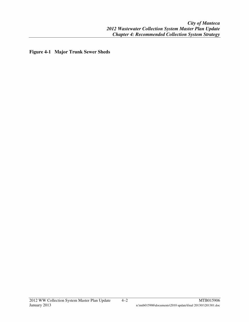
4.1 Sewer Collection System Strategy The overall trunk sewer strategy will consist of a combination trunk sewer gravity collection system with pump or lift stations located along the alignment to convey wastewater to an influent pump station located at the WQCF. Interim pump stations will be constructed as needed and gradually phased out as the collection system is completed. The boundaries of these three major sections (also referred to as sheds) are shown in Figure 4-1. The NMCS and SMCS will collect flow from areas where future growth is expected. The CMCS will connect the existing collection system to the NMCS. Wastewater flow from specific sections of the City will be directed to either a pump station, lift station, or the trunk sewer. The use of pump stations and lift stations provide the following benefits:
1. Reduce the number of interim pump stations to be constructed.
2. Reduce the depth of the trunk sewers.
3. Reduce restrictions on the depth of the gravity sewers within a particular shed. However, pump stations, lift stations, and force mains also tend to have higher operation and maintenance costs and an increased risk for failure. Measures such as parallel force mains and pumping redundancy are included to mitigate these risks. For reference, two permanent pump stations and two permanent lift stations will be included in the NMCS. Three permanent pump stations and four permanent lift stations will be included in the SMCS. Woodward Park Pump Station, Tara Park Pump Station, Bella Vista Lift Station, and Antigua Way Lift Station will be decommissioned and their influent sewers redirected to the trunk gravity alignment along Woodward Avenue following construction of Links 1-5. The proposed routing for these trunk sewers and preliminary locations for pump stations and lift stations are depicted in Plate 4-A. The numbering of trunk sewer links generally matches the link numbering presented in previous documents. Additional pump and lift stations will be constructed as needed for developments to connect to the proposed trunk sewers.
City of Manteca
2012 Wastewater Collection System Master Plan Update
Chapter 4: Recommended Collection System Strategy
2012 WW Collection System Master Plan Update 4–2 MTB015906 January 2013 n:\mtb015906\documents\2010 update\final 201301\201301.doc
Figure 4-1 Major Trunk Sewer Sheds
City of Manteca
2012 Wastewater Collection System Master Plan Update
Chapter 4: Recommended Collection System Strategy
2012 WW Collection System Master Plan Update 4–3 MTB015906 January 2013 n:\mtb015906\documents\2010 update\final 201301\201301.doc
4.2 Projected Flows The trunk sewers are sized to accommodate the projected flows along the route. Shed boundaries, shown in Plates 4-B through 4-H, were identified and assigned to a corresponding trunk sewer link, pump station, or lift station. The outer limits of the sheds were established to include all parcels with designated land uses in the General Plan. Once the shed boundaries were delineated, the method described in Section 3.5 was used to estimate PWWF for each link. ADWF projections for the City were based on the land uses presented in the General Plan. PWWF for the pump or lift stations and downstream sewer may differ based on the use of a different PF, as the PF varies as a function of flow. Cumulative flows estimates for each link are included in Appendix B.
4.3 Vertical Design Constraints The following vertical constraints were considered in establishing the inverts for the NMCS:
1. As-built information for Link 51A constructed under the WQCF Phase III Expansion Project, Schedule B. Link 51A was assumed to have an invert elevation of -3.87 ft per record documents.
2. City approved designs for Links 66, 66S1, 67, 68, 69, and 70 located within the
Union Ranch Development. As-built information was not available for these links.
3. A 12-inch sewer from the Villa Ticino No. 1 subdivision with an assumed invert elevation of 3.36 ft based on as-built drawings at the intersection of Geneva Way and Airport Way connecting to the NMCS at the upstream end of Link 56.
4. Matching springlines at downstream end of Link 54 and upstream end of Link 91, to
avoid potential backwater effect from the 60-inch diameter Link 91 to the 18-inch diameter Link 54. Crowns could not be matched due to the required upstream invert for Link 56 as described above.
5. Matching crowns of trunk sewer links and connections, where feasible. 6. Minimum 8 ft of cover.
The preliminary design for the SMCS reflected the following vertical constraints:
1. As-built information for Link 1A constructed under the WQCF Phase III Expansion Project, Schedule B. Link 1A was assumed to have an invert elevation of -3.92 ft per record documents.
City of Manteca
2012 Wastewater Collection System Master Plan Update
Chapter 4: Recommended Collection System Strategy
2012 WW Collection System Master Plan Update 4–4 MTB015906 January 2013 n:\mtb015906\documents\2010 update\final 201301\201301.doc
2. City as-built information dated 2/3/07 for Links 34A and 34B constructed as part of the Dutra Estates development.
3. Survey information from September 2008 for Link 6 conducted by Nolte Associates,
Inc. indicating an upstream invert of -1.23 ft and downstream invert of -2.31 ft.
4. A 15-inch sewer from Daniels Street with an assumed invert elevation of 0.47 ft connecting to the SMCS at the upstream end of Link 3. This connection will allow for decommissioning of the Westbrook Pump Station.
5. Survey information from May 2002 for previously constructed Links 16-18. 6. As-built information for previously constructed Links 14-15. 7. City approved designs for Links 19-21 and Links 30-32. 8. Matching crowns of trunk sewer links and connections, where feasible. 9. Minimum 8 ft of cover.
The CMCS will eliminate the need for the Union Road Pump Station and will connect the existing collection system to the NMCS at the upstream end of Link 91. Design of the CMCS reflects the following vertical constraints:
1. Upstream invert elevation of 11.00 ft (corresponds to the bottom elevation of the Union Road Pump Station wet well).
2. Upstream invert elevation of 17.18 ft for Link 93S1 (corresponds to the bottom
elevation of sewer leading to Fishback Pump Station).
4.4 Description of Proposed Trunk Sewer Each trunk sewer is described below.
a. North Manteca Collection Strategy
The NMCS will follow the alignment illustrated in Figure 4-2 including proposed “spines” (Links 66S2, 66S3, 66S4, 69S1, and 69S2) serving the northern areas of the City. The NMCS will include the existing Woodbridge Pump Station, a new pump station near Chadwick Square, a new lift station on the east side of SR-99, and a new lift station on Louise Avenue at the upstream end of Link 81. The existing Chadwick Unit 5 Pump Station will be decommissioned and replaced with a pump station capable of serving a larger area. The new lift station on the east side of SR-99 will reduce the depth of the sewer crossing at SR-99 to the connection with
City of Manteca
2012 Wastewater Collection System Master Plan Update
Chapter 4: Recommended Collection System Strategy
2012 WW Collection System Master Plan Update 4–5 MTB015906 January 2013 n:\mtb015906\documents\2010 update\final 201301\201301.doc
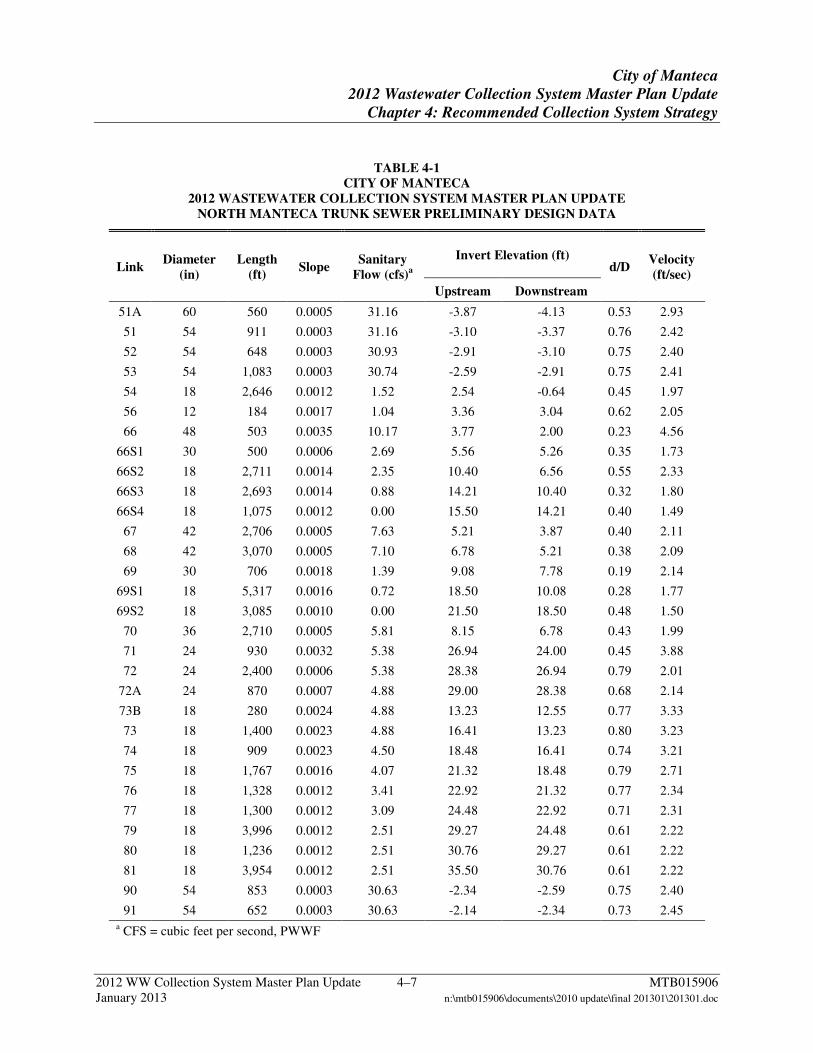
existing Link 70. The new Louise Avenue Lift Station upstream of Link 81 will facilitate service to the eastern extents of the City. Table 4-1 summarizes the hydraulic parameters for the NMCS.

City of Manteca
2012 Wastewater Collection System Master Plan Update
Chapter 4: Recommended Collection System Strategy
2012 WW Collection System Master Plan Update 4–6 MTB015906 January 2013 n:\mtb015906\documents\2010 update\final 201301\201301.doc
Figure 4-2 Proposed North Manteca Trunk Sewer Alignment and Sizing
City of Manteca
2012 Wastewater Collection System Master Plan Update
Chapter 4: Recommended Collection System Strategy
2012 WW Collection System Master Plan Update 4–7 MTB015906 January 2013 n:\mtb015906\documents\2010 update\final 201301\201301.doc
TABLE 4-1 CITY OF MANTECA
2012 WASTEWATER COLLECTION SYSTEM MASTER PLAN UPDATE NORTH MANTECA TRUNK SEWER PRELIMINARY DESIGN DATA
Link Diameter
(in) Length
(ft) Slope
Sanitary Flow (cfs)a
Invert Elevation (ft) d/D
Velocity (ft/sec)
Upstream Downstream
51A 60 560 0.0005 31.16 -3.87 -4.13 0.53 2.93
51 54 911 0.0003 31.16 -3.10 -3.37 0.76 2.42
52 54 648 0.0003 30.93 -2.91 -3.10 0.75 2.40
53 54 1,083 0.0003 30.74 -2.59 -2.91 0.75 2.41
54 18 2,646 0.0012 1.52 2.54 -0.64 0.45 1.97
56 12 184 0.0017 1.04 3.36 3.04 0.62 2.05
66 48 503 0.0035 10.17 3.77 2.00 0.23 4.56
66S1 30 500 0.0006 2.69 5.56 5.26 0.35 1.73
66S2 18 2,711 0.0014 2.35 10.40 6.56 0.55 2.33
66S3 18 2,693 0.0014 0.88 14.21 10.40 0.32 1.80
66S4 18 1,075 0.0012 0.00 15.50 14.21 0.40 1.49
67 42 2,706 0.0005 7.63 5.21 3.87 0.40 2.11
68 42 3,070 0.0005 7.10 6.78 5.21 0.38 2.09
69 30 706 0.0018 1.39 9.08 7.78 0.19 2.14
69S1 18 5,317 0.0016 0.72 18.50 10.08 0.28 1.77
69S2 18 3,085 0.0010 0.00 21.50 18.50 0.48 1.50
70 36 2,710 0.0005 5.81 8.15 6.78 0.43 1.99
71 24 930 0.0032 5.38 26.94 24.00 0.45 3.88
72 24 2,400 0.0006 5.38 28.38 26.94 0.79 2.01
72A 24 870 0.0007 4.88 29.00 28.38 0.68 2.14
73B 18 280 0.0024 4.88 13.23 12.55 0.77 3.33
73 18 1,400 0.0023 4.88 16.41 13.23 0.80 3.23
74 18 909 0.0023 4.50 18.48 16.41 0.74 3.21
75 18 1,767 0.0016 4.07 21.32 18.48 0.79 2.71
76 18 1,328 0.0012 3.41 22.92 21.32 0.77 2.34
77 18 1,300 0.0012 3.09 24.48 22.92 0.71 2.31
79 18 3,996 0.0012 2.51 29.27 24.48 0.61 2.22
80 18 1,236 0.0012 2.51 30.76 29.27 0.61 2.22
81 18 3,954 0.0012 2.51 35.50 30.76 0.61 2.22
90 54 853 0.0003 30.63 -2.34 -2.59 0.75 2.40
91 54 652 0.0003 30.63 -2.14 -2.34 0.73 2.45 a CFS = cubic feet per second, PWWF
City of Manteca
2012 Wastewater Collection System Master Plan Update
Chapter 4: Recommended Collection System Strategy
2012 WW Collection System Master Plan Update 4–8 MTB015906 January 2013 n:\mtb015906\documents\2010 update\final 201301\201301.doc
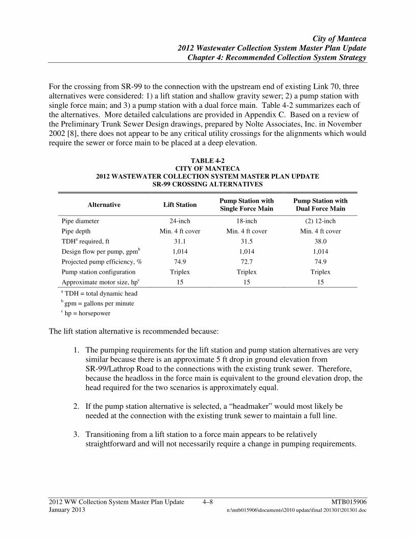
For the crossing from SR-99 to the connection with the upstream end of existing Link 70, three alternatives were considered: 1) a lift station and shallow gravity sewer; 2) a pump station with single force main; and 3) a pump station with a dual force main. Table 4-2 summarizes each of the alternatives. More detailed calculations are provided in Appendix C. Based on a review of the Preliminary Trunk Sewer Design drawings, prepared by Nolte Associates, Inc. in November 2002 [8], there does not appear to be any critical utility crossings for the alignments which would require the sewer or force main to be placed at a deep elevation.
TABLE 4-2 CITY OF MANTECA
2012 WASTEWATER COLLECTION SYSTEM MASTER PLAN UPDATE SR-99 CROSSING ALTERNATIVES
Alternative Lift Station Pump Station with Single Force Main
Pump Station with Dual Force Main
Pipe diameter 24-inch 18-inch (2) 12-inch
Pipe depth Min. 4 ft cover Min. 4 ft cover Min. 4 ft cover
TDHa required, ft 31.1 31.5 38.0
Design flow per pump, gpmb 1,014 1,014 1,014
Projected pump efficiency, % 74.9 72.7 74.9
Pump station configuration Triplex Triplex Triplex
Approximate motor size, hpc 15 15 15
a TDH = total dynamic head b gpm = gallons per minute c hp = horsepower
The lift station alternative is recommended because:
1. The pumping requirements for the lift station and pump station alternatives are very similar because there is an approximate 5 ft drop in ground elevation from SR-99/Lathrop Road to the connections with the existing trunk sewer. Therefore, because the headloss in the force main is equivalent to the ground elevation drop, the head required for the two scenarios is approximately equal.
2. If the pump station alternative is selected, a “headmaker” would most likely be needed at the connection with the existing trunk sewer to maintain a full line.
3. Transitioning from a lift station to a force main appears to be relatively
straightforward and will not necessarily require a change in pumping requirements.
City of Manteca
2012 Wastewater Collection System Master Plan Update
Chapter 4: Recommended Collection System Strategy
2012 WW Collection System Master Plan Update 4–9 MTB015906 January 2013 n:\mtb015906\documents\2010 update\final 201301\201301.doc
For the NMCS, the desired design criteria could not be met at the following locations:
1. Link 54 has a projected velocity less than 2 ft/sec and flows less than 70 percent full due to vertical design constraints.
2. Links 51A, 66, 66S1, 67, 68, 69, and 70 have projected velocities less than 2 ft/sec
and flow less than 70 percent full due to reduced WGFs for new development. These links are constructed.
3. Links 66S3, 66S4, 69S1, and 69S2 have projected velocities less than 2 ft/sec and
flow less than 70 percent full. 4. Links 56, 66S2, and 71 flow less than 70 percent full due to reduced WGFs for
residential development and/or vertical design constraints. The agricultural land uses attributed to Links 66S1, 66S2, 66S3, 66S4, 69S1, and 69S2 may be developed as residential beyond the General Plan timeline. Therefore, the projected flows into these links may increase beyond current estimates. To avoid future disruptions associated with additional sewer construction within existing streets, no change in pipe sizing to meet design criteria is recommended.
b. South Manteca Collection Strategy
The SMCS has changed significantly since the 2008 Addendum. The City has decided to route the SMTS along Woodward Avenue. A Woodward Avenue alignment better accommodates near-term growth in South Manteca and does not require obtaining additional right-of-way. Construction of a deep sewer along Woodward Avenue was selected by the City to allow for future abandonment of Woodward Park Pump Station following construction of Links 1-5 and Link 22. The following revised SMCS Strategy is recommended:
1. Three permanent pump stations and four permanent lift stations, as listed below.
a. Yosemite Square Pump Station
b. Austin Business Park Pump Station
c. South Main Lift Station
d. South Union Lift Station
e. South Airport Lift Station
f. Trails of Manteca Lift Station
City of Manteca
2012 Wastewater Collection System Master Plan Update
Chapter 4: Recommended Collection System Strategy
2012 WW Collection System Master Plan Update 4–10 MTB015906 January 2013 n:\mtb015906\documents\2010 update\final 201301\201301.doc
g. Oakwood Shores Pump Station
2. Three force mains, as listed below:
a. Force main 36 from Yosemite Square Pump Station to the existing gravity sewer along Woodward Avenue, upstream of Woodward Park Pump Station (Link 19). Force mains 36 and 27N converge in Force main 28.
b. Force main 27N from Austin Business Park Pump Station to the existing gravity sewer along Woodward Avenue, upstream of Woodward Park Pump Station (Link 19). Force mains 36 and 27N converge in Force main 28.
c. Force main 27S from Austin Business Park Pump Station to route flow to a proposed gravity sewer flowing to South Main Lift Station. This force main is recommended because the existing gravity sewer alignment upstream of Woodward Park Pump Station (Links 16 through 21) does not have sufficient capacity to accommodate flow from all of the area served by Austin Business Park Pump Station.
d. The Oakwood Shores force main (OSFM) from Oakwood Shores Pump Station to the gravity sewer immediately downstream of Trails of Manteca Lift Station (Link 33).
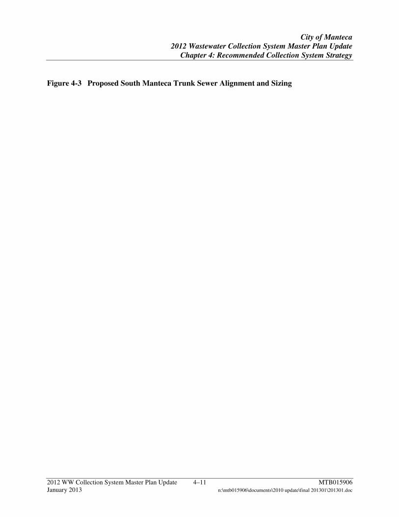
The proposed SMCS is shown in Figure 4-3. Table 4-3 summarizes the hydraulic parameters for the SMCS. To accommodate development while minimizing construction of infrastructure in South Manteca, phasing of the recommended SMCS was considered and is described further in Chapter 5.
City of Manteca
2012 Wastewater Collection System Master Plan Update
Chapter 4: Recommended Collection System Strategy
2012 WW Collection System Master Plan Update 4–11 MTB015906 January 2013 n:\mtb015906\documents\2010 update\final 201301\201301.doc
Figure 4-3 Proposed South Manteca Trunk Sewer Alignment and Sizing
City of Manteca
2012 Wastewater Collection System Master Plan Update
Chapter 4: Recommended Collection System Strategy
2012 WW Collection System Master Plan Update 4–12 MTB015906 January 2013 n:\mtb015906\documents\2010 update\final 201301\201301.doc
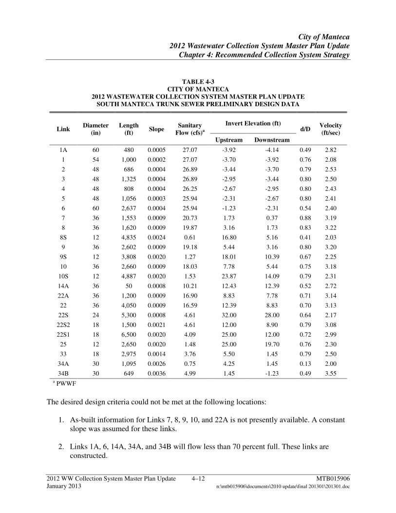
TABLE 4-3 CITY OF MANTECA
2012 WASTEWATER COLLECTION SYSTEM MASTER PLAN UPDATE SOUTH MANTECA TRUNK SEWER PRELIMINARY DESIGN DATA
Link Diameter
(in) Length
(ft) Slope
Sanitary Flow (cfs)a
Invert Elevation (ft) d/D
Velocity (ft/sec)
Upstream Downstream
1A 60 480 0.0005 27.07 -3.92 -4.14 0.49 2.82
1 54 1,000 0.0002 27.07 -3.70 -3.92 0.76 2.08
2 48 686 0.0004 26.89 -3.44 -3.70 0.79 2.53
3 48 1,325 0.0004 26.89 -2.95 -3.44 0.80 2.50
4 48 808 0.0004 26.25 -2.67 -2.95 0.80 2.43
5 48 1,056 0.0003 25.94 -2.31 -2.67 0.80 2.41
6 60 2,637 0.0004 25.94 -1.23 -2.31 0.54 2.40
7 36 1,553 0.0009 20.73 1.73 0.37 0.88 3.19
8 36 1,620 0.0009 19.87 3.16 1.73 0.83 3.22
8S 12 4,835 0.0024 0.61 16.80 5.16 0.41 2.03
9 36 2,602 0.0009 19.18 5.44 3.16 0.80 3.20
9S 12 3,808 0.0020 1.27 18.01 10.39 0.67 2.25
10 36 2,660 0.0009 18.03 7.78 5.44 0.75 3.18
10S 12 4,887 0.0020 1.53 23.87 14.09 0.79 2.31
14A 36 50 0.0008 10.21 12.43 12.39 0.52 2.72
22A 36 1,200 0.0009 16.90 8.83 7.78 0.71 3.14
22 36 4,050 0.0009 16.59 12.39 8.83 0.70 3.13
22S 24 5,300 0.0008 4.61 32.00 28.00 0.64 2.17
22S2 18 1,500 0.0021 4.61 12.00 8.90 0.79 3.08
22S1 18 6,500 0.0020 4.09 25.00 12.00 0.72 2.99
25 12 2,650 0.0020 1.48 25.00 19.70 0.76 2.30
33 18 2,975 0.0014 3.76 5.50 1.45 0.79 2.50
34A 30 1,095 0.0026 0.75 4.25 1.45 0.13 2.00
34B 30 649 0.0036 4.99 1.45 -1.23 0.49 3.55 a PWWF
The desired design criteria could not be met at the following locations:
1. As-built information for Links 7, 8, 9, 10, and 22A is not presently available. A constant slope was assumed for these links.
2. Links 1A, 6, 14A, 34A, and 34B will flow less than 70 percent full. These links are constructed.
City of Manteca
2012 Wastewater Collection System Master Plan Update
Chapter 4: Recommended Collection System Strategy
2012 WW Collection System Master Plan Update 4–13 MTB015906 January 2013 n:\mtb015906\documents\2010 update\final 201301\201301.doc
3. Links 8S, 9S, and 22S will flow less than 70 percent full due to vertical design constraints
and/or maintaining a minimum pipe diameter of 12-inches.
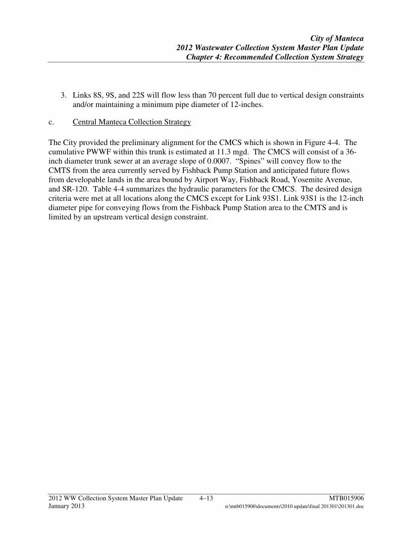
c. Central Manteca Collection Strategy
The City provided the preliminary alignment for the CMCS which is shown in Figure 4-4. The cumulative PWWF within this trunk is estimated at 11.3 mgd. The CMCS will consist of a 36-inch diameter trunk sewer at an average slope of 0.0007. “Spines” will convey flow to the CMTS from the area currently served by Fishback Pump Station and anticipated future flows from developable lands in the area bound by Airport Way, Fishback Road, Yosemite Avenue, and SR-120. Table 4-4 summarizes the hydraulic parameters for the CMCS. The desired design criteria were met at all locations along the CMCS except for Link 93S1. Link 93S1 is the 12-inch diameter pipe for conveying flows from the Fishback Pump Station area to the CMTS and is limited by an upstream vertical design constraint.

City of Manteca
2012 Wastewater Collection System Master Plan Update
Chapter 4: Recommended Collection System Strategy
2012 WW Collection System Master Plan Update 4–14 MTB015906 January 2013 n:\mtb015906\documents\2010 update\final 201301\201301.doc
Figure 4-4 Proposed Central Manteca Trunk Sewer Alignment and Sizing
City of Manteca
2012 Wastewater Collection System Master Plan Update
Chapter 4: Recommended Collection System Strategy
2012 WW Collection System Master Plan Update 4–15 MTB015906 January 2013 n:\mtb015906\documents\2010 update\final 201301\201301.doc
TABLE 4-4 CITY OF MANTECA
2012 WASTEWATER COLLECTION SYSTEM MASTER PLAN UPDATE CENTRAL MANTECA TRUNK SEWER PRELIMINARY DESIGN
Link Diameter
(in) Length
(ft) Slope
Sanitary Flow (cfs)a
Invert Elevation (ft) d/D
Velocity (ft/sec)
Upstream Downstream
92 36 902 0.0008 17.50 7.92 7.20 0.76 3.03
93 36 464 0.0007 17.50 8.26 7.92 0.79 2.91
93S1 12 1,088 0.0020 1.06 17.18 15.00 0.60 2.17
94 36 465 0.0007 16.86 8.59 8.26 0.78 2.86
95 36 450 0.0007 16.86 8.92 8.59 0.77 2.90
96 36 627 0.0007 16.86 9.38 8.92 0.77 2.90
97 36 499 0.0007 16.86 9.74 9.38 0.77 2.88
98 36 545 0.0007 16.86 10.14 9.74 0.77 2.90
99 36 542 0.0007 16.86 10.54 10.14 0.76 2.91
100 36 624 0.0007 16.86 11.00 10.54 0.76 2.91 a PWWF
2012 WW Collection System Master Plan Update 5–1 MTB015906 January 2013 n:\mtb015906\documents\2010 update\final 201301\201301.doc
5 Recommended System Improvements
This chapter presents recommended system improvements for completion of the proposed sewer collection system strategy for the City.
5.1 Recommended Collection System Strategy As described in Chapter 4, the recommended collection system strategy for the City will expand the existing collection system. The NMCS and SMCS will serve areas of future growth in the north and south. The Union Road Pump Station will be eliminated and the existing collection system will connect to the NMCS via the CMCS. The following sections summarize the system improvements needed for completion of this collection system strategy. The estimated numbers of manholes were based on the City standard for maximum spacing (every 400 ft for pipe diameters ranging from 8 to 18-inch; every 500 ft for pipe diameters ranging from 21 to 30-inch; and every 600 ft for pipe diameters larger than 30-inch). Manholes are also assumed at changes in direction and/or pipe size.
a. North Manteca Collection Strategy
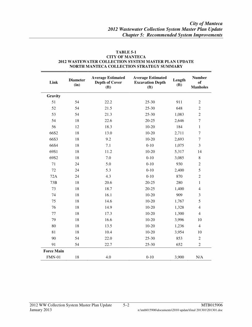
The majority of the NMCS is in the preliminary design phase. Links 66, 66S1, 67, 68, 69, and 70 have been constructed for the Union Ranch subdivision. Link 51A was constructed as part of the WQCF Phase III Expansion Project, Schedule B. Table 5-1 summarizes the pipe diameters and lengths required to construct the remaining segments of the NMCS. Table 5-1 also includes an estimate of the required number of manholes. Table 5-2 summarizes the estimated pump and lift station capacity requirements for the remaining elements of the NMCS.
City of Manteca
2012 Wastewater Collection System Master Plan Update
Chapter 5: Recommended System Improvements
2012 WW Collection System Master Plan Update 5–2 MTB015906 January 2013 n:\mtb015906\documents\2010 update\final 201301\201301.doc
TABLE 5-1 CITY OF MANTECA
2012 WASTEWATER COLLECTION SYSTEM MASTER PLAN UPDATE NORTH MANTECA COLLECTION STRATEGY SUMMARY
Link Diameter
(in)
Average Estimated Depth of Cover
(ft)
Average Estimated Excavation Depth
(ft)
Length (ft)
Number of
Manholes
Gravity
51 54 22.2 25-30 911 2
52 54 21.5 25-30 648 2
53 54 21.3 25-30 1,083 2
54 18 22.6 20-25 2,646 7
56 12 18.3 10-20 184 1
66S2 18 13.0 10-20 2,711 7
66S3 18 9.2 10-20 2,693 7
66S4 18 7.1 0-10 1,075 3
69S1 18 11.2 10-20 5,317 14
69S2 18 7.0 0-10 3,085 8
71 24 5.0 0-10 930 2
72 24 5.3 0-10 2,400 5
72A 24 4.3 0-10 870 2
73B 18 20.6 20-25 280 1
73 18 18.7 20-25 1,400 4
74 18 16.1 10-20 909 3
75 18 14.6 10-20 1,767 5
76 18 14.9 10-20 1,328 4
77 18 17.3 10-20 1,300 4
79 18 16.6 10-20 3,996 10
80 18 13.5 10-20 1,236 4
81 18 10.4 10-20 3,954 10
90 54 22.0 25-30 853 2
91 54 22.7 25-30 652 2
Force Main
FMN-01 18 4.0 0-10 3,900 N/A
City of Manteca
2012 Wastewater Collection System Master Plan Update
Chapter 5: Recommended System Improvements
2012 WW Collection System Master Plan Update 5–3 MTB015906 January 2013 n:\mtb015906\documents\2010 update\final 201301\201301.doc
TABLE 5-2 CITY OF MANTECA
2012 WASTEWATER COLLECTION SYSTEM MASTER PLAN UPDATE NORTH MANTECA PUMP AND LIFT STATION SUMMARY
Pump/Lift Station ADWF (mgd)
PWWF (mgd)
Estimated TDH (ft)
Estimated Wet Well
Elevation (ft)
Approximate Ground
Elevation (ft)
Chadwick Pump Station 618,054 1,626,116 67.0 -1.0 23.0
Louise Avenue Lift Station 615,120 1,620,499 30.0 22.0 52.0
SR-99 Lift Station 1,462,381 3,154,874 32.3 8.6 35.0
b. Overview of South Manteca Collection Strategy
Several sections of the SMCS have been constructed or designed in preparation for construction, as described in Chapter 4. Table 5-3 summarizes the components of the remaining segments of the SMCS. Table 5-4 summarizes the estimated pump and lift station requirements for the SMCS.
City of Manteca
2012 Wastewater Collection System Master Plan Update
Chapter 5: Recommended System Improvements
2012 WW Collection System Master Plan Update 5–4 MTB015906 January 2013 n:\mtb015906\documents\2010 update\final 201301\201301.doc
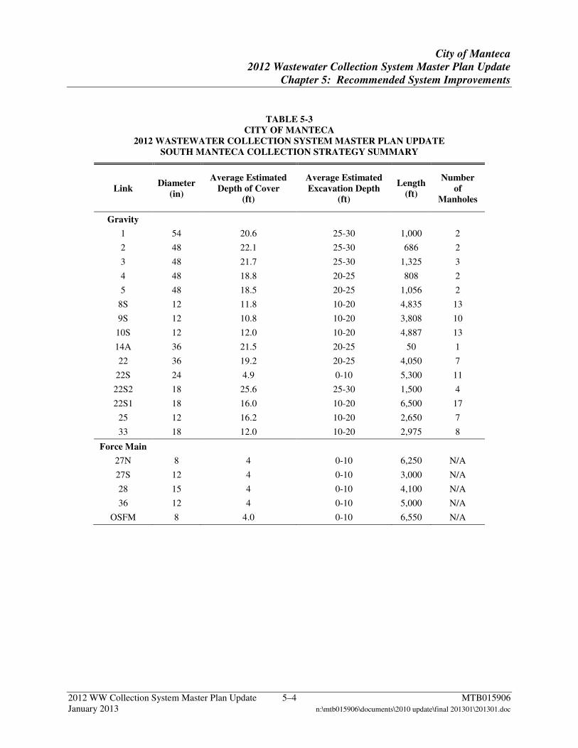
TABLE 5-3 CITY OF MANTECA
2012 WASTEWATER COLLECTION SYSTEM MASTER PLAN UPDATE SOUTH MANTECA COLLECTION STRATEGY SUMMARY
Link Diameter
(in)
Average Estimated Depth of Cover
(ft)
Average Estimated Excavation Depth
(ft)
Length (ft)
Number of
Manholes
Gravity
1 54 20.6 25-30 1,000 2
2 48 22.1 25-30 686 2
3 48 21.7 25-30 1,325 3
4 48 18.8 20-25 808 2
5 48 18.5 20-25 1,056 2
8S 12 11.8 10-20 4,835 13
9S 12 10.8 10-20 3,808 10
10S 12 12.0 10-20 4,887 13
14A 36 21.5 20-25 50 1
22 36 19.2 20-25 4,050 7
22S 24 4.9 0-10 5,300 11
22S2 18 25.6 25-30 1,500 4
22S1 18 16.0 10-20 6,500 17
25 12 16.2 10-20 2,650 7
33 18 12.0 10-20 2,975 8
Force Main
27N 8 4 0-10 6,250 N/A
27S 12 4 0-10 3,000 N/A
28 15 4 0-10 4,100 N/A
36 12 4 0-10 5,000 N/A
OSFM 8 4.0 0-10 6,550 N/A
City of Manteca
2012 Wastewater Collection System Master Plan Update
Chapter 5: Recommended System Improvements
2012 WW Collection System Master Plan Update 5–5 MTB015906 January 2013 n:\mtb015906\documents\2010 update\final 201301\201301.doc
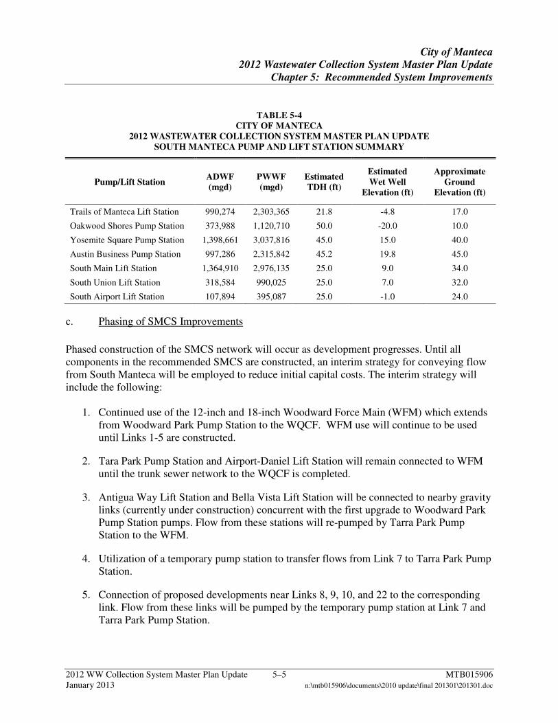
TABLE 5-4 CITY OF MANTECA
2012 WASTEWATER COLLECTION SYSTEM MASTER PLAN UPDATE SOUTH MANTECA PUMP AND LIFT STATION SUMMARY
Pump/Lift Station ADWF (mgd)
PWWF (mgd)
Estimated TDH (ft)
Estimated Wet Well
Elevation (ft)
Approximate Ground
Elevation (ft)
Trails of Manteca Lift Station 990,274 2,303,365 21.8 -4.8 17.0
Oakwood Shores Pump Station 373,988 1,120,710 50.0 -20.0 10.0
Yosemite Square Pump Station 1,398,661 3,037,816 45.0 15.0 40.0
Austin Business Pump Station 997,286 2,315,842 45.2 19.8 45.0
South Main Lift Station 1,364,910 2,976,135 25.0 9.0 34.0
South Union Lift Station 318,584 990,025 25.0 7.0 32.0
South Airport Lift Station 107,894 395,087 25.0 -1.0 24.0
c. Phasing of SMCS Improvements
Phased construction of the SMCS network will occur as development progresses. Until all components in the recommended SMCS are constructed, an interim strategy for conveying flow from South Manteca will be employed to reduce initial capital costs. The interim strategy will include the following:
1. Continued use of the 12-inch and 18-inch Woodward Force Main (WFM) which extends from Woodward Park Pump Station to the WQCF. WFM use will continue to be used until Links 1-5 are constructed.
2. Tara Park Pump Station and Airport-Daniel Lift Station will remain connected to WFM until the trunk sewer network to the WQCF is completed.
3. Antigua Way Lift Station and Bella Vista Lift Station will be connected to nearby gravity links (currently under construction) concurrent with the first upgrade to Woodward Park Pump Station pumps. Flow from these stations will re-pumped by Tarra Park Pump Station to the WFM.
4. Utilization of a temporary pump station to transfer flows from Link 7 to Tarra Park Pump Station.
5. Connection of proposed developments near Links 8, 9, 10, and 22 to the corresponding link. Flow from these links will be pumped by the temporary pump station at Link 7 and Tarra Park Pump Station.
City of Manteca
2012 Wastewater Collection System Master Plan Update
Chapter 5: Recommended System Improvements
2012 WW Collection System Master Plan Update 5–6 MTB015906 January 2013 n:\mtb015906\documents\2010 update\final 201301\201301.doc
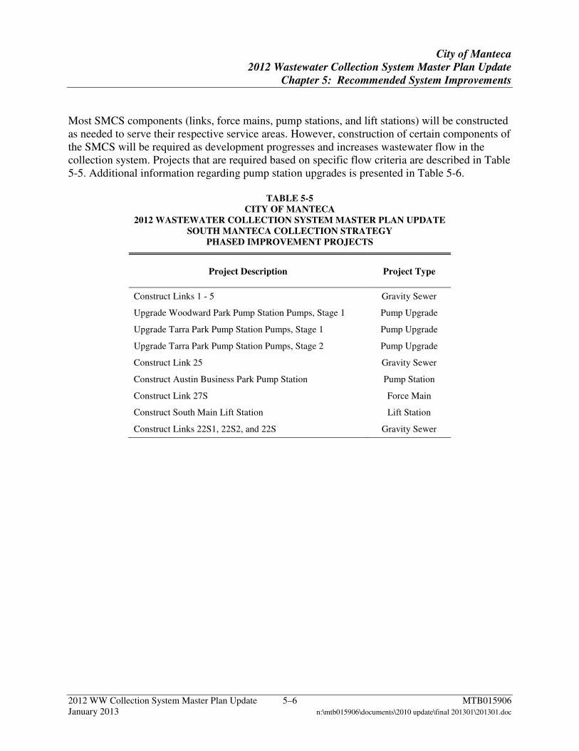
Most SMCS components (links, force mains, pump stations, and lift stations) will be constructed as needed to serve their respective service areas. However, construction of certain components of the SMCS will be required as development progresses and increases wastewater flow in the collection system. Projects that are required based on specific flow criteria are described in Table 5-5. Additional information regarding pump station upgrades is presented in Table 5-6.
TABLE 5-5 CITY OF MANTECA
2012 WASTEWATER COLLECTION SYSTEM MASTER PLAN UPDATE SOUTH MANTECA COLLECTION STRATEGY
PHASED IMPROVEMENT PROJECTS
Project Description Project Type
Construct Links 1 - 5 Gravity Sewer
Upgrade Woodward Park Pump Station Pumps, Stage 1 Pump Upgrade
Upgrade Tarra Park Pump Station Pumps, Stage 1 Pump Upgrade
Upgrade Tarra Park Pump Station Pumps, Stage 2 Pump Upgrade
Construct Link 25 Gravity Sewer
Construct Austin Business Park Pump Station Pump Station
Construct Link 27S Force Main
Construct South Main Lift Station Lift Station
Construct Links 22S1, 22S2, and 22S Gravity Sewer
City of Manteca
2012 Wastewater Collection System Master Plan Update
Chapter 5: Recommended System Improvements
2012 WW Collection System Master Plan Update 5–7 MTB015906 January 2013 n:\mtb015906\documents\2010 update\final 201301\201301.doc
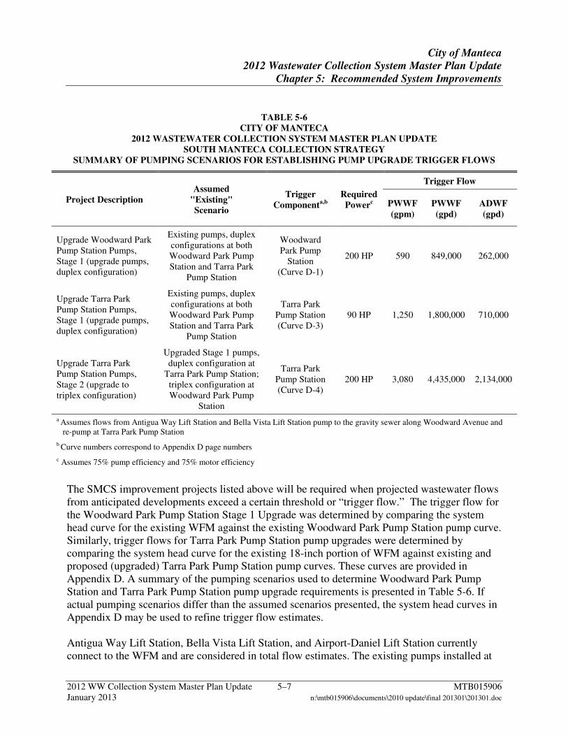
TABLE 5-6 CITY OF MANTECA
2012 WASTEWATER COLLECTION SYSTEM MASTER PLAN UPDATE SOUTH MANTECA COLLECTION STRATEGY
SUMMARY OF PUMPING SCENARIOS FOR ESTABLISHING PUMP UPGRADE TRIGGER FLOWS
Project Description Assumed
"Existing" Scenario
Trigger Componenta,b
Required Powerc
Trigger Flow
PWWF (gpm)
PWWF (gpd)
ADWF (gpd)
Upgrade Woodward Park Pump Station Pumps, Stage 1 (upgrade pumps, duplex configuration)
Existing pumps, duplex configurations at both Woodward Park Pump Station and Tarra Park
Pump Station
Woodward Park Pump
Station (Curve D-1)
200 HP 590 849,000 262,000
Upgrade Tarra Park Pump Station Pumps, Stage 1 (upgrade pumps, duplex configuration)
Existing pumps, duplex configurations at both Woodward Park Pump Station and Tarra Park
Pump Station
Tarra Park Pump Station (Curve D-3)
90 HP 1,250 1,800,000 710,000
Upgrade Tarra Park Pump Station Pumps, Stage 2 (upgrade to triplex configuration)
Upgraded Stage 1 pumps, duplex configuration at
Tarra Park Pump Station; triplex configuration at Woodward Park Pump
Station
Tarra Park Pump Station (Curve D-4)
200 HP 3,080 4,435,000 2,134,000
a Assumes flows from Antigua Way Lift Station and Bella Vista Lift Station pump to the gravity sewer along Woodward Avenue and re-pump at Tarra Park Pump Station
b Curve numbers correspond to Appendix D page numbers
c Assumes 75% pump efficiency and 75% motor efficiency
The SMCS improvement projects listed above will be required when projected wastewater flows from anticipated developments exceed a certain threshold or “trigger flow.” The trigger flow for the Woodward Park Pump Station Stage 1 Upgrade was determined by comparing the system head curve for the existing WFM against the existing Woodward Park Pump Station pump curve. Similarly, trigger flows for Tarra Park Pump Station pump upgrades were determined by comparing the system head curve for the existing 18-inch portion of WFM against existing and proposed (upgraded) Tarra Park Pump Station pump curves. These curves are provided in Appendix D. A summary of the pumping scenarios used to determine Woodward Park Pump Station and Tarra Park Pump Station pump upgrade requirements is presented in Table 5-6. If actual pumping scenarios differ than the assumed scenarios presented, the system head curves in Appendix D may be used to refine trigger flow estimates. Antigua Way Lift Station, Bella Vista Lift Station, and Airport-Daniel Lift Station currently connect to the WFM and are considered in total flow estimates. The existing pumps installed at
City of Manteca
2012 Wastewater Collection System Master Plan Update
Chapter 5: Recommended System Improvements
2012 WW Collection System Master Plan Update 5–8 MTB015906 January 2013 n:\mtb015906\documents\2010 update\final 201301\201301.doc
Antigua Way Lift Station and Bella Vista Lift Station may be unable to pump against the pressure generated by peak flows from Woodward Park Pump Station. The SMCS assumes that these pump stations will connect to the gravity sewer along Woodward Avenue and be re-pumped at Tarra Park Pump Station to the WQCF following the Stage 1 upgrade to Woodward Park Pump Station. Trigger flows for the construction of Links 27S, 22S1, 22S2, 22S and South Main Lift Station were determined by capacity limitations in the existing trunk sewers on Woodward Avenue. Appendix E includes a summary of the existing Links, estimated PWWF, corresponding ADWF capacities, and projected remaining capacity for flow from SMCS sheds. Sheds located north of SR-99 were assigned priority for being routed through the existing links in Woodward Avenue because of the option available for sheds located south of SR-99 to flow to Link 22S1. If development occurs slowly within Sheds 36N and 36S, capacity in existing Links 16 – 21 along Woodward Avenue could potentially be used on an interim basis by Sheds 25 and 27S. The 12-inch section of the WFM is not sufficient to convey buildout flows from the sheds upstream of Woodward Park Pump Station with a maximum pressure at or below 100 psi. As shown by Curve D-2 (Appendix D), the maximum PWWF through the existing 12-inch WFM is approximately 1,900 gpm, corresponding to an ADWF of 1.23 mgd. Once this flow is achieved at Woodward Park Pump Station, it is recommended that Links 1-5 be constructed and Woodward Park Pump Station abandoned. Alternatively, Links 1-5 will require construction when velocity in the 18-inch section of the WFM (downstream of Tarra Park Pump Station) exceeds 8 ft/sec or flow to Tarra Park Pump Station exceeds the 4,350 gpm capacity of the Stage 2 Tarra Park Pump Station Upgrade. Trigger flows, as ADWF and PWWF, have been calculated for each project component and are listed in Table 5-7. The ADWF values serve as a guide for determining when projects are needed as development occurs. ADWF is calculated based on proposed land uses and established WGFs. The PWWF values are a measure of the available (for constructed) or required (for proposed) capacity of each component. Flows listed are the total estimated flow in each trigger component.
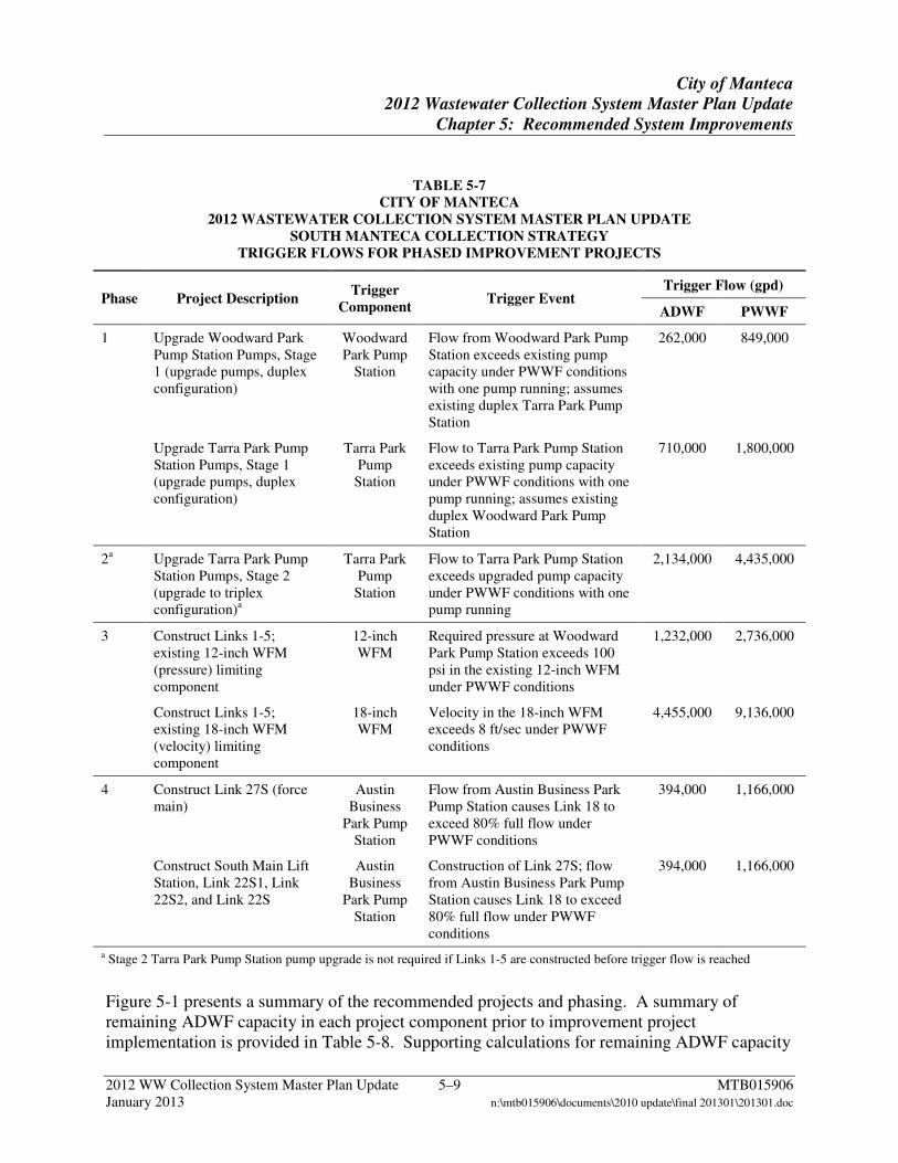
City of Manteca
2012 Wastewater Collection System Master Plan Update
Chapter 5: Recommended System Improvements
2012 WW Collection System Master Plan Update 5–9 MTB015906 January 2013 n:\mtb015906\documents\2010 update\final 201301\201301.doc
TABLE 5-7 CITY OF MANTECA
2012 WASTEWATER COLLECTION SYSTEM MASTER PLAN UPDATE SOUTH MANTECA COLLECTION STRATEGY
TRIGGER FLOWS FOR PHASED IMPROVEMENT PROJECTS
Phase Project Description Trigger
Component Trigger Event
Trigger Flow (gpd)
ADWF PWWF
1 Upgrade Woodward Park Pump Station Pumps, Stage 1 (upgrade pumps, duplex configuration)
Woodward Park Pump
Station
Flow from Woodward Park Pump Station exceeds existing pump capacity under PWWF conditions with one pump running; assumes existing duplex Tarra Park Pump Station
262,000 849,000
Upgrade Tarra Park Pump Station Pumps, Stage 1 (upgrade pumps, duplex configuration)
Tarra Park Pump
Station
Flow to Tarra Park Pump Station exceeds existing pump capacity under PWWF conditions with one pump running; assumes existing duplex Woodward Park Pump Station
710,000 1,800,000
2a Upgrade Tarra Park Pump Station Pumps, Stage 2 (upgrade to triplex configuration)a
Tarra Park Pump
Station
Flow to Tarra Park Pump Station exceeds upgraded pump capacity under PWWF conditions with one pump running
2,134,000 4,435,000
3 Construct Links 1-5; existing 12-inch WFM (pressure) limiting component
12-inch WFM
Required pressure at Woodward Park Pump Station exceeds 100 psi in the existing 12-inch WFM under PWWF conditions
1,232,000 2,736,000
Construct Links 1-5; existing 18-inch WFM (velocity) limiting component
18-inch WFM
Velocity in the 18-inch WFM exceeds 8 ft/sec under PWWF conditions
4,455,000 9,136,000
4 Construct Link 27S (force main)
Austin Business
Park Pump Station
Flow from Austin Business Park Pump Station causes Link 18 to exceed 80% full flow under PWWF conditions
394,000 1,166,000
Construct South Main Lift Station, Link 22S1, Link 22S2, and Link 22S
Austin Business
Park Pump Station
Construction of Link 27S; flow from Austin Business Park Pump Station causes Link 18 to exceed 80% full flow under PWWF conditions
394,000 1,166,000
a Stage 2 Tarra Park Pump Station pump upgrade is not required if Links 1-5 are constructed before trigger flow is reached
Figure 5-1 presents a summary of the recommended projects and phasing. A summary of remaining ADWF capacity in each project component prior to improvement project implementation is provided in Table 5-8. Supporting calculations for remaining ADWF capacity
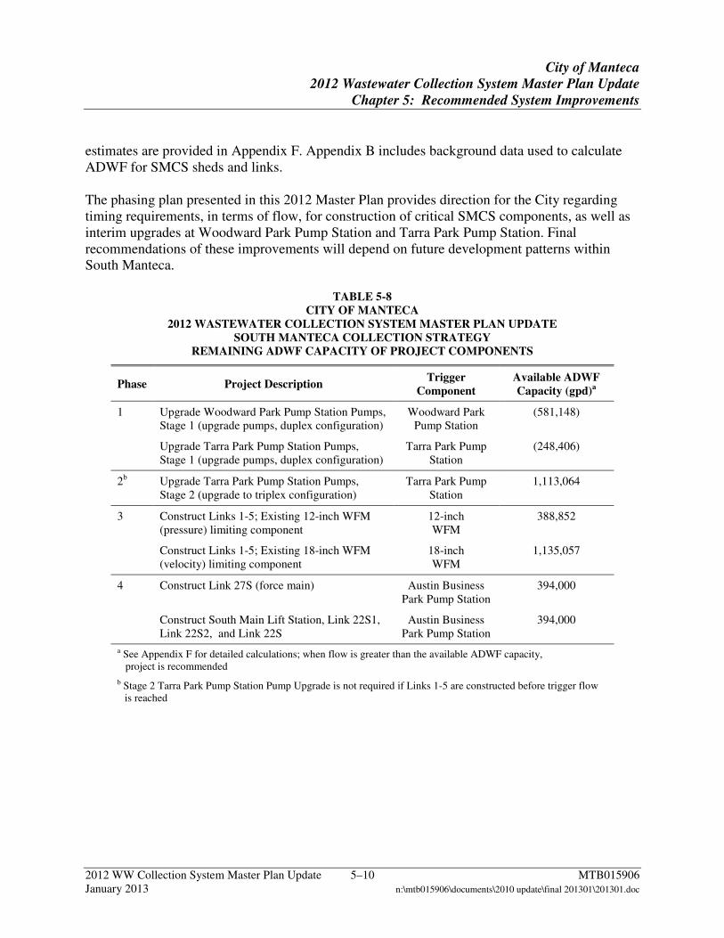
City of Manteca
2012 Wastewater Collection System Master Plan Update
Chapter 5: Recommended System Improvements
2012 WW Collection System Master Plan Update 5–10 MTB015906 January 2013 n:\mtb015906\documents\2010 update\final 201301\201301.doc
estimates are provided in Appendix F. Appendix B includes background data used to calculate ADWF for SMCS sheds and links. The phasing plan presented in this 2012 Master Plan provides direction for the City regarding timing requirements, in terms of flow, for construction of critical SMCS components, as well as interim upgrades at Woodward Park Pump Station and Tarra Park Pump Station. Final recommendations of these improvements will depend on future development patterns within South Manteca.
TABLE 5-8 CITY OF MANTECA
2012 WASTEWATER COLLECTION SYSTEM MASTER PLAN UPDATE SOUTH MANTECA COLLECTION STRATEGY
REMAINING ADWF CAPACITY OF PROJECT COMPONENTS
Phase Project Description Trigger
Component Available ADWF Capacity (gpd)a
1 Upgrade Woodward Park Pump Station Pumps, Stage 1 (upgrade pumps, duplex configuration)
Woodward Park Pump Station
(581,148)
Upgrade Tarra Park Pump Station Pumps, Stage 1 (upgrade pumps, duplex configuration)
Tarra Park Pump Station
(248,406)
2b Upgrade Tarra Park Pump Station Pumps, Stage 2 (upgrade to triplex configuration)
Tarra Park Pump Station
1,113,064
3 Construct Links 1-5; Existing 12-inch WFM (pressure) limiting component
12-inch WFM
388,852
Construct Links 1-5; Existing 18-inch WFM (velocity) limiting component
18-inch WFM
1,135,057
4 Construct Link 27S (force main) Austin Business Park Pump Station
394,000
Construct South Main Lift Station, Link 22S1, Link 22S2, and Link 22S
Austin Business Park Pump Station
394,000
a See Appendix F for detailed calculations; when flow is greater than the available ADWF capacity, project is recommended
b Stage 2 Tarra Park Pump Station Pump Upgrade is not required if Links 1-5 are constructed before trigger flow is reached

City of Manteca
2012 Wastewater Collection System Master Plan Update
Chapter 5: Recommended System Improvements
2012 WW Collection System Master Plan Update 5–11 MTB015906 January 2013 n:\mtb015906\documents\2010 update\final 201301\201301.doc
Figure 5-1 South Manteca Collection Strategy Phasing
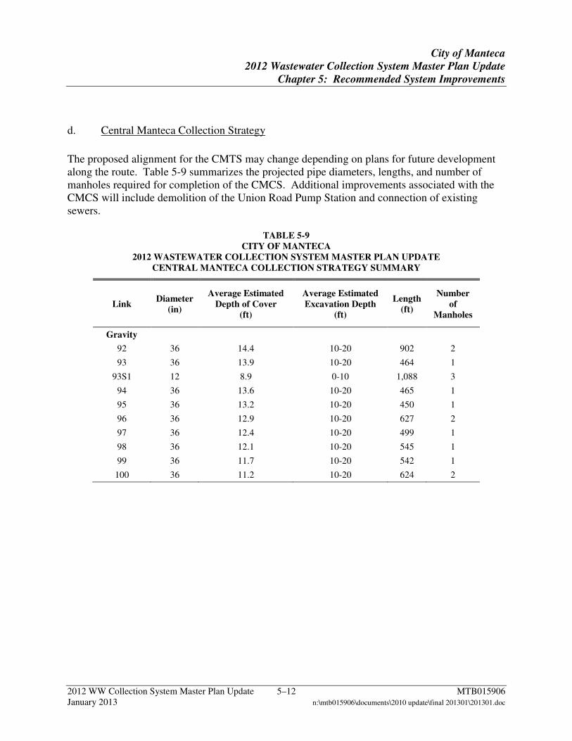
City of Manteca
2012 Wastewater Collection System Master Plan Update
Chapter 5: Recommended System Improvements
2012 WW Collection System Master Plan Update 5–12 MTB015906 January 2013 n:\mtb015906\documents\2010 update\final 201301\201301.doc
d. Central Manteca Collection Strategy
The proposed alignment for the CMTS may change depending on plans for future development along the route. Table 5-9 summarizes the projected pipe diameters, lengths, and number of manholes required for completion of the CMCS. Additional improvements associated with the CMCS will include demolition of the Union Road Pump Station and connection of existing sewers.
TABLE 5-9 CITY OF MANTECA
2012 WASTEWATER COLLECTION SYSTEM MASTER PLAN UPDATE CENTRAL MANTECA COLLECTION STRATEGY SUMMARY
Link Diameter
(in)
Average Estimated Depth of Cover
(ft)
Average Estimated Excavation Depth
(ft)
Length (ft)
Number of
Manholes
Gravity
92 36 14.4 10-20 902 2
93 36 13.9 10-20 464 1
93S1 12 8.9 0-10 1,088 3
94 36 13.6 10-20 465 1
95 36 13.2 10-20 450 1
96 36 12.9 10-20 627 2
97 36 12.4 10-20 499 1
98 36 12.1 10-20 545 1
99 36 11.7 10-20 542 1
100 36 11.2 10-20 624 2
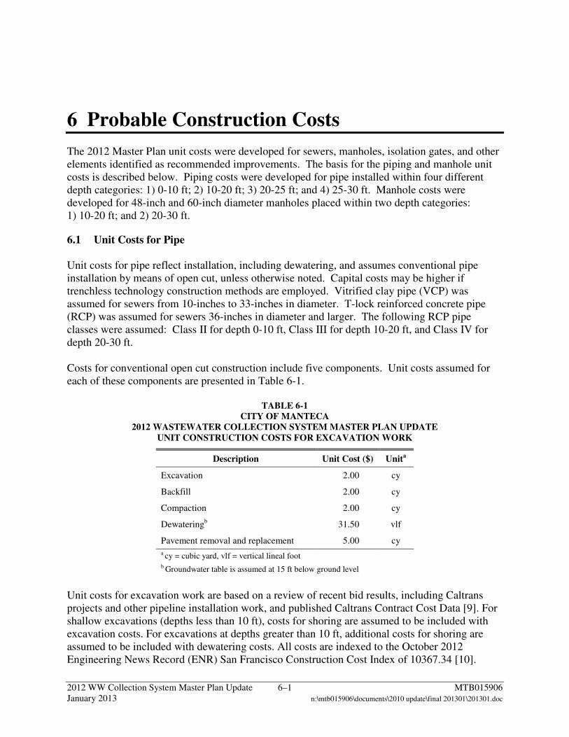
2012 WW Collection System Master Plan Update 6–1 MTB015906 January 2013 n:\mtb015906\documents\2010 update\final 201301\201301.doc
6 Probable Construction Costs
The 2012 Master Plan unit costs were developed for sewers, manholes, isolation gates, and other elements identified as recommended improvements. The basis for the piping and manhole unit costs is described below. Piping costs were developed for pipe installed within four different depth categories: 1) 0-10 ft; 2) 10-20 ft; 3) 20-25 ft; and 4) 25-30 ft. Manhole costs were developed for 48-inch and 60-inch diameter manholes placed within two depth categories: 1) 10-20 ft; and 2) 20-30 ft.
6.1 Unit Costs for Pipe Unit costs for pipe reflect installation, including dewatering, and assumes conventional pipe installation by means of open cut, unless otherwise noted. Capital costs may be higher if trenchless technology construction methods are employed. Vitrified clay pipe (VCP) was assumed for sewers from 10-inches to 33-inches in diameter. T-lock reinforced concrete pipe (RCP) was assumed for sewers 36-inches in diameter and larger. The following RCP pipe classes were assumed: Class II for depth 0-10 ft, Class III for depth 10-20 ft, and Class IV for depth 20-30 ft. Costs for conventional open cut construction include five components. Unit costs assumed for each of these components are presented in Table 6-1.
TABLE 6-1 CITY OF MANTECA
2012 WASTEWATER COLLECTION SYSTEM MASTER PLAN UPDATE UNIT CONSTRUCTION COSTS FOR EXCAVATION WORK
Description Unit Cost ($) Unita
Excavation 2.00 cy
Backfill 2.00 cy
Compaction 2.00 cy
Dewateringb 31.50 vlf
Pavement removal and replacement 5.00 cy
a cy = cubic yard, vlf = vertical lineal foot b Groundwater table is assumed at 15 ft below ground level
Unit costs for excavation work are based on a review of recent bid results, including Caltrans projects and other pipeline installation work, and published Caltrans Contract Cost Data [9]. For shallow excavations (depths less than 10 ft), costs for shoring are assumed to be included with excavation costs. For excavations at depths greater than 10 ft, additional costs for shoring are assumed to be included with dewatering costs. All costs are indexed to the October 2012 Engineering News Record (ENR) San Francisco Construction Cost Index of 10367.34 [10].
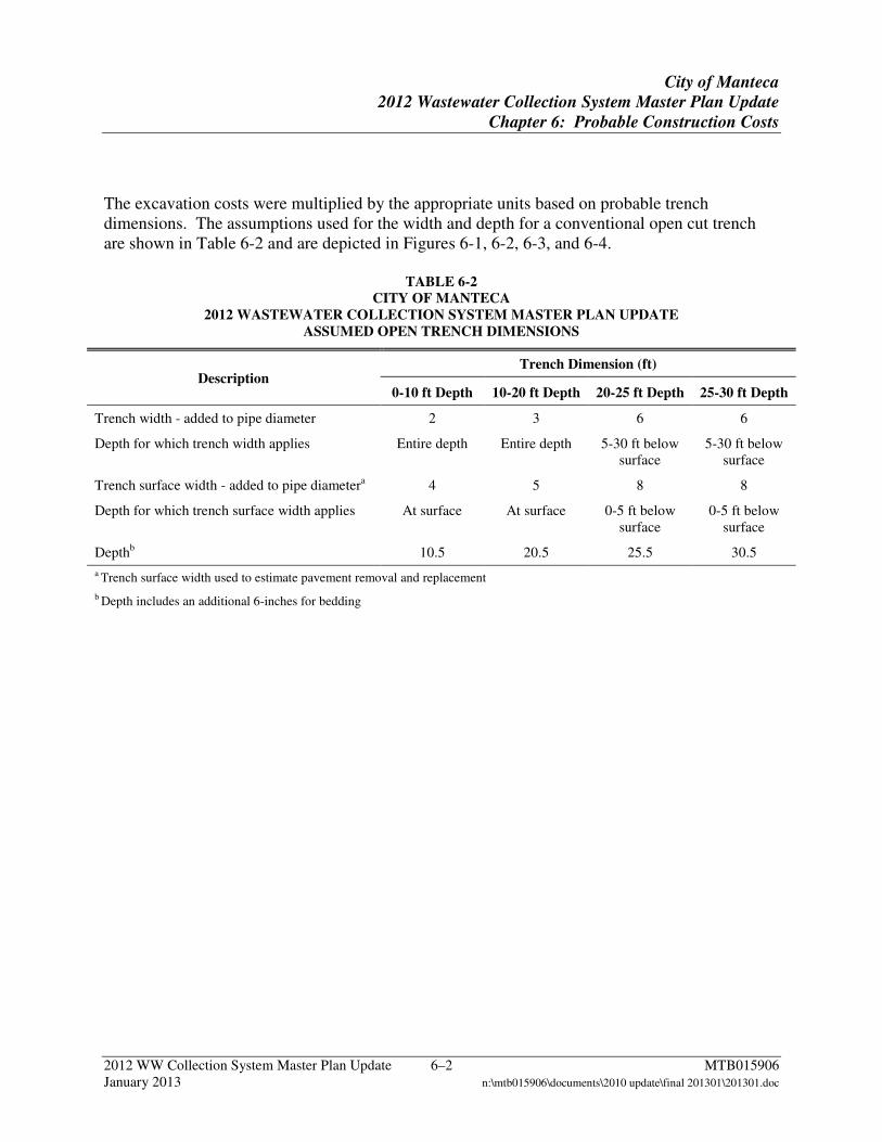
City of Manteca
2012 Wastewater Collection System Master Plan Update
Chapter 6: Probable Construction Costs
2012 WW Collection System Master Plan Update 6–2 MTB015906 January 2013 n:\mtb015906\documents\2010 update\final 201301\201301.doc
The excavation costs were multiplied by the appropriate units based on probable trench dimensions. The assumptions used for the width and depth for a conventional open cut trench are shown in Table 6-2 and are depicted in Figures 6-1, 6-2, 6-3, and 6-4.
TABLE 6-2 CITY OF MANTECA
2012 WASTEWATER COLLECTION SYSTEM MASTER PLAN UPDATE ASSUMED OPEN TRENCH DIMENSIONS
Description Trench Dimension (ft)
0-10 ft Depth 10-20 ft Depth 20-25 ft Depth 25-30 ft Depth
Trench width - added to pipe diameter 2 3 6 6
Depth for which trench width applies Entire depth Entire depth 5-30 ft below surface
5-30 ft below surface
Trench surface width - added to pipe diametera 4 5 8 8
Depth for which trench surface width applies At surface At surface 0-5 ft below surface
0-5 ft below surface
Depthb 10.5 20.5 25.5 30.5
a Trench surface width used to estimate pavement removal and replacement
b Depth includes an additional 6-inches for bedding
City of Manteca
2012 Wastewater Collection System Master Plan Update
Chapter 6: Probable Construction Costs
2012 WW Collection System Master Plan Update 6–3 MTB015906 January 2013 n:\mtb015906\documents\2010 update\final 201301\201301.doc
Figure 6-1 Assumed Open Trench Dimensions 0-10 ft depth
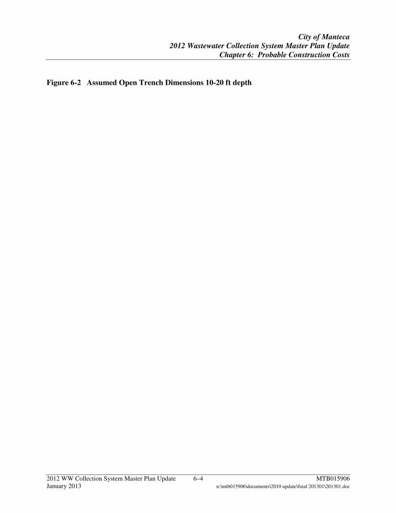
City of Manteca
2012 Wastewater Collection System Master Plan Update
Chapter 6: Probable Construction Costs
2012 WW Collection System Master Plan Update 6–4 MTB015906 January 2013 n:\mtb015906\documents\2010 update\final 201301\201301.doc
Figure 6-2 Assumed Open Trench Dimensions 10-20 ft depth

City of Manteca
2012 Wastewater Collection System Master Plan Update
Chapter 6: Probable Construction Costs
2012 WW Collection System Master Plan Update 6–5 MTB015906 January 2013 n:\mtb015906\documents\2010 update\final 201301\201301.doc
Figure 6-3 Assumed Open Trench Dimensions 20-25 ft depth

City of Manteca
2012 Wastewater Collection System Master Plan Update
Chapter 6: Probable Construction Costs
2012 WW Collection System Master Plan Update 6–6 MTB015906 January 2013 n:\mtb015906\documents\2010 update\final 201301\201301.doc
Figure 6-4 Assumed Open Trench Dimensions 25-30 ft depth
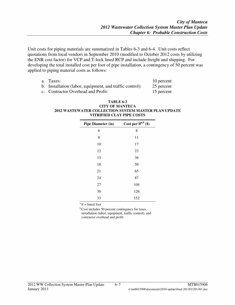
City of Manteca
2012 Wastewater Collection System Master Plan Update
Chapter 6: Probable Construction Costs
2012 WW Collection System Master Plan Update 6–7 MTB015906 January 2013 n:\mtb015906\documents\2010 update\final 201301\201301.doc
Unit costs for piping materials are summarized in Tables 6-3 and 6-4. Unit costs reflect quotations from local vendors in September 2010 (modified to October 2012 costs by utilizing the ENR cost factor) for VCP and T-lock lined RCP and include freight and shipping. For developing the total installed cost per foot of pipe installation, a contingency of 50 percent was applied to piping material costs as follows:
a. Taxes: 10 percent b. Installation (labor, equipment, and traffic control): 25 percent c. Contractor Overhead and Profit: 15 percent
TABLE 6-3
CITY OF MANTECA 2012 WASTEWATER COLLECTION SYSTEM MASTER PLAN UPDATE
VITRIFIED CLAY PIPE COSTS
Pipe Diameter (in) Cost per lfa,b ($)
6 8
8 11
10 17
12 23
15 36
18 50
21 65
24 87
27 104
30 126
33 152
a lf = lineal foot b Cost includes 50 percent contingency for taxes, installation (labor, equipment, traffic control), and contractor overhead and profit
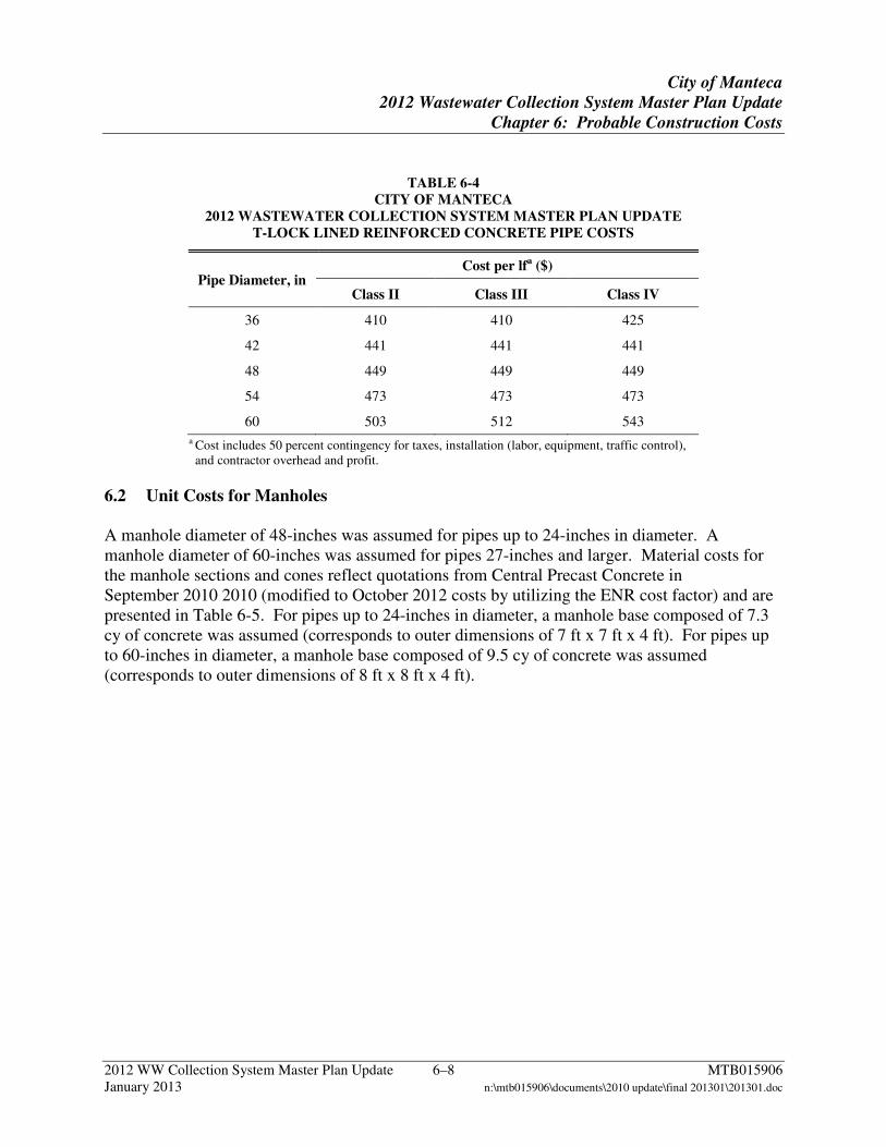
City of Manteca
2012 Wastewater Collection System Master Plan Update
Chapter 6: Probable Construction Costs
2012 WW Collection System Master Plan Update 6–8 MTB015906 January 2013 n:\mtb015906\documents\2010 update\final 201301\201301.doc
TABLE 6-4 CITY OF MANTECA
2012 WASTEWATER COLLECTION SYSTEM MASTER PLAN UPDATE T-LOCK LINED REINFORCED CONCRETE PIPE COSTS
Pipe Diameter, in Cost per lfa ($)
Class II Class III Class IV
36 410 410 425
42 441 441 441
48 449 449 449
54 473 473 473
60 503 512 543
a Cost includes 50 percent contingency for taxes, installation (labor, equipment, traffic control), and contractor overhead and profit.
6.2 Unit Costs for Manholes A manhole diameter of 48-inches was assumed for pipes up to 24-inches in diameter. A manhole diameter of 60-inches was assumed for pipes 27-inches and larger. Material costs for the manhole sections and cones reflect quotations from Central Precast Concrete in September 2010 2010 (modified to October 2012 costs by utilizing the ENR cost factor) and are presented in Table 6-5. For pipes up to 24-inches in diameter, a manhole base composed of 7.3 cy of concrete was assumed (corresponds to outer dimensions of 7 ft x 7 ft x 4 ft). For pipes up to 60-inches in diameter, a manhole base composed of 9.5 cy of concrete was assumed (corresponds to outer dimensions of 8 ft x 8 ft x 4 ft).
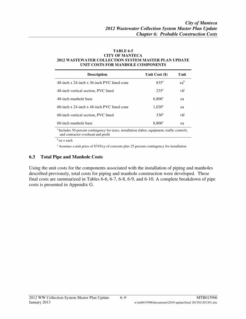
City of Manteca
2012 Wastewater Collection System Master Plan Update
Chapter 6: Probable Construction Costs
2012 WW Collection System Master Plan Update 6–9 MTB015906 January 2013 n:\mtb015906\documents\2010 update\final 201301\201301.doc
TABLE 6-5 CITY OF MANTECA
2012 WASTEWATER COLLECTION SYSTEM MASTER PLAN UPDATE UNIT COSTS FOR MANHOLE COMPONENTS
Description Unit Cost ($) Unit
48-inch x 24-inch x 36-inch PVC lined cone 835a eab
48-inch vertical section, PVC lined 235a vlf
48-inch manhole base 6,800c ea
60-inch x 24-inch x 48-inch PVC lined cone 1,020a ea
60-inch vertical section, PVC lined 330a vlf
60-inch manhole base 8,800c ea
a Includes 50 percent contingency for taxes, installation (labor, equipment, traffic control), and contractor overhead and profit
b ea = each c Assumes a unit price of $745/cy of concrete plus 25 percent contingency for installation
6.3 Total Pipe and Manhole Costs Using the unit costs for the components associated with the installation of piping and manholes described previously, total costs for piping and manhole construction were developed. These final costs are summarized in Tables 6-6, 6-7, 6-8, 6-9, and 6-10. A complete breakdown of pipe costs is presented in Appendix G.
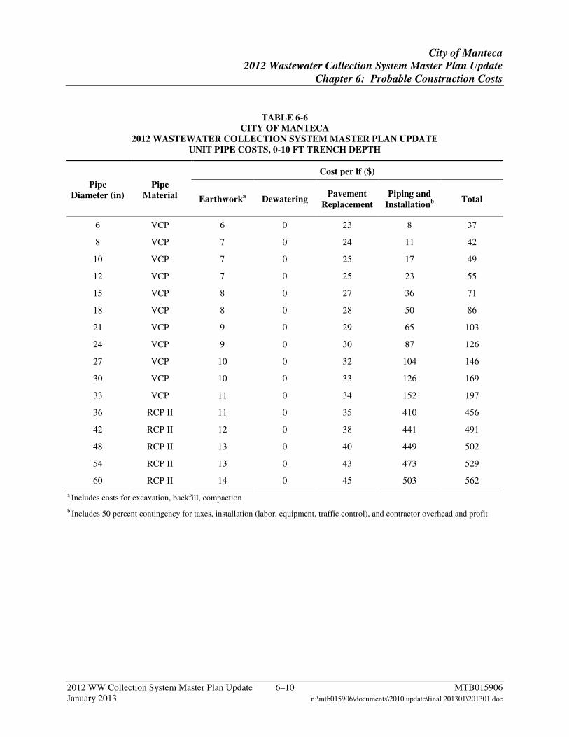
City of Manteca
2012 Wastewater Collection System Master Plan Update
Chapter 6: Probable Construction Costs
2012 WW Collection System Master Plan Update 6–10 MTB015906 January 2013 n:\mtb015906\documents\2010 update\final 201301\201301.doc
TABLE 6-6 CITY OF MANTECA
2012 WASTEWATER COLLECTION SYSTEM MASTER PLAN UPDATE UNIT PIPE COSTS, 0-10 FT TRENCH DEPTH
Pipe Diameter (in)
Pipe Material
Cost per lf ($)
Earthworka Dewatering Pavement
Replacement Piping and
Installationb Total
6 VCP 6 0 23 8 37
8 VCP 7 0 24 11 42
10 VCP 7 0 25 17 49
12 VCP 7 0 25 23 55
15 VCP 8 0 27 36 71
18 VCP 8 0 28 50 86
21 VCP 9 0 29 65 103
24 VCP 9 0 30 87 126
27 VCP 10 0 32 104 146
30 VCP 10 0 33 126 169
33 VCP 11 0 34 152 197
36 RCP II 11 0 35 410 456
42 RCP II 12 0 38 441 491
48 RCP II 13 0 40 449 502
54 RCP II 13 0 43 473 529
60 RCP II 14 0 45 503 562
a Includes costs for excavation, backfill, compaction
b Includes 50 percent contingency for taxes, installation (labor, equipment, traffic control), and contractor overhead and profit
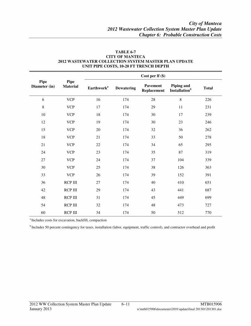
City of Manteca
2012 Wastewater Collection System Master Plan Update
Chapter 6: Probable Construction Costs
2012 WW Collection System Master Plan Update 6–11 MTB015906 January 2013 n:\mtb015906\documents\2010 update\final 201301\201301.doc
TABLE 6-7 CITY OF MANTECA
2012 WASTEWATER COLLECTION SYSTEM MASTER PLAN UPDATE UNIT PIPE COSTS, 10-20 FT TRENCH DEPTH
Pipe Diameter (in)
Pipe Material
Cost per lf ($)
Earthworka Dewatering Pavement
Replacement Piping and
Installationb Total
6 VCP 16 174 28 8 226
8 VCP 17 174 29 11 231
10 VCP 18 174 30 17 239
12 VCP 19 174 30 23 246
15 VCP 20 174 32 36 262
18 VCP 21 174 33 50 278
21 VCP 22 174 34 65 295
24 VCP 23 174 35 87 319
27 VCP 24 174 37 104 339
30 VCP 25 174 38 126 363
33 VCP 26 174 39 152 391
36 RCP III 27 174 40 410 651
42 RCP III 29 174 43 441 687
48 RCP III 31 174 45 449 699
54 RCP III 32 174 48 473 727
60 RCP III 34 174 50 512 770
a Includes costs for excavation, backfill, compaction
b Includes 50 percent contingency for taxes, installation (labor, equipment, traffic control), and contractor overhead and profit
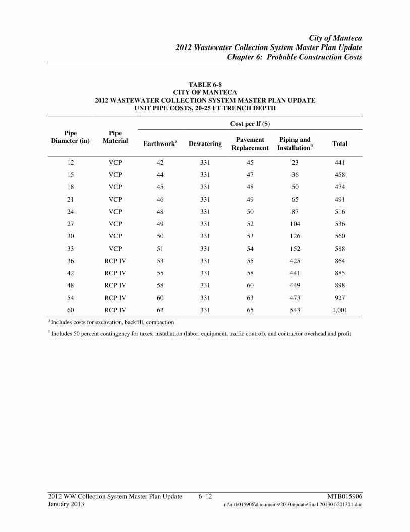
City of Manteca
2012 Wastewater Collection System Master Plan Update
Chapter 6: Probable Construction Costs
2012 WW Collection System Master Plan Update 6–12 MTB015906 January 2013 n:\mtb015906\documents\2010 update\final 201301\201301.doc
TABLE 6-8 CITY OF MANTECA
2012 WASTEWATER COLLECTION SYSTEM MASTER PLAN UPDATE UNIT PIPE COSTS, 20-25 FT TRENCH DEPTH
Pipe Diameter (in)
Pipe Material
Cost per lf ($)
Earthworka Dewatering Pavement
Replacement Piping and
Installationb Total
12 VCP 42 331 45 23 441
15 VCP 44 331 47 36 458
18 VCP 45 331 48 50 474
21 VCP 46 331 49 65 491
24 VCP 48 331 50 87 516
27 VCP 49 331 52 104 536
30 VCP 50 331 53 126 560
33 VCP 51 331 54 152 588
36 RCP IV 53 331 55 425 864
42 RCP IV 55 331 58 441 885
48 RCP IV 58 331 60 449 898
54 RCP IV 60 331 63 473 927
60 RCP IV 62 331 65 543 1,001
a Includes costs for excavation, backfill, compaction
b Includes 50 percent contingency for taxes, installation (labor, equipment, traffic control), and contractor overhead and profit
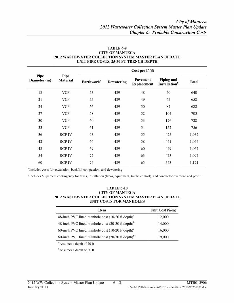
City of Manteca
2012 Wastewater Collection System Master Plan Update
Chapter 6: Probable Construction Costs
2012 WW Collection System Master Plan Update 6–13 MTB015906 January 2013 n:\mtb015906\documents\2010 update\final 201301\201301.doc
TABLE 6-9 CITY OF MANTECA
2012 WASTEWATER COLLECTION SYSTEM MASTER PLAN UPDATE UNIT PIPE COSTS, 25-30 FT TRENCH DEPTH
Pipe Diameter (in)
Pipe Material
Cost per lf ($)
Earthworka Dewatering Pavement
Replacement Piping and
Installationb Total
18 VCP 53 489 48 50 640
21 VCP 55 489 49 65 658
24 VCP 56 489 50 87 682
27 VCP 58 489 52 104 703
30 VCP 60 489 53 126 728
33 VCP 61 489 54 152 756
36 RCP IV 63 489 55 425 1,032
42 RCP IV 66 489 58 441 1,054
48 RCP IV 69 489 60 449 1,067
54 RCP IV 72 489 63 473 1,097
60 RCP IV 74 489 65 543 1,171
a Includes costs for excavation, backfill, compaction, and dewatering
b Includes 50 percent contingency for taxes, installation (labor, equipment, traffic control), and contractor overhead and profit
TABLE 6-10 CITY OF MANTECA
2012 WASTEWATER COLLECTION SYSTEM MASTER PLAN UPDATE UNIT COSTS FOR MANHOLES
Item Unit Cost ($/ea)
48-inch PVC lined manhole cost (10-20 ft depth)a 12,000
48-inch PVC lined manhole cost (20-30 ft depth)b 14,000
60-inch PVC lined manhole cost (10-20 ft depth)a 16,000
60-inch PVC lined manhole cost (20-30 ft depth)b 19,000
a Assumes a depth of 20 ft
b Assumes a depth of 30 ft
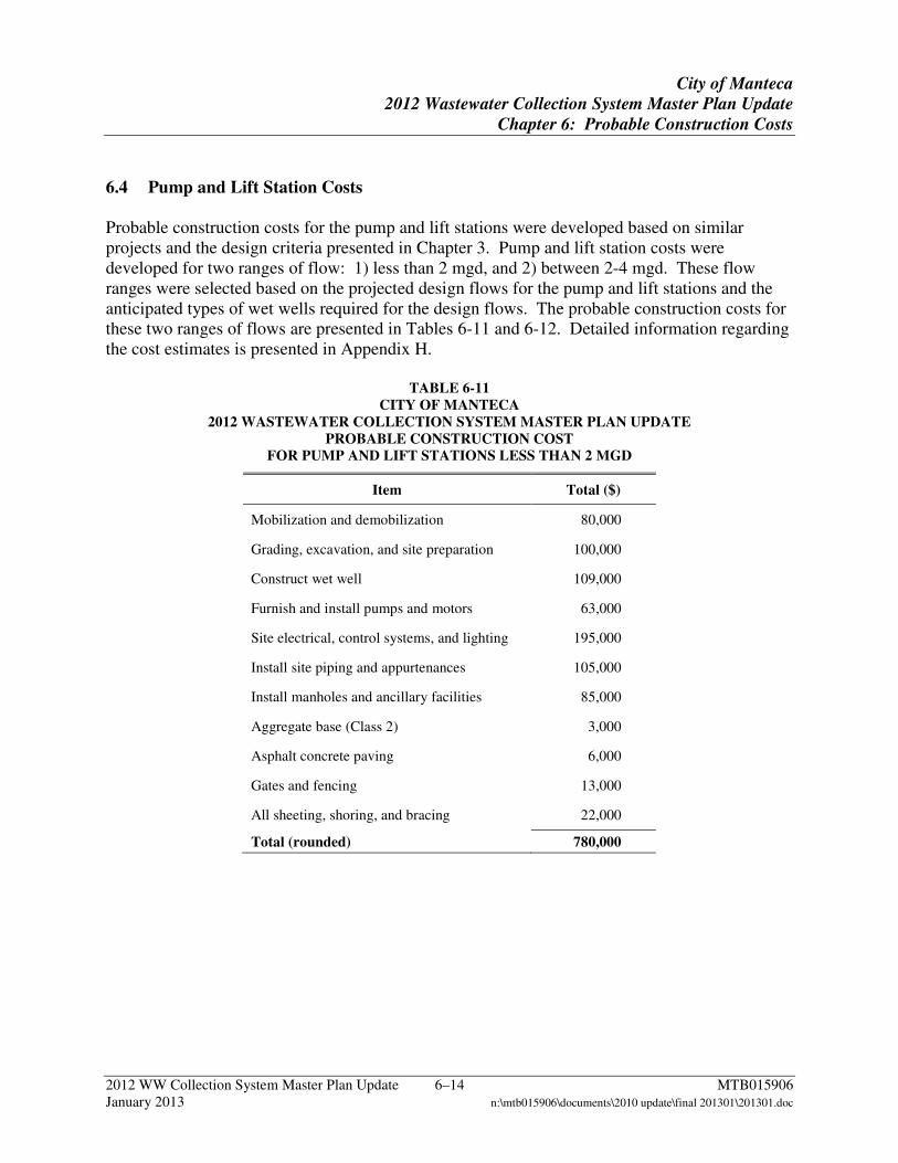
City of Manteca
2012 Wastewater Collection System Master Plan Update
Chapter 6: Probable Construction Costs
2012 WW Collection System Master Plan Update 6–14 MTB015906 January 2013 n:\mtb015906\documents\2010 update\final 201301\201301.doc
6.4 Pump and Lift Station Costs Probable construction costs for the pump and lift stations were developed based on similar projects and the design criteria presented in Chapter 3. Pump and lift station costs were developed for two ranges of flow: 1) less than 2 mgd, and 2) between 2-4 mgd. These flow ranges were selected based on the projected design flows for the pump and lift stations and the anticipated types of wet wells required for the design flows. The probable construction costs for these two ranges of flows are presented in Tables 6-11 and 6-12. Detailed information regarding the cost estimates is presented in Appendix H.
TABLE 6-11 CITY OF MANTECA
2012 WASTEWATER COLLECTION SYSTEM MASTER PLAN UPDATE PROBABLE CONSTRUCTION COST
FOR PUMP AND LIFT STATIONS LESS THAN 2 MGD
Item Total ($)
Mobilization and demobilization 80,000
Grading, excavation, and site preparation 100,000
Construct wet well 109,000
Furnish and install pumps and motors 63,000
Site electrical, control systems, and lighting 195,000
Install site piping and appurtenances 105,000
Install manholes and ancillary facilities 85,000
Aggregate base (Class 2) 3,000
Asphalt concrete paving 6,000
Gates and fencing 13,000
All sheeting, shoring, and bracing 22,000
Total (rounded) 780,000
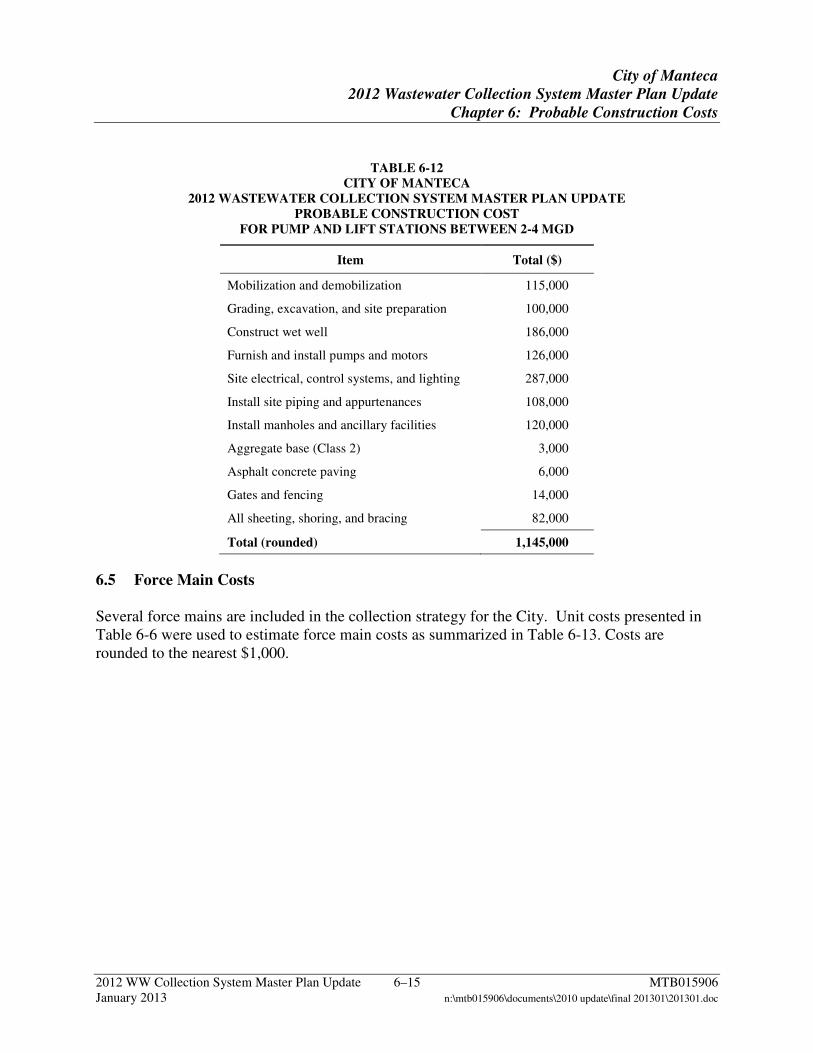
City of Manteca
2012 Wastewater Collection System Master Plan Update
Chapter 6: Probable Construction Costs
2012 WW Collection System Master Plan Update 6–15 MTB015906 January 2013 n:\mtb015906\documents\2010 update\final 201301\201301.doc
TABLE 6-12 CITY OF MANTECA
2012 WASTEWATER COLLECTION SYSTEM MASTER PLAN UPDATE PROBABLE CONSTRUCTION COST
FOR PUMP AND LIFT STATIONS BETWEEN 2-4 MGD
Item Total ($)
Mobilization and demobilization 115,000
Grading, excavation, and site preparation 100,000
Construct wet well 186,000
Furnish and install pumps and motors 126,000
Site electrical, control systems, and lighting 287,000
Install site piping and appurtenances 108,000
Install manholes and ancillary facilities 120,000
Aggregate base (Class 2) 3,000
Asphalt concrete paving 6,000
Gates and fencing 14,000
All sheeting, shoring, and bracing 82,000
Total (rounded) 1,145,000
6.5 Force Main Costs Several force mains are included in the collection strategy for the City. Unit costs presented in Table 6-6 were used to estimate force main costs as summarized in Table 6-13. Costs are rounded to the nearest $1,000.
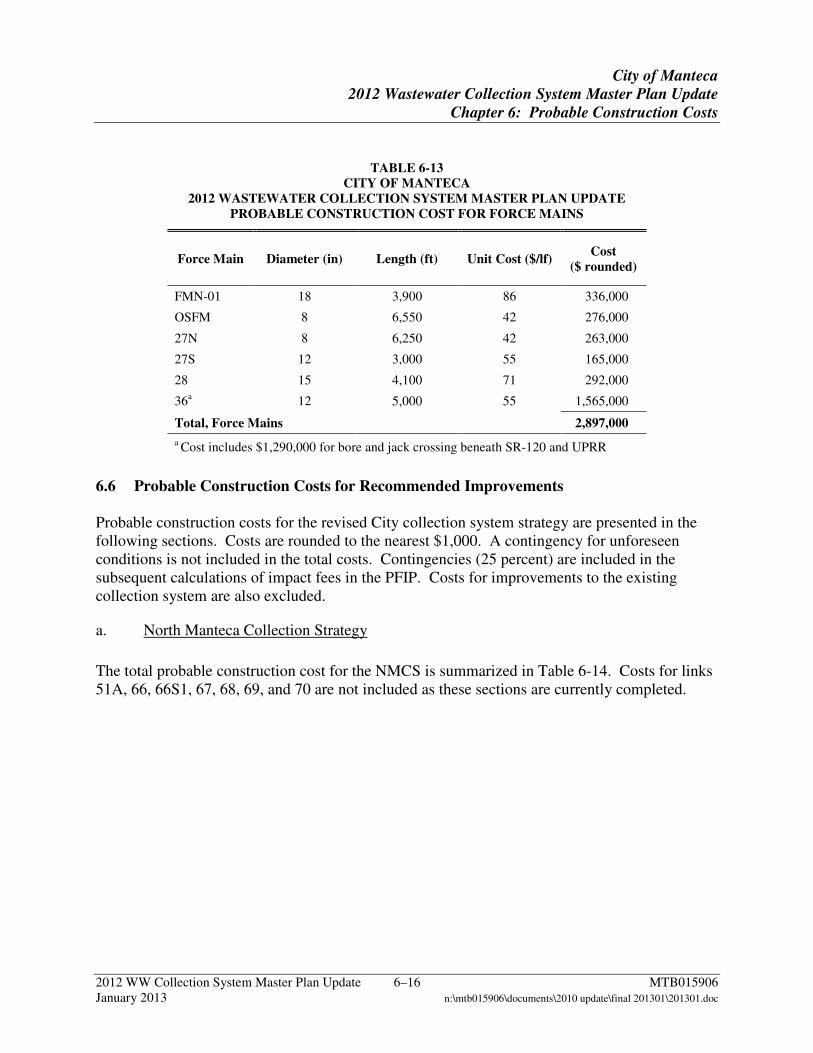
City of Manteca
2012 Wastewater Collection System Master Plan Update
Chapter 6: Probable Construction Costs
2012 WW Collection System Master Plan Update 6–16 MTB015906 January 2013 n:\mtb015906\documents\2010 update\final 201301\201301.doc
TABLE 6-13 CITY OF MANTECA
2012 WASTEWATER COLLECTION SYSTEM MASTER PLAN UPDATE PROBABLE CONSTRUCTION COST FOR FORCE MAINS
Force Main Diameter (in) Length (ft) Unit Cost ($/lf) Cost
($ rounded)
FMN-01 18 3,900 86 336,000
OSFM 8 6,550 42 276,000
27N 8 6,250 42 263,000
27S 12 3,000 55 165,000
28 15 4,100 71 292,000
36a 12 5,000 55 1,565,000
Total, Force Mains 2,897,000
a Cost includes $1,290,000 for bore and jack crossing beneath SR-120 and UPRR
6.6 Probable Construction Costs for Recommended Improvements Probable construction costs for the revised City collection system strategy are presented in the following sections. Costs are rounded to the nearest $1,000. A contingency for unforeseen conditions is not included in the total costs. Contingencies (25 percent) are included in the subsequent calculations of impact fees in the PFIP. Costs for improvements to the existing collection system are also excluded.
a. North Manteca Collection Strategy
The total probable construction cost for the NMCS is summarized in Table 6-14. Costs for links 51A, 66, 66S1, 67, 68, 69, and 70 are not included as these sections are currently completed.
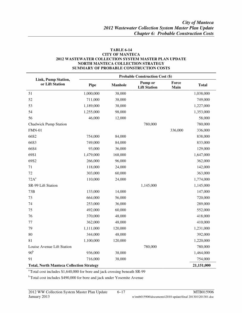
City of Manteca
2012 Wastewater Collection System Master Plan Update
Chapter 6: Probable Construction Costs
2012 WW Collection System Master Plan Update 6–17 MTB015906 January 2013 n:\mtb015906\documents\2010 update\final 201301\201301.doc
TABLE 6-14 CITY OF MANTECA
2012 WASTEWATER COLLECTION SYSTEM MASTER PLAN UPDATE NORTH MANTECA COLLECTION STRATEGY
SUMMARY OF PROBABLE CONSTRUCTION COSTS
Link, Pump Station, or Lift Station
Probable Construction Cost ($)
Pipe Manhole Pump or
Lift Station Force Main
Total
51 1,000,000 38,000
1,038,000
52 711,000 38,000
749,000
53 1,189,000 38,000
1,227,000
54 1,255,000 98,000
1,353,000
56 46,000 12,000
58,000
Chadwick Pump Station
780,000
780,000
FMN-01
336,000 336,000
66S2 754,000 84,000
838,000
66S3 749,000 84,000
833,000
66S4 93,000 36,000
129,000
69S1 1,479,000 168,000
1,647,000
69S2 266,000 96,000
362,000
71 118,000 24,000
142,000
72 303,000 60,000
363,000
72Aa 110,000 24,000
1,774,000
SR-99 Lift Station
1,145,000
1,145,000
73B 133,000 14,000
147,000
73 664,000 56,000
720,000
74 253,000 36,000
289,000
75 492,000 60,000
552,000
76 370,000 48,000
418,000
77 362,000 48,000
410,000
79 1,111,000 120,000
1,231,000
80 344,000 48,000
392,000
81 1,100,000 120,000
1,220,000
Louise Avenue Lift Station
780,000
780,000
90b 936,000 38,000
1,464,000
91 716,000 38,000 754,000
Total, North Manteca Collection Strategy 21,151,000 a Total cost includes $1,640,000 for bore and jack crossing beneath SR-99 b Total cost includes $490,000 for bore and jack under Yosemite Avenue
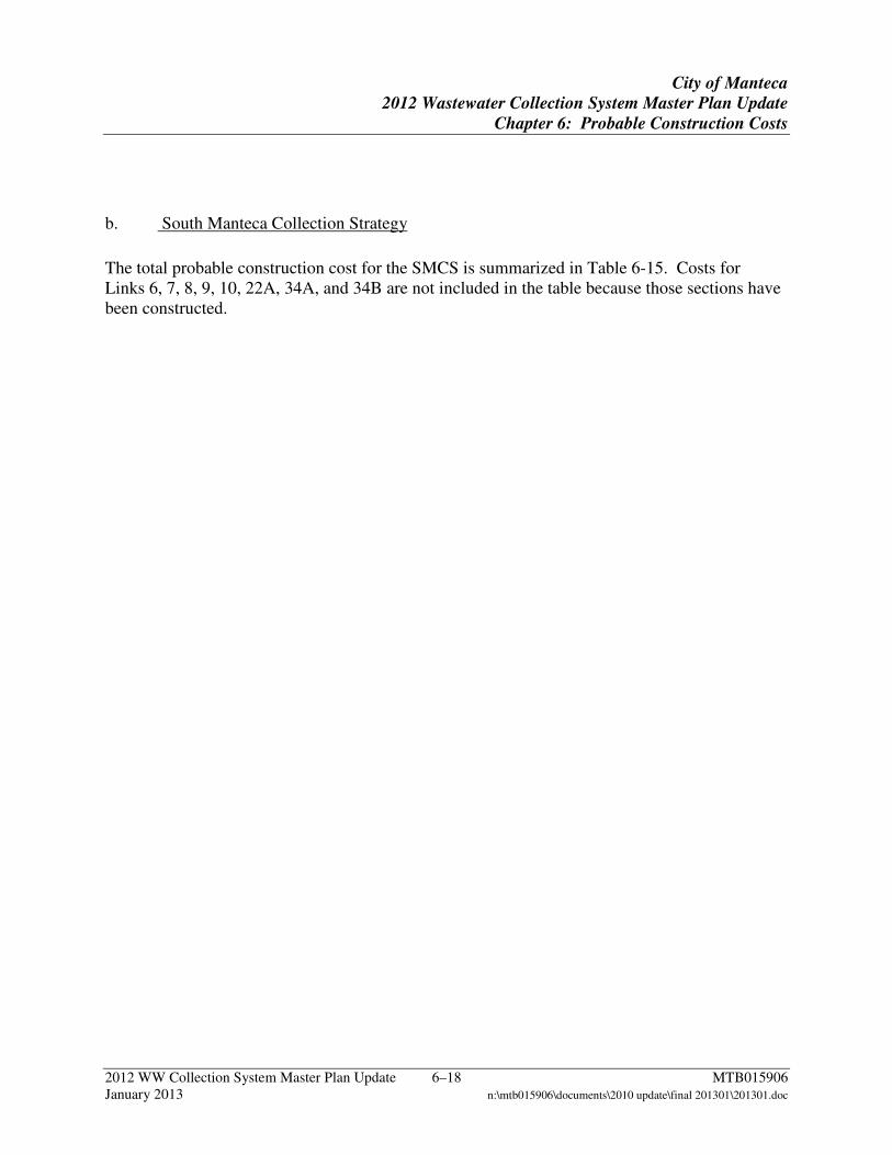
City of Manteca
2012 Wastewater Collection System Master Plan Update
Chapter 6: Probable Construction Costs
2012 WW Collection System Master Plan Update 6–18 MTB015906 January 2013 n:\mtb015906\documents\2010 update\final 201301\201301.doc
b. South Manteca Collection Strategy
The total probable construction cost for the SMCS is summarized in Table 6-15. Costs for Links 6, 7, 8, 9, 10, 22A, 34A, and 34B are not included in the table because those sections have been constructed.
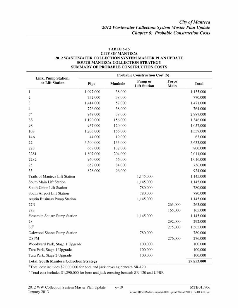
City of Manteca
2012 Wastewater Collection System Master Plan Update
Chapter 6: Probable Construction Costs
2012 WW Collection System Master Plan Update 6–19 MTB015906 January 2013 n:\mtb015906\documents\2010 update\final 201301\201301.doc
TABLE 6-15 CITY OF MANTECA
2012 WASTEWATER COLLECTION SYSTEM MASTER PLAN UPDATE SOUTH MANTECA COLLECTION STRATEGY
SUMMARY OF PROBABLE CONSTRUCTION COSTS
Link, Pump Station, or Lift Station
Probable Construction Cost ($)
Pipe Manhole Pump or
Lift Station Force Main
Total
1 1,097,000 38,000
1,135,000
2 732,000 38,000
770,000
3 1,414,000 57,000
1,471,000
4 726,000 38,000
764,000
5a 949,000 38,000
2,987,000
8S 1,190,000 156,000
1,346,000
9S 937,000 120,000
1,057,000
10S 1,203,000 156,000
1,359,000
14A 44,000 19,000
63,000
22 3,500,000 133,000
3,633,000
22S 668,000 132,000
800,000
22S1 1,807,000 204,000
2,011,000
22S2 960,000 56,000
1,016,000
25 652,000 84,000
736,000
33 828,000 96,000
924,000
Trails of Manteca Lift Station
1,145,000
1,145,000
South Main Lift Station
1,145,000
1,145,000
South Union Lift Station
780,000
780,000
South Airport Lift Station
780,000
780,000
Austin Business Pump Station
1,145,000
1,145,000
27N
263,000 263,000
27S
165,000 165,000
Yosemite Square Pump Station
1,145,000
1,145,000
28
292,000 292,000
36b
275,000 1,565,000
Oakwood Shores Pump Station
780,000
780,000
OSFM
276,000 276,000
Woodward Park, Stage 1 Upgrade
100,000
100,000
Tara Park, Stage 1 Upgrade
100,000
100,000
Tara Park, Stage 2 Upgrade 100,000 100,000
Total, South Manteca Collection Strategy 29,853,000 a Total cost includes $2,000,000 for bore and jack crossing beneath SR-120 b Total cost includes $1,290,000 for bore and jack crossing beneath SR-120 and UPRR
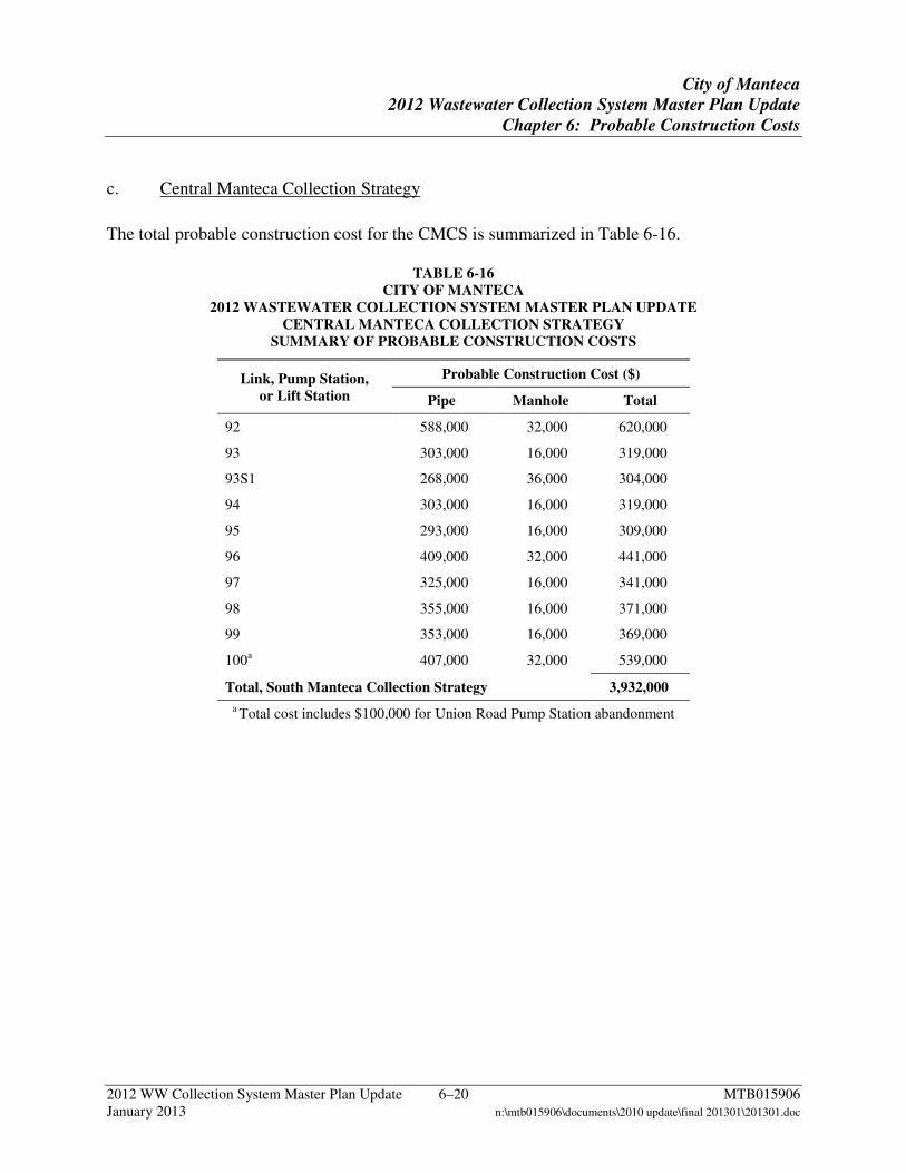
City of Manteca
2012 Wastewater Collection System Master Plan Update
Chapter 6: Probable Construction Costs
2012 WW Collection System Master Plan Update 6–20 MTB015906 January 2013 n:\mtb015906\documents\2010 update\final 201301\201301.doc
c. Central Manteca Collection Strategy
The total probable construction cost for the CMCS is summarized in Table 6-16.
TABLE 6-16 CITY OF MANTECA
2012 WASTEWATER COLLECTION SYSTEM MASTER PLAN UPDATE CENTRAL MANTECA COLLECTION STRATEGY
SUMMARY OF PROBABLE CONSTRUCTION COSTS
Link, Pump Station, or Lift Station
Probable Construction Cost ($)
Pipe Manhole Total
92 588,000 32,000 620,000
93 303,000 16,000 319,000
93S1 268,000 36,000 304,000
94 303,000 16,000 319,000
95 293,000 16,000 309,000
96 409,000 32,000 441,000
97 325,000 16,000 341,000
98 355,000 16,000 371,000
99 353,000 16,000 369,000
100a 407,000 32,000 539,000
Total, South Manteca Collection Strategy 3,932,000
a Total cost includes $100,000 for Union Road Pump Station abandonment
City of Manteca
2012 Wastewater Collection System Master Plan Update
Chapter 7: Capital Improvement Plan
2012 WW Collection System Master Plan Update 7–1 MTB015906 January 2013 n:\mtb015906\documents\2010 update\final 201301\201301.doc
7 Capital Improvement Plan
This chapter summarizes potential CIP projects for future implementation.
7.1 Projects Cost for construction of the NMCS, SMCS, and CMCS are presented for the City to use when developing PFIP fees and capital improvement projects. The construction costs were divided by fee zone for each link or element, where applicable. Costs for the zones contributing to each link were calculated based on ADWF. Acreage and land use information of developable land within the Central Trunk sewer shed were provided by the City and used to determine the project fee for Zone 21. The construction cost attributable to the portion of flow from existing development within the Central Trunk sewer shed is approximately $5,939,000. Table 7-1 summarizes all of the facilities included in the NMCS, SMCS, CMSCS and the division of construction costs among the fee zones. For reference, Plate 7-A presents the three collection strategies and the fee zones established under the PFIP.
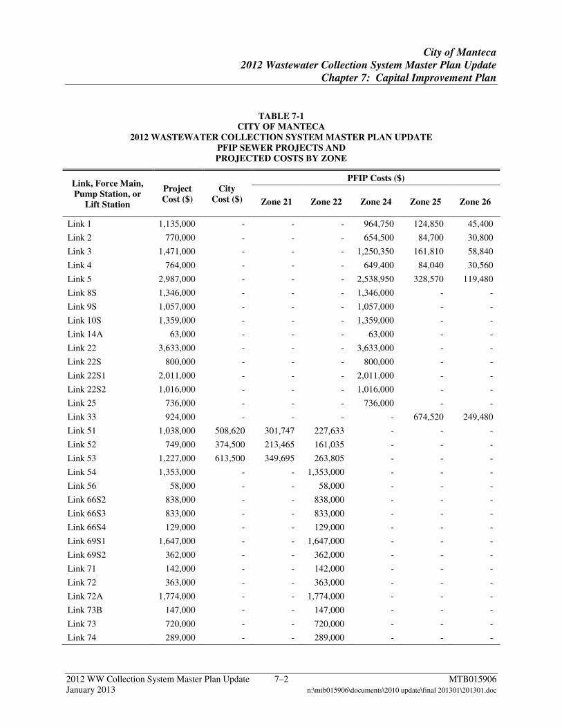
City of Manteca
2012 Wastewater Collection System Master Plan Update
Chapter 7: Capital Improvement Plan
2012 WW Collection System Master Plan Update 7–2 MTB015906 January 2013 n:\mtb015906\documents\2010 update\final 201301\201301.doc
TABLE 7-1 CITY OF MANTECA
2012 WASTEWATER COLLECTION SYSTEM MASTER PLAN UPDATE PFIP SEWER PROJECTS AND PROJECTED COSTS BY ZONE
Link, Force Main, Pump Station, or
Lift Station
Project Cost ($)
City Cost ($)
PFIP Costs ($)
Zone 21 Zone 22 Zone 24 Zone 25 Zone 26
Link 1 1,135,000 - - - 964,750 124,850 45,400
Link 2 770,000 - - - 654,500 84,700 30,800
Link 3 1,471,000 - - - 1,250,350 161,810 58,840
Link 4 764,000 - - - 649,400 84,040 30,560
Link 5 2,987,000 - - - 2,538,950 328,570 119,480
Link 8S 1,346,000 - - - 1,346,000 - -
Link 9S 1,057,000 - - - 1,057,000 - -
Link 10S 1,359,000 - - - 1,359,000 - -
Link 14A 63,000 - - - 63,000 - -
Link 22 3,633,000 - - - 3,633,000 - -
Link 22S 800,000 - - - 800,000 - -
Link 22S1 2,011,000 - - - 2,011,000 - -
Link 22S2 1,016,000 - - - 1,016,000 - -
Link 25 736,000 - - - 736,000 - -
Link 33 924,000 - - - - 674,520 249,480
Link 51 1,038,000 508,620 301,747 227,633 - - -
Link 52 749,000 374,500 213,465 161,035 - - -
Link 53 1,227,000 613,500 349,695 263,805 - - -
Link 54 1,353,000 - - 1,353,000 - - -
Link 56 58,000 - - 58,000 - - -
Link 66S2 838,000 - - 838,000 - - -
Link 66S3 833,000 - - 833,000 - - -
Link 66S4 129,000 - - 129,000 - - -
Link 69S1 1,647,000 - - 1,647,000 - - -
Link 69S2 362,000 - - 362,000 - - -
Link 71 142,000 - - 142,000 - - -
Link 72 363,000 - - 363,000 - - -
Link 72A 1,774,000 - - 1,774,000 - - -
Link 73B 147,000 - - 147,000 - - -
Link 73 720,000 - - 720,000 - - -
Link 74 289,000 - - 289,000 - - -
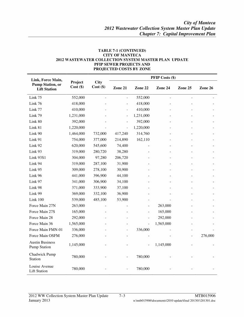
City of Manteca
2012 Wastewater Collection System Master Plan Update
Chapter 7: Capital Improvement Plan
2012 WW Collection System Master Plan Update 7–3 MTB015906 January 2013 n:\mtb015906\documents\2010 update\final 201301\201301.doc
TABLE 7-1 (CONTINUED) CITY OF MANTECA
2012 WASTEWATER COLLECTION SYSTEM MASTER PLAN UPDATE PFIP SEWER PROJECTS AND PROJECTED COSTS BY ZONE
Link, Force Main, Pump Station, or
Lift Station
Project Cost ($)
City Cost ($)
PFIP Costs ($)
Zone 21 Zone 22 Zone 24 Zone 25 Zone 26
Link 75 552,000 - - 552,000 - - -
Link 76 418,000 - - 418,000 - - -
Link 77 410,000 - - 410,000 - - -
Link 79 1,231,000 - - 1,231,000 - - -
Link 80 392,000 - - 392,000 - - -
Link 81 1,220,000 - - 1,220,000 - - -
Link 90 1,464,000 732,000 417,240 314,760 - - -
Link 91 754,000 377,000 214,890 162,110 - - -
Link 92 620,000 545,600 74,400 - - - -
Link 93 319,000 280,720 38,280 - - - -
Link 93S1 304,000 97,280 206,720 - - - -
Link 94 319,000 287,100 31,900 - - - -
Link 95 309,000 278,100 30,900 - - - -
Link 96 441,000 396,900 44,100 - - - -
Link 97 341,000 306,900 34,100 - - - -
Link 98 371,000 333,900 37,100 - - - -
Link 99 369,000 332,100 36,900 - - - -
Link 100 539,000 485,100 53,900 - - - -
Force Main 27N 263,000 - - - 263,000 - -
Force Main 27S 165,000 - - - 165,000 - -
Force Main 28 292,000 - - - 292,000 - -
Force Main 36 1,565,000 - - - 1,565,000 - -
Force Main FMN-01 336,000 - - 336,000 - - -
Force Main OSFM 276,000 - - - - - 276,000
Austin Business Pump Station
1,145,000 - - - 1,145,000 - -
Chadwick Pump Station
780,000 - - 780,000 - - -
Louise Avenue Lift Station
780,000 - - 780,000 - - -
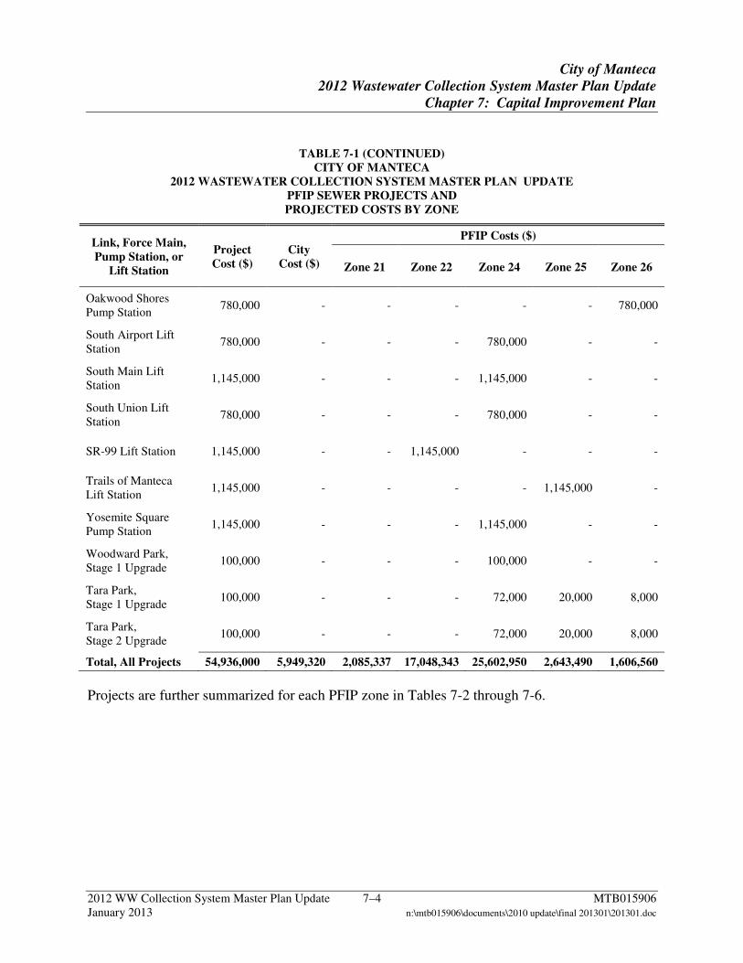
City of Manteca
2012 Wastewater Collection System Master Plan Update
Chapter 7: Capital Improvement Plan
2012 WW Collection System Master Plan Update 7–4 MTB015906 January 2013 n:\mtb015906\documents\2010 update\final 201301\201301.doc
TABLE 7-1 (CONTINUED) CITY OF MANTECA
2012 WASTEWATER COLLECTION SYSTEM MASTER PLAN UPDATE PFIP SEWER PROJECTS AND PROJECTED COSTS BY ZONE
Link, Force Main, Pump Station, or
Lift Station
Project Cost ($)
City Cost ($)
PFIP Costs ($)
Zone 21 Zone 22 Zone 24 Zone 25 Zone 26
Oakwood Shores Pump Station
780,000 - - - - - 780,000
South Airport Lift Station
780,000 - - - 780,000 - -
South Main Lift Station
1,145,000 - - - 1,145,000 - -
South Union Lift Station
780,000 - - - 780,000 - -
SR-99 Lift Station 1,145,000 - - 1,145,000 - - -
Trails of Manteca Lift Station
1,145,000 - - - - 1,145,000 -
Yosemite Square Pump Station
1,145,000 - - - 1,145,000 - -
Woodward Park, Stage 1 Upgrade
100,000 - - - 100,000 - -
Tara Park, Stage 1 Upgrade
100,000 - - - 72,000 20,000 8,000
Tara Park, Stage 2 Upgrade
100,000 - - - 72,000 20,000 8,000
Total, All Projects 54,936,000 5,949,320 2,085,337 17,048,343 25,602,950 2,643,490 1,606,560
Projects are further summarized for each PFIP zone in Tables 7-2 through 7-6.
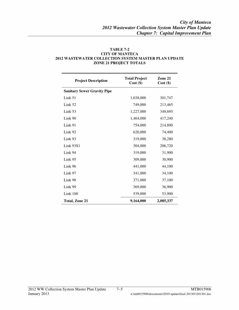
City of Manteca
2012 Wastewater Collection System Master Plan Update
Chapter 7: Capital Improvement Plan
2012 WW Collection System Master Plan Update 7–5 MTB015906 January 2013 n:\mtb015906\documents\2010 update\final 201301\201301.doc
TABLE 7-2 CITY OF MANTECA
2012 WASTEWATER COLLECTION SYSTEM MASTER PLAN UPDATE ZONE 21 PROJECT TOTALS
Project Description Total Project
Cost ($) Zone 21 Cost ($)
Sanitary Sewer Gravity Pipe
Link 51 1,038,000 301,747
Link 52 749,000 213,465
Link 53 1,227,000 349,695
Link 90 1,464,000 417,240
Link 91 754,000 214,890
Link 92 620,000 74,400
Link 93 319,000 38,280
Link 93S1 304,000 206,720
Link 94 319,000 31,900
Link 95 309,000 30,900
Link 96 441,000 44,100
Link 97 341,000 34,100
Link 98 371,000 37,100
Link 99 369,000 36,900
Link 100 539,000 53,900
Total, Zone 21 9,164,000 2,085,337
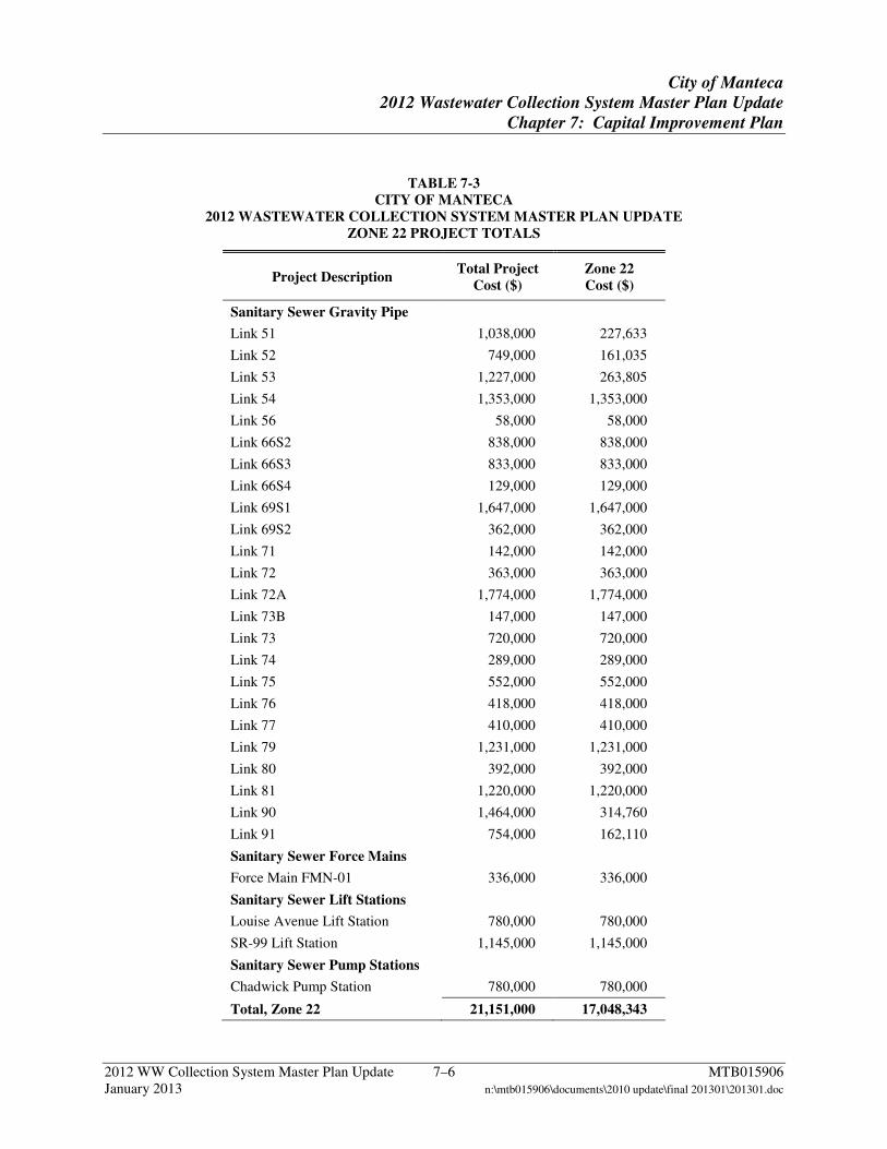
City of Manteca
2012 Wastewater Collection System Master Plan Update
Chapter 7: Capital Improvement Plan
2012 WW Collection System Master Plan Update 7–6 MTB015906 January 2013 n:\mtb015906\documents\2010 update\final 201301\201301.doc
TABLE 7-3 CITY OF MANTECA
2012 WASTEWATER COLLECTION SYSTEM MASTER PLAN UPDATE ZONE 22 PROJECT TOTALS
Project Description Total Project
Cost ($) Zone 22 Cost ($)
Sanitary Sewer Gravity Pipe
Link 51 1,038,000 227,633
Link 52 749,000 161,035
Link 53 1,227,000 263,805
Link 54 1,353,000 1,353,000
Link 56 58,000 58,000
Link 66S2 838,000 838,000
Link 66S3 833,000 833,000
Link 66S4 129,000 129,000
Link 69S1 1,647,000 1,647,000
Link 69S2 362,000 362,000
Link 71 142,000 142,000
Link 72 363,000 363,000
Link 72A 1,774,000 1,774,000
Link 73B 147,000 147,000
Link 73 720,000 720,000
Link 74 289,000 289,000
Link 75 552,000 552,000
Link 76 418,000 418,000
Link 77 410,000 410,000
Link 79 1,231,000 1,231,000
Link 80 392,000 392,000
Link 81 1,220,000 1,220,000
Link 90 1,464,000 314,760
Link 91 754,000 162,110
Sanitary Sewer Force Mains
Force Main FMN-01 336,000 336,000
Sanitary Sewer Lift Stations
Louise Avenue Lift Station 780,000 780,000
SR-99 Lift Station 1,145,000 1,145,000
Sanitary Sewer Pump Stations
Chadwick Pump Station 780,000 780,000
Total, Zone 22 21,151,000 17,048,343
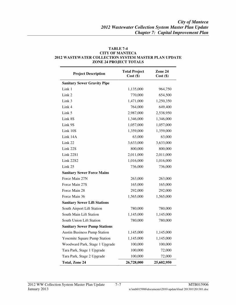
City of Manteca
2012 Wastewater Collection System Master Plan Update
Chapter 7: Capital Improvement Plan
2012 WW Collection System Master Plan Update 7–7 MTB015906 January 2013 n:\mtb015906\documents\2010 update\final 201301\201301.doc
TABLE 7-4 CITY OF MANTECA
2012 WASTEWATER COLLECTION SYSTEM MASTER PLAN UPDATE ZONE 24 PROJECT TOTALS
Project Description Total Project
Cost ($) Zone 24 Cost ($)
Sanitary Sewer Gravity Pipe
Link 1 1,135,000 964,750
Link 2 770,000 654,500
Link 3 1,471,000 1,250,350
Link 4 764,000 649,400
Link 5 2,987,000 2,538,950
Link 8S 1,346,000 1,346,000
Link 9S 1,057,000 1,057,000
Link 10S 1,359,000 1,359,000
Link 14A 63,000 63,000
Link 22 3,633,000 3,633,000
Link 22S 800,000 800,000
Link 22S1 2,011,000 2,011,000
Link 22S2 1,016,000 1,016,000
Link 25 736,000 736,000
Sanitary Sewer Force Mains
Force Main 27N 263,000 263,000
Force Main 27S 165,000 165,000
Force Main 28 292,000 292,000
Force Main 36 1,565,000 1,565,000
Sanitary Sewer Lift Stations
South Airport Lift Station 780,000 780,000
South Main Lift Station 1,145,000 1,145,000
South Union Lift Station 780,000 780,000
Sanitary Sewer Pump Stations
Austin Business Pump Station 1,145,000 1,145,000
Yosemite Square Pump Station 1,145,000 1,145,000
Woodward Park, Stage 1 Upgrade 100,000 100,000
Tara Park, Stage 1 Upgrade 100,000 72,000
Tara Park, Stage 2 Upgrade 100,000 72,000
Total, Zone 24 26,728,000 25,602,950
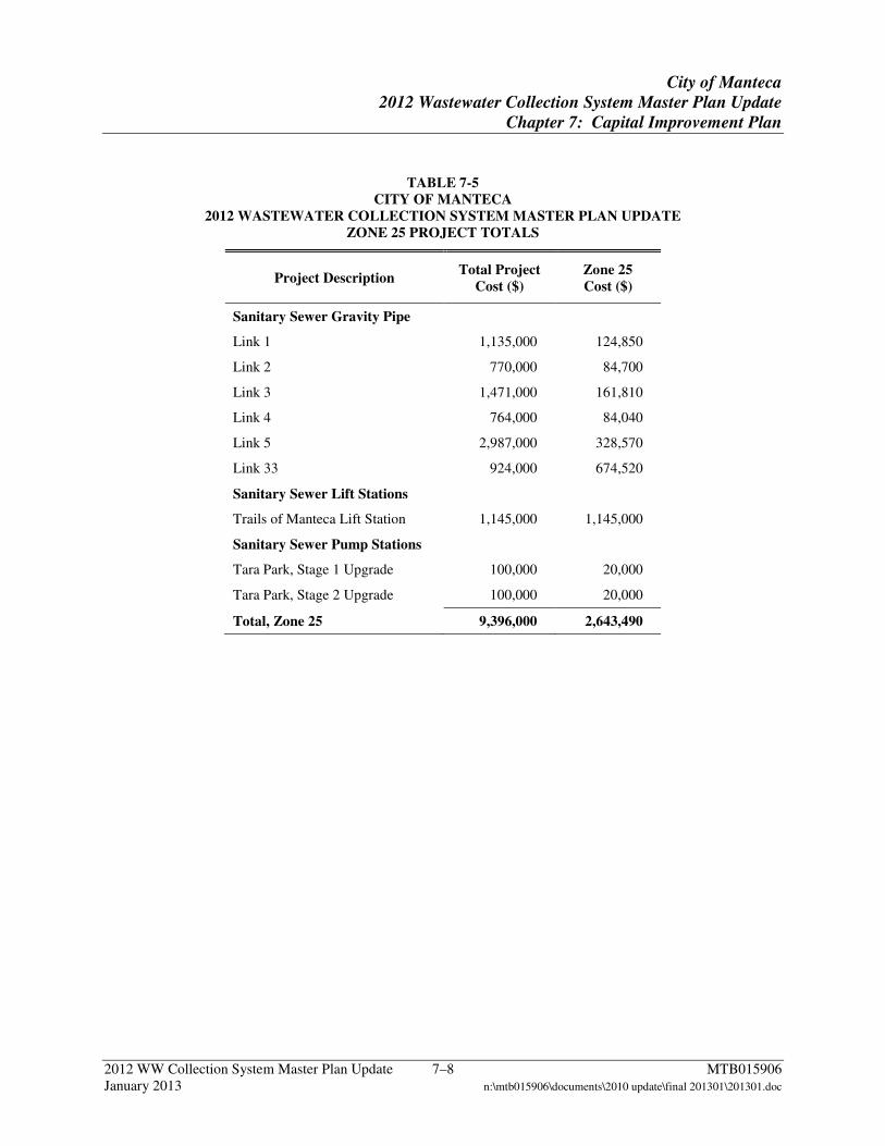
City of Manteca
2012 Wastewater Collection System Master Plan Update
Chapter 7: Capital Improvement Plan
2012 WW Collection System Master Plan Update 7–8 MTB015906 January 2013 n:\mtb015906\documents\2010 update\final 201301\201301.doc
TABLE 7-5 CITY OF MANTECA
2012 WASTEWATER COLLECTION SYSTEM MASTER PLAN UPDATE ZONE 25 PROJECT TOTALS
Project Description Total Project
Cost ($) Zone 25 Cost ($)
Sanitary Sewer Gravity Pipe
Link 1 1,135,000 124,850
Link 2 770,000 84,700
Link 3 1,471,000 161,810
Link 4 764,000 84,040
Link 5 2,987,000 328,570
Link 33 924,000 674,520
Sanitary Sewer Lift Stations
Trails of Manteca Lift Station 1,145,000 1,145,000
Sanitary Sewer Pump Stations
Tara Park, Stage 1 Upgrade 100,000 20,000
Tara Park, Stage 2 Upgrade 100,000 20,000
Total, Zone 25 9,396,000 2,643,490
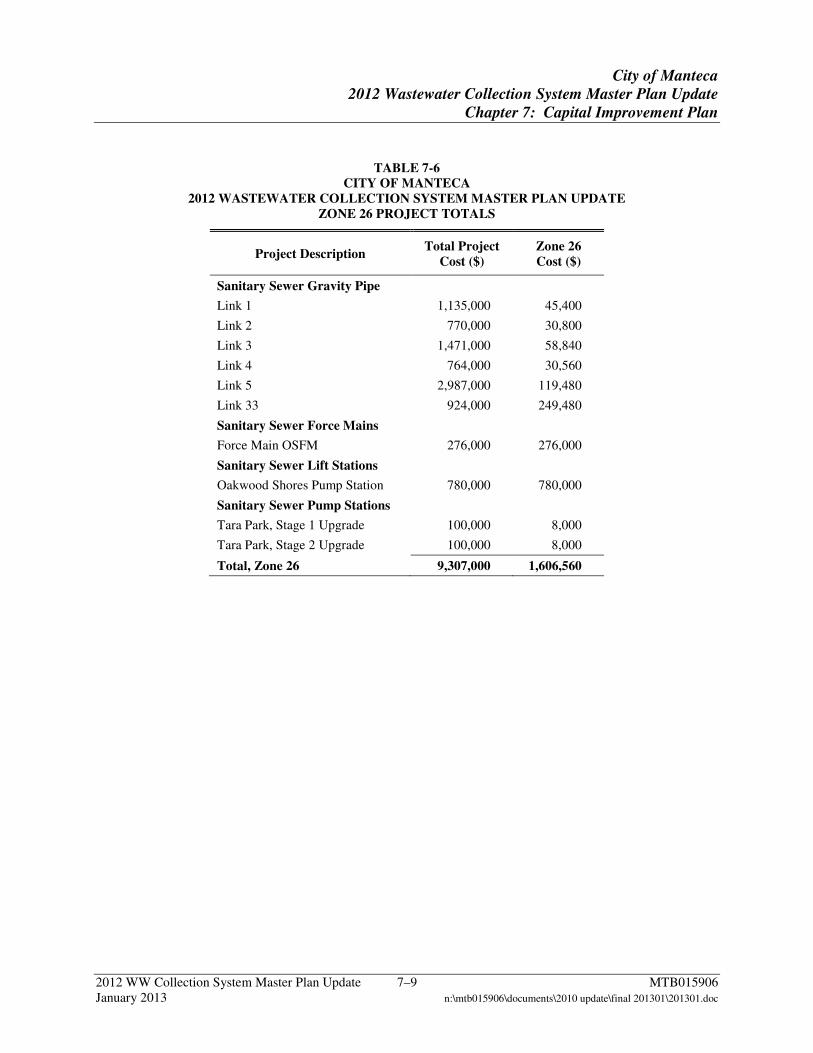
City of Manteca
2012 Wastewater Collection System Master Plan Update
Chapter 7: Capital Improvement Plan
2012 WW Collection System Master Plan Update 7–9 MTB015906 January 2013 n:\mtb015906\documents\2010 update\final 201301\201301.doc
TABLE 7-6 CITY OF MANTECA
2012 WASTEWATER COLLECTION SYSTEM MASTER PLAN UPDATE ZONE 26 PROJECT TOTALS
Project Description Total Project
Cost ($) Zone 26 Cost ($)
Sanitary Sewer Gravity Pipe
Link 1 1,135,000 45,400
Link 2 770,000 30,800
Link 3 1,471,000 58,840
Link 4 764,000 30,560
Link 5 2,987,000 119,480
Link 33 924,000 249,480
Sanitary Sewer Force Mains
Force Main OSFM 276,000 276,000
Sanitary Sewer Lift Stations
Oakwood Shores Pump Station 780,000 780,000
Sanitary Sewer Pump Stations
Tara Park, Stage 1 Upgrade 100,000 8,000
Tara Park, Stage 2 Upgrade 100,000 8,000
Total, Zone 26 9,307,000 1,606,560
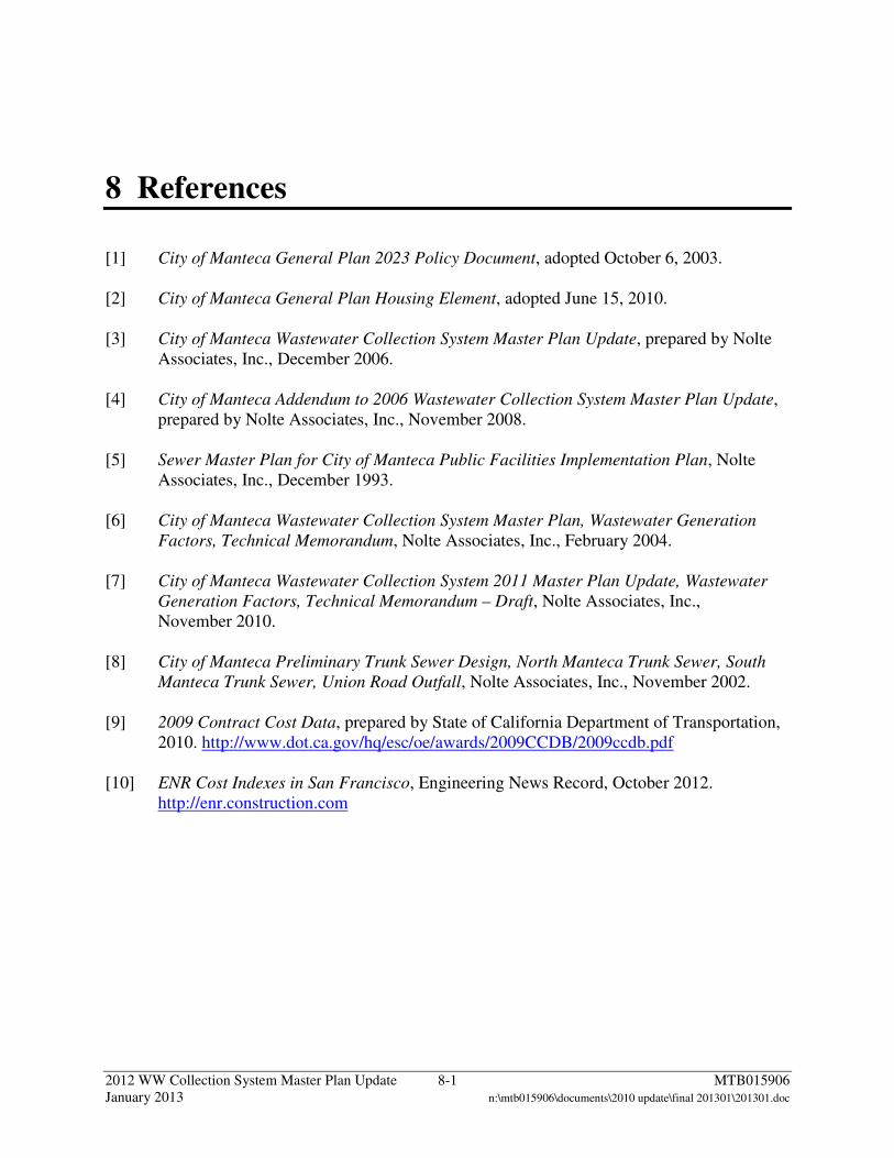
2012 WW Collection System Master Plan Update 8-1 MTB015906 January 2013 n:\mtb015906\documents\2010 update\final 201301\201301.doc
8 References
[1] City of Manteca General Plan 2023 Policy Document, adopted October 6, 2003. [2] City of Manteca General Plan Housing Element, adopted June 15, 2010. [3] City of Manteca Wastewater Collection System Master Plan Update, prepared by Nolte
Associates, Inc., December 2006. [4] City of Manteca Addendum to 2006 Wastewater Collection System Master Plan Update,
prepared by Nolte Associates, Inc., November 2008. [5] Sewer Master Plan for City of Manteca Public Facilities Implementation Plan, Nolte
Associates, Inc., December 1993. [6] City of Manteca Wastewater Collection System Master Plan, Wastewater Generation
Factors, Technical Memorandum, Nolte Associates, Inc., February 2004. [7] City of Manteca Wastewater Collection System 2011 Master Plan Update, Wastewater
Generation Factors, Technical Memorandum – Draft, Nolte Associates, Inc., November 2010.
[8] City of Manteca Preliminary Trunk Sewer Design, North Manteca Trunk Sewer, South
Manteca Trunk Sewer, Union Road Outfall, Nolte Associates, Inc., November 2002. [9] 2009 Contract Cost Data, prepared by State of California Department of Transportation,
2010. http://www.dot.ca.gov/hq/esc/oe/awards/2009CCDB/2009ccdb.pdf [10] ENR Cost Indexes in San Francisco, Engineering News Record, October 2012.
http://enr.construction.com