Embed Size (px)
DESCRIPTION
user guide.
Citation preview

Orcad® Component Information System
User’s Guide

Copyright © 1985-2000 Cadence Design Systems, Inc. All rights reserved.
Trademarks
Allegro, Ambit, BuildGates, Cadence, Cadence logo, Concept, Diva, Dracula, Gate Ensemble, NC Verilog, OpenBook online documentation library, Orcad, Orcad Capture, PSpice, SourceLink online customer support, SPECCTRA, Spectre, Vampire, Verifault-XL, Verilog, Verilog-XL, and Virtuoso are registered trademarks of Cadence Design Systems, Inc.
Affirma, Assura, Cierto, Envisia, Mercury Plus, Quickturn, Radium, Silicon Ensemble, and SPECCTRAQuest are trademarks of Cadence Design Systems, Inc.
Alanza is a service mark of Cadence Design Systems, Inc.
All other brand and product names mentioned herein are used for identification purposes only and are registered trademarks, trademarks, or service marks of their respective holders.
60-30-616
Second edition 31 May 2000
Cadence PCB Systems Division (PSD) officesPSD main office (Portland) (503) 671-9500PSD Irvine office (949) 788-6080PSD Japan office 81-45-682-5770PSD UK office 44-1256-381-400
PSD customer support (877) 237-4911
PSD web site www.orcad.comPSD customer support web page www.orcad.com/technical/technical.aspPSD customer support email form www.orcad.com/technical/email_support.asp
Cadence PCB Systems Division13221 SW 68th Parkway, Suite 200Portland, OR 97223

Contents
Before you begin ixWelcome . . . . . . . . . . . . . . . . . . . . . . . . . . . . . . . . . . . . . ixHow to use this guide . . . . . . . . . . . . . . . . . . . . . . . . . . . . . . x
Symbols and conventions . . . . . . . . . . . . . . . . . . . . . . . . . xRelated documentation . . . . . . . . . . . . . . . . . . . . . . . . . . . xi
What is the Orcad Component Information System? 1Chapter 1Overview . . . . . . . . . . . . . . . . . . . . . . . . . . . . . . . . . . . . . 1CIS product history . . . . . . . . . . . . . . . . . . . . . . . . . . . . . . . 3The internet component assistant (ICA) . . . . . . . . . . . . . . . . . . . . 4CIS in the PCB design process . . . . . . . . . . . . . . . . . . . . . . . . . 5The CIS work environment . . . . . . . . . . . . . . . . . . . . . . . . . . . 6
The CIS explorer window . . . . . . . . . . . . . . . . . . . . . . . . . 6The footprint window . . . . . . . . . . . . . . . . . . . . . . . . . 7The part window . . . . . . . . . . . . . . . . . . . . . . . . . . . . 8The visibility window . . . . . . . . . . . . . . . . . . . . . . . . . 8The explorer window . . . . . . . . . . . . . . . . . . . . . . . . . . 8The database parts window . . . . . . . . . . . . . . . . . . . . . . 9The ICA home page . . . . . . . . . . . . . . . . . . . . . . . . . . . 9
The part manager window . . . . . . . . . . . . . . . . . . . . . . . . . 10
Setting up Orcad CIS 11Chapter 2Overview . . . . . . . . . . . . . . . . . . . . . . . . . . . . . . . . . . . . . 11Creating a part database . . . . . . . . . . . . . . . . . . . . . . . . . . . . 12
Choosing a database format . . . . . . . . . . . . . . . . . . . . . . . . 12Determining part properties . . . . . . . . . . . . . . . . . . . . . . . . 14Setting the field format . . . . . . . . . . . . . . . . . . . . . . . . . . . 20Using more than one table . . . . . . . . . . . . . . . . . . . . . . . . . 20Creating a part database from an existing design . . . . . . . . . . . . 20Extracting ERP or MRP database part information . . . . . . . . . . . 22
Setting up the ODBC data source . . . . . . . . . . . . . . . . . . . . . . . 23

Contents
Creating a configuration file . . . . . . . . . . . . . . . . . . . . . . . . . 26Using the database configuration wizard . . . . . . . . . . . . . . . . 26Creating a configuration file manually . . . . . . . . . . . . . . . . . 32
Editing a configuration file . . . . . . . . . . . . . . . . . . . . . . . . . . 36Setting database table property options . . . . . . . . . . . . . . . . . 36Defining part reference associations . . . . . . . . . . . . . . . . . . . 43Setting administrative preferences . . . . . . . . . . . . . . . . . . . . 47Setting ICA supplier preferences . . . . . . . . . . . . . . . . . . . . . 50Saving the configuration file . . . . . . . . . . . . . . . . . . . . . . . 52
Setting up the ICA to access external part data . . . . . . . . . . . . . . . 53Creating Crystal Reports templates . . . . . . . . . . . . . . . . . . . . . 54
Working with database parts 57Chapter 3Overview . . . . . . . . . . . . . . . . . . . . . . . . . . . . . . . . . . . . 57Using the CIS interface . . . . . . . . . . . . . . . . . . . . . . . . . . . . . 58
Using the part manager window . . . . . . . . . . . . . . . . . . . . . 58Using the CIS explorer window . . . . . . . . . . . . . . . . . . . . . 60
Using docking windows . . . . . . . . . . . . . . . . . . . . . . . 61Using the database parts window . . . . . . . . . . . . . . . . . . 63
Placing a database part on a schematic page . . . . . . . . . . . . . . . . 66Using the explorer to locate a database part . . . . . . . . . . . . . . 66Using the query feature to locate database parts . . . . . . . . . . . . 67
Creating and executing a query . . . . . . . . . . . . . . . . . . . 67Placing a local database part on your schematic . . . . . . . . . . . . 69
Browsing part properties . . . . . . . . . . . . . . . . . . . . . . . . . . . 71Creating a new database part . . . . . . . . . . . . . . . . . . . . . . . . . 72
Deriving a new database part from the local part database . . . . . . 72Deriving a new database part from a placed part . . . . . . . . . . . 77Using the ICA to locate and create a new database part . . . . . . . . 81
Using the ICA to locate a part . . . . . . . . . . . . . . . . . . . . 81Using the ICA to create and place a part . . . . . . . . . . . . . . 82
Linking a placed part to a database part . . . . . . . . . . . . . . . . . . . 88Viewing a placed part’s database properties . . . . . . . . . . . . . . . . 92
To view a placed part’s database properties . . . . . . . . . . . . . . 92Copying part properties using the part manager . . . . . . . . . . . . . . 94
Finalizing and documenting designs 97Chapter 4Overview . . . . . . . . . . . . . . . . . . . . . . . . . . . . . . . . . . . . 97Viewing and updating part status . . . . . . . . . . . . . . . . . . . . . . 98
Opening the part manager . . . . . . . . . . . . . . . . . . . . . . . . 98Updating the part status for your design . . . . . . . . . . . . . . . . 99
iv

Contents
Saving the status report . . . . . . . . . . . . . . . . . . . . . . . . . . 102Creating design variants . . . . . . . . . . . . . . . . . . . . . . . . . . . 103Creating reports . . . . . . . . . . . . . . . . . . . . . . . . . . . . . . . . 104
Creating a standard CIS bill of materials . . . . . . . . . . . . . . . . 104Creating a report using a Crystal Reports template . . . . . . . . . . 109
Glossary 115
Index 125
v

Contents
vi

Tables
Table 1 Required part properties . . . . . . . . . . . . . . . . . . . . . . . . . . . . 15Table 2 Optional part properties . . . . . . . . . . . . . . . . . . . . . . . . . . . . 18

Tables May 11, 2000
viii

Before you begin
WelcomeOrcad family products offer a total solution for your core design tasks: schematic- and VHDL-based design entry; FPGA and CPLD design synthesis; digital, analog, and mixed-signal simulation; and printed circuit board layout. What's more, Orcad family products are a suite of applications built around an engineer's design flow—not just a collection of independently developed point tools. Orcad Component Information System (CIS) is just one element in our total solution design flow.
Orcad CIS is a part management system that is available as an option for use with Orcad Capture. Orcad CIS helps you manage part properties (including part information required at each step in the printed circuit board design process, from implementation through manufacturing) within your schematic designs.

Before you begin
x
Notation ExamplesC+r Press C+r
A, f, o From the File o)
Monospace font In the Part Na
UPPERCASE In Capture, op
Italics In Capture, sa
How to use this guideThis guide is designed so you can quickly find the information you need to use Orcad Component Information System (CIS). To help you learn and use Orcad CIS efficiently, this manual is separated into the following sections:
• What is the Orcad Component Information System? on page -1
• Setting up Orcad CIS on page -11
• Working with database parts on page -57
• Finalizing and documenting designs on page -97
Symbols and conventionsOur printed documentation uses a few special symbols and conventions.
DescriptionMeans to hold down the C key while pressing r.
menu, choose Open (A, f, Means that you have two options. You can use the mouse to choose the Open command from the File menu, or you can press each of the keys in parentheses in order: first A, then f, then o.
me text box, type PARAM. Text that you type is shown in monospace font. In the example, you type the characters P, A, R, A, and M.
en CLIPPERA.DSN. Path and filenames are shown in uppercase. In the example, you open the design file named CLIPPERA.DSN.
ve design_name.DSN. Information that you are to provide is shown in italics. In the example, you save the design with a name of your choice, but it must have an extension of .DSN.

How to use this guide
e for understanding and using the rcad CIS.
ation for understanding and using n Orcad CIS.
om the Help menu in Orcad CIS, by ton in a dialog box, or by pressing
nstructions for common tasks.
nu commands, dialog boxes, tools on l palettes, and the status bar.
d glossary terms.
tion.
formation.
nsitive help for a error message by the error message line in the session
interactive lessons. You can practice y going through the tutorial’s rcises that interact directly with rt the tutorial by choosing Learning
elp menu.
version of this guide, available when als from the Orcad family program nu).
f the commands, shortcuts, and tools , available when choosing Online ad family program group (on the
Related documentationIn addition to this guide, you can find technical product information in the online help, the online interactive tutorial, online books, and our technical web site, as well as in other books. The table below describes the types of technical documentation provided with Orcad Component Information System (CIS).
This documentation component . . . Provides this . . . This guide—
Orcad Component Information Sytem User’s Guide
A comprehensive guidfeatures available in O
Online help Comprehensive informthe features available i
You can access help frchoosing the Help but1. Topics include:
• Explanations and i
• Descriptions of methe toolbar and too
• Error messages an
• Reference informa
• Product support in
You can get context-seplacing your cursor inlog and pressing 1.
Online interactive tutorial A series of self-paced what you’ve learned bspecially designed exeOrcad CIS. You can staOrcad CIS from the H
Online Orcad Component Information Sytem User’s Guide
An online, searchable choosing Online Manugroup (on the Start me
Online Orcad CIS quick reference Concise descriptions oavailable in Orcad CISManuals from the OrcStart menu).
xi

Before you begin
xii
Orcad family customer support at www.orcad.com/technical/technical
This documentation component . . .
.asp An Internet-based support service available to customers with current support options. A few of the technical solutions within the customer support area are:
• The Knowledge Base, which is a searchable database containing thousands of articles on topics ranging from schematic design entry and VHDL-based PLD design to PCB layout methodologies. It also contains answers to frequently asked questions.
• The Knowledge Exchange, which enables you to share information and ideas with other users and with our technical experts in a real-time online forum. You can submit issues or questions for open discussion, search the Knowledge Exchange for information, or send email to another participant for one-on-one communication. A list of new postings will appear each time you visit the Knowledge Exchange, providing you with a quick update of what's been discussed since your last visit.
• The Technical Library, which contains online customer support information that you can search through by category or product. You can find product manuals, product literature, technical notes, articles, samples, books, and other technical information. Additionally, technical information can be obtained through SourceLink, which is an online customer support information service for users of Cadence software other than Capture, Component Information System (CIS), Express, Layout, or PSpice.
• The Support Connection, which allows you to choose to either view and update existing incidents, or create new incidents. The information is delivered directly to us via our internal database. This service is only available to customers with current maintenance or Extended Support Options (ESOs) in the United States and Canada.
• The Live Connection, which enables you to open access to your computer to a Customer Support person, who can then view your actions on your computer monitor as you demonstrate the problem you're having. Live Connection's two-way transmission can also let you view the actions on the Customer Support person's computer monitor, as he or she demonstrates a method or procedure to help you solve your problem. To participate in Live Connection, you need to contact a Customer Support person, in order to obtain a support number to grant you access to the Live Connection site, and to set up a time to “meet online” using Live Connection.
Provides this . . .

What is the Orcad Component Information System?
1
OverviewOrcad Component Information System (CIS) is a part management system that is available as an option for use with Orcad Capture. Orcad CIS helps you manage part properties (including part information required at each step in the printed circuit board design process, from implementation through manufacturing) within your schematic designs.
CIS provides access to local (preferred parts database) and remote part databases that contain all relevant information for the parts used in your designs. This information may include company part numbers, part descriptions, PCB layout footprints, technical parameters (such as speeds, tolerances, and ratings), and purchasing information.
With CIS, you can select a part from your preferred parts database or a remote database and place it directly in your schematic design. You can configure CIS to transfer any or all properties associated with that part to the schematic

Chapter 1 What is the Orcad Component Information System?
2
Orcad Layout
Libraries
Orcad Capture Libraries
Activeparts Database
Orcad Layout
Libraries
Orcad Capture Libraries
Supplier Pricing &
URLs to
LocalPreferredPartData
ExternalNewPartData
Preferred Parts Database
OD
Inter
Availa-bility
Mfr. SpecSheets
UNC, URLs,path to
browsablefiles
Orcad PSpice
Libraries
when you place the part. CIS maintains a link to the engineering database part so that you can retrieve other part properties at any time. Linking placed parts to your preferred parts database gives you access to complete part information during the schematic design process.
If you need a part for your design that is not yet in the parts database, you can create the part in the design and add the part to your part database immediately or at a later time. You can also link a non-database part you’ve created before to a database part at any time.
BC
Combined orseparatedatabases
Corporate Database (MRP/ERP/PDM)
Orcad Capture
Orcad CIS
Upload BOM to corporate system
Reports
Tab delimited ASCIIComma delimited ASCII
MS Access database format
net
ToFile
ToExchange
Folder
ToLotus Notes
Database
ToMS Mail
Seagate Crystal Reports
ICA

CIS product history
As part of an effort by Cadence to simplify packaging and licensing of the Design Desktop for Windows product line, the architecture of Express has changed with Release 9.0 to be a plug-in for Capture and Capture CIS.
CIS product historyOrcad CIS Release 9 is the latest version of the Orcad Enterprise CIS product offering. With the release of version 7.2 in April 1998, the Orcad Enterprise CIS family was the evolution and final merging of two popular Orcad CIS product lines—Enterprise Edition and EDA-Bridge.
Enterprise Edition evolved from the DDL product originally developed by an Orcad Industry Partner called Q-Point. Q-Point was acquired by Orcad in June 1997. Orcad Enterprise Edition was packaged and shipped under the product names Orcad Capture EE and Orcad Express EE. Version 7.1 was the last release of both these products lines. They were replaced by Orcad Enterprise CIS v7.2.
EDA-Bridge was acquired as part of The T.E.A.M. Corporation merger in April 1997. The product was sold as a stand-alone option and was available until the release of Orcad Capture v7.1 and Orcad Express v7.1. Subsequently, EDA-bridge was replaced by Orcad Enterprise CIS version 7.2.
Enterprise CIS v7.2 merged features of EDA-Bridge and Enterprise Edition, and can be used with both Orcad Capture v7.2 and Orcad Express v7.2.
With the Release 9.0, the name Orcad Enterprise CIS has been shortened to Orcad CIS. Orcad Capture is available with CIS as a product called Orcad Capture CIS. Orcad Capture CIS has additional options that can be purchased, including digital simulation and programmable logic functionality from the Orcad Express family and analog simulation from the Orcad PSpice family.
3
Chapter 1 What is the Orcad Component Information System?
4
The internet component assistant (ICA)The CIS internet component assistant (ICA) allows you to access new components over the Internet by providing a link to the part database at the activeparts web site. After finding an activepart, you can download the part’s component information to create temporary parts in your local preferred part database (PPD). You can immediately place the temporary part in your schematic designs. Temporary parts can then be elevated through your enterprise approval process, assigned corporate part numbers, and accepted as preferred parts within the database.

CIS in the PCB design process
CIS in the PCB design processTo use CIS in your printed circuit board design flow, you or your system administrator must perform the following setup tasks.
1 Create the preferred part database. This involves creating and entering the part data appropriate for the database.
2 Set up the Open Database Connectivity (ODBC) data source to point to the preferred part database.
3 Configure the part management system.
Each of these tasks is described in Chapter 2, Setting up Orcad CIS.
Once the setup is complete, you can use CIS in Capture to:
• Select parts with associated properties from the database and place them on schematic pages in your design.
• Check the status of placed parts and update placed part properties to reflect changes to the database.
• Generate bills of materials and other reports using both design and part database information.
Create thepart database
Set the ODBCdata source
ConfigureCIS
Placedatabase parts
Updatepart status
Createreports
Setup
Design
5

Chapter 1 What is the Orcad Component Information System?
6
For descriptions of how to use the CIS Windows interface, see Using the CIS interface on page 58.
The CIS work environmentThe CIS work environment includes two specialized windows that allow you to manage your local part database and explore sources of part data—the CIS explorer and the part manager. All the CIS functionality for these windows is integrated into Capture menus.
The CIS explorer window
The CIS explorer window allows you to search for and retrieve a variety of part information. The main window contains two tabbed windows—the local part database and the internet component assistant (ICA). The following table lists the windows available for each tabbed window.

The CIS work environment
The CIS explorer window displays in one of the following three modes, depending on which of the following CIS features you are using:
• Placing a database part
• Linking a database part to a placed part
• Viewing the database properties of a placed part
The mode is displayed as part of the window title bar.
The footprint window
Note The footprint window is only available if you chose to view Orcad Layout-generated footprint libraries during installation.
The footprint window displays the Layout-generated PCB footprint associated with the currently selected database part.
This window... Is available in this tabbed window...
Footprint Both
Part Both
Visibility Both
Explorer Local part database
Database parts Local part database
ICA home page Internet component assistant (ICA)
7

Chapter 1 What is the Orcad Component Information System?
8
You can also use the visibility window to display a compact summary of the part properties and their contents for the part you have selected in the database parts window. You can see more of the properties and contents in this view because the visibility window displays them in rows rather than columns.
The part windowThe part window displays the Capture library part associated with the currently selected database part. If the part has a convert (such as a DeMorgan equivalent), you can select it. For a multiple-part package, you can select the specific part in the package.
The visibility windowThe visibility window displays the default settings for which part properties are visible on your schematic page. You can use the visibility window to override these default settings. You can also set custom visibility settings for the current part selection.
The explorer windowThe explorer window allows you to search for parts using local data from your preferred part database. The window contains two tabbed sections—explore and query. In the explore tab, you can search for parts using a hierarchical tree organized by part type. The query tab allows you to further filter your selection based on parametric or field data.

The CIS work environment
When placing parts from the activeparts web site, CIS users have access to Orcad schematic representations of parts and PCB footprints over the Internet.
The database parts windowThe database parts window displays the results of your part browsing and database queries.
The ICA home pageThe ICA home page window provides access to the activeparts web site. This site is continuously updated to make sure you have the latest, most complete Internet part information.
When you select the activeparts web site from the ICA home page, CIS will replace the home page with the activeparts search page. Then, you can use the activeparts interface to search its part database. Because this is a live link to the database, you always have access to the most recent part information.
When you find a part that you want, you can place it, along with its component information, directly onto a schematic page. Component information associated with activeparts may include:
9

Chapter 1 What is the Orcad Component Information System?
10
• Part manufacturers and manufacturer part numbers
• Part values
• Orcad schematic parts and PCB footprints
• Supplier pricing and availability information
• URLs of manufacturer specification sheets
The part manager windowThe part manager window summarizes the status of all the parts in your design.
The part manager displays information for each part in your design including:
• Schematic page on which the part is placed
• Part reference designator
• Part value
• Part number
• Status of the placed part relative to the part database
• Database table that contains the placed part’s associated database part
• Capture source library from which the part was placed
• Capture source package to which the part belongs

Setting up Orcad CIS
2
OverviewThis chapter describes the four tasks necessary to set up Orcad Component Information System (CIS), including:
1 Create a part database. See Creating a part database on page 12.
2 Set up the Open Database Connectivity (ODBC) data source name. See Setting up the ODBC data source on page 23.
3 Create a configuration file to enable CIS to access and use the part database. See Creating a configuration file on page 26.
4 Edit your configuration file to customize how CIS interacts with your part database and your work environment. See Editing a configuration file on page 36.
Also included are procedures for setting the up the CIS work environment, including Setting up the ICA to access external part data on page 53 and Creating Crystal Reports templates on page 54.

Chapter 2 Setting up Orcad CIS
12
You can create a database from an existing Capture design. For more information, see Creating a part database from an existing design on page 2-20.
You can also extract information for your part database from an MRP database. For more information, see Extracting ERP or MRP database part information on page 2-22.
Note Cadence developed, wrote, and tested Orcad CIS in the Access 97 and SQL Server 6.5 environment. Access offers high performance queries with databases of several thousand parts. If your database outgrows Access, moving to SQL Server is a seamless process. Using the upsize wizard, Access can easily transfer the database to SQL Server and still serve as an interface for maintaining data.
Creating a part databaseThe part database is the entity that contains all the relevant information for the parts you use in your designs. You can think of a part database as one or more tables, with each row in a table representing a part and each column representing a part property.
Before you create your part database, you need to choose whether to use a database or spreadsheet application. Then, when you create your part database, you need to carefully setup its structure and organization, including:
• Part property assignments. See Determining part properties on page 2-14.
• Field formats for properties. See Setting the field format on page 2-20.
• Number of tables used in the database implementation. See Using more than one table on page 2-20.
Using ODBC, CIS interfaces directly with your ODBC compliant database or spreadsheet. This means you can use your preferred application to create and maintain your part database.
Choosing a database formatTo take full advantage of the speed and power of CIS, you may want to use a database application rather than a spreadsheet application. As a general rule, you should use a database application for databases with more than 1,000 parts. Database applications offer the following advantages over spreadsheets:
• Comprehensive data management features
• Better performance for part searching
• Form-based entry for entering part information
• Safeguard against duplicate part numbers
Creating a part database
Structured query language (SQL) is used in querying, updating, and managing relational databases.
The disadvantages of spreadsheets and delimited text files include:
Lack of structure. During data entry, spreadsheets allow you to configure every cell in a different format. This makes querying fields (columns) very difficult because CIS expects queried fields to be in a consistent format.
Lack of ANSI SQL compliance. Because true databases are ANSI SQL compliant, their drivers do very little work in relaying SQL commands to connected data sources. In contrast, with non-SQL compliant spreadsheets, the ODBC driver is responsible for translating the SQL commands into functions that the spreadsheet can understand. This results in a dramatic increase in the time your queries can be processed. Query time increases are even more dramatic with text files because the driver must search for and compile a matching list entirely on its own. An optimized, SQL-compliant database format is several times faster than a spreadsheet with more than 100 parts or a text file of over 20 parts.
Lack of replication support. If you have users in more than one location accessing your database, you have either a single, central database or a replicated database. Replication is a method of storing a single database in more than one location. True databases support scheduled synchronization: they maintain data integrity by checking separate database transaction logs and replicating modifications on multiple systems. If you are using a spreadsheet or text program, you must check manually because your format does not support replication.
13

Chapter 2 Setting up Orcad CIS
14
You may want to look at the sample part databases provided with CIS. Two samples are provided in the SAMPLES folder. The first part database, BENCH.MDB, is an Access 97 database. The second, BENCH.XLS, is an Excel spreadsheet. As you read this section, refer to these samples to get a better understanding of how to set up your part database.
Example: You can name the Part Number property My Company Part Number.
Example: you may call a property Tolerance in the database and Tol on the placed part.
Note Your database can also contain mechanical (non-electrical) parts. However, you must not allow users to add mechanical parts to the database whose schematic representations (symbols) have pins. If mechanical parts with pins are placed in a design, they will invalidate netlists generated from that design.
Determining part propertiesThe first step in creating a part database is to determine the properties to include for each part. Typical properties in a part database include part number, part description, tolerance, rating, speed, timing parameters, PCB footprint, manufacturer, and cost. CIS supports an unlimited number of properties, so you can include as much information in your part database as you want.
There are no restrictions on database table property names. Also, the names you use in the database can be different than the property names you assign to the placed parts. Database property types and placed-part property names are defined during database configuration. For more information, see Creating a configuration file on page 2-26.
Note Do not use the same property name more than once. For example, if you have two manufacturer columns in your database, call them Manufacturer 1 and Manufacturer 2.
When you transfer a property, that property is included in the schematic as an attribute of the placed part. Normally, you transfer properties that are required by CIS (such as Part Number and Schematic Part), used in the design process (such as Value, Tolerance, and Rating), or needed for use by other software products (such as PCB Footprint). Properties that aren’t transferred can still be included in a bill of materials report.
Parts in your database must include all of the properties in Table 1. Any of the optional properties in Table 2 may also be added. Recommendations on whether to transfer properties to your design are included in both tables. Properties recommended for transfer to the design are either likely to be required for netlisting or are generally needed on printouts of the design.

Creating a part database
Transfer to design?
with the CIS is required by the rt. CIS lets you same number in nique part number tries in your
Required
xplorer uses this hierarchy. Use this contents are \electrolytic, IC, The levels of the ) character (or any ou can define any
ence Associations tions on page 43.)ou use tly when entering
No
Table 1 Required part properties
Property Description
Part Number Required to identify the part in association Part_Number property type. This propertypart manager and the bill of materials repoenter more than one database part with thethe database. However, you should use a ufor each part and have no duplicate part endatabase.
Part Type Identifies the part type. The Part Database Eproperty to define the part database folder property to facilitate part searches. Typical resistor, resistor\fixed, capacitor, capacitorIC\Memory\SRAM, connector, and so on. hierarchy are defined using the backslash (\character you define in the configuration). Ynumber of levels in the hierarchy.This property is also used by the Part Referoption. (See Defining part reference associaThis property is case-sensitive. Make sure yuppercase-lowercase conventions consistenvalues for this property.
15

Chapter 2 Setting up Orcad CIS
16
Table 1 Required part prope
Property Description
Schematic Part (Symbol)
The part namDatabase Pathe part is stschematic paCapture. (Seinformation However, toidentically nbackslash (\DISCRETE\DISCRETE\OPAMP\CMIn addition, unconfigureC:\MYLIB\
Caution Dosupplied with Cayour installationsoftware versioninvalid. Instead,files or copying iYou can alsopart. Use theseparate eaccomma). ForDISCRETE\DISCRETE\
Tip The default setting administrthe character CISor vertical bar. Fon page 2-47
Then, when approve andacceptable nvalid schema
rties (continued)
Transfer to design?
e. This property is required to use the Place rt command. Only the part name is necessary if ored in the same directory as the custom rt libraries (.OLB files) that you configure in
e the Orcad Capture User’s Guide for more about configuring part libraries.) make sure that you don’t accidentally place an amed part, you should include the library name, a ), and then the part name. Examples include:CAPDIODE
P01you can use the explicit path so CIS can locate an d library. For example:DISCRETE\CAP
not directly reference the schematic part libraries that are pture CIS (resource libraries). Because the resource libraries in s of Capture CIS are often changed during upgrades to new s, the library names and paths in your database can be made create your own custom libraries by renaming the resource library ndividual parts from the resource libraries to your custom libraries. assign multiple schematic part names to a single same format as above for each name and
h one with the multi-value delimiter (by default, a example:CAPACITOR NON-POL, DISCRETE\CAP NP, SMALL CAP
value of the multi-value delimiter is a comma. However, when ative preferences during database configuration, you can change recognizes as the delimiter to a colon, semi-colon, question mark, or information, see Setting administrative preferences .
you update your design’s part status, CIS can make current a schematic part which has several ames. Also, if a database part has several different tic parts, you will be able to choose
Automatic

Creating a part database
Transfer to design?
from the database c parts for the -down list under
llowing set of
provided.E.INI that has a
ured libraries. your Capture
tory in your
nd 74ALS374. CIS ntifiers (such as K
version to part definitions, onsistent (for 2.7K, 2,700, 2.70K, (such as F for lation. include:
Required
Table 1 Required part properties (continued)
Property Description
any one of them when you are placing partsparts window. All the configured schematidatabase part will be available from a dropthe Schematic Part property name.CIS locates the Capture library using the foprioritized rules:1 Search the library at the explicit path, if 2 Search the first library listed in CAPTUR
matching library filename. 3 Search all directories that contain config4 If no libraries are included specifically in
design, CIS searches the LIBRARY direcCapture installation directory.
Value The part value. Examples are 1.2K, 10.0uF, asupports the use of common magnitude ideand uF).The database query uses intelligent unit coninterpret common magnitude identifiers insince entries in part databases are often incexample, the Value for a 2.7K resistor can be2.700K, 2700.0, 0.0027M, etc.). Unit suffixes farads or H for henries) are ignored in transThe magnitude identifiers supported in CIS
Identifier Represents Magnitude
f femto 10-15
p pico 10-12
n nano 10-9
u micro 10-6
m milli 10-3
K kilo 103
M mega 106
G giga 109
T tera 1012
17

Chapter 2 Setting up Orcad CIS
18
Table 2 Optional part properties
Property Description
Availability Number of the
Data Sheet The name of thBrowsable cheautomatically lproperty.Examples incluhttp://www.cRES1K1/4W.DYou can browsapplication assregistry. (ExtenWindows Explfor more informcause CIS to lacause it to laun
Note CIS uses the Pto find the specified
Description A brief descrip
Distributor Name of part d
Distributor Part Number
Part number u
Manufacturer Name of part m
Manufacturer Part Number
Part number u
Transfer to design?
parts in stock at your company. Not recommended
e detailed datasheet for this part. Select the ck box in the configuration for CIS to aunch the appropriate browser for this
de: 74ALS374.PDF, hipmaker.com/specs/74ALS374, and OC.e any format you want. CIS uses the igned to that file extension in your Windows sion assignments are managed in the orer. See your MS Windows documentation
ation.) For example, a .DOC entry might unch Microsoft Word, and a URL entry might ch your default web browser.
ATH environment variable and the current working directory document.
Not recommended
tion of the part. Not recommended
istributor. Not recommended
sed to order from the distributor. Not recommended
anufacturer. Not recommended
sed to order from the manufacturer. Not recommended

Creating a part database
Transfer to design?
t library)
use directory paths for a PCB footprint name, nt window. single part by your part e with the
mma. However, when uration, you can
colon, semi-colon, ting
status, CIS can which has a database part ou will be able to g parts from the
PCB footprints a drop-down list
Recommended
ting parts to orts to get a cost
Not recommended
ple, maximum Optional
. Optional
Optional
Table 2 Optional part properties (continued)
Property Description
PCB Footprint The PCB footprint name (from the footprinassigned to a part.
Note Unlike Schematic Part property names, you cannot libraries with PCB footprint names. If you use a path withthe footprint will not display in the CIS explorer’s footpriYou can assign multiple PCB footprints to aentering them in the part’s footprint field indatabase and separating each footprint nammulti-value delimiter.
Tip The default value of the multi-value delimiter is a cosetting administrative preferences during database configchange the character CIS recognizes as the delimiter to aquestion mark, or vertical bar. For information, see Setadministrative preferences on page 2-47.Then, when you update your design’s part approve and make current a schematic partseveral acceptable footprint names. Also, ifhas several different valid PCB footprints, ychoose any one of them when you are placindatabase parts window. All the configuredfor the database part will be available from under the PCB Footprint property name.
Price Part price. Use this information when selecdesign for cost. Include this property in reproll-up of your design.
Rating The maximum rating for the part (for examvoltage or power dissipation).
Tolerance The percent tolerance specified for the part
Voltage The voltage requirement of the part.
19
Chapter 2 Setting up Orcad CIS
20
You can obtain a wizard from the Orcad web site that automates this process. The wizard also automatically derives schematic part and source library information for the placed parts in your Capture schematic. If you use the manual procedure detailed here, you will have to manually reference your placed parts to your libraries.
To download the CIS wizard, visit the Orcad web site at www.orcad.com.
Setting the field formatCIS can work with database text and number format fields (known as the cell format in spreadsheets). As a general rule, set each database field (that is, each table column) to text format. CIS converts other database field formats, such as float, to text format when properties are transferred to placed parts.
Note Use only ANSI SQL-92 compliant data types for your field formats. If you use non-compliant data types, CIS may misinterpret property values.
Using more than one tableCIS can reference more than one table or worksheet in your part database. For example, you can group your parts into several tables according to type. That is, you can place resistors in one table, ICs in another, capacitors in another, and the remaining parts in a fourth table. When you’re viewing database parts with CIS, each table has a unique view. You can arrange the column settings for each table independently, allowing you to view different properties for each.
Creating a part database from an existing designYou can also create a part database by extracting part properties from an existing Capture design using the CIS Bill of Materials command.
Tip If your designs are created in another schematic capture program that creates bills of materials for part properties, you can still create a part database from an existing design. Follow the instructions supplied with the program to create the appropriate bill of materials file from your design. Then, use the bill of materials file to create a part database based on that design.

Creating a part database
Note Your database should have a unique part number for each part and no duplicate part entries. Although some database applications will not import more than one occurrence of a keyed property, you may need to eliminate duplicate part entries manually. To do this, sort the database by part number, then delete duplicate entries using your database or spreadsheet program.
Consider the example in the following illustration. The Standard Bill of Materials dialog box lists a typical set of properties to extract from the design.
In the Output Format list, CIS lists a number of properties that will be extracted to the bill of materials. You can add to this list by selecting properties from the Select Properties list and clicking the Add button. You can remove properties from the Output Format list by selecting them and clicking the Remove button.
When you click OK in the Standard Bill of Materials dialog box, CIS creates a file with the property information for all the parts in the design. You can directly import this file into your database.
21

Chapter 2 Setting up Orcad CIS
22
To take advantage of updated information in an ERP or MRP database, you need to set up a means of extracting data on a regular basis and using it to update your part database. That way, your part database will include information that changes frequently, such as quantity in stock and lead time.
Extracting ERP or MRP database part informationYou can also extract information from an existing enterprise or manufacturing resource planning (ERP or MRP) database, to create a part database. Save the ERP or MRP database as an ASCII file, then use that file as your part database file or as a source for a true part database file (for example, an MS Access format file).
Note If your ERP database is ODBC compliant, you may not need to extract part information. Instead, you should be able to directly connect your preferred part database (PPD) to the ERP database–you should not have to set up and run regular batch routines to update the data in your PPD. For information about connecting these databases, see the product documentation for both database applications.
You may need to enhance the information in an ERP or MRP database, since it generally will not include everything required for schematic design. However, an ERP or MRP database usually contains a complete list of your company’s parts, part numbers, part descriptions, costs, quantities in stock, lead times, manufacturers, and alternate manufacturers.
Often, the data in an ERP or MRP database exists in a format that does not lend itself to ease of use. For example, the part value may be merged with the description, such as:
RES 1K 5% 1/4W
This makes searching for parts more difficult. If you can, split this information out in the ERP or MRP database into separate database properties, such as Part Type, Value, Tolerance, and Rating.
You can also contact the Cadence Methodology Services group for assistance in converting your data into a more convenient format.

Setting up the ODBC data source
You must define the data source on each user’s system. When you do so, use the same data source name. This allows users to share the same configuration file.
Note If your workgroup is sharing a configuration file, make sure to write-protect the file.
Note If you are using the Windows 2000 operating system, double-click the Administrative Tools folder to access the ODBC icon.
Setting up the ODBC data sourceBefore you can set the CIS configuration, you must define the open database connectivity (ODBC) data source for your database. CIS interfaces to your part database using a defined ODBC data source name. A data source consists of a database filename and an associated ODBC driver with which to access it. If you are setting up a client-server database, the data source also references the database server. You define the data source name, assign the database file name, and specify the ODBC driver using the 32-bit ODBC Windows control panel.
To set the data source for the local database
1 From the Windows Settings menu, choose Control Panel.
2 Double-click on the ODBC icon. Depending on your system configuration, Windows displays the ODBC Data Source Administrator or a Data Sources dialog box.
Note If you do not see an icon for 32-bit ODBC, run the Capture CIS installation program to install ODBC.
23

Chapter 2 Setting up Orcad CIS
24
If the driver for your application is not present, you must install it. Check the CIS installation disk or contact the database or spreadsheet program supplier.
If you are using Windows NT, you should click the System DSN tab to create new data sources. If you do not use the System DSN tab, users with different logins will not be able to use the ODBC source.
3 Click the ODBC Drivers tab and make sure the driver appropriate to your database or spreadsheet is installed on your system.
4 Click the User DSN tab then choose the Add button. Windows displays the Create New Data Source dialog box.

Setting up the ODBC data source
See Setting administrative preferences on page 47 for more information on temporary parts.
5 Choose the appropriate driver for your program (Microsoft Access, in this example), then click the Finish button.
6 Assign a name for the data source. If desired, enter a description for the data source name.
Note Step 7 may be different depending on the type of program you used to create your database.
7 Under Database, click the Select button, and locate the database.
8 Click the Options button, and clear the Read Only check box so users can create new parts and add them to the database using CIS.
9 Click OK to set the data source.
25

Chapter 2 Setting up Orcad CIS
26
Keep the configuration (.DBC) file in a read-only directory that is accessible to all CIS users. You should make the directory read-only to prevent users from inadvertently changing the configuration.
You must set up a new ODBC data source before you can create a new configuration file. If you haven’t set up a new ODBC data source for your database, see Setting up the ODBC data source on page 2-23.
Creating a configuration fileCIS requires a configuration (.DBC) file to make use of your part database. The configuration file:
• Identifies the ODBC data source to use as the part database and specifies the tables to use within that database.
• Identifies the part properties that are transferred to your design when you place or link a database part.
• Sets the visibility for each of the transferred properties.
• Contains the part type associations.
Note If you use a CIS v7.2 configuration file with CIS Release 9, the file will be updated to support the new features of this release. After CIS updates the file, though, you cannot use it again with CIS v7.2. If you are using a configuration file from before CIS v7.2, you must recreate the file because the configuration file format was changed for CIS v7.2.
When creating a configuration file, you should use the database configuration wizard. Completing the wizard guarantees that your part database can be used with most CIS features. For information about using the wizard, see Using the database configuration wizard below.
However, if you need to use the manual method of creating a configuration file, you can reference Creating a configuration file manually on page 2-32.
Using the database configuration wizardYou can use the database configuration wizard each time you want to create a new database configuration file. The wizard is designed to make sure that you set at least the minimum table and property configuration that is required for CIS to work with your part database.

Creating a configuration file
However, the wizard does not include all the options available to you, including options to optimize the performance of CIS and customize your CIS work environment. For this reason, when you have finished running the wizard, you should read through the last two parts of this section, Setting other part database options on page 2-30 and Setting other configuration options on page 2-32.
Starting the database configuration wizard
You can start the database configuration wizard anytime you want to create a new database configuration file.
To start the database configuration wizard
1 Open a new or existing schematic design in Capture.
2 From the project manager’s Options menu, choose CIS Configuration. CIS displays the CIS Configuration File dialog box.
27

Chapter 2 Setting up Orcad CIS
28
3 Click the New button. CIS displays the Database Configuration Wizard.
4 Follow the instructions in the wizard to create your database configuration file. If you need more information about any of the wizard steps, click the Help button.

Creating a configuration file
5 Click the Finish button. CIS displays the Configure Database dialog box and the wizard is complete.
6 If you want to set other part database options, complete the next section, Setting other part database options.
7 If you do not want to set any other part database or configuration options, click OK to save the new database configuration file.
29

Chapter 2 Setting up Orcad CIS
30
Setting other part database options
You can set other part database options that are not available in the database configuration wizard, including:
• The part properties to be checked against the part database when you update the part status of a design. CIS sets which properties are checked by default but, if you have a special situation that requires different properties to be checked, you are allowed to change the defaults.
• The part tables that CIS will search when you are linking placed parts to database parts. This is useful when your database consists of several part tables that are organized by device type (for example, capacitors in one table, resistors in another, and so on). When you are linking database parts to placed parts, CIS uses allowed part reference prefixes to limit your search to the appropriate tables. The result is that your search takes less time.
The procedure below describes how to set these options.

Creating a configuration file
For example, if a table contains only capacitors, you could enter C as the allowed part reference prefix. Then, when you choose the Link Database Part command, CIS searches that table only when the placed part you are linking has a part reference prefix of C.
Note Leave this box blank if you want the table to be searched regardless of the part reference prefix.
To set other part database options
1 In the Configure Database dialog box, select the Part Database tab.
2 In the Tables list, select the database table for which you want to set options.
3 In Update Property column of the Configuration area, select the check box for each property that you want to be checked when you update the part status of your designs.
4 In the Allowed Part Reference Prefixes text box, type the part reference prefixes you want CIS to use to limit searches on the database table.
5 Repeat this procedure on each database table for which you want to set these options.
6 If you do not want to set any other part database or configuration options, click OK to save the new database configuration file.
31

Chapter 2 Setting up Orcad CIS
32
You must set up a new ODBC data source before you can create a new configuration file. If you haven’t set up a new ODBC data source for your database, see Setting up the ODBC data source on page 2-23.
7 If you want to set other configuration options, go to the next section, Setting other configuration options.
Setting other configuration options
You can set other options in the database configuration that customize how CIS interacts with your part database and how you use CIS in your work environment. These options include:
• Defining part reference associations to improve the speed and accuracy of the search for database parts to link to placed parts. For more information, see Defining part reference associations on page 2-43.
• Setting administrative preferences to customize some CIS features for your work environment. For more information, see Setting administrative preferences on page 2-47.
• Setting ICA supplier preferences to specify which component suppliers you want CIS to search for part pricing and availability. For more information, see Setting ICA supplier preferences on page 2-50.
Creating a configuration file manuallyYou can create a configuration file using the manual procedure below. When you are finished creating the file, you will need to set the options for the file so that CIS knows how to handle your database table part properties. For information about setting or editing configuration file options, see Editing a configuration file on page 2-36.

Creating a configuration file
To create a configuration file manually
1 Open a new or existing schematic design in Capture.
2 From the project manager’s Options menu, choose CIS Configuration. CIS displays the CIS Configuration File dialog box.
33

Chapter 2 Setting up Orcad CIS
34
3 Click the Setup button. CIS displays the Configure Database dialog box.
4 Click the Browse button. CIS displays the Browse Data Source dialog box.

Creating a configuration file
5 Select the data source name you defined for your ODBC driver, then click OK. The Configure Database dialog box lists the tables found in your data source.
6 Set the configuration file options as desired. For information about setting configuration file options, see Editing a configuration file on page 2-36.
35

Chapter 2 Setting up Orcad CIS
36
For information about creating a configuration file, see Creating a configuration file on page 2-26.
Editing a configuration fileAs you set up and work with CIS, you may discover performance issues or elements of the CIS work environment that are not optimal for your work group. This section describes in detail all the configuration options that are available and how to set them optimally for your situation. The four categories for these options include:
• Setting database table property options on page 2-36.
• Defining part reference associations on page 2-43.
• Setting administrative preferences on page 2-47.
• Setting ICA supplier preferences on page 2-50.
Setting database table property optionsOnce you have created a database configuration file, you need to set the options for the file so that CIS knows how to handle your database table part properties.
To set database table property options
1 Open a new or existing schematic design in Capture.

Editing a configuration file
2 From the project manager’s Options menu, choose CIS Configuration. CIS displays the CIS Configuration File dialog box.
3 Choose a configuration file to edit by doing one of the following:
• To edit the current configuration file, click the Setup button.
• To edit a different configuration file, click the Browse button, locate and open the file, then click the Setup button.
37

Chapter 2 Setting up Orcad CIS
38
CIS displays the Configure Database dialog box.
4 If you want to choose a new data source for your configuration, do the following:
Caution If you choose a new data source name, all of the settings made with the previously selected data source will be lost for the current configuration (.DBC) file. If you want to keep the settings in the current .DBC file, use the database configuration wizard to create a new configuration file instead. For more information, see Using the database configuration wizard on page 2-26.

Editing a configuration file
a Click the Browse button. CIS displays the Browse Data Source dialog box.
b Select the data source name you defined for your ODBC driver, then click OK. The Configure Database dialog box lists the tables found in your data source.
39

Chapter 2 Setting up Orcad CIS
40
folder view in CIS explorer
5 If you want to configure table properties, select the table that contains the properties. In the graphic below, the Capacitor table is selected.
When you select a table, the Configuration area lists the properties it contains. Each row represents a part property, and each property has the following characteristics:
Table Property Name. This is the name of the property as it is defined in the part database.
Table Property Type. This is the data type for the property. Most properties are type Text, but there may be other data types.
Property Type. The Property Type determines how CIS interprets the property. Your database must include a property of type Part_Number in every table.
Set the following property types:
• The Part_Type type for the database property that defines the part type. (This defines the field for folder view in CIS explorer.)
• The Schematic_Part type for the database property that contains the schematic part (symbol) name.
• The PCB_Footprint type for the database property that contains your Layout footprint name. If you want the database to include footprints not generated by Orcad Layout, set the property type to Normal. This prevents the footprint viewer from trying to interpret them.
Editing a configuration file
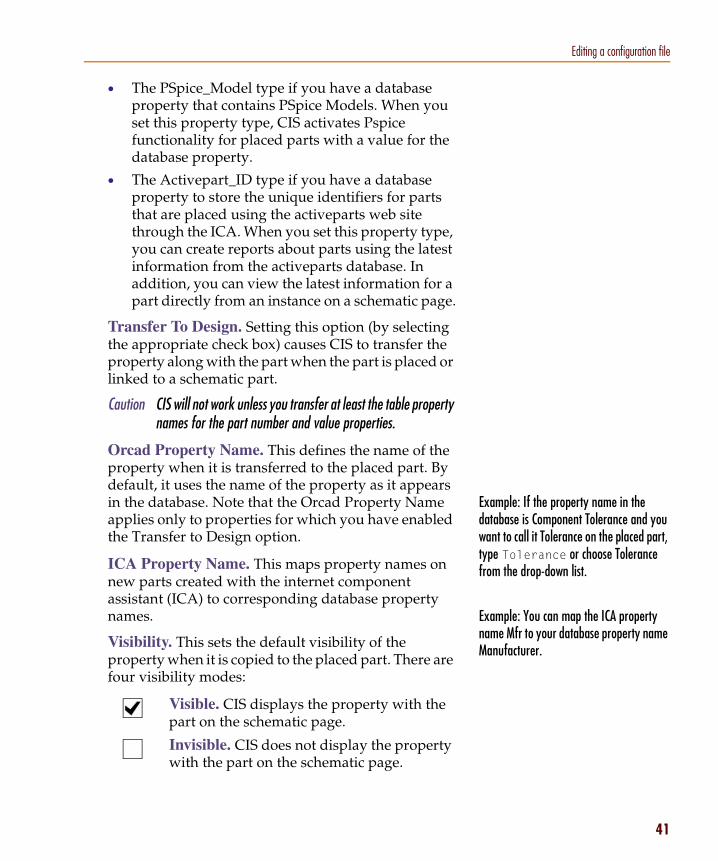
Example: If the property name in the database is Component Tolerance and you want to call it Tolerance on the placed part, type Tolerance or choose Tolerance from the drop-down list.
Example: You can map the ICA property name Mfr to your database property name Manufacturer.
• The PSpice_Model type if you have a database property that contains PSpice Models. When you set this property type, CIS activates Pspice functionality for placed parts with a value for the database property.
• The Activepart_ID type if you have a database property to store the unique identifiers for parts that are placed using the activeparts web site through the ICA. When you set this property type, you can create reports about parts using the latest information from the activeparts database. In addition, you can view the latest information for a part directly from an instance on a schematic page.
Transfer To Design. Setting this option (by selecting the appropriate check box) causes CIS to transfer the property along with the part when the part is placed or linked to a schematic part.
Caution CIS will not work unless you transfer at least the table property names for the part number and value properties.
Orcad Property Name. This defines the name of the property when it is transferred to the placed part. By default, it uses the name of the property as it appears in the database. Note that the Orcad Property Name applies only to properties for which you have enabled the Transfer to Design option.
ICA Property Name. This maps property names on new parts created with the internet component assistant (ICA) to corresponding database property names.
Visibility. This sets the default visibility of the property when it is copied to the placed part. There are four visibility modes:
Visible. CIS displays the property with the part on the schematic page.
Invisible. CIS does not display the property with the part on the schematic page.
41
Chapter 2 Setting up Orcad CIS
42
For more information about placing and linking database parts, see Placing a database part on a schematic page on page 3-66 and Linking a placed part to a database part on page 3-88.
For more information about linking database parts, see Linking a placed part to a database part on page 3-88.
No Change. CIS does not modify the property visibility. If the property does not exist, it is set to invisible. You can override the default visibility for specific parts when you place or link database parts. Cells that you cannot change are shown with a light gray background in this column.
Non-adjustable. CIS does not allow this property to be set as visible on schematic pages.
Key. This sets the property as a key during the initial part search. The key is used when you are linking a database part to a previously placed part. Normally, you set only the Value property as a key so that, when you want to link a part, CIS searches the part database for parts with a specific value. If you don’t have a Value property in your database, do not set a key.
Browsable. This sets browse capability for the property. It allows you to put references to datasheets, drawings, and documents in your part database. For example, you can reference Adobe Acrobat (.PDF) files, Microsoft Word (.DOC) files, and even worldwide web addresses (URLs). You can then view these items online in CIS when browsing the part database. They are also browsable when you are viewing standard CIS bills of materials.
You can browse any format you want. CIS uses the application assigned to that file extension in your Windows registry. (Extension assignments are managed in the Windows Explorer.) For example, a .DOC entry might cause CIS to launch Microsoft Word, and a URL entry might cause it to launch your default web browser.
Note CIS uses the PATH environment variable and the current working directory to find the specified document.
Update Part Property. Select this if you want the value of this property for placed parts to be checked against the database part’s value when you update the part status of your design.

Editing a configuration file
For more information about linking database parts, see Linking a placed part to a database part on page 3-88.
You must create a configuration file for your database before you can define its part reference associations. If you have not already created a configuration file for your database, see Setting database table property options on page 2-36.
6 (Optional) Type the part reference prefixes in the Allowed Part Reference Prefixes text box.
This is useful when your database consists of several part tables that are organized by device type (for example, capacitors in one table, resistors in another, and so on). When you are linking database parts to placed parts, CIS uses allowed part reference prefixes to limit your search to the appropriate tables. The result is that your search takes less time.
For example, if a table contains only capacitors, you could enter C as the allowed part reference prefix. Then, when you choose the Link Database Part command, CIS searches that table only when the placed part you are linking has a part reference prefix of C.
7 Repeat steps 5 and 6 for each table in the database.
8 When you are finished configuring table properties, click OK or choose another tab to continue configuring your database.
Defining part reference associationsPart reference associations are used to improve the speed and accuracy of the search for database parts to link to placed parts. You create associations between a particular part type and the prefixes in the part database for that part type. For example, you can create a part reference association for resistors such that all resistors in the part database use the R prefix.
Note Defining part reference associations only improves part search speeds for true databases (for example, Microsoft Access)—there is no speed improvement from setting up associations if you are using a spreadsheet or a text file for your database.
Note Leave this box blank if you want the table to be searched regardless of the part reference prefix.
43

Chapter 2 Setting up Orcad CIS
44
Example: If you select an inductor, L1, on the schematic page with a value of 100uH, then choose the Link Database Part command, CIS displays all parts in the database having a value of 100 x 10-6. This may include capacitors, inductors, or other parts with a similar value.
By defining a reference association between inductors and the L prefix, you can limit the parts that CIS displays to inductors only.
Example: An association between the part reference prefix C and the part type Capacitor applies to part types of Capacitor, Capacitor\Electrolytic, and Capacitor\Ceramic\Fixed. Note that a part reference prefix associated with the part type Capacitor\Ceramic does not apply to part types of Capacitor or Capacitor\Electrolytic.
Once you’ve defined part reference associations for your database, when you choose the Link Database Part command, CIS displays database parts of the appropriate type. Without defined part reference associations, CIS displays all parts in the database that match the keyed property value, regardless of the part type. By defining an appropriate reference association, you can limit the number of parts that CIS displays.
Note Defining part reference associations is optional. You can define associations later if you need to improve the search performance during database part linking.
When you define part reference associations for your part database, keep the following points in mind:
• Part reference associations apply to all database tables.
• The Part Type Property Contents value in the dialog box is case-sensitive.
• You can associate one prefix with several different part types.
• An association applies to its level in the part type hierarchy and all lower levels.
• A part reference prefix without a defined part type association can be matched to any part type in the database.
• If a particular part in the database does not have its Part Type property contents defined, that part will be matched only to part reference prefixes with no defined part type associations.

Editing a configuration file
You can add icons for custom part references that will automatically display in the Part Reference column of the part manager window. Add your custom icons to the standard icons used for the Part Reference column located in the directory:
ORCAD\CAPTURE\VENDOR
Each icon’s filename corresponds to a part reference prefix (for example, the icon for the part reference prefix R is stored in R.BMP).
Caution You can use a bitmap editor (such as Microsoft Paint) to modify the bitmaps, but be careful not to change the image size.
To define part reference associations
1 In your local preferred parts database, make sure that the Part Type property field is indexed.
2 If you are not already in the Configure Database dialog box, do the following:
a Open a new or existing schematic design in Capture.
b From the project manager’s Options menu, choose CIS Configuration. CIS displays the CIS Configuration File dialog box.
c If necessary, click Browse to locate the database configuration file you want to setup.
d Click Setup. CIS displays the Configure Database dialog box.
45

Chapter 2 Setting up Orcad CIS
46
3 In the Configure Database dialog box, choose the Part Reference Associations tab.
4 Enter a part type in the Part Type Property Contents column and a corresponding part reference prefix (or set of prefixes) for that part type in the Applicable Part Reference Prefixes column. Separate prefix entries with commas.
5 Click OK or choose another tab to continue configuring your database.
Note Part prefixes need not be unique to a particular part type. That is, you can make an association between one prefix and several different part types.
Editing a configuration file
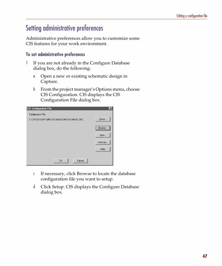
Setting administrative preferencesAdministrative preferences allow you to customize some CIS features for your work environment.
To set administrative preferences
1 If you are not already in the Configure Database dialog box, do the following:
a Open a new or existing schematic design in Capture.
b From the project manager’s Options menu, choose CIS Configuration. CIS displays the CIS Configuration File dialog box.
c If necessary, click Browse to locate the database configuration file you want to setup.
d Click Setup. CIS displays the Configure Database dialog box.
47

Chapter 2 Setting up Orcad CIS
48
If you want a database part to work with two or more different layout footprints, you can enter multiple PCB footprint names in your part database. For more information, see the PCB Footprint property entry in Table 2 on page 19.
Example: The database could have part types Capacitor\Electrolytic and Capacitor\Ceramic.
Example: Speed Grade does not apply to resistors.
2 In the Configure Database dialog box, choose the Administrative Preferences tab.
3 Select the Allow Duplicate Part Numbers check box to allow the same part number to appear more than once in the database.
4 In the Part Type Delimiter text box, type the character that indicates a hierarchical level within a path in the database. Normally, the delimiter is a backslash (\) character.
5 Select the Transfer Blank Properties check box to create a property on the placed part even if the database part property does not have a specific value. This is useful if all your database parts are in a single table since, in that case, you will have properties in the table which are not relevant to certain types of parts.
6 If you want to use a character other than a comma to separate multiple field values in your database,

Editing a configuration file
To promote a temporary part to an approved part, do the following:
1 Using your database application, enter the approved part number in the TMPPRTS table next to the corresponding temporary part number.
2 Replace the temporary part number with the approved part number in the part table.
CIS automatically monitors the TMPPRTS table and notifies you if a temporary part in the design has been promoted to an approved part.
If your workgroup is using a shared, read-only database configuration file, all users must use the same temporary part prefix.
The Part Not Present Display Value does not display in Capture’s schematic page editor. This property also cannot be repositioned or edited in the schematic page editor. For this reason, you will have to print preview or print a schematic page to make sure that the value you assign the property does not overlap another part or property display.
Because a long value is more likely to overlap a display, you should use a fairly short text equivalent for the default Not Present value.
choose another character from the Delimiters for Multi-Values list. For information about entering multiple values for part properties in your part database, see the Schematic Part (Symbol) property description in the Required part properties table on page 16.
7 Select the Assign Temporary Part Numbers Automatically check box so that CIS will create and track temporary part numbers for you. That way when you create a new part, CIS automatically assigns a temporary part number to that part and enters the part number into the part record in the database as well as in a special table named TMPPRTS.
8 In the Temporary Part Number Prefix text box, enter the prefix to use for temporary part numbers. CIS automatically increments the temporary part number each time you create a new part. The temporary part number is then appended to this supplied prefix.
9 In the Part Not Present Display Value text box, enter the text description that you want CIS to use for variant parts set to Not Present. The property is displayed in the following locations:
10 Click OK or choose another tab to continue configuring your database.
Caution CIS automatically creates the TMPPRTS table. Do not remove, rename, or modify the structure of this table or temporary part number tracking will not operate properly. Also, never remove temporary part records, even after you have assigned them approved part numbers. If you do, designs that have not yet been updated with the new part numbers will have to be updated manually.
• Part Number and Value fields in the part manager
• Design variant columns in variant reports
• Variant parts on schematic page previews and printouts. For information about design variants, see the CIS online help.
49

Chapter 2 Setting up Orcad CIS
50
Setting ICA supplier preferencesICA supplier preferences allow you to specify which component suppliers you wish CIS to search for part pricing and availability.
To set ICA supplier preferences
1 If you are not already in the Configure Database dialog box, do the following:
a Open a new or existing schematic design in Capture.
b From the project manager’s Options menu, choose CIS Configuration. CIS displays the CIS Configuration File dialog box.
c If necessary, click Browse to locate the database configuration file you want to setup.
d Click Setup. CIS displays the Configure Database dialog box.

Editing a configuration file
You should select as many part distributors as possible in case your preferred distributor does not carry a part you need.
2 In the Configure Database dialog box, choose the ICA Supplier Preferences tab.
3 In the list on the left, select the name of a supplier to be added to the list on the right, and click the Add button.
or
In the list on the right, select the name of a supplier to remove, and click the Remove button.
4 In the list on the right, select a supplier name, and use the arrow buttons to move the supplier higher or lower in the order of preference.
5 Click OK or choose another tab to continue configuring your database.
Note The internet component assistant only shows information for the first supplier that has the part you want, in the order of the preference you set here.
51
Chapter 2 Setting up Orcad CIS
52
Saving the configuration file1 (Optional) In the CIS Configuration File dialog box,
choose Save As to save the configuration for future use.
2 Choose OK to set the configuration for the current session and close the CIS Configuration File dialog box.

Setting up the ICA to access external part data
If you need assistance accessing the ICA, contact us by email at [email protected].
Setting up the ICA to access external part dataNote Internet Explorer 4 or higher must be installed on your system for
the internet component assistant (ICA) to run.
Setup of the ICA is handled during the Capture CIS installation process. CIS uses the Cadence product registration number to control your access to the ICA. You enter the registration number when you install Capture CIS.
53

Chapter 2 Setting up Orcad CIS
54
Crystal Reports is a widely-used report design software produced by Seagate Technology, Inc.
If you want to make a standard CIS bill of materials template, see Creating a standard CIS bill of materials on page 4-104.
You only need Crystal Reports software to create templates, not to use them. For this reason, you only need to buy one copy of the software for your entire workgroup.
You should use a schematic design that has all the non-database part properties defined that you want to use when designing your Crystal Reports templates.
Creating Crystal Reports templatesYou can use Crystal Reports in conjunction with CIS to make customized report templates with more advanced features than the standard CIS bill of materials, including precision formatting and formulas that total, filter, and analyze data for highly specific results. When you create customized Crystal Reports templates, you can use all of the part properties included in your preferred parts database and your individual design projects.
Note You must have Crystal Reports Designer installed on your system with CIS to create Crystal Reports templates. If you do not own a copy of Crystal Reports Version 6 or 7, visit Orcad’s web site at www.orcad.com for reseller information.
Once you have created Crystal Reports templates, any CIS user with access to them can generate, preview, print, and export reports with their design’s database part information from within CIS. They will not need to have copies of Crystal Reports installed locally on their workstations to use these templates.
This is the process you will complete to create your Crystal Reports templates:
1 Create an Access database bill of materials (.MDB) file using a standard CIS bill of materials.
2 Create report template (.RPT) files in Crystal Reports using the Access database file.
3 Store the Crystal Reports template files where CIS can use them.
To create an Access database (.MDB) file for use by Crystal Reports
1 Open a new or existing schematic design in Capture.
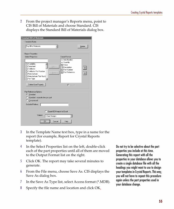
Creating Crystal Reports templates
Do not try to be selective about the part properties you include at this time. Generating this report with all the properties in your database allows you to create a single database file with all the headings you might want to use to design your templates in Crystal Reports. This way, you will not have to repeat this procedure again unless the part properties used in your database change.
2 From the project manager’s Reports menu, point to CIS Bill of Materials and choose Standard. CIS displays the Standard Bill of Materials dialog box.
3 In the Template Name text box, type in a name for the report (for example, Report for Crystal Reports template).
4 In the Select Properties list on the left, double-click each of the part properties until all of them are moved to the Output Format list on the right.
5 Click OK. The report may take several minutes to generate.
6 From the File menu, choose Save As. CIS displays the Save As dialog box.
7 In the Save As Type list, select Access format (*.MDB).
8 Specify the file name and location and click OK.
55

Chapter 2 Setting up Orcad CIS
56
To avoid having to browse for your template, store the file in the same directory as your database configuration (.DBC) file. The template will automatically appear in the Crystal Reports Bill of Materials dialog box.
You only need Crystal Reports software to create templates, not to use them. For this reason, you only need to buy one copy of the software for your entire workgroup.
To create a Crystal Reports template
Note You must have Crystal Reports Designer installed on your system with CIS to create Crystal Reports templates. If you do not own a copy of Crystal Reports Version 6 or 7, visit Orcad’s web site at www.orcad.com for reseller information.
1 Using Crystal Report Designer, create a custom report using the Access database bill of materials (.MDB) file as your data file.
To store a template file for use by CIS
1 Store your Crystal Reports template (.RPT) file where all users in your workgroup have access to it.

Working with database parts
3
OverviewThis chapter describes the various procedures you use when working with database parts, including the following:
Using the CIS interface on page 58
Placing a database part on a schematic page on page 66
Browsing part properties on page 71
Creating a new database part on page 72
Linking a placed part to a database part on page 88
Viewing a placed part’s database properties on page 92
Copying part properties using the part manager on page 94

Chapter 3 Working with database parts
58
For descriptions of the functions of the windows in the CIS interface, see The CIS work environment on page 1-6.
Tip Right mouse button access for the most commonly used CIS commands is available in the project manager, schematic page editor, part manager, and CIS explorer windows.
To open the part manager window, do the following:
1 From the project manager’s Tools menu, point to Part Manager and choose Open.
For information about how to use the part database management features of the part manager, see Viewing and updating part status on page 4-98.
Using the CIS interfaceThe CIS user interface includes standard Windows interface functionality along with a few additional features to make your work environment easy to use. You can also customize the layout of CIS windows for each of your Capture projects. The main CIS interface is comprised of the part manager and CIS explorer windows. Additional CIS menu commands are interspersed throughout the menus in Capture.
Using the part manager window
You can adjust the work environment for the part manager in the following ways:
• Sort the part manager data by any one of the data columns.
• Adjust the part manager display by changing data column width and splitting the window into panes.
• Display the toolbar.

Using the CIS interface
The column by which the data in the part manager is currently sorted is indicated by a triangle icon. If the triangle points upward, the data is sorted in ascending order. If it points downward, the data is sorted in descending order.
The tasks that you use these tools to perform are described later in this section.
To sort information in the part manager
1 Click the heading of the column you want to sort by. To reverse the sort order, click the same column heading again.
To adjust the part manager display
1 To adjust the width of a column, select the right border of the column heading and drag it to the left or right.
2 To split the part manager into panes, choose Split from the part manager’s Window menu.
To display the part manager toolbar
1 Move or dock the toolbar as desired.
2 To display the name of the button command, point at the button briefly.
3 To display the toolbar, choose Toolbar from part manager’s View menu.
column heading column heading border
59

Chapter 3 Working with database parts
60
CIS displays the CIS explorer when you choose Place Database Part or Link Database Part from a schematic page in Capture’s schematic page editor. Information about how to use the database part features of the CIS explorer is covered in the following sections of this chapter.
4 To hide the toolbar, click the hide button in the top corner of the toolbar.
Using the CIS explorer window
The CIS explorer contains two tabbed windows—the Local Part Database and the Internet Component Assistant (ICA). You can navigate between these windows by clicking either one of the tabs at the bottom of the CIS explorer. Each window consists of a set of docking windows that can be redisplayed as floating windows or hidden. The Local Part Database window also contains a non-docking part selection window that cannot be redisplayed as floating or hidden (the database parts window).

Using the CIS interface
docking window
CIS retains the size, position, and state of the windows between Capture sessions.
Since the expand/contract feature only functions horizontally, the arrow is dimmed if the window is not bordered by another window on the left or right.
Using docking windowsDocking windows can be positioned and sized independently like standard windows. But, they allow you added control over your workspace in relation to the other windows inside the CIS explorer. Docking windows have these unique features:
• Docking to the main window
• Expanding or contracting relative to other windows
• Floating over other docking windows
Depending on the function of the window, you can also choose to show or hide some docking windows.
To dock a window in the CIS explorer
1 Drag the window by the double bar over another border of the CIS explorer. The other windows automatically adjust to allow the window you are moving to dock on that border.
To expand or contract a window relative to other windows
1 Click the arrow above the window’s double bar to expand or contract the window in the direction of the arrow. The bordering window automatically expands or contracts to fit the new window size.
double bar
hide button
expand/contractarrow
61

Chapter 3 Working with database parts
62
To change a docked window to a floating window
1 Double-click in the window border. The docking window redisplays with a title bar instead of the double bar.
To dock a floating window
1 Double-click the window title bar to return the window to its previous docked location, or drag the window by the title bar to a different docking border.
To position a floating window over a dock (without docking it)
1 Press and hold down C and drag the window by the title bar.
To show or hide a window
1 To show a window, choose the window name (for example, Visibility) from the View menu.
2 To hide a window, click the hide button in the top corner of the window, or choose the window name from the View menu.
window border

Using the CIS interface
The database parts window is part of the main CIS explorer window—you cannot hide or dock it. This is so that the window will be present at all times to place and link database parts.
Once you set up the columns, CIS saves the new settings for your next session.
Using the database parts window
You can use the spreadsheet format of the database parts window to do the following:
• Sort rows using column values
• Adjust column widths
• Change the order of the columns
• Hide or unhide columns
Note For a description of the database parts window, see The database parts window on page 1-9.
63
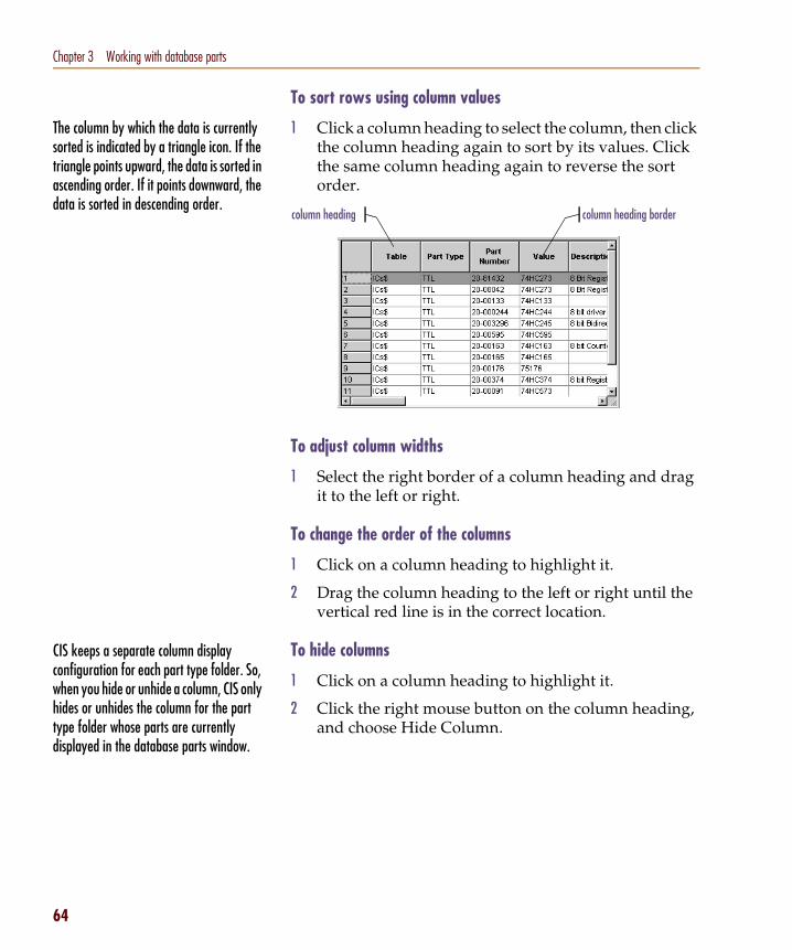
Chapter 3 Working with database parts
64
The column by which the data is currently sorted is indicated by a triangle icon. If the triangle points upward, the data is sorted in ascending order. If it points downward, the data is sorted in descending order.
CIS keeps a separate column display configuration for each part type folder. So, when you hide or unhide a column, CIS only hides or unhides the column for the part type folder whose parts are currently displayed in the database parts window.
To sort rows using column values
1 Click a column heading to select the column, then click the column heading again to sort by its values. Click the same column heading again to reverse the sort order.
To adjust column widths
1 Select the right border of a column heading and drag it to the left or right.
To change the order of the columns
1 Click on a column heading to highlight it.
2 Drag the column heading to the left or right until the vertical red line is in the correct location.
To hide columns
1 Click on a column heading to highlight it.
2 Click the right mouse button on the column heading, and choose Hide Column.
column heading column heading border

Using the CIS interface
To unhide columns
1 Click the right mouse button on any column heading, and choose Unhide Columns. CIS displays the Unhide Columns dialog box.
2 Select the names of the columns you want to unhide and click OK.
65

Chapter 3 Working with database parts
66
For information about locating and placing parts from the internet component assistant (ICA), see Using the ICA to locate and create a new database part on page 3-81.
Placing a database part on a schematic pageThis section describes how to do the following:
• Locate a part in your parts database.
• Place a database part on a schematic page.
When you place a database part, CIS includes all database part properties to be transferred.
Note The Place Database Part command will not work unless you have entered the schematic part name in your database and have set the Schematic_Part property type in the configuration.
Using the explorer to locate a database partYou can use the explorer to locate a particular part in your database.
To locate a database part with the explorer
1 From the schematic page editor’s Place menu, choose Database Part. CIS displays the explorer window.
2 In the explorer window, choose the Explore tab. The drum icon (labeled Benchacc in this example) represents the part database.
3 Choose or double-click the drum icon, to expand the database into the configured part tables. Similarly, choose on the table to expand the tree to display the first-level part type folders.
Tip If you want to display the whole part tree structure, from the View menu, choose Expand Part Tree.
4 Locate the part you want to place. When you open a part type folder at any given level, the database parts at that level are displayed in the database parts window. For information about adjusting the display

Placing a database part on a schematic page
of part information and property columns in the database parts window, see Using the database parts window on page 3-63.
Using the query feature to locate database partsYou can also use the query feature in the CIS explorer window to locate all parts in the database that fit a set of criteria. This is useful when you want to view all the available parts that match a set of attributes. To use the query feature, you must first create the query criteria, then execute the database search.
Creating and executing a query1 From the schematic page editor’s Place menu, choose
Database Part. CIS displays the CIS explorer window.
2 In the Explorer window, choose the Query tab.
Note CIS uses the part type property contents from your part database to determine the folder hierarchy. For a description of how to define your part database hierarchy, see Creating a part database on page 12.
67

Chapter 3 Working with database parts
68
Since a database search identifies only those parts that meet all the search criteria, you can use additional rows of criteria to pinpoint specific parts.
3 In the first cell in the Property column, type in the name of a property or choose one from the cell’s drop-down list.
4 In the first cell in the Compare column, type in a logical operator or choose one from the cell’s drop-down list. The available logical operators include the following:
5 In the first cell in the Value column, enter a value. If you’re using the equal to (=) logical operator, you can use wildcard characters for the value: an asterisk (*) matches a group of characters, and a question mark (?) matches any single character.
6 Repeat steps 3 through 5 as necessary to construct subsequent rows of search criteria. You can delete a query row by selecting the row and then pressing D.
This operator... Means this...
= Equal to
< Less than
> Greater than
<= Less than or equal to
>= Greater than or equal to
!= Not equal to
Contains Contains

Placing a database part on a schematic page
To gain a better understanding of database queries and their results, see the examples in the CIS online help.
You can define property place holder positions in the schematic library for properties which you want pre-positioned. For example, you can define a Tolerance property in the resistor schematic part and position it so that when the part is placed, the property position is satisfactory. See the Orcad Capture User’s Guide for more information.
You can also use the library convert feature to hold two different orientations of the part, one for the normal orientation and one for the 90-degree rotation. See the Orcad Capture User’s Guide for more information.
7 To perform the query, press R or choose Re-search Database from the Update menu. CIS displays the results in the database parts window.
Placing a local database part on your schematicAfter locating the database part from the local part database, you can place it on your schematic page. If you want to place a part from the ICA, see Using the ICA to locate and create a new database part on page 3-81.
Note If your database contains mechanical (non-electrical) parts, you can place them on your design. However, if you want the mechanical parts to be included in a CIS bill of materials, you must place them on the root schematic or on a schematic that is referenced by a hierarchical block on the root schematic. For information about root schematics and hierarchical blocks, see the Capture User’s Guide or Capture online help.
Any properties specified during configuration as transferable are copied to the placed part and are present in the placed part properties.
CIS sets the appropriate property visibility. If the property is set to Visible and exists in the library, CIS uses the property position defined in the library; otherwise, CIS displays the property in a default position. If you change the position of a property in the part editor, any subsequent updates to the part (using the Link Database Part command) retain the new position.
69
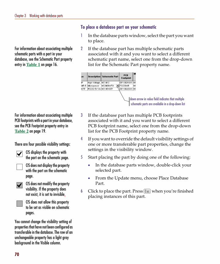
Chapter 3 Working with database parts
70
For information about associating multiple schematic parts with a part in your database, see the Schematic Part property entry in Table 1 on page 16.
For information about associating multiple PCB footprints with a part in your database, see the PCB Footprint property entry in Table 2 on page 19.
There are four possible visibility settings:
You cannot change the visibility setting of properties that have not been configured as transferable in the database. The row of an unchangeable property has a light gray background in the Visible column.
CIS displays the property with the part on the schematic page.
CIS does not display the property with the part on the schematic page.
CIS does not modify the property visibility. If the property does not exist, it is set to invisible.
CIS does not allow this property to be set as visible on schematic pages.
To place a database part on your schematic
1 In the database parts window, select the part you want to place.
2 If the database part has multiple schematic parts associated with it and you want to select a different schematic part name, select one from the drop-down list for the Schematic Part property name.
3 If the database part has multiple PCB footprints associated with it and you want to select a different PCB footprint name, select one from the drop-down list for the PCB Footprint property name.
4 If you want to override the default visibility settings of one or more transferable part properties, change the settings in the visibility window.
5 Start placing the part by doing one of the following:
• In the database parts window, double-click your selected part.
• From the Update menu, choose Place Database Part.
6 Click to place the part. Press E when you’re finished placing instances of this part.
down arrow in value field indicates that multiple schematic parts are available in a drop-down list

Browsing part properties
For information about configuring CIS, see Creating a configuration file on page 2-26.
Since the browsing feature is generic, you can view virtually any kind of data. You can include references to your component datasheets on your company’s intranet, as Word files, Acrobat files, or any other format. For example, you may want to view package drawings, mechanical models, simulation models, and so on.
Example: If the part property value is a URL such as:
http://www.chipmfgr.com/datasheets/74ALS138.html
CIS starts your default web browser and displays the web page for that URL.
Browsing part propertiesDatabase parts may include browsable properties. These properties actually specify links to documents or web sites. CIS allows you to browse properties for which the Browsable option was set during configuration.
To browse a database part property
1 In the database parts window, click the database part property you want to browse. The cursor turns into a hand when you point at a browsable property.
CIS launches the appropriate browser based on the value of the part property.
71

Chapter 3 Working with database parts
72
For more information about updating part information on designs, see Viewing and updating part status on page 98.
Creating a new database partAlmost every design will use some new parts that aren’t in your part database and do not have a company part number. CIS lets you create a new part while you’re working and save it to the database. This allows you to continue working without having to stop for the part approval process. When you save a temporary part to your database, CIS can automatically assign a temporary part number and track the part for you in the part manager. Later, if the part is approved and assigned a company part number, CIS can automatically update your design with the new part information.
You can create new database parts using one of the following methods:
• Derive a new database part from your local part database. See Deriving a new database part from the local part database below.
• Derive a new database part from a part placed on a schematic page. See Deriving a new database part from a placed part on page 3-77.
• Locate and create a new database part using the internet component assistant (ICA). See Using the ICA to locate and create a new database part on page 3-81.
Note You must have write permission for the part and footprint libraries to save a part with the internet component assistant (ICA).
Deriving a new database part from the local part databaseYou can create new database parts using parts that are already stored in your database. Once you have selected and altered an existing database part, you can store it as a temporary part in your database and place instances of the new part on schematic pages.
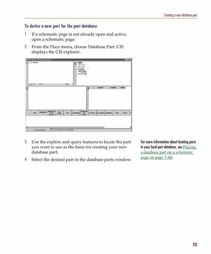
Creating a new database part
For more information about locating parts in your local part database, see Placing a database part on a schematic page on page 3-66.
To derive a new part for the part database
1 If a schematic page is not already open and active, open a schematic page.
2 From the Place menu, choose Database Part. CIS displays the CIS explorer.
3 Use the explore and query features to locate the part you want to use as the basis for creating your new database part.
4 Select the desired part in the database parts window.
73

Chapter 3 Working with database parts
74
You cannot change the selected table in the Save Part To area. This is because you are deriving the new part from a placed part that is already in your part database, so the new part is automatically placed in the same table as the existing database part.
5 From the Edit menu, choose Derive New Database Part. CIS displays the New Database Part dialog box.
6 Enter the appropriate values for the new part’s database properties in the Contents column.
7 Modify the visibility settings for each property as desired.
8 If you want to choose alternate schematic parts or footprints for the new database part, do the following:
a Click the Browse button in the Schematic Part area to choose alternate schematic parts or in the Footprint area to choose alternate footprints. CIS displays the Select Schematic Part or Select Footprint dialog box (see graphic below).
Note If you have selected Assign Temporary Part Numbers Automatically in the configuration, a temporary part number is already assigned which you cannot modify.

Creating a new database part
Tip If you know what library your footprints or schematic parts are stored in, highlight only that library in the Configured Libraries list. This will greatly reduce the number of schematic parts you have to scroll through to find part or footprint names.
b If you want to include the library name with the selected schematic parts or footprints, select the Attach the Library Name option. You can include the library name to avoid confusing the schematic part or footprint name with an identically named one in a different library.
c In the Schematic Part or the Footprint list, select a part or a footprint. The part or footprint displays in the preview window.
Caution Only select a schematic part from your own custom libraries; do not select a part from the libraries that are supplied with Capture (resource libraries). Resource libraries are often changed by upgrades to new versions of Capture. If the name or path of the schematic part you select is changed during an upgrade, it will become invalid for all your database parts.
Caution If you are deriving a new mechanical (non-electrical) part and choosing an alternate schematic part, you must choose a schematic part with no pins. If mechanical parts with pins are placed in a design, they will invalidate netlists generated from that design.
75

Chapter 3 Working with database parts
76
Note Once the new part is added to the database, you must have administrative privileges for the database to modify the properties that you set above.
d Click the Add button to move the schematic part or footprint to the Selected Schematic Parts or Selected Footprints list. You can remove it from the list by selecting it and clicking the Remove button.
e Repeat steps c and d until you have selected all the schematic parts or footprints that you want to be available for use with the database part.
f If you selected more than one schematic part or footprint, use the up and down arrows to arrange the order of the parts or footprints. The top one will be the default value for the database part. The order of the whole set determines the order in which they will display in the scroll-down list of the Schematic Part or PCB Footprint property value cells of the CIS explorer’s database parts window.
g Click OK. CIS returns you to the New Database Part dialog box.
9 Click the Place Part button. The dialog box closes, the new part is added to the part database, and you are returned to the schematic page with the pointer in place part mode.
10 Click to place the part. Press E when you’re finished placing instances of the part.
Order in the Selected Schematic Parts list Order in scroll-down list of Schematic Part property value cell in CIS explorer’s database parts window

Creating a new database part
Deriving a new database part from a placed partYou can create new database parts using parts that you have already placed on schematic pages. While you are deriving a new database part, you can change the values and visibility settings of the database part properties.
By default, CIS does not automatically copy all placed part properties to the part database. The properties that are automatically transferred have all three of the following characteristics:
• They are mapped to database part properties in the database configuration.
• They have been set to transfer to designs in the database configuration.
• They have a value for the placed part.
If you want other property values to be added to the database, you can manually add them during this procedure, but only if the property is mapped in the database configuration.
As soon as the new part is stored in the database, you can place instances of the part on schematic pages. The part will remain a temporary part, however, until your database administrator assigns a permanent part number.
To derive a new part from a database part
1 Open the schematic page that contains the placed part you want to use to derive a new database part.
2 Select the placed part.
77
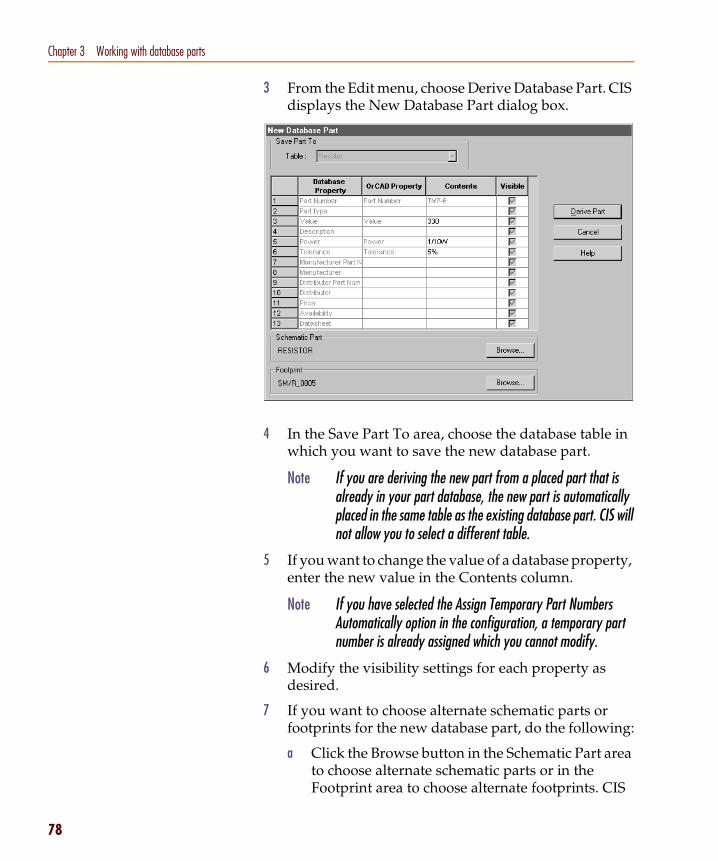
Chapter 3 Working with database parts
78
3 From the Edit menu, choose Derive Database Part. CIS displays the New Database Part dialog box.
4 In the Save Part To area, choose the database table in which you want to save the new database part.
5 If you want to change the value of a database property, enter the new value in the Contents column.
6 Modify the visibility settings for each property as desired.
7 If you want to choose alternate schematic parts or footprints for the new database part, do the following:
a Click the Browse button in the Schematic Part area to choose alternate schematic parts or in the Footprint area to choose alternate footprints. CIS
Note If you are deriving the new part from a placed part that is already in your part database, the new part is automatically placed in the same table as the existing database part. CIS will not allow you to select a different table.
Note If you have selected the Assign Temporary Part Numbers Automatically option in the configuration, a temporary part number is already assigned which you cannot modify.

Creating a new database part
Tip If you know what library your footprints or schematic parts are stored in, highlight only that library in the Schematic Part Libraries or Configured Libraries list. This will greatly reduce the number of schematic parts you have to scroll through to find part or footprint names.
displays the Select Schematic Part or Select Footprint dialog box.
b If you want to include the library name with the selected schematic parts or footprints, select the Attach the Library Name option. You can include the library name to avoid confusing the schematic part or footprint name with an identically named one in a different library.
c In the Schematic Part or the Footprint list, select a part or a footprint. The part or footprint displays in the preview window.
Caution Only select a schematic part from your own custom libraries; do not select a part from the libraries that are supplied with Capture (resource libraries). Resource libraries are often changed by upgrades to new versions of Capture. If the name or path of the schematic part you select is changed during an upgrade, it will become invalid for all your database parts.
Caution If you are deriving a new mechanical (non-electrical) part and choosing an alternate schematic part, you must choose a schematic part with no pins. If mechanical parts with pins are placed in a design, they will invalidate netlists generated from that design.
79

Chapter 3 Working with database parts
80
d Click the Add button to move the schematic part or footprint to the Selected Schematic Parts or Selected Footprints list. You can remove it from the list by selecting it and clicking the Remove button.
e Repeat steps c and d until you have selected all the schematic parts or footprints that you want to be available for use with the database part.
f If you selected more than one schematic part or footprint, use the up and down arrows to arrange the order of the parts or footprints. The top one will be the default value for the database part. The order of the whole set determines the order in which they will display in the scroll-down list of the Schematic Part or PCB Footprint property value cells of the CIS explorer’s database parts window.
g Click OK. CIS returns you to the New Database Part dialog box.
8 Click the Derive Part button. The part is added to the part database with the automatically assigned part number.
Order in the Selected Schematic Parts list Order in scroll-down list of Schematic Part property value cell in CIS explorer’s database parts window

Creating a new database part
Using the ICA to locate and create a new database partYou can use the ICA to access the activeparts web site’s part database and locate and create parts that are not yet stored in your local part database.
When you need to locate and create parts during a design session, do the following:
1 Locate a part using the ICA. See Using the ICA to locate a part on page 3-81.
2 Create and place a part using the ICA. See Using the ICA to create and place a part on page 3-82.
Using the ICA to locate a partThrough the ICA, you can locate new parts using the part database at the activeparts web site.
Note The activeparts database is updated as new part information becomes available without requiring you to update your CIS software installation.
To use the ICA to locate a part
1 Open a new or existing schematic design in Capture and, if a schematic page is not already open and active, open a schematic page.
81

Chapter 3 Working with database parts
82
2 From the Place menu, choose Database Part. CIS displays the CIS explorer.
3 Click the Internet Component Assistant (ICA) tab at the bottom of CIS explorer window. CIS displays the activeparts web site.
4 Use the activeparts part search features to locate the part you want to place in your design or add to your preferred parts database.
Using the ICA to create and place a partWhen you have found the part you want to create, you can add the part to your database and place instances of the new database part on a schematic page.
Note The first time you access the activeparts web site, you will have to create a login.
Note For information about using the activeparts search features, refer to the activeparts online help.
Internet Component Assistant (ICA) tab
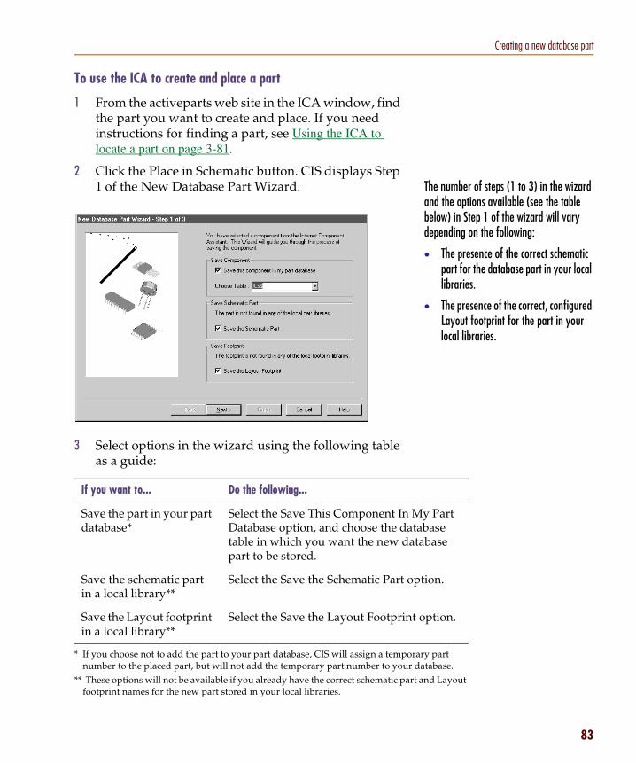
Creating a new database part
ary part database.
y Part abase tabase
t and Layout
ption.
option.
The number of steps (1 to 3) in the wizard and the options available (see the table below) in Step 1 of the wizard will vary depending on the following:
• The presence of the correct schematic part for the database part in your local libraries.
• The presence of the correct, configured Layout footprint for the part in your local libraries.
To use the ICA to create and place a part
1 From the activeparts web site in the ICA window, find the part you want to create and place. If you need instructions for finding a part, see Using the ICA to locate a part on page 3-81.
2 Click the Place in Schematic button. CIS displays Step 1 of the New Database Part Wizard.
3 Select options in the wizard using the following table as a guide:
If you want to... Do the following...
Save the part in your part database*
* If you choose not to add the part to your part database, CIS will assign a tempornumber to the placed part, but will not add the temporary part number to your
Select the Save This Component In MDatabase option, and choose the dattable in which you want the new dapart to be stored.
Save the schematic part in a local library**
** These options will not be available if you already have the correct schematic parfootprint names for the new part stored in your local libraries.
Select the Save the Schematic Part o
Save the Layout footprint in a local library**
Select the Save the Layout Footprint
83

Chapter 3 Working with database parts
84
If you accept the CIS default library name and the library has not already been created, Capture will prompt you to allow it to create the library and add the new part to that library. However, before you can place the part from your local part database, you must add the new library to your Capture configuration by doing the following:
1 From the schematic page editor’s Place menu, choose Part.
2 In the Place Part dialog box, click the Add Library button.
3 Browse for and select the new library then click Open.
4 Click Cancel.
5 Exit and restart Capture.
You can now place the part from your local part database.
4 If you are saving a schematic part or Layout footprint to a local library, complete the subsequent wizard steps. You will need to either accept the default library name supplied by CIS or browse to find a library in which to store the part or footprint.
When you finish the New Database Part wizard, CIS displays the New Database Part dialog box.
5 Enter the appropriate values for the new part’s properties in the Contents cells.
6 Modify the visibility settings for each property as desired.
Caution Only save schematic parts to your own custom libraries; do not save parts to the libraries that are supplied with Capture (resource libraries). Resource libraries are often changed by upgrades to new versions of Capture. If the library in which you save the schematic part is replaced during an upgrade, you will lose the schematic part information associated with the new database part.
Note If you have selected Assign Temporary Part Numbers Automatically in the configuration, a temporary part number is already assigned which you cannot modify.
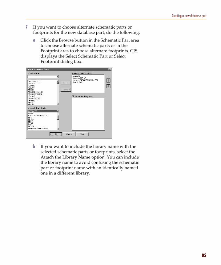
Creating a new database part
7 If you want to choose alternate schematic parts or footprints for the new database part, do the following:
a Click the Browse button in the Schematic Part area to choose alternate schematic parts or in the Footprint area to choose alternate footprints. CIS displays the Select Schematic Part or Select Footprint dialog box.
b If you want to include the library name with the selected schematic parts or footprints, select the Attach the Library Name option. You can include the library name to avoid confusing the schematic part or footprint name with an identically named one in a different library.
85

Chapter 3 Working with database parts
86
Tip If you know what library your footprints or schematic parts are stored in, highlight only that library in the Configured Libraries list. This will greatly reduce the number of schematic parts you have to scroll through to find part or footprint names.
c In the Schematic Part or the Footprint list, select a part or a footprint. The part or footprint displays in the preview window.
d Click the Add button to move the schematic part or footprint to the Selected Schematic Parts or Selected Footprints list. You can remove it from the list by selecting it and clicking the Remove button.
e Repeat steps c and d until you have selected all the schematic parts or footprints that you want to be available for use with the database part.
f If you selected more than one schematic part or footprint, use the up and down arrows to arrange the order of the parts or footprints. The top one will be the default value for the database part. The order of the whole set determines the order in which they will display in the scroll-down list of the Schematic Part or PCB Footprint property value cells of the CIS explorer’s database parts window (see graphic below).
Caution Only select a schematic part from your own custom libraries; do not select a part from the libraries that are supplied with Capture (resource libraries). Resource libraries are often changed by upgrades to new versions of Capture. If the name or path of the schematic part you select is changed during an upgrade, it will become invalid for all your database parts.
Caution If you are creating a new mechanical (non-electrical) part, the associated schematic part must not have pins. If mechanical parts with pins are placed in a design, they will invalidate netlists generated from that design.

Creating a new database part
selected schematic part
Note If you chose to add the new part to the database in step 3, a new record is added for the part at this point. Once this new part is added to the database, you must have administrative privileges for the database to modify the properties that you set above.
g Click OK. CIS returns you to the New Database Part dialog box.
8 Click the Place Part button. The dialog box closes and you are returned to the schematic page with the pointer in place part mode.
9 Click to place the part. Press E when you’re finished placing instances of this part.
Note Make sure that you have a schematic part selected before continuing. If you do not, CIS will return an error when you attempt to place the part and you will have to repeat this procedure to begin placing the part.
Order in the Selected Schematic Parts list Order in scroll-down list of Schematic Part property value cell in CIS explorer’s database parts window
87

Chapter 3 Working with database parts
88
Using the visibility window, you can override the default visibility settings of one or more part properties.
You cannot change the visibility setting of properties that have not been configured as transferable in the database. The row of an unchangeable property has a light gray background in the Visible column.
CIS displays the property with the part on the schematic page.
CIS does not display the property with the part on the schematic page.
CIS does not modify the property visibility. If the property does not exist, it is set to invisible.
You can group similar parts in the part manager by sorting on one of the columns (for example, the Value column). Choose a column heading to sort the list by the information in that column; choose the same heading again to reverse the sort order.
Linking a placed part to a database partYou can use the part manager or the Link Database Part command to assign a database part (and the associated transferable properties) to one or more placed parts. By linking a placed part to a database part, you replace the part and its properties with the database part and its transferable properties. If you are linking a part occurrence to a database part, both the occurrence and instance properties will be set to the database properties.
Note CIS warns you if you select a database part to link to a group of placed parts whose part reference prefixes or values differ. CIS will, however, allow you to link a placed part to a database part with a different schematic part name.
To link using the part manager
1 From the project manager’s Tools menu, point to Part Manager and choose Open. CIS displays the part manager window.
2 In the part manager, select a placed part or a group of placed parts. To select a group of parts, do one of the following:
3 From the Tools menu, choose Link Database Part.
or
Click the Link Database Part toolbar button.
4 In the part database explorer:
Double-click the database part you want.
or
Select the database part you want and, from the Update menu, choose Link Database Part.
• For a group of nonadjacent parts, hold down C and click the parts.
• For a group of adjacent parts, hold down S and click the first then the last part in the range.

Linking a placed part to a database part
If the schematic part property for the placed part is different from that of the selected database part, CIS will highlight the database part’s row yellow when you select it in the database parts window. Then, if you double-click or choose Link Database Part, CIS will allow you to change the schematic part property of the placed part to match the database part.
CIS links it to the placed part, and the appropriate properties are transferred.
To link using the schematic page editor
1 Select one or more parts on a schematic page.
2 From the Edit menu, choose Link Database Part. CIS performs a database query, using the keyed properties
Note In the visibility window, CIS displays the values of the selected database part’s properties in the Database Contents column and the values of the placed part’s properties in the Schematic Contents column. If the value of placed part’s property is green, then it matches the value of the property for the database part. If the value of placed part’s property is red, then the value does not match that of the database part.
Caution Because the schematic part used for the placed part will change, you must check the schematic page to make sure that you have correct connectivity when you are finished linking.
89

Chapter 3 Working with database parts
90
If you select several parts, CIS uses the keyed properties and part reference prefix of the first part in the group (from top left to bottom right) for the initial query.
for the database, then displays the results of the query in the database parts window.
Keyed properties are defined in the database configuration. Generally, though, the Value property is the primary keyed property. The initial query searches for parts with a value matching that of the placed part.
CIS also uses the configuration settings for Allowed Part Reference Prefixes and Part Reference Associations to filter the database for only those parts that apply to the reference prefix of the selected parts.
3 Select the database part you want to apply to the selected placed parts. You can also create a new query if the initial query did not locate the part of interest.
4 In the part database explorer, do one of the following:
Double-click the database part you want.
or
Select the database part you want and, from the Update menu, choose Link Database Part.
database parts window

Linking a placed part to a database part
If any of the selected placed parts are multiple-part packages and have defined part references, CIS updates all other parts in the package at the same time. For example, if the selected placed part is U33B, CIS will update U33A, U33C, and any other parts in the package as well. If the selected placed part reference is undefined, only the selected part is updated.
If the schematic part property for the placed part is different from that of the selected database part, CIS will highlight the database part’s row yellow when you select it in the database parts window. Then, if you double-click or choose Link Database Part, CIS will allow you to change the schematic part property of the placed part to match the database part.
The database part is linked to the placed parts, which also receive the transferable properties, including the part value.
Note In the visibility window, CIS displays the values of the selected database part’s properties in the Database Contents column and the values of the placed part’s properties in the Schematic Contents column. If the value of placed part’s property is green, then it matches the value of the property for the database part. If the value of placed part’s property is red, then the value does not match that of the database part.
Caution Because the schematic part used for the placed part will change, you must check the schematic page to make sure that you have correct connectivity when you are finished linking.
91

Chapter 3 Working with database parts
92
Viewing a placed part’s database propertiesYou can view a placed part’s local and Internet database properties right from the schematic page or the part manager, if the part has been added to the local part database. When you choose to view the part properties, CIS displays a read-only version of the CIS explorer with a comparison of the placed part’s properties to those of its linked database part. You can also use this part viewing capability to check the latest data sheet, stocking, and pricing information from the Internet.
To view a placed part’s database properties1 From the schematic page or the part manager, select
the part for which you want to view database properties.
Note On the schematic page, the selected part must be in your local part database for CIS to display part properties. If you attempt to view the database properties of a part not stored in your local part database, CIS will display the Local Part Database tab of the CIS explorer window with no part information. If you then click the Internet Component Assistant (ICA) tab, CIS will display an error message page.
2 From the View menu, choose Database Part. CIS displays the CIS explorer window in View Database Part mode.
CIS displays the database part property contents in the database parts window. In the visibility window, CIS displays both the contents of the database parts properties and of the properties that have been
Note The View Database Part mode is a read-only mode. For this reason, you cannot use the search or query functions of the explorer window to search for, place, or link a database part.

Viewing a placed part’s database properties
transferred to the schematic. If the content of a schematic property is green, then it matches the content of the part database. If the content of a schematic property is red, then the contents do not match the part database.
3 If you want to check the latest data sheet, stocking, or pricing information from the Internet, click the Internet Component Assistant (ICA) tab at the bottom of the CIS explorer. The Internet part property information is displayed for the part, including hyperlinked data sheet URLs for parts that have data sheets associated with them.
93

Chapter 3 Working with database parts
94
For information about transferring database part properties to placed parts, see Linking a placed part to a database part on page 88.
You can use the Split command (from the part manager’s Window menu) to display two areas of the part manager. This can make copying properties from one part to another much easier (by dragging the part across split panes) if the two parts are widely separated in the part manager.
Copying part properties using the part managerYou can also use the part manager to copy properties from one part to another (or to several others) in the design. CIS copies only those properties defined in the database configuration file as transferable.
To copy properties from one part to another
1 Open the schematic design that contains the part properties you want to copy.
2 From the project manager’s Tools menu, point to Part Manager and choose Open. CIS displays the part manager, showing all parts in the design, sorted by part reference.
3 Select the part with the properties to be copied.
4 Drag the selected part onto the part on the schematic page that is to receive the copied properties.

Copying part properties using the part manager
To copy properties from one part to a group of parts
1 Open the schematic design that contains the part properties you want to copy.
2 From the project manager’s Tools menu, point to Part Manager and choose Open. CIS displays the part manager, showing all parts in the design, sorted by part reference.
3 In the part manager, select the part with the properties you want to copy.
4 From the Edit menu, choose Copy.
5 Select the destination parts by holding down C while you select individual parts to add to the selected group, or by holding down S and selecting a contiguous group of parts.
6 From the Edit menu, choose Paste. CIS copies the properties from the first part to all the selected destination parts.
95

Chapter 3 Working with database parts
96

Finalizing and documenting designs
4
OverviewThis chapter describes the various procedures you use when working with the Orcad Component Information System (CIS), including the followinpg:
Viewing and updating part status on page 98
Creating design variants on page 103
Creating reports on page 104

Chapter 4 Finalizing and documenting designs
98
You can also set up how CIS sorts and displays the information in the part manager. For more information, see Using the part manager window on page 3-58.
If no configuration (.DBC) file has been specified for use with the part manager, no information will be displayed in these columns when you open the part manager for the first time. For information on setting up a part database and configuration file, see Chapter 2, Setting up Orcad CIS.
Viewing and updating part statusUse the CIS part manager to view and update the database status of placed parts in your design.
Note You should always update part status prior to creating a report. By making sure that all part status indicators are green before creating your bill of materials and netlist, you ensure that your report is complete.
Opening the part managerWhen you open the part manager, CIS generates a report describing the status of your design’s placed parts the last time they were checked against the database parts. If you have changed part properties on any placed parts or placed any non-database parts since the last time you updated part status, the report generated when you open the part manager will not reflect the current status of your design with respect to the database.
To open the part manager
1 Open a new or existing schematic design.
2 From the project manager’s Tools menu, point to Part Manager and choose Open. CIS displays the part manager, showing all parts in the design, sorted by part reference.

Viewing and updating part status
Example: Assume that an AND gate part in your database has a Part Number value of 456. Suppose that you assign a Part Number value of 123 to an instance of an AND gate in your design. That Part Number value applies only to that particular instance of the AND gate. When you update part status, CIS assigns the Part Number value 456 to all instances of the AND gate except that instance, which retains the value 123.
If you want to make sure that none of your parts have been modified since they were placed from their original libraries, from the Options menu in part manager, point to Update Part Status and choose Verify Parts Against Libraries (.OLB). Then, when you update part status, any placed part with a different timestamp than its library part will be flagged yellow.
Note If you turn on the Verify Parts Against Libraries (.OLB) option when you have placed parts in the design using a previous version of CIS (Release 9.0 or earlier), all parts placed from the previous Capture libraries will have mismatched timestamps and be flagged yellow. If you get an undesirable result, turn off the Verify Parts Against Libraries (.OLB) option and update part status again.
Updating the part status for your designYou can update the part status for your design using the part manager. When you update the part manager, CIS checks all the placed parts in your design against the part database, and updates part properties where necessary.
Any properties that you have assigned to part instances are retained when you update part status for your design, even if they differ from the values in the database.
Note You can also view an individual part's local and Internet database properties. For instructions, see Viewing a placed part’s database properties on page 92.)
To update part status for your design
1 Do one of the following:
• From the project manager’s Tools menu, point to Part Manager and choose Update.
• From the part manager’s Tools menu, choose Update Part Status.
CIS checks each placed part against the database part to which it is linked. The part database is searched for the Part Number property that matches the placed part, then transferred properties that are configured to be updated are compared.
For each placed part that is not current, you are prompted with the Update Part dialog box. This dialog box lets you decide whether or not you want to update the placed part properties with the transferred properties from the database part.
99

Chapter 4 Finalizing and documenting designs
100
n’t
perties.
The first row lists the database part and its properties, and the second row lists the placed part and its properties. The differences between the database part and placed part are highlighted in red.
2 Click one of the following buttons:
When complete, a list of updated parts and discrepancies with the database is written to the session log. Then, the part manager window displays the updated part status. The Part Status column contains both text and color-coded icons that indicate whether your placed part is linked to a part in a part database. The following table lists all the possible status conditions and what the each status condition means.
Click this button... To do this...
Yes Update the placed part.
Yes All Update all placed parts whose properties domatch the database part properties.
No Not update the placed part.
No all Not update any of the placed parts whose properties don’t match the database part pro
Note In some cases, CIS cannot automatically determine the correct database part with which to refresh the placed part. In these cases, you must wait until the update is complete and link the placed part to a database part. (See Linking a placed part to a database part on page 88.)

Viewing and updating part status
ce
If your configuration specifies that CIS assign temporary part numbers automatically, each status is preceded by either Temporary Part (if the placed part number prefix is the temporary part number prefix) or Approved Part.
When the status of all the parts in your design is Current, you are ready to generate a report such as a bill of materials.
Once you have updated part status, the part manager also includes tips for parts with a red icon status. The tips give more detail about the part’s status and about placed part properties that do not match the database part properties. To display a tip, point briefly over the status column.
Note The part status is based only on the part properties you have specified to be transferred from the part database. Other properties that may reside in the part are not checked.
This status... Means the part...
Green icon Is approved and current
Yellow icon Is in the approval process
Red icon Would be incorrect if you generated a BOM
Approved Has a defined part number property type
Temporary Has a temporary part number
Undefined Has no part number property
Current Transferable properties match those of the database part
Defined Has a part number property
Undefined part reference
Has an undefined part reference
Not current Has at least one transferable property that does not match the database part properties
Duplicate Has a part number that occurs more than onin the part database
Not found Has a part number that does not exist in thepart database
101

Chapter 4 Finalizing and documenting designs
102
Example: If your design’s filename is MYDESIGN.DSN, CIS automatically names your report MYDESIGN.PRP when you choose the Save command.
Saving the status reportYou can save the contents of the part manager window to a text (.PRP) file. The report file is saved (in the current sort order) in tab-delimited format which can be edited with a spreadsheet program or word processor.
To save a status report
1 Choose one of the following options:
To do this... Select this option...
Save the report file using the name of your design file
From the File menu, select Save.
Save the report file using the name of your choice
From the File menu, select Save As.

Creating design variants
Examples of product variation requirements include:
• Use in geographical regions with different performance requirements for component attributes such as power level, emissions standards, etc.
• Minor differences between product models such as the number and type of resistors.
Creating design variantsNote For more information about design variants and the procedures for
creating and documenting them, see the CIS online help.
Design variants are different assembly configurations of your basic or core design. When manufacturing design variants, the fabricated board will match the core design while the variants define how the board should be populated with parts. You can create and maintain all of your design variants within a single Capture project.
Because your design variations are captured within a single project, you can print variant schematic sheets and create variant bills of materials without having to maintain separate designs. Design variations include different property values for common components and different or not present components for identical footprints.
103

Chapter 4 Finalizing and documenting designs
104
Crystal Reports is a widely-used report design software produced by Seagate Technology, Inc.
You can use Crystal Reports in conjunction with CIS to make customized report templates with more advanced features than the standard CIS bill of materials, including precision formatting and formulas that total, filter, and analyze data for highly specific results.
You must have Crystal Reports installed on your system with CIS to create Crystal Reports templates. If you do not own a copy of Crystal Reports software, visit Orcad’s web site at www.orcad.com for reseller information.
If you want to make a Crystal Reports template, see Creating Crystal Reports templates on page 2-54.
Creating reportsA report contains relevant information about the parts in your design. You can customize the report to include both database and placed part properties. CIS supports the following two types of reports:
Note If you want mechanical (non-electrical) parts to be included in CIS reports, you must place these parts on the root schematic of the design or on a schematic that is referenced by a hierarchical block on the root schematic. For information about root schematics and hierarchical blocks, see the Capture User’s Guide or Capture online help.
• Standard bills of materials that you create completely within CIS. See Creating a standard CIS bill of materials below.
• Advanced reports that you generate from within CIS using templates created in Crystal Reports. See Creating a report using a Crystal Reports template on page 4-109.
Creating a standard CIS bill of materialsA bill of materials lists all the parts in your design. You can use the standard CIS bill of materials feature to create multiple, named report templates so that you can generate separate bills of materials for the different requirements of engineering, purchasing, and manufacturing.

Creating reports
You can also access the CIS Bill of Materials commands using the project manager’s Reports menu.
You can create multiple, named templates and define a different format for each. However, since a bill of materials file is, by default, saved using the design name and a .BOM extension, you’ll have to save each report under a unique filename using the part manager’s Save As command (from the File menu).
To create a standard CIS bill of materials
Note Do not use the Bill of Materials command from the project manager’s Tools menu to create your reports. This command does not use your part database information to produce the bill of materials. Only the CIS Bill of Materials commands from the Reports menu utilize your part database information.
1 From the part manager’s Reports menu, point to CIS Bill of Materials and choose Standard. CIS displays the Standard Bill of Materials dialog box.
2 In the Template Name text box, type in a name for the template, or select one from the drop-down list.
3 Select a part property you want in the bill of materials and click the Add button. The part property moves to the Output Format list. You can also double-click a property to move it from one side to the other.
105

Chapter 4 Finalizing and documenting designs
106
You specify the properties that are transferred from the database to your placed parts when you configure CIS.
The order of the items in the Output Format list box determines the order in which they appear in the report. To change the order of an item, select it and move it using the up or down arrow buttons to the right of the Output Format list box.
4 Repeat step 3 until all the properties you want in the bill of materials appear in the Output Format list box.
5 Select at least one property in the Output Format list box then select the Keyed option. You must do this to specify how CIS matches and groups records in the report. Normally, you should set Part Number to Keyed, so that parts with the same part number will be grouped in the report.
Tip The Select Properties list only includes schematic properties that you have configured to be transferred from the database. If you want to include a schematic property in your bill of materials that is not in your part database, you must type in its exact name and then choose the Add button. If you want to delete an added schematic property from the Select Properties list, select the property and click the Delete User Property button.
Note The property types that appear in the Select Properties list box include the following:
Default CIS property names
Properties transferred from placed parts on schematics
Properties transferred from database parts
Properties transferred over the Internet through the ICA
Note Keyed properties that are missing from the placed part or have blank contents are not grouped, but remain as distinct items in the report. This is so that undefined parts display as separate line items.
Creating reports
CIS checks for parts that are grouped (by having the same part number, for example), but that have different properties or packaging or have duplicate part references between instances of the parts.
CIS creates a report of the entire physical design regardless of the schematics and pages selected in the project manager.
6 Select one of the Part Reference Options from the following table:
7 In the Exclude Prefixes field, specify part reference prefixes for parts you do not want to include in the report. Typically, you use this to omit parts that are not purchased for manufacture.
8 If you want to export your report to spreadsheet format and open it automatically in MS Excel, select the Export BOM Report to Excel option
9 Click the OK button. CIS automatically adds the template name for the bill of materials you have designed to the Template Name list so that you can use the template again the next time you want to generate a bill of materials.
If any design errors are encountered during report creation, a dialog box prompts you to view the errors in the session log.
To do this... Select this option...
Group parts with matching keyed properties on a single line
Standard
Put each part on a separate line*
* Item Number and Quantity are only listed in the first line of each grouping.
Standard – Separate Line Per Part
Allow part ranges (such as R1–R14)
Compressed
Note If your design has design variants, you will have the option of selecting the variants whose part information CIS will use to generate the bill of materials. See the CIS online help for more information about creating bills of materials for design variants.
107

Chapter 4 Finalizing and documenting designs
108
You can choose a column heading to sort the rows by the values in that column, and choose the same column heading again to reverse the sort order. You can adjust the column widths by dragging the vertical lines between the column heading names to the left or right. If you save the bill of materials, it is saved with the current sort order.
You can use a spreadsheet application to sort the exported output by multiple keys.
If no design errors are encountered during report creation, the bill of materials report appears in a window.
10 To save the report, select one of the save options from the following table:
Note If you have included properties in your report that are configured as browsable, CIS will hyperlink (blue underline) the part values for those properties. You can click on the hyperlinks to display the latest version of the source file.
To do this... Select this option...
Save the report into the design folder using the default file name*. Note that you will overwrite any report previously saved using this default file name.
* CIS creates the default file name by concatenating the design name and the name of the bill of materials template used to generate the report. For example, if the design is named BENCH.DSN and the template is named ENG BILL OF MATERIALS, the bill of materials file will be named BENCH_ENG BILL OF MATERIALS.BOM by default.
From the File menu, choose Save.
Save the report using a new file name into the directory of your choice.
From the File menu, choose Save As.

Creating reports
If you want to make a Crystal Reports template, see Creating Crystal Reports templates on page 2-54.
When you export a report to a different file format, you may lose some or all of the formatting. The export function can only preserve as much formatting as the export format allows.
11 Specify a filename, save location, and format type. By default, CIS saves the report in tab-delimited format, but you can choose any of the following formats:
• TAB - Tab Separated Format
• (Excel) CSV - Comma Separated Format
• Access - Compatible with Microsoft Access as well as Seagate Crystal Reports.
Creating a report using a Crystal Reports templateIn addition to the standard CIS bill of materials, the print preview, print, and export functions of Seagate’s Crystal Reports software have been integrated into CIS to allow you to use Crystal Reports templates without having to install the software on your system. You only need access to the template files on your local drive or a network to generate your custom reports.
You can distribute reports you create in Crystal Reports in many ways, including the following:
• Print and distribute by hand
• Export in Crystal Reports Designer format (.RPT)
• Attach to an e-mail message in MS Word (.DOC) or Excel (.XLS) format
• Post in an MS Exchange folder in MS Word (.DOC) or Excel (.XLS) format
• Export to HTML and publish on the Internet
109

Chapter 4 Finalizing and documenting designs
110
You can also access the CIS Bill of Materials commands using the project manager’s Reports menu.
Sample Crystal Reports templates (.RPT files) are provided in ORCAD\CAPTURE\SAMPLES. These templates are designed to be used only with the BENCH.XLS and BENCH.MDB sample part databases. You must create your own Crystal Reports templates to work with your preferred parts database.
If you want to create more templates, see Creating Crystal Reports templates on page 2-54. You must have a copy of Crystal Reports software to create your own templates. Visit Orcad’s web site at www.orcad.com for reseller information.
To select and setup a predefined Crystal Reports template
1 From the part manager’s Reports menu, point to CIS Bill of Materials and choose Crystal Reports. CIS displays the Crystal Reports Bill of Materials dialog box.
2 In the Crystal Report Template list, select a report name, or click the Browse button and locate another template.

Creating reports
n proceed to...
print a Crystal Reports report low
preview a Crystal Reports ort below
export a Crystal Reports report page 4-113
3 Select one of the Part Reference Options from the following table:
4 In the Exclude Part Reference Prefixes field, specify part reference prefixes for parts you do not want to include in the report. Typically, you use this to omit parts that are not purchased for manufacture.
5 Select an option from the following table:
To do this... Select this option...
Group parts with matching keyed properties on a single line
Standard
Put each part on a separate line Standard – Separate Line Per Part
Allow part ranges (such as R1–R14)
Compressed
Note If your design has design variants, you will have the option of selecting the variants whose part information CIS will use to generate the report. See the CIS online help for more information about creating reports for design variants.
To do this... Click this button... The
Print your report Print Tobe
Preview your report before printing or exporting
Print Preview Torep
Export your report to a file, an MS Exchange folder, a Lotus Notes database, or MS Mail.
Export Toon
111

Chapter 4 Finalizing and documenting designs
112
CIS creates a report of the entire physical design regardless of the schematics and pages selected in the project manager.
Depending on the design of the Crystal Reports template, you might be required to input some information about your design (for example, part number or revision level) before you print.
The toolbar also displays status information about the records in your report.
total to beprocessed
percentage oftotal processed
numberread
To print a Crystal Reports report
1 If you have not done so already, complete To select and setup a predefined Crystal Reports template on page 4-110.
2 When CIS displays Crystal Report’s Print dialog box, select the print options you want and click OK.
To preview a Crystal Reports report
1 If you have not done so already, complete To select and setup a predefined Crystal Reports template on page 4-110.
2 When CIS displays Crystal Report’s print preview window, you can browse through the report using the navigation buttons on the toolbar.
Note After you select one of the above options, CIS generates the report. This can take several minutes, depending on the number of parts in your design and the complexity of the Crystal Reports template. CIS checks for parts that are grouped (by having the same part number, for example), but that have different properties or packaging or have duplicate part references between instances of the parts.
page backwardcontrols
zoom settingcurrent page
page forwardcontrols

Creating reports
n proceed to...
print a Crystal Reports report on ge 4-112
export a Crystal Reports report low
3 When you are ready to print or export your report, select one of the toolbar options from the following table:
To export a Crystal Reports report
1 If you have not done so already, complete To select and setup a predefined Crystal Reports template on page 4-110.
2 When CIS displays Crystal Report’s Export dialog box, select the format in which you want to export the report. For example, if you want to convert the report to Microsoft Excel 4.0 format, choose Excel 4.0 (.XLS) from the list.
To do this... Click this button... The
Print your report Topa
Export your report to a file, an MS Exchange folder, a Lotus Notes database, or MS Mail.
Tobe
113

Chapter 4 Finalizing and documenting designs
114
When you export a report to a disk file, CIS displays the Choose Export File dialog box. Do the following:
1 Select a path and file name for your file.
2 Click OK. The program exports the report to a disk file in the format you specify.
While the program assigns the native extension to all files you export in a specific word processor, database, or spreadsheet format, it automatically assigns the .TXT extension for all files you export in one of the common data interchange formats. However, the program you want to use the data in may require an extension other than .TXT. Consult the manual for that program to determine the correct file extension, and change the extension accordingly in the File Name text box.
3 From the Destination list, select one of the following options:
4 Click OK. The export process begins.
To do this... Select this...
Save the report to a disk file Disk file
Attach the report to a MS Mail e-mail document
Microsoft Mail (MAPI)
Store the report in an MS Exchange folder
Exchange Folder
Attach the report to a Lotus cc:Mail e-mail document
Lotus cc:Mail (VIM)
Send the report to a Lotus Notes database
Lotus Notes Database

Glossary
administrative preferences Options that you can set to customize database configuration features (for example, allowing duplicate part numbers or assigning temporary part numbers automatically).
allowed part reference prefixes The part reference prefixes that you assign to the data source tables of a part database during configuration. These assignments decrease search time when you are linking database parts by limiting the data source tables that CIS searches.
applicable part reference prefix The part reference prefixes that you assign to the part types of a part database during configuration. These assignments decrease search time when you are linking database parts by limiting the part types that CIS searches.
bill of materials See BOM.
blank property A database part property that does not have a value.
BOM Bill of materials. A report that includes a set of properties for all the physical parts required to build a design.
browsable property A property that is set in the configuration (.DBC) file to allow references to datasheets, drawings, and documents in your part database. Referenced file locations can be local or Internet URLs.
CIS Component Information System. A part management system that helps you manage part properties within your schematic designs, including part information required at each step in the printed circuit board design process.
CIS explorer The environment where you search for and retrieve a variety of part information for use in your schematic designs.

Glossary May 17, 2000
core design A schematic design from which design variants can be created.
Crystal Reports A widely-used report design software produced by Seagate Technology, Inc. The Crystal Reports Print, Print Preview, and Export options have been integrated into Orcad CIS to create customized bill of materials reports for printed circuit board designs.
data sheets Documents published by component manufacturers that contain the specifications engineers need to select the correct parts for their printed circuit board designs.
data source A data source consists of a database filename or server name and an associated ODBC driver with which to access the database.
database A collection of information related to a particular subject or purpose, such as maintenance of a list of approved parts.
database configuration (.DBC) file The file that enables CIS to access and use your part database. When you configure CIS, you can specify the database tables that CIS uses, the part properties that will be transferred to your designs, the visibility of transferred part properties, and the part type associations. This information is stored in the .DBC file.
database field name See table property name.
database part A part whose identifiers and properties are collected in a database.
database table A subset of database information with a common identifier or property, such as capacitors. Tables organize data into columns (called fields) and rows (called records).
DBC See database configuration (.DBC) file.
design errors Errors in the electrical connectivity of your design. If CIS finds design errors while generating a bill of materials, a dialog box will prompt you to view the errors in the session log so that you can fix them and generate a valid bill of materials.
116

***Draft*** Glossary
design variant A variation of the core design of a project that you can use to create a bill of materials for a different version of the project. All variations are kept within a single design. For more information about design variants, see the CIS online help.
EE Enterprise Edition. A previous release of the Orcad Enterprise CIS product offering. Enterprise Edition evolved from the DDL product originally developed by an Orcad Industry Partner called Q-Point. The software was packaged and shipped under the product names Orcad Capture EE and Orcad Express EE. The current release is Orcad Capture CIS with the option to include Express and PSpice.
Enterprise Edition See EE.
ERP Enterprise resource planning. See MRP.
footprint See PCB footprint.
ICA Internet component assistant. A tabbed window of the CIS Explorer that makes new components accessible to you over the Internet by providing access to the activeparts web site. Using the ICA, you can download component information to create temporary parts in your local preferred part database for immediate use in your schematic designs.
Activeparts web site A web site that allows access to a part database and is itself accessible through the internet component assistant (ICA). When you locate a part at activeparts through the ICA, you can place the part directly onto a schematic page and add the part to your local preferred parts database (PPD).
ICA property name A property that you select during database configuration that maps property names on new parts created with the internet component assistant (ICA) to corresponding database property names in your preferred part database.
ICA supplier preferences Preferences that you set when configuring your database to specify the component suppliers you wish CIS to search for part pricing and availability and the order in which you want them searched.
instance A part or a symbol that you have placed on a schematic page.
117

Glossary May 17, 2000
intelligent unit conversion The method that the database query feature uses to interpret common magnitude identifiers in part definitions. For example, intelligent unit conversion recognizes 2.7K, 2,700, 2.700K, and 0.0027M to be equal.
internet component assistant See ICA.
Internet part A part stored in a web-based part database that is searchable over the Internet. Parts stored at the activeparts web site are Internet parts.
keyed property A part property that CIS searches your preferred part database for when you are trying to link a placed part to a database part. You set which properties are keyed when you are configuring your database. Normally, you set only the Value property as a key so that CIS searches the database for parts with a specific value.
Link Database Part The command you use to link a part you’ve placed on a schematic page with a part in your preferred parts database. Once these parts are linked, you can automatically update a placed part when the database part changes.
manufacturing resource planning See MRP.
MIS Management information services. The department responsible for creating and maintaining company-wide information systems.
MRP Manufacturing resource planning. The computerized method for planning the use of a company's resources, including scheduling raw materials, vendors, and production equipment processes.
not present See part not present.
occurrence An instance placed on a schematic page with one or more property values that have been changed from the normal instance values.
ODBC Open Database Connectivity. Microsoft technology that provides a common interface for accessing heterogeneous databases. Using ODBC, CIS interfaces directly with whatever database or spreadsheet you want to use to create and maintain your part database.
Open Database Connectivity See ODBC.
118

***Draft*** Glossary
package A physical part that contains one or more logical parts. For example, a 2N3905 transistor, a fuse, and a 74LS00 are packages. Each part in a package has a unique part reference comprised of a prefix common to all the parts in the package, and a letter unique to each part. For example, a 74LS00 whose part reference prefix is U15 would have four parts whose part references are U15A, U15B, U15C, and U15D.
part A part is a basic building block of a design. A part may represent a physical component, or it may represent a function, a simulation model, or a text description for use by an external application. A part's behavior is described by a SPICE model, an attached schematic folder, HDL statements, or other means. Parts usually correspond to physical objects–gates, connectors, and so on–that come in packages of one or more parts. Packages with more than one part are sometimes referred to as multiple-part packages. See also package.
part database A collection of part information. See also database.
part description A brief textual description of a part.
part instance A part placed on a schematic page.
part manager A CIS window that summarizes the status of all the parts in a design. Using the part manager, you can update part status, link database parts to placed parts, and create design variants.
part not present A variant part setting indicating that a core schematic’s part is not installed in the footprint for a design variant. You can set parts as present or not present when you create design variants.
part number The number that uniquely identifies a part within the database.
part property A property of a part. See also property.
part reference association An association between a particular part type and the part reference prefixes used in the part database for that part type.
part reference prefix A single letter designator for a part type. For example, C is the part reference prefix for the part type capacitor.
119

Glossary May 17, 2000
part status The status of a placed part relative to the part database. Part status can be approved and current (green), in the approval process (yellow), or incorrect in the bill of materials (red). For a complete list of possible part statuses and their definitions, see the table on page 101.
part type A group of parts that have similar electrical functionality, such as capacitors or resistors.
part type delimiter The character that indicates a hierarchical level within a path in the database. You can choose your part type delimiter when you are configuring your database. By default, the delimiter is a backslash (\) character.
part type property contents The part type as defined in your database's part type property (such as resistor, capacitor, or IC). When you configure your database, you can associate these part type properties with part reference prefixes.
PATH environment variable The directory path that a Windows application uses to search for a file if the file is not in the application’s installation directory or the current working directory.
PCB footprint A description of the physical layout dimensions of pads for a component on a printed circuit board.
PDM Product data management. See MRP.
Place Database Part The command you use to place a part on a schematic page from your preferred parts database or the internet component assistant (ICA). Once you have placed a part, CIS can automatically update the placed part when the database part changes.
PPD Preferred parts database. The database in which you store and maintain all the parts and part properties you use in your designs. The database parts you place on or link to your designs from the PPD remain linked to your PPD. This way, when you change a database part, CIS can automatically update the placed parts on your designs.
preferred parts database See PPD.
present See present part.
present part A variant part with a core schematic’s part installed in the footprint. You can set parts as present or not present when you create design variants.
120

***Draft*** Glossary
property A characteristic of an object that can be edited. A property consists of a name and a value. Examples of property names are part value and color. Their respective property values can be something such as .1uF and red.
property name The name of a part property. You can use a different name for the same property in your database than for your placed parts. You define property names when you are configuring your database. See also property.
property type The property type determines how CIS interprets the database property. Your database must include a property of type Part_Number in every table. Other examples include Normal, Schematic_Part, and Part_Type. See also property.
property visibility The default visibility setting of a property when it is copied to from your database to a placed part. You set property visibility when you are configuring your database. See also visibility.
query A question about the data stored in your database tables, or a request to perform an action on the data. Using CIS, you can query your preferred part database and the part database at the activeparts web site.
report A report is an organized presentation of data. Using CIS, you can create standard bills of materials as well as more advanced reports using Crystal Reports templates.
schematic part The name of a part as listed in a local Capture library (.OLB files) and the database parts window. The CIS explorer searches these libraries for schematic parts when you place, link, or derive database parts.
schematic part property The part name property. This property is required to use the Place Database Part command. When entering a name for this property, you may include the library name, a backslash (\), and then the name of the part as listed in the Capture library.
source library A Capture or Express library from which you can place a part.
source package The name of a part as it appears in a Capture or Express library.
121

Glossary May 17, 2000
SQL Structured query language. A language used in querying, updating, and managing relational databases.
structured query language See SQL.
tab-delimited file A file whose discrete elements of data (such as part property values) are separated by tabs. You can save CIS report files in tab-delimited format and then modify the information with a spreadsheet editor or word processor.
table property name The name of a part property as it is defined in the part database. Also known as the database field name.
table property type The data type for a part property. Most properties are type Text, but there may be other data types.
temporary part number A part number that CIS automatically generates to track newly created parts. CIS enters the number into the part record in the database as well as in a special table named TMPPRTS.
temporary part number prefix The prefix that CIS appends to temporary part numbers. You can set this prefix when you configure CIS.
TMPPRTS table A table in your part database that CIS creates when you enable temporary part number tracking. CIS automatically monitors the TMPPRTS table and notifies you if a temporary part in the design has been promoted to an approved part.
transferable properties Properties that CIS transfers from database parts to parts you place on your schematic. You can set the properties that CIS transfers to your designs during database configuration.
uniform resource locator See URL.
Update Part Status The command you use to update your design’s placed part properties to reflect changes in the part database. When you update part status for your design, CIS detects property values that you have changed for part instances and allows you to retain the values for the schematic part or, when possible, choose to automatically update the values to match those in the database. CIS displays the updated part status in the part manager.
122
***Draft*** Glossary
URL Uniform resource locator. Text used for identifying and addressing an item in a computer network (for example, http://orcad.com). In short, a URL provides location information so that your browser can find and display items from a remote network.
value The part value. Examples are 1.2K, 10.0uF, and 74ALS374. CIS supports the use of common magnitude identifiers (such as K and uF).
variant property A part property with a different set of values than the same part property in the core design. Variant properties are used to create design variants.
visibility The setting that determines whether a part property is visible on your schematic page. You can set the default visibility for part properties during database configuration. You can also override default visibility settings when you place parts and when you select placed parts on the schematic page.
123

Glossary May 17, 2000
124

Index
Aactiveparts
using the ICA to locate, 81using the ICA to locate and place, 81using the ICA to place, 82
activeparts web site, definition of, 117administrative preferences
Administrative Preferences tab, 48definition of, 115setting, 47
allowed part reference prefixesdefinition of, 115setting, 30, 43
applicable part reference prefixesdefinition of, 115setting, 46
Bbill of materials, See BOMblank properties
definition of, 115transferring, 48
BOMcreating a part database from a design, 20creating Crystal Reports templates, 54creating standard CIS, 104creating using Crystal Reports templates, 109definition of, 115exporting Crystal Reports, 113previewing Crystal Reports, 112printing Crystal Reports, 112Standard CIS Bill of Materials dialog box, 21, 105
browsable propertiesdefinition of, 115setting, 18, 42
browsing part properties, 71
CCIS
definition of, 115setting up, 11
CIS bill of materials, See BOMCIS Configuration command, 27, 33, 37, 45, 47, 50CIS Configuration File dialog box, 27, 33, 37, 45, 47, 50
Index
CIS explorerdefinition of, 115Internet Component Assistant (ICA) tab, 6, 82Local Part Database tab, 6overview, 6using the window, 60
commandsCIS Bill of Materials
Crystal Reports, 110Standard, 105
CIS Configuration, 27, 33, 37, 45, 47, 50Link Database Part, 88–90Open Part Manager, 58, 88, 94–95, 98Place Database Part, 66, 70Save, 102, 108Save As, 102, 108Toolbar, 59Update Part Manager, 99
Component Information System, See CISconfiguration files
creating, 26creating manually, 32creating using a wizard, 26definition of, 116editing, 36setting up, 36
Configure Database dialog box, 34, 38copying properties, 95core designs
creating design variants from, 103definition of, 116
Crystal ReportsBill of Materials dialog box, 110creating a report from a template, 109creating templates, 54definition of, 116exporting a report, 113previewing a report, 112printing a report, 112
Ddata sheets, definition of, 116data sources
definition of, 116setting up ODBC, 23
database configuration (.DBC) files, See configuration files
database field name, See table property name
database partsbrowsing properties, 71creating new, 73definition of, 116deriving new, 77placing, 66querying for, 67working with, 57
database parts windowoverview, 9using, 63
database tablesconfiguring part properties, 32, 36, 40definition of, 116
databaseschoosing a format, 12creating a configuration file, 26creating a part database, 12creating from an existing design, 20defining part reference associations, 43definition of, 116determining the part properties, 14EDTN’s ICselector, 9extracting part information from MRP, 22setting the field format, 20setting up the ODBC data source, 23using more than one table, 20
deriving new database parts, 77design errors, definition of, 116design variants
creating, 103definition of, 117
dialog boxesCIS Configuration File, 27, 33, 37, 45, 47, 50Configure Database, 34, 38
Administrative Preferences tab, 48ICA Supplier Preferences tab, 51Part Reference Associations tab, 46
Crystal Reports Bill of Materials, 110New Database Part, 74Standard Bill of Materials, 21, 105Update Part, 99
EEE
definition of, 117product evolution, 3
Enterprise Edition, See EE
126

Index
enterprise resource planning, See ERPERP, definition of, 117explorer window
Explore tab, 8, 66Query tab, 8, 67
Ffootprint window, 7
IICA
creating database parts, 82definition of, 117ICA property name, 41locating parts, 81overview, 4placing parts on a schematic, 82setting supplier preferences, 50setting up access to external part data, 53using ICA windows, 60using the ICA, 81
ICA home page, 9ICA property names
definition of, 117mapping to database property names, 41
ICA supplier preferencesdefinition of, 117setting, 50
ICA Supplier Preferences tab, 51instances
definition of, 117deriving new database parts, 72updating part status, 99
intelligent unit conversionCIS database query feature, 17definition of, 118
internet component assistant, See ICAInternet part, definition of, 118
Kkeyed properties
defining part reference associations, 44definition of, 118
LLink Database Part command
definition of, 118using, 88–90
Mmanagement information services, See MISmanufacturing resource planning, See MRPMIS, definition of, 118MRP, definition of, 118
NNew Database Part dialog box, 74not present, See part not present
Ooccurrence, definition of, 118ODBC
definition of, 118setting up the data source, 23
Open Database Connectivity, See ODBCOpen Part Manager command, 88, 94–95, 98
Ppackages, definition of, 119part databases
choosing a format, 12creating, 12creating a configuration file, 26creating from an existing design, 20defining part reference associations, 43definition of, 119determining the part properties, 14extracting part information from MRP, 22setting the field format, 20setting up the ODBC data source, 23using more than one table, 20
part descriptionsdefinition of, 119determining part properties, 14
part instances, definition of, 119
127

Index
part manageradjusting the display, 59copying part properties, 94definition of, 119displaying the toolbar, 59linking parts, 88opening, 58, 98overview, 10saving the window contents, 102sorting information, 59, 98splitting into panes, 59updating part status, 99using the window, 58viewing and updating part status, 98
part not presentdefinition of, 119display value, 49
part numbersdefinition of, 119determining part properties, 14property, 15temporary, 49
part propertiesbrowsing, 71configuring CIS for use, 32, 36creating reports for, 104definition of, 119determining for a part database, 14optional for a database, 18required for a database, 15updating for placed parts, 99
part reference associationsdefining, 43definition of, 119
Part Reference Associations tab, 46part reference prefixes
definition of, 119limiting database tables searched, 43matching to part types, 44setting as allowed, 30, 43setting as applicable, 46
part statusdefinition of, 120viewing, 10viewing and updating, 98
part type delimiterdefinition of, 120setting, 48
part type property contentsdefinition of, 120setting up part reference associations, 46
part typesdefining part reference associations, 43definition of, 120property, 15
part window, 8parts
browsing properties, 71creating new, 73definition of, 119placing, 66querying for, 67
PATH environment variables, definition of, 120PCB footprints
definition of, 120footprint window, 7
PDM, definition of, 120Place Database Part command
definition of, 120using, 66, 70
placing a local database part, 69PPD, definition of, 120preferred parts database, See PPDpresent parts
definition of, 120present, See present partsproduct data management, See PDMproperties
copying, 95definition of, 121part number, 15part type, 15transferring to the design, 14
property namesassigning, 14definition of, 121ICA property names, 41Orcad property names, 41table property name, 40
property typesCIS interpretation, 40definition of, 121icons in Standard CIS Bill of Materials dialog
box, 106table property types, 40
128

Index
property visibilitydefault settings, 41definition of, 121overriding default settings, 42, 70, 88visibility settings, 41visibility window, 8
Qquery
database, 17, 67definition of, 121
Rreports
creating a part database from a design, 20creating Crystal Reports templates, 54creating standard CIS, 104creating using Crystal Reports templates, 109definition of, 121exporting Crystal Reports, 113previewing Crystal Reports, 112printing Crystal Reports, 112Standard CIS Bill of Materials dialog box, 21, 105
SSave As command, 102, 108Save command, 102, 108schematic part property
definition of, 121using, 16
schematic parts, definition of, 121sorting
bill of materials, 108part manager, 59, 98
source libraries, definition of, 121source packages, definition of, 121standard CIS bill of materials, See BOM
Ttab-delimited files
definition of, 122saving a part status report, 102saving a standard CIS bill of materials, 109
table property names, definition of, 122table property types, definition of, 122temporary part number prefixes
definition of, 122setting, 49
temporary part numbersdefinition of, 122description, 49enabling, 49promoting to an approved part, 49
TMPPRTS tableapproving temporary parts, 49definition of, 122
Toolbar command, 59transferable properties
definition of, 122using the Link Database Part command, 88
Uuniform resource locator, See URLUpdate Part dialog box, 99Update Part Status command
definition of, 122using, 99
URLbrowsable properties, 42browsing a database part property, 71definition of, 123
Vvalues, definition of, 123variant properties
definition of, 123visibility
default settings, 41definition of, 123overriding default settings, 42, 70, 88property visibility settings, 41, 70, 88visibility window, 8
visibility window, 8
Wwindows
database parts, 9, 70
129

Index
explorerExplore tab, 8, 66Query tab, 8, 67
footprint, 7part, 8visibility, 8
wizard, using the database configuration, 26
130


