Embed Size (px)
Citation preview
Cisco Wireless LAN Controller (WLC) Configuration Best Practices
Last Updated: August, 2017Release: Cisco Wireless LAN Controller (WLC) Configuration Best Practices, Release 8.1
IntroductionMobility has rapidly changed the expectation of wireless network resources and the way users perceive it. Wireless has become the preferred option for users to access the network, and in a lot of cases the only practical one. This document offers short configuration tips that cover common best practices in a typical Wireless LAN Controller (WLC) infrastructure. The objective of this document is to provide important notes that you can apply on most wireless network implementations.
Note: All the networks are not the same. Therefore, some of the tips might not be applicable on your installation. Always, verify them before you perform any changes on a live network.
Prerequisites
RequirementsCisco recommends that you have knowledge of these topics:
Knowledge on how to configure the Wireless LAN Controller (WLC) and Lightweight Access point (LAP) for basic operation
Basic knowledge of Control And Provisioning of Wireless Access points (CAPWAP) protocol and wireless security methods
Components UsedThe information in this document is based on these software and hardware versions:
Cisco series WLC that runs software release 8.1 and above
Cisco 802.11n and 11ac series APs
Note: Any reference to WLCs is based on software release 8.1 and above.
Note: The information in this document is created from the devices in a specific lab environment. All of the devices used in this document started with a cleared (default) configuration. If your network is live, make sure that you understand the potential impact of any command.
1
Cisco Systems, Inc. www.cisco.com
Cisco Wireless LAN Controller (WLC) Configuration Best Practices
Cisco WLC Configuration Best Practices
Cisco WLC Configuration Best Practices
Network DesignThe following sections list out the best practices for network design.
Use PortFast on AP Connected Switch PortsFor APs in local mode, configure the switch port with PortFast. To configure PortFast, set the port to be connected as a “host” port (switchport host command) or directly with the portfast command. This allows a faster join process for an AP. There is no risk of loops, as the CAPWAP APs never bridges between VLANs.
Note: For AP's in local mode, the round-trip latency must not exceed 20 milliseconds (ms) between the access point and the controller.
Interfaces Source (DHCP, SNMP, RADIUS, Multicast, and so on.)Per design, most of the CPU initiated traffic is sent from the management address in the controller, for example, SNMP traps, RADIUS authentication requests, multicast forwarding, and so on.
The default exception to this rule is DHCP related traffic. You can also enable “radius interface overwrite” on each SSID, and then the radius for this WLAN will be sent from the dynamic interface. However, this creates design issues with Bring Your Own Device (BYOD) flow and Change of Authorization (CoA).
Enabling “radius interface overwrite” on each SSID is important when you configure firewall policies, or design the network topology. It is important to avoid configuring a dynamic interface in the same sub-network as a server, for example RADIUS server, that is reachable from the controller, as it might cause asymmetric routing issues.
Radius can be sourced from a dynamic interface, with the Radius override feature. This should be used only when needed by the specific topologies.
Recommended SwitchPort Modes and VLAN PruningAlways configure the switchports in “access mode” for the APs in local mode. For the switchports in trunk mode, that go to the APs in FlexConnect mode (that do local switching) and to the WLCs, always prune the VLANs to allow only those VLANS configured on the FlexConnect AP and WLC. In addition, enter the switchport nonegotiate command on those trunks to disable Dynamic Trunking Protocol (DTP) on the switchport and to avoid the need for the AP/WLC to process frames that are not needed as they do not support DTP. Also, resources would be wasted on the switch, which would attempt to negotiate with a device that cannot support it.
Network ConnectivityIt is recommended to reload the controllers after you change these configuration settings:
Management address
SNMP configuration
HTTPS encryption settings
LAG mode (enable/disable)
2
Cisco Wireless LAN Controller (WLC) Configuration Best Practices
Network Design
Use VLAN Tagging for Management InterfaceCisco recommends to use VLAN tagging for the management interface on the WLC, as this is the only supported mode for HA scenarios. For untagged interface, the packet sent to and from the management interface assumes the Native VLAN of the trunk port to which the WLC is connected. However, if you want the management interface to be on a different VLAN, tag it to the appropriate VLAN with the command:
(Cisco Controller) >config interface vlan management <vlan-id>
Ensure that the corresponding VLAN is allowed on the switchport and tagged by the trunk (non-native VLAN):
For all trunk ports that connect to the controllers, filter out the VLANs that are not in use.
For example, in Cisco IOS switches, if the management interface is on VLAN 20, and VLAN 40 and VLAN 50 are used for two different WLANs, use this configuration command at the switch side:
Switch# switchport trunk allowed vlans 20,40,50
— Do not leave an interface with a 0.0.0.0 address, for example, an unconfigured service port. It might affect DHCP handling in the controller.
To verify:
(Cisco Controller) >show interface summaryInterface Name Port Vlan Id IP Address Type Ap Mgr-------------------- ---- -------- --------------- ------- ------ap-manager LAG 15 192.168.15.66 Static Yes example LAG 30 0.0.0.0 Dynamic No management LAG 15 192.168.15.65 Static No service-port N/A N/A 10.48.76.65 Static No
— Do not use link aggregation (LAG) unless all ports of the controller have the same Layer 2 configuration on the switch side. For example, avoid filtering some VLANs in one port, and not the others.
— While using LAG, the traffic must arrive on the same data plane. The controller relies on the switch for the load balancing decisions on traffic that come from the network. The controller expects that traffic that belongs to an AP to always enter on the same data plane. 5500 controllers are example of single data plane, in which traffic always arrive on the same data plane.
— WISM2 and 8500 are WLCs with two data planes. Whenever possible, the traffic needs to arrive on the same data plane. Generally, there is sufficient bandwidth to move frames between data planes. However, if there is limited bandwidth, the traffic may be dropped.
To verify the EtherChannel load balancing mechanism:
Switch#show etherchannel load-balance
EtherChannel Load-Balancing Configuration:src-dst-ipEtherChannel Load-Balancing Addresses Used Per-Protocol:Non-IP: Source XOR Destination MAC addressIPv4: Source XOR Destination IP addressIPv6: Source XOR Destination IP address
To change the switch configuration (IOS):
Switch(config)#port-channel load-balance src-dst-ip
With the Cisco IOS Software Release 12.2(33)SXH6 and above, there is an option for PFC3C mode chassis to exclude VLAN in the Load-distribution. Use the port-channel load-balance src-dst-ip exclude vlan command to implement this feature. This feature ensures that traffic that belongs to an LAP enters on the same port.
3
Cisco Wireless LAN Controller (WLC) Configuration Best Practices
Network Design
— LAG, while using VSS, stacked switch (3750/2960), or Nexus VPC, should work as long as the fragments of an IP packet are sent to the same port. The idea is that if you go to multiple switches, the ports must belong to the same L2 “entity” with regard to load balancing decisions.
— To connect the WLC to more than one switch, you must create an AP manager for each physical port and disable LAG. This provides redundancy and scalability.
— Do not create a backup port for an AP-manager interface, even if it is allowed in older software versions. The redundancy is provided by the multiple AP-manager interfaces as mentioned earlier in this document.
Use Multicast Forwarding ModeUse multicast forwarding mode for the best performance with less bandwidth utilization. Networks with large IPV6 client counts, heavy multicast application, such as Video Streaming and Bonjour without mDNS proxy, would benefit greatly with multicast mode.
To verify the multicast mode on the controller:
(Cisco Controller) >show network summary
RF-Network Name............................. rfdemoWeb Mode.................................... EnableSecure Web Mode............................. EnableSecure Web Mode Cipher-Option High.......... DisableSecure Web Mode Cipher-Option SSLv2......... DisableSecure Web Mode RC4 Cipher Preference....... DisableOCSP........................................ DisabledOCSP responder URL.......................... Secure Shell (ssh).......................... EnableTelnet...................................... EnableEthernet Multicast Forwarding............... EnableEthernet Broadcast Forwarding............... Enable
IPv4 AP Multicast/Broadcast Mode............ Multicast Address : 239.0.1.1
IGMP snooping............................... EnabledIGMP timeout................................ 60 secondsIGMP Query Interval......................... 20 secondsMLD snooping................................ Enabled
To configure multicast-multicast operations on the WLC command line:
(Cisco Controller) >config network multicast mode multicast 239.0.1.1
(Cisco Controller) >config network multicast global enable
The multicast address is used by the controller to forward traffic to Access Points (APs). Ensure that the multicast address does not match another address in use on your network by other protocols. For example, if you use 224.0.0.251, it breaks mDNS used by some third party applications. Cisco recommends that the address be in the private range (239.0.0.0 – 239.255.255.255, which does not include 239.0.0.x and 239.128.0.x). Also, ensure that the multicast IP address is set to a different value on each WLC. You do not want a WLC that speaks to its APs to reach the APs of another WLC.
If the APs are on a different subnetwork than the one used on the management interface and AP Multicast Mode is enabled, your network infrastructure must provide multicast routing between the management interface subnet and the AP subnetwork.
4
Cisco Wireless LAN Controller (WLC) Configuration Best Practices
Network Design
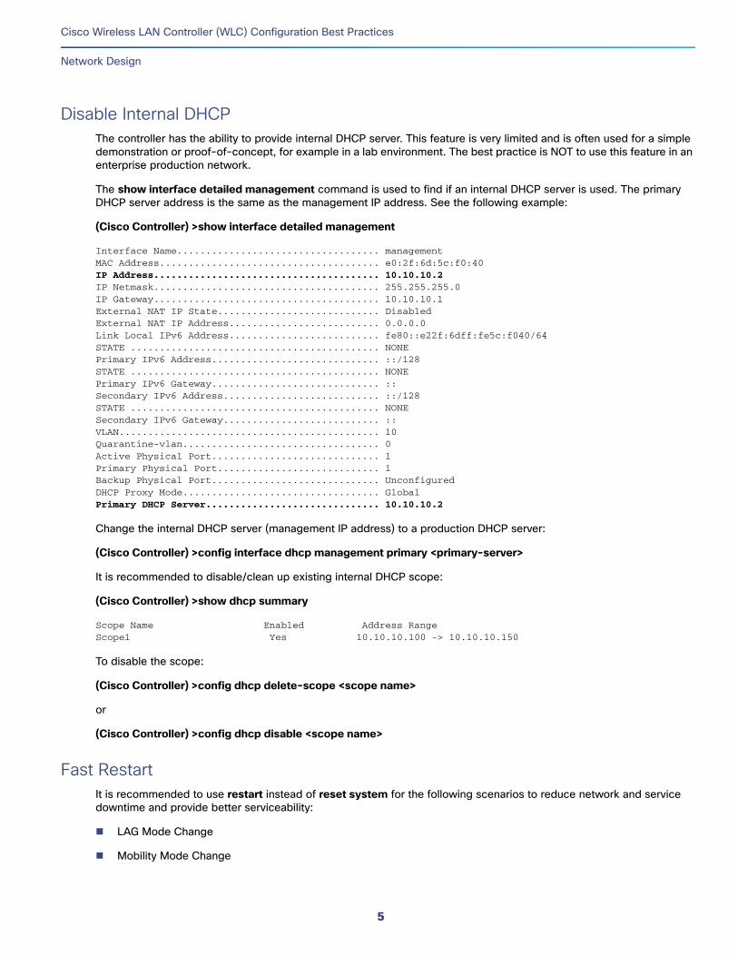
Disable Internal DHCPThe controller has the ability to provide internal DHCP server. This feature is very limited and is often used for a simple demonstration or proof-of-concept, for example in a lab environment. The best practice is NOT to use this feature in an enterprise production network.
The show interface detailed management command is used to find if an internal DHCP server is used. The primary DHCP server address is the same as the management IP address. See the following example:
(Cisco Controller) >show interface detailed management
Interface Name................................... managementMAC Address...................................... e0:2f:6d:5c:f0:40IP Address....................................... 10.10.10.2IP Netmask....................................... 255.255.255.0IP Gateway....................................... 10.10.10.1External NAT IP State............................ DisabledExternal NAT IP Address.......................... 0.0.0.0Link Local IPv6 Address.......................... fe80::e22f:6dff:fe5c:f040/64STATE ........................................... NONEPrimary IPv6 Address............................. ::/128STATE ........................................... NONEPrimary IPv6 Gateway............................. ::Secondary IPv6 Address........................... ::/128STATE ........................................... NONESecondary IPv6 Gateway........................... ::VLAN............................................. 10Quarantine-vlan.................................. 0Active Physical Port............................. 1Primary Physical Port............................ 1Backup Physical Port............................. UnconfiguredDHCP Proxy Mode.................................. GlobalPrimary DHCP Server.............................. 10.10.10.2
Change the internal DHCP server (management IP address) to a production DHCP server:
(Cisco Controller) >config interface dhcp management primary <primary-server>
It is recommended to disable/clean up existing internal DHCP scope:
(Cisco Controller) >show dhcp summary
Scope Name Enabled Address RangeScope1 Yes 10.10.10.100 -> 10.10.10.150
To disable the scope:
(Cisco Controller) >config dhcp delete-scope <scope name>
or
(Cisco Controller) >config dhcp disable <scope name>
Fast RestartIt is recommended to use restart instead of reset system for the following scenarios to reduce network and service downtime and provide better serviceability:
LAG Mode Change
Mobility Mode Change
5
Cisco Wireless LAN Controller (WLC) Configuration Best Practices
Security
Web-authentication cert installation
Clear Configuration
The Fast Restart feature is supported on Cisco WLC 7510, 8510, 5520, 8540, and vWLC starting release 8.1.
To restart the controller:
(Cisco Controller) >restart
The system has unsaved changes.Would you like to save them now? (y/N) y
Updating HBL license statistics fileDone.
Configuration Saved!System will now restart! Updating license storage ... Done.
SecurityThe following sections list out the best practices for security.
802.1x Authentication for APFor increased security, configure 802.1X authentication between a lightweight access point (AP) and a Cisco switch. The AP acts as an 802.1X supplicant and is authenticated by the switch using EAP-FAST with anonymous PAC provisioning. This is configurable on the global authentication settings.
To configure the global authentication username and password for all APs, which are currently joined to the controller as well as any AP that will join the controller in the future:
(Cisco Controller) >config ap 802.1Xuser add username <ap-username> password <ap-password> all
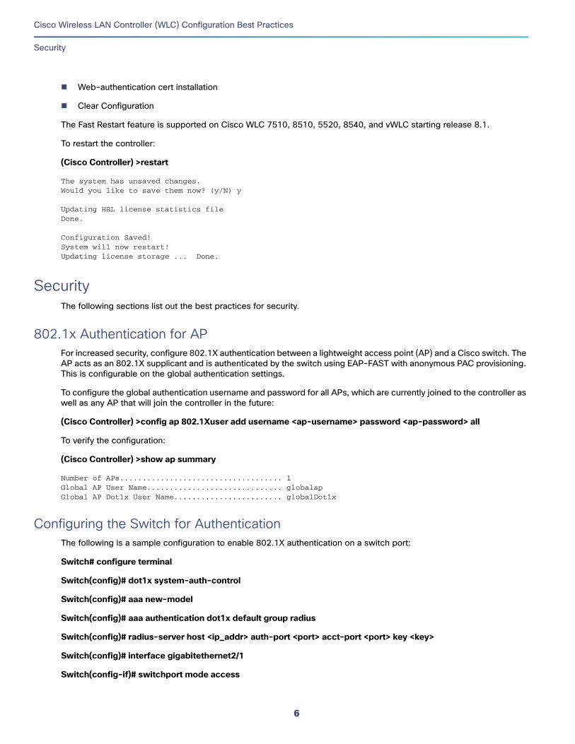
To verify the configuration:
(Cisco Controller) >show ap summary
Number of APs.................................... 1Global AP User Name.............................. globalapGlobal AP Dot1x User Name........................ globalDot1x
Configuring the Switch for AuthenticationThe following is a sample configuration to enable 802.1X authentication on a switch port:
Switch# configure terminal
Switch(config)# dot1x system-auth-control
Switch(config)# aaa new-model
Switch(config)# aaa authentication dot1x default group radius
Switch(config)# radius-server host <ip_addr> auth-port <port> acct-port <port> key <key>
Switch(config)# interface gigabitethernet2/1
Switch(config-if)# switchport mode access
6
Cisco Wireless LAN Controller (WLC) Configuration Best Practices
Security
Switch(config-if)# dot1x pae authenticator
Switch(config-if)# dot1x port-control auto
Switch(config-if)# end
Disable Management over WirelessThe Cisco WLAN Solution Management over Wireless feature allows Cisco WLAN Solution operators to monitor and configure local WLCs using a wireless client. Disable the Management over Wireless feature for security reasons.
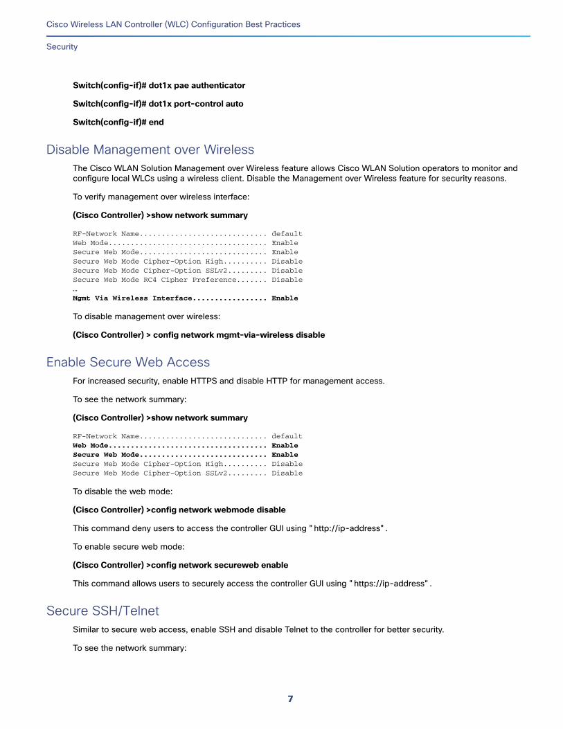
To verify management over wireless interface:
(Cisco Controller) >show network summary
RF-Network Name............................. defaultWeb Mode.................................... EnableSecure Web Mode............................. EnableSecure Web Mode Cipher-Option High.......... DisableSecure Web Mode Cipher-Option SSLv2......... DisableSecure Web Mode RC4 Cipher Preference....... Disable…Mgmt Via Wireless Interface................. Enable
To disable management over wireless:
(Cisco Controller) > config network mgmt-via-wireless disable
Enable Secure Web AccessFor increased security, enable HTTPS and disable HTTP for management access.
To see the network summary:
(Cisco Controller) >show network summary
RF-Network Name............................. defaultWeb Mode.................................... EnableSecure Web Mode............................. EnableSecure Web Mode Cipher-Option High.......... DisableSecure Web Mode Cipher-Option SSLv2......... Disable
To disable the web mode:
(Cisco Controller) >config network webmode disable
This command deny users to access the controller GUI using "http://ip-address".
To enable secure web mode:
(Cisco Controller) >config network secureweb enable
This command allows users to securely access the controller GUI using "https://ip-address".
Secure SSH/TelnetSimilar to secure web access, enable SSH and disable Telnet to the controller for better security.
To see the network summary:
7
Cisco Wireless LAN Controller (WLC) Configuration Best Practices
Security
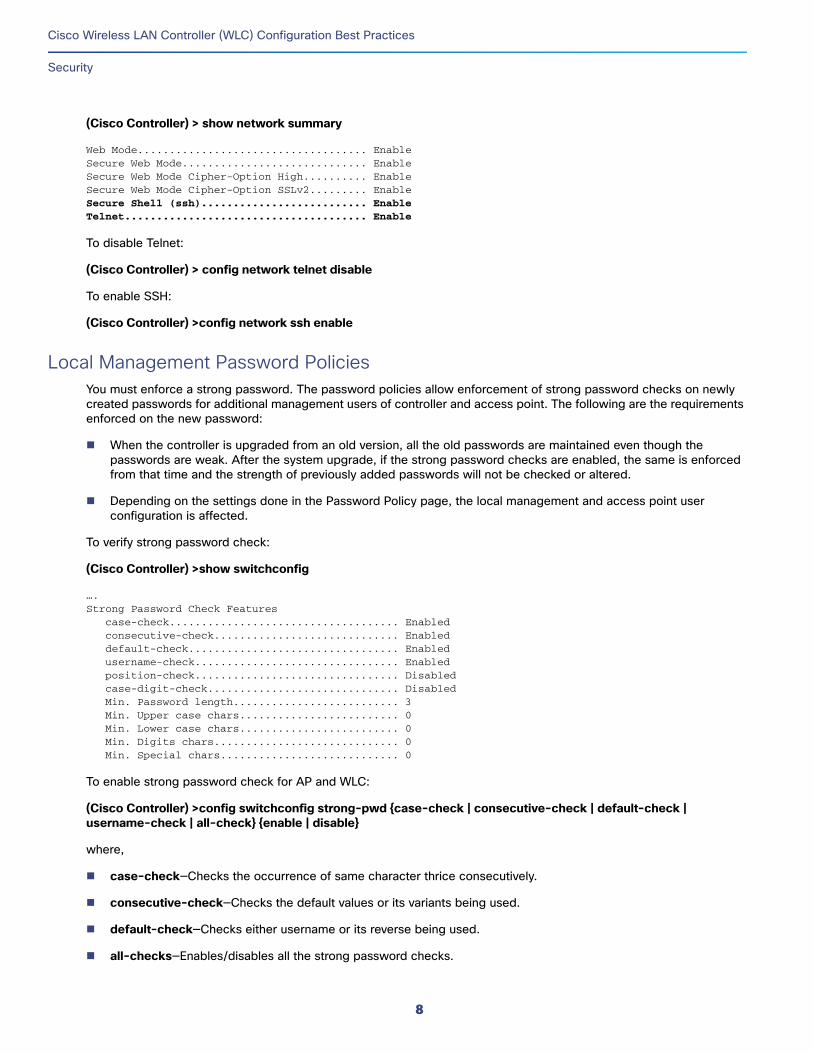
(Cisco Controller) > show network summary
Web Mode.................................... EnableSecure Web Mode............................. EnableSecure Web Mode Cipher-Option High.......... EnableSecure Web Mode Cipher-Option SSLv2......... EnableSecure Shell (ssh).......................... EnableTelnet...................................... Enable
To disable Telnet:
(Cisco Controller) > config network telnet disable
To enable SSH:
(Cisco Controller) >config network ssh enable
Local Management Password PoliciesYou must enforce a strong password. The password policies allow enforcement of strong password checks on newly created passwords for additional management users of controller and access point. The following are the requirements enforced on the new password:
When the controller is upgraded from an old version, all the old passwords are maintained even though the passwords are weak. After the system upgrade, if the strong password checks are enabled, the same is enforced from that time and the strength of previously added passwords will not be checked or altered.
Depending on the settings done in the Password Policy page, the local management and access point user configuration is affected.
To verify strong password check:
(Cisco Controller) >show switchconfig
….Strong Password Check Features case-check.................................... Enabled consecutive-check............................. Enabled default-check................................. Enabled username-check................................ Enabled position-check................................ Disabled case-digit-check.............................. Disabled Min. Password length.......................... 3 Min. Upper case chars......................... 0 Min. Lower case chars......................... 0 Min. Digits chars............................. 0 Min. Special chars............................ 0
To enable strong password check for AP and WLC:
(Cisco Controller) >config switchconfig strong-pwd {case-check | consecutive-check | default-check | username-check | all-check} {enable | disable}
where,
case-check—Checks the occurrence of same character thrice consecutively.
consecutive-check—Checks the default values or its variants being used.
default-check—Checks either username or its reverse being used.
all-checks—Enables/disables all the strong password checks.
8
Cisco Wireless LAN Controller (WLC) Configuration Best Practices
Security
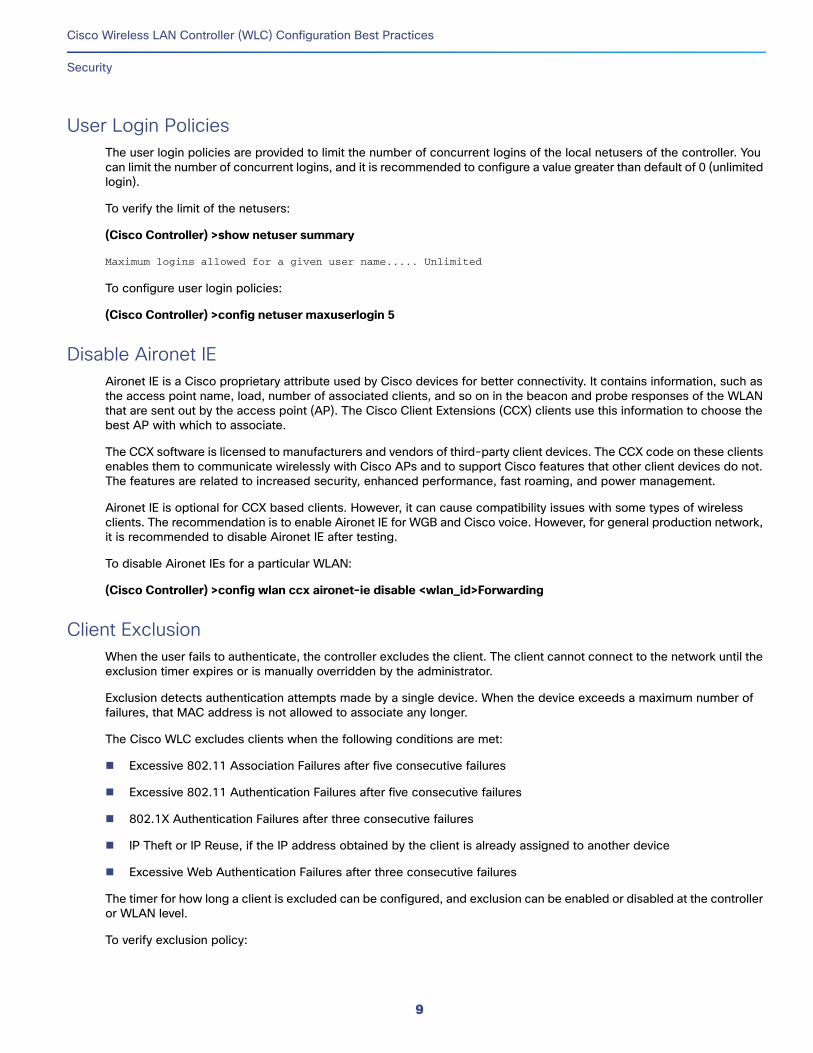
User Login PoliciesThe user login policies are provided to limit the number of concurrent logins of the local netusers of the controller. You can limit the number of concurrent logins, and it is recommended to configure a value greater than default of 0 (unlimited login).
To verify the limit of the netusers:
(Cisco Controller) >show netuser summary
Maximum logins allowed for a given user name..... Unlimited
To configure user login policies:
(Cisco Controller) >config netuser maxuserlogin 5
Disable Aironet IEAironet IE is a Cisco proprietary attribute used by Cisco devices for better connectivity. It contains information, such as the access point name, load, number of associated clients, and so on in the beacon and probe responses of the WLAN that are sent out by the access point (AP). The Cisco Client Extensions (CCX) clients use this information to choose the best AP with which to associate.
The CCX software is licensed to manufacturers and vendors of third-party client devices. The CCX code on these clients enables them to communicate wirelessly with Cisco APs and to support Cisco features that other client devices do not. The features are related to increased security, enhanced performance, fast roaming, and power management.
Aironet IE is optional for CCX based clients. However, it can cause compatibility issues with some types of wireless clients. The recommendation is to enable Aironet IE for WGB and Cisco voice. However, for general production network, it is recommended to disable Aironet IE after testing.
To disable Aironet IEs for a particular WLAN:
(Cisco Controller) >config wlan ccx aironet-ie disable <wlan_id>Forwarding
Client ExclusionWhen the user fails to authenticate, the controller excludes the client. The client cannot connect to the network until the exclusion timer expires or is manually overridden by the administrator.
Exclusion detects authentication attempts made by a single device. When the device exceeds a maximum number of failures, that MAC address is not allowed to associate any longer.
The Cisco WLC excludes clients when the following conditions are met:
Excessive 802.11 Association Failures after five consecutive failures
Excessive 802.11 Authentication Failures after five consecutive failures
802.1X Authentication Failures after three consecutive failures
IP Theft or IP Reuse, if the IP address obtained by the client is already assigned to another device
Excessive Web Authentication Failures after three consecutive failures
The timer for how long a client is excluded can be configured, and exclusion can be enabled or disabled at the controller or WLAN level.
To verify exclusion policy:
9
Cisco Wireless LAN Controller (WLC) Configuration Best Practices
Security
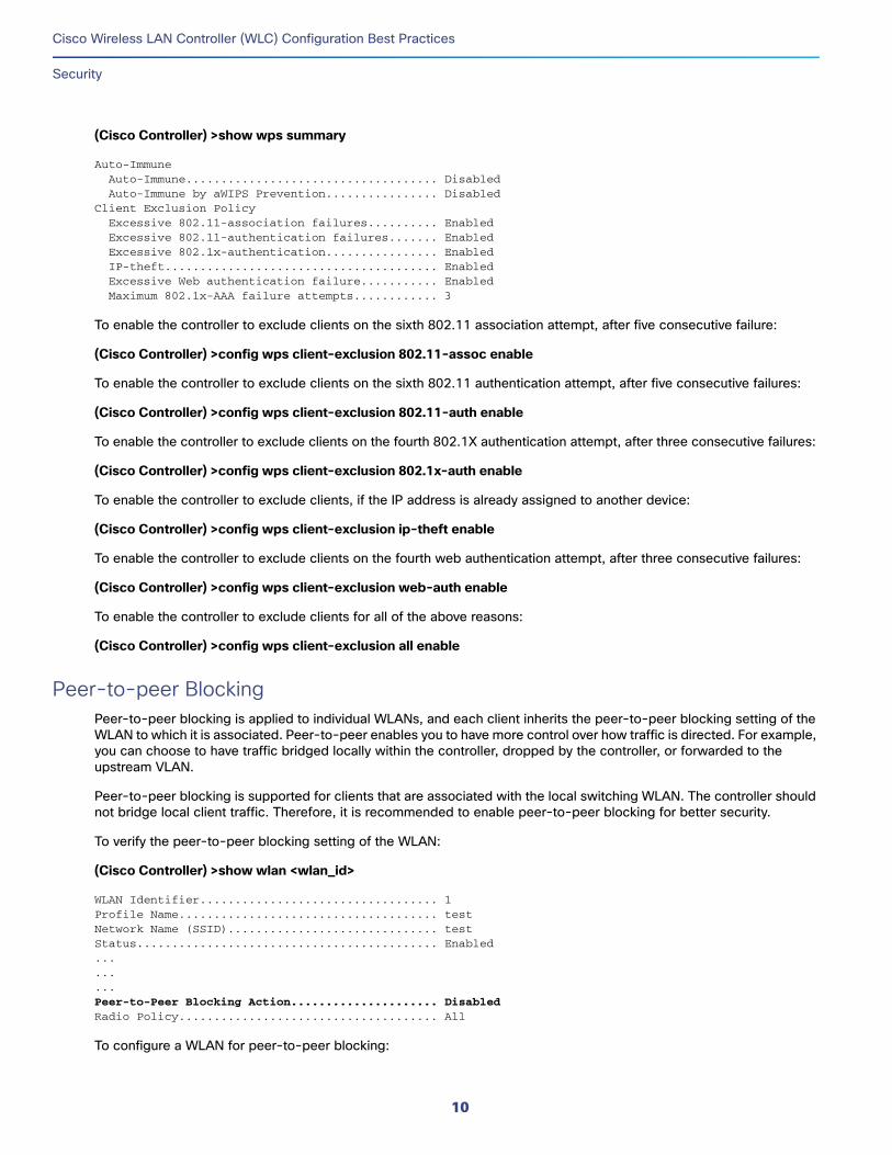
(Cisco Controller) >show wps summary
Auto-Immune Auto-Immune.................................... Disabled Auto-Immune by aWIPS Prevention................ DisabledClient Exclusion Policy Excessive 802.11-association failures.......... Enabled Excessive 802.11-authentication failures....... Enabled Excessive 802.1x-authentication................ Enabled IP-theft....................................... Enabled Excessive Web authentication failure........... Enabled Maximum 802.1x-AAA failure attempts............ 3
To enable the controller to exclude clients on the sixth 802.11 association attempt, after five consecutive failure:
(Cisco Controller) >config wps client-exclusion 802.11-assoc enable
To enable the controller to exclude clients on the sixth 802.11 authentication attempt, after five consecutive failures:
(Cisco Controller) >config wps client-exclusion 802.11-auth enable
To enable the controller to exclude clients on the fourth 802.1X authentication attempt, after three consecutive failures:
(Cisco Controller) >config wps client-exclusion 802.1x-auth enable
To enable the controller to exclude clients, if the IP address is already assigned to another device:
(Cisco Controller) >config wps client-exclusion ip-theft enable
To enable the controller to exclude clients on the fourth web authentication attempt, after three consecutive failures:
(Cisco Controller) >config wps client-exclusion web-auth enable
To enable the controller to exclude clients for all of the above reasons:
(Cisco Controller) >config wps client-exclusion all enable
Peer-to-peer BlockingPeer-to-peer blocking is applied to individual WLANs, and each client inherits the peer-to-peer blocking setting of the WLAN to which it is associated. Peer-to-peer enables you to have more control over how traffic is directed. For example, you can choose to have traffic bridged locally within the controller, dropped by the controller, or forwarded to the upstream VLAN.
Peer-to-peer blocking is supported for clients that are associated with the local switching WLAN. The controller should not bridge local client traffic. Therefore, it is recommended to enable peer-to-peer blocking for better security.
To verify the peer-to-peer blocking setting of the WLAN:
(Cisco Controller) >show wlan <wlan_id>
WLAN Identifier.................................. 1Profile Name..................................... testNetwork Name (SSID).............................. testStatus........................................... Enabled.........Peer-to-Peer Blocking Action..................... DisabledRadio Policy..................................... All
To configure a WLAN for peer-to-peer blocking:
10
Cisco Wireless LAN Controller (WLC) Configuration Best Practices
Security
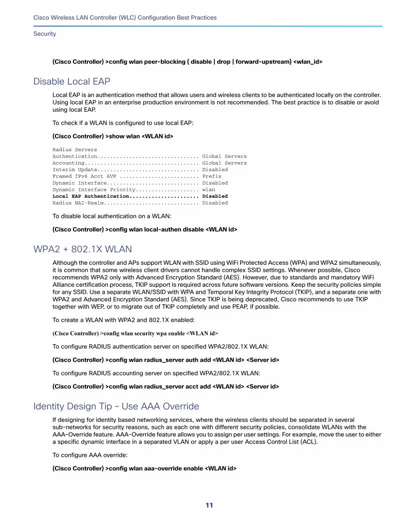
(Cisco Controller) >config wlan peer-blocking { disable | drop | forward-upstream} <wlan_id>
Disable Local EAPLocal EAP is an authentication method that allows users and wireless clients to be authenticated locally on the controller. Using local EAP in an enterprise production environment is not recommended. The best practice is to disable or avoid using local EAP.
To check if a WLAN is configured to use local EAP:
(Cisco Controller) >show wlan <WLAN id>
Radius ServersAuthentication................................ Global ServersAccounting.................................... Global ServersInterim Update................................ DisabledFramed IPv6 Acct AVP ......................... PrefixDynamic Interface............................. DisabledDynamic Interface Priority.................... wlanLocal EAP Authentication...................... DisabledRadius NAI-Realm.............................. Disabled
To disable local authentication on a WLAN:
(Cisco Controller) >config wlan local-authen disable <WLAN id>
WPA2 + 802.1X WLANAlthough the controller and APs support WLAN with SSID using WiFi Protected Access (WPA) and WPA2 simultaneously, it is common that some wireless client drivers cannot handle complex SSID settings. Whenever possible, Cisco recommends WPA2 only with Advanced Encryption Standard (AES). However, due to standards and mandatory WiFi Alliance certification process, TKIP support is required across future software versions. Keep the security policies simple for any SSID. Use a separate WLAN/SSID with WPA and Temporal Key Integrity Protocol (TKIP), and a separate one with WPA2 and Advanced Encryption Standard (AES). Since TKIP is being deprecated, Cisco recommends to use TKIP together with WEP, or to migrate out of TKIP completely and use PEAP, if possible.
To create a WLAN with WPA2 and 802.1X enabled:
(Cisco Controller) >config wlan security wpa enable <WLAN id>
To configure RADIUS authentication server on specified WPA2/802.1X WLAN:
(Cisco Controller) >config wlan radius_server auth add <WLAN id> <Server id>
To configure RADIUS accounting server on specified WPA2/802.1X WLAN:
(Cisco Controller) >config wlan radius_server acct add <WLAN id> <Server id>
Identity Design Tip – Use AAA OverrideIf designing for identity based networking services, where the wireless clients should be separated in several sub-networks for security reasons, such as each one with different security policies, consolidate WLANs with the AAA-Override feature. AAA-Override feature allows you to assign per user settings. For example, move the user to either a specific dynamic interface in a separated VLAN or apply a per user Access Control List (ACL).
To configure AAA override:
(Cisco Controller) >config wlan aaa-override enable <WLAN id>
11
Cisco Wireless LAN Controller (WLC) Configuration Best Practices
Security
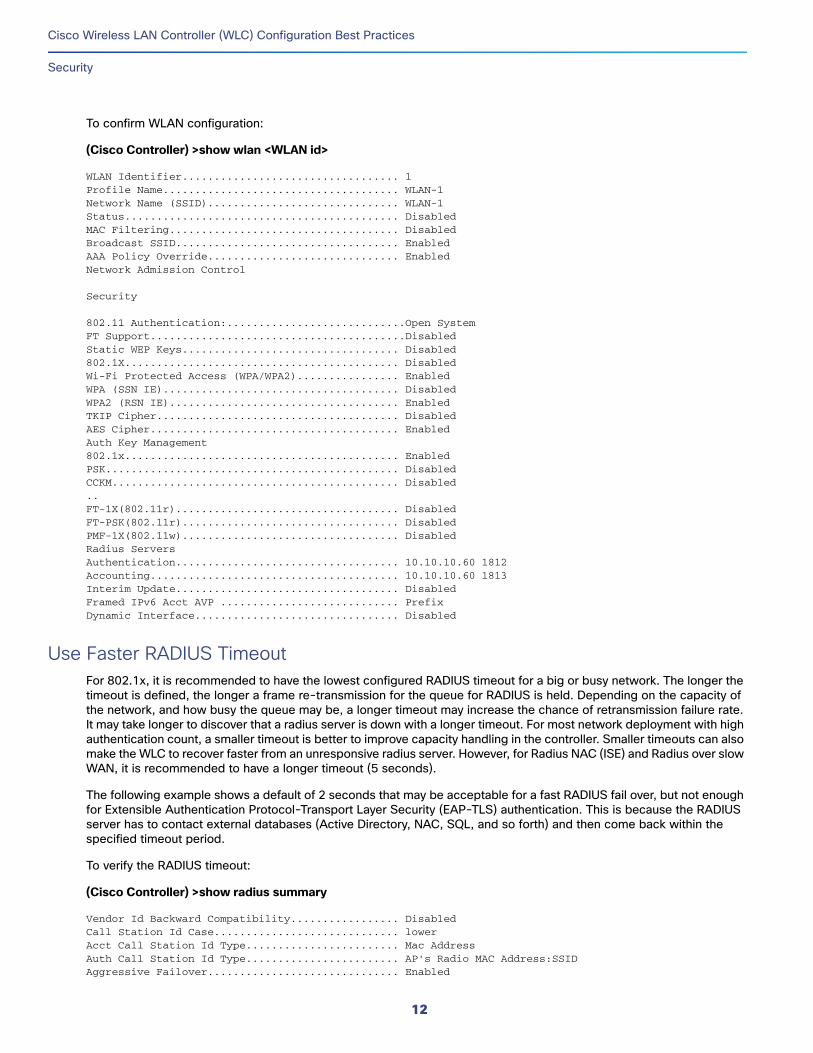
To confirm WLAN configuration:
(Cisco Controller) >show wlan <WLAN id>
WLAN Identifier.................................. 1Profile Name..................................... WLAN-1Network Name (SSID).............................. WLAN-1Status........................................... DisabledMAC Filtering.................................... DisabledBroadcast SSID................................... EnabledAAA Policy Override.............................. EnabledNetwork Admission Control
Security
802.11 Authentication:............................Open SystemFT Support........................................DisabledStatic WEP Keys.................................. Disabled802.1X........................................... DisabledWi-Fi Protected Access (WPA/WPA2)................ EnabledWPA (SSN IE)..................................... DisabledWPA2 (RSN IE).................................... EnabledTKIP Cipher...................................... DisabledAES Cipher....................................... EnabledAuth Key Management802.1x........................................... EnabledPSK.............................................. DisabledCCKM............................................. Disabled..FT-1X(802.11r)................................... DisabledFT-PSK(802.11r).................................. DisabledPMF-1X(802.11w).................................. DisabledRadius ServersAuthentication................................... 10.10.10.60 1812Accounting....................................... 10.10.10.60 1813Interim Update................................... DisabledFramed IPv6 Acct AVP ............................ PrefixDynamic Interface................................ Disabled
Use Faster RADIUS TimeoutFor 802.1x, it is recommended to have the lowest configured RADIUS timeout for a big or busy network. The longer the timeout is defined, the longer a frame re-transmission for the queue for RADIUS is held. Depending on the capacity of the network, and how busy the queue may be, a longer timeout may increase the chance of retransmission failure rate. It may take longer to discover that a radius server is down with a longer timeout. For most network deployment with high authentication count, a smaller timeout is better to improve capacity handling in the controller. Smaller timeouts can also make the WLC to recover faster from an unresponsive radius server. However, for Radius NAC (ISE) and Radius over slow WAN, it is recommended to have a longer timeout (5 seconds).
The following example shows a default of 2 seconds that may be acceptable for a fast RADIUS fail over, but not enough for Extensible Authentication Protocol-Transport Layer Security (EAP-TLS) authentication. This is because the RADIUS server has to contact external databases (Active Directory, NAC, SQL, and so forth) and then come back within the specified timeout period.
To verify the RADIUS timeout:
(Cisco Controller) >show radius summary
Vendor Id Backward Compatibility................. DisabledCall Station Id Case............................. lowerAcct Call Station Id Type........................ Mac AddressAuth Call Station Id Type........................ AP's Radio MAC Address:SSIDAggressive Failover.............................. Enabled
12
Cisco Wireless LAN Controller (WLC) Configuration Best Practices
Security
Keywrap.......................................... Disabled
Authentication ServersIdx Type Server Address Port State Tout RFC3576--- ---- ---------------- ------ -------- ---- -------1 N 10.48.76.50 1812 Enabled 2 Enabled
IPSec -AuthMode/Phase1/Group/Lifetime/Auth/Encr------------------------------------------------Disabled - none/unknown/group-0/0 none/none
To configure the RADIUS timeout:
(Cisco Controller) >config radius auth retransmit-timeout 1 <seconds>
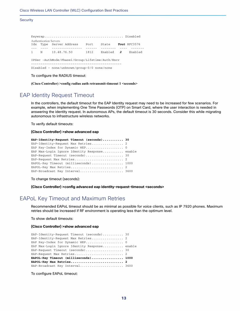
EAP Identity Request TimeoutIn the controllers, the default timeout for the EAP Identity request may need to be increased for few scenarios. For example, when implementing One Time Passwords (OTP) on Smart Card, where the user interaction is needed in answering the identity request. In autonomous APs, the default timeout is 30 seconds. Consider this while migrating autonomous to infrastructure wireless networks.
To verify default timeouts:
(Cisco Controller) >show advanced eap
EAP-Identity-Request Timeout (seconds)........... 30EAP-Identity-Request Max Retries................. 2EAP Key-Index for Dynamic WEP.................... 0EAP Max-Login Ignore Identity Response........... enableEAP-Request Timeout (seconds).................... 30EAP-Request Max Retries.......................... 2EAPOL-Key Timeout (milliseconds)................. 1000EAPOL-Key Max Retries............................ 2EAP-Broadcast Key Interval....................... 3600
To change timeout (seconds):
(Cisco Controller) >config advanced eap identity-request-timeout <seconds>
EAPoL Key Timeout and Maximum RetriesRecommended EAPoL timeout should be as minimal as possible for voice clients, such as IP 7920 phones. Maximum retries should be increased if RF environment is operating less than the optimum level.
To show default timeouts:
(Cisco Controller) >show advanced eap
EAP-Identity-Request Timeout (seconds)........... 30EAP-Identity-Request Max Retries................. 2EAP Key-Index for Dynamic WEP.................... 0EAP Max-Login Ignore Identity Response........... enableEAP-Request Timeout (seconds).................... 30EAP-Request Max Retries.......................... 2EAPOL-Key Timeout (milliseconds)................. 1000EAPOL-Key Max Retries............................ 2EAP-Broadcast Key Interval....................... 3600
To configure EAPoL timeout:
13
Cisco Wireless LAN Controller (WLC) Configuration Best Practices
Security
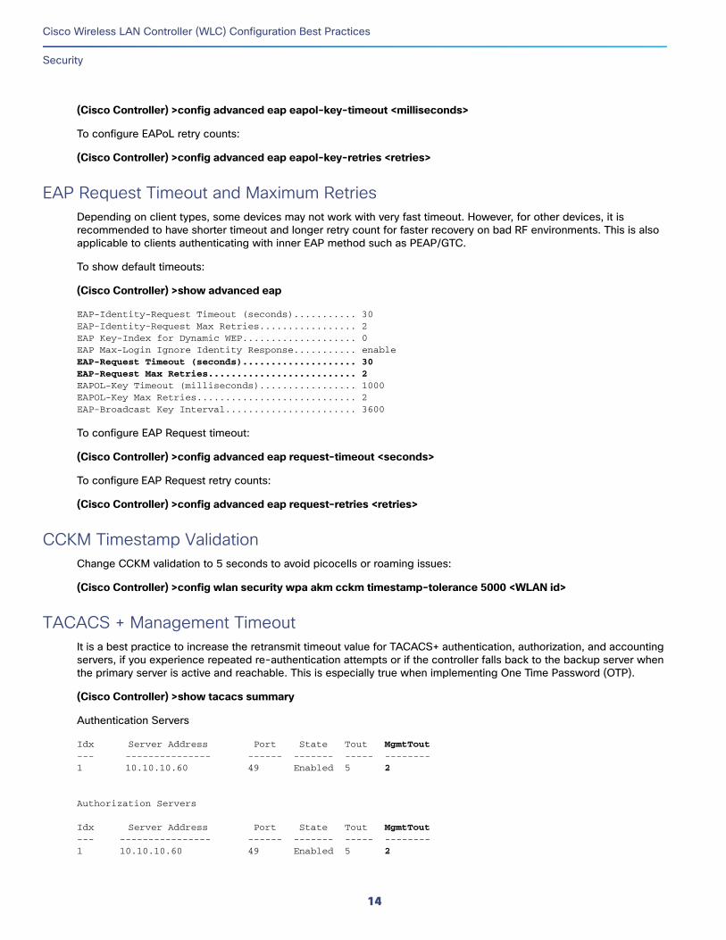
(Cisco Controller) >config advanced eap eapol-key-timeout <milliseconds>
To configure EAPoL retry counts:
(Cisco Controller) >config advanced eap eapol-key-retries <retries>
EAP Request Timeout and Maximum RetriesDepending on client types, some devices may not work with very fast timeout. However, for other devices, it is recommended to have shorter timeout and longer retry count for faster recovery on bad RF environments. This is also applicable to clients authenticating with inner EAP method such as PEAP/GTC.
To show default timeouts:
(Cisco Controller) >show advanced eap
EAP-Identity-Request Timeout (seconds)........... 30EAP-Identity-Request Max Retries................. 2EAP Key-Index for Dynamic WEP.................... 0EAP Max-Login Ignore Identity Response........... enableEAP-Request Timeout (seconds).................... 30EAP-Request Max Retries.......................... 2EAPOL-Key Timeout (milliseconds)................. 1000EAPOL-Key Max Retries............................ 2EAP-Broadcast Key Interval....................... 3600
To configure EAP Request timeout:
(Cisco Controller) >config advanced eap request-timeout <seconds>
To configure EAP Request retry counts:
(Cisco Controller) >config advanced eap request-retries <retries>
CCKM Timestamp ValidationChange CCKM validation to 5 seconds to avoid picocells or roaming issues:
(Cisco Controller) >config wlan security wpa akm cckm timestamp-tolerance 5000 <WLAN id>
TACACS + Management TimeoutIt is a best practice to increase the retransmit timeout value for TACACS+ authentication, authorization, and accounting servers, if you experience repeated re-authentication attempts or if the controller falls back to the backup server when the primary server is active and reachable. This is especially true when implementing One Time Password (OTP).
(Cisco Controller) >show tacacs summary
Authentication Servers
Idx Server Address Port State Tout MgmtTout--- --------------- ------ ------- ----- --------1 10.10.10.60 49 Enabled 5 2
Authorization Servers
Idx Server Address Port State Tout MgmtTout--- ---------------- ------ ------- ----- --------1 10.10.10.60 49 Enabled 5 2
14
Cisco Wireless LAN Controller (WLC) Configuration Best Practices
Security
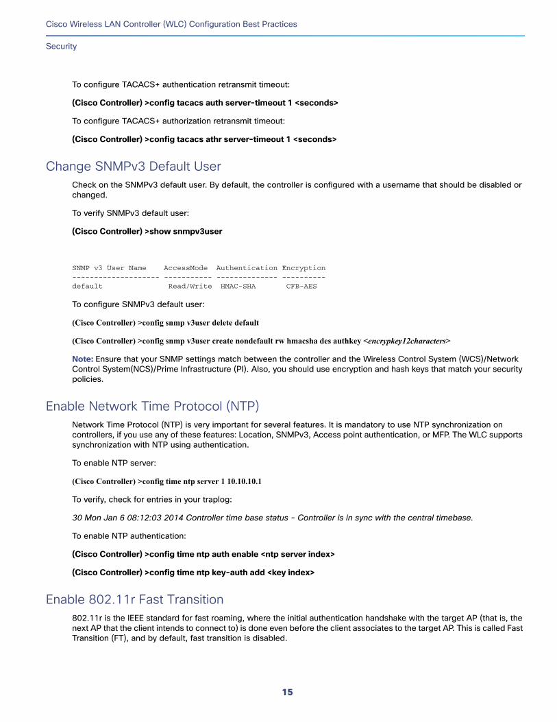
To configure TACACS+ authentication retransmit timeout:
(Cisco Controller) >config tacacs auth server-timeout 1 <seconds>
To configure TACACS+ authorization retransmit timeout:
(Cisco Controller) >config tacacs athr server-timeout 1 <seconds>
Change SNMPv3 Default UserCheck on the SNMPv3 default user. By default, the controller is configured with a username that should be disabled or changed.
To verify SNMPv3 default user:
(Cisco Controller) >show snmpv3user
SNMP v3 User Name AccessMode Authentication Encryption -------------------- ----------- -------------- ---------- default Read/Write HMAC-SHA CFB-AES
To configure SNMPv3 default user:
(Cisco Controller) >config snmp v3user delete default
(Cisco Controller) >config snmp v3user create nondefault rw hmacsha des authkey <encrypkey12characters>
Note: Ensure that your SNMP settings match between the controller and the Wireless Control System (WCS)/Network Control System(NCS)/Prime Infrastructure (PI). Also, you should use encryption and hash keys that match your security policies.
Enable Network Time Protocol (NTP)Network Time Protocol (NTP) is very important for several features. It is mandatory to use NTP synchronization on controllers, if you use any of these features: Location, SNMPv3, Access point authentication, or MFP. The WLC supports synchronization with NTP using authentication.
To enable NTP server:
(Cisco Controller) >config time ntp server 1 10.10.10.1
To verify, check for entries in your traplog:
30 Mon Jan 6 08:12:03 2014 Controller time base status - Controller is in sync with the central timebase.
To enable NTP authentication:
(Cisco Controller) >config time ntp auth enable <ntp server index>
(Cisco Controller) >config time ntp key-auth add <key index>
Enable 802.11r Fast Transition802.11r is the IEEE standard for fast roaming, where the initial authentication handshake with the target AP (that is, the next AP that the client intends to connect to) is done even before the client associates to the target AP. This is called Fast Transition (FT), and by default, fast transition is disabled.
15
Cisco Wireless LAN Controller (WLC) Configuration Best Practices
Security
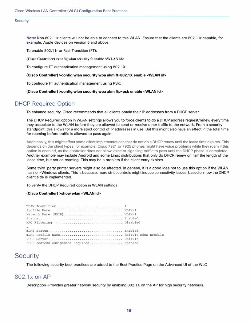
Note: Non 802.11r clients will not be able to connect to this WLAN. Ensure that the clients are 802.11r capable, for example, Apple devices on version 6 and above.
To enable 802.11r or Fast Transition (FT):
(Cisco Controller) >config wlan security ft enable <WLAN id>
To configure FT authentication management using 802.1X:
(Cisco Controller) >config wlan security wpa akm ft-802.1X enable <WLAN id>
To configure FT authentication management using PSK:
(Cisco Controller) >config wlan security wpa akm ftp-psk enable <WLAN id>
DHCP Required OptionTo enhance security, Cisco recommends that all clients obtain their IP addresses from a DHCP server.
The DHCP Required option in WLAN settings allows you to force clients to do a DHCP address request/renew every time they associate to the WLAN before they are allowed to send or receive other traffic to the network. From a security standpoint, this allows for a more strict control of IP addresses in use. But this might also have an effect in the total time for roaming before traffic is allowed to pass again.
Additionally, this might affect some client implementations that do not do a DHCP renew until the lease time expires. This depends on the client types, for example, Cisco 7921 or 7925 phones might have voice problems while they roam if this option is enabled, as the controller does not allow voice or signaling traffic to pass until the DHCP phase is completed. Another example may include Android and some Linux distributions that only do DHCP renew on half the length of the lease time, but not on roaming. This may be a problem if the client entry expires.
Some third-party printer servers might also be affected. In general, it is a good idea not to use this option if the WLAN has non-Windows clients. This is because, more strict controls might induce connectivity issues, based on how the DHCP client side is implemented.
To verify the DHCP Required option in WLAN settings:
(Cisco Controller) >show wlan <WLAN id>
WLAN Identifier.................................. 1Profile Name..................................... WLAN-1Network Name (SSID).............................. WLAN-1Status........................................... EnabledMAC Filtering.................................... Disabled…mDNS Status...................................... EnabledmDNS Profile Name................................ default-mdns-profileDHCP Server...................................... DefaultDHCP Address Assignment Required................. Enabled
SecurityThe following security best practices are added to the Best Practice Page on the Advanced UI of the WLC
802.1x on APDescription—Provides greater network security by enabling 802.1X on the AP for high security networks.
16
Cisco Wireless LAN Controller (WLC) Configuration Best Practices
Security
Status: Compliant—802.1x authentication for APs is enabled
Non-Compliant—802.1x authentication for APs is disabled
CLI Option:Enable 802.1x on AP by entering this command:
(Cisco Controller) >config ap 802.1Xuser add username ap-userpassword password all
CPU ACLsDescription—Control overall access to the WLC
Status: Compliant—Configured
Non-Compliant—Not configured
Client ExclusionDescription—Enables the Cisco WLC to exclude the clients from joining under specific conditions. Clicking Fix it Now enables client exclusion for all events.
Status: Compliant—Client exclusion is enabled for all events
Non-Compliant—Client exclusion is disabled for all events
CLI Option:Enable client exclusion for all events by entering this command:
(Cisco Controller) >config wps client-exclusion all enable
Legacy IDSDescription—Enables wireless IDS feature and 17 built-in signatures to avoid intrusion attacks. Clicking Fix it Now enables signature check.
For this best practice to work, ensure that at least one WLAN is enabled and client exclusion-listing is enabled for the WLAN. To enable client exclusion-listing for a WLAN, use the conf wlan exclusionlist wlan-id enabled command.
Status: Compliant—All standard signature check is enabled
Non-Compliant—All standard signature check is disabled
CLI Option:Enable signature check by entering this command:
(Cisco Controller) >config wps signature enable
17
Cisco Wireless LAN Controller (WLC) Configuration Best Practices
Security
Local Management Password PoliciesDescription—Strong password policies should be enforced. Clicking Fix it Now enables the following strong password policies:
case-check—Checks the occurrence of same character thrice consecutively
consecutive-check—Checks the default values or its variants are being used
default-check—Checks either username or its reverse is being used
all-checks—Enables/disables all the strong password checks
position-check—Checks four-character range from old password
case-digit-check—Checks all four combinations to be present: lower, upper, digits, and special characters
Status: Compliant—All strong password policies are enabled
Non-Compliant—Some or no password policies are enabled
CLI Option:Enable all strong password policies by entering this command:
(Cisco Controller) >config switchconfig strong-pwd all-checks enable
Min Rogue RSSI ThresholdDescription—Specifies the minimum RSSI value that rogues should have for APs to detect them and for the rogue entries to be created in the Cisco WLC. Recommended value is –80 dBm. Clicking Fix it Now changes the minimum RSSI value that rogues should have to –80 dBm.
Status: Compliant—Set to –80 dBm
Non-Compliant—Set to less than –80 dBm
CLI Option:Set the minimum RSSI value that rogues should have by entering this command:
(Cisco Controller) >config rogue detection min-rssi rssi-in-dBm
Peer to PeerDescription—Peer to peer blocking function disables bridging of traffic on the same subnet between clients. This is only recommended on high security networks where client to client communication is undesirable. Not recommended on enterprise and voice deployments.
Status: Compliant—Peer to peer blocking enabled on one or more WLANs
Non-Compliant—Peer to peer blocking is disabled on all WLAN
CLI Option:Enable Peer to peer blocking by entering this command:
(Cisco Controller) >config wlan peer-blocking drop wlan-id
18
Cisco Wireless LAN Controller (WLC) Configuration Best Practices
Security
Rogue PoliciesDescription—Policy should be at least High. Clicking Fix it Now sets the rogue detection security level to High.
Status: Compliant—Policy is set to High or above
Non-Compliant—Policy is set to Custom.
Set the rogue detection security level to High by entering this command:
(Cisco Controller) >config rogue detection security-level high
SSH/Telnet AccessDescription—SSH to the WLC should be enabled by default. Clicking Fix it Now enables SSH and disables Telnet to the WLC.
Status: Compliant—SSH enabled; Telnet disabled
Non-Compliant—SSH enabled and Telnet enabled OR SSH disabled and Telnet enabled
CLI Option: Enable SSH by entering this command:
(Cisco Controller) >config network ssh enable
Disable Telnet by entering this command:
(Cisco Controller) >config network telnet disable
User Login PoliciesDescription— The user login policies are provided to limit the number of concurrent logins of the local net users of the controller. You can limit the number of concurrent logins, and the recommendation is greater than default of 0 (unlimited).
Status: Compliant—Configured
Non-Compliant—No user login policies are present
CLI Option: Verify the limit of the net users by entering this command:
(Cisco Controller) >show netuser summary
Configure user login policies by entering this command:
(Cisco Controller) >config netuser maxUserLogin count
WLAN with WPA2 or 802.1XDescription—WLAN should be using 802.1X or WPA security. There is no fix it button. Link to the WLAN page is provided. Day 0 default does not mandate an 802.1X.
19
Cisco Wireless LAN Controller (WLC) Configuration Best Practices
ISE RADIUS
Status:Compliant—Enabled if at least one WLAN is using 802.1X or WPA
Non-Compliant—Disabled
WLAN with WPA2 and AES PolicyDescription—We recommend that you use WPA2+AES instead of WPA+AES and TKIP because WPA2+AES provides greater security. WPA+AES is deprecated and therefore not recommended to be used.
Status:Compliant—All WLANs configured with WPA+WPA2 have WPA2+AES security policy
Non-Compliant—All WLANs configured with WPA+WPA2 have the following security policies:
WPA+AES, WPA2+AES
WPA+AES
CLI Option:Use the following CLI to enable WPA2+AES on the WLAN:
(Cisco Controller) >config wlan security wpa enable wlan-id
ISE RADIUSThe following best practices are applicable to networks with ISE as the AAA server and are added to the Best Practice Page on the Advanced UI of the WLC
RADIUS Server TimeoutDescription—RADIUS authentication and accounting servers should have 5 seconds as the minimum value for server timeout to prevent client join timeout issues from the ISE RADIUS server.??
Status:Compliant—All the enabled RADIUS authentication and accounting server timeouts are greater or equal to 5 seconds.??
Non-Compliant—At least one enabled RADIUS authentication and accounting server timeout is less than 5 seconds.??
CLI Option:Set the timeout for RADIUS authentication and accounting servers by entering these commands:
(Cisco Controller) >config radius auth retransmit-timeout RADIUS-Server-ID timeout-in-seconds
(Cisco Controller) >config radius acct retransmit-timeout RADIUS-Server-ID timeout-in-seconds
WLAN ISE ConfigurationDescription—Allows you to identify if the WLAN is configured with recommended configuration for Cisco ISE RADIUS server.??
Status:Compliant—At least one WLAN in enabled state has the entire ISE configuration set.??
Non-Compliant—None of the WLANs in enabled state has the entire ISE configuration set.
20
Cisco Wireless LAN Controller (WLC) Configuration Best Practices
Rogue Management and Detection
CLI Option:Multiple features have to be configured by entering these commands:
SecurityEnable interim update in AAA server:
(Cisco Controller) >config wlan radius_server acct interim-update enable wlan-id
Set interim interval in AAA server to 0 second:
(Cisco Controller) >config wlan radius_server acct interim-update 0 wlan-id
AdvancedEnable client exclusion:
(Cisco Controller) >config wlan exclusionlist wlan-idenabled
Set session timeout to 7200 seconds:
(Cisco Controller) >config wlan session-timeout wlan-id7200
Set client exclusion list timeout to 180 seconds:
(Cisco Controller) >config wlan exclusionlist wlan-id 180
Set the user idle timeout to 3600 seconds:
(Cisco Controller) >config wlan usertimeout 3600 wlan-id
RADIUS Aggressive FailoverDescription—The RADIUS aggressive failover should be disabled to get optimum performance for client authentication on a Cisco ISE server.
Status: Compliant—The RADIUS aggressive failover is disabled.??
Non-Compliant—The RADIUS aggressive failover is enabled.??
CLI Option:Disable aggressive failover for RADIUS by entering this command:
(Cisco Controller) >config radius aggressive-failover disable
Rogue Management and DetectionRogue wireless devices are an ongoing threat to corporate wireless networks. Network owners need to do more than just scanning the unknown devices. They must be able to detect, disable, locate, and manage rogue/intruder threats automatically and in real time.
Rogue APs can disrupt wireless LAN operations by hijacking legitimate clients and using plain text, denial-of-service attacks, or man-in-the-middle attacks. That is, a hacker can use a rogue AP to capture sensitive information, such as passwords and usernames. The hacker can then transmit a series of clear-to-send (CTS) frames, which mimics an AP informing a particular wireless LAN client adapter to transmit and instruct all others to wait. This scenario results in legitimate clients being unable to access the wireless LAN resources. Thus, wireless LAN service providers look for banning rogue APs from the air space.
21
Cisco Wireless LAN Controller (WLC) Configuration Best Practices
Rogue Management and Detection
The best practice is to use rogue detection to minimize security risks, for example, in a corporate environment. However, there are certain scenarios in which rogue detection is not needed, for example, in OEAP deployment, open venues/stadium, citywide, and outdoors. Using outdoor mesh APs to detect rogues would provide little value while incurring resources to analyze. Finally, it is critical to evaluate (or avoid altogether) rogue auto-containment, as there are potential legal issues and liabilities if left to operate automatically.
Some best practices, listed in the following sections, improve efficiency in maintaining the rogue AP list and making it manageable.
For additional details on rogue management, refer to the following document:
http://www.cisco.com/c/en/us/td/docs/wireless/technology/roguedetection_deploy/Rogue_Detection.html
Define Appropriate Malicious Rogue AP RulesOn a daily basis, define malicious rogue AP rules to prioritize major and critical rogue AP alarms that require immediate attention and mitigation plan.
Critical or major rogue AP alarms are classified as ‘Malicious’ and are detected on the network.
Each rogue rule is composed of single or multiple conditions (Required or Recommended). The malicious rogue AP rules are as follows:
Managed SSIDs (Required)—Any rogue APs using managed SSIDs, the same as your wireless infrastructure, must be marked as “Malicious”. Administrators need to investigate and mitigate this threat.
Minimum RSSI >-70 dBm (Recommended)—This criterion normally indicates that unknown rogue APs are inside the facility perimeters, and can cause potential interference to the wireless network.
This rule is only recommended for Enterprise deployment having its own isolated buildings and secured perimeters.
This rule is not recommended for retail customers or venues that are shared by various tenants, where WiFi signals from all parties normally bleed into each other.
User configured SSIDs/Sub-string SSIDs (Recommended) monitor any SSIDs that use different variations or combinations of characters in your production SSIDs (Managed SSIDs).
The following points lists the recommended actions for matching conditions in malicious rouge AP rules:
For malicious rogue APs matching “Must” conditions, configure “Contain” as action.
Configure only one condition for each rule and make the rule name intuitive for its related condition. This facilitates the administrator to identify and troubleshoot.
For malicious rogue APs matching “Optional” conditions, it is not recommended to configure “Contain” as action due to legal complications. Instead, configure “Alert” as action.
Note: There are legal implications for containing rogue APs. However, rogue AP using same SSIDs as your production SSIDs can be the exception for auto containment in mitigating potential threat from this rogue attracting legitimate wireless clients.
Identify and Update Friendly Rogue AP List RegularlyResearch and investigate, and then remove friendly rogue APs from “Unclassified” rogue AP list on a regular basis (weekly or monthly).
Examples of friendly rogue APs are as follows:
Known Internal Friendly Rogue APs, for example within facility perimeters, and known AP MAC addresses imported into the friendly rouge AP list.
22
Cisco Wireless LAN Controller (WLC) Configuration Best Practices
Rogue Management and Detection
Known External Friendly Rogue APs, for example, vendor shared venues and neighboring retailers.
Best Effort for Unclassified Rogue APs By default, rogue AP alarms are displayed as “Unclassified” with “Minor” severity if they do not meet the defined classification rules. This list can grow and become unmanageable in PI. For example, transient rogue APs are detected only for a short duration, such as MiFi devices. It is unnecessary to monitor these rogues on a daily basis if they are not detected on the wired network. Instead, do the following:
Implement automated rogue AP mitigation mechanism, such as auto switchport tracing. If traced on wired network, critical alarms will be triggered.
Run monthly or quarterly report on unclassified rogue APs to identify potentially unknown friendly ones among them.
Implement Auto Switchport Tracing (SPT) as Rogue AP Mitigation SchemeThe recommendation is to implement auto SPT for rogue AP mitigation, that is to correlate rogue AP radio MAC address, heard over the air, to Ethernet MAC address on wired network side. Once the potential match is found, it will be reported as “Found On Network” on PI.
When auto SPT starts, it runs through each rogue AP radio MAC address against all known Ethernet MAC addresses on all known switches.
Auto SPT enabled for alarms with “Minor” severity eases the job of administrators as the mitigation scheme is already in place.
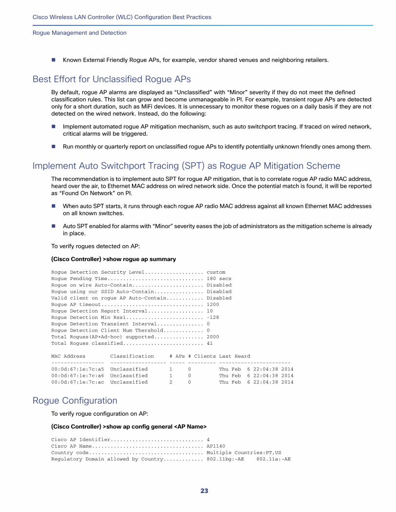
To verify rogues detected on AP:
(Cisco Controller) >show rogue ap summary
Rogue Detection Security Level................... customRogue Pending Time............................... 180 secsRogue on wire Auto-Contain....................... DisabledRogue using our SSID Auto-Contain................ DisabledValid client on rogue AP Auto-Contain............ DisabledRogue AP timeout................................. 1200Rogue Detection Report Interval.................. 10Rogue Detection Min Rssi......................... -128Rogue Detection Transient Interval............... 0Rogue Detection Client Num Thershold............. 0Total Rogues(AP+Ad-hoc) supported................ 2000Total Rogues classified.......................... 41
MAC Address Classification # APs # Clients Last Heard ----------------- ------------------ ----- --------- -----------------------00:0d:67:1e:7c:a5 Unclassified 1 0 Thu Feb 6 22:04:38 201400:0d:67:1e:7c:a6 Unclassified 1 0 Thu Feb 6 22:04:38 201400:0d:67:1e:7c:ac Unclassified 2 0 Thu Feb 6 22:04:38 2014
Rogue ConfigurationTo verify rogue configuration on AP:
(Cisco Controller) >show ap config general <AP Name>
Cisco AP Identifier.............................. 4Cisco AP Name.................................... AP1140Country code..................................... Multiple Countries:PT,USRegulatory Domain allowed by Country............. 802.11bg:-AE 802.11a:-AE
23
Cisco Wireless LAN Controller (WLC) Configuration Best Practices
Rogue Management and Detection
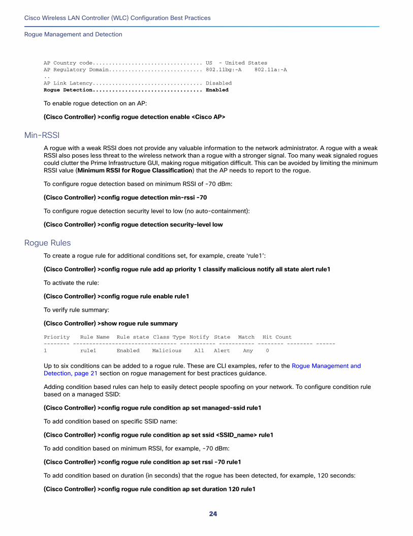
AP Country code.................................. US - United StatesAP Regulatory Domain............................. 802.11bg:-A 802.11a:-A ..AP Link Latency.................................. DisabledRogue Detection.................................. Enabled
To enable rogue detection on an AP:
(Cisco Controller) >config rogue detection enable <Cisco AP>
Min-RSSIA rogue with a weak RSSI does not provide any valuable information to the network administrator. A rogue with a weak RSSI also poses less threat to the wireless network than a rogue with a stronger signal. Too many weak signaled rogues could clutter the Prime Infrastructure GUI, making rogue mitigation difficult. This can be avoided by limiting the minimum RSSI value (Minimum RSSI for Rogue Classification) that the AP needs to report to the rogue.
To configure rogue detection based on minimum RSSI of -70 dBm:
(Cisco Controller) >config rogue detection min-rssi -70
To configure rogue detection security level to low (no auto-containment):
(Cisco Controller) >config rogue detection security-level low
Rogue RulesTo create a rogue rule for additional conditions set, for example, create ‘rule1’:
(Cisco Controller) >config rogue rule add ap priority 1 classify malicious notify all state alert rule1
To activate the rule:
(Cisco Controller) >config rogue rule enable rule1
To verify rule summary:
(Cisco Controller) >show rogue rule summary
Priority Rule Name Rule state Class Type Notify State Match Hit Count-------- -------------------------------- ----------- ----------- -------- -------- ------1 rule1 Enabled Malicious All Alert Any 0
Up to six conditions can be added to a rogue rule. These are CLI examples, refer to the Rogue Management and Detection, page 21 section on rogue management for best practices guidance.
Adding condition based rules can help to easily detect people spoofing on your network. To configure condition rule based on a managed SSID:
(Cisco Controller) >config rogue rule condition ap set managed-ssid rule1
To add condition based on specific SSID name:
(Cisco Controller) >config rogue rule condition ap set ssid <SSID_name> rule1
To add condition based on minimum RSSI, for example, -70 dBm:
(Cisco Controller) >config rogue rule condition ap set rssi -70 rule1
To add condition based on duration (in seconds) that the rogue has been detected, for example, 120 seconds:
(Cisco Controller) >config rogue rule condition ap set duration 120 rule1
24
Cisco Wireless LAN Controller (WLC) Configuration Best Practices
Rogue Management and Detection
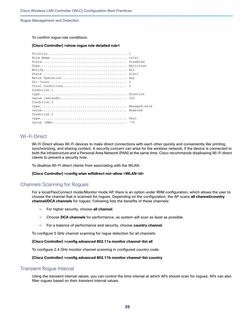
To confirm rogue rule conditions:
(Cisco Controller) >show rogue rule detailed rule1
Priority......................................... 1Rule Name........................................ rule1State............................................ DisabledType............................................. MaliciousNotify........................................... AllState ........................................... AlertMatch Operation.................................. AnyHit Count........................................ 0Total Conditions................................. 3Condition 1type............................................. Durationvalue (seconds).................................. 120Condition 2type............................................. Managed-ssidvalue............................................ EnabledCondition 3type............................................. Rssivalue (dBm)...................................... -70
Wi-Fi DirectWi-Fi Direct allows Wi-Fi devices to make direct connections with each other quickly and conveniently like printing, synchronizing, and sharing content. A security concern can arise for the wireless network, if the device is connected to both the infrastructure and a Personal Area Network (PAN) at the same time. Cisco recommends disallowing Wi-Fi direct clients to prevent a security hole.
To disallow Wi-Fi direct clients from associating with the WLAN:
(Cisco Controller) >config wlan wifidirect not-allow <WLAN-id>
Channels Scanning for RoguesFor a local/FlexConnect mode/Monitor mode AP, there is an option under RRM configuration, which allows the user to choose the channel that is scanned for rogues. Depending on the configuration, the AP scans all channel/country channel/DCA channels for rogues. Following lists the benefits of these channels:
— For higher security, choose all channel.
— Choose DCA channels for performance, as system will scan as least as possible.
— For a balance of performance and security, choose country channel.
To configure 5 GHz channel scanning for rogue detection for all channels:
(Cisco Controller) >config advanced 802.11a monitor channel-list all
To configure 2.4 GHz monitor channel scanning in configured country code:
(Cisco Controller) >config advanced 802.11b monitor channel-list country
Transient Rogue IntervalUsing the transient interval values, you can control the time interval at which APs should scan for rogues. APs can also filter rogues based on their transient interval values.
25
Cisco Wireless LAN Controller (WLC) Configuration Best Practices
Wireless/RF
This feature has the following advantages:
— Rogue reports from APs to the controller are shorter.
— Transient rogue entries are avoided in the controller.
— Unnecessary memory allocation for transient rogues is avoided.
To configure transient rogue interval of 2 minutes (120 seconds):
(Cisco Controller) >config rogue detection monitor-ap transient-rogue-interval 120
Enable Ad hoc Rogue DetectionSimilar to general rogue detection, ad hoc rogue detection is ideal in certain scenarios where security is justifiable. However, it is not recommended in scenarios such as open venues/stadiums, citywide, and public outdoors.
To enable ad hoc rogue detection and reporting:
(Cisco Controller) >config rogue adhoc enable
Enable Rogue Clients AAA ValidationThe reason for enabling AAA validation for rogue clients is that the WLC will reliably and continuously check for a client to exist on the AAA server, and then mark it either valid or malicious.
(Cisco Controller) >config rogue client aaa enable
Enable Rogue Clients MSE ValidationIf there is a Mobility Services Engine (MSE) available and integrated, it can share the information in its learned client’s database to compliment the WLC in validating whether a client is valid or a threat.
To enable the use of MSE (if available) to check if rogue clients are valid:
(Cisco Controller) >config rogue client mse enable
Wireless/RFFor any wireless deployment, always do a proper site survey to ensure proper quality of service for your wireless clients. The requirements for voice or location deployments are stricter than data services. Auto RF might help on channel and power settings management, but it cannot correct a bad RF design.
The site survey must be done with devices that match the power and propagation behavior of the devices to be used on the real network. For example, do not use an older 802.11b/g radio with omni antenna to study coverage, if the final network uses more modern dual radios for 802.11a/b/g/n and 802.11ac data rates.
The site survey should be done with the AP model that the customer is going to install. The AP should be at the orientation and height that will be typical of the final installation. The data rates on the AP should be set to the rates required by the customer application, bandwidth, and coverage requirements. Do not measure the coverage area to a data rate of 1 Mbps with 2.4 GHz. If the primary objective of the network design is for each area of coverage to support 30 users at 5 GHz with 9 Mbps of data rate, then perform a coverage test with the primary network device with only the 5 GHz data rate with 9 Mbps enabled. Then, measure the -67 dBm receive signal strength indicator (RSSI) on the AP for the test network client during active data traffic between the AP and client. High quality RF links have good signal to noise ratios (SNR) and low channel utilization (CU) percentages. RSSI, SNR, and CU values are found on the WLC’s client and AP information pages.
26
Cisco Wireless LAN Controller (WLC) Configuration Best Practices
Wireless/RF
Disable Low Data RatesYou must carefully plan the process to disable or enable data rates. If your coverage is sufficient, it is a good idea to incrementally disable lower data rates one by one. Management frames such as ACK or beacons are sent at the lowest mandatory rate (typically 1 Mbps), which slows down the whole throughput as the lowest mandatory rate consumes the most airtime.
Try not to have too many supported data rates so that clients can down-shift their rate faster when retransmitting. Typically, clients try to send at the fastest data rate. If the frame does not make it through, the client will retransmit at the next lowest data rate and so on until the frame goes through. The removal of some supported rates helps the clients that retransmit a frame to directly down-shift several data rates, which increases the chance for the frame to go through at the second attempt.
— Beacons are sent at the lowest mandatory rate, defining roughly the cell size.
— Multicast is sent on the range between lowest and highest priority, depending on associated clients.
— If your design does not require low data rates, consider disabling the 802.11b data rates (1, 2, 5.5, and 11) and leave the rest enabled.
— You might make a conscious decision to not disable all rates below 11 Mbps to not stop the support of 802.11b-only clients.
The following example serves only as an example and should not be viewed as a strict guideline for every design. These changes are sensitive and heavily dependent on your RF coverage design.
— For example, if you are designing for hotspot, enable lowest data rate, because the goal is to have coverage gain versus speed.
— Conversely, if you are designing for a high-speed network, with already good RF coverage, disable the lowest.
To disable low data rates (5 GHz and 2.4 GHz):
(Cisco Controller) >config 802.11a disable network
(Cisco Controller) >config 802.11a 11nSupport enable
(Cisco Controller) >config 802.11a rate disabled 6
(Cisco Controller) >config 802.11a rate disabled 9
(Cisco Controller) >config 802.11a rate disabled 12
(Cisco Controller) >config 802.11a rate disabled 18
(Cisco Controller) >config 802.11a rate mandatory 24
(Cisco Controller) >config 802.11a rate supported 36
(Cisco Controller) >config 802.11a rate supported 48
(Cisco Controller) >config 802.11a rate supported 54
(Cisco Controller) >config 802.11a enable network
(Cisco Controller) >config 802.11b disable network
(Cisco Controller) >config 802.11b 11gSupport enable
(Cisco Controller) >config 802.11b 11nSupport enable
27
Cisco Wireless LAN Controller (WLC) Configuration Best Practices
Wireless/RF
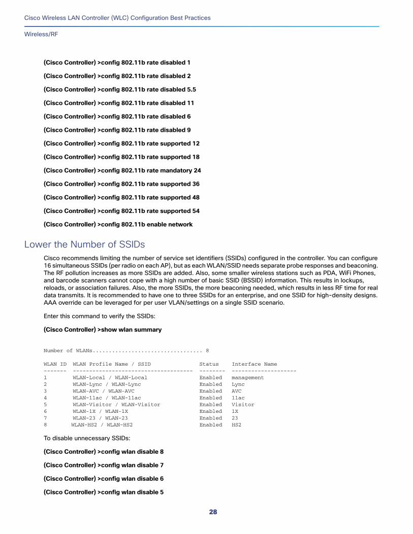
(Cisco Controller) >config 802.11b rate disabled 1
(Cisco Controller) >config 802.11b rate disabled 2
(Cisco Controller) >config 802.11b rate disabled 5.5
(Cisco Controller) >config 802.11b rate disabled 11
(Cisco Controller) >config 802.11b rate disabled 6
(Cisco Controller) >config 802.11b rate disabled 9
(Cisco Controller) >config 802.11b rate supported 12
(Cisco Controller) >config 802.11b rate supported 18
(Cisco Controller) >config 802.11b rate mandatory 24
(Cisco Controller) >config 802.11b rate supported 36
(Cisco Controller) >config 802.11b rate supported 48
(Cisco Controller) >config 802.11b rate supported 54
(Cisco Controller) >config 802.11b enable network
Lower the Number of SSIDsCisco recommends limiting the number of service set identifiers (SSIDs) configured in the controller. You can configure 16 simultaneous SSIDs (per radio on each AP), but as each WLAN/SSID needs separate probe responses and beaconing. The RF pollution increases as more SSIDs are added. Also, some smaller wireless stations such as PDA, WiFi Phones, and barcode scanners cannot cope with a high number of basic SSID (BSSID) information. This results in lockups, reloads, or association failures. Also, the more SSIDs, the more beaconing needed, which results in less RF time for real data transmits. It is recommended to have one to three SSIDs for an enterprise, and one SSID for high-density designs. AAA override can be leveraged for per user VLAN/settings on a single SSID scenario.
Enter this command to verify the SSIDs:
(Cisco Controller) >show wlan summary
Number of WLANs.................................. 8
WLAN ID WLAN Profile Name / SSID Status Interface Name------- ------------------------------------- -------- --------------------1 WLAN-Local / WLAN-Local Enabled management 2 WLAN-Lync / WLAN-Lync Enabled Lync3 WLAN-AVC / WLAN-AVC Enabled AVC4 WLAN-11ac / WLAN-11ac Enabled 11ac 5 WLAN-Visitor / WLAN-Visitor Enabled Visitor 6 WLAN-1X / WLAN-1X Enabled 1X 7 WLAN-23 / WLAN-23 Enabled 23 8 WLAN-HS2 / WLAN-HS2 Enabled HS2
To disable unnecessary SSIDs:
(Cisco Controller) >config wlan disable 8
(Cisco Controller) >config wlan disable 7
(Cisco Controller) >config wlan disable 6
(Cisco Controller) >config wlan disable 5
28
Cisco Wireless LAN Controller (WLC) Configuration Best Practices
Wireless/RF
…
Enable Client Load BalancingIn dense production networks, controllers have been verified to function optimally with load balancing ON and window size set at 5 or higher. In practical, this means load balancing behavior is only enabled when, for example, a large group of people congregate in a conference room or open area (meeting or class). Load balancing is very useful to spread these users between various available APs in such scenarios. It is recommended NOT to enable this feature for the voice WLAN as it can cause roaming issues. For other WLANs, it should be enabled only after testing.
To verify the load balancing:
(Cisco Controller) >show load-balancing
Aggressive Load Balancing........................ per WLAN enablingAggressive Load Balancing Window................. 5 clientsAggressive Load Balancing Denial Count........... 3 Aggressive Load Balancing Uplink Threshold....... 50
To configure load balancing window (5 is recommended minimum):
(Cisco Controller) >config load-balancing window <0-20>
To verify load balancing on WLAN:
(Cisco Controller) >show wlan <id>
WLAN Identifier.................................. 1Profile Name..................................... employeeNetwork Name (SSID).............................. employeeStatus........................................... Enabled…Band Select...................................... EnabledLoad Balancing................................... DisabledMulticast Buffer................................. Disabled
To allow load balancing on WLAN:
(Cisco Controller) >config wlan load-balance allow enable <WLAN id>
Enable Band SelectionBand selection enables client radios that are capable of dual-band (2.4 and 5 GHz) operation to move to a less congested 5 GHz AP. The 2.4 GHz band is often congested. Clients on this band experience interference from Bluetooth devices, microwave ovens, cordless phones as well as co-channel interference from other APs because of the 802.11b/g limit of three non-overlapping channels. To prevent these sources of interference and improve overall network performance, you can configure band selection on controller:
— Band selection is enabled/disabled globally by default.
— Band selection works by regulating probe responses to clients. It makes 5 GHz channels more attractive to clients by delaying probe responses to clients on 2.4 GHz channels.
— Evaluate band selection for voice, particularly focusing on roaming performance.
— Most newer model clients prefer 5 GHz by default if the 5 GHz signal of the AP is equal to or stronger than the 2.4 GHz signal.
— Band select should be enabled for high-density designs.
29
Cisco Wireless LAN Controller (WLC) Configuration Best Practices
Wireless/RF
Also, in high-density designs, the study of available UNII-2 channels should be made. The channels that are unaffected by Radar and also usable by the client base should be added to the RRM DCA list as usable channels.
Dual-band roaming can be slow depending on the client. If a majority of the base of voice clients exhibits a slow roaming behavior, it is more likely that the client sticks to 2.4 GHz. In this case, the client has scanning issues on 5 GHz. Generally, when a client decides to roam, it first scans its current channel and band. The clients generally scan for an AP that has a significantly better signal level, for example 20 dB and/or a significantly better SNR. Failing such available connection, the client may remain with its current AP. In this case, if the channel utilization on 2.4 GHz is low and the call quality is not poor, then you may disable the selected band. However, the preferred design is to enable band selection on 5 GHz with all data rates enabled and 6 Mbps as mandatory. Then, set the 5 GHz RRM minimum Tx power level at 6 dBm higher than the average 2.4 GHz power level set by RRM.
The goal of this configuration recommendation is to enable the client to obtain a band and channel with better SNR and Tx power initially. As already stated, generally when a client decides to roam, it scans its current channel and band first. So, if the client initially joins the 5 GHz band, then it is more likely to stay on the band if there are good power levels on 5 GHz. SNR levels on 5 GHz are generally better than 2.4 GHz because 2.4 GHz has only three Wi-Fi channels and is more susceptible to interference such as Bluetooth, iBeacons, and microwave signals.
It is recommended to enable 802.11k with dual-band reporting. This enables all 11k enabled clients to have the benefit of assisted roaming. With dual-band reporting enabled, the client receives a list of the best 2.4 and 5 GHz APs upon a directed request from the client. The client most likely looks at the top of the list for an AP on the same channel, and then on the same band as the client is currently on. This logic reduces scan times and saves battery power. Having 802.11k enabled on the WLC does not have a downside effect for non-802.11k clients.
Enter this command to verify the band select:
(Cisco Controller) >show band-select
Band Select Probe Response....................... per WLAN enablingCycle Count...................................... 2 cyclesCycle Threshold.................................. 200 millisecondsAge Out Suppression.............................. 20 secondsAge Out Dual Band................................ 60 secondsClient RSSI...................................... -80 dBm
To enable or disable band-select on specific WLANs:
(Cisco Controller) >config wlan band-select allow enable <WLAN id>
DCA – Dynamic Channel AssignmentWhen a wireless network is first initialized, all participating radios require a channel assignment to operate without interference. DCA optimizes the channel assignments to allow for interference free operation. Wireless network does this using the air metrics reported by each radio on every possible channel, and provides a solution that maximizes channel bandwidth and minimizes RF interference from all sources, such as self (signal), other networks (foreign interference), and noise (everything else).
DCA is enabled by default and provides a global solution to channel planning for your network.
Let RRM automatically configure all 802.11a or 802.11b/g channels based on availability and interference:
(Cisco Controller) >config 802.11a channel global auto
(Cisco Controller) >config 802.11b channel global auto
30
Cisco Wireless LAN Controller (WLC) Configuration Best Practices
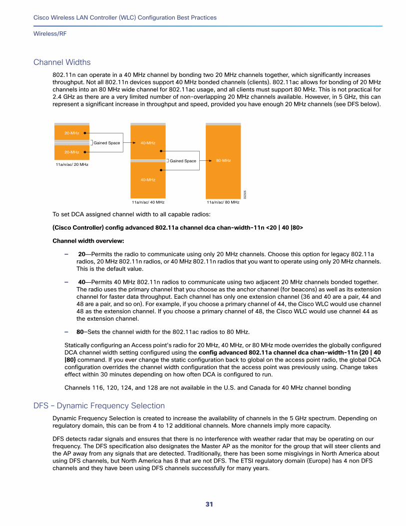
Wireless/RF
Channel Widths802.11n can operate in a 40 MHz channel by bonding two 20 MHz channels together, which significantly increases throughput. Not all 802.11n devices support 40 MHz bonded channels (clients). 802.11ac allows for bonding of 20 MHz channels into an 80 MHz wide channel for 802.11ac usage, and all clients must support 80 MHz. This is not practical for 2.4 GHz as there are a very limited number of non-overlapping 20 MHz channels available. However, in 5 GHz, this can represent a significant increase in throughput and speed, provided you have enough 20 MHz channels (see DFS below).
To set DCA assigned channel width to all capable radios:
(Cisco Controller) config advanced 802.11a channel dca chan-width-11n <20 | 40 |80>
Channel width overview:
— 20—Permits the radio to communicate using only 20 MHz channels. Choose this option for legacy 802.11a radios, 20 MHz 802.11n radios, or 40 MHz 802.11n radios that you want to operate using only 20 MHz channels. This is the default value.
— 40—Permits 40 MHz 802.11n radios to communicate using two adjacent 20 MHz channels bonded together. The radio uses the primary channel that you choose as the anchor channel (for beacons) as well as its extension channel for faster data throughput. Each channel has only one extension channel (36 and 40 are a pair, 44 and 48 are a pair, and so on). For example, if you choose a primary channel of 44, the Cisco WLC would use channel 48 as the extension channel. If you choose a primary channel of 48, the Cisco WLC would use channel 44 as the extension channel.
— 80—Sets the channel width for the 802.11ac radios to 80 MHz.
Statically configuring an Access point’s radio for 20 MHz, 40 MHz, or 80 MHz mode overrides the globally configured DCA channel width setting configured using the config advanced 802.11a channel dca chan-width-11n {20 | 40 |80} command. If you ever change the static configuration back to global on the access point radio, the global DCA configuration overrides the channel width configuration that the access point was previously using. Change takes effect within 30 minutes depending on how often DCA is configured to run.
Channels 116, 120, 124, and 128 are not available in the U.S. and Canada for 40 MHz channel bonding
DFS – Dynamic Frequency SelectionDynamic Frequency Selection is created to increase the availability of channels in the 5 GHz spectrum. Depending on regulatory domain, this can be from 4 to 12 additional channels. More channels imply more capacity.
DFS detects radar signals and ensures that there is no interference with weather radar that may be operating on our frequency. The DFS specification also designates the Master AP as the monitor for the group that will steer clients and the AP away from any signals that are detected. Traditionally, there has been some misgivings in North America about using DFS channels, but North America has 8 that are not DFS. The ETSI regulatory domain (Europe) has 4 non DFS channels and they have been using DFS channels successfully for many years.
20-MHz
20-MHz
Gained Space
11a/n/ac/ 20 MHz
11a/n/ac/ 40 MHz 11a/n/ac/ 80 MHz
3525
05
40-MHz
40-MHz
80-MHzGained Space
31
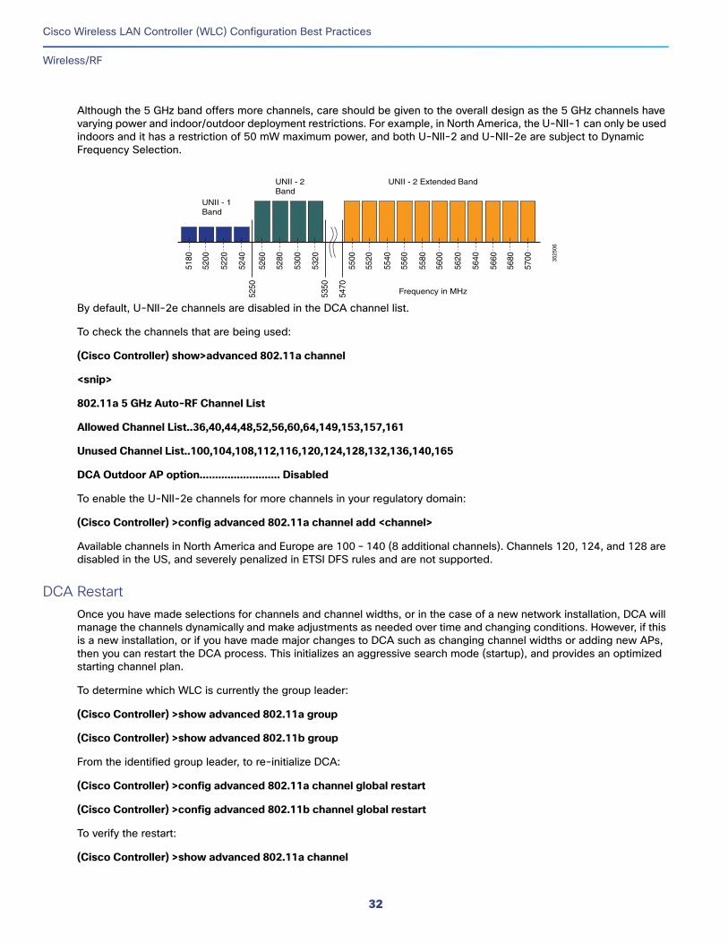
Cisco Wireless LAN Controller (WLC) Configuration Best Practices
Wireless/RF
Although the 5 GHz band offers more channels, care should be given to the overall design as the 5 GHz channels have varying power and indoor/outdoor deployment restrictions. For example, in North America, the U-NII-1 can only be used indoors and it has a restriction of 50 mW maximum power, and both U-NII-2 and U-NII-2e are subject to Dynamic Frequency Selection.
By default, U-NII-2e channels are disabled in the DCA channel list.
To check the channels that are being used:
(Cisco Controller) show>advanced 802.11a channel
<snip>
802.11a 5 GHz Auto-RF Channel List
Allowed Channel List..36,40,44,48,52,56,60,64,149,153,157,161
Unused Channel List..100,104,108,112,116,120,124,128,132,136,140,165
DCA Outdoor AP option.......................... Disabled
To enable the U-NII-2e channels for more channels in your regulatory domain:
(Cisco Controller) >config advanced 802.11a channel add <channel>
Available channels in North America and Europe are 100 – 140 (8 additional channels). Channels 120, 124, and 128 are disabled in the US, and severely penalized in ETSI DFS rules and are not supported.
DCA RestartOnce you have made selections for channels and channel widths, or in the case of a new network installation, DCA will manage the channels dynamically and make adjustments as needed over time and changing conditions. However, if this is a new installation, or if you have made major changes to DCA such as changing channel widths or adding new APs, then you can restart the DCA process. This initializes an aggressive search mode (startup), and provides an optimized starting channel plan.
To determine which WLC is currently the group leader:
(Cisco Controller) >show advanced 802.11a group
(Cisco Controller) >show advanced 802.11b group
From the identified group leader, to re-initialize DCA:
(Cisco Controller) >config advanced 802.11a channel global restart
(Cisco Controller) >config advanced 802.11b channel global restart
To verify the restart:
(Cisco Controller) >show advanced 802.11a channel
Frequency in MHz
UNII - 2 Extended BandUNII - 2 Band
UNII - 1 Band
5180
5200
5220
5240
5260
5250
5350
5470
5280
5300
5320
5500
5520
5540
5560
5580
5600
5620
5640
5660
5680
5700 35
2506
32
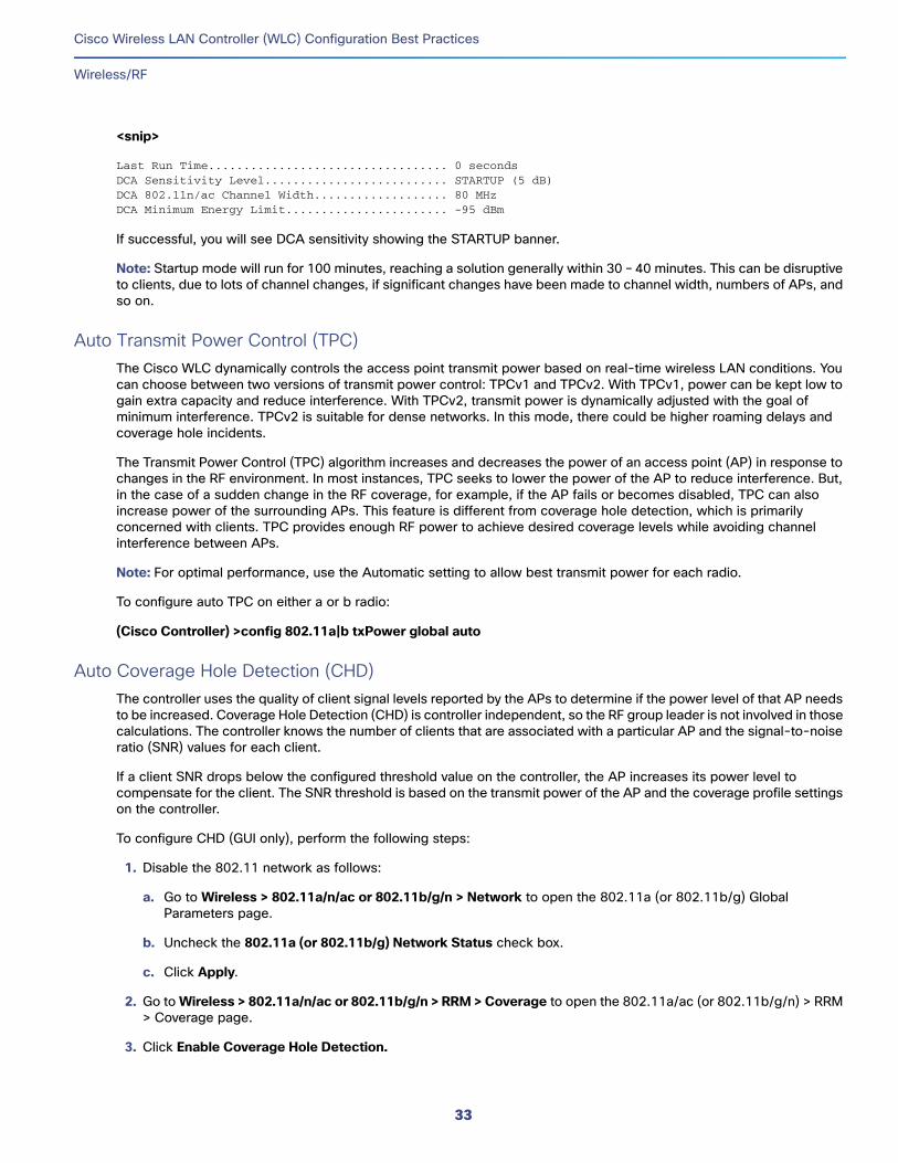
Cisco Wireless LAN Controller (WLC) Configuration Best Practices
Wireless/RF
<snip>
Last Run Time.................................. 0 secondsDCA Sensitivity Level.......................... STARTUP (5 dB)DCA 802.11n/ac Channel Width................... 80 MHzDCA Minimum Energy Limit....................... -95 dBm
If successful, you will see DCA sensitivity showing the STARTUP banner.
Note: Startup mode will run for 100 minutes, reaching a solution generally within 30 – 40 minutes. This can be disruptive to clients, due to lots of channel changes, if significant changes have been made to channel width, numbers of APs, and so on.
Auto Transmit Power Control (TPC)The Cisco WLC dynamically controls the access point transmit power based on real-time wireless LAN conditions. You can choose between two versions of transmit power control: TPCv1 and TPCv2. With TPCv1, power can be kept low to gain extra capacity and reduce interference. With TPCv2, transmit power is dynamically adjusted with the goal of minimum interference. TPCv2 is suitable for dense networks. In this mode, there could be higher roaming delays and coverage hole incidents.
The Transmit Power Control (TPC) algorithm increases and decreases the power of an access point (AP) in response to changes in the RF environment. In most instances, TPC seeks to lower the power of the AP to reduce interference. But, in the case of a sudden change in the RF coverage, for example, if the AP fails or becomes disabled, TPC can also increase power of the surrounding APs. This feature is different from coverage hole detection, which is primarily concerned with clients. TPC provides enough RF power to achieve desired coverage levels while avoiding channel interference between APs.
Note: For optimal performance, use the Automatic setting to allow best transmit power for each radio.
To configure auto TPC on either a or b radio:
(Cisco Controller) >config 802.11a|b txPower global auto
Auto Coverage Hole Detection (CHD)The controller uses the quality of client signal levels reported by the APs to determine if the power level of that AP needs to be increased. Coverage Hole Detection (CHD) is controller independent, so the RF group leader is not involved in those calculations. The controller knows the number of clients that are associated with a particular AP and the signal-to-noise ratio (SNR) values for each client.
If a client SNR drops below the configured threshold value on the controller, the AP increases its power level to compensate for the client. The SNR threshold is based on the transmit power of the AP and the coverage profile settings on the controller.
To configure CHD (GUI only), perform the following steps:
1. Disable the 802.11 network as follows:
a. Go to Wireless > 802.11a/n/ac or 802.11b/g/n > Network to open the 802.11a (or 802.11b/g) Global Parameters page.
b. Uncheck the 802.11a (or 802.11b/g) Network Status check box.
c. Click Apply.
2. Go to Wireless > 802.11a/n/ac or 802.11b/g/n > RRM > Coverage to open the 802.11a/ac (or 802.11b/g/n) > RRM > Coverage page.
3. Click Enable Coverage Hole Detection.
33
Cisco Wireless LAN Controller (WLC) Configuration Best Practices
Wireless/RF
4. Click Apply.
Access Point GroupsAfter you create up to 512 WLANs on the controller, you can selectively publish them (using access point groups) to different APs to better manage your wireless network. In a typical deployment, all users on a WLAN are mapped to a single interface on the controller. Therefore, all users that are associated with that WLAN are on the same subnet or VLAN. However, you can choose to distribute the load among several interfaces or to a group of users based on a specific criteria, such as individual departments (for example, Marketing) by creating AP groups. Additionally, these AP groups can be configured in separate VLANs to simplify network administration. Use AP groups to segregate traffic based on physical location.
To configure an AP Group:
(Cisco Controller) >config wlan apgroup add <group_name>
To add description to an AP group:
(Cisco Controller) >config wlan apgroup description <group_name description>
To assign a WLAN to an AP group:
(Cisco Controller) >config wlan apgroup interface-mapping add <group_name wlan_id interface_name>
To configure a WLAN radio policy on an AP group:
(Cisco Controller) >config wlan apgroup wlan-radio-policy <apgroup_name wlan_id> {802.11a-only | 802.11bg | 802.11g-only | all}
To assign an AP to an AP group:
(Cisco Controller) >config ap group-name <group_name Cisco_AP>
RF ProfilesRF Profiles allow you to tune groups of APs that share a common coverage zone together and selectively change how RRM operates the APs within that coverage zone. For example, a university might deploy high density APs in an area where large number of users will congregate or meet. This situation requires you to manipulate both data rates and power to address the cell density while managing the co-channel interference. In adjacent areas, normal coverage is provided and such manipulation would result in a loss of coverage.
Using RF profiles and AP groups allow you to optimize the RF settings for AP groups that operate in different environments or coverage zones. RF profiles are created for the 802.11 radios. RF profiles are applied to all APs that belong to an AP group, where all APs in that group will have the same profile settings. The RF profile gives you the control over the data rates and power (TPC) values, and is recommended for better control of RF networks.
Configuring RF profiles
Creating an RF profileTo specify a description for the RF profile:
(Cisco Controller) >config rf-profile description <text profile-name>
To configure the data rates to be applied to the APs of this profile:
(Cisco Controller) >config rf-profile data-rates {802.11a | 802.11b} supported <rate profile-name>
To configure the maximum and minimum power level assignment, that is the maximum and minimum power that the APs in this RF profile are allowed to use:
(Cisco Controller) >config rf-profile {tx-power-max | tx-power-min} <power-value profile-name>
34
Cisco Wireless LAN Controller (WLC) Configuration Best Practices
Wireless/RF
To configure a custom TPC power threshold for either Version1 or Version 2 of TPC:
(Cisco Controller) >config rf-profile {tx-power-control-thresh-v1 | tx-power-control-thresh-v2} <power-threshold profile-name>
To configure the coverage data:
(Cisco Controller) >config rf-profile coverage data <value-in-dBm profile-name>
To configure the minimum client coverage exception level:
(Cisco Controller) >config rf-profile coverage exception <clients profile-name>
To configure the coverage exception level percentage:
(Cisco Controller) >config rf-profile coverage level <percentage-value profile-name>
To configure the coverage of voice:
(Cisco Controller) >config rf-profile coverage voice <value-in-dBm profile-name>
To configure the maximum number of clients to be allowed per AP radio:
(Cisco Controller) >config rf-profile max-clients <num-of-clients profile-name>
To configure the client trap threshold value:
(Cisco Controller) >config rf-profile client-trap-threshold <threshold-value profile-name>
To configure multicast:
(Cisco Controller) >config rf-profile multicast data-rate <rate profile-name>
To configure load balancing:
(Cisco Controller) >config rf-profile load-balancing {window <num-of-clients> | denial <value} profile-name>
Configuring band selectTo configure the band select cycle count:
(Cisco Controller) >config rf-profile band-select cycle-count <max-num-of-cycles profile-name>
To configure the cycle threshold:
(Cisco Controller) >config rf-profile band-select cycle-threshold <time-in-milliseconds profile-name>
To configure the expiry of the band select:
(Cisco Controller) >config rf-profile band-select expire {dual-band | suppression} <time-in-seconds profile-name>
To configure the probe response:
(Cisco Controller) >config rf-profile band-select probe-response enable <profile-name>
To configure the minimum RSSI for a client to respond to a probe:
(Cisco Controller) >config rf-profile band-select client-rssi <value-in-dBm profile-name>
To configure the 802.11n only mode for an access point group base:
(Cisco Controller) >config rf-profile 11n-client-only enable <rf-profile-name>
35
Cisco Wireless LAN Controller (WLC) Configuration Best Practices
RF Management
Note: In the 802.11n only mode, the access point broadcasts support for 802.11n speeds. Only 802.11n clients are allowed to associate with the access point.
Applying RF Profiles to AP Groups (CLI)To apply RF profiles to AP groups:
(Cisco Controller) >config wlan apgroup profile-mapping add <ap-group-name rf-profile-name>
VLAN Select/PoolingThe VLAN select feature enables you to use a single WLAN that can support multiple VLANs. Clients can get assigned to one of the configured VLANs. This feature enables you to map a WLAN to a single or multiple interface VLANs using interface groups. Wireless clients associating to this WLAN receive an IP address from a pool of subnets identified by the interfaces. Once enabled, the VLAN Select feature allows clients of a given WLAN to get IPs from multiple dynamic interfaces.
To enable VLAN, perform the following steps:
1. Create an interface group.
2. Add interfaces to the interface group.
3. Add the interface group to a WLAN.
To create an interface group:
(Cisco Controller) >config interface group create <interface_group_name>
(Cisco Controller) >config interface group description <interface_group_name description>
To add interfaces to the interface group:
(Cisco Controller) >config interface group interface add <interface_group interface_name>
To add the interface group to a WLAN (CLI):
(Cisco Controller) >config wlan interface <wlan_id interface_group_name>
RF Management
Auto Coverage Hole DetectionDescription—Auto CHD should be enabled. ?The controller uses the quality of client signal levels reported by the APs to determine if the power level of that AP needs to be increased. Coverage Hole Detection (CHD) is controller independent, so the RF group leader is not involved in those calculations. The controller knows how many clients are associated with a particular AP and what are the signal-to-noise ratio (SNR) values for each client. ?If a client SNR drops below the configured threshold value on the controller, the AP increases its power level to try to compensate for the client. The SNR threshold is based on the transmit power of the AP and the coverage profile settings on the controller. ?For instructions on how to configure auto CHD, see the Cisco Wireless Controller Configuration Guide.
Status: Compliant—CHD enabled
Non-Compliant— None or one enabled
36
Cisco Wireless LAN Controller (WLC) Configuration Best Practices
RF Management
Auto Dynamic Channel AssignmentDescription—Auto DCA should be enabled to allow RRM to select best channels for each radio. Clicking Fix it Now enables Auto DCA. ?When a wireless network is first initialized, all radios participating require a channel assignment to operate without interference - optimizing the channel assignments to allow for interference free operation is DCA's job. Wireless network does this using the air metrics reported by each radio on every possible channel, and providing a solution that maximizes channel bandwidth and minimizes RF interference from all sources - Self (signal), other networks (foreign interference), Noise (everything else). ?DCA is enabled by default and provides a global solution to channel planning for your network.
Status: Compliant—DCA is enabled for 802.11a/b
Non-Compliant—None or one is enabled
CLI Option—Enable auto DCA by entering this command:
(Cisco Controller) >config 802.11a channel global auto ??(Cisco Controller) >config 802.11b channel global auto
Auto Transmit Power ControlDescription—Auto TPC should be enabled to allow RRM to select best transmit power for each radio. Clicking Fix it Now enables Auto TPC. The Cisco WLC dynamically controls the access point transmit power based on real-time wireless LAN conditions. You can choose between two versions of transmit power control: TPCv1 and TPCv2. With TPCv1, power can be kept low to gain extra capacity and reduce interference. With TPCv2, transmit power is dynamically adjusted with the goal of minimum interference. TPCv2 is suitable for dense networks. In this mode, there could be higher roaming delays and coverage hole incidents. ?The Transmit Power Control (TPC) algorithm increases and decreases the power of an access point (AP) in response to changes in the RF environment. In most instances, TPC seeks to lower the power of the AP to reduce interference. But, in the case of a sudden change in the RF coverage-for example, if the AP fails or becomes disabled-TPC can also increase power of the surrounding APs. This feature is different from coverage hole detection, which is primarily concerned with clients. TPC provides enough RF power to achieve desired coverage levels while avoiding channel interference between APs.
Note: For optimal performance, use the Automatic setting to allow best transmit power for each radio.
Status: Compliant—TPC enabled for 802.11a/b
Non-Compliant—None or one enabled
CLI Option—Enable Auto TPC by entering this command:
(Cisco Controller) >config 802.11a txPower global auto ??(Cisco Controller) >config 802.11b txPower global auto
Best Channel WidthDescription—DBS select the widest Channel Width with the highest Client Data rates, lowest channel utilization per radio. It minimizes data retries / CRC errors on the 5-GHz band while avoiding rogue APs and Clean Air Interferers.
Status: Compliant—Channel width is selected as Best on both bands
Non-Compliant—Channel width is not selected as Best on both bands
CLI Option: Enable Best Channel Width by entering this command:
37
Cisco Wireless LAN Controller (WLC) Configuration Best Practices
RF Management
(Cisco Controller) >config advanced 802.11a channel dca chan-width best
CleanAir DetectionDescription—CleanAir should be enabled. Clicking Fix it Now enables CleanAir. To effectively detect and mitigate RF interference, enable CleanAir whenever possible. There are recommendations to various sources of interference to trigger security alerts, such as generic DECT phones, jammer, and so on.
Status: Compliant—Enabled
Non-Compliant—Disabled
CLI Option: Verify CleanAir configuration on a network by entering this command:
(Cisco Controller) >show 802.11{a|b} cleanair config
Enable CleanAir functionality on a network by entering this command:
(Cisco Controller) >config 802.11{a|b} cleanair enable network
Configure to enable interference detection for specifically jammer by entering this command:
(Cisco Controller) >config 802.11{a|b} cleanair device enable jammer
Client Band SelectDescription—We recommend that you not use Band Selection when interactive traffic such as voice or video is used on the WLAN. Clicking Fix it Now enables Band Selection. ?Band selection enables client radios that are capable of dual-band (2.4 GHz and 5 GHz) operation to move to a less congested 5-GHz AP. The 2.4-GHz band is often congested. Clients on the 2.4-GHz band typically experience interference from Bluetooth devices, microwave ovens, and cordless phones as well as co-channel interference from other APs because of the 802.11b/g limit of three non-overlapping channels. To prevent these sources of interference and improve overall network performance, you can configure Band Selection on controller:
Band Selection is enabled/disabled globally by default.
Band Selection works by regulating probe responses to clients. It makes 5-GHz channels more attractive to clients by delaying probe responses to clients on 2.4-GHz channels.
Evaluate Band Selection for voice, particularly focusing on roaming performance. See below for further explanation.
Most newer model clients prefer 5 GHz by default if the 5-GHz signal of the AP is equal to or stronger than the 2.4-GHz signal.
Band Select should be enabled for high-density designs.
Also, in high-density designs, the study of available UNII-2 channels should be made. Those channels that are unaffected by Radar and also usable by the client base should be added to the RRM DCA list as usable channels. Dual-band roaming can be slow depending on the client. If a majority of the base of voice clients exhibits a slow roaming behavior, it is more likely that the client sticks to 2.4 GHz. In this case, it has scanning issues on 5 GHz. Generally when a client decides to roam, it scans its current channel and band first. The clients generally scan for an AP that has a significantly better signal level, maybe as much as 20 dB and/or a significantly better SNR. Failing such available connection, the client may remain with its current AP. In this case, if the CU on 2.4 GHz is low and the call quality is not poor, then disabling the selected band is acceptable. However, the preferred design is to enable band selection on 5 GHz with all data rates enabled and 6 Mbps as mandatory. Then, set the 5 GHz RRM minimum Tx power level 6 dBm higher than the average 2.4 GHz power level set by RRM. ?The goal of this configuration recommendation is to enable the client to obtain a band and channel with better SNR and Tx power initially. As already stated, generally when a client decides to roam, it scans its current
38
Cisco Wireless LAN Controller (WLC) Configuration Best Practices
RF Management
channel and band first. So, if the client initially joins the 5 GHz band, then it is more likely to stay on the band if there are good power levels on 5 GHz. SNR levels on 5 GHz are generally better than 2.4 GHz because 2.4 GHz has only three Wi-Fi channels and is more susceptible to interference such as Bluetooth, iBeacons, and microwave signals. ?802.11k is recommended to be enabled with dual-band reporting. This enables all 802.11k-enabled clients to have the benefit of assisted roaming. With dual-band reporting enabled, the client receives a list of the best 2.4-GHz and 5-GHz APs upon a directed request from the client. Here, the client most likely looks at the top of the list for an AP on the same channel, and then on the same band as the client is currently on. This logic reduces scan times and saves battery power. Having 802.11k enabled on the Cisco WLC does not have a downside effect for non-802.11k clients.
Status: Compliant—Enabled on all WLANs
Non-Compliant—Disabled
CLI Option: Verify Band Select by entering this command:
(Cisco Controller) >show band-select
Enable Band Select on a WLAN by entering this command:
(Cisco Controller) >config wlan band-select allow enable wlan-id
DCA Cisco AP LoadDescription—Disable this option to avoid frequent changes in DCA due to varying load conditions
Status: Compliant—Avoid Cisco AP Load is disabled on both bands
Non-Compliant—Avoid Cisco AP Load is enabled on either or both bands
CLI Option: Enable DCA Cisco AP Load by entering this command:
(Cisco Controller) >config advanced 802.11{a|b} channel load disable
Event Driven RRMDescription—Event driven RRM should be enabled. Clicking Fix it Now enables event driven RRM.
Status: Compliant—Enabled
Non-Compliant—Disabled
High SSID CountsDescription—Number of WLANs should be less than or equal 4. We recommend limiting the number of service set identifiers (SSIDs) configured at the Cisco WLC. You can configure 16 simultaneous SSIDs (per radio on each AP), but as each WLAN/SSID needs separate probe responses and beaconing, the RF pollution increases as more SSIDs are added. Furthermore, some smaller wireless stations like PDA, Wi-Fi phones, and barcode scanners cannot cope with a high number of basic SSID (BSSID) information. This results in lockups, reloads, or association failures. Also, the more
39
Cisco Wireless LAN Controller (WLC) Configuration Best Practices
RF Management
SSIDs, the more beaconing needed, and therefore, less RF time is available for real data transmits. For example, the recommendation is to have one to three SSIDs for corporate, and one SSID for high-density designs. AAA override can be leveraged for per user VLAN settings on a single SSID scenario.
Status: Compliant—Less than or equal to 4
Non-Compliant—Greater than 4
CLI Option: Verify the number of WLANs by entering this command:
(Cisco Controller) >show wlan summary
Disable unwanted WLANs by entering this command:
(Cisco Controller) >config wlan disable wlan-id
Wi-Fi InterferenceDescription—Triggers ED-RRM by Wi-Fi rogue interferences. Rogues are reported as Interference, with Duty Cycles and threat value.
Status: Compliant—Wi-Fi Interference Awareness is enabled on both bands and duty cycle is 80 percent or higher
Non-Compliant—Wi-Fi Interference Awareness is either not enabled on both bands or duty cycle is less than 80 percent
CLI Option: Enable Wi-Fi Interference by entering this command:
(Cisco Controller) >config advanced {802.11a|b} channel cleanair-event enable (Cisco Controller) >config advanced {802.11a|b} channel cleanair-event rogue-contribution enable (Cisco Controller) >config advanced {802.11a|b} channel cleanair-event rogue-contribution duty-cycle 80
FRA EnabledDescription—Flexible Radio Assignment (FRA) can automatically assign the XOR 2.4-GHz radios to other roles such as 5 GHz and Monitor. We recommend that you enable FRA when you have APs such as Cisco Aironet 2800 and 3800 Series APs that support XOR operation. Clicking Fix it Now enables FRA; clicking Restore Default disables FRA; clicking Ignore adds the FRA Enabled to the ignored best practices list (if you want, you can add it back to the best practices list from the ignored list).
Status: Compliant—FRA is enabled.
Non-Compliant—FRA is disabled.
CLI Option: Enable FRA by entering this command:
(Cisco Controller) >config advanced fra enable
40
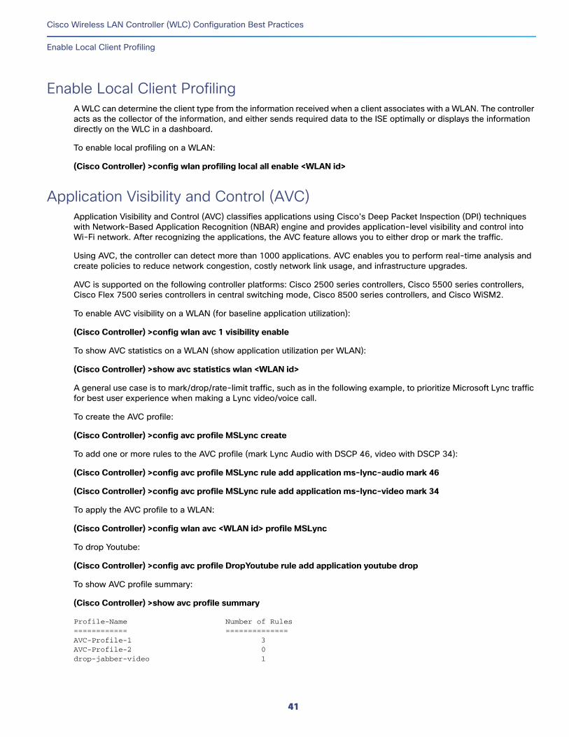
Cisco Wireless LAN Controller (WLC) Configuration Best Practices
Enable Local Client Profiling
Enable Local Client ProfilingA WLC can determine the client type from the information received when a client associates with a WLAN. The controller acts as the collector of the information, and either sends required data to the ISE optimally or displays the information directly on the WLC in a dashboard.
To enable local profiling on a WLAN:
(Cisco Controller) >config wlan profiling local all enable <WLAN id>
Application Visibility and Control (AVC)Application Visibility and Control (AVC) classifies applications using Cisco's Deep Packet Inspection (DPI) techniques with Network-Based Application Recognition (NBAR) engine and provides application-level visibility and control into Wi-Fi network. After recognizing the applications, the AVC feature allows you to either drop or mark the traffic.
Using AVC, the controller can detect more than 1000 applications. AVC enables you to perform real-time analysis and create policies to reduce network congestion, costly network link usage, and infrastructure upgrades.
AVC is supported on the following controller platforms: Cisco 2500 series controllers, Cisco 5500 series controllers, Cisco Flex 7500 series controllers in central switching mode, Cisco 8500 series controllers, and Cisco WiSM2.
To enable AVC visibility on a WLAN (for baseline application utilization):
(Cisco Controller) >config wlan avc 1 visibility enable
To show AVC statistics on a WLAN (show application utilization per WLAN):
(Cisco Controller) >show avc statistics wlan <WLAN id>
A general use case is to mark/drop/rate-limit traffic, such as in the following example, to prioritize Microsoft Lync traffic for best user experience when making a Lync video/voice call.
To create the AVC profile:
(Cisco Controller) >config avc profile MSLync create
To add one or more rules to the AVC profile (mark Lync Audio with DSCP 46, video with DSCP 34):
(Cisco Controller) >config avc profile MSLync rule add application ms-lync-audio mark 46
(Cisco Controller) >config avc profile MSLync rule add application ms-lync-video mark 34
To apply the AVC profile to a WLAN:
(Cisco Controller) >config wlan avc <WLAN id> profile MSLync
To drop Youtube:
(Cisco Controller) >config avc profile DropYoutube rule add application youtube drop
To show AVC profile summary:
(Cisco Controller) >show avc profile summary
Profile-Name Number of Rules============ ==============AVC-Profile-1 3AVC-Profile-2 0drop-jabber-video 1
41

Cisco Wireless LAN Controller (WLC) Configuration Best Practices
Application Visibility and Control (AVC)
MSLync 2
42
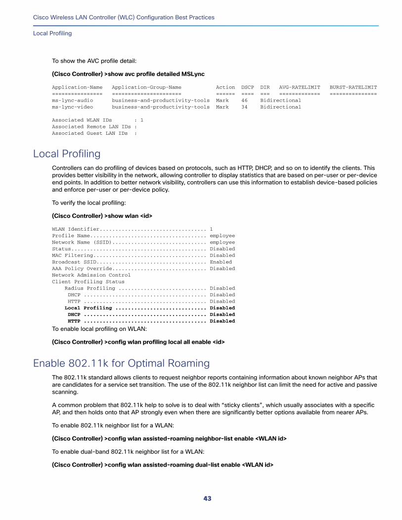
Cisco Wireless LAN Controller (WLC) Configuration Best Practices
Local Profiling
To show the AVC profile detail:
(Cisco Controller) >show avc profile detailed MSLync
Application-Name Application-Group-Name Action DSCP DIR AVG-RATELIMIT BURST-RATELIMIT================ ====================== ====== ==== === ============= ===============ms-lync-audio business-and-productivity-tools Mark 46 Bidirectionalms-lync-video business-and-productivity-tools Mark 34 Bidirectional
Associated WLAN IDs : 1Associated Remote LAN IDs :Associated Guest LAN IDs :
Local ProfilingControllers can do profiling of devices based on protocols, such as HTTP, DHCP, and so on to identify the clients. This provides better visibility in the network, allowing controller to display statistics that are based on per-user or per-device end points. In addition to better network visibility, controllers can use this information to establish device-based policies and enforce per-user or per-device policy.
To verify the local profiling:
(Cisco Controller) >show wlan <id>
WLAN Identifier.................................. 1Profile Name..................................... employeeNetwork Name (SSID).............................. employeeStatus........................................... DisabledMAC Filtering.................................... DisabledBroadcast SSID................................... EnabledAAA Policy Override.............................. DisabledNetwork Admission ControlClient Profiling Status Radius Profiling ............................ Disabled DHCP ....................................... Disabled HTTP ....................................... Disabled Local Profiling ............................. Disabled DHCP ....................................... Disabled HTTP ....................................... Disabled
To enable local profiling on WLAN:
(Cisco Controller) >config wlan profiling local all enable <id>
Enable 802.11k for Optimal RoamingThe 802.11k standard allows clients to request neighbor reports containing information about known neighbor APs that are candidates for a service set transition. The use of the 802.11k neighbor list can limit the need for active and passive scanning.
A common problem that 802.11k help to solve is to deal with “sticky clients”, which usually associates with a specific AP, and then holds onto that AP strongly even when there are significantly better options available from nearer APs.
To enable 802.11k neighbor list for a WLAN:
(Cisco Controller) >config wlan assisted-roaming neighbor-list enable <WLAN id>
To enable dual-band 802.11k neighbor list for a WLAN:
(Cisco Controller) >config wlan assisted-roaming dual-list enable <WLAN id>
43
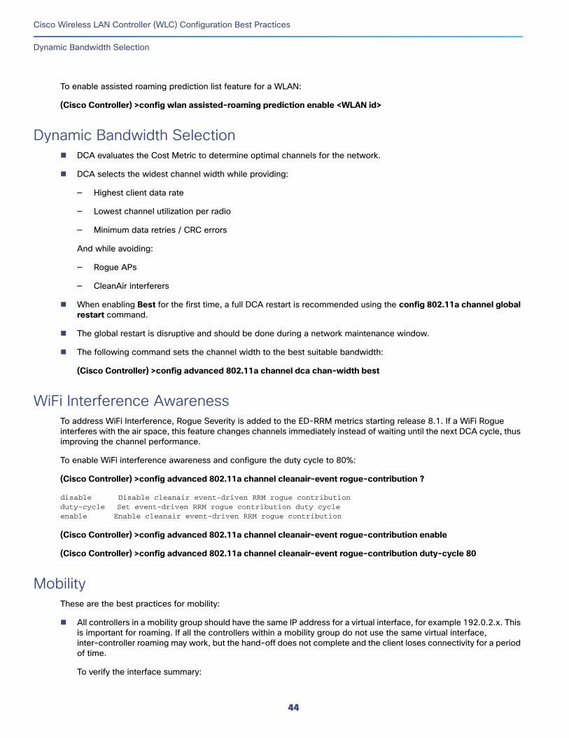
Cisco Wireless LAN Controller (WLC) Configuration Best Practices
Dynamic Bandwidth Selection
To enable assisted roaming prediction list feature for a WLAN:
(Cisco Controller) >config wlan assisted-roaming prediction enable <WLAN id>
Dynamic Bandwidth Selection DCA evaluates the Cost Metric to determine optimal channels for the network.
DCA selects the widest channel width while providing:
— Highest client data rate
— Lowest channel utilization per radio
— Minimum data retries / CRC errors
And while avoiding:
— Rogue APs
— CleanAir interferers
When enabling Best for the first time, a full DCA restart is recommended using the config 802.11a channel global restart command.
The global restart is disruptive and should be done during a network maintenance window.
The following command sets the channel width to the best suitable bandwidth:
(Cisco Controller) >config advanced 802.11a channel dca chan-width best
WiFi Interference AwarenessTo address WiFi Interference, Rogue Severity is added to the ED-RRM metrics starting release 8.1. If a WiFi Rogue interferes with the air space, this feature changes channels immediately instead of waiting until the next DCA cycle, thus improving the channel performance.
To enable WiFi interference awareness and configure the duty cycle to 80%:
(Cisco Controller) >config advanced 802.11a channel cleanair-event rogue-contribution ?
disable Disable cleanair event-driven RRM rogue contributionduty-cycle Set event-driven RRM rogue contribution duty cycleenable Enable cleanair event-driven RRM rogue contribution
(Cisco Controller) >config advanced 802.11a channel cleanair-event rogue-contribution enable
(Cisco Controller) >config advanced 802.11a channel cleanair-event rogue-contribution duty-cycle 80
MobilityThese are the best practices for mobility:
All controllers in a mobility group should have the same IP address for a virtual interface, for example 192.0.2.x. This is important for roaming. If all the controllers within a mobility group do not use the same virtual interface, inter-controller roaming may work, but the hand-off does not complete and the client loses connectivity for a period of time.
To verify the interface summary:
44
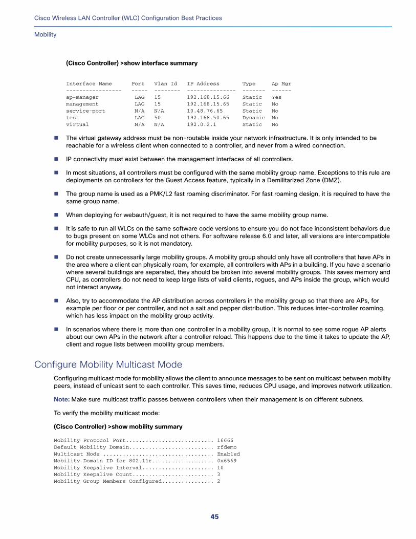
Cisco Wireless LAN Controller (WLC) Configuration Best Practices
Mobility
(Cisco Controller) >show interface summary
Interface Name Port Vlan Id IP Address Type Ap Mgr----------------- ----- -------- --------------- ------- ------ap-manager LAG 15 192.168.15.66 Static Yes management LAG 15 192.168.15.65 Static No service-port N/A N/A 10.48.76.65 Static No test LAG 50 192.168.50.65 Dynamic No virtual N/A N/A 192.0.2.1 Static No
The virtual gateway address must be non-routable inside your network infrastructure. It is only intended to be reachable for a wireless client when connected to a controller, and never from a wired connection.
IP connectivity must exist between the management interfaces of all controllers.
In most situations, all controllers must be configured with the same mobility group name. Exceptions to this rule are deployments on controllers for the Guest Access feature, typically in a Demilitarized Zone (DMZ).
The group name is used as a PMK/L2 fast roaming discriminator. For fast roaming design, it is required to have the same group name.
When deploying for webauth/guest, it is not required to have the same mobility group name.
It is safe to run all WLCs on the same software code versions to ensure you do not face inconsistent behaviors due to bugs present on some WLCs and not others. For software release 6.0 and later, all versions are intercompatible for mobility purposes, so it is not mandatory.
Do not create unnecessarily large mobility groups. A mobility group should only have all controllers that have APs in the area where a client can physically roam, for example, all controllers with APs in a building. If you have a scenario where several buildings are separated, they should be broken into several mobility groups. This saves memory and CPU, as controllers do not need to keep large lists of valid clients, rogues, and APs inside the group, which would not interact anyway.
Also, try to accommodate the AP distribution across controllers in the mobility group so that there are APs, for example per floor or per controller, and not a salt and pepper distribution. This reduces inter-controller roaming, which has less impact on the mobility group activity.
In scenarios where there is more than one controller in a mobility group, it is normal to see some rogue AP alerts about our own APs in the network after a controller reload. This happens due to the time it takes to update the AP, client and rogue lists between mobility group members.
Configure Mobility Multicast ModeConfiguring multicast mode for mobility allows the client to announce messages to be sent on multicast between mobility peers, instead of unicast sent to each controller. This saves time, reduces CPU usage, and improves network utilization.
Note: Make sure multicast traffic passes between controllers when their management is on different subnets.
To verify the mobility multicast mode:
(Cisco Controller) >show mobility summary
Mobility Protocol Port........................... 16666Default Mobility Domain.......................... rfdemoMulticast Mode .................................. EnabledMobility Domain ID for 802.11r................... 0x6569Mobility Keepalive Interval...................... 10Mobility Keepalive Count......................... 3Mobility Group Members Configured................ 2
45
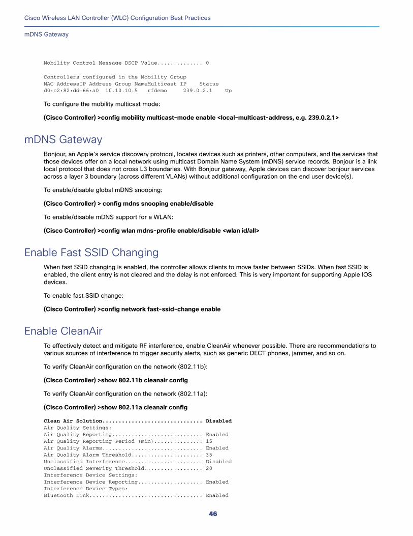
Cisco Wireless LAN Controller (WLC) Configuration Best Practices
mDNS Gateway
Mobility Control Message DSCP Value.............. 0
Controllers configured in the Mobility GroupMAC AddressIP Address Group NameMulticast IP Statusd0:c2:82:dd:66:a0 10.10.10.5 rfdemo 239.0.2.1 Up
To configure the mobility multicast mode:
(Cisco Controller) >config mobility multicast-mode enable <local-multicast-address, e.g. 239.0.2.1>
mDNS GatewayBonjour, an Apple’s service discovery protocol, locates devices such as printers, other computers, and the services that those devices offer on a local network using multicast Domain Name System (mDNS) service records. Bonjour is a link local protocol that does not cross L3 boundaries. With Bonjour gateway, Apple devices can discover bonjour services across a layer 3 boundary (across different VLANs) without additional configuration on the end user device(s).
To enable/disable global mDNS snooping:
(Cisco Controller) > config mdns snooping enable/disable
To enable/disable mDNS support for a WLAN:
(Cisco Controller) >config wlan mdns-profile enable/disable <wlan id/all>
Enable Fast SSID ChangingWhen fast SSID changing is enabled, the controller allows clients to move faster between SSIDs. When fast SSID is enabled, the client entry is not cleared and the delay is not enforced. This is very important for supporting Apple IOS devices.
To enable fast SSID change:
(Cisco Controller) >config network fast-ssid-change enable
Enable CleanAirTo effectively detect and mitigate RF interference, enable CleanAir whenever possible. There are recommendations to various sources of interference to trigger security alerts, such as generic DECT phones, jammer, and so on.
To verify CleanAir configuration on the network (802.11b):
(Cisco Controller) >show 802.11b cleanair config
To verify CleanAir configuration on the network (802.11a):
(Cisco Controller) >show 802.11a cleanair config
Clean Air Solution............................... DisabledAir Quality Settings:Air Quality Reporting............................ EnabledAir Quality Reporting Period (min)............... 15Air Quality Alarms............................... EnabledAir Quality Alarm Threshold...................... 35Unclassified Interference........................ DisabledUnclassified Severity Threshold.................. 20Interference Device Settings:Interference Device Reporting.................... EnabledInterference Device Types:Bluetooth Link................................... Enabled
46
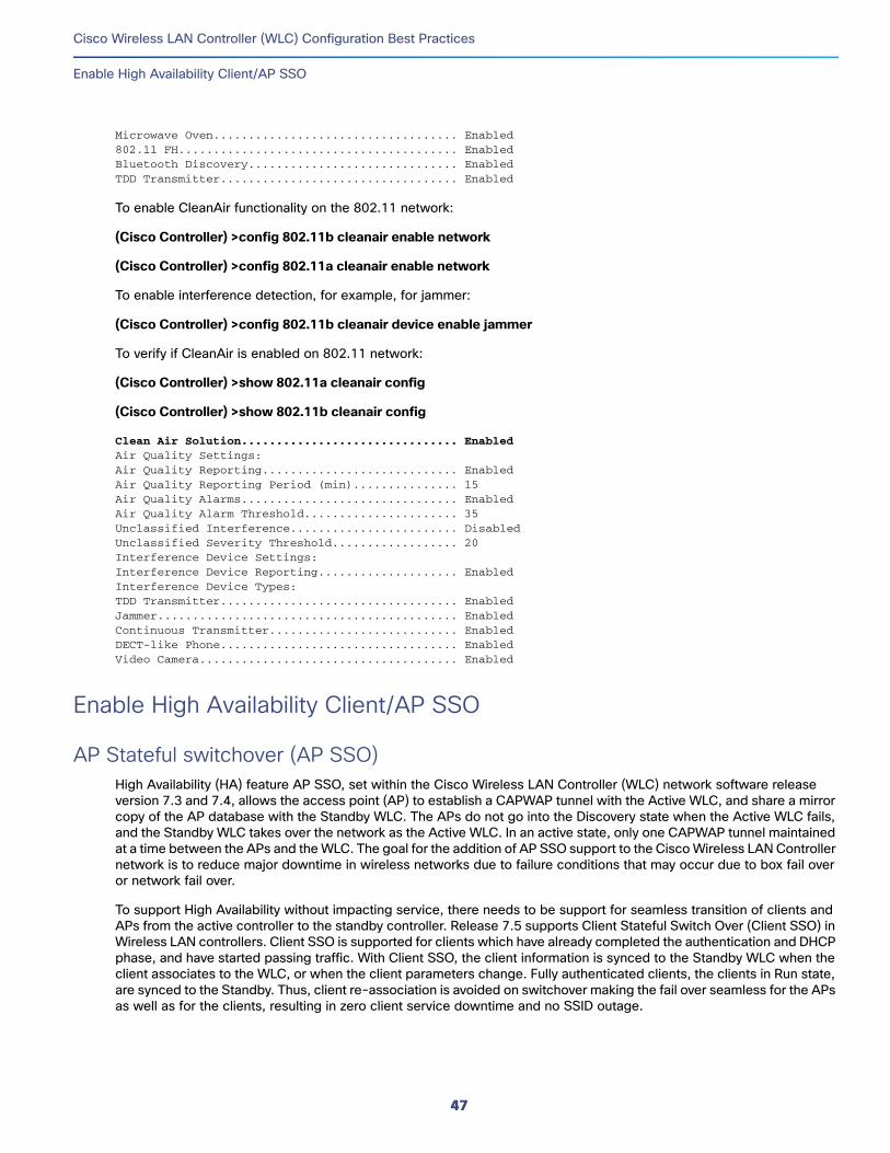
Cisco Wireless LAN Controller (WLC) Configuration Best Practices
Enable High Availability Client/AP SSO
Microwave Oven................................... Enabled802.11 FH........................................ EnabledBluetooth Discovery.............................. EnabledTDD Transmitter.................................. Enabled
To enable CleanAir functionality on the 802.11 network:
(Cisco Controller) >config 802.11b cleanair enable network
(Cisco Controller) >config 802.11a cleanair enable network
To enable interference detection, for example, for jammer:
(Cisco Controller) >config 802.11b cleanair device enable jammer
To verify if CleanAir is enabled on 802.11 network:
(Cisco Controller) >show 802.11a cleanair config
(Cisco Controller) >show 802.11b cleanair config
Clean Air Solution............................... EnabledAir Quality Settings:Air Quality Reporting............................ EnabledAir Quality Reporting Period (min)............... 15Air Quality Alarms............................... EnabledAir Quality Alarm Threshold...................... 35Unclassified Interference........................ DisabledUnclassified Severity Threshold.................. 20Interference Device Settings:Interference Device Reporting.................... EnabledInterference Device Types:TDD Transmitter.................................. EnabledJammer........................................... EnabledContinuous Transmitter........................... EnabledDECT-like Phone.................................. EnabledVideo Camera..................................... Enabled
Enable High Availability Client/AP SSO
AP Stateful switchover (AP SSO)High Availability (HA) feature AP SSO, set within the Cisco Wireless LAN Controller (WLC) network software release version 7.3 and 7.4, allows the access point (AP) to establish a CAPWAP tunnel with the Active WLC, and share a mirror copy of the AP database with the Standby WLC. The APs do not go into the Discovery state when the Active WLC fails, and the Standby WLC takes over the network as the Active WLC. In an active state, only one CAPWAP tunnel maintained at a time between the APs and the WLC. The goal for the addition of AP SSO support to the Cisco Wireless LAN Controller network is to reduce major downtime in wireless networks due to failure conditions that may occur due to box fail over or network fail over.
To support High Availability without impacting service, there needs to be support for seamless transition of clients and APs from the active controller to the standby controller. Release 7.5 supports Client Stateful Switch Over (Client SSO) in Wireless LAN controllers. Client SSO is supported for clients which have already completed the authentication and DHCP phase, and have started passing traffic. With Client SSO, the client information is synced to the Standby WLC when the client associates to the WLC, or when the client parameters change. Fully authenticated clients, the clients in Run state, are synced to the Standby. Thus, client re-association is avoided on switchover making the fail over seamless for the APs as well as for the clients, resulting in zero client service downtime and no SSID outage.
47
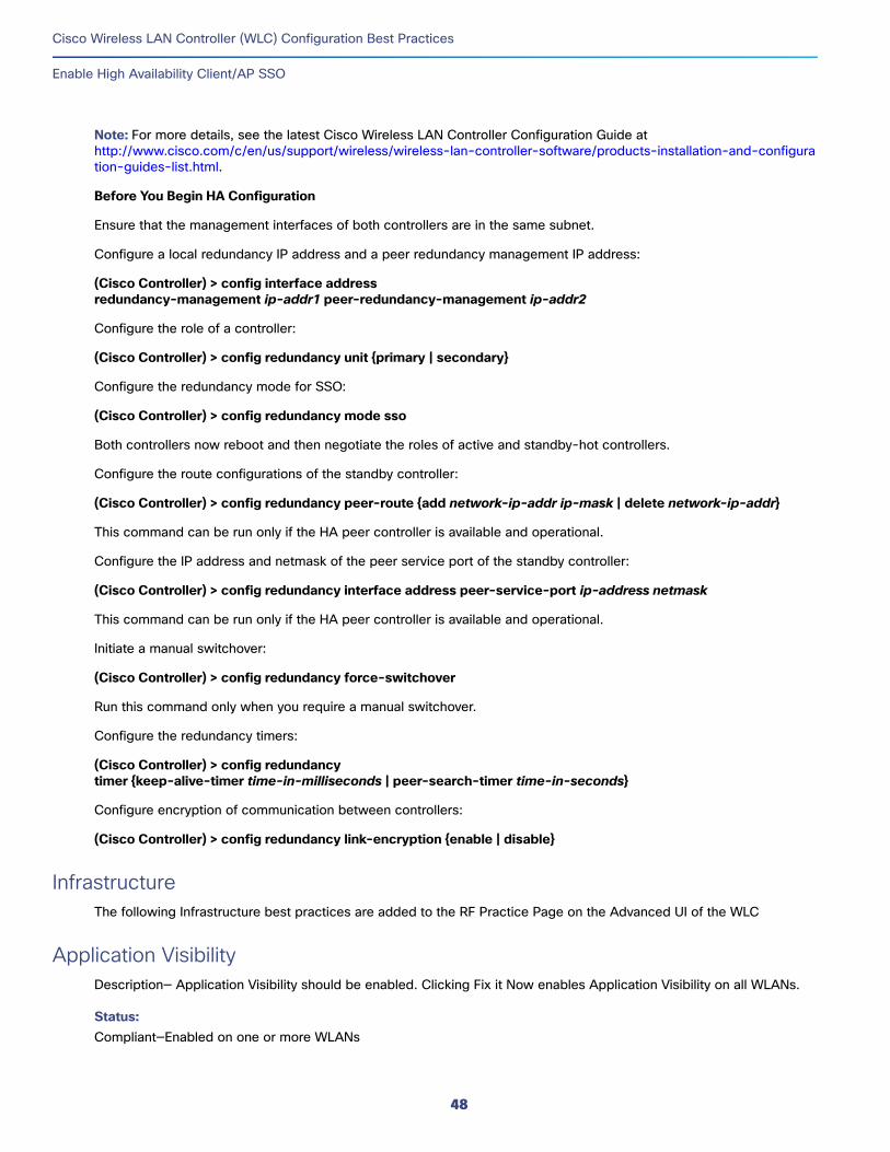
Cisco Wireless LAN Controller (WLC) Configuration Best Practices
Enable High Availability Client/AP SSO
Note: For more details, see the latest Cisco Wireless LAN Controller Configuration Guide at http://www.cisco.com/c/en/us/support/wireless/wireless-lan-controller-software/products-installation-and-configuration-guides-list.html.
Before You Begin HA Configuration
Ensure that the management interfaces of both controllers are in the same subnet.
Configure a local redundancy IP address and a peer redundancy management IP address:
(Cisco Controller) > config interface address redundancy-management ip-addr1 peer-redundancy-management ip-addr2
Configure the role of a controller:
(Cisco Controller) > config redundancy unit {primary | secondary}
Configure the redundancy mode for SSO:
(Cisco Controller) > config redundancy mode sso
Both controllers now reboot and then negotiate the roles of active and standby-hot controllers.
Configure the route configurations of the standby controller:
(Cisco Controller) > config redundancy peer-route {add network-ip-addr ip-mask | delete network-ip-addr}
This command can be run only if the HA peer controller is available and operational.
Configure the IP address and netmask of the peer service port of the standby controller:
(Cisco Controller) > config redundancy interface address peer-service-port ip-address netmask
This command can be run only if the HA peer controller is available and operational.
Initiate a manual switchover:
(Cisco Controller) > config redundancy force-switchover
Run this command only when you require a manual switchover.
Configure the redundancy timers:
(Cisco Controller) > config redundancy timer {keep-alive-timer time-in-milliseconds | peer-search-timer time-in-seconds}
Configure encryption of communication between controllers:
(Cisco Controller) > config redundancy link-encryption {enable | disable}
InfrastructureThe following Infrastructure best practices are added to the RF Practice Page on the Advanced UI of the WLC
Application VisibilityDescription— Application Visibility should be enabled. Clicking Fix it Now enables Application Visibility on all WLANs.
Status: Compliant—Enabled on one or more WLANs
48
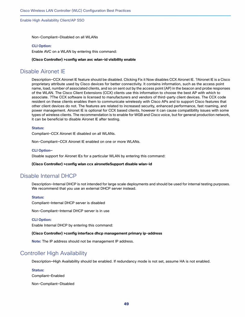
Cisco Wireless LAN Controller (WLC) Configuration Best Practices
Enable High Availability Client/AP SSO
Non-Compliant—Disabled on all WLANs
CLI Option:Enable AVC on a WLAN by entering this command:
(Cisco Controller) >config wlan avc wlan-id visibility enable
Disable Aironet IEDescription—CCX Aironet IE feature should be disabled. Clicking Fix it Now disables CCX Aironet IE. ?Aironet IE is a Cisco proprietary attribute used by Cisco devices for better connectivity. It contains information, such as the access point name, load, number of associated clients, and so on sent out by the access point (AP) in the beacon and probe responses of the WLAN. The Cisco Client Extensions (CCX) clients use this information to choose the best AP with which to associate. ?The CCX software is licensed to manufacturers and vendors of third-party client devices. The CCX code resident on these clients enables them to communicate wirelessly with Cisco APs and to support Cisco features that other client devices do not. The features are related to increased security, enhanced performance, fast roaming, and power management. Aironet IE is optional for CCX based clients, however it can cause compatibility issues with some types of wireless clients. The recommendation is to enable for WGB and Cisco voice, but for general production network, it can be beneficial to disable Aironet IE after testing.
Status: Compliant—CCX Aironet IE disabled on all WLANs.
Non-Compliant—CCX Aironet IE enabled on one or more WLANs.
CLI Option—Disable support for Aironet IEs for a particular WLAN by entering this command:
(Cisco Controller) >config wlan ccx aironetIeSupport disable wlan-id
Disable Internal DHCPDescription—Internal DHCP is not intended for large scale deployments and should be used for internal testing purposes. We recommend that you use an external DHCP server instead.
Status: Compliant—Internal DHCP server is disabled
Non-Compliant—Internal DHCP server is in use
CLI Option:Enable Internal DHCP by entering this command:
(Cisco Controller) >config interface dhcp management primary ip-address
Note: The IP address should not be management IP address.
Controller High AvailabilityDescription—High Availability should be enabled. If redundancy mode is not set, assume HA is not enabled.
Status: Compliant—Enabled
Non-Compliant—Disabled
49
Cisco Wireless LAN Controller (WLC) Configuration Best Practices
Enable High Availability Client/AP SSO
Disable Management over WirelessDescription—The Cisco WLAN solution Management over Wireless feature allows Cisco WLAN solution operators to monitor and configure local WLCs using a wireless client. Management over wireless should be disabled for security reasons. Clicking Fix it Now disables management over wireless.
Status:Compliant—Management over Wireless is disabled
Non-Compliant—Management over Wireless is disabled
CLI Option:Disable management over wireless by entering this command:
(Cisco Controller) >config network mgmt-via-wireless disable
Fast SSIDDescription—Fast SSID should be enabled. Clicking Fix it Now enables fast SSID.
Status: Compliant—Enabled
Non-Compliant—Disabled
CLI Option:Enable fast SSID by entering this command:
(Cisco Controller) >config network fast-ssid-change
HTTPS for ManagementDescription—Secure Web Access should be enabled. Web Access should be disabled. Clicking Fix it Now enables HTTPS and disables HTTP.
Status: Compliant—HTTPS enabled; HTTP disabled
Non-Compliant—HTTPS enabled, HTTP enabled or HTTPS disabled, HTTP enabled
CLI to configure: Disable the web mode to deny users to access the WLC GUI using http://ip-address, by entering this command:
(Cisco Controller) >config network webmode disable
Enable Secure Web Access mode to allow users to access the WLC GUI using https://ip-address, by entering this command:
(Cisco Controller) >config network secureweb enable
Load BalancingDescription—We recommend that you not use load balancing when interactive traffic such as voice or video is used on the WLAN. Clicking Fix it Now enables load balancing on all WLANs, which may impact service at the time.
Status: Compliant—Enabled on one or more WLANs
50
Cisco Wireless LAN Controller (WLC) Configuration Best Practices
Enable High Availability Client/AP SSO
Non-Compliant—Disabled on all WLANs
CLI Option:Enable load balancing on a WLAN by entering this command:
(Cisco Controller) >config wlan load-balance allow enable wlan-id
Load Balancing WindowDescription—When client load balancing is enabled, we recommend that you set the window size to 5 or higher to avoid an aggressive load balancing algorithm.
Status: Compliant—Load balancing window is 5 or higher
Non-Compliant—Load balancing window is less than 5
CLI Option:Enable load balancing window by entering this command:
(Cisco Controller) >config wlan disable wlan-id
(Cisco Controller) >config wlan load-balance allow enable wlan-id
(Cisco Controller) >config load-balancing window client-count-more-than-5
(Cisco Controller) >config wlan enable wlan-id
Local ProfilingDescription—Local profiling should be enabled. Clicking Fix it Now enables local profiling (DHCP/HTTP) on all WLANs; this may impact service at the time.
Status: Compliant—Enabled on one or more WLANs.
Non-Compliant—Disabled on all WLANs.
CLI Option:Enable local profiling (DHCP/HTTP) on all WLANs by entering this command:
(Cisco Controller) >config wlan profiling local all enable
mDNS GatewayDescription—mDNS snooping should be enabled. Clicking Fix it Now enables mDNS snooping.
Status: Compliant—Enabled
Non-Compliant—Disabled
CLI Option:Enable mDNS snooping by entering this command:
51
Cisco Wireless LAN Controller (WLC) Configuration Best Practices
Enable High Availability Client/AP SSO
(Cisco Controller) >config mdns snooping enable
Multicast ForwardingDescription—Use multicast forwarding mode for the best performance with less bandwidth utilization. ?Use multicast forwarding mode for the best performance with less bandwidth utilization. Networks with large IPv6 client counts, heavy multicast application such as Video Streaming, or mDNS without mDNS proxy, would benefit greatly with multicast mode.
Status: Compliant—Enabled
Non-Compliant—Disabled
To verify the multicast mode on the controller:
(Cisco Controller) >show network summary
To configure multicast-multicast operations:
(Cisco Controller) >config network multicast mode multicast multicast-group-ip-address
(Cisco Controller) >config network multicast global enable
Note: The multicast address is used by the WLC to forward traffic to Access Points (APs). It is important that the multicast address does not match another address in use on your network by other protocols. For example, if you use 224.0.0.251, it breaks mDNS used by some third party applications. We recommend that the address be in the private range (239.0.0.0 – 239.255.255.255, which does not include 239.0.0.x and 239.128.0.x). It is also important that the multicast IP address be set to a different value on each WLC. You would not want a WLC that speaks to its APs to reach the APs of another WLC.
If the APs are on a different subnetwork than the one used on the management interface, your network infrastructure must provide multicast routing between the management interface subnet and the AP subnetwork.
Multicast MobilityDescription—Allows WLCs to announce messages to all mobility peers instead of individual WLC with CPU and network benefits. Ensure multicast traffic is passing between WLCs when their management is on different subnets.
Status: Compliant—Enabled
Non-Compliant—Disabled
CLI Option—Configure the mobility multicast mode by entering this command:
(Cisco Controller) >config mobility multicast-mode enable local-multicast-address
Multicast VLANDescription—With interface groups in use, we recommend that you enable multicast VLAN to limit multicast on the air to a single copy on a predefined multicast VLAN.
Status: Compliant—Multicast VLAN is enabled for all WLANs that are mapped to an interface group
Non-Compliant—Multicast VLAN is not enabled for one or more WLANs that are mapped to an interface group
52
Cisco Wireless LAN Controller (WLC) Configuration Best Practices
Enable High Availability Client/AP SSO
CLI Option—Enable Multicast VLAN by entering this command:
(Cisco Controller) >config wlan multicast interface wlan-id enable interface-group
NTPDescription— NTP server should be used to sync the WLC time. ?Network Time Protocol (NTP) is very important for several features. It is mandatory to use NTP synchronization on WLCs if you use any of these features: Location, SNMPv3, access point authentication, or MFP. The WLC supports synchronization with NTP using authentication.
Status: Compliant—Configured
Non-Compliant—Not configured
CLI Option: Enable NTP server by entering this command:
(Cisco Controller) >config time ntp server ntp-server-index ntp-server-ip-address
Enable NTP authentication by entering this command:
(Cisco Controller) >config time ntp auth enable ntp-server-index
(Cisco Controller) >config time ntp key-auth add key-index
Tagged Management VLANDescription—We highly recommend that you tag the RMI and management interfaces for HA, IPv6, and WGB VLAN support.
Status: Compliant—Management VLAN is tagged
Non-Compliant—Management VLAN is untagged
CLI Option—Enable Tagged Management VLAN by entering this command:
(Cisco Controller) >config interface vlan management vlan-id
Virtual Gateway IPDescription—We recommend that you avoid overlapping the IP address of the virtual interface with Internet Allocated Addresses as per RCFC5737. This includes IP addresses in the 192.0.2.0/24, 198.51.100.0/24, and 203.0.113.0/24 networks.
Status: Compliant—Virtual IP address is not overlapping with Internet Allocated Addresses
Non-Compliant—Virtual IP address is overlapping with Internet Allocated Addresses
CLI Option—Enable Virtual Gateway IP by entering this command:
53
Cisco Wireless LAN Controller (WLC) Configuration Best Practices
FlexConnect Best Practices
(Cisco Controller) >config interface address virtual virtual-ip-address
WLAN not on Management InterfaceDescription—We recommend that you have the non-management WLANs mapped to dynamic interfaces to split user traffic from management traffic.
Status: Compliant—No user WLAN is mapped to the management interface
Non-Compliant—One or more WLANs are mapped to management interface
CLI Option—Enable WLAN not on Management interface by entering this command:
(Cisco Controller) >config wlan interface wlan-id interface-name
Note: The interface should not be a management interface.
FlexConnect Best PracticesThis section lists some of the FlexConnect best practices:
FlexConnect deployment in the branch site helps to reduce the branch footprint in terms of capital and operational expenditure savings with controllers at the central site as opposed to a WLC at each remote office. This results in reduced power consumption and centralized IT support. It also provides the benefit of centralizing control at a central site, survivability against WAN failures, and reduced WAN usage between the central and remote sites.
Certain architectural requirements need to be considered when deploying a distributed branch office in terms of the Minimum WAN Bandwidth, Maximum RTT, Minimum MTU, and fragmentation guidelines that are captured in the following guide:
See the latest Flex 7500 Wireless Branch Controller Deployment Guide at http://www.cisco.com/c/en/us/support/wireless/wireless-lan-controller-software/products-technical-reference-list.html.
Check to make sure that the AP model being used has FlexConnect support. The AP model OEAP600 does not support FlexConnect mode.
Set QoS to prioritize CAPWAP Control Channel traffic on UDP port 5246.
Local Switching Enable Local Switching on the WLAN to provide resiliency against WAN failures and reduce the amount of data going
over the WAN, thus reducing the WAN bandwidth usage.
Local switching is useful in deployments where resources are local to the branch site and data traffic does not need to be sent back to the controller over the WAN link.
Connect the FlexConnect AP to a 802.1Q trunk port on the switch.
Enable VLAN Support.
When connecting with Native VLAN on the AP, the native VLAN configuration on the L2 must match the configuration on the AP.
Each corresponding VLAN on locally switched WLANs should be allowed on the corresponding switch port.
Switch configuration for this scenario is as shown below:
54
Cisco Wireless LAN Controller (WLC) Configuration Best Practices
FlexConnect Best Practices
!interface GigabitEthernet0/1 switchport trunk encapsulation dot1q switchport trunk native vlan 52 switchport trunk allowed vlan 52,154,155 switchport mode trunk spanning-tree portfast trunk !
Some features are not available in standalone mode or in local switching mode. Note the following limitations when using Local Switching:
— MAC/Web Auth in Standalone Mode
— IPv6 L3 Mobility
— SXP TrustSec
— Application Visibility and Control
— Service Discovery Gateway
— Native Profiling and Policy Classification
See the full list in the following FlexConnect Feature Matrix guide:
http://www.cisco.com/en/US/products/ps6366/products_tech_note09186a0080b3690b.shtml
Split Tunneling Configure the Split Tunneling feature in scenarios where most of the resources are located at the central site and
client data needs to be switched centrally, but certain devices local to the remote office need local switching to reduce WAN bandwidth utilization.
A typical use case for this is the OEAP tele-worker setup, where clients on a Corporate SSID can talk to devices on a local network (printers, wired machine on a Remote LAN Port, or wireless devices on a Personal SSID) directly without consuming WAN bandwidth by sending packets over CAPWAP.
Central DHCP and Split Tunnel feature uses the routing functionality of the AP.
Note the following limitations when deploying Split Tunneling:
— Split tunneling is not supported on OEAP 600 APs.
— Static IP clients are not supported with central-DHCP and local split WLANs.
VLAN Based Central Switching Use VLAN based central switching in scenarios where dynamic decisions need to be made to local switch or central
switch the data traffic based on the VLANs returned by the AAA server and the VLANs present at the branch site.
For VLANs that are returned by the AAA server and not present on the branch site, traffic will be switched centrally.
FlexConnect GroupsDefine FlexConnect groups to leverage features such as:
CCKM/OKC fast roaming for Voice deployments
Local Backup Radius Server
55
Cisco Wireless LAN Controller (WLC) Configuration Best Practices
FlexConnect Best Practices
Local EAP
Smart AP Image Upgrade
WLAN-VLAN and VLAN-ACL mapping
CCKM/OKC Fast roaming Use FlexConnect groups in scenarios where CCKM/OKC fast roaming is required for clients when the FlexConnect
AP is in connected or standalone mode.
This feature prevents the need to perform a full RADIUS EAP authentication as the client roams from one AP to another.
The FlexConnect APs need to obtain the CCKM/OKC cache information for all the clients that might associate so that they can process it quickly instead of sending it back to the controller.
Local Backup RADIUS server Configure Local Backup RADIUS server to increase the resiliency of the branch taking into consideration failures at
the WAN, WLC failures, and failures at the RADIUS server.
This feature is also used for remote offices where the WAN latency to the central site is high.
Administrators can configure a primary backup RADIUS server or both the primary and secondary backup RADIUS server. FlexConnect AP in standalone mode can be configured to perform full 802.1X authentication to a backup RADIUS server.
These servers are used when the FlexConnect AP is not connected to the controller or when the WLAN is configured for local authentication.
If the RADIUS/ACS is located inside the branch, then the clients will authenticate and access wireless services even during a WAN outage.
Note the following limitation when configuring local backup RADIUS server:
— When a local backup RADIUS server is used in the branch, the IP addresses of all the APs acting as authenticators must be added on the RADIUS server.
Local EAP For an additional level of resiliency, enable Local EAP Server on the FlexConnect group (EAP-FAST, PEAP, EAP-TLS).
The Local EAP feature can be used in conjunction with the FlexConnect backup RADIUS server feature. If a FlexConnect group is configured with both backup RADIUS server and local authentication, the FlexConnect AP always attempts to authenticate clients using the primary backup RADIUS server first, followed by the secondary backup RADIUS server (if the primary is not reachable), and finally the Local EAP Server on FlexConnect AP itself (if the primary and secondary are not reachable).
Note the following limitations when configuring Local EAP on FlexConnect AP:
— Up to 100 statically configured users can be authenticated on the FlexConnect AP. Each AP in the group authenticates only its own associated clients.
— Active Directory (AD) integration is not supported with this feature.
56
Cisco Wireless LAN Controller (WLC) Configuration Best Practices
FlexConnect Best Practices
Smart AP Image Upgrade Use the Smart AP Image Upgrade feature to upgrade the branch sites as this feature conserves WAN bandwidth,
reduces upgrade-induced service downtime, and also reduces the risk of download failure over the WAN. Efficient AP image upgrade reduces the downtime for each FlexConnect AP.
Master AP selection is per FlexConnect group and per AP model in each group.
The best practices recommended for a network upgrade are as follows:
— Download Image to WLC, using controller CLI/GUI or Prime Infrastructure.
— Force the boot image to be the secondary (and not the newly upgraded one) to avoid parallel download of all AP in case of an unexpected WLC reboot.
— The controller elects a master AP in each FlexConnect group. The master AP can also be selected manually.
— Master AP pre-downloads the AP firmware in the secondary boot image. Schedule this per FlexConnect group to limit the WAN exhaust.
— Once the master AP finishes downloading the image, it sends a message to the controller. The controller instructs the slave APs to pre-download the AP firmware from the master AP.
— Change the boot image of the WLC to point to the new image.
— Reboot the controller.
WLAN-VLAN and VLAN-ACL Mapping WLAN-VLAN mapping at the FlexConnect group provides ease of configuration without having to configure the
mapping at each AP. For example, for all APs in a branch site to do local switching on the same VLAN, the WLAN-VLAN mapping can be configured at a per FlexConnect group level.
VLAN-ACL mapping at the FlexConnect group provides ease of configuration without having to configure the mapping at each FlexConnect AP.
If a VLAN is created at the AP using WLAN-VLAN mapping, the VLAN-ACL should also be created on the AP and not at FlexConnect group.
VLAN Support/Native VLAN on FlexConnect Group Configure VLAN Support and Native VLAN at the level of the FlexConnect group, and use the override flag to
consolidate all the VLAN configuration at a single place.
This feature helps you to consolidate configurations for all APs at the Branch Level, provides consistency of mapping, and eases configuration.
Avoid per AP configuration unless absolutely necessary.
(Cisco Controller) >config flexconnect group <groupName> vlan <enable / disable>
(Cisco Controller) >config flexconnect group <groupName> vlan native <vlan_id>
(Cisco Controller) >config flexconnect group <groupName> vlan override-native-ap <enable / disable>
57
Cisco Wireless LAN Controller (WLC) Configuration Best Practices
Outdoor Best Practices
AAA Override of VLAN Name The VLAN Name Override feature is useful in deployments that have a single central radius authenticating multiple branches. The requirement for this deployment is to map clients to different VLANs across different branch locations based on authentication profiles and policy rules.
The benefit of using this feature is that the RADIUS server only needs to be aware of the user function and logical categorization of that user. The details of VLAN design can be abstracted in the form of VLAN Name to VLAN ID mapping configurations.
Create VLAN Name template and add mapping rules as follows:
(Cisco Controller) >config flexconnect vlan-name-id create template1
(Cisco Controller) >config flexconnect vlan-name-id template-entry add template1 Marketing 20
(Cisco Controller) >config flexconnect vlan-name-id apply template1
A template can also be created by copying from another template:
(Cisco Controller) >config flexconnect vlan-name-id create template2 copy template1
Associate the template with a FlexConnect group:
(Cisco Controller) >config flexconnect group FlexGroup1 template-vlan-map add template1
Outdoor Best PracticesThis section explains the outdoor best practices for design, deployment, and security.
Design
Perform an RF Active Site SurveyThe outdoor environment is a challenging RF environment. Many obstacles and interferers exist that cannot be avoided. Prior to designing a network, an RF Active Site Survey is the first step to understand your RF environment.
Estimate Coverage Area Using the Cisco Range and Capacity CalculatorOnce the RF active site survey is performed, you must estimate the number of outdoor access points required to meet your network's design requirement. The best tool to estimate an access point's coverage area is the WNG Coverage and Capacity Calculator:
http://173.37.206.125/aspnet_client/system_web/2_0_50727/WNG_Coverage_Capacity_Calculator_V2.08/WNG_Coverage_Capacity_Calculator_V2.08.asp
Select the Optimal Operating modeOutdoor access points can operate in multiple deployment modes, with each deployment mode meeting a different use case.
Local Mode—Best option for an outdoor deployment. Provides full support of Cisco Unified Network features, Radio Resource Management (RRM), and allows the 2.4 GHz and 5 GHz radios to be used exclusively for client access. This deployment mode should be used when each access point has a dedicated Ethernet connection.
Bridge Mode—Leverages the Cisco Wireless Layer 2 protocol to allow access points to connect wirelessly over great distances. This deployment mode should be used when additional Ethernet connections are not available.
58
Cisco Wireless LAN Controller (WLC) Configuration Best Practices
Outdoor Best Practices
Deployment
Avoid Selecting DFS Channels for BackhaulWhen operating in Bridge Mode, the 5 GHz wireless channel used for the wireless backhaul must be manually selected. When selecting the backhaul channel for a mesh tree, if possible, avoid channels that can be used for radar (DFS channels). These channels are listed per regulatory domain:
http://www.cisco.com/c/en/us/products/collateral/wireless/aironet-1300-series/product_data_sheet0900aecd80537b6a.html#wp9005314
Set BGN and Preferred Parent for Each Bridge Mode Access PointWhen operating in Bridge Mode, each access point should be assigned a Bridge Group Name and Preferred Parent. This helps the mesh network to converge in the same sequence every time, allowing the network to match the initial design.
To set Bridge Group Name:
(Cisco Controller) >config` ap bridgegroupname set BGN-name ap-name
To verify:
(Cisco Controller) >show ap config general ap-name
To set Preferred Parent:
(Cisco Controller) >config mesh parent ap-name parent_MAC
To verify:
(Cisco Controller) >show ap config general ap-name
Deploy Multiple RAPs in Each BGNWhen deploying a mesh network, there should be multiple paths for each access point back to a WLC. Multiple paths can be added by having multiple Root Access Points (RAPs) per mesh tree. If an RAP fails and goes offline, other mesh access points will join another RAP in the same BGN and still have a path back to the WLC.
Set Backhaul Data Rates to autoWhen deploying a mesh network, each mesh node should communicate on the highest possible backhaul data rate. To ensure this, it is recommended to enable Dynamic Rate Adjustment (DRA) by selecting the “auto” backhaul data rate. DRA has to be enabled on every mesh link.
To enable “auto”:
(Cisco Controller) > config ap bhrate auto ap-name
To verify:
(Cisco Controller) > show ap bhrate ap-name
Set Backhaul Channel Width to 40 MHzWhen deploying a mesh network, each mesh node should communicate on the highest possible backhaul speed. Enabling 40 MHz backhaul channels allow greater backhaul speeds.
59
Cisco Wireless LAN Controller (WLC) Configuration Best Practices
Outdoor Best Practices
To set the channel width per AP:
(Cisco Controller) >config 802.11a chan_width ap-name 40
Ensure the Backhaul Link Signal to Noise Ratio (LinkSNR) is Greater than 25 dBmTo ensure optimal performance over your mesh network, make sure the backhaul link quality is good. An optimal link quality would be greater than 40 dBm, but this is not always achievable in non-line of site deployment or long-range bridges. Cisco recommends the link SNR to be at least 25 dBm or greater.
To check the LinkSNR:
(Cisco Controller) >show mesh neigh summary ap-name
AP Name/Radio Channel Rate Link-Snr Flags State------------- ------- ------ --------- ----- ------RAP_e380 136 m15 33 0x0 UPDATED NEIGH PARENT BEACON
Or:
(Cisco Controller) >show mesh neigh detail ap-name
AP MAC : 1C:AA:07:5F:E3:80 AP Name: RAP_e380backhaul rate m15FLAGS : 86F UPDATED NEIGH PARENT BEACON Neighbor reported by slot: 1worstDv 0, Ant 0, channel 136, biters 0, ppiters 10Numroutes 1, snr 0, snrUp 40, snrDown 43, linkSnr 39adjustedEase 8648576, unadjustedEase 8648576
Security
Use External Radius Server for Mesh MAC AuthenticationAn external radius server should be configured for MAC authentications. This allows all bridge mode access points to authenticate at a single location, thus simplifying network management.
For instructions on how to setup an external radius server, see the latest Mesh Deployment Guide at http://www.cisco.com/c/en/us/support/wireless/wireless-lan-controller-software/products-technical-reference-list.html.
Enable controller Based wIPS and Rogue DetectionController based wIPS and rogue detection is enabled on the WLC by default. This gives network administrators the additional security by monitoring the wireless network for unwanted rogue access points or potential wireless attackers.
To configure:
(Cisco Controller) >config mesh ids-state enable
Enable EAP as Security ModeEach mesh hop encrypts all wireless traffic. The most secure method for encrypting your over the air traffic is to use the EAP option with an external Radius server.
To configure:
(Cisco Controller) >config mesh security eap
60
Cisco Wireless LAN Controller (WLC) Configuration Best Practices
Adaptive 11r, 11k and 11v for Optimized WiFi Connectivity
Adaptive 11r, 11k and 11v for Optimized WiFi Connectivity The capable iOS devices running iOS 10 and higher will identify the Adaptive 11r functionality on a Cisco network running AireOS 8.3 and higher and perform an FT Association on the WLAN. The Cisco Wireless infrastructure will allow FT association on the WLAN from devices that can negotiate FT association on a non-FT WLAN.
config wlan security ft adaptive enable/disable
Enable AKM as 802.1x or PSK instead of FT 802.1x or FT PSK when adaptive 11r is enabled
In addition, with WLC running AireOS 8.3, 802.11k and 11v features are enabled by default on an SSID. These features help clients roam better by telling them when to roam and providing them with information about neighboring APs so that no time is wasted scanning when roaming is needed. Since iOS devices support dual- band, the 802.11k neighbor list is updated on dual-band, adaptively for iOS devices.
FastLane for Prioritized Business Apps Apple iOS device mark QoS as per IETF recommendations. With WLC running AireOS 8.3, you can enable the Fastlane feature, which enables several beneficial functions:
Your WLC QoS configuration is optimized globally to better support real-time applications iOS 10 devices can send upstream voice traffic without the requirement to perform WMM TSPEC/TCLAS negotiation. The infrastructure will honor the voice marking for these devices.
You can apply a QoS profile to your iOS 10 devices, and decide which applications should receive QoS marking upstream, and which applications should be sent as best effort or background.
config qos Fastlane enable/disable wlan <wlan id>
Apple Devices The following best practices are applicable to networks with Apple client devices are added to the Best Practice Page on the Advanced UI of the WLC.
WLAN ConfigurationDescription—Allows you to identify if the WLAN is configured with recommended L2 security, QoS, and advanced settings for Apple devices. Application Visibility should be enabled.
Status: Compliant—At least one WLAN is compliant with all the recommended WLAN configuration for Apple devices.
Non-Compliant—There is no WLAN that is compliant with all the recommended WLAN configuration for Apple devices.
CLI Option:Multiple features have to be configured by entering these commands:
SecuritySet Fast Transition to enabled or Adaptive:
(Cisco Controller) >config wlan security ft {enable | adaptive enable} wlan-id
Enable FT PSK when FT is enabled:
(Cisco Controller) >config wlan security wpa wpa2 enable wlan-id
61
Cisco Wireless LAN Controller (WLC) Configuration Best Practices
Apple Devices
(Cisco Controller) >config wlan security wpa akm ft psk enable wlan-id
Enable FT 802.1X when FT is enabled:
(Cisco Controller) >config wlan security wpa wpa2 enable wlan-id
(Cisco Controller) >config wlan security wpa akm ft 802.1x enable wlan-id
Disable Over-the-DS:
(Cisco Controller) >config wlan security ft over-the-ds disable wlan-id
QoSEnable Fastlane:
(Cisco Controller) >config qos fastlane enable wlan-id
Set WLAN QoS to Platinum (Voice):
(Cisco Controller) >config wlan qos wlan-id platinum
Enable AVC profile and apply AUTOQOS-AVCPROFILE for the WLAN:
(Cisco Controller) >config wlan avc wlan-id visibility enable
(Cisco Controller) >config wlan avc wlan-id profile AUTOQOS-AVCPROFILE??
WMM policy is set to Required:
(Cisco Controller) >config wlan wmm require wlan-id
AdvancedEnable 802.11k neighbor list or dual band:
(Cisco Controller) >config wlan assisted-roaming neighbor-list enable wlan-id
Enable 802.11v BSS Transition:
(Cisco Controller) >config wlan bss-transition enable wlan-id
Set WLAN radio policy to be All or 802.11a or 802.11a/g:
(Cisco Controller) >config wlan radio wlan-id {all | 802.11a-only | 802.11ag}??
Enable mDNS snooping:
(Cisco Controller) >config wlan mdns enable wlan-id
5 GHz EnabledDescription—Enable the 5-GHz radio to provide a faster and less interfering network for Apple devices.?
Status: Compliant—5-GHz radio is enabled on the network. ?
Non-Compliant—5-GHz radio is disabled on the network. ?
CLI Option:Enable the 5-GHz radio on the network by entering this command:
62
Cisco Wireless LAN Controller (WLC) Configuration Best Practices
Apple Devices
(Cisco Controller) >config 802.11a enable network
5 GHz EDCA FastlaneDescription—Configuring the EDCA Profile as Fastlane helps improve Apple Device performance on 5-GHz networks. ?
Status: Compliant—EDCA Profile name is Fastlane. ?
Non-Compliant—EDCA Profile name is not Fastlane. ?
CLI Option:Set the EDCA Profile name to Fastlane on a 5-GHz network by entering this command:
(Cisco Controller) >config advanced 802.11a edca-paramter fastlane??
5 GHz MCS RatesDescription—All the MCS Rates (0-31) should be enabled on the 5-GHz networks to help improve the performance of Apple client devices.?
Status: Compliant—All the MCS rates are enabled on the 5-GHz network.?
Non-Compliant—Some of the MCS rates are disabled on the 5-GHz network.?
CLI Option:Enabled MCS rates on a 5-GHz network by entering this command:
(Cisco Controller) >config 802.11a 11acsupport mcs tx {mcs8 | mcs9} ss {1-4} enable
QoS Trust DSCPDescription—Enabling the QoS Map and Trust DSCP Upstream helps improve the performance of Apple client devices.?
Status: Compliant—QoS Map is enabled and Trust DSCP Upstream is selected for QoS Map Upstream.?
Non-Compliant—QoS Map is disabled or UP to DSCP Map is selected for QoS Map Upstream. ?
CLI Option:Enable QoS Map values by entering these commands:
(Cisco Controller) >config qos qosmap enable
(Cisco Controller) >config qos qosmap trust-dscp-upstream enable
QoS Platinum ProfileDescription—The Unicast and Multicast priority should be Best Effort for Platinum Profile to help improve the performance of Apple client devices.?
Status: Compliant—QoS Platinum Profile has Best Effort for Unicast and Multicast priority.?
63
Cisco Wireless LAN Controller (WLC) Configuration Best Practices
Apple Devices
Non-Compliant—QoS Platinum Profile does not have Best Effort for either Unicast or Multicast priority.?
CLI Option:Enable Best Effort on the Platinum Profile by entering this command:
(Cisco Controller) >config qos priority platinum besteffortbesteffort besteffort
mDNS or BonjourDescription—mDNS or Bonjour snooping and policy are enabled for Apple client devices to identify local devices such as projectors, printers, and so on, that support the mDNS service. ?
Status: Compliant—mDNS snooping and policy are enabled.?
Non-Compliant—Either mDNS snooping or policy or both are disabled. ?
CLI Option:Enable mDNS snooping and policy by entering these commands:
(Cisco Controller) >config mdns snooping enable
(Cisco Controller) >config mdns policy enable
Optimized Roaming DisabledDescription—Optimized roaming should be disabled because Apple devices use the newer 802.11r, 802.11k, or 802.11v roaming improvement.?
Status: Compliant—Optimized roaming is disabled. ?
Non-Compliant—Optimized roaming is enabled. ?
CLI Option:Disable optimized roaming by entering this command:
(Cisco Controller) >config advanced 802.11{a | b} optimized-roaming disable
64