Embed Size (px)
Citation preview
Cisco Wireless LAN Controller (WLC) Configuration Best Practices
Introduction 2
Prerequisites 2
General Settings 2
Network 6
WLAN General Recommendations 12
Multicast Recommendations 16
Security 17
Mobility 45
FlexConnect Best Practices 47
Outdoor Best Practices 51
Apple Devices 53

Revised: February 19, 2018,
IntroductionMobility has rapidly changed the expectation of wireless network resources and the way users perceive it. Wireless has become thepreferred option for users to access the network, and in many cases the only practical one. This document offers short configurationtips that cover common best practices in a typical Wireless LAN Controller (WLC) infrastructure. The objective of this documentis to provide important notes that you can apply on most wireless network implementations.
Not all networks are the same. Therefore, some of the tips might not be applicable on your installation.Always, verify them before you perform any changes on a live network.
Note
Prerequisites
RequirementsCisco recommends that you have knowledge of these topics:
• Knowledge on how to configure the Wireless LAN Controller (WLC) and Lightweight Access point (LAP) for basic operation
• Basic knowledge of Control And Provisioning of Wireless Access points (CAPWAP) protocol and wireless security methods
Components UsedThe information in this document was based on these software and hardware versions:
• Cisco series WLC that runs software release 8.2 and above
• Cisco 802.11n and 11ac series APs
The information in this document was created from the devices in a specific lab environment. All of thedevices used in this document started with a cleared (default) configuration. If your network is live, makesure that you understand the potential impact of any command.
Note
General Settings
Controller
Configuration Changes
It is mandatory to reload the controllers after you change these configuration settings:
2

• Management address
• SNMP configuration
• HTTPS encryption settings
• LAG mode (enable/disable)
• Licensing
Configuration File Management
• Do not use a file from one controller type into another, for example a 2500 into a 5520. Some fields, especially password data,may be lost. If you need to use files across controller models, use a file conversion tool https://cway.cisco.com/tools/WirelessConfigConverter/
• Do not do configuration changes when a configuration upload is in progress, to avoid any possible data corruption.
• As a precaution, always do a configuration backup before a code upgrade.
Configuration files may contain sensitive data. If you want to ensure password confidentiality, use the transfer upload encrypted filefeature when doing configuration backups from the controller.How to enable (replace with your 16 characters key):(Cisco Controller) >transfer encrypt set-key <password>(Cisco Controller) >transfer encrypt enableHow to verify:(Cisco Controller) >transfer upload startMode............................................. TFTPTFTP Server IP................................... 192.168.0.45TFTP Path........................................ ./TFTP Filename.................................... 5520-1.txtData Type........................................ Config FileEncryption....................................... Enabled
This should be used in most scenarios.Restriction
Core Dump Export
In case of a controller crash, it is possible to enable automated upload of core dump for analysis to a FTP server, this file can beprovided to TAC for further analysis. By default this feature is enabled
How to configure:(Cisco Controller) >config coredump ftp <serverip> <filename>(Cisco Controller) >config coredump enableTo validate the configuration:(Cisco Controller) >show coredump summaryCore Dump upload is enabled
This should be used in most scenarios to facilitate data gathering in case of unexpected controller reload.Restriction
Related Documentation:
https://supportforums.cisco.com/t5/wireless-mobility-documents/how-to-find-amp-retrieve-wlc-s-crash-coredump-from-its-s-flash/ta-p/3145554
3
Support Bundle
In recent releases (8.0.150.0, 8.2.160.0 and higher versions), the controller now supports a single file upload option to easily collectthe most important support data in a simplified way. This will provide a bundle covering crash information, core files, configuration,RRM logs, and RF state data. It is advisable to always include this file when opening a TAC case, to have a good starting data set.
How to Upload (proceed with file upload mode as needed)(Cisco Controller) >transfer upload datatype support-bundle
This should be used in all scenarios.Restriction
Related documentation:https://www.cisco.com/c/en/us/td/docs/wireless/controller/8-6/config-guide/b_cg86/managing_configuration.html#diagnostic-support-bundle
Fast Restart
It is recommended to use restart instead of reset system for the following scenarios to reduce network and service downtime andprovide better serviceability:
• LAG Mode Change
• Mobility Mode Change
•Web-authentication cert installation
• Clear Configuration
The Fast Restart feature is supported on Cisco WLC 7510, 8510, 5520, 8540, and vWLC from release 8.1.
To restart the controller:(Cisco Controller) >restartThe system has unsaved changes.Would you like to save them now? (y/N) yUpdating HBL license statistics file Done.Configuration Saved!System will now restart!Updating license storage ... Done.mDNS GatewayBonjour, an Apple's service discovery protocol, locates devices such as printers, other computers, and the services that those devicesoffer on a local network using multicast Domain Name System (mDNS) service records. Bonjour is a link local protocol that doesnot cross L3 boundaries. With Bonjour gateway, Apple devices can discover Bonjour services across a layer 3 boundary (acrossdifferent VLANs) without additional configuration on the end user device(s).
Using a mDNS gateway can reduce significantly the amount of multicast traffic flooded across the wireless network, as the responsesare handled directly as unicast towards the device sending them, optimizing the use of RF time.
Also, this removes Bonjour from the CAPWAP multicast traffic requirements, reducing overall network load.
This should be used in most scenarios. It should only be disabled when there is some interoperability issuewith end devices, or when another local mDNS gateway is present, external to the WLC.
Restriction
To enable/disable global mDNS snooping:(Cisco Controller) > config mdns snooping enable/disable
4

To enable/disable mDNS support for a WLAN:(Cisco Controller) >config wlan mdns-profile enable/disable <wlan id/all>
Enable Fast SSID Changing
When fast SSID changing is enabled, the controller allows clients to move faster between SSIDs, changing the client context betweenWLANs, instead of forcing a client delete and a wait time. From a security point of view, it is preferable the disable option, as thereis full confirmation of all client state is deleted before it is allowed on another WLAN, that may have different security policies.
The enable option is advisable when Apple IOS clients are present, as these devices do not work properly with the "delete on WLANchange" behavior, and they may blacklist the currently associated AP
This should be used in most scenarios to have it enabled for better interoperability. It must be disabledwhen using RADIUS NAC.
Restriction
To enable fast SSID change:(Cisco Controller) >config network fast-ssid-change enable
Enable High Availability Client/AP SSO
High Availability (HA) with Client SSO is a feature supported from controller version 7.4 and higher. This allows a pair of controllersto act as a single network entity, working in an active/standby scenario, while preserving AP and client states, and ensuring thatdevices will not have to authenticate in case of a failure on the current active controller.
Whenever allowed by the controller hardware type in use, it is advisable to take advantage of the HA SSO feature, to reduce anypossible downtime in case of failure.
This should be used in most scenarios.Restriction
Related Documentation:
High Availability (SSO) Deployment Guide
N+1 High Availability Deployment Guide
Load Balancing Window
If load balancing is required on the WLAN, ensure that the controller has a global windows set to 5 clients or higher, to preventassociation errors
This should be used in most scenarios when Load Balancing feature is in use.Restriction
Aggregated Probe Response Optimizations
For large high density deployments, it is advisable to modify the default aggregate probe interval sent by access points. By default,the APs will update every 500ms about the probes sent by clients, this information is used by load balancing, band select, locationand 802.11k features.
If there is a large number of clients and access points, it is advisable to modify the update interval, to prevent control plane performanceissues in the WLC.
5

To change:config advanced probe limit 50 64000That would set it to 50 aggregated probe responses every 64 seconds.
This should be used in most scenarios with very large count of access points and clients.Restriction
Access Points
Configure Predictive Join
When configuring access points, always set the primary/secondary controller names, to control the AP selection during the CAPWAPjoin process. This can prevent "salt & pepper" scenarios that affect roaming time, make troubleshooting simpler and have a morepredictive network operation.
To configure:(Cisco Controller) > config ap primary-base <controller-name> <ap-name>
This should be used in most scenarios.Restriction
Set AP syslog destination
Access points will generate syslog about important events for troubleshooting and serviceability. By default, they will use a localbroadcast destination (255.255.255.255), to ensure that even when the AP is out of the box, it is possible to obtain some informationabout possible problems by doing a local capture.
For performance, security and ease of troubleshooting, it is recommended to set a unicast destination, and store the AP logs for lateranalysis in case of problems:
To configure for all access points that will join the controller:(Cisco Controller) > config ap syslog host global <server-ip>
This should be used in most scenarios.Restriction
Rogue Location Detection Protocol (RLDP)
If the RLDP feature is needed, use it only with monitor mode APs, to prevent performance and service impact to the wireless network.(Cisco Controller) > config rogue ap rldp enable alarm-only monitor-ap-only
This should be used in most scenarios.Restriction
NetworkThe following sections list out the best practices for network related features.
6
AP recommendations
Use PortFast on AP Switch Ports
For APs in local mode, or Flexconnect mode doing only central switched WLANs, configure the switch port with PortFast. Toconfigure PortFast, set the port to be connected as a "host" port (switchport host command) or directly with the portfast command.This allows a faster join process for an AP. There is no risk of loops, as the local mode APs never bridges traffic directly betweenVLANs.
The port can be set directly on access mode. Enable port fast, and remove any group membership with the command "switchporthost", supported on most switch platforms
For AP's in local mode, the round-trip latency must not exceed 20 milliseconds (ms) between the accesspoint and the controller.
Note
For APs in Flex mode, local switching, need to be in trunk mode for most scenarios.Restriction
Related Documentation:
Configuring Spanning Tree PortFast
Using PortFast and Other Commands to Fix Workstation Startup Connectivity Delays
Prune VLANs for Flexconnect mode AP Switch Ports
For APs in Flexconnect mode, when using locally switched WLANs mapped to different VLANs (AP switch port is on trunk mode),prune or limit the VLANs present on the port to match the AP configured VLANs.
This should be used in most scenarios.Restriction
Related Documentation:
Global Traffic Forwarding Configurations
Enable TCP MSS across all APs
To optimize the TCP client traffic encapsulation in CAPWAP, it is recommended to always enable TCPMSS feature, as it can reducethe overall amount of CAPWAP fragmentation, improving overall wireless network performance. The MSS value should be adjusteddepending of the traffic type and MTU of the WLC-AP path. In general, a 1300 bytes value is a good average, although it can befurther optimized depending on your setup.
This should be used in most scenarios.Restriction
Related Documentation:
Global Traffic Forwarding Configurations
7
Controller recommendations
Prune VLANs
To avoid unnecessary work of the controller data plane, it is advisable to always prune unused VLANs from the trunk ports arrivingto the WLC, and only leave those that are configured as management and dynamic interfaces.
This should be used in most scenarios.Restriction
DHCP Proxy Mode
Per design, most of the CPU initiated traffic is sent from the management address of the controller, for example, SNMP traps, RADIUSauthentication requests, multicast forwarding, and so on.
The default exception to this rule is DHCP related traffic. By default, the WLC is in DHCP proxy mode, and all DHCP traffic relatedto a client, is sent from the interface corresponding to the WLAN where client is associated, with the WLC as relay agent and sourceIP. If the WLC is in DHCP bridge mode, the traffic is transparently bridged to the corresponding VLAN.
• From best practices point of view, using DHCP bridge or proxy modes is mostly equivalent and it depends on the specificscenario being deployed. In general, using proxy mode is preferable for security reasons, as it hides the DHCP server IP fromclients.
• Ensure that DHCP mode matches across controllers in the same mobility group.
• It is possible to configure DHCP proxy mode per interface, or globally. If this is changed, ensure that the interface modeconfiguration matches all controllers in same WLAN mobility group.
DHCP proxy mode generally fits most deployment scenarios. It may be necessary to disable when usingan external DHCP relay, or for ISG DHCP as session initiator topologies.
Restriction
Related Documentation:
Configuring DHCP Proxy
Disable Internal DHCP
The controller has the ability to provide an internal DHCP server. This feature is not scalable and is normally used for a simpledemonstration or proof-of-concept or for very small networks (low client count), for example in a lab environment. The best practiceis not to use this feature in an enterprise production network.
Internal DHCP should be disabled in most scenarios.Restriction
The show interface detailed management command is used to find if an internal DHCP server is configured. The primary DHCPserver address is the same as the management IP address. See the following example:(Cisco Controller) >show interface detailed managementInterface Name................................... managementMAC Address...................................... e0:2f:6d:5c:f0:40IP Address....................................... 10.10.10.2IP Netmask....................................... 255.255.255.0
8

IP Gateway....................................... 10.10.10.1External NAT IP State............................ DisabledExternal NAT IP Address.......................... 0.0.0.0Link Local IPv6 Address.......................... fe80::e22f:6dff:fe5c:f040/64STATE ........................................... NONEPrimary IPv6 Address............................. ::/128STATE ........................................... NONEPrimary IPv6 Gateway............................. ::Secondary IPv6 Address........................... ::/128..Primary Physical Port............................ 1Backup Physical Port............................. UnconfiguredDHCP Proxy Mode.................................. GlobalPrimary DHCP Server.............................. 10.10.10.2Change the internal DHCP server (management IP address) to a production DHCP server:(Cisco Controller) >config interface dhcp management primary <primary-server>It is recommended to disable/clean up existing internal DHCP scope:(Cisco Controller) >show dhcp summaryScope Name Enabled Address RangeScope1 Yes 10.10.10.100 -> 10.10.10.150To disable the scope:(Cisco Controller) >config dhcp delete-scope <scope name>or(Cisco Controller) >config dhcp disable <scope name>Same DHCP servers per Interface across WLCsWhen deploying multiple WLCs to handle a WLAN across a mobility group, ensure that the interfaces on each WLC have the sameDHCP servers configured, to prevent address negotiation errors during client roaming.
This should be done in all scenarios.Restriction
DHCP Timeout
WLC has a timeout for each client state (authentication, DHCP address negotiation, webauth pending, etc.). It is possible to changethe default time allowed for a client to complete a successful address negotiation. This could be useful on some topology scenarios,for example, where the same SSID is served by 2 different controller groups that do not share a mobility relationship, and you wantto force clients to be deleted and restart DHCP negotiation after an inter-controller roam.
By default, the timer is 120 seconds, and can be verified with:(Cisco Controller) >show dhcp timeoutDHCP Timeout (seconds)................. 120
• Do not use a very short value, as it may lead to client disconnection on some scenarios. For example, on multi-controller mobilitygroup, the initial client association may take up to 3 seconds to allow for L3 roaming negotiation. If the DHCP timer is set toolow, it could cause unnecessary client disconnections, depending on the client DHCP discover request timers. The value shouldnot be set lower than 10 seconds.
In general, this is a configuration setting that does not need to be modified, and default values should beused.
Restriction
Related Documentation:
Configuring a DHCP Timeout
IP addressing
Do not leave an interface with a 0.0.0.0 address. It might negatively affect DHCP handling in the controller.
9
Do not use addresses starting with 127.x.x.x as it can break Web Authentication feature.
To verify:(Cisco Controller) >show interface summaryInterface Name Port Vlan Id IP Address Type Ap Mgr-------------------- ---- -------- --------------- ------- -----ap-manager LAG 15 192.168.15.66 Static Yesexample LAG 30 0.0.0.0 Dynamic Nomanagement LAG 15 192.168.15.65 Static Noservice-port N/A N/A 10.48.76.65 Static No
Changing management IP address may require a WLC reload.Note
This should be used in most scenarios.Restriction
Virtual Gateway IP
It is recommended to configure a non-routable IP address for the virtual interface, ideally not overlappingwith the network infrastructureaddresses. Use one of the options proposed on RFC5737, for example, 192.0.2.0/24, 198.51.100.0/24, and 203.0.113.0/24 networks.
This should be used in most scenarios.Restriction
To change the address:(Cisco Controller) >config interface address virtual <new address>
LAG Mode
• LAGmode is the preferred mode of operation, as it provides redundancy and additional network bandwidth (on some platforms)
This should be used in most scenarios, except if a physical separation of traffic per portsis needed, and trunk mode is not acceptable
Restriction
Changing WLC LAG state will require a WLC reload.Note
•When using Link aggregation (LAG) make sure all ports of the controller have the same Layer 2 configuration on the switchside. For example, avoid filtering some VLANs in one port, and not the others.
• The controller relies on the switch for the load balancing decisions on traffic that come from the network, with “source-destinationIP” as the typically recommended option. It is important to select a correct balancing configuration on the switch side, as somevariations may have an impact on controller performance or cause packet drops on some scenarios, especially for5520/8540/WISM2 models due to their hardware architecture, where traffic from different ports is split across different dataplanes internally.
• To verify the EtherChannel load balancing mechanism on switch side:Switch#show etherchannel load-balanceEtherChannel Load-Balancing Configuration:src-dst-ipEtherChannel Load-Balancing Addresses Used Per-Protocol:
10
Non-IP: Source XOR Destination MAC addressIPv4: Source XOR Destination IP addressIPv6: Source XOR Destination IP addressTo change the switch configuration (IOS):Switch(config)#port-channel load-balance src-dst-ip
•With the Cisco IOS Software Release 12.2(33)SXH6 and above, there is an option for PFC3C mode chassis to exclude VLANin the Load-distribution. Use the port-channel load-balance src-dst-ip exclude vlan command to implement this feature. Thisfeature ensures that traffic that belongs to an LAP enters on the same port.
• For LAG scenarios, using VSS, stacked switch (3750/2960), or Nexus VPC, should work as long as the fragments of an IPpacket are sent to the same port. The idea is if you go to multiple switches, the ports must belong to the same L2 “entity” withregard to load balancing decisions.
Non LAG topology
To connect the WLC to more than one switch, you must create an AP manager for each physical port and disable LAG. This providesredundancy and scalability. It is not supported to have a WLC with a port up, without a corresponding AP manager interface.
• Do not create a backup port for an AP-manager interface. This was possible in older software versions. The redundancy isprovided by the multiple AP-manager interfaces as mentioned earlier in this document.
Management Interface Vlan Tag
Cisco recommends to use VLAN tagging for the management interface of the WLC, as this is required for High Availabilitydeployments. For untagged interface, the packet sent to and from the management interface assumes the Native VLAN of the trunkport to which the WLC is connected. However, if you want the management interface to be on a different VLAN, tag it to theappropriate VLAN with the command:(Cisco Controller) >config interface vlan management <vlan-id>Ensure that the corresponding VLAN is allowed on the switchport and tagged by the trunk (non-native VLAN).
This should be used in most scenarios, exception: for ME/2504/3504 small network deployment, with alldevices (AP, WLC, clients) on same VLAN, which is a simple network, but has lower security
Restriction
Preventing Traffic Leaksfor Guest or AAA override scenarios
A "Black Hole" dynamic interface is a configuration scenario, where the dynamic interface VLAN configured on the controller, isnot forwarded by the switch, or lacks any default gateway. Any client assigned to this interface, can't pass traffic or reach any networkdestination, with the goal of preventing a human configuration error, and reducing the possibility of traffic leaks.
This scenario is targeted for:
• Guest access or mobility auto-anchor: Configure a black hole interface on the foreign, to ensure that there is no traffic leak atforeign level, and that the only connectivity possible is through the anchor assigned interface
• AAA override: This ensures that all clients must get an assigned interface from the RADIUS server, or they can’t reach anynetwork destination
This should be used in most scenarios.Restriction
11

WLAN General Recommendations
Use Broadcast SSIDWLANs can operate "hiding" the SSID name, and only answer when a probe request has the explicit SSID included (client knowsthe name). By default the SSID is included in the beacons, and APs will reply to null probe requests, providing the SSID nameinformation, even if clients are not pre-configured with it.
Hiding the SSID does not provide additional security, as it is always possible to obtain the SSID name by doing simple attacks, andit has secondary side effects, such as slower association for some client types (for example Apple IOS), or some clients can't workreliably at all in this mode. The only benefit is that it would prevent random association requests from devices trying to connect toit.
It is recommended to enable Broadcast SSID option to have best interoperability.
This should be used in most scenarios.Restriction
Voice–CCKM Timestamp ValidationChange CCKM validation to 5 seconds to avoid picocells or roaming issues when using Cisco clients (7925/7921/WGB):(Cisco Controller) >config wlan security wpa akm cckm timestamp-tolerance 5000 <WLAN id>
This should be used in most scenarios.Restriction
RADIUS source interfaceAs mentioned previously, WLC will source most of the traffic from its management interface, with the exception of DHCP. RADIUSis an special case, where it is possible to do a perWLAN setting, to force traffic to be sourced from the default interface of theWLAN,instead of using the management interface.
This is useful on some topology scenarios, where the authentication server is local to the WLC, and the management is done by aseparated administration entity (Managed service providers, some enterprise deployments)
• Enabling a per WLAN RADIUS source interface has implications when you configure firewall policies, or design the networktopology. It is important to avoid configuring a dynamic interface in the same sub-network as a server, for example the RADIUSserver, that is reachable from the controller, as it might cause asymmetric routing issues
• This feature may create design issues with Bring Your Own Device (BYOD) flow and Change of Authorization (CoA). Alsoit is not compatible with some AAA override scenarios
Related information:
Per-WLAN RADIUS Source
In general, it is not necessary to modify this setting, except for scenarios when the AAA server needs tobe reached with a dynamic interface IP address (managed service providers for example).
Restriction
12

Interface GroupsThe Interface Group or VLAN Select feature enables you to use a single WLAN that can support multiple VLANs corresponding todifferent DHCP pools dynamically for load balancing. Clients get assigned to one of the configured VLANs using a hash of theirMAC address, so the assignment is preserved over time, unless there is an interface group configuration change.
The VLAN Select pool feature will monitor the DHCP server responses, and automatically stop using those VLANs that have clientsthat fail to obtain a DHCP address assignment.
To enable VLAN Select, perform the following steps:
1 Create an interface group.2 Add interfaces to the interface group.3 Add the interface group to a WLAN.
To create an interface group:(Cisco Controller) >config interface group create <interface_group_name>(Cisco Controller) >config interface group description <interface_group_name description>To add interfaces to the interface group:(Cisco Controller) >config interface group interface add <interface_group interface_name>To add the interface group to a WLAN (CLI):(Cisco Controller) >config wlan interface <wlan_id interface_group_name>To change the DHCP pool exhaustion detection algorithm:(Cisco Controller) > config interface group failure-detect <interface_group interface_name> non-aggressive
This should be used in most scenarios for large scale networks that need to split clients across differentDHCP pools. Some client types may need to have the DHCP monitoring set to non-aggressive to avoidfalse positives about DHCP pool exhaustion
Restriction
Multicast VLANIf interface groups are in use, it is recommend to enable multicast VLAN to limit multicast on the air to a single copy on a predefinedmulticast VLAN.
This should be used in most scenarios when Interface Group feature is in use.Restriction
Enable Multicast VLAN by entering this command:(Cisco Controller) >config wlan multicast interface wlan-id enable interface-group
Enable Local Client ProfilingKnowing the client type can be extremely useful for troubleshooting scenarios, assigning policies per device type, or optimizing theconfiguration to adapt to them. Local profiling adds an easy way to detect the client types connected to the controller, without anyexternal server dependencies.
The controller will parse DHCP or HTTP requests from clients, against a known set of client type rules to make the best fit evaluationon the device type.
The information is available on the WLC GUI or through the CLI.
13
Do not combine this feature with Radius Profiling, they should be mutually exclusive.Restriction
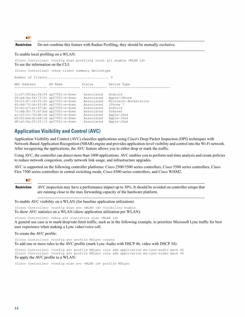
To enable local profiling on a WLAN:(Cisco Controller) >config wlan profiling local all enable <WLAN id>To see the information on the CLI:(Cisco Controller) >show client summary devicetype
Number of Clients................................ 9
MAC Address AP Name Status Device Type----------------- ---------------- ------------- --------------------------------
1c:67:58:be:fd:54 ap2700i-e-down Associated Android28:ed:6a:64:73:5c ap2700i-e-down Associated Apple-iPhone34:23:87:c6:f5:46 ap2700i-e-down Associated Microsoft-Workstation40:4d:7f:cb:43:85 ap2700i-e-down Associated iPhone 750:dc:e7:ec:97:dc ap2700i-e-down Associated Android7c:dd:90:7f:d7:bd ap2700i-e-down Associated Unknownac:cf:5c:7d:eb:1e ap2700i-e-down Associated Apple-iPadb0:65:bd:dc:e8:cd ap2700i-e-down Associated Apple-iPadd8:a2:5e:25:22:13 ap2700i-e-down Associated Apple-iPad
Application Visibility and Control (AVC)Application Visibility and Control (AVC) classifies applications using Cisco's Deep Packet Inspection (DPI) techniques withNetwork-Based Application Recognition (NBAR) engine and provides application-level visibility and control into theWi-Fi network.After recognizing the applications, the AVC feature allows you to either drop or mark the traffic.
Using AVC, the controller can detect more than 1000 applications. AVC enables you to perform real-time analysis and create policiesto reduce network congestion, costly network link usage, and infrastructure upgrades.
AVC is supported on the following controller platforms: Cisco 2500/3500 series controllers, Cisco 5500 series controllers, CiscoFlex 7500 series controllers in central switching mode, Cisco 8500 series controllers, and Cisco WiSM2.
AVC inspection may have a performance impact up to 30%. It should be avoided on controller setups thatare running close to the max forwarding capacity of the hardware platform.
Restriction
To enable AVC visibility on a WLAN (for baseline application utilization):(Cisco Controller) >config wlan avc <WLAN id> visibility enableTo show AVC statistics on a WLAN (show application utilization per WLAN):(Cisco Controller) >show avc statistics wlan <WLAN id>A general use case is to mark/drop/rate-limit traffic, such as in the following example, to prioritize Microsoft Lync traffic for bestuser experience when making a Lync video/voice call.
To create the AVC profile:(Cisco Controller) >config avc profile MSLync createTo add one or more rules to the AVC profile (mark Lync Audio with DSCP 46, video with DSCP 34):(Cisco Controller) >config avc profile MSLync rule add application ms-lync-audio mark 46(Cisco Controller) >config avc profile MSLync rule add application ms-lync-video mark 34To apply the AVC profile to a WLAN:(Cisco Controller) >config wlan avc <WLAN id> profile MSLync
14

Enable 802.11k for Optimal RoamingThe 802.11k standard allows clients to request neighbor reports containing information about known neighbor APs that are candidatesfor a service set transition. The use of the 802.11k neighbor list can limit the need for active and passive scanning.
A common problem that 802.11k helps solve is to deal with "sticky clients", which usually associate with a specific AP, and thenholds onto that AP strongly even when there are significantly better options available from nearer APs.
To enable 802.11k neighbor list for a WLAN:(Cisco Controller) >config wlan assisted-roaming neighbor-list enable <WLAN id>To enable dual-band 802.11k neighbor list for a WLAN:(Cisco Controller) >config wlan assisted-roaming dual-list enable <WLAN id>It is recommended to enable 802.11k with dual-band reporting. With dual-band reporting enabled, the client receives a list of the best2.4 and 5 GHz APs upon a directed request from the client. The client most likely looks at the top of the list for an AP on the samechannel, and then on the same band as the client is currently operating. This logic reduces scan times and saves battery power.Remember that dual-band reporting should only be used if the clients associating to the WLAN are dual band capable.
To enable assisted roaming prediction list feature for a WLAN:(Cisco Controller) >config wlan assisted-roaming prediction enable <WLAN id>
802.11k may cause problems on some legacy devices that react incorrectly to unknown informationelements. Most devices will ignore 11k information, even if they do not support it, but for some, it maylead to disconnections or failure to associate. These are corner cases, but it is advisable to test beforeenabling it. Do not enable the dual-list option, if using single band clients, or for deployment scenariosthat use devices primarily configured for 5 GHz priority.
Restriction
Sleeping Client feature and Idle timerIf using the Sleeping Client feature for web authentication, ensure that your idle timeout is lower than the session timeout, to preventincorrect client deletion.
This should be used in most scenarios.Restriction
802.11v and Management Frame Protection (MFP)When 802.11v feature is in use, it is recommended to disable the MFP infrastructure feature, as the combination can causeinteroperability problems with some devices.
This should be used in most scenarios, unless the interoperability for the devices present in the networkis tested.
Restriction
Flexconnect and Address Learning flagFor the FlexConnect local switching, central authentication deployments, for the scenarios of:
• Passive client with a static IP address, for example printer server, weight scales, camera, etc
15
• Multiple remote sites with overlapping local IP address range for clients
It is recommended to disable the Learn Client IP Address feature. This can be done in GUI from the WLAN settings, Advanced tab,or with command:config wlan flexconnect learn-ipaddr WLANID disable
This feature is enabled by default, and should be left enabled, except on the conditions described above.Disabling the feature may have impact on webauth or IP theft protection features.
Restriction
Multicast Recommendations
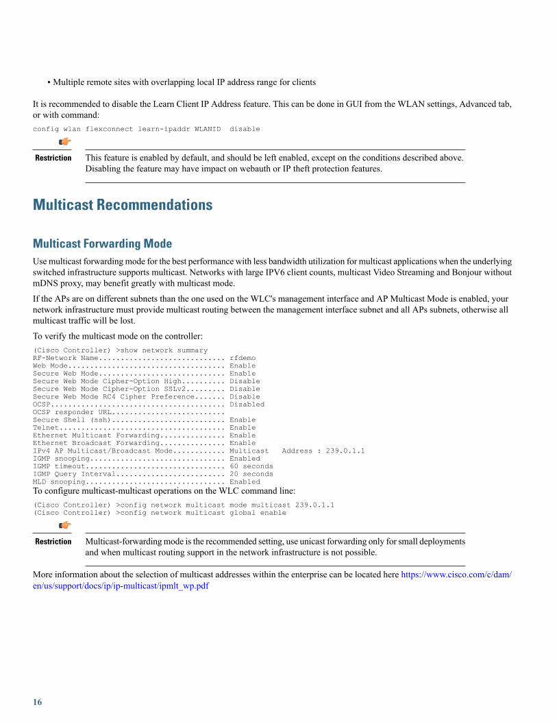
Multicast Forwarding ModeUsemulticast forwarding mode for the best performance with less bandwidth utilization for multicast applications when the underlyingswitched infrastructure supports multicast. Networks with large IPV6 client counts, multicast Video Streaming and Bonjour withoutmDNS proxy, may benefit greatly with multicast mode.
If the APs are on different subnets than the one used on the WLC's management interface and AP Multicast Mode is enabled, yournetwork infrastructure must provide multicast routing between the management interface subnet and all APs subnets, otherwise allmulticast traffic will be lost.
To verify the multicast mode on the controller:(Cisco Controller) >show network summaryRF-Network Name............................. rfdemoWeb Mode.................................... EnableSecure Web Mode............................. EnableSecure Web Mode Cipher-Option High.......... DisableSecure Web Mode Cipher-Option SSLv2......... DisableSecure Web Mode RC4 Cipher Preference....... DisableOCSP........................................ DisabledOCSP responder URL..........................Secure Shell (ssh).......................... EnableTelnet...................................... EnableEthernet Multicast Forwarding............... EnableEthernet Broadcast Forwarding............... EnableIPv4 AP Multicast/Broadcast Mode............ Multicast Address : 239.0.1.1IGMP snooping............................... EnabledIGMP timeout................................ 60 secondsIGMP Query Interval......................... 20 secondsMLD snooping................................ EnabledTo configure multicast-multicast operations on the WLC command line:(Cisco Controller) >config network multicast mode multicast 239.0.1.1(Cisco Controller) >config network multicast global enable
Multicast-forwardingmode is the recommended setting, use unicast forwarding only for small deploymentsand when multicast routing support in the network infrastructure is not possible.
Restriction
More information about the selection of multicast addresses within the enterprise can be located here https://www.cisco.com/c/dam/en/us/support/docs/ip/ip-multicast/ipmlt_wp.pdf
16

Multicast Address for CAPWAP
The multicast address is used by the controller to forward traffic to Access Points (APs). Ensure that the multicast address does notmatch another address in use on your network by other protocols. For example, if you use 224.0.0.251, it breaks mDNS used by somethird party applications.
• Cisco recommends that the address be in the private range (239.0.0.0 – 239.255.255.255, which does not include 239.0.0.x and239.128.0.x, as those ranges will cause L2 flood). Also, ensure that the multicast IP address is set to a different value on eachWLC to avoid multicast packet duplication.
This should be used in most scenarios.Restriction
Related Documentation:
More information about the selection of multicast addresses within the enterprise can be located here: https://www.cisco.com/c/dam/en/us/support/docs/ip/ip-multicast/ipmlt_wp.pdf
IGMP and MLD SnoopingUsing IGMP andMLD snooping may provide additional multicast forwarding optimization, as only APs with clients that have joinedthe respective multicast groups, will transmit the multicast traffic over the air, so this is a recommended setting to have in mostscenarios.
• Always check your client and multicast application behavior, as some implementations may not do IGMP group join, or maynot refresh properly, causing the multicast streams to expire. It is possible to modify the IGMP timeout if needed, to adapt toclient side or switch behaviors
When client multicast group join behavior may cause the IGMP group to expire.Restriction
Related Documentation:
Multicast/Broadcast Setup
SecurityThe following sections address best practices for security.
AP Security Recommendations
Change Default AP Console User
By default, Access Points have a default Cisco/Cisco username and password, with SSH and telnet disabled. It is advisable to configurea default password, to be applied as soon as they first join the controller:(Cisco Controller) > config ap mgmtuser add username <username> password <password> secret <secret> all
17
This should be used in most scenarios.Restriction
802.1x Authentication for AP port
For increased security, configure 802.1X authentication between a lightweight access point (AP) and a Cisco switch. The AP acts asan 802.1X supplicant and is authenticated by the switch using EAP-FAST with anonymous PAC provisioning. This is configurablein the global authentication settings.
This feature is supported across all releases for IOS APs (Wave1), and from 8.6 forWave2 APs (AP-COS:1800, 2800, 3800, 1560, 1540). This requires that Radius server supports EAP-FAST.
Restriction
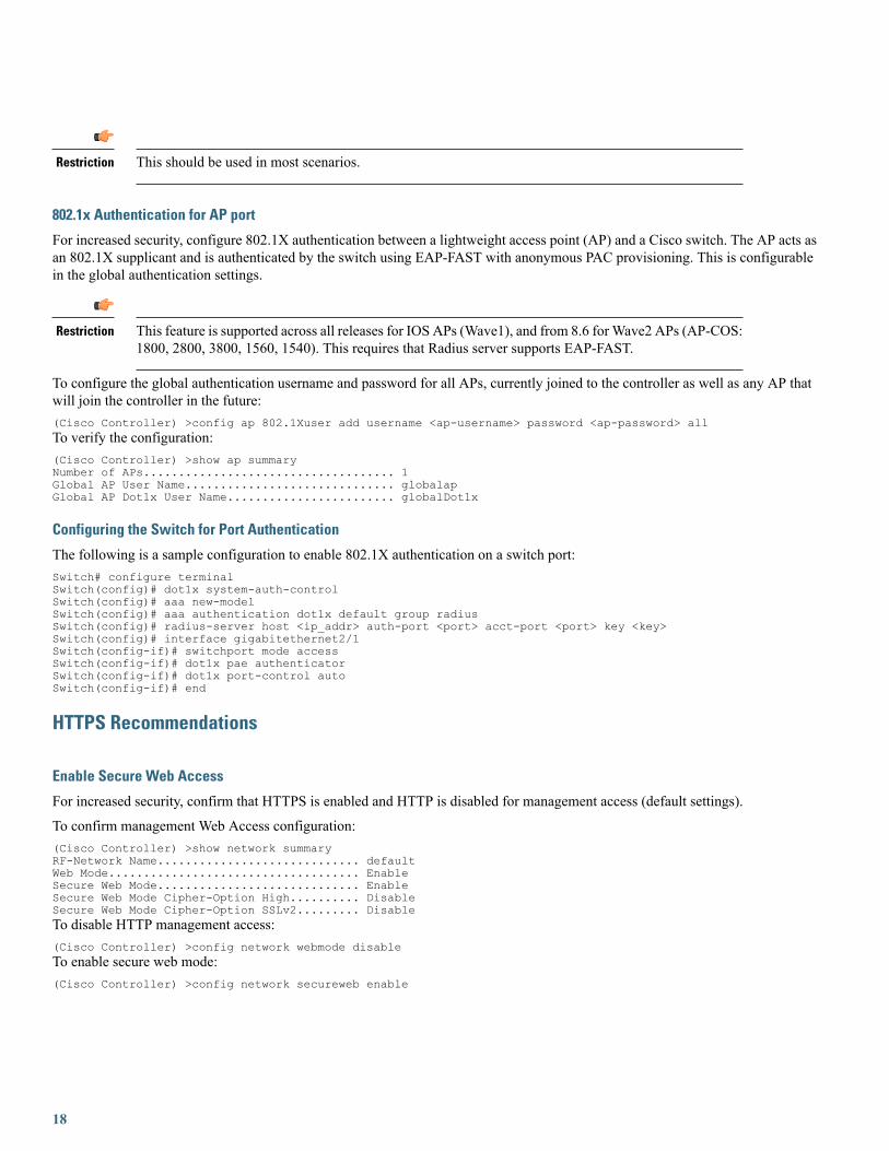
To configure the global authentication username and password for all APs, currently joined to the controller as well as any AP thatwill join the controller in the future:(Cisco Controller) >config ap 802.1Xuser add username <ap-username> password <ap-password> allTo verify the configuration:(Cisco Controller) >show ap summaryNumber of APs.................................... 1Global AP User Name.............................. globalapGlobal AP Dot1x User Name........................ globalDot1x
Configuring the Switch for Port Authentication
The following is a sample configuration to enable 802.1X authentication on a switch port:Switch# configure terminalSwitch(config)# dot1x system-auth-controlSwitch(config)# aaa new-modelSwitch(config)# aaa authentication dot1x default group radiusSwitch(config)# radius-server host <ip_addr> auth-port <port> acct-port <port> key <key>Switch(config)# interface gigabitethernet2/1Switch(config-if)# switchport mode accessSwitch(config-if)# dot1x pae authenticatorSwitch(config-if)# dot1x port-control autoSwitch(config-if)# end
HTTPS Recommendations
Enable Secure Web Access
For increased security, confirm that HTTPS is enabled and HTTP is disabled for management access (default settings).
To confirm management Web Access configuration:(Cisco Controller) >show network summaryRF-Network Name............................. defaultWeb Mode.................................... EnableSecure Web Mode............................. EnableSecure Web Mode Cipher-Option High.......... DisableSecure Web Mode Cipher-Option SSLv2......... DisableTo disable HTTP management access:(Cisco Controller) >config network webmode disableTo enable secure web mode:(Cisco Controller) >config network secureweb enable
18

This should be used in most scenarios.Restriction
Enable High Encryption for Web Access
By default, WLC allows low security crypto options for HTTPS negotiation to ensure backward compatibility, which are no longerconsidered strong enough in several scenarios. For security reasons, it is advisable to force the controller to use only strong cypherswith the high encryption command. This may cause some interoperability issues if the client connecting to HTTPS only supportslegacy or limited crypto options, so it is advisable to do testing for possible issues. This is not a problem for most modern browsersand operating systems.
To see the state:(Cisco Controller) >show network summaryRF-Network Name............................. defaultWeb Mode.................................... EnableSecure Web Mode............................. EnableSecure Web Mode Cipher-Option High.......... DisableSecure Web Mode Cipher-Option SSLv2......... DisableTo enable higher crypto options for HTTPS for management GUI:(Cisco Controller) > config network secureweb cipher-option high enableTo enable higher crypto options for HTTPS for webauth WLANS:(Cisco Controller) > config network web-auth secureweb cipher-option high
For release 8.2, the command " config network secureweb cipher-option high" applies to both managementand webauth scenarios.
Note
Changing HTTP/HTTPS state will require a WLC reload.Note
If management station has limitations on higher crypto options.Restriction
Ensure legacy crypto options are disabled for HTTPS
The Cisco Wireless LAN Controllers supports some older crypto option negotiation for HTTPS for compatibility reasons: SSLv2,SSLv3 support, and RC4 crypto preference. They are disabled by default, as they are affected by different protocol or cryptographicvulnerabilities, and only provided for backward compatibility.
The SSLv2 and RC4 options are deprecated on later releases, so it is no longer present.
These options are not needed on almost all scenarios, and only should be enabled on very specific corner cases for old HTTPS clientconnectivity to WLC management and webauth features.
To check if whenever they are enable (8.2 and older):(Cisco Controller) > show network summaryRF-Network Name............................. 5500Web Mode.................................... EnableSecure Web Mode............................. EnableSecure Web Mode Cipher-Option High.......... EnableSecure Web Mode Cipher-Option SSLv2......... DisableSecure Web Mode RC4 Cipher Preference....... DisableSecure Web Mode SSL Protocol................ Disable..
19

In 8.3 and higher:(Cisco Controller) > show network summaryRF-Network Name............................. 3500DNS Server IP............................... 0.0.0.0Web Mode.................................... EnableSecure Web Mode............................. EnableSecure Web Mode Cipher-Option High.......... EnableSecure Web Mode SSL Protocol................ DisableWeb CSRF check.............................. EnableTo disable them:config network secureweb sslv3 disableconfig network secureweb cipher-option rc4-preference disableconfig network secureweb cipher-option sslv2 disable
This should be used in most scenarios.Restriction
Ensure CSRF protection is in place
Cross Site Request Forgery is a type of attacks where an unsuspected user is tricked to perform unwanted actions. Starting with 8.3,Cisco Wireless LAN Controllers have embedded CSRF protection across all the management web interface.
This is enabled by default, and there is no reason to disable it, unless required as workaround for some specific issue. It should haveno impact when active.
How to check:(Cisco Controller) >show network summary
RF-Network Name............................. betaDNS Server IP............................... 0.0.0.0Web Mode.................................... EnableSecure Web Mode............................. EnableSecure Web Mode Cipher-Option High.......... DisableSecure Web Mode SSL Protocol................ EnableWeb CSRF check.............................. EnableOCSP........................................ Disabled..How to enable:config network secureweb csrfcheck enable
This should be used in most scenarios.Restriction
SSH Recommendations
Secure SSH/Telnet
Similar to secure web access, confirm that SSH is enabled and Telnet is disabled to the controller for better security.
To see the network summary:(Cisco Controller) > show network summaryWeb Mode.................................... EnableSecure Web Mode............................. EnableSecure Web Mode Cipher-Option High.......... EnableSecure Web Mode Cipher-Option SSLv2......... EnableSecure Shell (ssh).......................... EnableTelnet...................................... Enable
20

To disable Telnet:(Cisco Controller) > config network telnet disableTo enable SSH:(Cisco Controller) >config network ssh enable
This should be used in most scenarios.Restriction
Secure SSH High Crypto
The Cisco Wireless LAN Controllers support higher crypto protocol negotiation for SSH connections. This is disabled by default, asolder SSH clients may not support these cypher offerings. If your client is compatible, it is recommended to enable this option. Alwaystest compatibility before implementing across a production network.
To check if it is enabled:(Cisco Controller) >show network summaryRF-Network Name............................. 3500DNS Server IP............................... 0.0.0.0Web Mode.................................... Enable..Secure Shell (ssh).......................... EnableSecure Shell (ssh) Cipher-Option High....... EnableTo enable SSH High Crypto:(Cisco Controller) > config network ssh cipher-option high enable
If management station SSH client has limited support for higher crypto options.Restriction
WLAN Security Recommendations
Enable 802.11r Fast Transition
802.11r is the IEEE standard for fast roaming, where the initial authentication handshake with the target AP (that is, the next AP thatthe client intends to connect to) is done even before the client associates to the target AP. This is called Fast Transition (FT), and bydefault, fast transition is disabled in releases before 8.3. As of 8.3, a new capability called Adaptive FT is enabled by default, whichis used for Apple IOS devices (see Apple recommendations section).
Using either FT or Adaptive FT can lower the total usage of the authentication services, as clients can do secure roaming withoutincurring full authentication on each AP change, so this has benefits both in roaming speed and overall reduced authentication load.
If using FT instead of Adaptive FT, non 802.11r clients may not be able to connect to the WLAN. Ensurethat the clients are 802.11r capable, for example, Apple devices on version 6 and above, or split WLANs.Adaptive FT can be enabled for the WLANs in almost all scenarios with very low probability ofinteroperability problems.
Restriction
To enable 802.11r or Fast Transition (FT):(Cisco Controller) >config wlan security ft enable <WLAN id>To configure FT authentication management using 802.1X:(Cisco Controller) >config wlan security wpa akm ft-802.1X enable <WLAN id>
21

To configure FT authentication management using PSK:(Cisco Controller) >config wlan security wpa akm ftp-psk enable <WLAN id>DHCP Required OptionTo enhance security, Cisco recommends that all clients obtain their IP addresses from a DHCP server.
The DHCP Required option in WLAN settings allows you to force clients to do a DHCP address request/renew every time theyassociate to the WLAN before they are allowed to send or receive other traffic to the network. From a security standpoint, this allowsfor a more strict control of IP addresses in use, but this might also have an effect in the total time for roaming before traffic is allowedto pass again.
Additionally, this might affect some client implementations that do not do a DHCP renew until the lease time expires. This dependson the client types, for example, Cisco 7921 or 7925 phones might have voice problems while they roam if this option is enabled, asthe controller does not allow voice or signaling traffic to pass until the DHCP phase is completed. Another example may includeAndroid and some Linux distributions that only do DHCP renew on half the length of the lease time, but not on roaming. This maybe a problem if the client entry expires.
Some third-party printer servers might also be affected. In general, it is a good idea not to use this option if theWLAN has non-Windowsclients. This is because, stricter controls might induce connectivity issues, based on how the DHCP client side is implemented.
To verify the DHCP Required option in WLAN settings:(Cisco Controller) >show wlan <WLAN id>WLAN Identifier.................................. 1Profile Name..................................... WLAN-1Network Name (SSID).............................. WLAN-1Status........................................... EnabledMAC Filtering.................................... Disabled… mDNS Status...................................... EnabledmDNS Profile Name................................ default-mdns-profileDHCP Server...................................... DefaultDHCP Address Assignment Required................. Enabled
Never enable this for a WLAN supporting voice or video services, or when the wireless devices doconservative DHCP renewal on roaming.
Restriction
Disable Aironet IE
Aironet IE is a Cisco proprietary attribute used by Cisco devices for better connectivity and troubleshooting. It contains information,such as the access point name, load, and number of associated clients in the beacon and probe responses of the WLAN that are sentby the access point (AP). Cisco Client Extensions (CCX) clients use this information to choose the best AP with which to associate.
The CCX software is licensed to manufacturers and vendors of third-party client devices. The CCX code on these clients enablesthem to communicate wirelessly with Cisco APs and to support Cisco features that other client devices do not. The features are relatedto increased security, enhanced performance, fast roaming, and power management.
The CCX software is licensed to manufacturers and vendors of third-party client devices. The CCX code on these clients enablesthem to communicate wirelessly with Cisco APs and to support Cisco features that other client devices do not. The features are relatedto increased security, enhanced performance, fast roaming, and power management.
To disable Aironet IEs for a particular WLAN:(Cisco Controller) >config wlan ccx aironet-ie disable <wlan_id>Forwarding
Do not disable this if supporting Cisco voice devices (8821/792x, etc) or WGB.Restriction
22

Client Exclusion
When a user fails to authenticate, the controller can exclude the client. The client cannot connect to the network until the exclusiontimer expires or is manually overridden by the administrator. This feature can prevent authentication server problems due to highload, caused by intentional or inadvertent client security misconfiguration. It is advisable to always have a client exclusion configuredon all WLANs.
Client Exclusion can act as a protective mechanism for the AAA servers, as it will stop authentication request floods that could betriggered by misconfigured clients.
Exclusion detects authentication attempts made by a single device. When the device exceeds a maximum number of failures, thatMAC address is not allowed to associate any longer.
The Cisco WLC excludes clients when the following conditions are met:
• Excessive 802.11 Association Failures after five consecutive failures
• 802.1X Authentication Failures after three consecutive failures
• IP Theft or IP Reuse, if the IP address obtained by the client is already assigned to another device
• Excessive Web Authentication Failures after three consecutive failures
It is possible to configure how long a client remains excluded, and exclusion can be enabled or disabled at the controller or WLANlevel.
This should be used in most scenarios.Restriction
To verify exclusion policy:(Cisco Controller) >show wps summaryAuto-ImmuneAuto-Immune.................................... DisabledAuto-Immune by aWIPS Prevention................ Disabled
Client Exclusion PolicyExcessive 802.11-association failures.......... EnabledExcessive 802.11-authentication failures....... EnabledExcessive 802.1x-authentication................ EnabledIP-theft....................................... EnabledExcessive Web authentication failure........... EnabledMaximum 802.1x-AAA failure attempts............ 3
Related documentation:
Management Frame Protection
Peer-to-peer Blocking
Peer-to-peer blocking is a per WLAN setting, and each client inherits the peer-to-peer blocking setting of the WLAN to which it isassociated. Peer-to-peer enables you to have more control over how traffic is directed. For example, you can choose to have trafficbridged locally within the controller, dropped by the controller, or forwarded to the upstream VLAN.
This setting can prevent a client attacking another client connected to the same WLAN, but it is important to keep in mind that usingthe drop option will prevent any application that can communicate directly between clients, for example chat or voice services.
Do not use for WLANs supporting voice or video services, or for any scenario where client to client directcommunication is required.
Restriction
23

Related Documentation:
WLAN Security
To verify the peer-to-peer blocking setting of the WLAN:(Cisco Controller) >show wlan <wlan_id>WLAN Identifier.................................. 1Profile Name..................................... cckm-ftNetwork Name (SSID).............................. cckm-ftStatus........................................... Enabled......Peer-to-Peer Blocking Action..................... DisabledRadio Policy..................................... AllTo configure a WLAN for peer-to-peer blocking:(Cisco Controller) >config wlan peer-blocking { disable | drop | forward-upstream} <wlan_id>
Disable Local EAP
Local EAP is an authentication method that allows users and wireless clients to be authenticated locally on the controller instead ofusing a Radius server. Using local EAP in an enterprise production environment is not recommended for scalability reasons.
To check if a WLAN is configured to use local EAP:(Cisco Controller) >show wlan <WLAN id>Radius ServersAuthentication................................ Global ServersAccounting.................................... Global ServersInterim Update................................ DisabledFramed IPv6 Acct AVP ......................... PrefixDynamic Interface............................. DisabledDynamic Interface Priority.................... wlanLocal EAP Authentication...................... DisabledRadius NAI-Realm.............................. DisabledTo disable local authentication on a WLAN:(Cisco Controller) >config wlan local-authen disable <WLAN id>
This should be used in most scenarios.Restriction
WPA2 + 802.1X WLAN
From security standpoint, it is advisable to configure WLANs with WPA2 with AES encryption, and 802.1x authentication. Othersecurity policies like open, WEP, WPA/TKIP, etc, should be avoided, unless absolutely needed for legacy client support. Using apre-shared key as authentication is not recommended for enterprise environments, and should only be used for specific clientcompatibility scenarios. In these cases, a shared secret of 18 characters or more is advisable.
To create a WLAN with WPA2 and 802.1X enabled:(Cisco Controller) >config wlan security wpa enable <WLAN id>To configure RADIUS authentication server on specified WPA2/802.1X WLAN:(Cisco Controller) >config wlan radius_server auth add <WLAN id> <Server id>To configure RADIUS accounting server on specified WPA2/802.1X WLAN:(Cisco Controller) >config wlan radius_server acct add <WLAN id> <Server id
This should be used in most scenarios.Restriction
24

Do not use management interface for any WLAN
To avoid any possible errors that could lead to clients being assigned to the WLCmanagement VLAN, it is advisable not to configureany WLAN using management interface. In the scenario of an auto-anchored WLAN, where the foreign controller would forwardall traffic to the anchor, it is still recommended to set the WLAN on the foreign to a "dummy" interface
This should be used in most scenarios.Restriction
How to verify:(Cisco Controller) >show wlan 1WLAN Identifier.................................. 1Profile Name..................................... simftNetwork Name (SSID).............................. simftStatus........................................... DisabledMAC Filtering.................................... DisabledBroadcast SSID................................... EnabledAAA Policy Override.............................. EnabledNetwork Admission ControlClient Profiling Status
Radius Profiling ............................ DisabledDHCP ....................................... DisabledHTTP ....................................... DisabledLocal Profiling ............................. EnabledDHCP ....................................... Enabled (Auto)HTTP ....................................... Enabled (Auto)
Radius-NAC State............................... DisabledSNMP-NAC State................................. DisabledQuarantine VLAN................................ 0
Maximum Clients Allowed.......................... UnlimitedSecurity Group Tag............................... Unknown(0)
…Webauth DHCP exclusion........................... DisabledInterface........................................ managementIdentity Design Tip–Use AAA OverrideIf designing for identity based networking services, where the wireless clients should be separated in several sub-networks for securityreasons, for example using different VLANs, or other security policies, consolidate WLANs with the AAA-Override feature.AAA-Override feature allows you to assign per user settings or attributes. By using AAA override for example, a user can be assignedto a specific dynamic interface in a separated VLAN or receive a per user Access Control List (ACL).
Besides the possible security improvements, AAA override also could help on collapsing different WLANs/SSIDs into a single one,with significant improvements on overall RF utilization (less beacons/probe activity)
Besides the possible security improvements, AAA override also could help on collapsing differentWLANs/SSIDs into a single one, with significant improvements on overall RF utilization (lessbeacons/probe activity)
Restriction
To configure AAA override:(Cisco Controller) >config wlan aaa-override enable <WLAN id>To confirm WLAN configuration:(Cisco Controller) >show wlan <WLAN id>WLAN Identifier.................................. 1Profile Name..................................... WLAN-1Network Name (SSID).............................. WLAN-1Status........................................... DisabledMAC Filtering.................................... DisabledBroadcast SSID................................... EnabledAAA Policy Override.............................. Enabled
25
Network Admission ControlSecurity802.11 Authentication:............................Open SystemFT Support........................................DisabledStatic WEP Keys.................................. Disabled…
Global Security Recommendations
Local Management Password Policies
Youmust enforce a strong password. The password policies allow enforcement of strong password checks on newly created passwordsfor additional management users of controller and access point. The following are the requirements enforced on the new password:
•When the controller is upgraded from an old version, all the old passwords are maintained even though the passwords are weak.After the system upgrade, if the strong password checks are enabled, the same is enforced from that time and the strength ofpreviously added passwords will not be checked or altered.
• Depending on the settings done in the Password Policy page, the local management and access point user configuration isaffected.
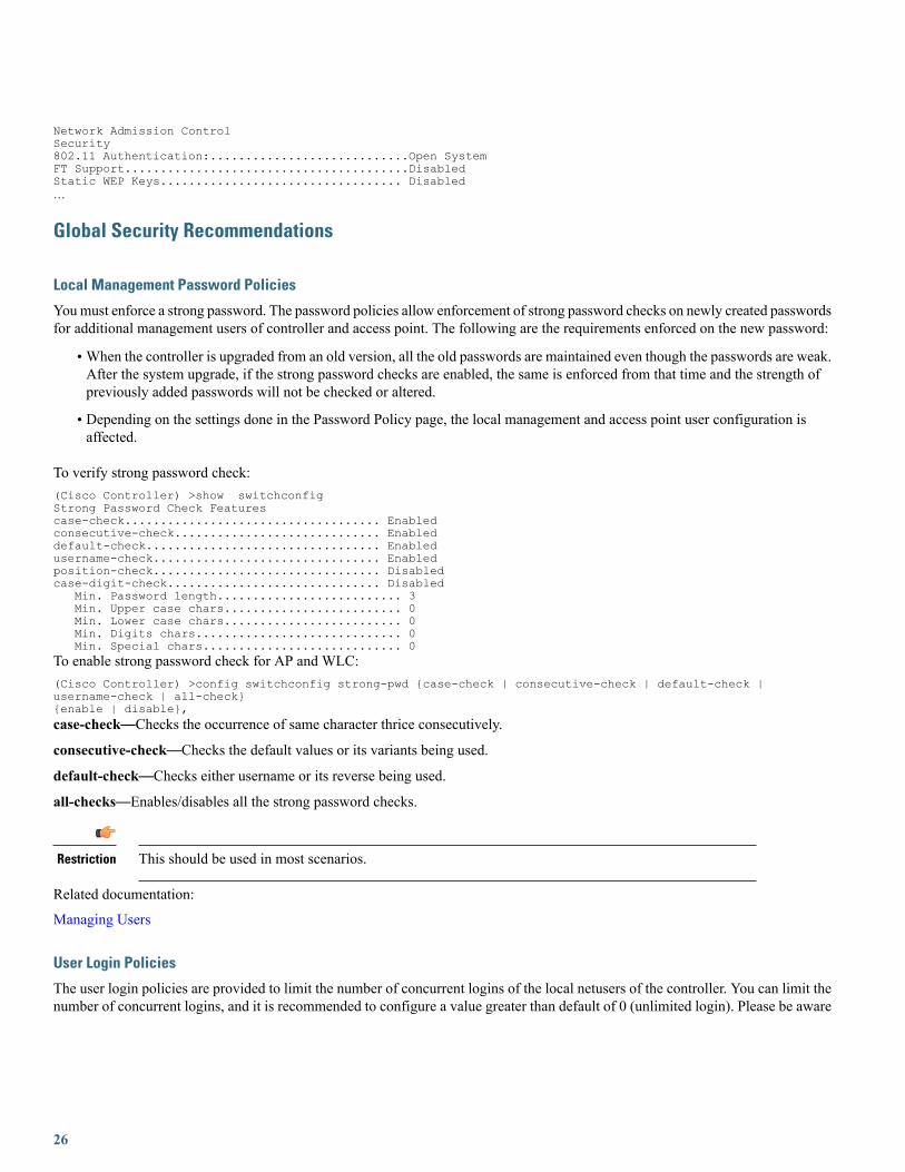
To verify strong password check:(Cisco Controller) >show switchconfigStrong Password Check Featurescase-check.................................... Enabledconsecutive-check............................. Enableddefault-check................................. Enabledusername-check................................ Enabledposition-check................................ Disabledcase-digit-check.............................. Disabled
Min. Password length.......................... 3Min. Upper case chars......................... 0Min. Lower case chars......................... 0Min. Digits chars............................. 0Min. Special chars............................ 0
To enable strong password check for AP and WLC:(Cisco Controller) >config switchconfig strong-pwd {case-check | consecutive-check | default-check |username-check | all-check}{enable | disable},case-check—Checks the occurrence of same character thrice consecutively.
consecutive-check—Checks the default values or its variants being used.
default-check—Checks either username or its reverse being used.
all-checks—Enables/disables all the strong password checks.
This should be used in most scenarios.Restriction
Related documentation:
Managing Users
User Login Policies
The user login policies are provided to limit the number of concurrent logins of the local netusers of the controller. You can limit thenumber of concurrent logins, and it is recommended to configure a value greater than default of 0 (unlimited login). Please be aware
26

that this could impact network devices that may be sharing same username and password, for example wireless phones same userprofile for their wireless connection.
To verify netuser limit:(Cisco Controller) >show netuser summaryMaximum logins allowed for a given user name..... UnlimitedTo configure user login policies:(Cisco Controller) >config netuser maxuserlogin 5
For some radius servers: when the external identity of the EAP authentication is shared across multipledevices (no username attribute on access-accept), or when intentionally a single user account is sharedacross devices.
Restriction
Disable Management over Wireless
The WLCManagement Via Wireless feature allows operators to monitor and configure local WLCs using wireless clients connectedto the controller. It is advisable to disable the Management over Wireless feature for security reasons.
To verify management over wireless interface:(Cisco Controller) >show network summaryRF-Network Name............................. defaultWeb Mode.................................... EnableSecure Web Mode............................. EnableSecure Web Mode Cipher-Option High.......... DisableSecure Web Mode Cipher-Option SSLv2......... DisableSecure Web Mode RC4 Cipher Preference....... Disable…Mgmt Via Wireless Interface................. EnableTo disable management over wireless:(Cisco Controller) > config network mgmt-via-wireless disable
This should be used in most scenarios.Restriction
Enable Network Time Protocol (NTP)
Network Time Protocol (NTP) is very important for several features. It is mandatory to use NTP synchronization on controllers, ifyou use any of these features: Location, SNMPv3, Access point authentication, or MFP. The WLC supports synchronization withNTP using authentication.
To enable NTP server:(Cisco Controller) >config time ntp server 1 10.10.10.1To verify, check for entries in your traplog:30 Mon Jan 6 08:12:03 2014 Controller time base status - Controller is in sync with the central timebase.To enable NTP authentication:(Cisco Controller) >config time ntp auth enable <ntp server index>(Cisco Controller) >config time ntp key-auth add <key index>
This should be used in most scenarios.Restriction
27
EAP Identity Request Timeout
The default timeout for EAP Identity requests may need to be increased for some scenarios. For example, when implementing OneTime Passwords (OTP) on Smart Cards, or where the user interaction is needed to answer the initial identity request. In autonomousAPs, the default timeout is 30 seconds. Consider this while migrating autonomous to infrastructure wireless networks.
To verify default timeouts:(Cisco Controller) >show advanced eapEAP-Identity-Request Timeout (seconds)........... 30EAP-Identity-Request Max Retries................. 2EAP Key-Index for Dynamic WEP.................... 0EAP Max-Login Ignore Identity Response........... enableEAP-Request Timeout (seconds).................... 30EAP-Request Max Retries.......................... 2EAPOL-Key Timeout (milliseconds)................. 1000EAPOL-Key Max Retries............................ 2EAP-Broadcast Key Interval....................... 3600To change timeout (seconds):(Cisco Controller) >config advanced eap identity-request-timeout <seconds>
EAPoL Key Timeout and Maximum Retries, KRACK attacks
The EAPoL timeout should be asminimal as possible for voice clients, such as IP 7925/882x phones. Normally 400 to 1000millisecondscan work correctly on most scenarios.
The maximum retry counter has a direct implication on several of the KRACK attacks reported on 2017 for wireless clients usingWPA/WPA2. If the counter is set to zero, it can prevent most attacks against clients that are not yet patched against the vulnerability.This has implications on authentications performed on bad RF scenarios, or over a WAN network with possible packet loss, as usingzero may cause a failed authentication process, if the original packet is lost.
For security reasons, it may be advisable to use zero retries, but please validate on your environment, asit may have impact on failed authentication for bad RF scenarios.
Restriction
To show default timeouts:(Cisco Controller) >show advanced eapEAP-Identity-Request Timeout (seconds)........... 30EAP-Identity-Request Max Retries................. 2EAP Key-Index for Dynamic WEP.................... 0EAP Max-Login Ignore Identity Response........... enableEAP-Request Timeout (seconds).................... 30EAP-Request Max Retries.......................... 2EAPOL-Key Timeout (milliseconds)................. 1000EAPOL-Key Max Retries............................ 2EAP-Broadcast Key Interval....................... 3600To configure EAPoL timeout:(Cisco Controller) >config advanced eap eapol-key-timeout <milliseconds>To configure EAPoL retry counts:(Cisco Controller) >config advanced eap eapol-key-retries <retries>
EAP Request Timeout and Maximum Retries
During the 802.1x authentication phase, in the event of an EAP retry due to packet loss or lack of response from client, the WLCmay retry the EAP request. Some clients may not properly handle fast retry timers, so this may need adjustment depending on clienttypes, to facilitate fast recovery for bad RF environments. Acceptable values may be around 10 seconds in most cases, up to 30 forslow clients (phones)
28

To show default timeouts:(Cisco Controller) >show advanced eapEAP-Identity-Request Timeout (seconds)........... 30EAP-Identity-Request Max Retries................. 2EAP Key-Index for Dynamic WEP.................... 0EAP Max-Login Ignore Identity Response........... enableEAP-Request Timeout (seconds).................... 30EAP-Request Max Retries.......................... 2EAPOL-Key Timeout (milliseconds)................. 1000EAPOL-Key Max Retries............................ 2EAP-Broadcast Key Interval....................... 3600To configure EAP Request timeout:(Cisco Controller) >config advanced eap request-timeout <seconds>To configure EAP Request retry counts:(Cisco Controller) >config advanced eap request-retries <retries>
TACACS + Management Timeout
It is a best practice to increase the retransmit timeout value for TACACS+ authentication, authorization, and accounting servers, ifyou experience repeated re-authentication attempts or if the controller falls back to the backup server when the primary server isactive and reachable. This is especially true when implementing One Time Password (OTP).(Cisco Controller) >show tacacs summaryAuthentication ServersIdx Server Address Port State Tout MgmtTout--- --------------- ------ ------- ----- -------1 10.10.10.60 49 Enabled 5 2
Authorization ServersIdx Server Address Port State Tout MgmtTout--- ---------------- ------ ------- ----- -------1 10.10.10.60 49 Enabled 5 2
To configure TACACS+ authentication retransmit timeout:(Cisco Controller) >config tacacs auth server-timeout 1 <seconds>To configure TACACS+ authorization retransmit timeout:(Cisco Controller) >config tacacs athr server-timeout 1 <seconds>
This should be used in most scenarios.Restriction
LEAP EAP Method
LEAP is an old simple EAP authentication protocol, used on some Cisco devices, and supported by several third party clients. Theprotocol is considered fully compromised, and its use could lead to man in the middle attacks, or password recovery of user credentials.It is currently only supported for legacy backwards compatibility.
It is strongly suggested to avoid using it in any scenario. It should be disabled on your authentication server (for example ISE orACS), or if the using Local EAP feature in WLC.
This should be avoided in most scenarios; including even legacy devices.Restriction
Legacy IDS
Enable the wireless IDS feature and 17 built-in signatures to detect intrusion attacks.
For this best practice feature to work, ensure that at least oneWLAN is enabled and client exclusion-listing is enabled for theWLAN.To enable client exclusion-listing for a WLAN, use the conf wlan exclusionlist wlan-id enabled command.
29

Enable signature check by entering this command:(Cisco Controller) >config wps signature enable
This should be used in most scenarios.Restriction
SNMP Security Recommendations
SNMP Security Recommendations
Check on the SNMPv3 default user. By default, the controller is configured with a username that must be disabled or changed,otherwise this could represent a security risk.
To verify SNMPv3 default user:(Cisco Controller) >show snmpv3userSNMP v3 User Name AccessMode Authentication Encryption-------------------- ----------- -------------- ----------default Read/Write HMAC-SHA CFB-AESTo configure SNMPv3 default user:(Cisco Controller) >config snmp v3user delete default(Cisco Controller) >config snmp v3user create nondefault rw hmacsha des authkey <encrypkey12characters>
Ensure that your SNMP settings match between the controller and the Wireless Control System(WCS)/Network Control System(NCS)/Prime Infrastructure (PI). Also, you should use encryption andhash keys that match your security policies.
Note
Changing some SNMP settings may require a WLC reload.Note
This should be used in most scenarios.Restriction
Remove SNMP Default Communities
Check on the SNMP default communities. By default, the controller is configured with communities used to simplify initial connectionto Prime Infrastructure(PI) services. These communities must be removed as they could represent a security risk in most deployments.
This should be used in most scenarios.Restriction
To verify SNMP default user:(Cisco Controller) >show snmpcommunity
IPSec mode: Disabled / Profile: none
SNMP Community Name Client IP Address Client IP Mask Access Mode Status------------------- ----------------- ----------------- ----------- --------public 0.0.0.0 0.0.0.0 Read Only Enable********** 0.0.0.0 0.0.0.0 Read/Write Enable
30

To configure SNMP communities:(Cisco Controller) config snmp community delete private(Cisco Controller) config snmp community delete public(Cisco Controller) >config snmp community create
Ensure that your SNMP settings match between the controller and the Wireless Control System(WCS)/Network Control System(NCS)/Prime Infrastructure (PI).
Note
ISE RADIUSThe following best practices are applicable to networks with ISE as the AAA server, and they are focused on optimizing the serverload, and reduce unnecessary authentication events.
RADIUS Server Timeout
RADIUS authentication and accounting servers should have 5 seconds as the minimum value for server timeout to prevent earlyexpiration of client authentication process during load.
Set the timeout for RADIUS authentication and accounting servers by entering these commands:(Cisco Controller) >config radius auth retransmit-timeout RADIUS-Server-ID timeout-in-seconds(Cisco Controller) >config radius acct retransmit-timeout RADIUS-Server-ID timeout-in-seconds
This should be used in most scenarios.Restriction
RADIUS Aggressive Failover
RADIUS aggressive failover should be disabled to get optimum performance for client authentication on a Cisco ISE server.(Cisco Controller) >config radius aggressive-failover disable
This should be used in most scenarios.Restriction
WLAN ISE Recommendations
Enable Accounting Interim UpdatesBy default, theWLCwill send interim updates on every client roam, and periodically, as per configured timer. For ISE is recommendedto enable the normal "on roam" update, and not use the periodic option.(Cisco Controller) >config wlan radius_server acct interim-update enable wlan-id(Cisco Controller) >config wlan radius_server acct interim-update 0 wlan-id
This should be used in most scenarios.Restriction
Client TimersSame as with security recommendation, it is advisable to use client exclusion for ISE. Exclusion should be enabled, normally withexclusion set to 180 seconds.(Cisco Controller) >config wlan exclusionlist <wlan-id> enabled(Cisco Controller) >config wlan exclusionlist <wlan-id> 180
31
Depending on deployment policies, the session timeout should be set to 7200, this is the minimum time, before a client reauthenticationis enforced.(Cisco Controller) >config wlan session-timeout <wlan-id> 7200Set the per WLAN user idle timeout to 3600 seconds, to reduce the probability of client deletion when moving out of coverage areas,or when client is battery operated and may go to sleep frequently.(Cisco Controller) >config wlan usertimeout 3600 <wlan-id>
This should be used in most scenarios.Restriction
Rogue Management and DetectionRogue wireless devices are an ongoing threat to corporate wireless networks. Network owners need to do more than just scanningthe unknown devices. They must be able to detect, disable, locate, and manage rogue/intruder threats automatically and in real time.
Rogue APs can disrupt wireless LAN operations by hijacking legitimate clients and using plain text, denial-of-service attacks, orman-in-the-middle attacks. That is, a hacker can use a rogue AP to capture sensitive information, such as passwords and usernames.The hacker can then transmit a series of clear-to-send (CTS) frames, which mimics an AP informing a particular wireless LAN clientadapter to transmit and instruct all others to wait. This scenario results in legitimate clients being unable to access the wireless LANresources. Thus, wireless LAN service providers look for banning rogue APs from the air space.
The best practice is to use rogue detection to minimize security risks, for example, in a corporate environment. However, there arecertain scenarios in which rogue detection is not needed, for example, in OEAP deployment, citywide, and outdoors. Using outdoormesh APs to detect rogues would provide little value while incurring resources to analyze. Finally, it is critical to evaluate (or avoidaltogether) rogue auto-containment, as there are potential legal issues and liabilities if left to operate automatically.
Some best practices, listed in the following sections, improve efficiency in maintaining the rogue AP list and making it manageable.
Rogue Management in a Unified Wireless Network
Rogue Policies
Policy should be set at least to High.
Set the rogue detection security level to High by entering this command:(Cisco Controller) >config rogue detection security-level high
Set "monitor all channels" for better Rogue detection
The controller maintains a single channel scan list for the RRM metrics (Noise, Interference) and for Rogue detection monitoring.The list can be configured to focus on "DCA channels", those channels which will be automatically assigned to APs, or to "countrychannels", which would be those only valid in the configured country, or to scan all possible channels. This latter is the best optionto ensure that any rogue using an uncommon channel can be detected properly. The drawback is that with a longer channel list, theAP will have to go off-channel more frequently inside the configured channel scan interval.
• For higher security, choose all channel.
• Choose DCA channels for performance, as system will scan as least as possible.
• For a balance of performance and security, choose country channel.
(Cisco Controller) > config advanced 802.11a monitor channel-list all(Cisco Controller) > config advanced 802.11b monitor channel-list all
32

Define Appropriate Malicious Rogue AP Rules
Define malicious rogue AP rules to prioritize major and critical rogue AP alarms that require immediate attention and mitigationplan.
Critical or major rogue AP alarms are classified as 'Malicious' and are detected on the network.
Each rogue rule is composed of single or multiple conditions (Required or Recommended). The malicious rogue AP rules are asfollows:
• Managed SSIDs (Required)—Any rogue APs using managed SSIDs, the same as your wireless infrastructure, must be markedas “Malicious”. Administrators need to investigate and mitigate this threat.
• Minimum RSSI >-70 dBm (Recommended)—This criterion normally indicates that unknown rogue APs are inside the facilityperimeters, and can cause potential interference to the wireless network.This rule is only recommended for Enterprise deployment having its own isolated buildings and secured perimeters.
This rule is not recommended for retail customers or venues that are shared by various tenants, where WiFi signals from allparties normally bleed into each other.
• User configured SSIDs/Sub-string SSIDs (Recommended) monitor any SSIDs that use different variations or combinations ofcharacters in your production SSIDs (Managed SSIDs).
The following points lists the recommended actions for matching conditions in malicious rouge AP rules:
• For malicious rogue APs matching “Must” conditions, configure “Contain” as action.
• Configure only one condition for each rule and make the rule name intuitive for its related condition. This facilitates theadministrator to identify and troubleshoot.
• For malicious rogue APs matching “Optional” conditions, it is not recommended to configure “Contain” as action due to legalcomplications. Instead, configure “Alert” as action.
There are legal implications for containing rogue APs. However, rogue AP using same SSIDs as yourproduction SSIDs can be the exception for auto containment in mitigating potential threat from this rogueattracting legitimate wireless clients. Additionally containing rogues using infrastructure APs will have asignificant negative impact on wireless service during operation, unless dedicated APs are used forcontainment activities
Note
To create a rogue rule for additional conditions set, for example, create 'rule1':(Cisco Controller) >config rogue rule add ap priority 1 classify malicious notify all state alert rule1To activate the rule:(Cisco Controller) >config rogue rule enable rule1To verify rule summary:(Cisco Controller) >show rogue rule summaryPriority Rule Name Rule state Class Type Notify State Match Hit Count-------- -------------------------------- ----------- ----------- -------- -------- ------1 rule1 Enabled Malicious All Alert Any 0Up to six conditions can be added to a rogue rule. These are CLI examples, refer to the Rogue Management and Detection, page 21section on rogue management for best practices guidance.
Adding condition based rules can help to easily detect people spoofing on your network. To configure condition rule based on amanaged SSID:(Cisco Controller) >config rogue rule condition ap set managed-ssid rule1
33

To add condition based on specific SSID name:(Cisco Controller) >config rogue rule condition ap set ssid <SSID_name> rule1To add condition based on minimum RSSI, for example, -70 dBm:(Cisco Controller) >config rogue rule condition ap set rssi -70 rule1To add condition based on duration (in seconds) that the rogue has been detected, for example, 120 seconds:(Cisco Controller) >config rogue rule condition ap set duration 120 rule1To confirm rogue rule conditions:(Cisco Controller) >show rogue rule detailed rule1Priority......................................... 1Rule Name........................................ rule1State............................................ DisabledType............................................. MaliciousNotify........................................... AllState ........................................... AlertMatch Operation.................................. AnyHit Count........................................ 0Total Conditions................................. 3 Condition 1 type....Duration value (seconds)....... 120Condition 2 type........... Managed-ssid value....................... EnabledCondition 3 type............Rssi value (dBm)...................................... -70
Identify and Update Friendly Rogue AP List Regularly
Research and investigate, and then remove friendly rogue APs from "Unclassified" rogue AP list on a regular basis (weekly ormonthly).
Examples of friendly rogue APs are as follows:
• Known Internal Friendly Rogue APs, for example within facility perimeters, and known AP MAC addresses imported into thefriendly rouge AP list.
• Known External Friendly Rogue APs, for example, vendor shared venues and neighboring retailers.
Best Effort for Unclassified Rogue APs
By default, rogue AP alarms are displayed as "Unclassified" with "Minor" severity if they do not meet the defined classification rules.This list can grow and become unmanageable in Prime Infrastructure. For example, transient rogue APs are detected only for a shortduration, such asMiFi devices. It is unnecessary to monitor these rogues on a daily basis if they are not detected on the wired network.Instead, do the following:
• Implement automated rogue AP mitigation mechanism, such as auto switchport tracing. If traced on wired network, criticalalarms will be triggered.
• Run monthly or quarterly report on unclassified rogue APs to identify potentially unknown friendly ones among them.
Implement Auto Switchport Tracing (SPT) as Rogue AP Mitigation Scheme
It is recommended is to implement auto SPT for rogue AP mitigation, which correlates rogue AP radio MAC addresses, heard overthe air, to Ethernet MAC addresses on wired network side. Once the potential match is found, it will be reported as "Found OnNetwork" on Prime Infrastructure.
•When auto SPT starts, it runs through each rogue AP radio MAC address against all known Ethernet MAC addresses on allknown switches.
• Auto SPT enabled for alarms with “Minor” severity eases the job of administrators as the mitigation scheme is already in place.
34
To verify rogues detected on AP:(Cisco Controller) >show rogue ap summaryRogue Detection Security Level................... customRogue Pending Time............................... 180 secsRogue on wire Auto-Contain....................... DisabledRogue using our SSID Auto-Contain................ DisabledValid client on rogue AP Auto-Contain............ DisabledRogue AP timeout................................. 1200Rogue Detection Report Interval.................. 10Rogue Detection Min Rssi......................... -128Rogue Detection Transient Interval............... 0Rogue Detection Client Num Thershold............. 0Total Rogues(AP+Ad-hoc) supported................ 2000Total Rogues classified.......................... 41MAC Address Classification # APs # Clients Last Heard----------------- ------------------ ----- --------- -----------------------00:0d:67:1e:7c:a5 Unclassified 1 0 Thu Feb 6 22:04:38 201400:0d:67:1e:7c:a6 Unclassified 1 0 Thu Feb 6 22:04:38 201400:0d:67:1e:7c:ac Unclassified 2 0 Thu Feb 6 22:04:38 2014
AP Rogue Detection Configuration
It is possible to configure rogue detection feature on a per AP basis. For example, it could be useful to disable rogue detection onAPs located on public areas. By default, rogue detection is enabled.
To verify rogue configuration on AP:(Cisco Controller) >show ap config general <AP Name>Cisco AP Identifier.............................. 4Cisco AP Name.................................... AP1140Country code..................................... Multiple Countries:PT,USRegulatory Domain allowed by Country............. 802.11bg:-AE 802.11a:-AEAP Country code.................................. US - United StatesAP Regulatory Domain............................. 802.11bg:-A 802.11a:-AAP Link Latency.................................. DisabledRogue Detection.................................. EnabledTo enable rogue detection on an AP:(Cisco Controller) >config rogue detection enable <Cisco AP>
Min Rogue RSSI Threshold
Specifies the minimum RSSI value that rogues should have for APs to detect them and for the rogue entries to be created in the CiscoWLC. Recommended value is around -70 to -80 dBm, depending of deployment scenario. The idea is to filter out rogues that are notinside the building, or significant enough to represent an RF impact to the infrastructure. If ensuring a full detection of rogues is done,independently of their RSSI level, then set this to a very low signal level.
Set the minimum RSSI value that rogues should have by entering this command:(Cisco Controller) >config rogue detection min-rssi rssi-in-dBm <value>
Transient Rogue Interval
Using the transient interval values, you can control the time interval at which APs should scan for rogues. APs can also filter roguesbased on their transient interval values.
This feature has the following advantages:
• Rogue reports from APs to the controller are shorter.
• Transient rogue entries are avoided in the controller.
• Unnecessary memory allocation for transient rogues is avoided.
To configure transient rogue interval of 2 minutes (120 seconds):(Cisco Controller) >config rogue detection monitor-ap transient-rogue-interval 120
35

Enable Adhoc Rogue Detection
Similar to general rogue detection, ad hoc rogue detection is ideal in certain scenarios where security is justifiable.
However, it is not recommended in scenarios such as open venues/stadiums, citywide, and public outdoors.
To enable ad hoc rogue detection and reporting:(Cisco Controller) >config rogue adhoc enable
Enable Rogue Clients AAA Validation
The reason for enabling AAA validation for rogue clients is that the WLC will reliably and continuously check for a client to existon the AAA server, and then mark it either valid or malicious.(Cisco Controller) >config rogue client aaa enable
Enable Rogue Clients MSE Validation
If there is a Mobility Services Engine (MSE) available and integrated, it can share the information in its learned client database tocompliment the WLC in validating whether a client is valid or a threat.
To enable the use of MSE (if available) to check if rogue clients are valid:(Cisco Controller) >config rogue client mse enable
Wireless/RF
Site Survey
For any wireless deployment, always do a proper site survey to ensure proper service levels for your wireless clients. The requirementsfor voice or location deployments are stricter than data services. Auto RF might help on channel and power settings management,but it cannot correct a bad RF design.
The site survey must be done with devices that match the power and propagation behavior of the devices to be used on the realnetwork. Ideally, the actual device model and operating system/firmware versions should be used in the same condition (with sledor case) and orientation that will be used in the live network. For example, do not use an older 802.11b/g radio with omni antenna tostudy coverage, if the final network uses more modern dual radios for 802.11a/b/g/n and 802.11ac data rates.
The site survey should match the AP model that the customer is going to install. The AP should be at the orientation and height thatwill be typical of the final installation. The data rates on the AP should be set to the rates required by the customer application,bandwidth, and coverage requirements. Do not measure the coverage area to a data rate of 1 Mbps with 2.4 GHz. If the primaryobjective of the network design is for each area of coverage to support 30 users at 5 GHz with 9 Mbps of data rate, then perform acoverage test with the primary network device with only the 5 GHz data rate with 9 Mbps enabled. Then, measure the -67 dBmreceive signal strength indicator (RSSI) on the AP for the test network client during active data traffic between the AP and client.High quality RF links have good signal to noise ratios (SNR, 25 or better) and low channel utilization (CU) percentages. RSSI, SNR,and CU values are found on the WLC's client and AP information pages.
Related Documentation:
Site Survey Guidelines for WLAN Deployment
Wireless LAN Design Guide for High Density Client Environments in Higher Education
Disable Low Data Rates
You must carefully plan the process to disable or enable data rates. If your coverage is sufficient, it is a good idea to incrementallydisable lower data rates one by one. Management frames such as ACK or beacons are sent at the lowest mandatory rate (typically 1Mbps), which slows down the whole throughput as the lowest mandatory rate consumes the most airtime.
36
Try not to have too many supported data rates so that clients can down-shift their rate faster when retransmitting. Typically, clientstry to send at the fastest data rate. If the frame does not make it through, the client will retransmit at the next lowest data rate and soon until the frame goes through. The removal of some supported rates helps the clients that retransmit a frame to directly down-shiftseveral data rates, which increases the chance for the frame to go through at the second attempt.
• Beacons are sent at the lowest mandatory rate, defining roughly the cell size.
• Multicast is sent on the range between lowest and highest priority, depending on associated clients.
• If your design does not require low data rates, consider disabling the 802.11b data rates (1, 2, 5.5, and 11) and leave the restenabled.
The following example serves only as an example and should not be viewed as a strict guideline for every design. These changes aresensitive and heavily dependent on your RF coverage design.
• For example, if you are designing for hotspot, enable lowest data rate, because the goal is to have coverage gain versus speed.
• Conversely, if you are designing for a high-speed network, with already good RF coverage, disable the lowest.
To disable low data rates (5 GHz and 2.4 GHz):(Cisco Controller) >config 802.11a disable network(Cisco Controller) >config 802.11a 11nSupport enable(Cisco Controller) >config 802.11a rate disabled 6(Cisco Controller) >config 802.11a rate disabled 9(Cisco Controller) >config 802.11a rate disabled 12(Cisco Controller) >config 802.11a rate disabled 18(Cisco Controller) >config 802.11a rate mandatory 24(Cisco Controller) >config 802.11a rate supported 36(Cisco Controller) >config 802.11a rate supported 48(Cisco Controller) >config 802.11a rate supported 54(Cisco Controller) >config 802.11a enable network(Cisco Controller) >config 802.11b disable network(Cisco Controller) >config 802.11b 11gSupport enable(Cisco Controller) >config 802.11b 11nSupport enable(Cisco Controller) >config 802.11b rate disabled 1(Cisco Controller) >config 802.11b rate disabled 2(Cisco Controller) >config 802.11b rate disabled 5.5(Cisco Controller) >config 802.11b rate disabled 11(Cisco Controller) >config 802.11b rate disabled 6(Cisco Controller) >config 802.11b rate disabled 9(Cisco Controller) >config 802.11b rate supported 12(Cisco Controller) >config 802.11b rate supported 18(Cisco Controller) >config 802.11b rate mandatory 24(Cisco Controller) >config 802.11b rate supported 36(Cisco Controller) >config 802.11b rate supported 48(Cisco Controller) >config 802.11b rate supported 54(Cisco Controller) >config 802.11b enable network
Keep a Low Number of SSIDs
Cisco recommends limiting the number of service set identifiers (SSIDs) configured in the controller. You can configure 16 simultaneousWLAN/SSIDs (per radio on each AP), but as each WLAN/SSID needs separate probe responses and beaconing, transmitted at thelowest mandatory rate, the RF pollution increases as more SSIDs are added. Also, some smaller wireless stations such as PDA, WiFiPhones, and barcode scanners cannot cope with a high number of basic SSID (BSSID) over the air. This results in lockups, reloads,or association failures. It is recommended to have one to three SSIDs for an enterprise, and one SSID for high-density designs.
By using the AAA override feature, the number of WLAN/SSID's can be reduced while assigning individual per user VLAN/settingson a single SSID scenario.
Enter this command to verify the SSIDs:(Cisco Controller) >show wlan summaryNumber of WLANs.................................. 8WLAN ID WLAN Profile Name / SSID Status Interface Name
37

------- ------------------------------------- -------- --------------------WLAN-Local / WLAN-Local Enabled managementWLAN-Lync / WLAN-Lync Enabled LyncWLAN-AVC / WLAN-AVC Enabled AVCWLAN-11ac / WLAN-11ac Enabled 11acWLAN-Visitor / WLAN-Visitor Enabled VisitorWLAN-1X / WLAN-1X Enabled 1XWLAN-23 / WLAN-23 Enabled 23WLAN-HS2 / WLAN-HS2 Enabled HS2To disable unnecessary SSIDs:(Cisco Controller) >config wlan disable <wlan-id>
This should be used in most scenarios.Restriction
Band Select
channel. The 2.4 GHz band is frequently under higher utilization, and can suffer interference from Bluetooth devices, microwaveovens, cordless phones as well as co-channel interference from other APs because of the 802.11b/g limit of three non-overlappingchannels. To prevent these sources of interference and improve overall network performance, you can configure band selection oncontroller:
• Band Select is disabled per wlan by default
• Band Select works by regulating probe responses to clients. It makes 5 GHz channels more attractive to clients by delayingprobe responses to clients on 2.4 GHz channels.
• Do not use Band Select if you will deploy voice or video services (any interactive traffic), as it may impair roaming performanceon some client types.
• Most newer model clients prefer 5 GHz by default if the 5 GHz signal of the AP is equal to or stronger than the 2.4 GHz signal.This means on deployments with newer client types, band select may not be necessary
In general, dual band clients will start scanning on the same band where they first associated. Band Select will impact the initial scan,steering clients towards 5 GHz so, if the client initially joins the 5 GHz band, then it is more likely to stay there if there are goodpower levels on 5 GHz.
Enter this command to verify the band select:.(Cisco Controller) >show band-selectBand Select Probe Response....................... per WLAN enablingCycle Count...................................... 2 cyclesCycle Threshold.................................. 200 millisecondsAge Out Suppression.............................. 20 secondsAge Out Dual Band................................ 60 secondsClient RSSI...................................... -80 dBmTo enable or disable band-select on specific WLANs:(Cisco Controller) >config wlan band-select allow enable <WLAN id>
Do not use Band Select when providing voice, video or other real-time based applications on the WLAN.Restriction
DCA–Dynamic Channel Assignment
When a wireless network is first initialized, all participating radios require a channel assignment to operate without interference.DCA optimizes the channel assignments to allow for interference free operation. Wireless network does this using the air metricsreported by each radio on every possible channel, and provides a solution that maximizes channel bandwidth and minimizes RFinterference from all sources, such as self (signal), other networks (foreign interference), and noise (everything else).
38

DCA is enabled by default and provides a global solution to channel planning for your network.
• Let RRM automatically configure all 802.11a or 802.11b/g channels based on availability and interference:
(Cisco Controller) >config 802.11a channel global auto(Cisco Controller) >config 802.11b channel global auto
Channel Widths802.11n can operate in a 40 MHz channel by bonding two 20 MHz channels together, which significantly increases throughput. Notall 802.11n devices support 40 MHz bonded channels (clients). 802.11ac allows for bonding of 20 MHz channels into an 80 MHzwide channel for 802.11ac usage, and all clients must support 80 MHz. This is not practical for 2.4 GHz as there are a very limitednumber of non-overlapping 20 MHz channels available. However, in 5 GHz, this can represent a significant increase in throughputand speed, provided you have enough 20 MHz channels (see DFS below).
To set DCA assigned channel width to all capable radios:(Cisco Controller) config advanced 802.11a channel dca chan-width-11n <20 | 40 |80 | 160 | best>Channel width overview:
• 20 : Permits the radio to communicate using only 20 MHz channels. Choose this option for legacy 802.11a radios, 20 MHz802.11n radios, or 40 MHz 802.11n radios that you want to operate using only 20 MHz channels. This is the default value.
• 40: Permits 40 MHz 802.11n radios to communicate using two adjacent 20 MHz channels bonded together. The radio uses theprimary channel that you choose as the anchor channel (for beacons) as well as its extension channel for faster data throughput.Each channel has only one extension channel (36 and 40 are a pair, 44 and 48 are a pair, and so on). For example, if you choosea primary channel of 44, the Cisco WLC would use channel 48 as the extension channel. If you choose a primary channel of48, the Cisco WLC would use channel 44 as the extension channel. 40 is the recommended width for Apple IOS focuseddeployments
• 80 : Sets the channel width for the 802.11ac radios to 80 MHz.
• 160 : Sets the channel width for the 802.11ac radios to 160 MHz.
• Best: Enables Dynamic Bandwidth Selection, to modify the width depending on environmental conditions
For optimal results in enterprise environments, use the "best" option for DCA channel width:config advanced 802.11a channel dca chan-width best
39

In case of multi-tenant buildings, where channel bonding overlap may happen due to other wireless networks working in the sameRF space, you can force "best" option to limit the bonding to 40 MHz:config advanced 802.11a channel dca best-width-max 40
This should be used in most scenarios. Using 80 or 160MHz should only be done when there are nooverlapping networks. Few client devices may not perform properly on 80 or 160 MHz, so it should bevalidated on your environment.
Restriction
When enabling Best for the first time, a full DCA restart is recommended using the config 802.11a channel global restart command.
WiFi Interference AwarenessTo improve handling of WiFi Interference, Rogue Severity was added to the ED-RRM metrics starting release 8.1. If a rogue accesspoint is generating interference above a given threshold, this feature changes channels immediately instead of waiting until the nextDCA cycle.
This should be used when ED-RRM is enabled. It should be avoided on buildings with very large numberof collocated wifi networks (multi-tenant buildings) that are 100% overlapping.
Restriction
To enable WiFi interference awareness and configure the duty cycle to 80%:(Cisco Controller) >config advanced 802.11a channel cleanair-event rogue-contribution enable(Cisco Controller) >config advanced 802.11a channel cleanair-event rogue-contribution duty-cycle 80DFS–Dynamic Frequency SelectionDynamic Frequency Selection was created to increase the availability of channels in the 5 GHz spectrum. Depending on regulatorydomain, this can be from 4 to 12 additional channels. More channels imply more capacity.
DFS detects radar signals and ensures that there is no interference with weather radar that may be operating on the frequency.
Although the 5 GHz band offers more channels, care should be given to the overall design as the 5 GHz channels have varying powerand indoor/outdoor deployment restrictions. For example, in North America, the U-NII-1 can only be used indoors and it has arestriction of 50 mW maximum power, and both U-NII-2 and U-NII-2e are subject to Dynamic Frequency Selection.
By default, U-NII-2e channels are disabled in the DCA channel list.
To check the channels that are being used:(Cisco Controller) show>advanced 802.11a channel<snip>802.11a 5 GHz Auto-RF Channel ListAllowed Channel List..36,40,44,48,52,56,60,64,149,153,157,161Unused Channel List..100,104,108,112,116,120,124,128,132,136,140,165DCA Outdoor AP option.......................... Disabled
40
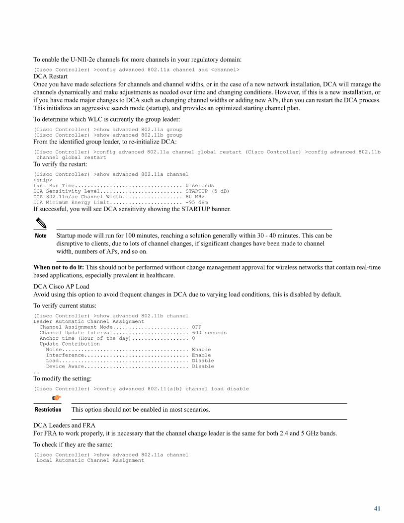
To enable the U-NII-2e channels for more channels in your regulatory domain:(Cisco Controller) >config advanced 802.11a channel add <channel>DCA RestartOnce you have made selections for channels and channel widths, or in the case of a new network installation, DCA will manage thechannels dynamically and make adjustments as needed over time and changing conditions. However, if this is a new installation, orif you have made major changes to DCA such as changing channel widths or adding new APs, then you can restart the DCA process.This initializes an aggressive search mode (startup), and provides an optimized starting channel plan.
To determine which WLC is currently the group leader:(Cisco Controller) >show advanced 802.11a group(Cisco Controller) >show advanced 802.11b groupFrom the identified group leader, to re-initialize DCA:(Cisco Controller) >config advanced 802.11a channel global restart (Cisco Controller) >config advanced 802.11bchannel global restartTo verify the restart:(Cisco Controller) >show advanced 802.11a channel<snip>Last Run Time.................................. 0 secondsDCA Sensitivity Level.......................... STARTUP (5 dB)DCA 802.11n/ac Channel Width................... 80 MHzDCA Minimum Energy Limit....................... -95 dBmIf successful, you will see DCA sensitivity showing the STARTUP banner.
Startup mode will run for 100 minutes, reaching a solution generally within 30 - 40 minutes. This can bedisruptive to clients, due to lots of channel changes, if significant changes have been made to channelwidth, numbers of APs, and so on.
Note
When not to do it: This should not be performed without change management approval for wireless networks that contain real-timebased applications, especially prevalent in healthcare.
DCA Cisco AP LoadAvoid using this option to avoid frequent changes in DCA due to varying load conditions, this is disabled by default.
To verify current status:(Cisco Controller) >show advanced 802.11b channelLeader Automatic Channel AssignmentChannel Assignment Mode........................ OFFChannel Update Interval........................ 600 secondsAnchor time (Hour of the day).................. 0Update ContributionNoise........................................ EnableInterference................................. EnableLoad......................................... DisableDevice Aware................................. Disable
..To modify the setting:(Cisco Controller) >config advanced 802.11{a|b} channel load disable
This option should not be enabled in most scenarios.Restriction
DCA Leaders and FRAFor FRA to work properly, it is necessary that the channel change leader is the same for both 2.4 and 5 GHz bands.
To check if they are the same:(Cisco Controller) >show advanced 802.11a channelLocal Automatic Channel Assignment
41

Channel Assignment Mode........................ OFFChannel Update Interval........................ 600 secondsAnchor time (Hour of the day).................. 0Update ContributionNoise........................................ EnableInterference................................. EnableLoad......................................... DisableDevice Aware................................. Disable
CleanAir Event-driven RRM option............... DisabledChannel Assignment Leader...................... controller (192.168.100.10)…
(Cisco Controller) >show advanced 802.11b channelLeader Automatic Channel AssignmentChannel Assignment Mode........................ OFFChannel Update Interval........................ 600 secondsAnchor time (Hour of the day).................. 0Update ContributionNoise........................................ EnableInterference................................. EnableLoad......................................... DisableDevice Aware................................. Disable
CleanAir Event-driven RRM option............... DisabledChannel Assignment Leader...................... controller (192.168.100.10)
…
Auto Transmit Power Control (TPC)
The Cisco WLC dynamically controls the access point transmit power based on real-time wireless LAN conditions. You can choosebetween two versions of transmit power control: TPCv1 and TPCv2. With TPCv1, power can be kept low to gain extra capacity andreduce interference. With TPCv2, transmit power is dynamically adjusted with the goal of minimum interference. TPCv2 is suitablefor dense networks. In this mode, there could be higher roaming delays and coverage hole incidents.
The Transmit Power Control (TPC) algorithm increases and decreases the power of an access point (AP) in response to changes inthe RF environment. In most instances, TPC seeks to lower the power of the AP to reduce interference. But, in the case of a suddenchange in the RF coverage, for example, if the AP fails or becomes disabled, TPC can also increase power of the surrounding APs.This feature is different from coverage hole detection, which is primarily concerned with clients. TPC provides enough RF power toachieve desired coverage levels while avoiding channel interference between APs.
For optimal performance, use the Automatic setting to allow best transmit power for each radio.Note
To configure auto TPC on either a or b radio:(Cisco Controller) >config 802.11a|b txPower global auto
This should be used in most scenarios. It is advisable to adjust the TPC threshold to adapt properly to theRF deployment characteristics.
Restriction
DCA Interval vs FRA IntervalStarting from release 8.2, the FRA interval needs to be greater or equal than the DCA interval. On previous releases, it was possibleto modify the DCA interval to match environment requirements directly, for example, set it to 8h, from the 1h default. Now, it isnecessary that the FRA interval is larger than the DCA, even if FRA is not in use. To modify, simply set FRA to the desired value,then modify DCA interval.
In general, FRA should be set to similar value used in DCA.
42

Auto Coverage Hole Detection (CHD)The controller uses the quality of client signal levels reported by the APs to determine if the power level of that AP needs to beincreased. Coverage Hole Detection (CHD) is controller independent, so the RF group leader is not involved in those calculations.The controller knows the number of clients that are associated with a particular AP and the signal-to-noise ratio (SNR) values foreach client.
If a client SNR drops below the configured threshold value on the controller, the AP increases its power level to compensate for theclient. The SNR threshold is based on the transmit power of the AP and the coverage profile settings on the controller.
To configure CHD (GUI only), perform the following steps:
1 Disable the 802.11 network as follows:
a Go toWireless > 802.11a/n/ac or 802.11b/g/n > Network to open the 802.11a (or 802.11b/g) Global Parameters page.
b Uncheck the 802.11a (or 802.11b/g) Network Status check box.
c Click Apply.
2 Go toWireless > 802.11a/n/ac or 802.11b/g/n > RRM > Coverage to open the 802.11a/ac (or 802.11b/g/n) > RRM > Coveragepage.
3 Click Enable Coverage Hole Detection.4 Click Apply.
Access Point GroupsAccess point groups are a key configuration component to adjust the Wireless deployment to the needs of each physical location.When used together with RF Profiles, they are a key tool to ensure a proper fine-tuning to each location's characteristics.
From best practices point of view, AP groups should be used to represent a set of access points on a common physical environment.For example:
• One AP group per each branch office
• On large campuses, one AP group for meeting rooms, then a separate group for office areas, another for outdoor areas, etc
• Or use AP groups to separate WLANs focused for Flex mode APs, from the ones for AP in local mode
Every time that there is a significant change in WLANs needed on a given place, or in physical building characteristics (materials),or in access point density, the area should be covered by a separated AP group.
Another aspect of AP groups, used normally in several large deployments, is to enforce a load balancing of traffic across differentVLANs, remapping the WLAN default interface into other available dynamic interfaces. This is a different approach versus usingInterface Groups (covered later), but still valid.
When using AP groups to do static VLAN load balancing, it is very important to remember that a "Salt and Pepper" roaming scenariomust be avoided. This will happen when client can see access points with different AP groups on the same RF roaming space, butthe groups used have VLAN to WLAN mapping differences.
This will typically happen when AP groups are deployed per physical building floor (floor 1 = ap group 1, floor 2 = ap group 2, etc).This situation will still work, but the roaming behavior would suboptimal in terms of mobility scenarios, especially if there is morethan one active controller handling the access points. Use interface groups for this case.
43

Default AP Group
It is important to remember that the "default ap group" will always contain WLANs with ID 1 to 16. All access points go into thisgroup when they are first added into the controller, until they are moved to a different group (out of the box).
For some scenarios, it is common to pre-define a set of "dummy" WLANs with IDs 1 to 16, to ensure that no WLANs are added byaccident into the default AP group, and broadcasted by APs on default configuration. This does not apply to small controllers, whereonly ID 1 to 16 are supported.
This should be used in most scenarios.Restriction
Related Documentation:
Configuring AP Groups
RF Profiles
RF Profiles are the mechanism used within AP Groups, to customize the RRM and RF parameters for a given set of access points.This will allow for fine tuning scenarios for channel selection, data rates, RX-SOP, among other configuration characteristics.
General recommendations:
• Set the desired TPC threshold on the RF group, based on the AP density and installed height. For large deployments, there canbe significant variations on the RF environment, so it is important to adjust properly TPC to ensure optimal coverage on eachlocation
• Together with transmit power, data rates are the primary mechanism to influence the client roaming behavior. Changing whichis the lowest mandatory rate can modify when the client may trigger a new roam, which is especially important for large openspaces, that suffer from "sticky client problems"
•When setting up RF profiles, try to avoid configuring adjacent AP groups/RF profiles, with different DCA channel sets, as thiscan impact negatively DCA channel assignment calculations.
This should be used in most scenarios.Restriction
General additional information:
Radio Resource Management
Enable CleanAir
To effectively detect and mitigate RF interference, enable CleanAir whenever possible. There are recommendations to various sourcesof interference to trigger security alerts, such as generic DECT phones, jammer, etc.
To verify CleanAir configuration on the network (802.11b):(Cisco Controller) >show 802.11b cleanair configTo verify CleanAir configuration on the network (802.11a):(Cisco Controller) >show 802.11a cleanair config
Clean Air Solution............................... DisabledAir Quality Settings:
Air Quality Reporting........................ EnabledAir Quality Reporting Period (min)........... 15
44
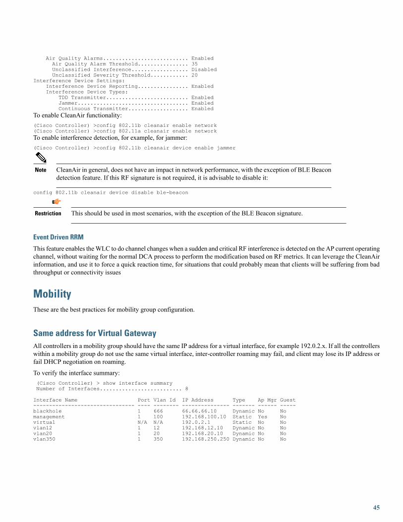
Air Quality Alarms........................... EnabledAir Quality Alarm Threshold................ 35Unclassified Interference.................. DisabledUnclassified Severity Threshold............ 20
Interference Device Settings:Interference Device Reporting................ EnabledInterference Device Types:
TDD Transmitter.......................... EnabledJammer................................... EnabledContinuous Transmitter................... Enabled
To enable CleanAir functionality:(Cisco Controller) >config 802.11b cleanair enable network(Cisco Controller) >config 802.11a cleanair enable networkTo enable interference detection, for example, for jammer:(Cisco Controller) >config 802.11b cleanair device enable jammer
CleanAir in general, does not have an impact in network performance, with the exception of BLE Beacondetection feature. If this RF signature is not required, it is advisable to disable it:
Note
config 802.11b cleanair device disable ble-beacon
This should be used in most scenarios, with the exception of the BLE Beacon signature.Restriction
Event Driven RRM
This feature enables theWLC to do channel changes when a sudden and critical RF interference is detected on the AP current operatingchannel, without waiting for the normal DCA process to perform the modification based on RF metrics. It can leverage the CleanAirinformation, and use it to force a quick reaction time, for situations that could probably mean that clients will be suffering from badthroughput or connectivity issues
MobilityThese are the best practices for mobility group configuration.
Same address for Virtual GatewayAll controllers in a mobility group should have the same IP address for a virtual interface, for example 192.0.2.x. If all the controllerswithin a mobility group do not use the same virtual interface, inter-controller roaming may fail, and client may lose its IP address orfail DHCP negotiation on roaming.
To verify the interface summary:(Cisco Controller) > show interface summaryNumber of Interfaces.......................... 8
Interface Name Port Vlan Id IP Address Type Ap Mgr Guest-------------------------------- ---- -------- --------------- ------- ------ -----blackhole 1 666 66.66.66.10 Dynamic No Nomanagement 1 100 192.168.100.10 Static Yes Novirtual N/A N/A 192.0.2.1 Static No Novlan12 1 12 192.168.12.10 Dynamic No Novlan20 1 20 192.168.20.10 Dynamic No Novlan350 1 350 192.168.250.250 Dynamic No No
45

This should be used in most scenarios.Restriction
Mobility Group ConnectivityEnsure that IP connectivity exists between the management interfaces of all controllers. If a controller in the mobility group ispermanently down (replacement, testing, etc) , it is recommended to remove it from the mobility configuration of all peers.
This should be used in most scenarios.Restriction
Fast RoamingThe mobility group name acts as a discriminator to indicate which controllers share a common cache for fast roaming information(CCKM, 802.11r, PKC). It is important to ensure that if fast roaming is needed between controllers, that they share the same mobilitygroup name.
This should be used in most scenarios.Restriction
Same VersionCisco supports roaming between controllers running different AireOS versions, but in general it is advisable to use equal code acrossthe controllers on the same mobility group, to ensure consistent behavior across the devices.
For more information on what version support interoperability:
Inter-Release Controller Mobility
Mobility Group SizeDo not create unnecessarily large mobility groups. A mobility group should only have all controllers that have APs in the area wherea client can physically roam, for example, all controllers with APs in a building. If you have a scenario where several buildings areseparated, they should be broken into several mobility groups. This saves memory and CPU, as controllers do not need to keep largelists of valid clients, rogues, and APs inside the group, which would not interact anyway.
This should be used in most scenarios.Restriction
Reduce the need for Inter–controller roamingWhen implementing AP distribution across controllers in the same mobility group, try to ensure that all access points on the sameRF space, belong to a single controller. This will reduce the number of inter-controller roams required. A "salt and pepper scenario"(APs from different controllers covering the same RF space), is supported, but it is a more expensive process in terms of CPU andprotocol exchanges, versus the scenario of single controller per RF space.
46

This should be used in most scenarios.Restriction
FlexConnect Best PracticesThis section lists some of the FlexConnect best practices:
• FlexConnect deployment in the branch site helps to reduce the branch footprint in terms of capital and operational expendituresavings with controllers at the central site as opposed to aWLC at each remote office. This results in reduced power consumptionand centralized IT support. It also provides the benefit of centralizing control at a central site, survivability againstWAN failures,and reduced WAN usage between the central and remote sites.
• Certain architectural requirements need to be considered when deploying a distributed branch office in terms of the MinimumWAN Bandwidth, Maximum RTT, Minimum MTU, and fragmentation guidelines that are captured in the following guide:
See the latest Flex 7500 Wireless Branch Controller Deployment Guide
• Set QoS to prioritize CAPWAP Control Channel traffic on UDP port 5246.
Local Switching• Enable Local Switching on the WLAN to provide resiliency against WAN failures and reduce the amount of data going overthe WAN, thus reducing the WAN bandwidth usage.
• Local switching is useful in deployments where resources are local to the branch site and data traffic does not need to be sentback to the controller over the WAN link.
• Connect the FlexConnect AP to a 802.1Q trunk port on the switch.
•When connecting with Native VLAN on the AP, the native VLAN configuration on the L2 must match the configuration onthe AP.
• Ensure that the native VLAN is the same across all AP in the same location / Flexconnect group.
• Some features are not available in standalone mode or in local switching mode. Note the following limitations when using LocalSwitching:
◦MAC/Web Auth in Standalone Mode
◦IPv6 L3 Mobility
◦SXP TrustSec
◦Application Visibility and Control
◦Service Discovery Gateway
◦Native Profiling and Policy Classification
See the full list in the FlexConnect Feature Matrix guide
47
Split Tunneling• Configure the Split Tunneling feature in scenarios where most of the resources are located at the central site and client dataneeds to be switched centrally, but certain devices local to the remote office need local switching to reduce WAN bandwidthutilization.
• A typical use case for this is the OEAP tele-worker setup, where clients on a Corporate SSID can talk to devices on a localnetwork (printers, wired machine on a Remote LAN Port, or wireless devices on a Personal SSID) directly without consumingWAN bandwidth by sending packets over CAPWAP.
• Central DHCP and Split Tunnel feature uses the routing functionality of the AP.
• Note the following limitations when deploying Split Tunneling:
◦Split tunneling is not supported on OEAP 600 APs.
◦Static IP clients are not supported with central-DHCP and local split WLANs.
VLAN Based Central Switching• Use VLAN based central switching in scenarios where dynamic decisions need to be made to local switch or central switch thedata traffic based on the VLANs returned by the AAA server and the VLANs present at the branch site.
• For VLANs that are returned by the AAA server and not present on the branch site, traffic will be switched centrally.
FlexConnect GroupsIn general, it is important to use the FlexConnect Group features, and avoid per-AP configuration setting when possible. If fastroaming, voice or WLAN-VLAN mappings are needed in the deployment, FlexGroups are a mandatory configuration step.
There are several features that can benefit from FlexConnect Groups:
• FT/CCKM/OKC fast roaming for Voice deployments
• Local Backup Radius Server
• Local EAP
• Smart AP Image Upgrade
•WLAN–VLAN and VLAN–ACL mapping
This should be used in most scenarios.Restriction
FT/CCKM/OKC Fast roaming• For Flex mode APs, fast roaming is only possible when the APs belong to a FlexConnect group
• Fast roaming is only supported across APs belonging to the same FlexConnect group, on the same controller
• Voice with 802.1x authentication is not supported for Flex, unless the APs are part of a FlexConnect group
48

Local Backup RADIUS server• Configure Local Backup RADIUS server to increase the resiliency of the branch taking into consideration failures at the WAN,WLC failures, and failures at the RADIUS server.
• This feature is also used for remote offices where the WAN latency to the central site is high.
• Administrators can configure a primary backup RADIUS server or both the primary and secondary backup RADIUS server.FlexConnect AP in standalone mode can be configured to perform full 802.1X authentication to a backup RADIUS server.
• These servers are used when the FlexConnect AP is not connected to the controller or when the WLAN is configured for localauthentication.
• If the RADIUS/ACS is located inside the branch, then the clients will authenticate and access wireless services even during aWAN outage.
• Note the following limitation when configuring local backup RADIUS server:
◦When a local backup RADIUS server is used in the branch, the IP addresses of all the APs acting as authenticators mustbe added on the RADIUS server.
Local EAP• For an additional level of resiliency, enable Local EAP Server on the FlexConnect group (EAP-FAST, PEAP, EAP-TLS).
• The Local EAP feature can be used in conjunction with the FlexConnect backup RADIUS server feature. If a FlexConnectgroup is configured with both backup RADIUS server and local authentication, the FlexConnect AP always attempts toauthenticate clients using the primary backup RADIUS server first, followed by the secondary backup RADIUS server (if theprimary is not reachable), and finally the Local EAP Server on FlexConnect AP itself (if the primary and secondary are notreachable).
• Note the following limitations when configuring Local EAP on FlexConnect AP:
◦Up to 100 statically configured users can be authenticated on the FlexConnect AP. Each AP in the group authenticatesonly its own associated clients.
◦Active Directory (AD) integration is not supported with this feature.
Smart AP Image Upgrade• Use the Smart AP Image Upgrade feature to upgrade the branch sites as this feature conserves WAN bandwidth, reducesupgrade-induced service downtime, and also reduces the risk of download failure over the WAN. Efficient AP image upgradereduces the downtime for each FlexConnect AP.
• Master AP selection is per FlexConnect group and per AP model in each group.
• The best practices recommended for a network upgrade are as follows:
◦Download Image to WLC, using controller CLI/GUI or Prime Infrastructure.
◦Force the boot image to be the secondary (and not the newly upgraded one) to avoid parallel download of all AP in caseof an unexpected WLC reboot.
◦The controller elects a master AP in each FlexConnect group. The master AP can also be selected manually.
49

◦Master AP pre-downloads the AP firmware in the secondary boot image. Schedule this per FlexConnect group to limitthe WAN exhaust.
◦Once the master AP finishes downloading the image, it sends a message to the controller. The controller instructs the slaveAPs to pre-download the AP firmware from the master AP.
◦Change the boot image of the WLC to point to the new image.
◦Reboot the controller.
WLAN-VLAN and VLAN-ACL Mapping•WLAN-VLAN mapping at the FlexConnect group provides ease of configuration without having to configure the mapping ateach AP. For example, for all APs in a branch site to do local switching on the same VLAN, the WLAN-VLAN mapping canbe configured at a per FlexConnect group level.
• VLAN-ACLmapping at the FlexConnect group provides ease of configuration without having to configure the mapping at eachFlexConnect AP.
• If a VLAN is created at the AP using WLAN-VLAN mapping, the VLAN-ACL should also be created on the AP and not atFlexConnect group. Preferred mode is using FlexConnect Group, and not per AP.
VLAN Support/Native VLAN on FlexConnect Group• Configure VLAN Support and Native VLAN at the level of the FlexConnect group, and use the override flag to consolidate allthe VLAN configuration at a single place.
• This feature helps you to consolidate configurations for all APs at the Branch Level, provides consistency of mapping, andeases configuration.
• Avoid per AP configuration unless absolutely necessary.
(Cisco Controller) >config flexconnect group <groupName> vlan <enable / disable>(Cisco Controller) >config flexconnect group <groupName> vlan native <vlan_id>(Cisco Controller) >config flexconnect group <groupName> vlan override-native-ap <enable / disable>
AAA Override of VLAN NameThe VLAN Name Override feature is useful in deployments that have a single central radius authenticating multiple branches. Therequirement for this deployment is to map clients to different VLANs across different branch locations based on authentication profilesand policy rules.
The benefit of using this feature is that the RADIUS server only needs to be aware of the user function and logical categorization ofthat user. The details of VLAN design can be abstracted in the form of VLAN Name to VLAN ID mapping configurations.
Create VLAN Name template and add mapping rules as follows:(Cisco Controller) >config flexconnect vlan-name-id create template1(Cisco Controller) >config flexconnect vlan-name-id template-entry add template1 Marketing 20(Cisco Controller) >config flexconnect vlan-name-id apply template1A template can also be created by copying from another template:(Cisco Controller) >config flexconnect vlan-name-id create template2 copy template1
Associate the template with a FlexConnect group:(Cisco Controller) >config flexconnect group FlexGroup1 template-vlan-map add template1
50

Outdoor Best PracticesThis section explains the outdoor best practices for design, deployment, and security.
Design
Perform an RF Active Site Survey
The outdoor environment is a challenging RF environment. Many obstacles and interferers exist that cannot be avoided.
Prior to designing a network, an RF Active Site Survey is the first step to understand your RF environment.
Estimate Coverage Area Using the Cisco Range and Capacity Calculator
Once the RF active site survey is performed, you must estimate the number of outdoor access points required to meet your network'sdesign requirement. The best tool to estimate an access point's coverage area is the WNG Coverage and Capacity Calculator
WNG Coverage and Capacity Calculator
Outdoor access points can operate in multiple deployment modes, with each deployment mode meeting a different use case.
Local Mode–Best option for an outdoor deployment. Provides full support of Cisco Unified Network features, Radio ResourceManagement (RRM), and allows the 2.4 GHz and 5 GHz radios to be used exclusively for client access. This deployment modeshould be used when each access point has a dedicated Ethernet connection.
Local Mode–Best option for an outdoor deployment. Provides full support of Cisco Unified Network features, Radio ResourceManagement (RRM), and allows the 2.4 GHz and 5 GHz radios to be used exclusively for client access. This deployment modeshould be used when each access point has a dedicated Ethernet connection.
Bridge–Flex Mode–Provides a hybrid operation between Mesh and Flex. This is recommended for scenarios where the AP areseparated by a WAN from the WLC, also when you need to have traffic to be locally switched at the AP level, and not sent centrallyto the controller.
Deployment
Avoid Selecting DFS Channels for Backhaul
If the regulatory domain channel plan allows it, when selecting the backhaul channel for a mesh tree, avoid channels that can be usedfor radar (DFS channels).
Set BGN and Preferred Parent for Each Bridge Mode Access Point
When operating in Bridge Mode, each access point should be assigned a Bridge Group Name and Preferred Parent. This helps themesh network to converge in the same sequence every time, allowing the network to match the initial design.
To set Bridge Group Name:(Cisco Controller) >config` ap bridgegroupname set BGN-name ap-nameTo verify:(Cisco Controller) >show ap config general ap-name
51

To set Preferred Parent:(Cisco Controller) >config mesh parent <ap-name> <parent_MAC>To verify:(Cisco Controller) >show ap config general <ap-name>
This should be used in most scenarios.Restriction
Deploy Multiple RAPs in Each BGN
When deploying a mesh network, there should be multiple paths for each access point back to a WLC. Multiple paths can be addedby having multiple Root Access Points (RAPs) per mesh tree. If an RAP fails and goes offline, other mesh access points will joinanother RAP in the same BGN and still have a path back to the WLC.
• For best results, ensure that RAPs are configured on different channels, to reduce or avoid co-channel interference. Map willuse background scanning to identify each RAP
• RAP should be on the same VLAN/subnet to prevent mesh AP address renegotiation on parent change, that could delay totalmesh convergence time
• Ensure that MAP have background scanning enabled, to facilitate new parent discovery
This should be used in most scenarios.Restriction
Set Backhaul Data Rates to auto
When deploying a mesh network, each mesh node should communicate on the highest possible backhaul data rate. To ensure this, itis recommended to enable Dynamic Rate Adjustment (DRA) by selecting the "auto" backhaul data rate.
DRA has to be enabled on every mesh link.
To enable "auto":(Cisco Controller) > config ap bhrate auto <ap-name>To verify:(Cisco Controller) > show ap bhrate <ap-name>
Set Backhaul Channel Width to 40 MHz
When deploying a mesh network, each mesh node should communicate on the highest possible backhaul speed, 40 MHz allows thebest equilibrium between performance and RF congestion avoidance.
To set the channel width per AP:(Cisco Controller) >config 802.11a chan_width <ap-name> 40
This should be used in most scenarios.Restriction
Ensure the Backhaul Link Signal to Noise Ratio (LinkSNR) is Greater than 25 dBm
To ensure optimal performance over your mesh network, make sure the backhaul link quality is good. An optimal link quality wouldbe greater than 40 dBm, but this is not always achievable in non-line of site deployment or long-range bridges. Cisco recommendsthe link SNR to be at least 25 dBm or greater.
52
This should be used in most scenarios.Restriction
To check the LinkSNR:(Cisco Controller) >show mesh neigh summary ap-nameAP Name/Radio Channel Rate Link-Snr Flags State------------- ------- ------ --------- ----- ------RAP_e380 136 m15 33 0x0 UPDATED NEIGH PARENT BEACON
Or:(Cisco Controller) >show mesh neigh detail ap-nameAP MAC : 1C:AA:07:5F:E3:80 AP Name: RAP_e380 backhaul rate m15FLAGS : 86F UPDATED NEIGH PARENT BEACON Neighbor reported by slot: 1worstDv 0, Ant 0, channel 136, biters 0, ppiters 10 Numroutes 1, snr 0, snrUp 40, snrDown 43, linkSnr 39adjustedEase 8648576, unadjustedEase 8648576
Security
Use External Radius Server for Mesh MAC Authentication
An external radius server should be configured for MAC authentications. This allows all bridge mode access points to authenticateat a single location, thus simplifying network management.
For instructions on how to setup an external radius server:
Mesh Access Points, Design and Deployment Guide
Enable Provisioned PSK as Security Mode
To have the best equilibrium between mesh security and ease of deployments, it is advisable to enable the Mesh Key Provisionedfeature.
Related Documentation:
Mesh PSK Key provisioning
Apple DevicesThe following best practices are applicable to networks with Apple client devices . For detailed information, please refer to theEnterprise Best Practices for iOS Devices on Cisco Wireless LAN document
WLAN Configuration
Adaptive 11r, 11k and 11v for Optimized WiFi Connectivity
iOS devices running iOS 10 and higher will identify the Adaptive 11r functionality on a Cisco network running AireOS 8.3 or laterand perform an FT Association on the WLAN. The Cisco Wireless infrastructure will allow FT association on the WLAN fromdevices that can negotiate FT association on a non-FT WLAN.config wlan security ft adaptive enable/disable
• Enable Authentication and Key Management (AKM) as 802.1x or PSK instead of FT 802.1x or FT PSK when adaptive 11r isenabled
53
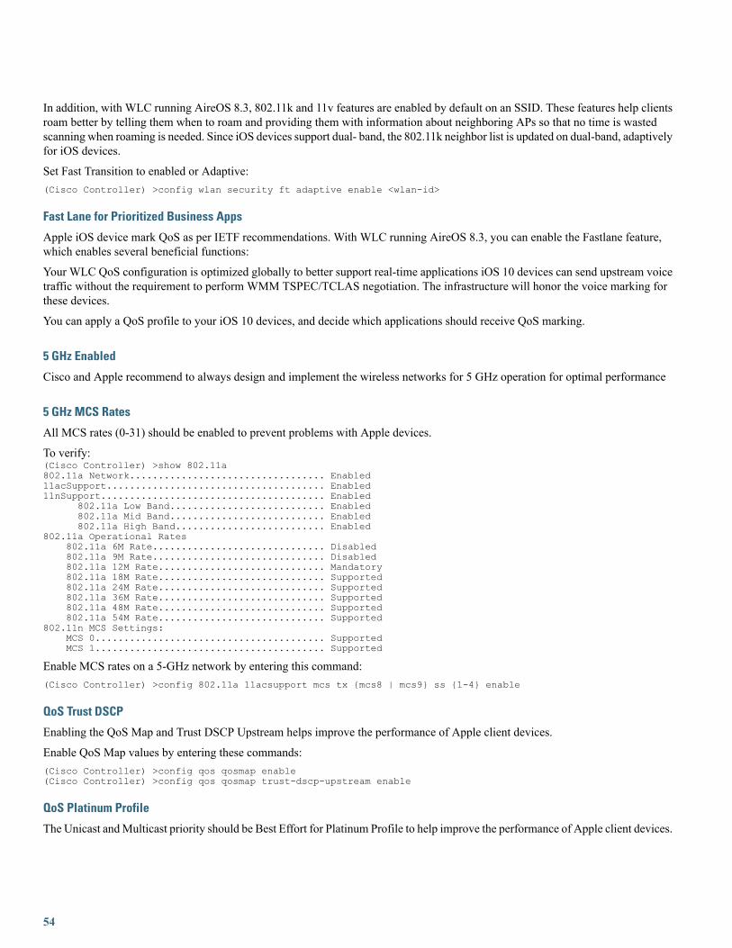
In addition, with WLC running AireOS 8.3, 802.11k and 11v features are enabled by default on an SSID. These features help clientsroam better by telling them when to roam and providing them with information about neighboring APs so that no time is wastedscanning when roaming is needed. Since iOS devices support dual- band, the 802.11k neighbor list is updated on dual-band, adaptivelyfor iOS devices.
Set Fast Transition to enabled or Adaptive:(Cisco Controller) >config wlan security ft adaptive enable <wlan-id>
Fast Lane for Prioritized Business Apps
Apple iOS device mark QoS as per IETF recommendations. With WLC running AireOS 8.3, you can enable the Fastlane feature,which enables several beneficial functions:
Your WLC QoS configuration is optimized globally to better support real-time applications iOS 10 devices can send upstream voicetraffic without the requirement to perform WMM TSPEC/TCLAS negotiation. The infrastructure will honor the voice marking forthese devices.
You can apply a QoS profile to your iOS 10 devices, and decide which applications should receive QoS marking.
5 GHz Enabled
Cisco and Apple recommend to always design and implement the wireless networks for 5 GHz operation for optimal performance
5 GHz MCS Rates
All MCS rates (0-31) should be enabled to prevent problems with Apple devices.
To verify:(Cisco Controller) >show 802.11a802.11a Network.................................. Enabled11acSupport...................................... Enabled11nSupport....................................... Enabled
802.11a Low Band........................... Enabled802.11a Mid Band........................... Enabled802.11a High Band.......................... Enabled
802.11a Operational Rates802.11a 6M Rate.............................. Disabled802.11a 9M Rate.............................. Disabled802.11a 12M Rate............................. Mandatory802.11a 18M Rate............................. Supported802.11a 24M Rate............................. Supported802.11a 36M Rate............................. Supported802.11a 48M Rate............................. Supported802.11a 54M Rate............................. Supported
802.11n MCS Settings:MCS 0........................................ SupportedMCS 1........................................ Supported
Enable MCS rates on a 5-GHz network by entering this command:(Cisco Controller) >config 802.11a 11acsupport mcs tx {mcs8 | mcs9} ss {1-4} enable
QoS Trust DSCP
Enabling the QoS Map and Trust DSCP Upstream helps improve the performance of Apple client devices.
Enable QoS Map values by entering these commands:(Cisco Controller) >config qos qosmap enable(Cisco Controller) >config qos qosmap trust-dscp-upstream enable
QoS Platinum Profile
The Unicast andMulticast priority should be Best Effort for Platinum Profile to help improve the performance of Apple client devices.
54

Enable Best Effort on the Platinum Profile by entering this command:(Cisco Controller) >config qos priority platinum besteffort besteffort besteffort
Optimized Roaming Disabled
Optimized roaming should be disabled because Apple devices use the newer 802.11r, 802.11k, or 802.11v roaming improvement.
Disable optimized roaming by entering this command:(Cisco Controller) >config advanced 802.11{a | b} optimized-roaming disable
55

© 2018 Cisco Systems, Inc. All rights reserved.

Europe HeadquartersAsia Pacific HeadquartersAmericas HeadquartersCisco Systems International BVAmsterdam, The Netherlands
Cisco Systems (USA) Pte. Ltd.Singapore
Cisco Systems, Inc.San Jose, CA 95134-1706USA
Cisco has more than 200 offices worldwide. Addresses, phone numbers, and fax numbers are listed on theCisco Website at www.cisco.com/go/offices.