Embed Size (px)
Citation preview
CISCO SYSTEMS PUBLICATION HISTORY170 WEST TASMAN DR.SAN JOSE, CA, 95134 REV A.6 JUNE 17, 2020 WWW.CISCO.COM
Spec Sheet
Cisco UCS C240 SD M5Rack Server
A printed version of this document is only a copy and not necessarily the latest version. Refer to the following link for the latest released version:
https://www.cisco.com/c/en/us/products/servers-unified-computing/ucs-c-series-rack-servers/datasheet-listing.html
Cisco UCS C240 SD M5 Rack Server (2
CONTENTS
OVERVIEW . . . . . . . . . . . . . . . . . . . . . . . . . . . . . . . . . . . . . . . . . . . . . . . 3DETAILED VIEWS . . . . . . . . . . . . . . . . . . . . . . . . . . . . . . . . . . . . . . . . . . . 5BASE SERVER STANDARD CAPABILITIES and FEATURES . . . . . . . . . . . . . . . . . 7CONFIGURING the SERVER . . . . . . . . . . . . . . . . . . . . . . . . . . . . . . . . . . . 11
STEP 1 VERIFY SERVER SKU . . . . . . . . . . . . . . . . . . . . . . . . . . . . . . . . . . . . . . . . . . . 12STEP 2 SELECT RISER CARDS (REQUIRED) . . . . . . . . . . . . . . . . . . . . . . . . . . . . . . . . . . 13STEP 3 SELECT CPU(s) . . . . . . . . . . . . . . . . . . . . . . . . . . . . . . . . . . . . . . . . . . . . . . 14STEP 4 SELECT MEMORY . . . . . . . . . . . . . . . . . . . . . . . . . . . . . . . . . . . . . . . . . . . . . 18STEP 5 SELECT STORAGE CONTROLLER . . . . . . . . . . . . . . . . . . . . . . . . . . . . . . . . . . . 23STEP 6 SELECT DRIVES . . . . . . . . . . . . . . . . . . . . . . . . . . . . . . . . . . . . . . . . . . . . . . 24STEP 7 SELECT PCIe OPTION CARD(s) . . . . . . . . . . . . . . . . . . . . . . . . . . . . . . . . . . . . 28STEP 8 ORDER OPTIONAL PCIe OPTION CARD ACCESSORIES . . . . . . . . . . . . . . . . . . . . . . 30STEP 9 ORDER GPU CARDS (OPTIONAL) . . . . . . . . . . . . . . . . . . . . . . . . . . . . . . . . . . . 34STEP 10 ORDER POWER SUPPLY . . . . . . . . . . . . . . . . . . . . . . . . . . . . . . . . . . . . . . . . 36STEP 11 SELECT INPUT POWER CORD(s) . . . . . . . . . . . . . . . . . . . . . . . . . . . . . . . . . . 37STEP 12 ORDER TOOL-LESS RAIL KIT and RAIL EXTENDER KIT . . . . . . . . . . . . . . . . . . . . . 40STEP 13 SELECT MANAGEMENT CONFIGURATION (OPTIONAL) . . . . . . . . . . . . . . . . . . . . 41STEP 14 SELECT SERVER BOOT MODE (OPTIONAL) . . . . . . . . . . . . . . . . . . . . . . . . . . . . 42STEP 15 ORDER SECURITY DEVICES (OPTIONAL) . . . . . . . . . . . . . . . . . . . . . . . . . . . . . 43STEP 16 ORDER CISCO SD CARD MODULE (OPTIONAL) . . . . . . . . . . . . . . . . . . . . . . . . . . 44STEP 17 ORDER M.2 SATA SSD (OPTIONAL) . . . . . . . . . . . . . . . . . . . . . . . . . . . . . . . . . 45STEP 18 ORDER INTERNAL MICRO-SD CARD MODULE (OPTIONAL) . . . . . . . . . . . . . . . . . . 46STEP 19 ORDER OPTIONAL USB 3.0 DRIVE . . . . . . . . . . . . . . . . . . . . . . . . . . . . . . . . . 47STEP 20 SELECT OPERATING SYSTEM AND VALUE-ADDED SOFTWARE . . . . . . . . . . . . . . . . 48STEP 21 SELECT SERVICE and SUPPORT LEVEL . . . . . . . . . . . . . . . . . . . . . . . . . . . . . . 54
OPTIONAL STEP - ORDER PDU . . . . . . . . . . . . . . . . . . . . . . . . . . . . . . . . . 62SUPPLEMENTAL MATERIAL . . . . . . . . . . . . . . . . . . . . . . . . . . . . . . . . . . . 63SPARE PARTS . . . . . . . . . . . . . . . . . . . . . . . . . . . . . . . . . . . . . . . . . . . . 77UPGRADING or REPLACING CPUs . . . . . . . . . . . . . . . . . . . . . . . . . . . . . . . 78UPGRADING or REPLACING MEMORY . . . . . . . . . . . . . . . . . . . . . . . . . . . . . 79TECHNICAL SPECIFICATIONS . . . . . . . . . . . . . . . . . . . . . . . . . . . . . . . . . . 81
OVERVIEW
OVERVIEWThe UCS C240 SD M5 SFF server is a two-socket C-Series 2U chassis designed to operate both in standalone and UCS environments. It serves the edge computing market that uses standard x86 based 19" rack servers.
The UCS C240 SD M5 SFF server is a derivative of the Cisco UCS 240 M5 server.
The following list summarizes the C240 SD M5 server features that are identical to the C240 M5 features:
■ 2U form factor
■ Intel® Xeon® Processor Scalable Family (maximum 2 CPUs)
■ 24 DIMM slots for 2933-MHz DIMMs with DIMM sizes up to 128 GB and 2666-MHz PMEMs with capacity points up to 512 GB
■ Maximum memory size is 7.6 TB (using 12 x 128 GB DDR4 DIMMs and 12 x 512 GB PMEMs)
■ Six PCIe slots
The following list summarizes how the C240 SD M5 differs from the C240 M5 server:
■ Up to six NVMe, SSD, or HDD drives mounted in risers in front of the chassis (C240 M5 has a maximum of 24 front-mount drives in drive cages)
■ I/O connectors on front (C240 M5 I/O is on the back)
■ Fans at rear of chassis (C240 M5 fans are towards the front)
■ 22” chassis depth requirement (C240 M5 is 29”)
■ Support for up to two NVIDIA T4 (only) GPUs (in riser slots)
■ Dedicated internal slot for Cisco 12G SAS HBA only (C240 M5 has SAS HBA or RAID controller)
■ Front accessible I/O connectors (C240 M5 has rear I/O)
■ New riser cards for Riser 1 and Riser 2
■ PCIe slot drive configurability
— Two drives and six PCIe slots for I/O-centric applications, or
— Six drives and two PCIe slots for storage-centric applications
The C240 SD M5 server includes a dedicated internal modular LAN on motherboard (mLOM) connector for installation of a Cisco Virtual Interface Card (VIC) or third-party network interface card (NIC), without consuming a PCI slot, in addition to 2 x 10Gbase-T Intel x550 embedded (on the motherboard) LOM ports.
The Cisco UCS C240 SD M5 server can be used standalone, or as part of the Cisco Unified Computing System, which unifies computing, networking, management, virtualization, and storage access into a single integrated architecture enabling end-to-end server visibility, management, and control in both bare metal and virtualized environments.
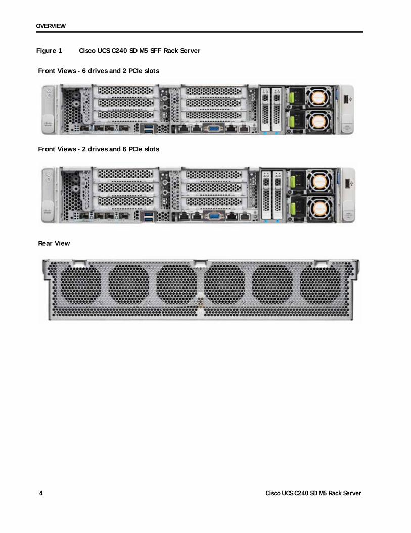
The C240 SD M5 comes in two versions: 6 PCIe slots and 2 drive slots, or 2 PCIe slots and 6 drive slots. Figure 1 on page 4 shows the version with 2 PCIe slots and 6 drive slots.
Cisco UCS C240 SD M5 Rack Server 3
OVERVIEW
Figure 1 Cisco UCS C240 SD M5 SFF Rack Server
Front Views - 6 drives and 2 PCIe slots
Rear View
Front Views - 2 drives and 6 PCIe slots
1 2
1 2
Cisco UCS C240 SD M5 Rack Server 4
DETAILED VIEWS
DETAILED VIEWS
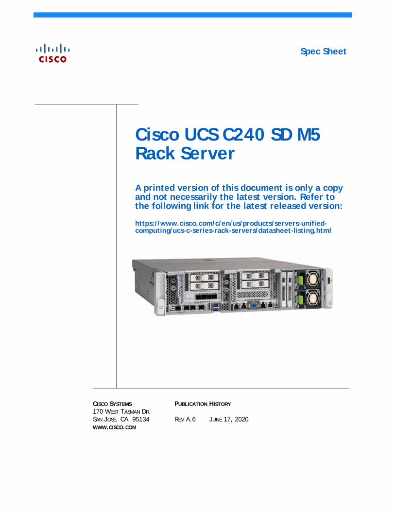
Chassis Front View
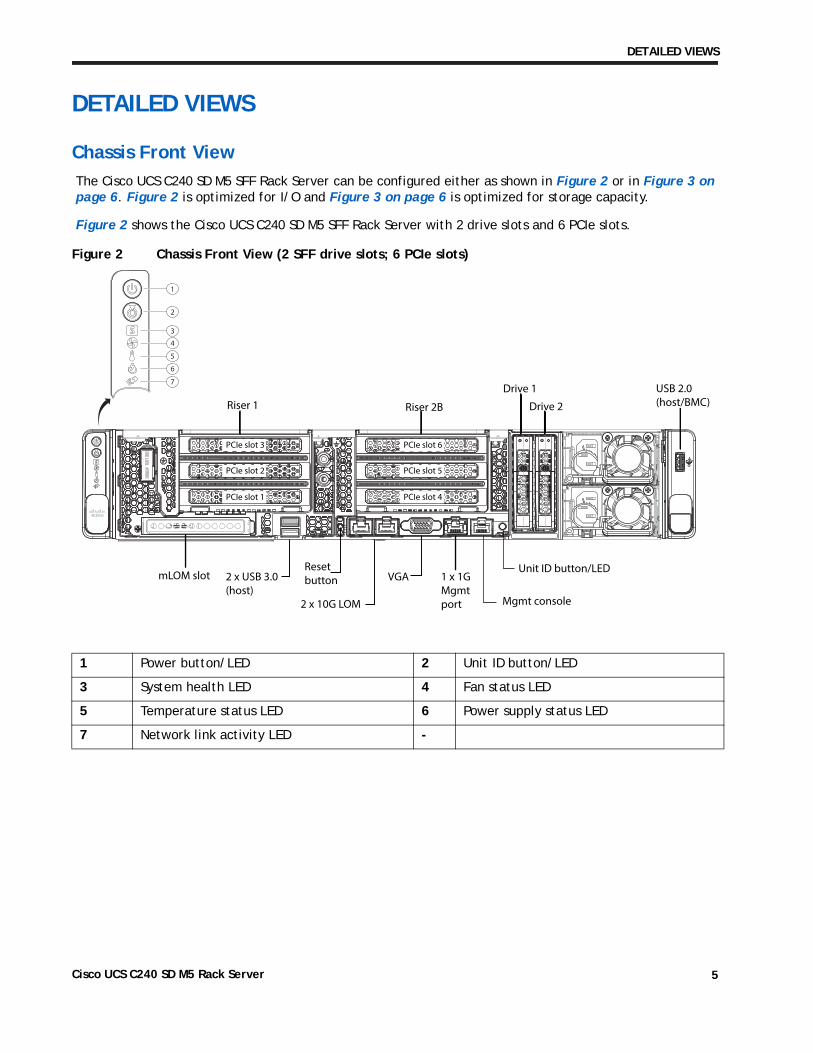
The Cisco UCS C240 SD M5 SFF Rack Server can be configured either as shown in Figure 2 or in Figure 3 on page 6. Figure 2 is optimized for I/O and Figure 3 on page 6 is optimized for storage capacity.
Figure 2 shows the Cisco UCS C240 SD M5 SFF Rack Server with 2 drive slots and 6 PCIe slots.
Figure 2 Chassis Front View (2 SFF drive slots; 6 PCIe slots)
Riser 1 Riser 2B Drive 2
Drive 1
mLOM slot 2 x USB 3.0(host)
2 x 10G LOM
VGAResetbutton 1 x 1G
Mgmtport
PCIe slot 1
PCIe slot 2
PCIe slot 3
PCIe slot 4
PCIe slot 5
PCIe slot 6
USB 2.0(host/BMC)
1
2
3
4
5
6
7
Mgmt console
Unit ID button/LED
1 Power button/LED 2 Unit ID button/LED
3 System health LED 4 Fan status LED
5 Temperature status LED 6 Power supply status LED
7 Network link activity LED -
Cisco UCS C240 SD M5 Rack Server 5
DETAILED VIEWS
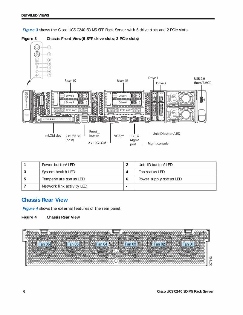
Figure 3 shows the Cisco UCS C240 SD M5 SFF Rack Server with 6 drive slots and 2 PCIe slots.
Figure 3 Chassis Front View(6 SFF drive slots; 2 PCIe slots)
mLOM slot
Riser 1C Riser 2E
2 x USB 3.0(host)
USB 2.0(host/BMC))
VGA 1 x 1G Mgmtport Mgmt console
Unit ID button/LED
PCIe slot 1
Drive 5
Drive 3
Drive 6
Drive 4
PCIe slot 2
Drive 2
Drive 1
1
2
3
4
5
6
7
2 x 10G LOM
Resetbutton
Chassis Rear View
Figure 4 shows the external features of the rear panel.
Figure 4 Chassis Rear View
1 Power button/LED 2 Unit ID button/LED
3 System health LED 4 Fan status LED
5 Temperature status LED 6 Power supply status LED
7 Network link activity LED -
Cisco UCS C240 SD M5 Rack Server 6
BASE SERVER STANDARD CAPABILITIES and FEATURES
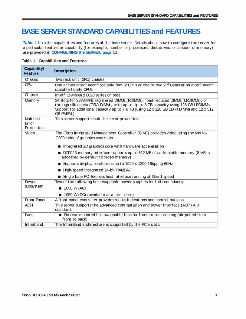
BASE SERVER STANDARD CAPABILITIES and FEATURESTable 1 lists the capabilities and features of the base server. Details about how to configure the server for a particular feature or capability (for example, number of processors, disk drives, or amount of memory) are provided in CONFIGURING the SERVER, page 11.
Table 1 Capabilities and Features
Capability/Feature
Description
Chassis Two rack unit (2RU) chassisCPU One or two Intel® Xeon® scalable family CPUs or one or two 2nd Generation Intel® Xeon®
scalable family CPUsChipset Intel® Lewisburg C620 series chipsetMemory 24 slots for 2933-MHz registered DIMMs (RDIMMs), load-reduced DIMMs (LRDIMMs), or
through silicon via (TSV) DIMMs, with up to Up to 3 TB capacity using 128 GB LRDIMMs. Support for additional capacity up to 7.6 TB (using 12 x 128 GB DDR4 DIMMs and 12 x 512 GB PMEMs).
Multi-bit Error Protection
This server supports multi-bit error protection.
Video The Cisco Integrated Management Controller (CIMC) provides video using the Matrox G200e video/graphics controller:
■ Integrated 2D graphics core with hardware acceleration
■ DDR2/3 memory interface supports up to 512 MB of addressable memory (8 MB is allocated by default to video memory)
■ Supports display resolutions up to 1920 x 1200 16bpp @ 60Hz
■ High-speed integrated 24-bit RAMDAC
■ Single lane PCI-Express host interface running at Gen 1 speedPower subsystem
Two of the following hot-swappable power supplies for full redundancy:
■ 1050 W (AC)
■ 1050 W (DC) (available at a later date)Front Panel A front panel controller provides status indications and control buttons.ACPI This server supports the advanced configuration and power interface (ACPI) 4.0
standard.Fans ■ Six rear-mounted hot-swappable fans for front-to-rear cooling (air pulled from
front to back)Infiniband The InfiniBand architecture is supported by the PCIe slots.
Cisco UCS C240 SD M5 Rack Server 7
BASE SERVER STANDARD CAPABILITIES and FEATURES
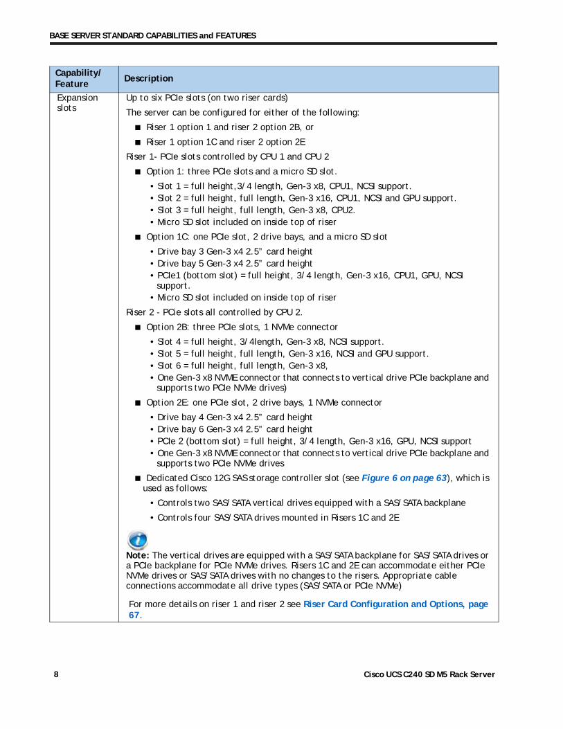
Expansion slots
Up to six PCIe slots (on two riser cards)
The server can be configured for either of the following:
■ Riser 1 option 1 and riser 2 option 2B, or
■ Riser 1 option 1C and riser 2 option 2E
Riser 1- PCIe slots controlled by CPU 1 and CPU 2
■ Option 1: three PCIe slots and a micro SD slot.
• Slot 1 = full height,3/4 length, Gen-3 x8, CPU1, NCSI support. • Slot 2 = full height, full length, Gen-3 x16, CPU1, NCSI and GPU support.• Slot 3 = full height, full length, Gen-3 x8, CPU2.• Micro SD slot included on inside top of riser
■ Option 1C: one PCIe slot, 2 drive bays, and a micro SD slot
• Drive bay 3 Gen-3 x4 2.5” card height• Drive bay 5 Gen-3 x4 2.5” card height• PCIe1 (bottom slot) = full height, 3/4 length, Gen-3 x16, CPU1, GPU, NCSI
support. • Micro SD slot included on inside top of riser
Riser 2 - PCie slots all controlled by CPU 2.
■ Option 2B: three PCIe slots, 1 NVMe connector
• Slot 4 = full height, 3/4length, Gen-3 x8, NCSI support. • Slot 5 = full height, full length, Gen-3 x16, NCSI and GPU support. • Slot 6 = full height, full length, Gen-3 x8, • One Gen-3 x8 NVME connector that connects to vertical drive PCIe backplane and
supports two PCIe NVMe drives)
■ Option 2E: one PCIe slot, 2 drive bays, 1 NVMe connector
• Drive bay 4 Gen-3 x4 2.5” card height• Drive bay 6 Gen-3 x4 2.5” card height• PCIe 2 (bottom slot) = full height, 3/4 length, Gen-3 x16, GPU, NCSI support• One Gen-3 x8 NVME connector that connects to vertical drive PCIe backplane and
supports two PCIe NVMe drives
■ Dedicated Cisco 12G SAS storage controller slot (see Figure 6 on page 63), which is used as follows:
• Controls two SAS/SATA vertical drives equipped with a SAS/SATA backplane
• Controls four SAS/SATA drives mounted in Risers 1C and 2E
Note: The vertical drives are equipped with a SAS/SATA backplane for SAS/SATA drives or a PCIe backplane for PCIe NVMe drives. Risers 1C and 2E can accommodate either PCIe NVMe drives or SAS/SATA drives with no changes to the risers. Appropriate cable connections accommodate all drive types (SAS/SATA or PCIe NVMe)
For more details on riser 1 and riser 2 see Riser Card Configuration and Options, page 67.
Capability/Feature
Description
Cisco UCS C240 SD M5 Rack Server 8
BASE SERVER STANDARD CAPABILITIES and FEATURES
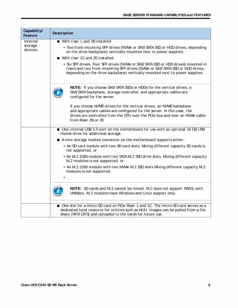
Internal storage devices
■ With riser 1 and 2B installed
• Two front-mounting SFF drives (NVMe or SAS/SATA SSD or HDD drives, depending on the drive backplane) vertically mounted next to power supplies.
■ With riser 1C and 2E installed
NOTE: If you choose SAS/SATA SSDs or HDDs for the vertical drives, a SAS/SATA backplane, storage controller, and appropriate cables are configured for the server.If you choose NVME drives for the vertical drives, an NVME backplaneand appropriate cables are configured for the server. In this case, the drives are controlled from the CPU over the PCIe bus and over an NVMe cable from Riser 2B or 2E
• Six SFF drives. Four SFF drives (NVMe or SAS/SATA SSD or HDD drives) mounted in risers and two front-mounting SFF drives (NVMe or SAS/SATA SSD or HDD drives, depending on the drive backplane) vertically mounted next to power supplies.
■ One internal USB 3.0 port on the motherboard for use with an optional 16 GB USB thumb drive for additional storage.
■ A mini-storage module connector on the motherboard supports either:
• An SD card module with two SD card slots. Mixing different capacity SD cards is not supported, or
• An M.2 2280 module with two SATA M.2 SSD drive slots. Mixing different capacity M.2 modules is not supported, or
• An M.2 2280 module with two NVMe M.2 SSD slots.Mixing different capacity M.2 modules is not supported.
•
■ One slot for a micro-SD card on PCIe Riser 1 and 1C. The micro-SD card serves as a dedicated local resource for utilities such as HUU. Images can be pulled from a file share (NFS/CIFS) and uploaded to the cards for future use.
Capability/Feature
Description
NOTE: SD cards and M.2 cannot be mixed. M.2 does not support RAID1 with VMWare. M.2 modules have Windows and Linux support only.
Cisco UCS C240 SD M5 Rack Server 9
BASE SERVER STANDARD CAPABILITIES and FEATURES
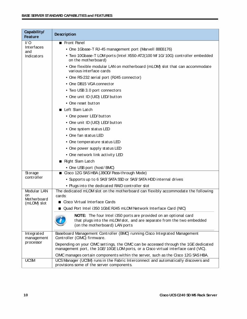
I/O Interfaces and Indicators
■ Front Panel
• One 1Gbase-T RJ-45 management port (Marvell 88E6176)
• Two 10Gbase-T LOM ports (Intel X550-AT2(100 M/1G/10G) controller embedded on the motherboard)
• One flexible modular LAN on motherboard (mLOM) slot that can accommodate various interface cards
• One RS-232 serial port (RJ45 connector)
• One DB15 VGA connector
• Two USB 3.0 port connectors
• One unit ID (UID) LED/button
• One reset button
■ Left Slam Latch
• One power LED/button
• One unit ID (UID) LED/button
• One system status LED
• One fan status LED
• One temperature status LED
• One power supply status LED
• One network link activity LED
■ Right Slam Latch
• One USB port (host/BMC)Storage controller
■ Cisco 12G SAS HBA (JBOD/Pass-through Mode)
• Supports up to 6 SAS/SATA SSD or SAS/SATA HDD internal drives
• Plugs into the dedicated RAID controller slotModular LAN on Motherboard (mLOM) slot
The dedicated mLOM slot on the motherboard can flexibly accommodate the following cards:
■ Cisco Virtual Interface Cards
■ Quad Port Intel i350 1GbE RJ45 mLOM Network Interface Card (NIC)
NOTE: The four Intel i350 ports are provided on an optional card that plugs into the mLOM slot, and are separate from the two embedded (on the motherboard) LAN ports
Integrated management processor
Baseboard Management Controller (BMC) running Cisco Integrated Management Controller (CIMC) firmware.
Depending on your CIMC settings, the CIMC can be accessed through the 1GE dedicated management port, the 1GE/10GE LOM ports, or a Cisco virtual interface card (VIC).
CIMC manages certain components within the server, such as the Cisco 12G SAS HBA. UCSM UCS Manager (UCSM) runs in the Fabric Interconnect and automatically discovers and
provisions some of the server components.
Capability/Feature
Description
Cisco UCS C240 SD M5 Rack Server 10
CONFIGURING the SERVER
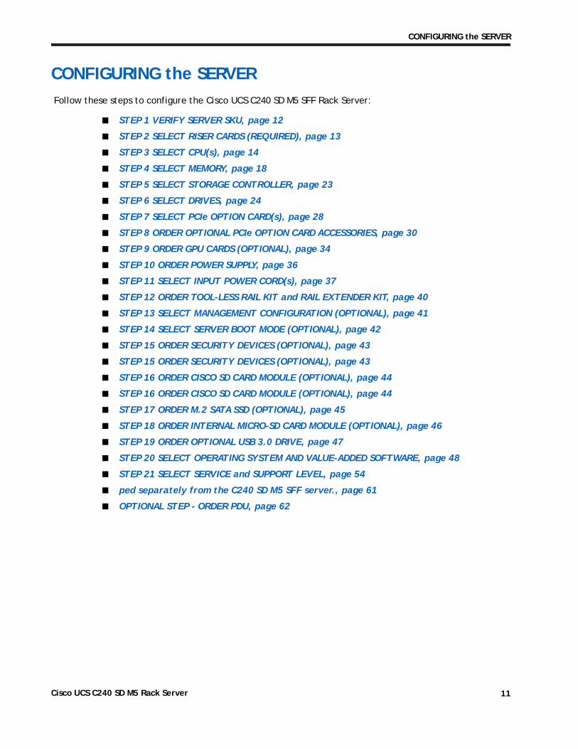
CONFIGURING the SERVERFollow these steps to configure the Cisco UCS C240 SD M5 SFF Rack Server:
■ STEP 1 VERIFY SERVER SKU, page 12
■ STEP 2 SELECT RISER CARDS (REQUIRED), page 13
■ STEP 3 SELECT CPU(s), page 14
■ STEP 4 SELECT MEMORY, page 18
■ STEP 5 SELECT STORAGE CONTROLLER, page 23
■ STEP 6 SELECT DRIVES, page 24
■ STEP 7 SELECT PCIe OPTION CARD(s), page 28
■ STEP 8 ORDER OPTIONAL PCIe OPTION CARD ACCESSORIES, page 30
■ STEP 9 ORDER GPU CARDS (OPTIONAL), page 34
■ STEP 10 ORDER POWER SUPPLY, page 36
■ STEP 11 SELECT INPUT POWER CORD(s), page 37
■ STEP 12 ORDER TOOL-LESS RAIL KIT and RAIL EXTENDER KIT, page 40
■ STEP 13 SELECT MANAGEMENT CONFIGURATION (OPTIONAL), page 41
■ STEP 14 SELECT SERVER BOOT MODE (OPTIONAL), page 42
■ STEP 15 ORDER SECURITY DEVICES (OPTIONAL), page 43
■ STEP 15 ORDER SECURITY DEVICES (OPTIONAL), page 43
■ STEP 16 ORDER CISCO SD CARD MODULE (OPTIONAL), page 44
■ STEP 16 ORDER CISCO SD CARD MODULE (OPTIONAL), page 44
■ STEP 17 ORDER M.2 SATA SSD (OPTIONAL), page 45
■ STEP 18 ORDER INTERNAL MICRO-SD CARD MODULE (OPTIONAL), page 46
■ STEP 19 ORDER OPTIONAL USB 3.0 DRIVE, page 47
■ STEP 20 SELECT OPERATING SYSTEM AND VALUE-ADDED SOFTWARE, page 48
■ STEP 21 SELECT SERVICE and SUPPORT LEVEL, page 54
■ ped separately from the C240 SD M5 SFF server., page 61
■ OPTIONAL STEP - ORDER PDU, page 62
Cisco UCS C240 SD M5 Rack Server 11
CONFIGURING the SERVER
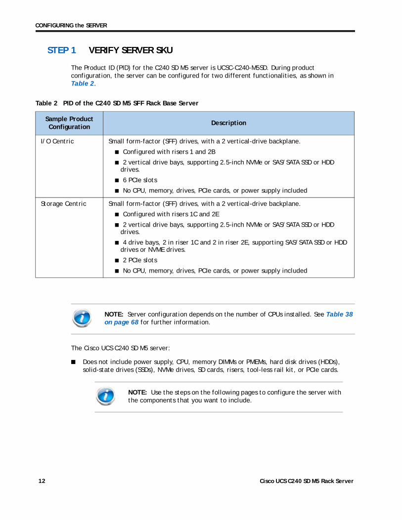
STEP 1 VERIFY SERVER SKU
The Product ID (PID) for the C240 SD M5 server is UCSC-C240-M5SD. During product configuration, the server can be configured for two different functionalities, as shown in Table 2.
Table 2 PID of the C240 SD M5 SFF Rack Base Server
Sample Product Configuration
Description
I/O Centric Small form-factor (SFF) drives, with a 2 vertical-drive backplane.
■ Configured with risers 1 and 2B
■ 2 vertical drive bays, supporting 2.5-inch NVMe or SAS/SATA SSD or HDD drives.
■ 6 PCIe slots
■ No CPU, memory, drives, PCIe cards, or power supply included
Storage Centric Small form-factor (SFF) drives, with a 2 vertical-drive backplane.
■ Configured with risers 1C and 2E
■ 2 vertical drive bays, supporting 2.5-inch NVMe or SAS/SATA SSD or HDD drives.
■ 4 drive bays, 2 in riser 1C and 2 in riser 2E, supporting SAS/SATA SSD or HDD drives or NVME drives.
■ 2 PCIe slots
■ No CPU, memory, drives, PCIe cards, or power supply included
NOTE: Server configuration depends on the number of CPUs installed. See Table 38 on page 68 for further information.
The Cisco UCS C240 SD M5 server:
■ Does not include power supply, CPU, memory DIMMs or PMEMs, hard disk drives (HDDs), solid-state drives (SSDs), NVMe drives, SD cards, risers, tool-less rail kit, or PCIe cards.
NOTE: Use the steps on the following pages to configure the server with the components that you want to include.
Cisco UCS C240 SD M5 Rack Server 12
CONFIGURING the SERVER
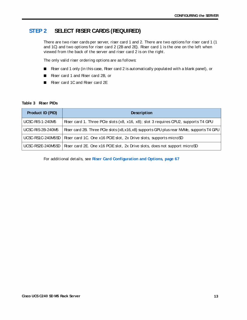
STEP 2 SELECT RISER CARDS (REQUIRED)
There are two riser cards per server, riser card 1 and 2. There are two options for riser card 1 (1 and 1C) and two options for riser card 2 (2B and 2E). Riser card 1 is the one on the left when viewed from the back of the server and riser card 2 is on the right.
The only valid riser ordering options are as follows:
■ Riser card 1 only (in this case, Riser card 2 is automatically populated with a blank panel), or
■ Riser card 1 and Riser card 2B, or
■ Riser card 1C and Riser card 2E
Table 3 Riser PIDs
Product ID (PID) Description
UCSC-RIS-1-240M5 Riser card 1. Three PCIe slots (x8, x16, x8); slot 3 requires CPU2, supports T4 GPU
UCSC-RIS-2B-240M5 Riser card 2B. Three PCIe slots (x8,x16,x8) supports GPU plus rear NVMe, supports T4 GPU
UCSC-RS1C-240M5SD Riser card 1C. One x16 PCIE slot, 2x Drive slots, supports microSD
UCSC-RS2E-240M5SD Riser card 2E. One x16 PCIE slot, 2x Drive slots, does not support microSD
For additional details, see Riser Card Configuration and Options, page 67
Cisco UCS C240 SD M5 Rack Server 13
CONFIGURING the SERVER
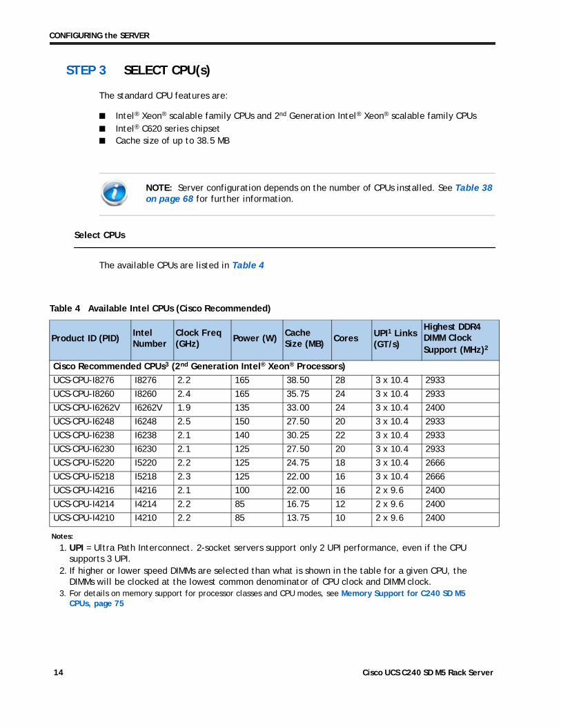
STEP 3 SELECT CPU(s)
The standard CPU features are:
■ Intel® Xeon® scalable family CPUs and 2nd Generation Intel® Xeon® scalable family CPUs■ Intel® C620 series chipset■ Cache size of up to 38.5 MB
NOTE: Server configuration depends on the number of CPUs installed. See Table 38 on page 68 for further information.
Select CPUs
The available CPUs are listed in Table 4
Table 4 Available Intel CPUs (Cisco Recommended)
Product ID (PID)Intel Number
Clock Freq(GHz)
Power (W)Cache Size (MB)
Cores UPI1 Links (GT/s)
Cisco Recommended CPUs3 (2nd Generation Intel® Xeon® Processors)
UCS-CPU-I8276 I8276 2.2 165 38.50 28 3 x 10.4 2933
UCS-CPU-I8260 I8260 2.4 165 35.75 24 3 x 10.4 2933
UCS-CPU-I6262V I6262V 1.9 135 33.00 24 3 x 10.4 2400
UCS-CPU-I6248 I6248 2.5 150 27.50 20 3 x 10.4 2933
UCS-CPU-I6238 I6238 2.1 140 30.25 22 3 x 10.4 2933
UCS-CPU-I6230 I6230 2.1 125 27.50 20 3 x 10.4 2933
UCS-CPU-I5220 I5220 2.2 125 24.75 18 3 x 10.4 2666
UCS-CPU-I5218 I5218 2.3 125 22.00 16 3 x 10.4 2666
UCS-CPU-I4216 I4216 2.1 100 22.00 16 2 x 9.6 2400
UCS-CPU-I4214 I4214 2.2 85 16.75 12 2 x 9.6 2400
UCS-CPU-I4210 I4210 2.2 85 13.75 10 2 x 9.6 2400
Notes:
1. UPI = Ultra Path Interconnect. 2-socket servers support only 2 UPI performance, even if the CPU supports 3 UPI.
Highest DDR4 DIMM Clock Support (MHz)2
2. If higher or lower speed DIMMs are selected than what is shown in the table for a given CPU, the DIMMs will be clocked at the lowest common denominator of CPU clock and DIMM clock.
3. For details on memory support for processor classes and CPU modes, see Memory Support for C240 SD M5 CPUs, page 75
Cisco UCS C240 SD M5 Rack Server 14
CONFIGURING the SERVER
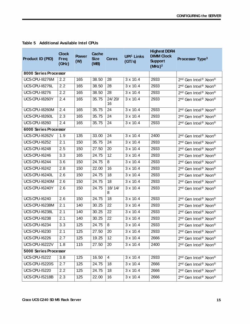
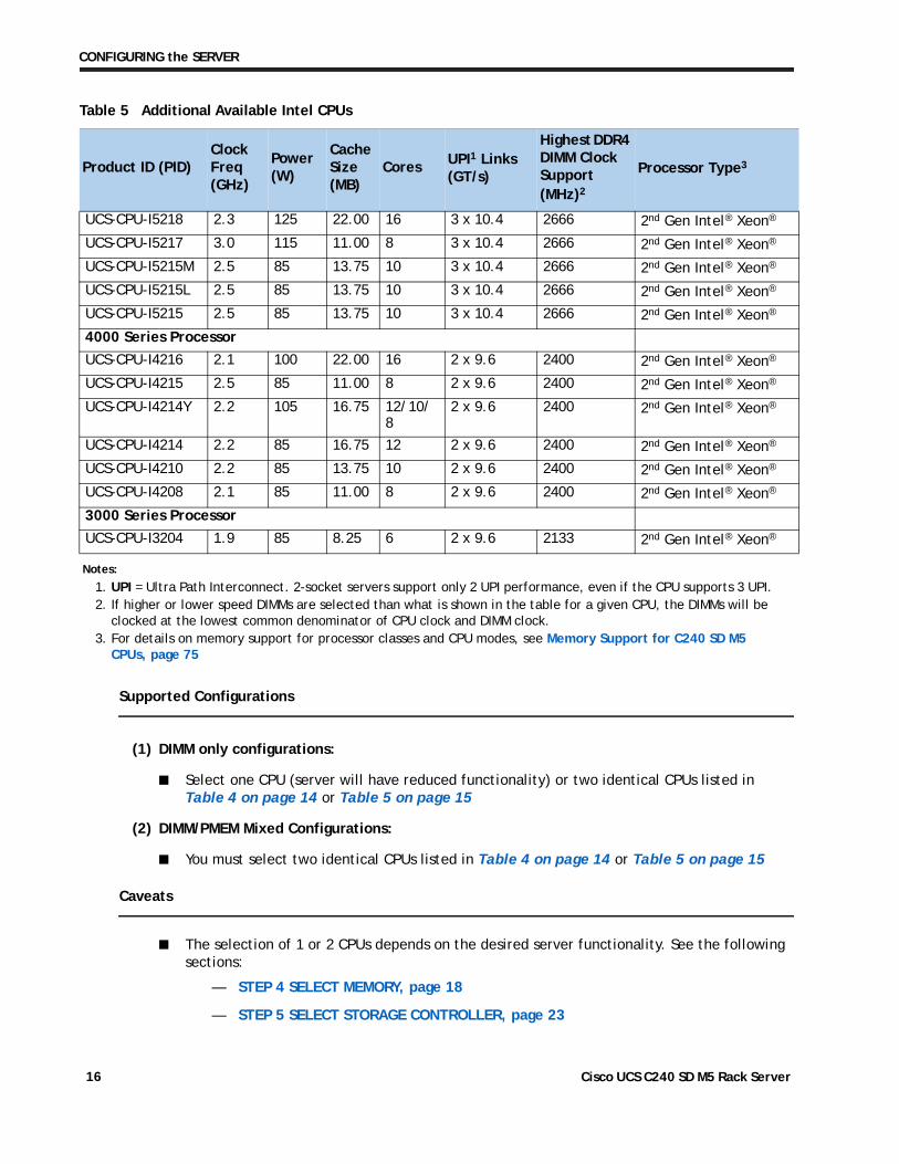
Table 5 Additional Available Intel CPUs
Product ID (PID)Clock Freq(GHz)
Power (W)
Cache Size (MB)
Cores UPI1 Links (GT/s)
Highest DDR4 DIMM Clock Support (MHz)2
Processor Type3
8000 Series Processor
UCS-CPU-I8276M 2.2 165 38.50 28 3 x 10.4 2933 2nd Gen Intel® Xeon®
UCS-CPU-I8276L 2.2 165 38.50 28 3 x 10.4 2933 2nd Gen Intel® Xeon®
UCS-CPU-I8276 2.2 165 38.50 28 3 x 10.4 2933 2nd Gen Intel® Xeon®
UCS-CPU-I8260Y 2.4 165 35.75 24/20/16
3 x 10.4 2933 2nd Gen Intel® Xeon®
UCS-CPU-I8260M 2.4 165 35.75 24 3 x 10.4 2933 2nd Gen Intel® Xeon®
UCS-CPU-I8260L 2.3 165 35.75 24 3 x 10.4 2933 2nd Gen Intel® Xeon®
UCS-CPU-I8260 2.4 165 35.75 24 3 x 10.4 2933 2nd Gen Intel® Xeon®
6000 Series Processor
UCS-CPU-I6262V 1.9 135 33.00 24 3 x 10.4 2400 2nd Gen Intel® Xeon®
UCS-CPU-I6252 2.1 150 35.75 24 3 x 10.4 2933 2nd Gen Intel® Xeon®
UCS-CPU-I6248 2.5 150 27.50 20 3 x 10.4 2933 2nd Gen Intel® Xeon®
UCS-CPU-I6246 3.3 165 24.75 12 3 x 10.4 2933 2nd Gen Intel® Xeon®
UCS-CPU-I6244 3.6 150 24.75 8 3 x 10.4 2933 2nd Gen Intel® Xeon®
UCS-CPU-I6242 2.8 150 22.00 16 3 x 10.4 2933 2nd Gen Intel® Xeon®
UCS-CPU-I6240L 2.6 150 24.75 18 3 x 10.4 2933 2nd Gen Intel® Xeon®
UCS-CPU-I6240M 2.6 150 24.75 18 3 x 10.4 2933 2nd Gen Intel® Xeon®
UCS-CPU-I6240Y 2.6 150 24.75 18/14/8
3 x 10.4 2933 2nd Gen Intel® Xeon®
UCS-CPU-I6240 2.6 150 24.75 18 3 x 10.4 2933 2nd Gen Intel® Xeon®
UCS-CPU-I6238M 2.1 140 30.25 22 3 x 10.4 2933 2nd Gen Intel® Xeon®
UCS-CPU-I6238L 2.1 140 30.25 22 3 x 10.4 2933 2nd Gen Intel® Xeon®
UCS-CPU-I6238 2.1 140 30.25 22 3 x 10.4 2933 2nd Gen Intel® Xeon®
UCS-CPU-I6234 3.3 125 24.75 8 3 x 10.4 2933 2nd Gen Intel® Xeon®
UCS-CPU-I6230 2.1 125 27.50 20 3 x 10.4 2933 2nd Gen Intel® Xeon®
UCS-CPU-I6226 2.7 125 19.25 12 3 x 10.4 2666 2nd Gen Intel® Xeon®
UCS-CPU-I6222V 1.8 115 27.50 20 3 x 10.4 2400 2nd Gen Intel® Xeon®
5000 Series Processor
UCS-CPU-I5222 3.8 125 16.50 4 3 x 10.4 2933 2nd Gen Intel® Xeon®
UCS-CPU-I5220S 2.7 125 24.75 18 3 x 10.4 2666 2nd Gen Intel® Xeon®
UCS-CPU-I5220 2.2 125 24.75 18 3 x 10.4 2666 2nd Gen Intel® Xeon®
UCS-CPU-I5218B 2.3 125 22.00 16 3 x 10.4 2666 2nd Gen Intel® Xeon®
Cisco UCS C240 SD M5 Rack Server 15
CONFIGURING the SERVER
Supported Configurations
(1) DIMM only configurations:
■ Select one CPU (server will have reduced functionality) or two identical CPUs listed in Table 4 on page 14 or Table 5 on page 15
(2) DIMM/PMEM Mixed Configurations:
■ You must select two identical CPUs listed in Table 4 on page 14 or Table 5 on page 15
Caveats
■ The selection of 1 or 2 CPUs depends on the desired server functionality. See the following sections:
— STEP 4 SELECT MEMORY, page 18
— STEP 5 SELECT STORAGE CONTROLLER, page 23
UCS-CPU-I5218 2.3 125 22.00 16 3 x 10.4 2666 2nd Gen Intel® Xeon®
UCS-CPU-I5217 3.0 115 11.00 8 3 x 10.4 2666 2nd Gen Intel® Xeon®
UCS-CPU-I5215M 2.5 85 13.75 10 3 x 10.4 2666 2nd Gen Intel® Xeon®
UCS-CPU-I5215L 2.5 85 13.75 10 3 x 10.4 2666 2nd Gen Intel® Xeon®
UCS-CPU-I5215 2.5 85 13.75 10 3 x 10.4 2666 2nd Gen Intel® Xeon®
4000 Series Processor
UCS-CPU-I4216 2.1 100 22.00 16 2 x 9.6 2400 2nd Gen Intel® Xeon®
UCS-CPU-I4215 2.5 85 11.00 8 2 x 9.6 2400 2nd Gen Intel® Xeon®
UCS-CPU-I4214Y 2.2 105 16.75 12/10/8
2 x 9.6 2400 2nd Gen Intel® Xeon®
UCS-CPU-I4214 2.2 85 16.75 12 2 x 9.6 2400 2nd Gen Intel® Xeon®
UCS-CPU-I4210 2.2 85 13.75 10 2 x 9.6 2400 2nd Gen Intel® Xeon®
UCS-CPU-I4208 2.1 85 11.00 8 2 x 9.6 2400 2nd Gen Intel® Xeon®
3000 Series Processor
UCS-CPU-I3204 1.9 85 8.25 6 2 x 9.6 2133 2nd Gen Intel® Xeon®
Notes:
1. UPI = Ultra Path Interconnect. 2-socket servers support only 2 UPI performance, even if the CPU supports 3 UPI.2. If higher or lower speed DIMMs are selected than what is shown in the table for a given CPU, the DIMMs will be
clocked at the lowest common denominator of CPU clock and DIMM clock.3. For details on memory support for processor classes and CPU modes, see Memory Support for C240 SD M5
CPUs, page 75
Table 5 Additional Available Intel CPUs
Product ID (PID)Clock Freq(GHz)
Power (W)
Cache Size (MB)
Cores UPI1 Links (GT/s)
Highest DDR4 DIMM Clock Support (MHz)2
Processor Type3
Cisco UCS C240 SD M5 Rack Server 16
CONFIGURING the SERVER
— STEP 6 SELECT DRIVES, page 24
— STEP 7 SELECT PCIe OPTION CARD(s), page 28
— Table 38 on page 68
Cisco UCS C240 SD M5 Rack Server 17
CONFIGURING the SERVER
STEP 4 SELECT MEMORY
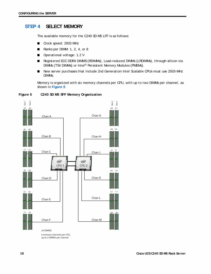
The available memory for the C240 SD M5 LFF is as follows:
■ Clock speed: 2933 MHz
■ Ranks per DIMM: 1, 2, 4, or 8
■ Operational voltage: 1.2 V
■ Registered ECC DDR4 DIMMS (RDIMMs), Load-reduced DIMMs (LRDIMMs), through-silicon via DIMMs (TSV DIMMs) or Intel® Persistent Memory Modules (PMEMs).
■ New server purchases that include 2nd Generation Intel Scalable CPUs must use 2933-MHz DIMMs.
Memory is organized with six memory channels per CPU, with up to two DIMMs per channel, as shown in Figure 5.
Figure 5 C240 SD M5 SFF Memory Organization
CPU 2
24 DIMMS
6 memory channels per CPU, up to 2 DIMMs per channel
A1 A2
B1 B2
E1 E2
Chan B
Chan C
Chan D
Chan A
Chan E
Chan F
Chan H
Chan J
Chan L
Chan M
F1 F2
CPU 1
Slot
2
Slot
1
Slot
2
Slot
1
H2 H1
J2 J1
L2 L1
M2 M1
Chan G
G2 G1
Chan K
K2 K1
C1 C2
D1 D2
Cisco UCS C240 SD M5 Rack Server 18
CONFIGURING the SERVER
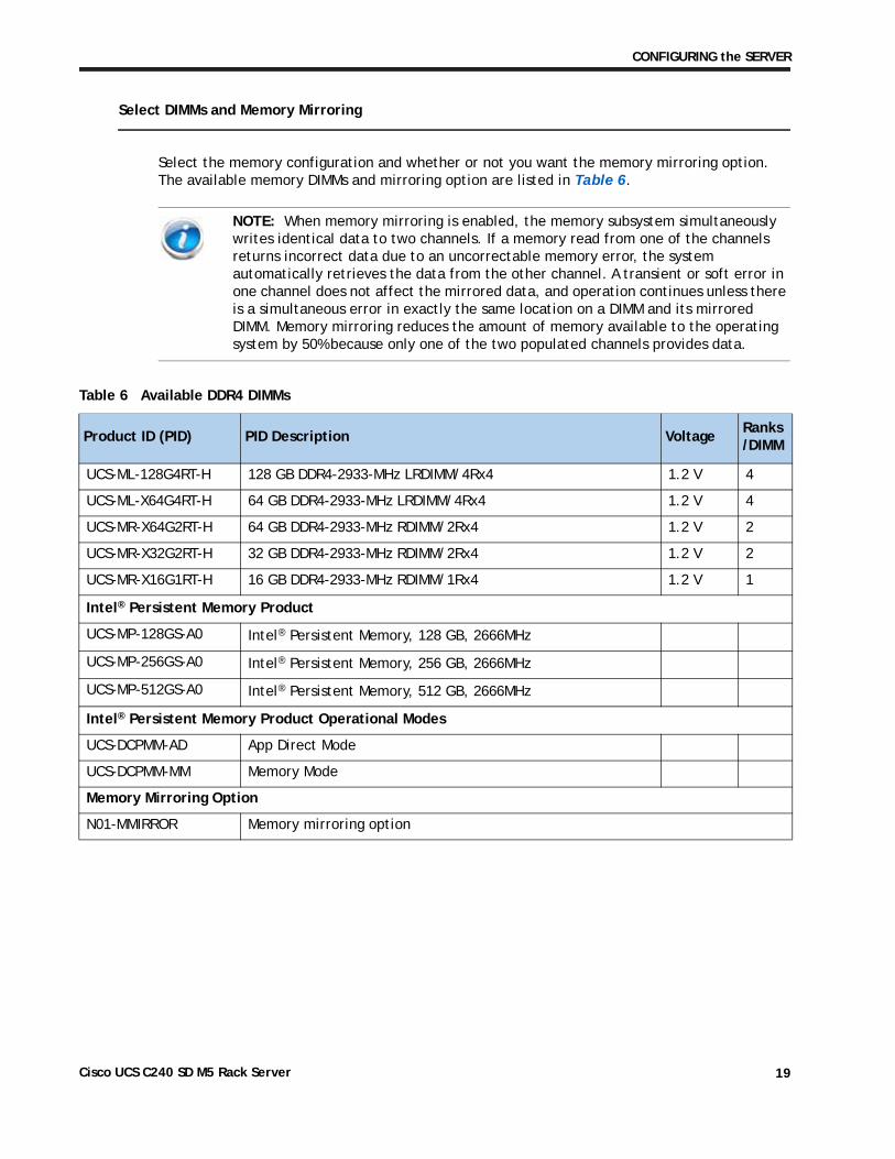
Select DIMMs and Memory Mirroring
Select the memory configuration and whether or not you want the memory mirroring option. The available memory DIMMs and mirroring option are listed in Table 6.
NOTE: When memory mirroring is enabled, the memory subsystem simultaneously writes identical data to two channels. If a memory read from one of the channels returns incorrect data due to an uncorrectable memory error, the system automatically retrieves the data from the other channel. A transient or soft error in one channel does not affect the mirrored data, and operation continues unless there is a simultaneous error in exactly the same location on a DIMM and its mirrored DIMM. Memory mirroring reduces the amount of memory available to the operating system by 50% because only one of the two populated channels provides data.
Table 6 Available DDR4 DIMMs
Product ID (PID) PID Description VoltageRanks/DIMM
UCS-ML-128G4RT-H 128 GB DDR4-2933-MHz LRDIMM/4Rx4 1.2 V 4
UCS-ML-X64G4RT-H 64 GB DDR4-2933-MHz LRDIMM/4Rx4 1.2 V 4
UCS-MR-X64G2RT-H 64 GB DDR4-2933-MHz RDIMM/2Rx4 1.2 V 2
UCS-MR-X32G2RT-H 32 GB DDR4-2933-MHz RDIMM/2Rx4 1.2 V 2
UCS-MR-X16G1RT-H 16 GB DDR4-2933-MHz RDIMM/1Rx4 1.2 V 1
Intel® Persistent Memory Product
UCS-MP-128GS-A0 Intel® Persistent Memory, 128 GB, 2666MHz
UCS-MP-256GS-A0 Intel® Persistent Memory, 256 GB, 2666MHz
UCS-MP-512GS-A0 Intel® Persistent Memory, 512 GB, 2666MHz
Intel® Persistent Memory Product Operational Modes
UCS-DCPMM-AD App Direct Mode
UCS-DCPMM-MM Memory Mode
Memory Mirroring Option
N01-MMIRROR Memory mirroring option
Cisco UCS C240 SD M5 Rack Server 19
CONFIGURING the SERVER
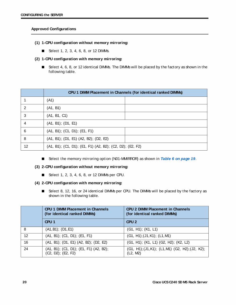
Approved Configurations
(1) 1-CPU configuration without memory mirroring:
■ Select 1, 2, 3, 4, 6, 8, or 12 DIMMs.
(2) 1-CPU configuration with memory mirroring:
■ Select 4, 6, 8, or 12 identical DIMMs. The DIMMs will be placed by the factory as shown in the following table.
CPU 1 DIMM Placement in Channels (for identical ranked DIMMs)
1 (A1)
2 (A1, B1)
3 (A1, B1, C1)
4 (A1, B1); (D1, E1)
6 (A1, B1); (C1, D1); (E1, F1)
8 (A1, B1); (D1, E1) (A2, B2); (D2, E2)
12 (A1, B1); (C1, D1); (E1, F1) (A2, B2); (C2, D2); (E2, F2)
■ Select the memory mirroring option (N01-MMIRROR) as shown in Table 6 on page 19.
(3) 2-CPU configuration without memory mirroring:
■ Select 1, 2, 3, 4, 6, 8, or 12 DIMMs per CPU.
(4) 2-CPU configuration with memory mirroring:
■ Select 8, 12, 16, or 24 identical DIMMs per CPU. The DIMMs will be placed by the factory as shown in the following table.
CPU 1 DIMM Placement in Channels (for identical ranked DIMMs)
CPU 2 DIMM Placement in Channels (for identical ranked DIMMs)
CPU 1 CPU 2
8 (A1,B1); (D1,E1) (G1, H1); (K1, L1)
12 (A1, B1); (C1, D1); (E1, F1) (G1, H1);(J1,K1); (L1,M1)
16 (A1, B1); (D1, E1) (A2, B2); (D2, E2) (G1, H1); (K1, L1) (G2, H2); (K2, L2)
24 (A1, B1); (C1, D1); (E1, F1) (A2, B2); (C2, D2); (E2, F2)
(G1, H1);(J1,K1); (L1,M1) (G2, H2);(J2, K2); (L2, M2)
Cisco UCS C240 SD M5 Rack Server 20
CONFIGURING the SERVER
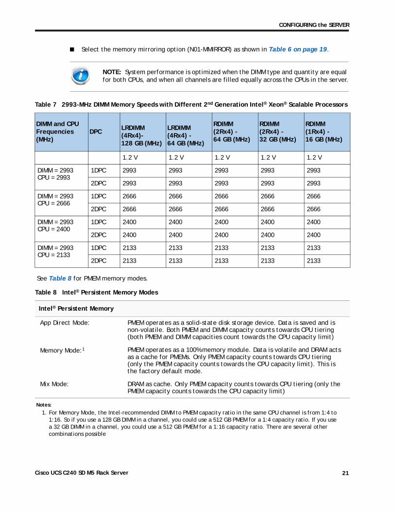
■ Select the memory mirroring option (N01-MMIRROR) as shown in Table 6 on page 19.
NOTE: System performance is optimized when the DIMM type and quantity are equal for both CPUs, and when all channels are filled equally across the CPUs in the server.
Table 7 2993-MHz DIMM Memory Speeds with Different 2nd Generation Intel® Xeon® Scalable Processors
DIMM and CPU Frequencies (MHz)
DPC
LRDIMM (4Rx4)-128 GB (MHz)
LRDIMM (4Rx4) - 64 GB (MHz)
RDIMM(2Rx4) - 64 GB (MHz)
RDIMM (2Rx4) - 32 GB (MHz)
RDIMM (1Rx4) - 16 GB (MHz)
1.2 V 1.2 V 1.2 V 1.2 V 1.2 V
DIMM = 2993CPU = 2993
1DPC 2993 2993 2993 2993 2993
2DPC 2993 2993 2993 2993 2993
DIMM = 2993CPU = 2666
1DPC 2666 2666 2666 2666 2666
2DPC 2666 2666 2666 2666 2666
DIMM = 2993CPU = 2400
1DPC 2400 2400 2400 2400 2400
2DPC 2400 2400 2400 2400 2400
DIMM = 2993CPU = 2133
1DPC 2133 2133 2133 2133 2133
2DPC 2133 2133 2133 2133 2133
Table 8 Intel® Persistent Memory Modes
Intel® Persistent Memory
App Direct Mode: PMEM operates as a solid-state disk storage device. Data is saved and is non-volatile. Both PMEM and DIMM capacity counts towards CPU tiering (both PMEM and DIMM capacities count towards the CPU capacity limit)
Memory Mode:1 PMEM operates as a 100% memory module. Data is volatile and DRAM acts as a cache for PMEMs. Only PMEM capacity counts towards CPU tiering (only the PMEM capacity counts towards the CPU capacity limit). This is the factory default mode.
Mix Mode: DRAM as cache. Only PMEM capacity counts towards CPU tiering (only the PMEM capacity counts towards the CPU capacity limit)
See Table 8 for PMEM memory modes.
Notes:
1. For Memory Mode, the Intel-recommended DIMM to PMEM capacity ratio in the same CPU channel is from 1:4 to 1:16. So if you use a 128 GB DIMM in a channel, you could use a 512 GB PMEM for a 1:4 capacity ratio. If you use a 32 GB DIMM in a channel, you could use a 512 GB PMEM for a 1:16 capacity ratio. There are several other combinations possible
Cisco UCS C240 SD M5 Rack Server 21
CONFIGURING the SERVER
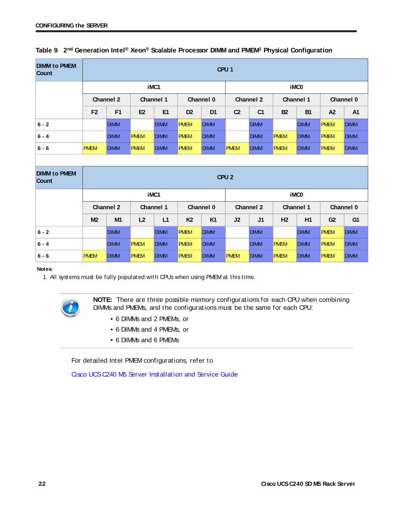
Table 9 2nd Generation Intel® Xeon® Scalable Processor DIMM and PMEM1 Physical Configuration
DIMM to PMEM Count
CPU 1
iMC1 iMC0
Channel 2 Channel 1 Channel 0 Channel 2 Channel 1 Channel 0
F2 F1 E2 E1 D2 D1 C2 C1 B2 B1 A2 A1
6 - 2 DIMM DIMM PMEM DIMM DIMM DIMM PMEM DIMM
6 - 4 DIMM PMEM DIMM PMEM DIMM DIMM PMEM DIMM PMEM DIMM
6 - 6 PMEM DIMM PMEM DIMM PMEM DIMM PMEM DIMM PMEM DIMM PMEM DIMM
DIMM to PMEM Count
CPU 2
iMC1 iMC0
Channel 2 Channel 1 Channel 0 Channel 2 Channel 1 Channel 0
M2 M1 L2 L1 K2 K1 J2 J1 H2 H1 G2 G1
6 - 2 DIMM DIMM PMEM DIMM DIMM DIMM PMEM DIMM
6 - 4 DIMM PMEM DIMM PMEM DIMM DIMM PMEM DIMM PMEM DIMM
6 - 6 PMEM DIMM PMEM DIMM PMEM DIMM PMEM DIMM PMEM DIMM PMEM DIMM
NOTE: There are three possible memory configurations for each CPU when combining DIMMs and PMEMs, and the configurations must be the same for each CPU:
For detailed Intel PMEM configurations, refer to
Cisco UCS C240 M5 Server Installation and Service Guide
Notes:
1. All systems must be fully populated with CPUs when using PMEM at this time.
• 6 DIMMs and 2 PMEMs, or
• 6 DIMMs and 4 PMEMs, or
• 6 DIMMs and 6 PMEMs
Cisco UCS C240 SD M5 Rack Server 22
CONFIGURING the SERVER
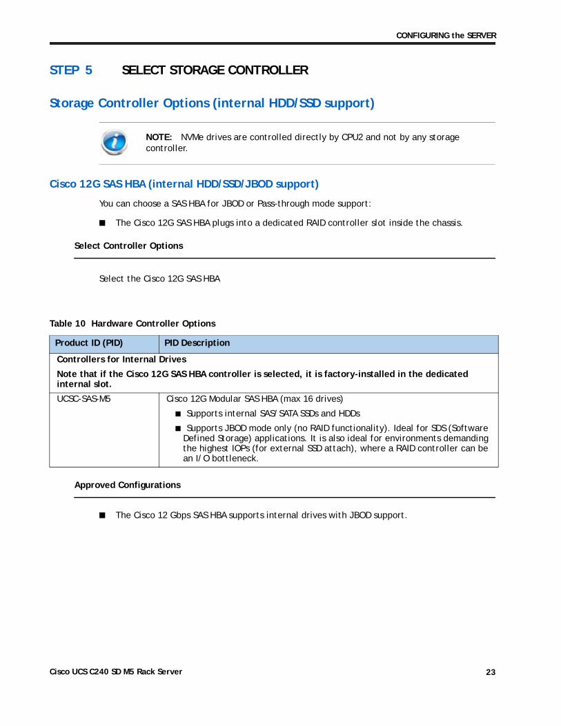
STEP 5 SELECT STORAGE CONTROLLER
Storage Controller Options (internal HDD/SSD support)
NOTE: NVMe drives are controlled directly by CPU2 and not by any storage controller.
Cisco 12G SAS HBA (internal HDD/SSD/JBOD support)
You can choose a SAS HBA for JBOD or Pass-through mode support:
■ The Cisco 12G SAS HBA plugs into a dedicated RAID controller slot inside the chassis.
Select Controller Options
Select the Cisco 12G SAS HBA
Approved Configurations
■ The Cisco 12 Gbps SAS HBA supports internal drives with JBOD support.
Table 10 Hardware Controller Options
Product ID (PID) PID Description
Controllers for Internal Drives
Note that if the Cisco 12G SAS HBA controller is selected, it is factory-installed in the dedicated internal slot.
UCSC-SAS-M5 Cisco 12G Modular SAS HBA (max 16 drives)
■ Supports internal SAS/SATA SSDs and HDDs
■ Supports JBOD mode only (no RAID functionality). Ideal for SDS (Software Defined Storage) applications. It is also ideal for environments demanding the highest IOPs (for external SSD attach), where a RAID controller can be an I/O bottleneck.
Cisco UCS C240 SD M5 Rack Server 23
CONFIGURING the SERVER
y
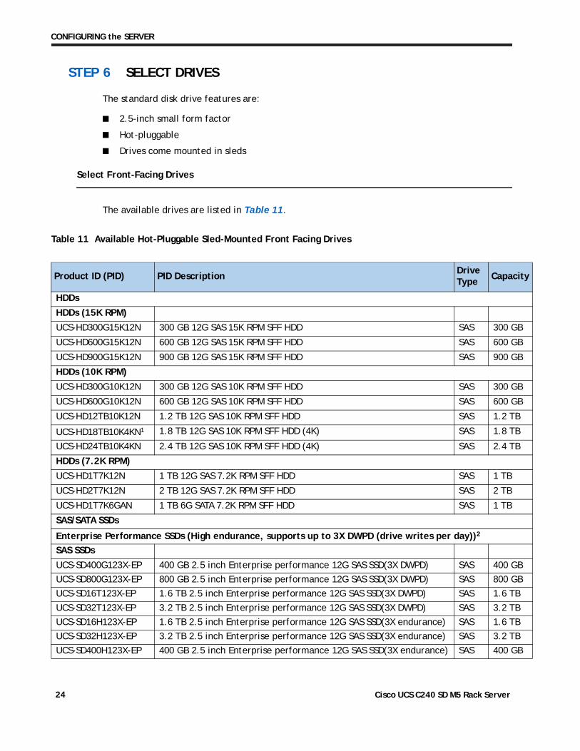
STEP 6 SELECT DRIVES
The standard disk drive features are:
■ 2.5-inch small form factor
■ Hot-pluggable
■ Drives come mounted in sleds
Select Front-Facing Drives
The available drives are listed in Table 11.
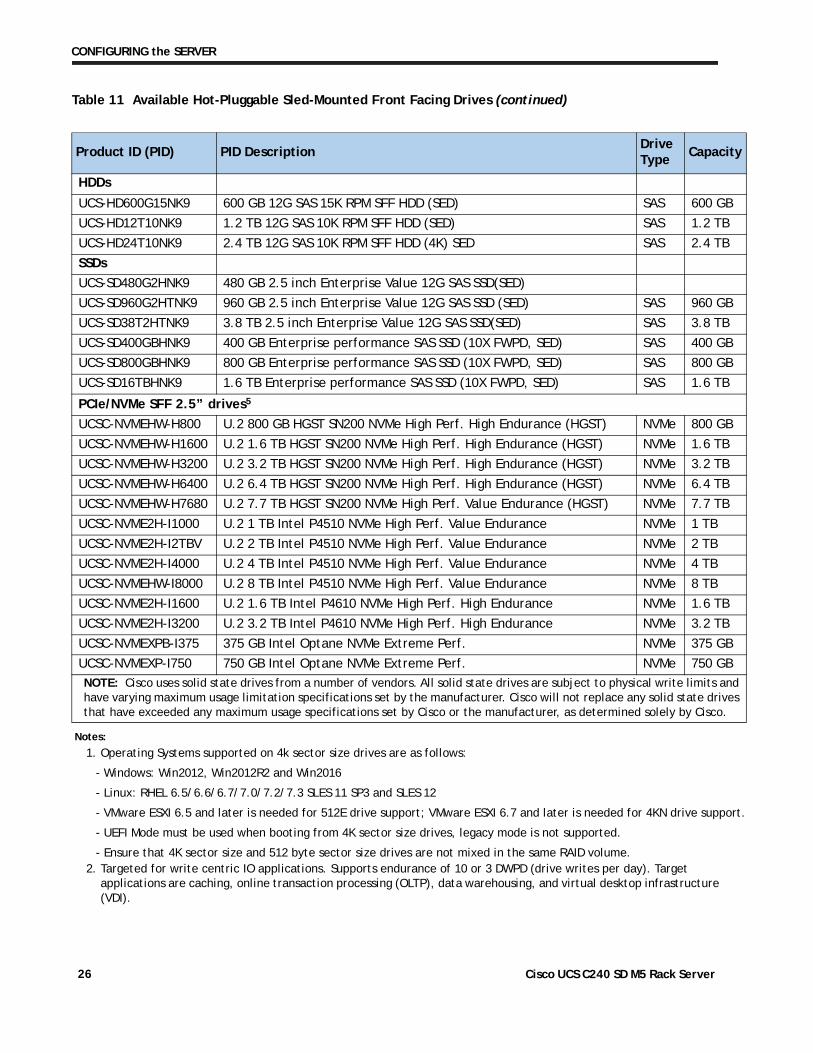
Table 11 Available Hot-Pluggable Sled-Mounted Front Facing Drives
Product ID (PID) PID DescriptionDrive Type
Capacit
HDDs
HDDs (15K RPM)
UCS-HD300G15K12N 300 GB 12G SAS 15K RPM SFF HDD SAS 300 GB
UCS-HD600G15K12N 600 GB 12G SAS 15K RPM SFF HDD SAS 600 GB
UCS-HD900G15K12N 900 GB 12G SAS 15K RPM SFF HDD SAS 900 GB
HDDs (10K RPM)
UCS-HD300G10K12N 300 GB 12G SAS 10K RPM SFF HDD SAS 300 GB
UCS-HD600G10K12N 600 GB 12G SAS 10K RPM SFF HDD SAS 600 GB
UCS-HD12TB10K12N 1.2 TB 12G SAS 10K RPM SFF HDD SAS 1.2 TB
UCS-HD18TB10K4KN1 1.8 TB 12G SAS 10K RPM SFF HDD (4K) SAS 1.8 TB
UCS-HD24TB10K4KN 2.4 TB 12G SAS 10K RPM SFF HDD (4K) SAS 2.4 TB
HDDs (7.2K RPM)
UCS-HD1T7K12N 1 TB 12G SAS 7.2K RPM SFF HDD SAS 1 TB
UCS-HD2T7K12N 2 TB 12G SAS 7.2K RPM SFF HDD SAS 2 TB
UCS-HD1T7K6GAN 1 TB 6G SATA 7.2K RPM SFF HDD SAS 1 TB
SAS/SATA SSDs
Enterprise Performance SSDs (High endurance, supports up to 3X DWPD (drive writes per day))2
SAS SSDs
UCS-SD400G123X-EP 400 GB 2.5 inch Enterprise performance 12G SAS SSD(3X DWPD) SAS 400 GB
UCS-SD800G123X-EP 800 GB 2.5 inch Enterprise performance 12G SAS SSD(3X DWPD) SAS 800 GB
UCS-SD16T123X-EP 1.6 TB 2.5 inch Enterprise performance 12G SAS SSD(3X DWPD) SAS 1.6 TB
UCS-SD32T123X-EP 3.2 TB 2.5 inch Enterprise performance 12G SAS SSD(3X DWPD) SAS 3.2 TB
UCS-SD16H123X-EP 1.6 TB 2.5 inch Enterprise performance 12G SAS SSD(3X endurance) SAS 1.6 TB
UCS-SD32H123X-EP 3.2 TB 2.5 inch Enterprise performance 12G SAS SSD(3X endurance) SAS 3.2 TB
UCS-SD400H123X-EP 400 GB 2.5 inch Enterprise performance 12G SAS SSD(3X endurance) SAS 400 GB
Cisco UCS C240 SD M5 Rack Server 24
CONFIGURING the SERVER
y
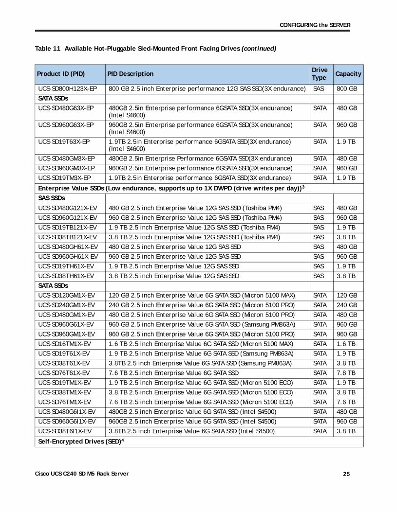
UCS-SD800H123X-EP 800 GB 2.5 inch Enterprise performance 12G SAS SSD(3X endurance) SAS 800 GB
SATA SSDs
UCS-SD480G63X-EP 480GB 2.5in Enterprise performance 6GSATA SSD(3X endurance) (Intel S4600)
SATA 480 GB
UCS-SD960G63X-EP 960GB 2.5in Enterprise performance 6GSATA SSD(3X endurance) (Intel S4600)
SATA 960 GB
UCS-SD19T63X-EP 1.9TB 2.5in Enterprise performance 6GSATA SSD(3X endurance) (Intel S4600)
SATA 1.9 TB
UCS-SD480GM3X-EP 480GB 2.5in Enterprise Performance 6GSATA SSD(3X endurance) SATA 480 GB
UCS-SD960GM3X-EP 960GB 2.5in Enterprise performance 6GSATA SSD(3X endurance) SATA 960 GB
UCS-SD19TM3X-EP 1.9TB 2.5in Enterprise performance 6GSATA SSD(3X endurance) SATA 1.9 TB
Enterprise Value SSDs (Low endurance, supports up to 1X DWPD (drive writes per day))3
SAS SSDs
UCS-SD480G121X-EV 480 GB 2.5 inch Enterprise Value 12G SAS SSD (Toshiba PM4) SAS 480 GB
UCS-SD960G121X-EV 960 GB 2.5 inch Enterprise Value 12G SAS SSD (Toshiba PM4) SAS 960 GB
UCS-SD19TB121X-EV 1.9 TB 2.5 inch Enterprise Value 12G SAS SSD (Toshiba PM4) SAS 1.9 TB
UCS-SD38TB121X-EV 3.8 TB 2.5 inch Enterprise Value 12G SAS SSD (Toshiba PM4) SAS 3.8 TB
UCS-SD480GH61X-EV 480 GB 2.5 inch Enterprise Value 12G SAS SSD SAS 480 GB
UCS-SD960GH61X-EV 960 GB 2.5 inch Enterprise Value 12G SAS SSD SAS 960 GB
UCS-SD19TH61X-EV 1.9 TB 2.5 inch Enterprise Value 12G SAS SSD SAS 1.9 TB
UCS-SD38TH61X-EV 3.8 TB 2.5 inch Enterprise Value 12G SAS SSD SAS 3.8 TB
SATA SSDs
UCS-SD120GM1X-EV 120 GB 2.5 inch Enterprise Value 6G SATA SSD (Micron 5100 MAX) SATA 120 GB
UCS-SD240GM1X-EV 240 GB 2.5 inch Enterprise Value 6G SATA SSD (Micron 5100 PRO) SATA 240 GB
UCS-SD480GM1X-EV 480 GB 2.5 inch Enterprise Value 6G SATA SSD (Micron 5100 PRO) SATA 480 GB
UCS-SD960G61X-EV 960 GB 2.5 inch Enterprise Value 6G SATA SSD (Samsung PM863A) SATA 960 GB
UCS-SD960GM1X-EV 960 GB 2.5 inch Enterprise Value 6G SATA SSD (Micron 5100 PRO) SATA 960 GB
UCS-SD16TM1X-EV 1.6 TB 2.5 inch Enterprise Value 6G SATA SSD (Micron 5100 MAX) SATA 1.6 TB
UCS-SD19T61X-EV 1.9 TB 2.5 inch Enterprise Value 6G SATA SSD (Samsung PM863A) SATA 1.9 TB
UCS-SD38T61X-EV 3.8TB 2.5 inch Enterprise Value 6G SATA SSD (Samsung PM863A) SATA 3.8 TB
UCS-SD76T61X-EV 7.6 TB 2.5 inch Enterprise Value 6G SATA SSD SATA 7.8 TB
UCS-SD19TM1X-EV 1.9 TB 2.5 inch Enterprise Value 6G SATA SSD (Micron 5100 ECO) SATA 1.9 TB
UCS-SD38TM1X-EV 3.8 TB 2.5 inch Enterprise Value 6G SATA SSD (Micron 5100 ECO) SATA 3.8 TB
UCS-SD76TM1X-EV 7.6 TB 2.5 inch Enterprise Value 6G SATA SSD (Micron 5100 ECO) SATA 7.6 TB
UCS-SD480G6I1X-EV 480GB 2.5 inch Enterprise Value 6G SATA SSD (Intel S4500) SATA 480 GB
UCS-SD960G6I1X-EV 960GB 2.5 inch Enterprise Value 6G SATA SSD (Intel S4500) SATA 960 GB
UCS-SD38T6I1X-EV 3.8TB 2.5 inch Enterprise Value 6G SATA SSD (Intel S4500) SATA 3.8 TB
Self-Encrypted Drives (SED)4
Table 11 Available Hot-Pluggable Sled-Mounted Front Facing Drives (continued)
Product ID (PID) PID DescriptionDrive Type
Capacit
Cisco UCS C240 SD M5 Rack Server 25
CONFIGURING the SERVER
d s
rt.
y
HDDs
UCS-HD600G15NK9 600 GB 12G SAS 15K RPM SFF HDD (SED) SAS 600 GB
UCS-HD12T10NK9 1.2 TB 12G SAS 10K RPM SFF HDD (SED) SAS 1.2 TB
UCS-HD24T10NK9 2.4 TB 12G SAS 10K RPM SFF HDD (4K) SED SAS 2.4 TB
SSDs
UCS-SD480G2HNK9 480 GB 2.5 inch Enterprise Value 12G SAS SSD(SED)
UCS-SD960G2HTNK9 960 GB 2.5 inch Enterprise Value 12G SAS SSD (SED) SAS 960 GB
UCS-SD38T2HTNK9 3.8 TB 2.5 inch Enterprise Value 12G SAS SSD(SED) SAS 3.8 TB
UCS-SD400GBHNK9 400 GB Enterprise performance SAS SSD (10X FWPD, SED) SAS 400 GB
UCS-SD800GBHNK9 800 GB Enterprise performance SAS SSD (10X FWPD, SED) SAS 800 GB
UCS-SD16TBHNK9 1.6 TB Enterprise performance SAS SSD (10X FWPD, SED) SAS 1.6 TB
PCIe/NVMe SFF 2.5” drives5
UCSC-NVMEHW-H800 U.2 800 GB HGST SN200 NVMe High Perf. High Endurance (HGST) NVMe 800 GB
UCSC-NVMEHW-H1600 U.2 1.6 TB HGST SN200 NVMe High Perf. High Endurance (HGST) NVMe 1.6 TB
UCSC-NVMEHW-H3200 U.2 3.2 TB HGST SN200 NVMe High Perf. High Endurance (HGST) NVMe 3.2 TB
UCSC-NVMEHW-H6400 U.2 6.4 TB HGST SN200 NVMe High Perf. High Endurance (HGST) NVMe 6.4 TB
UCSC-NVMEHW-H7680 U.2 7.7 TB HGST SN200 NVMe High Perf. Value Endurance (HGST) NVMe 7.7 TB
UCSC-NVME2H-I1000 U.2 1 TB Intel P4510 NVMe High Perf. Value Endurance NVMe 1 TB
UCSC-NVME2H-I2TBV U.2 2 TB Intel P4510 NVMe High Perf. Value Endurance NVMe 2 TB
UCSC-NVME2H-I4000 U.2 4 TB Intel P4510 NVMe High Perf. Value Endurance NVMe 4 TB
UCSC-NVMEHW-I8000 U.2 8 TB Intel P4510 NVMe High Perf. Value Endurance NVMe 8 TB
UCSC-NVME2H-I1600 U.2 1.6 TB Intel P4610 NVMe High Perf. High Endurance NVMe 1.6 TB
UCSC-NVME2H-I3200 U.2 3.2 TB Intel P4610 NVMe High Perf. High Endurance NVMe 3.2 TB
UCSC-NVMEXPB-I375 375 GB Intel Optane NVMe Extreme Perf. NVMe 375 GB
UCSC-NVMEXP-I750 750 GB Intel Optane NVMe Extreme Perf. NVMe 750 GBNOTE: Cisco uses solid state drives from a number of vendors. All solid state drives are subject to physical write limits anhave varying maximum usage limitation specifications set by the manufacturer. Cisco will not replace any solid state drivethat have exceeded any maximum usage specifications set by Cisco or the manufacturer, as determined solely by Cisco.
Notes:
1. Operating Systems supported on 4k sector size drives are as follows:
- Windows: Win2012, Win2012R2 and Win2016
- Linux: RHEL 6.5/6.6/6.7/7.0/7.2/7.3 SLES 11 SP3 and SLES 12
- VMware ESXI 6.5 and later is needed for 512E drive support; VMware ESXI 6.7 and later is needed for 4KN drive suppo
- UEFI Mode must be used when booting from 4K sector size drives, legacy mode is not supported.
- Ensure that 4K sector size and 512 byte sector size drives are not mixed in the same RAID volume.2. Targeted for write centric IO applications. Supports endurance of 10 or 3 DWPD (drive writes per day). Target
applications are caching, online transaction processing (OLTP), data warehousing, and virtual desktop infrastructure (VDI).
Table 11 Available Hot-Pluggable Sled-Mounted Front Facing Drives (continued)
Product ID (PID) PID DescriptionDrive Type
Capacit
Cisco UCS C240 SD M5 Rack Server 26
CONFIGURING the SERVER
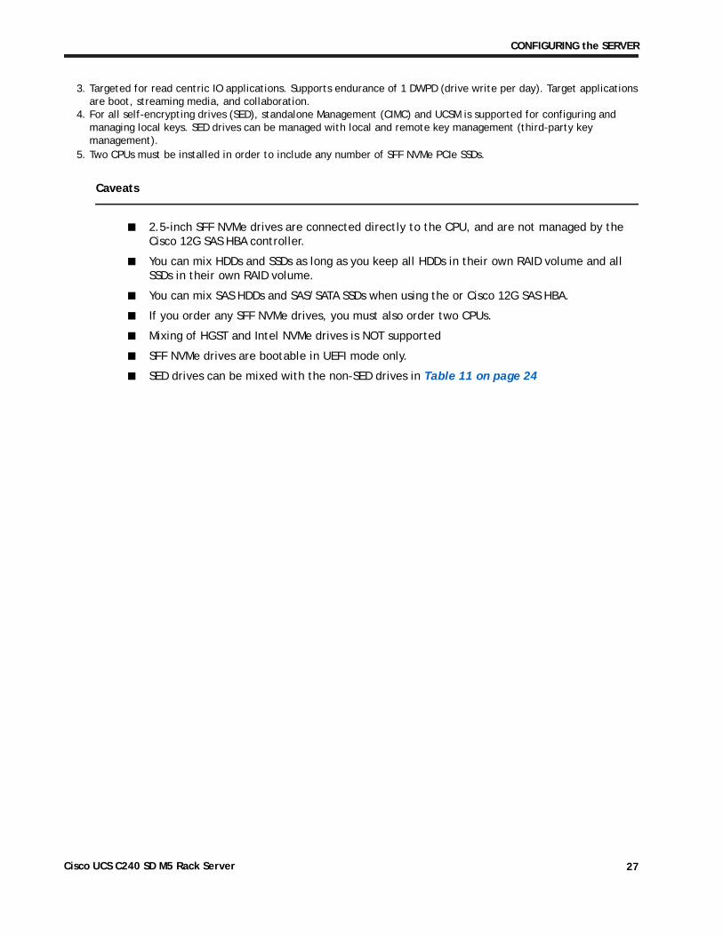
Caveats
■ 2.5-inch SFF NVMe drives are connected directly to the CPU, and are not managed by the Cisco 12G SAS HBA controller.
■ You can mix HDDs and SSDs as long as you keep all HDDs in their own RAID volume and all SSDs in their own RAID volume.
■ You can mix SAS HDDs and SAS/SATA SSDs when using the or Cisco 12G SAS HBA.
■ If you order any SFF NVMe drives, you must also order two CPUs.
■ Mixing of HGST and Intel NVMe drives is NOT supported
■ SFF NVMe drives are bootable in UEFI mode only.
■ SED drives can be mixed with the non-SED drives in Table 11 on page 24
3. Targeted for read centric IO applications. Supports endurance of 1 DWPD (drive write per day). Target applications are boot, streaming media, and collaboration.
4. For all self-encrypting drives (SED), standalone Management (CIMC) and UCSM is supported for configuring and managing local keys. SED drives can be managed with local and remote key management (third-party key management).
5. Two CPUs must be installed in order to include any number of SFF NVMe PCIe SSDs.
Cisco UCS C240 SD M5 Rack Server 27
CONFIGURING the SERVER
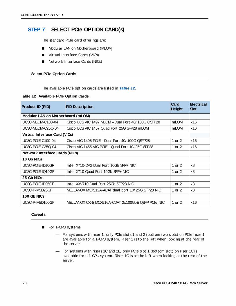
STEP 7 SELECT PCIe OPTION CARD(s)
The standard PCIe card offerings are:
■ Modular LAN on Motherboard (MLOM)
■ Virtual Interface Cards (VICs)
■ Network Interface Cards (NICs)
Select PCIe Option Cards
The available PCIe option cards are listed in Table 12
Table 12 Available PCIe Option Cards
Product ID (PID) PID DescriptionCard Height
Electrical Slot
Modular LAN on Motherboard (mLOM)
UCSC-MLOM-C100-04 Cisco UCS VIC 1497 MLOM – Dual Port 40/100G QSFP28 mLOM x16
UCSC-MLOM-C25Q-04 Cisco UCS VIC 1457 Quad Port 25G SFP28 mLOM mLOM x16
Virtual Interface Card (VICs)
UCSC-PCIE-C100-04 Cisco VIC 1495 PCIE – Dual Port 40/100G QSFP28 1 or 2 x16
UCSC-PCIE-C25Q-04 Cisco VIC 1455 VIC PCIE – Quad Port 10/25G SFP28 1 or 2 x16
Network Interface Cards (NICs)
10 Gb NICs
UCSC-PCIE-ID10GF Intel X710-DA2 Dual Port 10Gb SFP+ NIC 1 or 2 x8
UCSC-PCIE-IQ10GF Intel X710 Quad Port 10Gb SFP+ NIC 1 or 2 x8
25 Gb NICs
UCSC-PCIE-ID25GF Intel XXV710 Dual Port 25Gb SFP28 NIC 1 or 2 x8
UCSC-P-M5D25GF MELLANOX MCX512A-ACAT dual port 10/25G SFP28 NIC 1 or 2 x8
100 Gb NICs
UCSC-P-M5D100GF MELLANOX CX-5 MCX516A-CDAT 2x100GbE QSFP PCIe NIC 1 or 2 x16
.
Caveats
■ For 1-CPU systems:
— For systems with riser 1, only PCIe slots 1 and 2 (bottom two slots) on PCIe riser 1 are available for a 1-CPU system. Riser 1 is to the left when looking at the rear of the server
— For systems with risers 1C and 2E, only PCIe slot 1 (bottom slot) on riser 1C is available for a 1-CPU system. Riser 1C is to the left when looking at the rear of the server.
Cisco UCS C240 SD M5 Rack Server 28
CONFIGURING the SERVER
— The PCIe slots on riser 2B and 2E are not supported on 1-CPU systems. Riser 2B has PCIe slots 4, 5, and 6. These are the slots on the right when looking at the rear of the server. Slot 4 is the bottom slot. Riser 2E has PCIe2 (bottom slot)
— Only a single plug-in PCIe VIC card may be installed on a 1-CPU system, and it must be installed in slot 2 or 1 of riser 1.
— You can order an mLOM VIC card to be installed in the mLOM slot internal to the chassis and thus have two VIC cards in operation at the same time. If you order a GPU, it must be installed in slot 2, See Table 12 on page 28 for the selection of plug-in and mLOM VIC cards. See also Table 1 on page 7 and Riser Card Configuration and Options, page 67 or the PCIe slot physical descriptions.
■ For 2-CPU systems:
— For the riser 1/2B combination, six PCIe slots are available, three on PCIe riser 1 (PCIe slots 1, 2, and 3) and three on PCIe riser 2B (PCIe slots 4, 5, and 6).
— For the riser 1C/2E combination, the bottom slot on 1C (PCIe1) is available and the bottom slot on 1E (PCIe2) is available.
— Two plug-in PCIe VIC cards can be installed in dual CPU systems, using slots 2 and 5. In addition, you can order an mLOM VIC card, which is installed in the mLOM slot inside the chassis and thus have three VIC cards in operation at the same time. See Table 12 on page 28 for the selection of plug-in and mLOM VIC cards. See also Table 1 on page 7 and Riser Card Configuration and Options, page 67 for the PCIe slot physical descriptions.
— If GPUs are installed in slots 2 (riser 1) and 5 (riser 2B), the NCSI capability automatically switches over to slots 1 (riser 1) and 4 (riser 2B). Therefore, Cisco PCIe VICs can be installed in slots 1 and 4 if GPUs are installed in slots 2 and 5. If you order two GPUs, they must be installed in slots 2 and 5 and thus you will not be able to install VIC cards in those slots.
NOTE: UCSM managed servers are discoverable only if a VIC is installed in slot 2 or a VIC is installed in the MLOM slot. If you install two GPUs, they must be located in slots 2 and 5. Therefore, if two GPUs are installed, UCSM managed servers are discoverable only if you install a VIC in the MLOM slot.
— The server supports up to two PCIe Cisco VICs plus an MLOM VIC
However, single wire management is supported on only one VIC at a time. If multiple VICs are installed on a server, only one slot has NCSI enabled at a time and for single wire management, priority goes to the MLOM slot, then slot 2, then slot 5 for NCSI management traffic. When multiple cards are installed, connect the single wire management cables in the priority order mentioned above.
■ To help ensure that your operating system is compatible with the card you have selected, or to see additional cards that have been qualified to work with the UCS C240 SD M5 server, but are not sold on the Cisco price list, check the Hardware Compatibility List at this
URL: http://www.cisco.com/en/US/products/ps10477/prod_technical_reference_list.html
Cisco UCS C240 SD M5 Rack Server 29
CONFIGURING the SERVER
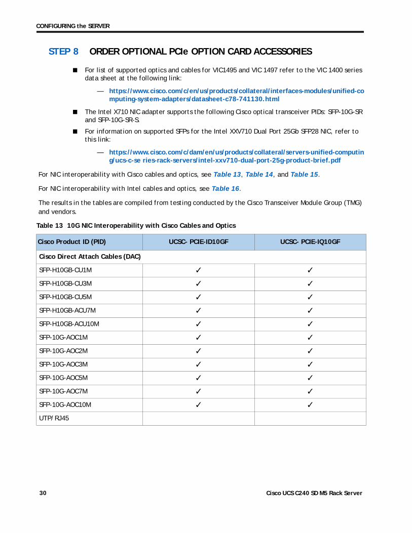
STEP 8 ORDER OPTIONAL PCIe OPTION CARD ACCESSORIES
■ For list of supported optics and cables for VIC1495 and VIC 1497 refer to the VIC 1400 series data sheet at the following link:
— https://www.cisco.com/c/en/us/products/collateral/interfaces-modules/unified-computing-system-adapters/datasheet-c78-741130.html
■ The Intel X710 NIC adapter supports the following Cisco optical transceiver PIDs: SFP-10G-SR and SFP-10G-SR-S.
■ For information on supported SFPs for the Intel XXV710 Dual Port 25Gb SFP28 NIC, refer to this link:
— https://www.cisco.com/c/dam/en/us/products/collateral/servers-unified-computing/ucs-c-se ries-rack-servers/intel-xxv710-dual-port-25g-product-brief.pdf
For NIC interoperability with Cisco cables and optics, see Table 13, Table 14, and Table 15.
For NIC interoperability with Intel cables and optics, see Table 16.
The results in the tables are compiled from testing conducted by the Cisco Transceiver Module Group (TMG) and vendors.
Table 13 10G NIC Interoperability with Cisco Cables and Optics
Cisco Product ID (PID) UCSC- PCIE-ID10GF UCSC- PCIE-IQ10GF
Cisco Direct Attach Cables (DAC)
SFP-H10GB-CU1M ✓ ✓
SFP-H10GB-CU3M ✓ ✓
SFP-H10GB-CU5M ✓ ✓
SFP-H10GB-ACU7M ✓ ✓
SFP-H10GB-ACU10M ✓ ✓
SFP-10G-AOC1M ✓ ✓
SFP-10G-AOC2M ✓ ✓
SFP-10G-AOC3M ✓ ✓
SFP-10G-AOC5M ✓ ✓
SFP-10G-AOC7M ✓ ✓
SFP-10G-AOC10M ✓ ✓
UTP/RJ45
Cisco UCS C240 SD M5 Rack Server 30
CONFIGURING the SERVER
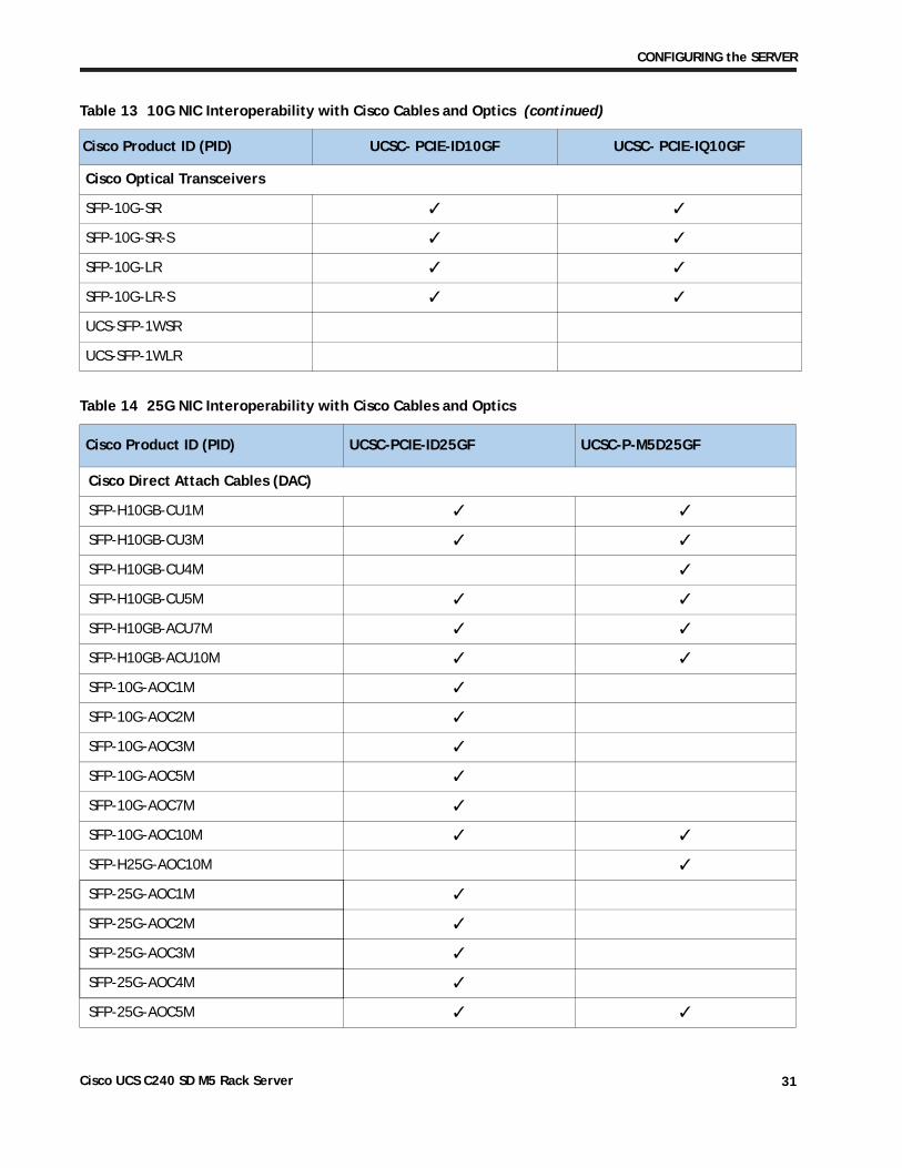
Cisco Optical Transceivers
SFP-10G-SR ✓ ✓
SFP-10G-SR-S ✓ ✓
SFP-10G-LR ✓ ✓
SFP-10G-LR-S ✓ ✓
UCS-SFP-1WSR
UCS-SFP-1WLR
Table 14 25G NIC Interoperability with Cisco Cables and Optics
Cisco Product ID (PID) UCSC-PCIE-ID25GF UCSC-P-M5D25GF
Cisco Direct Attach Cables (DAC)
SFP-H10GB-CU1M ✓ ✓
SFP-H10GB-CU3M ✓ ✓
SFP-H10GB-CU4M ✓
SFP-H10GB-CU5M ✓ ✓
SFP-H10GB-ACU7M ✓ ✓
SFP-H10GB-ACU10M ✓ ✓
SFP-10G-AOC1M ✓
SFP-10G-AOC2M ✓
SFP-10G-AOC3M ✓
SFP-10G-AOC5M ✓
SFP-10G-AOC7M ✓
SFP-10G-AOC10M ✓ ✓
SFP-H25G-AOC10M ✓
SFP-25G-AOC1M ✓
SFP-25G-AOC2M ✓
SFP-25G-AOC3M ✓
SFP-25G-AOC4M ✓
SFP-25G-AOC5M ✓ ✓
Table 13 10G NIC Interoperability with Cisco Cables and Optics (continued)
Cisco Product ID (PID) UCSC- PCIE-ID10GF UCSC- PCIE-IQ10GF
Cisco UCS C240 SD M5 Rack Server 31
CONFIGURING the SERVER
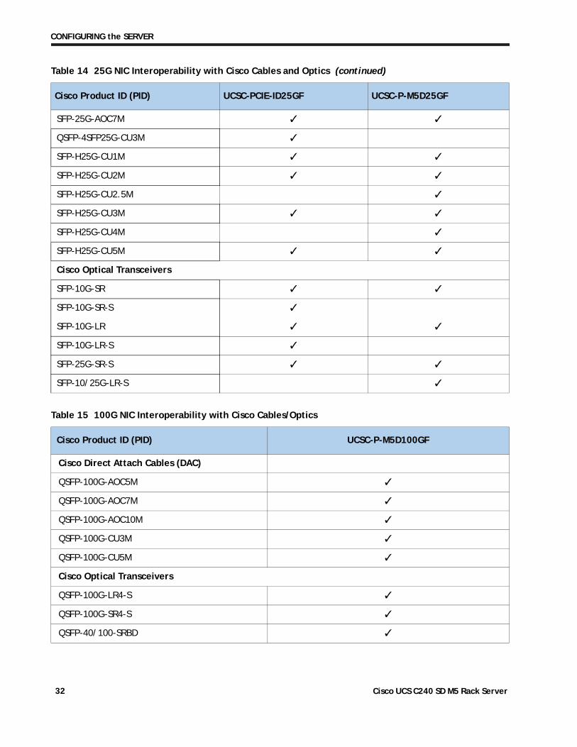
SFP-25G-AOC7M ✓ ✓
QSFP-4SFP25G-CU3M ✓
SFP-H25G-CU1M ✓ ✓
SFP-H25G-CU2M ✓ ✓
SFP-H25G-CU2.5M ✓
SFP-H25G-CU3M ✓ ✓
SFP-H25G-CU4M ✓
SFP-H25G-CU5M ✓ ✓
Cisco Optical Transceivers
SFP-10G-SR ✓ ✓
SFP-10G-SR-S ✓
SFP-10G-LR ✓ ✓
SFP-10G-LR-S ✓
SFP-25G-SR-S ✓ ✓
SFP-10/25G-LR-S ✓
Table 15 100G NIC Interoperability with Cisco Cables/Optics
Cisco Product ID (PID) UCSC-P-M5D100GF
Cisco Direct Attach Cables (DAC)
QSFP-100G-AOC5M ✓
QSFP-100G-AOC7M ✓
QSFP-100G-AOC10M ✓
QSFP-100G-CU3M ✓
QSFP-100G-CU5M ✓
Cisco Optical Transceivers
QSFP-100G-LR4-S ✓
QSFP-100G-SR4-S ✓
QSFP-40/100-SRBD ✓
Table 14 25G NIC Interoperability with Cisco Cables and Optics (continued)
Cisco Product ID (PID) UCSC-PCIE-ID25GF UCSC-P-M5D25GF
Cisco UCS C240 SD M5 Rack Server 32
CONFIGURING the SERVER
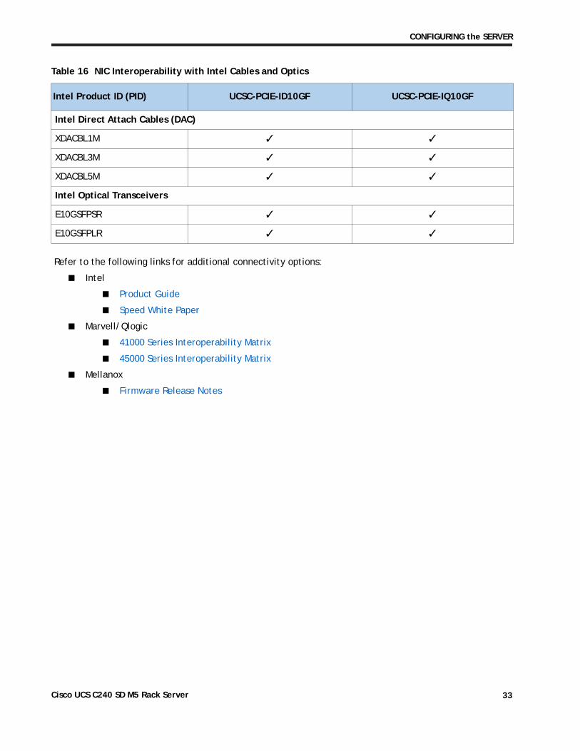
Table 16 NIC Interoperability with Intel Cables and Optics
Intel Product ID (PID) UCSC-PCIE-ID10GF UCSC-PCIE-IQ10GF
Intel Direct Attach Cables (DAC)
XDACBL1M ✓ ✓
XDACBL3M ✓ ✓
XDACBL5M ✓ ✓
Intel Optical Transceivers
E10GSFPSR ✓ ✓
E10GSFPLR ✓ ✓
Refer to the following links for additional connectivity options:
■ Intel
■ Product Guide
■ Speed White Paper
■ Marvell/Qlogic
■ 41000 Series Interoperability Matrix
■ 45000 Series Interoperability Matrix
■ Mellanox
■ Firmware Release Notes
Cisco UCS C240 SD M5 Rack Server 33
CONFIGURING the SERVER
STEP 9 ORDER GPU CARDS (OPTIONAL)
Select GPU Options
The available GPU PCIe options are listed in Table 17
Table 17 Available PCIe GPU Cards
Product ID (PID) PID Description Card Size
GPU PCIe Cards
UCSC-GPU-T4-161 NVIDIA T4 PCIE 75W 16GB Low Profile Single-Width
.
NOTE:
■ All GPU cards must be procured from Cisco as there is a unique SBIOS ID required by CIMC and UCSM
■ When a GPU is installed, it is recommended to have two CPUs if NVMe support is needed.
■ When two GPUs are installed, it is required to have two power supplies in the server. When only one GPU is installed, use the power calculator at the following link to determine the needed power based on the options chosen (CPUs, drives, GPUs, memory, and so on):
http://ucspowercalc.cisco.com
Caveats
— Currently, only T4 GPUs are supported.
— For riser combination 1/2B (see Figure 2 on page 5), slot 2 on riser card 1 is the required slot for the first GPU and slot 5 on riser card 1B is the required slot for the second GPU.
— For riser combination 1C/2E (see Figure 3 on page 6), slot 1 on riser card 1C is the required slot for the first GPU and slot 2 on riser card 2E is the required slot for the second GPU.
Notes:
1.Refer to C240 SD M5 GPU Card Installation for more details.
Cisco UCS C240 SD M5 Rack Server 34
CONFIGURING the SERVER
Refer to Table 18 for the PCIe slot usage for GPU cards.
Table 18 PCIe Slot Usage in Riser 1/2B and Riser 1C/2E Combinations
Riser Combinations
Total Riser Slots Available Riser Slots Available for GPUs
1-CPU System 2-CPU System 1-CPU System 2-CPU System
1/2B Slots 1 and 2 Slots 1, 2, 3, 4, 5, and 6 Slot 2 Slots 2 and 5
1C/2E Slot 1 Slots 1 and 2 Slot 1 Slots 1 and 2
NOTE:
■ UCSM managed servers are discoverable only if a PCIe VIC card is installed in slot 2 or an mLOM VIC card is installed in the mLOM slot. If you install two GPUs, they must be located in slots 2 and 5. Therefore, if two GPUs are installed, UCSM managed servers are discoverable only if you install a VIC in the MLOM slot.
■ For more information on the riser card options, see Riser Card Configuration and Options, page 67
Cisco UCS C240 SD M5 Rack Server 35
CONFIGURING the SERVER
STEP 10 ORDER POWER SUPPLY
Power supplies share a common electrical and physical design that allows for hot-plug and tool-less installation into M5 C-series servers. Each power supply is certified for high-efficiency operation and offer multiple power output options. This allows users to “right-size” based on server configuration, which improves power efficiency, lower overall energy costs and avoid stranded capacity in the data center. Use the power calculator at the following link to determine the needed power based on the options chosen (CPUs, drives, memory, and so on):
http://ucspowercalc.cisco.com
Table 19 Power Supply
Product ID (PID) PID Description
UCSC-PSUF-1050W UCSC 1050W Power Supply for SD
NOTE: In a two power supply server, both power supplies must be identical.
NOTE: If a GPU is installed, it is required to have two power supplies.
Cisco UCS C240 SD M5 Rack Server 36
CONFIGURING the SERVER
STEP 11 SELECT INPUT POWER CORD(s)
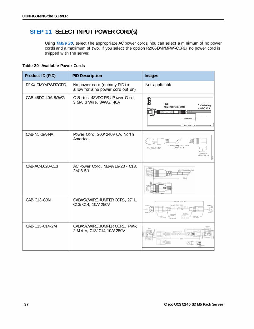
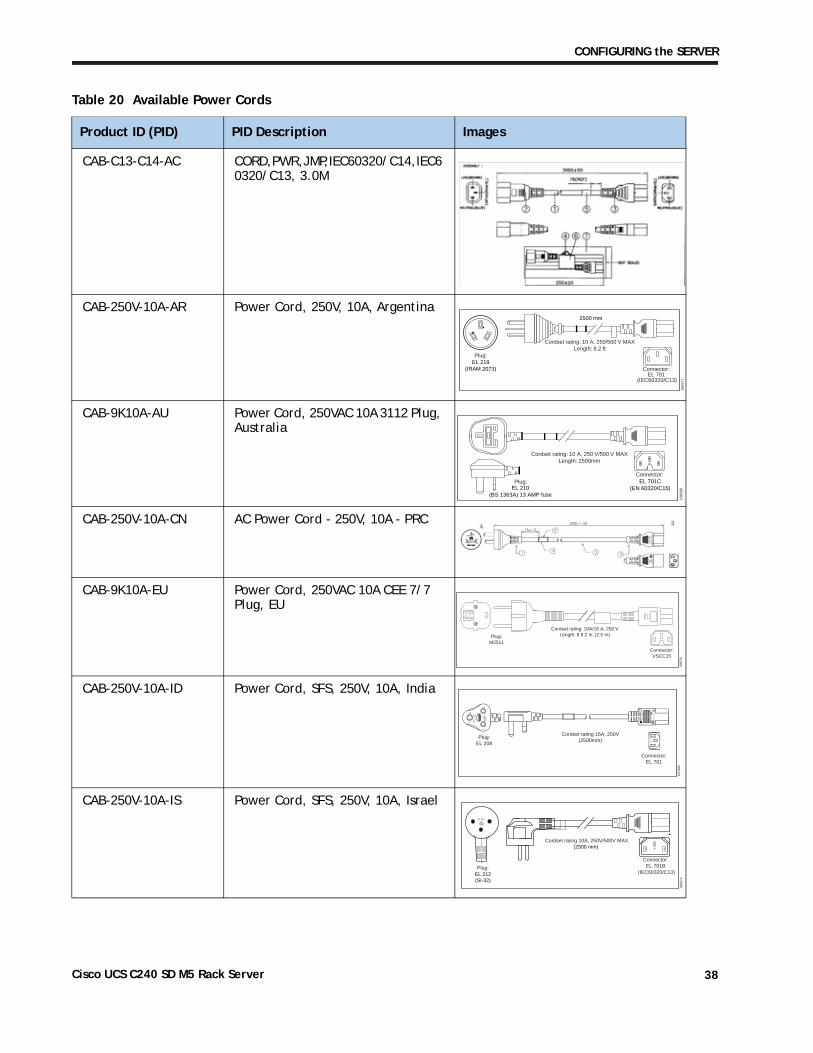
Using Table 20, select the appropriate AC power cords. You can select a minimum of no power cords and a maximum of two. If you select the option R2XX-DMYMPWRCORD, no power cord is shipped with the server.
Table 20 Available Power Cords
Product ID (PID) PID Description Images
R2XX-DMYMPWRCORD No power cord (dummy PID to allow for a no power cord option)
Not applicable
CAB-48DC-40A-8AWG C-Series -48VDC PSU Power Cord, 3.5M, 3 Wire, 8AWG, 40A
305085
Green 2.0 m
Black & red 3.5 m
Plug:Molex 3CKT 428160312
Cordset rating:-48 VDC, 40 A
Green 2.0 m
Black & red 3.5 m
Plug:Molex 3CKT 428160312
Cordset rating:-48 VDC, 40 A
CAB-N5K6A-NA Power Cord, 200/240V 6A, North America
Cordset rating: 10 A, 250 VLength: 8.2 ft
1865
70
Plug: NEMA 6-15P
Connector:IEC60320/C13
CAB-AC-L620-C13 AC Power Cord, NEMA L6-20 - C13, 2M/6.5ft
CAB-C13-CBN CABASY,WIRE,JUMPER CORD, 27" L, C13/C14, 10A/250V
CAB-C13-C14-2M CABASY,WIRE,JUMPER CORD, PWR, 2 Meter, C13/C14,10A/250V
Cisco UCS C240 SD M5 Rack Server 37
CONFIGURING the SERVER
CAB-C13-C14-AC CORD,PWR,JMP,IEC60320/C14,IEC6 0320/C13, 3.0M
CAB-250V-10A-AR Power Cord, 250V, 10A, Argentina
1865
71
2500 mm
Cordset rating: 10 A, 250/500 V MAXLength: 8.2 ft
Plug:EL 219
(IRAM 2073) Connector:EL 701
(IEC60320/C13)
CAB-9K10A-AU Power Cord, 250VAC 10A 3112 Plug, Australia
Plug:
Cordset rating: 10 A, 250 V/500 V MAXLength: 2500mm
1865
80
Connector:EL 701C
(EN 60320/C15)EL 210(BS 1363A) 13 AMP fuse
CAB-250V-10A-CN AC Power Cord - 250V, 10A - PRC
CAB-9K10A-EU Power Cord, 250VAC 10A CEE 7/7 Plug, EU
Connector:VSCC15
Cordset rating: 10A/16 A, 250 VLength: 8 ft 2 in. (2.5 m)Plug:
M2511
1865
76
CAB-250V-10A-ID Power Cord, SFS, 250V, 10A, India
OVE
Cordset rating 16A, 250V(2500mm)
Plug:EL 208
1874
90
Connector:EL 701
CAB-250V-10A-IS Power Cord, SFS, 250V, 10A, Israel
Cordset rating 10A, 250V/500V MAX(2500 mm)
Plug:EL 212(SI-32)
1865
74
Connector:EL 701B
(IEC60320/C13)
EL-21216A250V
Table 20 Available Power Cords
Product ID (PID) PID Description Images
Cisco UCS C240 SD M5 Rack Server 38
CONFIGURING the SERVER
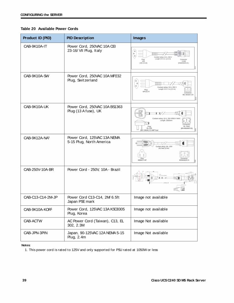
CAB-9K10A-IT Power Cord, 250VAC 10A CEI 23-16/VII Plug, Italy
Plug: I/3G
(CEI 23-16)
Connector C15M
(EN60320/C15 )
Cordset rating: 10 A, 250 VLength: 8 ft 2 in. (2.5 m)
1865
75
CAB-9K10A-SW Power Cord, 250VAC 10A MP232 Plug, Switzerland
Plug:MP232-R
Cordset rating: 10 A, 250 VLength: 8 ft. 2 in (2.5 m)
1865
78
Connector:IEC 60320 C15
CAB-9K10A-UK Power Cord, 250VAC 10A BS1363 Plug (13 A fuse), UK
Plug:
Cordset rating: 10 A, 250 V/500 V MAXLength: 2500mm
1865
80
Connector:EL 701C
(EN 60320/C15)EL 210(BS 1363A) 13 AMP fuse
CAB-9K12A-NA1 Power Cord, 125VAC 13A NEMA 5-15 Plug, North America
CAB-250V-10A-BR Power Cord - 250V, 10A - Brazil
CAB-C13-C14-2M-JP Power Cord C13-C14, 2M/6.5ft Japan PSE mark
Image not available
CAB-9K10A-KOR1 Power Cord, 125VAC 13A KSC8305 Plug, Korea
Image not available
CAB-ACTW AC Power Cord (Taiwan), C13, EL 302, 2.3M
Image Not available
CAB-JPN-3PIN Japan, 90-125VAC 12A NEMA 5-15 Plug, 2.4m
Image Not available
Notes:
1. This power cord is rated to 125V and only supported for PSU rated at 1050W or less
Table 20 Available Power Cords
Product ID (PID) PID Description Images
1 76.2 From Plug End
2,133.6 ± 25
Cisco UCS C240 SD M5 Rack Server 39
CONFIGURING the SERVER
STEP 12 ORDER TOOL-LESS RAIL KIT and RAIL EXTENDER KIT
Select a Tool-less Rail Kit
Select a tool-less rail kit from Table 21.
Table 21 Tool-less Rail Kit Options
Product ID (PID) PID Description
UCSC-RAILS-M5 Ball Bearing Rail Kit for C240M5 SD Rack Server
UCSC-RAIL-NONE No rail kit option
For more information about the tool-less rail kit, see the Cisco UCS C240 SD M5 Installation and Service Guide at this URL:
http://www.cisco.com/c/en/us/td/docs/unified_computing/ucs/c/hw/c240sdm5/install/c240sdm5.html
NOTE: If you plan to rackmount your UCS C240 SD M5 server, you must order a tool-less rail kit. The same rail kits is used for C240 M4 M5 and C240 SD M5 servers.
Select a Rail Extender Kit
For two-post rack installation, you must select a rail extender kit from Table 22.
Table 22 Rail Extender Kit Option
Product ID (PID) PID Description
UCSC-C240SD-EXT UCS C240SD M5 Extender Kit
Cisco UCS C240 SD M5 Rack Server 40
CONFIGURING the SERVER
STEP 13 SELECT MANAGEMENT CONFIGURATION (OPTIONAL)
By default, the C240 SD M5 server NIC mode is configured to be Shared LOM Extended. This NIC mode allows any LOM port or adapter card port to be used to access the Cisco Integrated Management Controller (CIMC). The Cisco VIC card must be installed in a slot with NCSI support.
To change the default NIC mode to Dedicated, select the UCSC-DLOM-01 PID shown in Table 23. In Dedicated NIC mode, the CIMC can be accessed only through the dedicated management port. See Chassis Rear View, page 6 for the location of the management port.
To change the default NIC mode to Cisco Card Mode, select the UCSC-CCARD-01 PID shown in Table 23. In this mode, you can assign an IP address to the CIMC using DHCP and from there you can fully automate your deployment.
For more details on all the NIC mode settings, see
https://www.cisco.com/c/en/us/td/docs/unified_computing/ucs/c/hw/C480M5/install/C480M5/C480M5_chapter_010.html#concept_rqj_vsr_fz
Table 23 Management Configuration Ordering Information
Product ID (PID) PID Description
UCSC-DLOM-01 Dedicated Mode BIOS setting for C-Series Servers
UCSC-CCARD-01 Cisco Card Mode BIOS setting for C-Series Servers
Cisco UCS C240 SD M5 Rack Server 41
CONFIGURING the SERVER
STEP 14 SELECT SERVER BOOT MODE (OPTIONAL)
By default, the C220 M5 server ships with UEFI as the default boot mode. To have a server shipped with the Legacy BIOS mode (which was standard on M4 and previous generation servers), select the Legacy BIOS PID from Table 24.
Table 24 Server Boot Mode Ordering Information
Product ID (PID) PID Description
UCSC-LBIOS-01 Legacy Boot Mode BIOS setting for C-Series Servers
Cisco UCS C240 SD M5 Rack Server 42
CONFIGURING the SERVER
STEP 15 ORDER SECURITY DEVICES (OPTIONAL)
A Trusted Platform Module (TPM) is a computer chip (microcontroller) that can securely store artifacts used to authenticate the platform (server). These artifacts can include passwords, certificates, or encryption keys. A TPM can also be used to store platform measurements that help ensure that the platform remains trustworthy. Authentication (ensuring that the platform can prove that it is what it claims to be) and attestation (a process helping to prove that a platform is trustworthy and has not been breached) are necessary steps to ensure safer computing in all environments.
A chassis intrusion switch gives a notification of any unauthorized mechanical access into the server.
The security device ordering information is listed in Table 25
Table 25 Security Devices
Product ID (PID) PID Description
UCSX-TPM2-002 Trusted Platform Module 2.0 for UCS servers
UCSX-TPM2-002B FIPS Compliant Trusted Platform Module 2.0 for UCS servers
UCSC-INT-SW01 C220 M5 and C240 SD M5 Chassis Intrusion Switch
.
.
NOTE:
■ The TPM module used in this system conforms to TPM v1.2 and 2.0, as defined by the Trusted Computing Group (TCG). It is also SPI-based.
■ TPM installation is supported after-factory. However, a TPM installs with a one-way screw and cannot be replaced, upgraded, or moved to another server. If a server with a TPM is returned, the replacement server must be ordered with a new TPM.
Cisco UCS C240 SD M5 Rack Server 43
CONFIGURING the SERVER
STEP 16 ORDER CISCO SD CARD MODULE (OPTIONAL)
Order one or two matching SD cards. See Figure 6 on page 63 for the location of the mini storage module connector, which accommodates an SD module. Each SD module accommodates two SD cards.
Table 26 Secure Digital (SD) Card (blank)
Product ID (PID) PID Description
UCS-SD-128G 128 GB SD Card for UCS Servers
UCS-SD-64G-S 64 GB SD Card for UCS Servers
UCS-SD-32G-S 32 GB SD Card for UCS Servers
Caveats
■ Install either one or two SD cards
■ Do not mix SD card sizes
■ You cannot mix SD cards with an internal M.2 SATA SSD (see ORDER M.2 SATA SSD (OPTIONAL), page 45).
Cisco UCS C240 SD M5 Rack Server 44
CONFIGURING the SERVER
STEP 17 ORDER M.2 SATA SSD (OPTIONAL)
Order one or two matching M.2 SATA SSDs. See Figure 6 on page 63 for the location of the mini storage module connector, which accommodates an M.2 module. Each M.2 module has two PCIe/SATA M.2 SSD slots.
Table 27 M.2 SATA SSDs
Product ID (PID) PID Description
UCS-M2-240GB 240 GB M.2 SATA SSD
UCS-M2-960GB 960 GB M.2 SATA SSD
Caveats
■ Install either one or two M.2 SATA SSDs.
■ You cannot mix M.2 SATA SSDs with SD cards (see ORDER CISCO SD CARD MODULE (OPTIONAL), page 44)
■ When ordering two M.2 devices with embedded software RAID, the maximum number of internal SATA drives supported is six.
Cisco UCS C240 SD M5 Rack Server 45
CONFIGURING the SERVER
STEP 18 ORDER INTERNAL MICRO-SD CARD MODULE (OPTIONAL)
Order a 32 GB micro-SD card. The micro-SD card serves as a dedicated local resource for utilities such as a Host Upgrade Utility (HUU). Images can be pulled from a file share (NFS/CIFS) and uploaded to the card for future use.
Table 28 32 GB Secure Digital (SD) Card
Product ID (PID) PID Description
UCS-MSD-32G 32GB Micro-SD Card for UCS servers
NOTE:
■ The microSD card mounts internally on riser 1 or riser 1C, so you must order either UCSC-PCI-1-C240M5 or UCSC-RS1C-240M5SD when you order a micro-SD card.
■ The Flexutil user partition does not support OS installation. The user partition must be used for storage only.
Cisco UCS C240 SD M5 Rack Server 46
CONFIGURING the SERVER
STEP 19 ORDER OPTIONAL USB 3.0 DRIVE
You can order one optional USB 3.0 drive. The USB drive ordering information is listed in Table 29
Table 29 USB 3.0 Drive
Product ID (PID) PID Description
UCS-USBFLSHB-16GB UCS Servers 16 GB Flash USB Drive
.
See Figure 6 on page 63 for the location of the USB connector
Cisco UCS C240 SD M5 Rack Server 47
CONFIGURING the SERVER
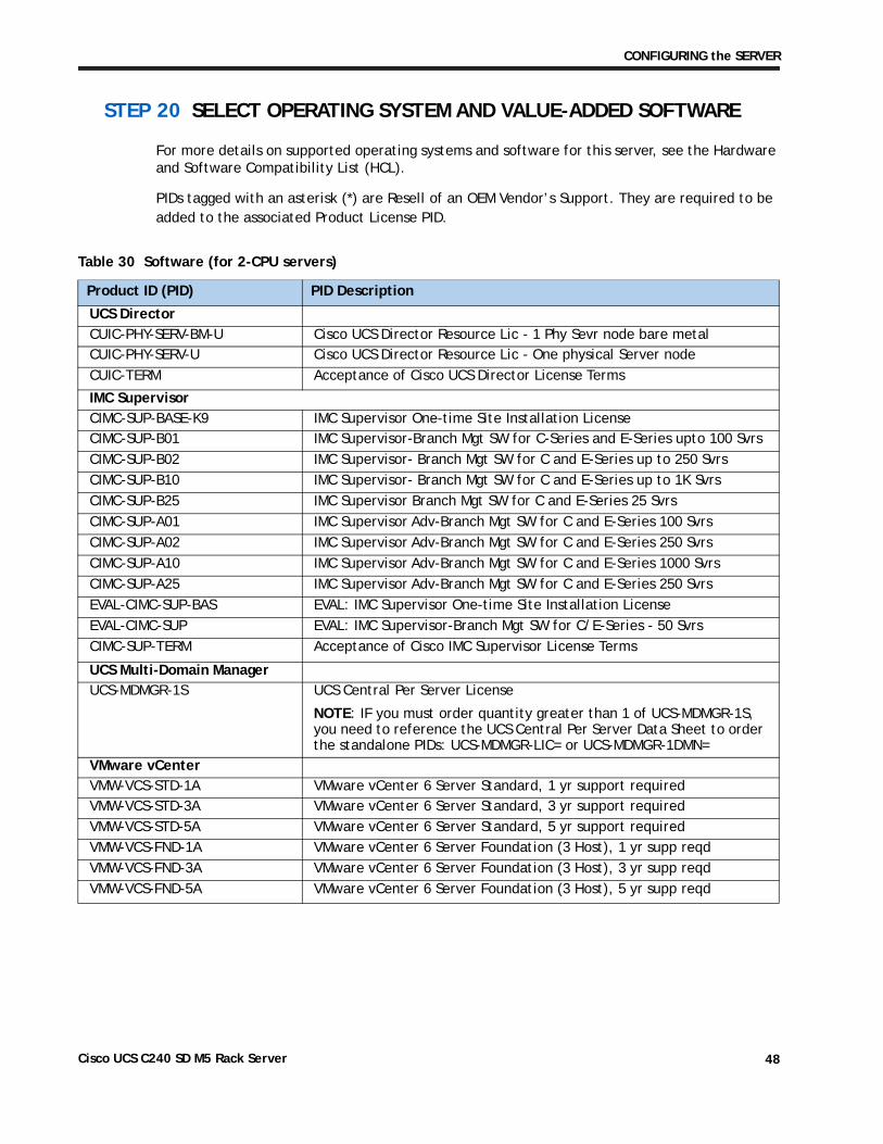
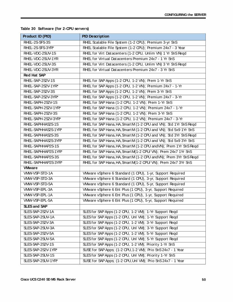
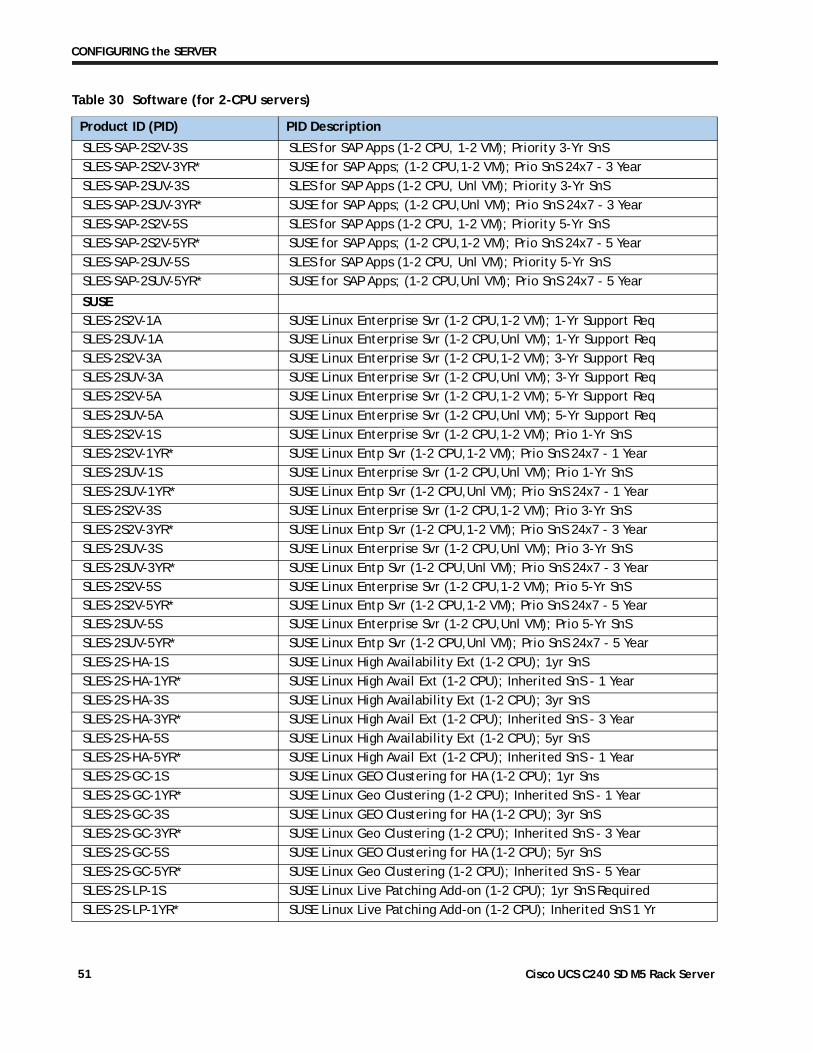
STEP 20 SELECT OPERATING SYSTEM AND VALUE-ADDED SOFTWARE
For more details on supported operating systems and software for this server, see the Hardware and Software Compatibility List (HCL).
PIDs tagged with an asterisk (*) are Resell of an OEM Vendor’s Support. They are required to be added to the associated Product License PID.
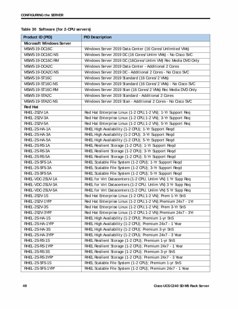
Table 30 Software (for 2-CPU servers)
Product ID (PID) PID Description
UCS DirectorCUIC-PHY-SERV-BM-U Cisco UCS Director Resource Lic - 1 Phy Sevr node bare metalCUIC-PHY-SERV-U Cisco UCS Director Resource Lic - One physical Server nodeCUIC-TERM Acceptance of Cisco UCS Director License Terms
IMC SupervisorCIMC-SUP-BASE-K9 IMC Supervisor One-time Site Installation LicenseCIMC-SUP-B01 IMC Supervisor-Branch Mgt SW for C-Series and E-Series upto 100 SvrsCIMC-SUP-B02 IMC Supervisor- Branch Mgt SW for C and E-Series up to 250 SvrsCIMC-SUP-B10 IMC Supervisor- Branch Mgt SW for C and E-Series up to 1K SvrsCIMC-SUP-B25 IMC Supervisor Branch Mgt SW for C and E-Series 25 SvrsCIMC-SUP-A01 IMC Supervisor Adv-Branch Mgt SW for C and E-Series 100 SvrsCIMC-SUP-A02 IMC Supervisor Adv-Branch Mgt SW for C and E-Series 250 SvrsCIMC-SUP-A10 IMC Supervisor Adv-Branch Mgt SW for C and E-Series 1000 SvrsCIMC-SUP-A25 IMC Supervisor Adv-Branch Mgt SW for C and E-Series 250 SvrsEVAL-CIMC-SUP-BAS EVAL: IMC Supervisor One-time Site Installation LicenseEVAL-CIMC-SUP EVAL: IMC Supervisor-Branch Mgt SW for C/E-Series - 50 SvrsCIMC-SUP-TERM Acceptance of Cisco IMC Supervisor License Terms
UCS Multi-Domain ManagerUCS-MDMGR-1S UCS Central Per Server License
NOTE: IF you must order quantity greater than 1 of UCS-MDMGR-1S, you need to reference the UCS Central Per Server Data Sheet to order the standalone PIDs: UCS-MDMGR-LIC= or UCS-MDMGR-1DMN=
VMware vCenterVMW-VCS-STD-1A VMware vCenter 6 Server Standard, 1 yr support requiredVMW-VCS-STD-3A VMware vCenter 6 Server Standard, 3 yr support requiredVMW-VCS-STD-5A VMware vCenter 6 Server Standard, 5 yr support requiredVMW-VCS-FND-1A VMware vCenter 6 Server Foundation (3 Host), 1 yr supp reqdVMW-VCS-FND-3A VMware vCenter 6 Server Foundation (3 Host), 3 yr supp reqdVMW-VCS-FND-5A VMware vCenter 6 Server Foundation (3 Host), 5 yr supp reqd
Cisco UCS C240 SD M5 Rack Server 48
CONFIGURING the SERVER
Microsoft Windows ServerMSWS-19-DC16C Windows Server 2019 Data Center (16 Cores/Unlimited VMs)
MSWS-19-DC16C-NS Windows Server 2019 DC (16 Cores/Unlim VMs) - No Cisco SVC
MSWS-19-DC16C-RM Windows Server 2019 DC (16Cores/Unlim VM) Rec Media DVD Only
MSWS-19-DCA2C Windows Server 2019 Data Center - Additional 2 Cores
MSWS-19-DCA2C-NS Windows Server 2019 DC - Additional 2 Cores - No Cisco SVC
MSWS-19-ST16C Windows Server 2019 Standard (16 Cores/2 VMs)
MSWS-19-ST16C-NS Windows Server 2019 Standard (16 Cores/2 VMs) - No Cisco SVC
MSWS-19-ST16C-RM Windows Server 2019 Stan (16 Cores/2 VMs) Rec Media DVD Only
MSWS-19-STA2C Windows Server 2019 Standard - Additional 2 Cores
MSWS-19-STA2C-NS Windows Server 2019 Stan - Additional 2 Cores - No Cisco SVCRed HatRHEL-2S2V-1A Red Hat Enterprise Linux (1-2 CPU,1-2 VN); 1-Yr Support ReqRHEL-2S2V-3A Red Hat Enterprise Linux (1-2 CPU,1-2 VN); 3-Yr Support ReqRHEL-2S2V-5A Red Hat Enterprise Linux (1-2 CPU,1-2 VN); 5-Yr Support ReqRHEL-2S-HA-1A RHEL High Availability (1-2 CPU); 1-Yr Support ReqdRHEL-2S-HA-3A RHEL High Availability (1-2 CPU); 3-Yr Support ReqdRHEL-2S-HA-5A RHEL High Availability (1-2 CPU); 5-Yr Support ReqdRHEL-2S-RS-1A RHEL Resilient Storage (1-2 CPU); 1-Yr Support ReqdRHEL-2S-RS-3A RHEL Resilient Storage (1-2 CPU); 3-Yr Support ReqdRHEL-2S-RS-5A RHEL Resilient Storage (1-2 CPU); 5-Yr Support ReqdRHEL-2S-SFS-1A RHEL Scalable File System (1-2 CPU); 1-Yr Support ReqdRHEL-2S-SFS-3A RHEL Scalable File System (1-2 CPU); 3-Yr Support ReqdRHEL-2S-SFS-5A RHEL Scalable File System (1-2 CPU); 5-Yr Support ReqdRHEL-VDC-2SUV-1A RHEL for Virt Datacenters (1-2 CPU, Unlim VN) 1 Yr Supp ReqRHEL-VDC-2SUV-3A RHEL for Virt Datacenters (1-2 CPU, Unlim VN) 3 Yr Supp ReqRHEL-VDC-2SUV-5A RHEL for Virt Datacenters (1-2 CPU, Unlim VN) 5 Yr Supp ReqRHEL-2S2V-1S Red Hat Enterprise Linux (1-2 CPU,1-2 VN); Prem 1-Yr SnSRHEL-2S2V-1YR* Red Hat Enterprise Linux (1-2 CPU,1-2 VN);Premium 24x7 - 1YrRHEL-2S2V-3S Red Hat Enterprise Linux (1-2 CPU,1-2 VN); Prem 3-Yr SnSRHEL-2S2V-3YR* Red Hat Enterprise Linux (1-2 CPU,1-2 VN);Premium 24x7 - 3YrRHEL-2S-HA-1S RHEL High Availability (1-2 CPU); Premium 1-yr SnSRHEL-2S-HA-1YR* RHEL High Availability (1-2 CPU); Premium 24x7 - 1 YearRHEL-2S-HA-3S RHEL High Availability (1-2 CPU); Premium 3-yr SnSRHEL-2S-HA-3YR* RHEL High Availability (1-2 CPU); Premium 24x7 - 3 YearRHEL-2S-RS-1S RHEL Resilient Storage (1-2 CPU); Premium 1-yr SnSRHEL-2S-RS-1YR* RHEL Resilient Storage (1-2 CPU); Premium 24x7 - 1 YearRHEL-2S-RS-3S RHEL Resilient Storage (1-2 CPU); Premium 3-yr SnSRHEL-2S-RS-3YR* RHEL Resilient Storage (1-2 CPU); Premium 24x7 - 3 YearRHEL-2S-SFS-1S RHEL Scalable File System (1-2 CPU); Premium 1-yr SnSRHEL-2S-SFS-1YR* RHEL Scalable File System (1-2 CPU); Premium 24x7 - 1 Year
Table 30 Software (for 2-CPU servers)
Product ID (PID) PID Description
Cisco UCS C240 SD M5 Rack Server 49
CONFIGURING the SERVER
RHEL-2S-SFS-3S RHEL Scalable File System (1-2 CPU); Premium 3-yr SnSRHEL-2S-SFS-3YR* RHEL Scalable File System (1-2 CPU); Premium 24x7 - 3 YearRHEL-VDC-2SUV-1S RHEL for Virt Datacenters (1-2 CPU, Unlim VN) 1 Yr SnS ReqdRHEL-VDC-2SUV-1YR RHEL for Virtual Datacenters Premium 24x7 - 1 Yr SnSRHEL-VDC-2SUV-3S RHEL for Virt Datacenters (1-2 CPU, Unlim VN) 3 Yr SnS ReqdRHEL-VDC-2SUV-3YR RHEL for Virtual Datacenters Premium 24x7 - 3 Yr SnSRed Hat SAPRHEL-SAP-2S2V-1S RHEL for SAP Apps (1-2 CPU, 1-2 VN); Prem 1-Yr SnSRHEL-SAP-2S2V-1YR* RHEL for SAP Apps (1-2 CPU, 1-2 VN); Premium 24x7 - 1-YrRHEL-SAP-2S2V-3S RHEL for SAP Apps (1-2 CPU, 1-2 VN); Prem 3-Yr SnSRHEL-SAP-2S2V-3YR* RHEL for SAP Apps (1-2 CPU, 1-2 VN); Premium 24x7 - 3-YrRHEL-SAPH-2S2V-1S RHEL for SAP Hana (1-2 CPU, 1-2 VN); Prem 1-Yr SnSRHEL-SAPH-2S2V-1YR* RHEL for SAP Hana (1-2 CPU, 1-2 VN); Premium 24x7 - 1-YrRHEL-SAPH-2S2V-3S RHEL for SAP Hana (1-2 CPU, 1-2 VN); Prem 3-Yr SnSRHEL-SAPH-2S2V-3YR* RHEL for SAP Hana (1-2 CPU, 1-2 VN); Premium 24x7 - 3-YrRHEL-SAPHHAS2S-1S RHEL for SAP Hana,HA,SmartM (1-2 CPU and VN); Std 1Yr SnS ReqdRHEL-SAPHHAS2S-1YR* RHEL for SAP Hana,HA,SmartM (1-2 CPU and VN); Std 5x9 1Yr SnSRHEL-SAPHHAS2S-3S RHEL for SAP Hana,HA,SmartM (1-2 CPU and VN); Std 3Yr SnS ReqdRHEL-SAPHHAS2S-3YR* RHEL for SAP Hana,HA,SmartM (1-2 CPU and VN); Std 5x9 3Yr SnSRHEL-SAPHHAP2S-1S RHEL for SAP Hana,HA,SmartM (1-2 CPU andVN); Prem 1Yr SnS ReqdRHEL-SAPHHAP2S-1YR* RHEL for SAP Hana,HA,SmartM(1-2 CPU/VN); Prem 24x7 1Yr SnSRHEL-SAPHHAP2S-3S RHEL for SAP Hana,HA,SmartM (1-2 CPU andVN); Prem 3Yr SnS ReqdRHEL-SAPHHAP2S-3YR* RHEL for SAP Hana,HA,SmartM(1-2 CPU/VN); Prem 24x7 3Yr SnSVMwareVMW-VSP-STD-1A VMware vSphere 6 Standard (1 CPU), 1-yr, Support RequiredVMW-VSP-STD-3A VMware vSphere 6 Standard (1 CPU), 3-yr, Support RequiredVMW-VSP-STD-5A VMware vSphere 6 Standard (1 CPU), 5-yr, Support RequiredVMW-VSP-EPL-3A VMware vSphere 6 Ent Plus (1 CPU), 3-yr, Support RequiredVMW-VSP-EPL-1A VMware vSphere 6 Ent Plus (1 CPU), 1-yr, Support RequiredVMW-VSP-EPL-5A VMware vSphere 6 Ent Plus (1 CPU), 5-yr, Support Required
SLES and SAPSLES-SAP-2S2V-1A SLES for SAP Apps (1-2 CPU, 1-2 VM); 1-Yr Support ReqdSLES-SAP-2SUV-1A SLES for SAP Apps (1-2 CPU, Unl VM); 1-Yr Support ReqdSLES-SAP-2S2V-3A SLES for SAP Apps (1-2 CPU, 1-2 VM); 3-Yr Support ReqdSLES-SAP-2SUV-3A SLES for SAP Apps (1-2 CPU, Unl VM); 3-Yr Support ReqdSLES-SAP-2S2V-5A SLES for SAP Apps (1-2 CPU, 1-2 VM); 5-Yr Support ReqdSLES-SAP-2SUV-5A SLES for SAP Apps (1-2 CPU, Unl VM); 5-Yr Support ReqdSLES-SAP-2S2V-1S SLES for SAP Apps (1-2 CPU, 1-2 VM); Priority 1-Yr SnSSLES-SAP-2S2V-1YR* SUSE for SAP Apps; (1-2 CPU,1-2 VM); Prio SnS 24x7 - 1 YearSLES-SAP-2SUV-1S SLES for SAP Apps (1-2 CPU, Unl VM); Priority 1-Yr SnSSLES-SAP-2SUV-1YR* SUSE for SAP Apps; (1-2 CPU,Unl VM); Prio SnS 24x7 - 1 Year
Table 30 Software (for 2-CPU servers)
Product ID (PID) PID Description
Cisco UCS C240 SD M5 Rack Server 50
CONFIGURING the SERVER
SLES-SAP-2S2V-3S SLES for SAP Apps (1-2 CPU, 1-2 VM); Priority 3-Yr SnSSLES-SAP-2S2V-3YR* SUSE for SAP Apps; (1-2 CPU,1-2 VM); Prio SnS 24x7 - 3 YearSLES-SAP-2SUV-3S SLES for SAP Apps (1-2 CPU, Unl VM); Priority 3-Yr SnSSLES-SAP-2SUV-3YR* SUSE for SAP Apps; (1-2 CPU,Unl VM); Prio SnS 24x7 - 3 YearSLES-SAP-2S2V-5S SLES for SAP Apps (1-2 CPU, 1-2 VM); Priority 5-Yr SnSSLES-SAP-2S2V-5YR* SUSE for SAP Apps; (1-2 CPU,1-2 VM); Prio SnS 24x7 - 5 YearSLES-SAP-2SUV-5S SLES for SAP Apps (1-2 CPU, Unl VM); Priority 5-Yr SnSSLES-SAP-2SUV-5YR* SUSE for SAP Apps; (1-2 CPU,Unl VM); Prio SnS 24x7 - 5 Year
SUSESLES-2S2V-1A SUSE Linux Enterprise Svr (1-2 CPU,1-2 VM); 1-Yr Support ReqSLES-2SUV-1A SUSE Linux Enterprise Svr (1-2 CPU,Unl VM); 1-Yr Support ReqSLES-2S2V-3A SUSE Linux Enterprise Svr (1-2 CPU,1-2 VM); 3-Yr Support ReqSLES-2SUV-3A SUSE Linux Enterprise Svr (1-2 CPU,Unl VM); 3-Yr Support ReqSLES-2S2V-5A SUSE Linux Enterprise Svr (1-2 CPU,1-2 VM); 5-Yr Support ReqSLES-2SUV-5A SUSE Linux Enterprise Svr (1-2 CPU,Unl VM); 5-Yr Support ReqSLES-2S2V-1S SUSE Linux Enterprise Svr (1-2 CPU,1-2 VM); Prio 1-Yr SnSSLES-2S2V-1YR* SUSE Linux Entp Svr (1-2 CPU,1-2 VM); Prio SnS 24x7 - 1 YearSLES-2SUV-1S SUSE Linux Enterprise Svr (1-2 CPU,Unl VM); Prio 1-Yr SnSSLES-2SUV-1YR* SUSE Linux Entp Svr (1-2 CPU,Unl VM); Prio SnS 24x7 - 1 YearSLES-2S2V-3S SUSE Linux Enterprise Svr (1-2 CPU,1-2 VM); Prio 3-Yr SnSSLES-2S2V-3YR* SUSE Linux Entp Svr (1-2 CPU,1-2 VM); Prio SnS 24x7 - 3 YearSLES-2SUV-3S SUSE Linux Enterprise Svr (1-2 CPU,Unl VM); Prio 3-Yr SnSSLES-2SUV-3YR* SUSE Linux Entp Svr (1-2 CPU,Unl VM); Prio SnS 24x7 - 3 YearSLES-2S2V-5S SUSE Linux Enterprise Svr (1-2 CPU,1-2 VM); Prio 5-Yr SnSSLES-2S2V-5YR* SUSE Linux Entp Svr (1-2 CPU,1-2 VM); Prio SnS 24x7 - 5 YearSLES-2SUV-5S SUSE Linux Enterprise Svr (1-2 CPU,Unl VM); Prio 5-Yr SnSSLES-2SUV-5YR* SUSE Linux Entp Svr (1-2 CPU,Unl VM); Prio SnS 24x7 - 5 YearSLES-2S-HA-1S SUSE Linux High Availability Ext (1-2 CPU); 1yr SnSSLES-2S-HA-1YR* SUSE Linux High Avail Ext (1-2 CPU); Inherited SnS - 1 YearSLES-2S-HA-3S SUSE Linux High Availability Ext (1-2 CPU); 3yr SnSSLES-2S-HA-3YR* SUSE Linux High Avail Ext (1-2 CPU); Inherited SnS - 3 YearSLES-2S-HA-5S SUSE Linux High Availability Ext (1-2 CPU); 5yr SnSSLES-2S-HA-5YR* SUSE Linux High Avail Ext (1-2 CPU); Inherited SnS - 1 YearSLES-2S-GC-1S SUSE Linux GEO Clustering for HA (1-2 CPU); 1yr SnsSLES-2S-GC-1YR* SUSE Linux Geo Clustering (1-2 CPU); Inherited SnS - 1 YearSLES-2S-GC-3S SUSE Linux GEO Clustering for HA (1-2 CPU); 3yr SnSSLES-2S-GC-3YR* SUSE Linux Geo Clustering (1-2 CPU); Inherited SnS - 3 YearSLES-2S-GC-5S SUSE Linux GEO Clustering for HA (1-2 CPU); 5yr SnSSLES-2S-GC-5YR* SUSE Linux Geo Clustering (1-2 CPU); Inherited SnS - 5 YearSLES-2S-LP-1S SUSE Linux Live Patching Add-on (1-2 CPU); 1yr SnS RequiredSLES-2S-LP-1YR* SUSE Linux Live Patching Add-on (1-2 CPU); Inherited SnS 1 Yr
Table 30 Software (for 2-CPU servers)
Product ID (PID) PID Description
Cisco UCS C240 SD M5 Rack Server 51
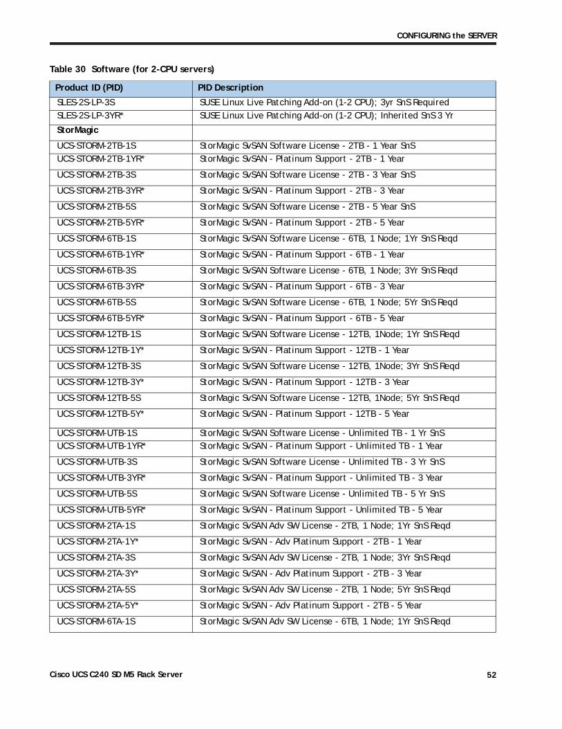
CONFIGURING the SERVER
SLES-2S-LP-3S SUSE Linux Live Patching Add-on (1-2 CPU); 3yr SnS RequiredSLES-2S-LP-3YR* SUSE Linux Live Patching Add-on (1-2 CPU); Inherited SnS 3 Yr
StorMagic
UCS-STORM-2TB-1S StorMagic SvSAN Software License - 2TB - 1 Year SnSUCS-STORM-2TB-1YR* StorMagic SvSAN - Platinum Support - 2TB - 1 Year
UCS-STORM-2TB-3S StorMagic SvSAN Software License - 2TB - 3 Year SnS
UCS-STORM-2TB-3YR* StorMagic SvSAN - Platinum Support - 2TB - 3 Year
UCS-STORM-2TB-5S StorMagic SvSAN Software License - 2TB - 5 Year SnS
UCS-STORM-2TB-5YR* StorMagic SvSAN - Platinum Support - 2TB - 5 Year
UCS-STORM-6TB-1S StorMagic SvSAN Software License - 6TB, 1 Node; 1Yr SnS Reqd
UCS-STORM-6TB-1YR* StorMagic SvSAN - Platinum Support - 6TB - 1 Year
UCS-STORM-6TB-3S StorMagic SvSAN Software License - 6TB, 1 Node; 3Yr SnS Reqd
UCS-STORM-6TB-3YR* StorMagic SvSAN - Platinum Support - 6TB - 3 Year
UCS-STORM-6TB-5S StorMagic SvSAN Software License - 6TB, 1 Node; 5Yr SnS Reqd
UCS-STORM-6TB-5YR* StorMagic SvSAN - Platinum Support - 6TB - 5 Year
UCS-STORM-12TB-1S StorMagic SvSAN Software License - 12TB, 1Node; 1Yr SnS Reqd
UCS-STORM-12TB-1Y* StorMagic SvSAN - Platinum Support - 12TB - 1 Year
UCS-STORM-12TB-3S StorMagic SvSAN Software License - 12TB, 1Node; 3Yr SnS Reqd
UCS-STORM-12TB-3Y* StorMagic SvSAN - Platinum Support - 12TB - 3 Year
UCS-STORM-12TB-5S StorMagic SvSAN Software License - 12TB, 1Node; 5Yr SnS Reqd
UCS-STORM-12TB-5Y* StorMagic SvSAN - Platinum Support - 12TB - 5 Year
UCS-STORM-UTB-1S StorMagic SvSAN Software License - Unlimited TB - 1 Yr SnSUCS-STORM-UTB-1YR* StorMagic SvSAN - Platinum Support - Unlimited TB - 1 Year
UCS-STORM-UTB-3S StorMagic SvSAN Software License - Unlimited TB - 3 Yr SnS
UCS-STORM-UTB-3YR* StorMagic SvSAN - Platinum Support - Unlimited TB - 3 Year
UCS-STORM-UTB-5S StorMagic SvSAN Software License - Unlimited TB - 5 Yr SnS
UCS-STORM-UTB-5YR* StorMagic SvSAN - Platinum Support - Unlimited TB - 5 Year
UCS-STORM-2TA-1S StorMagic SvSAN Adv SW License - 2TB, 1 Node; 1Yr SnS Reqd
UCS-STORM-2TA-1Y* StorMagic SvSAN - Adv Platinum Support - 2TB - 1 Year
UCS-STORM-2TA-3S StorMagic SvSAN Adv SW License - 2TB, 1 Node; 3Yr SnS Reqd
UCS-STORM-2TA-3Y* StorMagic SvSAN - Adv Platinum Support - 2TB - 3 Year
UCS-STORM-2TA-5S StorMagic SvSAN Adv SW License - 2TB, 1 Node; 5Yr SnS Reqd
UCS-STORM-2TA-5Y* StorMagic SvSAN - Adv Platinum Support - 2TB - 5 Year
UCS-STORM-6TA-1S StorMagic SvSAN Adv SW License - 6TB, 1 Node; 1Yr SnS Reqd
Table 30 Software (for 2-CPU servers)
Product ID (PID) PID Description
Cisco UCS C240 SD M5 Rack Server 52
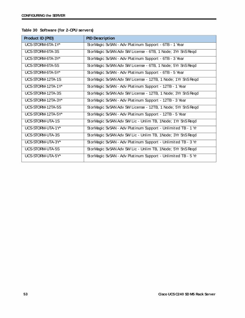
CONFIGURING the SERVER
UCS-STORM-6TA-1Y* StorMagic SvSAN - Adv Platinum Support - 6TB - 1 Year
UCS-STORM-6TA-3S StorMagic SvSAN Adv SW License - 6TB, 1 Node; 3Yr SnS Reqd
UCS-STORM-6TA-3Y* StorMagic SvSAN - Adv Platinum Support - 6TB - 3 Year
UCS-STORM-6TA-5S StorMagic SvSAN Adv SW License - 6TB, 1 Node; 5Yr SnS Reqd
UCS-STORM-6TA-5Y* StorMagic SvSAN - Adv Platinum Support - 6TB - 5 Year
UCS-STORM-12TA-1S StorMagic SvSAN Adv SW License - 12TB, 1 Node; 1Yr SnS Reqd
UCS-STORM-12TA-1Y* StorMagic SvSAN - Adv Platinum Support - 12TB - 1 Year
UCS-STORM-12TA-3S StorMagic SvSAN Adv SW License - 12TB, 1 Node; 3Yr SnS Reqd
UCS-STORM-12TA-3Y* StorMagic SvSAN - Adv Platinum Support - 12TB - 3 Year
UCS-STORM-12TA-5S StorMagic SvSAN Adv SW License - 12TB, 1 Node; 5Yr SnS Reqd
UCS-STORM-12TA-5Y* StorMagic SvSAN - Adv Platinum Support - 12TB - 5 Year
UCS-STORM-UTA-1S StorMagic SvSAN Adv SW Lic - Unlim TB, 1Node; 1Yr SnS Reqd
UCS-STORM-UTA-1Y* StorMagic SvSAN - Adv Platinum Support - Unlimited TB - 1 Yr
UCS-STORM-UTA-3S StorMagic SvSAN Adv SW Lic - Unlim TB, 1Node; 3Yr SnS Reqd
UCS-STORM-UTA-3Y* StorMagic SvSAN - Adv Platinum Support - Unlimited TB - 3 Yr
UCS-STORM-UTA-5S StorMagic SvSAN Adv SW Lic - Unlim TB, 1Node; 5Yr SnS Reqd
UCS-STORM-UTA-5Y* StorMagic SvSAN - Adv Platinum Support - Unlimited TB - 5 Yr
Table 30 Software (for 2-CPU servers)
Product ID (PID) PID Description
Cisco UCS C240 SD M5 Rack Server 53
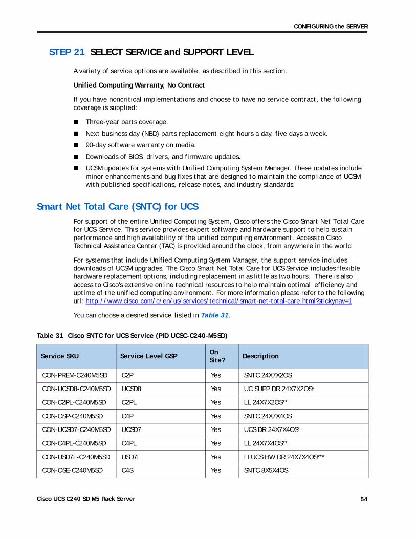
CONFIGURING the SERVER
STEP 21 SELECT SERVICE and SUPPORT LEVEL
A variety of service options are available, as described in this section.
Unified Computing Warranty, No Contract
If you have noncritical implementations and choose to have no service contract, the following coverage is supplied:
■ Three-year parts coverage.
■ Next business day (NBD) parts replacement eight hours a day, five days a week.
■ 90-day software warranty on media.
■ Downloads of BIOS, drivers, and firmware updates.
■ UCSM updates for systems with Unified Computing System Manager. These updates include minor enhancements and bug fixes that are designed to maintain the compliance of UCSM with published specifications, release notes, and industry standards.
Smart Net Total Care (SNTC) for UCS
For support of the entire Unified Computing System, Cisco offers the Cisco Smart Net Total Care for UCS Service. This service provides expert software and hardware support to help sustain performance and high availability of the unified computing environment. Access to Cisco Technical Assistance Center (TAC) is provided around the clock, from anywhere in the world
For systems that include Unified Computing System Manager, the support service includes downloads of UCSM upgrades. The Cisco Smart Net Total Care for UCS Service includes flexible hardware replacement options, including replacement in as little as two hours. There is also access to Cisco's extensive online technical resources to help maintain optimal efficiency and uptime of the unified computing environment. For more information please refer to the following url: http://www.cisco.com/c/en/us/services/technical/smart-net-total-care.html?stickynav=1
You can choose a desired service listed in Table 31.
Table 31 Cisco SNTC for UCS Service (PID UCSC-C240-M5SD)
Service SKU Service Level GSPOn Site?
Description
CON-PREM-C240M5SD C2P Yes SNTC 24X7X2OS
CON-UCSD8-C240M5SD UCSD8 Yes UC SUPP DR 24X7X2OS*
CON-C2PL-C240M5SD C2PL Yes LL 24X7X2OS**
CON-OSP-C240M5SD C4P Yes SNTC 24X7X4OS
CON-UCSD7-C240M5SD UCSD7 Yes UCS DR 24X7X4OS*
CON-C4PL-C240M5SD C4PL Yes LL 24X7X4OS**
CON-USD7L-C240M5SD USD7L Yes LLUCS HW DR 24X7X4OS***
CON-OSE-C240M5SD C4S Yes SNTC 8X5X4OS
Cisco UCS C240 SD M5 Rack Server 54
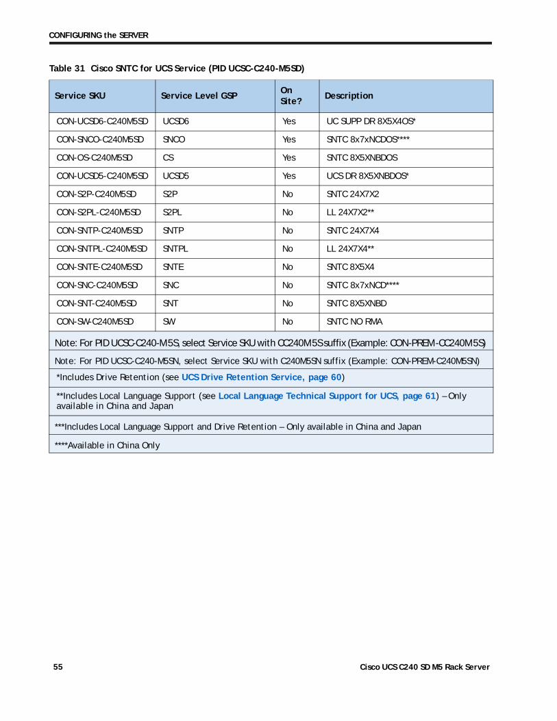
CONFIGURING the SERVER
CON-UCSD6-C240M5SD UCSD6 Yes UC SUPP DR 8X5X4OS*
CON-SNCO-C240M5SD SNCO Yes SNTC 8x7xNCDOS****
CON-OS-C240M5SD CS Yes SNTC 8X5XNBDOS
CON-UCSD5-C240M5SD UCSD5 Yes UCS DR 8X5XNBDOS*
CON-S2P-C240M5SD S2P No SNTC 24X7X2
CON-S2PL-C240M5SD S2PL No LL 24X7X2**
CON-SNTP-C240M5SD SNTP No SNTC 24X7X4
CON-SNTPL-C240M5SD SNTPL No LL 24X7X4**
CON-SNTE-C240M5SD SNTE No SNTC 8X5X4
CON-SNC-C240M5SD SNC No SNTC 8x7xNCD****
CON-SNT-C240M5SD SNT No SNTC 8X5XNBD
CON-SW-C240M5SD SW No SNTC NO RMA
Note: For PID UCSC-C240-M5S, select Service SKU with CC240M5S suffix (Example: CON-PREM-CC240M5S)
Note: For PID UCSC-C240-M5SN, select Service SKU with C240M5SN suffix (Example: CON-PREM-C240M5SN)
*Includes Drive Retention (see UCS Drive Retention Service, page 60)
**Includes Local Language Support (see Local Language Technical Support for UCS, page 61) – Only available in China and Japan
***Includes Local Language Support and Drive Retention – Only available in China and Japan
****Available in China Only
Table 31 Cisco SNTC for UCS Service (PID UCSC-C240-M5SD)
Service SKU Service Level GSPOn Site?
Description
Cisco UCS C240 SD M5 Rack Server 55
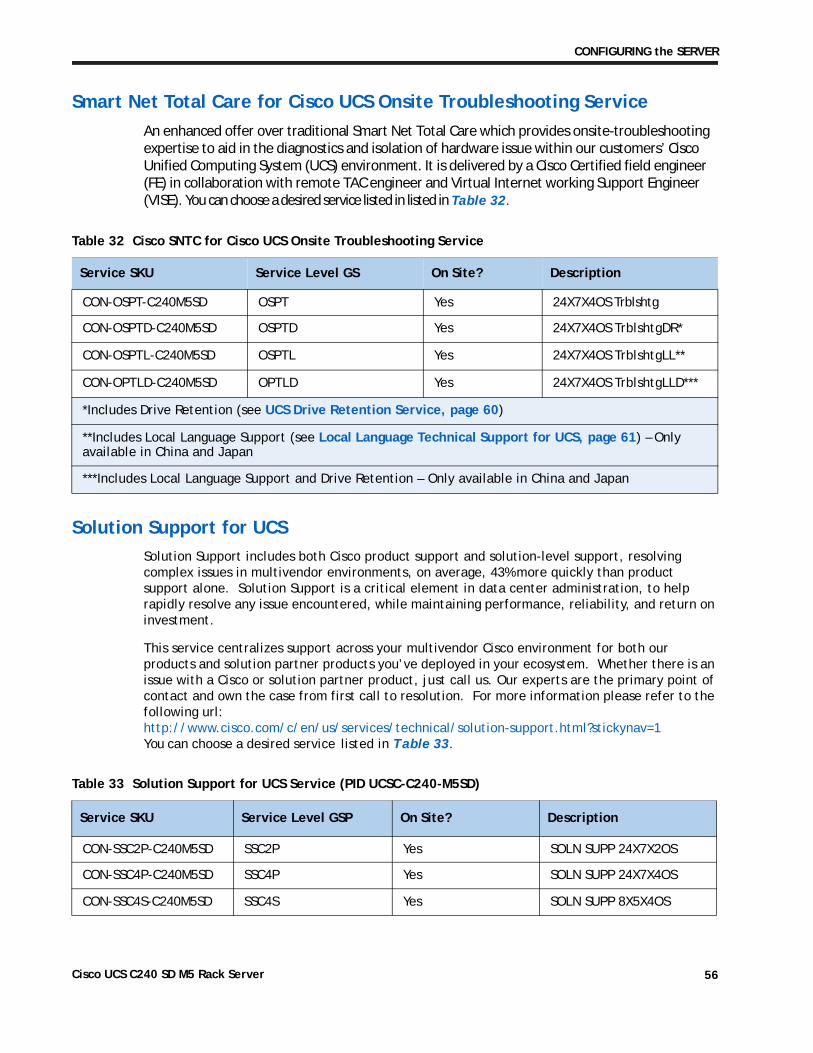
CONFIGURING the SERVER
Smart Net Total Care for Cisco UCS Onsite Troubleshooting Service
An enhanced offer over traditional Smart Net Total Care which provides onsite-troubleshooting expertise to aid in the diagnostics and isolation of hardware issue within our customers’ Cisco Unified Computing System (UCS) environment. It is delivered by a Cisco Certified field engineer (FE) in collaboration with remote TAC engineer and Virtual Internet working Support Engineer (VISE). You can choose a desired service listed in listed in Table 32.
Table 32 Cisco SNTC for Cisco UCS Onsite Troubleshooting Service
Service SKU Service Level GS On Site? Description
CON-OSPT-C240M5SD OSPT Yes 24X7X4OS Trblshtg
CON-OSPTD-C240M5SD OSPTD Yes 24X7X4OS TrblshtgDR*
CON-OSPTL-C240M5SD OSPTL Yes 24X7X4OS TrblshtgLL**
CON-OPTLD-C240M5SD OPTLD Yes 24X7X4OS TrblshtgLLD***
*Includes Drive Retention (see UCS Drive Retention Service, page 60)
**Includes Local Language Support (see Local Language Technical Support for UCS, page 61) – Only available in China and Japan
***Includes Local Language Support and Drive Retention – Only available in China and Japan
Solution Support for UCS
Solution Support includes both Cisco product support and solution-level support, resolving complex issues in multivendor environments, on average, 43% more quickly than product support alone. Solution Support is a critical element in data center administration, to help rapidly resolve any issue encountered, while maintaining performance, reliability, and return on investment.
This service centralizes support across your multivendor Cisco environment for both our products and solution partner products you’ve deployed in your ecosystem. Whether there is an issue with a Cisco or solution partner product, just call us. Our experts are the primary point of contact and own the case from first call to resolution. For more information please refer to the following url:http://www.cisco.com/c/en/us/services/technical/solution-support.html?stickynav=1You can choose a desired service listed in Table 33.
Table 33 Solution Support for UCS Service (PID UCSC-C240-M5SD)
Service SKU Service Level GSP On Site? Description
CON-SSC2P-C240M5SD SSC2P Yes SOLN SUPP 24X7X2OS
CON-SSC4P-C240M5SD SSC4P Yes SOLN SUPP 24X7X4OS
CON-SSC4S-C240M5SD SSC4S Yes SOLN SUPP 8X5X4OS
Cisco UCS C240 SD M5 Rack Server 56
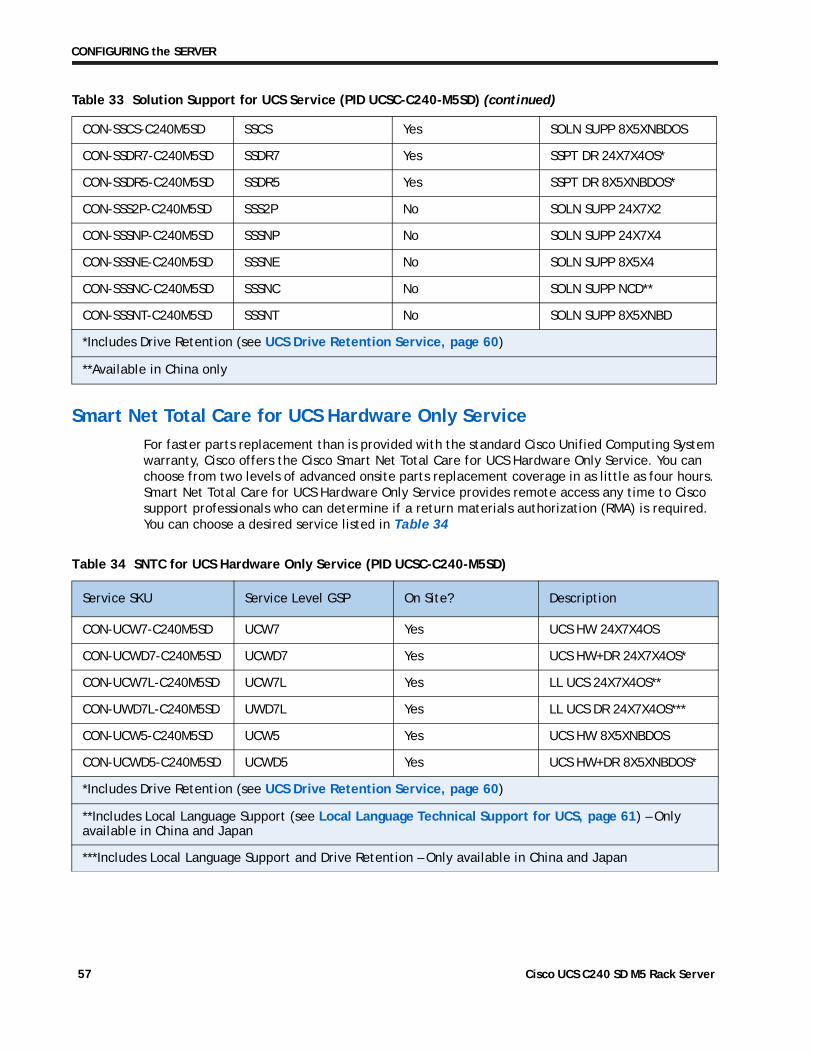
CONFIGURING the SERVER
Smart Net Total Care for UCS Hardware Only Service
For faster parts replacement than is provided with the standard Cisco Unified Computing System warranty, Cisco offers the Cisco Smart Net Total Care for UCS Hardware Only Service. You can choose from two levels of advanced onsite parts replacement coverage in as little as four hours. Smart Net Total Care for UCS Hardware Only Service provides remote access any time to Cisco support professionals who can determine if a return materials authorization (RMA) is required. You can choose a desired service listed in
Table 34 SNTC for UCS Hardware Only Service (PID UCSC-C240-M5SD)
Service SKU Service Level GSP On Site? Description
CON-UCW7-C240M5SD UCW7 Yes UCS HW 24X7X4OS
CON-UCWD7-C240M5SD UCWD7 Yes UCS HW+DR 24X7X4OS*
CON-UCW7L-C240M5SD UCW7L Yes LL UCS 24X7X4OS**
CON-UWD7L-C240M5SD UWD7L Yes LL UCS DR 24X7X4OS***
CON-UCW5-C240M5SD UCW5 Yes UCS HW 8X5XNBDOS
CON-UCWD5-C240M5SD UCWD5 Yes UCS HW+DR 8X5XNBDOS*
*Includes Drive Retention (see UCS Drive Retention Service, page 60)
**Includes Local Language Support (see Local Language Technical Support for UCS, page 61) – Only available in China and Japan
***Includes Local Language Support and Drive Retention – Only available in China and Japan
Table 34
CON-SSCS-C240M5SD SSCS Yes SOLN SUPP 8X5XNBDOS
CON-SSDR7-C240M5SD SSDR7 Yes SSPT DR 24X7X4OS*
CON-SSDR5-C240M5SD SSDR5 Yes SSPT DR 8X5XNBDOS*
CON-SSS2P-C240M5SD SSS2P No SOLN SUPP 24X7X2
CON-SSSNP-C240M5SD SSSNP No SOLN SUPP 24X7X4
CON-SSSNE-C240M5SD SSSNE No SOLN SUPP 8X5X4
CON-SSSNC-C240M5SD SSSNC No SOLN SUPP NCD**
CON-SSSNT-C240M5SD SSSNT No SOLN SUPP 8X5XNBD
*Includes Drive Retention (see UCS Drive Retention Service, page 60)
**Available in China only
Table 33 Solution Support for UCS Service (PID UCSC-C240-M5SD) (continued)
Cisco UCS C240 SD M5 Rack Server 57
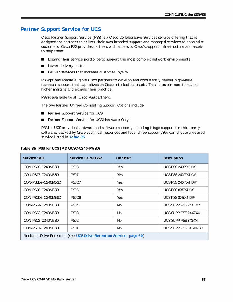
CONFIGURING the SERVER
Partner Support Service for UCS
Cisco Partner Support Service (PSS) is a Cisco Collaborative Services service offering that is designed for partners to deliver their own branded support and managed services to enterprise customers. Cisco PSS provides partners with access to Cisco's support infrastructure and assets to help them:
■ Expand their service portfolios to support the most complex network environments
■ Lower delivery costs
■ Deliver services that increase customer loyalty
PSS options enable eligible Cisco partners to develop and consistently deliver high-value technical support that capitalizes on Cisco intellectual assets. This helps partners to realize higher margins and expand their practice.
PSS is available to all Cisco PSS partners.
The two Partner Unified Computing Support Options include:
■ Partner Support Service for UCS
■ Partner Support Service for UCS Hardware Only
PSS for UCS provides hardware and software support, including triage support for third party software, backed by Cisco technical resources and level three support.You can choose a desired service listed in Table 35.
Table 35 PSS for UCS (PID UCSC-C240-M5SD)
Service SKU Service Level GSP On Site? Description
CON-PSJ8-C240M5SD PSJ8 Yes UCS PSS 24X7X2 OS
CON-PSJ7-C240M5SD PSJ7 Yes UCS PSS 24X7X4 OS
CON-PSJD7-C240M5SD PSJD7 Yes UCS PSS 24X7X4 DR*
CON-PSJ6-C240M5SD PSJ6 Yes UCS PSS 8X5X4 OS
CON-PSJD6-C240M5SD PSJD6 Yes UCS PSS 8X5X4 DR*
CON-PSJ4-C240M5SD PSJ4 No UCS SUPP PSS 24X7X2
CON-PSJ3-C240M5SD PSJ3 No UCS SUPP PSS 24X7X4
CON-PSJ2-C240M5SD PSJ2 No UCS SUPP PSS 8X5X4
CON-PSJ1-C240M5SD PSJ1 No UCS SUPP PSS 8X5XNBD
*Includes Drive Retention (see UCS Drive Retention Service, page 60)
Cisco UCS C240 SD M5 Rack Server 58
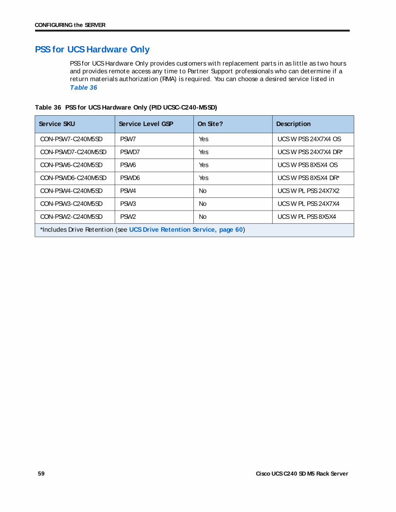
CONFIGURING the SERVER
PSS for UCS Hardware Only
PSS for UCS Hardware Only provides customers with replacement parts in as little as two hours and provides remote access any time to Partner Support professionals who can determine if a return materials authorization (RMA) is required. You can choose a desired service listed in
Table 36 PSS for UCS Hardware Only (PID UCSC-C240-M5SD)
Service SKU Service Level GSP On Site? Description
CON-PSW7-C240M5SD PSW7 Yes UCS W PSS 24X7X4 OS
CON-PSWD7-C240M5SD PSWD7 Yes UCS W PSS 24X7X4 DR*
CON-PSW6-C240M5SD PSW6 Yes UCS W PSS 8X5X4 OS
CON-PSWD6-C240M5SD PSWD6 Yes UCS W PSS 8X5X4 DR*
CON-PSW4-C240M5SD PSW4 No UCS W PL PSS 24X7X2
CON-PSW3-C240M5SD PSW3 No UCS W PL PSS 24X7X4
CON-PSW2-C240M5SD PSW2 No UCS W PL PSS 8X5X4
*Includes Drive Retention (see UCS Drive Retention Service, page 60)
Table 36
Cisco UCS C240 SD M5 Rack Server 59
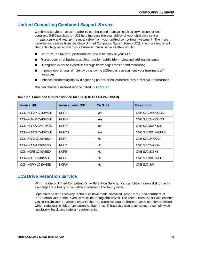
CONFIGURING the SERVER
Unified Computing Combined Support Service
Combined Services makes it easier to purchase and manage required services under one contract. SNTC services for UCS help increase the availability of your vital data center infrastructure and realize the most value from your unified computing investment. The more benefits you realize from the Cisco Unified Computing System (Cisco UCS), the more important the technology becomes to your business. These services allow you to:
■ Optimize the uptime, performance, and efficiency of your UCS
■ Protect your vital business applications by rapidly identifying and addressing issues
■ Strengthen in-house expertise through knowledge transfer and mentoring
■ Improve operational efficiency by allowing UCS experts to augment your internal staff resources
■ Enhance business agility by diagnosing potential issues before they affect your operations,
You can choose a desired service listed in
Table 37 Combined Support Service for UCS (PID UCSC-C240-M5SD)
Service SKU Service Level GSP On Site? Description
CON-NCF2P-C240M5SD NCF2P Yes CMB SVC 24X7X2OS
CON-NCF4P-C240M5SD NCF4P Yes CMB SVC 24X7X4OS
CON-NCF4S-C240M5SD NCF4S Yes CMB SVC 8X5X4OS
CON-NCFCS-C240M5SD NCFCS Yes CMB SVC 8X5XNBDOS
CON-NCF2-C240M5SD NCF2 No CMB SVC 24X7X2
CON-NCFP-C240M5SD NCFP No CMB SVC 24X7X4
CON-NCFE-C240M5SD NCFE No CMB SVC 8X5X4
CON-NCFT-C240M5SD NCFT No CMB SVC 8X5XNBD
CON-NCFW-C240M5SD NCFW No CMB SVC SW
Table 37
UCS Drive Retention Service
With the Cisco Unified Computing Drive Retention Service, you can obtain a new disk drive in exchange for a faulty drive without returning the faulty drive.
Sophisticated data recovery techniques have made classified, proprietary, and confidential information vulnerable, even on malfunctioning disk drives. The Drive Retention service enables you to retain your drives and ensures that the sensitive data on those drives is not compromised, which reduces the risk of any potential liabilities. This service also enables you to comply with regulatory, local, and federal requirements.
Cisco UCS C240 SD M5 Rack Server 60
CONFIGURING the SERVER
If your company has a need to control confidential, classified, sensitive, or proprietary data, you might want to consider one of the Drive Retention Services listed in the above tables (where available)
NOTE: Cisco does not offer a certified drive destruction service as part of this service.
Local Language Technical Support for UCS
Where available, and subject to an additional fee, local language support for calls on all assigned severity levels may be available for specific product(s) – see tables above.
For a complete listing of available services for Cisco Unified Computing System, see the following
http://www.cisco.com/en/US/products/ps10312/serv_group_home.html
ped separately from the C240 SD M5 SFF server.
Cisco UCS C240 SD M5 Rack Server 61
OPTIONAL STEP - ORDER PDU
OPTIONAL STEP - ORDER PDUAn optional power distribution unit (PDU) is available from Cisco for the C-Series rack servers. This PDU is available in a zero rack unit (RU) style or horizontal PDU style see Cisco RP-Series Rack and Rack PDU specification for more details at:
http://www.cisco.com/c/dam/en/us/products/collateral/servers-unified-computing/r-series-racks/rack-pdu-specsheet.pdf
Cisco UCS C240 SD M5 Rack Server 62
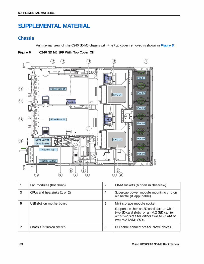
SUPPLEMENTAL MATERIAL
SUPPLEMENTAL MATERIAL
Chassis
An internal view of the C240 SD M5 chassis with the top cover removed is shown in Figure 6.
Figure 6 C240 SD M5 SFF With Top Cover Off
1 Fan modules (hot swap) 2 DIMM sockets (hidden in this view)
3 CPUs and heatsinks (1 or 2) 4 Supercap power module mounting clip on air baffle (if applicable)
5 USB slot on motherboard 6 Mini storage module socket
Supports either an SD card carrier with two SD card slots; or an M.2 SSD carrier with two slots for either two M.2 SATA or two M.2 NVMe SSDs.
7 Chassis intrusion switch 8 PCI cable connectors for NVMe drives
3076
41
Fan 01
Fan 02
Fan 03
Fan 04
Fan 05
Fan 06
CPU 02
CPU 01
PCIe Riser 01
PCIe Riser 02
Drive Bay 01
Drive Bay 02
PSU 01 Top
PSU 02 Bottom
1
2368
11
12
14
13
457910
15 16 17 18
Cisco UCS C240 SD M5 Rack Server 63
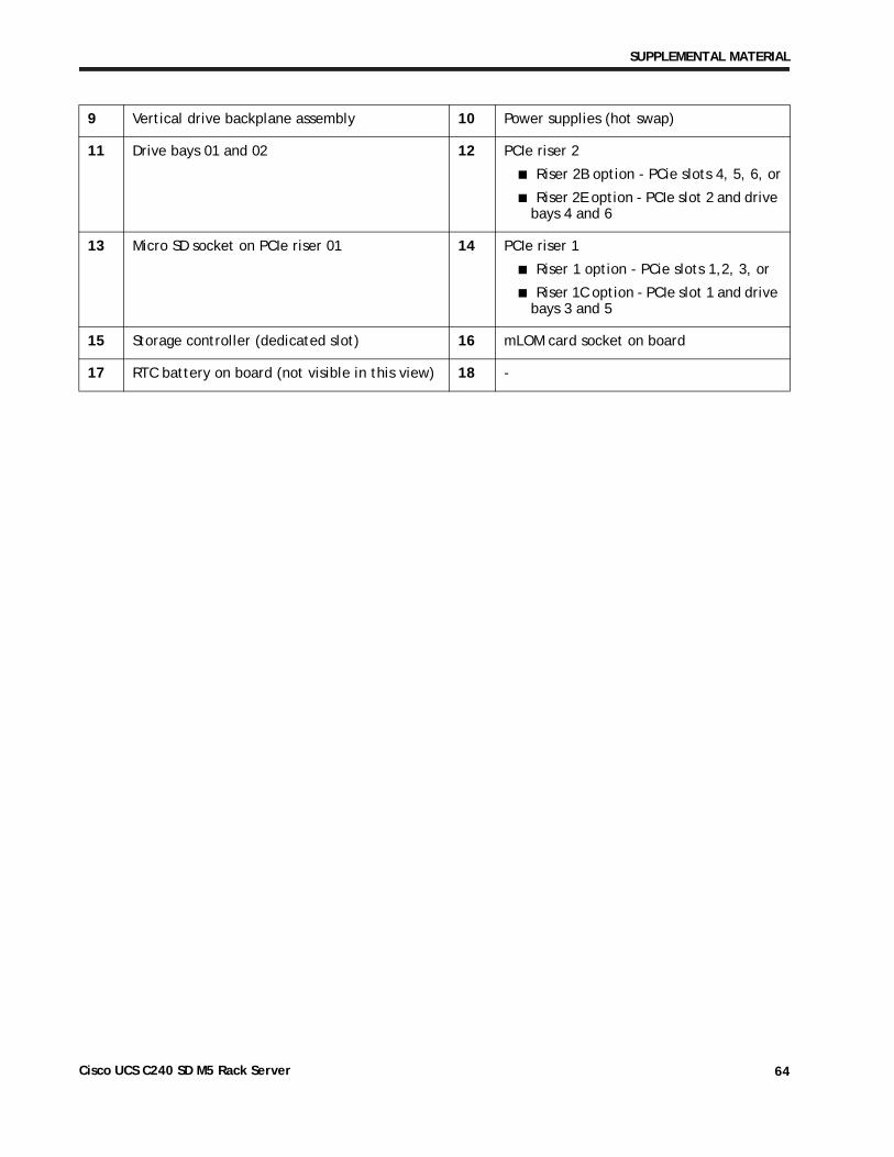
SUPPLEMENTAL MATERIAL
9 Vertical drive backplane assembly 10 Power supplies (hot swap)
11 Drive bays 01 and 02 12 PCIe riser 2
■ Riser 2B option - PCie slots 4, 5, 6, or
■ Riser 2E option - PCIe slot 2 and drive bays 4 and 6
13 Micro SD socket on PCIe riser 01 14 PCIe riser 1
■ Riser 1 option - PCie slots 1,2, 3, or
■ Riser 1C option - PCIe slot 1 and drive bays 3 and 5
15 Storage controller (dedicated slot) 16 mLOM card socket on board
17 RTC battery on board (not visible in this view) 18 -
Cisco UCS C240 SD M5 Rack Server 64
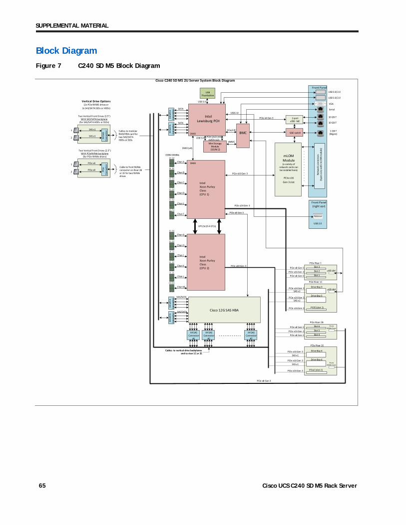
SUPPLEMENTAL MATERIAL
Block Diagram
Figure 7 C240 SD M5 Block Diagram
X4 S
ATA
Conn
ecto
rX4
SAT
A Co
nnec
tor
IntelLewisburg PCH
SATA
SATA
X4 S
ATA
Conn
ecto
rX4
SAT
A Co
nnec
tor
SAS/SATA
SAS/SATA Cisco 12G SAS HBA
A1
Chan A
Chan B
Chan C
Chan D
IntelXeon Purley Class(CPU 1)
IntelXeon Purley Class(CPU 2)
PCIe Riser 1
DMI3
DMI3 (x4)
USBThumbdrive
USB 3.0/2.0
VGA
10 GB-T
10 GB-T
1 GB-T (Mgmt)
Serial
PCIe x16 Gen 3
mLOM Module(a variety of
network cards can be installed here)
PCIe x16 Gen 3 slot
GbE switch
2-port x550 NIC
eMMC
BMC
Front Panel
PCIe x4 Gen 3
Net
wor
k co
nnec
tors
(typ
es v
ary
with
mLO
M m
odul
e)
. .
. .
. .
. .
. .
. .
Mini Storage Module
(SD/M.2)
Cisco C240 SD M5 2U Server System Block Diagram
USB 3.0
Front Panel(right ear)
USB 2.0
A2
B1 B2
C1 C2
D1 D2
E1 E2
F1 F2
Chan E
Chan F
G1
Chan G
Chan H
Chan J
Chan K
G2
H1 H2
J1 J2
K1 K2
L1 L2
M1 M2
Chan L
Chan M
UPI (3x10.4 GT/s)UPI (3x10.4 GT/s)
X4 SAS Connector
#1
Two Vertical Front Drives (2.5")With SAS/SATA backplane
(for SAS/SATA HDDs or SSDs)
1
2
X4 SAS Connector
#2
X4 SAS Connector
#7. . . . . . . . . . . .
X4 S
AS
Conn
ecto
r Cables to modular RAID/HBA card for two SAS/SATA HDDs ot SSDs
Cables to vertical drive backplanesand to riser 1C or 2E
Slot 1
Slot 2
Slot 3�SD slot
PCIE1(slot 1)
PCIe Riser 1C
�SD slot
Slot 4
Slot 5
Slot 6PCIe Riser 2B
FrontNVMe Conn
PCIe2 (slot 2)
Drive Bay 4
PCIe Riser 2E
PCIe x16 Gen 3
PCIe x8 Gen 3PCIe x16 Gen 3
PCIe x8 Gen 3
PCIe x16 Gen 3
PCIe x8 Gen 3PCIe x16 Gen 3
PCIe x8 Gen 3PCIe x40 Gen 3
PCIe x24 Gen 3
USB 3.0 PCIe (2x2) and sSATA (x2)
PCIe x8 Gen 3
DDR4 DIMMs
PCIe/LPC
SAS x1DMI3
USB 3.0/2.0
PCIe x8 Gen 3
FrontNVMe Conn
Two Vertical Front Drives (2.5")With PCIeNVMe backplane
(for PCIe NVMe drives)
1
2
Cable to front NVMe connector on Riser 2B or 2E for two NVMe drives
PCIe
Co
nnec
tor
PCIe x4
PCIe x4
SAS x1
Vertical Drive Options(2x PCIe NVME drives or
2x SAS/SATA SSDs or HDDs)
Drive Bay 6
Drive Bay 3
Drive Bay 5
SAS x1
SAS x1
PCIe x16 Gen 3
PCIe x16 Gen 3
PCIe x16 Gen 3
PCIe x16 Gen 3
SAS x1
SAS x1
USB 2.0
Cisco UCS C240 SD M5 Rack Server 65
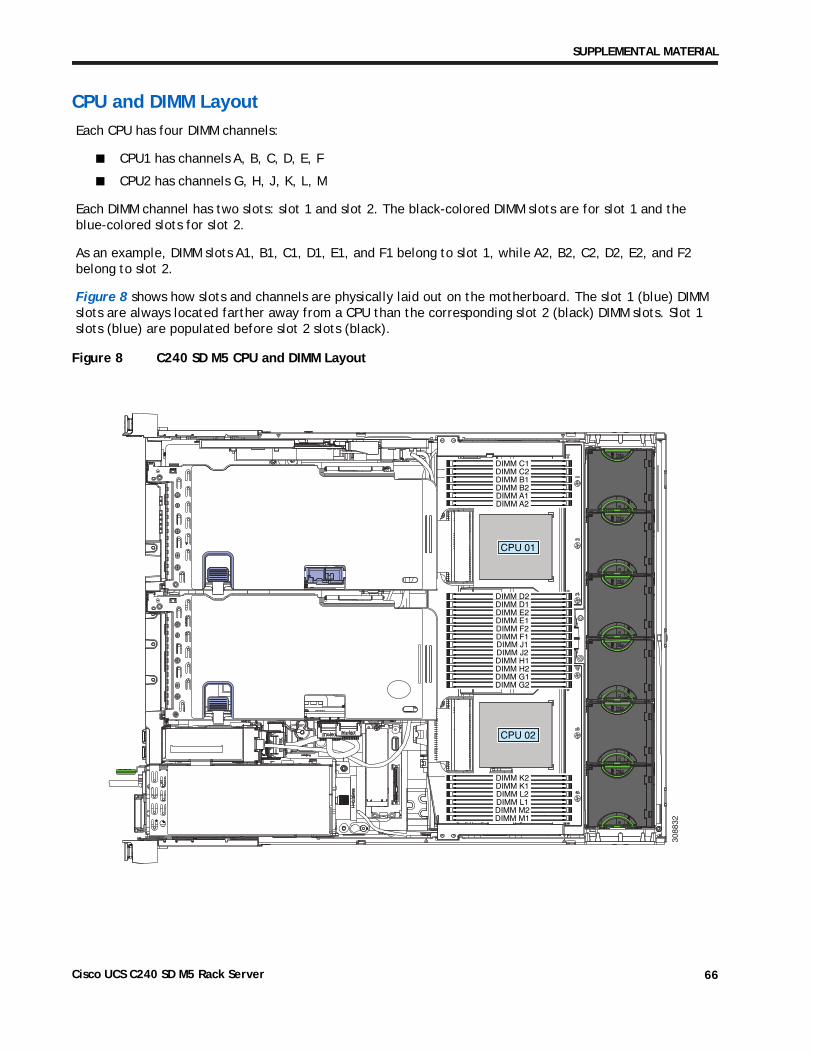
SUPPLEMENTAL MATERIAL
CPU and DIMM Layout
Each CPU has four DIMM channels:
■ CPU1 has channels A, B, C, D, E, F
■ CPU2 has channels G, H, J, K, L, M
Each DIMM channel has two slots: slot 1 and slot 2. The black-colored DIMM slots are for slot 1 and the blue-colored slots for slot 2.
As an example, DIMM slots A1, B1, C1, D1, E1, and F1 belong to slot 1, while A2, B2, C2, D2, E2, and F2 belong to slot 2.
Figure 8 shows how slots and channels are physically laid out on the motherboard. The slot 1 (blue) DIMM slots are always located farther away from a CPU than the corresponding slot 2 (black) DIMM slots. Slot 1 slots (blue) are populated before slot 2 slots (black).
Figure 8 C240 SD M5 CPU and DIMM Layout
308832
CPU 02
CPU 01
DIMM C1DIMM C2DIMM B1DIMM B2DIMM A1DIMM A2
DIMM D2DIMM D1DIMM E2DIMM E1DIMM F2DIMM F1DIMM J1DIMM J2DIMM H1DIMM H2DIMM G1DIMM G2
DIMM K2DIMM K1DIMM L2DIMM L1DIMM M2DIMM M1
Cisco UCS C240 SD M5 Rack Server 66
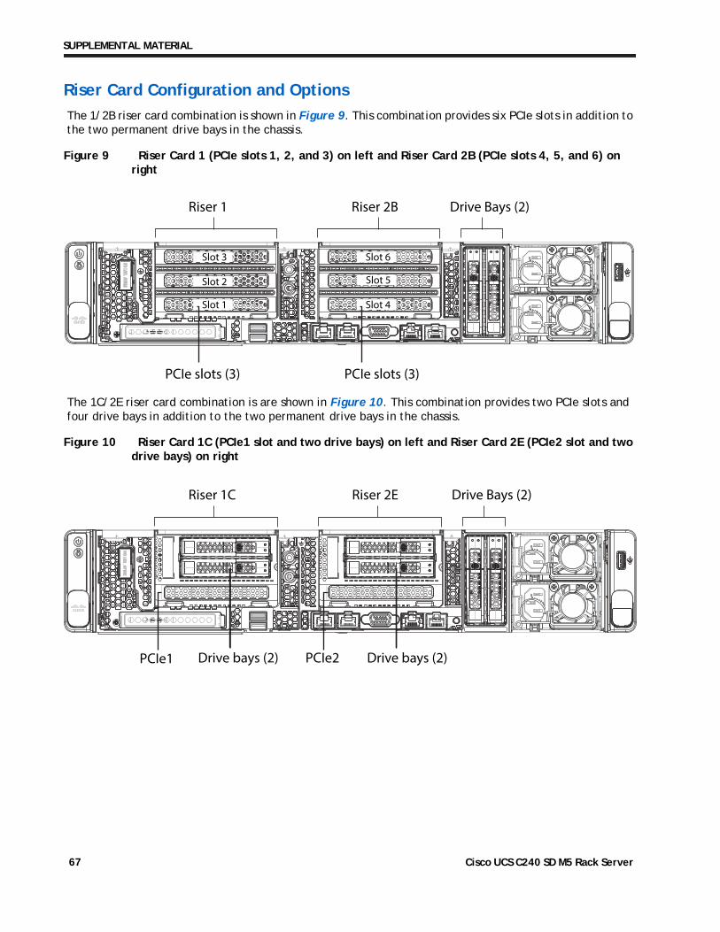
SUPPLEMENTAL MATERIAL
Riser Card Configuration and Options
The 1/2B riser card combination is shown in Figure 9. This combination provides six PCIe slots in addition to the two permanent drive bays in the chassis.
Figure 9 Riser Card 1 (PCIe slots 1, 2, and 3) on left and Riser Card 2B (PCIe slots 4, 5, and 6) on right
Riser 1 Drive Bays (2)Riser 2B
Slot 1
Slot 2
Slot 3
Slot 4
Slot 6
Slot 5
PCIe slots (3) PCIe slots (3)
The 1C/2E riser card combination is are shown in Figure 10. This combination provides two PCIe slots and four drive bays in addition to the two permanent drive bays in the chassis.
Figure 10 Riser Card 1C (PCIe1 slot and two drive bays) on left and Riser Card 2E (PCIe2 slot and two drive bays) on right
Riser 1C Riser 2E
PCIe1 Drive bays (2) PCIe2 Drive bays (2)
Drive Bays (2)
Cisco UCS C240 SD M5 Rack Server 67
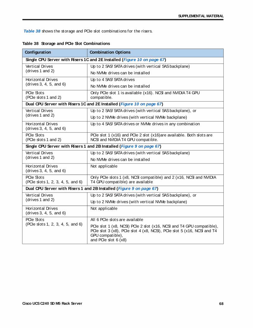
SUPPLEMENTAL MATERIAL
Table 38 shows the storage and PCIe slot combinations for the risers.
Table 38 Storage and PCIe Slot Combinations
Configuration Combination Options
Single CPU Server with Risers 1C and 2E Installed (Figure 10 on page 67)
Vertical Drives (drives 1 and 2)
Up to 2 SAS/SATA drives (with vertical SAS backplane)
No NVMe drives can be installed
Horizontal Drives(drives 3, 4, 5, and 6)
Up to 4 SAS/SATA drives
No NVMe drives can be installed
PCIe Slots (PCIe slots 1 and 2)
Only PCIe slot 1 is available (x16). NCSI and NVIDIA T4 GPU compatible.
Dual CPU Server with Risers 1C and 2E Installed (Figure 10 on page 67)
Vertical Drives (drives 1 and 2)
Up to 2 SAS/SATA drives (with vertical SAS backplane), or
Up to 2 NVMe drives (with vertical NVMe backplane)
Horizontal Drives(drives 3, 4, 5, and 6)
Up to 4 SAS/SATA drives or NVMe drives in any combination
PCIe Slots (PCIe slots 1 and 2)
PCIe slot 1 (x16) and PCIe 2 slot (x16)are available. Both slots are NCSI and NVIDIA T4 GPU compatible.
Single CPU Server with Risers 1 and 2B Installed (Figure 9 on page 67)
Vertical Drives (drives 1 and 2)
Up to 2 SAS/SATA drives (with vertical SAS backplane)
No NVMe drives can be installed
Horizontal Drives(drives 3, 4, 5, and 6)
Not applicable
PCIe Slots (PCIe slots 1, 2, 3, 4, 5, and 6)
Only PCIe slots 1 (x8, NCSI compatible) and 2 (x16, NCSI and NVIDIA T4 GPU compatible) are available
Dual CPU Server with Risers 1 and 2B Installed (Figure 9 on page 67)
Vertical Drives (drives 1 and 2)
Up to 2 SAS/SATA drives (with vertical SAS backplane), or
Up to 2 NVMe drives (with vertical NVMe backplane)
Horizontal Drives(drives 3, 4, 5, and 6)
Not applicable
PCIe Slots (PCIe slots 1, 2, 3, 4, 5, and 6)
All 6 PCIe slots are available
PCIe slot 1 (x8, NCSI) PCIe 2 slot (x16, NCSI and T4 GPU compatible), PCIe slot 3 (x8), PCIe slot 4 (x8, NCSI), PCIe slot 5 (x16, NCSI and T4 GPU compatible), and PCIe slot 6 (x8)
Cisco UCS C240 SD M5 Rack Server 68
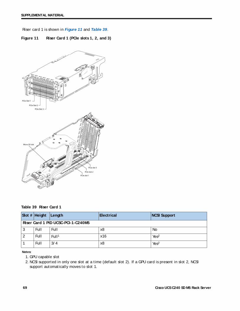
SUPPLEMENTAL MATERIAL
Riser card 1 is shown in Figure 11 and Table 39.
Figure 11 Riser Card 1 (PCIe slots 1, 2, and 3)
PCIe Slot 1
PCIe Slot 2
PCIe Slot 3
Micro SD slot
PCIe slot 1
PCIe slot 2
PCIe slot 3
Table 39 Riser Card 1
Slot # Height Length Electrical NCSI Support
Riser Card 1 PID UCSC-PCI-1-C240M5
3 Full Full x8 No
2 Full Full1 x16 Yes2
1 Full 3/4 x8 Yes2
Notes:
1. GPU capable slot2. NCSI supported in only one slot at a time (default slot 2). If a GPU card is present in slot 2, NCSI
support automatically moves to slot 1.
Cisco UCS C240 SD M5 Rack Server 69
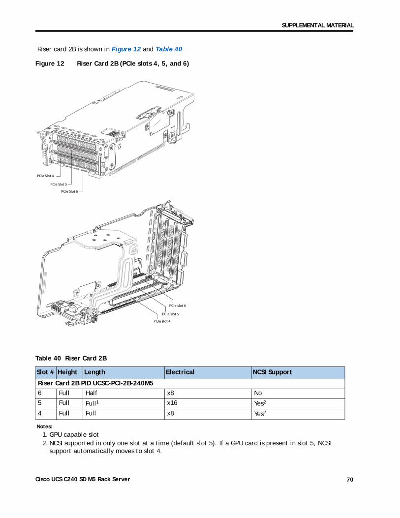
SUPPLEMENTAL MATERIAL
Riser card 2B is shown in Figure 12 and Table 40
Figure 12 Riser Card 2B (PCIe slots 4, 5, and 6)
PCIe slot 4
PCIe slot 5
PCIe slot 6
PCIe Slot 4
PCIe Slot 5
PCIe Slot 6
Table 40 Riser Card 2B
Slot # Height Length Electrical NCSI Support
Riser Card 2B PID UCSC-PCI-2B-240M5
6 Full Half x8 No
5 Full Full1 x16 Yes2
4 Full Full x8 Yes2
Notes:
1. GPU capable slot2. NCSI supported in only one slot at a time (default slot 5). If a GPU card is present in slot 5, NCSI
support automatically moves to slot 4.
Cisco UCS C240 SD M5 Rack Server 70
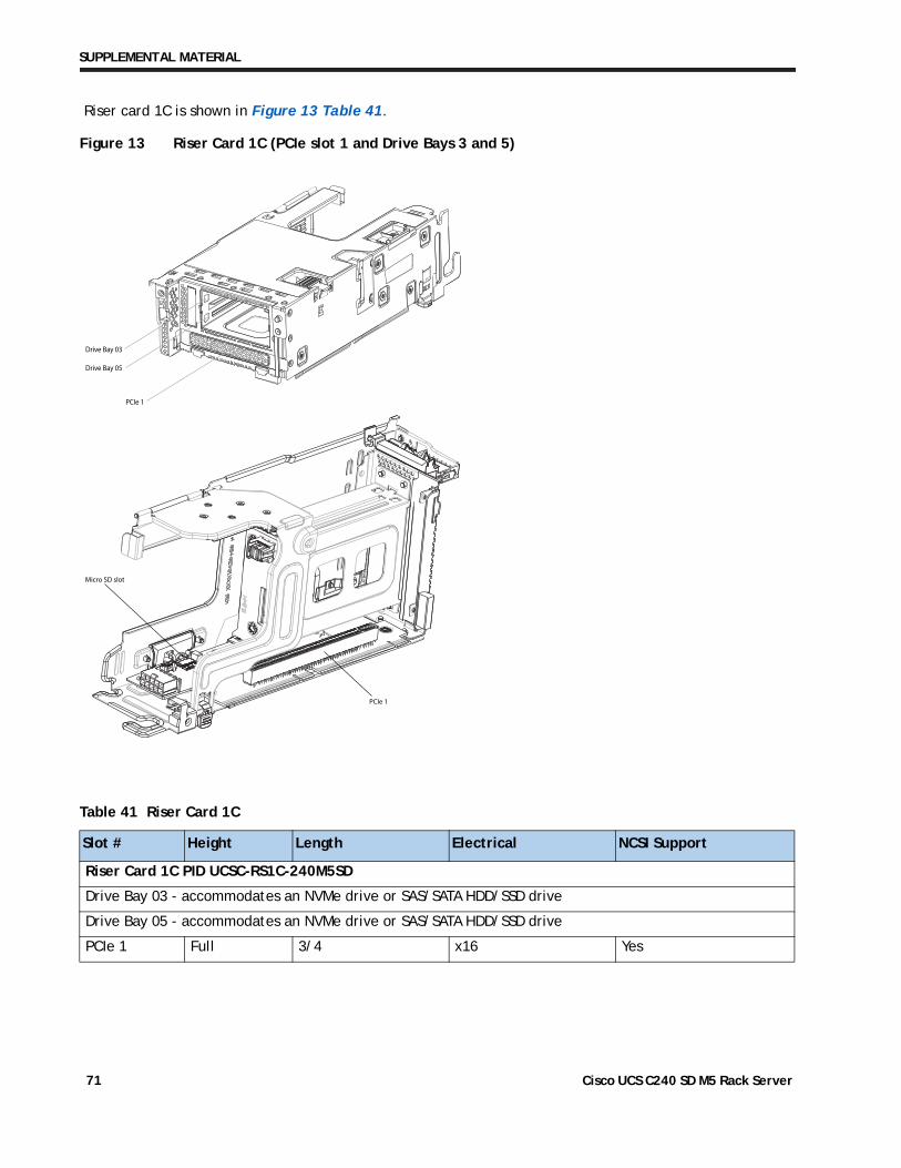
SUPPLEMENTAL MATERIAL
Riser card 1C is shown in Figure 13 Table 41.
Figure 13 Riser Card 1C (PCIe slot 1 and Drive Bays 3 and 5)
Drive Bay 03
Drive Bay 05
PCIe 1
Micro SD slot
PCIe 1
Table 41 Riser Card 1C
Slot # Height Length Electrical NCSI Support
Riser Card 1C PID UCSC-RS1C-240M5SD
Drive Bay 03 - accommodates an NVMe drive or SAS/SATA HDD/SSD drive
Drive Bay 05 - accommodates an NVMe drive or SAS/SATA HDD/SSD drive
PCIe 1 Full 3/4 x16 Yes
Cisco UCS C240 SD M5 Rack Server 71
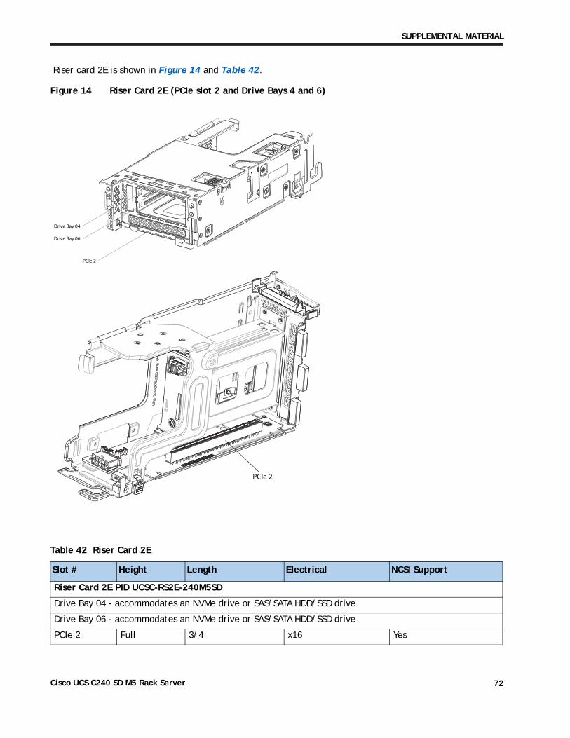
SUPPLEMENTAL MATERIAL
Riser card 2E is shown in Figure 14 and Table 42.
Figure 14 Riser Card 2E (PCIe slot 2 and Drive Bays 4 and 6)
Drive Bay 04
Drive Bay 06
PCIe 2
PCIe 2
Table 42 Riser Card 2E
Slot # Height Length Electrical NCSI Support
Riser Card 2E PID UCSC-RS2E-240M5SD
Drive Bay 04 - accommodates an NVMe drive or SAS/SATA HDD/SSD drive
Drive Bay 06 - accommodates an NVMe drive or SAS/SATA HDD/SSD drive
PCIe 2 Full 3/4 x16 Yes
Cisco UCS C240 SD M5 Rack Server 72
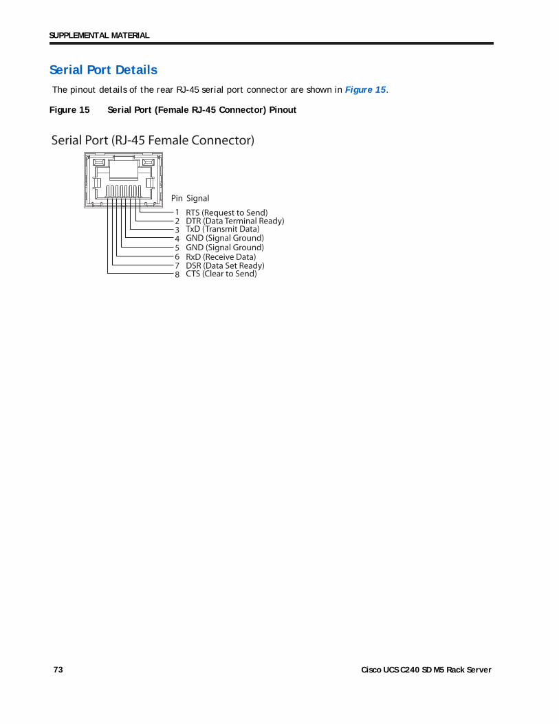
SUPPLEMENTAL MATERIAL
Serial Port Details
The pinout details of the rear RJ-45 serial port connector are shown in Figure 15.
Figure 15 Serial Port (Female RJ-45 Connector) Pinout
1 2345678
Pin
Serial Port (RJ-45 Female Connector)
Signal
RTS (Request to Send)DTR (Data Terminal Ready)TxD (Transmit Data)
RxD (Receive Data)DSR (Data Set Ready)CTS (Clear to Send)
GND (Signal Ground)GND (Signal Ground)
Cisco UCS C240 SD M5 Rack Server 73
SUPPLEMENTAL MATERIAL
PDUs
Cisco RP Series Power Distribution Units (PDUs) offer power distribution with branch circuit protection.
Cisco RP Series PDU models distribute power to up to 42 outlets. The architecture organizes power distribution, simplifies cable management, and enables you to move, add, and change rack equipment without an electrician.
With a Cisco RP Series PDU in the rack, you can replace up to two dozen input power cords with just one. The fixed input cord connects to the power source from overhead or under-floor distribution. Your IT equipment is then powered by PDU outlets in the rack using short, easy-to-manage power cords.
The C-series severs accept the zero-rack-unit (0RU) or horizontal PDU. see Cisco RP-Series Rack and Rack PDU specification for more details at
http://www.cisco.com/c/dam/en/us/products/collateral/servers-unified-computing/r-series-racks/rack-pdu-specsheet.pdf
Cisco UCS C240 SD M5 Rack Server 74
SUPPLEMENTAL MATERIAL
Memory Support for C240 SD M5 CPUs
■ DIMMs and PMEMs are supported
■ CPU PIDs ending in “M” support up to a limit of 2048 GB per CPU
■ CPU PIDs ending in “L” support up to a limit of 4608 GB per CPU
■ All other CPU PIDs support up to a limit of 1024 GB per CPU
■ For the App Direct Mode, both PMEM and DIMM capacities count towards the CPU capacity limit
■ For the Memory Mode and Mixed Mode only the PMEM capacity counts towards the CPU capacity limit
For Configurations Using Only DIMMs
■ CPU PIDs ending in “M” support DIMM capacities up to 1536 GB per CPU (using 12 x 128 GB DIMMs) and DIMM capacities up to 2048 GB per CPU (using 8 x 256 GB DIMMs).
■ CPU PIDs ending in “L” support DIMM capacities up to 1536 GB per CPU (using 12 x 128 GB DIMMs) and DIMM capacities up to 3072 GB per CPU (using 12 x 256 GB DIMMs). The 4608 GB limit cannot be reached with these capacity DIMMs.
■ CPU PIDs not ending in “L” or “M” support DIMM capacities up to 1024 GB per CPU (using 8 x 128 GB DIMMs or 4 x 256 GB DIMMs).
For Configurations Using DIMMs and PMEMs in App Direct Mode
■ CPU PIDs ending in “M” support capacities up to 1792 GB per CPU (using 6 x 128 GB DIMMS and 2 x 512 GB PMEMs or 4 x 256 GB PMEMs) or up to 2048 GB per CPU (using 6 x 256 GB DIMMs and 2 x 256 GB PMEMs or 6 x 256 GB DIMMs and 4 x 128 GB PMEMs)
■ CPU PIDs ending in “L” support capacities up to 3840 GB per CPU (using 6 x 128 GB DIMMs and 6 x 512 GB PMEMs) or up to 4608 GB per CPU (using 6 x 256 GB DIMMs and 6 x 512 GB PMEMs)
■ CPU PIDs not ending in “L” or “M” support capacities up to 1024 GB per CPU (using 6 x 128 GB DIMMs and 2 x 128 GB PMEMs).
For Configurations Using DIMMs and PMEMs in Memory or Mixed Mode
NOTE: For Memory and Mixed Modes, DIMMs are used as cache and do not factor into CPU capacity.
■ CPU PIDs ending in “M” support capacities up to 2048 GB per CPU using:
— 6 x 128 GB DIMMs as cache and 4 x 512 GB PMEMs as memory, or
— 6x 256 GB DIMMs as cache and 4 x 512 GB PMEMs as memory
Cisco UCS C240 SD M5 Rack Server 75
SUPPLEMENTAL MATERIAL
■ CPU PIDs ending in “L” support capacities up to 3072 GB using:
— 6 x 128 GB DIMMs as cache and 6 x 512 GB PMEMs as memory, or
— 6 x 256 GB DIMMs as cache and 6 x 512 GB PMEMs as memory
The allowable 4608 limit for PMEM capacity is not reached in this case.
■ CPU PIDs not ending in “L” or “M” support capacities up to 1024 GB per CPU using:
— 6 x 128 GB DIMMs as cache and 2 x 512 GB PMEMs as memory, or
— 6 x 256 GB DIMMs as cache and 2 x 512 GB PMEMs as memory
Cisco UCS C240 SD M5 Rack Server 76
SPARE PARTS
SPARE PARTSThis section lists the upgrade and servicing-related parts you may need during the life of your server. Some of these parts are configured with every server, and some may be ordered when needed or may be ordered and kept on hand as spares for future use. See Table 43
Table 43 Upgrade and Servicing-related Parts for UCS C240 SD M5 SFF Server
Spare Product ID (PID) Description
UCSC-HS2-C240M5= Heat sink for UCS C240 SD M5 rack servers CPUs above 150W
UCS-CPUAT= CPU Assembly Tool for M5 Servers
UCS-CPU-TIM= Single CPU thermal interface material syringe for M5 server HS seal
UCSX-HSCK= UCS Processor Heat Sink Cleaning Kit For Replacement of CPU
UCS-M5-CPU-CAR= UCS M5 CPU Carrier
UCSC-RNVME-240M5= C240 SD M5 Rear NVMe cable (1) kit, contain Rear NVMe cable and backplane
UCSC-RSAS-C240M5x C240M5SX Rear drive SAS cable kit (includes SAS cable/backplane)
UCSC-BBLKD-S2= C-Series M5 SFF drive blanking panel1
CBL-SASHBA-M5SD= CBL, SAS HBA to Riser1 & 2 w/ SAS/SATA drive, C240M5SD
UCSC-RIS-CBL-M5SD C240 M5SD Riser-2 to Riser-1 Cable
UCSC-PCI-1-C240M5= Riser 1 incl 3 PCIe slots (x8, x16, x8); slot 3 requires CPU2
UCSC-PCI-2B-240M5= Riser 2B incl 3PCIeslots(x8,x16,x8); supports GPU and rear SFF NVMe
UCSC-RS1C-240M5SD= Riser 1C one PCIe slot, 2 drive bays, and a micro SD slot
UCSC-RS2E-240M5SD= Riser 2E one PCIe slot, 2 drive bays, 1 NVMe connector
UCSC-PCIF-240M5=2 C240 SD M5 PCIe Riser Blanking Panel
UCSC-MLOMBLK-M5= C220 M5 and C240 SD M5 mLOM blanking panel
UCSC-RAILS-M5= Ball Bearing Rail Kit for C240M5 SD Rack Server
UCSC-C240SD-EXT= UCS C240SD M5 Extender Kit for 2-post rack
UCSC-FAN-C240M5SD= C240 SD M5 Fan Module (one)
N20-BKVM= KVM cable for Server console port
UCSC-PSU-M5BLK= Power Supply Blanking Panel for M5 servers
UCS-MSTOR-SD= Mini Storage Carrier for SD (holds up to 2)
UCS-MSTOR-M2= Mini Storage Carrier for M.2 SATA/NVME (holds up to 2)
PACK-QSFP-SFP= Packaging for QSFP 40G and SFP 10G
UCSC-INT-SW01= C220 M5 and C240 SD M5 Chassis Intrusion Switch
.
Notes:
1. A drive blanking panel must be installed if you remove a disk drive from a UCS server. These panels are required to maintain system temperatures at safe operating levels, and to keep dust away from system components.
2. If a new riser blanking panel is required, please order UCSC-PCIF-240M5=, which is a 3-panel filler for the entire riser. For a single slot filler, please order UCSC-PCIF-01F= (only for Riser 1 and Riser 2B).
Cisco UCS C240 SD M5 Rack Server 77
UPGRADING or REPLACING CPUs
UPGRADING or REPLACING CPUs
NOTE: Before servicing any CPU, do the following:
■ Decommission and power off the server.
■ Slide the C240 SD M5 SFF server out from the rack.
■ Remove the top cover.
To replace an existing CPU, follow these steps:
(1) Have the following tools and materials available for the procedure:
■ T-30 Torx driver—Supplied with replacement CPU.
■ #1 flat-head screwdriver—Supplied with replacement CPU.
■ CPU assembly tool—Supplied with replacement CPU. Can be ordered separately as Cisco PID UCS-CPUAT=.
■ Heatsink cleaning kit—Supplied with replacement CPU. Can be ordered separately as Cisco PID UCSX-HSCK=.
■ Thermal interface material (TIM)—Syringe supplied with replacement CPU. Can be ordered separately as Cisco PID UCS-CPU-TIM=.
(2) Order the appropriate replacement CPU from Table 4 on page 14 or Table 5 on page 15.
(3) Carefully remove and replace the CPU and heatsink in accordance with the instructions found in “Cisco UCS C240 SD M5 Server Installation and Service Guide,” found at:
https://www.cisco.com/c/en/us/td/docs/unified_computing/ucs/c/hw/C240M5/install/C240M5/C240M5_chapter_010.html#concept_bfk_kwp_hz.
To add a new CPU, follow these steps:
(1) Have the following tools and materials available for the procedure:
■ T-30 Torx driver—Supplied with new CPU.
■ #1 flat-head screwdriver—Supplied with new CPU
■ CPU assembly tool—Supplied with new CPU.Can be ordered separately as Cisco PID UCS-CPUAT=
■ Thermal interface material (TIM)—Syringe supplied with replacement CPU.Can be ordered separately as Cisco PID UCS-CPU-TIM=
(2) Order the appropriate new CPU from Table 4 on page 14 or Table 5 on page 15.
(3) Order one heat sink for each new CPU. Order PID UCSC-HS-C220M5= for CPUs that dissipate 150 W or less. Order PID UCSC-HS2-C220M5= for CPUs that dissipate more than 150 W.
Cisco UCS C240 SD M5 Rack Server 78
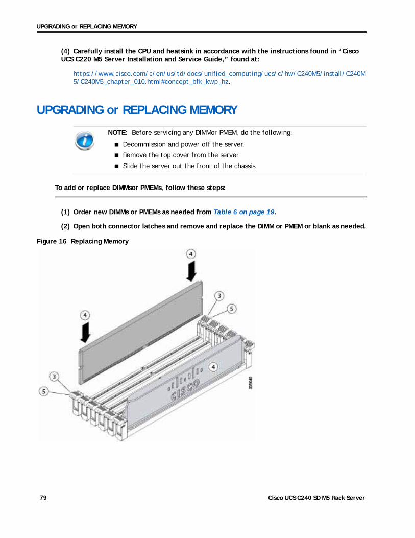
UPGRADING or REPLACING MEMORY
(4) Carefully install the CPU and heatsink in accordance with the instructions found in “Cisco UCS C220 M5 Server Installation and Service Guide,” found at:
https://www.cisco.com/c/en/us/td/docs/unified_computing/ucs/c/hw/C240M5/install/C240M5/C240M5_chapter_010.html#concept_bfk_kwp_hz.
UPGRADING or REPLACING MEMORY
NOTE: Before servicing any DIMMor PMEM, do the following:
■ Decommission and power off the server.
■ Remove the top cover from the server
■ Slide the server out the front of the chassis.
To add or replace DIMMsor PMEMs, follow these steps:
(1) Order new DIMMs or PMEMs as needed from Table 6 on page 19.
(2) Open both connector latches and remove and replace the DIMM or PMEM or blank as needed.
Figure 16 Replacing Memory
Cisco UCS C240 SD M5 Rack Server 79
UPGRADING or REPLACING MEMORY
(3) Press evenly on both ends of the DIMM or PMEM until it clicks into place in its slot.
(4) Press the connector latches inward slightly to seat them fully.
For additional details on replacing or upgrading DIMMs or PMEMs, see “Cisco UCS C240 SD M5 Server Installation and Service Guide,” found at these links:
https://www.cisco.com/c/en/us/td/docs/unified_computing/ucs/c/hw/C240M5/install/C240M5/C240M5_chapter_010.html#concept_c53_tbp_hz
https://www.cisco.com/c/en/us/td/docs/unified_computing/ucs/c/hw/C240M5/install/C240M5/C240M5_chapter_010.html#concept_b1k_mbt_tgb
NOTE: Ensure that the notch in the DIMM or PMEM aligns with the slot. If the notch is misaligned, it is possible to damage the DIMM or PMEM, the slot, or both.
Cisco UCS C240 SD M5 Rack Server 80
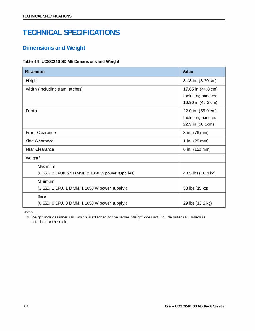
TECHNICAL SPECIFICATIONS
TECHNICAL SPECIFICATIONS
Dimensions and Weight
Table 44 UCS C240 SD M5 Dimensions and Weight
Parameter Value
Height 3.43 in. (8.70 cm)
Width (including slam latches) 17.65 in.(44.8 cm)
Including handles:
18.96 in (48.2 cm)
Depth 22.0 in. (55.9 cm)
Including handles:
22.9 in (58.1cm)
Front Clearance 3 in. (76 mm)
Side Clearance 1 in. (25 mm)
Rear Clearance 6 in. (152 mm)
Weight1
Maximum
(6 SSD, 2 CPUs, 24 DIMMs, 2 1050 W power supplies) 40.5 lbs (18.4 kg)
Minimum
(1 SSD, 1 CPU, 1 DIMM, 1 1050 W power supply)) 33 lbs (15 kg)
Bare
(0 SSD, 0 CPU, 0 DIMM, 1 1050 W power supply)) 29 lbs (13.2 kg)
Notes:
1. Weight includes inner rail, which is attached to the server. Weight does not include outer rail, which is attached to the rack.
Cisco UCS C240 SD M5 Rack Server 81
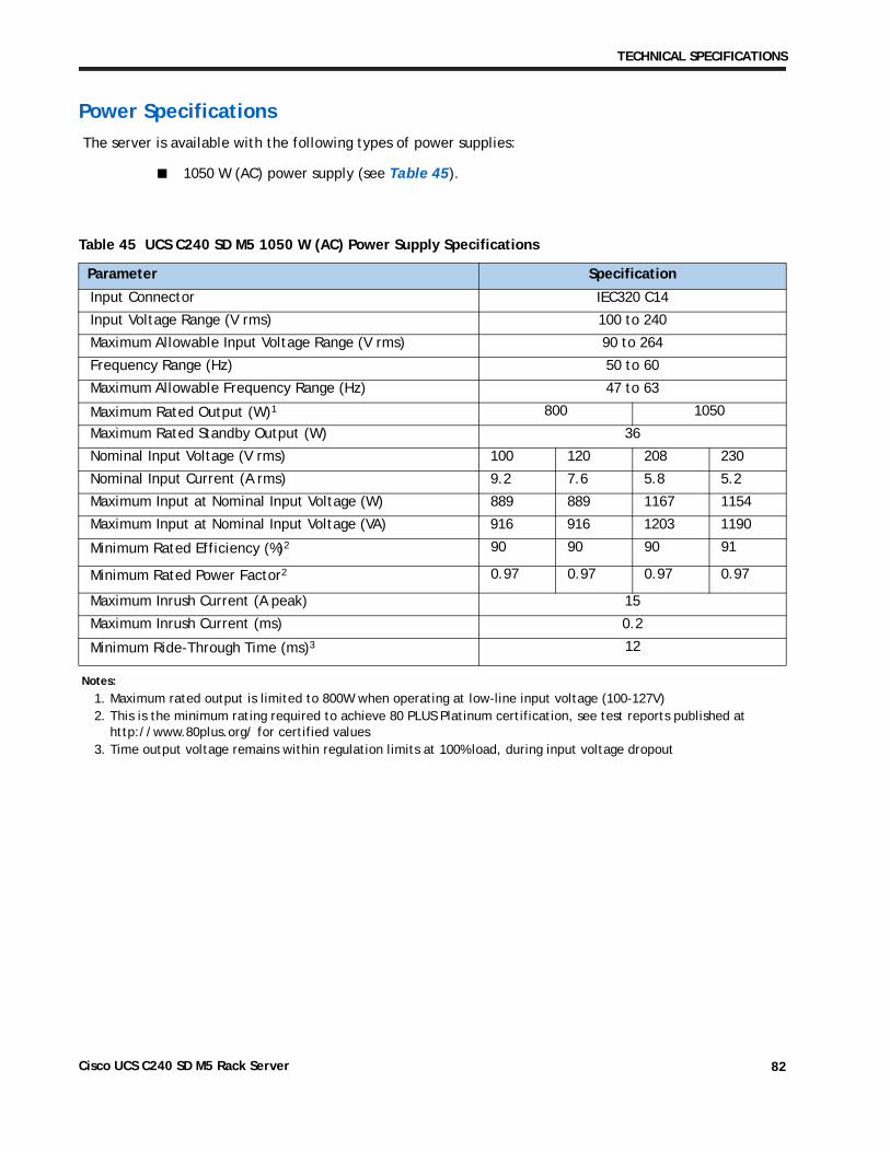
TECHNICAL SPECIFICATIONS
Power Specifications
The server is available with the following types of power supplies:
■ 1050 W (AC) power supply (see Table 45).
Table 45 UCS C240 SD M5 1050 W (AC) Power Supply Specifications
Parameter Specification
Input Connector IEC320 C14
Input Voltage Range (V rms) 100 to 240
Maximum Allowable Input Voltage Range (V rms) 90 to 264
Frequency Range (Hz) 50 to 60
Maximum Allowable Frequency Range (Hz) 47 to 63
Maximum Rated Output (W)1
Notes:
1. Maximum rated output is limited to 800W when operating at low-line input voltage (100-127V)
800 1050
Maximum Rated Standby Output (W) 36
Nominal Input Voltage (V rms) 100 120 208 230
Nominal Input Current (A rms) 9.2 7.6 5.8 5.2
Maximum Input at Nominal Input Voltage (W) 889 889 1167 1154
Maximum Input at Nominal Input Voltage (VA) 916 916 1203 1190
Minimum Rated Efficiency (%)2
2. This is the minimum rating required to achieve 80 PLUS Platinum certification, see test reports published at http://www.80plus.org/ for certified values
90 90 90 91
Minimum Rated Power Factor2 0.97 0.97 0.97 0.97
Maximum Inrush Current (A peak) 15
Maximum Inrush Current (ms) 0.2
Minimum Ride-Through Time (ms)3
3. Time output voltage remains within regulation limits at 100% load, during input voltage dropout
12
Cisco UCS C240 SD M5 Rack Server 82
TECHNICAL SPECIFICATIONS
For configuration-specific power specifications, use the Cisco UCS Power Calculator at this URL:
http://ucspowercalc.cisco.com
Cisco UCS C240 SD M5 Rack Server 83
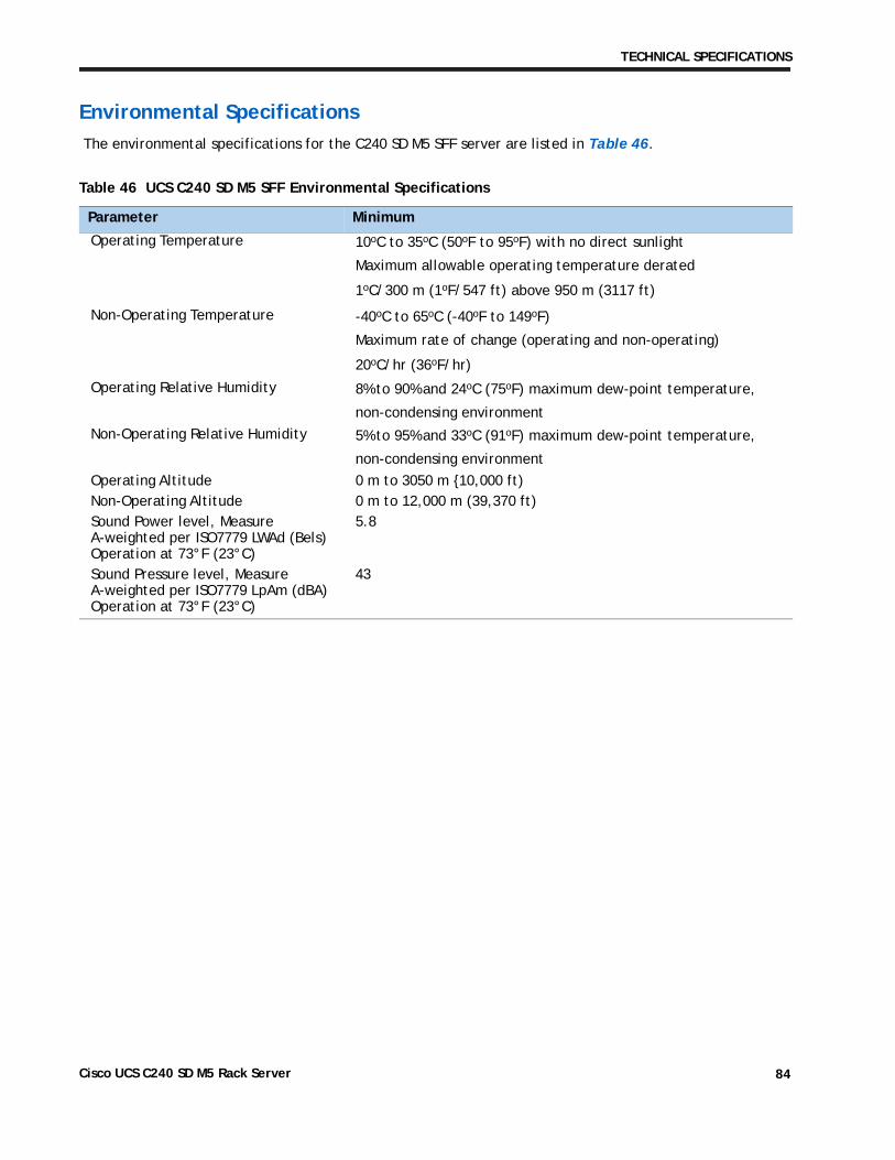
TECHNICAL SPECIFICATIONS
Environmental Specifications
The environmental specifications for the C240 SD M5 SFF server are listed in Table 46.
Table 46 UCS C240 SD M5 SFF Environmental Specifications
Parameter Minimum
Operating Temperature 10oC to 35oC (50oF to 95oF) with no direct sunlight
Maximum allowable operating temperature derated
1oC/300 m (1oF/547 ft) above 950 m (3117 ft)
Non-Operating Temperature -40oC to 65oC (-40oF to 149oF)
Maximum rate of change (operating and non-operating)
20oC/hr (36oF/hr)
Operating Relative Humidity 8% to 90% and 24oC (75oF) maximum dew-point temperature,
non-condensing environment
Non-Operating Relative Humidity 5% to 95% and 33oC (91oF) maximum dew-point temperature,
non-condensing environment
Operating Altitude 0 m to 3050 m {10,000 ft)Non-Operating Altitude 0 m to 12,000 m (39,370 ft)Sound Power level, Measure A-weighted per ISO7779 LWAd (Bels) Operation at 73°F (23°C)
5.8
Sound Pressure level, Measure A-weighted per ISO7779 LpAm (dBA) Operation at 73°F (23°C)
43
Cisco UCS C240 SD M5 Rack Server 84
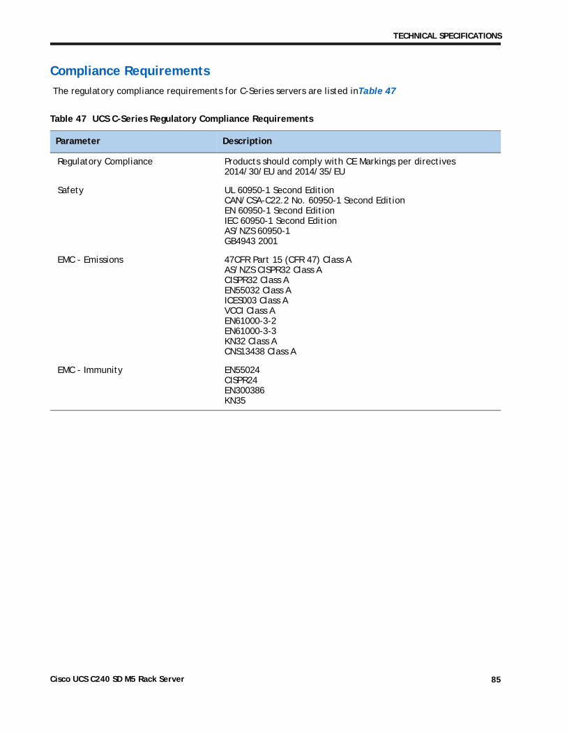
TECHNICAL SPECIFICATIONS
Compliance Requirements
The regulatory compliance requirements for C-Series servers are listed inTable 47
Table 47 UCS C-Series Regulatory Compliance Requirements
Parameter Description
Regulatory Compliance Products should comply with CE Markings per directives 2014/30/EU and 2014/35/EU
Safety UL 60950-1 Second EditionCAN/CSA-C22.2 No. 60950-1 Second EditionEN 60950-1 Second EditionIEC 60950-1 Second EditionAS/NZS 60950-1GB4943 2001
EMC - Emissions 47CFR Part 15 (CFR 47) Class A AS/NZS CISPR32 Class A CISPR32 Class AEN55032 Class A ICES003 Class A VCCI Class A EN61000-3-2EN61000-3-3KN32 Class A CNS13438 Class A
EMC - Immunity EN55024CISPR24EN300386KN35
Cisco UCS C240 SD M5 Rack Server 85
TECHNICAL SPECIFICATIONS
Cisco UCS C240 SD M5 Rack Server 86


![Zggh]hPH>new.groteck.ru/images/catalog/40429/9deec18637ee6ecbb5a6ae0a1… · UCS 6200 Series Fabric Interconnect UCS Manager UCS C240 M3/M4 Series Rack Server UCS Integrated Infrastructure](https://img.pdfslide.us/doc/110x75/5fcc7e22130a463bbb0b3c57/zgghhphnew-ucs-6200-series-fabric-interconnect-ucs-manager-ucs-c240-m3m4.jpg)