Embed Size (px)
Citation preview
Cisco IP Telephony Network Design GuideCisco CallManager Release 3.0(5)
170 West Tasman DriveSan Jose, CA 95134-1706USAhttp://www.cisco.com
Cisco Systems, Inc.Corporate Headquarters
Tel:800 553-NETS (6387)408 526-4000
Fax: 408 526-4100
Customer Order Number: DOC-7811103=Text Part Number: 78-11103-03

THE SPECIFICATIONS AND INFORMATION REGARDING THE PRODUCTS IN THIS MANUAL ARE SUBJECT TO CHANGE WITHOUT NOTICE. ALL STATEMENTS, INFORMATION, AND RECOMMENDATIONS IN THIS MANUAL ARE BELIEVED TO BE ACCURATE BUT ARE PRESENTED WITHOUT WARRANTY OF ANY KIND, EXPRESS OR IMPLIED. USERS MUST TAKE FULL RESPONSIBILITY FOR THEIR APPLICATION OF ANY PRODUCTS.
THE SOFTWARE LICENSE AND LIMITED WARRANTY FOR THE ACCOMPANYING PRODUCT ARE SET FORTH IN THE INFORMATION PACKET THAT SHIPPED WITH THE PRODUCT AND ARE INCORPORATED HEREIN BY THIS REFERENCE. IF YOU ARE UNABLE TO LOCATE THE SOFTWARE LICENSE OR LIMITED WARRANTY, CONTACT YOUR CISCO REPRESENTATIVE FOR A COPY.
The Cisco implementation of TCP header compression is an adaptation of a program developed by the University of California, Berkeley (UCB) as part of UCB’s public domain version of the UNIX operating system. All rights reserved. Copyright © 1981, Regents of the University of California.
NOTWITHSTANDING ANY OTHER WARRANTY HEREIN, ALL DOCUMENT FILES AND SOFTWARE OF THESE SUPPLIERS ARE PROVIDED “AS IS” WITH ALL FAULTS. CISCO AND THE ABOVE-NAMED SUPPLIERS DISCLAIM ALL WARRANTIES, EXPRESSED OR IMPLIED, INCLUDING, WITHOUT LIMITATION, THOSE OF MERCHANTABILITY, FITNESS FOR A PARTICULAR PURPOSE AND NONINFRINGEMENT OR ARISING FROM A COURSE OF DEALING, USAGE, OR TRADE PRACTICE.
IN NO EVENT SHALL CISCO OR ITS SUPPLIERS BE LIABLE FOR ANY INDIRECT, SPECIAL, CONSEQUENTIAL, OR INCIDENTAL DAMAGES, INCLUDING, WITHOUT LIMITATION, LOST PROFITS OR LOSS OR DAMAGE TO DATA ARISING OUT OF THE USE OR INABILITY TO USE THIS MANUAL, EVEN IF CISCO OR ITS SUPPLIERS HAVE BEEN ADVISED OF THE POSSIBILITY OF SUCH DAMAGES.
AtmDirector, Browse with Me, CCDA, CCDE, CCDP, CCIE, CCNA, CCNP, CCSI, CD-PAC, CiscoLink, the Cisco NetWorks logo, the Cisco Powered Network logo, Cisco Systems Networking Academy, the Cisco Systems Networking Academy logo, Fast Step, Follow Me Browsing, FormShare,FrameShare, GigaStack, IGX, Internet Quotient, IP/VC, iQ Breakthrough, iQ Expertise, iQ FastTrack, the iQ Logo, iQ Net Readiness Scorecard, MGX, the Networkers logo, Packet, PIX, RateMUX, ScriptShare, SlideCast, SMARTnet, TransPath, Voice LAN, Wavelength Router, WebViewer are trademarks of Cisco Systems, Inc.; Changing the Way We Work, Live, Play, and Learn, Empowering the Internet Generation, are service marks of Cisco Systems, Inc.; and Aironet, ASIST, BPX, Catalyst, Cisco, the Cisco Certified Internetwork Expert Logo, Cisco IOS, the Cisco IOS logo, Cisco Systems, Cisco Systems Capital, the Cisco Systems logo, Enterprise/Solver, EtherChannel, EtherSwitch, FastHub, IOS, IP/TV, LightStream, Post-Routing, Pre-Routing, Registrar, StrataView Plus, Stratm, SwitchProbe, TeleRouter, and VCO are registered trademarks of Cisco Systems, Inc. or its affiliates in the U.S. and certain other countries.
All other brands, names, or trademarks mentioned in this document or Web site are the property of their respective owners. The use of the word partner does not imply a partnership relationship between Cisco and any other company. (0011R)
Cisco IP Telephony Network Design GuideCopyright © 2000, 2001, Cisco Systems, Inc.All rights reserved.
C O N T E N T S
Preface xi
Purpose xi
Audience xii
Organization xii
Revision History xiv
Conventions xv
Additional Information xvii
Obtaining Documentation xviii
World Wide Web xviii
Documentation CD-ROM xviii
Ordering Documentation xviii
Documentation Feedback xix
Obtaining Technical Assistance xix
Cisco.com xix
Technical Assistance Center xx
Contacting TAC by Using the Cisco TAC Website xx
Contacting TAC by Telephone xxi
C H A P T E R 1 Introduction 1-1
General Design Models 1-1
Single-Site Model 1-3
Multiple Sites with Independent Call Processing 1-5
iiiCisco IP Telephony Network Design Guide
78-11103-03

Contents
Multisite IP WAN with Distributed Call Processing 1-7
Multisite IP WAN with Centralized Call Processing 1-10
C H A P T E R 2 Campus Infrastructure Considerations 2-1
Overview 2-2
Power Protection Strategies 2-4
Network Infrastructure 2-5
High Availability 2-7
Physical Connectivity Options 2-9
Power to IP Phones 2-10
Inline Power 2-10
Establishing Power to the IP Phone 2-12
Inline Power Configuration 2-13
Other Inline Power Considerations 2-15
External Patch Panel Power 2-17
Wall Power 2-20
Summary of Recommendations 2-20
IP Addressing and Management 2-21
CDP Enhancements 2-22
VVID Field 2-22
Trigger Field 2-22
Power Requirement Field 2-23
Auxiliary VLANs and Data VLANs 2-23
Voice VLAN Configuration 2-24
Connecting to the Network 2-25
Sample Addressing Plan and Recommendations 2-26
ivCisco IP Telephony Network Design Guide
78-11103-03
Contents
Quality of Service 2-28
Traffic Classification Types 2-28
Trust Boundaries 2-29
Traffic Classification at Layer 2 2-30
Traffic Classification at Layer 3 2-34
Layer 3 Traffic Classification on the Cisco Catalyst 6000 2-34
Summary of Capabilities and Recommendations 2-36
C H A P T E R 3 Cisco CallManager Clusters 3-1
Cluster Operation and Scalability Guidelines 3-1
Device Weights 3-3
Intracluster Communication 3-5
Cisco CallManager Redundancy 3-6
Redundancy Group Configurations 3-6
Device Pool Configuration 3-9
Campus Clustering Guidelines 3-12
Intercluster Communication 3-14
Cluster Provisioning for the Campus 3-14
Clusters for Multisite WAN with Distributed Call Processing 3-15
Clusters for Multisite WAN with Centralized Call Processing 3-18
Intracluster and Intercluster Feature Transparency 3-21
vCisco IP Telephony Network Design Guide
78-11103-03
Contents
C H A P T E R 4 Gateway Selection 4-1
Supported Protocols 4-2
DTMF Relay 4-3
Skinny Gateways 4-4
Cisco IOS H.323 Gateways 4-4
MGCP Gateway 4-4
Cisco CallManager Redundancy 4-5
Skinny Gateways 4-5
IOS H.323 Gateways 4-5
MGCP Gateway 4-6
Supplementary Services 4-7
Skinny Gateways 4-7
IOS H.323 Gateways 4-8
MGCP Gateway 4-9
Site-Specific Gateway Requirements 4-9
C H A P T E R 5 Dial Plan Architecture and Configuration 5-1
Cisco CallManager Dial Plan Architecture 5-1
Route Pattern 5-6
Route List 5-7
Route Group 5-7
Devices 5-8
Digit Translation Tables 5-9
Special Dial String Considerations 5-10
On-Net Route Pattern 5-11
Outbound Calls Through the PSTN 5-12
viCisco IP Telephony Network Design Guide
78-11103-03

Contents
Configuring Dial Plan Groups and Calling Restrictions 5-14
Partitions 5-15
Calling Search Space 5-15
Dial Plan Guidelines and Configuration 5-18
Campus and Individual Site Dial Plans 5-19
Multi-Site WAN Dial Plans 5-21
The Role of a Gatekeeper 5-21
C H A P T E R 6 Multisite WAN with Distributed Call Processing 6-1
Distributed Call Processing Model 6-1
Call Admission Control 6-3
Operational Model 6-8
Gatekeeper Configuration 6-9
Cisco CallManager Configuration 6-10
Interaction Between Cisco CallManager and Gatekeeper 6-11
Considerations for Using a Gatekeeper 6-15
Dial Plan Considerations 6-15
Using Cisco CallManager to Route Calls 6-17
Using the Gatekeeper to Route Calls 6-19
Cisco CallManager Configuration 6-22
Gatekeeper Configuration 6-27
Gatekeeper Selection and Redundancy 6-28
Configuring Dialing Restrictions 6-28
Bandwidth Consumption of Dialed Numbers 6-28
Cisco CallManager Cluster Considerations 6-30
DSP Resource Provisioning for Transcoding and Conferencing 6-30
Voice Messaging Considerations 6-32
viiCisco IP Telephony Network Design Guide
78-11103-03
Contents
C H A P T E R 7 Multisite WAN with Centralized Call Processing 7-1
Centralized Call Processing Model 7-1
Call Admission Control 7-3
Caveats for Locations-Based Call Admission Control 7-4
Dial Plan Considerations 7-5
Interlocation Calls 7-5
Intercluster Calls 7-6
Local PSTN Calls 7-6
Design Example 7-6
Cisco CallManager Cluster Considerations 7-8
DSP Resource Provisioning for Transcoding and Conferencing 7-10
Voice Messaging Considerations 7-12
C H A P T E R 8 Quality of Service 8-1
Campus QoS Model 8-1
Traffic Classification 8-2
Interface Queuing 8-2
WAN QoS Model 8-4
WAN Provisioning 8-4
WAN QoS Tools 8-5
Traffic Prioritization 8-5
Link Efficiency Techniques 8-7
Traffic Shaping 8-9
Best Practices 8-10
Call Admission Control 8-11
viiiCisco IP Telephony Network Design Guide
78-11103-03
Contents
C H A P T E R 9 Catalyst DSP Provisioning 9-1
Understanding the Catalyst DSP Resources 9-2
Catalyst Conferencing Services 9-4
Conferencing Design Details 9-4
Conferencing Caveats 9-6
Catalyst MTP Transcoding Services 9-7
MTP Transcoding Design Details 9-7
IP-to-IP Packet Transcoding and Voice Compression 9-7
Voice Compression, IP-to-IP Packet Transcoding, and Conferencing 9-9
IP-to-IP Packet Transcoding Across Intercluster Trunks 9-10
MTP Transcoding Caveats 9-12
Catalyst 4000 Voice Services 9-13
Catalyst 6000 Voice Services 9-15
C H A P T E R 10 Migrating to an IP Telephony Network 10-1
Network Models 10-1
PBX and Voice Messaging Interfaces and Protocols 10-2
Simple IP Network Migration Sequence 10-3
Reference Models for Migration Configurations 10-6
Detailed Discussion of Model A 10-7
Detailed Discussion of Model B 10-12
Detailed Discussion of Model C 10-15
Detailed Discussion of Model D 10-18
Cisco Digital PBX Adapter (DPA) 10-20
Understanding How the DPA 7630 Works 10-21
Why is the DPA 7630 Needed? 10-21
ixCisco IP Telephony Network Design Guide
78-11103-03
Contents
Can I Just Use SMDI? 10-21
What If I Cannot Use SMDI? 10-22
Choosing an Integration Mode 10-22
Using the Simple Integration Mode 10-23
Using the Hybrid Integration Mode 10-24
Using the Multiple Integration Mode 10-25
C H A P T E R 11 Network Management 11-1
Remote Serviceability for Cisco CallManager 11-1
SNMP Instrumentation on the Cisco CallManager Server 11-2
System Logging Components 11-3
Syslog Collector 11-4
Syslog Administrative Interface 11-6
CiscoWorks2000 Voice Management Features 11-8
Campus Manager 11-11
User Tracking 11-12
Trace Path Analysis 11-13
Resource Manager Essentials 11-15
Inventory Control and Reporting 11-15
System Logging Management 11-16
Syslog Message Filtering 11-18
Alarms 11-19
G L O S S A R Y
I N D E X
xCisco IP Telephony Network Design Guide
78-11103-03
Preface
This preface describes the purpose, intended audience, organization, and conventions for the Cisco IP Telephony Network Design Guide.
PurposeThis document serves as an implementation guide for Cisco AVVID (Architecture for Voice, Video and Integrated Data) networks based on Cisco CallManager Release 3.0(5). With such a high level of industry interest regarding IP telephony, customers are aggressively pursuing Cisco solutions for both large and small networks. Solutions based on Cisco CallManager Release 3.0(5) allow Cisco to deliver large-scale IP telephony systems with many capabilities.
However, it is important to ensure that these systems fit successfully within a set of boundaries. This document serves as a guide to all aspects of designing Cisco AVVID networks, and includes working configurations. The many new hardware and software capabilities in Cisco CallManager Release 3.0(5) are covered in detail in the various solutions and deployment models. Important components such as minimum Cisco IOS release requirements and recommended platforms are noted for each model.
This document will be updated as the Cisco AVVID solution set grows with subsequent releases of Cisco CallManager.
xiCisco IP Telephony Network Design Guide
78-11103-03
PrefaceAudience
AudienceThis guide is intended for systems engineers and others responsible for designing Cisco AVVID networks based on Cisco CallManager Release 3.0(5).
Caution The design guidelines in this document are based on the best currently available knowledge about the functionality and operation of the Cisco AVVID components. The information in this document is subject to change without notice.
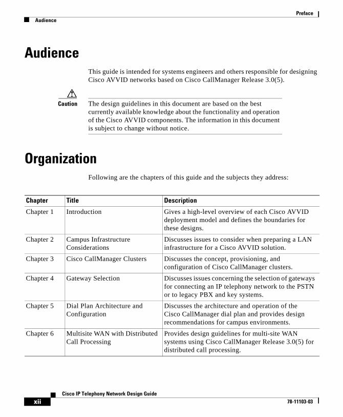
OrganizationFollowing are the chapters of this guide and the subjects they address:
Chapter Title Description
Chapter 1 Introduction Gives a high-level overview of each Cisco AVVID deployment model and defines the boundaries for these designs.
Chapter 2 Campus Infrastructure Considerations
Discusses issues to consider when preparing a LAN infrastructure for a Cisco AVVID solution.
Chapter 3 Cisco CallManager Clusters Discusses the concept, provisioning, and configuration of Cisco CallManager clusters.
Chapter 4 Gateway Selection Discusses issues concerning the selection of gateways for connecting an IP telephony network to the PSTN or to legacy PBX and key systems.
Chapter 5 Dial Plan Architecture and Configuration
Discusses the architecture and operation of the Cisco CallManager dial plan and provides design recommendations for campus environments.
Chapter 6 Multisite WAN with Distributed Call Processing
Provides design guidelines for multi-site WAN systems using Cisco CallManager Release 3.0(5) for distributed call processing.
xiiCisco IP Telephony Network Design Guide
78-11103-03
PrefaceOrganization
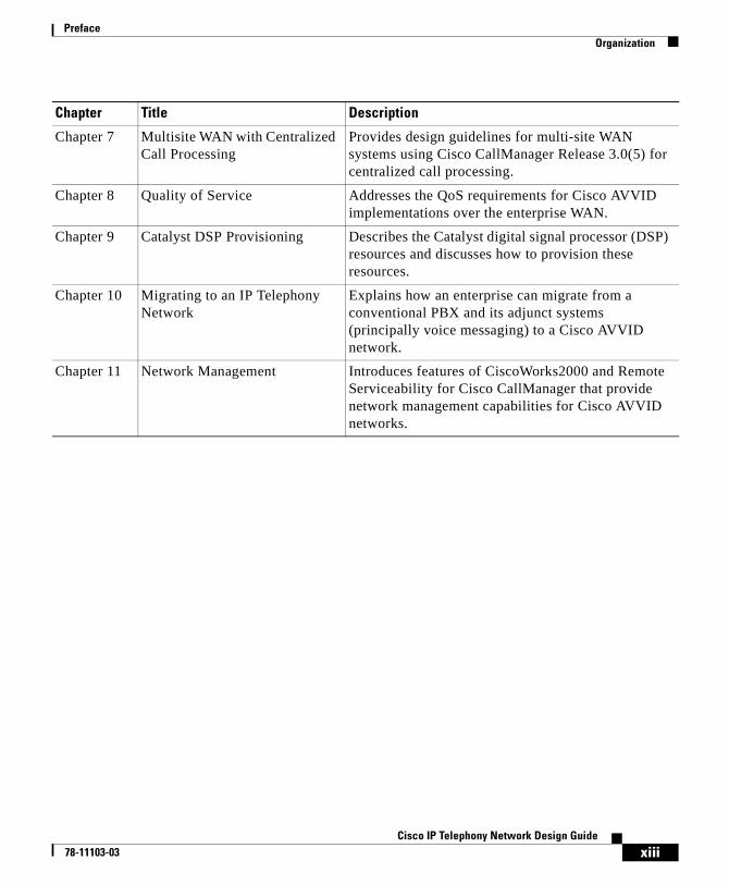
Chapter 7 Multisite WAN with Centralized Call Processing
Provides design guidelines for multi-site WAN systems using Cisco CallManager Release 3.0(5) for centralized call processing.
Chapter 8 Quality of Service Addresses the QoS requirements for Cisco AVVID implementations over the enterprise WAN.
Chapter 9 Catalyst DSP Provisioning Describes the Catalyst digital signal processor (DSP) resources and discusses how to provision these resources.
Chapter 10 Migrating to an IP Telephony Network
Explains how an enterprise can migrate from a conventional PBX and its adjunct systems (principally voice messaging) to a Cisco AVVID network.
Chapter 11 Network Management Introduces features of CiscoWorks2000 and Remote Serviceability for Cisco CallManager that provide network management capabilities for Cisco AVVID networks.
Chapter Title Description
xiiiCisco IP Telephony Network Design Guide
78-11103-03

PrefaceRevision History
Revision HistoryThe following revisions have been made to this document:
Revision Date Major Changes Since Previous Edition
12/08/00 • Added Chapter 11 on network management.
• Revised gatekeeper information in Chapter 6.
11/22/00 • Revised document for Cisco CallManager Release 3.0(5).
• Updated details of campus infrastructure design in Chapter 2.
• Revised bandwidth requirements for inter-cluster calls in Chapter 3.
• Updated gateway information in Chapter 4.
• Added gatekeeper information to Chapter 5.
• Updated details of call admission control and gatekeepers in Chapter 6.
• Revised major portions of the Quality of Service (QoS) information in Chapter 8.
• Updated details of Catalyst DSP provisioning in Chapter 9.
• Removed the chapter on Cisco uOne from this book. This information will be covered in a separate document.
• Updated migration information in Chapter 10.
06/30/00 • Reformatted document to allow for online display.
• Updated details of cluster provisioning in Chapter 3.
• Updated details of Catalyst DSP provisioning in Chapter 9.
xivCisco IP Telephony Network Design Guide
78-11103-03
PrefaceConventions
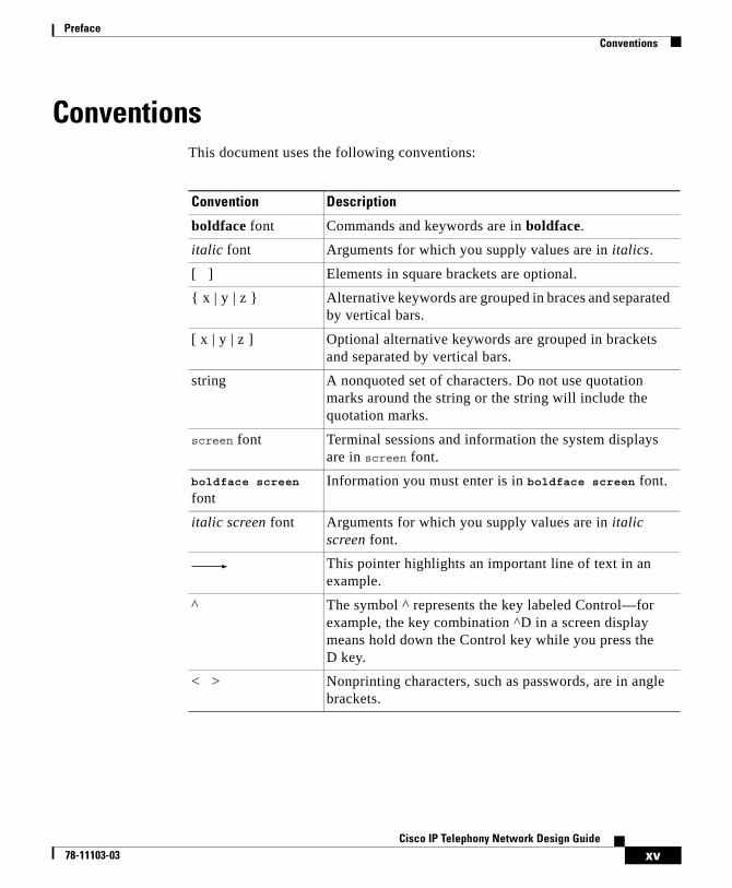
ConventionsThis document uses the following conventions:
Convention Description
boldface font Commands and keywords are in boldface.
italic font Arguments for which you supply values are in italics.
[ ] Elements in square brackets are optional.
{ x | y | z } Alternative keywords are grouped in braces and separated by vertical bars.
[ x | y | z ] Optional alternative keywords are grouped in brackets and separated by vertical bars.
string A nonquoted set of characters. Do not use quotation marks around the string or the string will include the quotation marks.
screen font Terminal sessions and information the system displays are in screen font.
boldface screen font
Information you must enter is in boldface screen font.
italic screen font Arguments for which you supply values are in italic screen font.
This pointer highlights an important line of text in an example.
^ The symbol ^ represents the key labeled Control—for example, the key combination ^D in a screen display means hold down the Control key while you press the D key.
< > Nonprinting characters, such as passwords, are in angle brackets.
xvCisco IP Telephony Network Design Guide
78-11103-03
PrefaceConventions
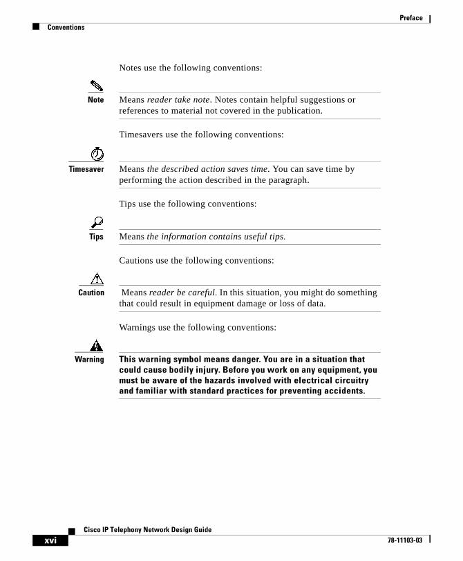
Notes use the following conventions:
Note Means reader take note. Notes contain helpful suggestions or references to material not covered in the publication.
Timesavers use the following conventions:
Timesaver Means the described action saves time. You can save time by performing the action described in the paragraph.
Tips use the following conventions:
Tips Means the information contains useful tips.
Cautions use the following conventions:
Caution Means reader be careful. In this situation, you might do something that could result in equipment damage or loss of data.
Warnings use the following conventions:
Warning This warning symbol means danger. You are in a situation that could cause bodily injury. Before you work on any equipment, you must be aware of the hazards involved with electrical circuitry and familiar with standard practices for preventing accidents.
xviCisco IP Telephony Network Design Guide
78-11103-03
PrefaceAdditional Information
Additional InformationThis section contains references to documents that provide additional information on subjects covered in this guide.
• High availability design:
– http://www.cisco.com/warp/partner/synchronicd/cc/sol/mkt/ent/ndsgn/highd_wp.htm
– http://www.zdnet.com/zdtag/whitepaper/campuslan.pdf
• Power protection:
– http://www.apcc.com/go/machine/cisco/3a.cfm
• Simple Mail Transfer Protocol (SMTP):
– http://www.cisco.com/univercd/cc/td/doc/product/software/ioss390/ios390ug/ugsmtp.htm
• Internet Message Access Protocol (IMAP):
– http://www.imap.org/whatisIMAP.html
• Lightweight Directory Access Protocol Version 3 (LDAPv3):
– http://www.critical-angle.com/ldapworld/ldapv3.html
• Glossary of terms and acronyms:
– http://www.cisco.com/univercd/cc/td/doc/cisintwk/ita/index.htm
– http://www.cisco.com/univercd/cc/td/doc/product/voice/index.htm
xviiCisco IP Telephony Network Design Guide
78-11103-03
PrefaceObtaining Documentation
Obtaining DocumentationThe following sections provide sources for obtaining documentation from Cisco Systems.
World Wide WebYou can access the most current Cisco documentation on the World Wide Web at the following sites:
• http://www.cisco.com
• http://www-china.cisco.com
• http://www-europe.cisco.com
Documentation CD-ROMCisco documentation and additional literature are available in a CD-ROM package, which ships with your product. The Documentation CD-ROM is updated monthly and may be more current than printed documentation. The CD-ROM package is available as a single unit or as an annual subscription.
Ordering DocumentationCisco documentation is available in the following ways:
• Registered Cisco Direct Customers can order Cisco Product documentation from the Networking Products MarketPlace:
http://www.cisco.com/cgi-bin/order/order_root.pl
• Registered Cisco.com users can order the Documentation CD-ROM through the online Subscription Store:
http://www.cisco.com/go/subscription
• Nonregistered Cisco.com users can order documentation through a local account representative by calling Cisco corporate headquarters (California, USA) at 408 526-7208 or, in North America, by calling 800 553-NETS(6387).
xviiiCisco IP Telephony Network Design Guide
78-11103-03
PrefaceObtaining Technical Assistance
Documentation FeedbackIf you are reading Cisco product documentation on the World Wide Web, you can submit technical comments electronically. Click Feedback in the toolbar and select Documentation. After you complete the form, click Submit to send it to Cisco.
You can e-mail your comments to [email protected].
To submit your comments by mail, for your convenience many documents contain a response card behind the front cover. Otherwise, you can mail your comments to the following address:
Cisco Systems, Inc.Document Resource Connection170 West Tasman DriveSan Jose, CA 95134-9883
We appreciate your comments.
Obtaining Technical AssistanceCisco provides Cisco.com as a starting point for all technical assistance. Customers and partners can obtain documentation, troubleshooting tips, and sample configurations from online tools. For Cisco.com registered users, additional troubleshooting tools are available from the TAC website.
Cisco.comCisco.com is the foundation of a suite of interactive, networked services that provides immediate, open access to Cisco information and resources at anytime, from anywhere in the world. This highly integrated Internet application is a powerful, easy-to-use tool for doing business with Cisco.
Cisco.com provides a broad range of features and services to help customers and partners streamline business processes and improve productivity. Through Cisco.com, you can find information about Cisco and our networking solutions, services, and programs. In addition, you can resolve technical issues with online
xixCisco IP Telephony Network Design Guide
78-11103-03
PrefaceObtaining Technical Assistance
technical support, download and test software packages, and order Cisco learning materials and merchandise. Valuable online skill assessment, training, and certification programs are also available.
Customers and partners can self-register on Cisco.com to obtain additional personalized information and services. Registered users can order products, check on the status of an order, access technical support, and view benefits specific to their relationships with Cisco.
To access Cisco.com, go to the following website:
http://www.cisco.com
Technical Assistance CenterThe Cisco TAC website is available to all customers who need technical assistance with a Cisco product or technology that is under warranty or covered by a maintenance contract.
Contacting TAC by Using the Cisco TAC Website
If you have a priority level 3 (P3) or priority level 4 (P4) problem, contact TAC by going to the TAC website:
http://www.cisco.com/tac
P3 and P4 level problems are defined as follows:
• P3—Your network performance is degraded. Network functionality is noticeably impaired, but most business operations continue.
• P4—You need information or assistance on Cisco product capabilities, product installation, or basic product configuration.
In each of the above cases, use the Cisco TAC website to quickly find answers to your questions.
To register for Cisco.com, go to the following website:
http://www.cisco.com/register/
xxCisco IP Telephony Network Design Guide
78-11103-03
PrefaceObtaining Technical Assistance
If you cannot resolve your technical issue by using the TAC online resources, Cisco.com registered users can open a case online by using the TAC Case Open tool at the following website:
http://www.cisco.com/tac/caseopen
Contacting TAC by Telephone
If you have a priority level 1(P1) or priority level 2 (P2) problem, contact TAC by telephone and immediately open a case. To obtain a directory of toll-free numbers for your country, go to the following website:
http://www.cisco.com/warp/public/687/Directory/DirTAC.shtml
P1 and P2 level problems are defined as follows:
• P1—Your production network is down, causing a critical impact to business operations if service is not restored quickly. No workaround is available.
• P2—Your production network is severely degraded, affecting significant aspects of your business operations. No workaround is available.
xxiCisco IP Telephony Network Design Guide
78-11103-03

PrefaceObtaining Technical Assistance
xxiiCisco IP Telephony Network Design Guide
78-11103-03
Cisco IP T78-11103-03
C H A P T E R 1
IntroductionThis chapter presents a high-level overview of several basic models that you can use in designing your IP telephony network. This overview provides some guidance with respect to when and why a particular design should be selected. Subsequent chapters delve into each network model in greater detail, beginning with the simplest model and building to increasingly complexity models.
This chapter includes the following major sections:
• General Design Models, page 1-1
• Single-Site Model, page 1-3
• Multiple Sites with Independent Call Processing, page 1-5
• Multisite IP WAN with Distributed Call Processing, page 1-7
• Multisite IP WAN with Centralized Call Processing, page 1-10
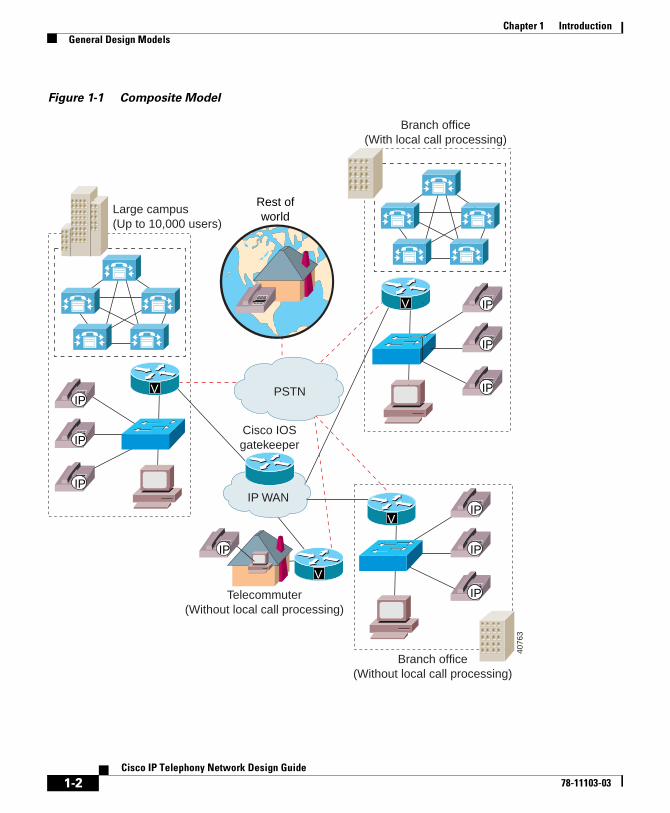
General Design ModelsFigure 1-1 provides a composite scenario that illustrates the goals of the network design models discussed in this guide. This scenario represents what is possible with Cisco CallManager Release 3.0(5).
1-1elephony Network Design Guide
Chapter 1 IntroductionGeneral Design Models
Figure 1-1 Composite Model
Large campus(Up to 10,000 users)
Telecommuter(Without local call processing)
Branch office(With local call processing)
Branch office(Without local call processing)
V
V
V
IP WAN
Rest ofworld
Cisco IOSgatekeeper
PSTNIP
IP
IP
V
IP
IP
IP
IP
IP
IP
IP
4076
3
1-2Cisco IP Telephony Network Design Guide
78-11103-03
Chapter 1 IntroductionSingle-Site Model
The overall goals of an IP telephony network are as follows:
• End-to-end IP telephony
• IP WAN as the primary voice path with the Public Switched Telephone Network (PSTN) as the secondary voice path between sites
• Lower total cost of ownership with greater flexibility
• Enabling of new applications
For IP telephony networks based on Cisco CallManager Release 3.0(5), there are four general design models that apply to the majority of implementations:
• Single-Site Model, page 1-3
• Multiple Sites with Independent Call Processing, page 1-5
• Multisite IP WAN with Distributed Call Processing, page 1-7
• Multisite IP WAN with Centralized Call Processing, page 1-10
The following sections summarize the design goals and implementation guidelines for each of these models.
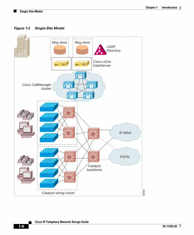
Single-Site ModelFigure 1-2 illustrates the model for an IP telephony network within a single campus or site.
1-3Cisco IP Telephony Network Design Guide
78-11103-03
Chapter 1 IntroductionSingle-Site Model
Figure 1-2 Single-Site Model
IP WAN
PSTN
Catalystbackbone
Catalyst wiring closet
Cisco CallManagercluster
Msg store Msg storeLDAPDirectory
Cisco uOneGateServer
IPIP
IPIP
4076
4
1-4Cisco IP Telephony Network Design Guide
78-11103-03
Chapter 1 IntroductionMultiple Sites with Independent Call Processing
The single-site model has the following design characteristics:
• Single Cisco CallManager or Cisco CallManager cluster.
• Maximum of 10,000 users per cluster.
• Maximum of eight servers in a Cisco CallManager cluster (four servers for primary call processing, two for backup call processing, one database publisher, and one TFTP server).
• Maximum of 2,500 users registered with a Cisco CallManager at any time.
• PSTN only for all external calls.
• Digital signal processor (DSP) resources for conferencing.
• Voice mail and unified messaging components.
• G.711 codec for all IP phone calls (80 kbps of IP bandwidth per call, uncompressed).
• To guarantee voice quality, use Cisco LAN switches with a minimum of two queues. See Chapter 2, “Campus Infrastructure Considerations,” for more details.
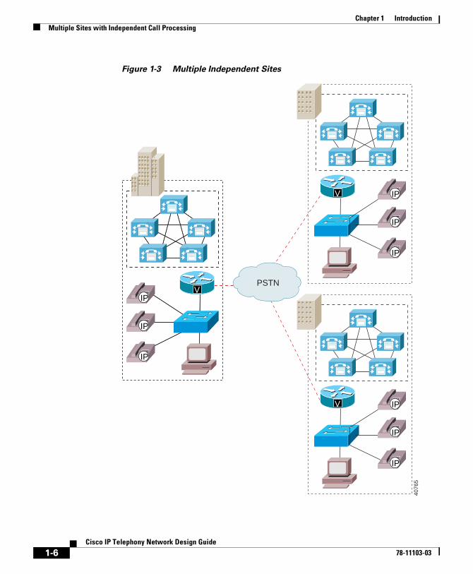
Multiple Sites with Independent Call ProcessingFigure 1-3 illustrates the model for multiple, isolated sites that are not connected by an IP WAN. In this model, each site has its own Cisco CallManager or Cisco CallManager cluster to handle call processing for that site.
1-5Cisco IP Telephony Network Design Guide
78-11103-03
Chapter 1 IntroductionMultiple Sites with Independent Call Processing
Figure 1-3 Multiple Independent Sites
VIP
IP
IP
VIP
IP
IP
V IP
IP
IP
V IP
IP
IP
PSTN
4076
5
1-6Cisco IP Telephony Network Design Guide
78-11103-03
Chapter 1 IntroductionMultisite IP WAN with Distributed Call Processing
The model for independent multiple sites has the following design characteristics:
• Cisco CallManager or Cisco CallManager cluster at each site to provide scalable call control.
• Maximum of 10,000 IP phones per cluster.
• No limit to number of clusters.
• Use of PSTN for networking multiple sites and for all external calls.
• DSP resources for conferencing at each site.
• Voice message or unified messaging components at each site.
• Voice compression not required.
Multisite IP WAN with Distributed Call ProcessingFigure 1-4 illustrates the model for multiple sites with distributed call processing.
1-7Cisco IP Telephony Network Design Guide
78-11103-03
Chapter 1 IntroductionMultisite IP WAN with Distributed Call Processing
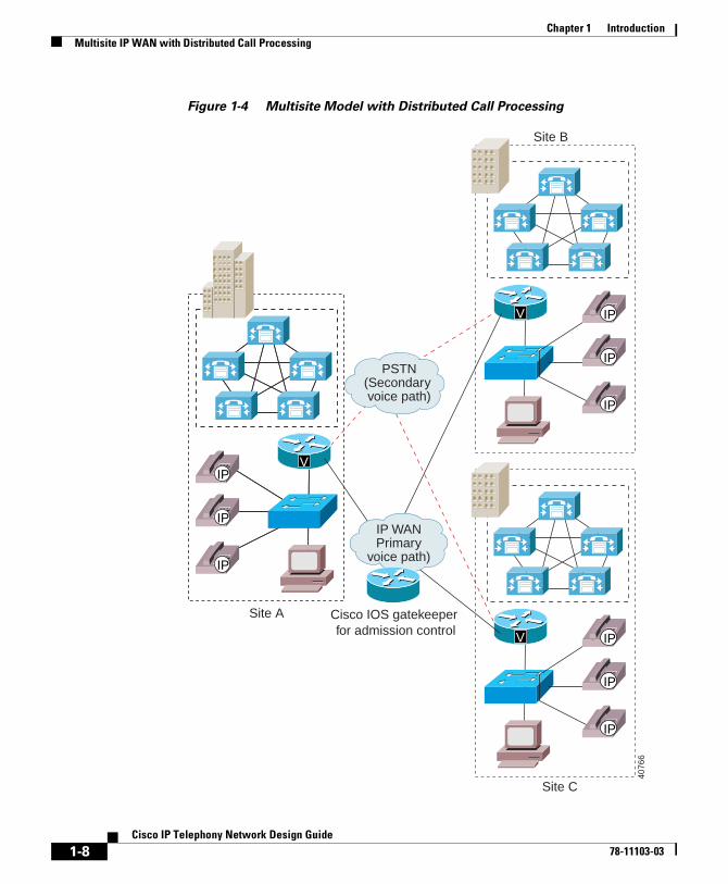
Figure 1-4 Multisite Model with Distributed Call Processing
Cisco IOS gatekeeper for admission control
VIP
IP
IP
VIP
IP
IP
V IP
IP
IP
V IP
IP
IP
4076
6
Site A
Site C
Site B
PSTN(Secondary voice path)
IP WANPrimary
voice path)
1-8Cisco IP Telephony Network Design Guide
78-11103-03

Chapter 1 IntroductionMultisite IP WAN with Distributed Call Processing
The multisite IP WAN with distributed call processing has the following design characteristics:
• Cisco CallManager or Cisco CallManager cluster at each location (10,000 users maximum per site).
• Cisco CallManager clusters are confined to a single campus and may not span the WAN.
• IP WAN as the primary voice path between sites, with the PSTN as the secondary voice path.
• Transparent use of the PSTN if the IP WAN is unavailable.
• Cisco IOS gatekeeper for E.164 address resolution.
• Cisco IOS gatekeeper for admission control to the IP WAN.
• Maximum of 100 sites interconnected across the IP WAN using hub and spoke topologies.
• Compressed voice calls supported across the IP WAN.
• Single WAN codec supported.
• DSP resources for conferencing and WAN transcoding at each site.
• Voice mail and unified messaging components at each site.
• Minimum bandwidth requirement for voice and data traffic is 56 kbps. For voice, interactive video, and data, the minimum requirement is 768 kbps. In each case, the bandwidth allocated to voice, video, and data should not exceed 75% of the total capacity.
• Remote sites can use Cisco IOS as well as gateways based on the Skinny Gateway Protocol.
1-9Cisco IP Telephony Network Design Guide
78-11103-03
Chapter 1 IntroductionMultisite IP WAN with Centralized Call Processing
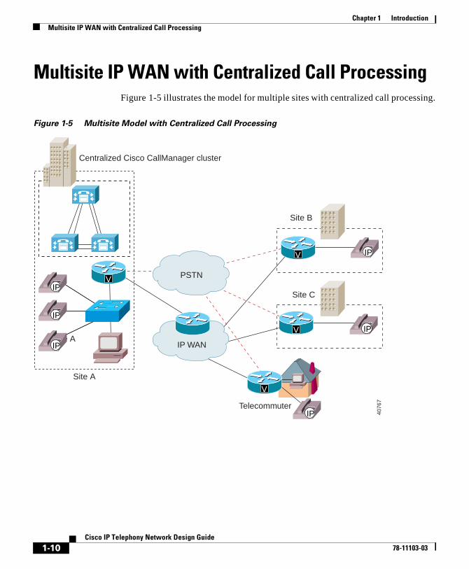
Multisite IP WAN with Centralized Call ProcessingFigure 1-5 illustrates the model for multiple sites with centralized call processing.
Figure 1-5 Multisite Model with Centralized Call Processing
Site A
Telecommuter
Site C
Site B
V
V
V
IP WAN
PSTN
IP
IP
IP
VIP
IP
IP
VIP
IP
IP
Site A
Centralized Cisco CallManager cluster
4076
7
1-10Cisco IP Telephony Network Design Guide
78-11103-03
Chapter 1 IntroductionMultisite IP WAN with Centralized Call Processing
The multisite IP WAN with centralized call processing has the following design characteristics:
• Central site supports only one active Cisco CallManager. A cluster can contain a secondary and tertiary Cisco CallManager as long as all IP phones served by the cluster are registered to the same Cisco CallManager at any given time. This is called a centralized call processing cluster.
• Each centralized call processing cluster supports a maximum of 2500 users (no limit on number of remote sites). Multiple centralized call processing clusters of 2500 users at a central site can be interconnected using H.323.
• IP phones at remote sites do not have a local Cisco CallManager.
• The call admission control mechanism is based on bandwidth by location. See the “Call Admission Control” section on page 7-3.
• Compressed voice calls across the IP WAN are supported.
• Manual use of the PSTN is available if the IP WAN is fully subscribed for voice traffic (PSTN access code must be dialed after a busy signal).
• Dial backup is required for IP phone service across the WAN in case the IP WAN goes down.
• Voice mail, unified messaging, and DSP resource components are available at the central site only.
• Minimum bandwidth requirement for voice and data traffic is 56 kbps. For voice, interactive video, and data, the minimum requirement is 768 kbps. In each case, the bandwidth allocated to voice, video, and data should not exceed 75% of the total capacity.
• Remote sites can use Cisco IOS as well as gateways based on the Skinny Station Protocol.
• If using voice mail, each site must have unique internal dial plan number ranges. You cannot overlap internal dial plans among remote sites if voice mail is required. (For example, no two sites can share 1XXX.)
1-11Cisco IP Telephony Network Design Guide
78-11103-03

Chapter 1 IntroductionMultisite IP WAN with Centralized Call Processing
1-12Cisco IP Telephony Network Design Guide
78-11103-03
Cisco IP T78-11103-03
C H A P T E R 2
Campus Infrastructure ConsiderationsTo ensure successful implementation of Cisco IP Telephony Solutions, you must first consider your LAN infrastructure. Before adding voice to your network, your data network must be configured properly.
You can use these concepts and implementation techniques regardless of whether you have a headquarters with tens of thousands of users or a small branch with fewer than a hundred users. However, the size of the network determines the actual components and platforms you will select and the details that determine the scalability, availability, and functionality of your network.
This chapter contains these sections:
• Overview, page 2-2
• Power Protection Strategies, page 2-4
• Network Infrastructure, page 2-5
• High Availability, page 2-7
• Physical Connectivity Options, page 2-9
• Power to IP Phones, page 2-10
• IP Addressing and Management, page 2-21
• Quality of Service, page 2-28
2-1elephony Network Design Guide
Chapter 2 Campus Infrastructure ConsiderationsOverview
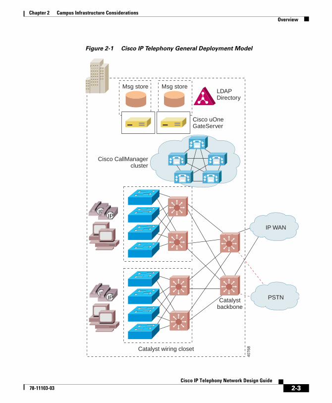
OverviewCisco IP Telephony Solutions rely on the stable foundation of Cisco multiprotocol routers and Catalyst multilayer LAN switches, which are the building blocks in enterprise networks. Figure 2-1 illustrates a general model of a Cisco IP telephony network using these components.
2-2Cisco IP Telephony Network Design Guide
78-11103-03
Chapter 2 Campus Infrastructure ConsiderationsOverview
Figure 2-1 Cisco IP Telephony General Deployment Model
IP WAN
PSTNCatalystbackbone
Catalyst wiring closet
Cisco CallManagercluster
Msg store Msg storeLDAPDirectory
Cisco uOneGateServer
IPIP
IPIP
4076
8
2-3Cisco IP Telephony Network Design Guide
78-11103-03
Chapter 2 Campus Infrastructure ConsiderationsPower Protection Strategies
Power Protection StrategiesReliable power is vital to IP telephony. An uninterruptible power supply (UPS) can be used to ensure a reliable and highly available infrastructure by protecting it from power failures. Each UPS has some amount of battery that will keep the equipment running for a certain period of time. The UPS can be configured with the appropriate amount of battery for desired results.
Caution Cisco strongly recommends that you provide some type of backup power for your IP telephony network. Cisco AVVID products do not ordinarily come with a backup power supply.
Here are some common strategies for using UPS:
• Back up the wiring closet switches and downstream data center using UPS. While this strategy ensures that power is maintained to the phones, wall powered devices such as PCs can still go down.
• Back up the whole building using UPS. This protects all devices and equipment from power failures. Protecting PCs in this fashion is useful because of the new breed of highly available data applications.
• Provide a separate generator for power (besides the feed from the utility company) and use it as backup. In this case you might still need to add UPS because it usually takes a few minutes for the generator to ramp up. The advantage of this strategy is that less battery time is needed for each UPS.
In addition, UPS can be configured with options such as Simple Network Management Protocol (SNMP) management, remote monitoring, alarm reporting, and so on.
Further Information
For more information on power protection, see the “Additional Information” section on page xvii.
2-4Cisco IP Telephony Network Design Guide
78-11103-03
Chapter 2 Campus Infrastructure ConsiderationsNetwork Infrastructure
Network InfrastructureBuilding an end-to-end IP telephony system requires an IP infrastructure based on Layer 2 and Layer 3 switches and routers, with switched connections to the desktop. Network designers must ensure that the endpoints are connected using switched 10/100 Ethernet ports, as illustrated in Figure 2-2.
Caution Cisco does not support using hubs for shared connectivity to the switches because they can interfere with correct operation of the IP telephony system.
2-5Cisco IP Telephony Network Design Guide
78-11103-03
Chapter 2 Campus Infrastructure ConsiderationsNetwork Infrastructure
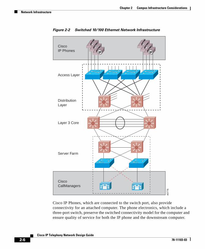
Figure 2-2 Switched 10/100 Ethernet Network Infrastructure
Cisco IP Phones, which are connected to the switch port, also provide connectivity for an attached computer. The phone electronics, which include a three-port switch, preserve the switched connectivity model for the computer and ensure quality of service for both the IP phone and the downstream computer.
CiscoIP Phones
Access Layer
Layer 3 Core
Server Farm
DistributionLayer
CiscoCallManagers
IPIP
IP
IPIP
IP
4077
6
2-6Cisco IP Telephony Network Design Guide
78-11103-03
Chapter 2 Campus Infrastructure ConsiderationsHigh Availability
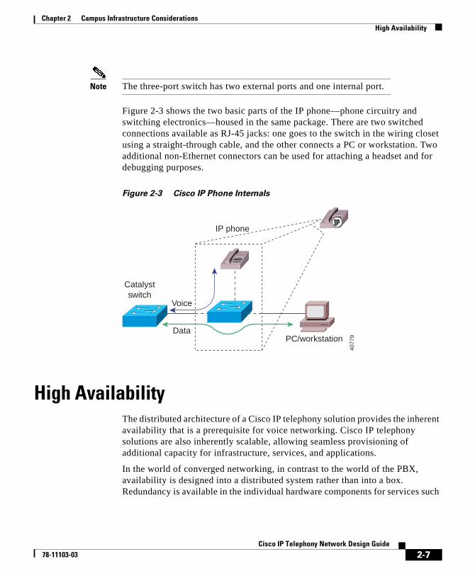
Note The three-port switch has two external ports and one internal port.
Figure 2-3 shows the two basic parts of the IP phone—phone circuitry and switching electronics—housed in the same package. There are two switched connections available as RJ-45 jacks: one goes to the switch in the wiring closet using a straight-through cable, and the other connects a PC or workstation. Two additional non-Ethernet connectors can be used for attaching a headset and for debugging purposes.
Figure 2-3 Cisco IP Phone Internals
High AvailabilityThe distributed architecture of a Cisco IP telephony solution provides the inherent availability that is a prerequisite for voice networking. Cisco IP telephony solutions are also inherently scalable, allowing seamless provisioning of additional capacity for infrastructure, services, and applications.
In the world of converged networking, in contrast to the world of the PBX, availability is designed into a distributed system rather than into a box. Redundancy is available in the individual hardware components for services such
PC/workstationData
Voice
IP phoneIP
Catalystswitch
4077
9
2-7Cisco IP Telephony Network Design Guide
78-11103-03
Chapter 2 Campus Infrastructure ConsiderationsHigh Availability
as power and supervisor modules. Network redundancy, however, is achieved with a combination of hardware, software, and intelligent network design practices.
Network redundancy is achieved at many levels (see Figure 2-2). Physical connections exist from the edge devices where IP phones and computers are attached to two spatially diverse aggregation devices. In the event that an aggregation device fails, or connectivity is lost for any reason (such as a broken fiber or a power outage), failover of traffic to the other device is possible. By provisioning clusters of Cisco CallManagers to provide resilient call control, other servers can pick up the load if any device within the cluster fails.
Advanced Layer 3 protocols such as Hot Standby Router Protocol (HSRP) or fast converging routing protocols, such as Open Shortest Path First (OSPF) and Enhanced Interior Gateway Routing Protocol (EIGRP), can be used to provide optimum network layer convergence around failures.
Advanced tools are also available for the MAC layer (Layer 2). Tunable spanning-tree parameters and the ability to supply a spanning tree per virtual LAN (VLAN) allow fast convergence. Value-added features such as uplink-fast and backbone-fast allow intelligently designed networks to further optimize network convergence.
High availability of the underlying network plays a major role in ensuring a successful deployment. This translates into redundancy, resiliency, and fast convergence.
Further Information
For more information on high availability, see the “Additional Information” section on page xvii.
2-8Cisco IP Telephony Network Design Guide
78-11103-03
Chapter 2 Campus Infrastructure ConsiderationsPhysical Connectivity Options
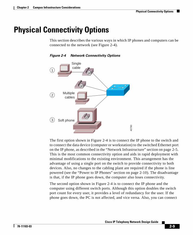
Physical Connectivity OptionsThis section describes the various ways in which IP phones and computers can be connected to the network (see Figure 2-4).
Figure 2-4 Network Connectivity Options
The first option shown in Figure 2-4 is to connect the IP phone to the switch and to connect the data device (computer or workstation) to the switched Ethernet port on the IP phone, as described in the “Network Infrastructure” section on page 2-5. This is the most common connectivity option and aids in rapid deployment with minimal modifications to the existing environment. This arrangement has the advantage of using a single port on the switch to provide connectivity to both devices. Also, no changes to the cabling plant are required if the phone is line powered (see the “Power to IP Phones” section on page 2-10). The disadvantage is that, if the IP phone goes down, the computer also loses connectivity.
The second option shown in Figure 2-4 is to connect the IP phone and the computer using different switch ports. Although this option doubles the switch port count for every user, it provides a level of redundancy for the user. If the phone goes down, the PC is not affected, and vice versa. Also, you can connect
Singlecable
Soft phone
Multiplecables
1
2
3
IP
IP
IP
4078
0
2-9Cisco IP Telephony Network Design Guide
78-11103-03
Chapter 2 Campus Infrastructure ConsiderationsPower to IP Phones
the phone and PC to ports on different modules, thus achieving another layer of redundancy by providing protection for one of the devices if either module goes down.
The third option shown in Figure 2-4 differs from the others in that the phone is not a hardware device, but is a JTAPI application running on a computer. This option, the Cisco IP SoftPhone, could be particularly useful in environments where the need for a separate handset is minimal.
Power to IP PhonesCisco IP Phones support a variety of power options. This section discusses each of the three available power schemes:
• Inline Power, page 2-10
• External Patch Panel Power, page 2-17
• Wall Power, page 2-20
Inline PowerThe advantage of inline power is that it does not require a local power outlet. It also permits centralization of power management facilities.
With the inline power method, pairs 2 and 3 (pins 1, 2, 3, and 6) of the four pairs in a Category 5 cable are used to transmit power (6.3W) from the switch. This method of supplying power is sometimes called phantom power because the power signals travel over the same two pairs used to transmit Ethernet signals. The power signals are completely transparent to the Ethernet signals and do not interfere with their operation.
2-10Cisco IP Telephony Network Design Guide
78-11103-03
Chapter 2 Campus Infrastructure ConsiderationsPower to IP Phones
The inline method of supplying power requires the new power-enabled line card for the switch. This mechanism is currently available in the following Cisco Catalyst systems:
• Catalyst 6000 Family Switches with minimum Cisco CatOS Release 5.5 or later.
• Catalyst 4000 Family Switches (Catalyst 4006 with Power Entry Module and Auxiliary Power Shelf. Require minimum of two power supplies to power 240 ports.) Minimum Cisco CatOS Release 6.1 or higher.
• Catalyst 3524-PWR (standalone 24-port 10/100 two gigabit uplinks). Minimum Cisco IOS Release 12.0(5).XU or higher.
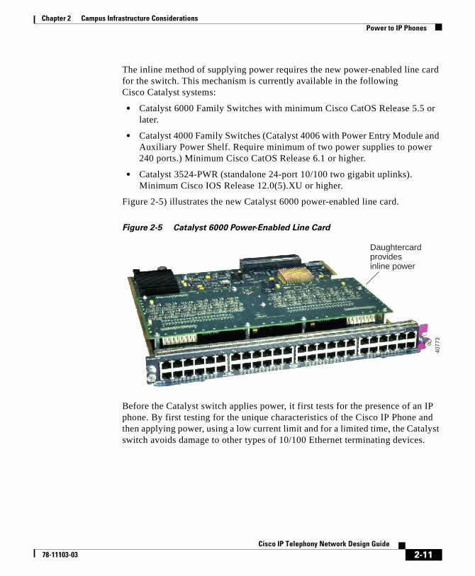
Figure 2-5) illustrates the new Catalyst 6000 power-enabled line card.
Figure 2-5 Catalyst 6000 Power-Enabled Line Card
Before the Catalyst switch applies power, it first tests for the presence of an IP phone. By first testing for the unique characteristics of the Cisco IP Phone and then applying power, using a low current limit and for a limited time, the Catalyst switch avoids damage to other types of 10/100 Ethernet terminating devices.
Daughtercardprovidesinline power
4077
3
2-11Cisco IP Telephony Network Design Guide
78-11103-03

Chapter 2 Campus Infrastructure ConsiderationsPower to IP Phones
Establishing Power to the IP Phone
To establish power to the IP phone, the power-enabled Catalyst switch performs the following steps:
1. The switch performs phone discovery by sending specific tones down the wire to the IP phone. In its unpowered state, the IP phone loops these tones back to the switch.
When the switch receives this tone, it knows that the device connected is a Cisco IP Phone and it is safe to deliver power to the device. This behavior is exhibited only by Cisco IP Phones, so that other devices connected to the switch port are safe from receiving current. This hardware polling is done by the system at fixed intervals on a port-by-port basis until a LINK signal is seen or the system has been configured not to apply inline power to that port.
2. When the switch finds an IP phone by using phone discovery, it applies power to the device. The Cisco IP Phone powers up, energizing the relay and removing the loopback (normally closed relay becomes open) between transmit and receive pairs. It also sends a LINK packet to the switch. From this point, the IP phone functions as a normal 10/100 Ethernet device.
If the LINK packet is received within five seconds, the Catalyst switch concludes that the attached device is a Cisco IP Phone, and it maintains the power feed. Otherwise power is removed and the discovery process is restarted.
3. Once the Cisco IP Phone is powered and responding, the phone discovery mechanism enters a steady state. If the phone is removed or the link is interrupted, the discovery mechanism starts again. The port is checked every five seconds for a LINK packet and, in its absence, the test tone is generated.
The advantage of this mechanism is that power is supplied to the phone by the switch just as it is in a traditional telephony environment. In some installations, it is entirely possible that only two pairs have been terminated out of the four available for the data run between the wiring closet and the desktop location. In such cases the inline power method can allow customers to deploy IP telephony by using the existing cable plant without any modification.
2-12Cisco IP Telephony Network Design Guide
78-11103-03

Chapter 2 Campus Infrastructure ConsiderationsPower to IP Phones
Inline Power Configuration
The inline power method requires Catalyst software Release 5.5 for Catalyst 6000, Cisco CatOS 6.1 or higher for Catalyst 4000, and Cisco IOS Release 12.0(5)XU or later for Catalyst 3524-PWR. These software releases support all the necessary commands to enable the switch to deliver power through the power-enabled line card. You also have the option of explicitly not providing power through the line card, but the auto detection feature has the capability of determining whether an attached phone requires power or not.
Configuring the Inline Power Mode
The inline power mode can be configured on each port on the switch using the one of the following commands.
For Cisco CatOS:
set port inlinepower mod/port {auto | off}
For native Cisco IOS:
Switch(config-if)# power inline {auto | never}
The two modes are defined as follows:
• auto—The supervisor engine tells the port to supply power to the phone only if it has discovered the phone using the phone discovery mechanism, as described in the “Establishing Power to the IP Phone” section on page 2-12. This is the default behavior.
• off—The supervisor engine instructs the port not to apply power, even if it can and if it knows that there is a connected Cisco IP Phone device.
If the set port inlinepower command executes successfully, the system displays a message similar to
Inline power for port 7/1 set to auto
If the set port inlinepower command does not execute successfully, the system prints a message similar to
Failed to set the inline power for port 7/1
2-13Cisco IP Telephony Network Design Guide
78-11103-03

Chapter 2 Campus Infrastructure ConsiderationsPower to IP Phones
Note The remainder of this chapter uses the Cisco CatOS command syntax. For native Cisco IOS commands, refer to the specific product documentation for the switches and line cards.
Configuring the Default Power Allocation
You can configure the default power allocation using the following command:
set inlinepower defaultallocation value
This command specifies how much power, in watts, to apply on a per-port basis. The default value of 10W is good for any currently available or planned Cisco IP Phone model. The phone has the intelligence to report to the switch how much power it actually needs (using Cisco Discovery Protocol), and the switch can adjust the delivered power accordingly, but under some circumstances you might want to reconfigure the default allocation. For example, if the switch has only 7W of available remaining power and you attach a new phone, the switch will refuse power to the phone because it initially needs to send the default 10W (even though the phone itself only requires 6.3W). In this case, you could reconfigure the default power allocation to 7W, and the switch would provide power.
If the set inlinepower defaultallocation command executes successfully, the system displays a message similar to
Default Inline Power allocation per port: 10.0 Watts (0.24 amps @42V)
If the set inlinepower defaultallocation command does not execute successfully, the system displays the following error message:
Default port inline power should be in the range of 2000..12500 (mW)
Displaying the Inline Power Status
You can display the details on the actual power consumed by using the following command:
show port inlinepower {mod | mod/port}
2-14Cisco IP Telephony Network Design Guide
78-11103-03

Chapter 2 Campus Infrastructure ConsiderationsPower to IP Phones
Here is an example display from the show port inlinepower command:
Default Inline Power allocation per port: 12.500 Watts (0.29 Amps @42V)Total inline power drawn by module 7: 37.80 Watts (0.90 Amps @42V)y module 5: 37.80 Watts ( 0.90 Port InlinePowered PowerAllocated Admin Oper Detected mWatt mA @42V----- ----- ------ -------- ----- -------- 7/1 auto off no 0 0 7/2 auto on yes 12600 300 7/3 auto faulty yes 12600 300 7/4 auto deny yes 0 0 7/5 on deny yes 0 0 7/6 on off no 0 0 7/7 off off no 0 0
Other Inline Power Considerations
This section briefly discusses miscellaneous issues related to inline power supply.
Power Consumption
Cisco IP Phone model 7960 consumes 6.3W. Depending upon the number of phones attached or planned, the system should be equipped with a 1300W power supply or the new power supply capable of delivering 2500W.
Note The new power supply for the Cisco Catalyst 6000 family switches needs 220V to deliver 2500W of power. When powered with 110V, it delivers only 1300W. In addition, the power supply needs 20A regardless of whether it is plugged into 110V or 220V.
2-15Cisco IP Telephony Network Design Guide
78-11103-03

Chapter 2 Campus Infrastructure ConsiderationsPower to IP Phones
Error and Status Messages
You can configure the system to send syslog messages that indicate any deviations from the norm. These messages include the following deviations:
• Not enough power available
5SYS-3-PORT_NOPOWERAVAIL:Device on port 5/12 will remain unpowered
• Link did not come up after powering up the port
%SYS-3-PORT_DEVICENOLINK:Device on port 5/26 powered but no link up
• Faulty port power
%SYS-6-PORT_INLINEPWRFLTY:Port 5/7 reporting inline power as faulty
Power status can also be displayed on a per-port basis using the show port status command. The command displays the following values:
• On—Power is being supplied by the port.
• Off—Power is not being supplied by the port.
• Power-deny—System does not have enough power, so the port does not supply power.
Dual Supervisors
When the system is using dual supervisors, power management per port and phone status are synchronized between the active and standby supervisor. This is done on an ongoing basis and is triggered with any change to the power allocation or phone status. The usefulness and functioning of the high availability features are unaffected by the use of inline power.
Power Protection
Cisco recommends that backup power be used for a higher degree of redundancy and availability. See the “Power Protection Strategies” section on page 2-4.
2-16Cisco IP Telephony Network Design Guide
78-11103-03
Chapter 2 Campus Infrastructure ConsiderationsPower to IP Phones
Ports and Power Supplies
Table 2-1 shows the number of IP phones that can be supported with the 1050W, 1300W, and 2500W power-enabled line cards on a Cisco Catalyst 6509 with the Policy Feature Card (PFC).
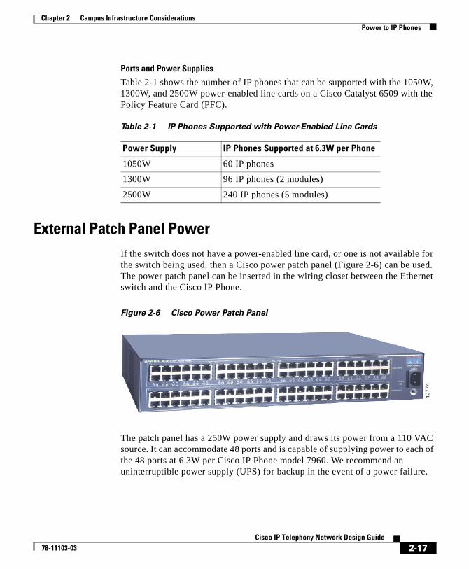
External Patch Panel PowerIf the switch does not have a power-enabled line card, or one is not available for the switch being used, then a Cisco power patch panel (Figure 2-6) can be used. The power patch panel can be inserted in the wiring closet between the Ethernet switch and the Cisco IP Phone.
Figure 2-6 Cisco Power Patch Panel
The patch panel has a 250W power supply and draws its power from a 110 VAC source. It can accommodate 48 ports and is capable of supplying power to each of the 48 ports at 6.3W per Cisco IP Phone model 7960. We recommend an uninterruptible power supply (UPS) for backup in the event of a power failure.
Table 2-1 IP Phones Supported with Power-Enabled Line Cards
Power Supply IP Phones Supported at 6.3W per Phone
1050W 60 IP phones
1300W 96 IP phones (2 modules)
2500W 240 IP phones (5 modules)
4077
4
2-17Cisco IP Telephony Network Design Guide
78-11103-03
Chapter 2 Campus Infrastructure ConsiderationsPower to IP Phones
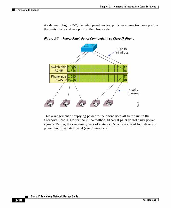
As shown in Figure 2-7, the patch panel has two ports per connection: one port on the switch side and one port on the phone side.
Figure 2-7 Power Patch Panel Connectivity to Cisco IP Phone
This arrangement of applying power to the phone uses all four pairs in the Category 5 cable. Unlike the inline method, Ethernet pairs do not carry power signals. Rather, the remaining pairs of Category 5 cable are used for delivering power from the patch panel (see Figure 2-8).
4 pairs(8 wires)
2 pairs(4 wires)
Switch sideRJ-45
Phone sideRJ-45
1 3 52 4 6
1 3 52 4 6
4847
4847
IP IP IP IP IP
4077
5
2-18Cisco IP Telephony Network Design Guide
78-11103-03

Chapter 2 Campus Infrastructure ConsiderationsPower to IP Phones
Figure 2-8 External Power Through the Power Patch Panel
As shown in Figure 2-8, pairs 2 and 3 from the switch are patched straight through to pairs 2 and 3 coming from the phone. Pairs 1 and 4 from the phone terminate at the patch panel (Ethernet does not use pairs 1 and 4) and power is applied across them to power the phone. The actual conductors used are pins 4 and 5 (pair 1) and pins 7 and 8 (pair 4) for power and ground return. This means that all four pairs in the Category 5 cable need to be terminated at the user’s desk and in the wiring closet.
The Cisco power patch panel operates in discovery mode. In discovery mode, the patch panel tries to verify if the device connected to it is a Cisco IP Phone. It does this by using the phone discovery mechanism used in the inline power method, except that here the patch panel, rather than the switch, generates the test tone. Everything else about the process is identical to that described in the “Establishing Power to the IP Phone” section on page 2-12.
Switch sideRJ-45
Switch portwithout
inline power
Phone sideRJ-45
PowerPair 4
Pair 1
Cisco IP phoneCategory5 cable
Pair 2
Pair 3
ACSource
IP
Power patch panel port
4077
7
2-19Cisco IP Telephony Network Design Guide
78-11103-03
Chapter 2 Campus Infrastructure ConsiderationsPower to IP Phones
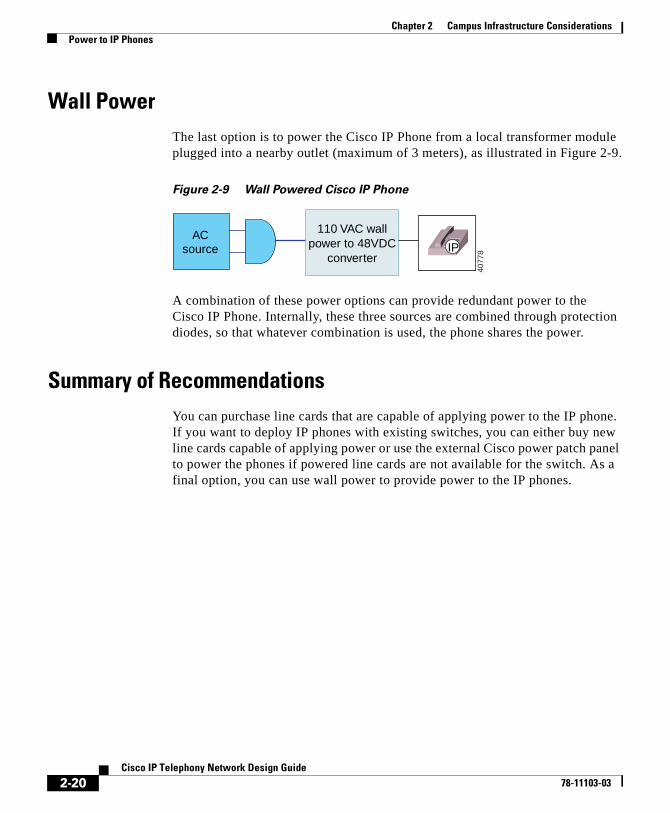
Wall PowerThe last option is to power the Cisco IP Phone from a local transformer module plugged into a nearby outlet (maximum of 3 meters), as illustrated in Figure 2-9.
Figure 2-9 Wall Powered Cisco IP Phone
A combination of these power options can provide redundant power to the Cisco IP Phone. Internally, these three sources are combined through protection diodes, so that whatever combination is used, the phone shares the power.
Summary of RecommendationsYou can purchase line cards that are capable of applying power to the IP phone. If you want to deploy IP phones with existing switches, you can either buy new line cards capable of applying power or use the external Cisco power patch panel to power the phones if powered line cards are not available for the switch. As a final option, you can use wall power to provide power to the IP phones.
ACsource
110 VAC wallpower to 48VDC
converterIP
4077
8
2-20Cisco IP Telephony Network Design Guide
78-11103-03
Chapter 2 Campus Infrastructure ConsiderationsIP Addressing and Management
IP Addressing and ManagementEach IP phone requires an IP address, along with associated information such as subnet mask, default gateway, and so on. Essentially, this means that your organization’s need for IP addresses doubles as you assign IP phones to users.
This information can be configured statically on the IP phone, or it can be provided by the Dynamic Host Configuration Protocol (DHCP).
The following sections describe various ways that you can meet these IP addressing requirements:
• Assigning IP Addresses Using Same Subnet as Data Devices
• Modifying the IP Addressing Plan
• Creating a Separate IP Subnet for IP Phones
Assigning IP Addresses Using Same Subnet as Data Devices
You might want to provide IP addresses to the IP phones using the same subnet as data devices. This might be a straightforward solution in your situation. However, many sites have IP subnets with more than 50% of subnet addresses already allocated. If your network fits this description, this is not the best solution for your needs.
Modifying the IP Addressing Plan
You could assign addresses for IP phones out of the existing subnets, but you must renumber the IP addressing plan. This may not always be feasible.
Creating a Separate IP Subnet for IP Phones
You can put the IP phones on a separate IP subnet. The new subnet could be in a registered address space or in a private address space, such as network 10.0.0.0. Using this scheme, the PC would be on a subnet reserved for data devices and the phone would be on a subnet reserved for voice. Configuration on the IP phone can be minimized by having the phone learn as much information dynamically as possible. Therefore, when the IP phone powers up it should get its voice subnet automatically, then send a DHCP request on that subnet for an IP address.
The automated mechanism by which the IP phone gets its voice subnet is provided through enhancements to the Cisco Discovery Protocol (CDP).
2-21Cisco IP Telephony Network Design Guide
78-11103-03
Chapter 2 Campus Infrastructure ConsiderationsIP Addressing and Management
CDP EnhancementsCisco Discovery Protocol (CDP) is a device discovery protocol that runs on all Cisco equipment. With CDP, each device sends periodic messages to a multicast address and in turn listens to the periodic messages sent by other devices. This allows devices on the network to discover one another and learn information such as protocols used, protocol addresses, native VLAN of interconnected ports, and so on. CDP is also used to send some Layer 2 and Layer 3 messages.
Cisco IP Phones use CDP to interact with the switch so that the switch knows that an IP phone is connected to it. To provide this level of support, three new fields have been added to CDP:
• Voice VLAN ID (VVID) for communicating the voice subnet to the IP phone
• Trigger field for soliciting a response from the connected device
• Power requirement field for getting the exact power requirement from the phone
VVID Field
A VLAN (Layer 2) maps to a subnet (Layer 3) as a broadcast domain, such that a VLAN is equivalent to a subnet. The VVID was introduced with release 5.5 of the Catalyst software. This is the voice VLAN that the switch assigns to the IP phone inside the CDP message. It allows the IP phone to get its VLAN ID automatically when it is plugged into the switch if a VLAN is configured for the phone (see the “Voice VLAN Configuration” section on page 2-24). If no VLAN is configured for the IP phone, the phone resides in the native VLAN (data subnet) of the switch.
Trigger Field
The trigger field is used to force a response from the connected device. Under normal circumstances, a device sends CDP update messages at a configured interval (default is one minute). If an IP phone is connected between CDP messages, it cannot receive its VVID. In this case, the IP phone issues a trigger in the CDP message it sends to the switch, forcing the switch to respond with a VVID.
2-22Cisco IP Telephony Network Design Guide
78-11103-03
Chapter 2 Campus Infrastructure ConsiderationsIP Addressing and Management
Power Requirement Field
When the switch provides inline power to an IP phone, it has no way of knowing how much power the phone needs (this varies by model). Initially, the switch allocates 10W, then adjusts the delivered power according to the requirements sent by the IP phone in the CDP message.
Auxiliary VLANs and Data VLANs
The new voice VLAN is called an auxiliary VLAN in the Catalyst software command-line interface (CLI). In the traditional switched world, data devices reside in a data VLAN. The new auxiliary VLAN is used to represent other types of devices collectively. Today those devices are IP phones (hence the notion of a voice VLAN), but, in the future, other types of non-data devices will also be part of the auxiliary VLAN. Just as data devices come up and reside in the native VLAN (default VLAN), IP phones come up and reside in the auxiliary VLAN, if one has been configured on the switch.
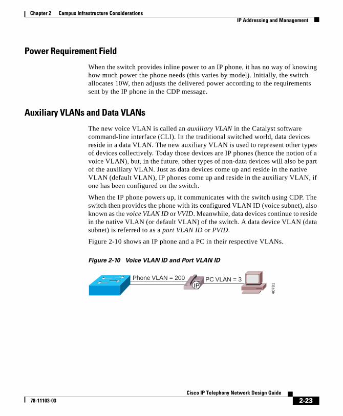
When the IP phone powers up, it communicates with the switch using CDP. The switch then provides the phone with its configured VLAN ID (voice subnet), also known as the voice VLAN ID or VVID. Meanwhile, data devices continue to reside in the native VLAN (or default VLAN) of the switch. A data device VLAN (data subnet) is referred to as a port VLAN ID or PVID.
Figure 2-10 shows an IP phone and a PC in their respective VLANs.
Figure 2-10 Voice VLAN ID and Port VLAN ID
PC VLAN = 3Phone VLAN = 200IP
4078
1
2-23Cisco IP Telephony Network Design Guide
78-11103-03

Chapter 2 Campus Infrastructure ConsiderationsIP Addressing and Management
Voice VLAN Configuration
To configure the VVID from the Catalyst software CLI, use the set port auxiliaryvlan command. You can use this command to set the VVID on a single port, on a range of ports, or for an entire module. The following example shows how to display the command syntax:
Console> (enable) set port auxiliaryvlan helpUsage: set port auxiliaryvlan <mod/port>
<vlan|untagged|dot1p|none>(vlan + 1..1000)
In the following example, the VVID is set to 222 for ports 2/1 through 2/3. When the phone powers up, the switch instructs it to register with VLAN 222.
Console> (enable) set port auxiliaryvlan 2/1-3 222Auxiliaryvlan 222 configuration successful.
The following examples show how to display which ports are in which auxiliary VLAN:
Console> show port auxiliaryvlan 222AuxiliaryVlan auxVlanStatus Mod/Ports------------- ------------- ---------222 222 1/2,2/1-3Console> show port 2/1Port AuxiliaryVlan AuxVlan-Status----- ------------- --------------2.1 222 active
The following is an example of VVID configuration on Catalyst switches running Cisco IOS at the interface level (for example, Catalyst 3524-PWR and 2900XL):
interface FastEthernet0/1switchport trunk encapsulation dot1qswitchport trunk native vlan <PVID>switchport mode trunkswitchport voice vlan <VVID>spanning-tree portfastswitchport mode trust
2-24Cisco IP Telephony Network Design Guide
78-11103-03
Chapter 2 Campus Infrastructure ConsiderationsIP Addressing and Management
Connecting to the Network
The following steps outline the process that takes place when an IP phone is powered up and plugged into the network:
1. The IP phone begins a CDP exchange with the switch. The phone issues a trigger CDP to force a response from the switch. That response contains the VVID for the phone.
2. If the IP phone is configured to use DHCP (the default), it issues a DHCP request on the voice subnet it got from the switch. This is the recommended mode of operation. Static addressing can be used, but it prevents mobility.
3. The IP phone gets a response from the DHCP server in the network. Along with the DHCP response, which provides the IP address to the telephone, it is also possible to supply the address of the TFTP server from which the phone gets its configuration. This is done by configuring option 150 on the DHCP server and specifying the address of the TFTP server; Cisco DHCP server supports this feature. Again, it is possible to specify the TFTP server address manually, but this would limit adds, moves, and changes, as well as remove some other benefits.
4. The IP phone contacts the TFTP server and receives a list of addresses of Cisco CallManagers. Up to three Cisco CallManagers can be specified in the list. This provides redundancy in case the first Cisco CallManager in the list is not available.
5. The IP phone now contacts the Cisco CallManager and registers itself, receiving in return a configuration file and runtime code necessary for the phone to operate. For each configuration, the IP phone receives a directory number (DN) from the Cisco CallManager to be used for calling that particular IP phone.
6. The IP phone is ready to make and receive calls.
Note This process takes about 90 seconds. To speed it up, turn on portfast and turn off port channeling and trunking. This reduces the time to about 30 seconds.
2-25Cisco IP Telephony Network Design Guide
78-11103-03
Chapter 2 Campus Infrastructure ConsiderationsIP Addressing and Management
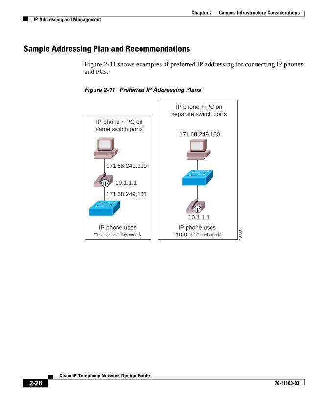
Sample Addressing Plan and Recommendations
Figure 2-11 shows examples of preferred IP addressing for connecting IP phones and PCs.
Figure 2-11 Preferred IP Addressing Plans
IP phone uses“10.0.0.0” network
IP phone uses“10.0.0.0” network
IP phone + PC onsame switch ports
171.68.249.100
171.68.249.101
IP phone + PC onseparate switch ports
171.68.249.100
10.1.1.1
10.1.1.1IP
IP
4078
3
2-26Cisco IP Telephony Network Design Guide
78-11103-03
Chapter 2 Campus Infrastructure ConsiderationsIP Addressing and Management
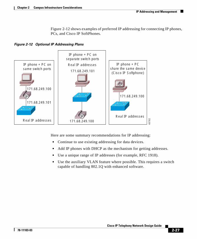
Figure 2-12 shows examples of preferred IP addressing for connecting IP phones, PCs, and Cisco IP SoftPhones.
Figure 2-12 Optional IP Addressing Plans
Here are some summary recommendations for IP addressing:
• Continue to use existing addressing for data devices.
• Add IP phones with DHCP as the mechanism for getting addresses.
• Use a unique range of IP addresses (for example, RFC 1918).
• Use the auxiliary VLAN feature where possible. This requires a switch capable of handling 802.1Q with enhanced software.
IP phone + PC onsame switch ports
171.68.249.100
171.68.249.101
Real IP addresses
IP phone + PC onseparate switch ports
171.68.249.100
171.68.249.101
Real IP addresses IP phone + PCshare the same device(Cisco IP Softphone)
171.68.249.100
Real IP addresses
IP
IP
IP
4078
2
2-27Cisco IP Telephony Network Design Guide
78-11103-03
Chapter 2 Campus Infrastructure ConsiderationsQuality of Service
Quality of ServiceIn a converged environment, all types of traffic travel over a single transport infrastructure. Yet all traffic types are not the same. Data is bursty, loss intolerant, and not latency sensitive. Voice, on the other hand, is nonbursty and has some tolerance to loss but is latency sensitive. The challenge is in providing the required level of service for each of these traffic types.
Running both voice and data on a common network requires the proper quality of service (QoS) tools to ensure that the delay and loss parameters of voice traffic are satisfied. These tools are available as features in IP phones, switches, and routers.
See Chapter 8, “Quality of Service,” for information on WAN QoS.
Traffic Classification TypesThe goal of protecting voice traffic from being run over by data traffic is accomplished by classifying voice traffic as high priority and then allowing it to travel in the network before low priority traffic. Classification can be done at Layer 2 or at Layer 3 as follows:
• At Layer 2 using the three bits in the 802.1p field (referred to as class of service, or CoS), which is part of the 802.1Q tag.
• At Layer 3 using the three bits of the differentiated services code point (DSCP) field in the type of service (ToS) byte of the IP header.
Classification is the first step toward achieving quality of service. Ideally, this step should be done as close to the source as possible, usually at the access layer of the network.
2-28Cisco IP Telephony Network Design Guide
78-11103-03
Chapter 2 Campus Infrastructure ConsiderationsQuality of Service
Trust BoundariesThe concept of trust is an important and integral one to implementing QoS. Once the end devices have a set class of service (CoS) or type of service (ToS), the switch has the option of trusting them or not. If the switch trusts the settings, it does not need to do any reclassification; if it does not trust the settings, then it must perform reclassification for appropriate QoS.
The notion of trusting or not trusting forms the basis for the trust boundary. Ideally, classification should be done as close to the source as possible. If the end device is capable of performing this function, then the trust boundary for the network is at the access layer in the wiring closet. If the device is not capable of performing this function, or the wiring closet switch does not trust the classification done by the end device, the trust boundary may shift. How this shift happens, depends on the capabilities of the switch in the wiring closet. If the switch can reclassify the packets, then the trust boundary remains in the wiring closet. If the switch cannot perform this function, then the task falls to other devices in the network going toward the backbone. In this case, the rule of thumb is to perform reclassification at the distribution layer. This means that the trust boundary has shifted to the distribution layer. It is more than likely that there is a high-end switch in the distribution layer with features to support this function. If possible, try to avoid performing this function in the core of the network.
In summary, try to maintain the trust boundary in the wiring closet. If necessary, move it down to the distribution layer on a case-by-case basis, but avoid moving it down to the core of the network. This advice conforms with the general guidelines to keep the trust boundary as close to the source as possible.
Note This discussion assumes a three-tier network model, which has proven to be a scalable architecture. If the network is small, and the logical functions of the distribution layer and core layer happen to be in the same device, then the trust boundary can reside in the core layer if it has to move from the wiring closet.
2-29Cisco IP Telephony Network Design Guide
78-11103-03
Chapter 2 Campus Infrastructure ConsiderationsQuality of Service
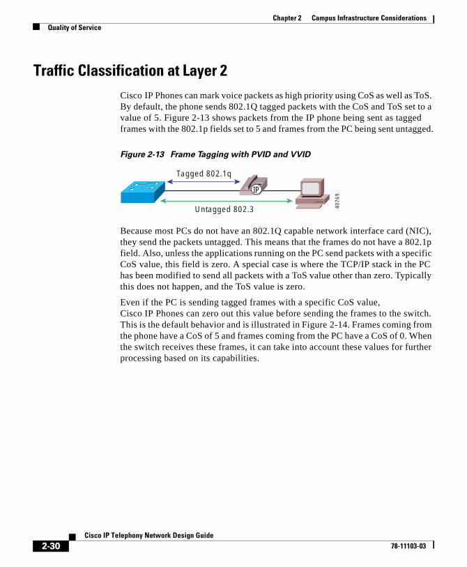
Traffic Classification at Layer 2Cisco IP Phones can mark voice packets as high priority using CoS as well as ToS. By default, the phone sends 802.1Q tagged packets with the CoS and ToS set to a value of 5. Figure 2-13 shows packets from the IP phone being sent as tagged frames with the 802.1p fields set to 5 and frames from the PC being sent untagged.
Figure 2-13 Frame Tagging with PVID and VVID
Because most PCs do not have an 802.1Q capable network interface card (NIC), they send the packets untagged. This means that the frames do not have a 802.1p field. Also, unless the applications running on the PC send packets with a specific CoS value, this field is zero. A special case is where the TCP/IP stack in the PC has been modified to send all packets with a ToS value other than zero. Typically this does not happen, and the ToS value is zero.
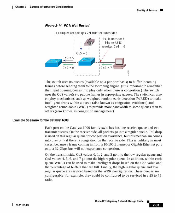
Even if the PC is sending tagged frames with a specific CoS value, Cisco IP Phones can zero out this value before sending the frames to the switch. This is the default behavior and is illustrated in Figure 2-14. Frames coming from the phone have a CoS of 5 and frames coming from the PC have a CoS of 0. When the switch receives these frames, it can take into account these values for further processing based on its capabilities.
Untagged 802.3
Tagged 802.1q
IP
4076
9
2-30Cisco IP Telephony Network Design Guide
78-11103-03
Chapter 2 Campus Infrastructure ConsiderationsQuality of Service
Figure 2-14 PC Is Not Trusted
The switch uses its queues (available on a per-port basis) to buffer incoming frames before sending them to the switching engine. (It is important to remember that input queuing comes into play only when there is congestion.) The switch uses the CoS value(s) to put the frames in appropriate queues. The switch can also employ mechanisms such as weighted random early detection (WRED) to make intelligent drops within a queue (also known as congestion avoidance) and weighted round-robin (WRR) to provide more bandwidth to some queues than to others (also known as congestion management).
Example Scenario for the Catalyst 6000
Each port on the Catalyst 6000 family switches has one receive queue and two transmit queues. On the receive side, all packets go into a regular queue. Tail drop is used on this regular queue for congestion avoidance, but this mechanism comes into play only if there is congestion on the receive side. This is unlikely in most cases, because a frame coming in from a 10/100 Ethernet or Gigabit Ethernet port onto a 32-Gbps bus will not experience congestion.
On the transmit side, CoS values 0, 1, 2, and 3 go into the low regular queue and CoS values 4, 5, 6, and 7 go into the high regular queue. In addition, within each queue WRED can be used to make intelligent drops based on the CoS value and the percentage of buffers that are full. Finally, the high regular queue and low regular queue are serviced based on the WRR configuration. These queues are configurable; for example, they could be configured to be serviced in a 25 to 75 ratio.
Example: set port qos 2/1 trust-ext untrusted
CoS = 5
CoS = 5
PC is untrustedPhone ASIC
rewrites CoS = 0
CoS = 0 CoS = 7
IP
4077
0
2-31Cisco IP Telephony Network Design Guide
78-11103-03

Chapter 2 Campus Infrastructure ConsiderationsQuality of Service
Note All the values for WRED, WRR, and queue size are configurable.
Cisco Catalyst 6000 family switches also support the notion of trusted and untrusted QoS on a per-port basis. This parameter is configured with the following command:
set port qos mod/ports.. trust {untrusted | trust-cos | trust-ipprec | trust-dscp}
This command allows you to configure the trust state as well as specify to trust CoS or ToS (trust-ipprec) or DSCP (trust-dscp), which is an emerging Layer 3 standard under the Differentiated Services working group of the Internet Engineering Task Force (IETF).
So far, this discussion has centered around the case depicted in Figure 2-14, where voice traffic comes in as CoS 5 and PC traffic is zeroed out if there is any tag. There may be times, however, when it is desirable to trust the PC CoS (if sending tagged packets) or assign a value other than zero. This can be achieved on Catalyst switches as well.
Figure 2-15 shows the case where the PC is trusted completely, and whatever CoS it presents is honored.
Figure 2-15 PC Is Trusted
Example: set port qos 2/1 trust-ext trust-cos
CoS = 5
CoS = 5
Trusted
CoS = 7 CoS = 7
IP
4077
1
2-32Cisco IP Telephony Network Design Guide
78-11103-03
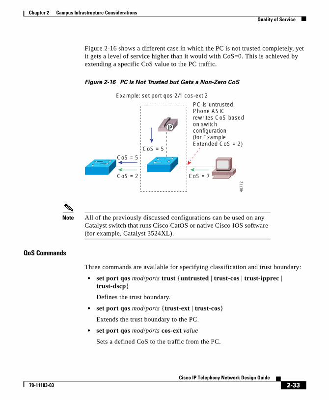
Chapter 2 Campus Infrastructure ConsiderationsQuality of Service
Figure 2-16 shows a different case in which the PC is not trusted completely, yet it gets a level of service higher than it would with CoS=0. This is achieved by extending a specific CoS value to the PC traffic.
Figure 2-16 PC Is Not Trusted but Gets a Non-Zero CoS
Note All of the previously discussed configurations can be used on any Catalyst switch that runs Cisco CatOS or native Cisco IOS software (for example, Catalyst 3524XL).
QoS Commands
Three commands are available for specifying classification and trust boundary:
• set port qos mod/ports trust {untrusted | trust-cos | trust-ipprec | trust-dscp}
Defines the trust boundary.
• set port qos mod/ports {trust-ext | trust-cos}
Extends the trust boundary to the PC.
• set port qos mod/ports cos-ext value
Sets a defined CoS to the traffic from the PC.
Example: set port qos 2/1 cos-ext 2
PC is untrusted.Phone ASICrewrites CoS basedon switchconfiguration (for ExampleExtended CoS = 2)
CoS = 5
CoS = 5
CoS = 2 CoS = 7
IP
4077
2
2-33Cisco IP Telephony Network Design Guide
78-11103-03
Chapter 2 Campus Infrastructure ConsiderationsQuality of Service
Traffic Classification at Layer 3Using the 802.1p bits within the 802.1Q tag provides the desired QoS results at Layer 2. When traffic has to cross a Layer 3 boundary, however, it becomes imperative to implement these mechanisms using Layer 3 parameters, such as the 3 IP precedence bits (commonly referred to as ToS) or the new DSCP parameter, which uses the six most significant bits within the ToS byte of the IP header. Traffic crosses a Layer 3 boundary when packets are routed between subnets by Layer 3 switches or routers. Traffic also crosses a Layer 3 boundary when packets need to go out of the campus network onto the WAN through edge routers. When this happens, Layer 2 classification does not help. Layer 3 classification is needed for achieving the desired level of QoS. All of the QoS techniques employed by the routers (including the very important WAN QoS) rely on Layer 3 classification.
Layer 3 classification can be achieved by using the appropriate platforms in the campus. Beginning with the IP phones, packets are already presented to the switch with CoS = ToS = 5. This Layer 3 classification is preserved even if the packets travel all the way through to the WAN edge router where the Layer 2 header is removed. So, if the trust boundary is at the source (IP phone), voice traffic has the ToS bits set to 5 and is presented to the network devices for appropriate treatment. WAN routers can use this classification to employ any of the queuing techniques. If the trust boundary is not at the source and packets need to be reclassified, then the device performing this function should be capable of doing it at Layer 3 before it can cross a Layer 3 boundary.
Layer 3 Traffic Classification on the Cisco Catalyst 6000
Cisco Catalyst 6000 family switches equipped with the Policy Feature Card (PFC) perform Layer 3 traffic classification by default when the port is trusted. Thus if a packet comes into a trusted port with CoS = 5, the switch takes this value and resets the ToS bits to 5 as well. No additional configuration is needed. If the port is untrusted, the packet gets a default CoS at the input port.
Then you can configure a QoS access control list (ACL) on the switch and rewrite the ToS to a desired value based on some matching criteria. For example, the following command sets a ToS of 5 for all packets coming from subnet 10.1.1.0 and destined to any address.
Console> (enable) set qos acl ip TEST dscp 40 10.1.1.0 0.0.0.255 any
2-34Cisco IP Telephony Network Design Guide
78-11103-03
Chapter 2 Campus Infrastructure ConsiderationsQuality of Service
QoS ACLs can also include Layer 4 information for classifying individual applications. Cisco Catalyst 6000 family switches are also capable of policing traffic based on Layer 3 addresses and Layer 4 port numbers. For example, you can police individual HTTP flows to 1 Mbps and aggregate all HTTP flows to 25 Mbps.
The following are important points in regard to QoS functionality on the Cisco Catalyst 6000 family switches:
• By default, QoS is not enabled. Use set qos enable to enable QoS on the switch.
• By default, ports are not trusted. Use the following command to enable trust on a port:
set port qos mod/ports.. trust {untrusted | trust-cos | trust-ipprec | trust-dscp}
• QoS configurations can be applied on a per-port basis or on a per-VLAN basis. This works very well for IP telephony implementations where phones are on a separate VLAN, as described in the “IP Addressing and Management” section on page 2-21.
• By default, Cisco Catalyst 6000 family switches map CoS to ToS when the port is trusted or by using QoS ACLs.
Tips If the trust boundary happens to be on a wiring closet switch that is not capable of reclassifying at Layer 3, you can shrink the trust boundary to the distribution layer where a Layer 3 capable device is more likely to be present.
2-35Cisco IP Telephony Network Design Guide
78-11103-03
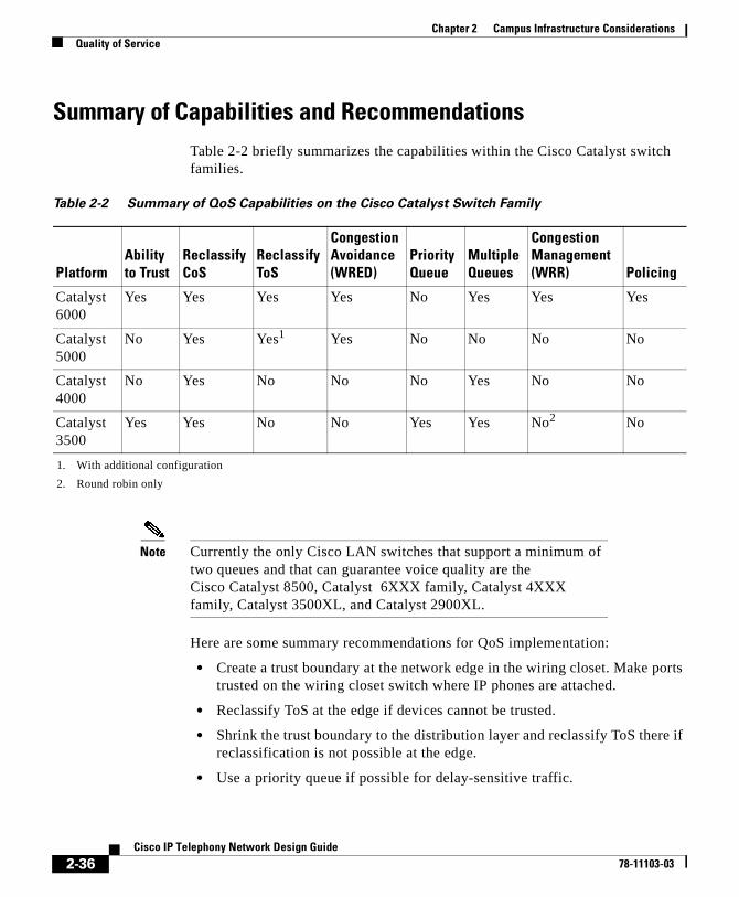
Chapter 2 Campus Infrastructure ConsiderationsQuality of Service
Summary of Capabilities and RecommendationsTable 2-2 briefly summarizes the capabilities within the Cisco Catalyst switch families.
Note Currently the only Cisco LAN switches that support a minimum of two queues and that can guarantee voice quality are the Cisco Catalyst 8500, Catalyst 6XXX family, Catalyst 4XXX family, Catalyst 3500XL, and Catalyst 2900XL.
Here are some summary recommendations for QoS implementation:
• Create a trust boundary at the network edge in the wiring closet. Make ports trusted on the wiring closet switch where IP phones are attached.
• Reclassify ToS at the edge if devices cannot be trusted.
• Shrink the trust boundary to the distribution layer and reclassify ToS there if reclassification is not possible at the edge.
• Use a priority queue if possible for delay-sensitive traffic.
Table 2-2 Summary of QoS Capabilities on the Cisco Catalyst Switch Family
PlatformAbility to Trust
Reclassify CoS
Reclassify ToS
Congestion Avoidance (WRED)
Priority Queue
Multiple Queues
Congestion Management (WRR) Policing
Catalyst 6000
Yes Yes Yes Yes No Yes Yes Yes
Catalyst 5000
No Yes Yes1
1. With additional configuration
Yes No No No No
Catalyst 4000
No Yes No No No Yes No No
Catalyst 3500
Yes Yes No No Yes Yes No2
2. Round robin only
No
2-36Cisco IP Telephony Network Design Guide
78-11103-03
Chapter 2 Campus Infrastructure ConsiderationsQuality of Service
• Use QoS ACLs for more granular classification of packets using Layer 4 information.
• Use policing if necessary to limit traffic for individual flows as well as aggregate flows.
• Have traffic going to the WAN edge classified at Layer 3 so that the router can use it for advanced WAN queuing mechanisms.
• Use a WAN edge router as the classifier for very small remote site networks where a Layer 3 capable switch is not available.
2-37Cisco IP Telephony Network Design Guide
78-11103-03

Chapter 2 Campus Infrastructure ConsiderationsQuality of Service
2-38Cisco IP Telephony Network Design Guide
78-11103-03
Cisco IP T78-11103-03
C H A P T E R 3
Cisco CallManager ClustersThis chapter discusses the concept, provisioning, and configuration of Cisco CallManager clusters. Clusters, which were introduced with Cisco CallManager Release 3.0, provide a mechanism for distributing call processing seamlessly across a converged IP network infrastructure to support IP telephony, facilitate redundancy, and provide feature transparency and scalability.
This chapter discusses the operation of clusters within both campus and WAN environments and proposes reference designs for implementation. The following sections cover these topics:
• Cluster Operation and Scalability Guidelines, page 3-1
• Cisco CallManager Redundancy, page 3-6
• Campus Clustering Guidelines, page 3-12
• Intercluster Communication, page 3-14
• Intracluster and Intercluster Feature Transparency, page 3-21
Cluster Operation and Scalability GuidelinesWith Cisco CallManager Release 3.0(5), a cluster can contain as many as eight servers, of which six are capable of call processing. The other two servers can be configured as a dedicated database publisher and a dedicated TFTP server, respectively.
The database publisher is used to make all configuration changes and also to produce call detail records. The TFTP server facilitates the downloading of configuration files, device loads (operating code), and ring types.
3-1elephony Network Design Guide
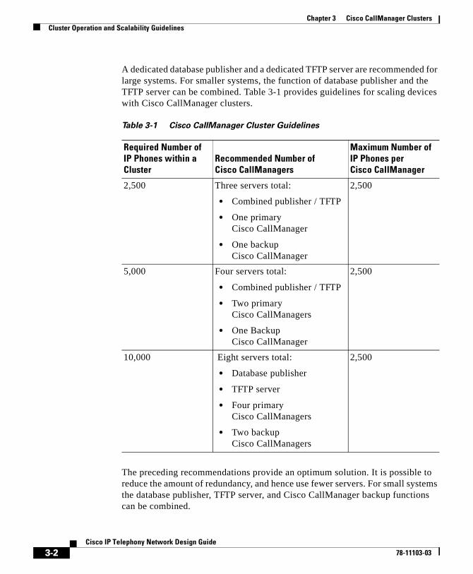
Chapter 3 Cisco CallManager ClustersCluster Operation and Scalability Guidelines
A dedicated database publisher and a dedicated TFTP server are recommended for large systems. For smaller systems, the function of database publisher and the TFTP server can be combined. Table 3-1 provides guidelines for scaling devices with Cisco CallManager clusters.
The preceding recommendations provide an optimum solution. It is possible to reduce the amount of redundancy, and hence use fewer servers. For small systems the database publisher, TFTP server, and Cisco CallManager backup functions can be combined.
Table 3-1 Cisco CallManager Cluster Guidelines
Required Number of IP Phones within a Cluster
Recommended Number of Cisco CallManagers
Maximum Number of IP Phones per Cisco CallManager
2,500 Three servers total:
• Combined publisher / TFTP
• One primary Cisco CallManager
• One backup Cisco CallManager
2,500
5,000 Four servers total:
• Combined publisher / TFTP
• Two primary Cisco CallManagers
• One Backup Cisco CallManager
2,500
10,000 Eight servers total:
• Database publisher
• TFTP server
• Four primary Cisco CallManagers
• Two backup Cisco CallManagers
2,500
3-2Cisco IP Telephony Network Design Guide
78-11103-03
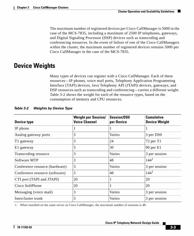
Chapter 3 Cisco CallManager ClustersCluster Operation and Scalability Guidelines
The maximum number of registered devices per Cisco CallManager is 5000 in the case of the MCS-7835, including a maximum of 2500 IP telephones, gateways, and Digital Signaling Processor (DSP) devices such as transcoding and conferencing resources. In the event of failure of one of the Cisco CallManagers within the cluster, the maximum number of registered devices remains 5000 per Cisco CallManager in the case of the MCS-7835.
Device WeightsMany types of devices can register with a Cisco CallManager. Each of these resources—IP phones, voice mail ports, Telephony Application Programming Interface (TAPI) devices, Java Telephony API (JTAPI) devices, gateways, and DSP resources such as transcoding and conferencing—carries a different weight. Table 3-2 shows the weight for each of the resource types, based on the consumption of memory and CPU resources.
Table 3-2 Weights by Device Type
Device typeWeight per Session/Voice Channel
Session/DS0 per Device
CumulativeDevice Weight
IP phone 1 1 1
Analog gateway ports 3 Varies 3 per DS0
T1 gateway 3 24 72 per T1
E1 gateway 3 30 90 per E1
Transcoding resource 3 Varies 3 per session
Software MTP 3 48 1441
1. When installed on the same server as Cisco CallManager, the maximum number of sessions is 48.
Conference resource (hardware) 3 Varies 3 per session
Conference resource (software) 3 48 1441
CTI port (TAPI and JTAPI) 20 1 20
Cisco SoftPhone 20 1 20
Messaging (voice mail) 3 Varies 3 per session
Intercluster trunk 3 Varies 3 per session
3-3Cisco IP Telephony Network Design Guide
78-11103-03
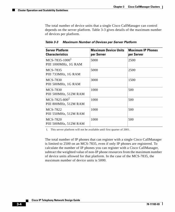
Chapter 3 Cisco CallManager ClustersCluster Operation and Scalability Guidelines
The total number of device units that a single Cisco CallManager can control depends on the server platform. Table 3-3 gives details of the maximum number of devices per platform.
The total number of IP phones that can register with a single Cisco CallManager is limited to 2500 on an MCS-7835, even if only IP phones are registered. To calculate the number of IP phones you can register with a Cisco CallManager, subtract the weighted value of non-IP phone resources from the maximum number of device units allowed for that platform. In the case of the MCS-7835, the maximum number of device units is 5000.
Table 3-3 Maximum Number of Devices per Server Platform
Server Platform Characteristics
Maximum Device Units per Server
Maximum IP Phones per Server
MCS-7835-10001
PIII 1000MHz, 1G RAM
1. This server platform will not be available until first quarter of 2001.
5000 2500
MCS-7835PIII 733MHz, 1G RAM
5000 2500
MCS-7830PIII 500MHz, 1G RAM
3000 1500
MCS-7830PIII 500MHz, 512M RAM
1000 500
MCS-7825-8001
PIII 800MHz, 512M RAM1000 500
MCS-7822PIII 550MHz, 512M RAM
1000 500
MCS-7820PIII 500MHz, 512M RAM
1000 500
3-4Cisco IP Telephony Network Design Guide
78-11103-03
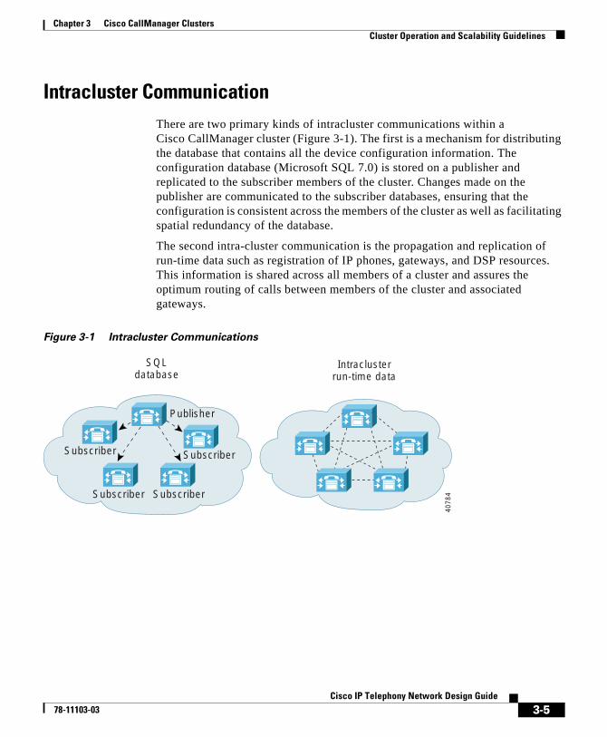
Chapter 3 Cisco CallManager ClustersCluster Operation and Scalability Guidelines
Intracluster CommunicationThere are two primary kinds of intracluster communications within a Cisco CallManager cluster (Figure 3-1). The first is a mechanism for distributing the database that contains all the device configuration information. The configuration database (Microsoft SQL 7.0) is stored on a publisher and replicated to the subscriber members of the cluster. Changes made on the publisher are communicated to the subscriber databases, ensuring that the configuration is consistent across the members of the cluster as well as facilitating spatial redundancy of the database.
The second intra-cluster communication is the propagation and replication of run-time data such as registration of IP phones, gateways, and DSP resources. This information is shared across all members of a cluster and assures the optimum routing of calls between members of the cluster and associated gateways.
Figure 3-1 Intracluster Communications
SQLdatabase
Intraclusterrun-time data
Publisher
Subscriber
SubscriberSubscriber
Subscriber40
784
3-5Cisco IP Telephony Network Design Guide
78-11103-03
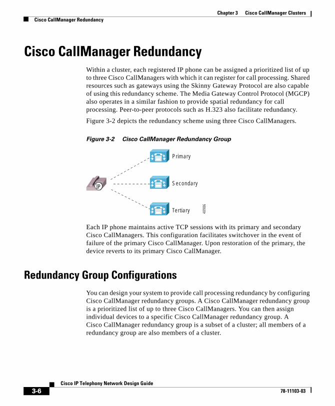
Chapter 3 Cisco CallManager ClustersCisco CallManager Redundancy
Cisco CallManager RedundancyWithin a cluster, each registered IP phone can be assigned a prioritized list of up to three Cisco CallManagers with which it can register for call processing. Shared resources such as gateways using the Skinny Gateway Protocol are also capable of using this redundancy scheme. The Media Gateway Control Protocol (MGCP) also operates in a similar fashion to provide spatial redundancy for call processing. Peer-to-peer protocols such as H.323 also facilitate redundancy.
Figure 3-2 depicts the redundancy scheme using three Cisco CallManagers.
Figure 3-2 Cisco CallManager Redundancy Group
Each IP phone maintains active TCP sessions with its primary and secondary Cisco CallManagers. This configuration facilitates switchover in the event of failure of the primary Cisco CallManager. Upon restoration of the primary, the device reverts to its primary Cisco CallManager.
Redundancy Group ConfigurationsYou can design your system to provide call processing redundancy by configuring Cisco CallManager redundancy groups. A Cisco CallManager redundancy group is a prioritized list of up to three Cisco CallManagers. You can then assign individual devices to a specific Cisco CallManager redundancy group. A Cisco CallManager redundancy group is a subset of a cluster; all members of a redundancy group are also members of a cluster.
Primary
Secondary
Tertiary
IP
4098
6
3-6Cisco IP Telephony Network Design Guide
78-11103-03
Chapter 3 Cisco CallManager ClustersCisco CallManager Redundancy
Note The sizes of clusters and redundancy groups are subject to change in future releases of Cisco CallManager.
The following recommendations apply to the configuration of redundancy groups for Cisco CallManager Release 3.0(5):
• Cisco CallManager cluster for up to 2500 users:
– Server A is a dedicated database publisher and TFTP server.
– Server B is the primary Cisco CallManager for all registered devices.
– Server C is the backup Cisco CallManager for all registered devices.
In the configuration above, only a single Cisco CallManager redundancy group is required for servers B and C.
• Cisco CallManager cluster for up to 5000 users:
– Server A is a dedicated database publisher and TFTP server.
– Server B is the primary Cisco CallManager for IP phones 1 through 2500.
– Server C is the primary Cisco CallManager for IP phones 2501 through 5000.
– Server D is the backup Cisco CallManager for all registered devices.
In the configuration above, two Cisco CallManager redundancy groups are required for servers BD and CD.
• Cisco CallManager cluster for up to 10, 000 users:
– Server A is a dedicated database publisher.
– Server B is a dedicated TFTP server.
– Server C is the primary Cisco CallManager for IP phones 1 through 2500.
– Server D is the primary Cisco CallManager for IP phones 2501 through 5000.
– Server E is the backup Cisco CallManager for IP phones 1 through 5000.
– Server F is the primary Cisco CallManager for IP phones 5001 through 7500.
3-7Cisco IP Telephony Network Design Guide
78-11103-03
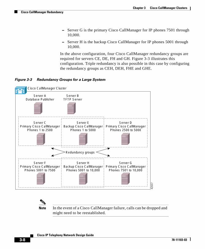
Chapter 3 Cisco CallManager ClustersCisco CallManager Redundancy
– Server G is the primary Cisco CallManager for IP phones 7501 through 10,000.
– Server H is the backup Cisco CallManager for IP phones 5001 through 10,000.
In the above configuration, four Cisco CallManager redundancy groups are required for servers CE, DE, FH and GH. Figure 3-3 illustrates this configuration. Triple redundancy is also possible in this case by configuring the redundancy groups as CEH, DEH, FHE and GHE.
Figure 3-3 Redundancy Groups for a Large System
Note In the event of a Cisco CallManager failure, calls can be dropped and might need to be reestablished.
Server ADatabase Publisher
Server CPrimary Cisco CallManager
Phones 1 to 2500
Server EBackup Cisco CallManager
Phones 1 to 5000
Server DPrimary Cisco CallManager
Phones 2500 to 5000
Server FPrimary Cisco CallManager
Phones 5001 to 7500
Server HBackup Cisco CallManager
Phones 5001 to 10,000
Server GPrimary Cisco CallManager
Phones 7501 to 10,000
Server BTFTP Server
Cisco CallManager Cluster
Redundancy groups42
657
3-8Cisco IP Telephony Network Design Guide
78-11103-03
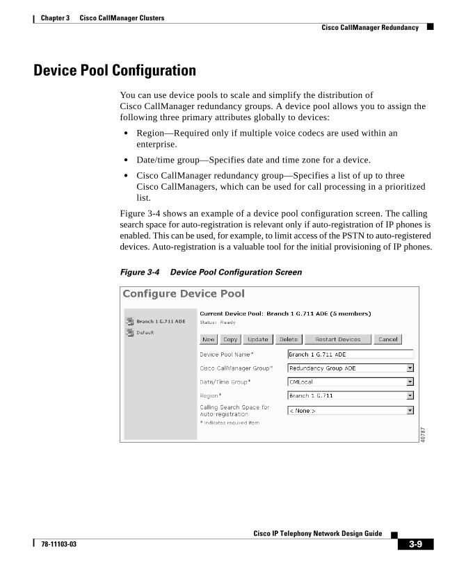
Chapter 3 Cisco CallManager ClustersCisco CallManager Redundancy
Device Pool ConfigurationYou can use device pools to scale and simplify the distribution of Cisco CallManager redundancy groups. A device pool allows you to assign the following three primary attributes globally to devices:
• Region—Required only if multiple voice codecs are used within an enterprise.
• Date/time group—Specifies date and time zone for a device.
• Cisco CallManager redundancy group—Specifies a list of up to three Cisco CallManagers, which can be used for call processing in a prioritized list.
Figure 3-4 shows an example of a device pool configuration screen. The calling search space for auto-registration is relevant only if auto-registration of IP phones is enabled. This can be used, for example, to limit access of the PSTN to auto-registered devices. Auto-registration is a valuable tool for the initial provisioning of IP phones.
Figure 3-4 Device Pool Configuration Screen
4078
7
3-9Cisco IP Telephony Network Design Guide
78-11103-03
Chapter 3 Cisco CallManager ClustersCisco CallManager Redundancy
In Figure 3-4, a device pool called Branch 1 G.711 ADE is configured with the following characteristics:
• It is assigned the region Branch 1 G.711. This region contains devices that are capable of communicating by means of G.711 only, such as a voice mail system or conference bridge.
• It is assigned to the appropriate date/time group.
• It is assigned the Cisco CallManager redundancy group ADE, where Cisco CallManager A is the primary, D is the secondary, and E is the tertiary.
A second device pool, called Branch 1 G.729 ADE, could be configured with the following characteristics:
• It is assigned the region Branch 1 G.729. This region contains devices that are capable of communicating by means of both G.729 and G.711, such as IP phones.
• It is assigned to the appropriate date/time group.
• It is assigned the Cisco CallManager redundancy group ADE, where Cisco CallManager A is the primary, D is the secondary, and E is the tertiary.
The same Cisco CallManager group is used for both device pools. However, it is now possible to specify interregion communication codec requirements:
• Intraregion communication uses G.711.
• Interregion communication uses G.729 across the WAN.
• All calls to the G.711 region use G.711. This is required, for example, when accessing an application that is G.711 only.
• This configuration is depicted in Figure 3-5.
3-10Cisco IP Telephony Network Design Guide
78-11103-03
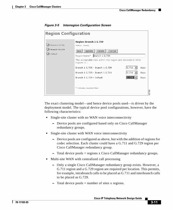
Chapter 3 Cisco CallManager ClustersCisco CallManager Redundancy
Figure 3-5 Interregion Configuration Screen
The exact clustering model—and hence device pools used—is driven by the deployment model. The typical device pool configurations, however, have the following characteristics:
• Single-site cluster with no WAN voice interconnectivity
– Device pools are configured based only on Cisco CallManager redundancy groups.
• Single-site cluster with WAN voice interconnectivity
– Device pools are configured as above, but with the addition of regions for codec selection. Each cluster could have a G.711 and G.729 region per Cisco CallManager redundancy group.
– Total device pools = regions x Cisco CallManager redundancy groups.
• Multi-site WAN with centralized call processing
– Only a single Cisco CallManager redundancy group exists. However, a G.711 region and a G.729 region are required per location. This permits, for example, intrabranch calls to be placed as G.711 and interbranch calls to be placed as G.729.
– Total device pools = number of sites x regions.
4078
8
3-11Cisco IP Telephony Network Design Guide
78-11103-03
Chapter 3 Cisco CallManager ClustersCampus Clustering Guidelines
Campus Clustering GuidelinesAll members of a Cisco CallManager cluster must be interconnected over a LAN. Cisco CallManager Release 3.0(5) clusters are not supported over a WAN.
The following considerations apply when configuring a campus IP telephony network:
• Maximum of eight servers per cluster with Cisco CallManager release 3.0(5).
• Maximum of 10,000 total registered devices.
• Maximum of 2500 registered IP phones or 3000 devices per Cisco CallManager, including devices registered under failure conditions.
• Switched infrastructure to the desktop (shared media is not supported).
Within a switched campus infrastructure, you can generally assume that the bandwidth is adequate for voice applications. This bandwidth availability depends upon appropriate design and capacity planning within the campus in addition to the establishment of a trust boundary and the required queuing, as discussed in Chapter 2, “Campus Infrastructure Considerations.” There is no requirement for call admission control within a campus cluster.
Cisco CallManager servers should be distributed within the campus to provide spatial redundancy and resiliency. Many metropolitan sites and campus buildings may have only a single conduit providing IP connectivity to other members of the cluster. In this case, if IP connectivity fails, local call processing must be maintained by means of a local server. Gateway resources for PSTN access should likewise be placed strategically to provide the highest possible availability.
Figure 3-6 depicts a typical campus or metropolitan-area network (MAN) cluster deployment.
3-12Cisco IP Telephony Network Design Guide
78-11103-03

Chapter 3 Cisco CallManager ClustersCampus Clustering Guidelines
Figure 3-6 Campus or MAN Cluster
In Figure 3-6 a Cisco CallManager is placed at each of the five buildings or sites. This configuration ensures that, in the event of a failure, local call processing is possible at each site. In cases where diverse routing of fiber cable negates the requirement for a local Cisco CallManager, all call processing could be located in one or more data centers.
Resources such as transcoding and the conferencing DSP are not shared resources and must be provisioned per Cisco CallManager. Once again, where fault tolerance is required, these resources require duplication, and spatial redundancy is recommended. This can be achieved by positioning these resources in strategically placed multi-layer switches.
Transcoder Conf Transcoder
Transcoder Transcoder
TranscoderConf Conf
ConfConf
V V
V V
4078
9
3-13Cisco IP Telephony Network Design Guide
78-11103-03
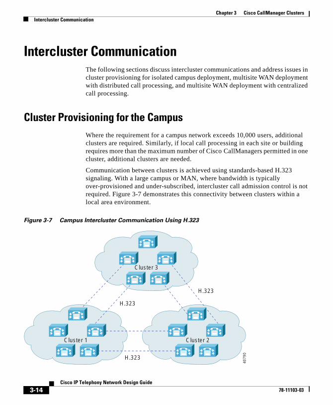
Chapter 3 Cisco CallManager ClustersIntercluster Communication
Intercluster CommunicationThe following sections discuss intercluster communications and address issues in cluster provisioning for isolated campus deployment, multisite WAN deployment with distributed call processing, and multisite WAN deployment with centralized call processing.
Cluster Provisioning for the CampusWhere the requirement for a campus network exceeds 10,000 users, additional clusters are required. Similarly, if local call processing in each site or building requires more than the maximum number of Cisco CallManagers permitted in one cluster, additional clusters are needed.
Communication between clusters is achieved using standards-based H.323 signaling. With a large campus or MAN, where bandwidth is typically over-provisioned and under-subscribed, intercluster call admission control is not required. Figure 3-7 demonstrates this connectivity between clusters within a local area environment.
Figure 3-7 Campus Intercluster Communication Using H.323
H.323
H.323
H.323
Cluster 3
Cluster 2Cluster 1
4079
0
3-14Cisco IP Telephony Network Design Guide
78-11103-03
Chapter 3 Cisco CallManager ClustersIntercluster Communication
In Figure 3-7 the dotted lines represent the H.323 intercluster links, which are configured in pairs to provide redundancy in the event of loss of IP connectivity to any member of the cluster. If desired, you could configure these links as a full mesh. However, Cisco recommends limiting intercluster configuration to two peers. In the majority of situations, this is sufficient to provide adequate resiliency. For deployments where a gatekeeper is used, Cisco recommends a single H.323 connection per cluster. You can implement redundancy by using a Cisco CallManager redundancy group assigned to the gatekeeper.
Unlike earlier releases of Cisco CallManager, release 3.0(5) does not require the use of an MTP to allow supplementary services for H.323 devices. Cisco CallManager 3.0(5) uses the “empty capabilities set” of H.323v2 to facilitate the opening and closing of logical channels between H.323 devices such as Cisco CallManager clusters and Cisco IOS gateways running Cisco IOS Release 12.0(7)T or greater.
Clusters for Multisite WAN with Distributed Call ProcessingWhere clusters are interconnected over a WAN, there is a pinch point for congestion between clusters, and the network should be engineered to accommodate the required volume of voice traffic. In such cases a method of providing call admission control is required. Because clusters are interconnected using H.323, a Cisco IOS gateway can be added to facilitate this gatekeeper function. Each cluster can be designated as a zone with a maximum configured bandwidth for voice calls.
When using a gatekeeper, Cisco CallManager requests 128 kbps of bandwidth per G.711 inter-cluster call and 20 kbps of bandwidth per G.729a intercluster call. In general, Cisco recommends configuring a single codec for calls that traverse the WAN because this greatly simplifies the provisioning of bandwidth.
Table 3-4 and Table 3-5 give recommendations for bandwidth configuration for intercluster calls.
3-15Cisco IP Telephony Network Design Guide
78-11103-03
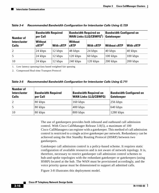
Chapter 3 Cisco CallManager ClustersIntercluster Communication
The use of gatekeepers provides both inbound and outbound call admission control. With Cisco CallManager Release 3.0(5), a maximum of 100 Cisco CallManagers can register with a gatekeeper. This method of call admission control is restricted to a single active gatekeeper per network. Redundancy can be achieved using the Hot Standby Routing Protocol (HSRP) between two gatekeepers.
Gatekeeper call admission control is a policy-based scheme. It requires static configuration of available resources and is not aware of network topology. It is, therefore, necessary to restrict gatekeeper call admission control schemes to hub-and-spoke topologies with the redundant gatekeeper or gatekeepers (using HSRP) located at the hub. The WAN must be provisioned accordingly, and the voice priority queue must be dimensioned to support all admitted calls.
Figure 3-8 illustrates this deployment model.
Table 3-4 Recommended Bandwidth Configuration for Intercluster Calls Using G.729
Number of Intercluster Calls
Bandwidth Required per Call
Bandwidth Required on WAN Links (LLQ/CBWFQ1)
1. Low latency queuing/class based weighted fair queuing
Bandwidth Configured on Gatekeeper
Without cRTP2
2. Compressed Real-time Transport Protocol
With cRTPWithout cRTP With cRTP Without cRTP With cRTP
2 24 kbps 12 kbps 48 kbps 24 kbps 40 kbps 40 kbps
5 24 kbps 12 kbps 120 kbps 60 kbps 100 kbps 100 kbps
10 24 kbps 12 kbps 240 kbps 120 kbps 200 kbps 200 kbps
Table 3-5 Recommended Bandwidth Configuration for Intercluster Calls Using G.711
Number of Intercluster Calls
Bandwidth Required per Call
Bandwidth Required on WAN Links (LLQ/CBWFQ)
Bandwidth Configured on Gatekeeper
2 80 kbps 160 kbps 256 kbps
5 80 kbps 400 kbps 640 kbps
10 80 kbps 800 kbps 1280 kbps
3-16Cisco IP Telephony Network Design Guide
78-11103-03
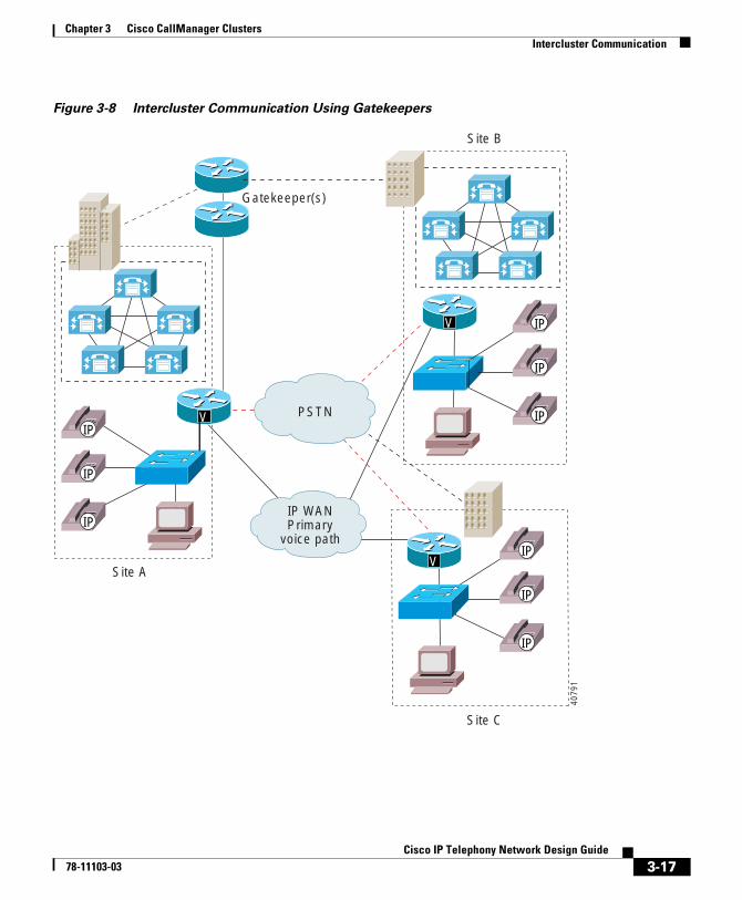
Chapter 3 Cisco CallManager ClustersIntercluster Communication
Figure 3-8 Intercluster Communication Using Gatekeepers
Site A
Site B
Site C
V
V
IP WANPrimary
voice path
PSTN
Gatekeeper(s)
IP
IP
IP
V
IP
IP
IP
IP
IP
IP
4079
1
3-17Cisco IP Telephony Network Design Guide
78-11103-03
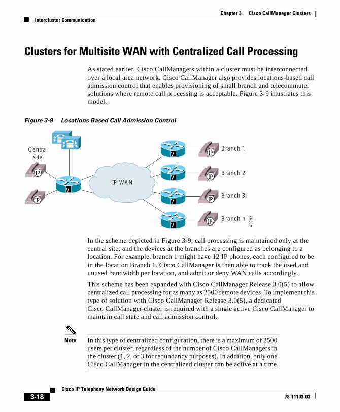
Chapter 3 Cisco CallManager ClustersIntercluster Communication
Clusters for Multisite WAN with Centralized Call ProcessingAs stated earlier, Cisco CallManagers within a cluster must be interconnected over a local area network. Cisco CallManager also provides locations-based call admission control that enables provisioning of small branch and telecommuter solutions where remote call processing is acceptable. Figure 3-9 illustrates this model.
Figure 3-9 Locations Based Call Admission Control
In the scheme depicted in Figure 3-9, call processing is maintained only at the central site, and the devices at the branches are configured as belonging to a location. For example, branch 1 might have 12 IP phones, each configured to be in the location Branch 1. Cisco CallManager is then able to track the used and unused bandwidth per location, and admit or deny WAN calls accordingly.
This scheme has been expanded with Cisco CallManager Release 3.0(5) to allow centralized call processing for as many as 2500 remote devices. To implement this type of solution with Cisco CallManager Release 3.0(5), a dedicated Cisco CallManager cluster is required with a single active Cisco CallManager to maintain call state and call admission control.
Note In this type of centralized configuration, there is a maximum of 2500 users per cluster, regardless of the number of Cisco CallManagers in the cluster (1, 2, or 3 for redundancy purposes). In addition, only one Cisco CallManager in the centralized cluster can be active at a time.
V
V
V
V
V
IP WAN
Centralsite
Branch 1
Branch 2
Branch 3
Branch n
IP
IP
IP
IP
IP
IP
4079
2
3-18Cisco IP Telephony Network Design Guide
78-11103-03
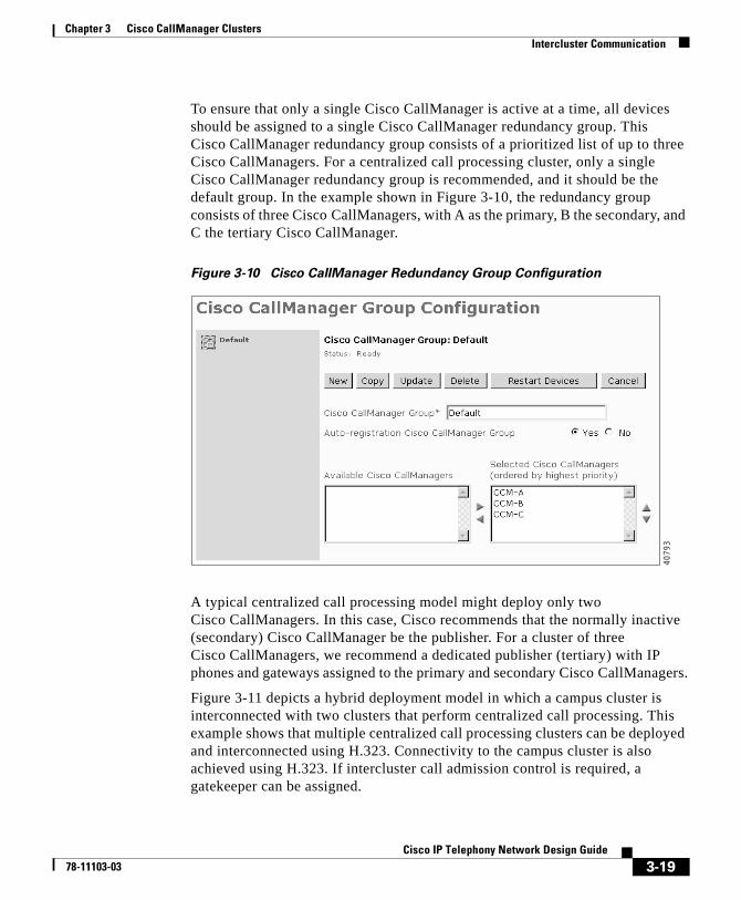
Chapter 3 Cisco CallManager ClustersIntercluster Communication
To ensure that only a single Cisco CallManager is active at a time, all devices should be assigned to a single Cisco CallManager redundancy group. This Cisco CallManager redundancy group consists of a prioritized list of up to three Cisco CallManagers. For a centralized call processing cluster, only a single Cisco CallManager redundancy group is recommended, and it should be the default group. In the example shown in Figure 3-10, the redundancy group consists of three Cisco CallManagers, with A as the primary, B the secondary, and C the tertiary Cisco CallManager.
Figure 3-10 Cisco CallManager Redundancy Group Configuration
A typical centralized call processing model might deploy only two Cisco CallManagers. In this case, Cisco recommends that the normally inactive (secondary) Cisco CallManager be the publisher. For a cluster of three Cisco CallManagers, we recommend a dedicated publisher (tertiary) with IP phones and gateways assigned to the primary and secondary Cisco CallManagers.
Figure 3-11 depicts a hybrid deployment model in which a campus cluster is interconnected with two clusters that perform centralized call processing. This example shows that multiple centralized call processing clusters can be deployed and interconnected using H.323. Connectivity to the campus cluster is also achieved using H.323. If intercluster call admission control is required, a gatekeeper can be assigned.
4079
3
3-19Cisco IP Telephony Network Design Guide
78-11103-03
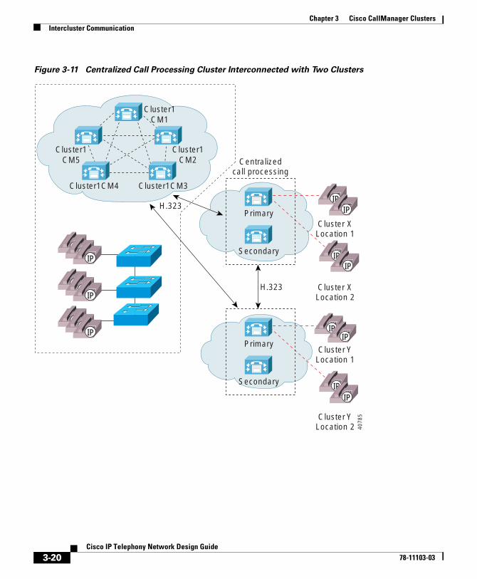
Chapter 3 Cisco CallManager ClustersIntercluster Communication
Figure 3-11 Centralized Call Processing Cluster Interconnected with Two Clusters
Centralizedcall processing
H.323
Cluster XLocation 1
Cluster XLocation 2
Primary
Secondary
Cluster YLocation 1
Cluster YLocation 2
Primary
Secondary
Cluster1CM1
Cluster1CM2
Cluster1CM3Cluster1CM4
Cluster1CM5
H.323
IPIP
IP
IPIP
IP
IPIP
IP
IP
IP
IP
IPIP
IP
IP
IP
4078
5
3-20Cisco IP Telephony Network Design Guide
78-11103-03
Chapter 3 Cisco CallManager ClustersIntracluster and Intercluster Feature Transparency
Intracluster and Intercluster Feature TransparencyThe distributed architecture of a Cisco CallManager cluster provides the following primary benefits for call processing:
• Spatial redundancy
• Resiliency
• Availability
• Survivability
In addition, a cluster provides transparent support of user features across all devices in the cluster. This enables distributed IP telephony to span an entire campus or high-speed metropolitan-area network (MAN) with full features.
Intercluster communication provided by H.323 permits a subset of the features to be extended between clusters. These features are currently available between clusters:
• Basic call setup
• G.711 and G.729 calls
• Multiparty conference
• Call hold
• Call transfer
• Calling line ID
In addition, Call Park is available within a cluster but not between clusters.
3-21Cisco IP Telephony Network Design Guide
78-11103-03

Chapter 3 Cisco CallManager ClustersIntracluster and Intercluster Feature Transparency
3-22Cisco IP Telephony Network Design Guide
78-11103-03
Cisco IP T78-11103-03
C H A P T E R 4
Gateway SelectionThis chapter discusses issues concerning the selection of gateways for connecting an IP telephony network to the PSTN or legacy PBX and key systems. Choosing a gateway from some 20 candidates—ranging from specialized, entry-level standalone voice gateways to the high-end, feature-rich integrated router and Catalyst gateways—can be daunting.
Although your particular VoIP implementation dictates specific gateway requirements, these are common required features:
• Dual tone multifrequency (DTMF) relay capabilities
• Ability to handle clustered Cisco CallManager systems
• Supplementary services support
Any gateway selected for an enterprise network should be able to support these features. In addition, every implementation has its own site-specific feature requirements, which helps you eliminate options.
This chapter includes these sections to address the required common and site-specific features:
• Supported Protocols, page 4-2
• DTMF Relay, page 4-3
• Cisco CallManager Redundancy, page 4-5
• Supplementary Services, page 4-7
• Site-Specific Gateway Requirements, page 4-9
4-1elephony Network Design Guide
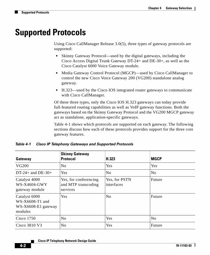
Chapter 4 Gateway SelectionSupported Protocols
Supported ProtocolsUsing Cisco CallManager Release 3.0(5), three types of gateway protocols are supported:
• Skinny Gateway Protocol—used by the digital gateways, including the Cisco Access Digital Trunk Gateway DT-24+ and DE-30+, as well as the Cisco Catalyst 6000 Voice Gateway module.
• Media Gateway Control Protocol (MGCP)—used by Cisco CallManager to control the new Cisco Voice Gateway 200 (VG200) standalone analog gateway.
• H.323—used by the Cisco IOS integrated router gateways to communicate with Cisco CallManager.
Of these three types, only the Cisco IOS H.323 gateways can today provide full-featured routing capabilities as well as VoIP gateway functions. Both the gateways based on the Skinny Gateway Protocol and the VG200 MGCP gateway act as standalone, application-specific gateways.
Table 4-1 shows which protocols are supported on each gateway. The following sections discuss how each of these protocols provides support for the three core gateway features.
Table 4-1 Cisco IP Telephony Gateways and Supported Protocols
GatewaySkinny Gateway Protocol H.323 MGCP
VG200 No Yes Yes
DT-24+ and DE-30+ Yes No No
Catalyst 4000 WS-X4604-GWY gateway module
Yes, for conferencing and MTP transcoding services
Yes, for PSTN interfaces
Future
Catalyst 6000 WS-X6608-T1 and WS-X6608-E1 gateway modules
Yes No Future
Cisco 1750 No Yes No
Cisco 3810 V3 No Yes Future
4-2Cisco IP Telephony Network Design Guide
78-11103-03
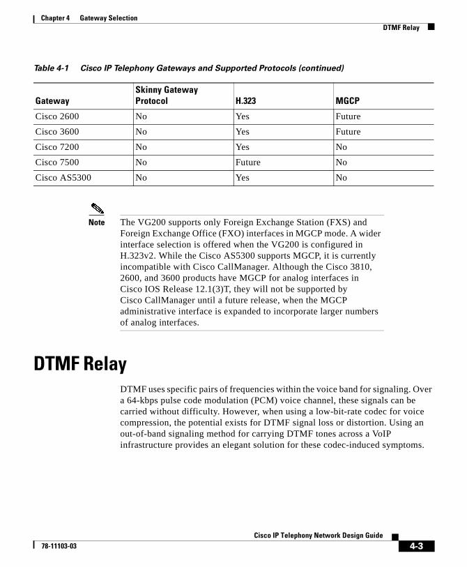
Chapter 4 Gateway SelectionDTMF Relay
Note The VG200 supports only Foreign Exchange Station (FXS) and Foreign Exchange Office (FXO) interfaces in MGCP mode. A wider interface selection is offered when the VG200 is configured in H.323v2. While the Cisco AS5300 supports MGCP, it is currently incompatible with Cisco CallManager. Although the Cisco 3810, 2600, and 3600 products have MGCP for analog interfaces in Cisco IOS Release 12.1(3)T, they will not be supported by Cisco CallManager until a future release, when the MGCP administrative interface is expanded to incorporate larger numbers of analog interfaces.
DTMF RelayDTMF uses specific pairs of frequencies within the voice band for signaling. Over a 64-kbps pulse code modulation (PCM) voice channel, these signals can be carried without difficulty. However, when using a low-bit-rate codec for voice compression, the potential exists for DTMF signal loss or distortion. Using an out-of-band signaling method for carrying DTMF tones across a VoIP infrastructure provides an elegant solution for these codec-induced symptoms.
Cisco 2600 No Yes Future
Cisco 3600 No Yes Future
Cisco 7200 No Yes No
Cisco 7500 No Future No
Cisco AS5300 No Yes No
Table 4-1 Cisco IP Telephony Gateways and Supported Protocols (continued)
GatewaySkinny Gateway Protocol H.323 MGCP
4-3Cisco IP Telephony Network Design Guide
78-11103-03
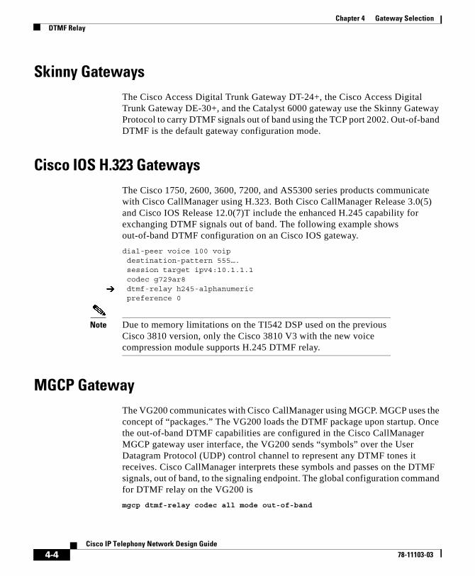
Chapter 4 Gateway SelectionDTMF Relay
Skinny GatewaysThe Cisco Access Digital Trunk Gateway DT-24+, the Cisco Access Digital Trunk Gateway DE-30+, and the Catalyst 6000 gateway use the Skinny Gateway Protocol to carry DTMF signals out of band using the TCP port 2002. Out-of-band DTMF is the default gateway configuration mode.
Cisco IOS H.323 GatewaysThe Cisco 1750, 2600, 3600, 7200, and AS5300 series products communicate with Cisco CallManager using H.323. Both Cisco CallManager Release 3.0(5) and Cisco IOS Release 12.0(7)T include the enhanced H.245 capability for exchanging DTMF signals out of band. The following example shows out-of-band DTMF configuration on an Cisco IOS gateway.
dial-peer voice 100 voip destination-pattern 555…. session target ipv4:10.1.1.1 codec g729ar8dtmf-relay h245-alphanumeric
preference 0
Note Due to memory limitations on the TI542 DSP used on the previous Cisco 3810 version, only the Cisco 3810 V3 with the new voice compression module supports H.245 DTMF relay.
MGCP GatewayThe VG200 communicates with Cisco CallManager using MGCP. MGCP uses the concept of “packages.” The VG200 loads the DTMF package upon startup. Once the out-of-band DTMF capabilities are configured in the Cisco CallManager MGCP gateway user interface, the VG200 sends “symbols” over the User Datagram Protocol (UDP) control channel to represent any DTMF tones it receives. Cisco CallManager interprets these symbols and passes on the DTMF signals, out of band, to the signaling endpoint. The global configuration command for DTMF relay on the VG200 is
mgcp dtmf-relay codec all mode out-of-band
4-4Cisco IP Telephony Network Design Guide
78-11103-03
Chapter 4 Gateway SelectionCisco CallManager Redundancy
You must enter additional configuration parameters in the Cisco CallManager MGCP gateway configuration interface.
Cisco CallManager RedundancyIntegral to the Cisco IP telephony solution is the provision for low-cost, distributed PC-based systems to replace expensive and proprietary legacy PBX systems. This distributed design lends itself to the robust, fault-tolerant architecture of clustered Cisco CallManagers. Even in its simplest form (a two-system cluster), a secondary Cisco CallManager should be able to pick up control of all gateways initially managed by the primary Cisco CallManager.
Skinny GatewaysWhen they are booted, the Cisco Access Digital Trunk Gateway DT-24+, the Cisco Access Digital Trunk Gateway DE-30+, and the Catalyst 6000 digital gateway are provisioned with Cisco CallManager location information. When these gateways initialize, a list of Cisco CallManagers, referred to as a Cisco CallManager redundancy group, is downloaded to the gateways. This list is prioritized into a primary Cisco CallManager and secondary Cisco CallManager. In the event that the primary Cisco CallManager becomes unreachable, the gateway registers with the secondary Cisco CallManager.
IOS H.323 GatewaysUsing several enhancements to the dial-peer and voice class commands in Cisco IOS Release 12.1(2)T, Cisco IOS gateways can now support redundant Cisco CallManagers. A new command, h225 tcp timeout seconds, has been added. This command specifies the time it takes for the Cisco IOS gateway to establish an H.225 control connection for H.323 call setup. If the Cisco IOS gateway cannot establish an H.225 connection to the primary Cisco CallManager, it tries a second Cisco CallManager defined in another dial-peer statement. The Cisco IOS gateway shifts to the dial-peer statement with next highest preference setting.
4-5Cisco IP Telephony Network Design Guide
78-11103-03
Chapter 4 Gateway SelectionCisco CallManager Redundancy
The following example shows the configuration for H.323 gateway failover:
interface Loopback0ip address 1.1.1.1 255.255.255.0voip-gateway voip bind srcaddr 1.1.1.1
dial-peer voice 101 voipdestination-pattern 1111session target ipv4:10.1.1.101preference 0voice class h323 1
dial-peer voice 102 voipdestination-pattern 1111session target ipv4:10.1.1.102preference 1voice class h323 1
voice class h323 1h225 timeout tcp establish 3
Note To simplify troubleshooting and firewall configurations, Cisco recommends that you use the new voip-gateway voip bind srcaddr command for forcing H.323 always to use a specific source IP address in call setup. Without this command, the source address used in the setup might vary depending on protocol (RAS, H.225, H.245 or RTP).
MGCP GatewayAdding MGCP to the VG200 and Cisco CallManager allows this standalone gateway to switch over to a secondary Cisco CallManager in the event communication is lost with the primary Cisco CallManager. Within the VG200 configuration file, the primary Cisco CallManager is identified using the call-agent hostname command, and a list of secondary Cisco CallManager systems is added using the ccm-manager redundant-host command. Keepalives with the actively associated Cisco CallManager are accomplished through the MGCP application-level keepalive mechanism, whereby the gateway sends an empty MGCP NTFY message to the Cisco CallManager and waits for an acknowledgement. Keepalive with the backup Cisco CallManager(s) is accomplished through the TCP keepalive mechanism (UDP will be used in a later version).
4-6Cisco IP Telephony Network Design Guide
78-11103-03
Chapter 4 Gateway SelectionSupplementary Services
If the primary Cisco CallManager becomes available at a later time, the VG200 can revert to the original Cisco CallManager. This fallback can either occur immediately, after a configurable amount of time, or only when all connected sessions have been released. This behavior is enabled through the following VG200 global configuration commands:
ccm-manager redundant-host {hostname1 | ipaddress1} [hostname2 | ipaddress2]
[no] call-manager redundancy switchback [immediate | graceful | delay delay-time]
Supplementary ServicesSupplementary services provide user functions such as hold, transfer, and conferencing. These are considered fundamental requirements of any voice installation. Any gateway evaluated for use in an Cisco AVVID network should provide native support for supplementary services without the use of a software media termination point (MTP).
Skinny GatewaysThe Cisco Access Digital Trunk Gateway DT-24+ and DE-30+ products as well as the Catalyst 6000 series gateways all provide full supplementary service support. These gateways utilize the gateway-to-Cisco CallManager signaling channel and Skinny Gateway Protocol to exchange call control parameters. For more information, see the “Additional Information” section on page xvii.
4-7Cisco IP Telephony Network Design Guide
78-11103-03
Chapter 4 Gateway SelectionSupplementary Services
IOS H.323 GatewaysOnly H.323v1 was supported prior to Cisco CallManager Release 3.0. The inability to modify the destination of an Real-Time Transport Protocol (RTP) stream after H.323v1 call setup prohibited supplementary services such as hold, forward, and transfer. Because H.323v1 provides no capability to move an RTP stream from one destination to another after original call setup, the software MTP tool was used to provide supplementary service support on the Cisco IOS gateways.
MTP, which runs as a software process on either the Cisco CallManager or on a separate Windows NT 4.0 server, terminates the RTP stream from the Cisco IOS gateway and the RTP stream from an IP phone. This workaround enables an IP phone to support supplementary services when using a Cisco IOS VoIP gateway because the RTP stream from the MTP to the Cisco IOS gateway is never modified until call completion. All RTP stream changes are made on the Skinny Station side of the MTP connection. An additional major caveat for using the software MTP is that it supports only G.711 voice streams; no compressed voice calls are supported. This greatly limits WAN systems.
The use of H.323v2 in Cisco IOS Release 12.0(7)T and above (specifically the OpenLogicalChannel, CloseLogicalChannel, and emptyCapabiliySet features) by Cisco IOS gateways and Cisco CallManager Release 3.0(5) eliminates the requirement for MTP to provide supplementary services. Because MTP is no longer needed to terminate the G.711 RTP streams from both the IP phones and the Cisco IOS gateway, compressed voice calls (G.723.1 and G.729a) are now supported between Cisco IOS gateways and Cisco CallManager endpoints.
Once an H.323v2 call is set up between an Cisco IOS gateway and an IP phone, using the Cisco CallManager as an H.323 proxy, the IP phone can request to modify the bearer connection. Because the RTP stream is directly connected to the IP phone from the Cisco IOS gateway, a supported voice codec can be negotiated.
The following steps illustrate the process that occurs if IP phone 1 wants to transfer the call from the Cisco IOS gateway to IP phone 2:
1. IP phone 1 issues a transfer request to Cisco CallManager using the Skinny Station Protocol.
2. Cisco CallManager translates this request into an H.323v2 CloseLogicalChannel request to the Cisco IOS gateway for the appropriate SessionID.
3. The Cisco IOS gateway closes the RTP channel to IP phone 1.
4-8Cisco IP Telephony Network Design Guide
78-11103-03
Chapter 4 Gateway SelectionSite-Specific Gateway Requirements
4. Cisco CallManager issues a request to IP phone 2, using the Skinny Station Protocol, to set up an RTP connection to the Cisco IOS gateway. At the same time, Cisco CallManager issues an OpenLogicalChannel request to the Cisco IOS gateway with the new destination parameters, but using the same SessionID.
5. After the Cisco IOS gateway acknowledges the request, an RTP voice bearer channel is set between IP phone 2 and the Cisco IOS gateway.
MGCP GatewayThe VG200 provides full support for the hold, transfer, and conference features using MGCP. Because MGCP is fundamentally a master-slave protocol, with Cisco CallManager controlling all session intelligence, it can easily manipulate VG200 voice connections. If a Cisco AVVID endpoint needs to modify the session (for example, transfer the call to another Cisco AVVID endpoint), the endpoint would notify Cisco CallManager through the Skinny Station Protocol. Cisco CallManager would then inform the VG200, using the MGCP UDP control connection, to terminate the current RTP stream associated with the SessionID and start a new media session with the new endpoint information.
Site-Specific Gateway RequirementsBesides the requirements for DMTF relay and supplementary services, each Cisco IP telephony implementation has its own gateway requirements. The following is a sample list of questions regarding required features that should be asked prior to selecting a Cisco IP telephony gateway.
• Is an analog or digital gateway required?
• What is the required capacity of the gateway?
• What type of connection is the gateway going to use (for example, FXO ground-start, E1-R2, network-side or user-side PRI)?
• What types of supplementary services are desired?
• Is voice compression a part of the design? If so, which types?
4-9Cisco IP Telephony Network Design Guide
78-11103-03
Chapter 4 Gateway SelectionSite-Specific Gateway Requirements
• Is direct inward dialing (DID) required?
DID is a private branch exchange (PBX) or Centrex feature that permits outside calls to be placed directly to a station line without use of an operator.
• Is calling line ID (CLID) needed?
CLID is a service available on digital telephone networks that tells the called party which number is calling. The central office equipment identifies the phone number of the caller, enabling information about the caller to be sent along with the call itself. CLID is synonymous with ANI (automatic number identification).
• Is fax relay needed?
• What type of network management interface is preferred?
• To which country will the hardware be shipped?
• Is rack space available for all needed gateways, routers, and switches?
Although this feature list could be much longer, it provides a starting point to help narrow the possible choices. Once the features have been defined, a gateway selection can be made for configurations ranging from single-site enterprise systems of various sizes and complexities to multisite enterprise systems. These categories are defined in more depth in the following sections.
4-10Cisco IP Telephony Network Design Guide
78-11103-03
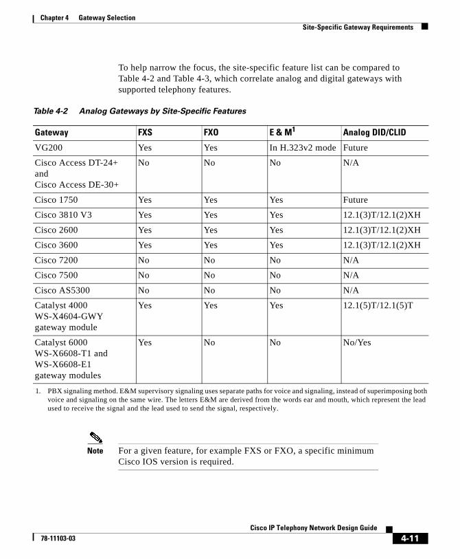
Chapter 4 Gateway SelectionSite-Specific Gateway Requirements
To help narrow the focus, the site-specific feature list can be compared to Table 4-2 and Table 4-3, which correlate analog and digital gateways with supported telephony features.
Note For a given feature, for example FXS or FXO, a specific minimum Cisco IOS version is required.
Table 4-2 Analog Gateways by Site-Specific Features
Gateway FXS FXO E & M1
1. PBX signaling method. E&M supervisory signaling uses separate paths for voice and signaling, instead of superimposing both voice and signaling on the same wire. The letters E&M are derived from the words ear and mouth, which represent the lead used to receive the signal and the lead used to send the signal, respectively.
Analog DID/CLID
VG200 Yes Yes In H.323v2 mode Future
Cisco Access DT-24+ and Cisco Access DE-30+
No No No N/A
Cisco 1750 Yes Yes Yes Future
Cisco 3810 V3 Yes Yes Yes 12.1(3)T/12.1(2)XH
Cisco 2600 Yes Yes Yes 12.1(3)T/12.1(2)XH
Cisco 3600 Yes Yes Yes 12.1(3)T/12.1(2)XH
Cisco 7200 No No No N/A
Cisco 7500 No No No N/A
Cisco AS5300 No No No N/A
Catalyst 4000 WS-X4604-GWY gateway module
Yes Yes Yes 12.1(5)T/12.1(5)T
Catalyst 6000 WS-X6608-T1 and WS-X6608-E1 gateway modules
Yes No No No/Yes
4-11Cisco IP Telephony Network Design Guide
78-11103-03
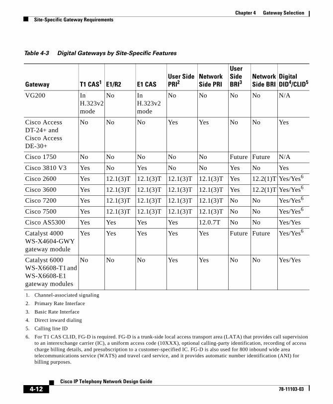
Chapter 4 Gateway SelectionSite-Specific Gateway Requirements
Table 4-3 Digital Gateways by Site-Specific Features
Gateway T1 CAS1
1. Channel-associated signaling
E1/R2 E1 CASUser Side PRI2
2. Primary Rate Interface
Network Side PRI
User Side BRI3
3. Basic Rate Interface
Network Side BRI
Digital DID4/CLID5
4. Direct inward dialing
5. Calling line ID
VG200 In H.323v2 mode
No In H.323v2 mode
No No No No N/A
Cisco Access DT-24+ and Cisco Access DE-30+
No No No Yes Yes No No Yes
Cisco 1750 No No No No No Future Future N/A
Cisco 3810 V3 Yes No Yes No No Yes No Yes
Cisco 2600 Yes 12.1(3)T 12.1(3)T 12.1(3)T 12.1(3)T Yes 12.2(1)T Yes/Yes6
6. For T1 CAS CLID, FG-D is required. FG-D is a trunk-side local access transport area (LATA) that provides call supervision to an interexchange carrier (IC), a uniform access code (10XXX), optional calling-party identification, recording of access charge billing details, and presubscription to a customer-specified IC. FG-D is also used for 800 inbound wide area telecommunications service (WATS) and travel card service, and it provides automatic number identification (ANI) for billing purposes.
Cisco 3600 Yes 12.1(3)T 12.1(3)T 12.1(3)T 12.1(3)T Yes 12.2(1)T Yes/Yes6
Cisco 7200 Yes 12.1(3)T 12.1(3)T 12.1(3)T 12.1(3)T No No Yes/Yes6
Cisco 7500 Yes 12.1(3)T 12.1(3)T 12.1(3)T 12.1(3)T No No Yes/Yes6
Cisco AS5300 Yes Yes Yes Yes 12.0.7T No No Yes/Yes
Catalyst 4000 WS-X4604-GWY gateway module
Yes Yes Yes Yes Yes Future Future Yes/Yes6
Catalyst 6000 WS-X6608-T1 and WS-X6608-E1 gateway modules
No No No Yes Yes No No Yes/Yes
4-12Cisco IP Telephony Network Design Guide
78-11103-03
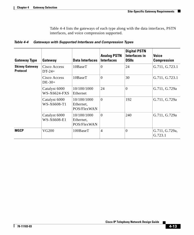
Chapter 4 Gateway SelectionSite-Specific Gateway Requirements
Table 4-4 lists the gateways of each type along with the data interfaces, PSTN interfaces, and voice compression supported.
Table 4-4 Gateways with Supported Interfaces and Compression Types
Gateway Type Gateway Data InterfacesAnalog PSTN Interfaces
Digital PSTN Interfaces in DS0s
Voice Compression
Skinny Gateway Protocol
Cisco Access DT-24+
10BaseT 0 24 G.711, G.723.1
Cisco Access DE-30+
10BaseT 0 30 G.711, G.723.1
Catalyst 6000 WS-X6624-FXS
10/100/1000 Ethernet
24 0 G.711, G.729a
Catalyst 6000 WS-X6608-T1
10/100/1000 Ethernet, POS/FlexWAN
0 192 G.711, G.729a
Catalyst 6000 WS-X6608-E1
10/100/1000 Ethernet, POS/FlexWAN
0 240 G.711, G.729a
MGCP VG200 100BaseT 4 0 G.711, G.729a, G.723.1
4-13Cisco IP Telephony Network Design Guide
78-11103-03
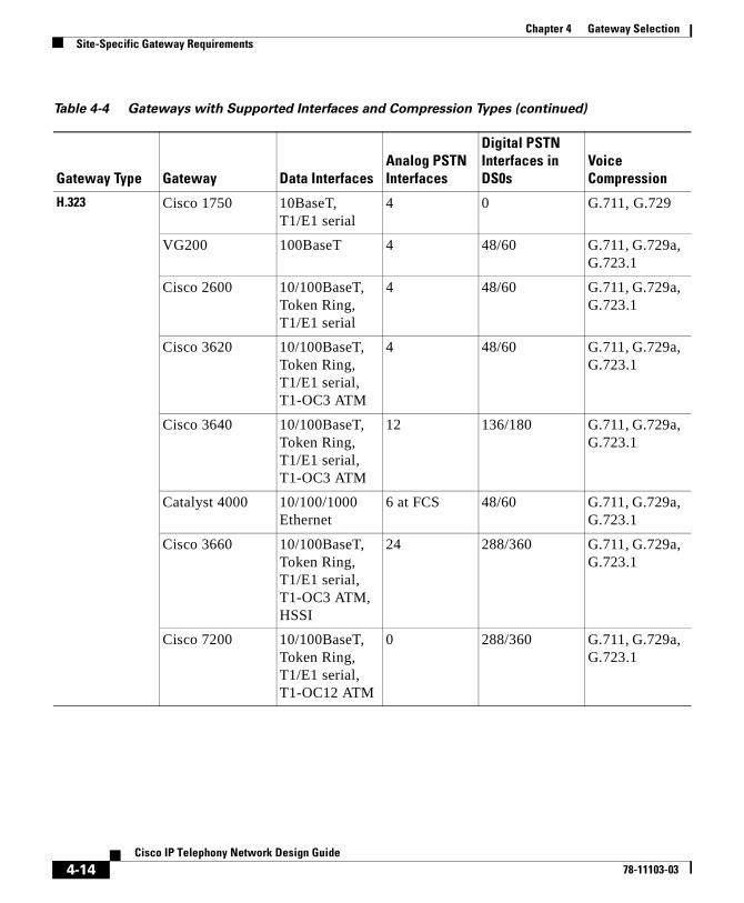
Chapter 4 Gateway SelectionSite-Specific Gateway Requirements
H.323 Cisco 1750 10BaseT, T1/E1 serial
4 0 G.711, G.729
VG200 100BaseT 4 48/60 G.711, G.729a, G.723.1
Cisco 2600 10/100BaseT, Token Ring, T1/E1 serial
4 48/60 G.711, G.729a, G.723.1
Cisco 3620 10/100BaseT, Token Ring, T1/E1 serial, T1-OC3 ATM
4 48/60 G.711, G.729a, G.723.1
Cisco 3640 10/100BaseT, Token Ring, T1/E1 serial, T1-OC3 ATM
12 136/180 G.711, G.729a, G.723.1
Catalyst 4000 10/100/1000 Ethernet
6 at FCS 48/60 G.711, G.729a, G.723.1
Cisco 3660 10/100BaseT, Token Ring, T1/E1 serial, T1-OC3 ATM, HSSI
24 288/360 G.711, G.729a, G.723.1
Cisco 7200 10/100BaseT, Token Ring, T1/E1 serial, T1-OC12 ATM
0 288/360 G.711, G.729a, G.723.1
Table 4-4 Gateways with Supported Interfaces and Compression Types (continued)
Gateway Type Gateway Data InterfacesAnalog PSTN Interfaces
Digital PSTN Interfaces in DS0s
Voice Compression
4-14Cisco IP Telephony Network Design Guide
78-11103-03
Cisco IP T78-11103-03
C H A P T E R 5
Dial Plan Architecture and ConfigurationThis chapter discusses the architecture and operation of the Cisco CallManager dial plan and provides design recommendations. A dial plan is essentially a telephony system interface that allows users to reach each other easily by dialing strings that can be routed to diverse locations by the system.
This chapter contains the following major sections:
• Cisco CallManager Dial Plan Architecture, page 5-1
• Special Dial String Considerations, page 5-10
• Configuring Dial Plan Groups and Calling Restrictions, page 5-14
• Dial Plan Guidelines and Configuration, page 5-18
• The Role of a Gatekeeper, page 5-21
Cisco CallManager Dial Plan ArchitectureThis section gives an explanation of the dial plan architecture and functional components. Since a dial plan can be configured in many ways, recommended configurations are also described.
Dial plan requirements can include support for abbreviated dialing, such as four- or five-digit extensions, as well as redundant paths that are transparent to the calling party. The dial plan in Cisco CallManager Release 3.0 is enhanced to
5-1elephony Network Design Guide
Chapter 5 Dial Plan Architecture and ConfigurationCisco CallManager Dial Plan Architecture
allow for greater scalability, flexibility, and ease of use, while tighter integration of Cisco CallManager and Cisco IOS gateways allows for larger network deployments.
The Cisco CallManager dial plan architecture is set up to handle two general types of calls.
• Internal calls to Cisco IP phones registered to the Cisco CallManager cluster itself
• External calls through a PSTN gateway or to another Cisco CallManager cluster over the IP WAN
Figure 5-1 shows a network designed to handle these two types of calls. With a well-designed dial plan, voice calls preferentially use the IP WAN and are routed to the PSTN only if the IP WAN is down or unavailable. This routing is transparent to the user.
5-2Cisco IP Telephony Network Design Guide
78-11103-03
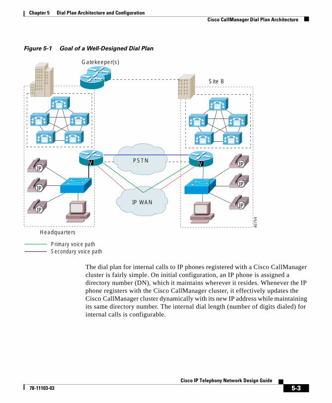
Chapter 5 Dial Plan Architecture and ConfigurationCisco CallManager Dial Plan Architecture
Figure 5-1 Goal of a Well-Designed Dial Plan
The dial plan for internal calls to IP phones registered with a Cisco CallManager cluster is fairly simple. On initial configuration, an IP phone is assigned a directory number (DN), which it maintains wherever it resides. Whenever the IP phone registers with the Cisco CallManager cluster, it effectively updates the Cisco CallManager cluster dynamically with its new IP address while maintaining its same directory number. The internal dial length (number of digits dialed) for internal calls is configurable.
IP WAN
PSTN
Primary voice pathSecondary voice path
Headquarters
Site B
V
Gatekeeper(s)
IP
IP
IP
V IP
IP
IP
4079
4
5-3Cisco IP Telephony Network Design Guide
78-11103-03
Chapter 5 Dial Plan Architecture and ConfigurationCisco CallManager Dial Plan Architecture
Note IP phones are not the only devices that can be accessed in this manner. Other devices that register with Cisco CallManager and maintain a directory number can include Cisco IP SoftPhones, analog phones, and fax machines attached to gateways that use MGCP or the Skinny Gateway Protocol.
Configuring Cisco CallManager to handle external calls requires the use of a route pattern. In most cases, the route pattern is used for directing calls out to a PSTN gateway, but it is also used in the case of an IP WAN call to a remote Cisco CallManager. The Cisco CallManager Release 3.0 dial plan architecture is a three-tiered decision tree that allows multiple routes for a given dialed number, as well as digit manipulation based on the network requirements. Digit manipulation is the task of adding or subtracting digits from the original dialed number to accommodate user dialing habits or gateway needs. You can also configure capabilities such as trunk groups for gateway redundancy and a form of least-cost routing.
As an example of alternate route selection, the path to a given dialed number typically takes the IP WAN as the first choice and the PSTN as the second choice if the IP WAN is down or has insufficient resources. The dial plan criteria for using an alternate route could be based on an indication by the call admission control mechanism that insufficient trunks are available on a gateway, meaning that the IP WAN cannot accept the call.
Figure 5-2 illustrates the Cisco CallManager Release 3.0 dial plan architecture that supports alternate route selection. The elements in this architecture are described in the subsections that follow.
5-4Cisco IP Telephony Network Design Guide
78-11103-03
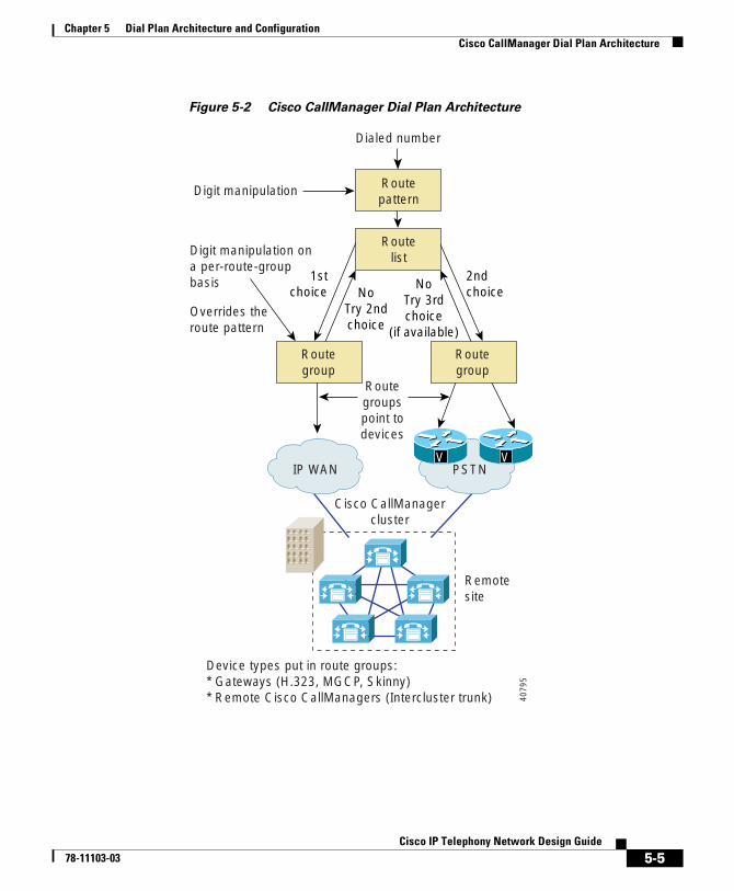
Chapter 5 Dial Plan Architecture and ConfigurationCisco CallManager Dial Plan Architecture
Figure 5-2 Cisco CallManager Dial Plan Architecture
IP WAN PSTNVV
Routegroup
Routegroup
Digit manipulation ona per-route-groupbasis
Digit manipulation
Dialed number
Overrides theroute pattern
Device types put in route groups:* Gateways (H.323, MGCP, Skinny)* Remote Cisco CallManagers (Intercluster trunk)
Cisco CallManagercluster
Remotesite
Routegroupspoint todevices
1stchoice
2ndchoiceNo
Try 2ndchoice
NoTry 3rdchoice
(if available)
Routelist
Routepattern
4079
5
5-5Cisco IP Telephony Network Design Guide
78-11103-03
Chapter 5 Dial Plan Architecture and ConfigurationCisco CallManager Dial Plan Architecture
Route PatternThe route pattern identifies a dialed number (E.164 numbers in North America) and uses the underlying route list and route group configurations to determine how to route the call. A route pattern can be entered as a specific number or, more commonly, a number range. Using a route pattern to represent a number range minimizes the number of entries required.
When a route pattern matches a dialed number, the call is handed to the route list associated with the route pattern. Prior to handing the call to the route list, digit manipulation can occur if digits need to be added to or removed from the matched route pattern. The route list then decides which downstream route groups (trunk groups) should receive the call based on the ordered priority.
Note The digit manipulation occurs in the route pattern for outbound calls only, before being sent to the route list plus route groups. Individual downstream route groups can have unique digit manipulations for the same route pattern. This is extremely useful where different routes to a given dialed number might require different manipulations. For example, users might be required to dial seven digits to reach a remote location that has a four-digit internal dial plan. Across the IP WAN the first three digits would have to be removed, so that the last four digits could be delivered to the remote Cisco CallManager in its native internal dial-string length. If the IP WAN were down or could not accept additional voice calls, the dialed seven digits would have to be prepended with the area code to reach the called party through the PSTN. A route pattern is associated with only one route list.
5-6Cisco IP Telephony Network Design Guide
78-11103-03
Chapter 5 Dial Plan Architecture and ConfigurationCisco CallManager Dial Plan Architecture
Route ListThe term route point from previous releases of Cisco CallManager has been replaced by route list in Cisco CallManager Release 3.0, though the function remains much the same. A route list defines the way a call is routed. Route lists are configured to point to one or more route groups, which effectively serve the purpose of trunk groups. The route list sends a given call to a route group in a configured order of preference. For example, the primary route group might offer a lower cost for calls, while the secondary route groups would be used only if the primary is unavailable due to an all-trunks-busy condition or insufficient IP WAN resources.
Route GroupRoute groups control specific devices such as gateways. Gateways can be based on the Skinny Gateway Protocol, MGCP, or H.323. Endpoints such as NetMeeting clients or remote Cisco CallManagers across the IP WAN are configured as H.323 gateways. The route group points to one or more devices and can select the devices for call routing based on preference. The route group can direct all calls to the primary device and then use the secondary devices when the primary is unavailable. This serves effectively as a trunk group.
One or more route lists can point to the same route group. All devices in a given route group have the same characteristics, such as path and digit manipulation. Route groups have the ability to perform digit manipulation and can override route pattern digit manipulation (see the “Route Pattern” section on page 5-6).
5-7Cisco IP Telephony Network Design Guide
78-11103-03
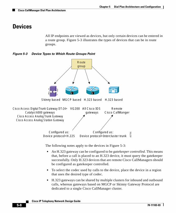
Chapter 5 Dial Plan Architecture and ConfigurationCisco CallManager Dial Plan Architecture
DevicesAll IP endpoints are viewed as devices, but only certain devices can be entered in a route group. Figure 5-3 illustrates the types of devices that can be in route groups.
Figure 5-3 Device Types to Which Route Groups Point
The following notes apply to the devices in Figure 5-3:
• An H.323 gateway can be configured to be gatekeeper controlled. This means that, before a call is placed to an H.323 device, it must query the gatekeeper successfully. Only H.323 devices that are remote Cisco CallManagers should be configured as gatekeeper controlled.
• To select the codec used by calls to the device, place the device in a region that uses the desired type of codec.
• H.323 gateways can be shared by multiple clusters for inbound and outbound calls, whereas gateways based on MGCP or Skinny Gateway Protocol are dedicated to a single Cisco CallManager cluster.
V V
Routegroup
Skinny based MGCP based H.323 based H.323 based
Cisco Access Digital Trunk Gateway DT-24+Catalyst 6000 gateways
Cisco Access Analog Trunk GatewayCisco Access Analog Station Gateway
VG200
Configured as:Device protocol=H.225
Configured as:Device protocol=Intercluster trunk
All Cisco IOS gateways
RemoteCisco CallManger
4079
6
5-8Cisco IP Telephony Network Design Guide
78-11103-03
Chapter 5 Dial Plan Architecture and ConfigurationCisco CallManager Dial Plan Architecture
An important feature of the route pattern dial structure is that it is typically used when IP phone calls are destined to go to gateways or remote Cisco CallManagers using H.323. In these cases, alternate routes can be taken in the event the primary path to a destination is not available. This is the scheme described in Chapter 6, “Multisite WAN with Distributed Call Processing,” where all intersite calls take the IP WAN as the primary path and the PSTN as the secondary path.
Calls between IP phones that reside on the same Cisco CallManager or Cisco CallManager cluster do not use the route pattern dial structure and, therefore, cannot use alternate routes if connectivity is down between them. If IP connectivity is lost between two IP phones, it is probably because one of the phones has lost connectivity to its Cisco CallManager. This can happen, for example, when using multisite WAN deployments with centralized call processing. In such cases there is no alternate routing between sites.
Digit Translation TablesCisco CallManager supports digit translation. This is the ability to translate the called and calling numbers into other numbers, including changing the number of digits. Digital translation is applicable for internal as well as external calls, inbound or outbound.
A common application of a translation table is to direct unassigned direct inward dialing (DID) numbers to an attendant when such numbers are dialed. For example, assume you have a DID range of 1000 to 1999 and want all calls to unassigned DID numbers to go to an attendant at extension 1111. You can configure a translation table of 1XXX that points to a translation mask of 1111, as follows:
In this example, Cisco CallManager performs a longest match lookup using wildcards. If there is an IP phone with a matching directory number in the 1000-1999 range, Cisco CallManager sends the call to that phone. If there is no matching IP phone number in the 1000-1999 range, then there is a match on the 1XXX translation table, and the call is sent to extension 1111.
Translation Table Translation Mask
1XXX 1111
5-9Cisco IP Telephony Network Design Guide
78-11103-03
Chapter 5 Dial Plan Architecture and ConfigurationSpecial Dial String Considerations
Digit translation can also be performed within the route pattern structure using called/calling party transformation, which performs the same digit translation functions for both incoming and outgoing calls. This means that within a route pattern, three types of digit manipulation can be performed on a called number:
• Discard digits
• Apply called-party transformation mask
• Prefix digits
In the following example, a route pattern of 2.XXXX is defined. The calling number is 1000, but the call needs to go to a PBX with a called party number of 444XXXX and a calling party number of 919392XXXX. The Cisco CallManager route pattern would be treated as follows:
Step 1 Apply the calling party transformation mask of 919392XXXX. This prefixes 91939 to the calling number.
Step 2 Discard the access code (2), leaving just XXXX.
Step 3 Prefix the digits 444.
An alternative way to accomplish steps 2 and 3 would be to use a called-party transformation mask of 444XXXX.
It is important to keep in mind that the calling party transformation mask applies only to the calling numbers, while the other masks apply to the called numbers. Cisco CallManager first discards digits, then applies the transformation mask, and finally prefixes digits.
Special Dial String ConsiderationsYou should try to make your dial plan as simple as possible and to minimize the number of entries. The most efficient way to achieve this is to configure specific dial plans only for locations on the network (IP WAN) and to use the local PSTN gateway access code, such as 9 or 0 (zero), for locations that must be reached over the PSTN, as well as for IP WAN calls if the IP WAN is down or has insufficient resources. These are called on-net and off-net route patterns, respectively.
5-10Cisco IP Telephony Network Design Guide
78-11103-03
Chapter 5 Dial Plan Architecture and ConfigurationSpecial Dial String Considerations
On-Net Route PatternIn a multisite IP WAN with distributed call processing, an abbreviation of the full E.164 address is typically used for ease of dialing. For example, where an on-net location has a number range of (408) 526-1000 through 1999, there may be only a single route pattern with an entry of 61XXX. This simplifies user dialing and requires only one route pattern entry where the Xs serve as wildcards.
To present the remote Cisco CallManager with the appropriate number of digits for the internal dial plan, the Cisco CallManager route pattern can also strip or prepend digits to the dialed number. In fact, the number of digits presented to a remote Cisco CallManager for all calls across the IP WAN must match the dialed digit length that the remote site uses for internal calls. The remote Cisco CallManager simply looks at the digits and routes the call. There is no digit manipulation for incoming calls.
If the IP WAN resources are insufficient in this environment and the call has to be sent over PSTN, the route group for the PSTN gateway must insert the area code and three-digit exchange. In earlier releases of Cisco CallManager, only one digit manipulation table could be used for any given route pattern. Therefore, only Cisco IOS gateways could be used because they could insert the area code and three-digit exchange. This administrative burden has been removed in Cisco CallManager Release 3.0, which now has the ability to perform unique digit manipulations on a per-route-group basis. This allows for a single point of dial plan administration per site and for use of both Cisco IOS gateways and gateways based on the Skinny Gateway Protocol.
Figure 5-4 depicts on-net calls across the IP WAN with the PSTN as a backup, where the digit manipulation required is different for each path.
5-11Cisco IP Telephony Network Design Guide
78-11103-03
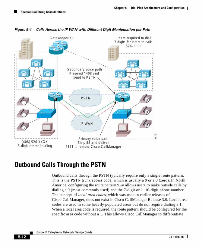
Chapter 5 Dial Plan Architecture and ConfigurationSpecial Dial String Considerations
Figure 5-4 Calls Across the IP WAN with Different Digit Manipulation per Path
Outbound Calls Through the PSTNOutbound calls through the PSTN typically require only a single route pattern. This is the PSTN trunk access code, which is usually a 9 or a 0 (zero). In North America, configuring the route pattern 9.@ allows users to make outside calls by dialing a 9 (most commonly used) and the 7-digit or 1+10-digit phone number. The concept of local area codes, which was used in earlier releases of Cisco CallManager, does not exist in Cisco CallManager Release 3.0. Local area codes are used in some heavily populated areas but do not require dialing a 1. When a local area code is required, the route pattern should be configured for the specific area code without a 1. This allows Cisco CallManager to differentiate
(408) 526-XXXX5-digit internal dialing
Secondary voice pathPrepend 1408 and
send to PSTN
Users required to dial7 digits for intersite calls
526-1111
Primary voice pathStrip 52 and deliver
6111 to remote Cisco CallManager
IP WAN
PSTNV
Gatekeeper(s)
IP
IP
IP
V IP
IP
IP
4079
7
5-12Cisco IP Telephony Network Design Guide
78-11103-03
Chapter 5 Dial Plan Architecture and ConfigurationSpecial Dial String Considerations
between a local seven-digit number and a local area code to determine when the dialing is complete. Otherwise, Cisco CallManager waits 10 seconds without detecting any digits before assuming the dialing is complete.
Local PSTN gateway dial plan configuration is fairly simple. The gateways based on MGCP and the Skinny Gateway Protocol have all of their dial plan information configured in Cisco CallManager, while an H.323-based Cisco IOS gateway typically requires only a minimal number of dial peers. These dial peers are used by the gateway to direct all calls from Cisco CallManager to the PSTN. For an example of this type of dial plan, see the configuration in Figure 5-8.
Outside of North America, dial strings often differ in length from one country to another. Multiple-length dial plans present a challenge in that Cisco CallManager does not know when dialing is complete unless you have a specific route pattern. Cisco CallManager by default waits 10 seconds without receiving any digits before assuming dialing is complete. The following two common options apply to configuring a route pattern for PSTN access outside of North America. The local PSTN access code, 0 (zero), is commonly used.
Option 1: Route Pattern = 0.!
By reducing the idle digit wait timer (to 3 seconds, for example) in the Cisco CallManager service parameters, a call can be sent without having to wait the full 10 seconds. The risk of this practice, however, is that Cisco CallManager can prematurely determine that the dialing is finished if the user simply pauses in the midst of dialing.
0. Represents the local PSTN access code.
! Stands for any digit and any number of digits. This also means that Cisco CallManager must wait 10 seconds (the default) without receiving any digits before it assumes the dialing is complete and sends the call.
5-13Cisco IP Telephony Network Design Guide
78-11103-03
Chapter 5 Dial Plan Architecture and ConfigurationConfiguring Dial Plan Groups and Calling Restrictions
Option 2: Route Pattern = 0.!#
In this option, users are instructed to press the # key to terminate the dial string and immediately place the call. This requires some user education and changes to existing customer dialing habits. However, this is similar in nature to pressing the send button on a cell phone.
Configuring Dial Plan Groups and Calling Restrictions
A new feature in Cisco CallManager Release 3.0 is the ability to impose calling restrictions on a per-phone basis and to create closed dial plan groups on the same Cisco CallManager. Users on the same Cisco CallManager can be grouped into communities of interest that have the same calling restrictions and dial plans. Different communities of interest can operate independently but still share the same gateways as well as have overlapping dial plans. These new capabilities, which are of particular interest in a multisite IP WAN with centralized call processing, are achieved with the use of partitions and calling search spaces.
0. Represents the local PSTN access code.
! Stands for any digit and any number of digits. This also means that Cisco CallManager must wait 10 seconds (the default) without receiving any digits before it assumes the dialing is complete and sends the call.
# Indicates that, when a user presses the # (pound) key, Cisco CallManager should assume dialing is complete and immediately send the call.
5-14Cisco IP Telephony Network Design Guide
78-11103-03
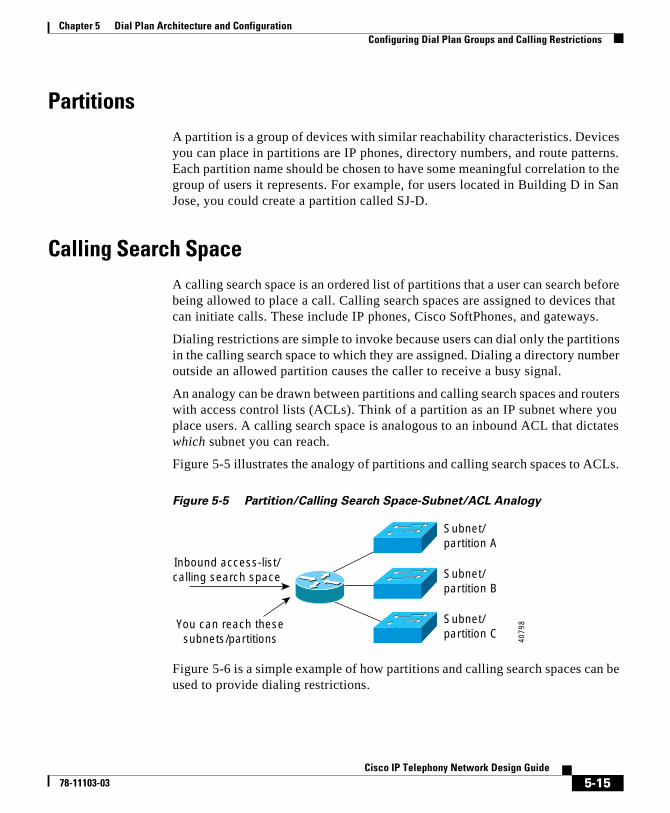
Chapter 5 Dial Plan Architecture and ConfigurationConfiguring Dial Plan Groups and Calling Restrictions
PartitionsA partition is a group of devices with similar reachability characteristics. Devices you can place in partitions are IP phones, directory numbers, and route patterns. Each partition name should be chosen to have some meaningful correlation to the group of users it represents. For example, for users located in Building D in San Jose, you could create a partition called SJ-D.
Calling Search SpaceA calling search space is an ordered list of partitions that a user can search before being allowed to place a call. Calling search spaces are assigned to devices that can initiate calls. These include IP phones, Cisco SoftPhones, and gateways.
Dialing restrictions are simple to invoke because users can dial only the partitions in the calling search space to which they are assigned. Dialing a directory number outside an allowed partition causes the caller to receive a busy signal.
An analogy can be drawn between partitions and calling search spaces and routers with access control lists (ACLs). Think of a partition as an IP subnet where you place users. A calling search space is analogous to an inbound ACL that dictates which subnet you can reach.
Figure 5-5 illustrates the analogy of partitions and calling search spaces to ACLs.
Figure 5-5 Partition/Calling Search Space-Subnet/ACL Analogy
Figure 5-6 is a simple example of how partitions and calling search spaces can be used to provide dialing restrictions.
Inbound access-list/calling search space
You can reach thesesubnets/partitions
Subnet/partition A
Subnet/partition B
Subnet/partition C
4079
8
5-15Cisco IP Telephony Network Design Guide
78-11103-03
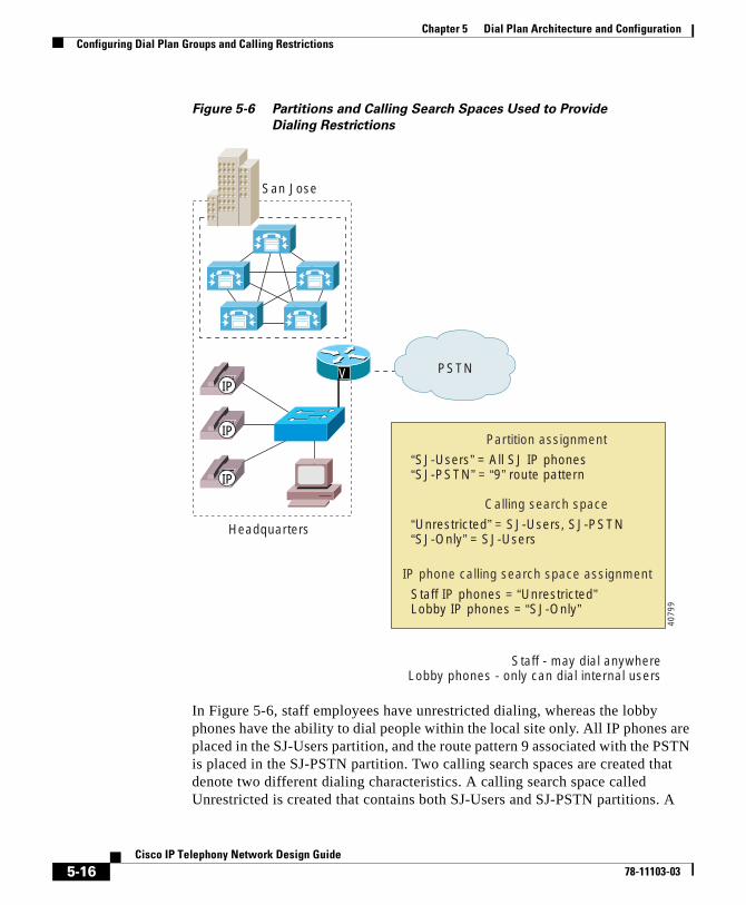
Chapter 5 Dial Plan Architecture and ConfigurationConfiguring Dial Plan Groups and Calling Restrictions
Figure 5-6 Partitions and Calling Search Spaces Used to Provide
Dialing Restrictions
In Figure 5-6, staff employees have unrestricted dialing, whereas the lobby phones have the ability to dial people within the local site only. All IP phones are placed in the SJ-Users partition, and the route pattern 9 associated with the PSTN is placed in the SJ-PSTN partition. Two calling search spaces are created that denote two different dialing characteristics. A calling search space called Unrestricted is created that contains both SJ-Users and SJ-PSTN partitions. A
San Jose
Staff - may dial anywhereLobby phones - only can dial internal users
“SJ-Users” = All SJ IP phones“SJ-PSTN” = “9” route pattern
Partition assignment
“Unrestricted” = SJ-Users, SJ-PSTN“SJ-Only” = SJ-Users
Calling search space
Staff IP phones = “Unrestricted”Lobby IP phones = “SJ-Only”
IP phone calling search space assignment
PSTN
Headquarters
VIP
IP
IP
4079
9
5-16Cisco IP Telephony Network Design Guide
78-11103-03
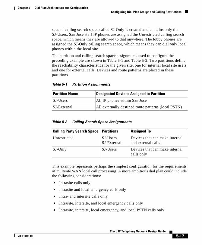
Chapter 5 Dial Plan Architecture and ConfigurationConfiguring Dial Plan Groups and Calling Restrictions
second calling search space called SJ-Only is created and contains only the SJ-Users. San Jose staff IP phones are assigned the Unrestricted calling search space, which means they are allowed to dial anywhere. The lobby phones are assigned the SJ-Only calling search space, which means they can dial only local phones within the local site.
The partition and calling search space assignments used to configure the preceding example are shown in Table 5-1 and Table 5-2. Two partitions define the reachability characteristics for the given site, one for internal local site users and one for external calls. Devices and route patterns are placed in these partitions.
This example represents perhaps the simplest configuration for the requirements of multisite WAN local call processing. A more ambitious dial plan could include the following considerations:
• Intrasite calls only
• Intrasite and local emergency calls only
• Intra- and intersite calls only
• Intrasite, intersite, and local emergency calls only
• Intrasite, intersite, local emergency, and local PSTN calls only
Table 5-1 Partition Assignments
Partition Name Designated Devices Assigned to Partition
SJ-Users All IP phones within San Jose
SJ-External All externally destined route patterns (local PSTN)
Table 5-2 Calling Search Space Assignments
Calling Party Search Space Partitions Assigned To
Unrestricted SJ-UsersSJ-External
Devices that can make internal and external calls
SJ-Only SJ-Users Devices that can make internal calls only
5-17Cisco IP Telephony Network Design Guide
78-11103-03
Chapter 5 Dial Plan Architecture and ConfigurationDial Plan Guidelines and Configuration
• Intrasite, intersite, local emergency, and national long-distance PSTN calls only
• Fully unrestricted dialing, including international numbers
Partitions and calling search spaces permit independent dial ranges on a partition basis. This means that extensions and access codes within different partitions can have overlapping numbers and yet function independently. The most common application of this is in a centralized call processing system where all sites and users share the same Cisco CallManager, yet each site can dial a 9 for local PSTN access. This is a new capability in Cisco CallManager Release 3.0. In prior releases, each remote site had to have its unique PSTN access code.
The following conditions apply with regard to overlapping users and extensions at different sites with the centralized call processing system:
• Overlapping internal dial plans at different sites are supported only if voice mail is not required. When Cisco CallManager sends a call to voice mail, it cannot determine for which partition (and therefore which voice mail user) the call is intended. For example, user 1111 at site A cannot be distinguished from user 1111 at site B when the call is sent to voice mail. Voice mail users must have unique IDs.
• If voice mail is not required, users that share extensions at different sites can be reached by the following means:
– PSTN—by dialing the local access code followed by the fully qualified directory number.
– IP WAN—by using translation tables, which can allow for prepending of overlapping numbers with a unique steering code that is stripped off when the call is delivered to the destination partition.
Dial Plan Guidelines and ConfigurationThe complexity of a dial plan can vary, depending on the number of paths over which a call could be routed. This section describes some typical dial plan scenarios.
5-18Cisco IP Telephony Network Design Guide
78-11103-03
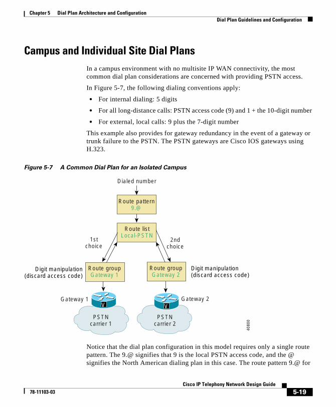
Chapter 5 Dial Plan Architecture and ConfigurationDial Plan Guidelines and Configuration
Campus and Individual Site Dial PlansIn a campus environment with no multisite IP WAN connectivity, the most common dial plan considerations are concerned with providing PSTN access.
In Figure 5-7, the following dialing conventions apply:
• For internal dialing: 5 digits
• For all long-distance calls: PSTN access code (9) and 1 + the 10-digit number
• For external, local calls: 9 plus the 7-digit number
This example also provides for gateway redundancy in the event of a gateway or trunk failure to the PSTN. The PSTN gateways are Cisco IOS gateways using H.323.
Figure 5-7 A Common Dial Plan for an Isolated Campus
Notice that the dial plan configuration in this model requires only a single route pattern. The 9.@ signifies that 9 is the local PSTN access code, and the @ signifies the North American dialing plan in this case. The route pattern 9.@ for
PSTNcarrier 2
Gateway 2V
Route groupGateway 2
Dialed number
Digit manipulation(discard access code)
Route listLocal-PSTN
Route pattern9.@
Digit manipulation(discard access code)
Route groupGateway 1
PSTNcarrier 1
Gateway 1V
2ndchoice
1stchoice
4080
0
5-19Cisco IP Telephony Network Design Guide
78-11103-03
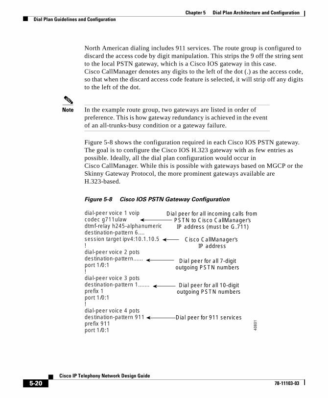
Chapter 5 Dial Plan Architecture and ConfigurationDial Plan Guidelines and Configuration
North American dialing includes 911 services. The route group is configured to discard the access code by digit manipulation. This strips the 9 off the string sent to the local PSTN gateway, which is a Cisco IOS gateway in this case. Cisco CallManager denotes any digits to the left of the dot (.) as the access code, so that when the discard access code feature is selected, it will strip off any digits to the left of the dot.
Note In the example route group, two gateways are listed in order of preference. This is how gateway redundancy is achieved in the event of an all-trunks-busy condition or a gateway failure.
Figure 5-8 shows the configuration required in each Cisco IOS PSTN gateway. The goal is to configure the Cisco IOS H.323 gateway with as few entries as possible. Ideally, all the dial plan configuration would occur in Cisco CallManager. While this is possible with gateways based on MGCP or the Skinny Gateway Protocol, the more prominent gateways available are H.323-based.
Figure 5-8 Cisco IOS PSTN Gateway Configuration
dial-peer voice 1 voipcodec g711ulawdtmf-relay h245-alphanumericdestination-pattern 6....session target ipv4:10.1.10.5!dial-peer voice 2 potsdestination-pattern......port 1/0:1!dial-peer voice 3 potsdestination-pattern 1.......prefix 1port 1/0:1!dial-peer voice 4 potsdestination-pattern 911prefix 911port 1/0:1
Dial peer for all incoming calls from PSTN to Cisco CallManager’sIP address (must be G.711)
Cisco CallManager’s IP address
Dial peer for all 7-digitoutgoing PSTN numbers
Dial peer for all 10-digitoutgoing PSTN numbers
Dial peer for 911 services
4080
1
5-20Cisco IP Telephony Network Design Guide
78-11103-03
Chapter 5 Dial Plan Architecture and ConfigurationThe Role of a Gatekeeper
This configuration assumes that 1+10 digit dialing would be required for long-distance calls to the PSTN, and 7-digit dialing would be required for local PSTN calling.
Although the scope of the 9.@ route pattern includes emergency 911 services, the Cisco IOS H.323 gateway still requires a dial peer for 911. Various dial peers can be added for 411 and 611 services, which are included in the scope of the 9.@ route pattern as well.
As noted earlier in the “Outbound Calls Through the PSTN” section on page 5-12, local area codes should be configured specifically with a route pattern and should not require a 1.
Multi-Site WAN Dial PlansDial plans for multi-site WAN systems are covered in Chapter 6, “Multisite WAN with Distributed Call Processing,” and Chapter 7, “Multisite WAN with Centralized Call Processing.”
The Role of a GatekeeperWithin a distributed call processing environment, you can use a gatekeeper to achieve call admission control across the WAN. With the introduction of Cisco CallManager Release 3.0(5), you can also use a gatekeeper to simplify dial plans between Cisco CallManagers.
For example, assume you have two Cisco CallManager servers connected via a WAN. One Cisco CallManager has an extension range of 1XXX and the other 2XXX, and both register to a gatekeeper for call admission control. Each Cisco CallManager has an appropriate entry in its respective dial plan Route Pattern Configuration that uses the Anonymous Calls Device feature to point the other Cisco CallManager’s extension number range to the gatekeeper. In practice, when subscriber 1001 dials subscriber 2002, Cisco CallManager 1XXX sends 2002 to the gatekeeper for address resolution. The gatekeeper in turn sends the IP address of Cisco CallManager 2XXX to Cisco CallManager 1XXX to ascertain the IP address for subscriber 2002. If the call admission control criteria are met, the gatekeeper allows the call to be established. Figure 5-9 illustrates this example.
5-21Cisco IP Telephony Network Design Guide
78-11103-03
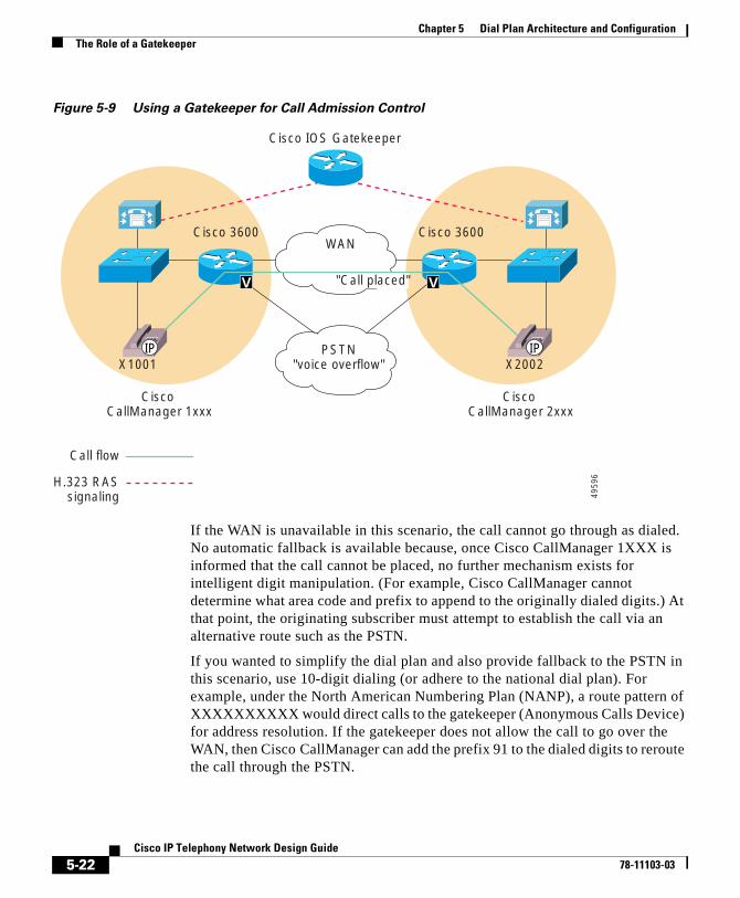
Chapter 5 Dial Plan Architecture and ConfigurationThe Role of a Gatekeeper
Figure 5-9 Using a Gatekeeper for Call Admission Control
If the WAN is unavailable in this scenario, the call cannot go through as dialed. No automatic fallback is available because, once Cisco CallManager 1XXX is informed that the call cannot be placed, no further mechanism exists for intelligent digit manipulation. (For example, Cisco CallManager cannot determine what area code and prefix to append to the originally dialed digits.) At that point, the originating subscriber must attempt to establish the call via an alternative route such as the PSTN.
If you wanted to simplify the dial plan and also provide fallback to the PSTN in this scenario, use 10-digit dialing (or adhere to the national dial plan). For example, under the North American Numbering Plan (NANP), a route pattern of XXXXXXXXXX would direct calls to the gatekeeper (Anonymous Calls Device) for address resolution. If the gatekeeper does not allow the call to go over the WAN, then Cisco CallManager can add the prefix 91 to the dialed digits to reroute the call through the PSTN.
IPIP
Cisco 3600 Cisco 3600WAN
PSTN"voice overflow"X1001 X2002
Cisco IOS Gatekeeper
Cisco CallManager 1xxx
Cisco CallManager 2xxx
"Call placed"
Call flow
H.323 RASsignaling
V V
4959
6
5-22Cisco IP Telephony Network Design Guide
78-11103-03
Cisco IP T78-11103-03
C H A P T E R 6
Multisite WAN with Distributed Call ProcessingThis chapter provides design guidelines for multisite WAN systems that use Cisco CallManager for distributed call processing. The discussion emphasizes issues specific to the distributed call processing model, with reference to relevant material in other sections of this guide.
This chapter includes the following sections:
• Distributed Call Processing Model, page 6-1
• Call Admission Control, page 6-3
• Dial Plan Considerations, page 6-15
• Cisco CallManager Cluster Considerations, page 6-30
• DSP Resource Provisioning for Transcoding and Conferencing, page 6-30
• Voice Messaging Considerations, page 6-32
Distributed Call Processing ModelIn a distributed call processing system (see Figure 6-1), each site contains its own Cisco CallManagers, voice messaging, and digital signal processor (DSP) resources.
6-1elephony Network Design Guide
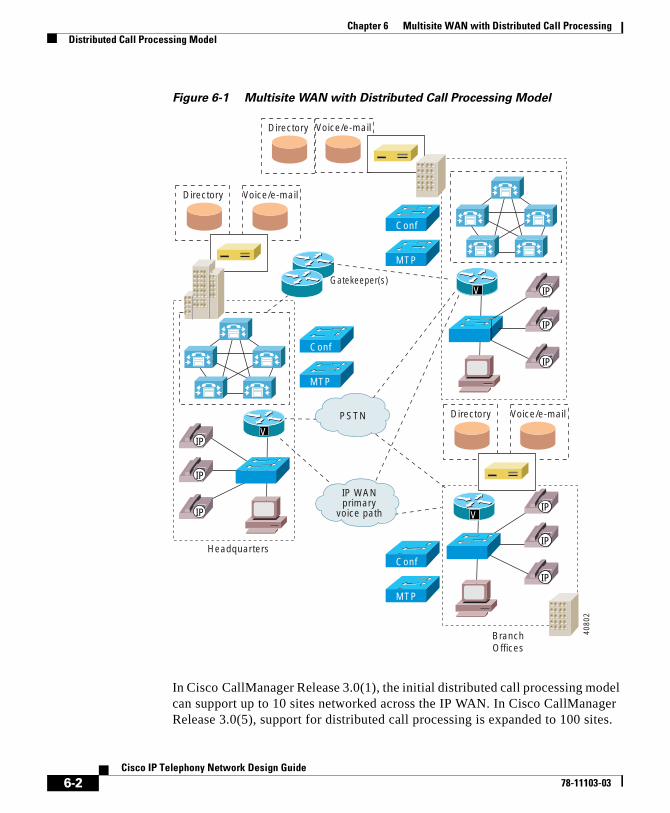
Chapter 6 Multisite WAN with Distributed Call ProcessingDistributed Call Processing Model
Figure 6-1 Multisite WAN with Distributed Call Processing Model
In Cisco CallManager Release 3.0(1), the initial distributed call processing model can support up to 10 sites networked across the IP WAN. In Cisco CallManager Release 3.0(5), support for distributed call processing is expanded to 100 sites.
Voice/e-mail
Directory Voice/e-mail
Headquarters
IP WANprimary
voice path
PSTN
Gatekeeper(s)
Conf
MTP
Conf
MTP
Conf
MTP
BranchOffices
VIP
IP
IP
V IP
IP
IP
4080
2
Directory
VIP
IP
IP
Directory Voice/e-mail
6-2Cisco IP Telephony Network Design Guide
78-11103-03
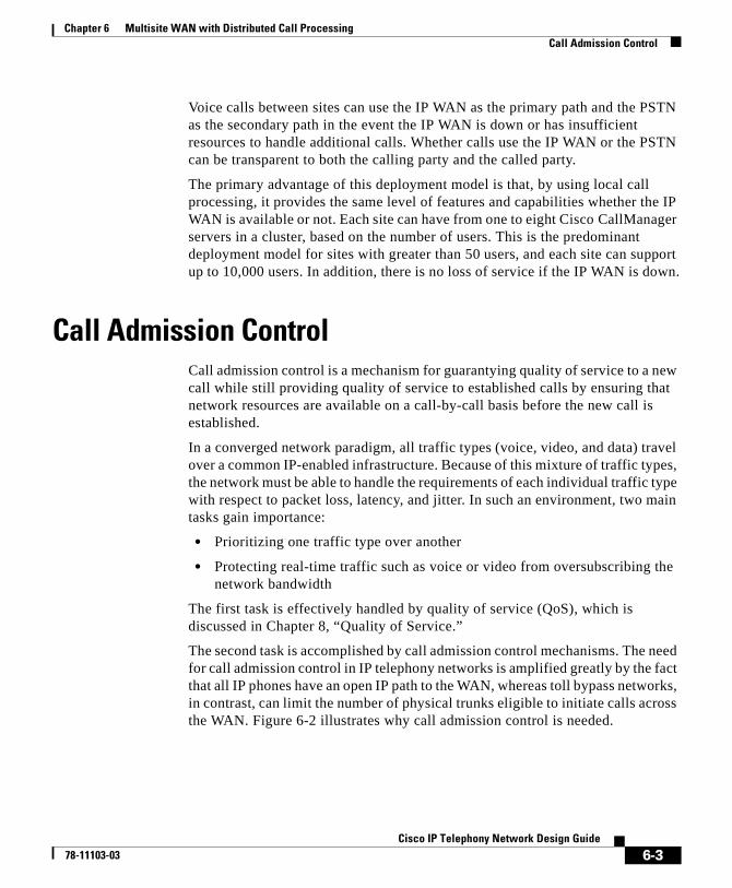
Chapter 6 Multisite WAN with Distributed Call ProcessingCall Admission Control
Voice calls between sites can use the IP WAN as the primary path and the PSTN as the secondary path in the event the IP WAN is down or has insufficient resources to handle additional calls. Whether calls use the IP WAN or the PSTN can be transparent to both the calling party and the called party.
The primary advantage of this deployment model is that, by using local call processing, it provides the same level of features and capabilities whether the IP WAN is available or not. Each site can have from one to eight Cisco CallManager servers in a cluster, based on the number of users. This is the predominant deployment model for sites with greater than 50 users, and each site can support up to 10,000 users. In addition, there is no loss of service if the IP WAN is down.
Call Admission ControlCall admission control is a mechanism for guarantying quality of service to a new call while still providing quality of service to established calls by ensuring that network resources are available on a call-by-call basis before the new call is established.
In a converged network paradigm, all traffic types (voice, video, and data) travel over a common IP-enabled infrastructure. Because of this mixture of traffic types, the network must be able to handle the requirements of each individual traffic type with respect to packet loss, latency, and jitter. In such an environment, two main tasks gain importance:
• Prioritizing one traffic type over another
• Protecting real-time traffic such as voice or video from oversubscribing the network bandwidth
The first task is effectively handled by quality of service (QoS), which is discussed in Chapter 8, “Quality of Service.”
The second task is accomplished by call admission control mechanisms. The need for call admission control in IP telephony networks is amplified greatly by the fact that all IP phones have an open IP path to the WAN, whereas toll bypass networks, in contrast, can limit the number of physical trunks eligible to initiate calls across the WAN. Figure 6-2 illustrates why call admission control is needed.
6-3Cisco IP Telephony Network Design Guide
78-11103-03

Chapter 6 Multisite WAN with Distributed Call ProcessingCall Admission Control
Figure 6-2 Why Call Admission Control is Needed
For distributed call processing systems, you can implement call admission control with an H.323 gatekeeper. In this design, Cisco CallManager registers with the Cisco IOS gatekeeper, also known as Multimedia Conference Manager (MCM), as a Voice over IP (VoIP) gateway and queries it each time it wants to make an IP WAN call. The Cisco IOS gatekeeper associates each Cisco CallManager with a zone that has specific bandwidth limitations. Thus the Cisco IOS gatekeeper can limit the maximum amount of bandwidth consumed by IP WAN voice calls in or out of a zone.
In brief, when Cisco CallManager wants to place an IP WAN call, it first requests permission from the gatekeeper. If the gatekeeper grants permission, the call is placed across the IP WAN. If the gatekeeper denies the request, Cisco CallManager places the call across the secondary path, the PSTN.
This is effectively a call accounting method of providing admission control, in which the gatekeeper simply keeps track of the bandwidth the IP WAN calls consume. The maximum bandwidth setting for a zone should take into account the limitation that voice traffic should not consume more than 75% of the WAN link. Figure 6-3 illustrates the process used by this call admission control mechanism.
Note In this scheme, IP phones are not mobile between sites. Should an IP phone register across the WAN, call admission control would not operate as designed.
WAN bandwidth can only support 2 calls.
What happens when 3rd call attempted?
causes poor quality for all calls
VoIP datanetwork
Call #1
Call #2
Call #3
IP
IP
IP
IP
IP
IP 4080
3
6-4Cisco IP Telephony Network Design Guide
78-11103-03
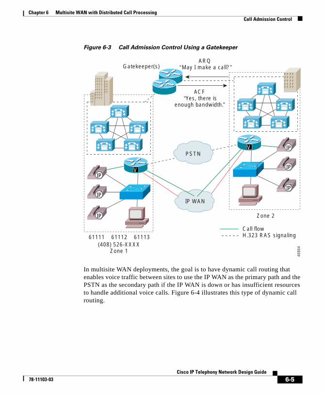
Chapter 6 Multisite WAN with Distributed Call ProcessingCall Admission Control
Figure 6-3 Call Admission Control Using a Gatekeeper
In multisite WAN deployments, the goal is to have dynamic call routing that enables voice traffic between sites to use the IP WAN as the primary path and the PSTN as the secondary path if the IP WAN is down or has insufficient resources to handle additional voice calls. Figure 6-4 illustrates this type of dynamic call routing.
(408) 526-XXXXZone 1
IP WAN
Zone 2
Gatekeeper(s)
Call flowH.323 RAS signaling
PSTN
ARQ “May I make a call?”
ACF “Yes, there is
enough bandwidth.”
61111 61112 61113
VIP
IP
IP
V IP
IP
IP
4080
4
6-5Cisco IP Telephony Network Design Guide
78-11103-03
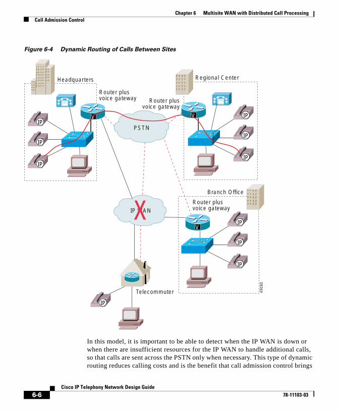
Chapter 6 Multisite WAN with Distributed Call ProcessingCall Admission Control
Figure 6-4 Dynamic Routing of Calls Between Sites
In this model, it is important to be able to detect when the IP WAN is down or when there are insufficient resources for the IP WAN to handle additional calls, so that calls are sent across the PSTN only when necessary. This type of dynamic routing reduces calling costs and is the benefit that call admission control brings
Headquarters Regional Center
Branch Office
Telecommuter
V
IP
IP
IP
IP
IP
IP
IP
IP
IP
IP
4908
0
V V
PSTN
IP WANX
Router plusvoice gateway
Router plusvoice gateway
Router plusvoice gateway
6-6Cisco IP Telephony Network Design Guide
78-11103-03
Chapter 6 Multisite WAN with Distributed Call ProcessingCall Admission Control
to this solution. In this case, the dial plan is tightly coupled with the gatekeeper call admission control mechanism because it is the dial plan that ultimately decides when to place a call across the IP WAN and what to do if the gatekeeper rejects the call. Dial plan issues are addressed in the “Dial Plan Considerations” section on page 6-15.
As mentioned before, you can use an H.323 gatekeeper to achieve call admission control by limiting the number of calls allowed in or out of specified zones. This effectively limits the amount of bandwidth per site because each site can be associated with a particular zone. This is the model that Cisco Call Manager uses with a gatekeeper to perform call admission control in hub-and-spoke topologies.
In addition to call admission control, a second very important function performed by the gatekeeper is address resolution. At any given site, Cisco CallManager knows about the extension range it controls and is able to route calls to those extensions. For anything outside its range, Cisco CallManager can go to a gatekeeper, which returns the IP address of another Cisco CallManager to which it should direct the call. This is possible because each Cisco CallManager (or one Cisco CallManager from a cluster) registers with the gatekeeper that is statically configured with the address range maintained by that particular cluster.
This address resolution feature greatly simplifies the dial plan in a multisite distributed call processing environment. The “Dial Plan Considerations” section on page 6-15 contains a more detailed discussion of address resolution.
In summary, the capabilities of Cisco CallManager for call admission control and E.164 address resolution are:
• Support for up to 100 sites in a multisite distributed call processing environment.
• Gatekeeper capability for address resolution of intercluster calls, which results in a simplified dial plan.
• Cisco CallManager requests 128 kbps of bandwidth for G.711 calls and 20 kbps for G.729 calls.
• Compressed Real-time Transport Protocol (cRTP) is not factored into the bandwidth calculations for the call Admission Request (ARQ).
6-7Cisco IP Telephony Network Design Guide
78-11103-03
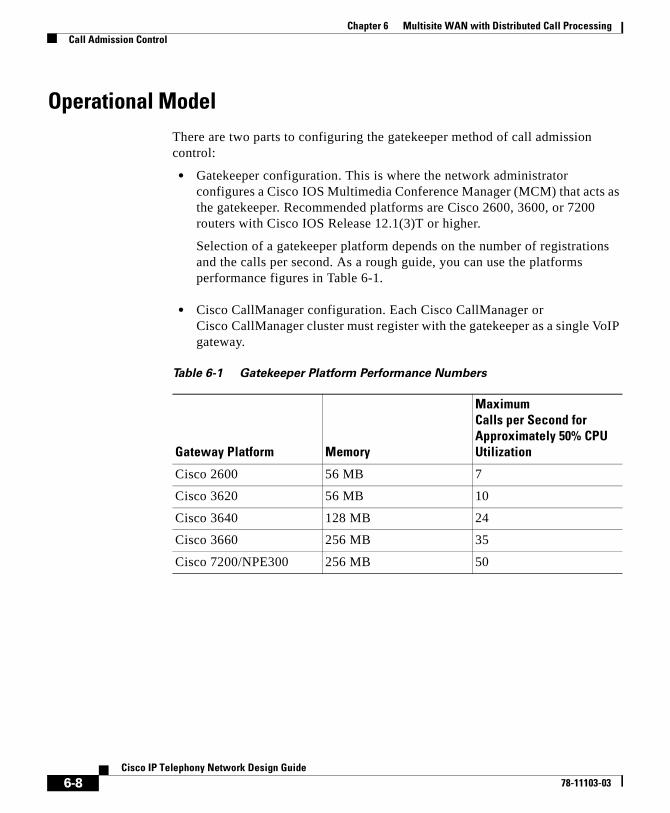
Chapter 6 Multisite WAN with Distributed Call ProcessingCall Admission Control
Operational ModelThere are two parts to configuring the gatekeeper method of call admission control:
• Gatekeeper configuration. This is where the network administrator configures a Cisco IOS Multimedia Conference Manager (MCM) that acts as the gatekeeper. Recommended platforms are Cisco 2600, 3600, or 7200 routers with Cisco IOS Release 12.1(3)T or higher.
Selection of a gatekeeper platform depends on the number of registrations and the calls per second. As a rough guide, you can use the platforms performance figures in Table 6-1.
• Cisco CallManager configuration. Each Cisco CallManager or Cisco CallManager cluster must register with the gatekeeper as a single VoIP gateway.
Table 6-1 Gatekeeper Platform Performance Numbers
Gateway Platform Memory
Maximum Calls per Second for Approximately 50% CPU Utilization
Cisco 2600 56 MB 7
Cisco 3620 56 MB 10
Cisco 3640 128 MB 24
Cisco 3660 256 MB 35
Cisco 7200/NPE300 256 MB 50
6-8Cisco IP Telephony Network Design Guide
78-11103-03

Chapter 6 Multisite WAN with Distributed Call ProcessingCall Admission Control
Gatekeeper Configuration
The following gatekeeper configuration defines four zones. Each zone contains a cluster with two Cisco CallManagers (except zone SJC1, which contains three Cisco CallManagers) that could possibly register as the gateway.
! Enter gateway configuration mode.gatekeeper! Define each zone that this gatekeeper administers.
zone local LHR cisco.comzone local HKG cisco.comzone local SJC1 cisco.comzone local SJC2 cisco.com
! Define which gateways are allowed to register. Remember to include ! all Cisco CallManagers in the Cisco CallManager group.
zone subnet LHR 172.26.18.2/32 enablezone subnet LHR 172.26.18.3/32 enable
! Deny all other possible hosts.no zone subnet LHR 0.0.0.0/0 enablezone subnet HKG 172.26.19.2/32 enablezone subnet HKG 172.26.19.3/32 enableno zone subnet HKG 0.0.0.0/0 enablezone subnet SJC1 172.26.17.2/32 enablezone subnet SJC1 172.26.17.3/32 enablezone subnet SJC1 172.26.17.4/32 enableno zone subnet SJC1 0.0.0.0/0 enablezone subnet SJC2 172.26.17.130/32 enablezone subnet SJC2 172.26.17.131/32 enableno zone subnet SJC2 0.0.0.0/0 enable
! Configure the bandwidth for each zone.zone bw LHR 512zone bw HKG 512zone bw SJC1 2048zone bw SJC2 2048
! Define the E.164 address range for each zone.zone prefix SJC1 1...zone prefix SJC2 2...zone prefix LHR 3...zone prefix HKG 4...
! gw-type-prefix 1#* default-technology
! no shutdown
6-9Cisco IP Telephony Network Design Guide
78-11103-03
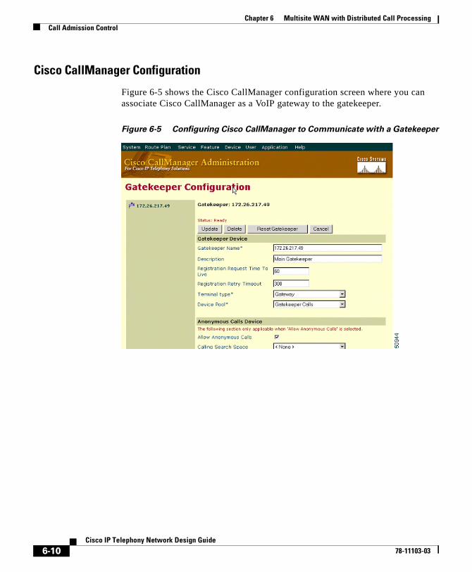
Chapter 6 Multisite WAN with Distributed Call ProcessingCall Admission Control
Cisco CallManager Configuration
Figure 6-5 shows the Cisco CallManager configuration screen where you can associate Cisco CallManager as a VoIP gateway to the gatekeeper.
Figure 6-5 Configuring Cisco CallManager to Communicate with a Gatekeeper
6-10Cisco IP Telephony Network Design Guide
78-11103-03
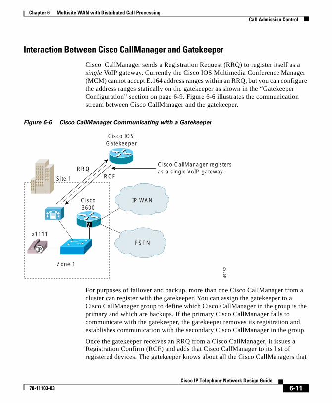
Chapter 6 Multisite WAN with Distributed Call ProcessingCall Admission Control
Interaction Between Cisco CallManager and Gatekeeper
Cisco CallManager sends a Registration Request (RRQ) to register itself as a single VoIP gateway. Currently the Cisco IOS Multimedia Conference Manager (MCM) cannot accept E.164 address ranges within an RRQ, but you can configure the address ranges statically on the gatekeeper as shown in the “Gatekeeper Configuration” section on page 6-9. Figure 6-6 illustrates the communication stream between Cisco CallManager and the gatekeeper.
Figure 6-6 Cisco CallManager Communicating with a Gatekeeper
For purposes of failover and backup, more than one Cisco CallManager from a cluster can register with the gatekeeper. You can assign the gatekeeper to a Cisco CallManager group to define which Cisco CallManager in the group is the primary and which are backups. If the primary Cisco CallManager fails to communicate with the gatekeeper, the gatekeeper removes its registration and establishes communication with the secondary Cisco CallManager in the group.
Once the gatekeeper receives an RRQ from a Cisco CallManager, it issues a Registration Confirm (RCF) and adds that Cisco CallManager to its list of registered devices. The gatekeeper knows about all the Cisco CallManagers that
Site 1
IP
V
IP WANCisco3600
x1111
Zone 1
RRQRCF
PSTN
IP WAN
Cisco CallManager registers as a single VoIP gateway.
4908
2
Cisco IOSGatekeeper
6-11Cisco IP Telephony Network Design Guide
78-11103-03

Chapter 6 Multisite WAN with Distributed Call ProcessingCall Admission Control
have registered with it. Also, by way of Cisco IOS configuration, the gatekeeper knows which Cisco CallManager belongs to what zone, and the amount of bandwidth associated with each zone.
To verify that a particular Cisco CallManager has registered with the gatekeeper, use the following Cisco IOS show command:
show gatekeeper endpoint
Following is an example of the output from this command:
MS-2621-3A#show gatekeeper endpointGATEKEEPER ENDPOINT REGISTRATION================================CallSignalAddr Port RASSignalAddr Port Zone Name Type F --------------- ----- --------------- - ---- --------- ---- --10.122.1.17 1720 10.122.1.17 1710 zone1 VOIP-GW H323-ID: 10.122.1.1710.122.1.19 1720 10.122.1.19 1710 zone2 VOIP-GW H323-ID: 10.122.1.1910.122.1.20 1720 10.122.1.20 1710 zone3 VOIP-GW H323-ID: 10.122.1.20Total number of active registrations = 3
Once Cisco CallManager has registered, it always checks with the gatekeeper before making an outbound call or accepting an inbound call. Cisco CallManager performs this check by issuing an Admission Request (ARQ) to the gatekeeper, as shown in Figure 6-7. As part of the ARQ, Cisco CallManager also requests a specific amount of bandwidth, depending upon the type of codec used for the call. It requests 128 kbps if the call uses a G.711 codec or 20 kbps if the call uses a G.729 codec.
6-12Cisco IP Telephony Network Design Guide
78-11103-03
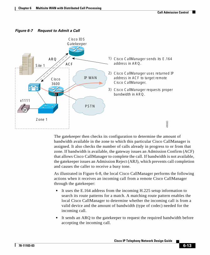
Chapter 6 Multisite WAN with Distributed Call ProcessingCall Admission Control
Figure 6-7 Request to Admit a Call
The gatekeeper then checks its configuration to determine the amount of bandwidth available in the zone to which this particular Cisco CallManager is assigned. It also checks the number of calls already in progress to or from that zone. If bandwidth is available, the gateway issues an Admission Confirm (ACF) that allows Cisco CallManager to complete the call. If bandwidth is not available, the gatekeeper issues an Admission Reject (ARJ), which prevents call completion and causes the caller to receive a busy tone.
As illustrated in Figure 6-8, the local Cisco CallManager performs the following actions when it receives an incoming call from a remote Cisco CallManager through the gatekeeper:
• It uses the E.164 address from the incoming H.225 setup information to search its route patterns for a match. A matching route pattern enables the local Cisco CallManager to determine whether the incoming call is from a valid device and the amount of bandwidth (type of codec) needed for the incoming call.
• It sends an ARQ to the gatekeeper to request the required bandwidth before accepting the incoming call.
Site 1
IP
V
Cisco3600
x1111
Zone 1
ARQACF
PSTN
IP WAN
Cisco CallManager sends its E.164address in ARQ.
Cisco CallManager uses returned IPaddress in ACF to target remote Cisco CallManager.
1)
2)
Cisco CallManager requests properbandwidth in ARQ.
3)
4908
3
Cisco IOSGatekeeper
6-13Cisco IP Telephony Network Design Guide
78-11103-03
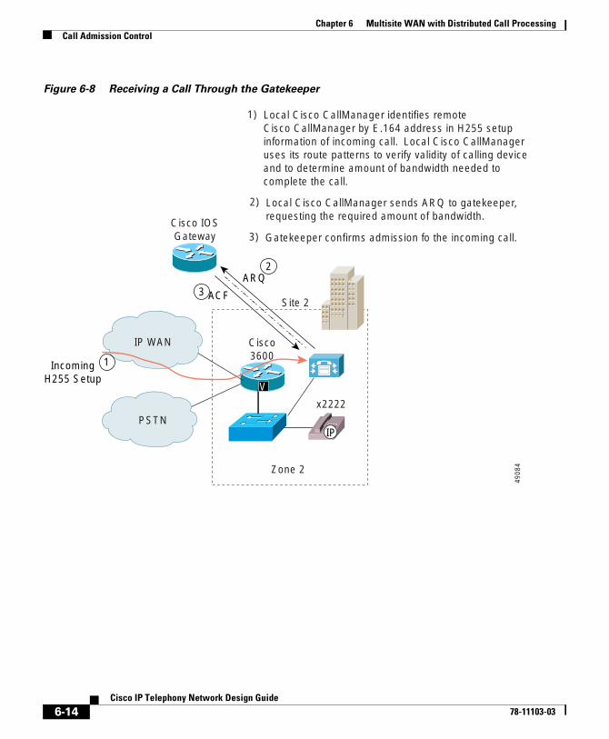
Chapter 6 Multisite WAN with Distributed Call ProcessingCall Admission Control
Figure 6-8 Receiving a Call Through the Gatekeeper
Site 2
IP
V
Cisco3600
Cisco IOSGateway
x2222
Zone 2
ARQ
ACF
PSTN
IP WAN
Local Cisco CallManager identifies remote Cisco CallManager by E.164 address in H255 setupinformation of incoming call. Local Cisco CallManageruses its route patterns to verify validity of calling deviceand to determine amount of bandwidth needed to complete the call.
Local Cisco CallManager sends ARQ to gatekeeper,requesting the required amount of bandwidth.
1)
2)
Gatekeeper confirms admission fo the incoming call.3)
4908
4
2
3
1IncomingH255 Setup
6-14Cisco IP Telephony Network Design Guide
78-11103-03
Chapter 6 Multisite WAN with Distributed Call ProcessingDial Plan Considerations
Considerations for Using a GatekeeperThe following considerations apply when using gatekeeper-based call admission control:
• The gatekeeper must be the Cisco IOS MCM. Recommended platforms are the Cisco 2600, 3600, or 7200 with Cisco IOS Release 12.1(3)T or greater.
• When using two gatekeepers in a redundant fashion and the primary one fails, the second gatekeeper becomes the primary with no knowledge of existing calls. This poses the possibility that poor quality could result if the new primary gatekeeper allows too many new calls in addition to existing calls of which it is unaware. This is a short-term situation that resolves when existing calls are terminated.
• Mobility of devices between sites is not possible unless a new number is assigned to the device to ensure that it uses the local Cisco CallManager for call processing.
Dial Plan ConsiderationsA new feature in Cisco CallManager Release 3.0(5) is the ability of the gatekeeper to resolve the dial plan between Cisco CallManager clusters. In prior releases, only Cisco CallManager could resolve the dial plan between clusters. With Cisco CallManager Release 3.0(5), there are now three deployment models for resolving the destination of intercluster calls:
• Cisco CallManager dial plan model (see Figure 6-9)
• Gatekeeper dial plan model (see Figure 6-10)
• Hybrid dial plan model
The Cisco CallManager dial plan model requires every Cisco CallManager cluster to have an intercluster trunk and a route pattern to each of the other clusters. The administrative overhead grows exponentially as the number of clusters increases. In this model, the gatekeeper provides only call admission control and not dial plan resolution. This model closely resembles the standard model used today in traditional PBXs.
The gatekeeper dial plan model, even in the hybrid form, greatly reduces configuration and administration overhead. In this model, each Cisco CallManager has only one intercluster trunk, known as the
6-15Cisco IP Telephony Network Design Guide
78-11103-03
Chapter 6 Multisite WAN with Distributed Call ProcessingDial Plan Considerations
Anonymous Device. This device can be thought of as a point-to-multipoint trunk, which removes the necessity for the meshed point-to-point trunks in the Cisco CallManager dial plan model. The Anonymous Device uses the gatekeeper to route calls to the correct Cisco CallManager cluster. If there is no requirement for automatic overflow or failover to the PSTN, then the dial plan in each cluster could be simplified to only two route patterns: one for intercluster calls and one for PSTN access. In this model, you configure the dial plan in the gatekeeper, thus providing a central point of administration. As new clusters are added, you update only the gatekeeper instead of every Cisco CallManager.
In summary, the three dial plan models provide the following features and capabilities:
• Cisco CallManager dial plan model (See the “Using Cisco CallManager to Route Calls” section on page 6-17.)
– Automatic overflow and failover to the PSTN, using the gatekeeper only for call admission control.
– Requires a separate intercluster trunk for each combination of two Cisco CallManager clusters.
– Requires two routes for each Cisco CallManager destination, one for the IP WAN and one for the PSTN.
– You must reconfigure every Cisco CallManager if a new cluster is added or the dial plan changes.
• Hybrid dial plan model
– Automatic overflow and failover to the PSTN, using the gatekeeper for call admission control and the intercluster dial plan.
– Requires only one Anonymous Device in each Cisco CallManager cluster.
– Requires two routes for each Cisco CallManager destination, one for the IP WAN and one for the PSTN.
– You configure the intercluster dial plan in both the gatekeeper and the Cisco CallManager.
• Gatekeeper dial plan model (See the “Using the Gatekeeper to Route Calls” section on page 6-19.)
– Manual overflow and failover to the PSTN, using the gatekeeper for call admission control and the intercluster dial plan.
6-16Cisco IP Telephony Network Design Guide
78-11103-03
Chapter 6 Multisite WAN with Distributed Call ProcessingDial Plan Considerations
– Requires only one Anonymous Device in each Cisco CallManager cluster.
– Requires only two route patterns, one for intercluster calls to all locations and one for PSTN access.
– You configure the dial plan in the gatekeeper (not in every Cisco CallManager) to route intercluster calls.
– Users must dial the correct PSTN number to access a remote site if the IP WAN is down or is busy.
Using Cisco CallManager to Route CallsIn the example depicted in Figure 6-9, users dial five digits for internal calls and seven digits for intersite calls across the IP WAN. If the IP WAN is down or has insufficient resources, the PSTN is used transparently for intersite calls. For long-distance calls that will be directed to the PSTN, users dial the access code 9 followed by 1 + area code and the 7-digit number. Users dialing local PSTN calls dial 9 plus the 7-digit number. This model also provides gateway redundancy in the event of a gateway or trunk failure to the PSTN. The PSTN gateways are Cisco IOS gateways using H.323.
Note This section deals only with intersite IP WAN calls that are intended to traverse the IP WAN as the first choice and use the PSTN as the second choice. See the “Outbound Calls Through the PSTN” section on page 5-12 for POTS-only calls.
The goal of this dial plan is to dial the San Jose location using only seven digits, where calls take the IP WAN as the first choice and the PSTN as the second choice. Thus, users in Philadelphia can dial San Jose users at (408) 526-XXXX by simply dialing 526XXXX.
This configuration begins at the route pattern. A route pattern is entered as 52.6XXXX with an assigned route list as SJ. The location of the dot (.) signifies that all digits to the left comprise the access code for this route pattern. Also, no digit manipulation is selected or required because each route group needs to invoke its own unique manipulation.
Figure 6-9 depicts the route pattern configuration for 52.6XXXX.
6-17Cisco IP Telephony Network Design Guide
78-11103-03
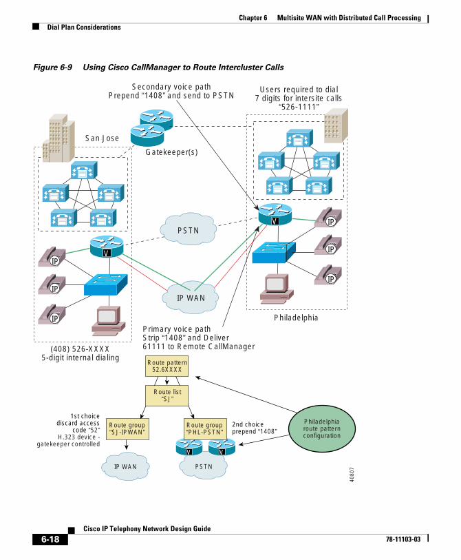
Chapter 6 Multisite WAN with Distributed Call ProcessingDial Plan Considerations
Figure 6-9 Using Cisco CallManager to Route Intercluster Calls
(408) 526-XXXX5-digit internal dialing
Philadelphia
San Jose
Primary voice pathStrip “1408” and Deliver61111 to Remote CallManager
Users required to dial7 digits for intersite calls
“526-1111”
Secondary voice pathPrepend “1408” and send to PSTN
IP WAN PSTN
VV
Route group“SJ-IPWAN”
Route group“PHL-PSTN”
2nd choiceprepend “1408”
1st choicediscard access
code “52”H.323 device -
gatekeeper controlled
Route list“SJ”
Route pattern52.6XXXX
Philadelphiaroute patternconfiguration
IP WAN
Gatekeeper(s)
PSTN
VIP
IP
IP
V IP
IP
IP
4080
7
6-18Cisco IP Telephony Network Design Guide
78-11103-03
Chapter 6 Multisite WAN with Distributed Call ProcessingDial Plan Considerations
As shown in Figure 6-9, the route list contains two route groups, SJ-IPWAN and PHL-PSTN, listed in order of priority. The SJ-IPWAN route group is listed first (highest priority) and points to the San Jose Cisco CallManager. The digit manipulation specified in route pattern SJ-IPWAN discards the access code (52). This ensures that, when the call is sent across the IP WAN, five digits are delivered to the remote Cisco CallManager because that is what it requires for its internal dial length. The H.323 device associated with the remote Cisco CallManager must be configured to be gatekeeper controlled to ensure that the gatekeeper is consulted before attempting the call across the IP WAN.
If the call is rejected by the gatekeeper, the route list uses the next route group, PHL-PSTN. This route group is configured to prepend 1408 to the dialed number to ensure that the call transparently reaches the other end.
Using the Gatekeeper to Route CallsThe example in Figure 6-9 illustrates one strategy for implementing a dial plan that uses a specific route pattern to select the IP WAN as the preferred path for calls between sites. Cisco CallManager Release 3.0(5) and later provides a second strategy that uses the gatekeeper to perform address resolution on calls between sites, thus simplifying the dial plans at the individual sites.
Prior to Cisco CallManager Release 3.0(5), each Cisco CallManager had to register with the gatekeeper once for each of the other Cisco CallManagers in the dial plan. For example, a network with 10 Cisco Callmanager sites required 10x9 or 90 gatekeeper registrations. In addition, each Cisco CallManager had to have an intercluster trunk and at least one route pattern to each of the other Cisco CallManagers (nine intercluster trunks and at least nine route patterns for this example). Cisco CallManager Release 3.0(5) has simplified and enhanced the gatekeeper registration process and has added a new Anonymous Device gateway.
The gatekeeper registration process has been enhanced in many areas. First, each Cisco CallManager cluster now registers only once with the gatekeeper. This allows up to 100 Cisco CallManager clusters to register with a single gatekeeper. In addition, the registration process now supports lightweight registration, which reduces the processing overhead on the gatekeeper. Finally, each Cisco CallManager sends its E.164 address in the Admission Request (ARQ) message, and the gatekeeper returns the IP addresses of all the other Cisco CallManagers in the Admission Confirm (ACF) message. Thus, the call admission transaction with the gatekeeper achieves two results: call admission control, as previously, and E.164 address resolution.
6-19Cisco IP Telephony Network Design Guide
78-11103-03
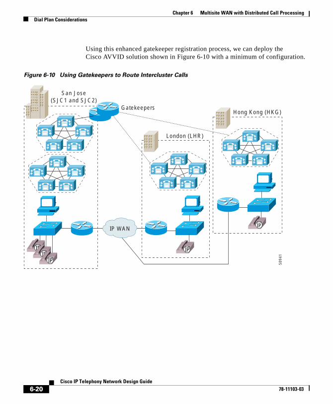
Chapter 6 Multisite WAN with Distributed Call ProcessingDial Plan Considerations
Using this enhanced gatekeeper registration process, we can deploy the Cisco AVVID solution shown in Figure 6-10 with a minimum of configuration.
Figure 6-10 Using Gatekeepers to Route Intercluster Calls
IP WAN
IPIP
IP
IP
IP
Hong Kong (HKG)
London (LHR)
San Jose(SJC1 and SJC2)
Gatekeepers
5094
1
6-20Cisco IP Telephony Network Design Guide
78-11103-03
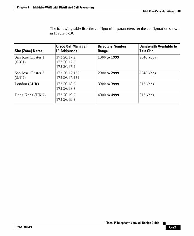
Chapter 6 Multisite WAN with Distributed Call ProcessingDial Plan Considerations
The following table lists the configuration parameters for the configuration shown in Figure 6-10.
Site (Zone) NameCisco CallManager IP Addresses
Directory Number Range
Bandwidth Available to This Site
San Jose Cluster 1 (SJC1)
172.26.17.2 172.26.17.3 172.26.17.4
1000 to 1999 2048 kbps
San Jose Cluster 2 (SJC2)
172.26.17.130 172.26.17.131
2000 to 2999 2048 kbps
London (LHR) 172.26.18.2 172.26.18.3
3000 to 3999 512 kbps
Hong Kong (HKG) 172.26.19.2 172.26.19.3
4000 to 4999 512 kbps
6-21Cisco IP Telephony Network Design Guide
78-11103-03
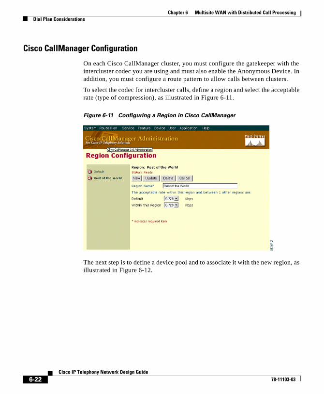
Chapter 6 Multisite WAN with Distributed Call ProcessingDial Plan Considerations
Cisco CallManager Configuration
On each Cisco CallManager cluster, you must configure the gatekeeper with the intercluster codec you are using and must also enable the Anonymous Device. In addition, you must configure a route pattern to allow calls between clusters.
To select the codec for intercluster calls, define a region and select the acceptable rate (type of compression), as illustrated in Figure 6-11.
Figure 6-11 Configuring a Region in Cisco CallManager
The next step is to define a device pool and to associate it with the new region, as illustrated in Figure 6-12.
6-22Cisco IP Telephony Network Design Guide
78-11103-03
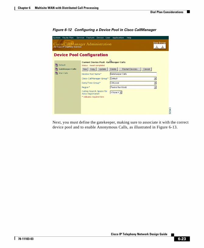
Chapter 6 Multisite WAN with Distributed Call ProcessingDial Plan Considerations
Figure 6-12 Configuring a Device Pool in Cisco CallManager
Next, you must define the gatekeeper, making sure to associate it with the correct device pool and to enable Anonymous Calls, as illustrated in Figure 6-13.
6-23Cisco IP Telephony Network Design Guide
78-11103-03
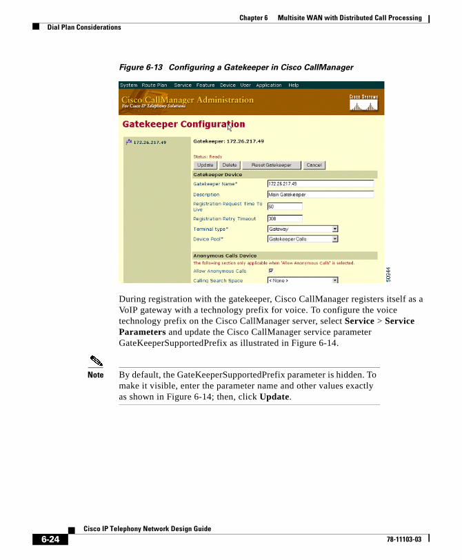
Chapter 6 Multisite WAN with Distributed Call ProcessingDial Plan Considerations
Figure 6-13 Configuring a Gatekeeper in Cisco CallManager
During registration with the gatekeeper, Cisco CallManager registers itself as a VoIP gateway with a technology prefix for voice. To configure the voice technology prefix on the Cisco CallManager server, select Service > Service Parameters and update the Cisco CallManager service parameter GateKeeperSupportedPrefix as illustrated in Figure 6-14.
Note By default, the GateKeeperSupportedPrefix parameter is hidden. To make it visible, enter the parameter name and other values exactly as shown in Figure 6-14; then, click Update.
6-24Cisco IP Telephony Network Design Guide
78-11103-03
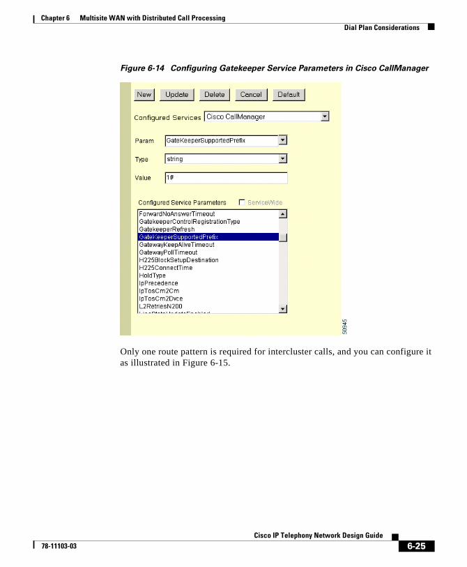
Chapter 6 Multisite WAN with Distributed Call ProcessingDial Plan Considerations
Figure 6-14 Configuring Gatekeeper Service Parameters in Cisco CallManager
Only one route pattern is required for intercluster calls, and you can configure it as illustrated in Figure 6-15.
6-25Cisco IP Telephony Network Design Guide
78-11103-03
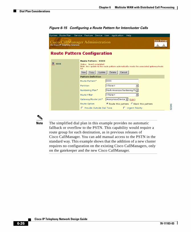
Chapter 6 Multisite WAN with Distributed Call ProcessingDial Plan Considerations
Figure 6-15 Configuring a Route Pattern for Intercluster Calls
Note The simplified dial plan in this example provides no automatic fallback or overflow to the PSTN. This capability would require a route group for each destination, as in previous releases of Cisco CallManager. You can add manual access to the PSTN in the standard way. This example shows that the addition of a new cluster requires no configuration on the existing Cisco CallManagers, only on the gatekeeper and the new Cisco CallManager.
6-26Cisco IP Telephony Network Design Guide
78-11103-03

Chapter 6 Multisite WAN with Distributed Call ProcessingDial Plan Considerations
Gatekeeper Configuration
The gatekeeper configuration requires you to enter the zones, each Cisco CallManager that will register with that zone, the zone prefix (directory number ranges), bandwidth allowed for call admission, and the technology prefix for voice.
Because Cisco CallManager does not indicate the gatekeeper zone with which it wishes to register, you must explicitly specify the IP address of the Cisco CallManager in a single zone and then disable registration of all other IP address ranges. For example
zone subnet LHR 172.26.18.2/32 enablezone subnet LHR 172.26.18.3/32 enableno zone subnet LHR 0.0.0.0/0 enable
Cisco CallManager registers with the gatekeeper using its IP address as the H.323 ID.
To specify the directory number range for a Cisco CallManager cluster, you must statically configure it on the gatekeeper because currently this information cannot be added during registration. For example
! LHR CallManager cluster has DN’s in the range 3000 3999zone prefix LHR 3...
The maximum number of calls that can be placed into and out of a zone depends on the codec used for each call. In Cisco CallManager Release 3.0(5), G.711 and G.729 request 128 kbps and 20 kbps, respectively. This mechanism allows enforcement of call admission control, which maintains QoS. For example
zone bw LHR 512
Finally, you must specify the technology prefix used for the Cisco CallManagers. Within the gatekeeper, you must also specify this as the default technology for any E.164 addresses that do not have a technology prefix. There is no need to specify each Cisco CallManager statically because the cluster registers the technology prefix and the fact that it is a VoIP gateway. For example
gw-type-prefix 1#* default-technology
6-27Cisco IP Telephony Network Design Guide
78-11103-03
Chapter 6 Multisite WAN with Distributed Call ProcessingDial Plan Considerations
Gatekeeper Selection and Redundancy
Fault tolerance for the gatekeeper is very important in the Cisco AVVID network. Through the use of Hot Standby Router Protocol (HSRP), you can achieve redundancy for the gatekeepers. Configuring a pair of gatekeepers with HSRP allows the active gatekeeper to process requests, and, in the event of a failure, the standby gatekeeper will take over.
Following a failover, the current call state is lost. The standby (now active) gatekeeper starts with no knowledge of any existing bandwidth or calls currently in progress. As the calls that were admitted by the failed gatekeeper complete, and new calls are admitted via the new gatekeeper, call state information is regained.
During the HSRP failover period, gatekeeper functionality is lost. This period is configurable with the standby timers command, and, by default, the hello interval is set to 3 seconds and hold time to 10 seconds.
The use of directory gatekeepers in a hierarchical deployment can support Cisco CallManager networks with very many clusters. The subject of directory gatekeepers is beyond the current scope of this document.
Configuring Dialing RestrictionsIn a distributed call processing environment, you configure dialing restrictions by using partitions and calling search spaces. This is very similar to configuring dialing restrictions in a campus or individual site, as explained in the “Configuring Dial Plan Groups and Calling Restrictions” section on page 5-14.
Bandwidth Consumption of Dialed NumbersThe bandwidth that is consumed by calls between devices (IP phones and gateways) can be controlled by setting up regions that dictate codec usage. Devices are placed in a region that has a particular codec specified for all intraregion calls and can have other codecs specified for interregion calls. Regions are assigned to devices using a device pool. The supported codecs defined in regions are G.711, G.729, and G.723. (G.723 is supported only on the Cisco IP Phone 12 SP+ and the Cisco IP Phone 30 VIP.)
6-28Cisco IP Telephony Network Design Guide
78-11103-03
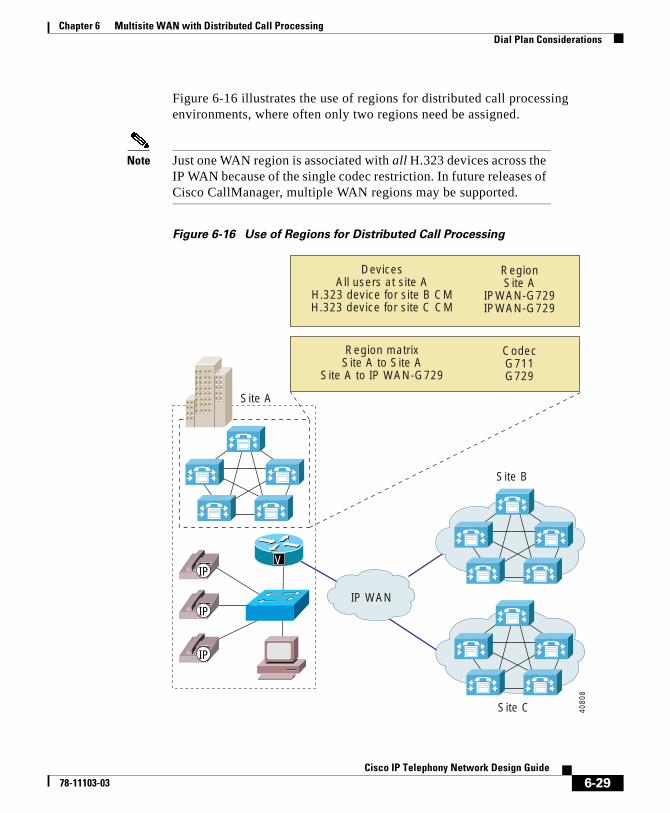
Chapter 6 Multisite WAN with Distributed Call ProcessingDial Plan Considerations
Figure 6-16 illustrates the use of regions for distributed call processing environments, where often only two regions need be assigned.
Note Just one WAN region is associated with all H.323 devices across the IP WAN because of the single codec restriction. In future releases of Cisco CallManager, multiple WAN regions may be supported.
Figure 6-16 Use of Regions for Distributed Call Processing
Site B
IP WAN
Region matrixSite A to Site A
Site A to IP WAN-G729
CodecG711G729
DevicesAll users at site A
H.323 device for site B CMH.323 device for site C CM
RegionSite A
IPWAN-G729IPWAN-G729
VIP
IP
IP
Site A
Site C 4080
8
6-29Cisco IP Telephony Network Design Guide
78-11103-03
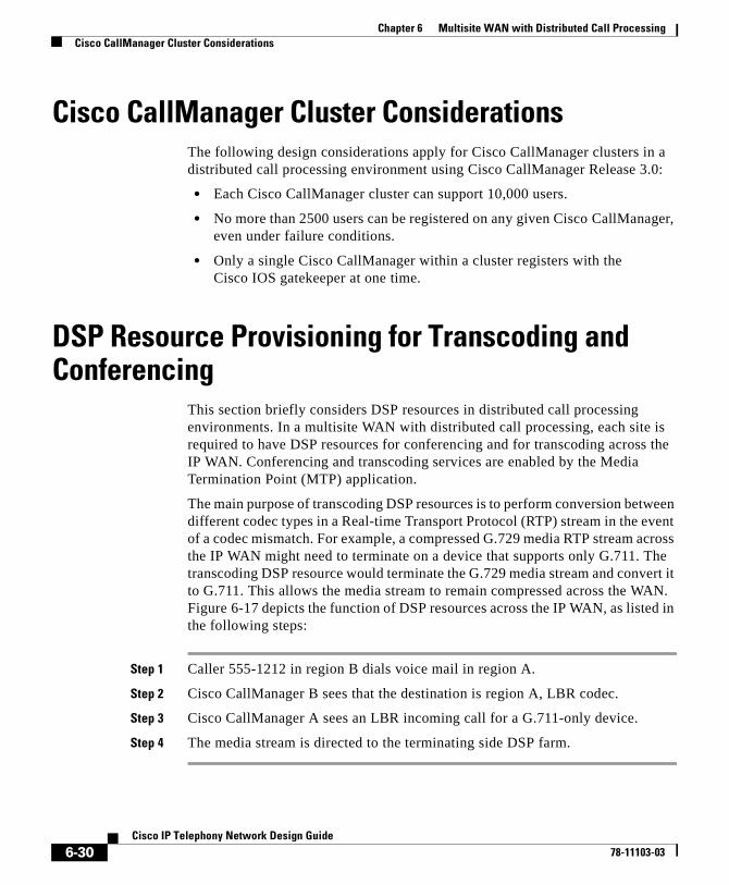
Chapter 6 Multisite WAN with Distributed Call ProcessingCisco CallManager Cluster Considerations
Cisco CallManager Cluster ConsiderationsThe following design considerations apply for Cisco CallManager clusters in a distributed call processing environment using Cisco CallManager Release 3.0:
• Each Cisco CallManager cluster can support 10,000 users.
• No more than 2500 users can be registered on any given Cisco CallManager, even under failure conditions.
• Only a single Cisco CallManager within a cluster registers with the Cisco IOS gatekeeper at one time.
DSP Resource Provisioning for Transcoding and Conferencing
This section briefly considers DSP resources in distributed call processing environments. In a multisite WAN with distributed call processing, each site is required to have DSP resources for conferencing and for transcoding across the IP WAN. Conferencing and transcoding services are enabled by the Media Termination Point (MTP) application.
The main purpose of transcoding DSP resources is to perform conversion between different codec types in a Real-time Transport Protocol (RTP) stream in the event of a codec mismatch. For example, a compressed G.729 media RTP stream across the IP WAN might need to terminate on a device that supports only G.711. The transcoding DSP resource would terminate the G.729 media stream and convert it to G.711. This allows the media stream to remain compressed across the WAN. Figure 6-17 depicts the function of DSP resources across the IP WAN, as listed in the following steps:
Step 1 Caller 555-1212 in region B dials voice mail in region A.
Step 2 Cisco CallManager B sees that the destination is region A, LBR codec.
Step 3 Cisco CallManager A sees an LBR incoming call for a G.711-only device.
Step 4 The media stream is directed to the terminating side DSP farm.
6-30Cisco IP Telephony Network Design Guide
78-11103-03
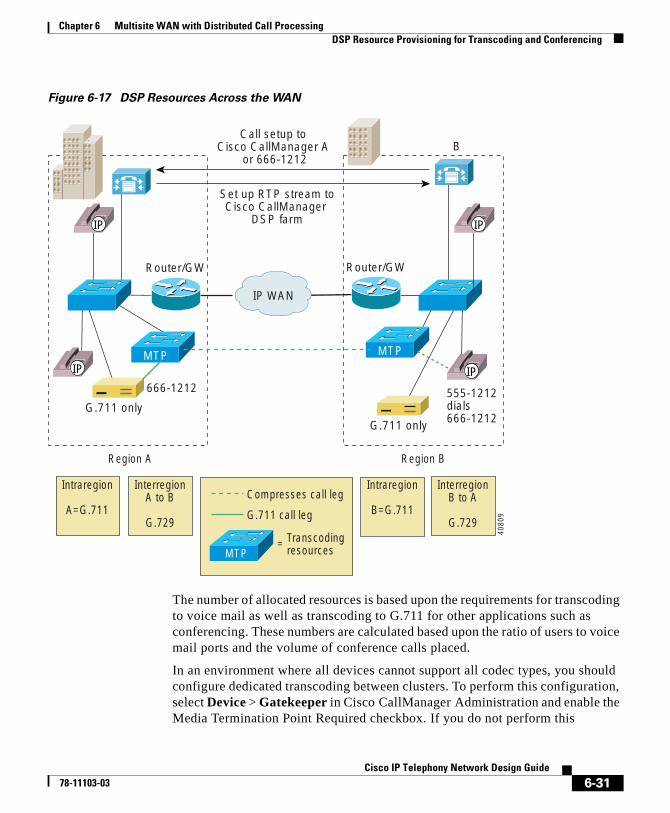
Chapter 6 Multisite WAN with Distributed Call ProcessingDSP Resource Provisioning for Transcoding and Conferencing
Figure 6-17 DSP Resources Across the WAN
The number of allocated resources is based upon the requirements for transcoding to voice mail as well as transcoding to G.711 for other applications such as conferencing. These numbers are calculated based upon the ratio of users to voice mail ports and the volume of conference calls placed.
In an environment where all devices cannot support all codec types, you should configure dedicated transcoding between clusters. To perform this configuration, select Device > Gatekeeper in Cisco CallManager Administration and enable the Media Termination Point Required checkbox. If you do not perform this
Region A
Call setup to Cisco CallManager A
or 666-1212
Set up RTP stream toCisco CallManager
DSP farm
IP WAN
G.711 only555-1212dials666-1212
MTP MTP
B
666-1212
Router/GW Router/GW
Intraregion
A=G.711
InterregionA to B
G.729
Region B
Intraregion
B=G.711
InterregionB to A
G.729
MTP
G.711 call leg
Compresses call leg
Transcodingresources=
IP
IP IP
IP
G.711 only
4080
9
6-31Cisco IP Telephony Network Design Guide
78-11103-03
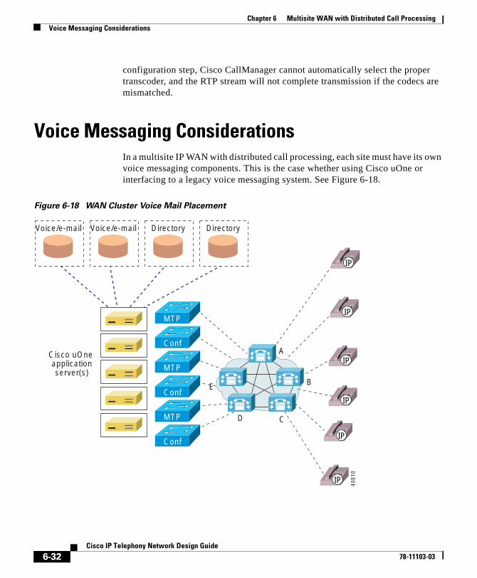
Chapter 6 Multisite WAN with Distributed Call ProcessingVoice Messaging Considerations
configuration step, Cisco CallManager cannot automatically select the proper transcoder, and the RTP stream will not complete transmission if the codecs are mismatched.
Voice Messaging ConsiderationsIn a multisite IP WAN with distributed call processing, each site must have its own voice messaging components. This is the case whether using Cisco uOne or interfacing to a legacy voice messaging system. See Figure 6-18.
Figure 6-18 WAN Cluster Voice Mail Placement
Voice/e-mail Voice/e-mail Directory Directory
Conf
MTP
Conf
MTP
Conf
MTP
Cisco uOne applicationserver(s)
A
E B
CD
IP
IP
IP
IP
IP
IP
4081
0
6-32Cisco IP Telephony Network Design Guide
78-11103-03
Cisco IP T78-11103-03
C H A P T E R 7
Multisite WAN with Centralized Call ProcessingThis chapter provides design guidelines for multisite WAN systems that use Cisco CallManager Release 3.0(5) for centralized call processing. The discussion emphasizes issues specific to the centralized call processing model, with reference to relevant material in other sections of this guide.
This chapter includes the following sections:
• Centralized Call Processing Model, page 7-1
• Call Admission Control, page 7-3
• Dial Plan Considerations, page 7-5
• Cisco CallManager Cluster Considerations, page 7-8
• DSP Resource Provisioning for Transcoding and Conferencing, page 7-10
• Voice Messaging Considerations, page 7-12
Centralized Call Processing ModelIn a centralized call processing system (see Figure 7-1), Cisco CallManagers are centrally located at the hub or aggregation site, with no local call processing at the branch location.
7-1elephony Network Design Guide
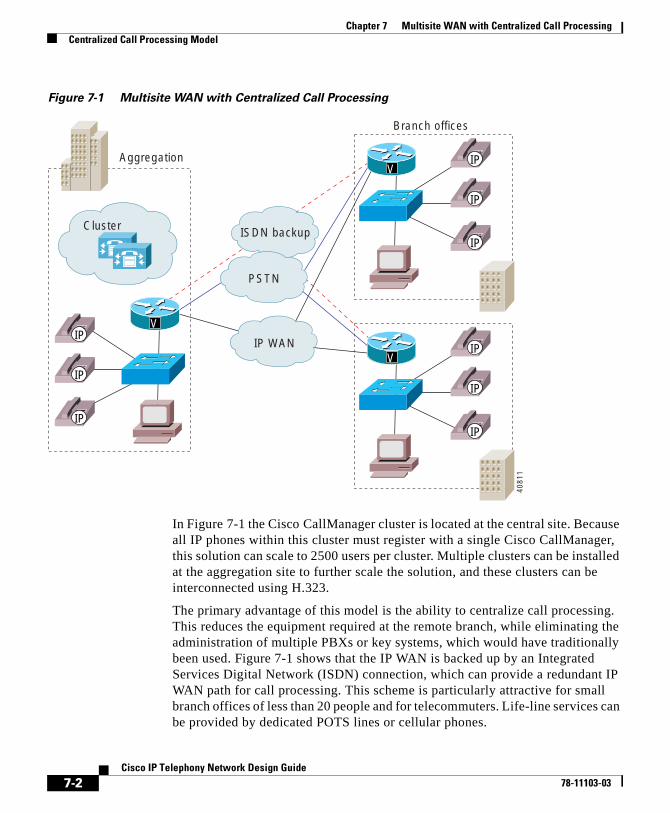
Chapter 7 Multisite WAN with Centralized Call ProcessingCentralized Call Processing Model
Figure 7-1 Multisite WAN with Centralized Call Processing
In Figure 7-1 the Cisco CallManager cluster is located at the central site. Because all IP phones within this cluster must register with a single Cisco CallManager, this solution can scale to 2500 users per cluster. Multiple clusters can be installed at the aggregation site to further scale the solution, and these clusters can be interconnected using H.323.
The primary advantage of this model is the ability to centralize call processing. This reduces the equipment required at the remote branch, while eliminating the administration of multiple PBXs or key systems, which would have traditionally been used. Figure 7-1 shows that the IP WAN is backed up by an Integrated Services Digital Network (ISDN) connection, which can provide a redundant IP WAN path for call processing. This scheme is particularly attractive for small branch offices of less than 20 people and for telecommuters. Life-line services can be provided by dedicated POTS lines or cellular phones.
IP WAN
PSTN
ISDN backup
V
VIP
IP
IP
IP
IP
IP
VIP
IP
IP
4081
1
Aggregation
Branch offices
Cluster
7-2Cisco IP Telephony Network Design Guide
78-11103-03
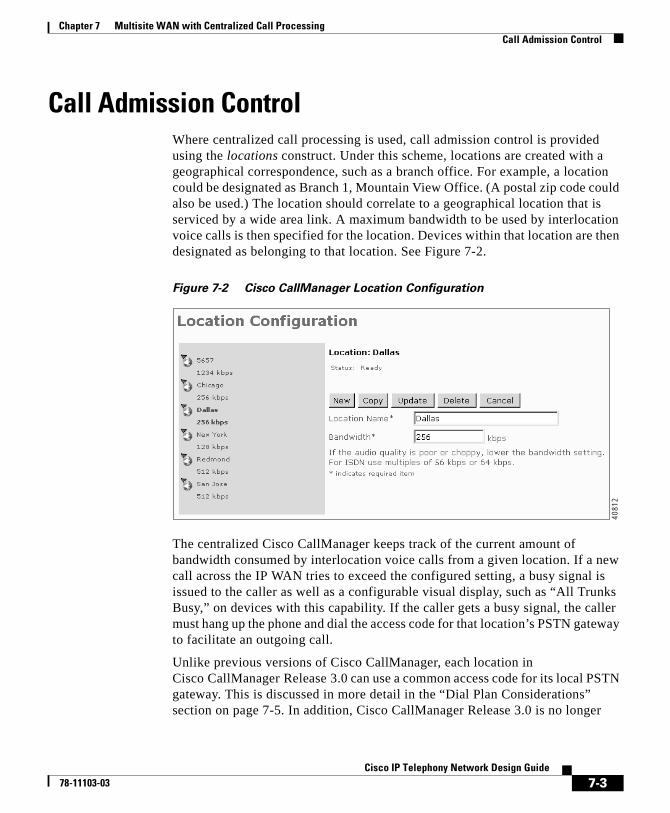
Chapter 7 Multisite WAN with Centralized Call ProcessingCall Admission Control
Call Admission ControlWhere centralized call processing is used, call admission control is provided using the locations construct. Under this scheme, locations are created with a geographical correspondence, such as a branch office. For example, a location could be designated as Branch 1, Mountain View Office. (A postal zip code could also be used.) The location should correlate to a geographical location that is serviced by a wide area link. A maximum bandwidth to be used by interlocation voice calls is then specified for the location. Devices within that location are then designated as belonging to that location. See Figure 7-2.
Figure 7-2 Cisco CallManager Location Configuration
The centralized Cisco CallManager keeps track of the current amount of bandwidth consumed by interlocation voice calls from a given location. If a new call across the IP WAN tries to exceed the configured setting, a busy signal is issued to the caller as well as a configurable visual display, such as “All Trunks Busy,” on devices with this capability. If the caller gets a busy signal, the caller must hang up the phone and dial the access code for that location’s PSTN gateway to facilitate an outgoing call.
Unlike previous versions of Cisco CallManager, each location in Cisco CallManager Release 3.0 can use a common access code for its local PSTN gateway. This is discussed in more detail in the “Dial Plan Considerations” section on page 7-5. In addition, Cisco CallManager Release 3.0 is no longer
4081
2
7-3Cisco IP Telephony Network Design Guide
78-11103-03
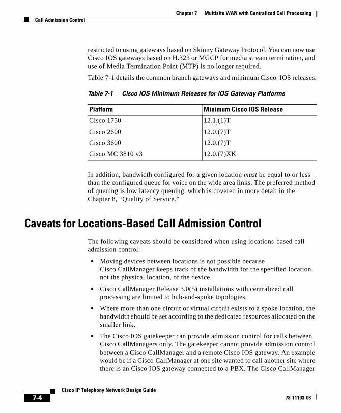
Chapter 7 Multisite WAN with Centralized Call ProcessingCall Admission Control
restricted to using gateways based on Skinny Gateway Protocol. You can now use Cisco IOS gateways based on H.323 or MGCP for media stream termination, and use of Media Termination Point (MTP) is no longer required.
Table 7-1 details the common branch gateways and minimum Cisco IOS releases.
In addition, bandwidth configured for a given location must be equal to or less than the configured queue for voice on the wide area links. The preferred method of queuing is low latency queuing, which is covered in more detail in the Chapter 8, “Quality of Service.”
Caveats for Locations-Based Call Admission ControlThe following caveats should be considered when using locations-based call admission control:
• Moving devices between locations is not possible because Cisco CallManager keeps track of the bandwidth for the specified location, not the physical location, of the device.
• Cisco CallManager Release 3.0(5) installations with centralized call processing are limited to hub-and-spoke topologies.
• Where more than one circuit or virtual circuit exists to a spoke location, the bandwidth should be set according to the dedicated resources allocated on the smaller link.
• The Cisco IOS gatekeeper can provide admission control for calls between Cisco CallManagers only. The gatekeeper cannot provide admission control between a Cisco CallManager and a remote Cisco IOS gateway. An example would be if a Cisco CallManager at one site wanted to call another site where there is an Cisco IOS gateway connected to a PBX. The Cisco CallManager
Table 7-1 Cisco IOS Minimum Releases for IOS Gateway Platforms
Platform Minimum Cisco IOS Release
Cisco 1750 12.1.(1)T
Cisco 2600 12.0.(7)T
Cisco 3600 12.0.(7)T
Cisco MC 3810 v3 12.0.(7)XK
7-4Cisco IP Telephony Network Design Guide
78-11103-03
Chapter 7 Multisite WAN with Centralized Call ProcessingDial Plan Considerations
does not use E.164 addresses in the admission request (ARQ) when it queries the gatekeeper for admission. This restriction may change in future releases of Cisco CallManager.
Dial Plan ConsiderationsA centralized call processing cluster must be able to handle three primary types of calls:
• Intracluster calls between IP phones within the cluster.
• Intercluster calls between Cisco CallManager clusters.
• PSTN calls through a local gateway at each site.
In this section, generalized design guidelines are provided for each of these cases.
Note Where location-based call admission control is used, automatic alternate routing through the PSTN is not possible. Instead, the calling party hears a busy tone and, on devices with a display, sees an out-of-bandwidth message.
Interlocation CallsInterlocation calls are generally made between IP phones and other devices such as fax machines and analog phones connected to gateway devices based on Media Gateway Control Protocol (MGCP) or the Skinny Gateway Protocol. As within a cluster, all devices register with a single Cisco CallManager so that the availability of all devices is known. When a call is attempted, the outcome is one of the following:
• The call succeeds.
• A busy tone is issued due to the remote device being active.
• A busy tone is issued due to insufficient WAN resources. A configurable message is also displayed on the device.
No configuration of a dial plan is required for intracluster calls in the majority of cases.
7-5Cisco IP Telephony Network Design Guide
78-11103-03
Chapter 7 Multisite WAN with Centralized Call ProcessingDial Plan Considerations
Intercluster CallsIntercluster calls are made using H.323 and can use alternative routing, including routing calls to the PSTN. Between clusters connected over a WAN, a gatekeeper is required for call admission control. The issues with intercluster calls are covered in greater detail in Chapter 6, “Multisite WAN with Distributed Call Processing.” See also Figure 3-11.
Local PSTN CallsEach site can dial a single number to access the local PSTN. The same code can be used for PSTN access, and, based upon the partition and calling search space, a local gateway is selected.
Design ExampleIn the network depicted in Figure 7-3, the desired operation is to permit all users to call each other within the cluster and also to permit a subset of the users to make PSTN calls. The text following Figure 7-3 explains how to achieve this.
7-6Cisco IP Telephony Network Design Guide
78-11103-03
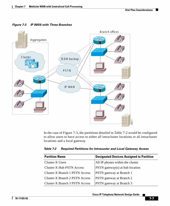
Chapter 7 Multisite WAN with Centralized Call ProcessingDial Plan Considerations
Figure 7-3 IP WAN with Three Branches
In the case of Figure 7-3, the partitions detailed in Table 7-2 would be configured to allow users to have access to either all intracluster locations or all intracluster locations and a local gateway.
IP WAN
PSTN
ISDN backup
V
VIP
IP
IP
IP
IP
IP
VIP
IP
IP
4081
1
Aggregation
Branch offices
Cluster
Table 7-2 Required Partitions for Intracuster and Local Gateway Access
Partition Name Designated Devices Assigned to Partition
Cluster-X Users All IP phones within the cluster
Cluster-X Hub PSTN Access PSTN gateway(s) at hub location
Cluster-X Branch 1 PSTN Access PSTN gateway at Branch 1
Cluster-X Branch 2 PSTN Access PSTN gateway at Branch 2
Cluster-X Branch 3 PSTN Access PSTN gateway at Branch 3
7-7Cisco IP Telephony Network Design Guide
78-11103-03

Chapter 7 Multisite WAN with Centralized Call ProcessingCisco CallManager Cluster Considerations
The calling party search spaces in Table 7-3 would then need to be defined. These calling search spaces would allow users to be assigned the ability to dial either numbers within the cluster only or all numbers within the cluster as well as PSTN calls through the local gateway.
This example presents one of the simplest configurations for multisite WAN local call processing. The dial plan would consist essentially of a single pattern for PSTN calls, typically a 9. Gateway selection would depend entirely upon the partition and calling search space of the calling device, as detailed above.
Additional considerations, which would require a more ambitious dial plan, are listed in the “Calling Search Space” section on page 5-15.
Cisco CallManager Cluster ConsiderationsThe following design parameters apply for Cisco CallManager clusters in a centralized call processing environment using Cisco CallManager Release 3.0(5):
• A single primary Cisco CallManager per cluster
• A maximum of 2500 IP phones per cluster
• A maximum of three Cisco CallManagers per Cisco CallManager cluster
• Hub-and-spoke topologies only
Table 7-3 Calling Search Space and Partition Assignments
Calling Search Space Partitions Assigned To
Cluster-X Internal Only Cluster-X Users Devices that can make only internal calls
Cluster-X Hub Unrestricted Cluster-X UsersCluster-X Hub PSTN Access
Internal calls and PSTN calls through hub location gateways
Cluster-X Branch 1 Unrestricted Cluster-X UsersCluster-X Branch 1 PSTN Access
Internal calls and PSTN calls through Branch 1 gateway
Cluster-X Branch 2 Unrestricted Cluster-X UsersCluster-X Branch 2 PSTN Access
Internal calls and PSTN calls through Branch 2 gateway
Cluster-X Branch 3 Unrestricted Cluster-X UsersCluster-X Branch 3 PSTN Access
Internal calls and PSTN calls through Branch 3 gateway
7-8Cisco IP Telephony Network Design Guide
78-11103-03
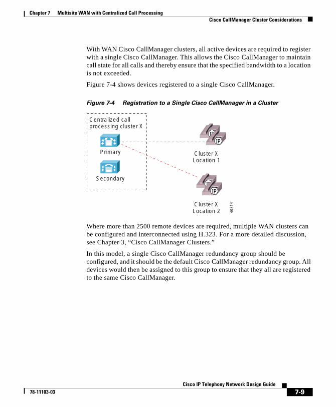
Chapter 7 Multisite WAN with Centralized Call ProcessingCisco CallManager Cluster Considerations
With WAN Cisco CallManager clusters, all active devices are required to register with a single Cisco CallManager. This allows the Cisco CallManager to maintain call state for all calls and thereby ensure that the specified bandwidth to a location is not exceeded.
Figure 7-4 shows devices registered to a single Cisco CallManager.
Figure 7-4 Registration to a Single Cisco CallManager in a Cluster
Where more than 2500 remote devices are required, multiple WAN clusters can be configured and interconnected using H.323. For a more detailed discussion, see Chapter 3, “Cisco CallManager Clusters.”
In this model, a single Cisco CallManager redundancy group should be configured, and it should be the default Cisco CallManager redundancy group. All devices would then be assigned to this group to ensure that they all are registered to the same Cisco CallManager.
Centralized callprocessing cluster X
Primary
Secondary
Cluster XLocation 1
Cluster XLocation 2
IPIP
IPIP
4081
4
7-9Cisco IP Telephony Network Design Guide
78-11103-03
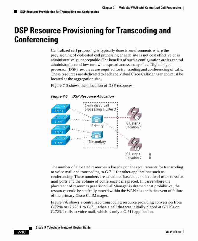
Chapter 7 Multisite WAN with Centralized Call ProcessingDSP Resource Provisioning for Transcoding and Conferencing
DSP Resource Provisioning for Transcoding and Conferencing
Centralized call processing is typically done in environments where the provisioning of dedicated call processing at each site is not cost effective or is administratively unacceptable. The benefits of such a configuration are its central administration and low cost when spread across many sites. Digital signal processor (DSP) resources are required for transcoding and conferencing of calls. These resources are dedicated to each individual Cisco CallManager and must be located at the aggregation site.
Figure 7-5 shows the allocation of DSP resources.
Figure 7-5 DSP Resource Allocation
The number of allocated resources is based upon the requirements for transcoding to voice mail and transcoding to G.711 for other applications such as conferencing. These numbers are calculated based upon the ratio of users to voice mail ports and the volume of conference calls placed. In cases where the placement of resources per Cisco CallManager is deemed cost prohibitive, the resources could be statically moved within the WAN cluster in the event of failure of the primary Cisco CallManager.
Figure 7-6 shows a centralized transcoding resource providing conversion from G.729a or G.723.1 to G.711 when a call that was initially placed at G.729a or G.723.1 rolls to voice mail, which is only a G.711 application.
Primary
Secondary
Cluster XLocation 1
Cluster XLocation 2
Conf
Trans
Trans
Conf
IPIP
IP
IP
Centralized callprocessing cluster X
4081
5
7-10Cisco IP Telephony Network Design Guide
78-11103-03
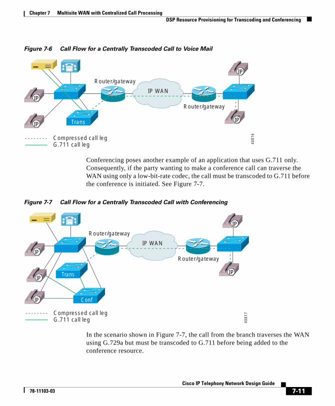
Chapter 7 Multisite WAN with Centralized Call ProcessingDSP Resource Provisioning for Transcoding and Conferencing
Figure 7-6 Call Flow for a Centrally Transcoded Call to Voice Mail
Conferencing poses another example of an application that uses G.711 only. Consequently, if the party wanting to make a conference call can traverse the WAN using only a low-bit-rate codec, the call must be transcoded to G.711 before the conference is initiated. See Figure 7-7.
Figure 7-7 Call Flow for a Centrally Transcoded Call with Conferencing
In the scenario shown in Figure 7-7, the call from the branch traverses the WAN using G.729a but must be transcoded to G.711 before being added to the conference resource.
IP WAN
Compressed call legG.711 call leg
Router/gateway
Router/gateway
Trans IP
IP
IP
IP
4081
6
IP WAN
Compressed call legG.711 call leg
Router/gateway
Router/gateway
IP
IP
4081
7
Conf
IP
IP
IP
Trans
7-11Cisco IP Telephony Network Design Guide
78-11103-03
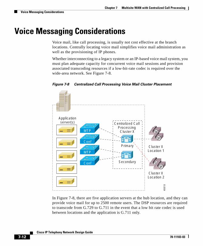
Chapter 7 Multisite WAN with Centralized Call ProcessingVoice Messaging Considerations
Voice Messaging ConsiderationsVoice mail, like call processing, is usually not cost effective at the branch locations. Centrally locating voice mail simplifies voice mail administration as well as the provisioning of IP phones.
Whether interconnecting to a legacy system or an IP-based voice mail system, you must plan adequate capacity for concurrent voice mail sessions and provision associated transcoding resources if a low-bit-rate codec is required over the wide-area network. See Figure 7-8.
Figure 7-8 Centralized Call Processing Voice Mail Cluster Placement
In Figure 7-8, there are five application servers at the hub location, and they can provide voice mail for up to 2500 remote users. The DSP resources are required to transcode from G.729 to G.711 in the event that a low bit rate codec is used between locations and the application is G.711 only.
Centralized Call Processing
Cluster X
Primary
Secondary
Cluster XLocation 1
Cluster XLocation 2
Conf
MTP
MTP
Conf
Applicationserver(s)
IP
IP
IPIP
4081
8
7-12Cisco IP Telephony Network Design Guide
78-11103-03
Cisco IP T78-11103-03
C H A P T E R 8
Quality of ServiceThis chapter addresses the Quality of Service (QoS) requirements for implementations of IP telephone solutions over an enterprise network. By applying the prerequisite tools, you can achieve excellent quality voice, video, and data transmissions over an IP infrastructure, irrespective of media and even at low data rates. For more detailed information on designing Quality of Service networks for AVVID deployments, please see the Cisco AVVID QoS Design Guide at
http://www.cisco.com/univercd/cc/td/doc/product/voice/ip_tele/index.htm
This chapter includes the following major sections:
• Campus QoS Model, page 8-1
• WAN QoS Model, page 8-4
Campus QoS ModelUntil recently, conventional wisdom stated that Quality of Service would never be an issue in the enterprise campus due to the bursty nature of data traffic and the capability to withstand buffer overflow and packet loss. When applications such as voice and video, which are sensitive to loss and delay, began to traverse the data network, network designers gradually came to understand that buffers and not bandwidth are the issue in the campus. Buffers can fill instantaneously. When this occurs, packets can be dropped when attempting to enter the interface buffer. For applications like voice, which are extremely drop intolerant, this results in voice quality degradation. QoS tools are required to manage these buffers to minimize loss, delay, and delay variation.
8-1elephony Network Design Guide
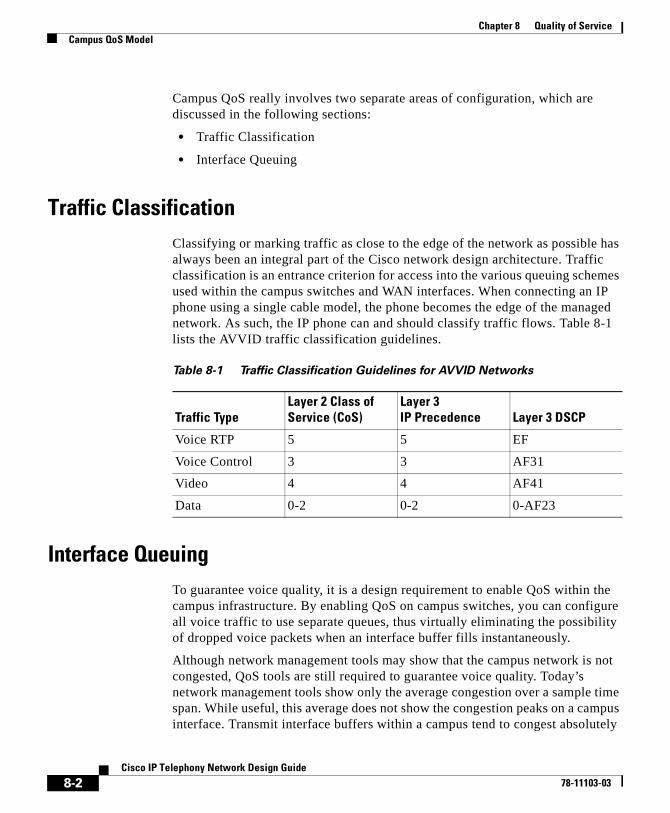
Chapter 8 Quality of ServiceCampus QoS Model
Campus QoS really involves two separate areas of configuration, which are discussed in the following sections:
• Traffic Classification
• Interface Queuing
Traffic ClassificationClassifying or marking traffic as close to the edge of the network as possible has always been an integral part of the Cisco network design architecture. Traffic classification is an entrance criterion for access into the various queuing schemes used within the campus switches and WAN interfaces. When connecting an IP phone using a single cable model, the phone becomes the edge of the managed network. As such, the IP phone can and should classify traffic flows. Table 8-1 lists the AVVID traffic classification guidelines.
Interface QueuingTo guarantee voice quality, it is a design requirement to enable QoS within the campus infrastructure. By enabling QoS on campus switches, you can configure all voice traffic to use separate queues, thus virtually eliminating the possibility of dropped voice packets when an interface buffer fills instantaneously.
Although network management tools may show that the campus network is not congested, QoS tools are still required to guarantee voice quality. Today’s network management tools show only the average congestion over a sample time span. While useful, this average does not show the congestion peaks on a campus interface. Transmit interface buffers within a campus tend to congest absolutely
Table 8-1 Traffic Classification Guidelines for AVVID Networks
Traffic TypeLayer 2 Class of Service (CoS)
Layer 3 IP Precedence Layer 3 DSCP
Voice RTP 5 5 EF
Voice Control 3 3 AF31
Video 4 4 AF41
Data 0-2 0-2 0-AF23
8-2Cisco IP Telephony Network Design Guide
78-11103-03

Chapter 8 Quality of ServiceCampus QoS Model
in small, finite intervals as a result of the bursty nature of network traffic. When this occurs, any packets destined for that transmit interface are dropped. The only way to prevent dropped voice traffic is to configure multiple queues on campus switches. Table 8-2 lists the Cisco Ethernet switches that support enhanced queuing services.
Table 8-2 Queuing Services Supported by Cisco Switches
Campus Switching Element Queuing Scheme Queue Scheduler Queue Admission
Catalyst 6000 2Q2T and 1P2Q2T WRR and PQ/WRR Configurable
Catalyst 8500 4Q1T WRR Configurable in CoS pairs
Catalyst 4000 2Q1T RR Configurable in CoS pairs
Catalyst 3500 2Q1T PQ Not configurable.CoS 0-3 = Queue1CoS 0-3 = Queue2
Catalyst 2900 XL (8 MB DRAM)
2Q1T PQ Not configurable.CoS 0-3 = Queue1CoS 0-3 = Queue2
IP Phone 1P3Q1T RR with a PQ timer Not configurable.CoS 5 = Queue0 (PQ).
All other CoS values = Queues 1-3.
8-3Cisco IP Telephony Network Design Guide
78-11103-03
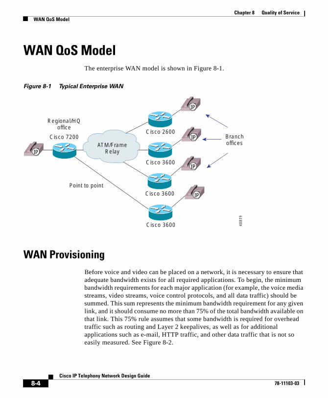
Chapter 8 Quality of ServiceWAN QoS Model
WAN QoS ModelThe enterprise WAN model is shown in Figure 8-1.
Figure 8-1 Typical Enterprise WAN
WAN ProvisioningBefore voice and video can be placed on a network, it is necessary to ensure that adequate bandwidth exists for all required applications. To begin, the minimum bandwidth requirements for each major application (for example, the voice media streams, video streams, voice control protocols, and all data traffic) should be summed. This sum represents the minimum bandwidth requirement for any given link, and it should consume no more than 75% of the total bandwidth available on that link. This 75% rule assumes that some bandwidth is required for overhead traffic such as routing and Layer 2 keepalives, as well as for additional applications such as e-mail, HTTP traffic, and other data traffic that is not so easily measured. See Figure 8-2.
Cisco 7200Cisco 2600
Cisco 3600
Cisco 3600
Cisco 3600
Point to point
ATM/FrameRelay
Regional/HQoffice
Branchoffices
IP
IP
IP
IP
IP
4081
9
8-4Cisco IP Telephony Network Design Guide
78-11103-03
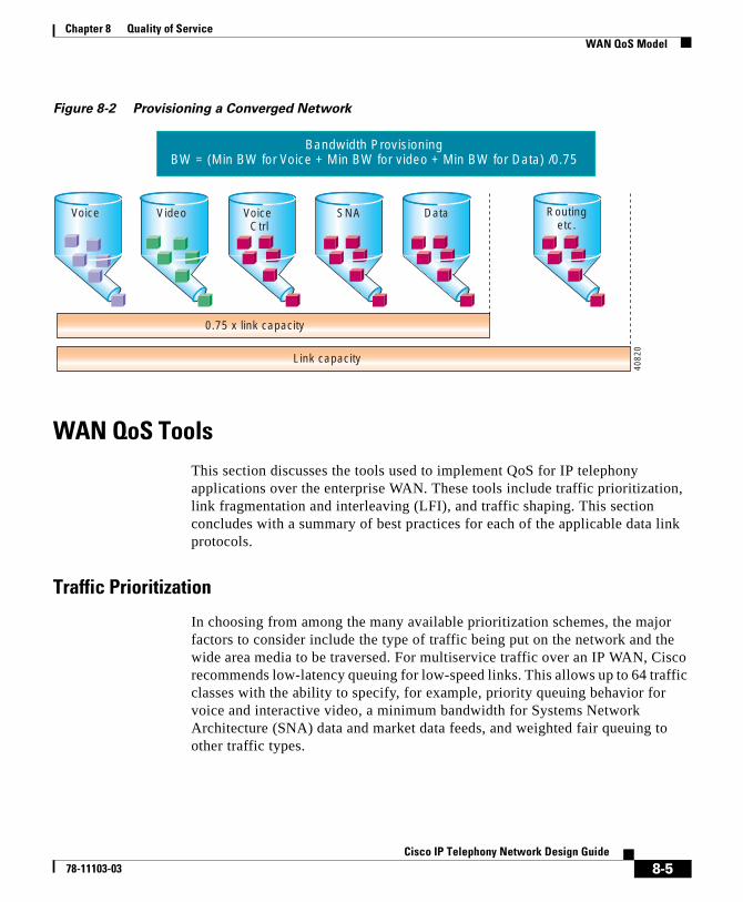
Chapter 8 Quality of ServiceWAN QoS Model
Figure 8-2 Provisioning a Converged Network
WAN QoS ToolsThis section discusses the tools used to implement QoS for IP telephony applications over the enterprise WAN. These tools include traffic prioritization, link fragmentation and interleaving (LFI), and traffic shaping. This section concludes with a summary of best practices for each of the applicable data link protocols.
Traffic Prioritization
In choosing from among the many available prioritization schemes, the major factors to consider include the type of traffic being put on the network and the wide area media to be traversed. For multiservice traffic over an IP WAN, Cisco recommends low-latency queuing for low-speed links. This allows up to 64 traffic classes with the ability to specify, for example, priority queuing behavior for voice and interactive video, a minimum bandwidth for Systems Network Architecture (SNA) data and market data feeds, and weighted fair queuing to other traffic types.
Video
0.75 x link capacity
Link capacity
Voice Ctrl
SNA Routingetc.
Voice Data
4082
0
Bandwidth ProvisioningBW = (Min BW for Voice + Min BW for video + Min BW for Data) /0.75
8-5Cisco IP Telephony Network Design Guide
78-11103-03
Chapter 8 Quality of ServiceWAN QoS Model
Figure 8-3 shows this prioritization scheme as follows:
• Voice is placed into a queue with priority queuing capabilities and is allocated a bandwidth of 48 kbps. The entrance criterion to this queue should be the differentiated services code point (DSCP) value of EF, or IP precedence value of 5. Traffic in excess of 48 kbps would be dropped if the interface becomes congested. Therefore, an admission control mechanism must be used to ensure that this value is not exceeded.
• Video conferencing traffic is placed into a queue with priority queuing capabilities and is allocated a bandwidth of 384 kbps. The entrance criterion to this queue should be a DSCP value of AF41, or IP precedence value of 4. Traffic in excess of 384 kbps would be dropped if the interface becomes congested. It is therefore imperative, as in the case of voice, to use an admission control mechanism to ensure that this value is not exceeded.
Note One-way video traffic, such as IP/TV, should use a class-based weighted fair queuing scheme because the delay tolerances are much higher.
• As the WAN links become congested, it is possible to completely starve the voice control signaling protocols, thereby eliminating the ability of the IP phones to complete calls across the IP WAN. Voice control protocol traffic, such as H.323 and the Skinny Client Control Protocol, requires its own class-based weighted fair queue with a minimum configurable bandwidth equal to a DSCP value of AF31, which correlates to an IP precedence value of 3.
• SNA traffic is placed into a queue that has a specified bandwidth of 56 kbps. Queueing operation within this class is first-in-first-out (FIFO) with a minimum allocated bandwidth of 56 kbps. Traffic in this class that exceeds 56 kbps is placed in the default queue. The entrance criterion to this queue could be TCP port numbers, Layer 3 address, IP precedence, or a DSCP.
• All remaining traffic can be placed in a default queue. If a bandwidth is specified, the queuing operation would be FIFO. Alternatively, by specifying the keyword fair, the operation would be weighted fair queuing (WFQ).
8-6Cisco IP Telephony Network Design Guide
78-11103-03
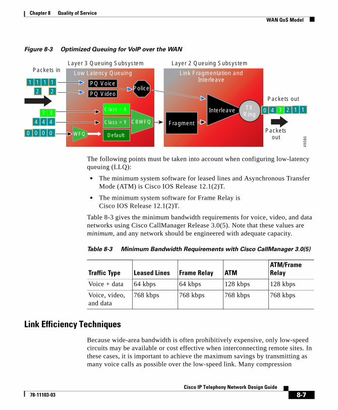
Chapter 8 Quality of ServiceWAN QoS Model
Figure 8-3 Optimized Queuing for VoIP over the WAN
The following points must be taken into account when configuring low-latency queuing (LLQ):
• The minimum system software for leased lines and Asynchronous Transfer Mode (ATM) is Cisco IOS Release 12.1(2)T.
• The minimum system software for Frame Relay is Cisco IOS Release 12.1(2)T.
Table 8-3 gives the minimum bandwidth requirements for voice, video, and data networks using Cisco CallManager Release 3.0(5). Note that these values are minimum, and any network should be engineered with adequate capacity.
Link Efficiency Techniques
Because wide-area bandwidth is often prohibitively expensive, only low-speed circuits may be available or cost effective when interconnecting remote sites. In these cases, it is important to achieve the maximum savings by transmitting as many voice calls as possible over the low-speed link. Many compression
Class = X
Class = Y CBWFQ
Default
Police
Layer 3 Queuing Subsystem Layer 2 Queuing Subsystem
Low Latency Queuing Link Fragmentation andInterleave
Fragment
Interleave
PQ Voice
PQ Video
490
86
Packetsout
WFQ
TXRing
1 1
1 1
1 1
0
0
0 0 0
4
4
4 4
3 33
2
2
2Packets out
Packets in
Table 8-3 Minimum Bandwidth Requirements with Cisco CallManager 3.0(5)
Traffic Type Leased Lines Frame Relay ATMATM/Frame Relay
Voice + data 64 kbps 64 kbps 128 kbps 128 kbps
Voice, video, and data
768 kbps 768 kbps 768 kbps 768 kbps
8-7Cisco IP Telephony Network Design Guide
78-11103-03
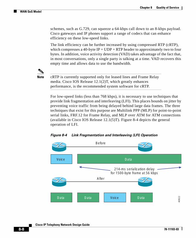
Chapter 8 Quality of ServiceWAN QoS Model
schemes, such as G.729, can squeeze a 64-kbps call down to an 8-kbps payload. Cisco gateways and IP phones support a range of codecs that can enhance efficiency on these low-speed links.
The link efficiency can be further increased by using compressed RTP (cRTP), which compresses a 40-byte IP + UDP + RTP header to approximately two to four bytes. In addition, voice activity detection (VAD) takes advantage of the fact that, in most conversations, only a single party is talking at a time. VAD recovers this empty time and allows data to use the bandwidth.
Note cRTP is currently supported only for leased lines and Frame Relay media. Cisco IOS Release 12.1(2)T, which greatly enhances performance, is the recommended system software for cRTP.
For low-speed links (less than 768 kbps), it is necessary to use techniques that provide link fragmentation and interleaving (LFI). This places bounds on jitter by preventing voice traffic from being delayed behind large data frames. The three techniques that exist for this purpose are Multilink PPP (MLP) for point-to-point serial links, FRF.12 for Frame Relay, and MLP over ATM for ATM connections (available in Cisco IOS Release 12.1(5)T). Figure 8-4 depicts the general operation of LFI.
Figure 8-4 Link Fragmentation and Interleaving (LFI) Operation
Voice Data
Before
After
Data VoiceData Data
214-ms serialization delayfor 1500-byte frame at 56 kbps
4082
2
8-8Cisco IP Telephony Network Design Guide
78-11103-03
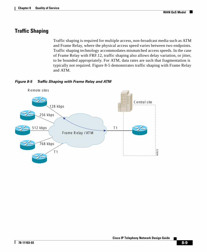
Chapter 8 Quality of ServiceWAN QoS Model
Traffic Shaping
Traffic shaping is required for multiple access, non-broadcast media such as ATM and Frame Relay, where the physical access speed varies between two endpoints. Traffic shaping technology accommodates mismatched access speeds. In the case of Frame Relay with FRF.12, traffic shaping also allows delay variation, or jitter, to be bounded appropriately. For ATM, data rates are such that fragmentation is typically not required. Figure 8-5 demonstrates traffic shaping with Frame Relay and ATM.
Figure 8-5 Traffic Shaping with Frame Relay and ATM
T1
T1
768 kbps
512 kbps
256 kbps
128 kbps
Frame Relay / ATM
Central site
Remote sites
4082
3
8-9Cisco IP Telephony Network Design Guide
78-11103-03
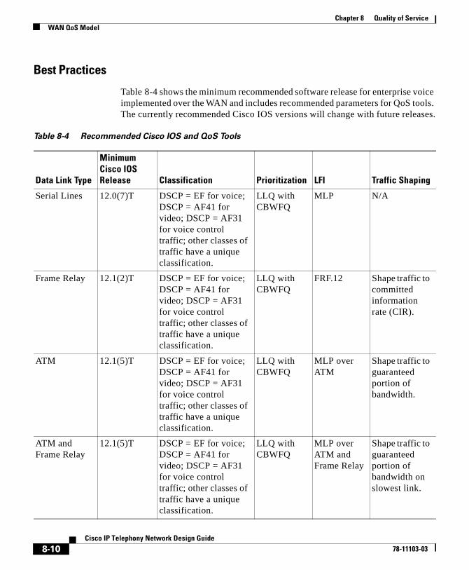
Chapter 8 Quality of ServiceWAN QoS Model
Best Practices
Table 8-4 shows the minimum recommended software release for enterprise voice implemented over the WAN and includes recommended parameters for QoS tools. The currently recommended Cisco IOS versions will change with future releases.
Table 8-4 Recommended Cisco IOS and QoS Tools
Data Link Type
Minimum Cisco IOS Release Classification Prioritization LFI Traffic Shaping
Serial Lines 12.0(7)T DSCP = EF for voice; DSCP = AF41 for video; DSCP = AF31 for voice control traffic; other classes of traffic have a unique classification.
LLQ with CBWFQ
MLP N/A
Frame Relay 12.1(2)T DSCP = EF for voice; DSCP = AF41 for video; DSCP = AF31 for voice control traffic; other classes of traffic have a unique classification.
LLQ with CBWFQ
FRF.12 Shape traffic to committed information rate (CIR).
ATM 12.1(5)T DSCP = EF for voice; DSCP = AF41 for video; DSCP = AF31 for voice control traffic; other classes of traffic have a unique classification.
LLQ with CBWFQ
MLP over ATM
Shape traffic to guaranteed portion of bandwidth.
ATM and Frame Relay
12.1(5)T DSCP = EF for voice; DSCP = AF41 for video; DSCP = AF31 for voice control traffic; other classes of traffic have a unique classification.
LLQ with CBWFQ
MLP over ATM and Frame Relay
Shape traffic to guaranteed portion of bandwidth on slowest link.
8-10Cisco IP Telephony Network Design Guide
78-11103-03
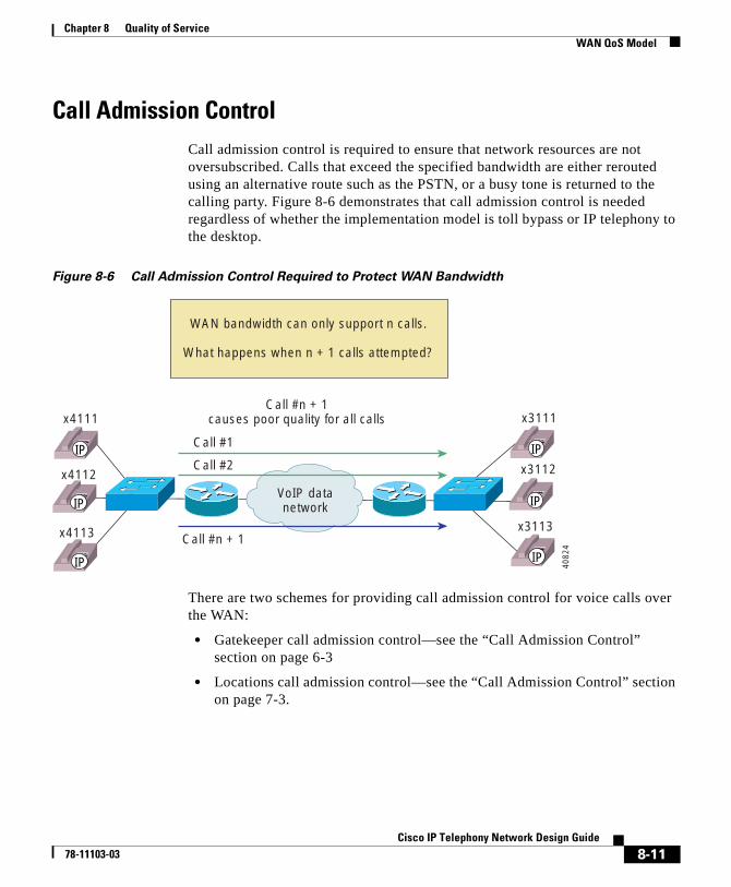
Chapter 8 Quality of ServiceWAN QoS Model
Call Admission ControlCall admission control is required to ensure that network resources are not oversubscribed. Calls that exceed the specified bandwidth are either rerouted using an alternative route such as the PSTN, or a busy tone is returned to the calling party. Figure 8-6 demonstrates that call admission control is needed regardless of whether the implementation model is toll bypass or IP telephony to the desktop.
Figure 8-6 Call Admission Control Required to Protect WAN Bandwidth
There are two schemes for providing call admission control for voice calls over the WAN:
• Gatekeeper call admission control—see the “Call Admission Control” section on page 6-3
• Locations call admission control—see the “Call Admission Control” section on page 7-3.
WAN bandwidth can only support n calls.
What happens when n + 1 calls attempted?
VoIP datanetwork
Call #1
Call #2
Call #n + 1
Call #n + 1causes poor quality for all callsx4111
x4112
x4113
x3111
x3112
x3113
IP
IP
IP
IP
IP
IP40
824
8-11Cisco IP Telephony Network Design Guide
78-11103-03

Chapter 8 Quality of ServiceWAN QoS Model
8-12Cisco IP Telephony Network Design Guide
78-11103-03
Cisco IP T78-11103-03
C H A P T E R 9
Catalyst DSP ProvisioningThis chapter describes Catalyst digital signal processor (DSP) resources, with emphasis on two new Catalyst 4000 and Catalyst 6000 voice modules, and it discusses how to provision these resources. These new modules are the WS-X4604-GWY for the Catalyst 4000 and the WS-X6608-T1 (WS-X6608-E1 for countries outside the USA) for the Catalyst 6000. They are available for use with Cisco CallManager Release 3.0(5). They can perform conferencing and Media Termination Point (MTP) transcoding services in addition to serving as a PSTN gateway (see Chapter 4, “Gateway Selection”).
This chapter includes the following major sections:
• Understanding the Catalyst DSP Resources, page 9-2
• Catalyst Conferencing Services, page 9-4
• Catalyst MTP Transcoding Services, page 9-7
• Catalyst 4000 Voice Services, page 9-13
• Catalyst 6000 Voice Services, page 9-15
9-1elephony Network Design Guide
Chapter 9 Catalyst DSP ProvisioningUnderstanding the Catalyst DSP Resources
Understanding the Catalyst DSP ResourcesThe DSP resources on the new Catalyst 4000 and 6000 gateway modules essentially provide hardware support for IP telephony features offered by Cisco CallManager. These features are hardware-enabled voice conferencing, hardware-based MTP support for supplementary services, and transcoding services.
Catalyst-enabled conferencing is the ability to support voice conferences in hardware. DSPs are used to convert voice over IP (VoIP) sessions into time-division multiplexing (TDM) streams, which can then be mixed into a multiparty conference call.
The Catalyst MTP service can act either like the original software MTP resource or as a transcoding MTP resource. An MTP service is the ability to provide supplementary services such as hold, transfer, and conferencing when using gateways and clients that do not support the H.323v2 feature of OpenLogicalChannel and CloseLogicalChannel with the EmptyCapabilitiesSet. MTP is available as a software feature that can run on Cisco CallManager or a separate Windows NT server. When MTP is running in software on Cisco CallManager, 24 MTP sessions are supported. When MTP is running on a separate Windows NT server, up to 48 MTP sessions are supported. The new Catalyst gateway modules can support this same functionality, but they provide the service in hardware.
Transcoding is in effect an IP-to-IP voice gateway service. A transcoding node can convert a G.711 voice stream into a low-bit-rate (LBR) compressed voice stream, such as G.729a. This is critical for enabling applications such as integrated voice response (IVR), voice messaging, and conference calls over low-speed IP WANs. MTP transcoding is currently supported only on the Catalyst voice gateways.
Table 9-1 shows DSP resources that can be configured on the Catalyst voice services modules.
9-2Cisco IP Telephony Network Design Guide
78-11103-03
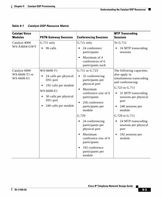
Chapter 9 Catalyst DSP ProvisioningUnderstanding the Catalyst DSP Resources
Table 9-1 Catalyst DSP Resource Matrix
Catalyst Voice Modules PSTN Gateway Sessions Conferencing Sessions
MTP Transcoding Sessions
Catalyst 4000 WS-X4604-GWY
G.711 only
• 96 calls
G.711 only
• 24 conference participants
• Maximum of 4 conferences of 6 participants each
To G.711
• 16 MTP transcoding sessions
Catalyst 6000 WS-6608-T1 or WS-6608-E1
WS-6608-T1
• 24 calls per physical DS1 port
• 192 calls per module
WS-6608-E1
• 30 calls per physical DS1 port
• 240 calls per module
G.711 or G.723
• 32 conferencing participants per physical port
• Maximum conference size of 6 participants
• 256 conference participants per module
G.729
• 24 conferencing participants per physical port
• Maximum conference size of 6 participants
• 192 conference participants per module
The following capacities also apply to simultaneous transcoding and conferencing:
G.723 to G.711
• 31 MTP transcoding sessions per physical port
• 248 sessions per module
G.729 to G.711
• 24 MTP transcoding sessions per physical port
• 192 sessions per module
9-3Cisco IP Telephony Network Design Guide
78-11103-03
Chapter 9 Catalyst DSP ProvisioningCatalyst Conferencing Services
Catalyst Conferencing ServicesTo scale IP telephony systems in large enterprise environments, hardware-based conferencing must be used. The new hardware for the Catalyst 4000 and 6000 switch families was developed with this requirement in mind. These new Catalyst voice modules can handle conferencing in hardware, eliminating the requirement of running a software conferencing service on a Windows NT server in the IP telephony network.
Conferencing Design DetailsThe following points summarize the design capabilities and requirements of the new Catalyst voice modules:
• Support for a maximum of 6 participants per conference call.
• The Catalyst 4000 WS-X4604-GWY module supports 24 conference participants per module.
• The Catalyst 4000 WS-X4604-GWY module supports conferencing for G.711 voice streams only. Transcoding can be used to convert G.729a or G.723.1 to G.711 for conference calls.
• The Catalyst 6000 WS-X6608-T1 or WS-X6608-E1 modules support 32 G.711 or G.723 conference participants per physical port (256 per module) or 24 G.729 conference participants per physical port (192 per module).
• The Catalyst 6000 WS-X6608-T1 or WS-X6608-E1 modules can support both uncompressed and compressed VoIP conference calls.
• Each Cisco CallManager must have its own conference and MTP transcoding resources, because the DSP resources can register with only one Cisco CallManager at a time. Cisco CallManagers cannot share DSP resources.
The Catalyst 4000 module, the WS-X4604-GWY, can support up to four simultaneous conference calls of six callers each. The Catalyst 6000 T1 or E1 PSTN gateway module, the WS-X6608, also has the ability to support conferencing. After the WS-X6608 has been added as a T1 or E1 Cisco AVVID gateway, it can be configured, on a per-port basis, for conferencing services. The Catalyst 6000 conferencing module supports up to six callers per conference call
9-4Cisco IP Telephony Network Design Guide
78-11103-03
Chapter 9 Catalyst DSP ProvisioningCatalyst Conferencing Services
with a maximum of 32 simultaneous G.711 or G.723 conference callers per configured logical port. This results in a maximum of 256 conference participants per module with G.711 or G.723 calls.
See Table 9-1 for a summary of conference call densities for each module.
Both the WS-X4604-GWY and WS-X6608-T1 (or WS-X6608-E1) modules use Skinny Station Protocol to communicate with Cisco CallManager when providing conferencing or transcoding services. The Catalyst 6000 voice conferencing solution can support both compressed and uncompressed conference attendees.
On the Catalyst 4000, only G.711, or uncompressed, calls can be joined to a conference call. When the conferencing service registers with Cisco CallManager, using Skinny Station Protocol, it announces that only G.711 voice calls can be connected. If any compressed calls request to be joined to a conference call, Cisco CallManager connects them to a transcoding port first, to convert the compressed voice call to G.711. Once the G.711 connections are associated with a particular conferencing session (maximum of six participants per conference call), the call is converted to a TDM stream and passed to the summing logic, which combines the streams. Unlike the WS-X6608-x1, which can mix all conference call participants, the Catalyst 4000 WS-X4604-GWY module sums only the three dominant speakers. The WS-X4604-GWY dynamically adjusts for the dominant speakers and determines dominance primarily by voice volume, not including any background noise.
You should also observe the following recommendations when configuring conferencing services:
• When provisioning an enterprise with conference ports, first determine how many callers will attempt to join the conference calls from a compressed Cisco CallManager region. Once you know the number of compressed callers, you can accurately provision the MTP transcoding resources.
• Conference bridges cannot register with more than one Cisco CallManager at a time, and Cisco CallManagers cannot share DSP resources. Therefore, you must configure separate conferencing modules for each Cisco CallManager in the cluster.
Figure 9-1 illustrates the components used in Catalyst conferencing services.
9-5Cisco IP Telephony Network Design Guide
78-11103-03
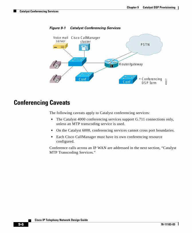
Chapter 9 Catalyst DSP ProvisioningCatalyst Conferencing Services
Figure 9-1 Catalyst Conferencing Services
Conferencing CaveatsThe following caveats apply to Catalyst conferencing services:
• The Catalyst 4000 conferencing services support G.711 connections only, unless an MTP transcoding service is used.
• On the Catalyst 6000, conferencing services cannot cross port boundaries.
• Each Cisco CallManager must have its own conferencing resource configured.
Conference calls across an IP WAN are addressed in the next section, “Catalyst MTP Transcoding Services.”
ConferencingDSP farm
Cisco CallManagercluster
Router/gateway
ConfMTP
V
PSTN
=
IP
IP
4082
7
Voice mailserver
Conf
9-6Cisco IP Telephony Network Design Guide
78-11103-03
Chapter 9 Catalyst DSP ProvisioningCatalyst MTP Transcoding Services
Catalyst MTP Transcoding ServicesIntroducing the WAN into an IP telephony implementation forces the issue of voice compression. In the previous designs shown in this document, all campus-oriented voice was uncompressed (G.711) to provide the highest quality while incurring the fewest complications. Once a WAN-enabled network is implemented, voice compression between sites is the recommended design choice. This calls into question how WAN users use the conferencing services or IP-enabled applications, which support only G.711 voice connections. The solution is to use hardware-based MTP transcoding services to convert the compressed voice streams into G.711.
MTP Transcoding Design DetailsThe following points summarize the design capabilities and requirements of the MTP transcoding:
• Provision MTP transcoding resources appropriately for the number of IP WAN callers to G.711 endpoints.
• The Catalyst 4000 WS-X4604-GWY module supports 16 transcoding sessions per module.
• The Catalyst 6000 WS-X6608-T1 or WS-X6608-E1 modules support 31 G.723 or G.711 transcoding sessions per physical port (248 per module) or 24 G.729 to G.711 transcoding sessions per physical port (192 per module).
• Transcoding is supported only in low bit rate to high bit rate (G.729a or G.723.1 to G.711), or vice versa, configurations.
• Each Cisco CallManager must have its own MTP transcoding resources.
• Each transcode has its own jitter buffer of 20-40 ms.
IP-to-IP Packet Transcoding and Voice Compression
Voice compression between IP phones is easily configured through the use of regions and locations in Cisco CallManager. However, the Catalyst conferencing services and some applications currently support only G.711, or uncompressed, connections. For these situations, MTP transcoding or packet-to-packet gateway
9-7Cisco IP Telephony Network Design Guide
78-11103-03
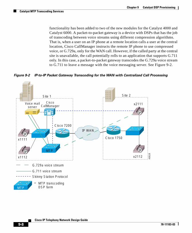
Chapter 9 Catalyst DSP ProvisioningCatalyst MTP Transcoding Services
functionality has been added to two of the new modules for the Catalyst 4000 and Catalyst 6000. A packet-to-packet gateway is a device with DSPs that has the job of transcoding between voice streams using different compression algorithms. That is, when a user on an IP phone at a remote location calls a user at the central location, Cisco CallManager instructs the remote IP phone to use compressed voice, or G.729a, only for the WAN call. However, if the called party at the central site is unavailable, the call potentially rolls to an application that supports G.711 only. In this case, a packet-to-packet gateway transcodes the G.729a voice stream to G.711 to leave a message with the voice messaging server. See Figure 9-2.
Figure 9-2 IP-to-IP Packet Gateway Transcoding for the WAN with Centralized Call Processing
Site 1
IP WAN
x1111
x1112 x2112
Cisco 7200
Cisco 1750
Site 2
MTP
Skinny Station Protocol
G.711 voice stream
G.729a voice stream
MTP transcodingDSP farm
=
MTP
x2111
IP
IP
IP
IP40
828
Voice mailserver
CiscoCallManager
9-8Cisco IP Telephony Network Design Guide
78-11103-03
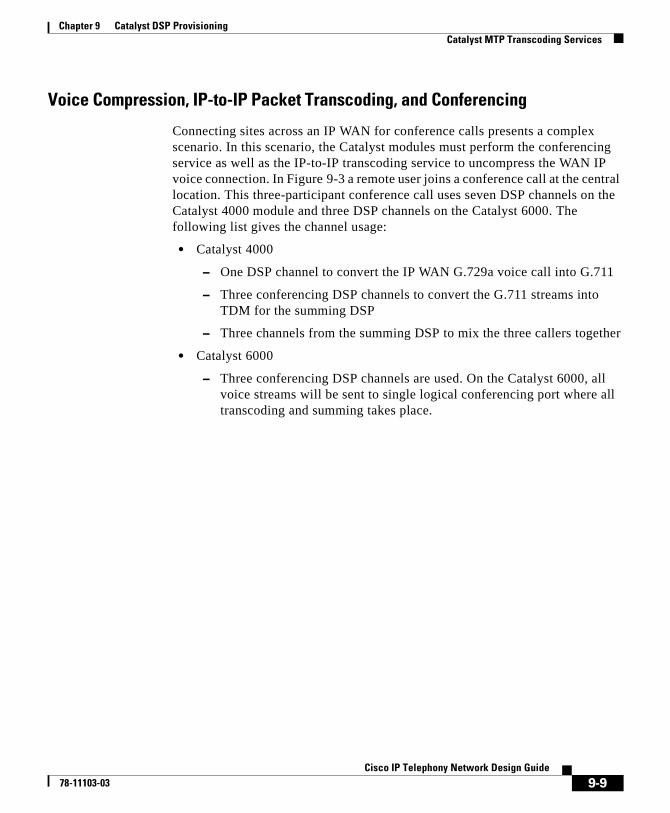
Chapter 9 Catalyst DSP ProvisioningCatalyst MTP Transcoding Services
Voice Compression, IP-to-IP Packet Transcoding, and Conferencing
Connecting sites across an IP WAN for conference calls presents a complex scenario. In this scenario, the Catalyst modules must perform the conferencing service as well as the IP-to-IP transcoding service to uncompress the WAN IP voice connection. In Figure 9-3 a remote user joins a conference call at the central location. This three-participant conference call uses seven DSP channels on the Catalyst 4000 module and three DSP channels on the Catalyst 6000. The following list gives the channel usage:
• Catalyst 4000
– One DSP channel to convert the IP WAN G.729a voice call into G.711
– Three conferencing DSP channels to convert the G.711 streams into TDM for the summing DSP
– Three channels from the summing DSP to mix the three callers together
• Catalyst 6000
– Three conferencing DSP channels are used. On the Catalyst 6000, all voice streams will be sent to single logical conferencing port where all transcoding and summing takes place.
9-9Cisco IP Telephony Network Design Guide
78-11103-03
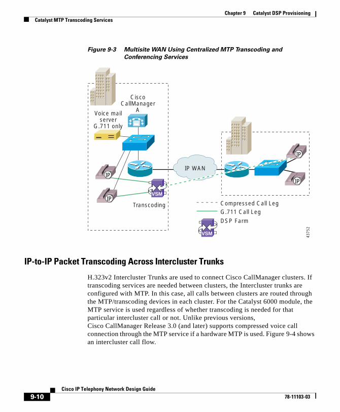
Chapter 9 Catalyst DSP ProvisioningCatalyst MTP Transcoding Services
Figure 9-3 Multisite WAN Using Centralized MTP Transcoding and
Conferencing Services
IP-to-IP Packet Transcoding Across Intercluster Trunks
H.323v2 Intercluster Trunks are used to connect Cisco CallManager clusters. If transcoding services are needed between clusters, the Intercluster trunks are configured with MTP. In this case, all calls between clusters are routed through the MTP/transcoding devices in each cluster. For the Catalyst 6000 module, the MTP service is used regardless of whether transcoding is needed for that particular intercluster call or not. Unlike previous versions, Cisco CallManager Release 3.0 (and later) supports compressed voice call connection through the MTP service if a hardware MTP is used. Figure 9-4 shows an intercluster call flow.
IP WAN
Compressed Call LegG.711 Call Leg
DSP Farm
CiscoCallManager
AVoice mailserver
G.711 only
IP
IP
IP
IP
VSM
VSM
Transcoding
4375
2
9-10Cisco IP Telephony Network Design Guide
78-11103-03
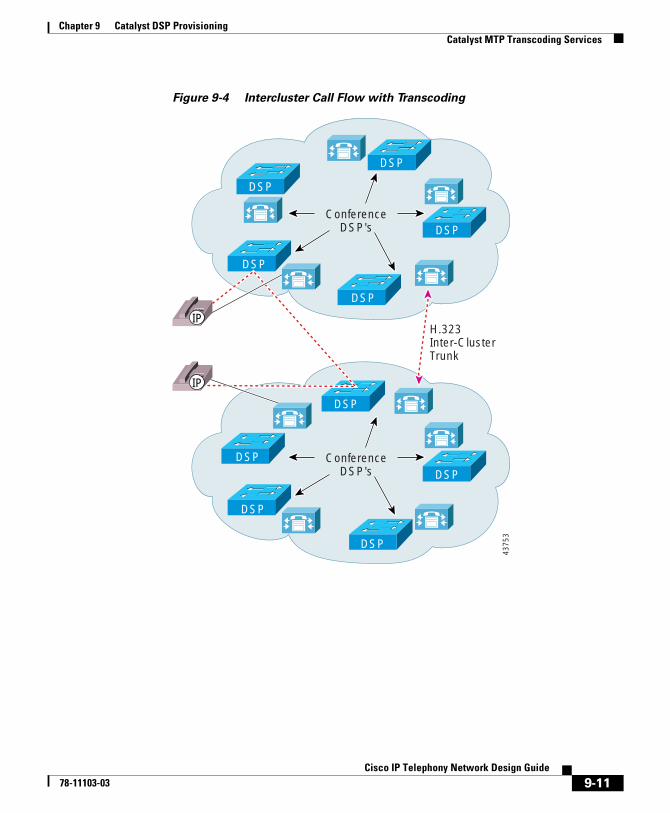
Chapter 9 Catalyst DSP ProvisioningCatalyst MTP Transcoding Services
Figure 9-4 Intercluster Call Flow with Transcoding
ConferenceDSP's
ConferenceDSP's
H.323Inter-ClusterTrunk
IP
IP
DSP
DSP
DSP
DSP
DSP
DSP
DSP
DSP
DSP
DSP
4375
3
9-11Cisco IP Telephony Network Design Guide
78-11103-03
Chapter 9 Catalyst DSP ProvisioningCatalyst MTP Transcoding Services
The following list gives intercluster MTP/Transcoding details:
• If transcoding is required between Cisco CallManager clusters, the H.323 Intercluster trunk must be configured with an MTP resource.
• All calls between Cisco CallManager clusters will go through MTPs.
• Outbound Intercluster calls will use an MTP/Transcoding resource from the Cisco CallManager from which the call originates.
• Inbound Intercluster call will use the MTP/Resource from the Cisco CallManager terminating the inbound Intercluster trunk.
• Additional DSP MTP/Transcoding resources should be allocated to Cisco CallManagers terminating H.323 Intercluster trunks
MTP Transcoding CaveatsThe following summary caveats apply to Catalyst MTP transcoding:
• Catalyst MTP transcoding service only support LBR codec-to-G.711 conversion, and vice versa. There is no support for LBR-to-LBR codec conversion.
• On the Catalyst 6000, transcoding services cannot cross port boundaries.
• Each Cisco CallManager must have its own MTP transcoding resource configured.
• If transcoding is required between Cisco CallManager clusters, the H.323 Intercluster trunk must be configured with an MTP resource. All calls between Cisco CallManager clusters will go through the MTPs.
• If all n MTP transcoding sessions are utilized, and an n + 1 connection is attempted, the next call will be completed without using the MTP transcoding resource. If this call attempted to use the software MTP function to provide supplementary services, the call would connect, but any attempt to use supplementary services would fail and could result in call disconnection. If the call attempted to use the transcoding features, the call would connect directly, but no audio would be heard.
See Table 9-1 for a list of transcoding capabilities for each module.
9-12Cisco IP Telephony Network Design Guide
78-11103-03
Chapter 9 Catalyst DSP ProvisioningCatalyst 4000 Voice Services
Catalyst 4000 Voice ServicesThe PSTN gateway and voice services module for the Catalyst 4003 and 4006 switches, supports three analog voice interface cards (VICs) with two ports each or one T1/E1 card with two ports and two analog VICs. The VIC interfaces can be provisioned in any combination of Foreign Exchange Office (FXO), Foreign Exchange Station (FXS), or Ear & Mouth (E&M). Additionally, when configured as an IP telephony gateway from the command line interface (CLI), this module can support conferencing and transcoding services.
The Catalyst 4000 voice gateway module can be configured in either toll bypass mode or gateway mode. However, the module’s conferencing and transcoding resources can be configured only in gateway mode. Once the gateway mode is enabled, the module’s 24 DSPs (4 SIMMs with 6 DSPs each) are automatically provisioned as follows:
• PSTN gateway: 96 channels of G.711 voice and
• Conferencing: 24 channels of G.711 conferencing and
• MTP transcoding: 16 channels of LBR-G.711 transcoding
Figure 9-5 shows a physical representation of the Catalyst 4000 voice gateway module in gateway mode.
9-13Cisco IP Telephony Network Design Guide
78-11103-03
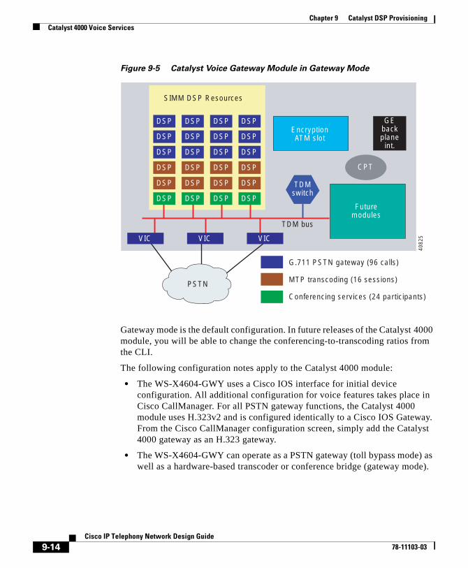
Chapter 9 Catalyst DSP ProvisioningCatalyst 4000 Voice Services
Figure 9-5 Catalyst Voice Gateway Module in Gateway Mode
Gateway mode is the default configuration. In future releases of the Catalyst 4000 module, you will be able to change the conferencing-to-transcoding ratios from the CLI.
The following configuration notes apply to the Catalyst 4000 module:
• The WS-X4604-GWY uses a Cisco IOS interface for initial device configuration. All additional configuration for voice features takes place in Cisco CallManager. For all PSTN gateway functions, the Catalyst 4000 module uses H.323v2 and is configured identically to a Cisco IOS Gateway. From the Cisco CallManager configuration screen, simply add the Catalyst 4000 gateway as an H.323 gateway.
• The WS-X4604-GWY can operate as a PSTN gateway (toll bypass mode) as well as a hardware-based transcoder or conference bridge (gateway mode).
VIC VIC VIC
TDMswitch
TDM bus
Futuremodules
CPT
EncryptionATM slot
GEbackplane
int.
PSTN
G.711 PSTN gateway (96 calls)
MTP transcoding (16 sessions)
Conferencing services (24 participants)
4082
5
SIMM DSP Resources
DSP
DSP
DSP
DSP
DSP
DSP
DSP
DSP
DSP
DSP
DSP
DSP
DSP
DSP
DSP
DSP
DSP
DSP
DSP
DSP
DSP
DSP
DSP
DSP
9-14Cisco IP Telephony Network Design Guide
78-11103-03
Chapter 9 Catalyst DSP ProvisioningCatalyst 6000 Voice Services
To configure this module as a DSP farm (gateway mode), enter one or both of the following CLI commands:
voicecard conferencevoicecard transcode
• The WS-X4604-GWY requires its own local IP address, in addition to the IP address for Cisco CallManager. It is also good practice to specify a loopback IP address for the local Signaling Connection Control Part (SCCP).
• A primary, secondary, and tertiary Cisco CallManager can be defined for both the conferencing services and MTP transcoding services.
Catalyst 6000 Voice ServicesThe WS-6608-T1 (or WS-6608-E1 for European countries) is the same module that provides T1 or E1 PSTN gateway support for the Catalyst 6000, as described in Chapter 4, “Gateway Selection.” This module has eight channel associated signaling (CAS) or PRI interfaces, each of which has its own CPU and DSPs. Once the card has been added from Cisco CallManager as a voice gateway, it can be configured as a conferencing or MTP transcoding node. Each port acts independently of the other ports on the module. Specifically, each port can be configured only as a PSTN gateway interface, a conferencing node, or an MTP transcoding node. In most configurations, a transcoding node would be configured for each conferencing node.
Note Conferencing and MTP transcoding services cannot cross port boundaries.
9-15Cisco IP Telephony Network Design Guide
78-11103-03
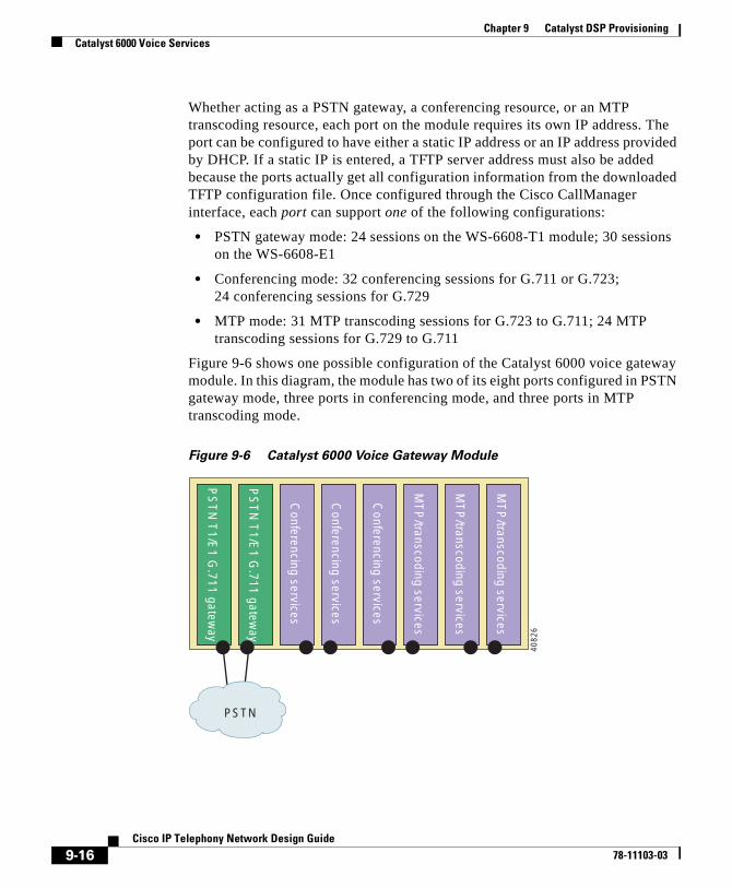
Chapter 9 Catalyst DSP ProvisioningCatalyst 6000 Voice Services
Whether acting as a PSTN gateway, a conferencing resource, or an MTP transcoding resource, each port on the module requires its own IP address. The port can be configured to have either a static IP address or an IP address provided by DHCP. If a static IP is entered, a TFTP server address must also be added because the ports actually get all configuration information from the downloaded TFTP configuration file. Once configured through the Cisco CallManager interface, each port can support one of the following configurations:
• PSTN gateway mode: 24 sessions on the WS-6608-T1 module; 30 sessions on the WS-6608-E1
• Conferencing mode: 32 conferencing sessions for G.711 or G.723; 24 conferencing sessions for G.729
• MTP mode: 31 MTP transcoding sessions for G.723 to G.711; 24 MTP transcoding sessions for G.729 to G.711
Figure 9-6 shows one possible configuration of the Catalyst 6000 voice gateway module. In this diagram, the module has two of its eight ports configured in PSTN gateway mode, three ports in conferencing mode, and three ports in MTP transcoding mode.
Figure 9-6 Catalyst 6000 Voice Gateway Module
PSTN
PS
TN
T1/E
1 G.711 gatew
ay
PS
TN
T1/E
1 G.711 gatew
ay
Conferencing services
Conferencing services
Conferencing services
MT
P/transcoding services
MT
P/transcoding services
MT
P/transcoding services
4082
6
9-16Cisco IP Telephony Network Design Guide
78-11103-03
Cisco IP T78-11103-03
C H A P T E R10
Migrating to an IP Telephony NetworkThis chapter explains how an enterprise can migrate from a conventional PBX and its adjunct systems, principally voice messaging, to an IP telephony network. Four migration models are presented, encompassing various feature sets, and the steps for achieving each are outlined.
This chapter contains the following major sections:
• Network Models, page 10-1
• PBX and Voice Messaging Interfaces and Protocols, page 10-2
• Simple IP Network Migration Sequence, page 10-3
• Reference Models for Migration Configurations, page 10-6
Network ModelsConventional voice networks to be migrated to IP networks contain, at a minimum, a single PBX and often several PBXs, which can be geographically dispersed. A network of PBXs can use a specialized, proprietary networking protocol to provide features across the different PBXs.
If voice messaging is a part of the voice network, the voice messaging systems are connected to the PBX using a protocol and hardware interface. If there are several voice messaging systems in the network, they might be networked to appear to the user as a single messaging system. Generally the protocols used to connect to and network between voice messaging systems are proprietary. See Figure 10-1.
10-1elephony Network Design Guide
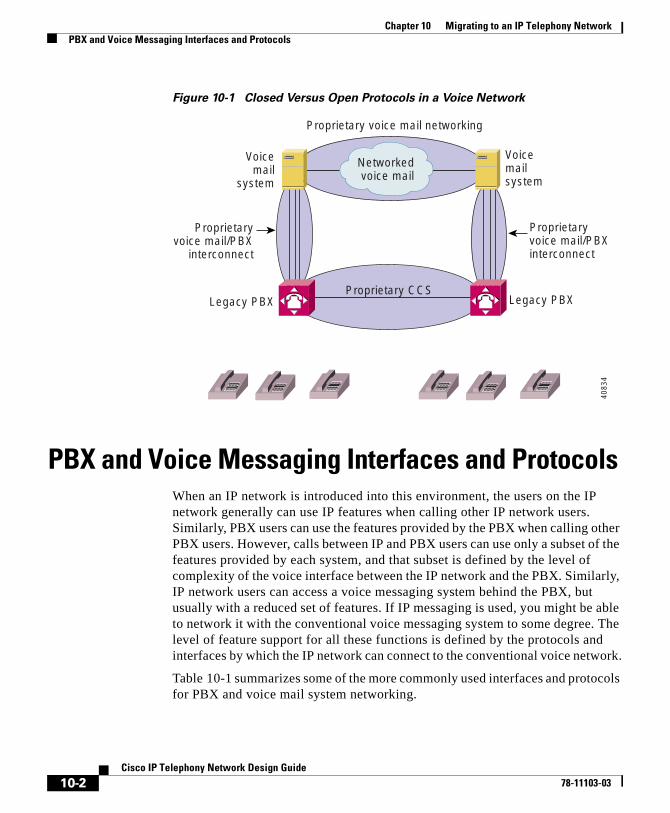
Chapter 10 Migrating to an IP Telephony NetworkPBX and Voice Messaging Interfaces and Protocols
Figure 10-1 Closed Versus Open Protocols in a Voice Network
PBX and Voice Messaging Interfaces and ProtocolsWhen an IP network is introduced into this environment, the users on the IP network generally can use IP features when calling other IP network users. Similarly, PBX users can use the features provided by the PBX when calling other PBX users. However, calls between IP and PBX users can use only a subset of the features provided by each system, and that subset is defined by the level of complexity of the voice interface between the IP network and the PBX. Similarly, IP network users can access a voice messaging system behind the PBX, but usually with a reduced set of features. If IP messaging is used, you might be able to network it with the conventional voice messaging system to some degree. The level of feature support for all these functions is defined by the protocols and interfaces by which the IP network can connect to the conventional voice network.
Table 10-1 summarizes some of the more commonly used interfaces and protocols for PBX and voice mail system networking.
Legacy PBX
Voicemail
system
Proprietary voice mail networking
Proprietary CCS
Voicemailsystem
Legacy PBX
Networked voice mail
Proprietaryvoice mail/PBXinterconnect
Proprietaryvoice mail/PBX
interconnect
4083
4
10-2Cisco IP Telephony Network Design Guide
78-11103-03
Chapter 10 Migrating to an IP Telephony NetworkSimple IP Network Migration Sequence
While conventional voice networks use proprietary, closed protocols internally, they can be connected to IP networks only through open protocols. This would also be the case when networking equipment from different vendors. PRI (or QSIG) between PBXs, analog Simplified Message Desk Interface (SMDI) between PBXs and voice mail systems, and Audio Messaging Interchange Specification (AMIS) between voice systems are the most powerful interfaces available.
Simple IP Network Migration SequenceThe following three figures illustrate the phases in migrating from a conventional voice network to an all-IP system. Figure 10-2 shows the initial conventional voice network.
Table 10-1 Interfaces and Protocols for PBX and Voice Mail System Networking
Vendor PBX to PBX ProtocolsPBX to Voice Mail Interfaces
Voice Mail to Voice Mail Networking
Cisco PRI, QSID, CAS SMDI, analog AMIS-A1
1. Cisco supports AMIS-A on Cisco uOne beginning with release 5.0E.
Avaya PRI, DCS, QSIG Digital set emulation
Proprietary, X.25/C-LAN
Octelnet
AUDIX Digital Networking
AMIS-A
Nortel PRI, MCDN, DPNSS, QSIG
Proprietary (IVMS) Meridian Mail Networking
VPIM
AMIS-A
Siemens PRI, CorNet, DPNSS, QSIG
BRI with proprietary extensions
PhoneMail Long Distance Networking (LDN)
AMIS-A
Alcatel PRI, ABC, QSIG unknown unknown
NEC PRI, CCIS, QSIG Proprietary Message Center Interface (MCI)
unknown
10-3Cisco IP Telephony Network Design Guide
78-11103-03
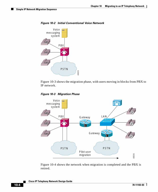
Chapter 10 Migrating to an IP Telephony NetworkSimple IP Network Migration Sequence
Figure 10-2 Initial Conventional Voice Network
Figure 10-3 shows the migration phase, with users moving in blocks from PBX to IP network.
Figure 10-3 Migration Phase
Figure 10-4 shows the network when migration is completed and the PBX is retired.
PSTN
PBX
Voicemessaging
system
4083
5
PSTN PSTN
PBX LAN
Gateway
Pilot usermigration
Gateway
Voicemessaging
system
V
V
IP
IP
IP40
836
10-4Cisco IP Telephony Network Design Guide
78-11103-03
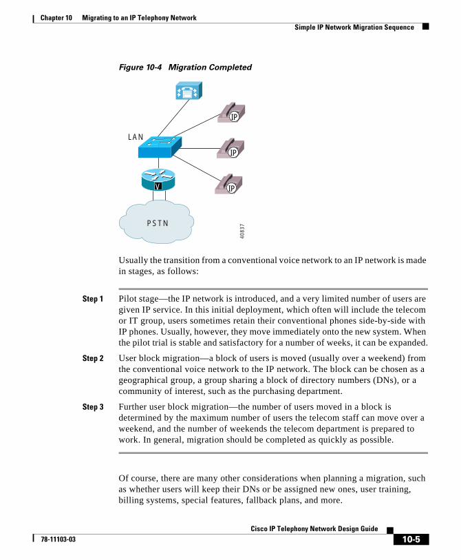
Chapter 10 Migrating to an IP Telephony NetworkSimple IP Network Migration Sequence
Figure 10-4 Migration Completed
Usually the transition from a conventional voice network to an IP network is made in stages, as follows:
Step 1 Pilot stage—the IP network is introduced, and a very limited number of users are given IP service. In this initial deployment, which often will include the telecom or IT group, users sometimes retain their conventional phones side-by-side with IP phones. Usually, however, they move immediately onto the new system. When the pilot trial is stable and satisfactory for a number of weeks, it can be expanded.
Step 2 User block migration—a block of users is moved (usually over a weekend) from the conventional voice network to the IP network. The block can be chosen as a geographical group, a group sharing a block of directory numbers (DNs), or a community of interest, such as the purchasing department.
Step 3 Further user block migration—the number of users moved in a block is determined by the maximum number of users the telecom staff can move over a weekend, and the number of weekends the telecom department is prepared to work. In general, migration should be completed as quickly as possible.
Of course, there are many other considerations when planning a migration, such as whether users will keep their DNs or be assigned new ones, user training, billing systems, special features, fallback plans, and more.
PSTN
LAN
V
IP
IP
IP
4083
7
10-5Cisco IP Telephony Network Design Guide
78-11103-03
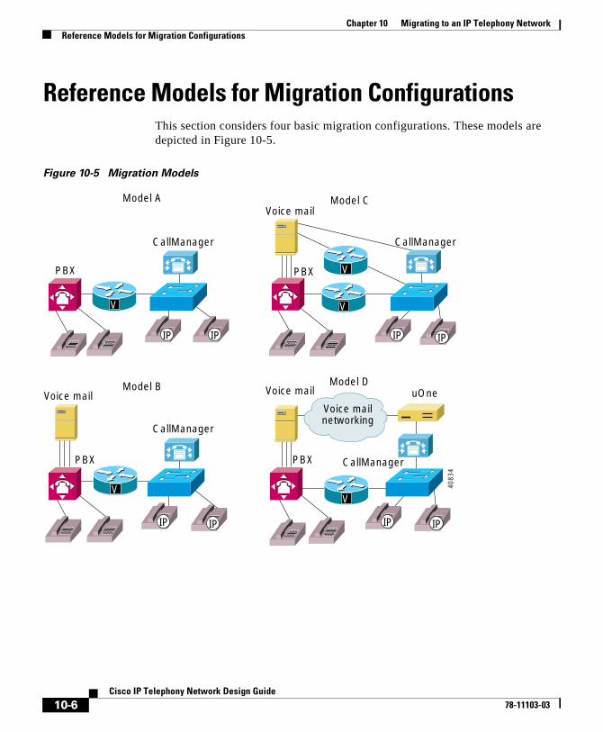
Chapter 10 Migrating to an IP Telephony NetworkReference Models for Migration Configurations
Reference Models for Migration ConfigurationsThis section considers four basic migration configurations. These models are depicted in Figure 10-5.
Figure 10-5 Migration Models
PBX
Voice mail
CallManager
Model A
PBX
CallManager
Model B
PBX
Voice mail
CallManager
Model C
PBX CallManager
uOneModel D
Voice mail
Voice mailnetworking
VV
V V
V
IP IP IP IP
IP IP IP IP
4083
4
10-6Cisco IP Telephony Network Design Guide
78-11103-03
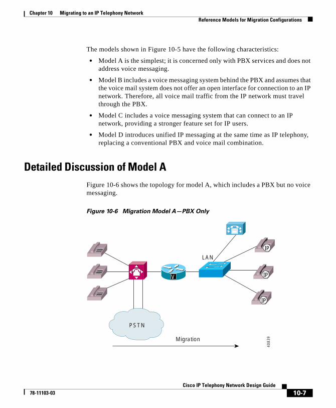
Chapter 10 Migrating to an IP Telephony NetworkReference Models for Migration Configurations
The models shown in Figure 10-5 have the following characteristics:
• Model A is the simplest; it is concerned only with PBX services and does not address voice messaging.
• Model B includes a voice messaging system behind the PBX and assumes that the voice mail system does not offer an open interface for connection to an IP network. Therefore, all voice mail traffic from the IP network must travel through the PBX.
• Model C includes a voice messaging system that can connect to an IP network, providing a stronger feature set for IP users.
• Model D introduces unified IP messaging at the same time as IP telephony, replacing a conventional PBX and voice mail combination.
Detailed Discussion of Model AFigure 10-6 shows the topology for model A, which includes a PBX but no voice messaging.
Figure 10-6 Migration Model A—PBX Only
PSTN
LAN
Migration
V
IP
IP
IP
4083
9
10-7Cisco IP Telephony Network Design Guide
78-11103-03
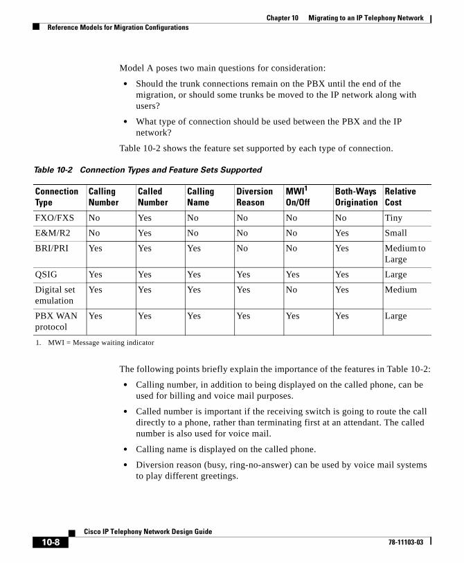
Chapter 10 Migrating to an IP Telephony NetworkReference Models for Migration Configurations
Model A poses two main questions for consideration:
• Should the trunk connections remain on the PBX until the end of the migration, or should some trunks be moved to the IP network along with users?
• What type of connection should be used between the PBX and the IP network?
Table 10-2 shows the feature set supported by each type of connection.
The following points briefly explain the importance of the features in Table 10-2:
• Calling number, in addition to being displayed on the called phone, can be used for billing and voice mail purposes.
• Called number is important if the receiving switch is going to route the call directly to a phone, rather than terminating first at an attendant. The called number is also used for voice mail.
• Calling name is displayed on the called phone.
• Diversion reason (busy, ring-no-answer) can be used by voice mail systems to play different greetings.
Table 10-2 Connection Types and Feature Sets Supported
Connection Type
CallingNumber
CalledNumber
CallingName
DiversionReason
MWI1
On/Off
1. MWI = Message waiting indicator
Both-WaysOrigination
RelativeCost
FXO/FXS No Yes No No No No Tiny
E&M/R2 No Yes No No No Yes Small
BRI/PRI Yes Yes Yes No No Yes Medium to Large
QSIG Yes Yes Yes Yes Yes Yes Large
Digital set emulation
Yes Yes Yes Yes No Yes Medium
PBX WAN protocol
Yes Yes Yes Yes Yes Yes Large
10-8Cisco IP Telephony Network Design Guide
78-11103-03
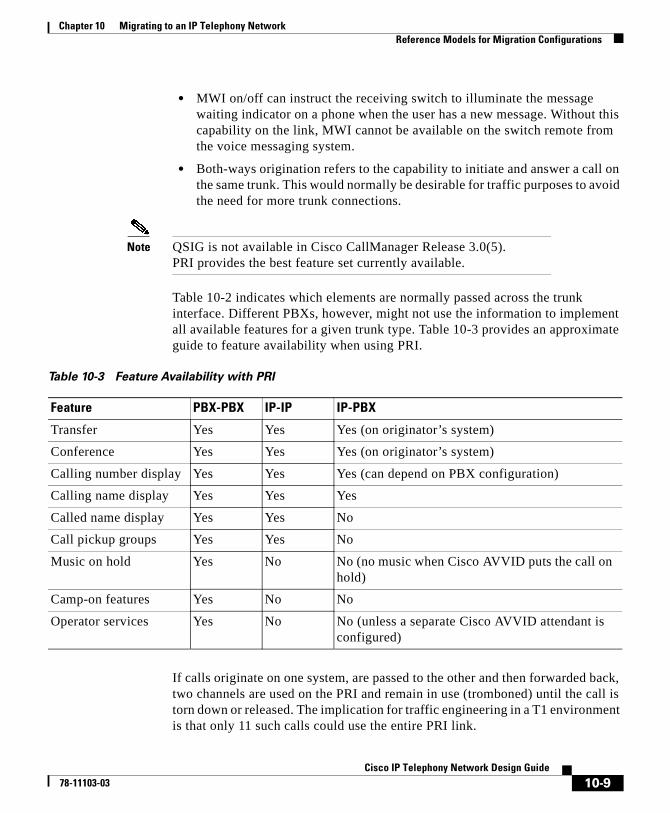
Chapter 10 Migrating to an IP Telephony NetworkReference Models for Migration Configurations
• MWI on/off can instruct the receiving switch to illuminate the message waiting indicator on a phone when the user has a new message. Without this capability on the link, MWI cannot be available on the switch remote from the voice messaging system.
• Both-ways origination refers to the capability to initiate and answer a call on the same trunk. This would normally be desirable for traffic purposes to avoid the need for more trunk connections.
Note QSIG is not available in Cisco CallManager Release 3.0(5). PRI provides the best feature set currently available.
Table 10-2 indicates which elements are normally passed across the trunk interface. Different PBXs, however, might not use the information to implement all available features for a given trunk type. Table 10-3 provides an approximate guide to feature availability when using PRI.
If calls originate on one system, are passed to the other and then forwarded back, two channels are used on the PRI and remain in use (tromboned) until the call is torn down or released. The implication for traffic engineering in a T1 environment is that only 11 such calls could use the entire PRI link.
Table 10-3 Feature Availability with PRI
Feature PBX-PBX IP-IP IP-PBX
Transfer Yes Yes Yes (on originator’s system)
Conference Yes Yes Yes (on originator’s system)
Calling number display Yes Yes Yes (can depend on PBX configuration)
Calling name display Yes Yes Yes
Called name display Yes Yes No
Call pickup groups Yes Yes No
Music on hold Yes No No (no music when Cisco AVVID puts the call on hold)
Camp-on features Yes No No
Operator services Yes No No (unless a separate Cisco AVVID attendant is configured)
10-9Cisco IP Telephony Network Design Guide
78-11103-03
Chapter 10 Migrating to an IP Telephony NetworkReference Models for Migration Configurations
If the trunks remain on the PBX, so that billing can be done at one point, it can be difficult to identify IP-originated calls by calling number.
The following configuration steps are required for the type A system:
Step 1 Configure the PRI link.
a. Add PRI gateway in Cisco CallManager and configure.
b. Add PBX PRI card and cable to IP network, and configure PRI on PBX.
c. Add Cisco CallManager route group to steer outgoing calls to the PRI trunk.
Step 2 Migrate each user.
a. Delete phone in PBX.
b. Modify PBX trunk routes to steer user calls to the IP network.
c. Add user phones in Cisco CallManager.
Step 3 Move PSTN trunks from PBX to IP network.
a. Delete trunks and routes from the PBX database.
b. Add trunk groups on the PBX to steer outgoing calls to the IP network.
c. Configure IP gateway hardware and software.
d. Move trunk connections to IP network.
e. Configure trunk groups and routes in Cisco CallManager.
f. Configure Call Detail Recording (CDR) for the IP network.
This configuration scenario assumes that users retain the same DNs after the migration and that trunks are moved after the users have migrated. Otherwise, it would be possible to preconfigure the IP phones and to allow users to have two working phones on their desks throughout the migration period. However, most users with Direct Inward Dialing (DID) service want to keep their original DN.
10-10Cisco IP Telephony Network Design Guide
78-11103-03
Chapter 10 Migrating to an IP Telephony NetworkReference Models for Migration Configurations
The following list summarizes the cost of the type A system:
The following list summarizes the pros and cons of the type A system:
Hardware Software
• PRI gateway for IP network
• PRI card on PBX
• Nothing extra on Cisco CallManager
• PRI software on PBX
Pros Cons
• Easy and inexpensive to implement
• Minimal reconfiguration of the PBX is needed.
• Without QSIG, display set users in particular will notice a lack of feature support on IP-PBX calls.
• Billing is difficult to reconcile across the two systems.
10-11Cisco IP Telephony Network Design Guide
78-11103-03
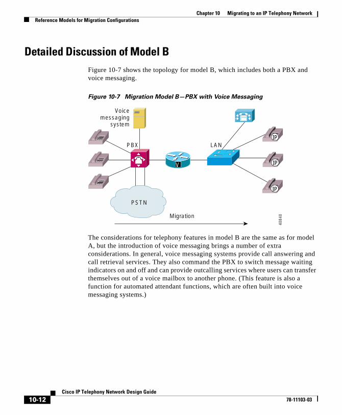
Chapter 10 Migrating to an IP Telephony NetworkReference Models for Migration Configurations
Detailed Discussion of Model BFigure 10-7 shows the topology for model B, which includes both a PBX and voice messaging.
Figure 10-7 Migration Model B—PBX with Voice Messaging
The considerations for telephony features in model B are the same as for model A, but the introduction of voice messaging brings a number of extra considerations. In general, voice messaging systems provide call answering and call retrieval services. They also command the PBX to switch message waiting indicators on and off and can provide outcalling services where users can transfer themselves out of a voice mailbox to another phone. (This feature is also a function for automated attendant functions, which are often built into voice messaging systems.)
PSTN
PBX LAN
Migration
Voicemessaging
system
V
IP
IP
IP
4084
0
10-12Cisco IP Telephony Network Design Guide
78-11103-03
Chapter 10 Migrating to an IP Telephony NetworkReference Models for Migration Configurations
There are three important requirements for IP telephony applications in model B networks:
• When a party calls an IP phone and the call is forwarded to voice mail, the caller should hear the IP user’s greeting for call answering. This can be a problem because, if the PBX sees the call from the IP network as a trunk call, it might not preserve the original called number on the call. In this case, the caller would hear the general greeting (for example, “Welcome to Cisco”).
• When IP users press their message key, they should be prompted for their password. That is, the voice messaging system should be passed the information to associate the call with a user’s calling number to identify the right mailbox.
• The MWI on the IP phone should be switched on and off to reflect the state of the user’s voice mailbox.
In general, none of these three features can be achieved in a simple type B system, where the link between the IP network and the PBX is PRI, and the configuration sequence for a type A system is used. However, by using a more complex configuration change on the PBX, the first two features can be achieved.
This model B implementation essentially requires configuring a phantom telephone user on the PBX. For ease of maintenance, it is convenient to choose a block of DNs that relate to the IP user’s DN. For example, for IP DNs 32XX, create equivalent PBX phantom users of 52XX. The phantom phone is permanently forwarded to voice messaging. On the IP network, the phone is configured to forward to the phantom DN for voice messaging, with a speed-dial key on the phone to dial the phantom DN. This key can be labeled for voice messaging (except on the Cisco IP Phone 7960). Now, both call answering and message retrieval calls go straight to the user’s voice mailbox.
There are drawbacks with this workaround. It requires extra administration and user effort, and the IP user’s voice mailbox must have a different number from the DN of the phone. Also, on some PBXs, it is necessary to configure real line cards for the phantom phones. Perhaps it would be easier to administer if the user’s PBX DN were retained on the PBX as the phantom DN during migration, and the user could be assigned a new DN on the IP network. The original DID (DDI) could be retained if the trunks are switched to the IP network and an incoming digit translation is used. However, this would perpetuate a situation in which the user’s DN, DID (DDI), and voice mailbox number do not match.
10-13Cisco IP Telephony Network Design Guide
78-11103-03
Chapter 10 Migrating to an IP Telephony NetworkReference Models for Migration Configurations
It is not possible for the voice messaging system to select the proper greeting (“busy”, “no answer,” or “all calls”) for IP users because that information is not sent across the PRI to the PBX.
It is also not possible for MWI information to traverse the PRI from the PBX to the IP network. The message indication feature would, therefore, not be available to IP users in a type B system.
The following configuration steps for the type B system include the workaround just described:
Step 1 Configure PRI link—same as for type A system.
Step 2 Migrate each user—same as for type A system.
Step 3 Configure the phantom DN on the PBX.
a. Add the phone to the PBX and forward to voice mail.
b. Configure speed-dial key on IP phone.
c. Modify the IP trunk routes to send forwarded calls to PBX.
Step 4 Move PSTN trunks from PBX to IP network—same as for type A system.
The following list summarizes the cost of the type B system:
Hardware Software
• PRI gateway for IP network
• PRI card on PBX
• Nothing extra on Cisco CallManager
• PRI software on PBX
10-14Cisco IP Telephony Network Design Guide
78-11103-03
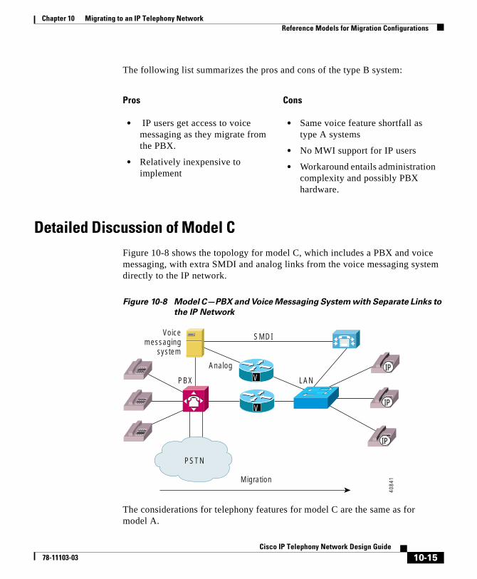
Chapter 10 Migrating to an IP Telephony NetworkReference Models for Migration Configurations
The following list summarizes the pros and cons of the type B system:
Detailed Discussion of Model CFigure 10-8 shows the topology for model C, which includes a PBX and voice messaging, with extra SMDI and analog links from the voice messaging system directly to the IP network.
Figure 10-8 Model C—PBX and Voice Messaging System with Separate Links to
the IP Network
The considerations for telephony features for model C are the same as for model A.
Pros Cons
• IP users get access to voice messaging as they migrate from the PBX.
• Relatively inexpensive to implement
• Same voice feature shortfall as type A systems
• No MWI support for IP users
• Workaround entails administration complexity and possibly PBX hardware.
PSTN
PBX LAN
Migration
Voicemessaging
system
V
VIP
IP
IP
SMDI
Analog
4084
1
10-15Cisco IP Telephony Network Design Guide
78-11103-03
Chapter 10 Migrating to an IP Telephony NetworkReference Models for Migration Configurations
For voice messaging, model C fixes the drawbacks of model B. Because the voice messaging system deals with the PBX and the IP network as separate systems, calls that reach the IP network can be forwarded directly into voice messaging without being routed back through the PBX. This should allow all normal call answering and message retrieval functions. In addition, since the voice messaging system is connected to the IP network directly with SMDI, the voice messaging system can send MWI on or off messages to the IP network for appropriate control of the indicators on the IP phones.
For this model to work, the voice messaging system must meet two qualifications. First, it must be able to support two PBXs simultaneously in its database and associate each mailbox with the correct PBX so that it can send MWI information on the correct link. Second, it must be possible to connect the IP network physically to the voice messaging system while maintaining the existing link to the PBX. Not all voice messaging systems can support this type of integration, and customers should therefore check with their voice mail vendor before proceeding with this type of scenario.
The following configuration steps are required for the type C system:
Step 1 Configure PRI link—same as for type A system.
Step 2 Migrate each user—same as for type A system.
Step 3 Migrate each user in voice mail—change the mailbox to reference the link to the IP network rather than the PBX.
Step 4 Move PSTN trunks from PBX to IP network—same as for type A system.
10-16Cisco IP Telephony Network Design Guide
78-11103-03
Chapter 10 Migrating to an IP Telephony NetworkReference Models for Migration Configurations
The following list summarizes the cost of the type C system:
The following list summarizes the pros and cons of the type C system:
Hardware Software
• PRI gateway for IP network
• PRI card on PBX
• Analog gateways for IP network for voice messaging
• Analog cards on voice messaging system
• SMDI interface on voice messaging system
• Nothing extra on Cisco CallManager
• PRI software on PBX
Pros Cons
• IP users can maintain access to voice messaging as they migrate from the PBX.
• Relatively inexpensive to implement
• Same voice feature shortfall as type A systems
• More complex administration of voice messaging system than the type B system, but simpler administration of the PBX
• Ideally, DID (DDI) trunks would be moved from PBX to IP network to follow the users. Otherwise, some features might be lost.
10-17Cisco IP Telephony Network Design Guide
78-11103-03
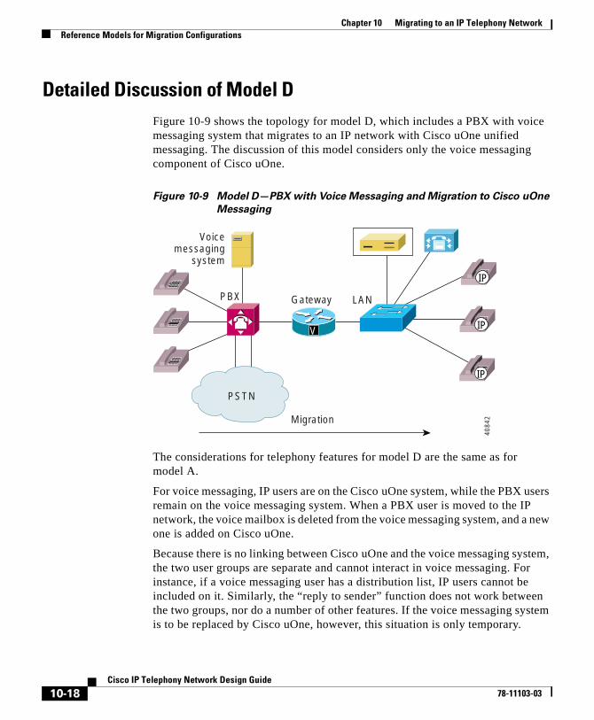
Chapter 10 Migrating to an IP Telephony NetworkReference Models for Migration Configurations
Detailed Discussion of Model DFigure 10-9 shows the topology for model D, which includes a PBX with voice messaging system that migrates to an IP network with Cisco uOne unified messaging. The discussion of this model considers only the voice messaging component of Cisco uOne.
Figure 10-9 Model D—PBX with Voice Messaging and Migration to Cisco uOne
Messaging
The considerations for telephony features for model D are the same as for model A.
For voice messaging, IP users are on the Cisco uOne system, while the PBX users remain on the voice messaging system. When a PBX user is moved to the IP network, the voice mailbox is deleted from the voice messaging system, and a new one is added on Cisco uOne.
Because there is no linking between Cisco uOne and the voice messaging system, the two user groups are separate and cannot interact in voice messaging. For instance, if a voice messaging user has a distribution list, IP users cannot be included on it. Similarly, the “reply to sender” function does not work between the two groups, nor do a number of other features. If the voice messaging system is to be replaced by Cisco uOne, however, this situation is only temporary.
PSTN
PBX LAN
Migration
Gateway
Voicemessaging
system
V
IP
IP
IP
4084
2
10-18Cisco IP Telephony Network Design Guide
78-11103-03
Chapter 10 Migrating to an IP Telephony NetworkReference Models for Migration Configurations
Audio Messaging Interchange Specification Analog (AMIS-A) networking of voice messaging systems is planned for a future release of Cisco uOne. When it is available, if both Cisco uOne and the voice messaging system are configured for networking, it will be possible to provide basic voice mail messaging functionality across the systems (provided the voice messaging system supports AMIS-A).
The following configuration steps are required for the type D system:
Step 1 Configure PRI link—same as for type A system.
Step 2 Migrate each user—same as for type A system.
Step 3 Migrate each user in voice mail.
a. Delete mailbox on voice messaging system.
b. Add users in Cisco uOne.
Step 4 Move PSTN trunks from PBX to IP network—same as for type A system.
The following list summarizes the cost of the type D system:
Hardware Software
• PRI gateway for IP network
• PRI card on PBX
• Nothing extra on Cisco CallManager
• PRI software on PBX
10-19Cisco IP Telephony Network Design Guide
78-11103-03
Chapter 10 Migrating to an IP Telephony NetworkCisco Digital PBX Adapter (DPA)
The following list summarizes the pros and cons of the type D system:
Cisco Digital PBX Adapter (DPA)The Cisco Digital PBX Adapter 7630 (DPA 7630) enables you to integrate Cisco CallManager systems with Octel voice mail systems, which might also be connected to a Lucent Definity PBX system. You might want to do this if you have these existing third-party telephony systems in your network, and you want to continue to use them along with your Cisco IP telephony system.
For example, you can ensure that features such as message waiting indicators (MWI) for Octel voice messages are properly set on Cisco IP Phones (connected to Cisco CallManager) and traditional telephony phones (connected to Lucent PBX systems).
Using the DPA 7630, you can integrate the following systems:
• Cisco CallManager
• Octel 200 and 300 voice messaging systems (using APIC integration)
• Octel 250 and 350 voice messaging systems (using FLT-A/PIC-A integration)
• Lucent Definity G3 PBX systems
The following sections provide you with an overview of the DPA 7630 and its interactions with the other components in traditional and IP telephony networks:
• Understanding How the DPA 7630 Works, page 10-21
• Choosing an Integration Mode, page 10-22
Pros Cons
• IP users get access to voice messaging as they migrate from the PBX.
• Relatively inexpensive to implement
• Same voice feature shortfall as type A systems
• No voice mail interaction between voice messaging and Cisco uOne
• Ideally, DID (DDI) trunks would be moved from PBX to IP network to follow the users. Otherwise, some features might be lost.
10-20Cisco IP Telephony Network Design Guide
78-11103-03
Chapter 10 Migrating to an IP Telephony NetworkCisco Digital PBX Adapter (DPA)
Understanding How the DPA 7630 WorksThe Cisco DPA 7630 enables you to integrate your existing Octel voice mail and Lucent PBX systems with Cisco CallManager. The DPA 7630 functions by emulating digital phones or a PBX system. This capability allows it to appear like these devices to Cisco CallManager, Octel, and Lucent systems.
Why is the DPA 7630 Needed?
If you want to migrate your telephony system from a Lucent Definity G3 PBX to Cisco CallManager, you must decide whether to do a complete cutover to Cisco CallManager or to migrate slowly. If you do a complete cutover to Cisco CallManager and Cisco uOne (Cisco’s voice mail solution), you do not need the DPA 7630. However, if you are slowly migrating your systems, you might want to maintain some phones on the Lucent PBX while installing new phones on the Cisco CallManager system. You might want to use your existing Octel voice mail system with your Cisco CallManager system. In these cases, the DPA 7630 can assist your migration to Cisco CallManager.
Can I Just Use SMDI?
One difficulty with migration is that voice mail systems such as Octel were designed to integrate to only one PBX at a time. To resolve this difficulty, many people use Simplified Message Desk Interface (SMDI), which was designed to enable integrated voice mail services to multiple clients.
However, to use SMDI, the voice mail system must meet several qualifications:
• It must have sufficient database capacity to support two PBX systems simultaneously and to associate each mailbox with the correct PBX in order to send MWI information on the correct link.
• It must be possible to physically connect the IP network to the voice messaging system while maintaining the existing physical link to the PBX.
• It must support analog integration. SMDI is primarily an analog technology.
Additionally, SMDI requires reconfiguration of your existing telephony network.
10-21Cisco IP Telephony Network Design Guide
78-11103-03
Chapter 10 Migrating to an IP Telephony NetworkCisco Digital PBX Adapter (DPA)
What If I Cannot Use SMDI?
SMDI might not be an option for you, particularly if you are using a digital interface on your Octel systems. Octel systems with digital line cards emulate digital phones, appearing to the PBX as digital extensions, referred to as per-port or PBX Integration Cards (PICs). On PIC systems, the voice and data are on the same path. MWI is set and cleared via feature access codes on dedicated ports. Because these PIC ports use proprietary interfaces, you cannot use standard interfaces to connect them to the Cisco CallManager system.
However, the DPA 7630 can translate these interfaces to enable communication among the Octel, Lucent, and Cisco CallManager systems. Depending on the needs of your network, you can choose among several different integration methods.
Choosing an Integration ModeSelect an integration mode based on the needs of your IP telephony network:
• Simple—Used to integrate Cisco CallManager with existing Octel voice mail systems. In this solution, you are not using a Lucent PBX system, or you are choosing not to integrate it with your IP telephony system. See the “Using the Simple Integration Mode” section on page 10-23.
• Hybrid—Used to integrate Cisco CallManager with existing Octel voice mail systems and Lucent PBX systems. See the “Using the Hybrid Integration Mode” section on page 10-24.
• Multiple—Used to integrate the systems in larger networks using a combination of simple and hybrid scenarios, which requires multiple DPA 7630 systems. See the “Using the Multiple Integration Mode” section on page 10-25.
10-22Cisco IP Telephony Network Design Guide
78-11103-03
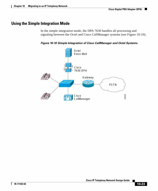
Chapter 10 Migrating to an IP Telephony NetworkCisco Digital PBX Adapter (DPA)
Using the Simple Integration Mode
In the simple integration mode, the DPA 7630 handles all processing and signaling between the Octel and Cisco CallManager systems (see Figure 10-10).
Figure 10-10 Simple Integration of Cisco CallManager and Octel Systems
Gateway
CiscoCallManager
Cisco7630 DPA
OctelVoice Mail
4909
9
PSTN
IP
IP
10-23Cisco IP Telephony Network Design Guide
78-11103-03
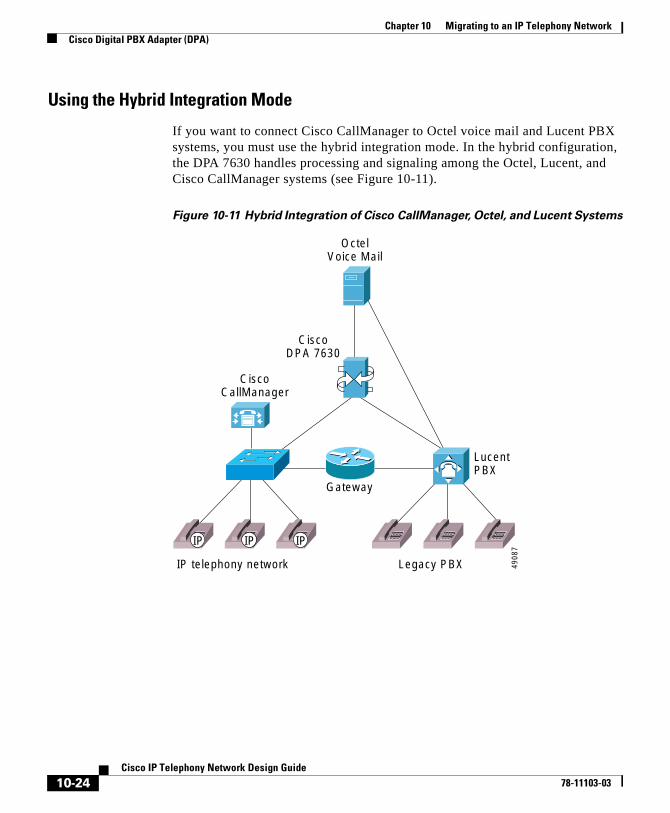
Chapter 10 Migrating to an IP Telephony NetworkCisco Digital PBX Adapter (DPA)
Using the Hybrid Integration Mode
If you want to connect Cisco CallManager to Octel voice mail and Lucent PBX systems, you must use the hybrid integration mode. In the hybrid configuration, the DPA 7630 handles processing and signaling among the Octel, Lucent, and Cisco CallManager systems (see Figure 10-11).
Figure 10-11 Hybrid Integration of Cisco CallManager, Octel, and Lucent Systems
Gateway
CiscoCallManager
IP telephony network Legacy PBX
Lucent PBX
CiscoDPA 7630
OctelVoice Mail
4908
7
IP IP IP
10-24Cisco IP Telephony Network Design Guide
78-11103-03
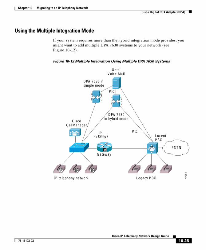
Chapter 10 Migrating to an IP Telephony NetworkCisco Digital PBX Adapter (DPA)
Using the Multiple Integration Mode
If your system requires more than the hybrid integration mode provides, you might want to add multiple DPA 7630 systems to your network (see Figure 10-12).
Figure 10-12 Multiple Integration Using Multiple DPA 7630 Systems
PIC
DPA 7630in hybrid mode
DPA 7630 insimple mode
IP(Skinny)
PIC
PSTN
Gateway
CiscoCallManager
IP telephony network Legacy PBX
Lucent PBX
OctelVoice Mail
4908
8IP IP IP
V
10-25Cisco IP Telephony Network Design Guide
78-11103-03
Chapter 10 Migrating to an IP Telephony NetworkCisco Digital PBX Adapter (DPA)
You might add multiple DPA 7630 systems to your network if you are using the DPA 7630 to capacity, and you need the following capability:
• More than eight MWI ports to the Lucent system.
If you need more MWI ports to the Lucent system, add an additional DPA 7630 in hybrid mode. However, you cannot use all 24 ports for Lucent MWIs. You must configure the DPA 7630 by following the guidelines for the hybrid integration, using up to eight ports.
• More than eight ports for call processing between the Cisco CallManager and Octel systems.
If you need more than eight ports for handling calls between Cisco CallManager and the Octel systems, add another DPA 7630 in simple mode. This would provide another full 24 ports dedicated to call processing between the two systems.
Alternatively, you might also use an additional DPA 7630 to achieve a higher level of fault tolerance. In this situation, you can use two DPA 7630 devices in parallel, sharing the MWI lines between the two units. If one unit fails, the Octel would use only the lines that were still operational, allowing voice mail to function normally.
10-26Cisco IP Telephony Network Design Guide
78-11103-03
Cisco IP T78-11103-03
C H A P T E R 11
Network ManagementThis chapter introduces two network management tools available for Cisco AVVID enterprise deployment models:
• Remote Serviceability for Cisco CallManager, page 11-1
• CiscoWorks2000 Voice Management Features, page 11-8
This chapter contains a brief overview of network management and the CiscoWorks2000 system architecture, including its capability to manage Cisco AVVID components in enterprise networks.
Remote Serviceability for Cisco CallManagerNetwork management tools, if properly deployed, can provide the network administrator with a complete view into any enterprise network. With the advent of converged networks, it is imperative to have network management systems enable the following capabilities, at a minimum:
• Network discovery and topology maps
• Inventory control and configuration management of networked nodes
• Report generation, system logging, and analysis of the respective data
Cisco CallManager Remote Serviceability and CiscoWorks2000 provide the above capabilities, as well as other mechanisms, which enable visibility into the health and availability of the Cisco AVVID network. Considerable management features have been added, starting with Cisco CallManager Release 3.0, to permit visibility into the operation and reporting capability of a Cisco AVVID network.
11-1elephony Network Design Guide
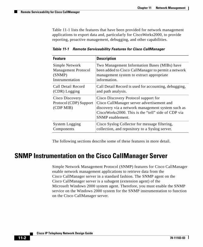
Chapter 11 Network ManagementRemote Serviceability for Cisco CallManager
Table 11-1 lists the features that have been provided for network management applications to export data and, particularly for CiscoWorks2000, to provide reporting, proactive management, debugging, and other capabilities.
The following sections describe some of these features in more detail.
SNMP Instrumentation on the Cisco CallManager ServerSimple Network Management Protocol (SNMP) features for Cisco CallManager enable network management applications to retrieve data from the Cisco CallManager server in a standard fashion. The SNMP agent on the Cisco CallManager server is a subagent (extension agent) of the Microsoft Windows 2000 system agent. Therefore, you must enable the SNMP service on the Windows 2000 system for the SNMP instrumentation to function on the Cisco CallManager server.
Table 11-1 Remote Serviceability Features for Cisco CallManager
Feature Description
Simple Network Management Protocol (SNMP) Instrumentation
Two Management Information Bases (MIBs) have been added to Cisco CallManager to permit a network management system to extract appropriate information.
Call Detail Record (CDR) Logging
Call Detail Record is used for accounting, debugging, and path analysis.
Cisco Discovery Protocol (CDP) Support (CDP MIB)
Cisco Discovery Protocol support for Cisco CallManager server advertisement and discovery via a network management system such as CiscoWorks2000. This is the “tell” side of CDP via SNMP enablement.
System Logging Components
Cisco Syslog Collector for message filtering, collection, and repository to a Syslog server.
11-2Cisco IP Telephony Network Design Guide
78-11103-03
Chapter 11 Network ManagementRemote Serviceability for Cisco CallManager
Two Management Information Bases (MIBs) were introduced in Cisco CallManager Release 3.0 to permit the export of data as well as to support server advertisement and discovery. Both MIBs are extension agents and are independent of each other to facilitate future applications and functionality:
• CISCO-CCM-MIB
This MIB exports data from the Cisco CallManager database and other data sources. Examples of the exported data include Cisco CallManager group tables, region tables, time zone group tables, device pool tables, phone detail tables, gateway information tables and status traps, CDR host log table, performance counters, and so on.
• CISCO-CDP-MIB
This MIB uses Cisco Discovery Protocol (CDP) to enable CiscoWorks2000 to discover the Cisco CallManager server and to retrieve information from variables such as the interface table, deviceID, and so on. This is a limited implementation of the MIB and is essentially a subset of the CDP MIB related to advertisement (that is, the “tell” side of the MIB).
More detailed information on the CDP MIB is available on Cisco Connection Online (CCO) at
http://www.cisco.com/univercd/cc/td/doc/product/fhubs/fh300mib/mibcdp.htm
System Logging ComponentsThe primary objective of system logging components is to provide a working solution for a centralized event logging and debug trace scheme in the multiplatform, distributed Cisco AVVID environment. In an open, distributed system, you can have multiple applications running on multiple systems. For ease of maintenance, have a common event log and a common trace log where Cisco CallManager can report events.
The interface to log events must be usable with most common programming languages. Also, with a common logging interface, the format of the log messages must be uniform across the system for ease of readability. Finally, the system should also have a common administrative interface to display and control all the
11-3Cisco IP Telephony Network Design Guide
78-11103-03
Chapter 11 Network ManagementRemote Serviceability for Cisco CallManager
event traces. Cisco CallManager and CiscoWorks2000 provide this functionality for unified message logging, display, and management. The following are the two main components to the system logging mechanism:
• Syslog Collector, which resides on Cisco CallManager
• Syslog Receiver (The CiscoWorks2000 server can also function as a receiver, as described in the “Syslog Administrative Interface” section on page 11-6.)
Syslog Collector
A Syslog Analyzer Collector (SAC) program runs as a Windows NT service on the Cisco CallManager server or any processing node in the network. The SAC program uses a configuration (.ini) file to set the environment variables such as the CiscoWorks2000 hostname and other parameters. This configuration file, SAenvProperties.ini, and its directory path are specified in the Windows NT registry, and the Cisco CallManager installation program sets their values. During startup time, the SAC tries to check in with the CiscoWorks2000 server to get some configuration and message filter information using a Common Object Request Broker Architecture (CORBA) method call. Then, it sends an initialization message that consists of the SAC hostname, the name of the syslog file, and other information for CiscoWorks2000 to keep track of it.
During normal operation, SAC reads messages from User Datagram Protocol (UDP) port 514. When it receives new messages, SAC processes the messages (for example, by performing filtering and time zone conversions) and then sends them to the CiscoWorks2000 server for storage and analysis. SAC also sends a status or statistic message periodically to the CiscoWorks2000 server. Figure 11-1 illustrates the interoperability of CiscoWorks2000 and Cisco CallManager.
11-4Cisco IP Telephony Network Design Guide
78-11103-03
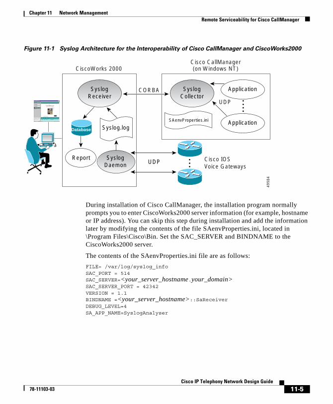
Chapter 11 Network ManagementRemote Serviceability for Cisco CallManager
Figure 11-1 Syslog Architecture for the Interoperability of Cisco CallManager and CiscoWorks2000
During installation of Cisco CallManager, the installation program normally prompts you to enter CiscoWorks2000 server information (for example, hostname or IP address). You can skip this step during installation and add the information later by modifying the contents of the file SAenvProperties.ini, located in \Program Files\Cisco\Bin. Set the SAC_SERVER and BINDNAME to the CiscoWorks2000 server.
The contents of the SAenvProperties.ini file are as follows:
FILE= /var/log/syslog_infoSAC_PORT = 514SAC_SERVER=<your_server_hostname.your_domain>SAC_SERVER_PORT = 42342VERSION = 1.1BINDNAME =<your_server_hostname>::SaReceiverDEBUG_LEVEL=4SA_APP_NAME=SyslogAnalyser
4998
4
SyslogReceiver
Syslog.logSAenvProperties.ini
Report
SyslogCollector
Application
ApplicationDatabase
SyslogDaemon
Cisco IOS Voice Gateways
UDP
CORBA
Cisco CallManager(on Windows NT)CiscoWorks 2000
UDP
11-5Cisco IP Telephony Network Design Guide
78-11103-03
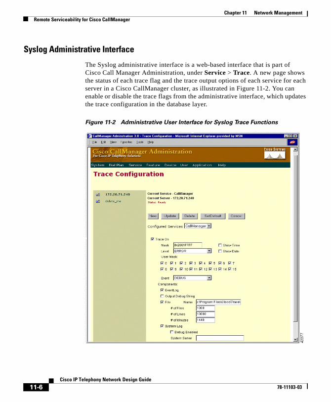
Chapter 11 Network ManagementRemote Serviceability for Cisco CallManager
Syslog Administrative Interface
The Syslog administrative interface is a web-based interface that is part of Cisco Call Manager Administration, under Service > Trace. A new page shows the status of each trace flag and the trace output options of each service for each server in a Cisco CallManager cluster, as illustrated in Figure 11-2. You can enable or disable the trace flags from the administrative interface, which updates the trace configuration in the database layer.
Figure 11-2 Administrative User Interface for Syslog Trace Functions
11-6Cisco IP Telephony Network Design Guide
78-11103-03

Chapter 11 Network ManagementRemote Serviceability for Cisco CallManager
Options also exist to enable the debug trace messages and to configure the Syslog server name. You should enable the debug trace message option only when there is little activity in the system. This method avoids putting excessive traffic on the network and lessens the burden on the system. You can send the debug trace messages to the Windows 2000 EventLog, to a local file, to the Syslog server, or to all three. Enter the Syslog server name only when using a syslog daemon other than the CiscoWorks2000 SAC as the Syslog server. Otherwise, leave the Syslog server name blank, and it will default to the local host name.
11-7Cisco IP Telephony Network Design Guide
78-11103-03
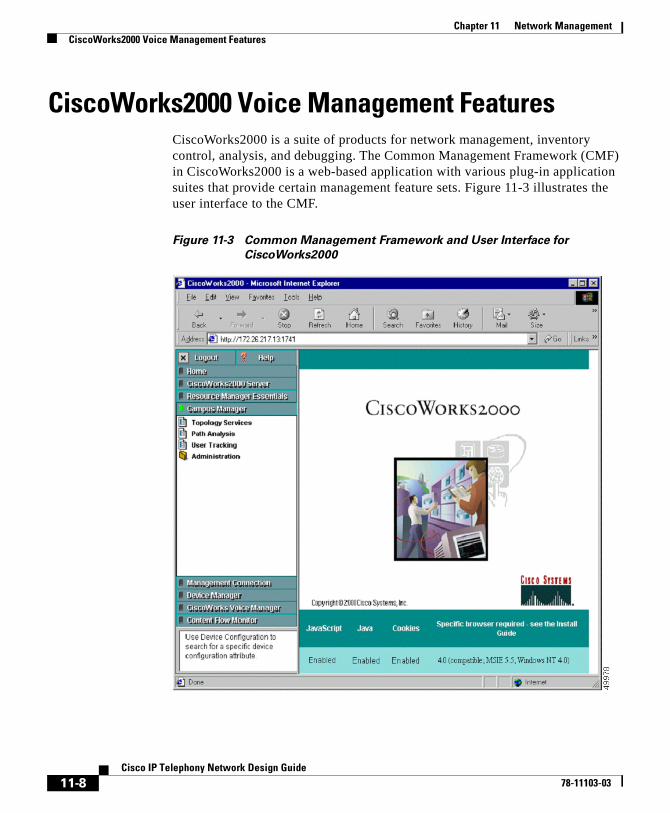
Chapter 11 Network ManagementCiscoWorks2000 Voice Management Features
CiscoWorks2000 Voice Management FeaturesCiscoWorks2000 is a suite of products for network management, inventory control, analysis, and debugging. The Common Management Framework (CMF) in CiscoWorks2000 is a web-based application with various plug-in application suites that provide certain management feature sets. Figure 11-3 illustrates the user interface to the CMF.
Figure 11-3 Common Management Framework and User Interface for
CiscoWorks2000
11-8Cisco IP Telephony Network Design Guide
78-11103-03
Chapter 11 Network ManagementCiscoWorks2000 Voice Management Features
Each application suite in the common web-based interface takes advantage of a common database. CiscoWorks2000 can run on either Windows NT or a Sun Solaris platform. Table 11-2 describes the respective components needed to complete the product suite for Cisco AVVID network management.
As mentioned, the CiscoWorks2000 architecture consists of a Common Management Framework (CMF) with a web-based desktop as a single point of management. An additional component, the asynchronous network interface (ANI), provides data collection services using Simple Network Management Protocol (SNMP), Cisco Discovery Protocol (CDP), and Interim Local Management Interface (ILMI) tables. Figure 11-4 illustrates this architecture.
Table 11-2 Components of CiscoWorks2000 Product Suite
CiscoWorks2000 Components Description and Function
Common Management Framework Release 1.1.1 (CD-ROM One, edition 3)
Serves as baseline web application for all components, single GUI manager for other CiscoWorks2000 components, and central database. This component is part of the LAN Management Solution (LMS) bundle.
Campus Manager Release 3.0.1 P1 (included with Voice update)
Provides various functionality such as discovery and topology map, central point for host management (console), user tracking, and path analysis.
Resource Manager Essentials Release 3.2 (included with Voice update)
Maintains the managed device inventory, configuration management, and system logging repository and analysis.
11-9Cisco IP Telephony Network Design Guide
78-11103-03
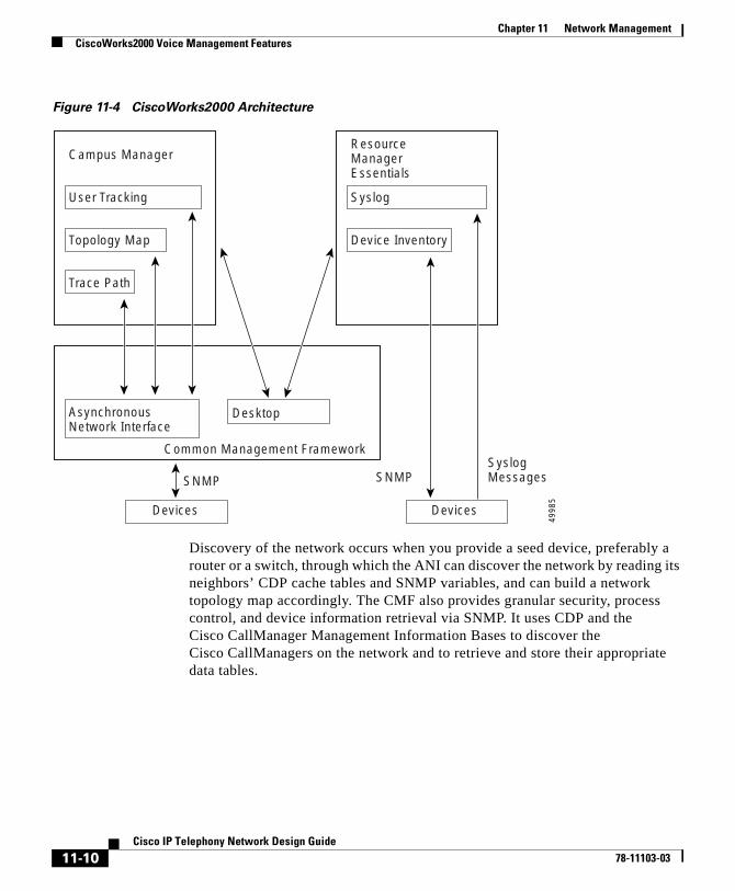
Chapter 11 Network ManagementCiscoWorks2000 Voice Management Features
Figure 11-4 CiscoWorks2000 Architecture
Discovery of the network occurs when you provide a seed device, preferably a router or a switch, through which the ANI can discover the network by reading its neighbors’ CDP cache tables and SNMP variables, and can build a network topology map accordingly. The CMF also provides granular security, process control, and device information retrieval via SNMP. It uses CDP and the Cisco CallManager Management Information Bases to discover the Cisco CallManagers on the network and to retrieve and store their appropriate data tables.
Campus Manager
User Tracking
Topology Map
Trace Path
Desktop
Common Management Framework
AsynchronousNetwork Interface
ResourceManagerEssentials
Syslog
Device Inventory
SNMP
Devices
SNMPSyslogMessages
Devices
4998
5
11-10Cisco IP Telephony Network Design Guide
78-11103-03
Chapter 11 Network ManagementCiscoWorks2000 Voice Management Features
Campus ManagerThe ANI discovery process added the support for voice components of the Cisco AVVID network in Common Management Framework (CMF) Release 1.1.1. This CMF release supports the following voice devices and functions:
• Cisco CallManager
Cisco CallManager Release 3.0 (and later) contains the CDP driver, and it supports partial CDP MIB and SNMP. This is the “tell” side of CDP, so it is always an edge device, and it displays as a Cisco CallManager icon in the topology map.
• Cisco IOS voice gateways
The voice gateways are discovered in the same way as regular routers.
• Cisco IP Phones (models 7960, 7940, and 7910)
Cisco IP Phones contain the “tell” side of the CDP driver, but they do not support SNMP.
• VLAN management
This feature provides tools for graphical VLAN configuration and logical topology mapping.
• End-station mobility and tracking
This feature provides tools for mobile user and dynamic VLAN tracking and configuration.
• Trace path analysis
This feature traces Layer 2 and Layer 3 paths between two devices or end stations using IP address or directory number.
Because there are usually many Cisco IP Phones installed on a network, the ANI must handle the discovery of Cisco IP Phones separately to avoid overcrowding the network topology map. For this reason, CMF Release 1.1.1 ignores the CDP cache entries of the Cisco IP Phones in the neighboring switches and does not create any device objects for them; hence, daisy-chained IP phones are not discovered. The Cisco IP Phones are treated as end user devices and are discovered through User Tracking discovery, as described in the next section.
11-11Cisco IP Telephony Network Design Guide
78-11103-03
Chapter 11 Network ManagementCiscoWorks2000 Voice Management Features
User Tracking
User Tracking (UT), a service module of the Campus Manager and ANI, specifically discovers end user nodes such as systems, Cisco CallManager hosts, Cisco IP Phones, and non-CDP systems as well. User Tracking performs an initial discovery of all hosts in the topology map and a subsequent discovery to maintain the user tracking table. You can specify a time limit for this subsequent discovery, and the default is 1 hour.
The initial UT discovery performs the following steps to generate a phone table:
1. UT reads the Content Addressable Memory (CAM) and Address Resolution Protocol (ARP) table of the switches and routers that have already been discovered by ANI and recorded in the topology map.
2. Based on information from CAM and ARP queries, UT generates an end-user table with device and port information. If the end user is a Cisco IP Phone, UT performs the following steps:
– It reads the phone entry from the CCM hosts, using the management information base CISCO-CCM-MIB.
– It generates a phone table that corresponds to the values depicted in Figure 11-5.
– For older models of Cisco IP Phones (Cisco IP Phone models 12 SP+ and 30 VIP), UT uses the CCM-MIB to query Cisco CallManager, and it builds the phone table based on the device and port information gathered from the initial discovery.
Note For non-Cisco IP phones, query is made to Cisco CallManager via SNMP, and the returned information is cross-referenced with information obtained from standard queries made to switches to get MAC addresses and switch ports (query of CAM table) and from queries made to routers to map IP addresses to MAC addresses (query of ARP cache).
11-12Cisco IP Telephony Network Design Guide
78-11103-03
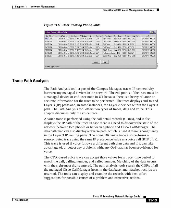
Chapter 11 Network ManagementCiscoWorks2000 Voice Management Features
Figure 11-5 User Tracking Phone Table
Trace Path Analysis
The Path Analysis tool, a part of the Campus Manager, traces IP connectivity between any managed devices in the network. The end points of the trace must be a managed device or end-user node in UT because there is a heavy reliance on accurate information for the trace to be performed. The trace displays end-to-end Layer 3 (IP) paths and, in some instances, the Layer 2 devices within the Layer 3 path. The Path Analysis tool offers two types of traces, data and voice. This chapter discusses only the voice trace.
A voice trace is performed using the call detail records (CDRs), and it also displays the IP path of the trace in case there is a need to discover the state of the network between two phones or between a phone and Cisco CallManager. The data path map can also display a reverse path, which is used if there is congruency in the Layer 3 IP routing paths. The non-CDR voice trace also performs a source-routed trace using the same IP precedence value as a voice call (RTP only). This trace is used if voice follows a different path than data and if it can take advantage of, or detect any problems with, any QoS that has been provisioned for voice.
The CDR-based voice trace can accept three values for a trace: time period to match the call, calling number, and called number. Matching of the data occurs with the right-most digits entered. The path analysis tools search the CDRs of all the managed Cisco CallManager hosts in the database, and matched records are returned. The tools can display and examine the records with best-effort suggestions for possible causes of a problem and corrective actions.
11-13Cisco IP Telephony Network Design Guide
78-11103-03
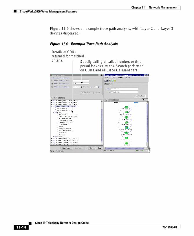
Chapter 11 Network ManagementCiscoWorks2000 Voice Management Features
Figure 11-6 shows an example trace path analysis, with Layer 2 and Layer 3 devices displayed.
Figure 11-6 Example Trace Path Analysis
Specify calling or called number, or timeperiod for voice traces. Search performedon CDRs and all Cisco CallManagers.
Details of CDRsreturned for matchedcriteria.
4998
0
11-14Cisco IP Telephony Network Design Guide
78-11103-03
Chapter 11 Network ManagementCiscoWorks2000 Voice Management Features
Resource Manager EssentialsThe CiscoWorks2000 LAN management solution is also bundled with the Resource Manager Essentials (RME), which are primarily responsible for inventory control, system configuration repository and configuration management, syslog server and syslog analysis, and other reporting functions. RME Release 3.1 is the minimum release that supports detailed reporting capabilities and manageability for Cisco CallManager hosts that are imported.
System logging capabilities of Cisco CallManager, described in the “System Logging Components” section on page 11-3, are well integrated with CiscoWorks2000. RME serves as a single point of management for Syslog Collector message filter configuration and device detail reporting for Cisco CallManager and other Cisco managed devices.
Inventory Control and Reporting
Cisco CallManager is supported in RME in the same manner as any Cisco device. The MIBs supported by Cisco CallManager are accessible through a standard SNMP agent. RME identifies the Cisco CallManager via the Compaq sysObjectID, so it is imperative to avoid exporting a similar system that is not running Cisco CallManager; otherwise, RME will waste resources by periodically collecting configuration information from the non-CallManager system.
RME also creates a separate group in the device selector (a new system view named "Cisco CallManagers") once it detects that Cisco CallManager hosts have been imported for inventory and reporting management. Reports exposed for the device selector are intended to show data about the configuration and state of Cisco CallManager itself, and they do not report on information regarding the individual components configured on Cisco CallManager. Figure 11-7 shows an example device report from RME.
11-15Cisco IP Telephony Network Design Guide
78-11103-03
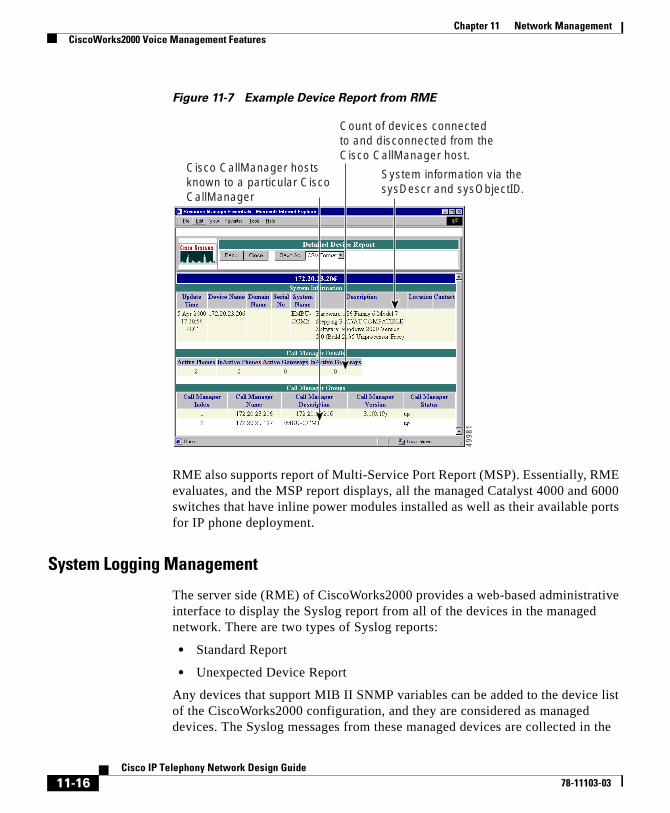
Chapter 11 Network ManagementCiscoWorks2000 Voice Management Features
Figure 11-7 Example Device Report from RME
RME also supports report of Multi-Service Port Report (MSP). Essentially, RME evaluates, and the MSP report displays, all the managed Catalyst 4000 and 6000 switches that have inline power modules installed as well as their available ports for IP phone deployment.
System Logging Management
The server side (RME) of CiscoWorks2000 provides a web-based administrative interface to display the Syslog report from all of the devices in the managed network. There are two types of Syslog reports:
• Standard Report
• Unexpected Device Report
Any devices that support MIB II SNMP variables can be added to the device list of the CiscoWorks2000 configuration, and they are considered as managed devices. The Syslog messages from these managed devices are collected in the
System information via thesysDescr and sysObjectID.
Count of devices connectedto and disconnected from the Cisco CallManager host.
Cisco CallManager hosts known to a particular Cisco CallManager
4998
1
11-16Cisco IP Telephony Network Design Guide
78-11103-03
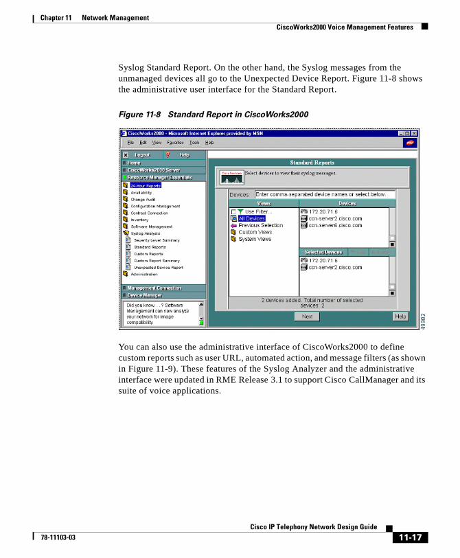
Chapter 11 Network ManagementCiscoWorks2000 Voice Management Features
Syslog Standard Report. On the other hand, the Syslog messages from the unmanaged devices all go to the Unexpected Device Report. Figure 11-8 shows the administrative user interface for the Standard Report.
Figure 11-8 Standard Report in CiscoWorks2000
You can also use the administrative interface of CiscoWorks2000 to define custom reports such as user URL, automated action, and message filters (as shown in Figure 11-9). These features of the Syslog Analyzer and the administrative interface were updated in RME Release 3.1 to support Cisco CallManager and its suite of voice applications.
11-17Cisco IP Telephony Network Design Guide
78-11103-03
Chapter 11 Network ManagementCiscoWorks2000 Voice Management Features
Syslog Message Filtering
In addition to System Diagnostic Interface (SDI) filtering, there are two places in the Syslog Analyzer where you can perform message filtering:
• In the Syslog Analyzer Collector (SAC) process, before the message is sent to the network
• In the CiscoWorks2000 server, where the administrator can define a custom report
Note If you set the Syslog filters on the CiscoWorks2000 server, all defined Syslog messages are sent to the server, thus creating erroneous network traffic. Cisco recommends that you use the SAC to create filters prior to sending them to a Syslog server.
The filtering mechanism allows you to define filters that are based on the source, the facility code, the subfacility codes, severity levels, mnemonic codes, or patterns in the message. Figure 11-9 shows an example of defining a message filter in the CiscoWorks2000 administrative interface.
11-18Cisco IP Telephony Network Design Guide
78-11103-03
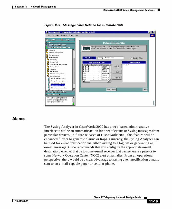
Chapter 11 Network ManagementCiscoWorks2000 Voice Management Features
Figure 11-9 Message Filter Defined for a Remote SAC
Alarms
The Syslog Analyzer in CiscoWorks2000 has a web-based administrative interface to define an automatic action for a set of events or Syslog messages from particular devices. In future releases of CiscoWorks2000, this feature will be enhanced further to generate alarms or traps. Currently, the Syslog Analyzer can be used for event notification via either writing to a log file or generating an e-mail message. Cisco recommends that you configure the appropriate e-mail destination, whether that be to some e-mail receiver that can generate a page or to some Network Operation Center (NOC) alert e-mail alias. From an operational perspective, there would be a clear advantage to having event notification e-mails sent to an e-mail capable pager or cellular phone.
11-19Cisco IP Telephony Network Design Guide
78-11103-03

Chapter 11 Network ManagementCiscoWorks2000 Voice Management Features
11-20Cisco IP Telephony Network Design Guide
78-11103-03

Cisco I78-11103-03
G L O S S A R Y
A—B
ACF admission confirm
ACL access control list
ADPCM adaptive differential pulse code modulation
AMIS-A Audio Messaging Interchange Specification Analog
ANI automatic number identification
ARQ admission request
ASIC application-specific integrated circuit
AVVID See Cisco AVVID.
BRI Basic Rate Interface. See also PRI.
C
CAC call admission control
CAS channel associated signaling
CBWFQ class based weighted fair queuing
CDP Cisco Discovery Protocol
CIR committed information rate
1P Telephony Network Design Guide
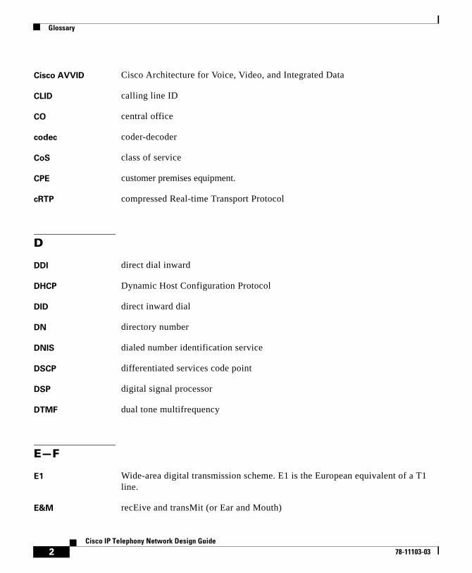
Glossary
Cisco AVVID Cisco Architecture for Voice, Video, and Integrated Data
CLID calling line ID
CO central office
codec coder-decoder
CoS class of service
CPE customer premises equipment.
cRTP compressed Real-time Transport Protocol
D
DDI direct dial inward
DHCP Dynamic Host Configuration Protocol
DID direct inward dial
DN directory number
DNIS dialed number identification service
DSCP differentiated services code point
DSP digital signal processor
DTMF dual tone multifrequency
E—F
E1 Wide-area digital transmission scheme. E1 is the European equivalent of a T1 line.
E&M recEive and transMit (or Ear and Mouth)
2Cisco IP Telephony Network Design Guide
78-11103-03
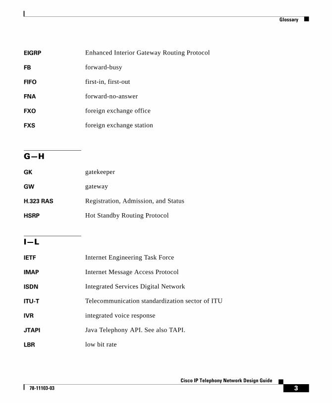
Glossary
EIGRP Enhanced Interior Gateway Routing Protocol
FB forward-busy
FIFO first-in, first-out
FNA forward-no-answer
FXO foreign exchange office
FXS foreign exchange station
G—H
GK gatekeeper
GW gateway
H.323 RAS Registration, Admission, and Status
HSRP Hot Standby Routing Protocol
I—L
IETF Internet Engineering Task Force
IMAP Internet Message Access Protocol
ISDN Integrated Services Digital Network
ITU-T Telecommunication standardization sector of ITU
IVR integrated voice response
JTAPI Java Telephony API. See also TAPI.
LBR low bit rate
3Cisco IP Telephony Network Design Guide
78-11103-03
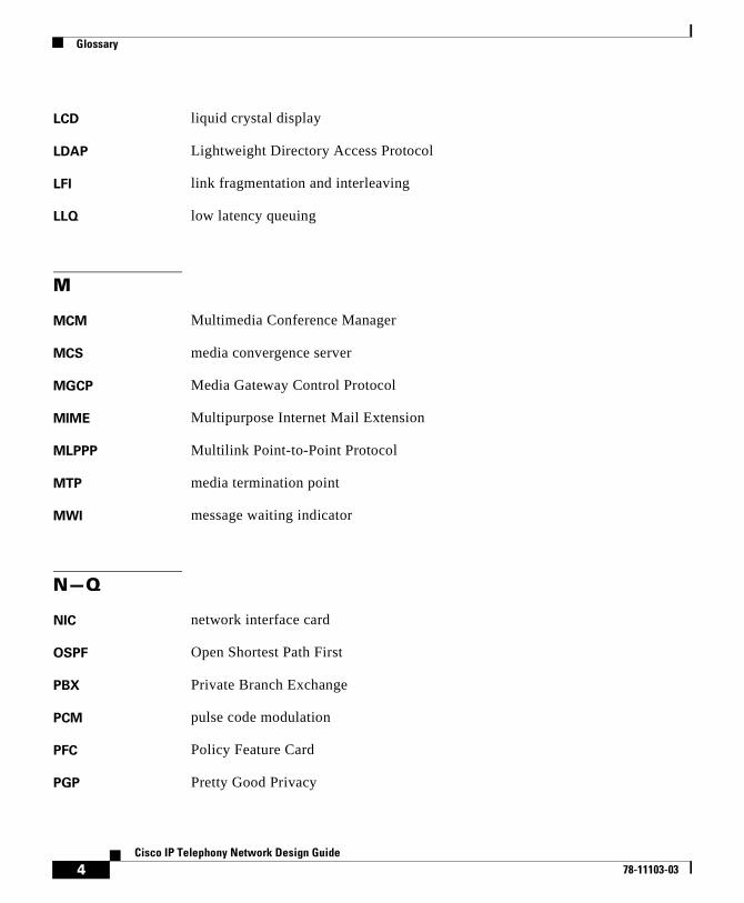
Glossary
LCD liquid crystal display
LDAP Lightweight Directory Access Protocol
LFI link fragmentation and interleaving
LLQ low latency queuing
M
MCM Multimedia Conference Manager
MCS media convergence server
MGCP Media Gateway Control Protocol
MIME Multipurpose Internet Mail Extension
MLPPP Multilink Point-to-Point Protocol
MTP media termination point
MWI message waiting indicator
N—Q
NIC network interface card
OSPF Open Shortest Path First
PBX Private Branch Exchange
PCM pulse code modulation
PFC Policy Feature Card
PGP Pretty Good Privacy
4Cisco IP Telephony Network Design Guide
78-11103-03
Glossary
POTS plain old telephone service
PQ priority queueing
PRI Primary Rate Interface
PSTN public switched telephone network
PVID port VLAN ID
QoS quality of service
R
RAS Registration, Admission, and Status protocol
route list Replaces route point in CallManager 3.0.
RRQ registration request
RSVP Resource Reservation Protocol
RTP Real-time Transport Protocol
S
SA/DA sending address/destination address
Skinny Station
Protocol
A Cisco protocol using low bandwidth messages that communicate between IP devices and the Cisco CallManager.
SMDI Simplified Message Desk Interface (or Station Message Desk Interface)
SMTP Simple Mail Transfer Protocol
SNMP Simple Network Management Protocol
5Cisco IP Telephony Network Design Guide
78-11103-03

Glossary
T—U
TAPI Telephony Application Programming Interface. See also JTAPI.
TDM time division multiplexing
TFTP Trivial File Transfer Protocol
ToS type of service
UPS uninterruptible power supply
V
VAD voice activity detection
VIC voice interface card
VLAN virtual LAN
VoIP voice over IP
VPIM voice profile for Internet messaging
VVID voice VLAN ID
W—Z
WRED weighted random early detection
WRR weighted round-robin
6Cisco IP Telephony Network Design Guide
78-11103-03
Cisco I78-11103-03
I N D E X
A
additional information xvii
addresses 2-21, 2-26
admission control 3-15, 3-18, 6-3
for centralized call processing 7-3
for QoS 8-11
gatekeeper 3-15, 6-8, 6-15
locations 3-18, 7-4
alarms 11-19
ANI 11-8
assistance with Cisco products xix
B
bandwidth
in distributed systems 6-28
per call 3-15
provisioning for WAN 8-4
best practices for QoS 8-10
C
call admission control 3-15, 3-18, 6-3
for centralized call processing 7-3
for QoS 8-11
gatekeeper 3-15, 6-8, 6-15
locations 3-18, 7-4
Call Detail Record (CDR) 11-1
called party transformation 5-9
calling party transformation 5-9
calling search space 5-14, 5-15
campus infrastructure 2-1
Campus Manager 11-11
Catalyst switches 9-1
4000 family 9-13
6000 family 2-34, 9-15
conferencing services 9-4
transcoding services 9-7
CDP 2-22, 11-1
CDR 11-1
centralized call processing 1-10, 3-18, 7-1
Cisco.com xix
Cisco CallManager clusters 3-1
Cisco Discovery Protocol (CDP) 2-22, 11-1
CiscoWorks2000 11-1, 11-8, 11-13
Asynchronous Network Interface (ANI) 11-8
Campus Manager 11-11
Common Management Framework (CMF) 11-8
1P Telephony Network Design Guide

Index
Resource Manager Essentials (RME) 11-15
User Tracking (UT) 11-12
class of service (CoS) 2-28
clusters 3-1
communication between 3-14
communication within 3-5
for centralized systems 7-8
guidelines 3-12
in distributed systems 6-30
provisioning 3-14
size of 3-1
with centralized call processing 3-18
with distributed call processing 3-15
CMF 11-8
comments on this guide xix
Common Object Request Broker Architecture (CORBA) 11-4
communication
between clusters 3-14
within a cluster 3-5
composite model 1-1
compression of voice stream 9-7
conferencing 9-4
connections
IP phone 2-9
PC 2-9
to the network 2-25
consumption of resources 3-3
conventions used in this guide xv
CORBA 11-4
CoS 2-28
D
database
publisher 3-1, 3-5
subscriber 3-5
default power allocation 2-14
design goals 1-1
device pools 3-9
devices
in route group 5-8
pools 3-9
sessions 3-3
weight of 3-1, 3-3
device weights 3-1, 3-3
DHCP 2-21
dial plan 5-1
calling search space 5-14
for centralized systems 7-5
for distributed systems 6-15
guidelines 5-18
individual site 5-19
multiple sites 5-21
partitions 5-14
restrictions 6-28
dial string 5-10
Digital PBX Adapter (DPA) 10-20
2Cisco IP Telephony Network Design Guide
78-11103-03
Index
digital signal processor (DSP) 9-1
digit translation 5-9
distributed call processing 1-7, 3-15, 6-1
documentation
CD-ROM xviii
obtaining xviii
ordering from Cisco xviii
World Wide Web xviii
your feedback xix
DPA 7630 10-20
described 10-20
integration modes 10-22
DSP 9-1
for centralized systems 7-10
for distributed systems 6-30
DTMF Relay
gateway support 4-3
supported in IOS H.323 gateways 4-4
supported in MGCP gateways 4-4
supported in Skinny gateways 4-4
dual supervisors 2-16
Dynamic Host Configuration Protocol (DHCP) 2-21
E
error messages for inline power 2-16
Ethernet 2-5
external patch panel 2-17
F
features required for gateway selection 4-1
feature transparency 3-21
G
gatekeeper 3-15, 6-8, 6-15, 6-19
gateways 4-1
list of 4-2
required features 4-1
site requirements 4-9
supported protocols 4-2
supported site requirements 4-11
goals 1-1
groups for redundancy 3-6
H
H.323 used in VoIP gateways 4-2
help with Cisco products xix
high availability 2-7
I
independent call processing 1-5
infrastructure 2-1
inline power 2-10
integration modes 10-22
3Cisco IP Telephony Network Design Guide
78-11103-03

Index
intercluster communication 3-14
interface queuing 8-2
intracluster communication 3-5
IP addresses 2-21, 2-26
IP phones 2-25
addresses 2-21, 2-26
external power supply 2-17
internals 2-5
power consumption 2-15
power to 2-10
wall power 2-20
IP telephony
design goals 1-1
network models 1-3
L
LAN infrastructure 2-1
legacy systems 10-1
link efficiency techniques 8-7
locations 3-18, 7-4
M
Management Information Base (MIB) 11-2
mask for digit translation 5-9
Media Gateway Control Protocol (MGCP) 4-2
media termination point (MTP) 9-7
MGCP 4-2
MIB 11-2
migration to IP telephony network 10-1
MTP 9-7
multisite 1-5
with centralized call processing 1-10, 7-1
with distributed call processing 1-7, 6-1
with independent call processing 1-5
N
network design 1-1
composite model 1-1
infrastructure 2-5
models 1-1
multiple sites with centralized call processing 1-10
multiple sites with distributed call processing 1-7
multiple sites with independent call processing 1-5
single site 1-3
topology 1-1
network management 11-1
notational conventions xv
O
off-net route pattern 5-12
on-net route pattern 5-11
4Cisco IP Telephony Network Design Guide
78-11103-03

Index
P
partitions 5-14, 5-15
PBX migration 10-1
physical connections 2-9
power
consumption 2-15
default allocation 2-14
error messages 2-16
external patch panel 2-17
for IP phones 2-10
from Catalyst module 2-10
inline 2-10
ports 2-17
protection 2-4, 2-16
recommendations 2-20
status 2-14
uninterruptible supply 2-4
wall outlet 2-20
protection for power 2-4
protocols
CDP 2-22
DHCP 2-21
for PBX and voice messaging 10-2
H.323 4-2
Media Gateway Control Protocol 4-2
Skinny Gateway Protocol 4-2
supported in VoIP gateways 4-2
PSTN 5-12
publisher of the database 3-1
Q
QoS 2-28, 2-33, 8-1
quality of service (QoS) 2-28
queuing 8-2
R
redundancy 2-7, 3-6
supported in IOS H.323 gateways 4-5
supported in MGCP gateway 4-6
supported in Skinny gateways 4-5
support for gateways 4-5
Remote Serviceability 11-1
reports for network management 11-16
resource consumption 3-3
restrictions on dialing 6-28
revision history xiv
RME 11-15
route group 5-1, 5-7
route list 5-1, 5-7
route pattern 5-1, 5-6
off-net 5-12
on-net 5-11
routing calls through a gatekeeper 6-19
5Cisco IP Telephony Network Design Guide
78-11103-03
Index
S
SAC 11-4
SAenvProperties.ini file 11-4
servers
per cluster 1-5
TFTP 3-1
service
class 2-28
quality 2-28
type 2-28
sessions 3-3
Simple Network Management Protocol (SNMP) 11-2
Simplified Message Desk Interface (SMDI) 10-21
single site 1-3
site requirements for gateway selection 4-9
Skinny Gateway Protocol 4-2
SMDI 10-21
SNMP 11-2
subscriber of the database 3-5
supplementary services 4-7
supported in IOS H.323 gateways 4-8
supported in MGCP gateways 4-9
supported in Skinny gateways 4-7
support for in gateways 4-7
Syslog
administrative interface 11-6
alarms 11-19
Analyzer Collector (SAC) 11-4
Collector 11-1, 11-4
components 11-3
log management 11-16
message filtering 11-18
Receiver 11-3
reports 11-16
T
TAC xix, xx
technical assistance xix
TFTP server 3-1
tools for QoS 8-5
ToS 2-28
trace path analysis 11-13
traffic
classification 2-28, 2-30, 2-34, 8-2
prioritization 8-5
shaping 8-9
transcoding 9-7
transformation of digits 5-9
translation of digits 5-9
transparency of features 3-21
trust boundaries 2-29
type of service (ToS) 2-28
6Cisco IP Telephony Network Design Guide
78-11103-03

Index
U
UDP 11-4
uninterrruptible power supply (UPS) 2-4
UPS 2-4
User Datagram Protocol (UDP) 11-4
User Tracking (UT) 11-12
UT 11-12
V
VLAN 2-22, 2-23, 2-24
voice compression 9-7
voice messaging
for centralized systems 7-12
for distributed systems 6-32
migration to IP network 10-1
Voice VLAN ID (VVID) 2-22
VVID 2-22
W
wall power 2-20
WAN
bandwidth provisioning 8-4
multisite with centralized call processing 7-1
multisite with distributed call processing 6-1
QoS 8-1
7Cisco IP Telephony Network Design Guide
78-11103-03

Index
8Cisco IP Telephony Network Design Guide
78-11103-03