Embed Size (px)
Citation preview
Send documenta t ion comments to mdsfeedback -doc@c i sco .com
Cisco Fabric Manager System Management Configuration Guide Cisco MDS NX-OS Release 4.1(1b) Through 4.2(1) July 2009
Americas HeadquartersCisco Systems, Inc.170 West Tasman DriveSan Jose, CA 95134-1706 USAhttp://www.cisco.comTel: 408 526-4000
800 553-NETS (6387)Fax: 408 527-0883
Text Part Number: OL-19583-01

Send documenta t ion comments to mdsfeedback -doc@c i sco .com
THE SPECIFICATIONS AND INFORMATION REGARDING THE PRODUCTS IN THIS MANUAL ARE SUBJECT TO CHANGE WITHOUT NOTICE. ALL STATEMENTS, INFORMATION, AND RECOMMENDATIONS IN THIS MANUAL ARE BELIEVED TO BE ACCURATE BUT ARE PRESENTED WITHOUT WARRANTY OF ANY KIND, EXPRESS OR IMPLIED. USERS MUST TAKE FULL RESPONSIBILITY FOR THEIR APPLICATION OF ANY PRODUCTS.
THE SOFTWARE LICENSE AND LIMITED WARRANTY FOR THE ACCOMPANYING PRODUCT ARE SET FORTH IN THE INFORMATION PACKET THAT SHIPPED WITH THE PRODUCT AND ARE INCORPORATED HEREIN BY THIS REFERENCE. IF YOU ARE UNABLE TO LOCATE THE SOFTWARE LICENSE OR LIMITED WARRANTY, CONTACT YOUR CISCO REPRESENTATIVE FOR A COPY.
The Cisco implementation of TCP header compression is an adaptation of a program developed by the University of California, Berkeley (UCB) as part of UCB’s public domain version of the UNIX operating system. All rights reserved. Copyright © 1981, Regents of the University of California.
NOTWITHSTANDING ANY OTHER WARRANTY HEREIN, ALL DOCUMENT FILES AND SOFTWARE OF THESE SUPPLIERS ARE PROVIDED “AS IS” WITH ALL FAULTS. CISCO AND THE ABOVE-NAMED SUPPLIERS DISCLAIM ALL WARRANTIES, EXPRESSED OR IMPLIED, INCLUDING, WITHOUT LIMITATION, THOSE OF MERCHANTABILITY, FITNESS FOR A PARTICULAR PURPOSE AND NONINFRINGEMENT OR ARISING FROM A COURSE OF DEALING, USAGE, OR TRADE PRACTICE.
IN NO EVENT SHALL CISCO OR ITS SUPPLIERS BE LIABLE FOR ANY INDIRECT, SPECIAL, CONSEQUENTIAL, OR INCIDENTAL DAMAGES, INCLUDING, WITHOUT LIMITATION, LOST PROFITS OR LOSS OR DAMAGE TO DATA ARISING OUT OF THE USE OR INABILITY TO USE THIS MANUAL, EVEN IF CISCO OR ITS SUPPLIERS HAVE BEEN ADVISED OF THE POSSIBILITY OF SUCH DAMAGES.
CCDE, CCENT, CCSI, Cisco Eos, Cisco HealthPresence, Cisco IronPort, the Cisco logo, Cisco Lumin, Cisco Nexus, Cisco Nurse Connect, Cisco StackPower, Cisco StadiumVision, Cisco TelePresence, Cisco Unified Computing System, Cisco WebEx, DCE, Flip Channels, Flip for Good, Flip Mino, Flip Video, Flip Video (Design), Flipshare (Design), Flip Ultra, and Welcome to the Human Network are trademarks; Changing the Way We Work, Live, Play, and Learn, Cisco Store, and Flip Gift Card are service marks; and Access Registrar, Aironet, AsyncOS, Bringing the Meeting To You, Catalyst, CCDA, CCDP, CCIE, CCIP, CCNA, CCNP, CCSP, CCVP, Cisco, the Cisco Certified Internetwork Expert logo, Cisco IOS, Cisco Press, Cisco Systems, Cisco Systems Capital, the Cisco Systems logo, Cisco Unity, Collaboration Without Limitation, EtherFast, EtherSwitch, Event Center, Fast Step, Follow Me Browsing, FormShare, GigaDrive, HomeLink, Internet Quotient, IOS, iPhone, iQuick Study, IronPort, the IronPort logo, LightStream, Linksys, MediaTone, MeetingPlace, MeetingPlace Chime Sound, MGX, Networkers, Networking Academy, Network Registrar, PCNow, PIX, PowerPanels, ProConnect, ScriptShare, SenderBase, SMARTnet, Spectrum Expert, StackWise, The Fastest Way to Increase Your Internet Quotient, TransPath, WebEx, and the WebEx logo are registered trademarks of Cisco Systems, Inc. and/or its affiliates in the United States and certain other countries.
All other trademarks mentioned in this document or website are the property of their respective owners. The use of the word partner does not imply a partnership relationship between Cisco and any other company. (0907R)
Any Internet Protocol (IP) addresses used in this document are not intended to be actual addresses. Any examples, command display output, and figures included in the document are shown for illustrative purposes only. Any use of actual IP addresses in illustrative content is unintentional and coincidental.
Cisco Fabric Manager System Management Configuration Guide © 2009 Cisco Systems, Inc. All rights reserved.
Send documenta t ion comments to mdsfeedback -doc@c i sco .com
OL-19583-01, Cisco MDS NX-OS Release 4.x
C O N T E N T S
New and Changed Information xi
Preface xiii
Audience xiii
Organization xiii
Document Conventions xiv
Related Documentation xv
Release Notes xv
Regulatory Compliance and Safety Information xv
Compatibility Information xv
Hardware Installation xv
Software Installation and Upgrade xvi
Cisco NX-OS xvi
Cisco Fabric Manager xvi
Command-Line Interface xvi
Intelligent Storage Networking Services Configuration Guides xvii
Troubleshooting and Reference xvii
C H A P T E R 1 System Management Overview 1-1
Cisco Fabric Services 1-1
System Messages 1-1
Call Home 1-2
Scheduler 1-2
System Processes and Logs 1-2
SNMP 1-2
RMON 1-3
Domain Parameters 1-3
SPAN 1-3
Fabric Configuration Server 1-3
C H A P T E R 2 Using the CFS Infrastructure 2-1
About CFS 2-1
Cisco MDS NX-OS Features Using CFS 2-2
CFS Features 2-2
iiiCisco Fabric Manager System Management Configuration Guide
Send documenta t ion comments to mdsfeedback -doc@c i sco .com
Contents
CFS Protocol 2-3
CFS Distribution Scopes 2-3
CFS Distribution Modes 2-4
Uncoordinated Distribution 2-4
Coordinated Distribution 2-4
Unrestricted Uncoordinated Distributions 2-4
Disabling CFS Distribution on a Switch 2-4
CFS Application Requirements 2-5
Enabling CFS for an Application 2-5
Locking the Fabric 2-6
Committing Changes 2-7
Discarding Changes 2-8
Saving the Configuration 2-8
Clearing a Locked Session 2-8
CFS Merge Support 2-9
Displaying CFS Configuration Information 2-9
CFS Distribution over IP 2-10
Configuring Static IP Peers for CFS over IP 2-11
Adding Peers to List 2-12
Removing an NPV Device from the Peer List 2-14
CFS Regions 2-16
About CFS Regions 2-16
Managing CFS Regions Using Fabric Manager 2-17
Creating CFS Regions 2-17
Assigning Features to CFS Regions 2-17
Moving a Feature to a Different Region 2-18
Removing a Feature from a Region 2-19
Deleting CFS Regions 2-19
CFS Example Using Fabric Manager 2-20
CFS Example Using Device Manager 2-23
Default Settings 2-23
C H A P T E R 3 Configuring System Message Logging 3-1
About System Message Logging 3-1
System Message Logging Configuration 3-3
Message Logging Initiation 3-3
Console Severity Level 3-4
Module Logging 3-5
ivCisco Fabric Manager System Management Configuration Guide
OL-19583-01, Cisco MDS NX-OS Release 4.x
Send documenta t ion comments to mdsfeedback -doc@c i sco .com
Contents
Log Files 3-6
System Message Logging Servers 3-7
Verifying Syslog Servers from Fabric Manager Web Server 3-9
Outgoing System Message Logging Server Facilities 3-9
Viewing Logs from Fabric Manager Web Server 3-10
Viewing Logs from Device Manager 3-10
Default Settings 3-10
C H A P T E R 4 Configuring Call Home 4-1
Call Home Features 4-2
About Smart Call Home 4-2
Obtaining Smart Call Home 4-5
Configuring Call Home 4-5
Configuring Contact Information 4-6
Destination Profiles 4-8
Alert Groups 4-9
Customized Alert Group Messages 4-10
Customizing Alert Group Messages Using Fabric Manager 4-11
Call Home Message Level Feature 4-12
Setting the Call Home Message Levels Using Fabric Manager 4-12
Syslog-Based Alerts 4-12
Configuring Syslog-Based Alerts Using Fabric Manager 4-13
RMON-Based Alerts 4-13
Configuring RMON Alerts Using Fabric Manager 4-14
E-Mail Options 4-14
Configuring General E-Mail Options Using Fabric Manager 4-14
HTTPS Support 4-15
Periodic Inventory Notification 4-15
Enabling Periodic Inventory Notifications Using Fabric Manager 4-15
Duplicate Message Throttle 4-16
Enabling Message Throttling Using Fabric Manager 4-16
Call Home Enable Function 4-17
Enabling Call Home Using Fabric Manager 4-17
Call Home Configuration Distribution 4-18
Enabling Call Home Fabric Distribution Using Fabric Manager 4-18
Fabric Lock Override 4-19
Database Merge Guidelines 4-19
vCisco Fabric Manager System Management Configuration Guide
OL-19583-01, Cisco MDS NX-OS Release 4.x
Send documenta t ion comments to mdsfeedback -doc@c i sco .com
Contents
Call Home Communications Test 4-19
Testing Call Home Using Fabric Manager 4-19
Clearing Call Home Name Server Database 4-20
Configuring EMC E-mail Home Delayed Traps 4-20
Configuring Delayed Traps Using Cisco Fabric Manager 4-20
Enabling Delayed Traps Using Cisco Device Manager 4-22
Sample Syslog Alert Notification in Full-txt Format 4-23
Sample Syslog Alert Notification in XML Format 4-23
Sample RMON Notification in XML Format 4-27
Event Triggers 4-29
Call Home Message Levels 4-31
Message Contents 4-32
Default Settings 4-39
C H A P T E R 5 Scheduling Maintenance Jobs 5-1
About the Command Scheduler 5-1
Scheduler Terminology 5-1
Scheduling Guidelines 5-2
Configuring the Command Scheduler 5-2
Enabling the Command Scheduler 5-3
Configuring Remote User Authentication 5-3
Defining a Job 5-4
Verifying the Job Definition 5-5
Deleting a Job 5-6
Specifying a Schedule 5-6
Specifying a Periodic Schedule 5-6
Specifying a One-Time Schedule 5-7
Verifying Scheduler Configuration 5-8
Deleting a Schedule 5-8
Removing an Assigned Job 5-8
Deleting a Schedule Time 5-9
Verifying the Command Scheduler Execution Status 5-9
Execution Logs 5-9
About Execution Logs 5-9
Configuring Execution Logs 5-10
Displaying Execution Log File Contents 5-10
Clearing the Execution Log File Contents 5-10
Default Settings 5-10
viCisco Fabric Manager System Management Configuration Guide
OL-19583-01, Cisco MDS NX-OS Release 4.x
Send documenta t ion comments to mdsfeedback -doc@c i sco .com
Contents
C H A P T E R 6 Monitoring System Processes and Logs 6-1
Displaying System Processes 6-1
Displaying System Status 6-2
Core and Log Files 6-3
Displaying Core Status 6-3
Clearing the Core Directory 6-4
First and Last Core 6-4
Verifying First and Last Core Status 6-5
Online System Health Management 6-5
About OHMS 6-5
Performing Internal Loopback Tests 6-6
Performing External Loopback Tests 6-6
Default Settings 6-6
C H A P T E R 7 Configuring SNMP 7-1
About SNMP Security 7-1
SNMP Version 1 and Version 2c 7-2
SNMP Version 3 7-2
Assigning SNMP Switch Contact and Location Information 7-2
SNMPv3 CLI User Management and AAA Integration 7-2
CLI and SNMP User Synchronization 7-3
Restricting Switch Access 7-3
Group-Based SNMP Access 7-3
Creating and Modifying Users 7-4
About AES Encryption-Based Privacy 7-4
Enforcing SNMPv3 Message Encryption 7-5
Assigning SNMPv3 Users to Multiple Roles 7-6
Adding Communities 7-7
Deleting a Community String 7-7
SNMP Trap and Inform Notifications 7-8
Configuring SNMPv2c Notifications 7-8
Configuring SNMPv3 Notifications 7-9
Enabling SNMP Notifications 7-9
Configuring the Notification Target User 7-12
Configuring Event Security 7-13
Viewing the SNMP Events Log 7-13
Default Settings 7-14
viiCisco Fabric Manager System Management Configuration Guide
OL-19583-01, Cisco MDS NX-OS Release 4.x
Send documenta t ion comments to mdsfeedback -doc@c i sco .com
Contents
C H A P T E R 8 Configuring RMON 8-1
About RMON 8-1
Configuring RMON Using Threshold Manager 8-1
RMON Alarm Configuration 8-2
Enabling RMON Alarms by Port 8-3
Enabling 32-Bit and 64-Bit Alarms 8-4
Create RMON Alarms in Fabric Manager 8-6
Enabling 32-Bit RMON Alarms for VSANs 8-9
Enabling 32-Bit and 64-Bit RMON Alarms for Physical Components 8-10
Creating a New RMON from Device Manager Threshold Manager 8-11
Managing RMON Events 8-12
Managing RMON Alarms 8-13
Viewing the RMON Log 8-14
Default Settings 8-15
C H A P T E R 9 Configuring Domain Parameters 9-1
Fibre Channel Domains 9-2
About Domain Restart 9-3
Configuring Domain Manager Turbo Mode 9-3
Restarting a Domain 9-5
About Switch Priority 9-6
Configuring Switch Priority 9-7
About fcdomain Initiation 9-7
Enabling or Disabling fcdomains 9-7
Setting Fabric Names 9-8
About Incoming RCFs 9-8
Rejecting Incoming RCFs 9-8
About Autoreconfiguring Merged Fabrics 9-9
Enabling Autoreconfiguration 9-9
Domain IDs 9-10
About Domain IDs 9-10
Specifying Static or Preferred Domain IDs 9-12
About Allowed Domain ID Lists 9-13
Configuring Allowed Domain ID Lists 9-13
About CFS Distribution of Allowed Domain ID Lists 9-14
Enabling Distribution 9-14
Locking the Fabric 9-15
Committing Changes 9-15
Discarding Changes 9-15
viiiCisco Fabric Manager System Management Configuration Guide
OL-19583-01, Cisco MDS NX-OS Release 4.x
Send documenta t ion comments to mdsfeedback -doc@c i sco .com
Contents
Clearing a Fabric Lock 9-16
Displaying Pending Changes 9-16
Displaying Session Status 9-16
About Contiguous Domain ID Assignments 9-17
Enabling Contiguous Domain ID Assignments 9-17
FC IDs 9-17
About Persistent FC IDs 9-18
Enabling the Persistent FC ID Feature 9-18
About Persistent FC ID Configuration 9-19
Configuring Persistent FC IDs 9-19
About Unique Area FC IDs for HBAs 9-20
Configuring Unique Area FC IDs for an HBA 9-20
About Persistent FC ID Selective Purging 9-21
Purging Persistent FC IDs 9-22
Displaying fcdomain Statistics 9-22
Default Settings 9-23
C H A P T E R 10 Monitoring Network Traffic Using SPAN 10-1
About SPAN 10-2
SPAN Sources 10-2
IPS Source Ports 10-3
Allowed Source Interface Types 10-3
VSAN as a Source 10-4
Guidelines to Configure VSANs as a Source 10-4
SPAN Sessions 10-5
Specifying Filters 10-5
Guidelines to Specifying Filters 10-5
SD Port Characteristics 10-5
Guidelines to Configure SPAN 10-6
Configuring SPAN 10-6
Configuring SPAN 10-6
Configuring SPAN max-queued-packets 10-7
Creating SPAN Sessions 10-7
Editing SPAN Sources 10-8
Deleting SPAN Sessions 10-9
SPAN Conversion Behavior 10-9
Monitoring Traffic Using Fibre Channel Analyzers 10-10
Without SPAN 10-10
ixCisco Fabric Manager System Management Configuration Guide
OL-19583-01, Cisco MDS NX-OS Release 4.x
Send documenta t ion comments to mdsfeedback -doc@c i sco .com
Contents
With SPAN 10-11
Configuring Fibre Channel Analyzers Using SPAN 10-12
Single SD Port to Monitor Traffic 10-12
Default SPAN Settings 10-13
C H A P T E R 11 Configuring Fabric Configuration Server 11-1
About FCS 11-1
Significance of FCS 11-2
Displaying FCS Discovery 11-3
Displaying FCS Elements 11-3
Creating an FCS Platform 11-4
Displaying FCS Fabric Ports 11-5
Default Settings 11-6
I N D E X
xCisco Fabric Manager System Management Configuration Guide
OL-19583-01, Cisco MDS NX-OS Release 4.x
Send documenta t ion comments to mdsfeedback -doc@c i sco .com
New and Changed Information
As of Cisco MDS NX-OS Release 4.2(1), software configuration information is available in new feature-specific configuration guides for the following information:
• System management
• Interfaces
• Fabric
• Quality of service
• Security
• IP services
• High availability and redundancy
The information in these new guides previously existed in the Cisco MDS 9000 Family CLI Configuration Guide and in the Cisco MDS 9000 Family Fabric Manager Configuration Guide. Those configuration guides remain available on Cisco.com and should be used for all software releases prior to MDS NX-OS Release 4.2(1). Each guide addresses the features introduced in or available in a particular release. Select and view the configuration guide that pertains to the software installed in your switch.
Some information from the Cisco MDS 9000 Family CLI Configuration Guide and the Cisco MDS 9000 Family Fabric Manager Configuration Guide now appears in the following guides that are common among products that run the Nexus operating system:
• Cisco NX-OS Family Licensing Guide – Explains the licensing model and describes the feature licenses.
• Cisco NX-OS Fundamentals Configuration Guide – Describes the switch setup utility and includes general CLI, file system, and configuration information.
For a complete list of document titles, see the list of Related Documentation in the “Preface.”
To find additional information about Cisco MDS NX-OS Release 4.2(x), see the Cisco MDS 9000 Family Release Notes available at the following Cisco Systems website:
http://www.cisco.com/en/US/products/ps5989/prod_release_notes_list.htm
About this Guide
The information in the new Cisco Fabric Manager System Management Configuration Guide previously existed in the following parts of the Cisco MDS 9000 Family Fabric Manager Configuration Guide:
• Part 2: Installation and Switch Management
• Part 5: Security
xiCisco Fabric Manager System Management Configuration Guide
OL-19583-01, Cisco MDS NX-OS Release 4.x
Send documenta t ion comments to mdsfeedback -doc@c i sco .com
New and Changed Information
• Part 8: Network and Switch Monitoring
• Part 9: Troubleshooting
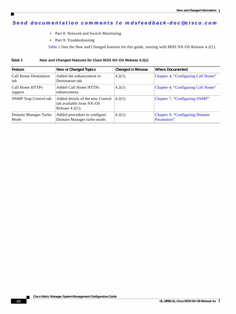
Table 1 lists the New and Changed features for this guide, starting with MDS NX-OS Release 4.2(1).
Table 1 New and Changed Features for Cisco MDS NX-OS Release 4.2(x)
Feature New or Changed Topics Changed in Release Where Documented
Call Home Destination tab
Added the enhancement in Destination tab.
4.2(1) Chapter 4, “Configuring Call Home”
Call Home HTTPs support
Added Call Home HTTPs enhancement.
4.2(1) Chapter 4, “Configuring Call Home”
SNMP Trap Control tab Added details of the new Control tab available from NX-OS Release 4.2(1).
4.2(1) Chapter 7, “Configuring SNMP”
Domain Manager Turbo Mode
Added procedure to configure Domain Manager turbo mode.
4.2(1) Chapter 9, “Configuring Domain Parameters”
xiiCisco Fabric Manager System Management Configuration Guide
OL-19583-01, Cisco MDS NX-OS Release 4.x
Send documenta t ion comments to mdsfeedback -doc@c i sco .com
Preface
This preface describes the audience, organization, and conventions of the Cisco Fabric Manager System Management Configuration Guide. It also provides information on how to obtain related documentation.
AudienceThis guide is for experienced network administrators who are responsible for configuring and maintaining the Cisco MDS 9000 Family of multilayer directors and fabric switches.
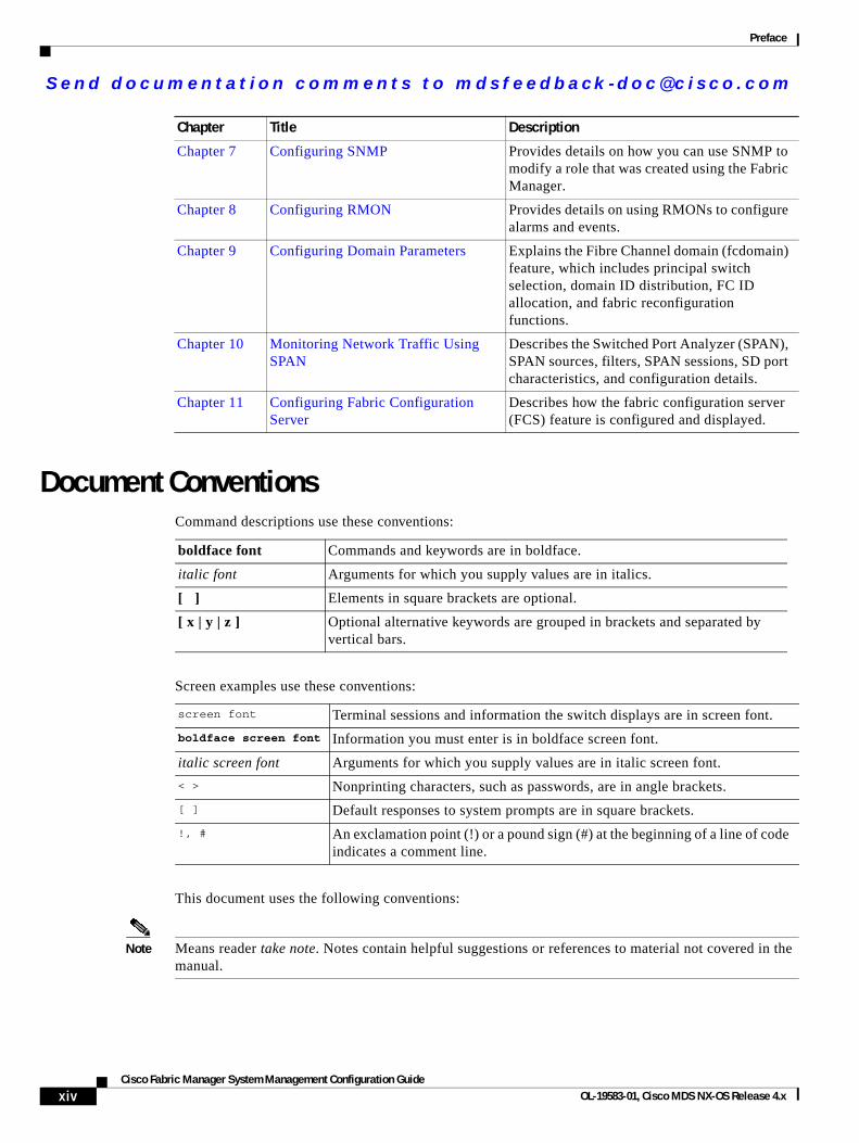
OrganizationThis guide is organized as follows:
Chapter Title Description
Chapter 1 System Management Overview Provides an overview of the system management features to monitor and manage a switch using the Fabric Manager.
Chapter 2 Using the CFS Infrastructure Explains the use of the Cisco Fabric Services (CFS) infrastructure to enable efficient database distribution.
Chapter 3 Configuring System Message Logging
Describes how system message logging is configured and displayed.
Chapter 4 Configuring Call Home Provides details on the Call Home service and includes information on Call Home, event triggers, contact information, destination profiles, and e-mail options.
Chapter 5 Scheduling Maintenance Jobs Describes the Cisco MDS command scheduler feature that helps you schedule configuration and maintenance jobs in any switch in the Cisco MDS 9000 Family.
Chapter 6 Monitoring System Processes and Logs
Provides information on displaying system processes and status. It also provides information on configuring core and log files, HA policy, heartbeat and watchdog checks, and upgrade resets.
xiiiCisco Fabric Manager System Management Configuration Guide
OL-19583-01, Cisco MDS NX-OS Release 4.x
Send documenta t ion comments to mdsfeedback -doc@c i sco .com
Preface
Document ConventionsCommand descriptions use these conventions:
Screen examples use these conventions:
This document uses the following conventions:
Note Means reader take note. Notes contain helpful suggestions or references to material not covered in the manual.
Chapter 7 Configuring SNMP Provides details on how you can use SNMP to modify a role that was created using the Fabric Manager.
Chapter 8 Configuring RMON Provides details on using RMONs to configure alarms and events.
Chapter 9 Configuring Domain Parameters Explains the Fibre Channel domain (fcdomain) feature, which includes principal switch selection, domain ID distribution, FC ID allocation, and fabric reconfiguration functions.
Chapter 10 Monitoring Network Traffic Using SPAN
Describes the Switched Port Analyzer (SPAN), SPAN sources, filters, SPAN sessions, SD port characteristics, and configuration details.
Chapter 11 Configuring Fabric Configuration Server
Describes how the fabric configuration server (FCS) feature is configured and displayed.
Chapter Title Description
boldface font Commands and keywords are in boldface.
italic font Arguments for which you supply values are in italics.
[ ] Elements in square brackets are optional.
[ x | y | z ] Optional alternative keywords are grouped in brackets and separated by vertical bars.
screen font Terminal sessions and information the switch displays are in screen font.
boldface screen font Information you must enter is in boldface screen font.
italic screen font Arguments for which you supply values are in italic screen font.
< > Nonprinting characters, such as passwords, are in angle brackets.
[ ] Default responses to system prompts are in square brackets.
!, # An exclamation point (!) or a pound sign (#) at the beginning of a line of code indicates a comment line.
xivCisco Fabric Manager System Management Configuration Guide
OL-19583-01, Cisco MDS NX-OS Release 4.x
Send documenta t ion comments to mdsfeedback -doc@c i sco .com
Preface
Caution Means reader be careful. In this situation, you might do something that could result in equipment damage or loss of data.
Related DocumentationThe documentation set for the Cisco MDS 9000 Family includes the following documents. To find a document online, use the Cisco MDS NX-OS Documentation Locator at:
http://www.cisco.com/en/US/docs/storage/san_switches/mds9000/roadmaps/doclocater.htm
Release Notes • Cisco MDS 9000 Family Release Notes for Cisco MDS NX-OS Releases
• Cisco MDS 9000 Family Release Notes for MDS SAN-OS Releases
• Cisco MDS 9000 Family Release Notes for Storage Services Interface Images
• Cisco MDS 9000 Family Release Notes for Cisco MDS 9000 EPLD Images
• Release Notes for Cisco MDS 9000 Family Fabric Manager
Regulatory Compliance and Safety Information • Regulatory Compliance and Safety Information for the Cisco MDS 9000 Family
Compatibility Information • Cisco Data Center Interoperability Support Matrix
• Cisco MDS 9000 NX-OS Hardware and Software Compatibility Information and Feature Lists
• Cisco MDS NX-OS Release Compatibility Matrix for Storage Service Interface Images
• Cisco MDS 9000 Family Switch-to-Switch Interoperability Configuration Guide
• Cisco MDS NX-OS Release Compatibility Matrix for IBM SAN Volume Controller Software for Cisco MDS 9000
• Cisco MDS SAN-OS Release Compatibility Matrix for VERITAS Storage Foundation for Networks Software
Hardware Installation • Cisco MDS 9500 Series Hardware Installation Guide
• Cisco MDS 9200 Series Hardware Installation Guide
• Cisco MDS 9100 Series Hardware Installation Guide
• Cisco MDS 9124 and Cisco MDS 9134 Multilayer Fabric Switch Quick Start Guide
xvCisco Fabric Manager System Management Configuration Guide
OL-19583-01, Cisco MDS NX-OS Release 4.x
Send documenta t ion comments to mdsfeedback -doc@c i sco .com
Preface
Software Installation and Upgrade • Cisco MDS 9000 NX-OS Release 4.1(x) and SAN-OS 3(x) Software Upgrade and Downgrade Guide
• Cisco MDS 9000 Family Storage Services Interface Image Install and Upgrade Guide
• Cisco MDS 9000 Family Storage Services Module Software Installation and Upgrade Guide
Cisco NX-OS • Cisco MDS 9000 Family NX-OS Licensing Guide
• Cisco MDS 9000 Family NX-OS Fundamentals Configuration Guide
• Cisco MDS 9000 Family NX-OS System Management Configuration Guide
• Cisco MDS 9000 Family NX-OS Interfaces Configuration Guide
• Cisco MDS 9000 Family NX-OS Fabric Configuration Guide
• Cisco MDS 9000 Family NX-OS Quality of Service Configuration Guide
• Cisco MDS 9000 Family NX-OS Security Configuration Guide
• Cisco MDS 9000 Family NX-OS IP Services Configuration Guide
• Cisco MDS 9000 Family NX-OS Intelligent Storage Services Configuration Guide
• Cisco MDS 9000 Family NX-OS High Availability and Redundancy Configuration Guide
• Cisco MDS 9000 Family NX-OS Inter-VSAN Routing Configuration Guide
Cisco Fabric Manager • Cisco Fabric Manager Fundamentals Configuration Guide
• Cisco Fabric Manager Interfaces Configuration Guide
• Cisco Fabric Manager Fabric Configuration Guide
• Cisco Fabric Manager Quality of Service Configuration Guide
• Cisco Fabric Manager Security Configuration Guide
• Cisco Fabric Manager IP Services Configuration Guide
• Cisco Fabric Manager Intelligent Storage Services Configuration Guide
• Cisco Fabric Manager High Availability and Redundancy Configuration Guide
• Cisco Fabric Manager Inter-VSAN Routing Configuration Guide
• Cisco Fabric Manager Online Help
• Cisco Fabric Manager Web Services Online Help
Command-Line Interface • Cisco MDS 9000 Family Command Reference
xviCisco Fabric Manager System Management Configuration Guide
OL-19583-01, Cisco MDS NX-OS Release 4.x
Send documenta t ion comments to mdsfeedback -doc@c i sco .com
Preface
Intelligent Storage Networking Services Configuration Guides • Cisco MDS 9000 I/O Acceleration Configuration Guide
• Cisco MDS 9000 Family SANTap Deployment Guide
• Cisco MDS 9000 Family Data Mobility Manager Configuration Guide
• Cisco MDS 9000 Family Storage Media Encryption Configuration Guide
• Cisco MDS 9000 Family Secure Erase Configuration Guide
• Cisco MDS 9000 Family Cookbook for Cisco MDS SAN-OS
Troubleshooting and Reference • Cisco NX-OS System Messages Reference
• Cisco MDS 9000 Family NX-OS Troubleshooting Guide
• Cisco MDS 9000 Family NX-OS MIB Quick Reference
• Cisco MDS 9000 Family NX-OS SMI-S Programming Reference
• Cisco MDS 9000 Family Fabric Manager Server Database Schema
xviiCisco Fabric Manager System Management Configuration Guide
OL-19583-01, Cisco MDS NX-OS Release 4.x

Send documenta t ion comments to mdsfeedback -doc@c i sco .com
Preface
xviiiCisco Fabric Manager System Management Configuration Guide
OL-19583-01, Cisco MDS NX-OS Release 4.x
Send documenta t ion comments to mdsfeedback -doc@c i sco .com
Cisco Fabric OL-19583-01, Cisco MDS NX-OS Release 4.x
C H A P T E R 1
System Management OverviewYou can use the system management features to monitor and manage a switch using the Fabric Manager. These features include Call Home, SNMP, RMON, SPAN, and the Embedded Event Manager (EEM).
This chapter describes these features and includes the following sections:
• Cisco Fabric Services, page 1-1
• System Messages, page 1-1
• Call Home, page 1-2
• Scheduler, page 1-2
• System Processes and Logs, page 1-2
• SNMP, page 1-2
• RMON, page 1-3
• Domain Parameters, page 1-3
• SPAN, page 1-3
• Fabric Configuration Server, page 1-3
Cisco Fabric ServicesThe Cisco MDS NX-OS software uses the Cisco Fabric Services (CFS) infrastructure to enable efficient database distribution and to promote device flexibility. CFS simplifies SAN provisioning by automatically distributing configuration information to all switches in a fabric.
For information on configuring CFS, see Chapter 2, “Using the CFS Infrastructure.”
System MessagesSystem messages are monitored remotely by accessing the switch through Telnet, SSH, or the console port, or by viewing the logs on a system message logging server. Log messages are not saved across system reboots.
For information about configuring system messages, see Chapter 3, “Configuring System Message Logging.”
1-1Manager System Management Configuration Guide
Send documenta t ion comments to mdsfeedback -doc@c i sco .com
Chapter 1 System Management OverviewCall Home
Call HomeCall Home provides e-mail-based notification of critical system events. A versatile range of message formats are available for optimal compatibility with pager services, standard e-mail, or XML-based automated parsing applications. Common uses of this feature may include direct paging of a network support engineer, e-mail notification to a Network Operations Center, and utilization of Cisco Smart Call Home services for direct case generation with the Technical Assistance Center.
For information about configuring Call Home, see Chapter 4, “Configuring Call Home.”
SchedulerThe Cisco MDS command scheduler feature helps you schedule configuration and maintenance jobs in any switch in the Cisco MDS 9000 Family switches.You can use this feature to schedule jobs on a one-time basis or periodically. The Cisco NX-OS command scheduler provides a facility to schedule a job (set of CLI commands) or multiple jobs at a specified time in the future. The jobs can be executed once at a specified time in the future or at periodic intervals.
For information on configuring the Cisco MDS command scheduler feature, see Chapter 5, “Scheduling Maintenance Jobs.”
System Processes and LogsThe health of a switch can be monitored by various system processes and logs. The Online Health Management System (system health) is a hardware fault detection and recovery feature. This Health Management System ensures the general health of switching, services, and supervisor modules in any switch in the Cisco MDS 9000 Family.
For information on monitoring the health of the switch, see Chapter 6, “Monitoring System Processes and Logs.”
SNMPSimple Network Management Protocol (SNMP) is an application layer protocol that facilitates the exchange of management information between network devices. In all Cisco MDS 9000 Family switches, three SNMP versions are available: SNMPv1, SNMPv2c, and SNMPv3. The CLI and SNMP use common roles in all switches in the Cisco MDS 9000 Family. You can use SNMP to modify a role that was created using the CLI and vice versa.
Users, passwords, and roles for all CLI and SNMP users are the same. A user configured through the CLI can access the switch using SNMP (for example, the Fabric Manager or the Device Manager) and vice versa.
For information on configuring SNMP, see Chapter 7, “Configuring SNMP.”
1-2Cisco Fabric Manager System Management Configuration Guide
OL-19583-01, Cisco MDS NX-OS Release 4.x
Send documenta t ion comments to mdsfeedback -doc@c i sco .com
Chapter 1 System Management OverviewRMON
RMONRMON is an Internet Engineering Task Force (IETF) standard monitoring specification that allows various network agents and console systems to exchange network monitoring data. You can use the RMON alarms and events to monitor Cisco MDS 9000 Family switches running the Cisco SAN-OS Release 2.0(1b) or later or Cisco Release NX-OS 4.1(3) or later software.
For information on configuring RMON, see Chapter 8, “Configuring RMON.”
Domain ParametersThe Fibre Channel domain (fcdomain) feature performs principal switch selection, domain ID distribution, FC ID allocation, and fabric reconfiguration functions as described in the FC-SW-2 standards. The domains are configured on a per-VSAN basis. If you do not configure a domain ID, the local switch uses a random ID.
For information on configuring the Fibre Channel domain feature, see Chapter 9, “Configuring Domain Parameters.”
SPANThe Switched Port Analyzer (SPAN) feature is specific to switches in the Cisco MDS 9000 Family. It monitors network traffic through a Fibre Channel interface. Traffic through any Fibre Channel interface can be replicated to a special port called the SPAN destination port (SD port). Any Fibre Channel port in a switch can be configured as an SD port. Once an interface is in SD port mode, it cannot be used for normal data traffic. You can attach a Fibre Channel analyzer to the SD port to monitor SPAN traffic.
For information on SPAN feature, see Chapter 10, “Monitoring Network Traffic Using SPAN.”
Fabric Configuration ServerThe Fabric Configuration Server (FCS) provides discovery of topology attributes and maintains a repository of configuration information of fabric elements. A management application is usually connected to the FCS on the switch through an N port. In the Cisco MDS 9000 Family switch environment, multiple VSANs constitute a fabric, where one instance of the FCS is present per VSAN.
For information on configuring FCS, see Chapter 11, “Configuring Fabric Configuration Servers.”
1-3Cisco Fabric Manager System Management Configuration Guide
OL-19583-01, Cisco MDS NX-OS Release 4.x

Send documenta t ion comments to mdsfeedback -doc@c i sco .com
Chapter 1 System Management OverviewFabric Configuration Server
1-4Cisco Fabric Manager System Management Configuration Guide
OL-19583-01, Cisco MDS NX-OS Release 4.x
Send documenta t ion comments to mdsfeedback -doc@c i sco .com
Cisco Fabric OL-19583-01, Cisco MDS NX-OS Release 4.x
C H A P T E R 2
Using the CFS InfrastructureThe Cisco MDS NX-OS software uses the Cisco Fabric Services (CFS) infrastructure to enable efficient database distribution and to provide device flexibility. It simplifies SAN provisioning by automatically distributing configuration information to all switches in a fabric.
Several Cisco MDS NX-OS applications use the CFS infrastructure to maintain and distribute the contents of a particular application’s database.
This chapter contains the following sections:
• About CFS, page 2-1
• Disabling CFS Distribution on a Switch, page 2-4
• CFS Application Requirements, page 2-5
• Enabling CFS for an Application, page 2-5
• Locking the Fabric, page 2-6
• Committing Changes, page 2-7
• Discarding Changes, page 2-8
• Saving the Configuration, page 2-8
• Clearing a Locked Session, page 2-8
• CFS Merge Support, page 2-9
• Displaying CFS Configuration Information, page 2-9
• CFS Regions, page 2-16
• CFS Example Using Fabric Manager, page 2-20
• CFS Example Using Device Manager, page 2-23
• Default Settings, page 2-23
About CFSMany features in the Cisco MDS switches require configuration synchronization in all switches in the fabric. Maintaining configuration synchronization across a fabric is important to maintain fabric consistency. In the absence of a common infrastructure, such synchronization is achieved through manual configuration at each switch in the fabric. This process is tedious and error prone.
2-1Manager System Management Configuration Guide
Send documenta t ion comments to mdsfeedback -doc@c i sco .com
Chapter 2 Using the CFS InfrastructureAbout CFS
Cisco Fabric Services (CFS) provides a common infrastructure for automatic configuration synchronization in the fabric. It provides the transport function as well as a rich set of common services to the applications. CFS has the ability to discover CFS-capable switches in the fabric and discover the application capabilities in all CFS-capable switches.
This section includes the following topics:
• Cisco MDS NX-OS Features Using CFS, page 2-2
• CFS Features, page 2-2
• CFS Protocol, page 2-3
• CFS Distribution Scopes, page 2-3
• CFS Distribution Modes, page 2-4
Cisco MDS NX-OS Features Using CFSThe following Cisco NX-OS features use the CFS infrastructure:
• N Port Virtualization
• FlexAttach Virtual pWWN
• NTP
• Dynamic Port VSAN Membership
• Distributed Device Alias Services
• IVR topology
• SAN device virtualization
• TACACS+ and RADIUS
• User and administrator roles
• Port security
• iSNS
• Call Home
• Syslog
• fctimer
• SCSI flow services
• Saved startup configurations using the Fabric Startup Configuration Manager (FSCM)
• Allowed domain ID lists
• RSCN timer
• iSLB
CFS FeaturesCFS has the following features:
• Peer-to-peer protocol with no client-server relationship at the CFS layer.
• Three scopes of distribution.
2-2Cisco Fabric Manager System Management Configuration Guide
OL-19583-01, Cisco MDS NX-OS Release 4.x
Send documenta t ion comments to mdsfeedback -doc@c i sco .com
Chapter 2 Using the CFS InfrastructureAbout CFS
– Logical scope—The distribution occurs within the scope of a VSAN.
– Physical scope—The distribution spans the entire physical topology.
– Over a selected set of VSANs—Some applications, such as Inter-VSAN Routing (IVR), require configuration distribution over some specific VSANs. These applications can specify to CFS the set of VSANs over which to restrict the distribution.
• Three modes of distribution.
– Coordinated distributions—Only one distribution is allowed in the fabric at any given time.
– Uncoordinated distributions—Multiple parallel distributions are allowed in the fabric except when a coordinated distribution is in progress.
– Unrestricted uncoordinated distributions—Multiple parallel distributions are allowed in the fabric in the presence of an existing coordinated distribution. Unrestricted uncoordinated distributions are allowed to run in parallel with all other types of distributions.
• Supports a merge protocol that facilitates the merge of application configuration during a fabric merge event (when two independent fabrics merge).
CFS ProtocolThe CFS functionality is independent of the lower layer transport. Currently, in Cisco MDS switches, the CFS protocol layer resides on top of the Fiber Channel 2 (FC2) layer and is peer-to-peer with no client-server relationship. CFS uses the FC2 transport services to send information to other switches. CFS uses a proprietary SW_ILS (0x77434653) protocol for all CFS packets. CFS packets are sent to or from the switch domain controller addresses.
CFS can also use IP to send information to other switches.
Applications that use CFS are completely unaware of the lower layer transport.
CFS Distribution ScopesDifferent applications on the Cisco MDS 9000 Family switches need to distribute the configuration at various levels:
• VSAN level (logical scope)
Applications that operate within the scope of a VSAN have the configuration distribution restricted to the VSAN. An example application is port security where the configuration database is applicable only within a VSAN.
• Physical topology level (physical scope)
Applications might need to distribute the configuration to the entire physical topology spanning several VSANs. Such applications include NTP and DPVM (WWN-based VSAN), which are independent of VSANs.
• Between two switches
Applications might only operate between selected switches in the fabric. An example application is SCSI flow services, which operates between two switches.
2-3Cisco Fabric Manager System Management Configuration Guide
OL-19583-01, Cisco MDS NX-OS Release 4.x
Send documenta t ion comments to mdsfeedback -doc@c i sco .com
Chapter 2 Using the CFS InfrastructureDisabling CFS Distribution on a Switch
CFS Distribution ModesCFS supports different distribution modes to support different application requirements: coordinated and uncoordinated distributions. Both modes are mutually exclusive. Only one mode is allowed at any given time.
Uncoordinated Distribution
Uncoordinated distributions are used to distribute information that is not expected to conflict with that from a peer. An example is local device registrations such as iSNS. Parallel uncoordinated distributions are allowed for an application.
Coordinated Distribution
Coordinated distributions can have only one application distribution at a given time. CFS uses locks to enforce this. A coordinated distribution is not allowed to start if locks are taken for the application anywhere in the fabric. A coordinated distribution consists of three stages:
1. A fabric lock is acquired.
2. The configuration is distributed and committed.
3. The fabric lock is released.
Coordinated distribution has two variants:
• CFS driven —The stages are executed by CFS in response to an application request without intervention from the application.
• Application driven—The stages are under the complete control of the application.
Coordinated distributions are used to distribute information that can be manipulated and distributed from multiple switches, for example, the port security configuration.
Unrestricted Uncoordinated Distributions
Unrestricted uncoordinated distributions allow multiple parallel distributions in the fabric in the presence of an existing coordinated distribution. Unrestricted uncoordinated distributions are allowed to run in parallel with all other types of distributions.
Disabling CFS Distribution on a SwitchBy default, CFS distribution is enabled. Applications can distribute data and configuration information to all CFS-capable switches in the fabric where the applications exist. This is the normal mode of operation.
You can globally disable CFS on a switch, to isolate the applications using CFS from fabric-wide distributions while maintaining physical connectivity. When CFS is globally disabled on a switch, CFS operations are restricted to the switch and all CFS commands continue to function as if the switch were physically isolated.
To globally disable or enable CFS distribution on a switch using Fabric Manager, follow these steps:
Step 1 In the Physical Attributes pane, expand Switches > CFS.
2-4Cisco Fabric Manager System Management Configuration Guide
OL-19583-01, Cisco MDS NX-OS Release 4.x
Send documenta t ion comments to mdsfeedback -doc@c i sco .com
Chapter 2 Using the CFS InfrastructureCFS Application Requirements
Step 2 In the information pane, from the drop-down menu, choose disable or enable for a switch.
Step 3 Click the Apply Changes icon to commit the configuration changes.
To globally disable or enable CFS distribution on a switch using Device Manager, follow these steps:
Step 1 Choose Admin > CFS (Cisco Fabric Services).
You see the CFS dialog box with the CFS status for all features on that switch.
Step 2 Uncheck or check the Globally Enabled check box to disable or enable CFS distribution on this switch.
Step 3 Click Apply to disable CFS on this switch.
CFS Application RequirementsAll switches in the fabric must be CFS capable. A Cisco MDS 9000 Family switch is CFS capable if it is running Cisco SAN-OS Release 2.0(1b) or later, or MDS NX-OS Release 4.1(1) or later. Switches that are not CFS capable do not receive distributions and result in part of the fabric not receiving the intended distribution.
CFS has the following requirements:
• Implicit CFS usage—The first time you issue a CFS task for a CFS-enabled application, the configuration modification process begins and the application locks the fabric.
• Pending database—The pending database is a temporary buffer to hold uncommitted information. The uncommitted changes are not applied immediately to ensure that the database is synchronized with the database in the other switches in the fabric. When you commit the changes, the pending database overwrites the configuration database (also known as the active database or the effective database).
• CFS distribution enabled or disabled on a per-application basis—The default (enable or disable) for CFS distribution state differs between applications. If CFS distribution is disabled for an application, then that application does not distribute any configuration nor does it accept a distribution from other switches in the fabric.
• Explicit CFS commit—Most applications require an explicit commit operation to copy the changes in the temporary buffer to the application database, to distribute the new database to the fabric, and to release the fabric lock. The changes in the temporary buffer are not applied if you do not perform the commit operation.
Enabling CFS for an ApplicationAll CFS-based applications provide an option to enable or disable the distribution capabilities. Features that existed prior to Cisco SAN-OS Release 2.0(1b) have the distribution capability disabled by default and must have distribution capabilities enabled explicitly.
Applications introduced in Cisco SAN-OS Release 2.0(1b) or later, or MDS NX-OS Release 4.1(1) or later have the distribution enabled by default.
2-5Cisco Fabric Manager System Management Configuration Guide
OL-19583-01, Cisco MDS NX-OS Release 4.x
Send documenta t ion comments to mdsfeedback -doc@c i sco .com
Chapter 2 Using the CFS InfrastructureLocking the Fabric
The application configuration is not distributed by CFS unless distribution is explicitly enabled for that application.
To enable CFS for a feature using Fabric Manager, follow these steps:
Step 1 Choose a feature on which to enable CFS. For example, expand Switches > Events, and then select CallHome in the Physical Attributes pane. The Information pane shows that feature with a CFS tab. Click the CFS tab to display the CFS state for each switch in the fabric for that feature.
Step 2 Decide on which switch(es) to enable CFS. Set the Admin column to either enable to enable CFS or disable to disable CFS.
Note Enable CFS for all switches in the fabric or VSAN for the feature that uses CFS.
Step 3 Right-click the row you changed to see the pop-up menu. Select Apply Changes to apply the CFS configuration change. The CFS tab updates as the CFS changes take effect.
Fabric Manager retrieves the status of the CFS change and updates the Last Result column.
To enable CFS for a feature using Device Manager, follow these steps:
Step 1 Choose Admin > CFS (Cisco Fabric Services).
You see the CFS dialog box with the CFS status for all features on that switch.
Step 2 Decide which features need CFS. Set the Command column to either enable to enable CFS or disable to disable CFS.
Note Enable or disable CFS for all switches in the fabric or VSAN for the feature that uses CFS.
Step 3 Click Pending Differences to compare the configuration of this feature on this switch to other switches in the fabric or VSAN that have CFS enabled for this feature. Close the Show Pending Diff pop-up window.
Step 4 Click Apply to apply the CFS configuration change.
Device Manager retrieves the status of the CFS change and updates the Last Command and Result columns.
Locking the FabricWhen you configure (first time configuration) a Cisco NX-OS feature (or application) that uses the CFS infrastructure, that feature starts a CFS session and locks the fabric. When a fabric is locked, the Cisco NX-OS software does not allow any configuration changes from a switch to this Cisco NX-OS feature, other than the switch holding the lock, and issues a message to inform the user about the locked status. The configuration changes are held in a pending database by that application.
2-6Cisco Fabric Manager System Management Configuration Guide
OL-19583-01, Cisco MDS NX-OS Release 4.x
Send documenta t ion comments to mdsfeedback -doc@c i sco .com
Chapter 2 Using the CFS InfrastructureCommitting Changes
If you start a CFS session that requires a fabric lock but forget to end the session, an administrator can clear the session. If you lock a fabric at any time, your user name is remembered across restarts and switchovers. If another user (on the same machine) tries to perform configuration tasks, that user’s attempts are rejected.
Committing ChangesA commit operation saves the pending database for all application peers and releases the lock for all switches.
In general, the commit function does not start a session; only a lock function starts a session. However, an empty commit is allowed if configuration changes are not previously made. In this case, a commit operation results in a session that acquires locks and distributes the current database.
When you commit configuration changes to a feature using the CFS infrastructure, you receive a notification about one of the following responses:
• One or more external switches report a successful status—The application applies the changes locally and releases the fabric lock.
• None of the external switches report a successful state—The application considers this state a failure and does not apply the changes to any switch in the fabric. The fabric lock is not released.
You can commit changes for a specified feature by setting CFS > Config Action to commit for that feature.
To commit changes using Fabric Manager for CFS-enabled features, follow these steps:
Step 1 Choose the feature you want to enable CFS for. For example, expand Switches expand Events, and then select CallHome from the Physical Attributes pane.
The Information pane shows that feature, with a CFS tab.
Step 2 Click the CFS tab to display the CFS state for each switch in the fabric for that feature.
Step 3 Right-click the value in the Config Action column for any switch and select an option from the drop-down menu (Copy, Paste, Export to File, Print Table, Detach Table).
Step 4 Click the Apply Changes icon to commit the configuration changes for that feature and distribute the changes through CFS.
Fabric Manager retrieves the status of the CFS change and updates the Last Command and Last Result columns for the feature or VSAN.
To commit changes using Device Manager for CFS-enabled features, follow these steps:
Step 1 Choose Admin > CFS (Cisco Fabric Services).
You see the CFS dialog box with the CFS status for all features on that switch.
Step 2 For each applicable feature, set the Command column to commit to commit the configuration changes for that feature and distribute the changes through CFS, or set it to abort to discard the changes for that feature and release the fabric lock for CFS for that feature.
Step 3 (Optional) Provide a Type or VsanID as the basis for the CFS distribution for CFS features that require this.
2-7Cisco Fabric Manager System Management Configuration Guide
OL-19583-01, Cisco MDS NX-OS Release 4.x
Send documenta t ion comments to mdsfeedback -doc@c i sco .com
Chapter 2 Using the CFS InfrastructureDiscarding Changes
Step 4 Click Pending Differences to check the configuration of this feature on this switch as compared to other switches in the fabric or VSAN that have CFS enabled for this feature.
Step 5 Click Apply to apply the CFS configuration change.
Device Manager retrieves the status of the CFS change and updates the Last Command and Result columns.
Caution If you do not commit the changes, they are not saved to the running configuration.
Discarding ChangesIf you discard configuration changes, the application flushes the pending database and releases locks in the fabric. Both the abort and commit functions are only supported from the switch from which the fabric lock is acquired.
You can discard changes for a specified feature by setting the Command column value to disable for that feature then clicking Apply.
Saving the ConfigurationConfiguration changes that have not been applied yet (still in the pending database) are not shown in the running configuration. The configuration changes in the pending database overwrite the configuration in the effective database when you commit the changes.
Caution If you do not commit the changes, they are not saved to the running configuration.
The CISCO-CFS-MIB contains SNMP configuration information for any CFS-related functions. Refer to the Cisco MDS 9000 Family MIB Quick Reference for more information on this MIB.
Clearing a Locked SessionYou can clear locks held by an application from any switch in the fabric. This option is provided to rescue you from situations where locks are acquired and not released. This function requires Admin permissions.
To clear locks using Fabric Manager, follow these steps:
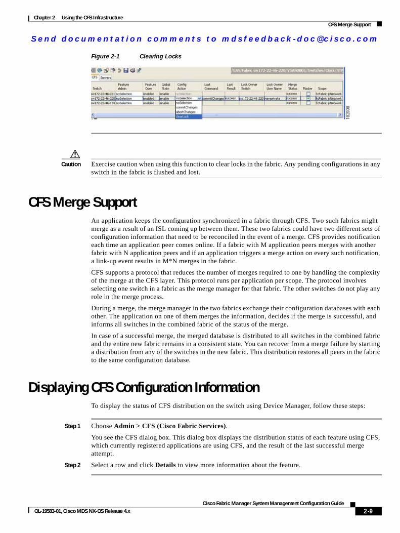
Step 1 Click the CFS tab.
Step 2 Select clearLock from the Config Action drop-down list for each switch that you want to clear the lock (see Figure 2-1).
Step 3 Click the Apply Changes icon to save the change.
2-8Cisco Fabric Manager System Management Configuration Guide
OL-19583-01, Cisco MDS NX-OS Release 4.x
Send documenta t ion comments to mdsfeedback -doc@c i sco .com
Chapter 2 Using the CFS InfrastructureCFS Merge Support
Figure 2-1 Clearing Locks
Caution Exercise caution when using this function to clear locks in the fabric. Any pending configurations in any switch in the fabric is flushed and lost.
CFS Merge SupportAn application keeps the configuration synchronized in a fabric through CFS. Two such fabrics might merge as a result of an ISL coming up between them. These two fabrics could have two different sets of configuration information that need to be reconciled in the event of a merge. CFS provides notification each time an application peer comes online. If a fabric with M application peers merges with another fabric with N application peers and if an application triggers a merge action on every such notification, a link-up event results in M*N merges in the fabric.
CFS supports a protocol that reduces the number of merges required to one by handling the complexity of the merge at the CFS layer. This protocol runs per application per scope. The protocol involves selecting one switch in a fabric as the merge manager for that fabric. The other switches do not play any role in the merge process.
During a merge, the merge manager in the two fabrics exchange their configuration databases with each other. The application on one of them merges the information, decides if the merge is successful, and informs all switches in the combined fabric of the status of the merge.
In case of a successful merge, the merged database is distributed to all switches in the combined fabric and the entire new fabric remains in a consistent state. You can recover from a merge failure by starting a distribution from any of the switches in the new fabric. This distribution restores all peers in the fabric to the same configuration database.
Displaying CFS Configuration InformationTo display the status of CFS distribution on the switch using Device Manager, follow these steps:
Step 1 Choose Admin > CFS (Cisco Fabric Services).
You see the CFS dialog box. This dialog box displays the distribution status of each feature using CFS, which currently registered applications are using CFS, and the result of the last successful merge attempt.
Step 2 Select a row and click Details to view more information about the feature.
2-9Cisco Fabric Manager System Management Configuration Guide
OL-19583-01, Cisco MDS NX-OS Release 4.x
Send documenta t ion comments to mdsfeedback -doc@c i sco .com
Chapter 2 Using the CFS InfrastructureCFS Distribution over IP
CFS Distribution over IPYou can configure CFS to distribute information over IP for networks containing switches that are not reachable over Fibre Channel. CFS distribution over IP supports the following features:
• Physical distribution over an entirely IP network.
• Physical distribution over a hybrid Fibre Channel and IP network with the distribution reaching all switches that are reachable over either Fibre Channel or IP.
Note The switch attempts to distribute information over Fibre Channel first and then over the IP network if the first attempt over Fibre Channel fails. CFS does not send duplicate messages if distribution over both IP and Fibre Channel is enabled.
• Distribution over IP version 4 (IPv4) or IP version 6 (IPv6).
Note CFS cannot distribute over both IPv4 and IPv6 from the same switch.
• Keepalive mechanism to detect network topology changes using a configurable multicast address.
• Compatibility with Cisco MDS SAN-OS Release 2.x.
• Distribution for logical scope applications is not supported because the VSAN implementation is limited to Fibre Channel.
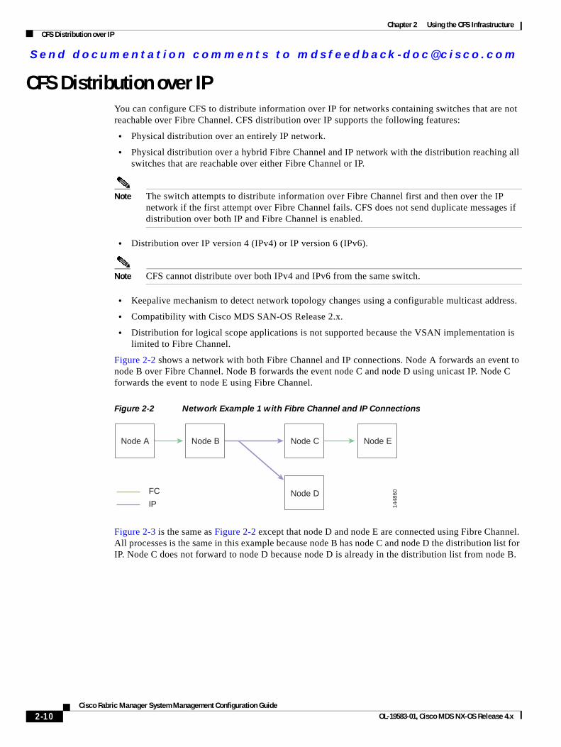
Figure 2-2 shows a network with both Fibre Channel and IP connections. Node A forwards an event to node B over Fibre Channel. Node B forwards the event node C and node D using unicast IP. Node C forwards the event to node E using Fibre Channel.
Figure 2-2 Network Example 1 with Fibre Channel and IP Connections
Figure 2-3 is the same as Figure 2-2 except that node D and node E are connected using Fibre Channel. All processes is the same in this example because node B has node C and node D the distribution list for IP. Node C does not forward to node D because node D is already in the distribution list from node B.
Node A Node B Node C Node E
Node DFC
IP 1448
60
2-10Cisco Fabric Manager System Management Configuration Guide
OL-19583-01, Cisco MDS NX-OS Release 4.x
Send documenta t ion comments to mdsfeedback -doc@c i sco .com
Chapter 2 Using the CFS InfrastructureCFS Distribution over IP
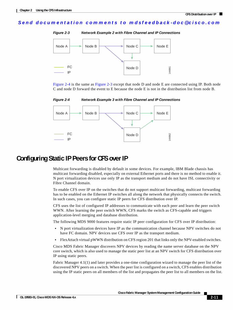
Figure 2-3 Network Example 2 with Fibre Channel and IP Connections
Figure 2-4 is the same as Figure 2-3 except that node D and node E are connected using IP. Both node C and node D forward the event to E because the node E is not in the distribution list from node B.
Figure 2-4 Network Example 3 with Fibre Channel and IP Connections
Configuring Static IP Peers for CFS over IPMulticast forwarding is disabled by default in some devices. For example, IBM Blade chassis has multicast forwarding disabled, especially on external Ethernet ports and there is no method to enable it. N port virtualization devices use only IP as the transport medium and do not have ISL connectivity or Fibre Channel domain.
To enable CFS over IP on the switches that do not support multicast forwarding, multicast forwarding has to be enabled on the Ethernet IP switches all along the network that physically connects the switch. In such cases, you can configure static IP peers for CFS distribution over IP.
CFS uses the list of configured IP addresses to communicate with each peer and learn the peer switch WWN. After learning the peer switch WWN, CFS marks the switch as CFS-capable and triggers application-level merging and database distribution.
The following MDS 9000 features require static IP peer configuration for CFS over IP distribution:
• N port virtualization devices have IP as the communication channel because NPV switches do not have FC domain. NPV devices use CFS over IP as the transport medium.
• FlexAttach virtual pWWN distribution on CFS region 201 that links only the NPV-enabled switches.
Cisco MDS Fabric Manager discovers NPV devices by reading the name server database on the NPV core switch, which is also used to manage the static peer list at an NPV switch for CFS distribution over IP using static peers.
Fabric Manager 4.1(1) and later provides a one-time configuration wizard to manage the peer list of the discovered NPV peers on a switch. When the peer list is configured on a switch, CFS enables distribution using the IP static peers on all members of the list and propagates the peer list to all members on the list.
Node A Node B Node C Node E
Node DFC
IP 1448
61
Node A Node B Node C Node E
Node DFC
IP 1448
62
2-11Cisco Fabric Manager System Management Configuration Guide
OL-19583-01, Cisco MDS NX-OS Release 4.x
Send documenta t ion comments to mdsfeedback -doc@c i sco .com
Chapter 2 Using the CFS InfrastructureCFS Distribution over IP
Note If a new NPV switch is added to the fabric, you must launch the NPV CFS Setup wizard to update the list, because Fabric Manager does not update the list automatically.
Adding Peers to List
To configure the static IP peers list using Fabric Manager, follow these steps:
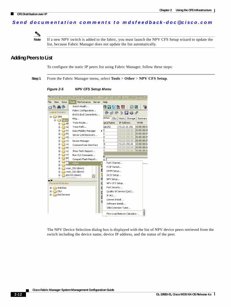
Step 1 From the Fabric Manager menu, select Tools > Other > NPV CFS Setup.
Figure 2-5 NPV CFS Setup Menu
The NPV Device Selection dialog box is displayed with the list of NPV device peers retrieved from the switch including the device name, device IP address, and the status of the peer.
2-12Cisco Fabric Manager System Management Configuration Guide
OL-19583-01, Cisco MDS NX-OS Release 4.x
Send documenta t ion comments to mdsfeedback -doc@c i sco .com
Chapter 2 Using the CFS InfrastructureCFS Distribution over IP
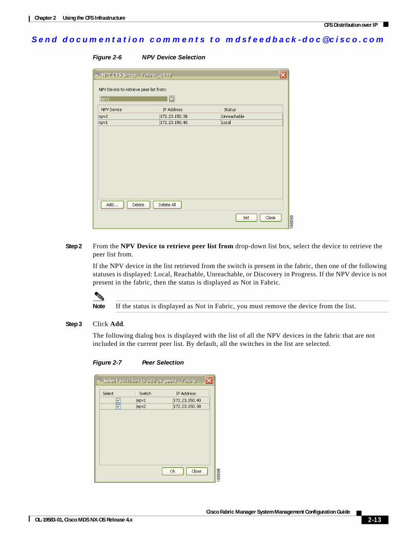
Figure 2-6 NPV Device Selection
Step 2 From the NPV Device to retrieve peer list from drop-down list box, select the device to retrieve the peer list from.
If the NPV device in the list retrieved from the switch is present in the fabric, then one of the following statuses is displayed: Local, Reachable, Unreachable, or Discovery in Progress. If the NPV device is not present in the fabric, then the status is displayed as Not in Fabric.
Note If the status is displayed as Not in Fabric, you must remove the device from the list.
Step 3 Click Add.
The following dialog box is displayed with the list of all the NPV devices in the fabric that are not included in the current peer list. By default, all the switches in the list are selected.
Figure 2-7 Peer Selection
2-13Cisco Fabric Manager System Management Configuration Guide
OL-19583-01, Cisco MDS NX-OS Release 4.x
Send documenta t ion comments to mdsfeedback -doc@c i sco .com
Chapter 2 Using the CFS InfrastructureCFS Distribution over IP
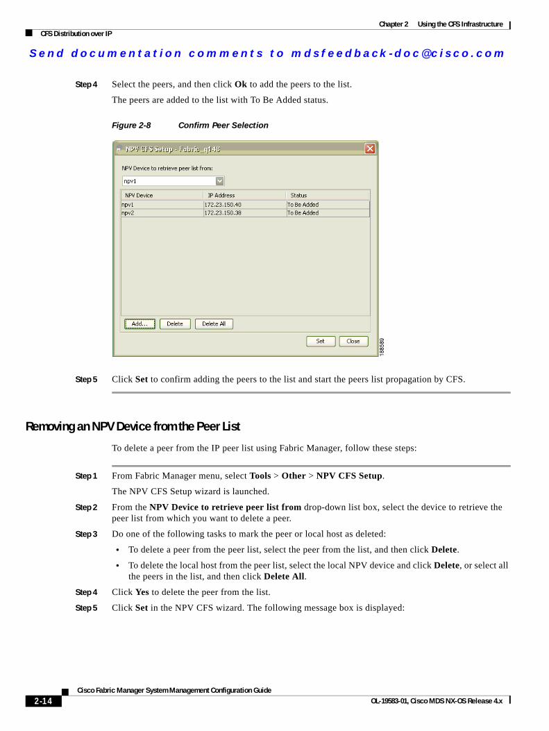
Step 4 Select the peers, and then click Ok to add the peers to the list.
The peers are added to the list with To Be Added status.
Figure 2-8 Confirm Peer Selection
Step 5 Click Set to confirm adding the peers to the list and start the peers list propagation by CFS.
Removing an NPV Device from the Peer List
To delete a peer from the IP peer list using Fabric Manager, follow these steps:
Step 1 From Fabric Manager menu, select Tools > Other > NPV CFS Setup.
The NPV CFS Setup wizard is launched.
Step 2 From the NPV Device to retrieve peer list from drop-down list box, select the device to retrieve the peer list from which you want to delete a peer.
Step 3 Do one of the following tasks to mark the peer or local host as deleted:
• To delete a peer from the peer list, select the peer from the list, and then click Delete.
• To delete the local host from the peer list, select the local NPV device and click Delete, or select all the peers in the list, and then click Delete All.
Step 4 Click Yes to delete the peer from the list.
Step 5 Click Set in the NPV CFS wizard. The following message box is displayed:
2-14Cisco Fabric Manager System Management Configuration Guide
OL-19583-01, Cisco MDS NX-OS Release 4.x
Send documenta t ion comments to mdsfeedback -doc@c i sco .com
Chapter 2 Using the CFS InfrastructureCFS Distribution over IP
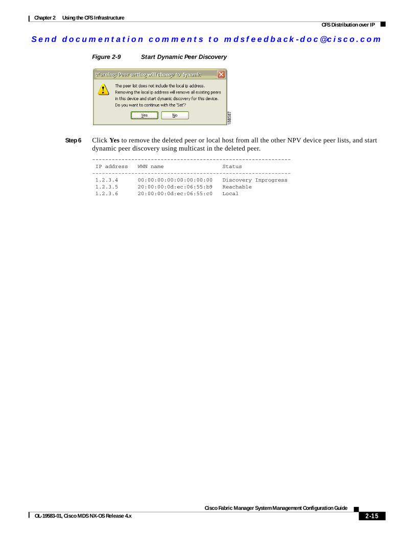
Figure 2-9 Start Dynamic Peer Discovery
Step 6 Click Yes to remove the deleted peer or local host from all the other NPV device peer lists, and start dynamic peer discovery using multicast in the deleted peer.
------------------------------------------------------------- IP address WWN name Status------------------------------------------------------------- 1.2.3.4 00:00:00:00:00:00:00:00 Discovery Inprogress 1.2.3.5 20:00:00:0d:ec:06:55:b9 Reachable 1.2.3.6 20:00:00:0d:ec:06:55:c0 Local
2-15Cisco Fabric Manager System Management Configuration Guide
OL-19583-01, Cisco MDS NX-OS Release 4.x
Send documenta t ion comments to mdsfeedback -doc@c i sco .com
Chapter 2 Using the CFS InfrastructureCFS Regions
CFS RegionsThis section contains the following topics:
• About CFS Regions, page 2-16
• Managing CFS Regions Using Fabric Manager, page 2-17
• Creating CFS Regions, page 2-17
• Assigning Features to CFS Regions, page 2-17
• Moving a Feature to a Different Region, page 2-18
• Removing a Feature from a Region, page 2-19
• Deleting CFS Regions, page 2-19
About CFS RegionsA CFS region is a user-defined subset of switches for a given feature or application in its physical distribution scope.When a SAN is spanned across a vast geography, you may need to localize or restrict the distribution of certain profiles among a set of switches based on their physical proximity. Before MDS SAN-OS Release 3.2.(1) the distribution scope of an application within a SAN was spanned across the entire physical fabric without the ability to confine or limit the distribution to a required set of switches in the fabric. CFS regions enables you to overcome this limitation by allowing you to create CFS regions, that is, multiple islands of distribution within the fabric, for a given CFS feature or application. CFS regions are designed to restrict the distribution of a feature’s configuration to a specific set or grouping of switches in a fabric.
Note You can only configure a CFS region on physical switches in a SAN. You cannot configure a CFS region in a VSAN.
Example CFS Scenario: Call Home is an application that triggers alerts to Network Administrators when a situation arises or something abnormal occurs. When the fabric covers many geographies and with multiple Network Administrators who are each responsible for a subset of switches in the fabric, the Call Home application sends alerts to all Network Administrators regardless of their location. For the Call Home application to send message alerts selectively to Network Administrators, the physical scope of the application has to be fine tuned or narrowed down, which is achieved by implementing CFS regions.
CFS regions are identified by numbers ranging from 0 through 200. Region 0 is reserved as the default region, and contains every switch in the fabric. You can configure regions from 1 through 200. The default region maintains backward compatibility. If there are switches on the same fabric running releases of SAN-OS before Release 3.2(1), only features in Region 0 are supported when those switches are synchronized. Features from other regions are ignored when those switches are synchronized.
If the feature is moved, that is, assigned to a new region, its scope is restricted to that region; it ignores all other regions for distribution or merging purposes. The assignment of the region to a feature has precedence in distribution over its initial physical scope.
You can configure a CFS region to distribute configurations for multiple features. However, on a given switch, you can configure only one CFS region at a time to distribute the configuration for a given feature. Once you assign a feature to a CFS region, its configuration cannot be distributed within another CFS region.
2-16Cisco Fabric Manager System Management Configuration Guide
OL-19583-01, Cisco MDS NX-OS Release 4.x
Send documenta t ion comments to mdsfeedback -doc@c i sco .com
Chapter 2 Using the CFS InfrastructureCFS Regions
Managing CFS Regions Using Fabric ManagerThis section describes how to use Fabric Manager for managing CFS regions. Fabric Manager provides a comprehensive view of all the switches, regions, and the features associated with each region in the topology. To complete the following tasks, use the tables under the All Regions and Feature by Region tabs:
• Creating CFS Regions, page 2-17
• Assigning Features to CFS Regions, page 2-17
• Moving a Feature to a Different Region, page 2-18
• Removing a Feature from a Region, page 2-19
Creating CFS Regions
To create a CFS region using Fabric Manager, follow these steps:
Step 1 Expand the Switches folder in the Physical Attributes pane and click CFS.
The information pane displays the Global, IP Multicast, Feature by Region, and All Regions tabs.
Step 2 Click the All Regions tab.
The tab displays a list of Switches and RegionIds.
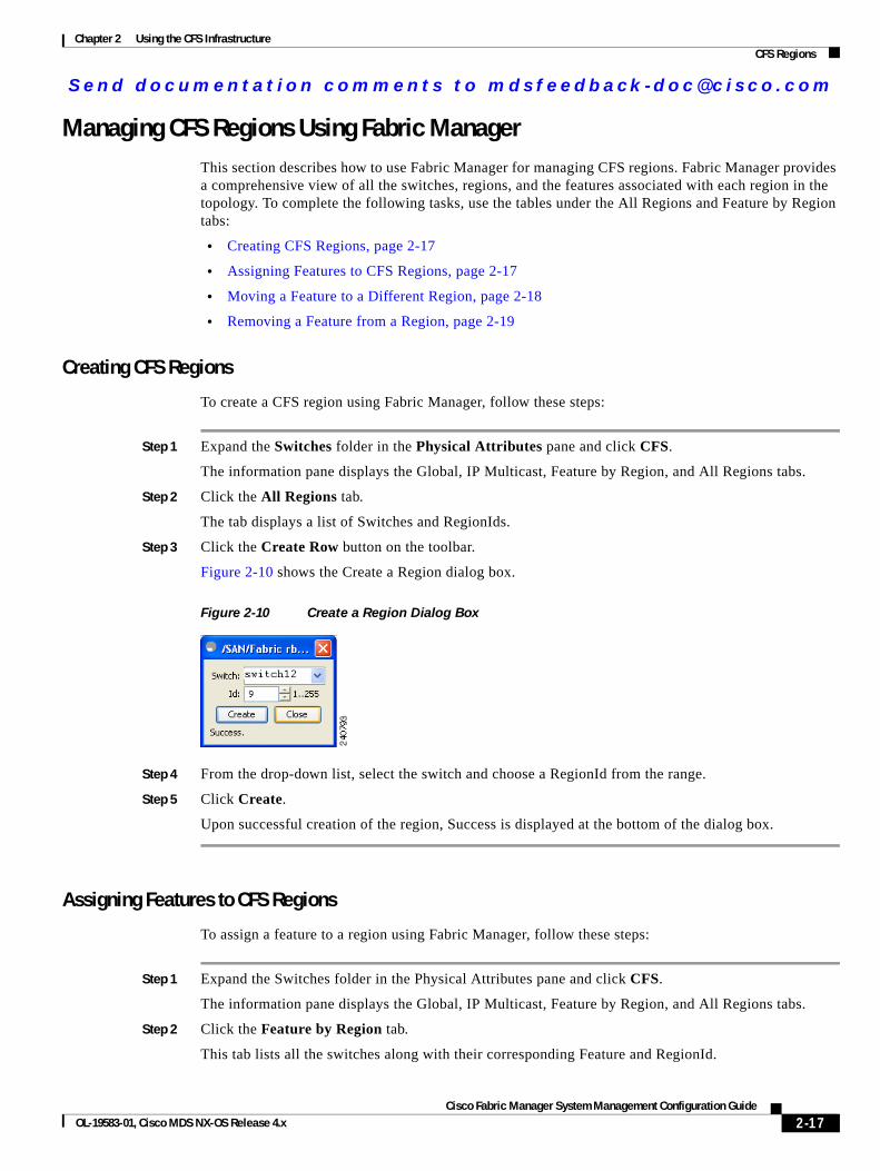
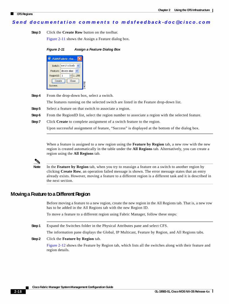
Step 3 Click the Create Row button on the toolbar.
Figure 2-10 shows the Create a Region dialog box.
Figure 2-10 Create a Region Dialog Box
Step 4 From the drop-down list, select the switch and choose a RegionId from the range.
Step 5 Click Create.
Upon successful creation of the region, Success is displayed at the bottom of the dialog box.
Assigning Features to CFS Regions
To assign a feature to a region using Fabric Manager, follow these steps:
Step 1 Expand the Switches folder in the Physical Attributes pane and click CFS.
The information pane displays the Global, IP Multicast, Feature by Region, and All Regions tabs.
Step 2 Click the Feature by Region tab.
This tab lists all the switches along with their corresponding Feature and RegionId.
2-17Cisco Fabric Manager System Management Configuration Guide
OL-19583-01, Cisco MDS NX-OS Release 4.x
Send documenta t ion comments to mdsfeedback -doc@c i sco .com
Chapter 2 Using the CFS InfrastructureCFS Regions
Step 3 Click the Create Row button on the toolbar.
Figure 2-11 shows the Assign a Feature dialog box.
Figure 2-11 Assign a Feature Dialog Box
Step 4 From the drop-down box, select a switch.
The features running on the selected switch are listed in the Feature drop-down list.
Step 5 Select a feature on that switch to associate a region.
Step 6 From the RegionID list, select the region number to associate a region with the selected feature.
Step 7 Click Create to complete assignment of a switch feature to the region.
Upon successful assignment of feature, “Success” is displayed at the bottom of the dialog box.
When a feature is assigned to a new region using the Feature by Region tab, a new row with the new region is created automatically in the table under the All Regions tab. Alternatively, you can create a region using the All Regions tab.
Note In the Feature by Region tab, when you try to reassign a feature on a switch to another region by clicking Create Row, an operation failed message is shown. The error message states that an entry already exists. However, moving a feature to a different region is a different task and it is described in the next section.
Moving a Feature to a Different Region
Before moving a feature to a new region, create the new region in the All Regions tab. That is, a new row has to be added in the All Regions tab with the new Region ID.
To move a feature to a different region using Fabric Manager, follow these steps:
Step 1 Expand the Switches folder in the Physical Attributes pane and select CFS.
The information pane displays the Global, IP Multicast, Feature by Region, and All Regions tabs.
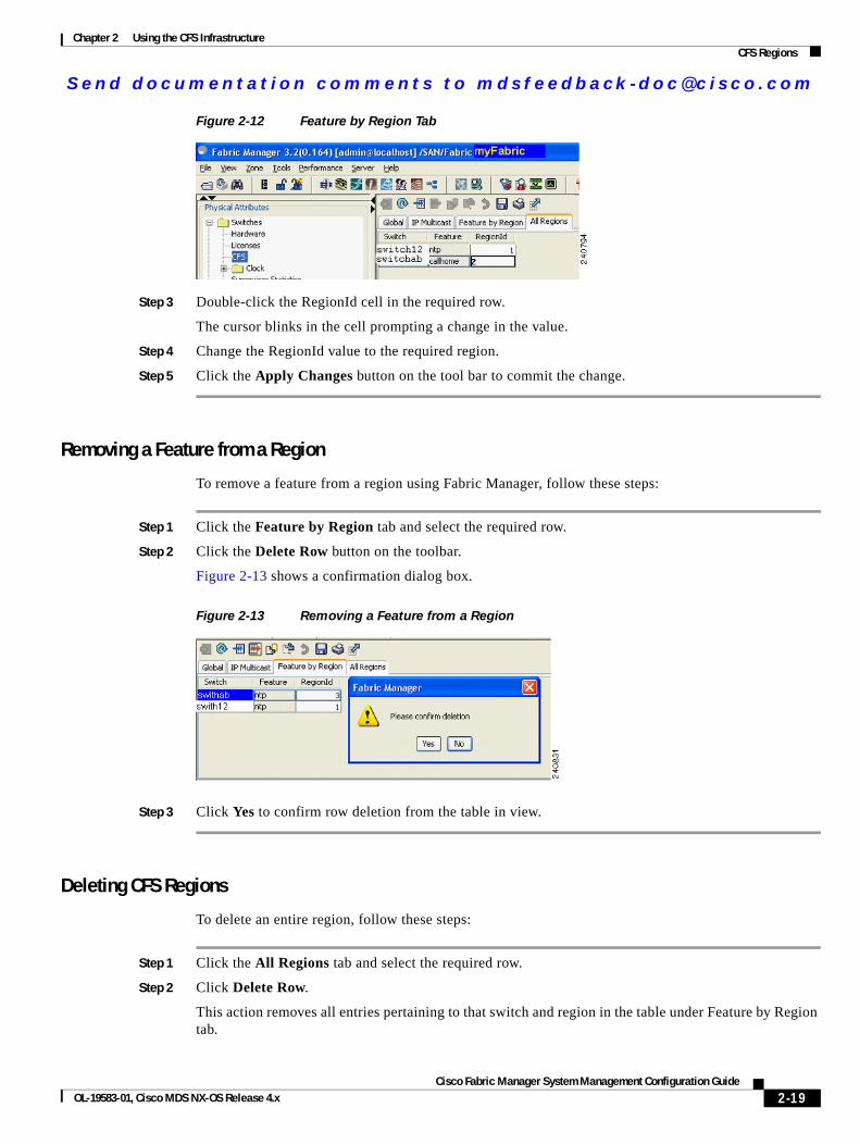
Step 2 Click the Feature by Region tab.
Figure 2-12 shows the Feature by Region tab, which lists all the switches along with their feature and region details.
2-18Cisco Fabric Manager System Management Configuration Guide
OL-19583-01, Cisco MDS NX-OS Release 4.x
Send documenta t ion comments to mdsfeedback -doc@c i sco .com
Chapter 2 Using the CFS InfrastructureCFS Regions
Figure 2-12 Feature by Region Tab
Step 3 Double-click the RegionId cell in the required row.
The cursor blinks in the cell prompting a change in the value.
Step 4 Change the RegionId value to the required region.
Step 5 Click the Apply Changes button on the tool bar to commit the change.
Removing a Feature from a Region
To remove a feature from a region using Fabric Manager, follow these steps:
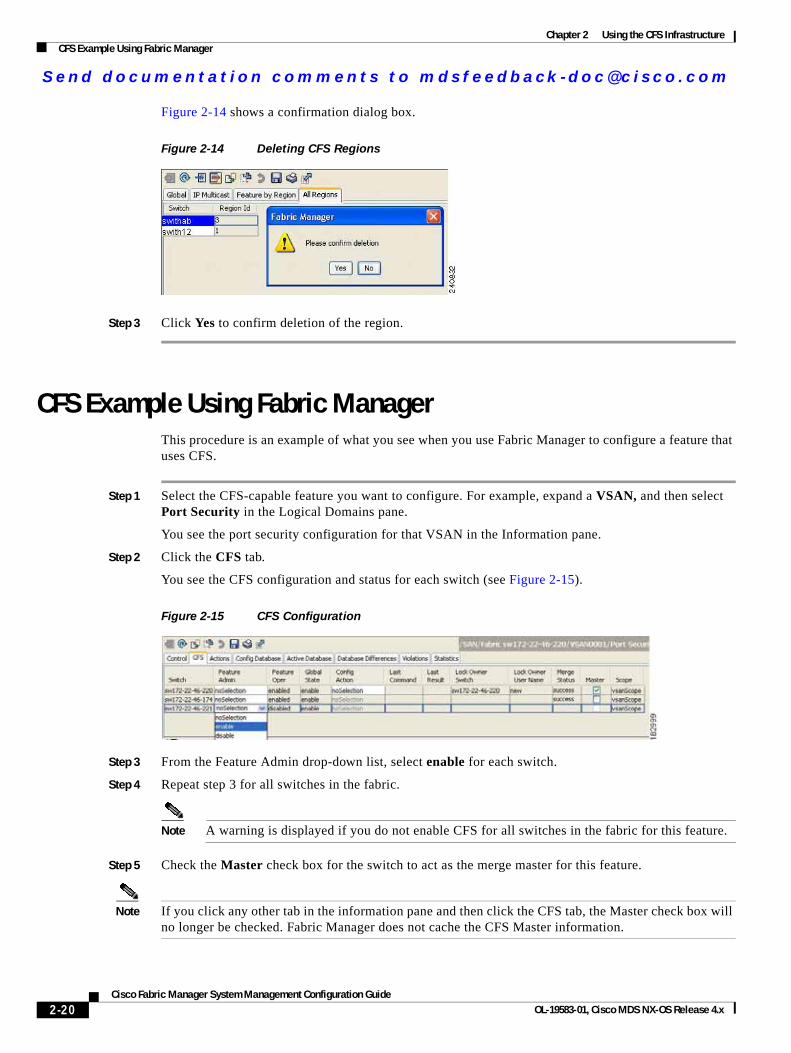
Step 1 Click the Feature by Region tab and select the required row.
Step 2 Click the Delete Row button on the toolbar.
Figure 2-13 shows a confirmation dialog box.
Figure 2-13 Removing a Feature from a Region
Step 3 Click Yes to confirm row deletion from the table in view.
Deleting CFS Regions
To delete an entire region, follow these steps:
Step 1 Click the All Regions tab and select the required row.
Step 2 Click Delete Row.
This action removes all entries pertaining to that switch and region in the table under Feature by Region tab.
2-19Cisco Fabric Manager System Management Configuration Guide
OL-19583-01, Cisco MDS NX-OS Release 4.x
Send documenta t ion comments to mdsfeedback -doc@c i sco .com
Chapter 2 Using the CFS InfrastructureCFS Example Using Fabric Manager
Figure 2-14 shows a confirmation dialog box.
Figure 2-14 Deleting CFS Regions
Step 3 Click Yes to confirm deletion of the region.
CFS Example Using Fabric ManagerThis procedure is an example of what you see when you use Fabric Manager to configure a feature that uses CFS.
Step 1 Select the CFS-capable feature you want to configure. For example, expand a VSAN, and then select Port Security in the Logical Domains pane.
You see the port security configuration for that VSAN in the Information pane.
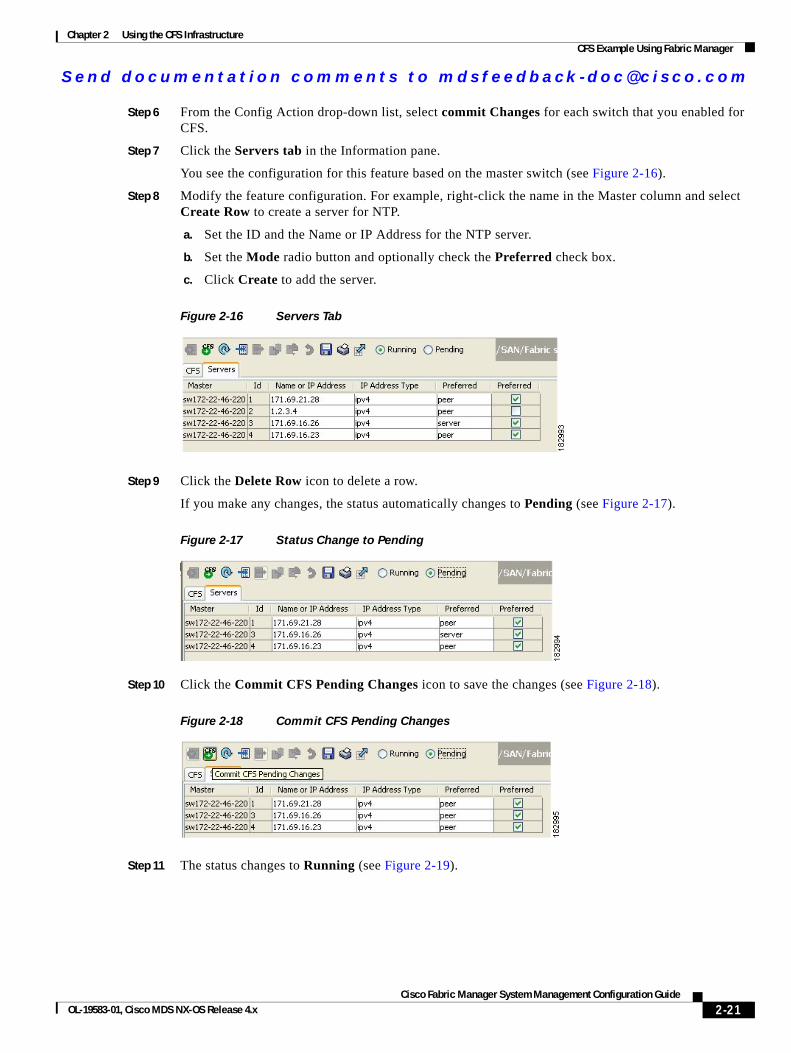
Step 2 Click the CFS tab.
You see the CFS configuration and status for each switch (see Figure 2-15).
Figure 2-15 CFS Configuration
Step 3 From the Feature Admin drop-down list, select enable for each switch.
Step 4 Repeat step 3 for all switches in the fabric.
Note A warning is displayed if you do not enable CFS for all switches in the fabric for this feature.
Step 5 Check the Master check box for the switch to act as the merge master for this feature.
Note If you click any other tab in the information pane and then click the CFS tab, the Master check box will no longer be checked. Fabric Manager does not cache the CFS Master information.
2-20Cisco Fabric Manager System Management Configuration Guide
OL-19583-01, Cisco MDS NX-OS Release 4.x
Send documenta t ion comments to mdsfeedback -doc@c i sco .com
Chapter 2 Using the CFS InfrastructureCFS Example Using Fabric Manager
Step 6 From the Config Action drop-down list, select commit Changes for each switch that you enabled for CFS.
Step 7 Click the Servers tab in the Information pane.
You see the configuration for this feature based on the master switch (see Figure 2-16).
Step 8 Modify the feature configuration. For example, right-click the name in the Master column and select Create Row to create a server for NTP.
a. Set the ID and the Name or IP Address for the NTP server.
b. Set the Mode radio button and optionally check the Preferred check box.
c. Click Create to add the server.
Figure 2-16 Servers Tab
Step 9 Click the Delete Row icon to delete a row.
If you make any changes, the status automatically changes to Pending (see Figure 2-17).
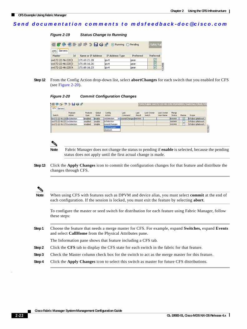
Figure 2-17 Status Change to Pending
Step 10 Click the Commit CFS Pending Changes icon to save the changes (see Figure 2-18).
Figure 2-18 Commit CFS Pending Changes
Step 11 The status changes to Running (see Figure 2-19).
2-21Cisco Fabric Manager System Management Configuration Guide
OL-19583-01, Cisco MDS NX-OS Release 4.x
Send documenta t ion comments to mdsfeedback -doc@c i sco .com
Chapter 2 Using the CFS InfrastructureCFS Example Using Fabric Manager
Figure 2-19 Status Change to Running
Step 12 From the Config Action drop-down list, select abortChanges for each switch that you enabled for CFS (see Figure 2-20).
Figure 2-20 Commit Configuration Changes
Note Fabric Manager does not change the status to pending if enable is selected, because the pending status does not apply until the first actual change is made.
Step 13 Click the Apply Changes icon to commit the configuration changes for that feature and distribute the changes through CFS.
Note When using CFS with features such as DPVM and device alias, you must select commit at the end of each configuration. If the session is locked, you must exit the feature by selecting abort.
To configure the master or seed switch for distribution for each feature using Fabric Manager, follow these steps:
Step 1 Choose the feature that needs a merge master for CFS. For example, expand Switches, expand Events and select CallHome from the Physical Attributes pane.
The Information pane shows that feature including a CFS tab.
Step 2 Click the CFS tab to display the CFS state for each switch in the fabric for that feature.
Step 3 Check the Master column check box for the switch to act as the merge master for this feature.
Step 4 Click the Apply Changes icon to select this switch as master for future CFS distributions.
.
2-22Cisco Fabric Manager System Management Configuration Guide
OL-19583-01, Cisco MDS NX-OS Release 4.x
Send documenta t ion comments to mdsfeedback -doc@c i sco .com
Chapter 2 Using the CFS InfrastructureCFS Example Using Device Manager
CFS Example Using Device ManagerThis procedure is an example of what you see when you use Device Manager to configure a feature that uses CFS. For specific procedures for features that use CFS, refer to that feature’s documentation.
To configure a feature that uses CFS using Device Manager, follow these steps:
Step 1 Open the dialog box for any CFS-capable feature. Device Manager checks to see whether CFS is enabled. It also checks to see if there is a lock on the feature by checking for at least one entry in the Owner table. If CFS is enabled and there is a lock, Device Manager sets the status to “pending” for that feature. You see a dialog box displaying the lock information.
Step 2 Click Continue or Cancel when prompted. If you continue, Device Manager remembers the CFS status.
Step 3 Choose Admin > CFS (Cisco Fabric Services) to view the user name of the CFS lock holder.
Step 4 Click the locked feature and click Details.
Step 5 Click the Owners tab and look in the UserName column.
Note Device Manager does not monitor the status of the feature across the fabric until you click Refresh. If a user on another CFS-enabled switch attempts to configure the same feature, they do not see the “pending” status. However, their configuration changes are rejected by your switch.
Step 6 If CFS is enabled and there is no lock, Device Manager sets the status to running for that feature.
You then see a dialog box for the feature. As soon as you perform a creation, deletion, or modification, Device Manager changes the status to pending and displays the updated information from the pending database.
Step 7 View the CFS table for a feature. Device Manager only changes the status to running when commit, clear, or abort is selected and applied. Device Manager will not change the status to “pending” if enable is selected, because the pending status does not apply until the first actual change is made.
The Last Command and Result fields are blank if the last command is noOp.
Note When using CFS with features like DPVM and device alias, you must select commit at the end of each configuration. If the session is locked, you must exit the feature by selecting abort.
Default SettingsTable 2-1 lists the default settings for CFS configurations.
Table 2-1 Default CFS Parameters
Parameters Default
CFS distribution on the switch Enabled.
Database changes Implicitly enabled with the first configuration change.
2-23Cisco Fabric Manager System Management Configuration Guide
OL-19583-01, Cisco MDS NX-OS Release 4.x
Send documenta t ion comments to mdsfeedback -doc@c i sco .com
Chapter 2 Using the CFS InfrastructureDefault Settings
Application distribution Differs based on application.
Commit Explicit configuration is required.
CFS over IP Disabled.
IPv4 multicast address 239.255.70.83
IPv6 multicast address ff15:efff:4653
Table 2-1 Default CFS Parameters (continued)
Parameters Default
2-24Cisco Fabric Manager System Management Configuration Guide
OL-19583-01, Cisco MDS NX-OS Release 4.x
Send documenta t ion comments to mdsfeedback -doc@c i sco .com
Cisco Fabric OL-19583-01, Cisco MDS NX-OS Release 4.x
C H A P T E R 3
Configuring System Message LoggingThis chapter describes how to configure system message logging on Cisco MDS 9000 Family switches. It includes the following sections:
• About System Message Logging, page 3-1
• System Message Logging Configuration, page 3-3
• Default Settings, page 3-10
About System Message LoggingYou can monitor system messages by clicking the Events tab on Fabric Manager or by choosing Logs > Events > Current on Device Manager. You can also monitor system messages remotely by accessing the switch through Telnet, SSH, or the console port, or by viewing the logs on a system message logging server.
Note When the switch first initializes, the network is not connected until initialization completes. Therefore, messages are not redirected to a system message logging server for a few seconds.
Log messages are not saved across system reboots. However, a maximum of 100 log messages with a severity level of critical and below (levels 0, 1, and 2) are saved in NVRAM.
Table 3-1 describes some samples of the facilities supported by the system message logs.
Table 3-1 Internal Logging Facilities
Facility Keyword Description Standard or Cisco MDS Specific
acl ACL manager Cisco MDS 9000 Family specific
all All facilities Cisco MDS 9000 Family specific
auth Authorization system Standard
authpriv Authorization (private) system Standard
bootvar Bootvar Cisco MDS 9000 Family specific
callhome Call Home Cisco MDS 9000 Family specific
cron Cron or at facility Standard
daemon System daemons Standard
3-1Manager System Management Configuration Guide
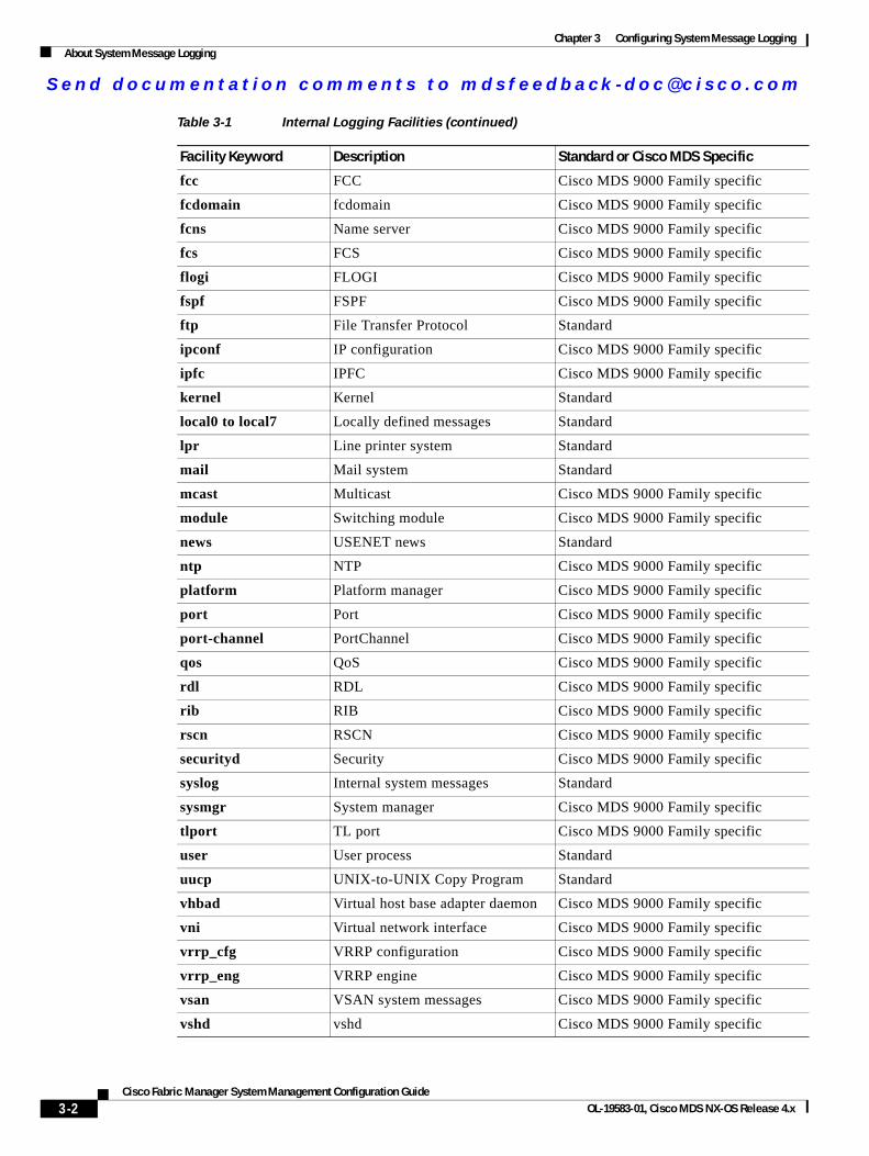
Send documenta t ion comments to mdsfeedback -doc@c i sco .com
Chapter 3 Configuring System Message LoggingAbout System Message Logging
fcc FCC Cisco MDS 9000 Family specific
fcdomain fcdomain Cisco MDS 9000 Family specific
fcns Name server Cisco MDS 9000 Family specific
fcs FCS Cisco MDS 9000 Family specific
flogi FLOGI Cisco MDS 9000 Family specific
fspf FSPF Cisco MDS 9000 Family specific
ftp File Transfer Protocol Standard
ipconf IP configuration Cisco MDS 9000 Family specific
ipfc IPFC Cisco MDS 9000 Family specific
kernel Kernel Standard
local0 to local7 Locally defined messages Standard
lpr Line printer system Standard
mail Mail system Standard
mcast Multicast Cisco MDS 9000 Family specific
module Switching module Cisco MDS 9000 Family specific
news USENET news Standard
ntp NTP Cisco MDS 9000 Family specific
platform Platform manager Cisco MDS 9000 Family specific
port Port Cisco MDS 9000 Family specific
port-channel PortChannel Cisco MDS 9000 Family specific
qos QoS Cisco MDS 9000 Family specific
rdl RDL Cisco MDS 9000 Family specific
rib RIB Cisco MDS 9000 Family specific
rscn RSCN Cisco MDS 9000 Family specific
securityd Security Cisco MDS 9000 Family specific
syslog Internal system messages Standard
sysmgr System manager Cisco MDS 9000 Family specific
tlport TL port Cisco MDS 9000 Family specific
user User process Standard
uucp UNIX-to-UNIX Copy Program Standard
vhbad Virtual host base adapter daemon Cisco MDS 9000 Family specific
vni Virtual network interface Cisco MDS 9000 Family specific
vrrp_cfg VRRP configuration Cisco MDS 9000 Family specific
vrrp_eng VRRP engine Cisco MDS 9000 Family specific
vsan VSAN system messages Cisco MDS 9000 Family specific
vshd vshd Cisco MDS 9000 Family specific
Table 3-1 Internal Logging Facilities (continued)
Facility Keyword Description Standard or Cisco MDS Specific
3-2Cisco Fabric Manager System Management Configuration Guide
OL-19583-01, Cisco MDS NX-OS Release 4.x
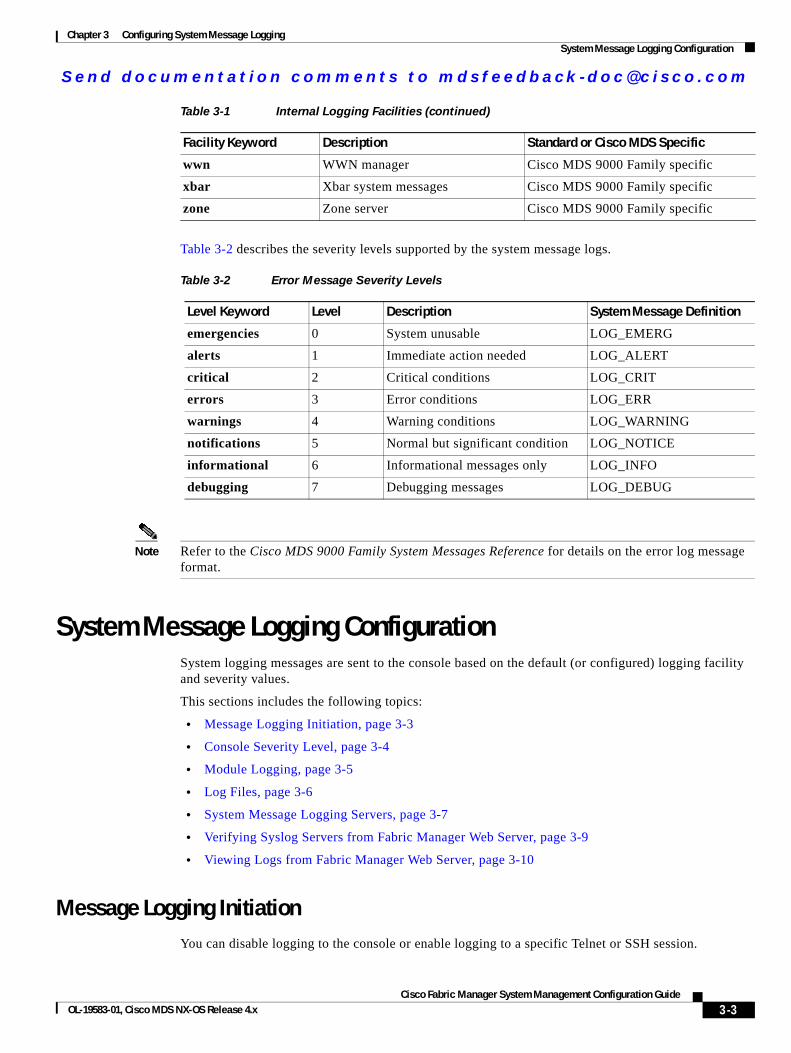
Send documenta t ion comments to mdsfeedback -doc@c i sco .com
Chapter 3 Configuring System Message LoggingSystem Message Logging Configuration
Table 3-2 describes the severity levels supported by the system message logs.
Note Refer to the Cisco MDS 9000 Family System Messages Reference for details on the error log message format.
System Message Logging ConfigurationSystem logging messages are sent to the console based on the default (or configured) logging facility and severity values.
This sections includes the following topics:
• Message Logging Initiation, page 3-3
• Console Severity Level, page 3-4
• Module Logging, page 3-5
• Log Files, page 3-6
• System Message Logging Servers, page 3-7
• Verifying Syslog Servers from Fabric Manager Web Server, page 3-9
• Viewing Logs from Fabric Manager Web Server, page 3-10
Message Logging InitiationYou can disable logging to the console or enable logging to a specific Telnet or SSH session.
wwn WWN manager Cisco MDS 9000 Family specific
xbar Xbar system messages Cisco MDS 9000 Family specific
zone Zone server Cisco MDS 9000 Family specific
Table 3-1 Internal Logging Facilities (continued)
Facility Keyword Description Standard or Cisco MDS Specific
Table 3-2 Error Message Severity Levels
Level Keyword Level Description System Message Definition
emergencies 0 System unusable LOG_EMERG
alerts 1 Immediate action needed LOG_ALERT
critical 2 Critical conditions LOG_CRIT
errors 3 Error conditions LOG_ERR
warnings 4 Warning conditions LOG_WARNING
notifications 5 Normal but significant condition LOG_NOTICE
informational 6 Informational messages only LOG_INFO
debugging 7 Debugging messages LOG_DEBUG
3-3Cisco Fabric Manager System Management Configuration Guide
OL-19583-01, Cisco MDS NX-OS Release 4.x
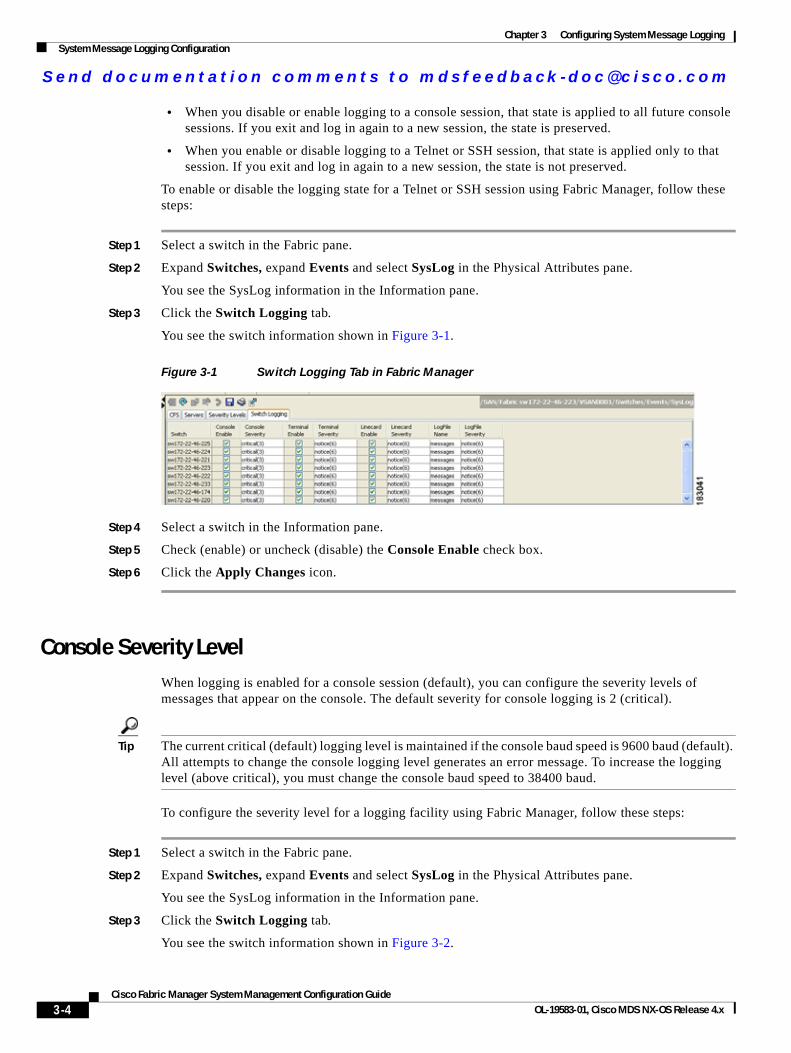
Send documenta t ion comments to mdsfeedback -doc@c i sco .com
Chapter 3 Configuring System Message LoggingSystem Message Logging Configuration
• When you disable or enable logging to a console session, that state is applied to all future console sessions. If you exit and log in again to a new session, the state is preserved.
• When you enable or disable logging to a Telnet or SSH session, that state is applied only to that session. If you exit and log in again to a new session, the state is not preserved.
To enable or disable the logging state for a Telnet or SSH session using Fabric Manager, follow these steps:
Step 1 Select a switch in the Fabric pane.
Step 2 Expand Switches, expand Events and select SysLog in the Physical Attributes pane.
You see the SysLog information in the Information pane.
Step 3 Click the Switch Logging tab.
You see the switch information shown in Figure 3-1.
Figure 3-1 Switch Logging Tab in Fabric Manager
Step 4 Select a switch in the Information pane.
Step 5 Check (enable) or uncheck (disable) the Console Enable check box.
Step 6 Click the Apply Changes icon.
Console Severity LevelWhen logging is enabled for a console session (default), you can configure the severity levels of messages that appear on the console. The default severity for console logging is 2 (critical).
Tip The current critical (default) logging level is maintained if the console baud speed is 9600 baud (default). All attempts to change the console logging level generates an error message. To increase the logging level (above critical), you must change the console baud speed to 38400 baud.
To configure the severity level for a logging facility using Fabric Manager, follow these steps:
Step 1 Select a switch in the Fabric pane.
Step 2 Expand Switches, expand Events and select SysLog in the Physical Attributes pane.
You see the SysLog information in the Information pane.
Step 3 Click the Switch Logging tab.
You see the switch information shown in Figure 3-2.
3-4Cisco Fabric Manager System Management Configuration Guide
OL-19583-01, Cisco MDS NX-OS Release 4.x
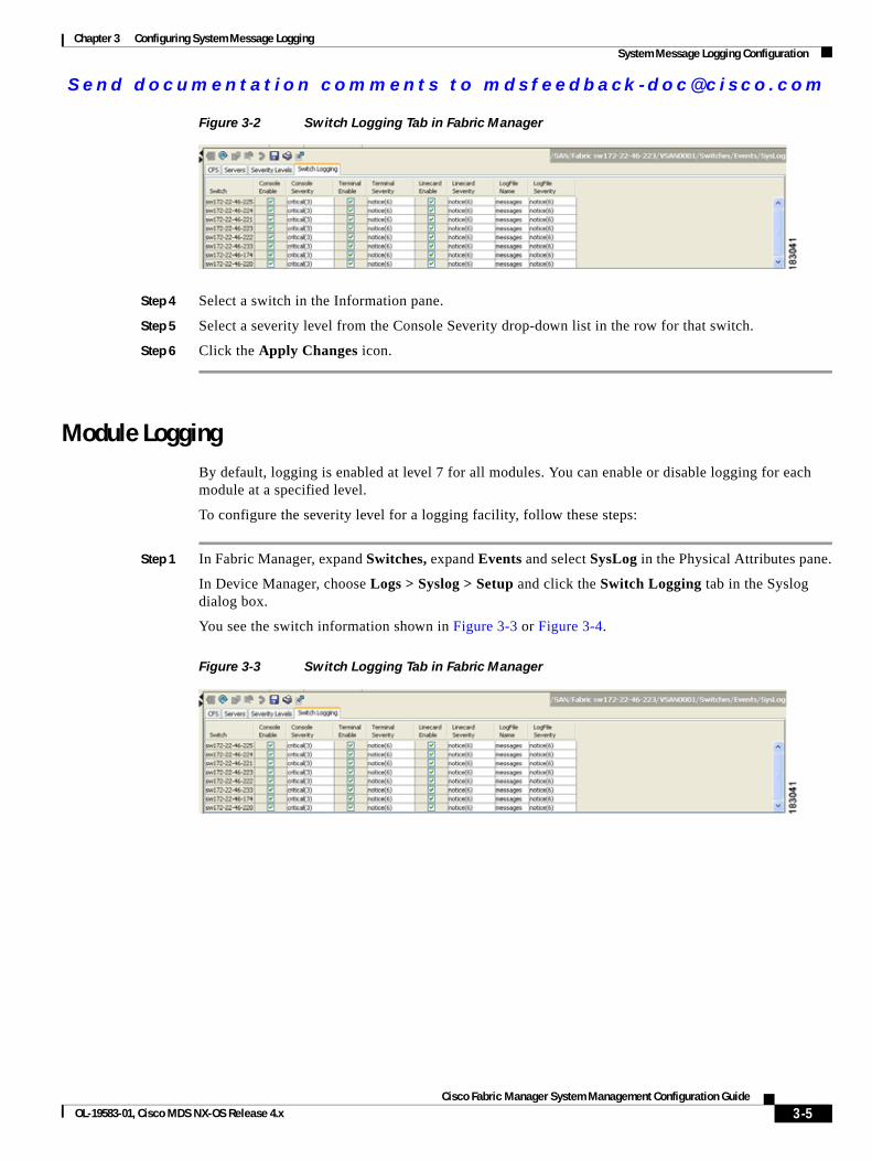
Send documenta t ion comments to mdsfeedback -doc@c i sco .com
Chapter 3 Configuring System Message LoggingSystem Message Logging Configuration
Figure 3-2 Switch Logging Tab in Fabric Manager
Step 4 Select a switch in the Information pane.
Step 5 Select a severity level from the Console Severity drop-down list in the row for that switch.
Step 6 Click the Apply Changes icon.
Module LoggingBy default, logging is enabled at level 7 for all modules. You can enable or disable logging for each module at a specified level.
To configure the severity level for a logging facility, follow these steps:
Step 1 In Fabric Manager, expand Switches, expand Events and select SysLog in the Physical Attributes pane.
In Device Manager, choose Logs > Syslog > Setup and click the Switch Logging tab in the Syslog dialog box.
You see the switch information shown in Figure 3-3 or Figure 3-4.
Figure 3-3 Switch Logging Tab in Fabric Manager
3-5Cisco Fabric Manager System Management Configuration Guide
OL-19583-01, Cisco MDS NX-OS Release 4.x
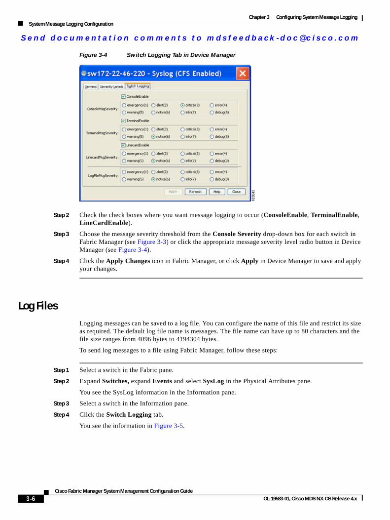
Send documenta t ion comments to mdsfeedback -doc@c i sco .com
Chapter 3 Configuring System Message LoggingSystem Message Logging Configuration
Figure 3-4 Switch Logging Tab in Device Manager
Step 2 Check the check boxes where you want message logging to occur (ConsoleEnable, TerminalEnable, LineCardEnable).
Step 3 Choose the message severity threshold from the Console Severity drop-down box for each switch in Fabric Manager (see Figure 3-3) or click the appropriate message severity level radio button in Device Manager (see Figure 3-4).
Step 4 Click the Apply Changes icon in Fabric Manager, or click Apply in Device Manager to save and apply your changes.
Log FilesLogging messages can be saved to a log file. You can configure the name of this file and restrict its size as required. The default log file name is messages. The file name can have up to 80 characters and the file size ranges from 4096 bytes to 4194304 bytes.
To send log messages to a file using Fabric Manager, follow these steps:
Step 1 Select a switch in the Fabric pane.
Step 2 Expand Switches, expand Events and select SysLog in the Physical Attributes pane.
You see the SysLog information in the Information pane.
Step 3 Select a switch in the Information pane.
Step 4 Click the Switch Logging tab.
You see the information in Figure 3-5.
3-6Cisco Fabric Manager System Management Configuration Guide
OL-19583-01, Cisco MDS NX-OS Release 4.x
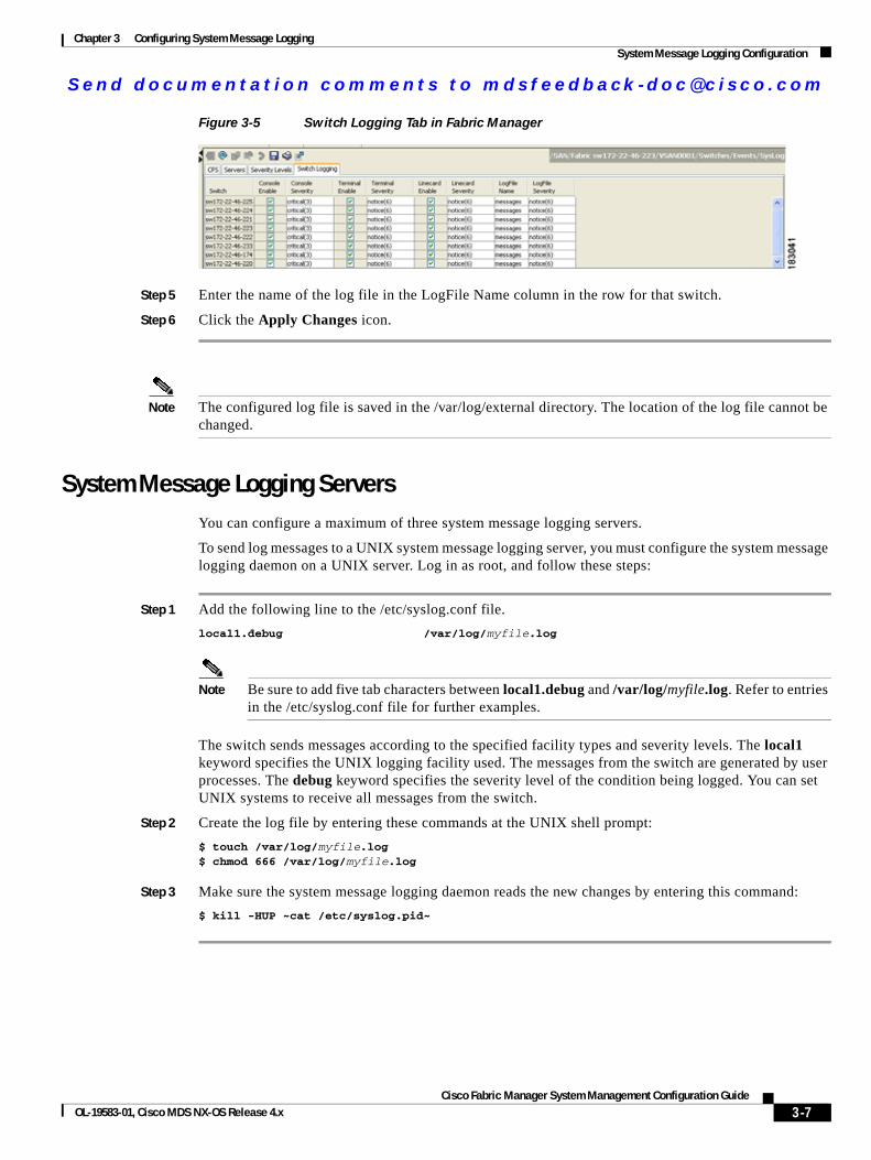
Send documenta t ion comments to mdsfeedback -doc@c i sco .com
Chapter 3 Configuring System Message LoggingSystem Message Logging Configuration
Figure 3-5 Switch Logging Tab in Fabric Manager
Step 5 Enter the name of the log file in the LogFile Name column in the row for that switch.
Step 6 Click the Apply Changes icon.
Note The configured log file is saved in the /var/log/external directory. The location of the log file cannot be changed.
System Message Logging ServersYou can configure a maximum of three system message logging servers.
To send log messages to a UNIX system message logging server, you must configure the system message logging daemon on a UNIX server. Log in as root, and follow these steps:
Step 1 Add the following line to the /etc/syslog.conf file.
local1.debug /var/log/myfile.log
Note Be sure to add five tab characters between local1.debug and /var/log/myfile.log. Refer to entries in the /etc/syslog.conf file for further examples.
The switch sends messages according to the specified facility types and severity levels. The local1 keyword specifies the UNIX logging facility used. The messages from the switch are generated by user processes. The debug keyword specifies the severity level of the condition being logged. You can set UNIX systems to receive all messages from the switch.
Step 2 Create the log file by entering these commands at the UNIX shell prompt:
$ touch /var/log/myfile.log$ chmod 666 /var/log/myfile.log
Step 3 Make sure the system message logging daemon reads the new changes by entering this command:
$ kill -HUP ~cat /etc/syslog.pid~
3-7Cisco Fabric Manager System Management Configuration Guide
OL-19583-01, Cisco MDS NX-OS Release 4.x
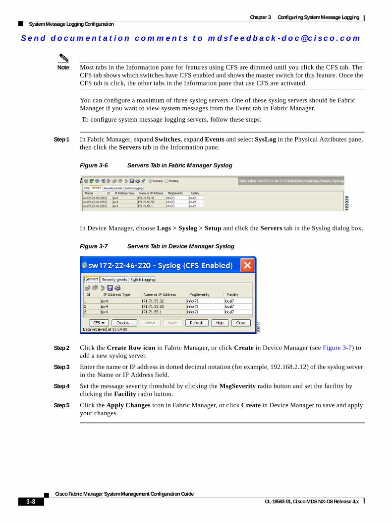
Send documenta t ion comments to mdsfeedback -doc@c i sco .com
Chapter 3 Configuring System Message LoggingSystem Message Logging Configuration
Note Most tabs in the Information pane for features using CFS are dimmed until you click the CFS tab. The CFS tab shows which switches have CFS enabled and shows the master switch for this feature. Once the CFS tab is click, the other tabs in the Information pane that use CFS are activated.
You can configure a maximum of three syslog servers. One of these syslog servers should be Fabric Manager if you want to view system messages from the Event tab in Fabric Manager.
To configure system message logging servers, follow these steps:
Step 1 In Fabric Manager, expand Switches, expand Events and select SysLog in the Physical Attributes pane, then click the Servers tab in the Information pane.
Figure 3-6 Servers Tab in Fabric Manager Syslog
In Device Manager, choose Logs > Syslog > Setup and click the Servers tab in the Syslog dialog box.
Figure 3-7 Servers Tab in Device Manager Syslog
Step 2 Click the Create Row icon in Fabric Manager, or click Create in Device Manager (see Figure 3-7) to add a new syslog server.
Step 3 Enter the name or IP address in dotted decimal notation (for example, 192.168.2.12) of the syslog server in the Name or IP Address field.
Step 4 Set the message severity threshold by clicking the MsgSeverity radio button and set the facility by clicking the Facility radio button.
Step 5 Click the Apply Changes icon in Fabric Manager, or click Create in Device Manager to save and apply your changes.
3-8Cisco Fabric Manager System Management Configuration Guide
OL-19583-01, Cisco MDS NX-OS Release 4.x
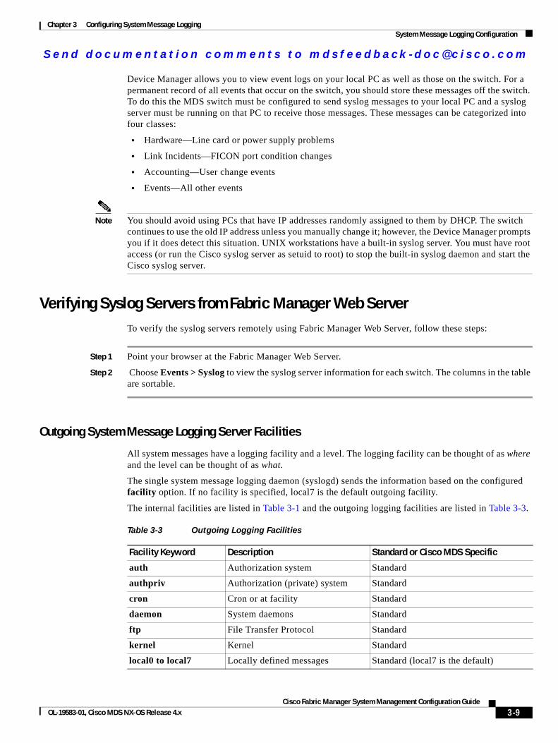
Send documenta t ion comments to mdsfeedback -doc@c i sco .com
Chapter 3 Configuring System Message LoggingSystem Message Logging Configuration
Device Manager allows you to view event logs on your local PC as well as those on the switch. For a permanent record of all events that occur on the switch, you should store these messages off the switch. To do this the MDS switch must be configured to send syslog messages to your local PC and a syslog server must be running on that PC to receive those messages. These messages can be categorized into four classes:
• Hardware—Line card or power supply problems
• Link Incidents—FICON port condition changes
• Accounting—User change events
• Events—All other events
Note You should avoid using PCs that have IP addresses randomly assigned to them by DHCP. The switch continues to use the old IP address unless you manually change it; however, the Device Manager prompts you if it does detect this situation. UNIX workstations have a built-in syslog server. You must have root access (or run the Cisco syslog server as setuid to root) to stop the built-in syslog daemon and start the Cisco syslog server.
Verifying Syslog Servers from Fabric Manager Web ServerTo verify the syslog servers remotely using Fabric Manager Web Server, follow these steps:
Step 1 Point your browser at the Fabric Manager Web Server.
Step 2 Choose Events > Syslog to view the syslog server information for each switch. The columns in the table are sortable.
Outgoing System Message Logging Server Facilities
All system messages have a logging facility and a level. The logging facility can be thought of as where and the level can be thought of as what.
The single system message logging daemon (syslogd) sends the information based on the configured facility option. If no facility is specified, local7 is the default outgoing facility.
The internal facilities are listed in Table 3-1 and the outgoing logging facilities are listed in Table 3-3.
Table 3-3 Outgoing Logging Facilities
Facility Keyword Description Standard or Cisco MDS Specific
auth Authorization system Standard
authpriv Authorization (private) system Standard
cron Cron or at facility Standard
daemon System daemons Standard
ftp File Transfer Protocol Standard
kernel Kernel Standard
local0 to local7 Locally defined messages Standard (local7 is the default)
3-9Cisco Fabric Manager System Management Configuration Guide
OL-19583-01, Cisco MDS NX-OS Release 4.x
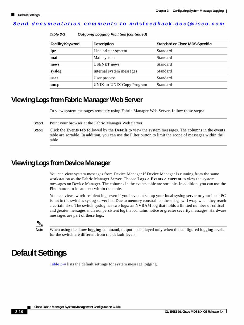
Send documenta t ion comments to mdsfeedback -doc@c i sco .com
Chapter 3 Configuring System Message LoggingDefault Settings
Viewing Logs from Fabric Manager Web ServerTo view system messages remotely using Fabric Manager Web Server, follow these steps:
Step 1 Point your browser at the Fabric Manager Web Server.
Step 2 Click the Events tab followed by the Details to view the system messages. The columns in the events table are sortable. In addition, you can use the Filter button to limit the scope of messages within the table.
Viewing Logs from Device ManagerYou can view system messages from Device Manager if Device Manager is running from the same workstation as the Fabric Manager Server. Choose Logs > Events > current to view the system messages on Device Manager. The columns in the events table are sortable. In addition, you can use the Find button to locate text within the table.
You can view switch-resident logs even if you have not set up your local syslog server or your local PC is not in the switch's syslog server list. Due to memory constraints, these logs will wrap when they reach a certain size. The switch syslog has two logs: an NVRAM log that holds a limited number of critical and greater messages and a nonpersistent log that contains notice or greater severity messages. Hardware messages are part of these logs.
Note When using the show logging command, output is displayed only when the configured logging levels for the switch are different from the default levels.
Default SettingsTable 3-4 lists the default settings for system message logging.
lpr Line printer system Standard
mail Mail system Standard
news USENET news Standard
syslog Internal system messages Standard
user User process Standard
uucp UNIX-to-UNIX Copy Program Standard
Table 3-3 Outgoing Logging Facilities (continued)
Facility Keyword Description Standard or Cisco MDS Specific
3-10Cisco Fabric Manager System Management Configuration Guide
OL-19583-01, Cisco MDS NX-OS Release 4.x
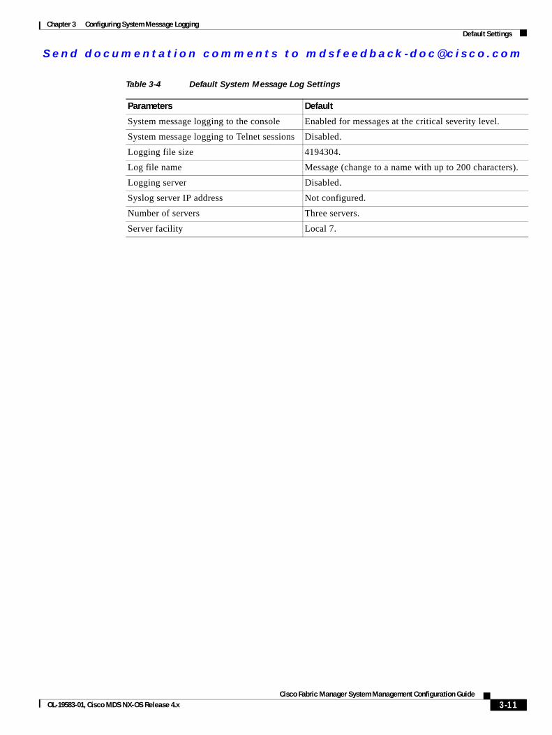
Send documenta t ion comments to mdsfeedback -doc@c i sco .com
Chapter 3 Configuring System Message LoggingDefault Settings
Table 3-4 Default System Message Log Settings
Parameters Default
System message logging to the console Enabled for messages at the critical severity level.
System message logging to Telnet sessions Disabled.
Logging file size 4194304.
Log file name Message (change to a name with up to 200 characters).
Logging server Disabled.
Syslog server IP address Not configured.
Number of servers Three servers.
Server facility Local 7.
3-11Cisco Fabric Manager System Management Configuration Guide
OL-19583-01, Cisco MDS NX-OS Release 4.x

Send documenta t ion comments to mdsfeedback -doc@c i sco .com
Chapter 3 Configuring System Message LoggingDefault Settings
3-12Cisco Fabric Manager System Management Configuration Guide
OL-19583-01, Cisco MDS NX-OS Release 4.x
Send documenta t ion comments to mdsfeedback -doc@c i sco .com
Cisco Fabric OL-19583-01, Cisco MDS NX-OS Release 4.x
C H A P T E R 4
Configuring Call HomeCall Home provides e-mail-based notification of critical system events. A versatile range of message formats are available for optimal compatibility with pager services, standard e-mail, or XML-based automated parsing applications. Common uses of this feature may include direct paging of a network support engineer, e-mail notification to a Network Operations Center, and utilization of Cisco Smart Call Home services for direct case generation with the Technical Assistance Center.
Note Cisco Autonotify is upgraded to a new capability called Smart Call Home. Smart Call Home has significant functionality improvement over Autonotify and is available across the Cisco product range. For detailed information on Smart Call Home, see the Smart Call Home page at this location: http://www.cisco.com/go/smartcall/
The Call Home feature provides message throttling capabilities. Periodic inventory messages, port syslog messages, and RMON alert messages are added to the list of deliverable Call Home messages. If required you can also use the Cisco Fabric Services application to distribute the Call Home configuration to all other switches in the fabric.
This chapter includes the following sections:
• Call Home Features, page 4-2
• About Smart Call Home, page 4-2
• Obtaining Smart Call Home, page 4-5
• Configuring Call Home, page 4-5
• Configuring Contact Information, page 4-6
• Destination Profiles, page 4-8
• Alert Groups, page 4-9
• Customized Alert Group Messages, page 4-10
• Call Home Message Level Feature, page 4-12
• Syslog-Based Alerts, page 4-12
• RMON-Based Alerts, page 4-13
• E-Mail Options, page 4-14
• HTTPS Support, page 4-15
• Periodic Inventory Notification, page 4-15
4-1Manager System Management Configuration Guide
Send documenta t ion comments to mdsfeedback -doc@c i sco .com
Chapter 4 Configuring Call HomeCall Home Features
• Duplicate Message Throttle, page 4-16
• Call Home Enable Function, page 4-17
• Call Home Configuration Distribution, page 4-18
• Call Home Communications Test, page 4-19
• Clearing Call Home Name Server Database, page 4-20
• Configuring EMC E-mail Home Delayed Traps, page 4-20
• Event Triggers, page 4-29
• Call Home Message Levels, page 4-31
• Message Contents, page 4-32
Call Home FeaturesThe Call Home functionality is available directly through the Cisco MDS 9000 Family. It provides multiple Call Home profiles (also referred to as Call Home destination profiles), each with separate potential destinations. You can define your own destination profiles in addition to predefined profiles.
The Call Home function can even leverage support from Cisco Systems or another support partner. Flexible message delivery and format options make it easy to integrate specific support requirements.
The Call Home feature offers the following advantages:
• Fixed set of predefined alerts and trigger events on the switch.
• Automatic execution and attachment of relevant command output.
• Multiple message format options:
– Short Text—Suitable for pagers or printed reports.
– Plain Text—Full formatted message information suitable for human reading.
– XML—Matching readable format using Extensible Markup Language (XML) and document type definitions (DTDs) named Messaging Markup Language (MML). The MML DTD is published on the Cisco.com website at http://www.cisco.com/. The XML format enables communication with the Cisco Systems Technical Assistance Center.
• Multiple concurrent message destinations. You can configure up to 50 e-mail destination addresses for each destination profile.
• Multiple message categories including system, environment, switching module hardware, supervisor module, hardware, inventory, syslog, RMON, and test.
About Smart Call HomeSmart Call Home is a component of Cisco SMARTnet Service that offers proactive diagnostics, real-time alerts, and personalized web-based reports on select Cisco devices.
Smart Call Home provides fast resolution of system problems by analyzing Call Home messages sent from your devices and providing a direct notification path to Cisco customer support.
Smart Call Home offers the following features:
• Continuous device health monitoring and real-time diagnostics alerts.
4-2Cisco Fabric Manager System Management Configuration Guide
OL-19583-01, Cisco MDS NX-OS Release 4.x
Send documenta t ion comments to mdsfeedback -doc@c i sco .com
Chapter 4 Configuring Call HomeAbout Smart Call Home
• Analysis of Call Home messages from your device and where appropriate, automatic service request generation, routed to the appropriate TAC team, including detailed diagnostic information to speed problem resolution.
• Secure message transport through a downloadable Transport Gateway (TG) aggregation point. You can use a TG aggregation point in cases requiring support for multiple devices or in cases where security requirements mandate that your devices not be connected directly to the Internet.
• Web-based access to Call Home messages and recommendations, inventory and configuration information for all Call Home devices. Provides access to associated Field Notices, Security Advisories and End-of-Life Information.
4-3Cisco Fabric Manager System Management Configuration Guide
OL-19583-01, Cisco MDS NX-OS Release 4.x
Send documenta t ion comments to mdsfeedback -doc@c i sco .com
Chapter 4 Configuring Call HomeAbout Smart Call Home
Table 4-1 lists the benefits of Smart Call Home.
Table 4-1 Benefits of Smart Call Home Compared to Autonotify
Feature Smart Call Home Autonotify
Low touch registration The registration process is considerably streamlined. Customers no longer need to know their device serial number or contract information. They can register devices without manual intervention from Cisco by sending a message from those devices. The procedures are outlined at www.cisco.com/go/smartcall
Requires the customer to request Cisco to add each specific serial number to the database.
Recommendations Smart Call Home provides recommendations for known issues including those for which SRs are raised and for which SRs are not appropriate but for which customers might want to still take action on.
Autonotify raises SRs for a set of failure scenarios but no recommendations are provided for these.
Device report Device report includes full inventory and configuration details. Once available, the information in these reports will be mapped to field notices, PSIRTs, EoX notices, configuration best practices and bugs.
No.
History report The history report is available to look up any message and its contents, including show commands, message processing, analysis results, recommendations and service request numbers for all messages sent over the past three months.
A basic version is available that does not include contents of message.
4-4Cisco Fabric Manager System Management Configuration Guide
OL-19583-01, Cisco MDS NX-OS Release 4.x
Send documenta t ion comments to mdsfeedback -doc@c i sco .com
Chapter 4 Configuring Call HomeObtaining Smart Call Home
Obtaining Smart Call HomeIf you have a service contract directly with Cisco Systems, you can receive automatic case generation from the Technical Assistance Center by registering with the Smart Call Home service.
You need the following items to register:
• The SMARTnet contract number for your switch.
• Your e-mail address
• Your Cisco.com ID
For detailed information on Smart Call Home, including quick start configuration and registration steps, see the Smart Call Home page at this location:
http://www.cisco.com/go/smartcall/
Configuring Call HomeHow you configure the Call Home process depends on how you intend to use the feature. Some points to consider include:
• An e-mail server and at least one destination profile (predefined or user-defined) must be configured. The destination profile(s) used depends on whether the receiving entity is a pager, e-mail, or automated service such as Cisco Smart Call Home.
• Switches can forward events (SNMP traps/informs) up to 10 destinations.
• The contact name (SNMP server contact), phone, and street address information must be configured before Call Home is enabled. This configuration is required to determine the origin of messages received.
• The Cisco MDS 9000 switch must have IP connectivity to an e-mail server.
• If Cisco Smart Call Home is used, an active service contract must cover the device being configured.
To configure Call Home, follow these steps:
Step 1 Assign contact information.
Network summary report A report that provides a summary of the make-up of devices and modules in the customer network (for those devices registered with Smart Call home)
No.
Cisco device support Device Support will be extended across the Cisco product range. See the supported products table at www.cisco.com/go/smartcall
Deprecated in favor of Smart Call Home in October 2008.
Table 4-1 Benefits of Smart Call Home Compared to Autonotify (continued)
Feature Smart Call Home Autonotify
4-5Cisco Fabric Manager System Management Configuration Guide
OL-19583-01, Cisco MDS NX-OS Release 4.x
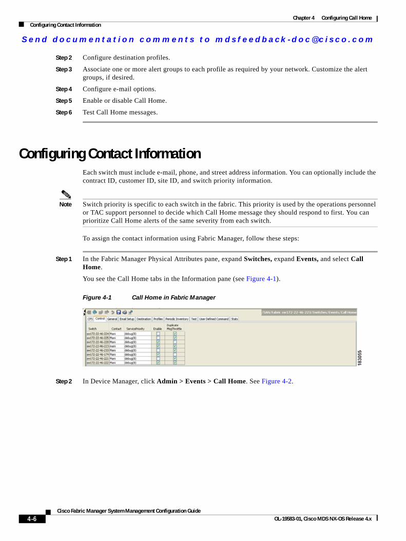
Send documenta t ion comments to mdsfeedback -doc@c i sco .com
Chapter 4 Configuring Call HomeConfiguring Contact Information
Step 2 Configure destination profiles.
Step 3 Associate one or more alert groups to each profile as required by your network. Customize the alert groups, if desired.
Step 4 Configure e-mail options.
Step 5 Enable or disable Call Home.
Step 6 Test Call Home messages.
Configuring Contact InformationEach switch must include e-mail, phone, and street address information. You can optionally include the contract ID, customer ID, site ID, and switch priority information.
Note Switch priority is specific to each switch in the fabric. This priority is used by the operations personnel or TAC support personnel to decide which Call Home message they should respond to first. You can prioritize Call Home alerts of the same severity from each switch.
To assign the contact information using Fabric Manager, follow these steps:
Step 1 In the Fabric Manager Physical Attributes pane, expand Switches, expand Events, and select Call Home.
You see the Call Home tabs in the Information pane (see Figure 4-1).
Figure 4-1 Call Home in Fabric Manager
Step 2 In Device Manager, click Admin > Events > Call Home. See Figure 4-2.
4-6Cisco Fabric Manager System Management Configuration Guide
OL-19583-01, Cisco MDS NX-OS Release 4.x
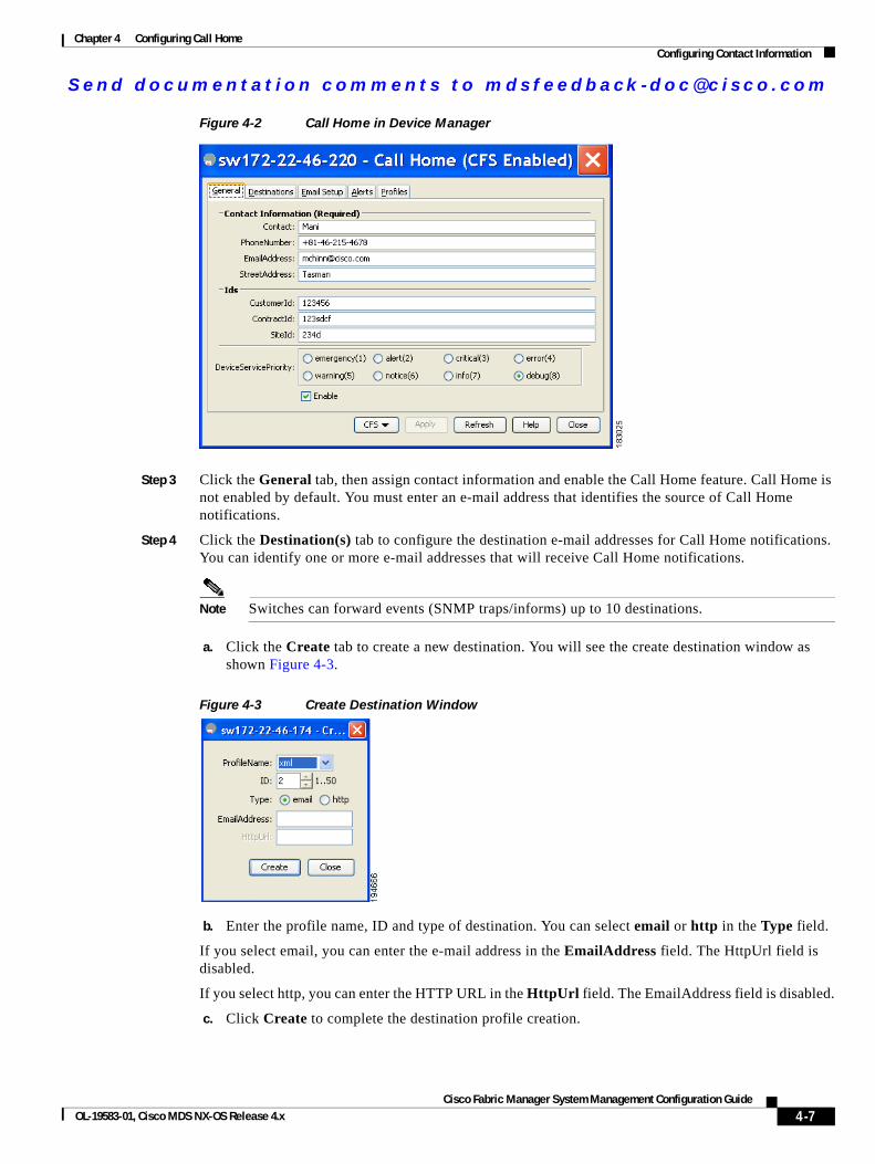
Send documenta t ion comments to mdsfeedback -doc@c i sco .com
Chapter 4 Configuring Call HomeConfiguring Contact Information
Figure 4-2 Call Home in Device Manager
Step 3 Click the General tab, then assign contact information and enable the Call Home feature. Call Home is not enabled by default. You must enter an e-mail address that identifies the source of Call Home notifications.
Step 4 Click the Destination(s) tab to configure the destination e-mail addresses for Call Home notifications. You can identify one or more e-mail addresses that will receive Call Home notifications.
Note Switches can forward events (SNMP traps/informs) up to 10 destinations.
a. Click the Create tab to create a new destination. You will see the create destination window as shown Figure 4-3.
Figure 4-3 Create Destination Window
b. Enter the profile name, ID and type of destination. You can select email or http in the Type field.
If you select email, you can enter the e-mail address in the EmailAddress field. The HttpUrl field is disabled.
If you select http, you can enter the HTTP URL in the HttpUrl field. The EmailAddress field is disabled.
c. Click Create to complete the destination profile creation.
4-7Cisco Fabric Manager System Management Configuration Guide
OL-19583-01, Cisco MDS NX-OS Release 4.x

Send documenta t ion comments to mdsfeedback -doc@c i sco .com
Chapter 4 Configuring Call HomeDestination Profiles
Step 5 Click the e-mail Setup tab to identify the SMTP server. Identify a message server to which your switch has access. This message server will forward the Call Home notifications to the destinations.
Step 6 In Fabric Manager, click the Apply Changes icon. In Device Manager, click Apply.
Destination ProfilesA destination profile contains the required delivery information for an alert notification. Destination profiles are typically configured by the network administrator. At least one destination profile is required. You can configure multiple destination profiles of one or more types.
You can use one of the predefined destination profiles or define a desired profile. If you define a new profile, you must assign a profile name.
Note If you use the Cisco Smart Call Home service, the XML destination profile is required (see http://www.cisco.com/en/US/partner/products/hw/ps4159/ps4358/products_configuration_example09186a0080108e72.shtml).
You can configure the following attributes for a destination profile:
• Profile name—A string that uniquely identifies each user-defined destination profile and is limited to 32 alphanumeric characters. The format options for a user-defined destination profile are full-txt, short-txt, or XML (default).
• Destination address—The actual address, pertinent to the transport mechanism, to which the alert should be sent.
• Message formatting—The message format used for sending the alert (full text, short text, or XML).
To configure predefined destination profile messaging options using Fabric Manager, follow these steps:
Step 1 Expand Switches, expand Events, and select Call Home in the Physical Attributes pane.
Note The Destination tab is disabled, until you click the Profiles tab. The profiles have to be loaded for the destination tab to be populated.
Step 2 Click the Profiles tab in the Information pane.
You see the Call Home profiles for multiple switches shown in Figure 4-4.
Figure 4-4 Call Home Profiles for Multiple Switches
Step 3 Set the profile name, message format, message size, and severity level.
Step 4 Click in the Alert Groups column and select or remove an alert group.
4-8Cisco Fabric Manager System Management Configuration Guide
OL-19583-01, Cisco MDS NX-OS Release 4.x
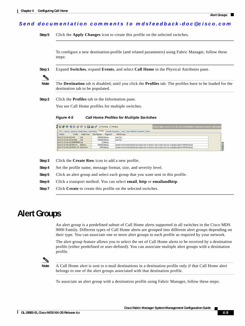
Send documenta t ion comments to mdsfeedback -doc@c i sco .com
Chapter 4 Configuring Call HomeAlert Groups
Step 5 Click the Apply Changes icon to create this profile on the selected switches.
To configure a new destination-profile (and related parameters) using Fabric Manager, follow these steps:
Step 1 Expand Switches, expand Events, and select Call Home in the Physical Attributes pane.
Note The Destination tab is disabled, until you click the Profiles tab. The profiles have to be loaded for the destination tab to be populated.
Step 2 Click the Profiles tab in the Information pane.
You see Call Home profiles for multiple switches.
Figure 4-5 Call Home Profiles for Multiple Switches
Step 3 Click the Create Row icon to add a new profile.
Step 4 Set the profile name, message format, size, and severity level.
Step 5 Click an alert group and select each group that you want sent in this profile.
Step 6 Click a transport method. You can select email, http or emailandhttp.
Step 7 Click Create to create this profile on the selected switches.
Alert GroupsAn alert group is a predefined subset of Call Home alerts supported in all switches in the Cisco MDS 9000 Family. Different types of Call Home alerts are grouped into different alert groups depending on their type. You can associate one or more alert groups to each profile as required by your network.
The alert group feature allows you to select the set of Call Home alerts to be received by a destination profile (either predefined or user-defined). You can associate multiple alert groups with a destination profile.
Note A Call Home alert is sent to e-mail destinations in a destination profile only if that Call Home alert belongs to one of the alert groups associated with that destination profile.
To associate an alert group with a destination profile using Fabric Manager, follow these steps:
4-9Cisco Fabric Manager System Management Configuration Guide
OL-19583-01, Cisco MDS NX-OS Release 4.x
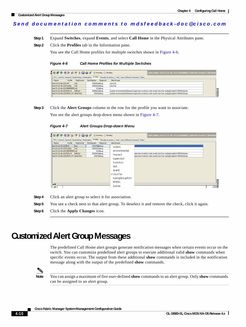
Send documenta t ion comments to mdsfeedback -doc@c i sco .com
Chapter 4 Configuring Call HomeCustomized Alert Group Messages
Step 1 Expand Switches, expand Events, and select Call Home in the Physical Attributes pane.
Step 2 Click the Profiles tab in the Information pane.
You see the Call Home profiles for multiple switches shown in Figure 4-6.
Figure 4-6 Call Home Profiles for Multiple Switches
Step 3 Click the Alert Groups column in the row for the profile you want to associate.
You see the alert groups drop-down menu shown in Figure 4-7.
Figure 4-7 Alert Groups Drop-down Menu
Step 4 Click an alert group to select it for association.
Step 5 You see a check next to that alert group. To deselect it and remove the check, click it again.
Step 6 Click the Apply Changes icon.
Customized Alert Group MessagesThe predefined Call Home alert groups generate notification messages when certain events occur on the switch. You can customize predefined alert groups to execute additional valid show commands when specific events occur. The output from these additional show commands is included in the notification message along with the output of the predefined show commands.
Note You can assign a maximum of five user-defined show commands to an alert group. Only show commands can be assigned to an alert group.
4-10Cisco Fabric Manager System Management Configuration Guide
OL-19583-01, Cisco MDS NX-OS Release 4.x
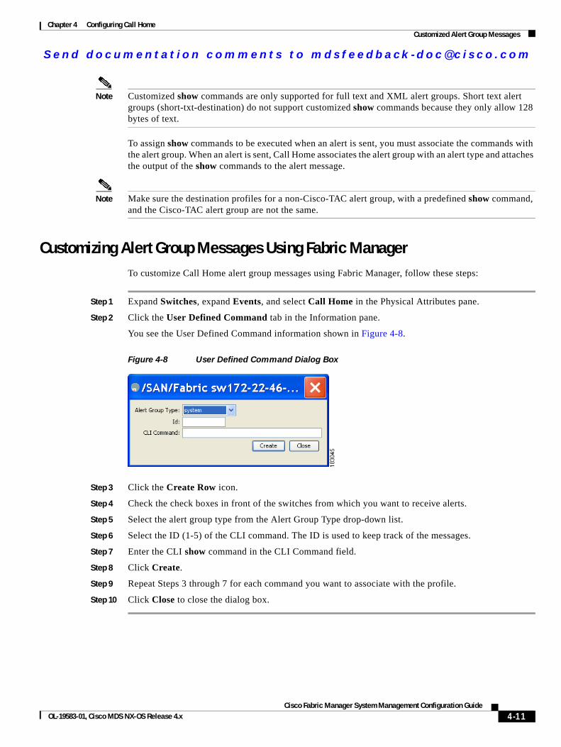
Send documenta t ion comments to mdsfeedback -doc@c i sco .com
Chapter 4 Configuring Call HomeCustomized Alert Group Messages
Note Customized show commands are only supported for full text and XML alert groups. Short text alert groups (short-txt-destination) do not support customized show commands because they only allow 128 bytes of text.
To assign show commands to be executed when an alert is sent, you must associate the commands with the alert group. When an alert is sent, Call Home associates the alert group with an alert type and attaches the output of the show commands to the alert message.
Note Make sure the destination profiles for a non-Cisco-TAC alert group, with a predefined show command, and the Cisco-TAC alert group are not the same.
Customizing Alert Group Messages Using Fabric ManagerTo customize Call Home alert group messages using Fabric Manager, follow these steps:
Step 1 Expand Switches, expand Events, and select Call Home in the Physical Attributes pane.
Step 2 Click the User Defined Command tab in the Information pane.
You see the User Defined Command information shown in Figure 4-8.
Figure 4-8 User Defined Command Dialog Box
Step 3 Click the Create Row icon.
Step 4 Check the check boxes in front of the switches from which you want to receive alerts.
Step 5 Select the alert group type from the Alert Group Type drop-down list.
Step 6 Select the ID (1-5) of the CLI command. The ID is used to keep track of the messages.
Step 7 Enter the CLI show command in the CLI Command field.
Step 8 Click Create.
Step 9 Repeat Steps 3 through 7 for each command you want to associate with the profile.
Step 10 Click Close to close the dialog box.
4-11Cisco Fabric Manager System Management Configuration Guide
OL-19583-01, Cisco MDS NX-OS Release 4.x
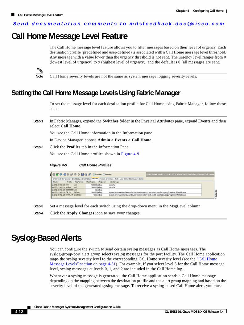
Send documenta t ion comments to mdsfeedback -doc@c i sco .com
Chapter 4 Configuring Call HomeCall Home Message Level Feature
Call Home Message Level FeatureThe Call Home message level feature allows you to filter messages based on their level of urgency. Each destination profile (predefined and user-defined) is associated with a Call Home message level threshold. Any message with a value lower than the urgency threshold is not sent. The urgency level ranges from 0 (lowest level of urgency) to 9 (highest level of urgency), and the default is 0 (all messages are sent).
Note Call Home severity levels are not the same as system message logging severity levels.
Setting the Call Home Message Levels Using Fabric ManagerTo set the message level for each destination profile for Call Home using Fabric Manager, follow these steps:
Step 1 In Fabric Manager, expand the Switches folder in the Physical Attributes pane, expand Events and then select Call Home.
You see the Call Home information in the Information pane.
In Device Manager, choose Admin > Events > Call Home.
Step 2 Click the Profiles tab in the Information Pane.
You see the Call Home profiles shown in Figure 4-9.
Figure 4-9 Call Home Profiles
Step 3 Set a message level for each switch using the drop-down menu in the MsgLevel column.
Step 4 Click the Apply Changes icon to save your changes.
Syslog-Based AlertsYou can configure the switch to send certain syslog messages as Call Home messages. The syslog-group-port alert group selects syslog messages for the port facility. The Call Home application maps the syslog severity level to the corresponding Call Home severity level (see the “Call Home Message Levels” section on page 4-31). For example, if you select level 5 for the Call Home message level, syslog messages at levels 0, 1, and 2 are included in the Call Home log.
Whenever a syslog message is generated, the Call Home application sends a Call Home message depending on the mapping between the destination profile and the alert group mapping and based on the severity level of the generated syslog message. To receive a syslog-based Call Home alert, you must
4-12Cisco Fabric Manager System Management Configuration Guide
OL-19583-01, Cisco MDS NX-OS Release 4.x
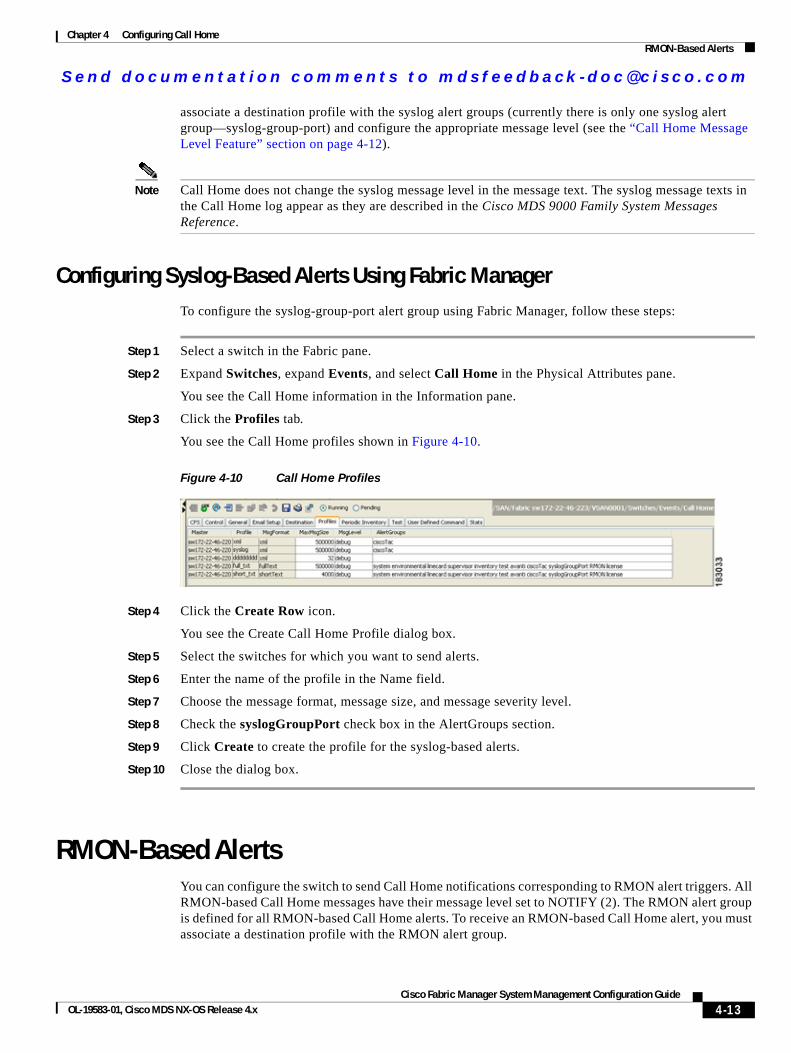
Send documenta t ion comments to mdsfeedback -doc@c i sco .com
Chapter 4 Configuring Call HomeRMON-Based Alerts
associate a destination profile with the syslog alert groups (currently there is only one syslog alert group—syslog-group-port) and configure the appropriate message level (see the “Call Home Message Level Feature” section on page 4-12).
Note Call Home does not change the syslog message level in the message text. The syslog message texts in the Call Home log appear as they are described in the Cisco MDS 9000 Family System Messages Reference.
Configuring Syslog-Based Alerts Using Fabric ManagerTo configure the syslog-group-port alert group using Fabric Manager, follow these steps:
Step 1 Select a switch in the Fabric pane.
Step 2 Expand Switches, expand Events, and select Call Home in the Physical Attributes pane.
You see the Call Home information in the Information pane.
Step 3 Click the Profiles tab.
You see the Call Home profiles shown in Figure 4-10.
Figure 4-10 Call Home Profiles
Step 4 Click the Create Row icon.
You see the Create Call Home Profile dialog box.
Step 5 Select the switches for which you want to send alerts.
Step 6 Enter the name of the profile in the Name field.
Step 7 Choose the message format, message size, and message severity level.
Step 8 Check the syslogGroupPort check box in the AlertGroups section.
Step 9 Click Create to create the profile for the syslog-based alerts.
Step 10 Close the dialog box.
RMON-Based AlertsYou can configure the switch to send Call Home notifications corresponding to RMON alert triggers. All RMON-based Call Home messages have their message level set to NOTIFY (2). The RMON alert group is defined for all RMON-based Call Home alerts. To receive an RMON-based Call Home alert, you must associate a destination profile with the RMON alert group.
4-13Cisco Fabric Manager System Management Configuration Guide
OL-19583-01, Cisco MDS NX-OS Release 4.x
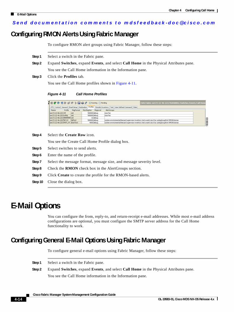
Send documenta t ion comments to mdsfeedback -doc@c i sco .com
Chapter 4 Configuring Call HomeE-Mail Options
Configuring RMON Alerts Using Fabric ManagerTo configure RMON alert groups using Fabric Manager, follow these steps:
Step 1 Select a switch in the Fabric pane.
Step 2 Expand Switches, expand Events, and select Call Home in the Physical Attributes pane.
You see the Call Home information in the Information pane.
Step 3 Click the Profiles tab.
You see the Call Home profiles shown in Figure 4-11.
Figure 4-11 Call Home Profiles
Step 4 Select the Create Row icon.
You see the Create Call Home Profile dialog box.
Step 5 Select switches to send alerts.
Step 6 Enter the name of the profile.
Step 7 Select the message format, message size, and message severity level.
Step 8 Check the RMON check box in the AlertGroups section.
Step 9 Click Create to create the profile for the RMON-based alerts.
Step 10 Close the dialog box.
E-Mail OptionsYou can configure the from, reply-to, and return-receipt e-mail addresses. While most e-mail address configurations are optional, you must configure the SMTP server address for the Call Home functionality to work.
Configuring General E-Mail Options Using Fabric ManagerTo configure general e-mail options using Fabric Manager, follow these steps:
Step 1 Select a switch in the Fabric pane.
Step 2 Expand Switches, expand Events, and select Call Home in the Physical Attributes pane.
You see the Call Home information in the Information pane.
4-14Cisco Fabric Manager System Management Configuration Guide
OL-19583-01, Cisco MDS NX-OS Release 4.x
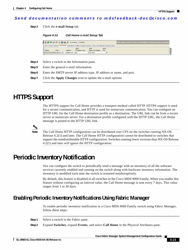
Send documenta t ion comments to mdsfeedback -doc@c i sco .com
Chapter 4 Configuring Call HomeHTTPS Support
Step 3 Click the e-mail Setup tab.
Figure 4-12 Call Home e-mail Setup Tab
Step 4 Select a switch in the Information pane.
Step 5 Enter the general e-mail information.
Step 6 Enter the SMTP server IP address type, IP address or name, and port.
Step 7 Click the Apply Changes icon to update the e-mail options.
HTTPS SupportThe HTTPS support for Call Home provides a transport method called HTTP. HTTPS support is used for a secure communication, and HTTP is used for nonsecure communication. You can configure an HTTP URL for the Call Home destination profile as a destination. The URL link can be from a secure server or nonsecure server. For a destination profile configured with the HTTP URL, the Call Home message is posted to the HTTP URL link.
Note The Call Home HTTP configuration can be distributed over CFS on the switches running NX-OS Release 4.2(1) and later. The Call Home HTTP configuration cannot be distributed to switches that support the nondistributable HTTP configuration. Switches running lower versions than NX-OS Release 4.2(1) and later will ignore the HTTP configuration.
Periodic Inventory NotificationYou can configure the switch to periodically send a message with an inventory of all the software services currently enabled and running on the switch along with hardware inventory information. The inventory is modified each time the switch is restarted nondisruptively.
By default, this feature is disabled in all switches in the Cisco MDS 9000 Family. When you enable this feature without configuring an interval value, the Call Home message is sent every 7 days. This value ranges from 1 to 30 days.
Enabling Periodic Inventory Notifications Using Fabric ManagerTo enable periodic inventory notification in a Cisco MDS 9000 Family switch using Fabric Manager, follow these steps:
Step 1 Select a switch in the Fabric pane.
Step 2 Expand Switches, expand Events, and select Call Home in the Physical Attributes pane.
4-15Cisco Fabric Manager System Management Configuration Guide
OL-19583-01, Cisco MDS NX-OS Release 4.x
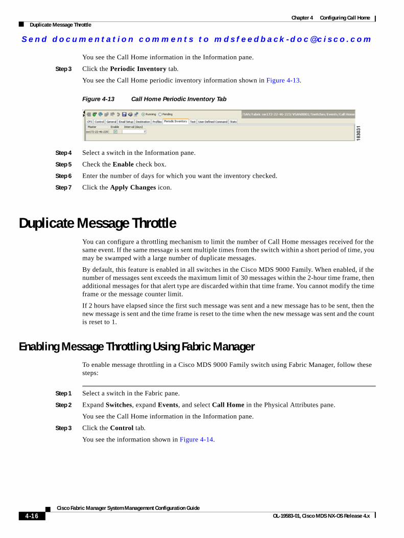
Send documenta t ion comments to mdsfeedback -doc@c i sco .com
Chapter 4 Configuring Call HomeDuplicate Message Throttle
You see the Call Home information in the Information pane.
Step 3 Click the Periodic Inventory tab.
You see the Call Home periodic inventory information shown in Figure 4-13.
Figure 4-13 Call Home Periodic Inventory Tab
Step 4 Select a switch in the Information pane.
Step 5 Check the Enable check box.
Step 6 Enter the number of days for which you want the inventory checked.
Step 7 Click the Apply Changes icon.
Duplicate Message ThrottleYou can configure a throttling mechanism to limit the number of Call Home messages received for the same event. If the same message is sent multiple times from the switch within a short period of time, you may be swamped with a large number of duplicate messages.
By default, this feature is enabled in all switches in the Cisco MDS 9000 Family. When enabled, if the number of messages sent exceeds the maximum limit of 30 messages within the 2-hour time frame, then additional messages for that alert type are discarded within that time frame. You cannot modify the time frame or the message counter limit.
If 2 hours have elapsed since the first such message was sent and a new message has to be sent, then the new message is sent and the time frame is reset to the time when the new message was sent and the count is reset to 1.
Enabling Message Throttling Using Fabric ManagerTo enable message throttling in a Cisco MDS 9000 Family switch using Fabric Manager, follow these steps:
Step 1 Select a switch in the Fabric pane.
Step 2 Expand Switches, expand Events, and select Call Home in the Physical Attributes pane.
You see the Call Home information in the Information pane.
Step 3 Click the Control tab.
You see the information shown in Figure 4-14.
4-16Cisco Fabric Manager System Management Configuration Guide
OL-19583-01, Cisco MDS NX-OS Release 4.x
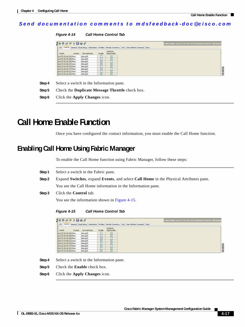
Send documenta t ion comments to mdsfeedback -doc@c i sco .com
Chapter 4 Configuring Call HomeCall Home Enable Function
Figure 4-14 Call Home Control Tab
Step 4 Select a switch in the Information pane.
Step 5 Check the Duplicate Message Throttle check box.
Step 6 Click the Apply Changes icon.
Call Home Enable FunctionOnce you have configured the contact information, you must enable the Call Home function.
Enabling Call Home Using Fabric ManagerTo enable the Call Home function using Fabric Manager, follow these steps:
Step 1 Select a switch in the Fabric pane.
Step 2 Expand Switches, expand Events, and select Call Home in the Physical Attributes pane.
You see the Call Home information in the Information pane.
Step 3 Click the Control tab.
You see the information shown in Figure 4-15.
Figure 4-15 Call Home Control Tab
Step 4 Select a switch in the Information pane.
Step 5 Check the Enable check box.
Step 6 Click the Apply Changes icon.
4-17Cisco Fabric Manager System Management Configuration Guide
OL-19583-01, Cisco MDS NX-OS Release 4.x
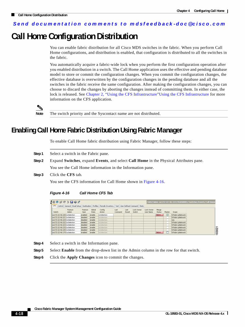
Send documenta t ion comments to mdsfeedback -doc@c i sco .com
Chapter 4 Configuring Call HomeCall Home Configuration Distribution
Call Home Configuration DistributionYou can enable fabric distribution for all Cisco MDS switches in the fabric. When you perform Call Home configurations, and distribution is enabled, that configuration is distributed to all the switches in the fabric.
You automatically acquire a fabric-wide lock when you perform the first configuration operation after you enabled distribution in a switch. The Call Home application uses the effective and pending database model to store or commit the configuration changes. When you commit the configuration changes, the effective database is overwritten by the configuration changes in the pending database and all the switches in the fabric receive the same configuration. After making the configuration changes, you can choose to discard the changes by aborting the changes instead of committing them. In either case, the lock is released. See Chapter 2, “Using the CFS Infrastructure”Using the CFS Infrastructure for more information on the CFS application.
Note The switch priority and the Syscontact name are not distributed.
Enabling Call Home Fabric Distribution Using Fabric ManagerTo enable Call Home fabric distribution using Fabric Manager, follow these steps:
Step 1 Select a switch in the Fabric pane.
Step 2 Expand Switches, expand Events, and select Call Home in the Physical Attributes pane.
You see the Call Home information in the Information pane.
Step 3 Click the CFS tab.
You see the CFS information for Call Home shown in Figure 4-16.
Figure 4-16 Call Home CFS Tab
Step 4 Select a switch in the Information pane.
Step 5 Select Enable from the drop-down list in the Admin column in the row for that switch.
Step 6 Click the Apply Changes icon to commit the changes.
4-18Cisco Fabric Manager System Management Configuration Guide
OL-19583-01, Cisco MDS NX-OS Release 4.x
Send documenta t ion comments to mdsfeedback -doc@c i sco .com
Chapter 4 Configuring Call HomeCall Home Communications Test
Fabric Lock OverrideIf you have performed a Call Home task and have forgotten to release the lock by either committing or discarding the changes, an administrator can release the lock from any switch in the fabric. If the administrator performs this task, your changes to the pending database are discarded and the fabric lock is released.
Tip The changes are only available in the volatile directory and are subject to being discarded if the switch is restarted.
Database Merge GuidelinesSee the “CFS Merge Support” section on page 2-9 for detailed concepts.
When merging two Call Home databases, follow these guidelines:
• Be aware that the merged database contains the following information:
– A superset of all the destination profiles from the dominant and subordinate switches that take part in the merge protocol.
– The e-mail addresses and alert groups for the destination profiles.
– Other configuration information (for example, message throttling, periodic inventory) from the switch that existed in the dominant switch before the merge.
• Verify that two destination profiles do not have the same name (even if they have different configuration information) on the subordinate and dominant switches. If they do contain the same name, the merge operation will fail. You must then modify or delete the conflicting destination profile on the required switch.
Call Home Communications TestYou can test Call Home communications by sending a test message to the configured destination(s) or sending a test inventory message to the configured destination(s).
Testing Call Home Using Fabric ManagerTo test the Call Home function and simulate a message generation using Fabric Manager, follow these steps:
Step 1 Select a switch in the Fabric pane.
Step 2 Expand Switches, expand Events, and select Call Home in the Physical Attributes pane.
You see the Call Home information in the Information pane.
Step 3 Click the Test tab.
You see the configured tests for the switch and the status of the last testing.
Step 4 Select a switch in the Information pane.
Step 5 Select test or testWithInventory from the TestAction drop-down list in the row for that switch.
4-19Cisco Fabric Manager System Management Configuration Guide
OL-19583-01, Cisco MDS NX-OS Release 4.x
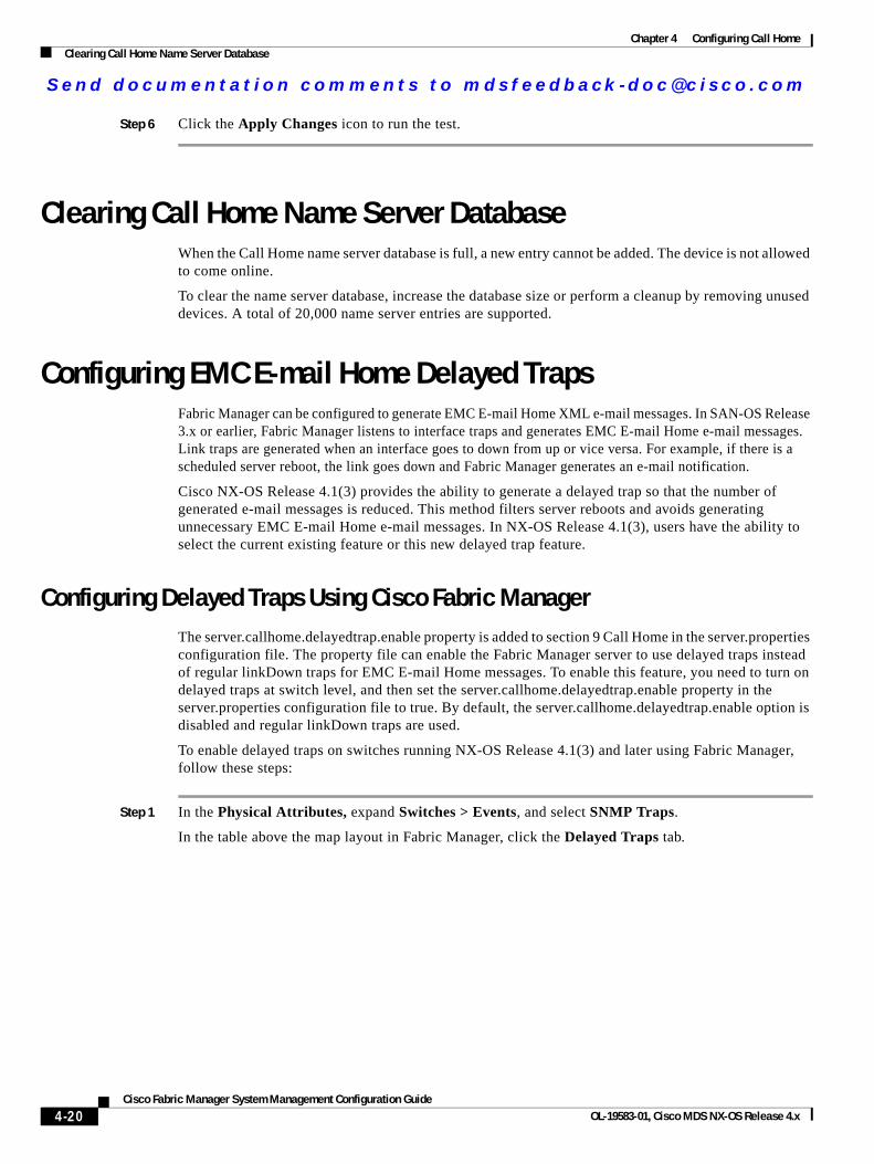
Send documenta t ion comments to mdsfeedback -doc@c i sco .com
Chapter 4 Configuring Call HomeClearing Call Home Name Server Database
Step 6 Click the Apply Changes icon to run the test.
Clearing Call Home Name Server DatabaseWhen the Call Home name server database is full, a new entry cannot be added. The device is not allowed to come online.
To clear the name server database, increase the database size or perform a cleanup by removing unused devices. A total of 20,000 name server entries are supported.
Configuring EMC E-mail Home Delayed TrapsFabric Manager can be configured to generate EMC E-mail Home XML e-mail messages. In SAN-OS Release 3.x or earlier, Fabric Manager listens to interface traps and generates EMC E-mail Home e-mail messages. Link traps are generated when an interface goes to down from up or vice versa. For example, if there is a scheduled server reboot, the link goes down and Fabric Manager generates an e-mail notification.
Cisco NX-OS Release 4.1(3) provides the ability to generate a delayed trap so that the number of generated e-mail messages is reduced. This method filters server reboots and avoids generating unnecessary EMC E-mail Home e-mail messages. In NX-OS Release 4.1(3), users have the ability to select the current existing feature or this new delayed trap feature.
Configuring Delayed Traps Using Cisco Fabric ManagerThe server.callhome.delayedtrap.enable property is added to section 9 Call Home in the server.properties configuration file. The property file can enable the Fabric Manager server to use delayed traps instead of regular linkDown traps for EMC E-mail Home messages. To enable this feature, you need to turn on delayed traps at switch level, and then set the server.callhome.delayedtrap.enable property in the server.properties configuration file to true. By default, the server.callhome.delayedtrap.enable option is disabled and regular linkDown traps are used.
To enable delayed traps on switches running NX-OS Release 4.1(3) and later using Fabric Manager, follow these steps:
Step 1 In the Physical Attributes, expand Switches > Events, and select SNMP Traps.
In the table above the map layout in Fabric Manager, click the Delayed Traps tab.
4-20Cisco Fabric Manager System Management Configuration Guide
OL-19583-01, Cisco MDS NX-OS Release 4.x
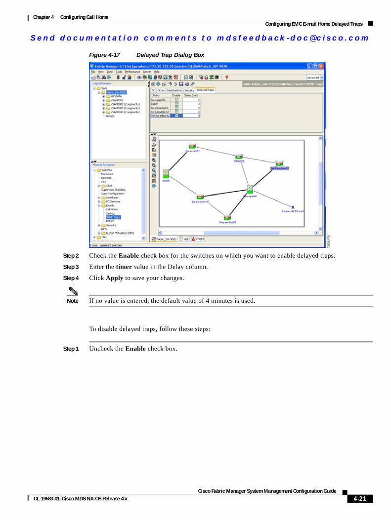
Send documenta t ion comments to mdsfeedback -doc@c i sco .com
Chapter 4 Configuring Call HomeConfiguring EMC E-mail Home Delayed Traps
Figure 4-17 Delayed Trap Dialog Box
Step 2 Check the Enable check box for the switches on which you want to enable delayed traps.
Step 3 Enter the timer value in the Delay column.
Step 4 Click Apply to save your changes.
Note If no value is entered, the default value of 4 minutes is used.
To disable delayed traps, follow these steps:
Step 1 Uncheck the Enable check box.
4-21Cisco Fabric Manager System Management Configuration Guide
OL-19583-01, Cisco MDS NX-OS Release 4.x
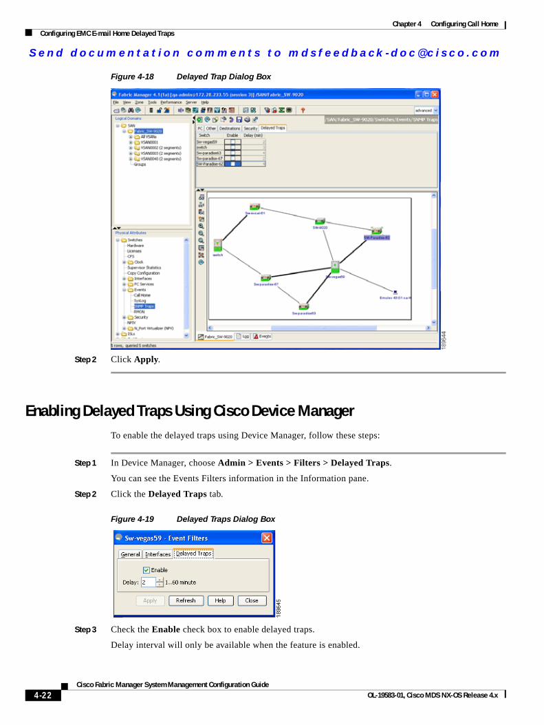
Send documenta t ion comments to mdsfeedback -doc@c i sco .com
Chapter 4 Configuring Call HomeConfiguring EMC E-mail Home Delayed Traps
Figure 4-18 Delayed Trap Dialog Box
Step 2 Click Apply.
Enabling Delayed Traps Using Cisco Device ManagerTo enable the delayed traps using Device Manager, follow these steps:
Step 1 In Device Manager, choose Admin > Events > Filters > Delayed Traps.
You can see the Events Filters information in the Information pane.
Step 2 Click the Delayed Traps tab.
Figure 4-19 Delayed Traps Dialog Box
Step 3 Check the Enable check box to enable delayed traps.
Delay interval will only be available when the feature is enabled.
4-22Cisco Fabric Manager System Management Configuration Guide
OL-19583-01, Cisco MDS NX-OS Release 4.x
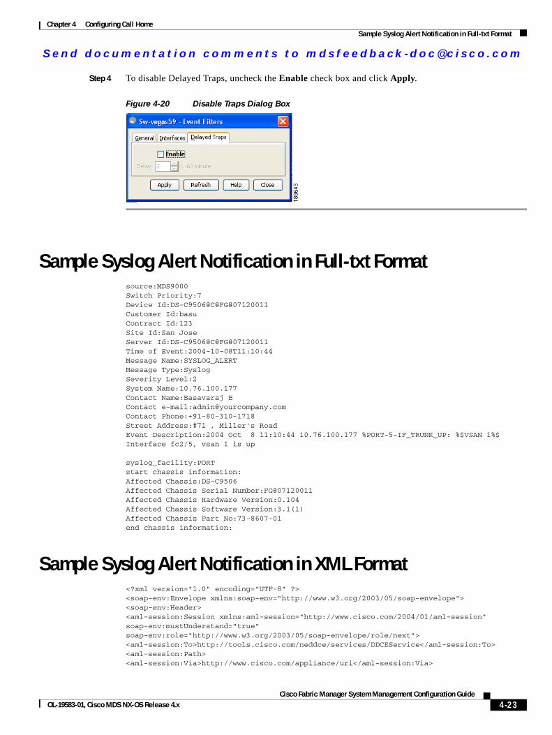
Send documenta t ion comments to mdsfeedback -doc@c i sco .com
Chapter 4 Configuring Call HomeSample Syslog Alert Notification in Full-txt Format
Step 4 To disable Delayed Traps, uncheck the Enable check box and click Apply.
Figure 4-20 Disable Traps Dialog Box
Sample Syslog Alert Notification in Full-txt Formatsource:MDS9000Switch Priority:7Device Id:DS-C9506@C@FG@07120011Customer Id:basuContract Id:123Site Id:San JoseServer Id:DS-C9506@C@FG@07120011Time of Event:2004-10-08T11:10:44Message Name:SYSLOG_ALERTMessage Type:SyslogSeverity Level:2System Name:10.76.100.177Contact Name:Basavaraj BContact e-mail:[email protected] Phone:+91-80-310-1718Street Address:#71 , Miller's RoadEvent Description:2004 Oct 8 11:10:44 10.76.100.177 %PORT-5-IF_TRUNK_UP: %$VSAN 1%$ Interface fc2/5, vsan 1 is up
syslog_facility:PORTstart chassis information:Affected Chassis:DS-C9506Affected Chassis Serial Number:FG@07120011Affected Chassis Hardware Version:0.104Affected Chassis Software Version:3.1(1)Affected Chassis Part No:73-8607-01end chassis information:
Sample Syslog Alert Notification in XML Format<?xml version="1.0" encoding="UTF-8" ?><soap-env:Envelope xmlns:soap-env="http://www.w3.org/2003/05/soap-envelope"><soap-env:Header><aml-session:Session xmlns:aml-session="http://www.cisco.com/2004/01/aml-session" soap-env:mustUnderstand="true" soap-env:role="http://www.w3.org/2003/05/soap-envelope/role/next"><aml-session:To>http://tools.cisco.com/neddce/services/DDCEService</aml-session:To><aml-session:Path><aml-session:Via>http://www.cisco.com/appliance/uri</aml-session:Via>
4-23Cisco Fabric Manager System Management Configuration Guide
OL-19583-01, Cisco MDS NX-OS Release 4.x
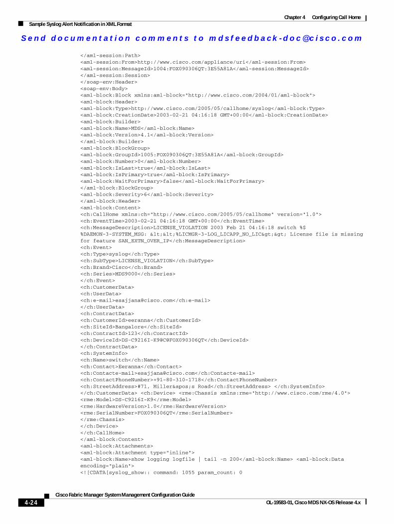
Send documenta t ion comments to mdsfeedback -doc@c i sco .com
Chapter 4 Configuring Call HomeSample Syslog Alert Notification in XML Format
</aml-session:Path><aml-session:From>http://www.cisco.com/appliance/uri</aml-session:From><aml-session:MessageId>1004:FOX090306QT:3E55A81A</aml-session:MessageId></aml-session:Session></soap-env:Header><soap-env:Body><aml-block:Block xmlns:aml-block="http://www.cisco.com/2004/01/aml-block"><aml-block:Header><aml-block:Type>http://www.cisco.com/2005/05/callhome/syslog</aml-block:Type><aml-block:CreationDate>2003-02-21 04:16:18 GMT+00:00</aml-block:CreationDate><aml-block:Builder><aml-block:Name>MDS</aml-block:Name><aml-block:Version>4.1</aml-block:Version></aml-block:Builder><aml-block:BlockGroup><aml-block:GroupId>1005:FOX090306QT:3E55A81A</aml-block:GroupId><aml-block:Number>0</aml-block:Number><aml-block:IsLast>true</aml-block:IsLast><aml-block:IsPrimary>true</aml-block:IsPrimary><aml-block:WaitForPrimary>false</aml-block:WaitForPrimary></aml-block:BlockGroup><aml-block:Severity>6</aml-block:Severity></aml-block:Header><aml-block:Content><ch:CallHome xmlns:ch="http://www.cisco.com/2005/05/callhome" version="1.0"><ch:EventTime>2003-02-21 04:16:18 GMT+00:00</ch:EventTime> <ch:MessageDescription>LICENSE_VIOLATION 2003 Feb 21 04:16:18 switch %$ %DAEMON-3-SYSTEM_MSG: <<%LICMGR-3-LOG_LICAPP_NO_LIC>> License file is missing for feature SAN_EXTN_OVER_IP</ch:MessageDescription><ch:Event><ch:Type>syslog</ch:Type><ch:SubType>LICENSE_VIOLATION</ch:SubType><ch:Brand>Cisco</ch:Brand><ch:Series>MDS9000</ch:Series></ch:Event><ch:CustomerData><ch:UserData><ch:e-mail>[email protected]</ch:e-mail></ch:UserData><ch:ContractData><ch:CustomerId>eeranna</ch:CustomerId><ch:SiteId>Bangalore</ch:SiteId><ch:ContractId>123</ch:ContractId><ch:DeviceId>DS-C9216I-K9@C@FOX090306QT</ch:DeviceId></ch:ContractData><ch:SystemInfo><ch:Name>switch</ch:Name><ch:Contact>Eeranna</ch:Contact><ch:Contacte-mail>[email protected]</ch:Contacte-mail><ch:ContactPhoneNumber>+91-80-310-1718</ch:ContactPhoneNumber><ch:StreetAddress>#71, Miller's Road</ch:StreetAddress> </ch:SystemInfo> </ch:CustomerData> <ch:Device> <rme:Chassis xmlns:rme="http://www.cisco.com/rme/4.0"><rme:Model>DS-C9216I-K9</rme:Model><rme:HardwareVersion>1.0</rme:HardwareVersion><rme:SerialNumber>FOX090306QT</rme:SerialNumber></rme:Chassis></ch:Device></ch:CallHome></aml-block:Content><aml-block:Attachments><aml-block:Attachment type="inline"><aml-block:Name>show logging logfile | tail -n 200</aml-block:Name> <aml-block:Data encoding="plain"><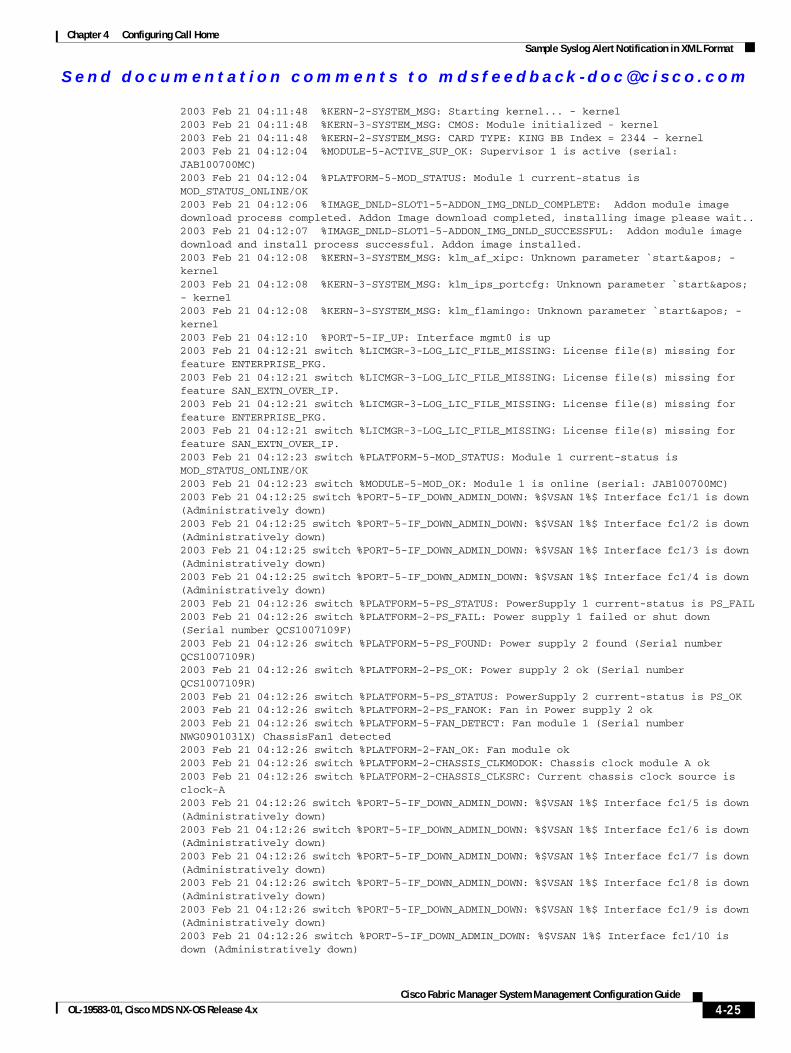
Send documenta t ion comments to mdsfeedback -doc@c i sco .com
Chapter 4 Configuring Call HomeSample Syslog Alert Notification in XML Format
2003 Feb 21 04:11:48 %KERN-2-SYSTEM_MSG: Starting kernel... - kernel2003 Feb 21 04:11:48 %KERN-3-SYSTEM_MSG: CMOS: Module initialized - kernel2003 Feb 21 04:11:48 %KERN-2-SYSTEM_MSG: CARD TYPE: KING BB Index = 2344 - kernel2003 Feb 21 04:12:04 %MODULE-5-ACTIVE_SUP_OK: Supervisor 1 is active (serial: JAB100700MC)2003 Feb 21 04:12:04 %PLATFORM-5-MOD_STATUS: Module 1 current-status is MOD_STATUS_ONLINE/OK2003 Feb 21 04:12:06 %IMAGE_DNLD-SLOT1-5-ADDON_IMG_DNLD_COMPLETE: Addon module image download process completed. Addon Image download completed, installing image please wait..2003 Feb 21 04:12:07 %IMAGE_DNLD-SLOT1-5-ADDON_IMG_DNLD_SUCCESSFUL: Addon module image download and install process successful. Addon image installed.2003 Feb 21 04:12:08 %KERN-3-SYSTEM_MSG: klm_af_xipc: Unknown parameter `start' - kernel2003 Feb 21 04:12:08 %KERN-3-SYSTEM_MSG: klm_ips_portcfg: Unknown parameter `start' - kernel2003 Feb 21 04:12:08 %KERN-3-SYSTEM_MSG: klm_flamingo: Unknown parameter `start' - kernel2003 Feb 21 04:12:10 %PORT-5-IF_UP: Interface mgmt0 is up2003 Feb 21 04:12:21 switch %LICMGR-3-LOG_LIC_FILE_MISSING: License file(s) missing for feature ENTERPRISE_PKG.2003 Feb 21 04:12:21 switch %LICMGR-3-LOG_LIC_FILE_MISSING: License file(s) missing for feature SAN_EXTN_OVER_IP.2003 Feb 21 04:12:21 switch %LICMGR-3-LOG_LIC_FILE_MISSING: License file(s) missing for feature ENTERPRISE_PKG.2003 Feb 21 04:12:21 switch %LICMGR-3-LOG_LIC_FILE_MISSING: License file(s) missing for feature SAN_EXTN_OVER_IP.2003 Feb 21 04:12:23 switch %PLATFORM-5-MOD_STATUS: Module 1 current-status is MOD_STATUS_ONLINE/OK2003 Feb 21 04:12:23 switch %MODULE-5-MOD_OK: Module 1 is online (serial: JAB100700MC)2003 Feb 21 04:12:25 switch %PORT-5-IF_DOWN_ADMIN_DOWN: %$VSAN 1%$ Interface fc1/1 is down (Administratively down)2003 Feb 21 04:12:25 switch %PORT-5-IF_DOWN_ADMIN_DOWN: %$VSAN 1%$ Interface fc1/2 is down (Administratively down)2003 Feb 21 04:12:25 switch %PORT-5-IF_DOWN_ADMIN_DOWN: %$VSAN 1%$ Interface fc1/3 is down (Administratively down)2003 Feb 21 04:12:25 switch %PORT-5-IF_DOWN_ADMIN_DOWN: %$VSAN 1%$ Interface fc1/4 is down (Administratively down)2003 Feb 21 04:12:26 switch %PLATFORM-5-PS_STATUS: PowerSupply 1 current-status is PS_FAIL2003 Feb 21 04:12:26 switch %PLATFORM-2-PS_FAIL: Power supply 1 failed or shut down (Serial number QCS1007109F)2003 Feb 21 04:12:26 switch %PLATFORM-5-PS_FOUND: Power supply 2 found (Serial number QCS1007109R)2003 Feb 21 04:12:26 switch %PLATFORM-2-PS_OK: Power supply 2 ok (Serial number QCS1007109R)2003 Feb 21 04:12:26 switch %PLATFORM-5-PS_STATUS: PowerSupply 2 current-status is PS_OK2003 Feb 21 04:12:26 switch %PLATFORM-2-PS_FANOK: Fan in Power supply 2 ok2003 Feb 21 04:12:26 switch %PLATFORM-5-FAN_DETECT: Fan module 1 (Serial number NWG0901031X) ChassisFan1 detected2003 Feb 21 04:12:26 switch %PLATFORM-2-FAN_OK: Fan module ok2003 Feb 21 04:12:26 switch %PLATFORM-2-CHASSIS_CLKMODOK: Chassis clock module A ok2003 Feb 21 04:12:26 switch %PLATFORM-2-CHASSIS_CLKSRC: Current chassis clock source is clock-A2003 Feb 21 04:12:26 switch %PORT-5-IF_DOWN_ADMIN_DOWN: %$VSAN 1%$ Interface fc1/5 is down (Administratively down)2003 Feb 21 04:12:26 switch %PORT-5-IF_DOWN_ADMIN_DOWN: %$VSAN 1%$ Interface fc1/6 is down (Administratively down)2003 Feb 21 04:12:26 switch %PORT-5-IF_DOWN_ADMIN_DOWN: %$VSAN 1%$ Interface fc1/7 is down (Administratively down)2003 Feb 21 04:12:26 switch %PORT-5-IF_DOWN_ADMIN_DOWN: %$VSAN 1%$ Interface fc1/8 is down (Administratively down)2003 Feb 21 04:12:26 switch %PORT-5-IF_DOWN_ADMIN_DOWN: %$VSAN 1%$ Interface fc1/9 is down (Administratively down)2003 Feb 21 04:12:26 switch %PORT-5-IF_DOWN_ADMIN_DOWN: %$VSAN 1%$ Interface fc1/10 is down (Administratively down)
4-25Cisco Fabric Manager System Management Configuration Guide
OL-19583-01, Cisco MDS NX-OS Release 4.x
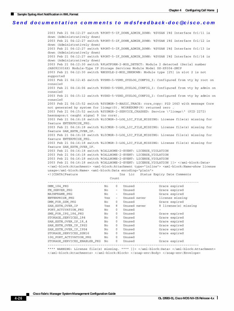
Send documenta t ion comments to mdsfeedback -doc@c i sco .com
Chapter 4 Configuring Call HomeSample Syslog Alert Notification in XML Format
2003 Feb 21 04:12:27 switch %PORT-5-IF_DOWN_ADMIN_DOWN: %$VSAN 1%$ Interface fc1/11 is down (Administratively down)2003 Feb 21 04:12:27 switch %PORT-5-IF_DOWN_ADMIN_DOWN: %$VSAN 1%$ Interface fc1/12 is down (Administratively down)2003 Feb 21 04:12:27 switch %PORT-5-IF_DOWN_ADMIN_DOWN: %$VSAN 1%$ Interface fc1/13 is down (Administratively down)2003 Feb 21 04:12:27 switch %PORT-5-IF_DOWN_ADMIN_DOWN: %$VSAN 1%$ Interface fc1/14 is down (Administratively down)2003 Feb 21 04:12:30 switch %PLATFORM-2-MOD_DETECT: Module 2 detected (Serial number JAB0923016X) Module-Type IP Storage Services Module Model DS-X9304-SMIP2003 Feb 21 04:12:30 switch %MODULE-2-MOD_UNKNOWN: Module type [25] in slot 2 is not supported2003 Feb 21 04:12:45 switch %VSHD-5-VSHD_SYSLOG_CONFIG_I: Configured from vty by root on console02003 Feb 21 04:14:06 switch %VSHD-5-VSHD_SYSLOG_CONFIG_I: Configured from vty by admin on console02003 Feb 21 04:15:12 switch %VSHD-5-VSHD_SYSLOG_CONFIG_I: Configured from vty by admin on console02003 Feb 21 04:15:52 switch %SYSMGR-3-BASIC_TRACE: core_copy: PID 1643 with message Core not generated by system for licmgr(0). WCOREDUMP(9) returned zero . 2003 Feb 21 04:15:52 switch %SYSMGR-2-SERVICE_CRASHED: Service \"licmgr\" (PID 2272) hasn't caught signal 9 (no core).2003 Feb 21 04:16:18 switch %LICMGR-3-LOG_LIC_FILE_MISSING: License file(s) missing for feature ENTERPRISE_PKG.2003 Feb 21 04:16:18 switch %LICMGR-3-LOG_LIC_FILE_MISSING: License file(s) missing for feature SAN_EXTN_OVER_IP.2003 Feb 21 04:16:18 switch %LICMGR-3-LOG_LIC_FILE_MISSING: License file(s) missing for feature ENTERPRISE_PKG.2003 Feb 21 04:16:18 switch %LICMGR-3-LOG_LIC_FILE_MISSING: License file(s) missing for feature SAN_EXTN_OVER_IP.2003 Feb 21 04:16:18 switch %CALLHOME-2-EVENT: LICENSE_VIOLATION2003 Feb 21 04:16:18 switch %CALLHOME-2-EVENT: LICENSE_VIOLATION2003 Feb 21 04:16:18 switch %CALLHOME-2-EVENT: LICENSE_VIOLATION2003 Feb 21 04:16:18 switch %CALLHOME-2-EVENT: LICENSE_VIOLATION ]]> </aml-block:Data> </aml-block:Attachment> <aml-block:Attachment type="inline"> <aml-block:Name>show license usage</aml-block:Name> <aml-block:Data encoding="plain"><![CDATA[Feature Ins Lic Status Expiry Date Comments Count--------------------------------------------------------------------------------DMM_184_PKG No 0 Unused Grace expiredFM_SERVER_PKG No - Unused Grace expiredMAINFRAME_PKG No - Unused Grace expiredENTERPRISE_PKG Yes - Unused never license missingDMM_FOR_SSM_PKG No 0 Unused Grace expiredSAN_EXTN_OVER_IP Yes 8 Unused never 8 license(s) missingPORT_ACTIVATION_PKG No 0 Unused -SME_FOR_IPS_184_PKG No 0 Unused Grace expiredSTORAGE_SERVICES_184 No 0 Unused Grace expiredSAN_EXTN_OVER_IP_18_4 No 0 Unused Grace expiredSAN_EXTN_OVER_IP_IPS2 No 0 Unused Grace expiredSAN_EXTN_OVER_IP_IPS4 No 0 Unused Grace expiredSTORAGE_SERVICES_SSN16 No 0 Unused Grace expired10G_PORT_ACTIVATION_PKG No 0 Unused -STORAGE_SERVICES_ENABLER_PKG No 0 Unused Grace expired--------------------------------------------------------------------------------**** WARNING: License file(s) missing. **** ]]> </aml-block:Data> </aml-block:Attachment> </aml-block:Attachments> </aml-block:Block> </soap-env:Body> </soap-env:Envelope>
4-26Cisco Fabric Manager System Management Configuration Guide
OL-19583-01, Cisco MDS NX-OS Release 4.x
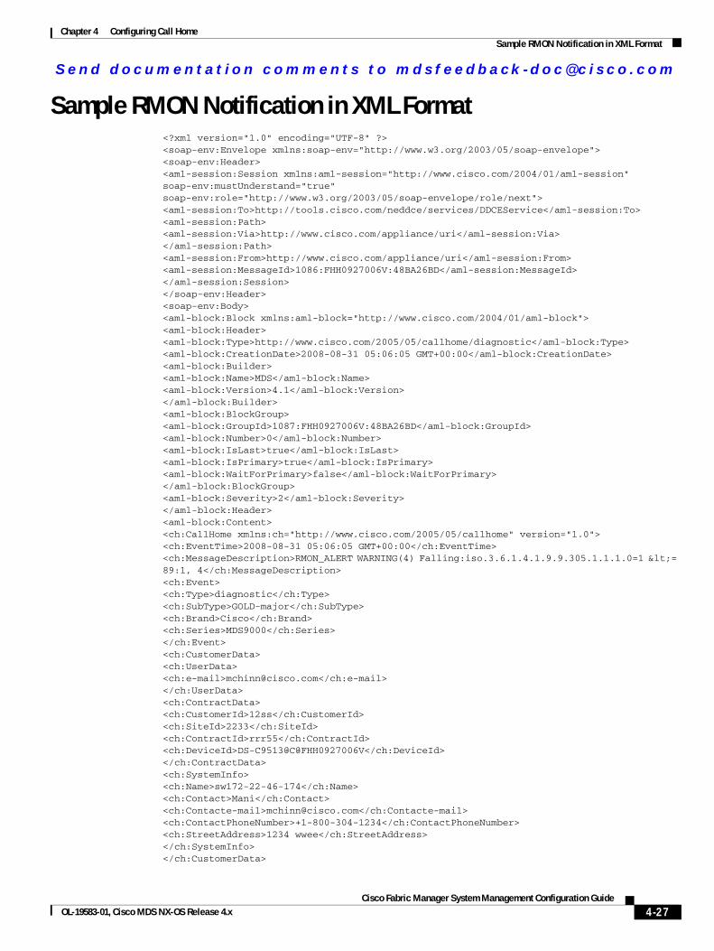
Send documenta t ion comments to mdsfeedback -doc@c i sco .com
Chapter 4 Configuring Call HomeSample RMON Notification in XML Format
Sample RMON Notification in XML Format<?xml version="1.0" encoding="UTF-8" ?><soap-env:Envelope xmlns:soap-env="http://www.w3.org/2003/05/soap-envelope"><soap-env:Header><aml-session:Session xmlns:aml-session="http://www.cisco.com/2004/01/aml-session" soap-env:mustUnderstand="true" soap-env:role="http://www.w3.org/2003/05/soap-envelope/role/next"><aml-session:To>http://tools.cisco.com/neddce/services/DDCEService</aml-session:To><aml-session:Path><aml-session:Via>http://www.cisco.com/appliance/uri</aml-session:Via></aml-session:Path><aml-session:From>http://www.cisco.com/appliance/uri</aml-session:From><aml-session:MessageId>1086:FHH0927006V:48BA26BD</aml-session:MessageId></aml-session:Session></soap-env:Header><soap-env:Body><aml-block:Block xmlns:aml-block="http://www.cisco.com/2004/01/aml-block"><aml-block:Header><aml-block:Type>http://www.cisco.com/2005/05/callhome/diagnostic</aml-block:Type><aml-block:CreationDate>2008-08-31 05:06:05 GMT+00:00</aml-block:CreationDate><aml-block:Builder><aml-block:Name>MDS</aml-block:Name><aml-block:Version>4.1</aml-block:Version></aml-block:Builder><aml-block:BlockGroup><aml-block:GroupId>1087:FHH0927006V:48BA26BD</aml-block:GroupId><aml-block:Number>0</aml-block:Number><aml-block:IsLast>true</aml-block:IsLast><aml-block:IsPrimary>true</aml-block:IsPrimary><aml-block:WaitForPrimary>false</aml-block:WaitForPrimary></aml-block:BlockGroup><aml-block:Severity>2</aml-block:Severity></aml-block:Header><aml-block:Content><ch:CallHome xmlns:ch="http://www.cisco.com/2005/05/callhome" version="1.0"><ch:EventTime>2008-08-31 05:06:05 GMT+00:00</ch:EventTime><ch:MessageDescription>RMON_ALERT WARNING(4) Falling:iso.3.6.1.4.1.9.9.305.1.1.1.0=1 <= 89:1, 4</ch:MessageDescription><ch:Event><ch:Type>diagnostic</ch:Type><ch:SubType>GOLD-major</ch:SubType><ch:Brand>Cisco</ch:Brand><ch:Series>MDS9000</ch:Series></ch:Event><ch:CustomerData><ch:UserData><ch:e-mail>[email protected]</ch:e-mail></ch:UserData><ch:ContractData><ch:CustomerId>12ss</ch:CustomerId><ch:SiteId>2233</ch:SiteId><ch:ContractId>rrr55</ch:ContractId><ch:DeviceId>DS-C9513@C@FHH0927006V</ch:DeviceId></ch:ContractData><ch:SystemInfo><ch:Name>sw172-22-46-174</ch:Name><ch:Contact>Mani</ch:Contact><ch:Contacte-mail>[email protected]</ch:Contacte-mail><ch:ContactPhoneNumber>+1-800-304-1234</ch:ContactPhoneNumber><ch:StreetAddress>1234 wwee</ch:StreetAddress></ch:SystemInfo></ch:CustomerData>
4-27Cisco Fabric Manager System Management Configuration Guide
OL-19583-01, Cisco MDS NX-OS Release 4.x

Send documenta t ion comments to mdsfeedback -doc@c i sco .com
Chapter 4 Configuring Call HomeSample RMON Notification in XML Format
<ch:Device><rme:Chassis xmlns:rme="http://www.cisco.com/rme/4.0"><rme:Model>DS-C9513</rme:Model><rme:HardwareVersion>0.205</rme:HardwareVersion><rme:SerialNumber>FHH0927006V</rme:SerialNumber></rme:Chassis></ch:Device></ch:CallHome></aml-block:Content></aml-block:Block></soap-env:Body></soap-env:Envelope>
4-28Cisco Fabric Manager System Management Configuration Guide
OL-19583-01, Cisco MDS NX-OS Release 4.x

Send documenta t ion comments to mdsfeedback -doc@c i sco .com
Chapter 4 Configuring Call HomeEvent Triggers
Event TriggersThis section discusses Call Home trigger events. Trigger events are divided into categories, with each category assigned CLI commands to execute when the event occurs. The command output is included in the transmitted message. Table 4-2 lists the trigger events.
Table 4-2 Event Triggers
Event Alert Group Event Name DescriptionCall Home Message Level
Call Home System and CISCO_TAC
SW_CRASH A software process has crashed with a stateless restart, indicating an interruption of a service.
5
System and CISCO_TAC
SW_SYSTEM_INCONSISTENT
Inconsistency detected in software or file system.
5
Environmental and CISCO_TAC
TEMPERATURE_ALARM Thermal sensor indicates temperature reached operating threshold.
6
POWER_SUPPLY_FAILURE Power supply failed. 6
FAN_FAILURE Cooling fan has failed. 5
Line Card Hardware and CISCO_TAC
LINECARD_FAILURE Line card hardware operation failed. 7
POWER_UP_DIAGNOSTICS_FAILURE
Line card hardware failed power-up diagnostics.
7
Line Card Hardware and CISCO_TAC
PORT_FAILURE Hardware failure of interface port(s). 6
Line Card Hardware, Supervisor Hardware, and CISCO_TAC
BOOTFLASH_FAILURE Failure of boot compact flash card. 6
Supervisor Hardware and CISCO_TAC
NVRAM_FAILURE Hardware failure of NVRAM on supervisor hardware.
6
Supervisor Hardware and CISCO_TAC
FREEDISK_FAILURE Free disk space is below a threshold on supervisor hardware.
6
Supervisor Hardware and CISCO_TAC
SUP_FAILURE Supervisor hardware operation failed. 7
POWER_UP_DIAGNOSTICS_FAILURE
Supervisor hardware failed power-up diagnostics.
7
Supervisor Hardware and CISCO_TAC
INBAND_FAILURE Failure of in-band communications path. 7
Supervisor Hardware and CISCO_TAC
EOBC_FAILURE Ethernet out-of-band channel communications failure.
6
4-29Cisco Fabric Manager System Management Configuration Guide
OL-19583-01, Cisco MDS NX-OS Release 4.x
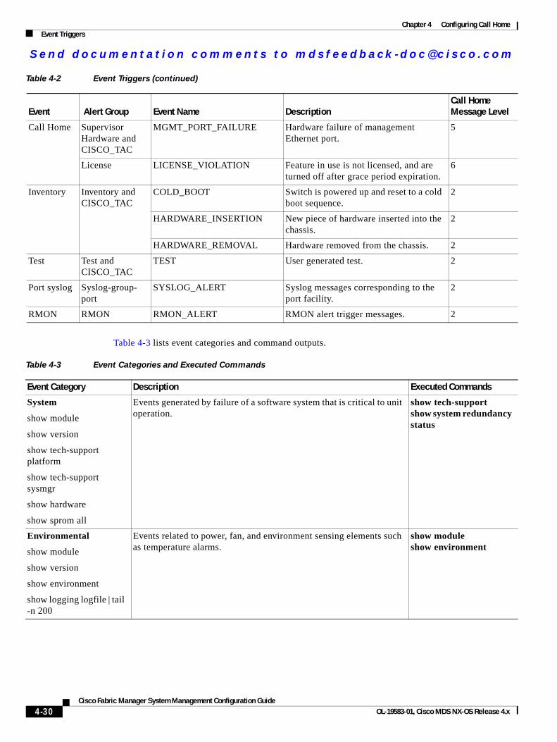
Send documenta t ion comments to mdsfeedback -doc@c i sco .com
Chapter 4 Configuring Call HomeEvent Triggers
Table 4-3 lists event categories and command outputs.
Call Home Supervisor Hardware and CISCO_TAC
MGMT_PORT_FAILURE Hardware failure of management Ethernet port.
5
License LICENSE_VIOLATION Feature in use is not licensed, and are turned off after grace period expiration.
6
Inventory Inventory and CISCO_TAC
COLD_BOOT Switch is powered up and reset to a cold boot sequence.
2
HARDWARE_INSERTION New piece of hardware inserted into the chassis.
2
HARDWARE_REMOVAL Hardware removed from the chassis. 2
Test Test and CISCO_TAC
TEST User generated test. 2
Port syslog Syslog-group- port
SYSLOG_ALERT Syslog messages corresponding to the port facility.
2
RMON RMON RMON_ALERT RMON alert trigger messages. 2
Table 4-2 Event Triggers (continued)
Event Alert Group Event Name DescriptionCall Home Message Level
Table 4-3 Event Categories and Executed Commands
Event Category Description Executed Commands
System
show module
show version
show tech-support platform
show tech-support sysmgr
show hardware
show sprom all
Events generated by failure of a software system that is critical to unit operation.
show tech-support show system redundancy status
Environmental
show module
show version
show environment
show logging logfile | tail -n 200
Events related to power, fan, and environment sensing elements such as temperature alarms.
show module show environment
4-30Cisco Fabric Manager System Management Configuration Guide
OL-19583-01, Cisco MDS NX-OS Release 4.x
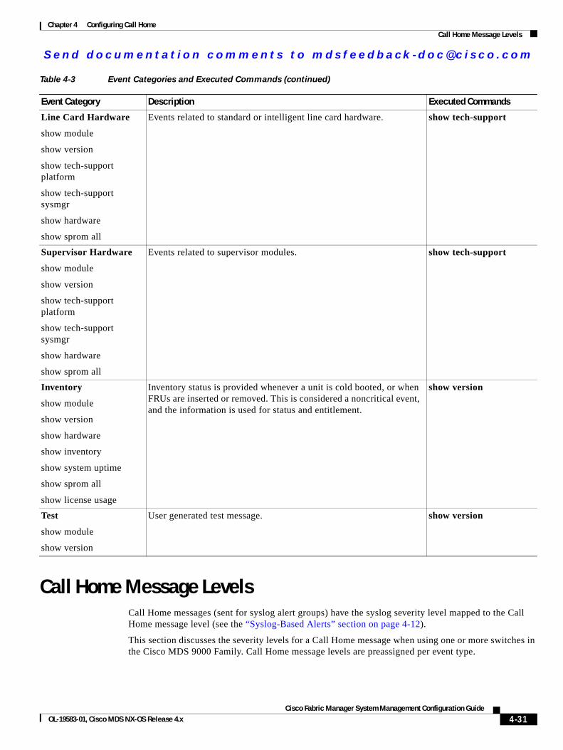
Send documenta t ion comments to mdsfeedback -doc@c i sco .com
Chapter 4 Configuring Call HomeCall Home Message Levels
Call Home Message LevelsCall Home messages (sent for syslog alert groups) have the syslog severity level mapped to the Call Home message level (see the “Syslog-Based Alerts” section on page 4-12).
This section discusses the severity levels for a Call Home message when using one or more switches in the Cisco MDS 9000 Family. Call Home message levels are preassigned per event type.
Line Card Hardware
show module
show version
show tech-support platform
show tech-support sysmgr
show hardware
show sprom all
Events related to standard or intelligent line card hardware. show tech-support
Supervisor Hardware
show module
show version
show tech-support platform
show tech-support sysmgr
show hardware
show sprom all
Events related to supervisor modules. show tech-support
Inventory
show module
show version
show hardware
show inventory
show system uptime
show sprom all
show license usage
Inventory status is provided whenever a unit is cold booted, or when FRUs are inserted or removed. This is considered a noncritical event, and the information is used for status and entitlement.
show version
Test
show module
show version
User generated test message. show version
Table 4-3 Event Categories and Executed Commands (continued)
Event Category Description Executed Commands
4-31Cisco Fabric Manager System Management Configuration Guide
OL-19583-01, Cisco MDS NX-OS Release 4.x
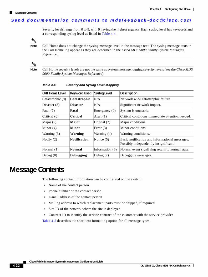
Send documenta t ion comments to mdsfeedback -doc@c i sco .com
Chapter 4 Configuring Call HomeMessage Contents
Severity levels range from 0 to 9, with 9 having the highest urgency. Each syslog level has keywords and a corresponding syslog level as listed in Table 4-4.
Note Call Home does not change the syslog message level in the message text. The syslog message texts in the Call Home log appear as they are described in the Cisco MDS 9000 Family System Messages Reference.
Note Call Home severity levels are not the same as system message logging severity levels (see the Cisco MDS 9000 Family System Messages Reference).
Message ContentsThe following contact information can be configured on the switch:
• Name of the contact person
• Phone number of the contact person
• E-mail address of the contact person
• Mailing address to which replacement parts must be shipped, if required
• Site ID of the network where the site is deployed
• Contract ID to identify the service contract of the customer with the service provider
Table 4-5 describes the short text formatting option for all message types.
Table 4-4 Severity and Syslog Level Mapping
Call Home Level Keyword Used Syslog Level Description
Catastrophic (9) Catastrophic N/A Network wide catastrophic failure.
Disaster (8) Disaster N/A Significant network impact.
Fatal (7) Fatal Emergency (0) System is unusable.
Critical (6) Critical Alert (1) Critical conditions, immediate attention needed.
Major (5) Major Critical (2) Major conditions.
Minor (4) Minor Error (3) Minor conditions.
Warning (3) Warning Warning (4) Warning conditions.
Notify (2) Notification Notice (5) Basic notification and informational messages. Possibly independently insignificant.
Normal (1) Normal Information (6) Normal event signifying return to normal state.
Debug (0) Debugging Debug (7) Debugging messages.
4-32Cisco Fabric Manager System Management Configuration Guide
OL-19583-01, Cisco MDS NX-OS Release 4.x
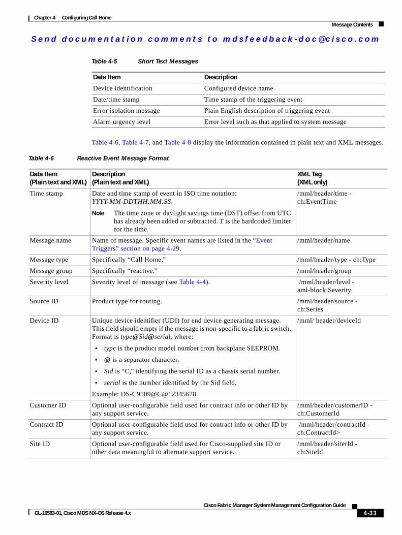
Send documenta t ion comments to mdsfeedback -doc@c i sco .com
Chapter 4 Configuring Call HomeMessage Contents
Table 4-6, Table 4-7, and Table 4-8 display the information contained in plain text and XML messages.
Table 4-5 Short Text Messages
Data Item Description
Device identification Configured device name
Date/time stamp Time stamp of the triggering event
Error isolation message Plain English description of triggering event
Alarm urgency level Error level such as that applied to system message
Table 4-6 Reactive Event Message Format
Data Item (Plain text and XML)
Description (Plain text and XML)
XML Tag (XML only)
Time stamp Date and time stamp of event in ISO time notation: YYYY-MM-DDTHH:MM:SS.
Note The time zone or daylight savings time (DST) offset from UTC has already been added or subtracted. T is the hardcoded limiter for the time.
/mml/header/time - ch:EventTime
Message name Name of message. Specific event names are listed in the “Event Triggers” section on page 4-29.
/mml/header/name
Message type Specifically “Call Home.” /mml/header/type - ch:Type
Message group Specifically “reactive.” /mml/header/group
Severity level Severity level of message (see Table 4-4). /mml/header/level - aml-block:Severity
Source ID Product type for routing. /mml/header/source - ch:Series
Device ID Unique device identifier (UDI) for end device generating message. This field should empty if the message is non-specific to a fabric switch. Format is type@Sid@serial, where:
• type is the product model number from backplane SEEPROM.
• @ is a separator character.
• Sid is “C,” identifying the serial ID as a chassis serial number.
• serial is the number identified by the Sid field.
Example: DS-C9509@C@12345678
/mml/ header/deviceId
Customer ID Optional user-configurable field used for contract info or other ID by any support service.
/mml/header/customerID - ch:CustomerId
Contract ID Optional user-configurable field used for contract info or other ID by any support service.
/mml/header/contractId - ch:ContractId>
Site ID Optional user-configurable field used for Cisco-supplied site ID or other data meaningful to alternate support service.
/mml/header/siterId - ch:SiteId
4-33Cisco Fabric Manager System Management Configuration Guide
OL-19583-01, Cisco MDS NX-OS Release 4.x
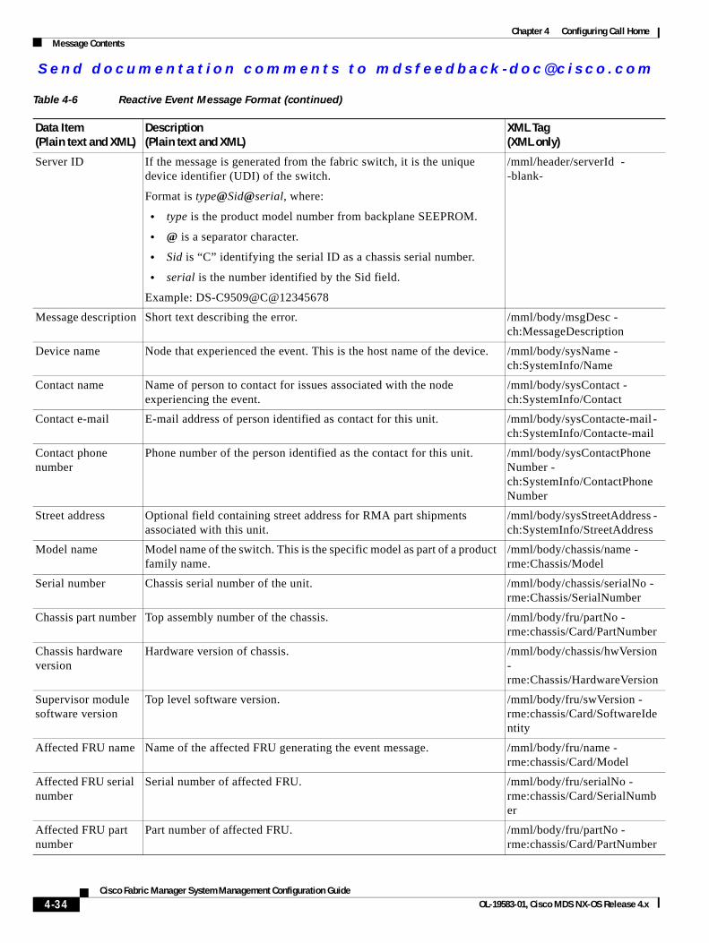
Send documenta t ion comments to mdsfeedback -doc@c i sco .com
Chapter 4 Configuring Call HomeMessage Contents
Server ID If the message is generated from the fabric switch, it is the unique device identifier (UDI) of the switch.
Format is type@Sid@serial, where:
• type is the product model number from backplane SEEPROM.
• @ is a separator character.
• Sid is “C” identifying the serial ID as a chassis serial number.
• serial is the number identified by the Sid field.
Example: DS-C9509@C@12345678
/mml/header/serverId - -blank-
Message description Short text describing the error. /mml/body/msgDesc - ch:MessageDescription
Device name Node that experienced the event. This is the host name of the device. /mml/body/sysName - ch:SystemInfo/Name
Contact name Name of person to contact for issues associated with the node experiencing the event.
/mml/body/sysContact - ch:SystemInfo/Contact
Contact e-mail E-mail address of person identified as contact for this unit. /mml/body/sysContacte-mail - ch:SystemInfo/Contacte-mail
Contact phone number
Phone number of the person identified as the contact for this unit. /mml/body/sysContactPhoneNumber - ch:SystemInfo/ContactPhoneNumber
Street address Optional field containing street address for RMA part shipments associated with this unit.
/mml/body/sysStreetAddress - ch:SystemInfo/StreetAddress
Model name Model name of the switch. This is the specific model as part of a product family name.
/mml/body/chassis/name - rme:Chassis/Model
Serial number Chassis serial number of the unit. /mml/body/chassis/serialNo - rme:Chassis/SerialNumber
Chassis part number Top assembly number of the chassis. /mml/body/fru/partNo - rme:chassis/Card/PartNumber
Chassis hardware version
Hardware version of chassis. /mml/body/chassis/hwVersion - rme:Chassis/HardwareVersion
Supervisor module software version
Top level software version. /mml/body/fru/swVersion - rme:chassis/Card/SoftwareIdentity
Affected FRU name Name of the affected FRU generating the event message. /mml/body/fru/name - rme:chassis/Card/Model
Affected FRU serial number
Serial number of affected FRU. /mml/body/fru/serialNo - rme:chassis/Card/SerialNumber
Affected FRU part number
Part number of affected FRU. /mml/body/fru/partNo - rme:chassis/Card/PartNumber
Table 4-6 Reactive Event Message Format (continued)
Data Item (Plain text and XML)
Description (Plain text and XML)
XML Tag (XML only)
4-34Cisco Fabric Manager System Management Configuration Guide
OL-19583-01, Cisco MDS NX-OS Release 4.x
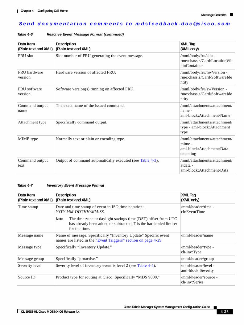
Send documenta t ion comments to mdsfeedback -doc@c i sco .com
Chapter 4 Configuring Call HomeMessage Contents
FRU slot Slot number of FRU generating the event message. /mml/body/fru/slot - rme:chassis/Card/LocationWithinContainer
FRU hardware version
Hardware version of affected FRU. /mml/body/fru/hwVersion - rme:chassis/Card/SoftwareIdentity
FRU software version
Software version(s) running on affected FRU. /mml/body/fru/swVersion - rme:chassis/Card/SoftwareIdentity
Command output name
The exact name of the issued command. /mml/attachments/attachment/name - aml-block:Attachment/Name
Attachment type Specifically command output. /mml/attachments/attachment/type - aml-block:Attachment type
MIME type Normally text or plain or encoding type. /mml/attachments/attachment/mime - aml-block:Attachment/Data encoding
Command output text
Output of command automatically executed (see Table 4-3). /mml/attachments/attachment/atdata - aml-block:Attachment/Data
Table 4-7 Inventory Event Message Format
Data Item (Plain text and XML)
Description (Plain text and XML)
XML Tag (XML only)
Time stamp Date and time stamp of event in ISO time notation: YYYY-MM-DDTHH:MM:SS.
Note The time zone or daylight savings time (DST) offset from UTC has already been added or subtracted. T is the hardcoded limiter for the time.
/mml/header/time - ch:EventTime
Message name Name of message. Specifically “Inventory Update” Specific event names are listed in the “Event Triggers” section on page 4-29.
/mml/header/name
Message type Specifically “Inventory Update.” /mml/header/type - ch-inv:Type
Message group Specifically “proactive.” /mml/header/group
Severity level Severity level of inventory event is level 2 (see Table 4-4). /mml/header/level - aml-block:Severity
Source ID Product type for routing at Cisco. Specifically “MDS 9000.” /mml/header/source - ch-inv:Series
Table 4-6 Reactive Event Message Format (continued)
Data Item (Plain text and XML)
Description (Plain text and XML)
XML Tag (XML only)
4-35Cisco Fabric Manager System Management Configuration Guide
OL-19583-01, Cisco MDS NX-OS Release 4.x
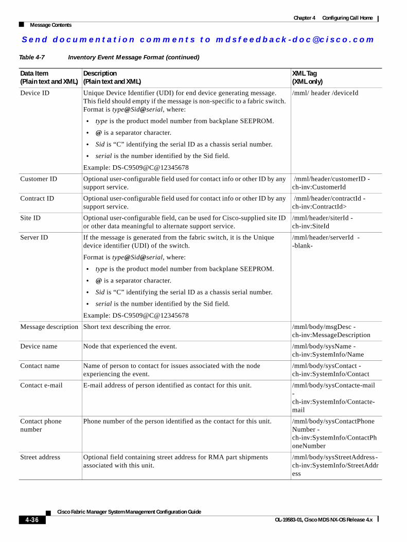
Send documenta t ion comments to mdsfeedback -doc@c i sco .com
Chapter 4 Configuring Call HomeMessage Contents
Device ID Unique Device Identifier (UDI) for end device generating message. This field should empty if the message is non-specific to a fabric switch. Format is type@Sid@serial, where:
• type is the product model number from backplane SEEPROM.
• @ is a separator character.
• Sid is “C” identifying the serial ID as a chassis serial number.
• serial is the number identified by the Sid field.
Example: DS-C9509@C@12345678
/mml/ header /deviceId
Customer ID Optional user-configurable field used for contact info or other ID by any support service.
/mml/header/customerID - ch-inv:CustomerId
Contract ID Optional user-configurable field used for contact info or other ID by any support service.
/mml/header/contractId - ch-inv:ContractId>
Site ID Optional user-configurable field, can be used for Cisco-supplied site ID or other data meaningful to alternate support service.
/mml/header/siterId - ch-inv:SiteId
Server ID If the message is generated from the fabric switch, it is the Unique device identifier (UDI) of the switch.
Format is type@Sid@serial, where:
• type is the product model number from backplane SEEPROM.
• @ is a separator character.
• Sid is “C” identifying the serial ID as a chassis serial number.
• serial is the number identified by the Sid field.
Example: DS-C9509@C@12345678
/mml/header/serverId - -blank-
Message description Short text describing the error. /mml/body/msgDesc - ch-inv:MessageDescription
Device name Node that experienced the event. /mml/body/sysName - ch-inv:SystemInfo/Name
Contact name Name of person to contact for issues associated with the node experiencing the event.
/mml/body/sysContact - ch-inv:SystemInfo/Contact
Contact e-mail E-mail address of person identified as contact for this unit. /mml/body/sysContacte-mail - ch-inv:SystemInfo/Contacte-mail
Contact phone number
Phone number of the person identified as the contact for this unit. /mml/body/sysContactPhoneNumber - ch-inv:SystemInfo/ContactPhoneNumber
Street address Optional field containing street address for RMA part shipments associated with this unit.
/mml/body/sysStreetAddress - ch-inv:SystemInfo/StreetAddress
Table 4-7 Inventory Event Message Format (continued)
Data Item (Plain text and XML)
Description (Plain text and XML)
XML Tag (XML only)
4-36Cisco Fabric Manager System Management Configuration Guide
OL-19583-01, Cisco MDS NX-OS Release 4.x
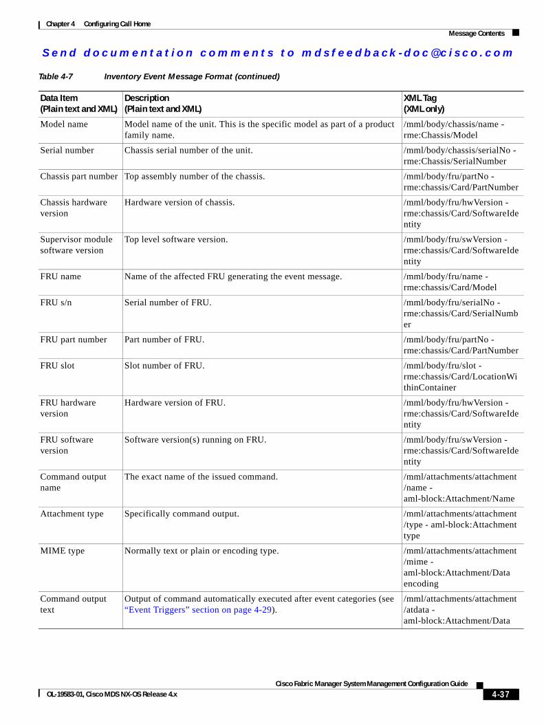
Send documenta t ion comments to mdsfeedback -doc@c i sco .com
Chapter 4 Configuring Call HomeMessage Contents
Model name Model name of the unit. This is the specific model as part of a product family name.
/mml/body/chassis/name - rme:Chassis/Model
Serial number Chassis serial number of the unit. /mml/body/chassis/serialNo - rme:Chassis/SerialNumber
Chassis part number Top assembly number of the chassis. /mml/body/fru/partNo - rme:chassis/Card/PartNumber
Chassis hardware version
Hardware version of chassis. /mml/body/fru/hwVersion - rme:chassis/Card/SoftwareIdentity
Supervisor module software version
Top level software version. /mml/body/fru/swVersion - rme:chassis/Card/SoftwareIdentity
FRU name Name of the affected FRU generating the event message. /mml/body/fru/name - rme:chassis/Card/Model
FRU s/n Serial number of FRU. /mml/body/fru/serialNo - rme:chassis/Card/SerialNumber
FRU part number Part number of FRU. /mml/body/fru/partNo - rme:chassis/Card/PartNumber
FRU slot Slot number of FRU. /mml/body/fru/slot - rme:chassis/Card/LocationWithinContainer
FRU hardware version
Hardware version of FRU. /mml/body/fru/hwVersion - rme:chassis/Card/SoftwareIdentity
FRU software version
Software version(s) running on FRU. /mml/body/fru/swVersion - rme:chassis/Card/SoftwareIdentity
Command output name
The exact name of the issued command. /mml/attachments/attachment/name - aml-block:Attachment/Name
Attachment type Specifically command output. /mml/attachments/attachment/type - aml-block:Attachment type
MIME type Normally text or plain or encoding type. /mml/attachments/attachment/mime - aml-block:Attachment/Data encoding
Command output text
Output of command automatically executed after event categories (see “Event Triggers” section on page 4-29).
/mml/attachments/attachment/atdata - aml-block:Attachment/Data
Table 4-7 Inventory Event Message Format (continued)
Data Item (Plain text and XML)
Description (Plain text and XML)
XML Tag (XML only)
4-37Cisco Fabric Manager System Management Configuration Guide
OL-19583-01, Cisco MDS NX-OS Release 4.x
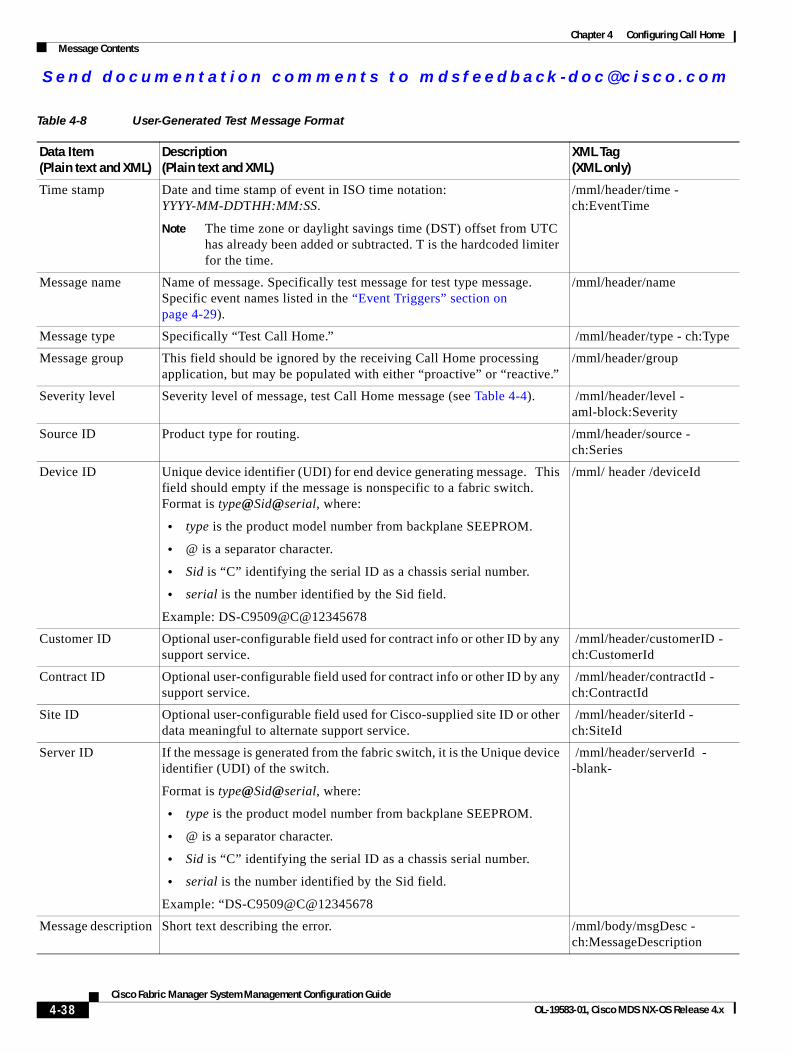
Send documenta t ion comments to mdsfeedback -doc@c i sco .com
Chapter 4 Configuring Call HomeMessage Contents
Table 4-8 User-Generated Test Message Format
Data Item (Plain text and XML)
Description (Plain text and XML)
XML Tag (XML only)
Time stamp Date and time stamp of event in ISO time notation: YYYY-MM-DDTHH:MM:SS.
Note The time zone or daylight savings time (DST) offset from UTC has already been added or subtracted. T is the hardcoded limiter for the time.
/mml/header/time - ch:EventTime
Message name Name of message. Specifically test message for test type message. Specific event names listed in the “Event Triggers” section on page 4-29).
/mml/header/name
Message type Specifically “Test Call Home.” /mml/header/type - ch:Type
Message group This field should be ignored by the receiving Call Home processing application, but may be populated with either “proactive” or “reactive.”
/mml/header/group
Severity level Severity level of message, test Call Home message (see Table 4-4). /mml/header/level - aml-block:Severity
Source ID Product type for routing. /mml/header/source - ch:Series
Device ID Unique device identifier (UDI) for end device generating message. This field should empty if the message is nonspecific to a fabric switch. Format is type@Sid@serial, where:
• type is the product model number from backplane SEEPROM.
• @ is a separator character.
• Sid is “C” identifying the serial ID as a chassis serial number.
• serial is the number identified by the Sid field.
Example: DS-C9509@C@12345678
/mml/ header /deviceId
Customer ID Optional user-configurable field used for contract info or other ID by any support service.
/mml/header/customerID - ch:CustomerId
Contract ID Optional user-configurable field used for contract info or other ID by any support service.
/mml/header/contractId - ch:ContractId
Site ID Optional user-configurable field used for Cisco-supplied site ID or other data meaningful to alternate support service.
/mml/header/siterId - ch:SiteId
Server ID If the message is generated from the fabric switch, it is the Unique device identifier (UDI) of the switch.
Format is type@Sid@serial, where:
• type is the product model number from backplane SEEPROM.
• @ is a separator character.
• Sid is “C” identifying the serial ID as a chassis serial number.
• serial is the number identified by the Sid field.
Example: “DS-C9509@C@12345678
/mml/header/serverId - -blank-
Message description Short text describing the error. /mml/body/msgDesc - ch:MessageDescription
4-38Cisco Fabric Manager System Management Configuration Guide
OL-19583-01, Cisco MDS NX-OS Release 4.x
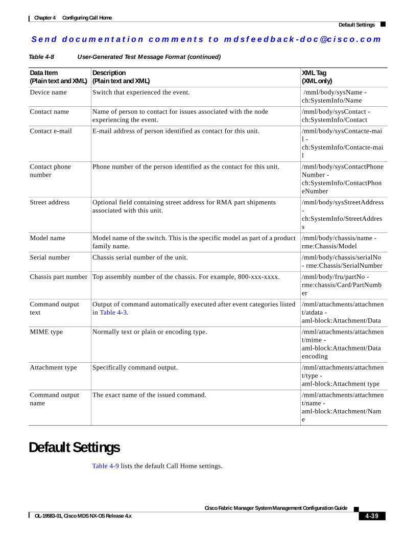
Send documenta t ion comments to mdsfeedback -doc@c i sco .com
Chapter 4 Configuring Call HomeDefault Settings
Default SettingsTable 4-9 lists the default Call Home settings.
Device name Switch that experienced the event. /mml/body/sysName - ch:SystemInfo/Name
Contact name Name of person to contact for issues associated with the node experiencing the event.
/mml/body/sysContact - ch:SystemInfo/Contact
Contact e-mail E-mail address of person identified as contact for this unit. /mml/body/sysContacte-mail - ch:SystemInfo/Contacte-mail
Contact phone number
Phone number of the person identified as the contact for this unit. /mml/body/sysContactPhoneNumber - ch:SystemInfo/ContactPhoneNumber
Street address Optional field containing street address for RMA part shipments associated with this unit.
/mml/body/sysStreetAddress - ch:SystemInfo/StreetAddress
Model name Model name of the switch. This is the specific model as part of a product family name.
/mml/body/chassis/name - rme:Chassis/Model
Serial number Chassis serial number of the unit. /mml/body/chassis/serialNo - rme:Chassis/SerialNumber
Chassis part number Top assembly number of the chassis. For example, 800-xxx-xxxx. /mml/body/fru/partNo - rme:chassis/Card/PartNumber
Command output text
Output of command automatically executed after event categories listed in Table 4-3.
/mml/attachments/attachment/atdata - aml-block:Attachment/Data
MIME type Normally text or plain or encoding type. /mml/attachments/attachment/mime - aml-block:Attachment/Data encoding
Attachment type Specifically command output. /mml/attachments/attachment/type - aml-block:Attachment type
Command output name
The exact name of the issued command. /mml/attachments/attachment/name - aml-block:Attachment/Name
Table 4-8 User-Generated Test Message Format (continued)
Data Item (Plain text and XML)
Description (Plain text and XML)
XML Tag (XML only)
4-39Cisco Fabric Manager System Management Configuration Guide
OL-19583-01, Cisco MDS NX-OS Release 4.x
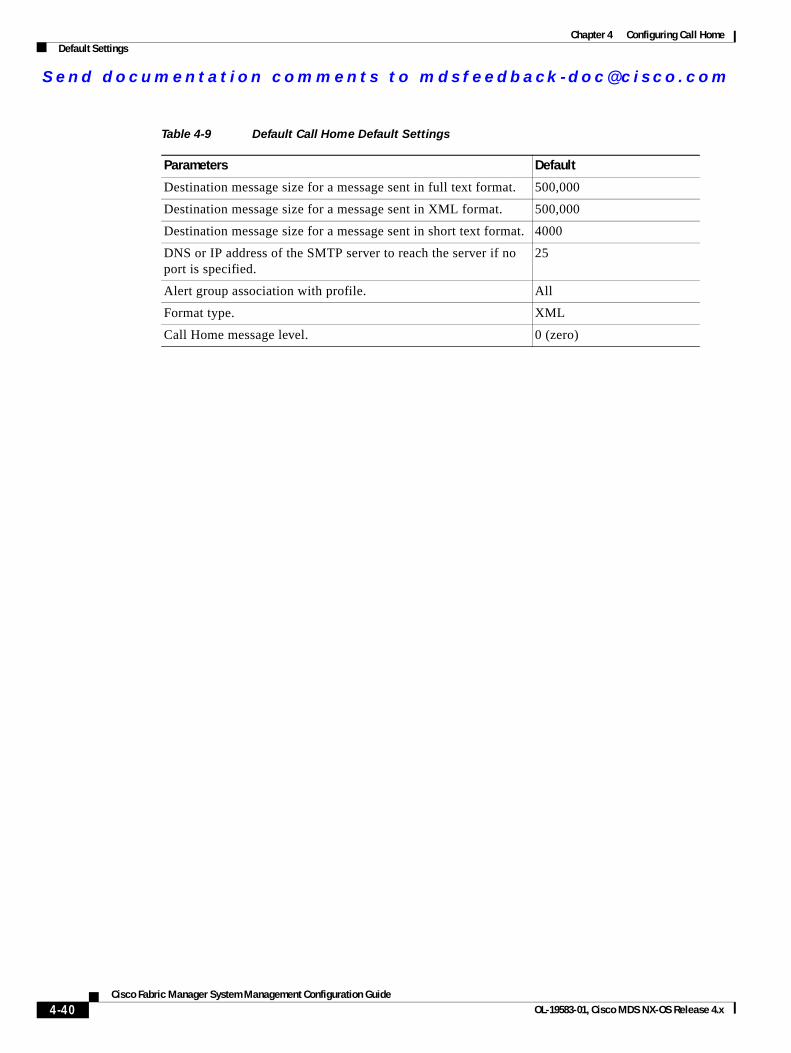
Send documenta t ion comments to mdsfeedback -doc@c i sco .com
Chapter 4 Configuring Call HomeDefault Settings
Table 4-9 Default Call Home Default Settings
Parameters Default
Destination message size for a message sent in full text format. 500,000
Destination message size for a message sent in XML format. 500,000
Destination message size for a message sent in short text format. 4000
DNS or IP address of the SMTP server to reach the server if no port is specified.
25
Alert group association with profile. All
Format type. XML
Call Home message level. 0 (zero)
4-40Cisco Fabric Manager System Management Configuration Guide
OL-19583-01, Cisco MDS NX-OS Release 4.x
Send documenta t ion comments to mdsfeedback -doc@c i sco .com
Cisco Fabric OL-19583-01, Cisco MDS NX-OS Release 4.x
C H A P T E R 5
Scheduling Maintenance JobsThe Cisco MDS command scheduler feature helps you schedule configuration and maintenance jobs in any switch in the Cisco MDS 9000 Family.You can use this feature to schedule jobs on a one-time basis or periodically.
This chapter includes the following sections:
• About the Command Scheduler, page 5-1
• Configuring the Command Scheduler, page 5-2
• Execution Logs, page 5-9
• Default Settings, page 5-10
About the Command SchedulerThe Cisco NX-OS command scheduler provides a facility to schedule a job (set of CLI commands) or multiple jobs at a specified time in the future. The job(s) can be executed once at a specified time in the future or at periodic intervals.
Note To use the command scheduler, you do not need to obtain any license.
You can use this feature to schedule zone set changes, make QoS policy changes, back up data, save the configuration and do other similar jobs.
Scheduler TerminologyThe following terms are used in this chapter.
• Job—A job is a set of NX-OS CLI commands (EXEC and config mode) that are executed as defined in the schedule.
• Schedule—A schedule determines the time when the assigned jobs must be executed. Multiple jobs can be assigned to a schedule. A schedule executes in one of two modes: one-time or periodic.
• Periodic mode—A job is executed at the user-specified periodic intervals, until it is deleted by the administrator. The following types of periodic intervals are supported:
– Daily—The job is executed once a day.
– Weekly—The job is executed once a week.
5-1Manager System Management Configuration Guide
Send documenta t ion comments to mdsfeedback -doc@c i sco .com
Chapter 5 Scheduling Maintenance JobsConfiguring the Command Scheduler
– Monthly—The job is executed once a month.
– Delta—The job is executed beginning at the specified start time and thereafter at user-specified intervals (days:hours:minutes).
• One-time mode—The job is executed once at a user-specified time.
Scheduling GuidelinesBefore scheduling jobs on a Cisco MDS switch, be aware of the following guidelines:
• Prior to Cisco MDS SAN-OS Release 3.0(3), only users local to the switch could perform scheduler configuration. As of Cisco MDS SAN-OS Release 3.0(3), remote users can perform job scheduling using AAA authentication.
• Be aware that the scheduled job can fail if it encounters one of the following situations when executing the job:
– If the license has expired for a feature at the time when a job containing commands pertaining to that feature is scheduled.
– If a feature is disabled at the time when a job containing commands pertaining to that feature is scheduled.
– If you have removed a module from a slot and the job has commands pertaining to the interfaces for that module or slot.
• Verify that you have configured the time. The scheduler does not have any default time configured. If you create a schedule and assign job(s) and do not configure the time, that schedule is not launched.
• While defining a job, verify that no interactive or disruptive commands (for example, copy bootflash: file ftp: URI, write erase, and other similar commands) are specified as part of a job because the job is executed noninteractively at the scheduled time.
Configuring the Command SchedulerTo configure the command scheduler, follow these steps:
Step 1 Enable the scheduler.
Step 2 Authorize remote user access (optional).
Step 3 Define the job.
Step 4 Specify the schedule and assign jobs to the schedule.
Step 5 Specify the time for the schedule(s).
Step 6 Verify the scheduled configuration.
This section includes the following topics:
• Enabling the Command Scheduler, page 5-3
• Configuring Remote User Authentication, page 5-3
• Defining a Job, page 5-4
5-2Cisco Fabric Manager System Management Configuration Guide
OL-19583-01, Cisco MDS NX-OS Release 4.x
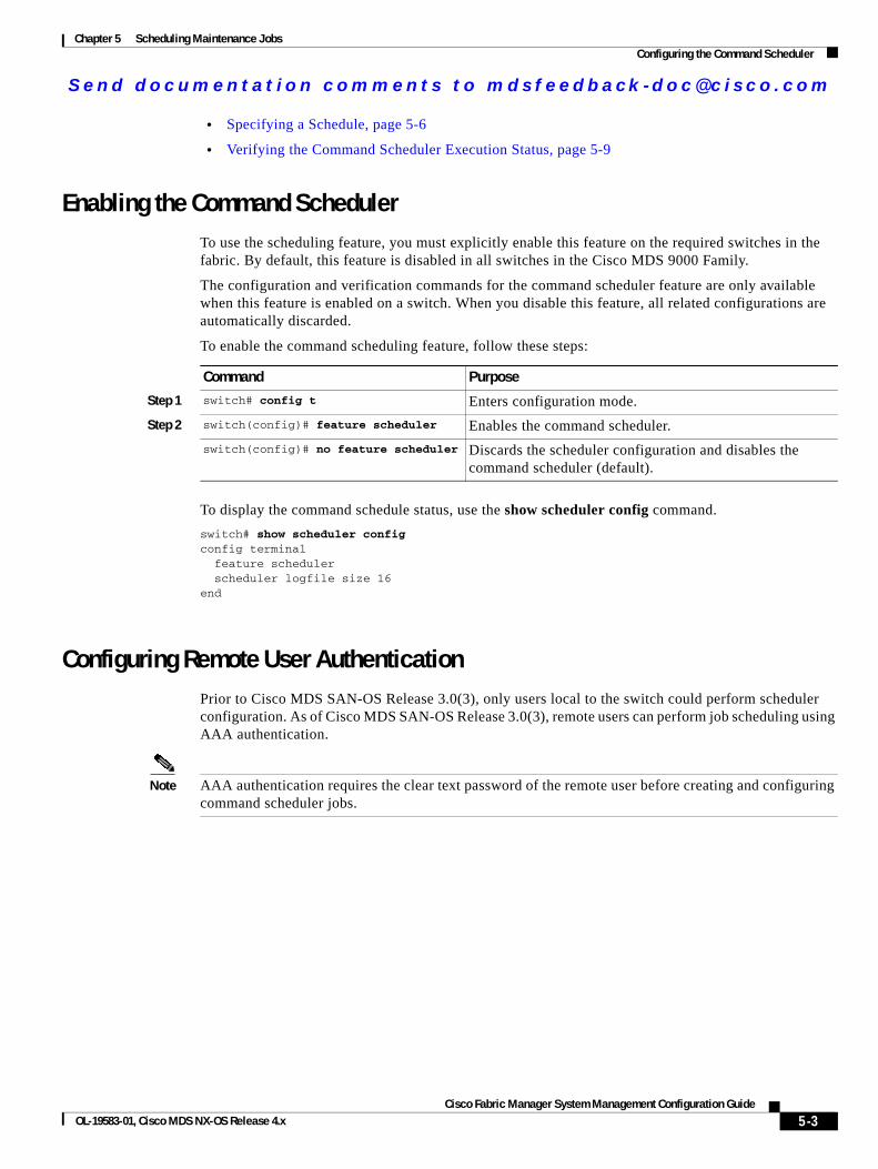
Send documenta t ion comments to mdsfeedback -doc@c i sco .com
Chapter 5 Scheduling Maintenance JobsConfiguring the Command Scheduler
• Specifying a Schedule, page 5-6
• Verifying the Command Scheduler Execution Status, page 5-9
Enabling the Command SchedulerTo use the scheduling feature, you must explicitly enable this feature on the required switches in the fabric. By default, this feature is disabled in all switches in the Cisco MDS 9000 Family.
The configuration and verification commands for the command scheduler feature are only available when this feature is enabled on a switch. When you disable this feature, all related configurations are automatically discarded.
To enable the command scheduling feature, follow these steps:
To display the command schedule status, use the show scheduler config command.
switch# show scheduler configconfig terminal feature scheduler scheduler logfile size 16end
Configuring Remote User AuthenticationPrior to Cisco MDS SAN-OS Release 3.0(3), only users local to the switch could perform scheduler configuration. As of Cisco MDS SAN-OS Release 3.0(3), remote users can perform job scheduling using AAA authentication.
Note AAA authentication requires the clear text password of the remote user before creating and configuring command scheduler jobs.
Command Purpose
Step 1 switch# config t Enters configuration mode.
Step 2 switch(config)# feature scheduler Enables the command scheduler.
switch(config)# no feature scheduler Discards the scheduler configuration and disables the command scheduler (default).
5-3Cisco Fabric Manager System Management Configuration Guide
OL-19583-01, Cisco MDS NX-OS Release 4.x
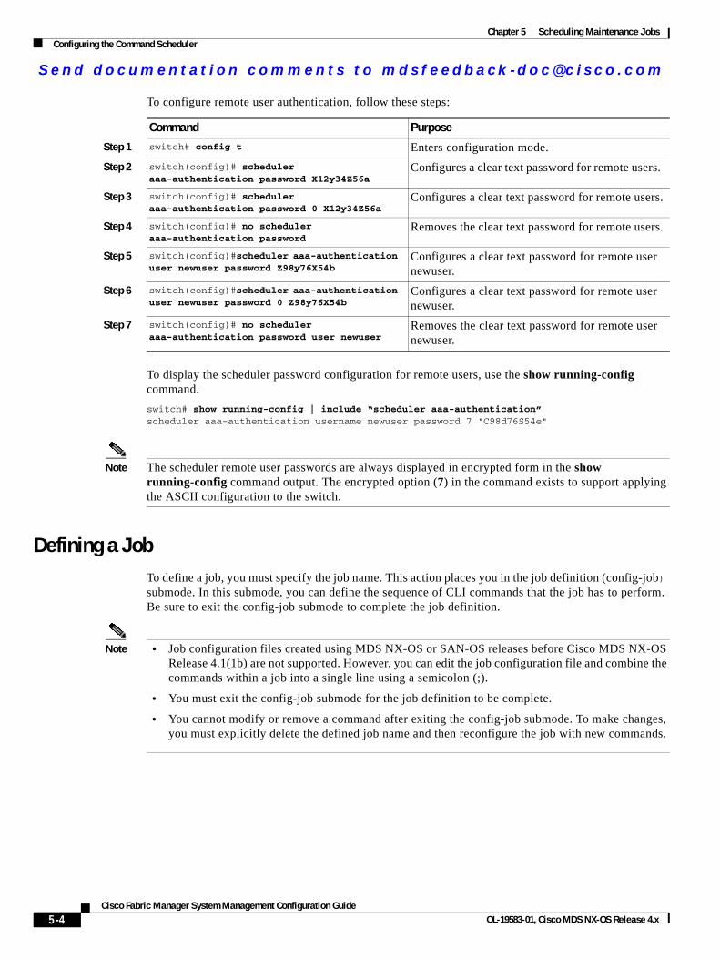
Send documenta t ion comments to mdsfeedback -doc@c i sco .com
Chapter 5 Scheduling Maintenance JobsConfiguring the Command Scheduler
To configure remote user authentication, follow these steps:
To display the scheduler password configuration for remote users, use the show running-config command.
switch# show running-config | include “scheduler aaa-authentication”scheduler aaa-authentication username newuser password 7 "C98d76S54e"
Note The scheduler remote user passwords are always displayed in encrypted form in the show running-config command output. The encrypted option (7) in the command exists to support applying the ASCII configuration to the switch.
Defining a JobTo define a job, you must specify the job name. This action places you in the job definition (config-job) submode. In this submode, you can define the sequence of CLI commands that the job has to perform. Be sure to exit the config-job submode to complete the job definition.
Note • Job configuration files created using MDS NX-OS or SAN-OS releases before Cisco MDS NX-OS Release 4.1(1b) are not supported. However, you can edit the job configuration file and combine the commands within a job into a single line using a semicolon (;).
• You must exit the config-job submode for the job definition to be complete.
• You cannot modify or remove a command after exiting the config-job submode. To make changes, you must explicitly delete the defined job name and then reconfigure the job with new commands.
Command Purpose
Step 1 switch# config t Enters configuration mode.
Step 2 switch(config)# scheduler aaa-authentication password X12y34Z56a
Configures a clear text password for remote users.
Step 3 switch(config)# scheduler aaa-authentication password 0 X12y34Z56a
Configures a clear text password for remote users.
Step 4 switch(config)# no scheduler aaa-authentication password
Removes the clear text password for remote users.
Step 5 switch(config)#scheduler aaa-authentication user newuser password Z98y76X54b
Configures a clear text password for remote user newuser.
Step 6 switch(config)#scheduler aaa-authentication user newuser password 0 Z98y76X54b
Configures a clear text password for remote user newuser.
Step 7 switch(config)# no scheduler aaa-authentication password user newuser
Removes the clear text password for remote user newuser.
5-4Cisco Fabric Manager System Management Configuration Guide
OL-19583-01, Cisco MDS NX-OS Release 4.x
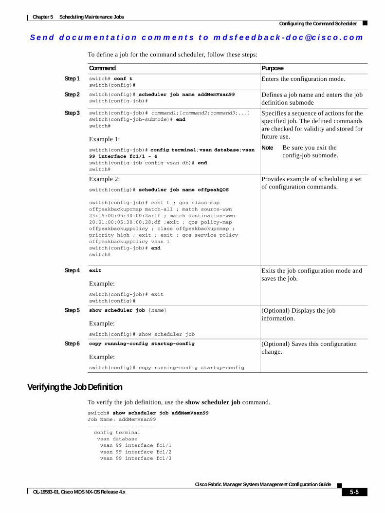
Send documenta t ion comments to mdsfeedback -doc@c i sco .com
Chapter 5 Scheduling Maintenance JobsConfiguring the Command Scheduler
To define a job for the command scheduler, follow these steps:
Verifying the Job Definition
To verify the job definition, use the show scheduler job command.
switch# show scheduler job addMemVsan99Job Name: addMemVsan99---------------------- config terminal vsan database vsan 99 interface fc1/1 vsan 99 interface fc1/2 vsan 99 interface fc1/3
Command Purpose
Step 1 switch# conf t switch(config)#
Enters the configuration mode.
Step 2 switch(config)# scheduler job name addMemVsan99switch(config-job)#
Defines a job name and enters the job definition submode
Step 3 switch(config-job)# command1;[command2;command3;...] switch(config-job-submode)# endswitch#
Example 1:
switch(config-job)# config terminal;vsan database;vsan 99 interface fc1/1 - 4switch(config-job-config-vsan-db)# endswitch#
Specifies a sequence of actions for the specified job. The defined commands are checked for validity and stored for future use.
Note Be sure you exit the config-job submode.
Example 2:
switch(config)# scheduler job name offpeakQOS
switch(config-job)# conf t ; qos class-map offpeakbackupcmap match-all ; match source-wwn 23:15:00:05:30:00:2a:1f ; match destination-wwn 20:01:00:05:30:00:28:df ;exit ; qos policy-map offpeakbackuppolicy ; class offpeakbackupcmap ; priority high ; exit ; exit ; qos service policy offpeakbackuppolicy vsan 1switch(config-job)# endswitch#
Provides example of scheduling a set of configuration commands.
Step 4 exit
Example:
switch(config-job)# exit switch(config)#
Exits the job configuration mode and saves the job.
Step 5 show scheduler job [name]
Example:
switch(config)# show scheduler job
(Optional) Displays the job information.
Step 6 copy running-config startup-config
Example:
switch(config)# copy running-config startup-config
(Optional) Saves this configuration change.
5-5Cisco Fabric Manager System Management Configuration Guide
OL-19583-01, Cisco MDS NX-OS Release 4.x
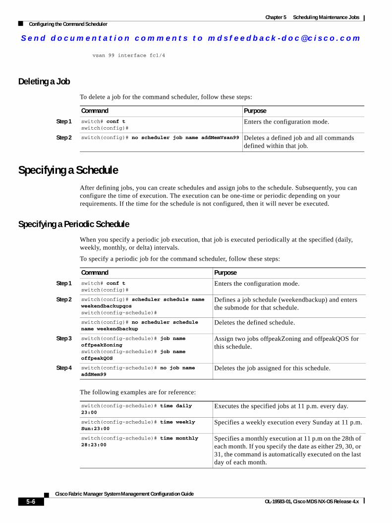
Send documenta t ion comments to mdsfeedback -doc@c i sco .com
Chapter 5 Scheduling Maintenance JobsConfiguring the Command Scheduler
vsan 99 interface fc1/4
Deleting a Job
To delete a job for the command scheduler, follow these steps:
Specifying a ScheduleAfter defining jobs, you can create schedules and assign jobs to the schedule. Subsequently, you can configure the time of execution. The execution can be one-time or periodic depending on your requirements. If the time for the schedule is not configured, then it will never be executed.
Specifying a Periodic Schedule
When you specify a periodic job execution, that job is executed periodically at the specified (daily, weekly, monthly, or delta) intervals.
To specify a periodic job for the command scheduler, follow these steps:
The following examples are for reference:
Command Purpose
Step 1 switch# conf t switch(config)#
Enters the configuration mode.
Step 2 switch(config)# no scheduler job name addMemVsan99 Deletes a defined job and all commands defined within that job.
Command Purpose
Step 1 switch# conf t switch(config)#
Enters the configuration mode.
Step 2 switch(config)# scheduler schedule name weekendbackupqosswitch(config-schedule)#
Defines a job schedule (weekendbackup) and enters the submode for that schedule.
switch(config)# no scheduler schedule name weekendbackup
Deletes the defined schedule.
Step 3 switch(config-schedule)# job name offpeakZoningswitch(config-schedule)# job name offpeakQOS
Assign two jobs offpeakZoning and offpeakQOS for this schedule.
Step 4 switch(config-schedule)# no job name addMem99
Deletes the job assigned for this schedule.
switch(config-schedule)# time daily 23:00
Executes the specified jobs at 11 p.m. every day.
switch(config-schedule)# time weekly Sun:23:00
Specifies a weekly execution every Sunday at 11 p.m.
switch(config-schedule)# time monthly 28:23:00
Specifies a monthly execution at 11 p.m on the 28th of each month. If you specify the date as either 29, 30, or 31, the command is automatically executed on the last day of each month.
5-6Cisco Fabric Manager System Management Configuration Guide
OL-19583-01, Cisco MDS NX-OS Release 4.x
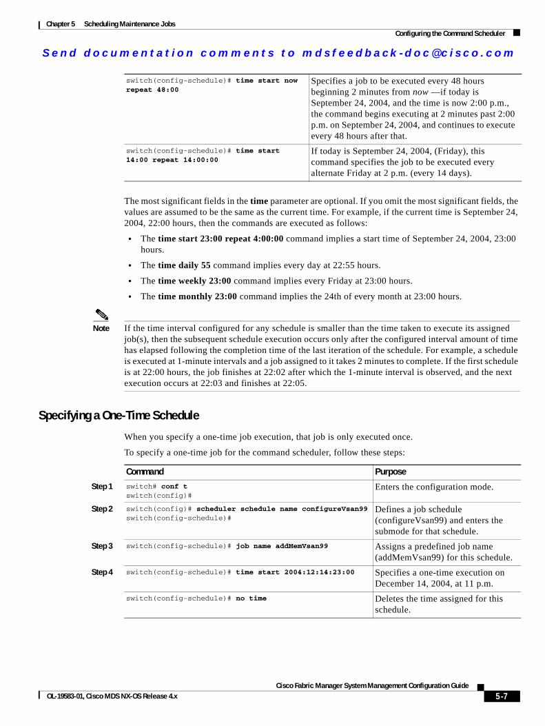
Send documenta t ion comments to mdsfeedback -doc@c i sco .com
Chapter 5 Scheduling Maintenance JobsConfiguring the Command Scheduler
The most significant fields in the time parameter are optional. If you omit the most significant fields, the values are assumed to be the same as the current time. For example, if the current time is September 24, 2004, 22:00 hours, then the commands are executed as follows:
• The time start 23:00 repeat 4:00:00 command implies a start time of September 24, 2004, 23:00 hours.
• The time daily 55 command implies every day at 22:55 hours.
• The time weekly 23:00 command implies every Friday at 23:00 hours.
• The time monthly 23:00 command implies the 24th of every month at 23:00 hours.
Note If the time interval configured for any schedule is smaller than the time taken to execute its assigned job(s), then the subsequent schedule execution occurs only after the configured interval amount of time has elapsed following the completion time of the last iteration of the schedule. For example, a schedule is executed at 1-minute intervals and a job assigned to it takes 2 minutes to complete. If the first schedule is at 22:00 hours, the job finishes at 22:02 after which the 1-minute interval is observed, and the next execution occurs at 22:03 and finishes at 22:05.
Specifying a One-Time Schedule
When you specify a one-time job execution, that job is only executed once.
To specify a one-time job for the command scheduler, follow these steps:
switch(config-schedule)# time start now repeat 48:00
Specifies a job to be executed every 48 hours beginning 2 minutes from now —if today is September 24, 2004, and the time is now 2:00 p.m., the command begins executing at 2 minutes past 2:00 p.m. on September 24, 2004, and continues to execute every 48 hours after that.
switch(config-schedule)# time start 14:00 repeat 14:00:00
If today is September 24, 2004, (Friday), this command specifies the job to be executed every alternate Friday at 2 p.m. (every 14 days).
Command Purpose
Step 1 switch# conf t switch(config)#
Enters the configuration mode.
Step 2 switch(config)# scheduler schedule name configureVsan99switch(config-schedule)#
Defines a job schedule (configureVsan99) and enters the submode for that schedule.
Step 3 switch(config-schedule)# job name addMemVsan99 Assigns a predefined job name (addMemVsan99) for this schedule.
Step 4 switch(config-schedule)# time start 2004:12:14:23:00 Specifies a one-time execution on December 14, 2004, at 11 p.m.
switch(config-schedule)# no time Deletes the time assigned for this schedule.
5-7Cisco Fabric Manager System Management Configuration Guide
OL-19583-01, Cisco MDS NX-OS Release 4.x
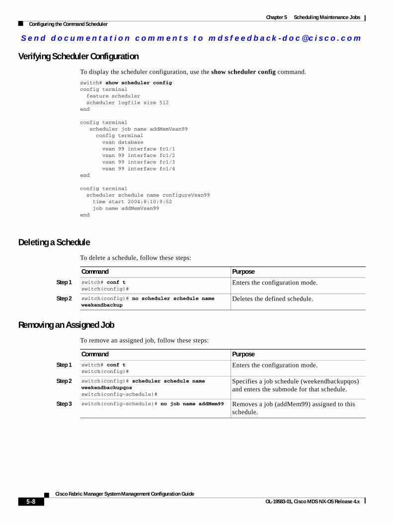
Send documenta t ion comments to mdsfeedback -doc@c i sco .com
Chapter 5 Scheduling Maintenance JobsConfiguring the Command Scheduler
Verifying Scheduler Configuration
To display the scheduler configuration, use the show scheduler config command.
switch# show scheduler configconfig terminal feature scheduler scheduler logfile size 512end
config terminal scheduler job name addMemVsan99 config terminal vsan database vsan 99 interface fc1/1 vsan 99 interface fc1/2 vsan 99 interface fc1/3 vsan 99 interface fc1/4end
config terminal scheduler schedule name configureVsan99 time start 2004:8:10:9:52 job name addMemVsan99end
Deleting a Schedule
To delete a schedule, follow these steps:
Removing an Assigned Job
To remove an assigned job, follow these steps:
Command Purpose
Step 1 switch# conf t switch(config)#
Enters the configuration mode.
Step 2 switch(config)# no scheduler schedule name weekendbackup
Deletes the defined schedule.
Command Purpose
Step 1 switch# conf t switch(config)#
Enters the configuration mode.
Step 2 switch(config)# scheduler schedule name weekendbackupqosswitch(config-schedule)#
Specifies a job schedule (weekendbackupqos) and enters the submode for that schedule.
Step 3 switch(config-schedule)# no job name addMem99 Removes a job (addMem99) assigned to this schedule.
5-8Cisco Fabric Manager System Management Configuration Guide
OL-19583-01, Cisco MDS NX-OS Release 4.x
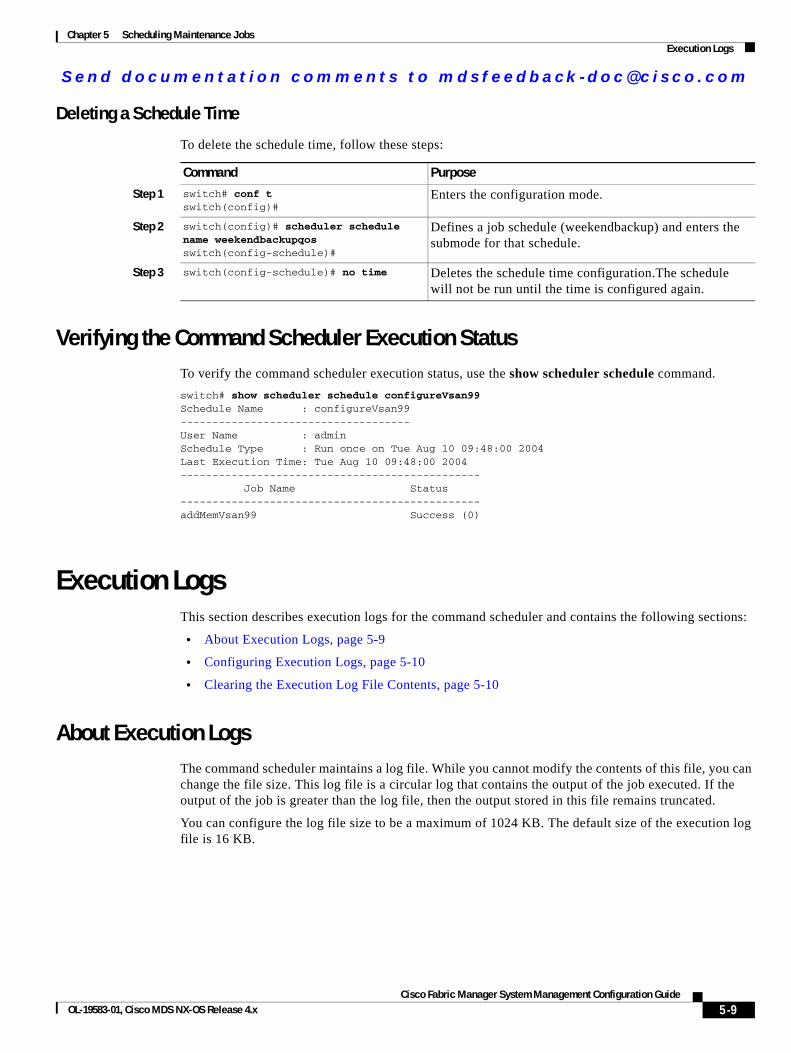
Send documenta t ion comments to mdsfeedback -doc@c i sco .com
Chapter 5 Scheduling Maintenance JobsExecution Logs
Deleting a Schedule Time
To delete the schedule time, follow these steps:
Verifying the Command Scheduler Execution StatusTo verify the command scheduler execution status, use the show scheduler schedule command.
switch# show scheduler schedule configureVsan99Schedule Name : configureVsan99------------------------------------User Name : adminSchedule Type : Run once on Tue Aug 10 09:48:00 2004Last Execution Time: Tue Aug 10 09:48:00 2004----------------------------------------------- Job Name Status-----------------------------------------------addMemVsan99 Success (0)
Execution LogsThis section describes execution logs for the command scheduler and contains the following sections:
• About Execution Logs, page 5-9
• Configuring Execution Logs, page 5-10
• Clearing the Execution Log File Contents, page 5-10
About Execution LogsThe command scheduler maintains a log file. While you cannot modify the contents of this file, you can change the file size. This log file is a circular log that contains the output of the job executed. If the output of the job is greater than the log file, then the output stored in this file remains truncated.
You can configure the log file size to be a maximum of 1024 KB. The default size of the execution log file is 16 KB.
Command Purpose
Step 1 switch# conf t switch(config)#
Enters the configuration mode.
Step 2 switch(config)# scheduler schedule name weekendbackupqosswitch(config-schedule)#
Defines a job schedule (weekendbackup) and enters the submode for that schedule.
Step 3 switch(config-schedule)# no time Deletes the schedule time configuration.The schedule will not be run until the time is configured again.
5-9Cisco Fabric Manager System Management Configuration Guide
OL-19583-01, Cisco MDS NX-OS Release 4.x
Send documenta t ion comments to mdsfeedback -doc@c i sco .com
Chapter 5 Scheduling Maintenance JobsDefault Settings
Configuring Execution LogsTo configure the execution log file size, follow these steps:
To display the execution log file configuration, use the show scheduler config command.
switch# show scheduler configconfig terminal feature scheduler scheduler logfile size 1024end
Displaying Execution Log File ContentsTo display the execution log for all jobs executed in the system, use the show scheduler logfile command.
switch# show scheduler logfileJob Name : addMemVsan99 Job Status: Success (0)Schedule Name : configureVsan99 User Name : adminCompletion time: Tue Aug 10 09:48:00 2004--------------------------- Job Output ---------------------------`config terminal``vsan database``vsan 99 interface fc1/1``vsan 99 interface fc1/2``vsan 99 interface fc1/3``vsan 99 interface fc1/4`
Clearing the Execution Log File ContentsTo clear the contents of the scheduler execution log file, issue the clear scheduler logfile command in EXEC mode.
switch# clear scheduler logfile
Default Settings Table 5-1 lists the default settings for command scheduling parameters.
Command Purpose
Step 1 switch# conf t switch(config)#
Enters the configuration mode.
Step 2 switch(config)# scheduler logfile size 1024 Configures the log file to be a maximum of 1024 KB
switch(config)# no scheduler logfile size Defaults to the log size of 16 KB.
5-10Cisco Fabric Manager System Management Configuration Guide
OL-19583-01, Cisco MDS NX-OS Release 4.x

Send documenta t ion comments to mdsfeedback -doc@c i sco .com
Chapter 5 Scheduling Maintenance JobsDefault Settings
Table 5-1 Default Command Scheduler Parameters
Parameters Default
Command scheduler Disabled.
Log file size 16 KB.
5-11Cisco Fabric Manager System Management Configuration Guide
OL-19583-01, Cisco MDS NX-OS Release 4.x

Send documenta t ion comments to mdsfeedback -doc@c i sco .com
Chapter 5 Scheduling Maintenance JobsDefault Settings
5-12Cisco Fabric Manager System Management Configuration Guide
OL-19583-01, Cisco MDS NX-OS Release 4.x
Send documenta t ion comments to mdsfeedback -doc@c i sco .com
Cisco Fabric OL-19583-01, Cisco MDS NX-OS Release 4.x
C H A P T E R 6
Monitoring System Processes and LogsThis chapter provides details on monitoring the health of the switch. It includes the following sections:
• Displaying System Processes, page 6-1
• Displaying System Status, page 6-2
• Core and Log Files, page 6-3
• Default Settings, page 6-6
Displaying System ProcessesTo obtain general information about all processes using Device Manager, follow these steps:
Step 1 Choose Admin > Running Processes.
You see the Running Processes dialog box shown in Figure 6-1.
6-1Manager System Management Configuration Guide
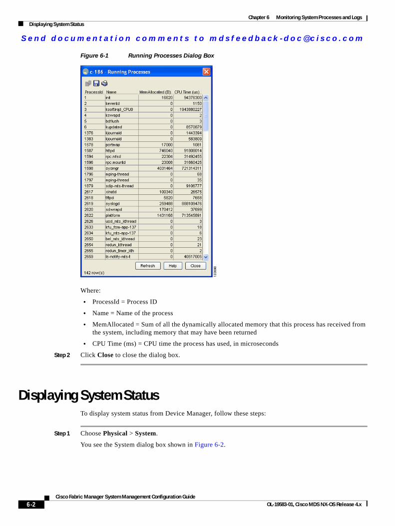
Send documenta t ion comments to mdsfeedback -doc@c i sco .com
Chapter 6 Monitoring System Processes and LogsDisplaying System Status
Figure 6-1 Running Processes Dialog Box
Where:
• ProcessId = Process ID
• Name = Name of the process
• MemAllocated = Sum of all the dynamically allocated memory that this process has received from the system, including memory that may have been returned
• CPU Time (ms) = CPU time the process has used, in microseconds
Step 2 Click Close to close the dialog box.
Displaying System StatusTo display system status from Device Manager, follow these steps:
Step 1 Choose Physical > System.
You see the System dialog box shown in Figure 6-2.
6-2Cisco Fabric Manager System Management Configuration Guide
OL-19583-01, Cisco MDS NX-OS Release 4.x
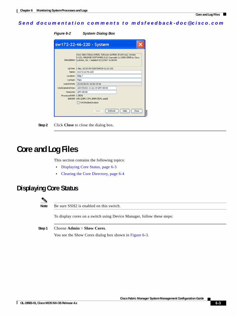
Send documenta t ion comments to mdsfeedback -doc@c i sco .com
Chapter 6 Monitoring System Processes and LogsCore and Log Files
Figure 6-2 System Dialog Box
Step 2 Click Close to close the dialog box.
Core and Log FilesThis section contains the following topics:
• Displaying Core Status, page 6-3
• Clearing the Core Directory, page 6-4
Displaying Core Status
Note Be sure SSH2 is enabled on this switch.
To display cores on a switch using Device Manager, follow these steps:
Step 1 Choose Admin > Show Cores.
You see the Show Cores dialog box shown in Figure 6-3.
6-3Cisco Fabric Manager System Management Configuration Guide
OL-19583-01, Cisco MDS NX-OS Release 4.x

Send documenta t ion comments to mdsfeedback -doc@c i sco .com
Chapter 6 Monitoring System Processes and LogsCore and Log Files
Figure 6-3 Show Cores Dialog Box
Module-num shows the slot number on which the core was generated. In this example, the fspf core was generated on the active supervisor module (slot 5), fcc was generated on the standby supervisor module (slot 6), and acltcam and fib were generated on the switching module (slot 8).
Step 2 Click Close to close the dialog box.
Clearing the Core Directory
Note Be sure SSH2 is enabled on this switch.
To clear the cores on a switch using Device Manager, follow these steps:
Step 1 Click Clear to clear the cores.
The software keeps the last few cores per service and per slot and clears all other cores present on the active supervisor module.
Step 2 Click Close to close the dialog box.
First and Last CoreThe first and last core feature uses the limited system resource and retains the most important core files. Generally, the first core and the most recently generated core have the information for debugging and, the first and last core feature tries to retain the first and the last core information.
If the core files are generated from an active supervisor module, the number of core files for the service is defined in the service.conf file. There is no upper limit on the total number of core files in the active supervisor module.
6-4Cisco Fabric Manager System Management Configuration Guide
OL-19583-01, Cisco MDS NX-OS Release 4.x
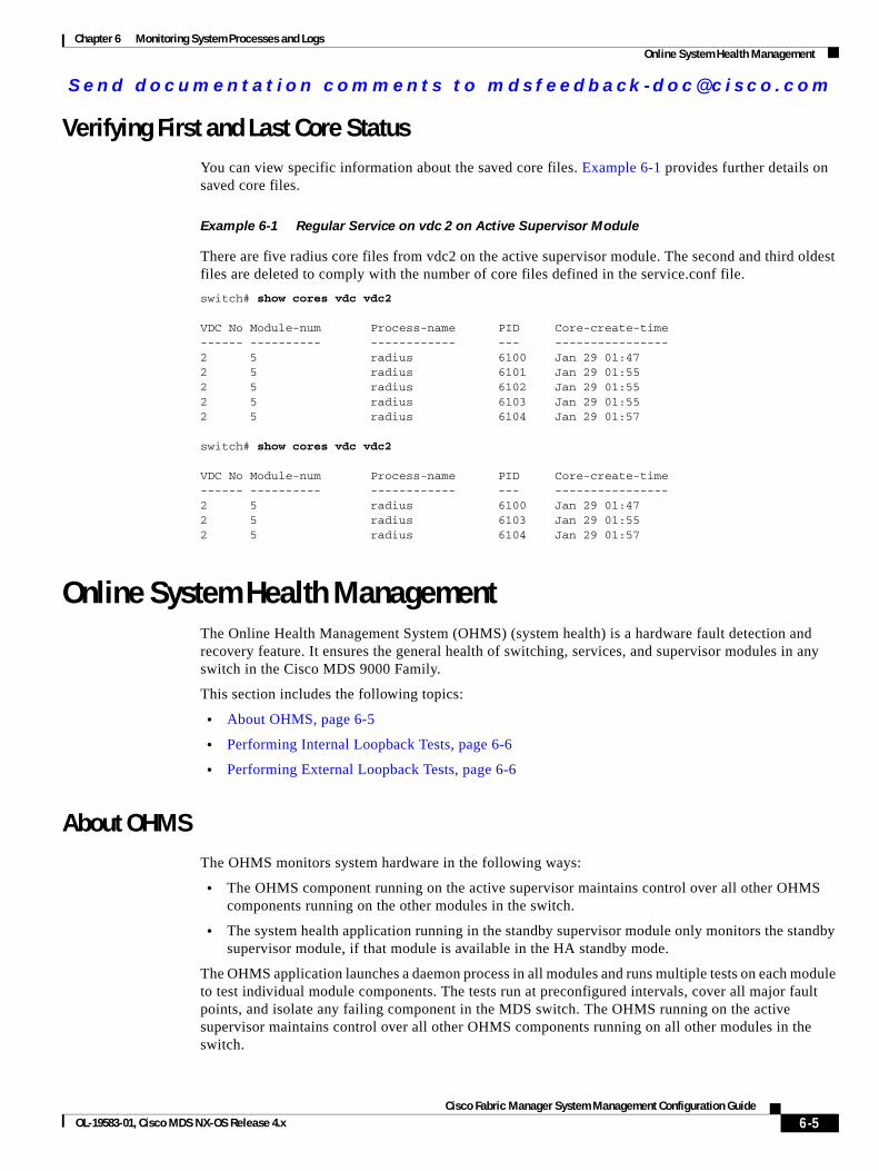
Send documenta t ion comments to mdsfeedback -doc@c i sco .com
Chapter 6 Monitoring System Processes and LogsOnline System Health Management
Verifying First and Last Core StatusYou can view specific information about the saved core files. Example 6-1 provides further details on saved core files.
Example 6-1 Regular Service on vdc 2 on Active Supervisor Module
There are five radius core files from vdc2 on the active supervisor module. The second and third oldest files are deleted to comply with the number of core files defined in the service.conf file.
switch# show cores vdc vdc2
VDC No Module-num Process-name PID Core-create-time------ ---------- ------------ --- ----------------2 5 radius 6100 Jan 29 01:472 5 radius 6101 Jan 29 01:552 5 radius 6102 Jan 29 01:552 5 radius 6103 Jan 29 01:552 5 radius 6104 Jan 29 01:57 switch# show cores vdc vdc2
VDC No Module-num Process-name PID Core-create-time------ ---------- ------------ --- ----------------2 5 radius 6100 Jan 29 01:472 5 radius 6103 Jan 29 01:552 5 radius 6104 Jan 29 01:57
Online System Health ManagementThe Online Health Management System (OHMS) (system health) is a hardware fault detection and recovery feature. It ensures the general health of switching, services, and supervisor modules in any switch in the Cisco MDS 9000 Family.
This section includes the following topics:
• About OHMS, page 6-5
• Performing Internal Loopback Tests, page 6-6
• Performing External Loopback Tests, page 6-6
About OHMSThe OHMS monitors system hardware in the following ways:
• The OHMS component running on the active supervisor maintains control over all other OHMS components running on the other modules in the switch.
• The system health application running in the standby supervisor module only monitors the standby supervisor module, if that module is available in the HA standby mode.
The OHMS application launches a daemon process in all modules and runs multiple tests on each module to test individual module components. The tests run at preconfigured intervals, cover all major fault points, and isolate any failing component in the MDS switch. The OHMS running on the active supervisor maintains control over all other OHMS components running on all other modules in the switch.
6-5Cisco Fabric Manager System Management Configuration Guide
OL-19583-01, Cisco MDS NX-OS Release 4.x
Send documenta t ion comments to mdsfeedback -doc@c i sco .com
Chapter 6 Monitoring System Processes and LogsDefault Settings
On detecting a fault, the system health application attempts the following recovery actions:
• Performs additional testing to isolate the faulty component.
• Attempts to reconfigure the component by retrieving its configuration information from persistent storage.
• If unable to recover, sends Call Home notifications, system messages and exception logs; and shuts down and discontinues testing the failed module or component (such as an interface).
• Sends Call Home and system messages and exception logs as soon as it detects a failure.
• Shuts down the failing module or component (such as an interface).
• Isolates failed ports from further testing.
• Reports the failure to the appropriate software component.
• Switches to the standby supervisor module, if an error is detected on the active supervisor module and a standby supervisor module exists in the Cisco MDS switch. After the switchover, the new active supervisor module restarts the active supervisor tests.
• Reloads the switch if a standby supervisor module does not exist in the switch.
• Provides CLI support to view, test, and obtain test run statistics or change the system health test configuration on the switch.
• Performs tests to focus on the problem area.
Each module is configured to run the test relevant to that module. You can change the default parameters of the test in each module as required.
Performing Internal Loopback TestsYou can run manual loopback tests to identify hardware errors in the data path in the switching or services modules, and the control path in the supervisor modules. Internal loopback tests send and receive FC2 frames to and from the same ports and provide the round-trip time taken in microseconds. These tests are available for Fibre Channel, IPS, and iSCSI interfaces.
Choose Interface > Diagnostics > Internal to perform an internal loopback test from Device Manager.
Performing External Loopback TestsYou can run manual loopback tests to identify hardware errors in the data path in the switching or services modules, and the control path in the supervisor modules. External loopback tests send and receive FC2 frames to and from the same port or between two ports.
You need to connect a cable (or a plug) to loop the Rx port to the Tx port before running the test. If you are testing to and from the same port, you need a special loop cable. If you are testing to and from different ports, you can use a regular cable. This test is only available for Fibre Channel interfaces.
Choose Interface > Diagnostics > External to perform an external loopback test from Device Manager.
Default SettingsTable 6-1 lists the default system health and log settings.
6-6Cisco Fabric Manager System Management Configuration Guide
OL-19583-01, Cisco MDS NX-OS Release 4.x

Send documenta t ion comments to mdsfeedback -doc@c i sco .com
Chapter 6 Monitoring System Processes and LogsDefault Settings
Table 6-1 Default System Health and Log Settings
Parameters Default
Kernel core generation One module
System health Enabled
Loopback frequency 5 seconds
Failure action Enabled
6-7Cisco Fabric Manager System Management Configuration Guide
OL-19583-01, Cisco MDS NX-OS Release 4.x

Send documenta t ion comments to mdsfeedback -doc@c i sco .com
Chapter 6 Monitoring System Processes and LogsDefault Settings
6-8Cisco Fabric Manager System Management Configuration Guide
OL-19583-01, Cisco MDS NX-OS Release 4.x
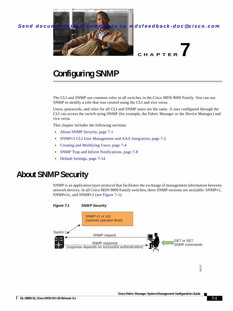
Send documenta t ion comments to mdsfeedback -doc@c i sco .com
Cisco Fabric OL-19583-01, Cisco MDS NX-OS Release 4.x
C H A P T E R 7
Configuring SNMPThe CLI and SNMP use common roles in all switches in the Cisco MDS 9000 Family. You can use SNMP to modify a role that was created using the CLI and vice versa.
Users, passwords, and roles for all CLI and SNMP users are the same. A user configured through the CLI can access the switch using SNMP (for example, the Fabric Manager or the Device Manager) and vice versa.
This chapter includes the following sections:
• About SNMP Security, page 7-1
• SNMPv3 CLI User Management and AAA Integration, page 7-2
• Creating and Modifying Users, page 7-4
• SNMP Trap and Inform Notifications, page 7-8
• Default Settings, page 7-14
About SNMP SecuritySNMP is an application layer protocol that facilitates the exchange of management information between network devices. In all Cisco MDS 9000 Family switches, three SNMP versions are available: SNMPv1, SNMPv2c, and SNMPv3 (see Figure 7-1).
Figure 7-1 SNMP Security
Switch 1
SNMP v1 or v2c(network operator level)
SNMP request
SNMP response(response depends on successful authentication)
GET or SETSNMP commands
8547
3
7-1Manager System Management Configuration Guide
Send documenta t ion comments to mdsfeedback -doc@c i sco .com
Chapter 7 Configuring SNMPSNMPv3 CLI User Management and AAA Integration
This section includes the following topics:
• SNMP Version 1 and Version 2c, page 7-2
• SNMP Version 3, page 7-2
• Assigning SNMP Switch Contact and Location Information, page 7-2
SNMP Version 1 and Version 2cSNMP Version 1 (SNMPv1) and SNMP Version 2c (SNMPv2c) use a community string match for user authentication. Community strings provided a weak form of access control in earlier versions of SNMP. SNMPv3 provides much improved access control using strong authentication and should be preferred over SNMPv1 and SNMPv2c wherever it is supported.
SNMP Version 3SNMP Version 3 (SNMPv3) is an interoperable standards-based protocol for network management. SNMPv3 provides secure access to devices by a combination of authenticating and encrypting frames over the network. The security features provided in SNMPv3 are:
• Message integrity—Ensures that a packet has not been tampered with in-transit.
• Authentication—Determines the message is from a valid source.
• Encryption—Scrambles the packet contents to prevent it from being seen by unauthorized sources.
SNMPv3 provides for both security models and security levels. A security model is an authentication strategy that is set up for a user and the role in which the user resides. A security level is the permitted level of security within a security model. A combination of a security model and a security level determines which security mechanism is employed when handling an SNMP packet.
Assigning SNMP Switch Contact and Location InformationYou can assign the switch contact information, which is limited to 32 characters (without spaces) and the switch location.
To configure contact and location information, using Fabric Manager, follow these steps:
Step 1 Expand Switches from the Physical Attributes pane. You see the switch settings in the Information pane.
Step 2 Fill in the Location and Contact fields for each switch.
Step 3 Click Apply Changes to save these changes or click Undo Changes to discard any unsaved changes.
SNMPv3 CLI User Management and AAA IntegrationThe Cisco NX-OS software implements RFC 3414 and RFC 3415, including user-based security model (USM) and role-based access control. While SNMP and the CLI have common role management and share the same credentials and access privileges, the local user database was not synchronized in earlier releases.
7-2Cisco Fabric Manager System Management Configuration Guide
OL-19583-01, Cisco MDS NX-OS Release 4.x
Send documenta t ion comments to mdsfeedback -doc@c i sco .com
Chapter 7 Configuring SNMPSNMPv3 CLI User Management and AAA Integration
SNMPv3 user management can be centralized at the AAA server level. This centralized user management allows the SNMP agent running on the Cisco MDS switch to leverage the user authentication service of the AAA server. Once user authentication is verified, the SNMP PDUs are processed further. The AAA server also is used to store user group names. SNMP uses the group names to apply the access/role policy that is locally available in the switch.
This section includes the following topics:
• CLI and SNMP User Synchronization, page 7-3
• Restricting Switch Access, page 7-3
• Group-Based SNMP Access, page 7-3
CLI and SNMP User SynchronizationAny configuration changes made to the user group, role, or password results in database synchronization for both SNMP and AAA.
Users are synchronized as follows:
• Deleting a user using either command results in the user being deleted for both SNMP and the CLI.
• User-role mapping changes are synchronized in SNMP and the CLI.
Note When the passphrase/password is specified in localized key/encrypted format, the password is not synchronized.
Note Starting in 3.0(1), the temporary SNMP login created for Fabric Manager is no longer 24 hours. It is one hour.
• Existing SNMP users continue to retain the auth and priv passphrases without any changes.
• If the management station creates an SNMP user in the usmUserTable, the corresponding CLI user is created without any password (login is disabled) and will have the network-operator role.
Restricting Switch AccessYou can restrict access to a Cisco MDS 9000 Family switch using IP Access Control Lists (IP-ACLs).
Group-Based SNMP Access
Note Because group is a standard SNMP term used industry-wide, we refer to role(s) as group(s) in this SNMP section.
SNMP access rights are organized by groups. Each group in SNMP is similar to a role through the CLI. Each group is defined with three accesses: read access, write access, and notification access. Each access can be enabled or disabled within each group.
7-3Cisco Fabric Manager System Management Configuration Guide
OL-19583-01, Cisco MDS NX-OS Release 4.x
Send documenta t ion comments to mdsfeedback -doc@c i sco .com
Chapter 7 Configuring SNMPCreating and Modifying Users
You can begin communicating with the agent once your user name is created, your roles are set up by your administrator, and you are added to the roles.
Creating and Modifying UsersYou can create users or modify existing users using SNMP, Fabric Manager, or the CLI.
• SNMP—Create a user as a clone of an existing user in the usmUserTable on the switch. Once you have created the user, change the cloned secret key before activating the user. Refer to RFC 2574.
• Fabric Manager.
• CLI—Create a user or modify an existing user using the snmp-server user command.
A network-operator and network-admin roles are available in a Cisco MDS 9000 Family switch. There is also a default-role if you want to use the GUI (Fabric Manager and Device Manager). You can also use any role that is configured in the Common Roles database.
Tip All updates to the CLI security database and the SNMP user database are synchronized. You can use the SNMP password to log into either Fabric Manager or Device Manager. However, after you use the CLI password to log into Fabric Manager or Device Manager, you must use the CLI password for all future logins. If a user exists in both the SNMP database and the CLI database before upgrading to Cisco MDS SAN-OS Release 2.0(1b), then the set of roles assigned to the user becomes the union of both sets of roles after the upgrade.
This section includes the following topics:
• About AES Encryption-Based Privacy, page 7-4
• Enforcing SNMPv3 Message Encryption, page 7-5
• Assigning SNMPv3 Users to Multiple Roles, page 7-6
• Adding Communities, page 7-7
• Deleting a Community String, page 7-7
About AES Encryption-Based Privacy The Advanced Encryption Standard (AES) is the symmetric cipher algorithm. The Cisco NX-OS software uses AES as one of the privacy protocols for SNMP message encryption and conforms with RFC 3826.
The priv option offers a choice of DES or 128-bit AES encryption for SNMP security encryption. The priv option along with the aes-128 token indicates that this privacy password is for generating a 128-bit AES key. The AES priv password can have a minimum of eight characters. If the passphrases are specified in clear text, you can specify a maximum of 64 characters. If you use the localized key, you can specify a maximum of 130 characters.
Note For an SNMPv3 operation using the external AAA server, user configurations in the external AAA server require AES to be the privacy protocol to use SNMP PDU encryption.
7-4Cisco Fabric Manager System Management Configuration Guide
OL-19583-01, Cisco MDS NX-OS Release 4.x
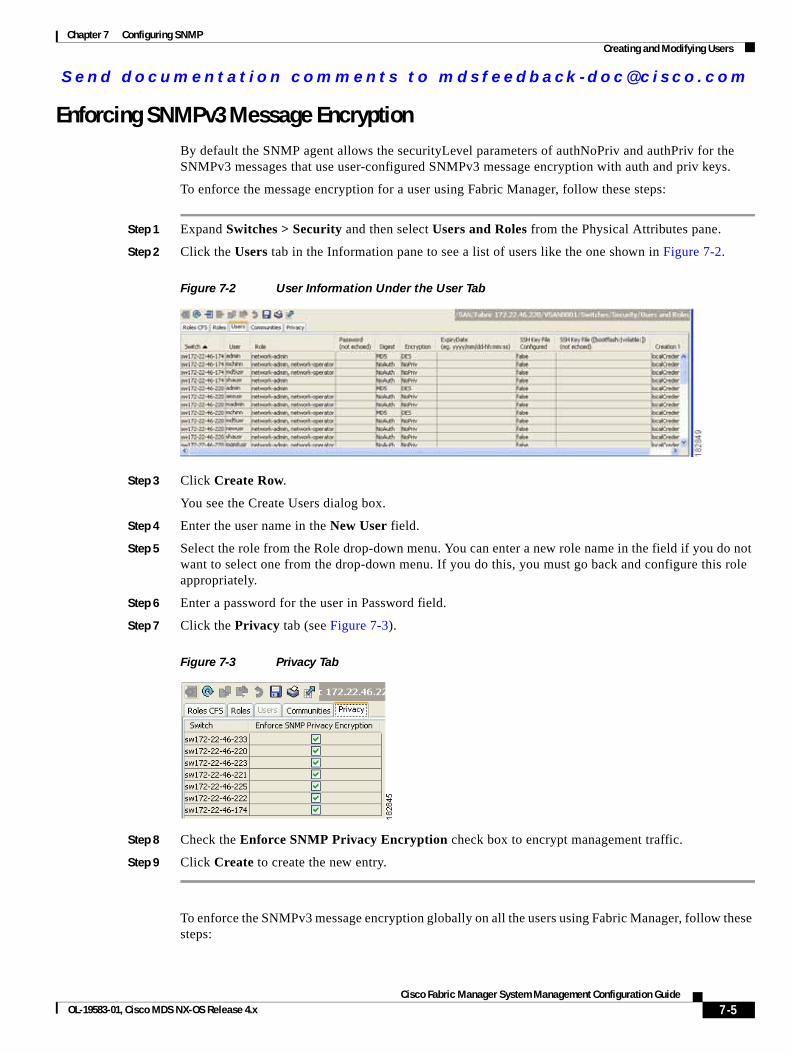
Send documenta t ion comments to mdsfeedback -doc@c i sco .com
Chapter 7 Configuring SNMPCreating and Modifying Users
Enforcing SNMPv3 Message EncryptionBy default the SNMP agent allows the securityLevel parameters of authNoPriv and authPriv for the SNMPv3 messages that use user-configured SNMPv3 message encryption with auth and priv keys.
To enforce the message encryption for a user using Fabric Manager, follow these steps:
Step 1 Expand Switches > Security and then select Users and Roles from the Physical Attributes pane.
Step 2 Click the Users tab in the Information pane to see a list of users like the one shown in Figure 7-2.
Figure 7-2 User Information Under the User Tab
Step 3 Click Create Row.
You see the Create Users dialog box.
Step 4 Enter the user name in the New User field.
Step 5 Select the role from the Role drop-down menu. You can enter a new role name in the field if you do not want to select one from the drop-down menu. If you do this, you must go back and configure this role appropriately.
Step 6 Enter a password for the user in Password field.
Step 7 Click the Privacy tab (see Figure 7-3).
Figure 7-3 Privacy Tab
Step 8 Check the Enforce SNMP Privacy Encryption check box to encrypt management traffic.
Step 9 Click Create to create the new entry.
To enforce the SNMPv3 message encryption globally on all the users using Fabric Manager, follow these steps:
7-5Cisco Fabric Manager System Management Configuration Guide
OL-19583-01, Cisco MDS NX-OS Release 4.x
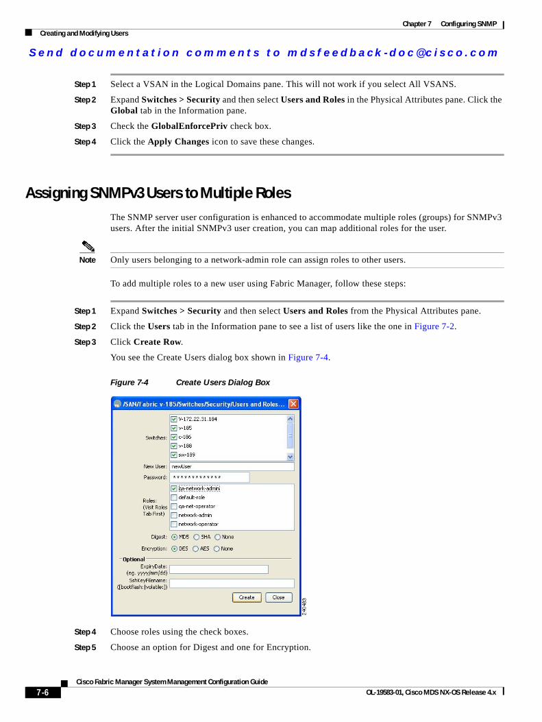
Send documenta t ion comments to mdsfeedback -doc@c i sco .com
Chapter 7 Configuring SNMPCreating and Modifying Users
Step 1 Select a VSAN in the Logical Domains pane. This will not work if you select All VSANS.
Step 2 Expand Switches > Security and then select Users and Roles in the Physical Attributes pane. Click the Global tab in the Information pane.
Step 3 Check the GlobalEnforcePriv check box.
Step 4 Click the Apply Changes icon to save these changes.
Assigning SNMPv3 Users to Multiple Roles The SNMP server user configuration is enhanced to accommodate multiple roles (groups) for SNMPv3 users. After the initial SNMPv3 user creation, you can map additional roles for the user.
Note Only users belonging to a network-admin role can assign roles to other users.
To add multiple roles to a new user using Fabric Manager, follow these steps:
Step 1 Expand Switches > Security and then select Users and Roles from the Physical Attributes pane.
Step 2 Click the Users tab in the Information pane to see a list of users like the one in Figure 7-2.
Step 3 Click Create Row.
You see the Create Users dialog box shown in Figure 7-4.
Figure 7-4 Create Users Dialog Box
Step 4 Choose roles using the check boxes.
Step 5 Choose an option for Digest and one for Encryption.
7-6Cisco Fabric Manager System Management Configuration Guide
OL-19583-01, Cisco MDS NX-OS Release 4.x
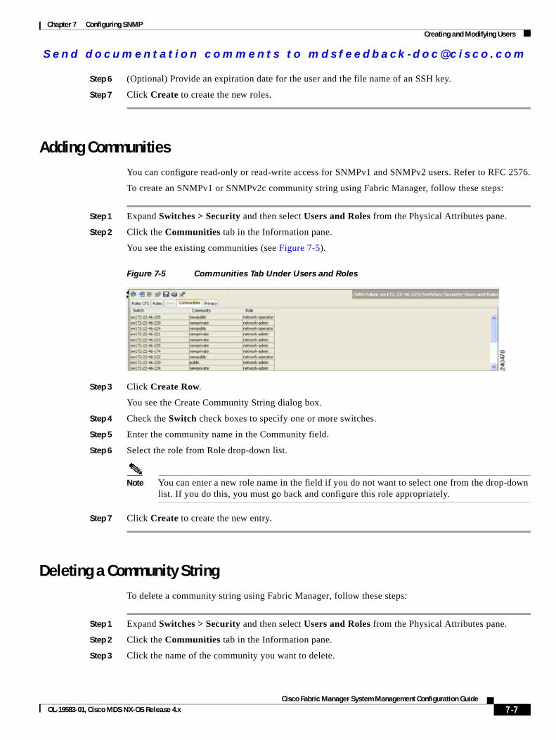
Send documenta t ion comments to mdsfeedback -doc@c i sco .com
Chapter 7 Configuring SNMPCreating and Modifying Users
Step 6 (Optional) Provide an expiration date for the user and the file name of an SSH key.
Step 7 Click Create to create the new roles.
Adding CommunitiesYou can configure read-only or read-write access for SNMPv1 and SNMPv2 users. Refer to RFC 2576.
To create an SNMPv1 or SNMPv2c community string using Fabric Manager, follow these steps:
Step 1 Expand Switches > Security and then select Users and Roles from the Physical Attributes pane.
Step 2 Click the Communities tab in the Information pane.
You see the existing communities (see Figure 7-5).
Figure 7-5 Communities Tab Under Users and Roles
Step 3 Click Create Row.
You see the Create Community String dialog box.
Step 4 Check the Switch check boxes to specify one or more switches.
Step 5 Enter the community name in the Community field.
Step 6 Select the role from Role drop-down list.
Note You can enter a new role name in the field if you do not want to select one from the drop-down list. If you do this, you must go back and configure this role appropriately.
Step 7 Click Create to create the new entry.
Deleting a Community StringTo delete a community string using Fabric Manager, follow these steps:
Step 1 Expand Switches > Security and then select Users and Roles from the Physical Attributes pane.
Step 2 Click the Communities tab in the Information pane.
Step 3 Click the name of the community you want to delete.
7-7Cisco Fabric Manager System Management Configuration Guide
OL-19583-01, Cisco MDS NX-OS Release 4.x
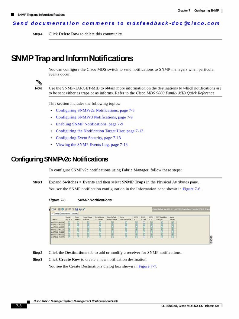
Send documenta t ion comments to mdsfeedback -doc@c i sco .com
Chapter 7 Configuring SNMPSNMP Trap and Inform Notifications
Step 4 Click Delete Row to delete this community.
SNMP Trap and Inform NotificationsYou can configure the Cisco MDS switch to send notifications to SNMP managers when particular events occur.
Note Use the SNMP-TARGET-MIB to obtain more information on the destinations to which notifications are to be sent either as traps or as informs. Refer to the Cisco MDS 9000 Family MIB Quick Reference.
This section includes the following topics:
• Configuring SNMPv2c Notifications, page 7-8
• Configuring SNMPv3 Notifications, page 7-9
• Enabling SNMP Notifications, page 7-9
• Configuring the Notification Target User, page 7-12
• Configuring Event Security, page 7-13
• Viewing the SNMP Events Log, page 7-13
Configuring SNMPv2c NotificationsTo configure SNMPv2c notifications using Fabric Manager, follow these steps:
Step 1 Expand Switches > Events and then select SNMP Traps in the Physical Attributes pane.
You see the SNMP notification configuration in the Information pane shown in Figure 7-6.
Figure 7-6 SNMP Notifications
Step 2 Click the Destinations tab to add or modify a receiver for SNMP notifications.
Step 3 Click Create Row to create a new notification destination.
You see the Create Destinations dialog box shown in Figure 7-7.
7-8Cisco Fabric Manager System Management Configuration Guide
OL-19583-01, Cisco MDS NX-OS Release 4.x
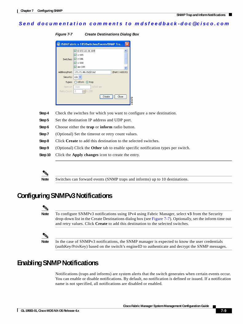
Send documenta t ion comments to mdsfeedback -doc@c i sco .com
Chapter 7 Configuring SNMPSNMP Trap and Inform Notifications
Figure 7-7 Create Destinations Dialog Box
Step 4 Check the switches for which you want to configure a new destination.
Step 5 Set the destination IP address and UDP port.
Step 6 Choose either the trap or inform radio button.
Step 7 (Optional) Set the timeout or retry count values.
Step 8 Click Create to add this destination to the selected switches.
Step 9 (Optional) Click the Other tab to enable specific notification types per switch.
Step 10 Click the Apply changes icon to create the entry.
Note Switches can forward events (SNMP traps and informs) up to 10 destinations.
Configuring SNMPv3 Notifications
Note To configure SNMPv3 notifications using IPv4 using Fabric Manager, select v3 from the Security drop-down list in the Create Destinations dialog box (see Figure 7-7). Optionally, set the inform time out and retry values. Click Create to add this destination to the selected switches.
Note In the case of SNMPv3 notifications, the SNMP manager is expected to know the user credentials (authKey/PrivKey) based on the switch’s engineID to authenticate and decrypt the SNMP messages.
Enabling SNMP NotificationsNotifications (traps and informs) are system alerts that the switch generates when certain events occur. You can enable or disable notifications. By default, no notification is defined or issued. If a notification name is not specified, all notifications are disabled or enabled.
7-9Cisco Fabric Manager System Management Configuration Guide
OL-19583-01, Cisco MDS NX-OS Release 4.x
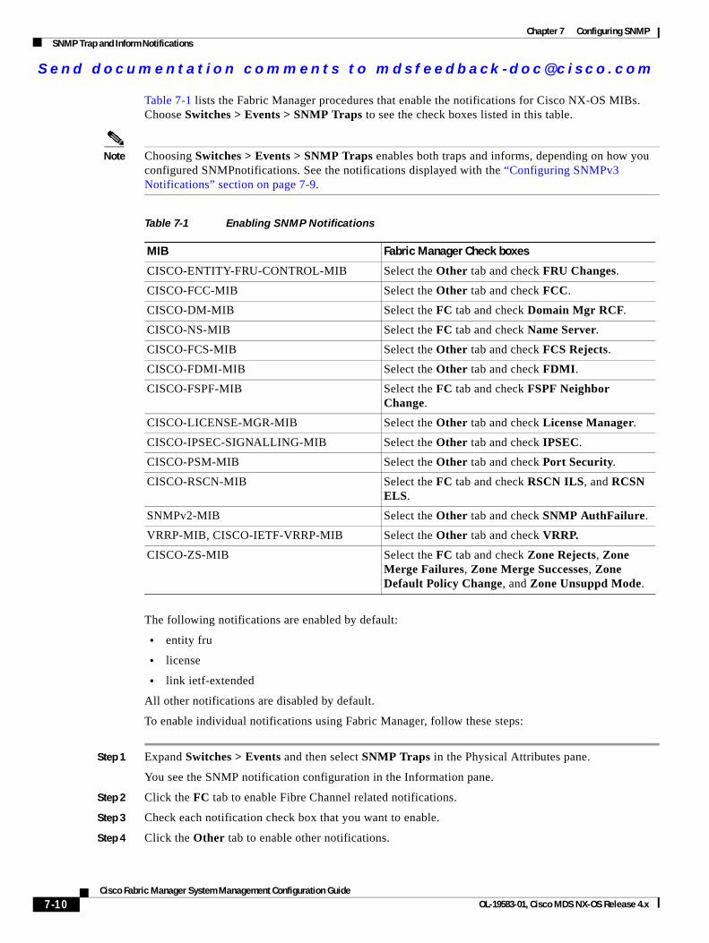
Send documenta t ion comments to mdsfeedback -doc@c i sco .com
Chapter 7 Configuring SNMPSNMP Trap and Inform Notifications
Table 7-1 lists the Fabric Manager procedures that enable the notifications for Cisco NX-OS MIBs. Choose Switches > Events > SNMP Traps to see the check boxes listed in this table.
Note Choosing Switches > Events > SNMP Traps enables both traps and informs, depending on how you configured SNMPnotifications. See the notifications displayed with the “Configuring SNMPv3 Notifications” section on page 7-9.
The following notifications are enabled by default:
• entity fru
• license
• link ietf-extended
All other notifications are disabled by default.
To enable individual notifications using Fabric Manager, follow these steps:
Step 1 Expand Switches > Events and then select SNMP Traps in the Physical Attributes pane.
You see the SNMP notification configuration in the Information pane.
Step 2 Click the FC tab to enable Fibre Channel related notifications.
Step 3 Check each notification check box that you want to enable.
Step 4 Click the Other tab to enable other notifications.
Table 7-1 Enabling SNMP Notifications
MIB Fabric Manager Check boxes
CISCO-ENTITY-FRU-CONTROL-MIB Select the Other tab and check FRU Changes.
CISCO-FCC-MIB Select the Other tab and check FCC.
CISCO-DM-MIB Select the FC tab and check Domain Mgr RCF.
CISCO-NS-MIB Select the FC tab and check Name Server.
CISCO-FCS-MIB Select the Other tab and check FCS Rejects.
CISCO-FDMI-MIB Select the Other tab and check FDMI.
CISCO-FSPF-MIB Select the FC tab and check FSPF Neighbor Change.
CISCO-LICENSE-MGR-MIB Select the Other tab and check License Manager.
CISCO-IPSEC-SIGNALLING-MIB Select the Other tab and check IPSEC.
CISCO-PSM-MIB Select the Other tab and check Port Security.
CISCO-RSCN-MIB Select the FC tab and check RSCN ILS, and RCSN ELS.
SNMPv2-MIB Select the Other tab and check SNMP AuthFailure.
VRRP-MIB, CISCO-IETF-VRRP-MIB Select the Other tab and check VRRP.
CISCO-ZS-MIB Select the FC tab and check Zone Rejects, Zone Merge Failures, Zone Merge Successes, Zone Default Policy Change, and Zone Unsuppd Mode.
7-10Cisco Fabric Manager System Management Configuration Guide
OL-19583-01, Cisco MDS NX-OS Release 4.x
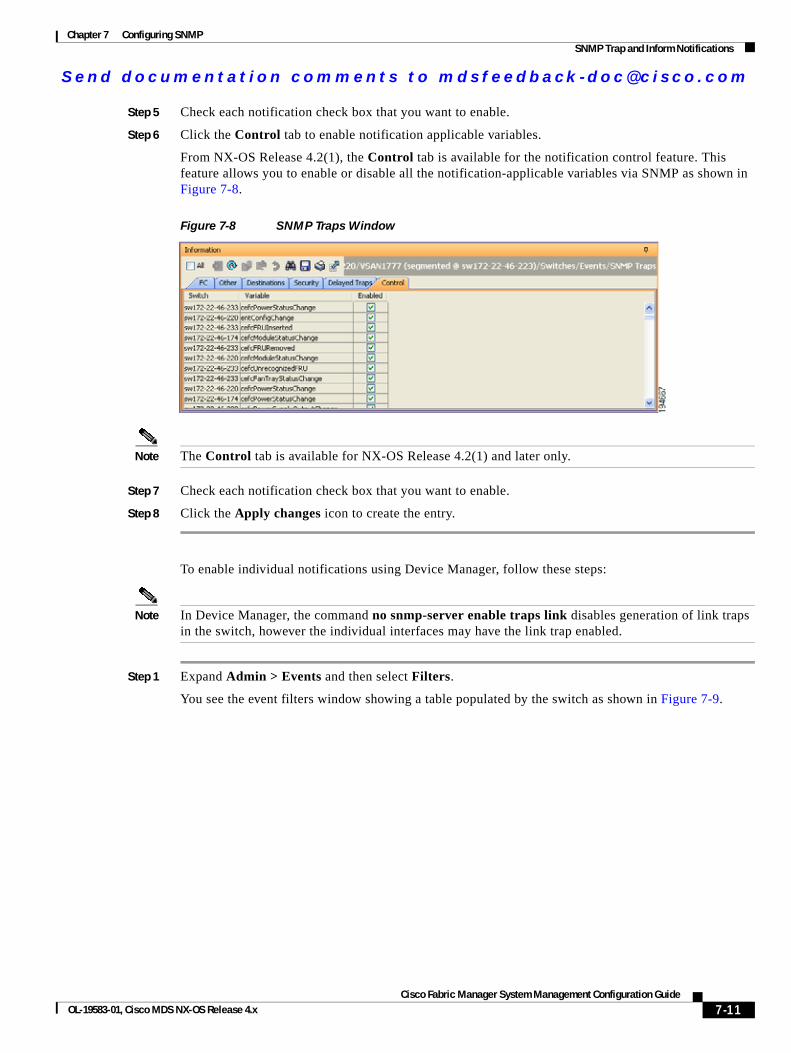
Send documenta t ion comments to mdsfeedback -doc@c i sco .com
Chapter 7 Configuring SNMPSNMP Trap and Inform Notifications
Step 5 Check each notification check box that you want to enable.
Step 6 Click the Control tab to enable notification applicable variables.
From NX-OS Release 4.2(1), the Control tab is available for the notification control feature. This feature allows you to enable or disable all the notification-applicable variables via SNMP as shown in Figure 7-8.
Figure 7-8 SNMP Traps Window
Note The Control tab is available for NX-OS Release 4.2(1) and later only.
Step 7 Check each notification check box that you want to enable.
Step 8 Click the Apply changes icon to create the entry.
To enable individual notifications using Device Manager, follow these steps:
Note In Device Manager, the command no snmp-server enable traps link disables generation of link traps in the switch, however the individual interfaces may have the link trap enabled.
Step 1 Expand Admin > Events and then select Filters.
You see the event filters window showing a table populated by the switch as shown in Figure 7-9.
7-11Cisco Fabric Manager System Management Configuration Guide
OL-19583-01, Cisco MDS NX-OS Release 4.x
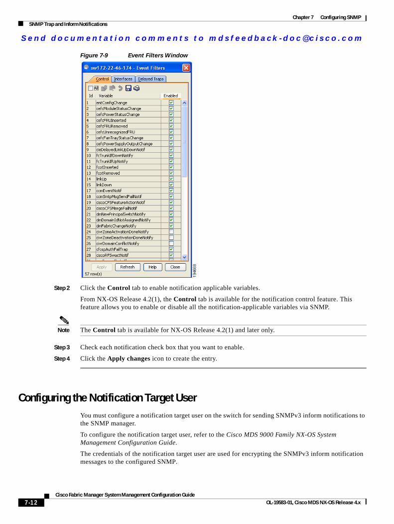
Send documenta t ion comments to mdsfeedback -doc@c i sco .com
Chapter 7 Configuring SNMPSNMP Trap and Inform Notifications
Figure 7-9 Event Filters Window
Step 2 Click the Control tab to enable notification applicable variables.
From NX-OS Release 4.2(1), the Control tab is available for the notification control feature. This feature allows you to enable or disable all the notification-applicable variables via SNMP.
Note The Control tab is available for NX-OS Release 4.2(1) and later only.
Step 3 Check each notification check box that you want to enable.
Step 4 Click the Apply changes icon to create the entry.
Configuring the Notification Target UserYou must configure a notification target user on the switch for sending SNMPv3 inform notifications to the SNMP manager.
To configure the notification target user, refer to the Cisco MDS 9000 Family NX-OS System Management Configuration Guide.
The credentials of the notification target user are used for encrypting the SNMPv3 inform notification messages to the configured SNMP.
7-12Cisco Fabric Manager System Management Configuration Guide
OL-19583-01, Cisco MDS NX-OS Release 4.x
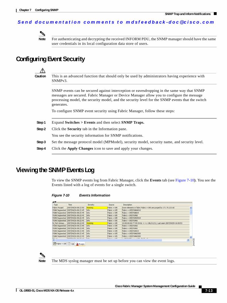
Send documenta t ion comments to mdsfeedback -doc@c i sco .com
Chapter 7 Configuring SNMPSNMP Trap and Inform Notifications
Note For authenticating and decrypting the received INFORM PDU, the SNMP manager should have the same user credentials in its local configuration data store of users.
Configuring Event Security
Caution This is an advanced function that should only be used by administrators having experience with SNMPv3.
SNMP events can be secured against interception or eavesdropping in the same way that SNMP messages are secured. Fabric Manager or Device Manager allow you to configure the message processing model, the security model, and the security level for the SNMP events that the switch generates.
To configure SNMP event security using Fabric Manager, follow these steps:
Step 1 Expand Switches > Events and then select SNMP Traps.
Step 2 Click the Security tab in the Information pane.
You see the security information for SNMP notifications.
Step 3 Set the message protocol model (MPModel), security model, security name, and security level.
Step 4 Click the Apply Changes icon to save and apply your changes.
Viewing the SNMP Events LogTo view the SNMP events log from Fabric Manager, click the Events tab (see Figure 7-10). You see the Events listed with a log of events for a single switch.
Figure 7-10 Events Information
Note The MDS syslog manager must be set up before you can view the event logs.
7-13Cisco Fabric Manager System Management Configuration Guide
OL-19583-01, Cisco MDS NX-OS Release 4.x
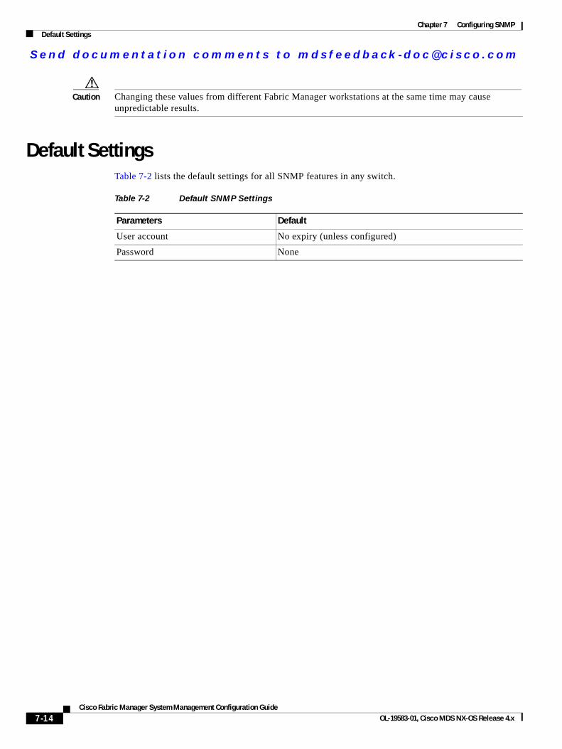
Send documenta t ion comments to mdsfeedback -doc@c i sco .com
Chapter 7 Configuring SNMPDefault Settings
Caution Changing these values from different Fabric Manager workstations at the same time may cause unpredictable results.
Default SettingsTable 7-2 lists the default settings for all SNMP features in any switch.
Table 7-2 Default SNMP Settings
Parameters Default
User account No expiry (unless configured)
Password None
7-14Cisco Fabric Manager System Management Configuration Guide
OL-19583-01, Cisco MDS NX-OS Release 4.x
Send documenta t ion comments to mdsfeedback -doc@c i sco .com
Cisco Fabric OL-19583-01, Cisco MDS NX-OS Release 4.x
C H A P T E R 8
Configuring RMONRMON is an Internet Engineering Task Force (IETF) standard monitoring specification that allows various network agents and console systems to exchange network monitoring data. You can use the RMON alarms and events to monitor Cisco MDS 9000 Family switches running the Cisco SAN-OS Release 2.0(1b) or later or Cisco NX-OS Release 4.1(3) or later software.
This chapter includes the following sections:
• About RMON, page 8-1
• Configuring RMON Using Threshold Manager, page 8-1
• Default Settings, page 8-15
About RMONAll switches in the Cisco MDS 9000 Family support the following RMON functions (defined in RFC 2819):
• Alarm—Each alarm monitors a specific management information base (MIB) object for a specified interval. When the MIB object value exceeds a specified value (rising threshold), the alarm condition is set and only one event is triggered regardless of how long the condition exists. When the MIB object value falls below a certain value (falling threshold), the alarm condition is cleared. This allows the alarm to trigger again when the rising threshold is crossed again.
• Event—Determines the action to take when an event is triggered by an alarm. The action can be to generate a log entry, an SNMP trap, or both.
For agent and management information, see the Cisco MDS 9000 Family MIB Quick Reference.
For SNMP security-related CLI configurations, see the “About SNMP Security” section on page 7-1.
Configuring RMON Using Threshold ManagerRMON is disabled by default and no events or alarms are configured in the switch. You can configure your RMON alarms and events by using the CLI or by using Threshold Manager in Device Manager.
The Threshold Monitor allows you to trigger an SNMP event or log a message when the selected statistic goes over a configured threshold value. RMON calls this a rising alarm threshold. The configurable settings are as follows:
• Variable—The statistic you want to set the threshold value on.
8-1Manager System Management Configuration Guide
Send documenta t ion comments to mdsfeedback -doc@c i sco .com
Chapter 8 Configuring RMONConfiguring RMON Using Threshold Manager
• Value—The value of the variable that you want the alarm to trigger at. This value is the difference (delta) between two consecutive polls of the variable by Device Manager.
• Sample—The sample period (in seconds) between two consecutive polls of the variable. Select your sample period such that the variable does not cross the threshold value you set under normal operating conditions.
• Warning—The warning level used by Device Manager to indicate the severity of the triggered alarm. This is a Fabric Manager and Device Manager enhancement to RMON.
Note To configure any type of RMON alarm (absolute or delta, rising or falling threshold) click More on the Threshold Manager dialog box. You should be familiar with how RMON defines these concepts before configuring these advanced alarm types. Refer to the RMON-MIB (RFC 2819) for information on how to configure RMON alarms.
Note You must also configure SNMP on the switch to access RMON MIB objects.
RMON Alarm ConfigurationThreshold Manager provides a list of common MIB objects to set an RMON threshold and alarm on. You can also set an alarm on any MIB object. The specified MIB must be an existing SNMP MIB object in standard dot notation (1.3.6.1.2.1.2.2.1.14.16 for ifInOctets.16).
Use one of the following options to specify the interval to monitor the MIB variable (ranges from 1 to 4294967295 seconds):
• Use the delta option to test the change between samples of a MIB variable.
• Use the absolute option to test each MIB variable directly.
• Use the delta option to test any MIB objects that are counters.
The range for the rising threshold and falling threshold values is -2147483647 to 2147483647.
Caution The falling threshold must be less than the rising threshold.
You can optionally specify the following parameters:
• The event-number to trigger if the rising or falling threshold exceeds the specified limit.
• The owner of the alarm.
8-2Cisco Fabric Manager System Management Configuration Guide
OL-19583-01, Cisco MDS NX-OS Release 4.x
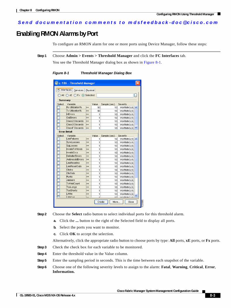
Send documenta t ion comments to mdsfeedback -doc@c i sco .com
Chapter 8 Configuring RMONConfiguring RMON Using Threshold Manager
Enabling RMON Alarms by PortTo configure an RMON alarm for one or more ports using Device Manager, follow these steps:
Step 1 Choose Admin > Events > Threshold Manager and click the FC Interfaces tab.
You see the Threshold Manager dialog box as shown in Figure 8-1.
Figure 8-1 Threshold Manager Dialog Box
Step 2 Choose the Select radio button to select individual ports for this threshold alarm.
a. Click the ... button to the right of the Selected field to display all ports.
b. Select the ports you want to monitor.
c. Click OK to accept the selection.
Alternatively, click the appropriate radio button to choose ports by type: All ports, xE ports, or Fx ports.
Step 3 Check the check box for each variable to be monitored.
Step 4 Enter the threshold value in the Value column.
Step 5 Enter the sampling period in seconds. This is the time between each snapshot of the variable.
Step 6 Choose one of the following severity levels to assign to the alarm: Fatal, Warning, Critical, Error, Information.
8-3Cisco Fabric Manager System Management Configuration Guide
OL-19583-01, Cisco MDS NX-OS Release 4.x
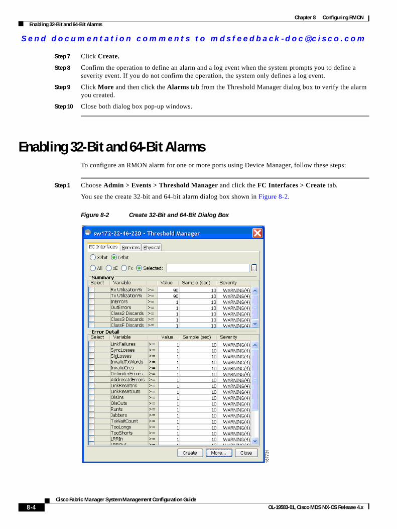
Send documenta t ion comments to mdsfeedback -doc@c i sco .com
Chapter 8 Configuring RMONEnabling 32-Bit and 64-Bit Alarms
Step 7 Click Create.
Step 8 Confirm the operation to define an alarm and a log event when the system prompts you to define a severity event. If you do not confirm the operation, the system only defines a log event.
Step 9 Click More and then click the Alarms tab from the Threshold Manager dialog box to verify the alarm you created.
Step 10 Close both dialog box pop-up windows.
Enabling 32-Bit and 64-Bit AlarmsTo configure an RMON alarm for one or more ports using Device Manager, follow these steps:
Step 1 Choose Admin > Events > Threshold Manager and click the FC Interfaces > Create tab.
You see the create 32-bit and 64-bit alarm dialog box shown in Figure 8-2.
Figure 8-2 Create 32-Bit and 64-Bit Dialog Box
8-4Cisco Fabric Manager System Management Configuration Guide
OL-19583-01, Cisco MDS NX-OS Release 4.x
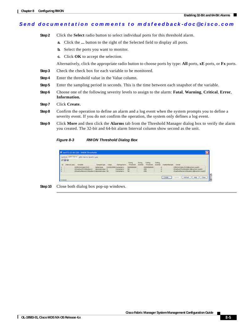
Send documenta t ion comments to mdsfeedback -doc@c i sco .com
Chapter 8 Configuring RMONEnabling 32-Bit and 64-Bit Alarms
Step 2 Click the Select radio button to select individual ports for this threshold alarm.
a. Click the ... button to the right of the Selected field to display all ports.
b. Select the ports you want to monitor.
c. Click OK to accept the selection.
Alternatively, click the appropriate radio button to choose ports by type: All ports, xE ports, or Fx ports.
Step 3 Check the check box for each variable to be monitored.
Step 4 Enter the threshold value in the Value column.
Step 5 Enter the sampling period in seconds. This is the time between each snapshot of the variable.
Step 6 Choose one of the following severity levels to assign to the alarm: Fatal, Warning, Critical, Error, Information.
Step 7 Click Create.
Step 8 Confirm the operation to define an alarm and a log event when the system prompts you to define a severity event. If you do not confirm the operation, the system only defines a log event.
Step 9 Click More and then click the Alarms tab from the Threshold Manager dialog box to verify the alarm you created. The 32-bit and 64-bit alarm Interval column show second as the unit.
Figure 8-3 RMON Threshold Dialog Box
Step 10 Close both dialog box pop-up windows.
8-5Cisco Fabric Manager System Management Configuration Guide
OL-19583-01, Cisco MDS NX-OS Release 4.x
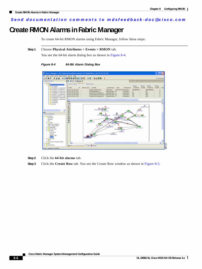
Send documenta t ion comments to mdsfeedback -doc@c i sco .com
Chapter 8 Configuring RMONCreate RMON Alarms in Fabric Manager
Create RMON Alarms in Fabric ManagerTo create 64-bit RMON alarms using Fabric Manager, follow these steps:
Step 1 Choose Physical Attributes > Events > RMON tab.
You see the 64-bit alarm dialog box as shown in Figure 8-4.
Figure 8-4 64-Bit Alarm Dialog Box
Step 2 Click the 64-bit alarms tab.
Step 3 Click the Create Row tab. You see the Create Row window as shown in Figure 8-5.
8-6Cisco Fabric Manager System Management Configuration Guide
OL-19583-01, Cisco MDS NX-OS Release 4.x
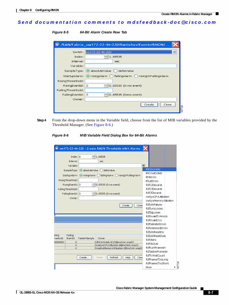
Send documenta t ion comments to mdsfeedback -doc@c i sco .com
Chapter 8 Configuring RMONCreate RMON Alarms in Fabric Manager
Figure 8-5 64-Bit Alarm Create Row Tab
Step 4 From the drop-down menu in the Variable field, choose from the list of MIB variables provided by the Threshold Manager. (See Figure 8-6.)
Figure 8-6 MIB Variable Field Dialog Box for 64-Bit Alarms
8-7Cisco Fabric Manager System Management Configuration Guide
OL-19583-01, Cisco MDS NX-OS Release 4.x
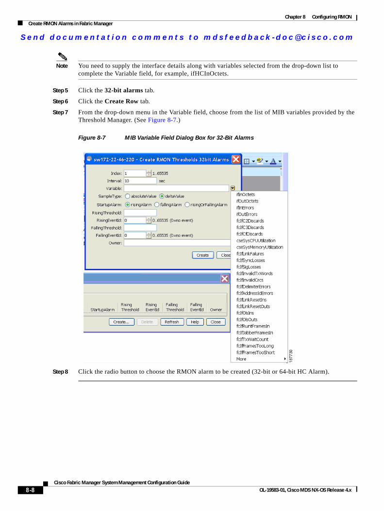
Send documenta t ion comments to mdsfeedback -doc@c i sco .com
Chapter 8 Configuring RMONCreate RMON Alarms in Fabric Manager
Note You need to supply the interface details along with variables selected from the drop-down list to complete the Variable field, for example, ifHCInOctets.
Step 5 Click the 32-bit alarms tab.
Step 6 Click the Create Row tab.
Step 7 From the drop-down menu in the Variable field, choose from the list of MIB variables provided by the Threshold Manager. (See Figure 8-7.)
Figure 8-7 MIB Variable Field Dialog Box for 32-Bit Alarms
Step 8 Click the radio button to choose the RMON alarm to be created (32-bit or 64-bit HC Alarm).
8-8Cisco Fabric Manager System Management Configuration Guide
OL-19583-01, Cisco MDS NX-OS Release 4.x
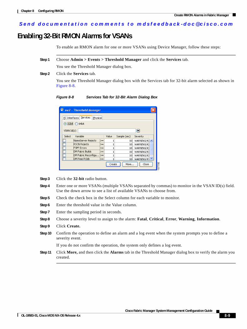
Send documenta t ion comments to mdsfeedback -doc@c i sco .com
Chapter 8 Configuring RMONCreate RMON Alarms in Fabric Manager
Enabling 32-Bit RMON Alarms for VSANsTo enable an RMON alarm for one or more VSANs using Device Manager, follow these steps:
Step 1 Choose Admin > Events > Threshold Manager and click the Services tab.
You see the Threshold Manager dialog box.
Step 2 Click the Services tab.
You see the Threshold Manager dialog box with the Services tab for 32-bit alarm selected as shown in Figure 8-8.
Figure 8-8 Services Tab for 32-Bit Alarm Dialog Box
Step 3 Click the 32-bit radio button.
Step 4 Enter one or more VSANs (multiple VSANs separated by commas) to monitor in the VSAN ID(s) field. Use the down arrow to see a list of available VSANs to choose from.
Step 5 Check the check box in the Select column for each variable to monitor.
Step 6 Enter the threshold value in the Value column.
Step 7 Enter the sampling period in seconds.
Step 8 Choose a severity level to assign to the alarm: Fatal, Critical, Error, Warning, Information.
Step 9 Click Create.
Step 10 Confirm the operation to define an alarm and a log event when the system prompts you to define a severity event.
If you do not confirm the operation, the system only defines a log event.
Step 11 Click More, and then click the Alarms tab in the Threshold Manager dialog box to verify the alarm you created.
8-9Cisco Fabric Manager System Management Configuration Guide
OL-19583-01, Cisco MDS NX-OS Release 4.x
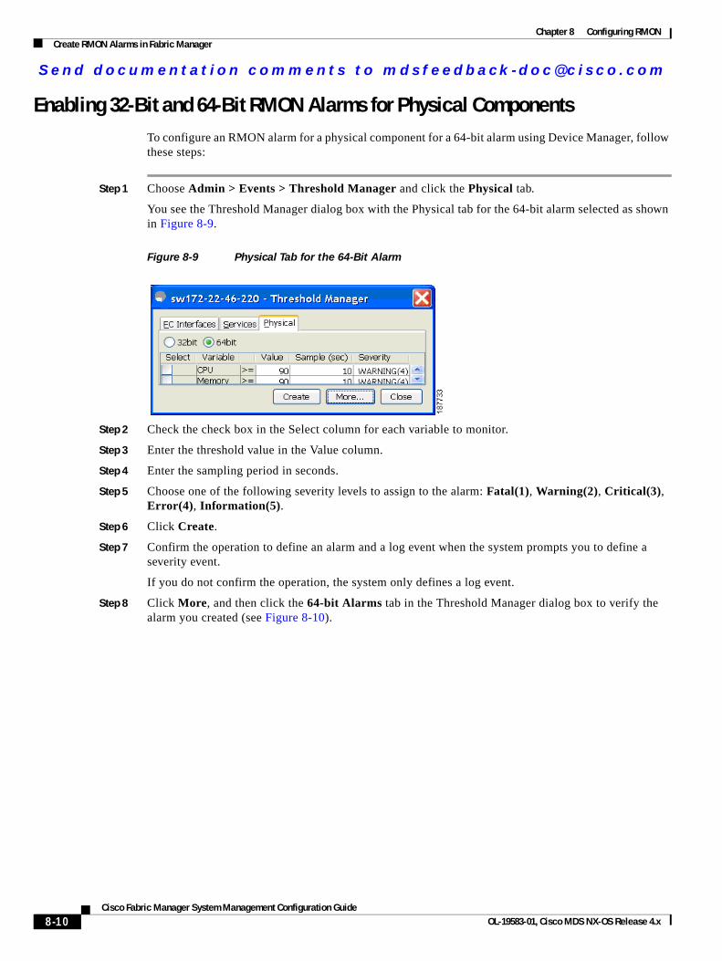
Send documenta t ion comments to mdsfeedback -doc@c i sco .com
Chapter 8 Configuring RMONCreate RMON Alarms in Fabric Manager
Enabling 32-Bit and 64-Bit RMON Alarms for Physical ComponentsTo configure an RMON alarm for a physical component for a 64-bit alarm using Device Manager, follow these steps:
Step 1 Choose Admin > Events > Threshold Manager and click the Physical tab.
You see the Threshold Manager dialog box with the Physical tab for the 64-bit alarm selected as shown in Figure 8-9.
Figure 8-9 Physical Tab for the 64-Bit Alarm
Step 2 Check the check box in the Select column for each variable to monitor.
Step 3 Enter the threshold value in the Value column.
Step 4 Enter the sampling period in seconds.
Step 5 Choose one of the following severity levels to assign to the alarm: Fatal(1), Warning(2), Critical(3), Error(4), Information(5).
Step 6 Click Create.
Step 7 Confirm the operation to define an alarm and a log event when the system prompts you to define a severity event.
If you do not confirm the operation, the system only defines a log event.
Step 8 Click More, and then click the 64-bit Alarms tab in the Threshold Manager dialog box to verify the alarm you created (see Figure 8-10).
8-10Cisco Fabric Manager System Management Configuration Guide
OL-19583-01, Cisco MDS NX-OS Release 4.x
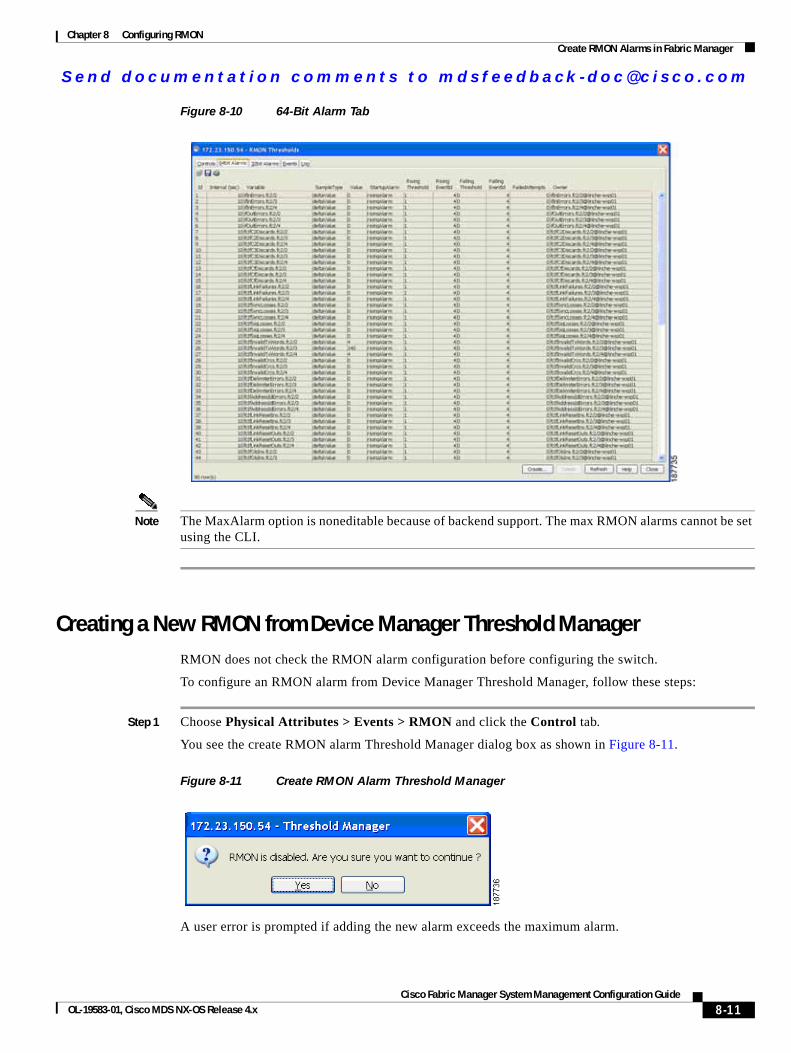
Send documenta t ion comments to mdsfeedback -doc@c i sco .com
Chapter 8 Configuring RMONCreate RMON Alarms in Fabric Manager
Figure 8-10 64-Bit Alarm Tab
Note The MaxAlarm option is noneditable because of backend support. The max RMON alarms cannot be set using the CLI.
Creating a New RMON from Device Manager Threshold ManagerRMON does not check the RMON alarm configuration before configuring the switch.
To configure an RMON alarm from Device Manager Threshold Manager, follow these steps:
Step 1 Choose Physical Attributes > Events > RMON and click the Control tab.
You see the create RMON alarm Threshold Manager dialog box as shown in Figure 8-11.
Figure 8-11 Create RMON Alarm Threshold Manager
A user error is prompted if adding the new alarm exceeds the maximum alarm.
8-11Cisco Fabric Manager System Management Configuration Guide
OL-19583-01, Cisco MDS NX-OS Release 4.x
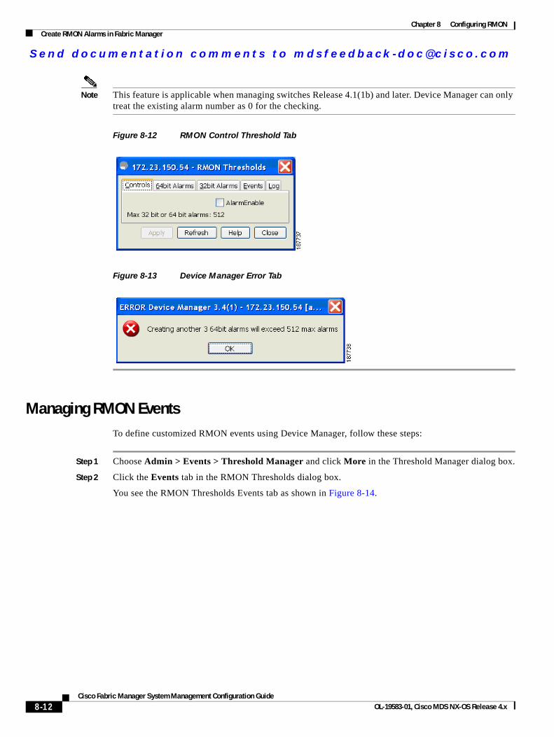
Send documenta t ion comments to mdsfeedback -doc@c i sco .com
Chapter 8 Configuring RMONCreate RMON Alarms in Fabric Manager
Note This feature is applicable when managing switches Release 4.1(1b) and later. Device Manager can only treat the existing alarm number as 0 for the checking.
Figure 8-12 RMON Control Threshold Tab
Figure 8-13 Device Manager Error Tab
Managing RMON EventsTo define customized RMON events using Device Manager, follow these steps:
Step 1 Choose Admin > Events > Threshold Manager and click More in the Threshold Manager dialog box.
Step 2 Click the Events tab in the RMON Thresholds dialog box.
You see the RMON Thresholds Events tab as shown in Figure 8-14.
8-12Cisco Fabric Manager System Management Configuration Guide
OL-19583-01, Cisco MDS NX-OS Release 4.x
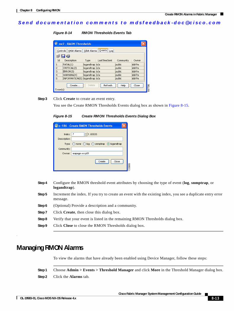
Send documenta t ion comments to mdsfeedback -doc@c i sco .com
Chapter 8 Configuring RMONCreate RMON Alarms in Fabric Manager
Figure 8-14 RMON Thresholds Events Tab
Step 3 Click Create to create an event entry.
You see the Create RMON Thresholds Events dialog box as shown in Figure 8-15.
Figure 8-15 Create RMON Thresholds Events Dialog Box
Step 4 Configure the RMON threshold event attributes by choosing the type of event (log, snmptrap, or logandtrap).
Step 5 Increment the index. If you try to create an event with the existing index, you see a duplicate entry error message.
Step 6 (Optional) Provide a description and a community.
Step 7 Click Create, then close this dialog box.
Step 8 Verify that your event is listed in the remaining RMON Thresholds dialog box.
Step 9 Click Close to close the RMON Thresholds dialog box.
.
Managing RMON AlarmsTo view the alarms that have already been enabled using Device Manager, follow these steps:
Step 1 Choose Admin > Events > Threshold Manager and click More in the Threshold Manager dialog box.
Step 2 Click the Alarms tab.
8-13Cisco Fabric Manager System Management Configuration Guide
OL-19583-01, Cisco MDS NX-OS Release 4.x
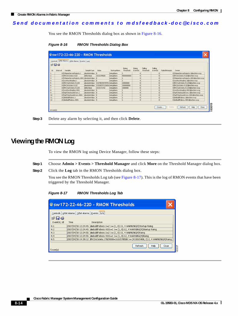
Send documenta t ion comments to mdsfeedback -doc@c i sco .com
Chapter 8 Configuring RMONCreate RMON Alarms in Fabric Manager
You see the RMON Thresholds dialog box as shown in Figure 8-16.
Figure 8-16 RMON Thresholds Dialog Box
Step 3 Delete any alarm by selecting it, and then click Delete.
Viewing the RMON LogTo view the RMON log using Device Manager, follow these steps:
Step 1 Choose Admin > Events > Threshold Manager and click More on the Threshold Manager dialog box.
Step 2 Click the Log tab in the RMON Thresholds dialog box.
You see the RMON Thresholds Log tab (see Figure 8-17). This is the log of RMON events that have been triggered by the Threshold Manager.
Figure 8-17 RMON Thresholds Log Tab
8-14Cisco Fabric Manager System Management Configuration Guide
OL-19583-01, Cisco MDS NX-OS Release 4.x
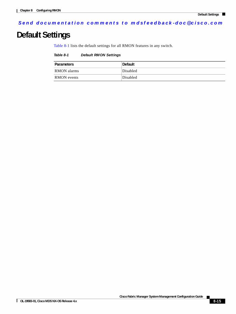
Send documenta t ion comments to mdsfeedback -doc@c i sco .com
Chapter 8 Configuring RMONDefault Settings
Default SettingsTable 8-1 lists the default settings for all RMON features in any switch.
Table 8-1 Default RMON Settings
Parameters Default
RMON alarms Disabled
RMON events Disabled
8-15Cisco Fabric Manager System Management Configuration Guide
OL-19583-01, Cisco MDS NX-OS Release 4.x

Send documenta t ion comments to mdsfeedback -doc@c i sco .com
Chapter 8 Configuring RMONDefault Settings
8-16Cisco Fabric Manager System Management Configuration Guide
OL-19583-01, Cisco MDS NX-OS Release 4.x
Send documenta t ion comments to mdsfeedback -doc@c i sco .com
Cisco Fabric OL-19583-01, Cisco MDS NX-OS Release 4.x
C H A P T E R 9
Configuring Domain ParametersThe Fibre Channel domain (fcdomain) feature performs principal switch selection, domain ID distribution, FC ID allocation, and fabric reconfiguration functions as described in the FC-SW-2 standards. The domains are configured on a per VSAN basis. If you do not configure a domain ID, the local switch uses a random ID.
Caution Changes to fcdomain parameters should not be performed on a daily basis. These changes should be made by an administrator or individual who is completely familiar with switch operations.
Tip When you change the configuration, be sure to save the running configuration. The next time you reboot the switch, the saved configuration is used. If you do not save the configuration, the previously saved startup configuration is used.
This chapter includes the following sections:
• Fibre Channel Domains, page 9-2
• Domain IDs, page 9-10
• FC IDs, page 9-17
• Displaying fcdomain Statistics, page 9-22
• Default Settings, page 9-23
9-1Manager System Management Configuration Guide
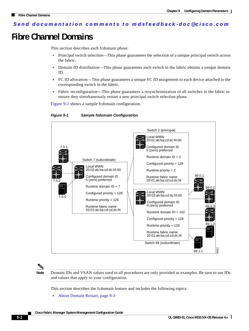
Send documenta t ion comments to mdsfeedback -doc@c i sco .com
Chapter 9 Configuring Domain ParametersFibre Channel Domains
Fibre Channel DomainsThis section describes each fcdomain phase:
• Principal switch selection—This phase guarantees the selection of a unique principal switch across the fabric.
• Domain ID distribution—This phase guarantees each switch in the fabric obtains a unique domain ID.
• FC ID allocation—This phase guarantees a unique FC ID assignment to each device attached to the corresponding switch in the fabric.
• Fabric reconfiguration—This phase guarantees a resynchronization of all switches in the fabric to ensure they simultaneously restart a new principal switch selection phase.
Figure 9-1 shows a sample fcdomain configuration.
Figure 9-1 Sample fcdomain Configuration
Note Domain IDs and VSAN values used in all procedures are only provided as examples. Be sure to use IDs and values that apply to your configuration.
This section describes the fcdomain feature and includes the following topics:
• About Domain Restart, page 9-3
Local WWN 20:02:ab:ba:cd:dc:f4:00
Configured domain ID0 (zero) preferred
Runtime domain ID = 7
Configured priority = 128
Runtime priority = 128
Runtime fabric name20:01:ab:ba:cd:cd:dc:f4
Local WWN 20:01:ab:ba:cd:dc:f4:00
Configured domain ID0 (zero) preferred
Runtime domain ID = 2
Configured priority = 128
Runtime priority = 2
Runtime fabric name20:01:ab:ba:cd:cd:dc:f4
Local WWN 20:03:ab:ba:cd:dc:f4:00
Configured domain ID0 (zero) preferred
Runtime domain ID = 102
Configured priority = 128
Runtime priority = 128
Runtime fabric name20:01:ab:ba:cd:cd:dc:f4
7.0.1
7.0.2
7.0.0
99.0.1
99.0.2
99.0.3
99.1.2
99.1.1
7995
3
Switch 7 (subordinate)
Switch 99 (subordinate)
Switch 2 (principal)
9-2Cisco Fabric Manager System Management Configuration Guide
OL-19583-01, Cisco MDS NX-OS Release 4.x
Send documenta t ion comments to mdsfeedback -doc@c i sco .com
Chapter 9 Configuring Domain ParametersFibre Channel Domains
• Configuring Domain Manager Turbo Mode, page 9-3
• Restarting a Domain, page 9-5
• About Switch Priority, page 9-6
• Configuring Switch Priority, page 9-7
• About fcdomain Initiation, page 9-7
• Enabling or Disabling fcdomains, page 9-7
• Setting Fabric Names, page 9-8
• About Incoming RCFs, page 9-8
• Rejecting Incoming RCFs, page 9-8
• About Autoreconfiguring Merged Fabrics, page 9-9
• Enabling Autoreconfiguration, page 9-9
About Domain RestartFibre Channel domains can be started disruptively or nondisruptively. If you perform a disruptive restart, reconfigure fabric (RCF) frames are sent to other switches in the fabric and data traffic is disrupted on all the switches in the VSAN (including remotely segmented ISLs). If you perform a nondisruptive restart, build fabric (BF) frames are sent to other switches in the fabric and data traffic is disrupted only on the switch.
If you are attempting to resolve a domain ID conflict, you must manually assign domain IDs. A disruptive restart is required to apply most configuration changes–including manually assigned domain IDs. Nondisruptive domain restarts are acceptable only when changing a preferred domain ID into a static one (and the actual domain ID remains the same).
Note A static domain is specifically configured by the user and may be different from the runtime domain. If the domain IDs are different, the runtime domain ID changes to take on the static domain ID after the next restart, either disruptive or nondisruptive.
Tip If a VSAN is in interop mode, you cannot restart the fcdomain for that VSAN disruptively.
You can apply most of the configurations to their corresponding runtime values. Each of the following sections provide further details on how the fcdomain parameters are applied to the runtime values.
Configuring Domain Manager Turbo ModeThe Domain Manager turbo mode feature allows you to restart the Domain Manager with optimization. You have the option to select fast-restart or selective-restart mode for restarting the Domain Manager, You can leave the restart mode empty indicating that optimization is disabled.
To configure the Domain Manager turbo mode using Fabric Manager, follow these steps:
9-3Cisco Fabric Manager System Management Configuration Guide
OL-19583-01, Cisco MDS NX-OS Release 4.x
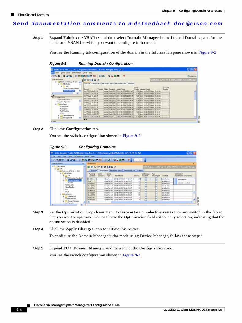
Send documenta t ion comments to mdsfeedback -doc@c i sco .com
Chapter 9 Configuring Domain ParametersFibre Channel Domains
Step 1 Expand Fabricxx > VSANxx and then select Domain Manager in the Logical Domains pane for the fabric and VSAN for which you want to configure turbo mode. You see the Running tab configuration of the domain in the Information pane shown in Figure 9-2.
Figure 9-2 Running Domain Configuration
Step 2 Click the Configuration tab.
You see the switch configuration shown in Figure 9-3.
Figure 9-3 Configuring Domains
Step 3 Set the Optimization drop-down menu to fast-restart or selective-restart for any switch in the fabric that you want to optimize. You can leave the Optimization field without any selection, indicating that the optimization is disabled.
Step 4 Click the Apply Changes icon to initiate this restart.
To configure the Domain Manager turbo mode using Device Manager, follow these steps:
Step 1 Expand FC > Domain Manager and then select the Configuration tab.
You see the switch configuration shown in Figure 9-4.
9-4Cisco Fabric Manager System Management Configuration Guide
OL-19583-01, Cisco MDS NX-OS Release 4.x
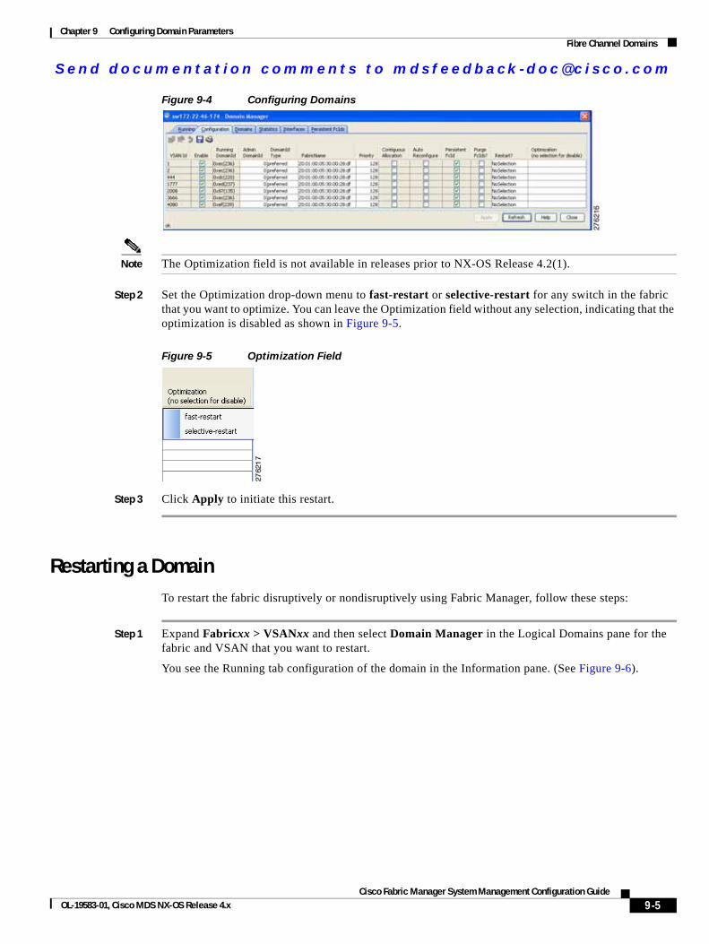
Send documenta t ion comments to mdsfeedback -doc@c i sco .com
Chapter 9 Configuring Domain ParametersFibre Channel Domains
Figure 9-4 Configuring Domains
Note The Optimization field is not available in releases prior to NX-OS Release 4.2(1).
Step 2 Set the Optimization drop-down menu to fast-restart or selective-restart for any switch in the fabric that you want to optimize. You can leave the Optimization field without any selection, indicating that the optimization is disabled as shown in Figure 9-5.
Figure 9-5 Optimization Field
Step 3 Click Apply to initiate this restart.
Restarting a DomainTo restart the fabric disruptively or nondisruptively using Fabric Manager, follow these steps:
Step 1 Expand Fabricxx > VSANxx and then select Domain Manager in the Logical Domains pane for the fabric and VSAN that you want to restart.
You see the Running tab configuration of the domain in the Information pane. (See Figure 9-6).
9-5Cisco Fabric Manager System Management Configuration Guide
OL-19583-01, Cisco MDS NX-OS Release 4.x
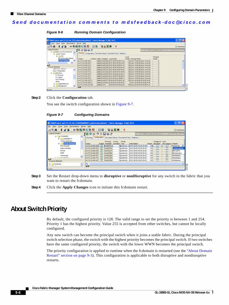
Send documenta t ion comments to mdsfeedback -doc@c i sco .com
Chapter 9 Configuring Domain ParametersFibre Channel Domains
Figure 9-6 Running Domain Configuration
Step 2 Click the Configuration tab.
You see the switch configuration shown in Figure 9-7.
Figure 9-7 Configuring Domains
Step 3 Set the Restart drop-down menu to disruptive or nonDisruptive for any switch in the fabric that you want to restart the fcdomain.
Step 4 Click the Apply Changes icon to initiate this fcdomain restart.
About Switch PriorityBy default, the configured priority is 128. The valid range to set the priority is between 1 and 254. Priority 1 has the highest priority. Value 255 is accepted from other switches, but cannot be locally configured.
Any new switch can become the principal switch when it joins a stable fabric. During the principal switch selection phase, the switch with the highest priority becomes the principal switch. If two switches have the same configured priority, the switch with the lower WWN becomes the principal switch.
The priority configuration is applied to runtime when the fcdomain is restarted (see the “About Domain Restart” section on page 9-3). This configuration is applicable to both disruptive and nondisruptive restarts.
9-6Cisco Fabric Manager System Management Configuration Guide
OL-19583-01, Cisco MDS NX-OS Release 4.x
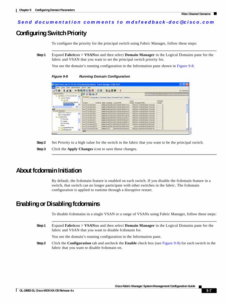
Send documenta t ion comments to mdsfeedback -doc@c i sco .com
Chapter 9 Configuring Domain ParametersFibre Channel Domains
Configuring Switch PriorityTo configure the priority for the principal switch using Fabric Manager, follow these steps:
Step 1 Expand Fabricxx > VSANxx and then select Domain Manager in the Logical Domains pane for the fabric and VSAN that you want to set the principal switch priority for.
You see the domain’s running configuration in the Information pane shown in Figure 9-8.
Figure 9-8 Running Domain Configuration
Step 2 Set Priority to a high value for the switch in the fabric that you want to be the principal switch.
Step 3 Click the Apply Changes icon to save these changes.
About fcdomain InitiationBy default, the fcdomain feature is enabled on each switch. If you disable the fcdomain feature in a switch, that switch can no longer participate with other switches in the fabric. The fcdomain configuration is applied to runtime through a disruptive restart.
Enabling or Disabling fcdomainsTo disable fcdomains in a single VSAN or a range of VSANs using Fabric Manager, follow these steps:
Step 1 Expand Fabricxx > VSANxx and then select Domain Manager in the Logical Domains pane for the fabric and VSAN that you want to disable fcdomain for.
You see the domain’s running configuration in the Information pane.
Step 2 Click the Configuration tab and uncheck the Enable check box (see Figure 9-9) for each switch in the fabric that you want to disable fcdomain on.
9-7Cisco Fabric Manager System Management Configuration Guide
OL-19583-01, Cisco MDS NX-OS Release 4.x
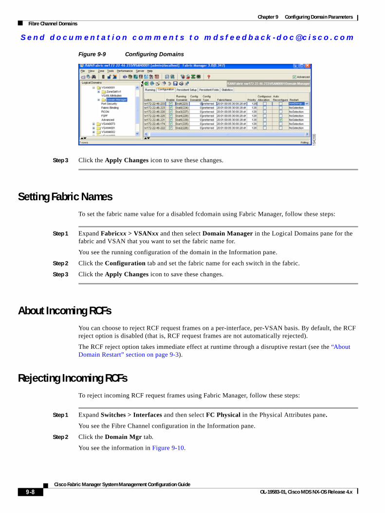
Send documenta t ion comments to mdsfeedback -doc@c i sco .com
Chapter 9 Configuring Domain ParametersFibre Channel Domains
Figure 9-9 Configuring Domains
Step 3 Click the Apply Changes icon to save these changes.
Setting Fabric NamesTo set the fabric name value for a disabled fcdomain using Fabric Manager, follow these steps:
Step 1 Expand Fabricxx > VSANxx and then select Domain Manager in the Logical Domains pane for the fabric and VSAN that you want to set the fabric name for.
You see the running configuration of the domain in the Information pane.
Step 2 Click the Configuration tab and set the fabric name for each switch in the fabric.
Step 3 Click the Apply Changes icon to save these changes.
About Incoming RCFsYou can choose to reject RCF request frames on a per-interface, per-VSAN basis. By default, the RCF reject option is disabled (that is, RCF request frames are not automatically rejected).
The RCF reject option takes immediate effect at runtime through a disruptive restart (see the “About Domain Restart” section on page 9-3).
Rejecting Incoming RCFsTo reject incoming RCF request frames using Fabric Manager, follow these steps:
Step 1 Expand Switches > Interfaces and then select FC Physical in the Physical Attributes pane.
You see the Fibre Channel configuration in the Information pane.
Step 2 Click the Domain Mgr tab.
You see the information in Figure 9-10.
9-8Cisco Fabric Manager System Management Configuration Guide
OL-19583-01, Cisco MDS NX-OS Release 4.x
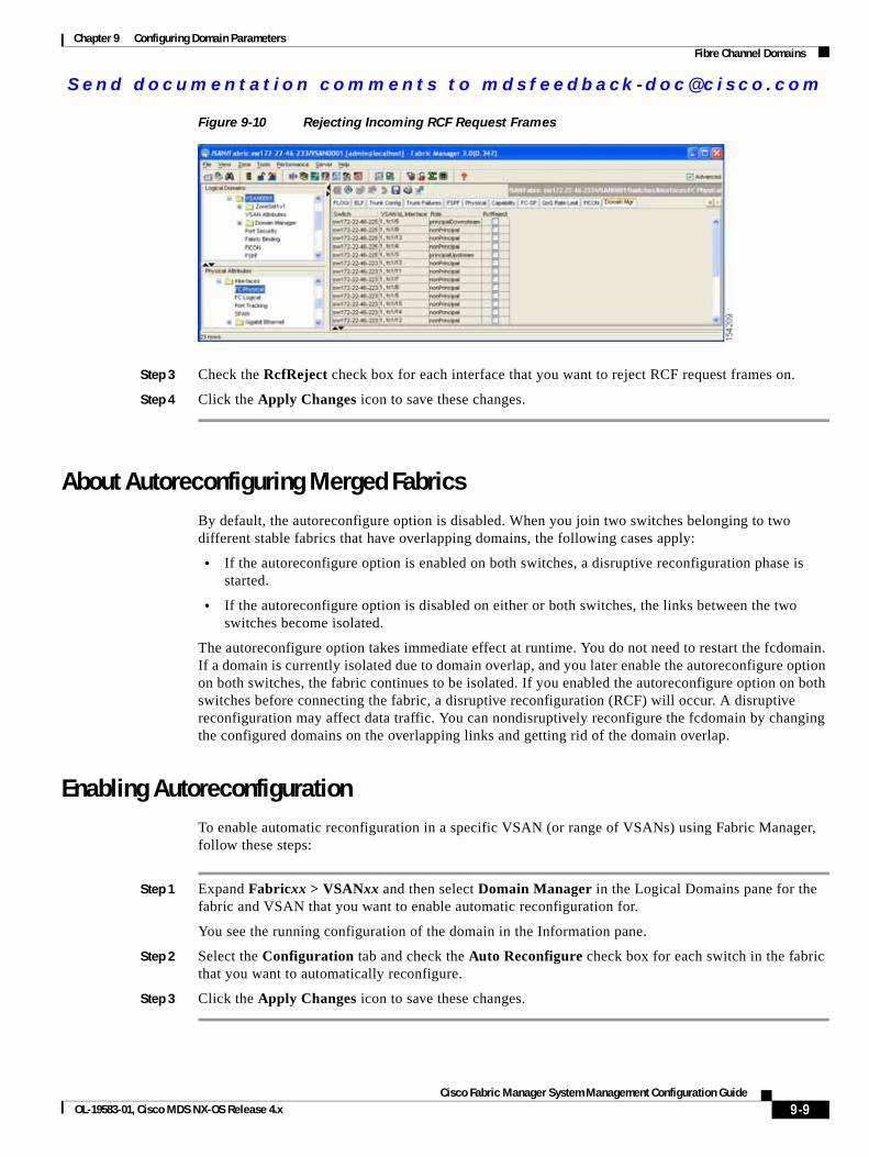
Send documenta t ion comments to mdsfeedback -doc@c i sco .com
Chapter 9 Configuring Domain ParametersFibre Channel Domains
Figure 9-10 Rejecting Incoming RCF Request Frames
Step 3 Check the RcfReject check box for each interface that you want to reject RCF request frames on.
Step 4 Click the Apply Changes icon to save these changes.
About Autoreconfiguring Merged FabricsBy default, the autoreconfigure option is disabled. When you join two switches belonging to two different stable fabrics that have overlapping domains, the following cases apply:
• If the autoreconfigure option is enabled on both switches, a disruptive reconfiguration phase is started.
• If the autoreconfigure option is disabled on either or both switches, the links between the two switches become isolated.
The autoreconfigure option takes immediate effect at runtime. You do not need to restart the fcdomain. If a domain is currently isolated due to domain overlap, and you later enable the autoreconfigure option on both switches, the fabric continues to be isolated. If you enabled the autoreconfigure option on both switches before connecting the fabric, a disruptive reconfiguration (RCF) will occur. A disruptive reconfiguration may affect data traffic. You can nondisruptively reconfigure the fcdomain by changing the configured domains on the overlapping links and getting rid of the domain overlap.
Enabling AutoreconfigurationTo enable automatic reconfiguration in a specific VSAN (or range of VSANs) using Fabric Manager, follow these steps:
Step 1 Expand Fabricxx > VSANxx and then select Domain Manager in the Logical Domains pane for the fabric and VSAN that you want to enable automatic reconfiguration for.
You see the running configuration of the domain in the Information pane.
Step 2 Select the Configuration tab and check the Auto Reconfigure check box for each switch in the fabric that you want to automatically reconfigure.
Step 3 Click the Apply Changes icon to save these changes.
9-9Cisco Fabric Manager System Management Configuration Guide
OL-19583-01, Cisco MDS NX-OS Release 4.x
Send documenta t ion comments to mdsfeedback -doc@c i sco .com
Chapter 9 Configuring Domain ParametersDomain IDs
Domain IDsDomain IDs uniquely identify a switch in a VSAN. A switch may have different domain IDs in different VSANs. The domain ID is part of the overall FC ID.
This section describes how to configure domain IDs and includes the following topics:
• About Domain IDs, page 9-10
• Specifying Static or Preferred Domain IDs, page 9-12
• About Allowed Domain ID Lists, page 9-13
• Configuring Allowed Domain ID Lists, page 9-13
• About CFS Distribution of Allowed Domain ID Lists, page 9-14
• Enabling Distribution, page 9-14
• Locking the Fabric, page 9-15
• Committing Changes, page 9-15
• Discarding Changes, page 9-15
• Clearing a Fabric Lock, page 9-16
• Displaying Pending Changes, page 9-16
• Displaying Session Status, page 9-16
• About Contiguous Domain ID Assignments, page 9-17
• Enabling Contiguous Domain ID Assignments, page 9-17
About Domain IDsThe configured domain ID can be preferred or static. By default, the configured domain ID is 0 (zero) and the configured type is preferred.
Note The 0 (zero) value can be configured only if you use the preferred option.
If you do not configure a domain ID, the local switch sends a random ID in its request. We recommend that you use static domain IDs.
When a subordinate switch requests a domain, the following process takes place (see Figure 9-11):
1. The local switch sends a configured domain ID request to the principal switch.
2. The principal switch assigns the requested domain ID if available. Otherwise, it assigns another available domain ID.
9-10Cisco Fabric Manager System Management Configuration Guide
OL-19583-01, Cisco MDS NX-OS Release 4.x
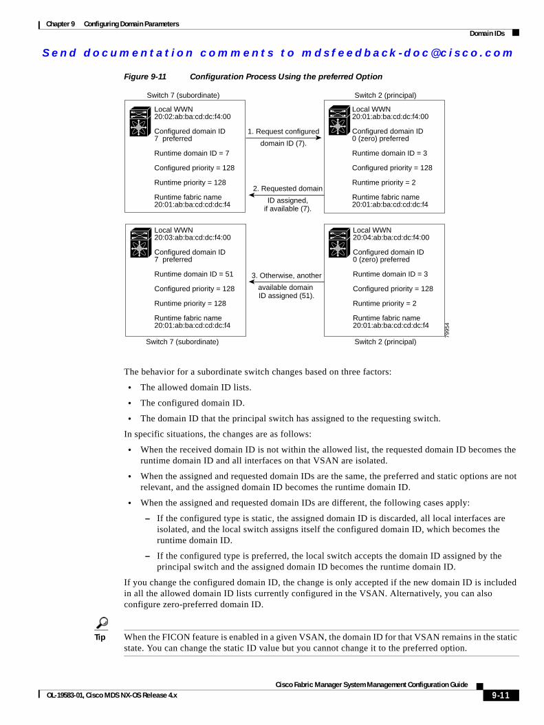
Send documenta t ion comments to mdsfeedback -doc@c i sco .com
Chapter 9 Configuring Domain ParametersDomain IDs
Figure 9-11 Configuration Process Using the preferred Option
The behavior for a subordinate switch changes based on three factors:
• The allowed domain ID lists.
• The configured domain ID.
• The domain ID that the principal switch has assigned to the requesting switch.
In specific situations, the changes are as follows:
• When the received domain ID is not within the allowed list, the requested domain ID becomes the runtime domain ID and all interfaces on that VSAN are isolated.
• When the assigned and requested domain IDs are the same, the preferred and static options are not relevant, and the assigned domain ID becomes the runtime domain ID.
• When the assigned and requested domain IDs are different, the following cases apply:
– If the configured type is static, the assigned domain ID is discarded, all local interfaces are isolated, and the local switch assigns itself the configured domain ID, which becomes the runtime domain ID.
– If the configured type is preferred, the local switch accepts the domain ID assigned by the principal switch and the assigned domain ID becomes the runtime domain ID.
If you change the configured domain ID, the change is only accepted if the new domain ID is included in all the allowed domain ID lists currently configured in the VSAN. Alternatively, you can also configure zero-preferred domain ID.
Tip When the FICON feature is enabled in a given VSAN, the domain ID for that VSAN remains in the static state. You can change the static ID value but you cannot change it to the preferred option.
Local WWN 20:02:ab:ba:cd:dc:f4:00
Configured domain ID7 preferred
Runtime domain ID = 7
Configured priority = 128
Runtime priority = 128
Runtime fabric name20:01:ab:ba:cd:cd:dc:f4
Local WWN 20:01:ab:ba:cd:dc:f4:00
Configured domain ID0 (zero) preferred
Runtime domain ID = 3
Configured priority = 128
Runtime priority = 2
Runtime fabric name20:01:ab:ba:cd:cd:dc:f4
Local WWN 20:04:ab:ba:cd:dc:f4:00
Configured domain ID0 (zero) preferred
Runtime domain ID = 3
Configured priority = 128
Runtime priority = 2
Runtime fabric name20:01:ab:ba:cd:cd:dc:f4
Local WWN 20:03:ab:ba:cd:dc:f4:00
Configured domain ID7 preferred
Runtime domain ID = 51
Configured priority = 128
Runtime priority = 128
Runtime fabric name20:01:ab:ba:cd:cd:dc:f4
1. Request configured
domain ID (7).
2. Requested domain
ID assigned,if available (7).
3. Otherwise, another
available domain ID assigned (51).
Switch 7 (subordinate) Switch 2 (principal)
Switch 7 (subordinate) Switch 2 (principal)
7995
4
9-11Cisco Fabric Manager System Management Configuration Guide
OL-19583-01, Cisco MDS NX-OS Release 4.x
Send documenta t ion comments to mdsfeedback -doc@c i sco .com
Chapter 9 Configuring Domain ParametersDomain IDs
Note In an IVR without NAT configuration, if one VSAN in the IVR topology is configured with static domain IDs, then the other VSANs (edge or transit) in the topology should also be configured with static domain IDs. In an IVR NAT configuration, if one VSAN in the IVR topology is configured with static domain IDs, then the IVR domains that can be exported to that VSAN must also be assigned static domains.
Caution You must restart the fcdomain if you want to apply the configured domain changes to the runtime domain.
Note If you have configured an allowed domain ID list, the domain IDs that you add must be in that range for the VSAN. See the “About Allowed Domain ID Lists” section on page 9-13.
Specifying Static or Preferred Domain IDsWhen you assign a static domain ID type, you are requesting a particular domain ID. If the switch does not get the requested address, it will isolate itself from the fabric. When you specify a preferred domain ID, you are also requesting a particular domain ID; however, if the requested domain ID is unavailable, then the switch will accept another domain ID.
While the static option can be applied at runtime after a disruptive or nondisruptive restart, the preferred option is applied at runtime only after a disruptive restart (see the “About Domain Restart” section on page 9-3).
Note Within a VSAN all switches should have the same domain ID type (either static or preferred). If a configuration is mixed (some switches with static domain types and others with preferred) then you may experience link isolation.
To specify a static or preferred domain ID using Fabric Manager, follow these steps:
Step 1 Expand Fabricxx > VSANxx and then select Domain Manager in the Logical Domains pane for the fabric and VSAN that you want to configure the domain ID for.
You see the running configuration of the domain in the Information pane.
Step 2 Enter a value for the Config DomainID and click static or preferred from the Config Type drop-down menu to set the domain ID for switches in the fabric.
Step 3 Click the Apply Changes icon to save these changes.
9-12Cisco Fabric Manager System Management Configuration Guide
OL-19583-01, Cisco MDS NX-OS Release 4.x
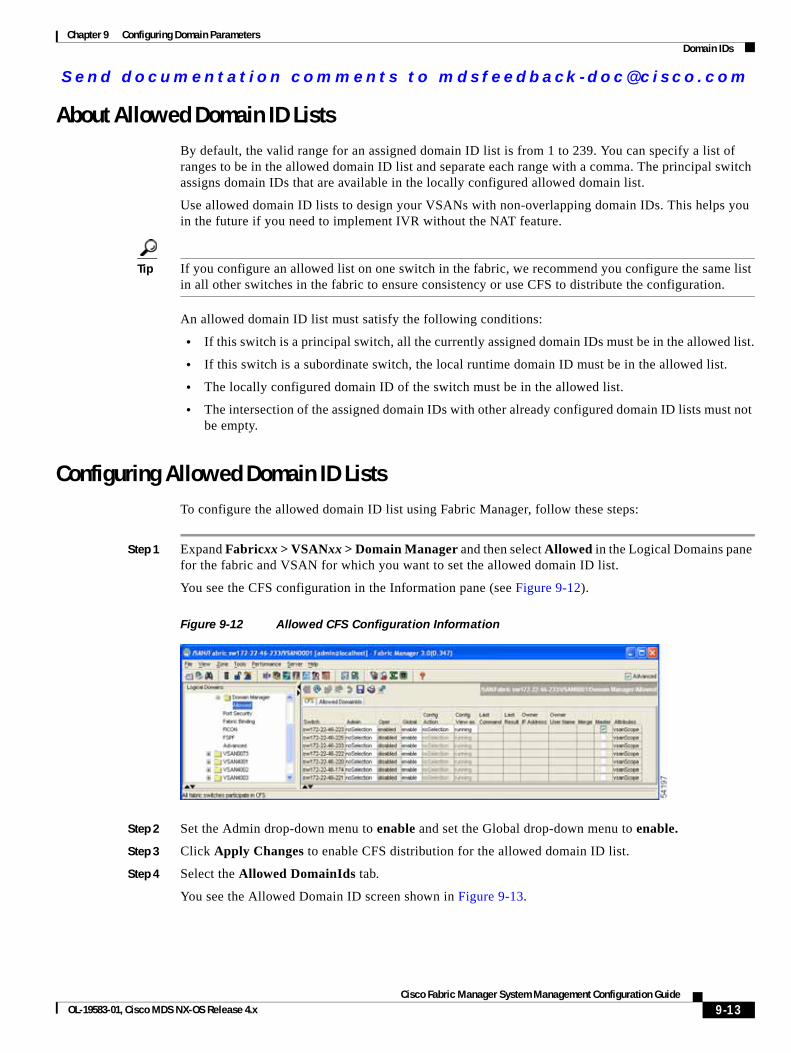
Send documenta t ion comments to mdsfeedback -doc@c i sco .com
Chapter 9 Configuring Domain ParametersDomain IDs
About Allowed Domain ID ListsBy default, the valid range for an assigned domain ID list is from 1 to 239. You can specify a list of ranges to be in the allowed domain ID list and separate each range with a comma. The principal switch assigns domain IDs that are available in the locally configured allowed domain list.
Use allowed domain ID lists to design your VSANs with non-overlapping domain IDs. This helps you in the future if you need to implement IVR without the NAT feature.
Tip If you configure an allowed list on one switch in the fabric, we recommend you configure the same list in all other switches in the fabric to ensure consistency or use CFS to distribute the configuration.
An allowed domain ID list must satisfy the following conditions:
• If this switch is a principal switch, all the currently assigned domain IDs must be in the allowed list.
• If this switch is a subordinate switch, the local runtime domain ID must be in the allowed list.
• The locally configured domain ID of the switch must be in the allowed list.
• The intersection of the assigned domain IDs with other already configured domain ID lists must not be empty.
Configuring Allowed Domain ID ListsTo configure the allowed domain ID list using Fabric Manager, follow these steps:
Step 1 Expand Fabricxx > VSANxx > Domain Manager and then select Allowed in the Logical Domains pane for the fabric and VSAN for which you want to set the allowed domain ID list.
You see the CFS configuration in the Information pane (see Figure 9-12).
Figure 9-12 Allowed CFS Configuration Information
Step 2 Set the Admin drop-down menu to enable and set the Global drop-down menu to enable.
Step 3 Click Apply Changes to enable CFS distribution for the allowed domain ID list.
Step 4 Select the Allowed DomainIds tab.
You see the Allowed Domain ID screen shown in Figure 9-13.
9-13Cisco Fabric Manager System Management Configuration Guide
OL-19583-01, Cisco MDS NX-OS Release 4.x
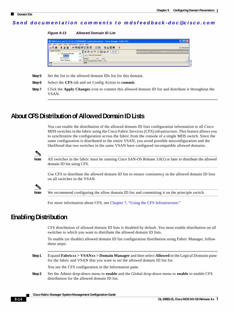
Send documenta t ion comments to mdsfeedback -doc@c i sco .com
Chapter 9 Configuring Domain ParametersDomain IDs
Figure 9-13 Allowed Domain ID List
Step 5 Set the list to the allowed domain IDs list for this domain.
Step 6 Select the CFS tab and set Config Action to commit.
Step 7 Click the Apply Changes icon to commit this allowed domain ID list and distribute it throughout the VSAN.
About CFS Distribution of Allowed Domain ID ListsYou can enable the distribution of the allowed domain ID lists configuration information to all Cisco MDS switches in the fabric using the Cisco Fabric Services (CFS) infrastructure. This feature allows you to synchronize the configuration across the fabric from the console of a single MDS switch. Since the same configuration is distributed to the entire VSAN, you avoid possible misconfiguration and the likelihood that two switches in the same VSAN have configured incompatible allowed domains.
Note All switches in the fabric must be running Cisco SAN-OS Release 3.0(1) or later to distribute the allowed domain ID list using CFS.
Use CFS to distribute the allowed domain ID list to ensure consistency in the allowed domain ID lists on all switches in the VSAN.
Note We recommend configuring the allow domain ID list and committing it on the principle switch.
For more information about CFS, see Chapter 7, “Using the CFS Infrastructure.”
Enabling DistributionCFS distribution of allowed domain ID lists is disabled by default. You must enable distribution on all switches to which you want to distribute the allowed domain ID lists.
To enable (or disable) allowed domain ID list configuration distribution using Fabric Manager, follow these steps:
Step 1 Expand Fabricxx > VSANxx > Domain Manager and then select Allowed in the Logical Domains pane for the fabric and VSAN that you want to set the allowed domain ID list for.
You see the CFS configuration in the Information pane.
Step 2 Set the Admin drop-down menu to enable and the Global drop-down menu to enable to enable CFS distribution for the allowed domain ID list.
9-14Cisco Fabric Manager System Management Configuration Guide
OL-19583-01, Cisco MDS NX-OS Release 4.x
Send documenta t ion comments to mdsfeedback -doc@c i sco .com
Chapter 9 Configuring Domain ParametersDomain IDs
Step 3 Click the Apply Changes icon to enable CFS distribution for the allowed domain ID list.
Locking the FabricThe first action that modifies the existing configuration creates the pending configuration and locks the feature in the fabric. Once you lock the fabric, the following conditions apply:
• No other user can make any configuration changes to this feature.
• A pending configuration is created by copying the active configuration. Modifications from this point on are made to the pending configuration and remain there until you commit the changes to the active configuration (and other switches in the fabric) or discard them.
Committing ChangesTo apply the pending domain configuration changes to other MDS switches in the VSAN, you must commit the changes. The pending configuration changes are distributed and, on a successful commit, the configuration changes are applied to the active configuration in the MDS switches throughout the VSAN and the fabric lock is released.
To commit pending domain configuration changes and release the lock using Fabric Manager, follow these steps:
Step 1 Expand Fabricxx > VSANxx > Domain Manager and then select Allowed in the Logical Domains pane for the fabric and VSAN that you want to set the allowed domain ID list for.
You see the CFS configuration in the Information pane.
Step 2 Set the Config Action drop-down menu to commit.
Step 3 Click the Apply Changes icon to commit the allowed domain ID list and distribute it throughout the VSAN.
Discarding ChangesAt any time, you can discard the pending changes to the domain configuration and release the fabric lock. If you discard (abort) the pending changes, the configuration remains unaffected and the lock is released.
To discard pending domain configuration changes and release the lock using Fabric Manager, follow these steps:
Step 1 Expand Fabricxx > VSANxx > Domain Manager and then select Allowed in the Logical Domains pane for the fabric and VSAN that you want to set the allowed domain ID list for.
You see the CFS configuration in the Information pane.
Step 2 Set the Config Action drop-down menu to abort.
Step 3 Click the Apply Changes icon to discard any pending changes to the allowed domain ID list.
9-15Cisco Fabric Manager System Management Configuration Guide
OL-19583-01, Cisco MDS NX-OS Release 4.x
Send documenta t ion comments to mdsfeedback -doc@c i sco .com
Chapter 9 Configuring Domain ParametersDomain IDs
Clearing a Fabric LockIf you have performed a domain configuration task and have not released the lock by either committing or discarding the changes, an administrator can release the lock from any switch in the fabric. If the administrator performs this task, your pending changes are discarded and the fabric lock is released.
Tip The pending changes are only available in the volatile directory and are discarded if the switch is restarted.
To release a fabric lock using Fabric Manager, follow these steps:
Step 1 Expand Fabricxx > VSANxx > Domain Manager and then select AllowedId in the Logical Domains pane for the fabric and VSAN for which you want the allowed domain ID list.
You see the CFS configuration in the Information pane.
Step 2 Set the Config Action drop-down menu to clear.
Step 3 Click the Apply Changes icon to clear the fabric lock.
Displaying Pending ChangesTo display the pending configuration changes using Fabric Manager, follow these steps:
Step 1 Expand Fabricxx > VSANxx > Domain Manager > Allowed in the Logical Domains pane for the fabric and VSAN that you want to set the allowed domain ID list for.
You see the CFS configuration in the Information pane.
Step 2 Set the Config View As drop-down menu to pending.
Step 3 Click the Apply Changes icon to clear the fabric lock.
Step 4 Click the AllowedDomainIds tab.
You see the pending configuration for the allowed domain IDs list.
Displaying Session StatusTo display the status of the distribution session using Fabric Manager, follow these steps:
Step 1 Expand Fabricxx > VSANxx > Domain Manager and then select Allowed in the Logical Domains pane for the fabric and VSAN for which you want to set the allowed domain ID list.
Step 2 View the CFS configuration and session status in the Information pane.
9-16Cisco Fabric Manager System Management Configuration Guide
OL-19583-01, Cisco MDS NX-OS Release 4.x
Send documenta t ion comments to mdsfeedback -doc@c i sco .com
Chapter 9 Configuring Domain ParametersFC IDs
About Contiguous Domain ID AssignmentsBy default, the contiguous domain assignment is disabled. When a subordinate switch requests the principal switch for two or more domains and the domains are not contiguous, the following cases apply:
• If the contiguous domain assignment is enabled in the principal switch, the principal switch locates contiguous domains and assigns them to the subordinate switches. If contiguous domains are not available, the NX-OS software rejects this request.
• If the contiguous domain assignment is disabled in the principal switch, the principal switch assigns the available domains to the subordinate switch.
Enabling Contiguous Domain ID AssignmentsTo enable contiguous domains in a specific VSAN (or a range of VSANs) using Fabric Manager, follow these steps:
Step 1 Expand Fabricxx > VSANxx and then select Domain Manager in the Logical Domains pane for the fabric and VSAN that you want to enable contiguous domains for.
You see the running configuration of the domain in the Information pane.
Step 2 Click the Configuration tab and check the Contiguous Allocation check box for each switch in the fabric that will have contiguous allocation.
Step 3 Click the Apply Changes icon to save these changes.
FC IDsWhen an N or NL port logs into a Cisco MDS 9000 Family switch, it is assigned an FC ID. By default, the persistent FC ID feature is enabled. If this feature is disabled, the following consequences apply:
• An N or NL port logs into a Cisco MDS 9000 Family switch. The WWN of the requesting N or NL port and the assigned FC ID are retained and stored in a volatile cache. The contents of this volatile cache are not saved across reboots.
• The switch is designed to preserve the binding FC ID to the WWN on a best-effort basis. For example, if one N port disconnects from the switch and its FC ID is requested by another device, this request is granted and the WWN with the initial FC ID association is released.
• The volatile cache stores up to 4000 entries of WWN to FC ID binding. If this cache is full, a new (more recent) entry overwrites the oldest entry in the cache. In this case, the corresponding WWN to FC ID association for the oldest entry is lost.
• The switch connection behavior differs between N ports and NL ports:
– N ports receive the same FC IDs if disconnected and reconnected to any port within the same switch (as long as it belongs to the same VSAN).
– NL ports receive the same FC IDs only if connected back to the same port on the switch to which they were originally connected.
This section describes configuring FC IDs and includes the following topics:
• About Persistent FC IDs, page 9-18
9-17Cisco Fabric Manager System Management Configuration Guide
OL-19583-01, Cisco MDS NX-OS Release 4.x
Send documenta t ion comments to mdsfeedback -doc@c i sco .com
Chapter 9 Configuring Domain ParametersFC IDs
• Enabling the Persistent FC ID Feature, page 9-18
• About Persistent FC ID Configuration, page 9-19
• Configuring Persistent FC IDs, page 9-19
• About Unique Area FC IDs for HBAs, page 9-20
• Configuring Unique Area FC IDs for an HBA, page 9-20
• About Persistent FC ID Selective Purging, page 9-21
• Purging Persistent FC IDs, page 9-22
About Persistent FC IDsWhen persistent FC IDs are enabled, the following consequences apply:
• The currently in use FC IDs in the fcdomain are saved across reboots.
• The fcdomain automatically populates the database with dynamic entries that the switch has learned about after a device (host or disk) is plugged into a port interface.
Note If you connect to the switch from an AIX or HP-UX host, be sure to enable the persistent FC ID feature in the VSAN that connects these hosts.
Note FC IDs are enabled by default. This change of default behavior from releases prior to Cisco MDS SAN-OS Release 2.0(1b) prevents FC IDs from being changed after a reboot. You can disable this option for each VSAN.
A persistent FC ID assigned to an F port can be moved across interfaces and can continue to maintain the same persistent FC ID.
Note Persistent FC IDs with loop-attached devices (FL ports) need to remain connected to the same port in which they were configured.
Note Due to differences in Arbitrated Loop Physical Address (ALPA) support on devices, FC ID persistency for loop-attached devices is not guaranteed.
Enabling the Persistent FC ID FeatureTo enable the persistent FC ID feature using Fabric Manager, follow these steps:
Step 1 Expand Fabricxx > VSANxx and then select Domain Manager in the Logical Domains pane for the fabric and VSAN that you want to enable the Persistent FC ID feature for.
You see the running configuration of the domain in the Information pane.
Step 2 Select the Persistent Setup tab and check the enable check box for each switch in the fabric that will have persistent FC ID enabled.
9-18Cisco Fabric Manager System Management Configuration Guide
OL-19583-01, Cisco MDS NX-OS Release 4.x
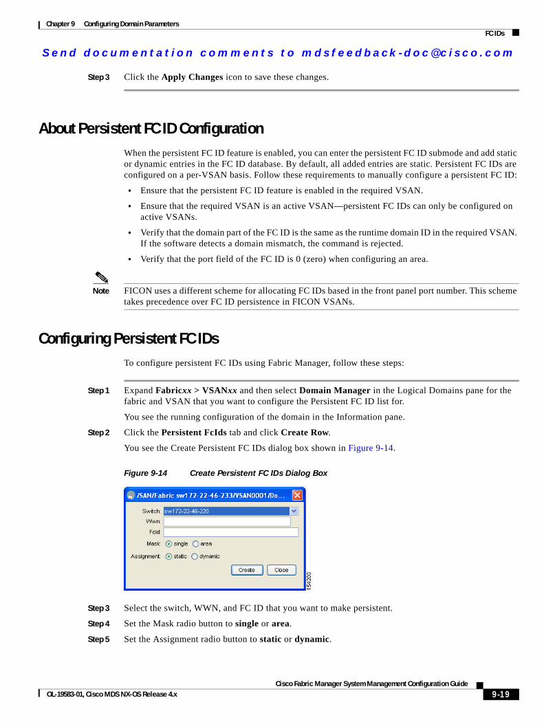
Send documenta t ion comments to mdsfeedback -doc@c i sco .com
Chapter 9 Configuring Domain ParametersFC IDs
Step 3 Click the Apply Changes icon to save these changes.
About Persistent FC ID ConfigurationWhen the persistent FC ID feature is enabled, you can enter the persistent FC ID submode and add static or dynamic entries in the FC ID database. By default, all added entries are static. Persistent FC IDs are configured on a per-VSAN basis. Follow these requirements to manually configure a persistent FC ID:
• Ensure that the persistent FC ID feature is enabled in the required VSAN.
• Ensure that the required VSAN is an active VSAN—persistent FC IDs can only be configured on active VSANs.
• Verify that the domain part of the FC ID is the same as the runtime domain ID in the required VSAN. If the software detects a domain mismatch, the command is rejected.
• Verify that the port field of the FC ID is 0 (zero) when configuring an area.
Note FICON uses a different scheme for allocating FC IDs based in the front panel port number. This scheme takes precedence over FC ID persistence in FICON VSANs.
Configuring Persistent FC IDsTo configure persistent FC IDs using Fabric Manager, follow these steps:
Step 1 Expand Fabricxx > VSANxx and then select Domain Manager in the Logical Domains pane for the fabric and VSAN that you want to configure the Persistent FC ID list for.
You see the running configuration of the domain in the Information pane.
Step 2 Click the Persistent FcIds tab and click Create Row.
You see the Create Persistent FC IDs dialog box shown in Figure 9-14.
Figure 9-14 Create Persistent FC IDs Dialog Box
Step 3 Select the switch, WWN, and FC ID that you want to make persistent.
Step 4 Set the Mask radio button to single or area.
Step 5 Set the Assignment radio button to static or dynamic.
9-19Cisco Fabric Manager System Management Configuration Guide
OL-19583-01, Cisco MDS NX-OS Release 4.x
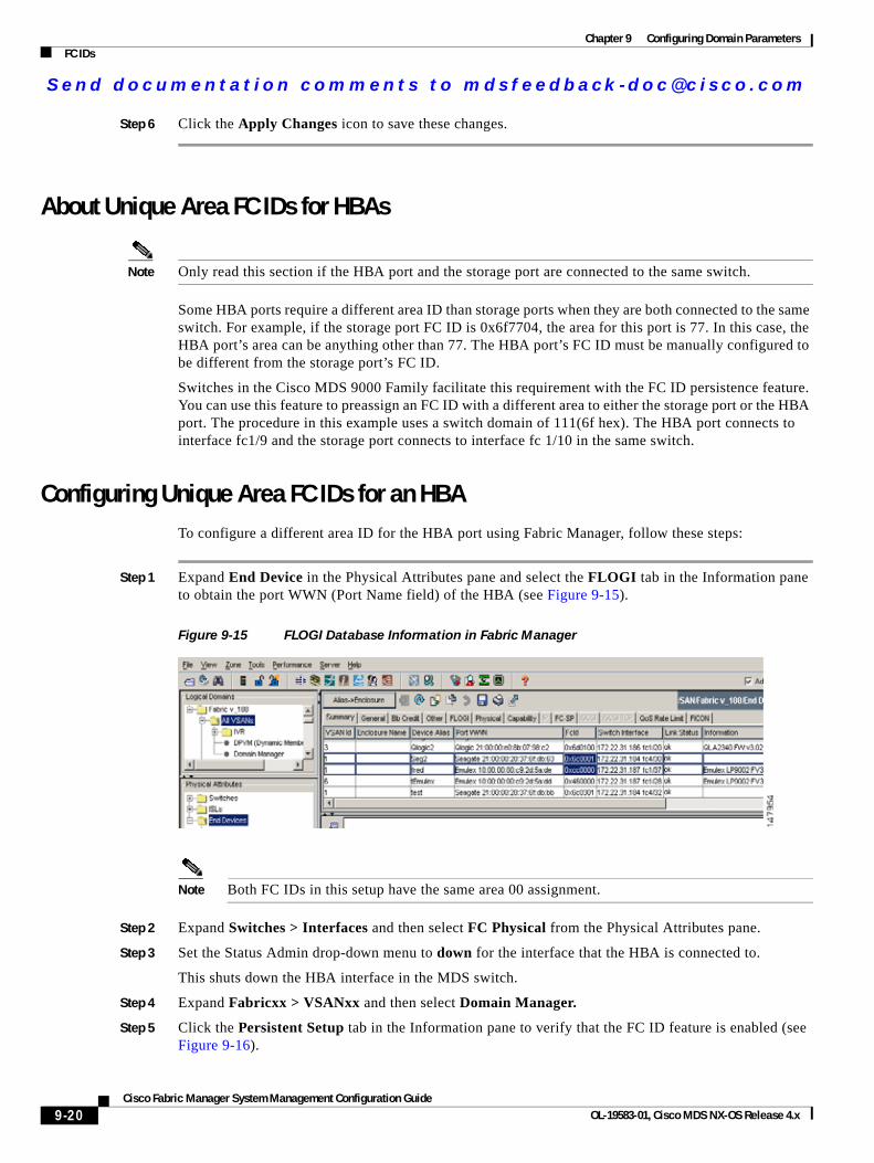
Send documenta t ion comments to mdsfeedback -doc@c i sco .com
Chapter 9 Configuring Domain ParametersFC IDs
Step 6 Click the Apply Changes icon to save these changes.
About Unique Area FC IDs for HBAs
Note Only read this section if the HBA port and the storage port are connected to the same switch.
Some HBA ports require a different area ID than storage ports when they are both connected to the same switch. For example, if the storage port FC ID is 0x6f7704, the area for this port is 77. In this case, the HBA port’s area can be anything other than 77. The HBA port’s FC ID must be manually configured to be different from the storage port’s FC ID.
Switches in the Cisco MDS 9000 Family facilitate this requirement with the FC ID persistence feature. You can use this feature to preassign an FC ID with a different area to either the storage port or the HBA port. The procedure in this example uses a switch domain of 111(6f hex). The HBA port connects to interface fc1/9 and the storage port connects to interface fc 1/10 in the same switch.
Configuring Unique Area FC IDs for an HBATo configure a different area ID for the HBA port using Fabric Manager, follow these steps:
Step 1 Expand End Device in the Physical Attributes pane and select the FLOGI tab in the Information pane to obtain the port WWN (Port Name field) of the HBA (see Figure 9-15).
Figure 9-15 FLOGI Database Information in Fabric Manager
Note Both FC IDs in this setup have the same area 00 assignment.
Step 2 Expand Switches > Interfaces and then select FC Physical from the Physical Attributes pane.
Step 3 Set the Status Admin drop-down menu to down for the interface that the HBA is connected to.
This shuts down the HBA interface in the MDS switch.
Step 4 Expand Fabricxx > VSANxx and then select Domain Manager.
Step 5 Click the Persistent Setup tab in the Information pane to verify that the FC ID feature is enabled (see Figure 9-16).
9-20Cisco Fabric Manager System Management Configuration Guide
OL-19583-01, Cisco MDS NX-OS Release 4.x
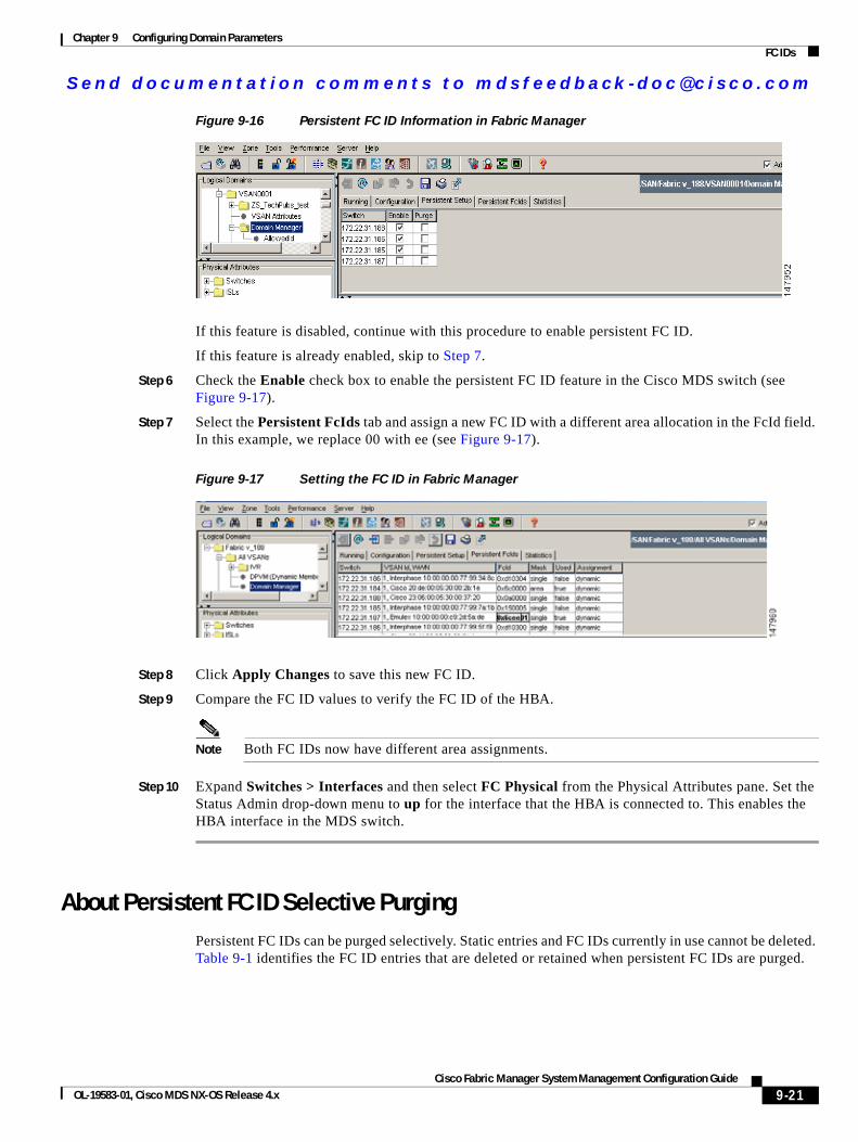
Send documenta t ion comments to mdsfeedback -doc@c i sco .com
Chapter 9 Configuring Domain ParametersFC IDs
Figure 9-16 Persistent FC ID Information in Fabric Manager
If this feature is disabled, continue with this procedure to enable persistent FC ID.
If this feature is already enabled, skip to Step 7.
Step 6 Check the Enable check box to enable the persistent FC ID feature in the Cisco MDS switch (see Figure 9-17).
Step 7 Select the Persistent FcIds tab and assign a new FC ID with a different area allocation in the FcId field. In this example, we replace 00 with ee (see Figure 9-17).
Figure 9-17 Setting the FC ID in Fabric Manager
Step 8 Click Apply Changes to save this new FC ID.
Step 9 Compare the FC ID values to verify the FC ID of the HBA.
Note Both FC IDs now have different area assignments.
Step 10 EXpand Switches > Interfaces and then select FC Physical from the Physical Attributes pane. Set the Status Admin drop-down menu to up for the interface that the HBA is connected to. This enables the HBA interface in the MDS switch.
About Persistent FC ID Selective PurgingPersistent FC IDs can be purged selectively. Static entries and FC IDs currently in use cannot be deleted. Table 9-1 identifies the FC ID entries that are deleted or retained when persistent FC IDs are purged.
9-21Cisco Fabric Manager System Management Configuration Guide
OL-19583-01, Cisco MDS NX-OS Release 4.x
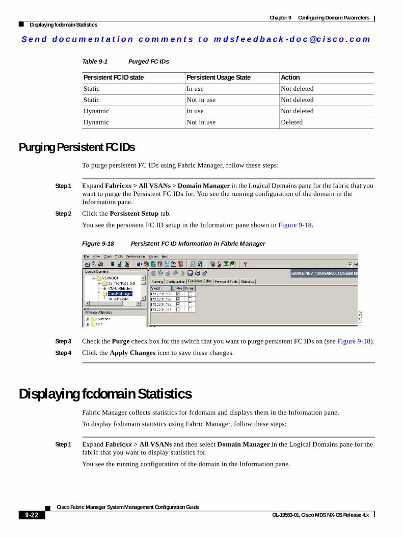
Send documenta t ion comments to mdsfeedback -doc@c i sco .com
Chapter 9 Configuring Domain ParametersDisplaying fcdomain Statistics
Purging Persistent FC IDsTo purge persistent FC IDs using Fabric Manager, follow these steps:
Step 1 Expand Fabricxx > All VSANs > Domain Manager in the Logical Domains pane for the fabric that you want to purge the Persistent FC IDs for. You see the running configuration of the domain in the Information pane.
Step 2 Click the Persistent Setup tab.
You see the persistent FC ID setup in the Information pane shown in Figure 9-18.
Figure 9-18 Persistent FC ID Information in Fabric Manager
Step 3 Check the Purge check box for the switch that you want to purge persistent FC IDs on (see Figure 9-18).
Step 4 Click the Apply Changes icon to save these changes.
Displaying fcdomain StatisticsFabric Manager collects statistics for fcdomain and displays them in the Information pane.
To display fcdomain statistics using Fabric Manager, follow these steps:
Step 1 Expand Fabricxx > All VSANs and then select Domain Manager in the Logical Domains pane for the fabric that you want to display statistics for.
You see the running configuration of the domain in the Information pane.
Table 9-1 Purged FC IDs
Persistent FC ID state Persistent Usage State Action
Static In use Not deleted
Static Not in use Not deleted
Dynamic In use Not deleted
Dynamic Not in use Deleted
9-22Cisco Fabric Manager System Management Configuration Guide
OL-19583-01, Cisco MDS NX-OS Release 4.x

Send documenta t ion comments to mdsfeedback -doc@c i sco .com
Chapter 9 Configuring Domain ParametersDefault Settings
Step 2 Click the Statistics tab. You see the FC ID statistics in the Information pane.
Default SettingsTable 9-2 lists the default settings for all fcdomain parameters.
Table 9-2 Default fcdomain Parameters
Parameters Default
fcdomain feature Enabled.
Configured domain ID 0 (zero).
Configured domain Preferred.
autoreconfigure option Disabled.
contiguous-allocation option Disabled.
Priority 128.
Allowed list 1 to 239.
Fabric name 20:01:00:05:30:00:28:df.
rcf-reject Disabled.
Persistent FC ID Enabled.
Allowed domain ID list configuration distribution Disabled.
9-23Cisco Fabric Manager System Management Configuration Guide
OL-19583-01, Cisco MDS NX-OS Release 4.x

Send documenta t ion comments to mdsfeedback -doc@c i sco .com
Chapter 9 Configuring Domain ParametersDefault Settings
9-24Cisco Fabric Manager System Management Configuration Guide
OL-19583-01, Cisco MDS NX-OS Release 4.x
Send documenta t ion comments to mdsfeedback -doc@c i sco .com
Cisco Fabric OL-19583-01, Cisco MDS NX-OS Release 4.x
C H A P T E R 10
Monitoring Network Traffic Using SPANThis chapter describes the Switched Port Analyzer (SPAN) features provided in switches in the Cisco MDS 9000 Family. It includes the following sections:
• About SPAN, page 10-2
• SPAN Sources, page 10-2
• SPAN Sessions, page 10-5
• Specifying Filters, page 10-5
• SD Port Characteristics, page 10-5
• Configuring SPAN, page 10-6
• Monitoring Traffic Using Fibre Channel Analyzers, page 10-10
• Default SPAN Settings, page 10-13
10-1Manager System Management Configuration Guide
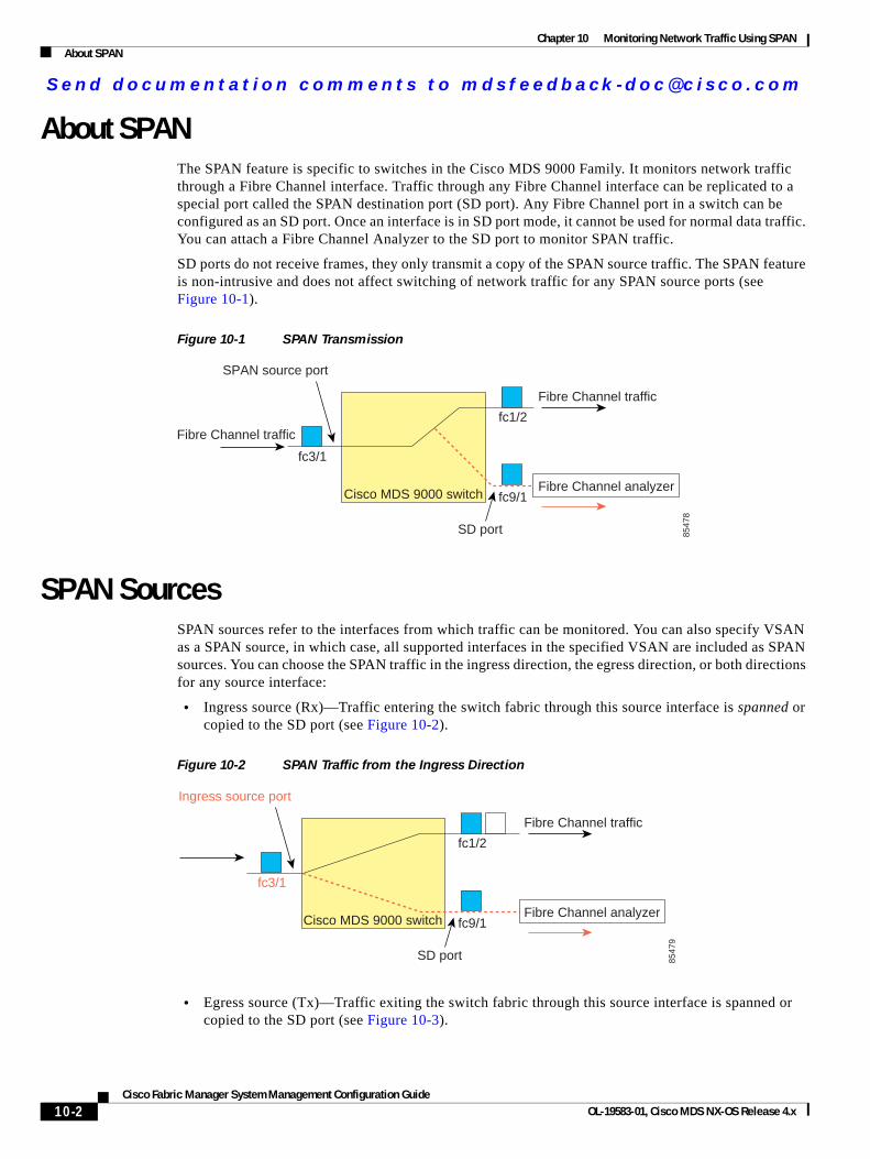
Send documenta t ion comments to mdsfeedback -doc@c i sco .com
Chapter 10 Monitoring Network Traffic Using SPANAbout SPAN
About SPANThe SPAN feature is specific to switches in the Cisco MDS 9000 Family. It monitors network traffic through a Fibre Channel interface. Traffic through any Fibre Channel interface can be replicated to a special port called the SPAN destination port (SD port). Any Fibre Channel port in a switch can be configured as an SD port. Once an interface is in SD port mode, it cannot be used for normal data traffic. You can attach a Fibre Channel Analyzer to the SD port to monitor SPAN traffic.
SD ports do not receive frames, they only transmit a copy of the SPAN source traffic. The SPAN feature is non-intrusive and does not affect switching of network traffic for any SPAN source ports (see Figure 10-1).
Figure 10-1 SPAN Transmission
SPAN SourcesSPAN sources refer to the interfaces from which traffic can be monitored. You can also specify VSAN as a SPAN source, in which case, all supported interfaces in the specified VSAN are included as SPAN sources. You can choose the SPAN traffic in the ingress direction, the egress direction, or both directions for any source interface:
• Ingress source (Rx)—Traffic entering the switch fabric through this source interface is spanned or copied to the SD port (see Figure 10-2).
Figure 10-2 SPAN Traffic from the Ingress Direction
• Egress source (Tx)—Traffic exiting the switch fabric through this source interface is spanned or copied to the SD port (see Figure 10-3).
Fibre Channel traffic
Fibre Channel traffic
Fibre Channel analyzerfc9/1
fc3/1
fc1/2
SPAN source port
SD port
Cisco MDS 9000 switch
8547
8
Fibre Channel traffic
Fibre Channel analyzerfc9/1
fc3/1
fc1/2
Ingress source port
SD port
Cisco MDS 9000 switch
8547
9
10-2Cisco Fabric Manager System Management Configuration Guide
OL-19583-01, Cisco MDS NX-OS Release 4.x
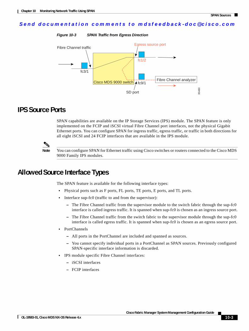
Send documenta t ion comments to mdsfeedback -doc@c i sco .com
Chapter 10 Monitoring Network Traffic Using SPANSPAN Sources
Figure 10-3 SPAN Traffic from Egress Direction
IPS Source PortsSPAN capabilities are available on the IP Storage Services (IPS) module. The SPAN feature is only implemented on the FCIP and iSCSI virtual Fibre Channel port interfaces, not the physical Gigabit Ethernet ports. You can configure SPAN for ingress traffic, egress traffic, or traffic in both directions for all eight iSCSI and 24 FCIP interfaces that are available in the IPS module.
Note You can configure SPAN for Ethernet traffic using Cisco switches or routers connected to the Cisco MDS 9000 Family IPS modules.
Allowed Source Interface TypesThe SPAN feature is available for the following interface types:
• Physical ports such as F ports, FL ports, TE ports, E ports, and TL ports.
• Interface sup-fc0 (traffic to and from the supervisor):
– The Fibre Channel traffic from the supervisor module to the switch fabric through the sup-fc0 interface is called ingress traffic. It is spanned when sup-fc0 is chosen as an ingress source port.
– The Fibre Channel traffic from the switch fabric to the supervisor module through the sup-fc0 interface is called egress traffic. It is spanned when sup-fc0 is chosen as an egress source port.
• PortChannels
– All ports in the PortChannel are included and spanned as sources.
– You cannot specify individual ports in a PortChannel as SPAN sources. Previously configured SPAN-specific interface information is discarded.
• IPS module specific Fibre Channel interfaces:
– iSCSI interfaces
– FCIP interfaces
Fibre Channel trafficEgress source port
fc9/1
fc3/1
fc1/2
SD port
Cisco MDS 9000 switch
8548
0
Fibre Channel analyzer
10-3Cisco Fabric Manager System Management Configuration Guide
OL-19583-01, Cisco MDS NX-OS Release 4.x
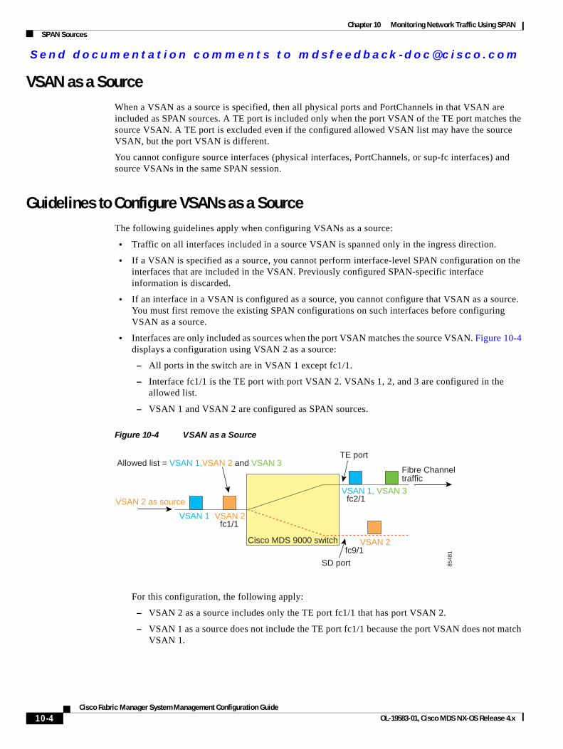
Send documenta t ion comments to mdsfeedback -doc@c i sco .com
Chapter 10 Monitoring Network Traffic Using SPANSPAN Sources
VSAN as a SourceWhen a VSAN as a source is specified, then all physical ports and PortChannels in that VSAN are included as SPAN sources. A TE port is included only when the port VSAN of the TE port matches the source VSAN. A TE port is excluded even if the configured allowed VSAN list may have the source VSAN, but the port VSAN is different.
You cannot configure source interfaces (physical interfaces, PortChannels, or sup-fc interfaces) and source VSANs in the same SPAN session.
Guidelines to Configure VSANs as a SourceThe following guidelines apply when configuring VSANs as a source:
• Traffic on all interfaces included in a source VSAN is spanned only in the ingress direction.
• If a VSAN is specified as a source, you cannot perform interface-level SPAN configuration on the interfaces that are included in the VSAN. Previously configured SPAN-specific interface information is discarded.
• If an interface in a VSAN is configured as a source, you cannot configure that VSAN as a source. You must first remove the existing SPAN configurations on such interfaces before configuring VSAN as a source.
• Interfaces are only included as sources when the port VSAN matches the source VSAN. Figure 10-4 displays a configuration using VSAN 2 as a source:
– All ports in the switch are in VSAN 1 except fc1/1.
– Interface fc1/1 is the TE port with port VSAN 2. VSANs 1, 2, and 3 are configured in the allowed list.
– VSAN 1 and VSAN 2 are configured as SPAN sources.
Figure 10-4 VSAN as a Source
For this configuration, the following apply:
– VSAN 2 as a source includes only the TE port fc1/1 that has port VSAN 2.
– VSAN 1 as a source does not include the TE port fc1/1 because the port VSAN does not match VSAN 1.
Allowed list = VSAN 1,VSAN 2 and VSAN 3TE port
fc2/1
fc9/1
fc1/1
VSAN 2
VSAN 2
VSAN 2 as sourceVSAN 1, VSAN 3
VSAN 1
SD port
Cisco MDS 9000 switch
8548
1
Fibre Channeltraffic
10-4Cisco Fabric Manager System Management Configuration Guide
OL-19583-01, Cisco MDS NX-OS Release 4.x
Send documenta t ion comments to mdsfeedback -doc@c i sco .com
Chapter 10 Monitoring Network Traffic Using SPANSPAN Sessions
SPAN SessionsEach SPAN session represents an association of one destination with a set of source(s) along with various other parameters that you specify to monitor the network traffic. One destination can be used by one or more SPAN sessions. You can configure up to 16 SPAN sessions in a switch. Each session can have several source ports and one destination port.
To activate any SPAN session, at least one source and the SD port must be up and functioning. Otherwise, traffic is not directed to the SD port.
Tip A source can be shared by two sessions, however, each session must be in a different direction—one ingress and one egress.
You can temporarily deactivate (suspend) any SPAN session. The traffic monitoring is stopped during this time.
Specifying FiltersYou can perform VSAN-based filtering to selectively monitor network traffic on specified VSANs. You can apply this VSAN filter to all sources in a session (see Figure 10-4). Only VSANs present in the filter are spanned.
You can specify session VSAN filters that are applied to all sources in the specified session. These filters are bidirectional and apply to all sources configured in the session.
Guidelines to Specifying FiltersThe following guidelines apply to SPAN filters:
• PortChannel configurations are applied to all ports in the PortChannel.
• If no filters are specified, the traffic from all active VSANs for that interface is spanned by default.
• While you can specify arbitrary VSAN filters in a session, traffic can only be monitored on the port VSAN or on allowed-active VSANs in that interface.
SD Port CharacteristicsAn SD port has the following characteristics:
• Ignores BB_credits.
• Allows data traffic only in the egress (Tx) direction.
• Does not require a device or an analyzer to be physically connected.
• Supports only 1 Gbps or 2 Gbps speeds. The auto speed option is not allowed.
• Multiple sessions can share the same destination ports.
• If the SD port is shut down, all shared sessions stop generating SPAN traffic.
• The outgoing frames can be encapsulated in Extended Inter-Switch Link (EISL) format.
10-5Cisco Fabric Manager System Management Configuration Guide
OL-19583-01, Cisco MDS NX-OS Release 4.x
Send documenta t ion comments to mdsfeedback -doc@c i sco .com
Chapter 10 Monitoring Network Traffic Using SPANConfiguring SPAN
• The SD port does not have a port VSAN.
• SD ports cannot be configured using Storage Services Modules (SSMs).
• The port mode cannot be changed if it is being used for a SPAN session.
Note If you need to change an SD port mode to another port mode, first remove the SD port from all sessions and then change the port mode.
Guidelines to Configure SPANThe following guidelines apply for SPAN configurations:
• You can configure up to 16 SPAN sessions with multiple ingress (Rx) sources.
• You can configure a maximum of three SPAN sessions with one egress (Tx) port.
• In a 32-port switching module, you must configure the same session in all four ports in one port group (unit). If you wish, you can also configure only two or three ports in this unit.
• SPAN frames are dropped if the sum of the bandwidth of the sources exceeds the speed of the destination port.
• Frames dropped by a source port are not spanned.
Configuring SPAN To monitor network traffic using SD ports, follow these steps:
Step 1 Configure the SD port.
Step 2 Attach the SD port to a specific SPAN session.
Step 3 Monitor network traffic by adding source interfaces to the session.
Configuring SPANTo configure an SD port for SPAN monitoring using Device Manager, follow these steps:
Step 1 Right-click the port you want to configure and select Configure.
You see the general port configuration dialog.
Step 2 Under Mode, choose SD.
Step 3 Click Apply to accept the change.
Step 4 Close the dialog box.
10-6Cisco Fabric Manager System Management Configuration Guide
OL-19583-01, Cisco MDS NX-OS Release 4.x
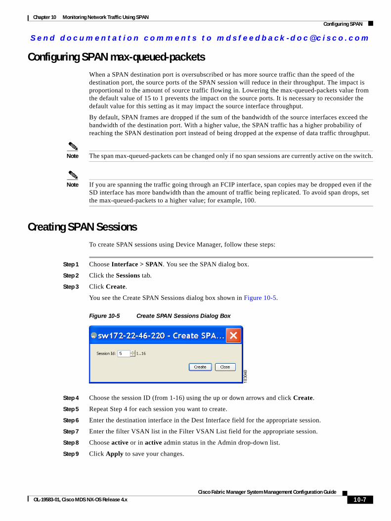
Send documenta t ion comments to mdsfeedback -doc@c i sco .com
Chapter 10 Monitoring Network Traffic Using SPANConfiguring SPAN
Configuring SPAN max-queued-packetsWhen a SPAN destination port is oversubscribed or has more source traffic than the speed of the destination port, the source ports of the SPAN session will reduce in their throughput. The impact is proportional to the amount of source traffic flowing in. Lowering the max-queued-packets value from the default value of 15 to 1 prevents the impact on the source ports. It is necessary to reconsider the default value for this setting as it may impact the source interface throughput.
By default, SPAN frames are dropped if the sum of the bandwidth of the source interfaces exceed the bandwidth of the destination port. With a higher value, the SPAN traffic has a higher probability of reaching the SPAN destination port instead of being dropped at the expense of data traffic throughput.
Note The span max-queued-packets can be changed only if no span sessions are currently active on the switch.
Note If you are spanning the traffic going through an FCIP interface, span copies may be dropped even if the SD interface has more bandwidth than the amount of traffic being replicated. To avoid span drops, set the max-queued-packets to a higher value; for example, 100.
Creating SPAN SessionsTo create SPAN sessions using Device Manager, follow these steps:
Step 1 Choose Interface > SPAN. You see the SPAN dialog box.
Step 2 Click the Sessions tab.
Step 3 Click Create.
You see the Create SPAN Sessions dialog box shown in Figure 10-5.
Figure 10-5 Create SPAN Sessions Dialog Box
Step 4 Choose the session ID (from 1-16) using the up or down arrows and click Create.
Step 5 Repeat Step 4 for each session you want to create.
Step 6 Enter the destination interface in the Dest Interface field for the appropriate session.
Step 7 Enter the filter VSAN list in the Filter VSAN List field for the appropriate session.
Step 8 Choose active or in active admin status in the Admin drop-down list.
Step 9 Click Apply to save your changes.
10-7Cisco Fabric Manager System Management Configuration Guide
OL-19583-01, Cisco MDS NX-OS Release 4.x
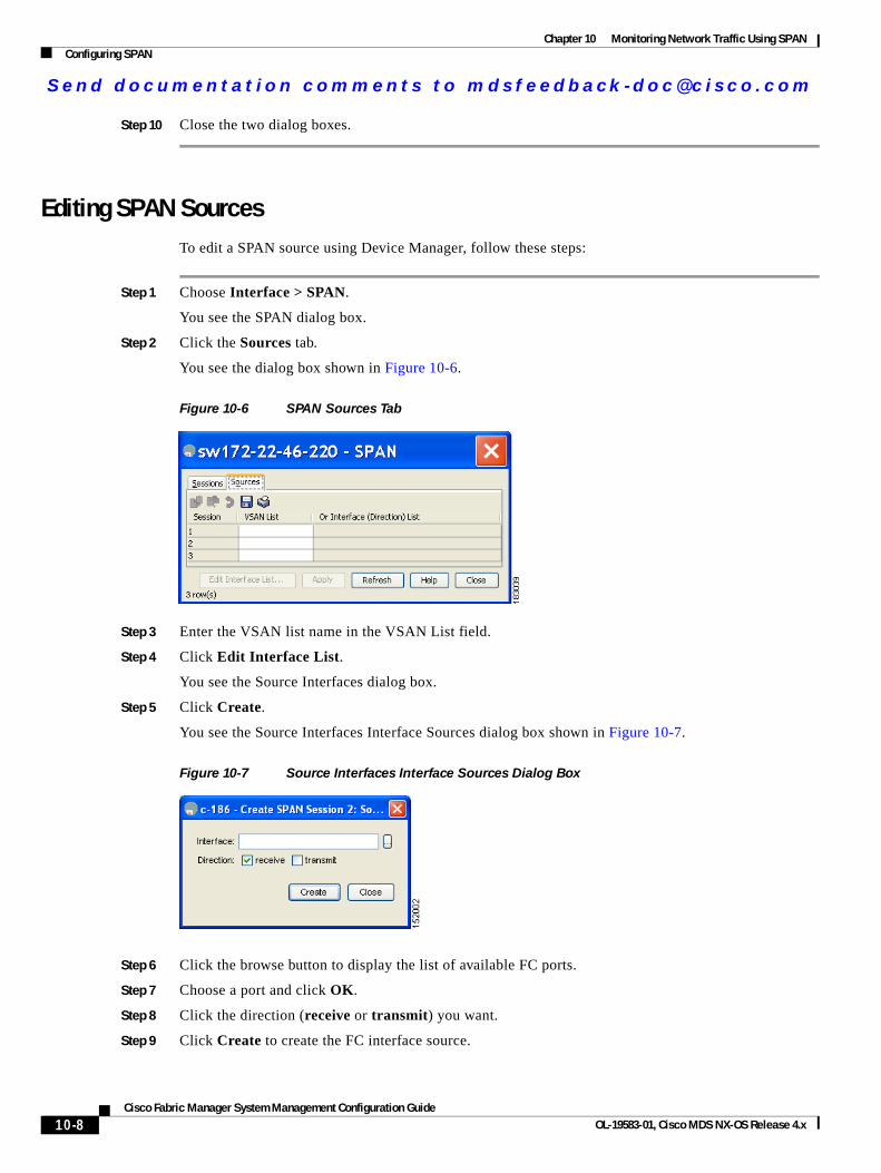
Send documenta t ion comments to mdsfeedback -doc@c i sco .com
Chapter 10 Monitoring Network Traffic Using SPANConfiguring SPAN
Step 10 Close the two dialog boxes.
Editing SPAN SourcesTo edit a SPAN source using Device Manager, follow these steps:
Step 1 Choose Interface > SPAN.
You see the SPAN dialog box.
Step 2 Click the Sources tab.
You see the dialog box shown in Figure 10-6.
Figure 10-6 SPAN Sources Tab
Step 3 Enter the VSAN list name in the VSAN List field.
Step 4 Click Edit Interface List.
You see the Source Interfaces dialog box.
Step 5 Click Create.
You see the Source Interfaces Interface Sources dialog box shown in Figure 10-7.
Figure 10-7 Source Interfaces Interface Sources Dialog Box
Step 6 Click the browse button to display the list of available FC ports.
Step 7 Choose a port and click OK.
Step 8 Click the direction (receive or transmit) you want.
Step 9 Click Create to create the FC interface source.
10-8Cisco Fabric Manager System Management Configuration Guide
OL-19583-01, Cisco MDS NX-OS Release 4.x
Send documenta t ion comments to mdsfeedback -doc@c i sco .com
Chapter 10 Monitoring Network Traffic Using SPANConfiguring SPAN
Step 10 Click Close in each of the three open dialog boxes.
Deleting SPAN SessionsTo delete a SPAN session using Device Manager, follow these steps:
Step 1 Choose Interface > SPAN.
You see the SPAN dialog box.
Step 2 Click the Sessions tab.
Step 3 Click the SPAN session you want to delete.
Step 4 Click Delete.
The SPAN session is deleted.
Step 5 Close the dialog box.
SPAN Conversion BehaviorSPAN features (configured in any prior release) are converted as follows:
• If source interfaces and source VSANs are configured in a given session, then all the source VSANs are removed from that session.
For example, before Cisco MDS SAN-OS Release 1.0(4):
Session 1 (active) Destination is fc1/9 No session filters configured Ingress (rx) sources are vsans 10-11 fc1/3, Egress (tx) sources are fc1/3,
Once upgraded to Cisco MDS SAN-OS Release 1.1(1):
Session 1 (active) Destination is fc1/9 No session filters configured Ingress (rx) sources are fc1/3, Egress (tx) sources are fc1/3,
Session 1 had both source interfaces and source VSANs before the upgrade. After the upgrade, the source VSANs were removed (rule 1).
• If interface level VSAN filters are configured in source interfaces, then the source interfaces are also removed from the session. If this interface is configured in both directions, it is removed from both directions.
For example, before Cisco MDS SAN-OS Release 1.0(4):
10-9Cisco Fabric Manager System Management Configuration Guide
OL-19583-01, Cisco MDS NX-OS Release 4.x
Send documenta t ion comments to mdsfeedback -doc@c i sco .com
Chapter 10 Monitoring Network Traffic Using SPANMonitoring Traffic Using Fibre Channel Analyzers
Session 2 (active) Destination is fc1/9 No session filters configured Ingress (rx) sources are vsans 12 fc1/6 (vsan 1-20), Egress (tx) sources are fc1/6 (vsan 1-20),
Once upgraded to Cisco MDS SAN-OS Release 1.1(1):
Session 2 (inactive as no active sources) Destination is fc1/9 No session filters configured No ingress (rx) sources No egress (tx) sources
Note The deprecated configurations are removed from persistent memory once a switchover or a new startup configuration is implemented.
Session 2 had a source VSAN 12 and a source interface fc1/6 with VSAN filters specified in Cisco MDS SAN-OS Release 1.0(4). When upgraded to Cisco MDS SAN-OS Release 1.1(1) the following changes are made:
– The source VSAN (VSAN 12) is removed (rule 1).
– The source interface fc1/6 had VSAN filters specified—it is also removed (rule 2).
Monitoring Traffic Using Fibre Channel AnalyzersYou can use SPAN to monitor traffic on an interface without any traffic disruption. This feature is especially useful in troubleshooting scenarios where traffic disruption changes the problem environment and makes it difficult to reproduce the problem.
Without SPANYou can monitor traffic using interface fc1/1 in a Cisco MDS 9000 Family switch that is connected to another switch or host. You need to physically connect a Fibre Channel analyzer between the switch and the storage device to analyze the traffic through interface fc1/1 as shown in Figure 10-8.
10-10Cisco Fabric Manager System Management Configuration Guide
OL-19583-01, Cisco MDS NX-OS Release 4.x

Send documenta t ion comments to mdsfeedback -doc@c i sco .com
Chapter 10 Monitoring Network Traffic Using SPANMonitoring Traffic Using Fibre Channel Analyzers
Figure 10-8 Fibre Channel Analyzer Usage Without SPAN
This type of connection has the following limitations:
• It requires you to physically insert the FC analyzer between the two network devices.
• It disrupts traffic when the Fibre Channel analyzer is physically connected.
• The analyzer captures data only on the Rx links in both port 1 and port 2. Port 1 captures traffic exiting interface fc1/1 and port 2 captures ingress traffic into interface fc1/1.
With SPANUsing SPAN you can capture the same traffic scenario shown in Figure 10-8 without any traffic disruption. The Fibre Channel analyzer uses the ingress (Rx) link at port 1 to capture all the frames going out of the interface fc1/1. It uses the ingress link at port 2 to capture all the ingress traffic on interface fc1/1.
Using SPAN you can monitor ingress traffic on fc1/1 at SD port fc2/2 and egress traffic on SD port fc2/1. This traffic is seamlessly captured by the FC analyzer as shown in Figure 10-9.
Cisco MDS 9000
switch
Cisco MDS 9000
switch
fc1/1
fc1/1 RX
TX RX
=TX1 2FC Analyzer
Storagedevice
Storagedevice
FC Analyzer usage without SPAN
8565
1
10-11Cisco Fabric Manager System Management Configuration Guide
OL-19583-01, Cisco MDS NX-OS Release 4.x
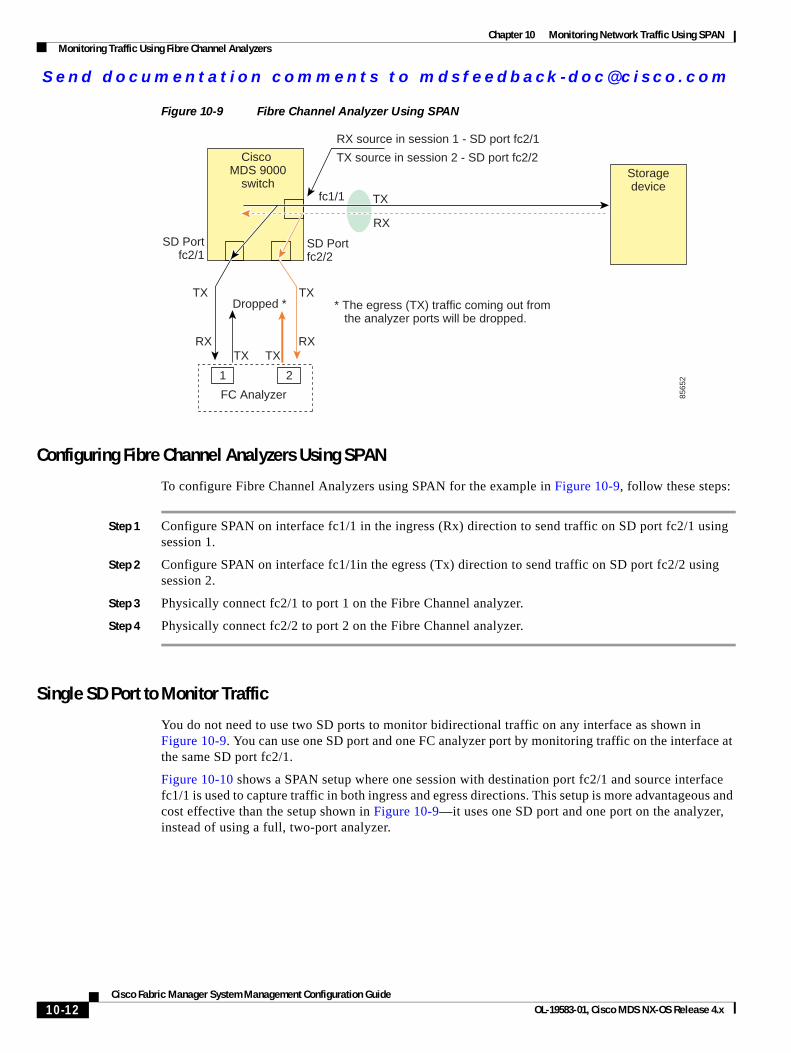
Send documenta t ion comments to mdsfeedback -doc@c i sco .com
Chapter 10 Monitoring Network Traffic Using SPANMonitoring Traffic Using Fibre Channel Analyzers
Figure 10-9 Fibre Channel Analyzer Using SPAN
Configuring Fibre Channel Analyzers Using SPAN
To configure Fibre Channel Analyzers using SPAN for the example in Figure 10-9, follow these steps:
Step 1 Configure SPAN on interface fc1/1 in the ingress (Rx) direction to send traffic on SD port fc2/1 using session 1.
Step 2 Configure SPAN on interface fc1/1in the egress (Tx) direction to send traffic on SD port fc2/2 using session 2.
Step 3 Physically connect fc2/1 to port 1 on the Fibre Channel analyzer.
Step 4 Physically connect fc2/2 to port 2 on the Fibre Channel analyzer.
Single SD Port to Monitor Traffic
You do not need to use two SD ports to monitor bidirectional traffic on any interface as shown in Figure 10-9. You can use one SD port and one FC analyzer port by monitoring traffic on the interface at the same SD port fc2/1.
Figure 10-10 shows a SPAN setup where one session with destination port fc2/1 and source interface fc1/1 is used to capture traffic in both ingress and egress directions. This setup is more advantageous and cost effective than the setup shown in Figure 10-9—it uses one SD port and one port on the analyzer, instead of using a full, two-port analyzer.
Cisco MDS 9000
switchfc1/1
RX
RXRX
TX
TXTX
1 2
FC Analyzer
* The egress (TX) traffic coming out from the analyzer ports will be dropped.
8565
2
Dropped *
SD Portfc2/1
SD Portfc2/2
RX source in session 1 - SD port fc2/1
TX source in session 2 - SD port fc2/2
TXTX
Storagedevice
10-12Cisco Fabric Manager System Management Configuration Guide
OL-19583-01, Cisco MDS NX-OS Release 4.x
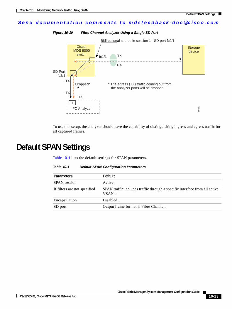
Send documenta t ion comments to mdsfeedback -doc@c i sco .com
Chapter 10 Monitoring Network Traffic Using SPANDefault SPAN Settings
Figure 10-10 Fibre Channel Analyzer Using a Single SD Port
To use this setup, the analyzer should have the capability of distinguishing ingress and egress traffic for all captured frames.
Default SPAN SettingsTable 10-1 lists the default settings for SPAN parameters.
Cisco MDS 9000
switchfc1/1
RX
TX
TX
TX
TX
8565
3
Dropped* * The egress (TX) traffic coming out from the analyzer ports will be dropped.
SD Portfc2/1
Bidirectional source in session 1 - SD port fc2/1
1
FC Analyzer
Storagedevice
Table 10-1 Default SPAN Configuration Parameters
Parameters Default
SPAN session Active.
If filters are not specified SPAN traffic includes traffic through a specific interface from all active VSANs.
Encapsulation Disabled.
SD port Output frame format is Fibre Channel.
10-13Cisco Fabric Manager System Management Configuration Guide
OL-19583-01, Cisco MDS NX-OS Release 4.x

Send documenta t ion comments to mdsfeedback -doc@c i sco .com
Chapter 10 Monitoring Network Traffic Using SPANDefault SPAN Settings
10-14Cisco Fabric Manager System Management Configuration Guide
OL-19583-01, Cisco MDS NX-OS Release 4.x
Send documenta t ion comments to mdsfeedback -doc@c i sco .com
Cisco Fabric OL-19583-01, Cisco MDS NX-OS Release 4.x
C H A P T E R 11
Configuring Fabric Configuration ServerThis chapter describes the Fabric Configuration Server (FCS) feature provided in the Cisco MDS 9000 Family of directors and switches. It includes the following sections:
• About FCS, page 11-1
• Displaying FCS Discovery, page 11-3
• Displaying FCS Elements, page 11-3
• Creating an FCS Platform, page 11-4
• Displaying FCS Fabric Ports, page 11-5
• Default Settings, page 11-6
About FCSThe Fabric Configuration Server (FCS) provides discovery of topology attributes and maintains a repository of configuration information of fabric elements. A management application is usually connected to the FCS on the switch through an N port. The FCS views the entire fabric based on the following objects:
• Interconnect element (IE) object—Each switch in the fabric corresponds to an IE object. One or more IE objects form a fabric.
• Port object—Each physical port in an IE corresponds to a port object. This includes the switch ports (xE, Fx, and TL ports) and their attached Nx ports.
• Platform object—A set of nodes may be defined as a platform object to make it a single manageable entity. These nodes are end-devices (host systems, storage subsystems) attached to the fabric. Platform objects reside at the edge switches of the fabric.
Each object has its own set of attributes and values. A null value may also be defined for some attributes.
In the Cisco MDS 9000 Family switch environment, multiple VSANs constitute a fabric, where one instance of the FCS is present per VSAN.
As of Cisco NX-OS Release 4.1(1), FCS supports the discovery of virtual devices. The fcs virtual-device-add command, issued in FCS configuration submode, allows you to discover virtual devices in a particular VSAN or in all VSANs. The devices that are zoned for IVR must be discovered with this command and have request domain_ID (RDI) enabled, before activating the IVR zone set.
11-1Manager System Management Configuration Guide
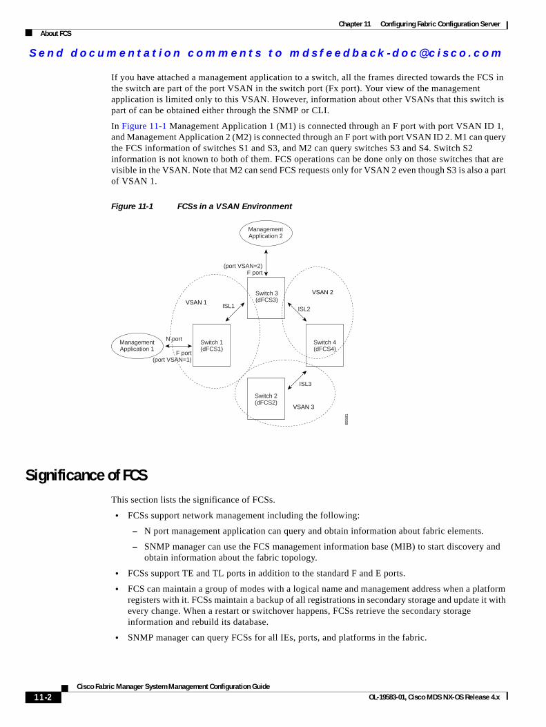
Send documenta t ion comments to mdsfeedback -doc@c i sco .com
Chapter 11 Configuring Fabric Configuration ServerAbout FCS
If you have attached a management application to a switch, all the frames directed towards the FCS in the switch are part of the port VSAN in the switch port (Fx port). Your view of the management application is limited only to this VSAN. However, information about other VSANs that this switch is part of can be obtained either through the SNMP or CLI.
In Figure 11-1 Management Application 1 (M1) is connected through an F port with port VSAN ID 1, and Management Application 2 (M2) is connected through an F port with port VSAN ID 2. M1 can query the FCS information of switches S1 and S3, and M2 can query switches S3 and S4. Switch S2 information is not known to both of them. FCS operations can be done only on those switches that are visible in the VSAN. Note that M2 can send FCS requests only for VSAN 2 even though S3 is also a part of VSAN 1.
Figure 11-1 FCSs in a VSAN Environment
Significance of FCS This section lists the significance of FCSs.
• FCSs support network management including the following:
– N port management application can query and obtain information about fabric elements.
– SNMP manager can use the FCS management information base (MIB) to start discovery and obtain information about the fabric topology.
• FCSs support TE and TL ports in addition to the standard F and E ports.
• FCS can maintain a group of modes with a logical name and management address when a platform registers with it. FCSs maintain a backup of all registrations in secondary storage and update it with every change. When a restart or switchover happens, FCSs retrieve the secondary storage information and rebuild its database.
• SNMP manager can query FCSs for all IEs, ports, and platforms in the fabric.
ManagementApplication 1
Switch 1(dFCS1)
ManagementApplication 2
Switch 4(dFCS4)
Switch 3(dFCS3)
Switch 2(dFCS2)
ISL1 ISL2
ISL3
F port(port VSAN=1)
(port VSAN=2)F port
VSAN 3
VSAN 2
VSAN 1
8558
1
N port
11-2Cisco Fabric Manager System Management Configuration Guide
OL-19583-01, Cisco MDS NX-OS Release 4.x
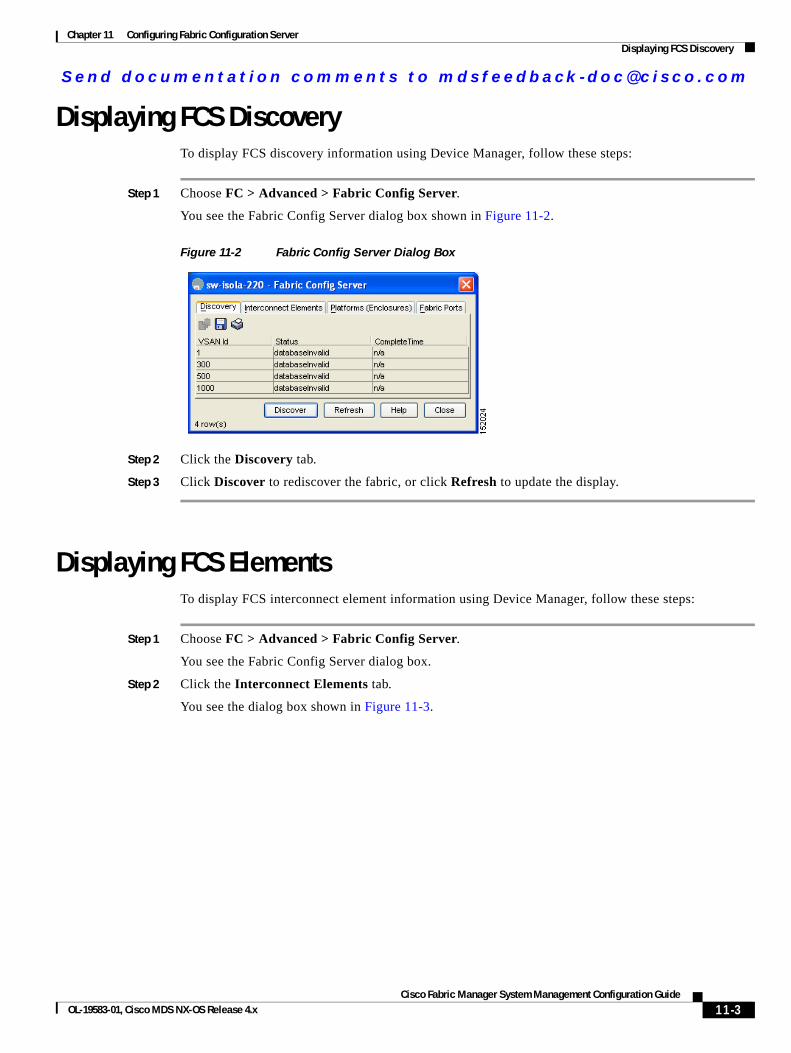
Send documenta t ion comments to mdsfeedback -doc@c i sco .com
Chapter 11 Configuring Fabric Configuration ServerDisplaying FCS Discovery
Displaying FCS DiscoveryTo display FCS discovery information using Device Manager, follow these steps:
Step 1 Choose FC > Advanced > Fabric Config Server.
You see the Fabric Config Server dialog box shown in Figure 11-2.
Figure 11-2 Fabric Config Server Dialog Box
Step 2 Click the Discovery tab.
Step 3 Click Discover to rediscover the fabric, or click Refresh to update the display.
Displaying FCS ElementsTo display FCS interconnect element information using Device Manager, follow these steps:
Step 1 Choose FC > Advanced > Fabric Config Server.
You see the Fabric Config Server dialog box.
Step 2 Click the Interconnect Elements tab.
You see the dialog box shown in Figure 11-3.
11-3Cisco Fabric Manager System Management Configuration Guide
OL-19583-01, Cisco MDS NX-OS Release 4.x
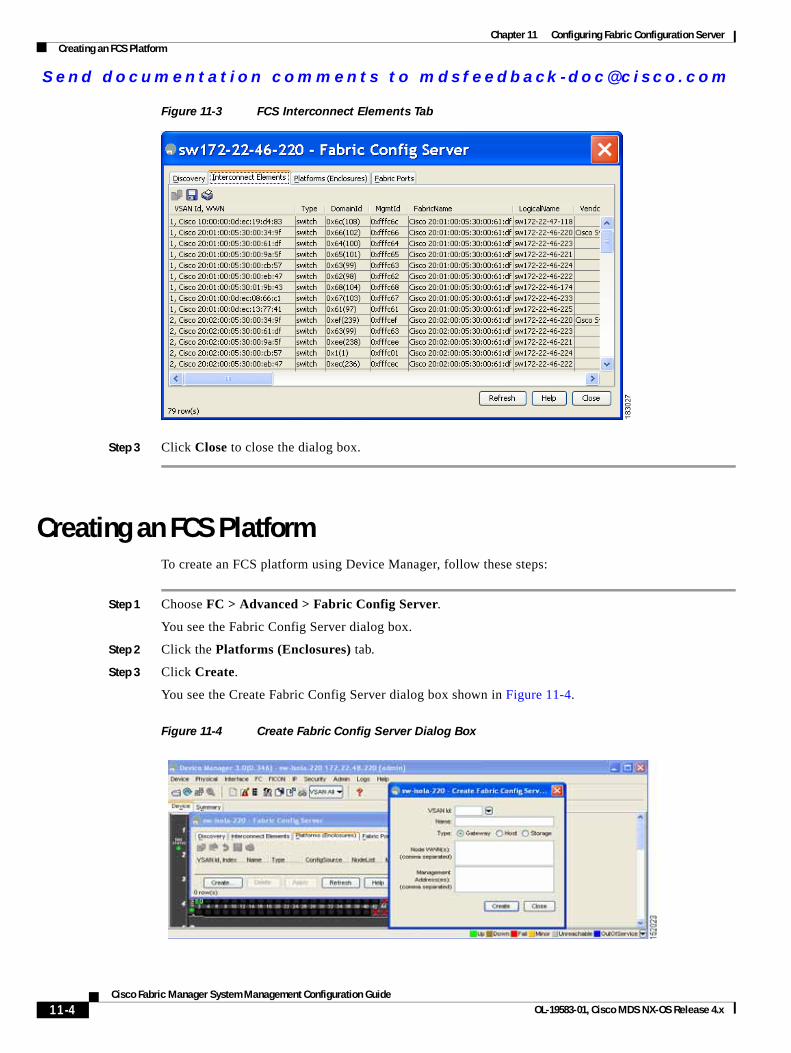
Send documenta t ion comments to mdsfeedback -doc@c i sco .com
Chapter 11 Configuring Fabric Configuration ServerCreating an FCS Platform
Figure 11-3 FCS Interconnect Elements Tab
Step 3 Click Close to close the dialog box.
Creating an FCS PlatformTo create an FCS platform using Device Manager, follow these steps:
Step 1 Choose FC > Advanced > Fabric Config Server.
You see the Fabric Config Server dialog box.
Step 2 Click the Platforms (Enclosures) tab.
Step 3 Click Create.
You see the Create Fabric Config Server dialog box shown in Figure 11-4.
Figure 11-4 Create Fabric Config Server Dialog Box
11-4Cisco Fabric Manager System Management Configuration Guide
OL-19583-01, Cisco MDS NX-OS Release 4.x
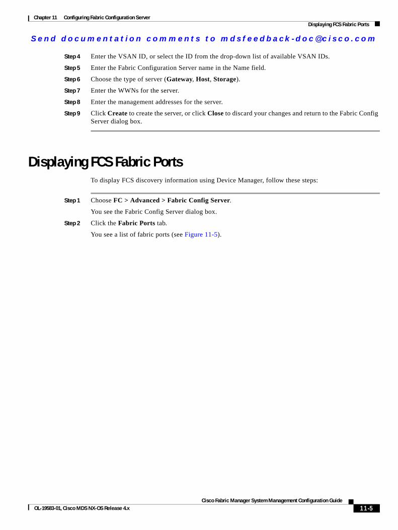
Send documenta t ion comments to mdsfeedback -doc@c i sco .com
Chapter 11 Configuring Fabric Configuration ServerDisplaying FCS Fabric Ports
Step 4 Enter the VSAN ID, or select the ID from the drop-down list of available VSAN IDs.
Step 5 Enter the Fabric Configuration Server name in the Name field.
Step 6 Choose the type of server (Gateway, Host, Storage).
Step 7 Enter the WWNs for the server.
Step 8 Enter the management addresses for the server.
Step 9 Click Create to create the server, or click Close to discard your changes and return to the Fabric Config Server dialog box.
Displaying FCS Fabric PortsTo display FCS discovery information using Device Manager, follow these steps:
Step 1 Choose FC > Advanced > Fabric Config Server.
You see the Fabric Config Server dialog box.
Step 2 Click the Fabric Ports tab.
You see a list of fabric ports (see Figure 11-5).
11-5Cisco Fabric Manager System Management Configuration Guide
OL-19583-01, Cisco MDS NX-OS Release 4.x
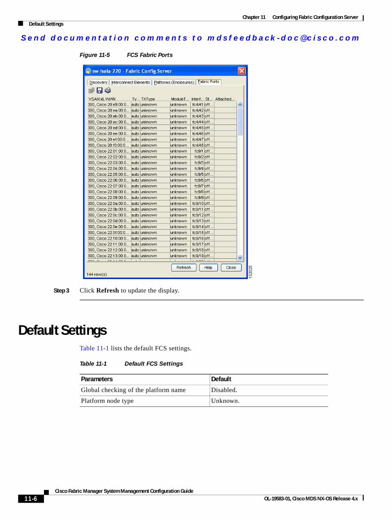
Send documenta t ion comments to mdsfeedback -doc@c i sco .com
Chapter 11 Configuring Fabric Configuration ServerDefault Settings
Figure 11-5 FCS Fabric Ports
Step 3 Click Refresh to update the display.
Default SettingsTable 11-1 lists the default FCS settings.
Table 11-1 Default FCS Settings
Parameters Default
Global checking of the platform name Disabled.
Platform node type Unknown.
11-6Cisco Fabric Manager System Management Configuration Guide
OL-19583-01, Cisco MDS NX-OS Release 4.x
Send documenta t ion comments to mdsfeedback -doc@c i sco .com
Cisco Fabric OL-19583-01, Cisco MDS NX-OS Release 4.x
I N D E X
Numerics
32-port switching modules
SPAN guidelines 10-6
A
AES encryption
description 7-4
SNMP support 7-4
AutoNotify
description 4-5
B
build fabric frames
description 9-3
C
Call Home
alert groups 4-9 to 4-12
AutoNotify feature 4-5
CFS support 2-2
configuration distribution 4-18
configuring 4-5 to 4-19
configuring e-mail options 4-14
contact information 4-6
database merge guidelines 4-19
default settings 4-39
description 4-1
destination profiles 4-8 to 4-9
duplicate message throttle 4-16
enabling 4-17
features 4-2
inventory notifications 4-15
message format options 4-2
RMON-based alerts 4-13
syslog-based alerts 4-12
testing communications 4-19
Call Home alert groups
configuring 4-9
customizing messages 4-10
description 4-9
Call Home destination profiles
attributes 4-8
description 4-8
Call Home messages
configuring levels 4-12
format options 4-2
Call Home notifications
full-txt format for syslog 4-23
XML format for RMON 4-27
XML format for syslog 4-23
CFS
application requirements 2-5
default settings 2-23
description 2-1 to 2-4
disabling on a switch 2-4
displaying configuration information 2-9
distribution modes 2-4
distribution over IP 2-10
distribution scopes 2-3
enabling on a switch 2-4
example configuration using Device Manager 2-23
example configuration using Fabric Manager 2-20
IN-1Manager System Management Configuration Guide
Send documenta t ion comments to mdsfeedback -doc@c i sco .com
Index
feature description 2-2
merge support 2-9
merge support (procedure) 2-22
protocol description 2-3
SAN-OS features supported 2-2
saving configurations 2-8
CFS applications
clearing session locks 2-8
committing changes 2-7
discarding changes 2-8
enabling 2-5
enabling (procedure) 2-6
fabric locking 2-6
CFS over IP
configuring static IP peers 2-11
default settings 2-23
description 2-10
CFS regions
assigning features 2-17
creating 2-17
deleting 2-19
description 2-16
moving a feature 2-18
removing a feature 2-19
usisng Fabric Manager 2-17
Cisco Fabric Service. See CFS
command scheduler
configuring 5-2
default settings 5-10
defining jobs 5-4
deleting jobs 5-6
description 5-1
enabling 5-3
execution logs 5-9
specifying schedules 5-6 to 5-9
verifying execution status 5-9
See also execution logs; jobs; schedules
console logging
configuring 3-4
IN-2Cisco Fabric Manager System Management Configuration Guide
console sessions
message logging severity levels 3-4
Contiguous Domain ID Assignments
About 9-17
contract IDs
description 4-32
core files
clearing directory 6-4
displaying information 6-3
D
device aliases
CFS support 2-2
device IDs
Call Home format 4-33
Device Manager
viewing system messages 3-10
documentation
related documents i-xv
domain ID
CFS support 2-2
domain IDs
allowed lists 9-13
configuring allowed lists 9-13
configuring CFS distribution 9-14 to 9-17
contiguous assignments 9-17
description 9-10
distributing 9-2
enabling contiguous assignments 9-17
preferred 9-12
static 9-12
DPVM
CFS support 2-2
E
e-mail addresses
OL-19583-01, Cisco MDS NX-OS Release 4.x
Send documenta t ion comments to mdsfeedback -doc@c i sco .com
Index
assigning for Call Home 4-7
e-mail notifications
Call Home 4-1
E ports
FCS support 11-1
SPAN sources 10-3
execution logs
clearing log files 5-10
configuring 5-10
description 5-9
displaying configuration 5-10
displaying log file contents 5-10
external loopback tests
description 6-6
performing 6-6
F
Fabric Configuration Server. See FCS
Fabric Configuration Servers. See FCSs
Fabric Manager Web Server
viewing system messages 3-10
fabric reconfiguration
fcdomain phase 9-2
fabrics
See also build fabric frames
fabrics. See RCFs; build fabric frames
FCC
logging facility 3-2
fcdomains
autoreconfigured merged fabrics 9-9
configuring CFS distribution 9-14 to 9-17
default settings 9-23
description 9-2
disabling 9-7
domain IDs 9-10
dsiplaying statistics 9-22
enabling 9-7
enabling autoreconfiguration 9-9
CiscOL-19583-01, Cisco MDS NX-OS Release 4.x
incoming RCFs 9-8
initiation 9-7
restarts 9-3
switch priorities 9-6
FC IDs
allocating 9-2
description 9-17
persistent 9-18 to ??
FCIP interfaces
SPAN sources 10-3
FCS
description 11-1
logging facility 3-2
significance 11-2
FCSs
default settings 11-6
description 11-1
displaying information 11-3 to ??
fctimers
CFS support 2-2
Fibre Channel Analyzers
configuring using SPAN 10-12
Fibre Channel analyzers
monitoring without SPAN 10-10
Fibre Channel domains. See fcdomains
Fibre Channel traffic
SPAN sources 10-3
File Transfer Protocol. See FTP
FLOGI
logging facility 3-2
FL ports
persistent FC IDs 9-18
SPAN sources 10-3
F ports
SPAN sources 10-3
FTP
logging facility 3-2
Fx ports
FCS 11-1
IN-3o Fabric Manager System Management Configuration Guide
Send documenta t ion comments to mdsfeedback -doc@c i sco .com
Index
FCS support 11-1
H
HBA ports
configuring area FCIDs 9-20
I
IDs
contract IDs 4-32
serial IDs 4-33, 4-34, 4-36, 4-38
server IDs 4-34
site IDs 4-32
internal loopback tests
description 6-6
performing 6-6
IPFC
logging facility 3-2
IPS ports
SPAN sources 10-3
iSCSI interfaces
SPAN sources 10-3
iSLB
CFS support 2-2
iSNS
CFS support 2-2
IVR topologies
CFS support 2-2
J
jobs
assigning to a schedule 5-6, 5-7
command scheduler 5-1
defining 5-4
deleting 5-6
removing from a schedule 5-8
IN-4Cisco Fabric Manager System Management Configuration Guide
verifying definition 5-5
L
log files
configuring 3-6
default names 3-6
description 6-3
sizes 3-6
logging
default settings 3-10
disabling 3-3
enabling 3-3
message severity levels 3-3
logs
RMON 8-14
SNMP events 7-13
loopback tests
external 6-6
M
merged fabrics
autoreconfigured 9-9
modules
configuring message logging 3-5
monitoring traffic
SPAN 10-6
N
NTP
CFS support 2-2
logging facility 3-2
Nx ports
FCS support 11-1
See also N ports; NL ports
OL-19583-01, Cisco MDS NX-OS Release 4.x
Send documenta t ion comments to mdsfeedback -doc@c i sco .com
Index
O
OHMS
description 6-5
P
persistent FC IDs
configuring 9-19
description 9-18
enabling 9-18
purging 9-21
PortChannels
logging facility 3-2
SPAN sources 10-3
port security
CFS support 2-2
principal switches
assigning domain ID 9-11
Q
QoS
logging facilities 3-2
R
RADIUS
CFS support 2-2
RCFs
description 9-3
incoming 9-8
rejecting incoming 9-8
reconfigure fabric frames. See RCFs
RMON
alarms 8-1
configuring using Threshold Manager 8-1
default settings 8-15
CiscOL-19583-01, Cisco MDS NX-OS Release 4.x
defining an event (procedure) 8-12
description 8-1
enabling alarms 8-2
enabling alarms (procedure) 8-9
events 8-1
setting alarms (procedure) 8-3, 8-4, 8-6
viewing alarms (procedure) 8-13
viewing logs (procedure) 8-14
roles
CFS support 2-2
RSCNs
logging facility 3-2
RSCN timers
CFS support 2-2
S
scheduler. See command scheduler
schedules
assigning jobs 5-6, 5-7
command scheduler 5-1
deleting 5-8
deleting schedule time 5-9
one-time 5-7
periodic 5-6
specifying 5-6 to 5-9
specifying execution time 5-6
verifying configuration 5-8
SCSI flow services
CFS support 2-2
SD ports
bidirectional traffic 10-12
characteristics 10-5
configuring for SPAN monitoring 10-6
monitoring bidirectional traffic 10-12
serial IDs
description 4-33
site IDs
description 4-32
IN-5o Fabric Manager System Management Configuration Guide
Send documenta t ion comments to mdsfeedback -doc@c i sco .com
Index
SMTP
assigning contact names 4-8
server address 4-14
SNMP
access control 7-2
access groups 7-3
adding communities 7-7
assigning contact 7-2
assigning location 7-2
configuring event security 7-13
configuring event security (procedure) 7-13
configuring notification target users 7-12
creating users 7-4
default settings 7-14
deleting communities 7-7
deleting community strings (procedure) 7-7
enabling SNMP notifications 7-9
encryption-based privacy 7-4
group-based access 7-3
modifying users 7-4
read-only access 7-7
read-write access 7-7
server contact name 4-5
users with multiple roles (procedure) 7-6
user synchronization with CLI 7-3
Version 3 security features 7-1, 7-2
versions supported 7-1
viewing event log 7-13
See also SNMPv1; SNMPv2c; SNMPv3
SNMP manager
FCS 11-2
SNMPv1
community strings 7-2
description 7-2
See also SNMP
SNMPv2
community strings 7-2
SNMPv2c
configuring notifications 7-8
IN-6Cisco Fabric Manager System Management Configuration Guide
description 7-2
See also SNMP
SNMPv3
assigning multiple roles 7-6
CLI user managementSNMPv3
AAA integration 7-2
configuring notifications 7-9
description 7-2
enforcing message encryption 7-5
restricting switch access 7-3
security features 7-2
See also SNMP 7-2
source IDs
Call Home event format 4-33
SPAN
configuration guidelines 10-6
configuring 10-6 to 10-10
configuring Fibre Channel analyzers 10-11
conversion behavior 10-9
default settings 10-13
description 10-2
egress sources 10-2
Fibre Channel analyzers 10-10
filters 10-5
monitoring traffic 10-2
SD ports 10-5
sessions 10-5
sources 10-4
sources for monitoring 10-2
VSAN sources 10-4
SPAN filters
description 10-5
guidelines 10-5
SPAN sessions
deleting using Device Manager 10-9
description 10-5
VSAN filters 10-5
SPAN sources
editing with Device Manager 10-8
OL-19583-01, Cisco MDS NX-OS Release 4.x
Send documenta t ion comments to mdsfeedback -doc@c i sco .com
Index
egress 10-2
ingress 10-2
interface types 10-3
IPS ports 10-3
VSANs configuration guidelines 10-4
SSH sessions
message logging 3-3
Switched Port Analyzer. See SPAN
switch priorities
configuring 9-7
default 9-6
description 9-6
syslog
CFS support 2-2
syslog servers
verifying using Fabric Manager Web Services 3-9
system health
default settings 6-6
system messages
configuring log files 3-6
configuring logging 3-3
configuring logging servers 3-7
default settings 3-10
monitoring 3-1
severity levels 3-3
viewing from Device Manager 3-10
viewing from Fabric Manager Web Server 3-10
system processes
displaying 6-1
T
TACACS+
CFS support 2-2
Telnet sessions
message logging 3-3
TE ports
FCS support 11-1, 11-2
SPAN sources 10-3
CiscOL-19583-01, Cisco MDS NX-OS Release 4.x
Threshold Manager
configuring RMON 8-1
TL ports
FCS 11-1, 11-2
FCS support 11-1, 11-2
logging facility 3-2
SPAN sources 10-3
U
unique area FC IDs
configuring 9-20
description 9-20
users
CFS support 2-2
SNMP support 7-4
V
VRRP
logging facility 3-2
VSANs
allowed list 10-4
domain ID automatic reconfiguration 9-9
FCS 11-1
FCS support 11-1
SPAN filters 10-5
SPAN source 10-4
SPAN sources 10-4
Z
zones
logging facility 3-3
IN-7o Fabric Manager System Management Configuration Guide

Send documenta t ion comments to mdsfeedback -doc@c i sco .com
Index
IN-8Cisco Fabric Manager System Management Configuration Guide
OL-19583-01, Cisco MDS NX-OS Release 4.x