Embed Size (px)
Citation preview

Cisco APIC Troubleshooting Guide, Release 4.2(x)First Published: 2019-09-08
Americas HeadquartersCisco Systems, Inc.170 West Tasman DriveSan Jose, CA 95134-1706USAhttp://www.cisco.comTel: 408 526-4000
800 553-NETS (6387)Fax: 408 527-0883

© 2019 Cisco Systems, Inc. All rights reserved.

C O N T E N T S
Preface xiiiP R E F A C E
Audience xiii
Document Conventions xiii
Related Documentation xv
Documentation Feedback xv
New and Changed 1C H A P T E R 1
New and Changed Information 1
Troubleshooting Overview 3C H A P T E R 2
Troubleshooting Basics 4
Troubleshooting APIC Crash Scenarios 7C H A P T E R 3
Cisco APIC Cluster Failure Scenarios 7
Cluster Troubleshooting Scenarios 7
Cluster Faults 10
Troubleshooting Application Centric Infrastructure Crash Scenarios 11
Troubleshooting Fabric Node and Process Crash 11
APIC Process Crash Verification and Restart 13
Troubleshooting an APIC Process Crash 15
Recovering Cisco APIC Passwords and Accessing Special Logins 17C H A P T E R 4
Recovering the APIC Password 17
Using the Rescue-user Account to Erase the Cisco APIC Configuration Using the NX-OS Style CLI18
Using the Fallback Login Domain to Log in to the Local Database 18
Cisco APIC Troubleshooting Guide, Release 4.2(x)iii

Cisco APIC Troubleshooting Operations 19C H A P T E R 5
Shutting Down the APIC System 19
Shutting Down the APIC Controller Using the GUI 19
Using the APIC Reload Option Using the GUI 20
Controlling the LED Locator Using the GUI 21
Using the Cisco APIC Troubleshooting Tools 23C H A P T E R 6
Enabling and Viewing ACL Contract and Deny Logs 24
About ACL Contract Permit and Deny Logs 24
Enabling ACL Contract Permit and Deny Logging Using the GUI 25
Enabling ACL Contract Permit Logging Using the NX-OS CLI 26
Enabling ACL Contract Permit Logging Using the REST API 26
Enabling Taboo Contract Deny Logging Using the GUI 27
Enabling Taboo Contract Deny Logging Using the NX-OS CLI 27
Enabling Taboo Contract Deny Logging Using the REST API 28
Viewing ACL Permit and Deny Logs Using the GUI 28
Viewing ACL Permit and Deny Logs Using the REST API 29
Viewing ACL Permit and Deny Logs Using the NX-OS CLI 30
Using Atomic Counter Policies for Gathering Statistics 32
Atomic Counters 32
Atomic Counters Guidelines and Restrictions 33
Configuring Atomic Counters 34
Enabling Atomic Counters 34
Troubleshooting Using Atomic Counters with the REST API 35
Enabling and Viewing Digital Optical Monitoring Statistics 36
Enabling Digital Optical Monitoring Using the GUI 36
Enabling Digital Optical Monitoring Using the REST API 37
Viewing Digital Optical Monitoring Statistics With the GUI 38
Troubleshooting Using Digital Optical Monitoring With the REST API 38
Viewing and Understanding Health Scores 39
Health Score Types 39
Filtering by Health Score 39
Viewing Tenant Health 39
Cisco APIC Troubleshooting Guide, Release 4.2(x)iv
Contents

Viewing Fabric Health 40
Viewing MO Health in Visore 40
Debugging Health Scores Using Logs 40
Viewing Faults 41
Enabling Port Tracking for Uplink Failure Detection 42
Port Tracking Policy for Uplink Failure Detection 42
Port Tracking Using the GUI 42
Port Tracking Using the NX-OS CLI 43
Port Tracking Using the REST API 43
Configuring SNMP for Monitoring and Managing Devices 44
About SNMP 44
SNMP Access Support in ACI 44
Configuring the SNMP Policy Using the GUI 45
Configuring an SNMP Trap Destination Using the GUI 46
Configuring an SNMP Trap Source Using the GUI 47
Monitoring the System Using SNMP 47
Configuring SPAN for Traffic Monitoring 48
About SPAN 48
SPAN Guidelines and Restrictions 49
Configuring SPAN Using the GUI 51
Configuring a Tenant SPAN Session Using the Cisco APIC GUI 51
Configuring a SPAN Filter Group Using the APIC GUI 51
Configuring an Access SPAN Policy Using the Cisco APIC GUI 52
Configuring a Fabric SPAN Policy Using the Cisco APIC GUI 53
Configuring a Layer 3 EPG SPAN Session for External Access Using the APIC GUI 54
Configuring a Destination Group for an Access SPAN Policy Using the Cisco APIC GUI 55
Configuring a Destination Group for a Fabric SPAN Policy Using the Cisco APIC GUI 55
Configuring SPAN Using the NX-OS Style CLI 56
Configuring Local SPAN in Access Mode 56
Configuring a SPAN Filter Group 58
Associating a SPAN Filter Group 60
Configuring ERSPAN in Access Mode 62
Configuring ERSPAN in Fabric Mode 65
Configuring ERSPAN in Tenant Mode 68
Cisco APIC Troubleshooting Guide, Release 4.2(x)v
Contents

Configuring a Global SPAN-On-Drop Session Using the CLI 70
Configuring SPAN Using the REST API 71
Configuring a Fabric Destination Group for an ERSPAN Destination Using the REST API 71
Configuring a Global Drop Source Group Using the REST API 72
Configuring a Leaf Port as a SPAN Destination Using the REST API 72
Configuring a SPAN Access Source Group Using the REST API 72
Configuring a SPAN Fabric Source Group Using the REST API 73
Configuring an Access Destination Group for an ERSPAN Destination Using the REST API 73
Using Statistics 74
Viewing Statistics in the GUI 74
Switch Statistics Commands 75
Managing Statistics Thresholds Using the GUI 76
Statistics Troubleshooting Scenarios 76
Statistics Cleanup 78
Specifying Syslog Sources and Destinations 79
About Syslog 79
Creating a Syslog Destination and Destination Group 80
Creating a Syslog Source 80
Enabling Syslog to Display in NX-OS CLI Format, Using the REST API 81
Discovering Paths and Testing Connectivity with Traceroute 83
About Traceroute 83
About Windows and Linux Traceroute 83
Traceroute Guidelines and Restrictions 85
Performing a Traceroute Between Endpoints 85
Using the Troubleshooting Wizard 86
Getting Started with the Troubleshooting Wizard 86
Generating Troubleshooting Reports 88
Topology in the Troubleshooting Wizard 89
Using the Faults Troubleshooting Screen 90
Using the Drop/Statistics Troubleshooting Screen 92
Using the Contracts Troubleshooting Screen 93
Using the Events Troubleshooting Screen 94
Using the Traceroute Troubleshooting Screen 94
Using the Atomic Counter Troubleshooting Screen 96
Cisco APIC Troubleshooting Guide, Release 4.2(x)vi
Contents

Using the SPAN Troubleshooting Screen 96
Creating a SPAN Session Using the Cisco APIC Troubleshooting CLI 97
L4 - L7 Services Validated Scenarios 98
List of APIs for Endpoint to Endpoint Connections 98
interactive API 99
createsession API 100
modifysession API 101
atomiccounter API 101
traceroute API 102
span API 102
generatereport API 103
schedulereport API 104
getreportstatus API 104
getreportslist API 105
getsessionslist API 105
getsessiondetail API 105
deletesession API 105
clearreports API 106
contracts API 107
List of APIs for Endpoint to Layer 3 External Connections 107
interactive API 107
createsession API 108
modifysession API 109
atomiccounter API 110
traceroute API 111
span API 111
generatereport API 112
schedulereport API 113
getreportstatus API 114
getreportslist API 114
getsessionslist API 115
getsessiondetail API 116
deletesession API 117
clearreports API 117
Cisco APIC Troubleshooting Guide, Release 4.2(x)vii
Contents

contracts API 117
ratelimit API 118
13ext API 119
Checking for Configuration Synchronization Issues 119
Viewing User Activities 120
Accessing User Activities 120
Embedded Logic Analyzer Module 120
About the Embedded Logic Analyzer Module 120
Generating an ELAM Report in the Simplified Output for Modular Switches 121
Generating an ELAM Report in the Simplified Output for Fixed Form-Factor Switches 122
Troubleshooting Switch Discovery 123C H A P T E R 7
Troubleshooting Switch Discovery Issues 123
Manually Removing Disabled Interfaces and Decommissioned Switches from the GUI 127C H A P T E R 8
Manually Removing Disabled Interfaces and Decommissioned Switches from the GUI 127
Decommissioning and Recommissioning Switches 129C H A P T E R 9
Decommissioning and Recommissioning Switches 129
Troubleshooting Steps for Endpoint Connectivity Problems 131C H A P T E R 1 0
Troubleshooting Endpoint Connectivity 131
Inspecting Endpoint and Tunnel Interface Status 132
Inspecting the Endpoint Status 132
Inspecting the Tunnel Interface Status 132
Connecting an SFP Module 133
Troubleshooting EVPN Type-2 Route Advertisement 135C H A P T E R 1 1
Troubleshooting EVPN Type-2 Route Distribution to a DCIG 135
Performing a Rebuild of the Fabric 139C H A P T E R 1 2
Rebuilding the Fabric 139
Cisco APIC Troubleshooting Guide, Release 4.2(x)viii
Contents

Verifying IP-Based EPG Configurations 141C H A P T E R 1 3
Verifying IP-Based EPG Configurations Using the GUI 141
Verifying IP-EPG Configurations Using Switch Commands 142
Recovering a Disconnected Leaf 145C H A P T E R 1 4
Recovering a Disconnected Leaf Using the REST API 145
Troubleshooting a Loopback Failure 147C H A P T E R 1 5
Identifying a Failed Line Card 147
Determining Why a PIM Interface Was Not Created 149C H A P T E R 1 6
A PIM Interface Was Not Created For an L3Out Interface 149
A PIM Interface Was Not Created For a Multicast Tunnel Interface 150
A PIM Interface Was Not Created For a Multicast-Enabled Bridge Domain 150
Confirming the Port Security Installation 151C H A P T E R 1 7
Confirming Your Port Security Installation Using Visore 151
Confirming Your Hardware Port Security Installation Using the Cisco NX-OS CLI 151
Troubleshooting QoS Policies 155C H A P T E R 1 8
Troubleshooting Cisco APIC QoS Policies 155
Determining the Supported SSL Ciphers 157C H A P T E R 1 9
About SSL Ciphers 157
Determining the Supported SSL Ciphers Using the CLI 158
Removing Unwanted _ui_ Objects 159C H A P T E R 2 0
Removing Unwanted _ui_ Objects Using the REST API 160
Troubleshooting Multipod and Multi-Site Issues 161C H A P T E R 2 1
Troubleshooting Multi-Site and Multi-Pod 161
Cisco APIC Troubleshooting Guide, Release 4.2(x)ix
Contents

acidiag Command 163A P P E N D I X A
Configuring Export Policies for Troubleshooting 173A P P E N D I X B
About Exporting Files 173
File Export Guidelines and Restrictions 173
Configuring a Remote Location 174
Configuring a Remote Location Using the GUI 174
Configuring a Remote Location Using the REST API 174
Configuring a Remote Location Using the NX-OS Style CLI 174
Sending an On-Demand Tech Support File 175
Sending an On-Demand Tech Support File Using the GUI 175
Sending an On-Demand Tech Support File Using the REST API 176
Finding the Switch Inventory 177A P P E N D I X C
Finding Your Switch Inventory Using the GUI 177
Finding Your Switch Inventory Using the NX-OS CLI 177
Finding Your Switch Inventory Using the REST API 180
Cisco APIC Cluster Management 183A P P E N D I X D
Expanding the Cisco APIC Cluster 183
Contracting the Cisco APIC Cluster 183
Cluster Management Guidelines 184
Expanding the APIC Cluster Size 185
Reducing the APIC Cluster Size 185
Replacing Cisco APIC Controllers in the Cluster 186
Expanding the Cluster Examples 187
Expanding the APIC Cluster Using the GUI 187
Expanding the APIC Cluster Using the REST API 188
Contracting the Cluster Examples 188
Contracting the APIC Cluster Using the GUI 188
Contracting the APIC Cluster Using the REST API 189
Commissioning and Decommissioning Cisco APIC Controllers 189
Commissioning a Cisco APIC Controller in the Cluster Using the GUI 189
Cisco APIC Troubleshooting Guide, Release 4.2(x)x
Contents

Decommissioning a Cisco APIC Controller in the Cluster Using the GUI 190
Replacing a Cisco APIC in a Cluster Using the CLI 191
Cisco APIC SSD Replacement 193A P P E N D I X E
Replacing the Solid-State Drive in Cisco APIC 193
Expected Output Errors 195A P P E N D I X F
Expected Output Errors 195
Viewing CRC Error Counters 197A P P E N D I X G
Viewing CRC and Stomped CRC Error Counters 197
Viewing CRC Errors Using the GUI 197
Viewing CRC Errors Using the CLI 198
Cisco APIC Troubleshooting Guide, Release 4.2(x)xi
Contents

Cisco APIC Troubleshooting Guide, Release 4.2(x)xii
Contents

Preface
This preface includes the following sections:
• Audience, on page xiii• Document Conventions, on page xiii• Related Documentation, on page xv• Documentation Feedback, on page xv
AudienceThis guide is intended for system and network engineers with a background in troubleshooting data systems,networks, and storage systems.
Document ConventionsCommand descriptions use the following conventions:
DescriptionConventionBold text indicates the commands and keywords that you enter literallyas shown.
bold
Italic text indicates arguments for which the user supplies the values.Italic
Square brackets enclose an optional element (keyword or argument).[x]
Square brackets enclosing keywords or arguments separated by a verticalbar indicate an optional choice.
[x | y]
Braces enclosing keywords or arguments separated by a vertical barindicate a required choice.
{x | y}
Nested set of square brackets or braces indicate optional or requiredchoices within optional or required elements. Braces and a vertical barwithin square brackets indicate a required choice within an optionalelement.
[x {y | z}]
Cisco APIC Troubleshooting Guide, Release 4.2(x)xiii

DescriptionConvention
Indicates a variable for which you supply values, in context where italicscannot be used.
variable
A nonquoted set of characters. Do not use quotation marks around thestring or the string will include the quotation marks.
string
Examples use the following conventions:
DescriptionConventionTerminal sessions and information the switch displays are in screen font.screen font
Information you must enter is in boldface screen font.boldface screen font
Arguments for which you supply values are in italic screen font.italic screen font
Nonprinting characters, such as passwords, are in angle brackets.< >
Default responses to system prompts are in square brackets.[ ]
An exclamation point (!) or a pound sign (#) at the beginning of a lineof code indicates a comment line.
!, #
This document uses the following conventions:
Means reader take note. Notes contain helpful suggestions or references to material not covered in the manual.Note
Means reader be careful. In this situation, you might do something that could result in equipment damage orloss of data.
Caution
IMPORTANT SAFETY INSTRUCTIONS
This warning symbol means danger. You are in a situation that could cause bodily injury. Before you workon any equipment, be aware of the hazards involved with electrical circuitry and be familiar with standardpractices for preventing accidents. Use the statement number provided at the end of each warning to locateits translation in the translated safety warnings that accompanied this device.
SAVE THESE INSTRUCTIONS
Warning
Cisco APIC Troubleshooting Guide, Release 4.2(x)xiv
PrefacePreface

Related DocumentationCisco Application Centric Infrastructure (ACI) Documentation
The ACI documentation is available at the following URL: http://www.cisco.com/c/en/us/support/cloud-systems-management/application-policy-infrastructure-controller-apic/tsd-products-support-series-home.html.
Cisco Application Centric Infrastructure (ACI) Simulator Documentation
The Cisco ACI Simulator documentation is available at http://www.cisco.com/c/en/us/support/cloud-systems-management/application-centric-infrastructure-simulator/tsd-products-support-series-home.html.
Cisco Nexus 9000 Series Switches Documentation
The Cisco Nexus 9000 Series Switches documentation is available at http://www.cisco.com/c/en/us/support/switches/nexus-9000-series-switches/tsd-products-support-series-home.html.
Cisco Application Virtual Switch Documentation
The Cisco Application Virtual Switch (AVS) documentation is available at http://www.cisco.com/c/en/us/support/switches/application-virtual-switch/tsd-products-support-series-home.html.
Cisco Application Centric Infrastructure (ACI) Integration with OpenStack Documentation
Cisco ACI integration with OpenStack documentation is available at http://www.cisco.com/c/en/us/support/cloud-systems-management/application-policy-infrastructure-controller-apic/tsd-products-support-series-home.html.
Documentation FeedbackTo provide technical feedback on this document, or to report an error or omission, please send your commentsto [email protected]. We appreciate your feedback.
Cisco APIC Troubleshooting Guide, Release 4.2(x)xv
PrefaceRelated Documentation

Cisco APIC Troubleshooting Guide, Release 4.2(x)xvi
PrefaceDocumentation Feedback

C H A P T E R 1New and Changed
• New and Changed Information, on page 1
New and Changed InformationThe following table provides an overview of the significant changes to this guide up to this current release.The table does not provide an exhaustive list of all changes made to the guide or of the new features up tothis release.
DescriptionFeatureCisco APIC Release Version
acidiag Command, on page 163A new avread command wasadded. This command provides thesame information as the acidiagavread command but in a tabularformat.
4.2(1)
Verifying the Cisco APIC ClusterUsing the CLI
The cluster_health command wasadded to verify the cluster health.
Troubleshooting Switch DiscoveryIssues, on page 123
The show discoveryissuescommand was added fortroubleshooting switch discoveryissues.
Generating an ELAMReport in theSimplified Output for FixedForm-Factor Switches, on page 122
Generating an ELAMReport in theSimplified Output for ModularSwitches, on page 121
This release adds an option to theEmbedded Logic AnalyzerModule(ELAM) tool that changes theoutput to a human-readable format,which enables you to find keyinformation quickly and moreefficiently. In addition,hexadecimal values have beenconverted to decimal values insome instances for improvedreadability. For backwardcompatibility, the existing usage ofELAM is kept intact.
Cisco APIC Troubleshooting Guide, Release 4.2(x)1

Cisco APIC Troubleshooting Guide, Release 4.2(x)2
New and ChangedNew and Changed Information

C H A P T E R 2Troubleshooting Overview
The chapters in this guide describe common troubleshooting tips for specific Cisco APIC features and provideinformation about monitoring tools you can use for troubleshooting problems.
The features, issues, and tasks covered in this guide are listed below.
• _ui_ Objects—Explains how to remove unwanted _ui_ objects caused bymaking changes with theBasicMode or the NX-OS CLI before using the Advanced Mode.
• acidiag—Explains how to use the acidiag command for troubleshooting operations on the Cisco APIC.
• Cisco APIC Cluster—Explains how to diagnose cluster faults and troubleshoot common cluster issues.For basic cluster management information, see the appendix of this guide.
• Cisco APIC Password Recovery and Emergency/Hidden Login Access—Explains how to recover apassword, how to access the rescue-user login to run troubleshooting commands, including erasing theconfiguration, and how to access a hidden login domain in case of a lockout.
• Cisco APIC Troubleshooting Operations—Explains how to gather information about your switchesand how perform troubleshooting operations such as shutting down the system, shutting down the CiscoAPIC controller, reloading the APIC controller, and turning on the LED locator.
• Cisco APIC Troubleshooting Tools—Explains how to use the Cisco APIC troubleshooting tools fordebugging, monitoring traffic, viewing user activity history, checking for delays in synchronizing thepolicy manager and the policy distributor, and detecting issues such as traffic drops, misrouting, blockedpaths, and uplink failures.
• Endpoint Connectivity—Explains how to troubleshoot endpoint connectivity using the Cisco APICtroubleshooting tools, such as traceroute, atomic counters, and SPAN, and how to connect an SFPmoduleto a new card.
Information about the Cisco APIC troubleshooting tools is located in the Usingthe Cisco APIC Troubleshooting Tools, on page 23 chapter.
Note
• EVPN Type-2 Host Routes—Provides verification steps for this feature.
• Export Policies—Enables you to export statistics, tech support collections, faults and events, and toprocess core files and debug data from the fabric to any external hosts in a variety of formats.
• Fabric Rebuild—Explains how to rebuild your fabric.
Cisco APIC Troubleshooting Guide, Release 4.2(x)3

• Identifying a Failed Line Card—Explains the procedure for identifying a line card that may have causeda loopback failure.
• IP-Based EPG—Explains how to verify that you have correctly configured an IP-based EPG using theCisco APIC GUI and using switch commands.
• Leaf Connectivity—Explains how to recover a disconnected leaf using the REST API.
• PIM Interfaces—Explains what to check when a PIM interface is not created for an L3Out, a multicasttunnel interface, or for a multicast-enabled bridge domain.
• Port Security—Explains how to confirm your port security hardware and software installations.
• Removing Disabled Interfaces and Decommissioned Switches—Explains how remove a disabled portentry in the GUI.
• Decommissioning and Recommissioning Switches—Explains how to decommission and recommissionnodes in a pod. A use case for this task would be to renumber the nodes in the pod in a more logical,scalable numbering convention.
• Cisco APIC SSD Replacement—Explains how remove an SSD in the GUI.
• QoS—Provides specific troubleshooting scenarios for this feature.
• SSL Ciphers—Explains how to determine if an SSL cipher is supported.
• Switch Inventory—Explains how to find the switch serial and model numbers. This helps TACtroubleshoot issues that you may experience.
• Expected Output Errors—Provides an example of expected output errors observed from the internalcounter interface of uplinks of the Cisco Nexus 93180YC-EX and ACI 93180YC-FX leaf switches inACI mode.
• Troubleshooting Basics, on page 4
Troubleshooting BasicsThe following are basic steps for troubleshooting:
Before you begin
• Familiarize yourself with the tools listed in Using the Cisco APIC Troubleshooting Tools, on page 23.
• Familiarize yourself with the Cisco APIC Troubleshooting Operations, on page 19.
• For issues with a specific feature, check the main contents of this guide for your feature. Troubleshootingtips are listed per-feature.
Step 1 Gather information that defines the specific symptoms.
In many cases, you can use the tools listed and described in the Using the Cisco APIC Troubleshooting Tools,on page 23 chapter to gather useful troubleshooting information.
Note
Step 2 Identify all potential problems that could be causing the symptoms.
Cisco APIC Troubleshooting Guide, Release 4.2(x)4
Troubleshooting OverviewTroubleshooting Basics

Step 3 Systematically eliminate each potential problem (from most likely to least likely) until the symptoms disappear.
This guide provides step-by-step instructions for confirming the installation and configuration of specificfeatures such as port security, endpoint connectivity, PIM, and IP-based EPGs. Following the instructions canhelp you to narrow down and resolve problems you are experiencing.
Note
Cisco APIC Troubleshooting Guide, Release 4.2(x)5
Troubleshooting OverviewTroubleshooting Basics

Cisco APIC Troubleshooting Guide, Release 4.2(x)6
Troubleshooting OverviewTroubleshooting Basics

C H A P T E R 3Troubleshooting APIC Crash Scenarios
This chapter contains information about various failure or crash scenarios and possible recovery solutions.
This chapter contains the following sections:
• Cisco APIC Cluster Failure Scenarios, on page 7• Troubleshooting Application Centric Infrastructure Crash Scenarios, on page 11
Cisco APIC Cluster Failure Scenarios
Cluster Troubleshooting ScenariosThe following table summarizes common cluster troubleshooting scenarios for the Cisco APIC.
SolutionProblem
There are two available solutions:
• Leave the target size and replace the APIC.
• Reduce the cluster size to 4, decommission controller 5, and recommissionit as APIC 2.The target size remains 4, and the operational size is 4 whenthe reconfigured APIC becomes active.
You can add a replacement APIC to the cluster and expand the targetand operational size. For instructions on how to add a newAPIC, referto theCisco APIC Management, Installation, Upgrade, and DowngradeGuide..
Note
An APIC node failswithin the cluster. Forexample, node 2 of acluster of 5 APICs fails.
Cisco APIC Troubleshooting Guide, Release 4.2(x)7

SolutionProblem
Use the following commands to check for an infra (infrastructure) VLANmismatch:
• cat /mit/sys/lldp/inst/if-\[eth1--1\]/ctrlradj/summary—Displays the VLANconfigured on the leaf switch.
• cat /mit/sys/lldp/inst/if-\[eth1--1\]/ctrlradj/summary—Displays the infra(infrastructure) VLANs advertised by connected APICs.
If the output of these commands shows different VLANs, the new APIC is notconfigured with the correct infra (infrastructure) VLAN. To correct this issue,follow these steps:
• Log in to the APIC using rescue-user.
Admin credentials do not work because the APIC is not part ofthe fabric.
Note
• Erase the configuration and reboot the APIC using the acidiag touch setupcommand.
• Reconfigure the APIC. Verify that the fabric name, TEP addresses, and infra(infrastructure) VLAN match the APICs in the cluster.
• Reload the leaf node.
A new APIC connects tothe fabric and losesconnection to a leafswitch.
The issue can occur after the following sequence of events:
• APIC1 and APIC2 discover each other.
• APIC1 reboots and becomes active with a new ChassisID (APIC1a)
• The two APICs no longer communicate.
In this scenario, APIC1a discovers APIC2, but APIC2 is unavailable because itis in a cluster with APIC1, which appears to be offline. As a result, APIC1a doesnot accept messages from APIC2.
To resolve the issue, decommission APIC1 on APIC2, and commission APIC1again.
Two APICs cannotcommunicate after areboot.
The issue can occur after the following sequence of events:
• A member of the cluster becomes unavailable or the cluster splits.
• An APIC is decommissioned.
• After the cluster recovers, the decommissioned APIC is automaticallycommissioned.
To resolve the issue, decommission the APIC after the cluster recovers.
A decommissioned APICjoins a cluster.
Cisco APIC Troubleshooting Guide, Release 4.2(x)8
Troubleshooting APIC Crash ScenariosCluster Troubleshooting Scenarios

SolutionProblem
The issue occurs when an APIC boots with a ChassisID different from theChassisID registered in the cluster. As a result, messages from this APIC arediscarded.
To resolve the issue, ensure that you decommission the APIC before rebooting.
Mismatched ChassisIDfollowing reboot.
A variety of conditions can prevent a cluster from extending theOperationalClusterSize to meet the AdminstrativeClusterSize. For moreinformation, inspect the fault and review Cluster Faults.
The APIC displays faultsduring changes to clustersize.
The issue occurs when two APICs are configured with the same ClusterID whena cluster expands. As a result, one of the two APICs cannot join the cluster anddisplays an expansion-contender-chassis-id-mismatch fault.
To resolve the issue, configure the APIC outside the cluster with a new clusterID.
An APIC is unable to joina cluster.
Check the following settings to diagnose the issue:
• Verify that fabric discovery is complete.
• Identify the switch that is missing from the fabric.
• Check whether the switch has requested and received an IP address from anAPIC.
• Verify that the switch has loaded a software image.
• Verify how long the switch has been active.
• Verify that all processes are running on the switch. For more information,see the acidiag Command.
• Confirm that the missing switch has the correct date and time.
• Confirm that the switch can communicate with other APICs.
APIC unreachable incluster.
The issue occurs under the following circumstances:
• The OperationalClusterSize is smaller than the number of APICs.
• No expansion contender (for example, the admin size is 5 and there is notan APIC with a clusterID of 4.
• There is no connectivity between the cluster and a new APIC
• Heartbeat messages are rejected by the new APIC
• System is not healthy
• An unavailable appliance is carrying a data subset that is related to relocation
• Service is down on an appliance with a data subset that is related to relocation
• Unhealthy data subset related to relocation
Cluster does not expand.
Cisco APIC Troubleshooting Guide, Release 4.2(x)9
Troubleshooting APIC Crash ScenariosCluster Troubleshooting Scenarios
SolutionProblem
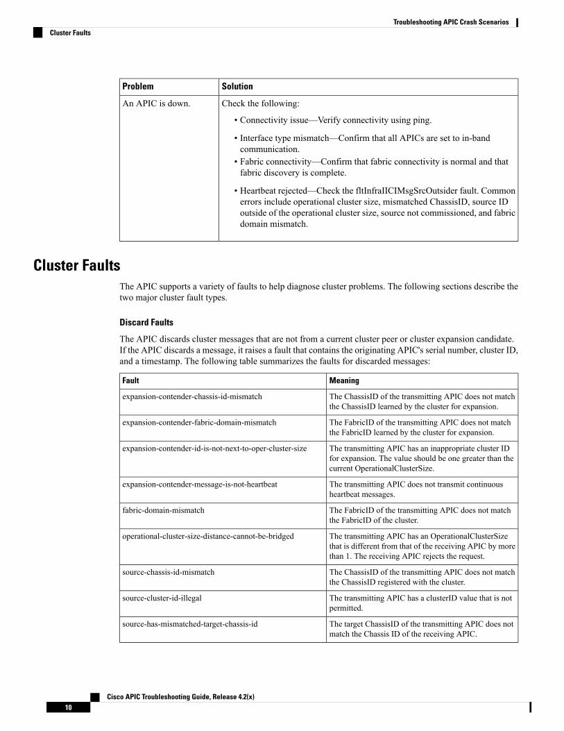
Check the following:
• Connectivity issue—Verify connectivity using ping.
• Interface type mismatch—Confirm that all APICs are set to in-bandcommunication.
• Fabric connectivity—Confirm that fabric connectivity is normal and thatfabric discovery is complete.
• Heartbeat rejected—Check the fltInfraIICIMsgSrcOutsider fault. Commonerrors include operational cluster size, mismatched ChassisID, source IDoutside of the operational cluster size, source not commissioned, and fabricdomain mismatch.
An APIC is down.
Cluster FaultsThe APIC supports a variety of faults to help diagnose cluster problems. The following sections describe thetwo major cluster fault types.
Discard Faults
The APIC discards cluster messages that are not from a current cluster peer or cluster expansion candidate.If the APIC discards a message, it raises a fault that contains the originating APIC's serial number, cluster ID,and a timestamp. The following table summarizes the faults for discarded messages:
MeaningFault
The ChassisID of the transmitting APIC does not matchthe ChassisID learned by the cluster for expansion.
expansion-contender-chassis-id-mismatch
The FabricID of the transmitting APIC does not matchthe FabricID learned by the cluster for expansion.
expansion-contender-fabric-domain-mismatch
The transmitting APIC has an inappropriate cluster IDfor expansion. The value should be one greater than thecurrent OperationalClusterSize.
expansion-contender-id-is-not-next-to-oper-cluster-size
The transmitting APIC does not transmit continuousheartbeat messages.
expansion-contender-message-is-not-heartbeat
The FabricID of the transmitting APIC does not matchthe FabricID of the cluster.
fabric-domain-mismatch
The transmitting APIC has an OperationalClusterSizethat is different from that of the receiving APIC by morethan 1. The receiving APIC rejects the request.
operational-cluster-size-distance-cannot-be-bridged
The ChassisID of the transmitting APIC does not matchthe ChassisID registered with the cluster.
source-chassis-id-mismatch
The transmitting APIC has a clusterID value that is notpermitted.
source-cluster-id-illegal
The target ChassisID of the transmitting APIC does notmatch the Chassis ID of the receiving APIC.
source-has-mismatched-target-chassis-id
Cisco APIC Troubleshooting Guide, Release 4.2(x)10
Troubleshooting APIC Crash ScenariosCluster Faults

MeaningFault
The transmitting APIC has a cluster ID that is outside ofthe OperationalClusterSize for the cluster.
source-id-is-outside-operational-cluster-size
The transmitting APIC has a cluster ID that is currentlydecommissioned in the cluster.
source-is-not-commissioned
Cluster Change Faults
The following faults apply when there is an error during a change to the APIC cluster size.
MeaningFault
This fault is issued if the OperationalClusterSize remains at 2 for anextended period. To resolve the issue, restore the cluster target size.
cluster-is-stuck-at-size-2
The last APIC within a cluster is still in service, which prevents thecluster from shrinking.
most-right-appliance-remains-commissioned
The cluster cannot detect an APICwith a higher cluster ID, preventingthe cluster from expanding.
no-expansion-contender
The data subset to be relocated has a copy on a service that isexperiencing a failure. Indicates that there are multiple such failureson the APIC.
service-down-on-appliance-carrying-replica-related-to-relocation
The data subset to be relocated has a copy on an unavailable APIC.To resolve the fault, restore the unavailable APIC.
unavailable-appliance-carrying-replica-related-to-relocation
The data subset to be relocated has a copy on an APIC that is nothealthy. To resolve the fault, determine the root cause of the failure.
unhealthy-replica-related-to-relocation
APIC Unavailable
The following cluster faults can apply when an APIC is unavailable:
MeaningFault
The cluster is unable to bring up a data subset.fltInfraReplicaReplicaState
Indicates a corruption in the data store service.fltInfraReplicaDatabaseState
Indicates that a data subset is not fully functional.fltInfraServiceHealth
Indicates that an APIC is not fully functional.fltInfraWiNodeHealth
Troubleshooting Application Centric Infrastructure CrashScenarios
Troubleshooting Fabric Node and Process CrashThe ACI switch node has numerous processes which control various functional aspects on the system. If thesystem has a software failure in a particular process, a core file will be generated and the process will bereloaded.
Cisco APIC Troubleshooting Guide, Release 4.2(x)11
Troubleshooting APIC Crash ScenariosTroubleshooting Application Centric Infrastructure Crash Scenarios

If the process is a Data Management Engine (DME) process, the DME process will restart automatically. Ifthe process is a non-DME process, it will not restart automatically and the switch will reboot to recover.
This section presents an overview of the various processes, how to detect that a process has cored, and whatactions should be taken when this occurs
DME Processes
The essential processes running on an APIC can be found through the CLI. Unlike the APIC, the processesthat can be seen via the GUI in FABRIC > INVENTORY > Pod 1 > node shows all processes running onthe leaf.
Through the ps-ef | grep svc_ifc:rtp_leaf1# ps -ef |grep svc_ifcroot 3990 3087 1 Oct13 ? 00:43:36 /isan/bin/svc_ifc_policyelem --xroot 4039 3087 1 Oct13 ? 00:42:00 /isan/bin/svc_ifc_eventmgr --xroot 4261 3087 1 Oct13 ? 00:40:05 /isan/bin/svc_ifc_opflexelem --x -vdptcp:8000root 4271 3087 1 Oct13 ? 00:44:21 /isan/bin/svc_ifc_observerelem --xroot 4277 3087 1 Oct13 ? 00:40:42 /isan/bin/svc_ifc_dbgrelem --xroot 4279 3087 1 Oct13 ? 00:41:02 /isan/bin/svc_ifc_confelem --xrtp_leaf1#
Each of the processes running on the switch writes activity to a log file on the system. These log files arebundled as part of the techsupport file but can be found via CLI access in /tmp/logs/ directory. For example,the Policy Element process log output is written into /tmp/logs/svc_ifc_policyelem.log.
The following is a brief description of the DME processes running on the system. This can help in understandingwhich log files to reference when troubleshooting a particular process or understand the impact to the systemif a process crashed:
FunctionProcess
Policy Element: Process logical MO from APIC andpush concrete model to the switch
policyelem
Event Manager: Processes local faults, events, healthscore
eventmgr
Opflex Element: Opflex server on switchopflexelem
Observer Element: Process local stats sent to APICobserverelem
Debugger Element: Core handlerdbgrelem
Web server handling traffic between the switch andAPIC
nginx
Identify When a Process Crashes
When a process crashes and a core file is generated, a fault as well as an event is generated. The fault for theparticular process is shown as a "process-crash" as shown in this syslog output from the APIC:Oct 16 03:54:35 apic3 %LOG_LOCAL7-3-SYSTEM_MSG [E4208395][process-crash][major][subj-[dbgs/cores/node-102-card-1-svc-policyelem-ts-2014-10-16T03:54:55.000+00:00]/rec-12884905092]Process policyelem cored
Cisco APIC Troubleshooting Guide, Release 4.2(x)12
Troubleshooting APIC Crash ScenariosTroubleshooting Fabric Node and Process Crash

When the process on the switch crashes, the core file is compressed and copied to the APIC. The syslogmessage notification comes from the APIC.
The fault that is generated when the process crashes is cleared when the process is Troubleshooting CiscoApplication Centric Infrastructure 275 restarted. The fault can be viewed via the GUI in the fabric history tabat FABRIC > INVENTORY > Pod 1.
Collecting the Core Files
The APIC GUI provides a central location to collect the core files for the fabric nodes.
An export policy can be created from ADMIN > IMPORT/EXPORT > Export Policies > Core. However,there is a default core policy where files can be downloaded directly.
The core files can be accessed via SSH/SCP through the APIC at /data/techsupport on the APIC where thecore file is located. Note that the core file will be available at /data/ techsupport on one APIC in the cluster,the exact APIC that the core file resides can be found by the Export Location path as shown in the GUI. Forexample, if the Export Location begins with “files/3/”, the file is located on node 3 (APIC3).
APIC Process Crash Verification and Restart
Symptom 1
Process on switch fabric crashes. Either the process restarts automatically or the switch reloads to recover.
• Verification:
As indicated in the overview section, if a DME process crashes, it should restart automatically withoutthe switch restarting. If a non-DME process crashes, the process will not automatically restart and theswitch will reboot to recover.
Depending on which process crashes, the impact of the process core will vary.
When a non-DME process crashes, this will typical lead to a HAP reset as seen on the console:[ 1130.593388] nvram_klm wrote rr=16 rr_str=ntp hap reset to nvram[ 1130.599990] obfl_klm writing reset reason 16, ntp hap reset[ 1130.612558] Collected 8 ext4 filesystems
• Check Process Log:
The process which crashes should have at some level of log output prior to the crash. The output of thelogs on the switch are written into the /tmp/logs directory. The process name will be part of the file name.For example, for the Policy Element process, the file is svc_ifc_policyelem.logrtp_leaf2# ls -l |grep policyelem-rw-r--r-- 2 root root 13767569 Oct 16 00:37 svc_ifc_policyelem.log-rw-r--r-- 1 root root 1413246 Oct 14 22:10 svc_ifc_policyelem.log.1.gz-rw-r--r-- 1 root root 1276434 Oct 14 22:15 svc_ifc_policyelem.log.2.gz-rw-r--r-- 1 root root 1588816 Oct 14 23:12 svc_ifc_policyelem.log.3.gz-rw-r--r-- 1 root root 2124876 Oct 15 14:34 svc_ifc_policyelem.log.4.gz-rw-r--r-- 1 root root 1354160 Oct 15 22:30 svc_ifc_policyelem.log.5.gz-rw-r--r-- 2 root root 13767569 Oct 16 00:37 svc_ifc_policyelem.log.6-rw-rw-rw- 1 root root 2 Oct 14 22:06 svc_ifc_policyelem.log.PRESERVED-rw-rw-rw- 1 root root 209 Oct 14 22:06 svc_ifc_policyelem.log.stderrrtp_leaf2#
There will be several files for each process located at /tmp/logs. As the log file increases in size, it willbe compressed and older log files will be rotated off. Check the core file creation time (as shown in theGUI and the core file name) to understand where to look in the file. Also, when the process first attempts
Cisco APIC Troubleshooting Guide, Release 4.2(x)13
Troubleshooting APIC Crash ScenariosAPIC Process Crash Verification and Restart

to come up, there be an entry in the log file that indicates “Process is restarting after a crash” that can beused to search backwards as to what might have happened prior to the crash.
• Check Activity:
A process which has been running has had some change which then caused it to crash. In many casesthe changes may have been some configuration activity on the system. What activity occurred on thesystem can be found in the audit log history of the system.
• Contact TAC:
A process crashing should not normally occur. In order to understand better why beyond the above stepsit will be necessary to decode the core file. At this point, the file will need to be collected and providedto the TAC for further processing.
Collect the core file (as indicated above how to do this) and open up a case with the TAC.
Symptom 2
Fabric switch continuously reloads or is stuck at the BIOS loader prompt.
• Verification:
If a DME process crashes, it should restart automatically without the switch restarting. If a non-DMEprocess crashes, the process will not automatically restart and the switch will reboot to recover. Howeverin either case if the process continuously crashes, the switch may get into a continuous reload loop orend up in the BIOS loader prompt.[ 1130.593388] nvram_klm wrote rr=16 rr_str=policyelem hap reset to nvram[ 1130.599990] obfl_klm writing reset reason 16, policyelem hap reset[ 1130.612558] Collected 8 ext4 filesystems
• Break the HAP Reset Loop:
First step is to attempt to get the switch back into a state where further information can be collected.
If the switch is continuously rebooting, when the switch is booting up, break into the BIOS loader promptthrough the console by typing CTRL C when the switch is first part of the boot cycle.
Once the switch is at the loader prompt, enter in the following commands:
• cmdline no_hap_reset
• boot
The cmdline command will prevent the switch from reloading with a hap reset is called. The secondcommand will boot the system. Note that the boot command is needed instead of a reload at the loaderas a reload will remove the cmdline option entered.
Though the system should now remain up to allow better access to collect data, whatever process iscrashing will impact the functionality of the switch.
As in the previous table, check the process log, activity, and contact TAC steps.
Cisco APIC Troubleshooting Guide, Release 4.2(x)14
Troubleshooting APIC Crash ScenariosAPIC Process Crash Verification and Restart

Troubleshooting an APIC Process CrashThe APIC has a series of DataManagement Engine (DME) processes which control various functional aspectson the system. When the system has a software failure in a particular process, a core file will be generatedand the process will be reloaded.
The following sections cover potential issues involving system processes crashes or software failures, beginningwith an overview of the various system processes, how to detect that a process has cored, and what actionsshould be taken when this occurs. The displays taken on a working healthy system can then be used to identifyprocesses that may have terminated abruptly.
DME Processes
The essential processes running on an APIC can be found either through the GUI or the CLI. Using the GUI,the processes and the process ID running is found in System > Controllers > Processes.
Using the CLI, the processes and the process ID are found in the summary file at /aci/system/controllers/1/processes (for APIC1):admin@RTP_Apic1:processes> cat summaryprocesses:process-id process-name max-memory-allocated state---------- ----------------- -------------------- -------------------0 KERNEL 0 interruptible-sleep331 dhcpd 108920832 interruptible-sleep336 vmmmgr 334442496 interruptible-sleep554 neo 398274560 interruptible-sleep1034 ae 153690112 interruptible-sleep1214 eventmgr 514793472 interruptible-sleep2541 bootmgr 292020224 interruptible-sleep4390 snoopy 28499968 interruptible-sleep5832 scripthandler 254308352 interruptible-sleep19204 dbgr 648941568 interruptible-sleep21863 nginx 4312199168 interruptible-sleep32192 appliancedirector 136732672 interruptible-sleep32197 sshd 1228800 interruptible-sleep32202 perfwatch 19345408 interruptible-sleep32203 observer 724484096 interruptible-sleep32205 lldpad 1200128 interruptible-sleep32209 topomgr 280576000 interruptible-sleep32210 xinetd 99258368 interruptible-sleep32213 policymgr 673251328 interruptible-sleep32215 reader 258940928 interruptible-sleep32216 logwatch 266596352 interruptible-sleep32218 idmgr 246824960 interruptible-sleep32416 keyhole 15233024 interruptible-sleepadmin@apic1:processes>
Each of the processes running on the APIC writes to a log file on the system. These log files can be bundledas part of the APIC techsupport file but can also be observed through SSH shell access in /var/log/dme/log.For example, the PolicyManager process log output is written into /var/log/dme/log/svc_ifc_policymgr.bin.log.
The following is a brief description of the processes running on the system. This can help in understandingwhich log files to reference when troubleshooting a particular process or understand the impact to the systemif a process crashed:
FunctionProcess
Linux kernelKERNEL
Cisco APIC Troubleshooting Guide, Release 4.2(x)15
Troubleshooting APIC Crash ScenariosTroubleshooting an APIC Process Crash

FunctionProcess
DHCP process running for APIC to assign infraaddresses
dhcpd
Handles process between APIC and Hypervisorsvmmmgr
Shell CLI Interpreterneo
Handles the state and inventory of local APICappliance
ae
Handles all events and faults on the systemeventmgr
Controls boot and firmware updates on fabric nodesbootmgr
Shell CLI help, tab command completionsnoopy
Handles the L4-L7 device scripts and communicationscripthandler
Generates core files when process crashesdbgr
Web service handling GUI and REST API accessnginx
Handles formation and control of APIC clusterappliancedirector
Enabled SSH access into the APICsshd
Monitors Linux cgroup resource usageperfwatch
Monitors the fabric system and data handling of state,stats, health
observer
LLDP Agentlldpad
Maintains fabric topology and inventorytopomgr
Cisco APIC Troubleshooting Guide, Release 4.2(x)16
Troubleshooting APIC Crash ScenariosTroubleshooting an APIC Process Crash

C H A P T E R 4Recovering Cisco APIC Passwords andAccessing Special Logins
This chapter explains how to recover your Cisco APIC password, how to access the rescue-user login to runtroubleshooting commands, including the command for erasing the configuration, and how to access a hiddenlogin domain that allows you to log in using the local user database in case of a lockout.
This chapter contains the following sections:
• Recovering the APIC Password, on page 17• Using the Rescue-user Account to Erase the Cisco APIC Configuration Using the NX-OS Style CLI, onpage 18
• Using the Fallback Login Domain to Log in to the Local Database, on page 18
Recovering the APIC PasswordFollow these steps to recover the APIC password.
Step 1 Create and save an empty file named "aci-admin-passwd-reset.txt".Step 2 Add the file to a USB drive. You can format the USB drive to FAT or FAT32.Step 3 Connect the USB drive to one of the rear USB ports on the Cisco APIC.Step 4 Reboot the Cisco APIC using Cisco Integrated Management Controller (CIMC) or by hard power cycling the device.Step 5 Press the Esc key during the 10-second countdown timer that appears at the top left to bring up the list of boot targets.Step 6 Press the e key to edit the default grub line.Step 7 Go to the line that begins with "linux." Using the End key or Right Arrow key, move the cursor to the end of that line
and append "aci-admin-passwd-reset".Step 8 Press Ctrl+X to boot the entry.
It may take a few minutes for the new password to take effect.
Cisco APIC Troubleshooting Guide, Release 4.2(x)17

Using the Rescue-user Account to Erase the Cisco APICConfiguration Using the NX-OS Style CLI
The rescue-user is an emergency login that provides access to the Cisco APIC even when it is not in a cluster.You can use this login to run troubleshooting commands including erasing the configuration.
For a standby Cisco APIC, you can log in using SSH with the username "rescue-user" and no password. Ifthe standby Cisco APIC was previously part of a fabric, the "rescue-user" account will retain the oldadministrator password, unless the operating system is re-installed using the keyboard, video, mouse (KVM)console.
Note
Step 1 Access the APIC using the Cisco Integrated Management Controller (CIMC) console.Step 2 Login as rescue-user.
If an admin password is in place and the Cisco APIC is logged onto the fabric, the rescue-user password is thesame as the admin password. Otherwise there is no rescue-user password.
Note
Step 3 Use the acidiag touch command to clear the configuration.
Example:
apic1# acidiag touch setup
Using the Fallback Login Domain to Log in to the Local DatabaseThere is a hidden login domain named "fallback" that allows you to log in using the local user database incase of lockout. The format of the username used for the authenticationmethod is apic#fallback\\<username>.
Use the fallback login domain to log in to the local database in the GUI or log in to the fallback login domainusing the NX-OS CLI, shown as follows:
apic1(config)# aaa authentication login domain fallbackapic1(config-domain)# ?group Set provider group for login domainrealm Specify server realm
Or, you can use the REST API to log in to the fallback login domain, shown as follows:
• URL: https://ifav41-ifc1/api/aaaLogin.xml• DATA:
<aaaUser name="apic#fallback\\admin"pwd="passwordhere"/>
Cisco APIC Troubleshooting Guide, Release 4.2(x)18
Recovering Cisco APIC Passwords and Accessing Special LoginsUsing the Rescue-user Account to Erase the Cisco APIC Configuration Using the NX-OS Style CLI

C H A P T E R 5Cisco APIC Troubleshooting Operations
This chapter explains how to perform the basic troubleshooting operations and contains the following sections:
• Shutting Down the APIC System, on page 19• Shutting Down the APIC Controller Using the GUI, on page 19• Using the APIC Reload Option Using the GUI, on page 20• Controlling the LED Locator Using the GUI, on page 21
Shutting Down the APIC SystemThis procedure explains how to shut down the APIC system.
After you shut down the system, you will move it (re-locate the entire fabric) then power it up, then updatethe time zone and/or NTP servers accordingly.
Note
1. Shut down one Cisco APIC at a time by right-clicking on a controller then choosing Shutdown from thepull-down menu.
2. Start up the APIC at the new location.
3. Check that the cluster has fully converged.
4. Proceed with the next APIC.
Before you begin
Ensure cluster health is fully fit.
Shutting Down the APIC Controller Using the GUIThis document describes how to shut down the APIC controller.
Cisco APIC Troubleshooting Guide, Release 4.2(x)19

This procedure instructs on how to shut down the APIC controller only (not the entire APIC system itself).Following this procedure causes the controller to shut down immediately. Use caution in performing a shutdownbecause the only way to bring the controller back up is to do so from the actual machine. If you need to accessthe machine, refer to the "Turning on the Locator LED Using the GUI" section in this chapter.
Note
Shut down a single APIC controller as follows:
If possible, move APICs one at a time. As long as there are at least two APICs in the cluster online, there isread/write access. If you need to relocate more than one APIC at a time, this results in one or no remainingcontrollers online, and the fabric will go into a read-only mode when they are shutdown. During this timethere can be no policy changes including Endpoint moves (including Virtual Machine movement). Once theAPICs are shut down using the following procedure, relocate the controller, and power it back up under thenew rack. Then, confirm that the cluster health returns to fully fit status.
Note
1. In the menu bar, click System.
2. In the submenu bar, click Controllers.
3. Under Controllers, click the APIC node that you would like to reload, for example, apic1 (Node-1).
4. In the right window pane, at the top of the screen, click the General tab.
5. In the right window pane, at the top of the screen and under the tabs, click the ACTIONS pull-downmenu.
6. Select Shutdown from the pull-down menu to immediately reload the APIC controller.
Another way to use this Shutdown option is to right-click on the APIC node (such as apic1 (Node-1), andselect Shutdown from the pull-down list.
Note
7. Relocate the controller, then power it up.
8. Confirm cluster health returns to fully fit status.
Using the APIC Reload Option Using the GUIThis document describes how to reload the APIC controller (not the entire APIC system) using the GUI.
Reload the APIC controller as follows:
1. In the menu bar, click System.
2. In the submenu bar, click Controllers.
3. Under Controllers, click the APIC node that you would like to reload, for example, apic1 (Node-1).
4. In the right window pane, at the top of the screen, click the General tab.
Cisco APIC Troubleshooting Guide, Release 4.2(x)20
Cisco APIC Troubleshooting OperationsUsing the APIC Reload Option Using the GUI

5. In the right window pane, at the top of the screen and under the tabs, click the ACTIONS pull-downmenu.
6. Select Reload from the pull-down menu to immediately reload the APIC controller.
Another way to use this Reload option is to right-click on the APIC node (such as apic1 (Node-1), and selectReload from the pull-down list.
Note
Controlling the LED Locator Using the GUIThis document describes how to turn on the LED locator for the APIC controller using the GUI.
Turn on (or turn off) the LED locator of the APIC controller using the GUI as follows:
1. In the menu bar, click System.
2. In the submenu bar, click Controllers.
3. Under Controllers, click the APIC node that you would like to reload, for example, apic1 (Node-1).
4. In the right window pane, at the top of the screen, click the General tab.
5. In the right window pane, at the top of the screen and under the tabs, click the ACTIONS pull-downmenu.
6. Select Turn On LED Locator (or Turn Off LED Locator) from the pull-down menu.
Another way to use this option is to right-click on the APIC node (such as apic1 (Node-1), and select TurnOn LED Locator (or Turn Off LED Locator) from the pull-down list.
Note
Cisco APIC Troubleshooting Guide, Release 4.2(x)21
Cisco APIC Troubleshooting OperationsControlling the LED Locator Using the GUI

Cisco APIC Troubleshooting Guide, Release 4.2(x)22
Cisco APIC Troubleshooting OperationsControlling the LED Locator Using the GUI

C H A P T E R 6Using the Cisco APIC Troubleshooting Tools
This chapter introduces the tools and methodology commonly used to troubleshoot problems you mayexperience. These tools can assist you with monitoring traffic, debugging, and detecting issues such as trafficdrops, misrouting, blocked paths, and uplink failures. See the tools listed below for a summary overview ofthe tools described in this chapter:
• ACL Contract Permit and Deny Logs—Enables the logging of packets or flows that were allowed tobe sent because of contract permit rules and the logging of packets or flows dropped because of taboocontract deny rules.
• Atomic Counters—Enables you to gather statistics about traffic between flows for detecting drops andmisrouting in the fabric and for enabling quick debugging and isolation of application connectivity issues.
• Digital Optical Monitoring—Enables you to view digital optical monitoring (DOM) statistics about aphysical interface.
• Health Scores—Enables you to isolate performance issues by drilling down through the network hierarchyto isolate faults to specific managed objects (MOs).
• Port Tracking—Enables you to monitor the status of links between leaf switches and spine switchesfor detecting uplink failure.
• SNMP—Simple Network Management Protocol (SNMP) enables you to remotely monitor individualhosts (APIC or another host) and find out the state of any particular node.
• SPAN—Switchport Analizer (SPAN) enables you to perform detailed troubleshooting or to take a sampleof traffic from a particular application host for proactive monitoring and analysis.
• Statistics—Provides real-time measures of observed objects. Viewing statistics enable you to performtrend analysis and troubleshooting.
• Syslog—Enables you to specify the minimum severity level of messages to be sent, the items to beincluded in the syslog messages, and the syslog destination. The format can also be displayed in NX-OSCLI format.
• Traceroute—Enables you to find the routes that packets actually take when traveling to their destination.• Troubleshooting Wizard—Enables administrators to troubleshoot issues that occur during specific timeframes, which can be designated by selecting two endpoints.
• Configuration Sync Issues—Enables you to see if any transactions in Cisco APIC have not yet synched.
This chapter contains the following sections:
• Enabling and Viewing ACL Contract and Deny Logs, on page 24• Using Atomic Counter Policies for Gathering Statistics, on page 32• Enabling and Viewing Digital Optical Monitoring Statistics, on page 36• Viewing and Understanding Health Scores, on page 39
Cisco APIC Troubleshooting Guide, Release 4.2(x)23

• Enabling Port Tracking for Uplink Failure Detection, on page 42• Configuring SNMP for Monitoring and Managing Devices, on page 44• Configuring SPAN for Traffic Monitoring, on page 48• Using Statistics, on page 74• Specifying Syslog Sources and Destinations, on page 79• Discovering Paths and Testing Connectivity with Traceroute, on page 83• Using the Troubleshooting Wizard, on page 86• Checking for Configuration Synchronization Issues, on page 119• Viewing User Activities, on page 120• Embedded Logic Analyzer Module, on page 120
Enabling and Viewing ACL Contract and Deny Logs
About ACL Contract Permit and Deny LogsTo log and/or monitor the traffic flow for a contract rule, you can enable and view the logging of packets orflows that were allowed to be sent because of contract permit rules or the logging of packets or flows thatwere dropped because of:
• Taboo contract deny rules
• Deny actions in contract subjects
• Contract or subject exceptions
• ACL contract permit in the ACI fabric is only supported on Nexus 9000 Series switches with names thatend in EX or FX, and all later models. For example, N9K-C93180LC-EX or N9K-C9336C-FX.
• Deny logging in the ACI fabric is supported on all platforms.
• Using log directive on filters in management contracts is not supported. Setting the log directive willcause zoning-rule deployment failure.
For information on standard and taboo contracts and subjects, see Cisco Application Centric InfrastructureFundamentals and Cisco APIC Basic Configuration Guide.
EPG Data Included in ACL Permit and Deny Log Output
Up to Cisco APIC, Release 3.2(1), the ACL permit and deny logs did not identify the EPGs associated withthe contracts being logged. In release 3.2(1) the source EPG and destination EPG are added to the output ofACI permit and deny logs. ACL permit and deny logs include the relevant EPGs with the following limitations:
• Depending on the position of the EPG in the network, EPG data may not be available for the logs.
• When configuration changes occur, log data may be out of date. In steady state, log data is accurate.
The most accurate EPG data in the permit and deny logs results when the logs are focussed on:
• Flows from EPG to EPG, where the ingress policy is installed at the ingress TOR and the egress policyis installed at the egress TOR.
Cisco APIC Troubleshooting Guide, Release 4.2(x)24
Using the Cisco APIC Troubleshooting ToolsEnabling and Viewing ACL Contract and Deny Logs

• Flows from EPG to L3Out, where one policy is applied on the border leaf TOR and the other policy isapplied on a non-BL TOR.
EPGs in the log output are not supported for uSeg EPGs or for EPGs used in shared services (including sharedL3Outs).
Enabling ACL Contract Permit and Deny Logging Using the GUIThe following steps show how to enable contract permit and deny logging using the GUI:
The tenant that contains the permit logging is the tenant that contains the VRF that the EPG is associated to.This will not necessarily be the same tenant as the EPG or its associated contracts.
Note
Step 1 On the menu bar, choose Tenants > <tenant name>.Step 2 In the Navigation pane, expand Contracts, right-click Standard, and choose Create Contract.Step 3 In the Create Contract dialog box, perform the following actions:
a) In the Name field, type the name for the contract.b) In the Scope field, choose the scope for it (VRF, Tenant, or Global).c) Optional. Set the target DSCP or QoS class to be applied to the contract.d) Click the + icon to expand Subjects.
Step 4 In the Create Contract Subject dialog box, perform the following actions:Step 5 Enter the name of the subject and an optional description.Step 6 Optional. From the drop-down list for the target DSCP, select the DSCP to be applied to the subject.Step 7 Leave Apply Both Directions checked, unless you want the contract to only be applied from the consumer to the
provider, instead of in both directions.Step 8 LeaveReverse Filter Ports checked if you uncheckedApply Both Directions to swap the Layer 4 source and destination
ports so that the rule is applied from the provider to the consumer.Step 9 Click the + icon to expand Filters.Step 10 In the Name drop-down list, choose an option; for example, click arp, default, est, or icmp, or choose a previously
configured filter.Step 11 In the Directives drop-down list, click log.Step 12 (Optional) Change the Action to be taken with this subject to Deny (or leave the action to the default, Permit.
With Directive: log enabled, if the action for this subject is Permit, ACL permit logs track the flows and packets thatare controlled by the subject and contract. If the action for this subject is Deny, ACL deny logs track the flows andpackets.
Step 13 (Optional) Set the priority for the subject.Step 14 Click Update.Step 15 Click OK.Step 16 Click Submit.
Logging is enabled for this contract.
Cisco APIC Troubleshooting Guide, Release 4.2(x)25
Using the Cisco APIC Troubleshooting ToolsEnabling ACL Contract Permit and Deny Logging Using the GUI

Enabling ACL Contract Permit Logging Using the NX-OS CLIThe following example shows how to enable Contract permit logging using the NX-OS CLI.
Step 1 To enable logging of packets or flows that were allowed to be sent because of Contract permit rules, use the followingcommands:configuretenant <tenantName>contract <contractName> type <permit>subject <subject Name>access-group <access-list> <in/out/both> log
Example:
For example:apic1# configureapic1(config)# tenant BDMode1apic1(config-tenant)# contract Logicmp type permitapic1(config-tenant-contract)# subject icmpapic1(config-tenant-contract-subj)# access-group arp both log
Step 2 To disable the permit logging use the no form of the access-group command; for example, use the no access-group
arp both log command.
Enabling ACL Contract Permit Logging Using the REST APIThe following example shows you how to enable permit and deny logging using the RESTAPI. This exampleconfigures ACL permit and deny logging for a contract with subjects that have Permit and Deny actionsconfigured.
For this configuration, send a post with XML similar to the following example:
Example:<vzBrCP dn="uni/tn-Tenant64/brc-C64" name="C64" scope="context">
<vzSubj consMatchT="AtleastOne" name="HTTPSsbj" provMatchT="AtleastOne" revFltPorts="yes"rn="subj-HTTPSsbj">
<vzRsSubjFiltAtt action="permit" directives="log" forceResolve="yes" priorityOverride="default"
rn="rssubjFiltAtt-PerHTTPS" tDn="uni/tn-Tenant64/flt-PerHTTPS" tRn="flt-PerHTTPS"tnVzFilterName="PerHTTPS"/>
</vzSubj><vzSubj consMatchT="AtleastOne" name="httpSbj" provMatchT="AtleastOne" revFltPorts="yes"
rn="subj-httpSbj"><vzRsSubjFiltAtt action="deny" directives="log" forceResolve="yes" priorityOverride="default"
rn="rssubjFiltAtt-httpFilter" tDn="uni/tn-Tenant64/flt-httpFilter" tRn="flt-httpFilter"tnVzFilterName="httpFilter"/>
</vzSubj><vzSubj consMatchT="AtleastOne" name="subj64" provMatchT="AtleastOne" revFltPorts="yes"
rn="subj-subj64"><vzRsSubjFiltAtt action="permit" directives="log" forceResolve="yes" priorityOverride="default"
rn="rssubjFiltAtt-icmp" tDn="uni/tn-common/flt-icmp" tRn="flt-icmp" tnVzFilterName="icmp"/>
Cisco APIC Troubleshooting Guide, Release 4.2(x)26
Using the Cisco APIC Troubleshooting ToolsEnabling ACL Contract Permit Logging Using the NX-OS CLI

</vzSubj></vzBrCP>
Enabling Taboo Contract Deny Logging Using the GUIThe following steps show how to enable Taboo Contract deny logging using the GUI.
Step 1 On the menu bar, choose Tenants > <tenant name>.Step 2 In the Navigation pane, expand Contracts.Step 3 Right-click Taboos and choose Create Taboo Contract.Step 4 In the Create Taboo Contract dialog box, perform the following actions to specify the Taboo contract:
a) In the Name field, type the name for the contract.b) Optional. In the Description field, type a description of the Taboo contract.c) Click the + icon to expand Subjects.
Step 5 In the Create Taboo Contract Subject dialog box, perform the following actions:a) In the Specify Identity of Subject area, type a name and optional description.b) Click the + icon to expand Filters.c) From theName drop-down list, choose one of the default values, such as<tenant_name>/arp,<tenant_name>/default,
<tenant_name>/est, <tenant_name>/icmp, choose a previously created filter, orCreate Filter.
If you chose Create Filter, in the Specify Filter Identity Area, perform the following actions to specify criteriafor the ACL Deny rule:
a. Type a name and optional description.
b. Expand Entries, type a name for the rule, and choose the criteria to define the traffic you want to deny.
c. In theDirectives drop-down list, choose log.
d. Click Update.
e. Click OK.
Note
Step 6 Click Submit.Logging is enabled for this Taboo contract.
Enabling Taboo Contract Deny Logging Using the NX-OS CLIThe following example shows how to enable Taboo Contract deny logging using the NX-OS CLI.
Step 1 To enable logging of packets or flows dropped because of Taboo Contract deny rules, use the following commands:configuretenant <tenantName>contract <contractName> type <deny>
Cisco APIC Troubleshooting Guide, Release 4.2(x)27
Using the Cisco APIC Troubleshooting ToolsEnabling Taboo Contract Deny Logging Using the GUI
subject <subject Name>access-group <access-list> <both> log
Example:
For example:apic1# configureapic1(config)# tenant BDMode1apic1(config-tenant)# contract dropFTP type denyapic1(config-tenant-contract)# subject dropftpapic1(config-tenant-contract-subj)# access-group ftp both log
Step 2 To disable the deny logging use the no form of the access-group command; for example, use the no access-group https
both log command.
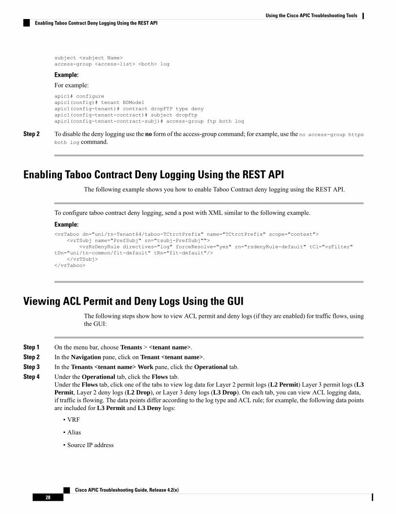
Enabling Taboo Contract Deny Logging Using the REST APIThe following example shows you how to enable Taboo Contract deny logging using the REST API.
To configure taboo contract deny logging, send a post with XML similar to the following example.
Example:<vzTaboo dn="uni/tn-Tenant64/taboo-TCtrctPrefix" name="TCtrctPrefix" scope="context">
<vzTSubj name="PrefSubj" rn="tsubj-PrefSubj""><vzRsDenyRule directives="log" forceResolve="yes" rn="rsdenyRule-default" tCl="vzFilter"
tDn="uni/tn-common/flt-default" tRn="flt-default"/></vzTSubj>
</vzTaboo>
Viewing ACL Permit and Deny Logs Using the GUIThe following steps show how to view ACL permit and deny logs (if they are enabled) for traffic flows, usingthe GUI:
Step 1 On the menu bar, choose Tenants > <tenant name>.Step 2 In the Navigation pane, click on Tenant <tenant name>.Step 3 In the Tenants <tenant name> Work pane, click the Operational tab.Step 4 Under the Operational tab, click the Flows tab.
Under the Flows tab, click one of the tabs to view log data for Layer 2 permit logs (L2 Permit) Layer 3 permit logs (L3Permit, Layer 2 deny logs (L2 Drop), or Layer 3 deny logs (L3 Drop). On each tab, you can view ACL logging data,if traffic is flowing. The data points differ according to the log type and ACL rule; for example, the following data pointsare included for L3 Permit and L3 Deny logs:
• VRF
• Alias
• Source IP address
Cisco APIC Troubleshooting Guide, Release 4.2(x)28
Using the Cisco APIC Troubleshooting ToolsEnabling Taboo Contract Deny Logging Using the REST API

• Destination IP address
• Protocol
• Source port
• Destination port
• Source MAC address
• Destination MAC address
• Node
• Source interface
• VRF Encap
• Source EPG
• Destination EPG
• Source PC Tag
• Destination PC Tag
You can also use the Packets tab (next to the Flows tab) to access ACL logs for groups of packets (up to 10)with the same signature, source and destination. You can see what type of packets are being sent and whichare being dropped.
Note
Viewing ACL Permit and Deny Logs Using the REST APIThe following example shows how to view Layer 2 deny log data for traffic flows, using the REST API. Youcan send queries using the following MOs:
• acllogDropL2Flow
• acllogPermitL2Flow
• acllogDropL3Flow
• acllogPermitL3Flow
• acllogDropL2Pkt
• acllogPermitL2Pkt
• acllogDropL3Pkt
• acllogPermitL3Pkt
Before you begin
You must enable permit or deny logging, before you can view ACL contract permit and deny log data.
Cisco APIC Troubleshooting Guide, Release 4.2(x)29
Using the Cisco APIC Troubleshooting ToolsViewing ACL Permit and Deny Logs Using the REST API

To view Layer 3 drop log data, send the following query using the REST API:GET https://apic-ip-address/api/class/acllogDropL3Flow
Example:
The following example shows sample output:<?xml version="1.0" encoding="UTF-8"?><imdata totalCount="2">
<acllogPermitL3Flow childAction="" dn="topology/pod-1/node-101/ndbgs/acllog/tn-common/ctx-inb
/permitl3flow-spctag-333-dpctag-444-sepgname-unknown-depgname-unknown-sip-[100:c000:a00:700:b00:0:f00:0]
-dip-[19.0.2.10]-proto-udp-sport-17459-dport-8721-smac-00:00:15:00:00:28-dmac-00:00:12:00:00:25-sintf-
[port-channel5]-vrfencap-VXLAN: 2097153" dstEpgName="unknown" dstIp="19.0.2.10"dstMacAddr="00:00:12:00:00:25"
dstPcTag="444" dstPort="8721" lcOwn="local" modTs="never" monPolDn="" protocol="udp"srcEpgName="unknown"
srcIntf="port-channel5" srcIp="100:c000:a00:700:b00:0:f00:0" srcMacAddr="00:00:15:00:00:28"srcPcTag="333"
srcPort="17459" status="" vrfEncap="VXLAN: 2097153"/><acllogPermitL3Flow childAction="" dn="topology/pod-1/node-102/ndbgs/acllog/tn-common/ctx-inb
/permitl3flow-spctag-333-dpctag-444-sepgname-unknown-depgname-unknown-sip-[100:c000:a00:700:b00:0:f00:0]-dip-
[19.0.2.10]-proto-udp-sport-17459-dport-8721-smac-00:00:15:00:00:28-dmac-00:00:12:00:00:25-sintf-[port-channel5]-vrfencap-VXLAN: 2097153" dstEpgName="unknown" dstIp="19.0.2.10"
dstMacAddr="00:00:12:00:00:25"dstPcTag="444" dstPort="8721" lcOwn="local" modTs="never" monPolDn="" protocol="udp"
srcEpgName="unknown"srcIntf="port-channel5" srcIp="100:c000:a00:700:b00:0:f00:0" srcMacAddr="00:00:15:00:00:28"
srcPcTag="333"srcPort="17459" status="" vrfEncap="VXLAN: 2097153"/>
</imdata>
Viewing ACL Permit and Deny Logs Using the NX-OS CLIThe following steps show how to view ACL log details using the NX-OS-style CLI show acllog command.
The syntax for the Layer 3 command is show acllog {permit | deny} l3 {pkt | flow} tenant <tenant_name>vrf <vrf_name> srcip <source_ip> dstip <destination_ip> srcport <source_port> dstport<destination_port> protocol <protocol> srcintf <source_interface> start-time <startTime> end-time<endTime> detail
The syntax for the Layer 2 command is show acllog {permit | deny} l2 {flow | pkt} tenant <tenant_name>vrf <VRF_name> srcintf <source_interface> vlan <VLAN_number> detail
Cisco APIC Troubleshooting Guide, Release 4.2(x)30
Using the Cisco APIC Troubleshooting ToolsViewing ACL Permit and Deny Logs Using the NX-OS CLI

The full syntax of the show acllog command is only available on Generation 2 Cisco Nexus 9000 seriesswitches (with names that end in EX or FX or later, such as N9K-C93180LC-EX) and Cisco APIC Release3.2 or later. With Generation 1 switches (with names that do not end in EX or FX) or Cisco APIC releasesbefore 3.2, the available syntax is as above.
Note
In Cisco APIC 3.2 and later, additional keywords are added to both versions of the command, with the detailkeyword:[dstEpgName <destination_EPG_name>| dstmac <destination_MAC_address> | dstpctag<destination_PCTag> | srcEpgName <source_EPG_name> | srcmac <source_MAC_address> | srcpctag<source_PCTag>]
Step 1 The following example shows how to use the show acllog drop l3 flow tenant common vrf default detail commandto display detailed information about Layer 3 deny logs for the common tenant:
Example:apic1# show acllog deny l3 flow tenant common vrf default detailSrcPcTag : 49153DstPcTag : 32773SrcEPG : uni/tn-TSW_Tenant0/ap-tsw0AP0/epg-tsw0ctx0BD0epg6DstEPG : uni/tn-TSW_Tenant0/ap-tsw0AP0/epg-tsw0ctx0BD0epg5SrcIp : 16.0.2.10DstIp : 19.0.2.10Protocol : udpSrcPort : 17459DstPort : 8721SrcMAC : 00:00:15:00:00:28DstMAC : 00:00:12:00:00:25Node : 101SrcIntf : port-channel5VrfEncap : VXLAN: 2097153
This example shows the output on Generation 2 switches, with Cisco APIC Release 3.2 or later.
Step 2 The following example shows how to use the show acllog deny l2 flow tenant common vrf tsw0connctx0 detailcommand to display detailed information about Layer 3 deny logs for the common tenant:
Example:apic1# show acllog deny l2 flow tenant common vrf tsw0connctx0 detailSrcPcTag DstPcTag SrcEPG DstEPG SrcMAC DstMAC Node SrcIntf
vlan––––––––– ––––––––– –––––––––––––––– –––––––––––––- ––––––––––––––––––- –––––––––––––––––- –––––
––––––––– ––––––32773 49153 uni/tn-TSW uni/tn-TSW 00:00:11:00:00:11 11:00:32:00:00:33 101 port-
2_Tenant0/ap- _Tenant0/ap- channel8
tsw0AP0/epg- tsw0AP0/epg-tsw0ctx0BD0epg5 tsw0ctx0BD0epg6
This example shows the output on Generation 2 switches, with Cisco APIC Release 3.2 or later.
Step 3 The following example shows how to use the show acllog permit l3 pkt tenant <tenant name> vrf <vrf name> [detail]command to display detailed information about the common VRF ACL Layer 3 permit packets that were sent:
apic1# show acllog permit l3 pkt tenant common vrf default detail acllog permit l3 packets detail:srcIp : 10.2.0.19
Cisco APIC Troubleshooting Guide, Release 4.2(x)31
Using the Cisco APIC Troubleshooting ToolsViewing ACL Permit and Deny Logs Using the NX-OS CLI

dstIp : 10.2.0.16protocol : udpsrcPort : 13124dstPort : 4386srcIntf : port-channel5vrfEncap : VXLAN: 2097153pktLen : 112srcMacAddr : 00:00:15:00:00:28dstMacAddr : 00:00:12:00:00:25timeStamp : 2015-03-17T21:31:14.383+00:00
This example shows the output on Generation 1 switches, or with Cisco APIC releases before 3.2.
Step 4 The following example shows how to use the show acllog permit l2 pkt tenant <tenant name> vrf <vrf name> srcintf<s interface> command to view information about default VRF Layer 2 packets sent from interface port-channel15:
apic1# show acllog permit l2 pkt tenant common vrf default srcintf port-channel5acllog permit L2 Packets
Node srcIntf pktLen timeStamp-------------- -------------- -------- --------------
port-channel5 1 2015-03-17T21:31:14.383+00:00
This example shows the output on Generation 1 switches, or with Cisco APIC releases before 3.2.
Using Atomic Counter Policies for Gathering StatisticsAtomic counter policies enable you to gather statistics about your traffic between a combination of endpoints,endpoint groups, external interfaces, and IP addresses. The information gathered enables you to detect dropsand misrouting in the fabric, which enables you to perform quick debugging and to isolate applicationconnectivity issues.
Atomic CountersAtomic Counters are useful for troubleshooting connectivity between endpoints, EPGs, or an applicationwithin the fabric. A user reporting application may be experiencing slowness, or atomic counters may beneeded for monitoring any traffic loss between two endpoints. One capability provided by atomic counters isthe ability to place a trouble ticket into a proactive monitoring mode, for example when the problem isintermittent, and not necessarily happening at the time the operator is actively working the ticket.
Atomic counters can help detect packet loss in the fabric and allow the quick isolation of the source ofconnectivity issues. Atomic counters require NTP to be enabled on the fabric.
Leaf-to-leaf (TEP to TEP) atomic counters can provide the following:
• Counts of drops, admits, and excess packets• Short-term data collection such as the last 30 seconds, and long-term data collection such as 5 minutes,15 minutes, or more
• A breakdown of per-spine traffic (available when the number of TEPs, leaf or VPC, is less than 64)• Ongoing monitoring
Leaf-to-leaf (TEP to TEP) atomic counters are cumulative and cannot be cleared. However, because 30 secondatomic counters reset at 30 second intervals, they can be used to isolate intermittent or recurring problems.
Cisco APIC Troubleshooting Guide, Release 4.2(x)32
Using the Cisco APIC Troubleshooting ToolsUsing Atomic Counter Policies for Gathering Statistics

Tenant atomic counters can provide the following:
• Application-specific counters for traffic across the fabric, including drops, admits, and excess packets• Modes include the following:• Endpoint to endpointMAC address, or endpoint to endpoint IP address. Note that a single target endpointcould have multiple IP addresses associated with it.
• EPG to EPG with optional drill down• EPG to endpoint• EPG to * (any)• Endpoint to external IP address
Atomic counters track the amount packets of between the two endpoints and use this as a measurement. Theydo not take into account drops or error counters in a hardware level.
Note
Dropped packets are calculated when there are less packets received by the destination than transmitted bythe source.
Excess packets are calculated when there are more packets received by the destination than transmitted bythe source.
Atomic Counters Guidelines and Restrictions• Use of atomic counters is not supported when the endpoints are in different tenants or in different contexts(VRFs) within the same tenant.
• In Cisco APIC Release 3.1(2m) (and later), if no statistics have been generated on a path in the lifetimeof the fabric, no atomic counters are generated for the path. Also the Traffic Map in the Visualizationtab (Operations > Visualization in the APIC GUI) does not show all paths, only the active paths (pathsthat had traffic at some point in the fabric lifetime).
• In pure Layer 2 configurations where the IP address is not learned (the IP address is 0.0.0.0),endpoint-to-EPG and EPG-to-endpoint atomic counter policies are not supported. In these cases,endpoint-to-endpoint and EPG-to-EPG policies are supported. External policies are virtual routing andforwarding (VRF)-based, requiring learned IP addresses, and are supported.
• When the atomic counter source or destination is an endpoint, the endpoint must be dynamic and notstatic. Unlike a dynamic endpoint (fv:CEp), a static endpoint (fv:StCEp) does not have a child object(fv:RsCEpToPathEp) that is required by the atomic counter.
• In a transit topology, where leaf switches are not in full mesh with all spine switches, then leaf-to-leaf(TEP to TEP) counters do not work as expected.
• For leaf-to-leaf (TEP to TEP) atomic counters, once the number of tunnels increases the hardware limit,the system changes the mode from trail mode to path mode and the user is no longer presented withper-spine traffic.
• The atomic counter does not count spine proxy traffic.
• Packets dropped before entering the fabric or before being forwarded to a leaf port are ignored by atomiccounters.
• Packets that are switched in the hypervisor (same Port Group and Host) are not counted.
Cisco APIC Troubleshooting Guide, Release 4.2(x)33
Using the Cisco APIC Troubleshooting ToolsAtomic Counters Guidelines and Restrictions

• Atomic counters require an active fabric Network Time Protocol (NTP) policy.
• Atomic counters work for IPv6 sources and destinations but configuring source and destination IPaddresses across IPv4 and IPv6 addresses is not allowed.
• An atomic counter policy configured with fvCEp as the source and/or destination counts only the trafficthat is from/to the MAC and IP addresses that are present in the fvCEp managed objects (MOs). If thefvCEp MO has an empty IP address field, then all traffic to/from that MAC address would be countedregardless of the IP address. If the APIC has learned multiple IP addresses for an fvCEp, then trafficfrom only the one IP address in the fvCEpMO itself is counted as previously stated. In order to configurean atomic counter policy to/from a specific IP address, use the fvIp MO as the source and/or destination.
• If there is an fvIp behind an fvCEp, you must add fvIP-based policies and not fvCEp-based policies.
Configuring Atomic Counters
Step 1 In the menu bar, click Tenants.Step 2 In the submenu bar, click the desired tenant.Step 3 In the Navigation pane, expand the tenant and expand Policies and then expand Troubleshoot.Step 4 Under Troubleshoot, expand Atomic Counter Policy and choose a traffic topology.
You can measure traffic between a combination of endpoints, endpoint groups, external interfaces, and IP addresses.
Step 5 Right-click the desired topology and choose Add topology Policy to open an Add Policy dialog box.Step 6 In the Add Policy dialog box, perform the following actions:
a) In the Name field, enter a name for the policy.b) choose or enter the identifying information for the traffic source.
The required identifying information differs depending on the type of source (endpoint, endpoint group, externalinterface, or IP address).
c) choose or enter the identifying information for the traffic destination.d) (Optional) (Optional) In the Filters table, click the + icon to specify filtering of the traffic to be counted.
In the resulting Create Atomic Counter Filter dialog box, you can specify filtering by the IP protocol number(TCP=6, for example) and by source and destination IP port numbers.
e) Click Submit to save the atomic counter policy.
Step 7 In the Navigation pane, under the selected topology, choose the new atomic counter policy.The policy configuration is displayed in the Work pane.
Step 8 In the Work pane, click the Operational tab and click the Traffic subtab to view the atomic counter statistics.
Enabling Atomic CountersTo enable using atomic counters to detect drops and misrouting in the fabric and enable quick debugging andisolation of application connectivity issues, create one or more tenant atomic counter policies, which can beone of the following types:
• EP_to_EP—Endpoint to endpoint (dbgacEpToEp)
Cisco APIC Troubleshooting Guide, Release 4.2(x)34
Using the Cisco APIC Troubleshooting ToolsConfiguring Atomic Counters

• EP_to_EPG—Endpoint to endpoint group (dbgacEpToEpg)
• EP_to_Ext—Endpoint to external IP address (dbgacEpToExt)
• EPG_to_EP—Endpoint group to endpoint(dbgacEpgToEp)
• EPG_to_EPG—Endpoint group to endpoing group (dbgacEpgToEpg)
• EPG_to_IP—Endpoint group to IP address (dbgacEpgToIp)
• Ext_to_EP—External IP address to endpoint (dbgacExtToEp)
• IP_to_EPG—IP address to endpoint group (dbgacIpToEpg)
• Any_to_EP—Any to endpoint (dbgacAnyToEp)
• EP_to_Any—Endpoint to any (dbgacEpToAny)
Step 1 To create an EP_to_EP policy using the REST API, use XML such as the following example:
Example:<dbgacEpToEp name="EP_to_EP_Policy" ownerTag="" ownerKey=""dn="uni/tn-Tenant64/acEpToEp-EP_to_EP_Policy" descr="" adminSt="enabled"><dbgacFilter name="EP_to_EP_Filter" ownerTag="" ownerKey="" descr=""srcPort="https" prot="tcp" dstPort="https"/></dbgacEpToEp>
Step 2 To create an EP_to_EPG policy using the REST API, use XML such as the following example:
Example:<dbgacEpToEpg name="EP_to_EPG_Pol" ownerTag="" ownerKey=""dn="uni/tn-Tenant64/epToEpg-EP_to_EPG_Pol" descr="" adminSt="enabled"><dbgacFilter name="EP_to_EPG_Filter" ownerTag="" ownerKey="" descr=""srcPort="http" prot="tcp" dstPort="http"/><dbgacRsToAbsEpg tDn="uni/tn-Tenant64/ap-VRF64_app_prof/epg-EPG64"/></dbgacEpToEpg>
Troubleshooting Using Atomic Counters with the REST API
Step 1 To get a list of the endpoint-to-endpoint atomic counters deployed within the fabric and the associated details such asdropped packet statistics and packet counts, use the dbgEpToEpTsIt class in XML such as the following example:
Example:https://apic-ip-address/api/node/class/dbgEpToEpRslt.xml
Step 2 To get a list of external IP-to-endpoint atomic counters and the associated details, use the dbgacExtToEp class in XMLsuch as the following example:
Example:https://apic-ip-address/api/node/class/dbgExtToEpRslt.xml
Cisco APIC Troubleshooting Guide, Release 4.2(x)35
Using the Cisco APIC Troubleshooting ToolsTroubleshooting Using Atomic Counters with the REST API

Enabling and Viewing Digital Optical Monitoring StatisticsReal-time digital optical monitoring (DOM) data is collected from SFPs, SFP+, and XFPs periodically andcompared with warning and alarm threshold table values. The DOM data collected are transceiver transmitbias current, transceiver transmit power, transceiver receive power, and transceiver power supply voltage.
Enabling Digital Optical Monitoring Using the GUIBefore you can view digital optical monitoring (DOM) statistics about a physical interface, enable DOM onthe leaf or spine interface, using a switch policy, associated to a policy group.
To enable DOM using the GUI:
Step 1 On the menu bar, choose Fabric > Fabric Policies.Step 2 In the Navigation pane, expand Switch Policies > Policies > Fabric Node Controls.Step 3 Expand Fabric Node Controls to see a list of existing policies.Step 4 In the Work pane, click the ACTIONS drop-down menu and select Create Fabric Node Control.
The Create Fabric Node Control dialog box appears.Step 5 In the Create Fabric Node Control dialog box, perform the following actions:
a) In the Name field, enter a name for the policy.b) Optional. In the Description field, enter a description of the policy.c) Check the box next to Enable DOM.
Step 6 Click SUBMIT to create the policy.Now you can associate this policy to a policy group and a profile, as described in the following steps.
Step 7 In the Navigation pane, expand Switch Policies > Policy Groups.Step 8 In the Work pane, click the ACTIONS drop-down menu and select Create Leaf Switch Policy Group (for a spine,
Create Spine Switch Policy Group.The Create Leaf Switch Policy Group or Create Spine Switch Policy Group dialog box appears.
Step 9 In the dialog box, perform the following actions:a) In the Name field, enter a name for the policy group.b) From theNode Control Policy drop-downmenu, choose either an existing policy (such as the one you just created)
or a new one by selecting Create Fabric Node Control.c) Click SUBMIT.
Step 10 Attach the policy group you created to a switch as follows:a) In the Navigation pane, expand Switch Policies > Profiles.b) In the Work pane, click the ACTIONS drop-down menu and select Create Leaf Switch Profile or Create Spine
Switch Profile, as appropriate.c) In the dialog box, enter a name for the profile in the Name field.d) Add the name of the switch you want associated with the profile under Switch Associations.e) From the Blocks pull-down menu, check the boxes next to the applicable switches.f) From the Policy Group pull-down menu, select the policy group you created earlier.g) Click UPDATE, then click SUBMIT.
Cisco APIC Troubleshooting Guide, Release 4.2(x)36
Using the Cisco APIC Troubleshooting ToolsEnabling and Viewing Digital Optical Monitoring Statistics

Enabling Digital Optical Monitoring Using the REST APIBefore you can view digital optical monitoring (DOM) statistics about a physical interface, enable DOM onthe interface.
To enable DOM using the REST API:
Step 1 Create a fabric node control policy (fabricNodeControlPolicy) as in the following example:<fabricNodeControl dn="uni/fabric/nodecontrol-testdom" name="testdom" control="1"rn="nodecontrol-testdom" status="created" />
Step 2 Associate a fabric node control policy to a policy group as follows:
<?xml version="1.0" encoding="UTF-8" ?><fabricLeNodePGrp dn="uni/fabric/funcprof/lenodepgrp-nodegrp2" name="nodegrp2"rn="lenodepgrp-nodegrp2" status="created,modified" >
<fabricRsMonInstFabricPol tnMonFabricPolName="default" status="created,modified" /><fabricRsNodeCtrl tnFabricNodeControlName="testdom" status="created,modified" />
</fabricLeNodePGrp>
Step 3 Associate a policy group to a switch (in the following example, the switch is 103) as follows:
<?xml version="1.0" encoding="UTF-8" ?><fabricLeafP><attributes><dn>uni/fabric/leprof-leafSwitchProfile</dn><name>leafSwitchProfile</name><rn>leprof-leafSwitchProfile</rn><status>created,modified</status></attributes><children><fabricLeafS><attributes><dn>uni/fabric/leprof-leafSwitchProfile/leaves-test-typ-range</dn><type>range</type><name>test</name><rn>leaves-test-typ-range</rn><status>created,modified</status></attributes><children><fabricNodeBlk><attributes><dn>uni/fabric/leprof-leafSwitchProfile/leaves-test-typ-range/nodeblk-09533c1d228097da</dn><from_>103</from_><to_>103</to_><name>09533c1d228097da</name><rn>nodeblk-09533c1d228097da</rn><status>created,modified</status></attributes></fabricNodeBlk></children><children><fabricRsLeNodePGrp><attributes><tDn>uni/fabric/funcprof/lenodepgrp-nodegrp2</tDn><status>created</status></attributes>
Cisco APIC Troubleshooting Guide, Release 4.2(x)37
Using the Cisco APIC Troubleshooting ToolsEnabling Digital Optical Monitoring Using the REST API

</fabricRsLeNodePGrp></children></fabricLeafS></children></fabricLeafP>
Viewing Digital Optical Monitoring Statistics With the GUITo view DOM statistics using the GUI:
Before you begin
You must have previously enabled digital optical monitoring (DOM) statistics for an interface, before youcan view the DOM statistics for it.
Step 1 In the Menu bar, choose Fabric and Inventory.Step 2 In the Navigation pane, expand the Pod and Leaf node where the physical interface you are investigating is located.Step 3 Expand Interfaces.Step 4 Expand Physical Interfaces.Step 5 Expand the physical interface you are investigating.Step 6 Choose DOM Stats.
DOM statitistics are displayed for the interface.
Troubleshooting Using Digital Optical Monitoring With the REST APITo view DOM statistics using an XML REST API query:
Before you begin
You must have previously enabled digital optical monitoring (DOM) on an interface, before you can viewthe DOM statistics for it.
The following example shows how to view DOM statistics on a physical interface, eth1/25 on node-104, using a RESTAPI query:GET https://apic-ip-address/api/node/mo/topology/pod-1/node-104/sys/phys-[eth1/25]/phys/domstats.xml?query-target=children&target-subtree-class=ethpmDOMRxPwrStats&subscription=yes
The following response is returned:
response : {"totalCount":"1",
"subscriptionId":"72057611234705430","imdata":[
{"ethpmDOMRxPwrStats":{"attributes":{
"alert":"none",
Cisco APIC Troubleshooting Guide, Release 4.2(x)38
Using the Cisco APIC Troubleshooting ToolsViewing Digital Optical Monitoring Statistics With the GUI

"childAction":"","dn":"topology/pod-1/node-104/sys/phys[eth1/25]/phys/domstats/rxpower","hiAlarm":"0.158490","hiWarn":"0.079430","loAlarm":"0.001050","loWarn":"0.002630","modTs":"never","status":"","value":"0.139170"}}}]}
Viewing and Understanding Health ScoresThe APIC uses a policy model to combine data into a health score. Health scores can be aggregated for avariety of areas such as for infrastructure, applications, or services. The health scores enable you to isolateperformance issues by drilling down through the network hierarchy to isolate faults to specific managedobjects (MOs). You can view network health by viewing the health of an application (by tenant) or by thehealth of a leaf switch (by pod).
For more information about health scores, faults, and health score calculation see theCisco APIC FundamentalsGuide.
Health Score TypesThe APIC supports the following health score types:
• System—Summarizes the health of the entire network.
• Leaf—Summarizes the health of leaf switches in the network. Leaf health includes hardware health ofthe switch including fan tray, power supply, and CPU.
• Tenant—Summarizes the health of a tenant and the tenant’s applications.
Filtering by Health ScoreYou can filter health scores using the following tools:
• Health Scroll Bar—You can use the health scroll bar to dictate which objects are visible; lowering thescore allows you to see only objects with a degraded health score.
• Displaying Degraded Health Scores—To display only the degraded health scores, click the Gear iconand choose Show only degraded health score.
Viewing Tenant HealthTo view application health, click Tenants > tenant-name in the menu bar, then click the tenant name in theNavigation pane. The GUI displays a summary of the tenant's health including applications and EPGs. Todrill down on the tenant configuration, double-click the health score.
For a health summary, click theHealth tab in theWork pane. This view of the network displays health scoresand relationships between MOs in the network so that you can isolate and resolve performance issues. For
Cisco APIC Troubleshooting Guide, Release 4.2(x)39
Using the Cisco APIC Troubleshooting ToolsViewing and Understanding Health Scores

example, a common sequence of managed objects in the tenant context is Tenant> Application profile >Application EPG > EPP > Fabric location > EPG to Path Attachment > Network Path Endpoint >Aggregation Interface > Aggregated Interface > Aggregated Member Interface.
Viewing Fabric HealthTo view fabric health, click Fabric in the menu bar. In the navigation pane, choose a pod. The GUI displaysa summary of the pod health including nodes. To drill down on part of the fabric configuration, double-clickthe health score.
For a health summary, click the Health tab in the work pane. This view of the network displays health scoresand relationships between MOs in the network so that you can isolate and resolve performance issues. Forexample, a common sequence of managed objects in the fabric context is Pod > Leaf> Chassis> Fan trayslot> Line module slot > Line module > Fabric Port > Layer 1 Physical Interface Configuration >Physical Interface Runtime State.
Fabric issues, such as physical network problems, can impact tenant performance when MOs are directlyrelated.
Note
Viewing MO Health in VisoreTo view the health of an MO in Visore, click the H icon.
Use the following MOs to display health information:
• health:Inst
• health:NodeInst
• observer:Node
• observer:Pod
For more information about Visore, see the Cisco Application Centric Infrastructure Fundamentals guide.
Debugging Health Scores Using LogsYou can use the following log files to debug health scores on the APIC:
• svc_ifc_eventmgr.log
• svc_ifc_observer.log
Check the following items when debugging health scores using logs:
• Verify the source of the syslog (fault or event).
• Check whether a syslog policy is configured on the APIC.
• Check whether the syslog policy type and severity is set correctly.
Cisco APIC Troubleshooting Guide, Release 4.2(x)40
Using the Cisco APIC Troubleshooting ToolsViewing Fabric Health

• You can specify a syslog destination of console, file, RemoteDest, or Prof. ForRemoteDest, ensure thatthe syslog server is running and reachable.
Viewing FaultsThe steps below explain where to view fault information.
Step 1 Go to a faults window:
• System Faults—From the menu bar, click System > Faults.
• Tenant Faults—From the menu bar:
a. Click Tenants > tenant-name.
b. From the Navigation pane, click the Tenants tenant name.
c. From the Work pane, click the Faults tab.
• Fabric Faults—From the menu bar:
a. Click Fabric > Inventory.
b. From the Navigation pane, click on a Pod
c. From the Work pane, click the Faults tab.
A list of faults appears in a summary table.
Step 2 Double-click on a fault.
The fabric and system tables change to display faults that match the fault code of the fault you clicked on.
a) From the fabric or system faults, double-click on a fault in the summary table to view more information.The Fault Properties dialog appears displaying the following tabs:
• General—Displays the following:
• Properties—Contains information found in the summary table
• Details—Contains fault information found in the summary table, the number of occurences, the change set,and the original, previous, and highest severity level for the chosen fault.
• Troubleshooting—Displays the following:
• Troubleshooting—Contains troubleshooting information that includes an explanation of the fault and therecommended action.
• Audit log—A tool that enables you to view the history of user-initiated events before the fault occurred. Thehistory is displayed in a list by a specified number of minutes. You can adjust the number of minutes by clickingthe drop-down arrow.
Cisco APIC Troubleshooting Guide, Release 4.2(x)41
Using the Cisco APIC Troubleshooting ToolsViewing Faults

• History—Displays history information of the affected object
Enabling Port Tracking for Uplink Failure DetectionThis section explains how to enable port tracking using the GUI, NX-OS CLI, and the REST API.
Port Tracking Policy for Uplink Failure DetectionUplink failure detection can be enabled in the fabric access global port tracking policy. The port trackingpolicy monitors the status of links between leaf switches and spine switches. When an enabled port trackingpolicy is triggered, the leaf switches take down all access interfaces on the switch that have EPGs deployedon them.
Port tracking is located under System > System Settings > Port Tracking.Note
Each leaf switch can have up to 6 uplink connections to each spine switch. The port tracking policy specifiesthe number of uplink connections that trigger the policy, and a delay timer for bringing the leaf switch accessports back up after the number of specified uplinks is exceeded.
The following example illustrates how a port tracking policy behaves:
• The leaf switches each have 6 active uplink connections to the spine switches.
• The port tracking policy specifies that the threshold of active uplink connections each leaf switch thattriggers the policy is 2.
• The port tracking policy triggers when the number of active uplink connections from the leaf switch tothe spine switches drops to 2.
• Each leaf switch monitors its uplink connections and triggers the port tracking policy according to thethreshold specified in the policy.
• When the uplink connections come back up, the leaf switch waits for the delay timer to expire beforebringing its access ports back up. This gives the fabric time to reconverge before allowing traffic toresume on leaf switch access ports. Large fabrics may need the delay timer to be set for a longer time.
Use caution when configuring this policy. If the port tracking setting for the number of active spine links thattriggers port tracking is too high, all leaf switch access ports will be brought down.
Note
Port Tracking Using the GUIThis procedure explains how to use the Port Tracking feature using the GUI.
Cisco APIC Troubleshooting Guide, Release 4.2(x)42
Using the Cisco APIC Troubleshooting ToolsEnabling Port Tracking for Uplink Failure Detection

Step 1 From the System menu, select System Settings.Step 2 In the navigation pane, select Quota > Port Tracking.Step 3 Turn on the Port Tracking feature by selecting on next to Port tracking state.Step 4 Turn off the Port Tracking feature by selecting off next to Port tracking state under Properties.Step 5 (Optional) Reset the Delay restore timer from the default (120 seconds).Step 6 Enter the maximum number of active spine links (any configuration value from 0 - 12) that are up before port tracking
is triggered.Step 7 Click Submit to push your desired Port Tracking configuration to all switches on the fabric.
Port Tracking Using the NX-OS CLIThis procedure explains how to use the Port Tracking feature using the NX-OS CLI.
Step 1 Turn on the Port Tracking feature as follows:
Example:apic1# show porttrackConfigurationAdmin State : onBringup Delay(s) : 120Bringdown # Fabric Links up : 0
Step 2 Turn off the Port Tracking feature as follows:
Example:apic1# show porttrackConfigurationAdmin State : offBringup Delay(s) : 120Bringdown # Fabric Links up : 0
Port Tracking Using the REST API
Before you begin
This procedure explains how to use the Port Tracking feature using the REST API.
Step 1 Turn on the Port Tracking feature using the REST API as follows (admin state: on):<polUni><infraInfra dn="uni/infra"><infraPortTrackPol name="default" delay="5" minlinks="4" adminSt="on">
</infraPortTrackPol></infraInfra></polUni>
Cisco APIC Troubleshooting Guide, Release 4.2(x)43
Using the Cisco APIC Troubleshooting ToolsPort Tracking Using the NX-OS CLI

Step 2 Turn off the Port Tracking feature using the REST API as follows (admin state: off):<polUni><infraInfra dn="uni/infra"><infraPortTrackPol name="default" delay="5" minlinks="4" adminSt=“off">
</infraPortTrackPol></infraInfra></polUni>
Configuring SNMP for Monitoring and Managing DevicesThis section explains how to configure SNMP using the GUI.
About SNMPThe Cisco Application Centric Infrastructure (ACI) provides extensive SNMPv1, v2, and v3 support, includingManagement Information Bases (MIBs) and notifications (traps). The SNMP standard allows any third-partyapplications that support the different MIBs to manage and monitor the ACI fabric.
SNMPv3 provides extended security. Each SNMPv3 device can be selectively enabled or disabled for SNMPservice. In addition, each device can be configured with a method of handling SNMPv1 and v2 requests.
For more information about using SNMP, see the Cisco ACI MIB Quick Reference.
SNMP Access Support in ACI
For the complete list ofMIBs supported in ACI, see http://www.cisco.com/c/en/us/td/docs/switches/datacenter/aci/apic/sw/1-x/mib/list/mib-support.html.
Note
SNMP support in ACI is as follows:
• SNMP read queries (Get, Next, Bulk, Walk) are supported by leaf and spine switches and by APIC.
• SNMP write commands (Set) are not supported by leaf and spine switches or by APIC.
• SNMP traps (v1, v2c, and v3) are supported by leaf and spine switches and by APIC.
ACI supports a maximum of 10 trap receivers.Note
• SNMPv3 is supported by leaf and spine switches and by APIC.
Cisco APIC Troubleshooting Guide, Release 4.2(x)44
Using the Cisco APIC Troubleshooting ToolsConfiguring SNMP for Monitoring and Managing Devices

Table 1: SNMP Support Changes by Cisco APIC Release
DescriptionRelease
IPv6 support is added for SNMP trap destinations.1.2(2)
SNMP support for the APIC controller is added. Previous releases support SNMP onlyfor leaf and spine switches.
1.2(1)
Configuring the SNMP Policy Using the GUIThis procedure configures and enables the SNMP policy on ACI switches.
Before you begin
To allow SNMP communications, you must configure the following:
• Configure an out-of-band contract allowing SNMP traffic. SNMP traffic typically uses UDP port 161for SNMP requests.
• Configure the APIC out-of-band IP addresses in the 'mgmt' tenant. Although the out-of-band addressesare configured during APIC setup, the addresses must be explicitly configured in the 'mgmt' tenant beforethe out-of-band contract will take effect.
Step 1 In the menu bar, click Fabric.Step 2 In the submenu bar, click Fabric Policies.Step 3 In the Navigation pane, expand Pod Policies.Step 4 Under Pod Policies, expand Policies.Step 5 Right-click SNMP and choose Create SNMP Policy.
As an alternative to creating a new SNMP policy, you can edit the default policy fields in the same manner as describedin the following steps.
Step 6 In the SNMP policy dialog box, perform the following actions:a) In the Name field, enter an SNMP policy name.b) In the Admin State field, select Enabled.c) (Optional) In the SNMP v3 Users table, click the + icon, enter a Name, enter the user's authentication data, and
click Update.
This step is needed only if SNMPv3 access is required.
d) In the Community Policies table, click the + icon, enter a Name (include only alphanumeric characters and do notinclude the @ symbol) and click Update.
e) In the Trap Forward Servers table, click the + icon, enter the IP Address of the external server and clickUpdate.
Step 7 Required: To configure allowed SNMPmanagement stations, perform the following actions in the SNMP policy dialogbox:a) In the Client Group Policies table, click the + icon to open the Create SNMP Client Group Profile dialog box.b) In the Name field, enter an SNMP client group profile name.c) From the Associated Management EPG drop-down list, choose the management EPG.
Cisco APIC Troubleshooting Guide, Release 4.2(x)45
Using the Cisco APIC Troubleshooting ToolsConfiguring the SNMP Policy Using the GUI

d) In the Client Entries table, click the + icon.e) Enter a client's name in the Name field, enter the client's IP address in the Address field, and click Update.
When an SNMP management station connects with APIC using SNMPv3, APIC does not enforce theclient IP address specified in the SNMP client group profile. For SNMPv3, the management station mustexist in the Client Entries list, but the IP address need not match, as the SNMPv3 credentials alone aresufficient for access.
Note
Step 8 Click OK.Step 9 Click Submit.Step 10 Under Pod Policies, expand Policy Groups and choose a policy group or right-click Policy Groups and chooseCreate
POD Policy Group.
You can create a new pod policy group or you can use an existing group. The pod policy group can contain other podpolicies in addition to the SNMP policy.
Step 11 In the pod policy group dialog box, perform the following actions:a) In the Name field, enter a pod policy group name.b) From the SNMP Policy drop-down list, choose the SNMP policy that you configured and click Submit.
Step 12 Under Pod Policies, expand Profiles and click default.Step 13 In the Work pane, from the Fabric Policy Group drop-down list, choose the pod policy group that you created.Step 14 Click Submit.Step 15 Click OK.
Configuring an SNMP Trap Destination Using the GUIThis procedure configures the host information for an SNMPmanager that will receive SNMP trap notifications.
ACI supports a maximum of 10 trap receivers. If you configure more than 10, some will not receivenotifications.
Note
Step 1 In the menu bar, click Admin.Step 2 In the submenu bar, click External Data Collectors.Step 3 In the Navigation pane, expand Monitoring Destinations.Step 4 Right-click SNMP and choose Create SNMP Monitoring Destination Group.Step 5 In the Create SNMP Monitoring Destination Group dialog box, perform the following actions:
a) In the Name field, enter an SNMP destination name and click Next.b) In the Create Destinations table, click the + icon to open the Create SNMP Trap Destination dialog box.c) In the Host Name/IP field, enter an IP address or a fully qualified domain name for the destination host.
Cisco APIC Release 1.2(2) and later releases support IPv6 SNMP trap destinations.Note
d) Choose the Port number and SNMP Version for the destination.
Cisco APIC Troubleshooting Guide, Release 4.2(x)46
Using the Cisco APIC Troubleshooting ToolsConfiguring an SNMP Trap Destination Using the GUI

e) For SNMP v1 or v2c destinations, enter one of the configured community names as the Security Name and choosenoauth as v3 Security Level.
SNMP community names cannot contain the @ symbol.
f) For SNMP v3 destinations, enter one of the configured SNMP v3 user names as Security Name and choose thedesired v3 Security Level.
g) From the Management EPG drop-down list, choose the management EPG.h) Click OK.i) Click Finish.
Configuring an SNMP Trap Source Using the GUIThis procedure selects and enables a source object within the fabric to generate SNMP trap notifications.
Step 1 In the menu bar, click Fabric.Step 2 In the submenu bar, click Fabric Policies.Step 3 In the Navigation pane, expand Monitoring Policies.
You can create an SNMP source in the Common Policy, the default policy, or you can create a new monitoring policy.
Step 4 Expand the desired monitoring policy and choose Callhome/SNMP/Syslog.If you chose theCommon Policy, right-clickCommon Policy, chooseCreate SNMP Source, and follow the instructionsbelow for that dialog box.
Step 5 In the Work pane, from the Monitoring Object drop-down list, choose ALL.Step 6 From the Source Type drop-down list, choose SNMP.Step 7 In the table, click the + icon to open the Create SNMP Source dialog box.Step 8 In the Create SNMP Source dialog box, perform the following actions:
a) In the Name field, enter an SNMP policy name.b) From the Dest Group drop-down list, choose an existing destination for sending notifications or choose Create
SNMP Monitoring Destination Group to create a new destination.The steps for creating an SNMP destination group are described in a separate procedure.
c) Click Submit.
Monitoring the System Using SNMPYou can remotely monitor individual hosts (APIC or another host) and find out the state of any particularnode.
You can check the system's CPU and memory usage using SNMP to find out if the CPU is spiking or not.The SNMP, a network management system, uses an SNMP client and accesses information over the APICand retrieves information back from it.
You can remotely access the system to figure out if the information is in the context of the networkmanagementsystem and you can learn whether or not it is taking too much CPU or memory, or if there are any system or
Cisco APIC Troubleshooting Guide, Release 4.2(x)47
Using the Cisco APIC Troubleshooting ToolsConfiguring an SNMP Trap Source Using the GUI

performance issues. Once you learn the source of the issue, you can check the system health and verify whetheror not it is using too much memory or CPU.
Refer to the Cisco ACI MIB Quick Reference Manual for additional information.
Configuring SPAN for Traffic MonitoringThis section lists the SPAN guidelines and restrictions and explains how to configure SPAN sessions.
About SPANYou can use the Switched Port Analyzer (SPAN) utility to perform detailed troubleshooting or to take a sampleof traffic from a particular application host for proactive monitoring and analysis.
SPAN copies traffic from one or more ports, VLANs, or endpoint groups (EPGs) and sends the copied trafficto one or more destinations for analysis by a network analyzer. The process is nondisruptive to any connecteddevices and is facilitated in the hardware, which prevents any unnecessary CPU load.
You can configure SPAN sessions to monitor traffic received by the source (ingress traffic), traffic transmittedfrom the source (egress traffic), or both. By default, SPAN monitors all traffic, but you can configure filtersto monitor only selected traffic.
You can configure SPAN on a tenant or on a switch. When configured on a switch, you can configure SPANas a fabric policy or an access policy.
Beginning with Release 4.1(1i), the following features are now supported:
• Support for local SPAN with static port-channels as the destination, as long as the sources and theport-channel are local on the same switch.
If you are running APIC release 4.1(1i) or later and you configure a staticport-channel as the destination, but then downgrade to a release prior to 4.1(1i),then the SPAN session will go into the administrator disabled state because thisfeature was not available prior to release 4.1.(1i). There is no other functionalityimpact.
Note
• You no longer have to include the IP prefix of the Layer 3 interface when configuring source SPAN withLayer 3 interface filtering.
• Support for configuring filter groups, which is a grouping of one or more filter entries. Use the filtergroup to specify the matching criteria that will be used to determine if a received packet should beanalyzed using SPAN.
• The SPAN-on-drop feature, which captures packets that are dropped due to forwarding at the ingress inthe ASIC and sends them to a pre-configured SPAN destination. There are 3 types of SPAN-on-dropconfiguration: access drop using access ports as a SPAN source, fabric drop using fabric ports as a SPANsource, and global drop using all ports on a node as a SPAN source. SPAN-on-drop is configured usingregular SPAN (through the CLI, GUI, and REST API) and using troubleshooting SPAN (CLI and RESTAPI, only). For more information about configuring this feature, see Configuring SPAN Using the GUI,Configuring SPAN Using the NX-OS Style CLI, and Configuring SPAN Using the REST API.
Cisco APIC Troubleshooting Guide, Release 4.2(x)48
Using the Cisco APIC Troubleshooting ToolsConfiguring SPAN for Traffic Monitoring

Multinode SPAN
APIC traffic monitoring policies can SPAN policies at the appropriate places to track members of eachapplication group and where they are connected. If any member moves, APIC automatically pushes the policyto the new leaf switch. For example, when an endpoint VMotions to a new leaf switch, the SPAN configurationautomatically adjusts.
SPAN Guidelines and Restrictions• Span sessions with an uSeg EPG as the source are not supported.
• You cannot specify an l3extLIfP layer 3 subinterface as a SPAN source. You must use the entire portfor monitoring traffic from external sources.
• In local SPAN for FEX interfaces—the FEX interfaces can only be used as SPAN sources, not SPANdestinations. On Generation 1 switches (Cisco Nexus 9000 Series switches without EX or FX on theswitch name), Tx SPAN does not work for any Layer 3 switched traffic. On Generation 2 switches (withEX or FX on the switch name), Tx SPAN does not work whether traffic is Layer 2 or Layer 3 switched.There are no limitations for Rx SPAN.
• The type of SPAN supported varies:
• For Generation 1 switches, tenant and access SPAN use the encapsulated remote extension of SPAN(ERSPAN) type I (Version 1 option in the APIC GUI). Generation 1 switches can be identified bythe lack of "EX", "FX", or "FX2" at the end of the switch name (for example, N9K-9312TX).
• For Generation 2 switches, tenant and access SPAN use the encapsulated remote extension of SPAN(ERSPAN) type II (Version 2 option in the APIC GUI). Generation 2 switches can be identifiedwith "EX", "FX", or "FX2" at the end of the switch name.
• Fabric SPAN uses ERSPAN type II.
For information regarding ERSPAN headers, refer to the IETF Internet Draft at this URL:https://tools.ietf.org/html/draft-foschiano-erspan-00.
• ERSPAN destination IPs must be learned in the fabric as an endpoint.
• SPAN supports IPv6 traffic but the destination IP for the ERSPAN cannot be an IPv6 address.
• The individual port member of a port-channel or a vPC cannot be configured as the source. Use theport-channel, vPC, or vPC component as the source in the SPAN session.
• A fault is not raised on the ERSPAN source group when the destination EPG is deleted or unavailable.
• SPAN filters are supported on -EX, -FX, and -FX2 leaf switches only.
• When an EPG filter is enabled within a SPAN session, ARP packets, which are sent out of the interfacein the transit, or tx, direction, will not be spanned.
• SPAN filters are not supported in the following:
• Fabric ports
• Fabric and tenant SPAN sessions
• Spine switches
Cisco APIC Troubleshooting Guide, Release 4.2(x)49
Using the Cisco APIC Troubleshooting ToolsSPAN Guidelines and Restrictions
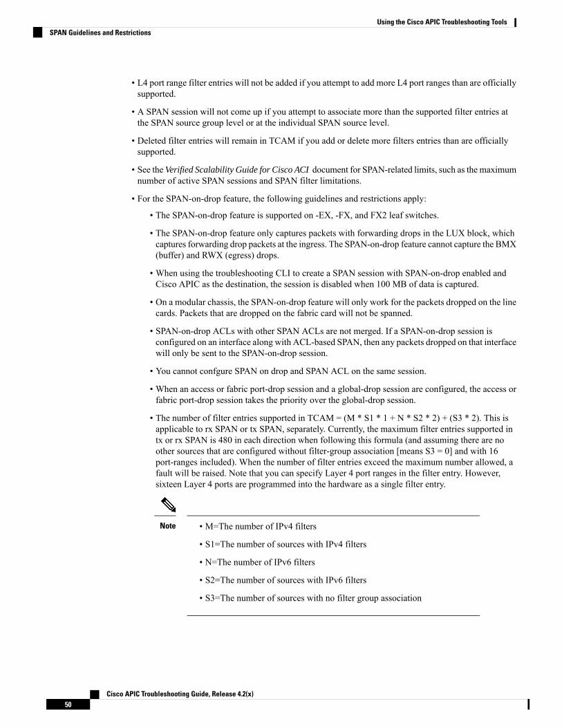
• L4 port range filter entries will not be added if you attempt to add more L4 port ranges than are officiallysupported.
• A SPAN session will not come up if you attempt to associate more than the supported filter entries atthe SPAN source group level or at the individual SPAN source level.
• Deleted filter entries will remain in TCAM if you add or delete more filters entries than are officiallysupported.
• See the Verified Scalability Guide for Cisco ACI document for SPAN-related limits, such as the maximumnumber of active SPAN sessions and SPAN filter limitations.
• For the SPAN-on-drop feature, the following guidelines and restrictions apply:
• The SPAN-on-drop feature is supported on -EX, -FX, and FX2 leaf switches.
• The SPAN-on-drop feature only captures packets with forwarding drops in the LUX block, whichcaptures forwarding drop packets at the ingress. The SPAN-on-drop feature cannot capture the BMX(buffer) and RWX (egress) drops.
• When using the troubleshooting CLI to create a SPAN session with SPAN-on-drop enabled andCisco APIC as the destination, the session is disabled when 100 MB of data is captured.
• On a modular chassis, the SPAN-on-drop feature will only work for the packets dropped on the linecards. Packets that are dropped on the fabric card will not be spanned.
• SPAN-on-drop ACLs with other SPAN ACLs are not merged. If a SPAN-on-drop session isconfigured on an interface along with ACL-based SPAN, then any packets dropped on that interfacewill only be sent to the SPAN-on-drop session.
• You cannot confgure SPAN on drop and SPAN ACL on the same session.
• When an access or fabric port-drop session and a global-drop session are configured, the access orfabric port-drop session takes the priority over the global-drop session.
• The number of filter entries supported in TCAM = (M * S1 * 1 + N * S2 * 2) + (S3 * 2). This isapplicable to rx SPAN or tx SPAN, separately. Currently, the maximum filter entries supported intx or rx SPAN is 480 in each direction when following this formula (and assuming there are noother sources that are configured without filter-group association [means S3 = 0] and with 16port-ranges included). When the number of filter entries exceed the maximum number allowed, afault will be raised. Note that you can specify Layer 4 port ranges in the filter entry. However,sixteen Layer 4 ports are programmed into the hardware as a single filter entry.
• M=The number of IPv4 filters
• S1=The number of sources with IPv4 filters
• N=The number of IPv6 filters
• S2=The number of sources with IPv6 filters
• S3=The number of sources with no filter group association
Note
Cisco APIC Troubleshooting Guide, Release 4.2(x)50
Using the Cisco APIC Troubleshooting ToolsSPAN Guidelines and Restrictions

Configuring SPAN Using the GUI
Configuring a Tenant SPAN Session Using the Cisco APIC GUISPAN can be configured on a switch or on a tenant. This section guides you through the Cisco APIC GUI toconfigure a SPAN policy on a tenant to forward replicated source packets to a remote traffic analyzer. Theconfiguration procedure requires entering values in the fields of one or more GUI dialog boxes. To understanda field and determine a valid value, view the help file by clicking the help icon (?) at the top-right corner ofthe dialog box.
Step 1 In the menu bar, click Tenants.Step 2 In the submenu bar, click the tenant that contains the source endpoint.Step 3 In the Navigation pane, expand the tenant, expand Policies > Troubleshooting > SPAN.
Two nodes appear under SPAN: SPAN Destination Groups and SPAN Source Groups.
Step 4 From the Navigation pane, right-click SPAN Source Groups and choose Create SPAN Source Group.The Create SPAN Source Group dialog appears.
Step 5 Enter the appropriate values in the required fields of the Create SPAN Source Group dialog box.
For a description of a field, click the information icon (?) at the top-right corner of the dialog box to displaythe help file.
Note
Step 6 Expand the Create Sources table to open the Create SPAN Source dialog box.Step 7 Enter the appropriate values in the Create SPAN Source dialog box fields.
For the explanation of a field, click the help icon (?) to view the help file.Note
Step 8 When finished creating the SPAN source, click OK.
You return to the Create SPAN Source Group dialog box.
Step 9 When finished entering values in the Create SPAN Source Group dialog box fields, click Submit.
What to do next
Using a traffic analyzer at the SPAN destination, you can observe the data packets from the SPAN sourceEPG to verify the packet format, addresses, protocols, and other information.
Configuring a SPAN Filter Group Using the APIC GUI
Step 1 In the menu bar, click on Fabric and in the submenu bar click on Access Policies.Step 2 In the Navigation pane, expand Policies > Troubleshooting, and expand SPAN.Step 3 Under SPAN, right-click SPAN Filter Groups and choose Create SPAN Filter Group.
The Create Filter Group dialog appears.Step 4 Enter a name for the SPAN filter group, then expand the Filter Entries table to enter values into the following fields:
Cisco APIC Troubleshooting Guide, Release 4.2(x)51
Using the Cisco APIC Troubleshooting ToolsConfiguring SPAN Using the GUI

• Source IP Prefix: Enter a source IP address in the form of IP-address/mask. Both IPv4 and IPv6 addresses aresupported. Use a value of 0.0.0.0 to denote an IPv4 address any entry in this field or use a value of :: to denote anIPv6 address any entry in this field.
• First Source Port: Enter the first source Layer 4 port. This field, together with the Last Source Port field, specifiesa port range for filtering source ports. Use a value of 0 to denote an any entry in this field.
• Last Source Port: Enter the last source Layer 4 port. This field, together with the First Source Port field, specifiesa port range for filtering source ports. Use a value of 0 to denote an any entry in this field.
• Destination IP Prefix: Enter a destination IP address in the form of IP-address/mask. Both IPv4 and IPv6 addressesare supported. Use a value of 0.0.0.0 to denote an IPv4 address any entry in this field or use a value of :: to denotean IPv6 address any entry in this field.
• First Destination Port: Enter the first destination Layer 4 port. This field, together with the Last Destination Portfield, specifies a port range for filtering destination ports. Use a value of 0 to denote an any entry in this field.
• Last Destination Port: Enter the last destination Layer 4 port. This field, together with the First Destination Portfield, specifies a port range for filtering destination ports. Use a value of 0 to denote an any entry in this field.
• IP Protocol: Enter the IP protocol. Use a value of 0 to denote an any entry in this field.
Step 5 Click Update, then click Submit when you have entered the appropriate values into each of the fields in this form.
Configuring an Access SPAN Policy Using the Cisco APIC GUIThis procedure guides you through the Cisco APICGUI to configure an access SPAN policy. The configurationprocedure requires entering values in the fields of one or more GUI dialog boxes. To understand a field anddetermine a valid value, view the help file by clicking the help icon (?) at the top-right corner of the dialogbox.
Step 1 In the menu bar, click on Fabric > Access Policies.Step 2 In the Navigation pane, expand Policies > Troubleshooting > SPAN.
Three nodes appear under SPAN: SPAN Source Groups, SPAN Filter Groups, and SPAN Destination Groups.
Step 3 Right-click SPAN Source Groups and choose Create SPAN Source Group.The Create SPAN Source Group dialog appears.
Step 4 Enter the appropriate values in the Create SPAN Source Group dialog box fields.
For the explanation of a field, click the help icon (?) to view the help file.Note
Step 5 Expand the Create Sources table to open the Create SPAN Source dialog box and enter the appropriate values in therequired fields.
For the explanation of a field, click the help icon (?) to view the help file.Note
Step 6 In the Create SPAN Source dialog box, expand Add Source Access Paths to specify the source path.
The Associate Source to Path dialog box appears.
Step 7 Enter the appropriate values in the Associate Source to Path dialog box fields.
Cisco APIC Troubleshooting Guide, Release 4.2(x)52
Using the Cisco APIC Troubleshooting ToolsConfiguring an Access SPAN Policy Using the Cisco APIC GUI

For the explanation of a field, click the help icon (?) to view the help file.Note
Step 8 When finished associating the source to a path, click OK.
You return to the Create SPAN Source dialog box.
Step 9 When finished configuring the SPAN source, click OK.
You return to the Create SPAN Source Group dialog box.
Step 10 When finished configuring the SPAN source group, click Submit.
What to do next
Using a traffic analyzer at the SPAN destination, you can observe the data packets from the SPAN source toverify the packet format, addresses, protocols, and other information.
Configuring a Fabric SPAN Policy Using the Cisco APIC GUIThis section guides you through the Cisco APIC GUI to create a fabric SPAN policy. The configurationprocedure requires entering values in the fields of one or more GUI dialog boxes. To understand a field anddetermine a valid value, view the help file by clicking the help icon (?) at the top-right corner of the dialogbox.
Step 1 In the menu bar, click on Fabric > Fabric Policies.Step 2 In the Navigation pane, expand Policies > Troubleshooting > SPAN.
Three nodes appear under SPAN: SPAN Source Groups, SPAN Filter Groups, and SPAN Destination Groups.
Step 3 Right-click SPAN Source Groups and choose Create SPAN Source Group.The Create SPAN Source Group dialog appears.
Step 4 Enter the appropriate values in the Create SPAN Source Group dialog box fields.
For the explanation of a field, click the help icon (?) to view the help file.Note
Step 5 Expand the Create Sources table to open the Create SPAN Source dialog box.Step 6 Enter the appropriate values in the Create SPAN Source dialog box fields.
For the explanation of a field, click the help icon (?) to view the help file.Note
Step 7 When finished, click OK.
You return to the Create SPAN Source Group dialog box.
Step 8 When finished entering values in the Create SPAN Source Group dialog box fields, click Submit.
What to do next
Using a traffic analyzer at the SPAN destination, you can observe the data packets from the SPAN source toverify the packet format, addresses, protocols, and other information.
Cisco APIC Troubleshooting Guide, Release 4.2(x)53
Using the Cisco APIC Troubleshooting ToolsConfiguring a Fabric SPAN Policy Using the Cisco APIC GUI

Configuring a Layer 3 EPG SPAN Session for External Access Using the APIC GUIThis procedure shows how to configure a Layer 3 EPG SPAN policy for External Access using the CiscoAPIC GUI. The configuration procedure requires entering values in the fields of one or more GUI dialogboxes. To understand a field and determine a valid value, view the help file by clicking the help icon (?) atthe top-right corner of the dialog box.
Step 1 In the menu bar, click on Fabric > Access Policies.Step 2 In the Navigation pane, expand Policies > Troubleshooting > SPAN.
Three nodes appear under SPAN: SPAN Source Groups, SPAN Filter Groups, and SPAN Destination Groups.
Step 3 Right-click SPAN Source Groups and choose Create SPAN Source Group.The Create SPAN Source Group dialog appears.
Step 4 Enter the appropriate values in the Create SPAN Source Group dialog box fields.
For the explanation of a field, click the help icon (?) to view the help file.Note
Step 5 In the Filter Group field, select or create a filter group.
See Configuring a SPAN Filter Group Using the APIC GUI, on page 51 for more information.
Step 6 Expand the Create Sources table to open the Create SPAN Source dialog box and perform the following actions:a) Enter a Name for the source policy.b) Choose a Direction option for the traffic flow.c) (Optional) Click to place a check mark in the Span Drop Packets check box. When checked, the SPAN-on-drop
feature is enabled.
For more information about the SPAN-on-drop feature, click the help icon (?) to view the help file.Note
d) For external access, click Routed Outside in the Type field.
If Routed Outside is chosen for external access, then the Name, Address, and Encap fields appear toconfigure the L3 Outside.
Note
e) Expand Add Source Access Paths to specify the source path.
The Associate Source to Path dialog box appears.
f) Enter the appropriate values in the Associate Source to Path dialog box fields.
For the explanation of a field, click the help icon (?) to view the help file.Note
g) When finished associating the source to a path, click OK.
You return to the Create SPAN Source dialog box.
h) When finished configuring the SPAN source, click OK.
You return to the Create SPAN Source Group dialog box.
Step 7 When finished configuring the SPAN source group, click Submit.
Cisco APIC Troubleshooting Guide, Release 4.2(x)54
Using the Cisco APIC Troubleshooting ToolsConfiguring a Layer 3 EPG SPAN Session for External Access Using the APIC GUI

What to do next
Using a traffic analyzer at the SPAN destination, you can observe the data packets from the SPAN source toverify the packet format, addresses, protocols, and other information.
Configuring a Destination Group for an Access SPAN Policy Using the Cisco APIC GUIThis section guides you through the Cisco APIC GUI to create a destination group for an access SPAN policy.The configuration procedure requires entering values in the fields of one or more GUI dialog boxes. Tounderstand a field and determine a valid value, view the help file by clicking the help icon (?) at the top-rightcorner of the dialog box.
Creating a SPAN destination group and source enables you to use a traffic analyzer at the SPAN destinationto observe the data packets from the SPAN source and verify the packet format, addresses, protocols, andother information.
Step 1 In the menu bar, click on Fabric > Access Policies.Step 2 In the Navigation pane, expand Policies > Troubleshooting > SPAN.
Three nodes appear under SPAN: SPAN Source Groups, SPAN Filter Groups, and SPAN Destination Groups.
Step 3 Right-click SPAN Destination Groups and choose Create SPAN Destination Group.The Create SPAN Destination Group dialog appears.
Step 4 Enter the appropriate values in the Create SPAN Destination Group dialog box fields.
For the explanation of a field, click the help icon (?) to view the help file.Note
Step 5 When finished, click Submit.
The destination group is created.
Configuring a Destination Group for a Fabric SPAN Policy Using the Cisco APIC GUIThis section guides you through the Cisco APIC GUI to create a destination group for a fabric SPAN policy.The configuration procedure requires entering values in the fields of one or more GUI dialog boxes. Tounderstand a field and determine a valid value, view the help file by clicking the help icon (?) at the top-rightcorner of the dialog box.
Creating a SPAN destination group and source enables you to use a traffic analyzer at the SPAN destinationto observe the data packets from the SPAN source and verify the packet format, addresses, protocols, andother information.
Step 1 In the menu bar, click on Fabric > Fabric Policies.Step 2 In the Navigation pane, expand Policies > Troubleshooting > SPAN.
Three nodes appear under SPAN: SPAN Source Groups, SPAN Filter Groups, and SPAN Destination Groups.
Step 3 Right-click SPAN Destination Groups and choose Create SPAN Destination Group.The Create SPAN Destination Group dialog appears.
Step 4 Enter the appropriate values in the Create SPAN Destination Group dialog box fields.
Cisco APIC Troubleshooting Guide, Release 4.2(x)55
Using the Cisco APIC Troubleshooting ToolsConfiguring a Destination Group for an Access SPAN Policy Using the Cisco APIC GUI

For the explanation of a field, click the help icon (?) to view the help file.Note
Step 5 When finished, click Submit.
The destination group is created.
What to do next
If not already created, configure a source for the fabric SPAN policy.
Configuring SPAN Using the NX-OS Style CLI
Configuring Local SPAN in Access ModeThis is the traditional SPAN configuration local to an Access leaf node. Traffic originating from one or moreaccess ports or port-channels can be monitored and sent to a destination port local to the same leaf node.
SUMMARY STEPS
1. configure terminal2. [no] monitor access session session-name
3. [no] description text
4. [no] destination interface ethernet slot/port leaf node-id
5. [no] source interface ethernet {[fex/] slot/port | port-range} leaf node-id
6. drop enable7. [no] direction {rx | tx | both}8. [no] filter tenant tenant-name application application-name epg epg-name
9. exit10. [no] destination interface port-channel port-channel-name-list leaf node-id
11. [no] source interface port-channel port-channel-name-list leaf node-id [fex fex-id]12. [no] filter tenant tenant-name l3out L3Out-name vlan interface-VLAN
13. [no] shutdown
DETAILED STEPS
PurposeCommand or Action
Enters global configuration mode.configure terminal
Example:
Step 1
apic1# configure terminal
Creates an access monitoring session configuration.[no] monitor access session session-name
Example:
Step 2
apic1(config)# monitor access session mySession
Cisco APIC Troubleshooting Guide, Release 4.2(x)56
Using the Cisco APIC Troubleshooting ToolsConfiguring SPAN Using the NX-OS Style CLI

PurposeCommand or Action
Adds a description for this access monitoring session. Ifthe text includes spaces, it must be enclosed in singlequotes.
[no] description text
Example:apic1(config-monitor-access)# description "Thisis my SPAN session"
Step 3
Specifies the destination interface. The destination interfacecannot be a FEX port.
[no] destination interface ethernet slot/port leaf node-id
Example:
Step 4
apic1(config-monitor-access)# destinationinterface ethernet 1/2 leaf 101
Specifies the source interface port or port range.[no] source interface ethernet {[fex/] slot/port |port-range} leaf node-id
Step 5
Example:apic1(config-monitor-access)# source interfaceethernet 1/2 leaf 101
Enables the SPAN on drop feature, which captures allpackets that are dropped in the ASIC and sends them to apre-configured SPAN destination.
drop enable
Example:apic1(config-monitor-access-source)# drop enable
Step 6
Specifies direction of traffic to be monitored. The directioncan be configured independently for each source portrange.
[no] direction {rx | tx | both}
Example:apic1(config-monitor-access-source)# direction tx
Step 7
Filters traffic to be monitored. The filter can be configuredindependently for each source port range.
[no] filter tenant tenant-name applicationapplication-name epg epg-name
Example:
Step 8
apic1(config-monitor-access-source)# filter tenantt1 application app1 epg epg1
Returns to access monitor session configuration mode.exit
Example:
Step 9
apic1(config-monitor-access-source)# exit
Specifies the destination interface. The destination interfacecannot be a FEX port.
[no] destination interface port-channelport-channel-name-list leaf node-id
Step 10
Example: Beginning with Release 4.1(1), support is nowavailable for having a static port-channel as thedestination interface, as shown in the examplecommand.
Note
apic1(config-monitor-access)# destinationinterface port-channel pc1 leaf 101
Specifies the source interface port channel.[no] source interface port-channelport-channel-name-list leaf node-id [fex fex-id]
Step 11
(Enters the traffic direction and filter configuration, notshown here.)Example:
Cisco APIC Troubleshooting Guide, Release 4.2(x)57
Using the Cisco APIC Troubleshooting ToolsConfiguring Local SPAN in Access Mode

PurposeCommand or Actionapic1(config-monitor-access)# source interfaceport-channel pc5 leaf 101
Filters traffic to be monitored. The filter can be configuredindependently for each source port range.
[no] filter tenant tenant-name l3out L3Out-name vlaninterface-VLAN
Step 12
Example: Beginning with Release 4.1(1), you no longerhave to specify the IP prefix when configuringL3Out interface filtering, as shown in theexample.
Note
apic1(config-monitor-access-source)# filter tenantt1 l3out l3out1 vlan 2820
Disables (or enables) the monitoring session.[no] shutdown
Example:
Step 13
apic1(config-monitor-access)# no shut
Examples
This example shows how to configure a local access monitoring session.
apic1# configure terminalapic1(config)# monitor access session mySessionapic1(config-monitor-access)# description "This is my SPAN session"apic1(config-monitor-access)# destination interface ethernet 1/2 leaf 101apic1(config-monitor-access)# source interface ethernet 1/1 leaf 101
apic1(config-monitor-access)# drop enable
apic1(config-monitor-access-source)# direction txapic1(config-monitor-access-source)# filter tenant t1 application app1 epg epg1apic1(config-monitor-access-source)# exitapic1(config-monitor-access)# no shutapic1(config-monitor-access)# show run# Command: show running-config monitor access session mySession# Time: Fri Nov 6 23:55:35 2015monitor access session mySessiondescription "This is my SPAN session"destination interface eth 1/2 leaf 101source interface eth 1/1 leaf 101direction txfilter tenant t1 application app1 epg epgexit
exit
Configuring a SPAN Filter GroupThese procedures describe how to configure a SPAN filter group and filter entries.
SUMMARY STEPS
1. configure2. [no] monitor access filter-group filtergroup-name
Cisco APIC Troubleshooting Guide, Release 4.2(x)58
Using the Cisco APIC Troubleshooting ToolsConfiguring a SPAN Filter Group

3. [no] filter srcaddress source-address dstaddress destination-address srcport-from source-from-portsrcport-to source-to-port dstport-from destination-from-port dstport-to destination-to-port ipprotoIP-protocol
4. exit5. exit
DETAILED STEPS
PurposeCommand or Action
Enters global configuration mode.configure
Example:
Step 1
apic1# configure
Creates an access monitoring filter group configuration.[no] monitor access filter-group filtergroup-name
Example:
Step 2
apic1(config)# monitor access filter-groupfiltergroup1
Configures the filter entries for the filter group, where:[no] filter srcaddress source-address dstaddressdestination-address srcport-from source-from-port
Step 3
• source-address is a source IP address in the form ofIP-address/mask. Both IPv4 and IPv6 addresses aresrcport-to source-to-port dstport-from
destination-from-port dstport-to destination-to-portipproto IP-protocol
supported. Use a value of 0.0.0.0 to denote an IPv4address any entry in this field or use a value of :: todenote an IPv6 address any entry in this field.Example:
apic1(config-monitor-fltgrp)# filter srcaddress1.1.1.0/24 dstaddress 0.0.0.0 srcport-from 0 • destination-address is a destination IP address in the
form of IP-address/mask. Both IPv4 and IPv6srcport-to 0 dstport-from 0 dstport-to 0 ipproto20 addresses are supported. Use a value of 0.0.0.0 to
denote an IPv4 address any entry in this field or usea value of :: to denote an IPv6 address any entry inthis field.
• source-from-port is the first source Layer 4 port. Thisfield, together with the srcport-to field, specifies aport range for filtering source ports. Use a value of 0to denote an any entry in this field.
• source-to-port is the last source Layer 4 port. Thisfield, together with the srcport-from field, specifiesa port range for filtering source ports. Use a value of0 to denote an any entry in this field.
• destination-from-port is the first destination Layer 4port. This field, together with the dstport-to field,specifies a port range for filtering destination ports.Use a value of 0 to denote an any entry in this field.
• destination-to-port is the last destination Layer 4 port.This field, together with the dstport-from field,specifies a port range for filtering destination ports.Use a value of 0 to denote an any entry in this field.
Cisco APIC Troubleshooting Guide, Release 4.2(x)59
Using the Cisco APIC Troubleshooting ToolsConfiguring a SPAN Filter Group
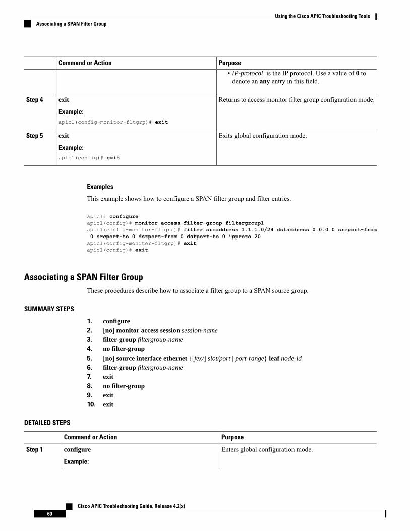
PurposeCommand or Action
• IP-protocol is the IP protocol. Use a value of 0 todenote an any entry in this field.
Returns to access monitor filter group configuration mode.exit
Example:
Step 4
apic1(config-monitor-fltgrp)# exit
Exits global configuration mode.exit
Example:
Step 5
apic1(config)# exit
Examples
This example shows how to configure a SPAN filter group and filter entries.
apic1# configureapic1(config)# monitor access filter-group filtergroup1apic1(config-monitor-fltgrp)# filter srcaddress 1.1.1.0/24 dstaddress 0.0.0.0 srcport-from0 srcport-to 0 dstport-from 0 dstport-to 0 ipproto 20apic1(config-monitor-fltgrp)# exitapic1(config)# exit
Associating a SPAN Filter GroupThese procedures describe how to associate a filter group to a SPAN source group.
SUMMARY STEPS
1. configure2. [no] monitor access session session-name
3. filter-group filtergroup-name
4. no filter-group5. [no] source interface ethernet {[fex/] slot/port | port-range} leaf node-id
6. filter-group filtergroup-name
7. exit8. no filter-group9. exit10. exit
DETAILED STEPS
PurposeCommand or Action
Enters global configuration mode.configure
Example:
Step 1
Cisco APIC Troubleshooting Guide, Release 4.2(x)60
Using the Cisco APIC Troubleshooting ToolsAssociating a SPAN Filter Group

PurposeCommand or Actionapic1# configure
Creates an access monitoring session configuration.[no] monitor access session session-name
Example:
Step 2
apic1(config)# monitor access session session1
Associates a filter group.filter-group filtergroup-name
Example:
Step 3
apic1(config-monitor-access)# filter-groupfiltergroup1
Disassociates a filter group, if necessary.no filter-group
Example:
Step 4
apic1(config-monitor-access)# no filter-group
Specifies the source interface port or port range.[no] source interface ethernet {[fex/] slot/port |port-range} leaf node-id
Step 5
Example:apic1(config-monitor-access)# source interfaceethernet 1/9 leaf 101
Associates a filter group to a SPAN source.filter-group filtergroup-name
Example:
Step 6
apic1(config-monitor-access-source)# filter-groupfiltergroup2
Returns to access monitor filter group configuration mode.exit
Example:
Step 7
apic1(config-monitor-access-source)# exit
Disassociates the filter group from a SPAN source, ifnecessary.
no filter-group
Example:
Step 8
apic1(config-monitor-access-source)# nofilter-group
Returns to access monitor filter group configuration mode.exit
Example:
Step 9
apic1(config-monitor-access)# exit
Exits global configuration mode.exit
Example:
Step 10
apic1(config)# exit
Cisco APIC Troubleshooting Guide, Release 4.2(x)61
Using the Cisco APIC Troubleshooting ToolsAssociating a SPAN Filter Group

Examples
This example shows how to associate a filter group.
apic1# configureapic1(config)# monitor access session session1apic1(config-monitor-access)# filter-group filtergroup1apic1(config-monitor-access)# source interface ethernet 1/9 leaf 101apic1(config-monitor-access-source)# filter-group filtergroup2apic1(config-monitor-access-source)# exitapic1(config-monitor-access-source)# no filter-groupapic1(config-monitor-access)# exitapic1(config)# exit
Configuring ERSPAN in Access ModeIn the ACI fabric, an access mode ERSPAN configuration can be used for monitoring traffic originating fromaccess ports, port-channels, and vPCs in one or more leaf nodes.
For an ERSPAN session, the destination is always an endpoint group (EPG) which can be deployed anywherein the fabric. The monitored traffic is forwarded to the destination wherever the EPG is moved.
SUMMARY STEPS
1. configure terminal2. [no] monitor access session session-name
3. [no] description text
4. [no] destination tenant tenant-name application application-name epg epg-name destination-ipdest-ip-address source-ip-prefix src-ip-address
5. [no] erspan-id flow-id
6. [no] ip dscp dscp-code
7. [no] ip ttl ttl-value
8. [no] mtu mtu-value
9. exit10. [no] source interface ethernet {[fex/] slot/port | port-range} leaf node-id
11. [no] source interface port-channel port-channel-name-list leaf node-id [fex fex-id]12. [no] source interface vpc vpc-name-list leaf node-id1 node-id2 [fex fex-id1 fex-id2]13. drop enable14. [no] direction {rx | tx | both}15. [no] filter tenant tenant-name application application-name epg epg-name
16. exit17. [no] shutdown
DETAILED STEPS
PurposeCommand or Action
Enters global configuration mode.configure terminal
Example:
Step 1
Cisco APIC Troubleshooting Guide, Release 4.2(x)62
Using the Cisco APIC Troubleshooting ToolsConfiguring ERSPAN in Access Mode

PurposeCommand or Actionapic1# configure terminal
Creates an access monitoring session configuration.[no] monitor access session session-name
Example:
Step 2
apic1(config)# monitor access session mySession
Adds a description for this monitoring session. If the textincludes spaces, it must be enclosed in single quotes.
[no] description text
Example:
Step 3
apic1(config-monitor-access)# description "Thisis my access ERSPAN session"
Specifies the destination interface as a tenant and entersdestination configuration mode.
[no] destination tenant tenant-name applicationapplication-name epg epg-name destination-ipdest-ip-address source-ip-prefix src-ip-address
Step 4
Example:apic1(config-monitor-access)# destination tenantt1 application app1 epg epg1 destination-ip192.0.20.123 source-ip-prefix 10.0.20.1
Configures the ERSPAN ID for the ERSPAN session. TheERSPAN range is from 1 to 1023.
[no] erspan-id flow-id
Example:
Step 5
apic1(config-monitor-access-dest)# erspan-id 100
Configures the differentiated services code point (DSCP)value of the packets in the ERSPAN traffic. The range isfrom 0 to 64.
[no] ip dscp dscp-code
Example:apic1(config-monitor-access-dest)# ip dscp 42
Step 6
Configures the IP time-to-live (TTL) value for theERSPAN traffic. The range is from 1 to 255.
[no] ip ttl ttl-value
Example:
Step 7
apic1(config-monitor-access-dest)# ip ttl 16
Configures the maximum transmit unit (MTU) size for theERSPAN session. The range is 64 to 9216 bytes.
[no] mtu mtu-value
Example:
Step 8
apic1(config-monitor-access-dest)# mtu 9216
Returns to monitor access configuration mode.exit
Example:
Step 9
apic1(config-monitor-access-dest)#
Specifies the source interface port or port range.[no] source interface ethernet {[fex/] slot/port |port-range} leaf node-id
Step 10
Example:apic1(config-monitor-access)# source interfaceeth 1/2 leaf 101
Specifies the source interface port-channel.[no] source interface port-channelport-channel-name-list leaf node-id [fex fex-id]
Step 11
Cisco APIC Troubleshooting Guide, Release 4.2(x)63
Using the Cisco APIC Troubleshooting ToolsConfiguring ERSPAN in Access Mode

PurposeCommand or Action
Example:apic1(config-monitor-access)# source interfaceport-channel pc1 leaf 101
Specifies the source interface vPC.[no] source interface vpc vpc-name-list leaf node-id1node-id2 [fex fex-id1 fex-id2]
Step 12
Example:apic1(config-monitor-access)# source interfacevpc pc1 leaf 101 102
Enables the SPAN on drop feature, which captures allpackets that are dropped in the ASIC and sends them to apre-configured SPAN destination.
drop enable
Example:apic1(config-monitor-access-source)# drop enable
Step 13
Specifies direction of traffic to be monitored. The directioncan be configured independently for each source portrange.
[no] direction {rx | tx | both}
Example:apic1(config-monitor-access-source)# direction tx
Step 14
Filters traffic to be monitored. The filter can be configuredindependently for each source port range.
[no] filter tenant tenant-name applicationapplication-name epg epg-name
Example:
Step 15
apic1(config-monitor-access-source)# filter tenantt1 application app1 epg epg1
Returns to access monitor session configuration mode.exit
Example:
Step 16
apic1(config-monitor-access-source)# exit
Disables (or enables) the monitoring session.[no] shutdown
Example:
Step 17
apic1(config-monitor-access)# no shut
Examples
This example shows how to configure an ERSPAN access monitoring session.
apic1# configure terminalapic1(config)# monitor access session mySessionapic1(config-monitor-access)# description "This is my access ERSPAN session"apic1(config-monitor-access)# destination tenant t1 application app1 epg epg1 destination-ip192.0.20.123 source-ip-prefix 10.0.20.1apic1(config-monitor-access-dest)# erspan-id 100apic1(config-monitor-access-dest)# ip dscp 42apic1(config-monitor-access-dest)# ip ttl 16apic1(config-monitor-access-dest)# mtu 9216apic1(config-monitor-access-dest)# exitapic1(config-monitor-access)# source interface eth 1/1 leaf 101
Cisco APIC Troubleshooting Guide, Release 4.2(x)64
Using the Cisco APIC Troubleshooting ToolsConfiguring ERSPAN in Access Mode

apic1(config-monitor-access-source)# direction txapic1(config-monitor-access-source)#drop enable
apic1(config-monitor-access-source)# filter tenant t1 application app1 epg epg1apic1(config-monitor-access-source)# exitapic1(config-monitor-access)# no shutapic1(config-monitor-access)# show run# Command: show running-config monitor access session mySession# Time: Fri Nov 6 23:55:35 2015monitor access session mySessiondescription "This is my ERSPAN session"source interface eth 1/1 leaf 101direction txfilter tenant t1 application app1 epg epg1exit
destination tenant t1 application app1 epg epg1 destination-ip 192.0.20.123source-ip-prefix 10.0.20.1
ip dscp 42ip ttl 16erspan-id 9216mtu 9216exit
exit
This example shows how to configure a port-channel as a monitoring source.
apic1(config-monitor-access)# source interface port-channel pc3 leaf 105
This example shows how to configure a one leg of a vPC as a monitoring source.
apic1(config-monitor-access)# source interface port-channel vpc3 leaf 105
This example shows how to configure a range of ports from FEX 101 as a monitoring source.
apic1(config-monitor-access)# source interface eth 101/1/1-2 leaf 105
Configuring ERSPAN in Fabric ModeIn the ACI fabric, a fabric mode ERSPAN configuration can be used for monitoring traffic originating fromone or more fabric ports in leaf or spine nodes. Local SPAN is not supported in fabric mode.
For an ERSPAN session, the destination is always an endpoint group (EPG) which can be deployed anywherein the fabric. The monitored traffic is forwarded to the destination wherever the EPG is moved. In the fabricmode, only fabric ports are allowed as source, but both leaf and spine switches are allowed.
SUMMARY STEPS
1. configure terminal2. [no] monitor fabric session session-name
3. [no] description text
4. [no] destination tenant tenant-name application application-name epg epg-name destination-ipdest-ip-address source-ip-prefix src-ip-address
5. [no] erspan-id flow-id
Cisco APIC Troubleshooting Guide, Release 4.2(x)65
Using the Cisco APIC Troubleshooting ToolsConfiguring ERSPAN in Fabric Mode

6. [no] ip dscp dscp-code
7. [no] ip ttl ttl-value
8. [no] mtu mtu-value
9. exit10. [no] source interface ethernet {slot/port | port-range} switch node-id
11. drop enable12. [no] direction {rx | tx | both}13. [no] filter tenant tenant-name bd bd-name
14. [no] filter tenant tenant-name vrf vrf-name
15. exit16. [no] shutdown
DETAILED STEPS
PurposeCommand or Action
Enters global configuration mode.configure terminal
Example:
Step 1
apic1# configure terminal
Creates a fabric monitoring session configuration.[no] monitor fabric session session-name
Example:
Step 2
apic1(config)# monitor fabric session mySession
Adds a description for this monitoring session. If the textincludes spaces, it must be enclosed in single quotes.
[no] description text
Example:
Step 3
apic1(config-monitor-fabric)# description "Thisis my fabric ERSPAN session"
Specifies the destination interface as a tenant and entersdestination configuration mode.
[no] destination tenant tenant-name applicationapplication-name epg epg-name destination-ipdest-ip-address source-ip-prefix src-ip-address
Step 4
Example:apic1(config-monitor-fabric)# destination tenantt1 application app1 epg epg1 destination-ip192.0.20.123 source-ip-prefix 10.0.20.1
Configures the ERSPAN ID for the ERSPAN session. TheERSPAN range is from 1 to 1023.
[no] erspan-id flow-id
Example:
Step 5
apic1(config-monitor-fabric-dest)# erspan-id 100
Configures the differentiated services code point (DSCP)value of the packets in the ERSPAN traffic. The range isfrom 0 to 64.
[no] ip dscp dscp-code
Example:apic1(config-monitor-fabric-dest)# ip dscp 42
Step 6
Configures the IP time-to-live (TTL) value for theERSPAN traffic. The range is from 1 to 255.
[no] ip ttl ttl-value
Example:
Step 7
Cisco APIC Troubleshooting Guide, Release 4.2(x)66
Using the Cisco APIC Troubleshooting ToolsConfiguring ERSPAN in Fabric Mode

PurposeCommand or Actionapic1(config-monitor-fabric-dest)# ip ttl 16
Configures the maximum transmit unit (MTU) size for theERSPAN session. The range is 64 to 9216 bytes.
[no] mtu mtu-value
Example:
Step 8
apic1(config-monitor-fabric-dest)# mtu 9216
Returns to monitor access configuration mode.exit
Example:
Step 9
apic1(config-monitor-fabric-dest)#
Specifies the source interface port or port range.[no] source interface ethernet {slot/port | port-range}switch node-id
Step 10
Example:apic1(config-monitor-fabric)# source interfaceeth 1/2 switch 101
Enables the SPAN on drop feature, which captures allpackets that are dropped in the ASIC and sends them to apre-configured SPAN destination.
drop enable
Example:apic1(config-monitor-fabric-source)# drop enable
Step 11
Specifies direction of traffic to be monitored. The directioncan be configured independently for each source portrange.
[no] direction {rx | tx | both}
Example:apic1(config-monitor-fabric-source)# direction tx
Step 12
Filters traffic by bridge domain.[no] filter tenant tenant-name bd bd-name
Example:
Step 13
apic1(config-monitor-fabric-source)# filter tenantt1 bd bd1
Filters traffic by VRF.[no] filter tenant tenant-name vrf vrf-name
Example:
Step 14
apic1(config-monitor-fabric-source)# filter tenantt1 vrf vrf1
Returns to access monitor session configuration mode.exit
Example:
Step 15
apic1(config-monitor-fabric-source)# exit
Disables (or enables) the monitoring session.[no] shutdown
Example:
Step 16
apic1(config-monitor-fabric)# no shut
Cisco APIC Troubleshooting Guide, Release 4.2(x)67
Using the Cisco APIC Troubleshooting ToolsConfiguring ERSPAN in Fabric Mode

Examples
This example shows how to configure an ERSPAN fabric monitoring session.
apic1# configure terminalapic1(config)# monitor fabric session mySessionapic1(config-monitor-fabric)# description "This is my fabric ERSPAN session"apic1(config-monitor-fabric)# destination tenant t1 application app1 epg epg1 destination-ip192.0.20.123 source-ip-prefix 10.0.20.1apic1(config-monitor-fabric-dest)# erspan-id 100apic1(config-monitor-fabric-dest)# ip dscp 42apic1(config-monitor-fabric-dest)# ip ttl 16apic1(config-monitor-fabric-dest)# mtu 9216apic1(config-monitor-fabric-dest)# exitapic1(config-monitor-fabric)# source interface eth 1/1 switch 101
apic1(config-monitor-fabric-source)# drop enable
apic1(config-monitor-fabric-source)# direction txapic1(config-monitor-fabric-source)# filter tenant t1 bd bd1apic1(config-monitor-fabric-source)# filter tenant t1 vrf vrf1apic1(config-monitor-fabric-source)# exitapic1(config-monitor-fabric)# no shut
Configuring ERSPAN in Tenant ModeIn the ACI fabric, a tenant mode ERSPAN configuration can be used for monitoring traffic originating fromendpoint groups within a tenant.
In the tenant mode, traffic originating from a source EPG is sent to a destination EPG within the same tenant.The monitoring of traffic is not impacted if the source or destination EPG is moved within the fabric.
SUMMARY STEPS
1. configure terminal2. [no] monitor tenant tenant-name session session-name
3. [no] description text
4. [no] destination tenant tenant-name application application-name epg epg-name destination-ipdest-ip-address source-ip-prefix src-ip-address
5. [no] erspan-id flow-id
6. [no] ip dscp dscp-code
7. [no] ip ttl ttl-value
8. [no] mtu mtu-value
9. exit10. [no] source application application-name epg epg-name
11. [no] direction {rx | tx | both}12. exit13. [no] shutdown
Cisco APIC Troubleshooting Guide, Release 4.2(x)68
Using the Cisco APIC Troubleshooting ToolsConfiguring ERSPAN in Tenant Mode

DETAILED STEPS
PurposeCommand or Action
Enters global configuration mode.configure terminal
Example:
Step 1
apic1# configure terminal
Creates a tenant monitoring session configuration.[no] monitor tenant tenant-name session session-name
Example:
Step 2
apic1(config)# monitor tenant session mySession
Adds a description for this access monitoring session. Ifthe text includes spaces, it must be enclosed in singlequotes.
[no] description text
Example:apic1(config-monitor-tenant)# description "Thisis my tenant ERSPAN session"
Step 3
Specifies the destination interface as a tenant and entersdestination configuration mode.
[no] destination tenant tenant-name applicationapplication-name epg epg-name destination-ipdest-ip-address source-ip-prefix src-ip-address
Step 4
Example:apic1(config-monitor-tenant)# destination tenantt1 application app1 epg epg1 destination-ip192.0.20.123 source-ip-prefix 10.0.20.1
Configures the ERSPAN ID for the ERSPAN session. TheERSPAN range is from 1 to 1023.
[no] erspan-id flow-id
Example:
Step 5
apic1(config-monitor-tenant-dest)# erspan-id 100
Configures the differentiated services code point (DSCP)value of the packets in the ERSPAN traffic. The range isfrom 0 to 64.
[no] ip dscp dscp-code
Example:apic1(config-monitor-tenant-dest)# ip dscp 42
Step 6
Configures the IP time-to-live (TTL) value for theERSPAN traffic. The range is from 1 to 255.
[no] ip ttl ttl-value
Example:
Step 7
apic1(config-monitor-tenant-dest)# ip ttl 16
Configures the maximum transmit unit (MTU) size for theERSPAN session. The range is 64 to 9216 bytes.
[no] mtu mtu-value
Example:
Step 8
apic1(config-monitor-tenant-dest)# mtu 9216
Returns to monitor access configuration mode.exit
Example:
Step 9
apic1(config-monitor-tenant-dest)#
Specifies the source interface port or port range.[no] source application application-name epg epg-name
Example:
Step 10
Cisco APIC Troubleshooting Guide, Release 4.2(x)69
Using the Cisco APIC Troubleshooting ToolsConfiguring ERSPAN in Tenant Mode

PurposeCommand or Actionapic1(config-monitor-tenant)# source applicationapp2 epg epg5
Specifies direction of traffic to be monitored. The directioncan be configured independently for each source portrange.
[no] direction {rx | tx | both}
Example:apic1(config-monitor-tenant-source)# direction tx
Step 11
Returns to access monitor session configuration mode.exit
Example:
Step 12
apic1(config-monitor-tenant-source)# exit
Disables (or enables) the monitoring session.[no] shutdown
Example:
Step 13
apic1(config-monitor-tenant)# no shut
Examples
This example shows how to configure an ERSPAN tenant monitoring session.
apic1# configure terminalapic1(config)# monitor access session mySessionapic1(config-monitor-tenant)# description "This is my tenant ERSPAN session"apic1(config-monitor-tenant)# destination tenant t1 application app1 epg epg1 destination-ip192.0.20.123 source-ip-prefix 10.0.20.1apic1(config-monitor-tenant-dest)# erspan-id 100apic1(config-monitor-tenant-dest)# ip dscp 42apic1(config-monitor-tenant-dest)# ip ttl 16apic1(config-monitor-tenant-dest)# mtu 9216apic1(config-monitor-tenant-dest)# exitapic1(config-monitor-tenant)# source application app2 epg epg5apic1(config-monitor-tenant-source)# direction txapic1(config-monitor-tenant-source)# exitapic1(config-monitor-tenant)# no shut
Configuring a Global SPAN-On-Drop Session Using the CLIThis section demonstrates how to create a global drop with all ports on a node as the SPAN source.
Procedure
PurposeCommand or Action
Enters global configuration mode.configure terminal
Example:
Step 1
apic1# configure terminal
Cisco APIC Troubleshooting Guide, Release 4.2(x)70
Using the Cisco APIC Troubleshooting ToolsConfiguring a Global SPAN-On-Drop Session Using the CLI

PurposeCommand or Action
Creates a fabric monitoring session configuration.[no] monitor fabric session session-name
Example:
Step 2
apic1(config)# monitor fabric sessionSpine301-GD-SOD
Adds a description for this monitoring session. If the textincludes spaces, it must be enclosed in single quotes.
[no] description text
Example:
Step 3
apic1(config-monitor-fabric)# description "This ismy fabric ERSPAN session"
Enables the SPAN on drop feature, which captures allpackets that are dropped in the ASIC and sends them to apre-configured SPAN destination.
source global-drop switch
Example:apic1(config-monitor-fabric)# source global-dropswitch
Step 4
Specifies the destination interface as a tenant and entersdestination configuration mode.
[no] destination tenant tenant-name applicationapplication-name epg epg-name destination-ipdest-ip-address source-ip-prefix src-ip-address
Step 5
Example:apic1(config-monitor-fabric-dest)# destinationtenant ERSPAN application A1 epg E1 destination-ip165.10.10.155 source-ip-prefix 22.22.22.22
Examples
This example shows how to configure a global SPAN-on-Drop session.
apic1# configure terminalapic1(config)# monitor fabric session Spine301-GD-SODapic1(config-monitor-fabric)# source global-drop switchapic1(config-monitor-fabric)# destination tenant ERSPAN application A1 epg E1 destination-ip179.10.10.179 source-ip-prefix 31.31.31.31
Configuring SPAN Using the REST API
Configuring a Fabric Destination Group for an ERSPAN Destination Using the REST APIThis section demonstrates how to use the REST API to configure a fabric destination group for an ERSPANdestination using the REST API. For a complete list of properties, see the APIC Management InformationModel Reference.
Configure a fabric destination group for an ERSPAN destination:
Cisco APIC Troubleshooting Guide, Release 4.2(x)71
Using the Cisco APIC Troubleshooting ToolsConfiguring SPAN Using the REST API

POST https://<APIC_IP>/api/node/mo/uni/infra.xml<spanDestGrp annotation="" descr="" name="Dest2" nameAlias="" ownerKey="" ownerTag="">
<spanDest annotation="" descr="" name="Dest2" nameAlias="" ownerKey="" ownerTag=""><spanRsDestEpg annotation="" dscp="unspecified" finalIp="0.0.0.0"
flowId="1" ip="179.10.10.179" mtu="1518" srcIpPrefix="20.20.20.2" tDn="uni/tn-ERSPAN/ap-A1/epg-E1"ttl="64" ver="ver2" verEnforced="no"/>
</spanDest></spanDestGrp>
Configuring a Global Drop Source Group Using the REST APIThis section demonstrates how to use the REST API to configure a global drop source group using the RESTAPI. For a complete list of properties, see the APIC Management Information Model Reference.
Configure a global drop source group:
POST https://<APIC_IP>/api/node/mo/uni/infra.xml<spanSrcGrp adminSt="enabled" annotation="" descr="" name="Spine-402-GD-SOD" nameAlias="">
<spanSrc annotation="" descr="" dir="both" name="402" nameAlias="" spanOnDrop="yes">
<spanRsSrcToNode annotation="" tDn="topology/pod-1/node-402"/></spanSrc><spanSpanLbl annotation="" descr="" name="402-dst-179" nameAlias=""
tag="yellow-green"/></spanSrcGrp>
Configuring a Leaf Port as a SPAN Destination Using the REST APIThis section demonstrates how to use the REST API to configure a leaf port as a SPAN destination using theREST API. For a complete list of properties, see the APIC Management Information Model Reference.
Configure a leaf port as a SPAN destination:
POST https://<APIC_IP>/api/node/mo/uni/infra.xml<spanDestGrp annotation="" descr="" name="Dest4" nameAlias="" ownerKey="" ownerTag="">
<spanDest annotation="" descr="" name="Dest4" nameAlias="" ownerKey="" ownerTag=""><spanRsDestPathEp annotation="" mtu="1518"
tDn="topology/pod-1/paths-301/pathep-[eth1/18]"/></spanDest>
</spanDestGrp>
Configuring a SPAN Access Source Group Using the REST APIThis section demonstrates how to use the RESTAPI to configure a SPAN access source group using the RESTAPI. For a complete list of properties, see the APIC Management Information Model Reference.
Configure a SPAN access source group:
Cisco APIC Troubleshooting Guide, Release 4.2(x)72
Using the Cisco APIC Troubleshooting ToolsConfiguring a Global Drop Source Group Using the REST API

POST https://<APIC_IP>/api/node/mo/uni/infra.xml<spanSrcGrp adminSt="enabled" annotation="" descr="" name="Test-Src2" nameAlias="" ownerKey=""ownerTag="">
<spanSrc annotation="" descr="" dir="both" name="Src1" nameAlias=""ownerKey="" ownerTag="" spanOnDrop="yes">
<spanRsSrcToPathEp annotation=""tDn="topology/pod-1/paths-301/pathep-[eth1/1]"/>
</spanSrc><spanSpanLbl annotation="" descr="" name="Dest1" nameAlias="" ownerKey="" ownerTag=""
tag="yellow-green"/></spanSrcGrp>
Configuring a SPAN Fabric Source Group Using the REST APIThis section demonstrates how to use the REST API to configure a SPAN fabric source group using the RESTAPI. For a complete list of properties, see the APIC Management Information Model Reference.
Configure a SPAN fabric source group:
POST https://<APIC_IP>/api/node/mo/uni/infra.xml<spanSrcGrp adminSt="enabled" annotation="" descr="" name="Test-Src2" nameAlias="" ownerKey=""ownerTag="">
<spanSrc annotation="" descr="" dir="both" name="Src1" nameAlias=""ownerKey="" ownerTag="" spanOnDrop="yes">
<spanRsSrcToPathEp annotation=""tDn="topology/pod-1/paths-301/pathep-[eth1/51]"/>
</spanSrc><spanSpanLbl annotation="" descr="" name="Dest2" nameAlias="" ownerKey="" ownerTag=""
tag="yellow-green"/></spanSrcGrp>
Configuring an Access Destination Group for an ERSPAN Destination Using the REST APIThis section demonstrates how to use the REST API to configure an access destination group for an ERSPANdestination using the REST API. For a complete list of properties, see the APIC Management InformationModel Reference.
Procedure
PurposeCommand or Action
POST https://<APIC_IP>/api/node/mo/uni/infra.xmlConfigure an access destination group for an ERSPANdestination.
Step 1
<spanDestGrp annotation="" descr="" name="Dest4"nameAlias="" ownerKey="" ownerTag="">
<spanDest annotation="" descr=""name="Dest4" nameAlias="" ownerKey="" ownerTag="">
<spanRsDestPathEpannotation="" mtu="1518"tDn="topology/pod-1/paths-301/pathep-[eth1/18]"/>
</spanDest></spanDestGrp>
Cisco APIC Troubleshooting Guide, Release 4.2(x)73
Using the Cisco APIC Troubleshooting ToolsConfiguring a SPAN Fabric Source Group Using the REST API

Using StatisticsStatistics provide real-timemeasures of observed object and enable trend analysis and troubleshooting. Statisticsgathering can be configured for ongoing or on-demand collection and can be collected in cumulative countersand gauges.
Policies define what statistics are gathered, at what intervals, and what actions to take. For example, a policycould raise a fault on an EPG if a threshold of dropped packets on an ingress VLAN is greater than 1000 persecond.
Statistics data are gathered from a variety of sources, including interfaces, VLANs, EPGs, applicationprofiles,ACL rules, tenants, or internal APIC processes. Statistics accumulate data in 5-minute, 15-minute,1-hour, 1-day, 1-week, 1-month, 1-quarter, or 1-year sampling intervals. Shorter duration intervals feed longerintervals. A variety of statistics properties are available, including last value, cumulative, periodic, rate ofchange, trend, maximum, min, average. Collection and retention times are configurable. Policies can specifyif the statistics are to be gathered from the current state of the system or to be accumulated historically orboth. For example, a policy could specify that historical statistics be gathered for 5-minute intervals over aperiod of 1 hour. The 1 hour is a moving window. Once an hour has elapsed, the incoming 5 minutes ofstatistics are added, and the earliest 5 minutes of data are abandoned.
Themaximum number of 5-minute granularity sample records is limited to 12 samples (one hour of statistics).All other sample intervals are limited to 1,000 sample records. For example, hourly granularity statistics canbe maintained for up to 41 days.
Note
Viewing Statistics in the GUIYou can view statistics for many objects using the APICGUI, including application profiles, physical interfaces,bridge domains, and fabric nodes. To view statistics in the GUI, choose the object in the navigation pane andclick the STATS tab.
Follow these steps to view statistics for an interface:
Step 1 On the menu bar, choose FABRIC > INVENTORY.Step 2 In the Navigation pane, choose a pod.Step 3 Expand the pod, and expand a switch.Step 4 In the Navigation pane, expand Interfaces and choose eth1/1.Step 5 In the Work pane, choose the STATS tab.
The APIC displays interface statistics.
Cisco APIC Troubleshooting Guide, Release 4.2(x)74
Using the Cisco APIC Troubleshooting ToolsUsing Statistics

Example
What to do next
You can use the following icons in the Work pane to manage how the APIC displays statistics:
• Refresh—Manually refreshes statistics.
• Show Table View—Toggles between table and chart views.
• Start or Stop Stats—Enables or disables automatic refresh for statistics.
• Select Stats—Specifies the counters and sample interval to display.
• Download Object as XML—Downloads the object in XML format.
• Measurement Type (Gear icon)—Specifies the statistics measurement type. Options include cumulative,periodic, average, or trend.
Switch Statistics CommandsYou can use the following commands to display statistics on ACI leaf switches.
PurposeCommand
For more information, see Cisco Nexus 9000 SeriesNX-OS Configuration Guides.
Legacy Cisco Nexus show/clear commands
Displays spine port statistics
• port_num—Front port number without the slot.
• detail—Returns SNMP, class and forwardingstatistics.
• nz—Displays only non-zero values.
• internal—Displays internal port statistics.
• int_port_num—Internal logical port number. Forexample, for BCM-0/97, enter 97.
If there is a link reset, the counters will bezeroed out on the switch. The conditionsof counter reset include the following:
Note
• accidental link reset• manually enabled port (after port isdisabled)
show platform internal counters port [port_num |detail | nz | {internal [nz | int_port_num]}]
Displays VLAN statistics.show platform internal counters vlan [hw_vlan_id]
Displays TEP statistics.show platform internal counters tep [tunnel_id]
Cisco APIC Troubleshooting Guide, Release 4.2(x)75
Using the Cisco APIC Troubleshooting ToolsSwitch Statistics Commands

PurposeCommand
Displays flow statistics.show platform internal counters flow [rule_id |{dump [asic inst] | [slice direction | indexhw_index]}]
Clears port statistics.clear platform internal counters port [port_num |{internal [ int_port_num]}]
Clears VLAN counters.clear platform internal counters vlan [hw_vlan_id]
Sets the debug logging level.debug platform internal stats logging levellog_level
Sets the debug logging type.debug platform internal stats logging{err|trace|flow}
Managing Statistics Thresholds Using the GUI
Step 1 On the menu bar, choose Fabric > Fabric Policies.Step 2 In the Navigation pane, click + to expand Monitoring Policies.Step 3 In the Navigation pane, expand the monitoring policy name (such as Default).Step 4 Click Stats Collection Policies.Step 5 In the Stats Collection Policies window, choose a Monitoring Object and Stats Type for which to set a threshold
value..Step 6 In the Work pane, Click the + icon below CONFIG THRESHOLDS.Step 7 In the THRESHOLDS FOR COLLECTION window, click + to add a threshold.Step 8 In the Choose a Property window, choose a statistics type.Step 9 In the EDIT STATS THRESHOLD window, specify the following threshold values:
• Normal Value—A valid value of the counter.
• Threshold Direction—Indicates whether the threshold is a maximum or minimum value.
• Rising Thresholds (Critical, Major, Minor, Warning)—Triggered when the value exceeds the threshold.
• Falling Thresholds (Critical, Major, Minor, Warning)—Triggered when the value drops below the threshold.
Step 10 You can specify a set and reset value for rising and falling thresholds. The set value specifies when a fault is triggered;the reset value specifies when the fault is cleared.
Step 11 Click SUBMIT to save the threshold value.Step 12 In the THRESHOLDS FOR COLLECTION window, click CLOSE.
Statistics Troubleshooting ScenariosThe following table summarizes common statistics troubleshooting scenarios for the Cisco APIC.
Cisco APIC Troubleshooting Guide, Release 4.2(x)76
Using the Cisco APIC Troubleshooting ToolsManaging Statistics Thresholds Using the GUI

SolutionProblem
The problem occurs when a monitoring policy is in place but the APIC does notperform a corresponding action, such as collecting the statistics or acting on atrigger threshold. Follow these steps to resolve the issue:
• Verify that monPolDn points to the correct monitoring policy.
• Ensure that the selectors are configured correctly and that there are no faults.
• For Tenant objects, check the relation to the monitoring policy.
The APIC does notenforce a configuredmonitoring policy
Follow these steps to resolve the issue:
• Review the statistics that are disabled by default within the monitoring policyand collection policy.
• Review the collection policy to determine if the statistics are disabled bydefault or disabled for certain intervals.
• Review the statistics policy to determine if the statistics are disabled bydefault or disabled for certain intervals.
Except for fabric health statistics, 5 minute statistics are stored on theswitch and are lost when the switch reboots.
Note
Some configured statisticsare missing.
Follow these steps to resolve the issue:
• Review the collection settings; if configured at the top level of the monitoringpolicy, the statistics can be overridden for a specific object or statistics type.
• Review the collection policy assigned to the monitoring object. Confirmthat the policy is present and review the administrative state, and historyretention values.
• Verify that the statistics type is configured correctly.
Statistics or history arenot maintained for theconfigured time period.
Review whether the configuration exceeds the maximum historical record size.The limitations are as follows:
• Switch statistics for 5 minute granularity are limited to 12 samples (1 hourof 5 minute granular statistics).
• There is a hard limit of 1000 samples. For example, hourly granular statisticscan be maintained for up to 41 days.
Some statistics are notmaintained for the fullconfigured interval.
Cisco APIC Troubleshooting Guide, Release 4.2(x)77
Using the Cisco APIC Troubleshooting ToolsStatistics Troubleshooting Scenarios
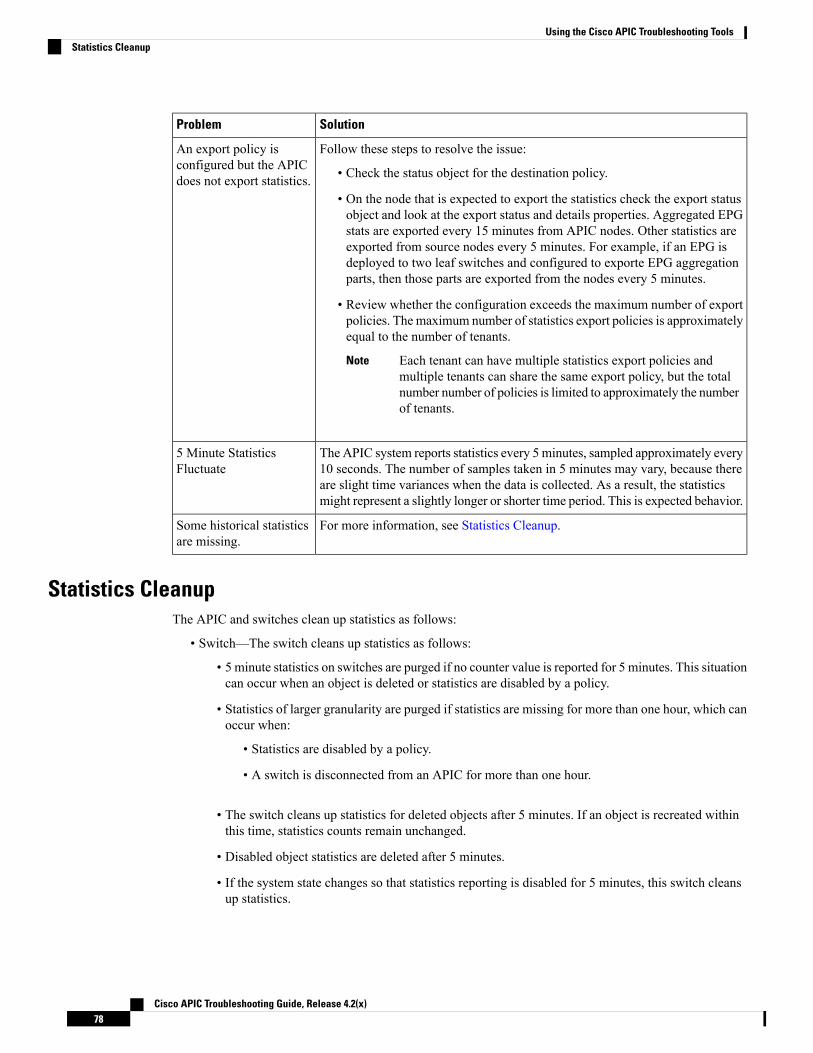
SolutionProblem
Follow these steps to resolve the issue:
• Check the status object for the destination policy.
• On the node that is expected to export the statistics check the export statusobject and look at the export status and details properties. Aggregated EPGstats are exported every 15 minutes from APIC nodes. Other statistics areexported from source nodes every 5 minutes. For example, if an EPG isdeployed to two leaf switches and configured to exporte EPG aggregationparts, then those parts are exported from the nodes every 5 minutes.
• Review whether the configuration exceeds the maximum number of exportpolicies. The maximum number of statistics export policies is approximatelyequal to the number of tenants.
Each tenant can have multiple statistics export policies andmultiple tenants can share the same export policy, but the totalnumber number of policies is limited to approximately the numberof tenants.
Note
An export policy isconfigured but the APICdoes not export statistics.
The APIC system reports statistics every 5 minutes, sampled approximately every10 seconds. The number of samples taken in 5 minutes may vary, because thereare slight time variances when the data is collected. As a result, the statisticsmight represent a slightly longer or shorter time period. This is expected behavior.
5 Minute StatisticsFluctuate
For more information, see Statistics Cleanup.Some historical statisticsare missing.
Statistics CleanupThe APIC and switches clean up statistics as follows:
• Switch—The switch cleans up statistics as follows:
• 5 minute statistics on switches are purged if no counter value is reported for 5 minutes. This situationcan occur when an object is deleted or statistics are disabled by a policy.
• Statistics of larger granularity are purged if statistics are missing for more than one hour, which canoccur when:
• Statistics are disabled by a policy.
• A switch is disconnected from an APIC for more than one hour.
• The switch cleans up statistics for deleted objects after 5 minutes. If an object is recreated withinthis time, statistics counts remain unchanged.
• Disabled object statistics are deleted after 5 minutes.
• If the system state changes so that statistics reporting is disabled for 5 minutes, this switch cleansup statistics.
Cisco APIC Troubleshooting Guide, Release 4.2(x)78
Using the Cisco APIC Troubleshooting ToolsStatistics Cleanup

• APIC—The APIC cleans up objects including interfaces, EPGs, temperature sensors, and health statisticsafter one hour.
Specifying Syslog Sources and DestinationsThis section explains how to create syslog destination groups, a syslog source, and how to enable syslog todisplay in NX-OS CLI format using the REST API.
About SyslogDuring operation, a fault or event in the Cisco Application Centric Infrastructure (ACI) system can triggerthe sending of a system log (syslog) message to the console, to a local file, and to a logging server on anothersystem. A system log message typically contains a subset of information about the fault or event. A systemlog message can also contain audit log and session log entries.
For a list of syslog messages that the APIC and the fabric nodes can generate, see http://www.cisco.com/c/en/us/td/docs/switches/datacenter/aci/apic/sw/1-x/syslog/guide/aci_syslog/ACI_SysMsg.html.
Note
Many system log messages are specific to the action that a user is performing or the object that a user isconfiguring or administering. These messages can be the following:
• Informational messages, providing assistance and tips about the action being performed
• Warning messages, providing information about system errors related to an object, such as a user accountor service profile, that the user is configuring or administering
In order to receive and monitor system log messages, you must specify a syslog destination, which can be theconsole, a local file, or one or more remote hosts running a syslog server. In addition, you can specify theminimum severity level of messages to be displayed on the console or captured by the file or host. The localfile for receiving syslog messages is /var/log/external/messages.
A syslog source can be any object for which an object monitoring policy can be applied. You can specify theminimum severity level of messages to be sent, the items to be included in the syslog messages, and the syslogdestination.
You can change the display format for the Syslogs to NX-OS style format.
Additional details about the faults or events that generate these system messages are described in the CiscoAPIC Faults, Events, and System Messages Management Guide, and system log messages are listed in theCisco ACI System Messages Reference Guide.
Not all system log messages indicate problems with your system. Some messages are purely informational,while others may help diagnose problemswith communications lines, internal hardware, or the system software.
Note
Cisco APIC Troubleshooting Guide, Release 4.2(x)79
Using the Cisco APIC Troubleshooting ToolsSpecifying Syslog Sources and Destinations
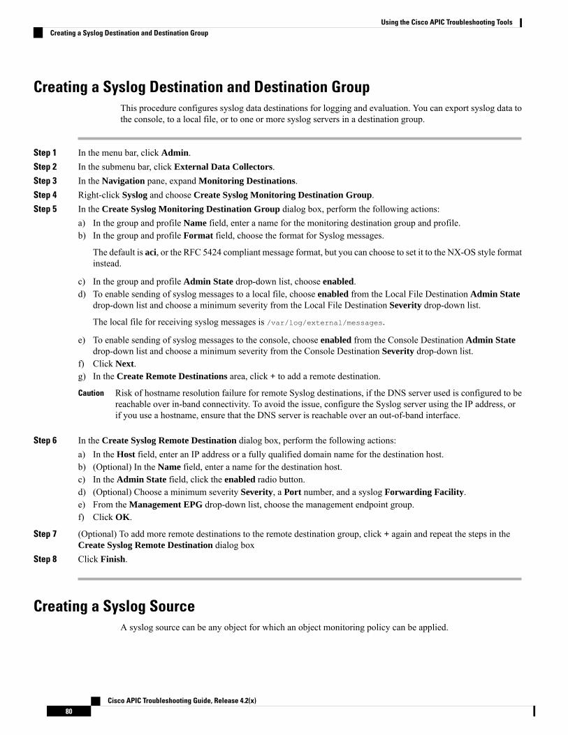
Creating a Syslog Destination and Destination GroupThis procedure configures syslog data destinations for logging and evaluation. You can export syslog data tothe console, to a local file, or to one or more syslog servers in a destination group.
Step 1 In the menu bar, click Admin.Step 2 In the submenu bar, click External Data Collectors.Step 3 In the Navigation pane, expand Monitoring Destinations.Step 4 Right-click Syslog and choose Create Syslog Monitoring Destination Group.Step 5 In the Create Syslog Monitoring Destination Group dialog box, perform the following actions:
a) In the group and profile Name field, enter a name for the monitoring destination group and profile.b) In the group and profile Format field, choose the format for Syslog messages.
The default is aci, or the RFC 5424 compliant message format, but you can choose to set it to the NX-OS style formatinstead.
c) In the group and profile Admin State drop-down list, choose enabled.d) To enable sending of syslog messages to a local file, choose enabled from the Local File Destination Admin State
drop-down list and choose a minimum severity from the Local File Destination Severity drop-down list.
The local file for receiving syslog messages is /var/log/external/messages.
e) To enable sending of syslog messages to the console, choose enabled from the Console Destination Admin Statedrop-down list and choose a minimum severity from the Console Destination Severity drop-down list.
f) Click Next.g) In the Create Remote Destinations area, click + to add a remote destination.
Risk of hostname resolution failure for remote Syslog destinations, if the DNS server used is configured to bereachable over in-band connectivity. To avoid the issue, configure the Syslog server using the IP address, orif you use a hostname, ensure that the DNS server is reachable over an out-of-band interface.
Caution
Step 6 In the Create Syslog Remote Destination dialog box, perform the following actions:a) In the Host field, enter an IP address or a fully qualified domain name for the destination host.b) (Optional) In the Name field, enter a name for the destination host.c) In the Admin State field, click the enabled radio button.d) (Optional) Choose a minimum severity Severity, a Port number, and a syslog Forwarding Facility.e) From the Management EPG drop-down list, choose the management endpoint group.f) Click OK.
Step 7 (Optional) To add more remote destinations to the remote destination group, click + again and repeat the steps in theCreate Syslog Remote Destination dialog box
Step 8 Click Finish.
Creating a Syslog SourceA syslog source can be any object for which an object monitoring policy can be applied.
Cisco APIC Troubleshooting Guide, Release 4.2(x)80
Using the Cisco APIC Troubleshooting ToolsCreating a Syslog Destination and Destination Group
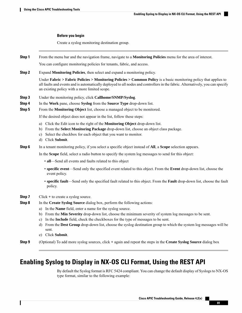
Before you begin
Create a syslog monitoring destination group.
Step 1 From the menu bar and the navigation frame, navigate to a Monitoring Policies menu for the area of interest.
You can configure monitoring policies for tenants, fabric, and access.
Step 2 Expand Monitoring Policies, then select and expand a monitoring policy.
Under Fabric > Fabric Policies > Monitoring Policies > Common Policy is a basic monitoring policy that applies toall faults and events and is automatically deployed to all nodes and controllers in the fabric. Alternatively, you can specifyan existing policy with a more limited scope.
Step 3 Under the monitoring policy, click Callhome/SNMP/Syslog.Step 4 In the Work pane, choose Syslog from the Source Type drop-down list.Step 5 From the Monitoring Object list, choose a managed object to be monitored.
If the desired object does not appear in the list, follow these steps:
a) Click the Edit icon to the right of the Monitoring Object drop-down list.b) From the Select Monitoring Package drop-down list, choose an object class package.c) Select the checkbox for each object that you want to monitor.d) Click Submit.
Step 6 In a tenant monitoring policy, if you select a specific object instead of All, a Scope selection appears.
In the Scope field, select a radio button to specify the system log messages to send for this object:
• all—Send all events and faults related to this object
• specific event—Send only the specified event related to this object. From the Event drop-down list, choose theevent policy.
• specific fault—Send only the specified fault related to this object. From the Fault drop-down list, choose the faultpolicy.
Step 7 Click + to create a syslog source.Step 8 In the Create Syslog Source dialog box, perform the following actions:
a) In the Name field, enter a name for the syslog source.b) From the Min Severity drop-down list, choose the minimum severity of system log messages to be sent.c) In the Include field, check the checkboxes for the type of messages to be sent.d) From the Dest Group drop-down list, choose the syslog destination group to which the system log messages will be
sent.e) Click Submit.
Step 9 (Optional) To add more syslog sources, click + again and repeat the steps in the Create Syslog Source dialog box
Enabling Syslog to Display in NX-OS CLI Format, Using the REST APIBy default the Syslog format is RFC 5424 compliant. You can change the default display of Syslogs to NX-OStype format, similar to the following example:
Cisco APIC Troubleshooting Guide, Release 4.2(x)81
Using the Cisco APIC Troubleshooting ToolsEnabling Syslog to Display in NX-OS CLI Format, Using the REST API

apic1# moquery -c "syslogRemoteDest"
Total Objects shown: 1
# syslog.RemoteDesthost : 172.23.49.77adminState : enabledchildAction :descr :dn : uni/fabric/slgroup-syslog-mpod/rdst-172.23.49.77epgDn :format : nxosforwardingFacility : local7ip :lcOwn : localmodTs : 2016-05-17T16:51:57.231-07:00monPolDn : uni/fabric/monfab-defaultname : syslog-destoperState : unknownport : 514rn : rdst-172.23.49.77severity : informationstatus :uid : 15374vrfId : 0vrfName :
To enable the Syslogs to display in NX-OS type format, perform the following steps, using the REST API.
Step 1 Enable the Syslogs to display in NX-OS type format, as in the following example:POST https://192.168.20.123/api/node/mo/uni/fabric.xml<syslogGroup name="DestGrp77" format="nxos"><syslogRemoteDest name="slRmtDest77" host="172.31.138.20" severity="debugging"/></syslogGroup>
The syslogGroup is the Syslog monitoring destination group, the sysLogRemoteDest is the name you previouslyconfigured for your Syslog server, and the host is the IP address for the previously configured Syslog server.
Step 2 Set the Syslog format back to the default RFC 5424 format, as in the following example:POST https://192.168.20.123/api/node/mo/uni/fabric.xml<syslogGroup name="DestGrp77" format="aci"><syslogRemoteDest name="slRmtDest77" host="172.31.138.20" severity="debugging"/></syslogGroup>
Cisco APIC Troubleshooting Guide, Release 4.2(x)82
Using the Cisco APIC Troubleshooting ToolsEnabling Syslog to Display in NX-OS CLI Format, Using the REST API

Discovering Paths and Testing Connectivity with TracerouteThis section lists the traceroute guidelines and restriction and explains how to perform a traceroute betweenendpoints.
About TracerouteThe traceroute tool is used to discover the routes that packets actually take when traveling to their destination.Traceroute identifies the path taken on a hop-by-hop basis and includes a time stamp at each hop in bothdirections. You can use traceroute to test the connectivity of ports along the path between the generatingdevice and the device closest to the destination. If the destination cannot be reached, the path discovery tracesthe path up to the point of failure.
A traceroute that is initiated from the tenant endpoints shows the default gateway as an intermediate hop thatappears at the ingress leaf switch.
Traceroute supports a variety of modes, including:
• Endpoint-to-endpoint, and leaf-to-leaf (tunnel endpoint, or TEP to TEP)
• Endpoint-to-external-IP
• External-IP-to-endpoint
• External-IP-to-external-IP
Traceroute discovers all paths across the fabric, discovers point of exits for external endpoints, and helps todetect if any path is blocked.
About Windows and Linux TracerouteThe traceroute command enables you to determine the path a packet takes in order to get to a destinationfrom a given source by returning the sequence of hops the packet has traversed. This utility comes with yourhost operating system (for example, Linux or Microsoft (MS) Windows).
If you execute the traceroute ip-address command on a source device (such as a host, or a router acting asa host), it sends IP packets toward the destination with Time To Live (TTL) values that increment up to themaximum specified hop count. This is 30 by default. Typically, each router in the path towards the destinationdecrements the TTL field by one unit while it forwards these packets. When a router in the middle of the pathfinds a packet with TTL = 1, it responds with an Internet Control Message Protocol (ICMP) "time exceeded"message to the source. This message lets the source know that the packet traverses that particular router as ahop
There are some differences with the way the traceroute command is implemented in the various operatingsystems as described in the following Linux and Windows sections.
Note
Cisco APIC Troubleshooting Guide, Release 4.2(x)83
Using the Cisco APIC Troubleshooting ToolsDiscovering Paths and Testing Connectivity with Traceroute

Linux
The TTL for the initial User Datagram Protocol (UDP) datagram probe is set to 1 (or the minimum TTL, asspecified by user in the extended traceroute command. The destination UDP port of the initial datagramprobe is set to 33434 (or as specified in the extended traceroute command output). The extended traceroutecommand is a variation of the ordinary traceroute command which allows the default values of the parametersused by the traceroute operation such as TTL and destination port number to be modified. The source UDPport of the initial datagram probe is randomized and has logical operator ORwith 0x8000 (ensures a minimumsource port of 0x8000). These steps illustrate what happens when the UDP datagram is launched:
The parameters are configurable. This example starts with n = 1 and finishes with n = 3.Note
1. The UDP datagram is dispatched with TTL = 1, destination UDP port= 33434, and the source portrandomized.
2. The UDP destination port is incremented, the source UDP port is randomized, and the second datagramdispatched.
3. Step 2 is repeated for up to three probes (or as many times as requested in an extended traceroute commandoutput). For each of the probes sent, you receive a "TTL exceeded" message, which is used to build astep-by-step path to the destination host.
4. TTL is incremented, and this cycle repeats with incremental destination port numbers, if the ICMP "timeexceeded" message is received. You can also get one of these messages:
• An ICMP type 3, code 3 ("destination unreachable," "port unreachable") message, which indicatesthat a host has been reached.
• A "host unreachable," "net unreachable," "maximumTTL exceeded," or a "timeout" type of message,which means that the probe is resent.
Cisco routers send UDP probe packets with a random source port and an incremental destination port (todistinguish the different probes). Cisco routers send the ICMP message "time exceeded" back to the sourcefrom where the UDP/ICMP packet was received.
The Linux traceroute command is similar to the Cisco router implementation. However, it uses a fixed sourceport. The -noption in the traceroute command is used to avoid a request to a name server.
The CIMC controller on a UCS server does not respond to UDP-based traceroute messages. It responds onlyto ICMP-based traceroute. Windows traceroute, by default, sends ICMP-based messages. Linux (and Mac)traceroute, by default, sends UDP-based messages. The Linux (and Mac) traceroute will send ICMP-basedmessages if you use the -I (capital i) option.
Because of the Linux traceroute default, if you are troubleshooting an ACI network and need to send tracerouteto the Cisco APIC, you must use Windows traceroute or specify ICMP-based traceroute.
Note
Windows
TheMSWindows tracert command uses ICMP echo request datagrams instead of UDP datagrams as probes.ICMP echo requests are launched with incrementing TTL, and the same operation as described above occurs.
Cisco APIC Troubleshooting Guide, Release 4.2(x)84
Using the Cisco APIC Troubleshooting ToolsAbout Windows and Linux Traceroute

The significance of using ICMP echo request datagrams is that the final hop does not rely on the response ofan ICMP "unreachable" message from the destination host. It relies instead on an ICMP echo reply message.
The command syntax is:tracert [-d] [-h maximum_hops] [-j computer-list] [-w timeout] target_name
This table explains the command parameters:
Table 2:
DescriptionParameter
Specifies not to resolve addresses to computer names.-d
Specifies the maximum number of hops to search fora target.
-h maximum_hops
Specifies a loose source route along computer-list.-j computer-list
Waits the number of milliseconds specified by thetimeout for each reply.
-w timeout
Name of the target computer.target_name
Traceroute Guidelines and Restrictions• When the traceroute source or destination is an endpoint, the endpoint must be dynamic and not static.Unlike a dynamic endpoint (fv:CEp), a static endpoint (fv:StCEp) does not have a child object(fv:RsCEpToPathEp) that is required for traceroute.
• Traceroute works for IPv6 source and destinations but configuring source and destination IP addressesacross IPv4 and IPv6 addresses is not allowed.
• See the Verified Scalability Guide for Cisco ACI document for traceroute-related limits.
• When an endpoint moves from one ToR switch to a different ToR switch that has a new MAC address(one that is different than the MAC address that you specified while configuring the traceroute policy),the traceroute policy shows "missing-target" for the endpoint. In this scenario you must configure a newtraceroute policy with the new MAC address.
Performing a Traceroute Between Endpoints
Step 1 In the menu bar, click Tenants.Step 2 In the submenu bar, click the tenant that contains the source endpoint.Step 3 In the Navigation pane, expand the tenant and expand Policies > Troubleshoot.Step 4 Under Troubleshoot, right-click on one of the following traceroute policies:
• Endpoint-to-Endpoint Traceroute Policies and choose Create Endpoint-to-Endpoint Traceroute Policy
• Endpoint-to-External-IP Traceroute Policies and choose Create Endpoint-to-External-IP Traceroute Policy
Cisco APIC Troubleshooting Guide, Release 4.2(x)85
Using the Cisco APIC Troubleshooting ToolsTraceroute Guidelines and Restrictions

• External-IP-to-Endpoint Traceroute Policies and choose Create External-IP-to-Endpoint Traceroute Policy
• External-IP-to-External-IP Traceroute Policies and choose Create External-IP-to-External-IP TraceroutePolicy
Step 5 Enter the appropriate values in the dialog box fields and click Submit.
For the description of a field, click the help icon (?) in the top-right corner of the dialog box.Note
Step 6 In the Navigation pane or the Traceroute Policies table, click the traceroute policy.The traceroute policy is displayed in the Work pane.
Step 7 In the Work pane, click the Operational tab, click the Source Endpoints tab, and click the Results tab.Step 8 In the Traceroute Results table, verify the path or paths that were used in the trace.
• More than one path might have been traversed from the source node to the destination node.
• For readability, you can increase the width of one or more columns, such as the Name column.
Note
Using the Troubleshooting WizardThe Troubleshooting Wizard allows you to understand and visualize how your network is behaving, whichcan ease your networking concerns should issues arise. For example, you might have two endpoints that arehaving intermittent packet loss, but you do not understand why. Using the Troubleshooting Wizard, you canevaluate the issue so that you can effectively resolve the issue rather than logging onto each machine that yoususpect to be causing this faulty behavior.
This wizard allows you (the administrative user) to troubleshoot issues that occur during specific time framesfor the chosen source and destination. You can define a time window in which you want to perform the debug,and you can generate a troubleshooting report that you can send to TAC.
Getting Started with the Troubleshooting WizardBefore you start using the Troubleshooting Wizard, you must be logged on as an Administrative user. Then,you must designate a source and destination and select a time window for your troubleshooting session. Thetime window is used for retrieving events, fault records, deployment records, audit logs, and statistics.
As you navigate through the screens of the Troubleshooting Wizard, you have the option to take a screen shot
at any time and send it to a printer or save it as a PDF by clicking the Print icon ( ) at the top, right side
of the screen. There are also Zoom In and ZoomOut icons ( ) that you can use to modify your viewof any screen.
Cisco APIC Troubleshooting Guide, Release 4.2(x)86
Using the Cisco APIC Troubleshooting ToolsUsing the Troubleshooting Wizard

• You cannot modify the source and destination after you click either Generate Report or Submit. If youwant to change the source and destination information after you have entered it, you must delete thecurrent session and start a new session.
• You cannot modify the description and time window on the first page of the wizard after you clickSubmit.
• You cannot use static IP address endpoints with the Troubleshooting Wizard.
• Any endpoints that you specify must be under an EPG.
Note
To set up your troubleshooting session information:
Step 1 Choose Operations > Visibility & Troubleshooting.
The Visibility & Troubleshooting screen appears.
Step 2 In the Session Name field, choose an existing troubleshooting session using the drop-down list or create a new sessionby entering a name.
Step 3 In the Session Type drop-down list, choose the desired session type.
• Endpoint to Endpoint: The source and destination are both internal endpoints.
You should choose source and destination endpoints from the same tenant, or some of the troubleshooting functionalitymay be impacted, as explained later in this document. With this session type, you cannot use atomic counters whenboth endpoints connect to the same set of leaf switches.
• Endpoint to External IP: The source is an internal endpoint, while the destination is an external IP address.
• External IP to Endpoint: The source is an external IP address, while the destination is an internal endpoint.
• External IP to External IP: The source and destination are both external IP addresses. You can choose this typestarting in the 3.2(6) release. With this session type, you cannot use traceroute, atomic counters, nor latency.
Step 4 (Optional) Enter a description in the Description field to provide additional information.Step 5 Enter the source information in the Source area.
• If you chose a session type of Endpoint to Endpoint or Endpoint to External IP, enter a MAC, IPv4, or IPv6address, or a VM name, then click Search.
You can enter a MAC address only if the session type is Endpoint to Endpoint and both endpoints' MAC addressdo not have any IP addresses learned from them.
A box appears that displays one or more rows with detailed information to help you make a selection. Each rowshows that the IP address (in the IP column) you entered is in a specific endpoint group (in the EPG column), whichbelongs to a certain application (in the Application column), which is in a particular tenant (in the Tenant column).The leaf switch number, FEX number, and port details are shown in the Learned At column.
• If you chose a session type of External IP to Endpoint, enter the external IP address.
• If you chose a session type of External IP to External IP, enter the external IP address and distinguished name ofthe external Layer 3 outside network.
Cisco APIC Troubleshooting Guide, Release 4.2(x)87
Using the Cisco APIC Troubleshooting ToolsGetting Started with the Troubleshooting Wizard
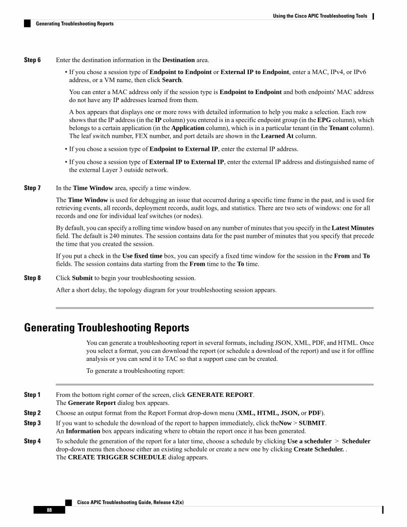
Step 6 Enter the destination information in the Destination area.
• If you chose a session type of Endpoint to Endpoint or External IP to Endpoint, enter a MAC, IPv4, or IPv6address, or a VM name, then click Search.
You can enter a MAC address only if the session type is Endpoint to Endpoint and both endpoints' MAC addressdo not have any IP addresses learned from them.
A box appears that displays one or more rows with detailed information to help you make a selection. Each rowshows that the IP address (in the IP column) you entered is in a specific endpoint group (in the EPG column), whichbelongs to a certain application (in the Application column), which is in a particular tenant (in the Tenant column).The leaf switch number, FEX number, and port details are shown in the Learned At column.
• If you chose a session type of Endpoint to External IP, enter the external IP address.
• If you chose a session type of External IP to External IP, enter the external IP address and distinguished name ofthe external Layer 3 outside network.
Step 7 In the Time Window area, specify a time window.
The Time Window is used for debugging an issue that occurred during a specific time frame in the past, and is used forretrieving events, all records, deployment records, audit logs, and statistics. There are two sets of windows: one for allrecords and one for individual leaf switches (or nodes).
By default, you can specify a rolling timewindow based on any number of minutes that you specify in theLatest Minutesfield. The default is 240 minutes. The session contains data for the past number of minutes that you specify that precedethe time that you created the session.
If you put a check in the Use fixed time box, you can specify a fixed time window for the session in the From and Tofields. The session contains data starting from the From time to the To time.
Step 8 Click Submit to begin your troubleshooting session.
After a short delay, the topology diagram for your troubleshooting session appears.
Generating Troubleshooting ReportsYou can generate a troubleshooting report in several formats, including JSON, XML, PDF, and HTML. Onceyou select a format, you can download the report (or schedule a download of the report) and use it for offlineanalysis or you can send it to TAC so that a support case can be created.
To generate a troubleshooting report:
Step 1 From the bottom right corner of the screen, click GENERATE REPORT.The Generate Report dialog box appears.
Step 2 Choose an output format from the Report Format drop-down menu (XML, HTML, JSON, or PDF).Step 3 If you want to schedule the download of the report to happen immediately, click theNow > SUBMIT.
An Information box appears indicating where to obtain the report once it has been generated.Step 4 To schedule the generation of the report for a later time, choose a schedule by clicking Use a scheduler > Scheduler
drop-down menu then choose either an existing schedule or create a new one by clicking Create Scheduler. .The CREATE TRIGGER SCHEDULE dialog appears.
Cisco APIC Troubleshooting Guide, Release 4.2(x)88
Using the Cisco APIC Troubleshooting ToolsGenerating Troubleshooting Reports

Step 5 Enter information for the Name, Description (optional), and Schedule Windows fields.
For more information on how to use the SCHEDULER, please refer to the online help.Note
Step 6 Click SUBMIT.
The reports take some time to generate (from a couple of minutes to up to ten minutes), depending on the sizeof the fabric and howmany faults or events exist. A status message displays while the report is being generated.To retrieve and view the troubleshooting report, click SHOW GENERATED REPORTS.
Supply the credentials (User Name and Password) of the server in the Authentication Required window.The troubleshooting report is then downloaded locally to your system.
The ALL REPORTS window appears showing a list of all the reports that have been generated, includingthe one you just triggered. From there, you can click the link to either download or immediately view thereport, depending on the output file format you chose (for example, if the file is a PDF, it may open immediatelyin your browser).
Topology in the Troubleshooting WizardThis section explains the topology in the Troubleshooting Wizard. The topology shows how the source anddestination are connected to the fabric, what the network path is from the source to the destination, and whatthe intermediate switches are.
The source is displayed on the left side of the topology and the destination is on the right, as shown in thefollowing wizard topology diagram.
This wizard topology only shows the leaf switches, spine switches, and FEXes of the devices involved in thetraffic from the source to the destination. However, there may be many other leaf switches (tens or hundredsof leaf switches and many other spine switches) that exist.
Note
This topology also shows links, ports, and devices. If you hover over the icon), you can see the tenantthat the source or destination belongs to, which application it belongs to, and the traffic encapsulation it isusing (such as VLAN).
There is a color legend on the left side of the screen (shown as follows) that describes the severity levelsassociated with each color in the topology diagram (for example, critical versus minor).
Cisco APIC Troubleshooting Guide, Release 4.2(x)89
Using the Cisco APIC Troubleshooting ToolsTopology in the Troubleshooting Wizard

Hovering over items such as boxes or ports in the topology provides more detailed information. If the port orlink has a color, this means that there is a problem for you to troubleshoot. For example, if the color is red ororange, this indicates that there is a fault on a port or link. If the color is white, then there are no faults thatexist. If the link has a number in a circle, it indicates how many parallel links between the same two nodesare affected by a fault of the severity given by the color of the circle. Hovering over a port allows you to seewhich port is connected to the source.
Right-clicking on a leaf switch allows you to access the console of the switch. A pop-up window appears thatallows you to log into that device.
• If there are Layer 4 to Layer 7 services (firewall and load balancer), they will be shown in the topologyas well.
• For a topology with the load balancer, the destination is expected to be the virtual IP (VIP) address.
• When the source or destination is behind an ESX server, the ESX is shown in the topology.
Note
Using the Faults Troubleshooting ScreenThis procedure describes how to use the faults of the Troubleshooting Wizard.
Cisco APIC Troubleshooting Guide, Release 4.2(x)90
Using the Cisco APIC Troubleshooting ToolsUsing the Faults Troubleshooting Screen

Procedure
PurposeCommand or Action
The Faults screen shows the topology that connects thesource and destination that you previously selected as well
Click Faults in the Navigation pane to begin using theFaults troubleshooting screen.
Step 1
as the faults that were found. Only faults for the designatedcommunication are shown. Wherever there are faults, theyare highlighted in a certain color to convey the severity.Refer to the color legend at the top of the screen tounderstand the severity levels associated with each color.White boxes indicate that there are no issues to troubleshootin that particular area.
This topology also shows the relevant leaf switches, spineswitches, and FEXes for your troubleshooting session.Hovering over items, such as leaf switches, spine switches,and FEXes, or clicking on faults provides more detailedinformation for analysis.
Click on a fault to display a dialog box with theDrop Stats,Contract Drops, and Traffic Stats tabs that contain moredetailed information for analysis.
Step 2
Related TopicsUsing the Drop/Statistics Troubleshooting Screen, on page 92
Cisco APIC Troubleshooting Guide, Release 4.2(x)91
Using the Cisco APIC Troubleshooting ToolsUsing the Faults Troubleshooting Screen

Using the Drop/Statistics Troubleshooting ScreenClick Drop/Stats in the Navigation pane to begin using the Drop/Stats troubleshooting screen.
The Drop/Stats window displays the topology with all the statistics from the drops so that you can clearlysee where drops exist or not. You can click on any drop image to see more information for analysis.
Once you click a drop image, there are three tabs at the top of the Drop/Stats screen, and the statistics shownare localized to that particular leaf or switch.
The three statistics tabs are:
• DROP STATS
This tab shows the statistics for drop counters. The packets that are dropped at various levels are shownhere.
By default, counters with zero values are hidden but the user can choose to seeall the values.
Note
• CONTRACT DROPS
This tab shows a list of the contract drops that have occurred, which are individual packet logs (ACLlogs), and shows information for each packet such as the Source Interface, Source IP address, SourcePort, Destination IP address, Destination Port, and Protocol.
Cisco APIC Troubleshooting Guide, Release 4.2(x)92
Using the Cisco APIC Troubleshooting ToolsUsing the Drop/Statistics Troubleshooting Screen

Not every packet is displayed here.Note
• TRAFFIC STATS
This tab shows the statistics that indicate ongoing traffic. These are how many packets have beentransferring.
By default, counters with zero values are hidden but the user can choose to seeall the values.
Note
You can also view all of the statistics for all managed objects at once by clicking the All icon ( ) locatedin the top, left corner of the screen.
You also have the option to pick zero or non-zero drops. Checking the box for Show stats with zero values(located in the top, left corner of the screen) allows you to see all the existing drops. The fields for Time,Affected Object, Stats, and Value become populated with data for all the zero values.
If you do not check the Show stats with zero values box, you will see results with non-zero drops.
The same logic applies if you click the All icon. All three tabs (DROP STATS, CONTRACT DROPS, andTRAFFIC STATS) are also available and have the same type of information appearing.
Note
Related TopicsUsing the Contracts Troubleshooting Screen, on page 93
Using the Contracts Troubleshooting ScreenClick Contracts in the Navigation pane to begin using the Contracts troubleshooting screen.
The Contracts troubleshooting screen displays the contracts that are applicable from the Source to theDestination and from the Destination to the Source.
Each one of the blue table heading rows indicates a filter. There are multiple rows under each filter that indicatemultiple filter entries (Protocol, L4 Src, L4 Dest, TCP Flags, Action, Nodes, and Hits) for a particular leafor switch.
Hovering over the certificate icon, shows you the contract name and the contract filter name. The text appearingon the right side of each blue table heading row (or filter) tells what type of contract it is, for example:
• Epg to Epg• BD Allow• Any to Any• Context Deny
These contracts are categorized from the Source to the Destination and from the Destination to the Source.
Cisco APIC Troubleshooting Guide, Release 4.2(x)93
Using the Cisco APIC Troubleshooting ToolsUsing the Contracts Troubleshooting Screen

The hits shown for each filter are cumulative (that is, the total hits for that contract hit, contract filter, or ruleare shown for each particular leaf.) Statistics are refreshed automatically every (one) minute.
Note
You can get policy information by hovering over the Information ( ) icon. You can also see which EPGsare being referred to.
If there are no contracts between the endpoints, this will be indicated with aThere is no contract data pop-up.Note
Related TopicsUsing the Events Troubleshooting Screen, on page 94
Using the Events Troubleshooting ScreenClick Events and Audits in the Navigation pane to begin using the Events and Audits troubleshootingscreen.
If you click on an individual leaf or spine switch, you can see more detailed information about that individualevent.
There are two tabs available: EVENTS and DEPLOYMENT RECORDS.
• EVENTS show event records for any changes that have occurred in systems (such as physical interfacesor VLANS, for example). There are individual events listed for each particular leaf. You can sort theseevents based on Severity, Affected Object, Creation Time, Cause, and Description.
• DEPLOYMENT RECORDS show the deployment of policies on physical interfaces, VLANs, VXLANs,and L3 CTXs. These records show the time when a VLAN was placed on a leaf because of the epg.
If you click theAll icon ( ) for theAll Changes screen, you can see all the events indicating any changesthat have occurred during your specified time interval (or troubleshooting session).
There are three tabs in the All Changes screen, including:
• AUDITS
Audits do not have a leaf association, which is why they are only available in the All Changes screen.
• EVENTS (described above)
• DEPLOYMENT RECORDS (described above)
Related TopicsUsing the Traceroute Troubleshooting Screen, on page 94
Using the Traceroute Troubleshooting ScreenClick Traceroute in the Navigation pane to begin using the Traceroute troubleshooting screen.
Cisco APIC Troubleshooting Guide, Release 4.2(x)94
Using the Cisco APIC Troubleshooting ToolsUsing the Events Troubleshooting Screen

To create and run a traceroute for troubleshooting:
1. In the TRACEROUTE dialog box, choose a destination port from the Destination Port drop-downmenu.
2. Choose a protocol from the Protocol pull-down menu. The options supported include:
• icmp —This protocol is uni-directional, in that it does a traceroute from the Source leaf to theDestination endpoint only.
• tcp—This protocol is also bi-directional, as described above for the udp protocol.• udp—This protocol is bi-directional, in that it does a traceroute from the Source leaf to the Destinationendpoint, then from the Destination leaf back to the Source endpoint.
UDP, TCP and ICMP are the only supported protocols for IPv4. For IPv6, only UDP is supported.Note
3. Once you create a traceroute, click the Play (or Start) button to start the traceroute.
When you press the Play button, the polices are created on the system and a Warning message appears.Note
4. ClickOK to proceed and the traceroute starts to run.5. Click the Stop button to end the traceroute.
When you press the Stop button, the policies are removed from the system.Note
Once the traceroute completes, you can see where it was launched and what the result was. There is a pull-downmenu next to Traceroute Results that shows where the traceroute was launched (from the Source to theDestination or from the Destination to the Source).
The result is also shown in theTraceroute dialog, which includes information forRunning Time, TracerouteStatus, Destination Port, and Protocol.
The results are represented by green and/or red arrows. A green arrow is used to represent each node in thepath that responded to the traceroute probes. The beginning of a red arrow represents where the path ends asthat's the last node that responded to the traceroute probes. You don't choose which direction to launch thetraceroute. Instead, the traceroute is always started for the session. If the session is:
• EP to external IP or external IP to EP, the traceroute is always launched from EP to external IP.
• EP to EP and protocol is ICMP, the traceroute is always launched from the source to the destination.
• EP to EP and protocol is UDP/TCP, the traceroute is always bidirectional.
Cisco APIC Troubleshooting Guide, Release 4.2(x)95
Using the Cisco APIC Troubleshooting ToolsUsing the Traceroute Troubleshooting Screen

• The Traceroute Results drop-down menu can be used to expose/visualize the results for each directionfor scenario #3 above. In scenarios #1 and #2, it's always greyed out.
• If the Traceroute Status shows as incomplete, this means you are still waiting for part of the data tocome back. If the Traceroute Status shows as complete, then it is actually complete.
Note
Related TopicsUsing the Atomic Counter Troubleshooting Screen, on page 96
Using the Atomic Counter Troubleshooting ScreenClick Atomic Counter in the Navigation pane to begin using the Atomic Counter troubleshooting screen.
The Atomic Counter screen is used to take source and destination information and create a counter policybased on that. You can create an atomic counter policy between two endpoints and monitor the traffic goingback and forth from the Source to the Destination and from the Destination to the Source. You can determinehow much traffic is going through and especially determine if any anomalies (drops or excess packets) arereported between the source and destination leaves.
There are Play (or Start) and Stop buttons at the top of the screen so that you can start and stop the atomiccounter policy at any point and can count the packets that are being sent.
When you press the Play button, the polices are created on the system and the packet counter starts. Whenyou press the Stop button, the policies are removed from the system.
Note
The results are shown in two different formats. You can view them in either a brief format, which includes asummary, or in a longer format (by clicking on the Expand button). Both brief and expanded formats showboth directions. The expanded format shows the cumulative counts plus the counts for each of the latest 30sintervals, while the brief format only shows the counts for cumulative and last interval.
Related TopicsUsing the SPAN Troubleshooting Screen, on page 96
Using the SPAN Troubleshooting ScreenClick SPAN in the Navigation pane to begin using the SPAN troubleshooting screen.
Using this screen, you can span (or mirror) bi-directional traffic and redirect it to the analyzer. In a SPANsession, you are making a copy and sending it to the analyzer.
This copy goes to a particular host (the analyzer IP address) and then you can use a software tool such asWireshark to view the packets. The session information has source and destination information, session type,and the timestamp range.
When you press the Play button, the polices are created on the system. When you press the Stop button, thepolicies are removed from the system.
Note
Cisco APIC Troubleshooting Guide, Release 4.2(x)96
Using the Cisco APIC Troubleshooting ToolsUsing the Atomic Counter Troubleshooting Screen

For a list of Troubleshooting Wizard CLI commands, see the Cisco APIC Command-Line Interface UserGuide.
Note
Creating a SPAN Session Using the Cisco APIC Troubleshooting CLIThis section demonstrates how to use the Cisco APIC troubleshooting CLIs to create a SPAN session.
Step 1 troubleshoot node session <session_name> nodename <node_id>
To create a node-level session (global drop):
Example:apic1(config)# troubleshoot node session 301-GD-APIC nodeid 301
Step 2 troubleshoot node session <session_name> nodename <node_id> interface ethernet <interface>
To create an interface-level session:
Example:apic1(config)# troubleshoot node session 301-GD-APIC nodeid 301 interface eth1/3
Step 3 troubleshoot node session <session_name> monitor destination apic_ip srcipprefix <ip_prefix> drop enableerspan-id[optional]To specify the destination as Cisco APIC and enable SPAN on drop:
Example:apic1(config)# troubleshoot node session 301-GD-APIC monitor destination apic srcipprefix 13.13.13.13drop enable
Step 4 troubleshoot node session <session_name> monitor destination tenant tenant application <app> destip <dest_ip>srcipprefix <ip_prefix> drop enable erspan-id[optional]To specify an ERSPAN destination and enable SPAN on drop:
Example:apic1(config)# troubleshoot node session 301-GD-APIC monitor destination tenant ERSPAN applicationA1 epg E1 destip 179.10.10.179 srcipprefix 31.31.13.31 drop enable
To check the SPAN-on-drop packets on the Cisco APIC when it is set as destination:
a. Disable the SPAN-on-drop session:apic1(config)# no troubleshoot node session 301-GD-APIC monitor
b. Go to the drop-stats directory and check the DropPackets_*.pcap file:/data2/techsupport/troubleshoot/node/Session_name/span_capture/drop-stats/DropPackets_*.pcap
Cisco APIC Troubleshooting Guide, Release 4.2(x)97
Using the Cisco APIC Troubleshooting ToolsCreating a SPAN Session Using the Cisco APIC Troubleshooting CLI

L4 - L7 Services Validated ScenariosThe TroubleshootingWizard allows you to provide two endpoints and see the corresponding topology betweenthose endpoints. When L4 - L7 services exist between the two endpoints in the topology, you are able to viewthese as well.
This section describes the L4 - L7 scenarios that have been validated for this release. Within the L4 - L7services, the number of topologies is very high, which means that you can have different configurations forfirewalls, load balancers, and combinations of each. If a firewall exists between the two endpoints in thetopology, the Troubleshooting Wizard retrieves the firewall data and connectivity from the firewall to theleafs. If a load balancer exists between the two endpoints, you can retrieve and view information up to theload balancer but not up to the server.
The following table shows the L4 - L7 service scenarios that were validated for the Troubleshooting Wizard:
654321Scenario
211211Number of Nodes
FW, SLB(GoThrough,GoTo)
SLB-GoToFW-GoThroughGoTo,GoToFW,SLB
GoToSLB
GoTo FW(vrf split)
Device
222222Number of Arms
L3OutL3OutL3OutEPGEPGEPGConsumer
EPGEPGEPGEPGEPGEPGProvider
physicalphysicalphysicalVMVMVMDevice Type
globalcontextcontextcontextcontexttenantContract Scope
L3 / L2,L3L3L3, L2L2, L2L2L2Connector Mode
regular portvPCregular portDL/PCBSWBSWService Attach
regular portRegular PortRegular PortFEXFEXFEXClient Attach
regular portregular portregular portvPCvPCvPCServer Attach
List of APIs for Endpoint to Endpoint ConnectionsThe following is a list of the available Troubleshooting Wizard APIs for EP to EP (endpoint to endpoint)connections:
• interactive API, on page 99
• createsession API, on page 100
• modifysession API, on page 101
• atomiccounter API, on page 101
• traceroute API, on page 102
Cisco APIC Troubleshooting Guide, Release 4.2(x)98
Using the Cisco APIC Troubleshooting ToolsL4 - L7 Services Validated Scenarios

• span API, on page 102
• generatereport API, on page 103
• schedulereport API, on page 104
• getreportstatus API, on page 104
• getreportslist API, on page 105
• getsessionslist API, on page 105
• getsessiondetail API, on page 105
• deletesession API, on page 105
• clearreports API, on page 106
• contracts API, on page 107
interactive APITo create an endpoint (ep) to endpoint interactive troubleshooting session, use the interactive API. Themodule name is troubleshoot.eptoeputils.topo and the function is getTopo. The required argument (req_args)for the interactive API is - session.
The following table lists the optional arguments (opt_args) and descriptions for each.
Syntax Description DescriptionOptional Arguments (opt_args)
Source endpoint name- srcep
Destination endpoint name- dstep
Source endpoint IP address- srcip
Destination endpoint IP address- dstip
Source endpoint MAC- srcmac
Destination endpoint MAC- dstmac
L3 external source IP address- srcextip
L3 external destination IP address- dstextip
Start time of the troubleshooting session- starttime
End time of the troubleshooting session- endtime
Time window for the troubleshooting session starting fromstart time (in minutes)
- latestmin
Description about the session- description
Scheduler name for report generation- scheduler
Cisco APIC Troubleshooting Guide, Release 4.2(x)99
Using the Cisco APIC Troubleshooting Toolsinteractive API

Obsolete- srcepid
Obsolete- dstepid
Obsolete- include
Format of report to be generated- format
Used internally (ignore)- ui
Location of the report- sessionurl
Start/stop/status etc. for traceroute/atomiccounter-action
Used internally- mode
Used internally- _dc
Used internally- ctx
createsession APITo create an endpoint (ep) to endpoint troubleshooting session, use the createsession API. The module nameis troubleshoot.eptoeputils.session and the function is createSession.
The required argument (req_args) for the createsession API is - session (session name).
The following table lists the optional arguments (opt_args) and descriptions for each.
Syntax Description DescriptionOptional Arguments (opt_args)
Source endpoint name- srcep
Destination endpoint name- dstep
Source endpoint IP address- srcip
Destination endpoint IP address- dstip
Source endpoint MAC- srcmac
Destination endpoint MAC- dstmac
L3 external source IP address- srcextip
L3 external destination IP address- dstextip
Start time of the troubleshooting session- starttime
End time of the troubleshooting session- endtime
Time window for the troubleshooting session starting fromstart time (in minutes)
- latestmin
Description about the session- description
Cisco APIC Troubleshooting Guide, Release 4.2(x)100
Using the Cisco APIC Troubleshooting Toolscreatesession API

Format of report to be generated- format
Used internally (ignore)- ui
Start/stop/status etc. for traceroute/atomiccounter-action
- scheduler
Name of the tenant for the source endpoint- srctenant
Name of the app for the source endpoint- srcapp
Name of the endpoint group for the source endpoint- srcepg
Name of the tenant for the destination endpoint- dsttenant
Name of the app for the destination endpoint- dstapp
Name of the endpoint group for the destination endpoint- dstepg
Used internally- mode
modifysession APITo modify an endpoint (ep) to endpoint troubleshooting session, use the modifysession API. The modulename is troubleshoot.eptoeputils.topoand the function is modifySession.
The required arguments (req_args) for the modifysession API are - session (session name) and - mode.
The following table lists the optional arguments (opt_args) and descriptions for each.
Syntax Description DescriptionOptional Arguments (opt_args)
Start time of the troubleshooting session- starttime
End time of the troubleshooting session- endtime
Time window for the troubleshooting session starting fromstart time (in minutes)
- latestmin
Description about the session- description
atomiccounter APITo create an endpoint (ep) to endpoint atomic counter session, use the atomiccounterAPI. The module nameis troubleshoot.eptoeputils.atomiccounter and the function is manageAtomicCounterPols.
The required arguments (req_args) for the atomiccounter API include:
• - session
• - action
• - mode
Cisco APIC Troubleshooting Guide, Release 4.2(x)101
Using the Cisco APIC Troubleshooting Toolsmodifysession API

There are no optional arguments (opt_args) for the atomiccounter API.Note
traceroute APITo create an endpoint (ep) to endpoint traceroute session using the API, use the traceroute API. The modulename is troubleshoot.eptoeputils.traceroute and the function is manageTraceroutePols.
The required arguments (req_args) for the traceroute API include:
• - session (session name)
• - action (start/stop/status)
• - mode
Syntax Description DescriptionOptional Arguments (opt_args)
Protocol name- protocol
Destination port name- dstport
span APITo create an endpoint (ep) to endpoint span troubleshooting session, use the span API. The module name istroubleshoot.eptoeputils.span and the function is monitor.
The required arguments (req_args) for the span API include:
• - session (session name)
• - action (start/stop/status)
The following table lists the optional arguments (opt_args) and descriptions for each.
Syntax Description DescriptionOptional Arguments (opt_args)
Source endpoint name- srcep
Destination endpoint name- dstep
Source endpoint IP address- srcip
Destination endpoint IP address- dstip
Source endpoint MAC- srcmac
Destination endpoint MAC- dstmac
L3 external source IP address- srcextip
L3 external destination IP address- dstextip
Cisco APIC Troubleshooting Guide, Release 4.2(x)102
Using the Cisco APIC Troubleshooting Toolstraceroute API

Start time of the troubleshooting session- starttime
End time of the troubleshooting session- endtime
Time window for the troubleshooting session startingfrom start time (in minutes)
- latestmin
Description about the session- description
Scheduler name for report generation- scheduler
Obsolete- srcepid
Obsolete- dstepid
Obsolete- include
Format of report to be generated- format
Used internally (ignore)- ui
Location of the report- sessionurl
Start/stop/status etc. for traceroute/atomiccounter-action
Name of the tenant for the source endpoint- srctenant
Name of the app for the source endpoint- srcapp
Name of the endpoint group for the source endpoint- srcepg
Name of the tenant for the destination endpoint- dsttenant
Name of the app for the destination endpoint- dstapp
Name of the endpoint group for the destination endpoint- dstepg
Used internally- mode
Used internally- _dc
Used internally- ctx
generatereport APITo generate a troubleshooting report using the API, use the generatereport API. The module name istroubleshoot.eptoeputils.report and the function is generateReport.
The required arguments (req_args) for the generatereport API are - session (session name) and - mode.
The following table lists the optional arguments (opt_args) and descriptions for each.
Syntax Description DescriptionOptional Arguments (opt_args)
Obsolete- include
Cisco APIC Troubleshooting Guide, Release 4.2(x)103
Using the Cisco APIC Troubleshooting Toolsgeneratereport API

Format of report to be generated- format
schedulereport APITo schedule the generation of a troubleshooting report using the API, use the schedulereportAPI. The modulename is troubleshoot.eptoeputils.report and the function is scheduleReport. The required argument(req_args) for the schedulereport API is - session
The required arguments (req_args) for the schedulereport API include:
• - session (session name)
• - scheduler (scheduler name)
• - mode
The following table lists the optional arguments (opt_args) and descriptions for each.
Syntax Description DescriptionOptional Arguments (opt_args)
Start time of the troubleshooting session- starttime
End time of the troubleshooting session- endtime
Time window for the troubleshooting session starting fromstart time (in minutes)
- latestmin
Obsolete- include
Format of report to be generated- format
Start/stop/status etc. for traceroute/atomiccounter- action
getreportstatus APITo get the status of a generated report using the API, use the getreportstatus API. The module name istroubleshoot.eptoeputils.report and the function is getStatus.
The required arguments (req_args) for the getreportstatus API include:
• - session (session name)
• - sessionurl (session URL)
• - mode
There are no optional arguments (opt_args) for the getreportstatus API.Note
Cisco APIC Troubleshooting Guide, Release 4.2(x)104
Using the Cisco APIC Troubleshooting Toolsschedulereport API

getreportslist APITo get a list of generated reports using the API, use the getreportslist API. The module name istroubleshoot.eptoeputils.report and the function is getReportsList.
The required arguments (req_args) for the getreportslist API are- session (session name) and - mode.
There are no optional arguments (opt_args) for the getreportslist API.Note
getsessionslist APITo get a list of troubleshooting sessions using the API, use the getsessionslist API. The module name istroubleshoot.eptoeputils.session and the function is getSessions.
The required argument (req_args) for the getsessionlist API is - mode.
There are no optional arguments (opt_args) for the getsessionlist API.Note
getsessiondetail APITo get specific details about a troubleshooting session using the API, use the getsessiondetailAPI. The modulename is troubleshoot.eptoeputils.session and the function is getSessionDetail.
The required arguments (req_args) for the getsessiondetail API are - session (session name) and - mode.
There are no optional arguments (opt_args) for the getsessiondetail API.Note
deletesession APITo delete a particular troubleshooting session using the API, use the deletesession API. The module name istroubleshoot.eptoeputils.session and the function is deleteSession.
The required argument (req_args) for the deletesession API is - session (session name).
The following table lists the optional arguments (opt_args) and descriptions for each.
Syntax Description DescriptionOptional Arguments (opt_args)
Source endpoint name- srcep
Destination endpoint name- dstep
Source endpoint IP address- srcip
Destination endpoint IP address- dstip
Cisco APIC Troubleshooting Guide, Release 4.2(x)105
Using the Cisco APIC Troubleshooting Toolsgetreportslist API

Source endpoint MAC- srcmac
Destination endpoint MAC- dstmac
L3 external source IP address- srcextip
L3 external destination IP address- dstextip
Start time of the troubleshooting session- starttime
End time of the troubleshooting session- endtime
Time window for the troubleshooting session starting fromstart time (in minutes)
- latestmin
Description about the session- description
Scheduler name for report generation- scheduler
Obsolete- srcepid
Obsolete- dstepid
Obsolete- include
Format of report to be generated- format
Used internally (ignore)- ui
Location of report- sessionurl
Start/stop/status etc. for traceroute/atomiccounter- action
Used internally- mode
Used internally- _dc
Used internally- ctx
clearreports APITo clear the list of generated reports using the API, use the clearreports API. The module name istroubleshoot.eptoeputils.report and the function is clearReports.
The required arguments (req_args) for the clearreports API are- session (session name) and - mode.
There are no optional arguments (opt_args) for the clearreports API.Note
Cisco APIC Troubleshooting Guide, Release 4.2(x)106
Using the Cisco APIC Troubleshooting Toolsclearreports API

contracts APITo get contracts information using the API, use the contracts API. The module name istroubleshoot.eptoeputils.contracts and the function is getContracts.
The required arguments (req_args) for the contracts API are- session (session name) and -mode.
There are no optional arguments (opt_args) for the contracts API.
List of APIs for Endpoint to Layer 3 External ConnectionsThe following is a list of the available Troubleshooting Wizard APIs for EP to EP (endpoint to endpoint)connections:
• interactive API, on page 107
• modifysession API, on page 109
• atomiccounter API, on page 110
• traceroute API, on page 111
• span API, on page 111
• generatereport API, on page 112
• schedulereport API, on page 113
• getreportstatus API, on page 104
• getreportslist API, on page 105
• clearreports API, on page 106
• createsession API, on page 108
• getsessionslist API, on page 115
• getsessiondetail API, on page 116
• deletesession API, on page 117
• contracts API, on page 117
• ratelimit API, on page 118
• 13ext API, on page 119
interactive APITo create an endpoint (ep) to Layer 3 (L3) external interactive troubleshooting session, use the interactiveAPI. The module name is troubleshoot.epextutils.epext_topo and the function is getTopo. The requiredarguments (req_args) for the interactive API are - session, - include, and - mode.
The following table shows the optional argument (opt_args):
Syntax Description DescriptionOptional Arguments (opt_args)
Cisco APIC Troubleshooting Guide, Release 4.2(x)107
Using the Cisco APIC Troubleshooting Toolscontracts API
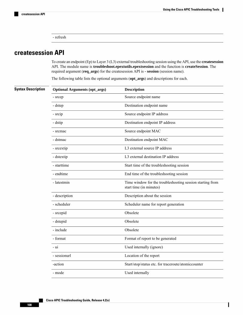
- refresh
createsession APITo create an endpoint (Ep) to Layer 3 (L3) external troubleshooting session using the API, use the createsessionAPI. The module name is troubleshoot.epextutils.epextsession and the function is createSession. Therequired argument (req_args) for the createsession API is - session (session name).
The following table lists the optional arguments (opt_args) and descriptions for each.
Syntax Description DescriptionOptional Arguments (opt_args)
Source endpoint name- srcep
Destination endpoint name- dstep
Source endpoint IP address- srcip
Destination endpoint IP address- dstip
Source endpoint MAC- srcmac
Destination endpoint MAC- dstmac
L3 external source IP address- srcextip
L3 external destination IP address- dstextip
Start time of the troubleshooting session- starttime
End time of the troubleshooting session- endtime
Time window for the troubleshooting session starting fromstart time (in minutes)
- latestmin
Description about the session- description
Scheduler name for report generation- scheduler
Obsolete- srcepid
Obsolete- dstepid
Obsolete- include
Format of report to be generated- format
Used internally (ignore)- ui
Location of the report- sessionurl
Start/stop/status etc. for traceroute/atomiccounter-action
Used internally- mode
Cisco APIC Troubleshooting Guide, Release 4.2(x)108
Using the Cisco APIC Troubleshooting Toolscreatesession API

Used internally- _dc
Used internally- ctx
modifysession APITo modify an endpoint (Ep) to Layer 3 (L3) external troubleshooting session, use the modifysession API.The module name is troubleshoot.epextutils.epextsessionand the function is modifySession. The requiredargument (req_args) for the modifysession API is - session (session name).
The following table lists the optional arguments (opt_args) and descriptions for each.
Syntax Description DescriptionOptional Arguments (opt_args)
Source endpoint name- srcep
Destination endpoint name- dstep
Source endpoint IP address- srcip
Destination endpoint IP address- dstip
Source endpoint MAC- srcmac
Destination endpoint MAC- dstmac
L3 external source IP address- srcextip
L3 external destination IP address- dstextip
Start time of the troubleshooting session- starttime
End time of the troubleshooting session- endtime
Time window for the troubleshooting session starting fromstart time (in minutes)
- latestmin
Description about the session- description
Scheduler name for report generation- scheduler
Obsolete- srcepid
Obsolete- dstepid
Obsolete- include
Format of report to be generated- format
Used internally (ignore)- ui
Location of the report- sessionurl
Start/stop/status etc. for traceroute/atomiccounter-action
Cisco APIC Troubleshooting Guide, Release 4.2(x)109
Using the Cisco APIC Troubleshooting Toolsmodifysession API

Used internally- mode
Used internally- _dc
Used internally- ctx
atomiccounter APITo create an endpoint (ep) to endpoint atomic counter session, use the atomiccounterAPI. The module nameis troubleshoot.epextutils.epext_ac and the function is manageAtomicCounterPols.
The required arguments (req_args) for the atomiccounter API include:
• - session (session name)
• - action (start/stop/status)
The following table lists the optional arguments (opt_args) and descriptions for each.
Syntax Description DescriptionOptional Arguments (opt_args)
Source endpoint name- srcep
Destination endpoint name- dstep
Source endpoint IP address- srcip
Destination endpoint IP address- dstip
Source endpoint MAC- srcmac
Destination endpoint MAC- dstmac
L3 external source IP address- srcextip
L3 external destination IP address- dstextip
Start time of the troubleshooting session- starttime
End time of the troubleshooting session- endtime
Time window for the troubleshooting session starting fromstart time (in minutes)
- latestmin
Used internally (ignore)- ui
Used internally- mode
Used internally- _dc
Used internally- ctx
Cisco APIC Troubleshooting Guide, Release 4.2(x)110
Using the Cisco APIC Troubleshooting Toolsatomiccounter API

traceroute APITo create an endpoint (ep) to to Layer 3 external traceroute troubleshooting session using the API, use thetraceroute API. The module name is troubleshoot.epextutils.epext_traceroute and the function ismanageTraceroutePols.
The required arguments (req_args) for the traceroute API include:
• - session (session name)
• - action (start/stop/status)
Syntax Description DescriptionOptional Arguments (opt_args)
Protocol name- protocol
Destination port name- dstport
Source endpoint- srcep
Destination endpoint- dstep
Source IP address- srcip
Destination IP address- dstip
Source external IP address- srcextip
Destination external IP address- dstIp
Used internally (ignore)- ui
Used internally- mode
Used internally- _dc
Used internally- ctx
span APITo create an endpoint (Ep) to Layer 3 (L3) external span troubleshooting session, use the span API. Themodule name is troubleshoot.epextutils.epext_span and the function is monitor.
The required arguments (req_args) for the span API include:
• - session (session name)
• - action (start/stop/status)
• - mode
The following table lists the optional arguments (opt_args) and descriptions for each.
Syntax Description DescriptionOptional Arguments (opt_args)
Cisco APIC Troubleshooting Guide, Release 4.2(x)111
Using the Cisco APIC Troubleshooting Toolstraceroute API
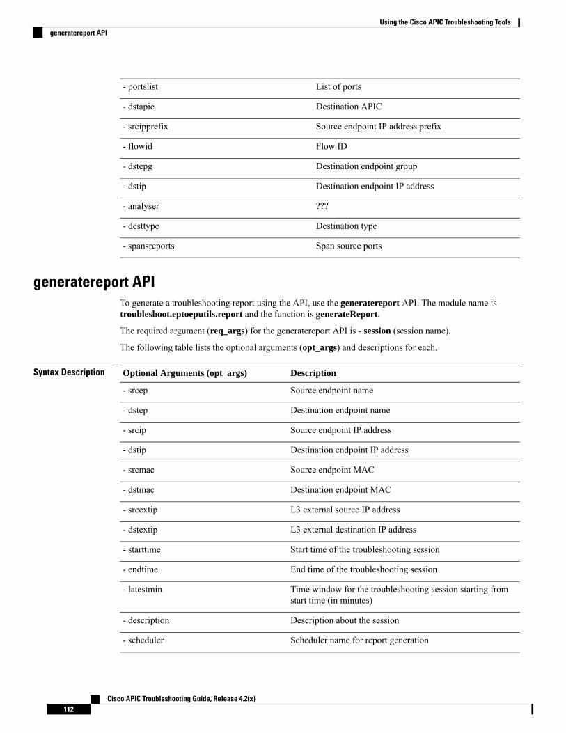
List of ports- portslist
Destination APIC- dstapic
Source endpoint IP address prefix- srcipprefix
Flow ID- flowid
Destination endpoint group- dstepg
Destination endpoint IP address- dstip
???- analyser
Destination type- desttype
Span source ports- spansrcports
generatereport APITo generate a troubleshooting report using the API, use the generatereport API. The module name istroubleshoot.eptoeputils.report and the function is generateReport.
The required argument (req_args) for the generatereport API is - session (session name).
The following table lists the optional arguments (opt_args) and descriptions for each.
Syntax Description DescriptionOptional Arguments (opt_args)
Source endpoint name- srcep
Destination endpoint name- dstep
Source endpoint IP address- srcip
Destination endpoint IP address- dstip
Source endpoint MAC- srcmac
Destination endpoint MAC- dstmac
L3 external source IP address- srcextip
L3 external destination IP address- dstextip
Start time of the troubleshooting session- starttime
End time of the troubleshooting session- endtime
Time window for the troubleshooting session starting fromstart time (in minutes)
- latestmin
Description about the session- description
Scheduler name for report generation- scheduler
Cisco APIC Troubleshooting Guide, Release 4.2(x)112
Using the Cisco APIC Troubleshooting Toolsgeneratereport API

Obsolete- srcepid
Obsolete- dstepid
Obsolete- include
Format of report to be generated- format
Used internally (ignore)- ui
Location of the report- sessionurl
Start/stop/status etc. for traceroute/atomiccounter-action
Used internally- mode
Used internally- _dc
Used internally- ctx
schedulereport APITo schedule the generation of a troubleshooting report using the API, use the schedulereportAPI. The modulename is troubleshoot.eptoeputils.report and the function is scheduleReport. The required argument(req_args) for the schedulereport API is - session
The required arguments (req_args) for the schedulereport API include:
• - session (session name)
• - scheduler (scheduler name)
The following table lists the optional arguments (opt_args) and descriptions for each.
Syntax Description DescriptionOptional Arguments (opt_args)
Source endpoint- srcep
Destination endpoint- dstep
Source endpoint IP address- srcip
Destination endpoint IP address- dstip
Source endpoint MAC- srcmac
Destination endpoint MAC- dstmac
L3 external source IP address- srcextip
L3 external destination IP address- dstextip
Start time of the troubleshooting session- starttime
End time of the troubleshooting session- endtime
Cisco APIC Troubleshooting Guide, Release 4.2(x)113
Using the Cisco APIC Troubleshooting Toolsschedulereport API

Time window for the troubleshooting session starting fromstart time (in minutes)
- latestmin
Description about the session- description
Obsolete- srcepid
Obsolete- dstepid
Obsolete- include
Format of report to be generated- format
Used internally (ignore)- ui
Location of the report- sessionurl
Start/stop/status etc. for traceroute/atomiccounter-action
Used internally- mode
Used internally- _dc
Used internally- ctx
getreportstatus APITo get the status of a generated report using the API, use the getreportstatus API. The module name istroubleshoot.eptoeputils.report and the function is getStatus.
The required arguments (req_args) for the getreportstatus API include:
• - session (session name)
• - sessionurl (session URL)
• - mode
There are no optional arguments (opt_args) for the getreportstatus API.Note
getreportslist APITo get a list of generated reports using the API, use the getreportslist API. The module name istroubleshoot.eptoeputils.report and the function is getReportsList.
The required arguments (req_args) for the getreportslist API are- session (session name) and - mode.
There are no optional arguments (opt_args) for the getreportslist API.Note
Cisco APIC Troubleshooting Guide, Release 4.2(x)114
Using the Cisco APIC Troubleshooting Toolsgetreportstatus API

getsessionslist APITo get a list of troubleshooting sessions using the API, use the getsessionslist API. The module name istroubleshoot.epextutils.epextsession and the function is getSessions.
There are no required arguments for this API.Note
The following table lists the optional arguments (opt_args) and descriptions for each.
Syntax Description DescriptionOptional Arguments (opt_args)
Session name- session
Source endpoint name- srcep
Destination endpoint name- dstep
Source endpoint IP address- srcip
Destination endpoint IP address- dstip
Source endpoint MAC- srcmac
Destination endpoint MAC- dstmac
L3 external source IP address- srcextip
L3 external destination IP address- dstextip
Start time of the troubleshooting session- starttime
End time of the troubleshooting session- endtime
Time window for the troubleshooting session starting fromstart time (in minutes)
- latestmin
Description about the session- description
Scheduler name for report generation- scheduler
Obsolete- srcepid
Obsolete- dstepid
Obsolete- include
Format of report to be generated- format
Used internally (ignore)- ui
Location of report- sessionurl
Start/stop/status etc. for traceroute/atomiccounter- action
Cisco APIC Troubleshooting Guide, Release 4.2(x)115
Using the Cisco APIC Troubleshooting Toolsgetsessionslist API

Used internally- mode
Used internally- _dc
Used internally- ctx
getsessiondetail APITo get specific details about a troubleshooting session using the API, use the getsessiondetailAPI. The modulename is troubleshoot.epextutils.session and the function is getSessionDetail. The required argument(req_args) for the getsessiondetail API is - session (session name).
The following table lists the optional arguments (opt_args) and descriptions for each.
Syntax Description DescriptionOptional Arguments (opt_args)
Source endpoint name- srcep
Destination endpoint name- dstep
Source endpoint IP address- srcip
Destination endpoint IP address- dstip
Source endpoint MAC- srcmac
Destination endpoint MAC- dstmac
L3 external source IP address- srcextip
L3 external destination IP address- dstextip
Start time of the troubleshooting session- starttime
End time of the troubleshooting session- endtime
Time window for the troubleshooting session starting fromstart time (in minutes)
- latestmin
Description about the session- description
Scheduler name for report generation- scheduler
Obsolete- srcepid
Obsolete- dstepid
Obsolete- include
Format of report to be generated- format
Used internally (ignore)- ui
Location of report- sessionurl
Cisco APIC Troubleshooting Guide, Release 4.2(x)116
Using the Cisco APIC Troubleshooting Toolsgetsessiondetail API

Start/stop/status etc. for traceroute/atomiccounter- action
Used internally- mode
Used internally- _dc
Used internally- ctx
deletesession APITo delete a particular troubleshooting session using the API, use the deletesession API. The module name istroubleshoot.epextutils.epextsession and the function is deleteSession.
The required arguments (req_args) for the deletesession API are - session (session name) and - mode.
There are no optional arguments (opt_args) for the deletesession API.Note
clearreports APITo clear the list of generated reports using the API, use the clearreports API. The module name istroubleshoot.eptoeputils.report and the function is clearReports.
The required arguments (req_args) for the clearreports API are- session (session name) and - mode.
There are no optional arguments (opt_args) for the clearreports API.Note
contracts APITo get contracts information using the API, use the contracts API. The module name istroubleshoot.epextutils.epext_contracts and the function is getContracts. The required argument (req_args)for the contracts API is - session (session name).
The following table lists the optional arguments (opt_args) and descriptions for each.
Syntax Description DescriptionOptional Arguments (opt_args)
Source endpoint name- srcep
Destination endpoint name- dstep
Source endpoint IP address- srcip
Destination endpoint IP address- dstip
Source endpoint MAC- srcmac
Destination endpoint MAC- dstmac
Cisco APIC Troubleshooting Guide, Release 4.2(x)117
Using the Cisco APIC Troubleshooting Toolsdeletesession API

L3 external source IP address- srcextip
L3 external destination IP address- dstextip
Start time of the troubleshooting session- starttime
End time of the troubleshooting session- endtime
Time window for the troubleshooting session starting fromstart time (in minutes)
- latestmin
Endpoint to external- epext
Used internally- mode
Used internally- _dc
Used internally- ctx
Used internally (ignore)- ui
ratelimit APIThis section provides information on the the ratelimit API. The module name istroubleshoot.eptoeputils.ratelimit and the function is control. The required argument (req_args) for theratelimit API is - action (start/stop/status).
The following table lists the optional arguments (opt_args) and descriptions for each.
Syntax Description DescriptionOptional Arguments (opt_args)
Source endpoint name- srcep
Destination endpoint name- dstep
Source endpoint IP address- srcip
Destination endpoint IP address- dstip
Source endpoint MAC- srcmac
Destination endpoint MAC- dstmac
L3 external source IP address- srcextip
L3 external destination IP address- dstextip
Start time of the troubleshooting session- starttime
End time of the troubleshooting session- endtime
Time window for the troubleshooting session starting fromstart time (in minutes)
- latestmin
Endpoint to external- epext
Cisco APIC Troubleshooting Guide, Release 4.2(x)118
Using the Cisco APIC Troubleshooting Toolsratelimit API

Used internally- mode
Used internally- _dc
Used internally- ctx
13ext APIThis section provides information on the the 13ext API. The module name is troubleshoot.epextutils.l3extand the function is execute. The required argument (req_args) for the 13ext API is - action (start/stop/status).
The following table lists the optional arguments (opt_args) and descriptions for each.
Syntax Description DescriptionOptional Arguments (opt_args)
Source endpoint name- srcep
Destination endpoint name- dstep
Source endpoint IP address- srcip
Destination endpoint IP address- dstip
Source endpoint MAC- srcmac
Destination endpoint MAC- dstmac
L3 external source IP address- srcextip
L3 external destination IP address- dstextip
Start time of the troubleshooting session- starttime
End time of the troubleshooting session- endtime
Time window for the troubleshooting session starting fromstart time (in minutes)
- latestmin
Endpoint to external- epext
Used internally- mode
Checking for Configuration Synchronization IssuesWhen you make a request in Cisco Application Centric Infrastructure (APIC)—for example, changing aconfiguration—you generally see immediately that the change has occurred. However, if you encounter anissue with Cisco APIC, you can check in the GUI to see if there are any transactions involving user-configurableobjects that have yet to take effect. You can use information in the panel to help with debugging.
The Configuration Objects Pending Resolution panel in the Cisco APIC GUI tells you if there are delays.
Cisco APIC Troubleshooting Guide, Release 4.2(x)119
Using the Cisco APIC Troubleshooting Tools13ext API

Before you begin
Step 1 Log in to Cisco APIC.Step 2 Click the settings icon (the gear symbol) in the upper right of the screen and choose Config Sync Issues.Step 3 In the Configuration Objects Pending Resolution panel, check if anything is listed in the table.
If there are no entries in the table, there are no synchronization issues.
Step 4 If there are any entries, capture the information in the table and use it for debugging or working with Cisco support.
Viewing User ActivitiesIn situations where an admin notices a change to the Cisco APIC setup, the admin can use theUser Activitiesfeature to view a 2-week history of actions performed by a user. The historical data includes a timestamp ofwhen the action occured, the user who performed the action, the action the user performed, the affected object,and a description.
Accessing User ActivitiesThe User Activities window enables you to view a 2-week history of user activities performed in the CiscoAPIC GUI.
Step 1 From the menu bar, choose System > Active Sessions .
The Active Session window appears.
Step 2 Right-click on an active session and choose User Activities.
A list of user activities appears.
For an explanation of a field, click the help icon in the top-right corner of theActive Sessionwindow to displaythe help file.
Note
Step 3 Click the Actions in the last drop-down menu to choose how far back in history you want to view the user activities.
Embedded Logic Analyzer Module
About the Embedded Logic Analyzer ModuleELAM (Embedded Logic Analyzer Module) is an engineering tool that enables you to look inside CiscoASICs and understand how a packet is being forwarded. ELAM is embedded within the forwarding pipelineand can capture a packet in real time without affecting performance or control plane resources. ELAM canperform the following functions:
Cisco APIC Troubleshooting Guide, Release 4.2(x)120
Using the Cisco APIC Troubleshooting ToolsViewing User Activities

• Determine if a packet reached the forwarding engine
• Specify the port and VLAN of the packet that was received
• View the packet (Layer 2 to Layer 4 data)
• Check if the packet was altered where it was sent
Generating an ELAM Report in the Simplified Output for Modular SwitchesThe Cisco Application Policy Infrastructure Controller (APIC) 4.2(1) release introduces simplified,human-readable ELAM output. Only switch models with EX, FX, or FX2 at the end of the switch namesupport the simplified output. Use the following procedure for modular switches.
Step 1 Run the ELAM tool to collect the packet forwarding information. The exact commands and parameters depend on yourhardware.
Step 2 Run the ereport command to create ELAM reports of the packet forwarding information in the original format and thesimplified format.
Example:module-1(DBG-elam-el6)# ereportPython available. Continue ELAM decode with LC PkgELAM REPORT
===============================================================Trigger/Basic Information
===============================================================ELAM Report File : /tmp/logs/elam_2019-09-04-51m-13h-30s.txt...
module-1(DBG-elam-el6)# exitmodule-1(DBG-elam)# exitmodule-1# exit
apic1-leaf11# cd /tmp/logsapic1-leaf11# ls | grep elamelam_2019-09-04-51m-13h-30s.txtpretty_elam_2019-09-04-51m-13h-30s.txtapic1-leaf11#
ELAM saves the output files in the /tmp/logs/ directory. In the example, theelam_2019-09-04-51m-13h-30s.txt file is the ELAM report in the original format. Thepretty_elam_2019-09-04-51m-13h-30s.txt file is the ELAM report in the simplified format. However, thesimplified format file will be empty. You must perform additional steps to get the report in the simplified format.
Step 3 Upload the original format ELAM report to the /bootflash directory on the supervisor.
In the example, this report is the elam_2019-09-04-51m-13h-30s.txt file.
Step 4 Log in to the supervisor as admin.Step 5 Change the directory to /tmp, or any directory with write privileges for the admin user.
Example:# cd /tmp
Cisco APIC Troubleshooting Guide, Release 4.2(x)121
Using the Cisco APIC Troubleshooting ToolsGenerating an ELAM Report in the Simplified Output for Modular Switches

Step 6 Run the decode_elam_parser command on the original format ELAM report.
Example:# decode_elam_parser /bootflash/elam_2019-09-04-51m-13h-30s.txt
The decode_elam_parser command saves the simplified output file in the current directory.
Generating an ELAM Report in the Simplified Output for Fixed Form-FactorSwitches
The Cisco Application Policy Infrastructure Controller (APIC) 4.2(1) release introduces simplified,human-readable ELAM output. Only switch models with EX, FX, or FX2 at the end of the switch namesupport the simplified output. Use the following procedure for fixed form-factor leaf switches and spineswitches.
Step 1 Run the ELAM tool to collect the packet forwarding information. The exact commands and parameters depend on yourhardware.
Step 2 Run the ereport command to create ELAM reports of the packet forwarding information in the original format and thesimplified format.
Example:module-1(DBG-elam-insel6)# ereportPython available. Continue ELAM decode with LC PkgELAM REPORT
===============================================================Trigger/Basic Information
===============================================================ELAM Report File : /tmp/logs/elam_2019-09-04-51m-13h-30s.txt...
module-1(DBG-elam-insel6)# exitmodule-1(DBG-elam)# exitmodule-1# exit
apic1-leaf11# cd /tmp/logsapic1-leaf11# ls | grep elamelam_2019-09-04-51m-13h-30s.txtpretty_elam_2019-09-04-51m-13h-30s.txtapic1-leaf11#
ELAM saves the output files in the /tmp/logs/ directory. In the example, theelam_2019-09-04-51m-13h-30s.txt file is the ELAM report in the original format. Thepretty_elam_2019-09-04-51m-13h-30s.txt file is the ELAM report in the simplified format.
Cisco APIC Troubleshooting Guide, Release 4.2(x)122
Using the Cisco APIC Troubleshooting ToolsGenerating an ELAM Report in the Simplified Output for Fixed Form-Factor Switches

C H A P T E R 7Troubleshooting Switch Discovery
• Troubleshooting Switch Discovery Issues, on page 123
Troubleshooting Switch Discovery IssuesThe ACI-mode switch software includes a comprehensive leaf and spine switch discovery validation program.The validation program is launchedwith a switch CLI commandwhen a switch is stuck in the discoverymode.
The validation program performs the following tests:
1. System state—Checks the state of the topSystem managed object (MO).
a. If the state is "out-of-service," checks for any scheduled upgrades.
b. If the state is "downloading bootscript," a failure has occurred in the downloading bootscript. Thefailure is reported. If the switch is an L3out spine, the program additionally checks the bootstrapdownload state and reports any failure.
2. DHCP status—Checks for DHCP status and information, such as the TEP IP, node Id, and name assignedfrom the dhcpRespMO.
3. AV details—Checks whether the APICs are registered and whether they have valid IP addresses.
4. IP reachability—Uses the iping command to verify IP reachability to the address assigner APIC. Toretest this condition, use the show discoveryissues apic ipaddress command.
5. infra VLAN received—Checks for the presence of the infra VLAN details in the lldpInstMO. If thisswitch belongs to a pod that has no APIC, no infra VLAN details are present, and this section of thetest result can be ignored.
6. LLDP adjacency—Checks for the presence of LLDP adjacencies and for any wiring mismatch issues.LLDP issues can generate fault reports such as infra VLAN mismatch, chassis ID mismatch, or noconnection to the front end ports.
7. Switch version—Reports the running firmware version of the switch. Also reports the version of theAPIC, if available.
8. FPGA/BIOS—Checks for any FPGA/BIOS version mismatch on the switch.
9. SSL validation—Checks for validity of the SSL certificate details using the acidiag verifyssl -sserialNumber command.
Cisco APIC Troubleshooting Guide, Release 4.2(x)123

10. Policy downloads—Checks the pconsBootStrapMO to see whether registration to APIC (PM shards)is complete and whether all policies were downloaded successfully.
11. Time—Reports the current time on the switch.
12. Hardware status—Checks the module, power, and fan status from the eqptCh, eqptFan, eqptPsu,
eqptFt and eqptLCMOs.
Running the Test Manually
To run the switch discovery validation program, log in to the spine or leaf switch CLI console and executethe following command:
show discoveryissues [apic ipaddress ]
Example of a Successful Test
The following example shows the switch discovery validation program output for a successful test.
spine1# show discoveryissues
Checking the platform type................SPINE!Check01 - System state - in-service [ok]Check02 - DHCP status [ok]
TEP IP: 10.0.40.65 Node Id: 106 Name: spine1Check03 - AV details check [ok]Check04 - IP rechability to apic [ok]
Ping from switch to 10.0.0.1 passedCheck05 - infra VLAN received [ok]
infra vLAN:1093Check06 - LLDP Adjacency [ok]
Found adjacency with LEAFCheck07 - Switch version [ok]
version: n9000-14.2(0.167) and apic version: 5.0(0.25)Check08 - FPGA/BIOS out of sync test [ok]Check09 - SSL check [check]
SSL certificate details are validCheck10 - Downloading policies [ok]Check11 - Checking time [ok]
2019-08-21 17:15:45Check12 - Checking modules, power and fans [ok]
Example of a Failed Test
The following example shows the switch discovery validation program output for a switch with discoveryissues.
spine1# show discoveryissues
Checking the platform type................SPINE!Check01 - System state - out-of-service [FAIL]
Upgrade status is notscheduledNode upgrade is notscheduled state
Check02 - DHCP status [FAIL]ERROR: discover not being sent by switchIgnore this, if the IP is already known by switchERROR: node Id not configuredERROR: Ip not assigned by dhcp server
Cisco APIC Troubleshooting Guide, Release 4.2(x)124
Troubleshooting Switch DiscoveryTroubleshooting Switch Discovery Issues

ERROR: Address assigner's IP not populatedTEP IP: unknown Node Id: unknown Name: unknown
Check03 - AV details check [ok]Check04 - IP reachability to apic [FAIL]
please rerun the CLI with argument apic Ip(show discoveryissues apic <ip>) to check its reachability from switch
Check05 - infra VLAN received [FAIL]Please ignore if this switch is part of a pod with no apic
Check06 - LLDP Adjacency [FAIL]Error: spine not connected to any leaf
Check07 - Switch version [ok]version: n9000-14.2(0.146) and apic version: unknown
Check08 - FPGA/BIOS out of sync test [ok]Check09 - SSL check [ok]
SSL certificate details are validCheck10 - Downloading policies [FAIL]
Registration to all PM shards is not completePolicy download is not completePcons booststrap is in triggered state
Check11 - Checking time [ok]2019-07-17 19:26:29
Check12 - Checking modules, power and fans [FAIL]Line card state is testing
Cisco APIC Troubleshooting Guide, Release 4.2(x)125
Troubleshooting Switch DiscoveryTroubleshooting Switch Discovery Issues

Cisco APIC Troubleshooting Guide, Release 4.2(x)126
Troubleshooting Switch DiscoveryTroubleshooting Switch Discovery Issues

C H A P T E R 8Manually Removing Disabled Interfaces andDecommissioned Switches from the GUI
In a scenario where a fabric port is shut down then brought back up, it is possible that the port entry willremain disabled in the GUI. If this occurs, no operations can be performed on the port. To resolve this, theport must be manually removed from the GUI.
• Manually Removing Disabled Interfaces and Decommissioned Switches from the GUI, on page 127
Manually Removing Disabled Interfaces and DecommissionedSwitches from the GUI
This section explains how to manually remove disabled interfaces and decommissioned switches in the GUI.
Step 1 From the Fabric tab, click Inventory.Step 2 In the Navigation pane, click Disabled Interfaces and Decommissioned Switches.
The list of disabled interfaces and decommissioned switches appears in a summary table in the Work pane.Step 3 From the Work pane, right-click on the interface or switch that you want to remove and choose Delete.
Cisco APIC Troubleshooting Guide, Release 4.2(x)127

Cisco APIC Troubleshooting Guide, Release 4.2(x)128
Manually Removing Disabled Interfaces and Decommissioned Switches from the GUIManually Removing Disabled Interfaces and Decommissioned Switches from the GUI

C H A P T E R 9Decommissioning and RecommissioningSwitches
This chapter contains the following sections:
• Decommissioning and Recommissioning Switches, on page 129
Decommissioning and Recommissioning SwitchesTo decommission and recommission all the nodes in a pod, perform this procedure. One use case for this isto change the node IDs to a more logical, scalable numbering convention.
Step 1 Decommission the nodes in the pod by following these steps for each one:a) Navigate to Fabric > Inventory and expand the Pod.b) Select the switch, right-click on it, and choose Remove from Controller.c) Confirm the action and click OK.
The process takes about 10 minutes. The node is automatically wiped and reloaded. In addition, the node configurationis removed from the controller.
d) If a decommissioned node had the port profile feature deployed on it, some port configurations are not removed withthe rest of the configuration. It is necessary to manually delete the configurations after the decommission for the portsto return to the default state. To do this, log on to the switch, run the setup-clean-config.sh script, and wait for it torun. Then, enter the reload command.
Step 2 When all the switches have been decommissioned from the pod, verify they are all physically connected and booted inthe desired configuration.
Step 3 Perform the following actions to recommission each node.
Before recommissioning a node with a port profile configuration as a new node, you must run thesetup-clean-config.sh script to restore the port configuration to the default settings.
Note
a) Navigate to Fabric > Inventory, expand Quick Start, and click Node or Pod Setup.b) Click Setup Node.c) In the Pod ID field, choose the pod ID.d) Click the + to open the Nodes table.e) Enter the node ID, serial number, Switch name, TEP Pool ID, and Role (leaf or spine) for the switch.
Cisco APIC Troubleshooting Guide, Release 4.2(x)129

f) Click Update.
Step 4 Verify the nodes are all set up by navigating to Fabric > Inventory > Fabric Membership.
What to do next
If the pod is one of the pods in a multipod topology, reconfigure multipod for this pod and the nodes. Formore information, see Multipod in the Cisco APIC Layer 3 Networking Configuration Guide.
Cisco APIC Troubleshooting Guide, Release 4.2(x)130
Decommissioning and Recommissioning SwitchesDecommissioning and Recommissioning Switches

C H A P T E R 10Troubleshooting Steps for Endpoint ConnectivityProblems
This chapter lists the steps for troubleshooting endpoint connectivity issues using the Cisco APIC tools,contains procedures for inspecting the operational status of your endpoints and tunnel interfaces, and explainshow to connect an SFP module.
This chapter contains the following sections:
• Troubleshooting Endpoint Connectivity, on page 131• Inspecting Endpoint and Tunnel Interface Status, on page 132• Connecting an SFP Module, on page 133
Troubleshooting Endpoint Connectivity
Step 1 Inspect the operational status of each endpoint.
The operational status will reveal any fault or misconfiguration of the endpoints. See
Inspecting the Endpoint Status, on page 132 .
Step 2 Inspect the status of the tunnel interface.
The operational status will reveal any fault or misconfiguration of the tunnel. See Inspecting the Tunnel Interface Status,on page 132.
Step 3 Perform a traceroute between the endpoint groups (EPGs).
A traceroute will reveal any problems with intermediate nodes, such as spine nodes, between the endpoints. See Performinga Traceroute Between Endpoints, on page 85.
Step 4 Configure an atomic counter on an endpoint.
The atomic counter will confirmwhether the source endpoint is transmitting packets or the destination endpoint is receivingpackets, and whether the number of packets received equals the number of packets sent. See Configuring Atomic Counters,on page 34.
Step 5 Inspect the contracts under each EPG.
Inspect the contracts under each EPG to make sure they allow the traffic that should flow between the EPGs. As a test,you can temporarily open the contracts to allow unrestricted traffic.
Cisco APIC Troubleshooting Guide, Release 4.2(x)131
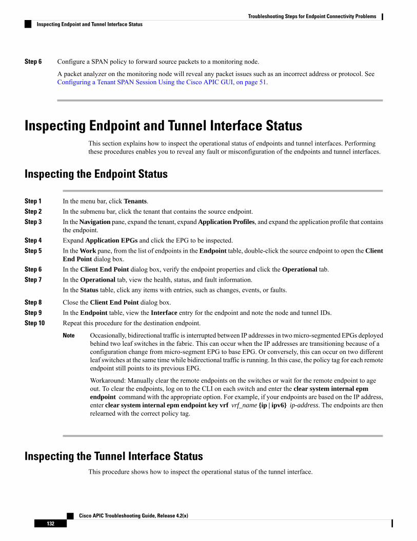
Step 6 Configure a SPAN policy to forward source packets to a monitoring node.
A packet analyzer on the monitoring node will reveal any packet issues such as an incorrect address or protocol. SeeConfiguring a Tenant SPAN Session Using the Cisco APIC GUI, on page 51.
Inspecting Endpoint and Tunnel Interface StatusThis section explains how to inspect the operational status of endpoints and tunnel interfaces. Performingthese procedures enables you to reveal any fault or misconfiguration of the endpoints and tunnel interfaces.
Inspecting the Endpoint Status
Step 1 In the menu bar, click Tenants.Step 2 In the submenu bar, click the tenant that contains the source endpoint.Step 3 In theNavigation pane, expand the tenant, expandApplication Profiles, and expand the application profile that contains
the endpoint.Step 4 Expand Application EPGs and click the EPG to be inspected.Step 5 In theWork pane, from the list of endpoints in the Endpoint table, double-click the source endpoint to open theClient
End Point dialog box.Step 6 In the Client End Point dialog box, verify the endpoint properties and click the Operational tab.Step 7 In the Operational tab, view the health, status, and fault information.
In the Status table, click any items with entries, such as changes, events, or faults.
Step 8 Close the Client End Point dialog box.Step 9 In the Endpoint table, view the Interface entry for the endpoint and note the node and tunnel IDs.Step 10 Repeat this procedure for the destination endpoint.
Occasionally, bidirectional traffic is interrupted between IP addresses in twomicro-segmented EPGs deployedbehind two leaf switches in the fabric. This can occur when the IP addresses are transitioning because of aconfiguration change from micro-segment EPG to base EPG. Or conversely, this can occur on two differentleaf switches at the same time while bidirectional traffic is running. In this case, the policy tag for each remoteendpoint still points to its previous EPG.
Workaround: Manually clear the remote endpoints on the switches or wait for the remote endpoint to ageout. To clear the endpoints, log on to the CLI on each switch and enter the clear system internal epmendpoint command with the appropriate option. For example, if your endpoints are based on the IP address,enter clear system internal epm endpoint key vrf vrf_name {ip | ipv6} ip-address. The endpoints are thenrelearned with the correct policy tag.
Note
Inspecting the Tunnel Interface StatusThis procedure shows how to inspect the operational status of the tunnel interface.
Cisco APIC Troubleshooting Guide, Release 4.2(x)132
Troubleshooting Steps for Endpoint Connectivity ProblemsInspecting Endpoint and Tunnel Interface Status

Step 1 In the menu bar, click Fabric.Step 2 In the submenu bar, click Inventory.Step 3 In the Navigation pane, expand the pod and expand the node ID of the source endpoint interface.Step 4 Under the node, expand Interfaces, expand Tunnel Interfaces, and click the tunnel ID of the source endpoint interface.Step 5 In the Work pane, verify the tunnel interface properties and click the Operational tab.Step 6 In the Operational tab, view the health, status, and fault information.
In the Status table, click any items with entries, such as changes, events, or faults.
Step 7 Repeat this procedure for the destination endpoint interface.
Connecting an SFP ModuleWhen you connect an SFP module to a new card, you need to create a link speed policy for the module tocommunicate with the card. Follow these steps to create a link speed policy.
Step 1 Create an interface policy to specify the link speed:
Example:<fabricHIfPol name=”SpeedPol” speed=”1G”/>
Step 2 Reference the link speed policy within an interface policy group:
Example:<infraAccPortGrp name=”myGroup”>
<infraRsHIfPol tnFabricHIfPolName=”SpeedPol”/></infraAccPortGrp>
Cisco APIC Troubleshooting Guide, Release 4.2(x)133
Troubleshooting Steps for Endpoint Connectivity ProblemsConnecting an SFP Module

Cisco APIC Troubleshooting Guide, Release 4.2(x)134
Troubleshooting Steps for Endpoint Connectivity ProblemsConnecting an SFP Module

C H A P T E R 11Troubleshooting EVPN Type-2 RouteAdvertisement
• Troubleshooting EVPN Type-2 Route Distribution to a DCIG, on page 135
Troubleshooting EVPN Type-2 Route Distribution to a DCIGFor optimal traffic forwarding in an EVPN topology, you can enable fabric spines to distribute host routes toa Data Center Interconnect Gateway (DCIG) using EVPN type-2 (MAC-IP) routes along with the public BDsubnets in the form of BGP EVPN type-5 (IP Prefix) routes. This is enabled using the HostLeak object. Ifyou encounter problems with route distribution, use the steps in this topic to troubleshoot.
SUMMARY STEPS
1. Verify that HostLeak object is enabled under the VRF-AF in question, by entering a command such asthe following in the spine-switch CLI:
2. Verify that the config-MO has been successfully processed by BGP, by entering a command such as thefollowing in the spine-switch CLI:
3. Verify that the public BD-subnet has been advertised to DCIG as an EVPN type-5 route:4. Verify whether the host route advertised to the EVPN peer was an EVPN type-2 MAC-IP route:5. Verify that the EVPN peer (a DCIG) received the correct type-2 MAC-IP route and the host route was
successfully imported into the given VRF, by entering a command such as the following on the DCIGdevice (assuming that the DCIG is a Cisco ASR 9000 switch in the example below):
DETAILED STEPS
Step 1 Verify that HostLeak object is enabled under the VRF-AF in question, by entering a command such as the following inthe spine-switch CLI:
Example:
spine1# ls /mit/sys/bgp/inst/dom-apple/af-ipv4-ucast/ctrl-l2vpn-evpn ctrl-vpnv4-ucast hostleak summary
Step 2 Verify that the config-MO has been successfully processed by BGP, by entering a command such as the following in thespine-switch CLI:
Cisco APIC Troubleshooting Guide, Release 4.2(x)135

Example:
spine1# show bgp process vrf apple
Look for output similar to the following:Information for address family IPv4 Unicast in VRF apple
Table Id : 0Table state : UPTable refcount : 3Peers Active-peers Routes Paths Networks Aggregates0 0 0 0 0 0
RedistributionNone
Wait for IGP convergence is not configuredGOLF EVPN MAC-IP route is enabledEVPN network next-hop 192.41.1.1EVPN network route-map map_pfxleakctrl_v4Import route-map rtctrlmap-apple-v4EVPN import route-map rtctrlmap-evpn-apple-v4
Step 3 Verify that the public BD-subnet has been advertised to DCIG as an EVPN type-5 route:
Example:
spine1# show bgp l2vpn evpn 10.6.0.0 vrf overlay-1Route Distinguisher: 192.41.1.5:4123 (L3VNI 2097154)BGP routing table entry for [5]:[0]:[0]:[16]:[10.6.0.0]:[0.0.0.0]/224, version 2088Paths: (1 available, best #1)Flags: (0x000002 00000000) on xmit-list, is not in rib/evpnMultipath: eBGP iBGP
Advertised path-id 1Path type: local 0x4000008c 0x0 ref 1, path is valid, is best pathAS-Path: NONE, path locally originated192.41.1.1 (metric 0) from 0.0.0.0 (192.41.1.5)Origin IGP, MED not set, localpref 100, weight 32768Received label 2097154Community: 1234:444Extcommunity:
RT:1234:51014BYTEAS-GENERIC:T:1234:444
Path-id 1 advertised to peers:50.41.50.1
In the Path type entry, ref 1 indicates that one route was sent.
Step 4 Verify whether the host route advertised to the EVPN peer was an EVPN type-2 MAC-IP route:
Example:
spine1# show bgp l2vpn evpn 10.6.41.1 vrf overlay-1Route Distinguisher: 10.10.41.2:100 (L2VNI 100)BGP routing table entry for [2]:[0]:[2097154]:[48]:[0200.0000.0002]:[32]:[10.6.41.1]/272, version 1146Shared RD: 192.41.1.5:4123 (L3VNI 2097154)Paths: (1 available, best #1)Flags: (0x00010a 00000000) on xmit-list, is not in rib/evpnMultipath: eBGP iBGP
Advertised path-id 1Path type: local 0x4000008c 0x0 ref 0, path is valid, is best path
Cisco APIC Troubleshooting Guide, Release 4.2(x)136
Troubleshooting EVPN Type-2 Route AdvertisementTroubleshooting EVPN Type-2 Route Distribution to a DCIG

AS-Path: NONE, path locally originatedEVPN network: [5]:[0]:[0]:[16]:[10.6.0.0]:[0.0.0.0] (VRF apple)10.10.41.2 (metric 0) from 0.0.0.0 (192.41.1.5)Origin IGP, MED not set, localpref 100, weight 32768Received label 2097154 2097154Extcommunity:
RT:1234:16777216
Path-id 1 advertised to peers:50.41.50.1
The Shared RD line indicates the RD/VNI shared by the EVPN type-2 route and the BD subnet.
The EVPN Network line shows the EVPN type-5 route of the BD-Subnet.
The Path-id advertised to peers indicates the path advertised to EVPN peers.
Step 5 Verify that the EVPN peer (a DCIG) received the correct type-2 MAC-IP route and the host route was successfullyimported into the given VRF, by entering a command such as the following on the DCIG device (assuming that the DCIGis a Cisco ASR 9000 switch in the example below):
Example:
RP/0/RSP0/CPU0:asr9k#show bgp vrf apple-2887482362-8-1 10.6.41.1Tue Sep 6 23:38:50.034 UTCBGP routing table entry for 10.6.41.1/32, Route Distinguisher: 44.55.66.77:51Versions:Process bRIB/RIB SendTblVerSpeaker 2088 2088
Last Modified: Feb 21 08:30:36.850 for 28w2dPaths: (1 available, best #1)Not advertised to any peerPath #1: Received by speaker 0Not advertised to any peerLocal192.41.1.1 (metric 42) from 10.10.41.1 (192.41.1.5)Received Label 2097154Origin IGP, localpref 100, valid, internal, best, group-best, import-candidate, importedReceived Path ID 0, Local Path ID 1, version 2088Community: 1234:444Extended community: 0x0204:1234:444 Encapsulation Type:8 Router
MAC:0200.c029.0101 RT:1234:5101RIB RNH: table_id 0xe0000190, Encap 8, VNI 2097154, MAC Address: 0200.c029.0101,
IP Address: 192.41.1.1, IP table_id 0x00000000Source AFI: L2VPN EVPN, Source VRF: default,
Source Route Distinguisher: 192.41.1.5:4123
In this output, the received RD, next hop, and attributes are the same for the type-2 route and the BD subnet.
Cisco APIC Troubleshooting Guide, Release 4.2(x)137
Troubleshooting EVPN Type-2 Route AdvertisementTroubleshooting EVPN Type-2 Route Distribution to a DCIG

Cisco APIC Troubleshooting Guide, Release 4.2(x)138
Troubleshooting EVPN Type-2 Route AdvertisementTroubleshooting EVPN Type-2 Route Distribution to a DCIG

C H A P T E R 12Performing a Rebuild of the Fabric
This chapter explains how to rebuild your fabric.
• Rebuilding the Fabric, on page 139
Rebuilding the Fabric
This procedure is extremely disruptive. It eliminates the existing fabric and recreates a new one.Caution
This procedure allows you to rebuild (reinitialize) your fabric, which you may need to do for any of thefollowing reasons:
• To change the TEP IPs
• To change the Infra VLAN
• To change the fabric name
• To perform TAC troubleshooting tasks
Deleting the APICs erases the configuration on them and brings them up in the startup script. Performing thison the APICs can be done in any order, but ensure that you perform the procedure on all of them (every leafand spine in the fabric).
Before you begin
Ensure that the following is in place:
• Regularly scheduled backups of the configuration
• Console access to the leaves and spines
• A configured and reachable CIMC, which is necessary for KVM console access
• No Java issues
Cisco APIC Troubleshooting Guide, Release 4.2(x)139

Step 1 If you would like to retain your current configuration, you can perform a configuration export. For more information,see the Cisco ACI Configuration Files: Import and Export document: https://www.cisco.com/c/en/us/support/cloud-systems-management/application-policy-infrastructure-controller-apic/tsd-products-support-series-home.html
Step 2 Erase the configuration on the APICs by connecting to the KVM console and entering the following commands:a) >acidiag touch cleanb) >acidiag touch setupc) >acidiag reboot
Ensure that each node boots up in fabric discovery mode and is not part of the previously configured fabric.
The acidiag touch command alone is not useful for this procedure, because it does not bring the APIC up inthe startup script.
Note
It is extremely important that you ensure that all previous fabric configurations have been removed. If anyprevious fabric configuration exists on even a single node, the fabric cannot be rebuilt.
Caution
Step 3 When all previous configurations have been removed, run the startup script for all APICs. At this point, you can changeany of the above values, TEP, TEP Vlan, and/or Fabric Name. Ensure that these are consistent across all APICs. Formore information, refer to the Cisco APIC Getting Started Guide: https://www.cisco.com/c/en/us/support/cloud-systems-management/application-policy-infrastructure-controller-apic/tsd-products-support-series-home.html.
Step 4 To clean reboot the fabric nodes, log in to each fabric node and execute the following:a) >setup-clean-config.shb) >reload
Step 5 Log in to apic1 and perform a configuration import. For more information, see theCisco ACI Configuration Files: Importand Export document: https://www.cisco.com/c/en/us/support/cloud-systems-management/application-policy-infrastructure-controller-apic/tsd-products-support-series-home.html.
Step 6 Wait for a few minutes as the fabric now uses the previous fabric registration policies to rebuild the fabric over the nodes.(Depending on the size of the fabric, this step may take awhile.)
Cisco APIC Troubleshooting Guide, Release 4.2(x)140
Performing a Rebuild of the FabricRebuilding the Fabric

C H A P T E R 13Verifying IP-Based EPG Configurations
There are two types of endpoint groups (EPGs) that you can create: application EPGs and IP-based EPGs.IP-based EPGs differ from regular application EPGs in that they are microsegment EPGs. This chapter explainshow to verify that your IP-based EPG configurations are properly classified as IP-based using the GUI orusing switch commands.
This chapter contains the following sections:
• Verifying IP-Based EPG Configurations Using the GUI, on page 141• Verifying IP-EPG Configurations Using Switch Commands, on page 142
Verifying IP-Based EPG Configurations Using the GUIThis procedure explains how to verify that you have correctly configured an IP-based EPG using the GUIand Visore tool.
Step 1 Verify that the IP-based EPG you created is listed under the uSeg EPGs folder in the GUI (shown in the following screencapture).Note that there is one IP-based EPG listed under uSeg EPGs named "IP" that was created using the REST API.
Step 2 Verify that the information is correct in the EPG - IP properties screen (right side window pane) for each EPG IP (IP-basedEPG).Note the list of IP-based EPGs and IP addresses that are shown at the bottom of the screen.
Step 3 From your web browser, enter the APIC IP address followed by "/visore.html." Visore is a tool that allows you to viewall the objects in the system, such as EPGs. You can use Visore to verify that your IP-based EPGs have been properlyconfigured. For more information about Visore, see the Application Policy Infrastructure Controller Visore ToolIntroduction document.
Step 4 Enter your username and password then click Login to log into Visore.Step 5 Run a query for the IP-based EPGs that you verified in the GUI by entering the name of the class in the field next to
Class or DN (for example, "fvAEPg").
This is a view from the APIC point of view. You can see that the "Total objects shown" above is "3", meaningthere are three EPGs that were downloaded to the switch. You can see that the IP-based EPG that was previouslylisted in the GUI as "IP" is now shown next to "dn". Also note that "yes" is displayed next to "isAttrBasedEPg",which means that this has been properly configured as an IP-based EPG. You can verify all the objects havebeen configured successfully using Visore, including both application EPGs and IP-based EPGs.
Note
Cisco APIC Troubleshooting Guide, Release 4.2(x)141

Step 6 This is a view from the switch point of view. On the switch, you can run a query for the fvEpP class to see the EPGs andcheck for the "crtrnEnabled" attribute. It will be set to "yes" for IP-based EPGs.Verify that under this EPG, the children of the EPG are shown with IP addresses to ensure a proper configuration. Foreach IP address configured, there is one object (named "l3IpCktEp") that the switch uses to classify the traffic. Once theconfiguration is there, when the packets arrive, the switch uses these objects to classify them.
Step 7 Verify that the pcTags for all the endpoints and IP addresses that you configured match. Every EPG has a pcTag. All theendpoints that match with the IP addresses you configured are classified into this pcTag. Every endpoint has an IP addressthat you can run a class query on. When you are troubleshooting, you want to verify whether these endpoints (servers)are properly getting classified into this IP-based EPG or not. (The pcTags should match for the IP-based EPG.)
Verifying IP-EPG Configurations Using Switch CommandsThis procedure explains how to use switch commands to verify you IP-EPG ("IpCkt") configurations.
Step 1 Log in to the leaf.Step 2 Navigate to the /mit/sys directory.Step 3 In the /mit/sys directory, find ctx (vrf context directory)Step 4 In the VRF cts directory, go to the specific BD directory where the IpCkt is configured.
You should see the IpCkt.
"IpCkt" and "IP-EPG" are used interchangeably in this document.Note
Step 5 Navigate to the directory and the "cat summary" gives you the information regarding IpCkt.Step 6 Ensure that the summary's "operSt' does not say "unsupported".Step 7 Find out the VLAN ID that corresponds to the BD where the IpCkt is configured.
The VLAN ID can be found through any of the show vlan internal bd-info commands or through the showsystem internal epm vlan all command.
Note
Step 8 Once you find the VLAN ID of the BD, issue show system internal epm <vlan-id> detail.Here you should be able to see all the configured IpCkts with a specific sclass. (It should match that of what you seein the /mit/sys directory.)
Step 9 Repeat the steps for vsh_lc that you followed for vsh.Step 10 Send the traffic with an IP matching the IpCtk in the BD, and through show system internal epm endp ip <a.b.c.d>,
you can verify that the learned IP has the IP-flags for "sclass" and a specific sclass value.Step 11 Repeat the steps for vsh_lc that you followed for vsh.
List of the Switch Troubleshooting Commands Used in this Procedure:
Cd /mits/sys/ctx-vxlan…/bd-vxlan…- cat summary
Vsh -c “show system internal epm vlan all” orVsh -c “show vlan internal bd-info”Vsh -c “show system internal epm vlan <vlan-id> detail”Vsh -c “show system internal epm endp ip <a.b.c.d>"Vsh_lc -c “show system internal epm vlan all” or
Cisco APIC Troubleshooting Guide, Release 4.2(x)142
Verifying IP-Based EPG ConfigurationsVerifying IP-EPG Configurations Using Switch Commands

Vsh_lc -c “show vlan internal bd-info”Vsh_lc -c “show system internal epm vlan <vlan-id> detail”vsh_lc -c “show system internal epm endp ip <a.b.c.d>”vsh_lc -c “show system internal epm epg”
Cisco APIC Troubleshooting Guide, Release 4.2(x)143
Verifying IP-Based EPG ConfigurationsVerifying IP-EPG Configurations Using Switch Commands

Cisco APIC Troubleshooting Guide, Release 4.2(x)144
Verifying IP-Based EPG ConfigurationsVerifying IP-EPG Configurations Using Switch Commands

C H A P T E R 14Recovering a Disconnected Leaf
If all fabric interfaces on a leaf are disabled (interfaces connecting a leaf to the spine) due to a configurationpushed to the leaf, connectivity to the leaf is lost forever and the leaf becomes inactive in the fabric. Tryingto push a configuration to the leaf does not work because connectivity has been lost. This chapter describeshow to recover a disconnected leaf.
• Recovering a Disconnected Leaf Using the REST API, on page 145
Recovering a Disconnected Leaf Using the REST APITo recover a disconnected leaf, at least one of the fabric interfaces must be enabled using the following process.The remaining interfaces can be enabled using the GUI, REST API, or CLI.
To enable the first interface, post a policy using the REST API to delete the policy posted and bring the fabricports Out-of-Service. You can post a policy to the leaf to bring the port that is Out-of-Service to In-Serviceas follows:
In the following examples, the assumption is that 1/49 is one of the leaf ports connecting to the spine.Note
Step 1 Clear the blacklist policy from the APIC (using the REST API).
Example:$APIC_Address/api/policymgr/mo/.xml<polUni>
<fabricInst><fabricOOServicePol>
<fabricRsOosPath tDn="topology/pod-1/paths-$LEAF_Id/pathep-[eth1/49]"lc="blacklist" status ="deleted" />
</fabricOOServicePol></fabricInst>
</polUni>
Step 2 Post a local task to the node itself to bring up the interfaces you want using l1EthIfSetInServiceLTask.
Example:$LEAF_Address/api/node/mo/topology/pod-1/node-$LEAF_Id/sys/action.xml<actionLSubj oDn="sys/phys-[eth1/49]">
Cisco APIC Troubleshooting Guide, Release 4.2(x)145

<l1EthIfSetInServiceLTask adminSt='start'/></actionLSubj>
Cisco APIC Troubleshooting Guide, Release 4.2(x)146
Recovering a Disconnected LeafRecovering a Disconnected Leaf Using the REST API

C H A P T E R 15Troubleshooting a Loopback Failure
• Identifying a Failed Line Card, on page 147
Identifying a Failed Line CardThis section expains how to identify a failed line card when getting a loopback failure.
Before you begin
You should have created a On-Demand TechSupport policy for the fabric node. If you have not already createdan On-Demand TechSupport policy, see Sending an On-Demand Tech Support File Using the GUI, on page175
Step 1 Collect the Logs Location file of the On-Demand TechSupport policy for the fabric node. To initiate the collection:a) In the menu bar, click Admin.b) In the submenu bar, click Import/Export.c) In the Navigation pane, expand Export Policies and right-click the On-Demand TechSupport policy for the fabric
node.A list of options appears.
d) Choose Collect Tech Supports.The Collect Tech Supports dialog box appears.
e) In the Collect Tech Supports dialog box, click Yes to begin collecting tech support information.
Step 2 Download the the Logs Location file of the On-Demand TechSupport policy for the fabric node. To download the LogsLocation file:a) From the On-Demand TechSupport policy window in the Work pane, click the Operational tab.
A summary table appears in the On-Demand TechSupport policy window with several columns, including the LogsLocation column.
b) Click the URL in the Logs Location column.
Step 3 Inside the Logs Location file, go to the /var/sysmgr/tmp_logs/ directory and unzip the svc_ifc_techsup_nxos.tar file.
-bash-4.1$ tar xopf svc_ifc_techsup_nxos.tar
The show_tech_info directory is created.Step 4 Run zgrep "fclc-conn failed" show-tech-sup-output.gz | less.
Cisco APIC Troubleshooting Guide, Release 4.2(x)147

-bash-4.1$ zgrep "fclc-conn failed" show-tech-sup-output.gz | less[103] diag_port_lb_fail_module: Bringing down the module 25 for Loopback test failed. Packets possiblylost on the switch SPINE or LC fabric (fclc-conn failed)[103] diag_port_lb_fail_module: Bringing down the module 24 for Loopback test failed. Packets possiblylost on the switch SPINE or LC fabric (fclc-conn failed)
The fclc-conn failed message indicates a failed line card.Note
Step 5 Power cycle the currently failed fabric cards and ensure the fabric cards come online.Step 6 If the fabric cards fail to come online, or after the fabric cards go offline again, immediately collect the diag_port_lb.log
file and send the file to the TAC team. The diag_port_lb.log file is located in the /var/sysmgr/tmp_logs/ directory of theLogs Location file.
Cisco APIC Troubleshooting Guide, Release 4.2(x)148
Troubleshooting a Loopback FailureIdentifying a Failed Line Card
C H A P T E R 16Determining Why a PIM Interface Was NotCreated
A PIM interface (pim:if) is created for L3Out interfaces (note that L3Out SVI interfaces are not supported),multicast tunnel interfaces (per VRF), SVI interfaces corresponding to PIM-enabled pervasive BDs, andloopback interfaces on border leafs (each per VRF).
This chapter contains troubleshooting information for situations where the pim:if is not being created. Formore information on PIM, see the Cisco ACI and Layer 3 Multicast with Cisco ACI and the Cisco ApplicationCentric Infrastructure Fundamentals guides.
This chapter contains the following sections:
• A PIM Interface Was Not Created For an L3Out Interface, on page 149• A PIM Interface Was Not Created For a Multicast Tunnel Interface, on page 150• A PIM Interface Was Not Created For a Multicast-Enabled Bridge Domain, on page 150
A PIM Interface Was Not Created For an L3Out InterfaceIf a PIM interface (pim:If) is not being created for an L3Out interface, confirm the following:
1. PIM is enabled on the L3Out. If PIM is disabled, enable it.2. If PIM is enabled on the container L3Out, confirm that a multicast l3ext:InstP has been created with
"__int_" as a prefixed name. This multicast l3ext:InstP is used to deploy L3Out PIM policies to theswitches. There should be one multicast l3ext:InstP per L3Out.
• If a multicast l3ext:InstP exists on the IFC, we can check whether a corresponding fv:RtdEpP is createdand deployed on each switch where there is an interface in that L3Out.
• We do not support an L3Out SVI interface for PIM.
Note
Cisco APIC Troubleshooting Guide, Release 4.2(x)149

A PIM Interface Was Not Created For a Multicast TunnelInterface
If a PIM interface (pim:if) is not created for a multicast tunnel interface (tunnel:If), confirm the following:
1. The corresponding tunnel:If has been created.
The tunnel:If should have type “underlay-mcast."Note
2. Each mcast-enabled VRF has created an mcast tunnel.3. The destination IP field of the tunnel:If is populated with a valid GIPO address.4. If the tunnel:If is not populated with a valid GIPO address, check the pim:CtxP on the IFC and the
pim:CtxDef on the switches to make sure GIPO is allocated correctly.5. The source IP of the tunnel:If has the loopback address of an L3Out for BL and “127.0.0.100” for NBL.
A PIM Interface Was Not Created For a Multicast-EnabledBridge Domain
If a PIM interface (pim:if) is not created for a multicast-enabled bridge domain (BD), confirm the following:
1. The corresponding BD or corresponding Ctx has PIM enabled.2. The corresponding BD is pervasive.3. The pervasive BD-based pim:If takes default parameters.
For interaction with igmp snooping, when PIM is enabled on a pervasive BD, the routing bit should beautomatically enabled for the corresponding igmpsnoop:If.
Note
Cisco APIC Troubleshooting Guide, Release 4.2(x)150
Determining Why a PIM Interface Was Not CreatedA PIM Interface Was Not Created For a Multicast Tunnel Interface

C H A P T E R 17Confirming the Port Security Installation
This chapter explains how to confirm the port security installation in the APIC and leaf switch using Visoreand how to confirm port security has been programmed in the hardware using the Cisco NX-OS-style CLI.For information about configuring port security, see the Cisco Port Security document.
This chapter contains the following sections:
• Confirming Your Port Security Installation Using Visore , on page 151• Confirming Your Hardware Port Security Installation Using the Cisco NX-OS CLI, on page 151
Confirming Your Port Security Installation Using Visore
Step 1 On the Cisco APIC, run a query for the l2PortSecurityPol class in Visore to verify the port security policy installation.Step 2 On the leaf switch, run a query for l2PortSecurityPolDef in Visore to confirm that the concrete object exists on the
interface.If you have confirmed that port security is installed on the Cisco APIC and leaf switch, use the Cisco NX-OS CLI toconfirm that port security has been programmed in the hardware.
Confirming Your Hardware Port Security Installation Using theCisco NX-OS CLI
Step 1 View the port security status on the switch interface as follows:
Example:switch# show system internal epm interface ethernet 1/35 detname : Ethernet1/35 ::: if index : 0x1a022000 ::: state : UPvPC : No ::: EPT : 0x0MAC Limit : 8 ::: Learn Disable : No ::: PortSecurity Action : ProtectVLANs : 4-23Endpoint count : 5Active Endpoint count : 5
Cisco APIC Troubleshooting Guide, Release 4.2(x)151

switch# show system internal epm interface port-channel 1 det
name : port-channel1 ::: if index : 0x16000000 ::: state : UPvPC : No ::: EPT : 0x0MAC Limit : 6 ::: Learn Disable : No ::: PortSecurity Action : ProtectVLANs :Endpoint count : 0Active Endpoint count : 0Number of member ports : 1Interface : Ethernet1/34 /0x1a021000::::
Step 2 View the port security status on the module interface as follows:
Example:module-1# show system internal epmc interface ethernet 1/35 detif index : 0x1a022000 ::: name : Ethernet1/35 ::: tun_ip = 0.0.0.0MAC limit : 8 ::: is_learn_disable : No ::: MAC limit action: Protectpc if index : 0 ::: name :is_vpc_fc FALSE ::: num_mem_ports : 0interface state : upEndpoint count : 5EPT : 0
module-1# show system internal epmc interface port-channel 1 detif index : 0x16000000 ::: name : port-channel1 ::: tun_ip = 0.0.0.0MAC limit : 6 ::: is_learn_disable : No ::: MAC limit action: Protectpc if index : 0 ::: name :is_vpc_fc FALSE ::: num_mem_ports : 1interface state : upEndpoint count : 0EPT : 0::::
Step 3 View the port security status on the leaf switch as follows:
Example:swtb15-leaf2# show system internal epm interface ethernet 1/35 det
name : Ethernet1/35 ::: if index : 0x1a022000 ::: state : UPvPC : No ::: EPT : 0x0MAC Limit : 5 ::: Learn Disable : Yes ::: PortSecurity Action : ProtectVLANs : 4-23Endpoint count : 5Active Endpoint count : 5::::
Step 4 Confirm the MAC limit on the module interface as follows:
Example:module-1# show system internal eltmc info interface port-channel1 | grep mac_limit
mac_limit_reached: 0 ::: mac_limit: 8port_sec_feature_set: 1 ::: mac_limit_action: 1
Example:module-1# show system internal eltmc info interface ethernet 1/35 | grep mac_limit
mac_limit_reached: 0 ::: mac_limit: 8port_sec_feature_set: 1 ::: mac_limit_action: 1
Step 5 View the port security status in the module and confirm the MAC limit as follows:
Example:
Cisco APIC Troubleshooting Guide, Release 4.2(x)152
Confirming the Port Security InstallationConfirming Your Hardware Port Security Installation Using the Cisco NX-OS CLI

module-1# show system internal epmc interface ethernet 1/35 detif index : 0x1a022000 ::: name : Ethernet1/35 ::: tun_ip = 0.0.0.0MAC limit : 5 ::: is_learn_disable : Yes ::: MAC limit action: Protectpc if index : 0 ::: name :is_vpc_fc FALSE ::: num_mem_ports : 0interface state : upEndpoint count : 5EPT : 0::::
Example:module-1# show system internal eltmc info interface ethernet 1/35 | grep mac_limit
mac_limit_reached: 1 ::: mac_limit: 5port_sec_feature_set: 1 ::: mac_limit_action: 1module-1# exit
Cisco APIC Troubleshooting Guide, Release 4.2(x)153
Confirming the Port Security InstallationConfirming Your Hardware Port Security Installation Using the Cisco NX-OS CLI

Cisco APIC Troubleshooting Guide, Release 4.2(x)154
Confirming the Port Security InstallationConfirming Your Hardware Port Security Installation Using the Cisco NX-OS CLI

C H A P T E R 18Troubleshooting QoS Policies
This section provides solutions for troubleshooting QoS policies.
• Troubleshooting Cisco APIC QoS Policies, on page 155
Troubleshooting Cisco APIC QoS PoliciesThe following table summarizes common troubleshooting scenarios for Cisco APIC QoS.
SolutionProblem
1. Invoke the following API to ensure that qospDscpRule is present on the leaf.GET https://192.0.20.123/api/node/class/qospDscpRule.xml
2. Ensure that the QoS rules are accurately configured and associated to the EPGID to which the policy is attached.
Use the following NX-OS style CLI commands to verify the configuration.leaf1#show vlan
leaf1#show system internal aclqos qos policy detail
apic1#show running-config tenant tenant-name policy-map typeqos custom-qos-policy-name
apic1#show running-config tenant tenant-name applicationapplication-name epg epg-name
Unable to update aconfigured QoSpolicy.
Cisco APIC Troubleshooting Guide, Release 4.2(x)155

SolutionProblem
CLI displays statistics for eth1/1 for only QoS classes – level1, leve2, level3, level4,level5, level6, and policy-plane – if you don’t use “detail” option.NXOS ibash cli:tor-leaf1# show queuing interface ethernet 1/1 [detail]
If you want to display statistics for control-plane and span classes for an interface,you need to use CLI with the “detail” option.
Example: fabric 107 show queuing interface ethernet 1/1 detailAPIC CLI:swtb123-ifc1# fabric node_id show queuing interface ethernet 1/1
Show QoS interfacestatistics.
Cisco APIC Troubleshooting Guide, Release 4.2(x)156
Troubleshooting QoS PoliciesTroubleshooting Cisco APIC QoS Policies

C H A P T E R 19Determining the Supported SSL Ciphers
This chapter explains how to determine which SSL ciphers are supported.
• About SSL Ciphers, on page 157• Determining the Supported SSL Ciphers Using the CLI , on page 158
About SSL CiphersThe Cisco Application Centric Infrastructure (ACI) Representational State Transfer (REST) ApplicationProgramming Interface (API) has gone through an evolution from the day the solution debuted to recentversions where the HTTPS/SSL/TLS support has gotten increasinglymore stringent. This document is intendedto cover the evolution of HTTPS, SSL, and TLS support on the Cisco ACI REST API and provide customerswith a guide of what is required for a client to utilize the REST API securely.
HTTPS is a protocol that utilizes either Secure Socket Layers (SSL) or Transport Layer Security (TLS) toform a secure connection for a HTTP session. SSL or TLS is used to encrypt the traffic between a client anda HTTP server. In addition, servers that support HTTPS have a certificate that can usually be used by theclient to verify the server's authenticity. This is the opposite of the client authenticating with the server. Inthis case, the server is saying, "I am server_xyz and here is the certificate that proves it." The client can thenutilize that certificate to verify the server is "server_xyz."
There are other important aspects to SSL/TLS that involve the supported encryption ciphers available in eachprotocol as well as the inherent security of the SSL or TLS protocols. SSL has gone through three iterations- SSLv1, SSLv2 and SSLv3 - all of which are now considered insecure. TLS has gone through three iterations- TLSv1, TLSv1.1 and TLSv1.2 - of which only TLSv1.1 and TLSv1.2 are considered "secure." Ideally, aclient should utilize the highest available TLS version it can and the server should support only TLSv1.1 andTLSv1.2. However, most servers must keep TLSv1 for outdated clients.
Almost all modern browsers support both TLSv1.1 and TLSv1.2. However, a client that utilizes HTTPS maynot be a browser. The client may be a java application or a python script that communicates with a web serverand must negotiate HTTPS/TLS. In this type of a situation, the questions of what is supported and wherebecomes much more important.
Cisco APIC Troubleshooting Guide, Release 4.2(x)157

Determining the Supported SSL Ciphers Using the CLIBefore you begin
This section describes how to use the CLI to determine which SSL ciphers are supported.
Step 1 Get the supported ciphers in your openssl environment, shown as follows:
Example:openssl ciphers 'ALL:eNULL'
Step 2 Separate the ciphers using sed or some other tool, shown as follows:
Example:openssl ciphers 'ALL:eNULL' | sed -e 's/:/\n/g'
Step 3 Loop over the ciphers and poll the APIC to see which ones are supported, shown as follows:
Example:openssl s_client -cipher ?<some cipher to test>? -connect <apic ipaddress>:<ssl port, usually 443>
See the following example cipher:
Example:openssl s_client -cipher ?ECDHE-ECDSA-AES128-GCM-SHA256? -connect 10.1.1.14:443
If the response contains CONNECTED, then the cipher is supported.Note
Cisco APIC Troubleshooting Guide, Release 4.2(x)158
Determining the Supported SSL CiphersDetermining the Supported SSL Ciphers Using the CLI

C H A P T E R 20Removing Unwanted _ui_ Objects
Changes made through the APIC Basic GUI can be seen, but cannot be modified in the Advanced GUI, andchanges made in the Advanced GUI cannot be rendered in the Basic GUI. The Basic GUI is kept synchronizedwith the NX-OS style CLI, so that if you make a change from the NX-OS style CLI, these changes are renderedin the Basic GUI, and changes made in the Basic GUI are rendered in the NX-OS style CLI, but the samesynchronization does not occur between the Advanced GUI and the NX-OS style CLI. See the followingexamples:
• Do not mix Basic and Advanced GUImodes. If you apply an interface policy to two ports using Advancedmode and then change the settings of one port using Basic mode, your changes might be applied to bothports.
• Do not mix the Advanced GUI and the CLI, when doing per-interface configuration on APIC.Configurations performed in the GUI, may only partially work in the NX-OS CLI.
For example, if you configure a switch port in the GUI at Tenants > tenant-name > ApplicationProfiles > application-profile-name > Application EPGs > EPG-name > Static Ports > DeployStatic EPG on PC, VPC, or Interface
Then you use the show running-config command in the NX-OS style CLI, you receive output such as:leaf 102interface ethernet 1/15switchport trunk allowed vlan 201 tenant t1 application ap1 epg ep1exitexit
If you use these commands to configure a static port in the NX-OS style CLI, the following error occurs:apic1(config)# leaf 102apic1(config-leaf)# interface ethernet 1/15apic1(config-leaf-if)# switchport trunk allowed vlan 201 tenant t1 application ap1 epgep1No vlan-domain associated to node 102 interface ethernet1/15 encap vlan-201
This occurs because the CLI has validations that are not performed by the APIC GUI. For the commandsfrom the show running-config command to function in the NX-OS CLI, a vlan-domain must have beenpreviously configured. The order of configuration is not enforced in the GUI.
• Do not make changes with the Basic GUI or the NX-OS CLI before using the Advanced GUI. This mayalso inadvertantly cause objects to be created (with names prepended with _ui_) which cannot bechanged or deleted in the Advanced GUI.
Caution
Cisco APIC Troubleshooting Guide, Release 4.2(x)159

If you make changes with the Basic GUI or the NX-OS CLI before using the Advanced GUI, this mayinadvertently cause objects to be created (with names prepended with _ui_) which cannot be changed ordeleted in the Advanced GUI.
For the steps to remove such objects, see Removing Unwanted _ui_ Objects Using the REST API, on page160.
• Removing Unwanted _ui_ Objects Using the REST API, on page 160
Removing Unwanted _ui_ Objects Using the REST APIIf you make changes with the Cisco NX-OS-Style CLI before using the Cisco APIC GUI, and objects appearin the Cisco APIC GUI (with names prepended with _ui_), these objects can be removed by performing aREST API request to the API, containing the following:
• The Class name, for example infraAccPortGrp
• The Dn attribute, for example dn="uni/infra/funcprof/accportgrp-__ui_l101_eth1--31"
• The Status attribute set to status="deleted"
Perform the POST to the API with the following steps:
Step 1 Log on to a user account with write access to the object to be removed.Step 2 Send a POST to the API such as the following example:
POST https://192.168.20.123/api/mo/uni.xmlPayload:<infraAccPortGrp dn="uni/infra/funcprof/accportgrp-__ui_l101_eth1--31" status="deleted"/>
Cisco APIC Troubleshooting Guide, Release 4.2(x)160
Removing Unwanted _ui_ ObjectsRemoving Unwanted _ui_ Objects Using the REST API

C H A P T E R 21Troubleshooting Multipod and Multi-Site Issues
This chapter contains the following sections:
• Troubleshooting Multi-Site and Multi-Pod, on page 161
Troubleshooting Multi-Site and Multi-PodThis section describes how to troubleshoot Multi-Site and Multi-Pod.
Error:400
If you receive the following error:Error:400 - Invalid Configuration Following Intersite Spines are not configured as MpodSpines: 1202
You must enable the fabric external connectivity for all the existing spines and if you are trying to add newspines use the Setup Multipod GUI wizard.
There are two ways to resolve this issue.
• Enable all the spines under the external routed network:
• In the APIC GUI, on the menu bar, click Tenant > infra.
• In the Navigation pane, expand Networking > External Routed Networks, right-click on theexternal routed network and choose Enable Fabric External Connectivity.
• Add new spines under the external routed network:
• In the APIC GUI, on the menu bar, click Fabric.
• In theNavigation pane, expandQuick Start >Node or Pod Setup > Setup Multipod and completethe Multipod setup.
Cisco APIC Troubleshooting Guide, Release 4.2(x)161

Cisco APIC Troubleshooting Guide, Release 4.2(x)162
Troubleshooting Multipod and Multi-Site IssuesTroubleshooting Multi-Site and Multi-Pod

A P P E N D I X Aacidiag Command
To troubleshoot operations on the Cisco APIC, use the acidiag command.
This command is not intended for every day operation of ACI. Running all forms of the command can bevery disruptive and cause major issues in your network if not used properly. Make sure you understand thefull effect on your fabric before running them.
Caution
Cluster Commands
acidiag
acidiag avread
acidiag fnvread
acidiag fnvreadex
Syntax Description FunctionOption
Displays APICs within the cluster. The avread outputincludes:
• Cluster of —Operational cluster size
• out of targeted—The desired cluster size
• active= —Indicates whether the APIC isreachable
• health= —The overall APIC health summary.Displays services with degraded health scores.
• chassisID=—The known chassis IDs for a givenAPIC.
Peer chassis IDs can be incorrect forAPICs not currently in the cluster.
Note
avread
Cisco APIC Troubleshooting Guide, Release 4.2(x)163
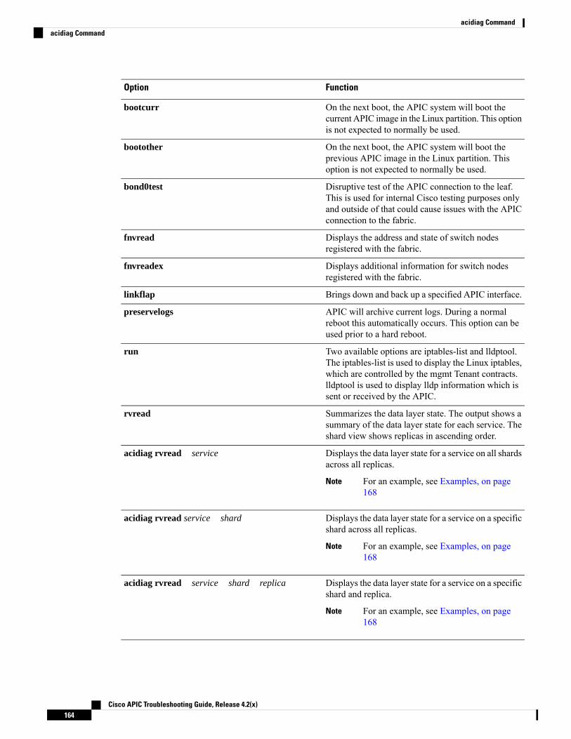
FunctionOption
On the next boot, the APIC system will boot thecurrent APIC image in the Linux partition. This optionis not expected to normally be used.
bootcurr
On the next boot, the APIC system will boot theprevious APIC image in the Linux partition. Thisoption is not expected to normally be used.
bootother
Disruptive test of the APIC connection to the leaf.This is used for internal Cisco testing purposes onlyand outside of that could cause issues with the APICconnection to the fabric.
bond0test
Displays the address and state of switch nodesregistered with the fabric.
fnvread
Displays additional information for switch nodesregistered with the fabric.
fnvreadex
Brings down and back up a specified APIC interface.linkflap
APIC will archive current logs. During a normalreboot this automatically occurs. This option can beused prior to a hard reboot.
preservelogs
Two available options are iptables-list and lldptool.The iptables-list is used to display the Linux iptables,which are controlled by the mgmt Tenant contracts.lldptool is used to display lldp information which issent or received by the APIC.
run
Summarizes the data layer state. The output shows asummary of the data layer state for each service. Theshard view shows replicas in ascending order.
rvread
Displays the data layer state for a service on all shardsacross all replicas.
For an example, see Examples, on page168
Note
acidiag rvread service
Displays the data layer state for a service on a specificshard across all replicas.
For an example, see Examples, on page168
Note
acidiag rvread service shard
Displays the data layer state for a service on a specificshard and replica.
For an example, see Examples, on page168
Note
acidiag rvread service shard replica
Cisco APIC Troubleshooting Guide, Release 4.2(x)164
acidiag Commandacidiag Command

FunctionOption
Prior to loading an image into the firmware repository,the image can be validated. Note that this functionruns as a normal part of the process of the image beingadded into the repository.
validateimage
Validates the generated nginx configuration file onAPIC to ensure nginx can start with that configurationfile. This is meant for debug use, in cases where thenginx webserver is not running on APIC.
validateenginxconf
Service IDs
The service IDs listed in the table below are also visible when entering the man acidiag command.
Table 3: Service IDs
IDService
1cliD
2controller
3eventmgr
4extXMLApi
5policyelem
6policymgr
7reader
8ae
9topomgr
10observer
11dbgr
12observerelem
13dbgrelem
14vmmmgr
15nxosmock
16bootmgr
17appliancedirector
18adrelay
Cisco APIC Troubleshooting Guide, Release 4.2(x)165
acidiag Commandacidiag Command

IDService
19ospaagent
20vleafelem
21dhcpd
22scripthandler
23idmgr
24ospaelem
25osh
26opflexagent
27opflexelem
28confelem
29vtap
30snmpd
31opflexp
32analytics
33policydist
34plghandler
35domainmgr
36licensemgr
37N/A
38platformmgr
39edmgr
Table 4: Data States
IDState
0COMATOSE
1NEWLY_BORN
2UNKNOWN
11DATA_LAYER_DIVERGED
12DATA_LAYER_DEGRADED_LEADERSHIP
Cisco APIC Troubleshooting Guide, Release 4.2(x)166
acidiag Commandacidiag Command

IDState
111DATA_LAYER_ENTIRELY_DIVERGED
112DATA_LAYER_PARTIALLY_DIVERGED
121DATA_LAYER_ENTIRELY_DEGRADED_LEADERSHIP
122DATA_LAYER_PARTIALLY_DEGRADED_LEADERSHIP
255FULLY_FIT
System Keywords
acidiag [{ start | stop | restart }] [{ mgmt | xinetd }]
acidiag installer -u imageurl -c
acidiag reboot
acidiag touch [{ clean | setup }]
acidiag verifyapic
Syntax Description FunctionOption
Specifies a clean install-c
Specifies a URL for the APIC image.-u
Specifies an APIC image.imageurl
Installs a new image on the APIC, -c for clean installinstaller
Specifies all services on the APIC.mgmt
Reboots the APIC.reboot
Restarts services on an APIC.restart
Starts services on an APIC.start
Stops services on an APIC.stop
Resets the APIC configuration.
• The clean option removes all policy data whileretaining the APIC network configuration (suchas fabric name, IP address, login)
• The setup option removes both policy data andthe APIC network configuration.
touch [clean | setup]
Displays the APIC software version.verifyapic
Specifies xinetd (extended internet daemon) service,which controls the ssh and telnet daemons.
xinetd
Cisco APIC Troubleshooting Guide, Release 4.2(x)167
acidiag Commandacidiag Command

Diagnostic Keywords
acidiag crashsuspecttracker
acidiag dbgtoken
acidiag version
Syntax Description FunctionOption
Tracks states of a service or data subset that indicatea crash.
crashsuspecttracker
Generates a token used to generate a root password.This is to be used as directed while working with theTAC as needed.
dbgtoken
Displays the APIC ISO software version.version
Examples
The following examples show how to use the acidiag command:apic1# acidiag version 2.2.1o
apic1# acidiag verifyapicopenssl_check: certificate detailssubject= CN=ABC12345678,serialNumber=PID:APIC-SERVER-L1 SN:ABC12345678issuer= CN=Cisco Manufacturing CA,O=Cisco SystemsnotBefore=Sep 28 17:17:42 2016 GMTnotAfter=Sep 28 17:27:42 2026 GMTopenssl_check: passedssh_check: passedall_checks: passed
apic1# acidiag avreadLocal appliance ID=1 ADDRESS=10.0.0.1 TEP ADDRESS=10.0.0.0/16 ROUTABLE IP ADDRESS=0.0.0.0CHASSIS_ID=1009f750-adab-11e9-a044-8dbd212cd556Cluster of 7 lm(t):1(2019-08-08T01:02:17.961-07:00) appliances (out of targeted 7lm(t):7(2019-08-08T03:50:57.240-07:00)) with FABRIC_DOMAIN name=ACI Fabric1 set toversion=apic-4.2(0.235j) lm(t):1(2019-08-17T01:09:16.413-07:00); discoveryMode=PERMISSIVElm(t):0(1969-12-31T17:00:00.007-07:00); drrMode=OFF lm(t):0(1969-12-31T17:00:00.007-07:00);kafkaMode=OFF lm(t):0(1969-12-31T17:00:00.007-07:00)
appliance id=1 address=10.0.0.1 lm(t):1(2019-08-08T01:02:08.544-07:00) tepaddress=10.0.0.0/16 lm(t):1(2019-08-08T01:02:08.544-07:00) routable address=0.0.0.0lm(t):1(zeroTime) oob address=172.23.96.10/21 lm(t):1(2019-08-08T01:02:18.218-07:00)version=4.2(0.235j) lm(t):1(2019-08-15T15:22:00.158-07:00)chassisId=1009f750-adab-11e9-a044-8dbd212cd556 lm(t):1(2019-08-15T15:22:00.158-07:00)capabilities=0X3EEFFFFFFFFF--0X2020--0X7F lm(t):1(2019-08-17T01:13:46.997-07:00)rK=(stable,present,0X206173722D687373) lm(t):1(2019-08-08T01:02:18.228-07:00)aK=(stable,present,0X206173722D687373) lm(t):1(2019-08-08T01:02:18.228-07:00)oobrK=(stable,present,0X206173722D687373) lm(t):1(2019-08-08T01:02:18.228-07:00)oobaK=(stable,present,0X206173722D687373) lm(t):1(2019-08-08T01:02:18.228-07:00)cntrlSbst=(APPROVED, FCH1748V0SZ) lm(t):1(2019-08-15T15:22:00.158-07:00) (targetMbSn=lm(t):0(zeroTime), failoverStatus=0 lm(t):0(zeroTime)) podId=1lm(t):1(2019-08-08T01:02:08.544-07:00) commissioned=YES lm(t):1(zeroTime) registered=YESlm(t):1(2019-08-08T01:02:08.544-07:00) standby=NO lm(t):1(2019-08-08T01:02:08.544-07:00)DRR=NO lm(t):0(zeroTime) apicX=NO lm(t):1(2019-08-08T01:02:08.544-07:00) virtual=NO
Cisco APIC Troubleshooting Guide, Release 4.2(x)168
acidiag Commandacidiag Command

lm(t):1(2019-08-08T01:02:08.544-07:00) active=YES(2019-08-08T01:02:08.544-07:00)health=(applnc:255 lm(t):1(2019-08-17T01:39:26.296-07:00) svc's)
appliance id=2 address=10.0.0.2 lm(t):7(2019-08-08T03:50:55.470-07:00) tepaddress=10.0.0.0/16 lm(t):2(2019-07-23T17:51:38.997-07:00) routable address=0.0.0.0lm(t):0(zeroTime) oob address=172.23.96.11/21 lm(t):1(2019-08-18T23:14:28.720-07:00)version=4.2(0.235j) lm(t):2(2019-08-15T15:22:00.300-07:00)chassisId=694e6a98-adac-11e9-ad79-d1f60e3ee822 lm(t):2(2019-08-15T15:22:00.300-07:00)capabilities=0X3EEFFFFFFFFF--0X2020--0X2 lm(t):2(2019-08-14T07:55:10.074-07:00)rK=(stable,present,0X206173722D687373) lm(t):1(2019-08-15T15:22:00.829-07:00)aK=(stable,present,0X206173722D687373) lm(t):1(2019-08-15T15:22:00.829-07:00)oobrK=(stable,present,0X206173722D687373) lm(t):1(2019-08-15T15:22:00.829-07:00)oobaK=(stable,present,0X206173722D687373) lm(t):1(2019-08-15T15:22:00.829-07:00)cntrlSbst=(APPROVED, FCH1748V0MS) lm(t):2(2019-08-15T15:22:00.300-07:00) (targetMbSn=lm(t):0(zeroTime), failoverStatus=0 lm(t):0(zeroTime)) podId=1lm(t):2(2019-08-08T01:42:03.670-07:00) commissioned=YES lm(t):1(2019-08-08T01:02:17.961-07:00)registered=YES lm(t):7(2019-07-24T15:24:25.693-07:00) standby=NOlm(t):2(2019-08-08T01:42:03.670-07:00) DRR=NO lm(t):1(2019-08-08T01:02:17.961-07:00) apicX=NOlm(t):2(2019-08-08T01:42:03.670-07:00) virtual=NO lm(t):0(zeroTime)active=YES(2019-08-13T17:02:32.983-07:00) health=(applnc:255lm(t):2(2019-08-17T01:32:51.454-07:00) svc's)
appliance id=3 address=10.0.0.3 lm(t):7(2019-08-08T03:50:55.470-07:00) tepaddress=10.0.0.0/16 lm(t):3(2019-07-23T19:05:56.405-07:00) routable address=0.0.0.0lm(t):0(zeroTime) oob address=172.23.96.12/21 lm(t):1(2019-08-18T23:14:28.721-07:00)version=4.2(0.235j) lm(t):3(2019-08-15T15:21:59.893-07:00)chassisId=1f98b916-adb7-11e9-a6f8-abe00a04e8e6 lm(t):3(2019-08-15T15:21:59.893-07:00)capabilities=0X3EEFFFFFFFFF--0X2020--0X4 lm(t):3(2019-08-14T07:55:22.256-07:00)rK=(stable,present,0X206173722D687373) lm(t):1(2019-08-15T15:22:00.824-07:00)aK=(stable,present,0X206173722D687373) lm(t):1(2019-08-15T15:22:00.824-07:00)oobrK=(stable,present,0X206173722D687373) lm(t):1(2019-08-15T15:22:00.824-07:00)oobaK=(stable,present,0X206173722D687373) lm(t):1(2019-08-15T15:22:00.824-07:00)cntrlSbst=(APPROVED, FCH1930V1X6) lm(t):3(2019-08-15T15:21:59.893-07:00) (targetMbSn=lm(t):0(zeroTime), failoverStatus=0 lm(t):0(zeroTime)) podId=1lm(t):3(2019-08-08T02:15:20.560-07:00) commissioned=YES lm(t):2(2019-08-08T01:42:15.337-07:00)registered=YES lm(t):7(2019-07-24T15:24:25.693-07:00) standby=NOlm(t):3(2019-08-08T02:15:20.560-07:00) DRR=NO lm(t):2(2019-08-08T01:42:15.337-07:00) apicX=NOlm(t):3(2019-08-08T02:15:20.560-07:00) virtual=NO lm(t):0(zeroTime)active=YES(2019-08-13T17:02:33.182-07:00) health=(applnc:255lm(t):3(2019-08-15T16:08:46.119-07:00) svc's)
appliance id=4 address=10.0.0.4 lm(t):7(2019-08-08T03:50:55.470-07:00) tepaddress=10.0.0.0/16 lm(t):4(2019-07-23T17:46:15.545-07:00) routable address=0.0.0.0lm(t):0(zeroTime) oob address=172.23.97.231/21 lm(t):1(2019-08-18T23:14:28.717-07:00)version=4.2(0.235j) lm(t):4(2019-08-15T15:22:00.669-07:00)chassisId=3a7f38aa-adac-11e9-8869-a9e520cdc042 lm(t):4(2019-08-15T15:22:00.669-07:00)capabilities=0X3EEFFFFFFFFF--0X2020--0X8 lm(t):4(2019-08-14T07:54:59.490-07:00)rK=(stable,present,0X206173722D687373) lm(t):1(2019-08-15T15:22:00.825-07:00)aK=(stable,present,0X206173722D687373) lm(t):1(2019-08-15T15:22:00.825-07:00)oobrK=(stable,present,0X206173722D687373) lm(t):1(2019-08-15T15:22:00.825-07:00)oobaK=(stable,present,0X206173722D687373) lm(t):1(2019-08-15T15:22:00.825-07:00)cntrlSbst=(APPROVED, FCH1902V1WW) lm(t):4(2019-08-15T15:22:00.669-07:00) (targetMbSn=lm(t):0(zeroTime), failoverStatus=0 lm(t):0(zeroTime)) podId=1lm(t):4(2019-08-08T02:40:09.610-07:00) commissioned=YES lm(t):3(2019-08-08T02:15:32.613-07:00)registered=YES lm(t):7(2019-07-24T15:24:25.693-07:00) standby=NOlm(t):4(2019-08-08T02:40:09.610-07:00) DRR=NO lm(t):3(2019-08-08T02:15:32.613-07:00) apicX=NOlm(t):4(2019-08-08T02:40:09.610-07:00) virtual=NO lm(t):0(zeroTime)active=YES(2019-08-15T15:21:59.914-07:00) health=(applnc:255lm(t):4(2019-08-17T01:39:26.477-07:00) svc's)
appliance id=5 address=10.0.0.5 lm(t):7(2019-08-08T03:50:55.470-07:00) tepaddress=10.0.0.0/16 lm(t):5(2019-07-23T19:05:11.089-07:00) routable address=0.0.0.0lm(t):0(zeroTime) oob address=172.23.97.232/21 lm(t):1(2019-08-18T23:14:28.723-07:00)version=4.2(0.235j) lm(t):5(2019-08-15T15:22:00.248-07:00)chassisId=35428666-adb7-11e9-a315-1d7671b518b3 lm(t):5(2019-08-15T15:22:00.248-07:00)capabilities=0X3EEFFFFFFFFF--0X2020--0X10 lm(t):5(2019-08-14T07:55:19.573-07:00)rK=(stable,present,0X206173722D687373) lm(t):1(2019-08-15T15:22:00.854-07:00)aK=(stable,present,0X206173722D687373) lm(t):1(2019-08-15T15:22:00.854-07:00)
Cisco APIC Troubleshooting Guide, Release 4.2(x)169
acidiag Commandacidiag Command

oobrK=(stable,present,0X206173722D687373) lm(t):1(2019-08-15T15:22:00.854-07:00)oobaK=(stable,present,0X206173722D687373) lm(t):1(2019-08-15T15:22:00.854-07:00)cntrlSbst=(APPROVED, FCH1902V1EG) lm(t):5(2019-08-15T15:22:00.248-07:00) (targetMbSn=lm(t):0(zeroTime), failoverStatus=0 lm(t):0(zeroTime)) podId=1lm(t):5(2019-08-08T03:03:50.338-07:00) commissioned=YES lm(t):4(2019-08-08T02:40:15.939-07:00)registered=YES lm(t):7(2019-07-24T15:24:25.693-07:00) standby=NOlm(t):5(2019-08-08T03:03:50.338-07:00) DRR=NO lm(t):4(2019-08-08T02:40:15.939-07:00) apicX=NOlm(t):5(2019-08-08T03:03:50.338-07:00) virtual=NO lm(t):0(zeroTime)active=YES(2019-08-15T15:21:59.756-07:00) health=(applnc:255lm(t):5(2019-08-17T01:32:43.730-07:00) svc's)
appliance id=6 address=10.0.0.6 lm(t):7(2019-08-08T03:50:55.470-07:00) tepaddress=10.0.0.0/16 lm(t):6(2019-07-23T19:39:41.972-07:00) routable address=0.0.0.0lm(t):0(zeroTime) oob address=172.31.170.230/21 lm(t):1(2019-08-18T23:14:28.727-07:00)version=4.2(0.235j) lm(t):6(2019-08-15T15:22:00.562-07:00)chassisId=066c943a-adbc-11e9-bbed-257398025731 lm(t):6(2019-08-15T15:22:00.562-07:00)capabilities=0X3EEFFFFFFFFF--0X2020--0X20 lm(t):6(2019-08-14T07:55:20.053-07:00)rK=(stable,present,0X206173722D687373) lm(t):1(2019-08-15T15:22:00.820-07:00)aK=(stable,present,0X206173722D687373) lm(t):1(2019-08-15T15:22:00.821-07:00)oobrK=(stable,present,0X206173722D687373) lm(t):1(2019-08-15T15:22:00.821-07:00)oobaK=(stable,present,0X206173722D687373) lm(t):1(2019-08-15T15:22:00.821-07:00)cntrlSbst=(APPROVED, WZP22350JFT) lm(t):6(2019-08-15T15:22:00.562-07:00) (targetMbSn=lm(t):0(zeroTime), failoverStatus=0 lm(t):0(zeroTime)) podId=9lm(t):6(2019-08-08T03:28:11.246-07:00) commissioned=YES lm(t):5(2019-08-08T03:03:57.387-07:00)registered=YES lm(t):7(2019-07-24T15:24:25.693-07:00) standby=NOlm(t):6(2019-08-08T03:28:11.246-07:00) DRR=NO lm(t):5(2019-08-08T03:03:57.387-07:00) apicX=NOlm(t):6(2019-08-08T03:28:11.246-07:00) virtual=NO lm(t):0(zeroTime)active=YES(2019-08-13T17:30:37.663-07:00) health=(applnc:255lm(t):6(2019-08-15T15:57:05.128-07:00) svc's)
appliance id=7 address=10.0.0.7 lm(t):7(2019-08-08T03:50:48.149-07:00) tepaddress=10.0.0.0/16 lm(t):7(2019-07-24T15:24:19.988-07:00) routable address=0.0.0.0lm(t):0(zeroTime) oob address=172.31.172.157/21 lm(t):1(2019-08-18T23:14:28.722-07:00)version=4.2(0.235j) lm(t):7(2019-08-15T15:22:00.539-07:00)chassisId=859be4ae-ae61-11e9-9840-7d9d67698989 lm(t):7(2019-08-15T15:22:00.539-07:00)capabilities=0X3EEFFFFFFFFF--0X2020--0X40 lm(t):7(2019-08-14T07:55:23.872-07:00)rK=(stable,present,0X206173722D687373) lm(t):1(2019-08-15T15:22:00.824-07:00)aK=(stable,present,0X206173722D687373) lm(t):1(2019-08-15T15:22:00.824-07:00)oobrK=(stable,present,0X206173722D687373) lm(t):1(2019-08-15T15:22:00.824-07:00)oobaK=(stable,present,0X206173722D687373) lm(t):1(2019-08-15T15:22:00.824-07:00)cntrlSbst=(APPROVED, FCH2051V116) lm(t):7(2019-08-15T15:22:00.539-07:00) (targetMbSn=lm(t):0(zeroTime), failoverStatus=0 lm(t):0(zeroTime)) podId=10lm(t):7(2019-08-08T03:50:48.149-07:00) commissioned=YES lm(t):6(2019-08-08T03:28:16.727-07:00)registered=YES lm(t):6(2019-07-24T15:27:25.518-07:00) standby=NOlm(t):7(2019-08-08T03:50:48.149-07:00) DRR=NO lm(t):6(2019-08-08T03:28:16.727-07:00) apicX=NOlm(t):7(2019-08-08T03:50:48.149-07:00) virtual=NO lm(t):0(zeroTime)active=YES(2019-08-13T17:30:45.488-07:00) health=(applnc:255lm(t):7(2019-08-17T01:39:26.549-07:00) svc's)---------------------------------------------clusterTime=<diff=2817 common=2019-08-19T15:33:55.929-07:00local=2019-08-19T15:33:53.112-07:00 pF=<displForm=0 offsSt=0 offsVlu=-25200lm(t):7(2019-08-08T03:50:55.925-07:00)>>---------------------------------------------
apic1# acidiag rvread 6 3 1(6,3,1) st:6 lm(t):3(2014-10-16T08:48:20.238+00:00) le: reSt:LEADER voGr:0 cuTerm:0x19lCoTe:0x18
lCoIn:0x1800000000001b2a veFiSt:0x31 veFiEn:0x31 lm(t):3(2014-10-16T08:48:20.120+00:00)
lastUpdt 2014-10-16T09:07:00.214+00:00---------------------------------------------clusterTime=<diff=65247252 common=2014-10-16T09:07:01.837+00:00local=2014-10-15T14:59:34.585+00:00
pF=<displForm=0 offsSt=0 offsVlu=0 lm(t):3(2014-10-16T04:50:08.714+00:00)>>
Cisco APIC Troubleshooting Guide, Release 4.2(x)170
acidiag Commandacidiag Command

apic1# acidiag rvread 6 3(6,3,1) st:6 lm(t):3(2014-10-16T08:48:20.238+00:00) le: reSt:LEADER voGr:0 cuTerm:0x19lCoTe:0x18
lCoIn:0x1800000000001b2a veFiSt:0x31 veFiEn:0x31 lm(t):3(2014-10-16T08:48:20.120+00:00)
lastUpdt 2014-10-16T09:08:30.240+00:00(6,3,2) st:6 lm(t):1(2014-10-16T08:47:25.323+00:00) le: reSt:FOLLOWER voGr:0 cuTerm:0x19lCoTe:0x18
lCoIn:0x1800000000001b2a veFiSt:0x49 veFiEn:0x49 lm(t):1(2014-10-16T08:48:20.384+00:00)lp: clSt:2
lm(t):1(2014-10-16T08:47:03.286+00:00) dbSt:2 lm(t):1(2014-10-16T08:47:02.143+00:00)stMmt:1
lm(t):0(zeroTime) dbCrTs:2014-10-16T08:47:02.143+00:00 lastUpdt2014-10-16T08:48:20.384+00:00(6,3,3) st:6 lm(t):2(2014-10-16T08:47:13.576+00:00) le: reSt:FOLLOWER voGr:0 cuTerm:0x19lCoTe:0x18
lCoIn:0x1800000000001b2a veFiSt:0x43 veFiEn:0x43 lm(t):2(2014-10-16T08:48:20.376+00:00)
lastUpdt 2014-10-16T09:08:30.240+00:00---------------------------------------------clusterTime=<diff=65247251 common=2014-10-16T09:08:30.445+00:00local=2014-10-15T15:01:03.194+00:00
pF=<displForm=0 offsSt=0 offsVlu=0 lm(t):3(2014-10-16T04:50:08.714+00:00)>>
Cisco APIC Troubleshooting Guide, Release 4.2(x)171
acidiag Commandacidiag Command

Cisco APIC Troubleshooting Guide, Release 4.2(x)172
acidiag Commandacidiag Command

A P P E N D I X BConfiguring Export Policies for Troubleshooting
Export policies enable you to export statistics, technical support collections, faults, and events to process corefiles and debug data from the fabric (the APIC as well as the switch) to any external host.
• About Exporting Files, on page 173• File Export Guidelines and Restrictions, on page 173• Configuring a Remote Location, on page 174• Sending an On-Demand Tech Support File, on page 175
About Exporting FilesAn administrator can configure export policies in the APIC to export statistics, technical support collections,faults and events, to process core files and debug data from the fabric (the APIC as well as the switch) to anyexternal host. The exports can be in a variety of formats, including XML, JSON, web sockets, secure copyprotocol (SCP), or HTTP. You can subscribe to exports in streaming, periodic, or on-demand formats.
An administrator can configure policy details such as the transfer protocol, compression algorithm, andfrequency of transfer. Policies can be configured by users who are authenticated using AAA. A securitymechanism for the actual transfer is based on a username and password. Internally, a policy element handlesthe triggering of data.
File Export Guidelines and Restrictions• HTTP export and the streaming API format is supported only with statistics information. Core and Tech
Support data are not supported.
• The destination IP for exported files cannot be an IPv6 address.
Do not trigger Tech Support from more than five nodes simultaneously, especially if they are to be exportedinto the APIC or to an external server with insufficient bandwidth and compute resources.
In order to collectTech Support from all the nodes in the fabric periodically, you must create multiple policies.Each policy must cover a subset of the nodes and should be scheduled to trigger in a staggered way (at least30 minutes apart).
Note
Cisco APIC Troubleshooting Guide, Release 4.2(x)173

Configuring a Remote Location
Configuring a Remote Location Using the GUIThis procedure explains how to create a remote location using the APIC GUI.
Step 1 On the menu bar, choose ADMIN > Import/Export.Step 2 In the navigation pane, right-click Remote Locations and choose Create Remote Location.
The Create Remote Location dialog appears.Step 3 Enter the appropriate values in the Create Remote Location dialog fields.
For an explanation of a field, click the 'i' icon to display the help file.Note
Step 4 When finished entering values in the Create Remote Location dialog fields, click Submit.You have now created a remote location for backing up your data.
Configuring a Remote Location Using the REST APIThis procedure explains how to create a remote location using the REST API.<fileRemotePath name="local" host=“host or ip" protocol=“ftp|scp|sftp" remotePath=“path tofolder" userName=“uname" userPasswd=“pwd" />
Configuring a Remote Location Using the NX-OS Style CLIIn the ACI fabric, you can configure one or more remote destinations for exporting techsupport or configurationfiles.
SUMMARY STEPS
1. configure2. [no] remote path remote-path-name
3. user username
4. path {ftp | scp | sftp} host [:port] [remote-directory ]
DETAILED STEPS
PurposeCommand or Action
Enters global configuration mode.configure
Example:
Step 1
apic1# configure
Enters configuration mode for a remote path.[no] remote path remote-path-name
Example:
Step 2
Cisco APIC Troubleshooting Guide, Release 4.2(x)174
Configuring Export Policies for TroubleshootingConfiguring a Remote Location

PurposeCommand or Actionapic1(config)# remote path myFiles
Sets the user name for logging in to the remote server. Youare prompted for a password.
user username
Example:
Step 3
apic1(config-remote)# user admin5
Sets the path and protocol to the remote server. You areprompted for a password.
path {ftp | scp | sftp} host [:port] [remote-directory ]
Example:
Step 4
apic1(config-remote)# path sftpfilehost.example.com:21 remote-directory/reports/apic
Examples
This example shows how to configure a remote path for exporting files.
apic1# configureapic1(config)# remote path myFilesapic1(config-remote)# user admin5You must reset the password when modifying the path:Password:Retype password:apic1(config-remote)# path sftp filehost.example.com:21 remote-directory /reports/apicYou must reset the password when modifying the path:Password:Retype password:
Sending an On-Demand Tech Support File
Sending an On-Demand Tech Support File Using the GUI
Step 1 In the menu bar, click Admin.Step 2 In the submenu bar, click Import/Export.Step 3 In the Navigation pane, expand Export Policies.Step 4 Right-click On-demand Tech Support and choose Create On-demand Tech Support.
The Create On-demand Tech Support dialog box appears.
Step 5 Enter the appropriate values in the fields of the Create On-demand Tech Support dialog box.
For an explanation of a field, click the help icon in the Create On-demand Tech Support dialog box. Thehelp file opens to a properties description page.
Note
Step 6 Click Submit to send the tech support file.
Cisco APIC Troubleshooting Guide, Release 4.2(x)175
Configuring Export Policies for TroubleshootingSending an On-Demand Tech Support File

On-demand tech support files can be saved to another APIC to balance storage and CPU requirements. Toverify the location, click on the On-demand Tech Support policy in the Navigation pane, then click theOPERATIONAL tab in the Work pane. The controller is displayed in the EXPORT LOCATION field.
Note
Step 7 Right-click the policy name and choose Collect Tech Support.Step 8 Choose Yes to begin collecting tech support information.
Sending an On-Demand Tech Support File Using the REST API
Step 1 Set the remote destination for a technical support file using the REST API, by sending a POST with XML such as thefollowing example:
Example:<fileRemotePath userName="" remotePort="22" remotePath="" protocol="sftp" name="ToSupport"host="192.168.200.2"dn="uni/fabric/path-ToSupport" descr="">
<fileRsARemoteHostToEpg tDn="uni/tn-mgmt/mgmtp-default/oob-default"/>
</fileRemotePath>
Step 2 Generate an on-demand technical support file using the REST API by sending a POST with XML such as the following:
Example:<dbgexpTechSupOnD upgradeLogs="no" startTime="unspecified" name="Tech_Support_9-20-16"exportToController="no"endTime="unspecified" dn="uni/fabric/tsod-Tech_Support_9-20-16" descr="" compression="gzip"category="forwarding" adminSt="untriggered">
<dbgexpRsExportDest tDn="uni/fabric/path-ToSupport"/>
<dbgexpRsTsSrc tDn="topology/pod-1/node-102/sys"/>
<dbgexpRsTsSrc tDn="topology/pod-1/node-103/sys"/>
<dbgexpRsTsSrc tDn="topology/pod-1/node-101/sys"/>
<dbgexpRsData tDn="uni/fabric/tscont"/>
</dbgexpTechSupOnD>
Cisco APIC Troubleshooting Guide, Release 4.2(x)176
Configuring Export Policies for TroubleshootingSending an On-Demand Tech Support File Using the REST API

A P P E N D I X CFinding the Switch Inventory
Knowing your switch model and serial numbers can help TAC support with troubleshooting your fabric. Thissection explains how to find the switch model and serial numbers using the Cisco APIC GUI, CLI, and RESTAPI.
• Finding Your Switch Inventory Using the GUI, on page 177• Finding Your Switch Inventory Using the NX-OS CLI, on page 177• Finding Your Switch Inventory Using the REST API, on page 180
Finding Your Switch Inventory Using the GUIThis section explains how to find your switch model and serial numbers using the Cisco APIC GUI.
Before you begin
You must have access to the Cisco APIC GUI
Step 1 On the menu bar, choose Fabric > Inventory.Step 2 In the navigation pane, click a Pod icon.
Your switch icons appear in the navigation pane.Step 3 In the navigation pane, click on a switch icon.
A list of tabs appears at the top of the work pane.Step 4 Click the General tab.
Your switch information appears in the work pane.
Finding Your Switch Inventory Using the NX-OS CLIThis section explains how to find your switch model and serial numbers using the NX-OS CLI.
Find your switch inventory as follows:
Example:
Cisco APIC Troubleshooting Guide, Release 4.2(x)177

switch# show hardwareCisco Nexus Operating System (NX-OS) SoftwareTAC support: http://www.cisco.com/tacDocuments: http://www.cisco.com/en/US/products/ps9372/tsd_products_support_series_home.htmlCopyright (c) 2002-2014, Cisco Systems, Inc. All rights reserved.The copyrights to certain works contained in this software areowned by other third parties and used and distributed underlicense. Certain components of this software are licensed underthe GNU General Public License (GPL) version 2.0 or the GNULesser General Public License (LGPL) Version 2.1. A copy of eachsuch license is available athttp://www.opensource.org/licenses/gpl-2.0.php andhttp://www.opensource.org/licenses/lgpl-2.1.php
SoftwareBIOS: version 07.56kickstart: version 12.1(1h) [build 12.1(1h)]system: version 12.1(1h) [build 12.1(1h)]PE: version 2.1(1h)BIOS compile time: 06/08/2016kickstart image file is: /bootflash/aci-n9000-dk9.12.1.1h.binkickstart compile time: 10/01/2016 20:10:40 [10/01/2016 20:10:40]system image file is: /bootflash/auto-ssystem compile time: 10/01/2016 20:10:40 [10/01/2016 20:10:40]
Hardwarecisco N9K-C93180YC-EX ("supervisor")Intel(R) Xeon(R) CPU @ 1.80GHz with 16400384 kB of memory.Processor Board ID FDO20101H1W
Device name: ifav41-leaf204bootflash: 62522368 kB
Kernel uptime is 02 day(s), 21 hour(s), 42 minute(s), 31 second(s)
Last reset at 241000 usecs after Sun Oct 02 01:27:25 2016Reason: reset-by-installerSystem version: 12.1(1e)Service: Upgrade
pluginCore Plugin, Ethernet Plugin
--------------------------------Switch hardware ID information--------------------------------
Switch is booted upSwitch type is : Nexus C93180YC-EX ChassisModel number is N9K-C93180YC-EXH/W version is 0.2010Part Number is 73-15298-01Part Revision is 1Manufacture Date is Year 20 Week 10Serial number is FDO20101H1WCLEI code is 73-15298-01
--------------------------------Chassis has one slot--------------------------------
Module1 okModule type is : 48x10/25G1 submodules are present
Cisco APIC Troubleshooting Guide, Release 4.2(x)178
Finding the Switch InventoryFinding the Switch Inventory

Model number is N9K-C93180YC-EXH/W version is 0.2110Part Number is 73-17776-02Part Revision is 11Manufacture Date is Year 20 Week 10Serial number is FDO20101H1WCLEI code is 73-17776-02
GEM okModule type is : 6x40/100G Switch1 submodules are presentModel number is N9K-C93180YC-EXH/W version is 0.2110Part Number is 73-17776-02Part Revision is 11Manufacture Date is Year 20 Week 10Serial number is FDO20101H1WCLEI code is 73-17776-02
---------------------------------------Chassis has 2 PowerSupply Slots---------------------------------------
PS1 shutPower supply type is : 54.000000W 220v ACModel number is NXA-PAC-650W-PEH/W version is 0.0Part Number is 341-0729-01Part Revision is A0Manufacture Date is Year 19 Week 50Serial number is LIT19500ZEKCLEI code is 341-0729-01
PS2 okPower supply type is : 54.000000W 220v ACModel number is NXA-PAC-650W-PEH/W version is 0.0Part Number is 341-0729-01Part Revision is A0Manufacture Date is Year 19 Week 50Serial number is LIT19500ZEACLEI code is 341-0729-01
---------------------------------------Chassis has 4 Fans---------------------------------------
FT1 ok
Fan1(sys_fan1)(fan_model:NXA-FAN-30CFM-F) is inserted but infois not available
FT2 ok
Fan2(sys_fan2)(fan_model:NXA-FAN-30CFM-F) is inserted but infois not available
FT3 ok
Fan3(sys_fan3)(fan_model:NXA-FAN-30CFM-F) is inserted but infois not available
FT4 ok
Cisco APIC Troubleshooting Guide, Release 4.2(x)179
Finding the Switch InventoryFinding the Switch Inventory

Fan4(sys_fan4)(fan_model:NXA-FAN-30CFM-F) is inserted but infois not available
====================================================================================
Finding Your Switch Inventory Using the REST APIThis section explains how to find your switch model and serial numbers using the REST API
Find your switch inventory as follows:
Example:GEThttps://192.0.20.123/api/node/mo/topology/pod-1.json?query-target=children&target-subtree-class=fabricNode
The following response is returned:response:{
"totalCount":"8","imdata":[{
"fabricNode":{"attributes":{
"adSt":"on","childAction":"","delayedHeartbeat":"no","dn":"topology/pod-1/node-103","fabricSt":"active","id":"103","lcOwn":"local","modTs":"2016-10-08T14:49:35.665+00:00","model":"N9K-C9396PX","monPolDn":"uni/fabric/monfab-default","name":"leaf3","nameAlias":"","role":"leaf","serial":"TEP-1-103","status":"","uid":"0","vendor":"Cisco Systems, Inc","version":""}}
},{"fabricNode":{"attributes":{"adSt":"on","childAction":"","delayedHeartbeat":"no","dn":"topology/pod-1/node-105","fabricSt":"active","id":"105","lcOwn":"local","modTs":"2016-10-08T14:47:52.011+00:00","model":"N9K-C9508","monPolDn":"uni/fabric/monfab-default",
Cisco APIC Troubleshooting Guide, Release 4.2(x)180
Finding the Switch InventoryFinding Your Switch Inventory Using the REST API

"name":"spine2","nameAlias":"","role":"spine","serial":"TEP-1-105","status":"","uid":"0","vendor":"Cisco Systems, Inc","version":""
...[TRUNCATED]
...}
Cisco APIC Troubleshooting Guide, Release 4.2(x)181
Finding the Switch InventoryFinding the Switch Inventory

Cisco APIC Troubleshooting Guide, Release 4.2(x)182
Finding the Switch InventoryFinding the Switch Inventory
A P P E N D I X DCisco APIC Cluster Management
This section explains how to expand, contract, commission, and decommission Cisco APIC clusters. For moreinformation about Cisco APIC clusters, see the Cisco APIC Cluster Management document:
http://www.cisco.com/c/en/us/support/cloud-systems-management/application-policy-infrastructure-controller-apic/tsd-products-support-series-home.html
This section contains the following topics:
• Expanding the Cisco APIC Cluster, on page 183• Contracting the Cisco APIC Cluster , on page 183• Cluster Management Guidelines, on page 184• Expanding the Cluster Examples, on page 187• Contracting the Cluster Examples, on page 188• Commissioning and Decommissioning Cisco APIC Controllers, on page 189• Replacing a Cisco APIC in a Cluster Using the CLI, on page 191
Expanding the Cisco APIC ClusterExpanding the Cisco APIC cluster is the operation to increase any size mismatches, from a cluster size of Nto size N+1, within legal boundaries. The operator sets the administrative cluster size and connects the APICswith the appropriate cluster IDs, and the cluster performs the expansion.
During cluster expansion, regardless of in which order you physically connect the APIC controllers, thediscovery and expansion takes place sequentially based on the APIC ID numbers. For example, APIC2 isdiscovered after APIC1, and APIC3 is discovered after APIC2 and so on until you add all the desired APICsto the cluster. As each sequential APIC is discovered, a single data path or multiple data paths are established,and all the switches along the path join the fabric. The expansion process continues until the operational clustersize reaches the equivalent of the administrative cluster size.
Contracting the Cisco APIC ClusterContracting the Cisco APIC cluster is the operation to decrease any size mismatches, from a cluster size ofN to size N -1, within legal boundaries. As the contraction results in increased computational and memoryload for the remaining APICs in the cluster, the decommissioned APIC cluster slot becomes unavailable byoperator input only.
Cisco APIC Troubleshooting Guide, Release 4.2(x)183
During cluster contraction, you must begin decommissioning the last APIC in the cluster first and work yourway sequentially in reverse order. For example, APIC4 must be decommissioned before APIC3, and APIC3must be decommissioned before APIC2.
Cluster Management GuidelinesThe APIC cluster is comprised of multiple APIC controllers that provide operators a unified real timemonitoring, diagnostic, and configuration management capability for the ACI fabric. To assure optimal systemperformance, follow the guidelines below for making changes to the APIC cluster.
Prior to initiating a change to the cluster, always verify its health. When performing planned changes to thecluster, all controllers in the cluster should be healthy. If one or more of the APIC controllers' health statusin the cluster is not "fully fit", remedy that situation before proceeding. Also, assure that cluster controllersadded to the APIC are running the same version of firmware as the other controllers in the APIC cluster.
Note
Follow these general guidelines when managing clusters:
• Cisco recommends that you have at least 3 active APICs in a cluster, along with additional standbyAPICs. A cluster size of 3, 5, or 7 APICs is recommended. A cluster size of 4 or 6 APICs is notrecommended.
• Disregard cluster information fromAPICs that are not currently in the cluster; they do not provide accuratecluster information.
• Cluster slots contain an APIC ChassisID. Once you configure a slot, it remains unavailable until youdecommission the APIC with the assigned ChassisID.
• If an APIC firmware upgrade is in progress, wait for it to complete and the cluster to be fully fit beforeproceeding with any other changes to the cluster.
• When moving an APIC, first ensure that you have a healthy cluster. After verifying the health of theAPIC Cluster, choose the APIC you intend to shut down. After the APIC has shutdown, move the APIC,re-connect it, and then turn it back on. From the GUI, verify that the all controllers in the cluster returnto a fully fit state.
Only move one APIC at a time.Note
• When an APIC cluster is split into two or more groups, the ID of a node is changed and the changes arenot synchronized across all APICs. This can cause inconsistency in the node IDs between APICs andalso the affected leaf nodes may not appear in the inventory in the APIC GUI. When you split an APICcluster, decommission the affected leaf nodes fromAPIC and register them again, so that the inconsistencyin the node IDs is resolved and the health status of the APICs in a cluster are in a fully fit state.
• Before configuring the APIC cluster, ensure that all the APICs are running the same firmware version.Initial clustering of APICs running differing versions is an unsupported operation andmay cause problemswithin the cluster.
This section contains the following topics:
Cisco APIC Troubleshooting Guide, Release 4.2(x)184
Cisco APIC Cluster ManagementCluster Management Guidelines

Expanding the APIC Cluster SizeFollow these guidelines to expand the APIC cluster size:
• Schedule the cluster expansion at a time when the demands of the fabric workload will not be impactedby the cluster expansion.
• If one or more of the APIC controllers' health status in the cluster is not "fully fit", remedy that situationbefore proceeding.
• Stage the newAPIC controller(s) according to the instructions in their hardware installation guide. Verifyin-band connectivity with a PING test.
• Increase the cluster target size to be equal to the existing cluster size controller count plus the newcontroller count. For example, if the existing cluster size controller count is 3 and you are adding 3controllers, set the new cluster target size to 6. The cluster proceeds to sequentially increase its size onecontroller at a time until all new the controllers are included in the cluster.
Cluster expansion stops if an existing APIC controller becomes unavailable.Resolve this issue before attempting to proceed with the cluster expansion.
Note
• Depending on the amount of data the APIC must synchronize upon the addition of each appliance, thetime required to complete the expansion could be more than 10 minutes per appliance. Upon successfulexpansion of the cluster, the APIC operational size and the target size will be equal.
Allow the APIC to complete the cluster expansion before making additionalchanges to the cluster.
Note
Reducing the APIC Cluster SizeFollow these guidelines to reduce the APIC cluster size and decommission the APIC controllers that areremoved from the cluster:
Failure to follow an orderly process to decommission and power downAPIC controllers from a reduced clustercan lead to unpredictable outcomes. Do not allow unrecognized APIC controllers to remain connected to thefabric.
Note
• Reducing the cluster size increases the load on the remaining APIC controllers. Schedule the APICcontroller size reduction at a time when the demands of the fabric workload will not be impacted by thecluster synchronization.
• If one or more of the APIC controllers' health status in the cluster is not "fully fit", remedy that situationbefore proceeding.
• Reduce the cluster target size to the new lower value. For example if the existing cluster size is 6 andyou will remove 3 controllers, reduce the cluster target size to 3.
Cisco APIC Troubleshooting Guide, Release 4.2(x)185
Cisco APIC Cluster ManagementExpanding the APIC Cluster Size

• Starting with the highest numbered controller ID in the existing cluster, decommission, power down,and disconnect the APIC controller one by one until the cluster reaches the new lower target size.
Upon the decommissioning and removal of each controller, the APIC synchronizes the cluster.
After decommissioning an APIC controller from the cluster, power it down anddisconnect it from fabric. Before returning it to service, do a wiped clean backto factory reset.
Note
• Cluster synchronization stops if an existing APIC controller becomes unavailable. Resolve this issuebefore attempting to proceed with the cluster synchronization.
• Depending on the amount of data the APIC must synchronize upon the removal of a controller, the timerequired to decommission and complete cluster synchronization for each controller could be more than10 minutes per controller.
Complete the entire necessary decommissioning steps, allowing the APIC to complete the clustersynchronization accordingly before making additional changes to the cluster.
Note
Replacing Cisco APIC Controllers in the ClusterFollow these guidelines to replace Cisco APIC controllers:
• If the health status of any Cisco APIC controller in the cluster is not Fully Fit, remedy the situationbefore proceeding.
• Schedule the Cisco APIC controller replacement at a time when the demands of the fabric workload willnot be impacted by the cluster synchronization.
• Make note of the initial provisioning parameters and image used on the Cisco APIC controller that willbe replaced. The same parameters and image must be used with the replacement controller. The CiscoAPIC proceeds to synchronize the replacement controller with the cluster.
Cluster synchronization stops if an existing Cisco APIC controller becomesunavailable. Resolve this issue before attempting to proceed with the clustersynchronization.
Note
• You must choose a Cisco APIC controller that is within the cluster and not the controller that is beingdecommissioned. For example: Log in to Cisco APIC1 or APIC2 to invoke the shutdown of APIC3 anddecommission APIC3.
• Perform the replacement procedure in the following order:
1. Make note of the configuration parameters and image of the APIC being replaced.
2. Decommission the APIC you want to replace (see Decommissioning a Cisco APIC Controller in theCluster Using the GUI, on page 190)
Cisco APIC Troubleshooting Guide, Release 4.2(x)186
Cisco APIC Cluster ManagementReplacing Cisco APIC Controllers in the Cluster

3. Commission the replacement APIC using the same configuration and image of the APIC beingreplaced (see Commissioning a Cisco APIC Controller in the Cluster Using the GUI, on page 189)
• Stage the replacement Cisco APIC controller according to the instructions in its hardware installationguide. Verify in-band connectivity with a PING test.
Failure to decommission Cisco APIC controllers before attempting theirreplacement will preclude the cluster from absorbing the replacement controllers.Also, before returning a decommissioned Cisco APIC controller to service, do awiped clean back to factory reset.
Note
• Depending on the amount of data the Cisco APICmust synchronize upon the replacement of a controller,the time required to complete the replacement could be more than 10 minutes per replacement controller.Upon successful synchronization of the replacement controller with the cluster, the Cisco APIC operationalsize and the target size will remain unchanged.
Allow the Cisco APIC to complete the cluster synchronization before makingadditional changes to the cluster.
Note
• The UUID and fabric domain name persist in a Cisco APIC controller across reboots. However, a cleanback-to-factory reboot removes this information. If a Cisco APIC controller is to be moved from onefabric to another, a clean back-to-factory reboot must be done before attempting to add such an controllerto a different Cisco ACI fabric.
Expanding the Cluster Examples
Expanding the APIC Cluster Using the GUI
Step 1 On the menu bar, choose System >Controllers. In theNavigation pane, expandControllers > apic_controller_name >Cluster as Seen by Node.
You must choose an apic_controller_name that is within the cluster that you wish to expand.
TheCluster as Seen by Node window appears in theWork pane with three tabs:APIC Cluster, APIC-X, and StandbyAPIC. In the APIC Cluster tab, the controller details appear. This includes the current cluster target and current sizes,the administrative, operational, and health states of each controller in the cluster.
Step 2 Verify that the health state of the cluster is Fully Fit before you proceed with contracting the cluster.Step 3 In the Work pane, click Actions > Change Cluster Size.Step 4 In the Change Cluster Size dialog box, in the Target Cluster Administrative Size field, choose the target number to
which you want to expand the cluster. Click Submit.
It is not acceptable to have a cluster size of two APIC controllers. A cluster of one, three, or more APICcontrollers is acceptable.
Note
Cisco APIC Troubleshooting Guide, Release 4.2(x)187
Cisco APIC Cluster ManagementExpanding the Cluster Examples

Step 5 In the Confirmation dialog box, click Yes.In the Work pane, under Properties , the Target Size field must display your target cluster size.
Step 6 Physically connect all the APIC controllers that are being added to the cluster.In the Work pane, in the Cluster > Controllers area, the APIC controllers are added one by one and displayed in thesequential order starting with N + 1 and continuing until the target cluster size is achieved.
Step 7 Verify that the APIC controllers are in operational state, and the health state of each controller is Fully Fit .
Expanding the APIC Cluster Using the REST APIThe cluster drives its actual size to the target size. If the target size is higher than the actual size, the clustersize expands.
Step 1 Set the target cluster size to expand the APIC cluster size.
Example:POSThttps://<IP address>/api/node/mo/uni/controller.xml<infraClusterPol name='default' size=3/>
Step 2 Physically connect the APIC controllers that you want to add to the cluster.
Contracting the Cluster Examples
Contracting the APIC Cluster Using the GUI
Step 1 On the menu bar, choose System >Controllers. In theNavigation pane, expandControllers > apic_controller_name >Cluster as Seen by Node.
You must choose an apic_controller_name that is within the cluster and not the controller that is being decommissioned.
TheCluster as Seen by Node window appears in theWork pane with three tabs:APIC Cluster, APIC-X, and StandbyAPIC. In the APIC Cluster tab, the controller details appear. This includes the current cluster target and current sizes,the administrative, operational, and health states of each controller in the cluster.
Step 2 Verify that the health state of the cluster is Fully Fit before you proceed with contracting the cluster.Step 3 In the Work pane, click Actions > Change Cluster Size.Step 4 In the Change Cluster Size dialog box, in the Target Cluster Administrative Size field, choose the target number to
which you want to contract the cluster. Click Submit.
It is not acceptable to have a cluster size of two APIC controllers. A cluster of one, three, or more APICcontrollers is acceptable.
Note
Step 5 From the Active Controllers area of the Work pane, choose the APIC that is last in the cluster.
Example:
Cisco APIC Troubleshooting Guide, Release 4.2(x)188
Cisco APIC Cluster ManagementExpanding the APIC Cluster Using the REST API
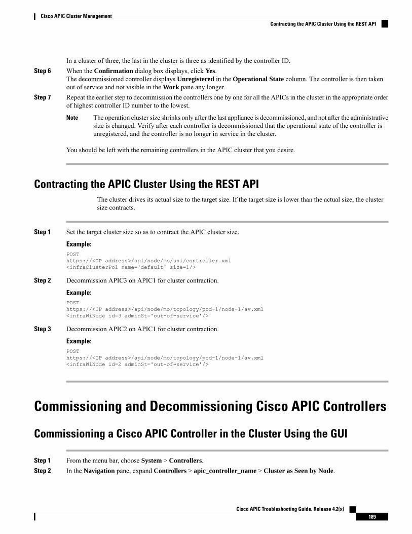
In a cluster of three, the last in the cluster is three as identified by the controller ID.Step 6 When the Confirmation dialog box displays, click Yes.
The decommissioned controller displays Unregistered in the Operational State column. The controller is then takenout of service and not visible in the Work pane any longer.
Step 7 Repeat the earlier step to decommission the controllers one by one for all the APICs in the cluster in the appropriate orderof highest controller ID number to the lowest.
The operation cluster size shrinks only after the last appliance is decommissioned, and not after the administrativesize is changed. Verify after each controller is decommissioned that the operational state of the controller isunregistered, and the controller is no longer in service in the cluster.
Note
You should be left with the remaining controllers in the APIC cluster that you desire.
Contracting the APIC Cluster Using the REST APIThe cluster drives its actual size to the target size. If the target size is lower than the actual size, the clustersize contracts.
Step 1 Set the target cluster size so as to contract the APIC cluster size.
Example:POSThttps://<IP address>/api/node/mo/uni/controller.xml<infraClusterPol name='default' size=1/>
Step 2 Decommission APIC3 on APIC1 for cluster contraction.
Example:POSThttps://<IP address>/api/node/mo/topology/pod-1/node-1/av.xml<infraWiNode id=3 adminSt='out-of-service'/>
Step 3 Decommission APIC2 on APIC1 for cluster contraction.
Example:POSThttps://<IP address>/api/node/mo/topology/pod-1/node-1/av.xml<infraWiNode id=2 adminSt='out-of-service'/>
Commissioning and Decommissioning Cisco APIC Controllers
Commissioning a Cisco APIC Controller in the Cluster Using the GUI
Step 1 From the menu bar, choose System > Controllers.Step 2 In the Navigation pane, expand Controllers > apic_controller_name > Cluster as Seen by Node.
Cisco APIC Troubleshooting Guide, Release 4.2(x)189
Cisco APIC Cluster ManagementContracting the APIC Cluster Using the REST API

TheCluster as Seen by Node window appears in theWork pane with three tabs:APIC Cluster, APIC-X, and StandbyAPIC. In the APIC Cluster tab, the controller details appear. This includes the current cluster target and current sizes,the administrative, operational, and health states of each controller in the cluster.
Step 3 From the APIC Cluster tab of the Work pane, verify in the Active Controllers summary table that the cluster HealthState is Fully Fit before continuing.
Step 4 From the Work pane, right-click the decommissioned controller that is displaying Unregistered in the OperationalState column and choose Commission .The controller is highlighted.
Step 5 In the Confirmation dialog box, click Yes.Step 6 Verify that the commissioned Cisco APIC controller is in the operational state and the health state is Fully Fit.
Decommissioning a Cisco APIC Controller in the Cluster Using the GUI
Step 1 On the menu bar, choose System > Controllers.Step 2 In the Navigation pane, expand Controllers > apic_controller_name > Cluster as Seen by Node.
You must choose an apic_controller_name that is within the cluster and not the controller that is being decommissioned.
TheCluster as Seen by Nodewindow appears in theWork pane with the controller details and three tabs:APIC Cluster,APIC-X, and Standby APIC.
Step 3 In theWork pane, verify in theAPIC Cluster tab that theHealth State in theActive Controllers summary table indicatesthe cluster is Fully Fit before continuing.
Step 4 In theActive Controllers table located in theAPIC Cluster tab of theWork pane, right-click on the controller you wantto decommission and choose Decommission.The Confirmation dialog box displays.
Step 5 Click Yes.
The decommissioned controller displays Unregistered in the Operational State column. The controller is then takenout of service and no longer visible in the Work pane.
• After decommissioning anAPIC controller from the cluster, power the APIC controller down and disconnectit from the fabric. Before returning the APIC controller to service, perform a factory reset on the APICcontroller.
• The operation cluster size shrinks only after the last appliance is decommissioned, and not after theadministrative size is changed. Verify after each controller is decommissioned that the operational stateof the controller is unregistered, and the controller is no longer in service in the cluster.
• After decommissioning the APIC controller, you must reboot the APIC for Layer 4 to Layer 7 services.Reboot must be done before commissioning back the controller.
Note
Cisco APIC Troubleshooting Guide, Release 4.2(x)190
Cisco APIC Cluster ManagementDecommissioning a Cisco APIC Controller in the Cluster Using the GUI

Replacing a Cisco APIC in a Cluster Using the CLI
• For more information about managing clusters, see Cluster Management Guidelines.
• When you replace an APIC, the password will always be synced from the cluster. When replacing APIC1, you will be asked for a password but it will be ignored in favor of the existing password in the cluster.When replacing APIC 2 or 3, you will not be asked for a password.
Note
Before you begin
Before replacing an APIC, ensure that the replacement APIC is running the same firmware version as theAPIC to be replaced. If the versions are not the same, you must update the firmware of the replacement APICbefore you begin. Initial clustering of APICs running differing versions is an unsupported operation and maycause problems within the cluster.
Step 1 Identify the APIC that you want to replace.Step 2 Note the configuration details of the APIC to be replaced by using the acidiag avread command.Step 3 Decommission the APIC using the controller controller-id decommission command.
Decommissioning the APIC removes the mapping between the APIC ID and Chassis ID. The new APICtypically has a different APIC ID, so you must remove this mapping in order to add a new APIC to the cluster.
Note
Step 4 To commission the new APIC, follow these steps:a) Disconnect the old APIC from the fabric.b) Connect the replacement APIC to the fabric.
The new APIC controller appears in the APIC GUI menu System > Controllers > apic_controller_name > Clusteras Seen by Node in the Unauthorized Controllers list.
c) Commission the new APIC using the controller controller-id commission command.d) Boot the new APIC.e) Allow several minutes for the new APIC information to propagate to the rest of the cluster.
The new APIC controller appears in the APIC GUI menu System > Controllers > apic_controller_name > Clusteras Seen by Node in the Active Controllers list.
Cisco APIC Troubleshooting Guide, Release 4.2(x)191
Cisco APIC Cluster ManagementReplacing a Cisco APIC in a Cluster Using the CLI

Cisco APIC Troubleshooting Guide, Release 4.2(x)192
Cisco APIC Cluster ManagementReplacing a Cisco APIC in a Cluster Using the CLI

A P P E N D I X ECisco APIC SSD Replacement
Use this procedure to replace the Solid-State Drive (SSD) in Cisco APIC.
This procedure should only be performed when there is at least one APIC with a healthy SSD in the cluster,that is fully fit. If all the APIC controllers in the cluster have SSDs that have failed, open a case with the CiscoTechnical Assistance Center (TAC).
Note
• Replacing the Solid-State Drive in Cisco APIC, on page 193
Replacing the Solid-State Drive in Cisco APIC
Step 1 Decommission the APIC.a) On the menu bar, choose System > Controllers.b) In the Navigation pane, expand Controllers > apic_controller_name > Cluster as Seen by Node. From this point,
select an apic_controller_name that is not the controller that is being decommissioned.c) In theWork pane, verify that theHealth State in theActive Controllers summary table indicates the cluster is Fully
Fit before continuing.d) In the same Work pane, click Actions > Decommission after selecting the controller to be decommissioned..e) Click Yes.
The decommissioned controller displaysUnregistered in theOperational State column. The controller is then takenout of service and no longer visible in the Work pane.
Step 2 This step is conditional and is required if your Cisco IMC version is earlier than 2.0(9c). The minimumCisco IMC versionrequired to replace SSD is 2.0(9c). Upgrade to Cisco IMC version 2.0(9c) if required.a) Use the Host Upgrade Utility (HUU) to upgrade to Cisco IMC version 2.0(9c).b) Download the .iso image. See Cisco Host Upgrade Utility 2.0(7) User Guide to upgrade to Cisco IMC version
2.0(9c).
Step 3 Physically remove the old SSD if any, and add the new SSD.Step 4 Create RAID volume using the newly installed SSD.
a) Log in to Cisco IMC.b) Choose Storage > Physical Drive . Select the newly added physical drive.c) Choose Storage > Controller Drive Info, and click Clear Foreign Config.
Cisco APIC Troubleshooting Guide, Release 4.2(x)193

d) Click OK.e) Choose Storage Controller Drive Info, and click Create Virtual Drive from Unused Physical Drives.f) Select 0 from the Raid Level drop-down list.g) Click Create Virtual Drive.h) Select the newly created virtual drive and click Initialize.i) Select the Initialize Type from the drop-down list and click Fast Initialize.
Step 5 Check TPM Status in BIOS or CIMC before installing APIC. If TPM is not activated, enable TPM in BIOS.Step 6 Install the APIC image using the virtual media. In this step, the SSD is partitioned and the APIC software is installed on
the HDD.
For a fresh install of Cisco APIC OS 4.x or later, see the Cisco APIC Installation, Upgrade, and DowngradeGuide.
Note
a) Obtain the relevant APIC .iso image from CCO. The image version of the APIC must be the same version asthe other Controllers in the cluster.
b) Mount the APIC .iso image using the Cisco IMC vMedia functionality.c) Boot or power cycle the controller.d) During the boot process press F6 to select the Cisco vKVM-Mapped vDVD as the one-time boot device. You may
be required to enter the BIOS password. The default password is 'password'.e) Follow the onscreen instructions to install the APIC software.f) After the installation is completed, un-map the virtual media mount.
Step 7 Commission the APIC.a) Select any other APIC that is part of the cluster. From the menu bar, choose SYSTEM > Controllers.b) In the Navigation pane, expand Controllers > apic_controller_name > Cluster as Seen by Node. From this point,
select any apic_controller_name that is part of the cluster.c) From the Work pane, click the decommissioned controller that displaying Unregistered in the Operational State
column.d) From the Work pane, click Actions > Commission.e) In the Confirmation dialog box, click Yes.
The commissioned controller displays the Health state as Fully-fit and the operational state as Available. The controllershould now be visible in the Work pane.
Cisco APIC Troubleshooting Guide, Release 4.2(x)194
Cisco APIC SSD ReplacementCisco APIC SSD Replacement
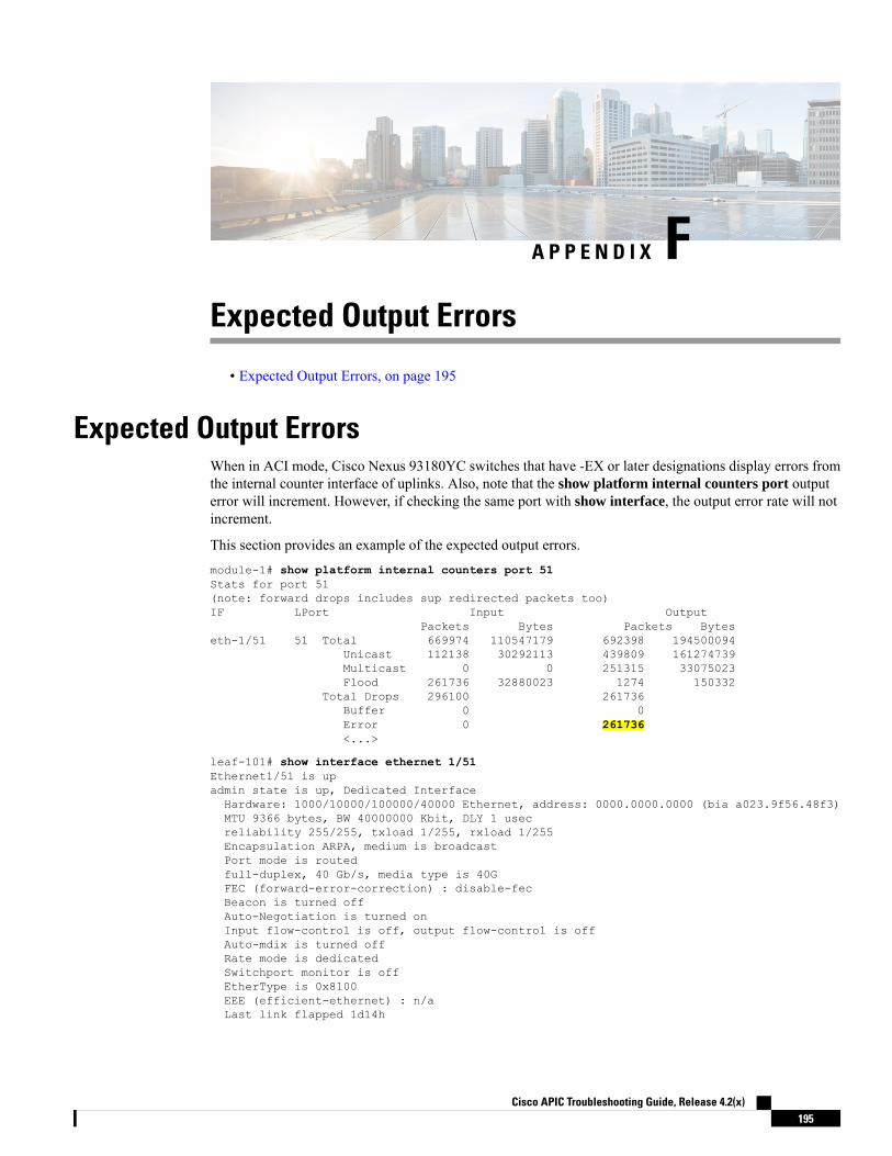
A P P E N D I X FExpected Output Errors
• Expected Output Errors, on page 195
Expected Output ErrorsWhen in ACI mode, Cisco Nexus 93180YC switches that have -EX or later designations display errors fromthe internal counter interface of uplinks. Also, note that the show platform internal counters port outputerror will increment. However, if checking the same port with show interface, the output error rate will notincrement.
This section provides an example of the expected output errors.module-1# show platform internal counters port 51Stats for port 51(note: forward drops includes sup redirected packets too)IF LPort Input Output
Packets Bytes Packets Byteseth-1/51 51 Total 669974 110547179 692398 194500094
Unicast 112138 30292113 439809 161274739Multicast 0 0 251315 33075023Flood 261736 32880023 1274 150332
Total Drops 296100 261736Buffer 0 0Error 0 261736<...>
leaf-101# show interface ethernet 1/51Ethernet1/51 is upadmin state is up, Dedicated InterfaceHardware: 1000/10000/100000/40000 Ethernet, address: 0000.0000.0000 (bia a023.9f56.48f3)MTU 9366 bytes, BW 40000000 Kbit, DLY 1 usecreliability 255/255, txload 1/255, rxload 1/255Encapsulation ARPA, medium is broadcastPort mode is routedfull-duplex, 40 Gb/s, media type is 40GFEC (forward-error-correction) : disable-fecBeacon is turned offAuto-Negotiation is turned onInput flow-control is off, output flow-control is offAuto-mdix is turned offRate mode is dedicatedSwitchport monitor is offEtherType is 0x8100EEE (efficient-ethernet) : n/aLast link flapped 1d14h
Cisco APIC Troubleshooting Guide, Release 4.2(x)195

Last clearing of "show interface" counters never1 interface resets30 seconds input rate 4912 bits/sec, 3 packets/sec30 seconds output rate 1944 bits/sec, 2 packets/secLoad-Interval #2: 5 minute (300 seconds)input rate 3360 bps, 2 pps; output rate 10504 bps, 4 pps
L3 in Switched:ucast: 0 pkts, 0 bytes - mcast: 0 pkts, 0 bytes
L3 out Switched:ucast: 0 pkts, 0 bytes - mcast: 0 pkts, 0 bytes
RX352942 unicast packets 317417 multicast packets 0 broadcast packets670359 input packets 110608007 bytes8643 jumbo packets 0 storm suppression bytes0 runts 0 giants 0 CRC 0 no buffer0 input error 0 short frame 0 overrun 0 underrun 0 ignored0 watchdog 0 bad etype drop 0 bad proto drop 0 if down drop0 input with dribble 0 input discard0 Rx pause
TX417109 unicast packets 275682 multicast packets 0 broadcast packets692791 output packets 194559643 bytes7173 jumbo packets0 output error 0 collision 0 deferred 0 late collision0 lost carrier 0 no carrier 0 babble 0 output discard0 Tx pause
Cisco APIC Troubleshooting Guide, Release 4.2(x)196
Expected Output ErrorsExpected Output Errors

A P P E N D I X GViewing CRC Error Counters
• Viewing CRC and Stomped CRC Error Counters, on page 197
Viewing CRC and Stomped CRC Error CountersBeginning in Cisco APIC Release 4.2(3), CRC errors are split into two categories: CRC errors and stompedCRC errors. CRC errors are corrupted frames that were dropped locally and stomped CRC errors are corruptedframes that were cut-through switched. This differentiation can make it easier to identify the actual interfaceimpacted by CRC errors and troubleshoot physical layer issues within the fabric.
This section demonstrates how to view the CRC and stomped CRC errors.
Viewing CRC Errors Using the GUIThis section demonstrates how to view CRC and stomped CRC error counters using the GUI.
SUMMARY STEPS
1. On the menu bar, choose Fabric > Inventory.2. In the Navigation pane, click to expand a pod.3. Click to expand Interfaces.4. Click to choose an interface.5. In the Work pane, click the Error Counters tab.
DETAILED STEPS
Step 1 On the menu bar, choose Fabric > Inventory.Step 2 In the Navigation pane, click to expand a pod.Step 3 Click to expand Interfaces.
A list of interfaces appear in the Navigation pane.Step 4 Click to choose an interface.
A list of tabs appear in the Work pane.Step 5 In the Work pane, click the Error Counters tab.
Cisco APIC Troubleshooting Guide, Release 4.2(x)197

A list of error categories appears including CRC Errors (FCS Errors) and Stomped CRC Errors (packets).
Viewing CRC Errors Using the CLIThis section demonstrates how to view CRC and stomped CRC error counters using the CLI
To view CRC and stomped CRC errors:
Example:Switch# show interface ethernet 1/1Ethernet1/1 is upadmin state is up, Dedicated InterfaceBelongs to po4Hardware: 100/1000/10000/25000/auto Ethernet, address: 00a6.cab6.bda5 (bia 00a6.cab6.bda5)MTU 9000 bytes, BW 10000000 Kbit, DLY 1 usecreliability 255/255, txload 1/255, rxload 1/255Encapsulation ARPA, medium is broadcastPort mode is trunkfull-duplex, 10 Gb/s, media type is 10GFEC (forward-error-correction) : disable-fec
^[[B Beacon is turned offAuto-Negotiation is turned onInput flow-control is off, output flow-control is offAuto-mdix is turned offRate mode is dedicatedSwitchport monitor is offEtherType is 0x8100EEE (efficient-ethernet) : n/aLast link flapped 3d02hLast clearing of "show interface" counters never1 interface resets30 seconds input rate 0 bits/sec, 0 packets/sec30 seconds output rate 4992 bits/sec, 8 packets/secLoad-Interval #2: 5 minute (300 seconds)input rate 0 bps, 0 pps; output rate 4536 bps, 8 pps
RX0 unicast packets 200563 multicast packets 0 broadcast packets200563 input packets 27949761 bytes0 jumbo packets 0 storm suppression bytes0 runts 0 giants 0 CRC 0 Stomped CRC 0 no buffer0 input error 0 short frame 0 overrun 0 underrun 0 ignored0 watchdog 0 bad etype drop 0 bad proto drop 0 if down drop0 input with dribble 0 input discard0 input buffer drop 0 input total drop0 Rx pause
TX0 unicast packets 2156812 multicast packets 0 broadcast packets2156812 output packets 151413837 bytes0 jumbo packets0 output error 0 collision 0 deferred 0 late collision0 lost carrier 0 no carrier 0 babble 0 output discard0 output buffer drops 0 output total drops0 Tx pause
Cisco APIC Troubleshooting Guide, Release 4.2(x)198
Viewing CRC Error CountersViewing CRC Errors Using the CLI

I N D E X
(enabling) NX-OS Format 81(enabling) Syslog 81
A
acidiag Command 163ACL deny logging 27, 28ACL permit and deny logs 29ACL permit logging 25, 26atomic counters 33, 34, 35, 89, 98
about 89, 98configuring 34guidelines and restrictions 33
C
Cisco APIC 119cluster 187, 188, 189, 190
Commissioning 189contracting 188decommissioning 190expanding 187
configuration sync 119configuration synchronization 119Contract permit logging 25, 26Contract permit logs 29contracting cluster 183core files 173
D
digital optical monitoring 36Digital Optical Monitoring 37, 38DOM 36, 37, 38
E
endpoint connectivity 131
eventlog Command 99, 100, 101, 102, 103, 104, 105, 106, 107, 108, 109, 110, 111, 112, 113, 114, 115, 116, 117, 118, 119
expanding cluster 183exporting files 173
about 173
P
permit logging 28, 30
S
SNMP 44, 45, 46, 47about 44configuring policy 45configuring trap destination 46configuring trap source 47
SPAN 48, 49, 51about 48configuring 51guidelines and restrictions 49
syslog 79, 80about 79destination 80source 80
T
Taboo Contract deny logging 27, 28Taboo Contract deny logs 29Taboo Contract drop logging 27, 28techsupport file 175
sending 175techsupport files 173traceroute 83, 85
about 83configuring 85guidelines and restrictions 85
troubleshooting 119
Cisco APIC Troubleshooting Guide, Release 4.2(x)IN-1

Cisco APIC Troubleshooting Guide, Release 4.2(x)IN-2
INDEX


![Tivoli Workload Scheduler for z/OS - IBM Supportpublib.boulder.ibm.com/tividd/td/TWS/SH19-4544-00/ja_JA/...^(,-xiii \qNP]IT xiii \qN=. xiii 2MqA xv Tivoli Workload Scheduler for z/OS](https://img.pdfslide.us/doc/110x75/5ab7add17f8b9ad5338bdef7/tivoli-workload-scheduler-for-zos-ibm-xiii-qnpit-xiii-qn-xiii-2mqa-xv.jpg)