Embed Size (px)
Citation preview

Cisco Access Server AS5X00
Device Management
Supports Management Module SM-CIS1004
Titlep
age

D e v i c e M a n a g e m e n t Page 2 C i s c o A c c e s s S e r v e r A S 5 X 0 0
Copyright NoticeDocument 2925. Copyright © 2002-present by Aprisma Management Technologies, Inc. All rights reserved worldwide. Use, duplication, or disclosure by the United States government is subject to the restrictions set forth in DFARS 252.227-7013(c)(1)(ii) and FAR 52.227-19.Liability DisclaimerAprisma Management Technologies, Inc. (“Aprisma”) reserves the right to make changes in specifications and other information contained in this document without prior notice. In all cases, the reader should contact Aprisma to inquire if any changes have been made.
The hardware, firmware, or software described in this manual is subject to change without notice.
IN NO EVENT SHALL APRISMA, ITS EMPLOYEES, OFFICERS, DIRECTORS, AGENTS, OR AFFILIATES BE LIABLE FOR ANY INCIDENTAL, INDIRECT, SPECIAL, OR CONSEQUENTIAL DAMAGES WHATSOEVER (INCLUDING BUT NOT LIMITED TO LOST PROFITS) ARISING OUT OF OR RELATED TO THIS MANUAL OR THE INFORMATION CONTAINED IN IT, EVEN IF APRISMA HAS BEEN ADVISED OF, HAS KNOWN, OR SHOULD HAVE KNOWN, THE POSSIBILITY OF SUCH DAMAGES.
Trademark, Service Mark, and Logo InformationSPECTRUM, IMT, and the SPECTRUM IMT/VNM logo are registered trademarks of Aprisma Management Technologies, Inc., or its affiliates. APRISMA, APRISMA MANAGEMENT TECHNOLOGIES, the APRISMA MANAGEMENT TECHNOLOGIES logo, MANAGE WHAT MATTERS, DCM, VNM, SpectroGRAPH, SpectroSERVER, Inductive Modeling Technology, Device Communications Manager, SPECTRUM Security Manager, and Virtual Network Machine are unregistered trademarks of Aprisma Management Technologies, Inc., or its affiliates. For a complete list of Aprisma trademarks, service marks, and trade names, go tohttp://www.aprisma.com/manuals/trademark-list.htm.
All referenced trademarks, service marks, and trade names identified in this document, whether registered or unregistered, are the intellectual property of their respective owners. No rights are granted by Aprisma Management Technologies, Inc., to use such marks, whether by implication, estoppel, or otherwise. If you have comments or concerns
about trademark or copyright references, please send an e-mail to [email protected]; we will do our best to help.
Restricted Rights Notice(Applicable to licenses to the United States government only.)This software and/or user documentation is/are provided with RESTRICTED AND LIMITED RIGHTS. Use, duplication, or disclosure by the government is subject to restrictions as set forth in FAR 52.227-14 (June 1987) Alternate III(g)(3) (June 1987), FAR 52.227-19 (June 1987), or DFARS 52.227-7013(c)(1)(ii) (June 1988), and/or in similar or successor clauses in the FAR or DFARS, or in the DOD or NASA FAR Supplement, as applicable. Contractor/manufacturer is Aprisma Management Technologies, Inc. In the event the government seeks to obtain the software pursuant to standard commercial practice, this software agreement, instead of the noted regulatory clauses, shall control the terms of the government's license.Virus DisclaimerAprisma makes no representations or warranties to the effect that the licensed software is virus-free.
Aprisma has tested its software with current virus-checking technologies. However, because no antivirus system is 100 percent effective, we strongly recommend that you write-protect the licensed software and verify (with an antivirus system in which you have confidence) that the licensed software, prior to installation, is virus-free.
Contact InformationAprisma Management Technologies, Inc.273 Corporate DrivePortsmouth, NH 03801Phone: 603-334-2100U.S. toll-free: 877-468-1448Web site: http://www.aprisma.com

D e v i c e M a n a g e m e n t Page 3 C i s c o A c c e s s S e r v e r A S 5 X 0 0
ContentsINTRODUCTION 6
Purpose and Scope ........................................................6Required Reading ...........................................................6Supported Devices..........................................................7The SPECTRUM Model ..................................................7
EVENTS 9
CISCOVIEW 10
DEVICE VIEW 12
Interface Icons ...........................................................13Sub-Interfaces Button ............................................14Icon Subviews Menu Options ................................15
Secondary Address Panel View ................................16
DEVICE TOPOLOGY VIEW 17
Interface Device Topology View ...................................17Sub-Interfaces Topology View ......................................18
APPLICATION VIEWS 19
Supported Applications .................................................20Common Applications................................................20
Device-Specific MIBs ....................................................21Generic Routing Application .........................................23
Routing Protocol Comparison View...........................23Cisco AppleTalk Application ......................................... 24
AppleTalk Routing Detail View .................................. 25Novell Routing Application ............................................ 27
Novell Service Advertisement Protocol (SAP) View..27Novell Internet Packet Exchange (IPX) View ............ 27
Check Point Information ..................................... 27IPX Accounting Information................................ 28Check Point Accounting Table ...........................28Accounting Table................................................ 28
Vines Routing Application ............................................. 29Vines Routing Echo View .......................................... 29Vines Routing ICP View ............................................ 30Vines Broadcast Detail View ..................................... 30Vines Rx View ........................................................... 31Vines Tx View............................................................ 31
XNS Routing Application............................................... 32Cisco BSTUN Application ............................................. 32
BSTUN Groups View................................................. 32BSTUN Ports View .................................................... 33BSTUN Routes View ................................................. 34
Cisco STUN Application................................................ 34STUN Groups View ................................................... 35STUN Ports View ...................................................... 35STUN Routes View ................................................... 36
Cisco Chassis Application............................................. 37Cisco Chassis Card View .......................................... 37
C o n t e n t s C o n t e n t s
D e v i c e M a n a g e m e n t Page 4 C i s c o A c c e s s S e r v e r A S 5 X 0 0
Cisco Card Interface View.........................................37Cisco Chassis General Information View ..................38
Chassis Information............................................38ROM Information ................................................38RAM Information ................................................39
Cisco Modem Application .............................................39Modem System Information View..............................39Modem Line Status Table View.................................40Modem Line Configuration Table View......................44Modem Line Statistics Table View.............................46Modem Line Speed Statistics Table View .................48
Cisco Flash Application.................................................48Cisco Flash Configuration View.................................48
Flash Directory ...................................................48Flash Device Chip Properties Table View .................49Flash Copy Operations Table View...........................49Flash Device Properties Table View..........................50Flash File Properties Table View...............................50Flash Miscellaneous Operations Table View.............51Flash Device Partition Properties Table View ...........51Flash Partitioning Operations Table View .................52
Cisco Ping Application ..................................................52Ping Request Table View ..........................................52
Cisco Queue Application...............................................54Queue Interface View................................................54Queue Statistics View................................................55Queue Rotation Interface View..................................55
ATM Client Application..................................................56VCL Table..................................................................56ATM Link Modeling Options ......................................57
Creating VPL/VCL Models .................................... 58Destroying VPL/VCL Models................................. 59
Performance ............................................................. 59Configuration............................................................. 59
EnvMon Application...................................................... 60Enable Notifications .................................................. 60
Fan Status ............................................................. 61Power Supply Status................................................. 61Temperature Status .................................................. 61Voltage Status........................................................... 62
Discovery Application ................................................... 62Discovery Cache Table View.................................... 62
Interface Discovery Status Table .......................... 63Cisco DSIAPP1406 Application.................................... 64
DSI Configuration Table............................................ 64DS1 Fractional Table ................................................ 68DS1App1406 Current Table View............................. 69
Interface Ethernet Application ...................................... 70Cisco Interface Application........................................... 70Cisco Terminal Server Application ............................... 70
Line Configuration View............................................ 70Cisco Terminal Server Line View.............................. 71Cisco Terminal Server Session View........................ 72
Cisco Memory Pool Application.................................... 73Cisco Memory Pool Monitor Table View ............... 73
Cisco Interface Application........................................... 74CiscoIfceApp Configuration View .......................... 74
Cisco RTT-Mon Application.......................................... 74Cisco Pop Application .................................................. 75
Cisco DS0 Usage Table View................................... 75

C o n t e n t s C o n t e n t s
D e v i c e M a n a g e m e n t Page 5 C i s c o A c c e s s S e r v e r A S 5 X 0 0
Cisco DS1-DS0 Usage Table View ...........................76Cisco DS0 Active Call Information View....................77Cisco Call Failure Information View...........................77
ISDN Information................................................77Modem Information ............................................78
Cisco Active Call Summary Table View ....................78Cisco Call History Summary Table View...................79
SYSLOG TRAP SUPPORT 81
PERFORMANCE VIEWS 82
Performance View.........................................................82Device Performance View.............................................83
Cisco Processes CPU Statistics Table View.............84
CONFIGURATION VIEW 85
Device Configuration View............................................85Redundancy and Model Reconfiguration Options .86Interface Address Translation Table View .............88Cisco Buffer Management View.............................88Buffer Elements .....................................................88Buffer Management Buttons ..................................88
Network/Host Configuration View..............................91Network Configuration........................................91Host Configuration..............................................92
Cisco Running Config Event/Alarm Configuration View ................................................................93
Cisco Config-Copy Table View ..............................94
MODEL INFORMATION VIEW 97
INDEX 98
D e v i c e M a n a g e m e n t Page 6 C i s c o A c c e s s S e r v e r A S 5 X 0 0
Introduction
This section introduces the SPECTRUM Device Management documentation for Cisco Access Server devices.
This introduction contains the following topics:
• Purpose and Scope
• Required Reading
• Supported Devices (Page 7)
• The SPECTRUM Model (Page 7)
Purpose and ScopeUse this document as a guide for managing the Cisco Access Server devices described on Page 7 with SPECTRUM management module SM-CIS1004. This document describes the icons, menus, and views that enable you to remotely monitor, configure, and troubleshoot Cisco Access Server devices through software models in your SPECTRUM database.
Information specific to SM-CIS1004 is what is primarily included in this document. For general information about device management using SPECTRUM and explanations of SPECTRUM
functionality and navigation techniques, refer to the topics listed under Required Reading.
Required ReadingTo use this documentation effectively, you must be familiar with the information covered by the other SPECTRUM online documents listed below.
• Getting Started with SPECTRUM for Operators
• Getting Started with SPECTRUM for Administrators
• How to Manage Your Network with SPECTRUM
• SPECTRUM Views
• SPECTRUM Menus
• SPECTRUM Icons
• SPECTRUM Software Release Notice

I n t r o d u c t i o n S u p p o r t e d D e v i c e s
D e v i c e M a n a g e m e n t Page 7 C i s c o A c c e s s S e r v e r A S 5 X 0 0
Supported DevicesThe SPECTRUM management module SM-CIS1004 currently allows you to model four different types of Cisco Access Server devices as described below.
Cisco_AS5100. The AS5100 Series Access Servers provide high-density functionality and manageability for asynchronous modem dial-up services as a standalone system, channel banks, 48 managed modems, and up to 48 access server ports all in a single chassis.
Cisco_AS5200. The AS5200 Series Access Servers provide universal access using one trunk line for all calls, combine LAN, WAN, and asynchronous line support in a single package, and support up to 60 integrated modems.
Cisco_AS5300.The AS5300 Series Access Servers provide the ability to terminate ISDN and 56K analog modem calls on the same interface, deliver near line-speed performance for as many as 120 concurrent analog modem calls and ISDN B channels over a single dial-in telephone number for telecommunications carriers and other service providers.
Cisco_AS5800. The AS5800 Series Access Servers provide the highest concentration of modem and integrated services digital net-work (ISDN) terminations available in a single remote access concentrator product meeting the demands of large service providers.
The SPECTRUM ModelSPECTRUM uses a single device model type, AS5X00, for modeling any of the supported Cisco Access Servers. AS5X00 models are represented in SpectroGRAPH views by Device icons. As shown below, the appearance of the Device icon varies slightly depending on the kind of view in which it appears.
Figure 1: Small and Large Device Icons
Model Name
AS5X00
Model Name
AS5X00
Small Device icon appears inTopology, Device Topology, Application Views
Large Device iconappears in Device Topology,Lost and Found, Location,and Interface Device views.
I n t r o d u c t i o n T h e S P E C T R U M M o d e l
D e v i c e M a n a g e m e n t Page 8 C i s c o A c c e s s S e r v e r A S 5 X 0 0
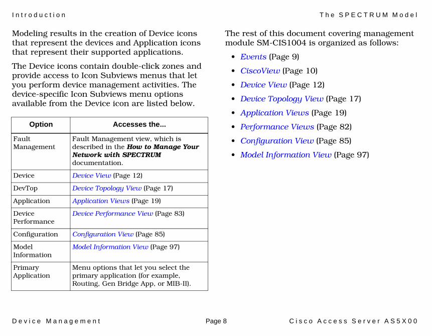
Modeling results in the creation of Device icons that represent the devices and Application icons that represent their supported applications.
The Device icons contain double-click zones and provide access to Icon Subviews menus that let you perform device management activities. The device-specific Icon Subviews menu options available from the Device icon are listed below.
The rest of this document covering management module SM-CIS1004 is organized as follows:
• Events (Page 9)
• CiscoView (Page 10)
• Device View (Page 12)
• Device Topology View (Page 17)
• Application Views (Page 19)
• Performance Views (Page 82)
• Configuration View (Page 85)
• Model Information View (Page 97)
Option Accesses the...
Fault Management
Fault Management view, which is described in the How to Manage Your Network with SPECTRUM documentation.
Device Device View (Page 12)
DevTop Device Topology View (Page 17)
Application Application Views (Page 19)
Device Performance
Device Performance View (Page 83)
Configuration Configuration View (Page 85)
Model Information
Model Information View (Page 97)
Primary Application
Menu options that let you select the primary application (for example, Routing, Gen Bridge App, or MIB-II).

D e v i c e M a n a g e m e n t Page 9 C i s c o A c c e s s S e r v e r A S 5 X 0 0
Events
This section lists the Events and Probable Causes that are available for the Cisco Access Server.
The Cisco Access Server has several event and alarm messages that are specific to its devices. If these messages are not sufficient and you wish to create your own messages, or view the existing messages for the Access Server, you can do so using the ECEditor.
The event messages for the Access Server, which range from Event00210000 to Event00210016, can be found in the following directory:
~/SG-Support/CsEvFormat

D e v i c e M a n a g e m e n t Page 10 C i s c o A c c e s s S e r v e r A S 5 X 0 0
CiscoView
This section describes how to access Cisco’s CiscoView management software from SPECTRUM.
CiscoView is management software specific to Cisco Routers.
The AS5X00 Model Type provides a menu option from the Device icon that is used to launch CiscoView.
For SolarisAdd the following information to the /opt/SPECTRUM/spectrum60.env file:
#CiscoView 3.0
CVIEW =<path_to_ciscoview>
For Windows NT and Windows 2000From the Start>Run window, type
regedit (registry editor)
Navigate to HKEY_LOCAL_MACHINE>SOFTWARE> Aprisma Management Technologies> Spectrum60> Environment
Choose Edit>New>String Value
Type CVIEW for the name, and <path_to_ciscoview> as the string value.
Zoom - >CiscoViewDeviceDevTop
Application
Device PerformanceAcknowledge
Cisco_12012

C i s c o V i e w
D e v i c e M a n a g e m e n t Page 11 C i s c o A c c e s s S e r v e r A S 5 X 0 0
Note:Note:
CiscoView 3.0 will appear as “Cisco View” on your device menu after the above steps have been followed. This should not be confused with “CiscoView”, which denotes the CiscoWorks 2000 CiscoView. The CiscoWorks 2000 menu picks will only appear in the device menu if the SPECTRUM Adapter script has been run. See the CiscoWorks 2000 documentation for further information.
D e v i c e M a n a g e m e n t Page 12 C i s c o A c c e s s S e r v e r A S 5 X 0 0
Device View
This section describes the Device views and subviews available for models of Cisco Access Server devices in SPECTRUM.
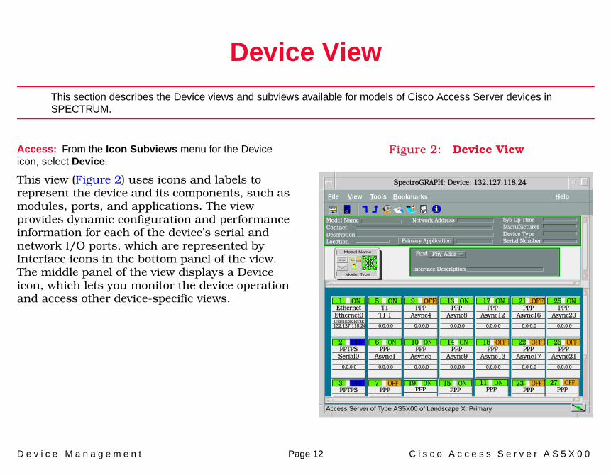
Access: From the Icon Subviews menu for the Device icon, select Device.
This view (Figure 2) uses icons and labels to represent the device and its components, such as modules, ports, and applications. The view provides dynamic configuration and performance information for each of the device’s serial and network I/O ports, which are represented by Interface icons in the bottom panel of the view. The middle panel of the view displays a Device icon, which lets you monitor the device operation and access other device-specific views.
Figure 2: Device View
Access Server of Type AS5X00 of Landscape X: Primary
File View Help Tools
Model NameContactDescriptionLocation
Sys Up TimeManufacturerDevice TypeSerial Number
Network Address
Primary Application
Interface Description
Find Phy AddrModel Name
Model Type
EthernetEthernet0
1 ON
0:E0:1E:3E:B5:2E132.127.118.24
PPTPSSerial0
2 OFF
0.0.0.0
T1T1 1
5 ON
0.0.0.0
PPPAsync1
6 ON
0.0.0.0
PPPAsync4
9 OFF
0.0.0.0
PPPAsync5
10 ON
0.0.0.0
PPPAsync8
13 ON
0.0.0.0
PPPAsync9
14 ON
0.0.0.0
PPPAsync12
17 ON
0.0.0.0
PPPAsync13
18 OFF
0.0.0.0
PPPAsync16
21 OFF
0.0.0.0
PPPAsync17
22 OFF
0.0.0.0
PPPAsync20
25 ON
0.0.0.0
PPPAsync21
26 OFF
0.0.0.0
PPTPS3 OFF
PPP7 OFF
PPP11 ON
PPP15 ON
PPP19 ON
PPP23 OFF
PPP27 OFF
Bookmarks
SpectroGRAPH: Device: 132.127.118.24

D e v i c e V i e w
D e v i c e M a n a g e m e n t Page 13 C i s c o A c c e s s S e r v e r A S 5 X 0 0
Interface IconsFigure 3 illustrates an Interface icon from the Interface Device view. Most of the informational labels on the icon also provide double-click access to other views, as explained in the following label descriptions. The Sub-Interfaces button only appears on certain Interface icons (see Sub-Interfaces Button (Page 14).
Figure 3: Interface Icon
Interface Number LabelThis label displays the interface (port) number.
IF Status LabelThis label displays the current status of the interface for the primary application selected, e.g., Gen Rtr App or MIB-II App. Table 1 lists the possible label color representations. Note that the color of the label also depends on the interface’s current Administrative Status, which you set in the Interface Configuration view. This view can be accessed by double-clicking the Interface Type label.
Interface Type LabelThis label identifies the interface type (Ethernet, ATM, etc.). Double-click this label to access the Interface Configuration view (see the SPECTRUM Views documentation).
c
f
b1Ethernet
0:0:1D:F:FD:B6
a
a Interface Number Label
b IF Status Label
c Interface Type Label
d Network Type Label
e Physical Address Label
f IP Address Label
qaa1
0.0.0.0
d
e
ON
Sub-Interfaces Button (Page 14)
Table 1: Interface Status Label Colors
ColorOperational
StatusAdministrative
StatusLabelText
Green up up ON
Blue down down OFF
Yellow down up OFF
Red testing testing TEST

D e v i c e V i e w
D e v i c e M a n a g e m e n t Page 14 C i s c o A c c e s s S e r v e r A S 5 X 0 0
Network Type LabelThis label identifies the type of network the interface is connected to. Double-click the label to open the Model Information view for the interface.
Physical Address LabelThis label displays the physical (MAC) address of the interface. Double-click the label to open the Interface Address Translation table, which cross-references network addresses to MAC addresses for selected nodes between networks. Double-click any column entry to open an address-specific Address Translation Table Information view. This view provides the same information as the corresponding row for the Interface Address Translation table, but lets you modify field values.
IP Address LabelThis label displays the IP address for the interface. Double-click this label to open the Secondary Address Panel View (Page 16), which lets you change the address and mask for the interface.
Sub-Interfaces ButtonThis button appears on an Interface icon when the interface model has sub-interfaces associated with it. Examples include a physical ATM interface with Permanent Virtual Circuits (PVCs) provisioned on it or a physical Frame Relay interface with DCL circuits on it. The endpoints of these multiplexed connections are modeled by SPECTRUM as sub-interfaces. Double-click this button to access the Sub-Interfaces Topology View (Page 18).

D e v i c e V i e w
D e v i c e M a n a g e m e n t Page 15 C i s c o A c c e s s S e r v e r A S 5 X 0 0
Icon Subviews Menu OptionsTable 2 lists the Icon Subviews menu options available for the Interface icon.
Table 2: Interface Menu Options
Option Opens the...
Detail Interface Detail view, which displays Packet, Error, and Discard Breakdown pie charts.
Sub-Interfaces Sub-Interfaces Topology View (Page 18)
IF Configuration Interface Configuration view (see SPECTRUM Views).
Address Translation Table
Address Translation Table (AT) (see SPECTRUM Views).
Secondary Address Panel
Secondary Address Panel View (Page 16).
Thresholds Interface Threshold view, which allows you to set the thresholds for; load, packet rate, error rate, and % discarded.
Model Information Model Information View (Page 97).
Trap Configuration Interface Trap Configuration view (see How to Manage Your Network with SPECTRUM).
Cisco Network Info Cisco Interface Network View which displays In Packets, Out Packets, In Octets, and Out Octets pie charts.
Cisco Router Info Cisco Interface Router View which displays generic routing applications information.
Cisco Traffic Info Cisco Interface Traffic View which displays slow and fast traffic pie charts.
Cisco Other Info Other Cisco Interface View which displays In Packets, Out Packets, In Octets, and Out Octets pie charts.
Table 2: Interface Menu Options (Continued)
Option Opens the...

D e v i c e V i e w
D e v i c e M a n a g e m e n t Page 16 C i s c o A c c e s s S e r v e r A S 5 X 0 0
Secondary Address Panel ViewAccess: From the Icon Subviews menu for the Interface icon in the Interface Device view, select Secondary Address Panel.
This panel provides a table of IP addresses and masks obtained from the Address Translation table within the device’s firmware. You can change the current address displayed in the IP Address field by selecting an entry from the table in this panel and clicking the Update button.

D e v i c e M a n a g e m e n t Page 17 C i s c o A c c e s s S e r v e r A S 5 X 0 0
Device Topology View
This section describes the Device Topology views available for models of Cisco Access Server devices in SPECTRUM.
Device Topology views show the connections between a modeled device and other network entities. There are two types of Device Topology views available for models of Cisco Routers:
• Interface Device Topology View• Sub-Interfaces Topology View (Page 18)
Interface Device Topology ViewAccess: From the Icon Subviews menu for the Cisco_AS5X00 Device icon, select DevTop.
This view (Figure 4) displays interface icons that represent the connections between the Cisco Access Server and the devices it is connected to. The Interface Icons provide the same information and menu options as those described in the Device view. See SPECTRUM Views for more details.
Figure 4: DevTop View
Access Server of Type AS5X00 of Landscape X: Primary
Access Server
Cisco_AS5200
File View Help Tools
EthernetEthernet0
1 ON
0:0:30:68:6F:1B132.127.118.24
PPTPSSerial1
3 OFF
0.0.0.0
PPTPSSerial0
2 OFF
0.0.0.0
T1T10
4 ON
0.0.0.0
5200
Bookmarks
SpectroGRAPH: Device Topology: 132.127.118.24

D e v i c e T o p o l o g y V i e w S u b - I n t e r f a c e s T o p o l o g y V i e w
D e v i c e M a n a g e m e n t Page 18 C i s c o A c c e s s S e r v e r A S 5 X 0 0
Sub-Interfaces Topology ViewAccess: From the Icon Subviews menu for an Interface icon whose interface contains sub-interfaces, select Sub-Interfaces.
When present, the endpoints associated with multiplexed, physical connections are modeled by SPECTRUM as sub-interfaces. This includes, for example, Permanent Virtual Circuits (PVCs) on a physical ATM interface and DCL circuits on a physical Frame Relay interface.
The lower panel of the Sub-Interfaces Topology view (Figure 5) uses Interface icons to represent these non-physical entities and circuits that are connected to the physical interface. These Interface icons provide the same labels and menu options as the Interface icons in the Device View (Page 12).
Figure 5: Sub-Interfaces Topology View
File View Tools Bookmarks Help
ethernet
FastEthernet0/1
2 ON
132.127.118.23
SpectroGRAPH: Device Topology: Model Name
propVirtual
FastEthernet0/1.1
1 ON
132.127.118.24
0.0.FO:27.62.ID
0.0.FO:27.62.ID

D e v i c e M a n a g e m e n t Page 19 C i s c o A c c e s s S e r v e r A S 5 X 0 0
Application Views
This section describes the Application view and the associated application-specific subviews available for models of Cisco Access Server devices in SPECTRUM.
Access: From the Icon Subviews menu for the Cisco_AS5x00 Device icon, select Application.
When a device model is created, SPECTRUM automatically creates models for each of the major and minor applications supported by the device. The Application view identifies all of these application models, shows their current condition status, and provides access to application-specific subviews.
Figure 6 shows an Application view in its default mode (Icon) where each of the application models is represented by an Application icon. The Application icons are arranged hierarchically under a Device icon, with major applications in the top row and their respective minor applications stacked directly below.
If you prefer to see applications displayed by name only, in a single vertical list, select View > Mode > List.
Figure 6: Main Application View
Access Server of type AS5x00 of Landscape node: Primary
Model Name
Contact
Description
Location Primary Application
System Up Time
Manufacturer
Device Type
Serial Number
Network Address
AS5x00
File View Help Tools
Access Server
Server_Routing
GenRtrApp
IP Routing
CiscoIPApp
AccessServer_MIB-II
SNMP2_Agent
AccessServer_ICMP
ICMP_App
AccessServer_System
System2_App
AccessServer_TCP
TCP2_App
SNMP2_Agent
ICMP_App
TCP2_App
System2_App
CiscoBSTUN
CiscoBSTUNApp
CiscoSTUN
CiscoSTUNApp
Bridge App
Bridge_App
AccessServer_Static
Static_App
CiscoChasApp
CiscoChasApp
AccessServer_Chassis
Bookmarks
SpectroGRAPH: Application:
i

A p p l i c a t i o n V i e w s S u p p o r t e d A p p l i c a t i o n s
D e v i c e M a n a g e m e n t Page 20 C i s c o A c c e s s S e r v e r A S 5 X 0 0
Supported ApplicationsSPECTRUM’s applications can be grouped within two general categories as follows:
• Applications associated with non proprietary MIBs. See Common Applications below.
• Applications associated with device-specific MIBs. See Device-Specific MIBs (Page 21).
Common ApplicationsFor the most part, these applications represent the non proprietary MIBs supported by devices. Listed below (beneath the title of the SPECTRUM document that describes them) are some of the common applications currently supported by SPECTRUM. Refer to these documents when your devices support these applications.
• Routing Applications- Generic Routing- Repeater- AppleTalk- DECnet
- OSPF- OSPF2- BGP4- VRRP- RFC 2932
• Bridging Applications- Ethernet Special Database- Spanning Tree- Static- Transparent- PPP Bridging- Source Routing- Translation- QBridge
• MIB II Applications- SNMP- IP- ICMP- TCP- System2- UDP
• Transmission Applications- FDDI- Point to Point- DS1- DS3
Note:Note:
The documents listed below (in bold font) are available for viewing at:
www.aprisma.com/manuals/

A p p l i c a t i o n V i e w s D e v i c e - S p e c i f i c M I B s
D e v i c e M a n a g e m e n t Page 21 C i s c o A c c e s s S e r v e r A S 5 X 0 0
- RS-232- WAN- Frame Relay- Token Ring- Ethernet- Fast Ethernet- RFC 1317App- RFC 1285App- RFC 1315App- 802.11App- SONET
• Technology Applications- APPN- ATM Client- DHCP- DLSw- PNNI- RFC 1316App- RFC 1514- RFC 2287- RFC 2790- RFC 2925
• DOCSIS Applications- DOCSISCblDvApp - DOCSISQOSApp- DOCSISBPI2App - DOCSISBPIApp
- DOCSISIFApp
• Digital Subscriber Line (DSL) Applications- ADSL
Device-Specific MIBsSPECTRUM imports the following device-level proprietary MIBs into its database:
• CISCO-BSC-MIB • CISCO-BSTUN-MIB • CISCO-CIPCSNA-MIB • CISCO-CHANNEL-MIB • CISCO-PING-MIB • CISCO-ENVMON-MIB • CISCO-INTERFACES-MIB • CISCO-IP-MIB • CISCO-NOVELL-MIB • CISCO-TS-MIB • CISCO-VINES-MIB • CISCO-XNS-MIB • CISCO-CHASSIS-MIB • CISCO-ENV-MIB • CISCO-DSPU-MIB • CISCO-DLSW-MIB • CISCO-ISDN-MIB • CISCO-QUEUE-MIB
A p p l i c a t i o n V i e w s D e v i c e - S p e c i f i c M I B s
D e v i c e M a n a g e m e n t Page 22 C i s c o A c c e s s S e r v e r A S 5 X 0 0
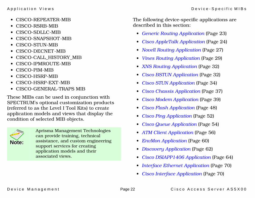
• CISCO-REPEATER-MIB • CISCO-RSRB-MIB • CISCO-SDLLC-MIB • CISCO-SNAPSHOT-MIB • CISCO-STUN-MIB • CISCO-DECNET-MIB • CISCO-CALL_HISTORY_MIB • CISCO-IPMROUTE-MIB• CISCO-PIM-MIB• CISCO-HSRP-MIB • CISCO-HSRP-EXT-MIB • CISCO-GENERAL-TRAPS MIB
These MIBs can be used in conjunction with SPECTRUM’s optional customization products (referred to as the Level I Tool Kits) to create application models and views that display the condition of selected MIB objects.
The following device-specific applications are described in this section:
• Generic Routing Application (Page 23)
• Cisco AppleTalk Application (Page 24)
• Novell Routing Application (Page 27)
• Vines Routing Application (Page 29)
• XNS Routing Application (Page 32)
• Cisco BSTUN Application (Page 32)
• Cisco STUN Application (Page 34)
• Cisco Chassis Application (Page 37)
• Cisco Modem Application (Page 39)
• Cisco Flash Application (Page 48)
• Cisco Ping Application (Page 52)
• Cisco Queue Application (Page 54)
• ATM Client Application (Page 56)
• EnvMon Application (Page 60)
• Discovery Application (Page 62)
• Cisco DSIAPP1406 Application (Page 64)
• Interface Ethernet Application (Page 70)
• Cisco Interface Application (Page 70)
Note:Note:
Aprisma Management Technologies can provide training, technical assistance, and custom engineering support services for creating application models and their associated views.
A p p l i c a t i o n V i e w s G e n e r i c R o u t i n g A p p l i c a t i o n
D e v i c e M a n a g e m e n t Page 23 C i s c o A c c e s s S e r v e r A S 5 X 0 0
• Cisco Terminal Server Application (Page 70)
• Cisco Memory Pool Application (Page 73)
• Cisco Interface Application (Page 74)
• Cisco RTT-Mon Application (Page 74)
• Cisco Pop Application (Page 75)
The Cisco application model types common to multiple Cisco device model types are described in the Cisco Applications (5127) guide.
Generic Routing ApplicationThis major application (GenRtrApp) has one menu option that provides access to the following view.
Routing Protocol Comparison ViewAccess: From the Icon Subviews menu for the GenRtrApp Application icon, select Protocol Comparison.
This view displays pie charts that present the following performance statistics for each routing application.
• Frames Forwarded• Frames Delivered• Frames Transmitted• Errors• Discards
A p p l i c a t i o n V i e w s C i s c o A p p l e T a l k A p p l i c a t i o n
D e v i c e M a n a g e m e n t Page 24 C i s c o A c c e s s S e r v e r A S 5 X 0 0
The following device specific Generic Routing Sub-Applications are available.
• Cisco AppleTalk Application
• Novell Routing Application (Page 27)
• Vines Routing Application (Page 29)
• XNS Routing Application (Page 32)
• Cisco BSTUN Application (Page 32)
• Cisco STUN Application (Page 34)
Cisco AppleTalk ApplicationAccess: From the Icon Subviews menu for the CiscoATApp Application icon, select AT Protocol Stats.
This application provides access to the AppleTalk Routing Table view.
RTMP ReceivesThe total number of AppleTalk Routing Table Management Protocol (RTMP) packets received.
RTMP SentThe total number of AppleTalk RTMP packets transmitted.
NBP ReceivesThe total number of AppleTalk Name Binding Protocol (NBP) packets received.
NBP SentThe total number of AppleTalk NBP packets transmitted.
ATP ReceivesThe total number of AppleTalk Transaction Protocol (ATP) packets received.
DDP ShortThe total number of short AppleTalk Datagram Delivery Protocol (DDP) packets received.
DDP LongThe total number of long AppleTalk DDP packets received.
DDP BadThe total number of illegally sized AppleTalk DDP packets received. The actual packet size and claimed packet size are different.
ZIP ReceivedThe total number of AppleTalk Zone Information Protocol (ZIP) packets received.
ZIP SentThe total number of AppleTalk ZIP packets transmitted.
Echo ReceivesThe total number of AppleTalk Echo packets received.
A p p l i c a t i o n V i e w s C i s c o A p p l e T a l k A p p l i c a t i o n
D e v i c e M a n a g e m e n t Page 25 C i s c o A c c e s s S e r v e r A S 5 X 0 0
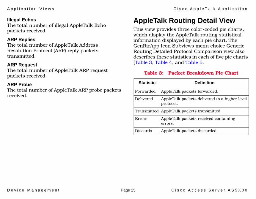
Illegal EchosThe total number of illegal AppleTalk Echo packets received.
ARP RepliesThe total number of AppleTalk Address Resolution Protocol (ARP) reply packets transmitted.
ARP RequestThe total number of AppleTalk ARP request packets received.
ARP ProbeThe total number of AppleTalk ARP probe packets received.
AppleTalk Routing Detail ViewThis view provides three color-coded pie charts, which display the AppleTalk routing statistical information displayed by each pie chart. The GenRtrApp Icon Subviews menu choice Generic Routing Detailed Protocol Comparison view also describes these statistics in each of five pie charts (Table 3, Table 4, and Table 5.
Table 3: Packet Breakdown Pie Chart
Statistic Definition
Forwarded AppleTalk packets forwarded.
Delivered AppleTalk packets delivered to a higher level protocol.
Transmitted AppleTalk packets transmitted.
Errors AppleTalk packets received containing errors.
Discards AppleTalk packets discarded.

A p p l i c a t i o n V i e w s C i s c o A p p l e T a l k A p p l i c a t i o n
D e v i c e M a n a g e m e n t Page 26 C i s c o A c c e s s S e r v e r A S 5 X 0 0
Table 4: Error Breakdown Pie Chart
Statistic Definition
Too Short AppleTalk packets received with Too Short errors.
Too Long AppleTalk packets received with Too Long errors.
CheckSum AppleTalk packets received with checksum errors.
Note:Note:
In the Error Breakdown Pie Chart, CiscoATApp displays only the Check Sum statistic; ApplTlkRtrApp displays the Too Short and Too Long statistics in addition.
Table 5: Discard Breakdown Pie Chart
Statistic Definition
No Routes AppleTalk packets discarded because the router did not know where to forward them.
Unknown Unknown AppleTalk packet types received.
Hop Count Received AppleTalk packets that have exceeded the maximum hop count.
Encap Fail AppleTalk packets discarded due to output encapsulation failure. Packets were received for a connected network but a node could not be found.
No Access AppleTalk packets discarded because access was denied.
No Buffer AppleTalk packets discarded due to no memory. An attempted packet buffer allocation failed.
Note:Note:
In the Discard Breakdown Pie Chart, CiscoATApp displays all of the above statistics; ApplTlkRtrApp displays only HopCount and Broadcast.

A p p l i c a t i o n V i e w s N o v e l l R o u t i n g A p p l i c a t i o n
D e v i c e M a n a g e m e n t Page 27 C i s c o A c c e s s S e r v e r A S 5 X 0 0
Novell Routing Application This application (CiscoNovellApp) has two menu options. The Detail option provides access to pie charts that display standard Packet Breakdown, Error Breakdown, and Discard Breakdown information. The SAP/IPX option opens a submenu that has two options that provide access to the following views:
• Novell Service Advertisement Protocol (SAP) View (Page 27)
• Novell Internet Packet Exchange (IPX) View (Page 27)
Novell Service Advertisement Protocol (SAP) ViewAccess: From the Icon Subviews menu for the CiscoNovellApp Application icon, select SAP/IPX > SAP Chart.
The view is a color-coded pie chart displaying a breakdown of Novell SAP statistics. Table 6 provides definitions for the statistics presented by the pie chart.
Novell Internet Packet Exchange (IPX) ViewAccess: From the Icon Subviews menu for the CiscoNovellApp Application icon, select SAP/IPX > IPX Chart.
This view includes the Check Point Accounting table, Accounting table, and additional Check Point Accounting and IPX Accounting information described below.
Check Point InformationThis section of the Novell (IPX) view provides the following information:
Table 6: Novell SAP Statistics
Statistic Definition
SAP Requests Sent The total number of Novell SAP request packets transmitted.
SAP Replies Sent The total number of Novell SAP reply packets transmitted.
SAP Requests Rec The total number of Novell SAP request packets received.
SAP Responses Rec The total number of Novell SAP reply packets received.

A p p l i c a t i o n V i e w s N o v e l l R o u t i n g A p p l i c a t i o n
D e v i c e M a n a g e m e n t Page 28 C i s c o A c c e s s S e r v e r A S 5 X 0 0
Check PointThe check point for the IPX accounting database. This mib variable must be read and then set with the same value for the check point to succeed. The value read and then set will be incremented after a successful set request.
Check Point AgeThe age of the data in the IPX checkpoint matrix.
IPX Accounting InformationThis section of the Novell (IPX) view provides the following information:
ThresholdThe threshold of IPX accounting records in use before IPX traffic will be unaccounted.
AgeThe age of the data in the IPX data matrix.
Lost BytesThe total bytes of lost IPX packets.
Lost PacketsThe lost IPX packets due to memory limitations.
Check Point Accounting TableThe list of IPX checkpoint accounting entries. The fields for this table are described below.
Source AddressThe IPX Source address for host traffic matrix.
Destination AddressThe IPX Destination address for host traffic matrix.
Number PacketsThe number of IPX packets sent from source to destination.
Number BytesThe total number of bytes in IPX packets from source to destination.
Accounting TableThis table displays the list of IPX accounting entries. The fields in the Accounting Table are described below.
Source AddressThe IPX Source address for host in the checkpoint traffic matrix.
Destination AddressThe IPX Destination address for host in the checkpoint traffic matrix.
Number PacketsThe number of IPX packets sent from source to destination in the checkpoint matrix.

A p p l i c a t i o n V i e w s V i n e s R o u t i n g A p p l i c a t i o n
D e v i c e M a n a g e m e n t Page 29 C i s c o A c c e s s S e r v e r A S 5 X 0 0
Number BytesThe total number of bytes in IPX packets from source to destination in the checkpoint matrix.
Vines Routing Application This application (CiscoVinesApp) has two menu options. The Detail option provides access to pie charts that display standard Packet Breakdown, Error Breakdown, and Discard Breakdown information. The Vines Specifics option opens a submenu that has five options that provide access to the following views:
• Vines Routing Echo View• Vines Routing ICP View (Page 30)• Vines Broadcast Detail View (Page 30)• Vines Rx View (Page 31)• Vines Tx View (Page 31)
Vines Routing Echo ViewAccess: From the Icon Subviews menu for the CiscoVinesApp Application icon, select Vines Specifics > Echos.
This view displays a color-coded pie chart displaying a breakdown of Vines Echo statistics. Table 7 provides definitions for the statistics presented by the pie chart.
Table 7: Vines Echo Statistics
Statistic Definition
MAC In The total number of Vines MAC level Echo packets received.
MAC Out MAC level Echo packets transmitted.
Echo In The total number of Vines Echo packets received.
Echo Out The total number of Vines Echo packets transmitted.

A p p l i c a t i o n V i e w s V i n e s R o u t i n g A p p l i c a t i o n
D e v i c e M a n a g e m e n t Page 30 C i s c o A c c e s s S e r v e r A S 5 X 0 0
Vines Routing ICP View Access: From the Icon Subviews menu for the CiscoVinesApp Application icon, select Vines Specifics > ICP.
This view displays a color-coded pie chart of Vines Interprocess Communications Protocol (ICP) statistics. Table 8 provides definitions for the statistics presented by the pie chart.
Vines Broadcast Detail View Access: From the Icon Subviews menu for the CiscoVinesApp Application icon, select Vines Specifics > Broadcasts.
This view displays a color-coded pie chart of Vines Broadcast statistics. Table 9 (Page 30) provides definitions for the statistics presented by the pie chart.
Table 8: Vines ICP Statistics
Statistic Definition
ICP In The total number of Vines ICP packets received.
ICP Out The total number of Vines ICP packets transmitted.
Metric Out
The total number of Vines ICP Metric Notification packets transmitted.
Table 9: Vines Broadcast Statistics
Statistic Definition
Forward The total number of Vines broadcast packets forwarded.
Received The total number of Vines broadcast packets received.
Transmitted The total number of Vines broadcast packets transmitted.
Not LAN The total number of Vines broadcast packets not forwarded to all interfaces because the LAN ONLY bit was set.
Not Forward The total number of Vines broadcast packets not forwarded to all interfaces because the OVER 4800 BPS bit was set.
No Charge The total number of Vines broadcast packets not forwarded to all interfaces because the NO CHARGES bit was set.

A p p l i c a t i o n V i e w s V i n e s R o u t i n g A p p l i c a t i o n
D e v i c e M a n a g e m e n t Page 31 C i s c o A c c e s s S e r v e r A S 5 X 0 0
Vines Rx ViewAccess: From the Icon Subviews menu for the CiscoVinesApp Application icon, select Vines Specifics > Rx Table.
This view provides the following information:
ForwardedThe total number of incoming Vines packets forwarded to another interface.
Format ErrorThe total number of incoming Vines packets containing header errors.
Local DestinationThe total number of incoming Vines packets destined for this router.
Encapsulation TypeThe Vines protocol default encapsulation type.
Echo Count The total number of incoming IPC Echo messages.
Vines Tx ViewAccess: From the Icon Subviews menu for the CiscoVinesApp Application icon, select Vines Specifics > Tx Table.
This view provides the following information:
ForwardedThe total number of outgoing Vines packets forwarded to another interface.
Proxy CountThe total number of Proxy packets sent by this interface.
UnicastsThe total number of unicast packets generated by this interface.
IPC CountThe total number of IPC output messages sent by this interface.
IPC Error CountThe total number of IPC Error messages sent by this interface.
BroadcastsThe total number of broadcast packets generated by this interface.
A p p l i c a t i o n V i e w s X N S R o u t i n g A p p l i c a t i o n
D e v i c e M a n a g e m e n t Page 32 C i s c o A c c e s s S e r v e r A S 5 X 0 0
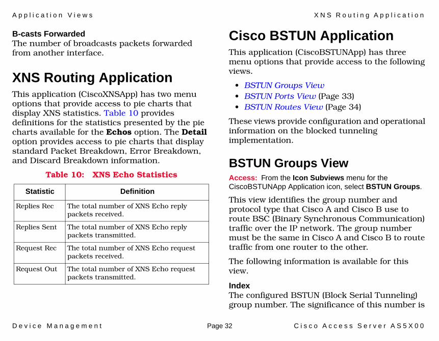
B-casts ForwardedThe number of broadcasts packets forwarded from another interface.
XNS Routing Application This application (CiscoXNSApp) has two menu options that provide access to pie charts that display XNS statistics. Table 10 provides definitions for the statistics presented by the pie charts available for the Echos option. The Detail option provides access to pie charts that display standard Packet Breakdown, Error Breakdown, and Discard Breakdown information.
Cisco BSTUN ApplicationThis application (CiscoBSTUNApp) has three menu options that provide access to the following views.
• BSTUN Groups View• BSTUN Ports View (Page 33)• BSTUN Routes View (Page 34)
These views provide configuration and operational information on the blocked tunneling implementation.
BSTUN Groups ViewAccess: From the Icon Subviews menu for the CiscoBSTUNApp Application icon, select BSTUN Groups.
This view identifies the group number and protocol type that Cisco A and Cisco B use to route BSC (Binary Synchronous Communication) traffic over the IP network. The group number must be the same in Cisco A and Cisco B to route traffic from one router to the other.
The following information is available for this view.
IndexThe configured BSTUN (Block Serial Tunneling) group number. The significance of this number is
Table 10: XNS Echo Statistics
Statistic Definition
Replies Rec The total number of XNS Echo reply packets received.
Replies Sent The total number of XNS Echo reply packets transmitted.
Request Rec The total number of XNS Echo request packets received.
Request Out The total number of XNS Echo request packets transmitted.

A p p l i c a t i o n V i e w s C i s c o B S T U N A p p l i c a t i o n
D e v i c e M a n a g e m e n t Page 33 C i s c o A c c e s s S e r v e r A S 5 X 0 0
that it must match the BSTUN Group number configured in the router at the other end of the BSTUN tunnel.
TypeThe protocol type for this BSTUN group.
Local AckIndicates if the BSTUN connection is locally acknowledged.
True - BSTUN connection is locally acknowledged.
False - BSTUN connection is not locally acknowledged.
Unroutable TransmitThe number of unroutable frames received by this group from the remote partner. They were unroutable because the address was not recognized; that is, there is no BSTUN route command configured for this address. This indicates that the configuration in this router is incompatible with the peer router.
Unroutable ReceiveCount of frames received from a serial interface with an unsupported poll address. Note that there may be several ports configured within this BSTUN group; a non-zero value in this field indicates that at least one of these ports is receiving frames for which there are no BSTUN
route commands configured. This indicates that the configuration in this router is incompatible with the configuration in at least one of the attached devices.
BSTUN Ports ViewAccess: From the Icon Subviews menu for the CiscoBSTUNApp Application icon, select BSTUN Ports.
This view identifies the serial interface to the BSC line that the router is providing serial tunneling. It also identifies the BSTUN group that the interface is in and the default routing for unrecognized BSC addresses.
The following information is available for this selection.
GroupThe group number to which the BSTUN port belongs. Frames will only be routed to other ports (on this or another router) in the same BSTUN group.
Default Peer TypeThe type of identification of the remote default partner.
Default Peer IPThe IP address of the remote default BSTUN partner, for unrecognized addresses.
A p p l i c a t i o n V i e w s C i s c o S T U N A p p l i c a t i o n
D e v i c e M a n a g e m e n t Page 34 C i s c o A c c e s s S e r v e r A S 5 X 0 0
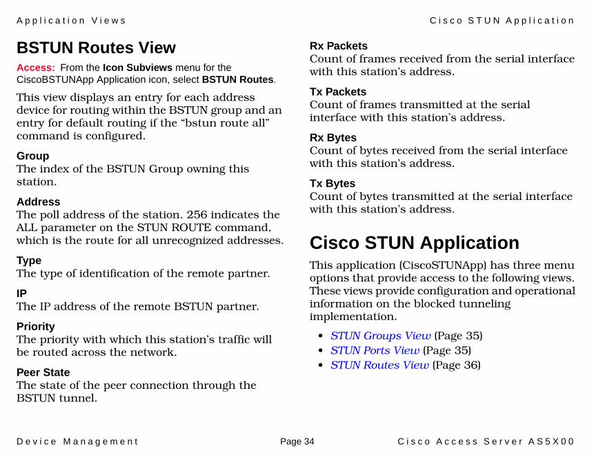
BSTUN Routes ViewAccess: From the Icon Subviews menu for the CiscoBSTUNApp Application icon, select BSTUN Routes.
This view displays an entry for each address device for routing within the BSTUN group and an entry for default routing if the “bstun route all” command is configured.
GroupThe index of the BSTUN Group owning this station.
AddressThe poll address of the station. 256 indicates the ALL parameter on the STUN ROUTE command, which is the route for all unrecognized addresses.
TypeThe type of identification of the remote partner.
IPThe IP address of the remote BSTUN partner.
Priority The priority with which this station’s traffic will be routed across the network.
Peer StateThe state of the peer connection through the BSTUN tunnel.
Rx PacketsCount of frames received from the serial interface with this station’s address.
Tx PacketsCount of frames transmitted at the serial interface with this station’s address.
Rx BytesCount of bytes received from the serial interface with this station’s address.
Tx BytesCount of bytes transmitted at the serial interface with this station’s address.
Cisco STUN ApplicationThis application (CiscoSTUNApp) has three menu options that provide access to the following views. These views provide configuration and operational information on the blocked tunneling implementation.
• STUN Groups View (Page 35)• STUN Ports View (Page 35)• STUN Routes View (Page 36)

A p p l i c a t i o n V i e w s C i s c o S T U N A p p l i c a t i o n
D e v i c e M a n a g e m e n t Page 35 C i s c o A c c e s s S e r v e r A S 5 X 0 0
STUN Groups ViewAccess: From the Icon Subviews menu for the CiscoSTUNApp Application icon, select STUN Group Table.
This view identifies the STUN (Serial Tunneling) group number and protocol type that Cisco A and Cisco B use to route SDLC traffic over the IP network. The table contains an entry for each STUN group defined on the router.
Group IndexThe configured STUN group number.
Protocol TypeThe protocol type for this STUN group.
STUN IP AddressThe configured IP address used for all serial tunnelling in this router.
STUN Ports ViewAccess: From the Icon Subviews menu for the CiscoSTUNApp Application icon, select STUN Port Table.
This view identifies the serial interface to the SDLC line that the router is providing serial tunneling. It also identifies the STUN group that the interface is in and the default routing for unrecognized SDLC addresses.
Group IndexThe group number to which the STUN port belongs. Frames will only be routed to other ports (on this or another router) in the same STUN group.
Default Peer TypeThe type of identification of the default partner for unrecognized addresses.
Default Peer IPThe IP address of the remote default STUN partner, for unrecognized addresses.
Default Peer Serial IFThere are three STUN Route Types:
Serial - this is the serial interface index of the point-to-point link to the remote partner;
Serial direct - the partner is in the local STUN.
IP - this field is “0”.

A p p l i c a t i o n V i e w s C i s c o S T U N A p p l i c a t i o n
D e v i c e M a n a g e m e n t Page 36 C i s c o A c c e s s S e r v e r A S 5 X 0 0
STUN Routes ViewAccess: From the Icon Subviews menu for the CiscoSTUNApp Application icon, select STUN Route Table.
This view displays an entry for each address device for routing within the STUN group and an entry for default routing if the “stun route all” command is configured.
Station AddrThe poll address of the station.
TypeThe type of identification of the remote partner.
Remote IPThe IP address of the remote STUN partner.
Serial IFThe local interface index to the remote partner.
PriorityThe priority with which this station’s traffic will be routed across the network.
Peer State The state of the peer connection through the STUN tunnel.
Local AckIndicates if the STUN connection is locally acknowledged.
Rx PacketsCount of frames received from the serial interface with this station’s address.
Tx PacketsCount of frames transmitted at the serial interface with this station’s address.
Rx BytesCount of bytes received from the serial interface with this station’s address.
Tx BytesCount of bytes transmitted at the serial interface with this station’s address.

A p p l i c a t i o n V i e w s C i s c o C h a s s i s A p p l i c a t i o n
D e v i c e M a n a g e m e n t Page 37 C i s c o A c c e s s S e r v e r A S 5 X 0 0
Cisco Chassis Application This application (CiscoChasApp) model representing this application provides access to the following views:
• Cisco Chassis Card View• Cisco Card Interface View• Cisco Chassis General Information View
(Page 38)
Cisco Chassis Card ViewAccess: From the Icon Subviews menu for the CiscoChasApp Application icon, select Card Information.
This view provides information on the cards contained in the chassis.
SlotThe slot number in which this card is installed. If the slot number is not applicable or not determinable, this field will display “-1”.
TypeThe functional type of the card installed in this slot. The possible types are: Unknown, csc1, csc2, csc3, csc4, rp, csc-m, csc-mt, csc-mc, etc.
DescriptionA textual description of this card.
Software Ver.The version number of the firmware installed on this card. If no version number is available, this field will remain empty.
Hardware Ver.The hardware revision level of this card. If no revision level is available, this field will remain empty.
Serial No.The serial number of this card. If no serial number is available, this field will contain a zero.
Cisco Card Interface ViewAccess: From the Icon Subviews menu for the CiscoChasApp Application icon, select Interface Information.
This table provides Chassis Interface information.
IndexThe unique index identifier for the table entry.
Slot NumberChassis slot number, or -1 if neither applicable nor determinable.
Port NumberChassis port number, unique per port on a given card if available. If the Port Number is not

A p p l i c a t i o n V i e w s C i s c o C h a s s i s A p p l i c a t i o n
D e v i c e M a n a g e m e n t Page 38 C i s c o A c c e s s S e r v e r A S 5 X 0 0
applicable to the card, then the object instance won't be populated.
Card IndexThe card Index of the card in the Chassis card Table which contains this interface, or -1 if not applicable.
Enabled Connector TypeThe Interface connector type currently enabled. Possible types are not-specified, none, rj-45, db-40, db-15, auto-select, gbic-sx, gbic-lx, gbic-lh, gbic-cx, gbic-zx, missing, mmf-st, mmf-sc, rj-11, rj-48s, rj-48c, db-60.
Cisco Chassis General Information ViewAccess: From the Icon Subviews menu for the CiscoChasApp Application icon, select General.
This view displays information on the chassis in which the router is installed. This view is divided into the three sections described below.
Chassis InformationThis section of the Chassis General Information view provides physical information about the chassis. The following information is provided:
Hardware Revision LevelThe version number of the chassis hardware. If the version number is not available, this field will remain empty.
Chassis TypeThe type of chassis. Possible chassis types are Unknown, Multibus, Agsplus, Igs, c2000, c3000, c4000, c7000, cs-500, c7010, c2500, and c4500.
Chassis ID/Serial No.A unique identifier for this chassis. The default value is the serial number of the chassis. If no serial number is available and no alternative ID has been set for the chassis, this field will remain empty.
Number of Chassis SlotsThe number of slots in this chassis model.
ROM InformationThis section of the Chassis General Information view provides the following information about the ROM installed in the chassis:
ROM Monitor VersionThe version number of the ROM monitor.
ROM Software VersionThe version number of the ROM system software. If no version number is available, this field will remain empty.

A p p l i c a t i o n V i e w s C i s c o M o d e m A p p l i c a t i o n
D e v i c e M a n a g e m e n t Page 39 C i s c o A c c e s s S e r v e r A S 5 X 0 0
Config RegisterThe current value of the configuration register.
RAM InformationThis section of the Chassis General Information view provides the following information about the RAM installed in the chassis:
System CPU RAM (bytes)The amount of RAM available to the CPU, displayed in bytes.
Non-volatile RAM Used (bytes)The amount of non-volatile configuration memory in use, displayed in bytes.
Non-volatile RAM Size (bytes)The total size, in bytes, of non-volatile configuration memory.
Cisco Modem ApplicationThis applications has the following views available:
• Modem System Information View• Modem Line Status Table View (Page 40)• Modem Line Configuration Table View
(Page 44)• Modem Line Statistics Table View (Page 46)• Modem Line Speed Statistics Table View
(Page 48)
Modem System Information ViewAccess: From the Icon Subviews menu for the CiscoModemApp Application icon, select System Info.
Installed ModemThe actual number of modems that are currently installed within this system.
Configured GroupThe actual number of modem groups that are currently configured within this system.
Watchdog TimeA passive software watchdog timer value will be used to recover a modem which enters into an unexpected state and hangs. When this watchdog timer times out, the modem associated Call

A p p l i c a t i o n V i e w s C i s c o M o d e m A p p l i c a t i o n
D e v i c e M a n a g e m e n t Page 40 C i s c o A c c e s s S e r v e r A S 5 X 0 0
Processing state will be set back to IDLE, all related TDM paths will be restored to default configurations, and all of call processing related actions will stop for the modem.
Status Poll TimeThe ideal time interval between modem status polling via the out of band management port.
Max RetriesA reply event is expected to be received for every message sent to the modem through the out of band management port. If an expected reply event is not received, the message will be sent to the modem again. This object specifies the maximum number of retires that should be executed.
Modems In Use The number of modems in the system that are in the following states: connected, offHook, loopback, or downloadFirmware.
Modems AvailableThe number of modems in the system that are onHook, that is, they are ready to accept a call.
Modems UnavailableThe number of modems in the system that cannot accept calls. These modems are in a state other than the following: connected, offHook, loopback, or downloadFirmware.
Modems OfflineThe number of modems in the system which have been held administratively offline.
Modems DeadThe number of modems in the system with the state bad or downloadFirmwareFailed.
Modem Line Status Table ViewAccess: From the Icon Subviews menu for the CiscoModemApp Application icon, select Line Status Table.
InterfaceThe interface to which this modem is connected.
GroupThe modem group number that the modem may be in.
Manufacturer IDA textual description to identify the modem, including the manufacturer’s name and type of modem.
Product DetailsA textual description of the modem, including hardware revision number, firmware revision number, feature set and optionally, its serial number.

A p p l i c a t i o n V i e w s C i s c o M o d e m A p p l i c a t i o n
D e v i c e M a n a g e m e n t Page 41 C i s c o A c c e s s S e r v e r A S 5 X 0 0
ManageableThe Manageable modem allows access through the out of band management port in which the modem statistic data can be retrieved, and the Direct Connect session can be used to provide the test and debugging ability. This object specifies whether this modem is a Manageable modem.
StateIndicates the current state of modem. The meaning of each state code is explained in the Table 11.
Table 11: Modem States
State Meaning
unknown The current state of the modem is unknown.
onHook The condition similar to hanging up a telephone receiver. The call cannot enter a connected state when the modem is onHook.
offHook The condition similar to picking up a telephone receiver to dial or answer a call.
connected The modem is in a state when it can transmit or receive data over the communications line.
busiedOut The modem is busied out (i.e. taken out of service) and cannot make outgoing calls or receive incoming calls.
disabled The modem is in a reset state and non-functional. This state can be set and clear via cmHoldReset.
bad The modem is suspected or proven to be bad. The operator can take the modem out of service and mark the modem as “bad” via cmBad.
loopback The modem is in a state where it is currently running back-to-back loopback testing.
downloadFirmware The modem is in a state where it is currently downloading the firmware.
downloadFirmwareFailed The modem is not operational because the downloading of firmware to it has failed.
Table 11: Modem States (Continued)
State Meaning

A p p l i c a t i o n V i e w s C i s c o M o d e m A p p l i c a t i o n
D e v i c e M a n a g e m e n t Page 42 C i s c o A c c e s s S e r v e r A S 5 X 0 0
Call DirectionThe modem can be used either as an incoming call or outgoing call. This object specifies the direction of the current or previous call.
Disconnect ReasonIndicates the reason that the last connection or call attempt disconnected. The meaning of each reason code is explained in Table 12.
Table 12: Disconnect Reasons
Reason Code Meaning
unknown The failure reason is unknown or there has been no previous call.
lostCarrier The call was disconnected because of the loss of a carrier.
noCarrier The dial out attempt has failed because the modem detects no carrier.
noDialTone The dial out attempt has failed because modem failed to detect a dial tone.
busy The call attempt failed because the modem detected a busy signal.
modemWatchdogTimeout The modem internal watchdog timer has expired.
dtrDrop DTR has been turned off while the modem is disconnected on DTR drop.
userHangup Normal disconnect where the user hangs up call.
compressionProblem The call is disconnected due to a problem detected during compression in the modem.
retrainFailure The modem did not successfully train and reach data mode on the previous connections.
remoteLinkDisconnect The remote link disconnected the connection.
abort The call was aborted.
inactivityTimeout The modem automatically hangs up because data is not sent or received within the inactivity time out.
dialStringError The dialed phone number is invalid.
linkFailure The modem detects a link failure.
modulationError The modem detects a modulation error.
Table 12: Disconnect Reasons (Continued)
Reason Code Meaning

A p p l i c a t i o n V i e w s C i s c o M o d e m A p p l i c a t i o n
D e v i c e M a n a g e m e n t Page 43 C i s c o A c c e s s S e r v e r A S 5 X 0 0
Call DurationThis object specifies the call duration of the current or previous call.
Call Phone NumberThe dialed outgoing telephone number of the current or previous call.
dialTimeout The modem times out while attempting to dial.
remoteHangup The remote side hangs up the connection.
trainupFailure Failure to trainup with a remote peer.
fallbackTerminate User has EC fallback set to disconnect.
excessiveEC Link loss due to excessive EC retransmissions.
hostDrop Host initiated link drop.
terminate Lost Carrier Microcom HDMS product relating to password security issues.
autoLogonError An autologon sequence did not complete successfully.
ccpNotSeen The Credit Card Prompt was not detected.
Table 12: Disconnect Reasons (Continued)
Reason Code Meaning
callbackFailed Applies to leased line information - if a switched line dialback due to a leased line connection failure, the switched line connection also fails and a connection can still not be made on the leased line, a disconnect occurs with this reason set.
blacklist In countries that support blacklisting, an attempt was mode to go off hook with a null dial string (ATD).
mnp10ProtocolError MNP10 Protocol Error
lapmProtocolError LAPM Protocol Error
faxClass2Error Fax Class 2 Error
Table 12: Disconnect Reasons (Continued)
Reason Code Meaning
A p p l i c a t i o n V i e w s C i s c o M o d e m A p p l i c a t i o n
D e v i c e M a n a g e m e n t Page 44 C i s c o A c c e s s S e r v e r A S 5 X 0 0
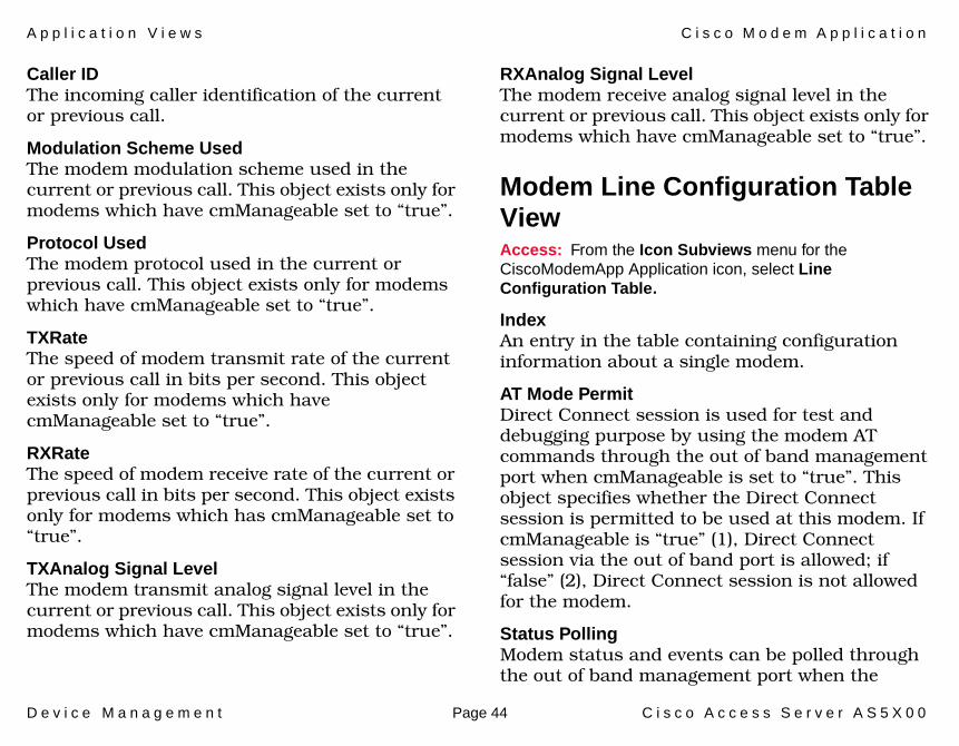
Caller IDThe incoming caller identification of the current or previous call.
Modulation Scheme UsedThe modem modulation scheme used in the current or previous call. This object exists only for modems which have cmManageable set to “true”.
Protocol UsedThe modem protocol used in the current or previous call. This object exists only for modems which have cmManageable set to “true”.
TXRateThe speed of modem transmit rate of the current or previous call in bits per second. This object exists only for modems which have cmManageable set to “true”.
RXRateThe speed of modem receive rate of the current or previous call in bits per second. This object exists only for modems which has cmManageable set to “true”.
TXAnalog Signal LevelThe modem transmit analog signal level in the current or previous call. This object exists only for modems which have cmManageable set to “true”.
RXAnalog Signal LevelThe modem receive analog signal level in the current or previous call. This object exists only for modems which have cmManageable set to “true”.
Modem Line Configuration Table ViewAccess: From the Icon Subviews menu for the CiscoModemApp Application icon, select Line Configuration Table.
IndexAn entry in the table containing configuration information about a single modem.
AT Mode PermitDirect Connect session is used for test and debugging purpose by using the modem AT commands through the out of band management port when cmManageable is set to “true”. This object specifies whether the Direct Connect session is permitted to be used at this modem. If cmManageable is “true” (1), Direct Connect session via the out of band port is allowed; if “false” (2), Direct Connect session is not allowed for the modem.
Status PollingModem status and events can be polled through the out of band management port when the

A p p l i c a t i o n V i e w s C i s c o M o d e m A p p l i c a t i o n
D e v i c e M a n a g e m e n t Page 45 C i s c o A c c e s s S e r v e r A S 5 X 0 0
cmManageable is set to “true”. This object specifies whether this status polling feature is enabled at this modem. If cmManageable is “true” (1), status polling will occur for the modem; if “false” (2) no status polling will occur.
Busy Out RequestThis object is used to put modem out of service, i.e. modem cannot make calls or answer calls. If the modem to be busyout is handling a call, the busyout action will be taken after the current call is disconnected. After the modem is busyout, the following commands can be applied to those modems - reset, bad modem, download modem firmware, etc. This is called nice or graceful busyout. The value of “true” (1) indicates the busyout request has been issued to the modem, but the busyout could be pending. The management entity needs to query the cmState to see if the modem is successfully busied out. The value of “false” (2) indicates the modem has not been given the busyout command.
ShutdownThis object is used to put the modem out of service, i.e., modem cannot make calls or answer calls. This is a hard busyout command to bring the modem out of service immediately without waiting for the call to be ended normally. After the modem is shutdown, the following commands can be applied to those modems - reset, bad modem,
download modem firmware, etc. The value of “true” (1) indicates the hard busyout has been issued to the modem. The value of “false” (2) indicates the modem has not been given a hard busyout command.
Hold ResetA command hold-reset will put the state of modem into reset mode until an inverse command is given to bring modem out of RESET mode. During the period of reset mode, this modem cannot be used and is non-functional. This object is only valid when cmState is onHook, busiedOut, or disabled. The value of “true” (1) attempts to put the modem in reset mode, and the value of “false” (2) takes the modem out of reset.
BadThis object can hold the modem out of service and marks the modem as suspected or proven to be bad. During the router start-up initialization sequence, modem back-to-back tests will test modems and mark those modems failing tests as bad modems. The management entity also can use this command to lock out the suspicious modem or unlock the modem to do further debugging or test. This object is only valid when cmState is onHook or busiedOut. The value of “true” (1) indicates the modem is suspected to be bad and its state is set to bad. The value of “false”

A p p l i c a t i o n V i e w s C i s c o M o d e m A p p l i c a t i o n
D e v i c e M a n a g e m e n t Page 46 C i s c o A c c e s s S e r v e r A S 5 X 0 0
(2) indicates the modem has not been suspected to be bad or has been remarked as good.
Modem Line Statistics Table ViewAccess: From the Icon Subviews menu for the CiscoModemApp Application icon, select Line Statistics Table.
IndexAn entry in the table, containing status information about a single modem.
Ring No AnswersA counter to total the calls where ringing was detected but the call was not answered at this modem.
In Connect FailuresA counter to total the number of incoming connection requests that this modem answered in which it could not train with the other DCE. This object exists only for modems which have cmManageable set to “true”.
In Connect CompletionsA counter to total the number of incoming connection requests that this modem answered and successfully trained with the other DCE. This object exists only for modems which have cmManageable set to “true”.
Out Connect FailuresA counter to total the number of outgoing calls from this modem which successfully went off hook and dialed, in which it could not train with the other DCE. This object exists only for modems which have cmManageable set to “true”.
Out Connect CompletionsA counter to total the number of outgoing calls from this modem which resulted in successfully training with the other DCE. This object exists only for modems which have cmManageable set to “true”.
Failed Dial AttemptsA counter to total the number of call attempts that failed because the modem did not go off hook, or there was no dial tone.
No Dial Tones A counter to total the number of times the dial tone was expected but was not received. This object exists only for modems which have cmManageable set to “true”.
Dial TimeoutsA counter to total the number of times the dial time-out occurred. This object exists only for modems which have cmManageable set to “true”.
A p p l i c a t i o n V i e w s C i s c o M o d e m A p p l i c a t i o n
D e v i c e M a n a g e m e n t Page 47 C i s c o A c c e s s S e r v e r A S 5 X 0 0
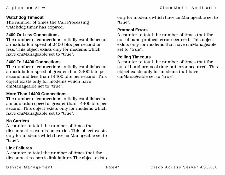
Watchdog TimeoutThe number of times the Call Processing watchdog timer has expired.
2400 Or Less ConnectionsThe number of connections initially established at a modulation speed of 2400 bits per second or less. This object exists only for modems which have cmManageable set to “true”.
2400 To 14400 ConnectionsThe number of connections initially established at a modulation speed of greater than 2400 bits per second and less than 14400 bits per second. This object exists only for modems which have cmManageable set to “true”.
More Than 14400 ConnectionsThe number of connections initially established at a modulation speed of greater than 14400 bits per second. This object exists only for modems which have cmManageable set to “true”.
No CarriersA counter to total the number of times the disconnect reason is no carrier. This object exists only for modems which have cmManageable set to “true”.
Link FailuresA counter to total the number of times that the disconnect reason is link failure. The object exists
only for modems which have cmManageable set to “true”.
Protocol ErrorsA counter to total the number of times that the out of band protocol error occurred. This object exists only for modems that have cmManageable set to “true”.
Polling TimeoutsA counter to total the number of times that the out of band protocol time-out error occurred. This object exists only for modems that have cmManageable set to “true”.
A p p l i c a t i o n V i e w s C i s c o F l a s h A p p l i c a t i o n
D e v i c e M a n a g e m e n t Page 48 C i s c o A c c e s s S e r v e r A S 5 X 0 0
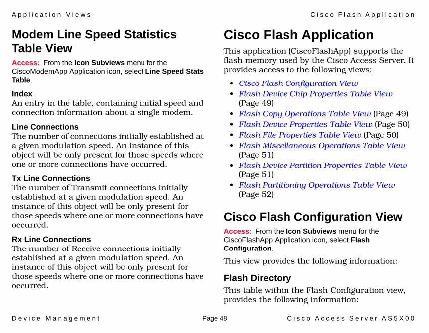
Modem Line Speed Statistics Table ViewAccess: From the Icon Subviews menu for the CiscoModemApp Application icon, select Line Speed Stats Table.
IndexAn entry in the table, containing initial speed and connection information about a single modem.
Line ConnectionsThe number of connections initially established at a given modulation speed. An instance of this object will be only present for those speeds where one or more connections have occurred.
Tx Line ConnectionsThe number of Transmit connections initially established at a given modulation speed. An instance of this object will be only present for those speeds where one or more connections have occurred.
Rx Line ConnectionsThe number of Receive connections initially established at a given modulation speed. An instance of this object will be only present for those speeds where one or more connections have occurred.
Cisco Flash Application This application (CiscoFlashApp) supports the flash memory used by the Cisco Access Server. It provides access to the following views:
• Cisco Flash Configuration View• Flash Device Chip Properties Table View
(Page 49)• Flash Copy Operations Table View (Page 49)• Flash Device Properties Table View (Page 50)• Flash File Properties Table View (Page 50)• Flash Miscellaneous Operations Table View
(Page 51)• Flash Device Partition Properties Table View
(Page 51)• Flash Partitioning Operations Table View
(Page 52)
Cisco Flash Configuration View Access: From the Icon Subviews menu for the CiscoFlashApp Application icon, select Flash Configuration.
This view provides the following information:
Flash DirectoryThis table within the Flash Configuration view, provides the following information:

A p p l i c a t i o n V i e w s C i s c o F l a s h A p p l i c a t i o n
D e v i c e M a n a g e m e n t Page 49 C i s c o A c c e s s S e r v e r A S 5 X 0 0
Name The flash device name.
SizeThe total size of the flash device.
StatusThe status of the flash device.
Flash Size (Bytes)Total size, in bytes, of flash memory.
Available (Bytes)Unused size, in bytes, of flash memory.
Flash writeThe current write permission, Disabled or Enabled.
Flash Device Chip Properties Table ViewAccess: From the Icon Subviews menu for the CiscoFlashApp Application icon, select Chip Properties.
This view displays the following flash device chip information for each initialized flash device.
DescriptionThe flash chip name corresponding to the chip code.
Write RetriesA cumulative count of write retries done on this chip.
Erase RetriesA cumulative count of erase retries done on this chip.
Flash Copy Operations Table ViewAccess: From the Icon Subviews menu for the CiscoFlashApp Application icon, select Copy Operations.
This view displays the following information:
CommandThe copy command to be executed.
ProtocolThe protocol to be used for any copy. Default is tftp.
Server AddressThe server address for any copy. Default is 255.255.255.255.
Source NameThe source file name, either flash or on a server.
Destination AddressThe destination address for any copy.

A p p l i c a t i o n V i e w s C i s c o F l a s h A p p l i c a t i o n
D e v i c e M a n a g e m e n t Page 50 C i s c o A c c e s s S e r v e r A S 5 X 0 0
Remote UserThe remote user name for copy through rcp protocol.
Copy StatusThe status of the specified copy operation.
Notify On CompletionWhether a notification should be generated on the completion of the copy operation.
Entry StatusThe status of this table entry.
Flash Device Properties Table ViewAccess: From the Icon Subviews menu for the CiscoFlashApp Application icon, select Device Properties.
This view displays the following information:
Name Used to refer to the device within the system.
PartitionsNumber of partitions present.
DescriptionsSystem Flash (primary) and Boot Flash (secondary).
ControllerThe card that controls Flash read/write/erase.
Card Index for the card in the card table.
JumperThe state of the jumper that controls the programming voltage to the Flash device.
Init TimeThe time (system time) the device was initialized.
Flash File Properties Table ViewAccess: From the Icon Subviews menu for the CiscoFlashApp Application icon, select File Properties.
This view displays the following information for the files in a flash partition:
Name The name for the file specified by the user copying in the file.
SizeThe size of the file in bytes.
StatusThe status of the file.
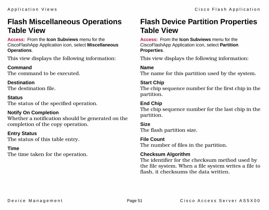
A p p l i c a t i o n V i e w s C i s c o F l a s h A p p l i c a t i o n
D e v i c e M a n a g e m e n t Page 51 C i s c o A c c e s s S e r v e r A S 5 X 0 0
Flash Miscellaneous Operations Table ViewAccess: From the Icon Subviews menu for the CiscoFlashApp Application icon, select Miscellaneous Operations.
This view displays the following information:
CommandThe command to be executed.
DestinationThe destination file.
StatusThe status of the specified operation.
Notify On CompletionWhether a notification should be generated on the completion of the copy operation.
Entry StatusThe status of this table entry.
TimeThe time taken for the operation.
Flash Device Partition Properties Table ViewAccess: From the Icon Subviews menu for the CiscoFlashApp Application icon, select Partition Properties.
This view displays the following information:
Name The name for this partition used by the system.
Start ChipThe chip sequence number for the first chip in the partition.
End ChipThe chip sequence number for the last chip in the partition.
SizeThe flash partition size.
File CountThe number of files in the partition.
Checksum AlgorithmThe identifier for the checksum method used by the file system. When a file system writes a file to flash, it checksums the data written.

A p p l i c a t i o n V i e w s C i s c o P i n g A p p l i c a t i o n
D e v i c e M a n a g e m e n t Page 52 C i s c o A c c e s s S e r v e r A S 5 X 0 0
Flash Partitioning Operations Table ViewAccess: From the Icon Subviews menu for the CiscoFlashApp Application icon, select Partitioning Operations.
This view displays the following information:
CommandThe partitioning command to be executed.
DestinationThe destination device name.
Partition CountThe number of partitions to be created.
Partition SizesThe size of each partition to be created.
StatusThe status of the specified partitioning process.
Notify On CompletionWhether a notification should be generated on the completion of the copy operation.
Entry StatusThe status of this table entry.
TimeThe time taken for the operation.
Cisco Ping ApplicationThis application (CiscoPingApp) provides access to the Ping Request Table View.
Ping Request Table ViewAccess: From the Icon Subviews menu for the CiscoPingApp Application icon, select Ping Request Entry Table.
This application provides access to the Ping Request Table view which allows you to update the ping request list for this device. The following information is available for this view.
OwnerThe user who configured this entry.
ProtocolThe protocol to use once an instance of this object is created. Example: Novell, Apple Talk, Vines, etc.
AddressThe address of the device to be pinged.
StatusThe status of this table entry. Possible states are: active, notInService, notReady, createAndGo, createAndWait, and destroy.

A p p l i c a t i o n V i e w s C i s c o P i n g A p p l i c a t i o n
D e v i c e M a n a g e m e n t Page 53 C i s c o A c c e s s S e r v e r A S 5 X 0 0
Pkt CntSpecifies the number of ping packets to send to the target device in this sequence.
Pkt SzSpecifies the size of ping packets to send to the target device in this sequence.
Pkt TimeoutSpecifies the amount of time to wait for a response to transmitted packet before declaring the packet dropped.
DelaySpecifies the minimum amount of time to wait before sending the next packet in a sequence after receiving a response or declaring a timeout for a previous packet.
Trap OnSpecifies whether or not a ciscoPingCompletion trap should be issued on completion of the sequence of pings.
Pkts SentThe number of ping packets that have been sent to the target.
Pkts RcvdThe number of ping packets that have been received from the target in this sequence.
Min RTTThe minimum round trip time in milliseconds of all the packets that have been sent in this sequence.
Avg RTTThe average round trip time in milliseconds of all the packets that have been sent in this sequence.
Max RTTThe maximum round trip time in milliseconds of all the packets that have been sent in this sequence.
CompletedIndicates (true) that all the packets in this sequence have been either responded to or timed out.

A p p l i c a t i o n V i e w s C i s c o Q u e u e A p p l i c a t i o n
D e v i c e M a n a g e m e n t Page 54 C i s c o A c c e s s S e r v e r A S 5 X 0 0
This button opens the Add Ping Request window. Enter the following information and click the Add Request button to add an entry to the Ping Request Entry Table:
• Address• Owner• Packet Count• Packet Size• Packet Timeout• Delay• Protocol• Trap on Completion
Cisco Queue ApplicationThis application provides access to the information used to manage interface queuing within this device.
• Queue Interface View• Queue Statistics View (Page 55)• Queue Rotation Interface View (Page 55)
Queue Interface ViewAccess: From the Icon Subviews menu for the CiscoQueueApp Application icon, select Queue Interface.
This view provides the following information on the queues for a particular Cisco interface.
IFThe if index for this interface.
TypeThe type of queuing used in the hold queue.
Maximum Number of MsgsThe maximum number of messages place in the hardware transmission queue.
Number of Sub-QueuesThe number of sub-queues of which the hold queue is built.
Add an Entry

A p p l i c a t i o n V i e w s C i s c o Q u e u e A p p l i c a t i o n
D e v i c e M a n a g e m e n t Page 55 C i s c o A c c e s s S e r v e r A S 5 X 0 0
Queue Statistics ViewAccess: From the Icon Subviews menu for the CiscoQueueApp Application icon, select Queue Statistics.
This view provides the following statistical information on the queues for a particular Cisco interface:
Sub-Queue AttrsA list of sub-queue attributes for an interface.
Number of MsgsThe number of messages in the sub-queue.
Maximum Permitted MsgsThe maximum number of messages permitted in the sub-queue.
Number of Msgs DiscardedThe number of messages discarded from this queue since restart.
Queue Rotation Interface ViewAccess: From the Icon Subviews menu for the CiscoQueueApp Application icon, select Rotation Interface.
This view provides the following information on the rotation of custom queues for a particular Cisco interface:
Statistics Queue NumberCustom queuing sub-queue attributes for an interface.
Number of Transmitted OctetsThe number of octets which may be transmitted from a custom queuing sub-queue before it must yield to another queue.

A p p l i c a t i o n V i e w s A T M C l i e n t A p p l i c a t i o n
D e v i c e M a n a g e m e n t Page 56 C i s c o A c c e s s S e r v e r A S 5 X 0 0
ATM Client ApplicationThis application (ATMClientApp) has four menu options that provide access to the following views:
• VCL Table• ATM Link Modeling Options (Page 57)• Performance (Page 59)• Configuration (Page 59)
VCL TableAccess: From the Icon Subviews menu for the ATMClientApp Application icon, select VCL Table.
This view opens the ATM Client Application Virtual Channel Link view with the following information.
If IndexAn entry in the VCL Table.
VPIThe VPI value of the VCL.
VCIThe VCI value of the VCL.
Admin StatusThis object is implemented only for a VCL which terminates a VCC (i.e., one which is not cross-connected to other VCLs). Its value specifies the
desired administrative state of the VCL. The up and down states indicate that the traffic flow is enabled and disabled respectively for this VCL.
Oper StatusThis object indicates the current operational status of the VCL. The up and down states indicate that the VCL is currently operational, or not operational, respectively. The unknown state indicates that the status of this VCL cannot be determined.
Last ChangeThe value of MIB II’s system Up Time object at the time this VCL entered its current operational state. If the current state was entered prior to the last re-initialization of the agent, then this object contains a zero value.
Rcv Descr IndexThe value of this object identifies the row in the ATM Traffic Descriptor Table which applies to the receive direction of this VCL.
Xmit Descr IndexThe value of this object identifies the row of the ATM Traffic Descriptor Table which applies to the transmit direction of this VCL.
AAL TypeThe type of AAL used on this VCC. An instance of this object only exists when the local VCL end-
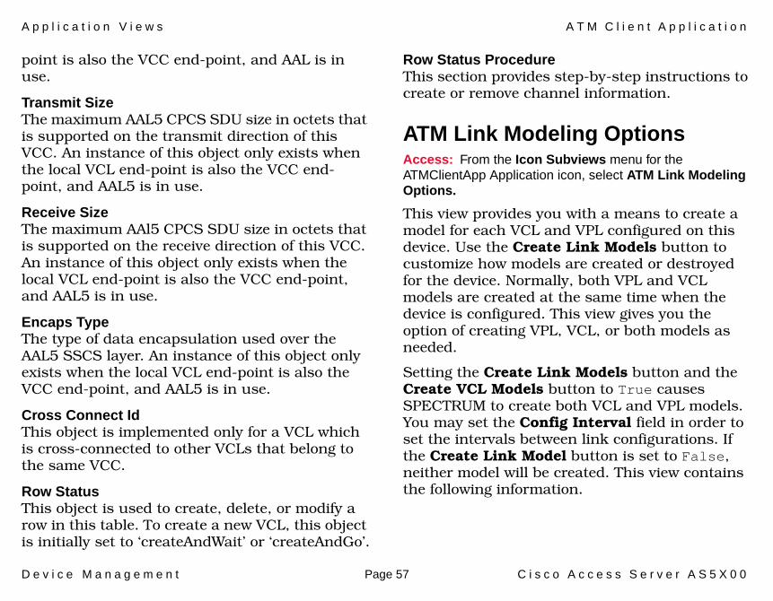
A p p l i c a t i o n V i e w s A T M C l i e n t A p p l i c a t i o n
D e v i c e M a n a g e m e n t Page 57 C i s c o A c c e s s S e r v e r A S 5 X 0 0
point is also the VCC end-point, and AAL is in use.
Transmit SizeThe maximum AAL5 CPCS SDU size in octets that is supported on the transmit direction of this VCC. An instance of this object only exists when the local VCL end-point is also the VCC end-point, and AAL5 is in use.
Receive SizeThe maximum AAl5 CPCS SDU size in octets that is supported on the receive direction of this VCC. An instance of this object only exists when the local VCL end-point is also the VCC end-point, and AAL5 is in use.
Encaps TypeThe type of data encapsulation used over the AAL5 SSCS layer. An instance of this object only exists when the local VCL end-point is also the VCC end-point, and AAL5 is in use.
Cross Connect IdThis object is implemented only for a VCL which is cross-connected to other VCLs that belong to the same VCC.
Row StatusThis object is used to create, delete, or modify a row in this table. To create a new VCL, this object is initially set to ‘createAndWait’ or ‘createAndGo’.
Row Status ProcedureThis section provides step-by-step instructions to create or remove channel information.
ATM Link Modeling OptionsAccess: From the Icon Subviews menu for the ATMClientApp Application icon, select ATM Link Modeling Options.
This view provides you with a means to create a model for each VCL and VPL configured on this device. Use the Create Link Models button to customize how models are created or destroyed for the device. Normally, both VPL and VCL models are created at the same time when the device is configured. This view gives you the option of creating VPL, VCL, or both models as needed.
Setting the Create Link Models button and the Create VCL Models button to True causes SPECTRUM to create both VCL and VPL models. You may set the Config Interval field in order to set the intervals between link configurations. If the Create Link Model button is set to False, neither model will be created. This view contains the following information.

A p p l i c a t i o n V i e w s A T M C l i e n t A p p l i c a t i o n
D e v i c e M a n a g e m e n t Page 58 C i s c o A c c e s s S e r v e r A S 5 X 0 0
This button can be set to either true or false. Setting this button’s value to true causes a model to be created for the VPLs.
This button can be set to either true or false. Setting this button’s value to true causes a model to be created for the VCLs.
Config IntervalThis value represents the number of seconds between link model configuration.
Clicking this button forces a link model reconfiguration.
Clicking this button will display information on the buttons and fields in this view and show you how to force a link model reconfiguration.
Below are detailed instructions on how to create and destroy VCL and VPL models.
Creating VPL/VCL Models1 Model the device that contains the ATM
application.
2 Proceed to the Application view and find the ATM application icon.
3 Right-click the icon and select ATM Link Modeling Options. You may select the Option Explanations button to display instructions on screen.
4 Set both Create Link Models and Create VCL Models buttons to True. Save the change.
5 Click the Reconfigure Now button. This will create both VPL and VCL models.
6 Launch your Device Topology view.
7 Locate the port number associated with the ATM application.
8 Go to the port's Sub-Interface view. You will see the VPL/VCL models after the reconfiguration is completed.
Create Link Models
Create VCL Models
Reconfigure Now
Option ExplanationsNote:Note:
If you set Create Link Models to True but Create VCL Models to False, VCL models will not be created during the reconfiguration.

A p p l i c a t i o n V i e w s A T M C l i e n t A p p l i c a t i o n
D e v i c e M a n a g e m e n t Page 59 C i s c o A c c e s s S e r v e r A S 5 X 0 0
Destroying VPL/VCL Models1 In the ATM Link Modeling Options view set
the Create Link Models button to False.
2 Save the changes.
3 Click the Reconfigure Now button. The VPL/VCL models will be destroyed during the reconfiguration.
4 Launch the Device Topology view.
5 Locate the port associated with the ATM Application.
Go to the Sub-Interface view of the port. You should not see the VPL/VCL models after the reconfiguration is completed.
PerformanceAccess: From the Icon Subviews menu for the ATMClientApp Application icon, select Interfaces > Serial_IF_Port_8 > Performance.
This view provides performance information about the packets being passed through a particular interface. The following packet statistics for the selected interface are displayed in this view:
• Load• Packet Rate
• % Error• % Discarded
ConfigurationAccess: From the Icon Subviews menu for the ATMClientApp Application icon, select Interfaces > Serial_IF_Port_8 > Configuration.
This view provides port configuration information for the Cisco Access Server. See the Redundancy and Model Reconfiguration Options (Page 86) for field explanations and more detailed information.
Table 13: Performance View Buttons
Button Opens the...
Transmit Detailed Port Performance view for packets transmitted.
Receive Detailed Port Performance view for packets received.
Detail Interface Detail view which displays packet, error, and discarded breakdown statistics.
Config Interface Configuration View.
Alarms Enterprise Alarm Manager.
Events Event Log.

A p p l i c a t i o n V i e w s E n v M o n A p p l i c a t i o n
D e v i c e M a n a g e m e n t Page 60 C i s c o A c c e s s S e r v e r A S 5 X 0 0
EnvMon ApplicationThis application (CiscoEnvMonApp) has five menu options that provide access to the following views:
• Enable Notifications• Fan Status (Page 61)• Power Supply Status (Page 61)• Temperature Status (Page 61)• Voltage Status (Page 62)
Enable NotificationsAccess: From the Icon Subviews menu for the CiscoEnvMonApp Application icon, select Enable Notifications.
This is where you enable or disable system notifications.
ShutdownThis variable indicates whether the system produces the Shutdown Notification. A “true” value will generate shutdown notifications. A “false” value will prevent shutdown notifications from being generated by this system.
VoltageThis variable indicates whether the system produces the Voltage Notification. A “true” value will generate voltage notifications. A “false” value
will prevent voltage notifications from being generated by this system.
Redundant SupplyThis variable indicates whether the system produces the Redundant Supply Notification. A “true” value will generate redundant supply notifications. A “false” value prevents redundant supply notifications from being generated by this system.
TemperatureThis variable indicates whether the system produces Temperature Notification. A “true” value will generate temperature notifications. A “false” value prevents temperature notifications from being sent by this entity.
FanThis variable indicates whether the system produces the Fan Notifications. A “true” value will generate temperature notification. A “false” value prevents fan notifications from being sent by this entity.

A p p l i c a t i o n V i e w s E n v M o n A p p l i c a t i o n
D e v i c e M a n a g e m e n t Page 61 C i s c o A c c e s s S e r v e r A S 5 X 0 0
Fan StatusAccess: From the Icon Subviews menu for the CiscoEnvMonApp Application icon, select Fan Status.
This table provides the fan status maintained by the environmental monitor.
DescriptionThe fan being instrumented.
StateThe current state of the fan being instrumented.
Power Supply StatusAccess: From the Icon Subviews menu for the CiscoEnvMonApp Application icon, select Power Supply Status.
This table provides the power supply status maintained by the environmental monitor card.
DescriptionThe power supply being instrumented.
StateThe current state of the power supply being instrumented.
Temperature StatusAccess: From the Icon Subviews menu for the CiscoEnvMonApp Application icon, select Temperature Status.
This table provides the ambient temperature status maintained by the environmental monitor.
DescriptionThe testpoint being instrumented.
ValueThe current measurement of the testpoint being instrumented.
ThresholdThe highest value that the associated instance of the object Status Value may obtain before an emergency shutdown of the managed device is initiated.
@ Last ShutdownThe value of the associated instance of the object Status Value at the time an emergency shutdown of the managed device was last initiated. This value is stored in non-volatile RAM and is therefore able to survive the shutdown.
StateThe current state of the testpoint being instrumented.

A p p l i c a t i o n V i e w s D i s c o v e r y A p p l i c a t i o n
D e v i c e M a n a g e m e n t Page 62 C i s c o A c c e s s S e r v e r A S 5 X 0 0
Voltage StatusAccess: From the Icon Subviews menu for the CiscoEnvMonApp Application icon, select Voltage Status.
This table provides the voltage status maintained by the environmental monitor.
DescriptionThe testpoint being instrumented.
ValueThe current measurement of the testpoint being instrumented.
Lo ThresholdThe lowest value that the associated instance of the object Voltage Status Value may obtain before an emergency shutdown of the managed device is initiated.
Hi ThresholdThe highest value that the associated instance of the object Voltage Status Value may obtain before an emergency shutdown of the managed device is initiated.
@ Last ShutdownThe value of the associated instance of the object Voltage Status Value at the time an emergency shutdown of the managed device was last initiated. This value is stored in non-volatile RAM and hence is able to survive the shutdown.
StateThe current state of the testpoint being instrumented.
Discovery ApplicationThis application (CiscoCDPApp) has two menu options that provide access to the following views.
• Discovery Cache Table View • Interface Discovery Status Table (Page 63)
Discovery Cache Table ViewAccess: From the Icon Subviews menu for the CiscoCDPApp Application icon, select Cache.
This is the table containing the cached information obtained by receiving CDP (Cisco Discovery Protocol) messages.
Type An indication of the type of address contained in the corresponding instance of cdpCacheAddress.
AddressThe (first) network-layer address of the device’s SNMP-agent as reported in the most recent CDP message.

A p p l i c a t i o n V i e w s D i s c o v e r y A p p l i c a t i o n
D e v i c e M a n a g e m e n t Page 63 C i s c o A c c e s s S e r v e r A S 5 X 0 0
Device IDThe Device-ID string as reported in the most recent CDP message. The zero-length string indicates no Device-ID field was reported in the most recent CDP message.
Device PortThe Port-ID string as reported in the most recent CDP message. This will typically be the value of the ifName object (e.g., ‘Ethernet0’.) The zero-length string indicates no Port-ID field was reported in the most recent CDP message.
PlatformThe device’s hardware platform as reported in the most recent CDP message. The zero-length string indicates that no Platform field was reported in the most recent CDP message.
CapabilitiesThe device’s functional capabilities as reported in the most recent CDP message. For latest set of specific values, see the latest version of the CDP specification. The zero-length string indicates no Capabilities field was reported in the most recent CDP message.
Interface Discovery Status TableAccess: From the Icon Subviews menu for the CiscoCDPApp Application icon, select Interfaces.
This is the table containing the status of CDP on the device’s interfaces.
IFThe interface index value of the local interface.
DiscoveryAn indication of whether the Cisco Discovery Protocol is currently running on this interface.
GroupThis object is only relevant to interfaces which are repeater ports on 802.3 repeaters. In this situation, it indicates the RFC1516 group number of the repeater port which corresponds to this interface.
PortThis object is only relevant to interfaces which are repeater ports on 802.3 repeaters. In this situation, it indicates the RFC1516 port number of the repeater port which corresponds to this interface.
IntervalThe interval at which CDP (Cisco Discovery Protocol) messages are to be generated on this interface. The default value is 60 seconds.

A p p l i c a t i o n V i e w s C i s c o D S I A P P 1 4 0 6 A p p l i c a t i o n
D e v i c e M a n a g e m e n t Page 64 C i s c o A c c e s s S e r v e r A S 5 X 0 0
Cisco DSIAPP1406 ApplicationThis application (DSIAPP1406) has three menu options that provide access to the following views.
• DSI Configuration Table (Page 64)• DS1 Fractional Table (Page 68)• DS1App1406 Current Table View (Page 69)
DSI Configuration TableAccess: From the Icon Subviews menu for the DSIAPP1406 Application icon, select DSI Configuration Table.
DS1 IndexThis object is the identifier of a DS1 Interface on a managed device.
If IndexThe value for this object is equal to the value of Interface Index from the Interfaces table of MIB II (RFC1213).
Line TypeThis variable indicates the variety of DS1 Line implementing this circuit. The type of circuit affects the number of bits per second that the circuit can reasonably carry, as well as the interpretation of the usage and error statistics. Table 14 provides you with a list of the line types and their values.
Zero CodingThis variable describes the variety of Zero Code Suppression used on the link, which in turn affects a number of its characteristics. Table 15 provides you with a list of the codes and their descriptions.
Table 14: Line Types
Type Value
dsx1ESF Extended SuperFrame DS1
dsx1D4 AT&T D4 format DS1
dsx1E1 CCITT Recommendation G.704 (Table 4a)
dsx1E1-CRC CCITT Recommendation G.704 (Table 4b)
dsxE1-Mf G.704 (Table 4a) with TS16 multiframing enabled
dsx1E1-CRC-MF G.704 (Table 4b) with TS16 multiframing enabled

A p p l i c a t i o n V i e w s C i s c o D S I A P P 1 4 0 6 A p p l i c a t i o n
D e v i c e M a n a g e m e n t Page 65 C i s c o A c c e s s S e r v e r A S 5 X 0 0
Send CodeThis variable indicates what type of code is being sent across the DS1 interface by the device. Table 16 describes the send codes and their meanings.
Table 15: Zero Codes
Code Description
dsx1JBZS Jammed Bit Zero Suppression, in which the AT&T specification of at least one pulse every 8 bit periods is literally implemented by forcing a pulse in bit 8 of each channel. Thus, only seven bits per channel, or 1.3444 Mbps, is available for data.
dsx1B8ZS Refers to the use of a specified pattern of normal bits and bipolar violations which are used to replace a sequence of eight zero bits.
ANSI Clear Channels
May use dsx1ZBTSI, or Zero Byte Time Slot Interchange.
E1 links With or without CRC, use dsx1HDB3 or dsx1AMI.
dsx1AMI Refers to a mode wherein no zero code suppression is present and the line encoding does not solve the problem directly. In this application, the higher layer must provide data which meets or exceeds the pulse density requirements, such as inverting HDLC data.
Table 16: Send Codes
Code Description
dsx1SendNoCode Sending looped or normal data.
dsx1SendLineCode Sending a request for a line loopback.
dsx1SendPayloadCode Sending a request for a payload loopback.
dsx1SendResetCode Sending a loopback termination request.
dsx1SendQRS Sending a Quasi-Random Signal (QRS) test pattern.
dsx1Send511Pattern Sending a 511 bit fixed test pattern.
dsx1Send3in24Pattern Sending a fixed test pattern of 3 bits set in 24.
dsx1SendOtherTestPattern
Sending a test pattern other than those described by this object.

A p p l i c a t i o n V i e w s C i s c o D S I A P P 1 4 0 6 A p p l i c a t i o n
D e v i c e M a n a g e m e n t Page 66 C i s c o A c c e s s S e r v e r A S 5 X 0 0
Vendor IDThis variable contains the transmission vendor’s circuit identifier, for the purpose of facilitating troubleshooting.
Loopback ConfigThis variable represents the loopback configuration of the DS1 interface. Agents supporting read/write access should return badValue in response to a requested loopback state that the interface does not support. Table 17 describes the loopback configurations and their meanings.
Line StatusThis variable indicates the Line Status of the interface. It contains loopback, failure, received “alarm” and transmitted “alarm” information. The Line Status is a bit map represented as a sum, therefore, it can represent multiple failures (alarms) and a Loopback State simultaneously. The various bit positions are shown in Table 18.Table 17: Loopback Configurations
Value Description
dsx1NoLoop Not in the loopback state. A device that is not capable of performing a loopback on the interface shall always return this as its value.
dsx1PayloadLoop The received signal at this interface is looped through the device. Typically the received signal is looped back for retransmission after it has passed through the device’s framing function.
dsx1LineLoop The received signal at this interface does not go through the device (minimum penetration) but is looped back out.
dsx1OtherLoop Loopbacks that are not defined here.
Table 18: Line Statuses
Bit Status Description
1 dsx1NoAlarm No Alarm Present
2 dsx1RcvFarEndLOF Far end LOF (a.k.a., Yellow Alarm
4 dsx1XmtFarEndLOF Near end sending LOF Indication
8 dsx1RcvAIS Far end sending AIS
16 dsx1XmtAIS Near end sending AIS
32 dsx1LossOfFrame Near end LOF (a.k.a., Red Alarm)
Table 17: Loopback Configurations
Value Description
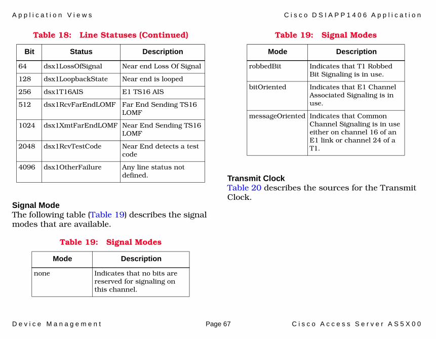
A p p l i c a t i o n V i e w s C i s c o D S I A P P 1 4 0 6 A p p l i c a t i o n
D e v i c e M a n a g e m e n t Page 67 C i s c o A c c e s s S e r v e r A S 5 X 0 0
Signal ModeThe following table (Table 19) describes the signal modes that are available.
Transmit ClockTable 20 describes the sources for the Transmit Clock.
64 dsx1LossOfSignal Near end Loss Of Signal
128 dsx1LoopbackState Near end is looped
256 dsx1T16AIS E1 TS16 AIS
512 dsx1RcvFarEndLOMF Far End Sending TS16 LOMF
1024 dsx1XmtFarEndLOMF Near End Sending TS16 LOMF
2048 dsx1RcvTestCode Near End detects a test code
4096 dsx1OtherFailure Any line status not defined.
Table 19: Signal Modes
Mode Description
none Indicates that no bits are reserved for signaling on this channel.
Table 18: Line Statuses (Continued)
Bit Status Description
robbedBit Indicates that T1 Robbed Bit Signaling is in use.
bitOriented Indicates that E1 Channel Associated Signaling is in use.
messageOriented Indicates that Common Channel Signaling is in use either on channel 16 of an E1 link or channel 24 of a T1.
Table 19: Signal Modes
Mode Description
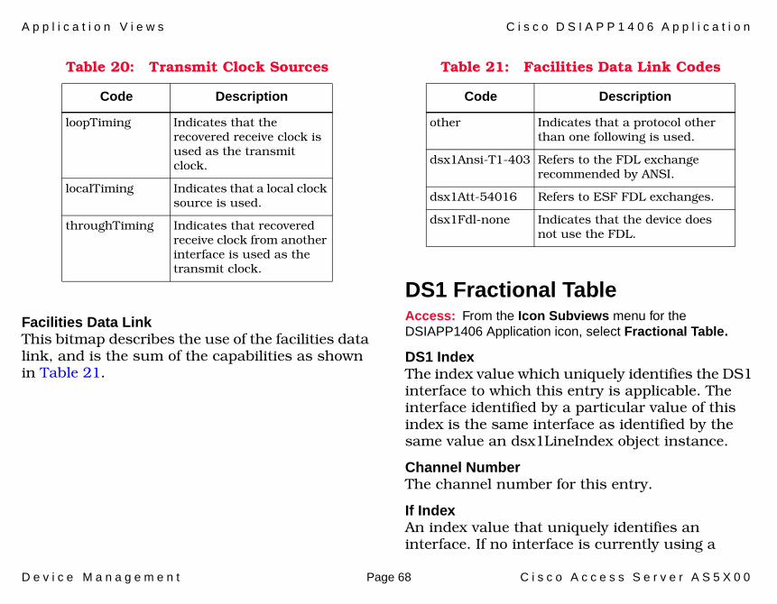
A p p l i c a t i o n V i e w s C i s c o D S I A P P 1 4 0 6 A p p l i c a t i o n
D e v i c e M a n a g e m e n t Page 68 C i s c o A c c e s s S e r v e r A S 5 X 0 0
Facilities Data LinkThis bitmap describes the use of the facilities data link, and is the sum of the capabilities as shown in Table 21.
DS1 Fractional TableAccess: From the Icon Subviews menu for the DSIAPP1406 Application icon, select Fractional Table.
DS1 IndexThe index value which uniquely identifies the DS1 interface to which this entry is applicable. The interface identified by a particular value of this index is the same interface as identified by the same value an dsx1LineIndex object instance.
Channel NumberThe channel number for this entry.
If IndexAn index value that uniquely identifies an interface. If no interface is currently using a
Table 20: Transmit Clock Sources
Code Description
loopTiming Indicates that the recovered receive clock is used as the transmit clock.
localTiming Indicates that a local clock source is used.
throughTiming Indicates that recovered receive clock from another interface is used as the transmit clock.
Table 21: Facilities Data Link Codes
Code Description
other Indicates that a protocol other than one following is used.
dsx1Ansi-T1-403 Refers to the FDL exchange recommended by ANSI.
dsx1Att-54016 Refers to ESF FDL exchanges.
dsx1Fdl-none Indicates that the device does not use the FDL.

A p p l i c a t i o n V i e w s C i s c o D S I A P P 1 4 0 6 A p p l i c a t i o n
D e v i c e M a n a g e m e n t Page 69 C i s c o A c c e s s S e r v e r A S 5 X 0 0
channel, the value should be zero. If a single interface occupies more than one time slot, that ifIndex value will be found in multiple time slots.
DS1App1406 Current Table ViewAccess: From the Icon Subviews menu for the DSIAPP1406 Application icon, select DS1 Current Table.
The DS1 current table contains various statistics being collected for the current 15 minute interval.
IndexThe index value which uniquely identifies the DS1 interface to which this entry is applicable.
ESsThe number of Errored Seconds, encountered by a DS1 interface in the current 15 minute interval.
SESsThe number of Severely Errored Seconds encountered by a DS1 interface in the current 15 minute interval.
SEFsThe number of Severely Errored Framing Seconds encountered by a DS1 interface in the current 15 minute interval.
UASsThe number of Unavailable Seconds encountered by a DS1 interface in the current 15 minute interval.
CSSsThe number of Controlled Slip Seconds encountered by a DS1 interface in the current 15 minute interval.
PCVsThe number of Path Coding Violations encountered by a DS1 interface in the current 15 minute interval.
LESsThe number of Line Errored Seconds encountered by a DS1 interface in the current 15 minute interval.
BESsThe number of Bursty Errored Seconds (BESs) encountered by a DS1 interface in the current 15 minute interval.
DMsThe number of Degraded Minutes (DMs) encountered by a DS1 interface in the current 15 minute interval.

A p p l i c a t i o n V i e w s I n t e r f a c e E t h e r n e t A p p l i c a t i o n
D e v i c e M a n a g e m e n t Page 70 C i s c o A c c e s s S e r v e r A S 5 X 0 0
LCVsThe number of Line Code Violations (LCVs) en- countered by a DS1 interface in the current 15 minute interval.
Interface Ethernet ApplicationThis application (EthernetIfApp) provides access to the application-specific Detail view.
To access the Detail view, select Detail from the Icon Subviews menu. This view provides access to three pie charts with performance statistics. For more information about the frame or transmit error performance statistics, refer to How to Manage Your Network with SPECTRUM.
Cisco Interface ApplicationThis application (CiscoIfceApp) provides access to the application-specific Configuration view.
To access the Configuration view, select Configuration from the Icon Subviews menu. The CiscoIfceApp Configuration window opens where you can choose to Create Interface Applications and/or Create Sub Interface Applications.
Cisco Terminal Server ApplicationThe Cisco Terminal Server Application (CiscoTSApp) provides access to the following application-specific views:
• Line Configuration View• Cisco Terminal Server Line View (Page 71)• Cisco Terminal Server Session View (Page 72)
Line Configuration ViewAccess: From the Icon Subviews menu for the CiscoTSApp Application icon, select Line Configuration.
This view displays the following information on the terminal server line.
LinesNumber of lines.
Message tty LineThe tty line to send the message to.
Message Interval timeThe interval in milliseconds between reissuing message.
Message DurationThe length of time in milliseconds to reissue message.

A p p l i c a t i o n V i e w s C i s c o T e r m i n a l S e r v e r A p p l i c a t i o n
D e v i c e M a n a g e m e n t Page 71 C i s c o A c c e s s S e r v e r A S 5 X 0 0
Message TextThe actual message up to 256 characters.
Message Temporary BannerSelect to use the message as a temporary banner in addition to the normal banner.
Message send The value used to determine what is done after the message is sent.
Clear tty LineThe last line cleared.
Cisco Terminal Server Line ViewAccess: From the Icon Subviews menu for the CiscoTSApp Application icon, select Line Table.
This view displays the following information on each terminal server line connected to the Cisco Router.
StatusThe current state of this line. Possible states are Active and Inactive.
TypeThe type of line. Possible types are Unknown, Console, Terminal, Line-Printer, Virtual-Terminal, and Auxiliary.
AutobaudWhether the line will autobaud
Speed InThe input speed of this line, displayed as a baud rate.
Speed OutThe output speed of this line, displayed as a baud rate.
Flow ControlThe type of flow control in use on this line. Possible flow control types are Unknown, None, Software-Input, Software-Output, Software-Both, Hardware-Input, Hardware-Output, and Hardware-Both.
Modem ControlThe type of modem control in use on this line. Possible modem control types are Unknown, None, Call-In, Call-Out, CTS-Required, RI-IS-CD, and InOut.
LocationThe physical location of this line.
Term TypeThe type of terminal on this line.
Length in LinesLength, in lines, of the terminal’s screen attached to this line.

A p p l i c a t i o n V i e w s C i s c o T e r m i n a l S e r v e r A p p l i c a t i o n
D e v i c e M a n a g e m e n t Page 72 C i s c o A c c e s s S e r v e r A S 5 X 0 0
Width in CharWidth, in characters, of the terminal’s screen attached to this line.
Escape CharEscape character used to breakout the active sessions.
Idle Time outThe amount of idle time allowed on this line before the line times out.
Session Time outThe amount of idle time allowed in this session before the session times out.
RotaryThe rotary group number the line belongs to.
# of ConnectionsThe number of times a connection has been made to or from this line.
Current SessionThe current number of sessions in use on this line.
UserTACACS user name, if TACACS is enabled.
NoiseCount of garbage characters received when the line is inactive.
Line NumberThe number (listed in sequential order) for this terminal server line.
Time ActiveThe time, in seconds, since the line was activated.
Cisco Terminal Server Session ViewAccess: From the Icon Subviews menu for the CiscoTSApp Application icon, select Session Table.
This view displays the Terminal Server (TS) Session Table, which provides information about each terminal server session connected to the Cisco Router. The table provides the following information:
TypeThe type of this session. Possible types are Unknown, Pad, Stream, Rlogin, Telnet, and TCP.
DirectionThe direction of this session. Possible directions are Unknown, Incoming, and Outgoing.
AddrThe remote host address of the session.
Name The remote host name of the session.

A p p l i c a t i o n V i e w s C i s c o M e m o r y P o o l A p p l i c a t i o n
D e v i c e M a n a g e m e n t Page 73 C i s c o A c c e s s S e r v e r A S 5 X 0 0
StateThe indicator of whether this session is the currently active session. Possible states are Inactive and Active.
IdleTime in seconds that the session has been idle.
LineThe index value that identifies this line.
SessionA second index value that identifies this session.
Cisco Memory Pool ApplicationThis major application provides the following application-specific subview.
• Cisco Memory Pool Monitor Table View
Cisco Memory Pool Monitor Table ViewAccess: From the Icon Subviews menu for the CiscoMemPoolApp Application icon, select Memory Pool Monitor.
This table displays memory pool monitoring entries. Column headings are as follows.
NameA textual name assigned to the memory pool.
AlternateIndicates whether or not this memory pool has an alternate pool configured. Alternate pools are used for fallback when the current pool runs out of memory.
If an instance of this field has a value of zero, then this pool does not have an alternate. Otherwise the value of this field is the same as the value of ciscoMemoryPoolType of the alternate pool.

A p p l i c a t i o n V i e w s C i s c o I n t e r f a c e A p p l i c a t i o n
D e v i c e M a n a g e m e n t Page 74 C i s c o A c c e s s S e r v e r A S 5 X 0 0
ValidIndicates whether or not the remaining fields in this entry contain accurate data. If an instance of this field has the value False (indicating an internal error condition), the values of the remaining fields in the conceptual row may contain inaccurate information (specifically, the reported values may be less than the actual values).
UsedIndicates the number of bytes from the memory pool that are currently in use by applications on the managed device.
Free Indicates the number of bytes from the memory pool that are currently unused on the managed device.
Note that the sum of Used and Free is the total amount of memory in the pool.
Largest FreeIndicates the largest number of contiguous bytes from the memory pool that are currently unused on the managed device.
Cisco Interface ApplicationThis major application (model type CiscoIFApp) provides the following application-specific subview.
• CiscoIfceApp Configuration View
CiscoIfceApp Configuration ViewAccess: From the Icon Subviews menu for the CiscoIFApp Application icon, select Configuration.
Allows you to configure the interfaces. By default, the interfaces will not be modeled.
Create Interface ApplicationsSetting this button to True will create CiscoIfceApps for physical interfaces.
Create Sub-Interface ApplicationsSetting this button to True will create CiscoIfceApps for all interfaces.
Cisco RTT-Mon ApplicationThis application is described in the Cisco RTT-Mon Application documentation.

A p p l i c a t i o n V i e w s C i s c o P o p A p p l i c a t i o n
D e v i c e M a n a g e m e n t Page 75 C i s c o A c c e s s S e r v e r A S 5 X 0 0
Cisco Pop ApplicationThe Cisco Point of Presence application contains the following subviews:
• Cisco DS0 Usage Table View• Cisco DS1-DS0 Usage Table View (Page 76)• Cisco DS0 Active Call Information View
(Page 77)• Cisco Call Failure Information View (Page 77)• Cisco Active Call Summary Table View
(Page 78)• Cisco Call History Summary Table View
(Page 79)
Cisco DS0 Usage Table ViewAccess: From the Icon Subviews menu for the CiscoPopApp icon, select DS0 Usage Table.
Slot IndexThe slot index indicates the slot number on the device where the DS1 card resides.
Port IndexIndicates the port number of a specific DS1 on the DS1 card in the slot.
Config TypeThe configured technology for the channel. Possible types are unknown, isdn, ct1 (Channelized T1) and ce1 (Channelized D1).
DS0 Call TypeThe type of the current call carried by this DS0. Possible types are idle, unknown, analog (modem), digital, v110, v120, and voice.
L2 EncapThe data link encapsulation of the call currently occupying this DS0. Possible values are idle, unknown, PPP, slip, arap, hdlc, exec, and voice.
Call CountThe number of calls that have occupied this DS0.
Time In UseThe amount of time that this DS0 has been in use. This is computed by summing up the call durations of all past calls that have occupied this DS0.
In OctetsThe total number of octets received on this DS0 for data calls. All the received ‘raw’ octets are counted, including any protocol headers which may or may not be present, depending on the service type of data call.

A p p l i c a t i o n V i e w s C i s c o P o p A p p l i c a t i o n
D e v i c e M a n a g e m e n t Page 76 C i s c o A c c e s s S e r v e r A S 5 X 0 0
Out OctetsThe total number of octets transmitted on this DS0 for data calls. All the transmitted ‘raw’ octets are counted, including any protocol headers which may or may not be present, depending on the service type of data call.
In PktsThe total number of packets received on this DS0 for data calls.
Out PktsThe total number of packets transmitted on this DS0 for data calls.
Associated InterfaceThe value of the ifIndex when the specific channel has an active call with a corresponding interface in the ifTable. For example, a digital ISDN call has a value pointing to the B-Channel entry in the ifTable. A modem call over ISDN or CT1/CE1 has a value pointing to the async interface of the modem assigned to this call. If the channel is idle, this value is 0.
Cisco DS1-DS0 Usage Table ViewAccess: From the Icon Subviews menu for the CiscoPopApp icon, select DS1-DS0 Usage Table.
Slot IndexIndicates the slot number on the device where the DS1 card resides. The slot index of the first slot is starting from 0 and increments by 1 for the next slot in the series.
Port IndexIndicates the port number of a specific DS1 on the DS1 card in the slot. The port index of the first port is starting from 0 and increments by 1 for the next port on the DS1 card.
Active DS0The number of DS0s that are currently in use for a particular DS1.
High Water MarkThe highest number of simultaneously activated DS0s on a specified DS1.

A p p l i c a t i o n V i e w s C i s c o P o p A p p l i c a t i o n
D e v i c e M a n a g e m e n t Page 77 C i s c o A c c e s s S e r v e r A S 5 X 0 0
Cisco DS0 Active Call Information ViewAccess: From the Icon Subviews menu for the CiscoPopApp icon, select DS0 Active Call Information.
V.110The current number of active V.110 calls received by the managed device.
V.120The current number of active V.120 calls received by the managed device.
ISDN AnalogThe number of configured ISDN B-Channels that are currently occupied by analog calls.
ISDN Digital/AnalogThe number of configured IDSN B-Channels that are currently occupied by both Digital and Analog calls.
DS0The number of DS0s that are currently in use.
PPPThe current number of active PPP calls received by the managed device.
SW56 DigitalThe number of configured SW56 B-Channels that are currently occupied by Digital calls.
High Water MarkThe high water mark for number of DS0s that are active simultaneously.
Cisco Call Failure Information ViewAccess: From the Icon Subviews menu for the CiscoPopApp icon, select Call Failure Information.
ISDN Information
Calls RejectedThe number of ISDN calls rejected in this managed device.
Cleared AbnormallyThe number of connected ISDN calls that have been abnormally cleared, that is, they were cleared by some event other than the following:
• The transmission of a normal disconnect message by the local end.
• The reception of a normal disconnect message from the remote end.
No ResourcesThe number of ISDN calls that have been rejected because there is no B-Channel available to handle the call.

A p p l i c a t i o n V i e w s C i s c o P o p A p p l i c a t i o n
D e v i c e M a n a g e m e n t Page 78 C i s c o A c c e s s S e r v e r A S 5 X 0 0
Modem Information
Calls RejectedThe number of analog calls rejected in this managed device.
Cleared AbnormallyThe number of connected analog calls that have been abnormally cleared, that is, they were cleared by some event other than the following:
• The transmission of a normal disconnect message by the local end.
• The reception of a normal disconnect message from the remote end.
No ResourcesThe number of analog calls that have been rejected because there is no B-Channel available to handle the call.
Cisco Active Call Summary Table ViewAccess: From the Icon Subviews menu for the CiscoPopApp icon, select Active Call Table.
The Active Call Summary Table is used to track currently active calls. It contains the following information.
Start Time IndexThe start time of the current call.
Summary IndexAn arbitrary small integer to distinguish calls that occurred at the same time tick.
User IDThe User login ID or zero length string if unavailable.
User IP AddrThe IP address of the call or 0.0.0.0 if unavailable.
Call TypeThe type of call. Possible types are unknown, analog (modem), digital, v110, v120, and voice.
Modem SlotIdentification of modem resource allocated to call. This value along with the Modem Port uniquely

A p p l i c a t i o n V i e w s C i s c o P o p A p p l i c a t i o n
D e v i c e M a n a g e m e n t Page 79 C i s c o A c c e s s S e r v e r A S 5 X 0 0
identifies a modem. Value is -1 if the call does not utilize a modem.
Modem PortIdentification of modem resource allocated to call. The value along with the Modem Slot uniquely identifies a modem. Value is -1 if the call does not utilize a modem.
Call DurationThe duration of the current call.
Entry SlotThe logical slot in which the DS1 line that the user connected on resides.
Entry PortThe logical port for the DS1 line that the user connected on.
Entry ChannelThe channel within the DS1 line that is allocated to the call.
Remote Phone #The remote phone number. For a call into the device, this is the originating number. For a call out of the device, this is the dialed number. If not available, the string length is zero.
Local Phone #The local telephone number. For a call into the device, this is the dialed number. For a call out of
the device, this is the originating number. If not available the string length is zero.
TTY #The TTY number associated with this call. This information comes from the IOS ‘show line’ command.
Cisco Call History Summary Table ViewAccess: From the Icon Subviews menu for the CiscoPopApp icon, select Call History Table.
Discon Time IndexThe disconnect time of the call.
Start Time IndexThe start time of the current call.
Hist Summary IndexAn arbitrary small integer.
User IDThe User login ID or zero length string if unavailable.
User IP AddrThe IP address of the call or 0.0.0.0 if unavailable.

A p p l i c a t i o n V i e w s C i s c o P o p A p p l i c a t i o n
D e v i c e M a n a g e m e n t Page 80 C i s c o A c c e s s S e r v e r A S 5 X 0 0
Call TypeThe type of call. Possible types are unknown, analog (modem), digital, v110, and v120,
Modem SlotIdentification of modem resource allocated to call. This value along with the Modem Port uniquely identifies a modem. The value is -1 if the call does not utilize a modem.
Modem PortIdentification of modem resource allocated to call. This value along with the Modem Slot uniquely identifies a modem. The value is -1 if the call does not utilize a modem.
Call DurationThe duration of the current call.
Entry SlotThe physical system slot in which the DS1 line that the user connected on resides.
Entry PortThe logical port for the DS1 line the user connected on.
Entry ChnlThe channel within the DS1 that is allocated to the call.
Remote Phone #The remote telephone number. For a call into the device, this is the originating number. For a call out of the device, this is the dialed number. If not available the string length is zero.
Local Phone #The local telephone number. For a call into the device, this is the dialed number. For a call out of the device, this is the originating number. If not available, the string length is zero.
TTY #The TTY number associated with this call. This information comes from the IOS ‘show line’ command.
Max LengthThe upper limit on the number of entries that the cpmCall History Table may contain. A value of 0 will prevent any history from being retained. When this table is full, the oldest entry will be deleted and the new one will be created.
Retain TimerThe minimum amount of time that an cpmCall History entry will be maintained before being deleted. A value of 0 will prevent any history from being retained, but will not prevent callCompletion traps being generated.

D e v i c e M a n a g e m e n t Page 81 C i s c o A c c e s s S e r v e r A S 5 X 0 0
Syslog Trap Support
This section describes the Syslog Trap Support available for the Cisco Access Server.
The System Message Log (syslog) protocol is used to send text messages from a Cisco Access Server to the Network Management Software. These messages are sent to the SPECTRUM Event Manager as SNMP traps. For more information about syslog trap support and the Cisco Syslog Application (CiscSysLogApp), see the Cisco Applications (5127) guide.
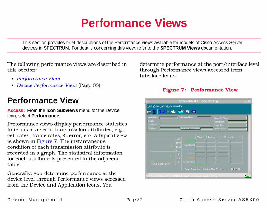
D e v i c e M a n a g e m e n t Page 82 C i s c o A c c e s s S e r v e r A S 5 X 0 0
Performance Views
This section provides brief descriptions of the Performance views available for models of Cisco Access Server devices in SPECTRUM. For details concerning this view, refer to the SPECTRUM Views documentation.
The following performance views are described in this section:
• Performance View• Device Performance View (Page 83)
Performance ViewAccess: From the Icon Subviews menu for the Device icon, select Performance.
Performance views display performance statistics in terms of a set of transmission attributes, e.g., cell rates, frame rates, % error, etc. A typical view is shown in Figure 7. The instantaneous condition of each transmission attribute is recorded in a graph. The statistical information for each attribute is presented in the adjacent table.
Generally, you determine performance at the device level through Performance views accessed from the Device and Application icons. You
determine performance at the port/interface level through Performance views accessed from Interface icons.
Figure 7: Performance View
SpectroGRAPH: Type Routing
Model Name
Contact
Description
Location
Network Address System Up Time
Manufacturer
Device Type
Serial Number
Log
100.0
10.00
1.00
0.10
0.01
000:40:0 0:30:0 0:20:0
Value Average Peak Value
* Frame Rate
% Delivered
% Forwarded
% Transmit
% Error
DetailGraph Properties Scroll to Date-Time
File View Tools Bookmarks
% Discarded*Frames per second
type routing of type IP Routing of Landscape node: Primary
Primary Application

P e r f o r m a n c e V i e w s D e v i c e P e r f o r m a n c e V i e w
D e v i c e M a n a g e m e n t Page 83 C i s c o A c c e s s S e r v e r A S 5 X 0 0
Device Performance ViewAccess: From the Icon Subviews menu for the Device icon, select Device Performance.t
This view (Figure 8) includes both a graph and a table that show current, average, and peak values for the following performance statistics:
• CPU Utilization• 1 Minute Average• 5 Minute Average
The view also provides button access to the Enterprise Alarm Manager and the Event Log.
Figure 8: Device Performance View
Note:Note:
For devices with firmware greater than 12.0, selecting Device Performance opens the Cisco Processes CPU Statistics Table View (Page 84). Log
100.0
10.00
1.00
0.10
0.01
000:40:0 0:30:0 0:20:0
Value Average Peak Value
1 Minute Average
5 Minute Average
Events
Graph Properties Scroll to Date-Time
of Type Rtr_Cisco of Landscape : Primary
Primary Application
System Up Time
Manufacturer
Device Type
Serial Number
Network Address
CPU Utilization
Model NameContactDescriptionLocation
File View Help Tools
Alarms
Primary Address
Bookmarks
SpectroGRAPH:
Hardware Type
Cisco Device Performance Viewi

P e r f o r m a n c e V i e w s D e v i c e P e r f o r m a n c e V i e w
D e v i c e M a n a g e m e n t Page 84 C i s c o A c c e s s S e r v e r A S 5 X 0 0
Cisco Processes CPU Statistics Table ViewThis table displays overall CPU statistics. Column headings are as follows.
CPUAn index that uniquely represents a CPU (or group of CPUs) whose load information is reported by a row in this table. This index is assigned arbitrarily by the engine and is not saved over reboots.
Physical IndexThe physical entity for which the CPU statistics in this entry are maintained. The physical entity can be a CPU chip, a group of CPUs, a CPU card etc. The exact type of this entity is described by its entPhysicalVendorType value. If the CPU statistics in this entry correspond to more than one physical entity (or to no physical entity), or if the entPhysicalTable is not supported on the SNMP agent, the value of this field must be zero.
5 Sec Busy %The overall CPU busy percentage in the last 5 second period.
1 Min Busy %The overall CPU busy percentage in the last 1 minute period.
5 Min Busy %The overall CPU busy percentage in the last 5 minute period.

D e v i c e M a n a g e m e n t Page 85 C i s c o A c c e s s S e r v e r A S 5 X 0 0
Configuration View
This section describes the Configuration view accessible from the Device icon.
Configuration views allow you to view and modify current settings for the modeled device and its interfaces, ports, and applications.
Figure 9: Device Configuration View
Device Configuration ViewA typical Device Configuration view is shown in Figure 9. Generally, this view includes a few fields that display device information as well as an Interface Configuration Table that lists interface parameters, some of which can be changed (see SPECTRUM Views). Some Device Configuration views include one or more buttons that provide access to device-specific configuration information. These are described below.
Access Server of Type AS5X00 of Landscape X: Primary
Primary Application
System Up TimeManufacturerDevice TypeSerial Number
Network AddressModel ContactDescriptionLocation
File View Help Tools
Contact Status
Host Name
Primary Address
Number of Interfaces
Domain Name
Cisco Configuration View
Boot Host
Why Last Reload
Bootstrap Revision
Authentication Fail
Full DescriptionCisco Internet Operating System SoftwareIOS (tm) 4000 Software (XX-BPX), Version 10.2(2). Release Sftwre
Discover/Reconfigure Control IF Address Translation Buffer Management Network/Host Config
Interface Configuration TableSort Find Update
Bookmarks
i
SpectroGRAPH: 132.127.118.24

C o n f i g u r a t i o n V i e w D e v i c e C o n f i g u r a t i o n V i e w
D e v i c e M a n a g e m e n t Page 86 C i s c o A c c e s s S e r v e r A S 5 X 0 0
This button opens the Redundancy and Model Reconfiguration Options.
This button opens the Interface Address Translation Table View (Page 88).
This button opens the Cisco Buffer Management View (Page 88), which provides data information for network traffic to the Cisco Access Server. It counts IP Packets received and tracks activity for the various buffers.
This button opens the Network/Host Configuration View (Page 91).
This button opens the Cisco Running Config Event/Alarm Configuration View (Page 93).
Redundancy and Model Reconfiguration OptionsThis view allows you to enable redundant addresses, have SPECTRUM notify you of a redundancy update, and reconfigure aspects of your network connections.
This button opens the Preferred Addresses dialog box which allows you to select the redundant preferred address for the device.
Redundancy Administrative StatusSet this button to “Enabled” to cause SPECTRUM to update this model with an address from the Redundant Preferred Address list when the primary address is not accessible.
Generate Redundancy AlarmsSet this button to “True” to cause SPECTRUM to generate an alarm when a redundant address is selected.
Note:Note:
For Cisco devices that have firmware 12.0 or greater, see Page 94 for additional configuration views.
Discover/Reconfigure Control
IF Address Translation
Buffer Management
Network/Host Config
Running Configuration Changes
Preferred Addresses

C o n f i g u r a t i o n V i e w D e v i c e C o n f i g u r a t i o n V i e w
D e v i c e M a n a g e m e n t Page 87 C i s c o A c c e s s S e r v e r A S 5 X 0 0
Automatically Reconfigure InterfacesSet this button to “True” to cause SPECTRUM to monitor the number of interfaces for this device. If a change is detected by SPECTRUM, the interfaces displayed in SPECTRUM are updated to reflect the change.
Create Sub-InterfacesSet this button to determine if SPECTRUM should model its sub-interfaces. If set to “True”, these models will be displayed in the Sub-Interface view of the Physical Interface model.
Reconfigure due to LINK UP/Down eventsSet this button to “True” to cause SPECTRUM to verify the interfaces displayed when a LINK UP or LINK DOWN event is received.
Topologically Relocate ModelSet this button to “True” to allow SPECTRUM to relocate the model to a different topological location as part of the AutoDiscovery process.
Device Discovery after ReconfigurationSet this button to “True” to cause SPECTRUM to verify the interfaces displayed after a model reconfiguration occurs.
This button does a complete re-read of the device and its ports. The SpectroSERVER information for this device will be updated if any of the port addresses have been changed or removed, or if the port type has been changed.
This button discovers the devices that are connected to the ports for this device. Clicking on this button will create all LANS which are defined for each port.
Reconfigure Model
Discover LANs

C o n f i g u r a t i o n V i e w D e v i c e C o n f i g u r a t i o n V i e w
D e v i c e M a n a g e m e n t Page 88 C i s c o A c c e s s S e r v e r A S 5 X 0 0
Interface Address Translation Table ViewThis view cross-references device IP addresses to device MAC addresses for selected nodes between networks. Double-clicking on any column entry opens an address-specific Address Translation Table Information view allowing you to modify each of the three fields for that entry.
Cisco Buffer Management ViewThis view provides the following information:
Free MemoryThe amount of available memory in bytes.
Buffer FailuresThe number of packets discarded due to no memory. An attempted packet buffer allocation failed.
Buffer No MemoryThe number of buffer creation failures due to no memory.
Max Buffer ElementsThe maximum number of buffer elements the Cisco Router may create.
Buffer ElementsThis area of the Cisco Buffer Management view displays statistics on buffer “elements” (data structures used to enqueue buffers in multiple output queues). Each attribute is summarized for two intervals: total interval since first poll and rate interval between polls (Delta).
Buffer Elements FreeThe number of buffer elements available.
Buffer Element HitsThe number of successful requests for buffer elements.
Buffer Element MissesThe number of unsuccessful requests for buffer elements.
Buffer Element CreatesThe number of new buffer elements created by the Cisco Router.
Buffer Management ButtonsThese five buttons located in the Cisco Buffer Management view allow you to access additional buffer management information according to buffer size. Each attribute is summarized for the total interval since first poll and the rate interval between polls (Delta).

C o n f i g u r a t i o n V i e w D e v i c e C o n f i g u r a t i o n V i e w
D e v i c e M a n a g e m e n t Page 89 C i s c o A c c e s s S e r v e r A S 5 X 0 0
This button opens the Small Buffer Management view. Table 22 provides the information displayed in this view.
This button opens the Cisco Medium Buffer Management view. Table 23 provides the information displayed in this view.
Small Buffers
Table 22: Small Buffers View Fields
Field Description
Small Buffer Size The maximum size of a small buffer
Max Small Buffers The maximum number of small buffers the Cisco Access Server may create.
Small Buffer Total The total number of enqueued small buffers.
Small Buffer Free The number of small buffers available.
Small Buffer Hits The number of successful requests for small buffers.
Small Buffer Misses The number of unsuccessful requests for small buffers.
Small Buffer Creates The number of new small buffers created by the Cisco Access Server.
Small Buffer Trims The number of small buffers returned to the free buffer pool.
Medium Buffers
Table 23: Medium Buffers View Fields
Field Description
Medium Buffer Size The maximum size of a medium buffer.
Max Medium Buffers The maximum number of medium buffers the Cisco Access Server may create.
Medium Buffer Total The total number of enqueued medium buffers.
Medium Buffer Free The number of medium buffers available.
Medium Buffer Hits The number of successful requests for medium buffers.
Medium Buffer Misses
The number of unsuccessful requests for medium buffers.
Medium Buffer Creates
The number of new medium buffers created by the Cisco Access Server.
Medium Buffer Trims
The number of medium buffers returned to the free buffer pool.

C o n f i g u r a t i o n V i e w D e v i c e C o n f i g u r a t i o n V i e w
D e v i c e M a n a g e m e n t Page 90 C i s c o A c c e s s S e r v e r A S 5 X 0 0
The button opens the Big Buffers view. Table 24 provides the information displayed in the Big Buffers View.
This button opens the Cisco Large Buffer Management view. Table 25 provides the information displayed in this view.
Big Buffers
Table 24: Big Buffers View Fields
Field Description
Big Buffer Size The maximum size of a big buffer.
Max Big Buffers The maximum number of big buffers the Cisco Access Server may create.
Big Buffer Total The total number of enqueued big buffers.
Big Buffer Free The number of big buffers available.
Big Buffer Hits The number of successful requests for big buffers.
Big Buffer Misses The number of unsuccessful requests for big buffers.
Big Buffer Creates The number of new big buffers created by the Cisco Access Server.
Big Buffer Trims The number of big buffers returned to the free buffer pool.
Large Buffers
Table 25: Large Buffers View Fields
Field Description
Large Buffer Size The maximum number of bytes in a large buffer.
Max Large Buffers The maximum number of large buffers the Cisco Access Server may create.
Large Buffer Total The total number of enqueued large buffers.
Large Buffer Free The number of large buffers available.
Large Buffer Hits The number of successful requests for large buffers.
Large Buffer Misses The number of unsuccessful requests for large buffers.
Large Buffer Creates The number of new large buffers created by the Cisco Access Server.
Large Buffer Trims The number of large buffers returned to the free buffer pool.

C o n f i g u r a t i o n V i e w D e v i c e C o n f i g u r a t i o n V i e w
D e v i c e M a n a g e m e n t Page 91 C i s c o A c c e s s S e r v e r A S 5 X 0 0
This button opens the Cisco Huge Buffer Management view. Table 26 provides the information displayed in this view.
Network/Host Configuration ViewThis view displays the following information:
Network ConfigurationThe network configuration file contains commands that apply to all network servers and terminal services on a network.
Previous Host AddrProvides the address of the host that supplied the network configuration file for the managed device.
Previous File NameProvides the name of the network configuration file that resides on the managed device.
New Host AddrThis field replaces the Previous Host Addr field (when the Upload Net Config File is selected).
New File NameThis field replaces the Previous File Name field (when the Upload Net Config File is selected).
Initiates the transfer of configuration file from host to server.
TFTP Server AddrSends the configuration file from server to a host.
Huge Buffers
Table 26: Huge Buffers View Fields
Field Description
Huge Buffer Size The maximum number of bytes in a huge buffer.
Max Huge Buffers The maximum number of huge buffers the Cisco Access Server may create.
Huge Buffer Total The total number of enqueued huge buffers.
Huge Buffer Free The number of huge buffers available.
Huge Buffer Hits The number of successful requests for huge buffers.
Huge Buffer Misses The number of unsuccessful requests for huge buffers.
Huge Buffer Creates The number of new huge buffers created by the Cisco Access Server.
Huge Buffer Trims The number of huge buffers returned to the free buffer pool.
Upload Net Config File

C o n f i g u r a t i o n V i e w D e v i c e C o n f i g u r a t i o n V i e w
D e v i c e M a n a g e m e n t Page 92 C i s c o A c c e s s S e r v e r A S 5 X 0 0
File NameThe file name where you are storing the configuration.
Initiates the transfer of configuration file from server to host.
Host ConfigurationThe host configuration file contains commands that apply to one network server in particular.
Previous Host AddrProvides the address of the host that provided the host configuration file for the managed device.
Previous File NameProvides the name of the last host configuration file used by the device.
New Host AddrThis field replaces the Previous Host Addr field (when the Upload Host Config File is selected).
New File NameThis field replaces the Previous File Name field (when the Upload Host Config File is selected).
Initiates the transfer of configuration file from host to server.
When you select this button, the current (running) server configuration is written into Non-Volatile Random Access Memory (NVRAM) where it can be stored and retained even if the server is reloaded.
When you select this button, whatever was in Non-Volatile Random Access Memory (NVRAM) on the server is erased.
Copy Config to Net
Upload Host Config File
Copy Config to NVRAM
Clear NVRAM
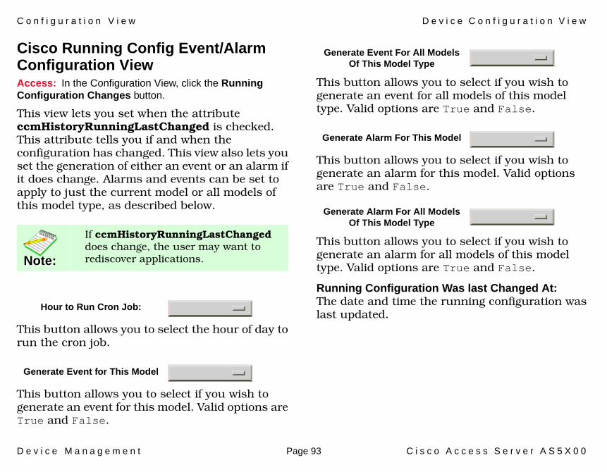
C o n f i g u r a t i o n V i e w D e v i c e C o n f i g u r a t i o n V i e w
D e v i c e M a n a g e m e n t Page 93 C i s c o A c c e s s S e r v e r A S 5 X 0 0
Cisco Running Config Event/Alarm Configuration ViewAccess: In the Configuration View, click the Running Configuration Changes button.
This view lets you set when the attribute ccmHistoryRunningLastChanged is checked. This attribute tells you if and when the configuration has changed. This view also lets you set the generation of either an event or an alarm if it does change. Alarms and events can be set to apply to just the current model or all models of this model type, as described below.
This button allows you to select the hour of day to run the cron job.
This button allows you to select if you wish to generate an event for this model. Valid options are True and False.
This button allows you to select if you wish to generate an event for all models of this model type. Valid options are True and False.
This button allows you to select if you wish to generate an alarm for this model. Valid options are True and False.
This button allows you to select if you wish to generate an alarm for all models of this model type. Valid options are True and False.
Running Configuration Was last Changed At:The date and time the running configuration was last updated.
Note:Note:
If ccmHistoryRunningLastChanged does change, the user may want to rediscover applications.
Hour to Run Cron Job:
Generate Event for This Model
Generate Event For All Models Of This Model Type
Generate Alarm For This Model
Generate Alarm For All Models Of This Model Type
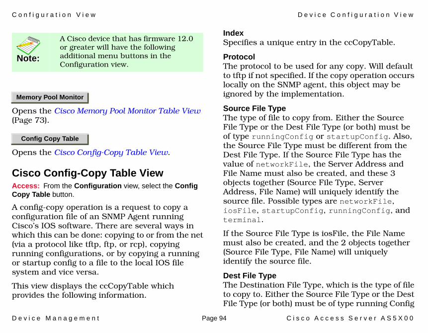
C o n f i g u r a t i o n V i e w D e v i c e C o n f i g u r a t i o n V i e w
D e v i c e M a n a g e m e n t Page 94 C i s c o A c c e s s S e r v e r A S 5 X 0 0
Opens the Cisco Memory Pool Monitor Table View (Page 73).
Opens the Cisco Config-Copy Table View.
Cisco Config-Copy Table ViewAccess: From the Configuration view, select the Config Copy Table button.
A config-copy operation is a request to copy a configuration file of an SNMP Agent running Cisco’s IOS software. There are several ways in which this can be done: copying to or from the net (via a protocol like tftp, ftp, or rcp), copying running configurations, or by copying a running or startup config to a file to the local IOS file system and vice versa.
This view displays the ccCopyTable which provides the following information.
IndexSpecifies a unique entry in the ccCopyTable.
ProtocolThe protocol to be used for any copy. Will default to tftp if not specified. If the copy operation occurs locally on the SNMP agent, this object may be ignored by the implementation.
Source File TypeThe type of file to copy from. Either the Source File Type or the Dest File Type (or both) must be of type runningConfig or startupConfig. Also, the Source File Type must be different from the Dest File Type. If the Source File Type has the value of networkFile, the Server Address and File Name must also be created, and these 3 objects together (Source File Type, Server Address, File Name) will uniquely identify the source file. Possible types are networkFile, iosFile, startupConfig, runningConfig, and terminal.
If the Source File Type is iosFile, the File Name must also be created, and the 2 objects together (Source File Type, File Name) will uniquely identify the source file.
Dest File TypeThe Destination File Type, which is the type of file to copy to. Either the Source File Type or the Dest File Type (or both) must be of type running Config
Note:Note:
A Cisco device that has firmware 12.0 or greater will have the following additional menu buttons in the Configuration view.
Memory Pool Monitor
Config Copy Table

C o n f i g u r a t i o n V i e w D e v i c e C o n f i g u r a t i o n V i e w
D e v i c e M a n a g e m e n t Page 95 C i s c o A c c e s s S e r v e r A S 5 X 0 0
or startupConfig. Also, the Source File Type must be different from the Dest File Type. If the Dest File Type has the value of network File, the Server Address and File Name must also be created, and these three objects together (Dest File Type, Server Address, File Name) will uniquely identify the destination file. If the Dest File Type is iosFile, the File Name must also be created, and the two objects together (Dest File Type, File Name) will uniquely identify the destination file. Possible types are networkFile, iosFile, startupConfig, runningConfig, and terminal.
Server AddressThe IP address of the TFTP server from (or to) which to copy the configuration file. This object must be created when either the Source File Type or Dest File Type has the value networkFile. Values of 0.0.0.0 or FF.FF.FF.FF. for Server Address are not allowed.
File NameThe file name (including the path, if applicable) of the file. This object must be created when either the Source File or Dest File Type has the value networkFile or iosFile.
User NameRemote user name for copy via rcp protocol. This object must be created when the Protocol is rcp or ftp. If the protocol is rcp, it will override the
remote user name configured through the rcmd remote-username configuration command. The remote user name is sent as the server user-name in an rcp command request sent by the system to a remote rcp server.
User PasswordPassword used by ftp for copying a file to/from an ftp server. This object must be created when the Protocol is ftp. Reading it returns a zero-length string for security reasons.
Notification On CompletionSpecifies whether or not a Notification on Completion should be issued on completion of the tftp transfer. If such a notification is desired, it is the responsibility of the management entity to ensure that the SNMP administrative model is configured in such a way as to allow the notification to be delivered.
StateThe state of this config-copy request. This value of this object is instantiated only after the row has been instantiated, i.e., after the Row Status has been made active.
Time StartedThe time the Copy State last transitioned to running, or 0 if the state has never transitioned to running (for e.g., stuck in waiting state). This

C o n f i g u r a t i o n V i e w D e v i c e C o n f i g u r a t i o n V i e w
D e v i c e M a n a g e m e n t Page 96 C i s c o A c c e s s S e r v e r A S 5 X 0 0
object is instantiated only after the row has been instantiated.
Time CompletedThe time the Copy State last transitioned from running to successful or failed states. This object is instantiated only after the row has been instantiated. Its value will remain 0 until the request has completed.
Fail ReasonThe reason why the config-copy operation failed. This object is instantiated only when the Copy State for this entry is in the failed state.
Row StatusThe status of this table entry. Once the entry status is set to active, the associated entry cannot be modified until the request completes (Copy State transitions to successful or failed state).
Add an EntryThis button opens the Add a Cisco Copy Config Entry view which allows you to add an entry to the Cisco Copy Config Table.

D e v i c e M a n a g e m e n t Page 97 C i s c o A c c e s s S e r v e r A S 5 X 0 0
Model Information View
This section provides a brief overview of the Model Information view.
Model Information views display administrative information about devices and their applications and let you set thresholds and alarm severity for the devices.
Figure 10 shows a sample Model Information view. The layout of this view is the same for all model types in SPECTRUM but some information will vary depending on the model it defines. Refer to the SPECTRUM Views documentation for a complete description of this view.
Figure 10: Model Information View
Model Name ContactDescriptionLocation
SpectroGRAPH: Model Name
File View Tools Bookmarks Help
IP Address of Model Type of Landscape: Primary
ManufacturerSysUpTime
Net AddressDevice TypeSerial Number
Model Information View
MM Name
MM Part Number
MM Version Type
Model Type
Model Creation Time
Model Created By
Model State
Security String
Communication Information
Poll / Log Information
Condition Value
Contact Status
DCM TimeOut
DCM Retry
Lost Child Count
Value When Yellow
Value When OrangeValue When Red
Community Name
Mgnmt Protocol
Poll Interval
Poll Status
Log Ratio
Last Successful Poll
Logged Polled
True
Condition Value

D e v i c e M a n a g e m e n t Page 98 C i s c o A c c e s s S e r v e r A S 5 X 0 0
Index
Symbols# Connect 72
Numerics1 Min Busy % 845 Min Busy % 845 Sec Busy % 84
AAdd an Entry button 54Address
Interface IP 14Physical (MAC) 14
Address Translation Table 15Admin Status 13Alternate 73AppleTalk
Address Resolution Protocol 25Datagram Delivery Protocol 24Echo 24Name Binding Protocol 24Routing
Table Management Protocol 24
Table View 24Transaction Protocol 24Zone Information Protocol 24
AppleTalk Routing Application Views 24
ARP 25Probe 25Replies 25Request 25
ATM Client Application 56ATM Link Modeling Options 57Configuration 59Performance 59VCL Table 56
ATM Link Modeling Options ViewConfig Interval 58Create Link Models 58Create VCL Models 58Option Explanations 58Reconfigure Now 58
ATP 24Receives 24
BB-casts Forwarded 32Big Buffers button 90Bridging
Application Views 73Broadcasts 31BSC 32BSTUN Groups View 32BSTUN Ports View 33BSTUN Routes View 34Buffer
Allocation 26Buffer Elements 88Buffer Management 86, 88
CccmHistoryRunningLastChanged 9
3CDP Application 70Chassis
ID/Serial No. 38Information 38Type 38
Chassis Application 37Chassis Card View 37
I n d e x I n d e x
D e v i c e M a n a g e m e n t Page 99 C i s c o A c c e s s S e r v e r A S 5 X 0 0
Chassis General Information View 38
Chassis Information 38RAM Information 39ROM Information 38
Chassis Views 20CheckSum 26Cisco
Channel Application 70Chassis
Card View 37General Information View 38
FlashApplication Views 48
Terminal ServerLine View 70Session View 70, 72
Cisco Applications (5127) guide 81Cisco Buffer Management View 88Cisco Chassis Card View 37Cisco Interface Application 70Cisco Network Info 15Cisco Other Info 15Cisco Router Info 15Cisco RTT-Mon Application 74Cisco STUN Application 34Cisco Syslog Application 81Cisco Traffic Info 15Cisco_AS5100 7Cisco_AS5200 7Cisco_AS5300 7Cisco_AS5800 7
CiscoChasApp 37, 48, 52CiscoFddiApp 62, 64CiscoTSApp 70CiscoXNSApp 32CiscSysLogApp 81Config
Register 39Configuration 59Configuration View 85CPU 84Create Interface Applications 74Create Sub-Interface
Applications 74CsEvFormat 9Current
Sess 72
DDDP 24
Bad 24Long 24Short 24
Delivered 25Description 37Discard 25Disconnect Reasons 42Discover LANs 87Discover/Reconfigure Control
button 86Discovery Application
Cache Table View 62Interface Discovery Status
Table 63Documentation 6DSIAPP1406 Application 64
DSI Fractional Table 68DSPU Application 70
EECEditor 9Echo
Count 31In 29Out 29Receives 24
Encap Fail 26Encapsulation
Failure 26Type 31
EnvMon Application 60Power Supply Status 61Temperature Status 61Voltage Status 62
Errors 25event messages 9
FFacilities Data Link Codes 68

I n d e x I n d e x
D e v i c e M a n a g e m e n t Page 100 C i s c o A c c e s s S e r v e r A S 5 X 0 0
FlashSize 49
Flash Application 48Flash Configuration View 48Flash Copy Operations Table
View 49Flash Device Chip Properties Table
View 49Flash Device Partition Properties
Table View 51Flash Device Properties Table
View 50Flash File Properties Table View 50Flash Memory
Available (Bytes) 49Total Size (Bytes) 49
Flash Miscellaneous Operations Table View 51
Flash Partitioning Operations Table View 52
Flow Control 71Format Error 31Forward 25, 30Forwarded 31Free 74
GGeneral Information View 37Generic Routing
Sub-Applications 24
GenRtrApp 23
HHardware
Revision Level 38Ver. 37
Hop Count 26Huge Buffers button 91
IIcon Subviews Menu Options 15Icons
Interface, Device View 13ICP
In 30Out 30
Idle T-out 72IF Address Translation button 86Illegal Echos 25Interface
Detail view 15Type, Device 13
Interface Address Translation Table View 88
Interface Configuration 15Interface Ethernet Application 70IPC
Count 31
Error Count 31
LLAN
ONLY 30Large Buffers button 90Largest Free 74Line Statuses 66Line Type 64Local Destination 31Location 71Loopback Configurations 66
MMAC
In 29Out 29
Medium Buffers button 89Metric Out 30Model
Information 97Model Information 15Modem Control 71Modem Line Configuration Table
View 44Modem Line Speed Statistics Table
View 48

I n d e x I n d e x
D e v i c e M a n a g e m e n t Page 101 C i s c o A c c e s s S e r v e r A S 5 X 0 0
Modem Line Statistics Table View 46
Modem States 41
NNBP 24
Receives 24Sent 24
NetworkType 14
Network/Host Config button 86Network/Host Configuration
View 91No
Access 26Buffer 26Charge 30Routes 26
Non-volatile RAMSize (bytes) 39Used (bytes) 39
NotForward 30LAN 30
NovellAccounting Table 28Check Point Accounting Table 28Check Point Information 27IPX Accounting Information 28SAP
Statistics 27View 27
Service Advertisement Protocol View 27
Novell Internet Packet Exchange View 27
Novell Routing Application 27Number
of Chassis Slots 38
OOVER 4800 BPS 30
PPerformance View 82Physical Index 84Ping Application 52Ping Request Table View 52Port Number, Device 13Power Supply Status 61Preferred Addresses 86Proxy Count 31
QQueue Application 54Queue Interface View 54
Queue Rotation Interface View 55Queue Statistics View 55
RRAM Information 39Received 30Reconfigure Model 87Redundancy and Model
Reconfiguration Options 86Replies
Rec 32Sent 32
RequestOut 32Rec 32
ROMInformation 38Monitor Version 38Software Version 38
Routing Protocol Comparison View 23, 24
RTMP 24Receives 24Sent 24
Running Configuration Changes 93
SSAP

I n d e x I n d e x
D e v i c e M a n a g e m e n t Page 102 C i s c o A c c e s s S e r v e r A S 5 X 0 0
Replies Sent 27Requests
Rec 27Sent 27
Responses Rec 27Secondary Address Panel 15Send Codes 65Serial Number 37Sess T-out 72Session
Table 72View 72
Signal Modes 67Slot 37Small Buffers button 89SMT
Table 62SMT Table View 62Software
Ver. 37SPECTRUM Model 7Speed
In 71Out 71
State 62Status 71STUN Groups View 35STUN Ports View 35STUN Routes View 36Sub-Interfaces 15Supported Devices 7Syslog Trap Support 81
SystemCPU RAM (bytes) 39
TTemperature Status 61Term Type 71Terminal Server
Line View 71Session View 72
Terminal Server Application 70Line Configuration View 70Terminal Server Line View 71Terminal Server Session View 72
Thresholds 15T-Neg 62Transmit Clock Sources 67Transmitted 25, 30Trap Configuration 15TS Session Table 72Type 37, 71
UUnicasts 31Unknown 26Used 74
VValid 74VCL Table 56Vines
BroadcastDetail View 30Packets 30Statistics 30
EchoPackets 29Statistics 29
ICP 30Metric Notification 30Packets 30Statistics 30
Interprocess Communications Protocol 30
RoutingEcho View 29ICP View 30
Rx View 31Tx View 31
Vines Routing Application 29Voltage Status 62
XXNS
EchoReply 32

I n d e x I n d e x
D e v i c e M a n a g e m e n t Page 103 C i s c o A c c e s s S e r v e r A S 5 X 0 0
Echo Statistics 32Routing
Application Views 32
ZZero Codes 64ZIP 24
Received 24Sent 24