Embed Size (px)
Citation preview
Americas HeadquartersCisco Systems, Inc.170 West Tasman DriveSan Jose, CA 95134-1706 USAhttp://www.cisco.comTel: 408 526-4000
800 553-NETS (6387)Fax: 408 527-0883
Cisco 900 Series Integrated Services Routers Software Configuration GuideJune 6, 2019

Cisco and the Cisco logo are trademarks or registered trademarks of Cisco and/or its affiliates in the U.S. and other countries. To view a list of Cisco trademarks, go to this URL: www.cisco.com/go/trademarks. Third-party trademarks mentioned are the property of their respective owners. The use of the word partner does not imply a partnership relationship between Cisco and any other company. (1721R)
Cisco 900 Series, Integrated Services Routers Software Configuration Guide© 2019 Cisco Systems, Inc. All rights reserved.
iiiCisco 900 Series Integrated Services Routers Software Configuration Guide
C O N T E N T S
Preface ix
Objectives ix
Audience ix
Organization ix
Conventions x
Related Documentation xi
Obtaining Documentation and Submitting a Service Request xi
Cisco 900 Series Integrated Services Routers Overview 1-1
Overview of the Cisco 900 Series ISR 1-1
Cisco 900 Series ISR Models 1-2
Cisco 900 Series ISR Features 1-3
LEDs on the Cisco 900 Series ISR 1-3
IOS Images for Cisco 900 Series ISRs 1-4
Installing the Software 2-5
ROM Monitor 2-5
ROM Monitor Mode Command Prompt 2-5
Why is the Router in ROM Monitor Mode? 2-5
When do I use ROM Monitor? 2-6
Tips for Using ROM Monitor Commands 2-6
How to Use the ROM Monitor—Typical Tasks 2-6
Entering ROM Monitor Mode 2-7
Modifying the Configuration Register (confreg) 2-8
Obtaining Information on USB Flash Devices 2-9
Exiting ROM Monitor Mode 2-10
Upgrading ROMMON using Capsule Upgrade 2-10
Upgrading the Cisco IOS Software 2-11
Information About Upgrading the System Image 2-11
Why Would I Upgrade the System Image? 2-11
Which Cisco IOS Release Is Running on My Router Now? 2-11
How Do I Choose the New Cisco IOS Release and Feature Set? 2-11
Where Do I Download the System Image? 2-12
How to Upgrade the Cisco IOS Image 2-12
Contents
ivCisco 900 Series Integrated Services Routers Software Configuration Guide
Saving Backup Copies of Your Old System Image and Configuration 2-12
Copying the System Image into Flash Memory 2-13
Loading the New System Image 2-16
Saving Backup Copies of Your New System Image and Configuration 2-19
Licensing 2-21
Basic Router Configuration 3-23
Default Configuration 3-24
Configuring Global Parameters 3-25
Configuring I/O Memory Allocation 3-26
Interface Ports 3-27
Configuring Gigabit Ethernet Interfaces 3-27
Configuring a Loopback Interface 3-28
Configuring Command-Line Access 3-29
Configuring Static Routes 3-29
Configuring Dynamic Routes 3-30
Configuring Routing Information Protocol 3-30
Configuring Enhanced Interior Gateway Routing Protocol 3-31
Configuring Ethernet Switches 4-33
Configuring VLANs 4-33
Example: VLAN configuration 4-34
Configuring VTP 4-34
Example: Configuring VTP 4-35
Configuring 802.1x Authentication 4-35
Example: Enabling IEEE 802.1x and AAA on a Switch Port 4-36
Configuring Spanning Tree Protocol 4-36
Example: Spanning Tree Protocol Configuration 4-37
Configuring MAC Address Table Manipulation 4-38
Example: MAC Address Table Manipulation 4-38
Configuring MAC Address Notification Traps 4-39
Example: Configuring MAC Address Notification Traps 4-39
Configuring the Switched Port Analyzer 4-39
Example: SPAN Configuration 4-40
Configuring IGMP Snooping 4-40
Example: Configuring IGMP Snooping 4-40
Configuring Per-Port Storm Control 4-41
Example: Per-Port Storm-Control 4-41
Configuring HSRP 4-42
Contents
vCisco 900 Series Integrated Services Routers Software Configuration Guide
Example: Configuring HSRP 4-42
Configuring VRRP 4-43
Example: Configuring VRRP 4-43
Configuring PPP over Ethernet with NAT 5-45
Configuring the Virtual Private Dialup Network Group Number 5-46
Configuring Ethernet WAN Interfaces 5-46
Configuring the Dialer Interface 5-47
Configuring Network Address Translation 5-47
Configuration Example 5-48
Verifying Your Configuration 5-49
Configuring a LAN with DHCP and VLANs 6-51
Configuring DHCP 6-52
Configuring VLANs 6-53
Assign a Switch Port to a VLAN 6-53
Configuring Identity Features on Layer 3 Interface 7-57
Authentication Methods 7-57
Configuring the IEEE 802.1X 7-58
Configuring the MAC Authentication Bypass (MAB) 7-58
Controlling Port Authorization State 7-59
Configuring the Controlling Port Authorization State 7-60
Flexible Authentication 7-61
Configuring Flexible Authentication 7-61
Host mode 7-61
Open Access 7-62
Configuring Open Access 7-62
Control-Direction (Wake-on-LAN) 7-62
Configuring Control-Direction (Wake-on-LAN) 7-62
Preauthentication Access Control List 7-64
Configuring the Preauthentication Access Control List 7-64
Downloadable Access Control List 7-65
Filter-ID or Named Access Control List 7-65
IP Device Tracking 7-65
Configuring Security Features 8-67
Configuring SSL VPN 8-67
Authentication, Authorization, and Accounting 8-68
Contents
viCisco 900 Series Integrated Services Routers Software Configuration Guide
Configuring AutoSecure 8-68
Configuring Access Lists 8-68
Access Groups 8-69
Configuring Cisco IOS Firewall 8-69
Zone-Based Policy Firewall 8-70
Configuring Cisco IOS IPS 8-70
Content Filtering 8-71
Configuring VPN 8-71
Configuring Dynamic Multipoint VPN 8-74
Configuring Group Encrypted Transport VPN 8-74
SGT over Ethernet Tagging 8-74
Crypto Engine Throughput Policing 8-75
Configuring VDSL2 and ADSL2/2+ 9-79
Overview 9-79
Configuring DSL 9-80
DSL Configuration Restrictions 9-80
Configuring ADSL Mode 9-81
Configuring ADSL Auto Mode 9-81
Configuring CPE and Peer for ADSL Mode 9-81
ADSL Configuration Example 9-82
Verifying ADSL Configuration 9-84
Verifying CPE to Peer Connection for ADSL 9-85
Configuring VDSL Mode 9-85
Configuring VDSL Auto Mode 9-85
Configuring CPE and Peer for VDSL Mode 9-86
VDSL Configuration Example 9-86
Verifying VDSL Configuration 9-88
Verifying CPE to Peer Connection for VDSL 9-89
Configuring VLAN 0 Priority Tagging 9-90
Enabling ADSL2/2+ Annex M Mode on Over POTS VDSL2/ADSL Multimode Annex A SKUs 9-90
Enabling Seamless Rate Adaption 9-91
Configuring UBR+ 9-91
Troubleshooting 9-91
Collecting DSL Training Logs 9-92
Upgrading DSL Firmware 9-92
Configuring 4G Wireless WAN 10-95
Overview of 4G LTE 10-95
Contents
viiCisco 900 Series Integrated Services Routers Software Configuration Guide
Cisco 4G LTE Features 10-97
Prerequisites for Configuring Cisco 4G LTE 10-98
Restrictions for Configuring Cisco 4G LTE 10-98
How to Configure Cisco 4G LTE 10-98
Verifying Modem Signal Strength and Service Availability 10-99
Creating, Modifying, or Deleting Modem Data Profiles 10-99
Usage Guidelines for Creating, Modifying, or Deleting Data Profiles 10-100
Configuration Examples 10-100
Configuring a SIM for Data Calls 10-101
Locking and Unlocking a SIM Card Using a PIN Code 10-101
Changing the PIN Code 10-101
Verifying the Security Information of a Modem 10-101
Configuring Automatic Authentication for a Locked SIM 10-101
Configuring an Encrypted PIN for a SIM 10-102
Applying a Modem Profile in a SIM Configuration 10-102
Data Call Setup 10-103
Configuring the Cellular Interface 10-103
Configuring DDR 10-104
Configuring DDR Backup 10-104
Configuring 4G SMS Messaging 10-104
Upgrading Modem Firmware 10-105
Configuring Modem DM Log Collection 10-106
Enabling Modem Crashdump Collection 10-107
Prerequisites 10-107
Displaying Modem Log Error and Dump Information 10-107
Configuration Examples for 4G LTE 10-108
Example: Basic Cellular Interface Configuration 10-108
Cellular Interface Configuration for Always-On Connection 10-108
Dialer-Watch Configuration without External Dialer Interface 10-109
Dialer-Persistent Configuration with External Dialer Interface 10-109
4G-LTE Wireless WAN as Backup with NAT and IPSec 10-110
SIM Configuration: Examples 10-112
Locking the SIM Card: Example 10-112
Unlocking the SIM Card: Example 10-112
Automatic SIM Authentication: Example 10-113
Changing the PIN Code: Example 10-114
Configuring an Encrypted PIN: Example 10-115
Configuration Examples for 4G Serviceability Enhancement 10-115
Example: Sample Output for the show cellular logs dm-log Command 10-116
Contents
viiiCisco 900 Series Integrated Services Routers Software Configuration Guide
Example: Sample Output for the show cellular logs modem-crashdump Command 10-116
Example: Sample Output for the show cellular log error Command 10-116
Example: Sample Output for the test cellular modem-error-clear Command 10-117
PLMN Search and Selection 10-117
Restrictions 10-117
Commands 10-118
Searching the Network 10-118
Selecting the Network 10-119
Verifying PLMN Selection 10-120
SNMP MIBs 10-120
SNMP 4G LTE Configuration: Example 10-121
Troubleshooting 10-121
Verifying Data Call Setup 10-122
Checking Signal Strength 10-122
Verifying Service Availability 10-122
Successful Call Setup 10-124
Configuring Secure Storage 11-125
Enabling Secure Storage 11-125
Disabling Secure Storage 11-125
Verifying the Status of Encryption 11-126
Verifying the Platform Identity 11-126
Downgrading the Platform Image to an Older Version 11-127
ixCisco 900 Series Integrated Services Routers Software Configuration Guide
Preface
This preface describes the objectives, audience, organization, conventions of this guide, and the references that accompany this document set. The following sections are provided:
• Objectives, page ix
• Audience, page ix
• Organization, page ix
• Conventions, page x
• Related Documentation, page xi
• Obtaining Documentation and Submitting a Service Request, page xi
ObjectivesThis guide provides information about how to configure the various features of Cisco 900 Series integrated services routers (ISRs).
AudienceThis document is written for experienced technical workers who install, monitor, and troubleshoot routers under a service contract, or who work for an information technology (IT) department.
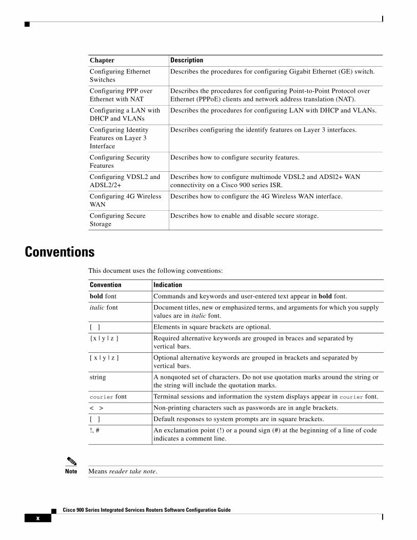
OrganizationThis document is organized into the following chapters:
Chapter Description
Product Overview Provides an overview of the hardware and software features of Cisco 900 Series ISRs.
Installing the Software Describes how to upgrade Cisco IOS image, Field Replaceable units, and use Cisco Licenses.
Basic Router Configuration
Describes how to perform the basic router configuration, interface configuration, and routing configuration.
xCisco 900 Series Integrated Services Routers Software Configuration Guide
ConventionsThis document uses the following conventions:
Note Means reader take note.
Configuring Ethernet Switches
Describes the procedures for configuring Gigabit Ethernet (GE) switch.
Configuring PPP over Ethernet with NAT
Describes the procedures for configuring Point-to-Point Protocol over Ethernet (PPPoE) clients and network address translation (NAT).
Configuring a LAN with DHCP and VLANs
Describes the procedures for configuring LAN with DHCP and VLANs.
Configuring Identity Features on Layer 3 Interface
Describes configuring the identify features on Layer 3 interfaces.
Configuring Security Features
Describes how to configure security features.
Configuring VDSL2 and ADSL2/2+
Describes how to configure multimode VDSL2 and ADSl2+ WAN connectivity on a Cisco 900 series ISR.
Configuring 4G Wireless WAN
Describes how to configure the 4G Wireless WAN interface.
Configuring Secure Storage
Describes how to enable and disable secure storage.
Chapter Description
Convention Indication
bold font Commands and keywords and user-entered text appear in bold font.
italic font Document titles, new or emphasized terms, and arguments for which you supply values are in italic font.
[ ] Elements in square brackets are optional.
{x | y | z } Required alternative keywords are grouped in braces and separated by vertical bars.
[ x | y | z ] Optional alternative keywords are grouped in brackets and separated by vertical bars.
string A nonquoted set of characters. Do not use quotation marks around the string or the string will include the quotation marks.
courier font Terminal sessions and information the system displays appear in courier font.
< > Non-printing characters such as passwords are in angle brackets.
[ ] Default responses to system prompts are in square brackets.
!, # An exclamation point (!) or a pound sign (#) at the beginning of a line of code indicates a comment line.
xiCisco 900 Series Integrated Services Routers Software Configuration Guide
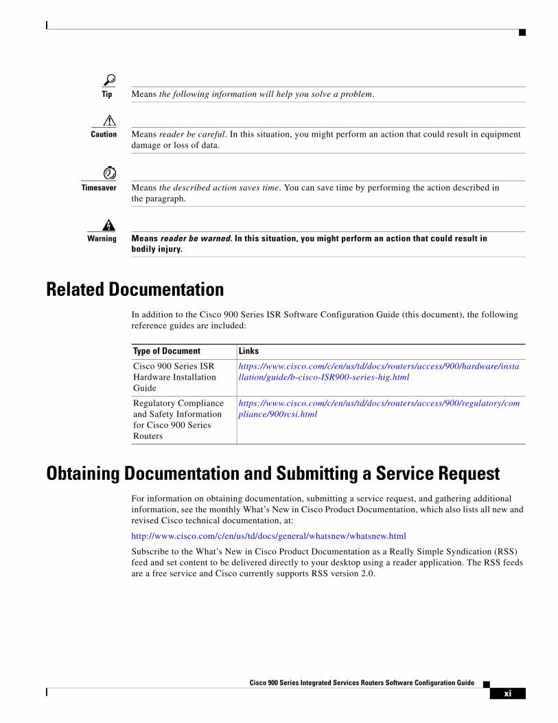
Tip Means the following information will help you solve a problem.
Caution Means reader be careful. In this situation, you might perform an action that could result in equipment damage or loss of data.
Timesaver Means the described action saves time. You can save time by performing the action described in the paragraph.
Warning Means reader be warned. In this situation, you might perform an action that could result in bodily injury.
Related DocumentationIn addition to the Cisco 900 Series ISR Software Configuration Guide (this document), the following reference guides are included:
Obtaining Documentation and Submitting a Service RequestFor information on obtaining documentation, submitting a service request, and gathering additional information, see the monthly What’s New in Cisco Product Documentation, which also lists all new and revised Cisco technical documentation, at:
http://www.cisco.com/c/en/us/td/docs/general/whatsnew/whatsnew.html
Subscribe to the What’s New in Cisco Product Documentation as a Really Simple Syndication (RSS) feed and set content to be delivered directly to your desktop using a reader application. The RSS feeds are a free service and Cisco currently supports RSS version 2.0.
Type of Document Links
Cisco 900 Series ISR Hardware Installation Guide
https://www.cisco.com/c/en/us/td/docs/routers/access/900/hardware/installation/guide/b-cisco-ISR900-series-hig.html
Regulatory Compliance and Safety Information for Cisco 900 Series Routers
https://www.cisco.com/c/en/us/td/docs/routers/access/900/regulatory/compliance/900rcsi.html

xiiCisco 900 Series Integrated Services Routers Software Configuration Guide
C H A P T E R
1Cisco 900 Series Integrated Services Routers Software Configuration Guide
1Cisco 900 Series Integrated Services Routers Overview
This chapter provides an overview of Cisco 900 Series Integrated Services Routers (ISRs). The chapter contains the following sections:
• Overview of the Cisco 900 Series ISR, page 1
• Cisco 900 Series ISR Models, page 2
• Cisco 900 Series ISR Features, page 3
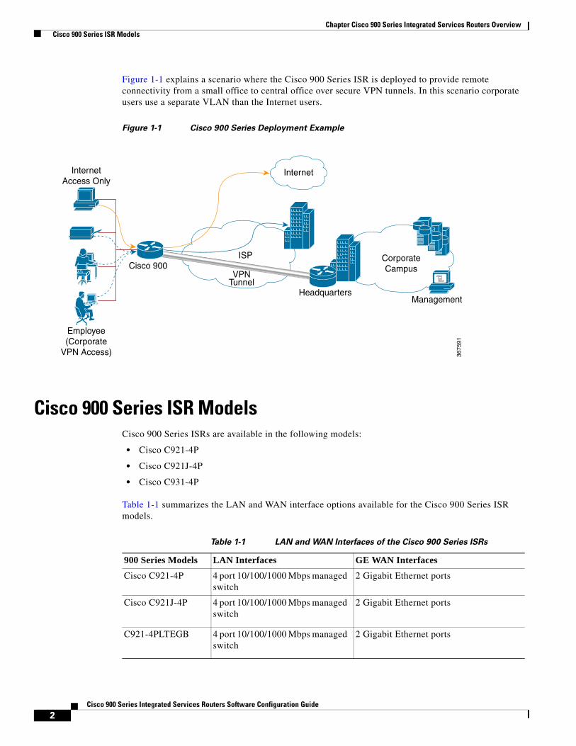
Overview of the Cisco 900 Series ISRCisco 900 Series ISRs are entry level branch routers that provide secure network connectivity for small offices to a central location. These powerful, fixed-configuration routers provide secure broadband and Metro Ethernet and connectivity. Service providers offering managed Ethernet WAN services can deploy them in customer locations as CPE.
2Cisco 900 Series Integrated Services Routers Software Configuration Guide
Chapter Cisco 900 Series Integrated Services Routers Overview Cisco 900 Series ISR Models
Figure 1-1 explains a scenario where the Cisco 900 Series ISR is deployed to provide remote connectivity from a small office to central office over secure VPN tunnels. In this scenario corporate users use a separate VLAN than the Internet users.
Figure 1-1 Cisco 900 Series Deployment Example
Cisco 900 Series ISR ModelsCisco 900 Series ISRs are available in the following models:
• Cisco C921-4P
• Cisco C921J-4P
• Cisco C931-4P
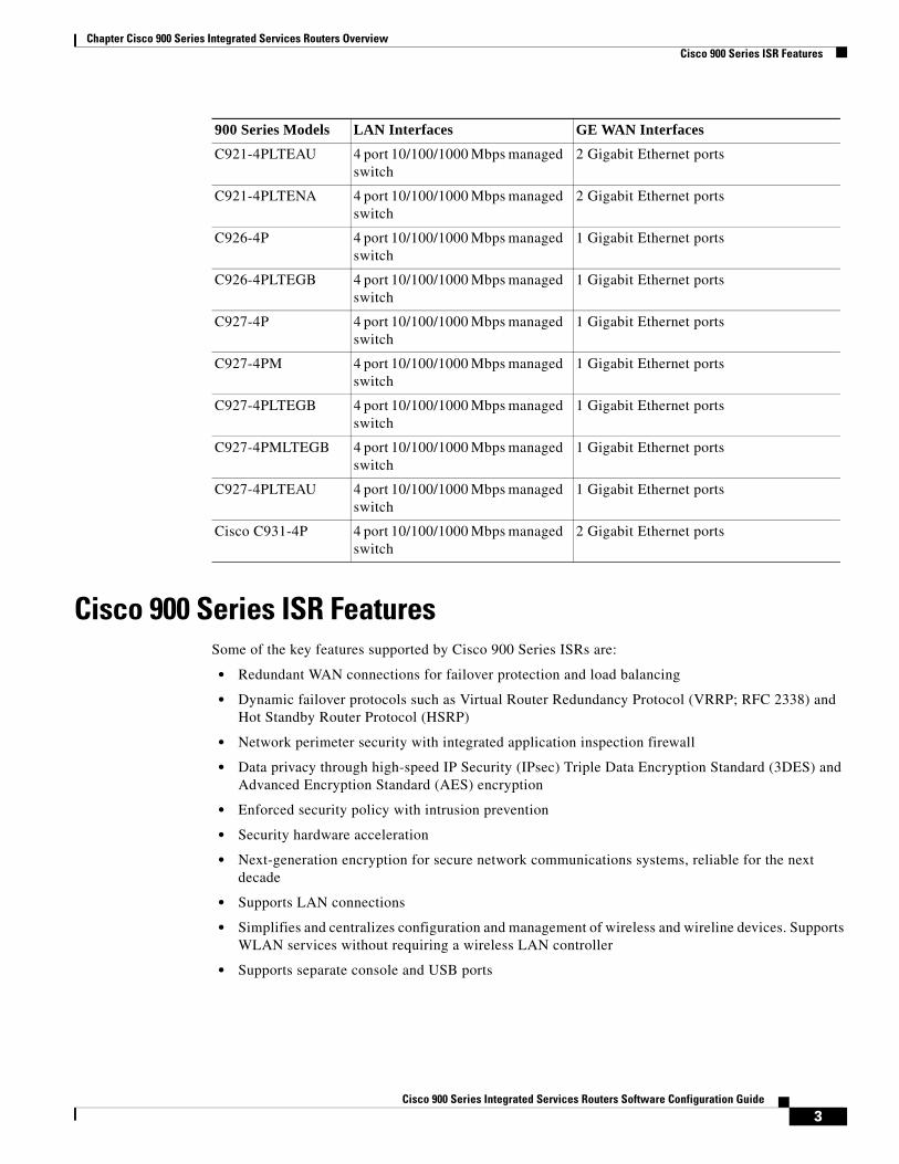
Table 1-1 summarizes the LAN and WAN interface options available for the Cisco 900 Series ISR models.
Table 1-1 LAN and WAN Interfaces of the Cisco 900 Series ISRs
InternetAccess Only
Employee(Corporate
VPN Access)
Cisco 900ISP
VPNTunnel
HeadquartersManagement
CorporateCampus
Internet
3675
91
900 Series Models LAN Interfaces GE WAN InterfacesCisco C921-4P 4 port 10/100/1000 Mbps managed
switch2 Gigabit Ethernet ports
Cisco C921J-4P 4 port 10/100/1000 Mbps managed switch
2 Gigabit Ethernet ports
C921-4PLTEGB 4 port 10/100/1000 Mbps managed switch
2 Gigabit Ethernet ports
3Cisco 900 Series Integrated Services Routers Software Configuration Guide
Chapter Cisco 900 Series Integrated Services Routers Overview Cisco 900 Series ISR Features
Cisco 900 Series ISR Features Some of the key features supported by Cisco 900 Series ISRs are:
• Redundant WAN connections for failover protection and load balancing
• Dynamic failover protocols such as Virtual Router Redundancy Protocol (VRRP; RFC 2338) and Hot Standby Router Protocol (HSRP)
• Network perimeter security with integrated application inspection firewall
• Data privacy through high-speed IP Security (IPsec) Triple Data Encryption Standard (3DES) and Advanced Encryption Standard (AES) encryption
• Enforced security policy with intrusion prevention
• Security hardware acceleration
• Next-generation encryption for secure network communications systems, reliable for the next decade
• Supports LAN connections
• Simplifies and centralizes configuration and management of wireless and wireline devices. Supports WLAN services without requiring a wireless LAN controller
• Supports separate console and USB ports
C921-4PLTEAU 4 port 10/100/1000 Mbps managed switch
2 Gigabit Ethernet ports
C921-4PLTENA 4 port 10/100/1000 Mbps managed switch
2 Gigabit Ethernet ports
C926-4P 4 port 10/100/1000 Mbps managed switch
1 Gigabit Ethernet ports
C926-4PLTEGB 4 port 10/100/1000 Mbps managed switch
1 Gigabit Ethernet ports
C927-4P 4 port 10/100/1000 Mbps managed switch
1 Gigabit Ethernet ports
C927-4PM 4 port 10/100/1000 Mbps managed switch
1 Gigabit Ethernet ports
C927-4PLTEGB 4 port 10/100/1000 Mbps managed switch
1 Gigabit Ethernet ports
C927-4PMLTEGB 4 port 10/100/1000 Mbps managed switch
1 Gigabit Ethernet ports
C927-4PLTEAU 4 port 10/100/1000 Mbps managed switch
1 Gigabit Ethernet ports
Cisco C931-4P 4 port 10/100/1000 Mbps managed switch
2 Gigabit Ethernet ports
900 Series Models LAN Interfaces GE WAN Interfaces
4Cisco 900 Series Integrated Services Routers Software Configuration Guide
Chapter Cisco 900 Series Integrated Services Routers Overview Cisco 900 Series ISR Features
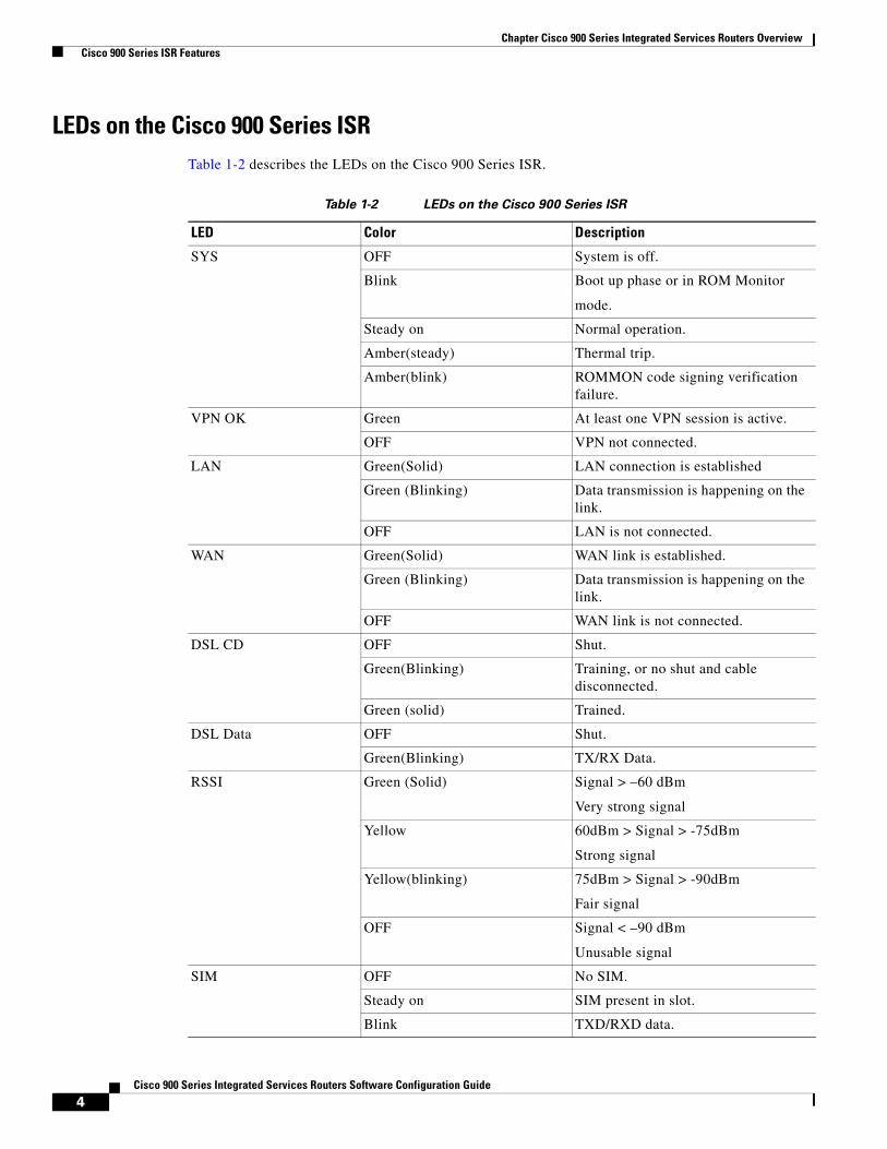
LEDs on the Cisco 900 Series ISRTable 1-2 describes the LEDs on the Cisco 900 Series ISR.
Table 1-2 LEDs on the Cisco 900 Series ISR
LED Color Description
SYS OFF System is off.
Blink Boot up phase or in ROM Monitor
mode.
Steady on Normal operation.
Amber(steady) Thermal trip.
Amber(blink) ROMMON code signing verification failure.
VPN OK Green At least one VPN session is active.
OFF VPN not connected.
LAN Green(Solid) LAN connection is established
Green (Blinking) Data transmission is happening on the link.
OFF LAN is not connected.
WAN Green(Solid) WAN link is established.
Green (Blinking) Data transmission is happening on the link.
OFF WAN link is not connected.
DSL CD OFF Shut.
Green(Blinking) Training, or no shut and cable disconnected.
Green (solid) Trained.
DSL Data OFF Shut.
Green(Blinking) TX/RX Data.
RSSI Green (Solid) Signal > –60 dBm
Very strong signal
Yellow 60dBm > Signal > -75dBm
Strong signal
Yellow(blinking) 75dBm > Signal > -90dBm
Fair signal
OFF Signal < –90 dBm
Unusable signal
SIM OFF No SIM.
Steady on SIM present in slot.
Blink TXD/RXD data.

5Cisco 900 Series Integrated Services Routers Software Configuration Guide
Chapter Cisco 900 Series Integrated Services Routers Overview Cisco 900 Series ISR Features

6Cisco 900 Series Integrated Services Routers Software Configuration Guide
Chapter Cisco 900 Series Integrated Services Routers Overview Cisco 900 Series ISR Features
C H A P T E R
5Cisco 900 Series Integrated Services Routers Software Configuration Guide
2Installing the Software
This chapter describes how to upgrade Cisco IOS images, use ROM Monitor, upgrade Field Programmable units, and the licensing packages supported on Cisco ISR 900 Series routers. This chapter includes the following sections:
• ROM Monitor, page 5
• Upgrading ROMMON using Capsule Upgrade, page 10
• Upgrading the Cisco IOS Software, page 11
• Licensing, page 21
ROM MonitorThe ROM monitor firmware runs when the router is powered up or reset. The firmware helps to initialize the processor hardware and boot the operating system software. You can use the ROM monitor to perform certain configuration tasks, such as recovering a lost password or downloading Cisco IOS software.
Before using the ROM monitor, you should understand the following concepts:
• ROM Monitor Mode Command Prompt, page 5
• Why is the Router in ROM Monitor Mode?, page 5
• When do I use ROM Monitor?, page 6
• Tips for Using ROM Monitor Commands, page 6
ROM Monitor Mode Command PromptThe ROM monitor uses the rommon x > command prompt. The x variable begins at 1 and increments each time you press Return or Enter in ROM monitor mode.
Why is the Router in ROM Monitor Mode?The router boots to ROM monitor mode when one of the following occurs:
• During power up or reload, the router did not find a valid system image.
6Cisco 900 Series Integrated Services Routers Software Configuration Guide
Chapter Installing the Software ROM Monitor
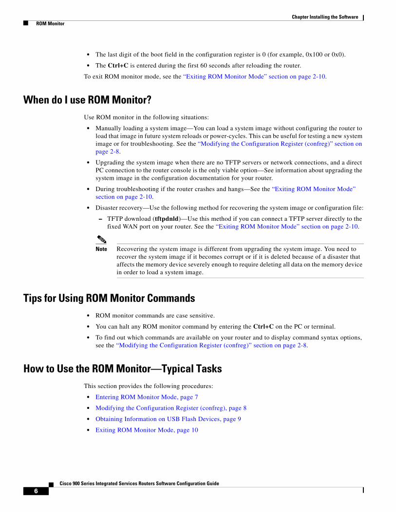
• The last digit of the boot field in the configuration register is 0 (for example, 0x100 or 0x0).
• The Ctrl+C is entered during the first 60 seconds after reloading the router.
To exit ROM monitor mode, see the “Exiting ROM Monitor Mode” section on page 2-10.
When do I use ROM Monitor?Use ROM monitor in the following situations:
• Manually loading a system image—You can load a system image without configuring the router to load that image in future system reloads or power-cycles. This can be useful for testing a new system image or for troubleshooting. See the “Modifying the Configuration Register (confreg)” section on page 2-8.
• Upgrading the system image when there are no TFTP servers or network connections, and a direct PC connection to the router console is the only viable option—See information about upgrading the system image in the configuration documentation for your router.
• During troubleshooting if the router crashes and hangs—See the “Exiting ROM Monitor Mode” section on page 2-10.
• Disaster recovery—Use the following method for recovering the system image or configuration file:
– TFTP download (tftpdnld)—Use this method if you can connect a TFTP server directly to the fixed WAN port on your router. See the “Exiting ROM Monitor Mode” section on page 2-10.
Note Recovering the system image is different from upgrading the system image. You need to recover the system image if it becomes corrupt or if it is deleted because of a disaster that affects the memory device severely enough to require deleting all data on the memory device in order to load a system image.
Tips for Using ROM Monitor Commands• ROM monitor commands are case sensitive.
• You can halt any ROM monitor command by entering the Ctrl+C on the PC or terminal.
• To find out which commands are available on your router and to display command syntax options, see the “Modifying the Configuration Register (confreg)” section on page 2-8.
How to Use the ROM Monitor—Typical TasksThis section provides the following procedures:
• Entering ROM Monitor Mode, page 7
• Modifying the Configuration Register (confreg), page 8
• Obtaining Information on USB Flash Devices, page 9
• Exiting ROM Monitor Mode, page 10
7Cisco 900 Series Integrated Services Routers Software Configuration Guide
Chapter Installing the Software ROM Monitor
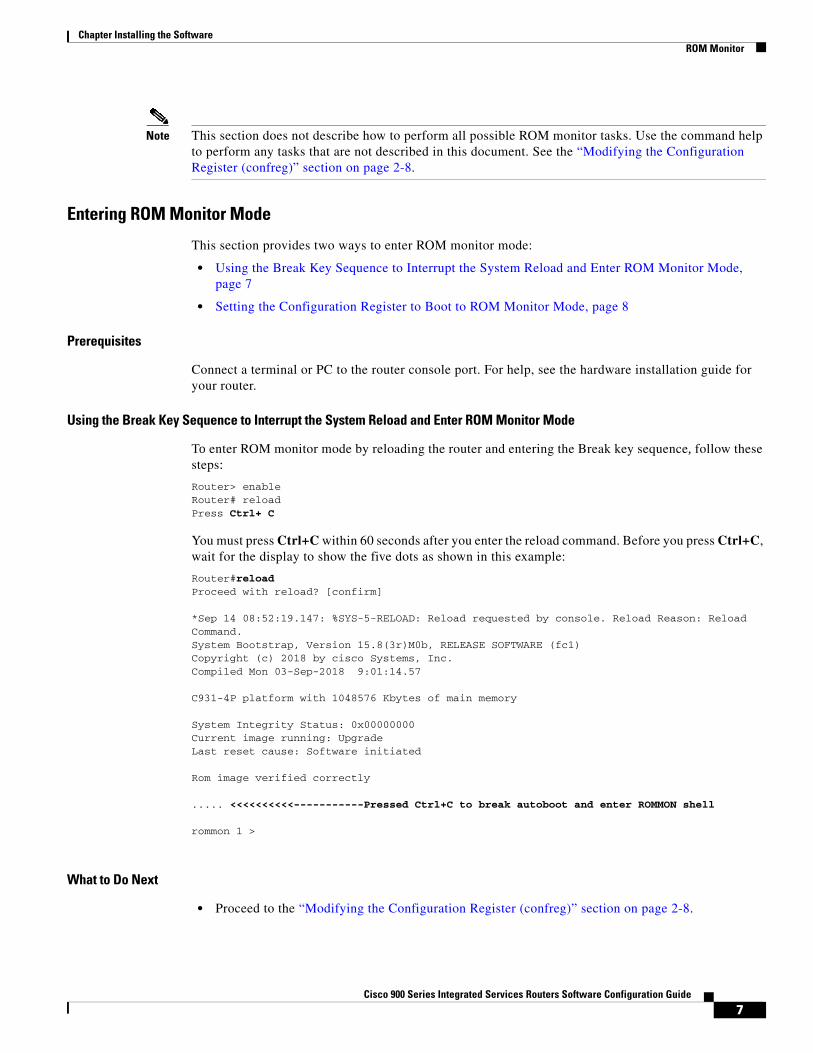
Note This section does not describe how to perform all possible ROM monitor tasks. Use the command help to perform any tasks that are not described in this document. See the “Modifying the Configuration Register (confreg)” section on page 2-8.
Entering ROM Monitor Mode
This section provides two ways to enter ROM monitor mode:
• Using the Break Key Sequence to Interrupt the System Reload and Enter ROM Monitor Mode, page 7
• Setting the Configuration Register to Boot to ROM Monitor Mode, page 8
Prerequisites
Connect a terminal or PC to the router console port. For help, see the hardware installation guide for your router.
Using the Break Key Sequence to Interrupt the System Reload and Enter ROM Monitor Mode
To enter ROM monitor mode by reloading the router and entering the Break key sequence, follow these steps:
Router> enableRouter# reload Press Ctrl+ C
You must press Ctrl+C within 60 seconds after you enter the reload command. Before you press Ctrl+C, wait for the display to show the five dots as shown in this example:
Router#reloadProceed with reload? [confirm] *Sep 14 08:52:19.147: %SYS-5-RELOAD: Reload requested by console. Reload Reason: Reload Command.System Bootstrap, Version 15.8(3r)M0b, RELEASE SOFTWARE (fc1)Copyright (c) 2018 by cisco Systems, Inc.Compiled Mon 03-Sep-2018 9:01:14.57 C931-4P platform with 1048576 Kbytes of main memory System Integrity Status: 0x00000000Current image running: UpgradeLast reset cause: Software initiated Rom image verified correctly ..... <<<<<<<<<<-----------Pressed Ctrl+C to break autoboot and enter ROMMON shell rommon 1 >
What to Do Next
• Proceed to the “Modifying the Configuration Register (confreg)” section on page 2-8.
8Cisco 900 Series Integrated Services Routers Software Configuration Guide
Chapter Installing the Software ROM Monitor
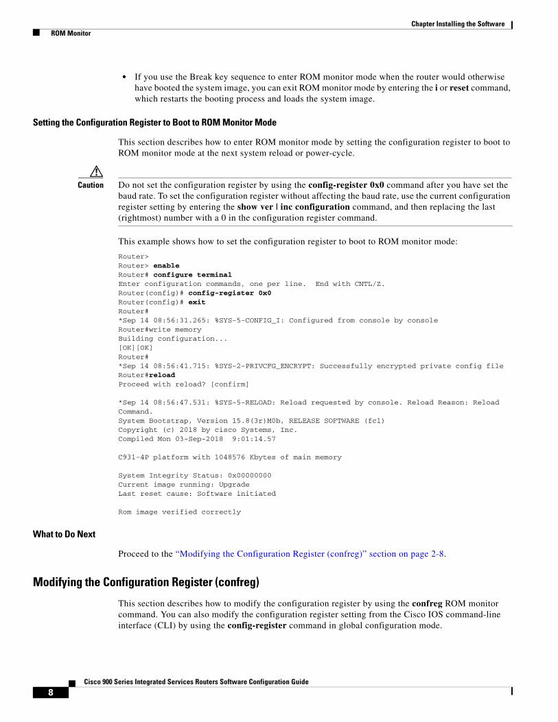
• If you use the Break key sequence to enter ROM monitor mode when the router would otherwise have booted the system image, you can exit ROM monitor mode by entering the i or reset command, which restarts the booting process and loads the system image.
Setting the Configuration Register to Boot to ROM Monitor Mode
This section describes how to enter ROM monitor mode by setting the configuration register to boot to ROM monitor mode at the next system reload or power-cycle.
Caution Do not set the configuration register by using the config-register 0x0 command after you have set the baud rate. To set the configuration register without affecting the baud rate, use the current configuration register setting by entering the show ver | inc configuration command, and then replacing the last (rightmost) number with a 0 in the configuration register command.
This example shows how to set the configuration register to boot to ROM monitor mode:
Router>Router> enableRouter# configure terminalEnter configuration commands, one per line. End with CNTL/Z.Router(config)# config-register 0x0Router(config)# exitRouter#*Sep 14 08:56:31.265: %SYS-5-CONFIG_I: Configured from console by consoleRouter#write memoryBuilding configuration...[OK][OK]Router#*Sep 14 08:56:41.715: %SYS-2-PRIVCFG_ENCRYPT: Successfully encrypted private config fileRouter#reloadProceed with reload? [confirm] *Sep 14 08:56:47.531: %SYS-5-RELOAD: Reload requested by console. Reload Reason: Reload Command.System Bootstrap, Version 15.8(3r)M0b, RELEASE SOFTWARE (fc1)Copyright (c) 2018 by cisco Systems, Inc.Compiled Mon 03-Sep-2018 9:01:14.57 C931-4P platform with 1048576 Kbytes of main memory System Integrity Status: 0x00000000Current image running: UpgradeLast reset cause: Software initiated Rom image verified correctly
What to Do Next
Proceed to the “Modifying the Configuration Register (confreg)” section on page 2-8.
Modifying the Configuration Register (confreg)
This section describes how to modify the configuration register by using the confreg ROM monitor command. You can also modify the configuration register setting from the Cisco IOS command-line interface (CLI) by using the config-register command in global configuration mode.
9Cisco 900 Series Integrated Services Routers Software Configuration Guide
Chapter Installing the Software ROM Monitor
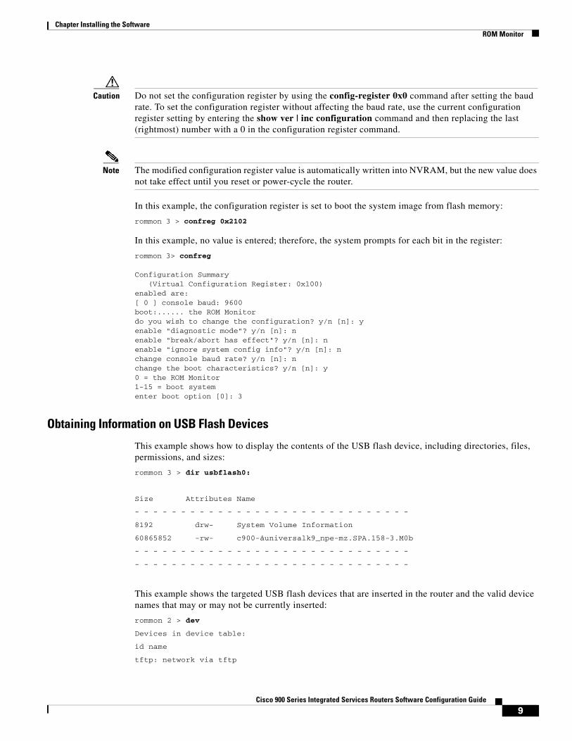
Caution Do not set the configuration register by using the config-register 0x0 command after setting the baud rate. To set the configuration register without affecting the baud rate, use the current configuration register setting by entering the show ver | inc configuration command and then replacing the last (rightmost) number with a 0 in the configuration register command.
Note The modified configuration register value is automatically written into NVRAM, but the new value does not take effect until you reset or power-cycle the router.
In this example, the configuration register is set to boot the system image from flash memory:
rommon 3 > confreg 0x2102
In this example, no value is entered; therefore, the system prompts for each bit in the register:
rommon 3> confreg
Configuration Summary (Virtual Configuration Register: 0x100)enabled are:[ 0 ] console baud: 9600boot:...... the ROM Monitordo you wish to change the configuration? y/n [n]: yenable "diagnostic mode"? y/n [n]: nenable "break/abort has effect"? y/n [n]: nenable "ignore system config info"? y/n [n]: nchange console baud rate? y/n [n]: nchange the boot characteristics? y/n [n]: y0 = the ROM Monitor1-15 = boot systementer boot option [0]: 3
Obtaining Information on USB Flash Devices
This example shows how to display the contents of the USB flash device, including directories, files, permissions, and sizes:
rommon 3 > dir usbflash0:
Size Attributes Name
- - - - - - - - - - - - - - - - - - - - - - - - - - - - - -
8192 drw- System Volume Information
60865852 -rw- c900-åuniversalk9_npe-mz.SPA.158-3.M0b
- - - - - - - - - - - - - - - - - - - - - - - - - - - - - -
- - - - - - - - - - - - - - - - - - - - - - - - - - - - - -
This example shows the targeted USB flash devices that are inserted in the router and the valid device names that may or may not be currently inserted:
rommon 2 > dev
Devices in device table:
id name
tftp: network via tftp
10Cisco 900 Series Integrated Services Routers Software Configuration Guide
Chapter Installing the Software ROM Monitor
flash: Internal flash drive
usbflash0: External USB drive 0
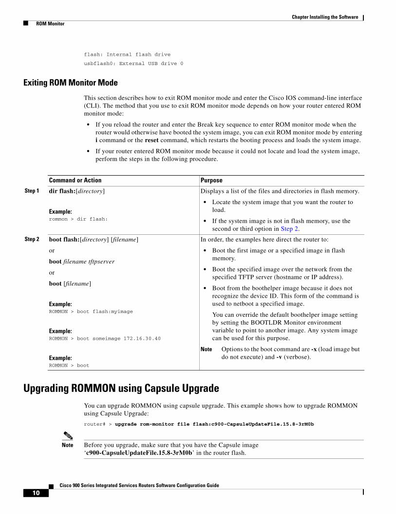
Exiting ROM Monitor Mode
This section describes how to exit ROM monitor mode and enter the Cisco IOS command-line interface (CLI). The method that you use to exit ROM monitor mode depends on how your router entered ROM monitor mode:
• If you reload the router and enter the Break key sequence to enter ROM monitor mode when the router would otherwise have booted the system image, you can exit ROM monitor mode by entering i command or the reset command, which restarts the booting process and loads the system image.
• If your router entered ROM monitor mode because it could not locate and load the system image, perform the steps in the following procedure.
Upgrading ROMMON using Capsule UpgradeYou can upgrade ROMMON using capsule upgrade. This example shows how to upgrade ROMMON using Capsule Upgrade:
router# > upgrade rom-monitor file flash:c900-CapsuleUpdateFile.15.8-3rM0b
Note Before you upgrade, make sure that you have the Capsule image ‘c900-CapsuleUpdateFile.15.8-3rM0b’ in the router flash.
Command or Action Purpose
Step 1 dir flash:[directory]
Example:rommon > dir flash:
Displays a list of the files and directories in flash memory.
• Locate the system image that you want the router to load.
• If the system image is not in flash memory, use the second or third option in Step 2.
Step 2 boot flash:[directory] [filename]
or
boot filename tftpserver
or
boot [filename]
Example:ROMMON > boot flash:myimage
Example:ROMMON > boot someimage 172.16.30.40
Example:ROMMON > boot
In order, the examples here direct the router to:
• Boot the first image or a specified image in flash memory.
• Boot the specified image over the network from the specified TFTP server (hostname or IP address).
• Boot from the boothelper image because it does not recognize the device ID. This form of the command is used to netboot a specified image.
You can override the default boothelper image setting by setting the BOOTLDR Monitor environment variable to point to another image. Any system image can be used for this purpose.
Note Options to the boot command are -x (load image but do not execute) and -v (verbose).
11Cisco 900 Series Integrated Services Routers Software Configuration Guide
Chapter Installing the Software Upgrading the Cisco IOS Software
Use the showmon -v command to verify the ROMMON version. This example shows the command output:
rommon 1 > showmon -v System Bootstrap, Version 15.8(3r)M0b, RELEASE SOFTWARE (fc1)Copyright (c) 2018 by cisco Systems, Inc.Compiled Mon 03-Sep-2018 9:01:14.57
Upgrading the Cisco IOS SoftwareYour router comes pre-installed with the Cisco IOS image. However, you can install the new version in order to keep router features up to date. This section describes how to upgrade the Cisco Internet Operating System (IOS) software image on a Cisco 900 series ISR.
• Information About Upgrading the System Image, page 11
• How to Upgrade the Cisco IOS Image, page 12
Information About Upgrading the System ImageTo upgrade the system image on your router, review the following sections:
• Why Would I Upgrade the System Image?, page 11
• Which Cisco IOS Release Is Running on My Router Now?, page 11
• How Do I Choose the New Cisco IOS Release and Feature Set?, page 11
• Where Do I Download the System Image?, page 12
Why Would I Upgrade the System Image?
System images contain the Cisco IOS software. Your router was shipped with an image installed. At some point, you may want to load a different image onto the router or the access point. For example, you may want to upgrade your IOS software to the latest release, or you may want to use the same Cisco IOS release for all the routers in a network. Each system image contains different sets of Cisco IOS features, therefore select an appropriate system image to suit your network requirements.
Which Cisco IOS Release Is Running on My Router Now?
To determine the Cisco IOS release that is currently running on your router, and the filename of the system image, enter the show version command in user EXEC or privileged EXEC mode.
How Do I Choose the New Cisco IOS Release and Feature Set?
To determine which Cisco IOS releases and feature are supported on your platform, go to Cisco Feature Navigator at http://www.cisco.com/go/cfn. You must have an account at Cisco.com. If you do not have an account or have forgotten your username or password, click Cancel at the login dialog box and follow the instructions that appear.
12Cisco 900 Series Integrated Services Routers Software Configuration Guide
Chapter Installing the Software Upgrading the Cisco IOS Software
Where Do I Download the System Image?
To download a system image you must have an account at Cisco.com to gain access to the following websites. If you do not have an account or have forgotten your username or password, click Cancel at the login dialog box, and follow the instructions that appear.
If you know the Cisco IOS release and feature set you want to download, go directly to
https://software.cisco.com/download/home
For more information about Loading and Managing System images, go to
https://www.cisco.com/c/en/us/td/docs/ios-xml/ios/fundamentals/configuration/15mt/fundamentals-15-mt-book/cf-config-overview.html
How to Upgrade the Cisco IOS ImageThis section provides information about upgrading the Cisco IOS image on the router.
• Saving Backup Copies of Your Old System Image and Configuration, page 12
• Copying the System Image into Flash Memory, page 13
• Loading the New System Image, page 16
• Saving Backup Copies of Your New System Image and Configuration, page 19
Saving Backup Copies of Your Old System Image and Configuration
To avoid unexpected downtime in the event you encounter serious problems using a new system image or startup configuration, we recommend that you save backup copies of your current startup configuration file and Cisco IOS software system image file on a server.
The following examples show how to copy a startup configuration to a TFTP server and how to copy from flash memory to an FTP server.
Copying the Startup Configuration to a TFTP Server: Example
The following example shows the startup configuration being copied to a TFTP server:
Router# copy nvram:startup-config tftp:
Remote host[]? 192.0.0.1
Name of configuration file to write [rtr2-confg]? rtr2-config-b4upgrade Write file rtr2-confg-b4upgrade on host 192.0.0.1?[confirm] <cr> ![OK]
Copying from Flash Memory to a TFTP Server: Example
The following example uses the dir flash: command in privileged EXEC mode to learn the name of the system image file and the copy flash: tftp: command in privileged EXEC mode to copy the system image to a TFTP server. The router uses the default username and password.
Router# copy flash: tftp:Source filename [running-config]?Address or name of remote host []? 192.0.0.1Destination filename [router-confg]? running-config983 bytes copied in 0.048 secs (20479 bytes/sec)
13Cisco 900 Series Integrated Services Routers Software Configuration Guide
Chapter Installing the Software Upgrading the Cisco IOS Software
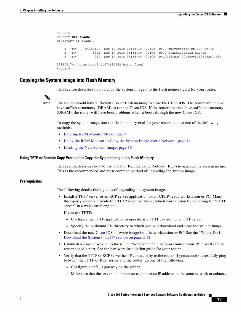
Router#Router# dir flash:Directory of flash:/ 1 -rw- 64383100 Sep 17 2018 05:58:14 +00:00 c900-universalk9-mz.SSA_09-10 2 -rw- 1524 Sep 17 2018 05:55:30 +00:00 c900_startupconfig-backup 3 -rw- 919 Sep 17 2018 05:58:44 +00:00 PSZ22241BW6_20180906052515287.zip 1936031744 bytes total (1871634432 bytes free)Router#
Copying the System Image into Flash Memory
This section describes how to copy the system image into the flash memory card for your router.
Note The router should have sufficient disk or flash memory to store the Cisco IOS. The router should also have sufficient memory (DRAM) to run the Cisco IOS. If the router does not have sufficient memory (DRAM), the router will have boot problems when it boots through the new Cisco IOS.
To copy the system image into the flash memory card for your router, choose one of the following methods:
• Entering ROM Monitor Mode, page 7
• Using the ROM Monitor to Copy the System Image over a Network, page 14
• Loading the New System Image, page 16
Using TFTP or Remote Copy Protocol to Copy the System Image into Flash Memory
This section describes how to use TFTP or Remote Copy Protocol (RCP) to upgrade the system image. This is the recommended and most common method of upgrading the system image.
Prerequisites
The following details the logistics of upgrading the system image.
• Install a TFTP server or an RCP server application on a TCP/IP-ready workstation or PC. Many third-party vendors provide free TFTP server software, which you can find by searching for “TFTP server” in a web search engine.
If you use TFTP:
– Configure the TFTP application to operate as a TFTP server, not a TFTP client.
– Specify the outbound file directory to which you will download and store the system image.
• Download the new Cisco IOS software image into the workstation or PC. See the “Where Do I Download the System Image?” section on page 2-12.
• Establish a console session to the router. We recommend that you connect your PC directly to the router console port. See the hardware installation guide for your router.
• Verify that the TFTP or RCP server has IP connectivity to the router. If you cannot successfully ping between the TFTP or RCP server and the router, do one of the following:
– Configure a default gateway on the router.
– Make sure that the server and the router each have an IP address in the same network or subnet. .
14Cisco 900 Series Integrated Services Routers Software Configuration Guide
Chapter Installing the Software Upgrading the Cisco IOS Software
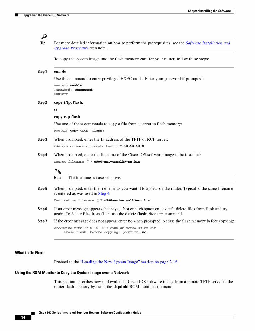
Tip For more detailed information on how to perform the prerequisites, see the Software Installation and Upgrade Procedure tech note.
To copy the system image into the flash memory card for your router, follow these steps:
Step 1 enable
Use this command to enter privileged EXEC mode. Enter your password if prompted:
Router> enable Password: <password> Router#
Step 2 copy tftp: flash:
or
copy rcp flash
Use one of these commands to copy a file from a server to flash memory:
Router# copy tftp: flash:
Step 3 When prompted, enter the IP address of the TFTP or RCP server:
Address or name of remote host []? 10.10.10.2
Step 4 When prompted, enter the filename of the Cisco IOS software image to be installed:
Source filename []? c900-universalk9-mz.bin
Note The filename is case sensitive.
Step 5 When prompted, enter the filename as you want it to appear on the router. Typically, the same filename is entered as was used in Step 4:
Destination filename []? c900-universalk9-mz.bin
Step 6 If an error message appears that says, “Not enough space on device”, delete files from flash and try again. To delete files from flash, use the delete flash: filename command.
Step 7 If the error message does not appear, enter no when prompted to erase the flash memory before copying:
Accessing tftp://10.10.10.2/c900-universalk9-mz.bin... Erase flash: before copying? [confirm] no
What to Do Next
Proceed to the “Loading the New System Image” section on page 2-16.
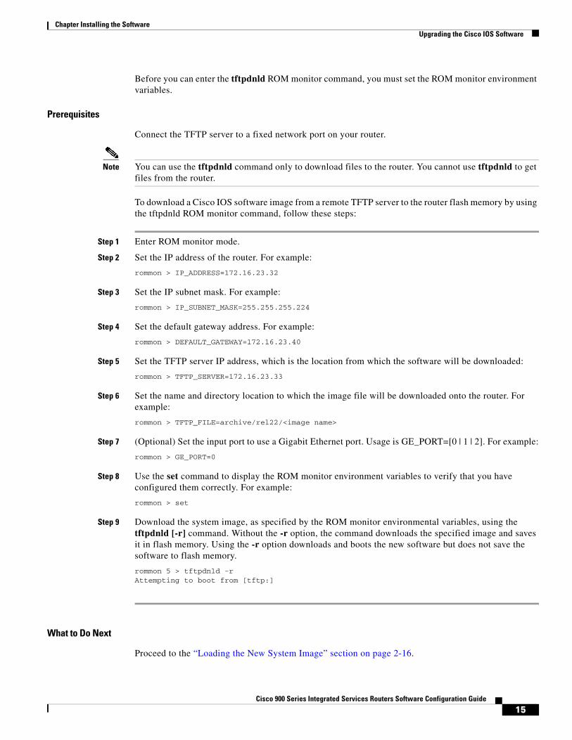
Using the ROM Monitor to Copy the System Image over a Network
This section describes how to download a Cisco IOS software image from a remote TFTP server to the router flash memory by using the tftpdnld ROM monitor command.
15Cisco 900 Series Integrated Services Routers Software Configuration Guide
Chapter Installing the Software Upgrading the Cisco IOS Software
Before you can enter the tftpdnld ROM monitor command, you must set the ROM monitor environment variables.
Prerequisites
Connect the TFTP server to a fixed network port on your router.
Note You can use the tftpdnld command only to download files to the router. You cannot use tftpdnld to get files from the router.
To download a Cisco IOS software image from a remote TFTP server to the router flash memory by using the tftpdnld ROM monitor command, follow these steps:
Step 1 Enter ROM monitor mode.
Step 2 Set the IP address of the router. For example:
rommon > IP_ADDRESS=172.16.23.32
Step 3 Set the IP subnet mask. For example:
rommon > IP_SUBNET_MASK=255.255.255.224
Step 4 Set the default gateway address. For example:
rommon > DEFAULT_GATEWAY=172.16.23.40
Step 5 Set the TFTP server IP address, which is the location from which the software will be downloaded:
rommon > TFTP_SERVER=172.16.23.33
Step 6 Set the name and directory location to which the image file will be downloaded onto the router. For example:
rommon > TFTP_FILE=archive/rel22/<image name>
Step 7 (Optional) Set the input port to use a Gigabit Ethernet port. Usage is GE_PORT=[0 | 1 | 2]. For example:
rommon > GE_PORT=0
Step 8 Use the set command to display the ROM monitor environment variables to verify that you have configured them correctly. For example:
rommon > set
Step 9 Download the system image, as specified by the ROM monitor environmental variables, using the tftpdnld [-r] command. Without the -r option, the command downloads the specified image and saves it in flash memory. Using the -r option downloads and boots the new software but does not save the software to flash memory.
rommon 5 > tftpdnld -rAttempting to boot from [tftp:]
What to Do Next
Proceed to the “Loading the New System Image” section on page 2-16.
16Cisco 900 Series Integrated Services Routers Software Configuration Guide
Chapter Installing the Software Upgrading the Cisco IOS Software
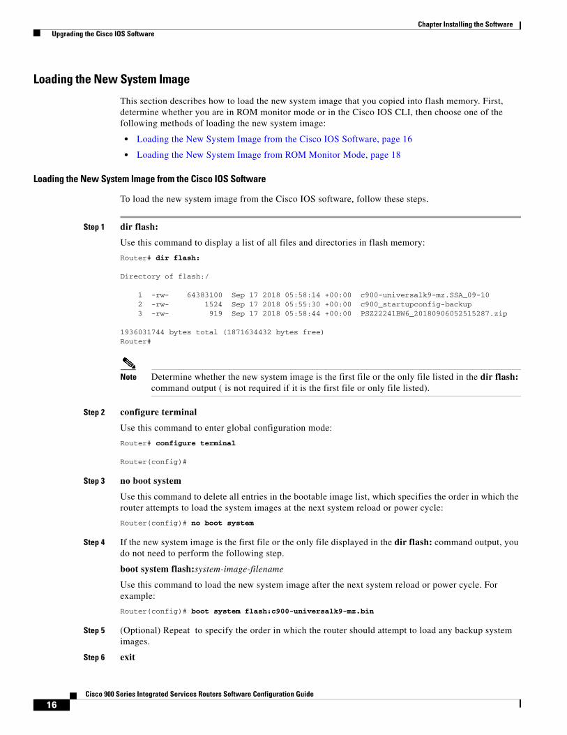
Loading the New System Image
This section describes how to load the new system image that you copied into flash memory. First, determine whether you are in ROM monitor mode or in the Cisco IOS CLI, then choose one of the following methods of loading the new system image:
• Loading the New System Image from the Cisco IOS Software, page 16
• Loading the New System Image from ROM Monitor Mode, page 18
Loading the New System Image from the Cisco IOS Software
To load the new system image from the Cisco IOS software, follow these steps.
Step 1 dir flash:
Use this command to display a list of all files and directories in flash memory:
Router# dir flash:
Directory of flash:/ 1 -rw- 64383100 Sep 17 2018 05:58:14 +00:00 c900-universalk9-mz.SSA_09-10 2 -rw- 1524 Sep 17 2018 05:55:30 +00:00 c900_startupconfig-backup 3 -rw- 919 Sep 17 2018 05:58:44 +00:00 PSZ22241BW6_20180906052515287.zip 1936031744 bytes total (1871634432 bytes free)Router#
Note Determine whether the new system image is the first file or the only file listed in the dir flash: command output ( is not required if it is the first file or only file listed).
Step 2 configure terminal
Use this command to enter global configuration mode:
Router# configure terminal
Router(config)#
Step 3 no boot system
Use this command to delete all entries in the bootable image list, which specifies the order in which the router attempts to load the system images at the next system reload or power cycle:
Router(config)# no boot system
Step 4 If the new system image is the first file or the only file displayed in the dir flash: command output, you do not need to perform the following step.
boot system flash:system-image-filename
Use this command to load the new system image after the next system reload or power cycle. For example:
Router(config)# boot system flash:c900-universalk9-mz.bin
Step 5 (Optional) Repeat to specify the order in which the router should attempt to load any backup system images.
Step 6 exit
17Cisco 900 Series Integrated Services Routers Software Configuration Guide
Chapter Installing the Software Upgrading the Cisco IOS Software
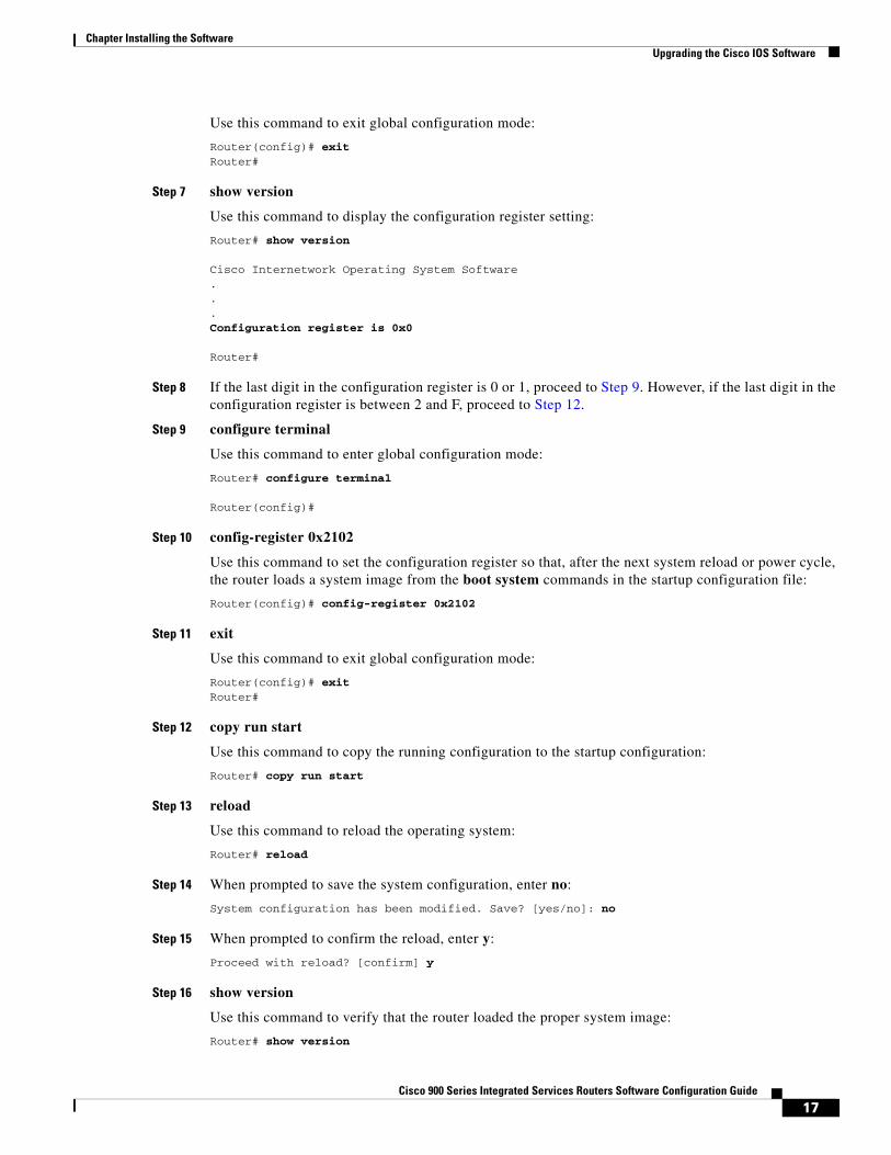
Use this command to exit global configuration mode:
Router(config)# exit Router#
Step 7 show version
Use this command to display the configuration register setting:
Router# show version
Cisco Internetwork Operating System Software...Configuration register is 0x0
Router#
Step 8 If the last digit in the configuration register is 0 or 1, proceed to Step 9. However, if the last digit in the configuration register is between 2 and F, proceed to Step 12.
Step 9 configure terminal
Use this command to enter global configuration mode:
Router# configure terminal
Router(config)#
Step 10 config-register 0x2102
Use this command to set the configuration register so that, after the next system reload or power cycle, the router loads a system image from the boot system commands in the startup configuration file:
Router(config)# config-register 0x2102
Step 11 exit
Use this command to exit global configuration mode:
Router(config)# exit Router#
Step 12 copy run start
Use this command to copy the running configuration to the startup configuration:
Router# copy run start
Step 13 reload
Use this command to reload the operating system:
Router# reload
Step 14 When prompted to save the system configuration, enter no:
System configuration has been modified. Save? [yes/no]: no
Step 15 When prompted to confirm the reload, enter y:
Proceed with reload? [confirm] y
Step 16 show version
Use this command to verify that the router loaded the proper system image:
Router# show version
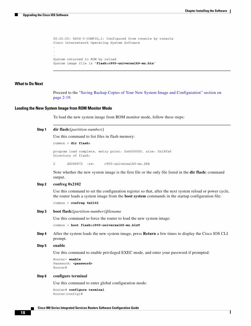
18Cisco 900 Series Integrated Services Routers Software Configuration Guide
Chapter Installing the Software Upgrading the Cisco IOS Software
00:22:25: %SYS-5-CONFIG_I: Configured from console by consoleCisco Internetwork Operating System Software ...System returned to ROM by reloadSystem image file is "flash:c900-universalk9-mz.bin"
What to Do Next
Proceed to the “Saving Backup Copies of Your New System Image and Configuration” section on page 2-19.
Loading the New System Image from ROM Monitor Mode
To load the new system image from ROM monitor mode, follow these steps:
Step 1 dir flash:[partition-number:]
Use this command to list files in flash memory:
rommon > dir flash:
program load complete, entry point: 0x4000000, size: 0x18fa0Directory of flash:
2 48296872 -rw- c900-universalk9-mz.SPA
Note whether the new system image is the first file or the only file listed in the dir flash: command output.
Step 2 confreg 0x2102
Use this command to set the configuration register so that, after the next system reload or power cycle, the router loads a system image from the boot system commands in the startup configuration file:
rommon > confreg 0x2102
Step 3 boot flash:[partition-number:]filename
Use this command to force the router to load the new system image:
rommon > boot flash:c900-universalk9-mz.binT
Step 4 After the system loads the new system image, press Return a few times to display the Cisco IOS CLI prompt.
Step 5 enable
Use this command to enable privileged EXEC mode, and enter your password if prompted:
Router> enable Password: <password> Router#
Step 6 configure terminal
Use this command to enter global configuration mode:
Router# configure terminalRouter(config)#
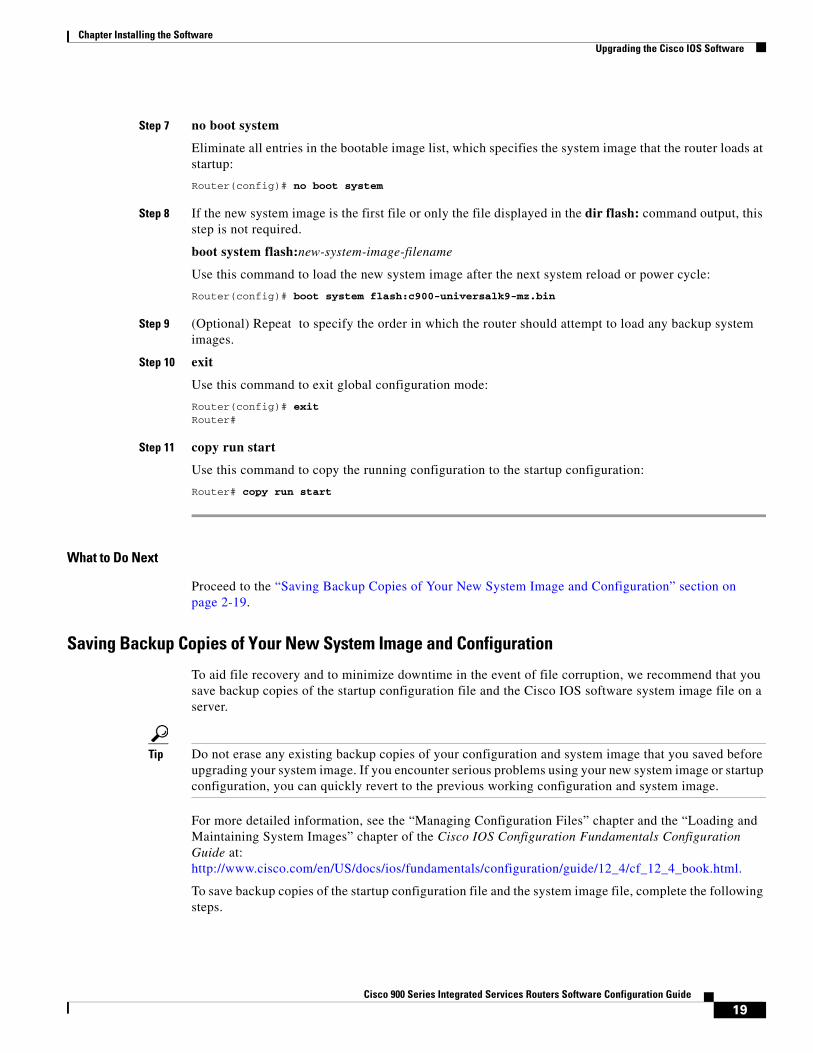
19Cisco 900 Series Integrated Services Routers Software Configuration Guide
Chapter Installing the Software Upgrading the Cisco IOS Software
Step 7 no boot system
Eliminate all entries in the bootable image list, which specifies the system image that the router loads at startup:
Router(config)# no boot system
Step 8 If the new system image is the first file or only the file displayed in the dir flash: command output, this step is not required.
boot system flash:new-system-image-filename
Use this command to load the new system image after the next system reload or power cycle:
Router(config)# boot system flash:c900-universalk9-mz.bin
Step 9 (Optional) Repeat to specify the order in which the router should attempt to load any backup system images.
Step 10 exit
Use this command to exit global configuration mode:
Router(config)# exit Router#
Step 11 copy run start
Use this command to copy the running configuration to the startup configuration:
Router# copy run start
What to Do Next
Proceed to the “Saving Backup Copies of Your New System Image and Configuration” section on page 2-19.
Saving Backup Copies of Your New System Image and Configuration
To aid file recovery and to minimize downtime in the event of file corruption, we recommend that you save backup copies of the startup configuration file and the Cisco IOS software system image file on a server.
Tip Do not erase any existing backup copies of your configuration and system image that you saved before upgrading your system image. If you encounter serious problems using your new system image or startup configuration, you can quickly revert to the previous working configuration and system image.
For more detailed information, see the “Managing Configuration Files” chapter and the “Loading and Maintaining System Images” chapter of the Cisco IOS Configuration Fundamentals Configuration Guide at:http://www.cisco.com/en/US/docs/ios/fundamentals/configuration/guide/12_4/cf_12_4_book.html.
To save backup copies of the startup configuration file and the system image file, complete the following steps.
20Cisco 900 Series Integrated Services Routers Software Configuration Guide
Chapter Installing the Software Upgrading the Cisco IOS Software
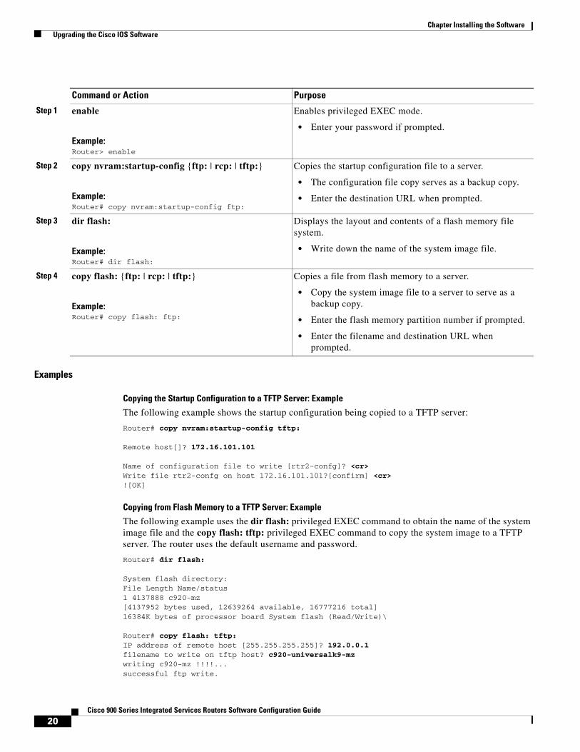
Examples
Copying the Startup Configuration to a TFTP Server: Example
The following example shows the startup configuration being copied to a TFTP server:
Router# copy nvram:startup-config tftp:
Remote host[]? 172.16.101.101
Name of configuration file to write [rtr2-confg]? <cr> Write file rtr2-confg on host 172.16.101.101?[confirm] <cr> ![OK]
Copying from Flash Memory to a TFTP Server: Example
The following example uses the dir flash: privileged EXEC command to obtain the name of the system image file and the copy flash: tftp: privileged EXEC command to copy the system image to a TFTP server. The router uses the default username and password.
Router# dir flash:
System flash directory:File Length Name/status1 4137888 c920-mz[4137952 bytes used, 12639264 available, 16777216 total]16384K bytes of processor board System flash (Read/Write)\
Router# copy flash: tftp: IP address of remote host [255.255.255.255]? 192.0.0.1 filename to write on tftp host? c920-universalk9-mz writing c920-mz !!!!...successful ftp write.
Command or Action Purpose
Step 1 enable
Example:Router> enable
Enables privileged EXEC mode.
• Enter your password if prompted.
Step 2 copy nvram:startup-config {ftp: | rcp: | tftp:}
Example:Router# copy nvram:startup-config ftp:
Copies the startup configuration file to a server.
• The configuration file copy serves as a backup copy.
• Enter the destination URL when prompted.
Step 3 dir flash:
Example:Router# dir flash:
Displays the layout and contents of a flash memory file system.
• Write down the name of the system image file.
Step 4 copy flash: {ftp: | rcp: | tftp:}
Example:Router# copy flash: ftp:
Copies a file from flash memory to a server.
• Copy the system image file to a server to serve as a backup copy.
• Enter the flash memory partition number if prompted.
• Enter the filename and destination URL when prompted.

21Cisco 900 Series Integrated Services Routers Software Configuration Guide
Chapter Installing the Software Licensing
LicensingWhen you order a new router, it is shipped preinstalled with the software image and the corresponding licenses for the packages and features that you specified. You do not need to activate or register the software before use. You need a license if you are upgrading or installing a new Cisco IOS feature. For more information about the license type, technology package, and installation, see Software Activation on Cisco Integrated Services Routers and Cisco Integrated Service Routers G2 guide.

22Cisco 900 Series Integrated Services Routers Software Configuration Guide
Chapter Installing the Software Licensing
C H A P T E R
23Cisco 900 Series Integrated Services Routers Software Configuration Guide
3Basic Router Configuration
This chapter provides configuration procedures for Cisco 900 series integrated services routers (ISRs). It also includes configuration examples and verification steps whenever possible. This chapter contains the following topics:
Basic Configuration
• Default Configuration, page 24
• Configuring Global Parameters, page 25
Interface Configuration
• Interface Ports, page 27
• Configuring Gigabit Ethernet Interfaces, page 27
• Configuring a Loopback Interface, page 28
Routing Configuration
• Configuring Command-Line Access, page 29
• Configuring Static Routes, page 29
• Configuring Dynamic Routes, page 30
24Cisco 900 Series Integrated Services Routers Software Configuration Guide
Chapter Basic Router Configuration Default Configuration
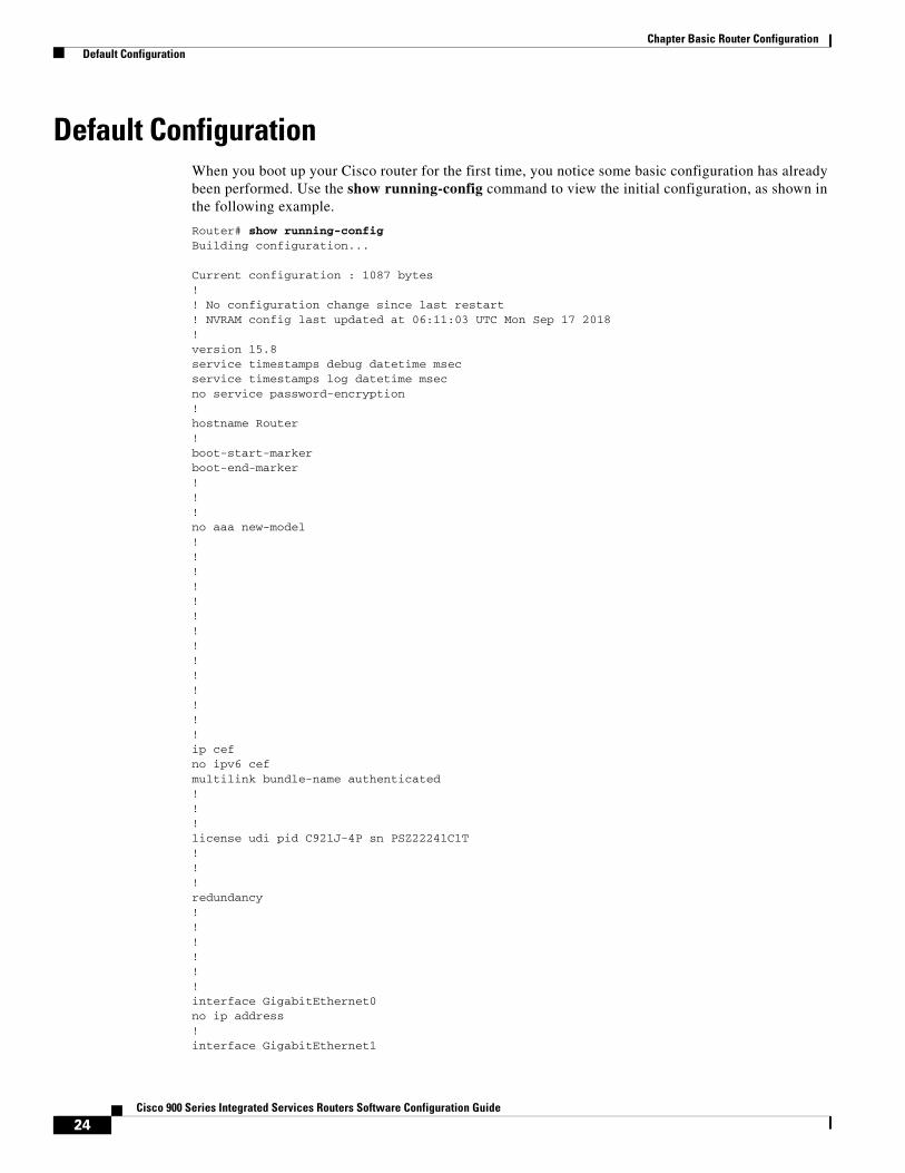
Default ConfigurationWhen you boot up your Cisco router for the first time, you notice some basic configuration has already been performed. Use the show running-config command to view the initial configuration, as shown in the following example.
Router# show running-configBuilding configuration... Current configuration : 1087 bytes!! No configuration change since last restart! NVRAM config last updated at 06:11:03 UTC Mon Sep 17 2018!version 15.8service timestamps debug datetime msecservice timestamps log datetime msecno service password-encryption!hostname Router!boot-start-markerboot-end-marker!!!no aaa new-model!!!!!!!!!!!!!!ip cefno ipv6 cefmultilink bundle-name authenticated!!!license udi pid C921J-4P sn PSZ22241C1T!!!redundancy!!!!!!interface GigabitEthernet0no ip address!interface GigabitEthernet1
25Cisco 900 Series Integrated Services Routers Software Configuration Guide
Chapter Basic Router Configuration Configuring Global Parameters
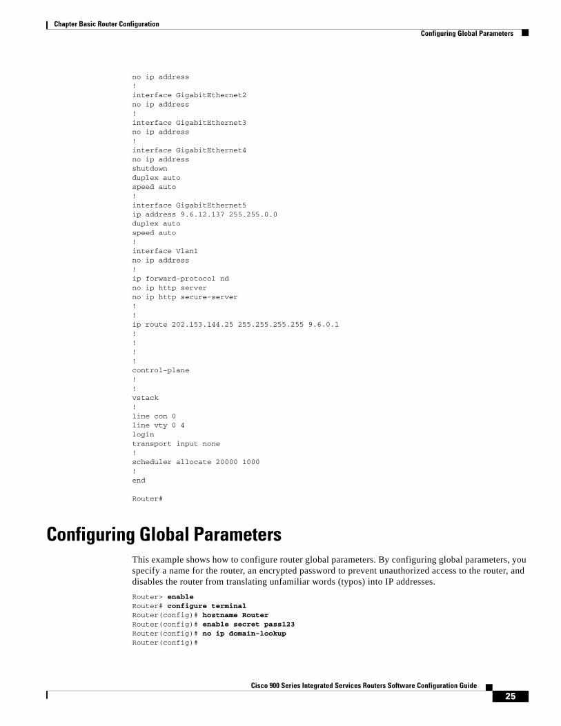
no ip address!interface GigabitEthernet2no ip address!interface GigabitEthernet3no ip address!interface GigabitEthernet4no ip addressshutdownduplex autospeed auto!interface GigabitEthernet5ip address 9.6.12.137 255.255.0.0duplex autospeed auto!interface Vlan1no ip address!ip forward-protocol ndno ip http serverno ip http secure-server!!ip route 202.153.144.25 255.255.255.255 9.6.0.1!!!!control-plane!!vstack!line con 0line vty 0 4logintransport input none!scheduler allocate 20000 1000!end Router#
Configuring Global ParametersThis example shows how to configure router global parameters. By configuring global parameters, you specify a name for the router, an encrypted password to prevent unauthorized access to the router, and disables the router from translating unfamiliar words (typos) into IP addresses.
Router> enableRouter# configure terminalRouter(config)# hostname RouterRouter(config)# enable secret pass123Router(config)# no ip domain-lookup Router(config)#
26Cisco 900 Series Integrated Services Routers Software Configuration Guide
Chapter Basic Router Configuration Configuring I/O Memory Allocation
For complete information on global parameter commands, see the Cisco IOS Release configuration guide documentation set.
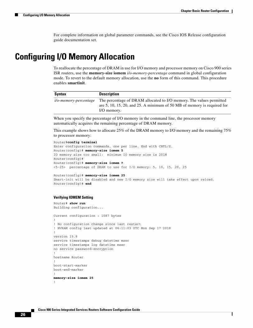
Configuring I/O Memory AllocationTo reallocate the percentage of DRAM in use for I/O memory and processor memory on Cisco 900 series ISR routers, use the memory-size iomem i/o-memory-percentage command in global configuration mode. To revert to the default memory allocation, use the no form of this command. This procedure enables smartinit.
When you specify the percentage of I/O memory in the command line, the processor memory automatically acquires the remaining percentage of DRAM memory.
This example shows how to allocate 25% of the DRAM memory to I/O memory and the remaining 75% to processor memory:
Router#config terminalEnter configuration commands, one per line. End with CNTL/Z.Router(config)# memory-size iomem 5IO memory size too small: minimum IO memory size is 201M Router(config)# Router(config)# memory-size iomem ?<5-25> percentage of DRAM to use for I/O memory: 5, 10, 15, 20, 25
Router(config)# memory-size iomem 25Smart-init will be disabled and new I/O memory size will take effect upon reload.Router(config)# end
Verifying IOMEM SettingRouter# show runBuilding configuration... Current configuration : 1087 bytes!! No configuration change since last restart! NVRAM config last updated at 06:11:03 UTC Mon Sep 17 2018!version 15.8service timestamps debug datetime msecservice timestamps log datetime msecno service password-encryption!hostname Router!boot-start-markerboot-end-marker!memory-size iomem 25!
Syntax Description
i/o-memory-percentage The percentage of DRAM allocated to I/O memory. The values permitted are 5, 10, 15, 20, and 25. A minimum of 50 MB of memory is required for I/O memory.
27Cisco 900 Series Integrated Services Routers Software Configuration Guide
Chapter Basic Router Configuration Interface Ports
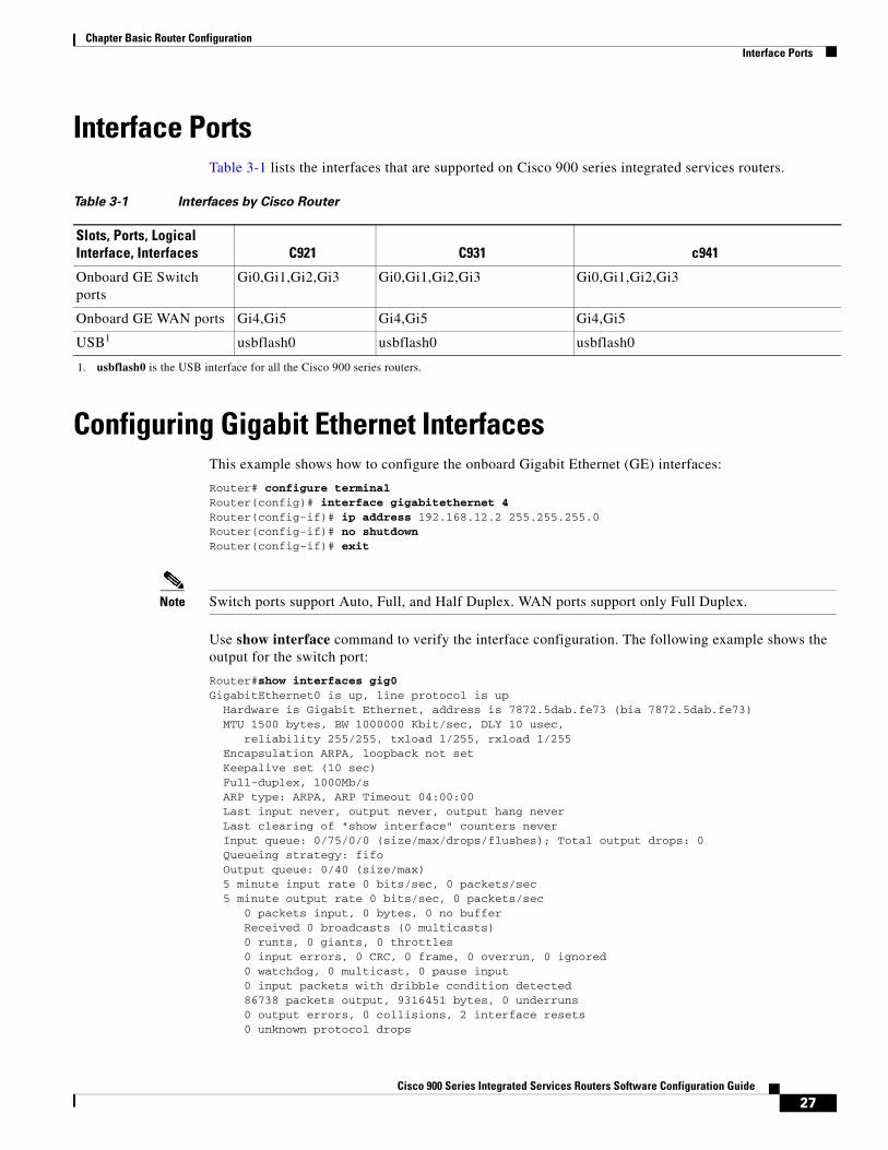
Interface PortsTable 3-1 lists the interfaces that are supported on Cisco 900 series integrated services routers.
Configuring Gigabit Ethernet InterfacesThis example shows how to configure the onboard Gigabit Ethernet (GE) interfaces:
Router# configure terminalRouter(config)# interface gigabitethernet 4Router(config-if)# ip address 192.168.12.2 255.255.255.0Router(config-if)# no shutdownRouter(config-if)# exit
Note Switch ports support Auto, Full, and Half Duplex. WAN ports support only Full Duplex.
Use show interface command to verify the interface configuration. The following example shows the output for the switch port:
Router#show interfaces gig0 GigabitEthernet0 is up, line protocol is up Hardware is Gigabit Ethernet, address is 7872.5dab.fe73 (bia 7872.5dab.fe73) MTU 1500 bytes, BW 1000000 Kbit/sec, DLY 10 usec, reliability 255/255, txload 1/255, rxload 1/255 Encapsulation ARPA, loopback not set Keepalive set (10 sec) Full-duplex, 1000Mb/s ARP type: ARPA, ARP Timeout 04:00:00 Last input never, output never, output hang never Last clearing of "show interface" counters never Input queue: 0/75/0/0 (size/max/drops/flushes); Total output drops: 0 Queueing strategy: fifo Output queue: 0/40 (size/max) 5 minute input rate 0 bits/sec, 0 packets/sec 5 minute output rate 0 bits/sec, 0 packets/sec 0 packets input, 0 bytes, 0 no buffer Received 0 broadcasts (0 multicasts) 0 runts, 0 giants, 0 throttles 0 input errors, 0 CRC, 0 frame, 0 overrun, 0 ignored 0 watchdog, 0 multicast, 0 pause input 0 input packets with dribble condition detected 86738 packets output, 9316451 bytes, 0 underruns 0 output errors, 0 collisions, 2 interface resets 0 unknown protocol drops
Table 3-1 Interfaces by Cisco Router
Slots, Ports, Logical Interface, Interfaces C921 C931 c941
Onboard GE Switch ports
Gi0,Gi1,Gi2,Gi3 Gi0,Gi1,Gi2,Gi3 Gi0,Gi1,Gi2,Gi3
Onboard GE WAN ports Gi4,Gi5 Gi4,Gi5 Gi4,Gi5
USB1
1. usbflash0 is the USB interface for all the Cisco 900 series routers.
usbflash0 usbflash0 usbflash0
28Cisco 900 Series Integrated Services Routers Software Configuration Guide
Chapter Basic Router Configuration Configuring a Loopback Interface
0 babbles, 0 late collision, 0 deferred 0 lost carrier, 0 no carrier, 0 pause output 0 output buffer failures, 0 output buffers swapped out
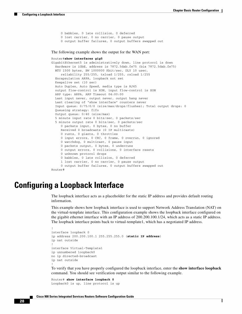
The following example shows the output for the WAN port:
Router#show interfaces gig5 GigabitEthernet5 is administratively down, line protocol is down Hardware is iGbE, address is 7872.5dab.fe75 (bia 7872.5dab.fe75) MTU 1500 bytes, BW 1000000 Kbit/sec, DLY 10 usec, reliability 255/255, txload 1/255, rxload 1/255 Encapsulation ARPA, loopback not set Keepalive set (10 sec) Auto Duplex, Auto Speed, media type is RJ45 output flow-control is XON, input flow-control is XON ARP type: ARPA, ARP Timeout 04:00:00 Last input never, output never, output hang never Last clearing of "show interface" counters never Input queue: 0/75/0/0 (size/max/drops/flushes); Total output drops: 0 Queueing strategy: fifo Output queue: 0/40 (size/max) 5 minute input rate 0 bits/sec, 0 packets/sec 5 minute output rate 0 bits/sec, 0 packets/sec 0 packets input, 0 bytes, 0 no buffer Received 0 broadcasts (0 IP multicasts) 0 runts, 0 giants, 0 throttles 0 input errors, 0 CRC, 0 frame, 0 overrun, 0 ignored 0 watchdog, 0 multicast, 0 pause input 0 packets output, 0 bytes, 0 underruns 0 output errors, 0 collisions, 0 interface resets 0 unknown protocol drops 0 babbles, 0 late collision, 0 deferred 1 lost carrier, 0 no carrier, 0 pause output 0 output buffer failures, 0 output buffers swapped outRouter#
Configuring a Loopback InterfaceThe loopback interface acts as a placeholder for the static IP address and provides default routing information.
This example shows how loopback interface is used to support Network Address Translation (NAT) on the virtual-template interface. This configuration example shows the loopback interface configured on the gigabit ethernet interface with an IP address of 200.200.100.1/24, which acts as a static IP address. The loopback interface points back to virtual-template1, which has a negotiated IP address.
!interface loopback 0ip address 200.200.100.1 255.255.255.0 (static IP address)ip nat outside!interface Virtual-Template1ip unnumbered loopback0no ip directed-broadcastip nat outside!
To verify that you have properly configured the loopback interface, enter the show interface loopback command. You should see verification output similar to the following example.
Router# show interface loopback 0Loopback0 is up, line protocol is up
29Cisco 900 Series Integrated Services Routers Software Configuration Guide
Chapter Basic Router Configuration Configuring Command-Line Access
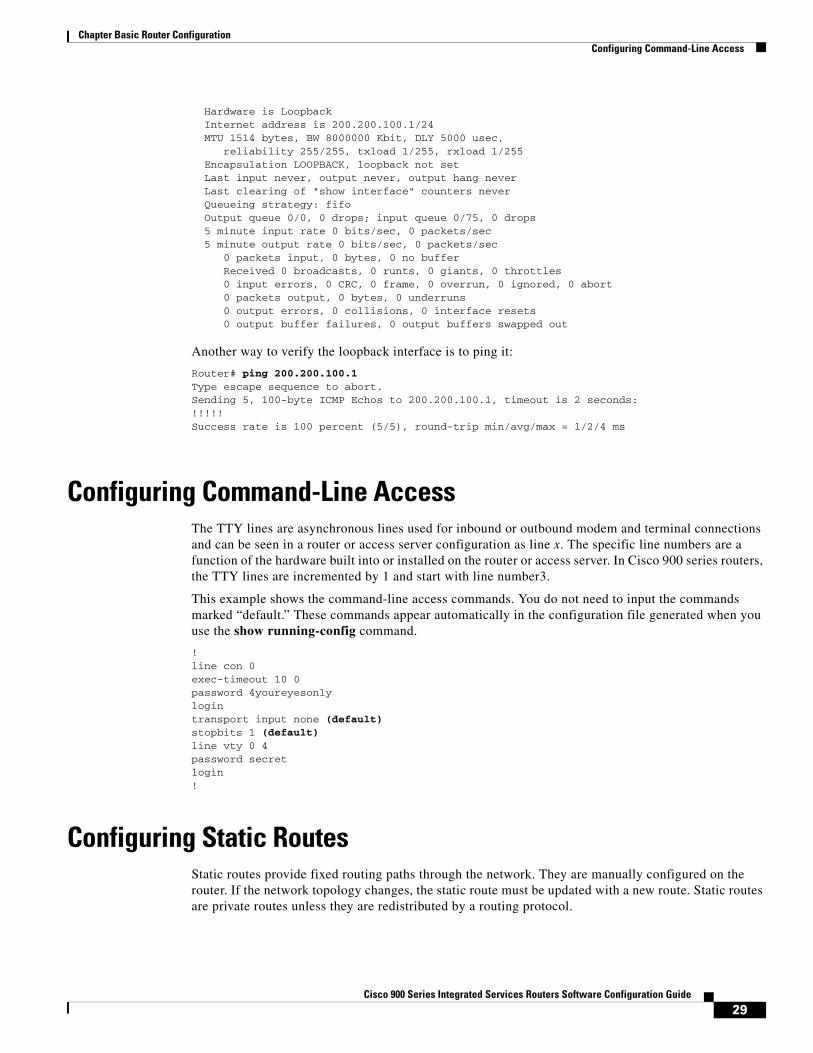
Hardware is Loopback Internet address is 200.200.100.1/24 MTU 1514 bytes, BW 8000000 Kbit, DLY 5000 usec, reliability 255/255, txload 1/255, rxload 1/255 Encapsulation LOOPBACK, loopback not set Last input never, output never, output hang never Last clearing of "show interface" counters never Queueing strategy: fifo Output queue 0/0, 0 drops; input queue 0/75, 0 drops 5 minute input rate 0 bits/sec, 0 packets/sec 5 minute output rate 0 bits/sec, 0 packets/sec 0 packets input, 0 bytes, 0 no buffer Received 0 broadcasts, 0 runts, 0 giants, 0 throttles 0 input errors, 0 CRC, 0 frame, 0 overrun, 0 ignored, 0 abort 0 packets output, 0 bytes, 0 underruns 0 output errors, 0 collisions, 0 interface resets 0 output buffer failures, 0 output buffers swapped out
Another way to verify the loopback interface is to ping it:
Router# ping 200.200.100.1 Type escape sequence to abort.Sending 5, 100-byte ICMP Echos to 200.200.100.1, timeout is 2 seconds:!!!!!Success rate is 100 percent (5/5), round-trip min/avg/max = 1/2/4 ms
Configuring Command-Line AccessThe TTY lines are asynchronous lines used for inbound or outbound modem and terminal connections and can be seen in a router or access server configuration as line x. The specific line numbers are a function of the hardware built into or installed on the router or access server. In Cisco 900 series routers, the TTY lines are incremented by 1 and start with line number3.
This example shows the command-line access commands. You do not need to input the commands marked “default.” These commands appear automatically in the configuration file generated when you use the show running-config command.
!line con 0exec-timeout 10 0password 4youreyesonlylogintransport input none (default)stopbits 1 (default)line vty 0 4password secretlogin!
Configuring Static RoutesStatic routes provide fixed routing paths through the network. They are manually configured on the router. If the network topology changes, the static route must be updated with a new route. Static routes are private routes unless they are redistributed by a routing protocol.
30Cisco 900 Series Integrated Services Routers Software Configuration Guide
Chapter Basic Router Configuration Configuring Dynamic Routes
In this configuration example, the static route sends out all IP packets with a destination IP address of 192.168.1.0 and a subnet mask of 255.255.255.0 on the Gigabit Ethernet interface to another device with an IP address of 10.10.10.2. Specifically, the packets are sent to the configured PVC.
You do not need to enter the command marked “(default).” This command appears automatically in the configuration file generated when you use the show running-config command.
!ip classless (default)ip route 192.168.1.0 255.255.255.0 10.10.10.2!
To verify that you have properly configured static routing, enter the show ip route command and look for static routes signified by the “S.”
You should see verification output similar to the following:
Router# show ip routeCodes: C - connected, S - static, R - RIP, M - mobile, B - BGP D - EIGRP, EX - EIGRP external, O - OSPF, IA - OSPF inter area N1 - OSPF NSSA external type 1, N2 - OSPF NSSA external type 2 E1 - OSPF external type 1, E2 - OSPF external type 2 i - IS-IS, su - IS-IS summary, L1 - IS-IS level-1, L2 - IS-IS level-2 ia - IS-IS inter area, * - candidate default, U - per-user static route o - ODR, P - periodic downloaded static route
Gateway of last resort is not set
10.0.0.0/24 is subnetted, 1 subnetsC 10.108.1.0 is directly connected, Loopback0S* 0.0.0.0/0 is directly connected, gigabitethernet0
Configuring Dynamic RoutesIn dynamic routing, the network protocol adjusts the path automatically, based on network traffic or topology. Changes in dynamic routes are shared with other routers in the network.
The Cisco routers can use IP routing protocols, such as Routing Information Protocol (RIP) or Enhanced Interior Gateway Routing Protocol (EIGRP), to learn routes dynamically. You can configure either of these routing protocols on your router.
• Configuring Routing Information Protocol, page 30
• Configuring Enhanced Interior Gateway Routing Protocol, page 31
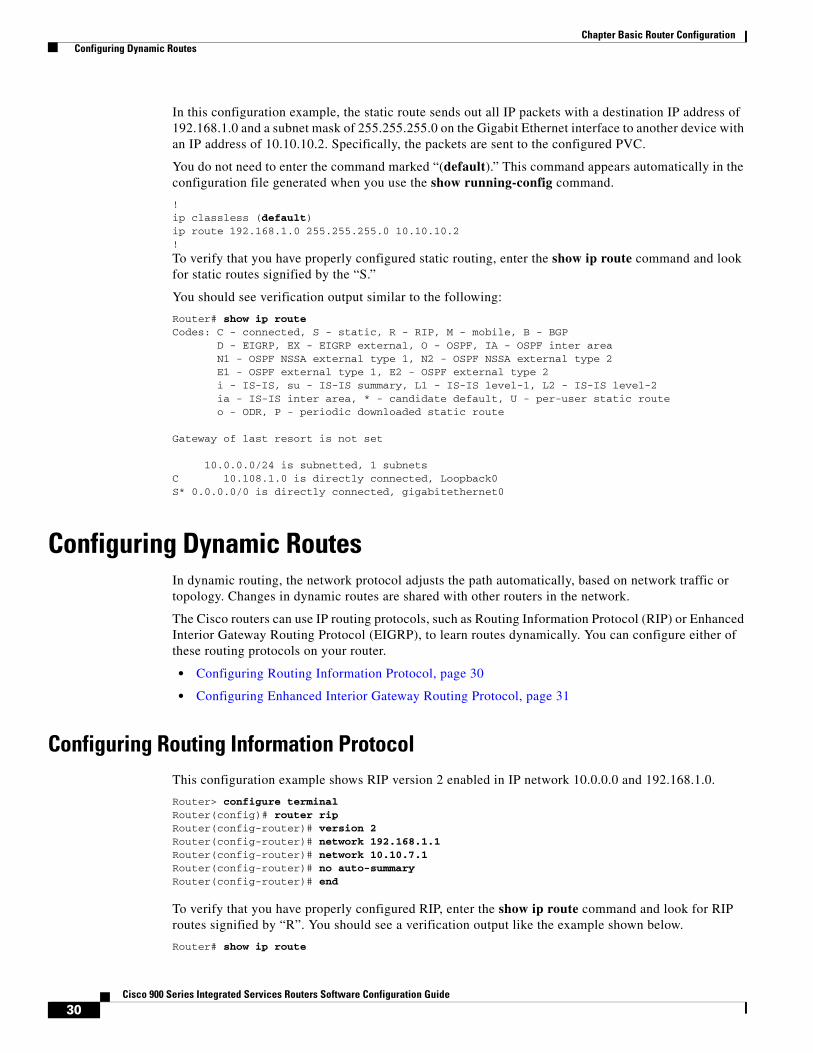
Configuring Routing Information ProtocolThis configuration example shows RIP version 2 enabled in IP network 10.0.0.0 and 192.168.1.0.
Router> configure terminalRouter(config)# router ripRouter(config-router)# version 2Router(config-router)# network 192.168.1.1Router(config-router)# network 10.10.7.1Router(config-router)# no auto-summaryRouter(config-router)# end
To verify that you have properly configured RIP, enter the show ip route command and look for RIP routes signified by “R”. You should see a verification output like the example shown below.
Router# show ip route
31Cisco 900 Series Integrated Services Routers Software Configuration Guide
Chapter Basic Router Configuration Configuring Dynamic Routes
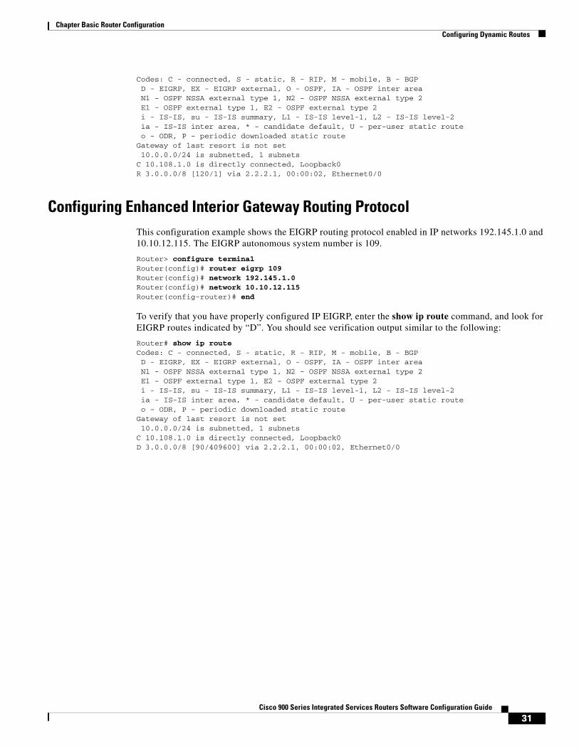
Codes: C - connected, S - static, R - RIP, M - mobile, B - BGP D - EIGRP, EX - EIGRP external, O - OSPF, IA - OSPF inter area N1 - OSPF NSSA external type 1, N2 - OSPF NSSA external type 2 E1 - OSPF external type 1, E2 - OSPF external type 2 i - IS-IS, su - IS-IS summary, L1 - IS-IS level-1, L2 - IS-IS level-2 ia - IS-IS inter area, * - candidate default, U - per-user static route o - ODR, P - periodic downloaded static routeGateway of last resort is not set 10.0.0.0/24 is subnetted, 1 subnetsC 10.108.1.0 is directly connected, Loopback0R 3.0.0.0/8 [120/1] via 2.2.2.1, 00:00:02, Ethernet0/0
Configuring Enhanced Interior Gateway Routing ProtocolThis configuration example shows the EIGRP routing protocol enabled in IP networks 192.145.1.0 and 10.10.12.115. The EIGRP autonomous system number is 109.
Router> configure terminalRouter(config)# router eigrp 109Router(config)# network 192.145.1.0Router(config)# network 10.10.12.115Router(config-router)# end
To verify that you have properly configured IP EIGRP, enter the show ip route command, and look for EIGRP routes indicated by “D”. You should see verification output similar to the following:
Router# show ip routeCodes: C - connected, S - static, R - RIP, M - mobile, B - BGP D - EIGRP, EX - EIGRP external, O - OSPF, IA - OSPF inter area N1 - OSPF NSSA external type 1, N2 - OSPF NSSA external type 2 E1 - OSPF external type 1, E2 - OSPF external type 2 i - IS-IS, su - IS-IS summary, L1 - IS-IS level-1, L2 - IS-IS level-2 ia - IS-IS inter area, * - candidate default, U - per-user static route o - ODR, P - periodic downloaded static routeGateway of last resort is not set 10.0.0.0/24 is subnetted, 1 subnetsC 10.108.1.0 is directly connected, Loopback0D 3.0.0.0/8 [90/409600] via 2.2.2.1, 00:00:02, Ethernet0/0

32Cisco 900 Series Integrated Services Routers Software Configuration Guide
Chapter Basic Router Configuration Configuring Dynamic Routes
C H A P T E R
33Cisco 900 Series Integrated Services Routers Software Configuration Guide
4Configuring Ethernet Switches
This chapter gives an overview of configuration tasks for the Gigabit Ethernet (GE) switch on the Cisco 900 Series ISR.
This chapter contains the following sections:
• Configuring VLANs, page 33
• Configuring VTP, page 34
• Configuring 802.1x Authentication, page 35
• Configuring Spanning Tree Protocol, page 36
• Configuring MAC Address Table Manipulation, page 38
• Configuring MAC Address Notification Traps, page 39
• Configuring the Switched Port Analyzer, page 39
• Configuring IGMP Snooping, page 40
• Configuring Per-Port Storm Control, page 41
• Configuring HSRP, page 42
• Configuring VRRP, page 43
Configuring VLANs A VLAN is a switched network that is logically segmented by function, project team, or application, without regard to the physical locations of the users. VLANs have the same attributes as physical LANs, but you can group end stations even if they are not physically located on the same LAN segment. Any switch port can belong to a VLAN, and unicast, broadcast, and multicast packets are forwarded and flooded only to end stations in the VLAN. Each VLAN is considered a logical network, and packets destined for stations that do not belong to the VLAN must be forwarded through a router. A VLAN is a switched network that is logically segmented by function, project team, or application, without regard to the physical locations of the users. VLANs have the same attributes as physical LANs, but you can group end stations even if they are not physically located on the same LAN segment. Any switch port can belong to a VLAN, and unicast, broadcast, and multicast packets are forwarded and flooded only to end stations in the VLAN. Each VLAN is considered a logical network, and packets destined for stations that do not belong to the VLAN must be forwarded through a router.
For detailed information on VLANs, see the following web link:
http://www.cisco.com/c/en/us/td/docs/switches/lan/catalyst3750/software/release/15-0_2_se/configuration/guide/scg3750/swvlan.html
34Cisco 900 Series Integrated Services Routers Software Configuration Guide
Chapter Configuring Ethernet Switches
For a sample VLAN configuration, see “Example: VLAN configuration”.
Example: VLAN configuration
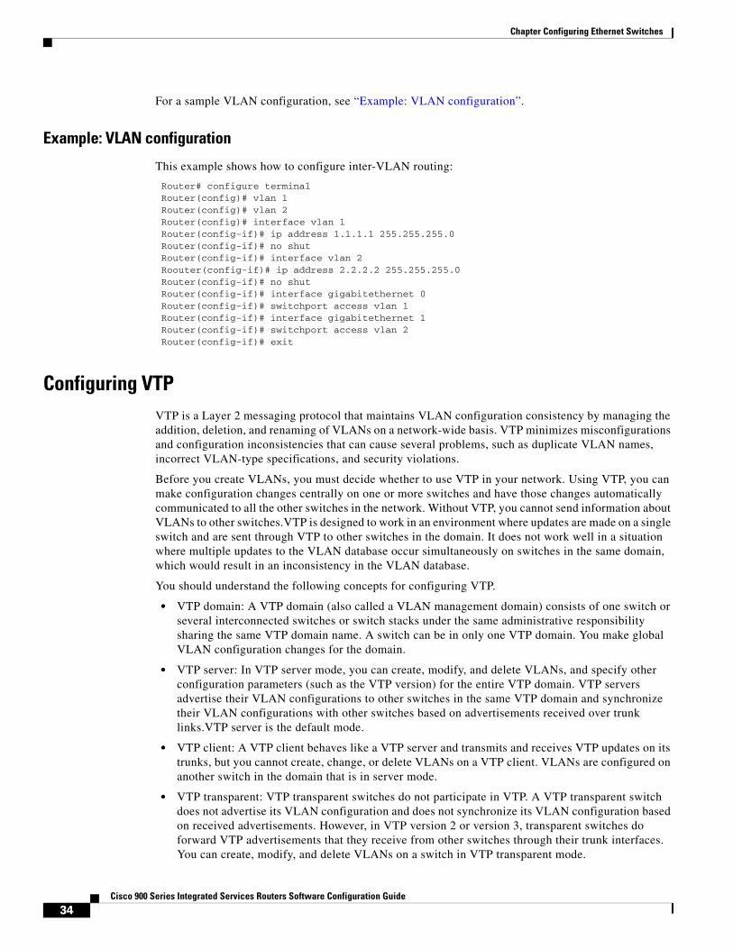
This example shows how to configure inter-VLAN routing:
Router# configure terminal Router(config)# vlan 1 Router(config)# vlan 2 Router(config)# interface vlan 1 Router(config-if)# ip address 1.1.1.1 255.255.255.0 Router(config-if)# no shut Router(config-if)# interface vlan 2 Roouter(config-if)# ip address 2.2.2.2 255.255.255.0 Router(config-if)# no shut Router(config-if)# interface gigabitethernet 0 Router(config-if)# switchport access vlan 1 Router(config-if)# interface gigabitethernet 1 Router(config-if)# switchport access vlan 2 Router(config-if)# exit
Configuring VTPVTP is a Layer 2 messaging protocol that maintains VLAN configuration consistency by managing the addition, deletion, and renaming of VLANs on a network-wide basis. VTP minimizes misconfigurations and configuration inconsistencies that can cause several problems, such as duplicate VLAN names, incorrect VLAN-type specifications, and security violations.
Before you create VLANs, you must decide whether to use VTP in your network. Using VTP, you can make configuration changes centrally on one or more switches and have those changes automatically communicated to all the other switches in the network. Without VTP, you cannot send information about VLANs to other switches.VTP is designed to work in an environment where updates are made on a single switch and are sent through VTP to other switches in the domain. It does not work well in a situation where multiple updates to the VLAN database occur simultaneously on switches in the same domain, which would result in an inconsistency in the VLAN database.
You should understand the following concepts for configuring VTP.
• VTP domain: A VTP domain (also called a VLAN management domain) consists of one switch or several interconnected switches or switch stacks under the same administrative responsibility sharing the same VTP domain name. A switch can be in only one VTP domain. You make global VLAN configuration changes for the domain.
• VTP server: In VTP server mode, you can create, modify, and delete VLANs, and specify other configuration parameters (such as the VTP version) for the entire VTP domain. VTP servers advertise their VLAN configurations to other switches in the same VTP domain and synchronize their VLAN configurations with other switches based on advertisements received over trunk links.VTP server is the default mode.
• VTP client: A VTP client behaves like a VTP server and transmits and receives VTP updates on its trunks, but you cannot create, change, or delete VLANs on a VTP client. VLANs are configured on another switch in the domain that is in server mode.
• VTP transparent: VTP transparent switches do not participate in VTP. A VTP transparent switch does not advertise its VLAN configuration and does not synchronize its VLAN configuration based on received advertisements. However, in VTP version 2 or version 3, transparent switches do forward VTP advertisements that they receive from other switches through their trunk interfaces. You can create, modify, and delete VLANs on a switch in VTP transparent mode.
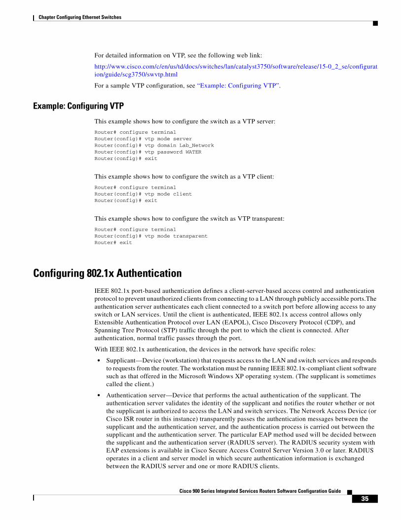
35Cisco 900 Series Integrated Services Routers Software Configuration Guide
Chapter Configuring Ethernet Switches
For detailed information on VTP, see the following web link:
http://www.cisco.com/c/en/us/td/docs/switches/lan/catalyst3750/software/release/15-0_2_se/configuration/guide/scg3750/swvtp.html
For a sample VTP configuration, see “Example: Configuring VTP”.
Example: Configuring VTP
This example shows how to configure the switch as a VTP server:
Router# configure terminalRouter(config)# vtp mode serverRouter(config)# vtp domain Lab_NetworkRouter(config)# vtp password WATERRouter(config)# exit
This example shows how to configure the switch as a VTP client:
Router# configure terminalRouter(config)# vtp mode clientRouter(config)# exit
This example shows how to configure the switch as VTP transparent:
Router# configure terminalRouter(config)# vtp mode transparentRouter# exit
Configuring 802.1x AuthenticationIEEE 802.1x port-based authentication defines a client-server-based access control and authentication protocol to prevent unauthorized clients from connecting to a LAN through publicly accessible ports.The authentication server authenticates each client connected to a switch port before allowing access to any switch or LAN services. Until the client is authenticated, IEEE 802.1x access control allows only Extensible Authentication Protocol over LAN (EAPOL), Cisco Discovery Protocol (CDP), and Spanning Tree Protocol (STP) traffic through the port to which the client is connected. After authentication, normal traffic passes through the port.
With IEEE 802.1x authentication, the devices in the network have specific roles:
• Supplicant—Device (workstation) that requests access to the LAN and switch services and responds to requests from the router. The workstation must be running IEEE 802.1x-compliant client software such as that offered in the Microsoft Windows XP operating system. (The supplicant is sometimes called the client.)
• Authentication server—Device that performs the actual authentication of the supplicant. The authentication server validates the identity of the supplicant and notifies the router whether or not the supplicant is authorized to access the LAN and switch services. The Network Access Device (or Cisco ISR router in this instance) transparently passes the authentication messages between the supplicant and the authentication server, and the authentication process is carried out between the supplicant and the authentication server. The particular EAP method used will be decided between the supplicant and the authentication server (RADIUS server). The RADIUS security system with EAP extensions is available in Cisco Secure Access Control Server Version 3.0 or later. RADIUS operates in a client and server model in which secure authentication information is exchanged between the RADIUS server and one or more RADIUS clients.
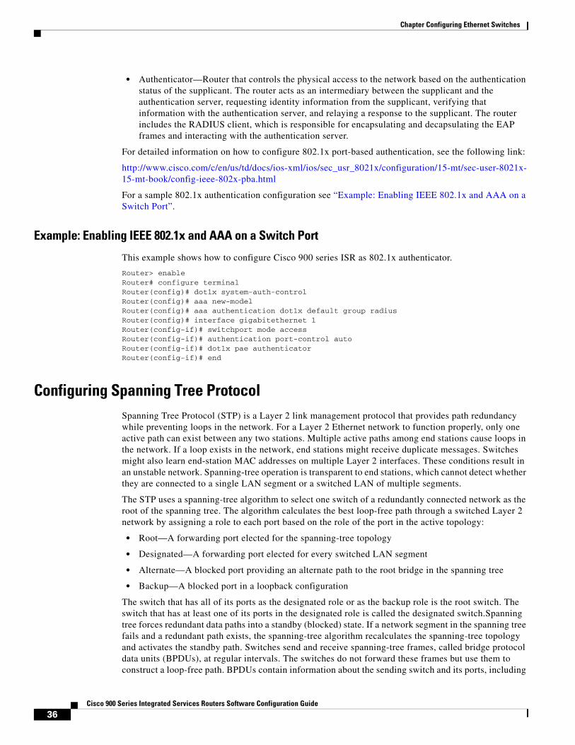
36Cisco 900 Series Integrated Services Routers Software Configuration Guide
Chapter Configuring Ethernet Switches
• Authenticator—Router that controls the physical access to the network based on the authentication status of the supplicant. The router acts as an intermediary between the supplicant and the authentication server, requesting identity information from the supplicant, verifying that information with the authentication server, and relaying a response to the supplicant. The router includes the RADIUS client, which is responsible for encapsulating and decapsulating the EAP frames and interacting with the authentication server.
For detailed information on how to configure 802.1x port-based authentication, see the following link:
http://www.cisco.com/c/en/us/td/docs/ios-xml/ios/sec_usr_8021x/configuration/15-mt/sec-user-8021x-15-mt-book/config-ieee-802x-pba.html
For a sample 802.1x authentication configuration see “Example: Enabling IEEE 802.1x and AAA on a Switch Port”.
Example: Enabling IEEE 802.1x and AAA on a Switch Port
This example shows how to configure Cisco 900 series ISR as 802.1x authenticator.
Router> enableRouter# configure terminalRouter(config)# dot1x system-auth-controlRouter(config)# aaa new-modelRouter(config)# aaa authentication dot1x default group radiusRouter(config)# interface gigabitethernet 1Router(config-if)# switchport mode accessRouter(config-if)# authentication port-control autoRouter(config-if)# dot1x pae authenticatorRouter(config-if)# end
Configuring Spanning Tree ProtocolSpanning Tree Protocol (STP) is a Layer 2 link management protocol that provides path redundancy while preventing loops in the network. For a Layer 2 Ethernet network to function properly, only one active path can exist between any two stations. Multiple active paths among end stations cause loops in the network. If a loop exists in the network, end stations might receive duplicate messages. Switches might also learn end-station MAC addresses on multiple Layer 2 interfaces. These conditions result in an unstable network. Spanning-tree operation is transparent to end stations, which cannot detect whether they are connected to a single LAN segment or a switched LAN of multiple segments.
The STP uses a spanning-tree algorithm to select one switch of a redundantly connected network as the root of the spanning tree. The algorithm calculates the best loop-free path through a switched Layer 2 network by assigning a role to each port based on the role of the port in the active topology:
• Root—A forwarding port elected for the spanning-tree topology
• Designated—A forwarding port elected for every switched LAN segment
• Alternate—A blocked port providing an alternate path to the root bridge in the spanning tree
• Backup—A blocked port in a loopback configuration
The switch that has all of its ports as the designated role or as the backup role is the root switch. The switch that has at least one of its ports in the designated role is called the designated switch.Spanning tree forces redundant data paths into a standby (blocked) state. If a network segment in the spanning tree fails and a redundant path exists, the spanning-tree algorithm recalculates the spanning-tree topology and activates the standby path. Switches send and receive spanning-tree frames, called bridge protocol data units (BPDUs), at regular intervals. The switches do not forward these frames but use them to construct a loop-free path. BPDUs contain information about the sending switch and its ports, including
37Cisco 900 Series Integrated Services Routers Software Configuration Guide
Chapter Configuring Ethernet Switches
switch and MAC addresses, switch priority, port priority, and path cost. Spanning tree uses this information to elect the root switch and root port for the switched network and the root port and designated port for each switched segment.
When two ports on a switch are part of a loop, the spanning-tree port priority and path cost settings control which port is put in the forwarding state and which is put in the blocking state. The spanning-tree port priority value represents the location of a port in the network topology and how well it is located to pass traffic. The path cost value represents the media speed.
For detailed configuration information on STP see the following link:
http://www.cisco.com/c/en/us/td/docs/switches/lan/catalyst3750/software/release/15-0_2_se/configuration/guide/scg3750/swstp.html
For configuration examples, see “Example: Spanning Tree Protocol Configuration”.
Example: Spanning Tree Protocol Configuration
This example shows configuring spanning-tree port priority of a Gigabit Ethernet interface. If a loop occurs, spanning tree uses the port priority when selecting an interface to put in the forwarding state.
Router# configure terminal Router(config)# interface gigabitethernet 2Router(config-if)# spanning-tree vlan 1 port-priority 64 Router(config-if)# end
This example shows how to change the spanning-tree port cost of a Gigabit Ethernet interface. If a loop occurs, spanning tree uses cost when selecting an interface to put in the forwarding state.
Router#configure terminal Router(config)# interface gigabitethernet 2Router(config-if)# spanning-tree cost 18 Router(config-if)# end
This example shows configuring the bridge priority of VLAN 10 to 33792:
Router# configure terminal Router(config)# spanning-tree vlan 10 priority 33792 Router(config)# end
This example shows configuring the hello time for VLAN 10 being configured to 7 seconds. The hello time is the interval between the generation of configuration messages by the root switch.
Router# configure terminal Router(config)# spanning-tree vlan 10 hello-time 4Router(config)# end
This example shows configuring forward delay time. The forward delay is the number of seconds an interface waits before changing from its spanning-tree learning and listening states to the forwarding state.Router# configure terminal Router(config)# spanning-tree vlan 10 forward-time 21 Router(config)# end
This example shows configuring maximum age interval for the spanning tree. The maximum-aging time is the number of seconds a switch waits without receiving spanning-tree configuration messages before attempting a reconfiguration.
Router# configure terminal Router(config)# spanning-tree vlan 20 max-age 36 Router(config)# end
38Cisco 900 Series Integrated Services Routers Software Configuration Guide
Chapter Configuring Ethernet Switches
This example shows the switch being configured as the root bridge for VLAN 10, with a network diameter of 4.
Router# configure terminal Router(config)# spanning-tree vlan 10 root primary diameter 4 Router(config)# exit
Configuring MAC Address Table ManipulationThe MAC address table contains address information that the switch uses to forward traffic between ports. All MAC addresses in the address table are associated with one or more ports. The address table includes these types of addresses:
• Dynamic address: a source MAC address that the switch learns and then drops when it is not in use. You can use the aging time setting to define how long the switch retains unseen addresses in the table.
• Static address: a manually entered unicast address that does not age and that is not lost when the switch resets.
The address table lists the destination MAC address, the associated VLAN ID, and port number associated with the address and the type (static or dynamic).
See the “Example: MAC Address Table Manipulation” for sample configurations for enabling secure MAC address, creating a statc entry, set the maximum number of secure MAC addresses and set the aging time.
For detailed configuration information on MAC address table manipulation see the following link:
http://www.cisco.com/c/en/us/td/docs/routers/access/interfaces/software/feature/guide/geshwic_cfg.html#wp1048223
Example: MAC Address Table Manipulation
This example shows configuration for enabling secure MAC address option on the port.
Router# configure terminalRouter(config)# mac-address-table secure 0004.0005.0006 GigabitEthernet 1 vlan 5Router(config)# end
This example shows creating a static entry in the MAC address table.
Router# configure terminalRouter(config)# mac-address-table static 0002.0003.0004 interface GigabitEthernet 2 vlan 3Router(config)# end
This example sets the maximum number of secure MAC addresses to 10.
Router# configure terminalRouter(config)# mac-address-table secure maximum 10 GigabitEthernet 1Router(config)# end
This example shows setting the aging timer.
Router# configure terminalRouter(config)# mac-address-table aging-time 300Router(config)# end
39Cisco 900 Series Integrated Services Routers Software Configuration Guide
Chapter Configuring Ethernet Switches
Configuring MAC Address Notification TrapsMAC address notification enables you to track users on a network by storing the MAC address activity on the switch. Whenever the switch learns or removes a MAC address, an SNMP notification can be generated and sent to the network management system (NMS). If you have many users coming and going from the network, you can set a trap interval time to bundle the notification traps and reduce network traffic. The MAC notification history table stores the MAC address activity for each hardware port for which the trap is enabled. MAC address notifications are generated for dynamic and secure MAC addresses; events are not generated for self addresses, multicast addresses, or other static addresses.
For configuration examples, see “Example: Configuring MAC Address Notification Traps”.
Example: Configuring MAC Address Notification Traps
This example shows how to enable the MAC notification trap when a MAC address is added to the interface:
Router(config)# interface gigabitethernet 1 Router(config-if)# snmp trap mac-notification added Router(config-if)# end
This example shows how to enable the MAC notification trap when a MAC address is removed from this interface.
Router(config)# interface gigabitethernet 1 Router(config-if)# snmp trap mac-notification removedRouter(config-if)# end
Configuring the Switched Port AnalyzerYou can analyze network traffic passing through ports or VLANs by using SPAN or RSPAN to send a copy of the traffic to another port on the switch or on another switch that has been connected to a network analyzer or other monitoring or security device. SPAN copies (or mirrors) traffic received or sent (or both) on source ports or source VLANs to a destination port for analysis. SPAN does not affect the switching of network traffic on the source ports or VLANs. You must dedicate the destination port for SPAN use. Except for traffic that is required for the SPAN or RSPAN session, destination ports do not receive or forward traffic.
Only traffic that enters or leaves source ports or traffic that enters or leaves source VLANs can be monitored by using SPAN; traffic routed to a source VLAN cannot be monitored. For example, if incoming traffic is being monitored, traffic that gets routed from another VLAN to the source VLAN cannot be monitored; however, traffic that is received on the source VLAN and routed to another VLAN can be monitored.
See Example: SPAN Configuration, page 40 for SPAN configuration examples.
For detailed information on how to configure a switched port analyzer (SPAN) session, see the following web link:
http://www.cisco.com/c/en/us/td/docs/switches/lan/catalyst3750/software/release/15-0_2_se/configuration/guide/scg3750/swspan.html
40Cisco 900 Series Integrated Services Routers Software Configuration Guide
Chapter Configuring Ethernet Switches
Example: SPAN Configuration
This example shows how to configure a SPAN session to monitor bidirectional traffic from a Gigabit Ethernet source interface:
Router# configure terminal Router(config)# monitor session 1 source gigabitethernet 1Router(config)# end
This example shows how to configure a gigabit ethernet interface as the destination for a SPAN session:
Router# configure terminalRouter(config)# monitor session 1 destination gigabitethernet 2Router(config)# end
This example shows how to remove gigabit ethernet as a SPAN source for SPAN session 1:
Router# configure terminalRouter(config)# no monitor session 1 source gigabitethernet 1Router(config)# end
Configuring IGMP SnoopingIGMP snooping constrains the flooding of multicast traffic by dynamically configuring Layer 2 interfaces so that multicast traffic is forwarded to only those interfaces associated with IP multicast devices. As the name implies, IGMP snooping requires the LAN switch to snoop on the IGMP transmissions between the host and the router and to keep track of multicast groups and member ports. When the switch receives an IGMP report from a host for a particular multicast group, the switch adds the host port number to the forwarding table entry; when it receives an IGMP Leave Group message from a host, it removes the host port from the table entry. It also periodically deletes entries if it does not receive IGMP membership reports from the multicast clients.
The multicast router sends out periodic general queries to all VLANs. All hosts interested in this multicast traffic send join requests and are added to the forwarding table entry. The switch creates one entry per VLAN in the IGMP snooping IP multicast forwarding table for each group from which it receives an IGMP join request.
By default, IGMP snooping is globally enabled. When globally enabled or disabled, it is also enabled or disabled in all existing VLAN interfaces. By default, IGMP snooping is enabled on all VLANs, but it can be enabled and disabled on a per-VLAN basis. Global IGMP snooping overrides the per-VLAN IGMP snooping capability. If global snooping is disabled, you cannot enable VLAN snooping. If global snooping is enabled, you can enable or disable snooping on a VLAN basis.
See the “Example: Configuring IGMP Snooping” for a sample configuration on IGMP snooping.
Example: Configuring IGMP Snooping
This example shows how to enable IGMP snooping on a VLAN interface.
Router# configure terminalRouter(config)# ip igmp snooping vlan 1Router# end
This example shows how to enable a static connection to a multicast router.
Router# configure terminalRouter(config)# ip igmp snooping vlan 1 mrouter interface gigabitethernet 1Router# end
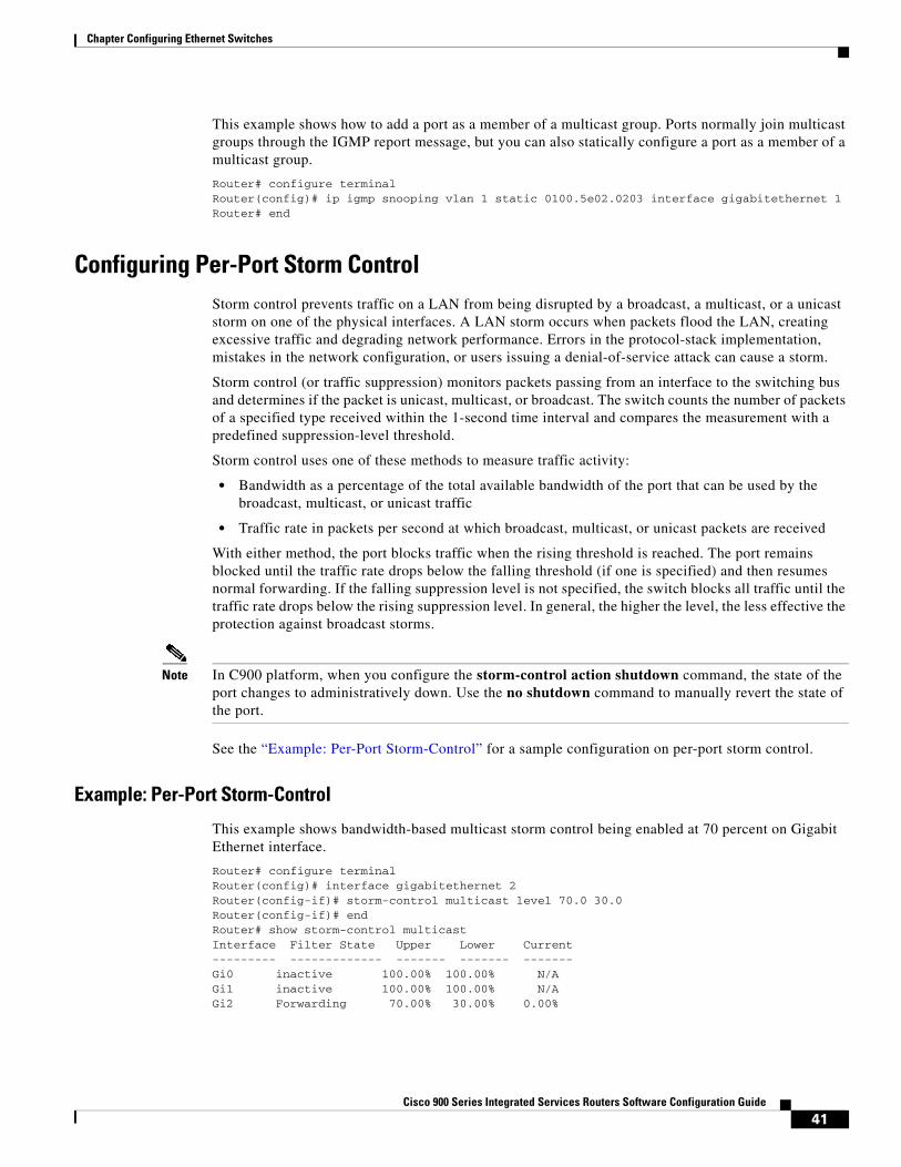
41Cisco 900 Series Integrated Services Routers Software Configuration Guide
Chapter Configuring Ethernet Switches
This example shows how to add a port as a member of a multicast group. Ports normally join multicast groups through the IGMP report message, but you can also statically configure a port as a member of a multicast group.
Router# configure terminalRouter(config)# ip igmp snooping vlan 1 static 0100.5e02.0203 interface gigabitethernet 1Router# end
Configuring Per-Port Storm ControlStorm control prevents traffic on a LAN from being disrupted by a broadcast, a multicast, or a unicast storm on one of the physical interfaces. A LAN storm occurs when packets flood the LAN, creating excessive traffic and degrading network performance. Errors in the protocol-stack implementation, mistakes in the network configuration, or users issuing a denial-of-service attack can cause a storm.
Storm control (or traffic suppression) monitors packets passing from an interface to the switching bus and determines if the packet is unicast, multicast, or broadcast. The switch counts the number of packets of a specified type received within the 1-second time interval and compares the measurement with a predefined suppression-level threshold.
Storm control uses one of these methods to measure traffic activity:
• Bandwidth as a percentage of the total available bandwidth of the port that can be used by the broadcast, multicast, or unicast traffic
• Traffic rate in packets per second at which broadcast, multicast, or unicast packets are received
With either method, the port blocks traffic when the rising threshold is reached. The port remains blocked until the traffic rate drops below the falling threshold (if one is specified) and then resumes normal forwarding. If the falling suppression level is not specified, the switch blocks all traffic until the traffic rate drops below the rising suppression level. In general, the higher the level, the less effective the protection against broadcast storms.
Note In C900 platform, when you configure the storm-control action shutdown command, the state of the port changes to administratively down. Use the no shutdown command to manually revert the state of the port.
See the “Example: Per-Port Storm-Control” for a sample configuration on per-port storm control.
Example: Per-Port Storm-Control
This example shows bandwidth-based multicast storm control being enabled at 70 percent on Gigabit Ethernet interface.
Router# configure terminalRouter(config)# interface gigabitethernet 2Router(config-if)# storm-control multicast level 70.0 30.0Router(config-if)# endRouter# show storm-control multicastInterface Filter State Upper Lower Current--------- ------------- ------- ------- -------Gi0 inactive 100.00% 100.00% N/AGi1 inactive 100.00% 100.00% N/AGi2 Forwarding 70.00% 30.00% 0.00%
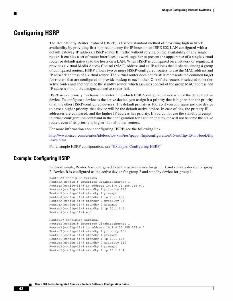
42Cisco 900 Series Integrated Services Routers Software Configuration Guide
Chapter Configuring Ethernet Switches
Configuring HSRP The Hot Standby Router Protocol (HSRP) is Cisco's standard method of providing high network availability by providing first-hop redundancy for IP hosts on an IEEE 802 LAN configured with a default gateway IP address. HSRP routes IP traffic without relying on the availability of any single router. It enables a set of router interfaces to work together to present the appearance of a single virtual router or default gateway to the hosts on a LAN. When HSRP is configured on a network or segment, it provides a virtual Media Access Control (MAC) address and an IP address that is shared among a group of configured routers. HSRP allows two or more HSRP-configured routers to use the MAC address and IP network address of a virtual router. The virtual router does not exist; it represents the common target for routers that are configured to provide backup to each other. One of the routers is selected to be the active router and another to be the standby router, which assumes control of the group MAC address and IP address should the designated active router fail.
HSRP uses a priority mechanism to determine which HSRP configured device is to be the default active device. To configure a device as the active device, you assign it a priority that is higher than the priority of all the other HSRP-configured devices. The default priority is 100, so if you configure just one device to have a higher priority, that device will be the default active device. In case of ties, the primary IP addresses are compared, and the higher IP address has priority. If you do not use the standby preempt interface configuration command in the configuration for a router, that router will not become the active router, even if its priority is higher than all other routers.
For more information about configuring HSRP, see the following link:
http://www.cisco.com/c/en/us/td/docs/ios-xml/ios/ipapp_fhrp/configuration/15-mt/fhp-15-mt-book/fhp-hsrp.html
For a sample HSRP configuration, see “Example: Configuring HSRP”
Example: Configuring HSRP
In this example, Router A is configured to be the active device for group 1 and standby device for group 2. Device B is configured as the active device for group 2 and standby device for group 1.
RouterA# configure terminalRouterA(config)# interface GigabitEthernet 1RouterA(config-if)# ip address 10.1.0.21 255.255.0.0RouterA(config-if)# standby 1 priority 110RouterA(config-if)# standby 1 preemptRouterA(config-if)# standby 1 ip 10.1.0.3RouterA(config-if)# standby 2 priority 95RouterA(config-if)# standby 2 preemptRouterA(config-if)# standby 2 ip 10.1.0.4RouterA(config-if)# end
RouterB# configure terminalRouterB(config)# interface GigabitEthernet 1RouterB(config-if)# ip address 10.1.0.22 255.255.0.0RouterB(config-if)# standby 1 priority 105RouterB(config-if)# standby 1 preemptRouterB(config-if)# standby 1 ip 10.1.0.3RouterB(config-if)# standby 2 priority 110RouterB(config-if)# standby 2 preemptRouterB(config-if)# standby 2 ip 10.1.0.4
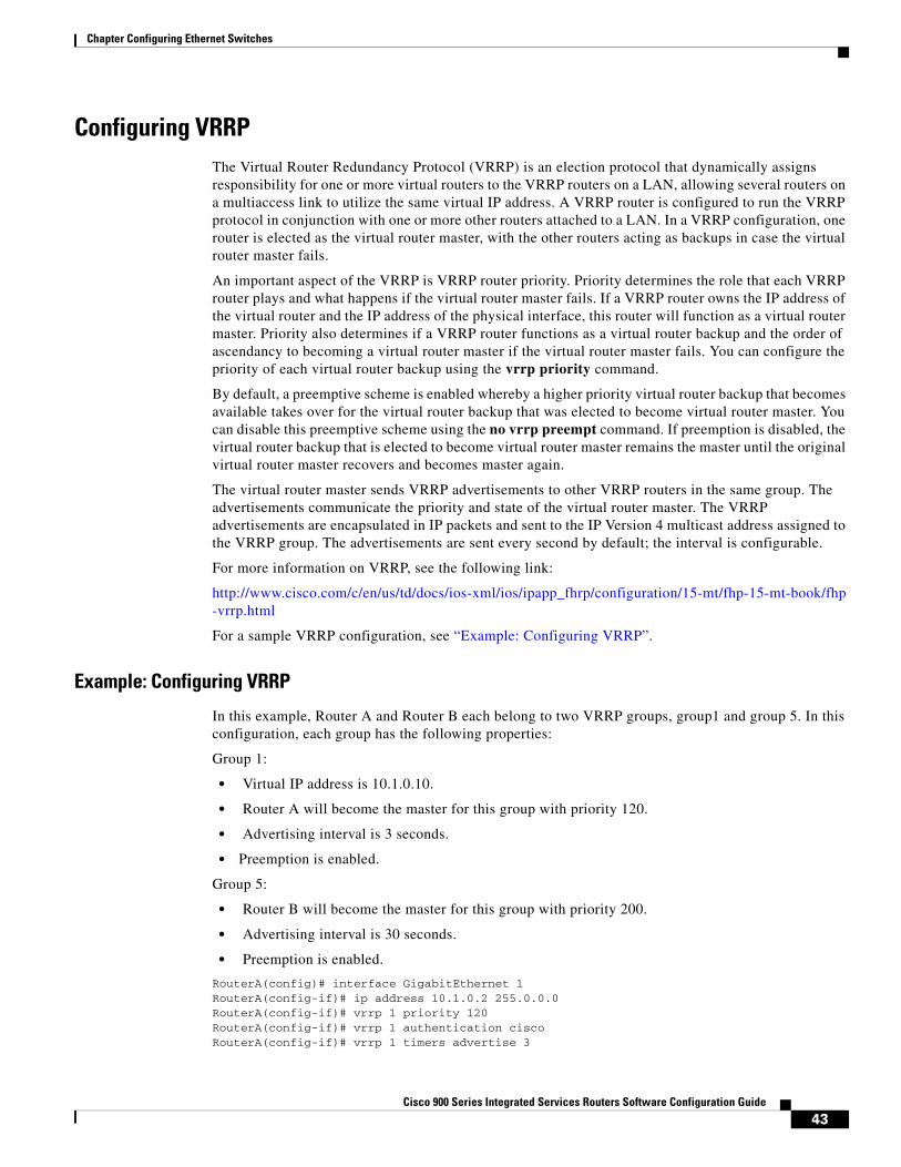
43Cisco 900 Series Integrated Services Routers Software Configuration Guide
Chapter Configuring Ethernet Switches
Configuring VRRP The Virtual Router Redundancy Protocol (VRRP) is an election protocol that dynamically assigns responsibility for one or more virtual routers to the VRRP routers on a LAN, allowing several routers on a multiaccess link to utilize the same virtual IP address. A VRRP router is configured to run the VRRP protocol in conjunction with one or more other routers attached to a LAN. In a VRRP configuration, one router is elected as the virtual router master, with the other routers acting as backups in case the virtual router master fails.
An important aspect of the VRRP is VRRP router priority. Priority determines the role that each VRRP router plays and what happens if the virtual router master fails. If a VRRP router owns the IP address of the virtual router and the IP address of the physical interface, this router will function as a virtual router master. Priority also determines if a VRRP router functions as a virtual router backup and the order of ascendancy to becoming a virtual router master if the virtual router master fails. You can configure the priority of each virtual router backup using the vrrp priority command.
By default, a preemptive scheme is enabled whereby a higher priority virtual router backup that becomes available takes over for the virtual router backup that was elected to become virtual router master. You can disable this preemptive scheme using the no vrrp preempt command. If preemption is disabled, the virtual router backup that is elected to become virtual router master remains the master until the original virtual router master recovers and becomes master again.
The virtual router master sends VRRP advertisements to other VRRP routers in the same group. The advertisements communicate the priority and state of the virtual router master. The VRRP advertisements are encapsulated in IP packets and sent to the IP Version 4 multicast address assigned to the VRRP group. The advertisements are sent every second by default; the interval is configurable.
For more information on VRRP, see the following link:
http://www.cisco.com/c/en/us/td/docs/ios-xml/ios/ipapp_fhrp/configuration/15-mt/fhp-15-mt-book/fhp-vrrp.html
For a sample VRRP configuration, see “Example: Configuring VRRP”.
Example: Configuring VRRP
In this example, Router A and Router B each belong to two VRRP groups, group1 and group 5. In this configuration, each group has the following properties:
Group 1:
• Virtual IP address is 10.1.0.10.
• Router A will become the master for this group with priority 120.
• Advertising interval is 3 seconds.
• Preemption is enabled.
Group 5:
• Router B will become the master for this group with priority 200.
• Advertising interval is 30 seconds.
• Preemption is enabled.
RouterA(config)# interface GigabitEthernet 1RouterA(config-if)# ip address 10.1.0.2 255.0.0.0 RouterA(config-if)# vrrp 1 priority 120 RouterA(config-if)# vrrp 1 authentication cisco RouterA(config-if)# vrrp 1 timers advertise 3
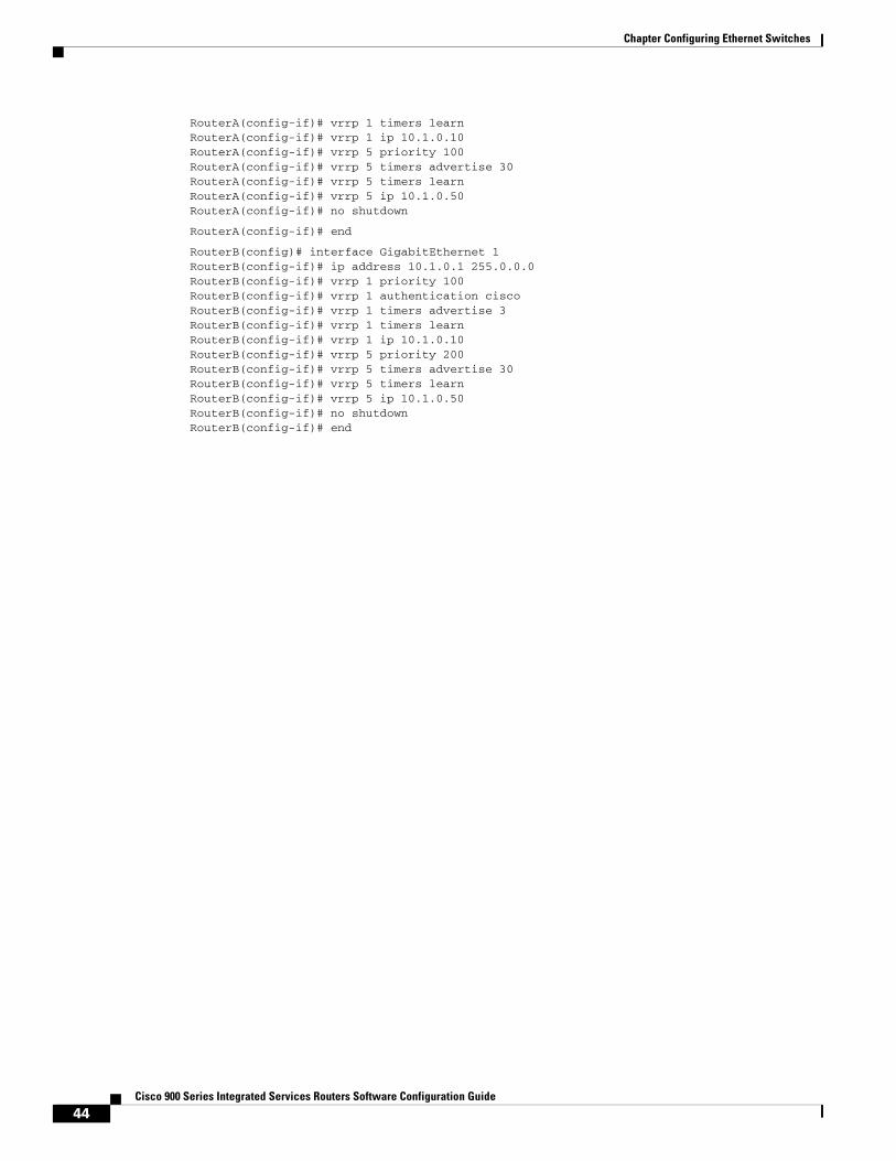
44Cisco 900 Series Integrated Services Routers Software Configuration Guide
Chapter Configuring Ethernet Switches
RouterA(config-if)# vrrp 1 timers learn RouterA(config-if)# vrrp 1 ip 10.1.0.10 RouterA(config-if)# vrrp 5 priority 100 RouterA(config-if)# vrrp 5 timers advertise 30RouterA(config-if)# vrrp 5 timers learnRouterA(config-if)# vrrp 5 ip 10.1.0.50 RouterA(config-if)# no shutdown
RouterA(config-if)# end
RouterB(config)# interface GigabitEthernet 1RouterB(config-if)# ip address 10.1.0.1 255.0.0.0 RouterB(config-if)# vrrp 1 priority 100 RouterB(config-if)# vrrp 1 authentication cisco RouterB(config-if)# vrrp 1 timers advertise 3 RouterB(config-if)# vrrp 1 timers learn RouterB(config-if)# vrrp 1 ip 10.1.0.10 RouterB(config-if)# vrrp 5 priority 200 RouterB(config-if)# vrrp 5 timers advertise 30RouterB(config-if)# vrrp 5 timers learnRouterB(config-if)# vrrp 5 ip 10.1.0.50 RouterB(config-if)# no shutdownRouterB(config-if)# end
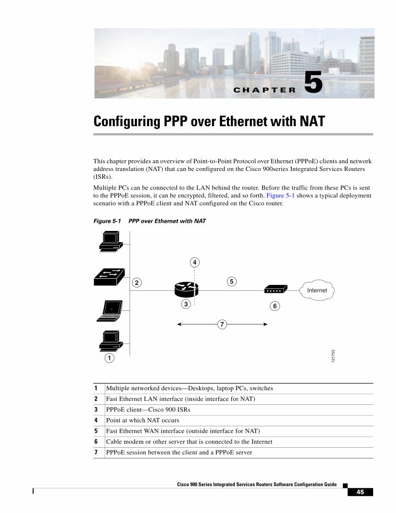
C H A P T E R
45Cisco 900 Series Integrated Services Routers Software Configuration Guide
5Configuring PPP over Ethernet with NAT
This chapter provides an overview of Point-to-Point Protocol over Ethernet (PPPoE) clients and network address translation (NAT) that can be configured on the Cisco 900series Integrated Services Routers (ISRs).
Multiple PCs can be connected to the LAN behind the router. Before the traffic from these PCs is sent to the PPPoE session, it can be encrypted, filtered, and so forth. Figure 5-1 shows a typical deployment scenario with a PPPoE client and NAT configured on the Cisco router.
Figure 5-1 PPP over Ethernet with NAT
1217
53
2
3
5
6
1
7
4
Internet
1 Multiple networked devices—Desktops, laptop PCs, switches
2 Fast Ethernet LAN interface (inside interface for NAT)
3 PPPoE client—Cisco 900 ISRs
4 Point at which NAT occurs
5 Fast Ethernet WAN interface (outside interface for NAT)
6 Cable modem or other server that is connected to the Internet
7 PPPoE session between the client and a PPPoE server
46Cisco 900 Series Integrated Services Routers Software Configuration Guide
Chapter Configuring PPP over Ethernet with NAT Configuring the Virtual Private Dialup Network Group Number
PPPoE
The PPPoE client feature on the router provides PPPoE client support on Ethernet interfaces. A dialer interface must be used for cloning virtual access. Multiple PPPoE client sessions can be configured on an Ethernet interface, but each session must use a separate dialer interface and a separate dialer pool.
A PPPoE session is initiated on the client side by the Cisco 860 or Cisco 880 ISRs. An established PPPoE client session can be terminated in one of two ways:
• By entering the clear vpdn tunnel pppoe command. The PPPoE client session is terminated, and the PPPoE client immediately tries to reestablish the session. This also occurs if the session has a timeout.
• By entering the no pppoe-client dial-pool number command to clear the session. The PPPoE client does not attempt to reestablish the session.
NAT
NAT (represented as the dashed line at the edge of the Cisco router) signifies two addressing domains and the inside source address. The source list defines how the packet travels through the network.
Configuration Tasks
Perform the following tasks to configure this network scenario:
• Configuring the Virtual Private Dialup Network Group Number
• Configuring Ethernet WAN Interfaces
• Configuring the Dialer Interface
• Configuring Network Address Translation
An example showing the results of these configuration tasks is shown in the “Configuration Example” section on page 48.
Configuring the Virtual Private Dialup Network Group NumberConfiguring a virtual private dialup network (VPDN) enables multiple clients to communicate through the router by way of a single IP address.
This example shows how to configure a VPDN:
Router(config)# vpdn enableRouter(config)# vpdn-group 1Router(config-vpdn)# request-dialinRouter(config-vpdn-req-in)# protocol pppoeRouter(config-vpdn-req-in)# exitRouter(config-vpdn)# exit
Configuring Ethernet WAN InterfacesIn this scenario, the PPPoE client (your Cisco router) communicates over a 10/100/1000 Mbps-Ethernet interface on both the inside and the outside.
This example shows how to configure the Fast Ethernet WAN interfaces:
Router(config)# interface gigabitethernet 4Router(config-if)# pppoe-client dial-pool-number 1
47Cisco 900 Series Integrated Services Routers Software Configuration Guide
Chapter Configuring PPP over Ethernet with NAT Configuring the Dialer Interface
Router(config-if)# no shutdownRouter(config-if)# exit
Ethernet Operations, Administration, and Maintenance
Ethernet Operations, Administration, and Maintenance (OAM) is a protocol for installing, monitoring, and troubleshooting Ethernet metropolitan-area networks (MANs) and Ethernet WANs. It relies on a new, optional sublayer in the data link layer of the Open Systems Interconnection (OSI) model. The OAM features covered by this protocol are Discovery, Link Monitoring, Remote Fault Detection, Remote Loopback, and Cisco Proprietary Extensions.
For setup and configuration information about Ethernet OAM, see Using Ethernet Operations, Administration, and Maintenance at:
https://www.cisco.com/c/en/us/td/docs/ios-xml/ios/cether/configuration/15-mt/ce-15-mt-book/ce-oam.html
Configuring the Dialer InterfaceThe dialer interface indicates how to handle traffic from the clients, including, for example, default routing information, the encapsulation protocol, and the dialer pool to use. The dialer interface is also used for cloning virtual access. Multiple PPPoE client sessions can be configured on a Fast Ethernet interface, but each session must use a separate dialer interface and a separate dialer pool.
This example shows how to configure a dialer interface for one of the Gigabit Ethernet LAN interfaces on the route:
Router(config)# interface dialer 0Router(config-if)# ip address negotiatedRouter(config-if)# ip mtu 1492Router(config-if)# encapsulation pppRouter(config-if)# ppp authentication chapRouter(config-if)# dialer pool 1Router(config-if)# dialer-group 1Router(config-if)# exitRouter(config)# dialer-list 1 protocol ip permitRouter(config)# ip route 10.10.25.2 255.255.255.255 dialer 0
Configuring Network Address TranslationNetwork Address Translation (NAT) translates packets from addresses that match a standard access list, using global addresses allocated by the dialer interface. Packets that enter the router through the inside interface, packets sourced from the router, or both are checked against the access list for possible address translation. You can configure NAT for either static or dynamic address translations.
This example shows how to configure the outside Gigabit Ethernet WAN interface with dynamic NAT:
Router(config)# ip nat pool pool1 192.168.1.0 192.168.2.0 netmask 255.255.252.0Router(config)# ip nat inside source list 1 interface dialer 0 overloadRouter(config)# interface vlan 1Router(config-if)# ip nat insideRouter(config-if)# no shutdownRouter(config-if)# exitRouter(config)# interface gigabitethernet1 Router(config-if)# ip nat outsideRouter(config-if)# no shutdown
48Cisco 900 Series Integrated Services Routers Software Configuration Guide
Chapter Configuring PPP over Ethernet with NAT Configuration Example
Router(config-if)# exitRouter(config)# access-list 1 permit 192.168.1.0 255.255.255.0
Note To use NAT with a virtual-template interface, you must configure a loopback interface. See Chapter 3, “Basic Router Configuration,” for information on configuring a loopback interface.
Configuration ExampleThe following configuration example shows a portion of the configuration file for the PPPoE scenario described in this chapter.
The VLAN interface has an IP address of 192.168.1.1 with a subnet mask of 255.255.255.0. NAT is configured for inside and outside
Note Commands marked by “(default)” are generated automatically when you run the show running-config command.
vpdn enablevpdn-group 1request-dialinprotocol pppoe!interface vlan 1ip address 192.168.1.1 255.255.255.0no ip directed-broadcast (default)ip nat inside interface gigabitethernet 4no ip address no ip directed-broadcast (default)ip nat outsidepppoe enable group globalpppoe-client dial-pool-number 1no sh !interface dialer 0ip address negotiatedip mtu 1492encapsulation pppppp authentication chapdialer pool 1dialer-group 1!dialer-list 1 protocol ip permitip nat inside source list 1 interface dialer 0 overloadip classless (default)ip route 10.10.25.2 255.255.255.255 dialer 0 ip nat pool pool1 192.168.1.0 192.168.2.0 netmask 255.255.252.0ip nat inside source list acl1 pool pool1!
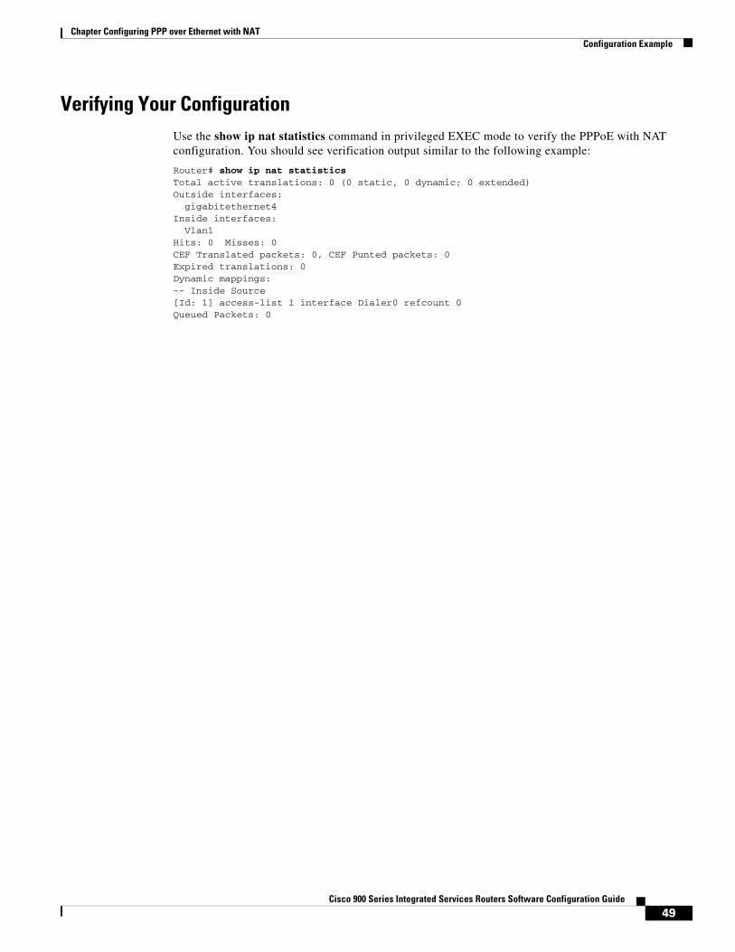
49Cisco 900 Series Integrated Services Routers Software Configuration Guide
Chapter Configuring PPP over Ethernet with NAT Configuration Example
Verifying Your ConfigurationUse the show ip nat statistics command in privileged EXEC mode to verify the PPPoE with NAT configuration. You should see verification output similar to the following example:
Router# show ip nat statistics Total active translations: 0 (0 static, 0 dynamic; 0 extended)Outside interfaces: gigabitethernet4Inside interfaces: Vlan1Hits: 0 Misses: 0CEF Translated packets: 0, CEF Punted packets: 0Expired translations: 0Dynamic mappings:-- Inside Source[Id: 1] access-list 1 interface Dialer0 refcount 0Queued Packets: 0

50Cisco 900 Series Integrated Services Routers Software Configuration Guide
Chapter Configuring PPP over Ethernet with NAT Configuration Example
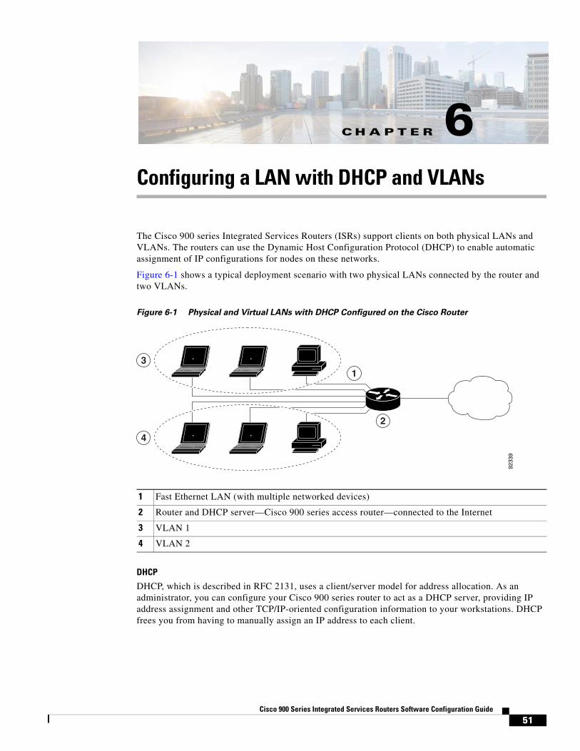
C H A P T E R
51Cisco 900 Series Integrated Services Routers Software Configuration Guide
6Configuring a LAN with DHCP and VLANs
The Cisco 900 series Integrated Services Routers (ISRs) support clients on both physical LANs and VLANs. The routers can use the Dynamic Host Configuration Protocol (DHCP) to enable automatic assignment of IP configurations for nodes on these networks.
Figure 6-1 shows a typical deployment scenario with two physical LANs connected by the router and two VLANs.
Figure 6-1 Physical and Virtual LANs with DHCP Configured on the Cisco Router
DHCP
DHCP, which is described in RFC 2131, uses a client/server model for address allocation. As an administrator, you can configure your Cisco 900 series router to act as a DHCP server, providing IP address assignment and other TCP/IP-oriented configuration information to your workstations. DHCP frees you from having to manually assign an IP address to each client.
1 Fast Ethernet LAN (with multiple networked devices)
2 Router and DHCP server—Cisco 900 series access router—connected to the Internet
3 VLAN 1
4 VLAN 2
9233
9
1
2
3
4
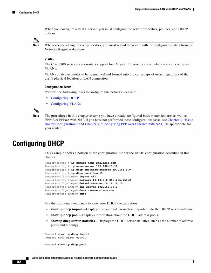
52Cisco 900 Series Integrated Services Routers Software Configuration Guide
Chapter Configuring a LAN with DHCP and VLANs Configuring DHCP
When you configure a DHCP server, you must configure the server properties, policies, and DHCP options.
Note Whenever you change server properties, you must reload the server with the configuration data from the Network Registrar database.
VLANs
The Cisco 900 series access routers support four Gigabit Ethernet ports on which you can configure VLANs.
VLANs enable networks to be segmented and formed into logical groups of users, regardless of the user’s physical location or LAN connection.
Configuration Tasks
Perform the following tasks to configure this network scenario:
• Configuring DHCP
• Configuring VLANs
Note The procedures in this chapter assume you have already configured basic router features as well as PPPoE or PPPoA with NAT. If you have not performed these configurations tasks, see Chapter 3, “Basic Router Configuration,” and Chapter 5, “Configuring PPP over Ethernet with NAT,” as appropriate for your router.
Configuring DHCPThis example shows a portion of the configuration file for the DCHP configuration described in this chapter.
Router(config)# ip domain name smallbiz.comRouter(config)# ip name-server 192.168.11.12Router(config)# ip dhcp excluded-address 192.168.9.0Router(config)# ip dhcp pool dpool1Router(config-dhcp)# import allRouter(config-dhcp)# network 10.10.0.0 255.255.255.0Router(config-dhcp)# default-router 10.10.10.10Router(config-dhcp)# dns-server 192.168.35.2Router(config-dhcp)# domain-name cisco.comRouter(config-dhcp)# exit
Use the following commands to view your DHCP configuration.
• show ip dhcp import—Displays the optional parameters imported into the DHCP server database.
• show ip dhcp pool—Displays information about the DHCP address pools.
• show ip dhcp server statistics—Displays the DHCP server statistics, such as the number of address pools and bindings.
Router# show ip dhcp importAddress Pool Name: dpool1
Router# show ip dhcp pool
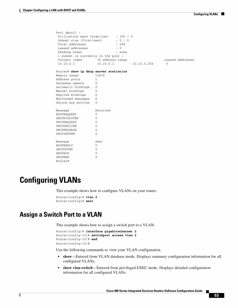
53Cisco 900 Series Integrated Services Routers Software Configuration Guide
Chapter Configuring a LAN with DHCP and VLANs Configuring VLANs
Pool dpool1 : Utilization mark (high/low) : 100 / 0 Subnet size (first/next) : 0 / 0 Total addresses : 254 Leased addresses : 0 Pending event : none 1 subnet is currently in the pool : Current index IP address range Leased addresses 10.10.0.1 10.10.0.1 - 10.10.0.254 0
Router# show ip dhcp server statisticsMemory usage 15419Address pools 1Database agents 0Automatic bindings 0Manual bindings 0Expired bindings 0Malformed messages 0Secure arp entries 0
Message ReceivedBOOTREQUEST 0DHCPDISCOVER 0DHCPREQUEST 0DHCPDECLINE 0DHCPRELEASE 0DHCPINFORM 0
Message SentBOOTREPLY 0DHCPOFFER 0DHCPACK 0DHCPNAK 0Router#
Configuring VLANsThis example shows how to configure VLANs on your router:
Router(config)# vlan 2Router(config)# exit
Assign a Switch Port to a VLANThis example shows how to assign a switch port to a VLAN:
Router(config)# interface gigabitethernet 2Router(config-if)# switchport access vlan 2Router(config-if)# end
Router(config-if)#
Use the following commands to view your VLAN configuration.
• show—Entered from VLAN database mode. Displays summary configuration information for all configured VLANs.
• show vlan-switch—Entered from privileged EXEC mode. Displays detailed configuration information for all configured VLANs.

54Cisco 900 Series Integrated Services Routers Software Configuration Guide
Chapter Configuring a LAN with DHCP and VLANs Configuring VLANs

55Cisco 900 Series Integrated Services Routers Software Configuration Guide
Chapter Configuring a LAN with DHCP and VLANs Configuring VLANs
Router# vlan databaseRouter(vlan)# show
VLAN ISL Id: 1Name: defaultMedia Type: EthernetVLAN 802.10 Id: 100001State: OperationalMTU: 1500Translational Bridged VLAN: 1002Translational Bridged VLAN: 1003
VLAN ISL Id: 2Name: VLAN0002Media Type: EthernetVLAN 802.10 Id: 100002State: OperationalMTU: 1500
VLAN ISL Id: 3Name: red-vlanMedia Type: EthernetVLAN 802.10 Id: 100003State: OperationalMTU: 1500
VLAN ISL Id: 1002Name: fddi-default
Media Type: FDDI VLAN 802.10 Id: 101002 State: Operational MTU: 1500 Bridge Type: SRB Translational Bridged VLAN: 1 Translational Bridged VLAN: 1003
VLAN ISL Id: 1003 Name: token-ring-default Media Type: Token Ring VLAN 802.10 Id: 101003 State: Operational MTU: 1500 Bridge Type: SRB Ring Number: 0 Bridge Number: 1 Parent VLAN: 1005 Maximum ARE Hop Count: 7 Maximum STE Hop Count: 7 Backup CRF Mode: Disabled Translational Bridged VLAN: 1 Translational Bridged VLAN: 1002
VLAN ISL Id: 1004 Name: fddinet-default Media Type: FDDI Net VLAN 802.10 Id: 101004 State: Operational MTU: 1500 Bridge Type: SRB Bridge Number: 1 STP Type: IBM
VLAN ISL Id: 1005 Name: trnet-default
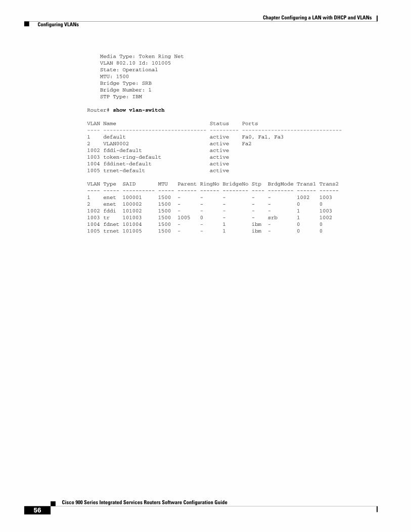
56Cisco 900 Series Integrated Services Routers Software Configuration Guide
Chapter Configuring a LAN with DHCP and VLANs Configuring VLANs
Media Type: Token Ring Net VLAN 802.10 Id: 101005 State: Operational MTU: 1500 Bridge Type: SRB Bridge Number: 1 STP Type: IBM
Router# show vlan-switch
VLAN Name Status Ports---- -------------------------------- --------- -------------------------------1 default active Fa0, Fa1, Fa32 VLAN0002 active Fa21002 fddi-default active1003 token-ring-default active1004 fddinet-default active1005 trnet-default active
VLAN Type SAID MTU Parent RingNo BridgeNo Stp BrdgMode Trans1 Trans2---- ----- ---------- ----- ------ ------ -------- ---- -------- ------ ------1 enet 100001 1500 - - - - - 1002 10032 enet 100002 1500 - - - - - 0 01002 fddi 101002 1500 - - - - - 1 10031003 tr 101003 1500 1005 0 - - srb 1 10021004 fdnet 101004 1500 - - 1 ibm - 0 01005 trnet 101005 1500 - - 1 ibm - 0 0
C H A P T E R
57Cisco 900 Series Integrated Services Routers Software Configuration Guide
7 Configuring Identity Features on Layer 3 Interface
This chapter describes the identify features supported on the Onboard Gigabit Ethernet Layer 3 ports of the Cisco 900 Integrated Services Router (ISR).
This chapter contains the following sections:
• Authentication Methods, page 57
• Controlling Port Authorization State, page 59
• Flexible Authentication, page 61
• Host mode, page 61
• Open Access, page 62
• Control-Direction (Wake-on-LAN), page 62
• Preauthentication Access Control List, page 64
• Downloadable Access Control List, page 65
• Filter-ID or Named Access Control List, page 65
• IP Device Tracking, page 65
Note Critical authentication, which is also known as Inaccessible Authentication Bypass or AAA Fail Policy, does not support the Identity features on the Onboard Gigabit Ethernet Layer 3 ports.
Authentication MethodsIdentity features support various types of authentication methods that are suitable for different kinds of end hosts and users. The two methods that are mainly used are:
• IEEE 802.1X
• MAC Authentication Bypass (MAB)
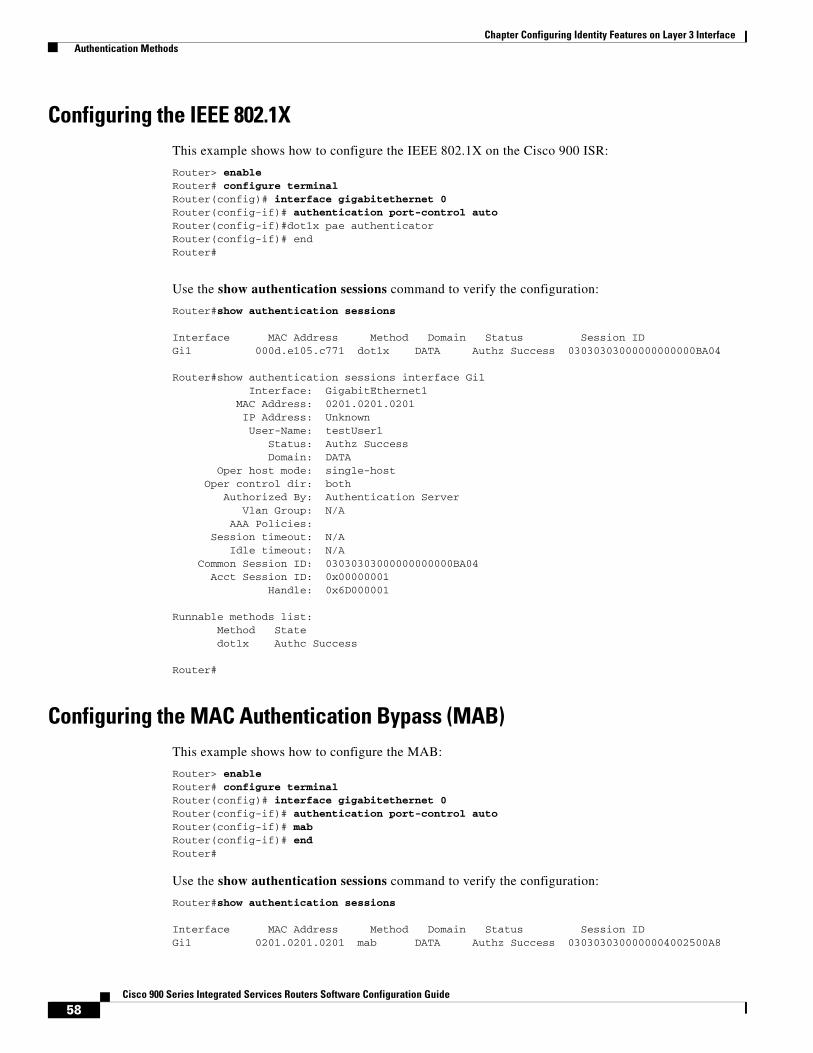
58Cisco 900 Series Integrated Services Routers Software Configuration Guide
Chapter Configuring Identity Features on Layer 3 Interface Authentication Methods
Configuring the IEEE 802.1XThis example shows how to configure the IEEE 802.1X on the Cisco 900 ISR:
Router> enableRouter# configure terminalRouter(config)# interface gigabitethernet 0Router(config-if)# authentication port-control autoRouter(config-if)#dot1x pae authenticatorRouter(config-if)# endRouter#
Use the show authentication sessions command to verify the configuration:
Router#show authentication sessions
Interface MAC Address Method Domain Status Session IDGi1 000d.e105.c771 dot1x DATA Authz Success 03030303000000000000BA04
Router#show authentication sessions interface Gi1 Interface: GigabitEthernet1 MAC Address: 0201.0201.0201 IP Address: Unknown User-Name: testUser1 Status: Authz Success Domain: DATA Oper host mode: single-host Oper control dir: both Authorized By: Authentication Server Vlan Group: N/A AAA Policies: Session timeout: N/A Idle timeout: N/A Common Session ID: 03030303000000000000BA04 Acct Session ID: 0x00000001 Handle: 0x6D000001
Runnable methods list: Method State dot1x Authc Success
Router#
Configuring the MAC Authentication Bypass (MAB)This example shows how to configure the MAB:
Router> enableRouter# configure terminalRouter(config)# interface gigabitethernet 0Router(config-if)# authentication port-control autoRouter(config-if)# mabRouter(config-if)# endRouter#
Use the show authentication sessions command to verify the configuration:
Router#show authentication sessions
Interface MAC Address Method Domain Status Session IDGi1 0201.0201.0201 mab DATA Authz Success 0303030300000004002500A8
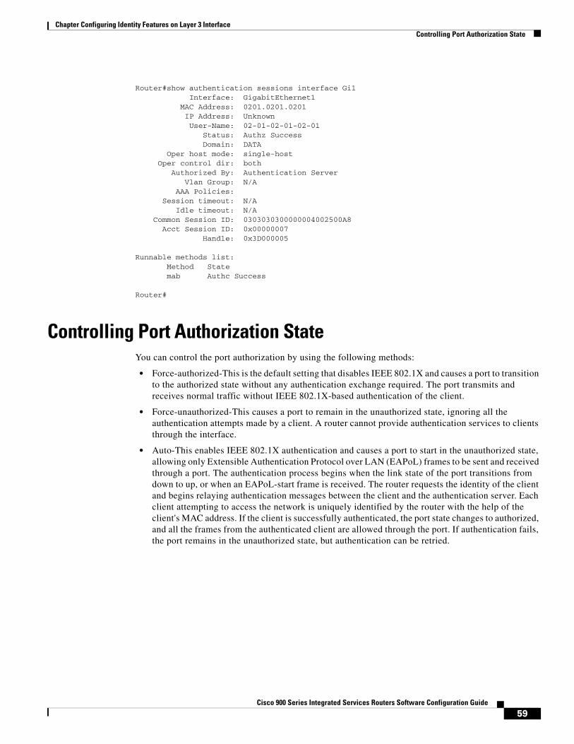
59Cisco 900 Series Integrated Services Routers Software Configuration Guide
Chapter Configuring Identity Features on Layer 3 Interface Controlling Port Authorization State
Router#show authentication sessions interface Gi1 Interface: GigabitEthernet1 MAC Address: 0201.0201.0201 IP Address: Unknown User-Name: 02-01-02-01-02-01 Status: Authz Success Domain: DATA Oper host mode: single-host Oper control dir: both Authorized By: Authentication Server Vlan Group: N/A AAA Policies: Session timeout: N/A Idle timeout: N/A Common Session ID: 0303030300000004002500A8 Acct Session ID: 0x00000007 Handle: 0x3D000005
Runnable methods list: Method State mab Authc Success
Router#
Controlling Port Authorization StateYou can control the port authorization by using the following methods:
• Force-authorized-This is the default setting that disables IEEE 802.1X and causes a port to transition to the authorized state without any authentication exchange required. The port transmits and receives normal traffic without IEEE 802.1X-based authentication of the client.
• Force-unauthorized-This causes a port to remain in the unauthorized state, ignoring all the authentication attempts made by a client. A router cannot provide authentication services to clients through the interface.
• Auto-This enables IEEE 802.1X authentication and causes a port to start in the unauthorized state, allowing only Extensible Authentication Protocol over LAN (EAPoL) frames to be sent and received through a port. The authentication process begins when the link state of the port transitions from down to up, or when an EAPoL-start frame is received. The router requests the identity of the client and begins relaying authentication messages between the client and the authentication server. Each client attempting to access the network is uniquely identified by the router with the help of the client's MAC address. If the client is successfully authenticated, the port state changes to authorized, and all the frames from the authenticated client are allowed through the port. If authentication fails, the port remains in the unauthorized state, but authentication can be retried.
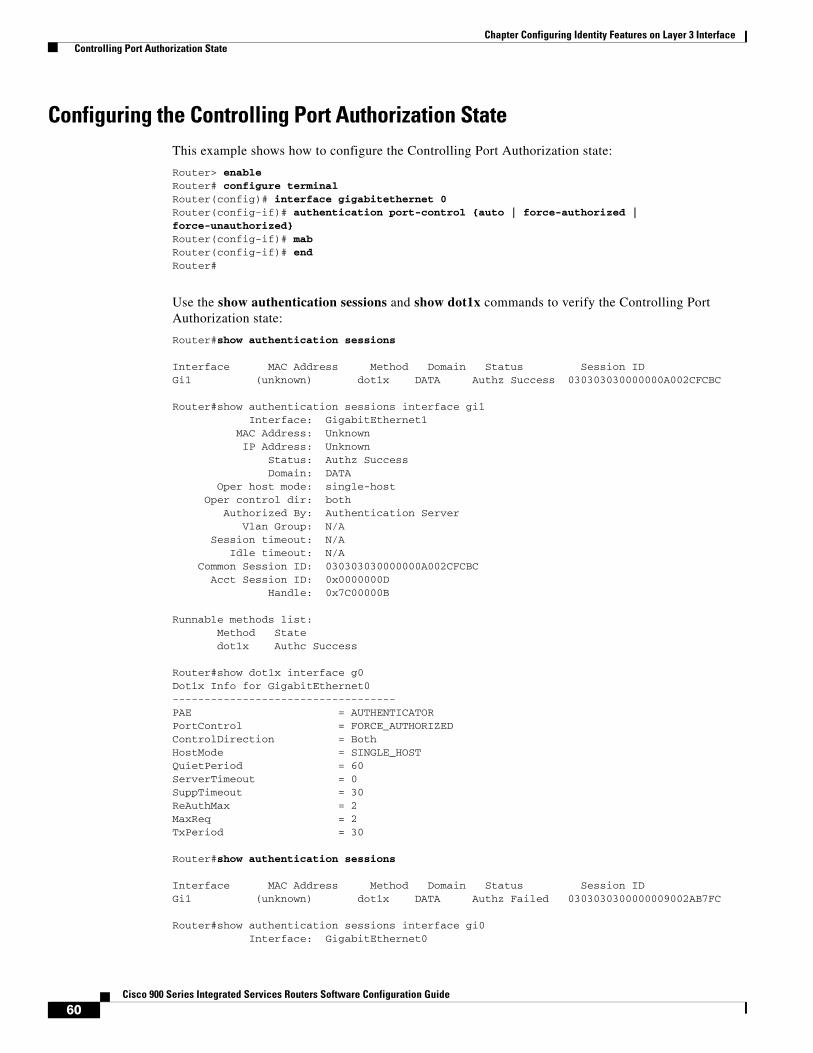
60Cisco 900 Series Integrated Services Routers Software Configuration Guide
Chapter Configuring Identity Features on Layer 3 Interface Controlling Port Authorization State
Configuring the Controlling Port Authorization StateThis example shows how to configure the Controlling Port Authorization state:
Router> enableRouter# configure terminalRouter(config)# interface gigabitethernet 0Router(config-if)# authentication port-control {auto | force-authorized | force-unauthorized}Router(config-if)# mabRouter(config-if)# endRouter#
Use the show authentication sessions and show dot1x commands to verify the Controlling Port Authorization state:
Router#show authentication sessions
Interface MAC Address Method Domain Status Session IDGi1 (unknown) dot1x DATA Authz Success 030303030000000A002CFCBC
Router#show authentication sessions interface gi1 Interface: GigabitEthernet1 MAC Address: Unknown IP Address: Unknown Status: Authz Success Domain: DATA Oper host mode: single-host Oper control dir: both Authorized By: Authentication Server Vlan Group: N/A Session timeout: N/A Idle timeout: N/A Common Session ID: 030303030000000A002CFCBC Acct Session ID: 0x0000000D Handle: 0x7C00000B
Runnable methods list: Method State dot1x Authc Success
Router#show dot1x interface g0Dot1x Info for GigabitEthernet0-----------------------------------PAE = AUTHENTICATORPortControl = FORCE_AUTHORIZEDControlDirection = BothHostMode = SINGLE_HOSTQuietPeriod = 60ServerTimeout = 0SuppTimeout = 30ReAuthMax = 2MaxReq = 2TxPeriod = 30
Router#show authentication sessions
Interface MAC Address Method Domain Status Session IDGi1 (unknown) dot1x DATA Authz Failed 0303030300000009002AB7FC
Router#show authentication sessions interface gi0 Interface: GigabitEthernet0
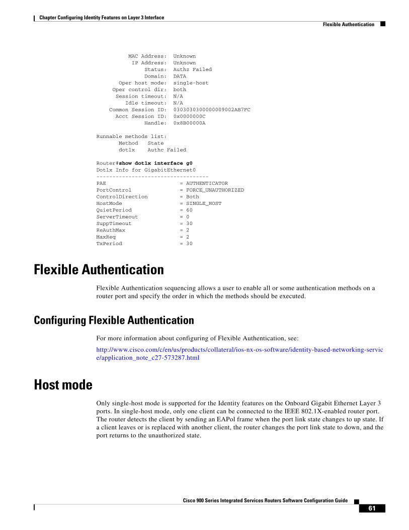
61Cisco 900 Series Integrated Services Routers Software Configuration Guide
Chapter Configuring Identity Features on Layer 3 Interface Flexible Authentication
MAC Address: Unknown IP Address: Unknown Status: Authz Failed Domain: DATA Oper host mode: single-host Oper control dir: both Session timeout: N/A Idle timeout: N/A Common Session ID: 0303030300000009002AB7FC Acct Session ID: 0x0000000C Handle: 0x8B00000A
Runnable methods list: Method State dot1x Authc Failed
Router#show dot1x interface g0 Dot1x Info for GigabitEthernet0-----------------------------------PAE = AUTHENTICATORPortControl = FORCE_UNAUTHORIZEDControlDirection = BothHostMode = SINGLE_HOSTQuietPeriod = 60ServerTimeout = 0SuppTimeout = 30ReAuthMax = 2MaxReq = 2TxPeriod = 30
Flexible AuthenticationFlexible Authentication sequencing allows a user to enable all or some authentication methods on a router port and specify the order in which the methods should be executed.
Configuring Flexible AuthenticationFor more information about configuring of Flexible Authentication, see:
http://www.cisco.com/c/en/us/products/collateral/ios-nx-os-software/identity-based-networking-service/application_note_c27-573287.html
Host modeOnly single-host mode is supported for the Identity features on the Onboard Gigabit Ethernet Layer 3 ports. In single-host mode, only one client can be connected to the IEEE 802.1X-enabled router port. The router detects the client by sending an EAPol frame when the port link state changes to up state. If a client leaves or is replaced with another client, the router changes the port link state to down, and the port returns to the unauthorized state.
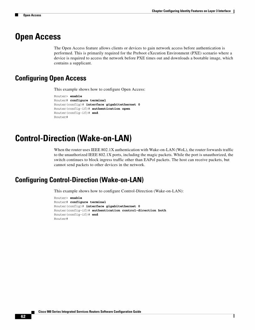
62Cisco 900 Series Integrated Services Routers Software Configuration Guide
Chapter Configuring Identity Features on Layer 3 Interface Open Access
Open AccessThe Open Access feature allows clients or devices to gain network access before authentication is performed. This is primarily required for the Preboot eXecution Environment (PXE) scenario where a device is required to access the network before PXE times out and downloads a bootable image, which contains a supplicant.
Configuring Open AccessThis example shows how to configure Open Access:
Router> enableRouter# configure terminalRouter(config)# interface gigabitethernet 0Router(config-if)# authentication openRouter(config-if)# endRouter#
Control-Direction (Wake-on-LAN)When the router uses IEEE 802.1X authentication with Wake-on-LAN (WoL), the router forwards traffic to the unauthorized IEEE 802.1X ports, including the magic packets. While the port is unauthorized, the switch continues to block ingress traffic other than EAPol packets. The host can receive packets, but cannot send packets to other devices in the network.
Configuring Control-Direction (Wake-on-LAN)This example shows how to configure Control-Direction (Wake-on-LAN):
Router> enableRouter# configure terminalRouter(config)# interface gigabitethernet 0Router(config-if)# authentication control-direction bothRouter(config-if)# endRouter#
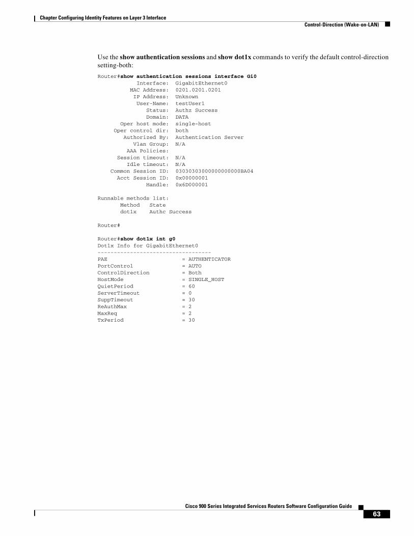
63Cisco 900 Series Integrated Services Routers Software Configuration Guide
Chapter Configuring Identity Features on Layer 3 Interface Control-Direction (Wake-on-LAN)
Use the show authentication sessions and show dot1x commands to verify the default control-direction setting-both:
Router#show authentication sessions interface Gi0 Interface: GigabitEthernet0 MAC Address: 0201.0201.0201 IP Address: Unknown User-Name: testUser1 Status: Authz Success Domain: DATA Oper host mode: single-host Oper control dir: both Authorized By: Authentication Server Vlan Group: N/A AAA Policies: Session timeout: N/A Idle timeout: N/A Common Session ID: 03030303000000000000BA04 Acct Session ID: 0x00000001 Handle: 0x6D000001
Runnable methods list: Method State dot1x Authc Success
Router#
Router#show dot1x int g0 Dot1x Info for GigabitEthernet0-----------------------------------PAE = AUTHENTICATORPortControl = AUTOControlDirection = BothHostMode = SINGLE_HOSTQuietPeriod = 60ServerTimeout = 0SuppTimeout = 30ReAuthMax = 2MaxReq = 2TxPeriod = 30
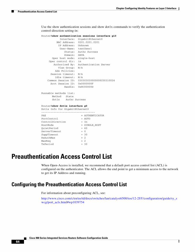
64Cisco 900 Series Integrated Services Routers Software Configuration Guide
Chapter Configuring Identity Features on Layer 3 Interface Preauthentication Access Control List
Use the show authentication sessions and show dot1x commands to verify the authentication control-direction setting-in:
Router#show authentication sessions interface gi0 Interface: GigabitEthernet0 MAC Address: 0201.0201.0201 IP Address: Unknown User-Name: testUser1 Status: Authz Success Domain: DATA Oper host mode: single-host Oper control dir: in Authorized By: Authentication Server Vlan Group: N/A AAA Policies: Session timeout: N/A Idle timeout: N/A Common Session ID: 030303030000000C00310024 Acct Session ID: 0x0000000F Handle: 0x8C00000D
Runnable methods list: Method State dot1x Authc Success
Router#show dot1x interface g0Dot1x Info for GigabitEthernet0-----------------------------------PAE = AUTHENTICATORPortControl = AUTOControlDirection = InHostMode = SINGLE_HOSTQuietPeriod = 60ServerTimeout = 0SuppTimeout = 30ReAuthMax = 2MaxReq = 2TxPeriod = 30
Preauthentication Access Control ListWhen Open-Access is installed, we recommend that a default port access control list (ACL) is configured on the authenticator. The ACL allows the end point to get a minimum access to the network to get its IP Address and running.
Configuring the Preauthentication Access Control ListFor information about preconfiguring ACL, see:
http://www.cisco.com/c/en/us/td/docs/switches/lan/catalyst6500/ios/12-2SY/configuration/guide/sy_swcg/port_acls.html#wp1039754
65Cisco 900 Series Integrated Services Routers Software Configuration Guide
Chapter Configuring Identity Features on Layer 3 Interface Downloadable Access Control List
Downloadable Access Control ListA Downloadable ACL is also referred to as dACL. For a dACL to work on a port, the ip device tracking feature should be enabled and the end point connected to the port should have an IP address assigned. After authentication on the port, use the show ip access-list privileged EXEC command to display the downloaded ACL on the port.
Filter-ID or Named Access Control ListFilter-Id also works as a dACL, but the ACL commands are configured on the authenticator. Authentication, authorization, and accounting (AAA) provides the name of the ACL to the authenticator.
IP Device TrackingThe IP Device Tracking feature is required for the dACL and Filter-ID features to function. To program a dACL or Filter-ID in a device, IP address is required. IP device tracking provides the IP address of the corresponding device to the Enterprise Policy Manager (EPM) module to convert the dACLs to each user by adding the IP address to them.

66Cisco 900 Series Integrated Services Routers Software Configuration Guide
Chapter Configuring Identity Features on Layer 3 Interface IP Device Tracking
C H A P T E R
67Cisco 900 Series Integrated Services Routers Software Configuration Guide
8Configuring Security Features
This chapter describes how to configure security features on a Cisco 900 Series Integrated Services Routers (ISRs). This chapter contains the following sections:
• Configuring SSL VPN, page 67
• Authentication, Authorization, and Accounting, page 68
• Configuring AutoSecure, page 68
• Configuring Access Lists, page 68
• Configuring Cisco IOS Firewall, page 69
• Zone-Based Policy Firewall, page 70
• Configuring Cisco IOS IPS, page 70
• Content Filtering, page 71
• Configuring VPN, page 71
• Configuring Dynamic Multipoint VPN, page 74
• Configuring Group Encrypted Transport VPN, page 74
• SGT over Ethernet Tagging, page 74
• Crypto Engine Throughput Policing, page 75
Configuring SSL VPNThe Secure Socket Layer Virtual Private Network (SSL VPN) feature (also known as WebVPN) provides support, in Cisco IOS software, for remote user access to enterprise networks from anywhere on the Internet. Remote access is provided through a SSL–enabled SSL VPN gateway. The SSL VPN gateway allows remote users to establish a secure VPN tunnel using a web browser. This feature provides a comprehensive solution that allows easy access to a broad range of web resources and web-enabled applications using native HTTP over SSL (HTTPS) browser support. SSL VPN delivers three modes of SSL VPN access: clientless, thin-client, and full-tunnel client support.
For additional information about configuring SSL VPN, see SSL VPN Configuration Guide, Cisco IOS Release 15M&T at:
https://www.cisco.com/c/en/us/td/docs/ios-xml/ios/sec_conn_sslvpn/configuration/15-mt/sec-conn-sslvpn-15-mt-book/sec-conn-sslvpn-ssl-vpn.html.
68Cisco 900 Series Integrated Services Routers Software Configuration Guide
Chapter Configuring Security Features Authentication, Authorization, and Accounting
Authentication, Authorization, and AccountingAuthentication, Authorization, and Accounting (AAA) network security services provide the primary framework through which you set up access control on your router. Authentication provides the method of identifying users, including login and password dialog, challenge and response, messaging support, and, depending on the security protocol you choose, encryption. Authorization provides the method for remote access control, including one-time authorization or authorization for each service, per-user account list and profile, user group support, and support of IP, Internetwork Packet Exchange (IPX), AppleTalk Remote Access (ARA), and Telnet. Accounting provides the method for collecting and sending security server information used for billing, auditing, and reporting, such as user identities, start and stop times, executed commands (such as PPP), number of packets, and number of bytes.
AAA uses protocols such as Remote Authentication Dial-In User Service (RADIUS), Terminal Access Controller Access Control System Plus (TACACS+), or Kerberos to administer its security functions. If your router is acting as a network access server, AAA is the means through which you establish communication between your network access server and your RADIUS, TACACS+, or Kerberos security server.
For information about configuring AAA services and supported security protocols, authentication authorization, accounting, RADIUS, TACACS+, or Kerberos, see the following sections of Cisco IOS Security Configuration Guide: Securing User Services at:
https://www.cisco.com/c/en/us/td/docs/ios-xml/ios/security/config_library/15-mt/secuser-15-mt-library.html
• Configuring Authentication
• Configuring Authorization
• Configuring Accounting
• Configuring RADIUS
• Configuring TACACS+
• Configuring Kerberos
Configuring AutoSecureThe AutoSecure feature disables common IP services that can be exploited for network attacks and enables IP services and features that can aid in the defense of a network when under attack. These IP services are all disabled and enabled simultaneously with a single command, greatly simplifying security configuration on your router. For a complete description of the AutoSecure feature, see the feature document at: https://www.cisco.com/c/en/us/td/docs/ios/sec_user_services/configuration/guide/convert/user_security/sec_autosecure.html
Configuring Access ListsAccess lists permit or deny network traffic over an interface, based on source IP address, destination IP address, or protocol. Access lists are configured as standard or extended. A standard access list either permits or denies passage of packets from a designated source. An extended access list allows designation of both the destination and the source, and it allows designation of individual protocols to be permitted or denied passage.
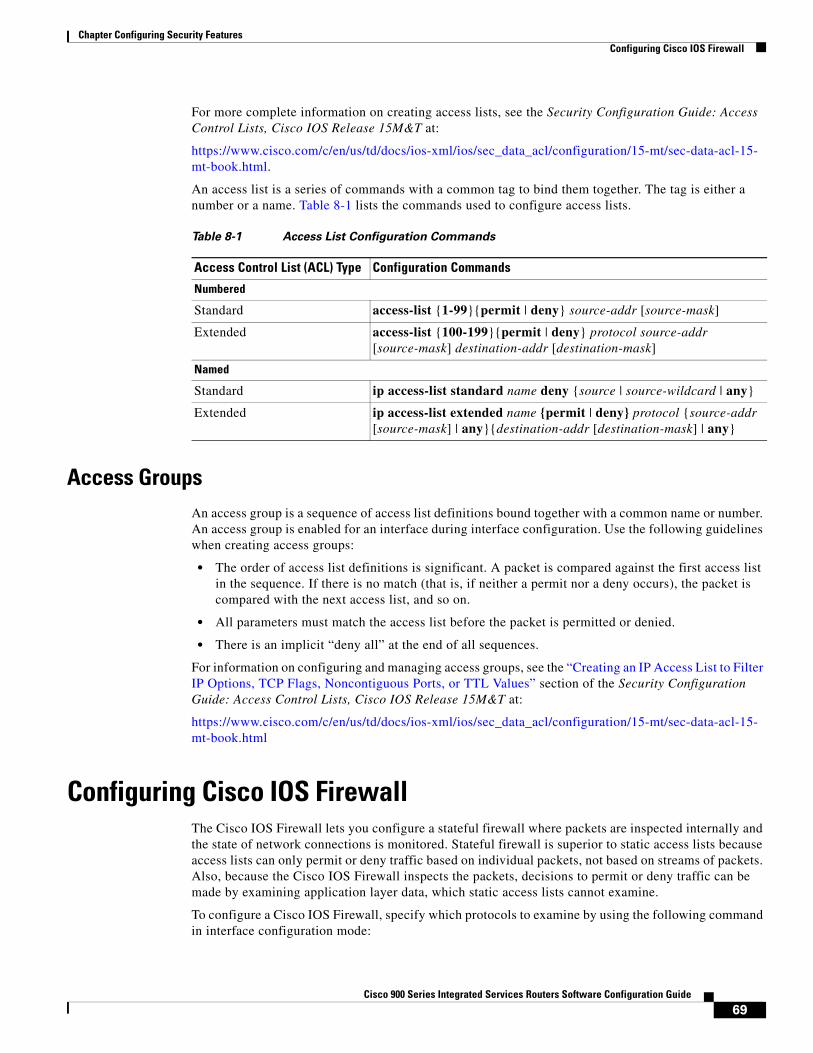
69Cisco 900 Series Integrated Services Routers Software Configuration Guide
Chapter Configuring Security Features Configuring Cisco IOS Firewall
For more complete information on creating access lists, see the Security Configuration Guide: Access Control Lists, Cisco IOS Release 15M&T at:
https://www.cisco.com/c/en/us/td/docs/ios-xml/ios/sec_data_acl/configuration/15-mt/sec-data-acl-15-mt-book.html.
An access list is a series of commands with a common tag to bind them together. The tag is either a number or a name. Table 8-1 lists the commands used to configure access lists.
Access GroupsAn access group is a sequence of access list definitions bound together with a common name or number. An access group is enabled for an interface during interface configuration. Use the following guidelines when creating access groups:
• The order of access list definitions is significant. A packet is compared against the first access list in the sequence. If there is no match (that is, if neither a permit nor a deny occurs), the packet is compared with the next access list, and so on.
• All parameters must match the access list before the packet is permitted or denied.
• There is an implicit “deny all” at the end of all sequences.
For information on configuring and managing access groups, see the “Creating an IP Access List to Filter IP Options, TCP Flags, Noncontiguous Ports, or TTL Values” section of the Security Configuration Guide: Access Control Lists, Cisco IOS Release 15M&T at:
https://www.cisco.com/c/en/us/td/docs/ios-xml/ios/sec_data_acl/configuration/15-mt/sec-data-acl-15-mt-book.html
Configuring Cisco IOS FirewallThe Cisco IOS Firewall lets you configure a stateful firewall where packets are inspected internally and the state of network connections is monitored. Stateful firewall is superior to static access lists because access lists can only permit or deny traffic based on individual packets, not based on streams of packets. Also, because the Cisco IOS Firewall inspects the packets, decisions to permit or deny traffic can be made by examining application layer data, which static access lists cannot examine.
To configure a Cisco IOS Firewall, specify which protocols to examine by using the following command in interface configuration mode:
Table 8-1 Access List Configuration Commands
Access Control List (ACL) Type Configuration Commands
Numbered
Standard access-list {1-99}{permit | deny} source-addr [source-mask]
Extended access-list {100-199}{permit | deny} protocol source-addr [source-mask] destination-addr [destination-mask]
Named
Standard ip access-list standard name deny {source | source-wildcard | any}
Extended ip access-list extended name {permit | deny} protocol {source-addr [source-mask] | any}{destination-addr [destination-mask] | any}
70Cisco 900 Series Integrated Services Routers Software Configuration Guide
Chapter Configuring Security Features Zone-Based Policy Firewall
ip inspect name inspection-name protocol timeout seconds
When inspection detects that the specified protocol is passing through the firewall, a dynamic access list is created to allow the passage of return traffic. The timeout parameter specifies the length of time that the dynamic access list remains active without return traffic passing through the router. When the timeout value is reached, the dynamic access list is removed, and subsequent packets (possibly valid ones) are not permitted.
Use the same inspection name in multiple statements to group them into one set of rules. This set of rules can be activated elsewhere in the configuration by using the ip inspect inspection-name { in | out } command when you configure an interface at the firewall.
For additional information about configuring a Cisco IOS Firewall, see Security Configuration Guide: Zone-Based Policy Firewall, Cisco IOS Release 15M&T at: https://www.cisco.com/c/en/us/td/docs/ios-xml/ios/sec_data_zbf/configuration/15-mt/sec-data-zbf-15-mt-book/sec-zone-pol-fw.html
The Cisco IOS Firewall may also be configured to provide voice security in Session Initiated Protocol (SIP) applications. SIP inspection provides basic inspection functionality (SIP packet inspection and detection of pinhole openings), as well protocol conformance and application security. For more information, see Security Configuration Guide: Zone-Based Policy Firewall, Cisco IOS Release 15M&T at: https://www.cisco.com/c/en/us/td/docs/ios-xml/ios/sec_data_zbf/configuration/15-mt/sec-data-zbf-15-mt-book/fw-sip-alg-aic.html
Zone-Based Policy FirewallThe Cisco IOS Zone-Based Policy Firewall can be used to deploy security policies by assigning interfaces to different zones and configuring a policy to inspect the traffic moving between these zones. The policy specifies a set of actions to be applied on the defined traffic class.
For additional information about configuring zone-based policy firewall, see the Security Configuration Guide: Zone-Based Policy Firewall, Cisco IOS Release 15M&T ” at: https://www.cisco.com/c/en/us/td/docs/ios-xml/ios/sec_data_zbf/configuration/15-mt/sec-data-zbf-15-mt-book/sec-zone-pol-fw.html
Configuring Cisco IOS IPSCisco IOS Intrusion Prevention System (IPS) technology enhances perimeter firewall protection by taking appropriate action on packets and flows that violate the security policy or represent malicious network activity.
Cisco IOS IPS identifies attacks using “signatures” to detect patterns of misuse in network traffic. Cisco IOS IPS acts as an in-line intrusion detection sensor, watching packets and sessions as they flow through the router, scanning each to match currently active (loaded) attack signatures. When Cisco IOS IPS detects suspicious activity, it responds before network security can be compromised, it logs the event, and, depending on the action(s) configured to be taken for the detected signature(s), it does one of the following:
• Sends an alarm in syslog format or logs an alarm in Secure Device Event Exchange (SDEE) format
• Drops suspicious packets
• Resets the connection
71Cisco 900 Series Integrated Services Routers Software Configuration Guide
Chapter Configuring Security Features Content Filtering
• Denies traffic from the source IP address of the attacker for a specified amount of time
• Denies traffic on theconnection for which the signature was seen for a specified amount of time
For additional information about configuring Cisco IOS IPS, see the “Cisco IOS IPS 5.x Signature Format Support and Usability Enhancements” section of
Cisco IOS Intrusion Prevention System Configuration Guide, Cisco IOS Release 15MT at:
https://www.cisco.com/c/en/us/td/docs/ios-xml/ios/sec_data_ios_ips/configuration/15-mt/sec-data-ios-ips-15-mt-book/sec-ips5-sig-fs-ue.html.
Content FilteringCisco 900 series ISRs provide category-based URL filtering. The user provisions URL filtering on the ISR by selecting categories of websites to be permitted or blocked. An external server, maintained by a third party, is used to check for URLs in each category. Permit and deny policies are maintained on the ISR. The service is subscription based, and the URLs in each category are maintained by the third party vendor.
For additional information about configuring URL filtering, see “Subscription-based Cisco IOS Content Filtering” at: https://www.cisco.com/c/en/us/td/docs/ios-xml/ios/sec_data_zbf/configuration/15-mt/sec-data-zbf-15-mt-book/subscrip-cont-filter.html.
Configuring VPNA Virtual Private Network (VPN) connection provides a secure connection between two networks over a public network such as the Internet. Cisco 900 series ISRs support two types of VPNs: site-to-site and remote access. Remote access VPNs are used by remote clients to log in to a corporate network. Site-to-site VPNs connect branch offices to corporate offices. This section gives an example for each.
Remote Access VPN Example
The configuration of a remote access VPN uses Cisco Easy VPN and an IP Security (IPSec) tunnel to configure and secure the connection between the remote client and the corporate network. Figure 8-1 shows a typical deployment scenario.
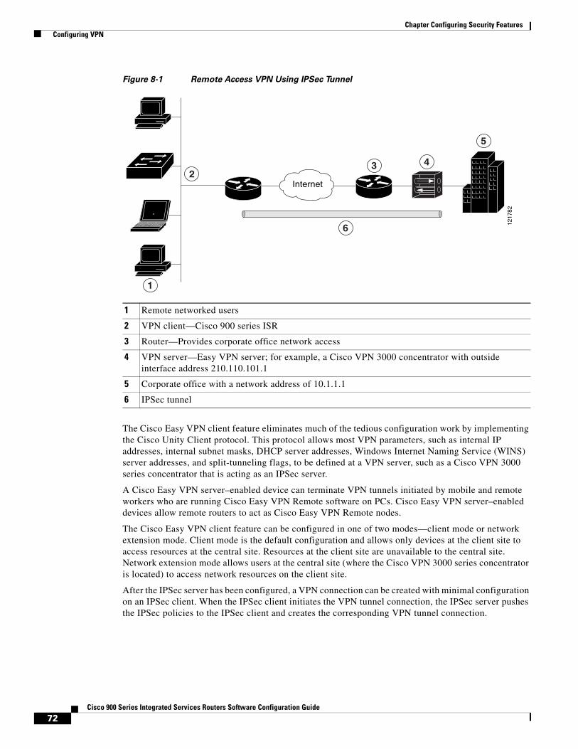
72Cisco 900 Series Integrated Services Routers Software Configuration Guide
Chapter Configuring Security Features Configuring VPN
Figure 8-1 Remote Access VPN Using IPSec Tunnel
The Cisco Easy VPN client feature eliminates much of the tedious configuration work by implementing the Cisco Unity Client protocol. This protocol allows most VPN parameters, such as internal IP addresses, internal subnet masks, DHCP server addresses, Windows Internet Naming Service (WINS) server addresses, and split-tunneling flags, to be defined at a VPN server, such as a Cisco VPN 3000 series concentrator that is acting as an IPSec server.
A Cisco Easy VPN server–enabled device can terminate VPN tunnels initiated by mobile and remote workers who are running Cisco Easy VPN Remote software on PCs. Cisco Easy VPN server–enabled devices allow remote routers to act as Cisco Easy VPN Remote nodes.
The Cisco Easy VPN client feature can be configured in one of two modes—client mode or network extension mode. Client mode is the default configuration and allows only devices at the client site to access resources at the central site. Resources at the client site are unavailable to the central site. Network extension mode allows users at the central site (where the Cisco VPN 3000 series concentrator is located) to access network resources on the client site.
After the IPSec server has been configured, a VPN connection can be created with minimal configuration on an IPSec client. When the IPSec client initiates the VPN tunnel connection, the IPSec server pushes the IPSec policies to the IPSec client and creates the corresponding VPN tunnel connection.
1 Remote networked users
2 VPN client—Cisco 900 series ISR
3 Router—Provides corporate office network access
4 VPN server—Easy VPN server; for example, a Cisco VPN 3000 concentrator with outside interface address 210.110.101.1
5 Corporate office with a network address of 10.1.1.1
6 IPSec tunnel
2
1
1217
82
Internet
3 4
5
6
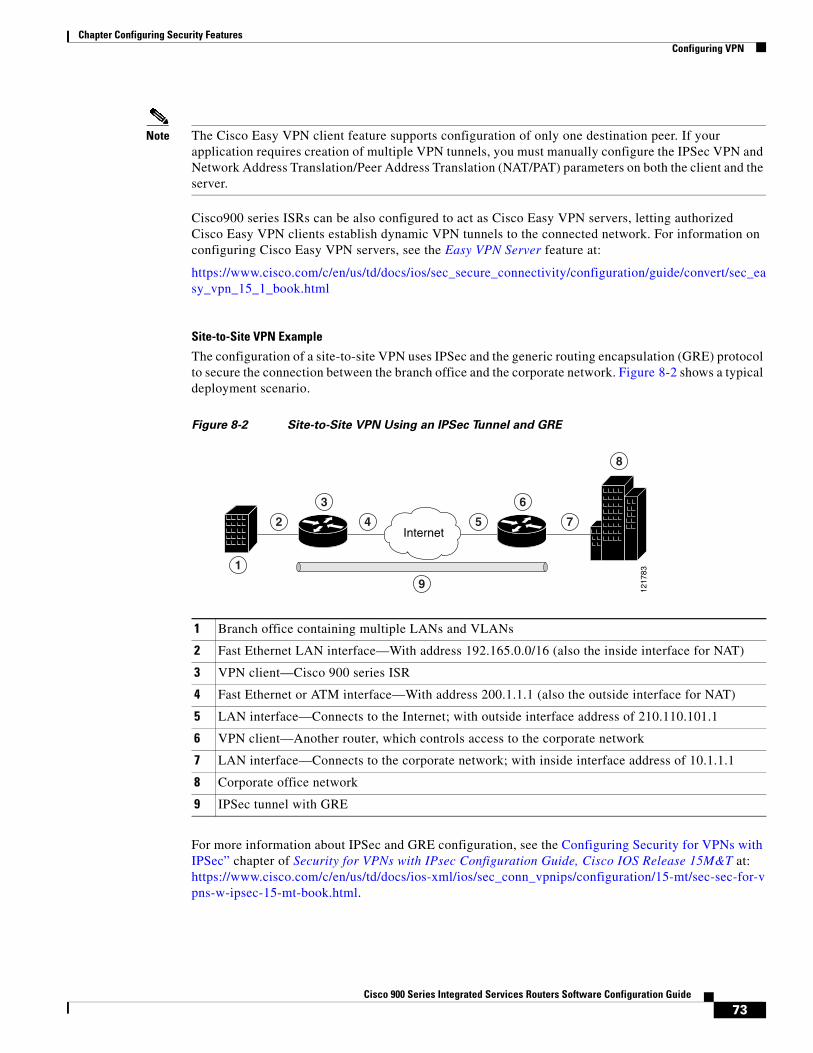
73Cisco 900 Series Integrated Services Routers Software Configuration Guide
Chapter Configuring Security Features Configuring VPN
Note The Cisco Easy VPN client feature supports configuration of only one destination peer. If your application requires creation of multiple VPN tunnels, you must manually configure the IPSec VPN and Network Address Translation/Peer Address Translation (NAT/PAT) parameters on both the client and the server.
Cisco900 series ISRs can be also configured to act as Cisco Easy VPN servers, letting authorized Cisco Easy VPN clients establish dynamic VPN tunnels to the connected network. For information on configuring Cisco Easy VPN servers, see the Easy VPN Server feature at:
https://www.cisco.com/c/en/us/td/docs/ios/sec_secure_connectivity/configuration/guide/convert/sec_easy_vpn_15_1_book.html
Site-to-Site VPN Example
The configuration of a site-to-site VPN uses IPSec and the generic routing encapsulation (GRE) protocol to secure the connection between the branch office and the corporate network. Figure 8-2 shows a typical deployment scenario.
Figure 8-2 Site-to-Site VPN Using an IPSec Tunnel and GRE
For more information about IPSec and GRE configuration, see the Configuring Security for VPNs with IPSec” chapter of Security for VPNs with IPsec Configuration Guide, Cisco IOS Release 15M&T at:https://www.cisco.com/c/en/us/td/docs/ios-xml/ios/sec_conn_vpnips/configuration/15-mt/sec-sec-for-vpns-w-ipsec-15-mt-book.html.
1 Branch office containing multiple LANs and VLANs
2 Fast Ethernet LAN interface—With address 192.165.0.0/16 (also the inside interface for NAT)
3 VPN client—Cisco 900 series ISR
4 Fast Ethernet or ATM interface—With address 200.1.1.1 (also the outside interface for NAT)
5 LAN interface—Connects to the Internet; with outside interface address of 210.110.101.1
6 VPN client—Another router, which controls access to the corporate network
7 LAN interface—Connects to the corporate network; with inside interface address of 10.1.1.1
8 Corporate office network
9 IPSec tunnel with GRE
1217
83
Internet
3
1
2 4 5 7
6
8
9
74Cisco 900 Series Integrated Services Routers Software Configuration Guide
Chapter Configuring Security Features Configuring Dynamic Multipoint VPN
Configuring Dynamic Multipoint VPNThe Dynamic Multipoint VPN (DMVPN) feature allows users to better scale large and small IP Security (IPsec) VPNs by combining GRE tunnels, IPsec encryption, and Next Hop Resolution Protocol (NHRP).
For additional information about configuring DMVPN, see Dynamic Multipoint VPN Configuration Guide, Cisco IOS Release 15M&T at:
https://www.cisco.com/c/en/us/td/docs/ios-xml/ios/sec_conn_dmvpn/configuration/15-mt/sec-conn-dmvpn-15-mt-book/sec-conn-dmvpn-dmvpn.html
Configuring Group Encrypted Transport VPNGroup Encrypted Transport (GET) VPN is a set of features that are necessary to secure IP multicast group traffic or unicast traffic over a private WAN that originates on or flows through a Cisco IOS device. GET VPN combines the keying protocol Group Domain of Interpretation (GDOI) with IPsec encryption to provide users with an efficient method of securing IP multicast traffic or unicast traffic. GET VPN enables the router to apply encryption to nontunneled (that is, “native”) IP multicast and unicast packets and eliminates the requirement to configure tunnels to protect multicast and unicast traffic.
By removing the need for point-to-point tunnels, meshed networks can scale higher while maintaining network-intelligence features that are critical to voice and video quality, such as QoS, routing, and multicast. GET VPN offers a new standards-based IP security (IPsec) security model that is based on the concept of “trusted” group members. Trusted member routers use a common security methodology that is independent of any point-to-point IPsec tunnel relationship.
For additional information about configuring GET VPN, see https://www.cisco.com/en/US/docs/ios-xml/ios/sec_conn_getvpn/configuration/15-2mt/sec-get-vpn.html
SGT over Ethernet Tagging Cisco TrustSec (CTS) is an end-to-end network infrastructure that provides a scalable architecture for enforcement of role-based access control, identity-aware networking, and data confidentiality that helps to secure the network and its resources. CTS works by identifying and authenticating each network user and resource and assigning a 16-bit number called Security Group Tag (SGT). SGT is then propagated between network hops to allow intermediary devices (switches and routers) to enforce policies based on the identity tag.
CTS-capable devices have built-in hardware capabilities than can send and receive packets with SGT embedded in the MAC (L2) layer. This feature is called L2-SGT imposition. This allows Ethernet interfaces on the device to be enabled for L2-SGT imposition to enable the device to insert an SGT in the packet that is to be carried to its next- hop Ethernet neighbor. SGT over Ethernet Tagging is a type of hop-by-hop propagation of SGTs embedded in clear-text (unencrypted) Ethernet packets.
For additional information about Cisco TrustSec, see https://www.cisco.com/c/en/us/td/docs/switches/lan/trustsec/configuration/guide/trustsec/config.html
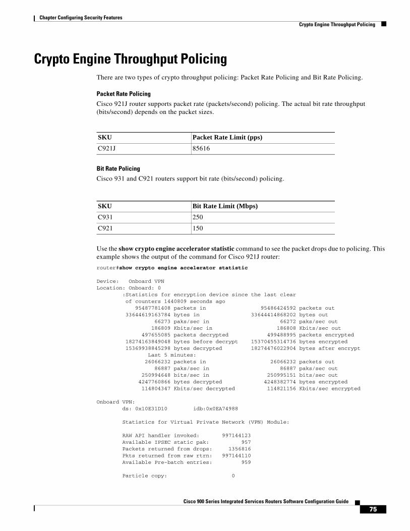
75Cisco 900 Series Integrated Services Routers Software Configuration Guide
Chapter Configuring Security Features Crypto Engine Throughput Policing
Crypto Engine Throughput PolicingThere are two types of crypto throughput policing: Packet Rate Policing and Bit Rate Policing.
Packet Rate Policing
Cisco 921J router supports packet rate (packets/second) policing. The actual bit rate throughput (bits/second) depends on the packet sizes.
Bit Rate Policing
Cisco 931 and C921 routers support bit rate (bits/second) policing.
Use the show crypto engine accelerator statistic command to see the packet drops due to policing. This example shows the output of the command for Cisco 921J router:
router#show crypto engine accelerator statistic Device: Onboard VPNLocation: Onboard: 0 :Statistics for encryption device since the last clear of counters 1440809 seconds ago 95487781408 packets in 95486424592 packets out 33644619163784 bytes in 33644414868202 bytes out 66273 paks/sec in 66272 paks/sec out 186809 Kbits/sec in 186808 Kbits/sec out 497655085 packets decrypted 499488995 packets encrypted 18274163849048 bytes before decrypt 15370455314736 bytes encrypted 15369938845298 bytes decrypted 18274476022904 bytes after encrypt Last 5 minutes: 26066232 packets in 26066232 packets out 86887 paks/sec in 86887 paks/sec out 250994648 bits/sec in 250995151 bits/sec out 4247760866 bytes decrypted 4248382774 bytes encrypted 114804347 Kbits/sec decrypted 114821156 Kbits/sec encrypted Onboard VPN: ds: 0x10E31D10 idb:0x0EA74988 Statistics for Virtual Private Network (VPN) Module: RAW API handler invoked: 997144123 Available IPSEC static pak: 957 Packets returned from drops: 1356816 Pkts returned from raw rtrn: 997144110 Available Pre-batch entries: 959 Particle copy: 0
SKU Packet Rate Limit (pps)C921J 85616
SKU Bit Rate Limit (Mbps)C931 250
C921 150
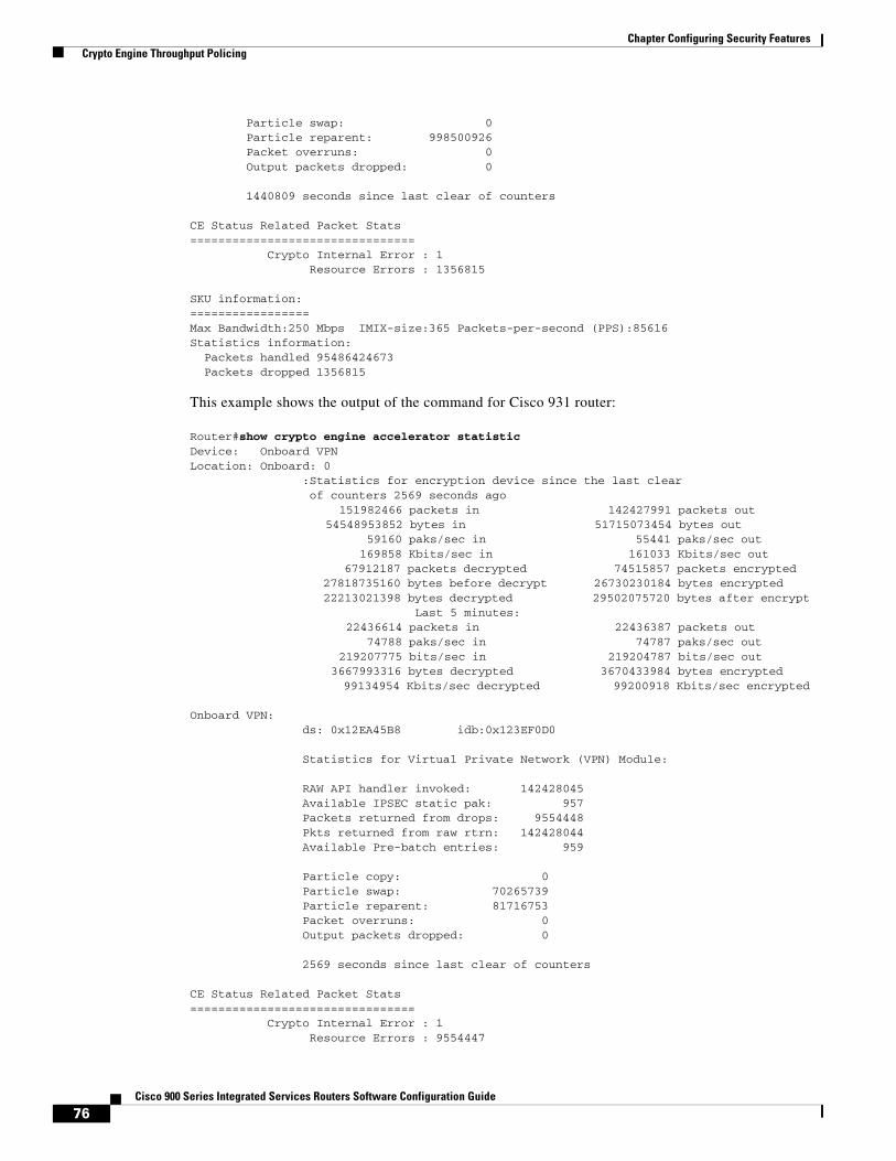
76Cisco 900 Series Integrated Services Routers Software Configuration Guide
Chapter Configuring Security Features Crypto Engine Throughput Policing
Particle swap: 0 Particle reparent: 998500926 Packet overruns: 0 Output packets dropped: 0 1440809 seconds since last clear of counters CE Status Related Packet Stats================================ Crypto Internal Error : 1 Resource Errors : 1356815 SKU information:=================Max Bandwidth:250 Mbps IMIX-size:365 Packets-per-second (PPS):85616Statistics information: Packets handled 95486424673 Packets dropped 1356815
This example shows the output of the command for Cisco 931 router:
Router#show crypto engine accelerator statisticDevice: Onboard VPNLocation: Onboard: 0 :Statistics for encryption device since the last clear of counters 2569 seconds ago 151982466 packets in 142427991 packets out 54548953852 bytes in 51715073454 bytes out 59160 paks/sec in 55441 paks/sec out 169858 Kbits/sec in 161033 Kbits/sec out 67912187 packets decrypted 74515857 packets encrypted 27818735160 bytes before decrypt 26730230184 bytes encrypted 22213021398 bytes decrypted 29502075720 bytes after encrypt Last 5 minutes: 22436614 packets in 22436387 packets out 74788 paks/sec in 74787 paks/sec out 219207775 bits/sec in 219204787 bits/sec out 3667993316 bytes decrypted 3670433984 bytes encrypted 99134954 Kbits/sec decrypted 99200918 Kbits/sec encrypted Onboard VPN: ds: 0x12EA45B8 idb:0x123EF0D0 Statistics for Virtual Private Network (VPN) Module: RAW API handler invoked: 142428045 Available IPSEC static pak: 957 Packets returned from drops: 9554448 Pkts returned from raw rtrn: 142428044 Available Pre-batch entries: 959 Particle copy: 0 Particle swap: 70265739 Particle reparent: 81716753 Packet overruns: 0 Output packets dropped: 0 2569 seconds since last clear of counters CE Status Related Packet Stats================================ Crypto Internal Error : 1 Resource Errors : 9554447
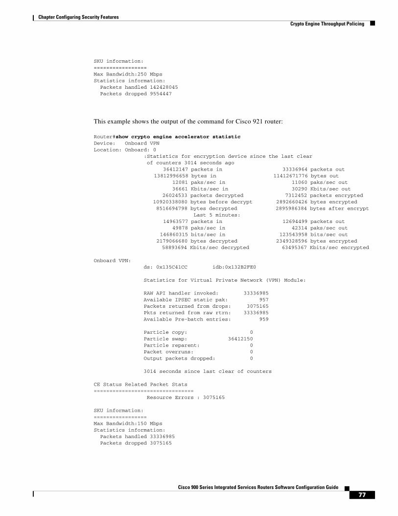
77Cisco 900 Series Integrated Services Routers Software Configuration Guide
Chapter Configuring Security Features Crypto Engine Throughput Policing
SKU information:=================Max Bandwidth:250 MbpsStatistics information: Packets handled 142428045 Packets dropped 9554447
This example shows the output of the command for Cisco 921 router:
Router#show crypto engine accelerator statisticDevice: Onboard VPNLocation: Onboard: 0 :Statistics for encryption device since the last clear of counters 3014 seconds ago 36412147 packets in 33336964 packets out 13812996658 bytes in 11412671776 bytes out 12081 paks/sec in 11060 paks/sec out 36661 Kbits/sec in 30290 Kbits/sec out 26024533 packets decrypted 7312452 packets encrypted 10920338080 bytes before decrypt 2892660426 bytes encrypted 8516694798 bytes decrypted 2895986384 bytes after encrypt Last 5 minutes: 14963577 packets in 12694499 packets out 49878 paks/sec in 42314 paks/sec out 146860315 bits/sec in 123543958 bits/sec out 2179066680 bytes decrypted 2349328596 bytes encrypted 58893694 Kbits/sec decrypted 63495367 Kbits/sec encrypted Onboard VPN: ds: 0x135C41CC idb:0x132B2FE0 Statistics for Virtual Private Network (VPN) Module: RAW API handler invoked: 33336985 Available IPSEC static pak: 957 Packets returned from drops: 3075165 Pkts returned from raw rtrn: 33336985 Available Pre-batch entries: 959 Particle copy: 0 Particle swap: 36412150 Particle reparent: 0 Packet overruns: 0 Output packets dropped: 0 3014 seconds since last clear of counters CE Status Related Packet Stats================================ Resource Errors : 3075165 SKU information:=================Max Bandwidth:150 MbpsStatistics information: Packets handled 33336985 Packets dropped 3075165

78Cisco 900 Series Integrated Services Routers Software Configuration Guide
Chapter Configuring Security Features Crypto Engine Throughput Policing
C H A P T E R
79Cisco 900 Series Integrated Services Routers Software Configuration Guide
9Configuring VDSL2 and ADSL2/2+
This chapter describes how to configure multimode VDSL2 and ADSl2+ WAN connectivity on a Cisco 900 series ISR. The VDSL2 and ADSl2+ WAN connectivity provides high-speed digital data transmission between customer premises equipment (CPE) and the central office. This chapter contains the following sections:
• Overview, page 79
• Configuring DSL, page 80
– DSL Configuration Restrictions, page 80
– Configuring ADSL Mode, page 81
– Configuring VDSL Mode, page 85
– Configuring VLAN 0 Priority Tagging, page 90
– Enabling ADSL2/2+ Annex M Mode on Over POTS VDSL2/ADSL Multimode Annex A SKUs, page 90
– Enabling Seamless Rate Adaption, page 91
– Configuring UBR+, page 91
– Collecting DSL Training Logs, page 92
– Upgrading DSL Firmware, page 92
OverviewOrganization needs high speed digital data transmission to operate between their data equipment and central office, usually located at the telecom service provider premises. The Cisco multimode VDSL2 and ADSL1/2/2+ provides 1-port (2-pair) multimode VDSL2 and ADSL2+ WAN connectivity. This connectivity in combination with Cisco 900 Series Integrated Service Routers, provides high-speed digital data transmission between customer premises equipment (CPE) and the central office.
The following table describes the VDSL2 and ADSL2/2+ Variants:
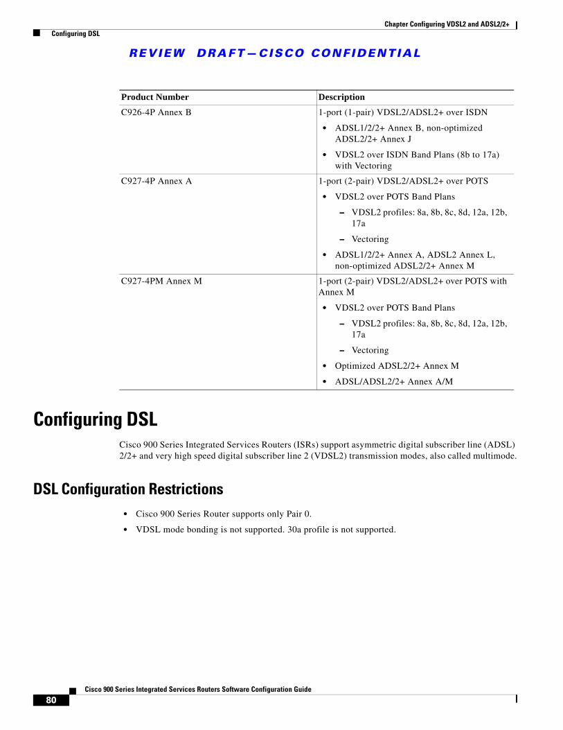
REVIEW DRAFT—CISCO CONF IDENT IAL
80Cisco 900 Series Integrated Services Routers Software Configuration Guide
Chapter Configuring VDSL2 and ADSL2/2+ Configuring DSL
Configuring DSL Cisco 900 Series Integrated Services Routers (ISRs) support asymmetric digital subscriber line (ADSL) 2/2+ and very high speed digital subscriber line 2 (VDSL2) transmission modes, also called multimode.
DSL Configuration Restrictions• Cisco 900 Series Router supports only Pair 0.
• VDSL mode bonding is not supported. 30a profile is not supported.
Product Number DescriptionC926-4P Annex B 1-port (1-pair) VDSL2/ADSL2+ over ISDN
• ADSL1/2/2+ Annex B, non-optimized ADSL2/2+ Annex J
• VDSL2 over ISDN Band Plans (8b to 17a) with Vectoring
C927-4P Annex A 1-port (2-pair) VDSL2/ADSL2+ over POTS
• VDSL2 over POTS Band Plans
– VDSL2 profiles: 8a, 8b, 8c, 8d, 12a, 12b, 17a
– Vectoring
• ADSL1/2/2+ Annex A, ADSL2 Annex L, non-optimized ADSL2/2+ Annex M
C927-4PM Annex M 1-port (2-pair) VDSL2/ADSL2+ over POTS with Annex M
• VDSL2 over POTS Band Plans
– VDSL2 profiles: 8a, 8b, 8c, 8d, 12a, 12b, 17a
– Vectoring
• Optimized ADSL2/2+ Annex M
• ADSL/ADSL2/2+ Annex A/M
81Cisco 900 Series Integrated Services Routers Software Configuration Guide
Chapter Configuring VDSL2 and ADSL2/2+ Configuring DSL
Configuring ADSL ModePerform the following tasks to configure ADSL mode:
• Configuring ADSL Auto Mode, page 81
• Configuring CPE and Peer for ADSL Mode, page 81
• Verifying ADSL Configuration, page 84
• Verifying CPE to Peer Connection for ADSL, page 85
Configuring ADSL Auto Mode
Note Configure the DSLAM in ADSL mode prior to configuring the router.
This example shows how to configure the ADSL controller to auto mode:
Router> enableRouter# configure terminalRouter(config)# controller vdsl 0Router(config-controller)# operating mode autoRouter(config-controller)# endRouter#
Configuring CPE and Peer for ADSL Mode
When configuring for ADSL, the ATM main interface or ATM sub-interface must be configured with a PVC and an IP address, perform a no shutdown command on the interface if needed.
Configuring the ATM CPE side
This example shows how to configure the ATM CPE side:
Router> enableRouter# configure terminalRouter(config)# interface atm0Router(config-if)# no shutdownRouter(config-if)# interface ATM0.1 point-to-pointRouter(config-subif)# ip address 30.0.0.1 255.255.255.0Router(config-subif)# pvc 13/32Router(config-if-atm-vc)# protocol ip 30.0.0.2 broadcastRouter(config-if-atm-vc)# end
Configuring the ATM Peer side
This example shows how to configure the ATM peer side:
Router> enableRouter# configure terminalRouter(config)# interface atm0Router(config-if)# no shutdownRouter(config-if)# interface ATM0.1 point-to-pointRouter(config-subif)# ip address 30.0.0.2 255.255.255.0Router(config-subif)# pvc 13/32Router(config-if-atm-vc)# protocol ip 30.0.0.1 broadcast
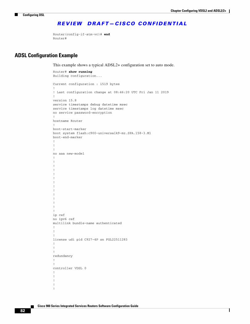
REVIEW DRAFT—CISCO CONF IDENT IAL
82Cisco 900 Series Integrated Services Routers Software Configuration Guide
Chapter Configuring VDSL2 and ADSL2/2+ Configuring DSL
Router(config-if-atm-vc)# endRouter#
ADSL Configuration Example
This example shows a typical ADSL2+ configuration set to auto mode.
Router# show runningBuilding configuration...
Current configuration : 1519 bytes! ! Last configuration change at 08:46:20 UTC Fri Jan 11 2019! version 15.8 service timestamps debug datetime msec service timestamps log datetime msec no service password-encryption ! hostname Router ! boot-start-marker boot system flash:c900-universalk9-mz.SPA.158-3.M1 boot-end-marker ! ! ! no aaa new-model ! ! ! ! ! ! ! ! ! ! ! ! ! ! ip cef no ipv6 cef multilink bundle-name authenticated ! ! ! license udi pid C927-4P sn FGL22511283 ! ! ! redundancy ! ! controller VDSL 0 ! ! ! ! !
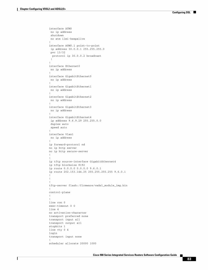
83Cisco 900 Series Integrated Services Routers Software Configuration Guide
Chapter Configuring VDSL2 and ADSL2/2+ Configuring DSL
interface ATM0 no ip address shutdown no atm ilmi-keepalive ! interface ATM0.1 point-to-point ip address 30.0.0.1 255.255.255.0 pvc 13/32 protocol ip 30.0.0.2 broadcast ! ! interface Ethernet0 no ip address ! interface GigabitEthernet0 no ip address ! interface GigabitEthernet1 no ip address ! interface GigabitEthernet2 no ip address ! interface GigabitEthernet3 no ip address ! interface GigabitEthernet4 ip address 9.6.9.29 255.255.0.0 duplex auto speed auto ! interface Vlan1 no ip address!ip forward-protocol ndno ip http serverno ip http secure-server!!ip tftp source-interface GigabitEthernet4ip tftp blocksize 8192ip route 0.0.0.0 0.0.0.0 9.6.0.1ip route 202.153.144.25 255.255.255.255 9.6.0.1!!!tftp-server flash:/firmware/vadsl_module_img.bin!control-plane!!line con 0exec-timeout 0 0line 4no activation-charactertransport preferred nonetransport input alltransport output allstopbits 1line vty 0 4logintransport input none!scheduler allocate 20000 1000
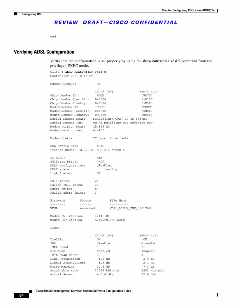
REVIEW DRAFT—CISCO CONF IDENT IAL
84Cisco 900 Series Integrated Services Routers Software Configuration Guide
Chapter Configuring VDSL2 and ADSL2/2+ Configuring DSL
!end
Verifying ADSL Configuration
Verify that the configuration is set properly by using the show controller vdsl 0 command from the privileged EXEC mode.
Router# show controller vdsl 0Controller VDSL 0 is UP
Daemon Status: Up
XTU-R (DS) XTU-C (US)Chip Vendor ID: 'BDCM' 'BDCM' Chip Vendor Specific: 0x0000 0xB11F Chip Vendor Country: 0xB500 0xB500 Modem Vendor ID: 'CSCO' 'BDCM' Modem Vendor Specific: 0x4602 0x0000 Modem Vendor Country: 0xB500 0xB500 Serial Number Near: FCH2234TH6R C927-4P 15.8(3)M1 Serial Number Far: eq_nr multiline_cpe software_rev Modem Version Near: 15.8(3)M1 Modem Version Far: 0xb11f
Modem Status: TC Sync (Showtime!)
DSL Config Mode: AUTO Trained Mode: G.992.5 (ADSL2+) Annex A
TC Mode: ATM Selftest Result: 0x00 DELT configuration: disabled DELT state: not running Link Status: UP
Full inits: 26Failed full inits: 15Short inits: 8 Failed short inits: 3
Firmware Source File Name -------- ------ ----------VDSL embedded VDSL_LINUX_DEV_01212008
Modem FW Version: 4.14L.04Modem PHY Version: A2pv6F039x8.d26d
Line:
XTU-R (DS) XTU-C (US)Trellis: ON ONSRA: disabled disabled SRA count: 0 0Bit swap: enabled enabled Bit swap count: 0 1Line Attenuation: 1.0 dB 2.4 dBSignal Attenuation: 1.9 dB 2.1 dBNoise Margin: 10.8 dB 7.3 dBAttainable Rate: 27564 kbits/s 1283 kbits/sActual Power: - 0.4 dBm 12.0 dBm
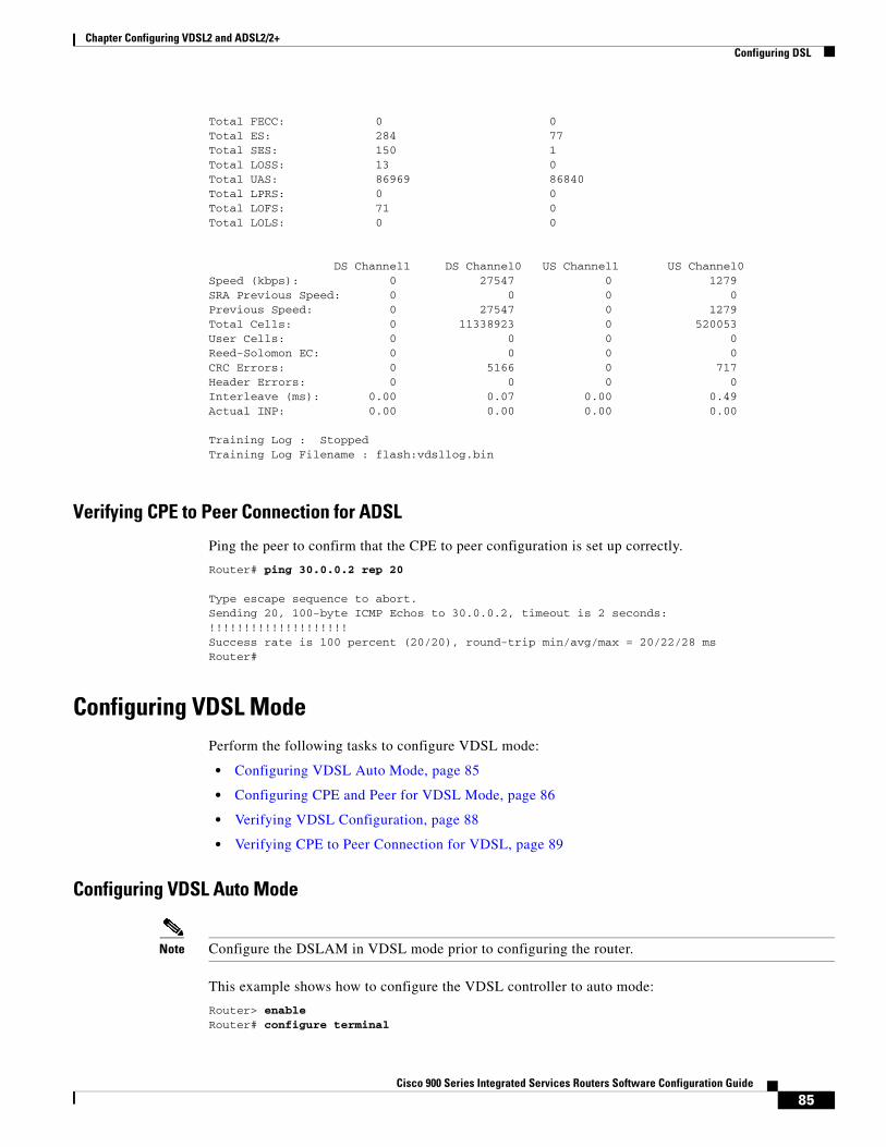
85Cisco 900 Series Integrated Services Routers Software Configuration Guide
Chapter Configuring VDSL2 and ADSL2/2+ Configuring DSL
Total FECC: 0 0Total ES: 284 77Total SES: 150 1Total LOSS: 13 0Total UAS: 86969 86840Total LPRS: 0 0Total LOFS: 71 0Total LOLS: 0 0
DS Channel1 DS Channel0 US Channel1 US Channel0Speed (kbps): 0 27547 0 1279SRA Previous Speed: 0 0 0 0Previous Speed: 0 27547 0 1279Total Cells: 0 11338923 0 520053User Cells: 0 0 0 0Reed-Solomon EC: 0 0 0 0CRC Errors: 0 5166 0 717Header Errors: 0 0 0 0Interleave (ms): 0.00 0.07 0.00 0.49Actual INP: 0.00 0.00 0.00 0.00
Training Log : StoppedTraining Log Filename : flash:vdsllog.bin
Verifying CPE to Peer Connection for ADSL
Ping the peer to confirm that the CPE to peer configuration is set up correctly.
Router# ping 30.0.0.2 rep 20
Type escape sequence to abort.Sending 20, 100-byte ICMP Echos to 30.0.0.2, timeout is 2 seconds:!!!!!!!!!!!!!!!!!!!!Success rate is 100 percent (20/20), round-trip min/avg/max = 20/22/28 msRouter#
Configuring VDSL ModePerform the following tasks to configure VDSL mode:
• Configuring VDSL Auto Mode, page 85
• Configuring CPE and Peer for VDSL Mode, page 86
• Verifying VDSL Configuration, page 88
• Verifying CPE to Peer Connection for VDSL, page 89
Configuring VDSL Auto Mode
Note Configure the DSLAM in VDSL mode prior to configuring the router.
This example shows how to configure the VDSL controller to auto mode:
Router> enableRouter# configure terminal
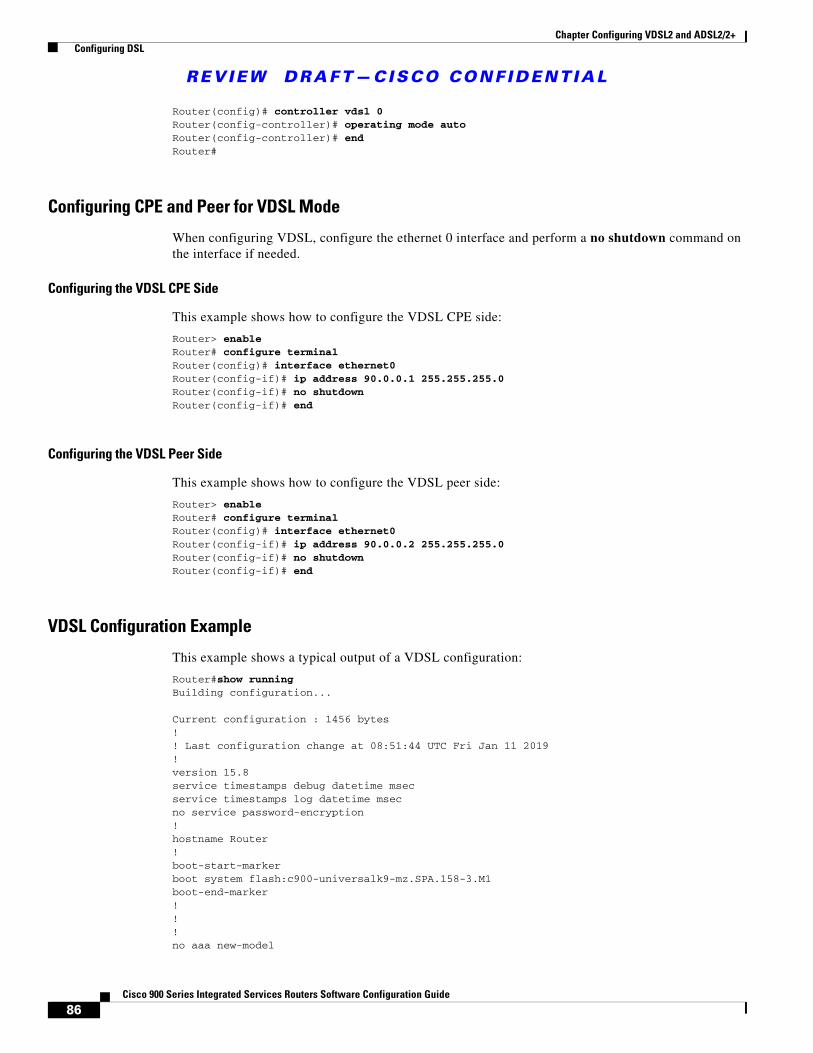
REVIEW DRAFT—CISCO CONF IDENT IAL
86Cisco 900 Series Integrated Services Routers Software Configuration Guide
Chapter Configuring VDSL2 and ADSL2/2+ Configuring DSL
Router(config)# controller vdsl 0Router(config-controller)# operating mode autoRouter(config-controller)# endRouter#
Configuring CPE and Peer for VDSL Mode
When configuring VDSL, configure the ethernet 0 interface and perform a no shutdown command on the interface if needed.
Configuring the VDSL CPE Side
This example shows how to configure the VDSL CPE side:
Router> enableRouter# configure terminalRouter(config)# interface ethernet0Router(config-if)# ip address 90.0.0.1 255.255.255.0Router(config-if)# no shutdownRouter(config-if)# end
Configuring the VDSL Peer Side
This example shows how to configure the VDSL peer side:
Router> enableRouter# configure terminalRouter(config)# interface ethernet0Router(config-if)# ip address 90.0.0.2 255.255.255.0Router(config-if)# no shutdownRouter(config-if)# end
VDSL Configuration Example
This example shows a typical output of a VDSL configuration:
Router#show running Building configuration...
Current configuration : 1456 bytes! ! Last configuration change at 08:51:44 UTC Fri Jan 11 2019! version 15.8 service timestamps debug datetime msec service timestamps log datetime msec no service password-encryption ! hostname Router ! boot-start-marker boot system flash:c900-universalk9-mz.SPA.158-3.M1 boot-end-marker ! ! ! no aaa new-model
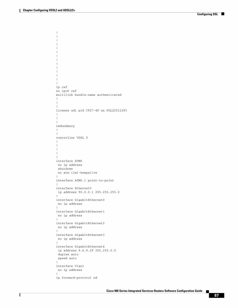
87Cisco 900 Series Integrated Services Routers Software Configuration Guide
Chapter Configuring VDSL2 and ADSL2/2+ Configuring DSL
! ! ! ! ! ! ! ! ! ! ! ! ! ! ip cef no ipv6 cef multilink bundle-name authenticated ! ! ! license udi pid C927-4P sn FGL22511283 ! ! ! redundancy ! ! controller VDSL 0 ! ! ! ! ! interface ATM0 no ip address shutdown no atm ilmi-keepalive ! interface ATM0.1 point-to-point ! interface Ethernet0 ip address 90.0.0.1 255.255.255.0 ! interface GigabitEthernet0 no ip address ! interface GigabitEthernet1 no ip address ! interface GigabitEthernet2 no ip address ! interface GigabitEthernet3 no ip address ! interface GigabitEthernet4 ip address 9.6.9.29 255.255.0.0 duplex auto speed auto ! interface Vlan1 no ip address!ip forward-protocol nd
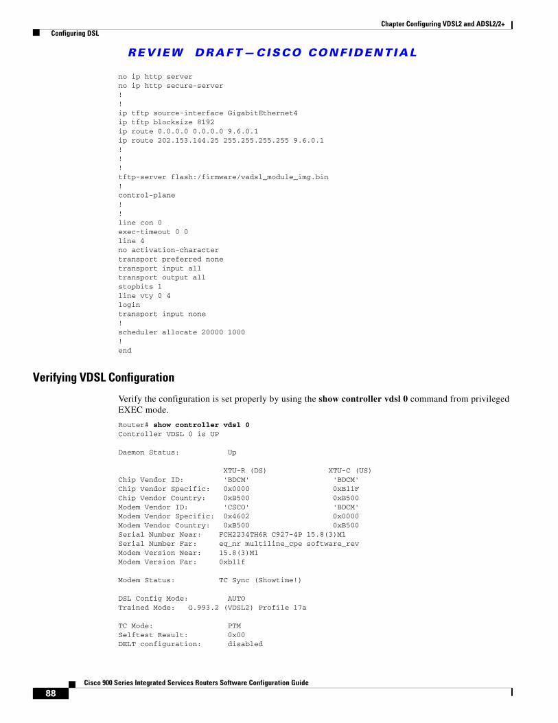
REVIEW DRAFT—CISCO CONF IDENT IAL
88Cisco 900 Series Integrated Services Routers Software Configuration Guide
Chapter Configuring VDSL2 and ADSL2/2+ Configuring DSL
no ip http serverno ip http secure-server!!ip tftp source-interface GigabitEthernet4ip tftp blocksize 8192ip route 0.0.0.0 0.0.0.0 9.6.0.1ip route 202.153.144.25 255.255.255.255 9.6.0.1!!!tftp-server flash:/firmware/vadsl_module_img.bin!control-plane!!line con 0exec-timeout 0 0line 4no activation-charactertransport preferred nonetransport input alltransport output allstopbits 1line vty 0 4logintransport input none!scheduler allocate 20000 1000!end
Verifying VDSL Configuration
Verify the configuration is set properly by using the show controller vdsl 0 command from privileged EXEC mode.
Router# show controller vdsl 0Controller VDSL 0 is UP
Daemon Status: Up
XTU-R (DS) XTU-C (US)Chip Vendor ID: 'BDCM' 'BDCM' Chip Vendor Specific: 0x0000 0xB11F Chip Vendor Country: 0xB500 0xB500 Modem Vendor ID: 'CSCO' 'BDCM' Modem Vendor Specific: 0x4602 0x0000 Modem Vendor Country: 0xB500 0xB500 Serial Number Near: FCH2234TH6R C927-4P 15.8(3)M1 Serial Number Far: eq_nr multiline_cpe software_rev Modem Version Near: 15.8(3)M1 Modem Version Far: 0xb11f
Modem Status: TC Sync (Showtime!)
DSL Config Mode: AUTO Trained Mode: G.993.2 (VDSL2) Profile 17a
TC Mode: PTM Selftest Result: 0x00 DELT configuration: disabled
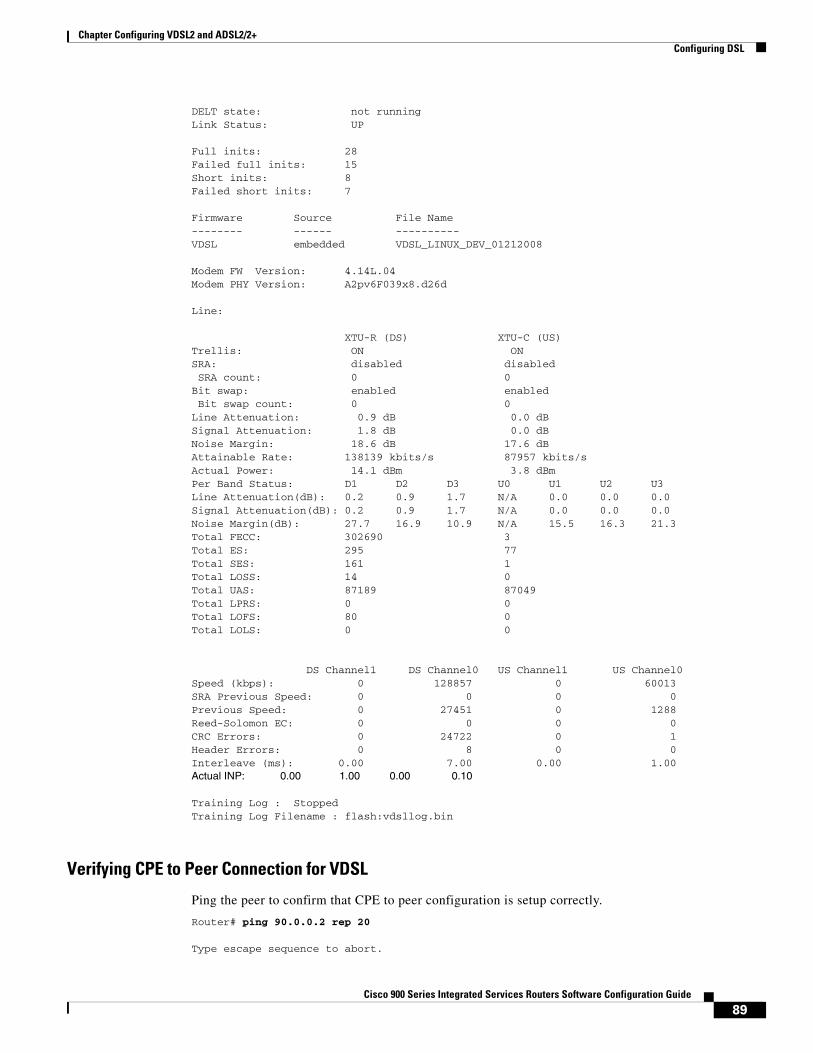
89Cisco 900 Series Integrated Services Routers Software Configuration Guide
Chapter Configuring VDSL2 and ADSL2/2+ Configuring DSL
DELT state: not running Link Status: UP
Full inits: 28Failed full inits: 15Short inits: 8 Failed short inits: 7
Firmware Source File Name -------- ------ ----------VDSL embedded VDSL_LINUX_DEV_01212008
Modem FW Version: 4.14L.04Modem PHY Version: A2pv6F039x8.d26d
Line:
XTU-R (DS) XTU-C (US)Trellis: ON ON SRA: disabled disabled SRA count: 0 0Bit swap: enabled enabled Bit swap count: 0 0Line Attenuation: 0.9 dB 0.0 dBSignal Attenuation: 1.8 dB 0.0 dBNoise Margin: 18.6 dB 17.6 dBAttainable Rate: 138139 kbits/s 87957 kbits/sActual Power: 14.1 dBm 3.8 dBmPer Band Status: D1 D2 D3 U0 U1 U2 U3Line Attenuation(dB): 0.2 0.9 1.7 N/A 0.0 0.0 0.0Signal Attenuation(dB): 0.2 0.9 1.7 N/A 0.0 0.0 0.0Noise Margin(dB): 27.7 16.9 10.9 N/A 15.5 16.3 21.3Total FECC: 302690 3Total ES: 295 77Total SES: 161 1Total LOSS: 14 0Total UAS: 87189 87049Total LPRS: 0 0Total LOFS: 80 0Total LOLS: 0 0
DS Channel1 DS Channel0 US Channel1 US Channel0Speed (kbps): 0 128857 0 60013SRA Previous Speed: 0 0 0 0Previous Speed: 0 27451 0 1288Reed-Solomon EC: 0 0 0 0CRC Errors: 0 24722 0 1Header Errors: 0 8 0 0Interleave (ms): 0.00 7.00 0.00 1.00Actual INP: 0.00 1.00 0.00 0.10
Training Log : StoppedTraining Log Filename : flash:vdsllog.bin
Verifying CPE to Peer Connection for VDSL
Ping the peer to confirm that CPE to peer configuration is setup correctly.
Router# ping 90.0.0.2 rep 20
Type escape sequence to abort.
REVIEW DRAFT—CISCO CONF IDENT IAL
90Cisco 900 Series Integrated Services Routers Software Configuration Guide
Chapter Configuring VDSL2 and ADSL2/2+ Configuring DSL
Sending 20, 100-byte ICMP Echos to 90.0.0.2, timeout is 2 seconds:!!!!!!!!!!!!!!!!!!!!Success rate is 100 percent (20/20), round-trip min/avg/max = 20/22/28 msRouter#
Configuring VLAN 0 Priority TaggingThe VLAN 0 Priority Tagging feature enables 802.1Q Ethernet frames to be transmitted with the VLAN ID set to zero. These frames are called priority tagged frames. Setting the VLAN ID tag to zero allows the VLAN ID tag to be ignored and the Ethernet frame to be processed according to the priority configured in the 802.1P bits of the 802.1Q Ethernet frame header.
This example shows how to configure VLAN Priority Tagging on the CPE side:
Router# configure terminalRouter(config)# interface GigabitEthernet0Router(config-if)# encapsulation priority-taggedRouter(config-if)# ip address 2.2.2.1 255.255.255.0Router(config-if)# end
This example shows how to configure VLAN Priority Tagging on the Peer side:
Router# configure terminalRouter(config)# interface GigabitEthernet0Router(config-if)# encapsulation priority-taggedRouter(config-if)# ip address 2.2.2.2 255.255.255.0Router(config-if)# end
Ping the peer to confirm that CPE to peer configuration is setup correctly. This example shows the ping output:
Router#ping 2.2.2.2Type escape sequence to abort.Sending 5, 100-byte ICMP Echos to 2.2.2.2, timeout is 2 seconds:!!!!!Success rate is 100 percent (5/5), round-trip min/avg/max = 1/1/1 msisr4221#sh run int gi0/0/0.1Building configuration...
Current configuration : 105 bytes!interface GigabitEthernet0/0/0.1 encapsulation priority-tagged ip address 2.2.2.2 255.255.255.0end
Enabling ADSL2/2+ Annex M Mode on Over POTS VDSL2/ADSL Multimode Annex A SKUs
This example shows how to enable ADSL2/2+ Annex M mode on Over POTS VDSL2/ADSL Multimode Annex A SKUs:
Router> enableRouter# configure terminalRouter(config)# controller vdsl 0Router(config-controller)# operating mode adsl2+ annex mRouter(config-controller)# end
91Cisco 900 Series Integrated Services Routers Software Configuration Guide
Chapter Configuring VDSL2 and ADSL2/2+ Configuring DSL
Router#
Enabling Seamless Rate Adaption This example shows how to enable SRA mode:
router# configure terminalrouter(config)# controller vdsl 0router(config-controller)# srarouter(config-controller)# endrouter#
Note Use the no form of the command to disable SRA. SRA mode is disabled by default.
Configuring UBR+This example shows how to configure UBR+ PVC on a DSL line:
Router> enableRouter# configure terminalRouter(config)# interface ATM 0/0Router(config-if)# pvc 4/100Router(config-if-atm-vc)# ubr+ 2304 2304
This example specifies the output-pcr argument for an ATM PVC to be 100000 kbps and the output-mcr to be 3000 kbps:
Router> enableRouter# configure terminalRouter(config)# interface ATM 0/0Router(config-if)# pvc 1/32Router(config-if-atm-vc)# ubr+ 100000 3000
This example specifies the output-pcr, output-mcr, input-pcr, and input-mcr arguments for an ATM SVC to be 10000 kbps, 3000 kbps, 9000 kbps, and 1000 kbps, respectively:
Router> enableRouter# configure terminalRouter(config)# interface ATM 0/0Router(config-if)# svc lion nsap 47.0091.81.000000.0040.0B0A.2501.ABC1.3333.3333.05Router(config-if-atm-vc)# ubr+ 10000 3000 9000 1000
Troubleshooting
Use the following show commands to troubleshoot DSL:
• show interface Ethernet0
• show interface ATM0
• show interface summary
• show controller vdsl 0
• show controller vdsl 0 datapath
• show atm pvc
REVIEW DRAFT—CISCO CONF IDENT IAL
92Cisco 900 Series Integrated Services Routers Software Configuration Guide
Chapter Configuring VDSL2 and ADSL2/2+ Configuring DSL
Collecting DSL Training LogsA training log provides you information about the different events that happened during the ADSL training.
This example shows how to start collecting the DSL training logs:
Router#debug vdsl 0 training log Training log generation started for VDSL 0.
This example shows how to stop collecting the DSL training logs:
Router#no debug vdsl 0 training log Training Log file for VDSL 0 written to flash:vdsllog.bin.
Training log also supports the auto-stop options. Use the following commands for auto-stop:
no debug vdsl 0 training log autostop linkdown: Stops the collection when the link goes down.no debug vdsl 0 training log autostop linkup: Stops the collection when the link reaches the showtime.
By default, training log is stored in flash:vdsllog.bin.
You can modify the filename in which the training logs are stored before starting the training log collection. This example shows how to modify the filename:
Router#conf tRouter(config)#controller vdsl 0Router(config-controller)#training log filename flash:mytraininglog.binRouter(config-controller)#endRouter#sh controller vdsl 0 | sec Training LogTraining Log :StoppedTraining Log Filename :flash:mytraininglog.binRouter#
Upgrading DSL Firmware To upgrade the firmware on a DSL interface, perform these steps:
Step 1 Download the VDSL2 firmware from the Cisco Software Download Centre at https://software.cisco.com/download/home
Step 2 Copy the firmware to the router.
Step 3 Configure the router to load the new firmware from a designated location.
Router#conf tEnter configuration commands, one per line. End with CNTL/Z.Router(config)#controller vdsl 0Router(config-controller)#firmware filename ? archive: Download fw file name cns: Download fw file name flash: Download fw file name ftp: Download fw file name http: Download fw file name https: Download fw file name
93Cisco 900 Series Integrated Services Routers Software Configuration Guide
Chapter Configuring VDSL2 and ADSL2/2+ Configuring DSL
null: Download fw file name nvram: Download fw file name pram: Download fw file name rcp: Download fw file name scp: Download fw file name security: Download fw file name system: Download fw file name tar: Download fw file name tftp: Download fw file name tmpsys: Download fw file name
Router(config-controller)#firmware filename flash:vdsl_fw.bin_39p1
Step 4 Restart the controller interface for the new firmware to take effect.
Router#conf tEnter configuration commands, one per line. End with CNTL/Z.Router(config)#controller vdsl 0Router(config-controller)#shutRouter(config-controller)#no shutRouter(config-controller)#end

REVIEW DRAFT—CISCO CONF IDENT IAL
94Cisco 900 Series Integrated Services Routers Software Configuration Guide
Chapter Configuring VDSL2 and ADSL2/2+ Configuring DSL
C H A P T E R
95Cisco 900 Series Integrated Services Routers Software Configuration Guide
10Configuring 4G Wireless WAN
This chapter provides information about configuring the 4G Wireless WAN interface on Cisco 900 Series ISRs and contains the following sections:
• Overview of 4G LTE, page 95
• Cisco 4G LTE Features, page 97
• Prerequisites for Configuring Cisco 4G LTE, page 98
• Restrictions for Configuring Cisco 4G LTE, page 98
• How to Configure Cisco 4G LTE, page 98
• SNMP MIBs, page 121
• Troubleshooting, page 122
Overview of 4G LTE Cisco 900 series routers support Wireless WAN (WWAN). The WWAN SKUs operate over Fourth-Generation Long-Term Evolution (4G LTE) cellular networks and Third-Generation (3G) cellular networks. The Cisco 900 series routers offer a highly secure, simplified, and cost-effective WAN alternative to DSL or Frame Relay. In areas where terrestrial broadband services (cable, DSL, or T1) are not available or are expensive, 4G LTE WWAN connectivity can be a viable alternative.
Cisco 900 series routers support the following 4G/3G modes:
• 4G LTE—4G LTE mobile specification provides multi-megabit bandwidth, more efficient radio network, latency reduction, and improved mobility. LTE solutions target new cellular networks. These networks initially support up to 97Mb/s peak rates in the downlink and up to 50 Mb/s peak rates in the uplink. The throughput of these networks is higher than the existing 3G networks
• 3G Evolution High-Speed Packet Access (HSPA/HSPA+)—HSPA is a UMTS-based 3G network. It supports High-Speed Downlink Packet Access (HSDPA) and High-Speed Uplink Packet Access (HSUPA) data for improved download and upload speeds. Evolution High-Speed Packet Access (HSPA+) supports Multiple Input/Multiple Output (MIMO) antenna capability.
Figure 1 explains the 4G LTE packet core network architecture.
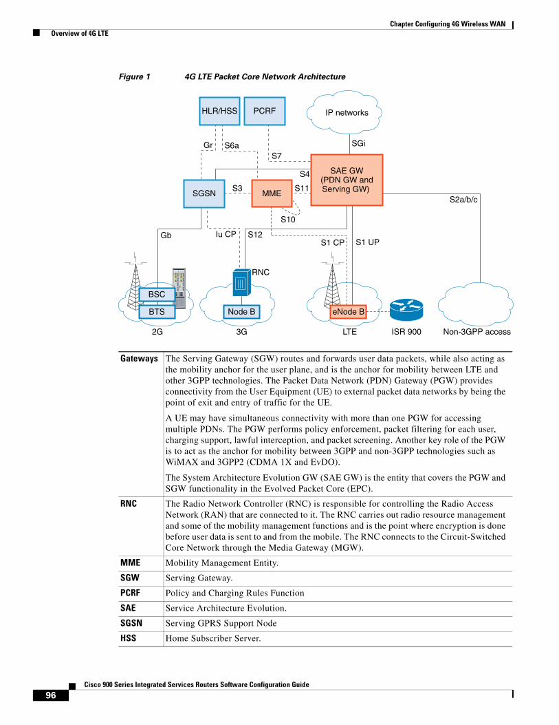
96Cisco 900 Series Integrated Services Routers Software Configuration Guide
Chapter Configuring 4G Wireless WAN Overview of 4G LTE
Figure 1 4G LTE Packet Core Network Architecture
2G
S1 CP S1 UP
Non-3GPP access
Iu CPGb
S3
S12
S11
GrS7
S10
SGi
S4
S6a
S2a/b/c
SAE GW(PDN GW andServing GW)
LTE ISR 9003G
RNC
Node B eNode B
IP networks
BTS
BSC
MME
HLR/HSS PCRF
SGSN
Gateways The Serving Gateway (SGW) routes and forwards user data packets, while also acting as the mobility anchor for the user plane, and is the anchor for mobility between LTE and other 3GPP technologies. The Packet Data Network (PDN) Gateway (PGW) provides connectivity from the User Equipment (UE) to external packet data networks by being the point of exit and entry of traffic for the UE.
A UE may have simultaneous connectivity with more than one PGW for accessing multiple PDNs. The PGW performs policy enforcement, packet filtering for each user, charging support, lawful interception, and packet screening. Another key role of the PGW is to act as the anchor for mobility between 3GPP and non-3GPP technologies such as WiMAX and 3GPP2 (CDMA 1X and EvDO).
The System Architecture Evolution GW (SAE GW) is the entity that covers the PGW and SGW functionality in the Evolved Packet Core (EPC).
RNC The Radio Network Controller (RNC) is responsible for controlling the Radio Access Network (RAN) that are connected to it. The RNC carries out radio resource management and some of the mobility management functions and is the point where encryption is done before user data is sent to and from the mobile. The RNC connects to the Circuit-Switched Core Network through the Media Gateway (MGW).
MME Mobility Management Entity.
SGW Serving Gateway.
PCRF Policy and Charging Rules Function
SAE Service Architecture Evolution.
SGSN Serving GPRS Support Node
HSS Home Subscriber Server.
97Cisco 900 Series Integrated Services Routers Software Configuration Guide
Chapter Configuring 4G Wireless WAN Cisco 4G LTE Features
Cisco 4G LTE FeaturesCisco 4G LTE WWAN supports the following major features:
• 3G/4G Simple Network Management Protocol (SNMP) MIB
• Auto-switch failover between primary and backup link
• SIM lock and unlock capabilities
• PLMN Search
• Short Message Service (SMS)
• 3G backward compatible
• IPv4 and IPv6 addressing
• Auto SIM Firmware Switching
• Call History
• Cellular Backoff
• Modem reset, modem power cycle, radio on/off
• Modem crashdump collection
• Dialer
• DM Logging
• External Micro USB
• Firmware Upgrade
• Link Recovery
• Modem LED
• Multiple Profile
• PnP LTE WebUI Integration
• SIM OIR
• DMVPN
• CAT
The following features are not supported:
• Dying Gasp
• MEP
• Multiple PDN Context
• LTE Module OIR
• GPS and NMEA
HLR Home Location Register.
BTS Base Transceiver Station.
BSC Base Station Controller.
SGSN Service GPRS Support Node.
98Cisco 900 Series Integrated Services Routers Software Configuration Guide
Chapter Configuring 4G Wireless WAN Prerequisites for Configuring Cisco 4G LTE
• Dual SIM
• QoS
• NAS Message (SVB)
• Dual Modems
• 2K MTU
• Carrier Aggregation
• FOTA (Firmware Over-The-Air)
• CAT6
Prerequisites for Configuring Cisco 4G LTE• You must have 4G LTE network coverage where your router is physically placed. For a complete list
of supported carriers, see the product data sheet.
• You must subscribe to a service plan with a wireless service provider and obtain a Subscriber Identity Module (SIM) card.
• You must install the SIM card before configuring the 4G LTE Wireless WAN Module. For instructions on how to install the SIM card, see the Configuring a SIM for Data Calls, page 101 for more information.
Restrictions for Configuring Cisco 4G LTE Follow these restrictions and usage guideline while configuring Cisco 4G LTE:
• Currently, cellular networks support only user initiated bearer establishment.
• Due to the shared nature of wireless communications, the experienced throughput varies depending on the number of active users or congestion in a given network.
• Cellular networks have higher latency compared to wired networks. Latency rates depend on the technology and carrier. Latency may be higher because of network congestion. Latency also depends on the signal conditions and can be higher because of network congestion.
• Any restrictions that are part of the terms of service from your carrier.
• For the router that runs the SNMP agent, you must configure appropriate access control (for example, SNMP-server community) using the Cisco IOS CLI for the NMS and agent to work properly.
• It is strongly recommended that you configure SNMP V3 with authentication/privacy when implementing SNMP SET operation.
How to Configure Cisco 4G LTEThis section explains how to configure 4G LTE on a Cisco 900 Series Router.
• Verifying Modem Signal Strength and Service Availability, page 99
• Creating, Modifying, or Deleting Modem Data Profiles, page 99
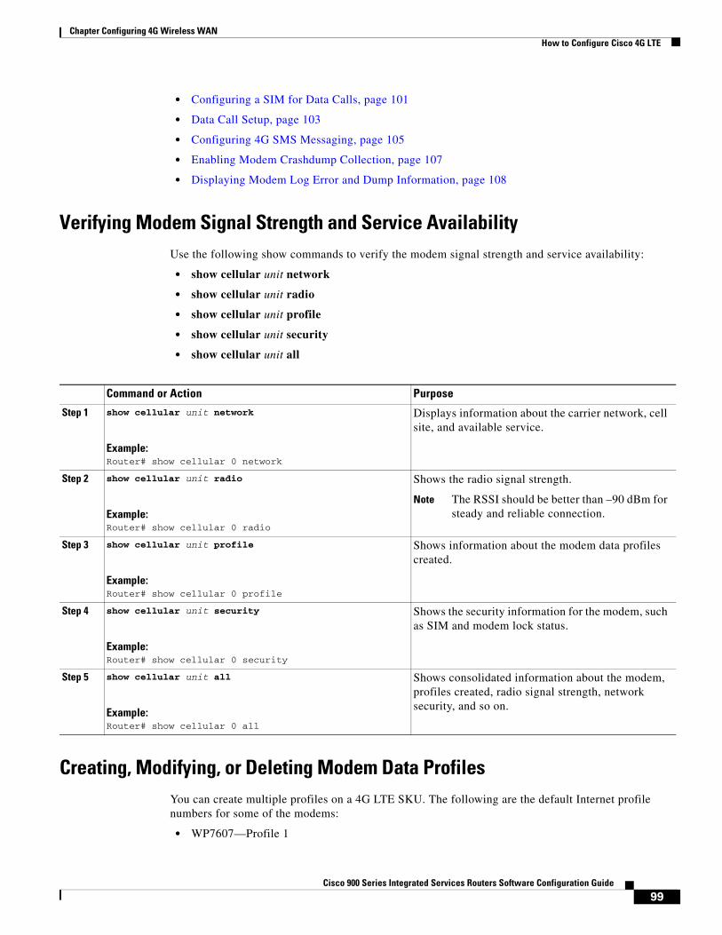
99Cisco 900 Series Integrated Services Routers Software Configuration Guide
Chapter Configuring 4G Wireless WAN How to Configure Cisco 4G LTE
• Configuring a SIM for Data Calls, page 101
• Data Call Setup, page 103
• Configuring 4G SMS Messaging, page 105
• Enabling Modem Crashdump Collection, page 107
• Displaying Modem Log Error and Dump Information, page 108
Verifying Modem Signal Strength and Service AvailabilityUse the following show commands to verify the modem signal strength and service availability:
• show cellular unit network
• show cellular unit radio
• show cellular unit profile
• show cellular unit security
• show cellular unit all
Creating, Modifying, or Deleting Modem Data ProfilesYou can create multiple profiles on a 4G LTE SKU. The following are the default Internet profile numbers for some of the modems:
• WP7607—Profile 1
Command or Action Purpose
Step 1 show cellular unit network
Example:Router# show cellular 0 network
Displays information about the carrier network, cell site, and available service.
Step 2 show cellular unit radio
Example:Router# show cellular 0 radio
Shows the radio signal strength.
Note The RSSI should be better than –90 dBm for steady and reliable connection.
Step 3 show cellular unit profile
Example:Router# show cellular 0 profile
Shows information about the modem data profiles created.
Step 4 show cellular unit security
Example:Router# show cellular 0 security
Shows the security information for the modem, such as SIM and modem lock status.
Step 5 show cellular unit all
Example:Router# show cellular 0 all
Shows consolidated information about the modem, profiles created, radio signal strength, network security, and so on.
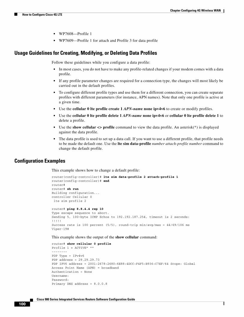
100Cisco 900 Series Integrated Services Routers Software Configuration Guide
Chapter Configuring 4G Wireless WAN How to Configure Cisco 4G LTE
• WP7608—Profile 1
• WP7609—Profile 1 for attach and Profile 3 for data profile
Usage Guidelines for Creating, Modifying, or Deleting Data Profiles
Follow these guidelines while you configure a data profile:
• In most cases, you do not have to make any profile-related changes if your modem comes with a data profile.
• If any profile parameter changes are required for a connection type, the changes will most likely be carried out in the default profiles.
• To configure different profile types and use them for a different connection, you can create separate profiles with different parameters (for instance, APN names). Note that only one profile is active at a given time.
• Use the cellular 0 lte profile create 1 APN-name none ipv4v6 to create or modify profiles.
• Use the cellular 0 lte profile delete 1 APN-name none ipv4v6 or cellular 0 lte profile delete 1 to delete a profile.
• Use the show cellular <> profile command to view the data profile. An asterisk(*) is displayed against the data profile.
• The data profile is used to set up a data call. If you want to use a different profile, that profile needs to be made the default one. Use the lte sim data-profile number attach-profile number command to change the default profile.
Configuration Examples
This example shows how to change a default profile:
router(config-controller)# lte sim data-profile 2 attach-profile 1router(config-controller)# endrouter#router# sh runBuilding configuration...controller Cellular 0 lte sim profile 2
router# ping 8.8.4.4 rep 10Type escape sequence to abort.Sending 5, 100-byte ICMP Echos to 192.192.187.254, timeout is 2 seconds:!!!!!Success rate is 100 percent (5/5), round-trip min/avg/max = 44/69/106 msViper-19#
This example shows the output of the show cellular command:
router# show cellular 0 profileProfile 1 = ACTIVE* **--------PDP Type = IPv4v6PDP address = 29.29.29.73PDP IPV6 address = 2001:2678:2680:6E88:4DCC:F4F5:B936:C7EF/64 Scope: GlobalAccess Point Name (APN) = broadbandAuthentication = NoneUsername:Password:Primary DNS address = 8.0.0.8
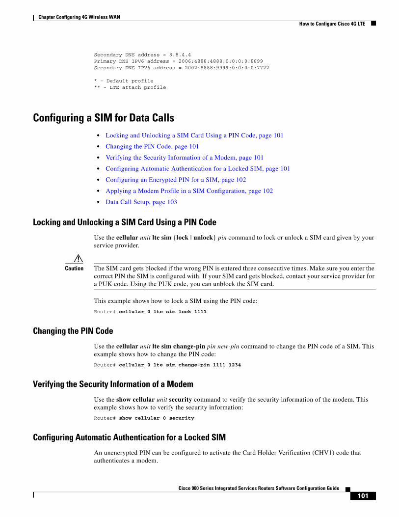
101Cisco 900 Series Integrated Services Routers Software Configuration Guide
Chapter Configuring 4G Wireless WAN How to Configure Cisco 4G LTE
Secondary DNS address = 8.8.4.4Primary DNS IPV6 address = 2006:4888:4888:0:0:0:0:8899Secondary DNS IPV6 address = 2002:8888:9999:0:0:0:0:7722
* - Default profile** - LTE attach profile
Configuring a SIM for Data Calls• Locking and Unlocking a SIM Card Using a PIN Code, page 101
• Changing the PIN Code, page 101
• Verifying the Security Information of a Modem, page 101
• Configuring Automatic Authentication for a Locked SIM, page 101
• Configuring an Encrypted PIN for a SIM, page 102
• Applying a Modem Profile in a SIM Configuration, page 102
• Data Call Setup, page 103
Locking and Unlocking a SIM Card Using a PIN Code
Use the cellular unit lte sim {lock | unlock} pin command to lock or unlock a SIM card given by your service provider.
Caution The SIM card gets blocked if the wrong PIN is entered three consecutive times. Make sure you enter the correct PIN the SIM is configured with. If your SIM card gets blocked, contact your service provider for a PUK code. Using the PUK code, you can unblock the SIM card.
This example shows how to lock a SIM using the PIN code:
Router# cellular 0 lte sim lock 1111
Changing the PIN Code
Use the cellular unit lte sim change-pin pin new-pin command to change the PIN code of a SIM. This example shows how to change the PIN code:
Router# cellular 0 lte sim change-pin 1111 1234
Verifying the Security Information of a Modem
Use the show cellular unit security command to verify the security information of the modem. This example shows how to verify the security information:
Router# show cellular 0 security
Configuring Automatic Authentication for a Locked SIM
An unencrypted PIN can be configured to activate the Card Holder Verification (CHV1) code that authenticates a modem.
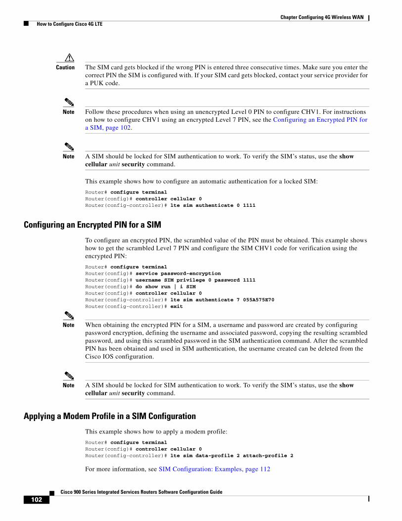
102Cisco 900 Series Integrated Services Routers Software Configuration Guide
Chapter Configuring 4G Wireless WAN How to Configure Cisco 4G LTE
Caution The SIM card gets blocked if the wrong PIN is entered three consecutive times. Make sure you enter the correct PIN the SIM is configured with. If your SIM card gets blocked, contact your service provider for a PUK code.
Note Follow these procedures when using an unencrypted Level 0 PIN to configure CHV1. For instructions on how to configure CHV1 using an encrypted Level 7 PIN, see the Configuring an Encrypted PIN for a SIM, page 102.
Note A SIM should be locked for SIM authentication to work. To verify the SIM’s status, use the show cellular unit security command.
This example shows how to configure an automatic authentication for a locked SIM:
Router# configure terminalRouter(config)# controller cellular 0Router(config-controller)# lte sim authenticate 0 1111
Configuring an Encrypted PIN for a SIM
To configure an encrypted PIN, the scrambled value of the PIN must be obtained. This example shows how to get the scrambled Level 7 PIN and configure the SIM CHV1 code for verification using the encrypted PIN:
Router# configure terminalRouter(config)# service password-encryptionRouter(config)# username SIM privilege 0 password 1111Router(config)# do show run | i SIMRouter(config)# controller cellular 0Router(config-controller)# lte sim authenticate 7 055A575E70Router(config-controller)# exit
Note When obtaining the encrypted PIN for a SIM, a username and password are created by configuring password encryption, defining the username and associated password, copying the resulting scrambled password, and using this scrambled password in the SIM authentication command. After the scrambled PIN has been obtained and used in SIM authentication, the username created can be deleted from the Cisco IOS configuration.
Note A SIM should be locked for SIM authentication to work. To verify the SIM’s status, use the show cellular unit security command.
Applying a Modem Profile in a SIM Configuration
This example shows how to apply a modem profile:
Router# configure terminalRouter(config)# controller cellular 0Router(config-controller)# lte sim data-profile 2 attach-profile 2
For more information, see SIM Configuration: Examples, page 112
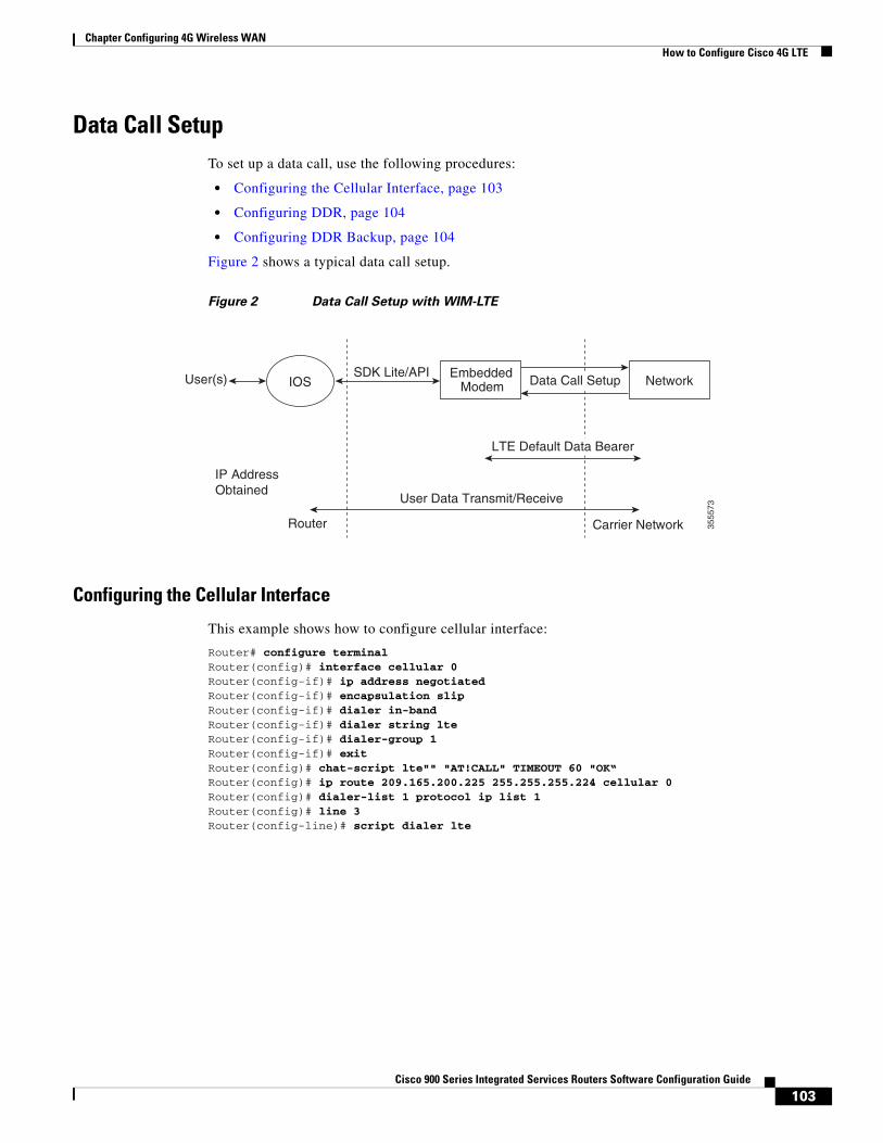
103Cisco 900 Series Integrated Services Routers Software Configuration Guide
Chapter Configuring 4G Wireless WAN How to Configure Cisco 4G LTE
Data Call SetupTo set up a data call, use the following procedures:
• Configuring the Cellular Interface, page 103
• Configuring DDR, page 104
• Configuring DDR Backup, page 104
Figure 2 shows a typical data call setup.
Figure 2 Data Call Setup with WIM-LTE
Configuring the Cellular Interface
This example shows how to configure cellular interface:
Router# configure terminalRouter(config)# interface cellular 0Router(config-if)# ip address negotiatedRouter(config-if)# encapsulation slipRouter(config-if)# dialer in-bandRouter(config-if)# dialer string lteRouter(config-if)# dialer-group 1Router(config-if)# exitRouter(config)# chat-script lte"" "AT!CALL" TIMEOUT 60 "OK“Router(config)# ip route 209.165.200.225 255.255.255.224 cellular 0Router(config)# dialer-list 1 protocol ip list 1Router(config)# line 3Router(config-line)# script dialer lte
3555
73
IOSUser(s) EmbeddedModem
IP Address Obtained
User Data Transmit/Receive
Network
Carrier NetworkRouter
SDK Lite/API
LTE Default Data Bearer
Data Call Setup
104Cisco 900 Series Integrated Services Routers Software Configuration Guide
Chapter Configuring 4G Wireless WAN How to Configure Cisco 4G LTE
Configuring DDR
This example shows how to configure DDR:
Router# configure terminalRouter(config)# interface cellular 0Router(config-if)# ip address negotiatedRouter(config-if)# encapsulation slipRouter(config-if)# dialer in-bandRouter(config-if)# dialer pool-member 1Router(config-if)# interface dialer 1Router(config-if)# ip address negotiatedRouter(config-if)# encapsulation slipRouter(config-if)# dialer pool 1Router(config-if)# dialer idle-timeout 30Router(config-if)# dialer string lteRouter(config-if)# dialer-group 1Router(config-if)# exitRouter(config)# dialer-list 1 protocol ip list 1Router(config)# access-list 1 permit anyRouter(config)# line 3Router(config-line)# script dialer lteRouter(config-line)# exitRouter(config)# chat-script lte"" "AT!CALL" TIMEOUT 60 "OK“
Configuring DDR Backup
To monitor the primary connection and initiate the backup connection when needed, the router can use one of the following methods:
• Backup Interface—The backup interface that stays in standby mode until the primary interface line protocol is detected as down and then is brought up.
• Floating Static Route—The route through the backup interface has an administrative distance that is greater than the administrative distance of the primary connection route and therefore would not be in the routing table until the primary interface goes down.
• Dialer Watch—Dialer watch is a backup feature that integrates dial backup with routing capabilities.
Configuring Interfaces to Use a Backup Interface
Note You cannot configure a backup interface for the cellular interface and any other asynchronous serial interface.
This example shows how to configure an interface as a backup interface:
Router# configure terminalRouter(config)# interface atm 0Router(config-if)# backup interface cellular 0Router(config-if)# backup delay 0 10
AutoSim and Firmware Based Switching
The advantages of the AutoSim feature are:
• Ease of Ordering Carrier Specific SKUs
• Quicker failover times in dual-sim deployments
105Cisco 900 Series Integrated Services Routers Software Configuration Guide
Chapter Configuring 4G Wireless WAN How to Configure Cisco 4G LTE
• Ease of switchover from other service providers to Telstra network
The modem in Auto-SIM mode selects the right carrier firmware after a SIM slot switch and an automatic modem reset. Auto-SIM is supported on the WP7607, WP7608, and WP7609 modems. During bootup, if the Auto-SIM configuration on the modem doesn’t match the IOS configuration, the corresponding Auto-SIM or manual mode is pushed to the modem.
The modem automatically resets after an Auto-SIM configuration change.The default is ‘auto-sim’ enabled.
This example shows how to enable Auto-SIM:
router(config)#controller cellular <slot>router(config-controller)#lte firmware auto-sim
Note After enabling auto-sim, wait for 5 minutes until the radio comes up. Once the radio is up, issue a modem power-cycle and wait for 3 minutes for the radio to come up again. Modem Power-Cycle is mandatory for auto-sim configuration to take effect.
This example shows how to disable Auto-SIM:
router(config)#controller cellular <slot>
router(config-controller)# no lte firmware auto-sim
Configuring 4G SMS MessagingThis example shows how to specify an FTP server folder path to send all the incoming and outgoing SMS messages. After the folder path is identified, it is appended automatically with outbox and inbox folders for the path to which SMS messages are sent and received:
Router# configure terminalRouter(config)# controller cellular 0Router(config-controller)# lte sms archive path ftp://username:[email protected]/SMS-LTERouter# end
This example shows how to display the message contents of the incoming texts received by a modem:
Router# cellular 0 lte sms view summary ID FROM YY/MM/DD HR:MN:SC SIZE CONTENT0 4442235525 12/05/29 10:50:13 137 Your entry last month has...2 5553337777 13/08/01 10:24:56 5 First3 5553337777 13/08/01 10:25:02 6 Second
This example shows how to display all the information in the text messages sent and received. The message information includes text messages sent successfully, received, archived, and messages pending to be sent. The LTE-specific information on errors, in case of a FAILED attempt, may also be displayed:
Router# show cellular 0 smsIncoming Message Information----------------------------SMS stored in modem = 20SMS archived since booting up = 0Total SMS deleted since booting up = 0Storage records allocated = 25Storage records used = 20Number of callbacks triggered by SMS = 0Number of successful archive since booting up = 0
106Cisco 900 Series Integrated Services Routers Software Configuration Guide
Chapter Configuring 4G Wireless WAN How to Configure Cisco 4G LTE
Number of failed archive since booting up = 0 Outgoing Message Information----------------------------Total SMS sent successfully = 0Total SMS send failure = 0Number of outgoing SMS pending = 0Number of successful archive since booting up = 0Number of failed archive since booting up = 0Last Outgoing SMS Status = SUCCESSCopy-to-SIM Status = 0x0Send-to-Network Status = 0x0Report-Outgoing-Message-Number:Reference Number = 0Result Code = 0x0Diag Code = 0x0 0x0 0x0 0x0 0x0 SMS Archive URL = ftp://lab:[email protected]/outbox
This example shows how to enable a user to send a 4G LTE band SMS message to other valid recipients, provided they have a text message plan:
Router# cellular 0 lte sms send 15554443333 <sms text>
Upgrading Modem FirmwareTo upgrade the modem firmware, perform these steps:
Step 1 Go to the Cisco Software Download website at: https://software.cisco.com/download/home
Step 2 On the download page, search ‘900 series integrated services router’, and select ‘900 integrated services router’ from the filtered list.
Step 3 Select Routers> 900 Series Integrated Routers >900 Integrated Services Router
Step 4 Select the release from the left pane. Available firmwares will be listed on the right pane.
Step 5 Select and download the appropriate firmware.
Step 6 Create a directory in the router flash to store the modem firmware.
Step 7 Copy the firmware to the flash directory.
Step 8 Use the following command to initiate the upgrade process:
Router# microcode reload cellular 0 lte modem-provision flash:firmware directory
Step 9 Verify the upgrade:
Router# show cellular 0 hardware
Modem Firmware Version = SWI9X07Y_02.18.05.00 000Modem Firmware built = 2018/07/19 17:40:21Device Model ID: WP7608International Mobile Subscriber Identity (IMSI) = 123456000009205International Mobile Equipment Identity (IMEI) = 354365090106005Integrated Circuit Card ID (ICCID) = 8952530076180099205Mobile Subscriber Integrated ServicesDigital Network-Number (MSISDN) =Factory Serial Number (FSN) = XG814285250410Modem Status = Online
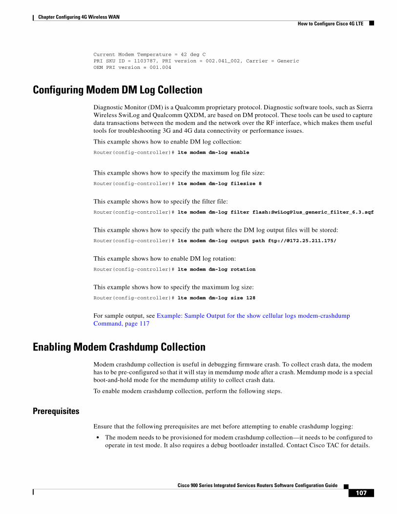
107Cisco 900 Series Integrated Services Routers Software Configuration Guide
Chapter Configuring 4G Wireless WAN How to Configure Cisco 4G LTE
Current Modem Temperature = 42 deg CPRI SKU ID = 1103787, PRI version = 002.041_002, Carrier = GenericOEM PRI version = 001.004
Configuring Modem DM Log CollectionDiagnostic Monitor (DM) is a Qualcomm proprietary protocol. Diagnostic software tools, such as Sierra Wireless SwiLog and Qualcomm QXDM, are based on DM protocol. These tools can be used to capture data transactions between the modem and the network over the RF interface, which makes them useful tools for troubleshooting 3G and 4G data connectivity or performance issues.
This example shows how to enable DM log collection:
Router(config-controller)# lte modem dm-log enable
This example shows how to specify the maximum log file size:
Router(config-controller)# lte modem dm-log filesize 8
This example shows how to specify the filter file:
Router(config-controller)# lte modem dm-log filter flash:SwiLogPlus_generic_filter_6.3.sqf
This example shows how to specify the path where the DM log output files will be stored:
Router(config-controller)# lte modem dm-log output path ftp://@172.25.211.175/
This example shows how to enable DM log rotation:
Router(config-controller)# lte modem dm-log rotation
This example shows how to specify the maximum log size:
Router(config-controller)# lte modem dm-log size 128
For sample output, see Example: Sample Output for the show cellular logs modem-crashdump Command, page 117
Enabling Modem Crashdump CollectionModem crashdump collection is useful in debugging firmware crash. To collect crash data, the modem has to be pre-configured so that it will stay in memdump mode after a crash. Memdump mode is a special boot-and-hold mode for the memdump utility to collect crash data.
To enable modem crashdump collection, perform the following steps.
Prerequisites
Ensure that the following prerequisites are met before attempting to enable crashdump logging:
• The modem needs to be provisioned for modem crashdump collection—it needs to be configured to operate in test mode. It also requires a debug bootloader installed. Contact Cisco TAC for details.
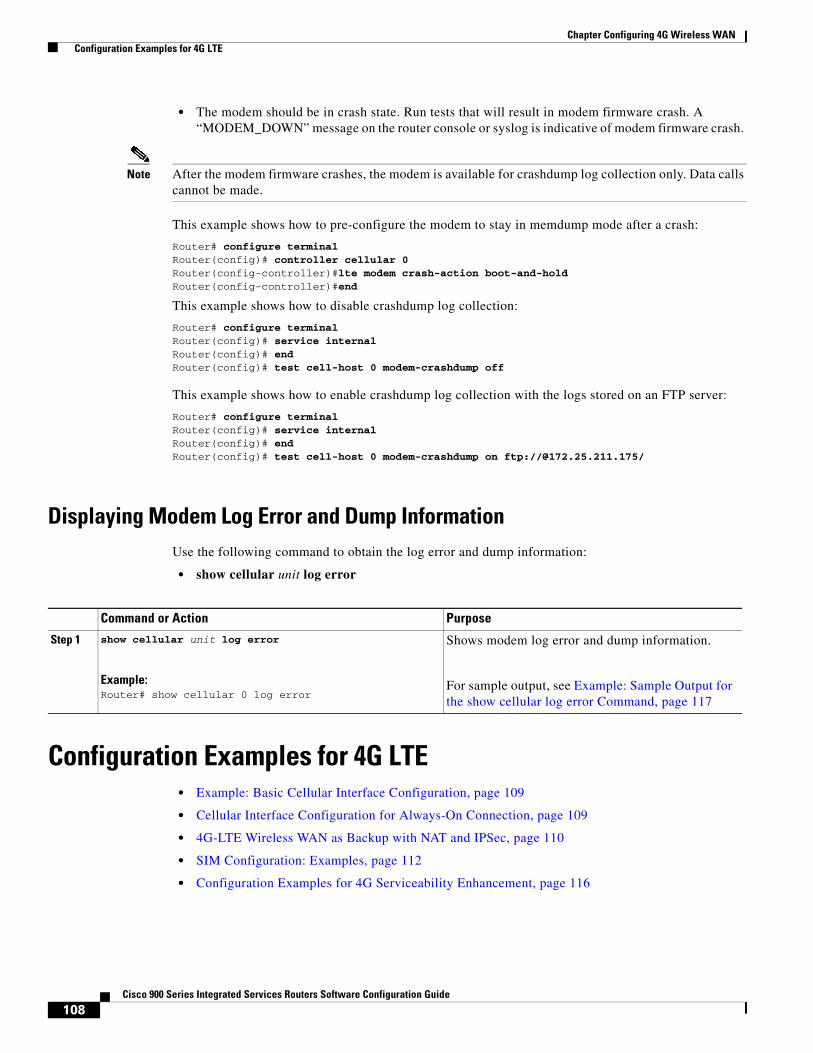
108Cisco 900 Series Integrated Services Routers Software Configuration Guide
Chapter Configuring 4G Wireless WAN Configuration Examples for 4G LTE
• The modem should be in crash state. Run tests that will result in modem firmware crash. A “MODEM_DOWN” message on the router console or syslog is indicative of modem firmware crash.
Note After the modem firmware crashes, the modem is available for crashdump log collection only. Data calls cannot be made.
This example shows how to pre-configure the modem to stay in memdump mode after a crash:
Router# configure terminal Router(config)# controller cellular 0Router(config-controller)#lte modem crash-action boot-and-holdRouter(config-controller)#end
This example shows how to disable crashdump log collection:
Router# configure terminal Router(config)# service internalRouter(config)# endRouter(config)# test cell-host 0 modem-crashdump off
This example shows how to enable crashdump log collection with the logs stored on an FTP server:
Router# configure terminal Router(config)# service internalRouter(config)# endRouter(config)# test cell-host 0 modem-crashdump on ftp://@172.25.211.175/
Displaying Modem Log Error and Dump InformationUse the following command to obtain the log error and dump information:
• show cellular unit log error
Configuration Examples for 4G LTE• Example: Basic Cellular Interface Configuration, page 109
• Cellular Interface Configuration for Always-On Connection, page 109
• 4G-LTE Wireless WAN as Backup with NAT and IPSec, page 110
• SIM Configuration: Examples, page 112
• Configuration Examples for 4G Serviceability Enhancement, page 116
Command or Action Purpose
Step 1 show cellular unit log error
Example:Router# show cellular 0 log error
Shows modem log error and dump information.
For sample output, see Example: Sample Output for the show cellular log error Command, page 117
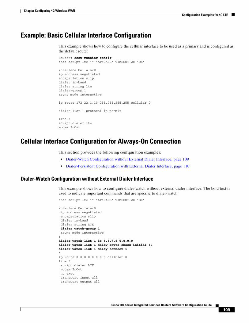
109Cisco 900 Series Integrated Services Routers Software Configuration Guide
Chapter Configuring 4G Wireless WAN Configuration Examples for 4G LTE
Example: Basic Cellular Interface ConfigurationThis example shows how to configure the cellular interface to be used as a primary and is configured as the default route:
Router# show running-configchat-script lte "" "AT!CALL" TIMEOUT 20 "OK"
interface Cellular0ip address negotiatedencapsulation slipdialer in-banddialer string ltedialer-group 1async mode interactive
ip route 172.22.1.10 255.255.255.255 cellular 0
dialer-list 1 protocol ip permit
line 3script dialer ltemodem InOut
Cellular Interface Configuration for Always-On ConnectionThis section provides the following configuration examples:
• Dialer-Watch Configuration without External Dialer Interface, page 109
• Dialer-Persistent Configuration with External Dialer Interface, page 110
Dialer-Watch Configuration without External Dialer Interface
This example shows how to configure dialer-watch without external dialer interface. The bold text is used to indicate important commands that are specific to dialer-watch.
chat-script lte "" "AT!CALL" TIMEOUT 20 "OK"
interface Cellular0 ip address negotiated encapsulation slip dialer in-band dialer string LTE dialer watch-group 1 async mode interactive!dialer watch-list 1 ip 5.6.7.8 0.0.0.0dialer watch-list 1 delay route-check initial 60dialer watch-list 1 delay connect 1!ip route 0.0.0.0 0.0.0.0 cellular 0line 3 script dialer LTE modem InOut no exec transport input all transport output all
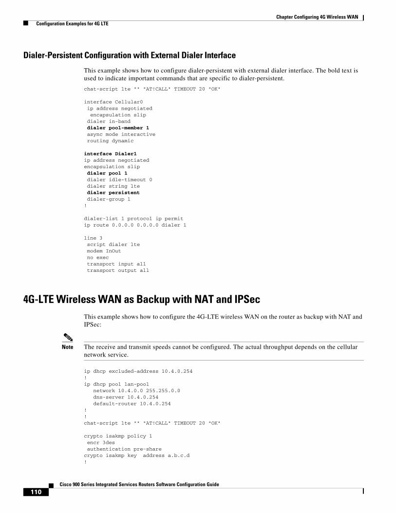
110Cisco 900 Series Integrated Services Routers Software Configuration Guide
Chapter Configuring 4G Wireless WAN Configuration Examples for 4G LTE
Dialer-Persistent Configuration with External Dialer Interface
This example shows how to configure dialer-persistent with external dialer interface. The bold text is used to indicate important commands that are specific to dialer-persistent.
chat-script lte "" "AT!CALL" TIMEOUT 20 "OK"
interface Cellular0 ip address negotiated encapsulation slip dialer in-band dialer pool-member 1 async mode interactive routing dynamic
interface Dialer1ip address negotiatedencapsulation slip dialer pool 1 dialer idle-timeout 0 dialer string lte dialer persistent dialer-group 1!
dialer-list 1 protocol ip permitip route 0.0.0.0 0.0.0.0 dialer 1
line 3 script dialer lte modem InOut no exec transport input all transport output all
4G-LTE Wireless WAN as Backup with NAT and IPSecThis example shows how to configure the 4G-LTE wireless WAN on the router as backup with NAT and IPSec:
Note The receive and transmit speeds cannot be configured. The actual throughput depends on the cellular network service.
ip dhcp excluded-address 10.4.0.254!ip dhcp pool lan-pool network 10.4.0.0 255.255.0.0 dns-server 10.4.0.254 default-router 10.4.0.254 !!chat-script lte "" "AT!CALL" TIMEOUT 20 "OK"
crypto isakmp policy 1 encr 3des authentication pre-sharecrypto isakmp key address a.b.c.d!
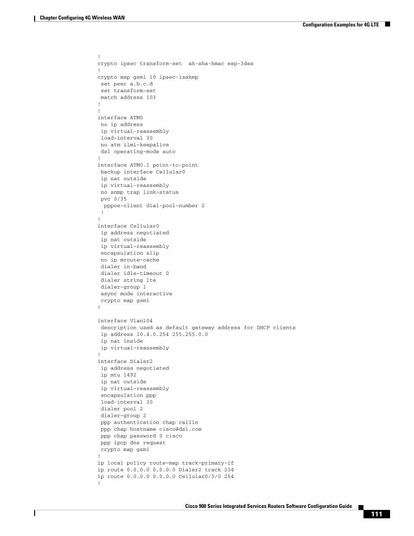
111Cisco 900 Series Integrated Services Routers Software Configuration Guide
Chapter Configuring 4G Wireless WAN Configuration Examples for 4G LTE
!crypto ipsec transform-set ah-sha-hmac esp-3des !crypto map gsm1 10 ipsec-isakmp set peer a.b.c.d set transform-set match address 103!!interface ATM0 no ip address ip virtual-reassembly load-interval 30 no atm ilmi-keepalive dsl operating-mode auto !interface ATM0.1 point-to-point backup interface Cellular0 ip nat outside ip virtual-reassembly no snmp trap link-status pvc 0/35 pppoe-client dial-pool-number 2 !!interface Cellular0 ip address negotiated ip nat outside ip virtual-reassembly encapsulation slip no ip mroute-cache dialer in-band dialer idle-timeout 0 dialer string lte dialer-group 1 async mode interactivecrypto map gsm1
!
interface Vlan104 description used as default gateway address for DHCP clients ip address 10.4.0.254 255.255.0.0 ip nat inside ip virtual-reassembly!interface Dialer2 ip address negotiated ip mtu 1492 ip nat outside ip virtual-reassembly encapsulation ppp load-interval 30 dialer pool 2 dialer-group 2 ppp authentication chap callin ppp chap hostname [email protected] ppp chap password 0 cisco ppp ipcp dns request crypto map gsm1!ip local policy route-map track-primary-ifip route 0.0.0.0 0.0.0.0 Dialer2 track 234ip route 0.0.0.0 0.0.0.0 Cellular0/3/0 254!
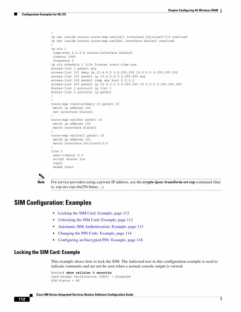
112Cisco 900 Series Integrated Services Routers Software Configuration Guide
Chapter Configuring 4G Wireless WAN Configuration Examples for 4G LTE
!ip nat inside source route-map nat2cell interface Cellular0/3/0 overloadip nat inside source route-map nat2dsl interface Dialer2 overload!ip sla 1 icmp-echo 2.2.2.2 source-interface Dialer2 timeout 1000 frequency 2ip sla schedule 1 life forever start-time nowaccess-list 1 permit anyaccess-list 101 deny ip 10.4.0.0 0.0.255.255 10.0.0.0 0.255.255.255access-list 101 permit ip 10.4.0.0 0.0.255.255 anyaccess-list 102 permit icmp any host 2.2.2.2access-list 103 permit ip 10.4.0.0 0.0.255.255 10.0.0.0 0.255.255.255dialer-list 1 protocol ip list 1dialer-list 2 protocol ip permit!!route-map track-primary-if permit 10 match ip address 102 set interface Dialer2!route-map nat2dsl permit 10 match ip address 101 match interface Dialer2!route-map nat2cell permit 10 match ip address 101 match interface Cellular0/3/0!line 3 exec-timeout 0 0 script dialer lte login modem InOut
Note For service providers using a private IP address, use the crypto ipsec transform-set esp command (that is, esp-aes esp-sha256-hmac…).
SIM Configuration: Examples• Locking the SIM Card: Example, page 112
• Unlocking the SIM Card: Example, page 113
• Automatic SIM Authentication: Example, page 113
• Changing the PIN Code: Example, page 114
• Configuring an Encrypted PIN: Example, page 116
Locking the SIM Card: Example
This example shows how to lock the SIM. The italicized text in this configuration example is used to indicate comments and are not be seen when a normal console output is viewed.
Router# show cellular 0 security Card Holder Verification (CHV1) = DisabledSIM Status = OK
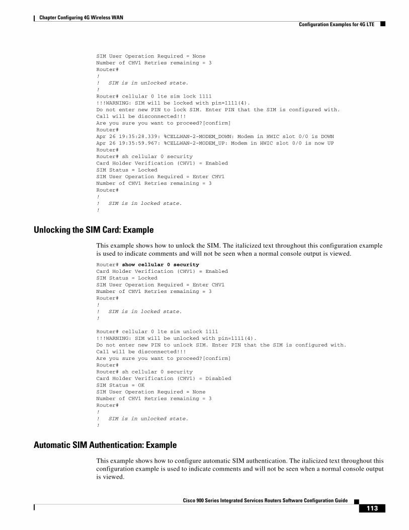
113Cisco 900 Series Integrated Services Routers Software Configuration Guide
Chapter Configuring 4G Wireless WAN Configuration Examples for 4G LTE
SIM User Operation Required = NoneNumber of CHV1 Retries remaining = 3Router#!! SIM is in unlocked state.!Router# cellular 0 lte sim lock 1111!!!WARNING: SIM will be locked with pin=1111(4). Do not enter new PIN to lock SIM. Enter PIN that the SIM is configured with.Call will be disconnected!!!Are you sure you want to proceed?[confirm]Router#Apr 26 19:35:28.339: %CELLWAN-2-MODEM_DOWN: Modem in HWIC slot 0/0 is DOWNApr 26 19:35:59.967: %CELLWAN-2-MODEM_UP: Modem in HWIC slot 0/0 is now UPRouter#Router# sh cellular 0 security Card Holder Verification (CHV1) = EnabledSIM Status = LockedSIM User Operation Required = Enter CHV1Number of CHV1 Retries remaining = 3Router#!! SIM is in locked state.!
Unlocking the SIM Card: Example
This example shows how to unlock the SIM. The italicized text throughout this configuration example is used to indicate comments and will not be seen when a normal console output is viewed.
Router# show cellular 0 security Card Holder Verification (CHV1) = EnabledSIM Status = LockedSIM User Operation Required = Enter CHV1Number of CHV1 Retries remaining = 3Router#!! SIM is in locked state.!
Router# cellular 0 lte sim unlock 1111!!!WARNING: SIM will be unlocked with pin=1111(4). Do not enter new PIN to unlock SIM. Enter PIN that the SIM is configured with.Call will be disconnected!!!Are you sure you want to proceed?[confirm]Router#Router# sh cellular 0 security Card Holder Verification (CHV1) = DisabledSIM Status = OKSIM User Operation Required = NoneNumber of CHV1 Retries remaining = 3Router#!! SIM is in unlocked state.!
Automatic SIM Authentication: Example
This example shows how to configure automatic SIM authentication. The italicized text throughout this configuration example is used to indicate comments and will not be seen when a normal console output is viewed.
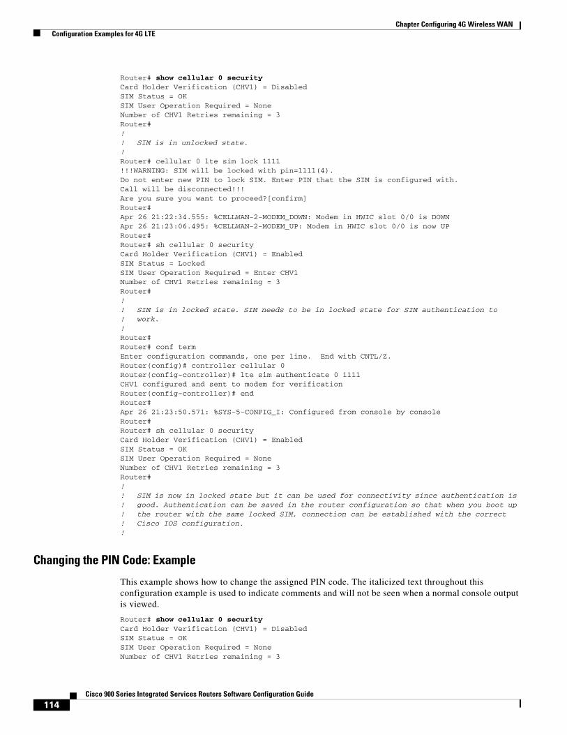
114Cisco 900 Series Integrated Services Routers Software Configuration Guide
Chapter Configuring 4G Wireless WAN Configuration Examples for 4G LTE
Router# show cellular 0 security Card Holder Verification (CHV1) = DisabledSIM Status = OKSIM User Operation Required = NoneNumber of CHV1 Retries remaining = 3Router#!! SIM is in unlocked state.!Router# cellular 0 lte sim lock 1111!!!WARNING: SIM will be locked with pin=1111(4). Do not enter new PIN to lock SIM. Enter PIN that the SIM is configured with.Call will be disconnected!!!Are you sure you want to proceed?[confirm]Router#Apr 26 21:22:34.555: %CELLWAN-2-MODEM_DOWN: Modem in HWIC slot 0/0 is DOWNApr 26 21:23:06.495: %CELLWAN-2-MODEM_UP: Modem in HWIC slot 0/0 is now UPRouter#Router# sh cellular 0 security Card Holder Verification (CHV1) = EnabledSIM Status = LockedSIM User Operation Required = Enter CHV1Number of CHV1 Retries remaining = 3Router#!! SIM is in locked state. SIM needs to be in locked state for SIM authentication to ! work.!Router#Router# conf termEnter configuration commands, one per line. End with CNTL/Z.Router(config)# controller cellular 0Router(config-controller)# lte sim authenticate 0 1111 CHV1 configured and sent to modem for verificationRouter(config-controller)# endRouter#Apr 26 21:23:50.571: %SYS-5-CONFIG_I: Configured from console by consoleRouter#Router# sh cellular 0 security Card Holder Verification (CHV1) = EnabledSIM Status = OKSIM User Operation Required = NoneNumber of CHV1 Retries remaining = 3Router#!! SIM is now in locked state but it can be used for connectivity since authentication is ! good. Authentication can be saved in the router configuration so that when you boot up ! the router with the same locked SIM, connection can be established with the correct ! Cisco IOS configuration.!
Changing the PIN Code: Example
This example shows how to change the assigned PIN code. The italicized text throughout this configuration example is used to indicate comments and will not be seen when a normal console output is viewed.
Router# show cellular 0 security Card Holder Verification (CHV1) = DisabledSIM Status = OKSIM User Operation Required = NoneNumber of CHV1 Retries remaining = 3
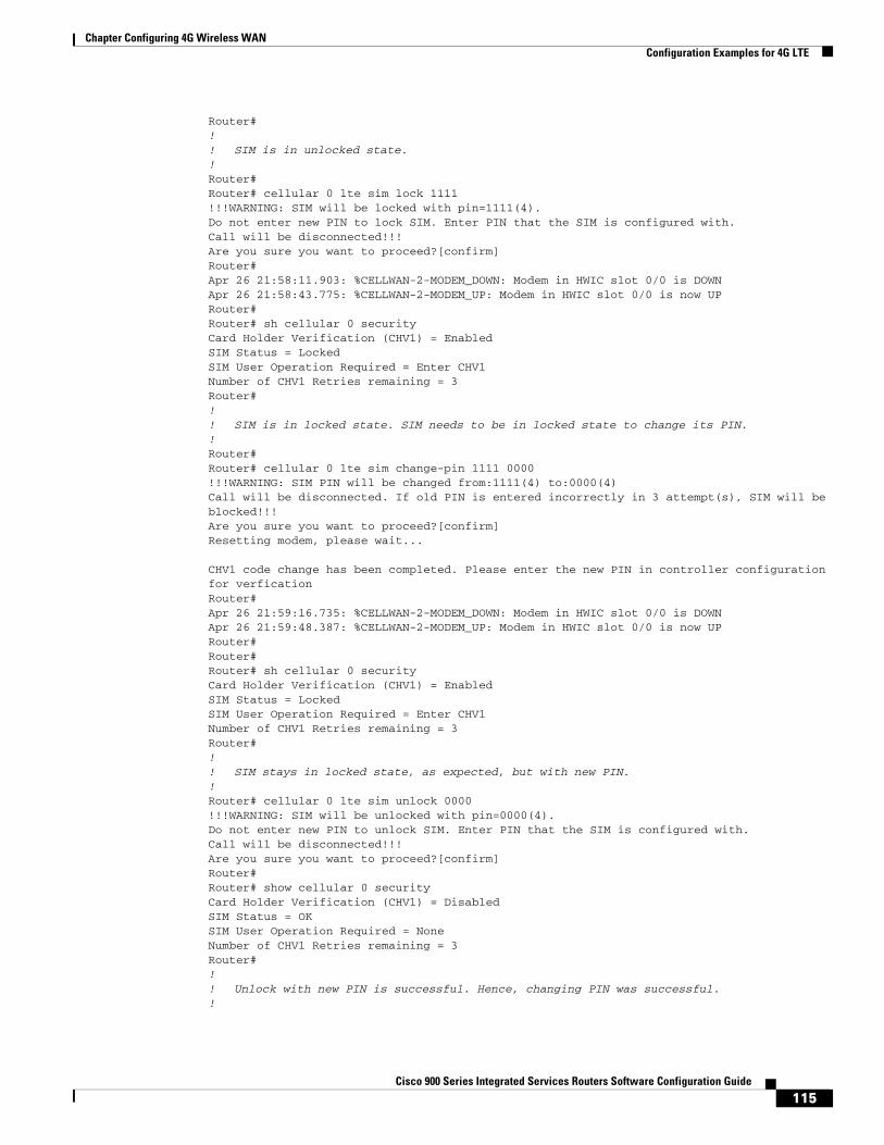
115Cisco 900 Series Integrated Services Routers Software Configuration Guide
Chapter Configuring 4G Wireless WAN Configuration Examples for 4G LTE
Router#!! SIM is in unlocked state.!Router#Router# cellular 0 lte sim lock 1111!!!WARNING: SIM will be locked with pin=1111(4). Do not enter new PIN to lock SIM. Enter PIN that the SIM is configured with.Call will be disconnected!!!Are you sure you want to proceed?[confirm]Router#Apr 26 21:58:11.903: %CELLWAN-2-MODEM_DOWN: Modem in HWIC slot 0/0 is DOWNApr 26 21:58:43.775: %CELLWAN-2-MODEM_UP: Modem in HWIC slot 0/0 is now UPRouter#Router# sh cellular 0 security Card Holder Verification (CHV1) = EnabledSIM Status = LockedSIM User Operation Required = Enter CHV1Number of CHV1 Retries remaining = 3Router#!! SIM is in locked state. SIM needs to be in locked state to change its PIN.!Router#Router# cellular 0 lte sim change-pin 1111 0000!!!WARNING: SIM PIN will be changed from:1111(4) to:0000(4)Call will be disconnected. If old PIN is entered incorrectly in 3 attempt(s), SIM will be blocked!!!Are you sure you want to proceed?[confirm]Resetting modem, please wait...
CHV1 code change has been completed. Please enter the new PIN in controller configuration for verficationRouter#Apr 26 21:59:16.735: %CELLWAN-2-MODEM_DOWN: Modem in HWIC slot 0/0 is DOWNApr 26 21:59:48.387: %CELLWAN-2-MODEM_UP: Modem in HWIC slot 0/0 is now UPRouter#Router#Router# sh cellular 0 security Card Holder Verification (CHV1) = EnabledSIM Status = LockedSIM User Operation Required = Enter CHV1Number of CHV1 Retries remaining = 3Router#!! SIM stays in locked state, as expected, but with new PIN.!Router# cellular 0 lte sim unlock 0000!!!WARNING: SIM will be unlocked with pin=0000(4). Do not enter new PIN to unlock SIM. Enter PIN that the SIM is configured with.Call will be disconnected!!!Are you sure you want to proceed?[confirm]Router#Router# show cellular 0 security Card Holder Verification (CHV1) = DisabledSIM Status = OKSIM User Operation Required = NoneNumber of CHV1 Retries remaining = 3Router#!! Unlock with new PIN is successful. Hence, changing PIN was successful.!
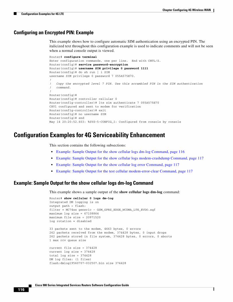
116Cisco 900 Series Integrated Services Routers Software Configuration Guide
Chapter Configuring 4G Wireless WAN Configuration Examples for 4G LTE
Configuring an Encrypted PIN: Example
This example shows how to configure automatic SIM authentication using an encrypted PIN. The italicized text throughout this configuration example is used to indicate comments and will not be seen when a normal console output is viewed.
Router# configure terminalEnter configuration commands, one per line. End with CNTL/Z.Router(config)# service password-encryptionRouter(config)# username SIM privilege 0 password 1111Router(config)# do sh run | i SIMusername SIM privilege 0 password 7 055A575E70.!! Copy the encrypted level 7 PIN. Use this scrambled PIN in the SIM authentication ! command.!Router(config)#Router(config)# controller cellular 0Router(config-controller)# lte sim authenticate 7 055A575E70CHV1 configured and sent to modem for verificationRouter(config-controller)# exitRouter(config)# no username SIMRouter(config)# endMay 14 20:20:52.603: %SYS-5-CONFIG_I: Configured from console by console
Configuration Examples for 4G Serviceability EnhancementThis section contains the following subsections:
• Example: Sample Output for the show cellular logs dm-log Command, page 116
• Example: Sample Output for the show cellular logs modem-crashdump Command, page 117
• Example: Sample Output for the show cellular log error Command, page 117
• Example: Sample Output for the test cellular modem-error-clear Command, page 117
Example: Sample Output for the show cellular logs dm-log Command
This example shows a sample output of the show cellular logs dm-log command:
Router# show cellular 0 logs dm-logIntegrated DM logging is onoutput path = flash:filter = MC74xx generic - GSM_GPRS_EDGE_WCDMA_LTE_EVDO.sqfmaximum log size = 67108864maximum file size = 20971520log rotation = disabled
33 packets sent to the modem, 4663 bytes, 0 errors262 packets received from the modem, 374428 bytes, 0 input drops262 packets stored in file system, 374428 bytes, 0 errors, 0 aborts1 max rcv queue size
current file size = 374428current log size = 374428total log size = 374428DM log files: (1 files)flash:dmlog19560707-032507.bin size 374428

117Cisco 900 Series Integrated Services Routers Software Configuration Guide
Chapter Configuring 4G Wireless WAN Configuration Examples for 4G LTE
Example: Sample Output for the show cellular logs modem-crashdump Command
This example shows a sample output of the show cellular logs modem-crashdump command:
Router# show cellular 0 logs modem-crashdumpModem crashdump logging: offProgress = 100%Last known State = Getting memory chunksTotal consecutive NAKs = 0Number of retries = 0Memory Region Info:1: Full SDRAM [Base:0x0, Length:0x2000000]2: MDSP RAM A region [Base:0x91000000, Length:0x8000]3: MDSP RAM B region [Base:0x91200000, Length:0x8000]4: MDSP RAM C region [Base:0x91400000, Length:0xC000]5: MDSP Register region [Base:0x91C00000, Length:0x28]6: ADSP RAM A region [Base:0x70000000, Length:0x10000]7: ADSP RAM B region [Base:0x70200000, Length:0x10000]8: ADSP RAM C region [Base:0x70400000, Length:0xC000]9: ADSP RAM I region [Base:0x70800000, Length:0x18000]10: CMM Script [Base:0x6A350, Length:0x310]Router#
Example: Sample Output for the show cellular log error Command
This example shows a sample output of the show cellular log error command:
Router# show cellular 0 log error Cached info is displayed
at!err
00 4E hsu_conf_sel_nv 0053601 9B uim 0828002 FF rrcllcpcie 1576203 FF rrccspfscan 0216904 4E dsatact 0069605 4E dsatcmdp 0184106 4D gsdi_convert 0152607 04 rrccsputil 1857908 02 cmss 0345909 2D tmc 03825
OK
at!gcdump
No crash data available
OK
Example: Sample Output for the test cellular modem-error-clear Command
This example shows a sample output of the test cellular modem-error-clear command:
Router# test cellular 0 modem-error-clear Cellular0/1/0 Dump/Error info before clear command
at!err
00 4E hsu_conf_sel_nv 00536
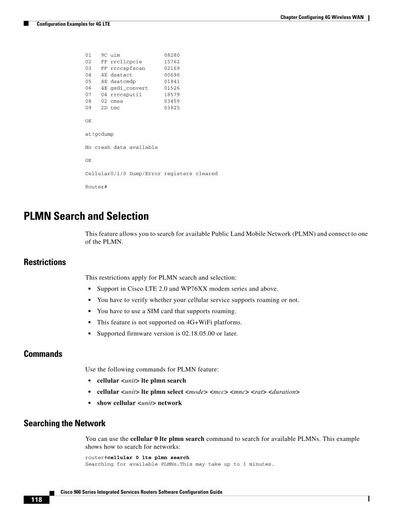
118Cisco 900 Series Integrated Services Routers Software Configuration Guide
Chapter Configuring 4G Wireless WAN Configuration Examples for 4G LTE
01 9C uim 0828002 FF rrcllcpcie 1576203 FF rrccspfscan 0216904 4E dsatact 0069605 4E dsatcmdp 0184106 4E gsdi_convert 0152607 04 rrccsputil 1857908 02 cmss 0345909 2D tmc 03825
OK
at!gcdump
No crash data available
OK
Cellular0/1/0 Dump/Error registers cleared
Router#
PLMN Search and SelectionThis feature allows you to search for available Public Land Mobile Network (PLMN) and connect to one of the PLMN.
Restrictions
This restrictions apply for PLMN search and selection:
• Support in Cisco LTE 2.0 and WP76XX modem series and above.
• You have to verify whether your cellular service supports roaming or not.
• You have to use a SIM card that supports roaming.
• This feature is not supported on 4G+WiFi platforms.
• Supported firmware version is 02.18.05.00 or later.
Commands
Use the following commands for PLMN feature:
• cellular <unit> lte plmn search
• cellular <unit> lte plmn select <mode> <mcc> <mnc> <rat> <duration>
• show cellular <unit> network
Searching the Network
You can use the cellular 0 lte plmn search command to search for available PLMNs. This example shows how to search for networks:
router#cellular 0 lte plmn searchSearching for available PLMNs.This may take up to 3 minutes.
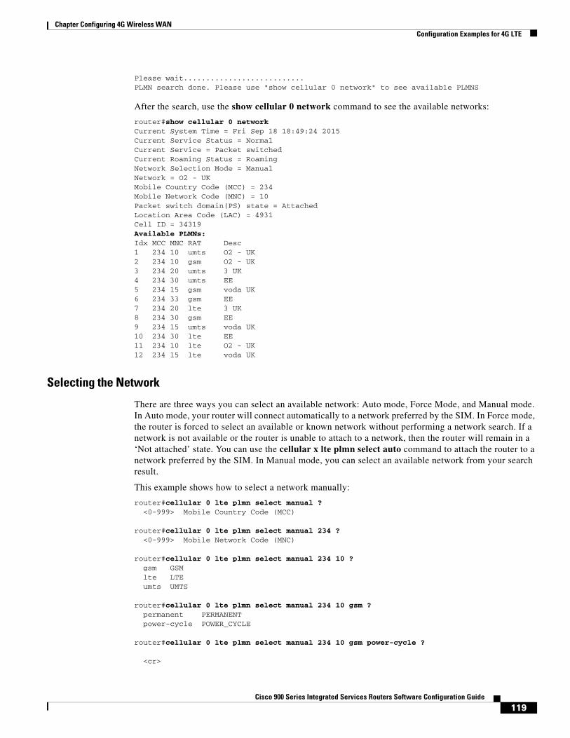
119Cisco 900 Series Integrated Services Routers Software Configuration Guide
Chapter Configuring 4G Wireless WAN Configuration Examples for 4G LTE
Please wait...........................PLMN search done. Please use "show cellular 0 network" to see available PLMNS
After the search, use the show cellular 0 network command to see the available networks:
router#show cellular 0 networkCurrent System Time = Fri Sep 18 18:49:24 2015Current Service Status = NormalCurrent Service = Packet switchedCurrent Roaming Status = RoamingNetwork Selection Mode = ManualNetwork = O2 - UKMobile Country Code (MCC) = 234Mobile Network Code (MNC) = 10Packet switch domain(PS) state = AttachedLocation Area Code (LAC) = 4931Cell ID = 34319Available PLMNs:Idx MCC MNC RAT Desc1 234 10 umts O2 - UK2 234 10 gsm O2 - UK3 234 20 umts 3 UK4 234 30 umts EE5 234 15 gsm voda UK6 234 33 gsm EE7 234 20 lte 3 UK8 234 30 gsm EE9 234 15 umts voda UK10 234 30 lte EE11 234 10 lte O2 - UK12 234 15 lte voda UK
Selecting the Network
There are three ways you can select an available network: Auto mode, Force Mode, and Manual mode. In Auto mode, your router will connect automatically to a network preferred by the SIM. In Force mode, the router is forced to select an available or known network without performing a network search. If a network is not available or the router is unable to attach to a network, then the router will remain in a ‘Not attached’ state. You can use the cellular x lte plmn select auto command to attach the router to a network preferred by the SIM. In Manual mode, you can select an available network from your search result.
This example shows how to select a network manually:
router#cellular 0 lte plmn select manual ? <0-999> Mobile Country Code (MCC)
router#cellular 0 lte plmn select manual 234 ? <0-999> Mobile Network Code (MNC)
router#cellular 0 lte plmn select manual 234 10 ? gsm GSM lte LTE umts UMTS
router#cellular 0 lte plmn select manual 234 10 gsm ? permanent PERMANENT power-cycle POWER_CYCLE
router#cellular 0 lte plmn select manual 234 10 gsm power-cycle ?
<cr>
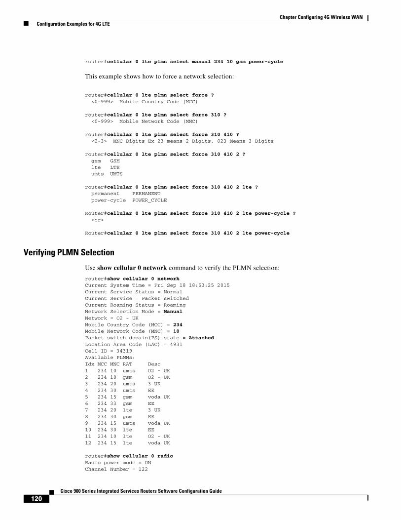
120Cisco 900 Series Integrated Services Routers Software Configuration Guide
Chapter Configuring 4G Wireless WAN Configuration Examples for 4G LTE
router#cellular 0 lte plmn select manual 234 10 gsm power-cycle
This example shows how to force a network selection:
router#cellular 0 lte plmn select force ? <0-999> Mobile Country Code (MCC)
router#cellular 0 lte plmn select force 310 ? <0-999> Mobile Network Code (MNC)
router#cellular 0 lte plmn select force 310 410 ? <2-3> MNC Digits Ex 23 means 2 Digits, 023 Means 3 Digits
router#cellular 0 lte plmn select force 310 410 2 ? gsm GSM lte LTE umts UMTS
router#cellular 0 lte plmn select force 310 410 2 lte ? permanent PERMANENT power-cycle POWER_CYCLE
Router#cellular 0 lte plmn select force 310 410 2 lte power-cycle ? <cr>
Router#cellular 0 lte plmn select force 310 410 2 lte power-cycle
Verifying PLMN Selection
Use show cellular 0 network command to verify the PLMN selection:
router#show cellular 0 networkCurrent System Time = Fri Sep 18 18:53:25 2015Current Service Status = NormalCurrent Service = Packet switchedCurrent Roaming Status = RoamingNetwork Selection Mode = ManualNetwork = O2 - UKMobile Country Code (MCC) = 234Mobile Network Code (MNC) = 10Packet switch domain(PS) state = AttachedLocation Area Code (LAC) = 4931Cell ID = 34319Available PLMNs:Idx MCC MNC RAT Desc1 234 10 umts O2 - UK2 234 10 gsm O2 - UK3 234 20 umts 3 UK4 234 30 umts EE5 234 15 gsm voda UK6 234 33 gsm EE7 234 20 lte 3 UK8 234 30 gsm EE9 234 15 umts voda UK10 234 30 lte EE11 234 10 lte O2 - UK12 234 15 lte voda UK
router#show cellular 0 radioRadio power mode = ONChannel Number = 122
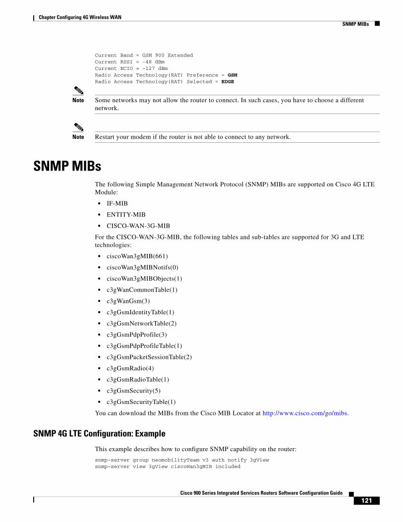
121Cisco 900 Series Integrated Services Routers Software Configuration Guide
Chapter Configuring 4G Wireless WAN SNMP MIBs
Current Band = GSM 900 ExtendedCurrent RSSI = -48 dBmCurrent ECIO = -127 dBmRadio Access Technology(RAT) Preference = GSMRadio Access Technology(RAT) Selected = EDGE
Note Some networks may not allow the router to connect. In such cases, you have to choose a different network.
Note Restart your modem if the router is not able to connect to any network.
SNMP MIBsThe following Simple Management Network Protocol (SNMP) MIBs are supported on Cisco 4G LTE Module:
• IF-MIB
• ENTITY-MIB
• CISCO-WAN-3G-MIB
For the CISCO-WAN-3G-MIB, the following tables and sub-tables are supported for 3G and LTE technologies:
• ciscoWan3gMIB(661)
• ciscoWan3gMIBNotifs(0)
• ciscoWan3gMIBObjects(1)
• c3gWanCommonTable(1)
• c3gWanGsm(3)
• c3gGsmIdentityTable(1)
• c3gGsmNetworkTable(2)
• c3gGsmPdpProfile(3)
• c3gGsmPdpProfileTable(1)
• c3gGsmPacketSessionTable(2)
• c3gGsmRadio(4)
• c3gGsmRadioTable(1)
• c3gGsmSecurity(5)
• c3gGsmSecurityTable(1)
You can download the MIBs from the Cisco MIB Locator at http://www.cisco.com/go/mibs.
SNMP 4G LTE Configuration: Example
This example describes how to configure SNMP capability on the router:
snmp-server group neomobilityTeam v3 auth notify 3gView snmp-server view 3gView ciscoWan3gMIB included
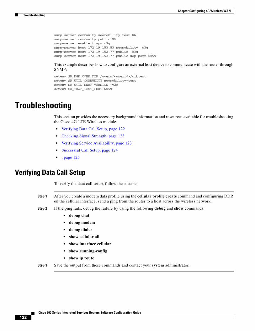
122Cisco 900 Series Integrated Services Routers Software Configuration Guide
Chapter Configuring 4G Wireless WAN Troubleshooting
snmp-server community neomobility-test RWsnmp-server community public RWsnmp-server enable traps c3gsnmp-server host 172.19.153.53 neomobility c3gsnmp-server host 172.19.152.77 public c3gsnmp-server host 172.19.152.77 public udp-port 6059
This example describes how to configure an external host device to communicate with the router through SNMP:
setenv SR_MGR_CONF_DIR /users/<userid>/mibtestsetenv SR_UTIL_COMMUNITY neomobility-testsetenv SR_UTIL_SNMP_VERSION -v2csetenv SR_TRAP_TEST_PORT 6059
TroubleshootingThis section provides the necessary background information and resources available for troubleshooting the Cisco 4G-LTE Wireless module.
• Verifying Data Call Setup, page 122
• Checking Signal Strength, page 123
• Verifying Service Availability, page 123
• Successful Call Setup, page 124
• , page 125
Verifying Data Call Setup To verify the data call setup, follow these steps:
Step 1 After you create a modem data profile using the cellular profile create command and configuring DDR on the cellular interface, send a ping from the router to a host across the wireless network.
Step 2 If the ping fails, debug the failure by using the following debug and show commands:
• debug chat
• debug modem
• debug dialer
• show cellular all
• show interface cellular
• show running-config
• show ip route
Step 3 Save the output from these commands and contact your system administrator.
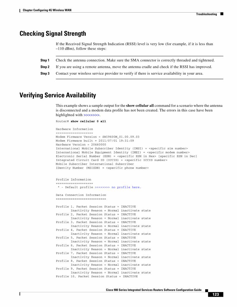
123Cisco 900 Series Integrated Services Routers Software Configuration Guide
Chapter Configuring 4G Wireless WAN Troubleshooting
Checking Signal StrengthIf the Received Signal Strength Indication (RSSI) level is very low (for example, if it is less than –110 dBm), follow these steps:
Step 1 Check the antenna connection. Make sure the SMA connector is correctly threaded and tightened.
Step 2 If you are using a remote antenna, move the antenna cradle and check if the RSSI has improved.
Step 3 Contact your wireless service provider to verify if there is service availability in your area.
Verifying Service AvailabilityThis example shows a sample output for the show cellular all command for a scenario where the antenna is disconnected and a modem data profile has not been created. The errors in this case have been highlighted with >>>>>>>.
Router# show cellular 0 all
Hardware Information====================Modem Firmware Version = SWI9600M_01.00.09.03Modem Firmware built = 2011/07/01 19:31:09Hardware Version = 20460000International Mobile Subscriber Identity (IMSI) = <specific sim number>International Mobile Equipment Identity (IMEI) = <specific modem number>Electronic Serial Number (ESN) = <specific ESN in Hex> [specific ESN in Dec]Integrated Circuit Card ID (ICCID) = <specific ICCID number>Mobile Subscriber International SubscriberIDentity Number (MSISDN) = <specific phone number>
Profile Information==================== * - Default profile >>>>>>>> no profile here.
Data Connection Information===========================
Profile 1, Packet Session Status = INACTIVE Inactivity Reason = Normal inactivate stateProfile 2, Packet Session Status = INACTIVE Inactivity Reason = Normal inactivate stateProfile 3, Packet Session Status = INACTIVE Inactivity Reason = Normal inactivate stateProfile 4, Packet Session Status = INACTIVE Inactivity Reason = Normal inactivate stateProfile 5, Packet Session Status = INACTIVE Inactivity Reason = Normal inactivate stateProfile 6, Packet Session Status = INACTIVE Inactivity Reason = Normal inactivate stateProfile 7, Packet Session Status = INACTIVE Inactivity Reason = Normal inactivate stateProfile 8, Packet Session Status = INACTIVE Inactivity Reason = Normal inactivate stateProfile 9, Packet Session Status = INACTIVE Inactivity Reason = Normal inactivate stateProfile 10, Packet Session Status = INACTIVE
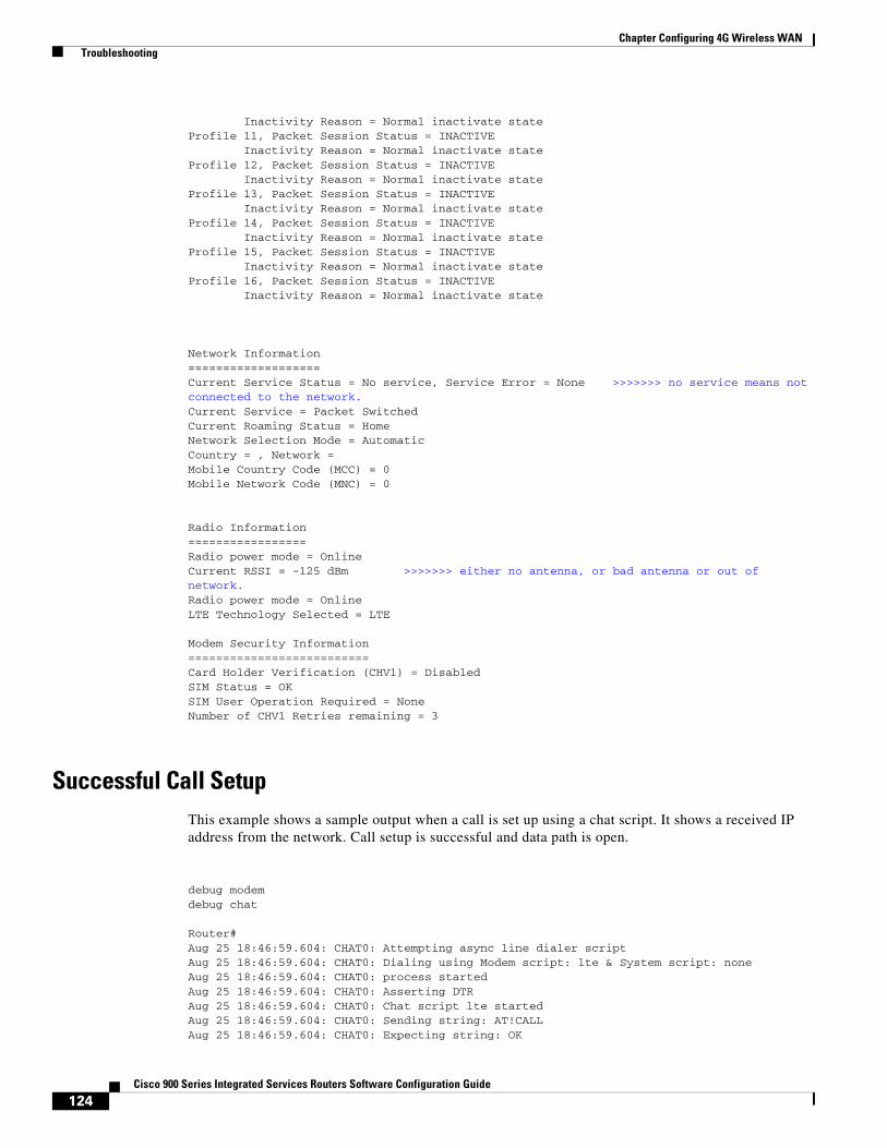
124Cisco 900 Series Integrated Services Routers Software Configuration Guide
Chapter Configuring 4G Wireless WAN Troubleshooting
Inactivity Reason = Normal inactivate stateProfile 11, Packet Session Status = INACTIVE Inactivity Reason = Normal inactivate stateProfile 12, Packet Session Status = INACTIVE Inactivity Reason = Normal inactivate stateProfile 13, Packet Session Status = INACTIVE Inactivity Reason = Normal inactivate stateProfile 14, Packet Session Status = INACTIVE Inactivity Reason = Normal inactivate stateProfile 15, Packet Session Status = INACTIVE Inactivity Reason = Normal inactivate stateProfile 16, Packet Session Status = INACTIVE Inactivity Reason = Normal inactivate state
Network Information===================Current Service Status = No service, Service Error = None >>>>>>> no service means not connected to the network.Current Service = Packet SwitchedCurrent Roaming Status = HomeNetwork Selection Mode = AutomaticCountry = , Network = Mobile Country Code (MCC) = 0Mobile Network Code (MNC) = 0
Radio Information=================Radio power mode = OnlineCurrent RSSI = -125 dBm >>>>>>> either no antenna, or bad antenna or out of network.Radio power mode = OnlineLTE Technology Selected = LTE
Modem Security Information==========================Card Holder Verification (CHV1) = DisabledSIM Status = OKSIM User Operation Required = NoneNumber of CHV1 Retries remaining = 3
Successful Call SetupThis example shows a sample output when a call is set up using a chat script. It shows a received IP address from the network. Call setup is successful and data path is open.
debug modemdebug chat
Router#Aug 25 18:46:59.604: CHAT0: Attempting async line dialer scriptAug 25 18:46:59.604: CHAT0: Dialing using Modem script: lte & System script: noneAug 25 18:46:59.604: CHAT0: process startedAug 25 18:46:59.604: CHAT0: Asserting DTRAug 25 18:46:59.604: CHAT0: Chat script lte startedAug 25 18:46:59.604: CHAT0: Sending string: AT!CALLAug 25 18:46:59.604: CHAT0: Expecting string: OK

125Cisco 900 Series Integrated Services Routers Software Configuration Guide
Chapter Configuring 4G Wireless WAN Troubleshooting
Aug 25 18:47:00.641: CHAT0: Completed match for expect: OKAug 25 18:47:00.641: CHAT0: Chat script lte finished, status = SuccessAug 25 18:47:00.641: TTY0: no timer type 1 to destroyAug 25 18:47:00.641: TTY0: no timer type 0 to destroyAug 25 18:47:00.641: TTY0: no timer type 2 to destroyAug 25 18:47:02.642: %LINK-3-UPDOWN: Interface Cellular0, changed state to upAug 25 18:47:02.642: %DIALER-6-BIND: Interface Ce0 bound to profile Di1Aug 25 18:47:03.642: %LINEPROTO-5-UPDOWN: Line protocol on Interface Cellular0, changed state to up (69.78.96.14) [OK]

126Cisco 900 Series Integrated Services Routers Software Configuration Guide
Chapter Configuring 4G Wireless WAN Troubleshooting
C H A P T E R
125Cisco 900 Series Integrated Services Routers Software Configuration Guide
11Configuring Secure Storage
Secure Storage feature allows you to secure critical configuration information by encrypting it. It encrypts VPN, IPSec, and other asymmetric key-pairs, pre-shared secrets, the type 6 password encryption key and certain credentials. An instance-unique encryption key is stored in the hardware trust anchor to prevent it from being compromised.
By default, this feature is enabled on platforms that come with a hardware trust anchor. This feature is not supported on platforms that do not have hardware trust anchor.
• Enabling Secure Storage
• Disabling Secure Storage
• Verifying the Status of Encryption
• Verifying the Platform Identity
• Downgrading the Platform Image to an Older Version
Enabling Secure Storage The following example shows how to enable Secure Storage:
router#config terminalrouter(config)# service private-config-encryptionrouter(config)# do write memory
Note By default, this feature is enabled on a platform. Use the above procedure on a platform where it is disabled.
Disabling Secure StorageThe following example shows how to disable Secure Storage:
router#config terminalrouter(config)# no service private-config-encryptionrouter(config)# do write memory
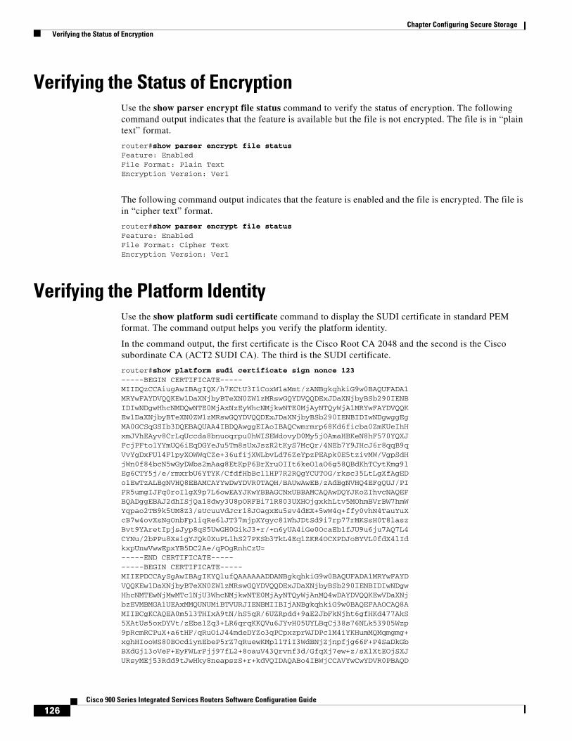
126Cisco 900 Series Integrated Services Routers Software Configuration Guide
Chapter Configuring Secure Storage Verifying the Status of Encryption
Verifying the Status of EncryptionUse the show parser encrypt file status command to verify the status of encryption. The following command output indicates that the feature is available but the file is not encrypted. The file is in “plain text” format.
router#show parser encrypt file status Feature: EnabledFile Format: Plain TextEncryption Version: Ver1
The following command output indicates that the feature is enabled and the file is encrypted. The file is in “cipher text” format.
router#show parser encrypt file status Feature: EnabledFile Format: Cipher TextEncryption Version: Ver1
Verifying the Platform IdentityUse the show platform sudi certificate command to display the SUDI certificate in standard PEM format. The command output helps you verify the platform identity.
In the command output, the first certificate is the Cisco Root CA 2048 and the second is the Cisco subordinate CA (ACT2 SUDI CA). The third is the SUDI certificate.
router#show platform sudi certificate sign nonce 123-----BEGIN CERTIFICATE-----MIIDQzCCAiugAwIBAgIQX/h7KCtU3I1CoxW1aMmt/zANBgkqhkiG9w0BAQUFADA1MRYwFAYDVQQKEw1DaXNjbyBTeXN0ZW1zMRswGQYDVQQDExJDaXNjbyBSb290IENBIDIwNDgwHhcNMDQwNTE0MjAxNzEyWhcNMjkwNTE0MjAyNTQyWjA1MRYwFAYDVQQKEw1DaXNjbyBTeXN0ZW1zMRswGQYDVQQDExJDaXNjbyBSb290IENBIDIwNDgwggEgMA0GCSqGSIb3DQEBAQUAA4IBDQAwggEIAoIBAQCwmrmrp68Kd6ficba0ZmKUeIhHxmJVhEAyv8CrLqUccda8bnuoqrpu0hWISEWdovyD0My5jOAmaHBKeN8hF570YQXJFcjPFto1YYmUQ6iEqDGYeJu5Tm8sUxJszR2tKyS7McQr/4NEb7Y9JHcJ6r8qqB9qVvYgDxFUl4F1pyXOWWqCZe+36ufijXWLbvLdT6ZeYpzPEApk0E5tzivMW/VgpSdHjWn0f84bcN5wGyDWbs2mAag8EtKpP6BrXruOIIt6keO1aO6g58QBdKhTCytKmg9lEg6CTY5j/e/rmxrbU6YTYK/CfdfHbBcl1HP7R2RQgYCUTOG/rksc35LtLgXfAgEDo1EwTzALBgNVHQ8EBAMCAYYwDwYDVR0TAQH/BAUwAwEB/zAdBgNVHQ4EFgQUJ/PIFR5umgIJFq0roIlgX9p7L6owEAYJKwYBBAGCNxUBBAMCAQAwDQYJKoZIhvcNAQEFBQADggEBAJ2dhISjQal8dwy3U8pORFBi71R803UXHOjgxkhLtv5MOhmBVrBW7hmWYqpao2TB9k5UM8Z3/sUcuuVdJcr18JOagxEu5sv4dEX+5wW4q+ffy0vhN4TauYuXcB7w4ovXsNgOnbFp1iqRe6lJT37mjpXYgyc81WhJDtSd9i7rp77rMKSsH0T8laszBvt9YAretIpjsJyp8qS5UwGH0GikJ3+r/+n6yUA4iGe0OcaEb1fJU9u6ju7AQ7L4CYNu/2bPPu8Xs1gYJQk0XuPL1hS27PKSb3TkL4Eq1ZKR4OCXPDJoBYVL0fdX4lIdkxpUnwVwwEpxYB5DC2Ae/qPOgRnhCzU=-----END CERTIFICATE----------BEGIN CERTIFICATE-----MIIEPDCCAySgAwIBAgIKYQlufQAAAAAADDANBgkqhkiG9w0BAQUFADA1MRYwFAYDVQQKEw1DaXNjbyBTeXN0ZW1zMRswGQYDVQQDExJDaXNjbyBSb290IENBIDIwNDgwHhcNMTEwNjMwMTc1NjU3WhcNMjkwNTE0MjAyNTQyWjAnMQ4wDAYDVQQKEwVDaXNjbzEVMBMGA1UEAxMMQUNUMiBTVURJIENBMIIBIjANBgkqhkiG9w0BAQEFAAOCAQ8AMIIBCgKCAQEA0m5l3THIxA9tN/hS5qR/6UZRpdd+9aE2JbFkNjht6gfHKd477AkS5XAtUs5oxDYVt/zEbslZq3+LR6qrqKKQVu6JYvH05UYLBqCj38s76NLk53905Wzp9pRcmRCPuX+a6tHF/qRuOiJ44mdeDYZo3qPCpxzprWJDPclM4iYKHumMQMqmgmg+xghHIooWS80BOcdiynEbeP5rZ7qRuewKMpl1TiI3WdBNjZjnpfjg66F+P4SaDkGbBXdGj13oVeF+EyFWLrFjj97fL2+8oauV43Qrvnf3d/GfqXj7ew+z/sXlXtEOjSXJURsyMEj53Rdd9tJwHky8neapszS+r+kdVQIDAQABo4IBWjCCAVYwCwYDVR0PBAQD
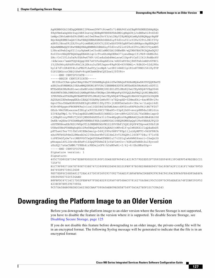
127Cisco 900 Series Integrated Services Routers Software Configuration Guide
Chapter Configuring Secure Storage Downgrading the Platform Image to an Older Version
AgHGMB0GA1UdDgQWBBRI2PHxwnDVW7t8cwmTr7i4MAP4fzAfBgNVHSMEGDAWgBQn88gVHm6aAgkWrSugiWBf2nsvqjBDBgNVHR8EPDA6MDigNqA0hjJodHRwOi8vd3d3LmNpc2NvLmNvbS9zZWN1cml0eS9wa2kvY3JsL2NyY2EyMDQ4LmNybDBQBggrBgEFBQcBAQREMEIwQAYIKwYBBQUHMAKGNGh0dHA6Ly93d3cuY2lzY28uY29tL3NlY3VyaXR5L3BraS9jZXJ0cy9jcmNhMjA0OC5jZXIwXAYDVR0gBFUwUzBRBgorBgEEAQkVAQwAMEMwQQYIKwYBBQUHAgEWNWh0dHA6Ly93d3cuY2lzY28uY29tL3NlY3VyaXR5L3BraS9wb2xpY2llcy9pbmRleC5odG1sMBIGA1UdEwEB/wQIMAYBAf8CAQAwDQYJKoZIhvcNAQEFBQADggEBAGh1qclr9tx4hzWgDERm371yeuEmqcIfi9b9+GbMSJbiZHc/CcCl0lJu0a9zTXA9w47H9/t6leduGxb4WeLxcwCiUgvFtCa51Iklt8nNbcKY/4dw1ex+7amATUQO4QggIE67wVIPu6bgAE3Ja/nRS3xKYSnj8H5TehimBSv6TECii5jUhOWryAK4dVo8hCjkjEkzu3ufBTJapnv89g9OE+H3VKM4L+/KdkUO+52djFKnhyl47d7cZR4DY4LIuFM2P1As8YyjzoNpK/urSRI14WdIlplR1nH7KNDl5618yfVP0IFJZBGrooCRBjOSwFv8cpWCbmWdPaCQT2nwIjTfY8c=-----END CERTIFICATE----------BEGIN CERTIFICATE----- MIIDhzCCAm+gAwIBAgIEAJT3DDANBgkqhkiG9w0BAQsFADAnMQ4wDAYDVQQKEwVDaXNjbzEVMBMGA1UEAxMMQUNUMiBTVURJIENBMB4XDTE1MTExNDA5MzMzN1oXDTI1MTExNDA5MzMzN1owczEsMCoGA1UEBRMjUElEOldTLUMzNjUwLTEyWDQ4VVEgU046RkRPMTk0NkJHMDUxDjAMBgNVBAoTBUNpc2NvMRgwFgYDVQQLEw9BQ1QtMiBMaXRlIFNVREkxGTAXBgNVBAMTEFdTLUMzNjUwLTEyWDQ4VVEwggEiMA0GCSqGSIb3DQEBAQUAA4IBDwAwggEKAoIBAQC6SARWyImWrRV/x7XQogAE+02WmzKki+4arMVBvl9oGgvJfkoJDdaHOROSUkEE3qXtd8N3lfKy3TZ+jtHD85m2aGz6+IRx/e/lLsQzi6dlWIB+N94pgecFBONPR9wJriox1IGD3B43b0hMLkmro4R5Zrs8XFkDo9k1tBU7F2O7GEzb/WkO5NLexznef2Niglx9fCDL0HC27BbsR5+03p8jhG0+mvrp8M9du1HKiGinZIV4XgTMp1/k/TVaIepEGZuWM3hxdUZjkNGG1c1m+oB8vLX3UlSL76sDBBoiaprDrjXBgBIozyFW8tTjh50jMDG84hKD5s31ifOe4KpqEcnVAgMBAAGjbzBtMA4GA1UdDwEB/wQEAwIF4DAMBgNVHRMBAf8EAjAAME0GA1UdEQRGMESgQgYJKwYBBAEJFQIDoDUTM0NoaXBJRD1VWUpOTlZJMENBUkhVM1Z1SUVSbFl5QXlPQ0F4TXpvek5Ub3lNU0EwS0NnPTANBgkqhkiG9w0BAQsFAAOCAQEADjtM8vdlf+p1WKSKX1C1qQ4aEnD5p8T5e4iTer7Y1fbCrHIEEm3mnip+568j299z0H8V7PDp1ljuLHyMFTC+945F9RfAeAuVWVb5A9dnGL8MssBJe2lVSnZwrWkT1EIdxLYrTiPAQHtll6CN77S4u/f71oYEtzPE5AGfyGw7ro1MEPVGffaQmYUDAwKFNBH1uI7c2S1qlwk4WWZ6xxci+lhaQnIGpWzapaiAYL1XrcBz4KwFc1ZZpQT6hHw24jzYaYimvCo+/kSKuA9xNdtSu18ycox0zKnXQ17s6aChMMt7Y8Nh4iz9BDejoOF6/b3sM0wRi+2/4j+6/GhcMRs0Og==-----END CERTIFICTAESignature version: 1Signature: 405C70D802B73947EDBF8D0D2C8180F10D4B3EF9694514219C579D2ED52F7D583E0F40813FC4E9F549B2EB1C21725F7CB1C79F98271E47E780E703E67472380FB52D4963E1D1FB9787B38E28B8E696570A180B7A2F131B1F174EA79F5DB4765DF67386126D89E07EDF6C26E0A81272EA1437D03F2692937082756AE1F1BFAFBFACD6BE9CF9C84C961FACE9FA0FE64D85AE4FA086969D0702C536ABDB8FBFDC47C14C17D02FEBF4F7F5B24D2932FA876F56B4C07816270A0B4195C53D975C85AEAE3A74F2DBF293F52423ECB7B853967080A9C57DA3E4B08B2B2CA623B2CBAF7080A0AEB09B2E5B756970A3A27E0F1D17C8A243
Downgrading the Platform Image to an Older VersionBefore you downgrade the platform image to an older version where the Secure Storage is not supported, you have to disable the feature in the version where it is supported. To disable Secure Storage, see Disabling Secure Storage, page 125
If you do not disable this feature before downgrading to an older image, the private-config file will be in an encrypted format. The following Syslog message will be generated to indicate that the file is in an encrypted format:

128Cisco 900 Series Integrated Services Routers Software Configuration Guide
Chapter Configuring Secure Storage Downgrading the Platform Image to an Older Version
%PARSER-4-BADCFG: Unexpected end of configuration file.
If the file is in ‘plain text’, no Syslog message will be generated.