Embed Size (px)
Citation preview

Cisco 7200 V78-5469-04 B0
C H A P T E R 1
tionsling,
lated
s. Thelot data,
toitchnnelsapter.g, a
as the1abit
Cisco 7200 VXR Product Overview
This chapter provides physical and functional overviews of the Cisco 7200 VXR routers. Descripand examples of software commands are included when they are necessary for replacing, instalconfiguring, or maintaining the router hardware.
The following sections describe router hardware, major components, and functions of hardware-refeatures:
• Physical Description, page 1-1
• Cisco 7204VXR Overview, page 1-4
• Cisco 7206VXR Overview, page 1-7
• Field-Replaceable Units, page 1-10
• Functional Overview, page 1-50
Warning Before you install, operate, or service the system, read the Site Preparation and Safety Guide. Thisguide contains important safety information you should know before working with the system.
Physical DescriptionThe Cisco 7200 VXR routers are the newest, multiservice members of the Cisco 7200 series routerCisco 7200 VXR routers include the Cisco 7204VXR (4-slot router) and the Cisco 7206VXR (6-srouter). The Cisco 7200 VXR routers are designed to support gigabit capabilities and to improvevoice, and video integration in both service provider and enterprise environments.
The Cisco 7200 VXR routers incorporate an integrated Multiservice Interchange (MIX) capabilitysupport future voice applications. MIX interconnections on the midplane provide the ability to swDS-0 time slots between multichannel T1 or E1 interfaces, much like a digital cross-connect or aadd-drop multiplexer. This feature enables the Cisco 7200 VXR routers to switch DS-0 voice chanon a T1 or E1 interface from one voice processing port adapter to another voice processing port adIt also enables DS-0s to be switched through the Cisco 7200 VXR routers without any processinrequirement in certain voice configurations.
The Cisco 7200 VXR routers support the high-speed network processing engine, NPE-G1, as wellnetwork services engine (NSE-1) and all other available network processing engines. The NPE-Gprovides high speed performance with the BCM 1250 700-Mhz processor and supports three GigEthernet interfaces with no additional bandwidth requirements. The NSE-1 is a combination of a
1-1XR Installation and Configuration Guide

Chapter 1 Cisco 7200 VXR Product OverviewPhysical Description
orkser 3
vide
Hz
p toigabit
or
rs and
out
owertion.pplyf the
t
thidth
high-performance RISC processor and a high-performance PXF processor. The PXF processor wwith the Route Processor to provide accelerated packet switching, as well as accelerated IP Layfeature processing.
The Cisco 7200 VXR routers also support high-speed network processing engines (NPEs) to proincreased routing and process switching performance.
The Cisco 7200 VXR routers with the NPE-G1, NPE-400, and NSE-1 installed support both 25-Mand 50-MHz port adapter operation.
Note For port adapter configuration information, refer to theCisco 7200 Series Port Adapter ConfigurationGuidelines publication.
The Cisco 7200 VXR routers accommodate a variety of network interface port adapters and I/Ocontrollers. A Cisco 7200 VXR router equipped with an NPE-G1, NSE-1, or NPE-400 can support usix high-speed port adapters and can also support higher-speed port adapter interfaces including GEthernet and OC-12 ATM. The Cisco 7200 VXR routers also contain bays for up to two AC-inputDC-input power supplies.
The port adapters, I/O controller, and power supplies are the same for all Cisco 7200 series routeare described in the“Field-Replaceable Units” section on page 1-10. The network processing enginesand network services engine are router model specific.
The Cisco 7200 VXR routers support the following features:
• Online insertion and removal (OIR)—Allows you to add, replace, or remove port adapters withinterrupting the system.
• Dual hot-swappable, load-sharing power supplies—Provide system power redundancy; if one psupply or power source fails, the other power supply maintains system power without interrupAlso, when one power supply is powered off and removed from the router, the second power suimmediately takes over the router’s power requirements without interrupting normal operation orouter.
• Environmental monitoring and reporting functions—Allow you to maintain normal systemoperation by resolving adverse environmental conditions prior to loss of operation.
• Downloadable software—Allows you to load new images into Flash memory remotely, withouhaving to physically access the router, for fast, reliable upgrades.
Table 1-1 lists the Cisco 7200 VXR physical specifications and power requirements.
Table 1-1 Cisco 7200 VXR Physical Specifications
Description Specification
Midplane Two primary PCI buses, and one secondary PCI bus
• With an NPE-G1 and an I/O controller installed, the I/O controller does not use bandwidpoints, and the NPE-G1 does use bandwidth points. The NPE-G1 does not use bandwpoints if installed without the I/O controller.
• With NSE-1, NPE-400, or NPE-300 installed: aggregate bandwidth of 900 Mbps1
• With NPE-100, NPE-150, or NPE-200 installed: aggregate bandwidth of 600 Mbps
1-2Cisco 7200 VXR Installation and Configuration Guide
78-5469-04 B0

Chapter 1 Cisco 7200 VXR Product OverviewPhysical Description
kg)
nd
Dimensions(H x W x D)
5.25 in. x 16.8 in. x 17 in. (13.34 cm x 42.67 cm x 43.18 cm)
Weight Chassis fully configured with a network processing engine or network services engine, I/Ocontroller, maximum number of port adapters, 2 power supplies, and a fan tray: ~ 50 lb (22.7
Heat dissipation 370W (1262 BTU2)
AC-input voltage rating 100–240 VAC3 wide input with power factor correction
AC-input current rating 5A4 at 100–240 VAC with the chassis fully configured
AC-input frequency rating 50/60 Hz5
AC-input cable 18 AWG6 three-wire cable, with a three-lead IEC-320 receptacle on the power supply end, aa country-dependent plug on the power source end
DC-output power 280W maximum (with either a single or dual power supply configuration)
DC-input voltage rating –48 VDC7 nominal in North America
–60 VDC nominal in the European Community
DC-input current rating 13A at –48 VDC (370W/–48 VDC = 7.7A typical draw)
8A at –60 VDC (370W/–60 VDC = 6.2A typical draw)
DC-input cable In accordance with local and national wiring regulations
Chassis fan noiselevels—single speed fan
Tested:
• Front (I/O controller and port adapter side) 44.2 dB
• Back (power supply side) 43.7 dB
• Left (fan side) 47.2 dB
• Right 44.8 dB
Maximum: 65 dBa
Airflow ~80 cfm8
Temperature 32 to 104 F (0 to 40 C) operating; –4 to 149 F (–20 to 65 C) nonoperating
Humidity 10 to 90% noncondensing
Recommended minimumsoftware requirements
Cisco IOS Release 12.0(2)XE2 or later releases of 12.0 XECisco IOS Release 12.1(1)E or later releases of 12.1 ECisco IOS Release 12.0(5)S or later releases of 12.0 SCisco IOS Release 12.0(3)T or later releases of 12.0 TCisco IOS Release 12.2(1) or later releases of 12.2Cisco IOS Release 12.2 (4)B or later releases of 12.2 B(
Compliance CE Marking
Table 1-1 Cisco 7200 VXR Physical Specifications (continued)
Description Specification
1-3Cisco 7200 VXR Installation and Configuration Guide
78-5469-04 B0

Chapter 1 Cisco 7200 VXR Product OverviewCisco 7204VXR Overview
XR
of
tputplace
/Othe
Note For a chassis footprint, additional dimensions, and clearance requirements for the Cisco 7200 Vrouters, see the“Site Requirement Guidelines” section on page 2-3 in Chapter 2, “Preparing forInstallation.”
Cisco 7204VXR OverviewThe Cisco 7204VXR supports multiprotocol, multimedia routing and bridging with a wide variety protocols and port adapter combinations available for Cisco 7200 series routers. In addition, theCisco 7204VXR midplane provides increased support for multiple high-bandwidth port adapters.
The Cisco 7204VXR has four slots (slot 1 through slot 4) for port adapters, one slot for an input/ou(I/O) controller, and one slot for a network processing engine or network services engine. You canthe port adapters in any of the four available slots. (SeeFigure 1-1.)
Note If you have difficulty installing a processing engine or I/O controller in the lowest slot of aCisco 7200 VXR router that is rack-mounted, remove the port adapters, processing engine and Icontroller from the chassis and reinstall them. Install the processing engine and I/O controller in lowest slots first, then populate the slots above them, in a bottom-to-top order.
Safety UL 1950, CSA 22.2 No. 950, EN60950, AUSTEL TS001,AS/NZS 3260, IEC 60950, IEC 60825, EN 60825, 21CFR1040
EMI FCC Class A (47 CFR, Part 15), ICES-003 Class A, EN55022 Class B, CISPR22 Class B,AS/NZS 3548 Class B, and VCCI Class B
1. Mbps = megabits per second
2. BTU = British thermal units
3. VAC = volts alternating current
4. A = amperes
5. Hz = hertz
6. AWG = American Wire Gauge
7. VDC = volts direct current
8. cfm = cubic feet per minute
Table 1-1 Cisco 7200 VXR Physical Specifications (continued)
Description Specification
1-4Cisco 7200 VXR Installation and Configuration Guide
78-5469-04 B0
Chapter 1 Cisco 7200 VXR Product OverviewCisco 7204VXR Overview
rt
ork
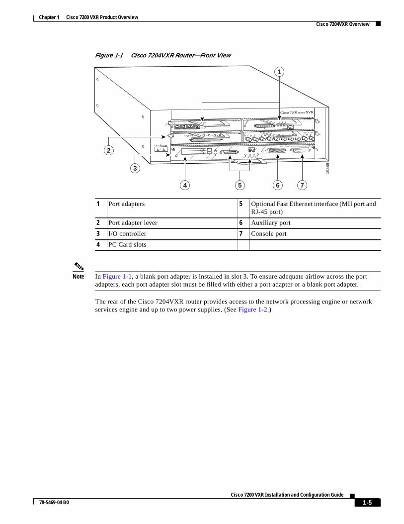
Figure 1-1 Cisco 7204VXR Router—Front View
Note In Figure 1-1, a blank port adapter is installed in slot 3. To ensure adequate airflow across the poadapters, each port adapter slot must be filled with either a port adapter or a blank port adapter.
The rear of the Cisco 7204VXR router provides access to the network processing engine or netwservices engine and up to two power supplies. (SeeFigure 1-2.)
1 Port adapters 5 Optional Fast Ethernet interface (MII port andRJ-45 port)
2 Port adapter lever 6 Auxiliary port
3 I/O controller 7 Console port
4 PC Card slots
2ETHERNET-10BFL
EN
RX
0 1 2 3 4TX RX TX RX TX RX TX RX TX
Cisco 7200 SERIES XVR
0
4
1
3
EN
0 71 2 3 4 5 6SERIAL-EIA/TIA-232
MII
EN R
J45
EN R
J45
LINK
1O P
WR
OK
RJ-45
CPU RESET FAST ETHERNET INPUT/OUTPUT CONTROLLER
ENABLED
PCMCIA
EJECT
SLOT 0
SLOT 1
FE MII
ETHERNET 10BT
ENAB
LED
0 2
1 3
LINK
0 1 2 3
ENAB
LED
MII
LIN
K
RJ4
5
FAST ETHERNET
0
1588
9
1
2
3
64 75
1-5Cisco 7200 VXR Installation and Configuration Guide
78-5469-04 B0

Chapter 1 Cisco 7200 VXR Product OverviewCisco 7204VXR Overview
) havessingis.
nsole
put
.) A
power.
r a
ths).
round
Figure 1-2 Cisco 7204VXR Router—Rear View
The network processing engines NPE-100 through NPE-400 or network services engine (NSE-1no external connectors or LEDs. There is a handle for removing and installing the network proceengine or network services engine and two captive installation screws for securing it to the chass
The NPE-G1 has external connectors and LEDs for the Gigabit Ethernet interfaces as well as coand auxiliary ports.
The Cisco 7204VXR router comes equipped with one 280W AC-input power supply. (A 280W DC-inpower supply option is available.) InFigure 1-2, a Cisco 7204VXR router is configured with a singleAC-input power supply. (A power supply filler plate is installed over the second power supply bayfully configured Cisco 7204VXR router operates with only one installed power supply; however, asecond, optional power supply of the same type provides hot-swappable, load-sharing, redundant
Note The Cisco 7204VXR does not support a mixture of AC- and DC-input power.
The power supply has the router’s main power switch and either an AC-input power receptacle ohardwired DC-input power cable (depending on the type of installed power supply).
Caution Do not mix power supplies in the Cisco 7204VXR. In dual power supply router configurations, bopower suppliesmustbe of the same type (two AC-input power supplies or two DC-input power supplie
Adjacent to the power supply bays are two chassis grounding receptacles that provide a chassis gconnection for ESD equipment or a two-hole grounding lug. (SeeFigure 1-2.)
1 Chassis grounding receptacles 6 Network processing engine or networkservices engine
2 Power supply filler plate 7 AC-input power supply
3 Power switch 8 PWR OK LED
4 AC power cable-retention clip 9 AC power supply receptacle
5 Internal fans
8439
6
NETWORK PROCESSING ENGINE-300
1 5
243
8 976
1-6Cisco 7200 VXR Installation and Configuration Guide
78-5469-04 B0
Chapter 1 Cisco 7200 VXR Product OverviewCisco 7206VXR Overview
and
ptersupied
vicesare nooller,
rs tocross
dard kitt rack.00
hsation
of
er. If
utputplace
face
/Othe
Three internal fans draw cooling air into the chassis and across internal components to maintainacceptable operating temperature. (SeeFigure 1-2.) The three fans are enclosed in a tray that is locateinside the chassis.
Caution To ensure the proper flow of cooling air across the internal components, make sure blank port adaare installed in unoccupied port adapter slots, and power supply filler plates are installed in unoccpower supply bays.
The I/O controller, port adapters, power supplies, and network processing engine or network serengine slide into their respective chassis slots and connect directly to the routers midplane; thereinternal cables to connect. The midplane distributes power from the power supplies to the I/O contrport adapters, fan tray, and network processing engine or network services engine.
The midplane also senses OIR of the port adapters, bridges the PCI buses from the port adaptepacket memory on the network processing engine or network services engine, arbitrates traffic athe PCI buses, and generates the clock signals for the port adapters on each PCI bus.
The Cisco 7204VXR operates as either a tabletop or a rack-mounted unit. A rack-mount kit is stanequipment included with all Cisco 7200 VXR routers when they are shipped from the factory. Theprovides the hardware needed to mount the router in a standard 19-inch equipment rack or a 2-posSteps for installing the Cisco 7204VXR router in an equipment rack are the same for all Cisco 72VXR routers and are explained in Chapter 3, “Installing a Cisco 7200 VXR Router.” If you are notrack-mounting your Cisco 7204VXR, place it on a sturdy tabletop or platform.
A fully configured Cisco 7204VXR, with two installed power supplies and all chassis slots filled, weigapproximately 50 pounds (22.7 kilograms [kg]). For clearance requirements and rack-mount installconsiderations, seeChapter 2, “Preparing for Installation,” the“Site Requirement Guidelines” sectionon page 2-3.
Cisco 7206VXR OverviewThe Cisco 7206VXR supports multiprotocol, multimedia routing and bridging with a wide variety protocols and port adapter combinations available for Cisco 7200 series routers. In addition, theCisco 7206VXR midplane provides increased support for multiple high-bandwidth port adapters.
Note The Cisco 7206VXR is also available as a router shelf in a Cisco AS5800 Universal Access Servyour Cisco 7206VXR is installed as a router shelf, use this publication in conjunction with theCisco AS5800 Universal Access Server publications that shipped with the access server.
The Cisco 7206VXR has six slots (slot 1 through slot 6) for port adapters, one slot for an input/o(I/O) controller, and one slot for a network processing engine or network services engine. You canthe port adapters in any of the six available slots.
The front of the Cisco 7206VXR provides access to the I/O controller and up to six network interport adapters. (SeeFigure 1-3.)
Note If you have difficulty installing a processing engine or I/O controller in the lowest slot of aCisco 7200 VXR router that is rack-mounted, remove the port adapters, processing engine and Icontroller from the chassis and reinstall them. Install the processing engine and I/O controller in lowest slots first, then populate the slots above them, in a bottom-to-top order.
1-7Cisco 7200 VXR Installation and Configuration Guide
78-5469-04 B0

Chapter 1 Cisco 7200 VXR Product OverviewCisco 7206VXR Overview
rt
Figure 1-3 Cisco 7206VXR Router—Front View
Note In Figure 1-3, a blank port adapter is installed in slot 5. To ensure adequate airflow across the poadapters, each port adapter slot must be filled with either a port adapter or a blank port adapter.
1 Blank port adapter 5 PC Card slots
2 Port adapters 6 Optional Fast Ethernet interface (MII port andRJ-45 port)
3 Port adapter lever 7 Auxiliary port
4 I/O controller 8 Console port
2ETHERNET-10BFL
EN
RX
0 1 2 3 4TX RX TX RX TX RX TX RX TX
0
4
1
3
56
FAST SERIAL
ENTD TC RD RC LB CD TD TC RD RC LB CD TD TC RD RC LB CD TD TC RD RC LB CD
TOKEN RING
0 1 2 3
Cisco 7200Series VXR
MII
EN R
J45
EN R
J45
LINK
1O P
WR
OK
RJ-45
CPU RESET FAST ETHERNET INPUT/OUTPUT CONTROLLER
ENABLED
PCMCIA
EJECT
SLOT 0
SLOT 1
FE MII
ETHERNET 10BT
ENAB
LED
0 2
1 3
LINK
0 1 2 3
ENAB
LED
MII
LIN
K
RJ4
5
FAST ETHERNET
0
8451
7
1
5
3
4
6
2
7 8
1-8Cisco 7200 VXR Installation and Configuration Guide
78-5469-04 B0

Chapter 1 Cisco 7200 VXR Product OverviewCisco 7206VXR Overview
ork
) havessingis.
nsole
put
.) A
power.
r a
Figure 1-4 Cisco 7206VXR Router—Rear View
The rear of the Cisco 7206VXR router provides access to the network processing engine or netwservices engine and up to two power supplies. (SeeFigure 1-4.)
The NPE-G1 can be used without an I/O controller, and has three Gigabit Ethernet interfaces, aCompactFlash Disk slot, and auxiliary and console port connections as well as status LEDs.
The network processing engines NPE-100 through NPE-400 or network services engine (NSE-1no external connectors or LEDs. There is a handle for removing and installing the network proceengine or network services engine and two captive installation screws for securing it to the chass
The NPE-G1 has external connectors and LEDs for the Gigabit Ethernet interfaces as well as coand auxiliary ports.
The Cisco 7206VXR router comes equipped with one 280W AC-input power supply. (A 280W DC-inpower supply option is available.) InFigure 1-4, a Cisco 7206VXR router is configured with a singleAC-input power supply. (A power supply filler plate is installed over the second power supply bayfully configured Cisco 7206VXR router operates with only one installed power supply; however, asecond, optional power supply of the same type provides hot-swappable, load-sharing, redundant
Note The Cisco 7206VXR does not support a mixture of AC- and DC-input power.
The power supply has the router’s main power switch and either an AC-input power receptacle ohardwired DC-input power cable (depending on the type of installed power supply).
1 Chassis grounding receptacles 6 Network processing engine or networkservices engine
2 Power supply filler plate 7 AC-input power supply
3 Power switch 8 PWR OK LED
4 AC power cable-retention clip 9 AC power supply receptacle
5 Internal fans
8439
6
NETWORK PROCESSING ENGINE-300
1 5
243
8 976
1-9Cisco 7200 VXR Installation and Configuration Guide
78-5469-04 B0
Chapter 1 Cisco 7200 VXR Product OverviewField-Replaceable Units
ths).
round
ain and
pterspied
vicesre no
oller,
s tocross
dard kitt rack.00
hsation
eable
Caution Do not mix power supplies in the Cisco 7206VXR. In dual power supply router configurations, bopower suppliesmustbe of the same type (two AC-input power supplies or two DC-input power supplie
Adjacent to the power supply bays are two chassis grounding receptacles that provide a chassis gconnection for ESD equipment or a two-hole grounding lug. (SeeFigure 1-4.)
Three internal fans draw cooling air into the chassis and across the internal components to maintacceptable operating temperature. (SeeFigure 1-4.) The three fans are enclosed in a tray that is locateinside the chassis.
Caution To ensure the proper flow of cooling air across the internal components, make sure blank port adaare installed in unoccupied port adapter slots, and power supply filler plates are installed in unoccupower supply bays.
The I/O controller, port adapters, power supplies, and network processing engine or network serengine slide into their respective chassis slots and connect directly to the router’s midplane; there ainternal cables to connect. The midplane distributes power from the power supplies to the I/O contrport adapters, fan tray, and network processing engine or network services engine.
The midplane also senses OIR of the port adapters, bridges the PCI buses from the port adapterpacket memory on the network processing engine or network services engine, arbitrates traffic athe PCI buses, and generates the clock signals for the port adapters on each PCI bus.
The Cisco 7206VXR operates as either a tabletop or a rack-mounted unit. A rack-mount kit is stanequipment included with all Cisco 7200 VXR routers when they are shipped from the factory. Theprovides the hardware needed to mount the router in a standard 19-inch equipment rack or a 2-posSteps for installing the Cisco 7206VXR router in an equipment rack are the same for all Cisco 72VXR routers and are explained in Chapter 3, “Installing a Cisco 7200 VXR Router.” If you are notrack-mounting your Cisco 7206VXR, place it on a sturdy tabletop or platform.
A fully configured Cisco 7206VXR, with two installed power supplies and all chassis slots filled, weigapproximately 50 pounds (22.7 kilograms [kg]). For clearance requirements and rack-mount installconsiderations, seeChapter 2, “Preparing for Installation,” the“Site Requirement Guidelines” sectionon page 2-3.
Field-Replaceable UnitsThe Cisco 7200 VXR routers are easy to service; many of their major components are field-replacunits (FRUs). The following sections describe Cisco 7200 VXR router FRUs:
• Network Processing Engine or Network Services Engine, page 1-11
• Input/Output Controller, page 1-30
• LED Descriptions, page 1-38
• Port Adapters and Service Adapters, page 1-44
• Power Supplies, page 1-45
• Chassis, page 1-47
• CompactFlash Disks, Flash Disks and PC Cards, page 1-48
• Rack-Mount and Cable-Management Kit, page 1-49
1-10Cisco 7200 VXR Installation and Configuration Guide
78-5469-04 B0

Chapter 1 Cisco 7200 VXR Product OverviewField-Replaceable Units
s thatupplys
ork
I/O-G1
-400,ginese andg
essoressorIP
icesonm.
ts:
Hz.
of
of
f
f
Note Replacement instructions for removing and replacing FRUs are contained in separate documentaccompany each FRU shipped from the factory. For example, if you need to replace an AC power sin your Cisco 7200 VXR router, refer to the280-Watt AC-Input Power Supply Replacement Instructionpublication. Replacement instructions are also available on the Documentation CD-ROM and onCisco.com.
Network Processing Engine or Network Services EngineThe network processing engine or network services engine maintains and executes the systemmanagement functions for Cisco 7200 VXR routers. Also, the network processing engine or netwservices engine shares the system memory and environmental monitoring functions with the I/Ocontroller.
Because the NPE-G1 contains I/O functionality the Cisco 7200 VXR routers can operate with nocontroller with an NPE-G1 installed. With both an I/O controller and the NPE-G1 installed, the NPEenhances the I/O controller functionality.
Cisco 7200 VXR routers support eight versions of the network processing engine: NPE-G1, NPENPE-300, NPE-225, NPE-200, NPE-175, NPE-150, and NPE-100. These network processing enhave the same functionality; however, their performance differs because of the microprocessor typthe type of memory for packet data (SRAM and DRAM, or SDRAM) that each network processinengine provides.
Cisco 7200 VXR routers also support the NSE-1, which consists of two modular boards: the procengine board and the network controller board. The NSE-1 Parallel eXpress Forwarding (PXF) procworks with the Route Processor to provide accelerated packet switching, as well as accelerated Layer 3 feature processing.
Note Detailed instructions for removing and replacing the network processing engines or network servengine are contained in the onlineNetwork Processing Engine and Network Services Engine Installatiand Configurationpublication. It is also available on the Documentation CD-ROM and on Cisco.co
The network processing engines and network services engine consist of the following componen
• Reduced instruction set computing (RISC) microprocessor
– The NPE-G1 uses a BCM1250 microprocessor that operates at an internal clock speed of 700 M
– The NSE-1 uses an RM7000 microprocessor that operates at an internal clock speed of262 MHz.
– The NPE-400 uses an RM7000 microprocessor that operates at an internal clock speed 350 MHz.
– The NPE-300 uses an RM7000 microprocessor that operates at an internal clock speed 262 MHz.
– The NPE-225 has an RM5271 microprocessor that operates at an internal clock speed o262 MHz.
– The NPE-200 has an R5000 microprocessor that operates at an internal clock speed of200 MHz.
– The NPE-175 has an RM5270 microprocessor that operates at an internal clock speed o200 MHz.
1-11Cisco 7200 VXR Installation and Configuration Guide
78-5469-04 B0

Chapter 1 Cisco 7200 VXR Product OverviewField-Replaceable Units
clock
heg
single two
e andf the
o the
ccessine.
Thet
The
Thet
to the
ternal
– The NPE-100 and NPE-150 have an R4700 microprocessor that operates at an internal speed of 150 MHz.
• System controller
– The NPE-G1 BCM 1250 maintains and executes the system management functions for tCisco 7200 VXR routers and also holds the system memory and environmental monitorinfunctions.
– The NSE-1 has one system controller that provides processor access to the midplane andI/O controller PCI buses. The system controller also allows port adapters on either of themidplane PCI buses to access SDRAM.
– The NPE-400 has one system controller that provides system access.
– The NPE-300 has two system controllers that provide processor access to the two midplansingle I/O controller PCI buses. The system controller also allows port adapters on either otwo midplane PCI buses to access SDRAM.
– The NPE-175 and NPE-225 have one system controller that provides processor access ttwo midplane and single I/O controller PCI buses. The system controller also allows theport adapters on either of the two midplane PCI buses to access SDRAM.
– The NPE-100, NPE-150, and NPE-200 have a system controller that uses direct memory a(DMA) to transfer data between DRAM and packet SRAM on the network processing eng
• Upgradable memory modules
– The NPE-G1 uses SDRAM for storing all packets received or sent from network interfaces.SDRAM also stores routing tables and network accounting applications. Two independenSDRAM memory arrays in the system allow concurrent access by port adapters and theprocessor.
– The NSE-1 uses SDRAM for providing code, data, and packet storage.
– The NPE-400 uses SDRAM for storing all packets received or sent from network interfaces.SDRAM memory array in the system allows concurrent access by port adapters and theprocessor.
– The NPE-300 uses SDRAM for storing all packets received or sent from network interfaces.SDRAM also stores routing tables and network accounting applications. Two independenSDRAM memory arrays in the system allow concurrent access by port adapters and theprocessor.
– The NPE-175 and NPE-225 use SDRAM for providing code, data, and packet storage.
– The NPE-100, NPE-150, and NPE-200 use DRAM for storing routing tables, networkaccounting applications, packets of information in preparation for process switching, andpacket buffering for SRAM overflow (except in the NPE-100, which contains no packetSRAM). The standard configuration is 32 MB, with up to 128 MB available through singlein-line memory module (SIMM) upgrades.
• Packet SRAM for storing packets of information in preparation for fast switching
The NPE-150 has 1 MB of SRAM and the NPE-200 has 4 MB of SRAM. No other networkprocessing engine or network services engine has SRAM.
• Cache memory
– The NPE-G1 has two levels of cache: a primary and a secondary cache that are internalmicroprocessor, with the secondary unified cache for data and instruction.
– The NSE-1 has three levels of cache: a primary and a secondary unified cache that are into the microprocessor, and a tertiary 2-MB external cache.
1-12Cisco 7200 VXR Installation and Configuration Guide
78-5469-04 B0
Chapter 1 Cisco 7200 VXR Product OverviewField-Replaceable Units
to therage
to therage
nd a
nd a
,
ement
and
– The NPE-400 has three levels of cache: a primary and a secondary cache that are internalmicroprocessor, and a tertiary 4-MB external cache that provides additional high-speed stofor data and instructions.
– The NPE-300 has three levels of cache: a primary and a secondary cache that are internalmicroprocessor, and a tertiary 2-MB external cache that provides additional high-speed stofor data and instructions.
– The NPE-225 has two levels of cache: a primary cache that is internal to the processor asecondary 2-MB external cache that provides additional high-speed storage for data andinstructions.
– The NPE-200 has unified cache SRAM that functions as the secondary cache for themicroprocessor. (The primary cache is within the microprocessor.)
– The NPE-175 has two levels of cache: a primary cache that is internal to the processor asecondary 2-MB external cache that provides additional high-speed storage for data andinstructions.
– The NPE-150 has unified cache SRAM that functions as the secondary cache for themicroprocessor. (The primary cache is within the microprocessor.)
– The NPE-100 has unified cache SRAM that functions as the secondary cache for themicroprocessor. (The primary cache is within the microprocessor.)
• Two environmental sensors for monitoring the cooling air as it leaves the chassis
• Boot ROM for storing sufficient code for booting the Cisco IOS software; the NPE-G1, NSE-1NPE-400, NPE-300, NPE-225, NPE-200, and NPE-175 have boot ROM.
The network processing engines and network services engine perform the following system managfunctions:
• Sending and receiving routing protocol updates
• Managing tables, caches, and buffers
• Monitoring interface and environmental status
• Providing Simple Network Management Protocol (SNMP) management through the console Telnet interface
• Accounting for and switching of data traffic
• Booting and reloading images
• Managing port adapters (recognition and initialization during online insertion and removal)
The following figures and memory tables provide information about your NPE or NSE:
• NPE-G1 is represented byFigure 1-5. Table 1-2lists NPE-G1 memory specifications, andTable 1-3lists memory configurations.
• NSE-1 is represented byFigure 1-6. Table 1-4 lists NSE-1 memory specifications, andTable 1-5lists memory configurations.
• The NPE-400 is represented byFigure 1-7. Table 1-6 lists NPE-400 memory specifications, andTable 1-7 lists memory configurations.
• NPE-300 is represented byFigure 1-8. Table 1-8 lists NPE-300 memory specifications, andTable 1-9 lists memory configurations.
• NPE-225 is represented byFigure 1-9. Table 1-10 lists NPE-225 memory specifications, andTable 1-11 lists memory configurations.
1-13Cisco 7200 VXR Installation and Configuration Guide
78-5469-04 B0

Chapter 1 Cisco 7200 VXR Product OverviewField-Replaceable Units
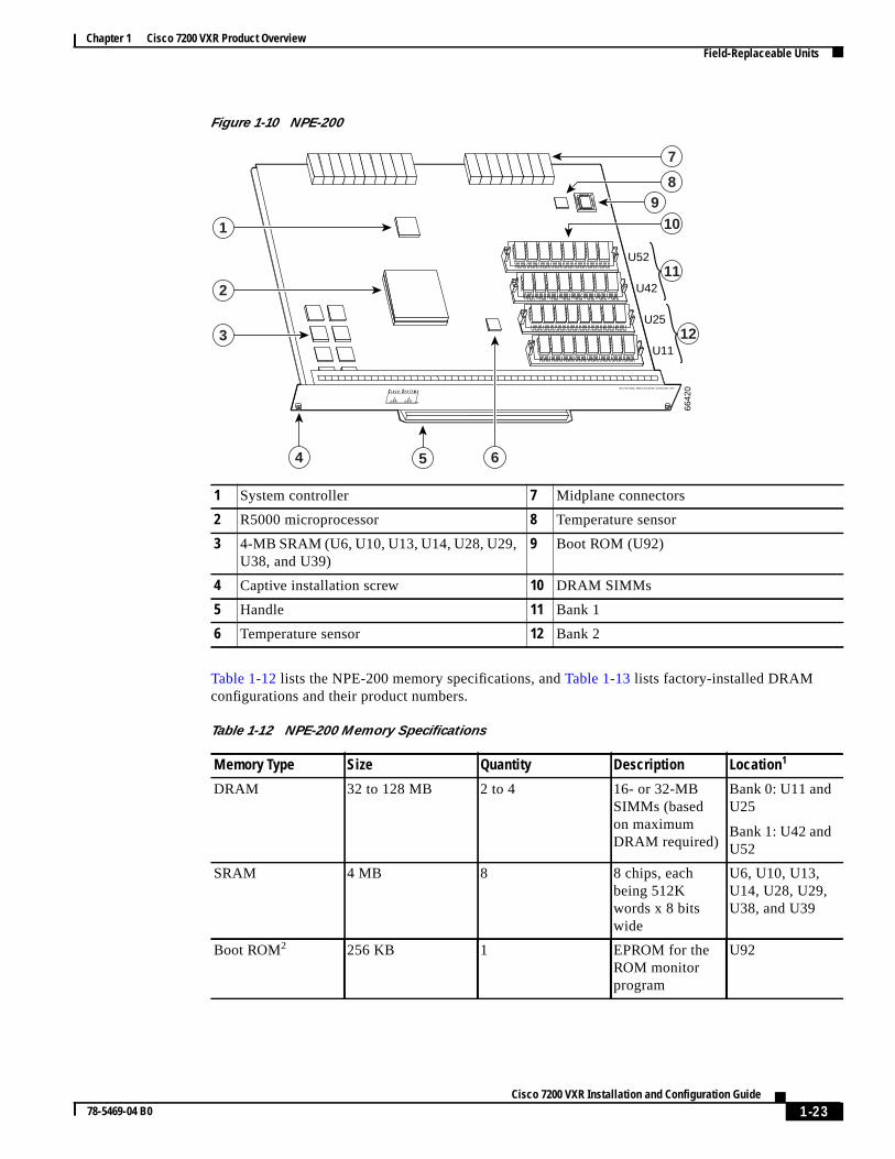
• NPE-200 is represented byFigure 1-10. Table 1-12 lists NPE-200 memory specifications, andTable 1-13 lists memory configurations.
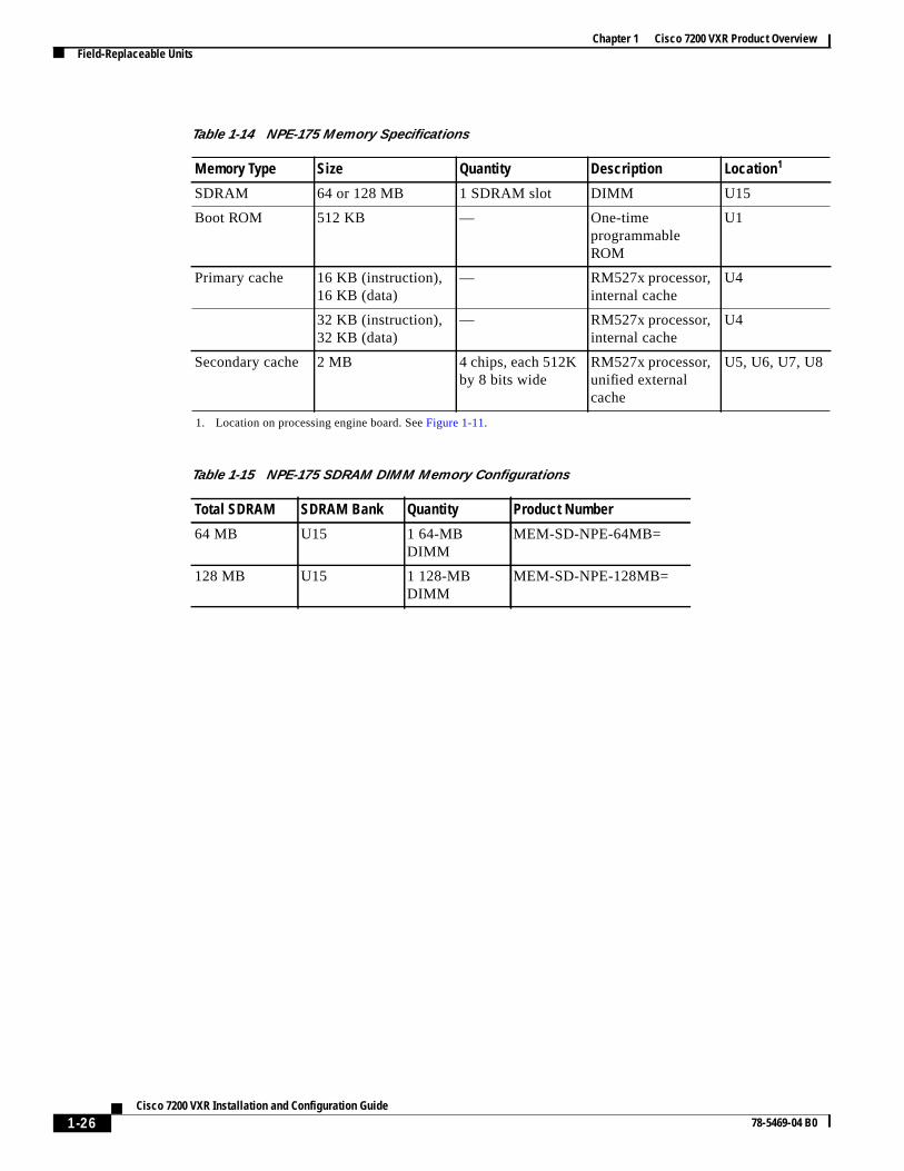
• NPE-175 is represented byFigure 1-11. Table 1-14 lists NPE-175 memory specifications, andTable 1-15 lists memory configurations.
• NPE-150 is represented byFigure 1-12. Table 1-16 lists NPE-150 memory specifications, andTable 1-17 lists memory configurations.
• NPE-100 is represented byFigure 1-13. Table 1-18 lists NPE-100 memory specifications, andTable 1-19 lists memory configurations.
Figure 1-5 NPE-G1
Table 1-2 lists the NPE-G1 memory specification, andTable 1-3 lists the factory-installed SDRAMconfigurations and their product numbers.
1 Midplane connectors 6 Boot ROM
2 Flash memory 7 NVRAM
3 Temperature sensor 8 DIMM 2
4 Processor 9 Temperature sensor
5 Keying post 10 DIMM 1
6643
5
G I G A B I T E T H E R N E T 0 / 1
R J 4 5 G B I CE N
R X T X
L I N K
CONSOLE AUX
G I G A B I T E T H E R N E T 0 / 1
R J 4 5 G B I CE N
R X T X
L I N K
G I G A B I T E T H E R N E T 0 / 1
R J 4 5 G B I CE N
R X T X
L I N KC P U
R E S E T
C O M PAC T F L A S HPOWER
ON
S L O TA C T I V E
NETWORK PROCESSING ENGINE - G1
5
4
3
6
8
7
9
10
1
2
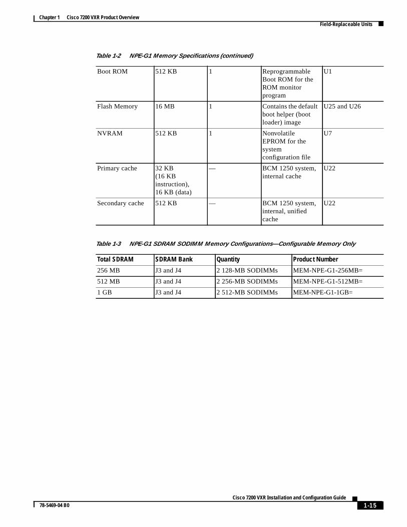
Table 1-2 NPE-G1 Memory Specifications
Memory Type Size Quantity Description
Component Locationon the NPE-G1Board
SDRAM 128 MB,256 MB,512 MB
2 128-MB, 256-MB,or 512-MBSODIMMs
J3, J4
1-14Cisco 7200 VXR Installation and Configuration Guide
78-5469-04 B0
Chapter 1 Cisco 7200 VXR Product OverviewField-Replaceable Units
Boot ROM 512 KB 1 ReprogrammableBoot ROM for theROM monitorprogram
U1
Flash Memory 16 MB 1 Contains the defaultboot helper (bootloader) image
U25 and U26
NVRAM 512 KB 1 NonvolatileEPROM for thesystemconfiguration file
U7
Primary cache 32 KB(16 KBinstruction),16 KB (data)
— BCM 1250 system,internal cache
U22
Secondary cache 512 KB — BCM 1250 system,internal, unifiedcache
U22
Table 1-3 NPE-G1 SDRAM SODIMM Memory Configurations—Configurable Memory Only
Total SDRAM SDRAM Bank Quantity Product Number
256 MB J3 and J4 2 128-MB SODIMMs MEM-NPE-G1-256MB=
512 MB J3 and J4 2 256-MB SODIMMs MEM-NPE-G1-512MB=
1 GB J3 and J4 2 512-MB SODIMMs MEM-NPE-G1-1GB=
Table 1-2 NPE-G1 Memory Specifications (continued)
1-15Cisco 7200 VXR Installation and Configuration Guide
78-5469-04 B0

Chapter 1 Cisco 7200 VXR Product OverviewField-Replaceable Units
Figure 1-6 NSE-1
Table 1-4 lists the NSE-1 memory specifications, andTable 1-5 lists the NSE-1 factory-installedSDRAM configurations and their product numbers.
1 Network controller board 8 Midplane connectors
2 Keying post 9 Boot ROM U1
3 System controller 10 Temperature sensor
4 Processor engine board 11 SDRAM
5 Captive installation screw 12 Parallel eXpress Forwarding engine (PXFprocessor)
6 RM7000 microprocessor 13 Temperature sensor
7 Handle
6641
8NETWORK PROCESSING ENGINE-200
18
5 76
3
2
4
910
11
12
13
Table 1-4 NSE-1 Memory Specifications
Memory Type Size Quantity Description Location1
SDRAM 128 or 256 MB 1 SDRAM slot 128- or 256-MB DIMM U15
Boot ROM 512 KB 1 OTP ROM for the ROMmonitor program
U1
Primary cache 16 KB(instruction),16 KB (data)
— RM7000 processor,primary internal cache
U22
1-16Cisco 7200 VXR Installation and Configuration Guide
78-5469-04 B0

Chapter 1 Cisco 7200 VXR Product OverviewField-Replaceable Units
Figure 1-7 NPE-400
Secondarycache
256 KB — RM7000 processor,internal, unifiedinstruction and data cache
U22
Tertiary cache 2 MB (fixed) — RM7000 processor,external cache
U7, U9,U12, U14,U17
1. Location on processing engine board. SeeFigure 1-6.
Table 1-5 NSE-1 SDRAM DIMM Memory Configurations
Total SDRAM SDRAM Bank Quantity Product Number
128 MB U15 1 128-MB DIMM MEM-SD-NPE-128MB=
256 MB U15 1 256-MB DIMM MEM-SD-NSE-256MB=
Table 1-4 NSE-1 Memory Specifications (continued)
Memory Type Size Quantity Description Location1
1 Temperature sensor (U31) 7 Midplane connector
2 Keying post 8 Boot ROM (U7)
3 RM7000 microprocessor 9 Temperature sensor
4 System controller 10 SODIMM (J1)
5 Captive installation screw 11 Standoff and screw
6 Handle
NETWORK PROCESSING ENGINE-400NETWORK PROCESSING ENGINE-400
6641
1
9
10
11
1
7
8
65
2
3
4
1-17Cisco 7200 VXR Installation and Configuration Guide
78-5469-04 B0

Chapter 1 Cisco 7200 VXR Product OverviewField-Replaceable Units
Table 1-6 lists the NPE-400 memory specifications, andTable 1-7 lists factory-installed DRAMconfigurations and their product numbers.
Table 1-6 NPE-400 Memory Specifications
Memory Type Size Quantity Description Location
SDRAM-configurable 128, 256, or512 MB
1 128-, 256-, or 512-MBSODIMM
J1
Boot ROM 512 KB 1 OTP1 ROM for the ROMmonitor program
1. OTP = one-time programmable
U7
Primary cache 16 KB(instruction),16 KB (data)
— RM7000 processor,integrated cache
U38
Secondary cache 256 KB (fixed) — RM7000 processor, unified,internal cache
U38
Tertiary cache 4 MB (fixed) — RM7000 processor, externalcache
U2, U26,U27, U28,U37
Table 1-7 NPE-400 SDRAM SODIMM Memory Configurations
Total SDRAM Bank 1 Quantity Product Number
128 MB J1 1 128-MB SODIMM MEM-NPE-400-128MB=
256 MB J1 1 256-MB SODIMM MEM-NPE-400-256MB=
512 MB J1 1 512 MB SODIMM MEM-NPE-400-512MB=
1-18Cisco 7200 VXR Installation and Configuration Guide
78-5469-04 B0

Chapter 1 Cisco 7200 VXR Product OverviewField-Replaceable Units
Figure 1-8 NPE-300
Table 1-8 lists the NPE-300 memory specifications, andTable 1-9 lists factory-installed SDRAMconfigurations and their product numbers.
1 Midplane connectors 9 RM7000 microprocessor
2 Keying post 10 Temperature sensor (U42)
3 DIMM 3 (U44) 11 Keying post
4 Bank 1 (user configurable) 12 Temperature sensor
5 DIMM 2 (U45) 13 Boot ROM (U1)
6 Captive installation screw 14 DIMM 0 (U16)
7 Handle 15 Bank 0 (fixed size)
8 System controllers 16 U15 never populated
6641
0NETWORK PROCESSING ENGINE-300
112
1
1213
3
4
5
1415
16
109876
Table 1-8 NPE-300 Memory Specifications
Memory Type Size Quantity Description Location1
SDRAM 32 to 256 MB 1 configurable2
bank with 2SDRAM slots
32-, 64-, or 128-MB DIMMs(based on maximum SDRAMrequired)
Bank 1:U45 andU443
Boot ROM 512 KB 1 OTP4 ROM for the ROM monitorprogram
SocketU1
Primary cache 16 KB(instruction),16 KB (data)
— RM7000 processor, internal cache U49
1-19Cisco 7200 VXR Installation and Configuration Guide
78-5469-04 B0

Chapter 1 Cisco 7200 VXR Product OverviewField-Replaceable Units
ryation
inot 3
,
fixed
number,
Note The NPE-300 contains two banks of SDRAM. Both SDRAM banks are used for all packet memorequirements; however, bank 0 is used exclusively for packet memory and is set at a fixed configurin the factory.
Bank 1 contains two user-configurable SDRAM slots, DIMM slot 2 and DIMM slot 3 (seeFigure 1-8).Both slots in bank 1 can be populated by DIMMs of different sizes; however, the size of the DIMMslot 2 must be greater than or equal to the size of the DIMM in slot 3, and the size of the DIMM in slcan be zero.
Secondarycache
256 KB — RM7000 processor, internal,unified instruction and data cache
U49
Tertiary cache 2 MB (fixed) — RM7000 processor, external cache U7, U8U9, U10,U17
1. Location on processing engine board. SeeFigure 1-8.
2. Bank 0 is used exclusively for packet memory and is not user configurable.
3. Bank 1 contains the Cisco IOS software, processor memory, and packet memory.
4. OTP = one-time programmable
Table 1-9 NPE-300 SDRAM DIMM Memory Configurations
Total SDRAM SDRAM Bank 11
1. There are two user-upgradable SDRAM slots in bank 1. (Bank 0 is used exclusively for packet memory and is set at aconfiguration in the factory.)
Quantity Product Number2
2. These products are also available as SDRAM upgrades. To order an upgrade, add an equal sign (=) after the productfor example, MEM-SD-NPE-128MB=.
323 MB + 32 MB
3. This 32 MB is fixed memory in SDRAM bank 0, socket U16. Socket U15 is never populated.
U45 (DIMM slot 2only)
1 32-MB DIMM MEM-SD-NPE-32MB=
323 MB + 64 MB U45 and U44or
2 32-MB DIMMsor
MEM-SD-NPE-32MB=
U45 1 64-MB DIMM MEM-SD-NPE-64MB=
323 MB + 128 MB U45 and U44or
2 64-MB DIMMsor
MEM-SD-NPE-64MB=
U45 1 128-MB DIMM MEM-SD-NPE-128MB=
323 MB + 256 MB U45 and U44 2 128-MB DIMMs MEM-SD-NPE-128MB=
Table 1-8 NPE-300 Memory Specifications (continued)
Memory Type Size Quantity Description Location1
1-20Cisco 7200 VXR Installation and Configuration Guide
78-5469-04 B0

Chapter 1 Cisco 7200 VXR Product OverviewField-Replaceable Units
Figure 1-9 NPE-225
Table 1-10 lists the NPE-225 memory specifications, andTable 1-11 lists factory-installed SDRAMconfigurations and their product numbers.
1 Network controller board 6 Handle
2 System controller 7 Midplane connectors
3 Processor engine board 8 Boot ROM (U1)
4 Captive installation screw 9 Temperature sensor
5 RM5271 microprocessor 10 SDRAM DIMM (U15)
6641
7NETWORK PROCESSING ENGINE-200
17
4 65
2
3
89
10
1-21Cisco 7200 VXR Installation and Configuration Guide
78-5469-04 B0

Chapter 1 Cisco 7200 VXR Product OverviewField-Replaceable Units
Table 1-10 NPE-225 Memory Specifications
Memory Type Size Quantity Description Location1
1. Location on processing engine board. SeeFigure 1-9.
SDRAM 64 or 128 MB 1 SDRAM slot 64- or 128-MBSDRAM DIMM
U15
Boot ROM 512 KB — One-timeprogrammableROM
U1
Primary cache 16 KB (instruction),16 KB (data)
— RM527xprocessor, internalcache
U4
32 KB(instruction),32 KB (data)
— RM527xprocessor, internalcache
U4
Secondary cache 2 MB 4 chips, each 512Kby 8 bits wide
RM527xprocessor, unifiedexternal cache
U5, U6, U7, U8
Table 1-11 NPE-225 SDRAM DIMM Memory Configurations
Total SDRAM Bank Quantity Product Number
64 MB U15 1 64-MB DIMM MEM-SD-NPE-64MB=
128 MB U15 1 128-MB DIMM MEM-SD-NPE-128MB=
256 MB U15 1 256-MB DIMM MEM-SD-NSE-256MB=
1-22Cisco 7200 VXR Installation and Configuration Guide
78-5469-04 B0
Chapter 1 Cisco 7200 VXR Product OverviewField-Replaceable Units
Figure 1-10 NPE-200
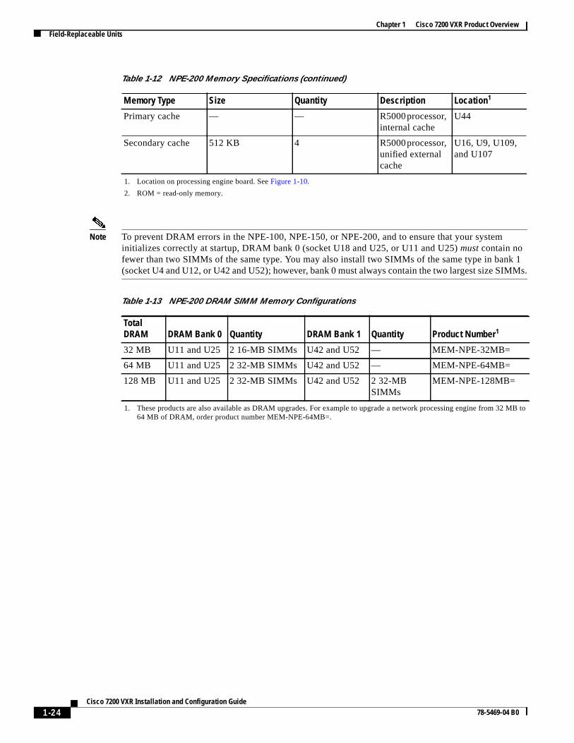
Table 1-12 lists the NPE-200 memory specifications, andTable 1-13 lists factory-installed DRAMconfigurations and their product numbers.
1 System controller 7 Midplane connectors
2 R5000 microprocessor 8 Temperature sensor
3 4-MB SRAM (U6, U10, U13, U14, U28, U29,U38, and U39)
9 Boot ROM (U92)
4 Captive installation screw 10 DRAM SIMMs
5 Handle 11 Bank 1
6 Temperature sensor 12 Bank 2
6642
0
U52
U42
U25
U11
NETWORK PROCESSING ENGINE-200
7
11
10
8
12
4 65
3
2
1
9
Table 1-12 NPE-200 Memory Specifications
Memory Type Size Quantity Description Location1
DRAM 32 to 128 MB 2 to 4 16- or 32-MBSIMMs (basedon maximumDRAM required)
Bank 0: U11 andU25
Bank 1: U42 andU52
SRAM 4 MB 8 8 chips, eachbeing 512Kwords x 8 bitswide
U6, U10, U13,U14, U28, U29,U38, and U39
Boot ROM2 256 KB 1 EPROM for theROM monitorprogram
U92
1-23Cisco 7200 VXR Installation and Configuration Guide
78-5469-04 B0
Chapter 1 Cisco 7200 VXR Product OverviewField-Replaceable Units
k 1MMs.
2 MB to
Note To prevent DRAM errors in the NPE-100, NPE-150, or NPE-200, and to ensure that your systeminitializes correctly at startup, DRAM bank 0 (socket U18 and U25, or U11 and U25)must contain nofewer than two SIMMs of the same type. You may also install two SIMMs of the same type in ban(socket U4 and U12, or U42 and U52); however, bank 0 must always contain the two largest size SI
Primary cache — — R5000processor,internal cache
U44
Secondary cache 512 KB 4 R5000processor,unified externalcache
U16, U9, U109,and U107
1. Location on processing engine board. SeeFigure 1-10.
2. ROM = read-only memory.
Table 1-13 NPE-200 DRAM SIMM Memory Configurations
TotalDRAM DRAM Bank 0 Quantity DRAM Bank 1 Quantity Product Number1
1. These products are also available as DRAM upgrades. For example to upgrade a network processing engine from 364 MB of DRAM, order product number MEM-NPE-64MB=.
32 MB U11 and U25 2 16-MB SIMMs U42 and U52 — MEM-NPE-32MB=
64 MB U11 and U25 2 32-MB SIMMs U42 and U52 — MEM-NPE-64MB=
128 MB U11 and U25 2 32-MB SIMMs U42 and U52 2 32-MBSIMMs
MEM-NPE-128MB=
Table 1-12 NPE-200 Memory Specifications (continued)
Memory Type Size Quantity Description Location1
1-24Cisco 7200 VXR Installation and Configuration Guide
78-5469-04 B0

Chapter 1 Cisco 7200 VXR Product OverviewField-Replaceable Units
Figure 1-11 NPE-175
Table 1-14 lists the NPE-175 memory specifications, andTable 1-15 lists memory configurations.
1 Network controller board 6 Handle
2 System controller 7 Midplane connectors
3 Processor engine board 8 Boot ROM (U1)
4 Captive installation screw 9 Temperature sensor
5 RM5270 microprocessor 10 SDRAM DIMM (U15)
6641
6NETWORK PROCESSING ENGINE-150
17
4 65
2
3
89
10
1-25Cisco 7200 VXR Installation and Configuration Guide
78-5469-04 B0
Chapter 1 Cisco 7200 VXR Product OverviewField-Replaceable Units
Table 1-14 NPE-175 Memory Specifications
Memory Type Size Quantity Description Location1
1. Location on processing engine board. SeeFigure 1-11.
SDRAM 64 or 128 MB 1 SDRAM slot DIMM U15
Boot ROM 512 KB — One-timeprogrammableROM
U1
Primary cache 16 KB (instruction),16 KB (data)
— RM527x processor,internal cache
U4
32 KB (instruction),32 KB (data)
— RM527x processor,internal cache
U4
Secondary cache 2 MB 4 chips, each 512Kby 8 bits wide
RM527x processor,unified externalcache
U5, U6, U7, U8
Table 1-15 NPE-175 SDRAM DIMM Memory Configurations
Total SDRAM SDRAM Bank Quantity Product Number
64 MB U15 1 64-MBDIMM
MEM-SD-NPE-64MB=
128 MB U15 1 128-MBDIMM
MEM-SD-NPE-128MB=
1-26Cisco 7200 VXR Installation and Configuration Guide
78-5469-04 B0

Chapter 1 Cisco 7200 VXR Product OverviewField-Replaceable Units
Figure 1-12 NPE-150
Table 1-16 lists the NPE-150 memory specifications, andTable 1-17 lists memory configurations.
1 System controller 7 Midplane connectors
2 R4700 microprocessor 8 Temperature sensor
3 1-MB SRAM (U700 through U703, U800through U803)
9 DRAM SIMMs
4 Captive installation screw 10 Bank 1
5 Handle 11 Bank 0
6 Temperature sensor
6642
4
U12
U4
U25
U18
NETWORK PROCESSING ENGINE-150
7
10
9
11
4 65
3
2
1
8
Table 1-16 NPE-150 Memory Specifications
Memory Type Size Quantity Description Location1
1. Location on processing engine board. SeeFigure 1-12.
DRAM 32 to 128 MB 2 to 4 16- or 32-MB SIMMs (basedon maximum DRAMrequired)
Bank 0: U18 andU25
Bank 1: U4 andU12
SRAM 1 MB 8 8 chips, each being 128Kwords x 9 bits wide
U700 throughU703U800 throughU803
Boot ROM The NPE-150 uses the boot ROM present on the I/O controller.
Primary cache — — R4700 processor, internalcache
U201
Secondary cache 512 KB 4 R4700 processor, unifiedexternal cache
U2, U10, U14,and U26
1-27Cisco 7200 VXR Installation and Configuration Guide
78-5469-04 B0

Chapter 1 Cisco 7200 VXR Product OverviewField-Replaceable Units
k 1MMs.
MB to
Note To prevent DRAM errors in the NPE-100, NPE-150, or NPE-200, and to ensure that your systeminitializes correctly at startup, DRAM bank 0 (socket U18 and U25, or U11 and U25)must contain nofewer than two SIMMs of the same type. You may also install two SIMMs of the same type in ban(socket U4 and U12, or U42 and U52); however, bank 0 must always contain the two largest size SI
Figure 1-13 NPE-100
Table 1-18 lists the NPE-100 network processing engine memory specifications, andTable 1-19 listsmemory configurations.
Table 1-17 NPE-150 DRAM SIMM Memory Configurations
Total DRAM DRAM Bank 0 Quantity DRAM Bank 1 Quantity Product Number1
1. These products are also available as DRAM upgrades. For example, to upgrade a network processing engine from 3264 MB of DRAM, order product number MEM-NPE-64MB=.
32 MB U18 and U25 2 16-MB SIMMs U4 and U12 — MEM-NPE-32MB=
64 MB U18 and U25 2 32-MB SIMMs U4 and U12 — MEM-NPE-64MB=
128 MB U18 and U25 2 32-MB SIMMs U4 and U12 2 32-MBSIMMs
MEM-NPE-128MB=
1 System controller 6 Midplane connectors
2 R4700 microprocessor 7 Temperature sensor
3 Captive installation screw 8 DRAM SIMMs
4 Handle 9 Bank 1
5 Temperature sensor 10 Bank 0
6643
3
U12
U4
U25
U18
NETWORK PROCESSING ENGINE-100
6
9
8
10
3 54
2
1
7
1-28Cisco 7200 VXR Installation and Configuration Guide
78-5469-04 B0

Chapter 1 Cisco 7200 VXR Product OverviewField-Replaceable Units
k 1MMs.
MB to
Note To prevent DRAM errors in the NPE-100, NPE-150, or NPE-200, and to ensure that your systeminitializes correctly at startup, DRAM bank 0 (socket U18 and U25, or U11 and U25)must contain nofewer than two SIMMs of the same type. You may also install two SIMMs of the same type in ban(socket U4 and U12, or U42 and U52); however, bank 0 must always contain the two largest size SI
To determine the memory configuration of your Cisco 7200 VXR router, use theshow versioncommand. The following example shows an NPE-G1 installed in a Cisco7206VXR router:
Router# show versionCisco Internetwork Operating System SoftwareIOS (tm) 7200 Software (C7200-JS-M),Released Version 12.2(20011220:181136) [biff]Copyright (c) 1986-2001 by cisco Systems, Inc.Compiled Fri 21-Dec-01 05:58 byImage text-base:0x600089B8, data-base:0x6196E000
ROM:System Bootstrap, Version 12.2(20011219:132854)
(display text omitted)
cisco 7206VXR (NPE-G1) processor (revision 0x00) with 245760K/16384K bytes of memory.Processor board ID 13250983BCM12500 CPU at 500Mhz, Implementation 1, Rev 0.1, 512KB L2 Cache6 slot VXR midplane, Version 2.0
Table 1-18 NPE-100 Memory Specifications
Memory Type Size Quantity Description Location1
1. Location on processing engine board. SeeFigure 1-13.
DRAM 32 to128 MB
2 to 4 16- or 32-MB SIMMs (basedon maximum DRAMrequired)
Bank 0: U18 and U25
Bank 1: U4 and U12
Boot ROM The NPE-100 uses boot ROM present on the I/O controller.
Primary cache — — R4700 processor, internalcache
U201
Secondarycache
512 KB 4 R4700 processor, unified,external cache
U2, U10, U14, and U26
Table 1-19 NPE-100 DRAM SIMM Memory Configurations
Total DRAM DRAM Bank 0 Quantity DRAM Bank 1 Quantity Product Number1
1. These products are also available as DRAM upgrades. For example, to upgrade a network processing engine from 3264 MB of DRAM, order product number MEM-NPE-64MB=.
32 MB U18 and U25 2 16-MBSIMMs
U4 and U12 — MEM-NPE-32MB
64 MB U18 and U25 2 32-MBSIMMs
U4 and U12 — MEM-NPE-64MB
128 MB U18 and U25 2 32-MBSIMMs
U4 and U12 2 32-MBSIMMs
MEM-NPE-128MB
1-29Cisco 7200 VXR Installation and Configuration Guide
78-5469-04 B0

Chapter 1 Cisco 7200 VXR Product OverviewField-Replaceable Units
one
your
port
r.ry
Input/Output ControllerThis section describes five different models of I/O controllers. These models are distinguished fromanother by their Ethernet interface options.Table 1-20 lists the I/O controllers by product number anddescribes their differences.
Note For a description of the configuration commands you need to configure the different interfaces onI/O controller, refer to theInput/Output Controller Replacement Instructions document that shippedwith your system.
You can also identify your I/O controller model from a terminal by using theshow diag slot 0command.(See the“Viewing Your System Configuration” section on page 4-19.)
The I/O controllers consist of the following components and options:
• Ethernet, Fast Ethernet, or Gigabit Ethernet interface options
• Dual channels for local console and auxiliary ports
The console port has full data communications equipment (DCE) functionality and the auxiliaryhas full data terminal equipment (DTE) functionality.
• NVRAM for storing the system configuration and environmental monitoring logs
Note NVRAM uses lithium batteries to maintain its contents when disconnected from poweSome I/O controllers use a static RAM (SRAM) component with an external lithium batteto provide the same functionality as the NVRAM.
Table 1-20 I/O Controller Descriptions
Product Number Description
C7200-I/O-GE+E 1 Gigabit Ethernet and 1 Ethernet port; equipped with aGBIC receptacle for 1000 megabits per second (Mbps)operation and an RJ-45 receptacle for 10-Mbpsoperation. (SeeFigure 1-14.)
C7200-I/O-2FE/E 2 autosensing Ethernet/Fast Ethernet ports; equippedwith 2 RJ-45 receptacles for 10/100-Mbps operation.(SeeFigure 1-15.)
C7200-I/O-FE1
1. The Product Number C7200-I/O-FE does not specify MII because both an MII and an RJ-45receptacle are included.
1 Fast Ethernet port; equipped with an MII receptacleand an RJ-45 receptacle for use at 100 Mbps full-duplexor half-duplex operation. Only 1 receptacle can beconfigured for use at a time. (SeeFigure 1-16.)
C7200-I/O Has no Fast Ethernet port. (SeeFigure 1-18.)
C7200-I/O-FE-MII2
2. The I/O controller with the Product Number C7200-I/O-FE-MII has a single MII Fast Ethernetreceptacle only. Although still supported by Cisco Systems, this I/O controller with a single MIIreceptacle is no longer an orderable product as of May 1998.
1 Fast Ethernet port; equipped with a single MIIreceptacle. (SeeFigure 1-20.)
1-30Cisco 7200 VXR Installation and Configuration Guide
78-5469-04 B0
Chapter 1 Cisco 7200 VXR Product OverviewField-Replaceable Units
IOS
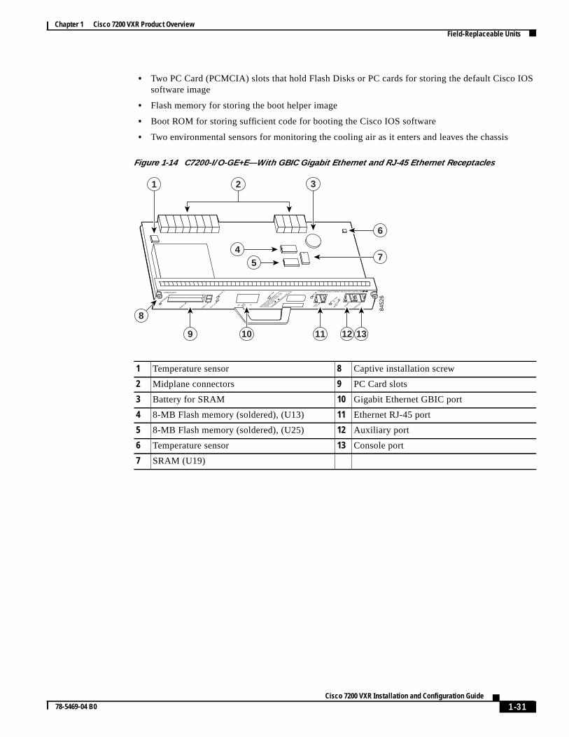
• Two PC Card (PCMCIA) slots that hold Flash Disks or PC cards for storing the default Ciscosoftware image• Flash memory for storing the boot helper image
• Boot ROM for storing sufficient code for booting the Cisco IOS software
• Two environmental sensors for monitoring the cooling air as it enters and leaves the chassis
Figure 1-14 C7200-I/O-GE+E—With GBIC Gigabit Ethernet and RJ-45 Ethernet Receptacles
1 Temperature sensor 8 Captive installation screw
2 Midplane connectors 9 PC Card slots
3 Battery for SRAM 10 Gigabit Ethernet GBIC port
4 8-MB Flash memory (soldered), (U13) 11 Ethernet RJ-45 port
5 8-MB Flash memory (soldered), (U25) 12 Auxiliary port
6 Temperature sensor 13 Console port
7 SRAM (U19)
8452
6
LINKC7200-I/O-GE+E
CLA
SS 1
LED
PRO
DU
CT
P
RO
DU
KT M
IT K
LASSE 1
LED
PRO
DU
IT A
VEC
VOYA
NT D
EL
D
E C
LASSE 1
PRO
DU
CTO
LED
DE C
LASE 1
ETHERNET GIGABIT ETHERNET INPUT/OUTPUT CONTROLLER
CONSOLEAUX
PORTE 0
LINK
SLOT 0PORT
GE ORX TX
EJECT
PCMCIA
SLOT 1
ENABLED
CPU
RESET
IO P
WR
OK
9
8
121110 13
1 3
7
6
54
2
1-31Cisco 7200 VXR Installation and Configuration Guide
78-5469-04 B0

Chapter 1 Cisco 7200 VXR Product OverviewField-Replaceable Units
Figure 1-15 C7200-I/O-2FE/E—With Two RJ-45 Ethernet/Fast Ethernet Receptacles
1 Temperature sensor 7 SRAM (U19)
2 Midplane connectors 8 Captive installation screw
3 Battery for SRAM 9 PC Card slots
4 8-MB Flash memory (soldered) (U15) 10 RJ-45 Fast Ethernet ports
5 8-MB Flash memory (soldered) (U25) 11 Auxiliary port
6 Temperature sensor 12 Console port84
525
DUAL FAST ETHERNET INPUT/OUTPUT CONTROLLERC7200-I/O-2FE/E
CONSOLEAUX
100 Mbps
LINK
100 Mbps
FE/E 0
FE/E 1
LINK
SLOT 0
EJECT
PCMCIA
SLOT 1
ENABLED
CPU
RESET
IO P
WR
OK
9
8
11 12
1 3
7
6
54
2
10
1-32Cisco 7200 VXR Installation and Configuration Guide
78-5469-04 B0

Chapter 1 Cisco 7200 VXR Product OverviewField-Replaceable Units
Figure 1-16 C7200-I/O-FE—With MII and RJ-45 Fast Ethernet Receptacles (Version 1)
1 Temperature sensor 8 PC Card slots
2 Midplane connectors 9 Optional Fast Ethernet interface (MII port andRJ-45 port)
3 Flash SIMM (U99) 10 LEDs
4 Boot ROM (U20) 11 CPU reset button
5 NVRAM (U41) 12 Auxiliary port
6 Temperature sensor 13 Console port
7 Captive installation screw84
531
AUX
CONSO
LE
PCMCIA
EJECT
SLOT 0
SLOT
1
FE MII
FAST ETHERNET INPUT/OUTPUT CONTROLLER
RJ45
CPU RESET
MII
EN
RJ45
EN RJ45
LINK
I/O P
WR
OK
ENABLED
8
10
7
111312
1
4
3
56
9
2
1-33Cisco 7200 VXR Installation and Configuration Guide
78-5469-04 B0

Chapter 1 Cisco 7200 VXR Product OverviewField-Replaceable Units
ike
s
in
Figure 1-17 C7200-I/O-FE—With MII and RJ-45 Fast Ethernet Receptacles (Version 2)
Note Your I/O controller with the MII and RJ-45 Fast Ethernet receptacles (C7200-I/O-FE) might look lthe first illustration inFigure 1-16, or it might look like the second illustration inFigure 1-16. There isno functional difference between these two I/O controllers with the Fast Ethernet port.
Note In the second illustration inFigure 1-16, the NVRAM is replaced by an SRAM component (U14) that imade to act like the NVRAM by the addition of some external components, one of which is thebutton-type lithium battery labeled “Battery for SRAM.”
Note Your I/O controller without the Fast Ethernet port (C7200-I/O) might look like the first illustration Figure 1-18, or it might look like the second illustration inFigure 1-18. There is no functional differencebetween these two I/O controllers without the Fast Ethernet port.
1 Temperature sensor 9 Captive installation screw
2 FPGA configuration PROM (U9) 10 PC Card slots
3 Midplane connectors 11 Optional Fast Ethernet interface (MII port andRJ-45 port)
4 4-MB Flash memory (soldered) (U10–U13)12 LEDs
5 SRAM (U14) 13 CPU reset button
6 Boot EPROM (U4) 14 Auxiliary port
7 Temperature sensor 15 Console port
8 Battery for SRAM
8452
3
AUX
CONSO
LE
PCMCIA
EJECT
SLOT 0
SLOT
1
FE MII
FAST ETHERNET INPUT/OUTPUT CONTROLLER
RJ45
CPU RESET
MII
EN
RJ45
EN RJ45
LINK
I/O P
WR
OK
ENABLED
10
12
9
131514
1 2 3 4
78
11
65
1-34Cisco 7200 VXR Installation and Configuration Guide
78-5469-04 B0

Chapter 1 Cisco 7200 VXR Product OverviewField-Replaceable Units
s
Note In the second illustration inFigure 1-18, the NVRAM is replaced by an SRAM component (U14) that imade to act like the NVRAM by the addition of some external components, one of which is thebutton-type lithium battery labeled “Battery for SRAM.”Figure 1-18 C7200-I/O—Without Fast Ethernet Port (Version 1)
1 Temperature sensor 7 Captive installation screw
2 Midplane connectors 8 PC Card slots
3 Flash SIMM (U99) 9 LED and CPU reset button
4 Boot ROM (U20) 10 Auxiliary port
5 NVRAM (U41) 11 Console port
6 Temperature sensor
9327
7
CPU
RESET
IO P
WR
OK
AUX
CONSO
LE
PCMCIA
EJECT
SLOT 0
SLOT
1 FAST ETHERNET INPUT/OUTPUT CONTROLLER
ENABLED
8
7
1110
1
4
3
56
2
9
1-35Cisco 7200 VXR Installation and Configuration Guide
78-5469-04 B0

Chapter 1 Cisco 7200 VXR Product OverviewField-Replaceable Units
Figure 1-19 C7200-I/O—Without Fast Ethernet Port (Version 2)
1 Temperature sensor 8 Battery for SRAM
2 FPGA configuration PROM (U9) 9 Captive installation screw
3 Midplane connectors 10 PC Card slots
4 4-MB Flash memory (soldered) (U10-U13) 11 LED
5 SRAM (U14) 12 CPU reset button
6 Boot EPROM (U4) 13 Auxiliary port
7 Temperature sensor 14 Console port
8452
4
AUX
CONSO
LE
PCMCIA
EJECT
SLOT 0
SLOT
1 INPUT/OUTPUT CONTROLLER
CPU RESET
I/O P
WR
OK
ENABLED
10
11
9
121413
1 2 3 4
786
5
1-36Cisco 7200 VXR Installation and Configuration Guide
78-5469-04 B0

Chapter 1 Cisco 7200 VXR Product OverviewField-Replaceable Units
Figure 1-20 C7200-I/O-FE-MII—With Single MII Fast Ethernet Receptacle
Note C7200-I/O-FE-MII, although still supported by Cisco Systems, was discontinued as an orderableproduct in May 1998.
Table 1-21 lists the I/O controller memory components.
1 Temperature sensor 7 Captive installation screw
2 Midplane connectors 8 PC Card slots
3 Flash SIMM (U99) 9 Optional Fast Ethernet interface (MIIconnector)
4 Boot ROM (U20) 10 LEDs and CPU reset button
5 NVRAM (U41) 11 Auxiliary port
6 Temperature sensor 12 Console port
8453
4
FE EN
ABLE
FE LIN
K
CPU
RESET
IO P
WR
OK
AUX
CONSO
LE
PCMCIA
EJECT
SLOT 0
SLOT
1
FE MII
FAST ETHERNET INPUT/OUTPUT CONTROLLER
ENABLED
89
7
1211
1
4
3
56
2
10
1-37Cisco 7200 VXR Installation and Configuration Guide
78-5469-04 B0

Chapter 1 Cisco 7200 VXR Product OverviewField-Replaceable Units
EDsresetr
portssed attheOT
. (For
card.-inch
LED DescriptionsAll I/O controllers have LEDs, and the NPE-G1 also has interfaces that have LEDs.
The I/O controller faceplate contains LEDs that indicate system and port status; two additional Lindicate the status of the Flash Disk or Flash memory cards installed in either PC Card slot. A CPUbutton is located next to the IO POWER OK LED or next to the auxiliary port on the I/O controllefaceplate. The CPU reset button resets the entire system.
The NPE-G1 faceplate contains LEDs that indicate system and port status. The RJ-45 and GBICshare the same LINK LED because only one of these ports per interface (0/1, 0/2, or 0/3) can be uany one time. The ENABLE LED is on if the RJ-45 port is in use. The POWER ON LED is on whensystem is powered on, whether or not an I/O controller is in the system with the NPE-G1.The SLACTIVE LED is on if there is a CompactFlash Disk in the NPE-G1.
Table 1-21 I/O Controller Memory Components
Type Size Quantity Memory Description Model Location
Boot ROM1
1. The C7200-I/O-GE+E and C7200-I/O-2FE/E do not have a boot ROM component.
256 KB 1 32-pin DIP-type C7200-I/O-FE-MII U20
32-pin DIP-type or32-pin PLCC-type
C7200-I/O-FE,C7200-I/O
U20 or U4
Flash memory 4 MB 1 Contains the defaultboot helper image
C7200-I/O-FE-MII U99
C7200-I/O-FE,C7200-I/O
U99or
U10, U11,U12, and U13(soldered)2
2. Some I/O controllers have no Flash SIMM but use a permanently soldered 4-MB or 8-MB Flash memory chip insteadthe location of the 4-MB Flash memory chip, see the second illustration inFigure 1-16 andFigure 1-18. For the location ofthe 8-MB Flash memory chip, seeFigure 1-14 andFigure 1-15.)
8 MB 1 C7200-I/O-GE+E,C7200-I/O-2FE/E
U13 and U25(soldered)2
Flash memorycard
16 or20 MB
Up to 2 Contains the defaultCisco IOS image
All models PC Card slot 0and slot 1
Flash Disk 32, 48, or128 MB
Up to 2
NVRAM 128 KB 1 Nonvolatile EPROMfor the systemconfiguration file
C7200-I/O-FE-MII U41
C7200-I/O-FE,C7200-I/O
U41or
U14(soldered)3
3. The NVRAM on some I/O controllers is replaced by a 32-pin nonsocketed SRAM component that is soldered onto theThe SRAM component is made to act like the NVRAM by the addition of some external components, one of which is a 1(2.54-cm) button-type lithium battery.
C7200-I/O-GE+E,C7200-I/O-2FE/E
U19(soldered)3
1-38Cisco 7200 VXR Installation and Configuration Guide
78-5469-04 B0
Chapter 1 Cisco 7200 VXR Product OverviewField-Replaceable Units
rvice
tion.ber
neitalns
d
ng
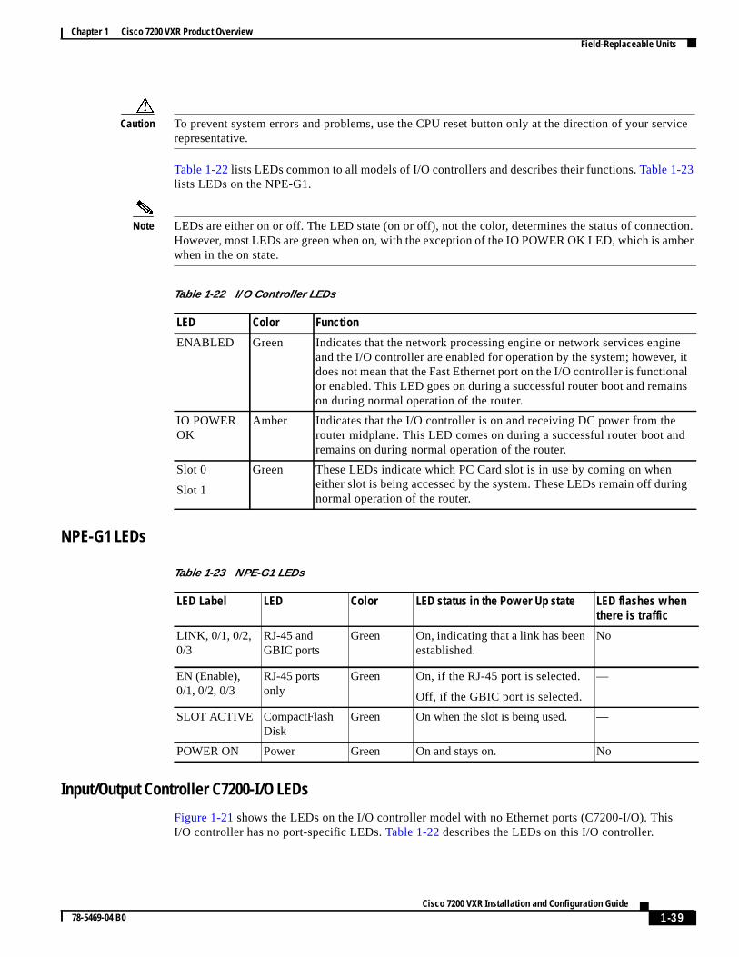
Caution To prevent system errors and problems, use the CPU reset button only at the direction of your serepresentative.
Table 1-22lists LEDs common to all models of I/O controllers and describes their functions.Table 1-23lists LEDs on the NPE-G1.
Note LEDs are either on or off. The LED state (on or off), not the color, determines the status of connecHowever, most LEDs are green when on, with the exception of the IO POWER OK LED, which is amwhen in the on state.
NPE-G1 LEDs
Input/Output Controller C7200-I/O LEDs
Figure 1-21 shows the LEDs on the I/O controller model with no Ethernet ports (C7200-I/O). ThisI/O controller has no port-specific LEDs.Table 1-22 describes the LEDs on this I/O controller.
Table 1-22 I/O Controller LEDs
LED Color Function
ENABLED Green Indicates that the network processing engine or network services engiand the I/O controller are enabled for operation by the system; however,does not mean that the Fast Ethernet port on the I/O controller is functionor enabled. This LED goes on during a successful router boot and remaion during normal operation of the router.
IO POWEROK
Amber Indicates that the I/O controller is on and receiving DC power from therouter midplane. This LED comes on during a successful router boot anremains on during normal operation of the router.
Slot 0
Slot 1
Green These LEDs indicate which PC Card slot is in use by coming on wheneither slot is being accessed by the system. These LEDs remain off durinormal operation of the router.
Table 1-23 NPE-G1 LEDs
LED Label LED Color LED status in the Power Up state LED flashes whenthere is traffic
LINK, 0/1, 0/2,0/3
RJ-45 andGBIC ports
Green On,indicating that a link has beenestablished.
No
EN (Enable),0/1, 0/2, 0/3
RJ-45 portsonly
Green On, if the RJ-45 port is selected.
Off, if the GBIC port is selected.
—
SLOT ACTIVE CompactFlashDisk
Green On when the slot is being used. —
POWER ON Power Green On and stays on. No
1-39Cisco 7200 VXR Installation and Configuration Guide
78-5469-04 B0

Chapter 1 Cisco 7200 VXR Product OverviewField-Replaceable Units
port
Figure 1-21 C7200-I/O LEDs and CPU Reset Button
Input/Output Controller C7200-I/O-GE+E LEDs
Figure 1-22 shows the LEDs on the I/O controller with the Gigabit Ethernet port and the Ethernet (C7200-I/O-GE+E), andTable 1-24 lists the LEDs specific to this I/O controller model. Also seeTable 1-22 for LEDs common to all I/O controllers.
AUX
CONSO
LE
PCMCIA
EJECT
SLOT 0
CPU RESET
IO P
OW
ER
OK
SLOT
1 INPUT/OUTPUT CONTROLLER
H74
01
SLOT 0
SLOT
1
CPU RESET
IO P
OW
ER
OK
ENABLED
ENABLED
AUX
CONSO
LE
PCMCIA
EJECT
SLOT 0
I/O P
WR
OK
SLOT
1 INPUT/OUTPUT CONTROLLER
2593
0
SLOT 0
SLOT
1
CPU RESET
I/O P
WR
OK
ENABLED
ENABLED
CPU RESET
1-40Cisco 7200 VXR Installation and Configuration Guide
78-5469-04 B0

Chapter 1 Cisco 7200 VXR Product OverviewField-Replaceable Units
k
Figure 1-22 C7200-I/O-GE+E LEDs and CPU Reset Button
Input/Output Controller C7200-I/O-2FE/E LEDs
Figure 1-23 shows the LEDs on the I/O controller with the two autosensing 10/100-Mbps RJ-45receptacles (C7200-I/O-2FE/E), andTable 1-25lists the LEDs specific to this I/O controller model. AlsoseeTable 1-22 for LEDs common to all I/O controllers.
Figure 1-23 C7200-I/O-2FE/E LEDs and CPU Reset Button
Table 1-24 C7200-I/O-GE+E I/O Controller LEDs
LED Color Function
LINK Green Indicates that the Ethernet RJ-45 receptacle has established a valid linwith the network. This LED remains off during normal operation of therouter unless there is an incoming carrier signal.
CLA
SS 1
LED
PRO
DU
CT
P
RO
DU
KT M
IT K
LASSE 1
LED
PRO
DU
IT A
VEC
VOYA
NT D
EL
D
E C
LASSE 1
PRO
DU
CTO
LED
DE C
LASE 1LIN
KETHERNET GIGABIT ETHERNET INPUT/OUTPUT CONTROLLER
CONSOLEAUX
PORTE 0
LINK
SLOT 0 PORT
GE 0RX TX
EJECT
PCMCIA
SLOT 1
ENABLED
CPU
RESET
IO P
WR
OK
3344
6
CPU
RESET
IO P
WR
OKLIN
K
SLOT 0
SLOT 1
C7200-I/O-GE+E
ENABLED LINK
GBIC
EN
DUAL FAST ETHERNET INPUT/OUTPUT CONTROLLER
CONSOLEAUX
100 Mbps
LINK
100 Mbps
LINK
SLOT 0
EJECT
PCMCIA
SLOT 1
ENABLED
CPU
RESET
IO P
WR
OK
3344
4
CPU
RESET
IO P
WR
OK
100 Mbps
LINK
SLOT 0
SLOT 1
C7200-I/O-2FE/E
ENABLED
FE/E 0
FE/E 1
1-41Cisco 7200 VXR Installation and Configuration Guide
78-5469-04 B0

Chapter 1 Cisco 7200 VXR Product OverviewField-Replaceable Units
an
0),a
hed
Input/Output Controller C7200-I/O-FE LEDs
Figure 1-24 shows the LEDs on the I/O controller with the Fast Ethernet port that is equipped withMII receptacle and an RJ-45 receptacle (C7200-I/O-FE), andTable 1-26 lists the LEDs specific to thisI/O controller model. Also seeTable 1-22 for LEDs common to all I/O controllers.
Table 1-25 C7200-I/O-2FE/E I/O Controller LEDs
LED Color Function
100 Mbps Green Indicates that the port is configured for 100-Mbps operation (speed 10or if configured for autonegotiation (speed auto), the port has detected valid link at 100 Mbps.
Note If the port is configured for 10-Mbps operation, or if it isconfigured for autonegotiation and the port has detected a validlink at 10 Mbps, the LED remains off.
LINK Green Indicates that the Ethernet/Fast Ethernet RJ-45 receptacle has establisa valid link with the network. This LED remains off during normaloperation of the router unless there is an incoming carrier signal.
1-42Cisco 7200 VXR Installation and Configuration Guide
78-5469-04 B0

Chapter 1 Cisco 7200 VXR Product OverviewField-Replaceable Units
byeedeg
ypesn
lid
Figure 1-24 C7200-I/O-FE LEDs and CPU Reset Button
Table 1-26 C7200-I/O-FE I/O Controller LEDs
LED Color Function
MII EN Green Indicates that the Fast Ethernet MII receptacle is initialized and enabledthe system, and is configured for operation. This LED comes on after thI/O controller has been enabled and the MII receptacle has been configuras the media type for the Fast Ethernet port (the RJ-45 receptacle is thdefault media type for the Fast Ethernet port). This LED remains on durinnormal operation of the router.
RJ45 EN Green Indicates that the Fast Ethernet RJ-45 receptacle (the default media tfor the Fast Ethernet port) is initialized and enabled by the system. ThiLED comes on after the I/O controller has been enabled and remains oduring normal operation of the router.
RJ45 LINK Green Indicates that the Fast Ethernet RJ-45 receptacle has established a valink with the network. This LED remains off during normal operation ofthe router unless there is an incoming carrier signal.
H11
294
SLOT 1
SLOT 0
FAST ETHERNET INPUT/OUTPUT CONTROLLER
RJ-45
CPU RESET
MII
EN RJ45
EN RJ45
LINK
IO P
WR
OK
MII
EN RJ45
EN RJ45
LINK
IO P
WR
OK
CPU RESET
ENABLED
ENABLED
AUX
CONSO
LE
PCMCIA
EJECT
SLOT 0
SLOT
1
FE MII
FAST ETHERNET INPUT/OUTPUT CONTROLLER
RJ45
CPU RESET
MII
EN
RJ45
EN RJ45
LINK
I/O P
WR
OK
2592
9
SLOT 1
SLOT 0M
II EN
RJ45
EN RJ45
LINK
I/O P
WRO
K
CPU RESET
ENABLED
ENABLED
1-43Cisco 7200 VXR Installation and Configuration Guide
78-5469-04 B0

Chapter 1 Cisco 7200 VXR Product OverviewField-Replaceable Units
et
MII
ype as series0) andand in
ioned
e
Note An MII LINK LED is not provided on this I/O controller because the LED is provided on externaltransceivers that are required for connecting to the MII receptacle on the I/O controller. SeeChapter 3,“Installing a Cisco 7200 VXR Router,”the“Connecting to the I/O Controller Ethernet and Fast EthernPorts” section on page 3-25 for Fast Ethernet MII connection requirements.
Input/Output Controller C7200-I/O-FE-MII LEDs
Figure 1-25shows the LEDs on the I/O controller with the Fast Ethernet port equipped with a singlereceptacle (C7200-I/O-FE-MII), andTable 1-27lists the LEDs specific to this I/O controller model. AlsoseeTable 1-22 for LEDs common to all I/O controllers.
Figure 1-25 C7200-I/O-FE-MII LEDs and CPU Reset Button
Port Adapters and Service AdaptersThe port adapters and service adapters installed in the Cisco 7200 VXR routers are of the same tthose installed on the second-generation Versatile Interface Processors (VIPs) in the Cisco 7500routers, in Cisco 7000 series routers with the Cisco 7000 series Route Switch Processor (RSP700Cisco 7000 series Chassis Interface (RSP7000CI), in the Cisco AS5800 Universal Access Server,the Cisco uBR7246 universal broadband router.
Table 1-27 C7200-I/O-FE-MII I/O Controller LEDs
LED Color Function
FE ENABLE Green Indicates that the Fast Ethernet port is initialized and enabled for operatby the system. This LED comes on after the I/O controller has been enabland remains on during normal operation of the router.
FE LINK Green Indicates that the Fast Ethernet port has established a valid link with thnetwork. This LED remains off during normal operation of the routerunless there is an incoming carrier signal.
H65
23
FE
ENABLE
SLOT 1
SLOT 0 FE L
INK
CPU RESET
IO P
OWER O
K
FAST ETHERNET INPUT/OUTPUT CONTROLLER
ENABLED
ENABLED
1-44Cisco 7200 VXR Installation and Configuration Guide
78-5469-04 B0

Chapter 1 Cisco 7200 VXR Product OverviewField-Replaceable Units
, see
buses
foression
n thef yoution
ion
r must
rately.ility.
wer
ned in
s a.com.
wer
assisply is
Note The port adapters installed in the Cisco 7200 VXR routers support OIR. For an explanation of OIRthe“Online Insertion and Removal” section on page 1-53.
All port adapters and service adapters connect to two Peripheral Component Interconnect (PCI) on the router midplane. The PCI buses provide a path to packet I/O memory and the system(route/switch) processor. The Fast Ethernet port on the I/O controller connects to a third PCI buspacket routing and switching. The port or service adapters either provide such services as compror encryption, or they provide network interfaces to connect the router to external networks.
Note Detailed instructions for removing, replacing, and configuring the port adapter types supported oCisco 7200 VXR routers are contained in the configuration note for the port adapter. For example, iplan to replace a 4-port Ethernet port adapter in your Cisco 7200 VXR router, refer to the configuranotePA-4E Ethernet 10BaseT Port Adapter Installation and Configuration. This configuration noteaccompanies every PA-4E port adapter that is shipped from the factory as an installed item in aCisco 7200 VXR router or as a FRU. The configuration note is also available on the DocumentatCD-ROM and on Cisco.com.
Caution To ensure adequate airflow across the router’s port adapters, a port adapter or a blank port adaptebe installed in each port adapter slot.
Power SuppliesThe Cisco 7200 VXR routers come equipped with one 280W AC-input power supply. (A 280WDC-input power supply is available as an option.) You must order the second power supply sepaA second power supply, although not required, allows load sharing and increased system availab
Note The Cisco 7200 VXR power supplies are the same as in all Cisco 7200 series routers.
Caution Do not mix power supplies in Cisco 7200 VXR routers. In dual power supply configurations, both posuppliesmust be of the same type (two AC-input power supplies or two DC-input power supplies).
Note Detailed instructions for handling and replacing the Cisco 7200 series power supplies are contaithe configuration notes280-Watt AC-Input Power Supply Replacement Instructionsand280-WattDC-Input Power Supply Replacement Instructions. These configuration notes accompany every 280WAC-input power supply and every 280W DC-input power supply that is shipped from the factory aFRU. These configuration notes are also available on the Documentation CD-ROM and on Cisco
A handle on the AC and DC power supplies provides a grip point for removing and replacing the posupply. (Figure 1-26shows the faceplate of the AC-input power supply.Figure 1-27shows the faceplateof the DC-input power supply.) Two captive installation screws secure the power supply to the chand seat the power supply in the router midplane. A power OK LED indicates that the power supdelivering +5 VDC to the router midplane.
1-45Cisco 7200 VXR Installation and Configuration Guide
78-5469-04 B0

Chapter 1 Cisco 7200 VXR Product OverviewField-Replaceable Units
ethe
Figure 1-26 Cisco 7200 Series AC-Input Power Supply
The AC-input power supply has a receptacle for an AC-input power cable. A modular power cablconnects the AC-input power supply to the site AC power source. A cable-retention clip secures power cable to the AC-input power supply.
Figure 1-27 Cisco 7200 Series DC-Input Power Supply
1 Captive installation screw 5 AC-input receptacle
2 Power switch guard 6 Handle
3 OK LED 7 Power cable retention-clip
4 Power switch
8439
7
1
7
3 62 4 5
1 Captive installation screw 4 Power switch
2 Power switch guard 5 DC-input receptacle
3 OK LED 6 Handle
8937
2
2 31 4 56
1-46Cisco 7200 VXR Installation and Configuration Guide
78-5469-04 B0

Chapter 1 Cisco 7200 VXR Product OverviewField-Replaceable Units
ock.plate
plater
end
ofires
at a
es for
es
to then ande
. Ther the power
d thefer tonotes also
The DC-input power supply has DC-input power leads that are hardwired to a DC-input terminal blA cable tie is shipped with each DC-input power supply to secure the leads to the power supply faceand provide strain relief for the leads.
Caution To ensure adequate airflow across the router power supplies, a power supply or a power supply fillermust be installed in each power supply bay.Figure 1-4shows a Cisco 7206VXR with an installed powesupply filler plate.
Table 1-1, earlier in this chapter, lists the AC-input and DC-input power supply system powerspecifications, including input voltage and operating current ratings.
Note Each AC-input power supply operating at 120 VAC requires a minimum of 5A service. We recommpowering the Cisco 7206VXR from a 15A receptacle at the power source.
Note Each DC-input power supply operating at –24 VDC in North America requires a minimum of 19Aservice. Each DC-input power supply operating at –48 VDC in North America requires a minimum13A service. Each DC-input power supply operating at –60 VDC in the European Community requa minimum of 8A service.
This product relies on the building’s installation for short-circuit (overcurrent) protection. Ensure thlisted and certified fuse or circuit breaker, 20A minimum 60 VDC, is used on all current-carryingconductors. Site wiring and circuit breakers need to be sized to accommodate the maximum valusafety reasons.
The power OK LED goes off and the power supply shuts itself down when the internal DC voltagexceed allowable tolerances or the internal temperature of the power supply exceeds allowabletolerances. The power supply remains in a shutdown state until it is disconnected and reconnectedsource power, and then restarted with the power switch. The power switch turns the power supply ostarts the system. For a description of power supply shutdown conditions and thresholds, see th“Environmental Monitoring and Reporting Functions” section on page 1-54.
ChassisThe Cisco 7200 VXR chassis, shown inFigure 1-28, has four or six slots for the port adapters(depending on your chassis model), one slot for the I/O controller, and one bay for the subchassissubchassis assembly contains the midplane, the fan tray, two power supply bays, and one slot fonetwork processing engine. The replacement chassis includes the subchassis assembly and onesupply.
Note To replace the chassis, you must remove and replace all the port adapters, the I/O controller, annetwork processing engine or network services engine; therefore, when replacing the chassis, rethe configuration notes that explain how to remove and replace these units. These configuration accompany every chassis that is shipped from the factory as a FRU. The configuration notes areavailable on the Documentation CD-ROM and on Cisco.com.
1-47Cisco 7200 VXR Installation and Configuration Guide
78-5469-04 B0

Chapter 1 Cisco 7200 VXR Product OverviewField-Replaceable Units
XR,ning
.
elperemoryboardheotely
hee andon
I/Oter,
Figure 1-28 Cisco 7200 VXR Chassis—7206VXR Shown
CompactFlash Disks, Flash Disks and PC CardsThe Cisco 7206VXR supports up to two installed Flash Disks or two PC Cards, also called Flashmemory cards. The NPE-G1 supports one CompactFlash Disk.
Note To avoid potential problems when you install spare Flash Disks or PC Cards in your Cisco 7206Vwe recommend that you reformat all your Flash Disks or PC Cards on a Cisco 7206VXR that is runthe Cisco IOS release recommended for your system (seeTable 1-1) during your regularly scheduledservice times. The online documentMemory Replacement Instructions for the Network ProcessingEngine or Network Services Engine and the Input/Output Controllerexplains how to reformat a PC Card
With Flash memory (Flash Disks, PC Cards, and the Flash SIMM on the I/O controller, or theCompactFlash Disk on the NPE-G1) you can remotely load and store multiple system and boot himages. You can download a new image over the network, and then add the new image to Flash mor replace existing files. You can also transfer images between Flash Disks or PC Cards and the onFlash memory SIMM. You can then boot the router either manually or automatically from any of tstored images. Flash memory can also function as a TFTP server to allow other routers to boot remfrom stored images or copy them into their own Flash memory.
Note For procedures that explain the use of the Flash Disk or CompactFlash Disk, refer to the onlineUsingthe Flash Diskdocument.
For procedures that explain how to replace the main, Flash, and ROM monitor memory, refer to tMemory Replacement Instructions for the Network Processing Engine or Network Services Enginthe Input/Output Controllerdocument that shipped with your system. Documents are also availablethe Documentation CD-ROM and on Cisco.com.
For NPE-G1 pre-installation information, which requires copying the running configuration from thecontroller to a Flash Disk or TFTP server before inserting the NPE-G1 into the Cisco 7200 VXR rousee theNetwork Processing Engine or Network Services Engine Installation and Configurationdocument at http://www.cisco.com/univercd/cc/td/doc/product/core/7206/fru/npense/index.htm.
1462
8
3
1
5
2
4
6
0
Cisco 7200Series VXR
1-48Cisco 7200 VXR Installation and Configuration Guide
78-5469-04 B0
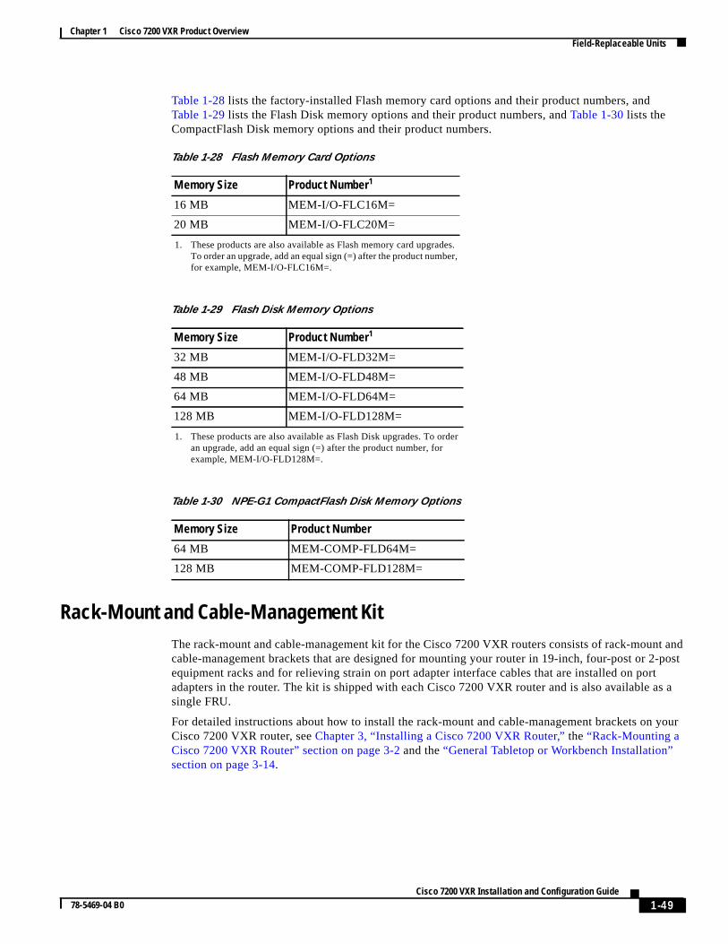
Chapter 1 Cisco 7200 VXR Product OverviewField-Replaceable Units
t and-post
rtas a
your
Table 1-28 lists the factory-installed Flash memory card options and their product numbers, andTable 1-29 lists the Flash Disk memory options and their product numbers, andTable 1-30 lists theCompactFlash Disk memory options and their product numbers.
Rack-Mount and Cable-Management KitThe rack-mount and cable-management kit for the Cisco 7200 VXR routers consists of rack-mouncable-management brackets that are designed for mounting your router in 19-inch, four-post or 2equipment racks and for relieving strain on port adapter interface cables that are installed on poadapters in the router. The kit is shipped with each Cisco 7200 VXR router and is also available single FRU.
For detailed instructions about how to install the rack-mount and cable-management brackets onCisco 7200 VXR router, seeChapter 3, “Installing a Cisco 7200 VXR Router,” the“Rack-Mounting aCisco 7200 VXR Router” section on page 3-2 and the“General Tabletop or Workbench Installation”section on page 3-14.
Table 1-28 Flash Memory Card Options
Memory Size Product Number1
1. These products are also available as Flash memory card upgrades.To order an upgrade, add an equal sign (=) after the product number,for example, MEM-I/O-FLC16M=.
16 MB MEM-I/O-FLC16M=
20 MB MEM-I/O-FLC20M=
Table 1-29 Flash Disk Memory Options
Memory Size Product Number1
1. These products are also available as Flash Disk upgrades. To orderan upgrade, add an equal sign (=) after the product number, forexample, MEM-I/O-FLD128M=.
32 MB MEM-I/O-FLD32M=
48 MB MEM-I/O-FLD48M=
64 MB MEM-I/O-FLD64M=
128 MB MEM-I/O-FLD128M=
Table 1-30 NPE-G1 CompactFlash Disk Memory Options
Memory Size Product Number
64 MB MEM-COMP-FLD64M=
128 MB MEM-COMP-FLD128M=
1-49Cisco 7200 VXR Installation and Configuration Guide
78-5469-04 B0
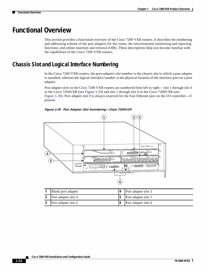
Chapter 1 Cisco 7200 VXR Product OverviewFunctional Overview
ringorting
with
rt
lot 4
r—if
Functional OverviewThis section provides a functional overview of the Cisco 7200 VXR routers. It describes the numbeand addressing scheme of the port adapters for the router, the environmental monitoring and repfunctions, and online insertion and removal (OIR). These descriptions help you become familiar the capabilities of the Cisco 7200 VXR routers.
Chassis Slot and Logical Interface NumberingIn the Cisco 7200 VXR routers, theport-adapter-slot-numberis the chassis slot in which a port adapteis installed, whereas thelogical-interface-numberis the physical location of the interface port on a poradapter.
Port adapter slots in the Cisco 7200 VXR routers are numbered from left to right— slot 1 through sin the Cisco 7204VXR (seeFigure 1-29) and slot 1 through slot 6 in the Cisco 7206VXR (seeFigure 1-30). Port adapter slot 0 is always reserved for the Fast Ethernet port on the I/O controllepresent.
Figure 1-29 Port Adapter Slot Numbering—Cisco 7204VXR
1 Blank port adapter 4 Port adapter slot 3
2 Port adapter slot 4 5 Port adapter slot 1
3 Port adapter slot 2 6 Port adapter slot 0
2ETHERNET-10BFL
EN
RX
0 1 2 3 4TX RX TX RX TX RX TX RX TX
0
4
1
3
56
EN
0 71 2 3 4 5 6SERIAL-EIA/TIA-232
Cisco 7200 SERIES
MII
EN R
J45
EN R
J45
LINK
1O P
WR
OK
RJ-45
CPU RESET FAST ETHERNET INPUT/OUTPUT CONTROLLER
ENABLED
PCMCIA
EJECT
SLOT 0
SLOT 1
FE MII
ENAB
LED
MII
LIN
K
RJ4
5
FAST ETHERNET
0
8454
0
1 2 3
4
5
6
1-50Cisco 7200 VXR Installation and Configuration Guide
78-5469-04 B0
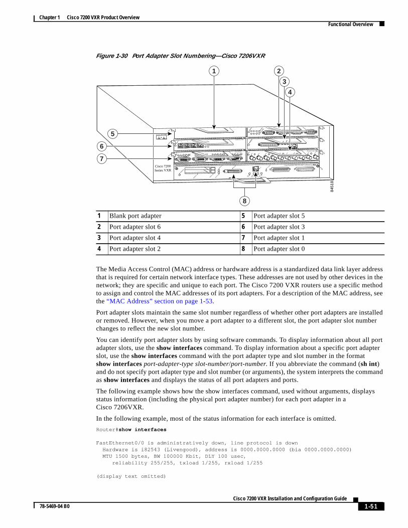
Chapter 1 Cisco 7200 VXR Product OverviewFunctional Overview
ddressin thethods, see
stalledber
l portr
mand
ays
Figure 1-30 Port Adapter Slot Numbering—Cisco 7206VXR
The Media Access Control (MAC) address or hardware address is a standardized data link layer athat is required for certain network interface types. These addresses are not used by other devicesnetwork; they are specific and unique to each port. The Cisco 7200 VXR routers use a specific meto assign and control the MAC addresses of its port adapters. For a description of the MAC addresthe“MAC Address” section on page 1-53.
Port adapter slots maintain the same slot number regardless of whether other port adapters are inor removed. However, when you move a port adapter to a different slot, the port adapter slot numchanges to reflect the new slot number.
You can identify port adapter slots by using software commands. To display information about aladapter slots, use theshow interfacescommand. To display information about a specific port adapteslot, use theshow interfaces command with the port adapter type and slot number in the formatshow interfacesport-adapter-type slot-number/port-number. If you abbreviate the command (sh int)and do not specify port adapter type and slot number (or arguments), the system interprets the comas show interfacesand displays the status of all port adapters and ports.
The following example shows how the show interfaces command, used without arguments, displstatus information (including the physical port adapter number) for each port adapter in aCisco 7206VXR.
In the following example, most of the status information for each interface is omitted.
Router# show interfaces
FastEthernet0/0 is administratively down, line protocol is down Hardware is i82543 (Livengood), address is 0000.0000.0000 (bia 0000.0000.0000) MTU 1500 bytes, BW 100000 Kbit, DLY 100 usec, reliability 255/255, txload 1/255, rxload 1/255
(display text omitted)
1 Blank port adapter 5 Port adapter slot 5
2 Port adapter slot 6 6 Port adapter slot 3
3 Port adapter slot 4 7 Port adapter slot 1
4 Port adapter slot 2 8 Port adapter slot 0
2ETHERNET-10BFL
EN
RX
0 1 2 3 4TX RX TX RX TX RX TX RX TX
0
4
1
3
56
FAST SERIAL
ENTD TC RD RC LB CD TD TC RD RC LB CD TD TC RD RC LB CD TD TC RD RC LB CD
TOKEN RING
0 1 2 3
Cisco 7200Series VXR
MII
EN R
J45
EN R
J45
LINK
1O P
WR
OK
RJ-45
CPU RESET FAST ETHERNET INPUT/OUTPUT CONTROLLER
ENABLED
PCMCIA
EJECT
SLOT 0
SLOT 1
FE MII
ETHERNET 10BT
ENAB
LED
0 2
1 3
LINK
0 1 2 3
ENAB
LED
MII
LIN
K
RJ4
5
FAST ETHERNET
0
8451
8
8
1 2
3
4
5
6
7
1-51Cisco 7200 VXR Installation and Configuration Guide
78-5469-04 B0

Chapter 1 Cisco 7200 VXR Product OverviewFunctional Overview
) and
rt
FastEthernet0/1 is administratively down, line protocol is down Hardware is i82543 (Livengood), address is 0000.0000.0000 (bia 0000.0000.0000) MTU 1500 bytes, BW 100000 Kbit, DLY 100 usec, reliability 255/255, txload 1/255, rxload 1/255
(display text omitted)
GigabitEthernet0/1 is up, line protocol is up Hardware is BCM-12500 Internal MAC, address is 0000.0000.0000 (bia 0000.0000.0000) Internet address is 00.00.00.00/00 MTU 1500 bytes, BW 1000000 Kbit, DLY 10 usec, reliability 255/255, txload 2/255, rxload 2/255
(display text omitted)
GigabitEthernet0/2 is up, line protocol is up Hardware is BCM-12500 Internal MAC, address is 0000.0000.0000(bia 0000.0000.0000) Internet address is 00.00.00.00/00 MTU 1500 bytes, BW 1000000 Kbit, DLY 10 usec, reliability 255/255, txload 2/255, rxload 2/255
(display text omitted)
GigabitEthernet0/3 is administratively down, line protocol is down Hardware is BCM-12500 Internal MAC, address is 0000.0000.0000 (bia 0000.0000.0000) Internet address is 00.00.00.00/00 MTU 1500 bytes, BW 1000000 Kbit, DLY 10 usec, reliability 255/255, txload 1/255, rxload 1/255
(display text omitted)
FastEthernet2/0 is administratively down, line protocol is down Hardware is i82543 (Livengood), address is 0000.0000.0000 (bia 0000.0000.0000) MTU 1500 bytes, BW 100000 Kbit, DLY 100 usec, reliability 255/255, txload 1/255, rxload 1/255
(display text omitted)
FastEthernet2/1 is administratively down, line protocol is down Hardware is i82543 (Livengood), address is 0000.0000.0000 (bia 0000.0000.0000) MTU 1500 bytes, BW 100000 Kbit, DLY 100 usec, reliability 255/255, txload 1/255, rxload 1/255
(display text omitted)
FastEthernet5/0 is up, line protocol is up Hardware is DEC21140, address is 0000.0000.0000 (bia 0000.0000.0000) Internet address is 00.00.00.00/00 MTU 1500 bytes, BW 100000 Kbit, DLY 100 usec, reliability 255/255, txload 1/255, rxload 1/255
You can also use arguments such as the interface type (Ethernet, Token Ring, ATM, and so forththe port address (slot-number/port-number) to display information about a specific interface only.
The following example shows the display for the first port on the Fast Ethernet port adapter in poadapter slot 3:
Router# show interface fastethernet 5/0
FastEthernet5/0 is up, line protocol is up Hardware is DEC21140, address is 0000.000.0000 (bia 0000.0000.0000) Internet address is 0.0.0.0 MTU 1500 bytes, BW 100000 Kbit, DLY 100 usec,
1-52Cisco 7200 VXR Installation and Configuration Guide
78-5469-04 B0

Chapter 1 Cisco 7200 VXR Product OverviewFunctional Overview
VXR
or
rface
f the. In the
hethere firstslot 6
m intoultiple
e you
pdatesame
the
dt hascan
reliability 255/255, txload 1/255, rxload 1/255 Encapsulation ARPA, loopback not set Keepalive not set Full-duplex, 100Mb/s, 100BaseTX/FX
ARP type:ARPA, ARP Timeout 04:00:00
(display text omitted)
For complete descriptions and instructions of the commands used to configure your Cisco 7200 router, refer to theConfiguration Fundamentals Configuration GuideandConfiguration FundamentalsCommand Referencepublications, which are available on Cisco.com, the Documentation CD-ROM,in print.
MAC AddressAll LAN interfaces (ports) require unique MAC addresses, also known ashardwareaddresses. Typically,the MAC address of an interface is stored on a memory component that resides directly on the intecircuitry; however, the OIR feature requires a different method. (For a description of OIR, see the“Online Insertion and Removal” section on page 1-53.)
Using OIR you can remove a port adapter and replace it with another identically configured one. Inew port adapter matches the port adapter you removed, the system immediately brings it onlineorder to enable OIR, an address allocator with unique MAC addresses is stored in an EPROM onrouter midplane. Each address is reserved for a specific port and slot in the router regardless of wa port adapter resides in that slot. The MAC addresses are assigned to the slots in sequence. Thaddress is assigned to slot 0, and the last address is assigned to slot 4 in the Cisco 7204VXR or toin the Cisco 7206VXR. Using this address scheme, you can remove port adapters and insert theother routers without causing the MAC addresses to move around the network or be assigned to mdevices.
Note that if the MAC addresses were stored on each port adapter, OIR would not function becauscould never replace one port adapter with an identical one; the MAC addresses would always bedifferent. Also, each time a port adapter was replaced, other devices on the network would have to utheir data structures with the new address. If the other devices did not update quickly enough, theMAC address could appear in more than one device at the same time.
Note Storing the MAC addresses for every slot in one central location means the addresses stay with memory device on which they are stored.
Online Insertion and RemovalAll port adapters and service adapters in the Cisco 7200 VXR routers support online insertion anremoval (OIR). However, it is wise to shut down the interface before removing a port adapter thaactive traffic moving through it. Removing a port adapter while traffic is flowing through the ports cause system disruption. Once the port adapter is inserted, the ports can be brought back up.
Note As you disengage the port adapter from the router or switch, online insertion and removal (OIR)administratively shuts down all active interfaces in the port adapter.
1-53Cisco 7200 VXR Installation and Configuration Guide
78-5469-04 B0

Chapter 1 Cisco 7200 VXR Product OverviewFunctional Overview
ating;rafficmless
uter,
stemngine shut
. Eachem aseceivesoved new
icest pins.
lane
and
whene, asintopter.
e orlving
upplyithin
fromat you
if any
OIR allows you to install and replace port adapters and service adapters while the router is operyou do not need to notify the software or shut down the system power, although you should not run tthrough the port adapter you are removing while it is being removed. OIR is a method that is seato end users on the network, maintains all routing information, and preserves sessions.
The following is a functional description of OIR for background information only; for specificprocedures for installing and replacing a port adapter or service adapter in a Cisco 7200 VXR rorefer to the online configuration note for each port adapter or service adapter.
Caution The network processing engine or network services engine and the I/O controller are required sycomponents that cannot be removed if the router is operating. Removing the network processing eor network services engine or the I/O controller while the router is operating causes the router todown or crash and might damage or destroy memory files.
Each port adapter or service adapter has a bus connector that connects it to the router midplanemidplane connector has a set of tiered pins in three lengths that send specific signals to the systthey make contact with the port adapter or service adapter. The system assesses the signals it rand the order in which it receives them to determine if a port adapter or service adapter is being remor inserted into the midplane. From these signals, the system determines whether to reinitialize ainterface or shut down a removed interface. For example, when you insert a port adapter or servadapter, the longest pins make contact with the port adapter or service adapter first, and the shortemake contact last. The system recognizes the signals and the sequence in which it receives them
When you remove or insert a port adapter or service adapter in a Cisco 7200 VXR router, the midppins send signals to notify the system, which then performs as follows:
1. Rapidly scans the midplane for configuration changes.
2. Initializes all newly inserted port adapter or service adapters, noting any removed interfaces placing them in the administratively shutdown state.
3. Brings all previously configured interfaces on the port adapter back to the state they were in they were removed. Any newly inserted interfaces are put in the administratively shutdown statif they were present (but not configured) at boot time. If a similar port adapter type is reinserteda slot, its ports are configured and brought online up to the port count of the original port ada(A service adapter has no configurable ports.)
Environmental Monitoring and Reporting FunctionsEnvironmental monitoring and reporting functions are controlled by the network processing enginnetwork services engine and allow you to maintain normal system operation by identifying and resoadverse conditions prior to loss of operation. The environmental monitoring functions constantlymonitor the internal chassis air temperature and DC supply voltages and currents. Each power smonitors its own voltage and temperature and shuts itself down if it detects a critical condition wthe power supply. If conditions reach shutdown, the system shuts down to avoid equipment damageexcessive heat. The reporting functions periodically log the values of measured parameters so thcan retrieve them for analysis later, and the reporting functions display warnings on the console of the monitored parameters exceed defined thresholds.
1-54Cisco 7200 VXR Installation and Configuration Guide
78-5469-04 B0

Chapter 1 Cisco 7200 VXR Product OverviewFunctional Overview
orir as
ges onr shutsand DC
pplyturestem
e
, but
tod.
mage
ryou
e,you
ed)
Environmental Monitoring
The environmental monitoring functions use four sensors, two on the network processing enginenetwork services engine and two on the I/O controller, to monitor the temperature of the cooling ait moves through the chassis.
If the air temperature exceeds a defined threshold, the system controller displays warning messathe console terminal, and if the temperature exceeds the shutdown threshold, the system controlledown the system. The system stores the present parameter measurements for both temperaturevoltage in NVRAM so you can retrieve them later as a report of the last shutdown parameters.
In addition, the power supplies monitor internal power supply temperature and voltages. A power suis either within tolerance (normal) or out of tolerance (critical). If an internal power supply temperaor voltage reaches a critical level, the power supply shuts down without any interaction with the syprocessor.
The environmental monitoring functions use the following levels of status conditions to monitor thsystem:
• Normal—All monitored parameters are within normal tolerances.
• Warning—The system has exceeded a specified threshold. The system continues to operateoperator action is recommended to bring the system back to a normal state.
• Critical—An out-of-tolerance temperature or voltage condition exists. The system continues operate; however, the system is approaching shutdown. Immediate operator action is require
• Shutdown—The processor has detected a temperature condition that could result in physical dato system components and has disabled DC power to all internal components. This conditionrequires immediate operator action. All DC power remains disabled until you toggle the poweswitch. Before any shutdown, the system logs the status of monitored parameters in NVRAM socan retrieve it later to help determine the cause of the problem.
• Power supply shutdown—The power supply detected an internal out-of-tolerance overvoltagovercurrent, or temperature condition and shut itself down. All DC power remains disabled untiltoggle the power switch.
Table 1-31 lists the typical temperature thresholds for each network processing engine type, andTable 1-32lists the DC power thresholds for the normal, warning, and critical (power supply-monitorlevels.
Table 1-31 Typical Processor-Monitored Temperature Thresholds
Parameter High Warning High Critical Shutdown
NPE-175, NPE-225,NPE-300, NPE-400,NSE-1, NPE-G1
Chassis inlet 104 F (40 C) 122 F (50 C) —
Chassis outlet 1 109 F (43 C) 127 F (53 C) 136 F (58 C)
Chassis outlet 2 109 F (43 C) 127 F (53 C) —
Chassis outlet 3 131 F (55 C) 149 F (65 C) 158 F (70 C)
NPE-100 or NPE-200
Chassis inlet 104 F (40 C) 122 F (50 C) —
Chassis outlet 1 109 F (43 C) 127 F (53 C) 136 F (58 C)
Chassis outlet 2 167 F (75 C) 167 F (75 C) —
1-55Cisco 7200 VXR Installation and Configuration Guide
78-5469-04 B0

Chapter 1 Cisco 7200 VXR Product OverviewFunctional Overview
toredeports
A brief
ratureuatere.
eystem
is a
Reporting Functions
The Cisco 7200 VXR routers display warning messages on the console if chassis interface-moniparameters exceed a desired threshold. You can also retrieve and display environmental status rwith theshow environment, show environment all, show environment last, andshow environmenttable commands. Parameters are measured and reporting functions are updated every 60 seconds.description of each of these commands follows.
Caution To prevent overheating the chassis, ensure that your system is drawing cool inlet air. Overtempeconditions can occur if the system is drawing in the exhaust air of other equipment. Ensure adeqclearance around the sides of the chassis so that cooling air can flow through the chassis interiounimpeded and exhaust air exits the chassis and is not drawn into the inlet vent of another devic
Theshow environment command displays reports of the current environmental system status. Threport displays parameters that are out of the normal values. No parameters are displayed if the sstatus is normal. The example that follows shows the display for a system in which all monitoredparameters are within normal range:
Router# show environment
All measured values are normal
If the environmental status isnot normal, the system reports the worst-case status level. Following sample overvoltage warning:
Router# show environment
Warning: +3.45 V measured at +3.83 V
Chassis outlet 3 122 F (50 C) 140 F (60 C) 149 F (65 C)
NPE-150
Chassis inlet 104 F (40 C) 122 F (50 C) —
Chassis outlet 1 109 F (43 C) 127 F (53 C) 136 F (58 C)
Chassis outlet 2 167 F (75 C) 167 F (75 C) —
Chassis outlet 3 131 F (55 C) 149 F (65 C) 158 F (70 C)
Table 1-32 Typical Power Supply-Monitored DC-Voltage Thresholds
Parameter Low Critical Low Warning High Warning High Critical
+3.45V +3.26V +3.34V +3.55V +3.63V
+5.15V +4.86V +4.99V +5.31V +5.43V
+12.15V +11.39V +11.67 +12.62V +12.91V
–11.95V –9.52V –10.73 –13.16V –14.38V
Table 1-31 Typical Processor-Monitored Temperature Thresholds (continued)
Parameter High Warning High Critical Shutdown
1-56Cisco 7200 VXR Installation and Configuration Guide
78-5469-04 B0

Chapter 1 Cisco 7200 VXR Product OverviewFunctional Overview
on
e
sted in
and
Theshow environment lastcommand retrieves and displays the NVRAM log, which shows the reasfor the last system shutdown (if the shutdown was related to voltage or temperature) and theenvironmental status at that time. Air temperature is measured and displayed, and the DC voltagsupplied by the power supply is also displayed.
Following is sample output of theshow environment last command:
NPE300(boot)# show environment lastchassis inlet previously measured at 26C/78F chassis outlet 1 previously measured at 28C/82F chassis outlet 2 previously measured at 29C/84F chassis outlet 3 previously measured at 33C/91F +3.45 V previously measured at +3.46 +5.15 V previously measured at +5.23 +12.15 V previously measured at +12.24 -11.95 V previously measured at -11.81 last shutdown reason - power supply shutdown
Theshow environment table command displays the temperature and voltage thresholds for eachtemperature sensor and for each monitored status level. These thresholds are related to those liTable 1-31 andTable 1-32. The display also lists the shutdown threshold for the system.
Following is sample output of theshow environment tablecommand for a Cisco 7206VXR that has aninstalled NPE-300:
NPE300(boot)# show environment table
System shutdown for chassis inlet is 75C/167FSystem shutdown for chassis outlet 1 is 58C/136FSystem shutdown for chassis outlet 2 is 75C/167FSystem shutdown for chassis outlet 3 is 65C/149F
Note Temperature ranges and values are subject to change.
Theshow environment allcommand displays an extended report that includes temperature readingsvoltage readings. Theshow environment all command also displays a report showing which powersupply slots are occupied and which are empty.
Following is sample output of theshow environment all command:
NPE300(boot)# show environment all
Power Supplies:Power Supply 1 is empty.Power Supply 2 is Zytek AC Power Supply. Unit is on.
Temperature readings:chassis inlet measured at 26C/78Fchassis outlet 1 measured at 28C/82F
Sample Point
chassis inletchassis outlet 1chassis outlet 2chassis outlet 3+3.45 V+5.15 V+12.15 V-11.95 V
LowCritical
+3.26+4.86+11.39-9.52
LowWarning
+3.34+4.99+11.67-10.73
HighWarning
40C/104F43C/109F75C/167F50C/122F+3.55+5.31+12.62-13.16
HighCritical
50C/122F53C/127F75C/167F60C/140F+3.63+5.43+12.91-14.38
1-57Cisco 7200 VXR Installation and Configuration Guide
78-5469-04 B0

Chapter 1 Cisco 7200 VXR Product OverviewFunctional Overview
te if aaysold, the
stemystem
t.
chassis outlet 2 measured at 29C/84Fchassis outlet 3 measured at 33C/91F
Voltage readings:+3.45 V measured at +3.46 V+5.15 V measured at +5.25 V+12.15 V measured at +12.24 V-11.95 V measured at -11.81 V
Envm stats saved 138 time(s) since reload
Fan Failures
When the system power is on, all three fans should be operational. The system continues to operafan fails; however, if the air temperature exceeds a defined threshold, the system controller displwarning messages on the console terminal, and if the temperature exceeds the shutdown threshsystem controller shuts down the system.
If the system does shut down because the temperature exceeded the shutdown threshold, the sydisplays the following message on the console screen and in the environment display when the srestarts:
Queued messages:%ENVM-1-SHUTDOWN: Environmental Monitor initiated shutdown
For complete descriptions and instructions for the environmental monitor commands, refer to theConfiguration Fundamentals Configuration Guide andConfiguration Fundamentals CommandReference publications, which are available on Cisco.com, the Documentation CD-ROM, or in prin
1-58Cisco 7200 VXR Installation and Configuration Guide
78-5469-04 B0