Embed Size (px)
Citation preview
Dell EMC Data Domain DD6300 System
Installation Guide302-005-015 REV 01
Copyright © 2016-2018 Dell Inc. or its subsidiaries. All rights reserved.
Published July 2018
Dell believes the information in this publication is accurate as of its publication date. The information is subject to change without notice.
THE INFORMATION IN THIS PUBLICATION IS PROVIDED “AS-IS.“ DELL MAKES NO REPRESENTATIONS OR WARRANTIES OF ANY KIND
WITH RESPECT TO THE INFORMATION IN THIS PUBLICATION, AND SPECIFICALLY DISCLAIMS IMPLIED WARRANTIES OF
MERCHANTABILITY OR FITNESS FOR A PARTICULAR PURPOSE. USE, COPYING, AND DISTRIBUTION OF ANY DELL SOFTWARE DESCRIBED
IN THIS PUBLICATION REQUIRES AN APPLICABLE SOFTWARE LICENSE.
Dell, EMC, and other trademarks are trademarks of Dell Inc. or its subsidiaries. Other trademarks may be the property of their respective owners.
Published in the USA.
Dell EMCHopkinton, Massachusetts 01748-91031-508-435-1000 In North America 1-866-464-7381www.DellEMC.com
2 Data Domain DD6300 System Installation Guide
5
7
Planning and Site Preparation 9Tools and supplies needed...........................................................................10Safety information...................................................................................... 10Field-installed systems vs. factory-racked systems..................................... 11
Install the System in the Rack 13Unpack the system..................................................................................... 14Rails and cable management assembly........................................................ 14Identify the rack location to install the system............................................ 15Install the rails............................................................................................. 15Install the system into a rack....................................................................... 17Installing the cable management assembly..................................................19Installing the expansion shelves into the racks........................................... 20
Connect Cables and Power On 23Connecting ES30 shelves........................................................................... 24
DD6300 with ES30 cabling............................................................ 24Connecting DS60 shelves...........................................................................27
DD6300 with DS60 cabling............................................................27Installing the front bezel............................................................................. 28Connect data cables...................................................................................29Power on all systems..................................................................................29
Configure System for Use 31Enable administrative communication.........................................................32Accepting the End User License Agreement...............................................33Run the configuration wizard......................................................................33
Configuring the network................................................................33Configuring additional system parameters.....................................35
Figures
Tables
Chapter 1
Chapter 2
Chapter 3
Chapter 4
CONTENTS
Data Domain DD6300 System Installation Guide 3

CONTENTS
4 Data Domain DD6300 System Installation Guide
Warning about lifting the system................................................................................. 11Warning about lifting the system.................................................................................14Cable management assembly (CMA).......................................................................... 15Warning about lifting the system.................................................................................17Service tag (components removed for clarity)............................................................ 19Installing the CMA on the rack.................................................................................... 19Adjusting the CMA depth........................................................................................... 20DD6300 with ES30 shelves........................................................................................ 26DD6300 with DS60 shelves........................................................................................ 28
123456789
FIGURES
Data Domain DD6300 System Installation Guide 5

FIGURES
6 Data Domain DD6300 System Installation Guide
Cables for primary or single node to ES30 shelf loop..................................................24ES30 to ES30 cable options....................................................................................... 24DD6300 with ES30 cabling instructions......................................................................25DS60 cables................................................................................................................27DD6300 with DS60 cabling instructions..................................................................... 27Communications settings........................................................................................... 32
123456
TABLES
Data Domain DD6300 System Installation Guide 7

TABLES
8 Data Domain DD6300 System Installation Guide
CHAPTER 1
Planning and Site Preparation
l Tools and supplies needed.................................................................................. 10l Safety information..............................................................................................10l Field-installed systems vs. factory-racked systems.............................................11
Planning and Site Preparation 9
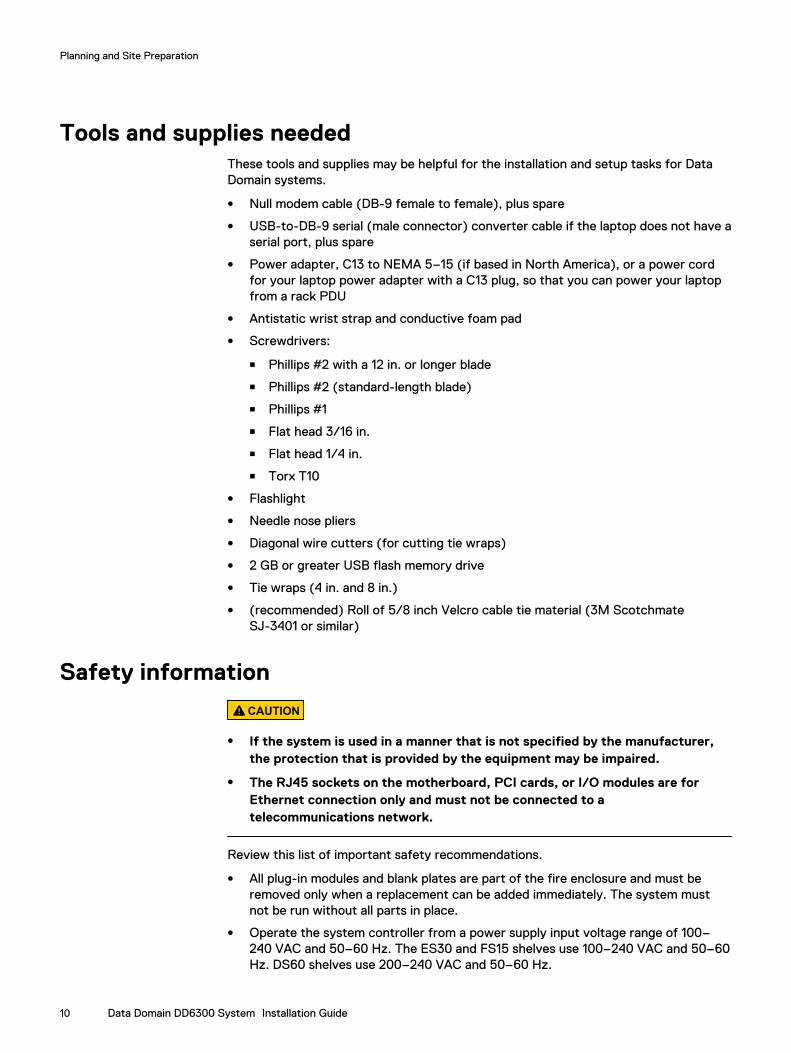
Tools and supplies neededThese tools and supplies may be helpful for the installation and setup tasks for DataDomain systems.
l Null modem cable (DB-9 female to female), plus spare
l USB-to-DB-9 serial (male connector) converter cable if the laptop does not have aserial port, plus spare
l Power adapter, C13 to NEMA 5–15 (if based in North America), or a power cordfor your laptop power adapter with a C13 plug, so that you can power your laptopfrom a rack PDU
l Antistatic wrist strap and conductive foam pad
l Screwdrivers:
n Phillips #2 with a 12 in. or longer blade
n Phillips #2 (standard-length blade)
n Phillips #1
n Flat head 3/16 in.
n Flat head 1/4 in.
n Torx T10
l Flashlight
l Needle nose pliers
l Diagonal wire cutters (for cutting tie wraps)
l 2 GB or greater USB flash memory drive
l Tie wraps (4 in. and 8 in.)
l (recommended) Roll of 5/8 inch Velcro cable tie material (3M ScotchmateSJ-3401 or similar)
Safety information
CAUTION
l If the system is used in a manner that is not specified by the manufacturer,the protection that is provided by the equipment may be impaired.
l The RJ45 sockets on the motherboard, PCI cards, or I/O modules are forEthernet connection only and must not be connected to atelecommunications network.
Review this list of important safety recommendations.
l All plug-in modules and blank plates are part of the fire enclosure and must beremoved only when a replacement can be added immediately. The system mustnot be run without all parts in place.
l Operate the system controller from a power supply input voltage range of 100–240 VAC and 50–60 Hz. The ES30 and FS15 shelves use 100–240 VAC and 50–60Hz. DS60 shelves use 200–240 VAC and 50–60 Hz.
Planning and Site Preparation
10 Data Domain DD6300 System Installation Guide

l Each component is intended to operate with all working power supplies installed.
l Provide a suitable power source with electrical overload protection.
l A safe electrical earth connection must be provided to each power cord. Checkthe grounding of the power sources before applying power.
l The plug on each power supply cord is used as the main device to disconnectpower from the system. Ensure that the socket outlets are located near theequipment and are easily accessible.
l Permanently unplug the unit if you think it is damaged in any way and beforemoving the system. Systems include two power supplies. To remove system powercompletely, disconnect both power supplies.
l The power connections must always be disconnected before removal orreplacement of a power supply module from the system.
l A faulty power supply module must be replaced within 24 hours.
l Do not lift system components by yourself. Systems weigh up to 80 lbs (36.29kg), an ES30 expansion shelf weighs up to 68 lbs (30.8 kg), and a DS60 shelfweighs up to 225 lbs (102 KG)
CAUTION
Data Domain systems are heavy. Use at least two people or a mechanical liftto move any system.
l Do not lift an expansion shelf by the front handles on any modules. The handles arenot designed to support the weight of the populated shelf.
l To comply with applicable safety, emission, and thermal requirements, coversmust not be removed and all bays must be fitted with plug-in modules.
l Once removed from the shipping box, it is ok to lift the system or the chassis
Figure 1 Warning about lifting the system
l To prevent the rack from becoming top-heavy, load the rack with storage shelvesbeginning at the bottom and the system in the designated location.
l Data Domain recommends that you wear a suitable antistatic wrist or ankle strapfor ESD protection. Observe all conventional ESD precautions when handling plug-in modules and components.
Field-installed systems vs. factory-racked systems
Data Domain systems are available from the factory as components to install in anexisting rack on site, or pre-installed in a rack. The following sections provideadditional information about each type of installation.
Planning and Site Preparation
Field-installed systems vs. factory-racked systems 11
Field-installed systemsThis installation guide is primarily intended for systems shipped as components to beinstalled in an existing rack on site. Follow all the instructions in this document to rack,cable, and configure the system.
Factory-racked systemsFactory-racked systems are pre-installed in the rack, with the cables alreadyconnected. Follow the instructions in the chapter Configure System For Use toconfigure the factory-racked system.
The following documents, available from the Online Support website at https://support.emc.com, provide additional information about the factory rack:
l Dell EMC 40U-P Cabinet Site Preparation Guide
l Dell EMC 40U-P Cabinet Unpacking and Setup Guide
l Data Domain Rack Service Guide
Planning and Site Preparation
12 Data Domain DD6300 System Installation Guide
CHAPTER 2
Install the System in the Rack
l Unpack the system............................................................................................. 14l Rails and cable management assembly............................................................... 14l Identify the rack location to install the system....................................................15l Install the rails.................................................................................................... 15l Install the system into a rack...............................................................................17l Installing the cable management assembly......................................................... 19l Installing the expansion shelves into the racks................................................... 20
Install the System in the Rack 13
Unpack the system1. Remove the accessories and rail mount kit from the shipping packages.
2. Remove the controller and the bezels from the shipping packages.
CAUTION
Data Domain systems are heavy. Always use two people or a mechanical lift tomove a system.
Figure 2 Warning about lifting the system
3. Remove expansion shelves and their bezels from the shipping packages.
Rails and cable management assemblyThe rail kit is universal in that it supports all rack mounting hole types and sizes. Boththe front and the rear ends of the rail kit contain threaded posts that come with a capinstalled. The cap fits square and round hole unthreaded racks. Large flat headed M4screws insert through the rail into the rail kit to secure the rail to the rack.
When installing rails, do not tighten the screws all the way until all the screws are inplace. This assures that the screws are all screwed in the same distance, and preventsone from skewing the others.
The rail kit includes two bracket assemblies, one marked for the left side and onemarked for the right side of the rack.
A cable management assembly (CMA), for organization of cables at the rear of thesystem, is already installed onto the system on a Data Domain rack. For field installedsystems, the CMA is shipped with the system.
Install the System in the Rack
14 Data Domain DD6300 System Installation Guide
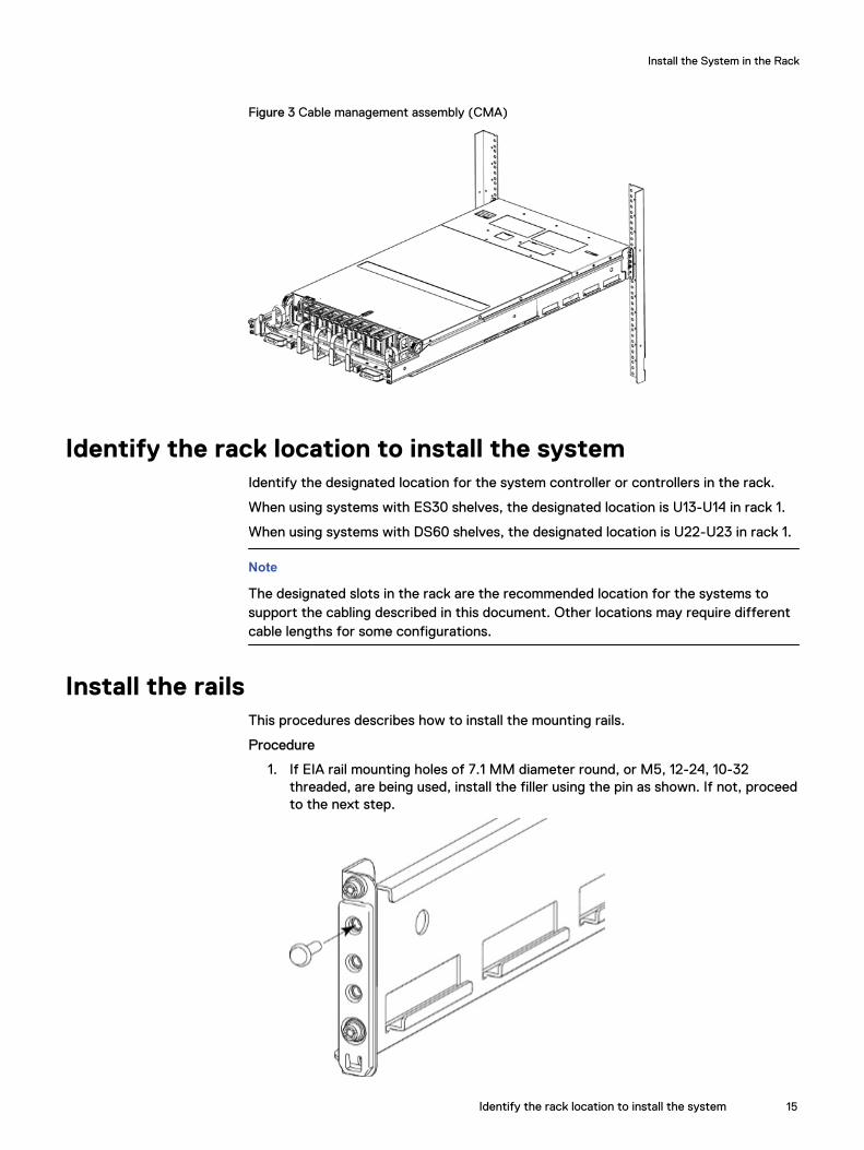
Figure 3 Cable management assembly (CMA)
Identify the rack location to install the systemIdentify the designated location for the system controller or controllers in the rack.
When using systems with ES30 shelves, the designated location is U13-U14 in rack 1.
When using systems with DS60 shelves, the designated location is U22-U23 in rack 1.
Note
The designated slots in the rack are the recommended location for the systems tosupport the cabling described in this document. Other locations may require differentcable lengths for some configurations.
Install the railsThis procedures describes how to install the mounting rails.
Procedure
1. If EIA rail mounting holes of 7.1 MM diameter round, or M5, 12-24, 10-32threaded, are being used, install the filler using the pin as shown. If not, proceedto the next step.
Install the System in the Rack
Identify the rack location to install the system 15
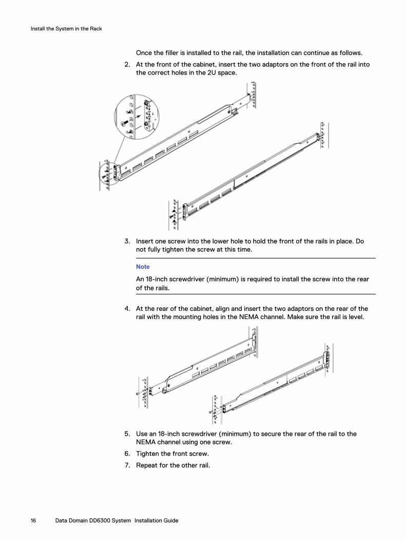
Once the filler is installed to the rail, the installation can continue as follows.
2. At the front of the cabinet, insert the two adaptors on the front of the rail intothe correct holes in the 2U space.
3. Insert one screw into the lower hole to hold the front of the rails in place. Donot fully tighten the screw at this time.
Note
An 18-inch screwdriver (minimum) is required to install the screw into the rearof the rails.
4. At the rear of the cabinet, align and insert the two adaptors on the rear of therail with the mounting holes in the NEMA channel. Make sure the rail is level.
5. Use an 18-inch screwdriver (minimum) to secure the rear of the rail to theNEMA channel using one screw.
6. Tighten the front screw.
7. Repeat for the other rail.
Install the System in the Rack
16 Data Domain DD6300 System Installation Guide
Install the system into a rack
CAUTION
Data Domain systems are heavy. Always use two people or a mechanical lift tomove a system.
Figure 4 Warning about lifting the system
CAUTION
l The system controller should be installed in the pre-defined location for thesystem controller in the rack to comply with Data Domain rack mountingguidelines.
l Do not apply AC power to the system controller until all expansion shelvesand cables are installed.
l Ensure the PSNT label, which is in a slot just beneath the power supply on therear of the chassis is not damaged or snagged during the installation of thesystem into the rack.
Procedure
1. From the front of the rack, lift the chassis to install the system in the rack in thecorrect location.
2. Slide the unit onto the rails and push it fully into the cabinet until the mountingholes on the unit are flush with the NEMA channel.
Install the System in the Rack
Install the system into a rack 17
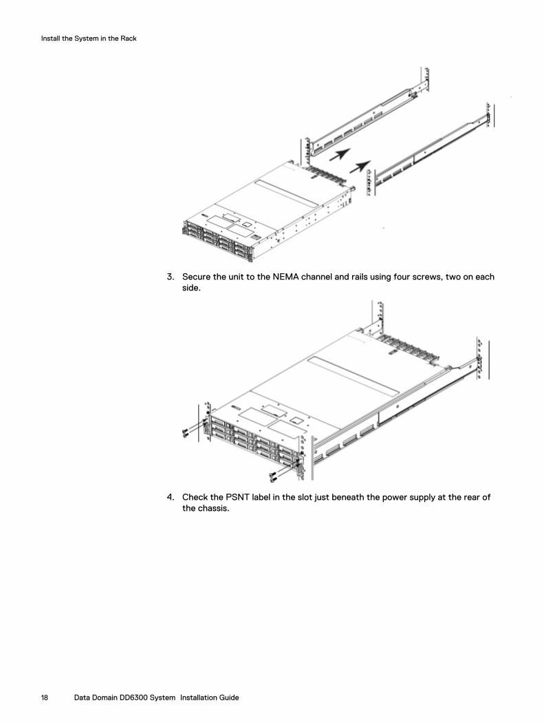
3. Secure the unit to the NEMA channel and rails using four screws, two on eachside.
4. Check the PSNT label in the slot just beneath the power supply at the rear ofthe chassis.
Install the System in the Rack
18 Data Domain DD6300 System Installation Guide
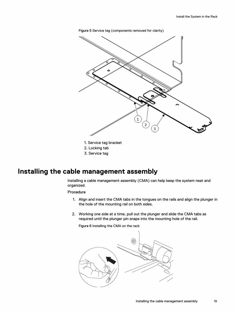
Figure 5 Service tag (components removed for clarity)
1. Service tag bracket2. Locking tab3. Service tag
Installing the cable management assemblyInstalling a cable management assembly (CMA) can help keep the system neat andorganized.
Procedure
1. Align and insert the CMA tabs in the tongues on the rails and align the plunger inthe hole of the mounting rail on both sides.
2. Working one side at a time, pull out the plunger and slide the CMA tabs asrequired until the plunger pin snaps into the mounting hole of the rail.
Figure 6 Installing the CMA on the rack
Install the System in the Rack
Installing the cable management assembly 19
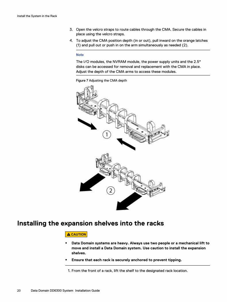
3. Open the velcro straps to route cables through the CMA. Secure the cables inplace using the velcro straps.
4. To adjust the CMA position depth (in or out), pull inward on the orange latches(1) and pull out or push in on the arm simultaneously as needed (2).
Note
The I/O modules, the NVRAM module, the power supply units and the 2.5"disks can be accessed for removal and replacement with the CMA in place.Adjust the depth of the CMA arms to access these modules.
Figure 7 Adjusting the CMA depth
Installing the expansion shelves into the racks
CAUTION
l Data Domain systems are heavy. Always use two people or a mechanical lift tomove and install a Data Domain system. Use caution to install the expansionshelves.
l Ensure that each rack is securely anchored to prevent tipping.
1. From the front of a rack, lift the shelf to the designated rack location.
Install the System in the Rack
20 Data Domain DD6300 System Installation Guide
2. Add shelves to the racks in order, one at a time, from the bottom of a rack to thetop filling each string in that rack before going to the next.
Note
Strings in add-on racks may connect to the same string number in other racks.
Shelves are added in the order V1.1, V1.2, V1.3, V1.4, V2.1, V2.2, and so on. Shelvesare labeled VN.M. VN refers to string "N" and the "M" is the number of the shelfin the string. For example, V3.2 refers to the second shelf in the third string.
3. Secure each expansion shelf in the rack.
4. When installing an SSD shelf for Data Domain metadata on flash:
l The SSD shelf counts towards the total number of shelves connected to thesystem.
l Data Domain recommends installing the SSD shelf in the V1.1 positon, but ifthat is not possible, the shelf can be placed in a different location in the rack solong as cables of sufficient length are available.
Note
V1.1 is recommended for better performance because this will the 1st hop wheredata will be written. If the SSD shelf is connected to the last enclosure in achain, then each read/write request has to go through many hops, whichintroduces latency issues when compared to when the SSD shelf is on the 1st
shelf of a chain.
Install the System in the Rack
Installing the expansion shelves into the racks 21

Install the System in the Rack
22 Data Domain DD6300 System Installation Guide
CHAPTER 3
Connect Cables and Power On
l Connecting ES30 shelves...................................................................................24l Connecting DS60 shelves...................................................................................27l Installing the front bezel.....................................................................................28l Connect data cables...........................................................................................29l Power on all systems..........................................................................................29
Connect Cables and Power On 23
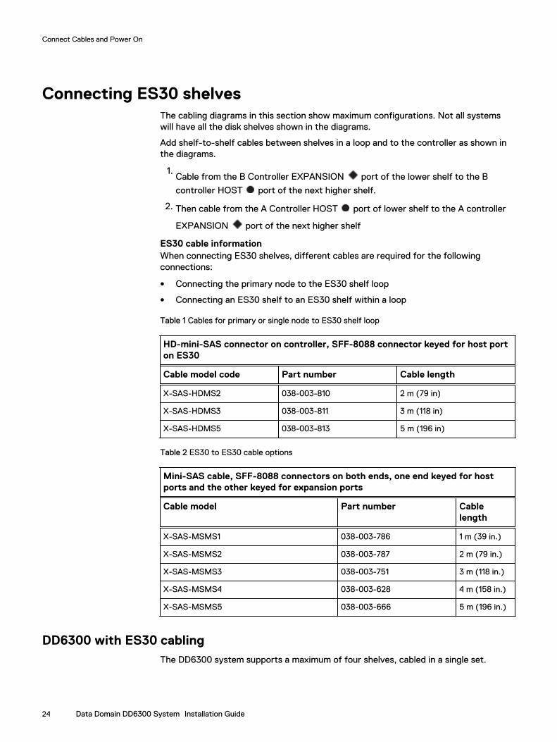
Connecting ES30 shelvesThe cabling diagrams in this section show maximum configurations. Not all systemswill have all the disk shelves shown in the diagrams.
Add shelf-to-shelf cables between shelves in a loop and to the controller as shown inthe diagrams.
1.Cable from the B Controller EXPANSION port of the lower shelf to the B
controller HOST port of the next higher shelf.
2. Then cable from the A Controller HOST port of lower shelf to the A controller
EXPANSION port of the next higher shelf
ES30 cable informationWhen connecting ES30 shelves, different cables are required for the followingconnections:
l Connecting the primary node to the ES30 shelf loop
l Connecting an ES30 shelf to an ES30 shelf within a loop
Table 1 Cables for primary or single node to ES30 shelf loop
HD-mini-SAS connector on controller, SFF-8088 connector keyed for host porton ES30
Cable model code Part number Cable length
X-SAS-HDMS2 038-003-810 2 m (79 in)
X-SAS-HDMS3 038-003-811 3 m (118 in)
X-SAS-HDMS5 038-003-813 5 m (196 in)
Table 2 ES30 to ES30 cable options
Mini-SAS cable, SFF-8088 connectors on both ends, one end keyed for hostports and the other keyed for expansion ports
Cable model Part number Cablelength
X-SAS-MSMS1 038-003-786 1 m (39 in.)
X-SAS-MSMS2 038-003-787 2 m (79 in.)
X-SAS-MSMS3 038-003-751 3 m (118 in.)
X-SAS-MSMS4 038-003-628 4 m (158 in.)
X-SAS-MSMS5 038-003-666 5 m (196 in.)
DD6300 with ES30 cablingThe DD6300 system supports a maximum of four shelves, cabled in a single set.
Connect Cables and Power On
24 Data Domain DD6300 System Installation Guide
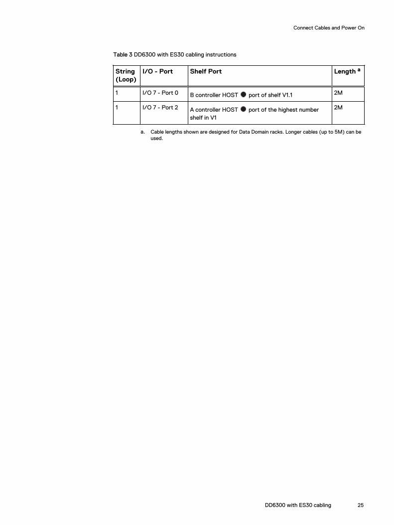
Table 3 DD6300 with ES30 cabling instructions
String(Loop)
I/O - Port Shelf Port Length a
1 I/O 7 - Port 0 B controller HOST port of shelf V1.1 2M
1 I/O 7 - Port 2 A controller HOST port of the highest numbershelf in V1
2M
a. Cable lengths shown are designed for Data Domain racks. Longer cables (up to 5M) can beused.
Connect Cables and Power On
DD6300 with ES30 cabling 25
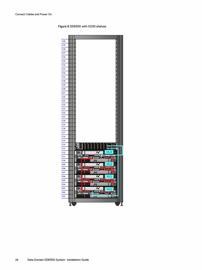
Figure 8 DD6300 with ES30 shelves
Connect Cables and Power On
26 Data Domain DD6300 System Installation Guide
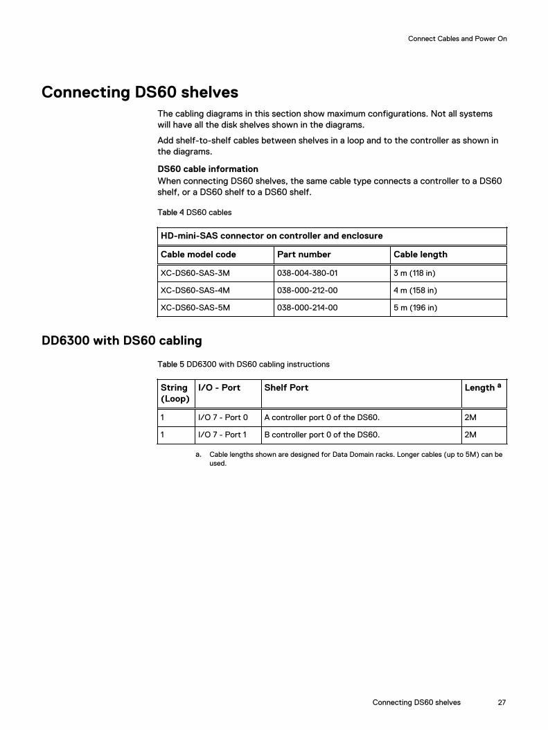
Connecting DS60 shelvesThe cabling diagrams in this section show maximum configurations. Not all systemswill have all the disk shelves shown in the diagrams.
Add shelf-to-shelf cables between shelves in a loop and to the controller as shown inthe diagrams.
DS60 cable informationWhen connecting DS60 shelves, the same cable type connects a controller to a DS60shelf, or a DS60 shelf to a DS60 shelf.
Table 4 DS60 cables
HD-mini-SAS connector on controller and enclosure
Cable model code Part number Cable length
XC-DS60-SAS-3M 038-004-380-01 3 m (118 in)
XC-DS60-SAS-4M 038-000-212-00 4 m (158 in)
XC-DS60-SAS-5M 038-000-214-00 5 m (196 in)
DD6300 with DS60 cabling
Table 5 DD6300 with DS60 cabling instructions
String(Loop)
I/O - Port Shelf Port Length a
1 I/O 7 - Port 0 A controller port 0 of the DS60. 2M
1 I/O 7 - Port 1 B controller port 0 of the DS60. 2M
a. Cable lengths shown are designed for Data Domain racks. Longer cables (up to 5M) can beused.
Connect Cables and Power On
Connecting DS60 shelves 27
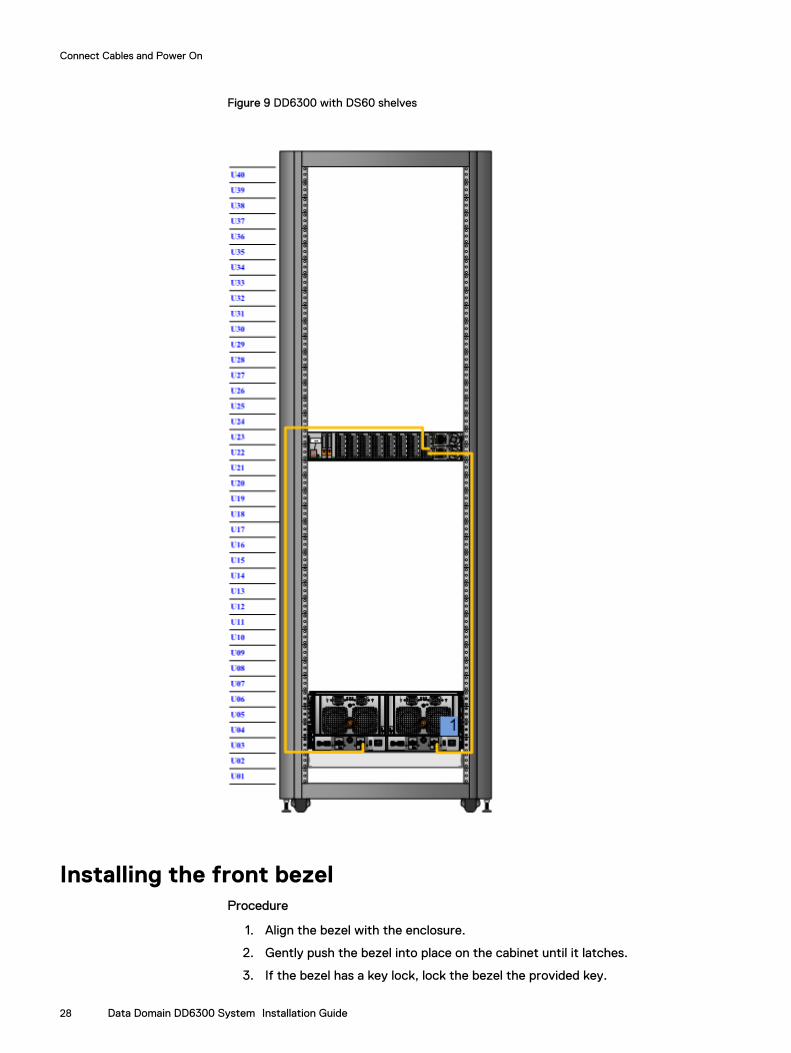
Figure 9 DD6300 with DS60 shelves
Installing the front bezelProcedure
1. Align the bezel with the enclosure.
2. Gently push the bezel into place on the cabinet until it latches.
3. If the bezel has a key lock, lock the bezel the provided key.
Connect Cables and Power On
28 Data Domain DD6300 System Installation Guide
Connect data cables1. Enable data transfer Ethernet connectivity. Repeat for each connection.
a. If using 1 Gb copper Ethernet, attach a Cat 5e or Cat 6 copper Ethernet cableto an RJ-45 Ethernet network port (start with ethMa and go up).
b. If using 10 Gb copper Ethernet with an SFP+ connector, use a qualified SFP+copper cable.
c. If using 1/10 Gb fiber Ethernet, use MMF-850nm cables with LC duplexconnectors.
d. For 10GBaseT connections, use Cat6a S-STP Ethernet cables.
2. Enable data transfer Fibre Channel (FC) connectivity. Repeat for each connection.
a. Attach a Fibre Channel fiber optical cable (LC connector) to an I/O moduleport on the controller, and attach the other end (LC connector) to an FCswitch or to an FC port on your server.
Power on all systems
Note
Power on all expansion shelves first before powering on the controller.
1. Connect power cables to each expansion shelf receptacle and attach the retentionclips.
2. Provide power to power on each expansion shelf. The shelves power on whenplugged in. Ensure that each shelf power cable is connected to a different powersource.
Note
Wait approximately 3 minutes after all expansion shelves are powered on beforepowering on the controller.
3. Provide power to power on the controller. The system powers on when plugged in.The first boot may take several minutes to complete.
Note
Connect systems to redundant AC power sources. Redundant power sources allowone AC source to fail or be serviced without impacting system operation. PSU0should be attached to one AC source. PSU1 should be attached to the other ACsource.
a. Connect power cables to each receptacle and attach the retention clips.
b. Ensure that each power supply is connected to a different power source.
Connect Cables and Power On
Connect data cables 29

Connect Cables and Power On
30 Data Domain DD6300 System Installation Guide
CHAPTER 4
Configure System for Use
l Enable administrative communication................................................................ 32l Accepting the End User License Agreement...................................................... 33l Run the configuration wizard............................................................................. 33
Configure System for Use 31
Enable administrative communicationThe administrative interfaces are located on the management module on the rear ofthe chassis. These interfaces are for management network traffic only. Do not usethese interfaces for data traffic.
1. Connect an administrative console to the serial port on the back panel of thesystem.
2.Note
You must have 115200 baud rate for the system to work correctly; 9600 baud ratedoes not work.
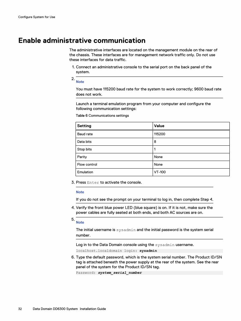
Launch a terminal emulation program from your computer and configure thefollowing communication settings:
Table 6 Communications settings
Setting Value
Baud rate 115200
Data bits 8
Stop bits 1
Parity None
Flow control None
Emulation VT-100
3. Press Enter to activate the console.
Note
If you do not see the prompt on your terminal to log in, then complete Step 4.
4. Verify the front blue power LED (blue square) is on. If it is not, make sure thepower cables are fully seated at both ends, and both AC sources are on.
5.Note
The initial username is sysadmin and the initial password is the system serialnumber.
Log in to the Data Domain console using the sysadmin username.
localhost.localdomain login: sysadmin6. Type the default password, which is the system serial number. The Product ID/SN
tag is attached beneath the power supply at the rear of the system. See the rearpanel of the system for the Product ID/SN tag.Password: system_serial_number
Configure System for Use
32 Data Domain DD6300 System Installation Guide
Note
If you type an incorrect password four consecutive times, the system locks out thespecified username for 120 seconds. The login count and lockout period areconfigurable and might be different on your system. See the Data Domain OperatingSystem Administration Guide and the Data Domain Operating System CommandReference Guide for setting these values.
Accepting the End User License AgreementThe first time you log in to a Data Domain system, the End User License Agreement(EULA) is displayed.
At the end of the EULA, you are prompted to accept it:
Press any key then hit enter to acknowledge the receipt of EULA information
Note
The customer must accept the EULA. A Data Domain representative should not acceptthis agreement. If a customer is not present, press Ctrl-C to exit from the EULAacceptance screen and continue the installation.
The customer can later type the following to redisplay the EULA and accept it:
system show eula
Run the configuration wizardThe CLI configuration wizard starts automatically the first time the system starts. Thewizard prompts you through a series of questions that provide just enough informationfor initial system configuration and basic network connectivity.
Note
You can begin the CLI configuration wizard manually by typing config setup.
Configuring the networkProcedure
1. Enter yes to configure the system for network connectivity.
Network ConfigurationConfigure Network at this time (yes|no) [no]:yes
2. Enter yes to configure DHCP (Dynamic Host Configuration Protocol) to obtainnetwork parameters (such as, the host name, domain name, and IP addresses)dynamically from a DHCP server. Or enter no to configure the parametersmanually.
Use DHCPUse DHCP for hostname, domainname, default gatewayand DNS servers? (At least one interface needs tobe configured using DHCP) (yes|no|?)
3. Enter a fully qualified domain name (FQDN) for the host name; for example,str01.yourcompany.com. Or accept the host name, if the system was able todiscover it.
Configure System for Use
Accepting the End User License Agreement 33
Enter the hostname for this system(fully-qualified domain name)[]:
4. Enter the DNS (Domain Name System) domain name; for example,yourcompany.com. Or accept the domain name, if the system was able todiscover it.
DomainnameEnter your DNS domainname []:
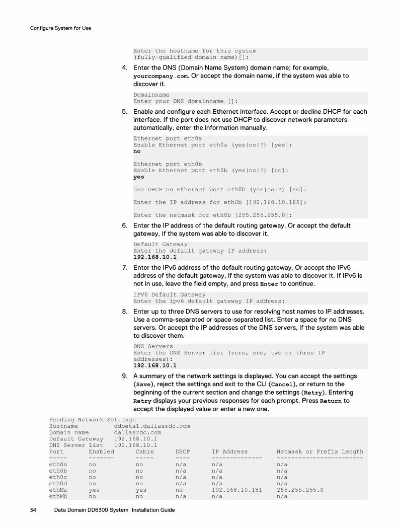
5. Enable and configure each Ethernet interface. Accept or decline DHCP for eachinterface. If the port does not use DHCP to discover network parametersautomatically, enter the information manually.
Ethernet port eth0aEnable Ethernet port eth0a (yes|no|?) [yes]:no
Ethernet port eth0bEnable Ethernet port eth0b (yes|no|?) [no]:yes
Use DHCP on Ethernet port eth0b (yes|no|?) [no]: Enter the IP address for eth0b [192.168.10.185]:
Enter the netmask for eth0b [255.255.255.0]:6. Enter the IP address of the default routing gateway. Or accept the default
gateway, if the system was able to discover it.
Default GatewayEnter the default gateway IP address:192.168.10.1
7. Enter the IPv6 address of the default routing gateway. Or accept the IPv6address of the default gateway, if the system was able to discover it. If IPv6 isnot in use, leave the field empty, and press Enter to continue.
IPV6 Default GatewayEnter the ipv6 default gateway IP address:
8. Enter up to three DNS servers to use for resolving host names to IP addresses.Use a comma-separated or space-separated list. Enter a space for no DNSservers. Or accept the IP addresses of the DNS servers, if the system was ableto discover them.
DNS ServersEnter the DNS Server list (zero, one, two or three IP addresses):192.168.10.1
9. A summary of the network settings is displayed. You can accept the settings(Save), reject the settings and exit to the CLI (Cancel), or return to thebeginning of the current section and change the settings (Retry). EnteringRetry displays your previous responses for each prompt. Press Return toaccept the displayed value or enter a new one.
Pending Network SettingsHostname ddbeta1.dallasrdc.comDomain name dallasrdc.com Default Gateway 192.168.10.1 DNS Server List 192.168.10.1 Port Enabled Cable DHCP IP Address Netmask or Prefix Length----- ------- ----- ---- -------------- ------------------------eth0a no no n/a n/a n/a eth0b no no n/a n/a n/a eth0c no no n/a n/a n/a eth0d no no n/a n/a n/a ethMa yes yes no 192.168.10.181 255.255.255.0 ethMb no no n/a n/a n/a
Configure System for Use
34 Data Domain DD6300 System Installation Guide
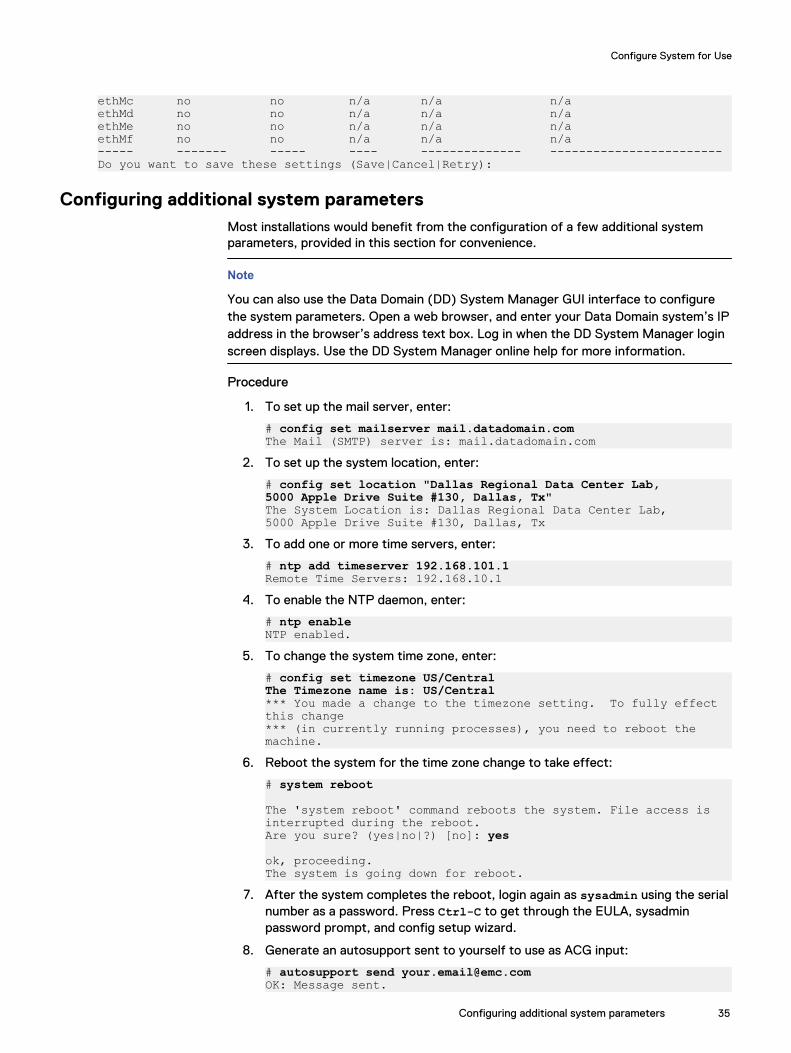
ethMc no no n/a n/a n/a ethMd no no n/a n/a n/a ethMe no no n/a n/a n/a ethMf no no n/a n/a n/a ----- ------- ----- ---- -------------- ------------------------Do you want to save these settings (Save|Cancel|Retry):
Configuring additional system parametersMost installations would benefit from the configuration of a few additional systemparameters, provided in this section for convenience.
Note
You can also use the Data Domain (DD) System Manager GUI interface to configurethe system parameters. Open a web browser, and enter your Data Domain system’s IPaddress in the browser’s address text box. Log in when the DD System Manager loginscreen displays. Use the DD System Manager online help for more information.
Procedure
1. To set up the mail server, enter:
# config set mailserver mail.datadomain.comThe Mail (SMTP) server is: mail.datadomain.com
2. To set up the system location, enter:
# config set location "Dallas Regional Data Center Lab,5000 Apple Drive Suite #130, Dallas, Tx"The System Location is: Dallas Regional Data Center Lab,5000 Apple Drive Suite #130, Dallas, Tx
3. To add one or more time servers, enter:
# ntp add timeserver 192.168.101.1Remote Time Servers: 192.168.10.1
4. To enable the NTP daemon, enter:
# ntp enableNTP enabled.
5. To change the system time zone, enter:
# config set timezone US/CentralThe Timezone name is: US/Central*** You made a change to the timezone setting. To fully effect this change *** (in currently running processes), you need to reboot the machine.
6. Reboot the system for the time zone change to take effect:
# system reboot
The 'system reboot' command reboots the system. File access is interrupted during the reboot.Are you sure? (yes|no|?) [no]: yes
ok, proceeding.The system is going down for reboot.
7. After the system completes the reboot, login again as sysadmin using the serialnumber as a password. Press Ctrl-C to get through the EULA, sysadminpassword prompt, and config setup wizard.
8. Generate an autosupport sent to yourself to use as ACG input:
# autosupport send [email protected]: Message sent.
Configure System for Use
Configuring additional system parameters 35

Configure System for Use
36 Data Domain DD6300 System Installation Guide