Embed Size (px)
Citation preview
Doc. No. 78-5045-02
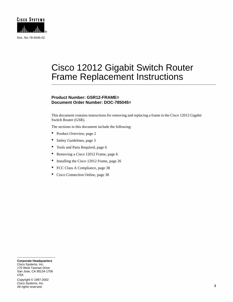
Cisco 12012 Gigabit Switch Router Frame Replacement Instructions
Product Number: GSR12-FRAME=Document Order Number: DOC-785045=
This document contains instructions for removing and replacing a frame in the Cisco 12012 Gigabit Switch Router (GSR).
The sections in this document include the following:
• Product Overview, page 2
• Safety Guidelines, page 3
• Tools and Parts Required, page 6
• Removing a Cisco 12012 Frame, page 6
• Installing the Cisco 12012 Frame, page 26
• FCC Class A Compliance, page 38
• Cisco Connection Online, page 38
1Cisco Systems, Inc.All rights reserved.
170 West Tasman DriveSan Jose, CA 95134-1706USA
Cisco Systems, Inc.Corporate Headquarters
Copyright © 1997-2002
Product Overview
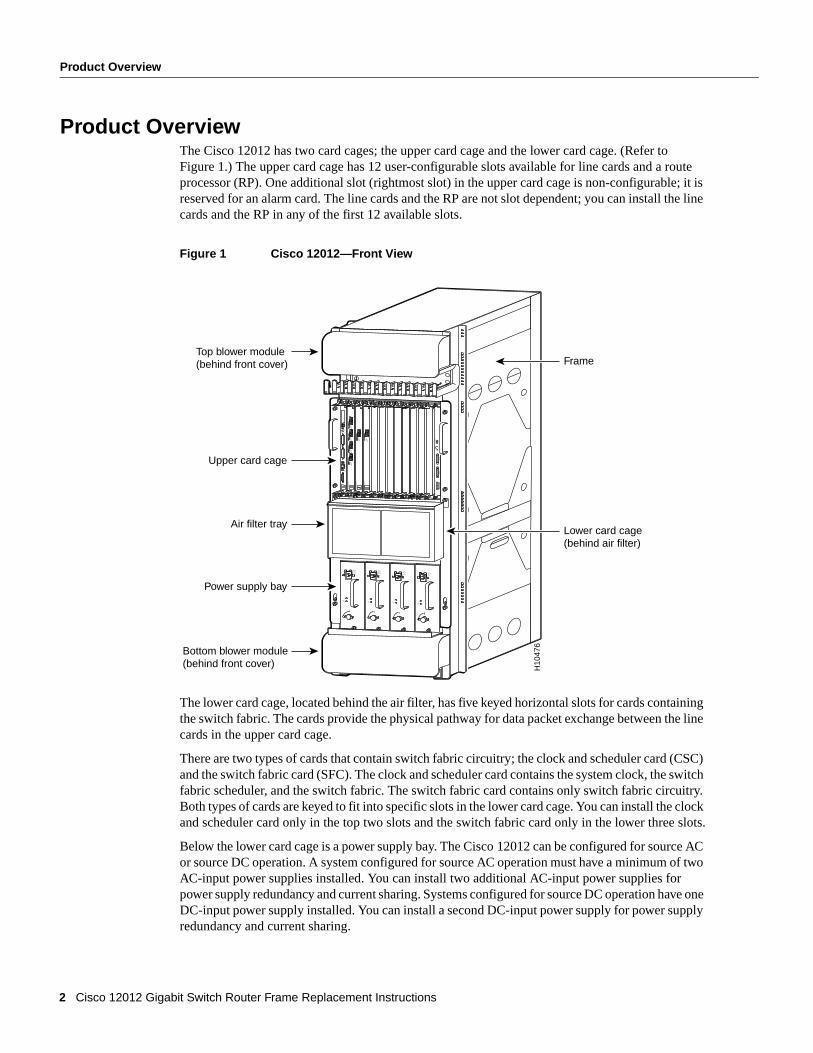
Product OverviewThe Cisco 12012 has two card cages; the upper card cage and the lower card cage. (Refer to Figure 1.) The upper card cage has 12 user-configurable slots available for line cards and a route processor (RP). One additional slot (rightmost slot) in the upper card cage is non-configurable; it is reserved for an alarm card. The line cards and the RP are not slot dependent; you can install the line cards and the RP in any of the first 12 available slots.
Figure 1 Cisco 12012—Front View
The lower card cage, located behind the air filter, has five keyed horizontal slots for cards containing the switch fabric. The cards provide the physical pathway for data packet exchange between the line cards in the upper card cage.
There are two types of cards that contain switch fabric circuitry; the clock and scheduler card (CSC) and the switch fabric card (SFC). The clock and scheduler card contains the system clock, the switch fabric scheduler, and the switch fabric. The switch fabric card contains only switch fabric circuitry. Both types of cards are keyed to fit into specific slots in the lower card cage. You can install the clock and scheduler card only in the top two slots and the switch fabric card only in the lower three slots.
Below the lower card cage is a power supply bay. The Cisco 12012 can be configured for source AC or source DC operation. A system configured for source AC operation must have a minimum of two AC-input power supplies installed. You can install two additional AC-input power supplies for power supply redundancy and current sharing. Systems configured for source DC operation have one DC-input power supply installed. You can install a second DC-input power supply for power supply redundancy and current sharing.
INPUT:200 -240V ~10 A50/60 HZ2000 W
ACOK
OUTPUTFAIL
INPUT:200 -240V ~10 A50/60 HZ2000 W
ACOK
OUTPUTFAIL
INPUT:200 -240V ~10 A50/60 HZ2000 W
ACOK
OUTPUTFAIL
INPUT:200 -240V ~10 A50/60 HZ2000 W
ACOK
OUTPUTFAIL
SLOT-0
RO
UT
E PR
OC
ESSO
R
SLOT-1COLL
LINKTX
RXRJ-45
MII
RESET
AUX
CONSOLE
EJECT
ACTIVE
0
CARRIER
RX PKT
ACTIVE
1
CARRIER
RX PKT
ACTIVE
2
CARRIER
RX PKT
ACTIVE
3
CARRIER
RX PKT
Q O
C-3/ST
M-PO
S
ACTIVE
0
CARRIER
RX CELL
OC
-12/STM
-4 AT
M
OC
-12/STM
-4 POS
ACTIVE
0
CARRIER
RX CELL
ACO/LT
AL
AR
M
CSC
0
FAIL
10
12
ENABLED
CRITICALMAJORMINOR
SFCALAR
M 1
ALARM
2
H10
476
Top blower module(behind front cover)
Upper card cage
Lower card cage(behind air filter)
Frame
Air filter tray
Power supply bay
Bottom blower module(behind front cover)
2 Cisco 12012 Gigabit Switch Router Frame Replacement Instructions
Safety Guidelines
The Cisco 12012 has two blower modules; one located above the upper card cage and one located below the power supply bay. They draw filtered cooling air in through both card cages and the power supply bay to maintain acceptable operating temperatures for the internal components.
Safety GuidelinesBefore you begin the replacement procedure, review the safety guidelines in this section to avoid injuring yourself or damaging the equipment. This section also repeats in multiple languages the warnings in this document.
In addition, review the safety warnings listed in the document Regulatory Compliance and Safety Information for the Cisco 12012 Gigabit Switch Router (Document Number 78-4347-xx) that supports your Cisco 12012 before installing, configuring, or maintaining the router.
Following are translations for the warning statements used in this document.
Safety Warnings
Waarschuwing Dit waarschuwingssymbool betekent gevaar. U verkeert in een situatie die lichamelijk letsel kan veroorzaken. Voordat u aan enige apparatuur gaat werken, dient u zich bewust te zijn van de bij elektrische schakelingen betrokken risico's en dient u op de hoogte te zijn van standaard maatregelen om ongelukken te voorkomen. Voor vertalingen van de waarschuwingen die in deze publicatie verschijnen, kunt u het document Regulatory Compliance and Safety Information (Informatie over naleving van veiligheids- en andere voorschriften) raadplegen dat bij dit toestel is ingesloten.
Varoitus Tämä varoitusmerkki merkitsee vaaraa. Olet tilanteessa, joka voi johtaa ruumiinvammaan. Ennen kuin työskentelet minkään laitteiston parissa, ota selvää sähkökytkentöihin liittyvistä vaaroista ja tavanomaisista onnettomuuksien ehkäisykeinoista. Tässä julkaisussa esiintyvien varoitusten käännökset löydät laitteen mukana olevasta Regulatory Compliance and Safety Information -kirjasesta (määräysten noudattaminen ja tietoa turvallisuudesta).
Attention Ce symbole d'avertissement indique un danger. Vous vous trouvez dans une situation pouvant causer des blessures ou des dommages corporels. Avant de travailler sur un équipement, soyez conscient des dangers posés par les circuits électriques et familiarisez-vous avec les procédures couramment utilisées pour éviter les accidents. Pour prendre connaissance des traductions d’avertissements figurant dans cette publication, consultez le document Regulatory Compliance and Safety Information (Conformité aux règlements et consignes de sécurité) qui accompagne cet appareil.
Warnung Dieses Warnsymbol bedeutet Gefahr. Sie befinden sich in einer Situation, die zu einer Körperverletzung führen könnte. Bevor Sie mit der Arbeit an irgendeinem Gerät beginnen, seien Sie sich der mit elektrischen Stromkreisen verbundenen Gefahren und der Standardpraktiken zur Vermeidung von Unfällen bewußt. Übersetzungen der in dieser Veröffentlichung enthaltenen Warnhinweise finden Sie im Dokument Regulatory Compliance and Safety Information (Informationen zu behördlichen Vorschriften und Sicherheit), das zusammen mit diesem Gerät geliefert wurde.
Warning This warning symbol means danger. You are in a situation that could cause bodily injury. Before you work on any equipment, be aware of the hazards involved with electrical circuitry and be familiar with standard practices for preventing accidents. To see translations of the warnings that appear in this publication, refer to the Regulatory Compliance and Safety Information document that accompanied this device.
Cisco 12012 Gigabit Switch Router Frame Replacement Instructions 3
Safety Guidelines
Avvertenza Questo simbolo di avvertenza indica un pericolo. La situazione potrebbe causare infortuni alle persone. Prima di lavorare su qualsiasi apparecchiatura, occorre conoscere i pericoli relativi ai circuiti elettrici ed essere al corrente delle pratiche standard per la prevenzione di incidenti. La traduzione delle avvertenze riportate in questa pubblicazione si trova nel documento Regulatory Compliance and Safety Information (Conformità alle norme e informazioni sulla sicurezza) che accompagna questo dispositivo.
Advarsel Dette varselsymbolet betyr fare. Du befinner deg i en situasjon som kan føre til personskade. Før du utfører arbeid på utstyr, må du vare oppmerksom på de faremomentene som elektriske kretser innebærer, samt gjøre deg kjent med vanlig praksis når det gjelder å unngå ulykker. Hvis du vil se oversettelser av de advarslene som finnes i denne publikasjonen, kan du se i dokumentet Regulatory Compliance and Safety Information (Overholdelse av forskrifter og sikkerhetsinformasjon) som ble levert med denne enheten.
Aviso Este símbolo de aviso indica perigo. Encontra-se numa situação que lhe poderá causar danos físicos. Antes de começar a trabalhar com qualquer equipamento, familiarize-se com os perigos relacionados com circuitos eléctricos, e com quaisquer práticas comuns que possam prevenir possíveis acidentes. Para ver as traduções dos avisos que constam desta publicação, consulte o documento Regulatory Compliance and Safety Information (Informação de Segurança e Disposições Reguladoras) que acompanha este dispositivo.
¡Advertencia! Este símbolo de aviso significa peligro. Existe riesgo para su integridad física. Antes de manipular cualquier equipo, considerar los riesgos que entraña la corriente eléctrica y familiarizarse con los procedimientos estándar de prevención de accidentes. Para ver una traducción de las advertencias que aparecen en esta publicación, consultar el documento titulado Regulatory Compliance and Safety Information (Información sobre seguridad y conformidad con las disposiciones reglamentarias) que se acompaña con este dispositivo.
Varning! Denna varningssymbol signalerar fara. Du befinner dig i en situation som kan leda till personskada. Innan du utför arbete på någon utrustning måste du vara medveten om farorna med elkretsar och känna till vanligt förfarande för att förebygga skador. Se förklaringar av de varningar som förkommer i denna publikation i dokumentet Regulatory Compliance and Safety Information (Efterrättelse av föreskrifter och säkerhetsinformation), vilket medföljer denna anordning.
Safety with EquipmentThe following guidelines will help ensure your safety and protect the equipment. This list is not inclusive of all potentially hazardous situations, so be alert.
• Always disconnect all power cords and interface cables before moving the system.
• Keep tools and assembly components away from walk areas.
• Do not work alone if potentially hazardous conditions exist.
• Do not perform any action that creates a potential hazard to people or makes the equipment unsafe.
• Carefully examine your work area for possible hazards such as moist floors, ungrounded power extension cables, and missing safety grounds.
4 Cisco 12012 Gigabit Switch Router Frame Replacement Instructions
Safety Guidelines
Safety with ElectricityThe line cards, alarm card, redundant clock and scheduler cards, switch fabric cards, blower modules, and redundant power supplies are designed to be removed and replaced while the system is operating without presenting an electrical hazard or damage to the system.
Follow these basic guidelines when working with any electrical equipment:
• Before beginning any procedures requiring access to the interior of the Cisco 12012, locate the emergency power-off switch for the room in which you are working.
• Look carefully for possible hazards in your work area, such as moist floors, ungrounded power extension cables, and missing safety grounds.
• If an electrical accident occurs, proceed as follows:
— Use caution; do not become a victim yourself. Disconnect power to the system.
— If possible, send another person to get medical aid. Otherwise, assess the condition of the victim and then call for help.
— Determine if the person needs rescue breathing or external cardiac compressions; then take appropriate action.
• Disconnect all power and external cables before installing or removing a router.
• Never assume that power has been disconnected from a circuit; always check.
• Do not perform any action that creates a potential hazard to people or makes the equipment unsafe.
• Never install equipment that appears damaged.
In addition, use the guidelines that follow when working with any equipment that is disconnected from a power source, but still connected to telephone or network wiring:
• Never install telephone wiring during a lightning storm.
• Never install telephone jacks in wet locations unless the jack is specifically designed for wet locations.
• Never touch uninsulated telephone wires or terminals unless the telephone line has been disconnected at the network interface.
• Use caution when installing or modifying telephone lines.
Preventing Electrostatic Discharge DamageElectrostatic discharge damage, which can occur when electronic boards or components are handled improperly, can result in complete or intermittent failures.
Following are guidelines for preventing ESD damage:
• Always use an ESD-preventive wrist strap or ankle strap and ensure that it makes good skin contact.
• When removing or installing a component, connect the equipment end of a ground strap to one of the two ESD ground sockets located on the front sides of the upper card cage or to a bare metal surface on the frame.
Cisco 12012 Gigabit Switch Router Frame Replacement Instructions 5
Tools and Parts Required
• If you plan to return a replaced component to the factory, immediately place it in a static shielding bag to avoid ESD damage to the component.
• The wrist strap only protects the component from ESD voltages on the body; ESD voltages on clothing can still cause damage.
Tools and Parts RequiredYou need the following tools and parts to remove and replace the frame:
• ESD-preventive wrist strap
• 1/4-inch flat-blade screwdriver
• 3/16-inch flat-blade screwdriver
• 10-mm nutdriver
• Antistatic mat
• The replacement frame (Product Number: GSR12-FRAME=)
Removing a Cisco 12012 FrameThis section provides the procedures for removing a Cisco 12012 frame. To accomplish this task, you must first remove the three major components housed in the frame: the two blower modules and the card cage assembly. Perform the following procedures to remove the blower modules and the card cage assembly.
Powering Down the Cisco 12012If your Cisco 12012 is installed in a rack and is powered up, perform the following steps to power down the system:
Step 1 Turn the DC-input power supply power switch to the OFF (O) position (on AC-input power supplies, turn the power switch counterclockwise to the STANDBY position) on all power supplies installed in the Cisco 12012.
Step 2 Verify that the system has powered down by checking that the LEDs on the power supplies are off and the green LEDs on both blower modules are off.
Caution You should periodically check the resistance value of the antistatic strap. The measurement should be between 1 and 10 megohms.
Warning This unit has more than one power supply connection; all connections must be removed completely to completely remove power from the unit.
6 Cisco 12012 Gigabit Switch Router Frame Replacement Instructions
Removing a Cisco 12012 Frame
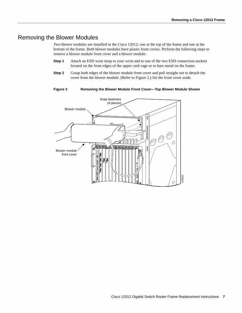
Removing the Blower ModulesTwo blower modules are installed in the Cisco 12012; one at the top of the frame and one at the bottom of the frame. Both blower modules have plastic front covers. Perform the following steps to remove a blower module front cover and a blower module:
Step 1 Attach an ESD wrist strap to your wrist and to one of the two ESD connection sockets located on the front edges of the upper card cage or to bare metal on the frame.
Step 2 Grasp both edges of the blower module front cover and pull straight out to detach the cover from the blower module. (Refer to Figure 2.) Set the front cover aside.
Figure 2 Removing the Blower Module Front Cover—Top Blower Module Shown
SLOT-0
RO
UT
E PR
OC
ESSO
R
SLOT-1COLL
LINKTX
RXRJ-45
MII
RESET
AUX
EJECT
ACTIVE
0
CARRIER
RX PKT
ACTIVE
1
CARRIER
RX PKT
ACTIVE
2
CARRIER
RX PKT
ACTIVE
3
CARRIER
RX PKT
Q O
C-3/ST
M-PO
S
ACTIVE
0
CARRIER
RX CELL
OC
-12/STM
-4 AT
M
OC
-12/STM
-4 POS
ACTIVE
0
CARRIER
RX CELL
ACO/LT
AL
AR
M
CSC
0
FAIL
10
12
ENABLED
CRITICALMAJORMINOR
SFCALAR
M 1
ALARM
2
Blower module
Snap fasteners(4 places)
Blower modulefront cover
H10
654
Cisco 12012 Gigabit Switch Router Frame Replacement Instructions 7
Removing a Cisco 12012 Frame
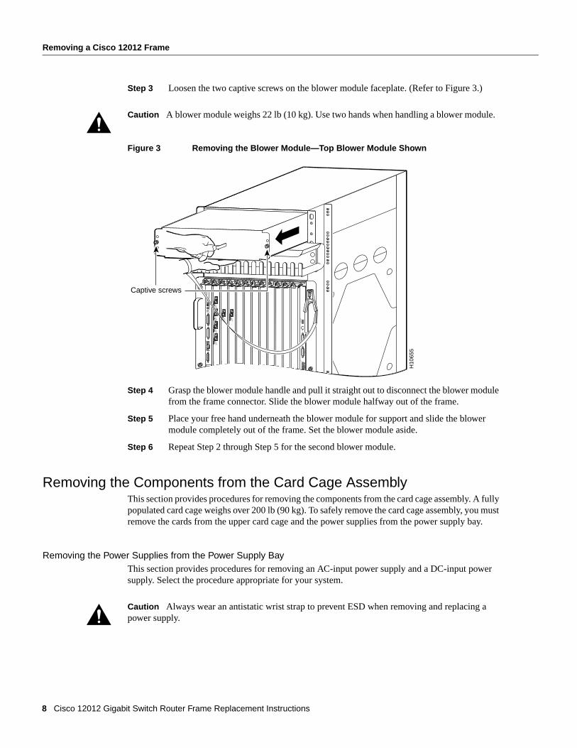
Step 3 Loosen the two captive screws on the blower module faceplate. (Refer to Figure 3.)
Figure 3 Removing the Blower Module—Top Blower Module Shown
Step 4 Grasp the blower module handle and pull it straight out to disconnect the blower module from the frame connector. Slide the blower module halfway out of the frame.
Step 5 Place your free hand underneath the blower module for support and slide the blower module completely out of the frame. Set the blower module aside.
Step 6 Repeat Step 2 through Step 5 for the second blower module.
Removing the Components from the Card Cage AssemblyThis section provides procedures for removing the components from the card cage assembly. A fully populated card cage weighs over 200 lb (90 kg). To safely remove the card cage assembly, you must remove the cards from the upper card cage and the power supplies from the power supply bay.
Removing the Power Supplies from the Power Supply BayThis section provides procedures for removing an AC-input power supply and a DC-input power supply. Select the procedure appropriate for your system.
Caution A blower module weighs 22 lb (10 kg). Use two hands when handling a blower module.
Caution Always wear an antistatic wrist strap to prevent ESD when removing and replacing a power supply.
H10
655
SLOT-0
RO
UT
E PR
OC
ESSO
R
SLOT-1COLL
LINKTX
RXRJ-45
MII
RESET
AUX
EJECT
ACTIVE
0
CARRIER
RX PKT
ACTIVE
1
CARRIER
RX PKT
ACTIVE
2
CARRIER
RX PKT
ACTIVE
3
CARRIER
RX PKT
Q O
C-3/ST
M-PO
S
ACTIVE
0
CARRIER
RX CELL
OC
-12/STM
-4 AT
M
OC
-12/STM
-4 POS
ACTIVE
0
CARRIER
RX CELL
ACO/LT
AL
AR
M
CSC
0
FAIL
10
12
ENABLED
CRITICALMAJORMINOR
SFCALAR
M 1
ALARM
2
Captive screws
8 Cisco 12012 Gigabit Switch Router Frame Replacement Instructions
Removing a Cisco 12012 Frame
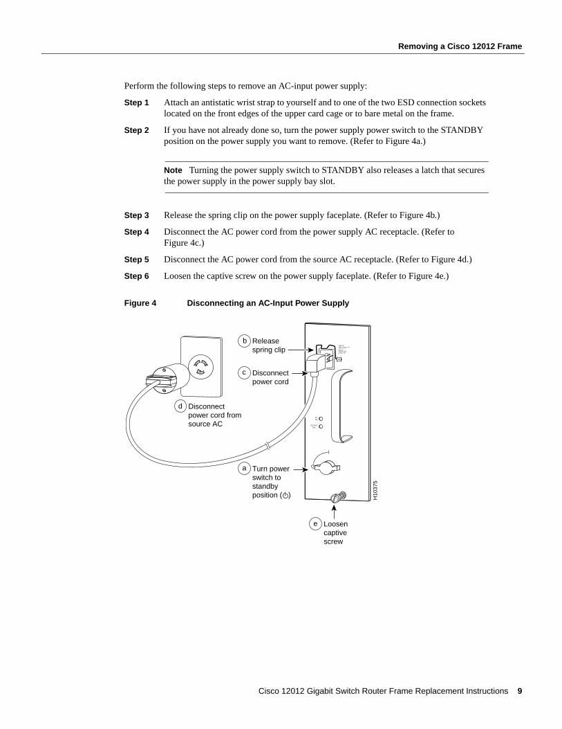
Perform the following steps to remove an AC-input power supply:
Step 1 Attach an antistatic wrist strap to yourself and to one of the two ESD connection sockets located on the front edges of the upper card cage or to bare metal on the frame.
Step 2 If you have not already done so, turn the power supply power switch to the STANDBY position on the power supply you want to remove. (Refer to Figure 4a.)
Note Turning the power supply switch to STANDBY also releases a latch that secures the power supply in the power supply bay slot.
Step 3 Release the spring clip on the power supply faceplate. (Refer to Figure 4b.)
Step 4 Disconnect the AC power cord from the power supply AC receptacle. (Refer to Figure 4c.)
Step 5 Disconnect the AC power cord from the source AC receptacle. (Refer to Figure 4d.)
Step 6 Loosen the captive screw on the power supply faceplate. (Refer to Figure 4e.)
Figure 4 Disconnecting an AC-Input Power Supply
INPUT:200 -240V ~10 A50/60 HZ2000 W
ACOK
OUTPUTFAIL
Releasespring clip
b
Loosencaptivescrew
Disconnectpower cord
Turn powerswitch tostandbyposition ( ) H
1037
5
a
c
Disconnectpower cord fromsource AC
d
e
Cisco 12012 Gigabit Switch Router Frame Replacement Instructions 9
Removing a Cisco 12012 Frame
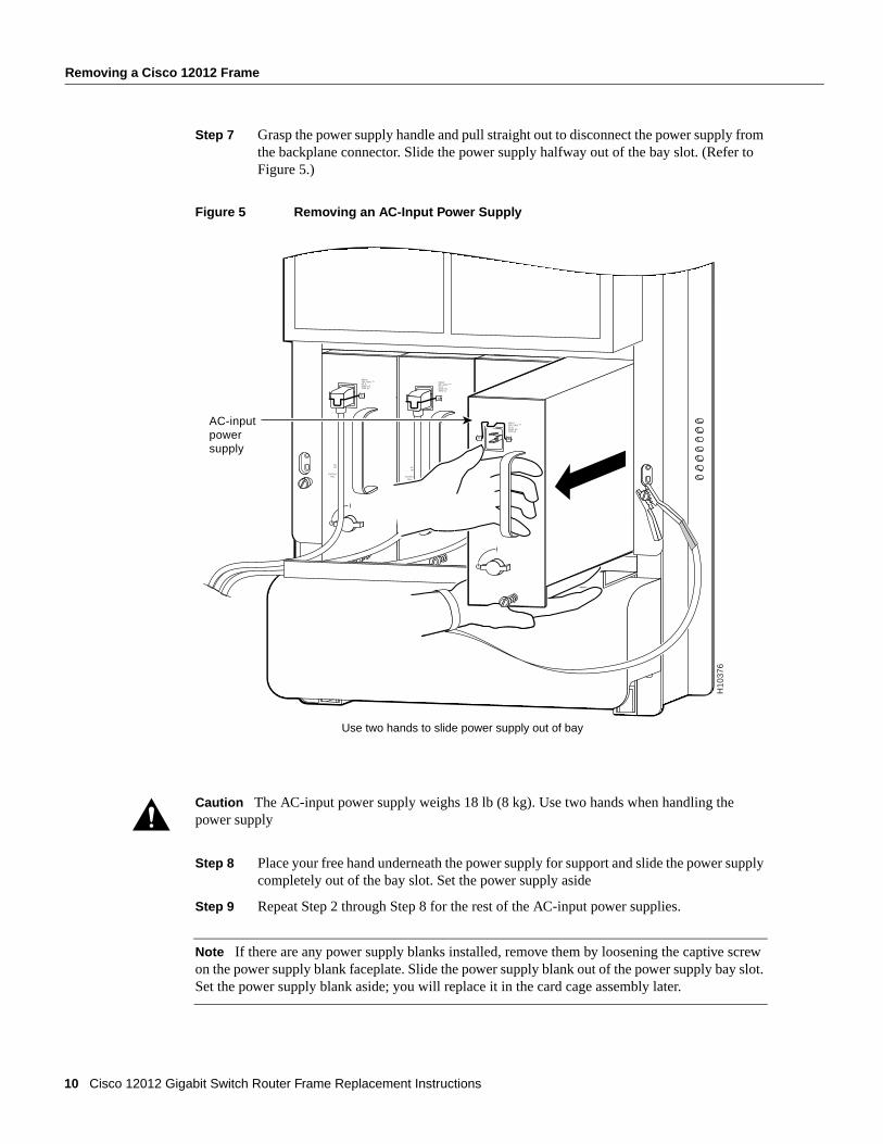
Step 7 Grasp the power supply handle and pull straight out to disconnect the power supply from the backplane connector. Slide the power supply halfway out of the bay slot. (Refer to Figure 5.)
Figure 5 Removing an AC-Input Power Supply
Step 8 Place your free hand underneath the power supply for support and slide the power supply completely out of the bay slot. Set the power supply aside
Step 9 Repeat Step 2 through Step 8 for the rest of the AC-input power supplies.
Note If there are any power supply blanks installed, remove them by loosening the captive screw on the power supply blank faceplate. Slide the power supply blank out of the power supply bay slot. Set the power supply blank aside; you will replace it in the card cage assembly later.
Caution The AC-input power supply weighs 18 lb (8 kg). Use two hands when handling the power supply
ACOK
OUTPUTFAIL
INPUT:200 -240V ~10 A50/60 HZ2000 W
ACOK
OUTPUTFAIL
INPUT:200 -240V ~10 A50/60 HZ2000 W
H10
376
Use two hands to slide power supply out of bay
ACOK
OUTPUTFAIL
INPUT:200 -240V ~10 A50/60 HZ2000 W
AC-inputpowersupply
10 Cisco 12012 Gigabit Switch Router Frame Replacement Instructions
Removing a Cisco 12012 Frame
Perform the following steps to remove a DC-input power supply:
Step 1 Attach an antistatic wrist strap to yourself and to one of the two ESD connection sockets located on the front edges of the upper card cage or to bare metal on the frame.
Step 2 If you have not already done so, turn OFF (O) the power switch on the DC-input power supply.
Note Turning the power supply switch to OFF (O) releases a latch that secures the power supply in the power supply bay.
Step 3 Using a flat-blade screwdriver or a 10-mm nutdriver, turn the captive jackscrew counterclockwise (eject) on the power supply faceplate to unseat the power supply from the backplane power connector. Continue turning the jackscrew to disengage the jackscrew from the power supply bay (approximately 12 revolutions).
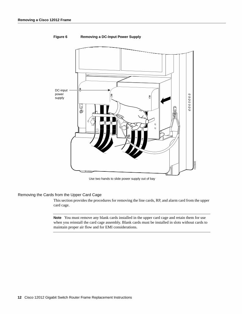
Step 4 Grasp the power supply handle and slide the power supply halfway out of the bay. (Refer to Figure 6.)
Step 5 Place your free hand underneath the power supply for support and slide the power supply completely out of the bay. Set the power supply aside
Step 6 Repeat Step 2 through Step 5 for the rest of the DC-input power supplies.
Caution Before performing the following procedure, ensure that power is removed from the DC circuit. To ensure that all power is OFF, locate the circuit breaker on the panel board that services the DC circuit, switch the circuit breaker to the OFF position, and tape the switch handle of the circuit breaker in the OFF position.
Warning Voltages might be present on the DC-input power supply terminals. Turn off the power source circuit breaker and remove the power supply before accessing the terminals.
Caution The DC-input power supply weighs 19 lb (8.3 kg). Use two hands when handling the power supply.
Cisco 12012 Gigabit Switch Router Frame Replacement Instructions 11
Removing a Cisco 12012 Frame
Figure 6 Removing a DC-Input Power Supply
Removing the Cards from the Upper Card CageThis section provides the procedures for removing the line cards, RP, and alarm card from the upper card cage.
Note You must remove any blank cards installed in the upper card cage and retain them for use when you reinstall the card cage assembly. Blank cards must be installed in slots without cards to maintain proper air flow and for EMI considerations.
H10
600
Use two hands to slide power supply out of bay
DC-inputpowersupply
12 Cisco 12012 Gigabit Switch Router Frame Replacement Instructions
Removing a Cisco 12012 Frame
Removing a Line Card from the Upper Card CagePerform the following steps to remove a line card from the upper card cage:
Step 1 Attach an ESD wrist strap to your wrist and to one of the two ESD connection sockets located on the front edges of the upper card cage or to bare metal on the frame.
Step 2 Proceeding from left to right, identify each line card and write down the following information:
• The line card’s slot number. When you reinstall the line cards in the card cage assembly, install them in the same card slots.
• The interface cable connections to the line card ports. You will reconnect the interface cables to the same line card ports.
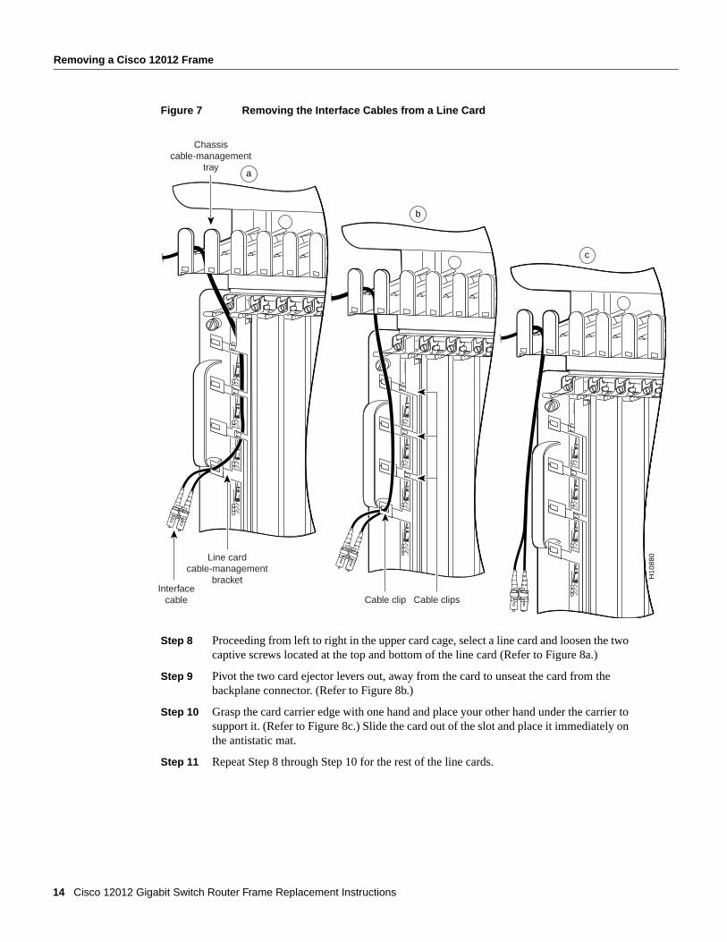
Step 3 Proceeding from left to right, select a line card. Starting with the bottom port on the line card, disconnect the network interface cable from the port. (Refer to Figure 7a.)
Step 4 Carefully remove the interface cable from the vertical cable-management bracket clips. (Refer to Figure 7b.)
Step 5 Carefully remove the interface cable from the vertical cable-management bracket clip nearest the line card port. (Refer to Figure 7c.)
Step 6 Carefully remove the interface cable from the horizontal cable-management tray and set the interface cable aside.
Step 7 Repeat Step 3 through Step 6 for rest of the interface cables on that line card, then proceed to the next line card in the upper card cage.
Continue the procedure until you have disconnected and removed all the line card interface cables from the cable-management system. Do not remove the vertical cable-management bracket from the line card.
Cisco 12012 Gigabit Switch Router Frame Replacement Instructions 13
Removing a Cisco 12012 Frame
Figure 7 Removing the Interface Cables from a Line Card
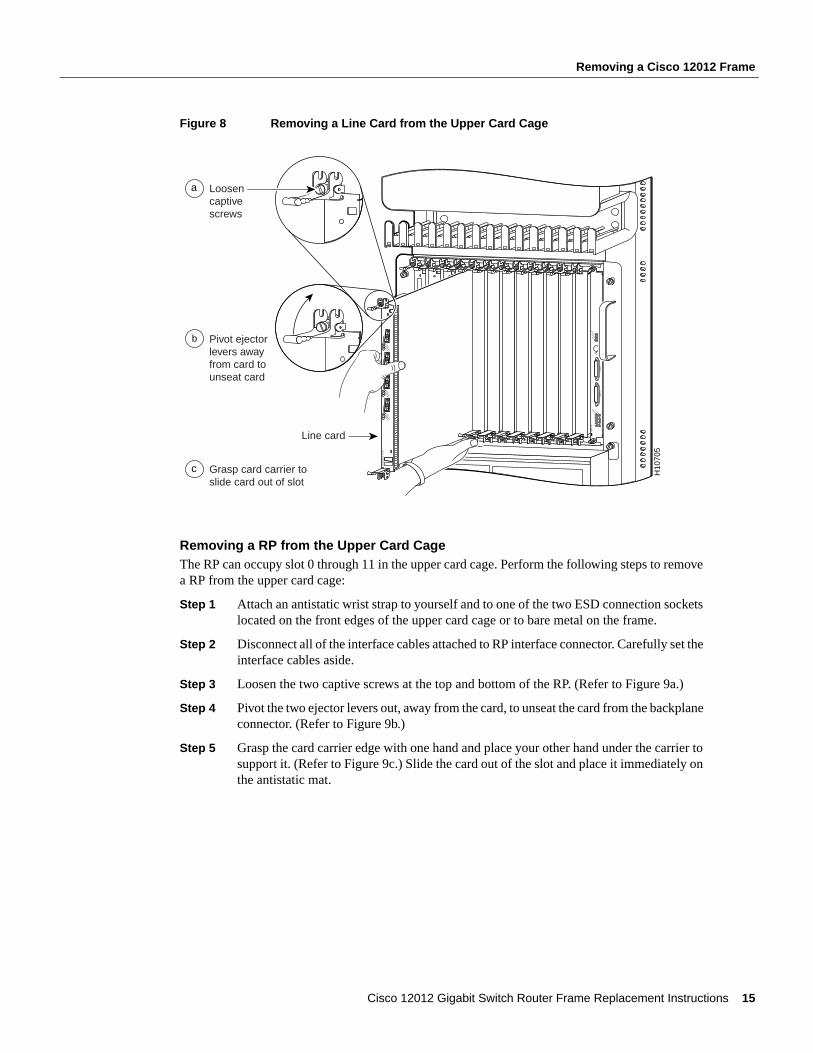
Step 8 Proceeding from left to right in the upper card cage, select a line card and loosen the two captive screws located at the top and bottom of the line card (Refer to Figure 8a.)
Step 9 Pivot the two card ejector levers out, away from the card to unseat the card from the backplane connector. (Refer to Figure 8b.)
Step 10 Grasp the card carrier edge with one hand and place your other hand under the carrier to support it. (Refer to Figure 8c.) Slide the card out of the slot and place it immediately on the antistatic mat.
Step 11 Repeat Step 8 through Step 10 for the rest of the line cards.
ACTIVE
0
CARRIER
RX PKT
ACTIVE
1
CARRIER
RX PKT
ACTIVE
2
CARRIER
RX PKT
ACTIVE
3
CARRIER
RX PKT
a
Chassiscable-management
tray
Line cardcable-management
bracketInterface
cable
ACTIVE
0
CARRIER
RX PKT
ACTIVE
1
CARRIER
RX PKT
ACTIVE
2
CARRIER
RX PKT
ACTIVE
3
CARRIER
RX PKT
b
Cable clip Cable clips
ACTIVE
0
CARRIER
RX PKT
ACTIVE
1
CARRIER
RX PKT
ACTIVE
2
CARRIER
RX PKT
ACTIVE
3
CARRIER
RX PKT
ACTIVE
0
CARRIER
RX PKT
ACTIVE
1
CARRIER
RX PKT
ACTIVE
2
CARRIER
RX PKT
ACTIVE
3
CARRIER
RX PKT
c
H10
880
14 Cisco 12012 Gigabit Switch Router Frame Replacement Instructions
Removing a Cisco 12012 Frame
Figure 8 Removing a Line Card from the Upper Card Cage
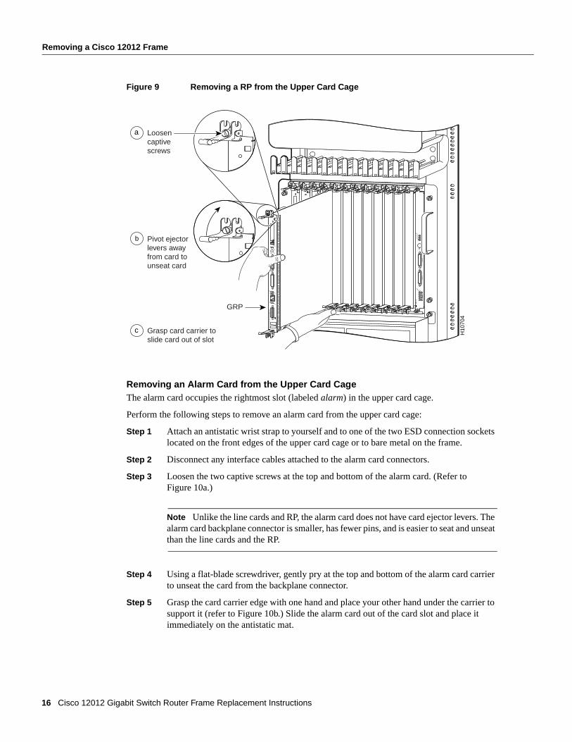
Removing a RP from the Upper Card CageThe RP can occupy slot 0 through 11 in the upper card cage. Perform the following steps to remove a RP from the upper card cage:
Step 1 Attach an antistatic wrist strap to yourself and to one of the two ESD connection sockets located on the front edges of the upper card cage or to bare metal on the frame.
Step 2 Disconnect all of the interface cables attached to RP interface connector. Carefully set the interface cables aside.
Step 3 Loosen the two captive screws at the top and bottom of the RP. (Refer to Figure 9a.)
Step 4 Pivot the two ejector levers out, away from the card, to unseat the card from the backplane connector. (Refer to Figure 9b.)
Step 5 Grasp the card carrier edge with one hand and place your other hand under the carrier to support it. (Refer to Figure 9c.) Slide the card out of the slot and place it immediately on the antistatic mat.
SLOT-0
GIG
AB
IT R
OU
TE
PRO
CE
SSOR
SLOT-1COLL
LINKTX
RXRJ-45
MII
RESET
AUX
CONSOLE
EJECT
ACTIVE
0
CARRIER
RX PKT
ACTIVE
1
CARRIER
RX PKT
ACTIVE
2
CARRIER
RX PKT
ACTIVE
3
CARRIER
RX PKT
Q O
C-3/ST
M-PO
S
ACTIVE
0
CARRIER
RX CELL
OC
-12/STM
-4 AT
M
OC
-12/STM
-4 POS
ACTIVE
0
CARRIER
RX CELL
ACO/LT
ALARM
1ALAR
M 2
AL
AR
M
CSC
0
FAIL
10
12
ENABLED
CRITICALMAJORMINOR
SFC
ACTIVE
0
CARRIER
RX PKT
ACTIVE
1
CARRIER
RX PKT
ACTIVE
2
CARRIER
RX PKT
ACTIVE
3
CARRIER
RX PKT
Q O
C-3/ST
M-PO
S
H10
705
Loosencaptivescrews
Line card
Pivot ejectorlevers awayfrom card tounseat card
Grasp card carrier toslide card out of slot
a
c
b
Cisco 12012 Gigabit Switch Router Frame Replacement Instructions 15
Removing a Cisco 12012 Frame
Figure 9 Removing a RP from the Upper Card Cage
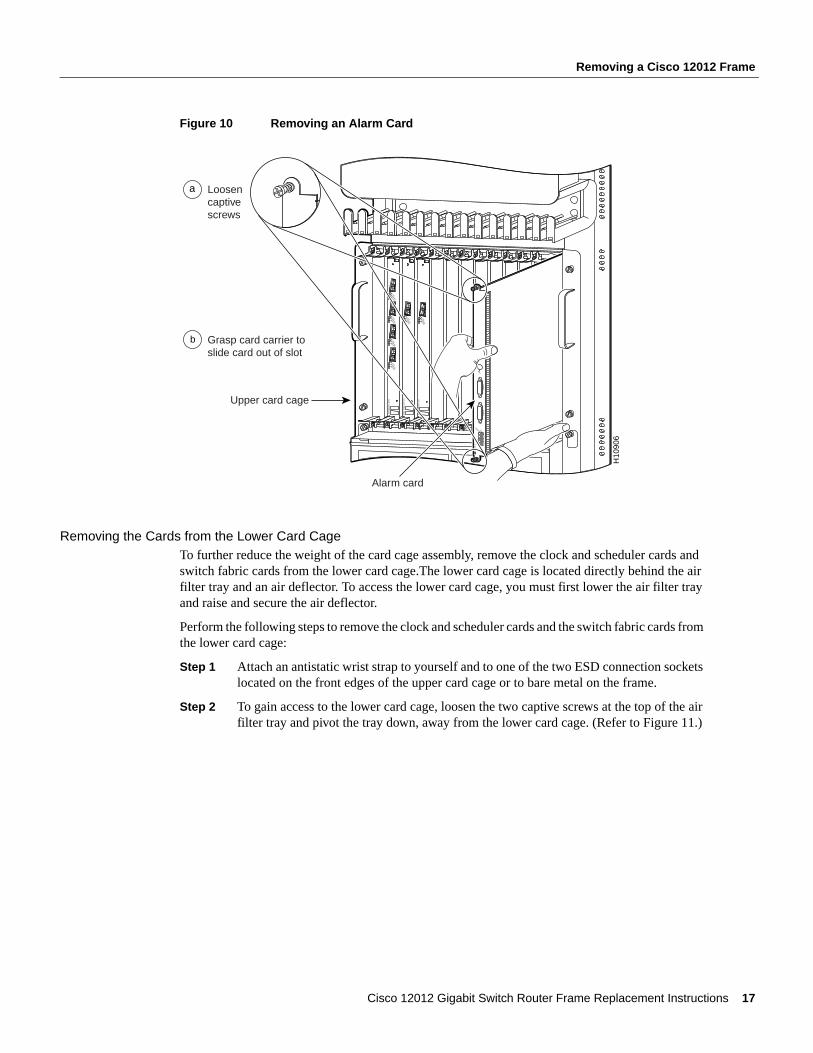
Removing an Alarm Card from the Upper Card CageThe alarm card occupies the rightmost slot (labeled alarm) in the upper card cage.
Perform the following steps to remove an alarm card from the upper card cage:
Step 1 Attach an antistatic wrist strap to yourself and to one of the two ESD connection sockets located on the front edges of the upper card cage or to bare metal on the frame.
Step 2 Disconnect any interface cables attached to the alarm card connectors.
Step 3 Loosen the two captive screws at the top and bottom of the alarm card. (Refer to Figure 10a.)
Note Unlike the line cards and RP, the alarm card does not have card ejector levers. The alarm card backplane connector is smaller, has fewer pins, and is easier to seat and unseat than the line cards and the RP.
Step 4 Using a flat-blade screwdriver, gently pry at the top and bottom of the alarm card carrier to unseat the card from the backplane connector.
Step 5 Grasp the card carrier edge with one hand and place your other hand under the carrier to support it (refer to Figure 10b.) Slide the alarm card out of the card slot and place it immediately on the antistatic mat.
SLOT-0
GIG
AB
IT R
OU
TE
PRO
CE
SSOR
SLOT-1COLL
LINKTX
RXRJ-45
MII
RESET
AUX
CONSOLE
EJECT
ACTIVE
0
CARRIER
RX PKT
ACTIVE
1
CARRIER
RX PKT
ACTIVE
2
CARRIER
RX PKT
ACTIVE
3
CARRIER
RX PKT
Q O
C-3/ST
M-PO
S
ACTIVE
0
CARRIER
RX CELL
OC
-12/STM
-4 AT
M
OC
-12/STM
-4 POS
ACTIVE
0
CARRIER
RX CELL
ACO/LT
ALARM
1ALAR
M 2
AL
AR
M
CSC
0
FAIL
10
12
ENABLED
CRITICALMAJORMINOR
SFC
SLOT-0
GIG
AB
IT R
OU
TE
PRO
CE
SSOR
SLOT-1COLL
LINKTX
RXRJ-45
MII
RESET
AUX
CONSOLE
EJECT
H10
704
Loosencaptivescrews
GRP
Pivot ejectorlevers awayfrom card tounseat card
Grasp card carrier toslide card out of slot
a
c
b
16 Cisco 12012 Gigabit Switch Router Frame Replacement Instructions
Removing a Cisco 12012 Frame
Figure 10 Removing an Alarm Card
Removing the Cards from the Lower Card CageTo further reduce the weight of the card cage assembly, remove the clock and scheduler cards and switch fabric cards from the lower card cage.The lower card cage is located directly behind the air filter tray and an air deflector. To access the lower card cage, you must first lower the air filter tray and raise and secure the air deflector.
Perform the following steps to remove the clock and scheduler cards and the switch fabric cards from the lower card cage:
Step 1 Attach an antistatic wrist strap to yourself and to one of the two ESD connection sockets located on the front edges of the upper card cage or to bare metal on the frame.
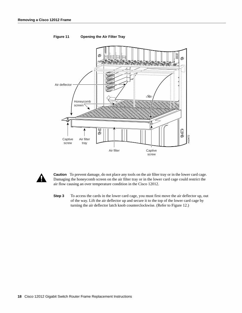
Step 2 To gain access to the lower card cage, loosen the two captive screws at the top of the air filter tray and pivot the tray down, away from the lower card cage. (Refer to Figure 11.)
ACTIVE
0
CARRIER
RX PKT
ACTIVE
1
CARRIER
RX PKT
ACTIVE
2
CARRIER
RX PKT
ACTIVE
3
CARRIER
RX PKT
Q O
C-3/ST
M-PO
S
0
ACTIVECARRIER
RX PKT
OC
-12/STM
-4 AT
M
ACTIVECARRIER
RX PKT
OC
-12/STM
-4 POS
0
ACO/LT
AL
AR
M
CSC
0
FAIL
10
12
ENABLED
CRITICALMAJORMINOR
SFCALAR
M 1
ALARM
2
H10
906
Loosencaptivescrews
a
Grasp card carrier toslide card out of slot
Upper card cage
Alarm card
b
Cisco 12012 Gigabit Switch Router Frame Replacement Instructions 17
Removing a Cisco 12012 Frame
Figure 11 Opening the Air Filter Tray
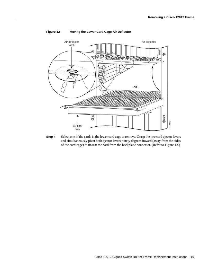
Step 3 To access the cards in the lower card cage, you must first move the air deflector up, out of the way. Lift the air deflector up and secure it to the top of the lower card cage by turning the air deflector latch knob counterclockwise. (Refer to Figure 12.)
Caution To prevent damage, do not place any tools on the air filter tray or in the lower card cage. Damaging the honeycomb screen on the air filter tray or in the lower card cage could restrict the air flow causing an over temperature condition in the Cisco 12012.
GIG
AB
IT R
OU
TE
PRO
CE
SSOR
Q O
C-3/ST
M-PO
S
OC
-12/STM
-4 AT
M
OC
-12/STM
-4 POS
AL
AR
M
CSC
0
FAIL
10
12
ENABLED
SFC
H10
472
Air filtertray
Air filter
Captivescrew
Captivescrew
Air deflector
Honeycombscreen
18 Cisco 12012 Gigabit Switch Router Frame Replacement Instructions
Removing a Cisco 12012 Frame
Figure 12 Moving the Lower Card Cage Air Deflector
Step 4 Select one of the cards in the lower card cage to remove. Grasp the two card ejector levers and simultaneously pivot both ejector levers ninety degrees inward (away from the sides of the card cage) to unseat the card from the backplane connector. (Refer to Figure 13.)
H10
473
GIG
AB
IT R
OU
TE
PRO
CE
SSOR
Q O
C-3/ST
M-PO
S
OC
-12/STM
-4 AT
M
OC
-12/STM
-4 POS
AL
AR
M
CSC
0
FAIL
10
12
ENABLED
SFC
Air deflectorlatch
Air filtertray
Air deflector
Cisco 12012 Gigabit Switch Router Frame Replacement Instructions 19
Removing a Cisco 12012 Frame
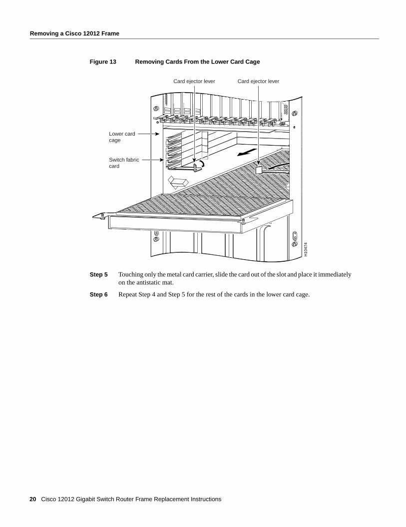
Figure 13 Removing Cards From the Lower Card Cage
Step 5 Touching only the metal card carrier, slide the card out of the slot and place it immediately on the antistatic mat.
Step 6 Repeat Step 4 and Step 5 for the rest of the cards in the lower card cage.
GIG
AB
IT R
OU
TE
PRO
CE
SSOR
Q O
C-3/ST
M-PO
S
OC
-12/STM
-4 AT
M
OC
-12/STM
-4 POS
AL
AR
M
CSC
0
FAIL
10
12
ENABLED
SFC
H10
474
Lower cardcage
Switch fabriccard
Card ejector lever Card ejector lever
20 Cisco 12012 Gigabit Switch Router Frame Replacement Instructions
Removing a Cisco 12012 Frame
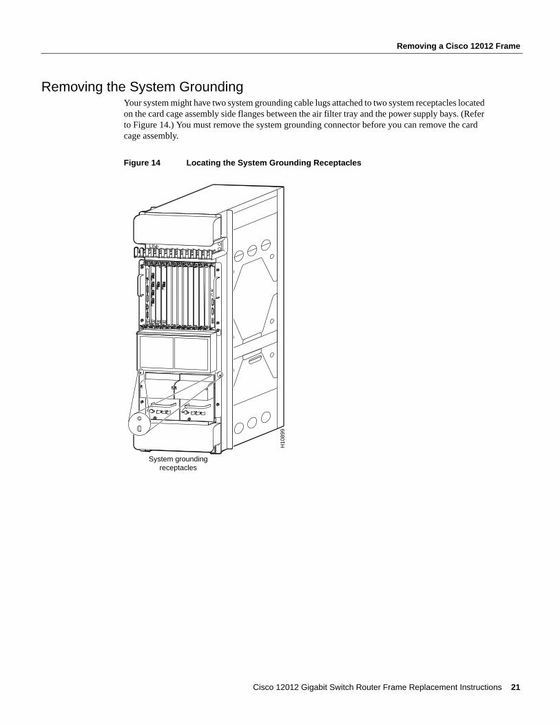
Removing the System GroundingYour system might have two system grounding cable lugs attached to two system receptacles located on the card cage assembly side flanges between the air filter tray and the power supply bays. (Refer to Figure 14.) You must remove the system grounding connector before you can remove the card cage assembly.
Figure 14 Locating the System Grounding Receptacles
SLOT-0
RO
UT
E PR
OC
ESSO
R
SLOT-1COLL
LINKTX
RXRJ-45
MII
RESET
AUX
CONSOLE
EJECT
ACTIVE
0
CARRIER
RX PKT
ACTIVE
1
CARRIER
RX PKT
ACTIVE
2
CARRIER
RX PKT
ACTIVE
3
CARRIER
RX PKT
Q O
C-3/ST
M-PO
S
ACTIVE
0
CARRIER
RX CELL
OC
-12/STM
-4 AT
M
OC
-12/STM
-4 POS
ACTIVE
0
CARRIER
RX CELL
ACO/LT
AL
AR
M
CSC
0
FAIL
10
12
ENABLED
CRITICALMAJORMINOR
SFCALAR
M 1
ALARM
2
H10
899
System groundingreceptacles
Cisco 12012 Gigabit Switch Router Frame Replacement Instructions 21
Removing a Cisco 12012 Frame
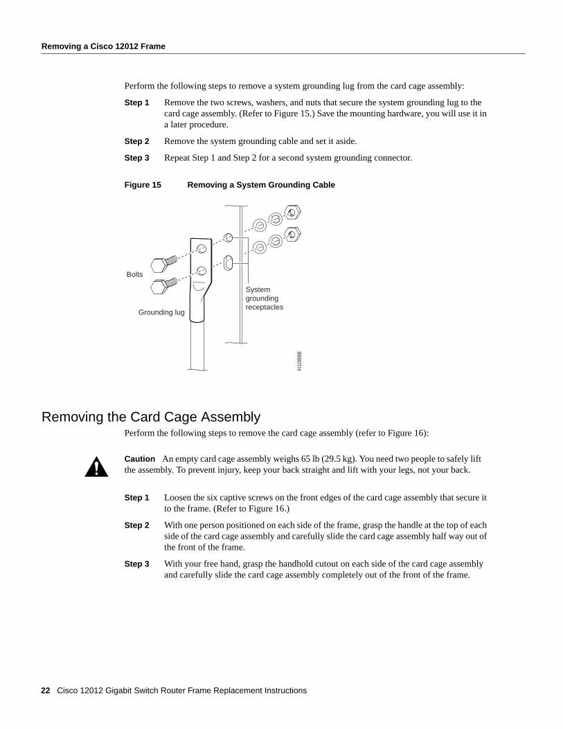
Perform the following steps to remove a system grounding lug from the card cage assembly:
Step 1 Remove the two screws, washers, and nuts that secure the system grounding lug to the card cage assembly. (Refer to Figure 15.) Save the mounting hardware, you will use it in a later procedure.
Step 2 Remove the system grounding cable and set it aside.
Step 3 Repeat Step 1 and Step 2 for a second system grounding connector.
Figure 15 Removing a System Grounding Cable
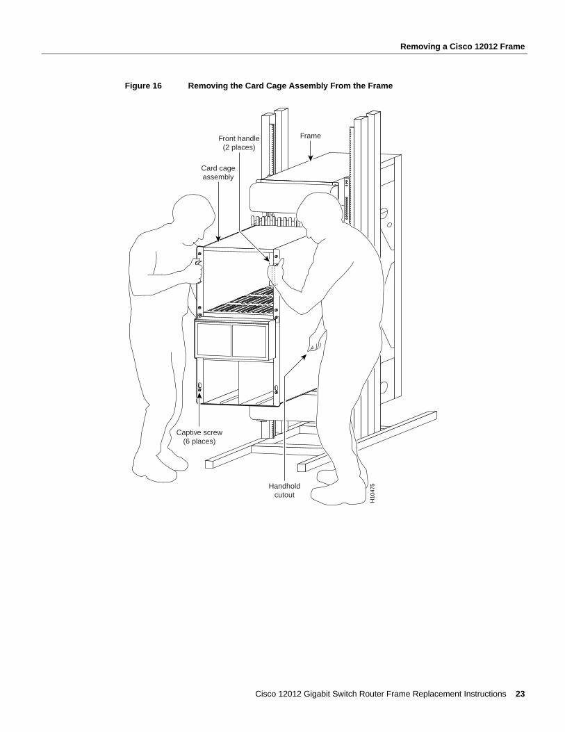
Removing the Card Cage AssemblyPerform the following steps to remove the card cage assembly (refer to Figure 16):
Step 1 Loosen the six captive screws on the front edges of the card cage assembly that secure it to the frame. (Refer to Figure 16.)
Step 2 With one person positioned on each side of the frame, grasp the handle at the top of each side of the card cage assembly and carefully slide the card cage assembly half way out of the front of the frame.
Step 3 With your free hand, grasp the handhold cutout on each side of the card cage assembly and carefully slide the card cage assembly completely out of the front of the frame.
Caution An empty card cage assembly weighs 65 lb (29.5 kg). You need two people to safely lift the assembly. To prevent injury, keep your back straight and lift with your legs, not your back.
H10
898
Grounding lug
Systemgroundingreceptacles
Bolts
22 Cisco 12012 Gigabit Switch Router Frame Replacement Instructions
Removing a Cisco 12012 Frame
Figure 16 Removing the Card Cage Assembly From the Frame
H10
475
Frame
Captive screw(6 places)
Handholdcutout
Card cageassembly
Front handle(2 places)
Cisco 12012 Gigabit Switch Router Frame Replacement Instructions 23
Removing a Cisco 12012 Frame
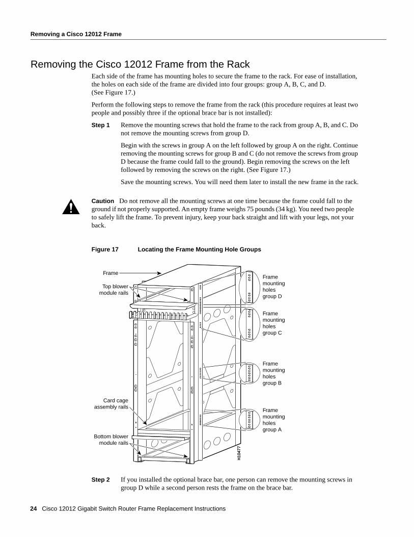
Removing the Cisco 12012 Frame from the RackEach side of the frame has mounting holes to secure the frame to the rack. For ease of installation, the holes on each side of the frame are divided into four groups: group A, B, C, and D. (See Figure 17.)
Perform the following steps to remove the frame from the rack (this procedure requires at least two people and possibly three if the optional brace bar is not installed):
Step 1 Remove the mounting screws that hold the frame to the rack from group A, B, and C. Do not remove the mounting screws from group D.
Begin with the screws in group A on the left followed by group A on the right. Continue removing the mounting screws for group B and C (do not remove the screws from group D because the frame could fall to the ground). Begin removing the screws on the left followed by removing the screws on the right. (See Figure 17.)
Save the mounting screws. You will need them later to install the new frame in the rack.
Figure 17 Locating the Frame Mounting Hole Groups
Step 2 If you installed the optional brace bar, one person can remove the mounting screws in group D while a second person rests the frame on the brace bar.
Caution Do not remove all the mounting screws at one time because the frame could fall to the ground if not properly supported. An empty frame weighs 75 pounds (34 kg). You need two people to safely lift the frame. To prevent injury, keep your back straight and lift with your legs, not your back.
H10
477
H10
477
Top blowermodule rails
FrameFramemountingholesgroup D
Bottom blowermodule rails
Card cageassembly rails
Framemountingholesgroup C
Framemountingholesgroup B
Framemountingholesgroup A
24 Cisco 12012 Gigabit Switch Router Frame Replacement Instructions
Removing a Cisco 12012 Frame
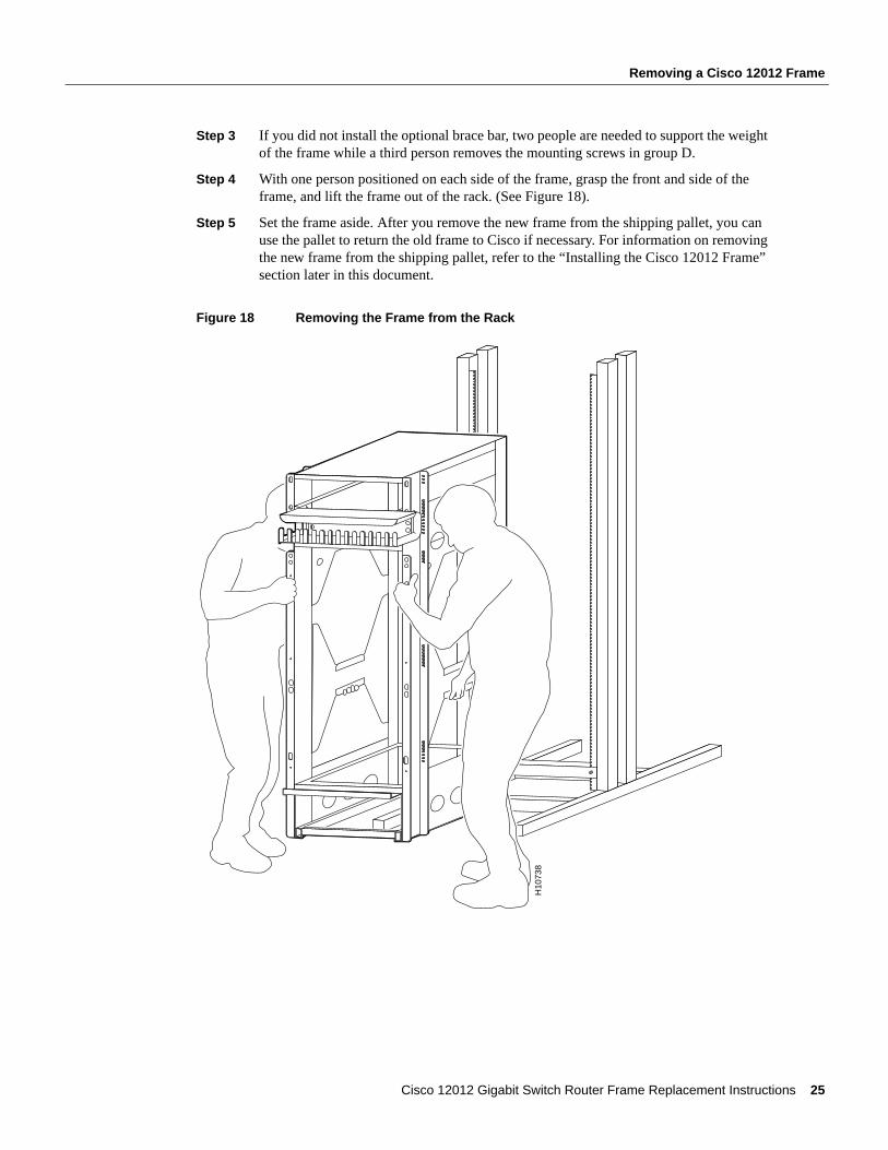
Step 3 If you did not install the optional brace bar, two people are needed to support the weight of the frame while a third person removes the mounting screws in group D.
Step 4 With one person positioned on each side of the frame, grasp the front and side of the frame, and lift the frame out of the rack. (See Figure 18).
Step 5 Set the frame aside. After you remove the new frame from the shipping pallet, you can use the pallet to return the old frame to Cisco if necessary. For information on removing the new frame from the shipping pallet, refer to the “Installing the Cisco 12012 Frame” section later in this document.
Figure 18 Removing the Frame from the Rack
H10
738
Cisco 12012 Gigabit Switch Router Frame Replacement Instructions 25
Installing the Cisco 12012 Frame
Installing the Cisco 12012 FrameThis section provides the procedures for installing a Cisco 12012 frame in a rack. After installing the frame, you must reinstall the three major components housed in the frame: the two blower modules and the card cage assembly. Next, you must reinstall all the components in the card cage assembly.
Rack-Mounting the Cisco 12012 FrameThis section provides the procedure for installing the Cisco 12012 frame in a rack. Each side of the frame has mounting holes to secure the frame to the rack. For ease of installation, the holes on each side of the frame are divided into four groups: group A, B, C, and D.
The mounting holes are drilled in the frame so that one mounting hole in each group aligns with a mounting hole in the rack. By using the corresponding mounting hole (in the same group) on the opposite side of the frame, you can level the frame in the rack.
Perform the following steps to remove the frame from the shipping pallet and install it in a rack:
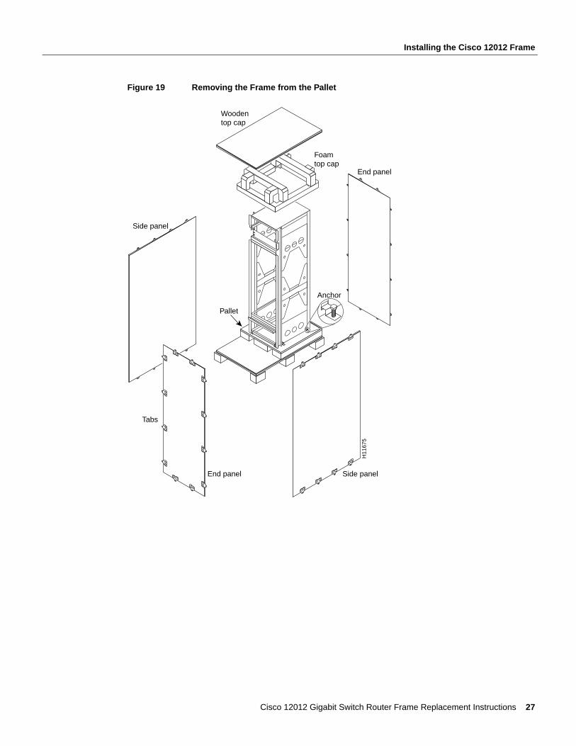
Step 1 Position the frame mounted on its shipping pallet (with the shipping container disassembled), as close to the installation site as possible. (See Figure 19.)
Step 2 Remove the four bolts and retainer clips that secure the base of the frame to the pallet.
Step 3 With one person positioned on each side of the frame, grasp the front and side of the frame, lift the frame off of the pallet, and position the frame in the rack. (See Figure 18.)
Step 4 If you installed the optional brace bar, rest the frame on the brace bar while you perform the next step. If you did not install the optional brace bar, two people are needed to support the weight of the frame while a third person performs the next step.
Step 5 Look at the bottom group of mounting holes (group A) on the frame. (See Figure 17.) Align one of the holes in group A with a mounting hole in the rack.
Step 6 Install the mounting screws that you saved when you removed the frame.
Step 7 Go to the other side of the frame and adjust the position of the frame so that the same mounting hole in the bottom group of mounting holes (group A) is aligned with a hole in the rack.
Step 8 Install one of the mounting screws that you saved when you removed the frame.
Step 9 Repeat Step 5 through Step 8 for mounting hole groups B, C, and D.
Caution An empty frame weighs 75 pounds (34 kg). You need two people to safely lift the frame. To prevent injury, keep your back straight and lift with your legs, not your back.
26 Cisco 12012 Gigabit Switch Router Frame Replacement Instructions
Installing the Cisco 12012 Frame
Figure 19 Removing the Frame from the Pallet
H11
675
End panel
Tabs
End panel
Pallet
Woodentop cap
Foamtop cap
Side panel
Anchor
Side panel
Cisco 12012 Gigabit Switch Router Frame Replacement Instructions 27
Installing the Cisco 12012 Frame
Reinstalling the Blower ModulesPerform the following steps to reinstall a blower module:
Step 1 Attach an ESD wrist strap to your wrist and to one of the two ESD connection sockets located on the front edges of the upper card cage or to bare metal on the frame.
Step 2 Using two hands to support the blower module, orient the replacement blower module in front of the frame so that the blower module connector (recessed in the back corner of the blower module) is aligned with the connector mounted on the back corner of the frame. (Refer to Figure 3.)
Note When you install the top blower module, the blower module connector should be on the right side (facing the frame). When you install the bottom blower module, the blower module connector should be on the left side (facing the frame).
Step 3 Slide the blower module on the frame rails into the frame. Stop when the blower module connector makes contact with the frame connector.
Step 4 Firmly push on the blower module handle to seat the blower module connector in the frame connector. (When completely seated, the blower module faceplate flanges should be in contact with the frame.)
Note All electrical and control line connections are made automatically when the two connectors mate. The blower module will immediately power up.
Step 5 Tighten the two captive screws on the blower module faceplate.
Step 6 Position the blower module front cover over the blower module faceplate. Snap the front cover onto the blower module faceplate. (Refer to Figure 2.)
Step 7 Repeat Step 2 through Step 6 to reinstall the second blower module.
Caution A blower module weighs 22 lb (10 kg). Use two hands when handling a blower module.
28 Cisco 12012 Gigabit Switch Router Frame Replacement Instructions
Installing the Cisco 12012 Frame
Reinstalling the Card Cage AssemblyThis section contains the instructions for reinstalling the card cage assembly in the frame.
Perform the following steps to reinstall the card cage assembly:
Step 1 With one person positioned on each side of the card cage assembly, grasp the handle on the front of the card cage assembly and the handhold cutout on the side of the card cage assembly. (Refer to Figure 16.)
Step 2 Lift the card cage assembly and position it on the frame rails. Slide the card cage assembly fully into the front of the frame until the card cage assembly flanges make contact with the frame.
Note All electrical connections between the card cage assembly and the blower module harnesses on the frame are made automatically when the card cage assembly is fully inserted in the frame.
Step 3 Secure the card cage assembly to the frame by tightening the six captive screws.
Reinstalling the System GroundingYour system might have two system grounding cable lugs. The system grounding receptacles are located on the card cage assembly side flanges between the air filter tray and the power supply bay. (Refer to Figure 14.)
Perform the following steps to install the system grounding lugs to the card cage assembly:
Step 1 Position the system ground lug over the card cage assembly system grounding receptacle.
Step 2 Secure the system grounding lug to the receptacle with two sets of screws, washers, and nuts. (Refer to Figure 15.)
Step 3 Repeat Step 1 and Step 2 for a second system grounding connection.
Caution An empty card cage assembly weighs 65 lb (29.5 kg). You need two people to safely lift the assembly. To prevent injury, keep your back straight and lift with your legs, not your back.
Cisco 12012 Gigabit Switch Router Frame Replacement Instructions 29
Installing the Cisco 12012 Frame
Reinstalling the Components in the Card Cage AssemblyThis section provides procedures for reinstalling the components in the card cage assembly. These components consist of the cards in the upper card cage, the cards in the lower card cage, and the power supplies.
Reinstalling the Cards from the Upper Card CageThis section provides the procedures for reinstalling the line cards, RP, and alarm card in the upper card cage.
Note You must install blank cards in the upper card cage. Blank cards must be installed in slots without cards to maintain proper air flow and for EMI considerations.
Reinstalling a Line Card in the Upper Card CagePerform the following steps to reinstall a line card in the upper card cage and reconnecting interface cables:
Step 1 Attach an antistatic wrist strap to yourself and to one of the two ESD connection sockets located on the front edges of the upper card cage or to bare metal on the frame.
Step 2 Select a line card from the antistatic mat. Check your list of occupied upper card cage slots to determine which slot the line card goes in. Grasp the front edge of the metal card carrier with one hand and place your other hand under the carrier to support and guide it into the upper card cage slot.
Step 3 Carefully slide the line card carrier into the slot until the ejector levers make contact with the front of the card cage, then stop.
Step 4 Grasp the two line card ejector levers and pivot them away from the card until they are perpendicular to the line card faceplate to completely seat the card in the backplane connector.
Step 5 Tighten the two captive screws at the top and bottom of the line card.
Step 6 Repeat Step 2 through Step 5 for the rest of the line cards.
Step 7 Proceeding from left to right in the upper card cage, check your list of interface cable connections and identify the interface cables that attach to the first line card.
Step 8 One interface cable at a time, carefully route the identified interface cable through the horizontal cable tray and down to the line card interface port.
Note On line cards with multiple ports, route and connect the interface cables to the line cards starting at the bottom port and working up.
Step 9 Proceeding from bottom port to the top port (line cards with multiple ports only) identify the interface cable that connects to each line card port. Connect the interface cable to the line card port. (Refer to Figure 20a.)
Step 10 Proceeding from bottom port to the top port (line cards with multiple ports only), carefully press the interface cable into the vertical cable bracket cable clip. (Refer to Figure 20b.) Avoid any kinks or sharp bends in the interface cable.
30 Cisco 12012 Gigabit Switch Router Frame Replacement Instructions
Installing the Cisco 12012 Frame
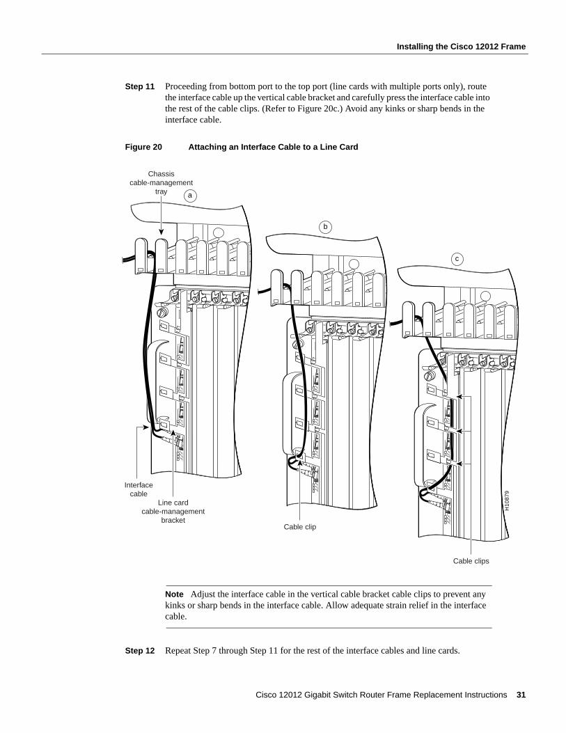
Step 11 Proceeding from bottom port to the top port (line cards with multiple ports only), route the interface cable up the vertical cable bracket and carefully press the interface cable into the rest of the cable clips. (Refer to Figure 20c.) Avoid any kinks or sharp bends in the interface cable.
Figure 20 Attaching an Interface Cable to a Line Card
Note Adjust the interface cable in the vertical cable bracket cable clips to prevent any kinks or sharp bends in the interface cable. Allow adequate strain relief in the interface cable.
Step 12 Repeat Step 7 through Step 11 for the rest of the interface cables and line cards.
ACTIVE
0
CARRIER
RX PKT
ACTIVE
1
CARRIER
RX PKT
ACTIVE
2
CARRIER
RX PKT
ACTIVE
3
CARRIER
RX PKT
Chassiscable-management
tray
Line cardcable-management
bracket
a
Interfacecable
ACTIVE
0
CARRIER
RX PKT
ACTIVE
1
CARRIER
RX PKT
ACTIVE
2
CARRIER
RX PKT
ACTIVE
3
CARRIER
RX PKT
Cable clip
b
ACTIVE
0
CARRIER
RX PKT
ACTIVE
1
CARRIER
RX PKT
ACTIVE
2
CARRIER
RX PKT
ACTIVE
3
CARRIER
RX PKT
H10
879
Cable clips
c
Cisco 12012 Gigabit Switch Router Frame Replacement Instructions 31
Installing the Cisco 12012 Frame
Note Blank cards must be installed in the upper card cage to fill any open slots. The blank cards are used to maintain proper air flow and for EMI considerations.
Reinstalling a RP in the Upper Card CagePerform the following steps to reinstall the RP in the upper card cage:
Step 1 Attach an antistatic wrist strap to yourself and to one of the two ESD connection sockets located on the front edges of the upper card cage or to bare metal on the frame.
Step 2 Grasp the card carrier edge with one hand and place your other hand under the carrier to support and guide it into the slot. Carefully slide the RP carrier into the slot until the ejector levers make contact with the front of the card cage, then stop.
Step 3 Grasp the two card ejector levers and pivot them toward the RP until they are perpendicular to the card faceplate to completely seat the RP in the backplane connector.
Step 4 Tighten the two captive screws at the top and bottom of the RP.
Step 5 Connect the console terminal and any auxiliary and Ethernet devices to their respective connectors on the RP. Verify that the console terminal is on.
Reinstalling an Alarm Card in the Upper Card CageThe alarm card is installed in the rightmost slot in the upper card cage.
Perform the following steps to reinstall the alarm card in the upper card cage:
Step 1 Attach an antistatic wrist strap to yourself and to one of the two ESD connection sockets located on the front edges of the upper card cage or to bare metal on the frame.
Step 2 Grasp the alarm card faceplate with one hand and place your other hand under the card carrier to support and guide it into the card cage slot labeled alarm card.
Step 3 Carefully slide the alarm card carrier into the slot until it makes contact with the backplane connector, then stop. Avoid touching the card circuitry or any connectors.
Step 4 Carefully push on the top and bottom of the alarm card to seat it in the backplane connector.
Step 5 Tighten the two captive screws to secure the alarm card in the upper card cage slot.
Step 6 Connect any external devices to their respective connectors on the alarm card.
Reinstalling the Cards in the Lower Card CagePerform the following steps to reinstall the switch fabric cards and clock scheduler cards in the lower card cage:
Step 1 Attach an antistatic wrist strap to yourself and to one of the two ESD connection sockets located on the front edges of the upper card cage or to bare metal on the frame.
Step 2 To access the lower card cage card slots, perform the following steps:
(a) Loosen the two captive screws at the top of the air filter tray and pivot the tray down, away from the lower card cage. (Refer to Figure 11.)
(b) Lift the air deflector up and secure it to the top of the lower card cage by turning the air deflector latch knob counterclockwise. (Refer to Figure 12.)
32 Cisco 12012 Gigabit Switch Router Frame Replacement Instructions
Installing the Cisco 12012 Frame
Step 3 Select a card from the antistatic mat. Determine which lower card cage slot the card should be installed in by checking the color of the label attached to the edge of the card carrier (near the ejector levers). Light blue labels identify clock and scheduler cards (installed in the upper two slots), and magenta labels identify switch fabric cards (installed in the lower three slots).
Note Lower card cage slots are keyed to prevent you from inserting cards in the wrong slots. You can install clock and scheduler cards only in the upper two card slots; switch fabric cards only in the lower three slots.
Step 4 Grasp the card carrier edge with one hand and place your other hand under the carrier to support and guide it into a matching color-coded slot. Slide the card halfway into the lower card cage slot. Avoid touching the card circuitry or any connectors.
Note When you install a clock and scheduler card or a switch fabric card in the lower card cage, make sure that you keep the card centered in the slot by applying even pressure to both sides of the card carrier as you slide it into the slot.
Step 5 Pivot the two card ejector levers out ninety degrees away from the sides of the card carrier.
Step 6 Continue sliding the card into the slot until the card ejector levers engage the edges of the lower card cage slot and both ejector levers begin to pivot.
Note Both types of cards have guide pins that make initial contact with the backplane connector. After the guide pins make contact, continue pushing on the card carrier until the card ejector levers start pivoting forward. Then use the card ejector levers to fully insert the card in the backplane connector.
Step 7 Grasp both card ejector levers and pivot them toward the sides of the card cage until they are parallel to the card carrier edge to seat the card in the backplane connector. Press on the ejector levers until they snap into the card carrier.
Step 8 Repeat Step 3 through Step 7 for the rest of the cards in the lower card cage.
Step 9 Release the air deflector latch (turn the latch clockwise) and lower the air deflector down to its stops.
Step 10 Pivot the air filter tray up so that it is flush with the front of the lower card cage and tighten the two captive screws.
Reinstalling the Power SuppliesThis section provides procedures for reinstalling an AC-input power supply and a DC-input power supply. Select the procedure appropriate for your system.
Caution Always wear an antistatic wrist strap to prevent ESD when removing and replacing a power supply.
Cisco 12012 Gigabit Switch Router Frame Replacement Instructions 33
Installing the Cisco 12012 Frame
Perform the following steps to reinstall an AC-input power supply:
Step 1 Attach an antistatic wrist strap to yourself and to one of the two ESD connection sockets located on the front edges of the upper card cage or to bare metal on the frame.
Step 2 Verify that the power switch on the power supply is in the STANDBY position.
Note The power supply bay positions are designated A1, A2, B1, and B2, from left to right. Install power supplies in the bay in the following order: A1, B1, A2, and B2. Any power supply bay position that does not have a power supply installed must have a power supply blank installed to maintain airflow and for EMI considerations.
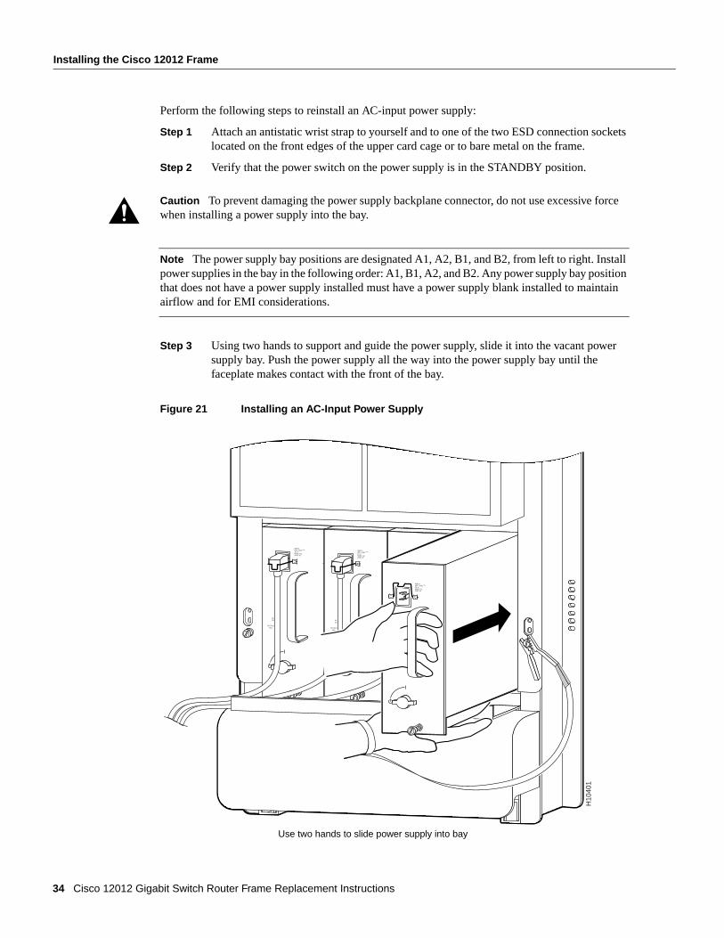
Step 3 Using two hands to support and guide the power supply, slide it into the vacant power supply bay. Push the power supply all the way into the power supply bay until the faceplate makes contact with the front of the bay.
Figure 21 Installing an AC-Input Power Supply
Caution To prevent damaging the power supply backplane connector, do not use excessive force when installing a power supply into the bay.
ACOK
OUTPUTFAIL
INPUT:200 -240V ~10 A50/60 HZ2000 W
ACOK
OUTPUTFAIL
INPUT:200 -240V ~10 A50/60 HZ2000 W
ACOK
OUTPUTFAIL
INPUT:200 -240V ~10 A50/60 HZ2000 W
H10
401
Use two hands to slide power supply into bay
34 Cisco 12012 Gigabit Switch Router Frame Replacement Instructions
Installing the Cisco 12012 Frame
Note All electrical connections between the power supply and the backplane are made automatically when the power supply is fully inserted in the power supply bay.
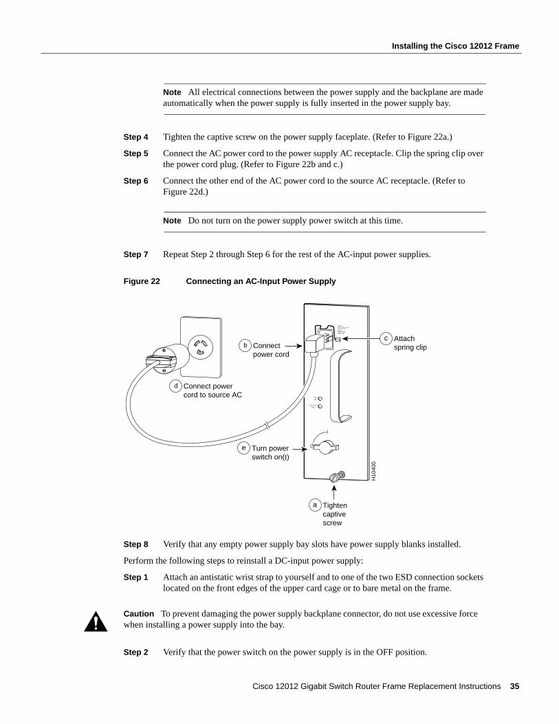
Step 4 Tighten the captive screw on the power supply faceplate. (Refer to Figure 22a.)
Step 5 Connect the AC power cord to the power supply AC receptacle. Clip the spring clip over the power cord plug. (Refer to Figure 22b and c.)
Step 6 Connect the other end of the AC power cord to the source AC receptacle. (Refer to Figure 22d.)
Note Do not turn on the power supply power switch at this time.
Step 7 Repeat Step 2 through Step 6 for the rest of the AC-input power supplies.
Figure 22 Connecting an AC-Input Power Supply
Step 8 Verify that any empty power supply bay slots have power supply blanks installed.
Perform the following steps to reinstall a DC-input power supply:
Step 1 Attach an antistatic wrist strap to yourself and to one of the two ESD connection sockets located on the front edges of the upper card cage or to bare metal on the frame.
Step 2 Verify that the power switch on the power supply is in the OFF position.
Caution To prevent damaging the power supply backplane connector, do not use excessive force when installing a power supply into the bay.
Tightencaptivescrew
H10
400
a
INPUT:200 -240V ~10 A50/60 HZ2000 W
ACOK
OUTPUTFAIL
Connectpower cord
b
Connect powercord to source AC
d
Turn powerswitch on(I)
e
Attachspring clip
c
Cisco 12012 Gigabit Switch Router Frame Replacement Instructions 35
Installing the Cisco 12012 Frame
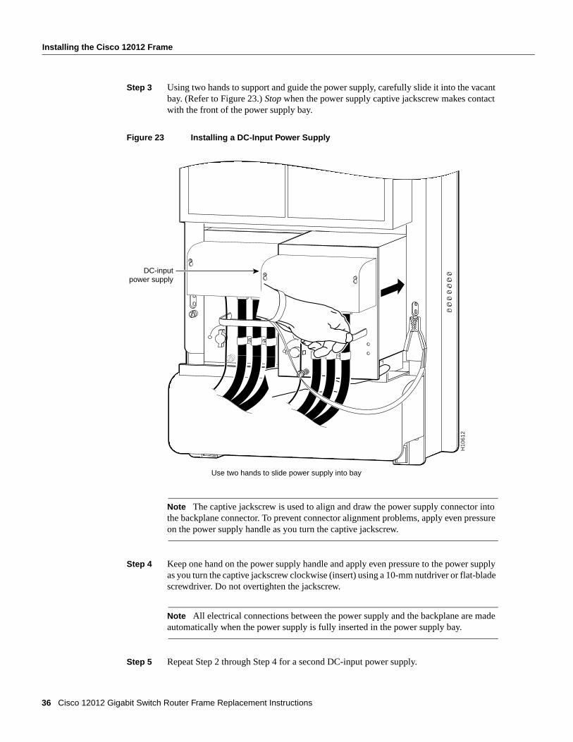
Step 3 Using two hands to support and guide the power supply, carefully slide it into the vacant bay. (Refer to Figure 23.) Stop when the power supply captive jackscrew makes contact with the front of the power supply bay.
Figure 23 Installing a DC-Input Power Supply
Note The captive jackscrew is used to align and draw the power supply connector into the backplane connector. To prevent connector alignment problems, apply even pressure on the power supply handle as you turn the captive jackscrew.
Step 4 Keep one hand on the power supply handle and apply even pressure to the power supply as you turn the captive jackscrew clockwise (insert) using a 10-mm nutdriver or flat-blade screwdriver. Do not overtighten the jackscrew.
Note All electrical connections between the power supply and the backplane are made automatically when the power supply is fully inserted in the power supply bay.
Step 5 Repeat Step 2 through Step 4 for a second DC-input power supply.
H10
612
Use two hands to slide power supply into bay
DC-inputpower supply
36 Cisco 12012 Gigabit Switch Router Frame Replacement Instructions
Installing the Cisco 12012 Frame
Step 6 Turn on the source DC circuit breaker servicing the DC-input power supply. Do not turn on the power supply power switch at this time.
Checking the Installation and Powering Up the Cisco 12012To complete the installation, perform a check of all connections, then power up the system.
Follow these steps to restart the system and verify that the system restarts successfully:
Step 1 Check the following components to make sure they are secure:
• Line cards are fully inserted in the slots and all captive screws are tightened.
• Vertical cable brackets are attached to their respective line cards and all captive screws are tightened.
• Interface cable connections are secured.
• Interface cables are routed neatly through the cable-management system.
• Any empty card slots or power supply bays are filled with card blanks or power supply blanks.
• Power supplies are fully inserted in the bays and the captive screws are tightened.
• Power supply cables are fully connected to the power supplies and the power source, and secured with appropriate strain relief.
• Front covers are installed on the DC-input power supplies.
• The air deflector in the lower card cage is down, resting on its stops.
• The air filter tray is up and the two captive screws are tightened.
• The blower modules are inserted all the way into the frame, the two captive screws are tightened, and the blower module front covers are securely installed on the front of the blower modules.
Step 2 Ensure that a console terminal is connected to the RP console port and turned on, or that you have a remote login to the router from another device through a Telnet session. (You will need to check the startup banner and displays to ensure that the system restarts properly and that all the interfaces reinitialize in the proper state.)
Step 3 Verify that all source voltage circuit breakers supplying power to your system are on.
Step 4 Turn the power switch on each power supply to ON (|). The input OK LED on each DC-input power supply (AC OK LED on each AC-input power supply) should go on.
Note Turning the power supply switch to ON (|) also engages a latch securing the power supply in place.
Step 5 Listen for the blower modules to power up. The green fans OK LED on the front cover of each blower module should go on.
Note In noisy environments, it might be difficult to hear the fans operating. Place your hand at the back of the frame behind the blower modules and feel for the airflow generated by the fans in the modules.
Cisco 12012 Gigabit Switch Router Frame Replacement Instructions 37
FCC Class A Compliance
Step 6 On the console terminal, verify that the console displays the system banner and that the system and all interfaces initialize successfully.
If the power supplies do not power up, or if the system or any interfaces do not initialize properly, refer to the Cisco 12012 Gigabit Switch Router Installation and Configuration Guide that shipped with your router for additional information and installation troubleshooting procedures. If you are still unable to resolve the problem, contact your service representative for assistance.
FCC Class A ComplianceThis equipment has been tested and found to comply with the limits for a Class A digital device, pursuant to part 15 of the FCC rules. These limits are designed to provide reasonable protection against harmful interference when the equipment is operated in a commercial environment. This equipment generates, uses, and can radiate radio-frequency energy and, if not installed and used in accordance with the instruction manual, may cause harmful interference to radio communications. Operation of this equipment in a residential area is likely to cause harmful interference, in which case users will be required to correct the interference at their own expense.
You can determine whether your equipment is causing interference by turning it off. If the interference stops, it was probably caused by the Cisco equipment or one of its peripheral devices. If the equipment causes interference to radio or television reception, try to correct the interference by using one or more of the following measures:
• Turn the television or radio antenna until the interference stops.
• Move the equipment to one side or the other of the television or radio.
• Move the equipment farther away from the television or radio.
• Plug the equipment into an outlet that is on a different circuit from the television or radio. (That is, make certain the equipment and the television or radio are on circuits controlled by different circuit breakers or fuses.)
Modifications to this product not authorized by Cisco Systems, Inc. could void the FCC approval and negate your authority to operate the product.
Cisco Connection OnlineCisco Connection Online (CCO) is Cisco Systems’ primary, real-time support channel. Maintenance customers and partners can self-register on CCO to obtain additional information and services.
Available 24 hours a day, 7 days a week, CCO provides a wealth of standard and value-added services to Cisco’s customers and business partners. CCO services include product information, product documentation, software updates, release notes, technical tips, the Bug Navigator, configuration notes, brochures, descriptions of service offerings, and download access to public and authorized files.
CCO serves a wide variety of users through two interfaces that are updated and enhanced simultaneously: a character-based version and a multimedia version that resides on the World Wide Web (WWW). The character-based CCO supports Zmodem, Kermit, Xmodem, FTP, and Internet e-mail, and it is excellent for quick access to information over lower bandwidths. The WWW version of CCO provides richly formatted documents with photographs, figures, graphics, and video, as well as hyperlinks to related information.
You can access CCO in the following ways:
• WWW: http://www.cisco.com
• WWW: http://www-europe.cisco.com
38 Cisco 12012 Gigabit Switch Router Frame Replacement Instructions
Cisco Connection Online
• WWW: http://www-china.cisco.com
• Telnet: cco.cisco.com
• Modem: From North America, 408 526-8070; from Europe, 33 1 64 46 40 82. Use the following terminal settings: VT100 emulation; databits: 8; parity: none; stop bits: 1; and connection rates up to 28.8 kbps.
For a copy of CCO’s Frequently Asked Questions (FAQ), contact [email protected]. For additional information, contact [email protected].
Note If you are a network administrator and need personal technical assistance with a Cisco product that is under warranty or covered by a maintenance contract, contact Cisco’s Technical Assistance Center (TAC) at 800 553-2447, 408 526-7209, or [email protected]. To obtain general information about Cisco Systems, Cisco products, or upgrades, contact 800 553-6387, 408 526-7208, or [email protected].
Cisco documentation and additional literature are available in a CD-ROM package, which ships with your product. The Documentation CD-ROM, a member of the Cisco Connection Family, is updated monthly. Therefore, it might be more up to date than printed documentation. To order additional copies of the Documentation CD-ROM, contact your local sales representative or call customer service. The CD-ROM package is available as a single package or as an annual subscription. You can also access Cisco documentation on the World Wide Web at http://www.cisco.com, http://www-china.cisco.com, or http://www-europe.cisco.com.
If you are reading Cisco product documentation on the World Wide Web, you can submit comments electronically. Click Feedback in the toolbar, select Documentation, and click Enter the feedback form. After you complete the form, click Submit to send it to Cisco. We appreciate your comments.
This document is to be used in conjunction with the Cisco 12012 Gigabit Switch Router Installation and Configuration Guide.
CCIP, the Cisco Powered Network mark, the Cisco Systems Verified logo, Cisco Unity, Follow Me Browsing, FormShare, Internet Quotient, iQ Breakthrough, iQ Expertise, iQ FastTrack, the iQ Logo, iQ Net Readiness Scorecard, Networking Academy, ScriptShare, SMARTnet, TransPath, and Voice LAN are trademarks of Cisco Systems, Inc.; Changing the Way We Work, Live, Play, and Learn, Discover All That’s Possible, The Fastest Way to Increase Your Internet Quotient, and iQuick Study are service marks of Cisco Systems, Inc.; and Aironet, ASIST, BPX, Catalyst, CCDA, CCDP, CCIE, CCNA, CCNP, Cisco, the Cisco Certified Internetwork Expert logo, Cisco IOS, the Cisco IOS logo, Cisco Press, Cisco Systems, Cisco Systems Capital, the Cisco Systems logo, Empowering the Internet Generation, Enterprise/Solver, EtherChannel, EtherSwitch, Fast Step, GigaStack, IOS, IP/TV, LightStream, MGX, MICA, the Networkers logo, Network Registrar, Packet, PIX, Post-Routing, Pre-Routing, RateMUX, Registrar, SlideCast, StrataView Plus, Stratm, SwitchProbe, TeleRouter, and VCO are registered trademarks of Cisco Systems, Inc. and/or its affiliates in the U.S. and certain other countries.
All other trademarks mentioned in this document or Web site are the property of their respective owners. The use of the word partner does not imply a partnership relationship between Cisco and any other company. (0203R)
Copyright © 1997-2002, Cisco Systems, Inc.All rights reserved.
Cisco 12012 Gigabit Switch Router Frame Replacement Instructions 39
Cisco Connection Online
40 Cisco 12012 Gigabit Switch Router Frame Replacement Instructions