Embed Size (px)
Citation preview

1
CISCAI Technical Report
Wireless Technologies as Last Mile Connection for
Avian Influenza Management
Contents
1. Introduction ................................................................................................ 2
2. Design concept and technical background of wireless system ........................ 4
3. Fixed Broadband Wireless Access System in Lao PDR .................................... 9
4. Mobile Broadband Wireless Access System in Vietnam ................................ 12
5. Balloon Wireless Access System for emergency response situation ............... 15
6. Future recommendation activities ............................................................... 19
7. Conclusion ................................................................................................ 20
Appendices
A. CISCAI Engineering Training ................................................................. A1-A3
B. CISCAI Site Survey and Tabletop Exercise in Lao PDR .......................... B1-B21
C. CISCAI Site Survey and Tabletop Exercise in Vietnam .......................... C1-C16
2
CISCAI Technical Report
Wireless Technologies as Last Mile Connection for
Avian Influenza Management
1. Introduction
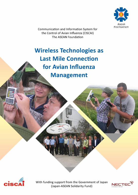
Communication and Information System for the Control of Avian Influenza (CISCAI)
project is established by ASEAN Foundation with the cooperation of multi-national partners from three ASEAN member countries (e.g., Vietnam, Lao PDR and
Thailand). CISCAI project is aimed to propose the information and communication technology tools and systems that can better manage Avian Influenza (AI)
outbreak. CISCAI involves the activities of software development tools such as Geographical Information System (GIS) tool and SMS system for AI surveillance and
monitoring. It also investigates and conducts the field trial of the new communication infrastructure that can effectively support AI disease control effort.
Vietnam and Lao PDR project teams develop the localized GIS application, conduct the wireless communication field trial and also perform the tabletop exercise of AI outbreak management in Vietnam and Lao PDR respectively. Thailand project team
led by National Electronics and Computer Technology Center (NECTEC) conducts field trial and provides the technical backstopping for two member countries. The
outcome and lesson learnt from the project can be disseminated and applied for other kinds of emerging diseases in ASEAN countries.
The goal of CISCAI is to introduce the ICT system that can fulfill “early detection,
early reporting and early response” concept in AI disease control. Early detection and early reporting mean that information gathering about the status of the live
chickens as well as suspicious dead chickens in the field or other kinds of outbreak indicators efficiently flows from the field to the Headquarter. Then Headquarter analyzes the current situation of AI outbreak and countermeasures with the
appropriated response on time. The earlier AI detected the quicker and the better the response. Successful implementing CISCAI concept is expected to significantly reduce the loss of life and money affected by the outbreak.
There are two main phases of AI disease control: 1) Surveillance and Monitoring Phase and 2) Incident Response Phase. Both phases have different business
processes and require the different ICT technology support. During the surveillance and monitoring phase, the field workers at chicken farms routinely report the status
of chicken life (i.e., how many life and dead chickens in the day) or other information to the animal health department according to the report escalation
flow. The information can be sent through SMS, email, fax or the Internet. The report escalation flow differs in each country. The information is gathering at the Headquarter. Then Headquarter evaluate the situation based on the report
information. In order to effectively analyze the big picture of situation and to track
3
the progress of the outbreak, the geographical information has to be included in
each surveillance report. Therefore, CISCAI proposed to develop the GIS application and SMS tools to be used for the Surveillance and Monitoring Phase. Once the outbreak area is declared, it will move to the Incident Response Phase
and the incident response team will be dispatched to the area. The incident response team goes to the area and gathering the outbreak information such as
sample field lab test, the pictures and video of the dead chicken or even the videoconference to consult with the headquarter. The outbreak area is typically in
the rural area with limited or lacking of the communication service (i.e., cellular phone service, the Internet service). Therefore, CISCAI proposed the
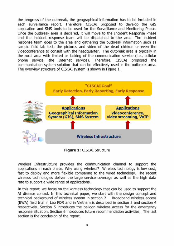
communication system solution that can be effectively used in the outbreak area. The overview structure of CISCAI system is shown in Figure 1.
Figure 1: CISCAI Structure
Wireless Infrastructure provides the communication channel to support the applications in each phase. Why using wireless? Wireless technology is low cost, fast to deploy and more flexible comparing to the wired technology. The recent
wireless technologies deliver the large service coverage as well as the high data rate to support a wide range of applications.
In this report, we focus on the wireless technology that can be used to support the
AI disease control. In this technical paper, we start with the design concept and technical background of wireless system in section 2. Broadband wireless access (BWA) field trial in Lao PDR and in Vietnam is described in section 3 and section 4
respectively. Section 5 introduces the balloon wireless access for the emergency response situation. Section 6 introduces future recommendation activities. The last section is the conclusion of the report.
4
2. Design concept and technical background of wireless system
As mentioned in the previous section, there are two main phases of AI disease control:
1) Surveillance and Monitoring Phase and
2) Incident Response Phase. The wireless system to support each phase may
be different.
The chicken farm, hospital, other local health office are typically in the fixed
location. The surveillance information is mostly reported around these fixed locations during the Surveillance and Monitoring Phase. The suitable wireless system will be Fixed Broadband Wireless Access (BWA) System where all wireless users are in the fixed location and not on the move. The wireless infrastructure in Lao PDR represents the model of Fixed BWA system.
In the incident response phase, the nature of AI outbreak can be anywhere. The area may not be in the service coverage of any existing wireless infrastructure.
Therefore, the emergency mobility type of wireless infrastructure is needed in the area. The suitable wireless system will be Mobile Broadband Wireless Access system. The wireless system in Vietnam represents the model of Mobile BWA system.
2.1 Wireless System Design Criteria
The design criteria of wireless system are focused on two parameters: 1) coverage of service area and 2) the speed or data rate of the wireless
system. The wireless system must provide enough service coverage to cover the area of operation. The wireless system must also deliver enough speed or date rate to support the applications such as voice, video and data.
The coverage area of wireless system depends on:
1) Transmitted Power: the transmitted power is the signal strength that transmits from transmitter of the wireless equipment. The higher transmitted power, the farther of signal travelling to the receiver end or the other word is the larger
coverage area. The transmitted power that the transmitter can send is limited by the Regulator rule of each country such as the maximum EIRP (Equivalent
Isotropic Radiation Power). For example, in Thailand, the maximum EIRP of 2.4 GHz WiFi is up to 100mW, while 5.8 GHz WiFi is up to 1W. The transmitted power on the unlicensed frequency band (i.e., 2.4 GHz, 5.8 GHz) is not high. On the other hand, in the licensed frequency band, only the operator who owns the licensed frequency can use that frequency. Therefore, EIRP allowed is much
5
higher. It means the wireless technology operating on the licensed frequency
band is allowed higher EIRP and then more coverage area. WiMAX and 3G operate on the licensed frequency (i.e., 2.1 GHz band for 3G or 2.3 GHz band for WiMAX)
2) Frequency Band: The signal with low frequency can travel farther than the one
with higher frequency. The higher the frequency is, the smaller the coverage area.
3) Receiver Sensitivity: Receiver sensitivity is the minimum signal strength that the
receiver can detect and communicate. The equipment with high receiver sensitivity can detect the very low signal. Therefore, the receiver equipment can
locate farther away from the transmitter. The higher the receiver sensitivity is, the larger the coverage area.
4) Modulation techniques
5) Antenna technologies: the smart antenna such as MIMO, Beam forming provides the larger coverage area.
6) Geographical area: the distance of the signal travelling through the valley is
short comparing to travelling through the flat area. The obstacles can block the signal.
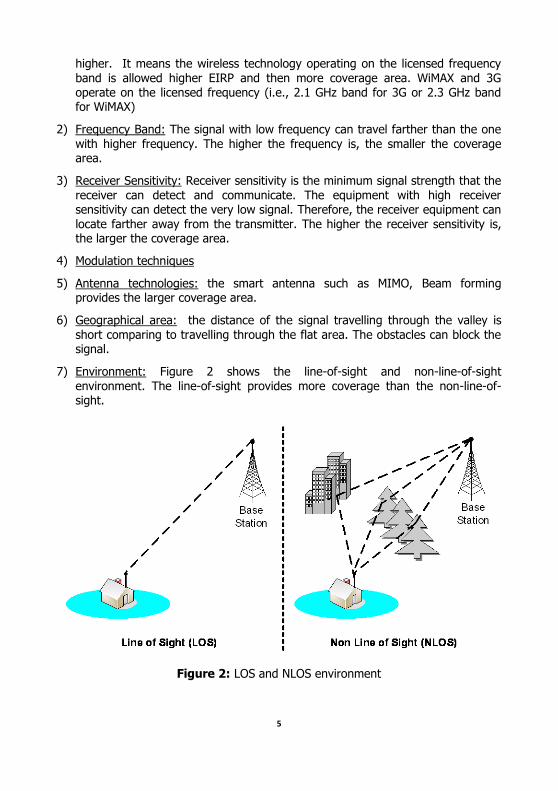
7) Environment: Figure 2 shows the line-of-sight and non-line-of-sight
environment. The line-of-sight provides more coverage than the non-line-of-sight.
Figure 2: LOS and NLOS environment
6
The speed or data rate of wireless system depends on:
1) Channel Bandwidth: the bandwidth of frequency band relates to the data rate. The wider the channel bandwidth is, the faster the data rate.
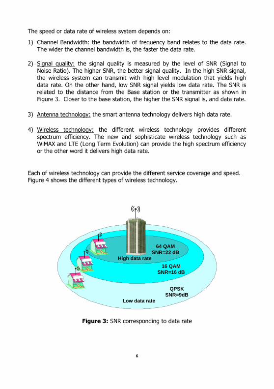
2) Signal quality: the signal quality is measured by the level of SNR (Signal to
Noise Ratio). The higher SNR, the better signal quality. In the high SNR signal, the wireless system can transmit with high level modulation that yields high
data rate. On the other hand, low SNR signal yields low data rate. The SNR is related to the distance from the Base station or the transmitter as shown in
Figure 3. Closer to the base station, the higher the SNR signal is, and data rate.
3) Antenna technology: the smart antenna technology delivers high data rate.
4) Wireless technology: the different wireless technology provides different
spectrum efficiency. The new and sophisticate wireless technology such as WiMAX and LTE (Long Term Evolution) can provide the high spectrum efficiency or the other word it delivers high data rate.
Each of wireless technology can provide the different service coverage and speed. Figure 4 shows the different types of wireless technology.
64 QAM
SNR=22 dB
16 QAM
SNR=16 dB
QPSK
SNR=9dB
High data rate
Low data rate
Figure 3: SNR corresponding to data rate
7
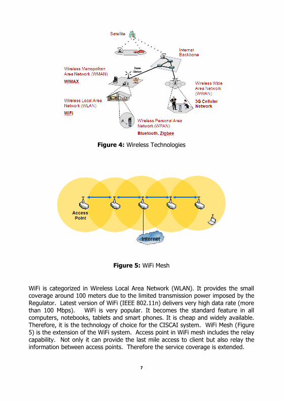
Figure 4: Wireless Technologies
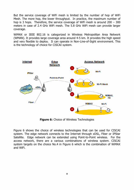
Figure 5: WiFi Mesh
WiFi is categorized in Wireless Local Area Network (WLAN). It provides the small coverage around 100 meters due to the limited transmission power imposed by the
Regulator. Latest version of WiFi (IEEE 802.11n) delivers very high data rate (more than 100 Mbps). WiFi is very popular. It becomes the standard feature in all computers, notebooks, tablets and smart phones. It is cheap and widely available.
Therefore, it is the technology of choice for the CISCAI system. WiFi Mesh (Figure 5) is the extension of the WiFi system. Access point in WiFi mesh includes the relay capability. Not only it can provide the last mile access to client but also relay the information between access points. Therefore the service coverage is extended.
8
But the service coverage of WiFi mesh is limited by the number of hop of WiFi
Mesh. The more hop, the lower throughput. In practice, the maximum number of hop is 3 hops. Therefore, the service coverage of WiFi mesh is around 200 – 300 meters in case of 2.4 GHz WiFi mesh. The 5.8 GHz WiFi mesh can provide larger coverage.
WiMAX or IEEE 802.16 is categorized in Wireless Metropolitan Area Network (WMAN). It provides large coverage area around 4-5 km. It provides the high speed
and very flexible to deploy. It can operate in Non-Line-of-Sight environment. This is the technology of choice for CISCAI system.
Figure 6: Choice of Wireless Technologies
Figure 6 shows the choice of wireless technologies that can be used for CISCAI system. The edge network connects to the Internet through xDSL, Fiber or IPStar
Satellite. Edge network can be extended using Point-to-Point wireless. For the access network, there are a various combinations of wireless system. CISCAI
system targets on the choice No.4 in Figure 6 which is the combination of WiMAX and WiFi.
9
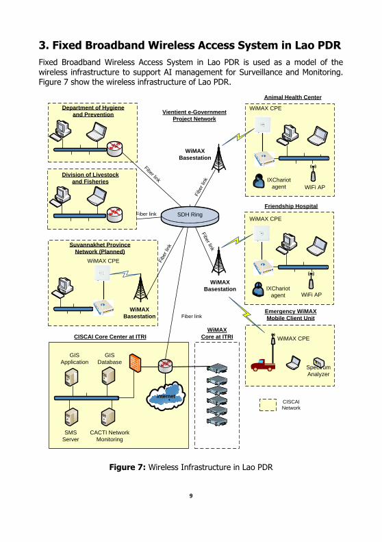
3. Fixed Broadband Wireless Access System in Lao PDR
Fixed Broadband Wireless Access System in Lao PDR is used as a model of the
wireless infrastructure to support AI management for Surveillance and Monitoring. Figure 7 show the wireless infrastructure of Lao PDR.
Internet
SDH Ring
WiMAX CPE
IXChariot
agent
WiMAX CPE
IXChariot
agent
WiFi AP
Animal Health Center
Friendship Hospital
WiFi AP
Department of Hygiene
and Prevention
Division of Livestock
and Fisheries
Vientient e-Government
Project Network
WiMAX
Basestation
WiMAX
Basestation
Suvannakhet Province
Network (Planned)
WiMAX
Basestation
WiMAX CPE
Fiber link
Fiber link
Fib
er lin
k
WiMAX CPE
Emergency WiMAX
Mobile Client Unit
Spectrum
Analyzer
GIS
Application
GIS
Database
SMS
Server
CACTI Network
Monitoring
Fiber link
CISCAI Core Center at ITRI
Fib
er lin
k
Fib
er lin
k
WiMAX
Core at ITRI
CISCAI
Network
Figure 7: Wireless Infrastructure in Lao PDR
10
CISCAI network in Lao PDR consists of CISCAI core center and CISCAI client sites.
The CISCAI core center located at ITRI contains the CISCAI server farm such as GIS application, GIS database, SMS server and CACTI network monitoring server.
There are four CISCAI client sites in Vientient capital. Two sites are connected to CISCAI core center through fiber lease line. The other two sites are connected to CISCAI core center through WiMAX.
The followings are the CISCAI client sites:
1) Animal Health Center (WiMAX)
2) Friendship Hospital (WiMAX)
3) Department of Hygiene and Prevention (Fiber lease line)
4) Division of Livestock and Fishery (Fiber lease line)
Two WiMAX client sites and the WiMAX core center establish Fixed Broadband Wireless Access. The field trial testing focuses on the service coverage of WiMAX and the WiMAX network and application performance. The detail testing is described in Appendices B.
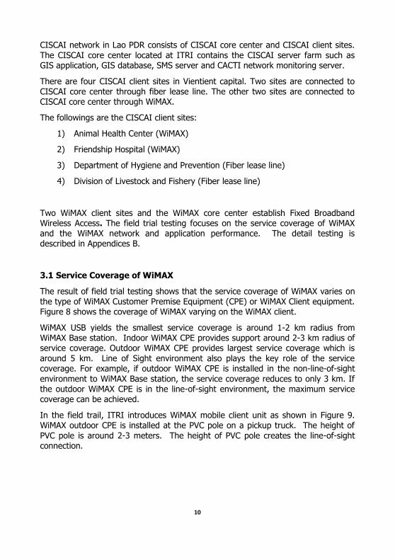
3.1 Service Coverage of WiMAX
The result of field trial testing shows that the service coverage of WiMAX varies on the type of WiMAX Customer Premise Equipment (CPE) or WiMAX Client equipment. Figure 8 shows the coverage of WiMAX varying on the WiMAX client.
WiMAX USB yields the smallest service coverage is around 1-2 km radius from WiMAX Base station. Indoor WiMAX CPE provides support around 2-3 km radius of service coverage. Outdoor WiMAX CPE provides largest service coverage which is
around 5 km. Line of Sight environment also plays the key role of the service coverage. For example, if outdoor WiMAX CPE is installed in the non-line-of-sight environment to WiMAX Base station, the service coverage reduces to only 3 km. If the outdoor WiMAX CPE is in the line-of-sight environment, the maximum service coverage can be achieved.
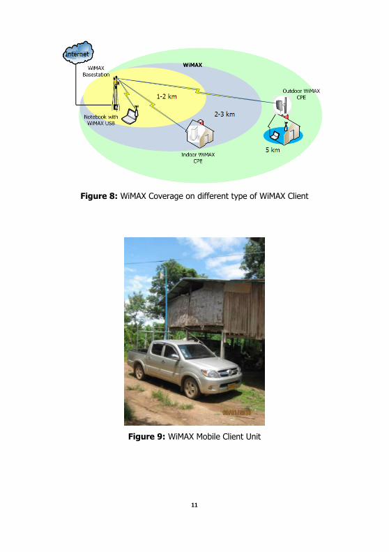
In the field trail, ITRI introduces WiMAX mobile client unit as shown in Figure 9. WiMAX outdoor CPE is installed at the PVC pole on a pickup truck. The height of
PVC pole is around 2-3 meters. The height of PVC pole creates the line-of-sight connection.
11
Figure 8: WiMAX Coverage on different type of WiMAX Client
Figure 9: WiMAX Mobile Client Unit
12
3.2 WiMAX Performance
In the field trial testing, WiMAX network performance (i.e., throughput, delay) and WiMAX application performance are investigated. The result is the following:
1) The maximum throughput of WiMAX system in Lao PDR is 4 Mbps (based
on 10 MHz Bandwidth and 2.3 GHz operating licensed frequency)
2) The maximum roundtrip latency is around 100 msec.
3) WiMAX supports the quality of services. VoIP, Videoconference and data transfer perform well on the system. GIS application is also tested successfully on this system.
3.3 Conclusion
Fixed Broadband Wireless Access based on the WiMAX technology provides the
maximum coverage of 5 km. It is a valid solution to provide the wireless infrastructure to support AI disease control.
4. Mobile Broadband Wireless Access System in Vietnam
Mobile Broadband Wireless Access System in Vietnam is used as a model of the
wireless infrastructure to support AI management for Incident Response. The incident response team move to the area with the mobile wireless system called Emergency WiMAX Mobile System.
Emergency WiMAX Mobile System consists of two main components:
Mobile Base station Unit, and Mobile Client Unit.
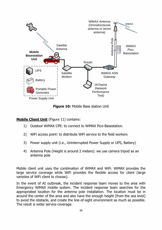
Mobile Base station Unit (Figure 10) contains:
1) Satellite modem and satellite antenna (IPStar): to connect to the Internet
and the Headquarter 2) WiMAX Base station System (i.e., WiMAX Pico-Basestation, WiMAX ASN
Gateway): to provide the WiMAX service 3) Router: to provide the network connectivity
4) Performance Testing Notebook: to be used for the network performance testing
5) Power supply unit (i.e., Uninterrupted Power Supply or UPS, Battery, Portable Power Generator)
6) Antenna Pole (Height is around 3 meters)
13
Satellite
Antenna
Satellite
Modem
Router
IXChariot
(Network
Performance
Test)
WiMAX ASN
Gateway
WiMAX
Pico-
Basestation
WiMAX Antenna
(Omnidirectional
antenna or sector
antenna)
UPS
Battery
Portable Power
Generator
Power Supply Unit
An
ten
na
Po
le
Mobile
Basestation
Unit
WiMAX
Figure 10: Mobile Base station Unit
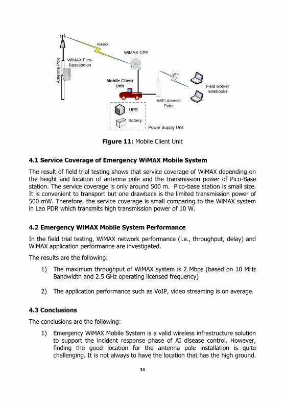
Mobile Client Unit (Figure 11) contains:
1) Outdoor WiMAX CPE: to connect to WiMAX Pico-Basestation.
2) WiFi access point: to distribute WiFi service to the field workers
3) Power supply unit (i.e., Uninterrupted Power Supply or UPS, Battery)
4) Antenna Pole (Height is around 2 meters): we use camera tripod as an antenna pole
Mobile client unit uses the combination of WiMAX and WiFi. WiMAX provides the large service coverage while WiFi provides the flexible access for client (large varieties of WiFi client to choose).
In the event of AI outbreak, the incident response team moves to the area with Emergency WiMAX mobile system. The incident response team searches for the appropriated location for the antenna pole installation. The location must be in around the center of the area and also have the enough height (from the sea level) to avoid the obstacle, and create the line-of-sight environment as much as possible. The result is wider service coverage.
14
WiFi Access
Point
WiMAX CPE
Field worker
notebooks
UPS
Battery
Power Supply Unit
An
ten
na
Po
le WiMAX Pico-
Basestation
Mobile Client
Unit
WiFi
WiMAX
Figure 11: Mobile Client Unit
4.1 Service Coverage of Emergency WiMAX Mobile System
The result of field trial testing shows that service coverage of WiMAX depending on the height and location of antenna pole and the transmission power of Pico-Base
station. The service coverage is only around 500 m. Pico-base station is small size. It is convenient to transport but one drawback is the limited transmission power of
500 mW. Therefore, the service coverage is small comparing to the WiMAX system in Lao PDR which transmits high transmission power of 10 W.
4.2 Emergency WiMAX Mobile System Performance
In the field trial testing, WiMAX network performance (i.e., throughput, delay) and WiMAX application performance are investigated.
The results are the following:
1) The maximum throughput of WiMAX system is 2 Mbps (based on 10 MHz Bandwidth and 2.5 GHz operating licensed frequency)
2) The application performance such as VoIP, video streaming is on average.
4.3 Conclusions
The conclusions are the following:
1) Emergency WiMAX Mobile System is a valid wireless infrastructure solution to support the incident response phase of AI disease control. However, finding the good location for the antenna pole installation is quite challenging. It is not always to have the location that has the high ground.
15
Another pole is sometimes bulky. The special design of antenna pole to
have light weight and not bulky is required.
2) The maximum coverage of WiMAX pico-basestation is around 500 meters
which is quite low comparing to other WiMAX vendor due to the limited output power (500 mW) and Omni-directional antenna. Increasing more
output power or better antenna system such as MIMO would improve the coverage significantly.
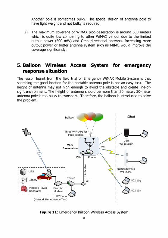
5. Balloon Wireless Access System for emergency response situation
The lesson learnt from the field trial of Emergency WiMAX Mobile System is that searching the good location for the portable antenna pole is not an easy task. The
height of antenna may not high enough to avoid the obstacle and create line-of-sight environment. The height of antenna should be more than 30 meter. 30-meter
antenna pole is too bulky to transport. Therefore, the balloon is introduced to solve the problem.
Satellite
Modem
Router
IXChariot
(Network Performance Test)
PoE
Three WiFi APs for
three sectors
UPS
Battery
Portable Power
Generator
LA
N c
ab
le
WiFi
PoE Router
WiFi
Basestation
Balloon
USB
WiFiStation
NanostationM2
WiFi CPE
802.11g
802.11n
Client
Figure 11: Emergency Balloon Wireless Access System
16
Emergency Balloon Wireless Access System (Figure 11) consists of:
1) The balloon The size of the balloon is varying on the payload (i.e., Weight of WiFi Base
station, balloon itself, rope, LAN cable). The lifting force of the balloon must be greater than the weight of payload. The weight of payload
consists of 1) wireless box 2) the balloon itself 3) LAN cable and 4) rope. The total weight of payload of the test bed system is around 8 kg.
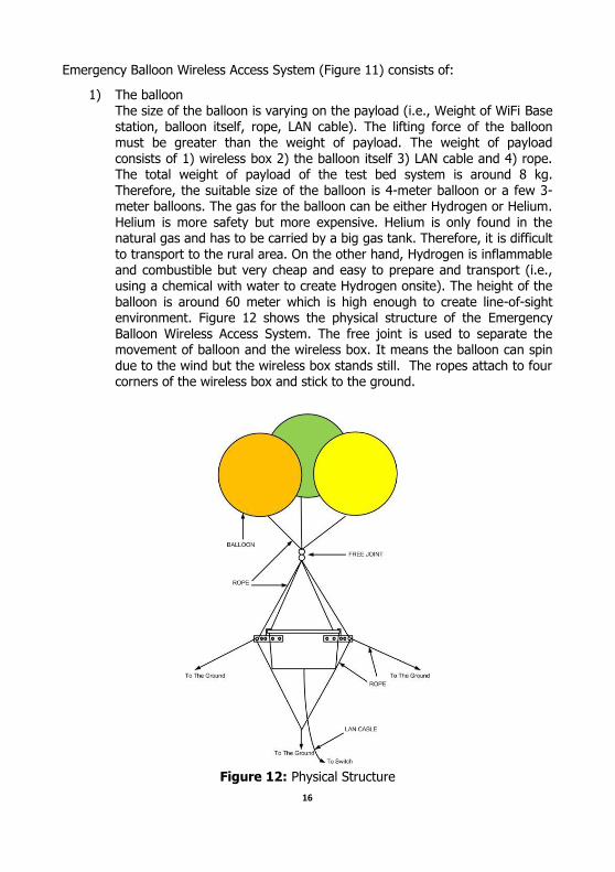
Therefore, the suitable size of the balloon is 4-meter balloon or a few 3-meter balloons. The gas for the balloon can be either Hydrogen or Helium.
Helium is more safety but more expensive. Helium is only found in the natural gas and has to be carried by a big gas tank. Therefore, it is difficult
to transport to the rural area. On the other hand, Hydrogen is inflammable and combustible but very cheap and easy to prepare and transport (i.e., using a chemical with water to create Hydrogen onsite). The height of the
balloon is around 60 meter which is high enough to create line-of-sight environment. Figure 12 shows the physical structure of the Emergency
Balloon Wireless Access System. The free joint is used to separate the movement of balloon and the wireless box. It means the balloon can spin
due to the wind but the wireless box stands still. The ropes attach to four corners of the wireless box and stick to the ground.
Figure 12: Physical Structure
17
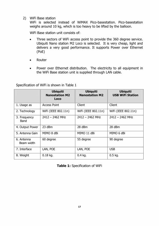
2) WiFi Base station
WiFi is selected instead of WiMAX Pico-basestation. Pico-basestation weighs around 10 kg, which is too heavy to be lifted by the balloon.
WiFi Base station unit consists of:
Three sectors of WiFi access point to provide the 360 degree service.
Ubiquiti Nano station M2 Loco is selected. It is very cheap, light and delivers a very good performance. It supports Power over Ethernet
(PoE)
Router
Power over Ethernet distribution. The electricity to all equipment in
the WiFi Base station unit is supplied through LAN cable.
Specification of WiFi is shown in Table 1
Ubiquiti Nanostation M2
Loco
Ubiquiti Nanostation M2
Ubiquiti USB WiFi Station
1. Usage as Access Point Client Client
2. Technology WiFi (IEEE 802.11n) WiFi (IEEE 802.11n) WiFi (IEEE 802.11n)
3. Frequency Band
2412 – 2462 MHz 2412 – 2462 MHz 2412 – 2462 MHz
4. Output Power 23 dBm 28 dBm 28 dBm
5. Antenna Gain MIMO 8 dBi MIMO 11 dBi MIMO 6 dBi
6. Antenna Beam width
60 degree 55 degree 90 degree
7. Interface LAN, POE LAN, POE USB
8. Weight 0.18 kg. 0.4 kg. 0.5 kg.
Table 1: Specification of WiFi
18
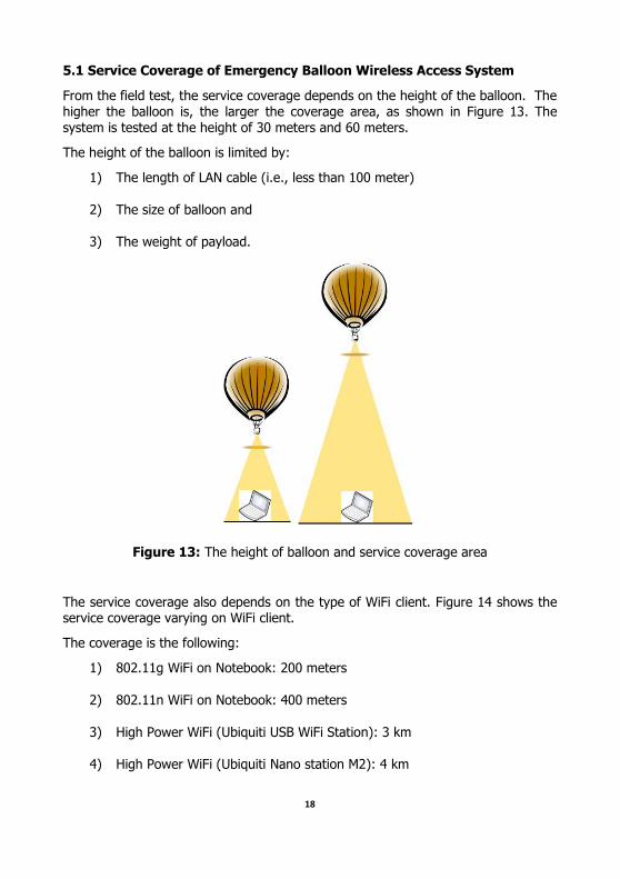
5.1 Service Coverage of Emergency Balloon Wireless Access System
From the field test, the service coverage depends on the height of the balloon. The higher the balloon is, the larger the coverage area, as shown in Figure 13. The system is tested at the height of 30 meters and 60 meters.
The height of the balloon is limited by:
1) The length of LAN cable (i.e., less than 100 meter)
2) The size of balloon and
3) The weight of payload.
Figure 13: The height of balloon and service coverage area
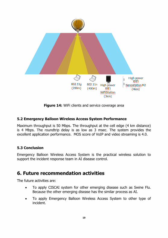
The service coverage also depends on the type of WiFi client. Figure 14 shows the service coverage varying on WiFi client.
The coverage is the following:
1) 802.11g WiFi on Notebook: 200 meters
2) 802.11n WiFi on Notebook: 400 meters
3) High Power WiFi (Ubiquiti USB WiFi Station): 3 km
4) High Power WiFi (Ubiquiti Nano station M2): 4 km
19
Figure 14: WiFi clients and service coverage area
5.2 Emergency Balloon Wireless Access System Performance
Maximum throughput is 50 Mbps. The throughput at the cell edge (4 km distance) is 4 Mbps. The roundtrip delay is as low as 3 msec. The system provides the excellent application performance. MOS score of VoIP and video streaming is 4.0.
5.3 Conclusion
Emergency Balloon Wireless Access System is the practical wireless solution to support the incident response team in AI disease control.
6. Future recommendation activities
The future activities are:
To apply CISCAI system for other emerging disease such as Swine Flu. Because the other emerging disease has the similar process as AI.
To apply Emergency Balloon Wireless Access System to other type of incident.
20
7. Conclusion
The field test on Fixed Broadband Wireless Access System in Lao PDR, Mobile
Broadband Wireless Access System in Vietnam clearly shows that the wireless system based on the combination of WiMAX and WiFi is the valid solution to
support AI disease control. Emergency Balloon Wireless System is an effective solution for the incident response. Lastly, CISCAI system can be applied to other kind of emerging disease.
A-1
Appendices A
CISCAI Engineering Training
1st CISCAI WiMAX Engineering Workshop (16-20 March 2009)
Code Name of Event Type
CISCAI_WS1 1st CISCAI WiMAX Engineering Workshop
WS SeminarOJT
Others
Date 16-20 March. 2009 Time AM9:00~16:00
Place NECTEC training center, Mahanakorn Gypsum Building
21st floor, Room 2102, Sriayuthaya Road, Rajthevee, Bangkok, Thailand 10400
Target Audience Engineers, Network administrators, and technical persons who are in charge of testing and administrating the CISCAI system.
Project staff NECTEC NECTEC team
Num.Participants Preview 8 persons Result 8 persons
Conditions PC Num
Goal & Target
Goal Achieved
1. The CISCAI Engineering Workshop aims to
provide the necessary background knowledge for implementing and administering the CISCAI wireless system including servers and computer networks securely and effectively.
As feedback from participants, it
shows that almost all of the audiences can apply the knowledge learnt from training to their work and project. Therefore, the goal for obtaining knowledge is achieved.
2. Train at least 8 persons to be able to exercise
the best practice of the wireless system operation for CISCAI project.
Attendees were 8, so achieved.
A-2
2nd CISCAI WiMAX Engineering Workshop (25 – 29 January 2010)
Code Name of Event Type
CISCAI_WS2 2nd CISCAI WiMAX Engineering Workshop
WS SeminarOJT
Others
Date 25-29 January 2010 Time AM9:00~16:00
Place Mae Hong Son community college training center, Mae Hong Son Province, Thailand
Target Audience Engineers, Network administrators, and technical persons who are in charge of testing and administrating the CISCAI system.
Project staff NECTEC NECTEC team
Num.Participants Preview 8 persons Result 8 persons
Conditions PC Num
Goal & Target
Goal Achieved
1. The CISCAI Engineering Workshop aims to
provide the necessary background knowledge for implementing and administering the CISCAI wireless system including servers and computer networks securely and effectively.
As feedback from participants, it
shows that almost all of the audiences can apply the knowledge learnt from training to their work and project. Therefore, the goal for obtaining knowledge is achieved.
2. Train at least 8 persons to be able to exercise with hand-on experience on WiMAX equipment.
Attendees were 8, so achieved.
3. Participants are able to learn the installation process of WiMAX equipment and tower. Also understand the concept of WiMAX design and planning.
From instructors and staff observation, participants perform very well in WiMAX design and planning and they gave us a lot of feedback during the installation process training topic. So achieved.
A-3
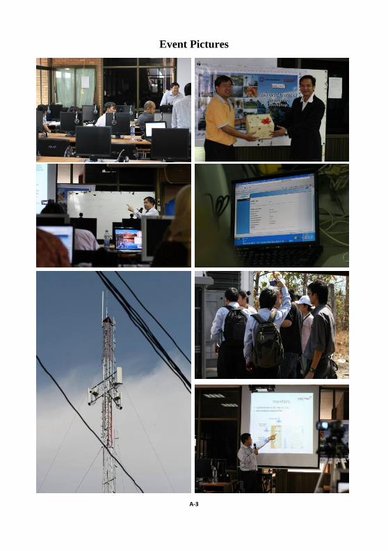
Event Pictures

B-1
Appendices B
CISCAI Site Survey and Tabletop Exercise in Lao PDR
1. Background
Fixed Broadband Wireless Access System in Lao PDR is used as a model of the wireless infrastructure to support AI management for Surveillance and Monitoring.
The field trial activities in Lao PDR are:
1) CISCAI Site Survey in Lao PDR (October 5 – 7, 2009)
2) CISCAI WiMAX Field Testing in Lao PDR # 1 (24-26 May 2010)
3) CISCAI WiMAX Testing in Lao PDR # 2 (28 February – 3 March 2010)
4) CISCAI Emergency Balloon Wireless Access (EBWA) Testing in Lao PDR
(1 – 4 August 2011)
2. CISCAI Site Survey in Lao PDR
2.1 Objective and Schedule
The objectives of the CISCAI Site Survey Mission are the following:
1. To examine the CISCAI network infrastructure running on the top of WiMAX e-government project networks.
2. To conduct the site surveys on client sites and examine the possible
interference at the sites that may affect the performance of WiMAX system.
2.2 CISCAI Network Infrastructure
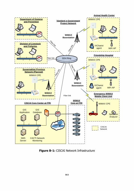
The NECTEC team examined the network infrastructure provided by ITRI. Figure B-
1 shows the CISCAI network infrastructure of Lao PDR which is running on the top of e-Government project network. E-Government project network implements the
network infrastructure to connect each of government departments together through either wire line (i.e., fiber line) or wireless (i.e., WiMAX). CISCAI network consists of CISCAI core center and CISCAI client sites. The CISCAI core center located at ITRI contains the CISCAI server farm such as GIS application, GIS database, SMS server and CACTI network monitoring server.
B-2
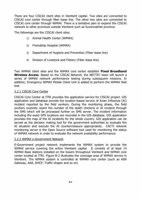
There are four CISCAI client sites in Vientient capital. Two sites are connected to
CISCAI core center through fiber lease line. The other two sites are connected to CISCAI core center through WiMAX. There is a tentative plan to expand the CISCAI network to other provinces outside Vientient such as Suvannakhet province.
The followings are the CISCAI client sites:
1) Animal Health Center (WiMAX)
2) Friendship Hospital (WiMAX)
3) Department of Hygiene and Prevention (Fiber lease line)
4) Division of Livestock and Fishery (Fiber lease line)
Two WiMAX client sites and the WiMAX core center establish Fixed Broadband Wireless Access. Based on the CISCAI Network, the NECTEC team will launch a
series of WiMAX network performance testing during subsequent missions. In addition, Emergency WiMAX Mobile Client Unit is added to perform the WiMAX field test.
2.2.1 CISCAI Core Center
CISCAI Core Center at ITRI provides the application service for CISCAI project. GIS application and database provide the location-based service of Avian Influenza (AI)
incident reported by the field workers. During the monitoring phase, the field workers routinely report the number of the death chickens or AI incident through the SMS which will be processed further on SMS server. The incident information
including the exact GPS locations are recorded in the GIS database. GIS application provides the map of the AI incidents for the whole country. GIS application can be served as the decision making tool for the government authorities to evaluate the AI situation and execute the AI countermeasure appropriately. CACTI network
monitoring server is the Open Source software tool used for monitoring the status of WiMAX network in order to evaluate the network availability performance.
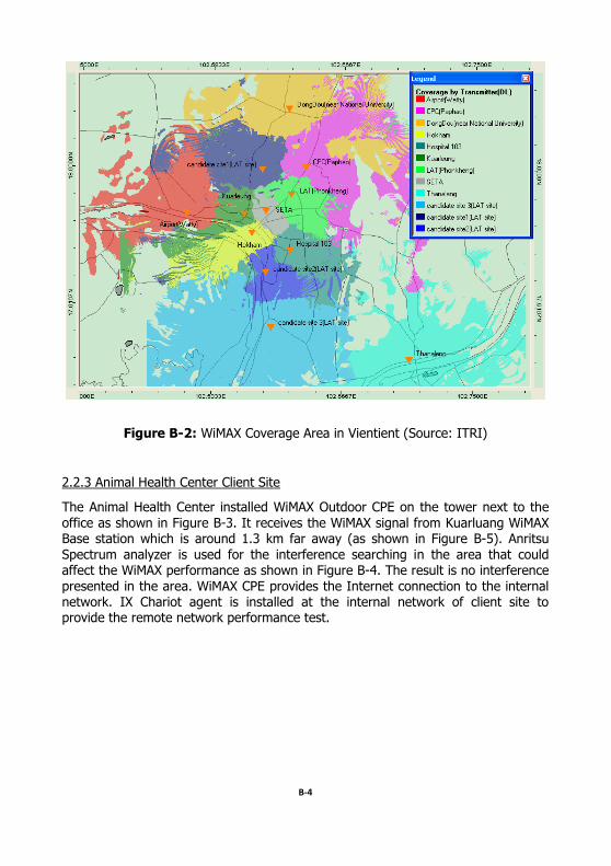
2.2.2 WiMAX e-Government Network
E-Government project network implements the WiMAX system to provide the
WiMAX service covering the entire Vientient capital. It consists of at least 14 WiMAX Base stations installed on the towers throughout Vientient and WiMAX core center located at ITRI. Figure B-2 illustrates the coverage area of WiMAX service in
Vientient. The WiMAX system is controlled at WiMAX core center (such as ASN Gateway, AAA, DHCP, Traffic shaper and so on)
B-3
Internet
SDH Ring
WiMAX CPE
IXChariot
agent
WiMAX CPE
IXChariot
agent
WiFi AP
Animal Health Center
Friendship Hospital
WiFi AP
Department of Hygiene
and Prevention
Division of Livestock
and Fisheries
Vientient e-Government
Project Network
WiMAX
Basestation
WiMAX
Basestation
Suvannakhet Province
Network (Planned)
WiMAX
Basestation
WiMAX CPE
Fiber link
Fiber link
Fib
er lin
k
WiMAX CPE
Emergency WiMAX
Mobile Client Unit
Spectrum
Analyzer
GIS
Application
GIS
Database
SMS
Server
CACTI Network
Monitoring
Fiber link
CISCAI Core Center at ITRI
Fib
er lin
k
Fib
er lin
k
WiMAX
Core at ITRI
CISCAI
Network
Figure B-1: CISCAI Network Infrastructure
B-4
Figure B-2: WiMAX Coverage Area in Vientient (Source: ITRI)
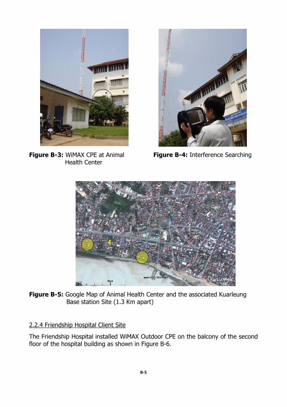
2.2.3 Animal Health Center Client Site
The Animal Health Center installed WiMAX Outdoor CPE on the tower next to the
office as shown in Figure B-3. It receives the WiMAX signal from Kuarluang WiMAX Base station which is around 1.3 km far away (as shown in Figure B-5). Anritsu
Spectrum analyzer is used for the interference searching in the area that could affect the WiMAX performance as shown in Figure B-4. The result is no interference
presented in the area. WiMAX CPE provides the Internet connection to the internal network. IX Chariot agent is installed at the internal network of client site to provide the remote network performance test.
B-5
Figure B-3: WiMAX CPE at Animal Health Center
Figure B-4: Interference Searching
Figure B-5: Google Map of Animal Health Center and the associated Kuarleung Base station Site (1.3 Km apart)
2.2.4 Friendship Hospital Client Site
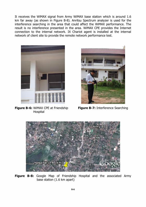
The Friendship Hospital installed WiMAX Outdoor CPE on the balcony of the second floor of the hospital building as shown in Figure B-6.
B-6
It receives the WiMAX signal from Army WiMAX base station which is around 1.6
km far away (as shown in Figure B-8). Anritsu Spectrum analyzer is used for the interference searching in the area that could affect the WiMAX performance. The result is no interference presented in the area. WiMAX CPE provides the Internet
connection to the internal network. IX Chariot agent is installed at the internal network of client site to provide the remote network performance test.
Figure B-6: WiMAX CPE at Friendship Hospital
Figure B-7: Interference Searching
Figure B-8: Google Map of Friendship Hospital and the associated Army base station (1.6 km apart)
B-7
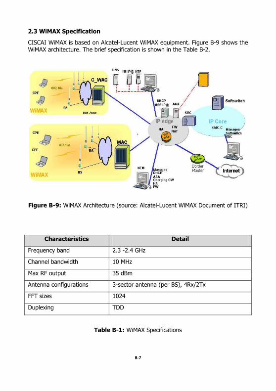
2.3 WiMAX Specification
CISCAI WiMAX is based on Alcatel-Lucent WiMAX equipment. Figure B-9 shows the WiMAX architecture. The brief specification is shown in the Table B-2.
Figure B-9: WiMAX Architecture (source: Alcatel-Lucent WiMAX Document of ITRI)
Characteristics Detail
Frequency band 2.3 -2.4 GHz
Channel bandwidth 10 MHz
Max RF output 35 dBm
Antenna configurations 3-sector antenna (per BS), 4Rx/2Tx
FFT sizes 1024
Duplexing TDD
Table B-1: WiMAX Specifications
B-8
3. CISCAI WiMAX Field Testing in Lao PDR #1 (24-26 May 2010)
3.1 Objectives and schedule
The objectives of CISCAI WiMAX Field Testing # 1 are the following:
1. To conduct the CISCAI WiMAX field trial testing in Lao PDR
2. To evaluate the CISCAI WiMAX performance for the support of AI
prevention
There are two tests in the mission:
1. Radio signal strength measurement at client sites
2. WiMAX throughput performance test at client sites
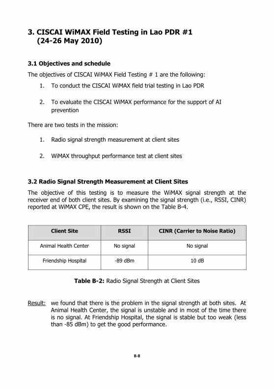
3.2 Radio Signal Strength Measurement at Client Sites
The objective of this testing is to measure the WiMAX signal strength at the
receiver end of both client sites. By examining the signal strength (i.e., RSSI, CINR) reported at WiMAX CPE, the result is shown on the Table B-4.
Client Site RSSI CINR (Carrier to Noise Ratio)
Animal Health Center No signal No signal
Friendship Hospital -89 dBm 10 dB
Table B-2: Radio Signal Strength at Client Sites
Result: we found that there is the problem in the signal strength at both sites. At Animal Health Center, the signal is unstable and in most of the time there
is no signal. At Friendship Hospital, the signal is stable but too weak (less than -85 dBm) to get the good performance.
B-9
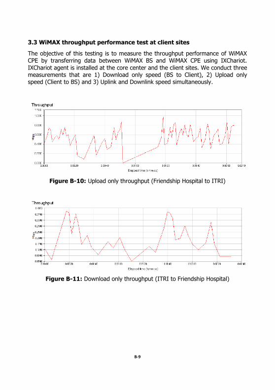
3.3 WiMAX throughput performance test at client sites
The objective of this testing is to measure the throughput performance of WiMAX CPE by transferring data between WiMAX BS and WiMAX CPE using IXChariot.
IXChariot agent is installed at the core center and the client sites. We conduct three measurements that are 1) Download only speed (BS to Client), 2) Upload only speed (Client to BS) and 3) Uplink and Downlink speed simultaneously.
Figure B-10: Upload only throughput (Friendship Hospital to ITRI)
Figure B-11: Download only throughput (ITRI to Friendship Hospital)
B-10
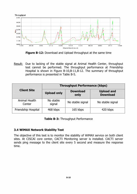
Figure B-12: Download and Upload throughput at the same time
Result: Due to lacking of the stable signal at Animal Health Center, throughput
test cannot be performed. The throughput performance at Friendship Hospital is shown in Figure B-10,B-11,B-12. The summary of throughput performance is presented in Table B-5.
Client Site
Throughput Performance (kbps)
Upload only Download
only Upload and Download
Animal Health Center
No stable signal
No stable signal No stable signal
Friendship Hospital 468 kbps 165 kbps 420 kbps
Table B-3: Throughput Performance
3.4 WiMAX Network Stability Test
The objective of this test is to monitor the stability of WiMAX service on both client sites. At CISCAI core center, CACTI Monitoring server is installed. CACTI server sends ping message to the client site every 5 second and measure the response time.
B-11
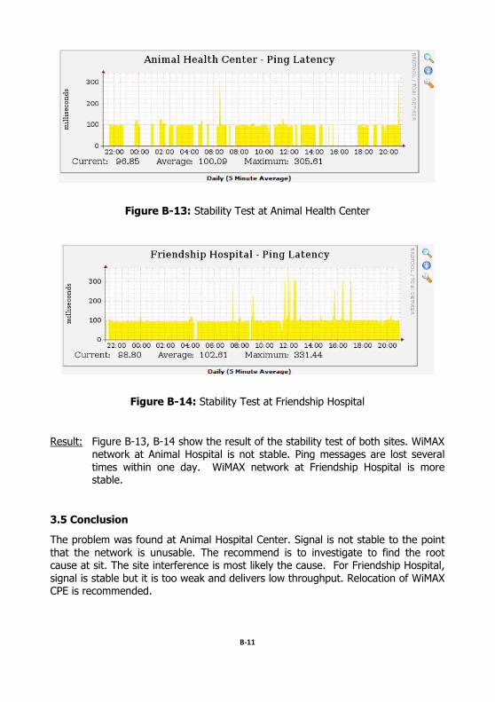
Figure B-13: Stability Test at Animal Health Center
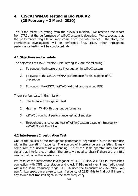
Figure B-14: Stability Test at Friendship Hospital
Result: Figure B-13, B-14 show the result of the stability test of both sites. WiMAX network at Animal Hospital is not stable. Ping messages are lost several
times within one day. WiMAX network at Friendship Hospital is more stable.
3.5 Conclusion
The problem was found at Animal Hospital Center. Signal is not stable to the point
that the network is unusable. The recommend is to investigate to find the root cause at sit. The site interference is most likely the cause. For Friendship Hospital,
signal is stable but it is too weak and delivers low throughput. Relocation of WiMAX CPE is recommended.
B-12
4. CISCAI WiMAX Testing in Lao PDR #2 (28 February – 3 March 2010)
This is the follow up testing from the previous mission. We received the report from ITRI that the performance of WiMAX system is degraded. We suspected that
the performance degradation may come from the interference. Therefore, the interference investigation will be performed first. Then, other throughput performance testing will be conducted later.
4.1 Objectives and schedule
The objectives of CISCAI WiMAX Field Testing # 2 are the following:
1. To conduct the interference investigation in WiMAX system
2. To evaluate the CISCAI WiMAX performance for the support of AI prevention
3. To conduct the CISCAI WiMAX field trial testing in Lao PDR
There are four tests in this mission.
1. Interference Investigation Test
2. Maximum WiMAX throughput performance
3. WiMAX throughput performance test at client sites
4. Throughput and coverage test of WiMAX system based on Emergency WiMAX Mobile Client Unit
4.2 Interference Investigation Test
One of the causes of the throughput performance degradation is the interference within the operating frequency. The sources of interference are varieties. It may
come from the incorrect radio planning. BSs of the same operator may transmit signal that interfere each other. Therefore, we need to check if there are any BSs nearby that cause the interference.
We conduct the interference investigation at ITRI BS site. WiMAX CPE establishes connection with ITRI base station and check if BSs nearby emit any radio signal within the same frequency range. ITRI BS uses the frequency of 2355 MHz. We use Anritsu spectrum analyze to scan frequency of 2355 MHz to find out if there is any source that transmit signal in the same frequency.
B-13
Results: there is no interference around. Later we receive the report from ITRI that the performance of WiMAX system is back to normal.
4.3 Maximum WiMAX Throughput Performance
This test will examine the maximum throughput of the WiMAX system. We conduct
the testing on ITRI BS. We measure the maximum throughput of traffic between ITRI BS and WiMAX CPE which locates only 300 meters apart. IXChariot is used to
generate the testing traffic. The test is run several times. Maximum throughput performance calculates from the average value. Throughput under the typical
usage is also tested. WiMAX CPE connects to BS that is 1 km. far apart. The testing result is shown in the Table B-7.
No Case BS ID Freq. (MHz)
Distance from BS
Channel Bandwidth
RSSI CINR
Throughput (Mbps)
DL Only
DL/UL
1 Max
Throughput 1
(ITRI BS) 2545 60 m 10 MHz -51.99 31.5 4.032 1.223/1.793
2
Throughput under typical usage
6 (LAT BS)
2505 1 km 10 MHz -58 33.5 3.835 1.482/1.654
Table B-4: Maximum Throughput Performance Test
Results: Max. Throughput performance that WiMAX system at ITRI can achieve is 4 Mbps.
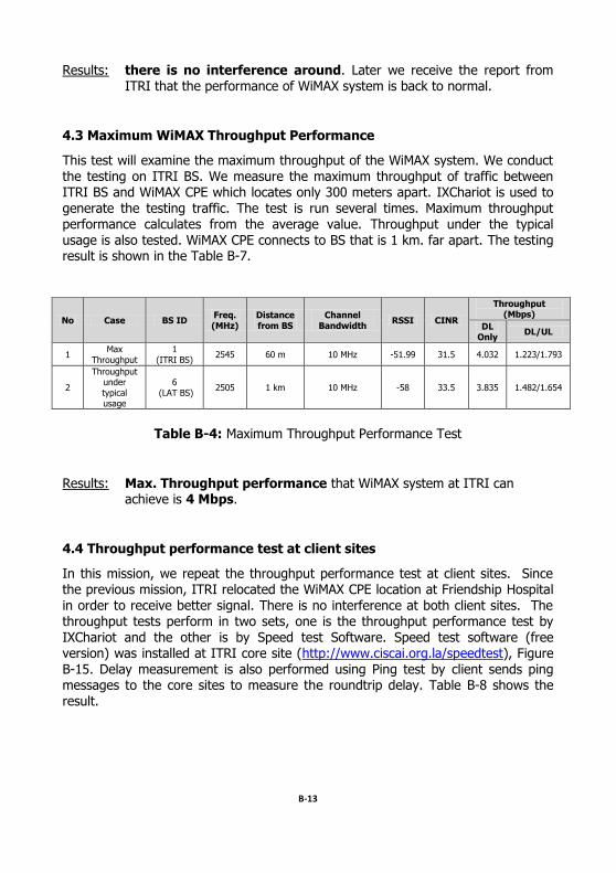
4.4 Throughput performance test at client sites
In this mission, we repeat the throughput performance test at client sites. Since the previous mission, ITRI relocated the WiMAX CPE location at Friendship Hospital
in order to receive better signal. There is no interference at both client sites. The throughput tests perform in two sets, one is the throughput performance test by
IXChariot and the other is by Speed test Software. Speed test software (free version) was installed at ITRI core site (http://www.ciscai.org.la/speedtest), Figure
B-15. Delay measurement is also performed using Ping test by client sends ping messages to the core sites to measure the roundtrip delay. Table B-8 shows the result.
B-14
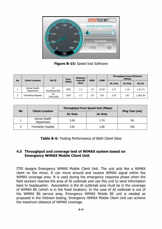
Figure B-15: Speed test Software
No Client Location BS ID Freq. (MHz)
Distance from BS
(Km) RSSI CINR
Throughput from IXChariot (Mbps)
DL Only UL Only DL/UL
1 Animal Health Department
12 (Kuraleung BS)
2385 1.3 -72 23.59 2.71 1.76 1.3/1.71
2 Friendship Hospital 30
(Army BS) 2335 1.7 --51 33.5 2.54 1.87 1.28/1.82
No Client Location Throughput from Speed test (Mbps)
Ping Test (ms) DL Only UL Only
1 Animal Health Department
3.04 1.74 99
2 Friendship Hospital 2.81 1.80 100
Table B-5: Testing Performance of Both Client Sites
4.5 Throughput and coverage test of WiMAX system based on Emergency WiMAX Mobile Client Unit
ITRI designs Emergency WiMAX Mobile Client Unit. The unit acts like a WiMAX client on the move. It can move around and receive WiMAX signal within the
WiMAX coverage area. It is used during the emergency response phase when the field workers reaches the area of AI outbreak and use this unit to send information
back to headquarter. Assumption is the AI outbreak area must be in the coverage of WiMAX BS (which is in the fixed location). In the case of AI outbreak is out of the WiMAX BS service area, Emergency WiMAX Mobile BS unit is needed as proposed in the Vietnam testing. Emergency WiMAX Mobile Client Unit can achieve the maximum distance of WiMAX coverage.
B-15
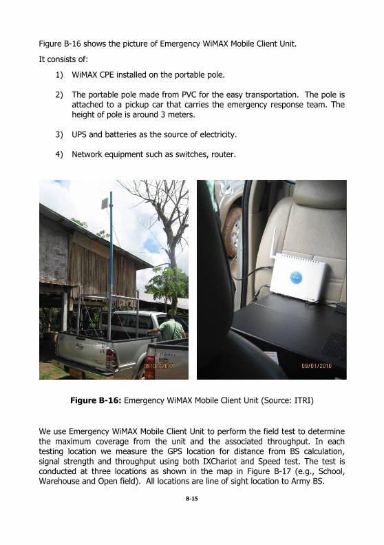
Figure B-16 shows the picture of Emergency WiMAX Mobile Client Unit.
It consists of:
1) WiMAX CPE installed on the portable pole.
2) The portable pole made from PVC for the easy transportation. The pole is attached to a pickup car that carries the emergency response team. The
height of pole is around 3 meters.
3) UPS and batteries as the source of electricity.
4) Network equipment such as switches, router.
Figure B-16: Emergency WiMAX Mobile Client Unit (Source: ITRI)
We use Emergency WiMAX Mobile Client Unit to perform the field test to determine
the maximum coverage from the unit and the associated throughput. In each testing location we measure the GPS location for distance from BS calculation,
signal strength and throughput using both IXChariot and Speed test. The test is conducted at three locations as shown in the map in Figure B-17 (e.g., School, Warehouse and Open field). All locations are line of sight location to Army BS.
B-16
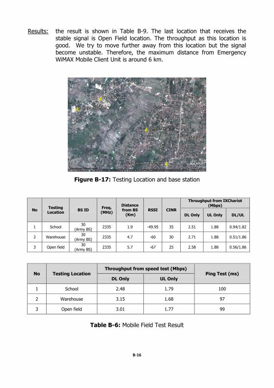
Results: the result is shown in Table B-9. The last location that receives the
stable signal is Open Field location. The throughput as this location is good. We try to move further away from this location but the signal become unstable. Therefore, the maximum distance from Emergency WiMAX Mobile Client Unit is around 6 km.
Figure B-17: Testing Location and base station
No Testing Location
BS ID Freq. (MHz)
Distance from BS (Km)
RSSI CINR
Throughput from IXChariot (Mbps)
DL Only UL Only DL/UL
1 School 30
(Army BS) 2335 1.9 -49.95 35 2.51 1.88 0.94/1.82
2 Warehouse 30
(Army BS) 2335 4.7 -60 30 2.71 1.88 0.51/1.86
3 Open field 30
(Army BS) 2335 5.7 -67 25 2.58 1.88 0.56/1.86
No Testing Location Throughput from speed test (Mbps)
Ping Test (ms) DL Only UL Only
1 School 2.48 1.79 100
2 Warehouse 3.15 1.68 97
3 Open field 3.01 1.77 99
Table B-6: Mobile Field Test Result
B-17
4.6 Conclusion
We can conclude the mission as the following:
1) No interference in the area that causes the interference degradation.
2) Maximum throughput of WiMAX system at Lao PDR site is around 4 Mbps
3) The maximum coverage of WiMAX using Emergency WiMAX Mobile
Client Unit is around 6 km.
5. CISCAI Emergency Balloon Wireless Access (EBWA) Testing in Lao PDR
5.1 Objectives and schedule
This testing is in a part of CISCAI Tabletop Exercise in Lao PDR. The objective of
the test is to perform trial test of Emergency Balloon Wireless Access applied for emergency response phase of AI outbreak. The schedule is shown in Table B-10.
5.2 Tabletop Exercise Setup
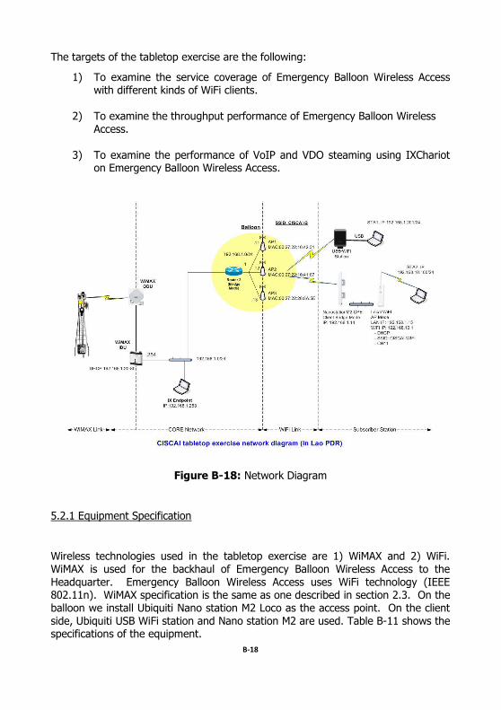
Figure B-18 shows the network diagram of testing. We conduct the tabletop
exercise by assuming there is an AI outbreak in the area. Emergency response team setup Emergency Balloon Wireless Access (EBWA) at the center area of AI
outbreak (i.e., ITRI office in Vientient). At the center area, it is in the WiMAX coverage. Therefore, WiMAX CPE can connect to WiMAX BS and the WiMAX connection serves as the backhaul of Emergency Balloon Wireless Access. Balloon is
launched at the height of 20 meters and provides the WiFi distribution surrounding the area. Field workers can access the Internet through various types of Wi-Fi
clients such as a regular WiFi built into Notebook, USB WiFi Station and Nano station M2 WiFi CPE). Each types of WiFi client will provide the different WiFi
coverage area. The information from the field workers sends to EBWA and is forwarded further to the Headquarter through WiMAX.
B-18
The targets of the tabletop exercise are the following:
1) To examine the service coverage of Emergency Balloon Wireless Access with different kinds of WiFi clients.
2) To examine the throughput performance of Emergency Balloon Wireless
Access.
3) To examine the performance of VoIP and VDO steaming using IXChariot on Emergency Balloon Wireless Access.
Figure B-18: Network Diagram
5.2.1 Equipment Specification
Wireless technologies used in the tabletop exercise are 1) WiMAX and 2) WiFi. WiMAX is used for the backhaul of Emergency Balloon Wireless Access to the
Headquarter. Emergency Balloon Wireless Access uses WiFi technology (IEEE 802.11n). WiMAX specification is the same as one described in section 2.3. On the balloon we install Ubiquiti Nano station M2 Loco as the access point. On the client side, Ubiquiti USB WiFi station and Nano station M2 are used. Table B-11 shows the specifications of the equipment.
B-19
Ubiquiti
Nanostation M2 Loco Ubiquiti
Nanostation M2 Ubiquiti
USB WiFi Station
1. Usage as Access Point Client Client
2. Technology WiFi (IEEE 802.11n) WiFi (IEEE 802.11n) WiFi (IEEE 802.11n)
3. Frequency Band 2412 – 2462 MHz 2412 – 2462 MHz 2412 – 2462 MHz
4. Output Power 23 dBm 28 dBm 28 dBm
5. Antenna Gain MIMO 8 dBi MIMO 11 dBi MIMO 6 dBi
6. Antenna Beam width
60 degree 55 degree 90 degree
7. Interface LAN, PoE LAN, PoE USB
8. Weight 0.18 kg. 0.4 kg. 0.5 kg.
Table B-7: Equipment Specifications
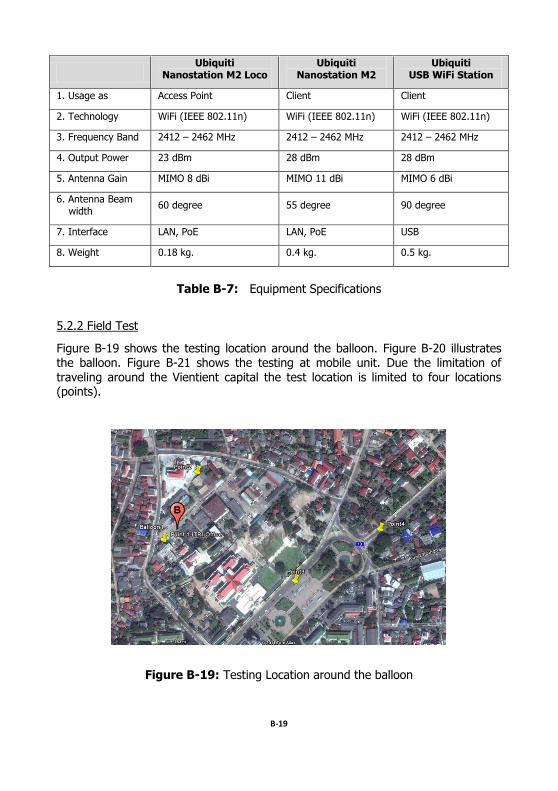
5.2.2 Field Test
Figure B-19 shows the testing location around the balloon. Figure B-20 illustrates the balloon. Figure B-21 shows the testing at mobile unit. Due the limitation of
traveling around the Vientient capital the test location is limited to four locations (points).
Figure B-19: Testing Location around the balloon
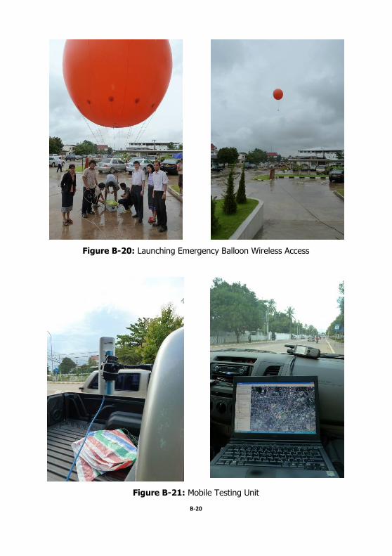
B-20
Figure B-20: Launching Emergency Balloon Wireless Access
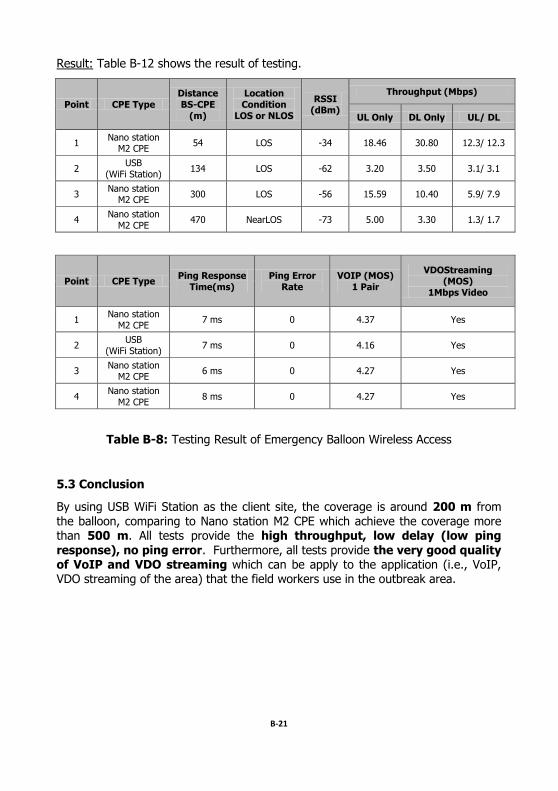
Figure B-21: Mobile Testing Unit
B-21
Result: Table B-12 shows the result of testing.
Point CPE Type
Distance
BS-CPE
(m)
Location
Condition
LOS or NLOS
RSSI (dBm)
Throughput (Mbps)
UL Only DL Only UL/ DL
1 Nano station
M2 CPE 54 LOS -34 18.46 30.80 12.3/ 12.3
2 USB
(WiFi Station) 134 LOS -62 3.20 3.50 3.1/ 3.1
3 Nano station
M2 CPE 300 LOS -56 15.59 10.40 5.9/ 7.9
4 Nano station
M2 CPE 470 NearLOS -73 5.00 3.30 1.3/ 1.7
Point CPE Type Ping Response
Time(ms)
Ping Error
Rate
VOIP (MOS)
1 Pair
VDOStreaming (MOS)
1Mbps Video
1 Nano station
M2 CPE 7 ms 0 4.37 Yes
2 USB
(WiFi Station) 7 ms 0 4.16 Yes
3 Nano station
M2 CPE 6 ms 0 4.27 Yes
4 Nano station
M2 CPE 8 ms 0 4.27 Yes
Table B-8: Testing Result of Emergency Balloon Wireless Access
5.3 Conclusion
By using USB WiFi Station as the client site, the coverage is around 200 m from
the balloon, comparing to Nano station M2 CPE which achieve the coverage more than 500 m. All tests provide the high throughput, low delay (low ping
response), no ping error. Furthermore, all tests provide the very good quality of VoIP and VDO streaming which can be apply to the application (i.e., VoIP, VDO streaming of the area) that the field workers use in the outbreak area.
C-1
Appendices C
CISCAI Site Survey and Tabletop Exercise in Vietnam
1. Background
Mobile Broadband Wireless Access System in Viet Nam is used as a model of the wireless infrastructure to support AI management for Incident Response. The
incident response team move to the area with the mobile wireless system called Emergency WiMAX Mobile System.
The field trial activities in Viet Nam are:
1) CISCAI WiMAX Testing in Vietnam #1
(2nd Tabletop Exercise, 28 – 30 September 2010)
2) CISCAI WiMAX Testing in Vietnam #2 (3rd Tabletop Exercise, 27 June – 1 July 2011)
2. CISCAI WiMAX Testing in Vietnam #1 (2nd Tabletop Exercise)
2.1 Objective and Schedule
The objective of 2nd tabletop exercise is to conduct the WiMAX field trial on Emergency WiMAX Mobile System. We simulate the AI outbreak in Bac Phong
Village area in Cao Phong district. The emergency response team moves to the area with all communication system carrying on the pickup truck. After arriving at Bac Phong Village, the team setup Emergency WiMAX Mobile System at the center of area and distributes the Internet connection through WiMAX and IPStar satellite system. Field workers can access the Internet to transmit the information (i.e.,
voice, video, data) from the area back to the Headquarter. The network performance such as throughput and delay and application testing are measured during the tabletop exercise.
C-2
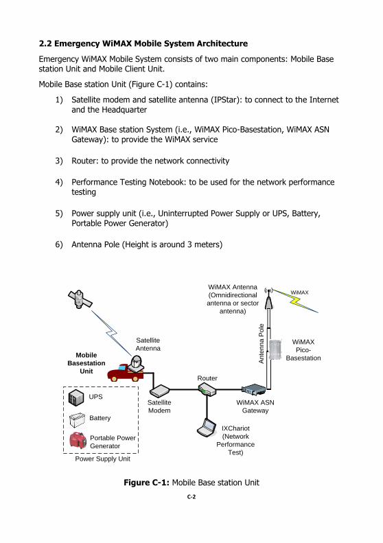
2.2 Emergency WiMAX Mobile System Architecture
Emergency WiMAX Mobile System consists of two main components: Mobile Base station Unit and Mobile Client Unit.
Mobile Base station Unit (Figure C-1) contains:
1) Satellite modem and satellite antenna (IPStar): to connect to the Internet
and the Headquarter
2) WiMAX Base station System (i.e., WiMAX Pico-Basestation, WiMAX ASN Gateway): to provide the WiMAX service
3) Router: to provide the network connectivity
4) Performance Testing Notebook: to be used for the network performance testing
5) Power supply unit (i.e., Uninterrupted Power Supply or UPS, Battery, Portable Power Generator)
6) Antenna Pole (Height is around 3 meters)
Satellite
Antenna
Satellite
Modem
Router
IXChariot
(Network
Performance
Test)
WiMAX ASN
Gateway
WiMAX
Pico-
Basestation
WiMAX Antenna
(Omnidirectional
antenna or sector
antenna)
UPS
Battery
Portable Power
Generator
Power Supply Unit
An
ten
na
Po
le
Mobile
Basestation
Unit
WiMAX
Figure C-1: Mobile Base station Unit
C-3
WiFi Access
Point
WiMAX CPE
Field worker
notebooks
UPS
Battery
Power Supply Unit
An
ten
na
Po
le WiMAX Pico-
Basestation
Mobile Client
Unit
WiFi
WiMAX
Figure C-2: Mobile Client Unit
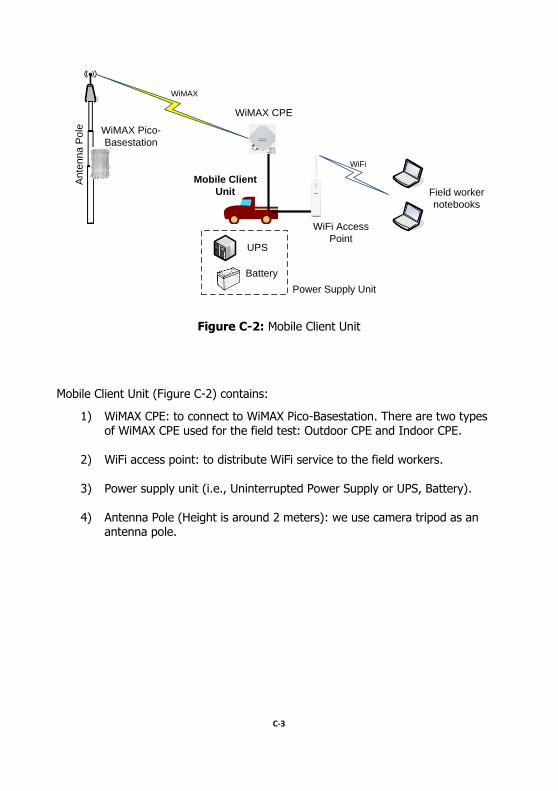
Mobile Client Unit (Figure C-2) contains:
1) WiMAX CPE: to connect to WiMAX Pico-Basestation. There are two types of WiMAX CPE used for the field test: Outdoor CPE and Indoor CPE.
2) WiFi access point: to distribute WiFi service to the field workers.
3) Power supply unit (i.e., Uninterrupted Power Supply or UPS, Battery).
4) Antenna Pole (Height is around 2 meters): we use camera tripod as an
antenna pole.
C-4
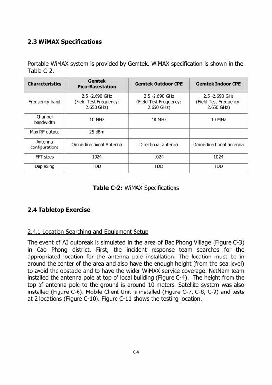
2.3 WiMAX Specifications
Portable WiMAX system is provided by Gemtek. WiMAX specification is shown in the Table C-2.
Characteristics Gemtek
Pico-Basestation Gemtek Outdoor CPE Gemtek Indoor CPE
Frequency band
2.5 -2.690 GHz
(Field Test Frequency: 2.650 GHz)
2.5 -2.690 GHz
(Field Test Frequency: 2.650 GHz)
2.5 -2.690 GHz
(Field Test Frequency: 2.650 GHz)
Channel bandwidth
10 MHz 10 MHz 10 MHz
Max RF output 25 dBm
Antenna configurations
Omni-directional Antenna Directional antenna Omni-directional antenna
FFT sizes 1024 1024 1024
Duplexing TDD TDD TDD
Table C-2: WiMAX Specifications
2.4 Tabletop Exercise
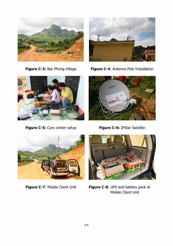
2.4.1 Location Searching and Equipment Setup
The event of AI outbreak is simulated in the area of Bac Phong Village (Figure C-3) in Cao Phong district. First, the incident response team searches for the appropriated location for the antenna pole installation. The location must be in
around the center of the area and also have the enough height (from the sea level) to avoid the obstacle and to have the wider WiMAX service coverage. NetNam team
installed the antenna pole at top of local building (Figure C-4). The height from the top of antenna pole to the ground is around 10 meters. Satellite system was also
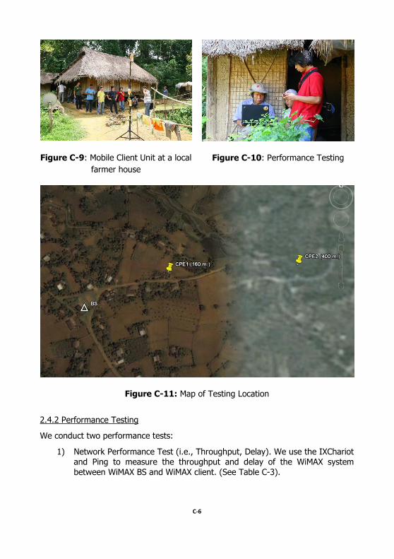
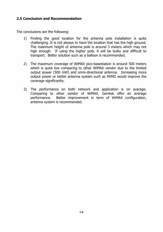
installed (Figure C-6). Mobile Client Unit is installed (Figure C-7, C-8, C-9) and tests at 2 locations (Figure C-10). Figure C-11 shows the testing location.
C-5
Figure C-3: Bac Phong Village Figure C-4: Antenna Pole Installation
Figure C-5: Core center setup Figure C-6: IPStar Satellite
Figure C-7: Mobile Client Unit Figure C-8: UPS and battery pack at
Mobile Client Unit
C-6
Figure C-9: Mobile Client Unit at a local
farmer house
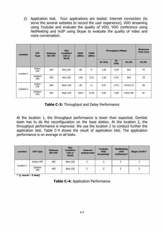
Figure C-10: Performance Testing
Figure C-11: Map of Testing Location
2.4.2 Performance Testing
We conduct two performance tests:
1) Network Performance Test (i.e., Throughput, Delay). We use the IXChariot and Ping to measure the throughput and delay of the WiMAX system between WiMAX BS and WiMAX client. (See Table C-3).
C-7
2) Application test. Four applications are tested: Internet connection (to
serve the several websites to record the user experience), VDO streaming using Youtube and evaluate the quality of VDO, VDO conference using NetMeeting and VoIP using Skype to evaluate the quality of video and
voice conversation.
Location CPE Type
Distance BS-CPE
Site Condition
LOS or NLOS
RSSI (dBm)
CINR (dBm)
Throughput (Mbps) Response Time (ms)
UL Only DL
Only UL/DL UL/DL
Location 1
Indoor CPE
160 Non LOS -86 9 1.00 0.36 N/A 70
Outdoor CPE
160 Non LOS -100 12.5 1.00 0.45 N/A 70
Location 2
Indoor CPE
400 Near LOS -85 11 0.91 0.73 0.91/0.13 60
Outdoor CPE
400 Near LOS -100.2 12.96 0.93 2.86 0.84/1.89 81
Table C-3: Throughput and Delay Performance
At the location 1, the throughput performance is lower than expected. Gemtek team has to do the reconfiguration on the base station. At the location 2, the
throughput performance is improved. We use the location 2 to conduct further the application test. Table C-4 shows the result of application test. The application performance is on average in all tests.
Location CPE Type Distance BS-CPE
Site Condition
LOS or NLOS
Internet webserving*
Youtube VDO
streaming*
NetMeeting VDO
conference* Skype (VoIP)*
Location 2
Indoor CPE 400 Near LOS 3 3 3 3
Outdoor CPE
400 Near LOS 3 3 3 3
* (1 worst – 5 best)
Table C-4: Application Performance
C-8
2.5 Conclusion and Recommendation
The conclusions are the following:
1) Finding the good location for the antenna pole installation is quite challenging. It is not always to have the location that has the high ground.
The maximum height of antenna pole is around 3 meters which may not high enough. If using the higher pole, it will be bulky and difficult to
transport. Better solution such as a balloon is recommended.
2) The maximum coverage of WiMAX pico-basestation is around 500 meters which is quite low comparing to other WiMAX vendor due to the limited
output power (500 mW) and omni-directional antenna. Increasing more output power or better antenna system such as MIMO would improve the coverage significantly.
3) The performance on both network and application is on average.
Comparing to other vendor of WiMAX, Gemtek offer an average performance. Better improvement in term of WiMAX configuration,
antenna system is recommended.
C-9
3. CISCAI WiMAX Testing in Vietnam #2 (3rd Tabletop Exercise, 27 June – 1 July 2011)
3.1 Objective and Schedule
The objective of 3rd tabletop exercise is to reconfirm the performance testing of Emergency WiMAX Mobile Unit and introduce the new solution of the emergency
wireless called Emergency Balloon Wireless Access). We simulate the AI outbreak in a village in Thai Nguyen province. The emergency response team moves to the
area with all communication system carrying on the pickup truck. After arriving at the selected village in Thai Nguyen province, the team setup Emergency WiMAX
Mobile Unit and Emergency Balloon Wireless Access at the center of area and distributes the Internet connection through WiMAX, WiFi and IPStar satellite
system. Field workers can access the Internet to transmit the information (i.e., voice, video, data) from the area back to the Headquarter. The network performance such as throughput and delay and application testing are measured during the tabletop exercise.
3.2 Emergency Balloon Wireless Access architecture
Emergency Balloon Wireless Access consists of
1) The balloon The size of the balloon is varying on the payload (i.e., Weight of WiFi Base
station, balloon itself, rope, LAN cable). The total weight of payload is around 8 kg. Therefore, the suitable size of the balloon is 4-meter balloon or a few 3-meter balloons. The gas for the balloon can be either Hydrogen
or Helium. Helium is more safety but more expensive. Helium is only found in the natural gas and has to be carried by a big gas tank.
Therefore, it is difficult to transport to the rural area. On the other hand, Hydrogen is inflammable and combustible but very cheap and easy to
prepare and transport (i.e., using a chemical with water to create Hydrogen onsite). We design the special rig to hold the balloon stable in
the air. At 3rd Tabletop exercise, we use 3 3-meter balloons with Hydrogen. The height of the balloon originally set at 30 meters. But during
testing, 30 meters of balloon is still too low to avoid the obstacle. Therefore, 60 meter height is tested.
C-10
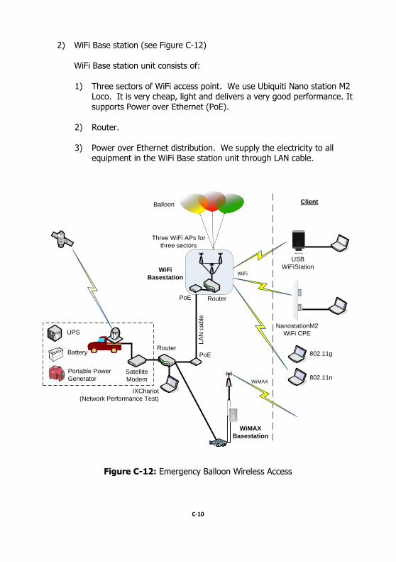
2) WiFi Base station (see Figure C-12)
WiFi Base station unit consists of:
1) Three sectors of WiFi access point. We use Ubiquiti Nano station M2 Loco. It is very cheap, light and delivers a very good performance. It
supports Power over Ethernet (PoE).
2) Router.
3) Power over Ethernet distribution. We supply the electricity to all equipment in the WiFi Base station unit through LAN cable.
Satellite
Modem
Router
IXChariot
(Network Performance Test)
PoE
Three WiFi APs for
three sectors
UPS
Battery
Portable Power
Generator
LA
N c
ab
le
WiFi
PoE Router
WiFi
Basestation
Balloon
USB
WiFiStation
NanostationM2
WiFi CPE
802.11g
802.11n
Client
WiMAX
Basestation
WiMAX
Figure C-12: Emergency Balloon Wireless Access
C-11
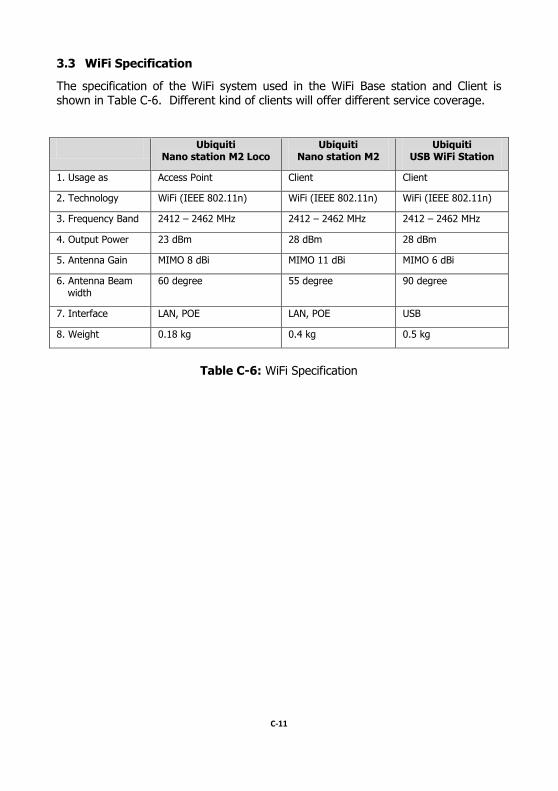
3.3 WiFi Specification
The specification of the WiFi system used in the WiFi Base station and Client is shown in Table C-6. Different kind of clients will offer different service coverage.
Ubiquiti Nano station M2 Loco
Ubiquiti Nano station M2
Ubiquiti USB WiFi Station
1. Usage as Access Point Client Client
2. Technology WiFi (IEEE 802.11n) WiFi (IEEE 802.11n) WiFi (IEEE 802.11n)
3. Frequency Band 2412 – 2462 MHz 2412 – 2462 MHz 2412 – 2462 MHz
4. Output Power 23 dBm 28 dBm 28 dBm
5. Antenna Gain MIMO 8 dBi MIMO 11 dBi MIMO 6 dBi
6. Antenna Beam width
60 degree 55 degree 90 degree
7. Interface LAN, POE LAN, POE USB
8. Weight 0.18 kg 0.4 kg 0.5 kg
Table C-6: WiFi Specification
C-12
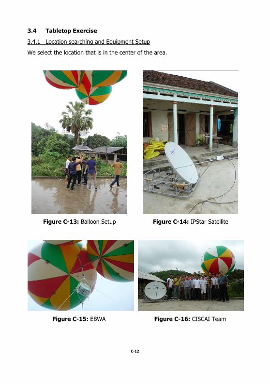
3.4 Tabletop Exercise
3.4.1 Location searching and Equipment Setup
We select the location that is in the center of the area.
Figure C-13: Balloon Setup Figure C-14: IPStar Satellite
Figure C-15: EBWA Figure C-16: CISCAI Team
C-13
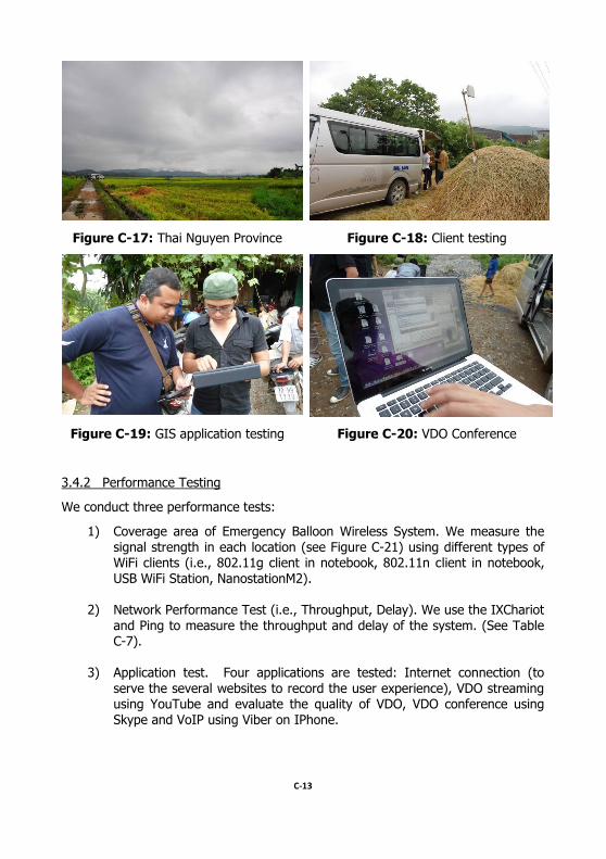
Figure C-17: Thai Nguyen Province Figure C-18: Client testing
Figure C-19: GIS application testing Figure C-20: VDO Conference
3.4.2 Performance Testing
We conduct three performance tests:
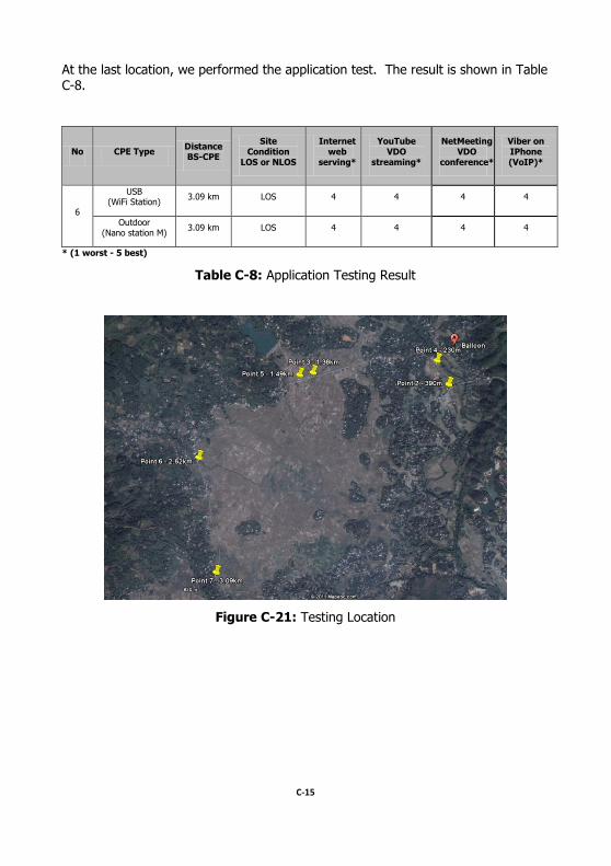
1) Coverage area of Emergency Balloon Wireless System. We measure the
signal strength in each location (see Figure C-21) using different types of WiFi clients (i.e., 802.11g client in notebook, 802.11n client in notebook,
USB WiFi Station, NanostationM2).
2) Network Performance Test (i.e., Throughput, Delay). We use the IXChariot
and Ping to measure the throughput and delay of the system. (See Table C-7).
3) Application test. Four applications are tested: Internet connection (to
serve the several websites to record the user experience), VDO streaming using YouTube and evaluate the quality of VDO, VDO conference using Skype and VoIP using Viber on IPhone.
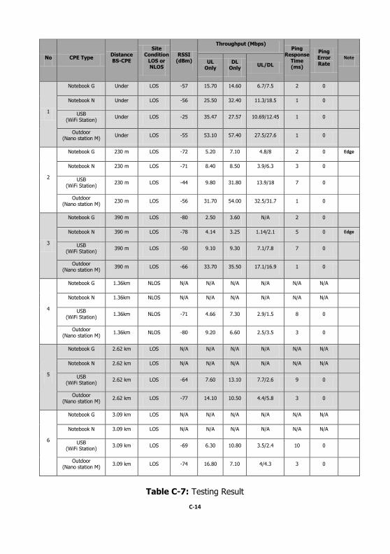
C-14
No CPE Type Distance BS-CPE
Site Condition
LOS or NLOS
RSSI (dBm)
Throughput (Mbps) Ping
Response Time (ms)
Ping Error Rate
Note UL
Only DL
Only UL/DL
1
Notebook G Under LOS -57 15.70 14.60 6.7/7.5 2 0
Notebook N Under LOS -56 25.50 32.40 11.3/18.5 1 0
USB (WiFi Station)
Under LOS -25 35.47 27.57 10.69/12.45 1 0
Outdoor (Nano station M)
Under LOS -55 53.10 57.40 27.5/27.6 1 0
2
Notebook G 230 m LOS -72 5.20 7.10 4.8/8 2 0 Edge
Notebook N 230 m LOS -71 8.40 8.50 3.9/6.3 3 0
USB (WiFi Station)
230 m LOS -44 9.80 31.80 13.9/18 7 0
Outdoor (Nano station M)
230 m LOS -56 31.70 54.00 32.5/31.7 1 0
3
Notebook G 390 m LOS -80 2.50 3.60 N/A 2 0
Notebook N 390 m LOS -78 4.14 3.25 1.14/2.1 5 0 Edge
USB (WiFi Station)
390 m LOS -50 9.10 9.30 7.1/7.8 7 0
Outdoor (Nano station M)
390 m LOS -66 33.70 35.50 17.1/16.9 1 0
4
Notebook G 1.36km NLOS N/A N/A N/A N/A N/A N/A
Notebook N 1.36km NLOS N/A N/A N/A N/A N/A N/A
USB (WiFi Station)
1.36km NLOS -71 4.66 7.30 2.9/1.5 8 0
Outdoor (Nano station M)
1.36km NLOS -80 9.20 6.60 2.5/3.5 3 0
5
Notebook G 2.62 km LOS N/A N/A N/A N/A N/A N/A
Notebook N 2.62 km LOS N/A N/A N/A N/A N/A N/A
USB (WiFi Station)
2.62 km LOS -64 7.60 13.10 7.7/2.6 9 0
Outdoor (Nano station M)
2.62 km LOS -77 14.10 10.50 4.4/5.8 3 0
6
Notebook G 3.09 km LOS N/A N/A N/A N/A N/A N/A
Notebook N 3.09 km LOS N/A N/A N/A N/A N/A N/A
USB (WiFi Station)
3.09 km LOS -69 6.30 10.80 3.5/2.4 10 0
Outdoor (Nano station M)
3.09 km LOS -74 16.80 7.10 4/4.3 3 0
Table C-7: Testing Result
C-15
At the last location, we performed the application test. The result is shown in Table C-8.
No CPE Type Distance BS-CPE
Site Condition
LOS or NLOS
Internet web
serving*
YouTube VDO
streaming*
NetMeeting VDO
conference*
Viber on IPhone (VoIP)*
6
USB (WiFi Station)
3.09 km LOS 4 4 4 4
Outdoor (Nano station M)
3.09 km LOS 4 4 4 4
* (1 worst - 5 best)
Table C-8: Application Testing Result
Figure C-21: Testing Location
C-16
3.5 Conclusion and Recommendation
1. The effective height of balloon for the rural area is at least 60 m.
2. The coverage area of Emergency Balloon Wireless Access varies on the type of client: Notebook 802.11g (230 m), Notebook 802.11n (400 m),
USB WiFi Station or Hi Power WiFi (3 km) and NanostationM2 (4 km).
3. All type of clients can deliver the high throughput even at cell edge.
4. All type of clients delivers very good performance in all applications we tested.

The ASEAN Foundation
The ASEAN Foundation was established by the ASEAN Leaders on 15 December 1997 during ASEAN’s 30th Anniversary in Kuala Lumpur.
The Foundation aims to help bring about shared prosperity and a sustainable future for the peoples of ASEAN whose member countries are Brunei Darussalam, Cambodia, Indonesia, Lao PDR, Malaysia, Myanmar, the Philippines, Singapore, Thailand, and Viet Nam. The Memorandum of Understanding on its establishment was revised in July 2000 and ratified by all ten member countries in July 2007. The Foundation has two objectives:
• Promote greater awareness of ASEAN, and greater interaction among the peoples of ASEAN as well as their wider participation in ASEAN’s activities inter alia through human resources development that will enable them to realize their full potential and capacity to contribute to the progress of ASEAN Member States as productive and responsible member of society
• Endeavour to contribute to the evolution of a development cooperation strategy that promotes mutual assistance, equitable economic development, and the alleviation of poverty.
On 20 November 2007, the ASEAN Leaders signed the ASEAN Charter at their 13th Summit held in Singapore. The Charter was ratified by all the Member States in 2008. Article 15 of the ASEAN Charter mandates the ASEAN Foundation to:
• Support the Secretary-General of ASEAN and collaborate with the relevant ASEAN bodies to support ASEAN community building, and
• Promote greater awareness of the ASEAN identity, people-to-people interaction, and close collaboration among the business sector, civil society, academia and other stakeholders in ASEAN.
The ASEAN Foundation is based in Jakarta, Indonesia.
The Japan-ASEAN Solidarity Fund (JASF)
In May 1998, H.E. Mr. Keizo Obuchi, Minister for Foreign Affairs of Japan, announced a contribution of US$20 million from the Government of Japan to the ASEAN Foundation to support projects in the areas of education, human resources development, business exchanges and other activities to promote development of the ASEAN region and strengthen Japan-ASEAN cooperation.
To date, almost USD 17 million of the Fund has been utilized and allocated to support over 100 social development projects, majority of which were for human resources development and poverty alleviation. Unless otherwise stated, projects of the ASEAN Foundation are funded by the Japan-ASEAN Solidarity Fund.

Jl. Sam Ratulangi No.2 Menteng,
Jakarta – 10350, INDONESIA T. +62 21 3192 4828 F. +62 21 3192 6078
[email protected] www.aseanfoundation.org