Embed Size (px)
Citation preview

Cirrus Perspective™ by GarminIntegrated Avionics SystemCockpit Reference Guide for the SR22

Flight instruments
eis
nav/Com/transponder/audio panel
automatiC Flight Control system
gps navigation
Flight planning
proCedures
hazard avoidanCe
additional Features
abnormal operation
annunCiations & alerts
appendix
index

Copyright © 2008 Garmin Ltd. or its subsidiaries. All rights reserved.
This manual reflects the operation of System Software version 0764.00 or later for the Cirrus SR22 and SR22T. Some differences in operation may be observed when comparing the information in this manual to earlier or later software versions.
Garmin International, Inc., 1200 East 151st Street, Olathe, Kansas 66062, U.S.A. Tel: 913/397.8200 Fax: 913/397.8282
Garmin AT, Inc., 2345 Turner Road SE, Salem, OR 97302, U.S.A.Tel: 503/391.3411 Fax 503/364.2138
Garmin (Europe) Ltd, Liberty House, Bulls Copse Road, Hounsdown Business Park, Southampton, SO40 9RB, U.K.Tel: 44/0870.8501241 Fax: 44/0870.8501251
Garmin Corporation, No. 68, Jangshu 2nd Road, Shijr, Taipei County, Taiwan Tel: 886/02.2642.9199 Fax: 886/02.2642.9099
Web Site Address: www.garmin.comExcept as expressly provided herein, no part of this manual may be reproduced, copied, transmitted, disseminated, downloaded or stored in any storage medium, for any purpose without the express written permission of Garmin. Garmin hereby grants permission to download a single copy of this manual and of any revision to this manual onto a hard drive or other electronic storage medium to be viewed for personal use, provided that such electronic or printed copy of this manual or revision must contain the complete text of this copyright notice and provided further that any unauthorized commercial distribution of this manual or any revision hereto is strictly prohibited.
Garmin® is a registered trademarks of Garmin Ltd. or its subsidiaries. FliteCharts® and SafeTaxi® are trademarks of Garmin Ltd. or its subsidiaries. These trademarks may not be used without the express permission of Garmin.
NavData® is a registered trademark of Jeppesen, Inc.; XM® is a registered trademark of XM Satellite Radio, Inc.
May, 2008 190-00821-00 Rev. C Printed in the U.S.A.
Cirrus Perspective™ by Garmin – Cockpit Reference Guide for the SR22 190-00821-00 Rev. C
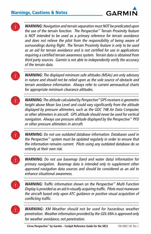
Warnings, Cautions & notes
WARNING: Navigation and terrain separation must NOT be predicated upon the use of the terrain function. The Perspective™ Terrain Proximity feature is NOT intended to be used as a primary reference for terrain avoidance and does not relieve the pilot from the responsibility of being aware of surroundings during flight. The Terrain Proximity feature is only to be used as an aid for terrain avoidance and is not certified for use in applications requiring a certified terrain awareness system. Terrain data is obtained from third party sources. Garmin is not able to independently verify the accuracy of the terrain data.
WARNING: The displayed minimum safe altitudes (MSAs) are only advisory in nature and should not be relied upon as the sole source of obstacle and terrain avoidance information. Always refer to current aeronautical charts for appropriate minimum clearance altitudes.
WARNING: The altitude calculated by Perspective™GPS receivers is geometric height above Mean Sea Level and could vary significantly from the altitude displayed by pressure altimeters, such as the GDC 74B Air Data Computer, or other altimeters in aircraft. GPS altitude should never be used for vertical navigation. Always use pressure altitude displayed by the Perspective™ PFD or other pressure altimeters in aircraft.
WARNING: Do not use outdated database information. Databases used in the Perspective™ system must be updated regularly in order to ensure that the information remains current. Pilots using any outdated database do so entirely at their own risk.
WARNING: Do not use basemap (land and water data) information for primary navigation. Basemap data is intended only to supplement other approved navigation data sources and should be considered as an aid to enhance situational awareness.
WARNING: Traffic information shown on the Perspective™ Multi Function Display is provided as an aid in visually acquiring traffic. Pilots must maneuver the aircraft based only upon ATC guidance or positive visual acquisition of conflicting traffic.
WARNING: XM Weather should not be used for hazardous weather penetration. Weather information provided by the GDL 69A is approved only for weather avoidance, not penetration.
Cirrus Perspective™ by Garmin – Cockpit Reference Guide for the SR22190-00821-00 Rev. C
Warnings, Cautions & notes
WARNING: NEXRAD weather data is to be used for long-range planning purposes only. Due to inherent delays in data transmission and the relative age of the data, NEXRAD weather data should not be used for short-range weather avoidance.
WARNING: The Perspective™ system, as installed in the Cirrus SR22 aircraft, has a very high degree of functional integrity. However, the pilot must recognize that providing monitoring and/or self-test capability for all conceivable system failures is not practical. Although unlikely, it may be possible for erroneous operation to occur without a fault indication shown by the Perspective™ system. It is thus the responsibility of the pilot to detect such an occurrence by means of cross-checking with all redundant or correlated information available in the cockpit.
WARNING: For safety reasons, Perspective™ system operational procedures must be learned on the ground.
WARNING: The United States government operates the Global Positioning System and is solely responsible for its accuracy and maintenance. The GPS system is subject to changes which could affect the accuracy and performance of all GPS equipment. Portions of the Perspective™ system utilize GPS as a precision electronic NAVigation AID (NAVAID). Therefore, as with all NAVAIDs, information presented by the Perspective™ system can be misused or misinterpreted and, therefore, become unsafe.
WARNING: To reduce the risk of unsafe operation, carefully review and understand all aspects of the Perspective™ Pilot’s Guide documentation and the Cirrus SR22 Airplane Flight Manual. Thoroughly practice basic operation prior to actual use. During flight operations, carefully compare indications from the Perspective™ system to all available navigation sources, including the information from other NAVAIDs, visual sightings, charts, etc. For safety purposes, always resolve any discrepancies before continuing navigation.
WARNING: The illustrations in this guide are only examples. Never use the Perspective™ system to attempt to penetrate a thunderstorm. Both the FAA Advisory Circular, Subject: Thunderstorms, and the Aeronautical Information Manual (AIM) recommend avoiding “by at least 20 miles any thunderstorm identified as severe or giving an intense radar echo.”
Cirrus Perspective™ by Garmin – Cockpit Reference Guide for the SR22 190-00821-00 Rev. C
Warnings, Cautions & notes
WARNING: Lamp(s) inside this product may contain mercury (HG) and must be recycled or disposed of according to local, state, or federal laws. For more information, refer to our website at www.garmin.com/aboutGarmin/environment/disposal.jsp.
WARNING: Because of anomalies in the earth’s magnetic field, operating the Perspective™ system within the following areas could result in loss of reliable attitude and heading indications. North of 70° North latitude and south of 70° South latitude. An area north of 65° North latitude between longitude 75º West and 120º West. An area south of 55° South latitude between longitude 120º East and 165º East.
CAUTION: The PFD and MFD displays use a lens coated with a special anti-reflective coating that is very sensitive to skin oils, waxes, and abrasive cleaners. CLEANERS CONTAINING AMMONIA WILL HARM THE ANTI-REFLECTIVE COATING. It is very important to clean the lens using a clean, lint-free cloth and an eyeglass lens cleaner that is specified as safe for anti-reflective coatings.
CAUTION: The Perspective™ system does not contain any user-serviceable parts. Repairs should only be made by an authorized Garmin service center. Unauthorized repairs or modifications could void both the warranty and the pilot’s authority to operate this device under FAA/FCC regulations.
NOTE: All visual depictions contained within this document, including screen images of the Perspective™ panel and displays, are subject to change and may not reflect the most current Perspective™ system and aviation databases. Depictions of equipment may differ slightly from the actual equipment.
NOTE: This device complies with part 15 of the FCC Rules. Operation is subject to the following two conditions: (1) this device may not cause harmful interference, and (2) this device must accept any interference received, including interference that may cause undesired operation.
NOTE: The data contained in the terrain and obstacle databases comes from government agencies. Garmin accurately processes and cross-validates the data, but cannot guarantee the accuracy and completeness of the data.
Cirrus Perspective™ by Garmin – Cockpit Reference Guide for the SR22190-00821-00 Rev. C
Warnings, Cautions & notes
NOTE: This product, its packaging, and its components contain chemicals known to the State of California to cause cancer, birth defects, or reproductive harm. This notice is being provided in accordance with California’s Proposition 65. If you have any questions or would like additional information, please refer to our web site at www.garmin.com/prop65.
NOTE: Interference from GPS repeaters operating inside nearby hangars can cause an intermittent loss of attitude and heading displays while the aircraft is on the ground. Moving the aircraft more than 100 yards away from the source of the interference should alleviate the condition.
NOTE: Use of polarized eyewear may cause the flight displays to appear dim or blank.

Cirrus Perspective™ by Garmin – Cockpit Reference Guide for the SR22 190-00821-00 Rev. C
Warnings, Cautions & notes
Blank Page
Cirrus Perspective™ by Garmin – Cockpit Reference Guide for the SR22190-00821-00 Rev. C RR-1
record of revisions
part number Change summary190-00821-00
Rev A
Rev B
Initial release
Made clerical changes
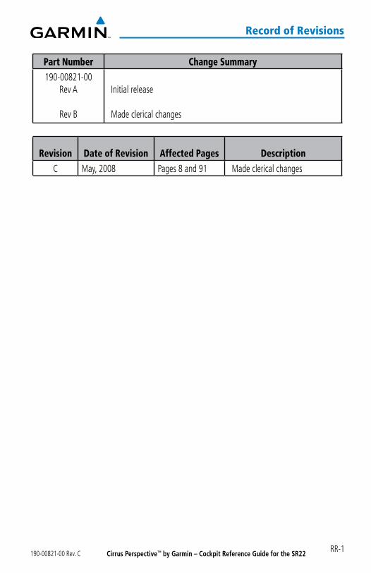
revision date of revision affected pages descriptionC May, 2008 Pages 8 and 91 Made clerical changes

Cirrus Perspective™ by Garmin – Cockpit Reference Guide for the SR22 190-00821-00 Rev. CRR-2
record of revisions
Blank Page
Cirrus Perspective™ by Garmin – Cockpit Reference Guide for the SR22190-00821-00 Rev. C i
table of Contents
Flight instruments ................................................................................................................ 1selecting the altimeter barometric pressure setting ...................................................... 1selecting standard barometric pressure ............................................................................. 1Change altimeter barometric pressure setting units ...................................................... 1Change navigation sources ................................................................................................... 1enable/disable obs mode While navigating with gps .................................................... 1generic timer ............................................................................................................................. 2Configure v-speed bugs ........................................................................................................... 2set barometric minimum descent altitude ........................................................................ 2displaying Wind data .............................................................................................................. 3
engine indiCation system ................................................................................................. 5engine page................................................................................................................................ 7leaning assist mode ................................................................................................................ 9system display ........................................................................................................................ 10
nav/Com/transponder/audio panel ....................................................................... 13dme tuning............................................................................................................................... 13enter a transponder Code..................................................................................................... 13selecting a Com radio .......................................................................................................... 13selecting a nav radio ........................................................................................................... 14nav/Com tuning ..................................................................................................................... 14intercom system (iCs) isolation .......................................................................................... 14digital Clearance player ........................................................................................................ 15
automatiC Flight Control system .......................................................................... 17Flight director activation ..................................................................................................... 17vertical modes ......................................................................................................................... 18lateral modes .......................................................................................................................... 19level........................................................................................................................................... 20
gps navigation ........................................................................................................................ 21direct-to navigation .............................................................................................................. 21activate a stored Flight plan ............................................................................................... 22activate a Flight plan leg ..................................................................................................... 22stop navigating a Flight plan .............................................................................................. 23vertical navigation (vnav)................................................................................................... 23
Flight planning ...................................................................................................................... 27trip planning ............................................................................................................................ 27Create a new user Waypoint ............................................................................................... 28delete a user Waypoint ......................................................................................................... 29Create a new Flight plan ...................................................................................................... 30insert a Waypoint in the active Flight plan ...................................................................... 31
Cirrus Perspective™ by Garmin – Cockpit Reference Guide for the SR22 190-00821-00 Rev. Cii
table of Contents
enter an airway in a Flight plan .......................................................................................... 32invert an active Flight plan .................................................................................................. 32remove a departure, arrival, approach, or airway from a Flight plan ..................... 32store a Flight plan .................................................................................................................. 33edit a stored Flight plan ....................................................................................................... 33delete a Waypoint from the Flight plan ............................................................................ 34invert and activate a stored Flight plan ........................................................................... 34Copy a Flight plan ................................................................................................................... 34delete a Flight plan ................................................................................................................ 35graphical Flight plan Creation ............................................................................................. 35
proCedures ................................................................................................................................. 37load and activate a departure procedure ....................................................................... 37activate a departure leg ..................................................................................................... 37load an arrival procedure .................................................................................................... 37activate an arrival leg ......................................................................................................... 38load and/or activate an approach procedure ................................................................. 38activate an approach in the active Flight plan ............................................................... 39activate a vector to Final approach Fix ............................................................................ 39activate a missed approach in the active Flight plan ................................................... 39
hazard avoidanCe ................................................................................................................ 41Customizing the hazard displays on the navigation map ............................................ 41stormsCope® (optional) .................................................................................................... 41xm Weather (optional) .......................................................................................................... 43traffic advisory systems ....................................................................................................... 44terrain and obstacle proximity ........................................................................................... 46terrain-svs ............................................................................................................................... 47terrain awareness & Warning system (taWs) display ................................................... 48
additional Features ........................................................................................................... 51synthetic vision ....................................................................................................................... 51terminal procedure Charts ................................................................................................... 52xm® radio entertainment..................................................................................................... 54
abnormal operation.......................................................................................................... 57reversionary mode ................................................................................................................ 57abnormal Com operation .................................................................................................... 57hazard displays with loss of gps position ....................................................................... 57unusual attitudes ................................................................................................................... 58dead reckoning ...................................................................................................................... 59
Cirrus Perspective™ by Garmin – Cockpit Reference Guide for the SR22190-00821-00 Rev. C iii
table of Contents
annunCiations & alerts ................................................................................................... 61Comparator annunciations ................................................................................................... 63reversionary sensor annunciations ................................................................................... 64message advisory alerts ....................................................................................................... 64aFCs alerts ............................................................................................................................... 64terrain-svs alerts ................................................................................................................... 65terrain-svs system status annunciations ........................................................................ 66taWs alerts .............................................................................................................................. 66aural alerts .............................................................................................................................. 68Co guardian messages (optional) ...................................................................................... 69mFd & pFd message advisories .......................................................................................... 69database message advisories ............................................................................................. 70gma 347 message advisories .............................................................................................. 73gia 63W message advisories ............................................................................................... 73gea 71 message advisories .................................................................................................. 76gtx 32 & gtx 33 message advisories ................................................................................ 76grs 77 message advisories .................................................................................................. 77gmu 44 message advisories ................................................................................................ 78gdl 69/69a message advisories ......................................................................................... 79gdC 74a message advisories ............................................................................................... 79gCu 478 message advisories ............................................................................................... 80gmC 705 message advisories .............................................................................................. 80miscellaneous message advisories ..................................................................................... 81
appendix ....................................................................................................................................... 85pFd softkey map .................................................................................................................... 85mFd softkey map ................................................................................................................... 90
index ......................................................................................................................................... Index-1

Cirrus Perspective™ by Garmin – Cockpit Reference Guide for the SR22 190-00821-00 Rev. Civ
table of Contents
Blank Page
Cirrus Perspective™ by Garmin – Cockpit Reference Guide for the SR22190-00821-00 Rev. C 1
Flight instruments
FlightInstrum
entsEIS
Nav/Com
/XPD
R/Audio
AFCS
GPS N
avFlight
PlanningProcedures
Hazard
AvoidanceA
dditionalFeatures
Abnorm
alO
perationA
nnun/A
lertsA
ppendixIndex
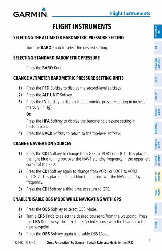
Flight instrumentsseleCting the altimeter barometriC pressure setting
Turn the BARO Knob to select the desired setting.
seleCting standard barometriC pressure
Press the BARO Knob.
Change altimeter barometriC pressure setting units
1) Press the PFD Softkey to display the second-level softkeys.
2) Press the ALT UNIT Softkey.
3) Press the IN Softkey to display the barometric pressure setting in inches of mercury (in Hg).
Or:
Press the HPA Softkey to display the barometric pressure setting in hectopascals.
4) Press the BACK Softkey to return to the top-level softkeys.
Change navigation sourCes
1) Press the CDI Softkey to change from GPS to VOR1 or LOC1. This places the light blue tuning box over the NAV1 standby frequency in the upper left corner of the PFD.
2) Press the CDI Softkey again to change from VOR1 or LOC1 to VOR2 or LOC2. This places the light blue tuning box over the NAV2 standby frequency.
3) Press the CDI Softkey a third time to return to GPS.
enable/disable obs mode While navigating With gps
1) Press the OBS Softkey to select OBS Mode.
2) Turn a CRS Knob to select the desired course to/from the waypoint. Press the CRS Knob to synchronize the Selected Course with the bearing to the next waypoint.
3) Press the OBS Softkey again to disable OBS Mode.
Cirrus Perspective™ by Garmin – Cockpit Reference Guide for the SR22 190-00821-00 Rev. C2
Flight instruments
Flig
htIn
stru
men
tsEI
SN
av/C
om/
XPD
R/A
udio
AFC
SG
PS N
avFl
ight
Plan
ning
Proc
edur
esH
azar
dAv
oida
nce
Add
ition
alFe
atur
esA
bnor
mal
Ope
ratio
nA
nnun
/A
lert
sA
ppen
dix
Inde
x
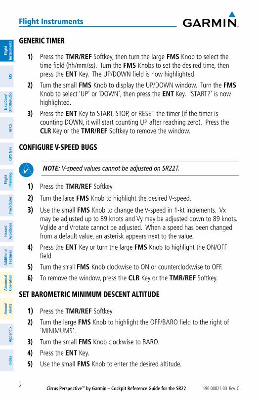
generiC timer
1) Press the TMR/REF Softkey, then turn the large FMS Knob to select the time field (hh/mm/ss). Turn the FMS Knobs to set the desired time, then press the ENT Key. The UP/DOWN field is now highlighted.
2) Turn the small FMS Knob to display the UP/DOWN window. Turn the FMS Knob to select ‘UP’ or ‘DOWN’, then press the ENT Key. ‘START?’ is now highlighted.
3) Press the ENT Key to START, STOP, or RESET the timer (if the timer is counting DOWN, it will start counting UP after reaching zero). Press the CLR Key or the TMR/REF Softkey to remove the window.
ConFigure v-speed bugs
NOTE: V-speed values cannot be adjusted on SR22T.
1) Press the TMR/REF Softkey.
2) Turn the large FMS Knob to highlight the desired V-speed.
3) Use the small FMS Knob to change the V-speed in 1-kt increments. Vx may be adjusted up to 89 knots and Vy may be adjusted down to 89 knots. Vglide and Vrotate cannot be adjusted. When a speed has been changed from a default value, an asterisk appears next to the value.
4) Press the ENT Key or turn the large FMS Knob to highlight the ON/OFF field
5) Turn the small FMS Knob clockwise to ON or counterclockwise to OFF.
6) To remove the window, press the CLR Key or the TMR/REF Softkey.
set barometriC minimum desCent altitude
1) Press the TMR/REF Softkey.
2) Turn the large FMS Knob to highlight the OFF/BARO field to the right of ‘MINIMUMS’.
3) Turn the small FMS Knob clockwise to BARO.
4) Press the ENT Key.
5) Use the small FMS Knob to enter the desired altitude.
Cirrus Perspective™ by Garmin – Cockpit Reference Guide for the SR22190-00821-00 Rev. C 3
Flight instruments
FlightInstrum
entsEIS
Nav/Com
/XPD
R/Audio
AFCS
GPS N
avFlight
PlanningProcedures
Hazard
AvoidanceA
dditionalFeatures
Abnorm
alO
perationA
nnun/A
lertsA
ppendixIndex
6) Press the ENT Key.
7) To remove the window, press the CLR Key or the TMR/REF Softkey.
displaying Wind data
1) Press the PFD Softkey.
2) Press the WIND Softkey to display wind data below the Selected Heading.
3) Press the OPTN 1 or OPTN 2 Softkey to change how wind data is displayed.
4) To remove the Wind Data Window, press the OFF Softkey.
Cirrus Perspective™ by Garmin – Cockpit Reference Guide for the SR22 190-00821-00 Rev. C4
Flight instruments
Flig
htIn
stru
men
tsEI
SN
av/C
om/
XPD
R/A
udio
AFC
SG
PS N
avFl
ight
Plan
ning
Proc
edur
esH
azar
dAv
oida
nce
Add
ition
alFe
atur
esA
bnor
mal
Ope
ratio
nA
nnun
/A
lert
sA
ppen
dix
Inde
x
Blank Page
Cirrus Perspective™ by Garmin – Cockpit Reference Guide for the SR22190-00821-00 Rev. C 5
eis
FlightInstrum
entsEIS
Nav/Com
/XPD
R/Audio
AFCS
GPS N
avFlight
PlanningProcedures
Hazard
AvoidanceA
dditionalFeatures
Abnorm
alO
perationA
nnun/A
lertsA
ppendixIndex
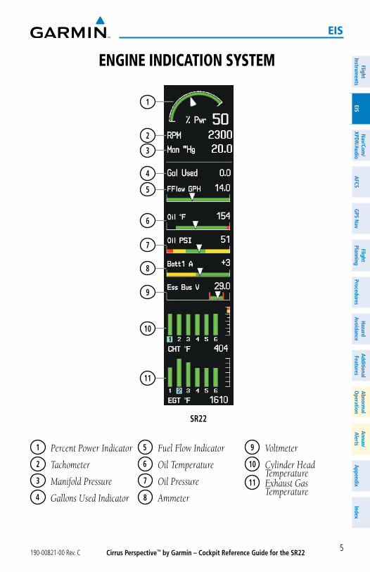
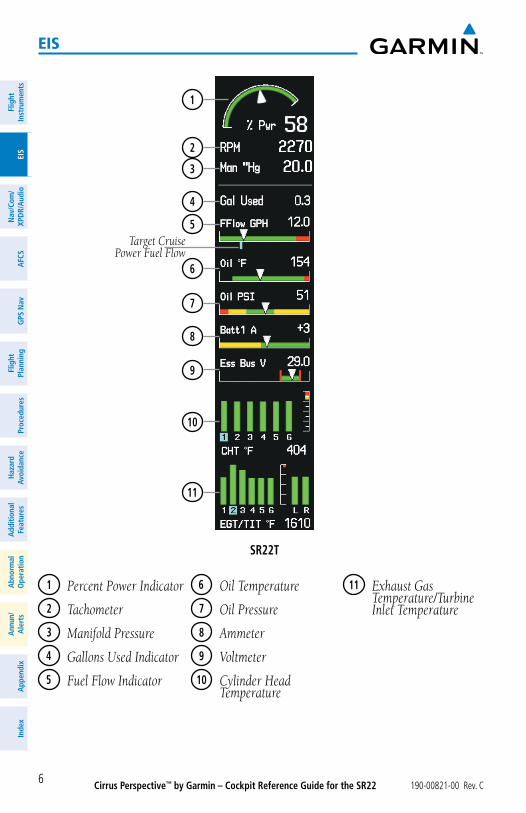
engine indiCation system
SR22
7
10
5
4
3
2
1
6
9
8
11
1 Percent Power Indicator
2 Tachometer
3 Manifold Pressure
4 Gallons Used Indicator
5 Fuel Flow Indicator
6 Oil Temperature
7 Oil Pressure
8 Ammeter
9 Voltmeter
10 Cylinder Head Temperature
11 Exhaust Gas Temperature
Cirrus Perspective™ by Garmin – Cockpit Reference Guide for the SR22 190-00821-00 Rev. C6
eis
Flig
htIn
stru
men
tsEI
SN
av/C
om/
XPD
R/A
udio
AFC
SG
PS N
avFl
ight
Plan
ning
Proc
edur
esH
azar
dAv
oida
nce
Add
ition
alFe
atur
esA
bnor
mal
Ope
ratio
nA
nnun
/A
lert
sA
ppen
dix
Inde
x
Target Cruise Power Fuel Flow
SR22T
7
10
5
4
3
2
1
6
9
8
11
1 Percent Power Indicator
2 Tachometer
3 Manifold Pressure
4 Gallons Used Indicator
5 Fuel Flow Indicator
6 Oil Temperature
7 Oil Pressure
8 Ammeter
9 Voltmeter
10 Cylinder Head Temperature
11 Exhaust Gas Temperature/Turbine Inlet Temperature
Cirrus Perspective™ by Garmin – Cockpit Reference Guide for the SR22190-00821-00 Rev. C 7
eis
FlightInstrum
entsEIS
Nav/Com
/XPD
R/Audio
AFCS
GPS N
avFlight
PlanningProcedures
Hazard
AvoidanceA
dditionalFeatures
Abnorm
alO
perationA
nnun/A
lertsA
ppendixIndex
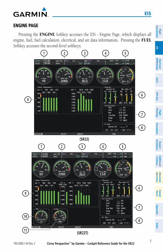
engine page
Pressing the ENGINE Softkey accesses the EIS - Engine Page, which displays all engine, fuel, fuel calculation, electrical, and air data information. Pressing the FUEL Softkey accesses the second-level softkeys.
(SR22)
9
8
6
7
1 32 4 5
(SR22T)11
1 32 4 5
8
6
7
9
10
Cirrus Perspective™ by Garmin – Cockpit Reference Guide for the SR22 190-00821-00 Rev. C8
eis
Flig
htIn
stru
men
tsEI
SN
av/C
om/
XPD
R/A
udio
AFC
SG
PS N
avFl
ight
Plan
ning
Proc
edur
esH
azar
dAv
oida
nce
Add
ition
alFe
atur
esA
bnor
mal
Ope
ratio
nA
nnun
/A
lert
sA
ppen
dix
Inde
x
1 Percent Power Indicator
2 Tachometer
3 Manifold Pressure
4 Fuel Flow Indicator
5 Oil Temperature
6 Electrical Group
7 Fuel Calculation Group
8 Air Data
9 Engine Temperature Group
10 Ice Protection Fluid Quantity
11 Oxygen Pressure
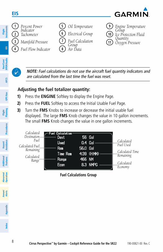
NOTE: Fuel calculations do not use the aircraft fuel quantity indicators and are calculated from the last time the fuel was reset.
Adjusting the fuel totalizer quantity:1) Press the ENGINE Softkey to display the Engine Page.
2) Press the FUEL Softkey to access the Initial Usable Fuel Page.
3) Turn the FMS Knobs to increase or decrease the initial usable fuel displayed. The large FMS Knob changes the value in 10 gallon increments. The small FMS Knob changes the value in one gallon increments.
Fuel Calculations Group
CalculatedEconomy
Calculated TimeRemaining
CalculatedFuel UsedCalculated Fuel
Remaining
CalculatedRange
CalculatedDestination
Fuel
Cirrus Perspective™ by Garmin – Cockpit Reference Guide for the SR22190-00821-00 Rev. C 9
eis
FlightInstrum
entsEIS
Nav/Com
/XPD
R/Audio
AFCS
GPS N
avFlight
PlanningProcedures
Hazard
AvoidanceA
dditionalFeatures
Abnorm
alO
perationA
nnun/A
lertsA
ppendixIndex
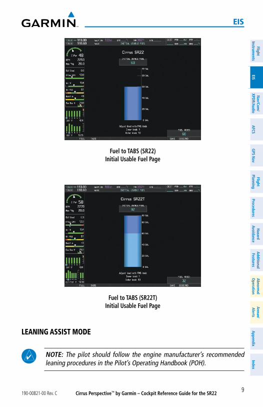
Fuel to TABS (SR22)Initial Usable Fuel Page
Fuel to TABS (SR22T)Initial Usable Fuel Page
leaning assist mode
NOTE: The pilot should follow the engine manufacturer’s recommended leaning procedures in the Pilot’s Operating Handbook (POH).
Cirrus Perspective™ by Garmin – Cockpit Reference Guide for the SR22 190-00821-00 Rev. C10
eis
Flig
htIn
stru
men
tsEI
SN
av/C
om/
XPD
R/A
udio
AFC
SG
PS N
avFl
ight
Plan
ning
Proc
edur
esH
azar
dAv
oida
nce
Add
ition
alFe
atur
esA
bnor
mal
Ope
ratio
nA
nnun
/A
lert
sA
ppen
dix
Inde
x
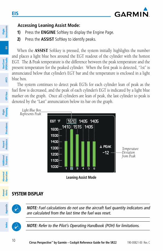
Accessing Leaning Assist Mode:1) Press the ENGINE Softkey to display the Engine Page.
2) Press the ASSIST Softkey to identify peaks.
When the ASSIST Softkey is pressed, the system initially highlights the number and places a light blue box around the EGT readout of the cylinder with the hottest EGT. The ∆ Peak temperature is the difference between the peak temperature and the present temperature for the peaked cylinder. When the first peak is detected, “1st” is annunciated below that cylinder’s EGT bar and the temperature is enclosed in a light blue box.
The system continues to detect peak EGTs for each cylinder lean of peak as the fuel flow is decreased, and the peak of each cylinder’s EGT is indicated by a light blue marker on the graph. Once all cylinders are lean of peak, the last cylinder to peak is denoted by the “Last” annunciation below its bar on the graph.
Leaning Assist Mode
Light Blue Box Represents Peak
TemperatureDeviationfrom Peak
system display
NOTE: Fuel calculations do not use the aircraft fuel quantity indicators and are calculated from the last time the fuel was reset.
NOTE: Refer to the Pilot’s Operating Handbook (POH) for limitations.
Cirrus Perspective™ by Garmin – Cockpit Reference Guide for the SR22190-00821-00 Rev. C 11
eis
FlightInstrum
entsEIS
Nav/Com
/XPD
R/Audio
AFCS
GPS N
avFlight
PlanningProcedures
Hazard
AvoidanceA
dditionalFeatures
Abnorm
alO
perationA
nnun/A
lertsA
ppendixIndex
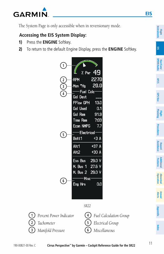
The System Page is only accessible when in reversionary mode.
Accessing the EIS System Display:1) Press the ENGINE Softkey.
2) To return to the default Engine Display, press the ENGINE Softkey.
SR22
1
2
3
6
4
5
1 Percent Power Indicator
2 Tachometer
3 Manifold Pressure
4 Fuel Calculation Group
5 Electrical Group
6 Miscellaneous
Cirrus Perspective™ by Garmin – Cockpit Reference Guide for the SR22 190-00821-00 Rev. C12
eis
Flig
htIn
stru
men
tsEI
SN
av/C
om/
XPD
R/A
udio
AFC
SG
PS N
avFl
ight
Plan
ning
Proc
edur
esH
azar
dAv
oida
nce
Add
ition
alFe
atur
esA
bnor
mal
Ope
ratio
nA
nnun
/A
lert
sA
ppen
dix
Inde
x
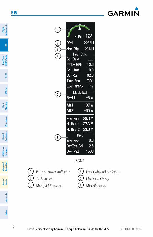
SR22T
1
2
3
6
4
5
1 Percent Power Indicator
2 Tachometer
3 Manifold Pressure
4 Fuel Calculation Group
5 Electrical Group
6 Miscellaneous
Cirrus Perspective™ by Garmin – Cockpit Reference Guide for the SR22190-00821-00 Rev. C 13
nav/Com/xpdr/audio panel
FlightInstrum
entsEIS
Nav/Com
/XPD
R/Audio
AFCS
GPS N
avFlight
PlanningProcedures
Hazard
AvoidanceA
dditionalFeatures
Abnorm
alO
perationA
nnun/A
lertsA
ppendixIndex
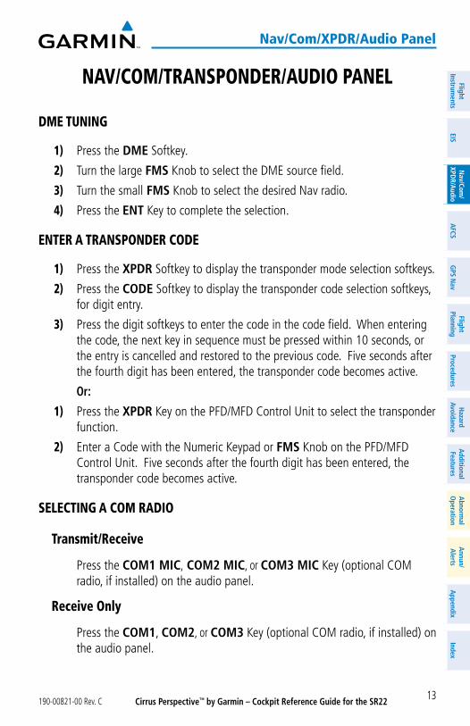
nav/Com/transponder/audio panel
dme tuning
1) Press the DME Softkey.
2) Turn the large FMS Knob to select the DME source field.
3) Turn the small FMS Knob to select the desired Nav radio.
4) Press the ENT Key to complete the selection.
enter a transponder Code
1) Press the XPDR Softkey to display the transponder mode selection softkeys.
2) Press the CODE Softkey to display the transponder code selection softkeys, for digit entry.
3) Press the digit softkeys to enter the code in the code field. When entering the code, the next key in sequence must be pressed within 10 seconds, or the entry is cancelled and restored to the previous code. Five seconds after the fourth digit has been entered, the transponder code becomes active.
Or:
1) Press the XPDR Key on the PFD/MFD Control Unit to select the transponder function.
2) Enter a Code with the Numeric Keypad or FMS Knob on the PFD/MFD Control Unit. Five seconds after the fourth digit has been entered, the transponder code becomes active.
seleCting a Com radio
transmit/receive
Press the COM1 MIC, COM2 MIC, or COM3 MIC Key (optional COM radio, if installed) on the audio panel.
receive only
Press the COM1, COM2, or COM3 Key (optional COM radio, if installed) on the audio panel.
Cirrus Perspective™ by Garmin – Cockpit Reference Guide for the SR22 190-00821-00 Rev. C14
nav/Com/xpdr/audio panel
Flig
htIn
stru
men
tsEI
SN
av/C
om/
XPD
R/A
udio
AFC
SG
PS N
avFl
ight
Plan
ning
Proc
edur
esH
azar
dAv
oida
nce
Add
ition
alFe
atur
esA
bnor
mal
Ope
ratio
nA
nnun
/A
lert
sA
ppen
dix
Inde
x
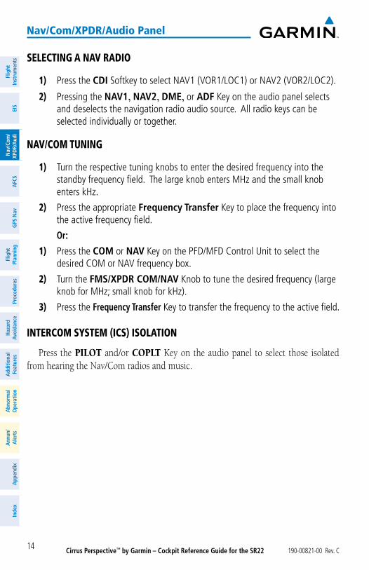
seleCting a nav radio
1) Press the CDI Softkey to select NAV1 (VOR1/LOC1) or NAV2 (VOR2/LOC2).
2) Pressing the NAV1, NAV2, DME, or ADF Key on the audio panel selects and deselects the navigation radio audio source. All radio keys can be selected individually or together.
nav/Com tuning
1) Turn the respective tuning knobs to enter the desired frequency into the standby frequency field. The large knob enters MHz and the small knob enters kHz.
2) Press the appropriate Frequency Transfer Key to place the frequency into the active frequency field.
Or:
1) Press the COM or NAV Key on the PFD/MFD Control Unit to select the desired COM or NAV frequency box.
2) Turn the FMS/XPDR COM/NAV Knob to tune the desired frequency (large knob for MHz; small knob for kHz).
3) Press the Frequency Transfer Key to transfer the frequency to the active field.
interCom system (iCs) isolation
Press the PILOT and/or COPLT Key on the audio panel to select those isolated from hearing the Nav/Com radios and music.
Cirrus Perspective™ by Garmin – Cockpit Reference Guide for the SR22190-00821-00 Rev. C 15
nav/Com/xpdr/audio panel
FlightInstrum
entsEIS
Nav/Com
/XPD
R/Audio
AFCS
GPS N
avFlight
PlanningProcedures
Hazard
AvoidanceA
dditionalFeatures
Abnorm
alO
perationA
nnun/A
lertsA
ppendixIndex
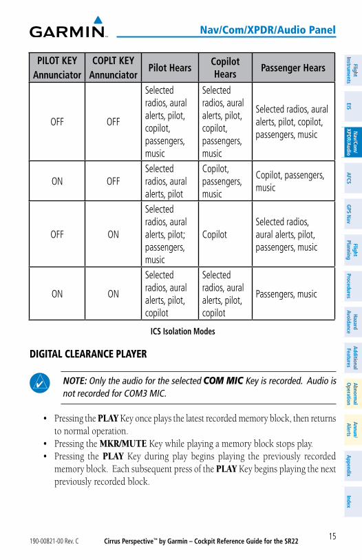
PILOT KEYAnnunciator
COPLT KEYAnnunciator
Pilot HearsCopilot Hears
Passenger Hears
OFF OFF
Selected radios, aural alerts, pilot, copilot, passengers, music
Selected radios, aural alerts, pilot, copilot, passengers, music
Selected radios, aural alerts, pilot, copilot, passengers, music
ON OFFSelected radios, aural alerts, pilot
Copilot, passengers, music
Copilot, passengers, music
OFF ON
Selected radios, aural alerts, pilot; passengers, music
CopilotSelected radios, aural alerts, pilot, passengers, music
ON ON
Selected radios, aural alerts, pilot, copilot
Selected radios, aural alerts, pilot, copilot
Passengers, music
ICS Isolation Modes
digital ClearanCe player
NOTE: Only the audio for the selected COM MIC Key is recorded. Audio is not recorded for COM3 MIC.
• Pressing the PLAY Key once plays the latest recorded memory block, then returns to normal operation.
• Pressing the MKR/MUTE Key while playing a memory block stops play.• Pressing the PLAY Key during play begins playing the previously recorded
memory block. Each subsequent press of the PLAY Key begins playing the next previously recorded block.
Cirrus Perspective™ by Garmin – Cockpit Reference Guide for the SR22 190-00821-00 Rev. C16
nav/Com/xpdr/audio panel
Flig
htIn
stru
men
tsEI
SN
av/C
om/
XPD
R/A
udio
AFC
SG
PS N
avFl
ight
Plan
ning
Proc
edur
esH
azar
dAv
oida
nce
Add
ition
alFe
atur
esA
bnor
mal
Ope
ratio
nA
nnun
/A
lert
sA
ppen
dix
Inde
x
Blank Page
Cirrus Perspective™ by Garmin – Cockpit Reference Guide for the SR22190-00821-00 Rev. C 17
aFCs
FlightInstrum
entsEIS
Nav/Com
/XPD
R/Audio
AFCS
GPS N
avFlight
PlanningProcedures
Hazard
AvoidanceA
dditionalFeatures
Abnorm
alO
perationA
nnun/A
lertsA
ppendixIndex
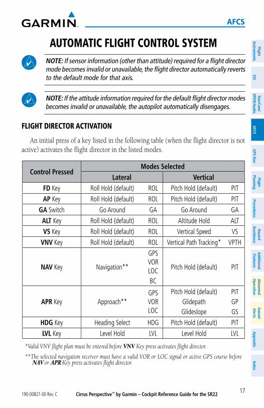
automatiC Flight Control system
NOTE: If sensor information (other than attitude) required for a flight director mode becomes invalid or unavailable, the flight director automatically reverts to the default mode for that axis.
NOTE: If the attitude information required for the default flight director modes becomes invalid or unavailable, the autopilot automatically disengages.
Flight direCtor aCtivation
An initial press of a key listed in the following table (when the flight director is not active) activates the flight director in the listed modes.
Control PressedModes Selected
Lateral VerticalFD Key Roll Hold (default) ROL Pitch Hold (default) PIT
AP Key Roll Hold (default) ROL Pitch Hold (default) PIT
GA Switch Go Around GA Go Around GA
ALT Key Roll Hold (default) ROL Altitude Hold ALT
VS Key Roll Hold (default) ROL Vertical Speed VS
VNV Key Roll Hold (default) ROL Vertical Path Tracking* VPTH
NAV Key Navigation**
GPS VOR LOCBC
Pitch Hold (default) PIT
APR Key Approach**GPS VOR LOC
Pitch Hold (default)GlidepathGlideslope
PITGPGS
HDG Key Heading Select HDG Pitch Hold (default) PIT
LVL Key Level Hold LVL Level Hold LVL
*Valid VNV flight plan must be entered before VNV Key press activates flight director.
**The selected navigation receiver must have a valid VOR or LOC signal or active GPS course before NAV or APR Key press activates flight director.
Cirrus Perspective™ by Garmin – Cockpit Reference Guide for the SR22 190-00821-00 Rev. C18
aFCs
Flig
htIn
stru
men
tsEI
SN
av/C
om/
XPD
R/A
udio
AFC
SG
PS N
avFl
ight
Plan
ning
Proc
edur
esH
azar
dAv
oida
nce
Add
ition
alFe
atur
esA
bnor
mal
Ope
ratio
nA
nnun
/A
lert
sA
ppen
dix
Inde
x
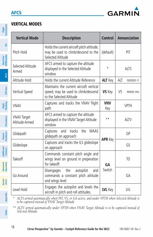
vertiCal modes
Vertical Mode Description Control Annunciation
Pitch HoldHolds the current aircraft pitch attitude; may be used to climb/descend to the Selected Altitude
(default) PIT
Selected Altitude Armed
AFCS armed to capture the altitude displayed in the Selected Altitude window
* ALTS
Altitude Hold Holds the current Altitude Reference ALT Key ALT nnnnn fT
Vertical SpeedMaintains the current aircraft vertical speed; may be used to climb/descend to the Selected Altitude
VS Key VS nnnn fpm
VNAVCaptures and tracks the VNAV flight path
VNV Key
VPTH
VNAV Target Altitude Armed
AFCS armed to capture the altitude displayed in the VNAV Target Altitude window
** ALTV
GlidepathCaptures and tracks the WAAS glidepath on approach
APR KeyGP
GlideslopeCaptures and tracks the ILS glideslope on approach
GS
TakeoffCommands constant pitch angle and wings level on ground in preperation for takeoff. GA
Switch
TO
Go AroundDisengages the autopilot and commands a constant pitch attitude and wings level
GA
Level HoldEngages the autopilot and levels the aircraft in pitch and roll attitudes.
LVL Key LVL
* ALTS armed automatically when PIT, VS, or GA active, and under VPTH when Selected Altitude is to be captured instead of VNAV Target Altitude
** ALTV armed automatically under VPTH when VNAV Target Altitude is to be captured instead of Selected Altitude
Cirrus Perspective™ by Garmin – Cockpit Reference Guide for the SR22190-00821-00 Rev. C 19
aFCs
FlightInstrum
entsEIS
Nav/Com
/XPD
R/Audio
AFCS
GPS N
avFlight
PlanningProcedures
Hazard
AvoidanceA
dditionalFeatures
Abnorm
alO
perationA
nnun/A
lertsA
ppendixIndex
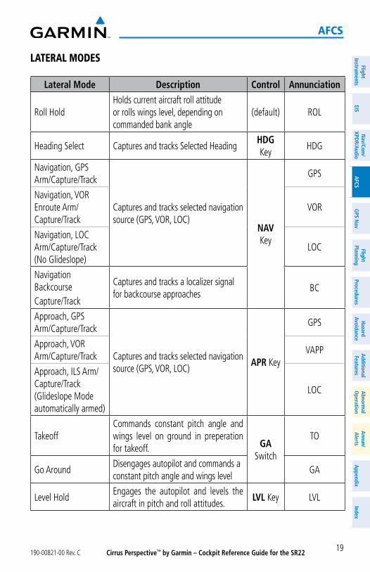
lateral modes
Lateral Mode Description Control Annunciation
Roll HoldHolds current aircraft roll attitude or rolls wings level, depending on commanded bank angle
(default) ROL
Heading Select Captures and tracks Selected HeadingHDG Key
HDG
Navigation, GPS Arm/Capture/Track
Captures and tracks selected navigation source (GPS, VOR, LOC)
NAV Key
GPS
Navigation, VOR Enroute Arm/Capture/Track
VOR
Navigation, LOC Arm/Capture/Track (No Glideslope)
LOC
Navigation BackcourseCapture/Track
Captures and tracks a localizer signal for backcourse approaches
BC
Approach, GPS Arm/Capture/Track
Captures and tracks selected navigation source (GPS, VOR, LOC)
APR Key
GPS
Approach, VOR Arm/Capture/Track
VAPP
Approach, ILS Arm/Capture/Track (Glideslope Mode automatically armed)
LOC
TakeoffCommands constant pitch angle and wings level on ground in preperation for takeoff. GA
Switch
TO
Go AroundDisengages autopilot and commands a constant pitch angle and wings level
GA
Level HoldEngages the autopilot and levels the aircraft in pitch and roll attitudes.
LVL Key LVL
Cirrus Perspective™ by Garmin – Cockpit Reference Guide for the SR22 190-00821-00 Rev. C20
aFCs
Flig
htIn
stru
men
tsEI
SN
av/C
om/
XPD
R/A
udio
AFC
SG
PS N
avFl
ight
Plan
ning
Proc
edur
esH
azar
dAv
oida
nce
Add
ition
alFe
atur
esA
bnor
mal
Ope
ratio
nA
nnun
/A
lert
sA
ppen
dix
Inde
x
level
Pressing the LVL Key engages the autopilot and levels the aircraft in pitch (to arrest a climb or descent) and roll. No other lateral or vertical modes are engaged, therefore, the aircraft will not hold a course or heading and will not hold a selected altitude.
Cirrus Perspective™ by Garmin – Cockpit Reference Guide for the SR22190-00821-00 Rev. C 21
gps navigation
FlightInstrum
entsEIS
Nav/Com
/XPD
R/Audio
AFCS
GPS N
avFlight
PlanningProcedures
Hazard
AvoidanceA
dditionalFeatures
Abnorm
alO
perationA
nnun/A
lertsA
ppendixIndex
gps navigation
direCt-to navigation
direct-to navigation using the mFd
1) Press the Direct-to ( ) Key on the Control Unit.
2) Enter the waypoint identifier.
3) Press the ENT Key to confirm the identifier. The ‘Activate?’ field is highlighted.
4) If no altitude constraint or course is desired, press the ENT Key to activate. To enter an altitude constraint, proceed to step 5.
5) Turn the large FMS Knob to place the cursor over the ‘VNV’ altitude field.
6) Enter the desired altitude.
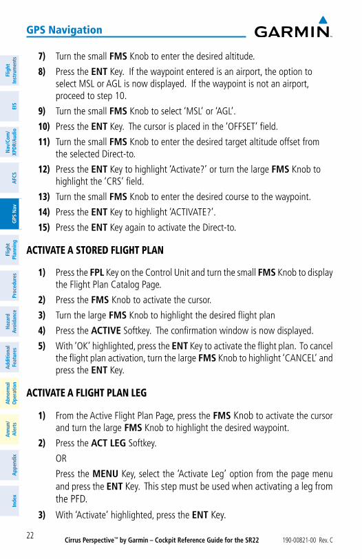
7) Press the ENT Key. If the waypoint entered is an airport, the option to select MSL or AGL is now displayed. If the waypoint is not an airport, proceed to step 9.
8) Turn the small FMS Knob to select ‘MSL’ or ‘AGL’.
9) Press the ENT Key. The cursor is now flashing in the VNV offset distance field.
10) Enter the desired offset distance before (-) the waypoint.
11) Press the ENT Key. The ‘Activate?’ field is highlighted.
12) Press the ENT Key to activate.
direct-to navigation using the pFd
1) Press the Direct-to Key ( ) on the PFD.
2) Turn the large FMS Knob to place the cursor in the desired selection field.
3) Turn the small FMS Knob to begin selecting the desired identifier, location, etc.
4) Press the ENT Key.
5) The cursor is now flashing on ‘ACTIVATE?’. If no altitude constraint or course is desired, press the ENT Key to activate. To enter an altitude constraint, proceed to step 6.
6) Turn the large FMS Knob to place the cursor over the ‘ALT’ altitude field.
Cirrus Perspective™ by Garmin – Cockpit Reference Guide for the SR22 190-00821-00 Rev. C22
gps navigation
Flig
htIn
stru
men
tsEI
SN
av/C
om/
XPD
R/A
udio
AFC
SG
PS N
avFl
ight
Plan
ning
Proc
edur
esH
azar
dAv
oida
nce
Add
ition
alFe
atur
esA
bnor
mal
Ope
ratio
nA
nnun
/A
lert
sA
ppen
dix
Inde
x
7) Turn the small FMS Knob to enter the desired altitude.
8) Press the ENT Key. If the waypoint entered is an airport, the option to select MSL or AGL is now displayed. If the waypoint is not an airport, proceed to step 10.
9) Turn the small FMS Knob to select ‘MSL’ or ‘AGL’.
10) Press the ENT Key. The cursor is placed in the ‘OFFSET’ field.
11) Turn the small FMS Knob to enter the desired target altitude offset from the selected Direct-to.
12) Press the ENT Key to highlight ‘Activate?’ or turn the large FMS Knob to highlight the ‘CRS’ field.
13) Turn the small FMS Knob to enter the desired course to the waypoint.
14) Press the ENT Key to highlight ‘ACTIVATE?’.
15) Press the ENT Key again to activate the Direct-to.
aCtivate a stored Flight plan
1) Press the FPL Key on the Control Unit and turn the small FMS Knob to display the Flight Plan Catalog Page.
2) Press the FMS Knob to activate the cursor.
3) Turn the large FMS Knob to highlight the desired flight plan
4) Press the ACTIVE Softkey. The confirmation window is now displayed.
5) With ‘OK’ highlighted, press the ENT Key to activate the flight plan. To cancel the flight plan activation, turn the large FMS Knob to highlight ‘CANCEL’ and press the ENT Key.
aCtivate a Flight plan leg
1) From the Active Flight Plan Page, press the FMS Knob to activate the cursor and turn the large FMS Knob to highlight the desired waypoint.
2) Press the ACT LEG Softkey.
OR
Press the MENU Key, select the ‘Activate Leg’ option from the page menu and press the ENT Key. This step must be used when activating a leg from the PFD.
3) With ‘Activate’ highlighted, press the ENT Key.
Cirrus Perspective™ by Garmin – Cockpit Reference Guide for the SR22190-00821-00 Rev. C 23
gps navigation
FlightInstrum
entsEIS
Nav/Com
/XPD
R/Audio
AFCS
GPS N
avFlight
PlanningProcedures
Hazard
AvoidanceA
dditionalFeatures
Abnorm
alO
perationA
nnun/A
lertsA
ppendixIndex
stop navigating a Flight plan
1) Press the FPL Key on the Control Unit to display the Active Flight Plan Page.
2) Press the MENU Key to display the Page Menu Window.
3) Turn the large FMS Knob to highlight ‘Delete Flight Plan’ and press the ENT Key. With ‘OK’ highlighted, press the ENT Key to deactivate the flight plan. This will not delete the stored flight plan, only the active flight plan.
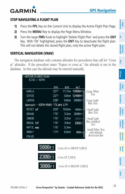
vertiCal navigation (vnav)
The navigation database only contains altitudes for procedures that call for “Cross at” altitudes. If the procedure states “Expect to cross at,” the altitude is not in the database. In this case the altitude may be entered manually.
Large Light Blue Text
Small White Text with Altitude
Restriction Bar
Large White Text
Small Light Blue Subdued
Text
Small Light Blue Text
Cross AT or ABOVE 5,000 ft
Cross AT or BELOW 3,000 ft
Cross AT 2,300 ft
Cirrus Perspective™ by Garmin – Cockpit Reference Guide for the SR22 190-00821-00 Rev. C24
gps navigation
Flig
htIn
stru
men
tsEI
SN
av/C
om/
XPD
R/A
udio
AFC
SG
PS N
avFl
ight
Plan
ning
Proc
edur
esH
azar
dAv
oida
nce
Add
ition
alFe
atur
esA
bnor
mal
Ope
ratio
nA
nnun
/A
lert
sA
ppen
dix
Inde
x
Altitudes associated with approach procedures are “auto-designated”. This means the system automatically uses the altitudes loaded with the approach for giving vertical flight path guidance outside the FAF. Note these altitudes are displayed as small light blue text.
Altitudes associated with arrival procedures are “manually-designated”. This means the system does not use the altitudes loaded with the arrival for giving vertical flight path guidance until designated to do so by the pilot. Note that these altitudes are initially displayed as white text. These altitudes may be “designated” by placing the cursor over the desired altitude and pressing the ENT Key. After designation, the text changes to light blue.
Altitudes that have been designated for use in vertical navigation may also be made “non-designated” by placing the cursor over the desired altitude and pressing the CLR Key. The altitude is now displayed only as a reference. It will not be used to give vertical flight path guidance. Other displayed altitudes may change due to re-calculations or rendered invalid as a result of manually changing an altitude to a non-designated altitude.
Cirrus Perspective™ by Garmin – Cockpit Reference Guide for the SR22190-00821-00 Rev. C 25
gps navigation
FlightInstrum
entsEIS
Nav/Com
/XPD
R/Audio
AFCS
GPS N
avFlight
PlanningProcedures
Hazard
AvoidanceA
dditionalFeatures
Abnorm
alO
perationA
nnun/A
lertsA
ppendixIndex
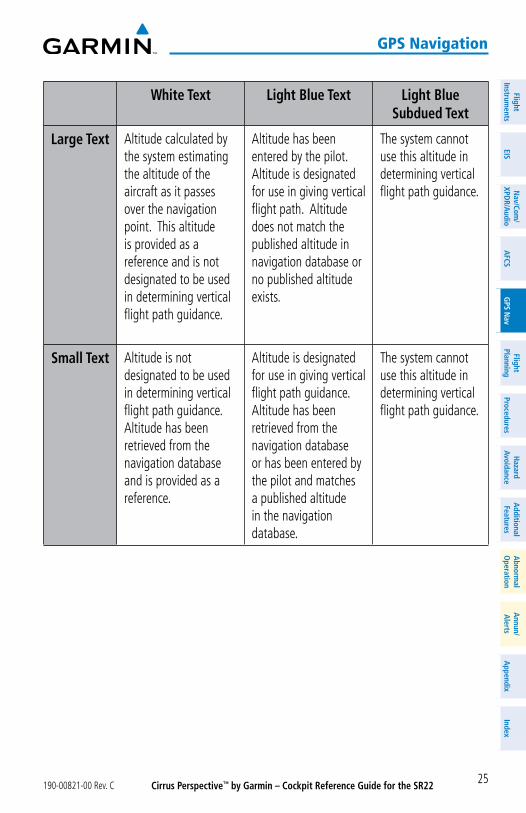
White Text Light Blue Text Light Blue Subdued Text
Large Text Altitude calculated by the system estimating the altitude of the aircraft as it passes over the navigation point. This altitude is provided as a reference and is not designated to be used in determining vertical flight path guidance.
Altitude has been entered by the pilot. Altitude is designated for use in giving vertical flight path. Altitude does not match the published altitude in navigation database or no published altitude exists.
The system cannot use this altitude in determining vertical flight path guidance.
Small Text Altitude is not designated to be used in determining vertical flight path guidance. Altitude has been retrieved from the navigation database and is provided as a reference.
Altitude is designated for use in giving vertical flight path guidance. Altitude has been retrieved from the navigation database or has been entered by the pilot and matches a published altitude in the navigation database.
The system cannot use this altitude in determining vertical flight path guidance.
Cirrus Perspective™ by Garmin – Cockpit Reference Guide for the SR22 190-00821-00 Rev. C26
gps navigation
Flig
htIn
stru
men
tsEI
SN
av/C
om/
XPD
R/A
udio
AFC
SG
PS N
avFl
ight
Plan
ning
Proc
edur
esH
azar
dAv
oida
nce
Add
ition
alFe
atur
esA
bnor
mal
Ope
ratio
nA
nnun
/A
lert
sA
ppen
dix
Inde
x
Blank Page
Cirrus Perspective™ by Garmin – Cockpit Reference Guide for the SR22190-00821-00 Rev. C 27
Flight planning
FlightInstrum
entsEIS
Nav/Com
/XPD
R/Audio
AFCS
GPS N
avFlight
PlanningProcedures
Hazard
AvoidanceA
dditionalFeatures
Abnorm
alO
perationA
nnun/A
lertsA
ppendixIndex
Flight planning
trip planning
1) Turn the large FMS Knob on the Control Unit to select the ‘AUX’ page group.
2) Turn the small FMS Knob to select the second rectangular page icon.
3) The current ‘PAGE MODE’ is displayed at the top of the page: ‘AUTOMATIC’ or ‘MANUAL’. To change the page mode, press the AUTO or MANUAL Softkey.
4) For Direct-to planning:
a) Press the WPTS Softkey and verify that the starting waypoint field indicates ‘P.POS’ (present position).
b) If necessary, press the MENU Key on the Control Unit and select ‘Set WPT to Present Position’ to display ‘P.POS’.
c) Press the ENT Key and the flashing cursor moves to the ending waypoint field.
d) Enter the identifier of the ending waypoint and press the ENT Key to accept the waypoint.
Or:
For point-to-point planning:
a) Enter the identifier of the starting waypoint.
b) Once the waypoint’s identifier is entered, press the ENT Key to accept the waypoint. The flashing cursor moves to the ending waypoint.
c) Again, enter the identifier of the ending waypoint.
d) Press the ENT Key to accept the waypoint.
Or:
For flight plan leg planning:
a) Press the FPL Softkey (at the bottom of the display).
b) Turn the small FMS Knob to select the desired flight plan (already stored in memory), by number.
c) Turn the large FMS Knob to highlight the ‘LEG’ field.
Cirrus Perspective™ by Garmin – Cockpit Reference Guide for the SR22 190-00821-00 Rev. C28
Flight planning
Flig
htIn
stru
men
tsEI
SN
av/C
om/
XPD
R/A
udio
AFC
SG
PS N
avFl
ight
Plan
ning
Proc
edur
esH
azar
dAv
oida
nce
Add
ition
alFe
atur
esA
bnor
mal
Ope
ratio
nA
nnun
/A
lert
sA
ppen
dix
Inde
x
d) Turn the small FMS Knob to select the desired leg of the flight plan, or select ‘CUM’ to apply trip planning calculations to the entire flight plan. Selecting ‘FPL 00’ displays the active flight plan. If an active flight plan is selected, ‘REM’ will be an available option to display planning data for the remainder of the flight plan.
NOTE: The page mode must be set to ‘MANUAL’ to perform the following steps.
5) Turn the large FMS Knob to highlight the departure time (DEP TIME) field.
NOTE: The departure time on the Trip Planning Page is used for preflight planning. Refer to the Utility Page for the actual flight departure time.
6) Enter the departure time. Press the ENT Key when finished. Departure time may be entered in local or UTC time, depending upon system settings.
7) Enter the fuel flow. Press the ENT Key when finished. Note that in ‘AUTOMATIC’ page mode, fuel flow is provided by the system.
8) The flashing cursor moves to the fuel onboard field. Modify the fuel onboard. Press the ENT Key when finished. In ‘AUTOMATIC’ mode, fuel onboard is provided by the entry made on the Initial Usable Fuel Page.
9) The flashing cursor moves to the calibrated airspeed field. Enter a calibrated airspeed. Press the ENT Key when finished.
Create a neW user Waypoint
1) Turn the large FMS Knob on the Control Unit to select the ‘WPT’ page group.
2) Turn the small FMS Knob to select the User WPT Information Page.
3) Press the NEW Softkey. A waypoint is created at the current aircraft position.
4) Enter the desired waypoint name.
5) Press the ENT Key.
6) The cursor is now in the ‘REFERENCE WAYPOINTS’ field. If desired, the waypoint can be defined by a reference waypoint. Use one of the following methods to enter the reference waypoint:
a) Turn the small FMS Knob to the left to display a list of flight plan waypoints. This list is populated only when there is an active flight plan.
Cirrus Perspective™ by Garmin – Cockpit Reference Guide for the SR22190-00821-00 Rev. C 29
Flight planning
FlightInstrum
entsEIS
Nav/Com
/XPD
R/Audio
AFCS
GPS N
avFlight
PlanningProcedures
Hazard
AvoidanceA
dditionalFeatures
Abnorm
alO
perationA
nnun/A
lertsA
ppendixIndex
b) Turn the large FMS Knob to select the desired waypoint.
c) Press the ENT Key.
Or:
a) Turn the small FMS Knob to the left. Initially, a flight plan waypoint list is displayed.
b) Turn the small FMS Knob to the right to display the ‘NRST’ waypoints to the aircraft’s current position.
c) Turn the large FMS Knob to select the desired waypoint.
d) Press the ENT Key.
Or:
a) Turn the small FMS Knob to the left. Initially, a flight plan waypoint list is displayed.
b) Turn the small FMS Knob to the right to display the ‘RECENT’ waypoints.
c) Turn the large FMS Knob to select the desired waypoint.
d) Press the ENT Key.
7) After pressing the ENT Key, the cursor is displayed in the ‘RAD’ (radial) field. Enter the desired radial from the reference waypoint.
8) Press the ENT Key.
9) The cursor is now displayed in the ‘DIS’ (distance) field. Enter the desired distance from the reference waypoint.
10) Press the ENT Key. The cursor is now placed for entering another reference waypoint, if desired.
11) Press the FMS Knob to remove the flashing cursor.
delete a user Waypoint
1) Turn the large FMS Knob on the Control Unit to select the ‘WPT’ page group.
2) Turn the small FMS Knob to select the User WPT Information Page.
3) Press the FMS Knob to activate the cursor.
4) Turn the large FMS Knob to the place the cursor in the ‘USER WAYPOINT LIST’ field.
Cirrus Perspective™ by Garmin – Cockpit Reference Guide for the SR22 190-00821-00 Rev. C30
Flight planning
Flig
htIn
stru
men
tsEI
SN
av/C
om/
XPD
R/A
udio
AFC
SG
PS N
avFl
ight
Plan
ning
Proc
edur
esH
azar
dAv
oida
nce
Add
ition
alFe
atur
esA
bnor
mal
Ope
ratio
nA
nnun
/A
lert
sA
ppen
dix
Inde
x
5) Turn the small FMS Knob to highlight the desired waypoint.
6) Press the DELETE Softkey.
7) The message ‘Would you like to delete the user waypoint?’ is displayed. With ‘YES’ highlighted, press the ENT Key.
Create a neW Flight plan
NOTE: When creating a new flight plan in the Active Flight Plan Window,
the first leg is activated automatically after it is created.
using the mFd
1) Press the FPL Key on the Control Unit.
2) Turn the small FMS Knob to display the Flight Plan Catalog Page.
3) Press the NEW Softkey to display a blank flight plan for the first empty storage location.
4) Turn the small FMS Knob to display the Waypoint Information Window.
5) Enter the identifier of the departure waypoint.
6) Press the ENT Key.
7) Repeat step number 4, 5, and 6 to enter the identifier for each additional flight plan waypoint.
8) When all waypoints have been entered, press the FMS Knob to return to the Flight Plan Catalog Page. The new flight plan is now in the list.
using the pFd
NOTE: If a flight plan is active, an additional flight plan cannot be entered
using the PFD.
1) Press the FPL Key on the PFD.
2) Turn the small FMS Knob on the PFD to display the Waypoint Information Page.
3) Turn the small FMS Knob to enter the first letter of the destination waypoint identifier.
4) Turn the large FMS Knob to the right to move the cursor to the next character position.
Cirrus Perspective™ by Garmin – Cockpit Reference Guide for the SR22190-00821-00 Rev. C 31
Flight planning
FlightInstrum
entsEIS
Nav/Com
/XPD
R/Audio
AFCS
GPS N
avFlight
PlanningProcedures
Hazard
AvoidanceA
dditionalFeatures
Abnorm
alO
perationA
nnun/A
lertsA
ppendixIndex
5) Repeat step 3 and 4 to spell out the rest of the waypoint identifier.
6) Press the ENT Key and the cursor is now ready for entering of the next flight plan waypoint.
7) Repeat steps 3 through 6 to enter the identifier for each additional flight plan waypoint.
8) Once all waypoints have been entered, press the FMS Knob to remove the cursor. The new flight plan is now active.
insert a Waypoint in the aCtive Flight plan
1) Press the FPL Key on the Control Unit to display the active flight plan.
2) If necessary, press the FMS Knob to activate the cursor.
3) Turn the large FMS Knob to highlight the desired flight plan waypoint. The new waypoint is inserted before the highlighted waypoint.
4) Turn the small FMS Knob. The Waypoint Information Window is now displayed.
5) Enter the new flight plan waypoint by one of the following:
a) Enter the user waypoint identifier, facility, or city.
b) Press the ENT Key.
Or:
a) Turn the small FMS Knob to the left. Initially, a flight plan waypoint list is displayed.
b) Turn the small FMS Knob to the right to display the ‘NRST’ airport waypoints to the aircraft’s current position.
c) Turn the large FMS Knob to select the desired waypoint.
d) Press the ENT Key.
Or:
a) Turn the small FMS Knob to the left. Initially, a flight plan waypoint list is displayed.
b) Turn the small FMS Knob to the right to display the ‘RECENT’ waypoints.
c) Turn the large FMS Knob to select the desired waypoint.
d) Press the ENT Key.
e) Press the ENT Key again to “accept” the waypoint.
Cirrus Perspective™ by Garmin – Cockpit Reference Guide for the SR22 190-00821-00 Rev. C32
Flight planning
Flig
htIn
stru
men
tsEI
SN
av/C
om/
XPD
R/A
udio
AFC
SG
PS N
avFl
ight
Plan
ning
Proc
edur
esH
azar
dAv
oida
nce
Add
ition
alFe
atur
esA
bnor
mal
Ope
ratio
nA
nnun
/A
lert
sA
ppen
dix
Inde
x
enter an airWay in a Flight plan
1) Press the FPL Key on the Control Unit.
2) Press the FMS Knob to activate the cursor (not required on the PFD).
3) Turn the large FMS Knob to highlight the waypoint after the desired airway entry point. If this waypoint is not a valid airway entry point, a valid entry point should be entered at this time.
4) Turn the small FMS Knob one click clockwise and press the LD AIRWY Softkey, or press the MENU Key and select “Load Airway”. The Select Airway Page is displayed. The LD AIRWY Softkey or the “Load Airway” menu item is available only when an acceptable airway entry waypoint has been chosen (the waypoint ahead of the cursor position).
5) Turn the FMS Knob to select the desired airway from the list, and press the ENT Key. Low altitude airways are shown first in the list, followed by “all” altitude airways, and then high altitude airways.
6) Turn the FMS Knob to select the desired airway exit point from the list, and press the ENT Key. ‘LOAD?’ is highlighted.
7) Press the ENT Key. The system returns to editing the flight plan with the new airway inserted.
invert an aCtive Flight plan
1) Press the FPL Key to display the active flight plan.
2) Press the MENU Key to display the Page Menu.
3) Turn the large FMS Knob to highlight ‘Invert Flight Plan’.
4) Press the ENT Key. The original flight plan remains intact in its flight plan catalog storage location.
5) With ‘OK’ highlighted, press the ENT Key to invert the flight plan.
remove a departure, arrival, approaCh, or airWay From a Flight plan
1) Press the FPL Key to display the active flight plan. Press the FMS Knob to activate the cursor.
Or, for a stored flight plan:
Cirrus Perspective™ by Garmin – Cockpit Reference Guide for the SR22190-00821-00 Rev. C 33
Flight planning
FlightInstrum
entsEIS
Nav/Com
/XPD
R/Audio
AFCS
GPS N
avFlight
PlanningProcedures
Hazard
AvoidanceA
dditionalFeatures
Abnorm
alO
perationA
nnun/A
lertsA
ppendixIndex
a) Press the FPL Key on the Control Unit and turn the small FMS Knob to select the Flight Plan Catalog Page.
b) Press the FMS Knob to activate the cursor.
c) Turn the large FMS Knob to highlight the desired flight plan.
d) Press the EDIT Softkey.
2) Turn the large FMS Knob to highlight the title for the approach, departure, arrival, or airway to be deleted. Titles appear in white directly above the procedure’s waypoints.
3) Press the CLR Key to display a confirmation window.
4) With ‘OK’ highlighted, press the ENT Key to remove the selected procedure or airway.
store a Flight plan
1) After creating a flight plan on either the PFD or MFD, it may be saved by pressing the MENU Key.
2) Turn the large FMS Knob to highlight ‘Store Flight Plan’ and press the ENT Key.
3) With ‘OK’ highlighted, press the ENT Key to store the flight plan.
edit a stored Flight plan
1) Press the FPL Key on the Control Unit and turn the small FMS Knob to display the Flight Plan Catalog Page.
2) Press the FMS Knob to activate the cursor.
3) Turn the large FMS Knob to highlight the desired flight plan.
4) Press the EDIT Softkey.
5) Turn the large FMS Knob to place the cursor in the desired location.
6) Enter the changes, then press the ENT Key.
7) Press the FMS Knob to return to the Flight Plan Catalog Page.
Cirrus Perspective™ by Garmin – Cockpit Reference Guide for the SR22 190-00821-00 Rev. C34
Flight planning
Flig
htIn
stru
men
tsEI
SN
av/C
om/
XPD
R/A
udio
AFC
SG
PS N
avFl
ight
Plan
ning
Proc
edur
esH
azar
dAv
oida
nce
Add
ition
alFe
atur
esA
bnor
mal
Ope
ratio
nA
nnun
/A
lert
sA
ppen
dix
Inde
x
delete a Waypoint From the Flight plan
1) Press the FPL Key to display the active flight plan. Press the FMS Knob to activate the cursor.
Or, for a stored flight plan:
a) Press the FPL Key on the Control Unit and turn the small FMS Knob to select the Flight Plan Catalog Page.
b) Press the FMS Knob to activate the cursor.
c) Turn the large FMS Knob to highlight the desired flight plan.
d) Press the EDIT Softkey.
2) Turn the large FMS Knob to highlight the waypoint to be deleted.
3) Press the CLR Key to display a ‘REMOVE (Wpt Name)?’ confirmation window.
4) With ‘OK’ highlighted, press the ENT Key to remove the waypoint. To cancel the delete request, turn the large FMS Knob to highlight ‘CANCEL’ and press the ENT Key.
5) Once all changes have been made, press the FMS Knob to remove the cursor.
invert and aCtivate a stored Flight plan
1) Press the FPL Key on the Control Unit.
2) Turn the small FMS Knob to select the Flight Plan Catalog Page.
3) Press the FMS Knob to activate the cursor.
4) Turn the large FMS Knob to highlight the desired flight plan.
5) Press the INVERT Softkey. ‘Invert and activate stored flight plan?’ is displayed.
6) With ‘OK’ highlighted, press the ENT Key. The selected flight plan is now inverted and activated. The original flight plan remains intact in its flight plan catalog storage location.
Copy a Flight plan
1) Press the FPL Key on the Control Unit.
2) Turn the small FMS Knob to select the Flight Plan Catalog Page.
Cirrus Perspective™ by Garmin – Cockpit Reference Guide for the SR22190-00821-00 Rev. C 35
Flight planning
FlightInstrum
entsEIS
Nav/Com
/XPD
R/Audio
AFCS
GPS N
avFlight
PlanningProcedures
Hazard
AvoidanceA
dditionalFeatures
Abnorm
alO
perationA
nnun/A
lertsA
ppendixIndex
3) Press the FMS Knob to activate the cursor.
4) Turn the large FMS Knob to highlight the flight plan to be copied.
5) Press the COPY Softkey. A ‘Copy to flight plan #?’ confirmation window is displayed.
6) With ‘OK’ highlighted, press the ENT Key to copy the flight plan. To cancel, turn the large FMS Knob to highlight ‘CANCEL’ and press the ENT Key.
delete a Flight plan
1) Press the FPL Key on the Control Unit.
2) Turn the small FMS Knob to select the Flight Plan Catalog Page.
3) Press the FMS Knob to activate the cursor.
4) Turn the large FMS Knob to highlight the flight plan to be deleted.
5) Press the DELETE Softkey. A ‘Delete flight plan #?’ confirmation window is displayed.
6) With ‘OK’ highlighted, press the ENT Key to delete the flight plan. To cancel, turn the large FMS Knob to highlight ‘CANCEL’ and press the ENT Key.
graphiCal Flight plan Creation
1) Press the FPL Key on the Control Unit to display the Active Flight Plan Page on the MFD.
2) Press the Joystick to activate the map pointer. Use the Joystick to move the pointer to the desired point on the map to be inserted as a waypoint in the flight plan.
3) The default insertion point is at the end of the flight plan. If the selected waypoint is to be placed anywhere other than the end of the flight plan, press the FMS Knob to activate the cursor. Waypoints are inserted ABOVE the cursor. Turn the large FMS Knob to select the desired insertion point.
4) Press the LD WPT Softkey. The selected waypoint is inserted at the selected point. The default user waypoint naming is USR000, USR001, USR002, and so on.
5) To change the user waypoint name, follow the procedure for modifying a user waypoint.
Cirrus Perspective™ by Garmin – Cockpit Reference Guide for the SR22 190-00821-00 Rev. C36
Flight planning
Flig
htIn
stru
men
tsEI
SN
av/C
om/
XPD
R/A
udio
AFC
SG
PS N
avFl
ight
Plan
ning
Proc
edur
esH
azar
dAv
oida
nce
Add
ition
alFe
atur
esA
bnor
mal
Ope
ratio
nA
nnun
/A
lert
sA
ppen
dix
Inde
x
Blank Page
Cirrus Perspective™ by Garmin – Cockpit Reference Guide for the SR22190-00821-00 Rev. C 37
procedures
FlightInstrum
entsEIS
Nav/Com
/XPD
R/Audio
AFCS
GPS N
avFlight
PlanningProcedures
Hazard
AvoidanceA
dditionalFeatures
Abnorm
alO
perationA
nnun/A
lertsA
ppendixIndex
proCedures
load and aCtivate a departure proCedure
1) Press the PROC Key.
2) Turn the large FMS Knob to highlight ‘SELECT DEPARTURE’.
3) Press the ENT Key. The cursor is displayed in the ‘DEPARTURE’ field with a list of available departures.
4) Turn the large FMS Knob to highlight the desired departure.
5) Press the ENT Key. A list of runways may be displayed for the departure. If so, turn either FMS Knob to select the desired runway.
6) Press the ENT Key. The cursor is displayed in the ‘TRANSITION’ field with a list of available transitions.
7) Turn the large FMS Knob to highlight the desired transition.
8) Press the ENT Key.
9) With ‘LOAD?’ highlighted, press the ENT Key. The departure is active when the flight plan is active.
aCtivate a departure leg
1) Press the FPL Key on the Control Unit to display the active flight plan.
2) Press the FMS Knob to activate the cursor.
3) Turn the large FMS Knob to highlight the desired waypoint within the departure.
4) Press the ACT LEG Softkey. A confirmation window showing the selected leg is displayed.
5) With ‘ACTIVATE’ highlighted, press the ENT Key.
load an arrival proCedure
1) Press the PROC Key.
2) Turn the large FMS Knob to highlight ‘SELECT ARRIVAL’.
3) Press the ENT Key. The cursor is displayed in the ‘ARRIVAL’ field with a list of available arrivals.
Cirrus Perspective™ by Garmin – Cockpit Reference Guide for the SR22 190-00821-00 Rev. C38
procedures
Flig
htIn
stru
men
tsEI
SN
av/C
om/
XPD
R/A
udio
AFC
SG
PS N
avFl
ight
Plan
ning
Proc
edur
esH
azar
dAv
oida
nce
Add
ition
alFe
atur
esA
bnor
mal
Ope
ratio
nA
nnun
/A
lert
sA
ppen
dix
Inde
x
4) Turn the large FMS Knob to highlight the desired arrival.
5) Press the ENT Key. A list of transitions is displayed for the selected arrival.
6) Turn either FMS Knob to select the desired transition.
7) Press the ENT Key. A list of runways may be displayed for the selected arrival.
8) Turn the large FMS Knob to highlight the desired runway.
9) Press the ENT Key.
10) With ‘LOAD?’ highlighted, press the ENT Key.
11) The arrival becomes part of the active flight plan.
aCtivate an arrival leg
1) Press the FPL Key on the Control Unit to display the active flight plan.
2) Press the FMS Knob to activate the cursor.
3) Turn the large FMS Knob to highlight the desired waypoint within the arrival.
4) Press the ACT LEG Softkey. A confirmation window showing the selected leg is displayed.
5) With ‘ACTIVATE’ highlighted, press the ENT Key.
load and/or aCtivate an approaCh proCedure
NOTE: If certain GPS parameters (WAAS, RAIM, etc.) are not available, some published approach procedures for the desired airport may not be displayed in the list of available approaches.
1) Press the PROC Key.
2) Turn the large FMS Knob to highlight ‘SELECT APPROACH’.
3) Press the ENT Key. A list of available approaches for the destination airport is displayed.
4) Turn either FMS Knob to highlight the desired approach.
5) Press the ENT Key. A list of available transitions for the selected approach procedure is now displayed.
Cirrus Perspective™ by Garmin – Cockpit Reference Guide for the SR22190-00821-00 Rev. C 39
procedures
FlightInstrum
entsEIS
Nav/Com
/XPD
R/Audio
AFCS
GPS N
avFlight
PlanningProcedures
Hazard
AvoidanceA
dditionalFeatures
Abnorm
alO
perationA
nnun/A
lertsA
ppendixIndex
6) Turn either FMS Knob to select the desired transition. The “Vectors” option assumes vectors will be received to the final course segment of the approach and will provide navigation guidance relative to the final approach course.
7) Press the ENT Key. ‘LOAD? or ACTIVATE?’ is now displayed with ‘LOAD?’ highlighted.
8) Turn the large FMS Knob to select either ‘LOAD?’ or ‘ACTIVATE?’.
Selecting ‘LOAD?’ enters the selected approach procedure into the active flight plan, but is not currently active. Selecting ‘ACTIVATE?’ enters the selected approach procedure into the active flight plan and is immediately activated.
9) Press the ENT Key.
aCtivate an approaCh in the aCtive Flight plan
1) Press the PROC Key.
2) Turn the large FMS Knob to highlight ‘ACTIVATE APPROACH’.
3) Press the ENT Key.
aCtivate a veCtor to Final approaCh Fix
1) Press the PROC Key.
2) Turn the large FMS Knob to highlight ‘ACTIVATE VECTOR-TO-FINAL’.
3) Press the ENT Key.
4) The final approach course becomes the active leg.
aCtivate a missed approaCh in the aCtive Flight plan
1) Press the PROC Key.
2) Turn the large FMS Knob to highlight ‘ACTIVATE MISSED APPROACH’.
3) Press the ENT Key. A confirmation window is displayed.
4) With ‘ACTIVATE’ highlighted, press the ENT Key.
Or:
Press the go-around button.
Cirrus Perspective™ by Garmin – Cockpit Reference Guide for the SR22 190-00821-00 Rev. C40
procedures
Flig
htIn
stru
men
tsEI
SN
av/C
om/
XPD
R/A
udio
AFC
SG
PS N
avFl
ight
Plan
ning
Proc
edur
esH
azar
dAv
oida
nce
Add
ition
alFe
atur
esA
bnor
mal
Ope
ratio
nA
nnun
/A
lert
sA
ppen
dix
Inde
x
Blank Page
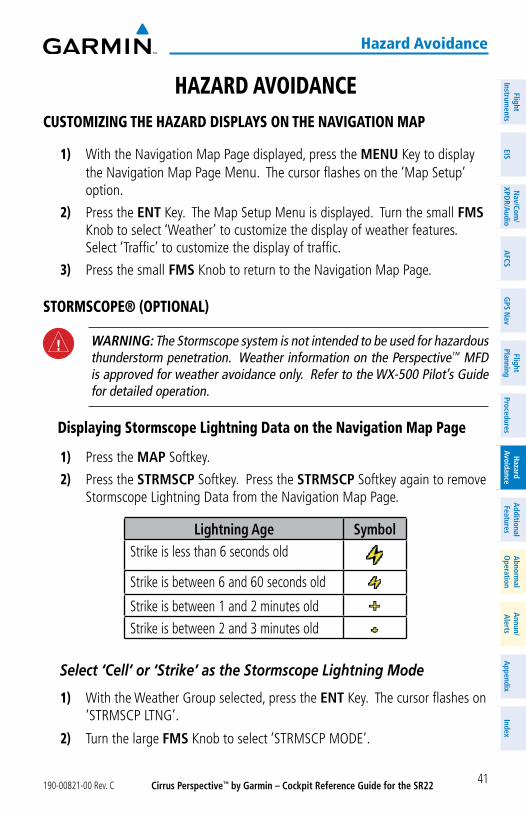
Cirrus Perspective™ by Garmin – Cockpit Reference Guide for the SR22190-00821-00 Rev. C 41
hazard avoidance
FlightInstrum
entsEIS
Nav/Com
/XPD
R/Audio
AFCS
GPS N
avFlight
PlanningProcedures
Hazard
AvoidanceA
dditionalFeatures
Abnorm
alO
perationA
nnun/A
lertsA
ppendixIndex
hazard avoidanCeCustomizing the hazard displays on the navigation map
1) With the Navigation Map Page displayed, press the MENU Key to display the Navigation Map Page Menu. The cursor flashes on the ‘Map Setup’ option.
2) Press the ENT Key. The Map Setup Menu is displayed. Turn the small FMS Knob to select ‘Weather’ to customize the display of weather features. Select ‘Traffic’ to customize the display of traffic.
3) Press the small FMS Knob to return to the Navigation Map Page.
stormsCope® (optional)
WARNING: The Stormscope system is not intended to be used for hazardous thunderstorm penetration. Weather information on the Perspective™ MFD is approved for weather avoidance only. Refer to the WX-500 Pilot’s Guide for detailed operation.
displaying stormscope lightning data on the navigation map page
1) Press the MAP Softkey.
2) Press the STRMSCP Softkey. Press the STRMSCP Softkey again to remove Stormscope Lightning Data from the Navigation Map Page.
Lightning Age SymbolStrike is less than 6 seconds old
Strike is between 6 and 60 seconds old
Strike is between 1 and 2 minutes oldStrike is between 2 and 3 minutes old
Select ‘Cell’ or ‘Strike’ as the Stormscope Lightning Mode
1) With the Weather Group selected, press the ENT Key. The cursor flashes on ‘STRMSCP LTNG’.
2) Turn the large FMS Knob to select ‘STRMSCP MODE’.
Cirrus Perspective™ by Garmin – Cockpit Reference Guide for the SR22 190-00821-00 Rev. C42
hazard avoidance
Flig
htIn
stru
men
tsEI
SN
av/C
om/
XPD
R/A
udio
AFC
SG
PS N
avFl
ight
Plan
ning
Proc
edur
esH
azar
dAv
oida
nce
Add
ition
alFe
atur
esA
bnor
mal
Ope
ratio
nA
nnun
/A
lert
sA
ppen
dix
Inde
x
3) Turn the small FMS Knob to display the ‘Cell/Strike’ window.
4) Turn either FMS Knob to select ‘Cell’ or ‘Strike’. Press the ENT Key.
5) Push the Fms Knob to return to the Navigation Map Page.
Clear Stormscope Lightning Data from the Navigation Map Page
1) Press the MENU Key (with the Navigation Map Page displayed).
2) Turn either FMS Knob to highlight the ‘Clear Stormscope® Lightning’ field and press the ENT Key.
NOTE: If heading input is lost, strikes and/or cells must be cleared manually after the execution of each turn. This is to ensure that the strike and/or cell positions are depicted accurately in relation to the nose of the aircraft.
stormscope page
1) Turn the large FMS Knob until the Map Page group is selected.
2) Turn the small FMS Knob until the Stormscope Page is selected.
Change the Stormscope Lightning Mode Between ‘Cell’ and ‘Strike’
1) Select the Stormscope Page.
2) Press the MODE Softkey. The CELL and STRIKE Softkeys are displayed. Press the CELL Softkey to display ‘CELL’ data or press the STRIKE Softkey to display ‘STRIKE’ data. ‘CELL’ or ‘STRIKE’ is displayed in the mode box located in the upper left corner of the Stormscope Page.
NOTE: “Cell mode” uses a clustering program to identify clusters of electrical activity that indicate cells.
Change the Viewing Mode Between 360˚ and 120˚
1) Select the Stormscope Page.
2) Press the VIEW Softkey. The 360 and ARC Softkeys are displayed. Press the 360 Softkey to display a 360˚ viewing area or press the ARC Softkey to display a 120˚ viewing area.
Press the CLEAR Softkey to remove all Stormscope lightning data from the display.
Cirrus Perspective™ by Garmin – Cockpit Reference Guide for the SR22190-00821-00 Rev. C 43
hazard avoidance
FlightInstrum
entsEIS
Nav/Com
/XPD
R/Audio
AFCS
GPS N
avFlight
PlanningProcedures
Hazard
AvoidanceA
dditionalFeatures
Abnorm
alO
perationA
nnun/A
lertsA
ppendixIndex
xm Weather (optional)
WARNING: Use of XM weather for hazardous weather penetration is not recommended. Weather information provided by XM Radio Service is approved only for weather avoidance, not penetration.
displaying xm Weather on the navigation map page
1) Press the MAP Softkey.
2) Press the NEXRAD and/or XM LTNG Softkey to display the desired weather. Press the applicable softkey again to remove weather data from the Navigation Map Page.
display metar and taF information on the airport information page
1) Turn the large FMS Knob to select the WPT Page Group.
2) Turn the small FMS Knob to select the Airport Information Page.
3) Press the WX Softkey to display METAR and TAF text (METAR and TAF information is updated every 12 minutes).
displaying Weather on the Weather data link page
1) Turn the large FMS Knob to select the Map Page Group.
2) Turn the small FMS Knob to select the Weather Data Link Page.
3) Press the available softkeys to select the desired XM weather product.
4) Press the LEGEND Softkey to view the legends for the selected products. If necessary, turn either FMS Knob to scroll through the list. Press the small FMS Knob or the ENT Key to return to the map.
map panning information – Weather data link page
1) Push in the Joystick to display the panning arrow.
2) Move the Joystick to place the panning arrow on AIRMETs, TFRs, METARs, or SIGMETs.
3) Press the ENT Key to display pertinent information for the selected product.
Note that pressing the ENT Key when panning over an AIRMET or a SIGMET displays an information box that shows the text of the report. Panning over an airport with METAR information does not display more
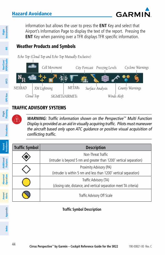
Cirrus Perspective™ by Garmin – Cockpit Reference Guide for the SR22 190-00821-00 Rev. C44
hazard avoidance
Flig
htIn
stru
men
tsEI
SN
av/C
om/
XPD
R/A
udio
AFC
SG
PS N
avFl
ight
Plan
ning
Proc
edur
esH
azar
dAv
oida
nce
Add
ition
alFe
atur
esA
bnor
mal
Ope
ratio
nA
nnun
/A
lert
sA
ppen
dix
Inde
x
information but allows the user to press the ENT Key and select that Airport’s Information Page to display the text of the report. Pressing the ENT Key when panning over a TFR displays TFR specific information.
Weather products and symbols
Echo Top (Cloud Top and Echo Top Mutually Exclusive)
NEXRAD
Cloud Top
XM Lightning
Cell Movement
SIGMETs/AIRMETs
METARs
City Forecast
Surface Analysis
Freezing Levels
Winds Aloft
County Warnings
Cyclone Warnings
traFFiC advisory systems
WARNING: Traffic information shown on the Perspective™ Multi Function Display is provided as an aid in visually acquiring traffic. Pilots must maneuver the aircraft based only upon ATC guidance or positive visual acquisition of conflicting traffic.
Traffic Symbol DescriptionNon-Threat Traffic
(intruder is beyond 5 nm and greater than 1200’ vertical separation)
Proximity Advisory (PA)(intruder is within 5 nm and less than 1200’ vertical separation)
Traffic Advisory (TA)(closing rate, distance, and vertical separation meet TA criteria)
Traffic Advisory Off Scale
Traffic Symbol Description
Cirrus Perspective™ by Garmin – Cockpit Reference Guide for the SR22190-00821-00 Rev. C 45
hazard avoidance
FlightInstrum
entsEIS
Nav/Com
/XPD
R/Audio
AFCS
GPS N
avFlight
PlanningProcedures
Hazard
AvoidanceA
dditionalFeatures
Abnorm
alO
perationA
nnun/A
lertsA
ppendixIndex
avidyne tas600 series traffic advisory system (optional)
Displaying Traffic on the Traffic Map Page
1) Turn the large FMS Knob to select the Map Page Group.
2) Turn the small FMS Knob to select the Traffic Map Page.
3) Turn the RANGE Knob clockwise to display a larger area or counter-clockwise to display a smaller area.
Displaying Traffic on the Navigation Map
1) Ensure TAS is operating.
2) With the Navigation Map displayed, press the MAP Softkey.
3) Press the TRAFFIC Softkey. Traffic is now displayed on the map.
l-3 skywatch hp (sKy497)(optional)
System Self Test
1) Set the range to 2/6 nm.
2) Press the STANDBY Softkey.
3) Press the TEST Softkey.
4) Self test takes approximately eight seconds to complete. When completed successfully, traffic symbols display and a voice alert “Traffic Advisory System Test Passed” is heard. If the self test fails, the system reverts to Standby Mode and a voice alert “Traffic Advisory System Test Failed” is heard.
Displaying Traffic on the Traffic Map Page
1) Turn the large FMS Knob to select the Map Page Group.
2) Turn the small FMS Knob to select the Traffic Map Page.
3) Press the OPERATE Softkey to begin displaying traffic. OPERATING is displayed in the Traffic mode field.
4) Press the ALT MODE Softkey to change the altitude volume.
5) Press the STANDBY Softkey to place the system in the Standby mode. STANDBY is displayed in the Traffic mode field.
6) Turn the RANGE Knob clockwise to display a larger area or counter-clockwise to display a smaller area.
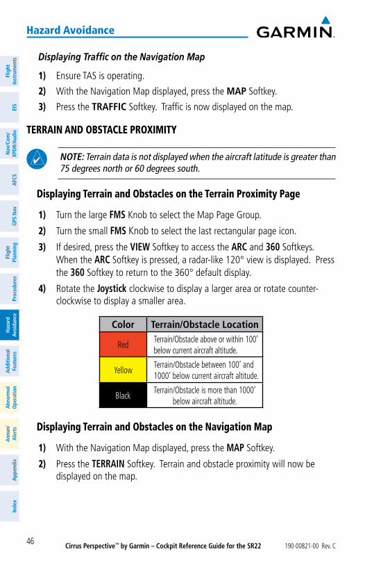
Cirrus Perspective™ by Garmin – Cockpit Reference Guide for the SR22 190-00821-00 Rev. C46
hazard avoidance
Flig
htIn
stru
men
tsEI
SN
av/C
om/
XPD
R/A
udio
AFC
SG
PS N
avFl
ight
Plan
ning
Proc
edur
esH
azar
dAv
oida
nce
Add
ition
alFe
atur
esA
bnor
mal
Ope
ratio
nA
nnun
/A
lert
sA
ppen
dix
Inde
x
Displaying Traffic on the Navigation Map
1) Ensure TAS is operating.
2) With the Navigation Map displayed, press the MAP Softkey.
3) Press the TRAFFIC Softkey. Traffic is now displayed on the map.
terrain and obstaCle proximity
NOTE: Terrain data is not displayed when the aircraft latitude is greater than 75 degrees north or 60 degrees south.
displaying terrain and obstacles on the terrain proximity page
1) Turn the large FMS Knob to select the Map Page Group.
2) Turn the small FMS Knob to select the last rectangular page icon.
3) If desired, press the VIEW Softkey to access the ARC and 360 Softkeys. When the ARC Softkey is pressed, a radar-like 120° view is displayed. Press the 360 Softkey to return to the 360° default display.
4) Rotate the Joystick clockwise to display a larger area or rotate counter-clockwise to display a smaller area.
Color Terrain/Obstacle Location
RedTerrain/Obstacle above or within 100’ below current aircraft altitude.
YellowTerrain/Obstacle between 100’ and 1000’ below current aircraft altitude.
BlackTerrain/Obstacle is more than 1000’
below aircraft altitude.
displaying terrain and obstacles on the navigation map
1) With the Navigation Map displayed, press the MAP Softkey.
2) Press the TERRAIN Softkey. Terrain and obstacle proximity will now be displayed on the map.
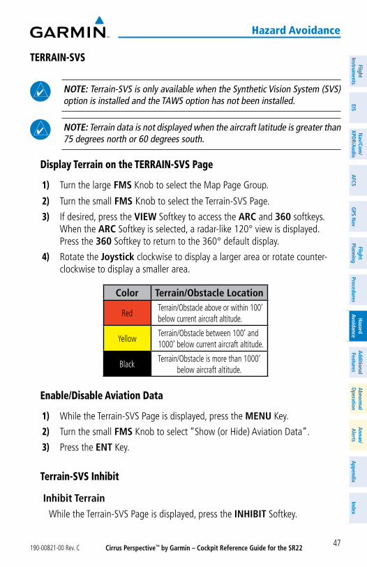
Cirrus Perspective™ by Garmin – Cockpit Reference Guide for the SR22190-00821-00 Rev. C 47
hazard avoidance
FlightInstrum
entsEIS
Nav/Com
/XPD
R/Audio
AFCS
GPS N
avFlight
PlanningProcedures
Hazard
AvoidanceA
dditionalFeatures
Abnorm
alO
perationA
nnun/A
lertsA
ppendixIndex
terrain-svs
NOTE: Terrain-SVS is only available when the Synthetic Vision System (SVS) option is installed and the TAWS option has not been installed.
NOTE: Terrain data is not displayed when the aircraft latitude is greater than 75 degrees north or 60 degrees south.
display terrain on the terrain-svs page
1) Turn the large FMS Knob to select the Map Page Group.
2) Turn the small FMS Knob to select the Terrain-SVS Page.
3) If desired, press the VIEW Softkey to access the ARC and 360 softkeys. When the ARC Softkey is selected, a radar-like 120° view is displayed. Press the 360 Softkey to return to the 360° default display.
4) Rotate the Joystick clockwise to display a larger area or rotate counter-clockwise to display a smaller area.
Color Terrain/Obstacle Location
RedTerrain/Obstacle above or within 100’ below current aircraft altitude.
YellowTerrain/Obstacle between 100’ and 1000’ below current aircraft altitude.
BlackTerrain/Obstacle is more than 1000’
below aircraft altitude.
enable/disable aviation data
1) While the Terrain-SVS Page is displayed, press the MENU Key.
2) Turn the small FMS Knob to select “Show (or Hide) Aviation Data”.
3) Press the ENT Key.
terrain-svs inhibit
Inhibit Terrain While the Terrain-SVS Page is displayed, press the INHIBIT Softkey.
Cirrus Perspective™ by Garmin – Cockpit Reference Guide for the SR22 190-00821-00 Rev. C48
hazard avoidance
Flig
htIn
stru
men
tsEI
SN
av/C
om/
XPD
R/A
udio
AFC
SG
PS N
avFl
ight
Plan
ning
Proc
edur
esH
azar
dAv
oida
nce
Add
ition
alFe
atur
esA
bnor
mal
Ope
ratio
nA
nnun
/A
lert
sA
ppen
dix
Inde
x
Or:
1) Press the MENU Key.
2) Turn the small FMS Knob to select ‘Inhibit Terrain’.
3) Press the ENT Key.
Enable Terrain While the Terrain-SVS Page is displayed, press the INHIBIT Softkey.
or:
1) While the Terrain-SVS Page is displayed, press the MENU Key.
2) Turn the small FMS Knob to select ‘Enable Terrain’.
3) Press the ENT Key.
NOTE: If Terrain-SVS alerts are inhibited when the Final Approach Fix is the active waypoint in a GPS WAAS approach, a LOW ALT annunciation may appear on the PFD next to the altimeter if the current aircraft altitude is at least 164 feet below the prescribed altitude at the Final Approach Fix.
terrain aWareness & Warning system (taWs) display
WARNING: The TAWS display shows supplemental information only. It should not be used for navigation.
NOTE: Terrain data is not displayed when the aircraft latitude is greater than 75 degrees north or 60 degrees south.
NOTE: TAWS operation is only available when the Perspective™ system is configured for a TAWS-B installation.
manual system test
1) While the TAWS Page is displayed, press the MENU Key.
2) Turn the small FMS Knob to select ‘Test TAWS’.
3) Press the ENT Key. During the test ‘TAWS TEST’ is displayed in the center of the TAWS Page.
When all is in working order, “TAWS System Test, OK” is heard.
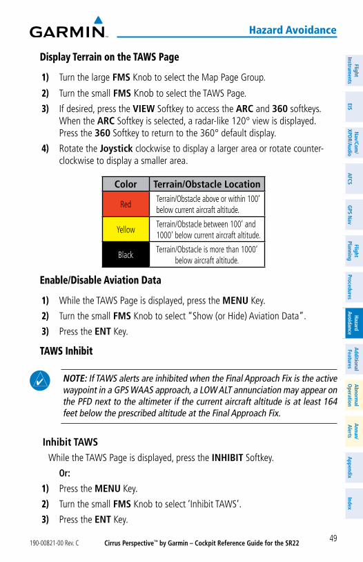
Cirrus Perspective™ by Garmin – Cockpit Reference Guide for the SR22190-00821-00 Rev. C 49
hazard avoidance
FlightInstrum
entsEIS
Nav/Com
/XPD
R/Audio
AFCS
GPS N
avFlight
PlanningProcedures
Hazard
AvoidanceA
dditionalFeatures
Abnorm
alO
perationA
nnun/A
lertsA
ppendixIndex
display terrain on the taWs page
1) Turn the large FMS Knob to select the Map Page Group.
2) Turn the small FMS Knob to select the TAWS Page.
3) If desired, press the VIEW Softkey to access the ARC and 360 softkeys. When the ARC Softkey is selected, a radar-like 120° view is displayed. Press the 360 Softkey to return to the 360° default display.
4) Rotate the Joystick clockwise to display a larger area or rotate counter-clockwise to display a smaller area.
Color Terrain/Obstacle Location
RedTerrain/Obstacle above or within 100’ below current aircraft altitude.
YellowTerrain/Obstacle between 100’ and 1000’ below current aircraft altitude.
BlackTerrain/Obstacle is more than 1000’
below aircraft altitude.
enable/disable aviation data
1) While the TAWS Page is displayed, press the MENU Key.
2) Turn the small FMS Knob to select “Show (or Hide) Aviation Data”.
3) Press the ENT Key.
taWs inhibit
NOTE: If TAWS alerts are inhibited when the Final Approach Fix is the active waypoint in a GPS WAAS approach, a LOW ALT annunciation may appear on the PFD next to the altimeter if the current aircraft altitude is at least 164 feet below the prescribed altitude at the Final Approach Fix.
Inhibit TAWS While the TAWS Page is displayed, press the INHIBIT Softkey.
Or:
1) Press the MENU Key.
2) Turn the small FMS Knob to select ‘Inhibit TAWS’.
3) Press the ENT Key.
Cirrus Perspective™ by Garmin – Cockpit Reference Guide for the SR22 190-00821-00 Rev. C50
hazard avoidance
Flig
htIn
stru
men
tsEI
SN
av/C
om/
XPD
R/A
udio
AFC
SG
PS N
avFl
ight
Plan
ning
Proc
edur
esH
azar
dAv
oida
nce
Add
ition
alFe
atur
esA
bnor
mal
Ope
ratio
nA
nnun
/A
lert
sA
ppen
dix
Inde
x
Enable TAWS While the TAWS Page is displayed, press the INHIBIT Softkey.
or:
1) While the TAWS Page is displayed, press the MENU Key.
2) Turn the small FMS Knob to select ‘Enable TAWS’.
3) Press the ENT Key.
Cirrus Perspective™ by Garmin – Cockpit Reference Guide for the SR22190-00821-00 Rev. C 51
additional Features
FlightInstrum
entsEIS
Nav/Com
/XPD
R/Audio
AFCS
GPS N
avFlight
PlanningProcedures
Hazard
AvoidanceA
dditionalFeatures
Abnorm
alO
perationA
nnun/A
lertsA
ppendixIndex
additional Features
synthetiC vision
NOTE: SVS is intended only as an aid to situational awareness. Other appropriate primary systems must be used for navigation as well as terrain, obstacle, and traffic avoidance.
Synthetic Vision System (SVS) functionality is offered as an optional enhancement to the Perspective™ Integrated Avionics System.
SVS is primarily comprised of a computer-generated forward-looking, attitude aligned view of the topography immediately in front of the aircraft from the pilot’s perspective. SVS information is shown on the primary flight display (PFD).
In addition to SVS enhancement to the PFD, the following features have been added to the PFD:
• Pathways• Flight Path Marker• Horizon Heading Marks• Terrain and Obstacle Alerting• Three-dimensional Traffic• Airport Signs• Runway Display
displaying svs terrain
1) Press the PFD Softkey.
2) Press the SYN VIS Softkey.
3) Press the SYN TERR Softkey.
4) Press the BACK Softkey to return to the previous page.
displaying pathways
1) Press the PFD Softkey.
2) Press the SYN VIS Softkey.
3) If not already enabled, press the SYN TERR Softkey.
4) Press the PATHWAY Softkey.
5) Press the BACK Softkey to return to the previous page.
Cirrus Perspective™ by Garmin – Cockpit Reference Guide for the SR22 190-00821-00 Rev. C52
additional Features
Flig
htIn
stru
men
tsEI
SN
av/C
om/
XPD
R/A
udio
AFC
SG
PS N
avFl
ight
Plan
ning
Proc
edur
esH
azar
dAv
oida
nce
Add
ition
alFe
atur
esA
bnor
mal
Ope
ratio
nA
nnun
/A
lert
sA
ppen
dix
Inde
x
displaying heading on the horizon
1) Press the PFD Softkey.
2) Press the SYN VIS Softkey.
3) If not already enabled, press the SYN TERR Softkey.
4) Press the HRZN HDG Softkey.
5) Press the BACK Softkey to return to the previous page.
displaying airport signs
1) Press the PFD Softkey.
2) Press the SYN VIS Softkey.
3) If not already enabled, press the SYN TERR Softkey.
4) Press the APTSIGNS Softkey.
5) Press the BACK Softkey to return to the previous page.
terminal proCedure Charts
NOTE: With the availability of SafeTaxi®, ChartView, or FliteCharts® in electronic form, it is still advisable to carry another source of charts on-board the aircraft.
safetaxi®
SafeTaxi® is an enhanced feature that gives greater map detail as the map range is adjusted in on the airport. The airport display on the map reveals runways with numbers, taxiways identifiers, and airport landmarks including ramps, buildings, control towers, and other prominent features. Resolution is greater at lower map ranges. The aircraft symbol provides situational awareness while taxiing.
Pressing the DCLTR Softkey (declutter) once removes the taxiway markings and airport identification labels. Pressing the DCLTR Softkey twice removes VOR station ID, the VOR symbol, and intersection names if within the airport plan view. Pressing the DCLTR Softkey a third time removes the airport runway layout, unless the airport in view is part of an active route structure. Pressing the DCLTR Softkey again cycles back to the original map detail.
The SafeTaxi database contains detailed airport diagrams for selected airports. These diagrams aid in following ground control instructions by accurately displaying the aircraft position on the map in relation to taxiways, ramps, runways, terminals, and services. This database is updated on a 56-day cycle.
Cirrus Perspective™ by Garmin – Cockpit Reference Guide for the SR22190-00821-00 Rev. C 53
additional Features
FlightInstrum
entsEIS
Nav/Com
/XPD
R/Audio
AFCS
GPS N
avFlight
PlanningProcedures
Hazard
AvoidanceA
dditionalFeatures
Abnorm
alO
perationA
nnun/A
lertsA
ppendixIndex
Chartview
ChartView resembles the paper version of Jeppesen terminal procedures charts. The charts are displayed in full color with high-resolution. The MFD depiction shows the aircraft position on the moving map in the plan view of most approach charts and on airport diagrams.
The ChartView database is updated on a 14-day cycle. If the ChartView database is not updated within 70 days of the expiration date, ChartView will no longer function.
FliteCharts®
FliteCharts® resemble the paper version of National Aeronautical Charting Office (NACO) terminal procedures charts. The charts are displayed with high-resolution and in color for applicable charts. Current aircraft position is not displayed on FliteCharts.
The FliteCharts database contains procedure charts for the United States only. This database is updated on a 28-day cycle. If not updated within 180 days of the expiration date, FliteCharts will no longer function.
view Charts from the navigation map page
1) Press the SHW CHRT Softkey when displayed.
or:
Move the map pointer to point to a desired point on the map and press the SHW CHRT Softkey.
2) Press the DP, STAR, APR, WX, or NOTAM Softkey to access charts for departures, arrivals, approaches, weather or NOTAMs.
3) Press the GO BACK Softkey to return to the previous page.
view Charts from the active Flight plan page
1) While viewing the Active Flight Plan Page, press the FMS Knob to activate the cursor.
2) Turn the large FMS Knob to select the departure airport, destination airport, departure, arrival, or approach.
3) Press the SHW CHRT Softkey. The appropriate chart is displayed, if available for the item selected.
4) Press the GO BACK Softkey to return to the previous page.
Cirrus Perspective™ by Garmin – Cockpit Reference Guide for the SR22 190-00821-00 Rev. C54
additional Features
Flig
htIn
stru
men
tsEI
SN
av/C
om/
XPD
R/A
udio
AFC
SG
PS N
avFl
ight
Plan
ning
Proc
edur
esH
azar
dAv
oida
nce
Add
ition
alFe
atur
esA
bnor
mal
Ope
ratio
nA
nnun
/A
lert
sA
ppen
dix
Inde
x
Change day/night view
1) While viewing a chart press the MENU Key to display the Page Menu OPTIONS.
2) Turn the large FMS Knob to highlight the ‘Chart Setup’ Menu Option and press the ENT Key.
3) Turn the large FMS Knob to move between the ‘FULL SCREEN’ and ‘COLOR SCHEME’ Options.
4) Turn the small FMS Knob to choose between the ‘On’ and ‘Off’ Full Screen Options.
5) Turn the small FMS Knob to choose between ‘Day’, ‘Auto’, and ‘Night’ Options.
6) In Auto Mode, turn the large FMS Knob to select the percentage field and change percentage with the small FMS Knob. The percentage of change is the day/night crossover point based on backlighting intensity.
7) Press the FMS Knob when finished to remove the Chart Setup Menu.
xm® radio entertainment
The XM® Radio Page provides information and control of the audio entertainment features of the XM Satellite Radio.
selecting the xm radio page
1) Turn the large FMS Knob to select the Auxiliary Page Group.
2) Turn the small FMS Knob to select the displayed AUX - XM Information Page.
3) Press the RADIO Softkey to show the XM Radio Page where audio entertainment is controlled.
active Channel and Channel list
The Active Channel Box on the XM Radio Page displays the currently selected channel. The Channels List Box of the XM Radio Page shows a list of the available channels for the selected category.
selecting a Category
The Category Box of the XM Radio Page displays the currently selected category of audio.
1) Press the CATGRY Softkey on the XM Radio Page.
2) Press the CAT + and CAT - softkeys to cycle through the categories.
Cirrus Perspective™ by Garmin – Cockpit Reference Guide for the SR22190-00821-00 Rev. C 55
additional Features
FlightInstrum
entsEIS
Nav/Com
/XPD
R/Audio
AFCS
GPS N
avFlight
PlanningProcedures
Hazard
AvoidanceA
dditionalFeatures
Abnorm
alO
perationA
nnun/A
lertsA
ppendixIndex
or:
Turn the small FMS Knob to display the ‘Categories’ list. Highlight the desired category with the small FMS Knob.
3) Press the ENT Key.
select an available Channel within the selected Category
1) While on the XM Radio Page, press the CHNL Softkey.
2) Press the CH + Softkey to go up through the list in the Channel Box, or move down the list with the CH – Softkey.
or:
Press the FMS Knob to highlight the channel list and turn the large FMS Knob to scroll through the channels.
3) With the desired channel highlighted, press the ENT Key.
entering a Channel directly
1) While on the XM Radio Page, press the CHNL Softkey.
2) Press the DIR CH Softkey. The channel number in the Active Channel Box is highlighted.
3) Press the numbered softkeys located on the bottom of the display to directly select the desired channel number. The number keys on the PFD/MFD Control Unit may also be used.
4) Press the ENT Key to activate the selected channel.
assigning Channel presets
Up to 15 channels from any category can be assigned a preset number.
1) On the XM Radio Page, with the desired channel active, press the PRESETS Softkey to access the first five preset channels (PS1 - PS5).
2) Press the MORE Softkey to access the next five channels (PS6 – PS10), and again to access the last five channels (PS11 – PS15). Pressing the MORE Softkey repeatedly cycles through the preset channels.
3) Press any one of the (PS1 - PS15) softkeys to assign a number to the active channel.
4) Press the SET Softkey on the desired channel number to save the channel as a preset.
Cirrus Perspective™ by Garmin – Cockpit Reference Guide for the SR22 190-00821-00 Rev. C56
additional Features
Flig
htIn
stru
men
tsEI
SN
av/C
om/
XPD
R/A
udio
AFC
SG
PS N
avFl
ight
Plan
ning
Proc
edur
esH
azar
dAv
oida
nce
Add
ition
alFe
atur
esA
bnor
mal
Ope
ratio
nA
nnun
/A
lert
sA
ppen
dix
Inde
x
adjusting volume
1) With the XM Radio Page displayed, press the VOL Softkey.
2) Press the VOL – Softkey to reduce volume or press the VOL + Softkey to increase volume. (Once the VOL Softkey is pressed, the volume can also be adjusted using the small FMS Knob.)
3) Press the MUTE Softkey to mute the audio. Press the MUTE Softkey again to unmute the audio.
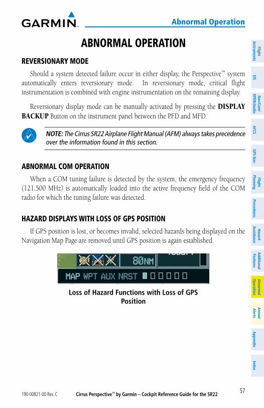
Cirrus Perspective™ by Garmin – Cockpit Reference Guide for the SR22190-00821-00 Rev. C 57
abnormal operation
FlightInstrum
entsEIS
Nav/Com
/XPD
R/Audio
AFCS
GPS N
avFlight
PlanningProcedures
Hazard
AvoidanceA
dditionalFeatures
Abnorm
alO
perationA
nnun/A
lertsA
ppendixIndex
abnormal operationreversionary mode
Should a system detected failure occur in either display, the Perspective™ system automatically enters reversionary mode. In reversionary mode, critical flight instrumentation is combined with engine instrumentation on the remaining display.
Reversionary display mode can be manually activated by pressing the DISPLAY BACKUP Button on the instrument panel between the PFD and MFD.
NOTE: The Cirrus SR22 Airplane Flight Manual (AFM) always takes precedence over the information found in this section.
abnormal Com operation
When a COM tuning failure is detected by the system, the emergency frequency (121.500 MHz) is automatically loaded into the active frequency field of the COM radio for which the tuning failure was detected.
hazard displays With loss oF gps position
If GPS position is lost, or becomes invalid, selected hazards being displayed on the Navigation Map Page are removed until GPS position is again established.
Loss of Hazard Functions with Loss of GPS Position
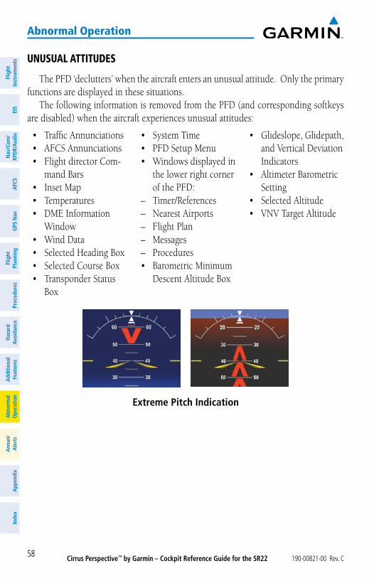
Cirrus Perspective™ by Garmin – Cockpit Reference Guide for the SR22 190-00821-00 Rev. C58
abnormal operation
Flig
htIn
stru
men
tsEI
SN
av/C
om/
XPD
R/A
udio
AFC
SG
PS N
avFl
ight
Plan
ning
Proc
edur
esH
azar
dAv
oida
nce
Add
ition
alFe
atur
esA
bnor
mal
Ope
ratio
nA
nnun
/A
lert
sA
ppen
dix
Inde
x
unusual attitudes
The PFD ‘declutters’ when the aircraft enters an unusual attitude. Only the primary functions are displayed in these situations.
The following information is removed from the PFD (and corresponding softkeys are disabled) when the aircraft experiences unusual attitudes:
• Traffic Annunciations• AFCS Annunciations• Flight director Com-
mand Bars• Inset Map• Temperatures• DME Information
Window• Wind Data• Selected Heading Box• Selected Course Box• Transponder Status
Box
• System Time• PFD Setup Menu• Windows displayed in
the lower right corner of the PFD:
– Timer/References– Nearest Airports– Flight Plan– Messages– Procedures• Barometric Minimum
Descent Altitude Box
• Glideslope, Glidepath, and Vertical Deviation Indicators
• Altimeter Barometric Setting
• Selected Altitude• VNV Target Altitude
Extreme Pitch Indication
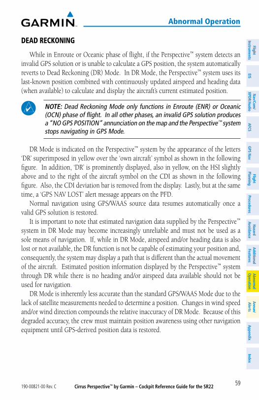
Cirrus Perspective™ by Garmin – Cockpit Reference Guide for the SR22190-00821-00 Rev. C 59
abnormal operation
FlightInstrum
entsEIS
Nav/Com
/XPD
R/Audio
AFCS
GPS N
avFlight
PlanningProcedures
Hazard
AvoidanceA
dditionalFeatures
Abnorm
alO
perationA
nnun/A
lertsA
ppendixIndex
dead reCKoning
While in Enroute or Oceanic phase of flight, if the Perspective™ system detects an invalid GPS solution or is unable to calculate a GPS position, the system automatically reverts to Dead Reckoning (DR) Mode. In DR Mode, the Perspective™ system uses its last-known position combined with continuously updated airspeed and heading data (when available) to calculate and display the aircraft’s current estimated position.
NOTE: Dead Reckoning Mode only functions in Enroute (ENR) or Oceanic (OCN) phase of flight. In all other phases, an invalid GPS solution produces a “NO GPS POSITION” annunciation on the map and the Perspective™ system stops navigating in GPS Mode.
DR Mode is indicated on the Perspective™ system by the appearance of the letters ‘DR’ superimposed in yellow over the ‘own aircraft’ symbol as shown in the following figure. In addition, ‘DR’ is prominently displayed, also in yellow, on the HSI slightly above and to the right of the aircraft symbol on the CDI as shown in the following figure. Also, the CDI deviation bar is removed from the display. Lastly, but at the same time, a ‘GPS NAV LOST’ alert message appears on the PFD.
Normal navigation using GPS/WAAS source data resumes automatically once a valid GPS solution is restored.
It is important to note that estimated navigation data supplied by the Perspective™ system in DR Mode may become increasingly unreliable and must not be used as a sole means of navigation. If, while in DR Mode, airspeed and/or heading data is also lost or not available, the DR function is not be capable of estimating your position and, consequently, the system may display a path that is different than the actual movement of the aircraft. Estimated position information displayed by the Perspective™ system through DR while there is no heading and/or airspeed data available should not be used for navigation.
DR Mode is inherently less accurate than the standard GPS/WAAS Mode due to the lack of satellite measurements needed to determine a position. Changes in wind speed and/or wind direction compounds the relative inaccuracy of DR Mode. Because of this degraded accuracy, the crew must maintain position awareness using other navigation equipment until GPS-derived position data is restored.
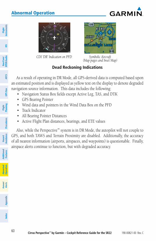
Cirrus Perspective™ by Garmin – Cockpit Reference Guide for the SR22 190-00821-00 Rev. C60
abnormal operation
Flig
htIn
stru
men
tsEI
SN
av/C
om/
XPD
R/A
udio
AFC
SG
PS N
avFl
ight
Plan
ning
Proc
edur
esH
azar
dAv
oida
nce
Add
ition
alFe
atur
esA
bnor
mal
Ope
ratio
nA
nnun
/A
lert
sA
ppen
dix
Inde
x
Dead Reckoning Indications
Symbolic Aircraft(Map pages and Inset Map)
CDI ‘DR’ Indication on PFD
As a result of operating in DR Mode, all GPS-derived data is computed based upon an estimated position and is displayed as yellow text on the display to denote degraded navigation source information. This data includes the following:
• Navigation Status Box fields except Active Leg, TAS, and DTK• GPS Bearing Pointer• Wind data and pointers in the Wind Data Box on the PFD• Track Indicator• All Bearing Pointer Distances• Active Flight Plan distances, bearings, and ETE values
Also, while the Perspective™ system is in DR Mode, the autopilot will not couple to GPS, and both TAWS and Terrain Proximity are disabled. Additionally, the accuracy of all nearest information (airports, airspaces, and waypoints) is questionable. Finally, airspace alerts continue to function, but with degraded accuracy.
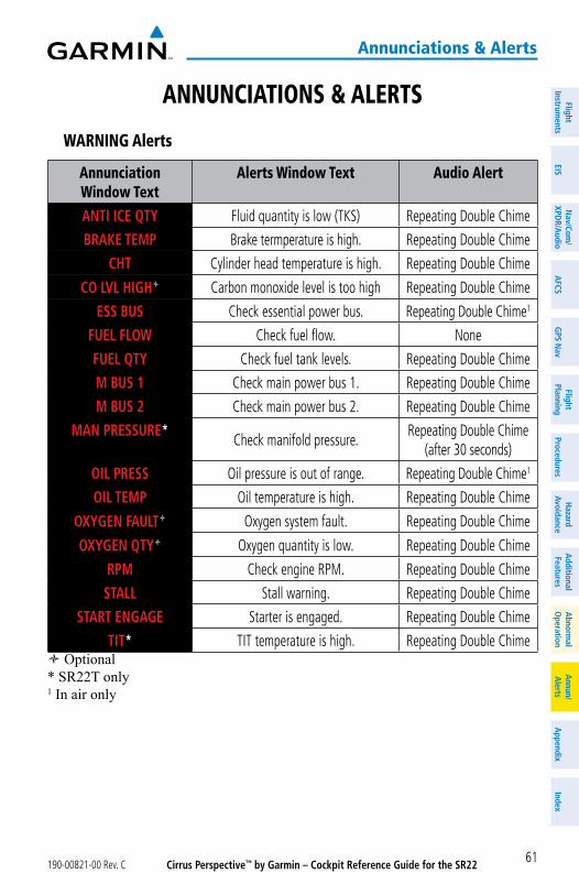
Cirrus Perspective™ by Garmin – Cockpit Reference Guide for the SR22190-00821-00 Rev. C 61
annunciations & alerts
FlightInstrum
entsEIS
Nav/Com
/XPD
R/Audio
AFCS
GPS N
avFlight
PlanningProcedures
Hazard
AvoidanceA
dditionalFeatures
Abnorm
alO
perationA
nnun/A
lertsA
ppendixIndex
annunCiations & alerts
Warning alerts
annunciation Window text
alerts Window text audio alert
ANTI ICE QTY Fluid quantity is low (TKS) Repeating Double Chime
BRAKE TEMP Brake termperature is high. Repeating Double Chime
CHT Cylinder head temperature is high. Repeating Double Chime
CO LVL HIGH Carbon monoxide level is too high Repeating Double Chime
ESS BUS Check essential power bus. Repeating Double Chime1
FUEL FLOW Check fuel flow. None
FUEL QTY Check fuel tank levels. Repeating Double Chime
M BUS 1 Check main power bus 1. Repeating Double Chime
M BUS 2 Check main power bus 2. Repeating Double Chime
MAN PRESSURE*Check manifold pressure.
Repeating Double Chime (after 30 seconds)
OIL PRESS Oil pressure is out of range. Repeating Double Chime1
OIL TEMP Oil temperature is high. Repeating Double Chime
OXYGEN FAULT Oxygen system fault. Repeating Double Chime
OXYGEN QTY Oxygen quantity is low. Repeating Double Chime
RPM Check engine RPM. Repeating Double Chime
STALL Stall warning. Repeating Double Chime
START ENGAGE Starter is engaged. Repeating Double Chime
TIT* TIT temperature is high. Repeating Double Chime Optional* SR22T only1 In air only
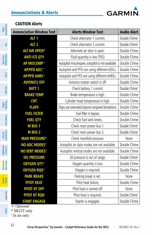
Cirrus Perspective™ by Garmin – Cockpit Reference Guide for the SR22 190-00821-00 Rev. C62
annunciations & alerts
Flig
htIn
stru
men
tsEI
SN
av/C
om/
XPD
R/A
udio
AFC
SG
PS N
avFl
ight
Plan
ning
Proc
edur
esH
azar
dAv
oida
nce
Add
ition
alFe
atur
esA
bnor
mal
Ope
ratio
nA
nnun
/A
lert
sA
ppen
dix
Inde
x
Caution alerts
annunciation Window text alerts Window text audio alertALT 1 Check alternator 1 current. Double Chime1
ALT 2 Check alternator 2 current. Double Chime1
ALT AIR OPEN* Alternate air door is open. Double Chime
ANTI ICE QTY Fluid quantity is low (TKS) Double Chime
AP MISCOMP Autopilot miscompare, autopilot is not available. Double Chime
AP/PFD ADC Autopilot and PFD are using different ADCs. Double Chime
AP/PFD AHRS Autopilot and PFD are using different AHRSs. Double Chime
AVIONICS OFF Avionics master switch is off. Double Chime
BATT 1 Check battery 1 current. Double Chime1
BRAKE TEMP Brake termperature is high. Double Chime
CHT Cylinder head temperature is high. Double Chime
FLAPS Flaps are extended beyond airspeed limitations. Double Chime
FUEL FILTER Fuel filter in bypass Double Chime
FUEL QTY Check fuel tank levels. Double Chime
M BUS 1 Check main power bus 1. Double Chime1
M BUS 2 Check main power bus 2. Double Chime1
MAN PRESSURE* Check manifold pressure. None
NO ADC MODES Autopilot air data modes are not available. Double Chime
NO VERT MODES Autopilot vertical modes are not available. Double Chime
OIL PRESSURE Oil pressure is out of range. Double Chime1
OXYGEN QTY Oxygen quantity is low. Double Chime
OXYGEN RQD Oxygen is required. Double Chime
PARK BRAKE Parking break is set. None
PITOT HEAT Pitot heat failure. Double Chime
PITOT HT OFF Pitot heat is turned off. None
PITOT HT RQD Pitot heat is required. Double Chime1
START ENGAGE Starter is engaged. Double Chime Optional* SR22T only1 In air only
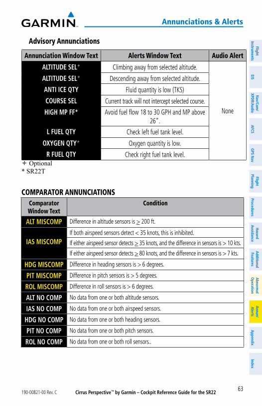
Cirrus Perspective™ by Garmin – Cockpit Reference Guide for the SR22190-00821-00 Rev. C 63
annunciations & alerts
FlightInstrum
entsEIS
Nav/Com
/XPD
R/Audio
AFCS
GPS N
avFlight
PlanningProcedures
Hazard
AvoidanceA
dditionalFeatures
Abnorm
alO
perationA
nnun/A
lertsA
ppendixIndex
advisory annunciations
annunciation Window text alerts Window text audio alert
ALTITUDE SEL Climbing away from selected altitude.
None
ALTITUDE SEL Descending away from selected altitude.
ANTI ICE QTY Fluid quantity is low (TKS)
COURSE SEL Current track will not intercept selected course.
HIGH MP FF* Avoid fuel flow 18 to 30 GPH and MP above 26”.
L FUEL QTY Check left fuel tank level.
OXYGEN QTY Oxygen quantity is low.
R FUEL QTY Check right fuel tank level. Optional* SR22T
Comparator annunCiationsComparator Window text
Condition
ALT MISCOMP Difference in altitude sensors is > 200 ft.
IAS MISCOMPIf both airspeed sensors detect < 35 knots, this is inhibited.
If either airspeed sensor detects > 35 knots, and the difference in sensors is > 10 kts.
If either airspeed sensor detects > 80 knots, and the difference in sensors is > 7 kts.
HDG MISCOMP Difference in heading sensors is > 6 degrees.
PIT MISCOMP Difference in pitch sensors is > 5 degrees.
ROL MISCOMP Difference in roll sensors is > 6 degrees.
ALT NO COMP No data from one or both altitude sensors.
IAS NO COMP No data from one or both airspeed sensors.
HDG NO COMP No data from one or both heading sensors.
PIT NO COMP No data from one or both pitch sensors.
ROL NO COMP No data from one or both roll sensors..
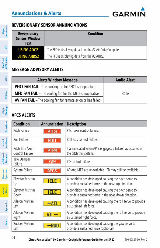
Cirrus Perspective™ by Garmin – Cockpit Reference Guide for the SR22 190-00821-00 Rev. C64
annunciations & alerts
Flig
htIn
stru
men
tsEI
SN
av/C
om/
XPD
R/A
udio
AFC
SG
PS N
avFl
ight
Plan
ning
Proc
edur
esH
azar
dAv
oida
nce
Add
ition
alFe
atur
esA
bnor
mal
Ope
ratio
nA
nnun
/A
lert
sA
ppen
dix
Inde
x
reversionary sensor annunCiations
reversionary sensor Window
text
Condition
USING ADC2 The PFD is displaying data from the #2 Air Data Computer.
USING AHRS2 The PFD is displaying data from the #2 AHRS.
message advisory alerts
alerts Window message audio alert
PFD1 FAN FAIL – The cooling fan for PFD1 is inoperative.
NoneMFD FAN FAIL – The cooling fan for the MFD is inoperative.
AV FAN FAIL – The cooling fan for remote avionics has failed.
aFCs alerts
Condition Annunciation DescriptionPitch Failure Pitch axis control failure.
Roll Failure Roll axis control failure.
Pitch Trim Axis Control Failure
If annunciated when AP is engaged, a failure has occurred in the pitch trim system.
Yaw Damper Failure
YD control failure.
System Failure AP and MET are unavailable. FD may still be available.
Elevator Mistrim Up
A condition has developed causing the pitch servo to provide a sustained force in the nose up direction.
Elevator Mistrim Down
A condition has developed causing the pitch servo to provide a sustained force in the nose down direction.
Aileron Mistrim Left
A condition has developed causing the roll servo to provide a sustained left force.
Aileron Mistrim Right
A condition has developed causing the roll servo to provide a sustained right force.
Rudder Mistrim Left
A condition has developed causing the yaw servo to provide a sustained force (optional).
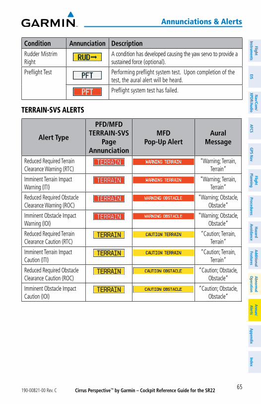
Cirrus Perspective™ by Garmin – Cockpit Reference Guide for the SR22190-00821-00 Rev. C 65
annunciations & alerts
FlightInstrum
entsEIS
Nav/Com
/XPD
R/Audio
AFCS
GPS N
avFlight
PlanningProcedures
Hazard
AvoidanceA
dditionalFeatures
Abnorm
alO
perationA
nnun/A
lertsA
ppendixIndex
Condition Annunciation DescriptionRudder Mistrim Right
A condition has developed causing the yaw servo to provide a sustained force (optional).
Preflight Test Performing preflight system test. Upon completion of the test, the aural alert will be heard.
Preflight system test has failed.
terrain-svs alerts
Alert Type
PFD/MFD TERRAIN-SVS
PageAnnunciation
MFDPop-Up Alert
Aural Message
Reduced Required Terrain Clearance Warning (RTC)
“Warning; Terrain, Terrain”
Imminent Terrain Impact Warning (ITI)
“Warning; Terrain, Terrain”
Reduced Required Obstacle Clearance Warning (ROC)
“Warning; Obstacle, Obstacle”
Imminent Obstacle Impact Warning (IOI)
“Warning; Obstacle, Obstacle”
Reduced Required Terrain Clearance Caution (RTC)
“Caution; Terrain, Terrain”
Imminent Terrain Impact Caution (ITI)
“Caution; Terrain, Terrain”
Reduced Required Obstacle Clearance Caution (ROC)
“Caution; Obstacle, Obstacle”
Imminent Obstacle Impact Caution (IOI)
“Caution; Obstacle, Obstacle”
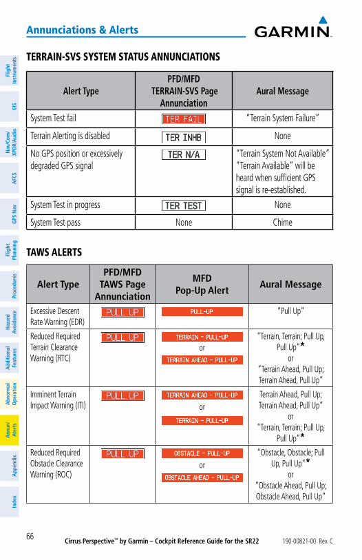
Cirrus Perspective™ by Garmin – Cockpit Reference Guide for the SR22 190-00821-00 Rev. C66
annunciations & alerts
Flig
htIn
stru
men
tsEI
SN
av/C
om/
XPD
R/A
udio
AFC
SG
PS N
avFl
ight
Plan
ning
Proc
edur
esH
azar
dAv
oida
nce
Add
ition
alFe
atur
esA
bnor
mal
Ope
ratio
nA
nnun
/A
lert
sA
ppen
dix
Inde
x
terrain-svs system status annunCiations
Alert TypePFD/MFD
TERRAIN-SVS PageAnnunciation
Aural Message
System Test fail “Terrain System Failure”
Terrain Alerting is disabled None
No GPS position or excessively degraded GPS signal
“Terrain System Not Available”“Terrain Available” will be heard when sufficient GPS signal is re-established.
System Test in progress None
System Test pass None Chime
taWs alerts
Alert TypePFD/MFD
TAWS PageAnnunciation
MFDPop-Up Alert
Aural Message
Excessive Descent Rate Warning (EDR)
“Pull Up”
Reduced Required Terrain Clearance Warning (RTC)
or“Terrain, Terrain; Pull Up,
Pull Up”*or
“Terrain Ahead, Pull Up; Terrain Ahead, Pull Up”
Imminent Terrain Impact Warning (ITI) or
Terrain Ahead, Pull Up; Terrain Ahead, Pull Up”
or“Terrain, Terrain; Pull Up,
Pull Up”*Reduced Required Obstacle Clearance Warning (ROC)
or“Obstacle, Obstacle; Pull
Up, Pull Up”*or
“Obstacle Ahead, Pull Up; Obstacle Ahead, Pull Up”
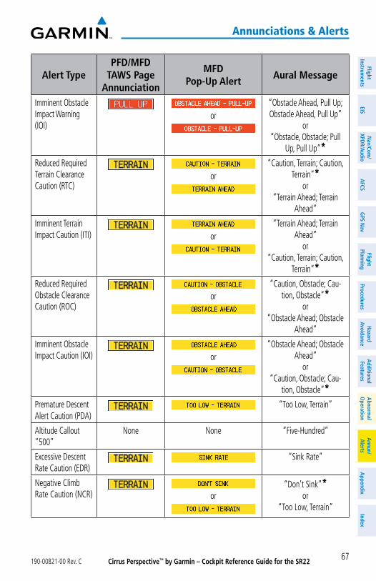
Cirrus Perspective™ by Garmin – Cockpit Reference Guide for the SR22190-00821-00 Rev. C 67
annunciations & alerts
FlightInstrum
entsEIS
Nav/Com
/XPD
R/Audio
AFCS
GPS N
avFlight
PlanningProcedures
Hazard
AvoidanceA
dditionalFeatures
Abnorm
alO
perationA
nnun/A
lertsA
ppendixIndex
Alert TypePFD/MFD
TAWS PageAnnunciation
MFDPop-Up Alert
Aural Message
Imminent Obstacle Impact Warning (IOI)
or“Obstacle Ahead, Pull Up; Obstacle Ahead, Pull Up”
or“Obstacle, Obstacle; Pull
Up, Pull Up”*Reduced Required Terrain Clearance Caution (RTC)
or“Caution, Terrain; Caution,
Terrain”*or
“Terrain Ahead; Terrain Ahead”
Imminent Terrain Impact Caution (ITI) or
“Terrain Ahead; Terrain Ahead”
or“Caution, Terrain; Caution,
Terrain”*Reduced Required Obstacle Clearance Caution (ROC)
or“Caution, Obstacle; Cau-
tion, Obstacle”*or
“Obstacle Ahead; Obstacle Ahead”
Imminent Obstacle Impact Caution (IOI) or
“Obstacle Ahead; Obstacle Ahead”
or“Caution, Obstacle; Cau-
tion, Obstacle”*Premature Descent Alert Caution (PDA)
“Too Low, Terrain”
Altitude Callout “500”
None None “Five-Hundred”
Excessive Descent Rate Caution (EDR)
“Sink Rate”
Negative Climb Rate Caution (NCR) or
“Don’t Sink”*or
“Too Low, Terrain”
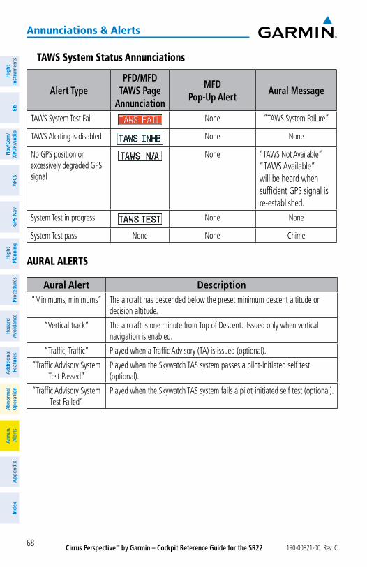
Cirrus Perspective™ by Garmin – Cockpit Reference Guide for the SR22 190-00821-00 Rev. C68
annunciations & alerts
Flig
htIn
stru
men
tsEI
SN
av/C
om/
XPD
R/A
udio
AFC
SG
PS N
avFl
ight
Plan
ning
Proc
edur
esH
azar
dAv
oida
nce
Add
ition
alFe
atur
esA
bnor
mal
Ope
ratio
nA
nnun
/A
lert
sA
ppen
dix
Inde
x
taWs system status annunciations
Alert TypePFD/MFD
TAWS PageAnnunciation
MFDPop-Up Alert
Aural Message
TAWS System Test Fail None “TAWS System Failure”
TAWS Alerting is disabled None None
No GPS position or excessively degraded GPS signal
None “TAWS Not Available”“TAWS Available” will be heard when sufficient GPS signal is re-established.
System Test in progress None None
System Test pass None None Chime
aural alerts
Aural Alert Description“Minimums, minimums” The aircraft has descended below the preset minimum descent altitude or
decision altitude.
“Vertical track” The aircraft is one minute from Top of Descent. Issued only when vertical navigation is enabled.
“Traffic, Traffic” Played when a Traffic Advisory (TA) is issued (optional).
“Traffic Advisory System Test Passed”
Played when the Skywatch TAS system passes a pilot-initiated self test (optional).
“Traffic Advisory System Test Failed”
Played when the Skywatch TAS system fails a pilot-initiated self test (optional).
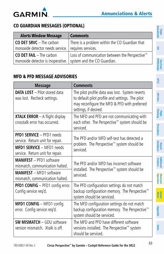
Cirrus Perspective™ by Garmin – Cockpit Reference Guide for the SR22190-00821-00 Rev. C 69
annunciations & alerts
FlightInstrum
entsEIS
Nav/Com
/XPD
R/Audio
AFCS
GPS N
avFlight
PlanningProcedures
Hazard
AvoidanceA
dditionalFeatures
Abnorm
alO
perationA
nnun/A
lertsA
ppendixIndex
Co guardian messages (optional)
alerts Window message Comments
CO DET SRVC – The carbon monoxide detector needs service.
There is a problem within the CO Guardian that requires services.
CO DET FAIL – The carbon monoxide detector is inoperative.
Loss of communication between the Perspective™ system and the CO Guardian.
mFd & pFd message advisories
Message CommentsDATA LOST – Pilot stored data was lost. Recheck settings.
The pilot profile data was lost. System reverts to default pilot profile and settings. The pilot may reconfigure the MFD & PFD with preferred settings, if desired.
XTALK ERROR – A flight display crosstalk error has occurred.
The MFD and PFD are not communicating with each other. The Perspective™ system should be serviced.
PFD1 SERVICE – PFD1 needs service. Return unit for repair. The PFD and/or MFD self-test has detected a
problem. The Perspective™ system should be serviced.MFD1 SERVICE – MFD1 needs
service. Return unit for repair.MANIFEST – PFD1 software mismatch, communication halted. The PFD and/or MFD has incorrect software
installed. The Perspective™ system should be serviced.MANIFEST – MFD1 software
mismatch, communication halted.PFD1 CONFIG – PFD1 config error. Config service req’d.
The PFD configuration settings do not match backup configuration memory. The Perspective™ system should be serviced.
MFD1 CONFIG – MFD1 config error. Config service req’d.
The MFD configuration settings do not match backup configuration memory. The Perspective™ system should be serviced.
SW MISMATCH – GDU software version mismatch. Xtalk is off.
The MFD and PFD have different software versions installed. The Perspective™ system should be serviced.
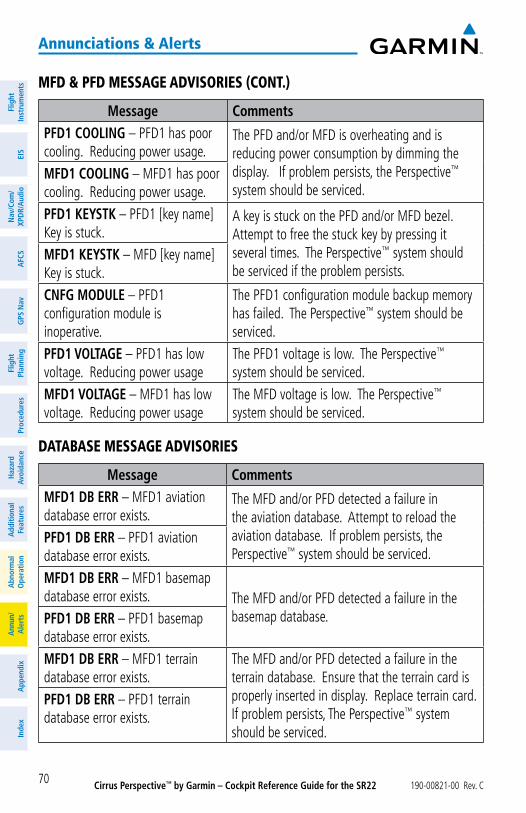
Cirrus Perspective™ by Garmin – Cockpit Reference Guide for the SR22 190-00821-00 Rev. C70
annunciations & alerts
Flig
htIn
stru
men
tsEI
SN
av/C
om/
XPD
R/A
udio
AFC
SG
PS N
avFl
ight
Plan
ning
Proc
edur
esH
azar
dAv
oida
nce
Add
ition
alFe
atur
esA
bnor
mal
Ope
ratio
nA
nnun
/A
lert
sA
ppen
dix
Inde
x
mFd & pFd message advisories (Cont.)
Message CommentsPFD1 COOLING – PFD1 has poor cooling. Reducing power usage.
The PFD and/or MFD is overheating and is reducing power consumption by dimming the display. If problem persists, the Perspective™ system should be serviced.
MFD1 COOLING – MFD1 has poor cooling. Reducing power usage. PFD1 KEYSTK – PFD1 [key name] Key is stuck.
A key is stuck on the PFD and/or MFD bezel. Attempt to free the stuck key by pressing it several times. The Perspective™ system should be serviced if the problem persists.
MFD1 KEYSTK – MFD [key name] Key is stuck.CNFG MODULE – PFD1 configuration module is inoperative.
The PFD1 configuration module backup memory has failed. The Perspective™ system should be serviced.
PFD1 VOLTAGE – PFD1 has low voltage. Reducing power usage
The PFD1 voltage is low. The Perspective™ system should be serviced.
MFD1 VOLTAGE – MFD1 has low voltage. Reducing power usage
The MFD voltage is low. The Perspective™ system should be serviced.
database message advisories
Message CommentsMFD1 DB ERR – MFD1 aviation database error exists.
The MFD and/or PFD detected a failure in the aviation database. Attempt to reload the aviation database. If problem persists, the Perspective™ system should be serviced.
PFD1 DB ERR – PFD1 aviation database error exists.MFD1 DB ERR – MFD1 basemap database error exists. The MFD and/or PFD detected a failure in the
basemap database. PFD1 DB ERR – PFD1 basemap database error exists.MFD1 DB ERR – MFD1 terrain database error exists.
The MFD and/or PFD detected a failure in the terrain database. Ensure that the terrain card is properly inserted in display. Replace terrain card. If problem persists, The Perspective™ system should be serviced.
PFD1 DB ERR – PFD1 terrain database error exists.
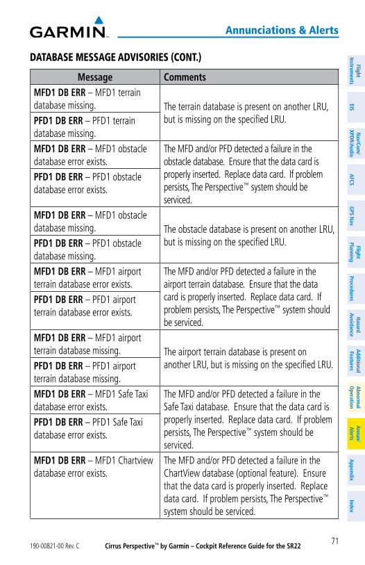
Cirrus Perspective™ by Garmin – Cockpit Reference Guide for the SR22190-00821-00 Rev. C 71
annunciations & alerts
FlightInstrum
entsEIS
Nav/Com
/XPD
R/Audio
AFCS
GPS N
avFlight
PlanningProcedures
Hazard
AvoidanceA
dditionalFeatures
Abnorm
alO
perationA
nnun/A
lertsA
ppendixIndex
database message advisories (Cont.)
Message CommentsMFD1 DB ERR – MFD1 terrain database missing. The terrain database is present on another LRU,
but is missing on the specified LRU.PFD1 DB ERR – PFD1 terrain database missing.MFD1 DB ERR – MFD1 obstacle database error exists.
The MFD and/or PFD detected a failure in the obstacle database. Ensure that the data card is properly inserted. Replace data card. If problem persists, The Perspective™ system should be serviced.
PFD1 DB ERR – PFD1 obstacle database error exists.
MFD1 DB ERR – MFD1 obstacle database missing. The obstacle database is present on another LRU,
but is missing on the specified LRU.PFD1 DB ERR – PFD1 obstacle database missing.MFD1 DB ERR – MFD1 airport terrain database error exists.
The MFD and/or PFD detected a failure in the airport terrain database. Ensure that the data card is properly inserted. Replace data card. If problem persists, The Perspective™ system should be serviced.
PFD1 DB ERR – PFD1 airport terrain database error exists.
MFD1 DB ERR – MFD1 airport terrain database missing. The airport terrain database is present on
another LRU, but is missing on the specified LRU.PFD1 DB ERR – PFD1 airport terrain database missing.MFD1 DB ERR – MFD1 Safe Taxi database error exists.
The MFD and/or PFD detected a failure in the Safe Taxi database. Ensure that the data card is properly inserted. Replace data card. If problem persists, The Perspective™ system should be serviced.
PFD1 DB ERR – PFD1 Safe Taxi database error exists.
MFD1 DB ERR – MFD1 Chartview database error exists.
The MFD and/or PFD detected a failure in the ChartView database (optional feature). Ensure that the data card is properly inserted. Replace data card. If problem persists, The Perspective™ system should be serviced.
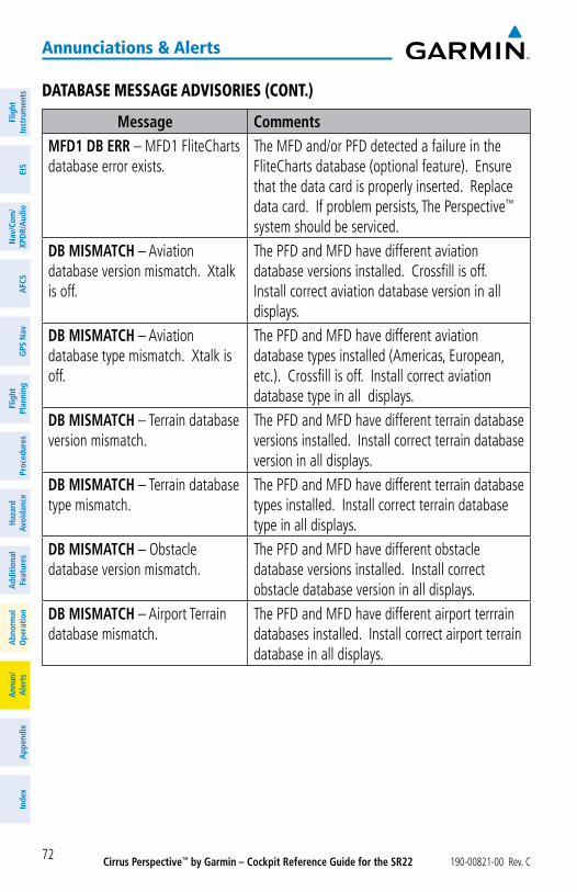
Cirrus Perspective™ by Garmin – Cockpit Reference Guide for the SR22 190-00821-00 Rev. C72
annunciations & alerts
Flig
htIn
stru
men
tsEI
SN
av/C
om/
XPD
R/A
udio
AFC
SG
PS N
avFl
ight
Plan
ning
Proc
edur
esH
azar
dAv
oida
nce
Add
ition
alFe
atur
esA
bnor
mal
Ope
ratio
nA
nnun
/A
lert
sA
ppen
dix
Inde
x
database message advisories (Cont.)
Message CommentsMFD1 DB ERR – MFD1 FliteCharts database error exists.
The MFD and/or PFD detected a failure in the FliteCharts database (optional feature). Ensure that the data card is properly inserted. Replace data card. If problem persists, The Perspective™ system should be serviced.
DB MISMATCH – Aviation database version mismatch. Xtalk is off.
The PFD and MFD have different aviation database versions installed. Crossfill is off. Install correct aviation database version in all displays.
DB MISMATCH – Aviation database type mismatch. Xtalk is off.
The PFD and MFD have different aviation database types installed (Americas, European, etc.). Crossfill is off. Install correct aviation database type in all displays.
DB MISMATCH – Terrain database version mismatch.
The PFD and MFD have different terrain database versions installed. Install correct terrain database version in all displays.
DB MISMATCH – Terrain database type mismatch.
The PFD and MFD have different terrain database types installed. Install correct terrain database type in all displays.
DB MISMATCH – Obstacle database version mismatch.
The PFD and MFD have different obstacle database versions installed. Install correct obstacle database version in all displays.
DB MISMATCH – Airport Terrain database mismatch.
The PFD and MFD have different airport terrrain databases installed. Install correct airport terrain database in all displays.
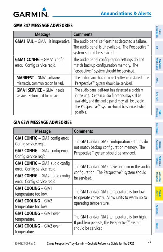
Cirrus Perspective™ by Garmin – Cockpit Reference Guide for the SR22190-00821-00 Rev. C 73
annunciations & alerts
FlightInstrum
entsEIS
Nav/Com
/XPD
R/Audio
AFCS
GPS N
avFlight
PlanningProcedures
Hazard
AvoidanceA
dditionalFeatures
Abnorm
alO
perationA
nnun/A
lertsA
ppendixIndex
gma 347 message advisories
Message CommentsGMA1 FAIL – GMA1 is inoperative. The audio panel self-test has detected a failure.
The audio panel is unavailable. The Perspective™ system should be serviced.
GMA1 CONFIG – GMA1 config error. Config service req’d.
The audio panel configuration settings do not match backup configuration memory. The Perspective™ system should be serviced.
MANIFEST – GMA1 software mismatch, communication halted.
The audio panel has incorrect software installed. The Perspective™ system should be serviced.
GMA1 SERVICE – GMA1 needs service. Return unit for repair.
The audio panel self-test has detected a problem in the unit. Certain audio functions may still be available, and the audio panel may still be usable. The Perspective™ system should be serviced when possible.
gia 63W message advisories
Message CommentsGIA1 CONFIG – GIA1 config error. Config service req’d. The GIA1 and/or GIA2 configuration settings do
not match backup configuration memory. The Perspective™ system should be serviced.GIA2 CONFIG – GIA2 config error.
Config service req’d.GIA1 CONFIG – GIA1 audio config error. Config service req’d. The GIA1 and/or GIA2 have an error in the audio
configuration. The Perspective™ system should be serviced.GIA2 CONFIG – GIA2 audio config
error. Config service req’d.GIA1 COOLING – GIA1 temperature too low. The GIA1 and/or GIA2 temperature is too low
to operate correctly. Allow units to warm up to operating temperature.GIA2 COOLING – GIA2
temperature too low.GIA1 COOLING – GIA1 over temperature. The GIA1 and/or GIA2 temperature is too high.
If problem persists, the Perspective™ system should be serviced.GIA2 COOLING – GIA2 over
temperature.
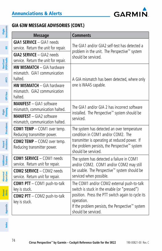
Cirrus Perspective™ by Garmin – Cockpit Reference Guide for the SR22 190-00821-00 Rev. C74
annunciations & alerts
Flig
htIn
stru
men
tsEI
SN
av/C
om/
XPD
R/A
udio
AFC
SG
PS N
avFl
ight
Plan
ning
Proc
edur
esH
azar
dAv
oida
nce
Add
ition
alFe
atur
esA
bnor
mal
Ope
ratio
nA
nnun
/A
lert
sA
ppen
dix
Inde
x
gia 63W message advisories (Cont.)
Message CommentsGIA1 SERVICE – GIA1 needs service. Return the unit for repair. The GIA1 and/or GIA2 self-test has detected a
problem in the unit. The Perspective™ system should be serviced.GIA2 SERVICE – GIA2 needs
service. Return the unit for repair.
HW MISMATCH – GIA hardware mismatch. GIA1 communication halted. A GIA mismatch has been detected, where only
one is WAAS capable.HW MISMATCH – GIA hardware mismatch. GIA2 communication halted.MANIFEST – GIA1 software mismatch, communication halted. The GIA1 and/or GIA 2 has incorrect software
installed. The Perspective™ system should be serviced.MANIFEST – GIA2 software
mismatch, communication halted.
COM1 TEMP – COM1 over temp. Reducing transmitter power.
The system has detected an over temperature condition in COM1 and/or COM2. The transmitter is operating at reduced power. If the problem persists, the Perspective™ system should be serviced.
COM2 TEMP – COM2 over temp. Reducing transmitter power.
COM1 SERVICE – COM1 needs service. Return unit for repair.
The system has detected a failure in COM1 and/or COM2. COM1 and/or COM2 may still be usable. The Perspective™ system should be serviced when possible.
COM2 SERVICE – COM2 needs service. Return unit for repair.
COM1 PTT – COM1 push-to-talk key is stuck.
The COM1 and/or COM2 external push-to-talk switch is stuck in the enable (or “pressed”) position. Press the PTT switch again to cycle its operation. If the problem persists, the Perspective™ system should be serviced.
COM2 PTT – COM2 push-to-talk key is stuck.
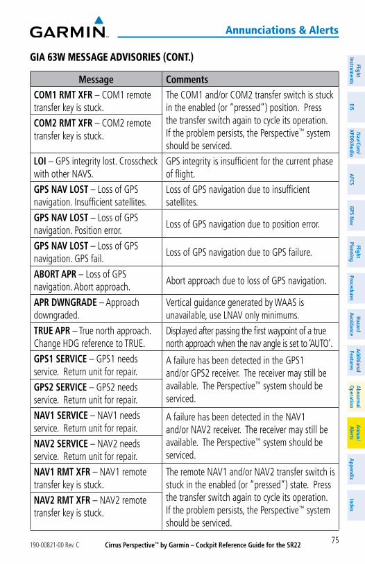
Cirrus Perspective™ by Garmin – Cockpit Reference Guide for the SR22190-00821-00 Rev. C 75
annunciations & alerts
FlightInstrum
entsEIS
Nav/Com
/XPD
R/Audio
AFCS
GPS N
avFlight
PlanningProcedures
Hazard
AvoidanceA
dditionalFeatures
Abnorm
alO
perationA
nnun/A
lertsA
ppendixIndex
gia 63W message advisories (Cont.)
Message CommentsCOM1 RMT XFR – COM1 remote transfer key is stuck.
The COM1 and/or COM2 transfer switch is stuck in the enabled (or “pressed”) position. Press the transfer switch again to cycle its operation. If the problem persists, the Perspective™ system should be serviced.
COM2 RMT XFR – COM2 remote transfer key is stuck.
LOI – GPS integrity lost. Crosscheck with other NAVS.
GPS integrity is insufficient for the current phase of flight.
GPS NAV LOST – Loss of GPS navigation. Insufficient satellites.
Loss of GPS navigation due to insufficient satellites.
GPS NAV LOST – Loss of GPS navigation. Position error.
Loss of GPS navigation due to position error.
GPS NAV LOST – Loss of GPS navigation. GPS fail.
Loss of GPS navigation due to GPS failure.
ABORT APR – Loss of GPS navigation. Abort approach.
Abort approach due to loss of GPS navigation.
APR DWNGRADE – Approach downgraded.
Vertical guidance generated by WAAS is unavailable, use LNAV only minimums.
TRUE APR – True north approach. Change HDG reference to TRUE.
Displayed after passing the first waypoint of a true north approach when the nav angle is set to ‘AUTO’.
GPS1 SERVICE – GPS1 needs service. Return unit for repair.
A failure has been detected in the GPS1 and/or GPS2 receiver. The receiver may still be available. The Perspective™ system should be serviced.
GPS2 SERVICE – GPS2 needs service. Return unit for repair.
NAV1 SERVICE – NAV1 needs service. Return unit for repair.
A failure has been detected in the NAV1 and/or NAV2 receiver. The receiver may still be available. The Perspective™ system should be serviced.
NAV2 SERVICE – NAV2 needs service. Return unit for repair.
NAV1 RMT XFR – NAV1 remote transfer key is stuck.
The remote NAV1 and/or NAV2 transfer switch is stuck in the enabled (or “pressed”) state. Press the transfer switch again to cycle its operation. If the problem persists, the Perspective™ system should be serviced.
NAV2 RMT XFR – NAV2 remote transfer key is stuck.
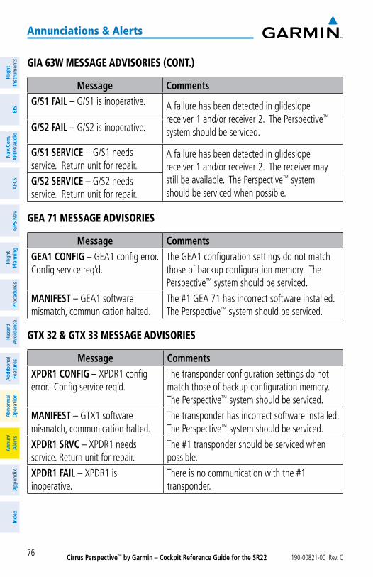
Cirrus Perspective™ by Garmin – Cockpit Reference Guide for the SR22 190-00821-00 Rev. C76
annunciations & alerts
Flig
htIn
stru
men
tsEI
SN
av/C
om/
XPD
R/A
udio
AFC
SG
PS N
avFl
ight
Plan
ning
Proc
edur
esH
azar
dAv
oida
nce
Add
ition
alFe
atur
esA
bnor
mal
Ope
ratio
nA
nnun
/A
lert
sA
ppen
dix
Inde
x
gia 63W message advisories (Cont.)
Message CommentsG/S1 FAIL – G/S1 is inoperative. A failure has been detected in glideslope
receiver 1 and/or receiver 2. The Perspective™ system should be serviced.G/S2 FAIL – G/S2 is inoperative.
G/S1 SERVICE – G/S1 needs service. Return unit for repair.
A failure has been detected in glideslope receiver 1 and/or receiver 2. The receiver may still be available. The Perspective™ system should be serviced when possible.
G/S2 SERVICE – G/S2 needs service. Return unit for repair.
gea 71 message advisories
Message CommentsGEA1 CONFIG – GEA1 config error. Config service req’d.
The GEA1 configuration settings do not match those of backup configuration memory. The Perspective™ system should be serviced.
MANIFEST – GEA1 software mismatch, communication halted.
The #1 GEA 71 has incorrect software installed. The Perspective™ system should be serviced.
gtx 32 & gtx 33 message advisories
Message CommentsXPDR1 CONFIG – XPDR1 config error. Config service req’d.
The transponder configuration settings do not match those of backup configuration memory. The Perspective™ system should be serviced.
MANIFEST – GTX1 software mismatch, communication halted.
The transponder has incorrect software installed. The Perspective™ system should be serviced.
XPDR1 SRVC – XPDR1 needs service. Return unit for repair.
The #1 transponder should be serviced when possible.
XPDR1 FAIL – XPDR1 is inoperative.
There is no communication with the #1 transponder.
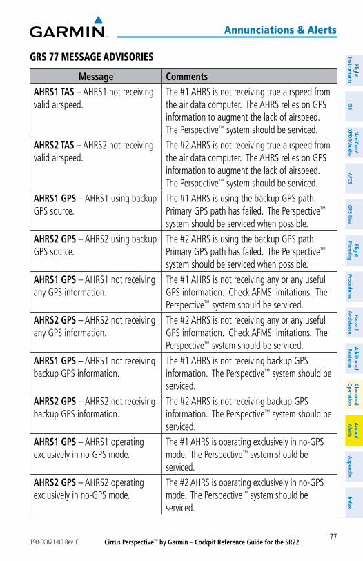
Cirrus Perspective™ by Garmin – Cockpit Reference Guide for the SR22190-00821-00 Rev. C 77
annunciations & alerts
FlightInstrum
entsEIS
Nav/Com
/XPD
R/Audio
AFCS
GPS N
avFlight
PlanningProcedures
Hazard
AvoidanceA
dditionalFeatures
Abnorm
alO
perationA
nnun/A
lertsA
ppendixIndex
grs 77 message advisories
Message CommentsAHRS1 TAS – AHRS1 not receiving valid airspeed.
The #1 AHRS is not receiving true airspeed from the air data computer. The AHRS relies on GPS information to augment the lack of airspeed. The Perspective™ system should be serviced.
AHRS2 TAS – AHRS2 not receiving valid airspeed.
The #2 AHRS is not receiving true airspeed from the air data computer. The AHRS relies on GPS information to augment the lack of airspeed. The Perspective™ system should be serviced.
AHRS1 GPS – AHRS1 using backup GPS source.
The #1 AHRS is using the backup GPS path. Primary GPS path has failed. The Perspective™ system should be serviced when possible.
AHRS2 GPS – AHRS2 using backup GPS source.
The #2 AHRS is using the backup GPS path. Primary GPS path has failed. The Perspective™ system should be serviced when possible.
AHRS1 GPS – AHRS1 not receiving any GPS information.
The #1 AHRS is not receiving any or any useful GPS information. Check AFMS limitations. The Perspective™ system should be serviced.
AHRS2 GPS – AHRS2 not receiving any GPS information.
The #2 AHRS is not receiving any or any useful GPS information. Check AFMS limitations. The Perspective™ system should be serviced.
AHRS1 GPS – AHRS1 not receiving backup GPS information.
The #1 AHRS is not receiving backup GPS information. The Perspective™ system should be serviced.
AHRS2 GPS – AHRS2 not receiving backup GPS information.
The #2 AHRS is not receiving backup GPS information. The Perspective™ system should be serviced.
AHRS1 GPS – AHRS1 operating exclusively in no-GPS mode.
The #1 AHRS is operating exclusively in no-GPS mode. The Perspective™ system should be serviced.
AHRS2 GPS – AHRS2 operating exclusively in no-GPS mode.
The #2 AHRS is operating exclusively in no-GPS mode. The Perspective™ system should be serviced.
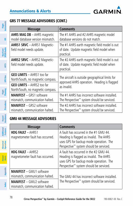
Cirrus Perspective™ by Garmin – Cockpit Reference Guide for the SR22 190-00821-00 Rev. C78
annunciations & alerts
Flig
htIn
stru
men
tsEI
SN
av/C
om/
XPD
R/A
udio
AFC
SG
PS N
avFl
ight
Plan
ning
Proc
edur
esH
azar
dAv
oida
nce
Add
ition
alFe
atur
esA
bnor
mal
Ope
ratio
nA
nnun
/A
lert
sA
ppen
dix
Inde
x
grs 77 message advisories (Cont.)
Message CommentsAHRS MAG DB – AHRS magnetic model database version mismatch.
The #1 AHRS and #2 AHRS magnetic model database versions do not match.
AHRS1 SRVC – AHRS1 Magnetic-field model needs update.
The #1 AHRS earth magnetic field model is out of date. Update magnetic field model when practical.
AHRS2 SRVC – AHRS2 Magnetic-field model needs update.
The #2 AHRS earth magnetic field model is out of date. Update magnetic field model when practical.
GEO LIMITS – AHRS1 too far North/South, no magnetic compass. The aircraft is outside geographical limits for
approved AHRS operation. Heading is flagged as invalid. GEO LIMITS – AHRS2 too far
North/South, no magnetic compass.MANIFEST – GRS1 software mismatch, communication halted.
The #1 AHRS has incorrect software installed. The Perspective™ system should be serviced.
MANIFEST – GRS2 software mismatch, communication halted.
The #2 AHRS has incorrect software installed. The Perspective™ system should be serviced.
gmu 44 message advisories
Message CommentsHDG FAULT – AHRS1 magnetometer fault has occurred.
A fault has occurred in the #1 GMU 44. Heading is flagged as invalid. The AHRS uses GPS for backup mode operation. The Perspective™ system should be serviced.
HDG FAULT – AHRS2 magnetometer fault has occurred.
A fault has occurred in the #2 GMU 44. Heading is flagged as invalid. The AHRS uses GPS for backup mode operation. The Perspective™ system should be serviced.
MANIFEST – GMU1 software mismatch, communication halted. The GMU 44 has incorrect software installed.
The Perspective™ system should be serviced.MANIFEST – GMU2 software mismatch, communication halted.
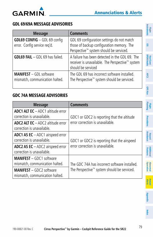
Cirrus Perspective™ by Garmin – Cockpit Reference Guide for the SR22190-00821-00 Rev. C 79
annunciations & alerts
FlightInstrum
entsEIS
Nav/Com
/XPD
R/Audio
AFCS
GPS N
avFlight
PlanningProcedures
Hazard
AvoidanceA
dditionalFeatures
Abnorm
alO
perationA
nnun/A
lertsA
ppendixIndex
gdl 69/69a message advisories
Message CommentsGDL69 CONFIG – GDL 69 config error. Config service req’d.
GDL 69 configuration settings do not match those of backup configuration memory. The Perspective™ system should be serviced.
GDL69 FAIL – GDL 69 has failed. A failure has been detected in the GDL 69. The receiver is unavailable. The Perspective™ system should be serviced
MANIFEST – GDL software mismatch, communication halted.
The GDL 69 has incorrect software installed. The Perspective™ system should be serviced.
gdC 74a message advisories
Message CommentsADC1 ALT EC – ADC1 altitude error correction is unavailable. GDC1 or GDC2 is reporting that the altitude
error correction is unavailable.ADC2 ALT EC – ADC2 altitude error correction is unavailable.ADC1 AS EC – ADC1 airspeed error correction is unavailable. GDC1 or GDC2 is reporting that the airspeed
error correction is unavailable.ADC2 AS EC – ADC2 airspeed error correction is unavailable.MANIFEST – GDC1 software mismatch, communication halted. The GDC 74A has incorrect software installed.
The Perspective™ system should be serviced.MANIFEST – GDC2 software mismatch, communication halted.
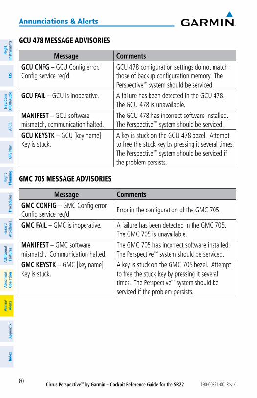
Cirrus Perspective™ by Garmin – Cockpit Reference Guide for the SR22 190-00821-00 Rev. C80
annunciations & alerts
Flig
htIn
stru
men
tsEI
SN
av/C
om/
XPD
R/A
udio
AFC
SG
PS N
avFl
ight
Plan
ning
Proc
edur
esH
azar
dAv
oida
nce
Add
ition
alFe
atur
esA
bnor
mal
Ope
ratio
nA
nnun
/A
lert
sA
ppen
dix
Inde
x
gCu 478 message advisories
Message CommentsGCU CNFG – GCU Config error. Config service req’d.
GCU 478 configuration settings do not match those of backup configuration memory. The Perspective™ system should be serviced.
GCU FAIL – GCU is inoperative. A failure has been detected in the GCU 478. The GCU 478 is unavailable.
MANIFEST – GCU software mismatch, communication halted.
The GCU 478 has incorrect software installed. The Perspective™ system should be serviced.
GCU KEYSTK – GCU [key name] Key is stuck.
A key is stuck on the GCU 478 bezel. Attempt to free the stuck key by pressing it several times. The Perspective™ system should be serviced if the problem persists.
gmC 705 message advisories
Message CommentsGMC CONFIG – GMC Config error. Config service req’d.
Error in the configuration of the GMC 705.
GMC FAIL – GMC is inoperative. A failure has been detected in the GMC 705. The GMC 705 is unavailable.
MANIFEST – GMC software mismatch. Communication halted.
The GMC 705 has incorrect software installed. The Perspective™ system should be serviced.
GMC KEYSTK – GMC [key name] Key is stuck.
A key is stuck on the GMC 705 bezel. Attempt to free the stuck key by pressing it several times. The Perspective™ system should be serviced if the problem persists.
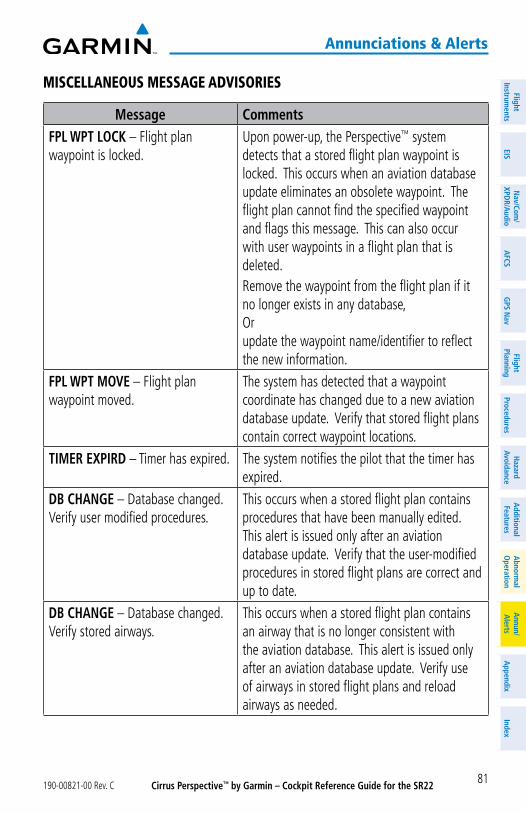
Cirrus Perspective™ by Garmin – Cockpit Reference Guide for the SR22190-00821-00 Rev. C 81
annunciations & alerts
FlightInstrum
entsEIS
Nav/Com
/XPD
R/Audio
AFCS
GPS N
avFlight
PlanningProcedures
Hazard
AvoidanceA
dditionalFeatures
Abnorm
alO
perationA
nnun/A
lertsA
ppendixIndex
misCellaneous message advisories
Message CommentsFPL WPT LOCK – Flight plan waypoint is locked.
Upon power-up, the Perspective™ system detects that a stored flight plan waypoint is locked. This occurs when an aviation database update eliminates an obsolete waypoint. The flight plan cannot find the specified waypoint and flags this message. This can also occur with user waypoints in a flight plan that is deleted.Remove the waypoint from the flight plan if it no longer exists in any database, Or update the waypoint name/identifier to reflect the new information.
FPL WPT MOVE – Flight plan waypoint moved.
The system has detected that a waypoint coordinate has changed due to a new aviation database update. Verify that stored flight plans contain correct waypoint locations.
TIMER EXPIRD – Timer has expired. The system notifies the pilot that the timer has expired.
DB CHANGE – Database changed. Verify user modified procedures.
This occurs when a stored flight plan contains procedures that have been manually edited. This alert is issued only after an aviation database update. Verify that the user-modified procedures in stored flight plans are correct and up to date.
DB CHANGE – Database changed. Verify stored airways.
This occurs when a stored flight plan contains an airway that is no longer consistent with the aviation database. This alert is issued only after an aviation database update. Verify use of airways in stored flight plans and reload airways as needed.
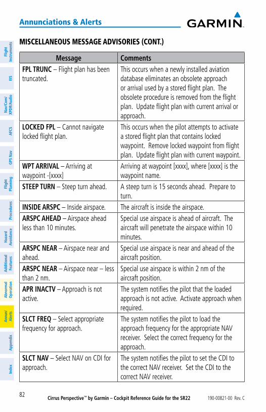
Cirrus Perspective™ by Garmin – Cockpit Reference Guide for the SR22 190-00821-00 Rev. C82
annunciations & alerts
Flig
htIn
stru
men
tsEI
SN
av/C
om/
XPD
R/A
udio
AFC
SG
PS N
avFl
ight
Plan
ning
Proc
edur
esH
azar
dAv
oida
nce
Add
ition
alFe
atur
esA
bnor
mal
Ope
ratio
nA
nnun
/A
lert
sA
ppen
dix
Inde
x
misCellaneous message advisories (Cont.)
Message CommentsFPL TRUNC – Flight plan has been truncated.
This occurs when a newly installed aviation database eliminates an obsolete approach or arrival used by a stored flight plan. The obsolete procedure is removed from the flight plan. Update flight plan with current arrival or approach.
LOCKED FPL – Cannot navigate locked flight plan.
This occurs when the pilot attempts to activate a stored flight plan that contains locked waypoint. Remove locked waypoint from flight plan. Update flight plan with current waypoint.
WPT ARRIVAL – Arriving at waypoint -[xxxx]
Arriving at waypoint [xxxx], where [xxxx] is the waypoint name.
STEEP TURN – Steep turn ahead. A steep turn is 15 seconds ahead. Prepare to turn.
INSIDE ARSPC – Inside airspace. The aircraft is inside the airspace.ARSPC AHEAD – Airspace ahead less than 10 minutes.
Special use airspace is ahead of aircraft. The aircraft will penetrate the airspace within 10 minutes.
ARSPC NEAR – Airspace near and ahead.
Special use airspace is near and ahead of the aircraft position.
ARSPC NEAR – Airspace near – less than 2 nm.
Special use airspace is within 2 nm of the aircraft position.
APR INACTV – Approach is not active.
The system notifies the pilot that the loaded approach is not active. Activate approach when required.
SLCT FREQ – Select appropriate frequency for approach.
The system notifies the pilot to load the approach frequency for the appropriate NAV receiver. Select the correct frequency for the approach.
SLCT NAV – Select NAV on CDI for approach.
The system notifies the pilot to set the CDI to the correct NAV receiver. Set the CDI to the correct NAV receiver.
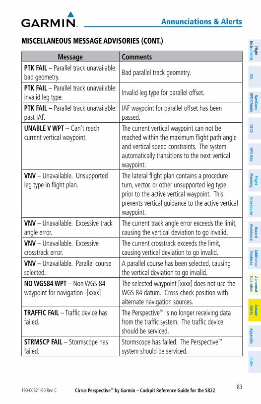
Cirrus Perspective™ by Garmin – Cockpit Reference Guide for the SR22190-00821-00 Rev. C 83
annunciations & alerts
FlightInstrum
entsEIS
Nav/Com
/XPD
R/Audio
AFCS
GPS N
avFlight
PlanningProcedures
Hazard
AvoidanceA
dditionalFeatures
Abnorm
alO
perationA
nnun/A
lertsA
ppendixIndex
misCellaneous message advisories (Cont.)
Message CommentsPTK FAIL – Parallel track unavailable: bad geometry.
Bad parallel track geometry.
PTK FAIL – Parallel track unavailable: invalid leg type.
Invalid leg type for parallel offset.
PTK FAIL – Parallel track unavailable: past IAF.
IAF waypoint for parallel offset has been passed.
UNABLE V WPT – Can’t reach current vertical waypoint.
The current vertical waypoint can not be reached within the maximum flight path angle and vertical speed constraints. The system automatically transitions to the next vertical waypoint.
VNV – Unavailable. Unsupported leg type in flight plan.
The lateral flight plan contains a procedure turn, vector, or other unsupported leg type prior to the active vertical waypoint. This prevents vertical guidance to the active vertical waypoint.
VNV – Unavailable. Excessive track angle error.
The current track angle error exceeds the limit, causing the vertical deviation to go invalid.
VNV – Unavailable. Excessive crosstrack error.
The current crosstrack exceeds the limit, causing vertical deviation to go invalid.
VNV – Unavailable. Parallel course selected.
A parallel course has been selected, causing the vertical deviation to go invalid.
NO WGS84 WPT – Non WGS 84 waypoint for navigation -[xxxx]
The selected waypoint [xxxx] does not use the WGS 84 datum. Cross-check position with alternate navigation sources.
TRAFFIC FAIL – Traffic device has failed.
The Perspective™ is no longer receiving data from the traffic system. The traffic device should be serviced.
STRMSCP FAIL – Stormscope has failed.
Stormscope has failed. The Perspective™ system should be serviced.
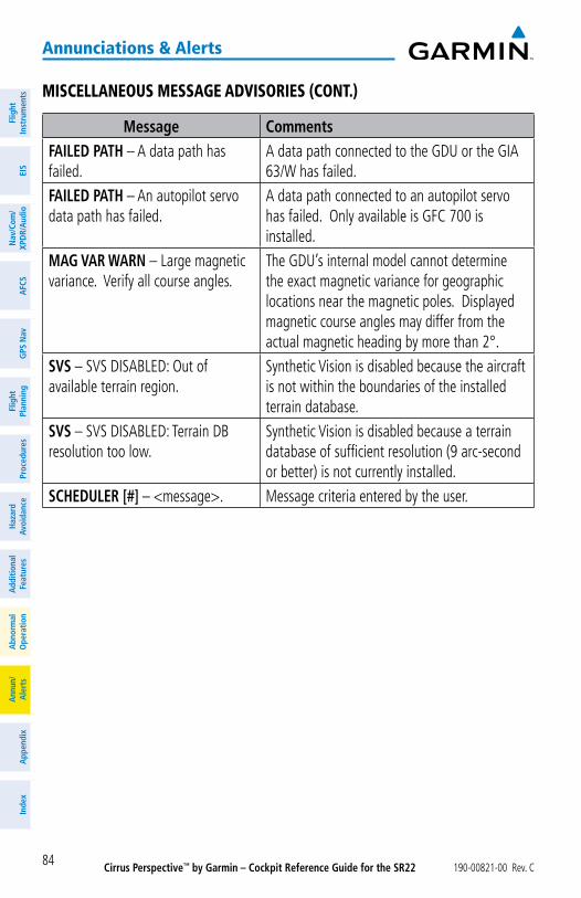
Cirrus Perspective™ by Garmin – Cockpit Reference Guide for the SR22 190-00821-00 Rev. C84
annunciations & alerts
Flig
htIn
stru
men
tsEI
SN
av/C
om/
XPD
R/A
udio
AFC
SG
PS N
avFl
ight
Plan
ning
Proc
edur
esH
azar
dAv
oida
nce
Add
ition
alFe
atur
esA
bnor
mal
Ope
ratio
nA
nnun
/A
lert
sA
ppen
dix
Inde
x
misCellaneous message advisories (Cont.)
Message CommentsFAILED PATH – A data path has failed.
A data path connected to the GDU or the GIA 63/W has failed.
FAILED PATH – An autopilot servo data path has failed.
A data path connected to an autopilot servo has failed. Only available is GFC 700 is installed.
MAG VAR WARN – Large magnetic variance. Verify all course angles.
The GDU’s internal model cannot determine the exact magnetic variance for geographic locations near the magnetic poles. Displayed magnetic course angles may differ from the actual magnetic heading by more than 2°.
SVS – SVS DISABLED: Out of available terrain region.
Synthetic Vision is disabled because the aircraft is not within the boundaries of the installed terrain database.
SVS – SVS DISABLED: Terrain DB resolution too low.
Synthetic Vision is disabled because a terrain database of sufficient resolution (9 arc-second or better) is not currently installed.
SCHEDULER [#] – <message>. Message criteria entered by the user.
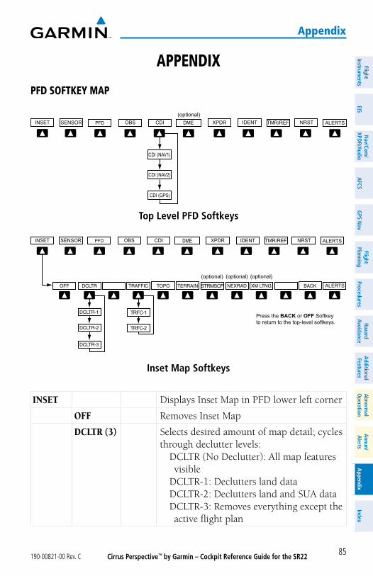
Cirrus Perspective™ by Garmin – Cockpit Reference Guide for the SR22190-00821-00 Rev. C
appendix
85
FlightInstrum
entsEIS
Nav/Com
/XPD
R/Audio
AFCS
GPS N
avFlight
PlanningProcedures
Hazard
AvoidanceA
dditionalFeatures
Abnorm
alO
perationA
nnun/A
lertsA
ppendixIndex
appendix
pFd soFtKey map
Top Level PFD Softkeys
ALERTS(optional)
Inset Map Softkeys
Press the BACK or OFF Softkeyto return to the top-level softkeys.
TRFC-1
TRFC-2
ALERTS
ALERTS DME
STRMSCP
INSET Displays Inset Map in PFD lower left corner
OFF Removes Inset Map
DCLTR (3) Selects desired amount of map detail; cycles through declutter levels:
DCLTR (No Declutter): All map features visible
DCLTR-1: Declutters land dataDCLTR-2: Declutters land and SUA dataDCLTR-3: Removes everything except the active flight plan
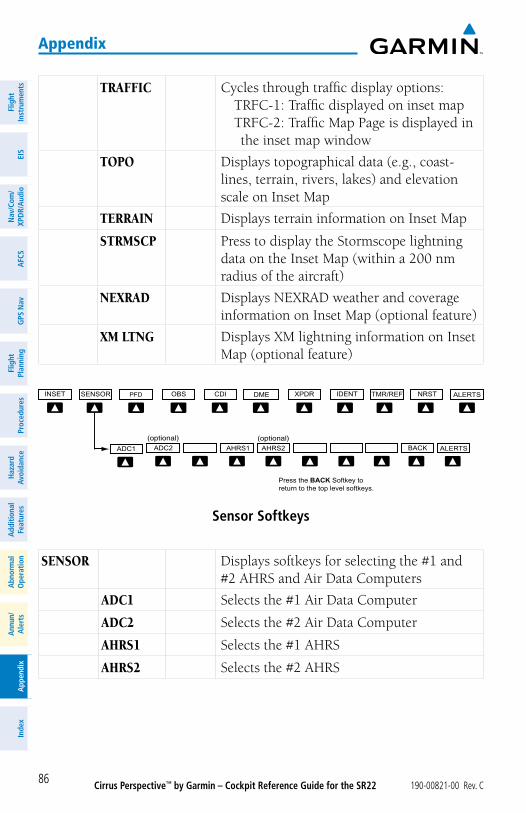
Cirrus Perspective™ by Garmin – Cockpit Reference Guide for the SR22 190-00821-00 Rev. C
appendix
86
Flig
htIn
stru
men
tsEI
SN
av/C
om/
XPD
R/A
udio
AFC
SG
PS N
avFl
ight
Plan
ning
Proc
edur
esH
azar
dAv
oida
nce
Add
ition
alFe
atur
esA
bnor
mal
Ope
ratio
nA
nnun
/A
lert
sA
ppen
dix
Inde
x
TRAFFIC Cycles through traffic display options:TRFC-1: Traffic displayed on inset mapTRFC-2: Traffic Map Page is displayed in the inset map window
TOPO Displays topographical data (e.g., coast-lines, terrain, rivers, lakes) and elevation scale on Inset Map
TERRAIN Displays terrain information on Inset Map
STRMSCP Press to display the Stormscope lightning data on the Inset Map (within a 200 nm radius of the aircraft)
NEXRAD Displays NEXRAD weather and coverage information on Inset Map (optional feature)
XM LTNG Displays XM lightning information on Inset Map (optional feature)
Sensor Softkeys
Press the BACK Softkey toreturn to the top level softkeys.
BACKADC2ADC1 AHRS1 AHRS2 ALERTS
ALERTS
SENSOR Displays softkeys for selecting the #1 and #2 AHRS and Air Data Computers
ADC1 Selects the #1 Air Data Computer
ADC2 Selects the #2 Air Data Computer
AHRS1 Selects the #1 AHRS
AHRS2 Selects the #2 AHRS
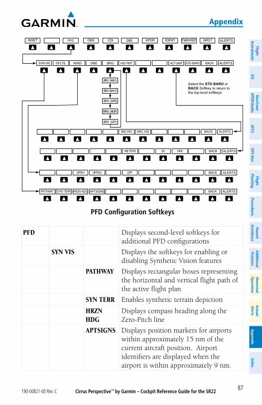
Cirrus Perspective™ by Garmin – Cockpit Reference Guide for the SR22190-00821-00 Rev. C
appendix
87
FlightInstrum
entsEIS
Nav/Com
/XPD
R/Audio
AFCS
GPS N
avFlight
PlanningProcedures
Hazard
AvoidanceA
dditionalFeatures
Abnorm
alO
perationA
nnun/A
lertsA
ppendixIndex
PFD Configuration Softkeys
Select the STD BARO orBACK Softkey to return tothe top-level softkeys
ALT UNIT
METERS IN HPA
DME ALERTS
ALERTS
ALERTS
ALERTS
BACK ALERTS360 HSI ARC HSI
HSI FMTSYN VIS
SYN TERR HRZN HDGPATHWAY APTSIGNS ALERTS
2
PFD Displays second-level softkeys for additional PFD configurations
SYN VIS Displays the softkeys for enabling or disabling Synthetic Vision features
PATHWAY Displays rectangular boxes representing the horizontal and vertical flight path of the active flight plan
SYN TERR Enables synthetic terrain depiction
HRZN HDG
Displays compass heading along the Zero-Pitch line
APTSIGNS Displays position markers for airports within approximately 15 nm of the current aircraft position. Airport identifiers are displayed when the airport is within approximately 9 nm.
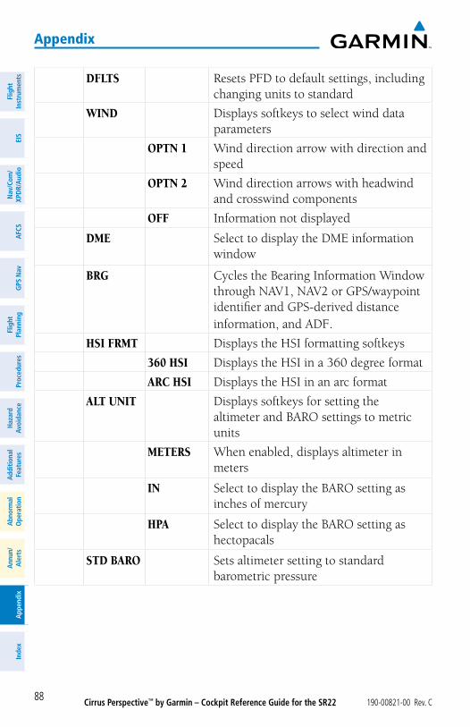
Cirrus Perspective™ by Garmin – Cockpit Reference Guide for the SR22 190-00821-00 Rev. C
appendix
88
Flig
htIn
stru
men
tsEI
SN
av/C
om/
XPD
R/A
udio
AFC
SG
PS N
avFl
ight
Plan
ning
Proc
edur
esH
azar
dAv
oida
nce
Add
ition
alFe
atur
esA
bnor
mal
Ope
ratio
nA
nnun
/A
lert
sA
ppen
dix
Inde
x
DFLTS Resets PFD to default settings, including changing units to standard
WIND Displays softkeys to select wind data parameters
OPTN 1 Wind direction arrow with direction and speed
OPTN 2 Wind direction arrows with headwind and crosswind components
OFF Information not displayed
DME Select to display the DME information window
BRG Cycles the Bearing Information Window through NAV1, NAV2 or GPS/waypoint identifier and GPS-derived distance information, and ADF.
HSI FRMT Displays the HSI formatting softkeys
360 HSI Displays the HSI in a 360 degree format
ARC HSI Displays the HSI in an arc format
ALT UNIT Displays softkeys for setting the altimeter and BARO settings to metric units
METERS When enabled, displays altimeter in meters
IN Select to display the BARO setting as inches of mercury
HPA Select to display the BARO setting as hectopacals
STD BARO Sets altimeter setting to standard barometric pressure
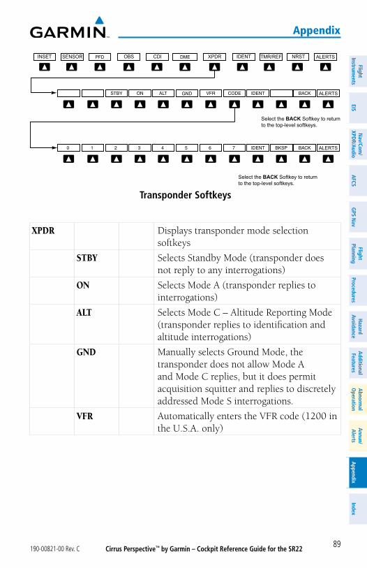
Cirrus Perspective™ by Garmin – Cockpit Reference Guide for the SR22190-00821-00 Rev. C
appendix
89
FlightInstrum
entsEIS
Nav/Com
/XPD
R/Audio
AFCS
GPS N
avFlight
PlanningProcedures
Hazard
AvoidanceA
dditionalFeatures
Abnorm
alO
perationA
nnun/A
lertsA
ppendixIndex
Transponder Softkeys
Select the BACK Softkey to returnto the top-level softkeys.
Select the BACK Softkey to returnto the top-level softkeys.
ALERTS
ALERTS
ALERTS
XPDR Displays transponder mode selection softkeys
STBY Selects Standby Mode (transponder does not reply to any interrogations)
ON Selects Mode A (transponder replies to interrogations)
ALT Selects Mode C – Altitude Reporting Mode (transponder replies to identification and altitude interrogations)
GND Manually selects Ground Mode, the transponder does not allow Mode A and Mode C replies, but it does permit acquisition squitter and replies to discretely addressed Mode S interrogations.
VFR Automatically enters the VFR code (1200 in the U.S.A. only)
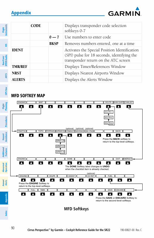
Cirrus Perspective™ by Garmin – Cockpit Reference Guide for the SR22 190-00821-00 Rev. C
appendix
90
Flig
htIn
stru
men
tsEI
SN
av/C
om/
XPD
R/A
udio
AFC
SG
PS N
avFl
ight
Plan
ning
Proc
edur
esH
azar
dAv
oida
nce
Add
ition
alFe
atur
esA
bnor
mal
Ope
ratio
nA
nnun
/A
lert
sA
ppen
dix
Inde
x
CODE Displays transponder code selection softkeys 0-7
0 — 7 Use numbers to enter code
BKSP Removes numbers entered, one at a time
IDENT Activates the Special Position Identification (SPI) pulse for 18 seconds, identifying the transponder return on the ATC screen
TMR/REF Displays Timer/References Window
NRST Displays Nearest Airports Window
ALERTS Displays the Alerts Window
mFd soFtKey map
MFD Softkeys
CHKLISTDCLTRENGINE
DCLTR-2
DCLTR-3
DCLTR-1
MAP
The DONE Softkey label changes to UNDOwhen the checklist item is already checked.
EXITDONEENGINE EMERGCY
BACKTOPO
(optional)
NEXRADTRAFFIC TERRAIN
(optional)
XM LTNG
Press the BACK softkey toreturn to the top-level softkeys.
AIRWY LO
AIRWY HI
AIRWY ON
AIRWAYS
SHW CHRT
(optional)
STRMSCP
Press the ENGINE Softkey toreturn to the top-level softkeys.
Press the SAVE or DISCARD Softkey toreturn to the second-level softkeys.
SAVEFULL TABS
ENGINE FUELASSIST CO RSTDCLTR
DISCARD
(optional)
Cirrus Perspective™ by Garmin – Cockpit Reference Guide for the SR22190-00821-00 Rev. C
appendix
91
FlightInstrum
entsEIS
Nav/Com
/XPD
R/Audio
AFCS
GPS N
avFlight
PlanningProcedures
Hazard
AvoidanceA
dditionalFeatures
Abnorm
alO
perationA
nnun/A
lertsA
ppendixIndex
ENGINE Displays EIS - Engine Page and second-level engine softkeys; press again to exit page
DCLTR Declutters the Engine Temperatures Box removing bars and temperatures readouts
ASSIST Identifies temperature peaks
CO RST Resets the CO Guardian
FUEL Accesses the Initial Usable Fuel Page
FULL Resets fuel totalizer to full (usable fuel)
TABS Resets fuel totalizer to tabs (usable fuel)
SAVE Saves the usable fuel amount as displayed on the Initial Usable Fuel Page
DISCARD Removes the usable fuel amount shown on the Initial Usable Fuel Page
MAP Enables second-level Navigation Map softkeys
TRAFFIC Displays traffic information on Navigation Map
TOPO Displays topographical data (e.g., coastlines, terrain, rivers, lakes) and elevation scale on Navigation Map
TERRAIN Displays terrain information on Navigation Map
AIRWAYS Displays airways on the map; cycles through the following: AIRWAYS: No airways are displayed AIRWY ON: All airways are displayed AIRWY LO: Only low altitude airways are displayed AIRWY HI: Only high altitude airways are displayed
STRMSCP Displays Stormscope lightning on the Navigation Map (optional feature). Stormscope lightning and XM lightning are mutually exclusive when displaying on the Navigation Map.
NEXRAD Displays NEXRAD weather and coverage information on Navigation Map (optional feature)
XM LTNG Displays XM lightning information on Navigation Map (optional feature)
Cirrus Perspective™ by Garmin – Cockpit Reference Guide for the SR22 190-00821-00 Rev. C
appendix
92
Flig
htIn
stru
men
tsEI
SN
av/C
om/
XPD
R/A
udio
AFC
SG
PS N
avFl
ight
Plan
ning
Proc
edur
esH
azar
dAv
oida
nce
Add
ition
alFe
atur
esA
bnor
mal
Ope
ratio
nA
nnun
/A
lert
sA
ppen
dix
Inde
x
BACK Returns to top-level softkeys
DCLTR (3) Selects desired amount of map detail; cycles through declutter levels:
DCLTR (No Declutter): All map features visibleDCLTR-1: Declutters land dataDCLTR-2: Declutters land and SUA dataDCLTR-3: Removes everything except the active flight plan
SHW CHRT When available, displays optional airport and terminal procedure charts
CHKLIST When available, displays optional checklists
Cirrus Perspective™ by Garmin – Cockpit Reference Guide for the SR22190-00821-00 Rev. C
index
Index-1
FlightInstrum
entsEIS
Nav/Com
/XPD
R/Audio
AFCS
GPS N
avFlight
PlanningProcedures
Hazard
AvoidanceA
dditionalFeatures
Abnorm
alO
perationA
nnun/A
lertsA
ppendixIndex
A
Activate a flight plan 22Active Channel 54ADF 13, 14Advisory alerts 64AHRS 77, 78, 80Airport Signs 51, 52Airways 91Altimeter setting 1, 58AP 64Assist, engine leaning 9–11Audio panel controls
NAV1, NAV2 14
B
Barometric Altitude Minimums 2
C
Caution alerts 62CDI 1, 14, 82Cell 41, 42Cell mode 42Channel Presets 55ChartView 52, 53Clearance player 15Clearance Recorder 15Code selection softkeys 13COM 13, 14, 15, 57
D
DCLTR Softkey 52Dead Reckoning 59Declutter 58, 85, 92Designated altitudes 25Direct-to 21DME 13, 14DR mode 59, 60
E
Edit a flight plan 33Enable Terrain 48Exhaust Gas Temperature (EGT) 10–11
F
FD 64Flight Director 17Flight path marker 51FliteCharts® 52, 53Frequency Transfer 14Fuel 7, 8, 10, 28, 91Fuel calculations 8, 10Fuel flow 5, 6, 8Fuel totalizer 8, 91
H
Horizon heading 51
I
Inhibit 47, 49Inhibit TAWS 49Inhibit Terrain 47, 48Inset Map 85, 86Intercom isolation 14IOI 65, 67
J
Jeppesen 53
L
Lightning 41, 42, 86
M
Map panning 43Message advisories 69 – 78, 80 – 84MET 64
Cirrus Perspective™ by Garmin – Cockpit Reference Guide for the SR22 190-00821-00 Rev. C
index
Index-2
Flig
htIn
stru
men
tsEI
SN
av/C
om/
XPD
R/A
udio
AFC
SG
PS N
avFl
ight
Plan
ning
Proc
edur
esH
azar
dAv
oida
nce
Add
ition
alFe
atur
esA
bnor
mal
Ope
ratio
nA
nnun
/A
lert
sA
ppen
dix
Inde
x
METAR 43Minimums 68MISCOMP 63Mistrim 64, 65MKR/MUTE 15Mode S 89Mode selection softkeys 13Multi Function Display (MFD)
Softkeys 90
N
NACO 53NAV 14NAV1 1, 14NAV2 1, 14Navigation database 23, 25NEXRAD 43, 44, 86, 91
O
OBS 1Obstacles 72, 74
P
Pathways 51PIT 63
R
Reversionary mode 57ROC 65, 66, 67
S
SafeTaxi® 52Sensor 64Softkeys
EIS 91Store Flight Plan 33Stormscope lightning data 41, 42, 86Strike 41
Strike mode 42SVS 51, 84SVS Terrain 51Synthetic Vision System 51
T
TA 68TAF 43TAS 77TAWS 48, 49, 50, 66, 68Terrain 46, 47, 48, 72, 86, 91Terrain-SVS 47, 48, 65, 66Timer 2, 81Topographical data 86, 91Traffic 41, 91Traffic Advisory 68Traffic map page 45, 46Transponder 13, 89, 90
V
Vertical speed guidance 25Vertical track 68VNV 21, 58, 83Voice alerts 61Vspeed 2
W
WAAS 74Warning alerts 61Weather data link page 43Wind data 88
X
XM lightning 86, 92XM weather 43


Garmin International, Inc. 1200 East 151st Street Olathe, KS 66062, U.S.A. p: 913.397.8200 f: 913.397.8282
Garmin AT, Inc.2345 Turner Road SESalem, OR 97302, U.S.A.p: 503.391.3411 f: 503.364.2138
Garmin (Europe) LtdLiberty House, Bulls Copse RoadHounsdown Business ParkSouthampton, SO40 9RB, U.K.p: 44/0870.8501241 f: 44/0870.8501251
Garmin CorporationNo. 68, Jangshu 2nd RoadShijr, Taipei County, Taiwanp: 886/2.2642.9199 f: 886/2.2642.9099
www.garmin.com
190-00821-00 Rev. C© 2008 Garmin Ltd. or its subsidiaries