Embed Size (px)
Citation preview
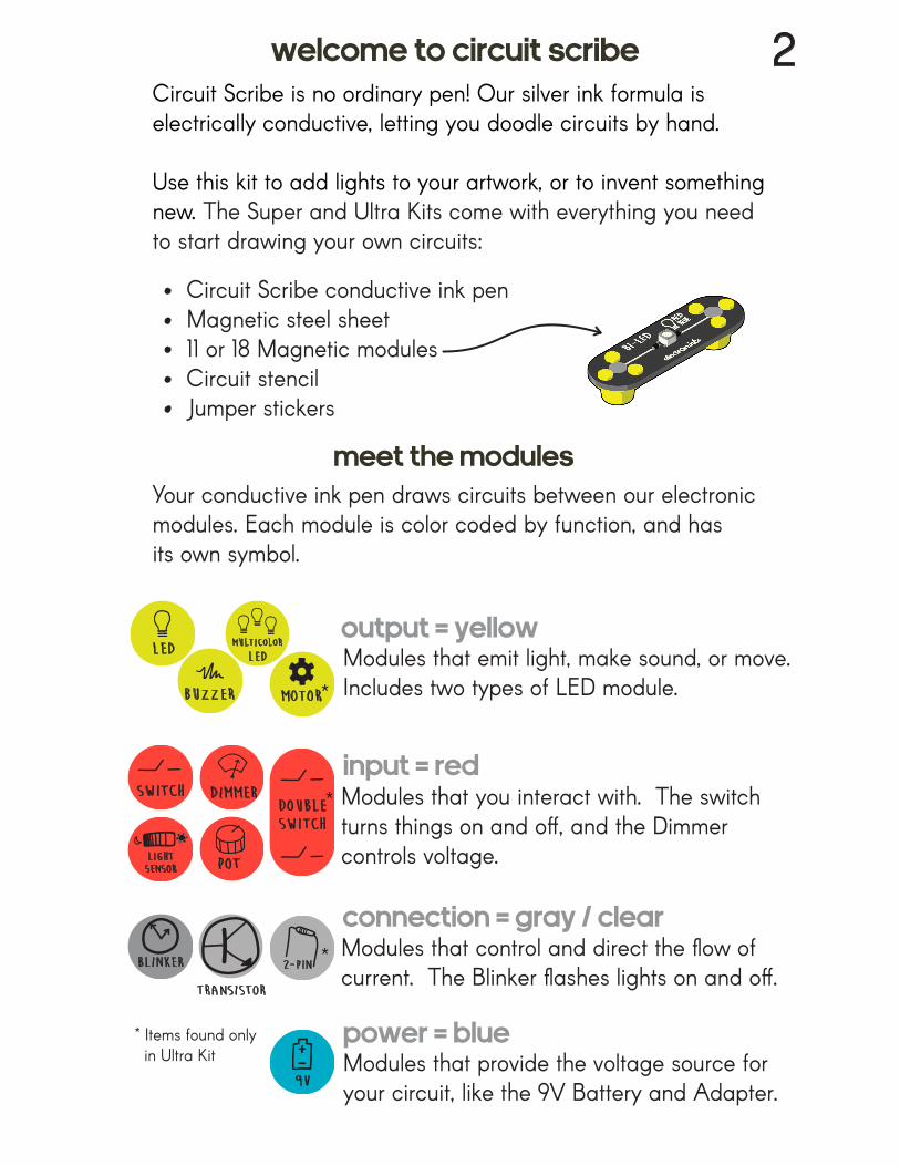
Your conductive ink pen draws circuits between our electronicmodules. Each module is color coded by function, and has its own symbol.
Circuit Scribe is no ordinary pen! Our silver ink formula is electrically conductive, letting you doodle circuits by hand.
Use this kit to add lights to your artwork, or to invent something new. The Super and Ultra Kits come with everything you need to start drawing your own circuits:
Circuit Scribe conductive ink penMagnetic steel sheet11 or 18 Magnetic modulesCircuit stencilJumper stickers
Modules that emit light, make sound, or move.Includes two types of LED module.
Modules that you interact with. The switch turns things on and off, and the Dimmercontrols voltage.
Modules that control and direct the flow of current. The Blinker flashes lights on and off.
Modules that provide the voltage source for your circuit, like the 9V Battery and Adapter.9V
LED
Dimmerswitch
blinker
pot
transistor
buzzer motor
2-pin
lightsensor
doubleswitch
multicolor
LED
welcome to circuit scribe 2
meet the modules
output = yellow
input = red
connection = gray / clear
power = blue* Items found only in Ultra Kit
*
*
*
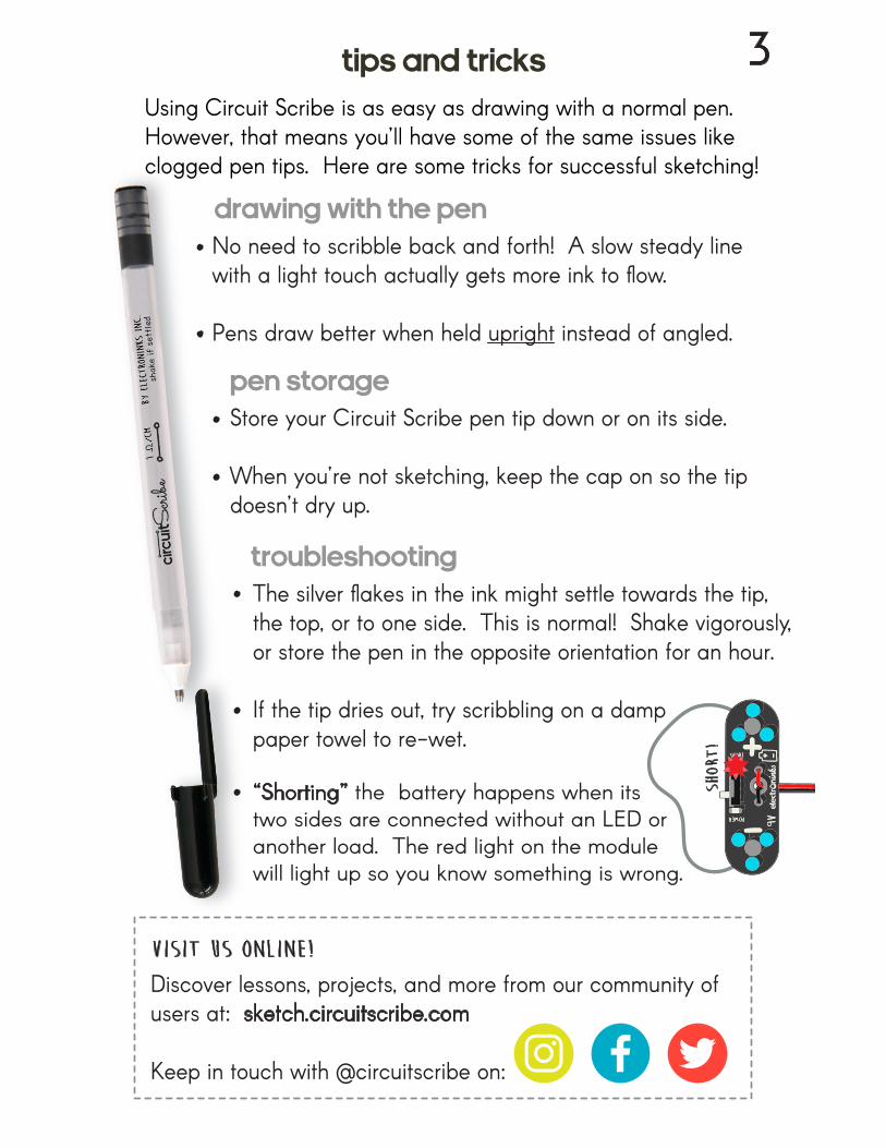
Store your Circuit Scribe pen tip down or on its side.
When you’re not sketching, keep the cap on so the tip doesn’t dry up.
Using Circuit Scribe is as easy as drawing with a normal pen. However, that means you’ll have some of the same issues like clogged pen tips. Here are some tricks for successful sketching!
The silver flakes in the ink might settle towards the tip,the top, or to one side. This is normal! Shake vigorously, or store the pen in the opposite orientation for an hour.
If the tip dries out, try scribbling on a damp paper towel to re-wet.
Discover lessons, projects, and more from our community of users at: sketch.circuitscribe.com
Keep in touch with @circuitscribe on:
visit us online!
short
!
“Shorting” the battery happens when its two sides are connected without an LED or another load. The red light on the module will light up so you know something is wrong.
Tips and tricks
drawing with the pen
3
No need to scribble back and forth! A slow steady line with a light touch actually gets more ink to flow.
Pens draw better when held upright instead of angled.
pen storage
troubleshooting
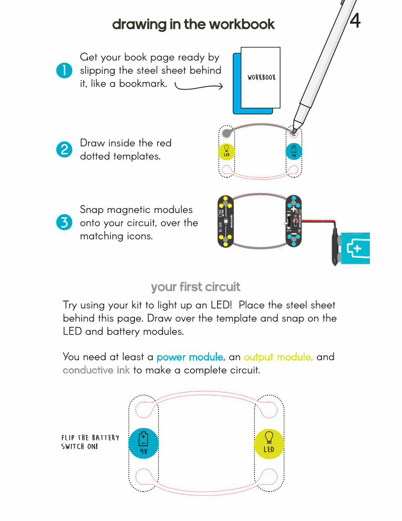
Draw inside the red dotted templates.
Snap magnetic modules onto your circuit, over the matching icons.
Get your book page ready by slipping the steel sheet behind it, like a bookmark. workbook
9VLED
9V LED
Try using your kit to light up an LED! Place the steel sheet behind this page. Draw over the template and snap on the LED and battery modules.
You need at least a power module, an output module, and conductive ink to make a complete circuit.
flip the batteryswitch on!
4drawing in the workbook
your first circuit
1
2
3
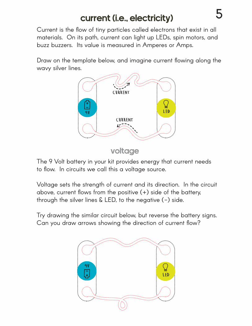
The 9 Volt battery in your kit provides energy that current needs to flow. In circuits we call this a voltage source.
Voltage sets the strength of current and its direction. In the circuit above, current flows from the positive (+) side of the battery, through the silver lines & LED, to the negative (-) side.
Try drawing the similar circuit below, but reverse the battery signs. Can you draw arrows showing the direction of current flow?
Current is the flow of tiny particles called electrons that exist in all materials. On its path, current can light up LEDs, spin motors, and buzz buzzers. Its value is measured in Amperes or Amps.
Draw on the template below, and imagine current flowing along the wavy silver lines.
9V LED
current
current
9V
LED
5current (i.e., electricity)
voltage
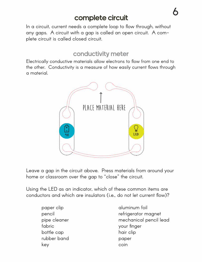
Leave a gap in the circuit above. Press materials from around your home or classroom over the gap to “close” the circuit.
Using the LED as an indicator, which of these common items are conductors and which are insulators (i.e., do not let current flow)?
paper clip aluminum foil pencil refrigerator magnet pipe cleaner mechanical pencil lead fabric your finger bottle cap hair clip rubber band paper key coin
place material here
In a circuit, current needs a complete loop to flow through, without any gaps. A circuit with a gap is called an open circuit. A com-plete circuit is called closed circuit.
Electrically conductive materials allow electrons to flow from one end to the other. Conductivity is a measure of how easily current flows through a material.
9V LED
6complete circuit
conductivity meter
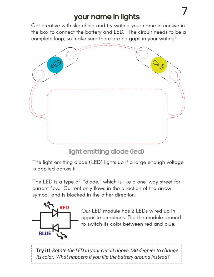
Get creative with sketching and try writing your name in cursive in the box to connect the battery and LED. The circuit needs to be a complete loop, so make sure there are no gaps in your writing!
RED
BLUE
The light emitting diode (LED) lights up if a large enough voltage is applied across it.
The LED is a type of “diode,” which is like a one-way street for current flow. Current only flows in the direction of the arrow symbol, and is blocked in the other direction.
Our LED module has 2 LEDs wired up in opposite directions. Flip the module around to switch its color between red and blue.
9vLED
Try it! Rotate the LED in your circuit above 180 degrees to change its color. What happens if you flip the battery around instead?
7your name in lights
light emitting diode (LEd)
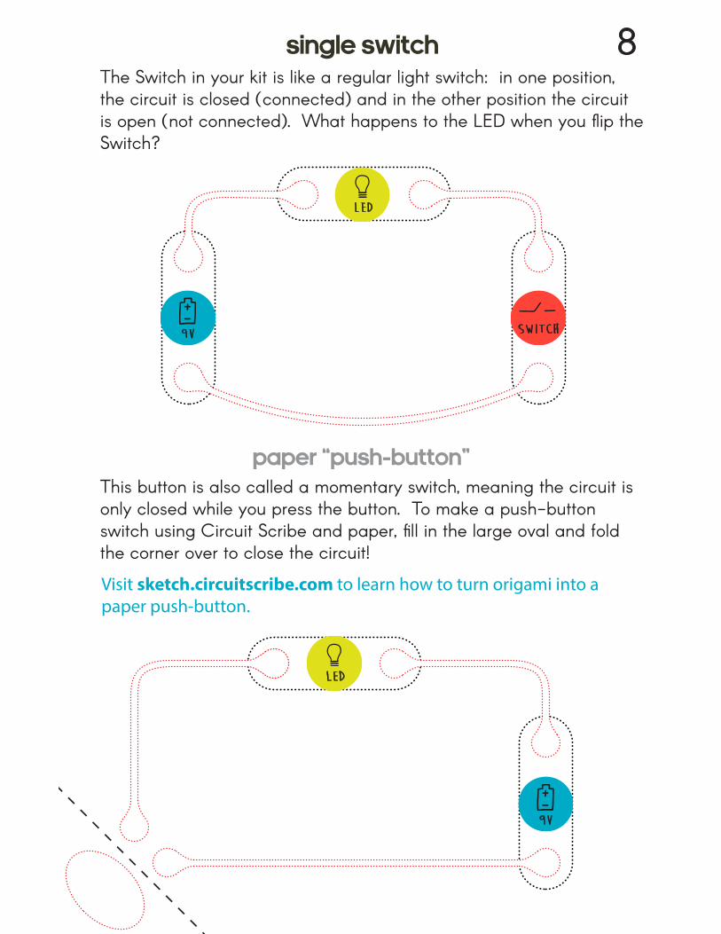
The Switch in your kit is like a regular light switch: in one position, the circuit is closed (connected) and in the other position the circuit is open (not connected). What happens to the LED when you flip the Switch?
This button is also called a momentary switch, meaning the circuit is only closed while you press the button. To make a push-button switch using Circuit Scribe and paper, fill in the large oval and fold the corner over to close the circuit!
LED
9V
LED
9V
Visit sketch.circuitscribe.com to learn how to turn origami into a paper push-button.
switch
8single switch
paper “push-button”
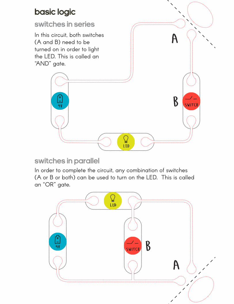
In this circuit, both switches (A and B) need to be turned on in order to light the LED. This is called an “AND” gate.
In order to complete the circuit, any combination of switches (A or B or both) can be used to turn on the LED. This is called an “OR” gate.
a
a
b
b
LED
LED
9V
9V
switch
switch
basic logic
switches in parallel
switches in series
Resistors are components that restrict or slow down the flow of current. Their main property, called resistance, is measured in units of ohms.
Low resistance: current flows easily, resulting in brighter LEDs,faster motors, and louder buzzers.
High resistance: current is restricted, resulting in dimmer LEDs, slower motors, and quieter buzzers (or no activity at all).
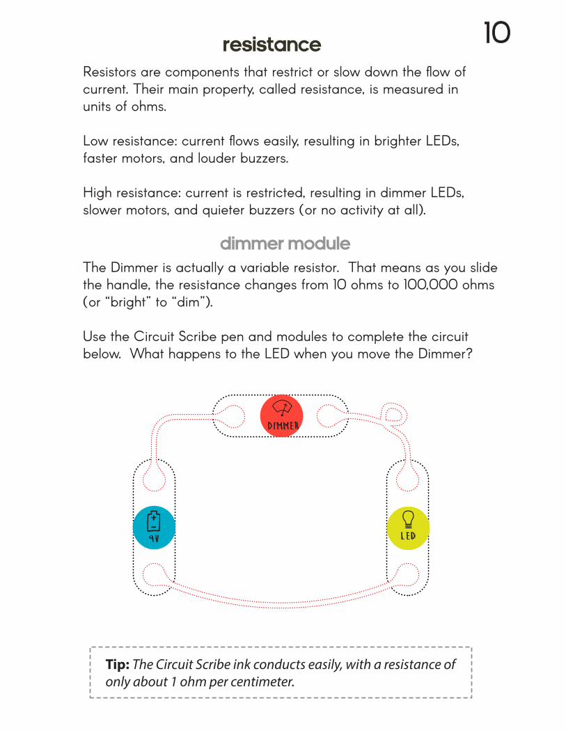
The Dimmer is actually a variable resistor. That means as you slide the handle, the resistance changes from 10 ohms to 100,000 ohms (or “bright” to “dim”).
Use the Circuit Scribe pen and modules to complete the circuit below. What happens to the LED when you move the Dimmer?
Tip: The Circuit Scribe ink conducts easily, with a resistance of only about 1 ohm per centimeter.
9V LED
Dimmer
10resistance
dimmer module
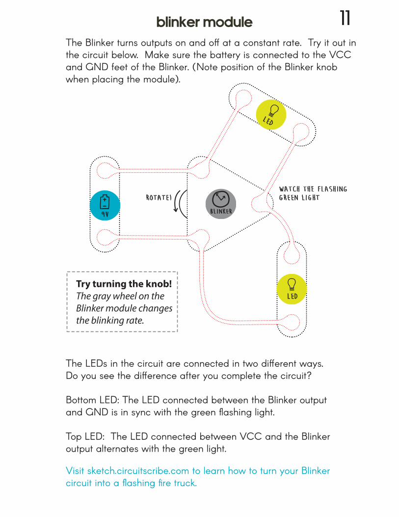
The LEDs in the circuit are connected in two different ways. Do you see the difference after you complete the circuit?
Bottom LED: The LED connected between the Blinker output and GND is in sync with the green flashing light.
Top LED: The LED connected between VCC and the Blinker output alternates with the green light.
The Blinker turns outputs on and off at a constant rate. Try it out in the circuit below. Make sure the battery is connected to the VCC and GND feet of the Blinker. (Note position of the Blinker knobwhen placing the module).
9V blinker
rotate!
LED
LED
Try turning the knob!The gray wheel on the Blinker module changes the blinking rate.
Visit sketch.circuitscribe.com to learn how to turn your Blinker circuit into a flashing fire truck.
watch the flashinggreen light
blinker module 11
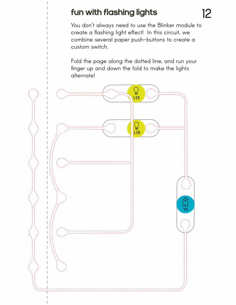
You don’t always need to use the Blinker module to create a flashing light effect! In this circuit, we combine several paper push-buttons to create a custom switch.
Fold the page along the dotted line, and run your finger up and down the fold to make the lights alternate!
9V
LED
LED
fun with flashing lights 12
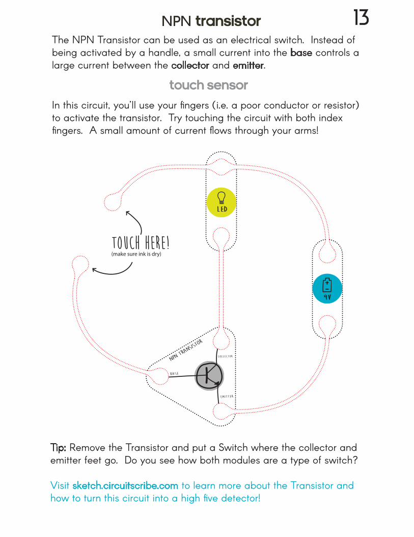
In this circuit, you’ll use your fingers (i.e. a poor conductor or resistor) to activate the transistor. Try touching the circuit with both index fingers. A small amount of current flows through your arms!
touch here!(make sure ink is dry)
The NPN Transistor can be used as an electrical switch. Instead of being activated by a handle, a small current into the base controls a large current between the collector and emitter.
LED
9V
Tip: Remove the Transistor and put a Switch where the collector and emitter feet go. Do you see how both modules are a type of switch?
Visit sketch.circuitscribe.com to learn more about the Transistor and how to turn this circuit into a high five detector!
NPN transistor 13
touch sensor
buzzer
buzzer
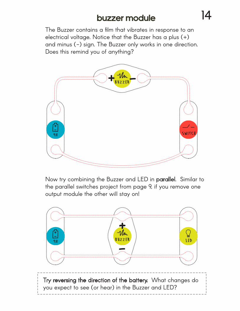
The Buzzer contains a film that vibrates in response to an electrical voltage. Notice that the Buzzer has a plus (+) and minus (-) sign. The Buzzer only works in one direction. Does this remind you of anything?
Now try combining the Buzzer and LED in parallel. Similar to the parallel switches project from page 9, if you remove one output module the other will stay on!
9V
9V LED
Try reversing the direction of the battery. What changes do you expect to see (or hear) in the Buzzer and LED?
switch
buzzer module 14
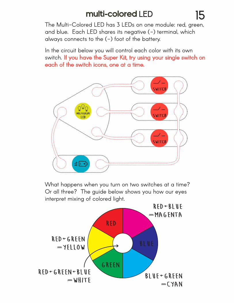
The Multi-Colored LED has 3 LEDs on one module: red, green, and blue. Each LED shares its negative (-) terminal, which always connects to the (-) foot of the battery.
In the circuit below you will control each color with its own switch. If you have the Super Kit, try using your single switch on each of the switch icons, one at a time.
What happens when you turn on two switches at a time? Or all three? The guide below shows you how our eyes interpret mixing of colored light.
9V
red
green
blue
red+blue=magenta
blue+green=cyan
red+green=yellow
red+green+blue=white
switch
switch
switch
multi-colored LED 15
multicolor
LED
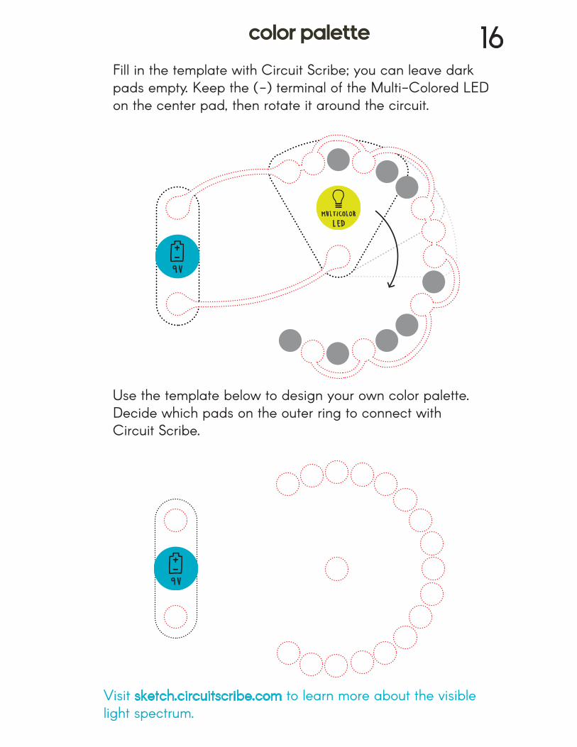
Use the template below to design your own color palette. Decide which pads on the outer ring to connect with Circuit Scribe.
Fill in the template with Circuit Scribe; you can leave dark pads empty. Keep the (-) terminal of the Multi-Colored LED on the center pad, then rotate it around the circuit.
9V
9V
Visit sketch.circuitscribe.com to learn more about the visiblelight spectrum.
multicolor
LED
color palette 16
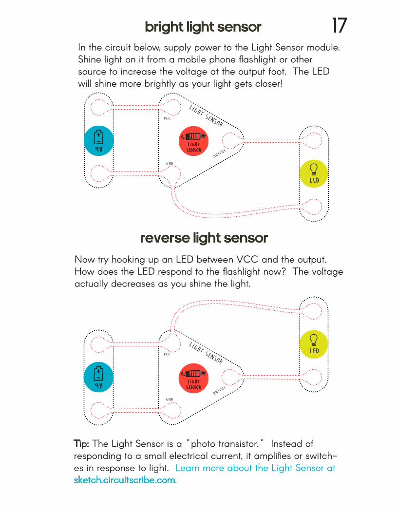
In the circuit below, supply power to the Light Sensor module. Shine light on it from a mobile phone flashlight or other source to increase the voltage at the output foot. The LED will shine more brightly as your light gets closer!
Tip: The Light Sensor is a "photo transistor." Instead of responding to a small electrical current, it amplifies or switch-es in response to light. Learn more about the Light Sensor at sketch.circuitscribe.com.
outpu
t
Light sensor
9Vlightsensor
LED
Now try hooking up an LED between VCC and the output. How does the LED respond to the flashlight now? The voltage actually decreases as you shine the light.
outpu
t
Light sensor
9Vlightsensor
LED
bright light sensor 17
reverse light sensor
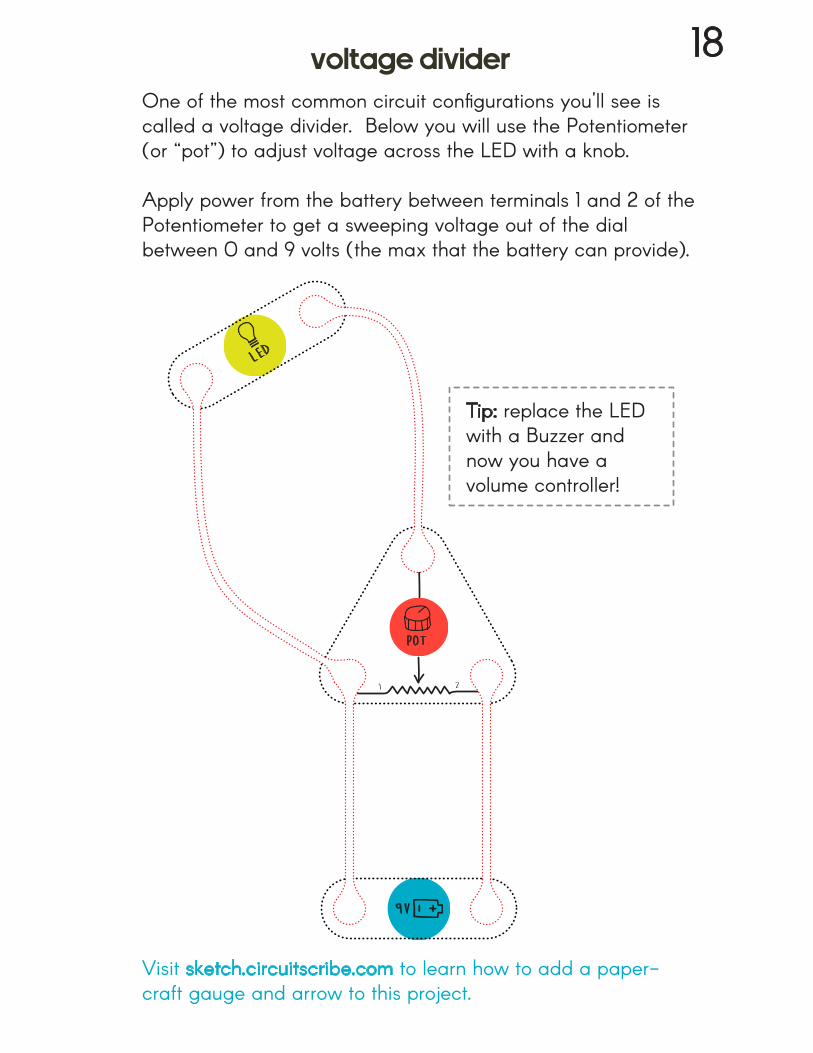
Visit sketch.circuitscribe.com to learn how to add a paper-craft gauge and arrow to this project.
One of the most common circuit configurations you'll see is called a voltage divider. Below you will use the Potentiometer(or “pot”) to adjust voltage across the LED with a knob.
Apply power from the battery between terminals 1 and 2 of thePotentiometer to get a sweeping voltage out of the dial between 0 and 9 volts (the max that the battery can provide).
Tip: replace the LED with a Buzzer and now you have a volume controller!
LED
9V
voltage divider 18
pot
wiper
1
2
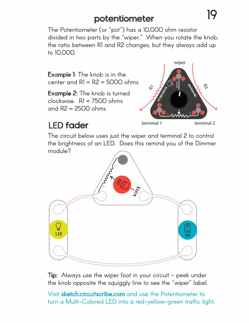
The circuit below uses just the wiper and terminal 2 to control the brightness of an LED. Does this remind you of the Dimmermodule?
Tip: Always use the wiper foot in your circuit - peek underthe knob opposite the squiggly line to see the “wiper” label.
Visit sketch.circuitscribe.com and use the Potentiometer to turn a Multi-Colored LED into a red-yellow-green traffic light.
9V
The Potentiometer (or “pot”) has a 10,000 ohm resistor divided in two parts by the “wiper.” When you rotate the knob, the ratio between R1 and R2 changes, but they always add upto 10,000.
Example 1: The knob is in the center and R1 = R2 = 5000 ohms
Example 2: The knob is turned clockwise. R1 = 7500 ohms and R2 = 2500 ohms
R1
R2
terminal 1 terminal 2
wiper
LED
potentiometer 19
LED faderpot
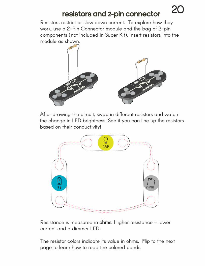
Resistors restrict or slow down current. To explore how they work, use a 2-Pin Connector module and the bag of 2-pin components (not included in Super Kit). Insert resistors into the module as shown.
After drawing the circuit, swap in different resistors and watch the change in LED brightness. See if you can line up the resistorsbased on their conductivity!
Resistance is measured in ohms. Higher resistance = lower current and a dimmer LED.
The resistor colors indicate its value in ohms. Flip to the next page to learn how to read the colored bands.
9V
LED
2-pin
resistors and 2-pin connector 20
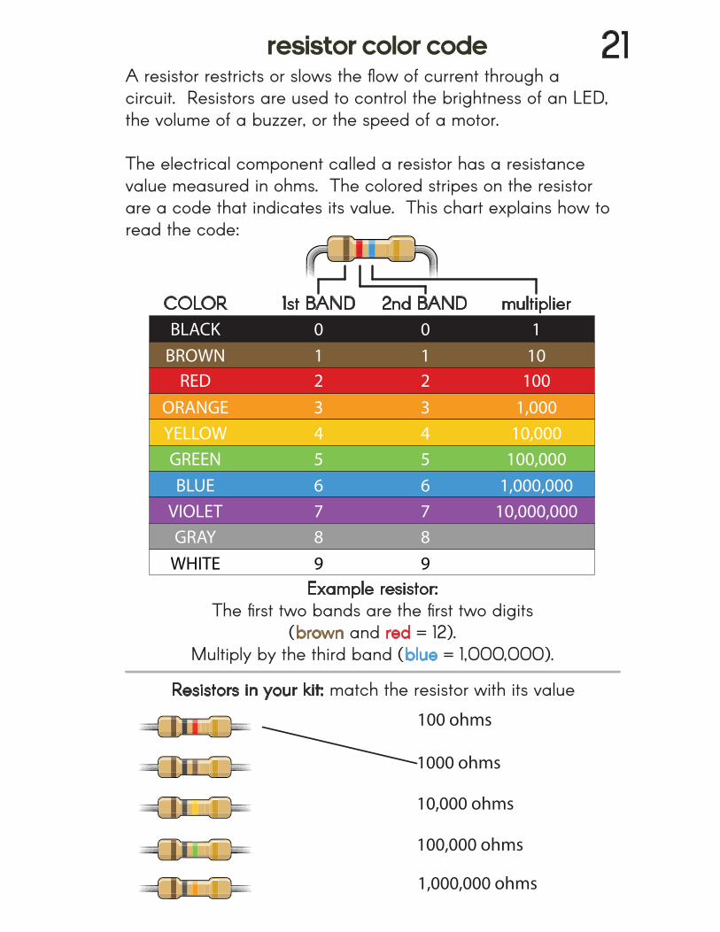
A resistor restricts or slows the flow of current through a circuit. Resistors are used to control the brightness of an LED, the volume of a buzzer, or the speed of a motor.
The electrical component called a resistor has a resistance value measured in ohms. The colored stripes on the resistor are a code that indicates its value. This chart explains how to read the code:
1000 ohms
10,000 ohms
100,000 ohms
100 ohms
1,000,000 ohms
Resistors in your kit: match the resistor with its value
COLORBLACK
BROWNRED
ORANGEYELLOWGREENBLUE
VIOLETGRAY
WHITE
1st BAND 2nd BAND multiplier0123456789
0123456789
110
1001,000
10,000100,000
1,000,00010,000,000
Example resistor: The first two bands are the first two digits
(brown and red = 12). Multiply by the third band (blue = 1,000,000).
resistor color code 21
top
bottom
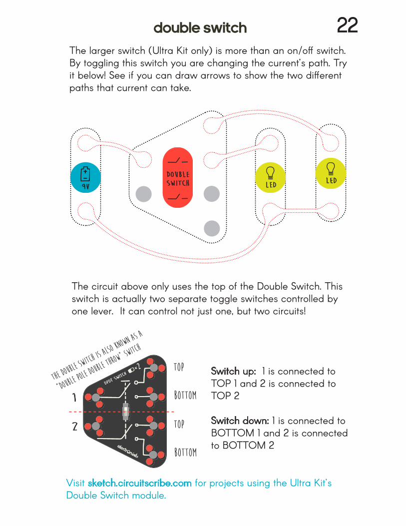
The larger switch (Ultra Kit only) is more than an on/off switch. By toggling this switch you are changing the current’s path. Try it below! See if you can draw arrows to show the two different paths that current can take.
top
bottom
1
2
9V LEDLED
doubleswitch
The circuit above only uses the top of the Double Switch. Thisswitch is actually two separate toggle switches controlled by one lever. It can control not just one, but two circuits!
Switch up: 1 is connected to TOP 1 and 2 is connected to TOP 2
Switch down: 1 is connected to BOTTOM 1 and 2 is connected to BOTTOM 2
Visit sketch.circuitscribe.com for projects using the Ultra Kit’s Double Switch module.
double switch 22
The doubl
e switch
is also kn
own as a
“double p
ole doubl
e throw”
switch
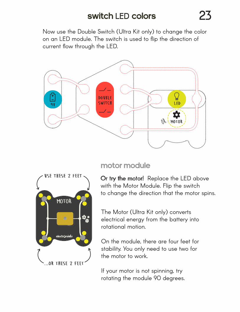
Now use the Double Switch (Ultra Kit only) to change the color on an LED module. The switch is used to flip the direction of current flow through the LED.
Or try the motor! Replace the LED above with the Motor Module. Flip the switch to change the direction that the motor spins.
9V
doubleswitch LED
motor
use these 2 feet
...or these 2 feet
The Motor (Ultra Kit only) converts electrical energy from the battery into rotational motion.
On the module, there are four feet for stability. You only need to use two forthe motor to work.
If your motor is not spinning, try rotating the module 90 degrees.
switch LED colors 23
motor module
or...
outpu
t
Light sensor
lightsensor
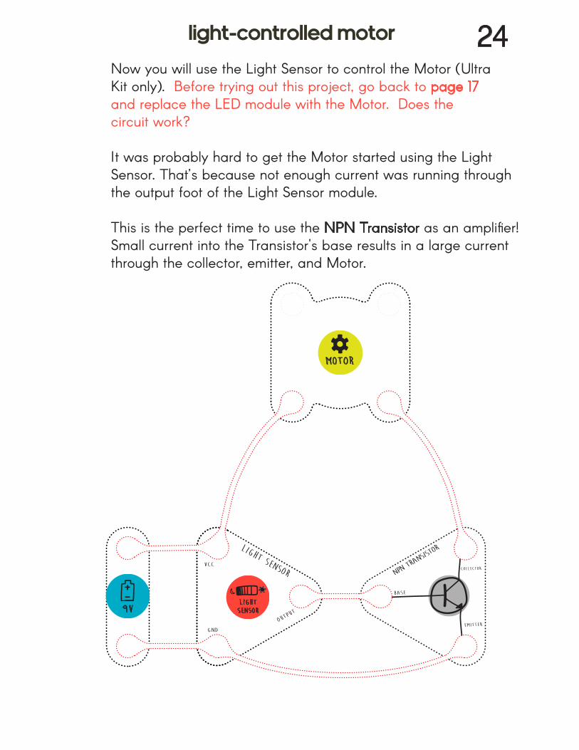
Now you will use the Light Sensor to control the Motor (Ultra Kit only). Before trying out this project, go back to page 17 and replace the LED module with the Motor. Does the circuit work?
It was probably hard to get the Motor started using the LightSensor. That’s because not enough current was running through the output foot of the Light Sensor module.
This is the perfect time to use the NPN Transistor as an amplifier! Small current into the Transistor's base results in a large current through the collector, emitter, and Motor.
9V
motor
light-controlled motor 24
Discover new projects and help grow the community at:
- Circuit name tags - Soft origami buttons - Interactive maps - Light-up architecture - Electronic paper dolls...and more!
@circuitscribe