Embed Size (px)
Citation preview
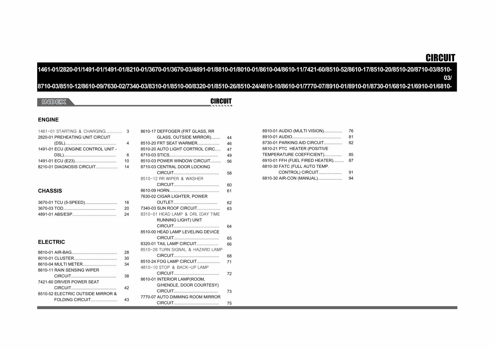
CIRCUIT1461-01/2820-01/1491-01/1491-01/8210-01/3670-01/3670-03/4891-01/8810-01/8010-01/8610-04/8610-11/7421-60/8510-52/8610-17/8510-20/8510-20/8710-03/8510-
03/8710-03/8510-12/8610-09/7630-02/7340-03/8310-01/8510-00/8320-01/8510-26/8510-24/4810-10/8610-01/7770-07/8910-01/8910-01/8730-01/6810-21/6910-01/6810-
30/6810-30CIRCUIT
ENGINE
8910-01 AUDIO (MULTI VISION)................8910-01 AUDIO..........................................8730-01 PARKING AID CIRCUIT................6810-21 PTC HEATER (POSITIVE TEMPERATURE COEFFICIENT)...............6910-01 FFH (FUEL FIRED HEATER).........6810-30 FATC (FULL AUTO TEMP. CONTROL) CIRCUIT....................6810-30 AIR-CON (MANUAL).....................
CHASSIS
3670-01 TCU (5-SPEED)............................3670-03 TOD.............................................4891-01 ABS/ESP......................................
ELECTRIC
8610-17 DEFFOGER (FRT GLASS, RR GLASS, OUTSIDE MIRROR)........8510-20 FRT SEAT WARMER...................8510-20 AUTO LIGHT CORTROL CIRC.....8710-03 STICS..........................................8510-03 POWER WINDOW CIRCUIT.........8710-03 CENTRAL DOOR LOCKING CIRCUIT.......................................8510-12 RR WIPER & WASHER
CIRCUIT.......................................8610-09 HORN...........................................7630-02 CIGAR LIGHTER, POWER OUTLET......................................7340-03 SUN ROOF CIRCUIT....................8310-01 HEAD LAMP & DRL (DAY TIME
RUNNING LIGHT) UNIT CIRCUIT.......................................8510-00 HEAD LAMP LEVELING DEVICE CIRCUIT.......................................8320-01 TAIL LAMP CIRCUIT...................8510-26 TURN SIGNAL & HAZARD LAMP
CIRCUIT.......................................8510-24 FOG LAMP CIRCUIT....................4810-10 STOP & BACK-UP LAMP
CIRCUIT.......................................8610-01 INTERIOR LAMP(ROOM, G/HENDLE, DOOR COURTESY) CIRCUIT......................................7770-07 AUTO DIMMING ROOM MIRROR CIRCUIT.......................................
8810-01 AIR-BAG.......................................8010-01 CLUSTER.....................................8610-04 MULTI METER.............................8610-11 RAIN SENSING WIPER CIRCUIT.......................................7421-60 DRIVER POWER SEAT CIRCUIT.......................................8510-52 ELECTRIC OUTSIDE MIRROR & FOLDING CIRCUIT.......................
768182
8587
9194
162024
283034
38
42
43
4446474956
58
6061
6263
64
6566
6871
72
73
75
1461-01 STARTING & CHARGING............
2820-01 PREHEATING UNIT CIRCUIT (DSL)............................................1491-01 ECU (ENGINE CONTROL UNIT - DSL).............................................1491-01 ECU (E23)....................................8210-01 DIAGNOSIS CIRCUIT...................
3
4
61014

0-3
CIRCUITRODIUS 2004.09
1461-01
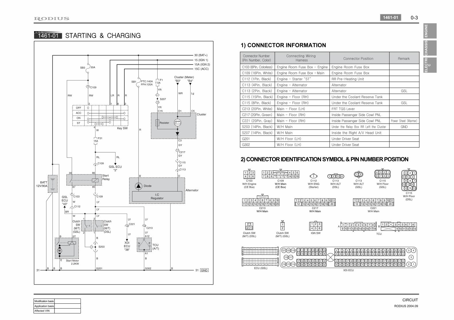
1461-01 STARTING & CHARGING
1) CONNECTOR INFORMATION
2) CONNECTOR IDENTIFICATION SYMBOL & PIN NUMBER POSITION
0-4
RODIUS 2004.09
2820-01
CIRCUIT
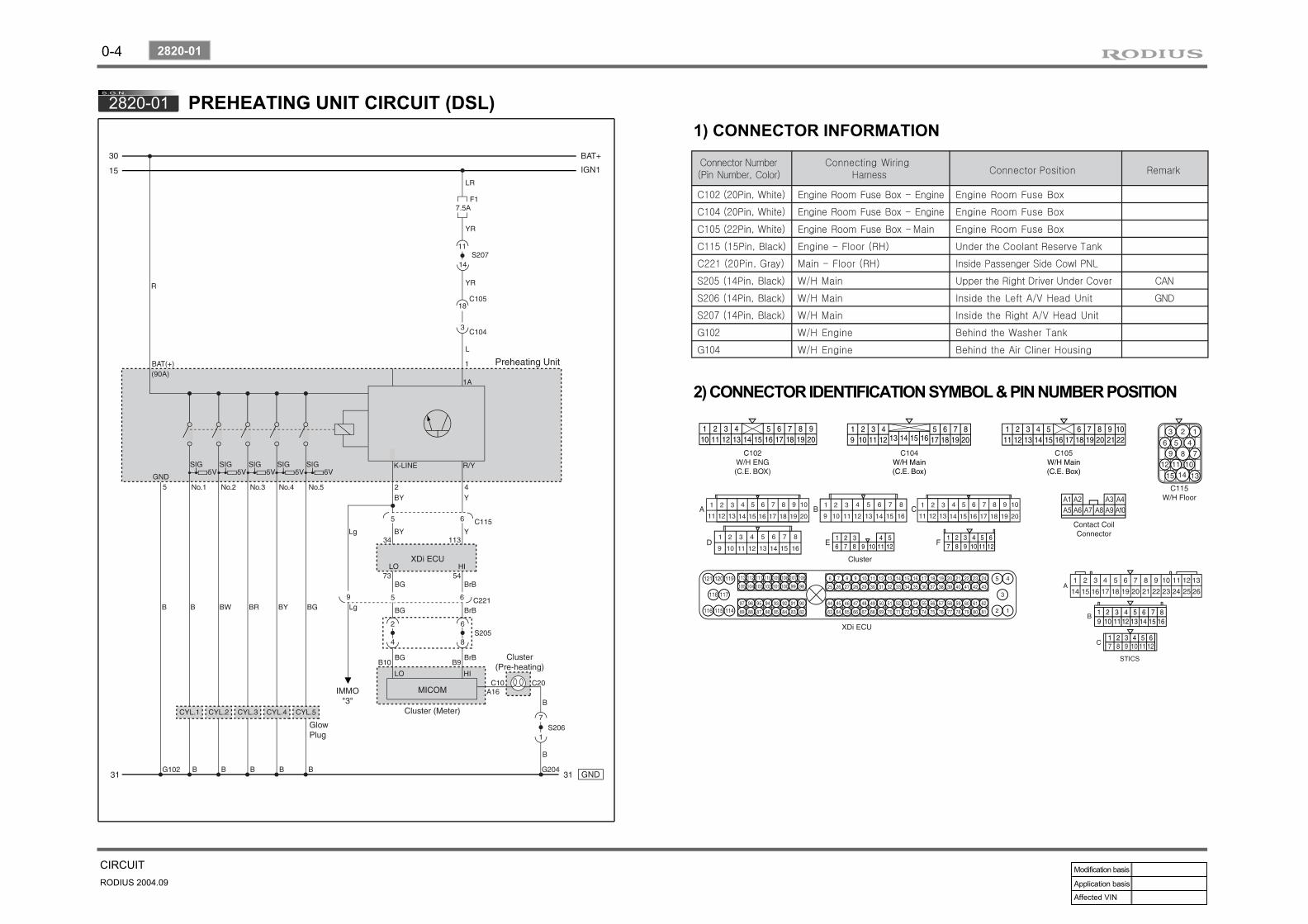
2820-01 PREHEATING UNIT CIRCUIT (DSL)1) CONNECTOR INFORMATION
2) CONNECTOR IDENTIFICATION SYMBOL & PIN NUMBER POSITION

0-5
CIRCUITRODIUS 2004.09
2820-01
3) CIRCUIT DESCRIPTIONGlow plug is installed on the cylinder head (combustion chamber) in the D27DT preheating control unit system. Cold starting performance has improved and exhaust gas during cold starting has reduced. ECU receives coolant temperature and engine speed to control; after monitoring the engine preheating/after heating and glow plug diagnosis function, the fault contents will be delivered to ECU.
Engine preheating/post heating functions▶
Preheating relay activation by ECU controls▶
Senses engine temperature and controls the preheating/post heating time.Preheating warning light.
--
K-LINE for information exchanges between preheating unit and ECU▶
Transmits preheating unit self-diagnosis results to ECU.Transmits glow plug diagnosis results and operating status to ECU.
--

0-6
RODIUS 2004.09
1491-01
CIRCUIT
1491-01 ECU (ENGINE CONTROL UNIT - DSL)1) ENG MAIN RELAY, PEDAL MODULE, HAN SENSORS, VALVE (1) CONNECTOR INFORMATION
(2) CONNECTOR IDENTIFICATION SYMBOL & PIN NUMBER POSITION
(1) TRUBO CHARGER BOOSTER, EGR VACUUM MODULE, INLETMETERING VALVE

0-7
CIRCUITRODIUS 2004.09
1491-01
2) FUEL FILTER WARNING LAMP, IMMOBILIZER, SENSOR CIRCUIT (FUEL PRESSURE, CAM SHAFT, BOOSTER PRESSURE, CRANK SHAFT, KNOCK, COOLANT TEMP., FUEL TEMP.)
(2) CONNECTOR IDENTIFICATION SYMBOL & PIN NUMBER POSITION
(1) CONNECTOR INFORMATION
0-8
RODIUS 2004.09
1491-01
CIRCUIT
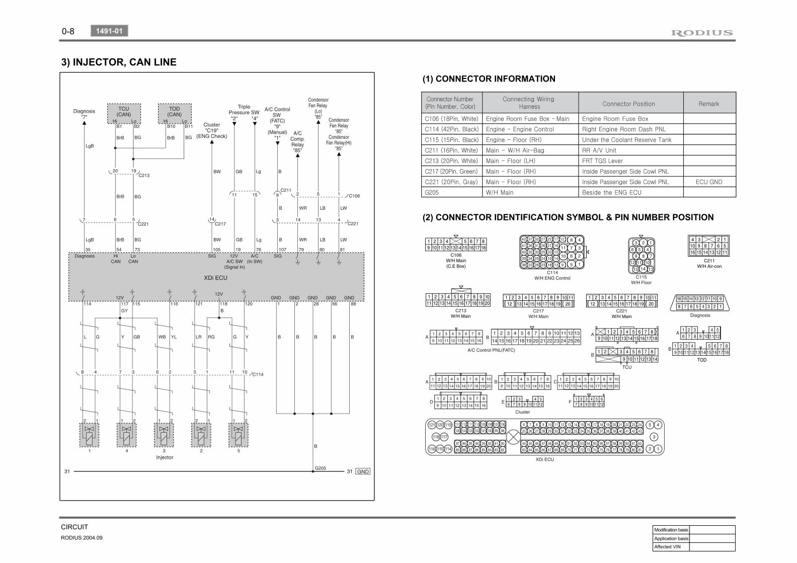
3) INJECTOR, CAN LINE(1) CONNECTOR INFORMATION
(2) CONNECTOR IDENTIFICATION SYMBOL & PIN NUMBER POSITION
0-9
CIRCUITRODIUS 2004.09
1491-01
(3) CIRCUIT DESCRIPTION
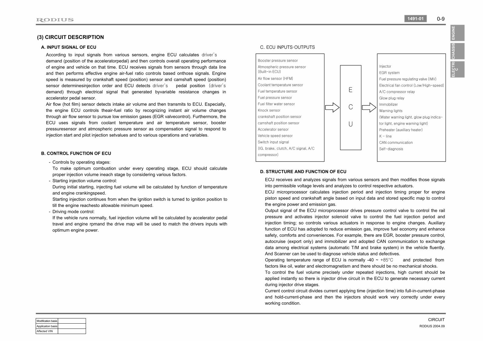
A. INPUT SIGNAL OF ECUAccording to input signals from various sensors, engine ECU calculates driver’s
demand (position of the acceleratorpedal) and then controls overall operating performance of engine and vehicle on that time. ECU receives signals from sensors through data line and then performs effective engine air-fuel ratio controls based onthose signals. Engine speed is measured by crankshaft speed (position) sensor and camshaft speed (position) sensor determinesinjection order and ECU detects driver’s pedal position (driver’s
demand) through electrical signal that generated byvariable resistance changes in accelerator pedal sensor.Air flow (hot film) sensor detects intake air volume and then transmits to ECU. Especially, the engine ECU controls theair-fuel ratio by recognizing instant air volume changes through air flow sensor to pursue low emission gases (EGR valvecontrol). Furthermore, the ECU uses signals from coolant temperature and air temperature sensor, booster pressuresensor and atmospheric pressure sensor as compensation signal to respond to injection start and pilot injection setvalues and to various operations and variables.
B. CONTROL FUNCTION OF ECU
Controls by operating stages:To make optimum combustion under every operating stage, ECU should calculate proper injection volume ineach stage by considering various factors.Starting injection volume control:During initial starting, injecting fuel volume will be calculated by function of temperature and engine crankingspeed.Starting injection continues from when the ignition switch is turned to ignition position to till the engine reachesto allowable minimum speed.Driving mode control:If the vehicle runs normally, fuel injection volume will be calculated by accelerator pedal travel and engine rpmand the drive map will be used to match the drivers inputs with optimum engine power.
-
-
-
C. ECU INPUTS·OUTPUTS
D. STRUCTURE AND FUNCTION OF ECU
ECU receives and analyzes signals from various sensors and then modifies those signals into permissible voltage levels and analyzes to control respective actuators.ECU microprocessor calculates injection period and injection timing proper for engine piston speed and crankshaft angle based on input data and stored specific map to control the engine power and emission gas.Output signal of the ECU microprocessor drives pressure control valve to control the rail pressure and activates injector solenoid valve to control the fuel injection period and injection timing; so controls various actuators in response to engine changes. Auxiliary function of ECU has adopted to reduce emission gas, improve fuel economy and enhance safety, comforts and conveniences. For example, there are EGR, booster pressure control, autocruise (export only) and immobilizer and adopted CAN communication to exchange data among electrical systems (automatic T/M and brake system) in the vehicle fluently. And Scanner can be used to diagnose vehicle status and defectives.Operating temperature range of ECU is normally -40 ~ +85°C and protected from factors like oil, water and electromagnetism and there should be no mechanical shocks.To control the fuel volume precisely under repeated injections, high current should be applied instantly so there is injector drive circuit in the ECU to generate necessary current during injector drive stages.Current control circuit divides current applying time (injection time) into full-in-current-phase and hold-current-phase and then the injectors should work very correctly under everyworking condition.
0-10
RODIUS 2004.09
1491-01
CIRCUIT
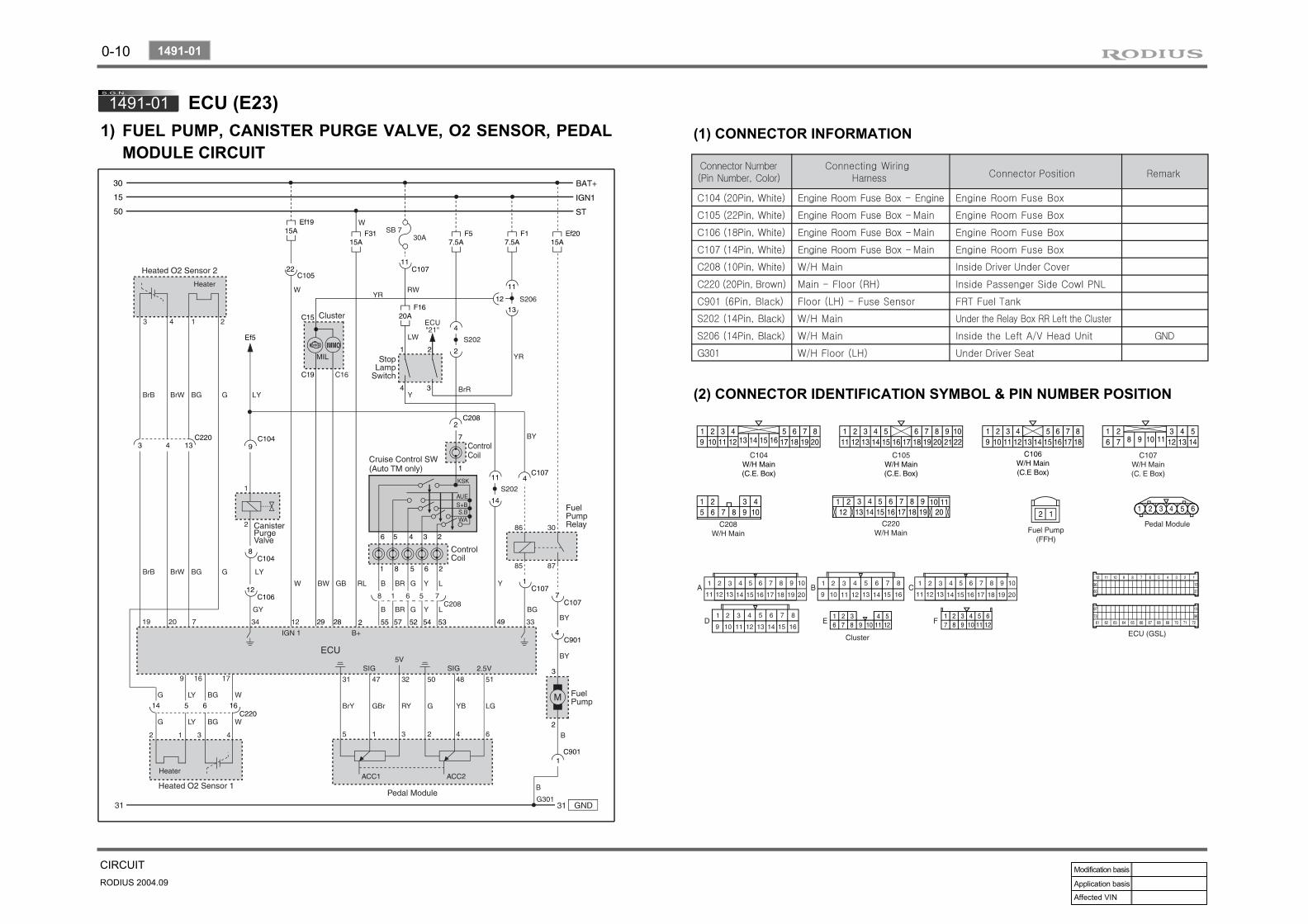
1491-01 ECU (E23)1) (1) CONNECTOR INFORMATION
(2) CONNECTOR IDENTIFICATION SYMBOL & PIN NUMBER POSITION
FUEL PUMP, CANISTER PURGE VALVE, O2 SENSOR, PEDAL MODULE CIRCUIT
0-11
CIRCUITRODIUS 2004.09
1491-01
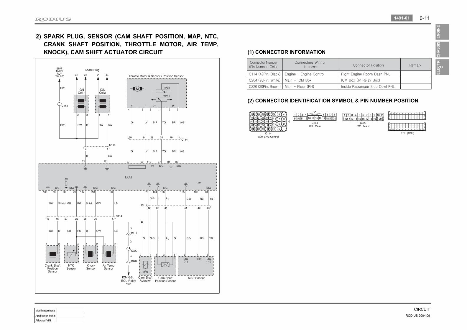
2) SPARK PLUG, SENSOR (CAM SHAFT POSITION, MAP, NTC, CRANK SHAFT POSITION, THROTTLE MOTOR, AIR TEMP, KNOCK), CAM SHIFT ACTUATOR CIRCUIT
(2) CONNECTOR IDENTIFICATION SYMBOL & PIN NUMBER POSITION
(1) CONNECTOR INFORMATION

0-12
RODIUS 2004.09
1491-01
CIRCUIT
3) DIGITAL CLOCK, ENG TEMP SENSOR, IMMOBILIZER CIRCUIT
(2) CONNECTOR IDENTIFICATION SYMBOL & PIN NUMBER POSITION
(1) CONNECTOR INFORMATION
0-13
CIRCUITRODIUS 2004.09
1491-01
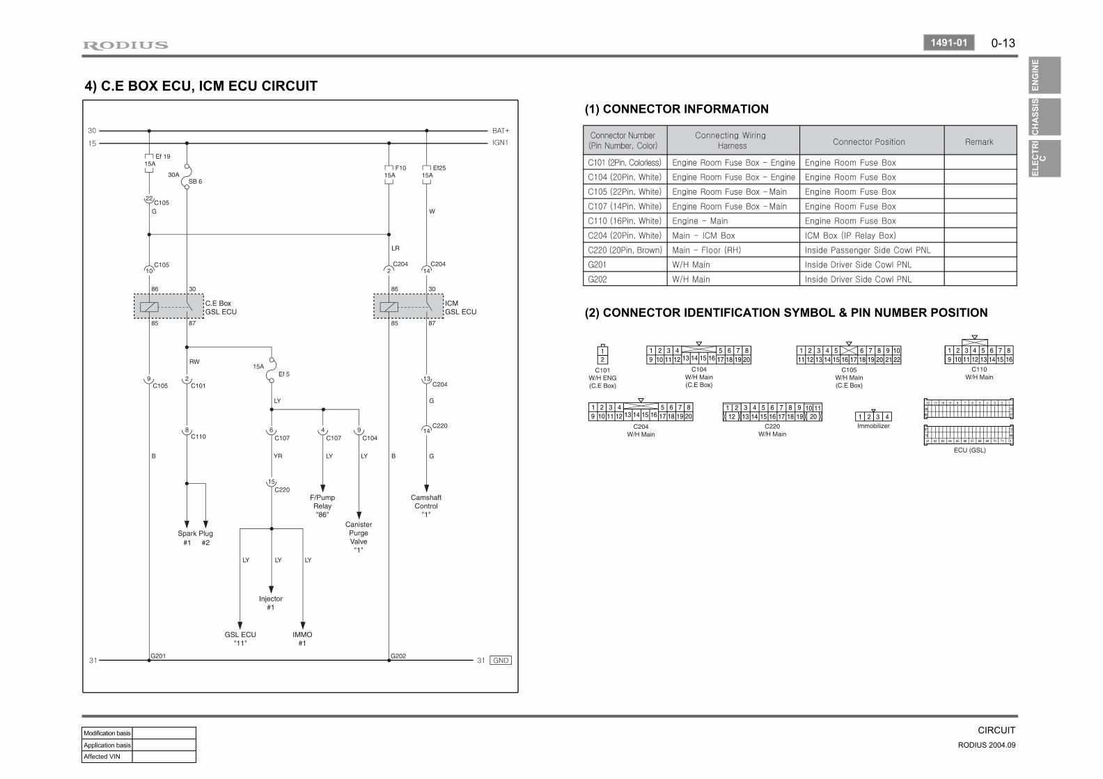
4) C.E BOX ECU, ICM ECU CIRCUIT(1) CONNECTOR INFORMATION
(2) CONNECTOR IDENTIFICATION SYMBOL & PIN NUMBER POSITION
0-14
RODIUS 2004.09
8210-01
CIRCUIT
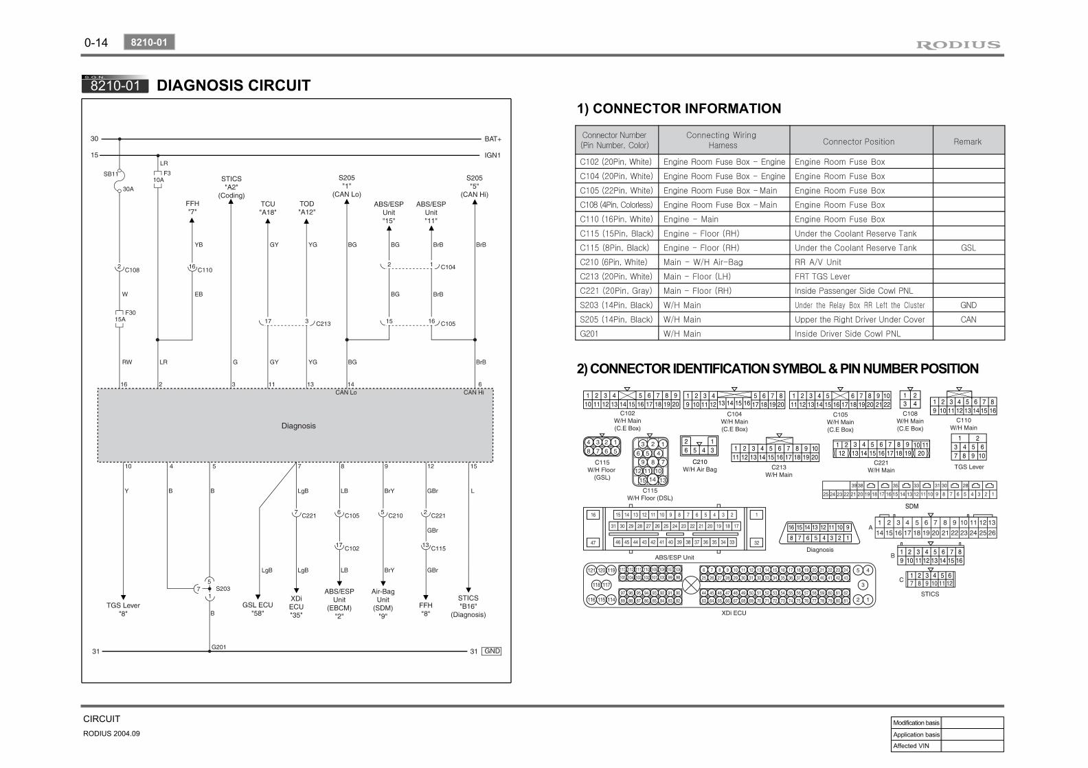
8210-01 DIAGNOSIS CIRCUIT
2) CONNECTOR IDENTIFICATION SYMBOL & PIN NUMBER POSITION
1) CONNECTOR INFORMATION

0-15
CIRCUITRODIUS 2004.09
8210-01
3) CIRCUIT DESCRIPTION
▶TRANSMITTER CODING
Remove the ignition key from key hole.Connect the No. 3 terminal (REKES coding) and No. 16 terminal (battery+) on the diagnosis connector with a jumper cable.Press any button on the remote control key shortly. (approx. 0.5 sec.)When the coding is successful, turn signal lamps blink once and warning horn sounds once.If the coding has failed, repeat 1 to 4 steps.
----
-