Embed Size (px)
Citation preview
04-3
ENGINE INTAKE SYSTEMACTYON 2008.07
0000-00
GENERAL
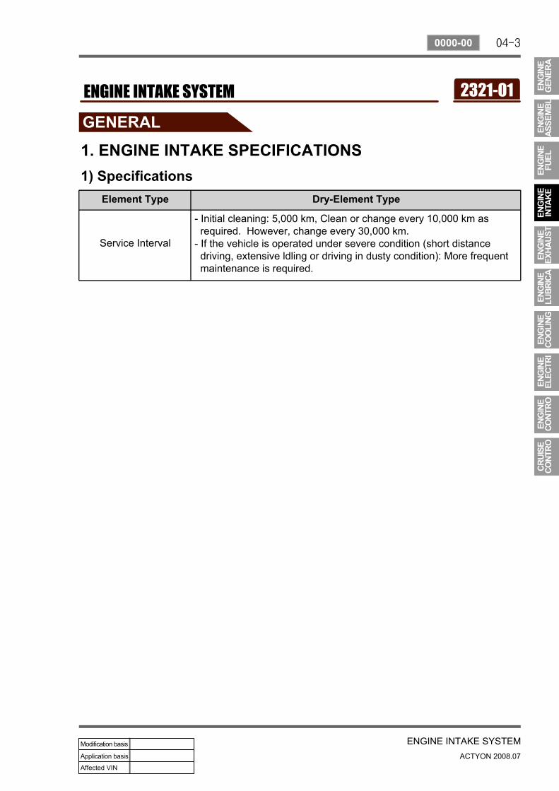
1. ENGINE INTAKE SPECIFICATIONS1) Specifications
Element Type Dry-Element Type
Service Interval
- Initial cleaning: 5,000 km, Clean or change every 10,000 km as required. However, change every 30,000 km.- If the vehicle is operated under severe condition (short distance driving, extensive ldling or driving in dusty condition): More frequent maintenance is required.
2321-01ENGINE INTAKE SYSTEM
04-4
ACTYON 2008.07
0000-00
ENGINE INTAKE SYSTEM
VGT Turbocharger
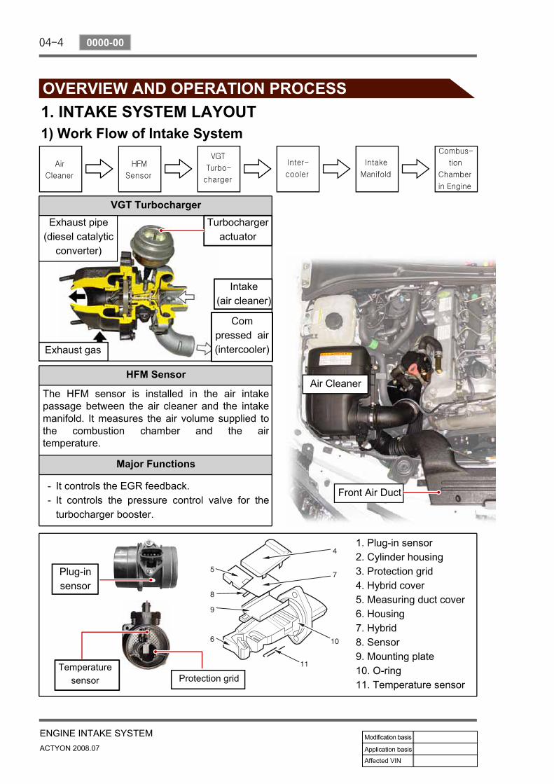
OVERVIEW AND OPERATION PROCESS1. INTAKE SYSTEM LAYOUT1) Work Flow of Intake System
HFM Sensor
The HFM sensor is installed in the air intake passage between the air cleaner and the intake manifold. It measures the air volume supplied to the combustion chamber and the air temperature.
Major Functions
It controls the EGR feedback.It controls the pressure control valve for the turbocharger booster.
--
1. Plug-in sensor2. Cylinder housing3. Protection grid4. Hybrid cover5. Measuring duct cover6. Housing7. Hybrid8. Sensor9. Mounting plate10. O-ring11. Temperature sensor
Turbochargeractuator
Intake(air cleaner)
Compressed air(intercooler)Exhaust gas
Exhaust pipe (diesel catalytic
converter)
Plug-insensor
Temperaturesensor Protection grid
Front Air Duct
Air Cleaner
04-5
ENGINE INTAKE SYSTEMACTYON 2008.07
2313-01
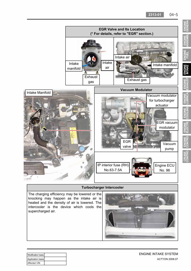
EGR Valve and Its Location (* For details, refer to "EGR" section.)
Vacuum Modulator
Turbocharger Intercooler
The charging efficiency may be lowered or the knocking may happen as the intake air is heated and the density of air is lowered. The intercooler is the device which cools the supercharged air.
Intakemanifold
Intake air
Exhaustgas Exhaust gas
Intake manifold
Vacuum modulatorfor turbocharger
actuator
EGR vacuummodulator
Vacuumpump
EGRvalve
IP interior fuse (RH)No.63-7.5A
Engine ECUNo. 96
Intake Manifold
Intake air
04-6
ACTYON 2008.07
2313-01
ENGINE INTAKE SYSTEM
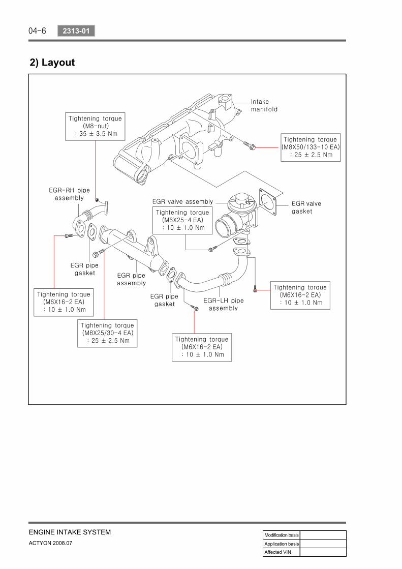
2) Layout
04-7
ENGINE INTAKE SYSTEMACTYON 2008.07
2313-01
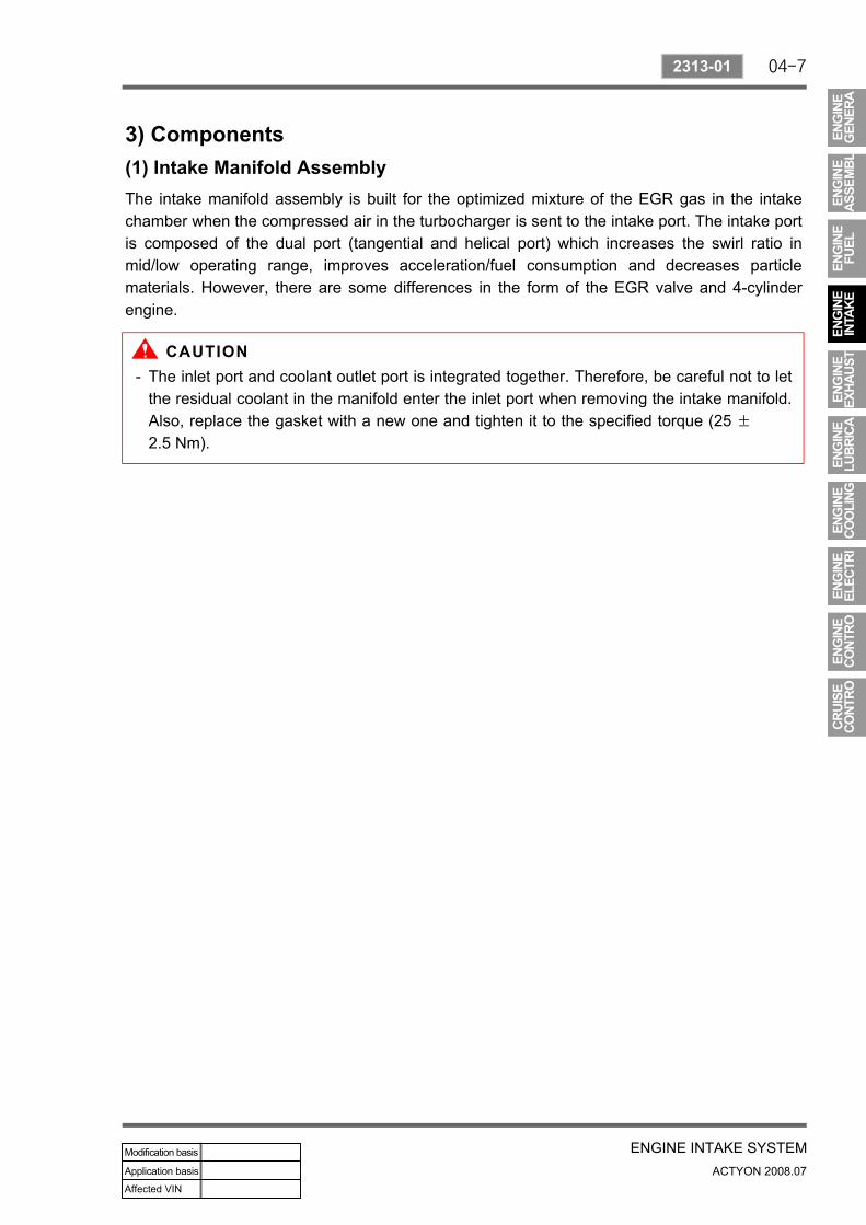
3) Components(1) Intake Manifold AssemblyThe intake manifold assembly is built for the optimized mixture of the EGR gas in the intake chamber when the compressed air in the turbocharger is sent to the intake port. The intake port is composed of the dual port (tangential and helical port) which increases the swirl ratio in mid/low operating range, improves acceleration/fuel consumption and decreases particle materials. However, there are some differences in the form of the EGR valve and 4-cylinder engine.
The inlet port and coolant outlet port is integrated together. Therefore, be careful not to let the residual coolant in the manifold enter the inlet port when removing the intake manifold. Also, replace the gasket with a new one and tighten it to the specified torque (25 ±
2.5 Nm).
-
04-8
ACTYON 2008.07
2313-01
ENGINE INTAKE SYSTEM
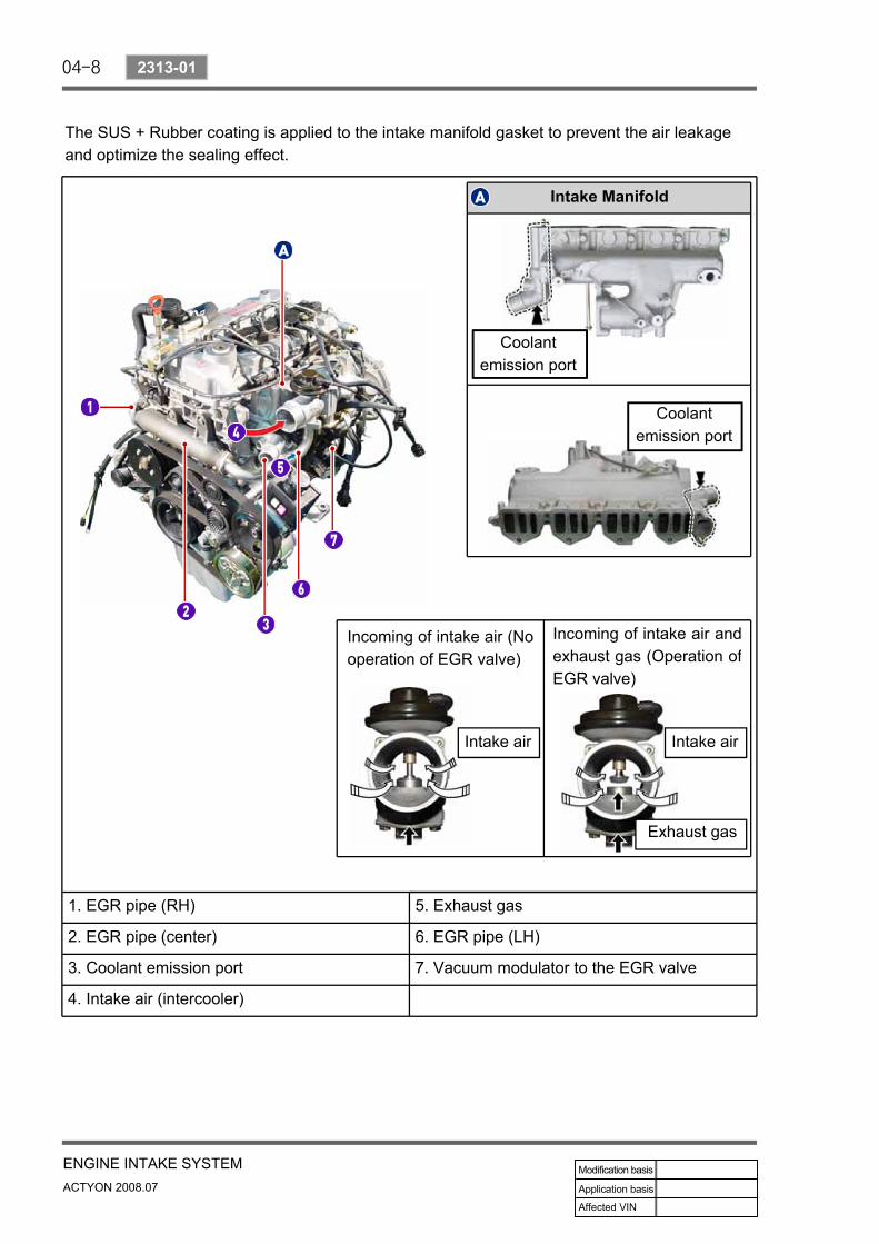
1. EGR pipe (RH) 5. Exhaust gas
2. EGR pipe (center) 6. EGR pipe (LH)
3. Coolant emission port 7. Vacuum modulator to the EGR valve
4. Intake air (intercooler)
Intake Manifold
Incoming of intake air and exhaust gas (Operation of EGR valve)
Incoming of intake air (No operation of EGR valve)
Coolantemission port
Coolantemission port
The SUS + Rubber coating is applied to the intake manifold gasket to prevent the air leakage and optimize the sealing effect.
Intake airIntake air
Exhaust gas
04-9
ENGINE INTAKE SYSTEMACTYON 2008.07
2313-01
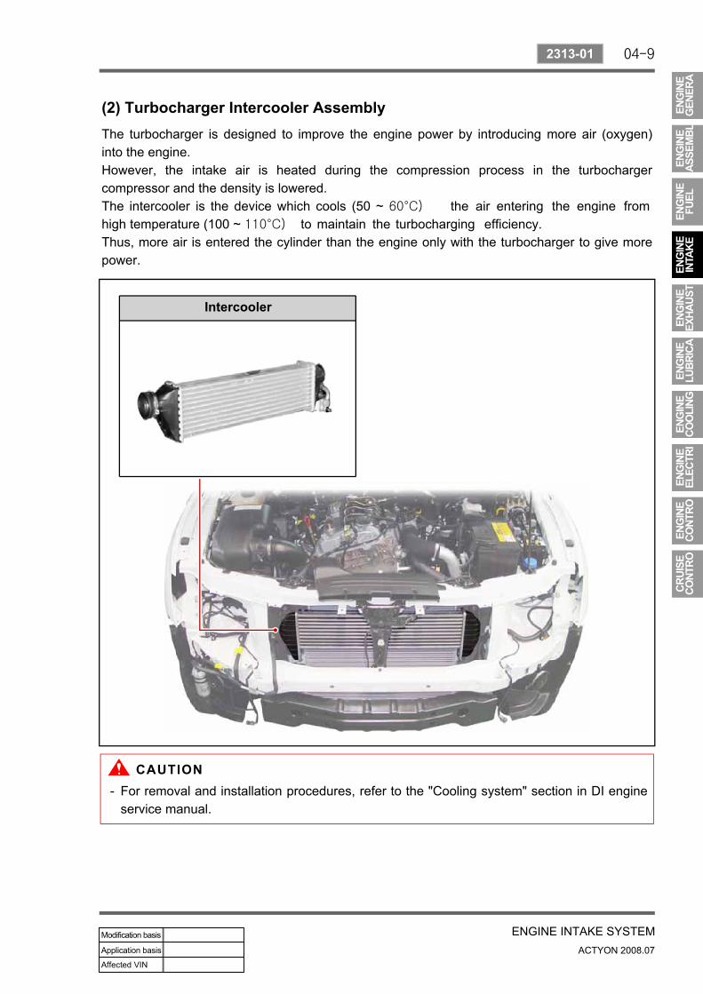
(2) Turbocharger Intercooler AssemblyThe turbocharger is designed to improve the engine power by introducing more air (oxygen) into the engine.However, the intake air is heated during the compression process in the turbocharger compressor and the density is lowered.The intercooler is the device which cools (50 ~ 60°C) the air entering the engine from high temperature (100 ~ 110°C) to maintain the turbocharging efficiency.Thus, more air is entered the cylinder than the engine only with the turbocharger to give more power.
Intercooler
For removal and installation procedures, refer to the "Cooling system" section in DI engine service manual.
-
04-10
ACTYON 2008.07
0000-00
ENGINE INTAKE SYSTEM
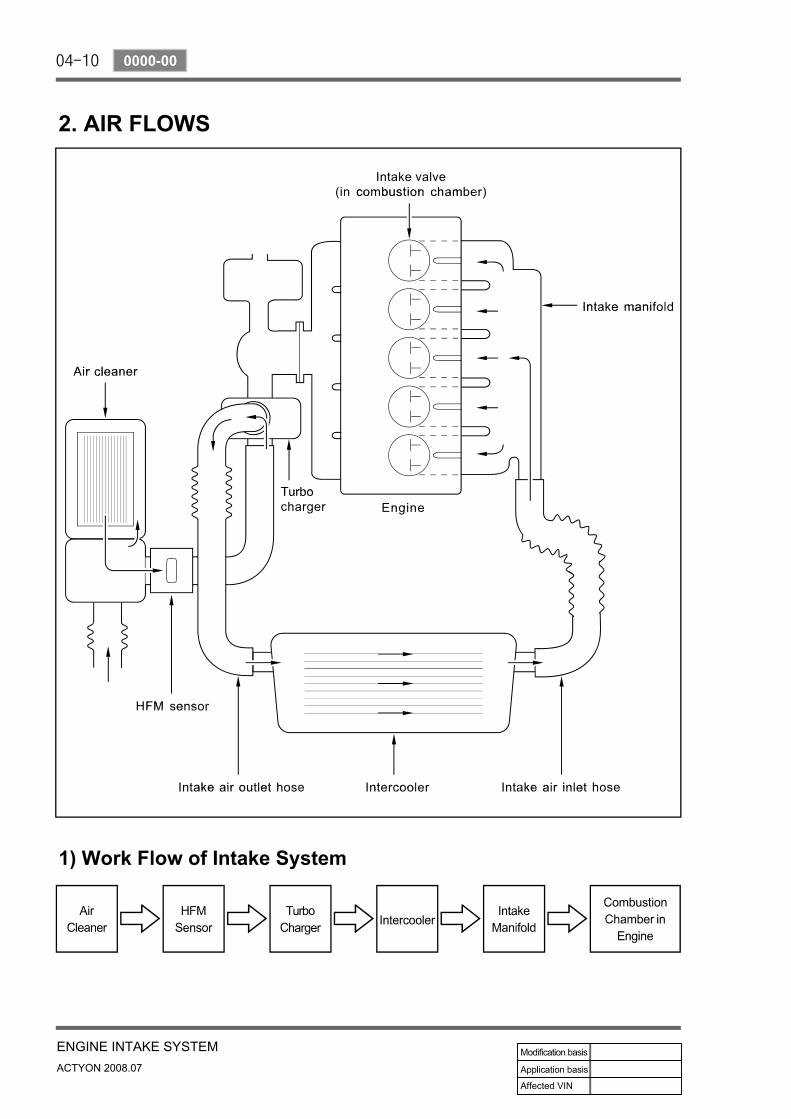
2. AIR FLOWS
1) Work Flow of Intake System