Embed Size (px)
Citation preview
Circuit Breaker Calibration
ECE 4901 Senior Design I
Fall 2015
Senior Design Proposal
Senior Design Team 1601 Philip Simonin (EE) Tyler Lyon (EE) Kyle Weber (EE) Louis LeBlanc (EE)
Advisor: Ali Gokirmak
Sponsor: Carling Technologies
Contacts: John Lach, Marek Szafranski, Mike Fasano

Carling Technologies Carling Technologies headquarters is located in Plainville CT. Founded in 1920, Carling
Technologies is established among the world's largest manufacturers of circuit breakers, switches, power distribution units, digital switching systems, and electronic controls. The engineering research and new product development is conducted in Connecticut. Manufacturing and production occur at the company’s plants located in Texas, China and Mexico. These facilities produce switches, power control systems, and other electrical components. Among these products are the company’s hydraulic circuit breakers created with various capabilities in mind. Calibration of these breakers is required depending upon application desired current trip point. Summary
The circuit breakers assigned to the group are Carling’s DC ASeries magnetic breakers. These are ideal for precision operation in OEM markets requiring general purpose and full load amp application due to their compact and temperature stable design. They are available with a choice of time delays, terminals, actuator styles, a wide range of standard colors, and imprinting. The problem to be resolved is that the current calibration process has a high margin of error since it is done manually. The solution to this problem will be to design a module using a microprocessor controlled current pickup type of detection. This will drive a motor connected to an adjustment pin within the breaker for spring tension adjustment of the circuit breaker actuation arm. Adjustments are to be made until the required threshold for the tripping of the breaker occurs. Objectives
The project was created in an effort to design and implement a functioning circuit breaker calibration unit which will adjust circuit breakers to trip at a designated point. Current company standards require this process to be completed in approximately 20 seconds and in order to improve efficiency and accuracy of calibration, will become semiautomated. This prototype unit will reduce the margin of error associated with calibrating circuit breakers manually to a value of 10% or less. The automated control is to be accomplished with a PSoC (Programmable System on Chip) made by Cypress prototype kit, programming unit, stepper motor and driver, solenoid to prevent breaker trip during load turnon, pneumatic rig, as well as logic and sensor pickup within the PSoC. All components will be combined to complete the calibration of a circuit breaker and any needed offsets for DC breakers of 5, 10, 15, and 20 Amp ratings. Approach
Beginning this project required research about the operation of circuit breakers and what the calibration was really adjusting. The process of tripping occurs with an induced electromagnetic field pulling a steel plunger submerged within a viscous silicone fluid into the coil inside the breaker. When the core reaches the top of the coil, the induced magnetic field pulls on an actuation arm that is spring loaded to a specific tension. When the force is great enough to pull the actuation arm down, the breaker trips and opens circuit. The calibrating of these breakers is accomplished by adjusting the level of spring tension against the actuation arm via an adjustment screw as shown in figure 1. Altering this tension changes the breakers allowed

current let through to the magnetic sense coil which responds with an increase or decrease of electromagnetic force on the actuation arm, meaning a higher or lower current trip point.
Figure 1. Internal layout of a Carling circuit breaker highlighting the adjustment screw and magnetic sense coil. The calibration of a breaker involves precise changes to the adjustment screw in order to increase or decrease current trip point.
The calibration of the breaker requires a method of retainment as well as the ability to make adjustments to the device while current is applied. In an effort to accomplish this task, the pneumatic rig in figure 2 maintains position of the breaker in the X, Y, and Z axes, and completes the circuit with two copper cylinders attached to the breaker’s external contacts. Electrical control of the amount of current let through in the breaker will be observed as voltage from a shunt resistor and monitored by two methods: A calibrated DMM and the PSoC. Based on this reading, the PSoC will signal a stepper motor to begin turning clockwise or counterclockwise, increasing or decreasing the amount of current being passed through the breaker.
The overall design of the calibration unit is setup with the PSoC, motor driver and stepper directly attached to the lower platform of the pneumatic rig represented in figure 3. Establishing a 200% load of rated current for the 20 Amp breakers using a 5 VDC supply translates into a need of 40 amps through the breaker and a generation of 200 W peak sustained for a maximum of 10 seconds. Due to the power generation of the 20 amp breaker load, the load bank was separated from the rig and electrical control equipment and has a fan available to allow for the cooling of the load bank while under test.

Figure 2. On the left is a view of the pneumatic rig be implemented. It has vertical movement and delivers a downforce of 50 psi to hold the breaker in position under load. On the right, circled in green are horizontal spring loaded constraints. The stepper motor is circled in yellow. The red circle is where the 3D plastic motor adapter will connect to a modified flat head screwdriver which will tune the adjustment screw circled in blue. The two copper cylinders circled in orange provide current while under test.
Figure 3 Block diagram of calibration unit and layout of components. Process
The control unit is set to the current breaker configuration through a series of logic switches and operations. This information is acquired and used for inputs to the PSoC. The breaker is positioned in the pneumatic rig. Upon activation, 50 psi is delivered to the rig and the restraint platform lowers into position. Spring loaded pins make contact with structure points within the breaker holding it position and copper contacts on the platform make contact with the
supply and load. Simultaneously, the stepper motor and solenoid which are mounted in line with the breaker, are lowered into position. The stepper being attached to a flat head screw driver is aligned over the set screw and held in position here with the assistance of a brass tubular sheath to ensure proper alignment and with the adjustment screw.
The second event is the activation of the electrical calibration unit. When the PSoC is started, a 200% of rated value current for the breaker is applied to the circuit. This causes the plunger of the circuit breaker to begin moving into position. A solenoid arm is activated and placed between the breaker’s contacts to prevent the breaker itself from tripping. After 10 seconds, the load is reduced to 115% of the rated value through a power relay controlled by the PSoC. The solenoid is deactivated within 2 clock pulses during the load switch and the stepper motor is turned on to adjust the trip point.
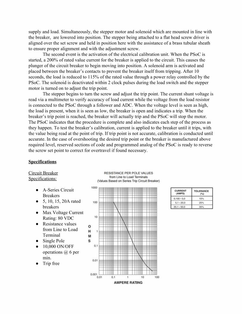
The stepper begins to turn the screw and adjust the trip point. The current shunt voltage is read via a multimeter to verify accuracy of load current while the voltage from the load resistor is connected to the PSoC through a follower and ADC. When the voltage level is seen as high, the load is present, when it is seen as low, the breaker is open and indicates a trip. When the breaker’s trip point is reached, the breaker will actually trip and the PSoC will stop the motor. The PSoC indicates that the procedure is complete and also indicates each step of the process as they happen. To test the breaker’s calibration, current is applied to the breaker until it trips, with the value being read at the point of trip. If trip point is not accurate, calibration is conducted until accurate. In the case of overshooting the desired trip point or the breaker is manufactured above required level, reserved sections of code and programmed analog of the PSoC is ready to reverse the screw set point to correct for overtravel if found necessary. Specifications Circuit Breaker Specifications:
● ASeries Circuit Breakers
● 5, 10, 15, 20A rated breakers
● Max Voltage Current Rating: 80 VDC
● Resistance values from Line to Load Terminal
● Single Pole ● 10,000 ON/OFF
operations @ 6 per min.
● Trip free

PSoC capabilities [1] [2]:
● 32bit MCU Subsystem ○ 48MHz ARM® Cortex®M0 CPU ○ Up to 128KB Flash, 16KB SRAM ○ DMA Controller ○ 2x CAN 2.0
● CapSense® with SmartSense™ Autotuning ○ Cypress Capacitive SigmaDelta™ (CSD) controller ○ CapSense supported on up to 55 pins
● Programmable Analog Blocks ○ 2x LowPower Comparators (CMP) ○ 4x LowPower Opamps ○ 1x 12bit, 1Msps SAR ADC ○ 4x IDACs (2x 8bit, 2x 7bit) ○ 1 55 Channel Analog Multiplexer
● Programmable Digital Blocks ○ 4x Universal Digital Blocks (UDBs) ○ 8x 16bit TCPWM blocks ○ 4x SCBs: I2C M/S, SPI M/S, UART
● 2x Controller Area Network (CAN 2.0) Controllers ● Packages:48pin LQFP, 64pin TQFP (0.8mm pitch), 64pin TQFP (0.5mm pitch), 68pin
QFN H bridge stepper motor driver [3] [4]:
● Bipolar Microstepping Driver ● 2A/Phase Max ● 1.41.7A/Phase w/o Heatsink ● Max Motor Drive Voltage: 30V ● Onboard 5V/3.3V Regulation
Setup for step resolution depending on motor type:

Figure 4. Cypress 4200 control chip with data pins highlighted in blue and supply pins in green.
Cypress’ 4200 chipset allows for up to 36 I/O pins to be used. This provides the ability to design a circuit with a wider variety of digital, analog, or combination of these capabilities. Due to the PSoC design and potential, it was chosen to be the controller for the calibration unit. In figure 4 are the pins used thus far in development. The possibility of using more of the controller's analog or digital devices may occur depending on need in the future.
Of the pins being used, Relay_Load (P2(4)), uses a 5 VDC signal to drive a high power relay via an optocoupler to control and switch between 115% or 200% load. There is an active Alive pin (P2(1)) which indicates to a used that the PSoC is still on and functioning as required. The stepper motor is controlled with clocked pulses intervalled between 1 and 10 microseconds by setting P2(2)) high or low, and sending the signal to an H bridge driver enable pin. Depending upon the speed of adjustment needed these values are subject to change moving forward. The PSoC sends this signal to an enable pin on the H bridge driver controlling the motor operation. A reverse relay motor drive (P2(3)) is available as well as a reserved function. Its purpose is to account for overtravel of the adjustment screw and reduce the trip point back down to required trip values. P0(7) acts as a system clock and acts as a reference for the operation of the internal functions of the PSoC. P0(4) delivers a 5VDC signal to drive an optocoupler to a solenoid which
is force the the solenoid arm between the internal contacts of the breaker during 200% load period.
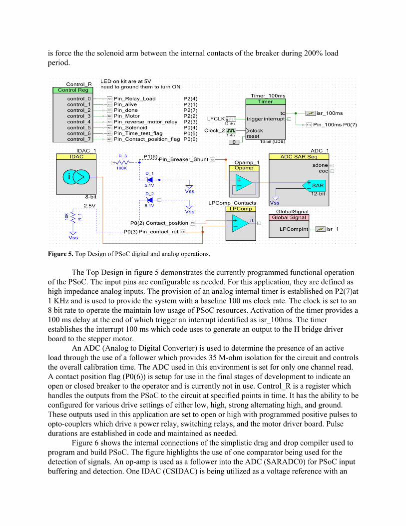
Figure 5. Top Design of PSoC digital and analog operations.
The Top Design in figure 5 demonstrates the currently programmed functional operation of the PSoC. The input pins are configurable as needed. For this application, they are defined as high impedance analog inputs. The provision of an analog internal timer is established on P2(7)at 1 KHz and is used to provide the system with a baseline 100 ms clock rate. The clock is set to an 8 bit rate to operate the maintain low usage of PSoC resources. Activation of the timer provides a 100 ms delay at the end of which trigger an interrupt identified as isr_100ms. The timer establishes the interrupt 100 ms which code uses to generate an output to the H bridge driver board to the stepper motor.
An ADC (Analog to Digital Converter) is used to determine the presence of an active load through the use of a follower which provides 35 Mohm isolation for the circuit and controls the overall calibration time. The ADC used in this environment is set for only one channel read. A contact position flag (P0(6)) is setup for use in the final stages of development to indicate an open or closed breaker to the operator and is currently not in use. Control_R is a register which handles the outputs from the PSoC to the circuit at specified points in time. It has the ability to be configured for various drive settings of either low, high, strong alternating high, and ground. These outputs used in this application are set to open or high with programmed positive pulses to optocouplers which drive a power relay, switching relays, and the motor driver board. Pulse durations are established in code and maintained as needed.
Figure 6 shows the internal connections of the simplistic drag and drop compiler used to program and build PSoC. The figure highlights the use of one comparator being used for the detection of signals. An opamp is used as a follower into the ADC (SARADC0) for PSoC input buffering and detection. One IDAC (CSIDAC) is being utilized as a voltage reference with an

internal resistor in to create a current source. The blue, purple, and pink lines indicate the onboard paths being used to complete the connections and components which are greyed are still available for use in the future.
Figure 6. Internal connections made in top design drag and drop set up. Progress
Thus far, a variety of goals have been met and tasks completed. Without having a mechanical engineering teammate, the team has endeavored to make modifications to a pneumatic rig provided by the company. The housing of the rig has been modified to properly seat and secure the A series breakers being used. Mounting brackets and layouts for both the stepper motor and solenoid are near completion and require sponsor assistance for completion over the winter recess. A load bank has been created and adjusted to deliver currents of 115% and 200% of rated current for the 5, 10, 15, and 20 amp DC breakers to be calibrated. A microcontroller has been setup with a functioning program having the capabilities of current detection, switching, timing, indirect driving of the motor utilizing an H bridge driver. This provides the overall control of the unit when under test. The accompanying electrical and mechanical circuits have been designed and will be constructed in the coming weeks. Assembly

of the project is to occur over the winter break with testing set to commence with the Spring 2016 semester.
Figure 7. This is the current resources used and available in the PSoC as it is currently programmed. Results
The PSoC programming thus far is capable of driving optocouplers used for driving the power and control relays, solenoid, and motor through the use of signal sequencing to the H bridge driver. Initial testing of the H bridge driver resulted in failure of the board. The H bridge has built in resistors which act as a pullup, keeping signals high which should have been low for the motor being used. Connecting the low end of the resistors to ground pulled too much current from the internal supply and overdrove the on board voltage regulator. The next attempt was done differently to separate the internal current requirements. Retesting on the Hbridge was done and shows that with an external and separate supply, functionality will be possible. Modifications to the testing rig will need to be made after conversing with the company to create mounting capabilities and proper alignment with the breakers. Regarding the PSoC resources

represented in figure 7, over 50% of the internal resources are still available for improvements and growth of capabilities in future revisions. Testing has shown that due to the minimal cost of purchase for the PSoC boards ($4 per board), boards may be purchased for individual breaker programming. That is, one board for the 5, 10, 15, and 20 amp breakers each. Timeline
Budget
Quantity Item Model Specifics Cost
1 Programming Unit for PSoC
CYPRESS – CY8CKIT002 PSoC® MiniProg3 Program and Debug Kit
$82.43
6 PSoC 4 CY8CKIT 04942XX KIT PSOC 4200 PROGRAMMING
$23.94
1 Stepper Motor Model NEMA11, product code: 11HS12
$14.00

1 Alternative Stepper Motor
Model – NEMA17, product code: RBAda138
$16.99
1 USB oscilloscope From Analog Discovery, to be used with LabVIEW
$159.00
1 Analog Parts Kit $49.99
1 NI Multisim & NI Ultiboard
NI Circuit Design Suite $34.95
1 Analog Discovery BNC Adapter Board
$19.99
1 BNC Oscilloscope Probes (pair)
$19.99
1 Mini "Grabber" Test Hooks
$14.99
1 Project Box $7.00
2 Power Relay Schneider Electric/Magnecraft Model 119DBX3
$37.70
3 Signal Relays Kemet EE25NUL, 3.75 V $1.81
3 Signal Relays Kemet EC212NU, 9 V $1.97
6 Optocouplers Part number: 4N26 $0.59
1 Package Nonmarring Flat Point Socket Set Screw 1/8" Long
Type 316 Stainless Steel, 256 Thread 92158A311
$12.55
1 Package Nonmarring Flat Point Socket Set Screw 3/16" Long
Type 316 Stainless Steel, 256 Thread 92158A312
$12.20
1 PLA plastic spool 1 kg spool for 3D printed motor adapter + labor hour (estimate)
$40.00

4 Big Easy Stepper Driver
$59.96
Total: $610.05
References [1] Digikey.com, 'PSoC® 4 CY8CKIT049 4xxx Prototyping Kits Cypress Semiconductor |
DigiKey', 2015. [Online]. Available: http://www.digikey.com/en/producthighlight/c/cypress/psoc4cy8ckit0494xxxprototypingkits. [Accessed: 10 Oct 2015].
[2] Cypress.com, 'PSoC® 4 CY8CKIT049 4xxx Prototyping Kits | Cypress', 2015. [Online]. Available: http://www.cypress.com/documentation/developmentkitsboards/psoc4cy8ckit0494xxxprototypingkits. [Accessed: 10 Oct 2015].
[3] B. Schmalz, 'Big Easy Driver stepper motor driver', Schmalzhaus.com, 2015. [Online]. Available: http://www.schmalzhaus.com/BigEasyDriver/. [Accessed: 15 Nov 2015].
[4] B. Schmalz, Big Easy Driver User Manual, 2nd ed. Schmalz Haus LLC, 2012, pp. 17.