Embed Size (px)
Citation preview
1
CIM Standards Overview
and CIM’s Role in the Utility
Enterprise – Part 1
Terry Saxton
Xtensible Solutions
2
Presentation Contents for Morning Session
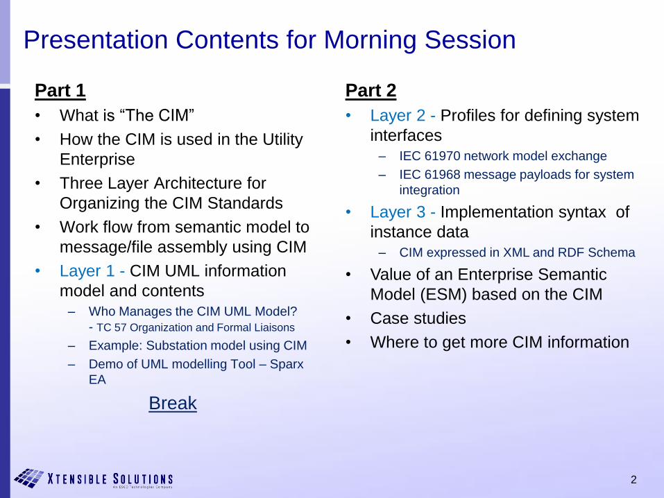
Part 1
• What is “The CIM”
• How the CIM is used in the Utility
Enterprise
• Three Layer Architecture for
Organizing the CIM Standards
• Work flow from semantic model to
message/file assembly using CIM
• Layer 1 - CIM UML information
model and contents– Who Manages the CIM UML Model?
- TC 57 Organization and Formal Liaisons
– Example: Substation model using CIM
– Demo of UML modelling Tool – Sparx
EA
Break
Part 2
• Layer 2 - Profiles for defining system
interfaces– IEC 61970 network model exchange
– IEC 61968 message payloads for system
integration
• Layer 3 - Implementation syntax of
instance data– CIM expressed in XML and RDF Schema
• Value of an Enterprise Semantic
Model (ESM) based on the CIM
• Case studies
• Where to get more CIM information
3
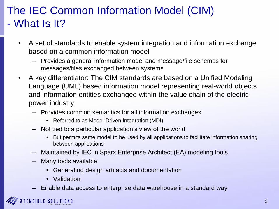
The IEC Common Information Model (CIM)
- What Is It?
• A set of standards to enable system integration and information exchange
based on a common information model
– Provides a general information model and message/file schemas for
messages/files exchanged between systems
• A key differentiator: The CIM standards are based on a Unified Modeling
Language (UML) based information model representing real-world objects
and information entities exchanged within the value chain of the electric
power industry
– Provides common semantics for all information exchanges
• Referred to as Model-Driven Integration (MDI)
– Not tied to a particular application’s view of the world
• But permits same model to be used by all applications to facilitate information sharing
between applications
– Maintained by IEC in Sparx Enterprise Architect (EA) modeling tools
– Many tools available
• Generating design artifacts and documentation
• Validation
– Enable data access to enterprise data warehouse in a standard way
4
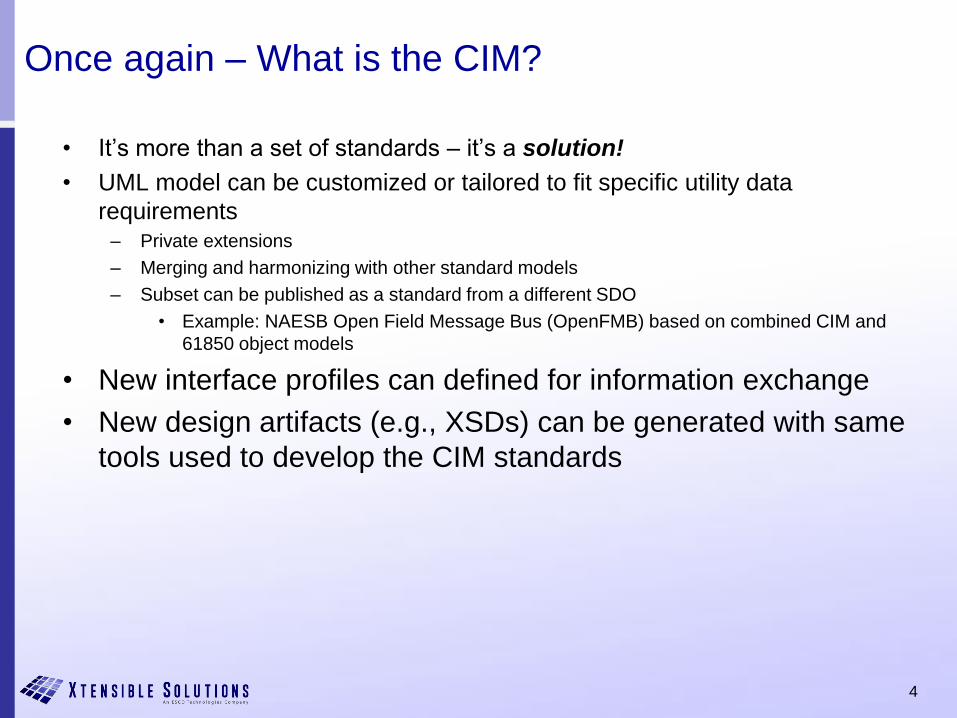
Once again – What is the CIM?
• It’s more than a set of standards – it’s a solution!
• UML model can be customized or tailored to fit specific utility data
requirements– Private extensions
– Merging and harmonizing with other standard models
– Subset can be published as a standard from a different SDO
• Example: NAESB Open Field Message Bus (OpenFMB) based on combined CIM and
61850 object models
• New interface profiles can defined for information exchange
• New design artifacts (e.g., XSDs) can be generated with same
tools used to develop the CIM standards
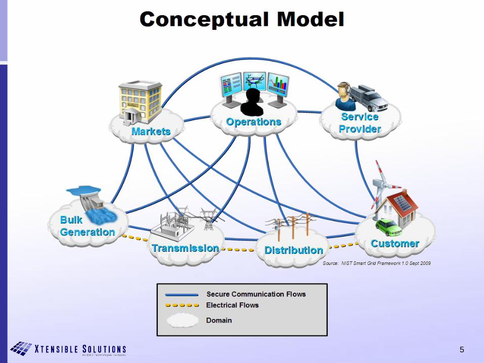
5
6
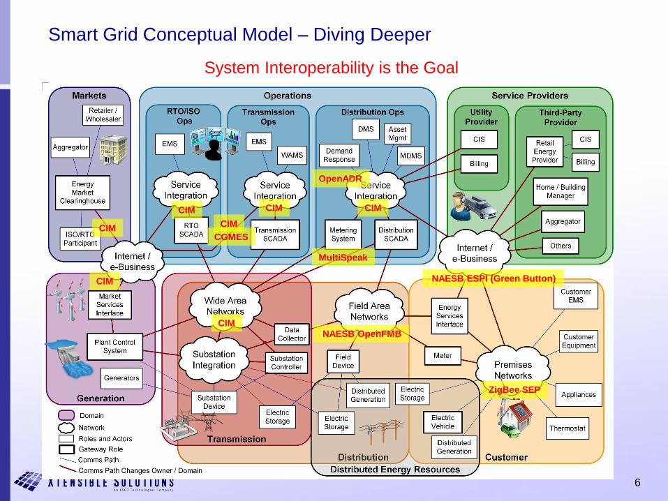
Smart Grid Conceptual Model – Diving Deeper
CIM
ZigBee SEP
NAESB ESPI (Green Button)
MultiSpeak
CIMCIMCIM
CIM
CIM
OpenADR
System Interoperability is the Goal
NAESB OpenFMB
CIM
CGMES
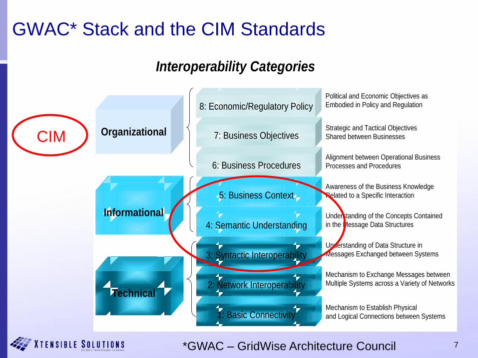
7
GWAC* Stack and the CIM Standards
Organizational
Technical
Informational
8: Economic/Regulatory Policy
7: Business Objectives
6: Business Procedures
3: Syntactic Interoperability
5: Business Context
2: Network Interoperability
4: Semantic Understanding
1: Basic Connectivity
Interoperability Categories
Political and Economic Objectives as
Embodied in Policy and Regulation
Strategic and Tactical Objectives
Shared between Businesses
Alignment between Operational Business
Processes and Procedures
Awareness of the Business Knowledge
Related to a Specific Interaction
Understanding of the Concepts Contained
in the Message Data Structures
Understanding of Data Structure in
Messages Exchanged between Systems
Mechanism to Exchange Messages between
Multiple Systems across a Variety of Networks
Mechanism to Establish Physical
and Logical Connections between Systems
CIM
*GWAC – GridWise Architecture Council

8
Role of CIM in Smart Grid Architecture
- and in the Utility Enterprise
• CIM standards aim to simplify integration of components and expand options for supply of components by standardizing information exchanges– Reduce complexity with clear consistent semantic modeling
across the enterprise
– Data sources: achieve a clear picture of data mastership in the enterprise
– Data consumers: make ‘data of record’ available on demand to qualified users
• CIM employs a canonical data model (CDM) strategy for standardizing interfaces in the power system operations and planning domain.
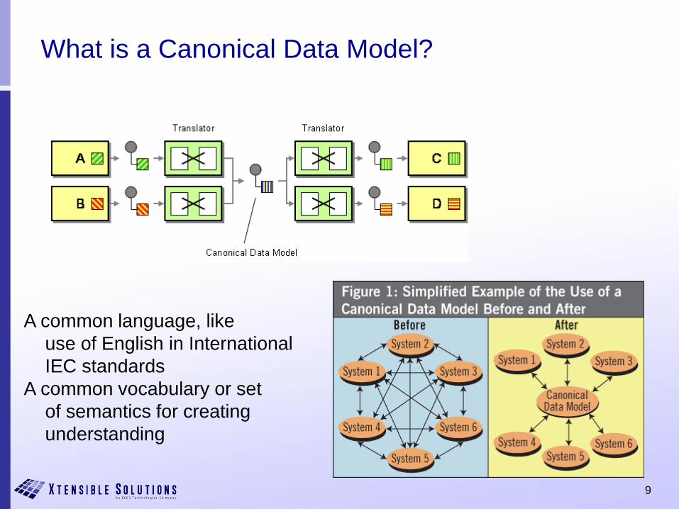
9
What is a Canonical Data Model?
A common language, like
use of English in International
IEC standards
A common vocabulary or set
of semantics for creating
understanding
10
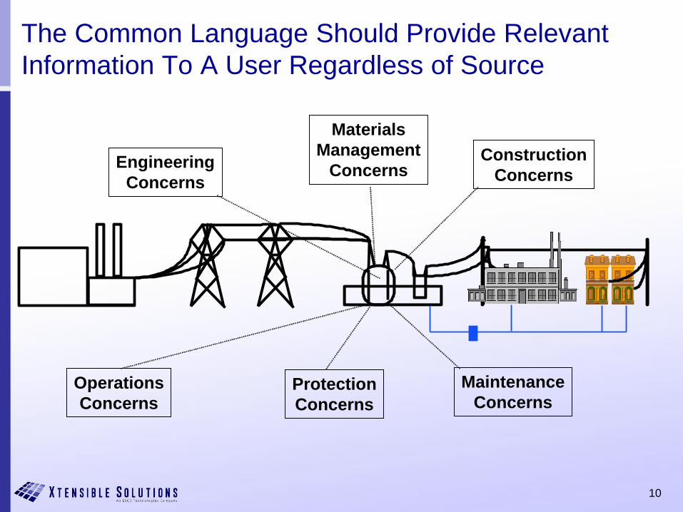
The Common Language Should Provide Relevant
Information To A User Regardless of Source
Engineering
Concerns
Materials
Management
ConcernsConstruction
Concerns
Operations
ConcernsProtection
Concerns
Maintenance
Concerns
11
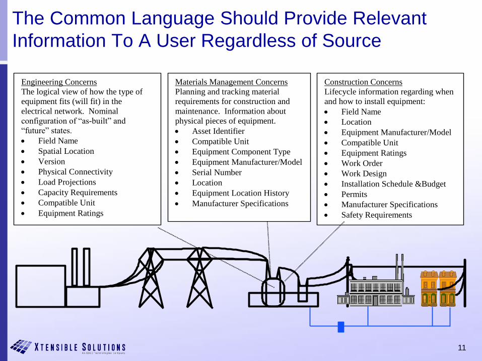
The Common Language Should Provide Relevant
Information To A User Regardless of Source
Engineering Concerns
The logical view of how the type of
equipment fits (will fit) in the
electrical network. Nominal
configuration of “as-built” and
“future” states.
Field Name
Spatial Location
Version
Physical Connectivity
Load Projections
Capacity Requirements
Compatible Unit
Equipment Ratings
Construction Concerns
Lifecycle information regarding when
and how to install equipment:
Field Name
Location
Equipment Manufacturer/Model
Compatible Unit
Equipment Ratings
Work Order
Work Design
Installation Schedule &Budget
Permits
Manufacturer Specifications
Safety Requirements
Materials Management Concerns
Planning and tracking material
requirements for construction and
maintenance. Information about
physical pieces of equipment.
Asset Identifier
Compatible Unit
Equipment Component Type
Equipment Manufacturer/Model
Serial Number
Location
Equipment Location History
Manufacturer Specifications
12
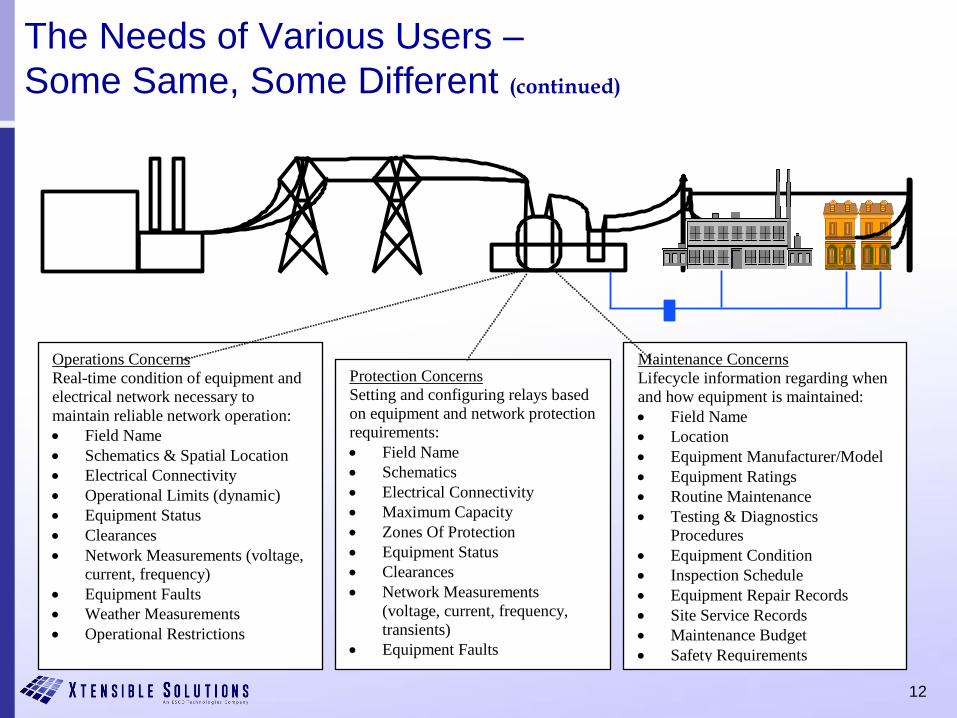
The Needs of Various Users –
Some Same, Some Different (continued)
Operations Concerns
Real-time condition of equipment and
electrical network necessary to
maintain reliable network operation:
Field Name
Schematics & Spatial Location
Electrical Connectivity
Operational Limits (dynamic)
Equipment Status
Clearances
Network Measurements (voltage,
current, frequency)
Equipment Faults
Weather Measurements
Operational Restrictions
Maintenance Concerns
Lifecycle information regarding when
and how equipment is maintained:
Field Name
Location
Equipment Manufacturer/Model
Equipment Ratings
Routine Maintenance
Testing & Diagnostics
Procedures
Equipment Condition
Inspection Schedule
Equipment Repair Records
Site Service Records
Maintenance Budget
Safety Requirements
Protection Concerns
Setting and configuring relays based
on equipment and network protection
requirements:
Field Name
Schematics
Electrical Connectivity
Maximum Capacity
Zones Of Protection
Equipment Status
Clearances
Network Measurements
(voltage, current, frequency,
transients)
Equipment Faults
13
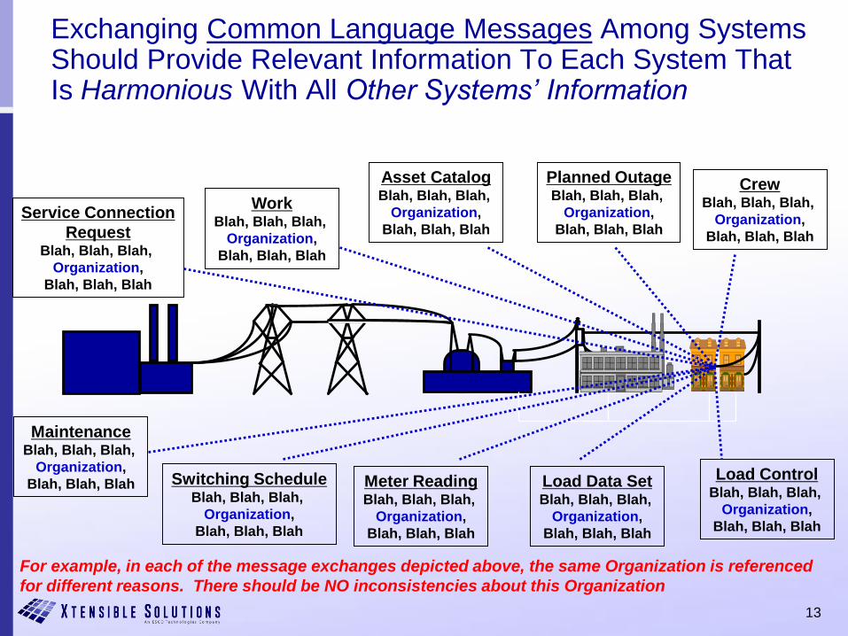
Exchanging Common Language Messages Among Systems Should Provide Relevant Information To Each System That Is Harmonious With All Other Systems’ Information
WorkBlah, Blah, Blah,
Organization,
Blah, Blah, Blah
MaintenanceBlah, Blah, Blah,
Organization,
Blah, Blah, Blah Switching ScheduleBlah, Blah, Blah,
Organization,
Blah, Blah, Blah
Load Data SetBlah, Blah, Blah,
Organization,
Blah, Blah, Blah
Meter ReadingBlah, Blah, Blah,
Organization,
Blah, Blah, Blah
Load ControlBlah, Blah, Blah,
Organization,
Blah, Blah, Blah
Asset CatalogBlah, Blah, Blah,
Organization,
Blah, Blah, Blah
CrewBlah, Blah, Blah,
Organization,
Blah, Blah, Blah
Service Connection
RequestBlah, Blah, Blah,
Organization,
Blah, Blah, Blah
Planned OutageBlah, Blah, Blah,
Organization,
Blah, Blah, Blah
For example, in each of the message exchanges depicted above, the same Organization is referenced
for different reasons. There should be NO inconsistencies about this Organization
14
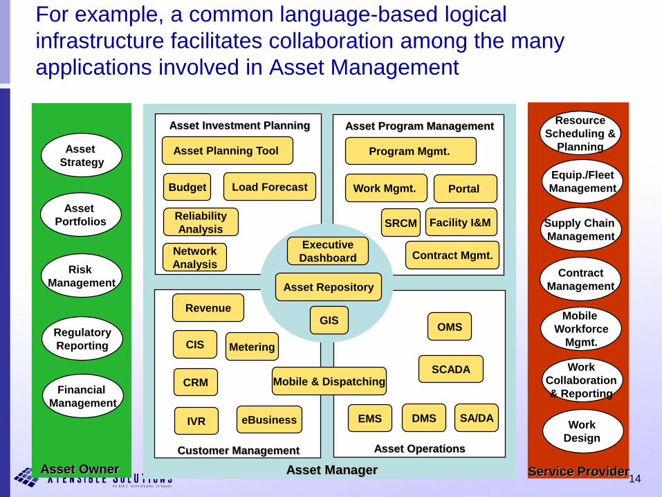
For example, a common language-based logical
infrastructure facilitates collaboration among the many
applications involved in Asset Management
Asset
Strategy
Asset
Portfolios
Risk
Management
Regulatory
Reporting
Financial
Management
Resource
Scheduling &
Planning
Equip./Fleet
Management
Supply Chain
Management
Contract
Management
Mobile
Workforce
Mgmt.
Work
Collaboration
& Reporting
Work
Design
Asset Owner Asset Manager Service Provider
Asset Investment Planning Asset Program Management
Customer Management Asset Operations
CIS
CRM
IVR eBusiness EMS DMS
SCADA
OMS
Asset Planning Tool
Budget Load Forecast
Reliability
Analysis
Network
Analysis
Asset Repository
Executive
Dashboard
Program Mgmt.
Work Mgmt.
Mobile & Dispatching
Contract Mgmt.
GISRevenue
Facility I&M
Portal
SA/DA
Metering
SRCM
15
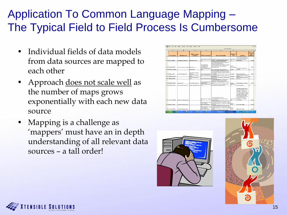
Application To Common Language Mapping –
The Typical Field to Field Process Is Cumbersome
• Individual fields of data models from data sources are mapped to each other
• Approach does not scale well as the number of maps grows exponentially with each new data source
• Mapping is a challenge as ‘mappers’ must have an in depth understanding of all relevant data sources – a tall order!
16
Using A Semantic Model Simplifies & Scales Up The
Mapping Process
• What is a Semantic Model?– The key ingredients that make up a semantic model are a vocabulary of
basic terms, a precise specification of what those terms mean and how they relate to each other.
• How is it used?– Before making mappings, a model (or an ontology) of a given business
domain is defined. – The model is expressed in a knowledge representation language and it
contains business concepts, relationships between them and a set of rules. – By organizing knowledge in a discrete layer for use by information
systems, semantic models enable communication between computer systems in a way that is independent of the individual system technologies, information architectures and applications.
– Compared to one-to-one mappings, mapping data sources to a common semantic model offer a much more scaleable and maintainable way to manage and integrate enterprise data.
17
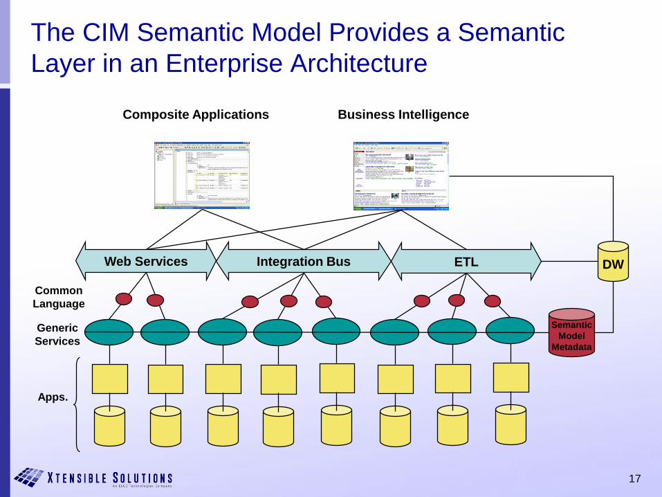
ETLIntegration BusWeb Services
Apps.
Generic
Services
Composite Applications
DW
Business Intelligence
Common
Language
Semantic
Model
Metadata
The CIM Semantic Model Provides a Semantic
Layer in an Enterprise Architecture
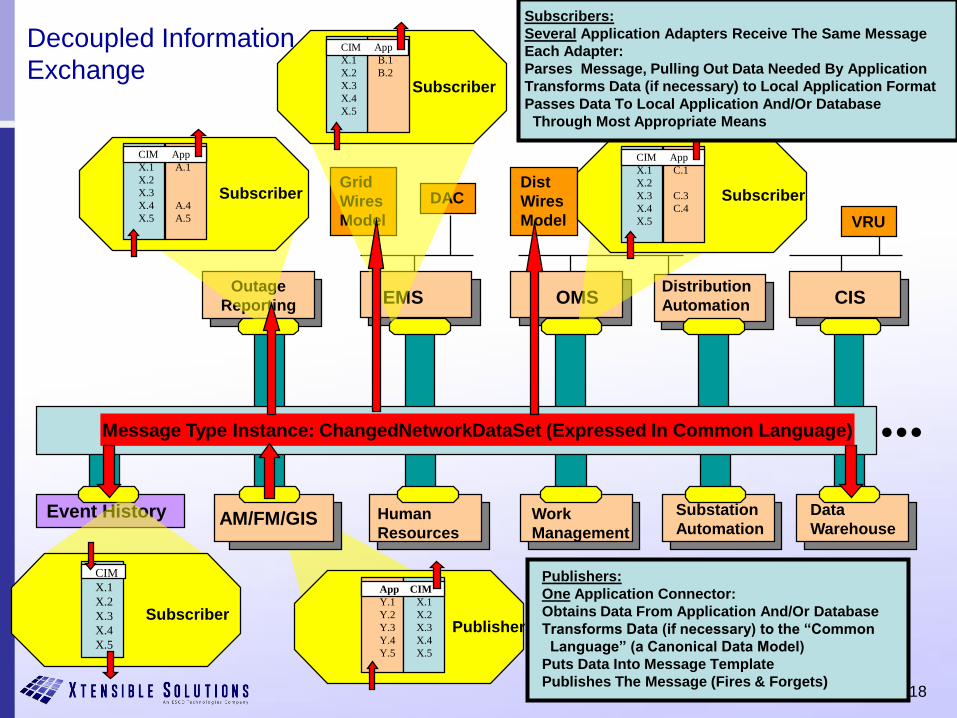
18
App CIM
Y.1 X.1
Y.2 X.2
Y.3 X.3
Y.4 X.4
Y.5 X.5
Publisher
Publishers:
One Application Connector:
Obtains Data From Application And/Or Database
Transforms Data (if necessary) to the “Common
Language” (a Canonical Data Model)
Puts Data Into Message Template
Publishes The Message (Fires & Forgets)
Data
Warehouse
Substation
Automation
OMS
Dist
Wires
Model
Grid
Wires
Model
DAC
CIS
VRU
AM/FM/GIS
Distribution
Automation
Human
Resources
Outage
Reporting
Event History Work
Management
EMS
...
CIM
X.1
X.2
X.3
X.4
X.5
Subscriber
CIM App
X.1 B.1
X.2 B.2
X.3
X.4
X.5
Subscriber
CIM App
X.1 A.1
X.2
X.3
X.4 A.4
X.5 A.5
Subscriber
CIM App
X.1 C.1
X.2
X.3 C.3
X.4 C.4
X.5
Subscriber
Subscribers:
Several Application Adapters Receive The Same Message
Each Adapter:
Parses Message, Pulling Out Data Needed By Application
Transforms Data (if necessary) to Local Application Format
Passes Data To Local Application And/Or Database
Through Most Appropriate Means
Message Type Instance: ChangedNetworkDataSet (Expressed In Common Language)
Decoupled Information
Exchange
19
We Need An Organizing Framework
• Let’s break it down
• The CIM standards include an information model expressed in UML
• Profiles for specifying a subset of the CIM classes and attributes for a specific business context at a specific system interface or system interaction
• Implementation models
– Use of XML to create serialized files and messages
• RDF Schema-based standards for power system model exchange
• XML Schema-based standards for information message payloads
– Could include ETL based on CIM for data base access
• DDLs for data tables
• But how do we organize these pieces?
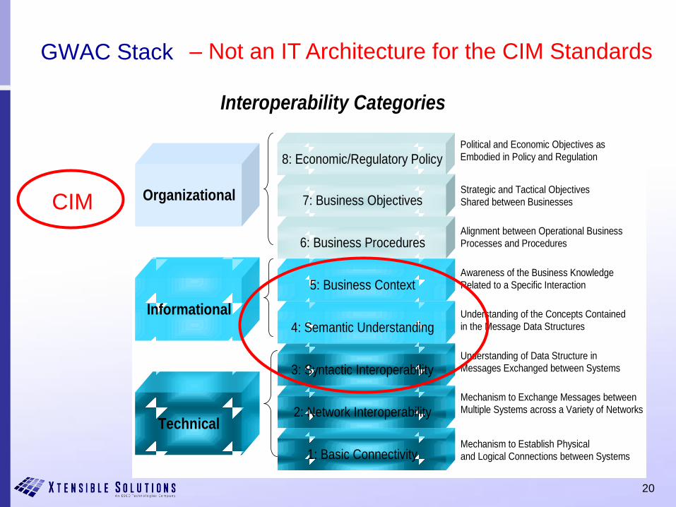
20
GWAC Stack
Organizational
Technical
Informational
8: Economic/Regulatory Policy
7: Business Objectives
6: Business Procedures
3: Syntactic Interoperability
5: Business Context
2: Network Interoperability
4: Semantic Understanding
1: Basic Connectivity
Interoperability Categories
Political and Economic Objectives as
Embodied in Policy and Regulation
Strategic and Tactical Objectives
Shared between Businesses
Alignment between Operational Business
Processes and Procedures
Awareness of the Business Knowledge
Related to a Specific Interaction
Understanding of the Concepts Contained
in the Message Data Structures
Understanding of Data Structure in
Messages Exchanged between Systems
Mechanism to Exchange Messages between
Multiple Systems across a Variety of Networks
Mechanism to Establish Physical
and Logical Connections between Systems
CIM
– Not an IT Architecture for the CIM Standards
21
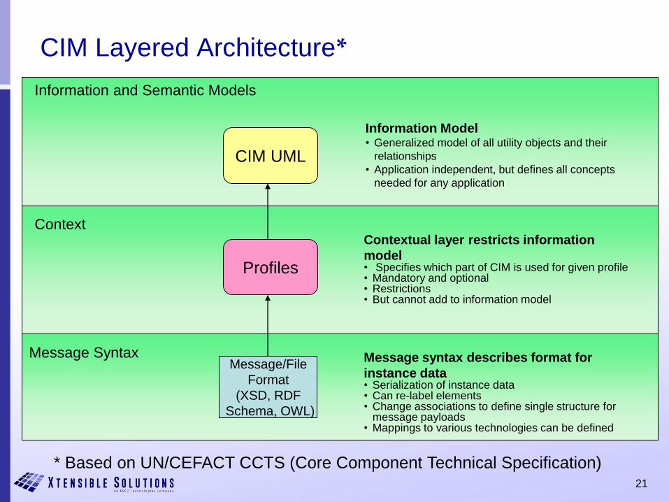
CIM Layered Architecture*
CIM UML
Information and Semantic Models
Context
Message Syntax
Profiles
Message/File
Format
(XSD, RDF
Schema, OWL)
Contextual layer restricts information
model• Specifies which part of CIM is used for given profile• Mandatory and optional• Restrictions• But cannot add to information model
Message syntax describes format for
instance data• Serialization of instance data• Can re-label elements• Change associations to define single structure for
message payloads• Mappings to various technologies can be defined
Information Model• Generalized model of all utility objects and their
relationships
• Application independent, but defines all concepts
needed for any application
* Based on UN/CEFACT CCTS (Core Component Technical Specification)
23
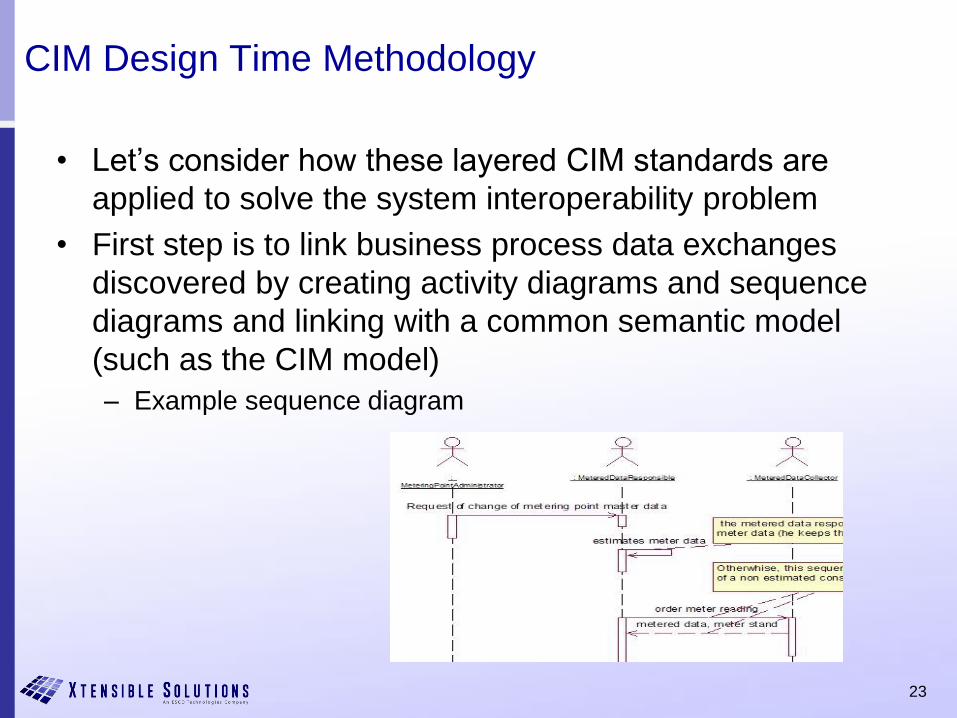
CIM Design Time Methodology
• Let’s consider how these layered CIM standards are
applied to solve the system interoperability problem
• First step is to link business process data exchanges
discovered by creating activity diagrams and sequence
diagrams and linking with a common semantic model
(such as the CIM model)
– Example sequence diagram
24
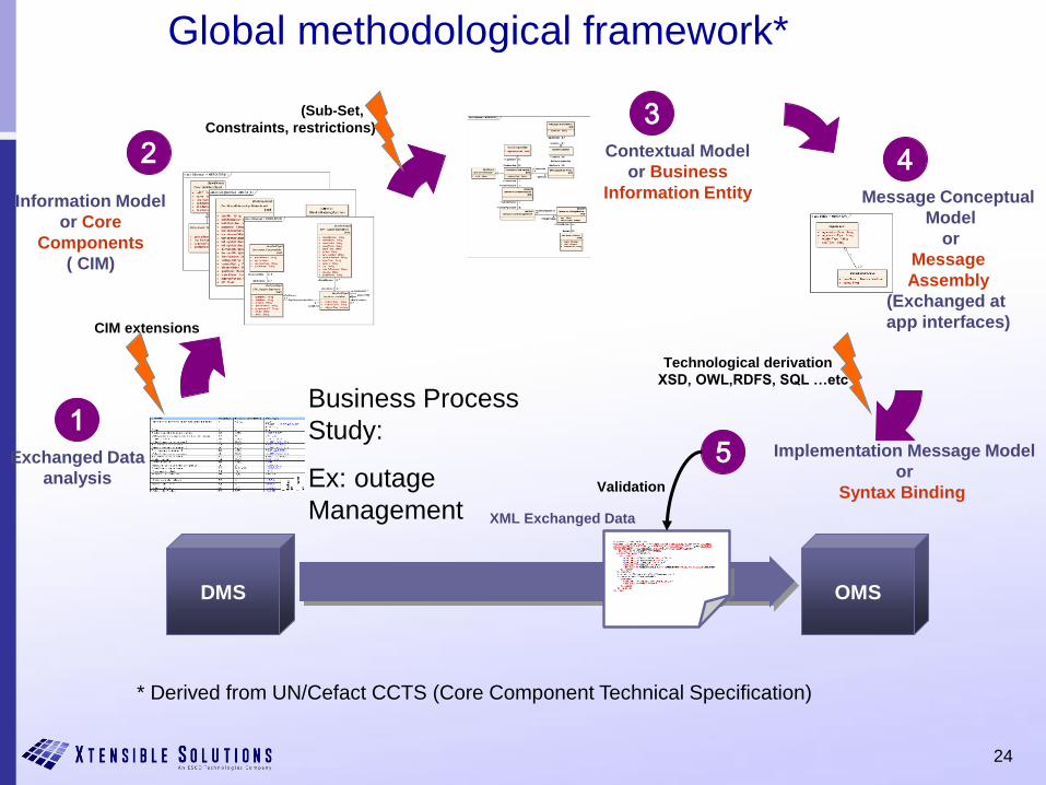
Global methodological framework*
DMS OMS
Exchanged Data
analysis
1
Message Conceptual
Model
or
Message
Assembly
(Exchanged at
app interfaces)
4
Business Process
Study:
Ex: outage
Management
Contextual Model
or Business
Information Entity
3(Sub-Set,
Constraints, restrictions)
5 Implementation Message Model
or
Syntax Binding
Technological derivation
XSD, OWL,RDFS, SQL …etc
XML Exchanged Data
Validation
Information Model
or Core
Components
( CIM)
2
CIM extensions
* Derived from UN/Cefact CCTS (Core Component Technical Specification)
25
CIM Design Time Methodology
• Another Example
– Need to exchange an Energy Transaction between System A and
System B
– Illustrates in more detail the design artifacts generated at each
step
– Important to note all design is done in UML using Sparx
Enterprise Architect with choice of CIM Tools
– Final step is to automatically generate XML or RDF schemas from
the UML
26
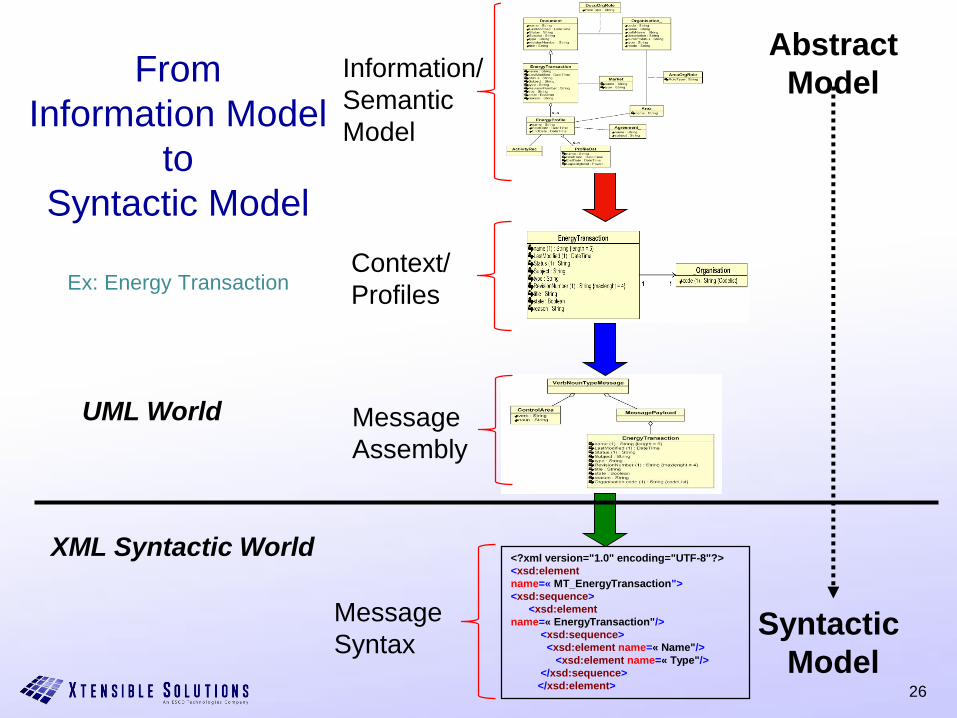
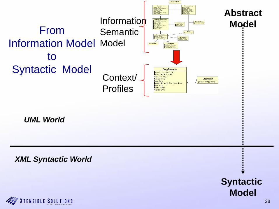
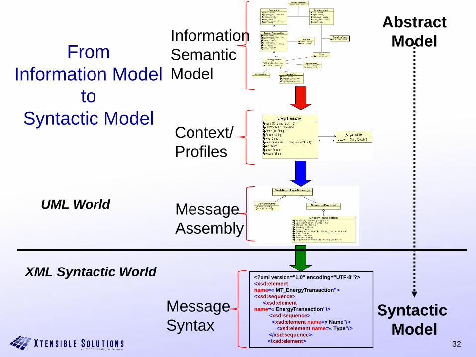
From
Information Model
to
Syntactic Model
Ex: Energy Transaction
Abstract
Model
Syntactic
Model
<?xml version="1.0" encoding="UTF-8"?>
<xsd:element
name=« MT_EnergyTransaction">
<xsd:sequence>
<xsd:element
name=« EnergyTransaction"/>
<xsd:sequence>
<xsd:element name=« Name"/>
<xsd:element name=« Type"/>
</xsd:sequence>
</xsd:element>
UML World
XML Syntactic World
Information/
Semantic
Model
Context/
Profiles
Message
Assembly
Message
Syntax
27
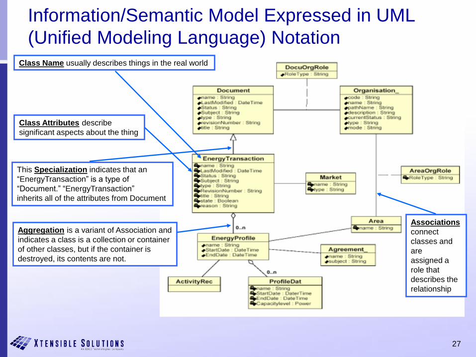
Information/Semantic Model Expressed in UML
(Unified Modeling Language) Notation
Class Name usually describes things in the real world
Class Attributes describe
significant aspects about the thing
This Specialization indicates that an
“EnergyTransaction” is a type of
“Document.” “EnergyTransaction”
inherits all of the attributes from Document
Aggregation is a variant of Association and
indicates a class is a collection or container
of other classes, but if the container is
destroyed, its contents are not.
Associations
connect
classes and
are
assigned a
role that
describes the
relationship
28
From
Information Model
to
Syntactic Model
Abstract
Model
Syntactic
Model
UML World
XML Syntactic World
Information/
Semantic
Model
Context/
Profiles
29
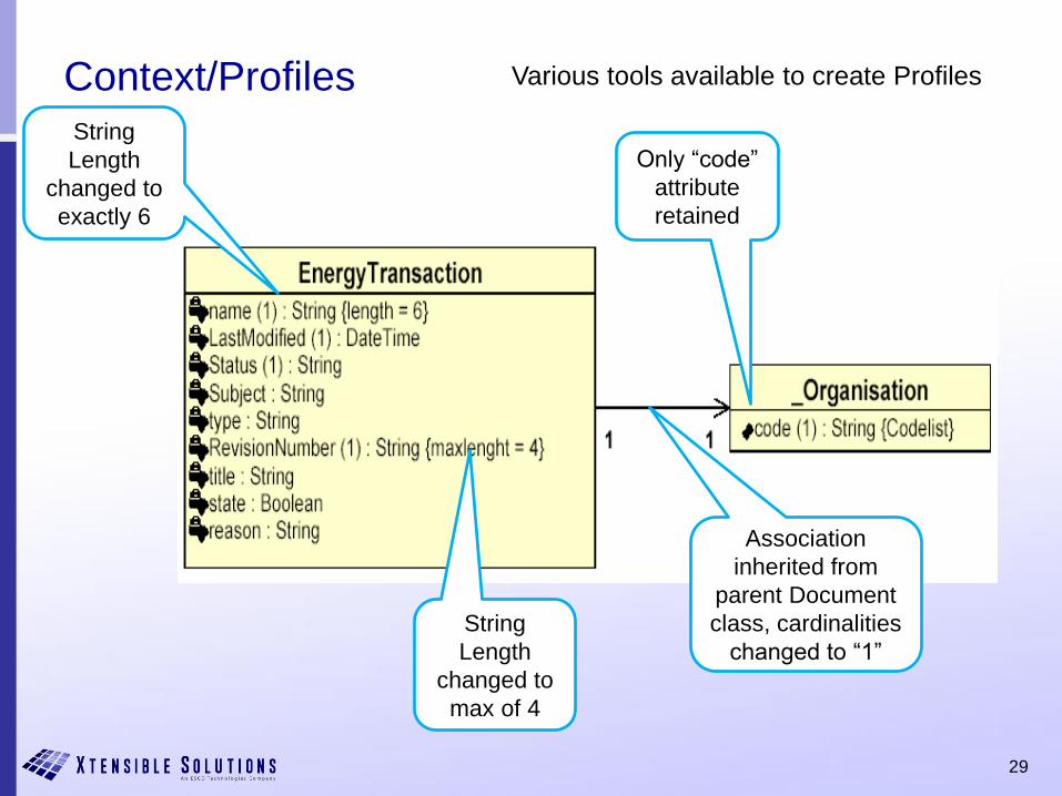
Context/Profiles
String
Length
changed to
exactly 6
String
Length
changed to
max of 4
Only “code”
attribute
retained
Association
inherited from
parent Document
class, cardinalities
changed to “1”
Various tools available to create Profiles
30
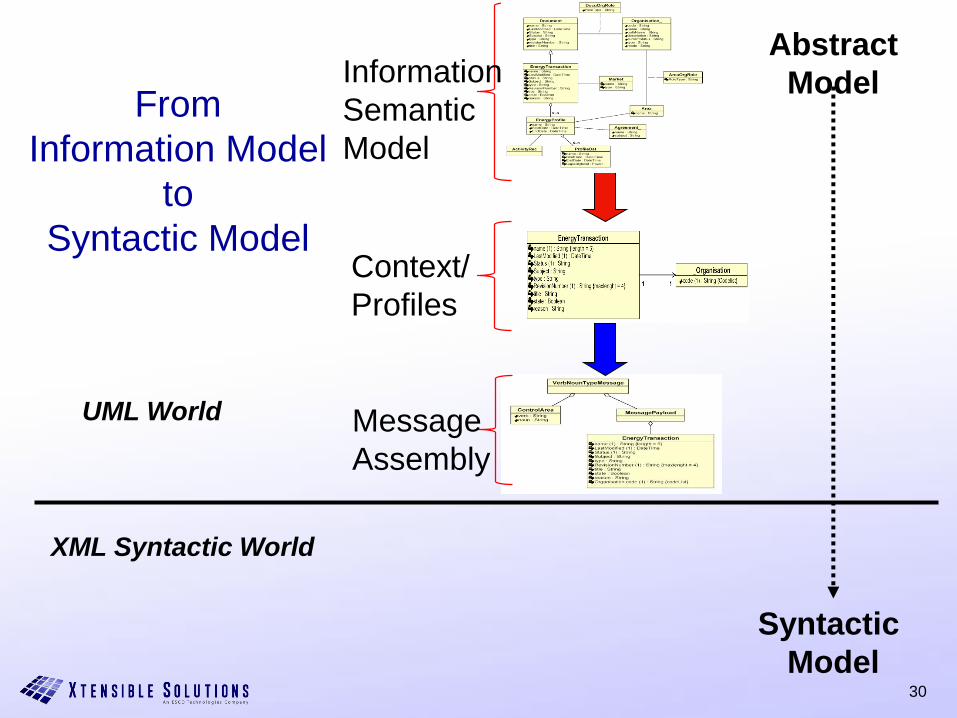
From
Information Model
to
Syntactic Model
Abstract
Model
Syntactic
Model
UML World
XML Syntactic World
Information/
Semantic
Model
Context/
Profiles
Message
Assembly

31
Message Assembly
32
From
Information Model
to
Syntactic Model
Abstract
Model
Syntactic
Model
<?xml version="1.0" encoding="UTF-8"?>
<xsd:element
name=« MT_EnergyTransaction">
<xsd:sequence>
<xsd:element
name=« EnergyTransaction"/>
<xsd:sequence>
<xsd:element name=« Name"/>
<xsd:element name=« Type"/>
</xsd:sequence>
</xsd:element>
UML World
XML Syntactic World
Information/
Semantic
Model
Context/
Profiles
Message
Assembly
Message
Syntax
33
To Summarize
• The CIM information model standard expressed in UML is used is the source of the semantics needed for a particular exchange
• A Profile specifies the restricted subset of the CIM classes and attributes for specific business context
– This is the CDM (Canonical Data Model) for a particular information exchange
• An Implementation Technology, such as XML, is used to create the schema for serializing the instance data as files or messages, resulting in
– Standards for power system models
– Standards for information message payloads
• The good news --- most of the power system models and message schemas needed by a utility are already defined as IEC standards
– 61970 series: Power system models for operations and planning (T&D)
– 61968 series: Message schemas for enterprise integration (T&D)
34
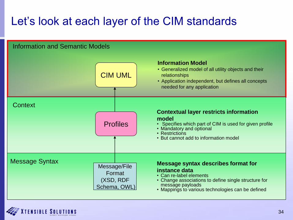
Let’s look at each layer of the CIM standards
CIM UML
Information and Semantic Models
Context
Message Syntax
Profiles
Message/File
Format
(XSD, RDF
Schema, OWL)
Contextual layer restricts information
model• Specifies which part of CIM is used for given profile• Mandatory and optional• Restrictions• But cannot add to information model
Message syntax describes format for
instance data• Can re-label elements• Change associations to define single structure for
message payloads• Mappings to various technologies can be defined
Information Model• Generalized model of all utility objects and their
relationships
• Application independent, but defines all concepts
needed for any application
35
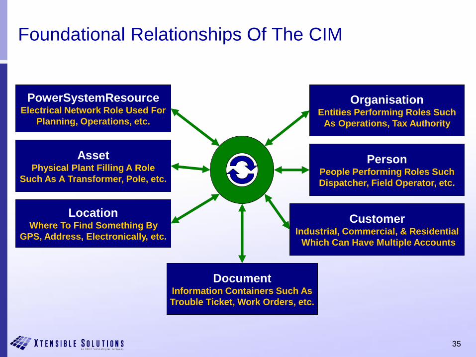
Foundational Relationships Of The CIM
PowerSystemResourceElectrical Network Role Used For
Planning, Operations, etc.
AssetPhysical Plant Filling A Role
Such As A Transformer, Pole, etc.
LocationWhere To Find Something By
GPS, Address, Electronically, etc.
OrganisationEntities Performing Roles Such
As Operations, Tax Authority
PersonPeople Performing Roles Such
Dispatcher, Field Operator, etc.
DocumentInformation Containers Such As
Trouble Ticket, Work Orders, etc.
CustomerIndustrial, Commercial, & Residential
Which Can Have Multiple Accounts
36
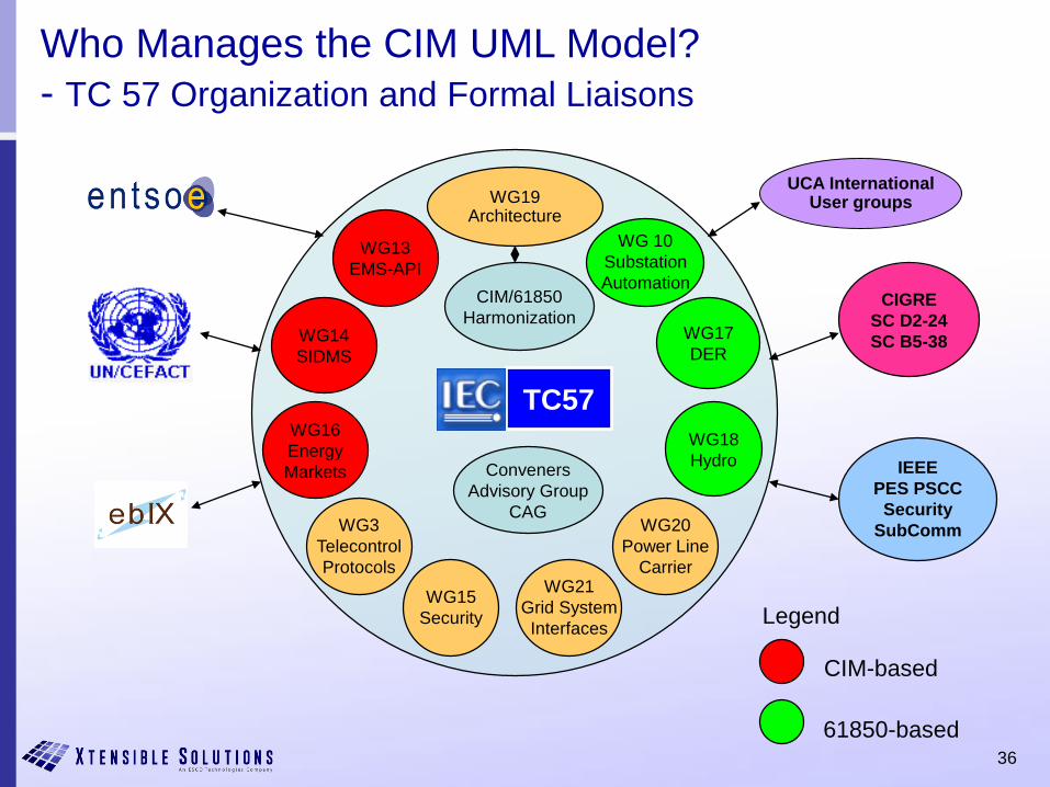
UCA InternationalUser groups
Who Manages the CIM UML Model?
- TC 57 Organization and Formal Liaisons
IEEE
PES PSCC
Security
SubComm
WG14
SIDMS
WG19Architecture
WG13
EMS-API
WG 10
Substation
AutomationCIGRE
SC D2-24
SC B5-38
TC57
CIM/61850
HarmonizationWG17
DER
WG16
Energy
Markets
WG18
Hydro
WG15
Security Legend
CIM-based
61850-based
WG3
Telecontrol
Protocols
WG20
Power Line
Carrier
Conveners
Advisory Group
CAG
WG21
Grid System
Interfaces
37
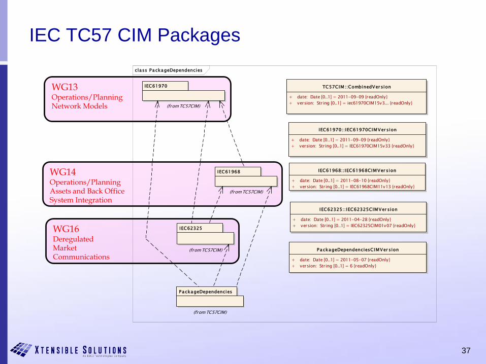
IEC TC57 CIM Packages
WG13Operations/Planning Network Models
WG14Operations/PlanningAssets and Back OfficeSystem Integration
WG16DeregulatedMarketCommunications
class PackageDependencies
TC57CIM::CombinedVer sion
+ date: Date [0..1] = 2011-09-09 {readOnly}
+ version: String [0..1] = iec61970CIM15v3... {readOnly}
IEC61970
(from TC57CIM)
PackageDependenciesCIMVer sion
+ date: Date [0..1] = 2011-05-07 {readOnly}
+ version: String [0..1] = 6 {readOnly}
IEC61968
(from TC57CIM)
IEC62325
(from TC57CIM)
PackageDependencies
(from TC57CIM)
IEC62325::IEC62325CIMVer sion
+ date: Date [0..1] = 2011-04-28 {readOnly}
+ version: String [0..1] = IEC62325CIM01v07 {readOnly}
IEC61968::IEC61968CIMVer sion
+ date: Date [0..1] = 2011-08-10 {readOnly}
+ version: String [0..1] = IEC61968CIM11v13 {readOnly}
IEC61970::IEC61970CIMVer sion
+ date: Date [0..1] = 2011-09-09 {readOnly}
+ version: String [0..1] = IEC61970CIM15v33 {readOnly}
38
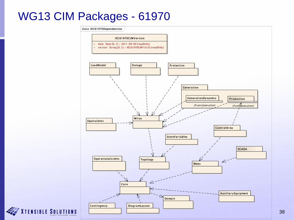
WG13 CIM Packages - 61970cla ss IEC61970Dependencies
Equiv a lents
P r otect ion
SCADA
Gener a t ion
OutageLoadModel
Topology
Meas
Wir es
Doma in
Cor e
IEC61970CIMVer sion
+ date: Date [0..1] = 2011-09-09 {readOnly}
+ version: String [0..1] = IEC61970CIM15v33 {readOnly}
Oper a t iona lLimits
Contr olAr ea
Gener a t ionDy namics
(from Generation)
P r oduct ion
(from Generation)
Cont ingency
Auxi l ia r y Equipment
Sta teVa r iables
Diagr amLay out
39
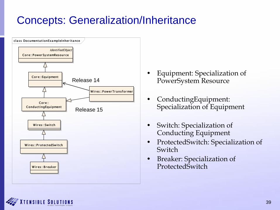
Concepts: Generalization/Inheritance
• Equipment: Specialization of PowerSystem Resource
• ConductingEquipment: Specialization of Equipment
• Switch: Specialization of Conducting Equipment
• ProtectedSwitch: Specialization of Switch
• Breaker: Specialization of ProtectedSwitch
Release 14
Release 15
class Documenta t ionExampleInher itance
IdentifiedObject
Cor e::Power Sy stemResour ce
Cor e::Equipment
Cor e::
Conduct ingEquipment
Wir es::Br eaker
W ir es::P r otectedSwitch
Wir es::Switch
Wir es::Power Tr ansfor mer
40
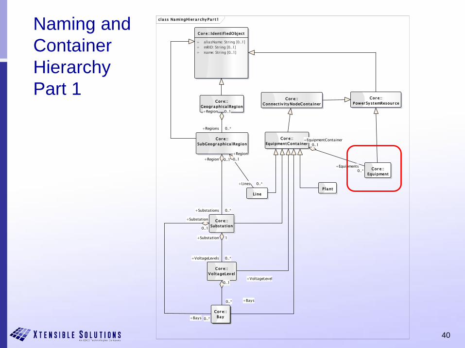
Naming and
Container
Hierarchy
Part 1
class NamingHier a r chy Pa r t1
Cor e::
Substa t ion
Cor e::
Bay
Cor e::
VoltageLev el
Cor e::
SubGeogr aphica lRegion
Line
Cor e::
Geogr aphica lRegion
Cor e::Ident if iedObject
+ aliasName: String [0..1]
+ mRID: String [0..1]
+ name: String [0..1]
Cor e::
Equipment
Cor e::
EquipmentConta iner
Cor e::
Power Sy stemResour ce
P lant
Cor e::
Connect iv ity NodeConta iner
+Substation 1
+VoltageLevels 0..*
+Region 0..1
+Regions 0..*
+VoltageLevel0..1
+Bays0..*
+Region
0..1
+Lines 0..*
+Region 0..1
+Substations 0..*
+Bays 0..*
+Substation
0..1
+EquipmentContainer
0..1
+Equipments0..*
41
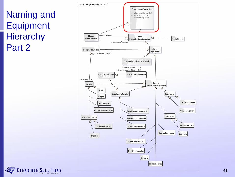
Naming and
Equipment
Hierarchy
Part 2
class NamingHier a r chy Pa r t2
Fuse
Ener gy Consumer
ShuntCompensa tor
Connector
Busbar Sect ion
Br eaker
ACLineSegment
Disconnector
Jumper
Fr equency Conv er ter
Ener gy Sour ce
Sta t icVa r Compensa tor
Rect if ier Inv er ter
Conductor
Cor e::
Conduct ingEquipment
Cor e::
Equipment
DCLineSegment
Sy nchr onousMachine
CompositeSwitch
Switch
Meas::
Measur ementCor e::
Power Sy stemResour ce TapChanger
Gr ound
Regula t ingCondEq
Gr oundDisconnector
P r oduct ion::Gener a t ingUnit
Cor e::Ident if iedObject
+ aliasName: String [0..1]
+ mRID: String [0..1]
+ name: String [0..1]
Ser iesCompensa tor
P r otectedSwitch
LoadBr eakSwitch
Junct ion
Rota t ingMachine
+CompositeSwitch0..1
+Switches 0..*
+GeneratingUnit 0..1
+SynchronousMachines 1..*
+PowerSystemResource
0..1
+Measurements
0..*
42
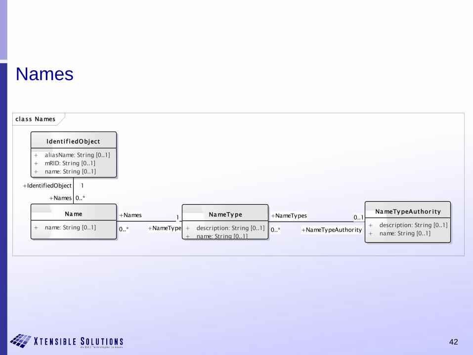
Names
class Names
Ident if iedObject
+ aliasName: String [0..1]
+ mRID: String [0..1]
+ name: String [0..1]
Name
+ name: String [0..1]
NameTy pe
+ description: String [0..1]
+ name: String [0..1]
NameTy peAuthor ity
+ description: String [0..1]
+ name: String [0..1]
+Names
0..* +NameType
1
+Names 0..*
+IdentifiedObject 1
+NameTypes
0..* +NameTypeAuthority
0..1
43
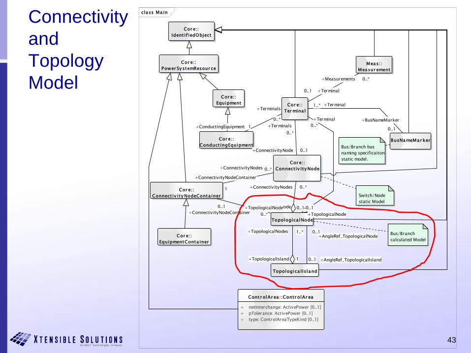
Connectivity
and
Topology
Model
class Ma in
Cor e::
EquipmentConta iner
Switch/Node
static Model
Cor e::
Connect iv ity Node
Cor e::
Connect iv ity NodeConta iner
Cor e::
Ter mina l
Bus/Branch
calculated Model
Topologica lNode
Meas::
Measur ement
Cor e::
Conduct ingEquipment
Topologica l Island
Cor e::
Power Sy stemResour ce
Cor e::
Ident if iedObject
BusNameMar ker
Cor e::
Equipment
Bus/Branch bus
naming specificaiton
static model.
Contr olAr ea ::Contr olAr ea
+ netInterchange: ActivePower [0..1]
+ pTolerance: ActivePower [0..1]
+ type: ControlAreaTypeKind [0..1]
+ConnectivityNodes 0..*
+TopologicalNode 0..1
+AngleRef_TopologicalIsland0..1
+AngleRef_TopologicalNode0..1
+Terminal
0..*
+TopologicalNode
0..1
+BusNameMarker
0..1
+Terminal1..*
+ConnectivityNodes 0..*
+ConnectivityNodeContainer
1
+Measurements 0..*
+Terminal0..1
+Terminals
0..*
+ConnectivityNode 0..1
+TopologicalNodes 1..*
+TopologicalIsland 1
+Terminals
0..*
+ConductingEquipment 1
+TopologicalNode
0..*+ConnectivityNodeContainer
0..1
44
Converting a Circuit to CIM Objects
• Example to show how voltage levels, current transformers, power transformers and generators are modelled
• Circuit contains a single generating source, load, line and busbar. The circuit also contains two power transformers resulting in three voltage levels of 17kV, 33kV and 132kV
Taken from Alan McMorran, Common Information Model Primer: First Edition., EPRI, Palo Alto,
CA: 2011, 1024449. Second Edition now available.
45
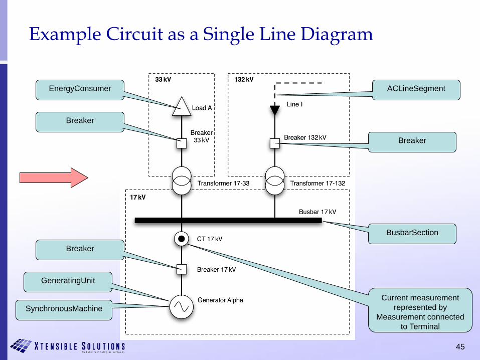
Example Circuit as a Single Line Diagram
EnergyConsumer
Breaker
SynchronousMachine
GeneratingUnit
Breaker
BusbarSection
Breaker
ACLineSegment
Current measurement
represented by
Measurement connected
to Terminal

46
Transformer Class DiagramCIM Release 15
Winding terminal for
balanced transformer model
network connection
Winding terminal for
unbalanced transformer
model network connection
ConductingEquipment with
associations to types of
TransformerEnds for
electrical connectivity
TransformerTank added for
distribution transformer
windings so each phase
winding could be modeled
Previously included in
Winding class
47
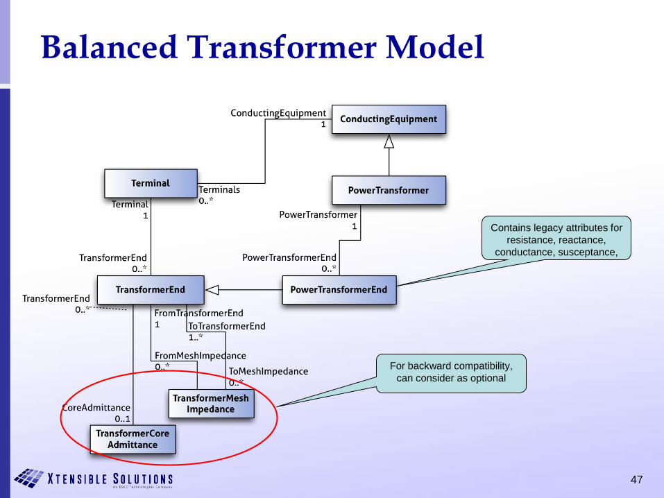
Balanced Transformer Model
Contains legacy attributes for
resistance, reactance,
conductance, susceptance,
For backward compatibility,
can consider as optional
48
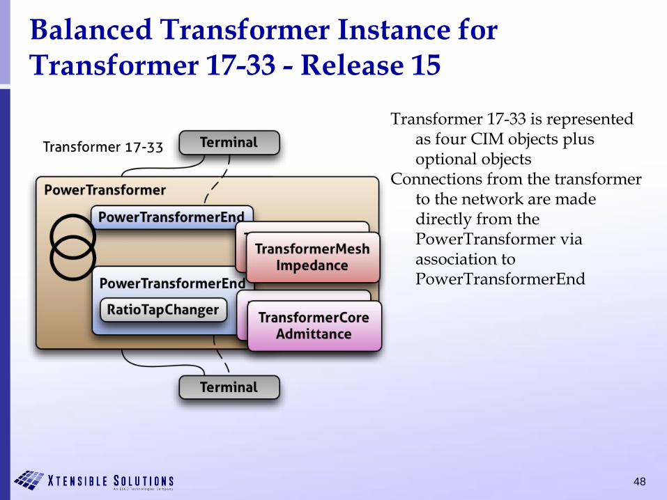
Balanced Transformer Instance for Transformer 17-33 - Release 15
Transformer 17-33 is represented as four CIM objects plus optional objects
Connections from the transformer to the network are made directly from the PowerTransformer via association to PowerTransformerEnd
49
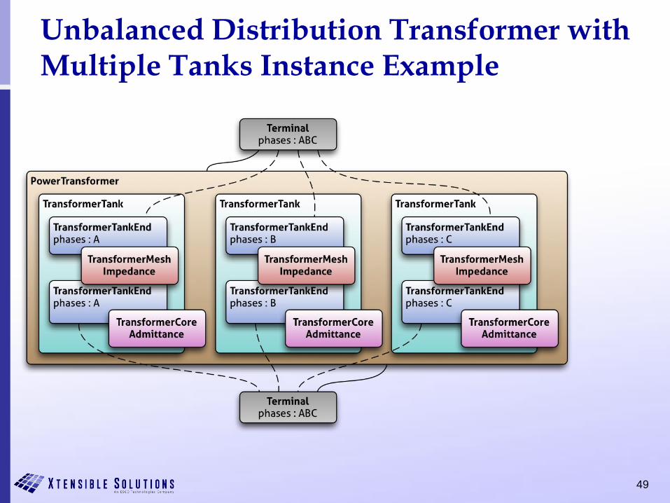
Unbalanced Distribution Transformer with Multiple Tanks Instance Example

50
Example Circuit with Full CIM Mappings
• Maps to
– 17 CIM classes
– 45 CIM objects
• Could be extended further with addition of objects for
– control areas
– equipment owners
– measurement units
– generation and load curves
– asset data
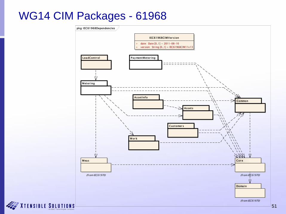
51
WG14 CIM Packages - 61968pkg IEC61968Dependencies
Meter ing
Pay mentMeter ing
Cor e
(from IEC61970)
Doma in
(from IEC61970)
Meas
(from IEC61970)
LoadContr ol
Common
Customer s
Asset Info
Assets
Wor k
IEC61968CIMVer sion
+ date: Date [0..1] = 2011-08-10
+ version: String [0..1] = IEC61968CIM11v13
52
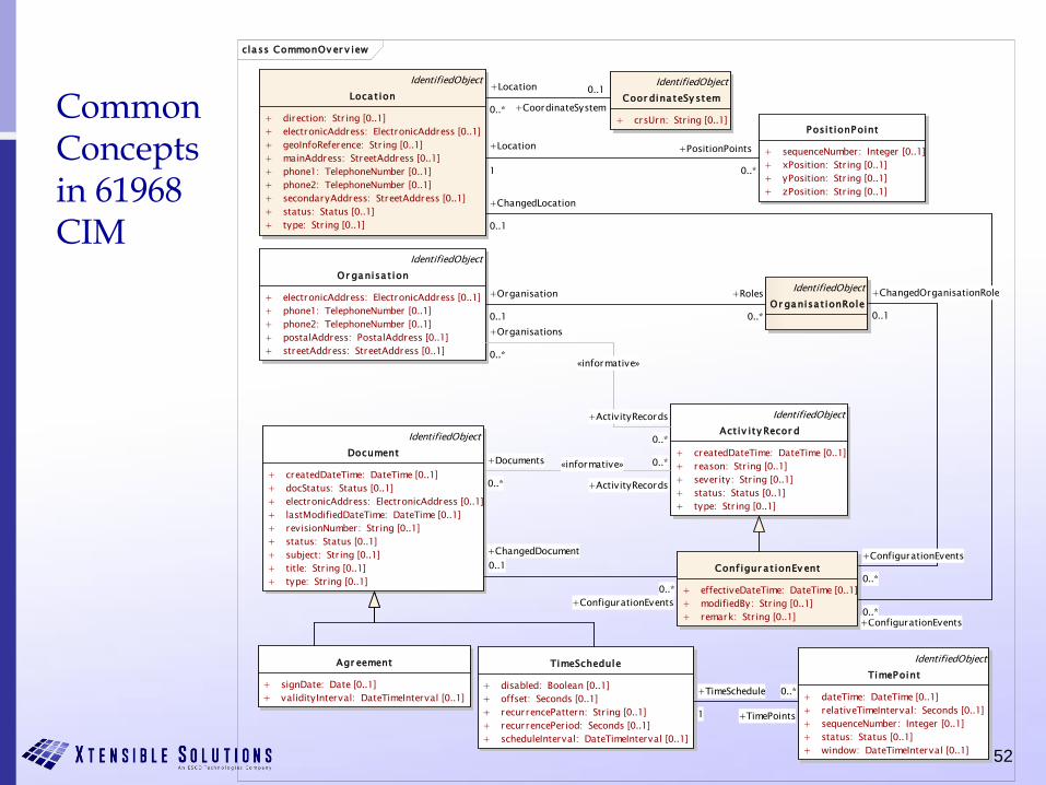
Common Concepts in 61968 CIM
class CommonOv er v iew
IdentifiedObject
Act iv ity Recor d
+ createdDateTime: DateTime [0..1]
+ reason: String [0..1]
+ severity: String [0..1]
+ status: Status [0..1]
+ type: String [0..1]
Agr eement
+ signDate: Date [0..1]
+ validityInterval: DateTimeInterval [0..1]
IdentifiedObject
Document
+ createdDateTime: DateTime [0..1]
+ docStatus: Status [0..1]
+ electronicAddress: ElectronicAddress [0..1]
+ lastModifiedDateTime: DateTime [0..1]
+ revisionNumber: String [0..1]
+ status: Status [0..1]
+ subject: String [0..1]
+ title: String [0..1]
+ type: String [0..1]
IdentifiedObject
Or ganisa t ion
+ electronicAddress: ElectronicAddress [0..1]
+ phone1: TelephoneNumber [0..1]
+ phone2: TelephoneNumber [0..1]
+ postalAddress: PostalAddress [0..1]
+ streetAddress: StreetAddress [0..1]
Posit ionPoint
+ sequenceNumber: Integer [0..1]
+ xPosition: String [0..1]
+ yPosition: String [0..1]
+ zPosition: String [0..1]
IdentifiedObject
TimePoint
+ dateTime: DateTime [0..1]
+ relativeTimeInterval: Seconds [0..1]
+ sequenceNumber: Integer [0..1]
+ status: Status [0..1]
+ window: DateTimeInterval [0..1]
TimeSchedule
+ disabled: Boolean [0..1]
+ offset: Seconds [0..1]
+ recurrencePattern: String [0..1]
+ recurrencePeriod: Seconds [0..1]
+ scheduleInterval: DateTimeInterval [0..1]
IdentifiedObject
Loca t ion
+ direction: String [0..1]
+ electronicAddress: ElectronicAddress [0..1]
+ geoInfoReference: String [0..1]
+ mainAddress: StreetAddress [0..1]
+ phone1: TelephoneNumber [0..1]
+ phone2: TelephoneNumber [0..1]
+ secondaryAddress: StreetAddress [0..1]
+ status: Status [0..1]
+ type: String [0..1]
IdentifiedObject
Coor dina teSy stem
+ crsUrn: String [0..1]
IdentifiedObject
Or ganisa t ionRole
Conf igur a t ionEv ent
+ effectiveDateTime: DateTime [0..1]
+ modifiedBy: String [0..1]
+ remark: String [0..1]
+Documents
0..*
«informative»
+ActivityRecords
0..*
+ChangedDocument
0..1
+ConfigurationEvents
0..*
+Organisations
0..*«informative»
+ActivityRecords
0..*
+TimeSchedule
1 +TimePoints
0..*
+Location
1
+PositionPoints
0..*
+ChangedLocation
0..1
+ConfigurationEvents0..*
+Location
0..* +CoordinateSystem
0..1
+Roles
0..*
+Organisation
0..1
+ChangedOrganisationRole
0..1
+ConfigurationEvents
0..*
53
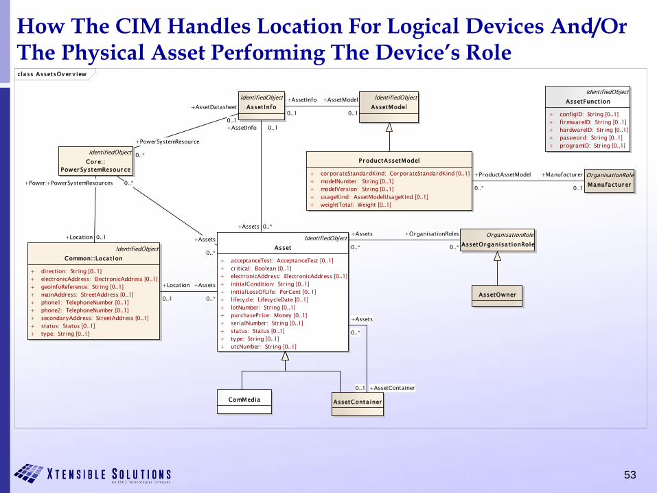
How The CIM Handles Location For Logical Devices And/OrThe Physical Asset Performing The Device’s Roleclass AssetsOv er v iew
IdentifiedObject
Asset
+ acceptanceTest: AcceptanceTest [0..1]
+ critical: Boolean [0..1]
+ electronicAddress: ElectronicAddress [0..1]
+ initialCondition: String [0..1]
+ initialLossOfLife: PerCent [0..1]
+ lifecycle: LifecycleDate [0..1]
+ lotNumber: String [0..1]
+ purchasePrice: Money [0..1]
+ serialNumber: String [0..1]
+ status: Status [0..1]
+ type: String [0..1]
+ utcNumber: String [0..1]
AssetConta iner
IdentifiedObject
AssetFunct ion
+ configID: String [0..1]
+ firmwareID: String [0..1]
+ hardwareID: String [0..1]
+ password: String [0..1]
+ programID: String [0..1]
ComMedia
IdentifiedObject
AssetModel
IdentifiedObject
Asset Info
P r oductAssetModel
+ corporateStandardKind: CorporateStandardKind [0..1]
+ modelNumber: String [0..1]
+ modelVersion: String [0..1]
+ usageKind: AssetModelUsageKind [0..1]
+ weightTotal: Weight [0..1]
OrganisationRole
AssetOr ganisa t ionRole
OrganisationRole
Manufactur er
AssetOwner
IdentifiedObject
Cor e::
Power Sy stemResour ce
IdentifiedObject
Common::Loca t ion
+ direction: String [0..1]
+ electronicAddress: ElectronicAddress [0..1]
+ geoInfoReference: String [0..1]
+ mainAddress: StreetAddress [0..1]
+ phone1: TelephoneNumber [0..1]
+ phone2: TelephoneNumber [0..1]
+ secondaryAddress: StreetAddress [0..1]
+ status: Status [0..1]
+ type: String [0..1]
+Location 0..1
+PowerSystemResources 0..*
+Assets
0..*
+Location
0..1
+Assets 0..*
+AssetInfo 0..1
+Assets
0..*
+AssetContainer0..1
+Assets
0..*
+PowerSystemResources 0..*
+Assets
0..*
+OrganisationRoles
0..*
+AssetModel
0..1
+AssetInfo
0..1+AssetDatasheet
0..1
+PowerSystemResource
0..*
+ProductAssetModel
0..*
+Manufacturer
0..1
54
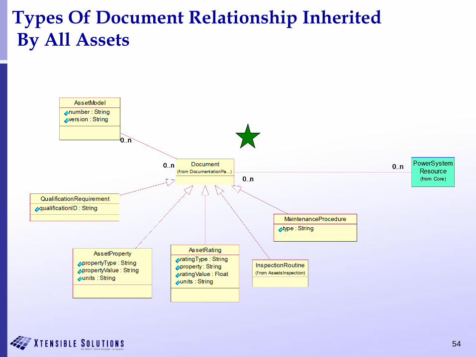
Types Of Document Relationship InheritedBy All Assets
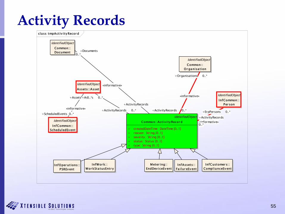
55
Activity Recordsclass tmpAct iv ity Recor d
IdentifiedObject
InfCommon::
Per son
IdentifiedObject
Common::
Document
IdentifiedObject
Common::Act iv ity Recor d
+ createdDateTime: DateTime [0..1]
+ reason: String [0..1]
+ severity: String [0..1]
+ status: Status [0..1]
+ type: String [0..1]
IdentifiedObject
Assets::Asset
IdentifiedObject
InfCommon::
ScheduledEv ent
InfWor k::
Wor kSta tusEntr y
InfCustomer s::
ComplianceEv ent
InfAssets::
Fa i lur eEv ent
Meter ing::
EndDev iceEv entInfOper a t ions::
PSREv ent
IdentifiedObject
Common::
Or ganisa t ion
+ErpPersons 0..*
«informative»
+ActivityRecords
0..*
+Documents0..*
«informative»
+ActivityRecords
0..*
+Assets 0..*
+ActivityRecords 0..*+ScheduledEvents 0..*
«informative»
+Assets 0..*
+Organisations 0..*
«informative»
+ActivityRecords 0..*
56
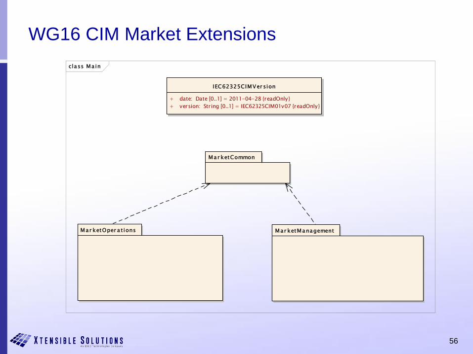
WG16 CIM Market Extensions
class Ma in
Mar ketCommon
Mar ketManagementMar ketOper a t ions
IEC62325CIMVer sion
+ date: Date [0..1] = 2011-04-28 {readOnly}
+ version: String [0..1] = IEC62325CIM01v07 {readOnly}
57
CIM UML Release Cycles
• 61970 CIM UML tries for annual release cycle• Basis for IEC 61970-301 CIM Base Fifth Edition
• Word document auto-generated from the UML electronic model
• Information system and Profile documents are synchronized with UML model release
• 61968 CIM UML different update cycles• Basis for IEC 61968-11 CIM Distribution Information Exchange
Model
• 62325 CIM UML on another update cycle• Basis for IEC 62325-301 CIM for Deregulated Markets
• Complete CIM UML available as a combined model on CIMugSharepoint site:
– Title: draft CIM16 + DCIM12 + MCIM02
– Name: iec61970cim16v13_iec61968cim12v05_iec62325cim02v05
58
CIM UML in Enterprise Architect
• The CIM UML model is maintained in Sparx Enterprise
Architect (EA)
• Current Official CIM Releases of UML Model
– iec61970cim16v29a_iec61968cim12v08_iec62325cim03v01a
(official release 16 WG13)
– iec61970cim17v04_iec61968cim12v09_iec62325cim03v01a
(updated by WG14)
– iec61970cim17v07_iec61968cim12v10_iec62325cim03v02
(current model release)
• Go to UML model in EA

59
Break