Embed Size (px)
Citation preview
1 | P a g e
CI Vision Side Grips User
Manual
Rev. 04
Customer: WCRX
Order No.: P30004UP1
2 | P a g e
Table of Contents
1. GENERAL INFORMATION ....................................................................................................................... 4
2. SAFETY INSTRUCTIONS ......................................................................................................................... 5
2.1. EXPLANATION OF SYMBOLS....................................................................................................................... 5
2.2. BASIC SAFETY MEASURES......................................................................................................................... 5
2.3. ELECTRICAL SYSTEM SAFETY ..................................................................................................................... 5
2.4. MECHANICAL SYSTEM SAFETY ................................................................................................................... 6
2.5. CUSTOMER RESPONSIBILITY ...................................................................................................................... 6
3. ABOUT THIS MANUAL ............................................................................................................................ 7
3.1. GENERAL .............................................................................................................................................. 7
3.2. SCOPE ................................................................................................................................................. 7
4. COMPONENT SPECIFICATIONS .............................................................................................................. 7
4.1. PLC & HMI.......................................................................................................................................... 7
4.2. SERVO MOTORS ..................................................................................................................................... 7
4.3. GEAR BOXES ......................................................................................................................................... 7
4.4. PRODUCT SENSOR .................................................................................................................................. 8
4.5. UV INSPECTION CAMERA.......................................................................................................................... 8
4.6. KBA PRINT HEAD .................................................................................................................................. 8
4.7. REJECT STATION WITH COUNTERCHECK ...................................................................................................... 8
4.8. EXTERNAL ENCODER ............................................................................................................................... 9
5. SOFTWARE SPECIFICATIONS ................................................................................................................. 9
5.1. I/O HANDSHAKE & TIMING CHART ............................................................................................................. 9
3 | P a g e
5.2. REMOTE VNC CONNECTION ................................................................................................................... 10
5.2.1. Windows 7 or Higher .................................................................................................................. 10
6. OPERATION ........................................................................................................................................ 11
6.1. MENU STRUCTURE ................................................................................................................................ 11
6.1.1. Main Menu .................................................................................................................................. 11
6.1.2. Config Menu ................................................................................................................................ 13
6.2. CUSTOM SIGNALS ................................................................................................................................. 21
7. PRODUCTION ..................................................................................................................................... 21
7.1. MANUAL START OF PRODUCTION ............................................................................................................. 21
7.2. REMOTE START OF PRODUCTION ............................................................................................................. 21
8. HMI ALARMS DEFINITION .................................................................................................................... 21
9. SYSTEM DRAWINGS ............................................................................................................................ 22
9.1. ELECTRICAL DRAWINGS ......................................................................................................................... 22
9.2. MECHANICAL DRAWINGS ....................................................................................................................... 22
10. RECOMMENDED SPARE PARTS LIST & PRICE ...................................................................................... 22
11. TROUBLESHOOTING GUIDE ................................................................................................................. 22
12. RECOMMENDED PREVENTATIVE MAINTENANCE ................................................................................... 22
4 | P a g e
1. General Information
These operating instructions will aid in the correct and safe operation of your CI Vision equipment. Therefore,
please observe the following instructions. It is necessary to read the complete operations instructions before
operating the CI Vision machine in order to avoid injury or improper use.
For your own safety, please observe the safety instructions in this operating manual. Please read the instruc-
tions carefully even if you are already trained in the application and operation of CI Vision equipment.
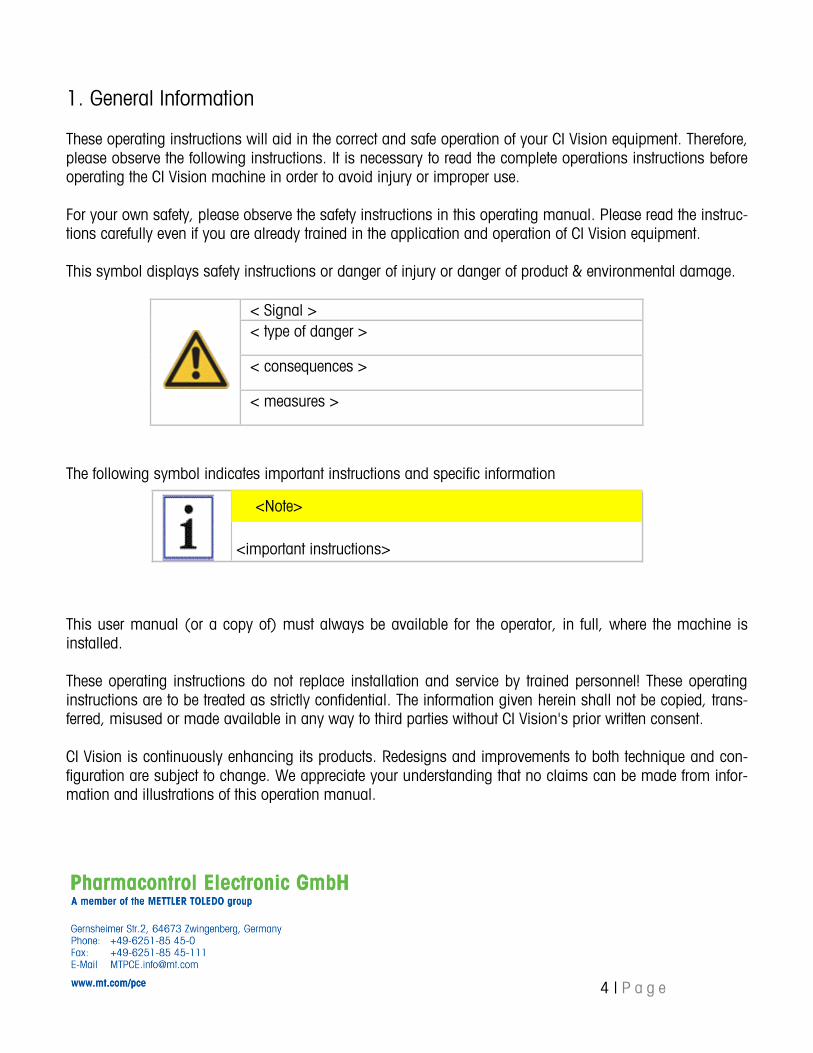
This symbol displays safety instructions or danger of injury or danger of product & environmental damage.
< Signal >
< type of danger >
< consequences >
< measures >
The following symbol indicates important instructions and specific information
<important instructions>
This user manual (or a copy of) must always be available for the operator, in full, where the machine is
installed.
These operating instructions do not replace installation and service by trained personnel! These operating
instructions are to be treated as strictly confidential. The information given herein shall not be copied, trans-
ferred, misused or made available in any way to third parties without CI Vision's prior written consent.
CI Vision is continuously enhancing its products. Redesigns and improvements to both technique and con-
figuration are subject to change. We appreciate your understanding that no claims can be made from infor-
mation and illustrations of this operation manual.
<Note>
5 | P a g e
<Note>
2. Safety Instructions
2.1. Explanation of Symbols
The following symbols and notes are warning signals of possible damage to person or property or assist
you as guidelines.
DANGER! This symbol can be found in the operations manual at all refer-
ences concerning operational safety, if not adhered to there will
be danger.
body and life of persons. Always observe the instructions carefully and perform with ex-
treme attention and wariness.
This symbol indicates the appropriate handling of PCE-components.
2.2. Basic Safety Measures
For safe operation of the CI Vision system the following points must be observed:
The system must be mounted on a stable concrete floor.
The system must be kept level (e.g. away from extreme vibration).
All factory installed safety equipment must be kept in place (e.g. machine guarding,
door interlocks, E-Stop switches, etc.).
When installing the device in an industrial environment, this should be done where
dust, moisture, temperature and vibration are at their very lowest.
2.3. Electrical System Safety
The CI Vision System Is powered by externally supplied (user supplied) 480 VAC 3-Phase electrical
power. This should only be connected / disconnected by an authorized installation engineer or trained
electrician.
6 | P a g e
DANGER!
The system is operated with supply voltage! Contact with live
parts can cause perilous state of shock and severe burns.
Operate system with duly mounted housing only.
Unplug electric supply prior to cleaning and care.
In case of liquid has been spilled on the system, immediately
switch off the system and unplug electric supply.
2.4. Mechanical System Safety
The CI Vision Side Grips System uses very powerful motors and has numerous pinch points. Use caution
at all times and never operate the system without the proper protective machine guarding in place.
2.5. Customer Responsibility
It is the customer's responsibility to:
Read the user manual and ask questions for items you do not understand.
Know the intended functions on the machine and how to properly use them.
Keep the user manual in readable condition and always accessible.
Regularly test, at acceptable intervals, the safety features of the system.
Ensure the Preventative Maintenance Schedule is followed and the system is in proper
working order.
DANGER!
Rotating axes!
Rotating axes! Can pull in and tear hair, clothing and jewelry.
Do not operate machine with opened housing! Keep away
long hair, loose clothing, jewelry etc. from machine!
DANGER!
Danger of injury by movable and rotating parts! Always ad-
here to the following rules:
7 | P a g e
3. About this Manual
3.1. General
This operating manual describes the CI Vision Side Grips conveyor system. The main components, over-
view and detailed functions are described as well as system drawings, recommended spare parts list
and a TPM schedule. The following chapters will describe the beginning of operation and use in produc-
tion.
3.2. Scope
Side Grip Conveyor. It is intended for those who operate / setup / program or maintain the system.
This includes:
Operators
Supervisors
Administrators
Engineers
4. Component Specifications
4.1. PLC & HMI
PLC is a B&R 1585 with B&R Touch Screen
4.2. Servo Motors
B&R
4.3. Gear Boxes
Neugart
8 | P a g e
4.4. Product Sensor
Sick Thru-Beam (PCE provided) – This is a sensor provided by PCE which interfaces directly to PCE's
PLC on the BSS 360 machine. It is used for identifying when a bottle is entering our combined system.
Once identified, the 360's PLC will track it through the combined system. By doing so, the cameras can
be triggered at the most opportune time to capture the best inspection images as well as reject at the
proper position (if necessary).
*NOTE: The Product Sensor is a CRITICAL COMPONENT for proper timing of the line. Adjustment / re-
placement of this sensor should ONLY be done by qualified, trained personnel. Please consult the PCE
BSS 360 or PCE directly for more information.
4.5. UV Inspection Camera
PCE provided and controlled as this is the 7th camera of the BSS 360 array and as such, it is completely
controlled by PCE's BSS 360. Its purpose is to verify, decode and inspect the UV helper code.
4.6. KBA Print Head
PCE provided and triggered. The CI Vision Side Grips provides a continuous raw output of Side Grips
encoder signal to this printer for tracking purposes but all other functionality and handshaking are done
directly with the PCE system (both PLM and PLC). Its purpose is to print a UV helper code on the bot-
tom of the bottle to assist in aggregation further down the line.
4.7. Reject Station with Countercheck
This station is provided by CI Vision but is built to PCE's specifications. It is completely controlled by
PCE via PLC. This is an SMC pneumatic cylinder reject station and two Sick thru-beam sensors for coun-
tercheck or "counter verification". Counter verification is preformed to ensure the proper bottle is ejected
at the proper time. One sensor is placed in front of the reject pusher and one after. The logic is such
that the first verifies alignment between the physical part and the PLC's shift register. The second verifies
that rejection has successfully taken place.
*NOTE: The position of the reject verification & countercheck sensors, as well as the distance between
them, is a CRITICAL relationship that must be maintained. Moving either sensor will cause the system to
become inoperable. Adjustment / replacement of either sensor should only be done by qualified, trained
personnel. Please consult the PCE BSS 360 or PCE directly for more information.
9 | P a g e
4.8. External Encoder
The Kubler / Turck external encoder is designed to allow the CI Vision Side Grip system to operate as a
slave and automatically adjust its speed or "track" your existing upstream equipment. Mount this encod-
er via the included 5/16-18" threaded shaft and secure the anti-rotation bracket on any acceptable loca-
tion on your upstream conveyor.
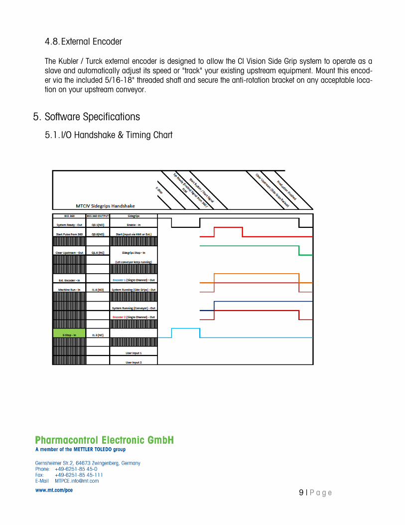
5. Software Specifications
5.1. I/O Handshake & Timing Chart
10 | P a g e
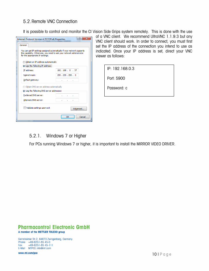
5.2. Remote VNC Connection
It is possible to control and monitor the CI Vision Side Grips system remotely. This is done with the use
of a VNC client. We recommend UltraVNC 1.1.9.3 but any
VNC client should work. In order to connect, you must first
set the IP address of the connection you intend to use as
indicated. Once your IP address is set, direct your VNC
viewer as follows:
5.2.1. Windows 7 or Higher
For PCs running Windows 7 or higher, it is important to install the MIRROR VIDEO DRIVER.
IP: 192.168.0.3
Port: 5900
Password: c
11 | P a g e
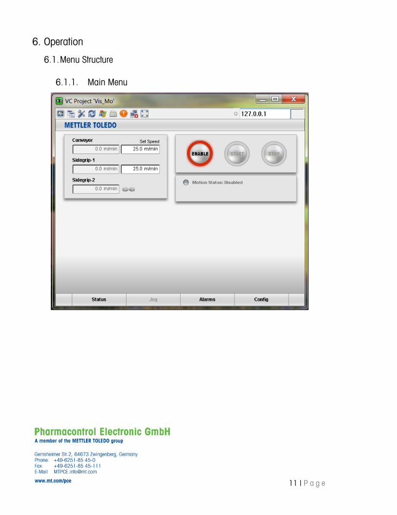
6. Operation
6.1. Menu Structure
6.1.1. Main Menu
12 | P a g e
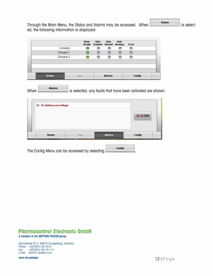
Through the Main Menu, the Status and Alarms may be accessed. When is select-
ed, the following information is displayed:
When is selected, any faults that have been activated are shown:
The Config Menu can be accessed by selecting .
13 | P a g e
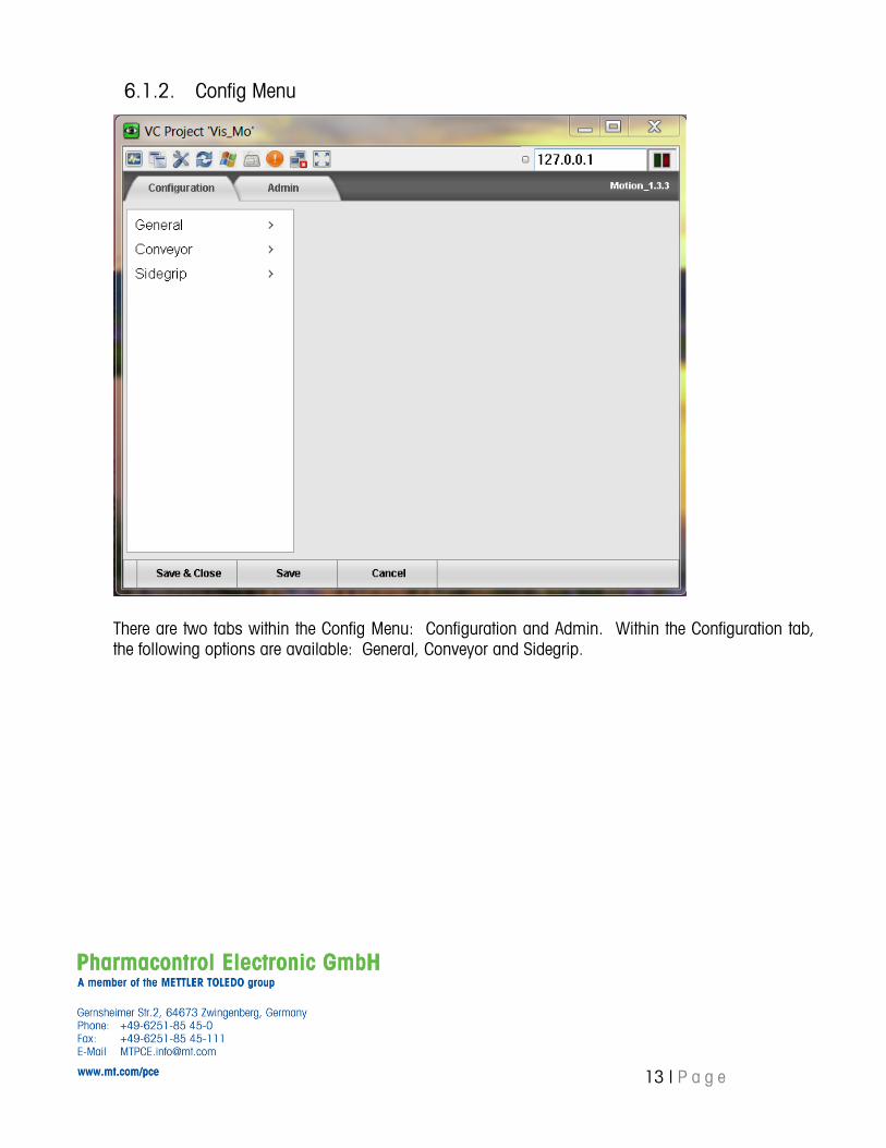
6.1.2. Config Menu
There are two tabs within the Config Menu: Configuration and Admin. Within the Configuration tab,
the following options are available: General, Conveyor and Sidegrip.
14 | P a g e
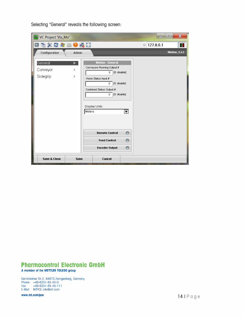
Selecting "General" reveals the following screen:
15 | P a g e
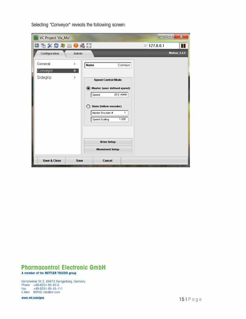
Selecting "Conveyor" reveals the following screen:
16 | P a g e
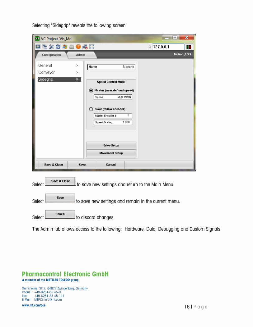
Selecting "Sidegrip" reveals the following screen:
Select to save new settings and return to the Main Menu.
Select to save new settings and remain in the current menu.
Select to discard changes.
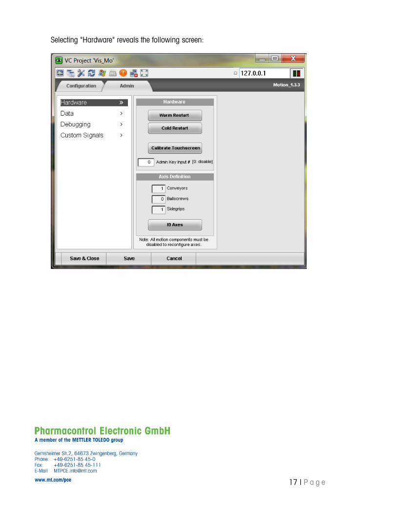
The Admin tab allows access to the following: Hardware, Data, Debugging and Custom Signals.
17 | P a g e
Selecting "Hardware" reveals the following screen:
18 | P a g e
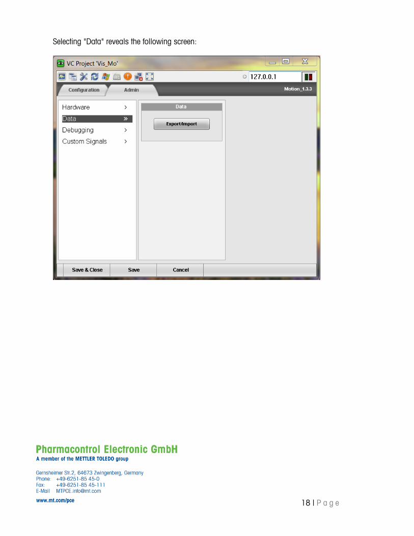
Selecting "Data" reveals the following screen:
19 | P a g e
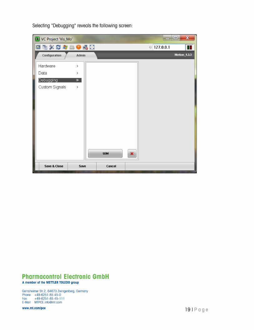
Selecting "Debugging" reveals the following screen:
20 | P a g e
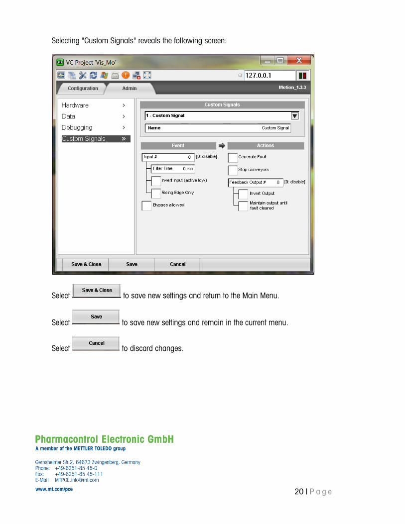
Selecting "Custom Signals" reveals the following screen:
Select to save new settings and return to the Main Menu.
Select to save new settings and remain in the current menu.
Select to discard changes.
21 | P a g e
6.2. Custom Signals
The system is equipped with 3 available free user definable I/O. These I/O can be configured in a variety
of ways to monitor inputs, activate outputs, and display custom alarms and more. Please contact your
CI Vision representative for more in-depth information on how to use these available signals.
*Not currently in use
7. Production
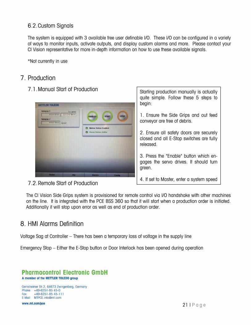
7.1. Manual Start of Production
7.2. Remote Start of Production
The CI Vision Side Grips system is provisioned for remote control via I/O handshake with other machines
on the line. It is integrated with the PCE BSS 360 so that it will start when a production order is initiated.
Additionally it will stop upon error as well as end of production order.
8. HMI Alarms Definition
Voltage Sag at Controller – There has been a temporary loss of voltage in the supply line
Emergency Stop – Either the E-Stop button or Door Interlock has been opened during operation
Starting production manually is actually
quite simple. Follow these 5 steps to
begin:
1. Ensure the Side Grips and out feed
conveyor are free of debris.
2. Ensure all safety doors are securely
closed and all E-Stop switches are fully
released.
3. Press the "Enable" button which en-
gages the servo drives. It should turn
green.
4. If set to Master, enter a system speed
(not necessary if tracking as slave).
5. Press the "Auto / Start" button. All
belts should begin to run and the Auto /
Start button should be green.
22 | P a g e
9. System Drawings
9.1. Electrical Drawings
See Appendix A
9.2. Mechanical Drawings
See Appendix B
10. Recommended Spare Parts List & Price
See Appendix C
11. Troubleshooting Guide
See Appendix D
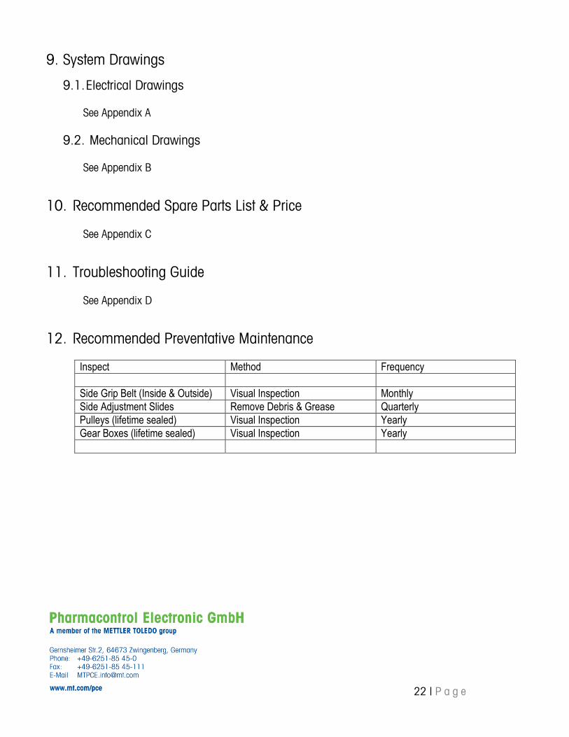
12. Recommended Preventative Maintenance
Inspect Method Frequency
Side Grip Belt (Inside & Outside) Visual Inspection Monthly
Side Adjustment Slides Remove Debris & Grease Quarterly
Pulleys (lifetime sealed) Visual Inspection Yearly
Gear Boxes (lifetime sealed) Visual Inspection Yearly