Embed Size (px)
Citation preview
1
M6a: O
pen C
hannel Flo
w
(Mannin
g’s
Equation, P
art
ially
Flo
win
g P
ipes, and S
pecific
Energ
y)
Robert
Pitt
Univ
ers
ity o
f A
labam
a
and
Shirle
y C
lark
Penn S
tate
-H
arr
isburg
Chin
2000
; F
igure
4.1
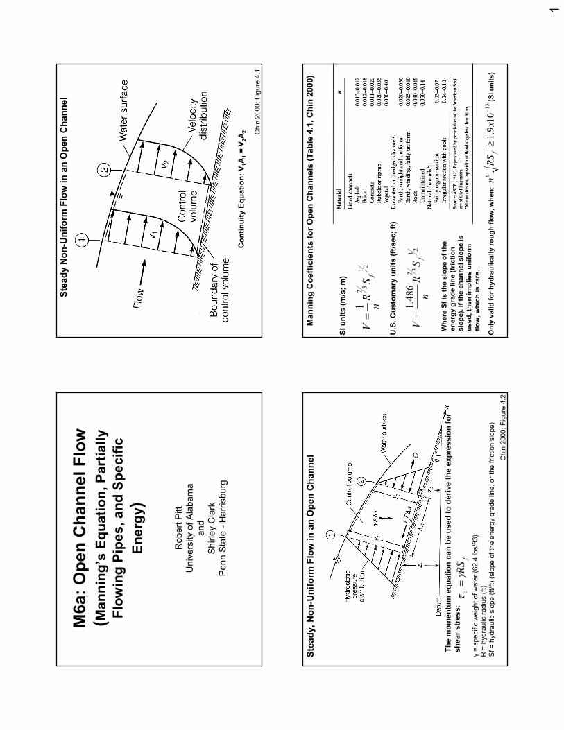
Ste
ady N
on-U
niform
Flo
w in a
n O
pen C
hannel
Continuity E
quation: V
1A
1= V
2A
2
Chin
2000
; F
igure
4.2
Ste
ady, N
on-U
niform
Flo
w in a
n O
pen C
hannel
The m
om
entu
m e
quation c
an b
e u
sed to d
eri
ve the e
xpre
ssio
n for
shear str
ess:
fo
RS
γτ
=γ
= s
pecific
weig
ht of
wate
r (6
2.4
lbs/f
t3)
R =
hydra
ulic
radiu
s (
ft)
Sf
= h
ydra
ulic
slo
pe
(ft
/ft)
(slo
pe o
f th
e e
nerg
y g
rad
e lin
e, or
the
fri
ction s
lope)
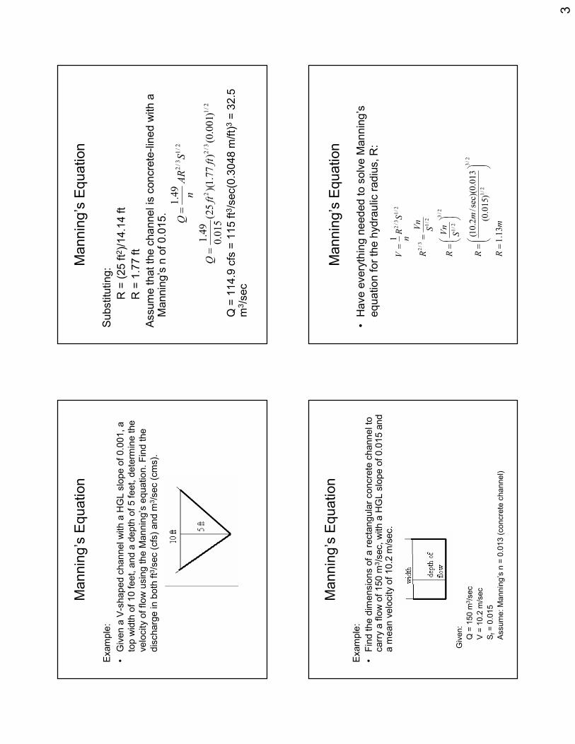
Mannin
g C
oeff
icie
nts
for
Open C
hannels
(Table
4.1
, C
hin
2000)
SI units (m
/s; m
)
U.S
. C
usto
mary
units (ft/s
ec; ft)
Only
valid for hydra
ulically r
ough flo
w, w
hen:
21
32
1fS
Rn
V=
21
32
486
.1
fS
Rn
V=
13
610
9.1
−≥
xRS
nf
(SI units)
Where
Sfis
the s
lope o
f th
e
energ
y g
rade lin
e (fr
iction
slo
pe). If th
e c
hannel slo
pe is
used, th
en im
plies u
niform
flow
, w
hic
h is rare
.

2
Mannin
g’s
Equation
Exam
ple
:
•D
ete
rmin
e the flo
w r
ate
in a
recta
ngula
r concre
te c
hannel
with a
wid
th o
f 3 m
and a
HG
L s
lope o
f 0.0
01 m
/mw
hen
the d
epth
of flow
is 1
.5 m
. A
ssum
e n
= 0
.014.
Giv
en:
n =
0.0
14 (
concre
te c
ha
nne
l)
L =
3 m
(w
idth
of
channel)
w =
1.5
m (d
epth
of
flow
)
sf=
0.0
01 m
/m
Mannin
g’s
Equation
•U
se t
he M
annin
g's
equation:
Need A
(cro
ss-s
ectional are
a o
f flow
):
A =
Lw
Substitu
ting:
A =
(3 m
)(1.5
m)
A =
4.5
m2
21
32
fS
RnA
Q=
Mannin
g’s
Equation
•N
eed R
(hydra
ulic
radiu
s):
R =
A/P
•N
eed P
, th
e w
etted p
erim
ete
r (n
ote
d o
n d
raw
ing b
y
thic
ker
lines). P =
L +
2w
Substitu
ting:
P =
(3 m
) +
2(1
.5 m
)
P =
6 m
Substitu
ting into
equation f
or
hydra
ulic
radiu
s:
R =
A/P
R =
(4.5
m2)/
(6 m
)
R =
0.7
5 m
Mannin
g’s
Equation
•S
ubstitu
ting into
Mannin
g's
equation:
sec
/39
.8
014
.0
)/
001
.0(
)75
.0
)(5.
4(
3
2/
13/
22
mQ
mm
mm
Q
==
3
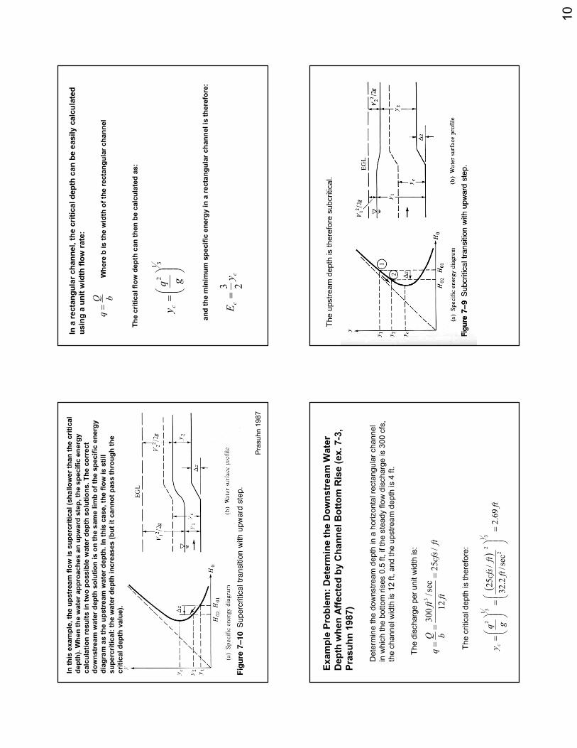
Mannin
g’s
Equation
Exam
ple
:
•G
iven a
V-s
haped c
hannel w
ith a
HG
L s
lope o
f 0.0
01, a
top w
idth
of
10 feet, a
nd a
depth
of
5 feet, d
ete
rmin
e the
velo
city o
f flow
usin
g the M
annin
g’s
equation. F
ind the
dis
charg
e in b
oth
ft3
/sec (
cfs
) and m
3/s
ec (
cm
s).
Mannin
g’s
Equation
Substitu
ting:
R =
(25 ft2
)/14.1
4 ft
R =
1.7
7 ft
Assum
e t
hat
the c
hannel is
concre
te-lin
ed w
ith a
M
annin
g’s
n o
f 0.0
15.
Q =
114.9
cfs
= 1
15 ft3
/sec(0
.3048 m
/ft)
3=
32.5
m
3/s
ec
2/
13/
22
2/
13/
2
)001
.0(
)77
.1
)(25
(015
.0
49
.1
49
.1
ftft
Q
SAR
nQ
=
=
Mannin
g’s
Equation
Exam
ple
:
•F
ind the d
imensio
ns o
f a r
ecta
ngula
r concre
te c
hannel to
carr
y a
flo
w o
f 150 m
3/s
ec, w
ith a
HG
L s
lope o
f 0.0
15 a
nd
a m
ean v
elo
city o
f 10.2
m/s
ec.
Giv
en:
Q =
150 m
3/s
ec
V =
10.2
m/s
ec
Sf=
0.0
15
Assum
e: M
annin
g’s
n =
0.0
13 (
co
ncre
te c
hanne
l)
Mannin
g’s
Equation
•H
ave e
very
thin
g n
eeded t
o s
olv
e M
annin
g’s
equation for
the h
ydra
ulic
radiu
s, R
:
mR
mR
SVn
R
SVn
R
SRn
V
13
.1
)015
.0(
013
.0
sec)(
/2.
10
(
1
2/
3
2/
1
2/
3
2/
1
2/
1
3/
2
2/
13/
2
=
=
=
=
=

4
Mannin
g’s
Equation
By d
efinitio
n, R
= c
ross-s
ectional are
a o
f flow
/wetted p
eri
mete
r
By the C
ontin
uity E
qu
atio
n:
[]
1.13m
Depth
2
Base
th)
(Base)(D
epR
:ng
Substituti
flow)
of
2(D
epth
channel)
of
(B
ase
P
flow)
of
epth
channel)(D
of
(B
ase
A
=+
=
+==
))(
(7.
14
sec
/2.
10
sec
/150
))(
(
23
Depth
Base
mA
mmA
Depth
Base
VQA
===
==
Mannin
g’s
Equation
•H
ave tw
o e
quations a
nd t
wo u
nkno
wns:
Tw
o p
ossib
le s
olu
tions to q
uadra
tic (
both
are
corr
ect)
:
Base =
2.9
mD
epth
of
Flo
w =
5.0
4 m
Base =
10.1
mD
epth
of
Flo
w =
1.4
6 m
07.
14
13
2
13
27.
14
0.13
27.
14
0.13
2
27.14
13
.1
7.14
))(
(7.
14
2
2
2
2
=+
−
=+
=+
=+
+==
=
Depth
Depth
Depth
DepthDepth
Depth
mDepth
Base
Depth
Base
mm
Depth
Base
Depth
Base
m
Fig
ure
5-8
(C
ho
w 1
959)
can b
e u
sed to s
ignific
antly s
hort
en th
e
calc
ula
tion e
ffort
for
the d
esig
n o
f channels
. T
his
fig
ure
is u
sed to
calc
ula
te th
e n
orm
al d
epth
(y)
of a c
hanne
l based o
n th
e c
hann
el
sid
e s
lopes a
nd k
no
wn f
low
an
d c
hanne
l chara
cte
ristics, usin
g
the M
an
nin
g’s
eq
uation in the f
ollo
win
g f
orm
:
5.0
32
49
.1
S
nQ
AR
=
Initia
l chan
ne
l chara
cte
ristics that m
ust be k
now
inclu
de: z (
the s
ide
slo
pe),
an
d b
(th
e c
ha
nne
l botto
m w
idth
, assum
ing a
tra
pezoid
). It is
easy to e
xam
ine s
evera
l diffe
rent channel options (
z a
nd b
) b
y
calc
ula
ting the n
orm
al d
epth
(y)
for
a g
iven p
eak d
ischarg
e r
ate
,
channe
l slo
pe,
and r
ough
ness. T
he m
ost pra
ctical chan
ne
l can th
en b
e
sele
cte
d f
rom
the a
ltern
atives.

5
Com
posite M
annin
g’s
n E
stim
ate
, Exam
ple
4.3
(C
hin
2000)
A flo
odpla
in (next slide) can b
e d
ivid
ed into
seven s
ections a
s s
how
n
belo
w. U
se the v
arious form
ula
in the table
to e
stim
ate
the c
om
posite
roughness v
alu
e for th
is c
hannel.
Flo
odpla
in s
how
ing s
even s
epara
te s
ections c
orr
espondin
g to
diffe
rent valu
es o
f n.
Fig
ure
4.4
, C
hin
200
0
Each s
ection h
as the follow
ing g
eom
etr
ic c
hara
cte
ristics:
These v
alu
es a
re u
sed w
ith the p
rior equations to result in the
follow
ing e
stim
ate
s for M
annin
g’s
n:
The e
stim
ate
s o
f th
e c
om
posite n
valu
es c
an v
ary
consid
era
bly
,
resultin
g in s
imilar diffe
rences is p
redic
ted d
ischarg
es.

6
As s
how
n e
arlie
r, the M
annin
g’s
equation c
an
als
o b
e a
lso u
sed to p
redic
t flow
s in p
ipes.
Dra
inage s
yste
ms a
re typic
ally d
esig
ned a
s
open c
hannel flow
s in c
ircula
r pip
es, although
oth
er
cro
ss-s
ectional shapes a
re u
sed.
Chart
s o
r ta
ble
s c
an b
e u
sed to h
elp
pre
dic
t th
e
flow
conditio
ns in these s
yste
ms w
hen the
pip
es a
re n
ot flow
ing full.
Sew
ers
Flo
win
g P
art
ly F
ull
Fro
m: M
etc
alf
and
Ed
dy, In
c.
and
Ge
org
e
Tchob
an
oglo
us.
Wastewater
Engineering:
Collection and
Pumping of
Wastewater.
McG
raw
-Hill
,
Inc.
198
1.
Sew
ers
Flo
win
g P
art
ly F
ull
Fro
m: M
etc
alf a
nd
Ed
dy,
Inc.
an
d G
eorg
e
Tchob
an
oglo
us. Wastewater Engineering:
Collection and Pumping of Wastewater.
McG
raw
-Hill
, In
c.
198
1.
Sew
ers
Flo
win
g P
art
ly F
ull
Exam
ple
:
•D
ete
rmin
e the d
epth
of flow
and v
elo
city in a
sew
er
with a
dia
mete
r of
300 m
m h
avin
g a
HG
L s
lope o
f
0.0
05 m
/mw
ith a
n n
valu
e o
f 0.0
15 w
hen
dis
charg
ing 0
.01 m
3/s
ec.
Giv
en:
D =
300 m
m
Sf=
0.0
05 m
/m
n =
0.0
15
Q =
0.0
1 m
3/s
ec

7
Sew
ers
Flo
win
g P
art
ly F
ull
•U
se t
he m
odifie
d M
annin
g’s
equation f
or
part
ly f
ull
se
wers
: 0526
.0
'
)/
005
.0(
)3.
0(
sec)
/01
.0
)(015
.0(
'
:
'
:Re
'
2/
13/
8
3
2/
13/
8
2/
13/
8
===
=
K
mm
m
mK
ng
Substituti
SD
nQ
K
arranging
SD
nKQ
Se
wers
Flo
win
g P
art
ly F
ull
•U
sin
g T
able
2-5
(equation in t
erm
s o
f
dia
mete
r of
pip
e):
Clo
se t
o K′=
0.0
534
There
fore
, d/D
= 0
.28
•S
ubstitu
ting:
d/(
0.3
m)
= 0
.28
Depth
of
flo
w,
d =
0.0
84 m
Se
wers
Flo
win
g P
art
ly F
ull
•T
o c
alc
ula
te v
elo
city a
t depth
of
wate
r of
84 m
m, need t
o u
se c
ontinuity e
quatio
n:
Q =
VA
•U
sin
g M
ann
ing
’s p
art
ial flo
w d
iagra
m
(assum
ing a
consta
nt
n):
At
d/D
= 0
.28
Sew
ers
Flo
win
g P
art
ly F
ull
Fro
m: M
etc
alf a
nd
Ed
dy,
Inc.
an
d G
eorg
e T
chob
an
oglo
us. Wastewater Engineering:
Collection and Pumping of Wastewater.
McG
raw
-Hill
, In
c.
1981
.
d/D
= 0
.28
A/A
full= 0
.22

8
Sew
ers
Flo
win
g P
art
ly F
ull
•U
sin
g M
annin
g’s
part
ial flow
dia
gra
m
(assum
ing a
consta
nt
n):
At d/D
= 0
.28, A
/Afu
ll=
0.2
2
•C
alc
ula
te A
full.
()
2
22
0707
.0
3.0
44
mA
mD
A
full
full
=
=
=
ππ
Sew
ers
Flo
win
g P
art
ly F
ull
•S
ubstitu
ting:
•S
ubstitu
ting into
the c
ontinuity e
quation:
2
2
0156
.0
0707
.0
22
.0
mA
m
A
A
A full =
==
sec
/641
.0
)0156
.0(
sec
/01
.0
23
mV
mV
mVA
Q
=
=
=
In-C
lass P
roble
m (Part
ially
Flo
win
g S
ew
er)
•D
ete
rmin
e the d
epth
of flow
and v
elo
city in a
sew
er
with a
dia
mete
r of
600 m
m h
avin
g a
HG
L
slo
pe o
f 0.0
05 m
/mw
ith a
n n
valu
e o
f 0.0
13
when d
ischarg
ing 0
.055 m
3/s
ec.
Pra
suh
n 1
98
7
Rem
em
ber th
e p
roble
m h
avin
g tw
o “
corr
ect”
answ
ers
:
The s
pecific
energ
y d
iagra
m is u
sed to d
ete
rmin
e the m
ost likely
wate
r depth
.

9
Typic
al Specific
Energ
y D
iagra
m
(Fig
ure
4.5
, C
hin
2000)
g
Vy
E2
2
α+
=
If w
ate
r de
pth
is d
eep
er
than
th
e
cri
tical depth
(y c
), th
en t
he
flo
w is
subcri
tical.
If the w
ate
r d
epth
is s
hallo
wer
tha
n
the c
ritical de
pth
, th
en t
he f
low
is
superc
ritical.
When the w
ate
r de
pth
is c
lose t
o
cri
tical, s
mall
chan
ges in s
pecific
energ
y r
esults in larg
e d
epth
chan
ges,
resultin
g in
unsta
ble
and
excessiv
e w
ave a
ction.
Fr
should
be <
0.8
6 o
r >
1.1
3 t
o
pre
ven
t th
is.
Pra
suh
n 1
98
7
In t
he s
ubcri
tical zo
ne
, th
e
wate
r d
epth
com
pon
en
t is
much larg
er
than t
he
velo
city
hea
d
In t
he s
up
erc
ritical
zo
ne
, th
e v
elo
city h
ea
d
com
pon
en
t is
much
larg
er
than t
he w
ate
r
dep
th.
Pra
suh
n 1
98
7
In this
exam
ple
, th
e u
pstr
eam
flo
w is s
ubcritical (d
eeper th
an the c
ritical
depth
). W
hen the w
ate
r appro
aches a
n u
pw
ard
ste
p, th
e s
pecific
energ
y
calc
ula
tion r
esults in tw
o p
ossib
le w
ate
r depth
solu
tions. The c
orr
ect
dow
nstr
eam
wate
r depth
solu
tion is o
n the s
am
e lim
b o
f th
e s
pecific
energ
y
dia
gra
m a
s the u
pstr
eam
wate
r depth
. In
this
case, th
e flo
w is s
till s
ubcritical,
although the w
ate
r depth
actu
ally d
ecre
ases (but it c
annot pass thro
ugh the
critical depth
valu
e).
10
Pra
suh
n 1
98
7
In this
exam
ple
, th
e u
pstr
eam
flo
w is s
uperc
ritical (s
hallow
er th
an the c
ritical
depth
). W
hen the w
ate
r appro
aches a
n u
pw
ard
ste
p, th
e s
pecific
energ
y
calc
ula
tion r
esults in tw
o p
ossib
le w
ate
r depth
solu
tions. The c
orr
ect
dow
nstr
eam
wate
r depth
solu
tion is o
n the s
am
e lim
b o
f th
e s
pecific
energ
y
dia
gra
m a
s the u
pstr
eam
wate
r depth
. In
this
case, th
e flo
w is s
till
superc
ritical: the w
ate
r depth
incre
ases (but it c
annot pass thro
ugh the
critical depth
valu
e).
In a
recta
ngula
r channel, the c
ritical depth
can b
e e
asily c
alc
ula
ted
usin
g a
unit w
idth
flo
w rate
:
bQq=
31
2
=gq
yc
cc
yE
23=
Where
b is the w
idth
of th
e recta
ngula
r channel
The c
ritical flow
depth
can then b
e c
alc
ula
ted a
s:
and the m
inim
um
specific
energ
y in a
recta
ngula
r channel is
there
fore
:
Exam
ple
Pro
ble
m: D
ete
rmin
e the D
ow
nstr
eam
Wate
r
Depth
when A
ffecte
d b
y C
hannel B
ottom
Ris
e (ex. 7-3
,
Pra
suhn 1
987)
Dete
rmin
e the d
ow
nstr
eam
depth
in a
horizonta
l re
cta
ng
ula
r cha
nn
el
in w
hic
h the b
ott
om
ris
es 0
.5 f
t, if th
e s
tead
y f
low
dis
charg
e is 3
00 c
fs,
the c
hann
el w
idth
is 1
2 f
t, a
nd the u
pstr
eam
depth
is 4
ft.
ftcfs
ft
ft
bQq
/25
12
sec
/300
3
==
=
The d
ischarg
e p
er
unit w
idth
is:
()
ftft
ftcfs
gqyc
69
.2
sec
/2.
32
/25
31
2
2
31
2
=
=
=
The c
ritical depth
is there
fore
:
()
()(
)ft
ftft
ftcfs
ftgy
qy
H61
.4
24
sec
/2.
32
2
/25
42
2
2
2 1
2
101
=+
=+
=
2 2
2
201
02
2gy
qy
zH
H+
=∆
−=
The u
pstr
eam
depth
is there
fore
subcritical.

11
()
()(
)ft
ftft
ftcfs
ftgy
qy
H61
.4
24
sec
/2.
32
2
/25
42
2
2
2 1
2
101
=+
=+
=
2 2
2
201
02
2gy
qy
zH
H+
=∆
−=
()
()2 2
22
202
sec
/2.
32
2
/25
11
.4
5.0
61
.4
yft
ftcfs
yft
ftft
H+
==
−=
The u
pstr
eam
specific
energ
y is c
alc
ula
ted t
o b
e:
and the c
orr
espo
ndin
g d
ow
nstr
ea
m s
pecific
energ
y is:
Fro
m the s
ubcritical positio
n o
n the s
pecific
energ
y
dia
gra
m, th
e d
epth
and the w
ate
r surf
ace e
levation w
ill
both
decre
ase d
ow
nstr
eam
over
the “
bum
p”
in the
channel bottom
. T
here
fore
, y
2m
ust be g
reate
r th
an y
c
and less than y
1-∆
z:
2.6
9 ft <
y2
< 3
.5 f
t
Solv
ing the e
quation b
y ite
ration w
ithin
this
range r
esults
in the s
olu
tion o
f y
2=
3.0
9 f
t. T
he trial solu
tions c
an b
e
used to d
raw
in the s
pecific
energ
y d
iagra
m.
In-C
lass P
roble
m
Dete
rmin
e t
he d
ow
nstr
eam
depth
in a
horizonta
l re
cta
ngula
r channel in
wh
ich t
he
bott
om
ris
es 0
.75 f
t, if
the s
tead
y f
low
dis
charg
e is 5
50 c
fs,
the c
hannel w
idth
is
5 f
t, a
nd t
he u
pstr
eam
depth
is 6
ft. A
lso
dra
w t
he s
pecific
en
erg
y d
iagra
m f
or
this
pro
ble
m.
“C
hoke”
What happens w
hen ∆
z is incre
ased to a
gre
ate
r and
gre
ate
r valu
e
under
subcritical conditio
ns? A
s ∆
zin
cre
ases, H
o2
must als
o c
ontinue to
decre
ase. T
here
fore
, y
2decre
ases a
s w
ell.
The lim
it is r
each
ed
for
subcritical flow
when y
2equals
the c
ritical depth
at
whic
h p
oin
t th
e
transitio
n b
eco
mes a
“choke.”
A f
urt
her
incre
ase in ∆
z r
esults in
the
impossib
le s
ituation
where
Ho
2is
less than
Ho
min
(the
re w
ould
be n
o
positiv
e s
olu
tion to H
o2):
the
upstr
ea
m f
low
has insuff
icie
nt energ
y t
o
pass thro
ugh t
he tra
nsitio
n a
t th
e s
pecifie
d d
ischa
rge.
The f
low
will
no
t cease
, but
will
adju
st
itself to e
ither
a lo
wer
dis
charg
e o
r
an incre
ase in s
pecific
energ
y.
The f
low
will
lik
ely
not ch
ange d
ue to
upstr
ea
m f
low
sourc
es. T
he u
pstr
ea
m f
low
will
incre
ase
both
its
upstr
ea
m d
ep
th a
nd s
pe
cific
energ
y b
y m
ean
s o
f a g
entle s
well
or
a
series o
f sm
all
waves that
travel upstr
ea
m.
The n
ew
upstr
ea
m d
epth
will
be s
uch tha
t th
e f
low
can just p
ass the t
ransitio
n a
nd
y2
will
eq
ual y
c, and
Ho
2w
ill e
qual H
om
in. H
o1
will
exceed H
om
inb
y t
he v
alu
e o
f ∆
z . T
his
transitio
n is c
alle
d a
choke
sin
ce the c
ritical dep
th p
revails
rega
rdle
ss o
f
the incre
ase in
upstr
ea
m e
nerg
y.
12
During s
uperc
ritical flow
conditio
ns, th
e f
low
behavio
r is
diffe
rent as ∆
z incre
ases. A
choke o
ccurs
when the
min
imum
specific
energ
y is r
eached. H
ow
ever,
when
additio
na
l ∆
z o
ccurs
, a s
urg
e (
wall
of
wate
r) m
oves
upstr
eam
. W
hen e
quili
briu
m is r
eached, th
e s
uperc
ritical
flow
will
ha
ve b
een r
epla
ced b
y the id
entical subcri
tical flow
dis
cussed a
bove, and the tra
nsitio
n w
ill c
ontinue t
o a
ct as a
choke.
(sum
mari
zed f
rom
Pra
suhn
1987)

![M6 rivers and lakes[1] - University of Alabamaunix.eng.ua.edu/~rpitt/Class/ExperimentalDesignFieldSampling/Modu… · Chemical Fate and Transport in the Environment, 2nd edition](https://img.pdfslide.us/doc/110x75/5f16cc075f91a75aca16c830/m6-rivers-and-lakes1-university-of-rpittclassexperimentaldesignfieldsamplingmodu.jpg)